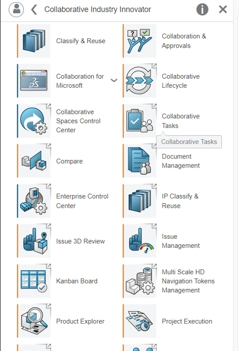
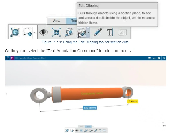
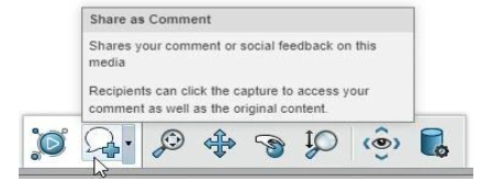
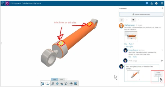
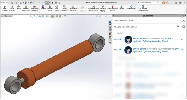
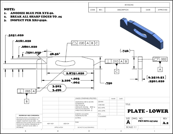
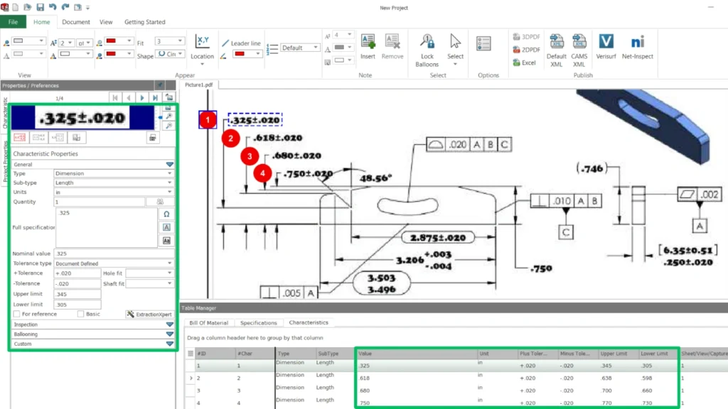
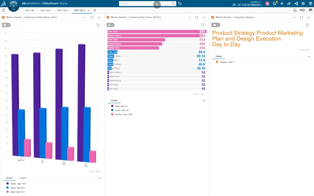
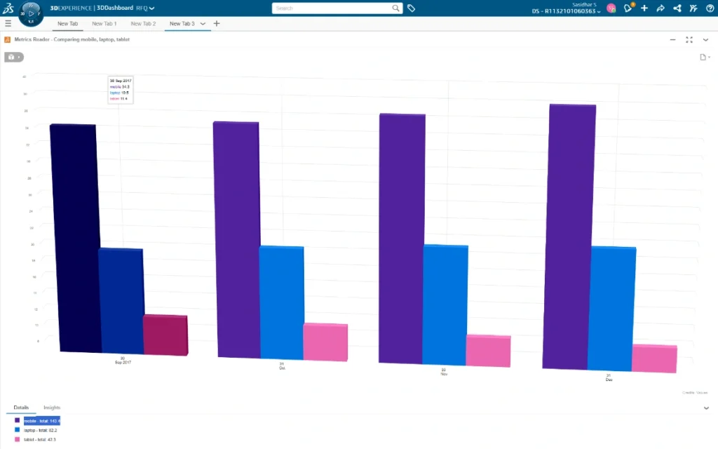
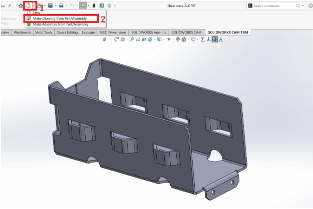
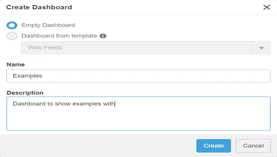
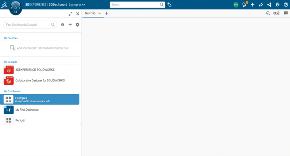
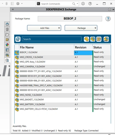
If you are looking for a blog to study 3DEXPERIENCE Document Management. Here is a blog that helps you to guide
Managing documents can be tricky, especially when working with a team on designs, reports, and feedback. The 3DEXPERIENCE software makes it easier by providing a central place where everyone can work together more effectively.
Key Benefits of Document Management
Enhanced Productivity: Spend less time searching for files and more time working on projects.
Secure Sharing: Share documents with internal teams or external stakeholders while controlling access permissions.
Collaboration Without Boundaries: Break down silos and enable team members from different locations to work together effortlessly.
Audit Readiness: Keep an organized record of all changes and actions for easy compliance with industry standards.
Getting Started with Document Management
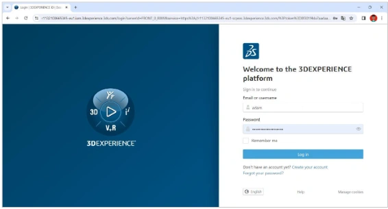
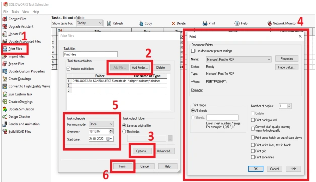
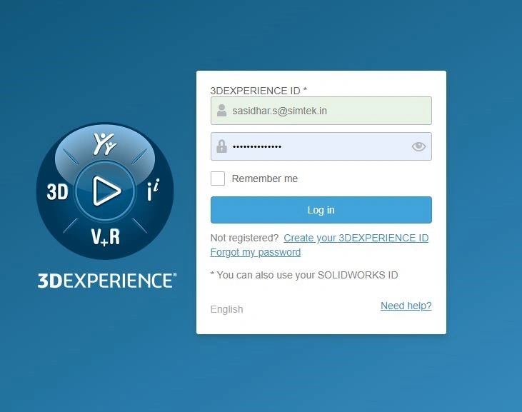
Step 1: Log In to the 3DEXPERIENCE Platform
Open your browser and navigate to the 3DEXPERIENCE platform.
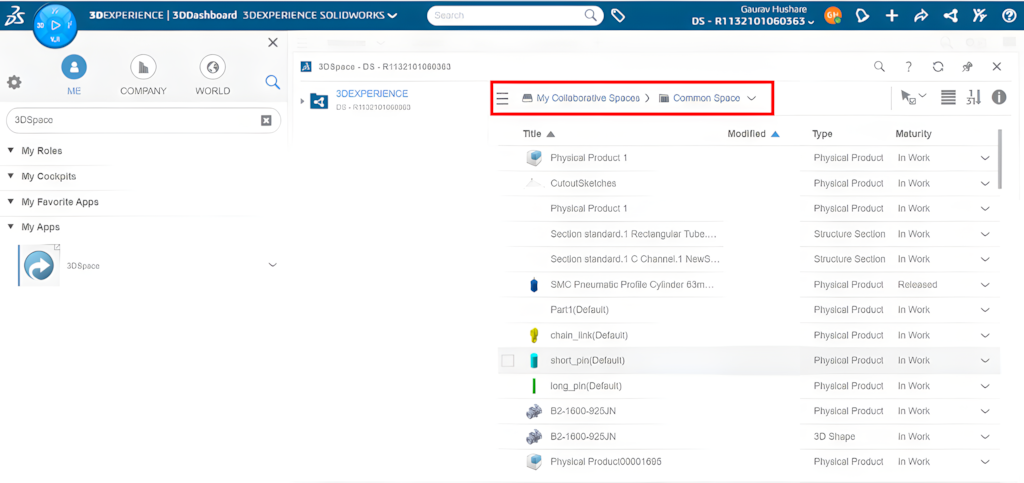
Step 2: Navigate to the Collaborative Space
Once logged in, head to the Collaborative Spaces app.
Collaborative Spaces are shared environments where teams can store and manage project files.
Select an existing space or create a new one for your project.
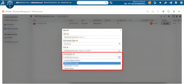
Step 3: Upload Your Documents
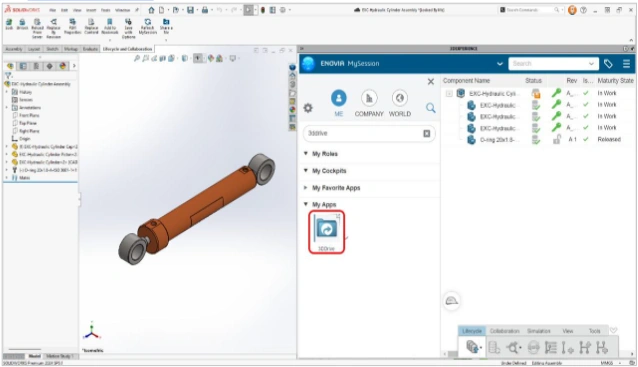
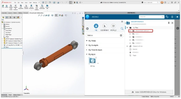
Open the 3DDrive or 3DSpace app, depending on your requirements.
Click Upload Files and drag and drop your documents or select them from your local device.
Organize files into folders for easy navigation.
Step 4: Tag and Categorize Files
Add metadata such as tags, categories, or keywords to your files.
This makes searching for documents faster and more efficient.
Step 5: Set Permissions
Control who can view, edit, or share your files.
In 3DSpace, you can assign permissions based on roles, ensuring that sensitive documents stay secure.
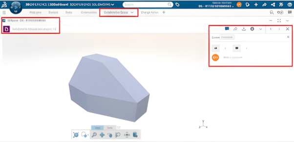
Step 6: Collaborate in Real-Time
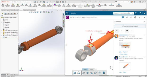
Use the 3DComment tool to leave feedback directly on documents.
Team members can reply, resolve comments, or tag others for input.
Keep all discussions tied to the relevant document for easy tracking.
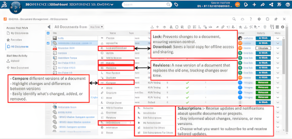
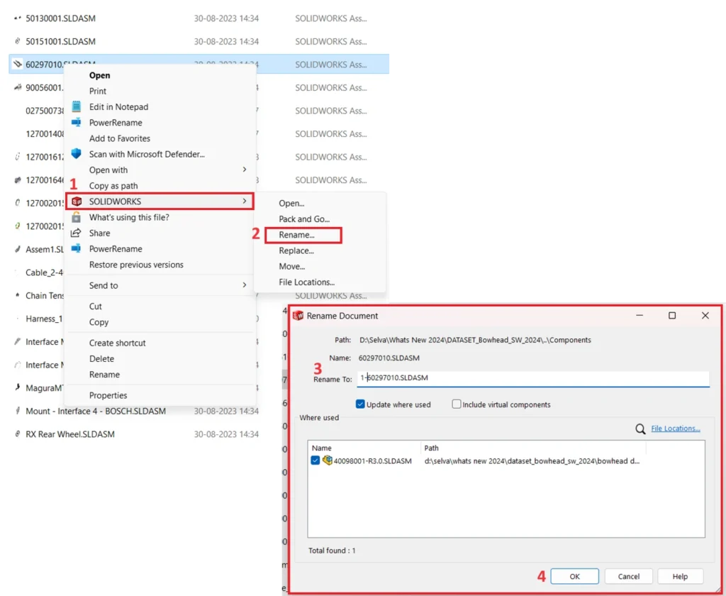
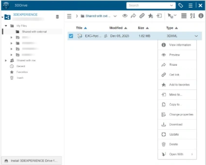
When you select a file and right-click, you'll see options like:
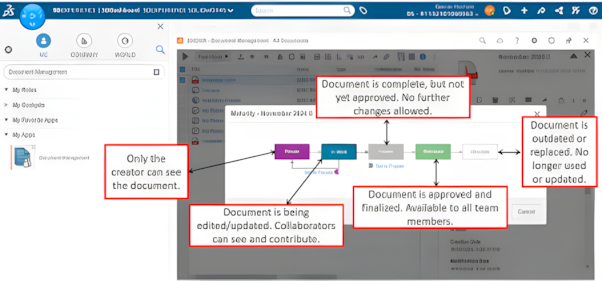
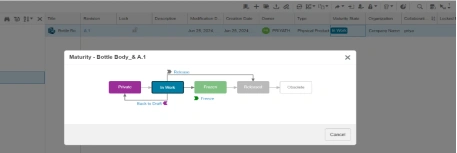
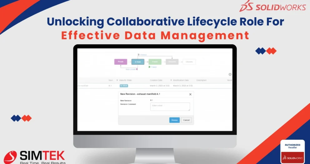
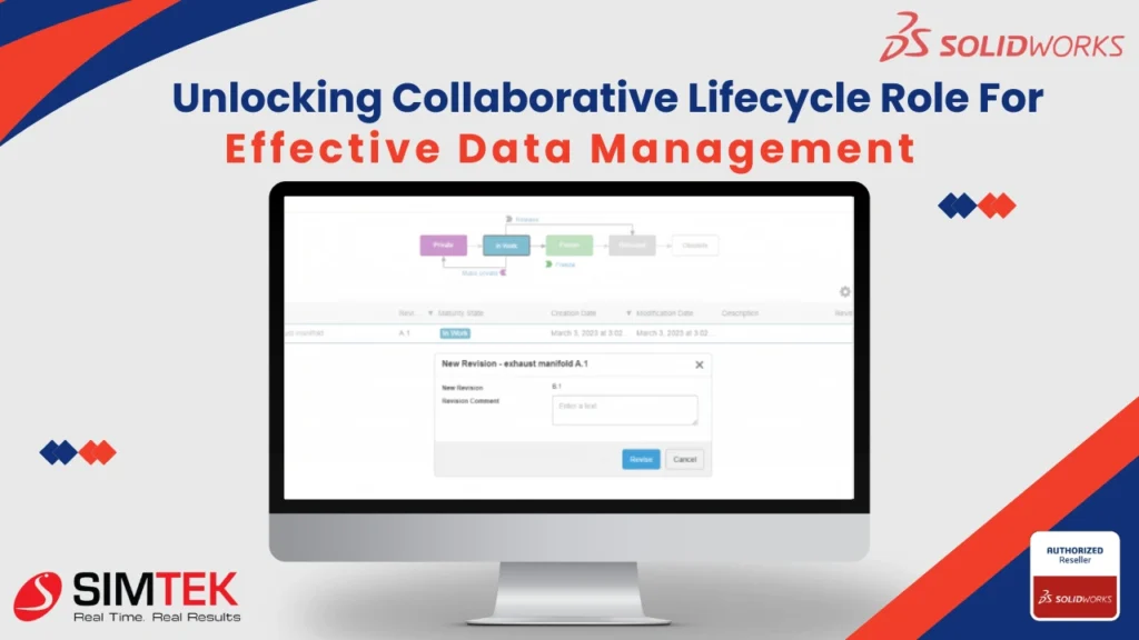
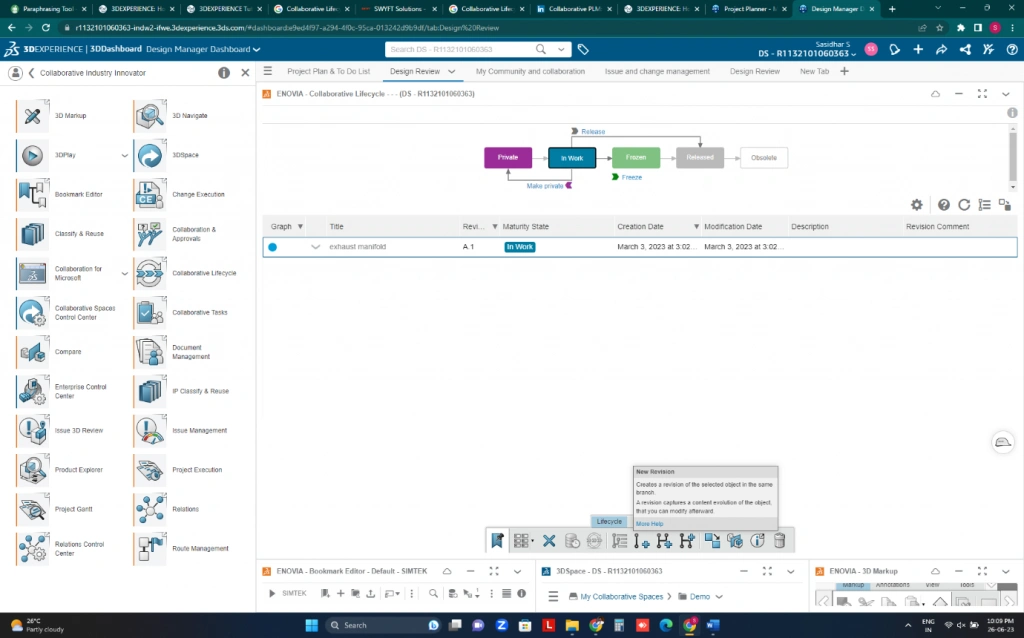
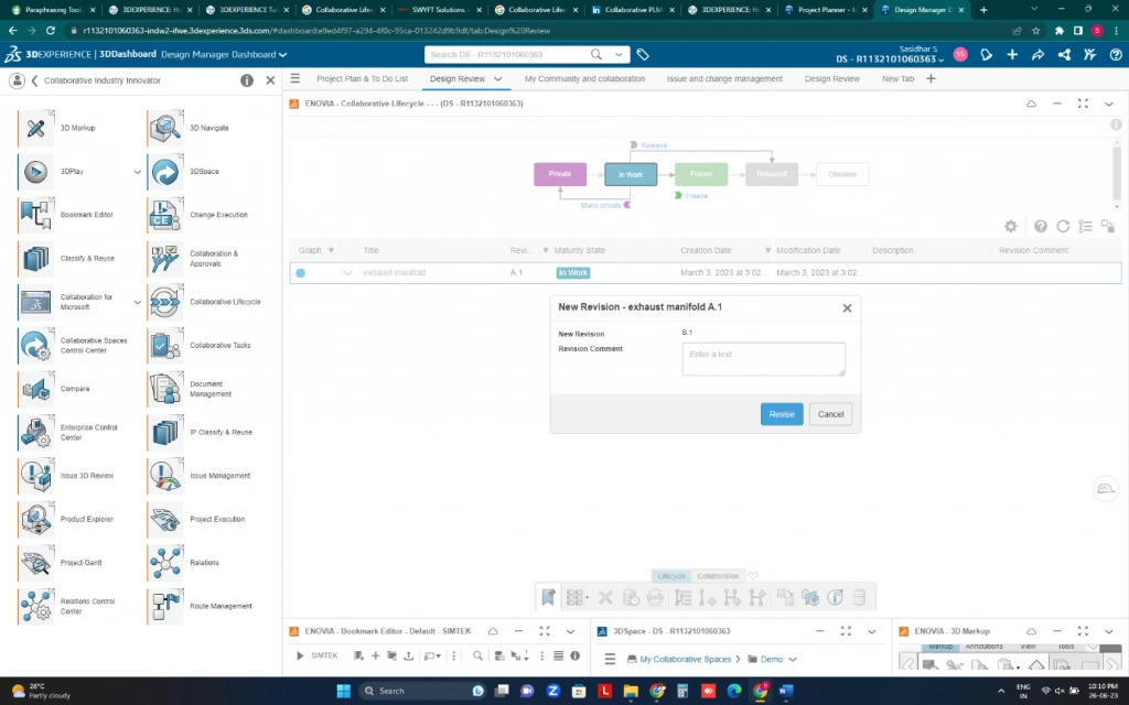
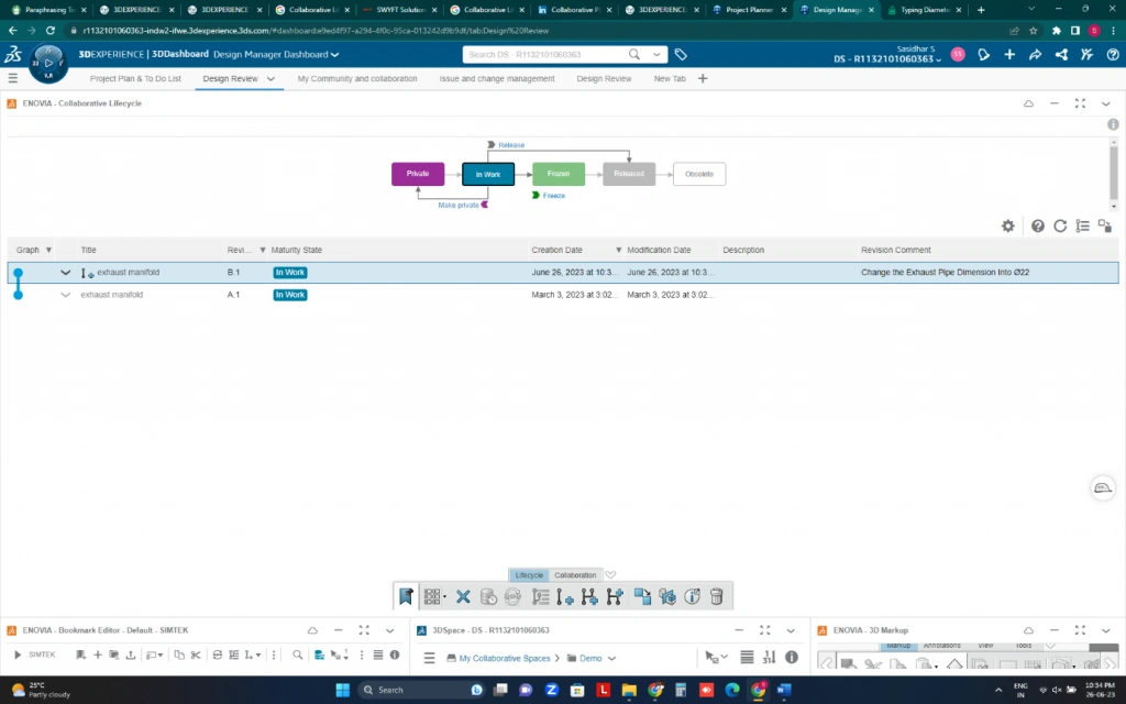
Step 7: Document's lifecycle (Maturity)
Private (draft)
In Work (development)
Frozen (review)
Released (final)
Obsolete (archived)
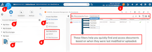
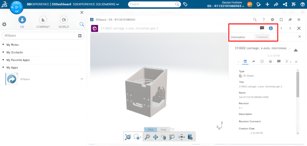
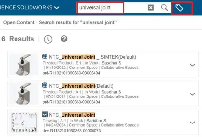
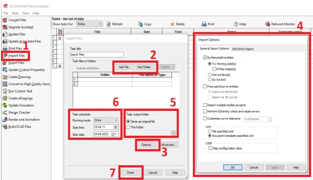
Step 8: Search and Retrieve Files
Use the search bar to locate documents by name, tag, or content.
Advanced filters help narrow down results, even in large repositories.
Step 9: Link Documents to Projects
Link your documents to specific tasks or projects using Project Management.
This ensures your files are connected to the right workflows, enhancing team coordination.
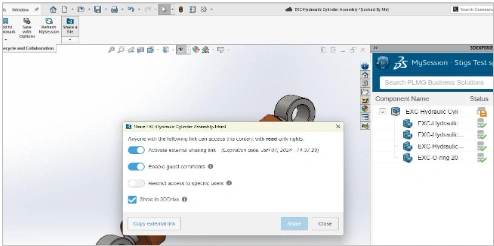
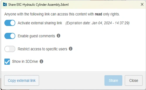
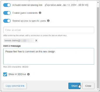
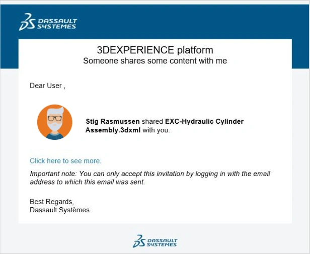
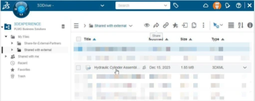
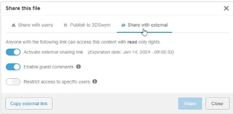
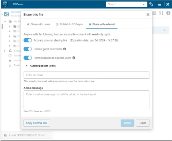
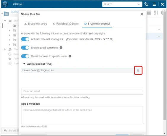
Step 10: Share Files with External Stakeholders
If you need to collaborate with people outside your organization, use secure sharing options.
You can send a link with access permissions and expiration dates to maintain control.
Benefit
✓ Engineers and Designers: Keep design files updated and linked with project tasks.
✓ Project Managers: Oversee all project-related documents and ensure timely delivery.
✓ Cross-Functional Teams: Collaborate effectively across departments like marketing, production, and quality assurance.
Conclusion
Managing documents doesn’t have to be stressful. Therefore, with 3DEXPERIENCE, all your files are organized, easy to access, and secure in one place. Whether you’re a designer, engineer, or project manager, this platform helps your team stay on track and focus on creating great ideas.
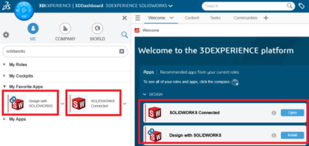
Good news! The latest update of SOLIDWORKS 2025 is now available. The collaboration and data management enhancements listed in this blog post apply to 3DEXPERIENCE SOLIDWORKS, SOLIDWORKS with Cloud Services, and SOLIDWORKS 3D CAD with Collaborative Designer for SOLIDWORKS.
1. Guided Tours for User Assistance
Interactively learn about workflows to help you quickly understand basic functionality and concepts.
You can now access short learning tutorials, called Quick Tours, from the Welcome dialog box. Each Quick Tour has a sequence of steps shown as interactive pop-ups that point to features in the user interface. Quick Tours include a user interface overview, how to save to the 3DEXPERIENCE platform, and more!
STEP 1:
Launch Design with SOLIDWORKS (or) SOLIDWORKS Connected from the 3DEXPERIENCE Platform.
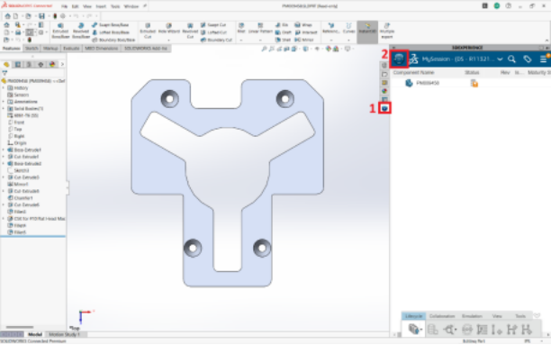
STEP 2:
In the Design with SOLIDWORKS (or) SOLIDWORKS Connected, open the home window to explore the Quick Tour.
STEP 3:
Start learning the Step-by-Step on SOLIDWORKS Basics, Moving files to 3DEXPERIENCE, and Data Management Topics.
Benefits: You can interactively learn the 3DEXPERIENCE apps to help you quickly understand basic functionality and concepts.
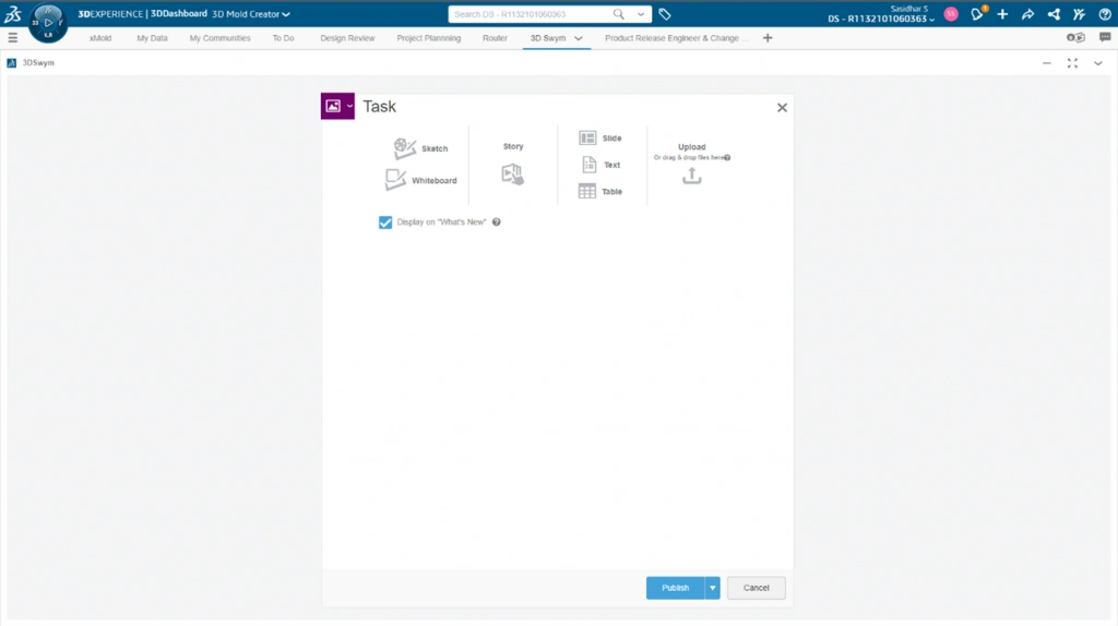
2. 3DSwym Integration
Chat and collaborate right from the SOLIDWORKS Task pane. This provides both community access as well as chat conversations. It takes full advantage of the share capability, so users can post files to these conversations and receive markups back. Users can stay connected to their colleagues and coworkers without ever leaving SOLIDWORKS.
STEP 1:
In the Design with SOLIDWORKS (or) SOLIDWORKS Connected Task pane, click Compass to access the 3DSwym application.
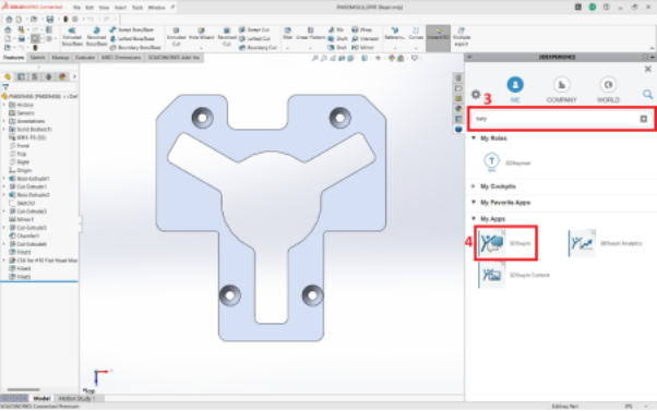
STEP 2:
Search for the 3DSwym application to use in the SOLIDWORKS window.
STEP 3:
Now the conversation window will appear to communicate with your team and community chat.
That is just a glimpse of what’s new in the area of collaboration and data management with the R2025x GA release.
The latest SOLIDWORKS update brings significant enhancements to collaboration and data management, making it easier for teams to work together and stay connected. By leveraging tools like Guided Tours for user assistance and 3DSwym for integrated communication, users can maximize efficiency and productivity within the 3DEXPERIENCE platform.
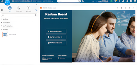
Kanban Board app uses direct access responsibilities instead of baseline behavior responsibilities, to determine whether you can access a specific Kanban board and whether you have permission to perform specific actions on it.
Any user with a license role that includes the Kanban Board app can create a Kanban board.
The system automatically assigns the Owner's responsibility to the user who creates the kanban board. The Owner is the only one who can access the kanban board when it is created.
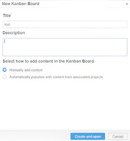
Step 1:
Click New Kanban Board for New Task
Step 2:
Enter Task Tile and Detailed Description of The Work
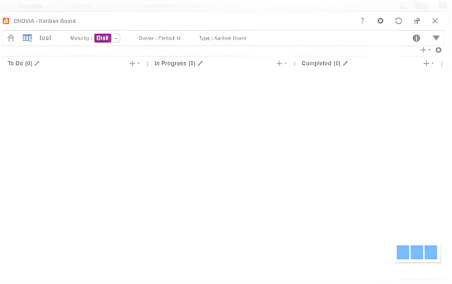
Kanban boards have the following maturity states:
Draft
Active
Archived
Contributors and Informed Users of a kanban board can only view it and work in it when the kanban board maturity is Active
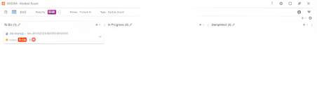
Step 3:
Click Add Button for Creating New Task and Select File From Cloud
Step 4:
Once Click The Issue Having File Task as Been Added Todo List
Step 5:
The Status of Your Work Monitored by Kanban Board.
Kanban Board is a web app that lets you create a kanban board according to your needs. You can:
Add or remove columns depending on the process flow that you want your team, project, or organization to follow.
Optionally map columns with actual maturity states to manage the maturity of the objects by moving the corresponding cards from one column to the other.
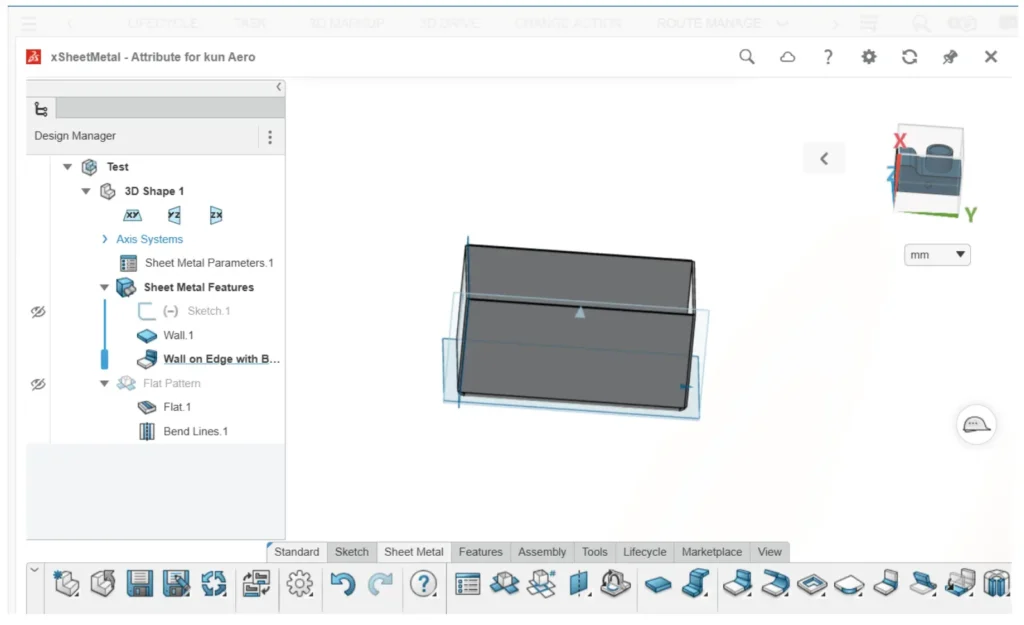
The 3D Sheetmetal Maker is a user-friendly web application that offers parametric associative sheet metal design tools for making enclosures, assemblies, and parts.
Quickly releasing sheet metal components to the market is made possible by its dedicated, all-in-one 3D sheet metal design environment, which streamlines the development, storage, sharing, validation, and management of designs.
3D Sheetmetal Maker is based on the 3DEXPERIENCEWorkscloud platform, providing seamless integration across design to manufacturing portfolios. It includes tools for data management and collaboration, ensuring efficient workflows and secure storage. All design data is safely kept in one location.
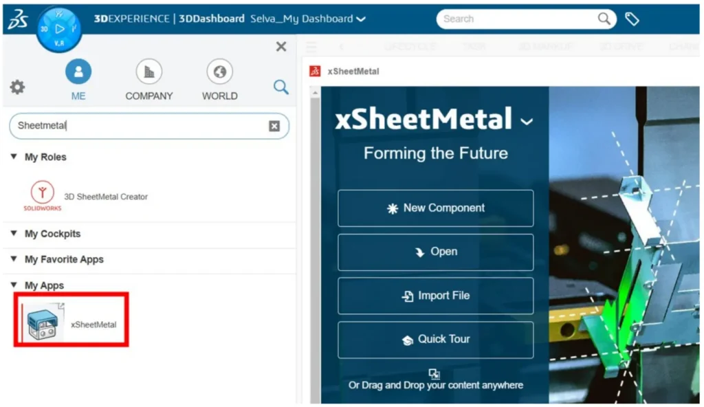
Log in the 3DEXPERIENCE and Search the Sheetmetal
STEP 1
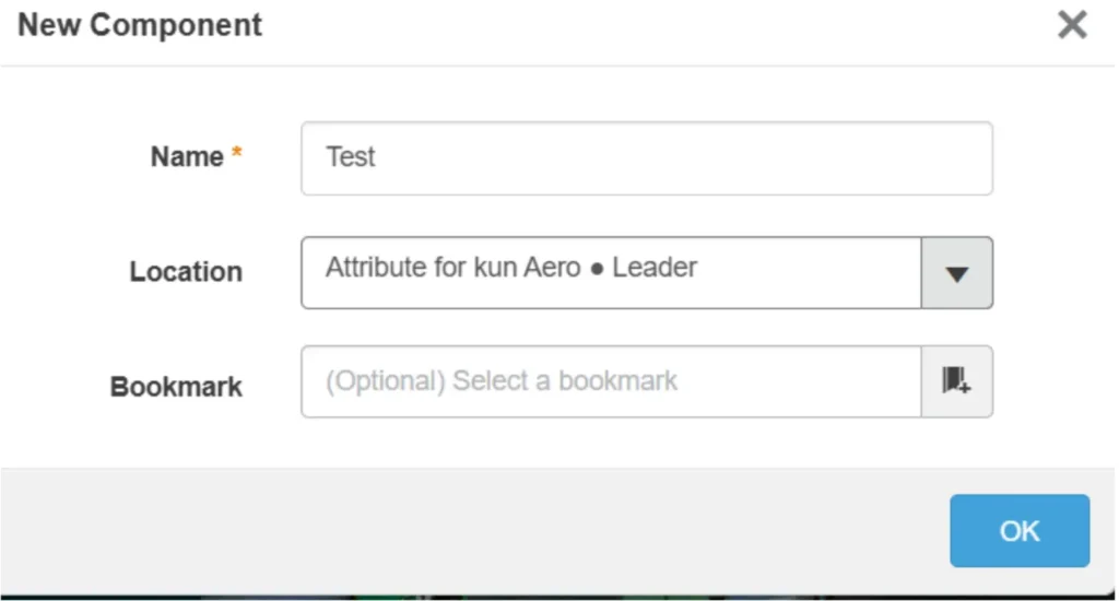
Select your file location, create a new component with a fresh interface, and begin designing.
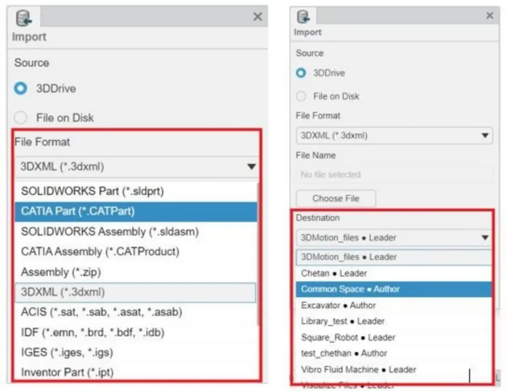
STEP 2
Importing Cad Files: You may start working on your current CAD files right away with Xapps by importing them as Neutral Files. This allows you to rebuild and remove components as well as add new features to the previous CAD file. Additionally, choose the file location after your project.
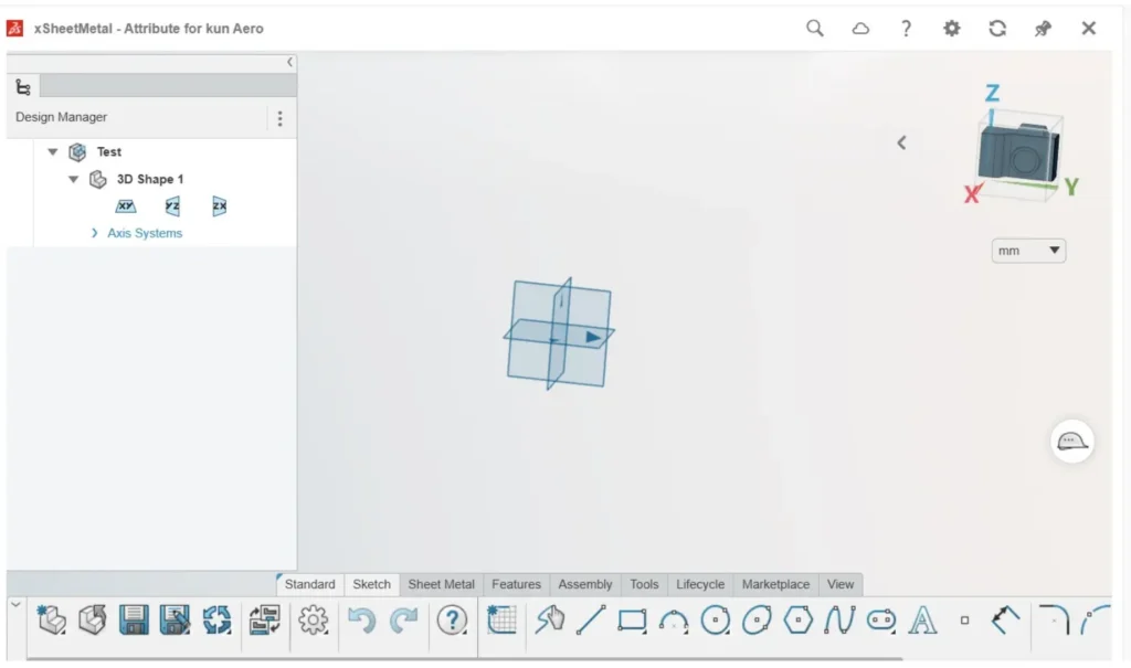
STEP 3
Making Sheet Metal: Begin by creating your design in Simple Sketch, and then begin building miter flanges, edge flanges, hem bends, and other shapes using the sheet metal feature. Select the Relief type and use the sheet metal specifications to calculate the K factor.
STEP 4
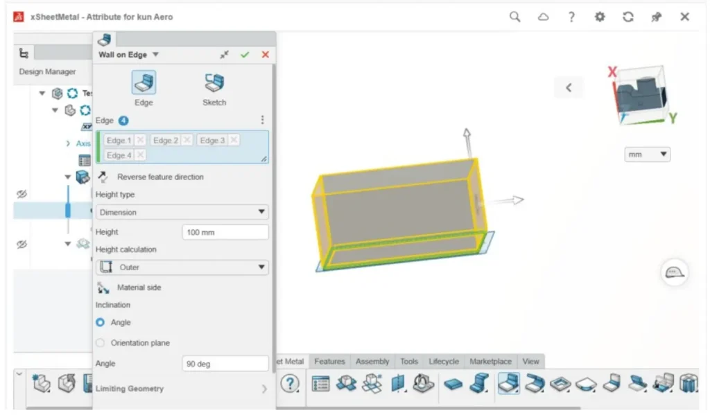
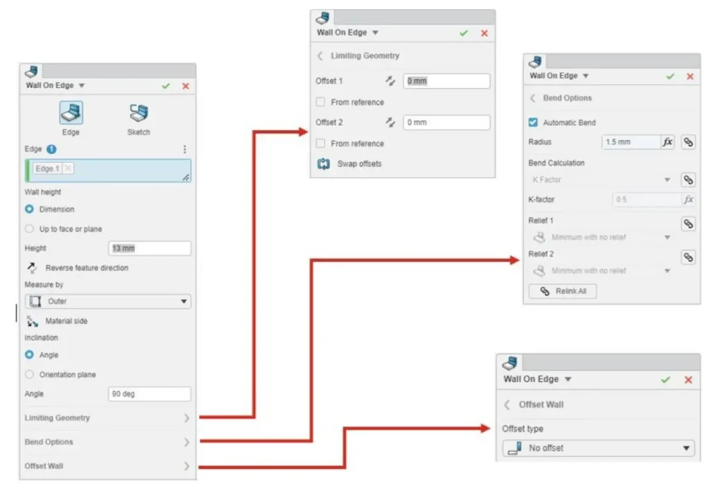
Creating a wall on edges: This will let you to construct flanges at the edges, offering additional features such as wall offset, bend option, and geometry modification. You can adjust the K factor and offset the bends from the edges
if you like to change the flanges using this option. Additionally, you can change the flanges' geometry.
Highlights
A versatile and user-friendly 3D sheet metal design role with powerful feature-based tools.
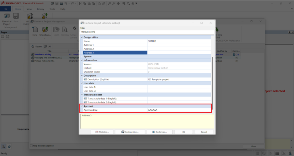
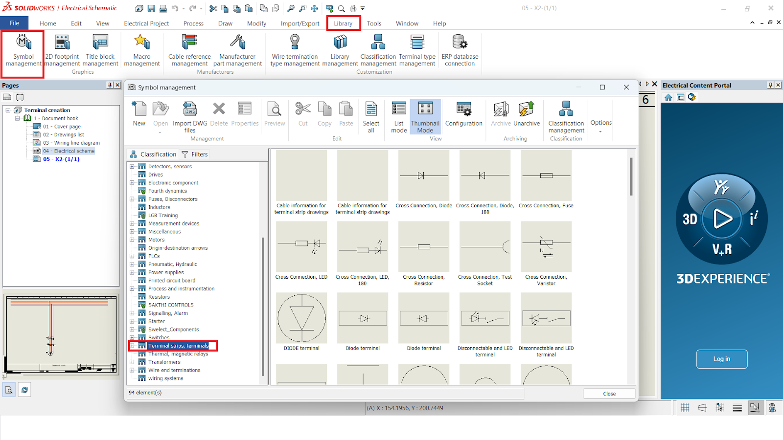
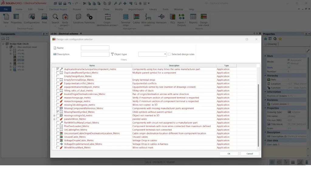
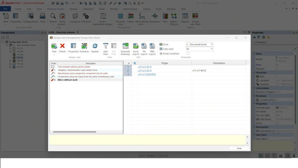
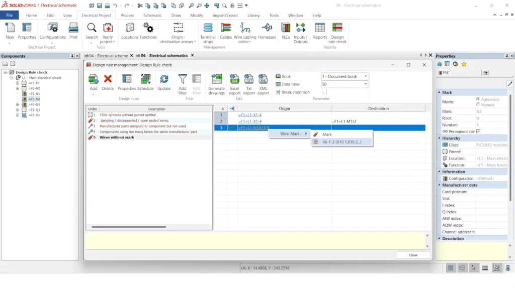
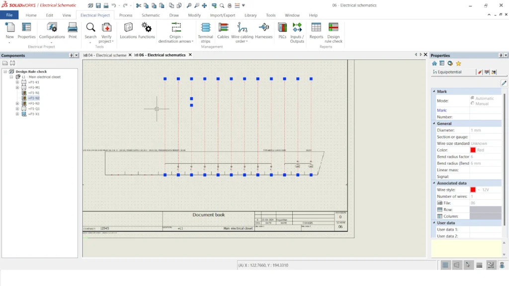
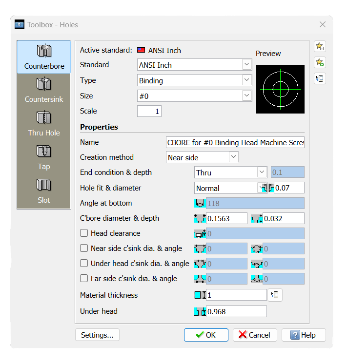
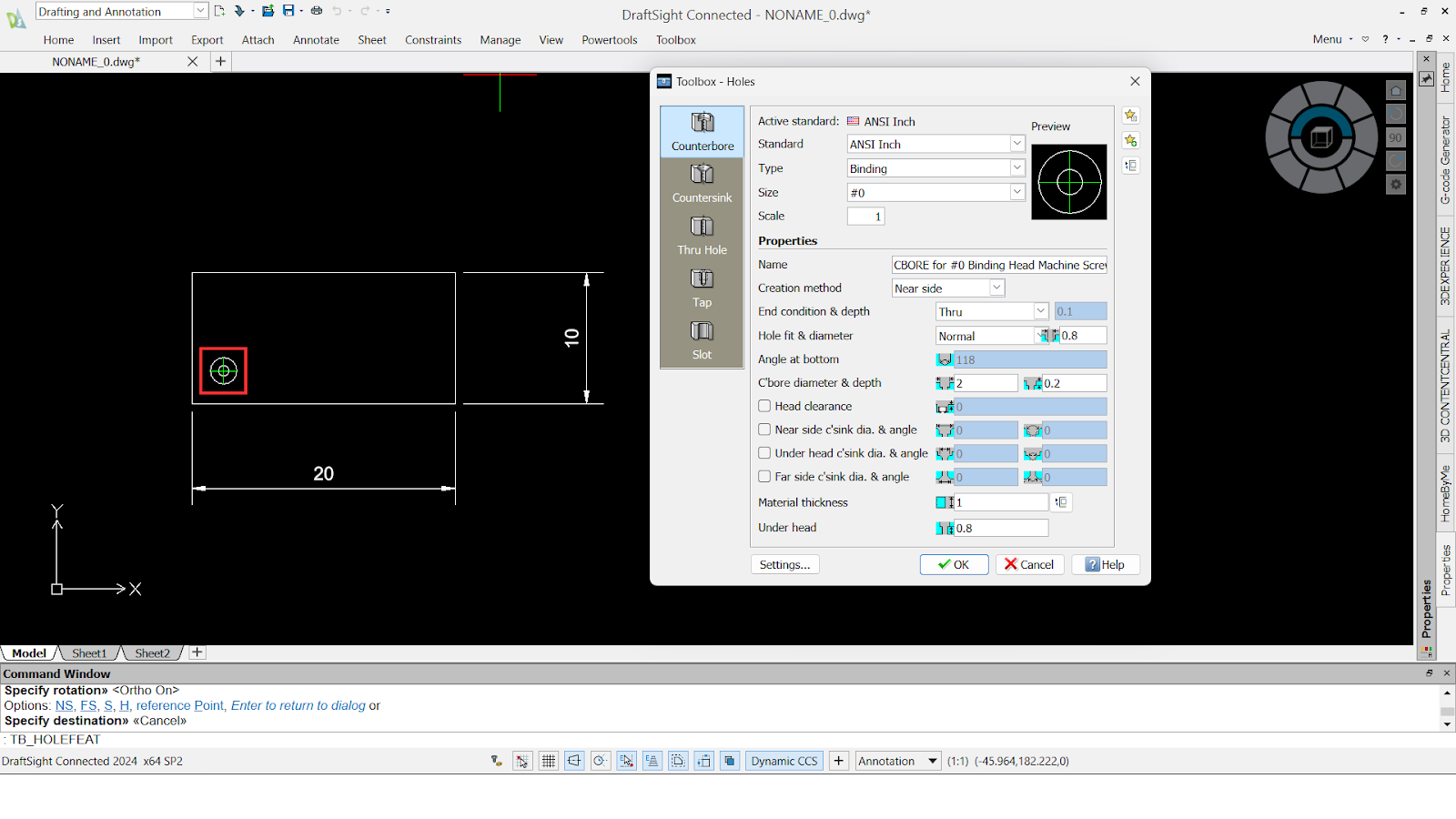
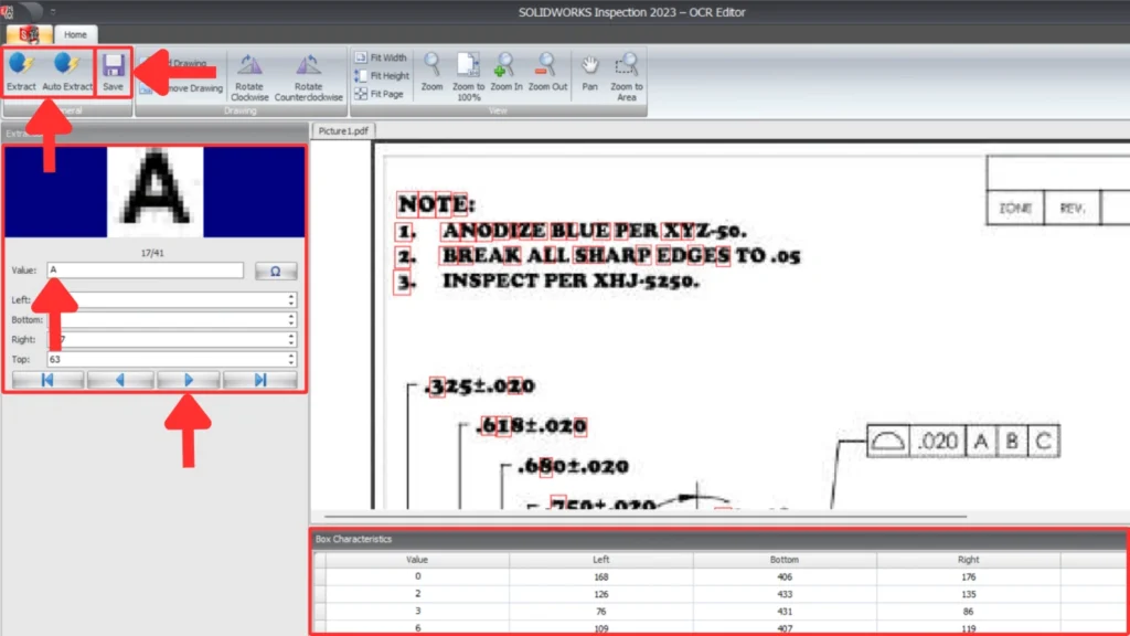
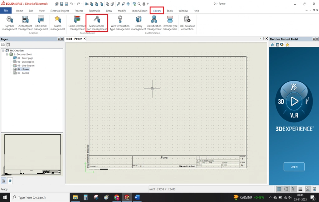
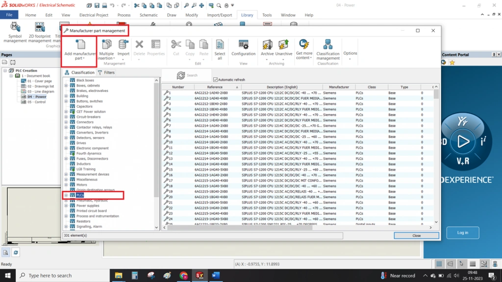
Creation of a new terminal strip drawing and modifying the default terminal symbol in Solidworks electrical and customizing it according to our specification.
In SOLIDWORKS Electrical, you must create and save the symbol in the library, while the system automatically generates the terminal page and dynamically updates component details on the terminal drawing sheet.
STEP 1
AS shown in the below image
To create a terminal symbol.
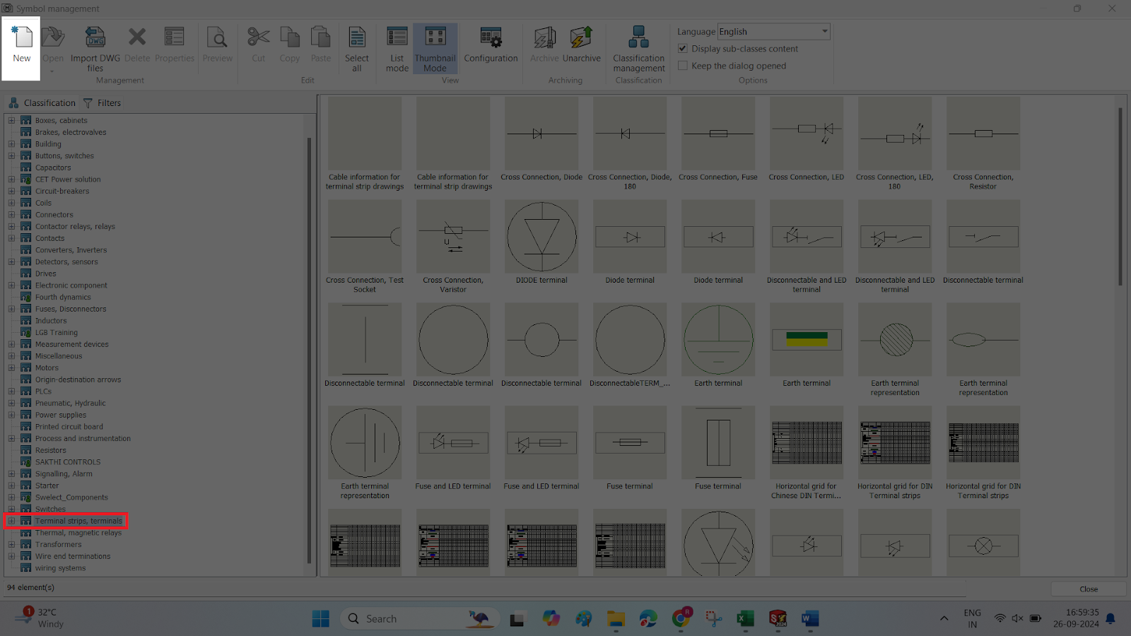
Had to click on Library->Symbol management->Terminal symbol classification.
This is exactly similar for creating a new symbol in library
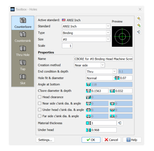
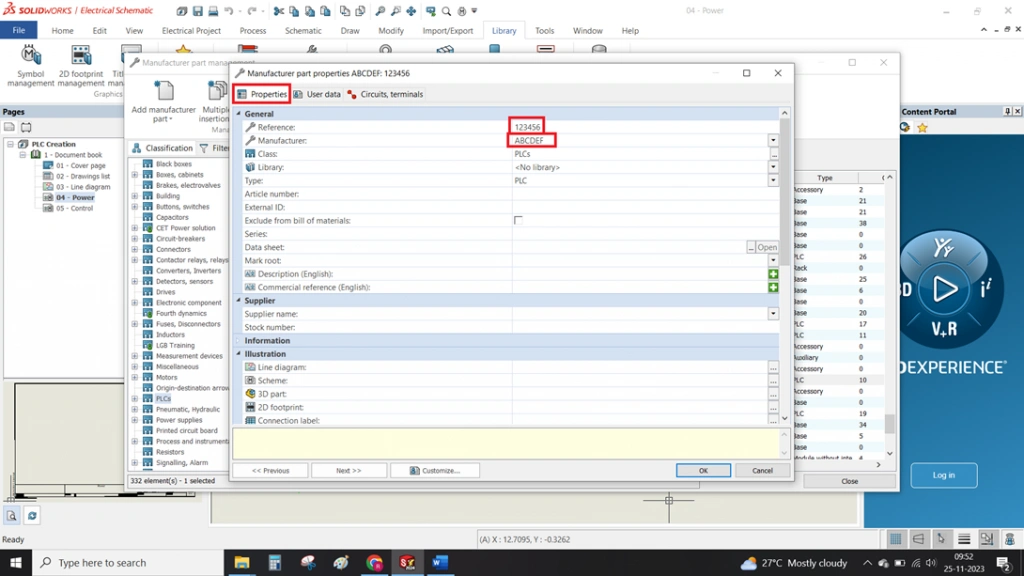
STEP 2
NEW SYMBOL
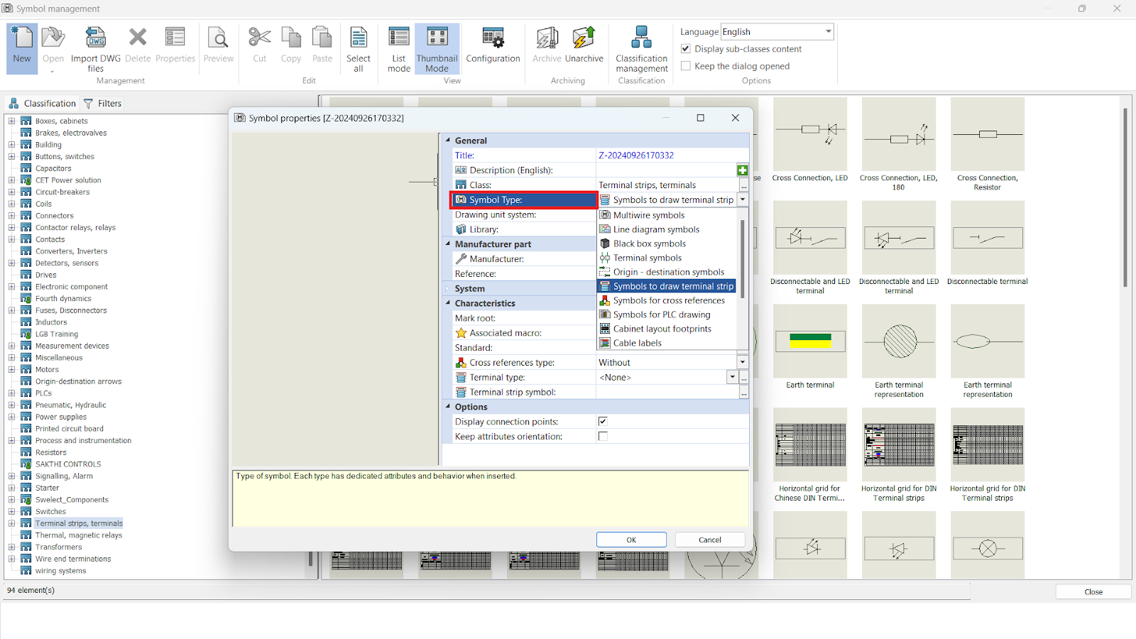
To create a new symbol first we have to fill the properties for that symbol
For example, you must fill in the properties, specifying whether it is a symbol, terminal, or line diameter.
To fill the properties have to go for new option in the symbol management tab as shown in the below image.
And also have to select the classification (folder) before going for new option, So that our new symbol will be present at that separate folder.
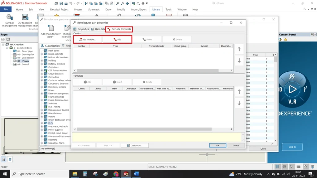
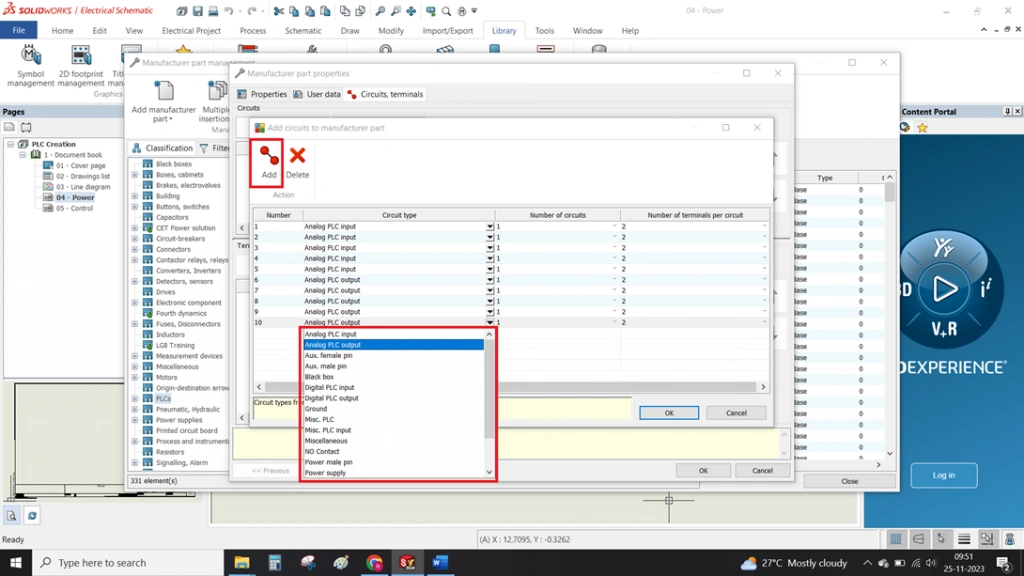
STEP 3
NEW SYMBOL PROPERTIES
Once you complete the above steps, the new symbol properties tab opens, where you create the details of the symbols.
You must fill in every detail before creating the drawings. Main this is to select which type of symbol we are going to create (highlighted in below image)
You must select the Symbols to Draw Terminal Strip option from the multiple options available.
This to avoid placing our terminal strip template inside the schematic. You only use this to create symbols automatically.
STEP 4
NEW SYMBOL PAGE
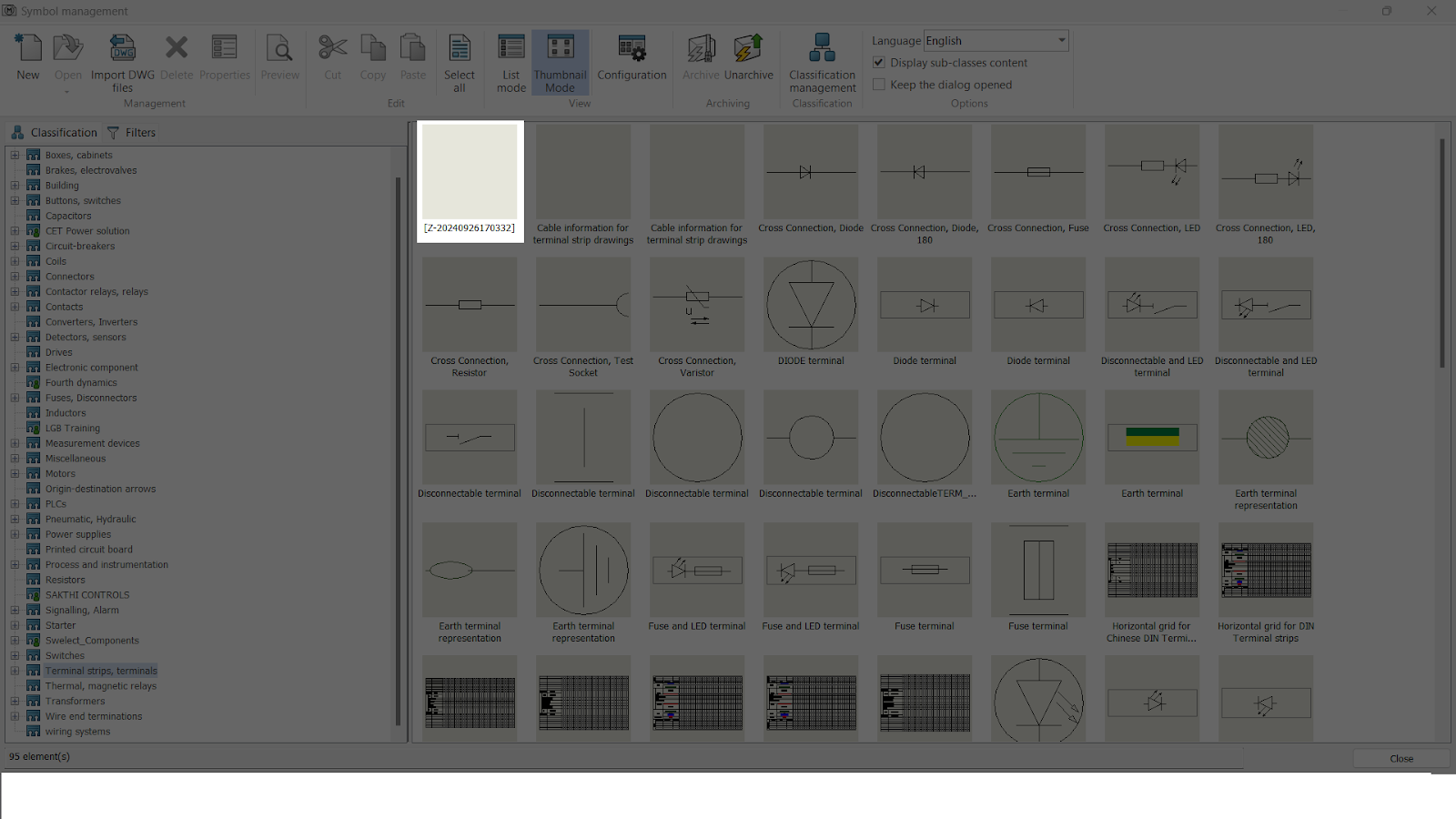
Once you fill in and submit the symbol details, the system creates a page using the description name specified in the symbol properties.
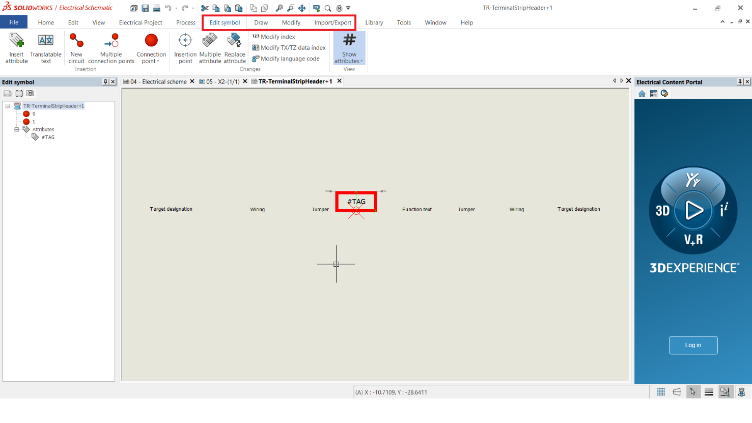
You will create the symbol drawing and place attributes inside those pages.
STEP 5
SYMBOL EDITOR
You can create a symbol using the highlighted option in the image below.
You can use the Draw and Modify options to create and modify the symbol according to your specifications.
You can also import any previous terminal symbol formats from .dwg files, save them in the library, and use them later.
A creation of symbols is present in our previous blog. We are suggesting to see our previous blog for better understanding of creation of new symbols.
You can import previous terminal symbol formats from .dwg files, save them in the library, and use them later. Stay tuned.
Summary
With these above-mentioned points we can be able to create a terminal symbol in solidworks electrical.
This TERMINAL will act as a default TERMINAL SYMBOL in SOLIDWORKS ELECTRICAL SCHEMATICS.
3DSpace App is a core application of the 3DEXPERIENCE platform designed for project management and collaboration. It serves as a centralized repository for project data, enabling teams to access, manage, and share information seamlessly.
Features:
1. Centralized Data Management
3DSpace allows users to store and organize all project-related information in one location.
2. Intuitive User Interface
With a user-friendly interface, 3DSpace simplifies navigation and data retrieval. Users can easily search for documents, models, and other project files.
3. Version Control
Allowing teams to track changes, manage revisions, and ensure that everyone is working with the most up-to-date information. This capability is crucial for maintaining data integrity throughout the project lifecycle.
4. Collaborative Workspaces
3DSpace provides collaborative workspaces where team members can share ideas, feedback, and project updates in real-time. This helps teams stay aligned on project goals.
Getting Started with 3DSpace
Accessing the App
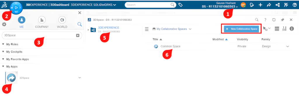
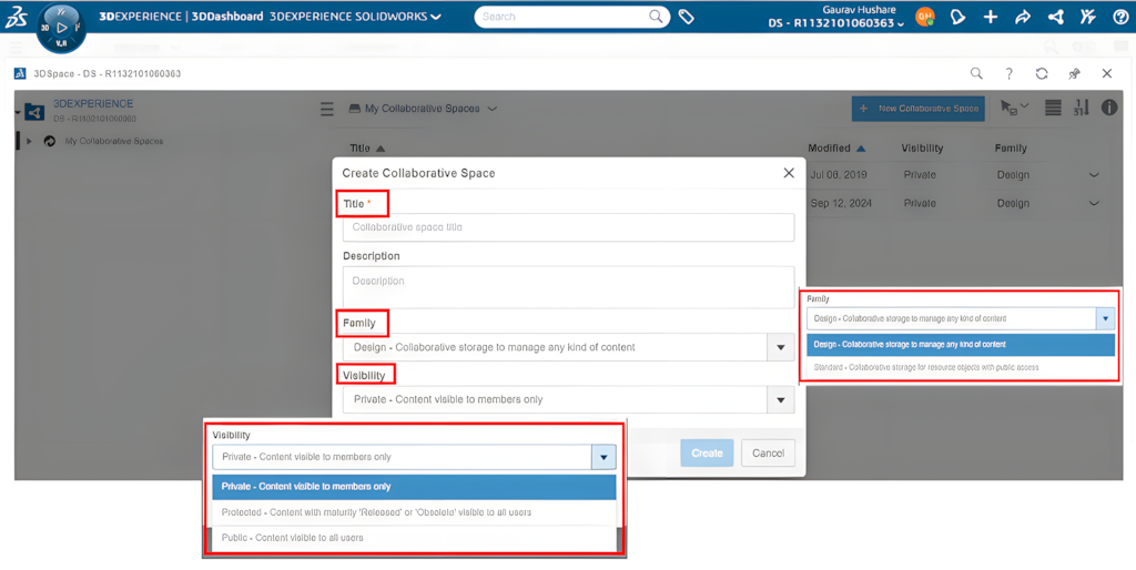
Step 1: Create a Collaborative Space
To get started, you need to create a Collaborative Space in 3DSpace. This is where all your project files and data will be stored.
Go to the 3DEXPERIENCE dashboard and select the 3DSpace app from the menu.
Click on “New Collaborative Space” to set up a new space for your project
Name your space based on your project (e.g., "Project X Design Files").
Define roles and permissions: Decide who will have access to this space and what actions they can take (view, edit, etc.).
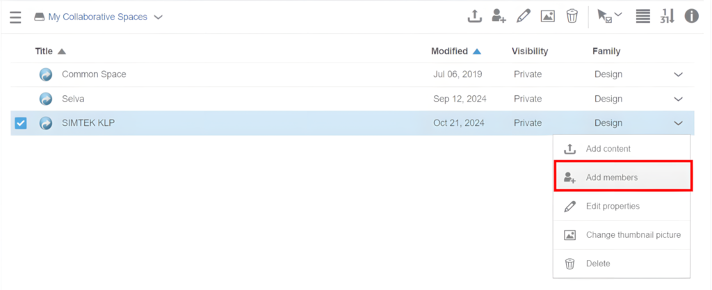
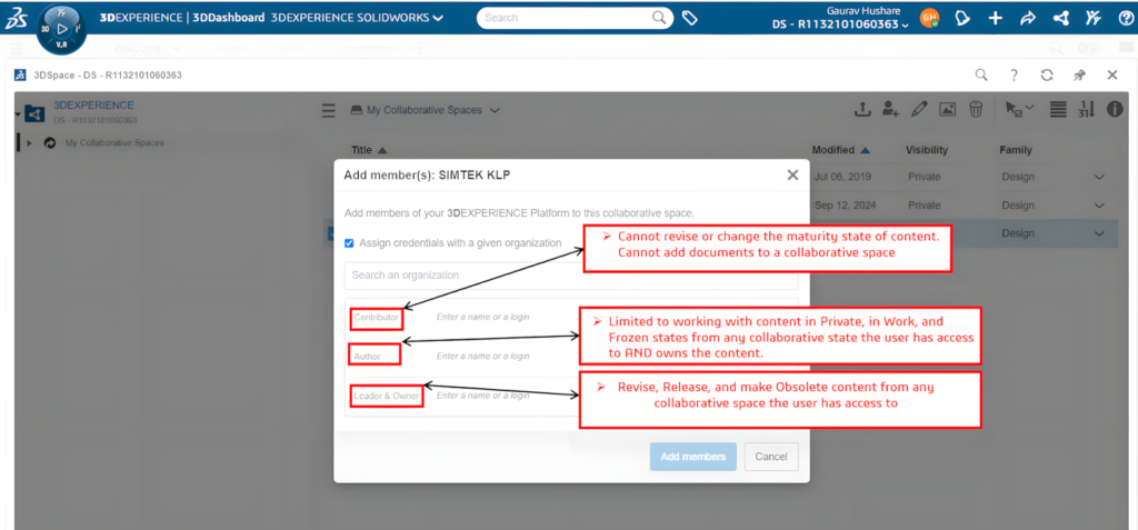
Step 2: Add Team Members
Now that you have your Collaborative Space set up, it’s time to bring your team in.
Within the space, click on “Members” or “Add Participants”.
Search for your team members by name or email and invite them to the space.
Assign roles to each team member (e.g., viewer, editor, project manager). This controls what they can do inside the space.
Set up folders for different tasks or project phases to keep everything easy to find.
Add tags or keywords to files to quickly find them during searches.
3DEXPERIENCE platform for viewing models, sharing ideas, or tracking tasks.
Benefits:
Enhanced Collaboration With 3DSpace, teams can work together more effectively,
Improved Efficiency By centralizing project data and streamlining workflows
Better Decision-Making Access to real-time data and insights enables teams to make informed decisions quickly.
3DSpace supports projects of varying sizes and complexities, providing scalability for diverse project needs.
Conclusion:
The 3DSpace app within the 3DEXPERIENCE platform is a powerful tool for enhancing collaboration and project management.
By centralizing data, promoting teamwork, and integrating with other applications, 3DSpace helps teams work more efficiently and effectively.
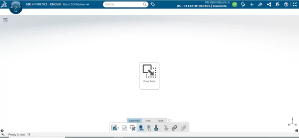
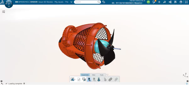
Moreover, the 3DEXPERIENCE platform includes a variety of applications, such as the Issue 3D Review app, designed to facilitate design, collaboration, and product lifecycle management. The 3D Review app is a crucial tool within this ecosystem; consequently, it focuses on the review and feedback process for 3D models.
Steps to Use the Issue 3D Review App:
Step 1: To begin, drag and drop the app into the tab, then insert the file from the 3D space.
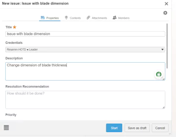
Step 2: Click new issue to create an issue report, and consecutively proceed to fill in the required details.
Step 3: Enter the detailed description and, consecutively, the title of the issue.
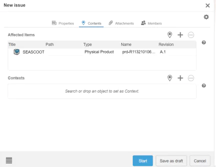
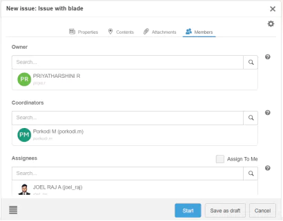
Step 4: Next, locate the issue-presented part, attach the related files, and consecutively assign the task to the relevant team member.
Step 5: First, click start to create a new issue, and then proceed to fill in the necessary details.
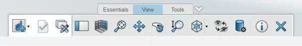
Step 6: Viewing tools also available in 3D issue review like rotate, pan, zoom in, zoom out, gridline line etc.
Step 7: Section view, measure, and relation also available on inside of 3D issue review app.
Step 8: After completing an issue report, the concerned team receives a notification in the issue management app for prompt action.
Create a Template for Future Issue Report Creation:
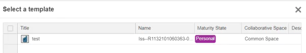
Step 1: The 3DEXPERIENCE platform includes a variety of applications. The Issue 3D Review app is designed to facilitate design, collaboration, and product lifecycle management consecutively.
Step 2: Then, click save and proceed to the Issue 3D Review app to select the template.
Conclusion
The 3DEXPERIENCE platform, with its variety of applications including the Issue 3D Review app, significantly enhances design, collaboration, and product lifecycle management. By providing tools to efficiently manage issues and feedback on 3D models, it supports teams in maintaining high standards of product quality and performance.
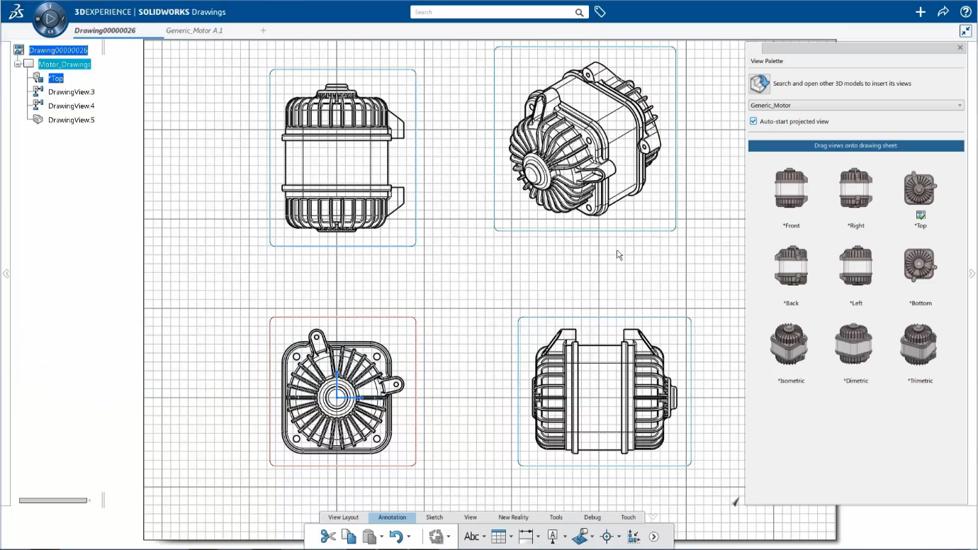
Drafter WDR-OC enables rapid conversion of 3D models into accurate 2D drawings, significantly enhancing the product development cycle. With real-time updates, modifications to the 3D model are instantly reflected in the 2D drawings, minimizing errors. Users can easily annotate and dimension their drawings, facilitating clear communication among team members. Integrated with the 3DEXPERIENCE platform.
Drafter allows for easy sharing and access to drawings from any device, enhancing collaboration. This streamlined approach reduces the time and cost associated with the design-to-manufacturing process, optimizing workflows and allowing teams to focus on creativity and innovation. Ultimately, Drafter is an invaluable asset for design and engineering teams.
Overview of Drafter WDR-OC
Connected to the 3DEXPERIENCE® platform, Drafter is a Windows-based application that rapidly derives 2D drawings from your 3D models. One of its standout features is the ability to update drawings instantly whenever modifications are made to the 3D design. With Drafter’s comprehensive, production-quality drawing and detailing capabilities, designers and engineers can easily annotate and add dimensions to their drawings. Plus, with data saved to the cloud, sharing drawings in real time has never been easier.
Key Features
Fully Associative 2D Drawings:
Drafter ensures that every 2D drawing is dynamically linked to its corresponding 3D model. This powerful integration means that any adjustments made to the 3D design—whether minor tweaks or significant overhauls—are automatically reflected in the associated 2D drawings. Your documentation is always accurate, reducing the risk of errors and discrepancies.
Efficient Design Communication:
Clear communication is essential in manufacturing. Drafter provides intuitive tools to apply dimensions, annotations, and cross-sections to your drawings. This functionality helps convey complex manufacturing requirements in a straightforward manner, facilitating better understanding among team members and stakeholders.
Accelerated Product Development:
In a competitive market, speed is essential. Drafter significantly reduces the time required to transition from design to manufacturing. By automating the drawing update process, your team can focus more on innovation and less on manual documentation tasks, giving your business a competitive edge.
Capabilities of Drafter
Quickly generate detailed drawings from your 3D parts and assemblies with ease.
Effortlessly apply dimensions, annotations, and cross-sections to enhance your drawings.
Your 2D drawings update instantly whenever you modify your 3D model, thanks to powerful integration.
Benefits of Using Drafter
Real-Time Updates: Enjoy the confidence that comes with knowing your 2D drawings are always accurate. The automatic update feature eliminates the tedious task of manual revisions.
Enhanced Productivity: By streamlining the drawing generation process, Drafter allows your team to focus on creative problem-solving and refining product designs.
Cost Efficiency: Less time spent on documentation directly translates to lower costs, helping you bring products to market faster.
Conclusion
Drafter (WDR-OC) is an essential tool for designers and engineers, integrating powerful drawing capabilities with the 3DEXPERIENCE platform to transform product development. It enhances accuracy, improves communication, and streamlines workflows while reducing costs and boosting productivity. Using Drafter can elevate your design processes and help you meet project goals. In today’s fast-paced environment, having the right tools is crucial, so start using Drafter today and see how it can improve your product development cycle.
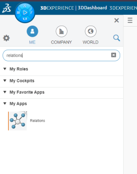
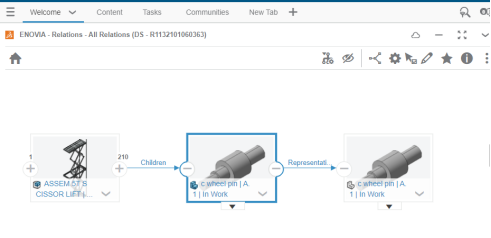
The Relations app in the 3DEXPERIENCE platform is designed to help users manage and visualize relationships between various entities, such as parts, documents, and projects.
This is a powerful tool for managing complex relationships in product development and ensuring that teams work cohesively.
Using the Relations app:
Step 1: Launch the platform for 3D experience.
Step 2: Please enter the term “Relations” into the search bar to initiate a comprehensive search on the topic. This will help you access relevant information and resources related to the subject matter.
Step 3: Please proceed to open the Relations Application to access the relevant features and functionalities it offers.
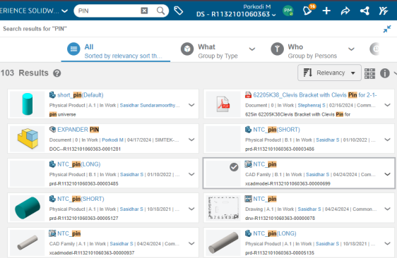
Step 4: To find specific files, utilize the 6W tags or enter keywords in the search bar. Make sure to apply the appropriate tags to enhance your search results and locate the documents you need more efficiently.
Step 5: Please locate the file you need and open it using the Relations application on your device. Make sure the app is installed and running properly before proceeding.
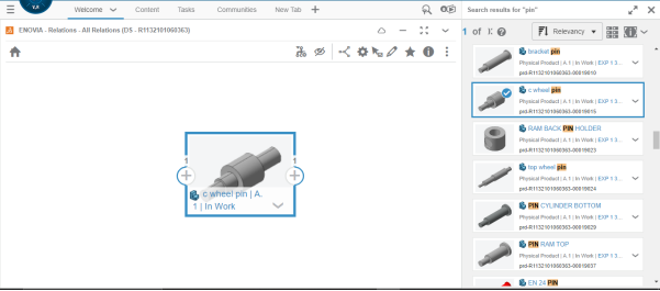
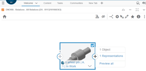
Step 6: Define Relationships. Select the entity you wish to link and choose the “Create Relation” option. Use the graphical interface to view all existing relationships. This will display connections clearly, helping you understand dependencies.
Benefits:
Enhanced Collaboration: By clearly defining relationships, teams can collaborate more effectively.
Improved Efficiency: Understanding dependencies helps streamline workflows and reduce errors.
Better Decision-Making: Visual insights into relationships aid in making informed decisions regarding design changes and project management.
Conclusion
The Relations app in the 3DEXPERIENCE platform is a powerful tool for managing complex relationships in product development. By providing tools to efficiently manage and visualize relationships, it supports teams in maintaining high standards of product quality and performance.
The 3D Motion Creator role within the 3DEXPERIENCE platform offers powerful simulation tools for performing kinematic and dynamic motion analyses of assemblies. This browser-based solution allows you to simulate mechanical motion and interactions efficiently without needing any software installation, making it accessible from anywhere with an internet connection.
Working with a kinematics player, you can easily analyze the kinematic system behaviour. Enhance the simulation with drivers, forces, torques, and 3D contacts or add dynamic modeling elements, such as a helical spring, to create a dynamic motion simulation. After running an analysis, you can review results with an animation or 2D plots.
Core Features Of 3D Motion Creator:
Motion Simulation with Mechanisms and Analysis Cases/Steps
Functions, Drivers, Gravity, Forces, Torques, …
Motion Manager for managing Mechanisms and quick preview.
Kinematics Player to see how parts with Joints are moving.
Animation Results & Plots and share them with anyone.
3D Motion Creator Key Capabilities:
Kinematic and Dynamic Simulation: Users can perform kinematic (motion without forces) and dynamic (motion with forces) simulations of mechanisms. This is useful for determining part movement, interaction, and overall system behaviour.
Mechanism Design and Motion Analysis: The role allows users to design complex mechanical systems. It also enables them to conduct motion studies to predict how the mechanisms will behave. This is valuable in evaluating the performance of assemblies under real-world conditions.
Contact and Collision Detection: Motion Creator helps detect contact between parts, including friction and collisions. These factors are essential for understanding how mechanical systems will perform in practical applications.
Time-Based and Event-Driven Simulations: The role supports time-based simulations, allowing observation of changes over time. It also includes event-driven simulations triggered by specific actions. This provides flexibility to model real-world scenarios, such as parts actuating in response to external triggers.
Data-Driven Simulations:It includes the ability to apply external forces, torques, and friction. This makes simulations more realistic by modeling real-world conditions.
Cloud-Based Collaboration:Since it’s on the 3DEXPERIENCE platform, users can collaborate and share their motion studies with other team members. This allows for real-time feedback and iteration on designs.
Results Visualization: After a motion study, the results can be visualized in a user-friendly format. These results include velocities, accelerations, and forces. Graphs and animations are generated to better communicate the motion behavior of the assembly.
Motion Study Integration: SOLIDWORKS Motion Creator works seamlessly with SOLIDWORKS CAD models. It allows users to easily import and export assemblies for motion analysis.
3D Motion Creator Benefits:
Enhanced design insight: Enables teams to analyze and optimize designs before physical prototyping, reducing costs and time-to-market.
Improved collaboration: As part of the cloud-based 3DEXPERIENCE platform, the role allows teams to collaborate effectively from anywhere.
Optimized performance: Through detailed simulations, engineers can refine their designs to ensure smooth mechanical operations and avoid potential issues.
Who Can Benefits:
Mechanical Engineers: To study and optimize moving components in machines.
Design Engineers: To ensure the functionality of mechanical systems during the design phase.
Simulation Analysts: To provide advanced motion analysis and troubleshooting.
This role is ideal for designers and engineers looking to enhance their design process with advanced motion simulations. It offers the opportunity to work in a fully connected, cloud-based environment
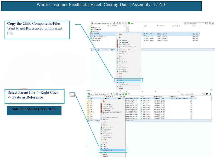
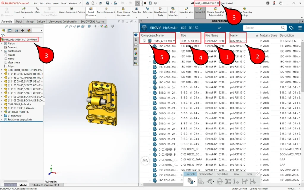
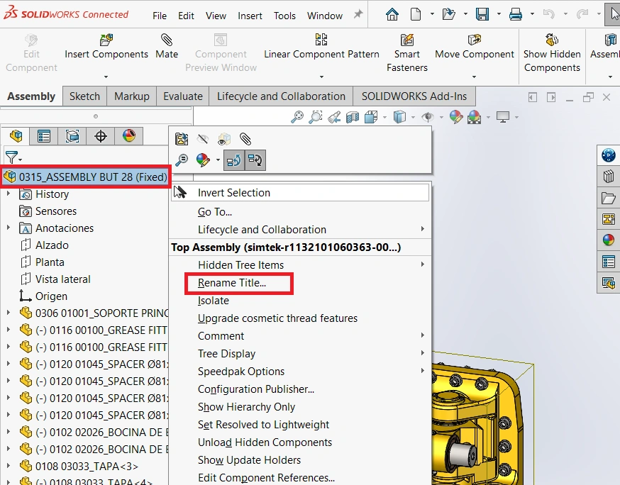
As You All Know SOLIDWORKS PDM is a Data Management Solution where You Can Secure/Organize/Manage You Data (CAD & Non-CAD). In this Blog We go through the Reference Management Tools Available in PDM.
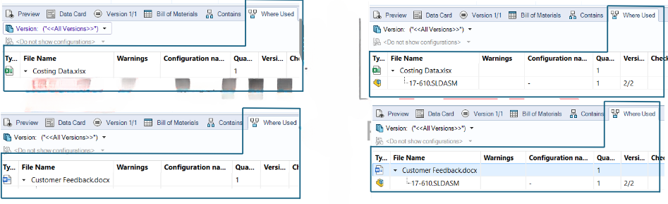
Creating Reference Between CAD & Non-CAD:
Feature Name: Copy & Paste as Reference
Scenario: An Excel & Word File Needs to Referenced with SOLIDWORKS Assembly File
Benefits of Contains & Where used:
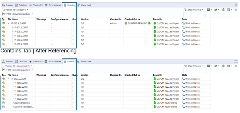
Contains & Where Used Tab are used to See & Verify the References Between Parent & Child Components
Contains
Where used
A Parent File that Contains Child Components
A Child Component Where It Was Used So Far
Let’s See Contains & Where Used Tab Result for Our Example
Contains Tab | Before Referencing
Where Used Tab | Before & After
Conclusion:
Thus Copy & Paste as Reference, Contains & Where Used Tab Make User Life Easy to Create Reference Between CAD & Non-CAD as well Reviewing them.
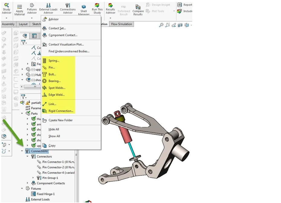
Simulation Connectors may be used to simplify behaviour without including a physical part such as a bolt or pin. This is a primer on the different types of connectors available in SOLIDWORKS Simulation.
Types of Connectors
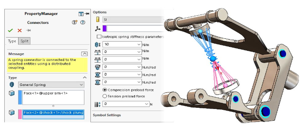
Springs
There are 3 types of Springs:
Compression Extension Spring: These are general purpose springs that generate forces as soon as parts connecting them start to move.
Compression Spring: You can use them to model rubber bumpers or springs that provide a compressive interface when sandwiched between two parts.
Tension Spring: You can use them to model cables or ropes that cannot take compressive loads but can significantly affect the overall stiffness under tension.
Pin
An assembly consists of multiple parts connected to each other with pins, bolts, screws, or springs. Examples of assemblies with pins include laptops, scissors lifts, pliers, and actuators. To model the behaviour of such assemblies, traditionally, you have to create each pin geometry and apply contact conditions between the pins and their contacting faces, a computationally expensive approach.
Bolt
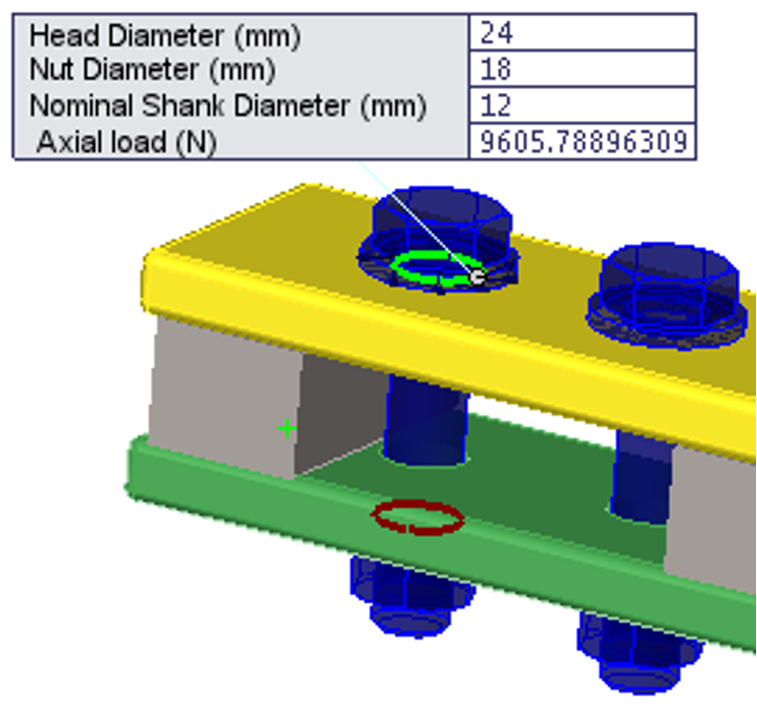
A Bolt can connect two components, multiple components, or a component and the ground. You can define bolts through a mixed stack of solids, shells, and sheet metal bodies. You can also define a bolt by selecting entities of the same component.
Simulation models a bolt connector in a spider-like arrangement with (a) a beam element to represent the bolt shank, and (b) rigid bar elements to represent the nut and head parts.
Link
A Link ties any two vertices or reference points on the model by a rigid bar that is hinged at both ends. The distance between the two locations remains unchanged during deformation.
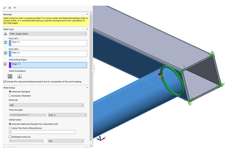
Edge Weld
The edge weld connector estimates the appropriate size of a weld required to attach two metal components.
The program calculates the appropriate weld size at each mesh node location along the weld seam.
Spot Weld
A Spot Weld connects two or more thin overlapping metal sheets at small areas (spots) without using any filling material.
Spot welds are most practical for joining metal sheets that are up to 3 mm thick. Internally, the program places a cylindrical spot weld connector of diameter D and height 0.5(t1+t2) between the meshed surfaces at the specified location.
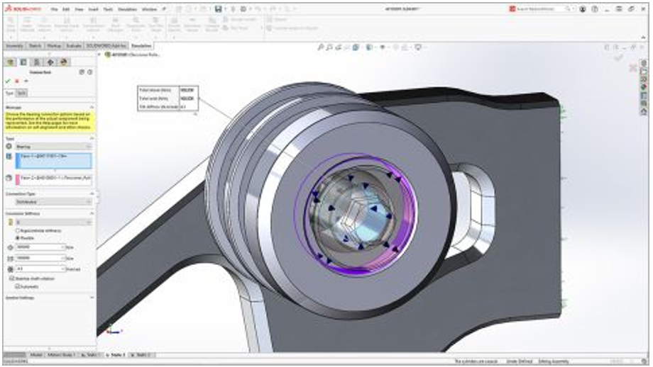
Bearing
You define a bearing connector between split cylindrical faces of a shaft and cylindrical or spherical faces of a housing. You can use a bearing connector when the housing is not much stiffer than the shaft.
A route template is a set of predetermined tasks that you can use repeatedly. Unlike creating a new route from scratch, using a template means that you do not have to perform a setup every time you need a new route.
It is possible to create multiple different route templates. This enables you to define and capture an array of different processes within the business or department.
ROUTE TEMPLATE TYPES
1. Approve
The assignee must approve the work that is associated with the task, whether it is a design or a document.
2. Notify only
Whoever is assigned to a task as Notify Only receives a notification about the task.
3. Comment
The task assignee must add a comment to complete the task. This is usually to provide additional insights or information for those who later approve the work that is tied to the sequence of tasks.
How to Create Route Template
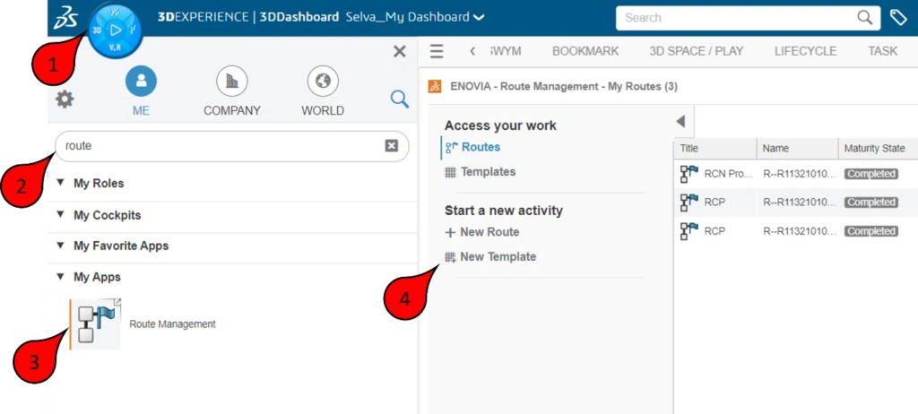
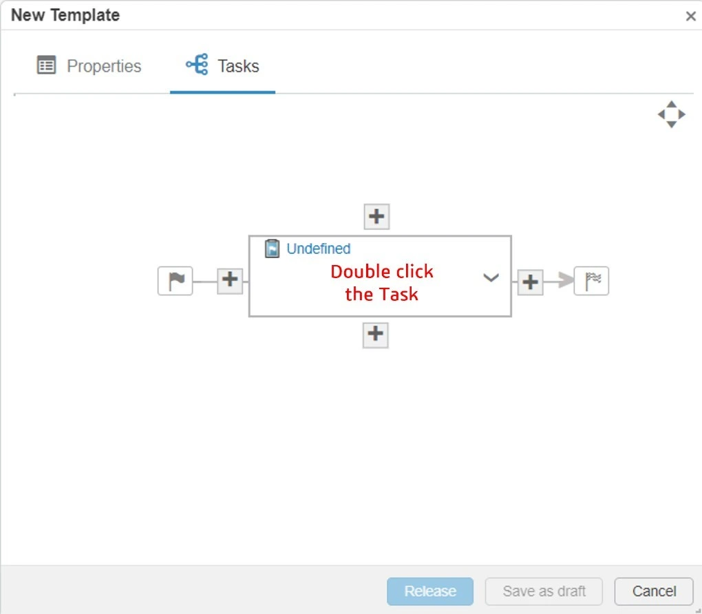
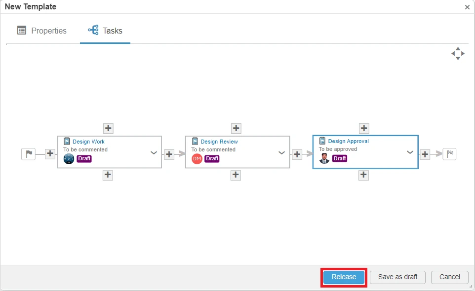
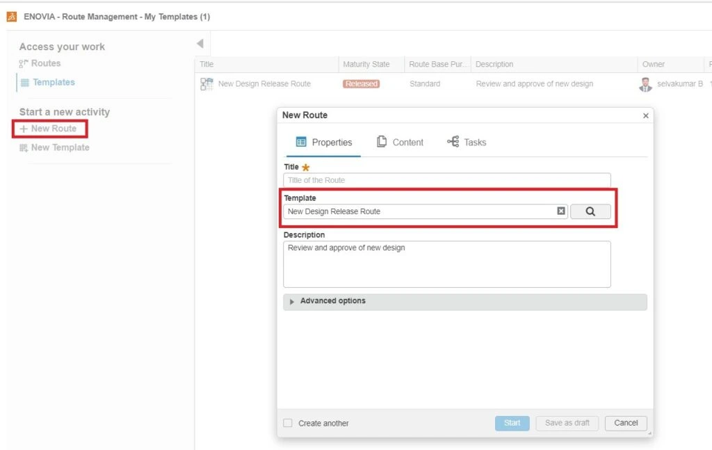
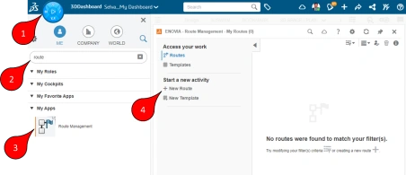
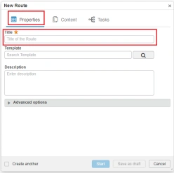
Use theRoute Managementwidget to create route templates. As an example, this document sets up a basic route template for creating, reviewing and approving a new design.
1. Launch Route management application in the compass to create a route template, in the Start a new activity section, click New Template.
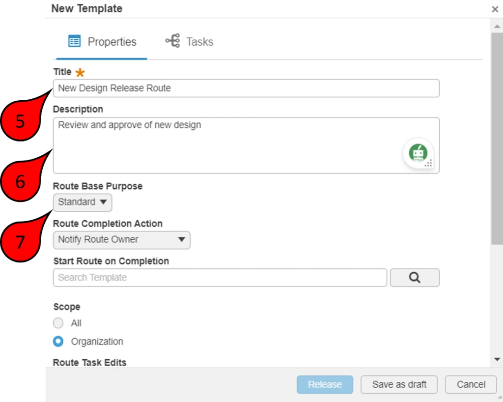
2. In the Properties dialog box that appears, enter a title for the route template and add a description that explains the purpose of the route. Because the template will have three different tasks, of which the Expected Action option for two tasks specifies Comment and for one task specifies Approve, the Route Base Purpose option specifies Standard. A Standard route template can contain several different types of tasks (Approval, Comment or Notify Only).
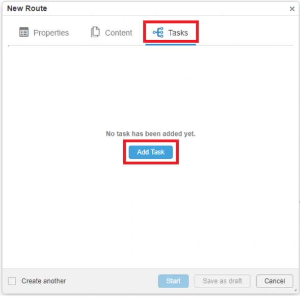
3. To add tasks to the route, click the Tasks tab. Then click Add Task.
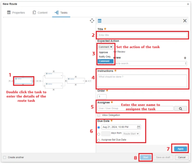
4. The creates a task in the route. You must double-click the route to provide a definition.
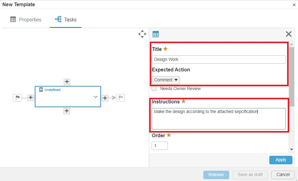
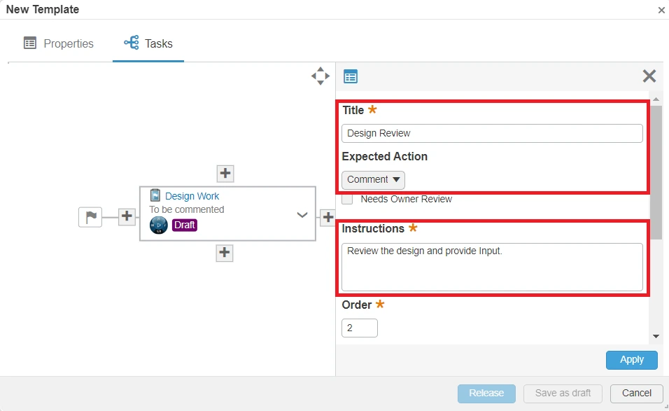
5. Add a title for the task, define the Expected Action option as Comment, and then add a description.
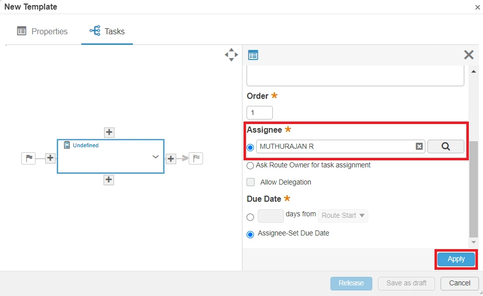
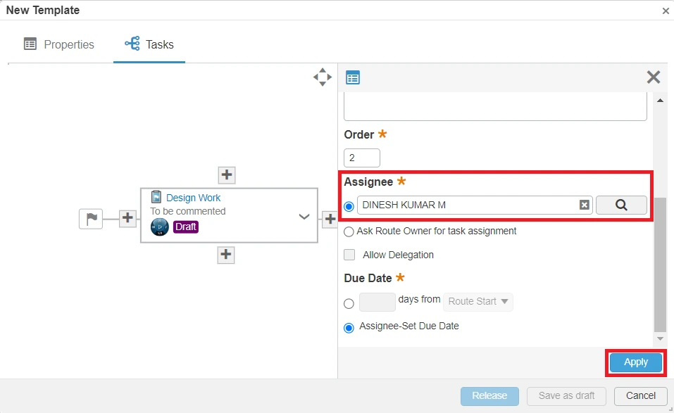
6. Scroll down and in the Assignee field, specify the Member of the platform that performs the design work. To apply the information and finish setting up the task, click Apply.
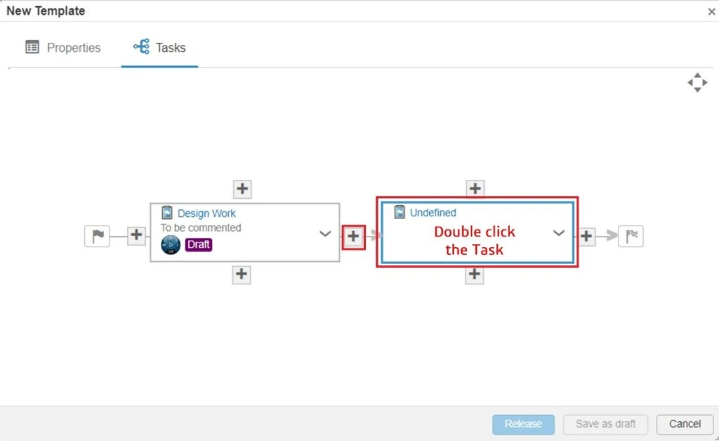
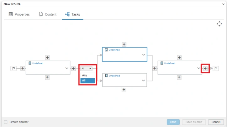
7. To add additional tasks, click the plus (+) icon at the right of the task just created to add another task after the first, then double- click the new task to open the properties pane.
8. In the properties pane, add a title and description, and ensure that the Expected Action option specifies Comment.
9. Scroll down the dialog box and define the assignee for the task, then click Apply.
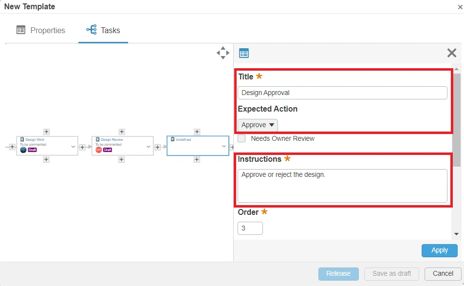
10. Once again, the click the + icon at the right of the Design Review task to create an additional task, access the task properties and enter a title and a description for the task.
11. The Expected Action option for this task is Approve because it is the final task in the route and the Assignee.
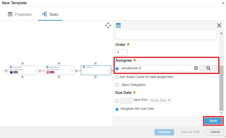
12. Scroll down the dialog box and define the assignee for the task, then click Apply.
13. We have now created a route that consists of three serial tasks. The final step to make this route template available for use is to click Release to activate the route.
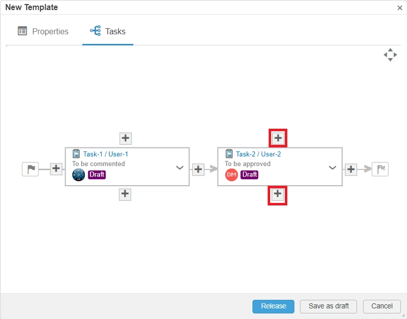
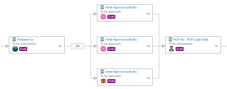
Parallel Task Template
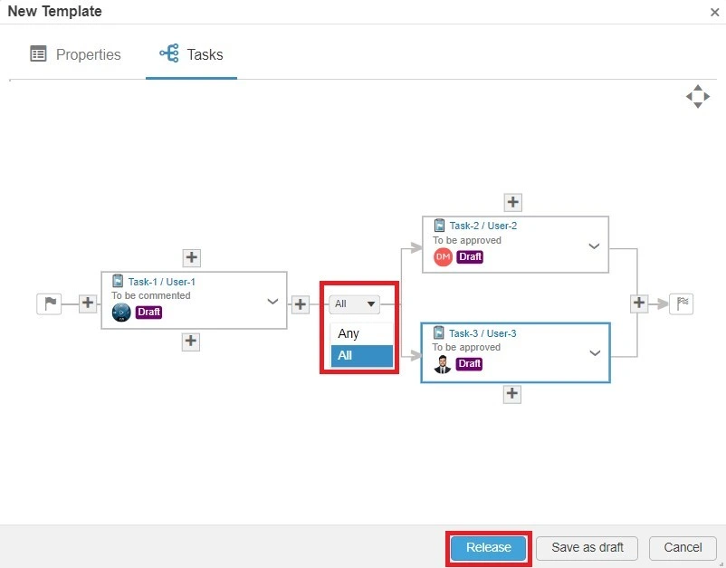
1. It is possible to create parallel tasks. To do this, click the + icon above or below the task that should have two or more assignees.
2. After setting up two or more parallel tasks, it is possible to select whether All or Any of the assignees of the task need to approve or comment for the route to progress.
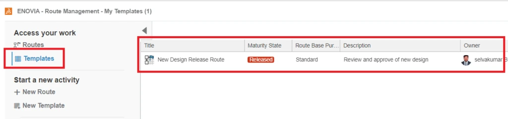
3. The final step to make this route template available for use is to click Release to activate the route. The Released templates are available in the Template Tab.
Templates can be used in the new route tab and search Template for use it.
Route Templates in 3DEXPERIENCE, Route Templates in 3DEXPERIENCE
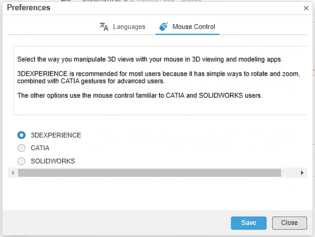
New users of the 3DEXPERIENCE platform might find the default mouse controls a bit different from what they are used to in desktop CAD applications like SOLIDWORKS. This can be initially disorienting as your muscle memory doesn't align with the platform's default control scheme.
However, you can customize the mouse controls to match your preferred CAD software. Here's how to adjust the settings to use native mouse navigation controls from SOLIDWORKS in the 3DEXPERIENCE web apps and other platform roles.
Accessing 3DEXPERIENCE Mouse Controls Preferences in the Browser Interface
Navigate to the Preferences:
Click on the icon in the top right corner of the screen, which could be your initials or a profile picture.
From the drop-down menu, select "Preferences."
Adjust Mouse Gestures:
The Preferences page will initially display language options. Select "Mouse Gestures" to access the mouse control settings.
You will see radio buttons with three options. Choose the option corresponding to the software you are most familiar with (SOLIDWORKS).
Using Mouse Controls Across Applications:
Once you've selected your preferred mouse controls, this setting will apply across all applications run through the platform. For desktop applications within the 3DEXPERIENCE platform, access the preferences similarly but navigate to the profile tab to adjust mouse control settings.
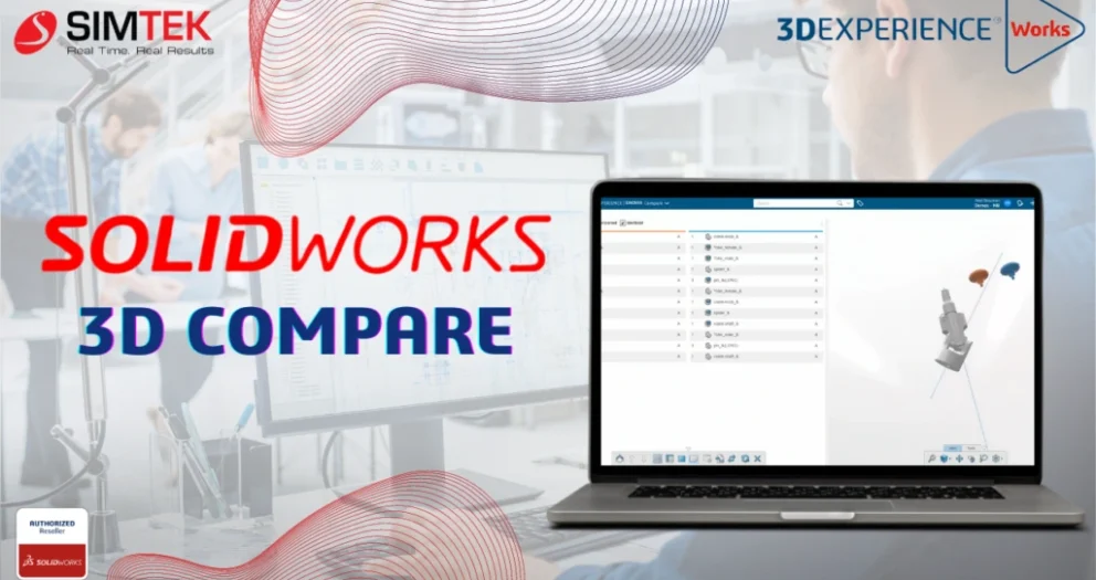
The powerful tool SOLIDWORKS 3D Compare streamlines the design review process by allowing users to visually compare different versions of 3D CAD models. Whether you're tracking geometry changes, analyzing dimensions, or identifying discrepancies, this browser-based tool available within the Collaborative Industry Innovator role on the 3DEXPERIENCE platform ensures that design validation is efficient and accurate.
With its intuitive color mapping and detailed comparison features, SOLIDWORKS 3D Compare helps teams make informed decisions, improving collaboration and speeding up time to market.
Users can visually compare different versions of 3D CAD models with 3DCompare.
Features:
✓ Geometry Comparison: Allows users to compare geometry, shapes, and dimensions between different versions of 3D models.
✓ Colour Mapping: It utilizes color mapping to visually indicate variations. This feature makes it easier to identify changes and analyze the impact on design.
This blog will give a brief explanation about 3DEXPERIENCE COMPARE Application
You open the component from the 3DEXPERIENCE Platform Compare application.
You can use filters such as Identical and Revisioned Components for the visual representation of components.
You can compare the custom properties of both versions in the Compare Application.
Summary:
✓ Associated revisions and duplicates are provided for comparison. You can simply drag and drop the object of interest, and the comparison results will load automatically. The tool overlays color-coded models, making it easy to see the differences and similarities in 3D.
✓ The ability to visualize changes in product designs improves your time to market. It achieves this by streamlining review and approval processes on the 3DEXPERIENCE Platform.
Benefits:
✓ Facilitates design validation and verification by highlighting discrepancies between model versions.
✓ Supports decision-making processes by providing clear visual feedback on design changes.
✓Additionally, it improves collaboration among design teams by ensuring everyone is aware of modifications and their implications.
Product Structure Explorer enables you to save your CAD files from cloud directly into your machines with few easy steps. The Product Explorer app comes with the Collaborative Industry Innovator role, allowing easy access with just a few steps. You can use it whether you're working with SOLIDWORKS Cloud-connected roles, Collaborative Designer for SOLIDWORKS, or 3DEXPERIENCE SOLIDWORKS.
1. Launch Product Explorer App
As previously indicated, you may discover this app in the Collaborative Industry Innovator role. Alternatively, you can search for it and open it with your compass.
Product Structure Explorer always launches with "ENOVIA 3D Navigate." This allows you to see your top-level assemblies and make necessary modifications to the product structure.
2.Opening content on cloud
• Click on Open Content, that will take you to 3DSearch, where we can enter the required file name.
• Use the 6WTags bookmark area to filter out search results, then open the full contents of the chosen file.
3. Exporting files
•After selecting all the files, you can proceed to export them.
• We don't need to open that file in SOLIDWORKS to see the assembly structure.
• There are several ways to see an assembly tree, including tree view, graph view, expand n levels, parent-child level, etc. You can export the structure in .csv file format, which other programs can then import.
• After waiting a few minutes for the export file to be generated, you will receive a notification stating that your export is complete.
• After the file generates, the system will notify you and redirect you to the 'CAD Data Processing Monitor. You can download the necessary files and view the history of your export file .A .zip file containing the assembly and all its sub-components will be sent to you.
• We can see the 3D models in 3D Navigate, and the tools let you measure, section, and examine relationships for a successful design review.
• With the structural tree and 3D data available side by side, this can expedite the process of making better product decisions by allowing for the simultaneous navigation and validation of both tabular and 3D data.
Benefits of Using 3DEXPERIENCE Product Explorer
• decreasing the time required for product design development. Optimizing designs to meet specific client needs.
• enabling users to test designs in a virtual environment will improve the quality of the final output.
• promoting interaction and cooperation between vendors, clients, and other stakeholders.
To sum up, the 3DEXPERIENCE Product Explorer completely transforms your design process. It gives teams more creative freedom, improves teamwork, and enables them to produce amazing 3D product designs. This platform, with its vast toolkit and cloud-based architecture, is what design will look like in the future.
This article thoroughly explains how to control document integrity by leveraging cooperation with Microsoft apps in conjunction with the 3DEXPERIENCE app. We'll learn how to use Microsoft Documents and its accompanying tools and techniques.
Setting up the essentials:
Open your 3DEXPERIENCE Platform and log in.
To access the Collaboration for Microsoft, open the compass and choose the Collaborative Industry Innovator position.
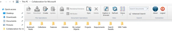
Locate the Microsoft Collaboration app, which ought to be installed on your computer since it is a native app.
Understanding what Collaboration for Microsoft really is:
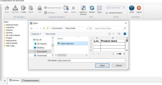
One easy option to batch upload both old data documents directly into designated bookmarks is through the app's Create tool. This is an advanced guide:
Uploading Legacy Data Documents Using the Create Tool:
Open "Collaboration for Microsoft" and select the Create tool, which is usually located in the toolbar or menu.
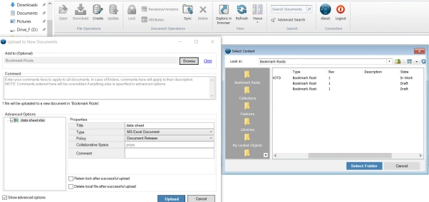
Batch Upload Functions: To upload numerous documents at once, use the batch upload option of the Create tool.
Designate Bookmarks: Choose the precise bookmarks on the website where you wish to upload the files. This guarantees that the uploaded files are immediately added to the appropriate bookmarks.
Select Files/Folders: From your device, select the needed files or folders, including the two legacy data documents.
Start Batch Upload: After choosing the files, begin the upload process using the Create tool.
Verification and Confirmation: Make sure the uploaded files show up in the designated bookmarks. Check to see if adding old data files was successful.
Arrange your previous data!
The following is a step-by-step tutorial to help with bulk uploads whether creating or uploading files:
Make Use of the Create Tool: On the 3DEXPERIENCE Platform, use the Create tool to upload files in bulk.
Batch Upload for Specified Bookmark: Select which documents, either old or new, to upload to a designated bookmark on the platform.
Access Bookmark Roots: Go through the platform's Bookmark Roots directory.
Select the Respective Bookmark: Choose the precise bookmark that you wish to use for file uploads.
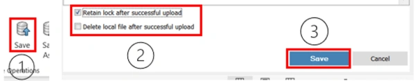
Enable Lock Retention (Optional): If you want to add more file permission control after uploading files, check the box next to "Retain lock after successful upload."
Start the Upload: Save the files to the 3DEXPERIENCE Platform by using the upload feature of the platform.
Validation!
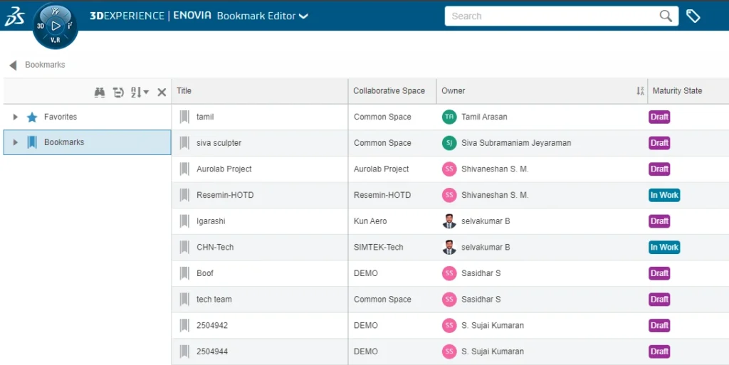
After a user uploads a document successfully, it appears in the platform's "Bookmarks" area. The "Bookmarks" function as a handy guide or shortcut for quickly accessing and viewing these submitted documents.
Comprehending Version, Revision, and Attributes Control in Microsoft Collaboration
Creating Versions:
Microsoft Office collaboration tools in Word, Excel, and PowerPoint frequently make use of the integrated version control provided by Collaboration for Microsoft
This is a synopsis:
1. Track Changes:
The version history of documents you work on together on in your 3DEXPERIENCE Platform is automatically preserved.
You can view & restore earlier iterations of the document. It changes made by various collaborators are tracked.
This feature maintains a record of who made what adjustments, which aids with version management.
2. Co-Authoring:
Multiple users can collaborate in real-time on the same document thanks to the support for real-time co-authoring.
Concurrent collaboration is made possible by the visibility of each user's changes to others.
3. Version History:
The ability to roll back to older versions is provided via this feature. It lists earlier versions along with timestamps.
4. Sharing and Permissions:
Granular control over document sharing and permissions is offered by 3DEXPERIENCE Platform.
Reviewing the Versions:
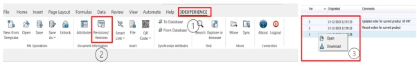
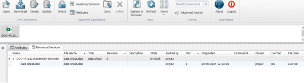
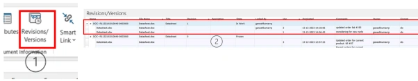
Through the usage of the Revisions/Versions tool, users are able to see, download, or access particular versions of files along with related information such as ownership and comments. This provides users with comprehensive information on file versions.
Checking File Versions and Status:
1. Accessing Revisions/Versions Tool: Click on the “Revisions/Versions” tool within the platform’s interface.
2. Version Information: Users can obtain information about file versions, such as available versions, locked status, and maturity level, in this tool.
3. File Status Details: Information is exposed, including owner details, versions available, locked status, maturity level, and comments.
4. Open or Download Versions: Users can use this tool to open or download certain versions directly.
Creating Revisions:
Options for Creating Document Revisions:
1. Create Revision Including All Previous Versions and Revisions:
By selecting this option, a new revision of the document is created that incorporates all previous iterations and revisions.
It creates a new version that retains and combines the whole revision history.
When users choose this method, they guarantee that the document's complete history will be included in the next version.
2. Create Revision Excluding All Previous Versions and Revisions:
This option generates a new revision that starts afresh without including any previous versions or revisions.
It creates a clean slate, disregarding the document’s historical versions and revisions
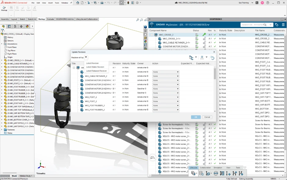
Validating Revisions:
Ensuring the Right Revision in Microsoft Applications:
1. Close Current File:
Close the currently open file within any Microsoft application.
2. Access “Replace by Revision” Command:
Use the 3DEXPERIENCE Platform's "Replace by Revision" command.
You can replace the current document with the specified revision by using this command.
3. Perform Replacement:
Execute the “Replace by Revision” command to substitute the current document with the intended revision from the platform.
4. Open Updated Document:
Reopen the modified document from any Microsoft application after replacing it, as indicated in the reference image below.
Reviewing the Revisions:
By selecting the ‘Include previous files with revision’ option in the Revisions/Versions tool, users can view the entire revision history of a file, encompassing the current revision, all previous versions, and related files. This is a synopsis:
Accessing Revision History with “Include Previous Files” Option:
1. Revisions/Versions Tool: Use the apps interface to access the Revisions/Versions tool. 2. Choosing "Include Previous Files with Revision": Make sure to select the option that incorporates the most recent version into all prior files. 3. Accessing Revision History: This option allows you to view the file's entire revision history. Users have the ability to view, open, and download files from all prior versions in addition to the current one.
Attributes handling within Microsoft Applications:
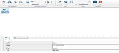
Metadata and Attributes: Users assign metadata or attributes to Microsoft Office documents kept on the 3DEXPERIENCE platform. For example, attributes include document type, author, creation date, revision, and project ID.
Custom Attributes: Users specify custom attributes suited to their specific requirements or industry needs. These characteristics offer more background or document information.
Search and Filtering: Attributes linked to documents enable effective search and filtering on the 3DEXPERIENCE platform. Users can simplify document retrieval and management by searching for documents based on particular criteria.
Integration with PLM Processes: Within the 3DEXPERIENCE platform, users can connect features related to Microsoft documents with Product Lifecycle Management (PLM) procedures. This integration ensures the alignment of document qualities with broader product development or project goals.
By collaborating with Microsoft apps, the tools and techniques in the 3DEXPERIENCE app work together to maintain document integrity, organize large volumes of data, and adhere to maturity life cycles. As a result, the 3DEXPERIENCE partnership with Microsoft apps not only provides your business with a competitive advantage but also offers seamless data management, thereby enabling unprecedented organizational growth.
➡️Ready to take your workflow management to the next level? Enhance your skills with our comprehensive SOLIDWORKS Trainings. Whether you’re new to SOLIDWORKS or looking to refine your expertise, our tailored courses will empower you to make the most of 3DEXPERIENCE and SolidWorks tools. Learn how to efficiently manage tasks, streamline processes, and drive your projects to success.
➡️Don’t miss out on the latest breakthroughs in 3D technology and engineering solutions. Subscribe to our newsletter today and stay connected with industry trends, expert advice, and exclusive offers. Join our community of innovators and ensure you’re always a step ahead in your field. Sign up now!
➡️Elevate your design and production capabilities with state-of-the-art 3D scanners and printers. Unlock precision, speed, and creativity in every project. Discover the power of 3D technology and take your work to the next level—explore our range today!
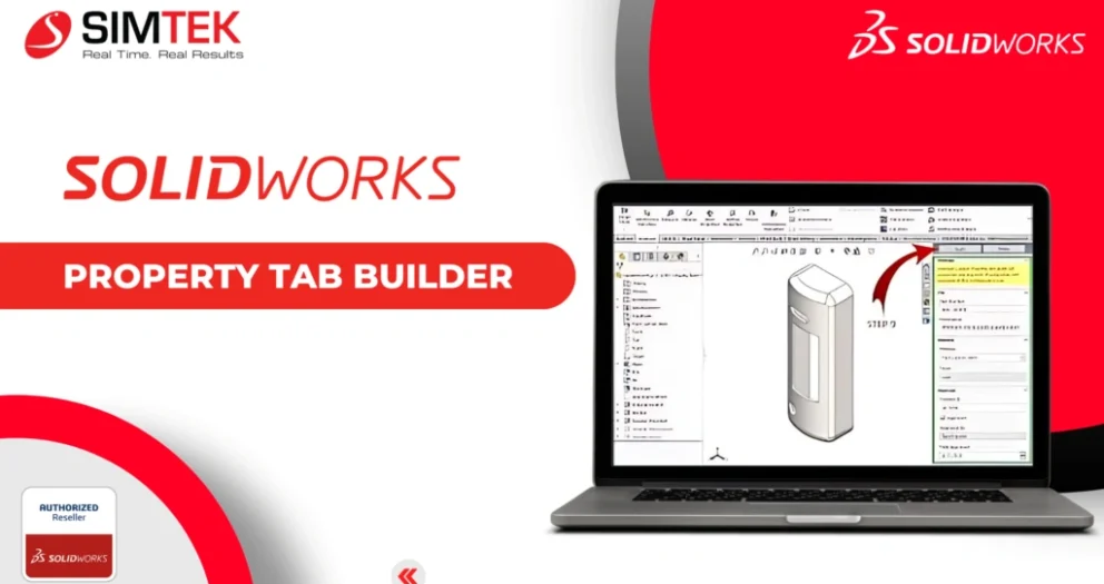
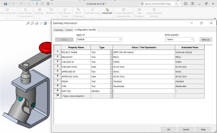
The Property Tab Builder is a stand-alone utility for creating a customized interface for adding properties to SOLIDWORKS Parts, Drawings, and Assemblies.
Custom Property tab builder is an easy way to enter information to our Parts, Assemblies and Drawings.
File Types:
You can use multiple property tab builder template for each document type. The file extension indicates the template type
S.No.
Template Type
Description
1
. prtprp
Part
2
. asmprp
Assembly
3
. drwprp
Drawings
4
. wldprp
Weldment
Example of creating Property Tab Builder:
We have to give these properties to a file.
• Description
• Number
• Material
• Weight
• Drawn By
• Checked By
• Checked Date
• Approved By
• Finish
• Type
Recognizing the Components :
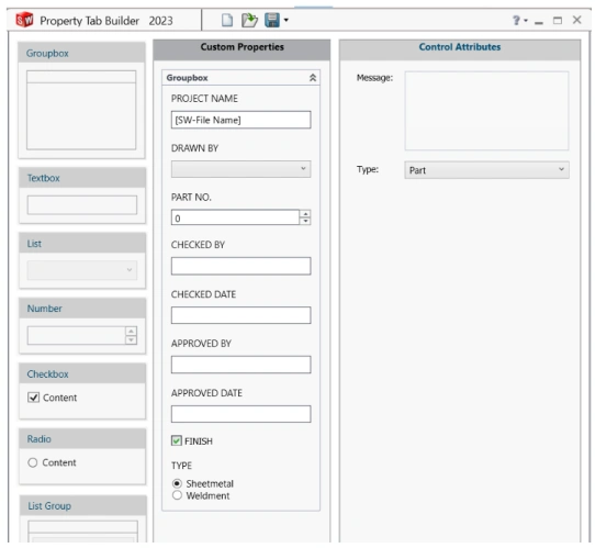
❖Group box: To put the other items in groups, the Group box is effectively a container.
For example, you can place part information such as Part Numbers, Article Numbers, and Descriptions into a Group box and material information like Material, Finish, and Weight into another Group box. Each Group box can have a name.
➢ Textbox: This object keeps text as an associated property and allows users to enter free-form text. ➢ List: List boxes present users with a list of predefined values that once selected will be stored as a property. ➢ Number: A number box accepts only numeric inputs to store as a property.
➢ Checkbox: With a checkbox you can have the user select between two predefined values to place as a property.
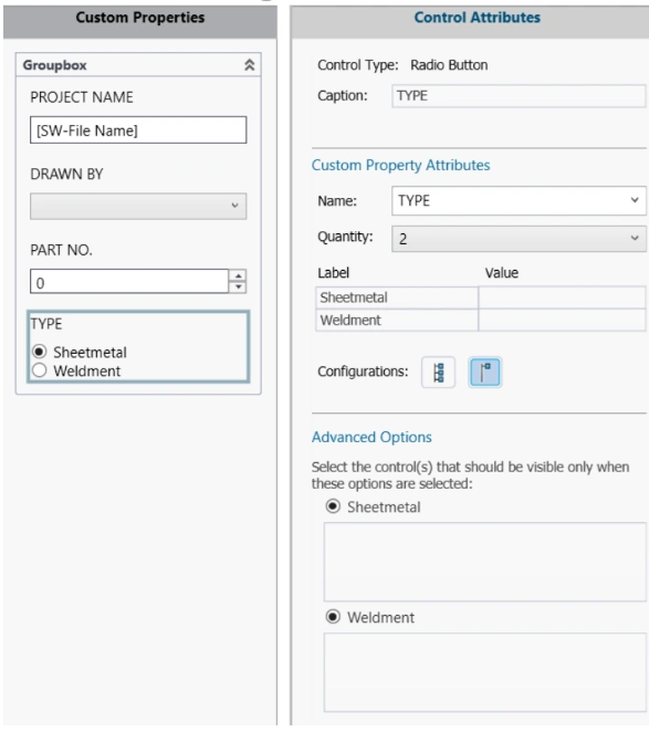
➢ Radio: Radio buttons allow you to define a selection of up to three predefined values that can be used to show or hide elements in the dialog. As an example, you might want different text boxes to show based on the selected radio button.
Starting the Property Tab Builder:
For this example, I am going to build a simple tab for Assembly.
Go to the task pane on the right side of SolidWorks after creating any new file to start constructing the property tab. The spot to establish the property tab is on the very last tab.
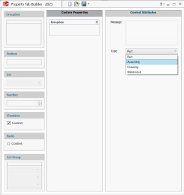
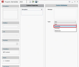
The new Application window called Property Tab Builder Will Pop-up as shown in Image 3.
Image 3: Property Tab Builder
Select the file type as shown in Image 4.
Image 4: Select File Type
1. The left column is a list of types of properties can be used.
2. The middle column is what will be shown in SOLIDWORKS when property tab is ready.
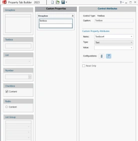
3. The right column is control attributes setting Custom Properties from Property Tab Builder: The Group Box of properties in the centre column can be expanded by double clicking on the group box and then dragging and dropping it onto the column.
Image 5: Adding Group Box
Control Attributes:
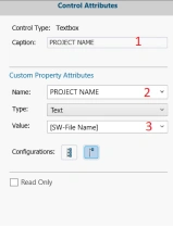
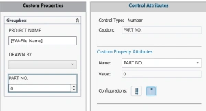
➢ Caption is name which appears above the text input field
➢This name stores the actual property in the model.
➢ Properties can be linked to the model by linking it to values.
Using the Property Tab Builder to Assign Properties:
1. Textbox
2. List
3. Number
4. Radio Button
Image 6: List
Image 7: Number
Image 8: Radio Button
Final Property Tab Builder:
By assigning attributes to the properties. You will get final Property Box.
Image 9: Assembly Property Tab Builder
Save as to find the file location of your existing property file:
To use the customized version, Give the Location of custom file to the SOLIDWORKS file location as.
When you model a part and goes to the custom property from task pane, you can see the customized property builder you designed.
Image 11: Applied Properties to Assembly
Image 12: Applied Properties in Custom Property Window
In the file property dialog, try activating the drop-down menu in the property name cell. Then you can create the custom properties.
The same method we can use to Part, Drawing and Weldment templates creation also.
Conclusion:
Property Tab Builder lets you create your specified properties in a single window and can be share it to all users so that properties can be applied by a single click, resulting in saving design time.
➡️Ready to take your workflow management to the next level? Enhance your skills with our comprehensive SOLIDWORKS Trainings. Whether you’re new to SOLIDWORKS or looking to refine your expertise, our tailored courses will empower you to make the most of 3DEXPERIENCE and SolidWorks tools. Learn how to efficiently manage tasks, streamline processes, and drive your projects to success.
➡️Don’t miss out on the latest breakthroughs in 3D technology and engineering solutions. Subscribe to our newsletter today and stay connected with industry trends, expert advice, and exclusive offers. Join our community of innovators and ensure you’re always a step ahead in your field. Sign up now!
➡️Elevate your design and production capabilities with state-of-the-art 3D scanners and printers. Unlock precision, speed, and creativity in every project. Discover the power of 3D technology and take your work to the next level—explore our range today!
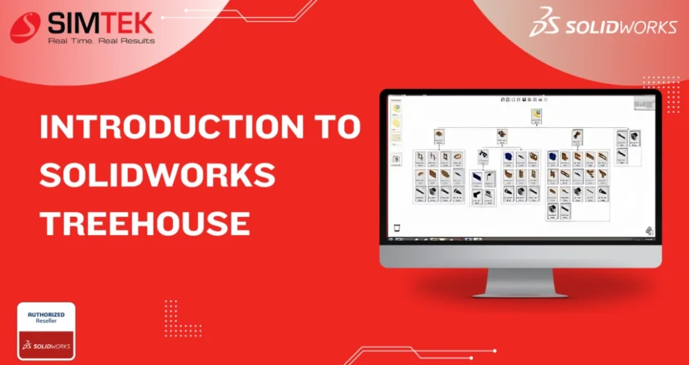
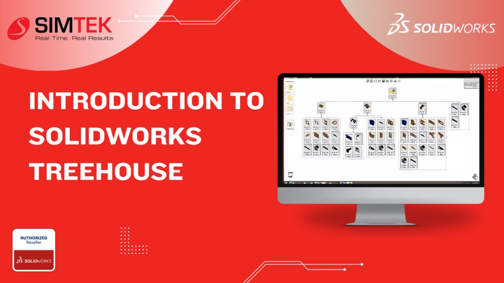
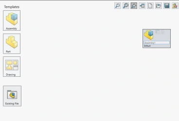
In Treehouse, you can set up your assembly hierarchy in a graphical user interface before you build your models in the SOLIDWORKS software. You can add to an existing file structure in Treehouse.
Establishing Default Templates
Choose a location for the templates you will use to build your assembly, and select the folder for importing and exporting assemblies and parts when you first use SOLIDWORKS Treehouse. Choose the Treehouse options button and add the places to add these spots.
Creating A Blank Assembly Structure
Drag and drop the preferred assembly template into the main workspace to start building a blank assembly structure. Then, start adding parts and subassemblies to the structure.
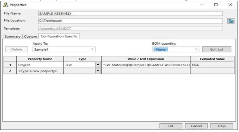
You may add properties and configurations to every part, assembly, and subassembly in your construction. By hovering over the section, you need to alter and using the "Show Document Properties" option, you can open the property editor.
You can change document properties, like the part or assembly name, after the property editor is active. When you export the assembly structure, you will also need to select the file location where you want that component to export to.
However, over a part and adjust the component count to indicate how many of the same part are required in the assembly structure.
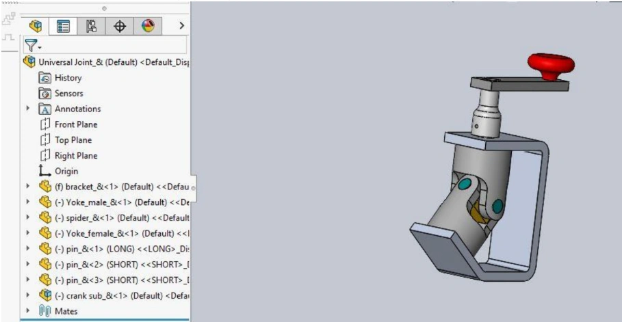
After creating the blank assembly, you can save the structure. Then, open it in SOLIDWORKS by selecting the 'Export to SOLIDWORKS' button from the toolbar.
SOLIDWORKS will then launch the Feature Manager tree and fill in the properties and structure you supplied to the assembly. This will allow you to start modeling each component.
Establishing A Preexisting Framework For File Assembly
You will use a similar procedure to construct an assembly framework out of pre-existing parts. First, you will choose from a template the top-level assembly. Drag and drop the files you want to add to your structure into the Treehouse workspace from the file explorer. Alternatively, use the 'Existing file' option under templates on the left side of the window to find the existing file.
When the structure is complete, you can select the “Export to SOLIDWORKS” button again to launch SOLIDWORKS with the assembly properties and structure specified
After being exported from SOLIDWORKS, an assembly structure constructed from pre-existing parts still needs to be properly bonded.
Configurations
Additionally, you can build several setups according to attributes. Hover over a part and adjust the component count. This will show you how many of the same part are required in the assembly structure.
After adding the configuration, you can edit the properties in the property editor under the configuration tab.
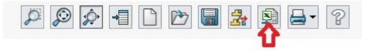
Exporting to Microsoft Excel
Treehouse can export the structure in list form to Microsoft Excel as well. To do so you will select the “Open in Excel” button from the toolbar. This will launch Excel and present the information from your assembly structure.
#Treehouse Assembly
➡️Ready to take your workflow management to the next level? Enhance your skills with our comprehensive SOLIDWORKS Trainings. Whether you’re new to SOLIDWORKS or looking to refine your expertise, our tailored courses will empower you to make the most of 3DEXPERIENCE and SolidWorks tools. Learn how to efficiently manage tasks, streamline processes, and drive your projects to success.
➡️Don’t miss out on the latest breakthroughs in 3D technology and engineering solutions. Subscribe to our newsletter today and stay connected with industry trends, expert advice, and exclusive offers. Join our community of innovators and ensure you’re always a step ahead in your field. Sign up now!
➡️Elevate your design and production capabilities with state-of-the-art 3D scanners and printers. Unlock precision, speed, and creativity in every project. Discover the power of 3D technology and take your work to the next level—explore our range today!
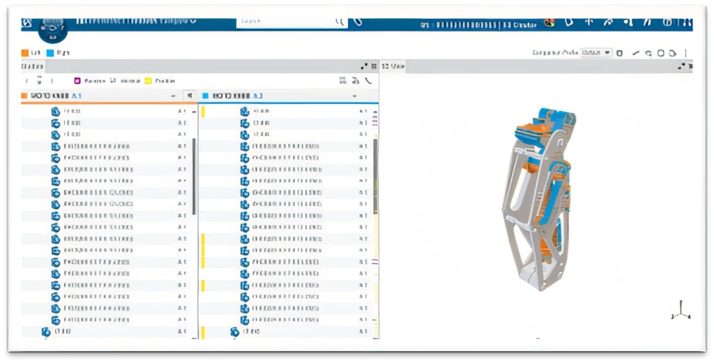
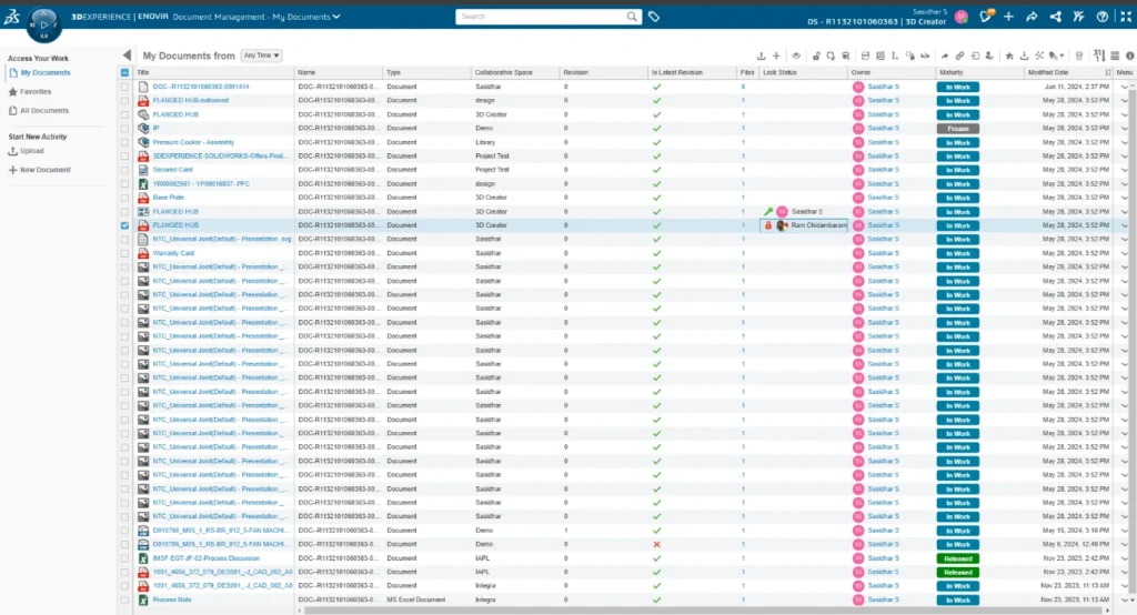
Document management is crucial for success across various business sectors. Organizations often face the challenge of efficiently and securely organizing, accessing, and collaborating on a diverse range of file formats, including engineering blueprints, regulatory compliance documents, and multimedia presentations. The 'Document Management app on the 3DEXPERIENCE Platformcan enhance your organization's productivity by addressing these challenges and streamlining document-related processes.
Document Management Interface:
This app offers users a centralized management system for various document formats. Whether dealing with traditional Excel spreadsheets, Word documents, or PowerPoint presentations, the platform supports all of them, providing a unified space for storing and managing essential documents.
The intuitive user interface makes it easy to learn and even easier to use, allowing users to take full advantage of its powerful features from the start.
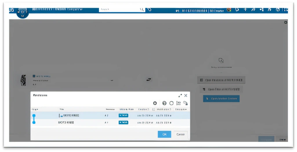
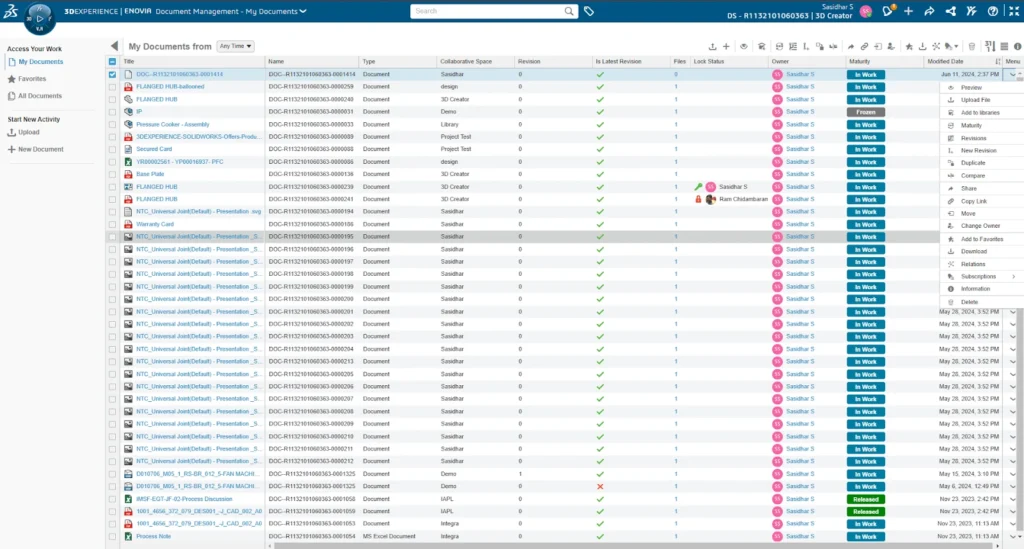
Features Available for Accessibility on the Interface:
You can access the same features displayed at the top right of the interface by either right-clicking after selecting the document or clicking the drop-down arrow in the same row.
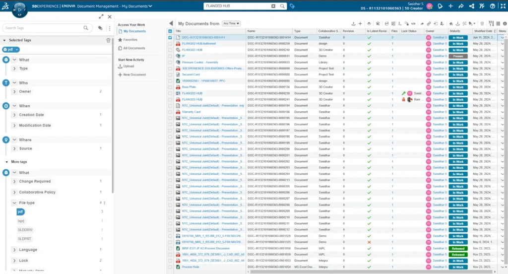
Using the 6W Tags in the Document Management app:
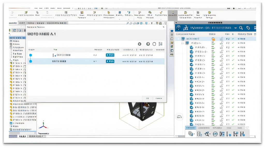
Finding your documents is now hassle-free with the 6W tags offered by the 3DEXPERIENCE Platform. Users can effortlessly filter the needed documents by setting tags such as Owner, Collaborative Space, and Maturity State. Additional filters include Lock Status, Latest Revision, Creation Date, Modification Date, and more.
The app integrates PLM features of the 3DEXPERIENCE Platform, such as Lifecycle Management and Revision Control, allowing users to effortlessly manage the entire document lifecycle. From creation to archiving, users can create revisions, track changes, and keep colleagues informed through notifications, all within a single, unified platform.
Editing the Document:
Users can preview, edit, and save their documents directly within the platform, without needing any additional software. They can also download the documents whenever necessary.
Users can maintain uninterrupted productivity, whether they're in the office, traveling, or working remotely. With the ability to access documents anytime and from anywhere, they have the flexibility to work seamlessly across different environments.
➡️Ready to take your workflow management to the next level? Enhance your skills with our comprehensive SOLIDWORKS Trainings. Whether you’re new to SOLIDWORKS or looking to refine your expertise, our tailored courses will empower you to make the most of 3DEXPERIENCE and SolidWorks tools. Learn how to efficiently manage tasks, streamline processes, and drive your projects to success.
➡️Don’t miss out on the latest breakthroughs in 3D technology and engineering solutions. Subscribe to our newsletter today and stay connected with industry trends, expert advice, and exclusive offers. Join our community of innovators and ensure you’re always a step ahead in your field. Sign up now!
➡️Elevate your design and production capabilities with state-of-the-art 3D scanners and printers. Unlock precision, speed, and creativity in every project. Discover the power of 3D technology and take your work to the next level—explore our range today!
Route Management in 3DEXPERIENCE simplifies workflows by automating tasks, tracking reviews, and managing approvals for efficient design and release processes.
A route is a set of tasks that a person defines for a group of people. Routes typically contain several tasks. However, it is also possible to create a route that contains a single task. Therefore, it is possible to define routes for different processes, for example, a design review or a release process.
Routes make it possible to define custom processes that are similar to custom PDM workflows, but with additional functionality.
ROUTE TYPES
1. Approve
The assignee must approve the work that is associated with the task, whether it is a design or a document.
2. Notify only
Whoever is assigned to a task as Notify Only receives a notification about the task.
3. Comment
The task assignee must add a comment to complete the task. This is usually to provide additional insights or information for those who later approve the work that is tied to the sequence of tasks.
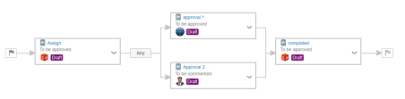
Tasks in a route can be either serial or in parallel.
a) Serial Route:
In a serial route, the tasks run in a particular order, which means that Route Task 1 must be completed before Route Task 2 can begin.
The image above gives an example of approval tasks, though the same principle applies to tasks that specify Comment. Tasks that specify Notify Only send a notification to the people assigned to the task and then automatically complete the task and proceed to the next task in the route.
b) Parallel Route:
It is possible to set up parallel tasks in two ways, i. Any one of the assignees complete the task, the route task moves to next stage.
ii. In all condition, every assignees need to complete the task. Then only the route task moves to next stage.
Why Use a Route?
A route ensures that contributors to the process follow the correct procedures, for example, in the product approval and release process. It is a systematic way of tracking reviews and approvals.
How to use Route?
Launch Route management application in compass and clicks + New Route.
2. In the Properties tab, enter the title of the route task.
3. In content tab, add the document to be reviewed by using drag and drop (or) use + icon.
4. In the task tab, click add task to create the workflow of the route.
5. Once the 1st task has been created use + icon to add series and parallel route task.
After setting up two or more parallel tasks, it is possible to select whether All or Any of the assignees of the task need to approve or comment for the route to progress.
On the task, double clickthe new task to open the properties pane. In the properties pane, add a title and description, and ensure that the Expected Action option. Then assignee the member to work on the route task.
Once the route task has been set to start. The route process workflow starts with the notification to the user to work on the route task.
Summary
routes provide organizations with a systematic process of performing a series of tasks with automation. In short, routes could be described in the following steps:
To start a new process, you can create and run a route on demand, which enables you to add or remove route tasks because the route is active.
When the route runs, notifications about the tasks to complete are sent automatically to those who are assigned to the task. If the assignee is a group, all members of the group receive a notification.
When the route task completes, the route automatically moves to the next task in the route and sends a notification to the assignees.
Upon completion, the route – if intended and set up to do so – promotes the connected files to the specified maturity state. For example, Released.
➡️Ready to take your workflow management to the next level? Enhance your skills with our comprehensive SOLIDWORKS Trainings. Whether you're new to SOLIDWORKS or looking to refine your expertise, our tailored courses will empower you to make the most of 3DEXPERIENCE and SolidWorks tools. Learn how to efficiently manage tasks, streamline processes, and drive your projects to success.
➡️Don't miss out on the latest breakthroughs in 3D technology and engineering solutions. Subscribe to our newsletter today and stay connected with industry trends, expert advice, and exclusive offers. Join our community of innovators and ensure you're always a step ahead in your field. Sign up now!
➡️Elevate your design and production capabilities with state-of-the-art 3D scanners and printers. Unlock precision, speed, and creativity in every project. Discover the power of 3D technology and take your work to the next level—explore our range today!
When searching for SolidWorks, one of the most popular 3D CAD software tools, it's common to stumble upon various links that promise easy downloads. But before you click on those enticing links, it’s essential to understand what you’re getting into, especially if the download seems too good to be true. Using pirated versions of SolidWorks can lead to severe consequences, including security risks, legal trouble, compromised performance and most importantly you need to pay very high price if you get caught by the resellers. Here's what you need to know before making a decision. Pirated software is a breeding ground for malware, viruses, and spyware. These malicious programs can compromise your system, leading to data loss, identity theft, or worse. Using unlicensed software is illegal. Companies that use pirated versions of SolidWorks can face hefty fines, legal action, and damage to their reputation. Official SolidWorks users receive regular updates, bug fixes, and customer support. Pirated versions lack these critical features, leaving you stuck with outdated and potentially unstable software. Pirated software often contains errors that can cause frequent crashes, slow performance, and compatibility issues, hindering productivity
Click Here to Get the Latest Version of SOLIDWORKS
SolidWorks System Requirements to Download SOLIDWORKS 2024
Before downloading SOLIDWORKS, it's crucial to ensure your system meets the minimum requirements. This guarantees optimal performance and a smooth user experience:
Operating System: Windows 10 or later (64-bit)
Processor: 3.3 GHz or higher
RAM: 16 GB (32 GB recommended)
Graphics Card: NVIDIA Quadro or AMD FirePro with the latest driver
Meeting these requirements will ensure that SolidWorks runs efficiently, allowing you to take full advantage of its powerful features.
FAQs About SOLIDWORKS
1. Can I download a trial version of SolidWorks? Yes, Dassault Systèmes offers a trial version of SolidWorks. It provides full access to the software for a limited period, allowing you to explore its features before purchasing.
2. What is the best way to purchase SolidWorks? You can purchase SolidWorks through authorized resellers or directly from the official website. Various licensing options are available, including perpetual licenses and subscription-based models.
3. How often are updates released for SolidWorks? SolidWorks typically releases major updates annually, with service packs and patches provided throughout the year to address issues and improve functionality.
4. Can I run SolidWorks on a Mac? SolidWorks is designed for Windows, but it can be run on a Mac using virtualization software like Parallels or Boot Camp.
5. Is there a student version of SolidWorks? Yes, a student version of SolidWorks is available at a discounted rate, providing access to the same tools and features used by professionals.
In conclusion, while the idea of downloading SolidWorks online might be tempting, it's vital to approach it with caution. Avoid the pitfalls of pirated software by ensuring your download is legitimate and that your system is prepared to handle this powerful CAD tool.
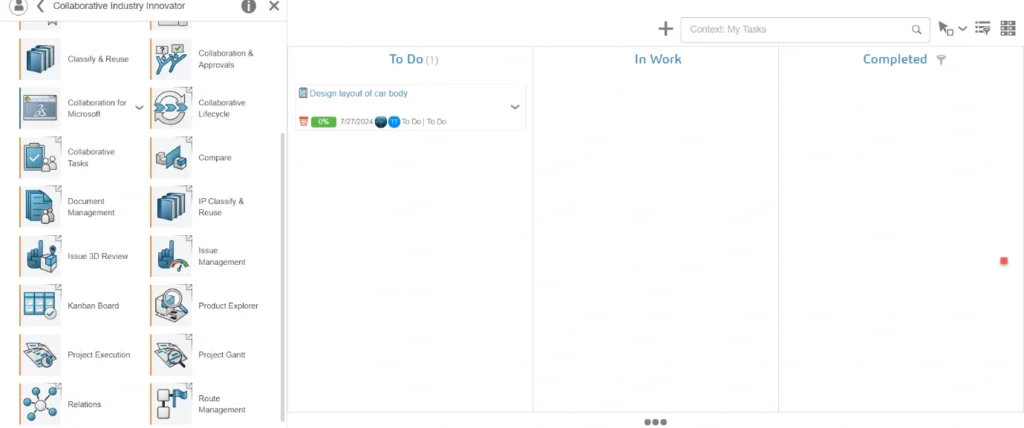
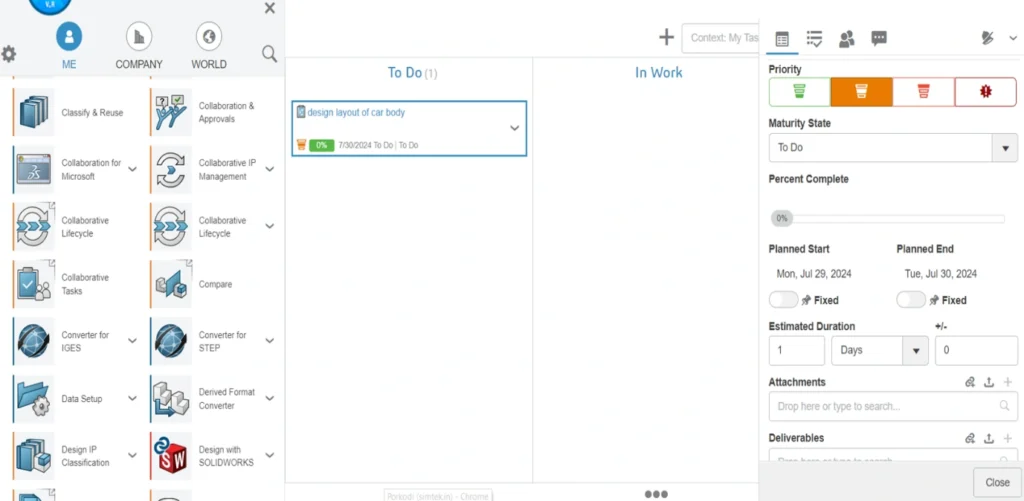
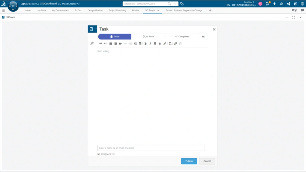
Task Management in Real-time and Seamless with 3DEXPERIENCE Works
Innovation in the quickly evolving domains of technology and design depends on teamwork. The 3DEXPERIENCE platform is excellent at fostering adaptable teamwork and creative thinking. At the center of this collaborative revolution is the 3DEXPERIENCE Collaborative Task, a feature that allows teams to collaborate in real-time, overcoming physical boundaries and revolutionizing the entire process of product development.
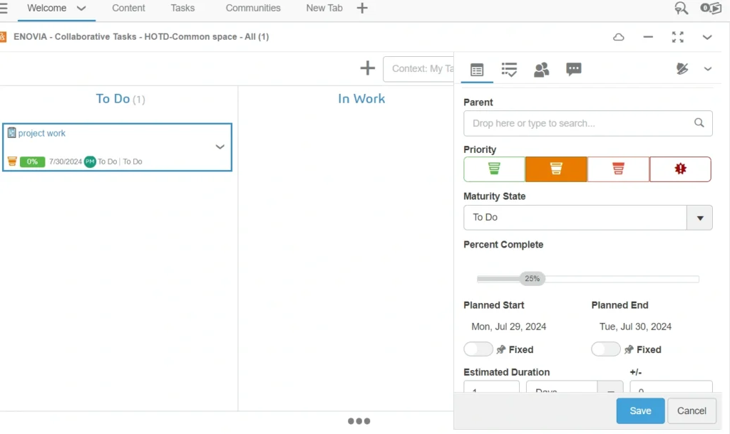
Step1:
Drag and drop a Collaborative tasks app from dashboard
Step 2:
Create a new task
Step 3:
Next, enter the description and title.
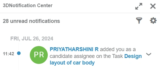
Step 4:
First, assign a person and then enter the details of the task.
Step 5:
Furthermore, the user can get notifications through the platform.
Step 6:
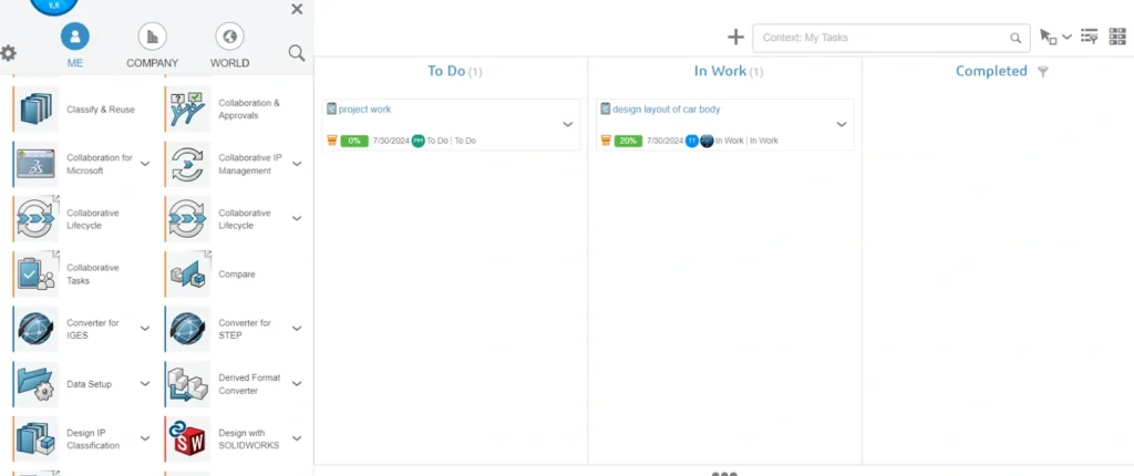
Additionally, update the task status through the platform
Step 7:
Next, move the task from the To Do stage to the In Work stage.
Once task is completed drag and drop a task to completed stage.
Partnering is far more than an expression of intent; in a world where creativity propels progress, teamwork is vital. Clearly, it becomes apparent that encouraging effectiveness, cooperation, and communication throughout the product development process needs the 3DEXPERIENCE Collaborative Task. As a result, breaking down organizational silos enables real-time collaboration, enhances communication, and seamlessly integrates with other tools—all of which contribute to the innovation and effectiveness of teams. Companies that want to succeed in the long run must acknowledge that collaboration platforms like 3DEXPERIENCE Works are a strategic need as they continue to handle the complexities of a rapidly evolving industry.
This blog is for you if you've experienced Solidworks Flow Simulation but are not aware of Engineering goals or the reasons you want to use them. To address any issues, I will break this blog into 3 sections.
Purpose of Using goals
Types of goals and Ways of defining the goals
PURPOSE OF USING GOALS:
To use your own criterion
Specify goals as physical parameters at areas of interest.
Used for Convergence Control
Finish the calculation.
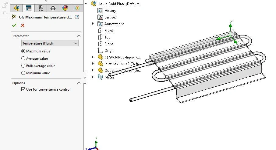
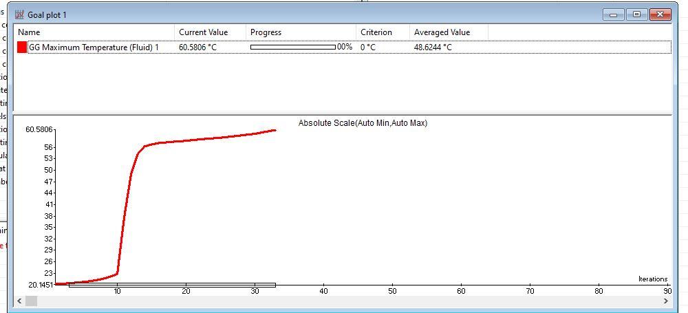
Goals primarily define your project, and you can also use them to monitor results while the solver runs. Some examples might include, if I want to perform a heat transfer analysis in a Heated cold plate and it also includes the maximum temperature of the fluid globally.
You can track the result by monitoring the goal plot. Let's say that the fluid's limiting temperature is 48 degrees Celsius, but the goal plot indicates that the fluid reaches above 55 degrees C within 20-30 iterations and that you must end the solution without continuing to run the solver indefinitely. You must end the solution without running the solver because the design requirements will not be met.
Thus, it provides a way to return to the project and CAD model right away to add anything you might have forgotten to put in the setup or make a design modification to increase the cooling effect.
You can examine a table of your goals or to generate one in an Excel spread sheet after you've solved the problem. This is excellent for giving your project a visual summary. Utilizing the goal chart in the Compare Tool also enables you to compare the outcomes of other projects where you have either changed the model geometry or a flow parameter in an instructive manner.
Goal definition helps you save time because it usually happens before the internal convergence criteria would have forced the solver to end because of the conservative structure of the software.
TYPES OF GOALS:
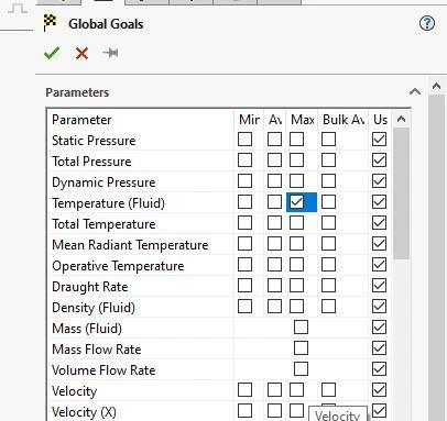
You can define five goal types in SolidWorks Flow Simulation
Global Goals
Point Goals
Surface Goals
Volume Goals
Equation Goals
Where to find it- Shortcut Menu: Right click Goals in Flow Simulation analysis Tree and click Insert goals.
Global Goals:
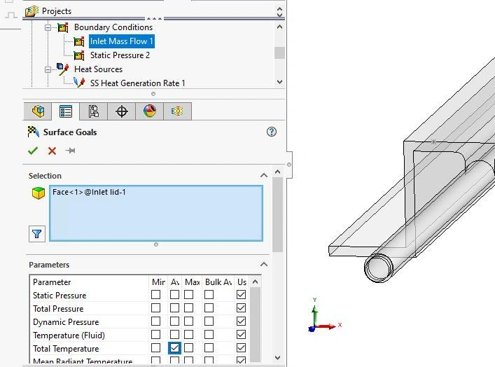
A global goal calculates a physical parameter within the computational domain. In the image below, I have created a global goal to find out the maximum temperature of the fluid.
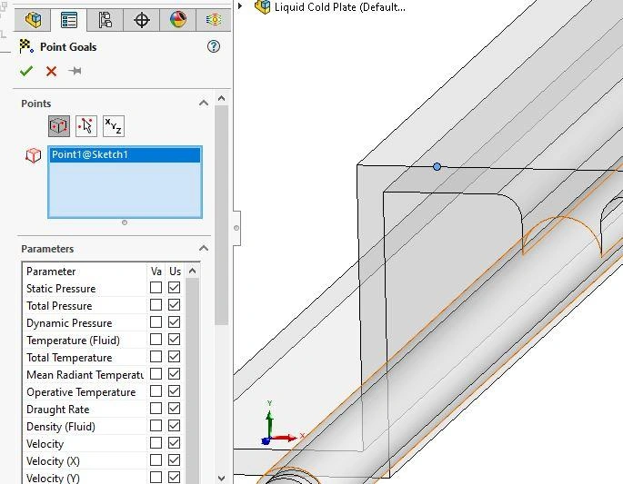
Point Goals:
You define a point goal by specifying a value at a certain point, either through a reference, directly on the screen, or using coordinate values.
Surface Goals:
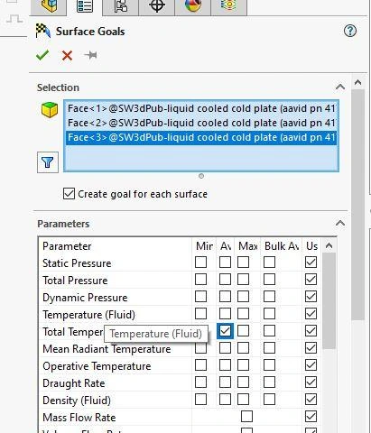
Surface goal is a parameter on selected surface(s). You can also preselect the surface of the inlet/Outlet boundary condition as a surface to define the goal. For example, if you specify mass flow rate, you will obtain the integral value for the entire surface. Alternatively, if you select a parameter like Total Temperature, you can obtain the min, average, max, or bulk average value on that surface.
Tips:
To select the inlet surface for the surface goal, Split the feature pane and specify the surface.
To create the surface goals for many surfaces, Hold the control key and select all the surfaces and Click create goal for each surface
Volume Goals:
Volume goal is a parameter within a specified volume, and it can be applied to parts, subassembly components, and even bodies within multi-body parts, in other words, to anything that defines a volume.
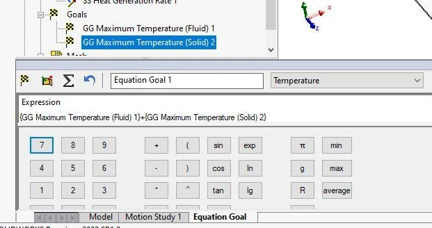
Equation Goals:
Last, but not least importantly, is an Equation goal which can be defined using anyone of the previous goal types in a mathematical equation i.e., combining output quantities with equations. For example, to find the temperature difference it will use the previously created surface goals for temperature maximum. This new temperature difference equation goal can also be plotted and monitored during solution.
The Reynolds number of the flow field, determining the efficiency of a fan or the coefficient of drag/lift on a component, Valve flow coefficient, heat exchange efficiency, pump efficiency, Pressure drop can also be calculated using Equation goals.
Setting goals for your Solidworks Flow Simulation projects can aid in producing an accurate and efficient result. Thank you for reading and stay tuned for my next blog, which will focus on a third advantageous aspect of goals: parametric optimization!
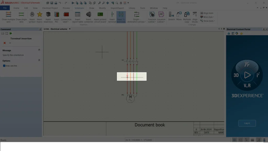
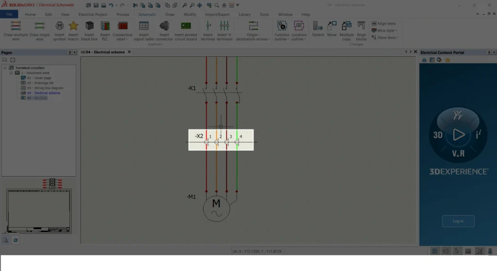
SOLIDWORKS ELECTRICALterminalCreation of a new terminal strip drawing and modifying the default terminal symbol in Solidworks electrical and customizing it according to our specification.
In SOLIDWORKS Electrical, the system automatically creates terminal symbols, dynamically updating the origin and destination of wires and component details on the terminal drawing sheet..
STEP 1
Step-by-Step Guide to SOLIDWORKS Electrical Terminal Creation
AS shown in the below image
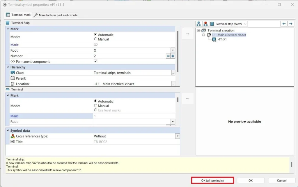
Once you create the terminal, you must create a page with the terminal details..
To create a page right click -> Draw terminal strip.
Then the system will automatically assign terminal strip details and create a page with the default symbol.
STEP 2
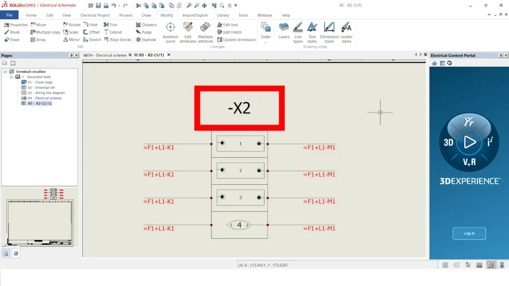
TERMINAL PAGE with default symbol
Once you complete the above steps, the system will generate a new page.
In the Display Tree Manager, you will create a new page with the terminal page symbol. The system will automatically generate this page with terminal details and the default symbol.
STEP 3
CHANGING DEFAULT SYMBOL
To modify the default symbol
First, create a new symbol and save it in a library.
We have already discussed creating a new symbol and saving it in a library in previous topics.
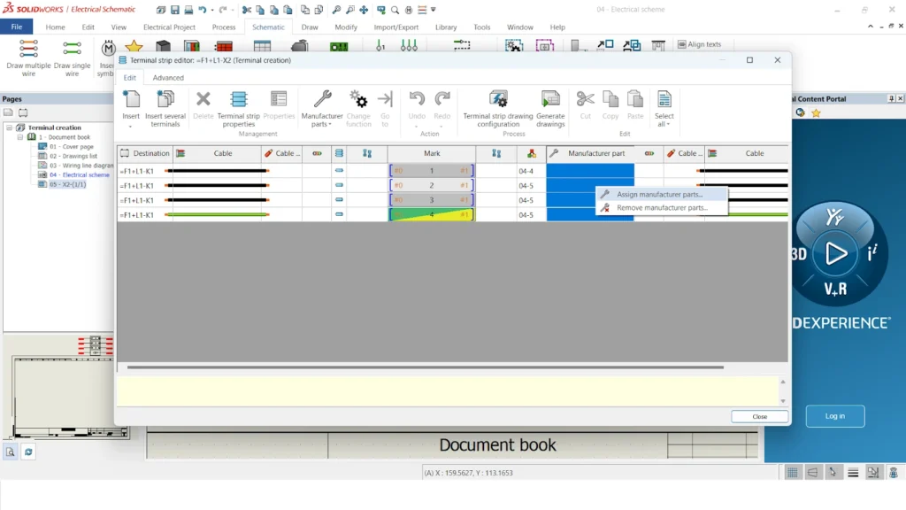
And after a new symbol saved, in terminal page have to go to right click ->
EDIT TERMINAL STRIP DRAWING CONFIGURATION.
STEP 4
TERMINAL STRIP CONFIGURATION
The system will open a new tab for the terminal strip configuration page.
This page is used to change the multiple option not only changing the symbols, but it will also be used to change the layout, Layout positions, wire origin and destination, Earth terminal, Bridges etc.…all others will be covered in the upcoming blogs.
As shown in the below image by selecting default terminal option (Highlighted with black box at the bottom)
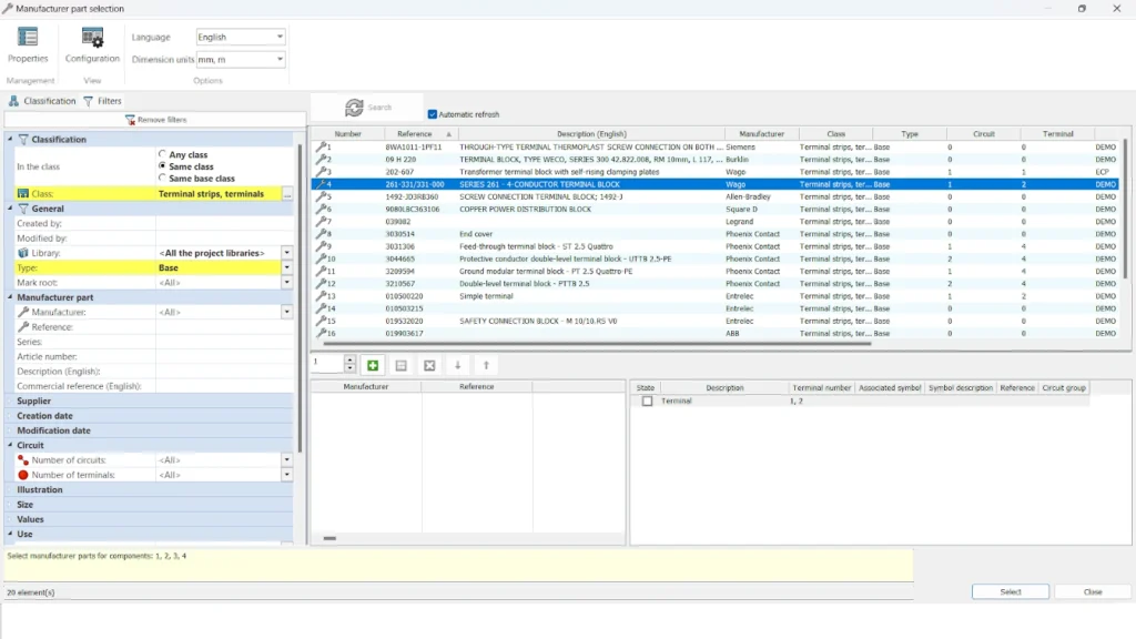
Use the SELECT option in the right corner (highlighted with a black box) to change the symbol.
STEP 5
SYMBOL SELECTOR
The system will open a library with more symbols, as shown below.
Must select symbol of our requirement of terminal symbols.
You can create and save multiple types of symbols in the library.
The second image shows that once you select a symbol, the preview of the symbol changes in the EDIT TERMINAL STRIP CONFIGURATION dialog box.
STEP 6
DEFAULT TERMINAL SYMBOL UPDATION
After applied those changes in the properties
Select UPDATE TERMINAL STRIP DRAWINGS as shown in the first image below
After you complete the update, the system will change the default symbol to another symbol, and the new symbol will then serve as the default.
Summary
With these above-mentioned points we can be able to create a Default terminal symbol in solidworks electrical.
This TERMINAL will act as a default TERMINAL SYMBOL in SOLIDWORKS ELECTRICAL SCHEMATICS.
Migrating SOLIDWORKS Files to the 3DEXPERIENCE Platform can be done with several tools available to prepare and move your SOLIDWORKS CAD files to the 3DEXPERIENCE platform.
1. SOLIDWORKS File Utilities
All packages of 3DEXPERIENCE SOLIDWORKS and SOLIDWORKS Desktop include the SOLIDWORKS File Utilities.
The utilities are accessible when you right-click a SOLIDWORKS file in File Explorer.
Use this tool during the file preparation phase to rename, replace and move files.
2. Pack and Go
Pack and Go is a very powerful SOLIDWORKS File Utilities tool. It is useful to gather all related files for a model and it allows you to rename and copy all related files to another location.
Pack and Go is accessible when you right-click a SOLIDWORKS file in File Explorer, or from the File menu within SOLIDWORKS.
Use this tool during the file preparation phase to locate your file set.
3. Interactive Save to 3DEXPERIENCE
The Save to 3DEXPERIENCE command is available from the SOLIDWORKS File menu, toolbars and from the My Session app within the 3DEXPERIENCE task pane. This is an interactive, synchronous command that securely uploads SOLIDWORKS files and creates corresponding SOLIDWORKS mastered database objects in a specified collaborative space. This command works well for file sets containing several projects with a combined file size. < 500 MB.
Accessible to all platform members.
Included with all 3DEXPERIENCE SOLIDWORKS roles and Collaborative Designer for SOLIDWORKS.
There is no gatekeeper. Saving the same files by multiple platform members only triggers a warning about duplicate data creation from the system. The system does not block the creation of duplicate data in the collaborative space.
Limited efficiency since it prevents you from using SOLIDWORKS while the save processes.
4. Batch Save to 3DEXPERIENCE.
The Batch Save to 3DEXPERIENCE tool is available from the SOLIDWORKS Tools menu. This is an automated, asynchronous tool that has the same secure upload and database object creation capability as the Save to 3DEXPERIENCE command. It provides the ability to save SOLIDWORKS files from multiple folders into various collaborative spaces and bookmarks. Large datasets containing multiple projects with specific size requirements benefit from this command. < 5GB.
Accessible to all platform members.
Included with all 3DEXPERIENCE SOLIDWORKS roles and Collaborative Designer for SOLIDWORKS.
Ability to save referenced files located outside of the selected folders.
Provides a save report.
The tool automatically prevents duplicate files within the same location when run multiple times on the same file set.
The tool improves efficiency because the save runs asynchronously, in a separate process. This allows you to use SOLIDWORKS while the save processes.
3DEXPERIENCE Integration is a feature available for users of 3DEXPERIENCE on Cloud for managing SOLIDWORKS CAD data. The platform has been continuously providing companies with more customization options to tailor their experience.
One of the critical features to be aware of is 3DEXPERIENCE Integration, which allows for improved metadata specification (such as part number, description, and author). SOLIDWORKS allows you to access this feature by navigating to Tools > Options > System Options. Detailed information is available in the SOLIDWORKS Help. So, what exactly does this option do? Let's delve into it.
3DEXPERIENCE Integration:
3DEXPERIENCE Integration empowers users to control both the configuration structure of parts or assemblies and how that structure translates into the Platform.
To ensure compatibility with the 3DEXPERIENCE platform, enable the "Update SOLIDWORKS files" option.. Be aware that updating a document for 3DEXPERIENCE compatibility is permanent. Additionally, the Rules Editor allows users to create rules for how certain configurations become Physical Products versus representations of existing data, though this is beyond the scope of this article.
Update SOLIDWORKS files to ensure compatibility with the 3DEXPERIENCE platform.
Introduced in FD01 2024x (February 2024), this feature allows a single physical product in new parts/assemblies or multiple physical products. You might wonder, what is a physical product? Let's explore this option further.
Physical Product:
3DEXPERIENCE Integration provides better control over the CAD object's structure within the Platform. The Platform is the source of truth for a company’s Purchasing department or Management seeking part numbers. In SOLIDWORKS, users are familiar with its structure—a part configuration and derived configuration form the potential structure in CAD. In 3DEXPERIENCE, there are CAD Family, Physical Product, and representations. SOLIDWORKS utilizes representations, but these are not transferred to the Platform.
The traditional feature tree in SOLIDWORKS shows the CAD Family top-level object with three physical products underneath. In the Relations app (All Relations), we see one CAD Family, three physical products, and three objects referred to as representations, which allow viewing in the web via 3DPlay. Web browsers leverage these tessellated models to generate graphics.
The following example demonstrates a different mapping approach: the feature tree displays one CAD Family object, one Physical Product, and two representations. The "Large" and "Small" sizes do not appear in the Platform but as a master configuration called Bracket. Thus, only one string of metadata exists, with Large and Small being different sizes used in various CAD states.
Working with Physical Products:
Physical Products are crucial in the 3DEXPERIENCE platform, showing CAD geometry when using tools like 3DPlay, and downstream apps like Product Release Engineer and Project Planner primarily work with the physical product object type. Hiding the CAD Family object reveals a Bracket with two configurations (Large and Small). Even though hidden, the CAD Family object remains part of the package.
3DEXPERIENCE Integration allows converting between physical products and representations. This flexibility helps in part number generation and other properties. The user can convert objects to a physical product or a representation.
When turning off 3DEXPERIENCE Integration with two configurations one derived, you end up with three physical products in 3DEXPERIENCE, meaning three independent but connected objects. Disabling 3DEXPERIENCE Integration allows you to assign separate part numbers.
Check the object’s name the prd prefix is the default naming convention for the Physical Product object type. Different numbers indicate different Physical Product objects. The right-click menu provides an option named "Update for 3DEXPERIENCE compatibility" to process documents for compatibility even after they've been created.
Should I Use 3DEXPERIENCE Integration:
Each organization should test the use of 3DEXPERIENCE Integration. Companies might create templates to standardize this feature across their design team. At the very least, companies should consider their part numbering intent early and understand this option's nuances.
3DEXPERIENCE Integration offers better control over a company’s numbering intent and aligns 3DEXPERIENCE object names—CAD Family, Physical Product, and representations. With the option off, the verbiage remains configurations and derived configurations, and variants called configurations generally become physical products in 3DEXPERIENCE, potentially with separate part numbers.
DraftSight is a powerful software solution that offers immense value to drafters and engineers engaged in editing and creating DWG and DXF files. Specifically, DraftSight's Professional through Enterprise Plus editions feature a specialized set of tools known as the DraftSight Mechanical Toolbox.
This toolbox is meticulously designed to cater to the needs of mechanical drafters by providing essential functionalities such as standardized holes, fasteners, tables, and annotations. These tools are integral for completing detailed mechanical drawings efficiently and accurately, streamlining the design process and ensuring adherence to industry standards.
Whether it's detailing parts, assembling components, or generating precise dimensions, the DraftSight Mechanical Toolbox empowers users to achieve high-quality results in mechanical engineering tasks within a user-friendly CAD environment.
Adding the Mechanical Toolbox in DraftSight either through the Tools menu in the Workspace or by using the Command Line with the command ADDINS, which opens the same window. This gives you flexibility in accessing and using the toolbox's tools for mechanical drafting tasks.
When the Toolbox is enabled, all tools are accessible via the Mechanical pull-down menu, the Mechanical ribbon tab, or the Mechanical toolbar, depending on the Workspace configuration.
Using the Toolbox starts with accessing the Standards command, which serves as the initial step in utilizing its functionalities. Within the Toolbox, there are six fundamental standards provided. To begin, users activate the specific standard that aligns with their requirements. For more tailored needs, custom standards can be generated by duplicating a basic standard. Then modifying parameters related to holes, hardware specifications, and thread data. This flexibility allows drafters and engineers to adapt the Toolbox to suit specific project demands, ensuring precision and efficiency in mechanical drafting tasks.
STANDARD HOLES:
The Standard Holes function particularly caught my attention. It addresses the challenge of recalling specific hole sizes required for different applications. To use it, begin by choosing the hole category, such as Counterbore or Countersink. Then, select the settings for the standard, fastener type, size, and scale as needed. For custom applications, all properties are adjustable. Allowing for precise customization of hole dimensions and specifications to meet project requirements effectively. This feature not only streamlines the design process but also enhances accuracy and consistency in mechanical drafting tasks.
Placing a hole is straightforward with DraftSight. Simply click once to specify the center location and a second time to set the angle. Clicking once to specify the center location and again to set the angle creates a block containing attributes and layer data, all easily modifiable as needed. This method ensures efficient placement and customization of holes within designs, enhancing the precision and flexibility of mechanical drafting tasks.
Hole Callouts:
After incorporating various sizes of holes, the next step in the process involves adding Hole Callout annotations to the drawing. Callouts are easily placed with a simple click-and-place operation, ensuring a highly efficient workflow. With just a few mouse clicks, the callouts can be quickly and accurately completed. Enhancing the clarity and completeness of the mechanical design documentation.
Hole Tables:
As the number of holes increases, adding more hole callouts can clutter the drawing. A clear and organized method to manage and document these holes is by adding a Hole Table. This table neatly labels and lists the locations and parameters of each hole. Providing a structured overview that enhances the clarity and organization of the mechanical design.
DraftSight Mechanical Toolbox
DraftSight Mechanical Toolbox offers a comprehensive solution for enhancing mechanical drafting capabilities. From simplifying the placement of standard holes to efficiently annotating drawings with callouts and organized hole tables. The Toolbox streamlines the entire drafting process. Exploring these tools can significantly enhance productivity and precision in creating detailed mechanical designs.
Introduction to Creation of a new Electrical terminal
Creation of a new Electrical terminal strip drawing in SolidWorks electrical and customizing it according to our specification.
In SOLIDWORKS ELECTRICAL, the creation of terminal drawings is automated, ensuring that the origin and destination of wires, as well as component details, are dynamically updated on the terminal drawing sheet.
STEP 1
AS shown in the below image
Create a wire before inserting a terminal.
To ensure automatic updates of wire origin and destination, place a component before and after the terminal.
STEP 2
TERMINAL OPTIONS
One method allows you to place a single terminal...
The other method is used for placing a set of multiple terminals...
SolidWorks Electrical offers two insertion options: one for placing a single terminal and another for placing a set of multiple terminals.
STEP 3
ADDING MULTIPLE TERMINAL
To add a multiple set of terminals a line needed to draw and a triangle in the image represents the flow of the wire
The line signifies that these wires function as a single group, from which you can extract a cable or a set of neutral wires.
STEP 4
TERMINAL PROPERTIES
Two important markers are displayed in the terminal properties: parent mark and terminal number.
To clarify the terminal hierarchy, the first MARK identifies the parent mark, such as X2.
Second MARK represents terminal number in the parent terminal i.e X2-1,2,3.
Before clicking "OK," ensure you haven't added manufacturer data yet. There is an easy way of adding manufacturer data that we ll discuss in next topic.
STEP 5
MANUFACTURER DATA ADDING
After adding a terminal, right-click on it and navigate to "Edit Terminal Strip X2" to include manufacturer data.
Second image shows adding the manufacturer by selecting every number of terminal and right click-> Assign manufacturer
STEP 6
MANUFACTURER PART PROPERTIES
The library will then display a list of manufacturers.
The selection process involves choosing the ideal manufacturer based on compatibility with the circuit and terminal points.
Completing these steps creates a terminal and assigns a manufacturer, as illustrated in the second image.
STEP 7
TERMINAL STRIP PAGE
SolidWorks Electrical can automatically generate a separate page for your terminal connection details.
Right-clicking the X2 terminal in the image reveals a menu with various options.
Following the image's highlight, select the "Draw" option.
A new page showcasing terminal strip connection details is automatically generated, as shown in the second image below.
Summary
Building on the steps outlined above, we can now create a terminal connection in SolidWorks Electrical.
Creating these points automatically generates a terminal connection detail page.
SOLIDWORKS Share and Markup simplifies design sharing with external stakeholders. They can view, annotate, and share comments on your designs. SOLIDWORKS Share and Markup streamlines collaboration. It allows external stakeholders to interact with your designs by viewing, annotating, and sharing comments. This functionality is available to anyone who has the 3DSwymer, Collaborative Designer for SOLIDWORKS or 3DEXPERIENCE SOLIDWORKS roles.
A key benefit of Share and Markup is that the recipient doesn't need a 3DEXPERIENCE role or SOLIDWORKS license. This allows them to view the file, make notes, and share comments with you directly. You only need a 3DEXPERIENCE account, which is free to create. This way, you can avoid the hassle of alternative file sharing tools that can add unnecessary overhead to your design collaboration process.
1. How to enable Share and Markup capabilities
To share files with external recipient some initial setup is required using the Drives Control Center app. The platform Administrator must turn on:
Allow platform members to share content with external users by link.
Allow external users to view and comment on shared content.
These settings are located on “Share with External” tab.
2. Sharing a file from SOLIDWORKS
In SOLIDWORKS you chose the file format to share. From the “Lifecycle and Collaboration” tab you can select the ‘arrow down’ on the “Share a file” button and then select the desired file format.
In this example 3DXML is chosen, this is the recommended format for sharing an assembly. The 3DXML file will contain all of child components and sub-assemblies.
After choosing the file format, you can create the sharable link. Click the “Share a file” command again and a formatted file is created and placed in your 3DDrive application, in the folder named “Shared with external”.
plus, a dialog box will appear with an option to enable guests to comment on the file, plus an option to restrict access to specific users. If you do NOT enable “restrict access to specific users” anyone with the shared link can access the file.
However, if you activate “Restrict access to specific users” you will have the option to type in the email address of the person you wish to share your file with or multiple email addresses if several persons are to be involved and finally, you can add a message in the dialog box.
Having applied the required settings, next click the “Share” button, to automatically send an email to your chosen recipient that will include a link to the file and a message.
The recipient will receive an email with a subject line stating the name of the sender, the name of the file, and a link to access the shared file.
When recipients click on the link, they will be prompted to set up a free 3DEXPERIENCE ID account, if they don’t have one already. If they do have an account, they can just select the link and access the model by signing in to the 3DEXPERIENCE platform. Note: They must use the same email address entered when creating the shared link.
3. Adding annotations and comments to the shared file
Once the recipient has logged in, they can access the model from their browser, which will take them to the shared model in the 3DPlay viewer application, where they can rotate, view, mark up, and comment on it using the intuitive tools in 3DPlay.
All the recipient needs to do is hover over the icons to get a description of the various tools to begin a “mark-up” procedure.
As an example, they can click on the Edit Clipping tool, which cuts through objects using a section plane to view and to access details inside an object, and also to measure hidden items.
4. Sharing annotations and comments with the original sender
Recipients can save their markups/comments as a snapshot by hitting the "Share as Comment" command. This will then display the snapshot in the Comments window on the right side of their screen.
The 3DEXPERIENCE platform will notify the original sender when the feedback has been applied and sent.
Clicking on the notification displays the 3DPlay app in the SOLIDWORKS task pane, where of the annotations and comments made by the recipient of the file can be viewed.
5. 3DDrive: Locating Shared Files
The process which has just been described, seems very automatic and simple, and so it is. However, it’s always important to be aware of where the shared files are located, if you, at some point, wish to search for a specific file and other files that might have been shared.
By opening the 3DDrive application, searching can be performed in SolidWorks as well, simply locating the 3DDrive application through the Compass and open it.
The 3DDrive application appears and shows all the 3DDrive folders you have access to. When you share a file like shown in previous steps, the folder “Shared with external” is automatically created and to be found in the “My Files” folder.
This is where all the files you have shared using the “Share a file” feature in SOLIDWORKS are be located.
All the files you have shared from SOLIDWORKS are accessible from this folder. From here you have several options, for example viewing the information of the files you have shared and previewing it so you are able to see exactly what the external recipient is seeing when they open the file in the browser.We recommend deleting the file, but be aware that this will also remove all comments and markups attached to it. The 3DDrive file, not the copy in your 3DSpace, stores this information
6. Adding new users to existing shared files
If you want to add more external recipients to collaborate with, you can do it from the folder as well. Just select the desired file, select the share button and then the “Share with external” tab and you get the same window as described previously.
Note: Although there is an expiration date “30 days from link creation” it is only the link to the file that expires, not the file itself. We will keep the shared file in the 3DDrive until we remove it.
7. Revoking access to shared files
You have the option to revoke the shared access. When you have located the file you wish to revoke access from in the 3DDrive “Share with external” folder, open the “Share with external” tab in the “Share this file” menu.
Select the “Authorized list”
This program will show you the list of authorized users for this file. You can then select the recycle bin icon next to a user to revoke their access.
Share and Markup – use case examples
In this chapter you will find 3 use cases for sharing documents. These examples are commonly used by consultant designers, suppliers, and manufacturers in their daily information exchange.
1. Sharing a SOLIDWORKS drawing
Let’s say you need to share 2D drawing with a supplier. In this case you have made some changes to an original part and would like to get feedback from the supplier.
From the drawing in SOLIDWORKS, you can share the file as PDF, DXF, DWG and PNG.
Having chosen PDF as file format - select “Share a file” again. In this example we will not restrict the access to the file, so we will just make sure that the “Enable guest comments” is active and then click the “Copy external link” followed by “Close”.
The dialogue closes with a message stating that you have uploaded the file to 3DDrive. And if you forget to copy the link before closing the “Share a file” window, there is a Copy Link button in the info pop-up. This pop-up will disappear after a while. Hovering over it, will keep it visible.
We can send the copied link to an external supplier by email.
The external recipient pastes the link into a browser. They can then log in to the 3DEXPERIENCE platform using their account credentials to view the file.
The recipient can now access the drawing and start giving feedback. They can also share comments as described previously.
2. Sharing a design for manufacture
We have approved your design and it is ready for manufacturing. Now you need to send the 3D file. You could send it as a STEP file or as a native SLDPRT file. This can in some cases make it much easier to start producing data for CNC machining or 3D Printing.
We can easily share a file after making modifications. Simply select 'Share a file' and a dialog box will appear, allowing you to update the existing file.
The update process retains all previous annotations and comments, allowing the communication thread to continue seamlessly.
3. Sharing a large assembly design for review
When dealing with large assemblies, sharing a design efficiently can pose a real challenge as file sizes can get large. Previously, opening a large assembly, even in lightweight mode, often required recipients to use a workstation with the native CAD application installed.
This task is now much easier in SOLIDWORKS by utilizing a combination of the 3DXML file format and the Share a File feature.
The 3DEXPERIENCE platform allows you to view 3DXML files on both workstations and mobile devices. As long as you access the received link for the shared file – you will be able to open, view, zoom and rotate, explode even complicated assemblies.
Let’s have a look at an example using an all-terrain adventure bike designed by Bowhead Corp.
I have opened the assembly in SOLIDWORKS and prepared it for sharing by selecting 3DXML as the file format.
The user selects the "Share a file" command and then proceeds to follow the sharing procedure outlined earlier.
The recipient clicks the link and logs in to 3DEXPERIENCE. They can then easily view the assembly and add comments. A non-windows device took these screenshots.
Share and Markup compared with traditional methods of file sharing.
Using the Share and Markup workflow can remove the need to use traditional methods of file sharing. Traditional methods of file sharing include PDFs, screenshots of models in documents, and even SolidWorks Pack and Go. These methods often require multiple applications and can cause compatibility issues. Share and markup takes away previously used unstructured workflows and eliminates the typical obstacles in historical file sharing which include:
The need for various applications for saving and viewing files.
File sizes exceeding mailbox capacity.
File formats not compatible with recipient operating system or applications for viewing.
1. Share and Markup summary
SOLIDWORKS Share and Markup offers a powerful solution for sharing designs with external stakeholders. This functionality leverages the Share a File command and the 3DEXPERIENCE platform. It eliminates the need for less efficient file sharing methods. With SOLIDWORKS Share and Markup, you eliminate the hassle of manual file zipping, email limitations, and recipient software downloads. Now, anyone can view and comment on your designs using a simple web link. The browser supports the 3DEXPERIENCE platform. This allows recipients to view and add comments to shared files on a mobile device.
SOLIDWORKS Share and Markup streamlines design collaboration. Designers and stakeholders can work together efficiently, getting products to market faster.
SOLIDWORKS Inspection software greatly assists in generating quality control and planning documentation. When utilizing the standalone edition of SolidWorks Inspection to balloon PDF or Tiff files and produce inspection reports, encountering a drawing with a non-standard font can lead to potential inaccuracies in dimension and note extraction.
Keep reading to learn how to prevent this problem and receive a quick tip for resolving it.
In this example, we are using Cooper Black as the non-standard font.
The OCR (Optical Character Recognition) function attempts to match the captured image of a dimension or note with characters from a predefined "dictionary" or list of known characters. Consequently, using non-standard fonts can lead to inaccurate matching between the two. Take note of the image below, where the dimension, tolerance, units, and dimension sub-type are extracted incorrectly.
As a default feature, SOLIDWORKS Inspection includes standard "dictionaries" or lists of characters available for selection. You can access these dictionaries under Options > Project Options > Imaging/OCR.
The solution to this issue is to train SOLIDWORKS Inspection to recognize and interpret the font used in the drawings you receive:
Step 1: Access the OCR Editor
Step 2: Insert a sample drawing into the editor to use as a tool to extracting characters and assigning them values.
Note: It would be ideal to have a print with all the letters, numbers and symbols used. (A thru Z, 1 to 9, and commonly used symbols).
Step 3: Extract the characters, assign the corresponding values, and store the dictionary.
You have the option to select "auto extract" or utilize the extraction tool in your command manager to box around of letters, numbers, or symbols. The Auto-extract feature in the OCR editor will then separate the characters for you, enabling you to input a value for each one.
For instance, in the example below, the character box is "A". On the extraction panel's left side, under the "value" section, we input "A" Subsequently, you can utilize the arrows in the extraction panel to proceed to the next character and input its corresponding value.
Ideally, aim to include all possible characters in the dictionary. Additionally, duplicating the same character multiple times could prove beneficial in certain situations. Once you have completed this process, save the dictionary to a location of your choice and then close the editor.
Step 4: Direct SOLIDWORKS Inspection to the dictionary you've created.
In SOLIDWORKS Inspection, incorporate the custom dictionary you've created.
Select the custom dictionary file in the specific folder.
Conclusion:
As a result, you'll achieve precise OCR recognition for the non-standard font. This dictionary is now applicable to any drawing featuring that specific font.
As we come together to celebrate the 25th anniversary of SIMTEK, I am delighted to express my deepest gratitude to each one of you. Over the past quarter-century, your trust and loyalty have been the cornerstones of our achievements. Your unwavering support has been instrumental in helping us grow, innovate, and exceed expectations.
SIMTEK’s Journey of Innovation and Excellence
For 25 years, SIMTEK has been at the forefront of innovation and growth in the technology industry. From our humble beginnings to becoming a trusted partner in technological solutions, our journey has been marked by resilience, adaptability, and a commitment to excellence.
Your feedback and support have inspired us to continually strive for greatness. Whether it’s through introducing cutting-edge solutions or providing exceptional service, SIMTEK remains dedicated to meeting and exceeding your expectations.
Looking Ahead with SIMTEK
As we celebrate this milestone, we are filled with optimism and excitement about the future. At SIMTEK, we are committed to staying on top of technological advancements and delivering innovative solutions that align with your needs.
Our vision for the next 25 years is to deepen our partnerships, explore new opportunities, and remain a trusted name in the industry. We are excited to embark on this journey together, driven by shared goals and a passion for success.
Thank You for 25 Years of Trust
This celebration is a testament to the strong relationships we have built over the years. Your loyalty is deeply appreciated, and we are honored to have you as part of our extended family. As we look ahead, we pledge to continue providing the quality and innovation that define SIMTEK.
Once again, thank you for being a vital part of our story. Together, let’s make the next 25 years even brighter.
The left side bottom tab consists of various properties used to change the colors, background colors, camera alignment and a few other options to change the product looks.
At the top, you'll find additional options that provide various features we'll explore in the following pages.
STEP 2
Assembly, Collaboration, Views
Once the above points are done, as per the below image
Three tabs (highlighted) will be present which consist of assembly, collaboration, and views.
In the Assembly option every subassembly can be selected and modified separately. In the model, the selected subassembly will be highlighted in the assembly tab in a shaded brown color as shown in the image.
Once selected we can hide others and work on the selected subassembly, or we can hide the selected subassembly and work on the other subassembly file.
The VIEW tab allows you to take screenshots. Will discuss about VIEW tab in upcoming topics.
STEP 3
TRIAD
A TIRAD option is to pull out the subassembly in any direction.
The image shows bolts selected.. Once selected, the left side tab shows the selected bolts with highlighted shaded brown color.
The software opens a pop-up with three colored triads for moving the selection.
Every color represents the XYZ directions. Selecting and dragging the colored triads will cause the subassembly file to move in that direction.
STEP 4
PATH
SOLIDWORKS Composer allows you to create an associative path using the "Create Associative Path from Neutral" tool.
A second image is the resulting image which shows where the removed bolt comes from i.e. neutral path.
With this option even in exploded view we find the origin of the removed items.
STEP 5
LINEAR DRAG
Linear drag allows you to drag multiple subassembly files simultaneously.
The only thing is that subassembly should be either vertical or horizontal.
Selecting subassembly files vertically or horizontally is necessary to maintain their removal process.
STEP 6
VIEWS
The VIEWS tab allows you to capture a screenshot, which can then be used to create videos.
Those videos show how to assemble the product and how to remove it at the same.
Every view will be different and showcase the process of the product assembling.
We will cover how to add various effects to views, including exploding parts, highlighting elements, zooming in for detail, and using diggers for interactive exploration..
STEP 7
HIGH RESOLUTION IMAGE
With high resolution image option under the tab Home, A workshops opened at the right side.
A multiple options will be available like preview, Detail view, background options etc…are selected and saved according to requirements.
Summary
With these above-mentioned points we can be able to create high-quality images (VIEWS) using SOLIDWORKS COMPOSER
We will cover video creation and other topics in the next session.
INTEC, the International Machine Tools & Industrial Trade Fair, has been a beacon of industrial advancement and a hub for business opportunities for two decades. As it reached its 20th edition, INTEC 2024 stands as a testament to the fair’s enduring legacy and its pivotal role in shaping the future of manufacturing and engineering.
At INTEC 2024, SIM Technologies Private Limitedtook center stage with an impressive display of their latest engineering solutions and services. Their participation was not just about exhibiting products; it was about demonstrating their role as a catalyst for innovation in the engineering sector.
A Display of Pioneering Solutions
SIM Technologies’ stall was a microcosm of the future of engineering design and manufacturing. They showcased the newest versions of SOLIDWORKS & 3DEXPERIENCE SOLIDWORKS, offering visitors a hands-on experience with the software that is driving the industry forward. The demonstrations highlighted the software’s capabilities in 3D design, simulation, and product data management, emphasizing how these tools can optimize the entire product development process.
Key Themes and Innovations at INTEC 2024
As the industrial world converges at INTEC 2024, the air is thick with anticipation for the key themes and innovations that will define the future of manufacturing. This year, the event was poised to unveil a series of groundbreaking advancements that promise to elevate the industry to new heights.
The Digital Transformation
Industry 4.0 and Beyond The buzzword ‘Industry 4.0’ finds concrete expression at INTEC 2024, where digital transformation takes center stage. Unconventional technologies such as AI-driven analytics, IoT-enabled devices, and smart automation systems are on display, showcasing how data and connectivity are reshaping the industrial landscape.
Additive Manufacturing
Crafting the Future 3D printing and additive manufacturing technologies are set to revolutionize how we create products. INTEC 2024 highlighted the latest advancements in this field, demonstrating how complex components can now be crafted with precision and speed, opening up possibilities for customization and innovation.
Strengthening Industry Presence
INTEC 2024 served as a platform for SIM Technologies to reinforce its presence in the engineering solutions sector. The event allowed them to showcase their strengths, particularly in the areas of CAD solutions and SOLIDWORKS expertise. Their interactive demonstrations and comprehensive product presentations left a lasting impression on the attendees, solidifying their reputation as a leader in the field.
A Green Gesture
Seed Balls Giveaway In a unique and thoughtful initiative, SIM Technologies provided visitors with a freebie that carried a message of sustainability – seed balls. These seed balls, given away to attendees, symbolize the company’s commitment to environmental consciousness and the greening of our planet. It was a small but powerful gesture that resonated with the event’s attendees, reflecting the company’s dedication to eco-friendly practices.
Setting the Stage for Future Innovations
The feedback and discussions at INTEC 2024 have set the stage for SIM Technologies to plan and develop future innovations. The company’s focus on sustainable and efficient solutions was well-received, and they are poised to continue this trajectory, developing products and services that not only meet but anticipate the future needs of the industry.
Introduction to Effective Data Representation with Metrics Readers
Metrics Reader is a cutting-edge application for public cloud dashboards that provides a range of essential features. With Metrics Reader, you can effortlessly generate charts based on your imported datasets, enabling you to gain valuable insights and analyse the data effectively. Additionally, this powerful tool allows you to compare multiple charts, empowering you to make informed decisions based on comprehensive visualizations.
Metrics Reader is compatible with 3DDrive, Social Analytics, and Potion for enhanced functionality.
When incorporating a Metrics Reader widget into your dashboard, it is essential to customize it with your specific data set to showcase a chart.
You can modify the settings of any Metrics Reader widget that you have personalized.
By importing your own data (.CSV or .XLS), you can analyse trends and uncover valuable insights through customizable charts and graphs.
The Task Shows:
Select data type.
Import data.
Select Range.
Customize.
1. Select Data Type:
Quantitative Time-series
Quantitative Series
Qualitative Series
Quantitative Time-Series:
Bring in a collection of numeric data gathered at consistent time intervals. We will closely examine the Quantitative time series.
2. Import Data:
There are three options for importing the data.
Cloud (One time upload):
This is a one-time upload process where you will need to enter your Login ID and Password in the File URL field.
Select the Cloud option and enter the URL of a file saved on the cloud. If access is limited, please provide your login information.
Note: Your 3DEXPERIENCE Platform requires Internet access if the URL you provided directs to an online resource.
Paste Data:
Select the "Paste data" option and then paste the data that you have copied from your clipboard.
Dropped file:
Choose the dropped file and effortlessly transfer a file from your 3DDrive (3DDrive is the storage application located on the 3DEXPERIENCE Platform. To draw a parallel, it functions similarly to Dropbox, Google Drive, and OneDrive. Interestingly, these three programs can also be seamlessly integrated into 3DEXPERIENCE).
In addition, there is an advantage to editing the dropped file from 3DDrive, as it will automatically update the Charts.
3. Select Range
You have the option to choose a column and import the time zone, indicating the date column and the desired date format. Additionally, you can display the results as Sum, Average, Maximum, or Minimum.
4. Customize
Within the design tab, you can modify the sequence of your products using Forecast, Smooth curve, Linear regression, total, and time zone. Additionally, you can define the name and Source URL in the Credits tab before choosing the Chart type displayed in the image.
The personalized dashboard is utilized by millions daily to effectively monitor, customize, and share various aspects of their digital lives. Depending on your company's needs, you can choose from a variety of chart types and configure multiple metric readers on the desired tab within the dashboard. This ensures that all the essential data of your company is conveniently accessible on a single page.
Essentially, this tool can assist you in replacing the outdated process of manually analysing Excel files, which often results in errors and is quite time-consuming. Moreover, it can be conveniently accessed from any location, at any time, and on any device - all you have to do is log in to the platform to access it.
Learn how to manage files on the 3DEXPERIENCE Platform using a 3DEXPERIENCE Title identifier in this blog.
As a SOLIDWORKS model, the 3DEXPERIENCE platform offers an excellent file management solution that makes sure all references are kept up-to-date, even if models are renamed or moved across multiple projects. SOLIDWORKS uses references to verify that all drawings, assemblies, and parts link together during parametric changes.
Windows File Management
The File and folder Name's that we've become use to is a unique Windows identification. It is the filename that is saved in various folders on the hard disk. The same name may appear in more than one file stored in different folders. If SOLIDWORKS PDM isn't used, then changing a file name or folder structure will unavoidably lead to file reference issues.
3DEXPERIENCE File Management
The 3DEXPERIENCE platform offers a different approach. All files are saved to a single local cache folder with unique file names, even though Windows still needs a file name to save a local copy to disk. The file name is no longer useful once it is saved to the platform. It is actually unchangeable at this point.
Now that we have a 3DEXPERIENCE attribute called Title, we can manage the naming. It is simple to rename this at any time. Organizing is done with the Bookmark Editor instead of storing things in different folders. References are not broken because the files are not renamed or moved to a different folder.
Differences in Terminologies
In the 3DEXPERIENCE platform, file management is referred to by a few terms. Here is a brief explanation, however the title is the primary and most important part.
1. File Name
This file's name is stored in Windows' local cache folder. The file is locked and cannot be modified once it has been saved to the platform. That prevents any references from being missed. Since Windows prohibits multiple files with the same name in the same folder, if two files with the same name were saved to the platform, the local cache may apply a unique file name (e.g., xcadmodel###.sldprt).
2. Name
A unique 3DEXPERIENCE identification, such as (prd-R###) is used to differentiate a product within a Collaborative Space.
3. File Title
This is a 3DEXPERIENCE feature that may be utilized for organizing your models. The CAD Family, physical products and drawing title are all included with this.
4. Title
This characteristic is also known as the Physical Product Title; it is basically the same as the File Title.
When a part or assembly has many configurations, the configuration name is added in the title to keep them unique, as in "Part123(Config123)".
In the case of a drawing, this might be the specific file title or the file title of the part or assembly that is being referenced.
5. Component Name
This is a unique SOLIDWORKS identifier that appears in the My Session app and provides the component's assembly instance number. This is related to the File Title. Any modifications made to the File Title will have an impact on the Component Name.
Renaming the 3DEXPERIENCE Title
We can now rename the Title without affecting the SOLIDWORKS references because we know the file name will never change. By right-clicking on the top of the Feature Manager Design Tree and selecting Rename Title, you can change it.
Conclusion:
The ability to connect to dashboards, messaging, activity streams, communities, and drag-and-drop task management means everyone is on the same page directly from SOLIDWORKS.
Windows explorer has current limitation on cache file, which will be removed in 3DEXPERIENCE SOLIDWORKS.
3DEXPERIENCE SOLIDWORKS has an in-built data management solution to manage and organize your CAD and Non-CAD Data with the help of Bookmark editor.
In our day-to-day design lives, the designer spends lots of time taking a number of pins, creating a drawing, and exporting and importing files. SOLIDWORKS professional and premium offer to access the SOLIDWORKS task scheduler for helps your productivity and work efficiently. The SolidWorks Task Scheduler sets up tasks to perform at a future time. You can use SOLIDWORKS Task Scheduler for scheduling the job during off-peak hours.
PURPOSE OF TASK SCHEDULER
The Task Scheduler allows you to perform automated tasks on a computer. you can schedule any program to run at any time for you. You can access SOLIDWORKS TASK SCHEDULER in two different locations:
Windows search > TYPE task > CLICK SOLIDWORKS task scheduler...
In SOLIDWORKS menu bar, click Tools > SOLIDWORKS applications > CLICK SOLIDWORKS task scheduler...
SOLIDWORKS TASK SCHEDULER INTERFACE
The user interface helps to assign the task and verify the status, along with a date and time. The highlighted area is the task lists.
The task details are given in the next picture, for more clarity. NOTE: In scheduling time, your system must be in switch ON condition.
TASK LIST
In the task scheduler, the most commonly used tasks are given below:
a) Print files b) Import files c) Export files d) Creating drawings
PRINT FILES
The print file task helps you save time and productivity. You can schedule tasks to print drawing files in are specified type within a folder. You can specify one or more files or folders, but you cannot specify both files and folders in the same task. For example, A0, A1, A2, A3, and A4
Steps:
1) Click the print file in the task list. 2) Add a specific file or folder to print. 3) Click an option for printer setting. 4) Set the printer name, sheet size, and number of copies. 5) Set the scheduling date and time. 6) Click Finish for scheduling. Note: your drawing sheet size and printer set size must be the same.
IMPORT FILES
You can schedule tasks to import Parasol ID, IGES, STEP, ACIS, VDAFS, SLDXML and Rhino files into SOLIDWORKS part (*.sldprt) files. You can import individual files or all files of a specified type within a folder.
Steps: 1) Click the import file in the task list. 2) Add a specific file or folder to import. 3) Click an option for import type. 4) Set the import option for your need. 5) Choose your file output location. 6) Set the scheduling date and time. 7) Click finish for scheduling.
EXPORTING FILES
You can schedule tasks to export SOLIDWORKS documents into other formats. You can export individual files or all files of a specified type within a folder.
Steps:
1) Click the export file in the task list. 2) Choose your export file type in the drop-down. 3) Add a specific file or folder to export. 4) Click an option for export type. 5) Set the export option for your requirement. 6) Choose your file output location. 7) Set the scheduling date and time. 8) Click finish for scheduling.
CREATE DRAWINGS
You can schedule tasks to create drawing files for the SOLIDWORKS part and assembly files. You can create drawings for individual files or all files of a specified type within a folder.
Steps:
1) Click creates drawings in the task list. 2) Choose your drawing template with a predefined view. 3) Add a specific file or folder to export. 4) Choose your file output location. 5) Set the scheduling date and time. 6) Click Finish for scheduling. Note: create a drawing template with a predefined view for proper drawing creation.
The world of product development is constantly evolving, and innovative tools like 3D Product Architect (PAU) are pushing the boundaries of Solidworks. This powerful software empowers users to create and modify complex product structures without the need for dedicated design software. This translates to a more inclusive development process, allowing even non-designers to contribute to product visualization and refinement. With 3D PAU, digital mockups become a breeze, fostering earlier collaboration and reducing the number of design iterations required. Let's delve deeper and explore the exciting functionalities of 3D PAU and how it can streamline your product development journey.
PREDEFINED VIEW
The predefined view in SOLIDWORKS is the easier way to set up the orientation of our models like the front view, top view, right view, and an isometric view. Additionally, configure the model dimensions, display style, and scale.
Streamline Drawing Creation with Predefined Views
Predefined views are a built-in feature in popular Computer-Aided Design (CAD) software like SolidWorks. They offer a faster and more efficient way to generate standard views of your 3D models, such as front, top, and right side views.
This blog dives into how you can leverage predefined views to create drawing templates, saving you significant time and effort in the long run.
Building Your Predefined View Template
The core of this technique lies in creating a template that incorporates your preferred view orientations, dimensions, and annotations. Here, we'll walk you through the steps involved in building your own predefined view template:
Choosing the Right Template and Sheet Size: We'll discuss selecting the appropriate base template and sheet size for your drawings.
Inserting Predefined Views: Learn how to easily insert standard views like front, top, and right side views using the predefined view options.
Customizing Annotations and Dimensions: Explore the options for setting annotations and dimensions within your predefined views.
Saving Your Template: Discover how to save your customized template for future use.
Benefits of Predefined View Templates
By investing time in creating predefined view templates, you'll reap numerous benefits:
Increased Efficiency: Significantly reduce the time spent on setting up basic views in your drawings.
Standardized Drawings: Ensure consistent layout and presentation across all your drawings.
Reduced Errors: Minimize the risk of errors by pre-defining critical annotations and dimensions.
Leverage Predefined Views for a Smoother Workflow
Predefined views offer a powerful approach to creating drawing templates in SolidWorks. implementing this technique, you can significantly boost your productivity and ensure consistent, high-quality drawings for your projects.
CREATING A PREDEFINED VIEW
STEP-1: Choosing drawing template and sheet size.
➢ Click New > Template > Drawing > Click OK. ➢ Select the sheet size > Click OK.
STEP-2: Placing the predefined views on the drawing sheet.
➢ In the command manager, click Drawing > Choose a predetermined view. ➢Begin by placing the first predefined view onto the drawing sheet. ➢ Select the front view as the orientation on the property manager tab. ➢ Set the annotation on the property management tab and choose import and design annotations from the drop-down menus. ➢ Set the first view by clicking OK. Note: The same procedures apply for the top view and right-side views as well.
STEP-3: Placing the flat pattern views on the drawing sheet.
➢ In the command manager, click Drawing > Choose a predetermined view. ➢ Place the predefined view in the necessary location on the drawing sheet. ➢ Select the flat pattern view as the orientation on the property manager tab. ➢ Set the annotation on the property management tab and choose import and design annotations from the drop-down menus. ➢ Set the view by clicking OK.
Note: In SOLIDWORKS 2022 version new features include the flat pattern view, dimetric views, and trimetric views.
STEP-4: Set the marked dimension for drawing.
➢Select the document properties option on the settings menu. ➢In the document properties drop-down select detailing. ➢ The dimensions marked for drawing should be turned on. ➢ To make the selection, click OK.
STEP-5: Review the final position of the predefined view
STEP-6: Save the predefined view as a template.
➢Click File > Save As. ➢ Save as type pick a drawing template from the drop-down menu. ➢ If the drawing template is selected as the save as type, it transports to the location of the pre-set template. ➢ Click OK to save the template
STEP-7: Create a drawing of the model.
➢Open the part > select the drop-down on a new tab. ➢ Choose mark drawing from part. ➢ Pick the created predefined view. ➢Click OK to see the model detailing.
Final Result:
Note: The predefined view template was also used in the task scheduler to increase productivity. Click Here for More Information.
Conclusion:
Using Predefined Views to build templates is an excellent method to automate projected or regular views and make the most of your Solidworks tools. To work smarter rather than harder, try incorporating Predefined views into your workflow.
Potion Lab is an innovative application in the 3DEXPERIENCE platform that simplifies workflow automation. By setting triggers like file uploads or project creations, users can activate automated actions effortlessly. What makes PL unique is its customizable ingredient selection, enabling users to choose outputs like notifications or bookmarks.
PL = Potion Lab.
What is Potion Lab?
Potion Lab is a groundbreaking application within the 3DEXPERIENCE platform that allows users to automate tasks and processes seamlessly. Whether you're managing projects, collaborating with teams, or optimizing workflows, PL empowers you to streamline your operations with ease.
How Does Potion Lab Work?
Creating your own "Potion" with Potion Lab is a breeze. You start by setting a trigger, which can range from a file being uploaded to the cloud to the creation or termination of a project. This trigger serves as the catalyst for your automated process, kicking off the magic of PL.
Next, you select the output, known as an ingredient, which determines what action should occur when the trigger is activated. The possibilities are endless – from sending notifications and emails to creating a new bookmark or updating the lifecycle of a component. With up to five ingredients per Potion, you have the flexibility to tailor your automation to suit your specific needs.
Empowering Users with Potions:
Potion Lab offers users the remarkable ability to harness the full potential of automation, placing control firmly in their hands. With each 3DSwym (IFW) role, users are granted the opportunity to craft three Potions, presenting ample scope to refine their workflows and amplify productivity levels. This allocation empowers users to tailor automation to their specific needs, whether it involves simplifying file management, expediting project processes, or automating communication tasks.
Furthermore, for individuals with the Social Analytics (NBA) role, the horizon expands exponentially, as they gain access to a generous quota of 20 Potions. This heightened accessibility not only broadens the scope of automation but also enables users to delve into more intricate and expansive automation scenarios. Whether users aim to streamline team collaboration, optimize data analysis processes, or enhance project management efficiency, PL equips them with the tools to transform their workflow landscape and achieve unprecedented levels of automation prowess.
Benefits of Potion Lab
Increased Efficiency:
Say goodbye to manual tasks and repetitive processes. Potion Lab automates routine actions, allowing you to focus your time and energy on more meaningful tasks
Enhanced Collaboration:
With Potion Lab, teams can collaborate more effectively by automating notifications, updates, and other communications, ensuring everyone stays in the loop.
Greater Control:
Potion Lab gives you full control over your automation processes. Easily customize triggers and ingredients to meet your unique requirements and preferences.
Ready to experience the transformative power of automation? With PL, you can unlock new levels of efficiency, collaboration, and control on the 3DEXPERIENCE platform. Start creating your Potions and unleash the magic of automation in your workflow. Revolutionize your workflow on the 3DEXPERIENCE platform? Look no further than PL, one of the most innovative applications that can automate large parts of your platform experience. Let's dive into how PL can transform the way you work and unleash a world of possibilities.
The 3DEXPERIENCE platform empowers users with a powerful tool: dashboards. These customizable interfaces provide a centralized location to access resources and content relevant to your organization's activities. Imagine having all the information you need at your fingertips, organized to streamline your workflow. That's the magic of 3DEXPERIENCE dashboards.
This guide walks you through the process of creating and customizing dashboards, putting you in control of your 3DEXPERIENCE experience.
Getting Started with "My First Dashboard"
Upon logging into 3DEXPERIENCE for the first time, you'll encounter "My First Dashboard." This serves as your launchpad, featuring pre-populated tabs like "Getting Started" and "Learn the Experience." These tabs showcase available widgets and applications in action, giving you a taste of the platform's capabilities.
Creating a New Dashboard
Ready to personalize your experience? Let's dive into creating a new dashboard.
1. Locate the Dashboard Menu:
Navigate to the top left corner of the page, next to the Compass icon. Expand the "Dashboard and Cockpit Search" menu by clicking it.
2. Initiate Dashboard Creation:
Click the plus sign (+) symbol displayed beside the search bar.
3. Choose Your Template (Optional)
The "Create Dashboard" menu appears. Here, you can choose between a blank dashboard or leverage a template to jumpstart the process. Template availability depends on your assigned roles. Provide a name for your dashboard and an optional description to personalize it further. Once satisfied, click "Create" to bring your new dashboard to life. For this example, let's create a blank dashboard named "Examples."
4. Your New Dashboard Appears:
The newly created dashboard will populate the main view and be added to your dashboard list.
Customizing Your Dashboard with Tabs
1. Welcome to the New Tab:
Upon creating a new dashboard, you'll land on a blank "New Tab." Rename this tab to reflect the tasks you intend to accomplish within this section.
2. Explore Roles and Apps:
Click the 3DEXPERIENCE Compass icon to explore the available Roles and Apps within the platform.
3. Identify Task-Specific Apps:
Locate the applications most relevant to your tasks. Widgets, identifiable by the arrow icon in their upper right corner, represent these applications.
4. Drag and Drop for Seamless Integration:
Don't hesitate to add widgets to your tabs! Simply drag and drop any widget you require onto the designated page.
5. Snapping to the Grid:
As you drag and drop widgets, observe how they attempt to snap to specific locations within the viewport, ensuring a clean and organized layout.
6. Widget Resizing and Rearrangement:
Widgets are not limited to their default square size. Feel free to rearrange and resize them to fit your preferences.
This guide equips you with the knowledge to create and personalize dashboards and tabs within 3DEXPERIENCE. With these custom dashboards, you can streamline your workflow, gain instant access to crucial information, and ultimately boost your productivity.
The 3DEXPERIENCE platform offers a powerful tool for collaboration and communication: 3DSwym. It empowers users to share ideas, spark discussions, and drive innovation within communities. This guide explores the various post types available in 3DSwym, equipping you to leverage its full potential.pen_spark
3DSWYM POSTS:
Share text-based content using 3DSwym's posts. Utilize the Rich Text Editor to format your message for clarity and impact. Additionally, categorize your posts with 6WTags for better organization. Furthermore, embed multimedia content to enhance understanding.
Engage Through Posts:
Take center stage with multimedia content using the 3D/Photo/Video post type. Upload directly to your SWYM community and don't worry if you lack pre-made media. Create presentations, tables, and drawings directly within this content type to support your message.
Showcase Visuals with 3D/Photo/Video:
Community ideas form the foundation for groundbreaking designs and advancements. These function similarly to articles, with an added advantage: users can evaluate and refine the concept. You can even customize the idea pipeline to match your existing workflows.
Ask and Answer with Questions:
Conduct surveys within your SWYM community to gather valuable insights. 3DSwym offers multiple answer formats, including rating scales, open-ended questions, and multiple choice. Results can be visualized in pie charts or downloaded as CSV files for further analysis.
Fuel Innovation with Ideas:
Wiki Pages serve as editable online resources for storing and sharing information within a community. Maintain a glossary of industry terms, provide quick access to crucial company documents, or leverage rich text formatting and embedded media for effective information presentation. Wikis can be nested for a structured hierarchy, and locked once finalized to prevent unauthorized changes.
Make Decisions with Surveys:
WeDos provide a space to assign simple tasks to community members or colleagues during discussions. They function alongside the Project Planning widget for enhanced capabilities. Add an optional title and description for further context. Leveraging your SWYM Community, you can assign WeDos to up to ten participants, each receiving relevant materials and deadlines based on their user credentials.
Organize Knowledge with Wiki Pages:
3DSwym unlocks a world of possibilities for collaborative communication within the 3DEXPERIENCE platform. By mastering the various post types, you can share knowledge, spark discussions, and drive innovation within your teams. Start exploring 3DSwym today and unlock the full potential of collaborative creation!
Assign Tasks with WeDos:
WeDos provide a space to assign simple tasks to community members or colleagues during discussions. They function alongside the Project Planning widget for enhanced capabilities. Add an optional title and description for further context. Leveraging your SWYM Community, you can assign WeDos to up to ten participants. Each participant will then receive relevant materials and deadlines based on their user credentials.
Empower Your Collaboration
Unleash the power of collaborative communication within the 3DEXPERIENCE platform with 3DSwym. By mastering its various post types, you can effortlessly share knowledge, spark engaging discussions, and ultimately drive innovation within your teams. Therefore, start exploring 3DSwym today and unlock the full potential of collaborative creation!
We have just wrapped up another successful webinar and are thrilled about the positive feedback that we’ve received. The focus of this live webinar addressed the unique issues of industrial equipment design. It showed how to use both SOLIDWORKS 3D modeling and cloud-based 3DEXPERIENCE Works® Industrial equipment manufacturers face a unique set of design challenges. Today's machines are becoming increasingly complex, with intricate electromechanical systems and large assemblies that can slow down the 3D CAD development process.
Traditional physical prototypes are often expensive and time-consuming to create, further hindering efficient design iterations.
Overcoming Industrial Equipment Design Issues
To stay competitive in a rapidly evolving market, manufacturers are embracing automation and specialized tools to achieve greater productivity and flexibility.
This is where SOLIDWORKS® 3DEXPERIENCE Works Simulation (3DEXPERIENCE Works Simulation, not SOLIDWORKS itself, should be the keyphrase in the title for SEO) comes in.
This cloud-based platform offers a powerful combination of 3D modeling and simulation (often referred to as MODSIM) that can help you address critical industrial equipment design issues, including:
Customization and Adaptability:
Industrial equipment needs often vary depending on specific customer requirements or unique processes. 3DEXPERIENCE Works Simulation empowers you to design equipment that is adaptable and customizable, meeting these diverse needs while maintaining efficiency and cost-effectiveness.
Durability and Reliability:
Industrial environments are often harsh, with extreme temperatures, vibration, dust, and corrosion being common factors. 3DEXPERIENCE Works Simulation allows you to virtually test your designs under these conditions, ensuring they are durable and reliable, minimizing downtime for maintenance or repairs.
Technological Advancements in Soliworks:
The industrial landscape is constantly evolving with advancements in automation, robotics, AI, and IoT. 3DEXPERIENCE Works Simulation helps you stay ahead of the curve by incorporating these innovations into your designs, meeting ever-changing customer expectations.pen_spark
Cost-Effectiveness:
Balancing advanced features and high-quality materials with cost control is a constant challenge for manufacturers. 3DEXPERIENCE Works Simulation allows you to optimize designs for cost-effectiveness without compromising on performance, durability, or efficiency.pen_spark
Safety and Compliance:
Stringent safety standards and regulations govern industrial equipment. 3DEXPERIENCE Works Simulation helps ensure your designs meet these safety requirements and comply with various regulations, streamlining the compliance process.
Unlocking the Power of MODSIM
By leveraging the collaborative cloud environment of 3DEXPERIENCE Works Simulation, you gain valuable insights from embedded simulation solutions. This allows you to analyze factors like strength, durability, thermal comfort, flow, manufacturability, and electromagnetic performance throughout the design process. This digital prediction of real-world behavior empowers you to make informed decisions at every stage, potentially reducing (or even eliminating) the need for physical prototypes and ultimately leading to higher quality industrial equipment.
Watch the Recorded Webinar
Gain insights on SOLIDWORKS-embedded simulation solutions while enhancing strength, durability, thermal comfort, flow, manufacturability, and electromagnetic performance within a collaborative cloud environment. The MODSIM approach to product development empowers you to make improvements at each phase of the design by predicting real-world behavior digitally, where you can help decrease (and sometimes eliminate) the need for prototypes and increase all aspects of product quality.
Conclusion
3DEXPERIENCE Works Simulation offers a powerful and cost-effective solution for industrial equipment manufacturers. This innovative platform allows you to overcome design challenges, optimize equipment performance, and ultimately deliver stronger, safer, smarter, and more comfortable industrial equipment to your customers.
Imagine captivating your audience with a presentation that transcends static images. SOLIDWORKS Composer empowers you to create dynamic, 2D and 3D visuals that bring your product or process to life. But how do you integrate these rich visuals into your existing presentations? Look no further than Microsoft PowerPoint!
This guide unlocks the secrets of embedding SOLIDWORKS Composer directly into PowerPoint. By following these steps, you'll transform your presentations from informative to interactive, fostering deeper audience engagement.
Enabling the Developer Ribbon:
Open a new PowerPoint presentation.
Navigate to the File menu and select Options.
Within the Options window, click on Customize Ribbon.
Locate the Developer checkbox and ensure it's selected. Click OK to confirm.
Inserting the Composer Player ActiveX Control:
With the Developer tab now visible, locate the Controls section.
Click on More Controls.
Scroll down the list and select Composer Player ActiveX. Click OK.
A rectangular box will appear on your slide. Resize and position it as desired.
Linking the Composer File:
Right-click on the Composer Player ActiveX control and choose Composer Player ActiveX Object followed by Properties.
Under the General tab, click Browse. Locate and select your SOLIDWORKS Composer file (.smg) and click Open.
In the Layout tab, uncheck all options to remove unnecessary toolbars from the ActiveX player. Click OK.
Creating Interactive Buttons (Optional):
While on the Developer tab, navigate to Controls and select Command Button.
Place the button on your slide where desired. Right-click and choose Command Button Object followed by Edit.
Rename the button text to match a specific view name within your SOLIDWORKS Composer project (e.g., Default, BOM1).
Double-click the button to access the Microsoft Visual Basic for Applications window.
Paste the following code, replacing "Default" with your desired view name:
6. Click Save and close the VBA window. Repeat steps 3-6 for additional buttons with different view names and corresponding code.
Testing and Saving:
Switch to Slide Show mode to view the embedded model.
Use your mouse to zoom, pan, and rotate the 3D model for a fully interactive experience.
Important Note: When reopening the presentation, you might need to enable macros for the ActiveX player to function correctly. To ensure compatibility, save your presentation as a PowerPoint Macro-Enabled Presentation (.pptm).
By following these steps, you'll successfully embed interactive 3D models from SOLIDWORKS Composer into your PowerPoint presentations. This powerful technique allows you to showcase your designs with unparalleled clarity, fostering a more impactful and engaging audience experience.
Imagine a world where managing revisions for your 3D projects is a breeze. No more confusion over version numbers or lost updates. This is the power of Collaborative Lifecycle Management (CLM) within the Open 3D Experience Platform. CLM empowers you to track changes, create branches, and effortlessly merge revisions, all while fostering seamless collaboration throughout your design process.
Harnessing the Power of Collaborative Lifecycle Management:
The Open 3D Experience Platform offers a robust set of tools accessible through Google Chrome. By leveraging your 3D Passport credentials, you can unlock the full potential of CLM. Here's a step-by-step guide to get you started:
1. Access the Collaborative Industry Innovator Role:
Upon logging in, navigate to the Compass icon. This will grant you access to the Collaborative Industry Innovator role, where you'll find the CLM app.
2. Launch the Collaborative Lifecycle App:
Double-clicking the CLM app icon will launch it within the platform.
3. Open Your Model and Initiate Revisions:
Select your desired model within the 3D space and open it within the CLM interface. This will initiate a new conversation for the updated revision.
4. Provide Revision Details:
This is where you can clearly document any changes made to the model. A detailed revision history is key for maintaining transparency and efficient collaboration.
5. Finalize the Revision:
Once you've documented the revision details, simply click "Revise" to commit the changes and update the file revision.
Beyond the Basics: Unlocking the Full Potential of CLM
While the above steps provide a foundational understanding of CLM, its capabilities extend far beyond basic revision control. This powerful tool allows you to:
Create and Manage Branches: Facilitate parallel development by creating separate branches for different design iterations. This enables exploration of alternative concepts without jeopardizing the core model.
Effortless Merging: Seamlessly integrate changes from various branches back into the main model, ensuring all team members are working with the most up-to-date version.
Enhanced Collaboration: CLM fosters a collaborative environment by providing a clear historical record of changes, revisions, and contributors. This promotes transparency and streamlines communication within your design team.
Conclusion
By incorporating Collaborative Lifecycle Management into your workflow, you can revolutionize the way you manage revisions and propel your 3D design projects to new heights. With its intuitive interface and comprehensive features, CLM empowers you to maintain control, streamline collaboration, and unlock the full potential of your design vision.
Creating a PLC in SOLIDWORKS ELECTRICAL SCHEMATICS and customizing the PLC according to our requirement.
Include this connector in your schematic diagrams to connect symbols like relays, contactors, sensors, and signals.
The creation of a PLC involves following a few steps. Once created, the same PLC specifications can be used for connections within SOLIDWORKS Electrical schematics.
STEP 1
To create a PLC first it must store in the library. The library permanently stores created connectors until you remove them manually
To create a PLC as shown in the below image first have to goto Library -> Manufacturer part management.
STEP 2
Manufacturer part management
Once the above points done.
Manufacturer part management will consist of more number classifications(folders). This section actively separates and organizes all components into different folders.
Selecting the PLC folder filters the manufacturer part management tab on the right side, displaying only PLC-related manufacturers already present in the library.
Selecting the "ADD MANUFACTURER PART" option allows you to create a new PLC. The system will provide a separate tab to enter details specific to the PLC.
STEP 3
New PLC details adding In Solidworks Electrical
Once the above points done.
The system will open a Manufacturer Part Properties tab.
In this section three options will be present PROPERTIES, USER DATA, CIRCUIT, TERMINALS
The Properties tab requires you to fill in essential details like reference and manufacturer. Scrolling down reveals additional optional specifications such as height, weight, frequencies, and supplier name.
STEP 4
Specifications of Circuit, Terminal
With continuation of above points
The third option, Circuit Terminals, lets you add circuit types.
At the top circuit, terminal option will be present near to the properties tab.
This tab allows you to add circuits using the ADD option
The ADD MULTIPLE option, illustrated in the image below, allows you to efficiently add multiple circuits at once
STEP 5
Add Multiple Circuits In Solidworks Electrical
The image below demonstrates how to quickly and easily add multiple circuits.
All circuits type are present in the scroll down. Select circuits based on your specific requirements.
Summary
With these above-mentioned points we can able to create a PLC in a solidworks electrical.
By following these steps, you will create a new connector that gets added to the SOLIDWORKS Electrical library for future use.
Let us see how we can Import and Export Package with 3DEXPERIENCE Exchange.
Collaborating together with users outside of your company has always been better! Assembly files can be easily bundled into a single package file by using the Export as a Package capability. You can share this file with third-party suppliers so you can track and get back their modifications. Even the files that are editable within the package can be restricted.
Similar to SOLIDWORKS Pack and Go, but with more ease of use as well as integration with 3DEXPERIENCE Platform products, is this capability.
How to Export as Package:
1. In 3DEXPERINCE SOLIDWORKS, open the assembly file you would like to share with External Stack Holder.
2. To save, pick Tools from the 3DEXPERIENCE tab on the right, choose Export, and then select Export as Package.
3. On the launch of the export window, you have the option to mark assemblies and components as read-only or editable for whoever you are sharing data with
4. Following that, providing the package a name and choose Export. The 3DEXPERIENCE Platform permits you to save the package file (.sldpkg) locally or to 3DDrive.
How to Import as Package with 3DEXPERIENCE Exchange for SOLIDWORKS:
1. Initially ensure certain SOLIDWORKS' "3DEXPERIENCE Exchange" Add-in is activated.
2. Select the 3DEXPERIENCE Exchange tab on task plane, then pick Import Package.
3. To open the ".sldpkg" file that you received, click the "Open" icon in the "Import Package" Window. A working folder will be created when importing this package, and its default path will be taken automatically.
4. The window on the right will display the files that are read-only or unchanged when the package has been imported.
5. The window on the right will display the files that are read-only or unchanged when the package has been imported.
Export Package:
Once you've decided to send the updated package back to the the sender, select Package, Export. The revised ".sldpkg" file can be saved from here on and forwarded to the 3DEXPERIENCE user you are collaborating with.
Product Communicator role within the 3DEXPERIENCE platform serves as a pivotal facilitator for makers, designers, technical-sales personnel, and marketers, empowering them to effortlessly craft compelling digital content for product communication.
Leveraging applications such as xHighlight for interactive storytelling and xStudio for photorealistic product shots, this role minimizes time-to-market by creating content directly from the latest 3DEXPERIENCE Twin. Offering an intuitive user experience accessible on all devices and within web browsers, it enables the interactive staging of products in global illumination for cloud-based rendering.
KEY FEATURES OF Product Communicator
Minimize Time-to-Market:
This capability emphasizes the role's efficiency in swiftly creating content for product launches directly from the latest 3DEXPERIENCE Twin. By reducing the time, it takes to bring a product to market, organizations can stay competitive and responsive to market demands.
Intuitive User Experience:
The intuitive user interface ensures that individuals with varying roles, including makers, designers, technical-sales personnel, and marketers, can easily navigate and utilize the tools. The accessibility across devices and web browsers promotes widespread adoption, fostering collaboration among diverse teams.
Interactive Staging in Global Illumination:
Interactive staging capabilities directly in the web browser, coupled with global illumination, highlight the platform's commitment to providing visually stunning renderings. The on-cloud rendering service, combined with a pay-as-you-go model, optimizes resources and allows for cost-effective production of high-quality visuals.
Render-as-a-Service:
The Render-as-a-Service is an infrastructure solution that adapts
to project needs, offering scalability for large-scale productions and teams. It dynamically adjusts rendering resources based on requirements, providing flexibility and efficiency. This ensures optimal resource use, with the system scaling up during high-demand periods and down during lower demand, optimizing costs. Overall, it's a responsive rendering solution that enhances workflow efficiency in design and content creation.
Illustration and Presentation:
Enabling the creation of impactful videos and technical illustrations, this capability allows for effective storytelling. Whether showcasing Unique Selling Points (USPs), usage scenarios, or providing detailed information in user guides, the platform supports the development of visually compelling content with a focus on accuracy through vector graphic technology.
Create Technical Illustrations with Vector Graphic Technology:
The platform allows for the creation of technical illustrations for user guides or functional product descriptions. This capability ensures maximum accuracy through the use of vector graphic technology, enabling precise and clear communication of technical information.
Managing Reference Component Revisions in 3DEXPERIENCE SOLIDWORKS
This blog post explains how to revise components within the SOLIDWORKS My Session Task Pane of the 3DEXPERIENCE platform. It covers the different approaches available and clarifies how to handle situations where reference components appear outdated.
This lesson demonstrates the many approaches to revising these components.
Challenges with Updating Downloaded Assemblies
When you download an assembly from the 3DEXPERIENCE platform and then update its reference components, those components might still show up in the Task Pane with the previous revision. This lesson will guide you through various methods to revise these components effectively.
Updating Individual Components
There are two main ways to update individual components:
Replace by Revision: Right-click a component in the Task Pane that has a newer revision available. Select "Replace by Revision" from the menu. This brings up a dialog box showcasing all compatible revisions for that component.
Latest Revision: This option replaces the component with its most recent revision.
Important Note: This functionality only works for components that have child references (components with derived parts or contextual connections).
2. Update Revisions in Top-Level Assembly: Selecting "Update Revision" on a top-level assembly offers a more streamlined approach. This action triggers a dialog box displaying the entire assembly structure. Next to each component, a drop-down list appears, allowing you to efficiently select the latest revision for multiple components simultaneously. This eliminates the need to update revisions one by one.
Important Considerations During Updates:
Warning Message: When replacing a file with a different revision while it still shows as updated in the Task Pane, a warning message will pop up. This message informs you that any local changes made to the file will be overwritten. It's recommended to back up your data beforehand if necessary.
Latest Revisions Update:
Selecting the "Update Revision" option on a top-level assembly streamlines the process. Consequently, a dialog box will appear, conveniently displaying the entire assembly structure. Furthermore, a drop-down list will be available next to each component, allowing you to efficiently link the most recent revisions of multiple components simultaneously. This eliminates the need to update each revision individually, as previously mentioned.
Replacing a component with the most recent revision available.
Replacing a component with the most recent stable revision takes it back to its most recent frozen or released lifecycle stage.
Replace with Most Recent Released Revision: Replace a component exclusively with the most recent revision to be made public.
Note: The option Replace by Latest Revision will be the only one available if there are only unreleased versions.
Updating All Components to Latest Revision
If you want to update all components within an assembly to their latest revisions at once, you don't need to use the drop-down menu for each component individually.
Simply select "Replace All" from the top right corner of the dialog box that appears when you choose "Update Revision" on the top-level assembly. This will instantly update all components to their most recent versions.
Additional Resources
You can find all the settings mentioned above within the Lifecycle tab located at the bottom of the My Session Task Pane.
This concludes the lesson on updating revisions in SOLIDWORKS My Session Task Pane. If you'd like to learn more about the 3DEXPERIENCE platform and SOLIDWORKS, explore the articles provided below.