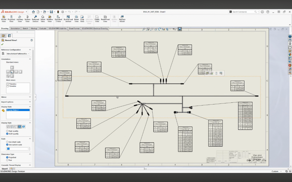
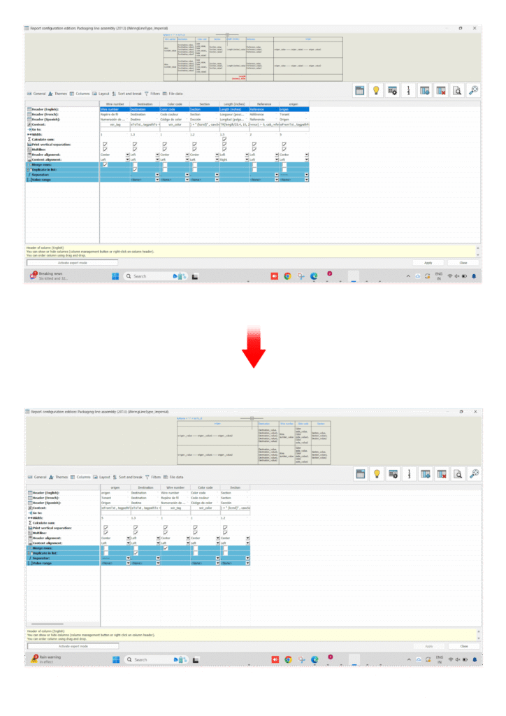
In the latest update of SOLIDWORKS Electrical, connector management becomes more powerful and flexible with the introduction of expanded variables in connector tables. This enhancement improves how electrical designers document, customize, and automate connector-related information directly within their projects.
What’s New?
Connector tables now support a broader set of variables, enabling users to include more detailed and project-specific data. These variables can be inserted directly into reports and drawings, allowing for better documentation and standardization.
Step-by-Step: How to Use Expanded Variables in Connector Tables
Step 1: Open Your Electrical Project
Launch SOLIDWORKS Electrical
Open an existing project or create a new one
Navigate to the schematic where connectors are defined
Step 2: Insert or Identify a Connector
Add a connector symbol if not already present
Ensure the connector has proper manufacturer part and attributes assigned
Verify pins and circuits are defined correctly
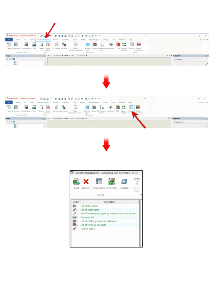
Step 3: Open Report Manager
Go to Project > Reports
Select an existing connector report or create a new report
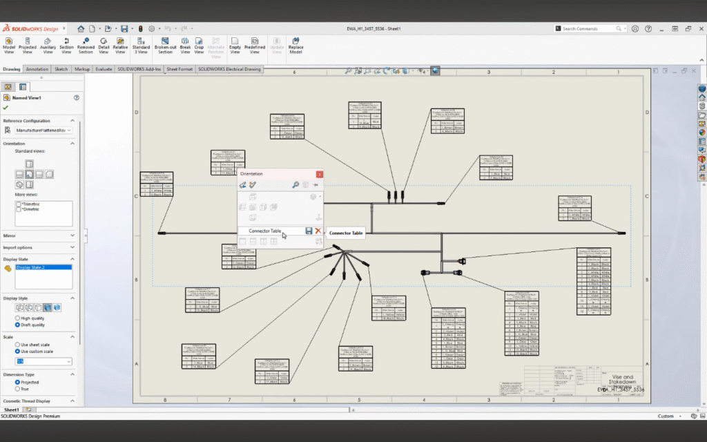
Choose Connector Table as the report type
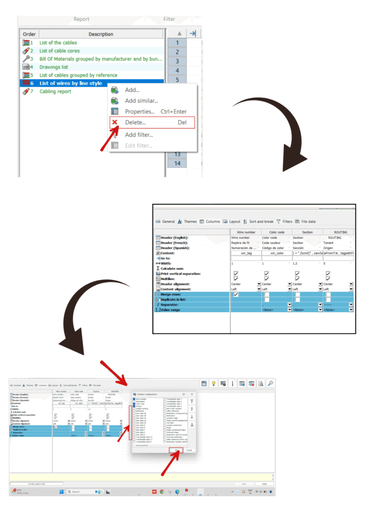
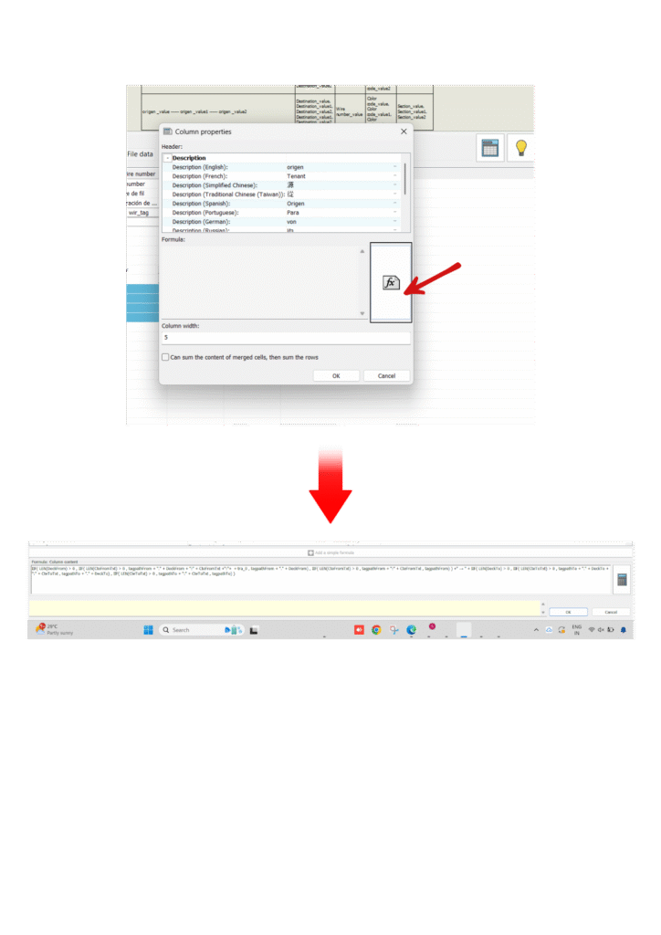
Step 4: Access Variable Configuration
In the report configuration window, locate “Available Variables”
Browse through the expanded list of variables
You will now see newly added connector-related parameters
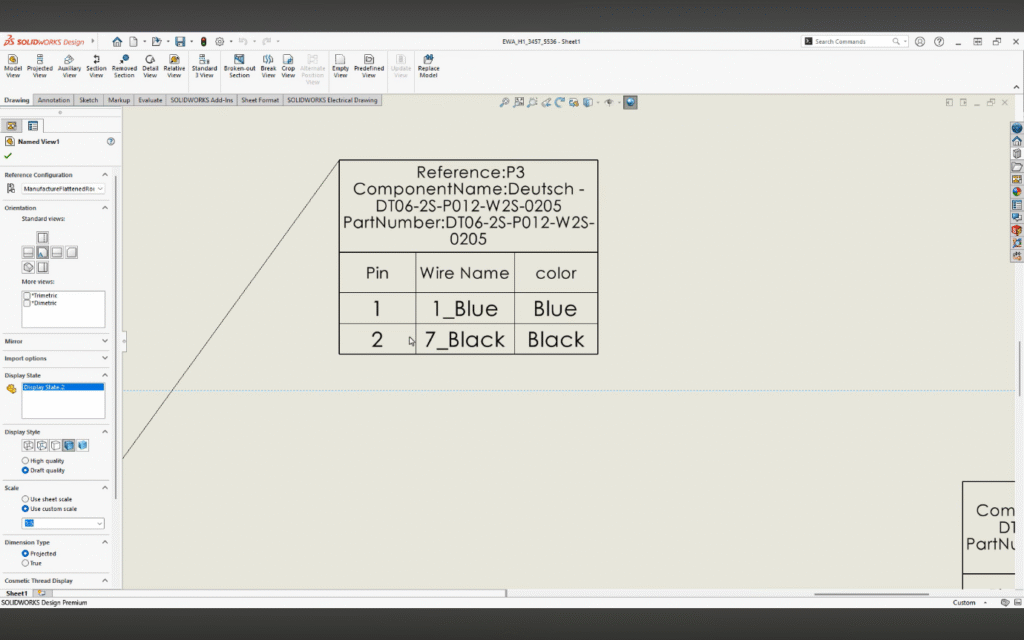
Step 5: Add Expanded Variables to Table
Drag and drop required variables into the report columns
Examples include:
Connector mark
Pin number
Signal name
Manufacturer data
Custom properties
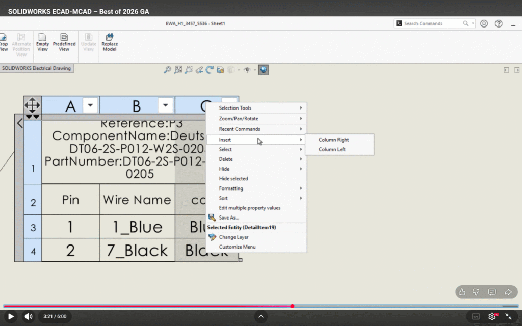
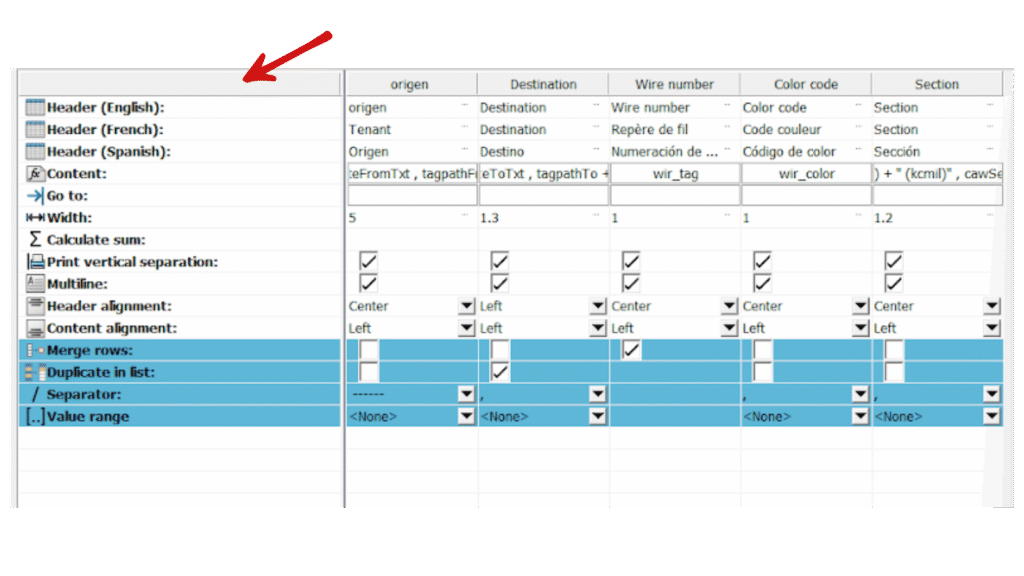
Step 6: Customize Layout
Adjust column order, width, and headers
Apply sorting or grouping if required
Format the table as per company standards
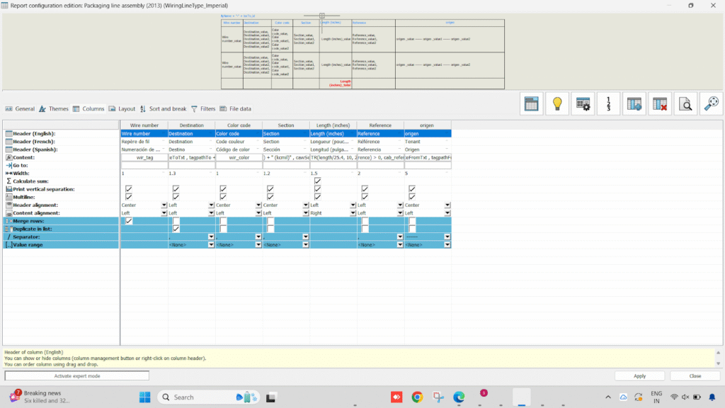
Step 7: Generate and Update Report
Click Generate to create the connector table
Place the report into your drawing
Use Update whenever design changes occur to keep data synchronized
Practical Use Cases
1. Detailed Connector Documentation
Include additional attributes such as:
Pin descriptions
Signal types
Manufacturer details
Wiring information
2. Custom Reporting
Generate connector tables tailored to:
Project standards
Client requirements
Industry compliance
Benefits:
Increased flexibility in connector table design
Better data visibility and traceability
Faster report generation
Reduced risk of documentation errors
Conclusion
The expanded variables in connector tables within SOLIDWORKS Electrical represent a significant step toward intelligent electrical documentation. This enhancement not only saves time but also ensures higher accuracy and better collaboration across teams working alongside SOLIDWORKS.
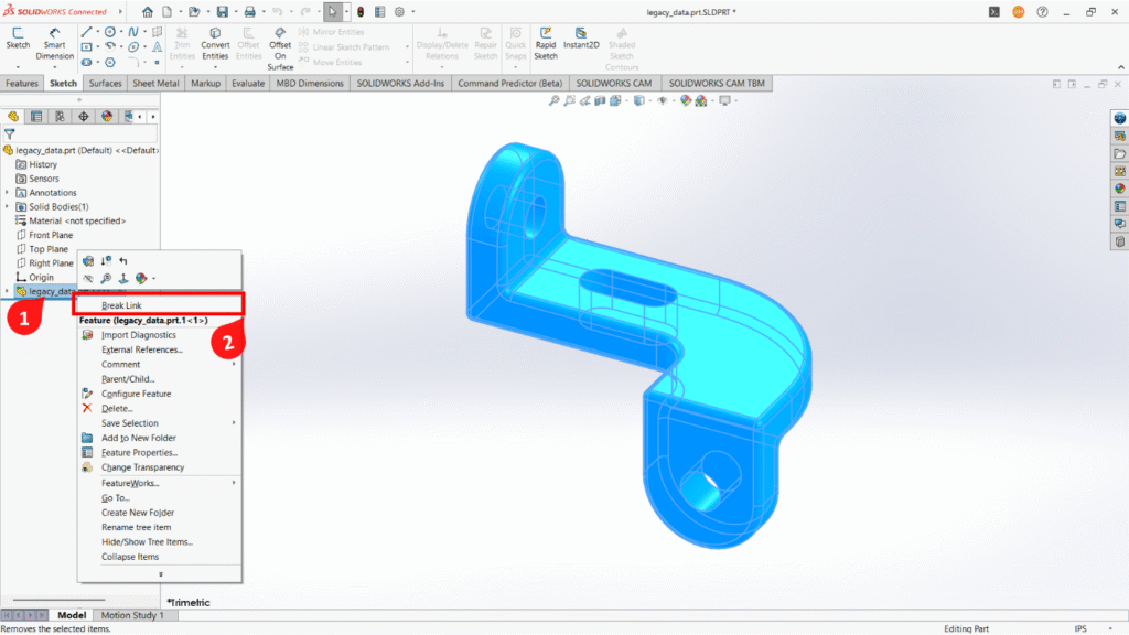
Mechanical engineers usually focus on drawings, deadlines, and design problems—not AI. But now, AI is slowly becoming a helpful tool in daily work. It is not replacing engineers, it is making their work easier and faster.
Key Features:
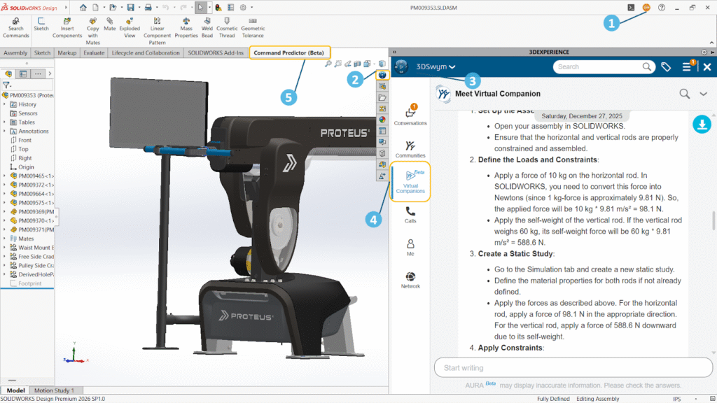
Command Predictor: Suggests the next possible commands based on your workflow, helping engineers work faster without searching through menus.
Sketch & Mate Repair Tools: Automatically detects and fixes broken sketch relations and missing mates, reducing rework and saving time.
Advanced Selection Tools: Makes it easier to select multiple faces, edges, or features quickly, improving productivity in complex models.
Error Detection Support: Helps identify the root cause of rebuild errors, allowing engineers to fix issues more efficiently instead of guessing.
AURA – AI Assistant: Provides quick access to important information by summarizing documents, standards, and discussions, reducing time spent searching.
Easily access AURA from MySession.
AURA can be used to quickly search documentation and content and can summarize posts, questions, and wikis to capture key takeaways at a glance. For example, when you ask AURA how to save your design to a previous version of SOLIDWORKS, it will quickly generate the answer with steps and point you to the right resources. You can access AURA from anywhere in 3DSwym and directly from SOLIDWORKS inside the MySession task pane.
Easily access AURA from MySession.
Benefits of AI in 3DEXPERIENCE
Saves Time: Reduces repetitive and manual tasks, allowing engineers to complete work faster.
Smooth Workflow: Helps engineers stay focused without interruptions or constant searching.
Fewer Errors: Minimizes mistakes and reduces the need for rework.
Quick Information Access: Provides the right data and answers instantly when needed.
Better Productivity: Improves overall efficiency and allows more focus on design and innovation.
Conclusion:
AI in mechanical engineering is not about replacing engineers, but about supporting them in their daily work. It helps reduce repetitive tasks, saves time, and improves overall workflow. With platforms like 3DEXPERIENCE, these AI-powered capabilities are becoming more integrated and accessible, helping engineers manage data, collaborate better, and work more efficiently.
By handling routine activities, AI allows engineers to focus more on creativity, problem-solving, and better design decisions. This shift is making engineering work faster, smarter, and more efficient—and it is just the beginning.
When working with structural members in SOLIDWORKS, the default library might not always meet your project requirements. Whether you're designing a custom frame, machine structure, or fabrication model, adding your own profiles can save time and standardize your workflow.
In this blog, we’ll walk you through how to create and add custom profiles to the SOLIDWORKS Weldments library. When working with structural members in SOLIDWORKS, the default library might not always meet your project requirements. Whether you're designing a custom frame, machine structure, or fabrication model, adding your own profiles can save time and standardize your workflow.
In this blog, we’ll walk you through how to create and add custom profiles to the SOLIDWORKS Weldments library.
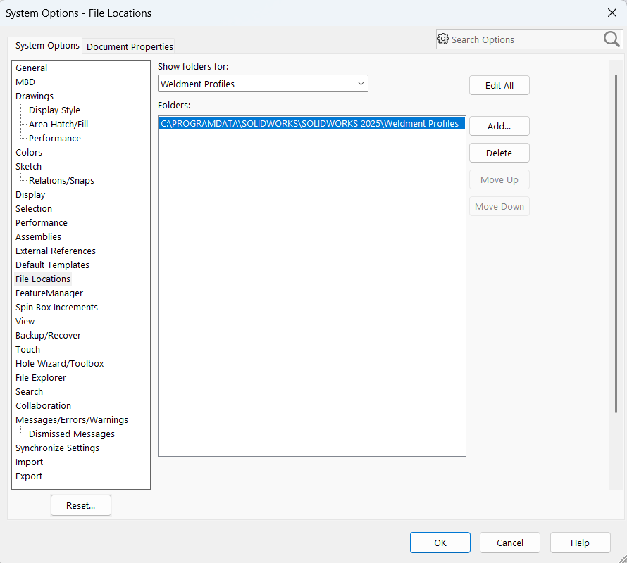
Step 1: Locate the Weldment Profiles Folder
Open SOLIDWORKS.
Go to: Tools → Options → System Options → File Locations
From the dropdown, select Weldment Profiles.
Note the folder path.
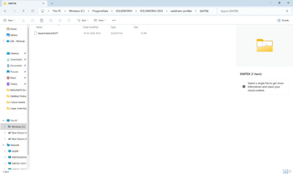
Step 2: Create Folder Structure
Inside the Weldment Profiles directory, create this structure:
For eg:“Weldment profile” > “SIMTEK”
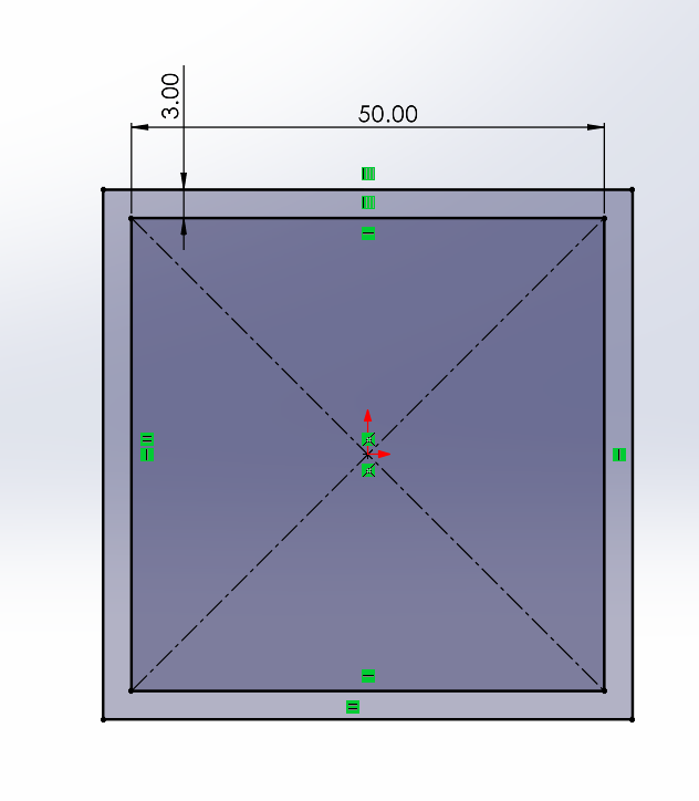
Step 3: Create a New Profile Sketch
Open a new part file
Select the Front Plane (or any plane)
Create a 2D sketch of your profile
Example: square tube, angle, channel
Fully define the sketch using dimensions
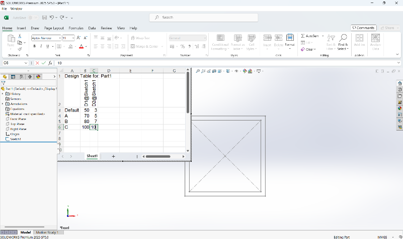
Step 4: Create configuration for the sketch
By using the excel design table create the configuration for the sketch drawn to make the custom weldment profile.
Step 5: Save as Library Feature Part (.SLDLFP)
Go to File → Save As
Select file type:
Lib Feat Part (*.sldlfp)
Save it inside your created folder (Size folder)Go to File → Save As
Select file type: Lib Feat Part (*.sldlfp)
Save it inside your created folder (Size folder)
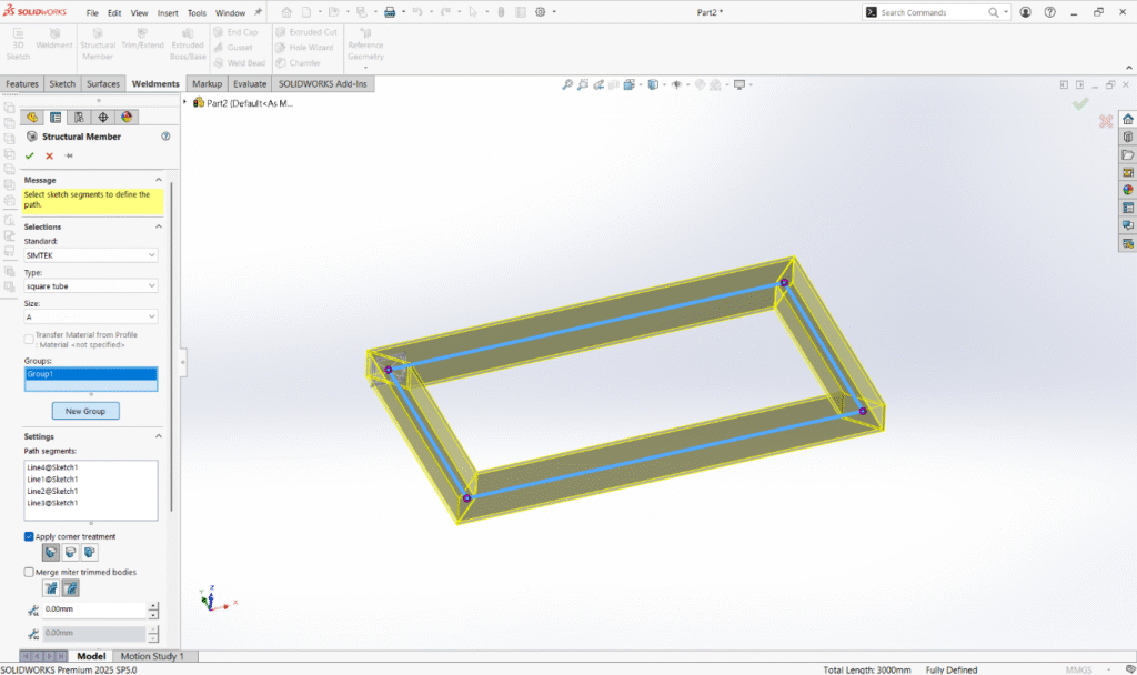
Step 7: Use the Custom Profile
Open a part.
Go to Weldments → Structural Member.
Browse:Standard → Type → Size.
Select your custom profile.
Apply it to sketch paths.
Conclusion:
Adding custom profiles to the SOLIDWORKS library is a simple yet powerful way to standardize your designs and boost productivity. Once set up, it becomes a one-time effort that saves hours in future projects.
Engineering analysis is only valuable when the results can be clearly communicated. In SOLIDWORKS Premium, the Simulation Report feature allows engineers to automatically generate professional reports containing model details, loads, fixtures, mesh information, and result plots.
Give any name to your simulation study and press the tick mark.
Now you can notice the simulation tab get created.
Step-2:
Apply the material to your part if not applied.
Then using connectors define the connectors you used in your design.
Then apply the fixtures like “fixed geometry”, “rollers and sliders” etc…
On extra loads you can apply the load(static) on the face where the load is going to applied.
After applying the load you can go to the mesh option and select the mesh and run option.
You can now notice the mesh gets created and the solver runs.
Step-3:
After the solver gets completed you notice the results for your static study gets created in the graphical area.
Here you can notice the result for stress , strain and displacement gets created.
If you need to add the factor of safety results you can add from right clicking on the result and select FOS.
Now you can also use generate reports in a word file format.
Step-4:
By clicking the report tool you can notice a dialogue box gets created.
Inside the Report Options dialog, you can select the sections to include.
Typical report sections include:
Study Properties
Material Properties
Parts and Bodies
Loads and Fixtures
Mesh Information
Contact Definitions
Stress Results
Displacement Results
Factor of Safety
Simply check or uncheck sections depending on what you want in the report.
You can also enter additional information such as:
Company Details
Report Format Options
Step-5:
Once everything looks correct:
Click Publish
Choose the output location
The report is automatically generated
The report is typically exported as a Microsoft Word document, which you can further edit or convert to PDF.
Conclusion:
The Simulation Report feature in SOLIDWORKS Premium simplifies the process of documenting engineering analysis. Instead of manually assembling results, engineers can automatically generate structured reports containing all simulation parameters and result plots.
If you regularly perform FEA studies, mastering this feature will significantly improve your workflow and reporting efficiency.
Accurate weight calculation is a critical part of modern electrical and mechanical design. In panel design, machine layout, and equipment manufacturing, incorrect weight data can lead to structural issues, handling problems, and inaccurate documentation. SOLIDWORKS Electrical addresses this challenge through the Manufacturer Part Weight property, which plays an important role in Electrical–Mechanical 3D integration.
This article explains what Manufacturer Part Weight is, how it works with 3D integration, and why it is essential for reliable design data.
What Is Manufacturer Part Weight?
Manufacturer Part Weight is a parameter defined at the manufacturer part level in the SOLIDWORKS Electrical catalog. It represents the real-world weight of an electrical component, typically taken from the manufacturer’s datasheet.
Once assigned, this weight becomes part of the component’s metadata and is used throughout the electrical project, including reports, bills of materials (BOMs), and 3D integration.
The electrical component is linked to a corresponding 3D part or assembly
The Manufacturer Part Weight is transferred to the 3D model
The overall assembly mass properties reflect the defined electrical weight
This ensures that the mechanical assembly weight matches the actual manufactured product, even if the 3D model geometry is simplified.
Step-by-Step Process: Defining Manufacturer Part Weight
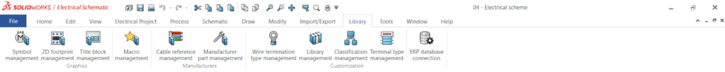
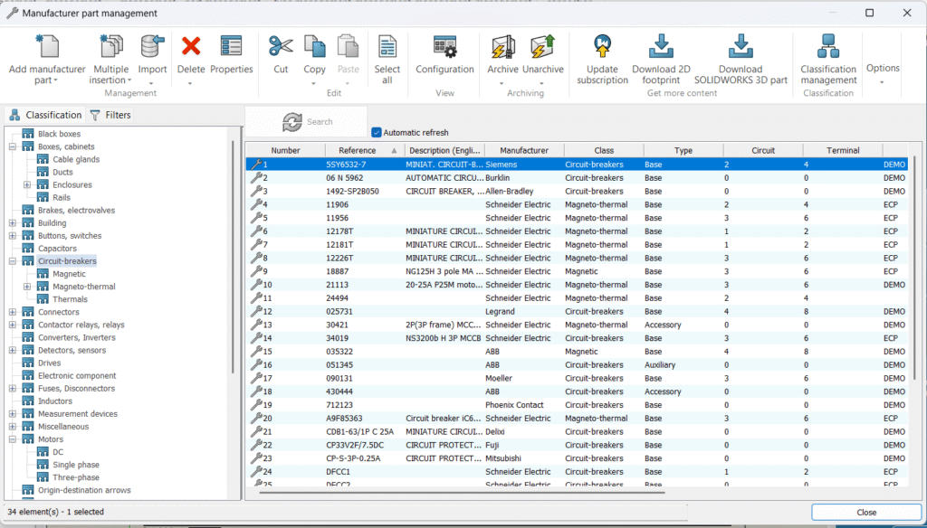
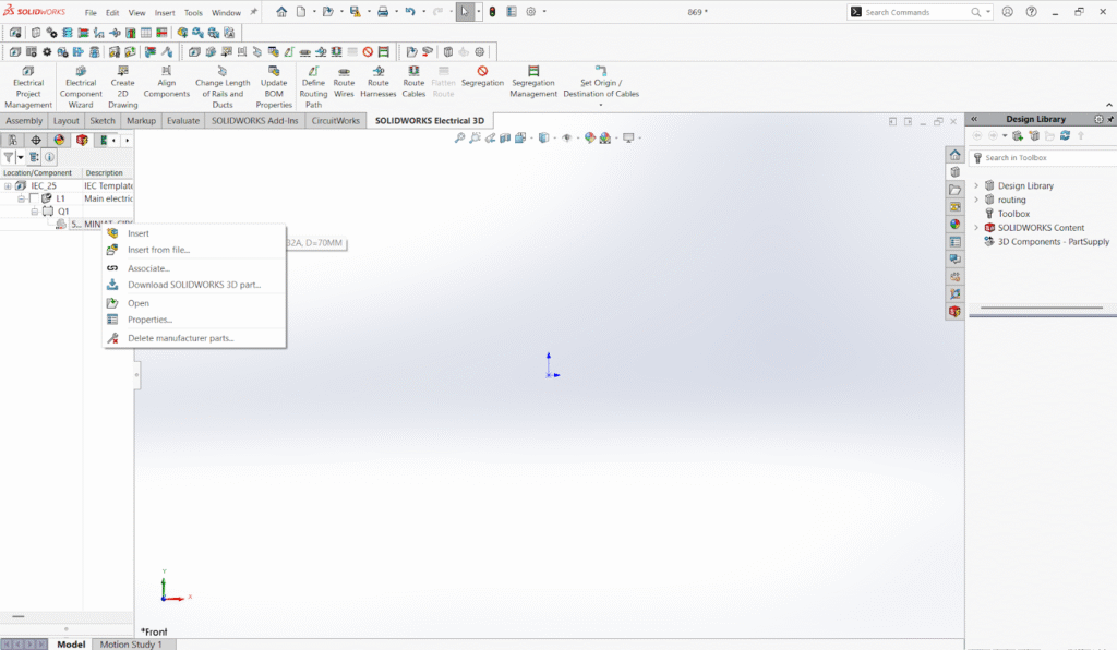
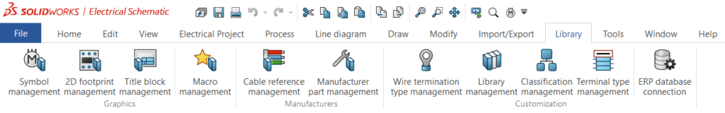
Step 1: Open Manufacturer Part Management
Navigate to Libraries > Manufacturer Parts Management in SOLIDWORKS Electrical.
Manufacturer Part Management dialog accessed from the SOLIDWORKS Electrical Libraries menu.
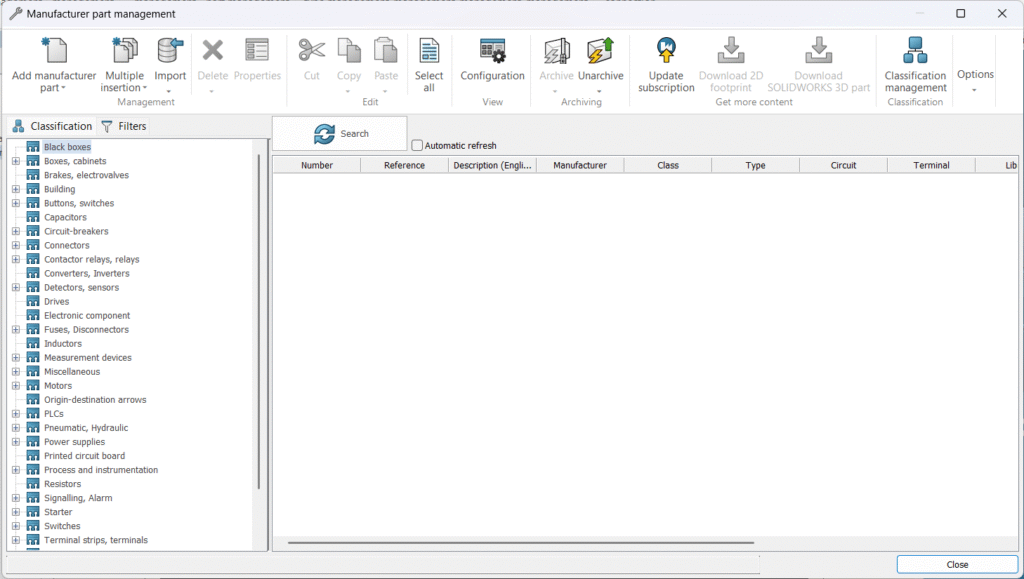
Step 2: Select or Create a Manufacturer Part
Select an existing manufacturer part from the catalog or create a new one that matches the electrical component used in the project.
Manufacturer Part list showing available components and part creation options.
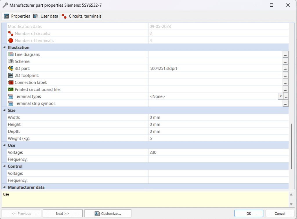
Step 3: Enter the Weight Value
In the manufacturer part properties, locate the Weight field and enter the actual component weight based on the manufacturer’s datasheet.
Manufacturer Part Properties dialog highlighting the Weight field.
Step 4: Assign the 3D Model
Associate the manufacturer part with a corresponding SOLIDWORKS 3D part or assembly. This link enables synchronization between electrical and mechanical designs.
3D model association tab showing linked SOLIDWORKS part file.
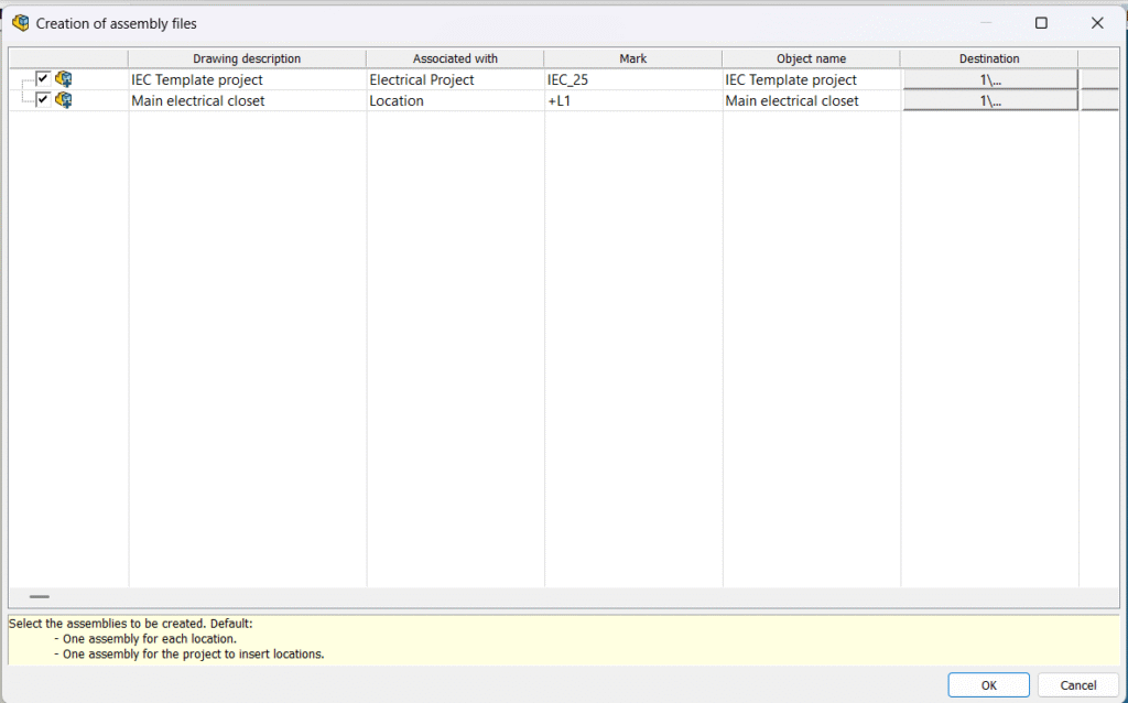
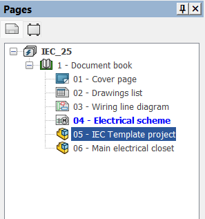
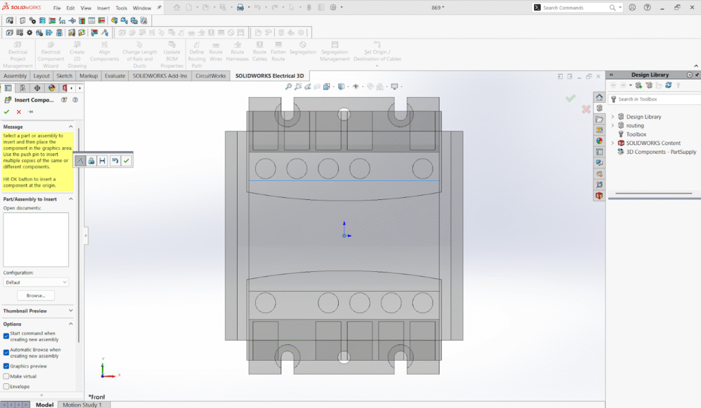
Step 5: Place the Component in a 3D Assembly
Insert the electrical component into a SOLIDWORKS 3D assembly such as a control panel, cabinet, or machine layout.
Electrical component placed in a SOLIDWORKS 3D panel or enclosure assembly.
Step 6: Verify Assembly Mass Properties
Open the Mass Properties tool in SOLIDWORKS 3D to confirm that the manufacturer part weight is included in the total assembly weight.
SOLIDWORKS Mass Properties window showing total assembly weight
Once placed, the defined manufacturer part weight is automatically included in the overall assembly mass without additional manual calculations.
Best Practices
Always use datasheet-based weights rather than estimated values
Keep unit settings consistent across electrical and mechanical projects
Update manufacturer parts centrally to ensure consistency across designs
Use simplified 3D models combined with accurate electrical weight for optimal performance
Conclusion
Manufacturer Part Weight in SOLIDWORKS Electrical is a small but powerful feature that significantly improves design accuracy. By linking real-world component weight to 3D assemblies, engineers can achieve precise mass calculations, reliable documentation, and seamless electrical–mechanical integration.
For projects where accuracy, efficiency, and collaboration matter, properly managing manufacturer part weight is not an optional step—it is an essential part of a professional design workflow.
In today’s product development environment, managing issues and changes in a structured way is very important.
The 3DEXPERIENCE platform provides a digital and collaborative system to manage Issues and Changes efficiently.
This blog explains Issue Management and Change Management in simple language and shows how both work together.
Issue Management:
Issue Management is the process of identifying, tracking, and resolving problems that occur during product development.
Issues can come from:
Design reviews
Simulation or validation failures
Manufacturing problems
Quality or customer feedback
In the 3DEXPERIENCE platform, users can create an issue, assign it to a responsible person, set priority and severity, and track its status from open to closed.
All related data such as CAD models, documents, and comments can be linked to the issue.
Benefits of Issue Management:
Clear communication
Better collaboration
Faster problem resolution
Full traceability
Basic Workflow:
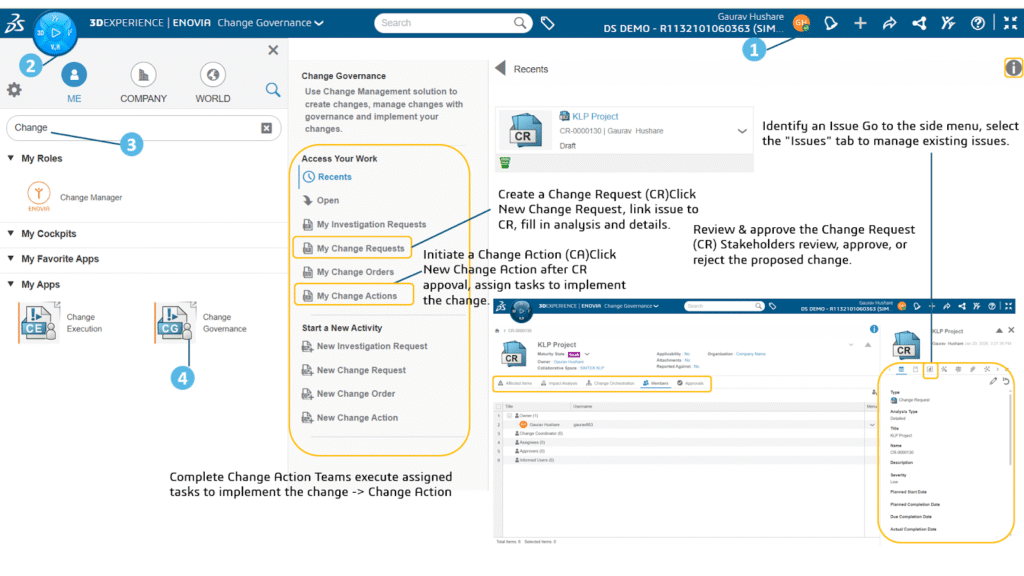
You can create issues to track resolutions of problems or initiatives.
From the toolbar, click → New Issue . You can also enter the title of the issue you are creating and click New Issue. The New Issue panel appears (including the Title of the issue, if specified).
Click Settings and choose from the following options:
If you want to automatically assign the issue, select Assign automatically content owner to the Issue
If you want the issue to use the workflow process, select Enable the approval to ensure validation and review of this issue. This option might be enabled or disabled depending on whether you are using the approval workflow. See Configuring Issue Management for more information.
If you want this issue to be saved as a template, select Save the Issue as a reusable template and enter a name and description for the template.
Note: Click and to switch between full form view and multistep view.
Change Management:
Change Management is the process of controlling and implementing changes in product design, documents, or processes.
When an issue requires a design or process update, a Change Request is created. The change is then analyzed to understand its impact on cost, quality, schedule, and manufacturing. After approval, the change is implemented, and a new revision is released. All actions are recorded, providing a complete history of the change.
Benefits of Change Management:
Controlled and approved changes
Reduced risk
Clear responsibility
Audit-ready documentation
How Issue and Change Management Work Together
Issue Management helps identify problems. Change Management helps solve those problems in a controlled way.
Typical flow:
1. Issue is created
2. Issue is analyzed
3. Change Request is raised
4. Impact analysis and approvals are completed
5. Change is implemented
6. Issue is closed
This connection ensures full traceability from problem to solution.
Conclusion:
Managing issues and changes using emails or spreadsheets is risky and inefficient.The 3DEXPERIENCE platform provides a structured, collaborative, and transparent way to manage both. Using Issue Management and Change Management together improves product quality, reduces rework, and shortens time to market.
Revolutionizing Drawing Creation in SOLIDWORKS 2026 with Auto-Generate Drawing
SOLIDWORKS 2026 introduces a groundbreaking feature in drafting automation: Auto-Generate Drawing (BETA) — a beta/preview-stage tool that automates the creation of 2D drawings from parts and assemblies. This isn’t the traditional “Make Drawing” dialog — it’s a new, AI-powered workflow designed to skip the blank sheet and quickly produce intelligent, standardized drawings with minimal manual steps.
Auto-Generate Drawing (BETA) is a preview automation tool in SOLIDWORKS 2026 aimed at drastically reducing the time needed to produce technical drawings. Instead of manually creating views, arranging them, and placing dimensions one by one, this feature:
Generates drawing sheets automatically
Places standard views and intelligent annotations
Proposes dimensions and detail views
Uses AI for layout, hole recognition, and sheet sizing
Step-by-Step Guide:
Step 1: Launch the Auto-Generate Drawing Tool
File > Auto-Generate Drawing (BETA)
Right-click a part or assembly in the Feature Manager tree and choose Auto-Generate Drawing (BETA)
Select multiple components (Ctrl-click) and run the command on a batch of models
Step 2: Property Manager & Options
Once launched, the Auto-Generate Drawing Property Manager lets you:
Select what parts/assemblies to include
Set a title
Choose save location (same folder as model or another path)
Reset the title to the filename (optional)
Step 3:Intelligent Drawing Generation
After you click Generate, SOLIDWORKS will:
Detect best sheet size and format based on model geometry
Auto-place views (front, top, side, isometric)
Recognize holes and features, adding hole callouts
Propose sections if internal detail is detected
Arrange views and annotations to avoid overlaps using AI logic
Conclusion
The Auto-Generate Drawing (BETA) feature in SOLIDWORKS 2026 is one of the most ambitious drawing automation tools introduced to date. Powered by AI and intelligent layout logic, it aims to replace repetitive manual tasks with a single command that produces a draft drawing you can refine.
As the feature evolves beyond Beta, it has the potential to transform how engineers create 2D documentation — minimizing the tedious start and maximizing design productivity.
In modern product design, sketching is not just about drawing shapes—it is about controlling design intent.
The 3D Creator role in the 3DEXPERIENCE platform offers a powerful and intuitive 2D Sketch Mechanism that helps designers create fully constrained, parametric sketches that behave predictably during modeling.
Step-by-Step Guide: Creating a Controlled 2D Sketch Mechanism in 3D Creator
Step 1: Create a New Sketch
Open 3D Creator from the 3DEXPERIENCE platform.
Create a new Physical Product.
Select a plane (XY, YZ, or ZX).
Click Sketch.
Step 2: Draw Basic Sketch Geometry
Use tools like:
Line
Rectangle
Circle
Arc
Create the rough shape without worrying about exact size.
Step 3: Observe Degrees of Freedom (Sketch Behavior)
Drag sketch entities using the mouse.
Notice how:
Lines rotate
Corners move
Shapes distort
This movement indicates missing constraints.
Step 4: Apply Geometric Constraints
Now control the sketch mechanism using constraints:
Common constraints used in the video:
Horizontal / Vertical – fixes orientation
Coincident – joins points
Parallel / Perpendicular – controls alignment
Tangent – smooth contact between entities
Equal – same size or length
After each constraint, test movement again.
Step 5: Add Dimensions (Driving the Mechanism)
Use Dimension tool
Define:
Lengths
Widths
Diameters
Angles
Modify dimension values and observe how the sketch updates.
This is the core of the sketch mechanism—dimensions drive geometry behavior.
Step 6: Achieve a Fully Defined Sketch
Check sketch status:
Under-defined → Blue
Fully defined → Black
Ensure no unwanted movement remains.
Step 7: Use the Sketch for 3D Features
Once the sketch is controlled:
Exit Sketch
Use features like:
Extrude
Extrude cut
Revolve
Because the sketch is well-defined, 3D changes become safe and fast.
Conclusion
The 2D Sketch Mechanism in 3D Creator is a powerful concept that transforms simple drawings into intelligent, parametric designs. By understanding how constraints and dimensions control sketch behavior, you can:
Reduce modeling errors
Improve design stability
Make faster design changes
Build professional-grade 3D models
If you master sketch mechanisms, your 3D models will automatically become stronger and smarter.
Introduction: The Role of Engineering Service Providers in Modern Industry
Modern industries operate under constant pressure to innovate, reduce costs, and accelerate product development. From automotive and heavy engineering to industrial machinery and emerging EV applications, engineering quality has a direct impact on productivity, reliability, and profitability.
To stay competitive, many organizations now rely on professional engineering service providers instead of building large in-house teams. An experienced engineering partner brings specialized skills, proven processes, and scalable resources.
In Chennai, one of India’s largest industrial hubs, SIMTEK has established itself as a trusted engineering service provider delivering reliable industrial solutions across the product lifecycle.
What Is an Engineering Service Provider?
An engineering service provider is a company that offers outsourced engineering services such as mechanical design, CAD modeling, CAE simulation, manufacturing engineering, CAM programming, and PLM support.
Unlike staffing firms or freelancers, engineering service providers:
Deliver outcome-based engineering solutions
Follow structured engineering processes
Use certified engineering tools
Act as long-term partners to manufacturers
SIMTEK operates as a full-service engineering service provider focused specifically on industrial and manufacturing applications.
Why Chennai Is a Strategic Hub for Engineering Services
Chennai is one of India’s most important manufacturing and engineering ecosystems. The region hosts:
Automotive OEMs and Tier-1 suppliers
Heavy engineering and industrial machinery manufacturers
Tool & die and mold manufacturing companies
Aerospace and defense suppliers
Robotics, automation, and EV manufacturers
This industrial concentration creates strong demand for engineering partners who understand manufacturing realities, shop-floor challenges, and production constraints.
SIMTEK’s presence in Chennai enables close alignment between engineering design and real-world industrial execution.
Rising Demand for Engineering Service Providers in Chennai
Industrial companies increasingly partner with engineering service providers due to:
Shortage of specialized engineering talent
Rising cost of maintaining large internal teams
Need to reduce product development cycles
Increasing complexity of industrial products
By outsourcing to a reliable engineering service provider in Chennai, companies gain access to scalable engineering expertise without increasing fixed costs.
SIMTEK was built to address these challenges efficiently.
About SIMTEK
SIMTEK is a professional engineering services company delivering end-to-end engineering solutions for industrial and manufacturing organizations. Its services cover mechanical design, simulation, manufacturing engineering, CAM programming, and digital engineering platforms.
What sets SIMTEK apart is its manufacturing-first approach. Every engineering output is evaluated for feasibility, efficiency, and production readiness, ensuring real value on the shop floor.
Authorized and Certified Engineering Expertise
Engineering credibility is built on certification and compliance with global standards.
SIMTEK is an Authorized Partner and Certified Service Provider for leading engineering platforms, including:
Many engineering vendors focus only on design delivery. SIMTEK focuses on manufacturing-ready engineering.
Each project is evaluated for:
Manufacturing feasibility
Tooling and machining efficiency
Material optimization
Cost reduction
Production reliability
This approach minimizes rework, reduces shop-floor issues, and improves overall operational efficiency.
Local Presence with Global Delivery Capability
SIMTEK’s strong presence in Chennai ensures deep understanding of:
Local manufacturing practices
Supplier and vendor ecosystems
Industry-specific expectations
At the same time, SIMTEK supports global clients through structured offshore delivery models, clear communication, and strong project governance.
Flexible Engagement Models
SIMTEK offers flexible engagement options to suit varying engineering needs:
Project-based engineering services
Dedicated engineering teams
Long-term engineering outsourcing
This flexibility helps companies scale engineering resources without long-term overhead commitments.
Industries Served by SIMTEK
SIMTEK supports a wide range of industrial sectors, including:
Automotive and electric vehicle manufacturing
Heavy engineering and industrial machinery
Tool & die and mold manufacturing
Robotics and industrial automation
Aerospace component suppliers
Precision manufacturing
Cross-industry experience allows SIMTEK to apply proven engineering best practices effectively.
Why Clients Choose SIMTEK in Chennai
Clients choose SIMTEK because of:
Certified and authorized engineering expertise
End-to-end engineering service capability
Manufacturing-ready engineering outputs
Structured processes and quality control
Reliable communication and delivery
Long-term partnership mindset
These strengths position SIMTEK as a leading engineering service provider in Chennai.
Supporting Long-Term Industrial Growth
Engineering requirements evolve over time. SIMTEK supports long-term growth by:
Acting as an extension of in-house engineering teams
Enabling continuous product improvement
Supporting digital transformation initiatives
Providing scalable and reliable engineering capacity
Conclusion
SIMTEK stands out as the best engineering service provider in Chennai for industrial solutions by combining certified expertise, manufacturing-focused execution, and end-to-end engineering services. Its strong local presence, global delivery capability, and commitment to quality make SIMTEK a trusted partner for industrial organizations seeking reliable and scalable engineering support.
Frequently Asked Questions
What makes SIMTEK different from other engineering service providers in Chennai? SIMTEK delivers manufacturing-ready engineering using certified tools, structured processes, and a long-term partnership approach.
Which industries does SIMTEK serve? SIMTEK supports automotive, heavy engineering, industrial machinery, tool & die, robotics, aerospace suppliers, and precision manufacturing.
Does SIMTEK offer end-to-end engineering services? Yes. SIMTEK provides CAD, CAE, CAM, PLM, and engineering outsourcing services under a single engagement model.
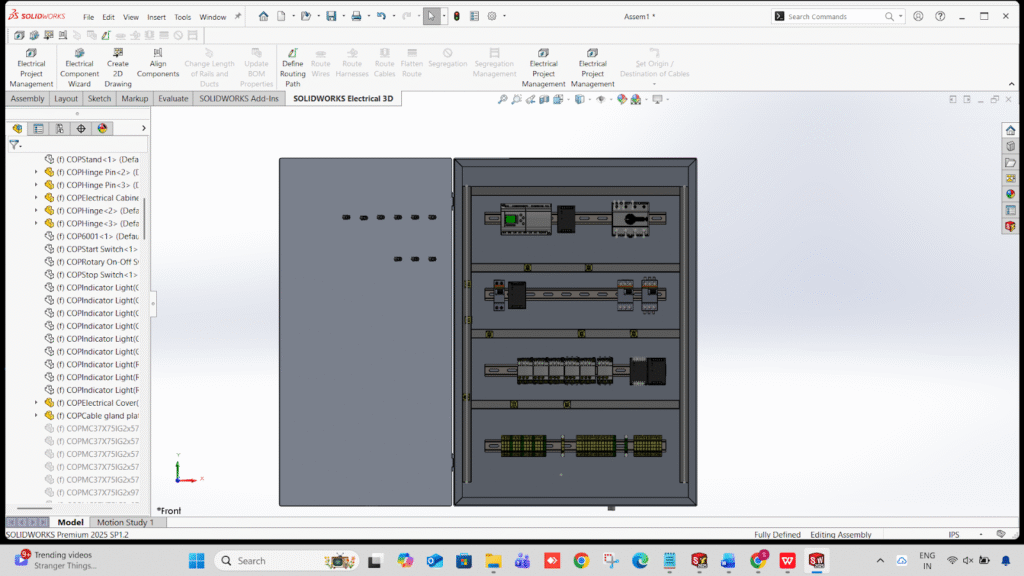
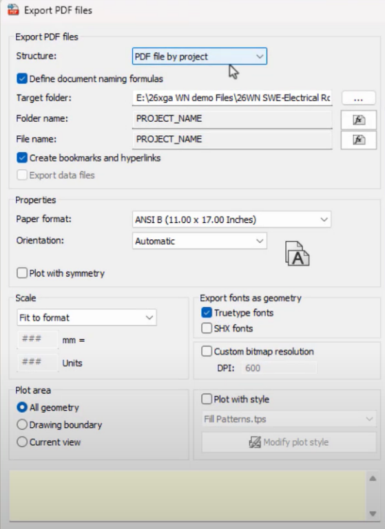
Routing only the selected wires instead of routing the full project is one of the most time-saving improvements in SOLIDWORKS Electrical 2026. This feature is perfect for large projects, modification work, and design updates where you don’t want to re-route the entire harness.
Why Use the Route Selected Wires Option
The Route Selected Wires option in SOLIDWORKS Electrical 2026 helps you save time, avoid unnecessary re-routing, and improve project efficiency. Instead of routing the entire project, you can route only the wires that changed. This makes the process faster, reduces system load, prevents changes to already-routed wires, and is ideal for troubleshooting or small design updates. It gives you better control, higher accuracy, and smoother workflow in large electrical assemblies.
Open Your 3D Model
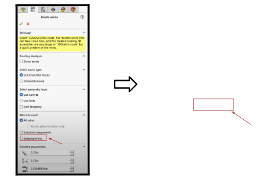
Go to → Electrical Command Manager → Route Wires
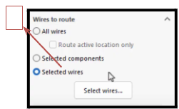
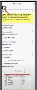
Enable the New Route Selected Wires Option In the routing dialog box, you will now see a new option:
Route only selected wires
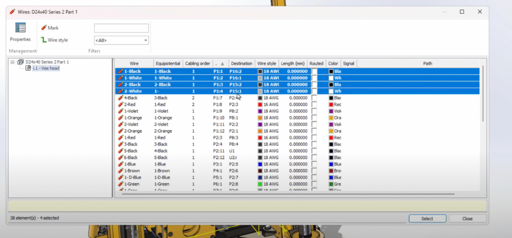
Select the Wires to Route
From 3D Assembly
Click the components
Select wire connections in the feature tree
Choose the wires you want to route
From the 2D Schematic
Open the wire list
Select specific wires
Right-click → Select wire in 3D
Run Routing
Click OK / Run.
Verify Route Results
Check the feature tree for new routes.
Green → Successfully routed
Yellow → Needs adjustment
Red → Routing failed
Troubleshooting Tips
Ensure all connection points have proper CPoints
Check for closed paths in routing assemblies
Avoid suppressed routing subassemblies
For multi-core cables, select the core wires individually
Conclusion
The Route Selected Wires feature in SOLIDWORKS Electrical 2026 is a major time-saving improvement. With selective routing and faster updates, you can modify complex projects more efficiently.
This guide explains what CAM software is, how it works, what features matter most, and how manufacturers can select a future-ready CAM solution.
What Is CAM Software?
CAM software is a manufacturing tool that converts digital designs into machine instructions (G-code) for CNC machines. It tells the machine how to cut, where to move, which tools to use, and how fast to operate.
CAM software is commonly used for:
CNC milling
CNC turning
Mill-turn machining
4-axis and 5-axis machining
High-precision manufacturing
How Does CAM Software Work?
CAM software follows a structured workflow:
Import CAD geometry (part model or drawing)
Define machining operations and tools
Generate toolpaths
Simulate machining to detect errors
Output CNC-ready G-code
Modern CAM software simplifies this process, allowing programmers to work faster while maintaining full control.
Why CAM Software Is Critical for Modern Manufacturing
In today’s manufacturing environment, manual CNC programming is no longer efficient or scalable.
CAM software helps manufacturers:
Reduce CNC programming time
Improve machining accuracy
Minimize scrap and rework
Handle complex geometries
Improve machine utilization
Meet tighter delivery schedules
For high-mix or precision manufacturing, CAM software is no longer optional — it is essential.
Key Features to Look for in CAM Software
When evaluating CAM software for CNC machines, manufacturers should focus on these core capabilities:
Essential CAM Software Capabilities
Support for milling and turning operations
Reliable post processors for CNC machines
Toolpath simulation and verification
Ease of use and learning curve
Scalability for advanced machining
Vendor support and implementation expertise
The right CAM software should support both current production needs and future growth.
Types of CAM Software Used in CNC Machining
CAM software is available in different levels based on machining complexity:
2.5D / 3D CAM software – for basic milling operations
Turning CAM software – for CNC lathes
Mill-turn CAM software – for multi-task machines
Multi-axis CAM software – for 4-axis and 5-axis machining
Many manufacturers prefer CAM solutions that can scale across all these applications in a single platform.
How Manufacturers Choose the Right CAM Software
Choosing CAM software is not just a technical decision — it’s a business decision.
Manufacturers should consider:
Machine tool types and controllers
Part complexity and tolerances
Production volume and mix
Skill level of programmers
Local training and support availability
This is why working with an authorized CAM solution partner is critical for successful implementation.
Role of CAM Software Partners in Successful Implementation
Even the best CAM software can fail without proper implementation.
An experienced solution partner helps with:
Correct software configuration
Machine-specific post processors
Programmer training
Workflow optimization
Ongoing technical support
In India, manufacturers often work with authorized CAM solution partners to ensure faster adoption and lower risk.
CAM Software for Future-Ready Manufacturing
As manufacturing evolves toward:
Multi-axis machining
Automation
Higher precision
Shorter lead times
CAM software must be flexible, scalable, and production-proven.
Solutions like GibbsCAM, when implemented by experienced partners such as SIMTEK, help manufacturers transition smoothly from basic CNC programming to advanced machining strategies — without changing platforms.
Frequently Asked Questions
What is CAM software used for?
CAM software is used to generate CNC programs that control machining operations such as milling, turning, and multi-axis machining.
Is CAM software necessary for CNC machines?
Yes. CAM software improves efficiency, accuracy, and consistency compared to manual CNC programming.
What is the difference between CAD and CAM software?
CAD software is used to design parts, while CAM software is used to manufacture those parts using CNC machines.
Can one CAM software handle milling and turning?
Yes. Many modern CAM solutions support both milling and turning in a single environment.
How do manufacturers choose the best CAM software?
Manufacturers evaluate CAM software based on machine compatibility, ease of use, scalability, and local support.
Final Thoughts
CAM software plays a critical role in modern CNC manufacturing. The right solution improves productivity today while preparing manufacturers for future machining challenges.
By choosing scalable CAM software and working with authorized solution partners, manufacturers can reduce risk, improve ROI, and stay competitive in a demanding global market.
This guide explains what GibbsCAM is, who should use it, why it matters, and how SIMTEK helps manufacturers stay competitive now and in the future.
What Is GibbsCAM?
GibbsCAM is a CAM (Computer-Aided Manufacturing) software used to create CNC programs for milling, turning, mill-turn, and 5-axis machines. It is known for its intuitive interface, powerful toolpath control, and reliable post processors that generate accurate G-code for CNC machines.
Key capabilities include:
CNC milling and turning programming
Multi-axis and multi-task machining
Toolpath simulation and collision detection
Machine-ready G-code output
Scalable modules for future growth
Why Is GibbsCAM Popular Among Manufacturers?
GibbsCAM is popular because it balances ease of use with advanced CNC programming power. Unlike complex CAM systems, GibbsCAM allows programmers to work faster while maintaining full control over machining strategies.
Top Reasons Manufacturers Choose GibbsCAM
Reduces CNC programming time
Improves machine utilization
Minimizes scrap and rework
Supports complex geometries
Scales from basic to advanced machining
Who Should Use GibbsCAM CNC Software?
GibbsCAM is ideal for manufacturers that require reliable, production-ready CNC programming.
It is widely used by:
CNC job shops
Automotive component manufacturers
Aerospace and defense suppliers
Medical device manufacturers
Tool rooms and die & mold shops
High-mix, low-volume production units
Why Buying from an Authorized GibbsCAM Solution Partner Matters
Buying GibbsCAM from an Authorized Solution Partner ensures correct implementation, support, and long-term success.
In India, SIMTEK is an Authorized GibbsCAM Solution Partner, providing more than just software licenses.
What SIMTEK Delivers
Right GibbsCAM module selection
Machine-specific post processor configuration
Local training and onboarding
Faster technical support
Long-term CAM strategy guidance
This reduces implementation risk and maximizes ROI.
How GibbsCAM Supports Future-Ready Manufacturing
GibbsCAM helps manufacturers stay competitive as machining complexity increases.
It supports:
Transition to 4-axis and 5-axis machining
Multi-task and mill-turn operations
High-precision and tight-tolerance jobs
Faster delivery timelines
Smarter use of existing CNC machines
When paired with SIMTEK’s expertise, GibbsCAM becomes a long-term manufacturing platform, not just a CAM tool.
GibbsCAM for Milling, Turning & Multi-Axis CNC Machines
GibbsCAM supports a wide range of CNC machining applications:
CNC milling (2.5D, 3D, 4-axis, 5-axis)
CNC turning and live tooling
Mill-turn and multi-task machining
High-speed machining strategies
Advanced simulation and verification
This modular approach allows manufacturers to start with current needs and scale later.
Frequently Asked Questions
Is GibbsCAM suitable for beginners?
Yes. GibbsCAM is known for its intuitive interface, making it suitable for both beginners and experienced CNC programmers.
Is GibbsCAM good for 5-axis machining?
Yes. GibbsCAM supports advanced 5-axis simultaneous machining with accurate toolpath control and simulation.
Can GibbsCAM generate machine-ready G-code?
Yes. GibbsCAM produces accurate, machine-ready G-code using proven post processors.
Who is the authorized GibbsCAM partner in India?
SIMTEK is an Authorized GibbsCAM Solution Partner in India, providing licensing, training, implementation, and support.
Is GibbsCAM suitable for Indian manufacturing industries?
Yes. GibbsCAM is widely used in automotive, aerospace, medical, and general engineering industries in India.
Why GibbsCAM + SIMTEK Is a Competitive Advantage
GibbsCAM provides the technology. SIMTEK ensures success.
Together, they help manufacturers:
Program CNC machines faster
Reduce machining risks
Improve productivity
Scale manufacturing capabilities
Stay competitive in global markets
Next Step: Learn More or Get Started
Manufacturers evaluating CAM software should consider GibbsCAM implemented by SIMTEK, an Authorized Solution Partner in India.
If you are searching for where to buy GibbsCAM software in India, choosing the right partner is just as important as choosing the software itself. GibbsCAM, a globally trusted CNC programming solution, is widely used by manufacturers for milling, turning, and advanced multi-axis machining. When purchased through SIMTEK, an authorized GibbsCAM partner in India, you get more than a license — you get complete implementation, training, and long-term technical support.
This blog explains why GibbsCAM is the preferred CAM software for CNC machines, what makes it different, and why SIMTEK is the right choice to buy, deploy, and support GibbsCAM in India.
What Is GibbsCAM Software?
GibbsCAM is an industry-proven CAM software for CNC programming that enables manufacturers to efficiently program milling, turning, mill-turn, Swiss-type, and 5-axis CNC machines. Known for its ease of use, powerful toolpath control, and reliable G-code output, GibbsCAM is widely adopted in production machining environments.
Key Capabilities of GibbsCAM CNC Software
CAM software for 2-axis, 3-axis, 4-axis, and 5-axis CNC machines
Advanced milling and turning CAM software
Mill-turn and multi-task machining support
Accurate machine simulation and collision detection
Ready-to-use post processors for most CNC controllers
Scalable licensing that grows with your manufacturing needs
Unlike complex CAM systems that require steep learning curves, GibbsCAM software is designed to be intuitive, helping programmers create machine-ready code faster with less risk.
Why Manufacturers Choose GibbsCAM for CNC Programming
Manufacturers across automotive, aerospace, medical devices, tooling, and general engineering prefer GibbsCAM because it delivers real productivity gains on the shop floor.
Business Benefits of GibbsCAM Software
Faster CNC programming time
Shorter cycle times
Reduced scrap and rework
Safer, optimized toolpaths
Higher machine utilization
Improved delivery timelines
GibbsCAM is not just a CAM tool — it is a production efficiency engine that directly impacts profitability.
Buy GibbsCAM Software in India – Why SIMTEK Is the Right Partner
When you buy GibbsCAM software in India, working with an authorized and experienced partner is critical. SIMTEK is a trusted engineering solutions provider with deep expertise in CAM, CNC machining workflows, and manufacturing software implementation.
Why Buy GibbsCAM from SIMTEK?
➤ Authorized GibbsCAM Partner in India
SIMTEK is an official and authorized partner, ensuring you receive genuine licenses, correct configurations, and reliable updates.
➤ Local Technical Support & Faster Response
Unlike global vendors with remote support, SIMTEK provides local support teams in India, ensuring faster issue resolution and minimal downtime.
➤ Right License Selection – No Overbuying
SIMTEK evaluates your machine tools, materials, and production goals and recommends the right GibbsCAM package — milling, turning, mill-turn, or 5-axis — so you only pay for what you actually need.
➤ Post Processor Setup & Machine Configuration
SIMTEK helps configure machine-specific post processors, ensuring accurate, machine-ready G-code from day one.
➤ Training & Implementation Support
From beginner-level programmers to advanced multi-axis users, SIMTEK delivers hands-on GibbsCAM training, helping teams become productive quickly.
GibbsCAM Modules Available Through SIMTEK
When you purchase GibbsCAM through SIMTEK, you can choose from a wide range of modular CAM solutions:
➤ GibbsCAM Milling Software
2.5D and 3D milling
High-speed machining
4-axis and 5-axis milling
➤ GibbsCAM Turning Software
CNC lathe programming
Live tooling
Multi-turret support
➤ Mill-Turn & Multi-Task Machining
Combined milling and turning in one environment
Ideal for complex CNC machines
➤ Advanced Simulation & Verification
Collision detection
Machine simulation
Toolpath validation before machining
This modular approach allows manufacturers to start small and scale up as their machining complexity increases.
Who Should Buy GibbsCAM Software?
GibbsCAM is ideal for:
CNC job shops
Production machining companies
Automotive component manufacturers
Aerospace and defense suppliers
Medical device manufacturers
Tool rooms and die & mold shops
Educational institutions and training centers
If your business relies on accurate, efficient, and repeatable CNC programming, GibbsCAM is a proven choice.
Why GibbsCAM + SIMTEK Is a Winning Combination
Buying CAM software alone does not guarantee results. Success comes from correct implementation, training, and long-term support.
With SIMTEK, you get:
Expert CAM consulting
Faster onboarding
Reduced learning curve
Lower implementation risk
Continuous technical support
This combination ensures maximum ROI from your GibbsCAM investment.
How to Buy GibbsCAM Software from SIMTEK
Getting started is simple:
Request a GibbsCAM demo or consultation
Get a customized quote based on your CNC machines
Finalize licensing and deployment
Receive training, post processor setup, and ongoing support
If you are looking to buy GibbsCAM software, SIMTEK offers the perfect blend of global-class CAM technology and local expertise. From CNC milling and turning to advanced 5-axis machining, GibbsCAM delivers speed, accuracy, and control — and SIMTEK ensures it works perfectly in your production environment.
Don’t just buy CAM software. Invest in productivity.
At SIMTEK, success is built on more than technology — it is built on people, passion, and purpose. 2025 was a defining year that reflected everything SIMTEK stands for: continuous learning, employee recognition, customer engagement, and a culture that celebrates every milestone.
From industry-leading seminars and academic collaborations to festive celebrations and employee rewards, SIMTEK Culture & Celebrations 2025 was a true showcase of how innovation and togetherness go hand in hand.
Empowering 500+ Students Through Education & Training
SIMTEK continued its strong commitment to engineering education by partnering with top institutions and delivering hands-on industry training.
Key Academic Programs in 2025
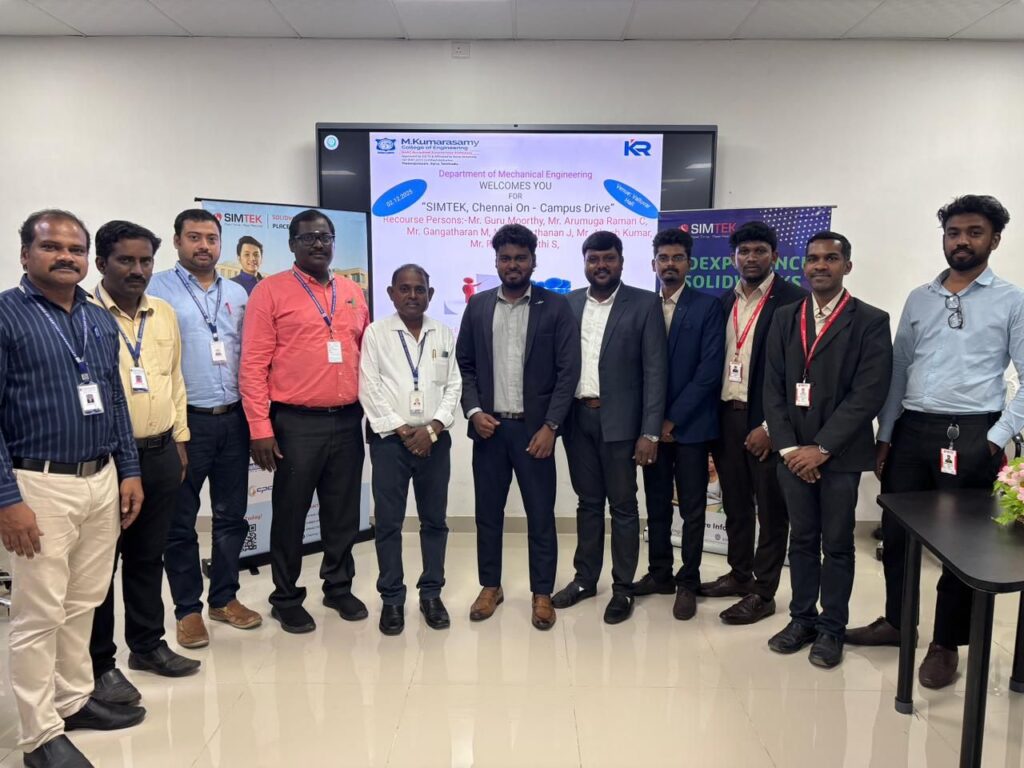
Campus Drive – M. Kumarasamy College of Engineering (Autonomous)
2-Day SOLIDWORKS & DraftSight Training – Murugappa Polytechnic College
Design of Industrial Components Using SOLIDWORKS
2-Day SOLIDWORKS Workshop – SRM Institute of Science and Technology
Value-Added Technical Support – SCSVMV (Sri Chandrasekharendra Saraswathi Viswa Mahavidyalaya)
Through these initiatives, over 500+ students were trained in real-world CAD, design, and drafting tools, helping bridge the gap between academic learning and industry expectations.
Driving Industry Growth Through High-Impact Seminars
SIMTEK also hosted powerful offline industry seminars that brought together professionals from manufacturing, aerospace, automotive, and product design sectors.
Major Industry Events – 2025
The Smarter CAD for Business Growth Event – 13 August 2025
Design Smarter with DraftSight 2025 – 16 August 2025
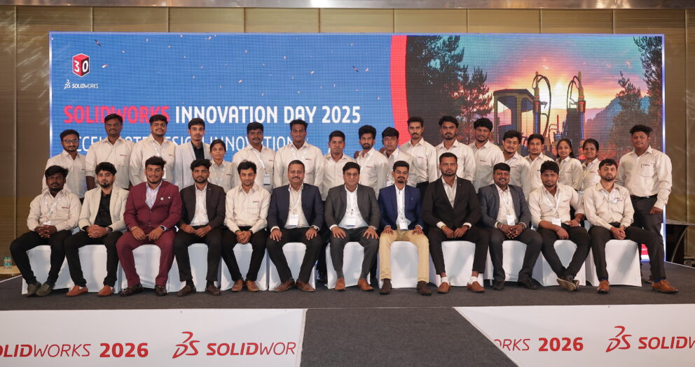
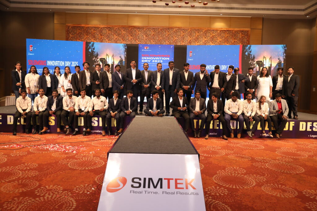
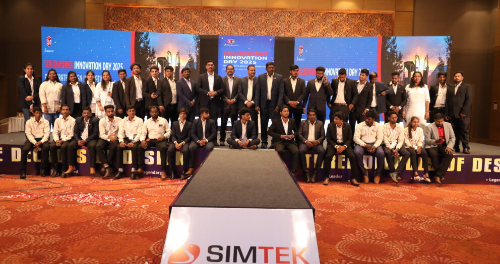
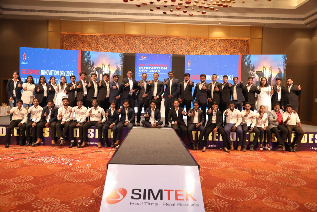
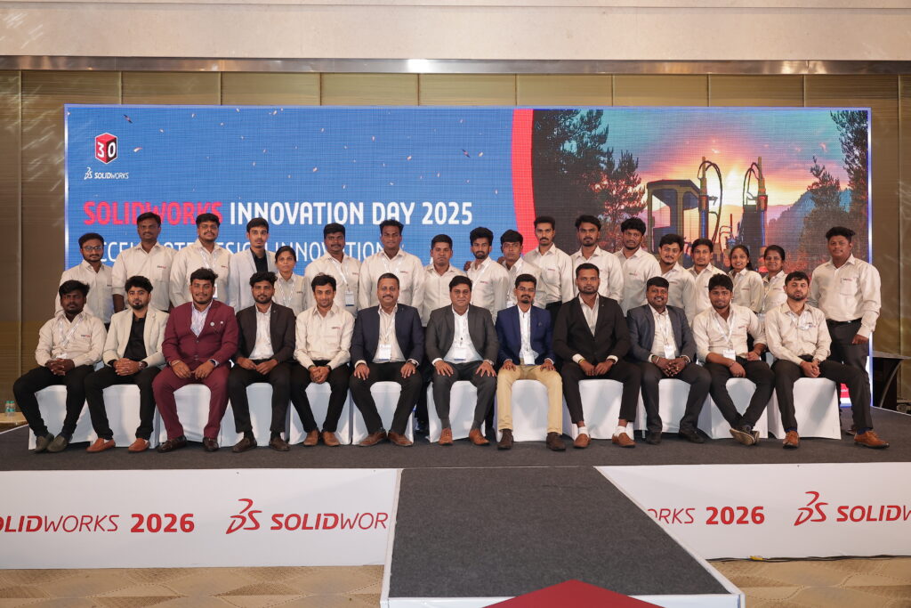
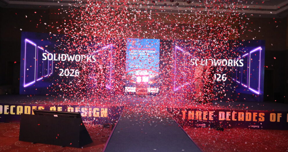
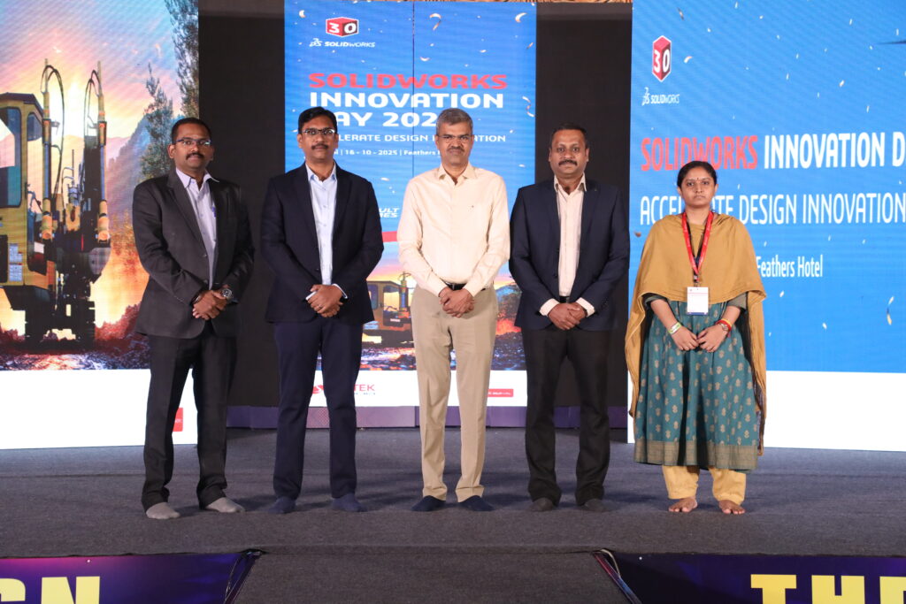
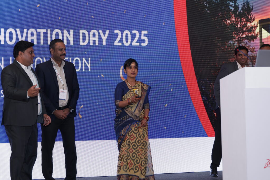
Innovation Day 2025 – Coimbatore – 08 October 2025
Innovation Day 2025 – Chennai – 16 October 2025
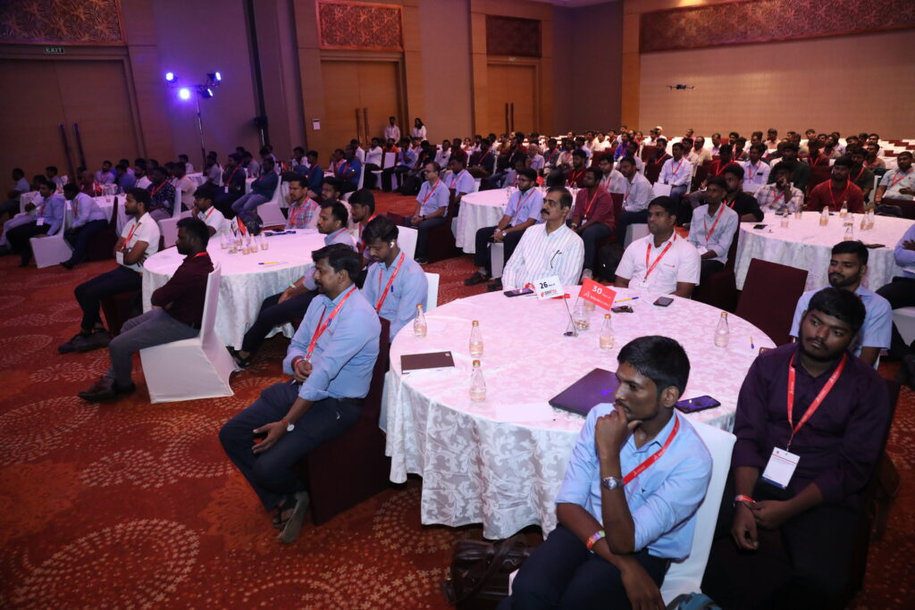
Each offline seminar attracted 80+ industry professionals, creating a platform for knowledge exchange, technology exploration, and future-ready engineering discussions.
Other impactful technical sessions included:
Unified Modeling & Simulation for Drone Industries
Synergizing Design and Simulation
Harmonizing Virtual Validation for Industrial Machinery
Reimagine Your CAD Data Management with 3DEXPERIENCE
From Imagination to Innovation – The Power of SOLIDWORKS
Faster Assembly Instructions = Faster Production (Composer in Manufacturing)
These events reinforced SIMTEK’s position as a trusted technology partner for digital design and simulation solutions.
2025 marked a defining chapter in SIMTEK’s growth journey. It was a year shaped by strong market momentum, deeper customer relationships, and a clear shift toward long-term digital engineering partnerships. With more than 75 new customers, over 50 existing customers expanding their engagement, and 7,500+ inquiries, support interactions, and training sessions, SIMTEK demonstrated how sales excellence and customer support, when aligned, create sustained business success.
This was not just a year of higher numbers—it was a year where trust, execution, and engineering expertise came together to create real impact for customers across India’s manufacturing and product development ecosystem.
Driving Growth Through the Right Technology Portfolio
At the heart of SIMTEK’s success in 2025 was a strong and future-ready portfolio. Customers did not just buy software—they invested in a connected ecosystem that supports design, simulation, manufacturing, and lifecycle management.
The key solutions that powered SIMTEK’s growth included:
SOLIDWORKS – The backbone of 3D design and engineering for hundreds of organizations
SIMULIA – Enabling advanced simulation, validation, and performance-driven design
CATIA – Supporting complex surface, product, and systems engineering
3DEXPERIENCE – Creating collaborative, cloud-based digital environments
DELMIA – Optimizing manufacturing, robotics, and digital process planning
Electrical Solutions – Supporting the fast-growing electrical and automation design market
These solutions allowed SIMTEK to serve companies at every stage of the product lifecycle—from concept and design to validation, manufacturing, and digital collaboration.
What made 2025 different was that customers increasingly chose multiple solutions together, rather than standalone products. Companies that started with SOLIDWORKS expanded into SIMULIA or 3DEXPERIENCE. Manufacturers moved from basic CAD into DELMIA-driven manufacturing planning. Electrical and automation teams integrated their workflows into the same digital platform.
This shift transformed SIMTEK from a software supplier into a long-term digital transformation partner.
75+ New Customers, 50+ Growing Relationships
Adding more than 75 new customers in a competitive engineering software market is no small achievement. But what made 2025 truly special was the 50+ existing customers who expanded their engagement with SIMTEK—through renewals, upgrades, new modules, and deeper solution adoption.
This reflects something powerful: customers stayed because SIMTEK delivered value.
These customers came from diverse industries such as:
Automotive & EV
Aerospace & Defense
Manufacturing & Machining
Heavy Engineering
Electronics
Tooling and Industrial Equipment
Across these sectors, SIMTEK was trusted not just for licenses, but for guidance, expertise, and dependable support.
Why Customers Chose SIMTEK Again and Again
In 2025, SIMTEK stood out because of how it combined technology with people, process, and commitment.
What made SIMTEK different:
Faster response than competitors Customers consistently experienced quick callbacks, rapid ticket resolution, and immediate engineering attention—critical in high-pressure design and production environments.
Strong pre-sales engineering SIMTEK’s sales team was backed by skilled application engineers who understood real-world engineering challenges. Customers did not get generic pitches—they received solution-driven recommendations.
Deep Dassault Systèmes expertise With strong capability across SOLIDWORKS, SIMULIA, CATIA, 3DEXPERIENCE, and DELMIA, SIMTEK delivered true platform-level consulting rather than just product selling.
Reliable post-sales support From installation to troubleshooting, SIMTEK remained involved long after the sale. This reliability built long-term trust.
Local presence with national reach SIMTEK’s teams across regions ensured customers got local attention with national-level capability.
Industry-specific solutioning Manufacturers, simulation teams, and design departments all received workflows tailored to their specific industry needs.
7,500+ Support, Training & Customer Engagements
One of the strongest indicators of SIMTEK’s operational excellence in 2025 was the scale of its customer engagement. Across the year, the SIMTEK team handled over 7,500+ interactions covering support, services, and training.
These included:
Software installation & upgrades – Ensuring customers always ran on stable, optimized systems
Technical troubleshooting – Fast resolution of critical engineering issues
Simulation & CAM support – Assisting engineers in solving real-world design and manufacturing challenges
User training – Helping teams become more productive and confident
3DEXPERIENCE onboarding – Supporting organizations as they transitioned to collaborative digital platforms
This massive volume of engagements shows that SIMTEK is not a passive vendor—it is an active partner in customers’ daily operations.
Sales and Support Working as One Engine
What made 2025 exceptional was how well SIMTEK aligned its sales, technical, and support teams. Instead of operating in silos, these teams worked as one unified customer success engine.
Sales teams identified business needs
Pre-sales engineers designed the right solution
Support teams ensured smooth deployment
Training teams helped users gain confidence
Customer success teams ensured long-term value
This cycle created momentum—happy customers led to renewals, upgrades, referrals, and new opportunities.
Building Long-Term Customer Trust
The most important outcome of 2025 was not just revenue growth—it was trust growth.
Customers continued with SIMTEK because they experienced:
Stable software environments
Faster engineering workflows
Reduced downtime
Better design and simulation outcomes
Confidence in their digital tools
That trust is what led to 50+ existing customers expanding their relationship with SIMTEK.
Looking Ahead: Stronger, Smarter, More Connected
The foundation built in 2025 positions SIMTEK for even greater success in the coming years. With a strong installed base, a growing ecosystem of 3DEXPERIENCE users, and deeper adoption of SIMULIA, DELMIA, and electrical solutions, SIMTEK is now helping customers move toward fully connected digital enterprises.
Conclusion
Sales & Support – A Year of Strong Growth is more than a headline. It reflects how SIMTEK combined:
75+ new customers
50+ expanding relationships
7,500+ service engagements
A powerful Dassault portfolio
And a customer-first culture
Together, these elements made 2025 a landmark year for SIMTEK—and laid the groundwork for an even more ambitious future.
In 2025, SIMTEK didn’t just host events — we created experiences that shaped how engineers think, design, and innovate. Throughout the year, hundreds of professionals joined us in a powerful journey of learning that spanned simulation, CAD, electrical design, PLM, and digital collaboration.
From drones and industrial machinery to electrical schematics and cloud-based platforms, every session helped participants answer one critical question:
“How can we build better products, faster?”
February – Starting the Year with Smarter Engineering
The year began with a strong focus on simulation-driven innovation.
On 18 February, SIMTEK hosted Unified Modeling and Simulation for Drone Industries, where engineers explored how SIMULIA tools help optimize flight performance, safety, and structural reliability — all before a physical prototype is built.
Just days later, on 26 February, Synergizing Design and Simulation showed how connecting CAD and CAE early in the design process reduces errors, shortens development cycles, and boosts product quality.
These two sessions set the tone for 2025: design smarter, validate earlier, and innovate faster.
March – Connecting Teams and Powering Electrical Design
March was all about collaboration and control.
On 11 March, Unlocking Innovation with 3DEXPERIENCE revealed how modern teams can collaborate securely in the cloud, manage data efficiently, and eliminate the chaos of disconnected files.
Then on 18 March, the spotlight turned to electrical engineering with Streamline Your Automation Equipment with Schematics and Wire Harness Design. Participants saw how SOLIDWORKS Electrical simplifies wiring, documentation, and automation design — saving time and reducing costly mistakes.
April – When Virtual Validation Becomes a Competitive Advantage
On 17 April, SIMTEK hosted Harmonizing Virtual Validation for Industrial Machinery. This session showed how manufacturers can digitally test machines before they are ever built, ensuring better performance, higher safety, and lower development risks.
For many attendees, it was a turning point in how they viewed simulation as a strategic business tool.
May – A Month of Digital Transformation
May was one of the most powerful months of the year.
On 7 May, From Chaos to Control helped companies take charge of their engineering data with SOLIDWORKS PDM, ensuring the right people always work on the right version.
On 10 May, Reimagine Your CAD Data Management with the 3DEXPERIENCE Platform showed how cloud-based PLM enables seamless collaboration across teams and locations.
On 15 May, SIMTEK demonstrated how SOLIDWORKS and DraftSight become even more powerful when connected to the 3DEXPERIENCE platform — accelerating product development like never before.
And on 20 May, From Imagination to Innovation: The Power of SOLIDWORKS inspired engineers to push boundaries using advanced design and simulation tools.
June – Making Teams Faster and Factories Smarter
June focused on productivity and execution.
On 10 June, Faster Assembly Instructions = Faster Production showed how SOLIDWORKS Composer improves communication between engineering and manufacturing.
On 24 June, Optimising Team Productivity Through PLM highlighted how modern PLM workflows help teams collaborate, control changes, and deliver better products — faster.
July – Electrifying Engineering Workflows
On 22 July, SIMTEK presented Design Smart. Go Beyond the Circuit, showing how SOLIDWORKS Electrical 2D and 3D bring electrical and mechanical teams together in one digital environment.
This session helped engineers move from disconnected drawings to fully integrated, production-ready designs.
August – CAD That Drives Business Growth
August brought two powerful offline seminars.
On 13 August, The Smarter CAD for Business Growth Event 2025 showed how modern CAD strategies directly impact profitability, productivity, and scalability.
On 19 August, Design Smarter with DraftSight 2025 proved that professional 2D drafting still plays a critical role in fast, accurate engineering.
September – Simulation and Multi-CAD Freedom
On 4 September, SIMULIA took center stage again, focusing on advanced simulation strategies.
On 18 September, 3D Creator & 3DEXPERIENCE for Multi-CAD demonstrated how cloud-based design supports teams working across multiple CAD tools — without losing control or collaboration.
October & November – Innovation That Lasts
On 14 October, Innovation Day brought the engineering community together to explore the future of digital design and manufacturing.
Finally, on 11 November, the DraftSight Seminar closed the year by reinforcing the importance of accurate, professional drafting in every engineering workflow.
Why SIMTEK’s Knowledge Platforms Matter
Every seminar and webinar in 2025 shared one purpose: to help customers become faster, smarter, and more competitive.
By turning complex technologies into practical insights, SIMTEK continues to lead not just through software — but through knowledge, guidance, and partnership.
In a powerful validation of its market leadership, customer-centric approach, and technical excellence, SIMTEK was honoured with multiple prestigious awards by Dassault Systèmes at the 3DEXPERIENCE Works India VAR Kick Off 2025, held on 06 February 2025 in Chandigarh.
This landmark recognition reflects not just performance metrics, but the deep trust, innovation culture, and customer success that SIMTEK consistently delivers across India’s manufacturing, engineering, and design ecosystem.
For SIMTEK, this moment is more than a trophy ceremony — it is a celebration of people, partnerships, and purpose.
A Strong Partnership Built on Innovation and Trust
Dassault Systèmes, the global leader in 3D design, engineering, and digital manufacturing platforms, recognizes its partners not only on revenue performance but also on technical capability, customer impact, and market leadership. Being honoured at the national level among VARs across India positions SIMTEK as one of the most trusted and high-performing Dassault partners in the country.
SIMTEK’s journey with Dassault Systèmes has always been anchored in one guiding philosophy:
“When our customers succeed, we succeed.”
From SOLIDWORKS design solutions to advanced 3DEXPERIENCE, electrical, simulation, and digital manufacturing platforms, SIMTEK has played a pivotal role in helping organizations modernize product development, accelerate innovation, and compete globally.
Awards That Define Excellence
At the 3DEXPERIENCE Works India VAR Kick Off 2025, SIMTEK received the following prestigious recognitions from Dassault Systèmes:
🏆 Best Sales FTE INDIA – 2024
Winner:Vijayanand R Senior Sales FTE – SIMTEK
This award recognizes exceptional sales leadership, customer relationship excellence, and strategic growth. Vijayanand’s ability to understand complex customer needs and deliver the right Dassault Systèmes solutions has played a major role in SIMTEK’s high-growth trajectory across India.
🏆 Best AE Electrical INDIA – 2024
Winner:Ragunathan G Senior Application Engineer – SIMTEK
Ragunathan was recognized for his outstanding expertise in electrical design and engineering solutions, helping customers implement advanced electrical workflows that improve accuracy, reduce rework, and accelerate time to market.
🏆 Best Design AE INDIA – Pre Sales 2024
Winner:Selvakumar B Senior Application Engineer – SIMTEK
This award celebrates Selvakumar’s excellence in pre-sales technical leadership, where his deep understanding of design engineering, product workflows, and customer challenges has helped SIMTEK win complex enterprise and mid-market projects.
Together, these awards highlight something powerful: SIMTEK is not just strong in sales — it is exceptional across the entire customer lifecycle, from pre-sales to implementation to long-term success.
Why SIMTEK Won: Performance with Purpose
SIMTEK’s recognition in 2025 is rooted in several key pillars that define how the company operates:
1. Highest SOLIDWORKS Growth
SIMTEK achieved one of the highest growth rates in SOLIDWORKS adoption, helping hundreds of organizations transition from legacy CAD tools to modern, connected 3D design platforms.
From startups to large manufacturing enterprises, SIMTEK enabled teams to design faster, collaborate better, and bring products to market more efficiently.
2. Strong Customer Retention
Winning customers is important — retaining and growing them is what defines excellence. SIMTEK’s strong focus on onboarding, training, and ongoing support has resulted in exceptionally high customer retention across India.
Customers don’t just buy software from SIMTEK — they gain a long-term technology partner.
3. Training & Certification Leadership
SIMTEK has invested heavily in certified engineers, structured training programs, and knowledge transfer. This ensures customers don’t just own software — they gain the skills to fully leverage it.
This focus on enablement directly contributes to higher adoption, stronger ROI, and long-term customer loyalty.
4. 3DEXPERIENCE Adoption
As Dassault Systèmes shifts the industry toward platform-based digital engineering, SIMTEK has been at the forefront of driving 3DEXPERIENCE adoption.
From cloud-based collaboration to connected product development, SIMTEK is helping Indian companies move into the future of digital manufacturing.
5. Large Enterprise Wins
SIMTEK has successfully delivered complex deployments across automotive, aerospace, industrial equipment, electronics, and manufacturing sectors — proving its ability to scale from small teams to enterprise-wide implementations.
A People-Driven Success Story
While awards are presented to individuals, SIMTEK’s leadership emphasizes that these wins belong to every engineer, sales professional, support specialist, and operations team member who contributes behind the scenes.
A senior SIMTEK leader shared:
“These awards are a reflection of the discipline, passion, and customer focus that our teams bring every single day. We don’t chase numbers — we chase customer success, and that is what drives sustainable growth.”
Dassault Systèmes also acknowledged SIMTEK’s contribution to the Indian market:
“SIMTEK continues to demonstrate what a high-performing VAR looks like — strong technical depth, customer-centric engagement, and consistent market leadership.”
More Than Awards — A Signal to the Market
These 2025 recognitions send a strong message to customers, partners, and the industry:
✔ SIMTEK is a trusted Dassault Systèmes partner ✔ SIMTEK delivers measurable business outcomes ✔ SIMTEK invests in people, skills, and innovation ✔ SIMTEK is positioned for future-ready digital engineering
For customers, this means confidence. For employees, it means pride. For partners, it means reliability.
Looking Ahead: Building the Future Together
SIMTEK is not slowing down.
With growing investments in advanced simulation, electrical design, digital manufacturing, and 3DEXPERIENCE platform services, SIMTEK is committed to helping Indian engineering organizations compete on a global scale.
These 2025 awards are not the end of a journey — they are the foundation for the next phase of growth.
A Proud Moment for SIMTEK
Winning three national-level awards from Dassault Systèmes is a rare and prestigious achievement. It reflects not just what SIMTEK has accomplished, but who SIMTEK is — a company driven by innovation, integrity, and customer success.
To Vijayanand R, Ragunathan G, Selvakumar B, and every SIMTEK team member — this success belongs to you.
Congratulations on making SIMTEK one of India’s most respected Dassault Systèmes partners in 2025. 🏆
In 2025, SIMTEK reached a new level of collaboration and operational excellence through a series of structured and strategic visits from our OEM partner, Dassault Systèmes. These monthly engagements across SIMTEK’s Chennai, Coimbatore, and Kolhapur locations played a defining role in aligning our business, technical, and customer success strategies.
More than routine partner meetings, these visits were purposeful working sessions designed to strengthen performance, deepen mutual understanding, and ensure that SIMTEK continues to deliver world-class engineering, design, and digital manufacturing solutions to customers across India.
The ongoing presence of the Dassault Systèmes leadership and technical teams reinforced the shared commitment of both organizations to innovation, customer success, and market leadership.
A Partnership Built on Alignment and Trust
SIMTEK’s relationship with Dassault Systèmes has always been rooted in shared values — technology leadership, engineering excellence, and long-term customer success. In 2025, this partnership matured further through monthly OEM visits, creating an environment of constant alignment and collaboration.
These visits ensured that SIMTEK was always in sync with Dassault Systèmes’ global strategy, product roadmap, and market priorities. They allowed both teams to jointly evaluate performance, review progress against goals, and identify opportunities for growth.
Through open dialogue and structured engagement, SIMTEK and Dassault Systèmes were able to move faster, execute better, and stay ahead of evolving customer and industry demands.
OEM Leadership Engagement Across SIMTEK Locations
Throughout 2025, Dassault Systèmes’ senior leadership and domain experts actively visited SIMTEK offices in Chennai and Coimbatore, working closely with SIMTEK’s management, sales, technical, and customer success teams.
Coimbatore Visits
The Coimbatore office hosted key leaders from Dassault Systèmes who focused on enterprise engagement, regional sales strategy, and partner development:
Theerthagiri – Head, Enterprise Engagements
Mithun – Regional Sales Director, SOLIDWORKS
Ramki – Director, SOLIDWORKS & 3DEXPERIENCE Works
Sneha – Partner Sales Manager, DraftSight
These sessions in Coimbatore strengthened SIMTEK’s regional market execution, partner alignment, and enterprise engagement strategy, ensuring the team was well positioned to serve manufacturing and engineering customers across Tamil Nadu and neighboring regions.
Chennai Visits
The Chennai office hosted Dassault Systèmes’ senior leadership and simulation experts, focusing on business growth, advanced technologies, and strategic customer engagement:
Pradeep Niduram – Senior Manager, Industry Consultant, Dassault Systèmes
Sandeep – India Business Manager, Simulation (3DEXPERIENCE Works)
Gopinath – Simulation Technical Manager, India
Mithun – Regional Sales Director, SOLIDWORKS
Ramki – Director, SOLIDWORKS & 3DEXPERIENCE Works
Sneha – Partner Sales Manager, DraftSight
These engagements in Chennai enabled deep technical, commercial, and strategic alignment, particularly in advanced areas such as simulation, digital engineering, and platform-based product development.
Their presence at SIMTEK offices brought strong leadership visibility, operational clarity, and strategic focus, enabling real-time discussions, joint planning, and effective problem-solving..
Strategic Objectives of the OEM Visits
Each visit followed a well-defined agenda focused on multiple dimensions of business and technical performance. The key objectives included:
Business Strategy Alignment
Dassault Systèmes and SIMTEK leadership worked closely to align on regional and industry-specific strategies. These sessions ensured that SIMTEK’s go-to-market approach, vertical focus, and sales priorities were in line with Dassault Systèmes’ global vision.
Partner Performance Reviews
Detailed performance reviews helped both organizations evaluate pipeline health, deal progress, customer engagement, and revenue growth. This allowed SIMTEK to fine-tune execution and continuously improve outcomes.
Technical Roadmap Planning
With Dassault Systèmes continuously innovating across SOLIDWORKS, SIMULIA, DELMIA, and the 3DEXPERIENCE platform, these visits ensured SIMTEK stayed fully aligned with future technology directions and solution strategies.
Training and Enablement
OEM teams supported SIMTEK’s technical and sales teams through product updates, positioning guidance, and enablement sessions, ensuring that SIMTEK professionals were always equipped with the latest knowledge.
Customer Success and Market Expansion
Joint reviews of key customer accounts and target markets helped SIMTEK strengthen customer relationships while identifying new growth opportunities.
New Product Launches
Dassault Systèmes shared updates on upcoming releases and new capabilities, enabling SIMTEK to prepare go-to-market strategies well in advance.
High-Impact Engagements During the Visits
Every OEM visit included a wide range of high-value activities that directly strengthened SIMTEK’s execution and customer engagement.
Product Demonstrations
Dassault Systèmes teams conducted in-depth demonstrations of the latest software releases and platform capabilities, helping SIMTEK teams better understand features, benefits, and competitive positioning.
Joint Customer Meetings
OEM representatives participated in key customer meetings alongside SIMTEK teams. These interactions enhanced credibility, built customer confidence, and enabled deeper solution discussions.
Factory and Customer Site Visits
On-site visits provided OEM teams with real-world insight into customer operations, challenges, and expectations, enabling more relevant solution recommendations.
Team Workshops
Cross-functional workshops between SIMTEK and Dassault Systèmes teams improved alignment between sales, pre-sales, technical, and support teams.
Technology and Roadmap Discussions
Strategic discussions ensured SIMTEK was fully prepared to support customers as they adopt new technologies and transition to next-generation digital platforms.
Driving Customer Success Through OEM Collaboration
One of the most significant outcomes of the OEM visits was the direct impact on customer success. By working closely with Dassault Systèmes experts, SIMTEK was able to deliver:
More accurate solution recommendations
Faster and more effective implementations
Better customer engagement strategies
Improved technical support outcomes
This collaboration allowed SIMTEK to act not just as a reseller, but as a trusted digital transformation partner to its customers.
Enhancing SIMTEK’s Market Position
The consistent presence of Dassault Systèmes leadership also strengthened SIMTEK’s position in the market. Customers, prospects, and industry stakeholders could clearly see that SIMTEK was closely connected to the OEM, giving them confidence in SIMTEK’s long-term capabilities, technical expertise, and strategic stability.
This enhanced credibility helped SIMTEK:
Win larger and more complex deals
Strengthen relationships with enterprise customers
Expand into new industry segments
Empowering SIMTEK Teams
Beyond business outcomes, the OEM visits had a powerful impact on SIMTEK’s internal teams. Direct interaction with Dassault Systèmes leaders and experts motivated employees, increased knowledge sharing, and created a strong sense of partnership and pride.
Sales teams gained sharper positioning skills, technical teams gained deeper product understanding, and support teams benefited from improved alignment with OEM best practices.
A Foundation for Long-Term Growth
The OEM visits in 2025 laid a strong foundation for SIMTEK’s future. By maintaining close alignment with Dassault Systèmes, SIMTEK is well positioned to lead customers through the next phase of digital transformation, simulation-driven design, and platform-based product development.
These visits ensured that SIMTEK is not only ready for today’s challenges, but prepared for tomorrow’s opportunities.
Looking Ahead
As SIMTEK moves forward, the collaboration with Dassault Systèmes will continue to be a cornerstone of our success. The strong relationships, shared goals, and operational alignment built in 2025 will drive even greater achievements in the years to come.
Together, SIMTEK and Dassault Systèmes remain committed to delivering innovation, excellence, and lasting value to every customer we serve.
2025 marked a transformative year for SIMTEK, as we took a major step forward in strengthening our digital manufacturing ecosystem with the addition of two world-class CAM solutions — GibbsCAM and Cimatron. These strategic partnerships represent far more than a portfolio expansion. They reflect SIMTEK’s unwavering commitment to empowering manufacturers, toolmakers, and industrial innovators with the most advanced, reliable, and future-ready technologies available globally.
In a rapidly evolving manufacturing landscape, the need for precision, speed, automation, and digital continuity has never been greater. With GibbsCAM and Cimatron now part of the SIMTEK family, we are uniquely positioned to deliver a truly end-to-end manufacturing workflow — from design and simulation all the way to machining and tooling.
This milestone reinforces SIMTEK’s role as not just a software reseller, but a strategic technology partner for India’s manufacturing growth.
Why 2025 Was the Right Time for This Expansion
Over the last few years, Indian manufacturing has undergone a powerful transformation. Customers across automotive, aerospace, industrial machinery, consumer products, and precision engineering are demanding:
Faster time to market
Higher machining accuracy
Greater automation
Reduced material waste
Better utilization of CNC machines
Digital integration between design and production
SIMTEK has always been at the forefront of this evolution, providing industry-leading solutions in CAD, PLM, simulation, and digital collaboration. However, as more customers looked to digitally connect their design teams with their shop floors, the need for advanced CAM and tooling solutions became increasingly clear.
The addition of GibbsCAM and Cimatron fills this critical gap and enables SIMTEK to offer a complete digital manufacturing ecosystem — one that supports the entire product lifecycle, from concept to finished part.
GibbsCAM is globally recognized as one of the most reliable and efficient CAM systems for CNC programming and machining. Used by thousands of manufacturers worldwide, it is trusted for its speed, flexibility, and machining accuracy.
With GibbsCAM, CNC programmers and production teams gain access to:
Advanced 2-axis to 5-axis machining
Multi-tasking and mill-turn operations
Automated toolpath generation
Collision detection and verification
Faster setup and reduced programming time
For manufacturers, this translates into:
Reduced cycle times
Improved machine utilization
Fewer errors and rework
Higher throughput on the shop floor
By integrating GibbsCAM into SIMTEK’s portfolio, we now empower customers to seamlessly move from SOLIDWORKS and 3DEXPERIENCE designs directly into production-ready CNC programs — accelerating the journey from digital model to physical product.
Introducing Cimatron – The Gold Standard for Tooling and Mold Making
While GibbsCAM strengthens CNC machining, Cimatron brings unmatched capabilities to tooling, mold, and die manufacturing. It is widely regarded as the industry’s leading CAD-CAM solution for mold makers and toolrooms.
Cimatron provides:
Advanced mold and die design tools
Automated electrode creation
High-speed machining strategies
Core, cavity, and parting surface workflows
Integrated CAD and CAM for tooling
For toolmakers and mold manufacturers, this means:
Shorter design-to-production cycles
Fewer design errors
Better surface quality
Faster delivery to customers
With Cimatron, SIMTEK now serves not only product manufacturers, but also the tooling backbone of India’s manufacturing ecosystem — the mold makers and toolrooms that drive quality, consistency, and innovation across industries.
One Unified Manufacturing Ecosystem
With the addition of GibbsCAM and Cimatron, SIMTEK now offers something truly powerful: a complete, digitally connected manufacturing workflow.
Our customers can now rely on SIMTEK for:
Stage
Technology
Product Design
SOLIDWORKS
Product Lifecycle
3DEXPERIENCE
Simulation & Validation
SIMULIA
CNC Programming
GibbsCAM
Tooling & Mold Making
Cimatron
This creates a single source of truth for product data, eliminates silos, and ensures that what is designed, simulated, and approved is exactly what gets manufactured.
For customers, this means:
Less data loss
Fewer errors
Faster engineering changes
Better collaboration between design and production teams
What This Means for SIMTEK Customers
The real impact of these partnerships is felt on the shop floor and in engineering departments across India.
Customers now benefit from:
A single technology partner instead of multiple vendors
Integrated workflows from CAD to CAM
Local training, implementation, and support
Proven global software with SIMTEK’s expertise
Whether a company is manufacturing automotive components, aerospace parts, industrial machinery, or consumer products, SIMTEK can now support them at every stage of production.
Driving India’s Industry 4.0 Vision
India is moving rapidly toward smart manufacturing and Industry 4.0. Digital twins, CNC automation, connected factories, and data-driven production are no longer future concepts — they are today’s competitive necessities.
GibbsCAM and Cimatron are perfectly aligned with this transformation. When combined with SIMTEK’s CAD, PLM, and simulation solutions, they enable:
Digital continuity
Automated machining
Real-time production intelligence
Reduced dependency on manual processes
This positions SIMTEK as a key enabler of India’s advanced manufacturing ambitions.
SIMTEK’s Commitment Beyond Software
What makes these partnerships truly powerful is not just the technology — it is the SIMTEK way of delivering it.
Customers receive:
Expert consulting
Implementation support
Custom training programs
Ongoing technical assistance
Industry-specific best practices
This ensures that GibbsCAM and Cimatron do not remain just tools, but become strategic assets that deliver measurable ROI.
Looking Ahead
The addition of GibbsCAM and Cimatron in 2025 is only the beginning. These partnerships open new doors for:
Advanced CNC automation
High-precision tooling
Digital factory initiatives
Export-ready manufacturing
As SIMTEK continues to grow, our mission remains unchanged: To empower engineers, manufacturers, and innovators with world-class technology and world-class support.
From the first sketch to the final machined part —SIMTEK is your partner in manufacturing excellence.
Beyond technology and training, SIMTEK is a workplace where people feel valued, connected, and celebrated. Every occasion in 2025 was an opportunity to bring our teams together and strengthen our culture of respect and togetherness.
Pongal Celebration
SIMTEK welcomed the harvest festival of Pongal with traditional rituals, decorations, and team gatherings. The celebration reflected gratitude, prosperity, and the spirit of unity that defines our workplace.
Diwali Celebration
Diwali at SIMTEK was filled with light, joy, and positivity. Employees came together to celebrate success, teamwork, and the shared journey of growth that the festival represents.
Ayudha Pooja
Ayudha Pooja was observed with reverence, honoring the tools, technology, and knowledge that power SIMTEK’s engineering excellence. It reinforced respect for craftsmanship and professional dedication.
Christmas Celebration
Christmas brought warmth and cheer across SIMTEK offices. The celebration created moments of togetherness, laughter, and appreciation, strengthening bonds across teams.
Men’s Day
Men’s Day was celebrated by recognizing the dedication, leadership, and contributions of our male colleagues, reinforcing a culture of appreciation and mutual respect.
Women’s Day
Women’s Day at SIMTEK honored the talent, resilience, and achievements of our women professionals, celebrating their role in shaping innovation and organizational success.
Cherishing Milestones and Anniversaries
Throughout the year, cake cutting moments marked milestones, birthdays, achievements, and special occasions, adding joy and a personal touch to the workplace.
Team Bonding Beyond the Office
SIMTEK believes that great teams are built not only through work but through shared experiences.
Monthly Playoff – Turf Matches
These energetic sporting events encouraged teamwork, healthy competition, and stress relief, helping employees connect beyond their daily roles.
Team Dinners
Team dinners provided a relaxed environment for colleagues to bond, celebrate wins, and build stronger interpersonal relationships.
Office Renovation Day
Renovation Day brought employees together to refresh and enhance the workplace, reinforcing a sense of ownership and pride in the SIMTEK environment.
Wayanad Team Trip
The Wayanad trip was a memorable experience that strengthened friendships, encouraged relaxation, and created lasting team memories outside the office.
Annual Award Event
The Annual Award Event celebrated achievements, dedication, and long-term commitment, reinforcing SIMTEK’s culture of recognition and excellence.
These activities enhanced collaboration, boosted morale, and made SIMTEK a place where people love to work.
Honoring Loyalty & Excellence
One of the proudest moments of 2025 was the Award Event Night, where employees who crossed their milestones and those recognized by Dassault Systèmes were honored with official awards and certificates.
Car Gifting Ceremony
The highlight of the evening was the Car Gifting Ceremony, where leaders who completed 10+ years of dedicated service were presented with cars as a symbol of SIMTEK’s deep respect for loyalty, leadership, and long-term commitment.
This milestone reflected SIMTEK’s philosophy:
When our people grow, the company grows.
SIMTEK Culture 2025 – Where People and Innovation Thrive
SIMTEK Culture & Celebrations 2025 was more than a series of events — it was a reflection of who we are.
From training future engineers… To empowering industry professionals… To celebrating festivals, friendships, and long-serving leaders…
SIMTEK continues to be a workplace where innovation meets inspiration, and every success is celebrated together.
Bringing the Future of Design & Engineering to Chennai and Coimbatore
In an era where engineering innovation is redefining how industries design, simulate, and manufacture products, SIM Technologies once again demonstrated its leadership by hosting Innovation Day 2025 – the SOLIDWORKS 2026 Grand Launch.
With two successful and high-impact events held in Coimbatore on 08 October 2025 at O by Radha and Chennai on 16 October 2025 at Feathers Hotel, Innovation Day brought together engineering professionals, academic leaders, students, and industry experts for a full day of technology, learning, and inspiration.
This year’s Innovation Day was more than a product launch—it was a celebration of how SOLIDWORKS 2026 and the 3DEXPERIENCE platform are shaping the future of digital engineering.
A Platform for Industry, Academia, and Innovation
Innovation Day 2025 was designed to serve as a common platform where industry and academia met technology. Engineers, manufacturing professionals, design consultants, faculty members, and students came together with a shared objective—to explore how the latest advancements in SOLIDWORKS 2026 can accelerate innovation, productivity, and business growth.
With India emerging as a global hub for product design, manufacturing, and R&D, SIM Technologies ensured that users in Tamil Nadu’s two major engineering hubs—Coimbatore and Chennai—received first-hand access to the latest SOLIDWORKS roadmap and future-ready technologies.
The presence of experts from Dassault Systèmes, leading industry professionals, and academic leadership from VIT Chennai elevated the event into a truly world-class engineering forum.
Coimbatore Chief Guest – Industry Perspective on Innovation
The Coimbatore edition of Innovation Day 2025 was further elevated by the presence of Ms. Sripriya Gowrisankar from BESTEN Group of Companies, who graced the event as the Chief Guest.
In her address, Ms. Sripriya shared valuable insights on how digital engineering, smart manufacturing, and data-driven design are transforming modern enterprises. Drawing from BESTEN Group’s real-world industrial experience, she emphasized that platforms like SOLIDWORKS and 3DEXPERIENCE are no longer optional tools but essential engines of growth for organizations that aim to remain competitive, efficient, and globally relevant.
Her inspiring message strongly resonated with industry professionals and students alike, reinforcing how SOLIDWORKS 2026 enables companies to design faster, innovate smarter, and deliver better products to market.
Powerful Keynotes That Set the Vision
A major highlight of Innovation Day 2025 was the leadership keynote sessions delivered by Dassault Systèmes experts, industry leaders, and the Dean from VIT Chennai. These sessions focused on:
The evolving role of AI in engineering design
The shift towards cloud-based collaboration
How simulation is becoming the foundation of innovation
Preparing the next generation of engineers for Industry 4.0 and beyond
Speakers emphasized that modern engineering is no longer limited to CAD modeling alone. It now involves intelligent design, integrated simulation, data-driven decisions, and cloud collaboration—all of which are built into SOLIDWORKS 2026 and the 3DEXPERIENCE ecosystem.
SOLIDWORKS 2026 – Redefining What Engineers Can Do
At the heart of Innovation Day was the much-anticipated SOLIDWORKS 2026 Grand Launch. Attendees got a detailed look at how the newest version pushes the boundaries of what engineers can achieve.
Key Highlights of SOLIDWORKS 2026
1. AI-Driven Design Intelligence
SOLIDWORKS 2026 introduces smarter, AI-powered tools that assist engineers in:
Predicting design errors
Suggesting optimal geometries
Reducing repetitive tasks
Improving model quality automatically
This allows designers to focus more on innovation and creativity rather than manual rework.
2. Advanced Simulation Upgrades
With stronger integration of simulation tools, engineers can now:
Test designs earlier
Run faster FEA and CFD analyses
Validate real-world performance in real time
This ensures better product quality, fewer failures, and faster time to market.
3. Seamless Cloud Collaboration
SOLIDWORKS 2026 is deeply integrated with the 3DEXPERIENCE platform, enabling:
Cloud-based file management
Team collaboration across locations
Real-time design sharing
Secure data control
Whether teams are working from Chennai, Coimbatore, or globally, collaboration is now frictionless.
4. Faster, More Powerful Modeling
Performance enhancements allow engineers to:
Handle larger assemblies
Work with complex surfaces
Experience smoother rendering and drafting
This translates into higher productivity and fewer slowdowns, even for complex industrial projects.
Live Demos, Hands-On Labs, and Real-World Use Cases
Innovation Day was designed to be highly interactive. Instead of just listening to presentations, attendees participated in:
Live SOLIDWORKS 2026 demonstrations
Hands-on labs
Real customer success stories
Technology roadmap walkthroughs
Engineers saw exactly how:
AI simplifies modeling
Simulation improves design decisions
Cloud collaboration eliminates data silos
3DEXPERIENCE connects the entire product lifecycle
This made the technology not just impressive—but practical and actionable.
Customer Success Stories That Inspired
Another powerful segment of Innovation Day was the customer success stories, where companies shared how SOLIDWORKS and SIM Technologies helped them:
Reduce product development time
Improve design accuracy
Lower prototyping costs
Collaborate better across teams
These real-world stories reinforced that SOLIDWORKS is not just software—it is a business transformation tool.
Awards & Recognition – Celebrating Excellence
Innovation Day 2025 also recognized outstanding users, partners, and innovators. The awards segment celebrated companies and individuals who have successfully leveraged SOLIDWORKS to achieve excellence in design, engineering, and innovation.
This recognition reinforced SIM Technologies’ commitment to not just selling software—but building a thriving engineering community
Special Offers, Trials & Onboarding Programs
To ensure attendees could immediately begin their digital transformation, SIM Technologies introduced:
Exclusive event-only offers
Special pricing plans
Free trials
Onboarding and training programs
These initiatives made it easier for organizations and students to adopt SOLIDWORKS 2026 and the 3DEXPERIENCE platform without barriers.
SIM Technologies – Driving the Engineering Ecosystem
As the organizer of Innovation Day 2025, SIM Technologies once again demonstrated its leadership as a trusted SOLIDWORKS partner and technology enabler in South India.
Through:
Events
Training
Support
Consulting
Digital transformation initiatives
SIM Technologies is empowering companies and institutions to design better, simulate smarter, and innovate faster.
Conclusion: A Grand Step Into the Future
Innovation Day 2025 was not just about launching SOLIDWORKS 2026—it was about launching the next era of digital engineering in India.
From AI-driven design and powerful simulation to cloud collaboration and integrated workflows, SOLIDWORKS 2026 is set to redefine how products are imagined, designed, and delivered.
With successful events in Coimbatore and Chennai, SIM Technologies has once again proven that the future of engineering is not somewhere far away—it is happening right here, right now.
Gifted Cars to Our Leaders: Recognising 10+ Years of Service, Leadership and Excellence at SIMTEK
At SIMTEK, we firmly believe that an organisation’s greatest strength lies in its people. While technology, innovation and market leadership define what we do, it is the dedication, loyalty and professionalism of our employees that truly define who we are.
In recognition of this belief, SIMTEK recently marked a proud milestone by awarding Tata Punch cars to three of its most respected and long-serving leaders:
Mr. Mohanraj – Executive Director
Mr. Anand – Head Office Sales Manager
Mr. Caine Newton – Branch Sales Manager, Coimbatore
Each of these leaders has completed more than 10 years of exemplary service at SIMTEK, contributing significantly to the company’s sustained growth, strong customer relationships and organisational stability.
This initiative reflects SIMTEK’s continued commitment to recognising loyalty, leadership and long-term contribution in a meaningful and lasting way.
Recognising Commitment Beyond Performance
In a highly competitive and fast-changing business environment, long-term commitment is a rare and valuable asset. At SIMTEK, we deeply value employees who demonstrate not only high performance, but also consistency, integrity and dedication over many years.
The decision to honour these three leaders was based not only on their individual achievements, but on their sustained contribution to the organisation’s journey. Over the past decade, they have played a pivotal role in shaping SIMTEK’s growth, strengthening customer trust and building high-performing teams across the organisation.
By recognising 10+ years of service with a life-enhancing reward, SIMTEK reinforces a simple yet powerful principle: loyalty and leadership deserve lasting recognition.
Why SIMTEK Chose to Gift Cars
A car represents progress, reliability and independence—qualities that closely reflect the professional journeys of the award recipients. By presenting Tata Punch cars, SIMTEK chose a reward that is both practical and symbolic.
The Tata Punch stands for:
Strength and dependability
Modern design and efficiency
Long-term value
These attributes mirror the qualities that Mr. Mohanraj, Mr. Anand and Mr. Caine Newton have consistently demonstrated throughout their tenure at SIMTEK.
This recognition goes beyond a momentary reward. It is an expression of respect and appreciation for the years of dedication that have helped build SIMTEK into the organisation it is today.
Honouring Three Leaders Who Have Shaped SIMTEK
Mr. Mohanraj – Executive Director
With more than a decade of service, Mr. Mohanraj has been a driving force behind SIMTEK’s strategic direction and organisational development. His leadership has been instrumental in strengthening SIMTEK’s market position, expanding its service offerings and nurturing a culture of accountability and excellence.
Under his guidance, SIMTEK has grown into a trusted partner for engineering and digital manufacturing solutions, supported by a strong and motivated workforce.
Mr. Anand – Head Quarters Sales Manager
Mr. Anand has been a cornerstone of SIMTEK’s sales operations for over ten years. Through his leadership, dedication and customer-focused approach, he has played a vital role in expanding SIMTEK’s client base and strengthening long-term relationships.
His ability to guide teams, maintain consistent performance and uphold SIMTEK’s values has made a significant impact on the organisation’s success.
Mr. Caine Newton – Branch Sales Manager, Coimbatore
As the Branch Sales Manager for Coimbatore, Mr. Caine Newton has been instrumental in building SIMTEK’s presence in the region. Over the past decade, he has contributed to business growth, team development and customer engagement, ensuring SIMTEK’s high standards are delivered consistently at the regional level.
His leadership has helped establish Coimbatore as an important and successful part of SIMTEK’s overall operations.
A Milestone That Reflects SIMTEK’s Values
The presentation of the Tata Punch cars was a proud moment for the entire SIMTEK organisation. It reflected not only the achievements of three individuals, but also the values that guide the company—integrity, respect, loyalty and long-term partnership.
Such initiatives reinforce a culture where employees feel valued, supported and motivated to contribute their best. When people know their efforts are recognised in meaningful ways, it creates a strong sense of belonging and commitment.
A Message to Every SIMTEK Employee
This recognition sends a clear message to all members of the SIMTEK family: your dedication and long-term contribution matter.
SIMTEK is committed to creating an environment where employees can grow, build lasting careers and be recognised for the value they bring to the organisation. The company believes that investing in people is the foundation for sustainable success.
Looking Forward
As SIMTEK continues to expand and innovate, the organisation remains firmly committed to honouring the people who make that growth possible. Initiatives such as this reflect SIMTEK’s focus on building a stable, motivated and high-performing workforce.
By recognising loyalty and leadership in a meaningful way, SIMTEK continues to strengthen its culture and reinforce its position as an employer of choice.
Customized reports in SOLIDWORKS Electrical are essential for producing accurate, professional, and customer-ready documentation. They allow engineers to modify default report formats by changing columns, filters, sorting, formulas, and layouts to match company and customer standards. Customized reports reduce manual work in Excel, improve manufacturing accuracy, support audit requirements, and help different teams—such as wiring, purchase, and panel assembly—receive exactly the information they need. SOLIDWORKS Electrical 2026 offers improved formula validation, cleaner formatting tools, and faster exporting, making customized reporting even more powerful and efficient.
What Are Customized Reports?
Customized reports are modified versions of standard SOLIDWORKS Electrical reports designed to match company standards, customer needs, and project formats.
Why We Use Customized Reports
To ensure accurate documentation, reduce errors, save time, eliminate manual editing, and meet industry/customer formatting requirements.
Company Standards & Customer Requirements
Reports can be adjusted to follow specific styles—such as wire list formats, cable schedules, or BOM layouts—that different companies and customers demand.
Benefits for Manufacturing & Wiring Teams
Customized wire lists, cable lists, and terminal reports reduce wiring mistakes and improve assembly accuracy.
Open Report Manager → Duplicate report → Modify columns → Apply filters → Add sorting/grouping → Insert formulas → Edit title block → Add report to project.
2026 Enhancements
New formatting tools, better formula validation, faster export, and improved PLC/cable report fields.
Final Outcome
Customized reports give clear, reliable, professional, and error-free documentation across all stages of a project
Create a Customized Report
Open Report Manager
Open your project in SOLIDWORKS Electrical. Go to the Project tab → Reports → Report Manager. This opens the list of available reports for the current project
Duplicate a Default Report
Select the report you want to customize (for example, Wire List). Right-click the report and choose Properties. Go to the Columns tab, then right-click on any column header and select Column Configuration. In the configuration window, choose the options you need by adding, removing, or rearranging columns as required. Once you have completed your custom settings, click OK to apply the changes.
Edit Columns
Open the duplicated report and go to the Columns tab. Add fields you need (From component, to component, Cable core, Manufacturer part, etc.), remove unwanted fields, reorder columns with the arrow buttons, and set column widths and alignment. Choose field labels that match company or customer terminology.
Insert Formulas and Expressions
In the Fields or Formulas section, add custom expressions to format data. Examples for Routing report formula on:
Validate formulas using the built-in checker (if available) and test on a small dataset.
Format Layout
Edit font sizes for headers and rows, add bolding for section headers, set merge rows, width, separator, valve range and add borders for printed clarity. Save a template if you plan to reuse the style.
Preview and Test
Before adding the report to the project, run a preview. Check for missing fields, incorrect sorting, or filter mistakes. Export to Excel or PDF in preview mode to verify formatting and column widths. Make iterative changes until the output matches requirements.
After completing all your column settings and customizations, click Apply to save the changes. Your routing report is now fully updated and ready to use. With this, the customization process is finished.
Generated Drawing – Final Output
When the customized report or routing data is applied inside SOLIDWORKS Electrical, the final generated drawing provides a clean, structured, and production-ready representation of your schematic or report output.
What the Final Output Includes
Clean Layout with Updated Fields
All customized column names, labels, formulas, and routing information appear neatly formatted according to your template settings.
Automatic From–To Wire Details
If formulas were used (From–To, Deck, Terminal, Cable Core), the drawing shows accurate, auto -generated information without manual editing.
Professional Table Format
Your drawing sheet includes:
Proper column widths
Header formatting
Borders and alignment
Company-standard labelling
No Duplicate Data
Because filtering/sorting rules are applied, the final output avoids:
Duplicate wires
Repeated terminals
Incorrect routing paths
Ready for PDF, Excel, or Print
The generated drawing can be directly exported to:
PDF (for submission)
Excel (for wiring teams)
DWG (if required for CAD sharing)
How It Looks (Description)
Your final drawing will appear like:
Title block updated
Wire list / routing table neatly placed
From–To information fully resolve
Cable cores properly listed
Clean, aligned, error-free layout
Benefits of Customized Reports
Saves Time
No more manual editing or formatting.
Reduces Wiring & Assembly Errors
Accurate information with formulas and conditions.
Company Standardization
Keeps all projects using the same report format.
Client Satisfaction
Clean, branded professional documents.
Manufacturing Efficiency
Technicians get exact wire, routing, and terminal details.
Conclusion
Customizing routing report formulas in SOLIDWORKS Electrical allows you to generate precise, readable, and project-specific output. By using fields, formulas, and column configurations, you can enhance clarity, improve accuracy, and automate repetitive tasks. Validating formulas and testing them on a small dataset ensures reliable results. With these customization options, your routing reports become more efficient, consistent, and tailored to your design requirements.
DraftSight has long been recognized for its precision 2D drafting capabilities. But with the evolution of design workflows, engineers and designers now need to visualize and model their ideas in three dimensions. The 3D Workspace in DraftSight Enterprise Plus brings exactly that — powerful 3D modeling tools integrated into a familiar drafting environment.
Unleashing the power of 3D in Draftsight Enterprise PlusStep-by-Step Guide:
Step 1: Make a 2d sketch
Create a circle using the “cir” command and press enter.
Then select (0,0) as centre point and the enter 50 as radius.
Then press enter , the circle is generated in the graphical area.
Step 2: Switch the workspace
The workspace in DraftSight provides a flexible environment that adapts to your design needs, offering predefined layouts such as 2D Drafting and 3D Modeling. Users can easily switch between these workspaces depending on their tasks or customize their own by arranging toolbars, ribbons, and palettes for maximum efficiency. Customized workspaces can be saved, transferred, and reused across systems, ensuring consistency and productivity for teams. This flexibility allows designers to maintain a clean, task-specific interface and focus more on drafting, detailing, or modeling without unnecessary distractions.
Switch the workspace from existing to 3D Modeling workspace.
Step 3: Extrude the circle:
You can also use push and pull option to extrude your entity. The Push and Pull option in DraftSight allows users to quickly create or modify 3D geometry from 2D shapes. By selecting a face or a closed boundary, you can pull it outward to add material or push it inward to remove material, effectively extruding or cutting the solid. This intuitive tool makes 3D modeling faster and more visual, as you can dynamically adjust the height or depth of features directly in the graphics area. It’s especially useful for quickly turning 2D sketches into 3D models or refining existing designs without needing complex commands.
Set the view to SW Isometric using the view option in the view tab or by the navigator wheel present in the graphical area.
Then select the extrude option from the modelling ribbon in the home tab.
Then select the circle and specify the height 20mm to be extruded.
The extruded circle appears in the graphical area in wireframe visuals.
Go to the visual style manager from the view tab and select the shaded with edges .
You can notice the wireframe visual gets converted to solid visual with shaded edges in the graphical area.
Step 4: Subtract a hole in the 3D model:
Change the UCS by typing UCS ,select the top view through the navigator and select the view option.
Create a cylinder in the centre of the circle.
Specify the centre point and, specify Radius as 20mm and height as 20mm towards downwards.
You can notice the cylinder gets created in the centre of the 3D model.
Select the subtract option from the solid editing ribbon in the home tab . Select the 3D circle first and select the cylinder next . You can notice the hole gets created in the 3D model.
Step 5: Fillet the edges:
Select the fillet edges or type fillet and press enter.
Select the edges need to be filleted in the 3D model and specify the radius and then press enter.
You’ll notice the fillet gets generated in the specified 3D model edges.
Step 6: Create holes and pattern it:
The 3D Pattern feature in DraftSight helps you quickly duplicate 3D objects in a specified arrangement, such as linear, circular, or along a path. It allows you to define the number of instances, spacing, and direction, making it easy to create repetitive features like holes, ribs, or slots. This tool saves significant modeling time by automating the duplication process instead of manually copying and positioning each object. Using 3D Pattern enhances design accuracy and consistency, especially in complex assemblies or symmetrical parts.
Create a cylinder on the top face of the 3D model and specify its height as 20mm downwards and you’ll notice the cylinder gets created.
Select the 3D pattern option and specify the entity(cylinder) ,enter the no .of components needed to be patterned as 4 , specify the angle as 360 degrees ,select the rotation of the component as “no” and specify the centre of axis (two points).
Then select the subtract option and select the 3D model first and select the four patterned cylinders.
Step 7: Modify / move / rotate the solid:
MOVE: select object, pick base point, pick destination.
ROTATE3D (or ROTATE with axis setting): rotate around an axis by degrees .You can also rotate by just pressing “shift” +”left click” +scroll wheel” to rotate your 3D model.
MIRROR3D: create symmetrical features.
Step 8: Section or slice 3D model:
Select the slice option from the ribbon and specify the entity.
Select the two points of your slicing plane and select the point for placing the slicing plane.
And press “Enter” and you’ll notice your 3D model gets sliced or sectioned.
Step 9: Exporting / saving your 3D model:
The DraftSight Connector allows users to seamlessly export and manage their drawings on the 3DEXPERIENCE platform. With this integration, you can directly save your DraftSight files (.dwg or .dxf) to the cloud-based platform, ensuring secure storage and easy access from anywhere. It also enables version control, collaboration, and lifecycle management, allowing team members to review, share, and update drawings efficiently. By exporting to 3DEXPERIENCE, you bridge your DraftSight design workflow with Dassault Systèmes’ digital ecosystem, enhancing teamwork, data security, and project traceability.
To save native: File → Save → .dwg (default).
To export STL for 3D printing: File → Export → STL (choose mesh resolution if prompted).
You can also export your 3D model as “SAT” file for using it in multiple CAD software.
Additional feature : Importing “Step” file :
File → Import → select .stp or .step file (or type IMPORT and choose STEP).
DraftSight will convert the STEP geometry to native solids/surfaces.
https://youtu.be/nZkUD-GtSbs?si=DGR5pRrSDEFoQDK5
Conclusion:
The 3D Workspace in DraftSight converts 2D drafting workflows into a practical 3D modeling pipeline—letting you quickly create primitives, extrude 2D sketches, perform Boolean operations, and edit imported STEP models. By following the steps above you can set up your environment, model parts, clean imported geometry, inspect designs, and export for manufacturing or documentation. Start small (simple primitives and extrudes), practice the key edits (PRESSPULL, SLICE, FILLET), and you’ll gain confidence to handle assemblies and STEP imports effectively. Once comfortable, combine these workflows with DraftSight’s 2D drawing tools to produce complete, production-ready documentation from a single DWG-based environment.
SOLIDWORKS – Faster and Smarter Sheet Metal Design
Create Complex Sheet Metal Parts Easily with SOLIDWORKS
Key Features:
Create base flanges, bends, notches, and edge flanges quickly.
Use tab and slot features for easy assembly.
Supports complex sheet metal and structural designs.
Below is a Step-by-Step Guide:
Create a Base Flange:
Open a new part document.
Select the Sheet Metal tab.
Click Base Flange/Tab and sketch the desired profile.
Add Edge Flanges:
Use Edge Flange to create bends along edges.
Adjust flange length and angle as required.
Use Tab and Slot Feature:
Go to Insert > Sheet Metal > Tab and Slot.
Choose the pattern (Equal Offset, Centre Align, etc.) and apply.
Add Bends and Notches:
Go to Insert > Sheet Metal > Bend Notch.
Select the edges and adjust parameters as needed.
Benefits:
Faster creation of sheet metal parts.
Reduces rework and increases accuracy.
Simplifies design of complex structures.
Conclusion:
The Sheet Metal Tools in SOLIDWORKS help engineers design parts efficiently and accurately. Features like bend notches and tab-and-slot save time and ensure high-quality results.
DraftSight’s BIM (Building Information Modelling) module offers a powerful set of tools for architects, engineers, and construction professionals to work with BIM files in a 2D and 3D environment efficiently. One of the most important features in this module is the Plan option, which allows users to extract and generate precise floor plans from imported BIM models such as IFC or RVT files. This blog will guide you through how the Plan option works and how it can be leveraged to create detailed architectural plans quickly and accurately.
What is the BIM Module in DraftSight?
The BIM module in DraftSight enables users to import, navigate, and extract drawings from 3D BIM models. It turns BIM data into usable CAD drawings without requiring a separate BIM authoring tool. You can generate sections, elevations, and most importantly, floor plans using predefined tools.
Step-by-Step Guide: Creating a Plan in the DraftSight BIM Module:
Step 1: Import Your BIM File
Open DraftSight.
Go to File > Import > BIM File.
Select your IFC or RVT file.
The BIM model will load into the graphical area.
Step 2: Choose the Plan Option
In the BIM Navigator, click on Generate Drawing.
Select Plan from the available options (Plan, Section, Elevation).
Choose the floor level for which you want to generate the plan.
Define the cut plane height.
Step 3: Place the Plan in Model or Sheet Space
DraftSight gives you two options:
Model Space – For editing and refinement
Sheet Space – For creating ready-to-print drawings with title blocks and annotations
Step 4: Extract your data using data extraction
You can use data extraction to extract your data from the drawing created.
Select the filter option and select the options you want to extract .
After the table of the data is created place it in your drawing.
And now your “.rvt”/”.ifc” file can be ready to export with the data and drawing you needed.
Conclusion
The Plan option in DraftSight’s BIM module is a game-changer for professionals who need accurate and quickly generated architectural drawings. Whether you are working on new construction, renovation, or facility layout projects, this feature helps you convert complex BIM data into clear and customizable 2D plans. By mastering this tool, you can dramatically enhance productivity and streamline your BIM-to-CAD workflow.
Start using the Plan option today and experience how DraftSight transforms your BIM documentation process!
Open and work with files from other CAD software like CATIA, NX, or Creo.
Maintain design intent and details without losing data.
Automatic updates when the original files are changed.
Feature Recognition: Imported parts can be automatically recognized as SOLIDWORKS features (extrudes, holes, fillets), allowing full editing capability.
Below is a Step-by-Step Guide to Enable 3D Interconnect:
Enable 3D Interconnect:
Go to Tools > Options > System Options > Import.
Check "Enable 3D Interconnect" and click OK.
Open a CAD File:
Click File > Open.
Select the CAD file (STEP, CATIA, Creo, NX, etc.).
The file will open with an associative link
Edit the Imported File:
Right-click the imported part in the FeatureManager Design Tree.
Right-click the imported part in the FeatureManager Design Tree.
Select "Break Link" if you want to fully edit it in SOLIDWORKS.
Use Feature Recognition:
Right-click the imported part in the FeatureManager Design Tree.
Select "FeatureWorks" > Recognize Features.
The software converts imported geometry into editable SOLIDWORKS features.
Edit Features: Once recognized, you can modify extrudes, holes, fillets, and other features just like a native SOLIDWORKS part.
Save and Update:
Make changes as needed and save the part.
Any future updates in the original file can still sync if 3D Interconnect is enabled.
Benefits:
Makes imported parts fully editable in SOLIDWORKS.
Save time by avoiding re-modelling imported geometry.
Reduces errors during design updates.
Works seamlessly with complex assemblies and drawings.
Conclusion:
With 3D Interconnect and Feature Recognition, SOLIDWORKS allows engineers to import parts from other CAD systems and immediately edit them as if they were created in SOLIDWORKS. This saves time, reduces errors, and improves workflow efficiency.
SOLIDWORKS Electrical 2026 introduces powerful improvements to PDF export capabilities, making it easier than ever to share professional and well-organized documentation with your team, clients, and production staff.
Why PDF Export Flexibility Matters
Professional Documentation: Ensure schematics and reports are presentation ready.
Improved Collaboration: Share project information without requiring SOLIDWORKS Electrical.
Efficiency in Updates: Quickly adjust export settings for different projects without repetitive steps.
Open Your Project
Launch SOLIDWORKS Electrical 2026.
Open the project, schematic, or book you want to export.
Navigate to PDF Export
Go to > Import/Export > PDF.
The Export PDF dialog box opens with new flexible options.
Choose Export Scope
Select whether you want to export:
Pdf file by project
Pdf file by book
Pdf file by page
Tailor exports for clients, internal review, or production.
Configure Page Layout
Enable Automatic Page Orientation to ensure diagrams fit correctly.
Adjust page size and margins if needed.
Preview the layout in the dialog box before exporting.
Customize Content
Choose which elements to include:
Wires and cable lists
Terminals
Components
Add header/footer information such as project name, date, and version number.
Export PDF
Click Export.
The system generates a high-quality PDF in the chosen folder.
Review the PDF to ensure all schematics and documentation are included correctly
Benefits of Enhanced PDF Export
Save time with batch export and templates
Reduce errors and miscommunication with standardized outputs
Deliver professional-quality schematics for clients or manufacturing teams
Simplify collaboration across teams, especially for remote work
Summary
The Enhanced PDF Export Flexibility in SOLIDWORKS Electrical 2026 empowers electrical designers to quickly generate professional, accurate, and client-ready documentation. With options to export entire projects, individual books, or selected pages, automatic page orientation, content customization, and template saving, this feature saves time, reduces errors, and ensures consistent outputs. When combined with other 2026 enhancements like dynamic connector insertion and advanced cable management, your electrical designs become fully optimized for production, review, and collaboration.
When large libraries are used in SOLIDWORKS Electrical, the classification tree may become crowded with built-in system classes such as Cables, Terminals, Connectors, and PLC Modules. Although these default classes are useful, situations may arise where only custom classifications need to be displayed in such cases, the “Hide System Classes” option can be utilized effectively.
What Are System Classes?
System classes are predefined categories that are automatically created by SOLIDWORKS Electrical to ensure components are organized efficiently.
Standard items are classified under these categories, including:
Power supplies
PLCs
Terminals
Cables
Connectors
System classes cannot be deleted or renamed, but they can be hidden to maintain a cleaner and more focused workspace.
Steps to Have System Classes Hidden
From the Classification Manager
SOLIDWORKS Electrical should be opened.
The path Project → Libraries → Classifications Manager should be navigated.
In the toolbar, the option “Hide System Classes” should be selected.
Once this is done, the default system categories will be hidden, and only user-defined classifications will be shown.
Step-1:
Step-2:
In Classification Management
The library → Classification Management option should be opened.
The Filter icon on the top toolbar should be clicked.
The checkbox for “Hide System Classes” should be enabled.
Built-in classifications will then be excluded, allowing custom parts to be viewed more easily.
🎯 Why This Feature Should Be Used
The classification tree can be kept clean and organized.
Custom components can be located and focused on more easily.
Confusion for new users or trainees can be reduced.
Company-specific design standards can be maintained more effectively.
Key Benefits
Benefit
Description
Simplified View
Unnecessary default classes are removed to maintain a neater interface.
Better Productivity
Only relevant components are focused on, saving valuable time.
Customization Focus
The visibility of company-specific standards is enhanced.
Easier Training
Only necessary categories are presented, helping new users understand quickly.
Summary
The Hide System Classes feature in SOLIDWORKS Electrical is considered a small yet powerful function that can be used to streamline the workspace. When default system categories are removed from view, complete focus can be maintained on user-defined classifications, resulting in improved efficiency, organization, and clarity throughout the design process.
DraftSight’s Draw Compare and Auto Dimension tools are game changers for anyone working in CAD, helping designers quickly spot differences between drawings and apply precise measurements automatically. Here’s a step-by-step guide to streamline your workflow and prevent costly mistakes.
Save Time with DraftSight Draw Compare & Auto Dimension
Part 1: Using Draw Compare
When collaborating or managing revisions, it can be tough to spot subtle differences between drawings. Draw Compare does the heavy lifting by instantly pinpointing additions, deletions, and modifications.
Have your two drawing files (e.g., previous and revised) ready.
Access Draw Compare
Go to the Powertools tab in the ribbon.
Click on Draw Compare.
Or, type DRAWCOMPARE in the command window.
Load Your Drawings
In the Draw Compare dialog, click Browse for the Drawing 1 field to select your first drawing.
Repeat for Drawing 2 to add your second drawing.
Run the Comparison
Click the Compare Drawings button.
The tool will analyze and visually highlight changes:
Entities present only in Drawing 1.
Entities present only in Drawing 2.
Review Results and Save
Zoom to areas for detailed inspection.
Save the results as a bitmap for record-keeping or collaboration.
Export Report
Export the comparision report for the Draw comparision of the old and revised diagram as a .dwg (drawing) file.
Part 2: Adding Dimensions Automatically
Auto Dimensioning speeds up annotation and ensures accuracy by placing the required measurements without manual effort.
Step-by-Step Guide:
Select Geometry
In your drawing, highlight the objects you want to dimension.
Use Auto Dimension Tool
Go to the Dimension tab in the ribbon.
Click Auto Dimension .
Configure settings in the dialog box .
Preview and Apply
The tool previews the proposed dimension placements.
Confirm the settings and apply. The dimensions will be created and placed automatically according to the rules you specify.
Refine as Needed
Adjust any dimension placements manually for clarity or compliance to company standards.
https://youtu.be/TUWVgJGI96I?si=wJT32tUSSR8gg6BJ
Conclusion In conclusion, DraftSight's Draw Compare and Auto Dimension tools are indispensable for professionals seeking to enhance their CAD workflows. By automating the detection of drawing changes and streamlining the dimensioning process, these features not only save valuable time but also significantly reduce the risk of errors. Whether working on complex assemblies or simple parts, users benefit from improved accuracy, consistency, and collaboration. Embracing these powerful capabilities ultimately leads to greater efficiency and higher-quality designs, making DraftSight an essential solution for any drafting and design team.
In Mold, die, and manufacturing workflows, repetitive programming tasks consume a lot of valuable time. Cimatron solves this with Automation Templates—a powerful feature that lets you save machining strategies, reapply them to similar jobs, and standardize processes across projects.
Below is a step-by-step guide to understanding, creating, and applying Automation Templates in Cimatron.
Understand What Automation Templates Are Automation Templates are predefined machining strategies that include toolpaths, cutting conditions, feeds, speeds, and approach methods. Instead of manually programming each time, you can store your best practices and reuse them with just a few clicks.
Reduce programming time by up to 50–70% on repeated part types.
Step 1: Prepare the First Part
Open your part file in Cimatron CAM.
Step 2: Save the Strategy as a Template
Once your machining setup is ready, go to the Operation Tree.
Give the template a clear name (e.g., Face Mill, 2D Pocket Roughing, Mold Base Finishing).
Store it in the Template Library for reuse.
Step 3: Organize Templates in Library
Cimatron lets you create folders to organize templates.
This ensures fast retrieval when programming similar jobs.
Step 4: Apply a Template to a New Part
Open a new part in Cimatron CAM
Step 5: Adjust if Needed
You can fine-tune feeds, speeds, or tools if the material or machine is different.
The template ensures the strategy is consistent but still allows flexibility.
Step 6: Verify and Simulate
Run a toolpath simulation to confirm accuracy.
Check for collision, gouge, or excess stock removal.
If everything is fine, proceed to post-process.
Step 7: Post Process and Save
Generate the NC code with the machine-specific post processor.
Save the project and keep the template for future jobs.
Key Benefits of Automation Templates
Speed: Cuts down programming time for repeated features.
Consistency: Ensures all programmers use the same machining standards.
Error Reduction: Less manual input means fewer mistakes.
Scalability: Supports team collaboration with shared template libraries.
Flexibility: Can be updated as machining technology evolves.
Conclusion Cimatron advanced features are designed to save time, increase precision, and standardize workflows in mold, die, and manufacturing environments. From automation tools Automation Templates to powerful machining strategies like HSM and 5-axis support, Cimatron empowers manufacturers to achieve higher productivity with fewer errors.
If you're looking for an advanced, integrated, and user-friendly CAM platform, Cimatron CAM is the right choice.
If you work with sheet metal in SOLIDWORKS 2025, learning how to create bend notches can save you time and improve your designs. Bend notches help guide bends accurately, reduce setup mistakes, and make your manufacturing process smoother. In this blog, we’ll show you simple, step-by-step methods to add bend notches using SOLIDWORKS Connected, customize their shape and size, and ensure your flat patterns are production-ready.
Boost Your Sheet Metal Workflow: Creating Bend Notches in SOLIDWORKS 2025
In the SOLIDWORKS Desktop My Session Task Pane, new revisions create immediate updates to old revision files. However, when reference components are updated on 3DEXPERIENCE after assembly download, the Task Pane still shows the previous revision. This lesson covers several ways to revise these components.
Creating bend notches in sheet metal parts using SOLIDWORKS 2025 significantly improves manufacturing accuracy and efficiency. Bend notches are small, precise cutouts placed at bend lines to guide operators during the bending process and reduce setup errors.
Open Your Sheet Metal Part in SOLIDWORKS Connected
Launch your SOLIDWORKS Connected app from 3DEXPERIENCE.
Start with a sheet metal part that has at least one bend feature.
Well the answer is yes, and it is pretty simple. All you need to do is follow these steps:
Flatten the sheet metal part
Click the Flatten tool on the Sheet Metal toolbar to switch your part to the flattened state. Bend Notches can only be created and edited in this flattened view.
Access the Bend Notch feature
Go to the Sheet Metal toolbar and click Bend Notch. Alternatively, use the menu path: Insert > Sheet Metal > Bend Notch
Select the bends to notch
In the graphics area, click on the specific bends where you want to add notches. You can also use the Select All Bends option to add notches to every bend line in the part simultaneously.
Customize the notch shape and size
In the Bend Notch Property Manager, choose the notch type:
Triangular
Circular
Rectangular
Set the size parameters depending on your chosen shape:
For triangular and rectangular: specify width and depth
For circular: specify the radius
Apply and review notches
Click OK to apply the bend notches. The notches will be visible on the flattened sheet metal part, acting as visual guides for manufacturing. They do not affect the bent state of the part.
They act as visual guides to assist manufacturing and bending processes
They provide reference only in the flat pattern for better fabrication accuracy
Key tips:
Bend notches only show in the flattened state, so switch back to the flattened view to edit or review them.
Customize notch size carefully to ensure visibility without weakening the part.
Use in combination with corner reliefs and other sheet metal best practices to avoid deformation.
This simple but powerful feature streamlines the bending process, reduces errors, saves material, and improves the quality of sheet metal assemblies.
If you want, I can help summarize or explain differences between the SOLIDWORKS Desktop and the 3DEXPERIENCE Platform or guide you through key features and collaboration capabilities of each system. Just let me know!
The Electrical Components Wizard is an Electrical 3D-specific tool through which connection points, mate references, and other placement intelligence for electrical parts can be defined without manually searching for all the geometry.
Using Mate Reference in Electrical Components Wizard
When designing electrical assemblies in SOLIDWORKS, positioning components quickly and accurately is essential. This is where Mate Reference in the Component Wizard comes in. Instead of manually adding mates every time you insert a connector, terminal block, or device into an assembly, you can predefine mate references that automate the process.
Why Use Mate Reference in Electrical Design?
Speeds up assembly creation – no need to manually mate each component.
Ensures accuracy – consistent positioning every time.
Standardization – once defined, the same logic applies across your project.
Time saving in routing – wires and harnesses connect more efficiently.
1. Part Opening
• The part (.sldprt) to be prepared (e.g., a circuit breaker, terminal block, or DIN-rail device) should be opened in SOLIDWORKS Electrical 3D.
2. Launching the Electrical Components Wizard
• The wizard can be launched from the menu: Tools → Routing → Routing tools → Routing library manager
3. Accessing the Mate Reference Section
• In the wizard, the Mate Reference or Mounting tab (displayed along with terminals, connection points, and manufacturer information) should be located. • Add should be clicked to create a new mate reference.
4. Geometry Selection for Each Mate
• Primary Mate: The geometry for the main alignment should be selected. Example: The axis of a mounting hole or post should be set to Concentric.
• Secondary Mate: A face to set orientation should be selected. Example: The rear face of the part should be set to Coincident with the mounting surface.
5. Reference Name Assignment
• In the wizard’s name field, a descriptive name should be assigned (e.g., DIN_RAIL_ Mount, Panel_ Front_ Hole, Connector Female). • If automatic snapping is required only when names match, the exact same name should be used for both the part and its matching component.
6. Saving and Exiting the Wizard
• Finish should be clicked in the wizard. • The part should be saved.
7. Mate Reference Testing
• The electrical assembly should be opened. • The prepared part should be dragged toward the matching mounting part (e.g., DIN rail). • If reference names and geometry match, the part will be snapped automatically into place with correct alignment.
Advantages of the Wizard Method: • Mate reference setup is combined with electrical connection points in a single workflow. • Standardization for multiple electrical parts is made easier. • The process is faster compared to creating mate references manually for each part.
Conclusion
Using Mate Reference in Component Wizard is a smart way to simplify electrical assemblies in SOLIDWORKS. By predefining how components should automatically snap into place, you save time, reduce errors, and ensure consistency across your electrical projects.
In the rapidly evolving digital landscape, capturing and maintaining user engagement is vital for the success of any online product, whether it's a gaming platform, educational tool, or social media app. Engagement reflects not just the number of users, but the depth of their interaction, emotional connection, and long-term loyalty.
At the heart of compelling user experiences are two fundamental elements: themes and mechanics. These components serve as the building blocks that shape perceptions, influence behaviors, and foster immersive environments. Thoughtfully designed, they can transform ordinary interactions into memorable journeys, encouraging users to return time and again.
Understanding how themes and mechanics interplay offers valuable insights for developers aiming to craft engaging digital experiences. This article explores these concepts in depth, illustrating their importance with practical examples and best practices.
Core Concepts: Themes and Mechanics as Foundations of Engagement
Thematic elements are the stories, motifs, and visual styles that create an immersive environment. They serve as the narrative backdrop, anchoring user experiences in a coherent universe. For example, a fantasy-themed educational platform might feature medieval castles and mythical creatures, encouraging users to explore and learn within that context.
Mechanics refer to the interactive systems and rules that facilitate user actions. These include game-like features such as points, levels, rewards, and challenges. Mechanics motivate users to engage actively, turning passive consumption into participatory experiences. For instance, progress bars or achievement badges can incentivize continued interaction.
The interplay between themes and mechanics is crucial. When mechanics reinforce thematic elements—such as earning treasure chests in a pirate adventure—they create a seamless narrative that enhances engagement. This synergy ensures that users not only understand what to do but feel emotionally invested in the experience.
The Psychological Impact of Themes on User Engagement
Consistency in themes fosters emotional bonds. When users recognize and relate to thematic elements—like a futuristic sci-fi motif—they develop a sense of familiarity and trust. This emotional connection increases the likelihood of prolonged engagement.
Storytelling amplifies this effect. Narratives turn abstract mechanics into meaningful journeys, motivating users through suspense, curiosity, and achievement. For example, a space exploration game might narrate a mission to discover new planets, making each mechanical reward—such as unlocking a new galaxy—feel like a chapter in a larger story.
"A well-crafted theme combined with narrative-driven mechanics transforms simple interactions into compelling stories that keep users returning."
Popular digital products like puzzle games or educational platforms often succeed because of their consistent thematic storytelling, which deepens user involvement and encourages habitual play.
Mechanics as Engagement Drivers: Beyond Aesthetics
Mechanics encompass various types, including:
Chance-based mechanics like lotteries or random drops
Skill-based mechanics requiring user dexterity or decision-making
Progression systems such as levels or unlocking features
Reward systems including bonuses, unlockables, or achievements
These mechanics influence motivation by tapping into fundamental psychological drivers—competition, mastery, and reward. For instance, cascading symbols in a slot game create a sense of anticipation and excitement, encouraging repeated spins.
Examples include:
Mechanic Type
Example
User Impact
Cascading Symbols
Slot machines
Builds excitement and prolongs play
Gem Upgrades
Match-3 puzzles
Encourages strategic planning and progression
Wild Symbols
Video slots
Increases winning chances, boosting satisfaction
Case Study: Pirots 4 - A Modern Illustration of Theme and Mechanics Synergy
gutted pirots-4 safe site? serves as an exemplary modern case of how thematic design and mechanics can coalesce to create engaging user experiences. Its space and pirate themes attract a broad audience, while its mechanics reinforce the narrative and drive engagement.
The game features:
Cascading symbols that allow multiple wins from a single spin, heightening excitement
Gem upgrade levels that reward strategic play and provide a sense of progression
Special symbols like wilds and bonus icons that trigger mini-games or free spins
These mechanics are not merely aesthetic but are designed to deepen the thematic immersion. For example, gem upgrades fit seamlessly into the treasure-hunting narrative, while cascading symbols evoke the chaos of a pirate battle. This synergy exemplifies how mechanics can reinforce themes to heighten engagement.
Deep Dive into Mechanics: Enhancing User Experience through Specific Features
Upgrading systems, such as gem levels in Pirots 4, serve as progression tools that motivate users to continue playing. These systems typically involve collecting elements or achieving milestones that unlock higher tiers, increasing perceived value.
Special symbols like wilds, bonuses, and transformations have multifaceted functions:
Wilds substitute for other symbols to create winning combinations
Bonuses trigger mini-games or free spins, adding variability
Transformations change symbols into more valuable ones, increasing win potential
Introducing variability and unpredictability—such as random bonus triggers—keeps users engaged by preventing monotony and maintaining a sense of excitement. This dynamic interplay between mechanics and theme sustains user interest over time.
Designing Themes and Mechanics for Maximum Engagement
Effective integration requires adherence to core principles:
Seamless thematic-mechanical alignment: Mechanics should reinforce the story or aesthetic.
Balancing complexity and accessibility: Ensuring that mechanics are engaging without overwhelming users of varying skill levels.
Iterative testing and feedback: Regularly refining mechanics based on user insights to optimize engagement.
For example, introducing a layered mechanic like gem upgrades in a space-themed game can enhance depth without sacrificing clarity if designed with user experience in mind.
Non-Obvious Factors Influencing Engagement
Beyond core design, several subtle factors influence user engagement:
Cultural and contextual considerations: Themes resonate differently across diverse audiences. Selecting culturally sensitive and relevant themes enhances relatability.
Visual and auditory cues: High-quality graphics and immersive sound effects deepen user immersion and emotional response.
Reward timing psychology: Distributing rewards at optimal intervals sustains motivation, leveraging principles from behavioral psychology.
Research indicates that well-timed rewards can significantly increase long-term user retention, emphasizing the importance of psychological insights in design.
Practical Applications and Recommendations for Developers
Developers aiming to craft engaging digital experiences should focus on:
Align themes with target audiences: Conduct user research to select themes that evoke positive emotional responses.
Design mechanics to support storytelling: Use mechanics that reinforce narrative elements, such as unlocking chapters or revealing story fragments.
Learn from successful examples: Modern games like Pirots 4 demonstrate how thematic depth combined with engaging mechanics can set a product apart. For a deeper understanding, explore the comprehensive insights offered in gutted pirots-4 safe site?.
Future Trends in Theme and Mechanics Design
Emerging technologies such as augmented reality (AR) and virtual reality (VR) promise to revolutionize user interaction, creating more immersive and personalized experiences. Mechanics will evolve towards adaptive systems that respond to individual user preferences and behaviors, fostering deeper engagement.
Furthermore, storytelling will continue to deepen, with dynamic narratives tailored to user choices, making each experience unique and memorable. These innovations underscore the importance of integrating thematic richness with flexible mechanics to sustain engagement in an increasingly competitive digital environment.
Conclusion: Synthesizing Themes and Mechanics to Unlock Engagement
Creating compelling user experiences requires a holistic approach that harmonizes thematic storytelling with engaging mechanics. When well-balanced, this synergy fosters emotional connections, sustains interest, and encourages long-term loyalty.
As exemplified by modern titles like gutted pirots-4 safe site?, continuous innovation and user-centric design principles are essential. By analyzing and applying these insights, developers can craft memorable experiences that stand out in a crowded digital world.
Ultimately, the future of user engagement lies in thoughtful integration—leveraging themes and mechanics not as separate entities but as interconnected forces driving compelling, immersive, and rewarding digital journeys.