In the world of 2D CAD design, efficiency and precision are everything. Whether you're an architect, mechanical engineer, or furniture designer, repetitive tasks and standard components can slow down your workflow. That's where Dynamic Blocks in DraftSight come in — a powerful feature that allows you to create intelligent, flexible symbols that adapt to your design needs.
In this blog, we’ll explore what Dynamic Blocks are, why they matter, and how you can start creating them in DraftSight to speed up your design process.
What Are Dynamic Blocks?
Dynamic Blocks are enhanced block definitions that contain adjustable parameters and actions. Unlike static blocks, which remain the same once inserted, Dynamic Blocks let you:
Stretch or scale objects
Rotate or mirror components
Show or hide parts of a block
Add visibility states for different configurations
Easily update blocks without recreating or re-inserting them
This means one block can do the work of many, reducing clutter and increasing efficiency.
Let’s walk through an example — creating a rectangle table with adjustable length and chairs that pattern accordingly.
Step 1: Create Your Base Geometry
Create a table (Rectangle) of your desired dimensions (1000*700).
Place the chair at one side of the table (take it from the tool palette).
Mirror the chair to the opposite side of the table.
Step 2: Define the Block
Select the geometry and type “BLOCK” or “Makeablock” command.
Give a block name, select the base point and save it as “Dinning table”.
Step 3: Enter the Block Editor
Double tap the created block to enter the block editor dialogue box.
This opens the Block Editor environment with tool palettes for Parameters and Actions.
Step 4: Add parameters to stretch the table
First explode the rectangle to make four different lines.
Select the Linear customizable element from element tab.
Select from one side to other side of the rectangle table and mention the distance1 as your desired name. (example: select first point as (0,0) and the second point as (1000,0)). Give grip count as 1.
Now select the stretch from the activities tab.
Then select the distance 1 element to link it to the activity.
Select the element point to associate with the activity.
Specify first and second corner of stretch frame.
Specify the entities to be stretched.
Step 5: Add parameters to pattern the chairs
Select the pattern option from the activity tab.
Select the “distance 1”to specify the element.
Now select the chair on one side to specify the selection set for the activity and press “ENTER”.
Now determine the gap between the chairs(e.g:1000) and press “ENTER”.
Repeat the above mentioned steps to another chair placed on other side of the table.
Step 6: Test and Save the block
Now test block created using the “Test block” option and see the block behaviour whether it works properly.
Then save and close the block editor.
Now, every time you insert this block, you can adjust the size and configuration without creating a new one.
Conclusion
Dynamic Blocks in DraftSight are more than just a convenience — they’re a productivity multiplier. With a little setup, you can create smart, scalable, and customizable components that adapt to your project needs and reduce redundant work.
So, the next time you’re building a drawing with repetitive or variable elements, think Dynamic — and let DraftSight do the heavy lifting.
Ready to streamline your 2D drafting workflow with powerful features like Dynamic Blocks in DraftSight? Take the next step towards smarter design – click below to request a personalized quote and discover the best DraftSight licensing options for your needs.
Customizing a drawing sheet report table in SOLIDWORKS ELECTRICAL.
The creation of drawing sheets is an automation process. The drawing sheet already consists of every page detail as a report. In this blog we are about to know how to customize a report table details of that drawing sheet
STEP 1
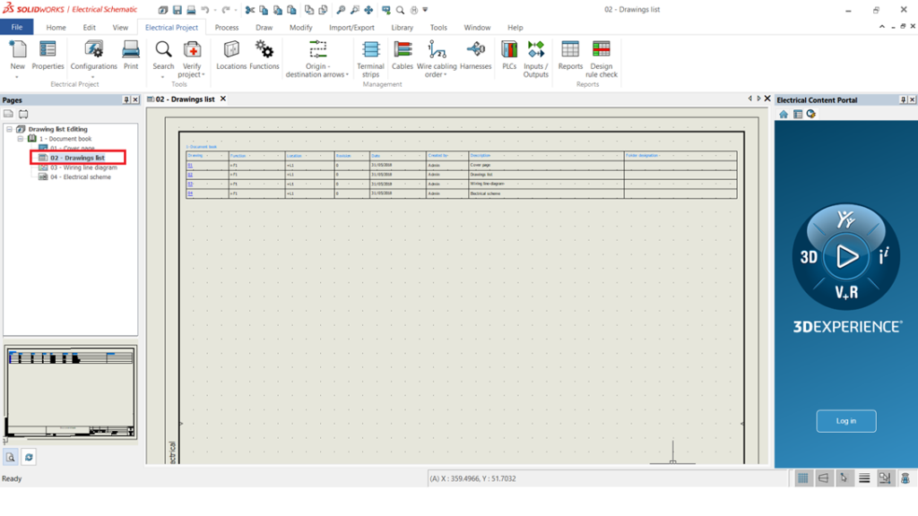
In the display tree manager drawing sheet is the default page present as a second page after the cover page.
Drawing sheet table will be useful to find the page information.
Even if the 100 pages available every page information will be present in this page table.
STEP 2
As per the image below.
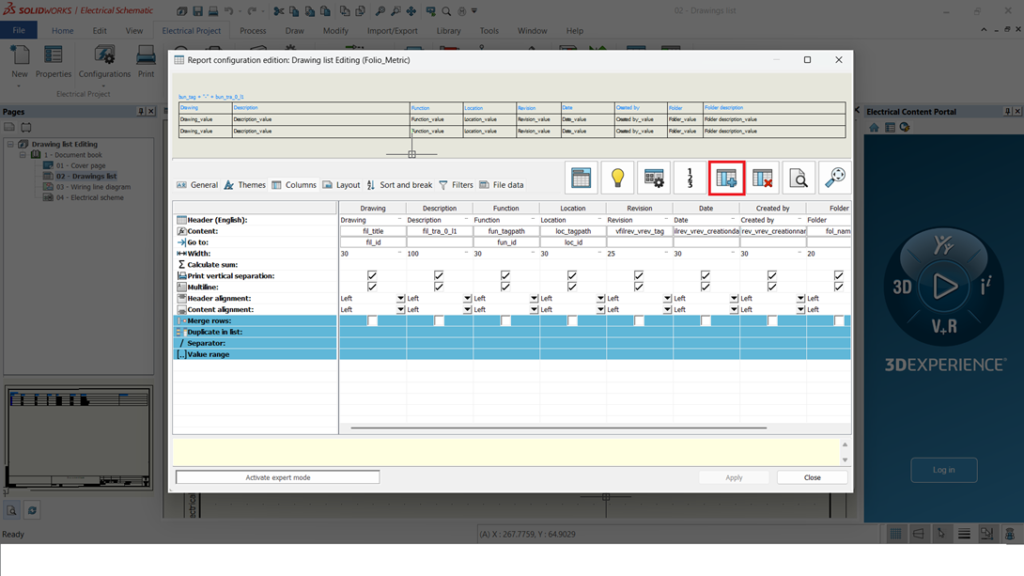
To customize the report in a page, right click at page -> Edit report configuration.
STEP 3
Once the above points are done a new tab Report configuration edition tab will be opened.
In this tab where column adding, width height modifying is done.
To add a column a new adding option will be present which is highlighted
in the image below.
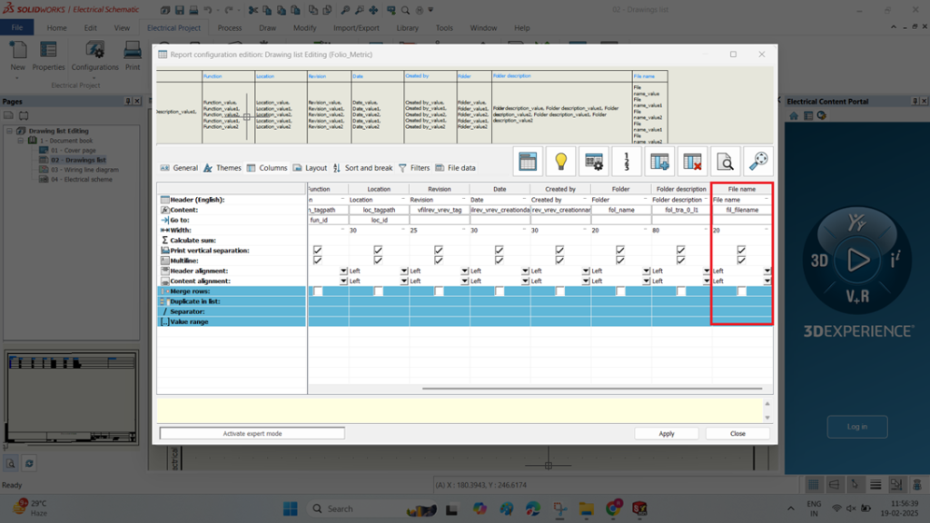
The second image shows once column added how it represents.
STEP 4
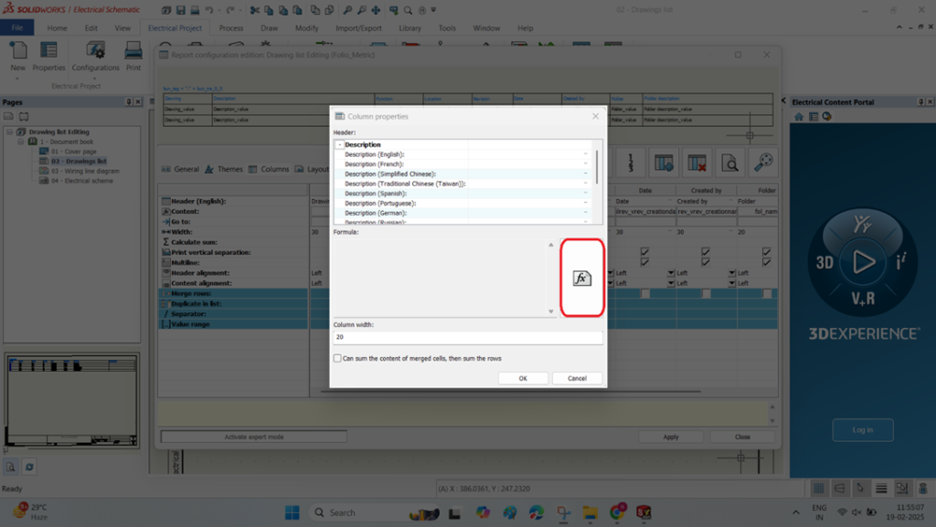
After creating a column with the above points, a column properties will be opened.
In the column properties a formula must be added. To add a formula Highlighted option must selected.
Second image represents after the formula added.
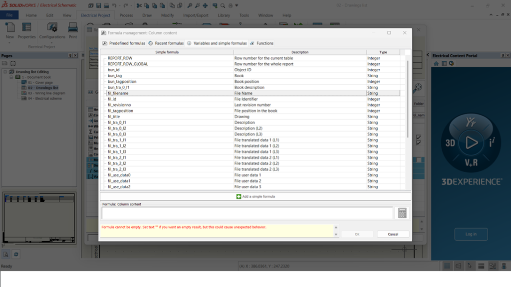
STEP 5
Once the above points are done a formula management tab for a column context will be opened.
It has multiple variables, formulas and functions. A required function has to be selected.
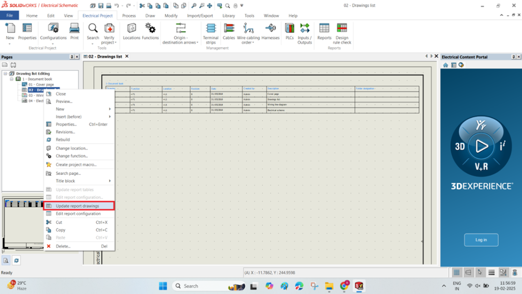
STEP 6
And a function selected an update is needed to change the report in the drawing sheet.
To update the drawing sheet right click -> Update report drawings must be selected like in the image.
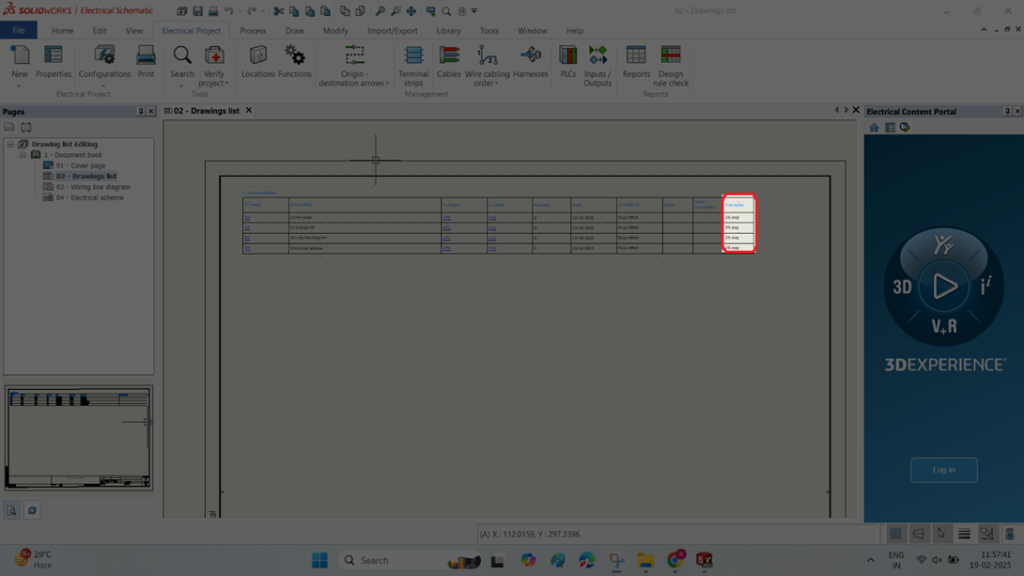
The second image shows once updating done a new column is added.
Summary
With these above-mentioned points we will be able to customize a new report table on the drawing sheet as per our requirement.
Introduction to 3DSculptor: Create Smooth & Organic 3D Designs
If you are looking for a blog to learn about 3D Sculptor in 3DEXPERIENCE, you’ve come to the right place! 3D Sculptor is a powerful, cloud-based subdivision (Sub-D) modeling tool designed for creating complex, freeform shapes with ease. It features the xShape app, which provides an intuitive push-pull modeling approach, making it ideal for designers, engineers, and artists who need to create organic and ergonomic designs quickly.
With 3D Sculptor, you can model directly in a web browser, collaborate in real-time, and seamlessly integrate with other 3DEXPERIENCE roles like 3D Creator (xDesign) for a smooth design workflow. Whether you're new to subdivision modeling or an experienced designer, this blog will guide you through the key features and steps to get started with xShape, helping you bring your creative ideas to life effortlessly.
3D Sculptor is a role on the 3DEXPERIENCE platform that contains the xShape app for 3D modeling. Create complex surfaces using intuitive push-pull interaction. Use images and sketches as templates to create 3D surface modeling. Automatically convert subdivision surfaces to geometry when finished.
xShape is browser-based freeform modeling on the 3DEXPERIENCE platform. It provides sub-D modeling capabilities for xDesign customers.
For industrial design professionals, xShape provides the following key capabilities:
Single Modeling Environment.
Primitive based sub-D modeling.
Import images to use as templates for modeling.
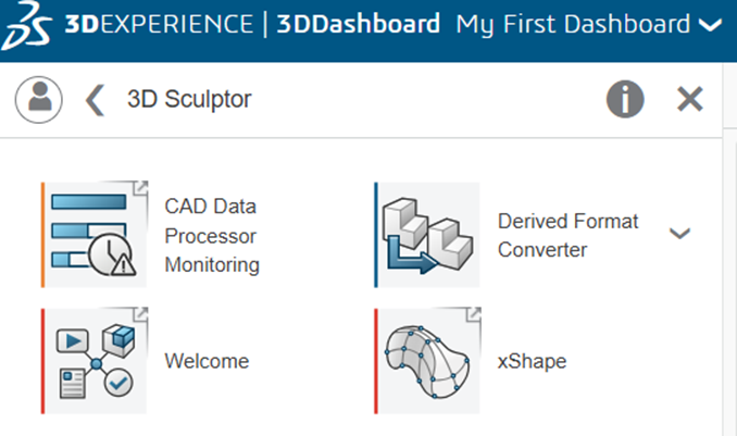
Step 1: Drag and drop x shape app from compass
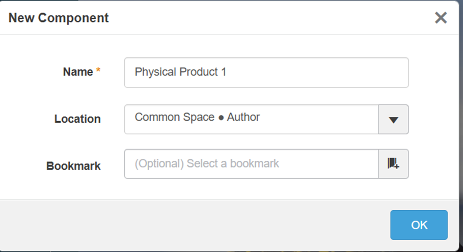
Step 2: Click import file or open to open existing file. If you wants to create new component click new component option.
Step 3: Enter part name and select custom location in bookmark
Step 4: Select subdivision tab to create a part
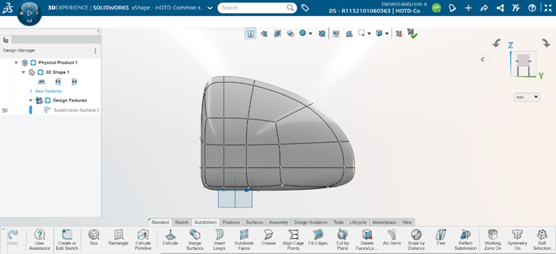
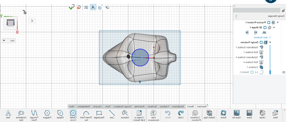
You can create a component based on the shape of a box, then customize that shape into a unique design.
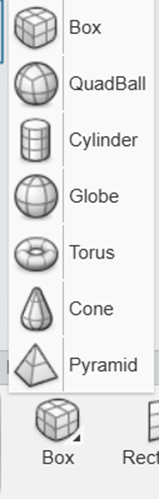
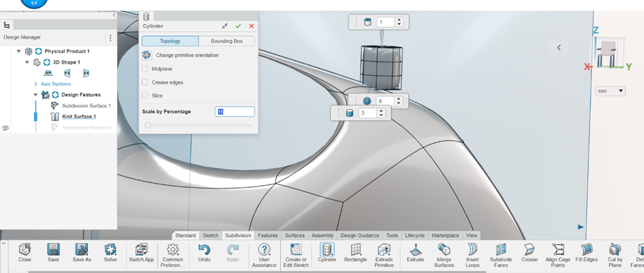
Step 5: From the Subdivision section of the action bar, click Box
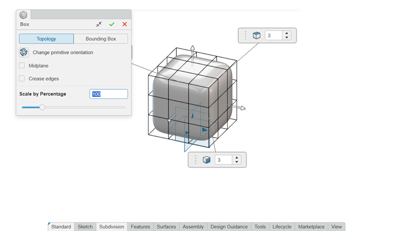
Step 6: Click box tool and fix location. To make additional changes to the topology of the subdivision shape, in the Box dialog box, click Topology and specify the following:
Option
Description
Change primitive orientation
Cycles through the standard orientations available to use as the reference.
Midplane
Extends the subdivision shape equally in both directions from the reference plane.
Crease edges
Creases the edges of the subdivision shape so that it no longer has round corners.
Scale by Percentage
Scales the subdivision shape by a percentage value.
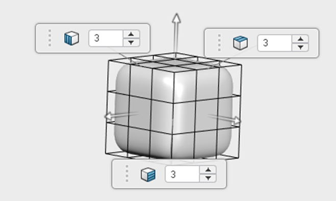
X/Y/Z Segments
Changes the number of subdivisions in the X, Y, or Z direction.
Step 7: To adjust the size and proportions of the subdivision shape, in the Box dialog box, click Bounding Box and specify the following:
Option
Description
Change primitive orientation
Cycles through the standard orientations available to use as the reference.
Non-uniform scale
Off: Scaling the subdivision shape along one axis is applied equally along the other axes.On: The subdivision shape can be scaled independently along X, Y, or Z.
Along X/Y/Z
Scales the subdivision shape along the X, Y, or Z axis.
Scale by Percentage
Scales the subdivision shape by a percentage value.
Step 8: Click ok.
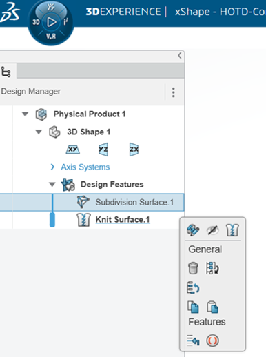
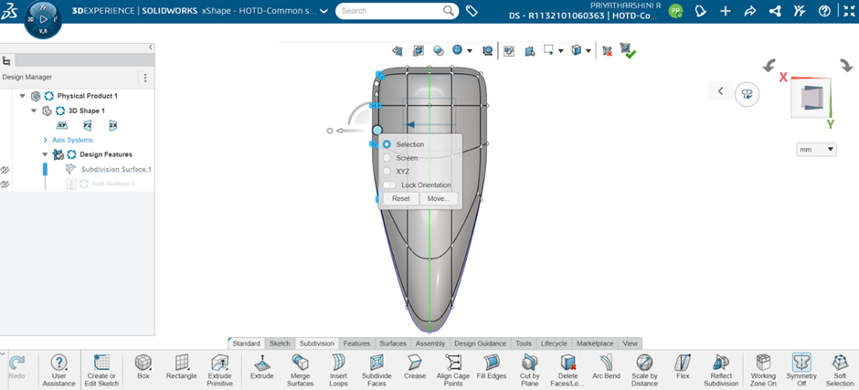
Step 9: To change the position of the subdivision shape, drag the Robot arrows.
Step 10: click edit button in design manger
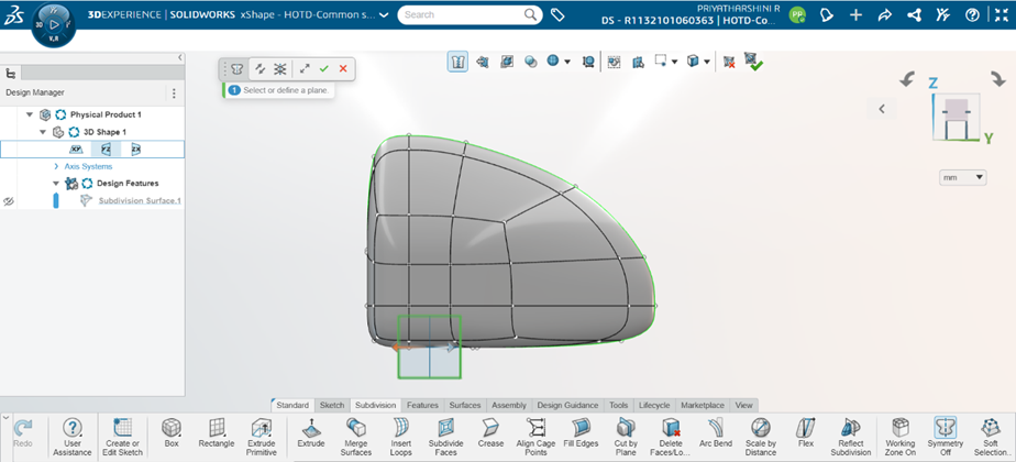
Step 11: click symmetry option.
Step 12: Select plane to as per requirements.
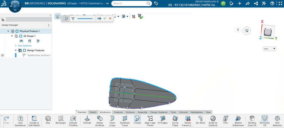
Step 13: Select crease option for adjusting edge as and faces
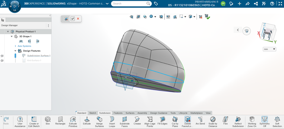
Step14: Choose the "Delete Face" tool. Mesh faces and loops on a subdivision object can be removed.
Step15: Use the box selection method to choose faces, then click the middle button to alter the axis.
Step16: You can extrude the laminar edges or mesh faces of a subdivision object to create more advanced subdivision objects.
Note: single face selection is used to extrude from selected face. Double side face to remove face.
Step 17: You can scale a subdivision body uniformly or non-uniformly using Scale By Distance.
Step 18: Using multiple shape for multiple bodies to achieve shape
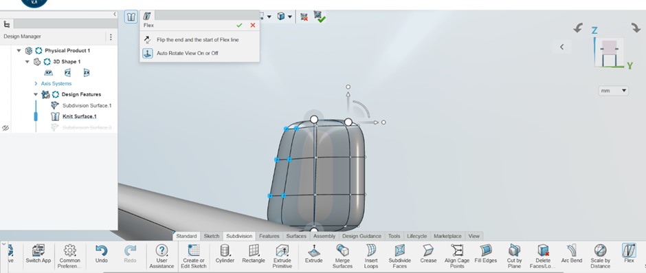
Step19: You can flex and shape subdivision objects along an axis line.
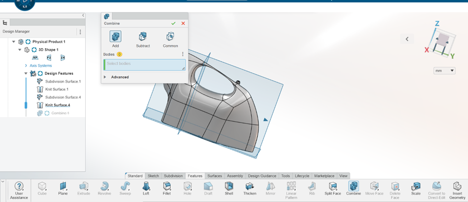
Step 20: To click feature tab and access combine tool for connecting two bodies
Step 21: click ok to continue.
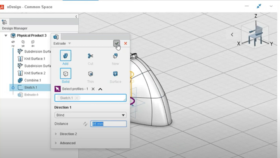
Step 22: Create a body with help of feature tab.
Step 23: After creating sketch click extrude to create bodies.
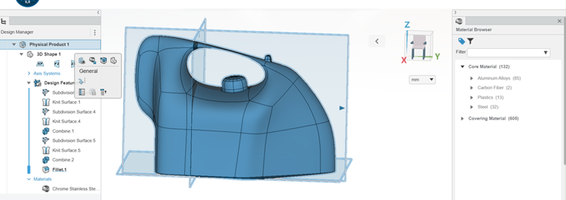
Step24: Click product name and add material .
Step 25: click ok to complete a part.
Compared to typical subdivision tools, 3DEXPERIENCE 3D Sculptor Role is a browser-based 3D subdivision modeling solution that helps engineers, artists, and industrial designers produce stylish, ergonomic, or organically shaped models more quickly and easily.
If you are looking for a blog to learn how to export all 3DEXPERIENCE data, you’re in the right place! Exporting data is essential for creating on-site backups and sharing designs with collaborators outside your organization while maintaining version control.
There is currently cloud-based file storage with 3DEXPERIENCE but continue reading if you would like to make an on-site backup. When exporting a single project, we advise exporting all the data into one package.
Purpose of Exporting 3dexperience Data:
Exporting 3DEXPERIENCE data allows users to share their design information with collaborators outside their organization, enabling them to access and potentially modify the design files while maintaining version control.
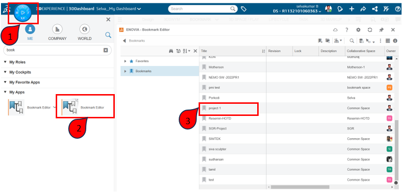
1. Export cloud data using the Bookmark Editor application.
Click the compass.
Search the bookmark editor in search tab.
Click and open the Bookmark editor widget.
2. Exporting the files
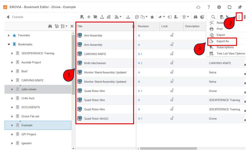
Open the existing bookmark for exporting the data.
Select Export As by clicking the Menu in the top right corner.
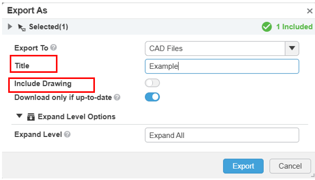
3. Optionally select Include Drawing and give the export a clear title.
Export To: Choose a method to drive your export. The 3DEXPERIENCE platform offers multiple methods to export your data based on the roles you have.
Title: Type the title what you want.
Include drawing: If you want to export drawings also turn on this option.
Download only if up-to-date: Enable this setting to download design files only if all CAD data are up-to-date.
Click export to exporting the data.
4. Notification that export is complete.
A notification in the 3DNotification Canter indicates that the job is finished and instructs the user to click for the download.
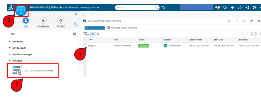
5. Monitoring export job status using CAD Data Processor Monitoring app
Open the CAD Data Processor and check the status of the exporting process.
A job is made and completed. The CAD Data Processor Monitoring software allows you to examine its status.
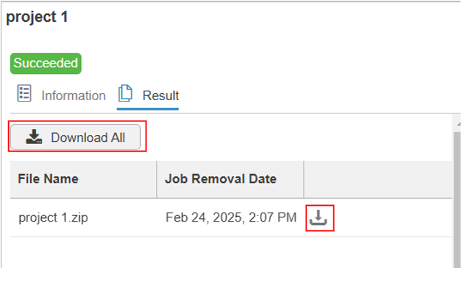
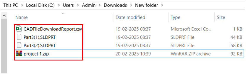
6. Download the resulting zip file
Click the download option to download the exported files.
Downloading files are stored in the downloads folder in desktop.
Before deleting any content, it’s essential to check user permissions, as only authorized users can remove or modify files. Additionally, reviewing dependencies between different design components helps avoid disruptions in linked projects.
To delete content, navigate to 3DDrive, 3DSpace, or the Collaborative Lifecycle app, locate the file or folder, and select the delete option. Some files may need to be released or unreserved before they can be removed. Administrators can also enforce content policies to ensure proper data management within the workspace.
By following these steps, you can efficiently manage and delete content while keeping your collaborative projects organized and seamless.
Introduction to 3DSpace(Collaborative Space)
The 3DEXPERIENCE platform offers a robust feature called Collaborative Spaces, which enables secure cloud storage and automatic relationship management for CAD files. The 3DSpace application facilitates the creation and management of these storage spaces. However, users are not limited to using the 3DSpace app exclusively; the Bookmark Editor application provides a structured, folder-like interface for organizing and accessing content. Additionally, the 3DSearch feature allows users to locate and retrieve items that may not be included in a bookmark.
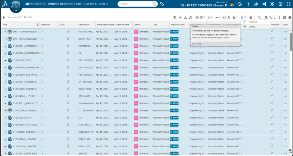
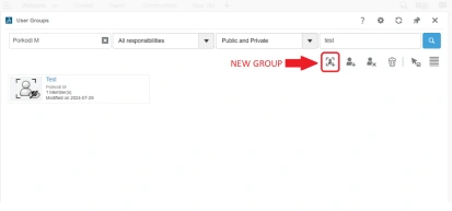
Deleting Files from the Bookmark Editor App
The Bookmark Editor App is the primary tool for deleting content from a Collaborative Space. When a file is removed from this application, it is permanently deleted from the 3DEXPERIENCE platform. To remove items, click on the trash can icon located in the upper right corner of the application. The Bookmark Editor App offers two functions: Remove and Delete, which have distinct functionalities:
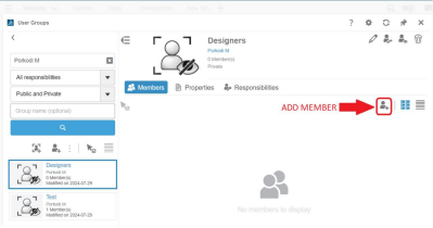
Remove: Takes the selected content out of the bookmark but does not delete it permanently.
Select one or more objects from the bookmark.
Use the Remove command to detach the chosen content from the bookmark.
Select one or more objects from the bookmark.
Use the Remove command to detach the chosen content from the bookmark.
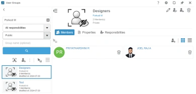
Delete: Permanently deletes the specified objects.
If you select one item, you can also delete its related structural objects by enabling the Include structural objects option.
If you select one item, you can also delete its related structural objects by enabling the Include structural objects option.
Deleting Files from the Collaborative Lifecycle App
Alternatively, users can delete files using the Collaborative Lifecycle app, which provides the same removal capabilities as the Bookmark Editor App. This method is useful when an item is not present in a bookmark. Users can either search for the item using the integrated search function or drag and drop items into the Collaborative Lifecycle application.
Steps to Delete Files Using the Lifecycle App:
Open the Collaborative Lifecycle app.
Select the items you wish to delete.
Click the trash can icon located on the Lifecycle tab in the action bar (positioned on the far right).
Managing File Deletion on 3DEXPERIENCE
Unlike local file storage, the 3DEXPERIENCE platform imposes varying levels of restrictions on file deletion to enhance data security and management. Not all users have the same file deletion capabilities, and administrators can configure specific restrictions to prevent unauthorized data removal. These measures ensure data integrity, security, and ease of maintenance across the platform.
By understanding the available deletion methods and their implications, users can effectively manage content within their Collaborative Spaces while ensuring compliance with data governance policies.
If you are looking for a blog to learn about 3D Structure Creator in 3DEXPERIENCE, this blog is perfect for you! It will explain the important features, benefits and how to use them in simple steps.
Whether you are just starting or already have some experience, this guide will help you understand things better. Keep reading to learn how to design 3D structures easily and use the best tools to improve your work!
3D Structure Creator is a cloud-based tool that helps engineers and designers create frame designs easily and quickly. It is part of the 3DEXPERIENCE platform and works entirely in a web browser, so you can design anytime, anywhere, without needing to install software. It covers every step of the design process, from the first idea to preparing for manufacturing.
Why Choose 3D Structure Creator?
Fast and Easy Design: Speed up your design process with easy-to-use tools.
Accurate and Precise: Ensure your structures are ready for manufacturing.
Work Anywhere: Cloud access lets you design on any device, anywhere.
Collaborate Effortlessly: Share your designs online for quick feedback.
Key Features of 3D Structure Creator (xFrame):
The main app in 3D Structure Creator is xFrame. It provides all the tools you need to design structures with accuracy and speed.
Who Should Use xFrame?
Engineers: For designing safe and accurate structures.
Product Designers: To bring new ideas to life easily.
Architects: To plan and visualize building structures.
Students and Teachers: For learning and teaching structure design.
Teams and Companies: To collaborate and share designs online.
Getting Started with xFrame: Step by Step
Open 3DEXPERIENCE Platform:
Go to your web browser and log in to the 3DEXPERIENCE platform.
Make sure you have the 3D Structure Creator role assigned.
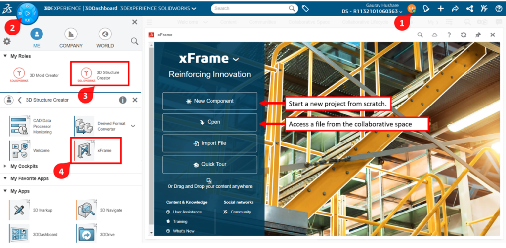
Launch xFrame:
In the dashboard, find and open the xFrame app Create a New Structure:
Click on New Component to start a new structure.
Choose a name and save your project in the cloud.
Sketch the Base:
Start by creating a 2D Sketch on a plane.
Draw lines, curves, or shapes where you want the structure members.
Add Structure Members:
Select the sketch lines and click on Add Structure Member.
Choose a profile from the library (like square, round, or custom profiles).
Set the size and orientation of the structure members.
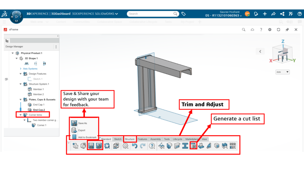
Trim and Adjust:
Use Trim and Extend tools to adjust corners and joints.
Ensure all members are connected precisely for manufacturing.
Check and Edit:
Review your structure in 3D View.
Make changes or add more members as needed.
Save and Share:
Save your design in the cloud for easy access later.
Share the design with your team for feedback and collaboration.
Generate Manufacturing Data:
When ready, generate a cut list or other manufacturing data.
Export to your preferred format for production.
Now you’re ready to create precise and accurate structures using xFrame on the 3DEXPERIENCE platform!
Benefits of Using 3D Structure Creator
Save Time: Design faster with easy-to-use tools.
Reduce Errors: Accurate designs mean fewer mistakes.
Flexible Access: Work on your designs from any device.
No Installations: Everything is online—no heavy software needed.
Better Teamwork: Collaborate with others in real-time.
Cost-Effective: No expensive hardware needed since it runs in the cloud.
Conclusion
3D Structure Creator on the 3DEXPERIENCE platform makes designing structures faster and simpler. With xFrame as its key app, you get powerful tools that are easy to use, accurate, and flexible enough to work anywhere. Whether you’re an engineer, designer, or builder, this tool helps you bring your ideas to life with speed and precision.
Creating an attribute in SOLIDWORKS ELECTRICAL and Customizing in sheet according to our requirement.
Creation of attributes has few steps to follow that has been seen in the previous blog. Now we can see how to place the attribute in a Template
STEP 1
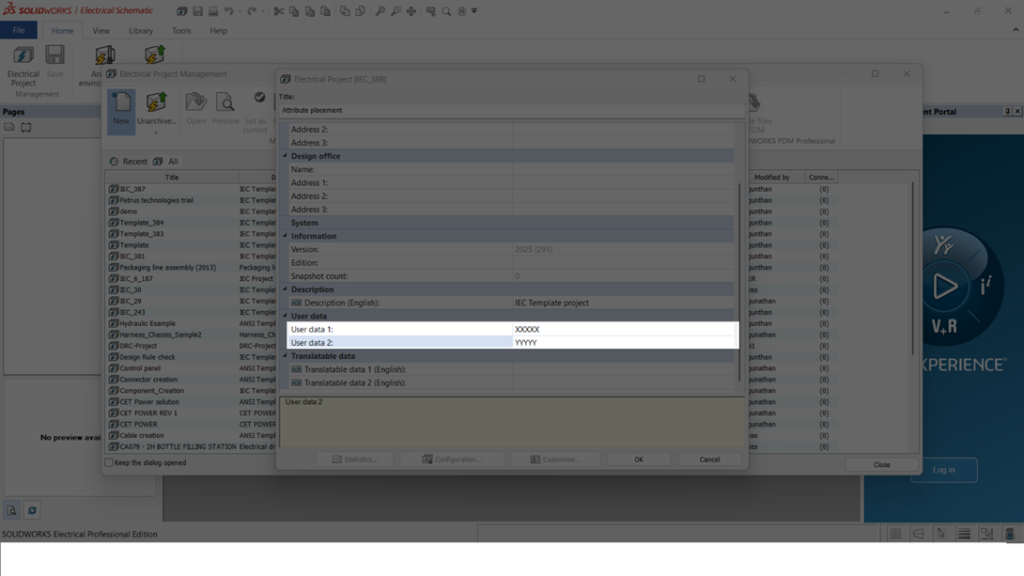
To start a project, first a detail of the project has to be filled.
As shown in the below image
This is the ELECTRICAL PROJECT MANAGEMENT TAB where the details of the whole project like customer, design office, designed by, approved by everything must be filled.
These details will be automatically updated in the sheet.
Using the highlighted "USER DATA" option, new information can be feeded and that feeded data will be automatically placed in a template.
STEP 2
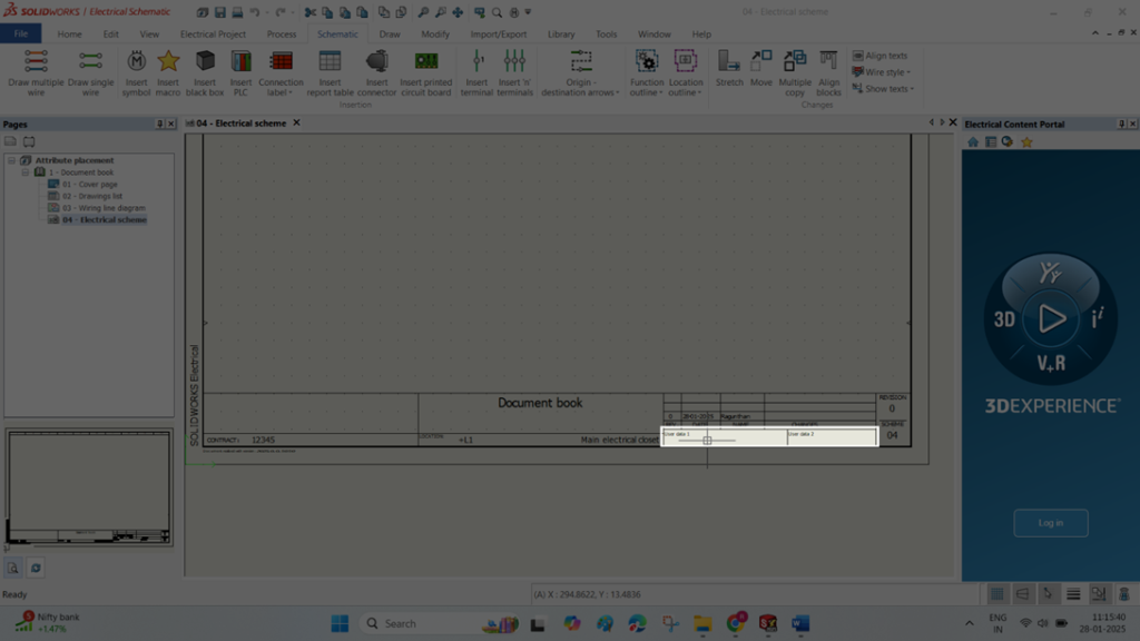
Once the above points are done. As shown in the below image
High lightened place is where the attribute is going to be added.
Once attribute are added e.g xxxx feeded at project management tab will be added here.
STEP 3
To place the attribute first a backside page where the templates are present are to be opened.
To open the page right click at the page -> Title block -> Open has to be done.
STEP 4
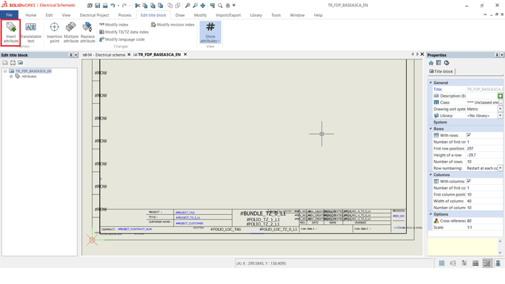
Once the above points a done a new page will be opened and looks exactly like the image at the bottom.
It also consists of multiple attributes. If any separate box needs to be added that can be added using draw option.
If any attributes are needed to be placed with Edit title block option and Insert attribute a new tab will be opened which has more attributes.
STEP 5
In an attribute management tab user data options and various other attribute options will be present.
As we need user data it can be selected.
And those attributes were placed at the location we are needed as per the second image.
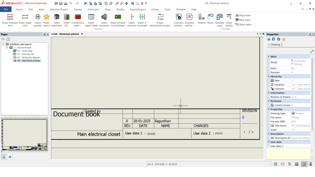
STEP 6
Once the above all points are done as per the below image our attribute will place in a template and it filled in upcoming projects.
Summary
With these above-mentioned points we can be able to create a new template and place our attribute as per our requirement.
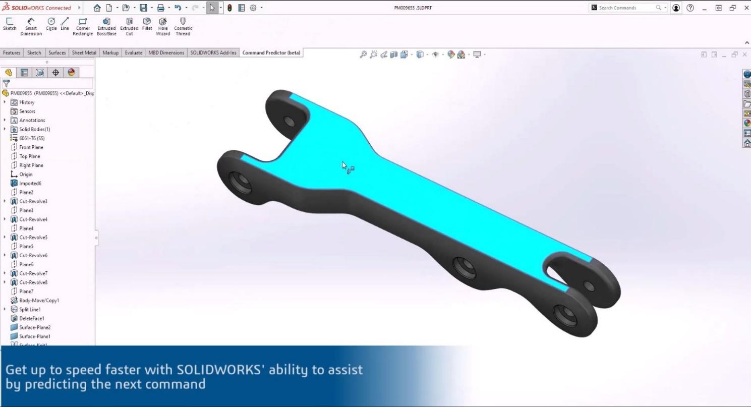
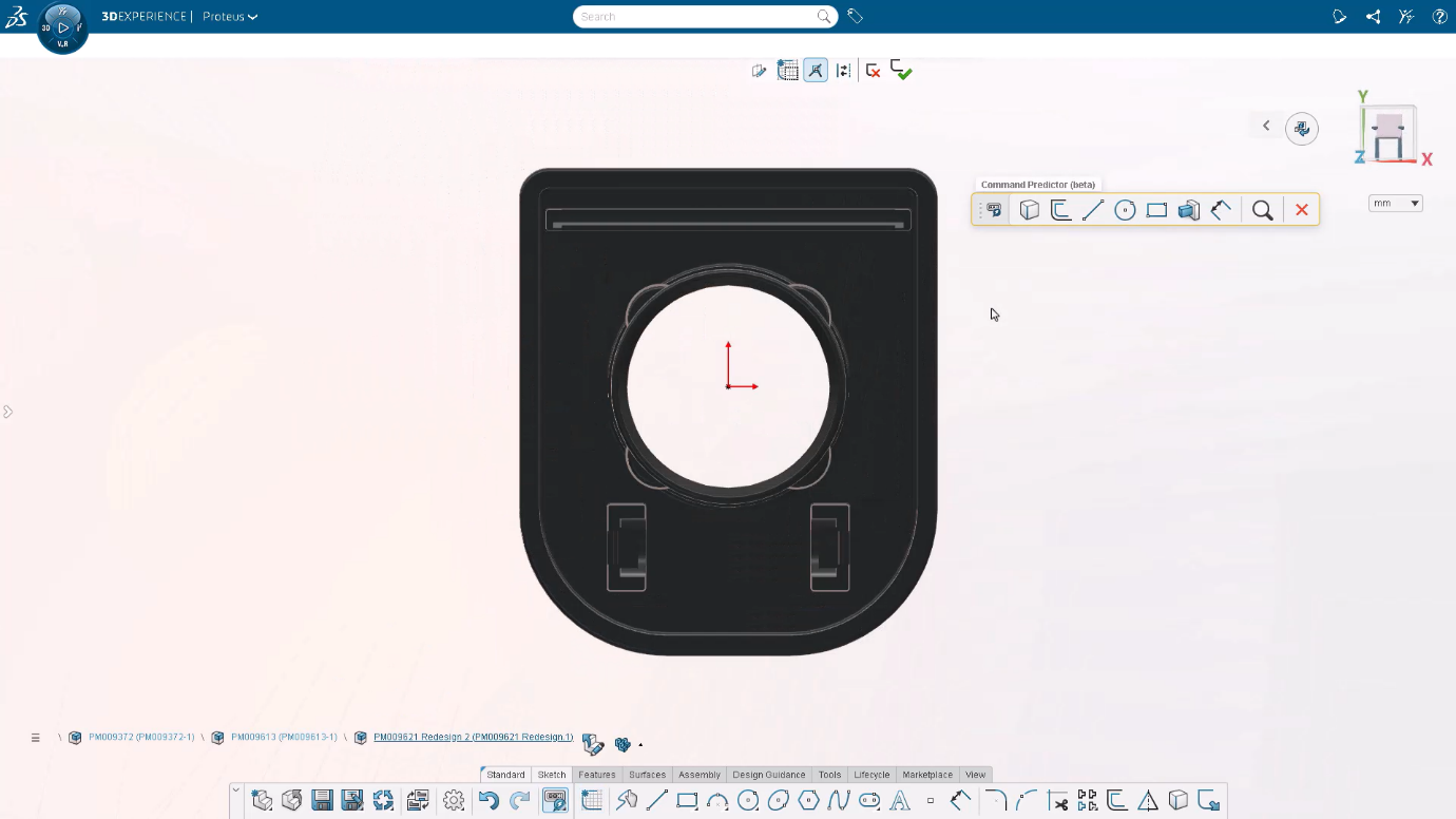
Innovation in design tools continues to drive efficiency and creativity, and the latest enhancement to SOLIDWORKS and 3DEXPERIENCE introduces the Command Predictor. This intelligent feature leverages advanced algorithms to anticipate user needs, streamline workflows, and provide a seamless design experience. Whether you’re a seasoned CAD professional or a newcomer to the software, the Command Predictor is here to redefine how you interact with your tools.
What is the Command Predictor?
The Command Predictor is an AI-driven feature designed to anticipate the next command or tool a user might need based on their current workflow. By analyzing the context of your actions and recognizing patterns in your design process, it suggests relevant commands, helping you save time and reduce repetitive clicks.
Available in both SOLIDWORKS and 3DEXPERIENCE’s 3D Creator app, this feature integrates seamlessly into your design environment, providing a smarter and more intuitive way to work.
Key Benefits
Enhanced Productivity
The Command Predictor minimizes the need to search through menus and toolbars, enabling you to focus more on your design. By presenting the most likely next steps, it reduces cognitive load and accelerates task completion.
2. Tailored to Your Workflow
The feature adapts to your unique style and usage patterns, offering personalized suggestions that align with your design habits.
3. Error Reduction
By suggesting the most appropriate commands, the Command Predictor helps avoid common mistakes, ensuring smoother operations and higher-quality outputs.
4. Streamlined Learning Curve
For new users, the Command Predictor serves as a guide, helping them navigate complex workflows and discover tools they might not have known existed.
How Does It Work?
The Command Predictor uses machine learning models trained on extensive data sets and user interactions. Here’s how it functions in practice:
Context Awareness: The system evaluates the design context, such as the geometry being worked on, the current tool in use, and the sequence of previous actions.
Pattern Recognition: By identifying common workflows and frequently used command sequences, it predicts the most likely next steps.
Dynamic Suggestions: Recommendations are displayed contextually, often as a floating menu or within the command manager, allowing users to select suggestions with a single click.
Real-World Applications
In SOLIDWORKS:
Automatically suggest fillets after creating sharp edges.
Recommend pattern tools after defining initial features like holes or extrusions.
Propose mate types during assembly creation based on component alignments.
In 3D Creator:
Offer relevant sketch tools when creating complex 3D shapes.
Suggest constraints and relationships for parametric designs.
Streamline the design validation process by predicting simulation tools.
Getting Started
To enable and use the Command Predictor:
Update Your Software: Ensure you have the latest version of SOLIDWORKS or 3DEXPERIENCE.
Activate the Feature: Navigate to the settings menu and enable the Command Predictor.
Personalize Suggestions: Spend some time working on your designs to allow the tool to learn and tailor recommendations.
Provide Feedback: As you use the feature, your interactions refine its accuracy and effectiveness.
What’s Next?
The Command Predictor is just the beginning of AI-powered enhancements in CAD software. Future updates aim to deepen the integration of predictive tools, bringing even smarter and more adaptive functionalities to your design process. Start leveraging the power of the Command Predictor today and experience a new level of efficiency and creativity in your workflows. With SOLIDWORKS and 3DEXPERIENCE, the future of design is intelligent, intuitive, and tailored to you.
With just one modelling environment, you can concentrate on what you do best—innovate! xDesign offers a user interface that is simple to use, intuitive, and easy to understand.
2 .Design Guidance
Allow Design Guidance to offer potential answers when confronted with difficult structural design problems. Design Guidance will tell you what geometry satisfies the force criteria and part connection points if you just supply them. Utilize it as a guide or incorporate it directly into your model.
3. No Hassle cloud
You are always working with the most recent version of xDesign, regardless of the device it is running on, because it is a web application that runs in your browser without the need for installation or configuration.
4. Transparent Data Management
You can securely communicate with your team and save, maintain, branch, and merge your designs using xDesign. Limit what other team members can do with the design data and only share what you want.
Key features of 3DEXPERIENCE XDesign:
Cloud-based Access: Accessible from any device with an internet connection, enabling remote design work and collaboration.
3D Modelling: Offers powerful 3D design tools for creating detailed models and assemblies.
Real-Time Collaboration: Allows multiple users to work on the same project simultaneously, improving team productivity and communication.
User-Friendly Interface: Designed to be intuitive, with a simple interface that is accessible even to those with limited CAD experience.
Integrated Data Management: Provides version control, ensuring that all team members work with the latest designs and documentation.
Parametric Design: Allows designers to use parameters to create flexible and adaptive models that can be easily modified.
Simulation and Testing: Includes basic simulation tools to test product performance and design integrity before physical prototyping.
Design Reuse: Enables the reuse of design elements and components across different projects, saving time and resources.
CAD File Compatibility: Supports various file formats like STL, STEP, IGES, and others, ensuring compatibility with other CAD software.
Modelling in XDesign:
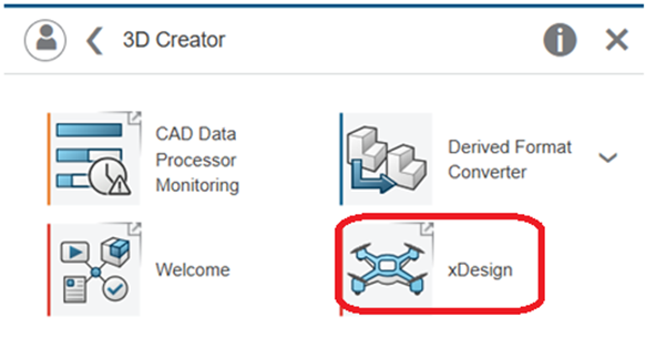
To access the xDesign, click the Compass and expand my cockpits. Under My Cockpits, click 3D Creator Home. 3D Creator is the role that includes xDesign.
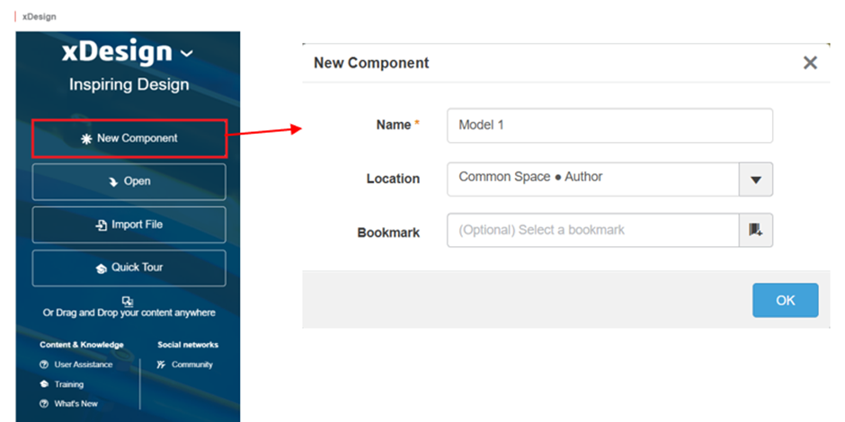
Click New Component, and type in a name. If you have access to more than one collaborative space, you will be able to select the one you want here, under the location. The physical product will be saved to the selected collaborative space. When you Click OK, you get a new workspace to begin designing your new component.
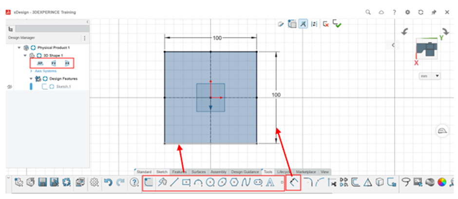
You can start by creating 2D sketches on various planes (XY, XZ, YZ).
Create the sketches in particular planes. These sketches can serve as the basis for creating 3D geometry. Sketch tools are like the SolidWorks.
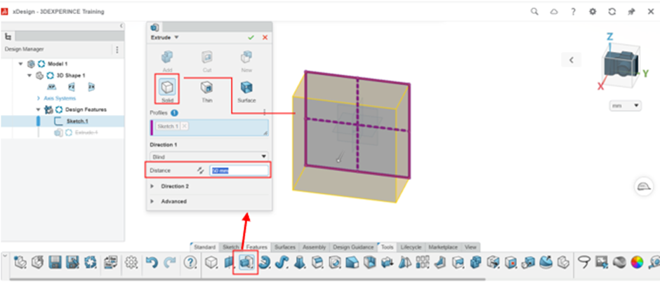
Once your sketch is complete, use operations like extrude, revolve, sweep, and loft to convert the 2D sketch into 3D solid bodies.
1.Extrude:
The Extrude tool is used to create 3D features from a 2D sketch. This operation allows you to add material by extruding a sketch profile along a specific direction, creating 3D shapes such as walls, ribs, bosses, or other solid features.
Extrude Cut:
Extrude Cut operation is used to remove material from a 3D part by extruding a sketch or profile in a specific direction. This is like other CAD systems where you create a cut feature by defining a closed profile (such as a rectangle, circle, or custom shape) and extruding it through a part.
Creating a Draft
You can taper the selected faces of a product by a specified angle. Drafting faces lets you pull parts of a feature.
The following two modes are available:
Neutral Plane
Parting Line
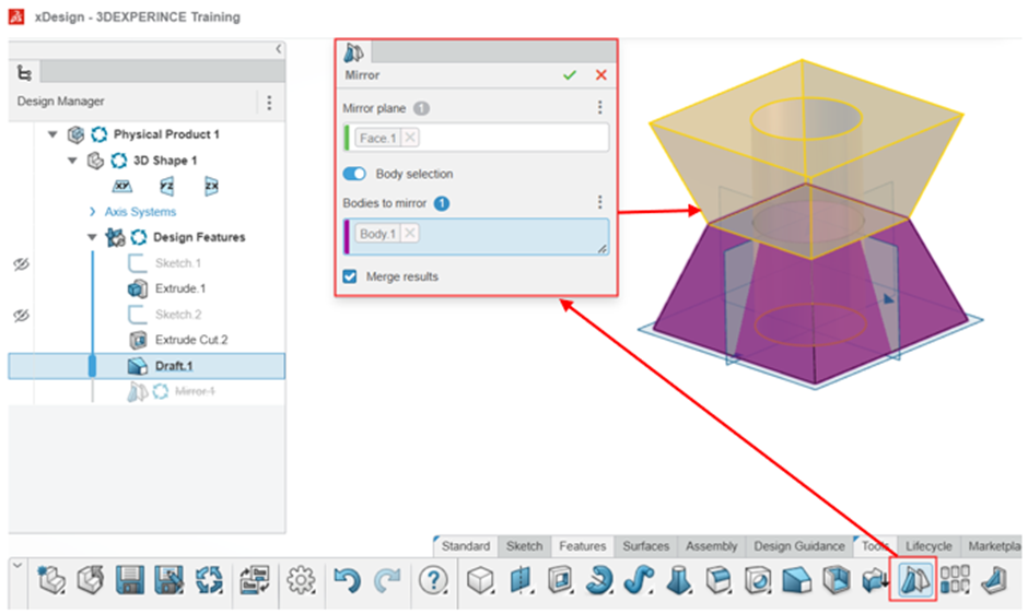
Mirror:
In 3DEXPERIENCE XDesign, the Mirror tool allows you to create a symmetrical copy of a part or feature, reflecting it across a plane. This is useful when designing parts or assemblies that require symmetry, as it helps to reduce modeling time and ensure consistency.
Fillet:
You can use fillets to create a smooth, rounded, transitional surface between faces, or on edges or vertices. Fillets can be decorative, to achieve the required visual effect, or functional, for example to strengthen a design by distributing stress across a larger surface area.
Three types of fillets available:
Constant fillet
Full round fillet
Variable fillet
How to save file in XDesign:
XDesign automatically saves your part as you work. Every time you make a change; the system automatically updates and saves the file in the cloud.
If you'd like to manually save your part, click the save or save as icon. You will be prompted to enter a new name for the part or choose a different location within the platform to store the file.
The default file format is .3DXML.
Conclusion:
3DEXPERIENCE XDesign is a comprehensive, cloud-based CAD tool that simplifies the design process, enhances collaboration, and integrates various engineering functions in one platform. It’s especially beneficial for teams working remotely or across multiple locations, as it streamlines communication and design sharing.
Creating molds for manufacturing can be complex and time-consuming. 3D Mold Creator (xMold), part of the 3DEXPERIENCE platform, makes this process faster and easier. It is a cloud-based tool designed for designers and engineers to quickly create mold designs with high precision.
What is 3D Mold Creator (xMold) :
3D Mold Creator is a professional tool for designing molds directly on the cloud. It works with the 3DEXPERIENCE platform, which means you don’t need heavy software installations. You can access it from anywhere, using just an internet connection.
Key Features of xMold :
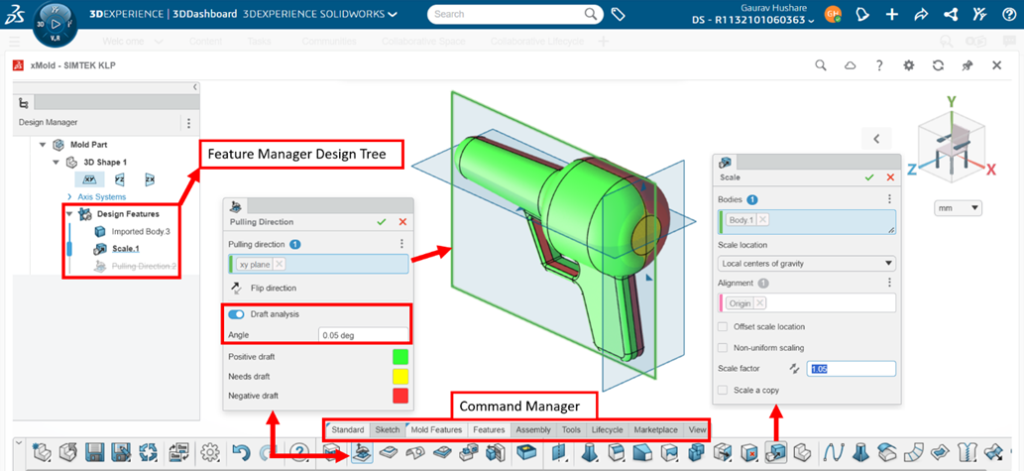
User-Friendly Interface:
xMold is easy to use, even if you’re new to mold design.
The interface is simple and intuitive, so you can focus on your design.
The interface is simple and intuitive, so you can focus on your design.
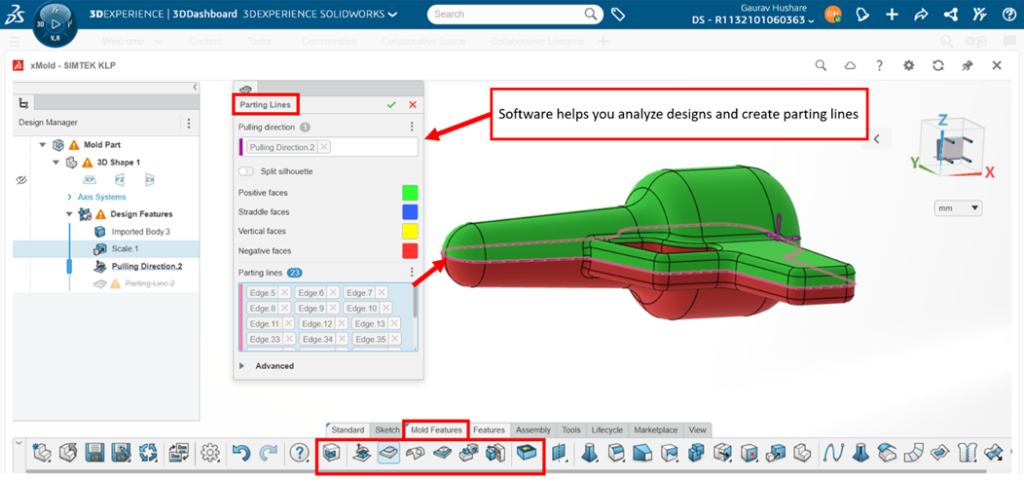
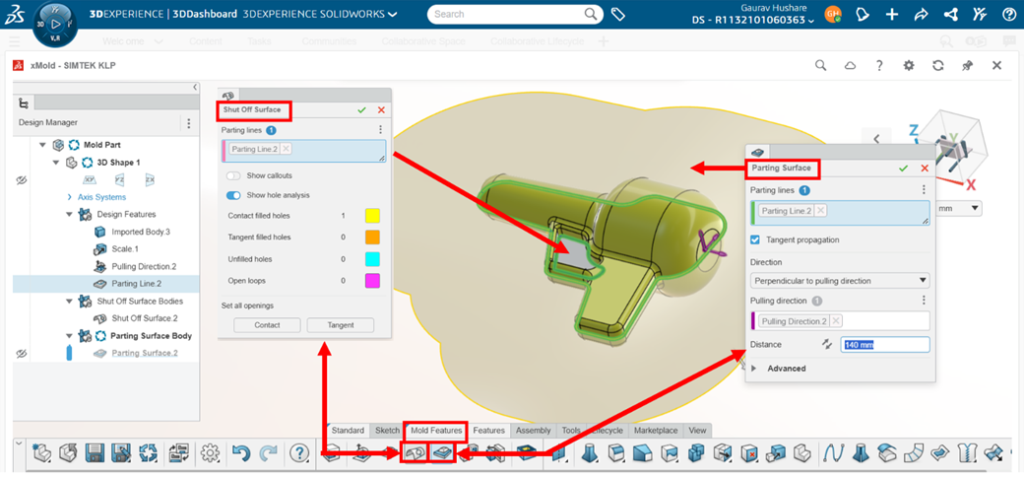
Automated Processes:
The software assists in analyzing your design and provides tools to define parting lines, parting surfaces, and mold bodies with user guidance.
This saves a lot of time and reduces the chance of errors.
This saves a lot of time and reduces the chance of errors.
Seamless Collaboration:
Since xMold is on the cloud, you can easily share your designs with team members.
Everyone can review, comment, and make changes in real-time.
Everyone can review, comment, and make changes in real-time.
Integration with Other Tools:
xMold models or xMold parts can be opened in other 3DEXPERIENCE applications, such as 3D Creator and 3D Sculptor.
This makes it easier to manage the entire product development process.
This makes it easier to manage the entire product development process.
Who Should Use xMold?
Mold designers are looking for a faster, smarter solution.
Engineers who want to ensure accuracy in mold creation.
Companies aiming to improve collaboration and efficiency in their workflow.
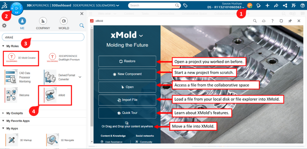
Getting Started with xMold
To start using 3D Mold Creator, you’ll need an account on the 3DEXPERIENCE platform.
Once you log in, you can find xMold under the apps section. Follow these steps:
Upload or create your 3D model.
2. 3D Mold Creator gives you easy-to-use automatic and manual tools to design mold parts like the core, cavity, and inserts.
Compensate for part scaling
Check for draft and undercut issues and make model edits as required
3. Assists in analyzing designs and defining parting lines, surfaces, and mold bodies.
5. Automatically split Mold tooling into core, cavity and inserts
6. Mold geometry updates with design model changes
Review your Mold design and make any necessary adjustments.
Save and Share your design with your team for feedback.
Benefits of Using 3D Mold Creator
Faster Design Process: With its automated tools, you can complete mold designs in less time.
Cost-Effective: By reducing errors and improving efficiency, xMold helps save money during manufacturing.
Flexibility: Access your designs anytime, anywhere, on any device.
Team Collaboration: Work closely with your team without worrying about file compatibility or version control.
Conclusion
3D Mold Creator (xMold) is a powerful tool for anyone involved in mold design. It simplifies complex tasks, saves time, and enhances teamwork. By using xMold, you can focus on creating high-quality molds and improving your product development process.
This document discusses the topic within the context of two operating systems (OS) or platforms – the Windows OS and 3DEXPERIENCE platform On Cloud, and the SOLIDWORKS 3D CAD software.
Members of an engineering department use SOLIDWORKS to create content. The additional information that they create for their content can be Windows file properties or SOLIDWORKS file properties.
Members of a company use the 3DEXPERIENCE platform On Cloud apps to create content. The additional information that they create for their content are 3DEXPERIENCE platform attributes.
Attributes are the common language for all platform members, regardless of department. Therefore, defining attributes is one of the first tasks that a platform administrator performs when configuring their platform for first use.
To ensure that the additional information is accurate in both systems, a mapping between the two systems is a requirement.
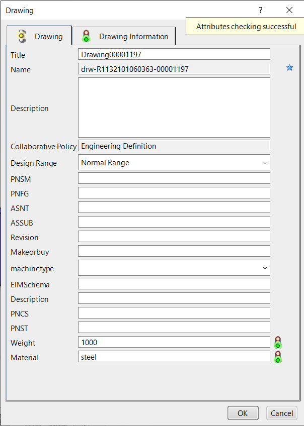
Understanding Attributes
In PDM systems, attributes are referred to as variables. In the 3DEXPERIENCE platform, attributes are a set of properties that identify a product lifecycle management (PLM) object, such as name, revision, description, the weight of a part, and the material it is made from, which are used to locate data.
Types of Attributes
Default Attributes: Basic properties similar to Windows file properties.
Custom Attributes: Flexible, user-defined properties akin to SOLIDWORKS file properties, supporting various CAD content and enhancing cross-departmental collaboration.
Attributes are accessible in the MySession and Information Side Panels. Benefits include:
Enhanced search using 6W tags.
Centralized, cloud-based data storage in Collaborative Spaces.
NOTE: Administrators can create attributes, while SOLIDWORKS file properties (custom and configuration) can be mapped to the platform, supporting parts, assemblies, and drawings.
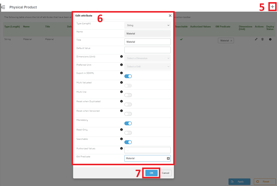
Click + Icon to create new attribute, Fill the attributes details in the edit attribute window and then click OK.
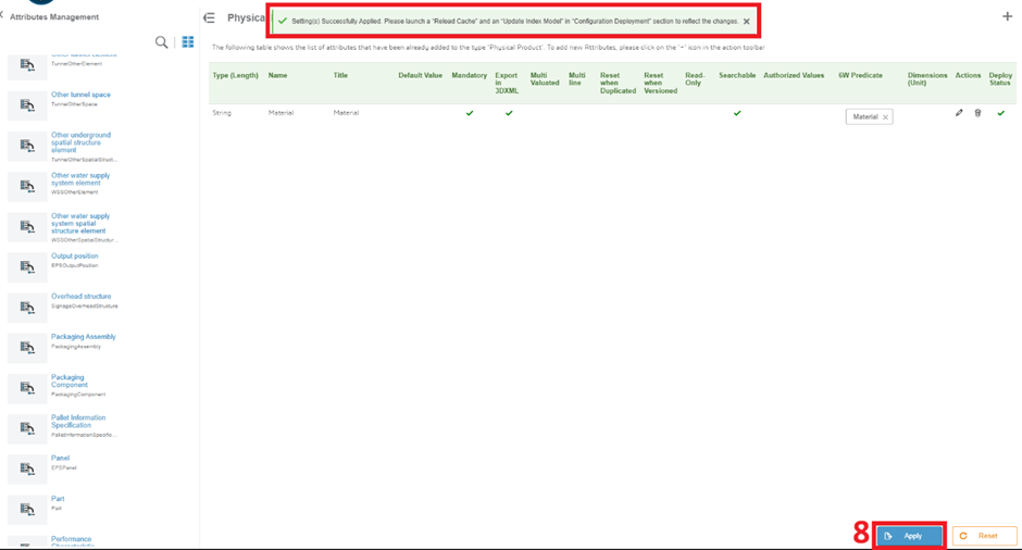
Once you add the attribute it will shows in the list. The Reset function deletes attributes that are not yet deployed.
Before proceeding, verify that all attributes are deployed and display green check marks. After clicking Apply to deploy your attributes, the following notification appears.
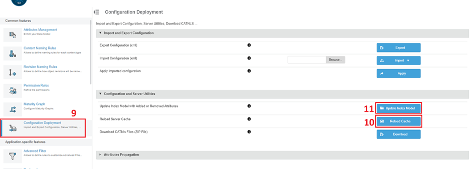
Reload Server Cache and Update Index Model
You must perform these two tasks to finalize the deployment of your attributes. The numbers in the following images depict the steps that you must follow to complete these tasks.
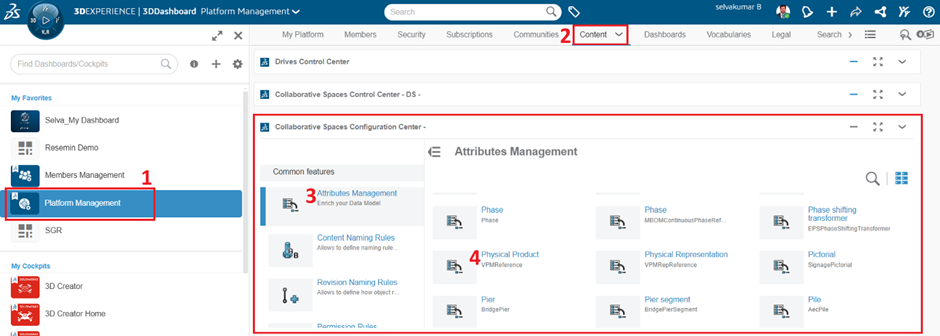
Platform Management > Content > Collaborative Spaces Configuration Center > Configuration Deployment > Configuration and Server Utilities
You must reload the server cache so that apps can make use of the new attributes. When you click Reload Cache, the following notification appears.
You must update the index model so that you can search for the new attributes. When you click Update Index Model, the following notification appears.
It takes a few minutes to complete both operations, depending on the amount of content in your platform and the number of attributes created. A notification does not appear when these operations are complete. You can consider these operations complete when you see the attributes in your content and see search results.
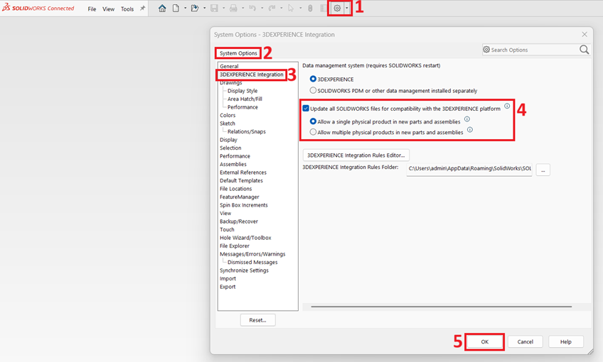
3DEXPERIENCE integration
Launch SOLIDWORKS Connected > Options > System Options > 3DEXPERIENCE Integration > Update SOLIDWORKS files for compatibility with the 3DEXPERIENCE platform.
Note:Once setting up the option need to restart the SOLIDWORKS Application.
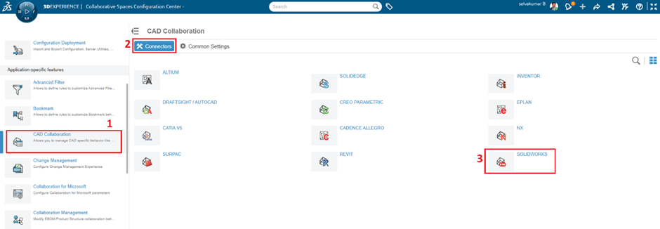
The numbers in the following images depict the steps that you must follow to configure attribute mapping.
Repeat steps 3-7 for all content types and SOLIDWORKS file properties that you want to configure.
When you map attributes bidirectionally or 3DEXPERIENCE platform > SOLIDWORKS, those attributes become available in the PLM Attributes list for selection as Configuration Properties
When complete, click Apply.
Once complete, you can delete, reset and recreate any attribute mappings, at any time, without affecting the attributes themselves.
Attribute Mapping in Use
After creating and deploying attributes and configuring the attribute mapping, you can invite uses to your platform and they can start creating content.
If you configure attribute mapping after creating content, then platform members must establish a new connection to the 3DEXPERIENCE platform on their client computers to use the mapping.
Conclusion:
Attributes are the linchpin for unlocking the 3DEXPERIENCE platform’s potential. Whether leveraging defaults or customizing, effective attribute management streamlines data processes, fostering collaboration across the design ecosystem.
Attributes are not only used in the technical form but can also be used by the sales department or any non-engineering or non-CAD department. This makes it very important that they are generic and understandable.
This step-by-step process and recommendations outlined above should serve as a helpful guide to get Administrators going with attributes.
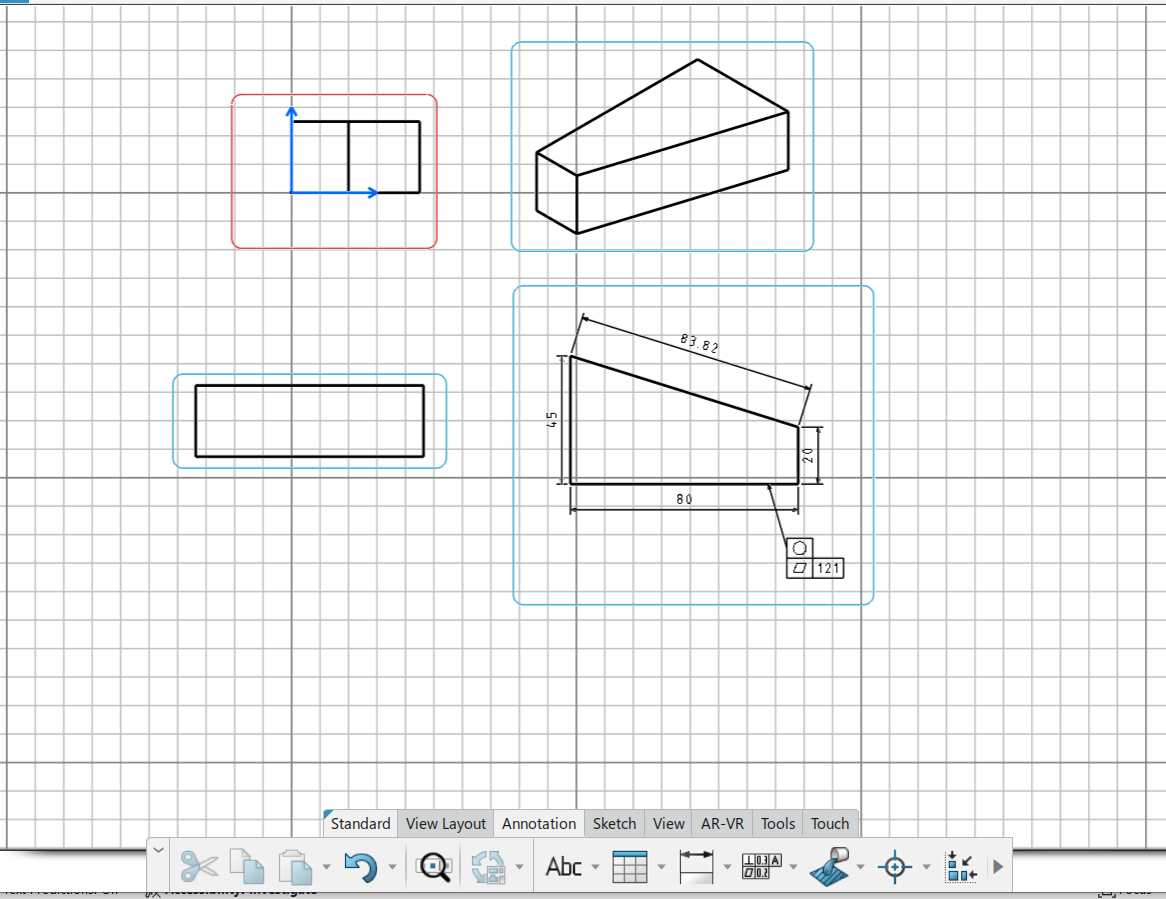
Drafter allows rapid creation of 2D Drawings from 3D models. Whenever you modify your 3D model, your drawings update instantly. With Drafter's comprehensive, production-quality, 2D detailing capabilities, designers can easily annotate drawings and with data saved to the cloud, can share drawings in real-time.
With Drafter you can:
Quickly generate drawings from your 3D parts and assemblies
Easily apply dimensions, annotations and section views to your drawings
Instantly update your 2D drawings to reflect any changes on your 3D models
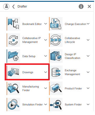
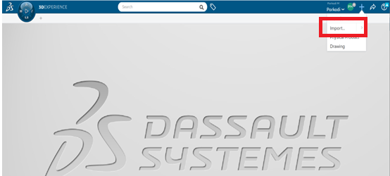
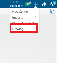
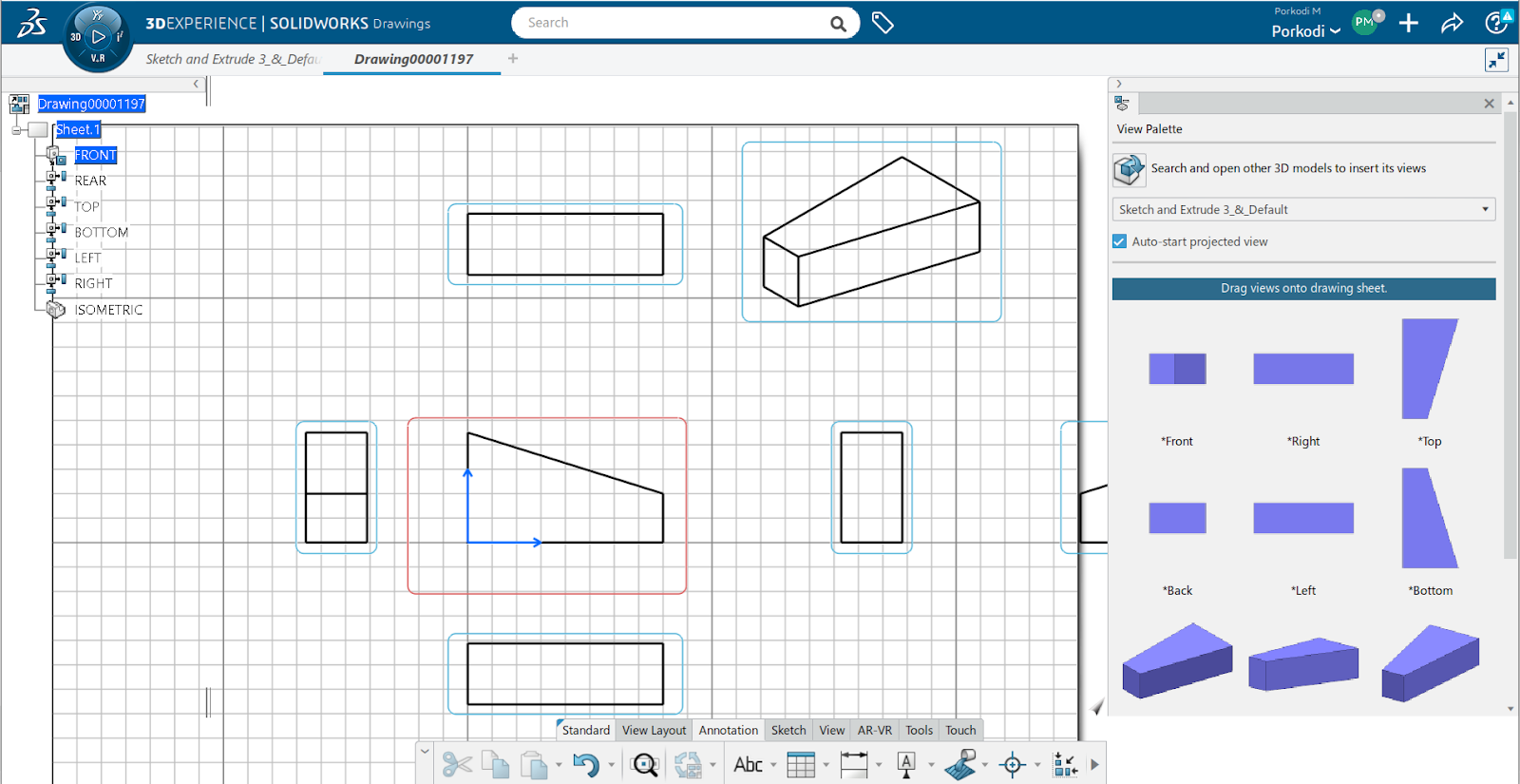
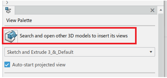
Open the Drawings App: Navigate to the 3DEXPERIENCE Dashboards. In the dashboard, look for the 3DEXPERIENCE Drawings App
Open the Drafter and install the Drawings.
Note: Install the Drawings App
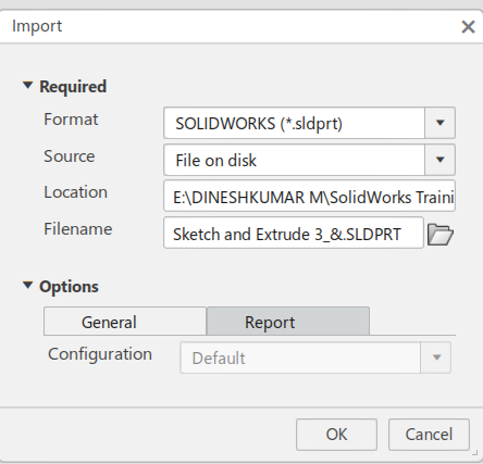
Step 2: Import a 3D Model
Importing 3D Model: If you already have a 3D model in formats such as SOLIDWORKS or other compatible formats, you can upload it directly into the 3DEXPERIENCE platform.
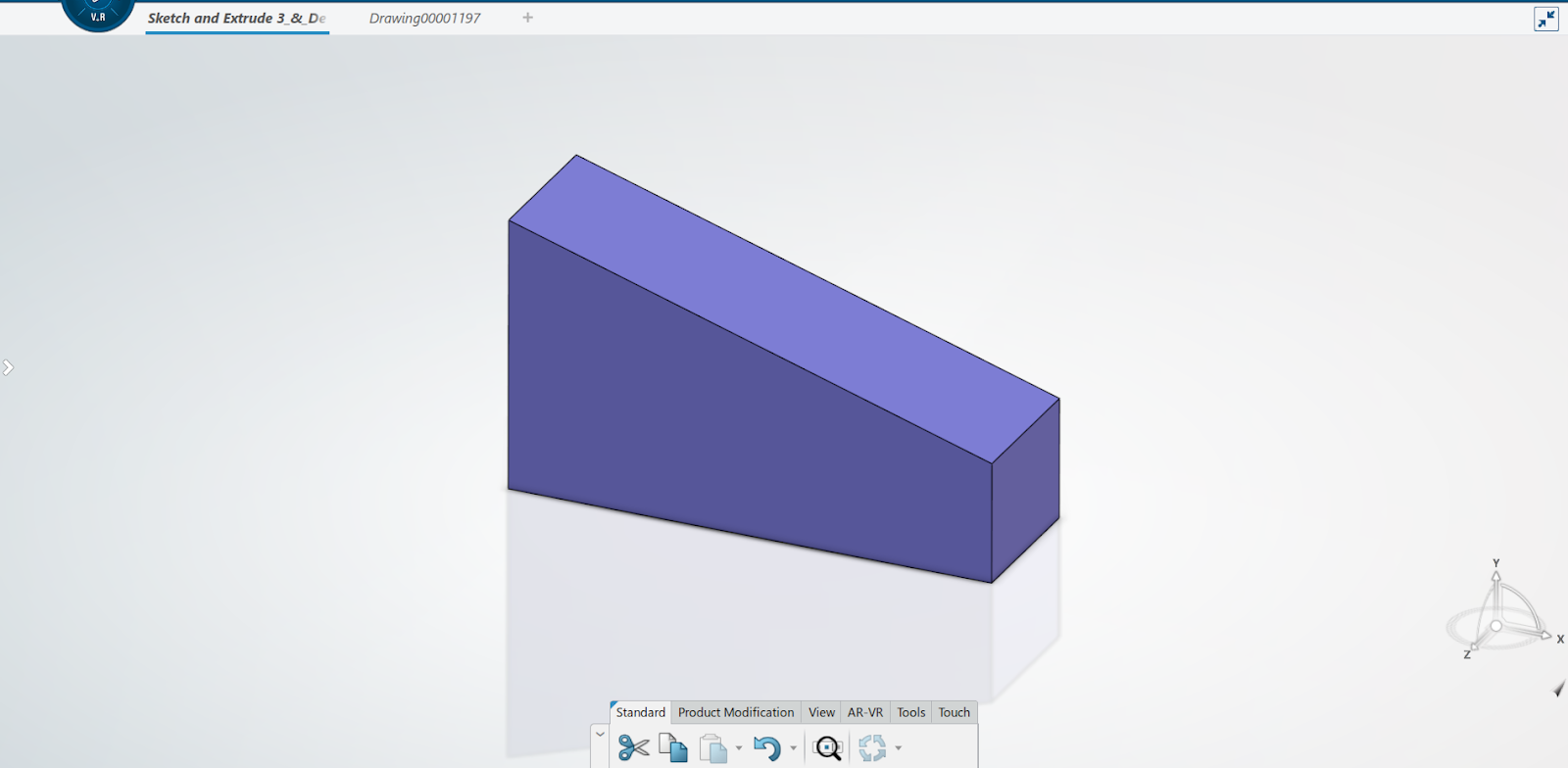
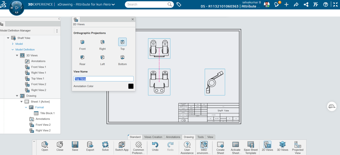
Step 3: Generate 2D Drawing
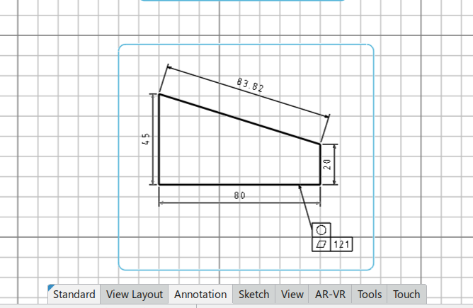
Select the 3D Model: Once your model is uploaded, navigate to the Drawings App and select the model you want to generate a 2D drawing for. After that, you will immediately see the drawings' default views.
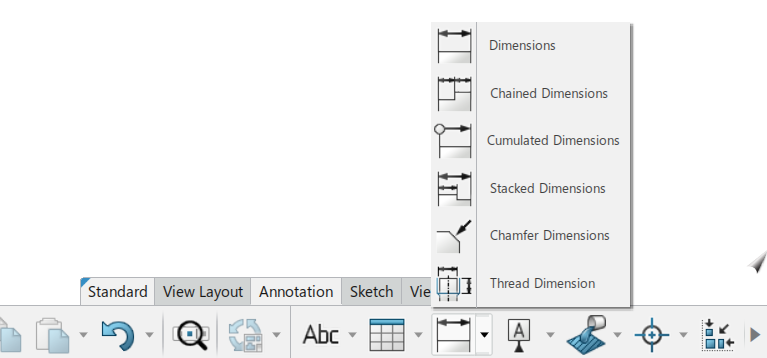
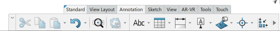
Step 4: Add Dimensions, Annotations, and SymbolsAdd Dimensions: Use the tools in the app to add precise dimensions to the drawing. The system allows you to dimension various elements like lengths, angles, diameters, and radii.
Annotations and Callouts: Add any necessary annotations such as material specifications, part numbers, surface finishes, and any custom text or instructions for manufacturing.
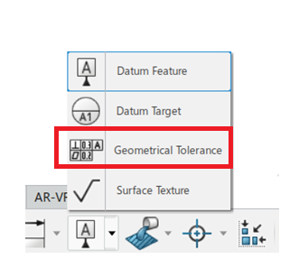
GD&T Symbols: If needed, you can include Geometric Dimensioning and Tolerancing (GD&T) symbols to indicate specific tolerances or constraints for the part.
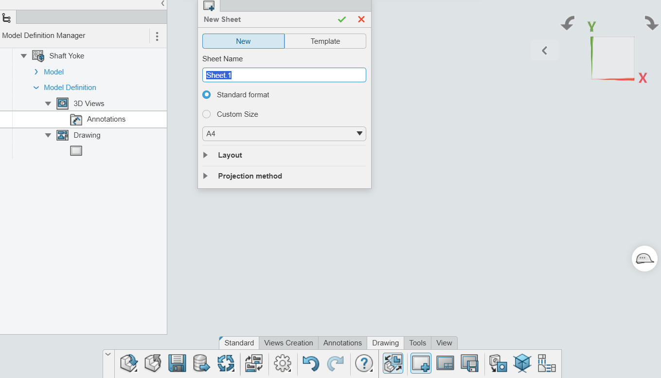
Step 5: Customize Drawing Templates and Title Blocks
Title Block: You can customize the title block with information like the part name, project, and revision details.
Templates: Choose or create custom drawing templates to maintain consistency with your company's standards.You can modify drawing sheets, paper sizes, and layout preferences.
Step 6: Update and Modify Drawings Automatically
Model Updates: If any changes are made to the 3D model, the 2D drawing will automatically update to reflect those changes.
No Manual Redrawing: You don't have to manually adjust your 2D drawing whenever the 3D model changes, as the app maintains the connection between them.
Advantages:
Time saving: Drawing creation is automated based on the 3D model, which reduces manual work.
Consistency: The app ensures that your 2D drawings are always aligned with the 3D model, minimizing discrepancies.
Real-Time Collaboration: Teams can work together, share feedback, and maintain version control in a unified system.
In the fast-paced world of digital design and engineering, having the right tools can make the difference between success and obsolescence. Enter xHighlight for 3DEXPERIENCE, a game-changing tool that is set to revolutionize the way designers, engineers and manufacturers approach their projects. This article will delve into how xHighlight enhances the 3DEXPERIENCE platform, offering unprecedented capabilities in visualization, collaboration and efficiency.
Getting Started with xHighlight: A Comprehensive Guide
xHighlight is an intuitive and powerful tool within the 3DEXPERIENCE platform that offers advanced visualization capabilities. To help you get started, this guide will walk you through the user interface, including Content Management, Canvas Manipulation, 3D Area, the Properties Manager Tab and Action Bar.
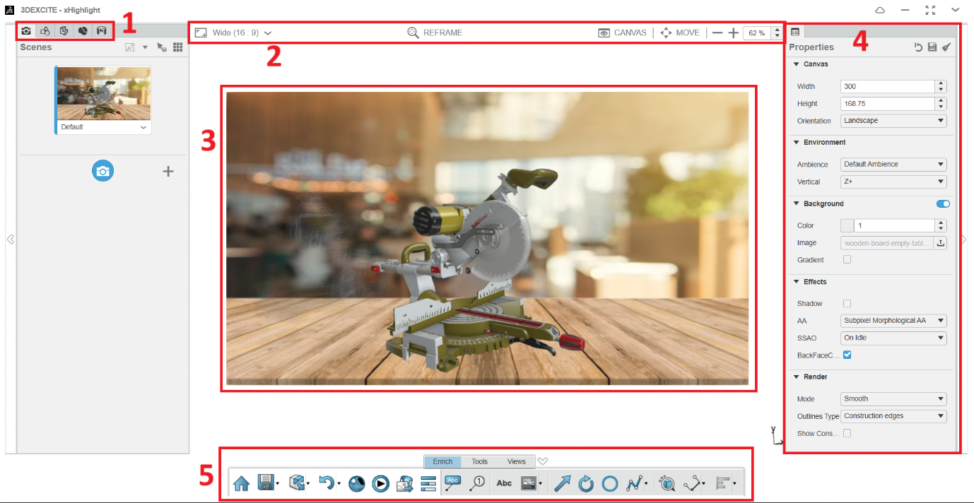
User Interface:
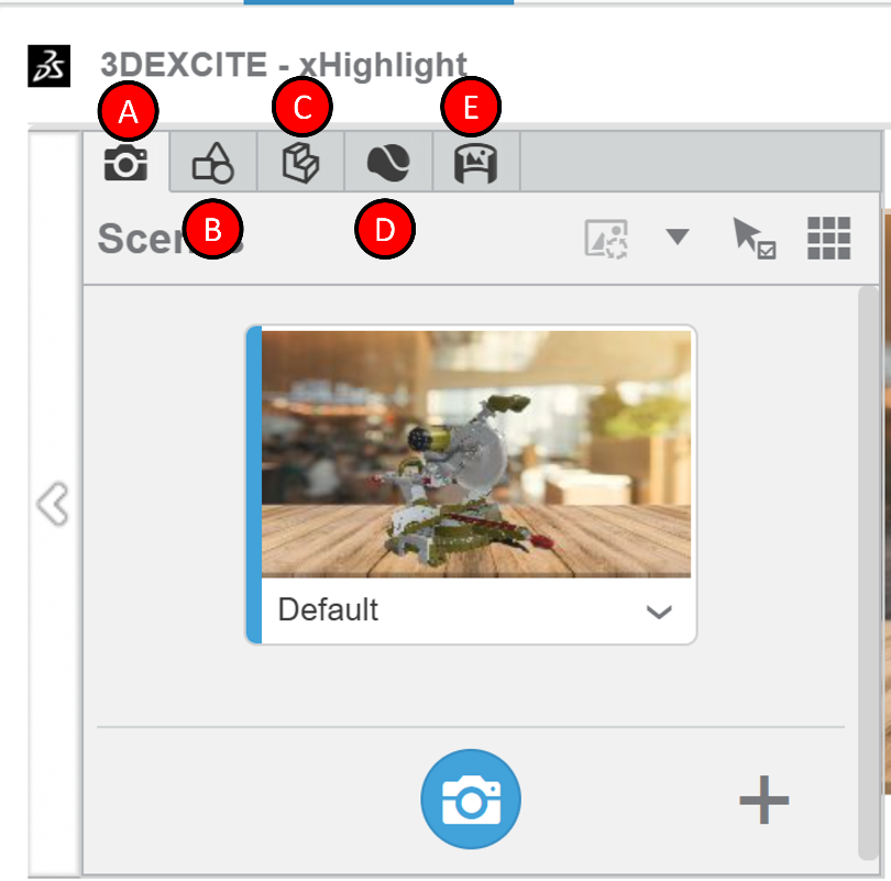
Content Management
The Content Management section is where you organize all the elements of your project.
Scenes Panel: Create and arrange various scenes.
Design Panel: Manage design elements like labels, callouts, markups, annotations and environment settings.
Assembly Panel: Select and organize parts and products.
Material Panel: Choose and apply different materials to components.
Ambiences Panel: Set and customize the overall lighting and atmosphere for scenes.
Canvas Manipulation
Modify the canvas settings, such as Aspect Ratio, Zoom and Move, in the top bar to suit your requirements.
3. 3D Area
The 3D Area showcases your scene along with the canvas where your content is displayed.
Here, you can choose and position products, parts and design elements. Additionally, you can adjust the camera’s perspective by sliding up or down.
4. Properties Manager Tab
Customize model parts or design elements in the Properties panel by adjusting attributes such as position, scale, effect, interaction and part list.
5. Action Bar
In the action bar and the Enrich section, you’ll discover essential commands such as callouts, text boxes, labels, images and arrows.
Meanwhile, the Tools section offers options including explode, 3DGrid and live preview rendering for arranging your product.
Lastly, the Views section provides commands for adjusting your model’s size, position and creating sections.
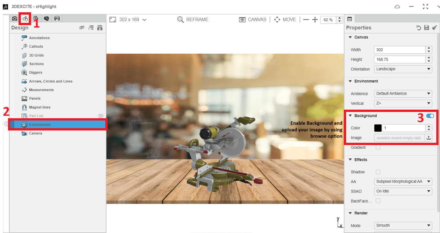
Setting the Scenes To set the environment:
Click the Navigate to Content Management and switch to the Design Panel.
In the Environment settings, click on the Environment tab in the right properties panel.
Enable Background and Browse the image to set your environment.
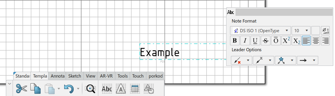
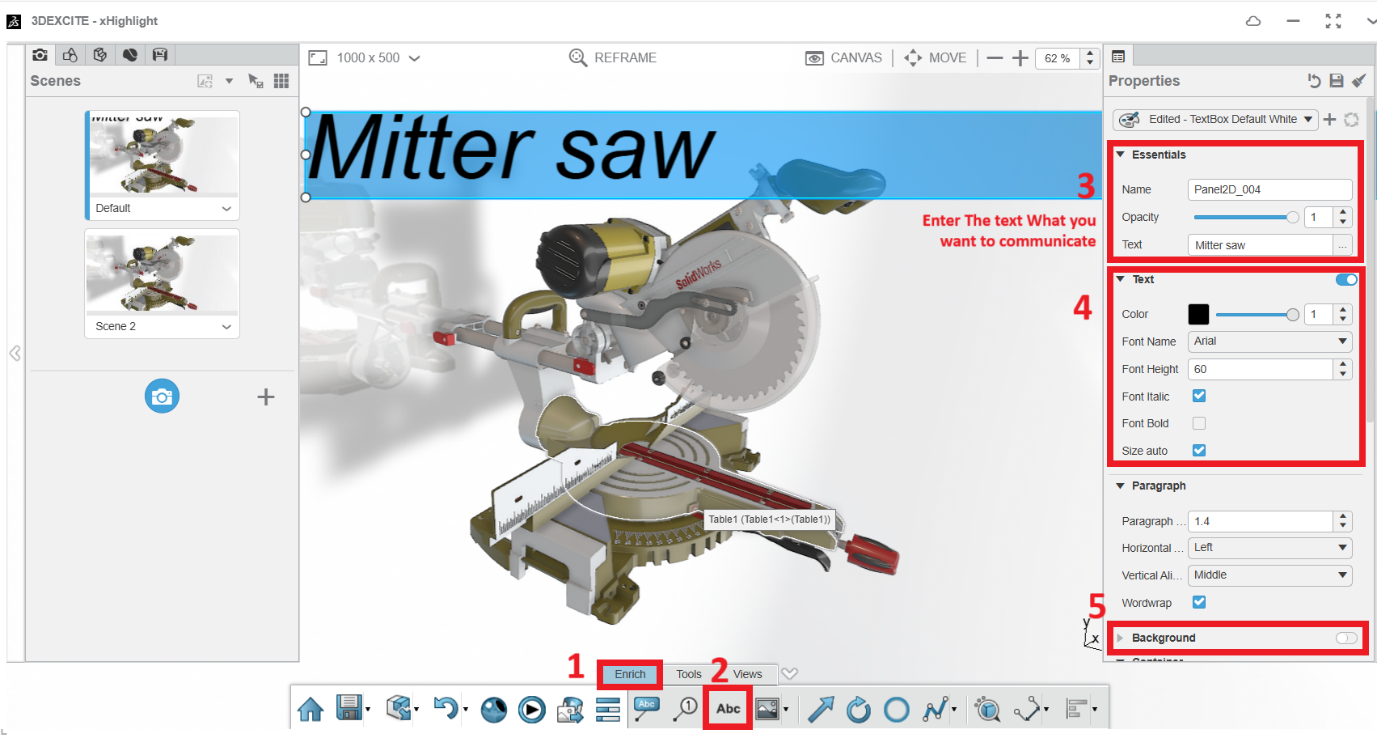
Create a Text Box:
In the enrich action bar and select the create Text box.
It allows you to Enter the text and you change the size, format, colour and background on/off in the properties pane.
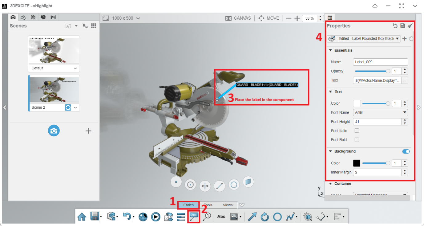
Working with Labels:
In the enrich action bar and select the create Label.
It allows you to place the component name and display state in the 3D View Port.
It allows you to change the style of the label, Text formatting and background on/off.
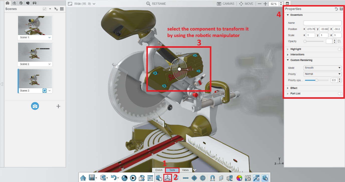
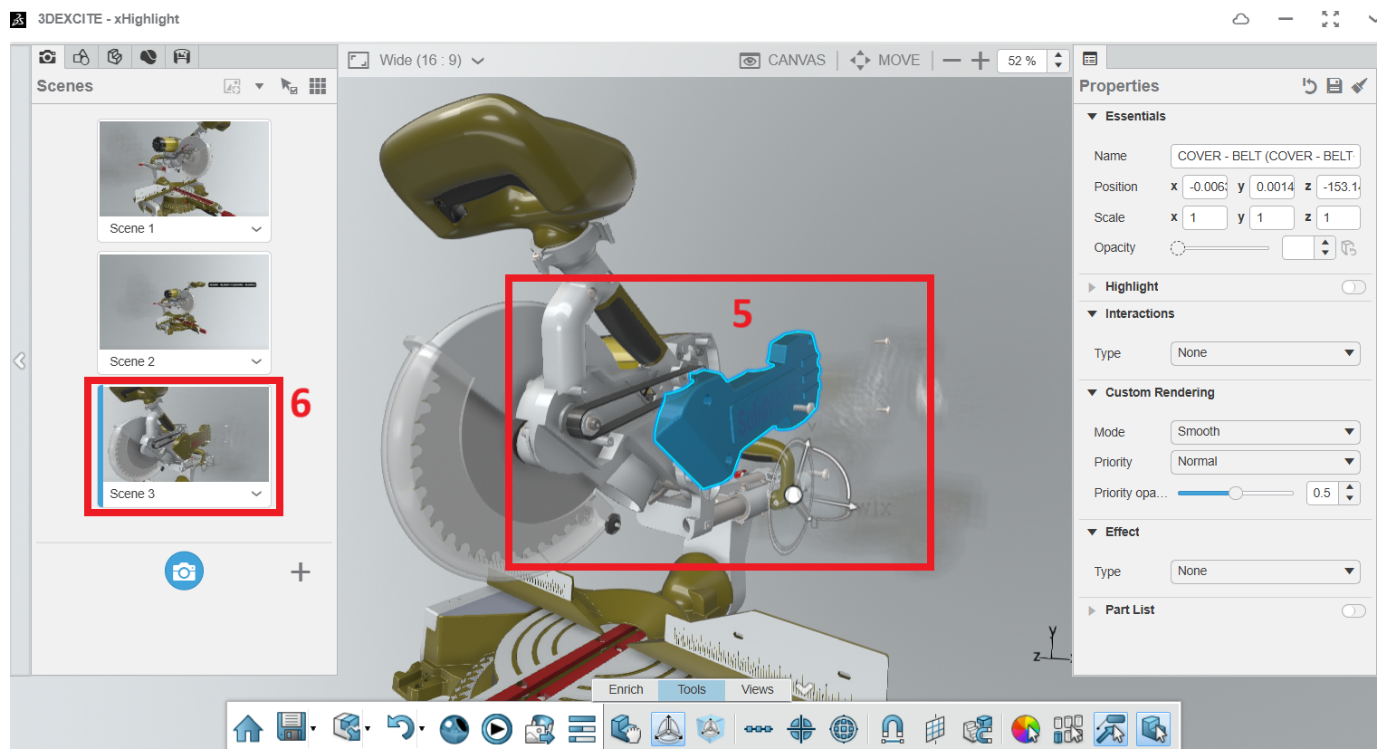
Working with Exploded Views:
In the Tools action bar and select the Transform.
It allows you to explode your component by using of robotic manipulator.
In the properties pane you can set the position of the component.
Once you will be exploded the component update the view in Scenes.
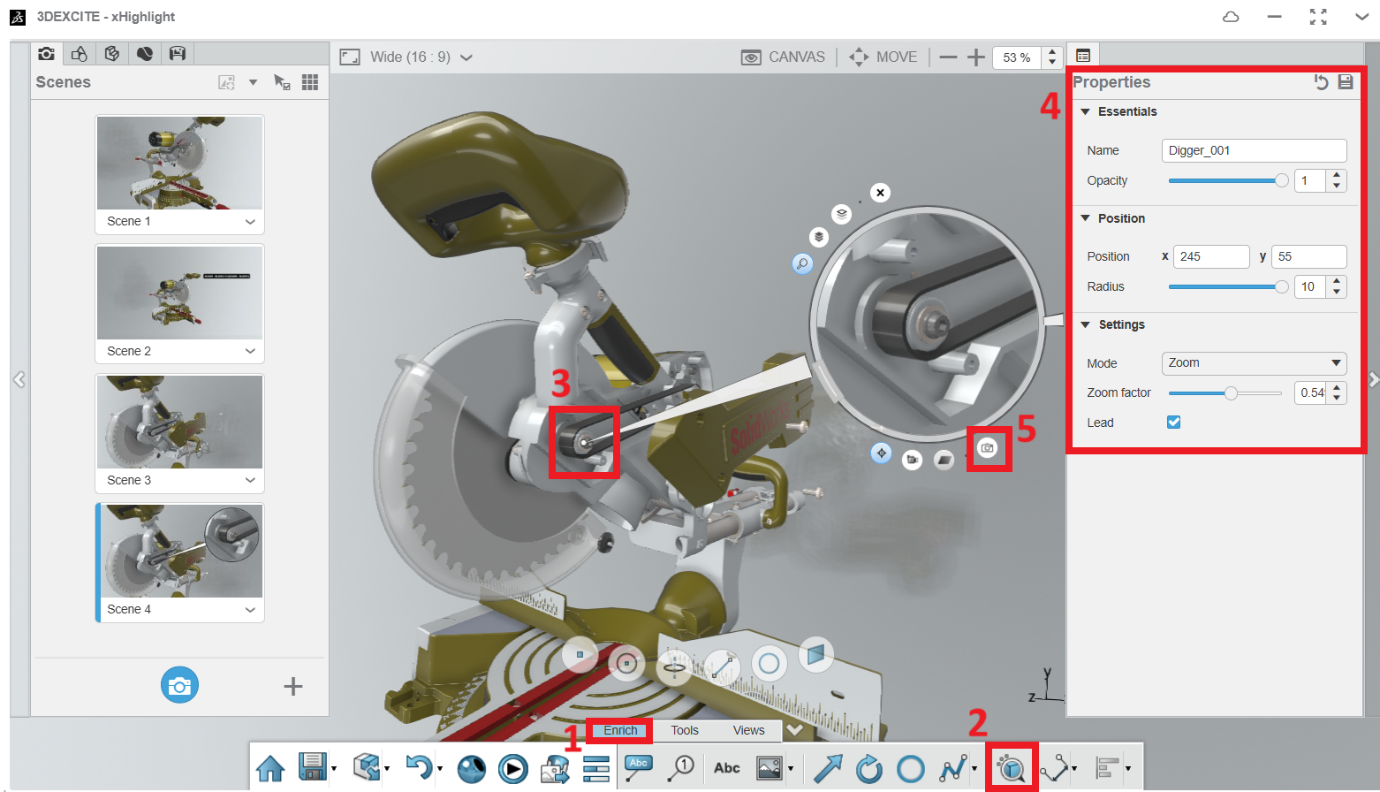
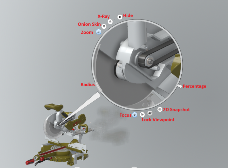
Working with Digger Tools:
In the enrich action bar and select the Create digger.
It allows you to place the Digger in the canvas.
Change the properties like position and setting and capture 2D Snapshot.
Digger Tool allows you to choose various action like zoom, onion skin and x-ray object. Then you can change the radius and percentage.
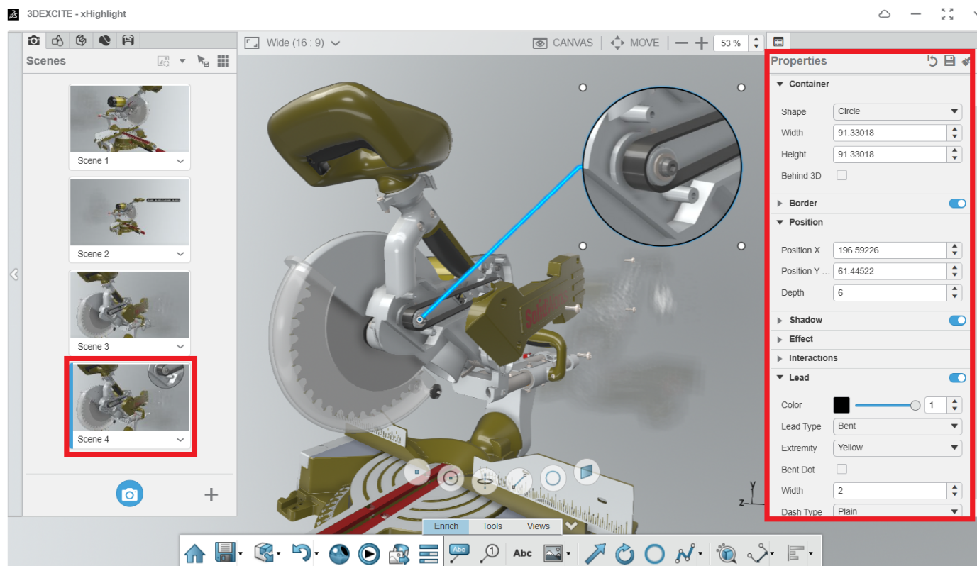
Select the captured 2D Snapshot and change the properties like shape, position and leader type and colour.
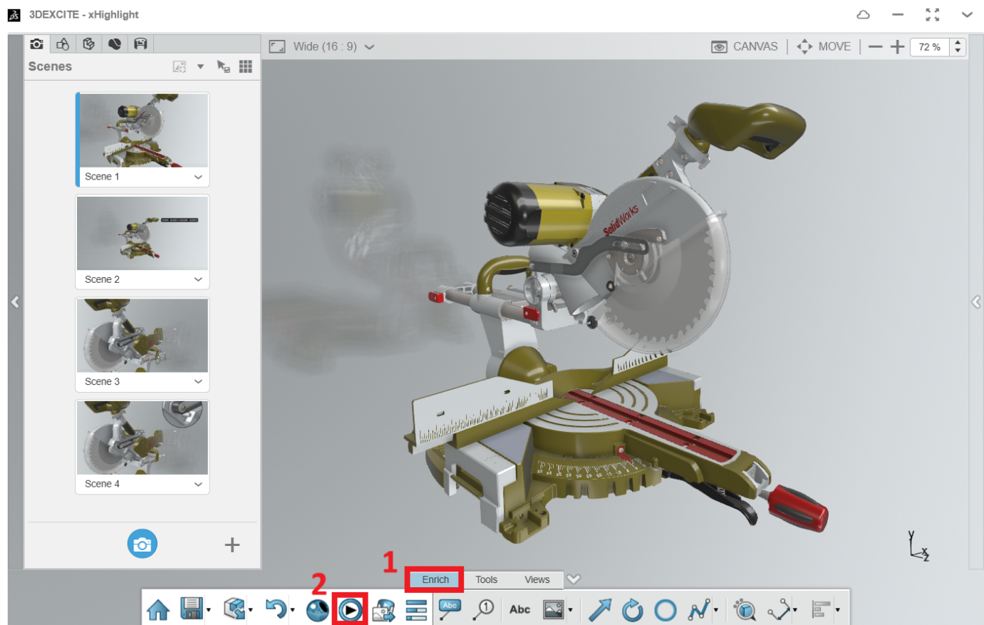
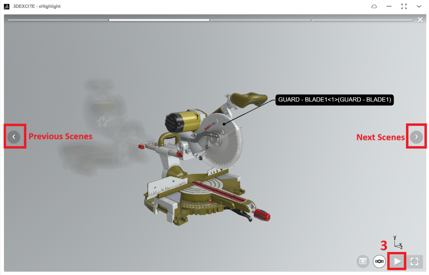
Working with Preview mode:
In the enrich action bar and select the Preview mode.
It allows you to preview the captured scenes and play the Scenes.
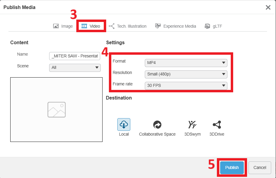
Working with Publish Media:
In the enrich action bar and select the Publish Media.
It allows you to capture the image, video and technical Illustrations.
Overall, xHighlight is a versatile tool that offers advanced Technical Documentation with visualization capabilities and enhances collaboration within the 3DEXPERIENCE platform.
If you’re new to machining, the NC Shop Floor Programmer app in 3DEXPERIENCE can be really useful. It helps connect your designs with manufacturing, making it easier to program CNC machines directly. In this blog, we’ll give you a quick guide to get started with this app.
Introduction:
Shop Floor Machining on the 3DEXPERIENCE platform bridges the gap between the virtual and physical worlds of manufacturing. It allows you to create, optimize, and validate NC (Numerical Control) programs directly from your 3D models & Learn how the NC Shop Floor Programmer in 3DEXPERIENCE makes CNC programming simple and accurate. Import designs, simulate, and create programs easily!
key features:
Machine and Tool Management: Easily manage your machines and tools to suit your specific needs. Stock Material Definition: Define the material you’ll be working with for accurate simulations and results. NC Program Creation: Quickly generate complete NC programs. The software identifies machinable features and reuses previous operations, speeding up the programming process. Simulation and Validation: Use advanced simulations to check your programs for any potential issues like accessibility and collisions before they happen on the shop floor. NC Code Generation: Automatically create precise NC code, reducing errors and ensuring efficient machining operations.
Step-by-step process of using the NC Shop Floor Programmer in 3DEXPERIENCE SOLIDWORKS:
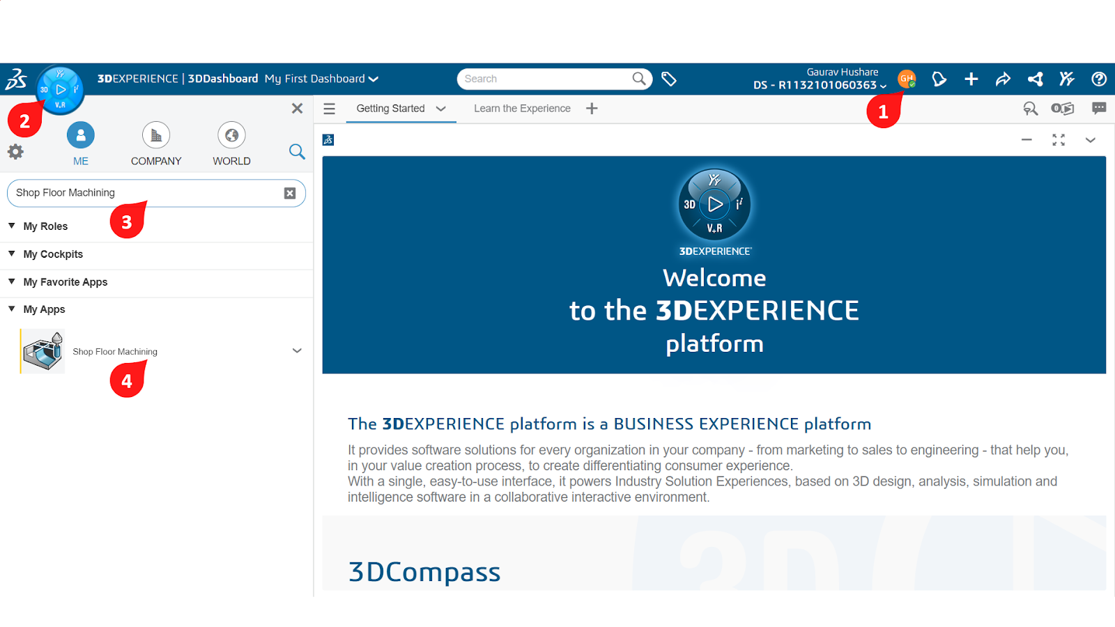
Step 1: Navigate to the NC Shop Floor App
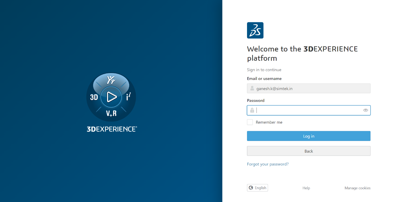
First, you need to log into your 3DEXPERIENCE platform using your account credentials (username and password).
Once you're logged in, go to the 3DEXPERIENCE Dashboard.
Look for the "Apps" section. Here, you'll find a list of available apps.
Search for “NC Shop Floor Machining” and click on it to open the app.
Step 2: Import Your 3D Model
To begin programming, you’ll need to import a 3D model (usually from CAD software like SOLIDWORKS or CATIA).
Click on “Import Model”, choose your file (like STEP, IGES, or CATPart), and load it into the app.
Step 3: Define the Machine and Tools
Select the machine type you will use (like a 3-axis mill or 5-axis, CNC lathe).
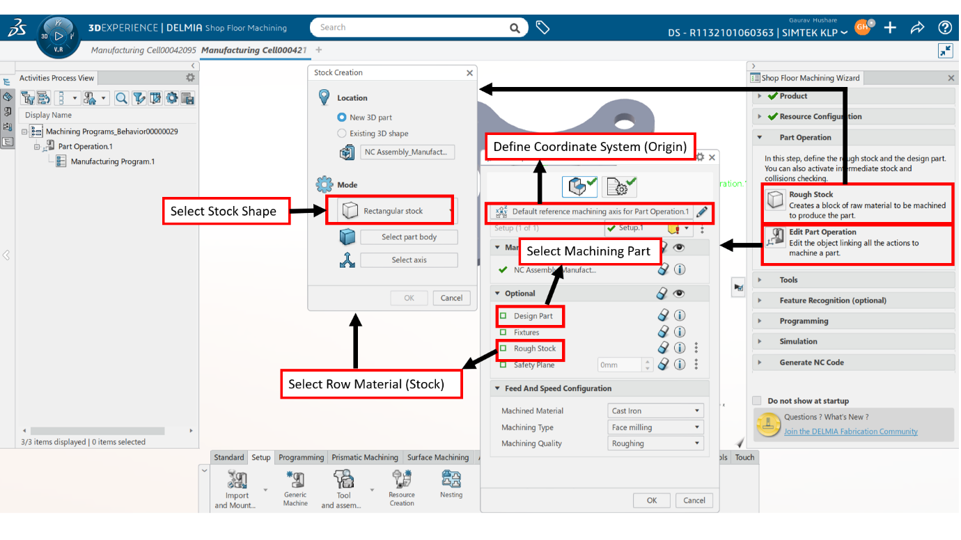
Step 4: Define the Machining Part and Stock
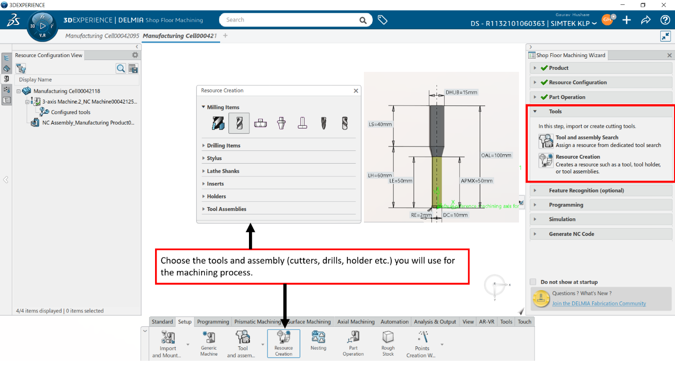
Step 5: Define the Tools
Then, choose the tools (cutters, drills, etc.) you will use for the machining process.
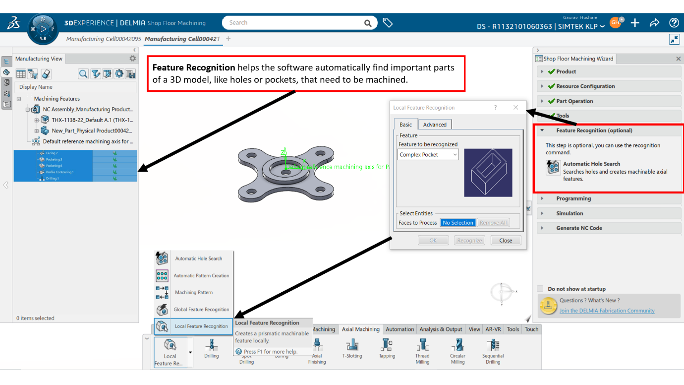
Step 6: Feature Recognition
Step 7: Generate the Toolpaths
Use the app to define the tool paths (the paths the cutting tool will follow).
The software will automatically generate these paths, but you can adjust them if needed.
Step 8: Simulate the Machining Process
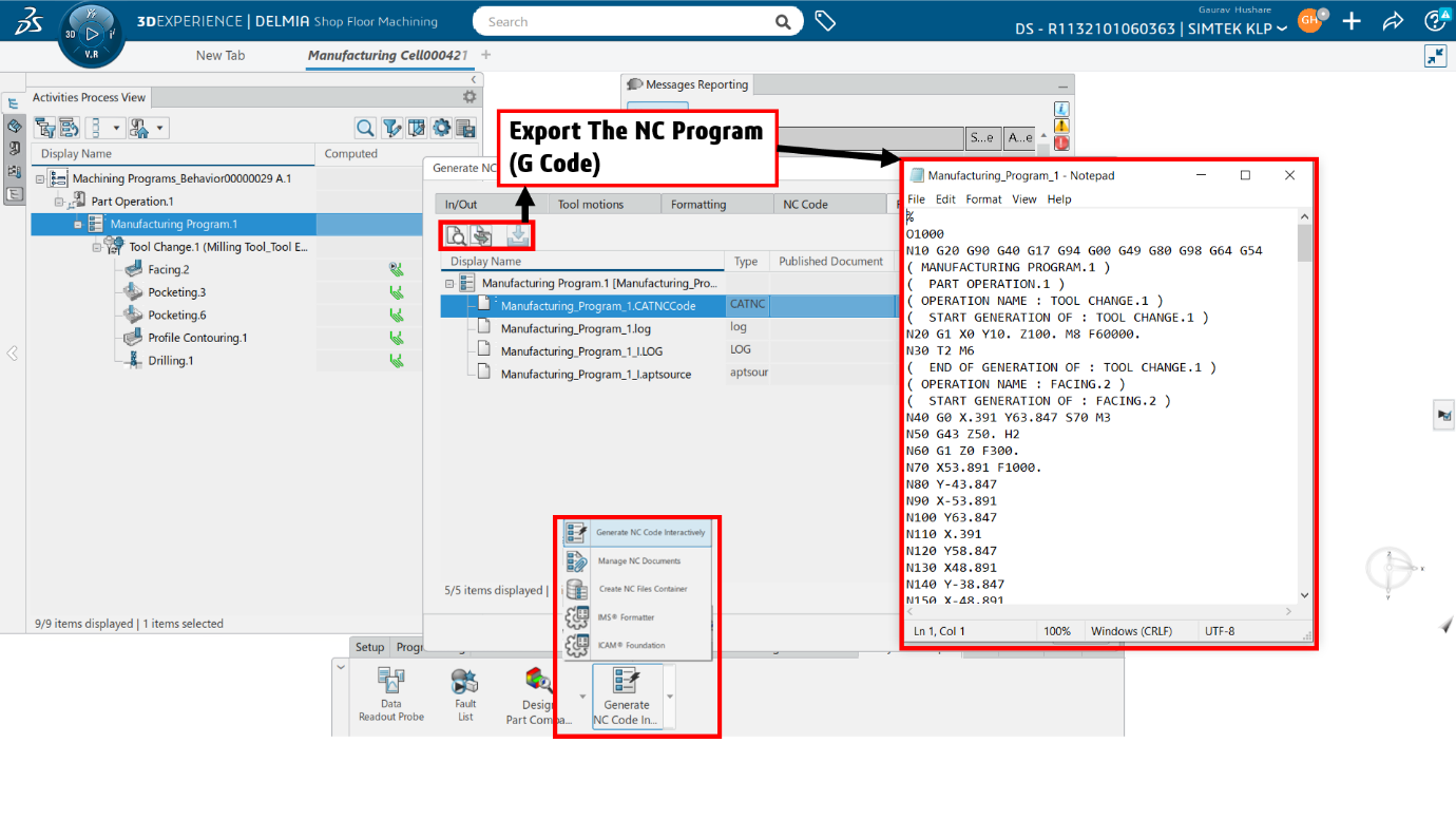
Step 9: Export the G-code
Once you're satisfied with the simulation, you can export the G-code (the set of instructions for the CNC machine).
Save the G-code file and send it to your CNC machine for actual production.
Step 10: Monitor the Process
After sending the program to the machine, you can monitor the progress and make adjustments, if necessary, directly from the app.
Step 11: Collaborate Share & Save
You can share your work with team members in real-time, so they can review and provide feedback.
Benefits:
Enhanced Efficiency: Streamline your machining processes with automated tools and reusable operations, which reduces programming time.
Improved Accuracy: Validate programs with digital simulations to find and fix issues before they reach the shop floor.
Seamless Integration: Connect design and manufacturing data to ensure consistency and reduce errors across your workflows.
Collaborative Environment: Use the 3DEXPERIENCE platform’s cloud capabilities to work together in real-time with your team, no matter where they are.
Conclusion:
The Shop Floor Machining module on the 3DEXPERIENCE platform is a powerful tool for manufacturers to boost efficiency and accuracy. It uses advanced simulations, automated tools, and a collaborative environment to make transitions from design to manufacturing smoother, ensuring high-quality outputs and streamlined operations.
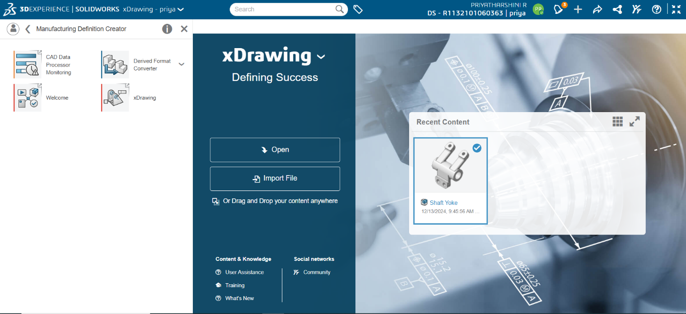
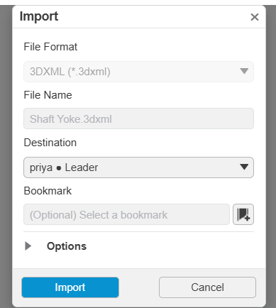
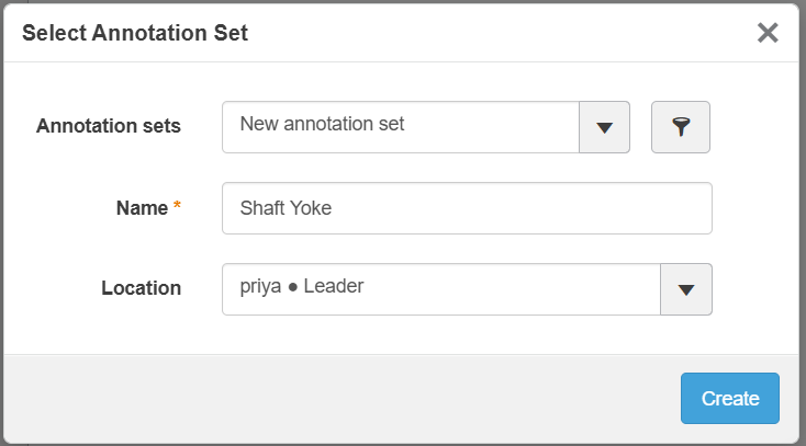
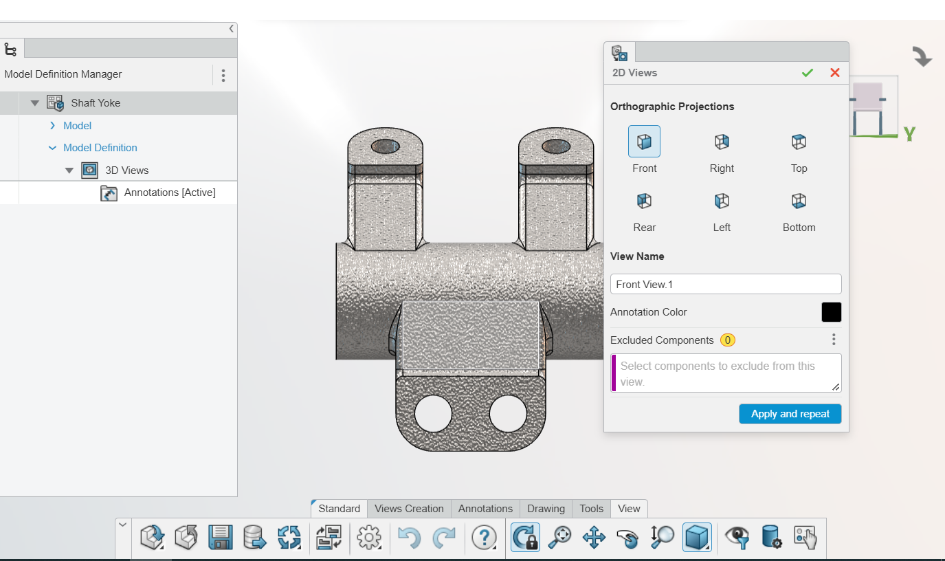
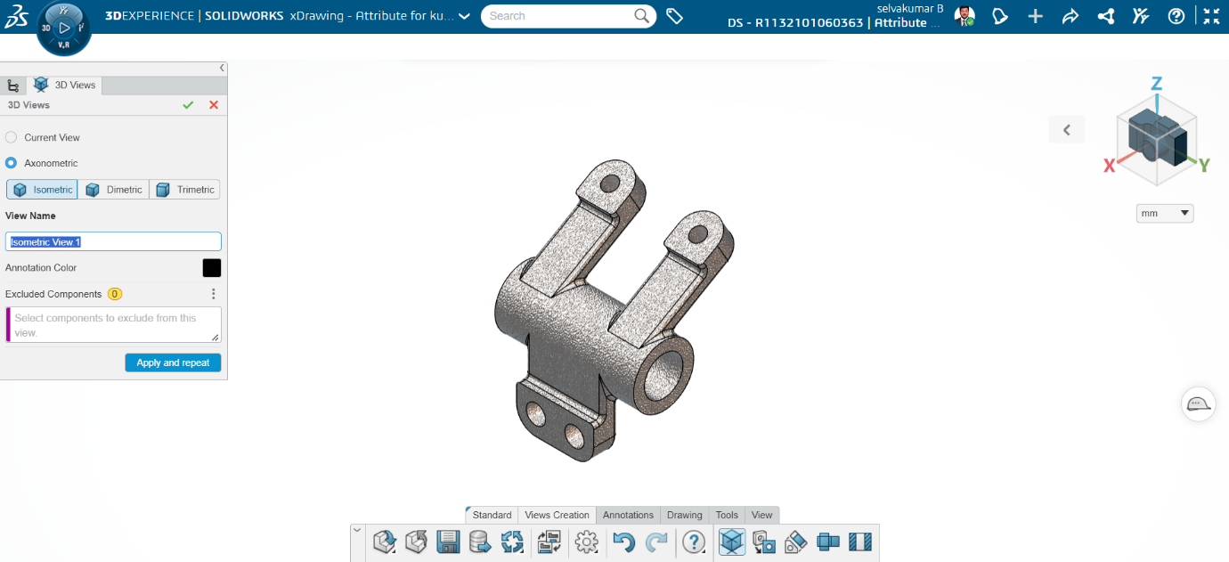
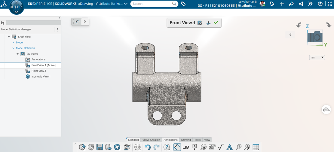
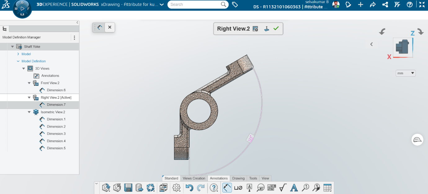
XDrawing defines, organizes, and communicates manufacturing specifications directly in 3D. This can reduce mistakes, and automate downstream productions such as manufacturing and inspections.
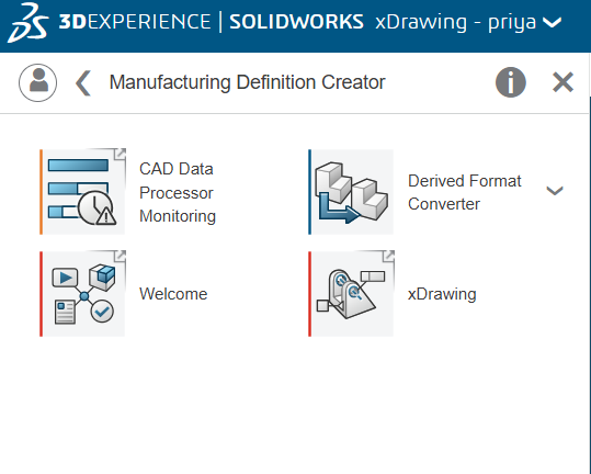
The key features of the app are to define, organize, and communicate 3D annotations. It provides access to MBD and 2D drawing environments. It is a web app and you can access it from the Compass.
As digital security becomes more critical, protecting your 3DEXPERIENCE platform with Two-Factor Authentication (2FA) is a smart move. 2FA adds an extra layer of security by requiring not only your password but also a code from an external device, like a phone or an app. Here's a quick guide to setting it up.
Why Use 2FA?
Enhanced Security: Even if your password is compromised, your data stays secure.
Reduced Risk: 2FA helps prevent unauthorized access and phishing attacks.
Steps to Enable 2FA on 3DEXPERIENCE platform
Log into Your Account: Head to the 3DEXPERIENCE login page and sign in with your usual credentials.
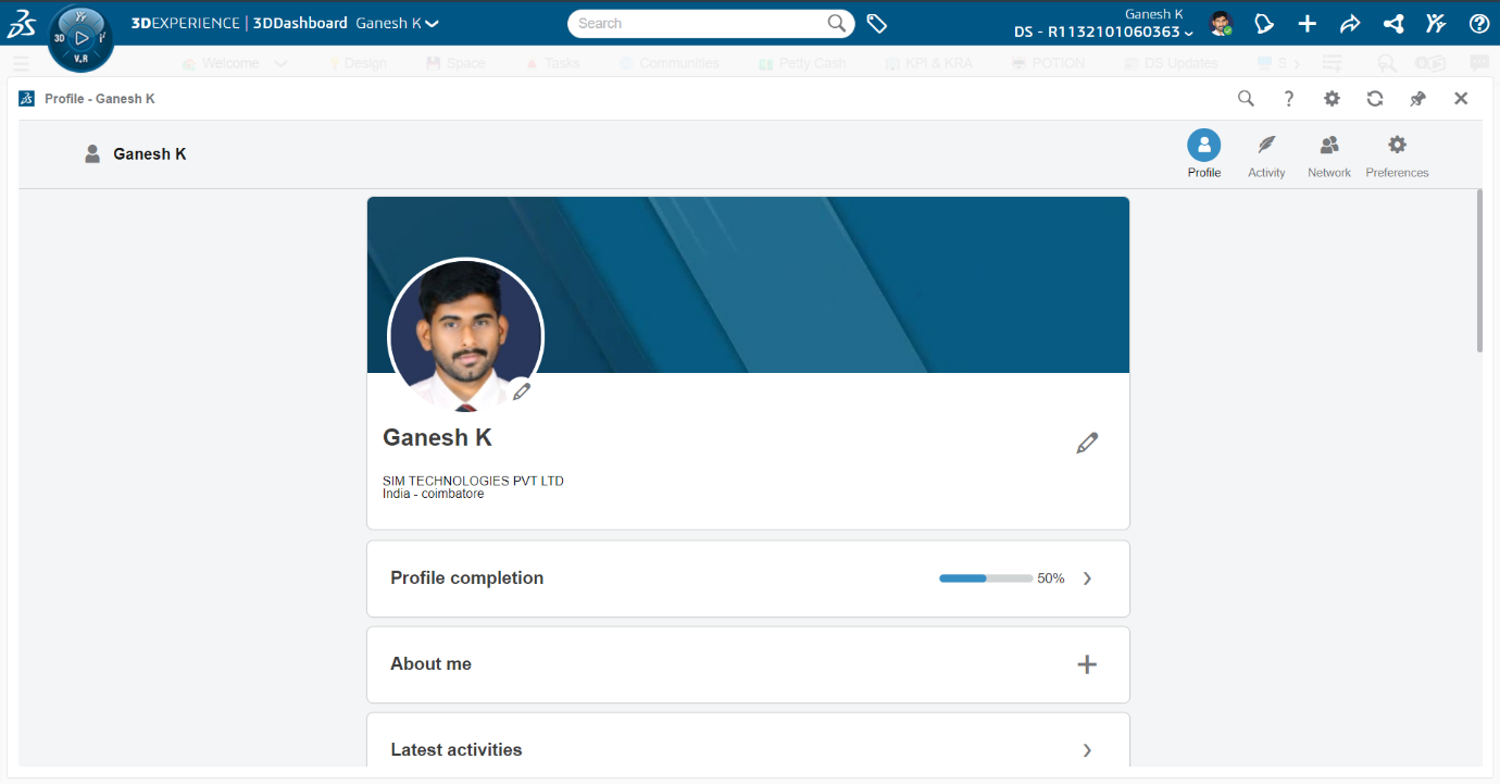
Access Security Settings:
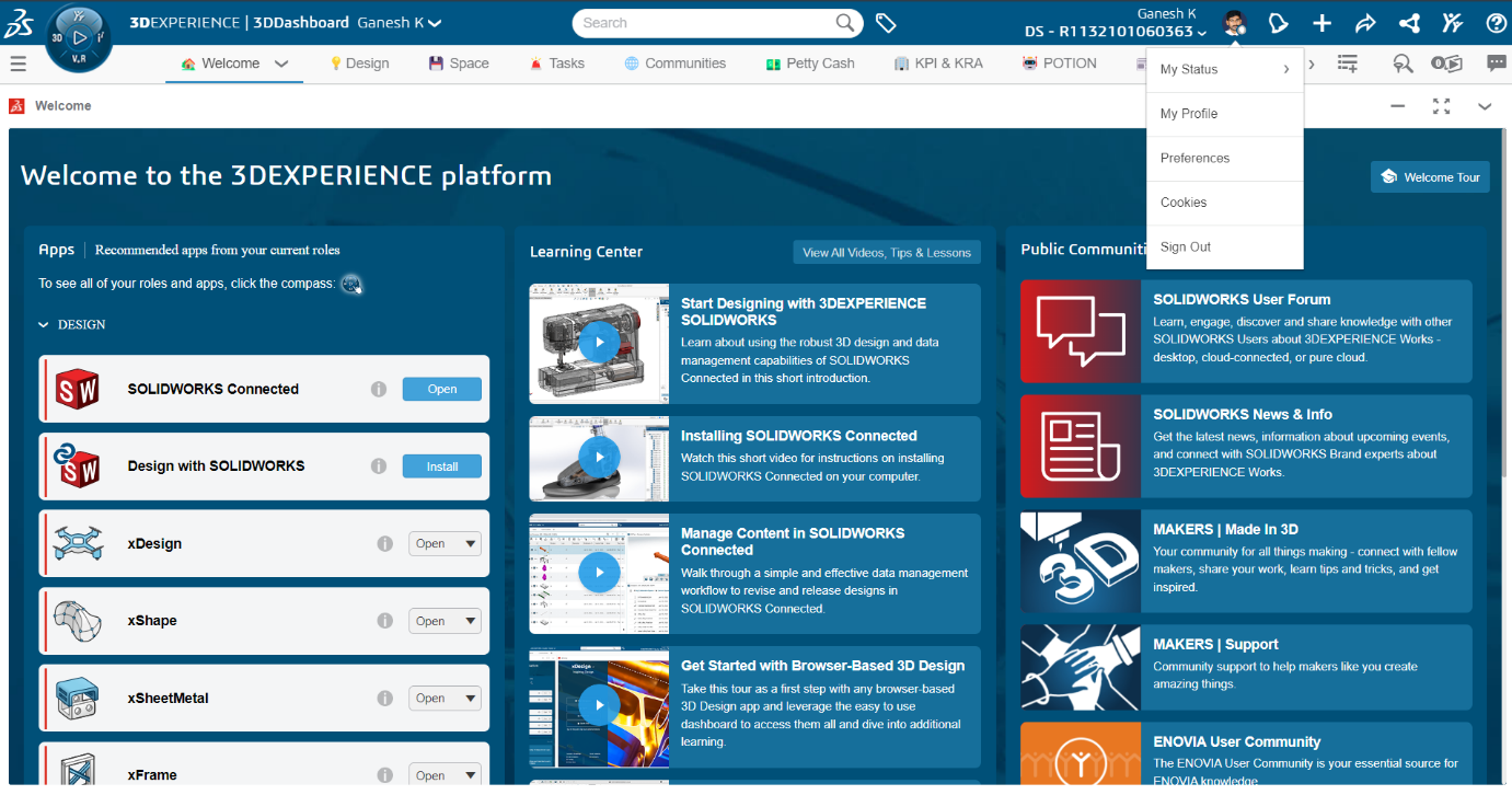
Once logged in, click on your profile icon in the top-right corner.
Select My Profile from the dropdown menu.
Once logged in, click on your profile icon in the top-right corner.
Select My Profile from the dropdown menu.
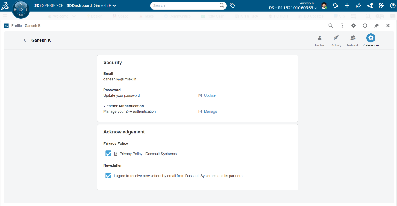
Go to the Preferences section.
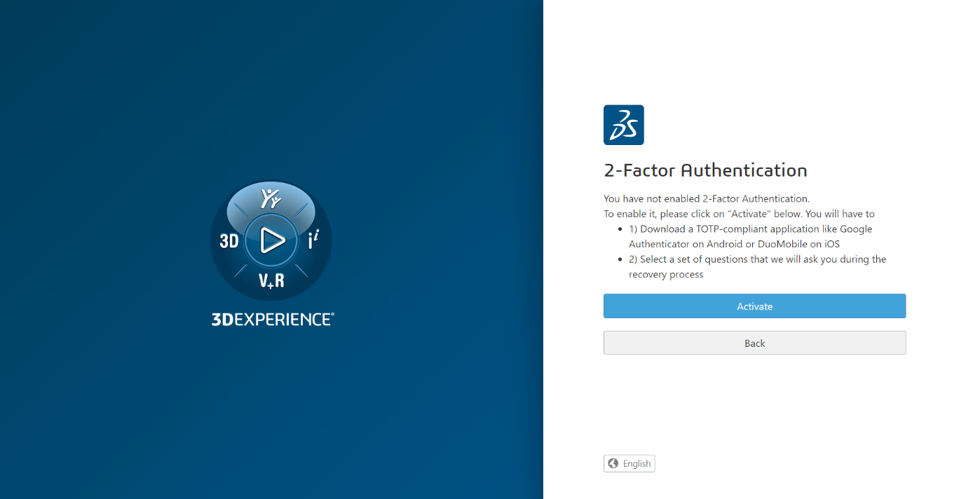
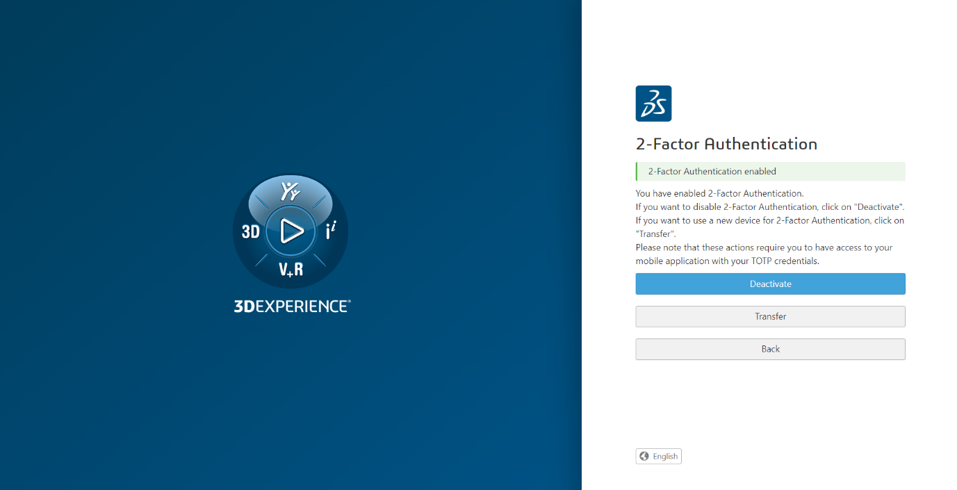
Enable Two-Factor Authentication:
Look for the option to Manage 2FA under security settings.
Click Activate and follow the on-screen instructions.
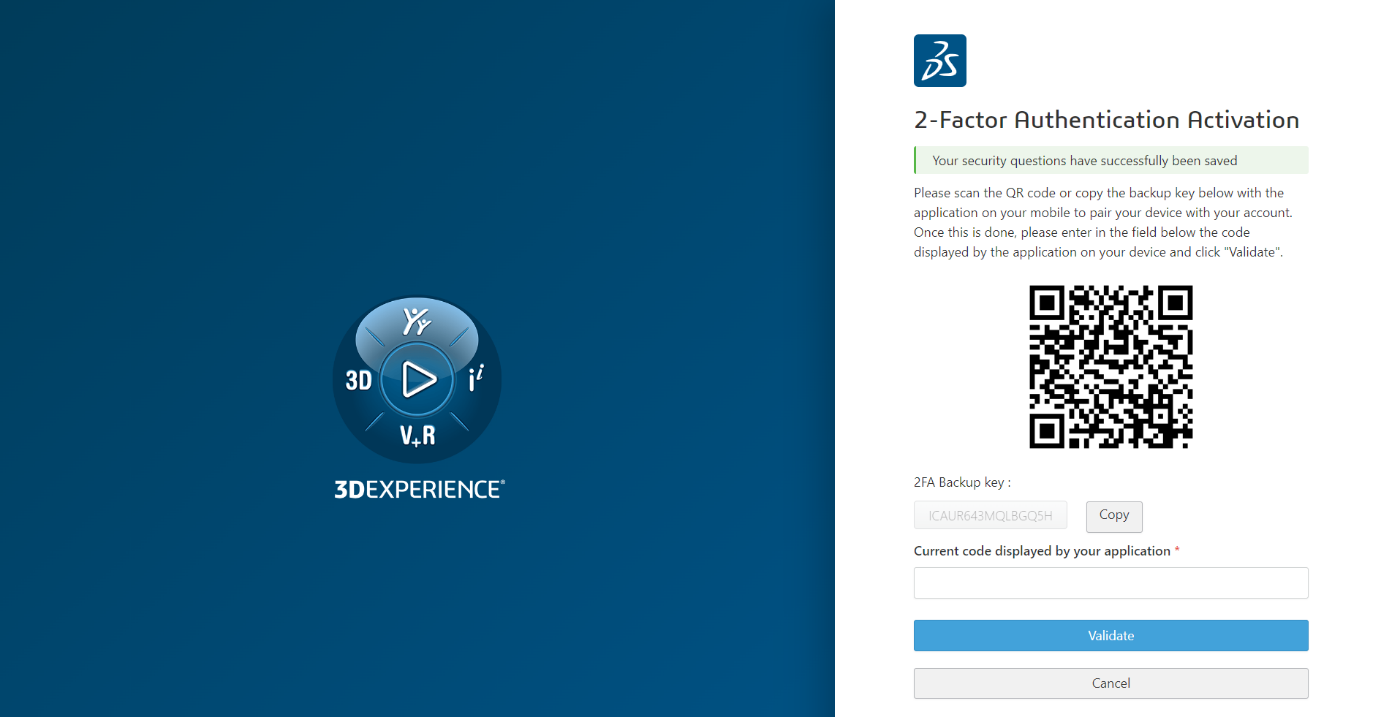
Choose Your Authentication App:
Authenticator App: Use apps like Google Authenticator or Microsoft Authenticator. Scan the QR code provided to link the app.
Authenticator App: Use apps like Google Authenticator or Microsoft Authenticator. Scan the QR code provided to link the app.
Verify the Setup:
Enter the code from the authenticator app.
Enter the code from the authenticator app.
Complete Setup: Once verified, 2FA is active on your account.
Every time you log in, you’ll need to provide both your password and a code from your chosen method.
Tips for Managing 2FA
Backup Codes: Keep your backup codes secure but accessible in case you lose your device.
Keep Your Phone Handy: You'll need it each time you log in.
Conclusion
Setting up 2FA on your 3DEXPERIENCE platform is a quick but crucial step to protect your data. This simple action can significantly reduce the risk of unauthorized access, keeping your work safe.
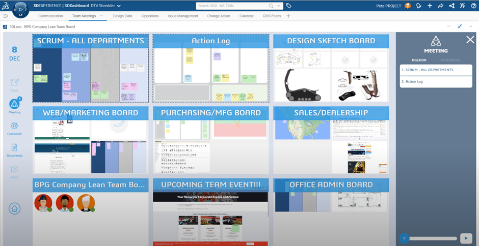
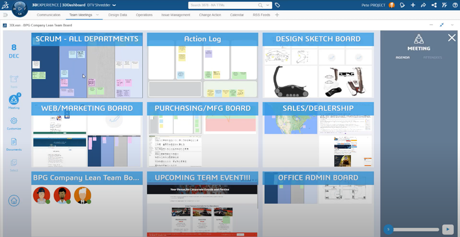
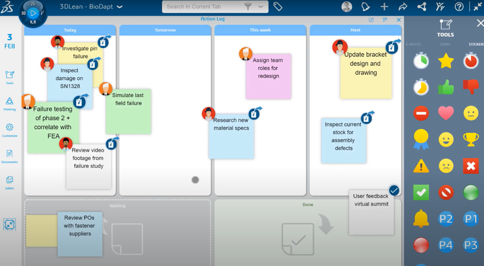
3DLEAN on the 3DEXPERIENCE platform transforms remote collaboration with dynamic, interactive tools, enhancing team meetings and bridging the gap in distributed work.
In an era where remote work has become the norm, the way we collaborate has evolved dramatically. Gone are the days when teams gathered around a physical whiteboard, armed with Post-It notes, brainstorming ideas and tackling challenges. As organizations adapt to distributed work environments, tools that enhance collaboration are essential. 3DLEAN on the 3DEXPERIENCEplatform is designed to bridge the gap, offering a dynamic, interactive solution for effective team meetings.
The Limitations of Traditional Collaboration Tools
While tools like Skype, Microsoft Teams, and Zoom have facilitated virtual communication, they often fall short in fostering genuine collaboration. Screen sharing can feel one-dimensional, and the ability to contribute in real-time is limited. This disconnect can lead to missed ideas and a lack of accountability, especially during spontaneous meetings like flash huddles.
Enter 3DLEAN: A Game Changer for Remote Teams
3DLEAN reimagines the concept of the whiteboard by providing a collaborative, web-based platform where team members can engage in real-time. Here’s how it stands out:
Key Benefits of 3DLEAN
Interactive Experience: Users can simultaneously edit and interact with the whiteboard, allowing for a more engaging and productive discussion.
Enhanced Accountability: With 3DLEAN, every sticky note and task is visible to all participants, ensuring that action items are clearly assigned and tracked.
User-Friendly Interface: The tool’s straightforward design allows teams to get started quickly, reducing setup time and keeping the focus on problem-solving.
How to Get Started with 3DLEAN
The process of using 3DLEAN is intuitive and efficient.
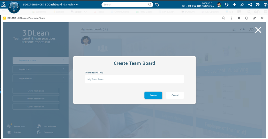
1. Create Your Board: Begin by setting up a new board tailored to your specific meeting or project needs.
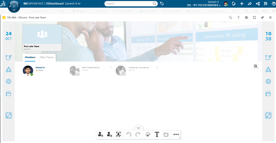
2. Invite Team Members: Send invitations to your team, ensuring everyone can join the collaborative space seamlessly.
3. Launch Your Meeting: Start the session and encourage all participants to dive in and contribute.
4. Use Sticky Notes for Ideas: Create sticky notes to capture thoughts, issues, and brainstorms, allowing everyone to visualize the discussion.
5. Context and Task Assignment: Attach context to each sticky note and assign tasks to enhance clarity and accountability among team members.
Versatile Applications of 3DLEAN
3DLEAN is not limited to one type of meeting; its versatility allows it to be used in various scenarios:
Quick Stand-Up Meetings: Ideal for daily check-ins to address immediate concerns or updates.
In-Depth Kaizen Sessions: Facilitate comprehensive discussions focused on continuous improvement and lean methodologies.
As teams continue to navigate the complexities of remote collaboration, 3DLEAN on the 3DEXPERIENCE platform offers a robust solution to enhance engagement and productivity. By transforming the traditional meeting experience into an interactive, real-time environment, 3DLEAN empowers teams to stay aligned and accountable, no matter where they are.
Embrace the future of collaboration with 3DLEAN and elevate your team’s efficiency and creativity!
What is 3DLEAN?
3DLEAN is an innovative tool within the 3DEXPERIENCE platform, designed to mimic and enhance the traditional whiteboard experience. It offers a dynamic, web-based interface where teams can collaborate in real time, regardless of location. By integrating lean methodologies and digital convenience, 3DLEAN helps teams brainstorm, problem-solve, and stay aligned like never before.
Key Features and Benefits of 3DLEAN
1. Interactive and Intuitive User Experience
The hallmark of 3DLEAN is its interactive interface. Unlike static screen-sharing tools, it allows all participants to contribute simultaneously. Whether it's editing sticky notes, rearranging ideas, or annotating content, team members can engage actively, creating a sense of shared ownership.
2. Enhanced Accountability and Transparency
Accountability is central to effective teamwork With 3DLEAN:
Sticky notes and action items are visible to all participants, ensuring clarity on who is responsible for each task.
Changes are tracked in real-time, reducing the chances of miscommunication or forgotten assignments.
3. Quick and Easy Setup
Time spent on tool setup is time lost from solving actual problems. 3DLEAN’s user-friendly design ensures teams can start collaborating with minimal training:
Create customized boards for specific projects or meetings.
Send quick invitations to participants for seamless access.
Begin sessions with minimal technical overhead.
4. Versatile Applications
3DLEAN is highly adaptable, making it suitable for various types of meetings and industries:
Daily Stand-Ups: Streamline daily check-ins by capturing key updates and immediate concerns.
Kaizen and Lean Sessions: Facilitate detailed discussions focused on continuous improvement.
Strategic Planning: Use visual aids to map out long-term goals, identify obstacles, and plan action steps.
How to Use 3DLEAN for Maximum Impact
Getting started with 3DLEAN is as straightforward as it is effective. Here’s a step-by-step guide to unlock its full potential:
1. Set Up Your Board
Start by creating a new whiteboard tailored to the specific purpose of your meeting, such as brainstorming, project planning, or issue resolution.
Customize the layout to include categories, timelines, or other elements that align with your goals.
2. Invite Your Team
Use the built-in invitation feature to ensure all relevant stakeholders can access the board.
Provide a brief overview of how 3DLEAN works to maximize participation.
3. Conduct Interactive Sessions
Begin your meeting by encouraging participants to add sticky notes for ideas, challenges, or feedback.
Group related notes into categories to maintain an organized discussion.
4. Assign Tasks and Track Progress
Attach context to sticky notes to clarify the intent behind each idea.
Assign specific tasks to individuals, complete with deadlines and priorities.
Use built-in tracking features to monitor progress and ensure accountability.
Why Choose 3DLEAN Over Other Collaboration Tools?
While tools like Microsoft Teams, Slack, and Miro are popular, 3DLEAN stands out for several reasons:
Real-Time Engagement: Unlike static tools, 3DLEAN enables dynamic interaction, replicating the spontaneity of in-person meetings.
Lean Methodology Integration: Its design aligns with lean principles, promoting efficiency, clarity, and continuous improvement.
Seamless Collaboration: With cloud-based access and integration into the 3DEXPERIENCE platform, teams can collaborate without worrying about software compatibility or data silos.
Real-World Applications of 3DLEAN
1. Quick Stand-Up Meetings
For daily check-ins, 3DLEAN provides a streamlined way to address pressing issues, track progress, and align priorities. By using visual aids like sticky notes, teams can keep discussions concise and actionable.
2. Kaizen Sessions
Kaizen, or continuous improvement, requires a platform that fosters open dialogue and accountability. 3DLEAN’s collaborative environment is ideal for identifying inefficiencies, brainstorming solutions, and tracking implementation.
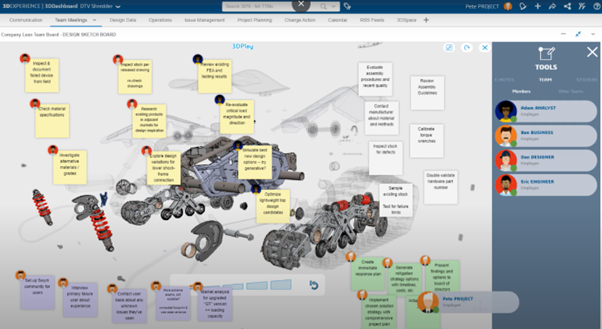
3. Remote Brainstorming
Remote teams often struggle to replicate the energy of in-person ideation sessions. With its interactive features, 3DLEAN bridges this gap, allowing teams to brainstorm creatively and visually.
4. Strategic Planning and Roadmapping
Long-term planning requires clear communication and visualization. Use 3DLEAN to map out strategies, identify potential roadblocks, and assign responsibilities.
Advantages of 3DLEAN for Remote Teams
Increased Productivity: By reducing setup time and fostering real-time collaboration, 3DLEAN helps teams focus on solving problems and driving results.
Improved Communication: Visual tools and transparent task assignments ensure that everyone is on the same page.
Higher Engagement: An interactive interface keeps participants engaged, even during lengthy discussions.
Better Outcomes: By combining the flexibility of digital tools with the structure of lean methodologies, 3DLEAN delivers tangible improvements in team performance.
Conclusion: The Future of Team Collaboration
As remote work becomes an enduring reality, the need for innovative collaboration tools is more important than ever. 3DLEAN on the 3DEXPERIENCE platform offers a powerful solution to the challenges of remote teamwork. By transforming traditional meetings into interactive, engaging, and results-oriented sessions, it empowers teams to stay aligned and achieve their goals efficiently.
Whether you’re conducting daily stand-ups, facilitating Kaizen sessions, or planning long-term strategies, 3DLEAN provides the tools you need to succeed in today’s collaborative landscape. Don’t let outdated methods hold your team back. Embrace the future of collaboration with 3DLEAN and unlock your team’s full potential.
Start your journey today and discover how 3DLEAN can revolutionize the way your team collaborates!
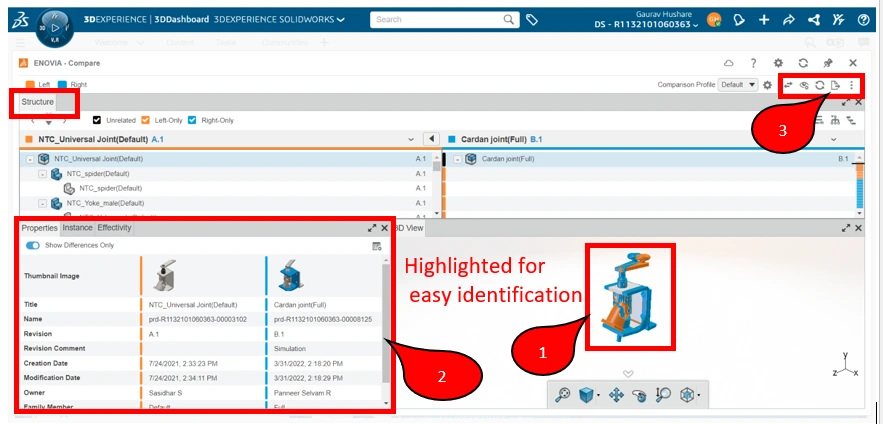
The 3DEXPERIENCE Compare App facilitates visual comparisons between different versions of 3D models and documents. This application helps users quickly identify differences, ensuring they track and manage design changes effectively.
Key Features of the Compare App
Intuitive Interface
The Compare App boasts a user-friendly interface that allows users to quickly upload and analyze files. This simplicity is crucial for teams that may not have extensive training in complex software.
Customizable Comparison Settings
Users can tailor the comparison process based on their specific needs, whether focusing on geometric changes, dimensions, or annotations. This flexibility helps teams prioritize what matters most in their reviews.
Real-Time Collaboration
The Compare App allows multiple users to view and analyze changes simultaneously. This real-time collaboration enhances communication and ensures everyone is aligned on the project’s progress.
Why Use the Compare App
Increased Efficiency: Quickly identify differences between model versions, reducing the time spent on manual comparisons.
Improved Accuracy: Minimize the risk of overlooking critical changes that could affect project outcomes, thereby enhancing overall quality.
Enhanced Team Collaboration: Foster a culture of transparency and teamwork by enabling all members to participate in the review process actively.
How to use Compare App Step-by-Step
Step 1: Preparing Your Files
Organize your 3D models or documents properly before using the Compare App.
Version Control: Make sure that you have the latest versions of the files you want to compare. Clear naming conventions can help identify versions easily.
Step 2: Uploading Files
Once your files are ready, follow these steps to upload them to the Compare App:
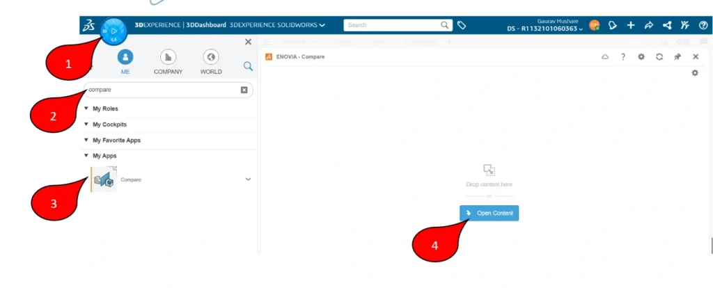
Access the Compare App: Log in to your 3DEXPERIENCE platform and navigate to the Compare App. Launch compare application in compass and clicks Open Content.
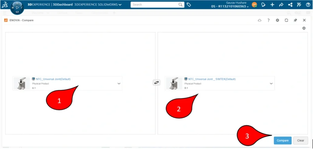
Select Files: Click on the option to upload files. Choose the two versions of the model or document you want to compare.
Initiate Comparison: After selecting the files, click “Compare” to begin the analysis.
Step 3: Analyze Comparison Results
Review visual results: Use the highlighting feature to see differences (e.g., colors indicating additions, deletions, or modifications).
Navigate through a summary report that lists detailed differences.
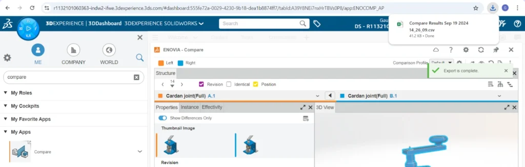
Step 4: Generate and Customize Reports
Export Results Excel Format (.csv)
Download or share the report.
Summary
The 3DEXPERIENCE Compare App is a powerful tool that enhances design reviews and team collaboration. By enabling efficient visual comparisons and fostering communication, it plays a crucial role in ensuring that projects are completed accurately and on time. Embracing the Compare App can lead to improved workflow efficiency and better overall project outcomes.
This guide will walk you through the process of downloading SOLIDWORKS, with a special focus on how you can easily access it through SIMTEK, an authorized SOLIDWORKS reseller.
Why Choose SOLIDWORKS?
Before we get into the download process, here’s why it is the preferred choice for many professionals and students alike:
Comprehensive Design Capabilities: SOLIDWORKS provides an extensive suite of tools for 3D design, simulation, visualization, and product data management.
Industry Standard: It’s the go-to software across various industries, ensuring that your designs meet global standards.
User-Friendly Interface: SOLIDWORKS is known for its intuitive user interface, making it accessible to both beginners and experts.
Strong Community Support: With a vast online community and abundant resources, learning and troubleshooting are made easy.
Here’s a step-by-step guide on how to download SOLIDWORKS, with a focus on getting your license through SIMTEK:
Determine Your SOLIDWORKS Version
Professional or Educational: SOLIDWORKS offers versions tailored for professionals, students, and educators. Determine which version suits your needs.
Trial Version: If you’re new to this software, consider starting with a free trial. This allows you to explore the software’s capabilities before making a purchase.
Visit SIMTEK’s Website
Go to the SIMTEK website, the authorized reseller for SOLIDWORKS in India.
Navigate to the 'Request for Quote' page or the 'Contact Us' page
Submit Your Request
On the 'Request a Quote' page, fill in your details and specify the SOLIDWORKS version you’re interested in. This ensures that you receive the most accurate pricing and information.
Alternatively, you can reach out directly via the contact details provided on the website, including phone and email.
Receive Your Download and Installation Instructions
Once you’ve submitted your request, a SIMTEK representative will contact you and will guide you through the further steps,they will take care of the rest of the process. In case if you have any doubt, feel free to ask the representative, they will clarify your doubt.
Download the Installation Manager
Follow the instructions provided by SIMTEK to download the SOLIDWORKS Installation Manager. This tool will help you download the full software package.
Run the Installation Manager
Open the Installation Manager and follow the guided steps to install the software on your computer. You’ll need the serial number provided by SIMTEK.
Activate Your License
After installation, activate your SOLIDWORKS license using the serial number provided. Ensure you have a stable internet connection during activation.
Start Designing!
With the software installed and activated, you’re ready to begin your design projects. Explore the tools and start creating your 3D models.
Why Buy SOLIDWORKS from SIMTEK?
Authorized Reseller: SIMTEK is an authorized reseller, ensuring that you receive genuine software and professional support.
Expert Support: SIMTEK offers excellent customer service and technical support, helping you with installation, activation, and any issues you may encounter.
Tailored Solutions: Whether you're a student, educator, or professional, SIMTEK provides solutions tailored to your specific needs.
Common Issues and Troubleshooting
Installation Errors: If you encounter errors during installation, SIMTEK’s support team is available to assist you.
License Activation Issues: Enter your serial number correctly and ensure your internet connection is stable during activation.
System Compatibility: Double-check system requirements before downloading to avoid performance issues.
Conclusion
Downloading SOLIDWORKS is an essential first step in your design journey. By choosing to download through SIMTEK, you ensure that you’re getting authentic software backed by expert support. Ready to get started? Visit SIMTEK’s Request a Quote page or contact them directly at the phone number or email provided on their website. Let SIMTEK guide you through every step of the process so you can focus on what you do best—designing!