Why SIMTEK Is the Best Engineering Service Provider in Chennai for Industrial Solutions

Introduction: The Role of Engineering Service Providers in Modern Industry
Modern industries operate under constant pressure to innovate, reduce costs, and accelerate product development. From automotive and heavy engineering to industrial machinery and emerging EV applications, engineering quality has a direct impact on productivity, reliability, and profitability.
To stay competitive, many organizations now rely on professional engineering service providers instead of building large in-house teams. An experienced engineering partner brings specialized skills, proven processes, and scalable resources.
In Chennai, one of India’s largest industrial hubs, SIMTEK has established itself as a trusted engineering service provider delivering reliable industrial solutions across the product lifecycle.
What Is an Engineering Service Provider?
An engineering service provider is a company that offers outsourced engineering services such as mechanical design, CAD modeling, CAE simulation, manufacturing engineering, CAM programming, and PLM support.
Unlike staffing firms or freelancers, engineering service providers:
- Deliver outcome-based engineering solutions
- Follow structured engineering processes
- Use certified engineering tools
- Act as long-term partners to manufacturers
SIMTEK operates as a full-service engineering service provider focused specifically on industrial and manufacturing applications.
Why Chennai Is a Strategic Hub for Engineering Services
Chennai is one of India’s most important manufacturing and engineering ecosystems. The region hosts:
- Automotive OEMs and Tier-1 suppliers
- Heavy engineering and industrial machinery manufacturers
- Tool & die and mold manufacturing companies
- Aerospace and defense suppliers
- Robotics, automation, and EV manufacturers
This industrial concentration creates strong demand for engineering partners who understand manufacturing realities, shop-floor challenges, and production constraints.
SIMTEK’s presence in Chennai enables close alignment between engineering design and real-world industrial execution.
Rising Demand for Engineering Service Providers in Chennai
Industrial companies increasingly partner with engineering service providers due to:
- Shortage of specialized engineering talent
- Rising cost of maintaining large internal teams
- Need to reduce product development cycles
- Increasing complexity of industrial products
By outsourcing to a reliable engineering service provider in Chennai, companies gain access to scalable engineering expertise without increasing fixed costs.
SIMTEK was built to address these challenges efficiently.
About SIMTEK
SIMTEK is a professional engineering services company delivering end-to-end engineering solutions for industrial and manufacturing organizations. Its services cover mechanical design, simulation, manufacturing engineering, CAM programming, and digital engineering platforms.
What sets SIMTEK apart is its manufacturing-first approach. Every engineering output is evaluated for feasibility, efficiency, and production readiness, ensuring real value on the shop floor.
Authorized and Certified Engineering Expertise
Engineering credibility is built on certification and compliance with global standards.
SIMTEK is an Authorized Partner and Certified Service Provider for leading engineering platforms, including:
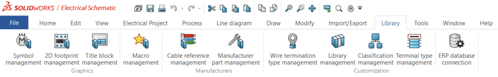
- SOLIDWORKS
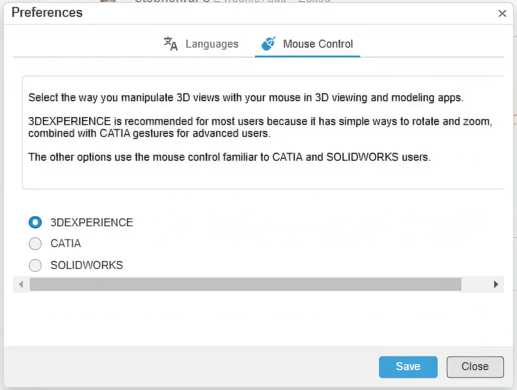
- Dassault Systèmes solutions such as 3DEXPERIENCE, CATIA, SIMULIA, and DELMIA
- CAM platforms including GibbsCAM and Cimatron
These certifications ensure best-practice workflows, validated methodologies, and consistent engineering quality.
End-to-End Engineering Services for Industrial Solutions
SIMTEK offers complete engineering services under one roof, enabling smooth collaboration and accountability throughout the product lifecycle.
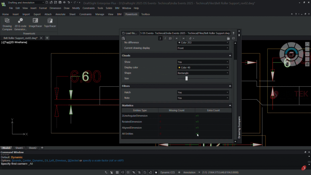
Mechanical Design and CAD Engineering Services
SIMTEK provides:
- 2D drafting and detailing
- 3D CAD modeling
- Industrial machine and equipment design
- Sheet metal, weldments, and structural design
- Plastic part and tooling design
All designs focus on manufacturability, assembly efficiency, and lifecycle performance.
CAE Simulation and Engineering Validation
SIMTEK’s simulation services help reduce risk and development cost through:
- Finite Element Analysis (FEA)
- Structural and thermal analysis
- Motion and kinematic simulations
- Design validation and optimization
These services improve product reliability and reduce dependency on physical prototypes.
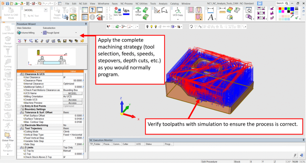
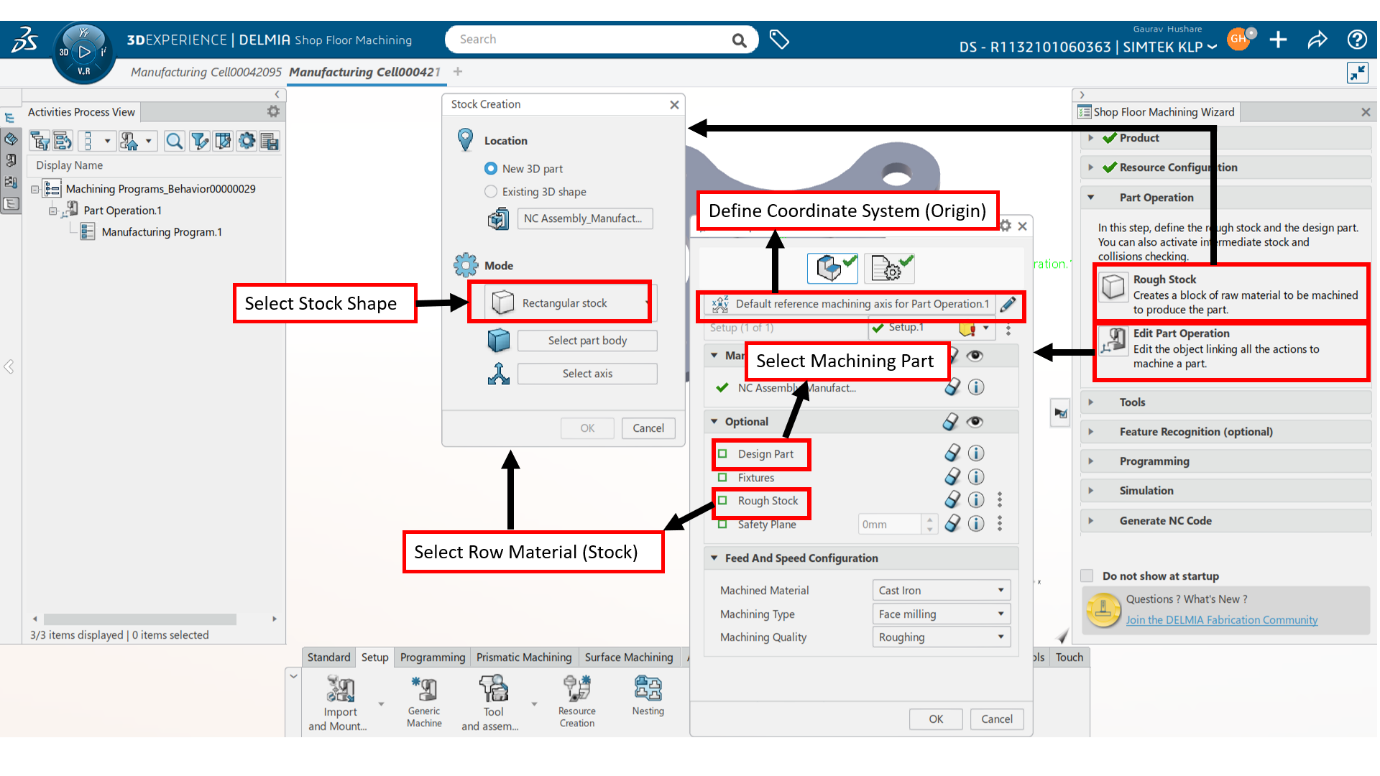
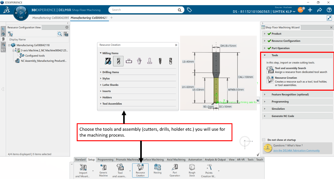
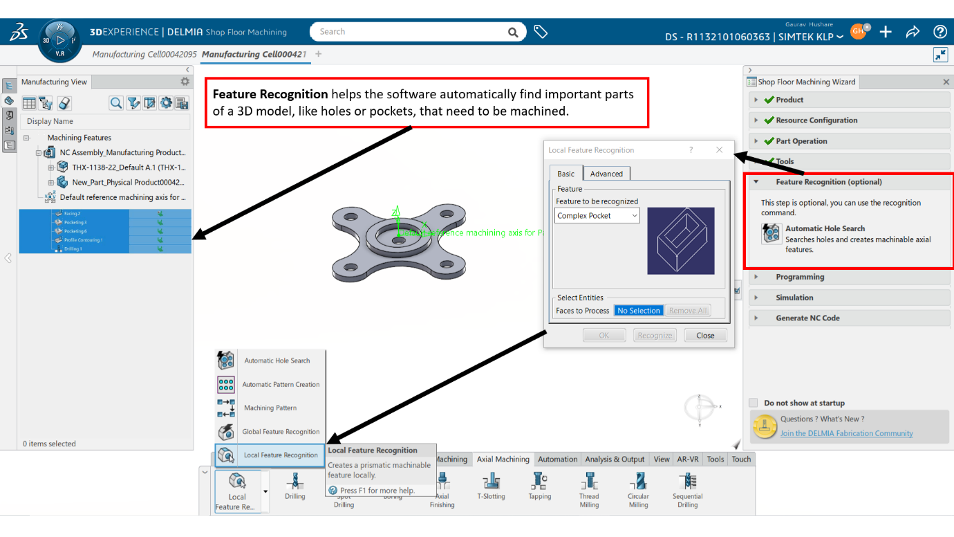
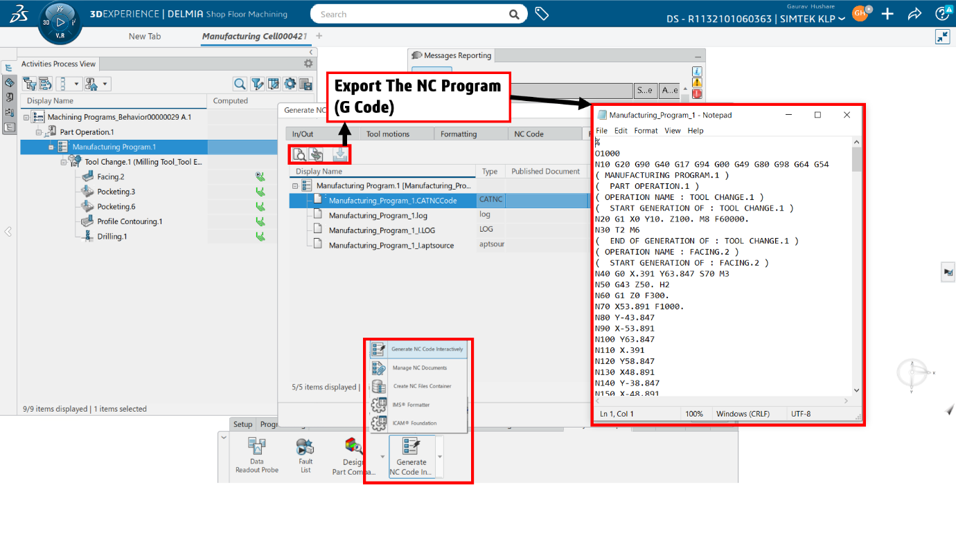
Manufacturing Engineering and CAM Programming
To bridge design and production, SIMTEK delivers:
- CNC programming
- 3-axis, 4-axis, and 5-axis CAM solutions
- Toolpath optimization
- Post-processor development and support
This capability supports machine shops and manufacturing plants across Chennai and Tamil Nadu.
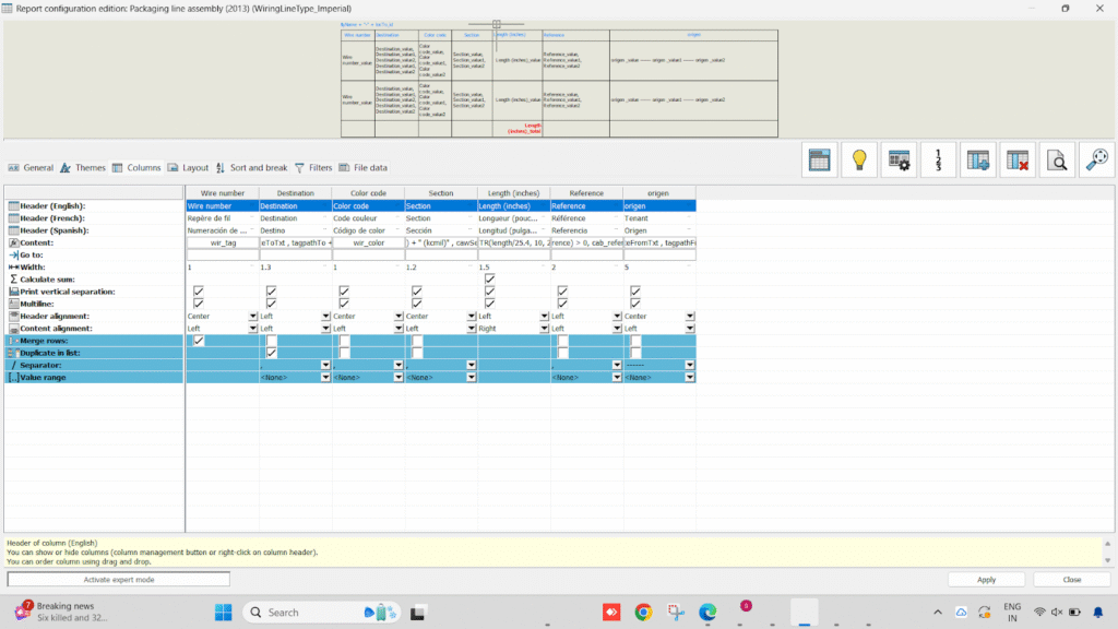
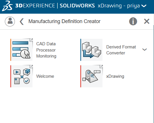
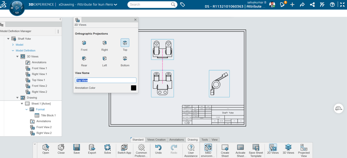
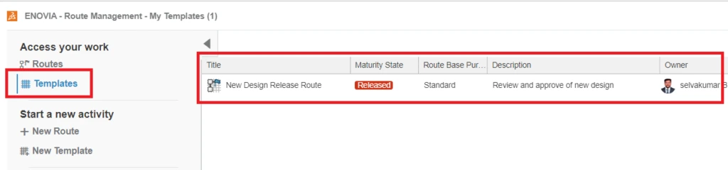
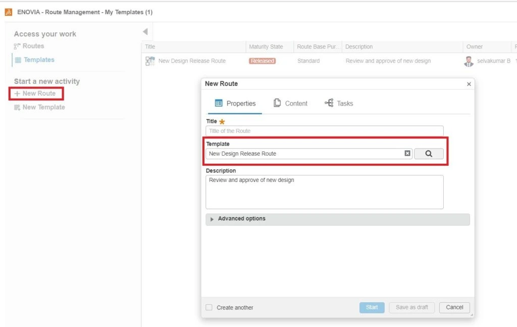
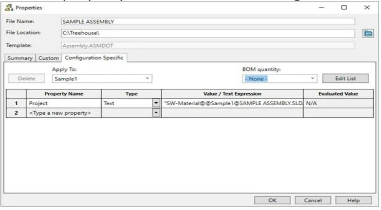
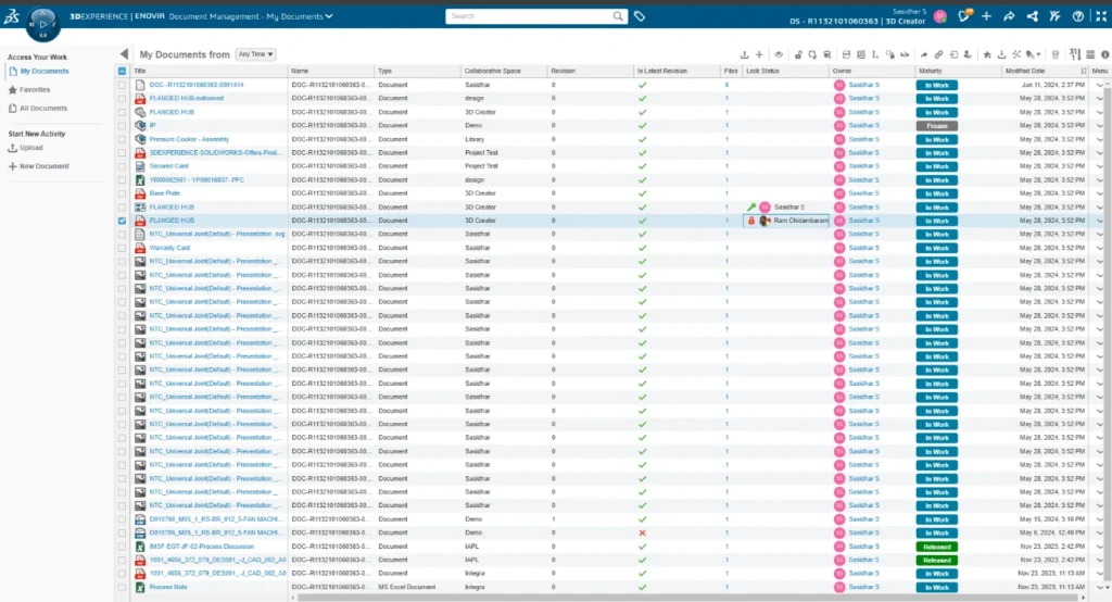
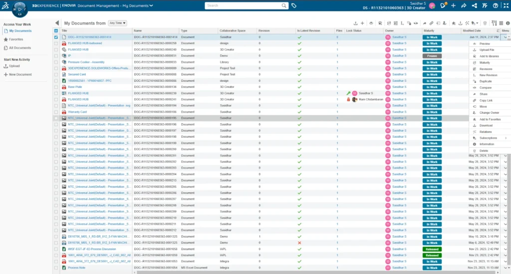
PLM and Digital Engineering Services
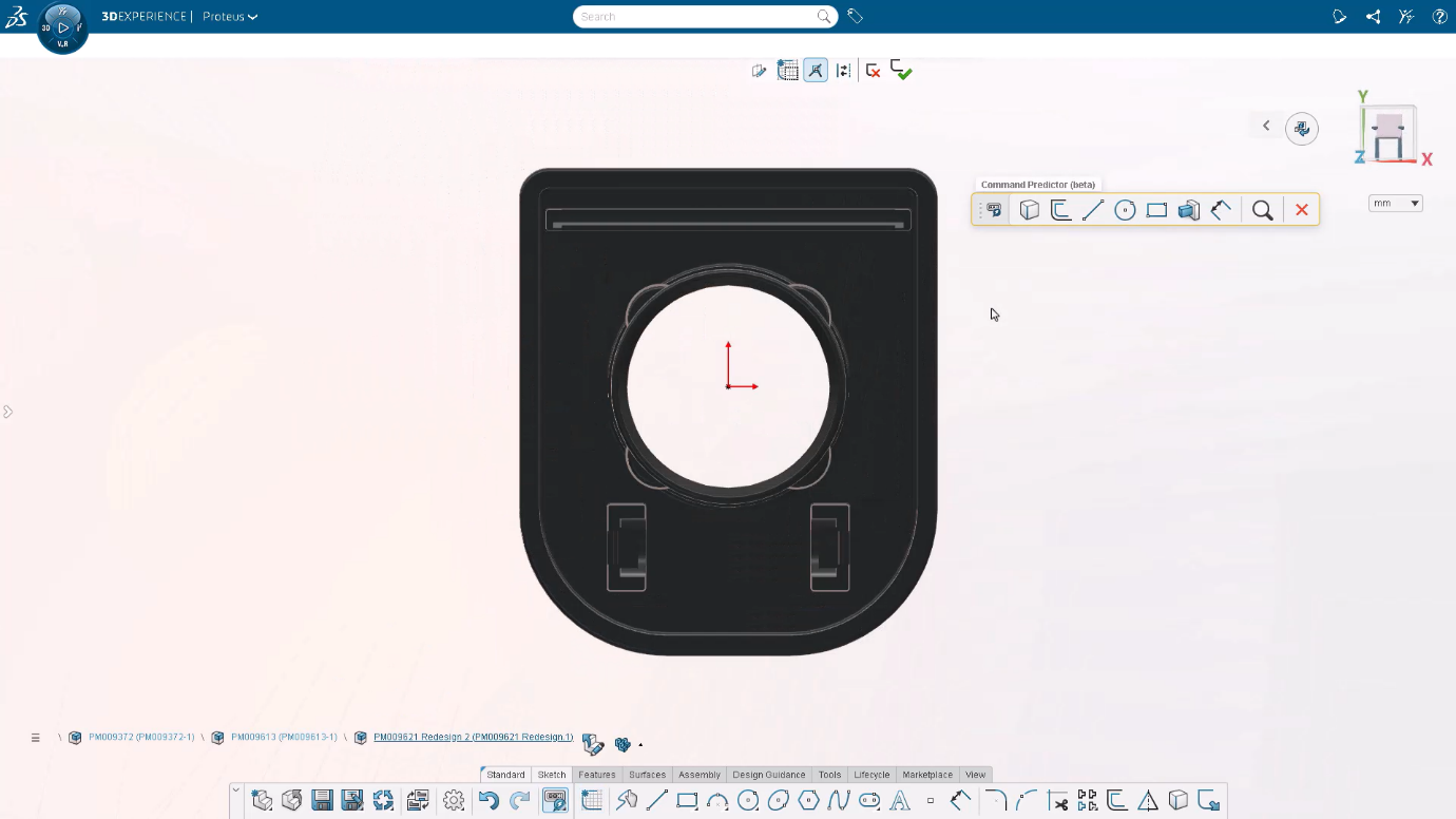
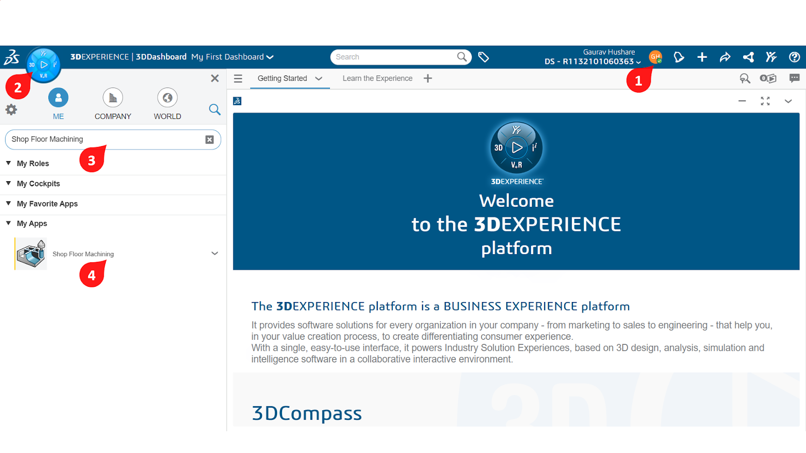
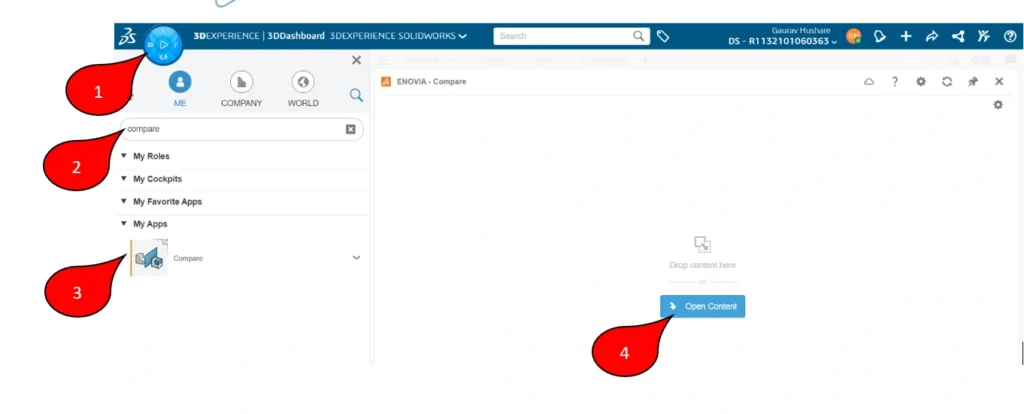
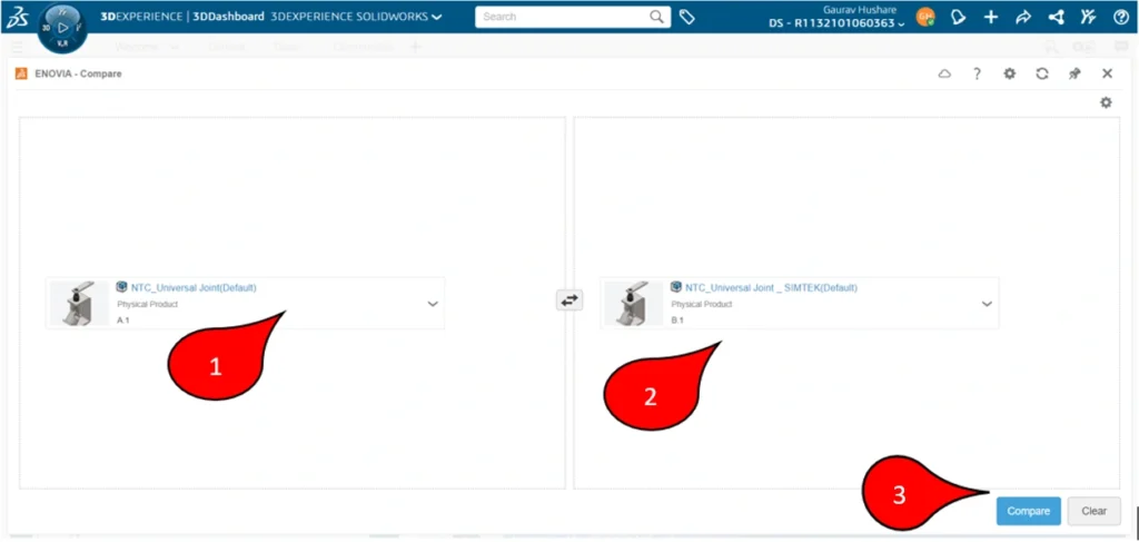
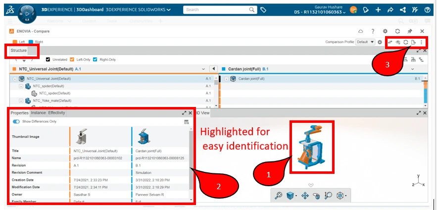
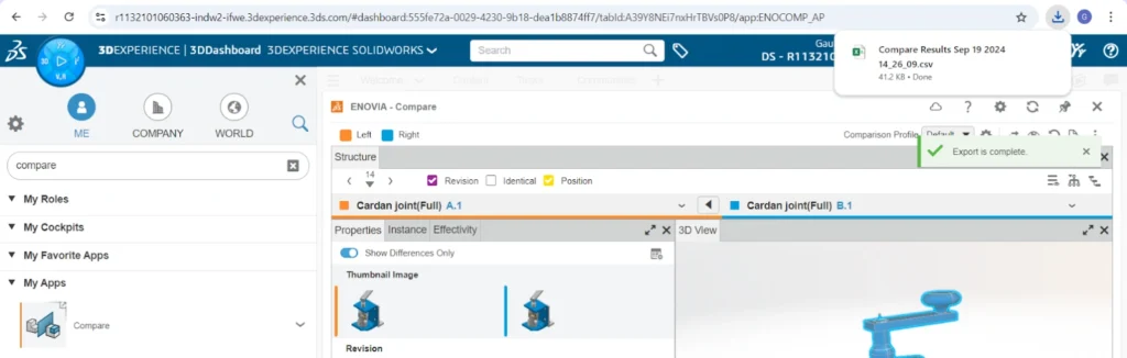
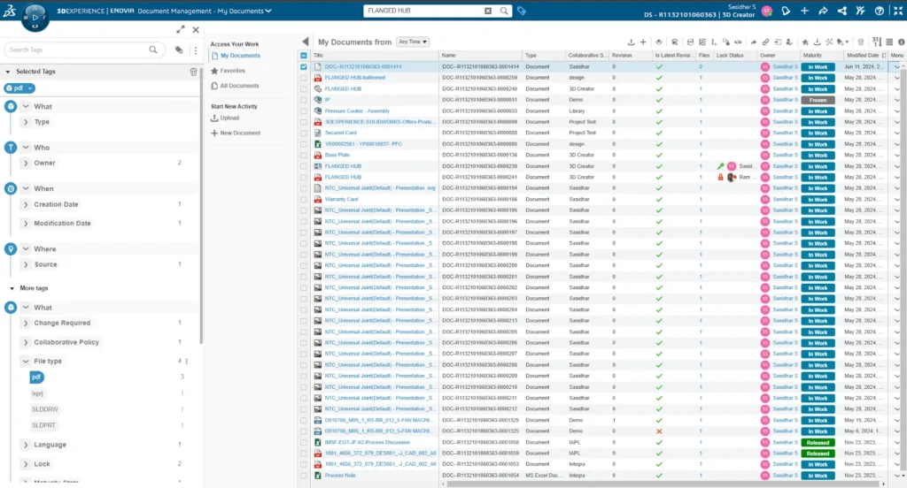
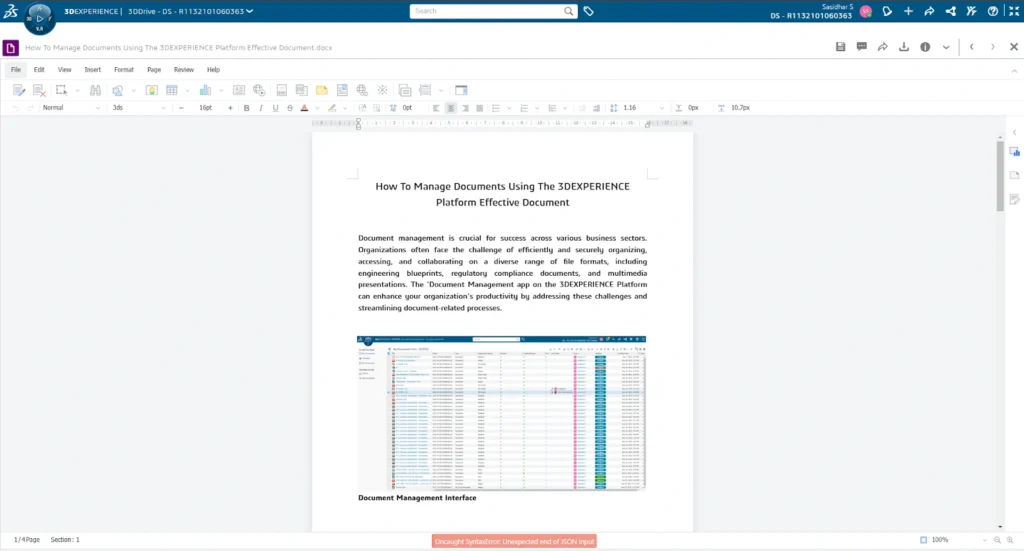
SIMTEK helps organizations adopt digital engineering practices using PLM platforms such as 3DEXPERIENCE to:
- Manage engineering data centrally
- Control design revisions and changes
- Improve cross-team collaboration
- Maintain traceability and compliance
Manufacturing-Focused Engineering: SIMTEK’s Key Strength
Many engineering vendors focus only on design delivery. SIMTEK focuses on manufacturing-ready engineering.
Each project is evaluated for:
- Manufacturing feasibility
- Tooling and machining efficiency
- Material optimization
- Cost reduction
- Production reliability
This approach minimizes rework, reduces shop-floor issues, and improves overall operational efficiency.
Local Presence with Global Delivery Capability
SIMTEK’s strong presence in Chennai ensures deep understanding of:
- Local manufacturing practices
- Supplier and vendor ecosystems
- Industry-specific expectations
At the same time, SIMTEK supports global clients through structured offshore delivery models, clear communication, and strong project governance.
Flexible Engagement Models
SIMTEK offers flexible engagement options to suit varying engineering needs:
- Project-based engineering services
- Dedicated engineering teams
- Long-term engineering outsourcing
This flexibility helps companies scale engineering resources without long-term overhead commitments.
Industries Served by SIMTEK
SIMTEK supports a wide range of industrial sectors, including:
- Automotive and electric vehicle manufacturing
- Heavy engineering and industrial machinery
- Tool & die and mold manufacturing
- Robotics and industrial automation
- Aerospace component suppliers
- Precision manufacturing
Cross-industry experience allows SIMTEK to apply proven engineering best practices effectively.
Why Clients Choose SIMTEK in Chennai
Clients choose SIMTEK because of:
- Certified and authorized engineering expertise
- End-to-end engineering service capability
- Manufacturing-ready engineering outputs
- Structured processes and quality control
- Reliable communication and delivery
- Long-term partnership mindset
These strengths position SIMTEK as a leading engineering service provider in Chennai.
Supporting Long-Term Industrial Growth
Engineering requirements evolve over time. SIMTEK supports long-term growth by:
- Acting as an extension of in-house engineering teams
- Enabling continuous product improvement
- Supporting digital transformation initiatives
- Providing scalable and reliable engineering capacity
Conclusion
SIMTEK stands out as the best engineering service provider in Chennai for industrial solutions by combining certified expertise, manufacturing-focused execution, and end-to-end engineering services. Its strong local presence, global delivery capability, and commitment to quality make SIMTEK a trusted partner for industrial organizations seeking reliable and scalable engineering support.
Frequently Asked Questions
What makes SIMTEK different from other engineering service providers in Chennai?
SIMTEK delivers manufacturing-ready engineering using certified tools, structured processes, and a long-term partnership approach.
Which industries does SIMTEK serve?
SIMTEK supports automotive, heavy engineering, industrial machinery, tool & die, robotics, aerospace suppliers, and precision manufacturing.
Does SIMTEK offer end-to-end engineering services?
Yes. SIMTEK provides CAD, CAE, CAM, PLM, and engineering outsourcing services under a single engagement model.