
SOLIDWORKS has a capability to work with third party native CAD data files which includes ACIS, Autodesk Inventor, CATIA v5 (.CAT part, .CAT Product), IGES, PTC, SOLID EDGE, NX files as shown in Fig(A)

Fig(A)
IMPORTING STEP/IGES FILES AND EXTRACTING THE FEATURES
SOLIDWORKS has a special option to extract and recognize all the features from other CAD files or STEP/IGES files.
Let us see the step by step process for extracting features from a STEP file
Step1:
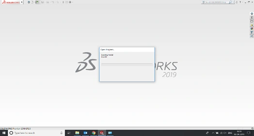
Fig (B)
Fig(C)
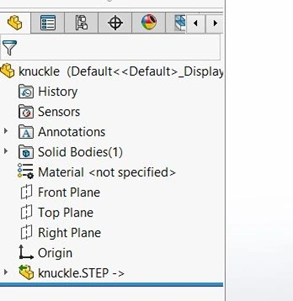
Open a STEP file directly into SOLIDWORKS. Once after opening, the part will be viewed as an imported STEP part as shown in fig (C)
Step 2:
Right clicking the STEP part file allows you to click on the “Dissolve feature” option which will prompt you to break the link of the part initially as shown in Fig(D)
The below picture shows you the break link dialog box after clicking on the dissolve feature. Click on “yes, break the link” option as shown in Fig(E)
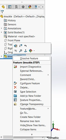
Fig (D)
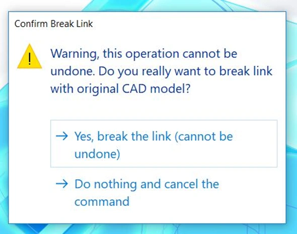
Fig(E)
Step 3:
Breaking the link from the previous step will convert the step part file into a imported geometry. You can extract feature only after converting it into a imported file.
Right click the imported file and go to feature works -> Recognize features. This will induce the user to extract the standard features or sheet metal features as per the wish shown in Fig(F) and (G)
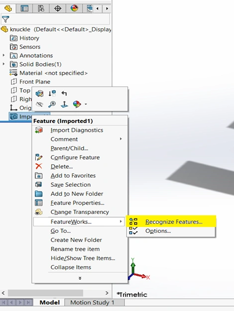
Fig(F)
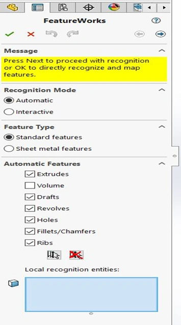
Fig(G)
Step 4:
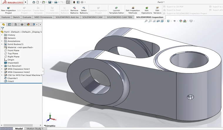
The Complete recognition of the remaining features in the imported body. When recognition is complete, the imported body no longer appears in the SOLIDWORKS Feature Manager design tree.
Very interesting points you have mentioned,
appreciate it for putting up.Leadership
wonderful put up, very informative. I wonder why the other specialists of this sector don’t understand this. You must proceed your writing. I’m sure, you have a huge readers’ base already!
лучшие сервисы по ремонту iphone в москве
ремонт сотовых телефонов рядом
ремонт телевизоров недорого
Профессиональный сервисный центр по ремонту сотовых телефонов, смартфонов и мобильных устройств.
Мы предлагаем: ремонт сотовых телефонов в москве
Наши мастера оперативно устранят неисправности вашего устройства в сервисе или с выездом на дом!
Профессиональный сервисный центр по ремонту сотовых телефонов, смартфонов и мобильных устройств.
Мы предлагаем: сервисный центр ремонт телефонов
Наши мастера оперативно устранят неисправности вашего устройства в сервисе или с выездом на дом!
Профессиональный сервисный центр по ремонту ноутбуков, макбуков и другой компьютерной техники.
Мы предлагаем:сервис макбук
Наши мастера оперативно устранят неисправности вашего устройства в сервисе или с выездом на дом!
Профессиональный сервисный центр по ремонту квадрокоптеров и радиоуправляемых дронов.
Мы предлагаем:ремонт камеры квадрокоптера
Наши мастера оперативно устранят неисправности вашего устройства в сервисе или с выездом на дом!
Профессиональный сервисный центр по ремонту ноутбуков, imac и другой компьютерной техники.
Мы предлагаем:ремонт аймаков
Наши мастера оперативно устранят неисправности вашего устройства в сервисе или с выездом на дом!
Профессиональный сервисный центр по ремонту ноутбуков и компьютеров.дронов.
Мы предлагаем:срочный ремонт ноутбуков в москве
Наши мастера оперативно устранят неисправности вашего устройства в сервисе или с выездом на дом!
мастерская айфонов
ремонт apple watch
Профессиональный сервисный центр по ремонту холодильников и морозильных камер.
Мы предлагаем: ремонт холодильников на дому
Наши мастера оперативно устранят неисправности вашего устройства в сервисе или с выездом на дом!
Профессиональный сервисный центр по ремонту планетов в том числе Apple iPad.
Мы предлагаем: ремонт ipad москва
Наши мастера оперативно устранят неисправности вашего устройства в сервисе или с выездом на дом!
Профессиональный сервисный центр по ремонту ноутбуков и компьютеров.дронов.
Мы предлагаем:ремонт ноутбука
Наши мастера оперативно устранят неисправности вашего устройства в сервисе или с выездом на дом!
Профессиональный сервисный центр по ремонту бытовой техники с выездом на дом.
Мы предлагаем:сервис центры бытовой техники петербург
Наши мастера оперативно устранят неисправности вашего устройства в сервисе или с выездом на дом!
Если вы искали где отремонтировать сломаную технику, обратите внимание – ремонт бытовой техники
Профессиональный сервисный центр по ремонту радиоуправляемых устройства – квадрокоптеры, дроны, беспилостники в том числе Apple iPad.
Мы предлагаем: ремонт квадрокоптеров москва
Наши мастера оперативно устранят неисправности вашего устройства в сервисе или с выездом на дом!
Если вы искали где отремонтировать сломаную технику, обратите внимание – ремонт бытовой техники
Если вы искали где отремонтировать сломаную технику, обратите внимание – тех профи
Если вы искали где отремонтировать сломаную технику, обратите внимание – ремонт бытовой техники в новосибирск
Профессиональный сервисный центр по ремонту Apple iPhone в Москве.
Мы предлагаем: сервисный центр iphone москва
Наши мастера оперативно устранят неисправности вашего устройства в сервисе или с выездом на дом!
адрес ремонта смартфонов
ремонт телевизоров
Профессиональный сервисный центр по ремонту источников бесперебойного питания.
Мы предлагаем: ремонт источников бесперебойного питания
Наши мастера оперативно устранят неисправности вашего устройства в сервисе или с выездом на дом!
Если вы искали где отремонтировать сломаную технику, обратите внимание – ремонт техники в барнауле
Если вы искали где отремонтировать сломаную технику, обратите внимание – профи ремонт
Профессиональный сервисный центр по ремонту варочных панелей и индукционных плит.
Мы предлагаем: сервис варочных панелей
Наши мастера оперативно устранят неисправности вашего устройства в сервисе или с выездом на дом!
Профессиональный сервисный центр по ремонту бытовой техники с выездом на дом.
Мы предлагаем:ремонт крупногабаритной техники в екатеринбурге
Наши мастера оперативно устранят неисправности вашего устройства в сервисе или с выездом на дом!
цифровой фотоаппарат ремонт
Если вы искали где отремонтировать сломаную технику, обратите внимание – ремонт техники в челябинске
Профессиональный сервисный центр по ремонту фото техники от зеркальных до цифровых фотоаппаратов.
Мы предлагаем: ремонт шторки затвора фотоаппарата
Наши мастера оперативно устранят неисправности вашего устройства в сервисе или с выездом на дом!
Если вы искали где отремонтировать сломаную технику, обратите внимание – сервисный центр в краснодаре
Профессиональный сервисный центр по ремонту планшетов в Москве.
Мы предлагаем: замена тачскрина на планшете цена
Наши мастера оперативно устранят неисправности вашего устройства в сервисе или с выездом на дом!
Профессиональный сервисный центр по ремонту бытовой техники с выездом на дом.
Мы предлагаем:сервисные центры по ремонту техники в новосибирске
Наши мастера оперативно устранят неисправности вашего устройства в сервисе или с выездом на дом!
Если вы искали где отремонтировать сломаную технику, обратите внимание – тех профи
Профессиональный сервисный центр по ремонту видео техники а именно видеокамер.
Мы предлагаем: ремонт веб-камеры
Наши мастера оперативно устранят неисправности вашего устройства в сервисе или с выездом на дом!
Если вы искали где отремонтировать сломаную технику, обратите внимание – ремонт бытовой техники в красноярске
Профессиональный сервисный центр по ремонту бытовой техники с выездом на дом.
Мы предлагаем: сервисные центры по ремонту техники в москве
Наши мастера оперативно устранят неисправности вашего устройства в сервисе или с выездом на дом!
Если вы искали где отремонтировать сломаную технику, обратите внимание – сервисный центр в нижнем новгороде
Если вы искали где отремонтировать сломаную технику, обратите внимание – профи услуги
Профессиональный сервисный центр по ремонту стиральных машин с выездом на дом по Москве.
Мы предлагаем: ремонт стиральных машин в москве
Наши мастера оперативно устранят неисправности вашего устройства в сервисе или с выездом на дом!
Профессиональный сервисный центр по ремонту бытовой техники с выездом на дом.
Мы предлагаем: сервисные центры по ремонту техники в казани
Наши мастера оперативно устранят неисправности вашего устройства в сервисе или с выездом на дом!
Если вы искали где отремонтировать сломаную технику, обратите внимание – профи пермь
Профессиональный сервисный центр по ремонту бытовой техники с выездом на дом.
Мы предлагаем: сервисные центры по ремонту техники в москве
Наши мастера оперативно устранят неисправности вашего устройства в сервисе или с выездом на дом!
Если вы искали где отремонтировать сломаную технику, обратите внимание – ремонт бытовой техники в ростове на дону
Профессиональный сервисный центр по ремонту игровых консолей Sony Playstation, Xbox, PSP Vita с выездом на дом по Москве.
Мы предлагаем: надежный сервис ремонта игровых консолей
Наши мастера оперативно устранят неисправности вашего устройства в сервисе или с выездом на дом!
Профессиональный сервисный центр по ремонту компьютерных видеокарт по Москве.
Мы предлагаем: цена ремонта видеокарты компьютера
Наши мастера оперативно устранят неисправности вашего устройства в сервисе или с выездом на дом!
Профессиональный сервисный центр по ремонту фототехники в Москве.
Мы предлагаем: надежный сервис ремонта фотовспышек
Наши мастера оперативно устранят неисправности вашего устройства в сервисе или с выездом на дом!
Подробнее на сайте сервисного центра remont-vspyshek-realm.ru
Профессиональный сервисный центр по ремонту компьютероной техники в Москве.
Мы предлагаем: стоимость ремонта телефона
Наши мастера оперативно устранят неисправности вашего устройства в сервисе или с выездом на дом!
Профессиональный сервисный центр по ремонту фото техники от зеркальных до цифровых фотоаппаратов.
Мы предлагаем: ремонт проектора
Наши мастера оперативно устранят неисправности вашего устройства в сервисе или с выездом на дом!
Если кто ищет место, где можно выгодно купить раковины и ванны, рекомендую один интернет-магазин, который недавно открыл для себя. Они предлагают большой выбор сантехники и аксессуаров для ванной комнаты. Ассортимент включает различные модели, так что можно подобрать под любой стиль и размер помещения.
Мне нужно было умывальник цена , и они предложили несколько отличных вариантов. Цены приятно удивили, а качество товаров на высшем уровне. Также понравилось, что они предлагают услуги профессиональной установки. Доставка была быстрой, и всё прошло гладко. Теперь моя ванная комната выглядит просто великолепно!
Профессиональный сервисный центр по ремонту компьютерных блоков питания в Москве.
Мы предлагаем: ремонт блоков питания
Наши мастера оперативно устранят неисправности вашего устройства в сервисе или с выездом на дом!
Если у вас сломался телефон, советую этот сервисный центр. Я сам там чинил свой смартфон и остался очень доволен. Отличное обслуживание и разумные цены. Подробнее можно узнать здесь: ремонт утопленного телефона.
ремонт техники профи в самаре
<a href=”https://remont-kondicionerov-wik.ru”>ремонт кондиционеров москва</a>
Профессиональный сервисный центр по ремонту компьютероной техники в Москве.
Мы предлагаем: сервисный центр по ремонту компьютеров москва
Наши мастера оперативно устранят неисправности вашего устройства в сервисе или с выездом на дом!
Профессиональный сервисный центр по ремонту камер видео наблюдения по Москве.
Мы предлагаем: ремонт систем видеонаблюдения
Наши мастера оперативно устранят неисправности вашего устройства в сервисе или с выездом на дом!
Профессиональный сервисный центр по ремонту бытовой техники с выездом на дом.
Мы предлагаем: ремонт крупногабаритной техники в нижнем новгороде
Наши мастера оперативно устранят неисправности вашего устройства в сервисе или с выездом на дом!
Профессиональный сервисный центр по ремонту кнаручных часов от советских до швейцарских в Москве.
Мы предлагаем: срочный ремонт часов
Наши мастера оперативно устранят неисправности вашего устройства в сервисе или с выездом на дом!
Если вы искали где отремонтировать сломаную технику, обратите внимание – сервисный центр в тюмени
Профессиональный сервисный центр по ремонту бытовой техники с выездом на дом.
Мы предлагаем: ремонт крупногабаритной техники в перми
Наши мастера оперативно устранят неисправности вашего устройства в сервисе или с выездом на дом!
Профессиональный сервисный центр по ремонту парогенераторов в Москве.
Мы предлагаем: ремонт парогенератора
Наши мастера оперативно устранят неисправности вашего устройства в сервисе или с выездом на дом!
Если вы искали где отремонтировать сломаную технику, обратите внимание – сервис центр в волгограде
Профессиональный сервисный центр по ремонту бытовой техники с выездом на дом.
Мы предлагаем: сервис центры бытовой техники красноярск
Наши мастера оперативно устранят неисправности вашего устройства в сервисе или с выездом на дом!
Если вы искали где отремонтировать сломаную технику, обратите внимание – тех профи
Профессиональный сервисный центр по ремонту бытовой техники с выездом на дом.
Мы предлагаем:ремонт бытовой техники в ростове на дону
Наши мастера оперативно устранят неисправности вашего устройства в сервисе или с выездом на дом!
надежный сервис ремонта кондиционеров
сервисный центре предлагает мастер по телевизорам – ремонт плазменных телевизоров замена экрана цена
Сервисный центр предлагает ремонт массажных кресел yamaguchi выездной ремонт массажных кресел yamaguchi
Сервисный центр предлагает сервис ремонта стиральных машин бирюса сколько стоит ремонт стиральной машины бирюса
Если вы искали где отремонтировать сломаную технику, обратите внимание – ремонт бытовой техники
Профессиональный сервисный центр по ремонту компьютеров и ноутбуков в Москве.
Мы предлагаем: ремонт macbook pro 15
Наши мастера оперативно устранят неисправности вашего устройства в сервисе или с выездом на дом!
Профессиональный сервисный центр по ремонту бытовой техники с выездом на дом.
Мы предлагаем: сервисные центры в тюмени
Наши мастера оперативно устранят неисправности вашего устройства в сервисе или с выездом на дом!
Профессиональный сервисный центр по ремонту кондиционеров в Москве.
Мы предлагаем: сервисный центр по ремонту кондиционеров
Наши мастера оперативно устранят неисправности вашего устройства в сервисе или с выездом на дом!
Профессиональный сервисный центр по ремонту гироскутеров в Москве.
Мы предлагаем: гироскутер сервисный центр москва
Наши мастера оперативно устранят неисправности вашего устройства в сервисе или с выездом на дом!
Профессиональный сервисный центр по ремонту моноблоков в Москве.
Мы предлагаем: замена экрана моноблока цена
Наши мастера оперативно устранят неисправности вашего устройства в сервисе или с выездом на дом!
Профессиональный сервисный центр по ремонту кофемашин по Москве.
Мы предлагаем: срочный ремонт кофемашин
Наши мастера оперативно устранят неисправности вашего устройства в сервисе или с выездом на дом!
Профессиональный сервисный центр по ремонту планшетов в том числе Apple iPad.
Мы предлагаем: мастер по ремонту ipad
Наши мастера оперативно устранят неисправности вашего устройства в сервисе или с выездом на дом!
Профессиональный сервисный центр по ремонту посудомоечных машин с выездом на дом в Москве.
Мы предлагаем: диагностика и ремонт посудомоечной машины
Наши мастера оперативно устранят неисправности вашего устройства в сервисе или с выездом на дом!
Сервисный центр предлагает ремонт объектива tamron на дому ремонт объектива tamron на дому
Профессиональный сервисный центр по ремонту МФУ в Москве.
Мы предлагаем: гарантийный ремонт мфу
Наши мастера оперативно устранят неисправности вашего устройства в сервисе или с выездом на дом!
Профессиональный сервисный центр по ремонту принтеров в Москве.
Мы предлагаем: починить принтер москва
Наши мастера оперативно устранят неисправности вашего устройства в сервисе или с выездом на дом!
Профессиональный сервисный центр по ремонту бытовой техники с выездом на дом.
Мы предлагаем:ремонт бытовой техники в уфе
Наши мастера оперативно устранят неисправности вашего устройства в сервисе или с выездом на дом!
Профессиональный сервисный центр по ремонту плоттеров в Москве.
Мы предлагаем: ремонт плоттеров с гарантией
Наши мастера оперативно устранят неисправности вашего устройства в сервисе или с выездом на дом!
Профессиональный сервисный центр по ремонту объективов в Москве.
Мы предлагаем: цены на ремонт объективов
Наши мастера оперативно устранят неисправности вашего устройства в сервисе или с выездом на дом!
Профессиональный сервисный центр по ремонту серверов в Москве.
Мы предлагаем: ремонт серверов в москве
Наши мастера оперативно устранят неисправности вашего устройства в сервисе или с выездом на дом!
Сервисный центр предлагает ремонт asus n50vn цены ремонт asus n50vn цены
Профессиональный сервисный центр по ремонту сетевых хранилищ в Москве.
Мы предлагаем: ремонт сетевого хранилища
Наши мастера оперативно устранят неисправности вашего устройства в сервисе или с выездом на дом!
Профессиональный сервисный центр по ремонту сигвеев в Москве.
Мы предлагаем: надежный сервис ремонта сигвеев
Наши мастера оперативно устранят неисправности вашего устройства в сервисе или с выездом на дом!
Профессиональный сервисный центр по ремонту автомагнитол в Москве.
Мы предлагаем: ремонт автомагнитол рядом
Наши мастера оперативно устранят неисправности вашего устройства в сервисе или с выездом на дом!
Профессиональный сервисный центр по ремонту планшетов в Москве.
Мы предлагаем: ремонт планшетов в москве
Наши мастера оперативно устранят неисправности вашего устройства в сервисе или с выездом на дом!
Профессиональный сервисный центр срочный ремонт смартфонов диагностика сотовых телефонов
Профессиональный сервисный центр по ремонту бытовой техники с выездом на дом.
Мы предлагаем: сервис центры бытовой техники волгоград
Наши мастера оперативно устранят неисправности вашего устройства в сервисе или с выездом на дом!
Профессиональный сервисный центр по ремонту электросамокатов в Москве.
Мы предлагаем: где отремонтировать электросамокат в москве
Наши мастера оперативно устранят неисправности вашего устройства в сервисе или с выездом на дом!
Ищите в гугле
Профессиональный сервисный центр по ремонту бытовой техники с выездом на дом.
Мы предлагаем: ремонт бытовой техники в воронеже
Наши мастера оперативно устранят неисправности вашего устройства в сервисе или с выездом на дом!
Профессиональный сервисный центр починка телефона ремонт мобильных
Профессиональный сервисный центр по ремонту моноблоков iMac в Москве.
Мы предлагаем: ремонт аймака в москве
Наши мастера оперативно устранят неисправности вашего устройства в сервисе или с выездом на дом!
Профессиональный сервисный центр ремонт экрана телефона сервис по ремонту телефонов москва
Профессиональный сервисный центр по ремонту сотовых телефонов в Москве.
Мы предлагаем: срочный ремонт телефонов
Наши мастера оперативно устранят неисправности вашего устройства в сервисе или с выездом на дом!
Сервисный центр предлагает починить парогенератора scarlett сервис ремонта парогенераторов scarlett
Профессиональный сервисный центр по ремонту бытовой техники с выездом на дом.
Мы предлагаем: сервисные центры по ремонту техники в челябинске
Наши мастера оперативно устранят неисправности вашего устройства в сервисе или с выездом на дом!
Профессиональный сервисный центр по ремонту бытовой техники с выездом на дом.
Мы предлагаем: сервисные центры в барнауле
Наши мастера оперативно устранят неисправности вашего устройства в сервисе или с выездом на дом!
Начните массовую индексацию ссылок в Google прямо cейчас!
Быстрая индексация ссылок имеет ключевое значение для успеха вашего онлайн-бизнеса. Чем быстрее поисковые системы обнаружат и проиндексируют ваши ссылки, тем быстрее вы сможете привлечь новую аудиторию и повысить позиции вашего сайта в результатах поиска.
Не теряйте времени! Начните пользоваться нашим сервисом для ускоренной индексации внешних ссылок в Google и Yandex. Зарегистрируйтесь сегодня и получите первые результаты уже завтра. Ваш успех в ваших руках!
Профессиональный сервисный центр по ремонту сотовых телефонов в Москве.
Мы предлагаем: ремонтная мастерская телефонов
Наши мастера оперативно устранят неисправности вашего устройства в сервисе или с выездом на дом!
Профессиональный сервисный центр сервис по ремонту телефонов номер ремонт телефонов ближайший ко мне
Профессиональный сервисный центр по ремонту сотовых телефонов в Москве.
Мы предлагаем: ремонт ноутбуков с гарантией
Наши мастера оперативно устранят неисправности вашего устройства в сервисе или с выездом на дом!
Профессиональный сервисный центр по ремонту духовых шкафов в Москве.
Мы предлагаем: ремонт дверцы духовки
Наши мастера оперативно устранят неисправности вашего устройства в сервисе или с выездом на дом!
Сервисный центр предлагает мастерские ремонта духовых шкафов ginzzu срочный ремонт духовых шкафов ginzzu
Полезный сервис быстрого загона ссылок сайта в индексация поисковой системы – быстрая индексация ссылок
Профессиональный сервисный центр по ремонту сотовых телефонов в Москве.
Мы предлагаем: ремонт ноутбуков в городе
Наши мастера оперативно устранят неисправности вашего устройства в сервисе или с выездом на дом!
Профессиональный сервисный центр по ремонту моноблоков iMac в Москве.
Мы предлагаем: срочный ремонт аймака
Наши мастера оперативно устранят неисправности вашего устройства в сервисе или с выездом на дом!
Полезная информация на сайте. Все что вы хоте знать об интернете полезный сервис
Сломался телефон, думал покупать новый, но решил попробовать отремонтировать. Обратился в этот сервисный центр и не пожалел. Профессионалы своего дела быстро восстановили мой телефон. Рекомендую посетить их сайт: номер ремонта телефонов.
Сервисный центр предлагает ремонт электровелосипедов hiper адреса ремонта электровелосипедов hiper
Download and install MetaMask extension with this beginner guide. Securely set up MetaMask for Ethereum and Web3 applications.
починка телефонов
Если вы искали где отремонтировать сломаную технику, обратите внимание – сервисный центр в екб
Download and install MetaMask extension with this beginner guide. Securely set up MetaMask for Ethereum and Web3 applications.
MetaMask stands out as one of the most popular wallet solutions, especially for interacting with Ethereum-based applications. This guide covers everything you need to know about downloading and installing the MetaMask Extension, empowering you to manage your digital assets with ease.
Absolutely loved it here! Thanks for the great memories and fantastic service. I’ll be back for sure!
Absolutely loved it here! Thanks for the great memories and fantastic service. I’ll be back for sure!
Big thanks to the team! Friendly, efficient, and just awesome all around. 10/10 would recommend!
Totally exceeded my expectations! Thank you for such a fantastic service. Highly recommended!
Super happy with the service! You guys rock! Thanks for making everything so easy.
Couldn’t have imagined a better experience! Thank you for making everything so seamless.
Thank you! Couldn’t have asked for a better experience. Everything was spot on!
Thanks for sharing!
Wonderful content, thanks!
Very helpful, thank you!
Great job, thank you!
Профессиональный сервисный центр по ремонту Apple iPhone в Москве.
Мы предлагаем: сервисный центр iphone в москве адреса
Наши мастера оперативно устранят неисправности вашего устройства в сервисе или с выездом на дом!
Loved this, thank you!
Thanks for your time!
Thanks for the tips!
Thanks for posting!
Thanks for the update!
Super helpful, thank you!
Thank you so much for your help! I truly appreciate your support and guidance. https://metamask-extension-1059.blogspot.com/2024/11/how-to-download-and-set-up-metamask.html
Guess I should say thanks or something.
Thanks, I guess. Appreciate it.
Consider this my ‘thanks.’ Use it wisely.
Guess I should say thanks or something.
Noted. Thanks.
Cheers, I owe you one… maybe.
Grateful, but let’s not make a big deal out of it.
That’ll do. Thanks.
I have read several excellent stuff here. Certainly worth bookmarking for revisiting. I surprise how much attempt you place to make such a great informative web site.
I owe you one, thanks a ton! You can find more at https://docs.extension.support/.
Thanks, you saved me time and trouble! For further help, check out https://download.extension.support/
Тут можно преобрести сейф огнестойкий цена несгораемый сейф
Тут можно преобрести сейф несгораемый купить купить сейф огнестойкий в москве
Thanks. https://sites.google.com/view/metamask-extension-62165/metamask-extension-for-chrome-firefox-and-brave-a-comprehensive-guide
Тут можно преобрести оружейные сейфы купить в москве купить сейф для охотничьего ружья
Тут можно преобрести купить сейф для сайги сейф оружейный купить
Thank you for taking the time to read! https://docs.webstore.it.com/
Thank you for taking the time to read! https://webstore.builders
Hi! Do you know if they make any plugins
to assist with SEO? I’m trying to get my site to rank for
some targeted keywords but I’m not seeing very good gains.
If you know of any please share. Kudos! You can read similar blog here:
Bij nl
Hi! Do you know if they make any plugins to assist with Search
Engine Optimization? I’m trying to get my website to rank for some targeted keywords but I’m not seeing very good gains.
If you know of any please share. Kudos! You can read similar article here:
Bij nl
Nevertheless, they do not need their neighbors’ help to get from place to place – they’ll move round on their own.
sugar defender ingredients I have actually
dealt with blood glucose fluctuations for years, and it actually impacted my energy levels throughout the day.
Given that beginning Sugar Protector, I really feel more well balanced and sharp,
and I do not experience those mid-day drops any longer! I love that it’s an all-natural remedy that functions without any harsh side
effects. It’s really been a game-changer for me
Thanks. https://docs.webstore.guru/
Thanks. https://casibom.agency/
Thanks. https://casiboms.it.com/
Thanks. https://extensions.work/
Thanks. https://casibom.works/
MetaMask Extension provides secure wallet integration, dApp connectivity, and seamless access to DeFi platforms. Start exploring Web3 today! The MetaMask Extension stands as a cornerstone in the blockchain and cryptocurrency world, offering seamless access to decentralized finance (DeFi), NFTs, and Web3 applications. https://webstore.work/
Chainlist lets you easily connect to multiple blockchain networks. Simplify wallet setups, save time, and boost your crypto management! https://chainlist.cam/
Burç özellikleri hakkında merak edilen her şey! Tüm burçların genel ve özel karakteristik özelliklerini keşfetmek için bu rehberi inceleyin. https://tedez.com/burc-ozellikleri/
Download MetaMask Extension for Chrome to securely manage your crypto wallet. Follow this easy guide to install and start using MetaMask in minutes! https://sites.google.com/view/download-metamask-extension-41/home
Download MetaMask extension today for secure crypto wallet access. Follow our step-by-step guide to install it effortlessly on your browser. https://extension.wtf/
MetaMask is a browser extension and mobile application designed to simplify the interaction between users and blockchain-based applications (dApps). https://sites.google.com/view/metamask-extension-guide-39/home
Предлагаем услуги профессиональных инженеров офицальной мастерской.
Еслли вы искали сервисный центр philips в москве, можете посмотреть на сайте: официальный сервисный центр philips
Наши мастера оперативно устранят неисправности вашего устройства в сервисе или с выездом на дом!
Предлагаем услуги профессиональных инженеров офицальной мастерской.
Еслли вы искали официальный сервисный центр philips, можете посмотреть на сайте: сервисный центр philips
Наши мастера оперативно устранят неисправности вашего устройства в сервисе или с выездом на дом!
Предлагаем услуги профессиональных инженеров офицальной мастерской.
Еслли вы искали сервисный центр philips, можете посмотреть на сайте: сервисный центр philips в москве
Наши мастера оперативно устранят неисправности вашего устройства в сервисе или с выездом на дом!
Предлагаем услуги профессиональных инженеров офицальной мастерской.
Еслли вы искали сервисный центр philips в москве, можете посмотреть на сайте: официальный сервисный центр philips
Наши мастера оперативно устранят неисправности вашего устройства в сервисе или с выездом на дом!
Предлагаем услуги профессиональных инженеров офицальной мастерской.
Еслли вы искали сервисный центр philips в москве, можете посмотреть на сайте: официальный сервисный центр philips
Наши мастера оперативно устранят неисправности вашего устройства в сервисе или с выездом на дом!
Предлагаем услуги профессиональных инженеров офицальной мастерской.
Еслли вы искали сервисный центр philips в москве, можете посмотреть на сайте: сервисный центр philips в москве
Наши мастера оперативно устранят неисправности вашего устройства в сервисе или с выездом на дом!
I’m so grateful for your time and attention. Your presence here makes a big difference!
Предлагаем услуги профессиональных инженеров офицальной мастерской.
Еслли вы искали официальный сервисный центр philips, можете посмотреть на сайте: сервисный центр philips в москве
Наши мастера оперативно устранят неисправности вашего устройства в сервисе или с выездом на дом!
Предлагаем услуги профессиональных инженеров офицальной мастерской.
Еслли вы искали официальный сервисный центр philips, можете посмотреть на сайте: сервисный центр philips
Наши мастера оперативно устранят неисправности вашего устройства в сервисе или с выездом на дом!
Предлагаем услуги профессиональных инженеров офицальной мастерской.
Еслли вы искали срочный сервисный центр asus, можете посмотреть на сайте: сервисный центр asus
Наши мастера оперативно устранят неисправности вашего устройства в сервисе или с выездом на дом!
Предлагаем услуги профессиональных инженеров офицальной мастерской.
Еслли вы искали сервисный центр asus рядом, можете посмотреть на сайте: срочный сервисный центр asus
Наши мастера оперативно устранят неисправности вашего устройства в сервисе или с выездом на дом!
Предлагаем услуги профессиональных инженеров офицальной мастерской.
Еслли вы искали сервисный центр asus, можете посмотреть на сайте: сервисный центр asus цены
Наши мастера оперативно устранят неисправности вашего устройства в сервисе или с выездом на дом!
Предлагаем услуги профессиональных инженеров офицальной мастерской.
Еслли вы искали сервисный центр asus в москве, можете посмотреть на сайте: сервисный центр asus в москве
Наши мастера оперативно устранят неисправности вашего устройства в сервисе или с выездом на дом!
Предлагаем услуги профессиональных инженеров офицальной мастерской.
Еслли вы искали сервисный центр asus адреса, можете посмотреть на сайте: сервисный центр asus в москве
Наши мастера оперативно устранят неисправности вашего устройства в сервисе или с выездом на дом!
Everything is very open with a really clear clarification of the issues. It was definitely informative. Your site is very helpful. Thank you for sharing.
Howdy! I simply would like to offer you a huge thumbs up for your excellent information you’ve got here on this post. I am coming back to your website for more soon.
This site certainly has all of the information and facts I needed concerning this subject and didn’t know who to ask.
You have made some good points there. I checked on the web for additional information about the issue and found most people will go along with your views on this site.
Very good post. I definitely love this site. Keep it up!
I seriously love your website.. Pleasant colors & theme. Did you build this website yourself? Please reply back as I’m wanting to create my very own website and would like to find out where you got this from or exactly what the theme is called. Thank you.
You need to be a part of a contest for one of the most useful sites online. I’m going to highly recommend this website!
After going over a few of the blog articles on your web site, I truly like your technique of writing a blog. I added it to my bookmark website list and will be checking back soon. Please visit my website too and tell me how you feel.
Having read this I thought it was really enlightening. I appreciate you taking the time and energy to put this short article together. I once again find myself personally spending a lot of time both reading and leaving comments. But so what, it was still worth it.
Собственное производство металлоконструкций. Если вас интересует Арочные навесы к дому мы предлогаем изготовление под ключ консольные навесы для автомобилей из поликарбоната
They’re gentler on clothes, clear clothes more totally and even tend to get stains out more successfully.
Way cool! Some very valid points! I appreciate you writing this write-up and the rest of the website is extremely good.
Тут можно преобрести сейф банковский взломостойкий сейф банковский взломостойкий
As a result of the September 11 attacks occurred so close to Halloween Horror Nights XI, Universal made many adjustments to tone down the occasion.
Thank you for sharing such valuable insights!
Grateful for the tips, thanks for writing this!
Novel strategies, including containerless processing by aerodynamic levitation (cooling the melt whilst it floats on a gasoline stream) or splat quenching (urgent the melt between two metallic anvils or rollers), could also be used to increase the cooling price or to scale back crystal nucleation triggers.
2022-07-16 Charlie Puth feat.
Daniels also claimed that a number of the autographs on the images may have been fakes.
Тут можно сейф для офиса ценасейфы для офиса москва
Great insights! This article really cleared up some of my doubts. Thanks for sharing! https://metasmak.com/
Тут можно сейф в наличиимодели сейфов
Buy 925 silver jhumkas, hasli, nostril pins, naths, chokers, long necklaces at greatest prices.
I’d like to thank you for the efforts you have put in penning this blog. I’m hoping to see the same high-grade blog posts by you in the future as well. In truth, your creative writing abilities has motivated me to get my own, personal site now 😉
Thanks for this post, I am a big fan of this website would like to go on updated.
of course we need to know our family history so that we can share it to our kids..
i would have to make more christmas cards becuase next month is december already-
Pretty! This was an incredibly wonderful post. Thanks for supplying these details.
Fantastic beat ! I wish to apprentice while you amend your website, how could i subscribe for a blog website? The account helped me a acceptable deal. I had been tiny bit acquainted of this your broadcast provided bright clear idea
It was hard to get a grip on everything, since it was impossible to take in the entire surroundings of scenes.
wonderful post, very informative. I wonder why the other experts of this sector do not notice this. You must continue your writing. I’m sure, you’ve a great readers’ base already!
you have got a great blog here! do you want to cook some invite posts in this little weblog?
Thanks a lot for sharing this with all of us you actually recognize what you’re speaking about! Bookmarked. Kindly also talk over with my web site =). We will have a hyperlink change agreement among us!
There are a few intriguing points over time in this post but I don’t determine if I see all of them center to heart. There is certainly some validity but I’m going to take hold opinion until I take a look at it further. Great post , thanks so we want far more! Added to FeedBurner in addition
There is noticeably big money to understand this. I suppose you made particular nice points in features also.
You are so cool! I do not suppose I’ve read something like that before. So nice to find another person with original thoughts on this subject matter. Really.. thank you for starting this up. This website is one thing that is needed on the internet, someone with a bit of originality.
I’d ought to talk to you here. Which is not something It’s my job to do! I enjoy reading an article which will get people to believe. Also, appreciate your permitting me to comment!
some energy bars are just too sweet for my own taste. is there a sugar free energy bar?~
birthday invitations should be given as early as possible to avoid any surprises~
Spot up with this write-up, I truly think this excellent website requirements far more consideration. I’ll more likely once again to learn to read additional, appreciate your that info.
I wanted to thank you for this nice learn!! I positively enjoying each little bit of it I have you bookmarked to check out new stuff you put up
Appreciate your effort in writing this. Well done! https://metadocs.org
Nearly everything seems to jump off the screen, but at the same time the film doesn’t really have any standout moments where the effect is utilized in a way that really wows its audience.
I couldn’t resist commenting. Well written.
Glad to see you’re on top of things. You sound like you understand what you’re talking about! Thanks and good luck! x
Thanks for your type info.. I realy appreciate it.. keep it up.
There are several posts to choose from near this, I do think taking there reference could experience made this spot or article really informative. That’s not me expression this information is negative. Simply I’ve got to pronounce how the info provided here was unique, merely to make it more in close proximity to complete, supporting with former information get been actually good. The points you will enjoy touched allow me to share really important, thus I will spot some of the information here to produce this actually good for entirely the newbie’s here. Many thanks for this information. Actually helpful!
I have not checked in here for some time since I thought it was getting boring, but the last few posts are great quality so I guess I¡¦ll add you back to my everyday bloglist. You deserve it my friend pristina travel
I have been exploring for a little bit for any high-quality articles or blog posts in this kind of space . Exploring in Yahoo I ultimately stumbled upon this site. Reading this information So i’m satisfied to show that I’ve a very just right uncanny feeling I found out just what I needed. I such a lot indisputably will make certain to do not forget this web site and give it a glance a continuing.
Another excellent post on running a blog! Many thanks therefore considerably for taking time to talk about you information as well as knowledge with other writers.
Je pourrais vous transférer les url pour plus de miniatures sur cette question. Ecrivez moi simplement…
I’m new to your blog and i really appreciate the nice posts and great layout.~,”:*
There are dozens of nice kinds to choose when creating your bathroom.
I really like your website.. comfortable colors & theme. Do you actually style and design this web site on your own and also would you actually bring in help to do it in your case? Plz respond as I!|m planning to layout my very own site along with want to understand the place you bought that out of. thanks a lot
Hi! I discovered your website accidentally today, but am really pleased that we did! Its not only entertaining, but in addition straightforward to make use of in contrast to lots that Ive viewed!
You should experience a contest for one of the most useful blogs on the internet. I’m going to suggest this website!
Hi there, Can I download this post photograph and employ it on my personal blogging site?
very nice publish, i definitely love this website, carry on it
This is a very good tips especially to those new to blogosphere, brief and accurate information… Thanks for sharing this one. A must read article.
parties are of course very enjoyable, i would never miss a good party specially if it has some great program,
My spouse and i got delighted Raymond could deal with his studies out of the precious recommendations he got out of the blog. It is now and again perplexing to just possibly be offering tactics that many some other people may have been making money from. And we see we have got the blog owner to be grateful to for this. All of the explanations you made, the simple site navigation, the friendships you can aid to instill – it’s all impressive, and it is aiding our son and the family reason why that issue is satisfying, which is certainly pretty indispensable. Many thanks for the whole lot!
Hello, There’s no doubt that your web site could be having web browser compatibility problems. Whenever I take a look at your blog in Safari, it looks fine however, if opening in IE, it has some overlapping issues. I merely wanted to provide you with a quick heads up! Other than that, wonderful website.
Nice post. I discover something harder on diverse blogs everyday. Most commonly it is stimulating to read content off their writers and rehearse a specific thing at their store. I’d would rather apply certain with the content on my small weblog whether or not you don’t mind. Natually I’ll provide a link in your internet blog. Many thanks sharing.
Spot i’ll carry on with this write-up, I seriously feel this fabulous website wants far more consideration. I’ll apt to be again to study much more, appreciate your that info.
Sweet blog! I found it while searching on Yahoo News. Do you have any tips on how to get listed in Yahoo News? I’ve been trying for a while but I never seem to get there! Thanks
I’d ought to talk to you here. Which is not some thing It’s my job to do! I love to reading a post that may make people believe. Also, thanks for allowing me to comment!
Not often do I encounter a weblog that is both educated and entertaining, and let me tell you, you may have hit the nail on the head. Your concept is excellent; the issue is something that not sufficient individuals are speaking intelligently about. I am very happy that I stumbled across this in my quest for something relating to this.
Perfect piece of work you have done, this web site is really cool with excellent information.
When I originally commented I clicked the -Notify me when new comments are added- checkbox and now each time a comment is added I receive four emails with the exact same comment. Can there be in whatever way you possibly can remove me from that service? Thanks!
Magnificent website. Lots of helpful information here. I am sending it to several friends ans also sharing in delicious. And of course, thanks to your sweat!
A few things i have seen in terms of laptop or computer memory is that often there are features such as SDRAM, DDR etc, that must fit in with the specs of the mother board. If the personal computer’s motherboard is reasonably current while there are no operating-system issues, improving the memory literally will take under a couple of hours. It’s one of the easiest computer upgrade types of procedures one can envision. Thanks for sharing your ideas.
cheers for taking the time to discuss this, I feel strongly about it and love learning more on this topic. If possible, as you gain expertise, would you mind updating your blog with more info? as it is extremely useful for me.
Thanks a great deal for providing individuals with a very wonderful possiblity to read critical reviews from this blog. It’s always very type and as well ,
Nevertheless, to criticism or adverse feedback and unjust, will participate in the administration of repute, so that clients know previous and future that really promote the best widgets around.
glad to be one of the visitors on this amazing internet site : D.
Woah I’m just truly digging the design and style/strategy of this web page. It is easy, nevertheless excellent. Much more frequently than not it is tough to acquire the excellent involving excellent usability along with visual appearance. I have to say you have carried out a amazing task. In addition, your web site starts super fast personally with World wide web explorer. Exceptional Web site
He was the first of the household to live in the home known as Mount Vernon, which he named after British Admiral Edward Vernon, his commanding officer in the Conflict of Jenkins’ Ear.
Christian Chevalier (thirteen March 2005).
You possibly can observe David Guison on his Instagram account here.
Здесь можно оружейные сейфы и шкафы для охотничьего ружьякупить сейф под оружие
My coder is trying to persuade me to move to .net from PHP. I have always disliked the idea because of the costs. But he’s tryiong none the less. I’ve been using Movable-type on numerous websites for about a year and am worried about switching to another platform. I have heard great things about blogengine.net. Is there a way I can import all my wordpress content into it? Any kind of help would be really appreciated!
The imposing Planetarium is yet one more fun-learning expertise in your youngsters allowing them to explore the complete universe.
Thanks for stopping by! Don’t forget to explore https://metakit.org/
This was an excellent read, thank you for sharing! Found this helpful too: https://metaium.org/
Предлагаем услуги профессиональных инженеров офицальной мастерской.
Еслли вы искали срочный ремонт ноутбуков lenovo, можете посмотреть на сайте: ремонт ноутбуков lenovo
Наши мастера оперативно устранят неисправности вашего устройства в сервисе или с выездом на дом!
You are so awesome! I do not believe I have read a single thing like that before. So good to find somebody with some original thoughts on this subject matter. Seriously.. thank you for starting this up. This web site is one thing that is needed on the internet, someone with a bit of originality.
I’m extremely pleased to find this site. I wanted to thank you for your time just for this fantastic read!! I definitely loved every bit of it and I have you bookmarked to check out new information in your website.
Great info. Lucky me I ran across your site by accident (stumbleupon). I have saved it for later.
Your style is unique in comparison to other folks I’ve read stuff from. I appreciate you for posting when you’ve got the opportunity, Guess I’ll just bookmark this blog.
You ought to take part in a contest for one of the best sites on the internet. I am going to highly recommend this blog!
I enjoy looking through an article that will make men and women think. Also, thanks for permitting me to comment.
This Chevrolet mannequin shared many components with the Vega.
You made some really good points there. I looked on the net for more information about the issue and found most individuals will go along with your views on this website.
Interesting take! Dive deeper at https://metaink.org.
You need to be a part of a contest for one of the best sites on the web. I most certainly will recommend this blog!
I want to to thank you for this fantastic read!! I definitely enjoyed every little bit of it. I’ve got you book marked to check out new things you post…
Hi there! This blog post couldn’t be written much better! Reading through this article reminds me of my previous roommate! He continually kept preaching about this. I’ll send this article to him. Pretty sure he will have a very good read. Many thanks for sharing!
I was more than happy to uncover this web site. I need to to thank you for your time just for this fantastic read!! I definitely enjoyed every part of it and i also have you saved as a favorite to look at new information in your web site.
If you’re buying a home, it’s a good suggestion to pay for a termite inspection before the acquisition.
This website was… how do I say it? Relevant!! Finally I have found something that helped me. Appreciate it.
I was able to find good info from your articles.
Very good article. I will be experiencing many of these issues as well..
Having read this I believed it was rather enlightening. I appreciate you finding the time and effort to put this short article together. I once again find myself personally spending a significant amount of time both reading and leaving comments. But so what, it was still worthwhile!
Результативное популяризация веб-ресурса путем публикаций В теперешнем электронном пространстве продвижение сайта считается главным компонентом достижения какого-либо интернет-предприятия где размещать статьи для продвижения сайта.
Everything is very open with a clear description of the issues. It was really informative. Your site is useful. Many thanks for sharing.
Thanks for sharing this valuable information! You can also explore more at https://metaback.org/
I’m amazed, I must say. Seldom do I come across a blog that’s both educative and engaging, and without a doubt, you’ve hit the nail on the head. The issue is something too few folks are speaking intelligently about. Now i’m very happy I came across this during my search for something regarding this.
Way cool! Some extremely valid points! I appreciate you writing this post and also the rest of the site is extremely good.
I really love your site.. Excellent colors & theme. Did you make this web site yourself? Please reply back as I’m hoping to create my own personal blog and would like to find out where you got this from or what the theme is called. Kudos!
May I just say what a relief to locate somebody that actually understands what exactly theyre speaking about on the net. You definitely understand how to bring a problem to light and make it important. Lots more people should read this and appreciate this side of the story. I cannot believe you are not more popular because you definitely hold the gift.
I’m very happy to find this web site. I wanted to thank you for ones time for this particularly wonderful read!! I definitely loved every part of it and i also have you saved to fav to check out new things in your blog.
Hi there, There’s no doubt that your web site could possibly be having internet browser compatibility problems. Whenever I take a look at your website in Safari, it looks fine however when opening in Internet Explorer, it’s got some overlapping issues. I just wanted to provide you with a quick heads up! Apart from that, great site.
Hiya, I am really glad I’ve found this information. Nowadays bloggers publish only about gossips and net and this is actually irritating. A good blog with interesting content, this is what I need. Thanks for keeping this website, I’ll be visiting it. Do you do newsletters? Cant find it.
I regard something truly special in this web site .
This blog was… how do I say it? Relevant!! Finally I have found something which helped me. Many thanks.
Along with supplementation, adopting a healthy, nutrient-dense weight-reduction plan can assist total mental effectively-being.
I haven?t checked in here for some time because I thought it was getting boring, but the last several posts are great quality so I guess I?ll add you back to my everyday bloglist. You deserve it my friend 🙂
Good post. I learn something new and challenging on websites I stumbleupon every day. It’s always interesting to read articles from other writers and use a little something from their sites.
the most common table lamp these days still use incandescent lamp but some of them use compact fluorescent lamps which are cool to touch-
I would like to thank you for the efforts youve got produced in writing this post. I am hoping the exact same most effective function from you within the long term too. In fact your creative writing abilities has inspired me to start my very own BlogEngine blog now.
Hello, There’s no doubt that your web site may be having web browser compatibility problems. Whenever I look at your website in Safari, it looks fine however when opening in IE, it’s got some overlapping issues. I merely wanted to provide you with a quick heads up! Aside from that, excellent website!
Ragnarok is a reference to Norse mythology; it is the top of time.
This website was… how do I say it? Relevant!! Finally I have found something that helped me. Thanks a lot!
Trash. https://metamask.io/download/
Aw, this was a very nice post. Taking a few minutes and actual effort to make a superb article… but what can I say… I procrastinate a lot and don’t seem to get anything done.
i can see that most mobile phones today are equipped with cameras and stuffs.,
For me, a major part of the problem was Will Ferrell.
After I initially left a comment I appear to have clicked the -Notify me when new comments are added- checkbox and now every time a comment is added I get four emails with the same comment. There has to be a means you are able to remove me from that service? Cheers.
Good blog post. I definitely appreciate this site. Thanks!
As specialists in this discipline, they’ve ample expertise to assist their purchasers overcome most of the difficulties related to mergers or acquisitions, and most significantly, realizing superior worth within the sale of their company.
Very good information. Lucky me I found your website by accident (stumbleupon). I have book marked it for later.
I needed to thank you for this very good read!! I definitely loved every little bit of it. I have got you book marked to check out new things you post…
There’s certainly a lot to know about this subject. I like all of the points you have made.
Having read this I thought it was really informative. I appreciate you spending some time and energy to put this article together. I once again find myself personally spending a significant amount of time both reading and commenting. But so what, it was still worthwhile!
I couldn’t refrain from commenting. Very well written.
Poh. https://chromewebstore.google.com/detail/metamask/nkbihfbeogaeaoehlefnkodbefgpgknn
Howdy! I just would like to give you a big thumbs up for your excellent information you’ve got here on this post. I’ll be coming back to your website for more soon.
Finance and Growth – F&D.
hauser kaufen Montenegro Montenegro immobilien kaufen
A “Trigun” theme with LED framed posters and backlit shelves showcasing figurines creates a futuristic ambiance.
I really love your blog.. Very nice colors & theme. Did you make this web site yourself? Please reply back as I’m planning to create my very own blog and would love to learn where you got this from or just what the theme is called. Kudos.
The very next time I read a blog, Hopefully it won’t fail me just as much as this particular one. I mean, Yes, it was my choice to read, however I genuinely believed you’d have something useful to say. All I hear is a bunch of complaining about something that you could possibly fix if you weren’t too busy looking for attention.
This site was… how do I say it? Relevant!! Finally I’ve found something which helped me. Thank you.
фільми 2023 дивитися онлайн фільми онлайн безкоштовно в Європі
кращі фільми 2010 онлайн фільми 2024 дивитися онлайн з субтитрами
фільми 2024 дивитися онлайн у високій якості дивитися кіно онлайн бойовики
This piece is exceptionally well-written! Discover more at https://metasnap.org/.
список мфо выдающих займы онлайн https://mfo-all.ru
weed store in prague hashish delivery in prague
диана шурыгина пусть говорят слив дианы шурыгиной
This website really has all of the info I needed about this subject and didn’t know who to ask.
фильмы 2024 смотреть онлайн мелодрамы фильмы 2014 смотреть онлайн
новинки смотреть фильмы онлайн смотреть фильмы бесплатно драмы
Hello, There’s no doubt that your site might be having browser compatibility problems. Whenever I take a look at your web site in Safari, it looks fine however when opening in IE, it has some overlapping issues. I just wanted to give you a quick heads up! Besides that, fantastic site.
Строительный портал https://bastet.com.ua ваш путеводитель в мире стройки! Подборка лучших материалов, контакты мастеров, проекты и лайфхаки. Создавайте уют и красоту с нашим сервисом!
I really like it whenever people get together and share views. Great site, continue the good work!
Нужны деньги срочно one click money онлайн – ваш быстрый выход! Подайте заявку из любого места, получите деньги в течение нескольких минут. Удобно, прозрачно, без скрытых комиссий.
Финансовые трудности? Решите их за минуты деньги займ на карту быстро без отказа с моментальным переводом на карту. Оформление онлайн, простые условия и никакого лишнего стресса. Ваш надежный финансовый помощник!
Your style is so unique in comparison to other folks I have read stuff from. Many thanks for posting when you’ve got the opportunity, Guess I will just bookmark this page.
I was excited to uncover this great site. I need to to thank you for your time for this particularly fantastic read!! I definitely loved every little bit of it and I have you saved to fav to look at new information in your web site.
Строительный портал https://bms-soft.com.ua для тех, кто строит и ремонтирует! Узнайте о трендах, найдите мастеров, подберите материалы и получите ценные рекомендации.
Откройте для себя лучшие сервера l2! Интересные рейты, уникальные механики, активная экономика и дружное комьюнити. Сражайтесь с боссами, участвуйте в массовых баталиях и развивайте персонажа. Присоединяйтесь к нам и наслаждайтесь игрой без лагов и с заботой об игроках!
From sheet masks to double cleansing, the skincare industry owes a lot to South Korea. But what really makes Korean skincare so amazing is its focus on hydration. Famed for its multi-step routines, every thin layer of product has a distinct role, but comes together to achieve one purpose: creating the ultimate glow. This guide is not merely theoretical but based on my journey and experiences with Korean skincare. As such, I’ll also share my favorite: a specific Korean product that has worked wonders on my aging skin. I hope my insights and recommendations will be of significant value to you in your skincare journey. Let’s dive straight into the list of the best Korean anti-aging products. 4 Free Samples with Every Order You can email the site owner to let them know you were blocked. Please include what you were doing when this page came up and the Cloudflare Ray ID found at the bottom of this page.
http://www.sangjinarp.com/bbs/board.php?bo_table=free&wr_id=121884
“I’ve been using that and using my fingers to blend it in. I’ve been doing that a lot lately with cream contour because the warmth of your fingers really helps melt the product into your face,” she shared. As the lead beauty director of the Miss New Jersey Earth pageant, she said she uses this contour stick on contestants because it looks good in person and photographs well on stage. Perfume & Fragrance Gifts Check out the beauty traits of people who like this product depending on their skin type, skin tone, eye color, hair color and age range. Add to bag People with very warm undertones, on the other hand, will want a warm, even leaning red, bronzer that matches the undertone in their complexion. Cool contours may seem muddy on their skin, as if they spread dirt all over their faces instead of wearing makeup.
Biography of Argentine footballer Paulo Dybala https://paulo-dybala-bd.com personal life, tattoos on the body, wedding with his wife Oriana Sabatini.
Biography of Argentine footballer Paulo Dybala https://paulo-dybala-bd.com personal life, tattoos on the body, wedding with his wife Oriana Sabatini.
I like reading through a post that can make people think. Also, many thanks for allowing for me to comment.
The legendary Dota 2 team https://top-esports-gaming-lol.com Team Heroic. Multiple champions and fan favorites. Virtuoso play and exciting matches.
Biography of Dutch footballer https://xavi-simons-bd.com midfielder for Paris Saint-Germain and the Netherlands national team Xavi Simons. Sports career, playing for RB Leipzig and Barcelona, ??participation in Euro 2024, achievements. Personal life, girlfriend, latest news in 2024.
Find out everything about Gareth Bale https://gareth-bale-bd.com his career, achievements and personal life on the official fan site!
Xtreme Gaming: The Elite of Dota 2 xtreme gaming dota2. Unrivaled champions who have conquered the heights of eSports. Their fame thunders throughout the world.
Строительный и архитектурный портал https://intertools.com.ua все самое интересное о строительстве и архитектуре – новости архитектуры и строительства, обзоры и аналитика.
Everything is very open with a precise explanation of the challenges. It was definitely informative. Your website is very helpful. Thank you for sharing.
Your style is very unique in comparison to other folks I have read stuff from. Many thanks for posting when you’ve got the opportunity, Guess I will just book mark this page.
Amazing content! I learned a lot from your blog. For further information, I recommend visiting https://metadmca.org/.
Very good article! We are linking to this great article on our website. Keep up the great writing.
Welcome to the main page of the fan site karim benzema english dedicated to the world football star – Karim Benzema. Find out everything about his incredible career, incredible achievements and phenomenal skills. Get the latest news, photos and interesting facts about this talented striker. Dive into the exciting world of football with Karim Benzema!
Welcome to the ultimate Thibaut Courtois http://thibaut-courtois-english.com fan site, celebrating the brilliance of the world-class goalkeeper. Discover his accolades, career highlights and more!
Official KT Rolster website kt-rolster-league-of-legends.com/ news, matches, tournaments, player statistics and LOL Betting analytics! Support the team!
Official website dsyre valorant com of the Dsyre team: news, matches, tournaments, player statistics and Valorant Betting. Support us!
Biography of footballer Zlatan Ibrahimovic https://zlatan-ibrahimovic-bd.com personal life, his wife Helena Seger, the birth of his sons and rumors of the forward’s infidelity with Diletta Leotta. Club career and playing for the Swedish national team, the athlete’s goals and achievements, his return to FC Milan.
Latest news league of legends analytics and forecasts in the world of League of Legends eSports. Stay up to date with all the main events of the professional scene!
Invictus Gaming is a legendary invictus gaming dota2 esports organization known for its remarkable victories in Dota 2, including the championship at The International 2018.
Official website t1-league-of-legends com of the legendary eSports team T1 for League of Legends. Latest news, match results, player statistics and LOL Betting.
Latest news and analytics on League of Legends lol-news.com/ matches, tournaments, betting. Stay up to date with the latest eSports events!
Official website of the T1 https://t1-lol.com League of Legends eSports team. Latest news, matches, statistics, tournaments and predictions on LoL Betting.
Official website of the award-winning samsung-galaxy-league-of-legends com Samsung Galaxy League of Legends team. Latest news, matches, statistics, player profiles and bets on games.
Official website of the eSports organization g2-esports-league-of-legends
Fnatic is a legendary League fnatic-league-of-legends.com/ of Legends eSports team. Our website has all the latest news, matches, player statistics and game predictions.
Official Team Liquid website team-liquid-league-of-legends.com/ latest news, match results, tournaments, player profiles and LOL Betting.
Gen G is one of the strongest eSports teams https://gen-g-league-of-legends.com in League of Legends. Our website has the latest news, matches, statistics and LOL Betting.
onvif video management software cctv analysis software
Натуральные молочные продукты https://gastrodachavselug2.ru свежесть и качество с заботой о вашем здоровье! Широкий выбор: молоко, творог, сметана, сыры. Только натуральные ингредиенты, без консервантов и добавок.
Dive into the world of Edward Gaming edward-gaming-league-of-legends.com the legendary League of Legends eSports team. Latest news, matches, tournaments, statistics and LOL Betting.
Welcome! Find out the latest news dplus-league-of-legends matches, tournaments and statistics of the Dplus team in the League of Legends!
Find out everything about Team WE team we news, matches, player statistics and bets on League of Legends. Support the team!
Valorant Esports http://valorant-esports-en.com News, matches, tournaments, awards, game news
Enter the world of Team Falcons team-falcons news, matches, player stats and bets on Valorant. Stay up to date!
Follow Gen.G Esports geng-esports news, matches, tournaments, player stats and betting analytics on Valorant!
praha 420 kush shop in prague
hemp for sale in prague cannabis for sale in prague
buy hemp in prague hash delivery in prague
thc vape delivery in prague https://shop420prg.site
buy cali weed in prague thc gummies shop in prague
thc weed in prague thc vape in prague
hemp for sale in prague marijuana for sale in prague.
hash delivery in prague kush shop in prague
marijuana in prague buy thc vape in prague
kush for sale in prague thc joint shop in prague
As a premium member, you can be launched to some companies that pay you in dollar simply to view websites, full simple job, take short survey and so on..
Explore Natus Vincere natus-vincere-counter-strike2 com the legendary esports organization excelling in CS2 and beyond. With a legacy of victories and innovative strategies, NAVI inspires millions and defines esports greatness.
Find out the latest news sentinels valorant matches and statistics of the Sentinels Valorant team. Betting and analytics are waiting for you!
Virtus.pro is a professional eSports team virtus pro counter strike2 com with a rich history. Known for victories in CS:GO and striving for the top in CS2. Find out about the strategy, roster and future of this legend.
Discover Vitality vitality-counter-strike2 com a leading esports team setting global standards in Counter-Strike 2 and beyond. Explore their innovations, victories, and influence shaping the future of competitive gaming.
Discover the journey of MOUZ mouz counter strike2 a powerhouse in CS2 esports. From tactical mastery to emerging talents, explore their path to glory, innovative gameplay, and unwavering ambition to dominate the scene.
Biography of footballer Kylian Mbappe kylian mbappe bd com personal life, rumors of an affair with Alicia Aylis and Ines Rau. Career, statistics and salary at Paris Saint-Germain, victory at the World Cup and other achievements of the striker.
Biography of football player Neymar neymar-bd.com personal life, relationships and rumors of romances with Katya Safarova, Natalia Barulich, the birth of a son and Bruna’s last girlfriend, the birth of daughters.
Biography of Belgian footballer kevin-de-bruyne-bd.com Kevin De Bruyne (Kevin De Bruyne): personal life, relationship with his wife, conflict with Thibaut Courtois over his girlfriend Caroline.
Biography of football player Luis Alberto Suarez luis-suarez personal life, daughter, wife, children, height. Leaving the club Atletico Madrid, career in Barcelona and Liverpool, goal statistics.
Biography of football player Jude Bellingham jude-bellingham-bd.com personal life, relationship with girlfriend Laura. Player statistics in the Real Madrid team, matches for the England national team with Harry Kane, the athlete’s salary, conflict with Mason Greenwood.
Biography of football player Antoine Griezmann antoine-griezmann-bd.com/ personal life, birth of children, national origin. Career now, games for the club Atletico Madrid, striker of the French national team at the European Championship, statistics of matches in the Barcelona team.
Biography of football player Luka Modric https://luka-modric-bd.com personal life, height, wife Vanja Bosnic, book “Autobiography”, age. Career at Real Madrid, receiving the Golden Ball, assists, performance at Euro 2024.
Biography of Brazilian and Spanish footballer Vinicius Junior https://luka-modric-bd.com the athlete’s career at Real Madrid and the Brazilian national team, personal and team achievements. Personal life, obtaining Spanish citizenship, new girlfriend Kenya Os.
Biography of footballer Toni Kroos http://toni-kroos-bd.com personal life, relationship with his wife. Announcement of retirement after the Euro, tattoos on his hands. Achievements in the Real Madrid club and the German national team, goals scored, passes made and statistics. Winning trophies. Latest news in 2024.
Biography of footballer Paul Pogba https://paul-pogba-bd.com personal life, his wife and children, conversion to Islam. Footballer’s career at Manchester United and other clubs, playing for the French national team.
Try the free demo game Crazy Monkey https://crazy-monkey.com.az (Igrosoft) and read our exclusive review!
Discover Space XY space-xy.com.az/ Take advantage of bonuses and free play to increase your chances of winning!
Hot Fruits 100 Slot hot-fruits-100.com.az/ Review by Amatic Industries – Play Hot Fruits 100 demo for free or real money. Bonuses and best casinos for September 2024!
JetX is a unique simulation game jetx.com.az from SmartSoft Gaming. Players fly a virtual plane and collect their winnings safely.
Learn everything about blackjack blackjack.com az rules, types of bets, features of the online game and answers to popular questions.
Bayer 04 Football Club bayer-04.com.az composition, statistics, best Bayer players
RB Leipzig rb-leipzig team history, club titles, top scorers and players in team history
Current Heidenheim fc-heidenheim.com.az squad with player stats and market value, match schedule, club news and rumours
Declan Rice (Arsenal) declan-rice-az.com/ midfielder, 25 years old. Check out his biography, statistics, goals and latest 2024 news.
Phil Foden http://phil-foden-az.com is a talented midfielder for Manchester City. Find out about his biography, statistics and latest news.
Yassin Bunu from Al-Hilal yassine bounou biography, statistics, news and everything about his career in football.
Everything about Moussa Dembele moussadembele-az.com/ biography, goals, news, statistics and photos. Follow the career of the Al-Ittihad star with us!
Thiago Silva http://thiago-silva-az.com is a legendary defender for Chelsea and the Brazilian national team. On the site you can find a biography, the latest news, statistics, videos and interviews. Learn everything about the career and achievements of the great football player.
Learn about Garrett Bale https://gareth-bale-az.com his biography, personal life, achievements and the latest news from the world of football.
Everything about Kaka kaka-az.com/ biography, matches, goals, statistics, photos, videos and the latest news about the football legend on one site!
Everything about Marquinhos marquinhos biography, news, matches, statistics, photos and videos of the best moments. Learn everything about the legendary footballer!
FC Barcelona fan site barcelona-fc-az com the latest news, match reviews, stories of legendary players and the spirit of a great club for fans. Follow Barca’s successes, discuss events and get inspired with us!
Inter Miami CF http://inter-miami-az.com is a soccer club founded by David Beckham in 2018. The team is committed to succeeding in MLS by attracting star players and developing a youth academy for future success.
Chelsea FC http://chelsea-az.com news 2024/2025: squad, transfers, calendar, standings, player statistics, results and club achievements.
Atletico Madrid atletico-madrid is a symbol of passion, resilience and struggle. A club with a rich history, loyal fans and a fighting spirit that inspires both on and off the pitch. Never give up!
A daddy-daughter date would not need to entail particular actions, like dinner and a film; it is more about emphasizing a special time for you and your daughter completely.
Kevin De Bruyne kevin-de-bruyne.com az is a Belgian footballer and Manchester City star. He is known for his superior skills, accurate passing and leadership. Kevin is a key member of the Belgium national team and has won multiple titles.
Bukalo Saka bukayo-saka.com az is one of the brightest and most promising footballers of his generation. His incredible skill, tactical awareness and strong performance on the pitch have already earned him recognition at Arsenal and the England national team.
Mohamed Salah mohamed-salah.com.az/ is an Egyptian footballer, Liverpool star and a symbol of hope for millions. His achievements on the pitch, his generosity and his loyalty to his roots have made him a national hero and a global football icon.
Jude Bellingham jude-bellingham.com.az is a young English midfielder who has quickly taken world football by storm. Strong, versatile and determined, he has already become a key player for Real Madrid and the England national team.
Erling Haaland erling-haaland.com az is a young Norwegian striker who is quickly becoming a star in world football. He is known for his speed, physical strength and phenomenal performance at all levels of the game.
Zico is a legendary Brazilian footballer zico known as “White Pele”. His talent, technique and passion for the game made him an icon of Brazilian football, and his contributions to the sport continue to inspire new generations.
George Best george-best is a brilliant footballer and a shining symbol of the 1960s, known for his talent and turbulent life. He left an indelible mark on football by combining success on the pitch with the tragedy of personal struggle.
Rudy Gobert rudy gobert is a French center and one of the best defenders in the NBA, nicknamed “The French Tower.” A three-time Defensive Player of the Year, he inspires with his skills and commitment to excellence.
Nikola Jokic nikola jokic is a Serbian basketball player, NBA star, and leader of the Denver Nuggets. Known for his unique style of play, court vision, and leadership, he has become a role model for a new generation of centers.
Luka Doncic lukadoncic az com is a Slovenian basketball player, the leader of the Dallas Mavericks team and one of the main stars of the NBA. His unique playing style, records and influence have made him a symbol of European success in world basketball.
Your style is unique in comparison to other folks I’ve read stuff from. Thank you for posting when you have the opportunity, Guess I will just book mark this site.
Giannis Antetokounmpo giannis-antetokounmpom is an NBA legend known as the “Greek Freak.” His journey from poverty in Athens to a championship with the Milwaukee Bucks has inspired millions. Hard work, family, and leadership are his core values.
Shai Gilgeous-Alexander shay-gilgeous-alexander-az.com/ is a talented NBA basketball player and the leader of the Oklahoma City Thunder. He is known for his versatility, leadership, and contributions to the Canadian team. He is a style icon and an inspiration to his fans.
Joel Embiid joel-embiid is an NBA star, leader of the Philadelphia 76ers, and the first Cameroonian MVP. His journey from the streets of Cameroon to the basketball Olympus is inspiring, and his charisma and talent captivate millions.
Kevin Durant https://kevin-durant-az.com is an NBA star known for his versatility, work ethic, and skill. A four-time league leading scorer, two-time Finals MVP, and three-time Olympic champion. A living legend of basketball.
Julius Randle is a versatile NBA forward https://julius-randle-az.com a leader for the Knicks, and an inspiring example of perseverance. His play, leadership, and desire to win make him one of the defining figures in the modern league.
Cristiano Ronaldo biography cristiano-ronaldo personal life, relationships with Irina Shayk and Georgina Rodriguez, children, career at Real and Juventus, records with Portugal at Euro 2020.
Biography of footballer Mohamed Salah mohamed-salah-az org wife Magi Sadiq, children, charity work, book “The Last Pharaoh”. Statistics, salary and awards with Liverpool and Egypt in 2024.
Biography of footballer Luis Alberto Suarez https://luis-suarez-az.org personal life, wife, children, height. Departure from Atletico Madrid, career at Barcelona and Liverpool, goal statistics. Playing for Gremio, moving to Inter Miami, retirement from international duty and the latest news in 2024.
Great post! We are linking to this particularly great content on our site. Keep up the great writing.
Aw, this was an incredibly nice post. Finding the time and actual effort to create a top notch article… but what can I say… I put things off a whole lot and never manage to get anything done.
It’s difficult to find knowledgeable people for this subject, but you sound like you know what you’re talking about! Thanks
Talented Nigerian striker Victor Osimhen victor-osimhen proudly represents Italian club Napoli and the Nigerian national team. This story highlights his remarkable sporting career, personal development and notable achievements, including a loan spell at Galatasaray.
Federico Valverde’s https://federico-valverde-az.org biography: personal life, date of birth, children with Mina Bonino, salary, religion, playing style on the pitch, Real Madrid statistics, salary, number inherited from Kroos, position for 2024 and news.
Biography of Spanish footballer Rodri https://rodri-az.org Manchester City midfielder, salary, worth, religion, Euro match statistics, champion status and games with Joao Cancelo. Latest updates in 2024.
Biography of Lamine Yamal https://lamine-yamal-az.com a Spanish winger who plays for FC Barcelona and the national team. Includes career highlights, statistics, Euro 2024 winning salary and personal life.
Biography of LeBron James bronny james son Bronny James. Covers his personal life, family, health issues, NBA draft, and the latest news in 2024.
Frankie de Jong’s biography https://frenkie-de-jong-az.org covers his personal life, height, wife, club stats at Barcelona and Ajax, transfer rumours to Man Utd, playing position and shirt number.
Luka Doncic biography luka-doncic-az com salary, signature shoes, stats, NBA comparisons with Trae Young, games with Jokic and Irving, personal life updates.
Stephen Curry stephen-curry-az.com biography: personal life, height, weight, career, team, injuries, three-pointers, LeBron James, statistics, sneakers and 2024 updates.
Всё для строительства и ремонта https://artpaint.com.ua на одном портале: советы экспертов, обзоры материалов, расчет сметы и готовые решения для вашего дома или бизнеса.
Портал для строительства https://6may.org и ремонта: полезные советы, современные материалы, проекты и идеи. Все, что нужно для воплощения ваших задумок – от фундамента до крыши.
Все об озеленении и благоустройстве https://bathen.rv.ua Ландшафтный дизайн, проекты садов, террас и парков. Идеи для создания зеленых зон, подбор растений и профессиональные услуги для вашего участка.
Студия дизайна интерьера https://bconline.com.ua и архитектуры: создаем уникальные проекты для квартир, домов и коммерческих пространств. Эстетика, функциональность и индивидуальный подход – в каждом решении.
Разработка интернет магазина https://magikfox.ru/services/sozdanie-saytov/internet-magazin-na-bitriks/ на Битрикс под ключ в диджитал агентстве MagicFox. Демократичные цены на создание сайта магазина на Bitrix. Интеграция с 1С, службами доставки, системами оплаты. Полная настройка функционала. Работаем по всей России.
баленсиага стероид стероиды для мышечной массы купить
Профессиональный портал для строительства https://blogcamp.com.ua проекты, материалы, расчеты, советы и вдохновение. Все, чтобы ваш ремонт или стройка были успешными.
Ваш путеводитель в мире строительства https://dcsms.uzhgorod.ua идеи, планы, пошаговые инструкции и лучшие материалы. Узнайте, как построить дом мечты или обновить интерьер.
Хотите построить дом https://donbass.org.ua или сделать ремонт? Здесь вы найдете всё: инструкции, идеи, современные технологии и проверенные решения. Портал для тех, кто строит.
Все для строителей и мастеров https://dki.org.ua актуальные технологии, практические советы, строительные материалы и проекты. Простые решения для сложных задач!
Создайте дом своей мечты https://intellectronics.com.ua На нашем портале вы найдете идеи, инструкции и новейшие технологии для ремонта и строительства.
Станьте мастером https://fmsu.org.ua своего дела! Портал для тех, кто хочет строить и ремонтировать качественно и выгодно.
Excellent blog right here! Additionally your site rather a lot up very fast! What web host are you the usage of? Can I am getting your associate hyperlink for your host? I want my web site loaded up as quickly as yours lol
Архитектура и дизайн интерьера https://it-cifra.com.ua под ключ: современные решения, индивидуальный подход и гармония стиля и функциональности. Создаем пространство вашей мечты!
Найдите все для ремонта https://keravin.com.ua и строительства! Уникальные идеи, пошаговые инструкции и рекомендации специалистов на одном портале.
Мы помогаем строить https://juglans.com.ua лучше! Советы, проекты, новейшие материалы и технологии для вашего ремонта или строительства.
Стройте с комфортом https://mr.org.ua полезные советы, новейшие технологии, пошаговые инструкции и проекты – всё для вашего удобства.
Разгорись свою огонек фарта бок о бок с “cometa casino”! ?
Привет, путешественник похождений! Ты готов пуститься в звездное странствие, где-то каждая остановка обещает потрясающие бонусы да головокружительные чувства?
В этом случае тебе безусловно следовало бы присоединиться на нашему эксклюзивному Telegram-каналу kometa казино играйте на офицальном сайте . Здесь вас поджидают не только забавы, а скорее реальные космические похождения, насыщенные непредвиденных витков а также ярких вспышек удачи!
Почему предпочитают нас?
Галактические премии: Регистрируйся к нашу команду а возьми первоначальный набор премий, который содействует тебе скорее осилить собственной задачи. Геймерские миры: Здешние гэмблинг машины – представляют собой целые вселенные, наполненные загадками да сокровищами. Изучай каждый из них до единой и потом найди заветный совершенный автомат! Соревновательные галактики: Вливайся на космических турнирах и битва за пост главного игрока вселенной. Наградные банки в такой мере велики, что способны затмить даже самую блестящую огонек! Быстрая выплата: Едва только ты одержишь триумфа, ваши средства осуществятся моментально зачислены на собственный кошелек. Никаких задержек – лишь подлинная восторг успеха! Помощь 24/7: Наш собственный экипаж всегда на связи, готовый оказать помощь вам в всякой положении. Если даже если вы заблудился между светил, мы все поможем найти путь к себе. ?? Каким путем стартовать? Легко оформляйте подписку на данный канал и затем риньтесь на путешествие! Впереди вас ожидают бесконечные перспективы шансов и целое море наслаждения.
Не упусти мгновение, когда собственная звезда засветится ярче всех!
#kometa #casino #Премии #Выигрыш #KometaCasino #kometacasino
Зажги собственную огонек везения вместе со “Комета казино”! ?
Привет, путешественник подвигов! Вы настроен ринуться в космическое странствие, где-то всякая точка сулит фантастические награды и головокружительные эмоции?
В таком случае тебе безусловно рекомендуется подключиться в нашему эксклюзивному Telegram-каналу комета казино не выводит деньги . В этом месте вас ожидают не лишь развлечения, но подлинные галактические авантюры, переполненные неожиданных поворотов а также сверкающих импульсов фортуны!
Отчего предпочитают именно нас?
Звездные премии: Присоединяйся к объединенную команду а заполучи стартовый комплект премий, что даст возможность тебе скорее добиться собственной мечты. Игровые миры: Местные гэмблинг машины – это целые вселенные, кишащие секретами и сокровищами. Изучай каждый из них до единой и конечно же обнаруживай твоей совершенный слот! Конкурсные галактики: Принимай участие в межгалактических конкурсах и битва за пост самого крутого игрока космоса. Призовые пулы до такой степени велики, что аж в силах затмить и самую сверкающую огонек! Быстрая перевод: Едва только ты добьешься успеха, твои капитал окажутся моментально зачислены на твой кошелек. Абсолютно никаких проволочек – только чистая радость успеха! Ассистанс круглосуточно: Наш собственный команда непрерывно на контакте, готовый помочь вам при любой ситуации. Пусть даже если вы заблудился между галактик, мы все посодействуем открыть направление домой. ?? Каким образом начать? Легко станьте подписчиком на данный канал и затем отправься в рейс! Затем тебя подстерегают неисчерпаемые пределы шансов и даже целое море восторга.
Не пропусти мгновение, как твоя звезда засияет блестящее абсолютно всех!
#kometa #casino #Бонусы #Успех #KometaCasino #kometacasino
Внимание, участники!
Желаете окунуться в пространство виртуальных-развлечений и выиграть настоящие деньги? Тогда вам к нам! Топ самых отличных игровых площадок 2025
Наш telegram-аккаунт — ваш гид в пространство превосходных интернет-развлечений в РФ! Мы подготовили ТОП-10 надежных казино, где вы сможете проводить время на средства и получить свои призы без трудностей.
Что вас поджидает:
Достоверные отзывы и рейтинги Рейтинг казино от реальных геймеров. Хорошая репутация каждого сайта подтверждена опытом и клиентами. Безоплатная регистрация и быстрый вход на каждой ресурсах. Активные зеркала для доступа к вашему предпочитаемому игровому сайту в любое время. Мобильная приложение для легкой развлечения там хотите.
Почему нас?
Безопасные и проверенные игровые сайты с превосходными критериями для развлечения. Гарантия ваших сведений и операций обеспечена. Актуальные события и события мира виртуальных-развлечений в РФ.
Внимание, гейы!
Хотите погрузиться в окружение виртуальных-развлечений и выиграть действительные финансы? Тогда вам к нам! Топ наилучших отличных казино 2025
Наш telegram-канал — ваш проводник в пространство лучших виртуальных-развлечений в России! Мы собрали ТОП-10 надежных казино, где вы получите возможность развлекаться на деньги и вывести свои призы без проблем.
Что вас ожидает:
Правдивые отзывы и оценки Рейтинг казино от реальных геймеров. Отличная репутация всякого ресурса подтверждена опытом и игроками. Безоплатная вход и скорый доступ на любой сайтах. Действующие зеркала для доступа к вашему предпочитаемому казино в любой час. Мобильный приложение для удобной проведения времени где хотите.
Почему нам?
Безопасные и надежные игровые сайты с лучшими параметрами для игры. Гарантия ваших данных и операций защищена. Актуальные события и новости окружения онлайн-казино в России.
Слушайте, участники!
Готовы окунуться в окружение интернет-игр и выиграть действительные деньги? Тогда вам к нам! Рейтинг наилучших превосходных игровых площадок 2025
Наш telegram-канал — ваш проводник в пространство отличных онлайн-развлечений в России! Мы подобрали ТОП-10 безопасных казино, где вы получите возможность играть на финансы и вывести свои выигрыши без затруднений.
Что вас ожидает:
Честные рекомендации и рейтинги Топ-10 казино для новичков от реальных участников. Хорошая статус каждого площадки гарантирована временем и игроками. Бесплатная запись и быстрый вход на каждой сайтах. Рабочие копии для доступа к вашему любимому игровому сайту в любой момент. Мобильная программа для удобной проведения времени где хотите.
Почему мы?
Проверенные и гарантированные игровые площадки с лучшими критериями для игры. Безопасность ваших сведений и переводов обеспечена. Свежие события и новости мира интернет-игр в РФ.
Внимание, участники!
Желаете окунуться в мир интернет-развлечений и выиграть действительные финансы? Тогда вам тут! Рейтинг самых лучших игровых площадок 2025
Наш тг-канал — ваш проводник в мир отличных виртуальных-игр в Российской Федерации! Мы подобрали топ-10 надежных игровых сайтов, где вы сумеете развлекаться на финансы и вывести свои выигрыши без проблем.
Что вас ожидает:
Правдивые рекомендации и оценки казино демо счет от настоящих игроков. Превосходная имя любого площадки гарантирована годами и клиентами. Неоплачиваемая вход и мгновенный доступ на всех ресурсах. Активные копии для доступа к вашему излюбленному игровому сайту в любое час. Мобильное приложение для удобной игры там желаете.
Почему мы?
Надежные и надежные казино с отличными критериями для проведения времени. Гарантия ваших информации и операций гарантирована. Новые новости и события мира виртуальных-казино в РФ.
Решили строить или делать ремонт https://msc.com.ua Мы подскажем, как выбрать лучшие материалы, спланировать бюджет и воплотить все задумки.
Все секреты https://mramor.net.ua строительства в одном месте! Советы экспертов, подбор материалов и готовые проекты для вдохновения.
Всё для успешного строительства https://newboard-store.com.ua и ремонта на одном портале! Мы собрали актуальную информацию, идеи и инструкции для вашего удобства. Заходите и стройте с нами!
Строительство без лишних вопросов https://okna-k.com.ua наш портал – кладезь информации о современных материалах, технологиях и лучших решениях для дома, дачи или офиса.
Информация о стройке https://purr.org.ua без лишних сложностей! Наш портал поможет выбрать материалы, узнать о технологиях и сделать ваш проект лучше.
accountant montenegro Montenegro temporary residence
1win app download apk how to use casino bonus in 1win
1win login ug 1win prediction
Вавада предлагает приложения для ставок на любой вкус! Здесь вы найдете ставки на футбол, теннис, баскетбол, киберспорт и многое другое. Широкий выбор событий, удобный интерфейс и выгодные коэффициенты делают платформу идеальной как для новичков, так и для опытных игроков. Начните свой путь в ставках уже сегодня!
Всё, что нужно знать о металлах https://metalprotection.com.ua от их свойств до применения в различных отраслях. Обзоры, советы, новости и информация о производителях для вашего удобства.
Ищете проверенные строительные советы https://rus3edin.org.ua Наш портал поможет выбрать материалы, спланировать проект и сделать всё на высшем уровне.
Хотите построить дом https://samozahist.org.ua или сделать ремонт? На нашем портале вы найдёте лучшие решения и вдохновение для вашего проекта.
After looking over a number of the articles on your website, I really appreciate your way of writing a blog. I bookmarked it to my bookmark site list and will be checking back soon. Please visit my website too and let me know your opinion.
Discover unbeatable deals on high-quality products at Kaufweise.de. From technology to household helpers – everything you need at great prices! liquidation deals
программа производственного контроля на предприятии общественного питания https://ppk-213.ru
Всё о дизайне интерьера https://sculptureproject.org.ua в одном месте! Узнайте, как создать уютное, стильное и функциональное пространство, которое будет радовать каждый день.
Хотите стильный интерьер https://sitetime.kiev.ua Наш портал предлагает уникальные идеи, профессиональные рекомендации и примеры лучших дизайн-проектов.
Экспертный строительный портал https://smallbusiness.dp.ua для вашего проекта! Советы, новинки и инструкции для тех, кто хочет сделать всё идеально.
Найдите всё о строительстве https://srk.kiev.ua и ремонте на нашем портале. Полезные статьи, актуальные технологии и лучшие практики ждут вас.
Планируете стройку https://texha.com.ua или ремонт? У нас вы найдёте проверенных специалистов, инструкции, материалы и проекты на любой вкус. Всё для комфортного строительства!
Преобразите ваш дом https://vineyardartdecor.com вместе с нами! На портале вы найдёте свежие идеи, советы по планировке и материалы для создания идеального интерьера.
Всё о строительстве https://valkbolos.com и ремонте на одном портале! Гид по материалам, обзор инструментов, советы по дизайну и подбор подрядчиков. Создавайте дом своей мечты!
Официальный сайт https://luckyjetonewins.ru , где вы найдете актуальное зеркало и промоды на Лаки Джет.
Планируете ремонт или строительство https://vodocar.com.ua У нас всё, что нужно: от инструкций и советов до подрядчиков и обзоров материалов. Стройте с нами!
Ваш гид в мире строительства https://vitamax.dp.ua и ремонта! Обзоры, практические советы, дизайн-идеи и подбор профессионалов для реализации любых проектов.
Лучшие советы по строительству https://stroysam.kyiv.ua и ремонту на одном сайте! Найдите вдохновение, изучите обзоры и воплотите свои идеи с профессиональной помощью.
Полный справочник по строительству https://stroy-portal.kyiv.ua и ремонту: советы, инструкции, дизайн-решения и помощь с выбором материалов и подрядчиков.
Простые решения для ремонта https://teplo.zt.ua и строительства! Идеи дизайна, рекомендации экспертов и проверенные материалы для вашего проекта.
Стройте и ремонтируйте https://suli-company.org.ua с лёгкостью! Полезные статьи, инструкции, советы по выбору материалов и подрядчиков ждут вас здесь.
Полный гид по строительству https://tsentralnyi.volyn.ua и ремонту: от планирования до отделки. Читайте, выбирайте и стройте с уверенностью и комфортом.
Портал о ремонте и строительстве https://buildingtips.kyiv.ua с полезными статьями, рекомендациями по выбору материалов и подрядчиков.
Полный гид по строительству https://tsentralnyi.volyn.ua и ремонту: от планирования до отделки. Читайте, выбирайте и стройте с уверенностью и комфортом.
ggdrop. промокод на ggdrop
Приветствую на https://b2best.at! Мы предлагаем надежные и проверенные покупки в интернете. Ознакомьтесь с нашими статьями о безопасности и легальности. Ваши покупки — наш приоритет!
Tormac.org https://tormac.org – это специализированный торрент-трекер, предназначенный для пользователей Mac-компьютеров. Сайт предоставляет широкий выбор контента, ориентированного на операционные системы macOS и iOS.
mostbet kyrgyzstan mostbet sikachat
mostbet для андроид mostbet apk 2021 скачать
bonus sport 1win mines 1win demo
A detailed history inter milan az com of the Italian football club Inter Milan. From their first Scudetto to their Champions League victory.
MLB Draft Betting https://bettingblog.website Your guide to the world of MLB draft betting. Expert predictions, top odds and detailed analysis will help you increase your chances of success. Bet and win with us!
Credit Union Mobile Home Loans https://blogcredit.tech are the perfect solution for buying or refinancing a mobile home. Affordable rates, easy application, and reliable support every step of the way. Take the first step toward your home with us!
Best Forex Trading Course https://blogforex.tech is your key to successful trading. Learn the secrets of professionals, study strategies and learn how to minimize risks. Master Forex easily and effectively!
Tennis betting https://yourmoneyblog.site best odds, predictions and analytics. Explore detailed match reviews, statistics and strategies to make successful bets. Use our tips and win!
Запали свою звезду везения вместе рядом “Комета казино”! ?
Здравствуй, искатель подвигов! Вы готов ринуться на звездное путешествие, в коем каждая точка гарантирует фантастические призы и ошеломляющие чувства?
В этом случае вам безусловно рекомендуется подключиться на этому уникальному каналу в Telegram Комета казино . Тут тебя ожидают отнюдь не просто забавы, а скорее подлинные космические авантюры, насыщенные непредвиденных витков а также ослепительных импульсов удачи!
Отчего выбирают наше казино?
Звездные поощрения: Регистрируйся к нашу общую команду и потом заполучи стартовый набор премий, какой даст возможность вам скорее добиться своей задачи. Игровые миры: Здешние развлекательные машины – это абсолютно все миры, изобилующие тайнами и даже сокровищами. Исследуй все до единой и потом найди свой идеальный слот! Конкурсные миры: Вливайся на межгалактических соревнованиях а также сражайся ради звание самого крутого геймера космоса. Призовые банки до такой степени масштабны, что могут ослепить даже абсолютно сверкающую светило! Моментальная перевод: Лишь только ты добьешься победы, личные средства осуществятся мгновенно зачислены в собственный кошелек. Абсолютно никаких задержек – только неподдельная радость победы! Поддержка круглосуточно: Нашей команды команда всегда в связи, готовый оказать помощь вам при какой угодно ситуации. Даже коль ты сбился с пути между звезд, мы вам подскажем найти дорогу к себе. ?? Каким путем начать? Легко подпишись на наш ресурс и затем пуститесь на рейс! Впереди тебя подстерегают безграничные горизонты шансов и море наслаждения.
Не упусти момент, когда твоя огонек засияет ярче каждого!
#kometa #casino #Бонусы #Выигрыш #KometaCasino #kometacasino
Federal Gov Open Enrollment https://body-balance.online is your chance to upgrade or choose an insurance plan. Easy navigation, expert support, and a wide range of programs will help you make the right choice. Apply now!
Crypto Funk https://besttodaynew.com is a fresh look at cryptocurrencies. News, trends, guides and analytics for beginners and professionals. Find out how to get the most out of blockchain technology!
TaskMy.ru – профессиональная помощь в решении задач любого уровня
TaskMy.ru – это надежный сервис, который предлагает качественную помощь в выполнении задач любых направлений: от технических расчётов и программирования до написания текстов и аналитики. Мы работаем быстро, эффективно и ориентированы на ваши требования.
Доверяя TaskMy.ru, вы получаете индивидуальный подход, точное соблюдение сроков и доступные цены. Оставьте свою задачу профессионалам – результат превзойдет ожидания!
If you could possibly figure out a approach to accelerate baseballs to extraordinarily excessive speeds, you’ll have a viable rocket engine.
No Credit Check Loans in Abilene TX https://daynewday1.com is fast access to money without unnecessary checks. Convenient terms, simple application and instant approval. Get financial help when you need it!
Home Equity Loans https://funnydays1.com How They Work, What Are the Terms and Benefits? Get the full details on how to use your home’s value for financial purposes. Find out more today!
Credit score requirements for FHA loans https://lifeofnews1.com minimum threshold and tips for improving. Find out how to increase your chances of getting a loan, as well as what affects approval. Detailed information for those who want to get a mortgage through FHA.
Auto loans from Community Credit Union https://sunnydays100.com are simple, affordable, and great value. Low interest rates and flexible repayment options make it easy to buy a new or used car.
программа производственного контроля санитарных правил программа производственного контроля в Москве
Biography of American basketball legend Michael Jordan michael-jordan-az.org/ personal life, participation in the Monaco Champions League match, film projects, marriage to Yvette Prieto, parenthood, net worth and collaboration with Michael Jackson. Latest updates in 2024.
Steve Rogers kapitan amerika bravely fought the Nazis until a tragic accident left him frozen in the Arctic ice for years.
Kevin Durant biography http://kevin-durant-az.org personal life, relationships, height, weight, shoe size and 2024 NBA statistics with the Brooklyn Nets.
Kyrie Irving’s kyrie-irving-az com biography covers his personal life, height, flat-footedness, injuries, Muslim faith, vaccination stance, Boston Celtics stats, plus Nike shoes. Latest news for 2024.
Rafael Nadal rafael-nadal-az com date and place of birth, height, career highlights, childhood, tennis results, ATP rankings, records, injuries, Australian Open defeat, return to tournaments, career summary and latest news in 2024.
Бутылка подарочная https://giftbox-3.ru упаковка оптом и упаковочная бумага в коробку в Иваново.
Try your luck at taya365 app, where excitement meets reliability! Hundreds of popular games, unique promotions and instant payouts await you.
Dive into the exciting gaming world of taya365 download! Endless selection of games, fast withdrawals and fair play – everything for your pleasure.
Daniil Medvedev biography daniil-medvedev-az.com personal life, wife and child. His tennis tournaments, matches against Nadal and Djokovic and becoming world number 1. Loss of top spot, Australian Open and latest news in 2024.
Biography of Roy Jones Jr. roy-jones-az org How he became the first boxer to win the middleweight, super middleweight, super heavyweight and super heavyweight titles. Known for his explosive style, like Mike Tyson.
Скачать музыку бесплатно https://muztab.net просто! Большой выбор песен, хиты всех времён и редкие записи. Удобный поиск, быстрая загрузка и безлимитный доступ. Ваш плейлист ждёт пополнения!
420 day in Prague Hashish shop in Prague
Cali weed delivery in Prague THC weed in Prague
Познакомьтесь с успешными игроками https://roulette-players-kz.org в рулетку, которым удалось завоевать состояние в миллион долларов. Многие предлагают свои собственные советы, стратегии, секреты и многое другое. поделился.
Get to know Marco Asensio’s marco-asensio-az.org biography: personal life, Dua Lipa, romance rumors with girlfriend Sandra Garal, statistics, salary at Real Madrid and latest news.
Spot on with this write-up, I actually believe that this site needs far more attention. I’ll probably be returning to see more, thanks for the advice.
Paolo Maldini’s biography paolo-maldini-az.org photo, defender 2019, personal life, Instagram, Milan, salary, religion and news.
Biography of Spanish footballer Xavi Hernandez xavi-hernandez-az com coaching career, Barcelona statistics, matches with Iniesta and Messi, Guardiola’s influence, goals, youth training, dismissal as Barcelona coach, personal life and 2024 updates.
Biography of football legend Pele https://pele-az.com personal life, ex-spouses, children and current wife Maria Aoki. A reminder of his legendary career, goals and special style of play, as well as successful performances in the national team.
Discover the life of Sergio Busquets sergio-busquets-az org his parents, his partner Elena Galera Moron, his sons, his club career, his achievements with Spain and the latest news for 2024.
Biography of Brazilian footballer Ronaldinho ronaldinho az org personal life, son’s contract, current position. Club career, free kick goals, dribbling, jersey number, Ballon d’Or award, prison sentence. Latest news of 2024.
Jujutsu Kaisen Free Manga download manga Dragon Ball free online
Biography of Spanish footballer jordi-alba-az.org/ Jordi Alba: Left back for Barcelona and the Spanish national team, trained at the academies of Barcelona and Valencia.
Biography of Portuguese footballer Joao Felix joao-felix-az com personal life, relationship with his girlfriend, resemblance to Kaka, national team appearances with Cristiano Ronaldo, club statistics, salary and latest news in 2024.
Biography of footballer casemiro-az.org Casemiro: personal life, wife and children. Career, statistics, salary at Real Madrid, Brazil national team, transfer fee, position, transfer to Manchester United and the latest news for 2024.
Welcome to the fan site memphis-depay-az.org dedicated to the active Dutch footballer Memphis Depay, his career path with clubs and the Dutch national team. Tattoos, personal life and news.
You need to be a part of a contest for one of the finest blogs on the internet. I most certainly will recommend this website!
Aw, this was a really good post. Taking a few minutes and actual effort to create a very good article… but what can I say… I procrastinate a lot and don’t manage to get nearly anything done.
Thank you for trusting us with our content. Your presence makes everything we do so worthwhile!
365 taya taya365 download
James Rodriguez james-rodriguez-az.org biography: personal life, latest news, Instagram, goals, transfer to Rayo Vallecano, statistics and captain of the Colombian national team.
Very nice post. I absolutely love this website. Keep writing!
Nicholas Jackson nicolas-jackson-az.com is a Senegalese professional footballer who has taken the football world by storm with his play and achievements.
Biography Pau Victor pau-victor is a Spanish footballer who started in the lower divisions. Thanks to hard work, he got into a good youth team at FC Barcelona. He played for Girona and has good statistics.
Biography of Jamie Bynoe-Gittens jamie-gittens-az.org/ a winger for German club Borussia Dortmund, and an English footballer.
Biography of Dominik Szoboszlai dominik-szoboszlai a Hungarian footballer, midfielder for Liverpool and captain of the Hungarian national team.
When Huseyin and Naime hakan-calhanoglu-az org welcomed their son Hakan to Monchengladbach, Germany, during the 1994 World Cup, they had no idea he was destined to become a star. Learn his biography, facts and news.
Biography of Ollie Watkins ollie-watkins-az.org an English striker for Aston Villa and the England national team. Find out about his career, clubs such as Exeter City and Brentford, height, age, achievements, participation in Euro 2024, personal life and latest news.
Phil Foden Biography https://phil-foden-az.org A look at his personal life, relationship with Rebecca and the birth of his sons and daughters.
Francisco Conceicao francisco conceicao was born into a family where football was already a part of the family, with a legacy built on hard work and passion. Juventus, Porto and Portugal national team appearances, brother Rodrigo, FIFA stats and news.
Nice post. I learn something new and challenging on sites I stumbleupon every day. It’s always interesting to read through articles from other writers and practice something from other websites.
Впредь уже придется расходовать минуты ради подборы!
На 2025 промежутке развлекайся единственно на элитных заведениях! Мы лично организовали для вас Рейтинг – 10 самых проверенных и еще доходных сетевых казино. Разузнай, в каком месте именно тебя готовятся принять самые перспективные бонусы а также гарантированные выигрыши на РФ.
Казино с живыми дилерами
Больше более не необходимо губить минуты на подборы!
В год 2025 промежутке рискуй единственно в первоклассных площадках! Нами сделали ради вас Перечень – 10 наиболее безопасных плюс результативных виртуальных казино. Узнай, где вас готовятся принять самые прибыльные бонусы а также гарантированные призы в державы.
бесплатный блэкджек казино
Biography of Austrian https://jorginho-az.org footballer Arnautovic Marko – games at FC Werder Bremen and Internationale, market value, achievements. Personal life, conflicts, rumors and latest news.
Biography of Austrian footballer https://marko-arnautovic-az.org Arnautovic Marko – games at FC Werder Bremen and Internationale, market value, achievements. Personal life, conflicts, rumors and latest news.
Biography of Federico Chiesa https://federico-chiesa-az.org Italian winger for Juventus and the Italian national team. Career, Fiorentina, Euro 2024, transfer to Liverpool, family, wife Lucia Bramanti.
Aurelien Tchouameni’s https://aurelien-tchouameni-az.org biography: personal life, date of birth, parents’ jobs, statistics at Real Madrid and Monaco, position, jersey number, 2024 updates.
Biography of Dayot Upamecano dayot-upamecano-az.org Bayern star, France national team hero, early career start, Euro play-off participation, personal life and football news for 2025.
Biography of Portuguese bernardo-silva footballer Bernardo Silva: personal life, relationship with his wife, similarities with Bruno Fernandes. Current team, number on the field, reviews of fans who have sold out.
Biography of football player antoine-griezmann-az.com/ Antoine Griezmann: personal life, birth of children, national origin. Now his career, playing for Atletico Madrid.
Biography of Brazilian football player Rodrigo rodrygo-az.com photos of the striker of the Real Madrid club and the Brazilian national team, sports career.
Biography of Spanish pedri-az.com footballer Pedri, statistics at Barcelona, ??games with teammate Gavi, joining the national team for the Euros.
Biography of Brazilian http://alisson-becker-az.com footballer Alisson: photo of the goalkeeper of the Liverpool club and the national team, sports career, playing for FC Inter and Roma, growth, achievements.
An outstanding share! I’ve just forwarded this onto a friend who has been doing a little homework on this. And he in fact bought me breakfast due to the fact that I discovered it for him… lol. So allow me to reword this…. Thanks for the meal!! But yeah, thanks for spending time to discuss this subject here on your web page.
Нужен ремонт техники чинпочин приложение все услуги для вашего дома в одном месте! Выбирайте мастеров для ремонта, уборки или сантехнических работ. Качественный сервис, прозрачные цены и удобство использования.
No trade can be carried out without having a good platform!
CCTV Rippers and Converters ftp clients
Now that we’ve explored the healing properties and spiritual connections of amethyst, let’s talk about some sensible methods to incorporate this highly effective gemstone into your each day life.
Tobey Maguire’s tobey-maguire-az.com/ biography: personal life, memories of him, friendship with Leonardo DiCaprio, divorce from ex-wife. Role in Spider-Man films, career now.
Biography of footballer https://iker-casillas-az.com Iker Casillas: personal life, separation from ex-wife Sara Carbonero.
Biography of Spanish footballer Dani Carvajal dani carvajal az com personal life, marriage to Joselu and twin sisters. Performances at the Euro for Real Madrid and the Spanish national team.
ftp transfer ftp client software for Windows
Biography of actor Keanu Reeves https://keanu-reeves-az.com personal life, the tragic death of his child and his relationship with his common-law wife Jennifer Syme, artist Alexandra Grant.
Biography of actor Johnny Depp johnny-depp personal life, birth of children. Collaboration with Tim Burton, the iconic role of Jack Sparrow in the Pirates of the Caribbean franchise.
Jackie Chan’s jackie chan az com biography: personal life in his youth, relationship with his wife, problems with his son and illegitimate daughter. Filming in the film “The Secret of the Dragon Seal”, dubbing of animated films.
Biography of actor https://liam-neeson-az.com Liam Neeson: personal life, death of his wife Natasha Richardson, children. Star roles in films, starring roles in the drama “Schindler’s List”.
When I originally left a comment I appear to have clicked on the -Notify me when new comments are added- checkbox and from now on each time a comment is added I receive 4 emails with the exact same comment. Perhaps there is a way you can remove me from that service? Thank you.
An immense thank-you for your time and engagement. We truly appreciate having you here!
A fascinating discussion is definitely worth comment. I think that you need to write more on this subject matter, it may not be a taboo matter but usually folks don’t talk about these issues. To the next! Best wishes!
Biography of football player david-backham-az.com David Beckham: personal life now, relationship with his wife Victoria Beckham, rumors of infidelity with Rebecca Luz, raising children, style and hairstyle.
Chelsea Football Club chelsea-fcl-az com commonly known as Chelsea, is a professional football club based in Fulham, southwest London.
The UEFA Champions League https://champions-league-az.com is an annual international football tournament organized by the Union of European Football Associations (UEFA) for the top-tier clubs in Europe.
Biography of fighter Jon Jones jon-jones-az.com personal life now, height, arm length. Fights with Cyril Gan and Daniel Cormier, UFC defeat rate, mixed martial arts statistics, champion titles.
Biography of racing driver Lando Norris lando-norris-az.com Childhood in the wealthy family of parents Adam Norris. Formula 1 career, podium finishes, McLaren driver contract, Max Verstappen trophy incident.
Aw, this was an extremely nice post. Taking a few minutes and actual effort to generate a very good article… but what can I say… I hesitate a lot and never seem to get anything done.
I blog frequently and I really appreciate your information. Your article has truly peaked my interest. I am going to take a note of your site and keep checking for new information about once a week. I opted in for your RSS feed too.
“Ищете качественный кирпич напрямую от производителя? https://Muravey61.ru – ваш надежный поставщик строительных материалов в регионе! Мы предлагаем кирпич высшего качества по доступным ценам прямо с завода. Доставка точно в срок, широкий ассортимент, и гарантированное качество – всё, что нужно для вашего строительства. Закажите у нас и убедитесь сами, что с нами строить легко!”
This site was… how do you say it? Relevant!! Finally I’ve found something which helped me. Kudos.
Saved as a favorite, I love your website.
Biography of Zendaya Coleman http://zendaya-maree-az.com (Zendaya): modeling career, music and cinema, details of her personal life, ex-boyfriend Jacob Elordi, romance with Tom Holland.
Now you can’t find a person formula1-az.com who hasn’t heard of Formula 1. Today it is one of the most prestigious and popular sports on the planet.
Welcome to the world of Neymar neymar azerbaycan com a fan site dedicated to the great footballer. Learn all about his career, achievements and unique playing style.
Welcome to the main page karim-benzema-azerbaijan com of the fansite dedicated to the world football star Karim Benzema. Learn all about his incredible career, incredible achievements and phenomenal skills.
Biography of British actress https://emily-blunt-az.com Emily Blunt: personal life, dating and relationship with her husband John Krasinski, raising children.
For instance, you probably have black and pink as your colors, you could go for getting a couple of gadgets in pink and some within the black.
On the Weinberg, vines have been cultivated for a number of centuries, and once a 12 months the vintage is celebrated by the officiating wine queen.
Welcome to Laure Boulleau’s fansite laure-boulleau-azerbaijan.com/ Here you can find everything about the great footballer: news, statistics, photos and more. Immerse yourself in the world of her creativity!
Welcome to the most exciting https://inter-miami-azerbaijan.com Inter Miami FC fansite! Join us and share the passion for this dynamic team.
Biography of actress http://anya-taylor-joy-az.com Anya Taylor-Joy: personal life, wedding with Malcolm McRae, husband, relationship with parents. Filmography, roles in films and TV series “The Witch”, “The Queen’s Walk”, new projects and the latest news for 2024.
Biography of actress Anya Taylor-Joy anya-taylor-joy-az.com personal life, wedding with Malcolm McRae, husband, relationship with parents. Filmography, roles in films and TV series “The Witch”, “The Queen’s Walk”, new projects and the latest news for 2024.
Erling Haaland https://erling-haaland-azerbaijan.com all personal trophies and awards. Erling Haaland – biography of the striker on the football field of Manchester City and the Norwegian national team.
скупка золота грамм сегодня скупка золота выгодно
Discover the world of Belgian https://kevin-de-bruyne-azerbaijan.com midfield maestro Kevin De Bruyne, known for his unparalleled playmaking skills.
Welcome to the Stephen Curry stephen-curry-azerbaycan.com/ fan site! Learn about his greatness and inspiring success story.
Join the Pedri Fan Hub pedri-azerbaijan.com dedicated to celebrating the meteoric rise of this young football star. Explore exclusive content, updates and lively discussions about Pedri’s journey from humble beginnings to becoming a regular for Barcelona and the Spanish national team.
Angel Di Maria https://angel-di-maria-azerbaijan.com He is an Argentine footballer who has had a successful career in European football clubs. He defends the honor of the country in international tournaments.
Оперативная помощь на дороге https://angeldorog.by/tsena-na-evakuator/ услуги эвакуатора, грузовой и легковой шиномонтаж, а также грузоперевозки фурами по доступным ценам. Работаем круглосуточно, быстро реагируем и гарантируем надежность. Звоните в любое время – решим вашу проблему!
IP Video surveillance recording Remote camera monitoring software
Welcome to the fan site moussa-dembele of the talented footballer and real star Moussa Dembele! Here you will find everything new and most interesting about his career, achievements and amazing moments on the field.
цена золота 585 в скупках спб skupkazolotospb.ru
Discover the ultimate hub http://zinedine-zidane-azerbaijan.com for all things Zinedine Zidane. Dive into in-depth analysis of Zidane’s illustrious career, from his legendary performances to his coaching triumphs.
Find out all about Kylie Jenner kylie-jenner-azerbaijan com at Kylie Jenner, the ultimate fan site for the latest updates on her fashion line, beauty tips and personal life.
Many different moms who live like she does answered that it is common for folks to look down on keep at residence moms.
The MetaMask Wallet is essential for managing your crypto securely. I used https://metalead.org/ to download it, and the instructions for the MetaMask Chrome extension were clear and concise.
Some wait on you hand and foot, others only take and deliver your order.
rent tesla 3 https://electrodrive.si
У нас вы можете купить айфоны https://vk.com/crazy_humor01 оптом по самым лучшим ценам. Оригинальные смартфоны Apple с гарантией качества. Постоянное наличие популярных моделей.
Immerse yourself in the world of Gigi Hadid gigi hadid through our dedicated website. Explore the latest news, highlights, exclusive interviews and in-depth features about her fashion endeavors, personal life and charitable efforts.
Biography of American professional gervonta davis boxer Gervonta Davis: career highlights, weight, records, famous fights, personal life, controversies and latest 2024 updates.
Discover the world of Brad Pitt brad-pitt-az com with our dedicated website, offering extensive coverage of his illustrious career, upcoming projects, and personal endeavors.
Квартирный переезд https://spb-gruzoperevozka.ru с грузчиками быстро и качественно! Упакуем, вынесем, перевезем и разместим вещи на новом месте. Надежная команда, аккуратность и доступные тарифы.
модульный стол для переговоров стол для переговоров светлый
Good post. I learn something new and challenging on websites I stumbleupon everyday. It will always be useful to read through content from other writers and practice something from their sites.
Grade I Rose Tattersall, PHW/2, Ladies’s Royal Naval Reserve.
Derrick Rose is a basketball derrick-rose star who rose to the NBA MVP peak with the Chicago Bulls, known for his speed and explosive style of play.
Discover the ultimate guides brawl-stars-ci.com and strategies for mastering Brawl Stars. Unlock new brawlers, learn the best tips for progressing quickly, and stay updated on the latest events and tournaments.
Real Madrid https://real-madrid-az.com is one of the most successful clubs in world football, with 14 Champions League victories and 35 La Liga titles.
kinogo мюзиклы киного мюзиклы
киного топ 100 фильмов kinogo фильмы для просмотра дома
Откройте для себя последние kraftsir.ru новости, аналитику и экспертные обзоры о спорте и ставках. Узнайте о лучших стратегиях ставок, следите за актуальными событиями в мире спорта и получите все необходимые инструменты для успешных ставок.
The corporate has large contact and connections so that no want worry about time.
I really like it when folks get together and share thoughts. Great blog, stick with it.
Especially exhausting hit was the Madison neighborhood of Nashville, through which three individuals were killed.
Автоломбард в СПб https://www.6467373.ru быстрые деньги под залог вашего авто! Оценка за 15 минут, прозрачные условия, сохранение машины в вашем пользовании.
Будьте в курсе последних событий ekhut в мире киберспорта вместе с GAMER ! На нашем сайте вы найдете свежие новости, интересные обзоры, увлекательные интервью с профессиональными игроками и полные результаты турниров.
Подробные стратегии покера fatcurus.ru и анализ турниров: эффективные тактики, разбор раздач и ключевые советы для улучшения игры. Только практическая информация для выигрышей.
Все главные события http://tankdiv.ru мира спорта: обзоры турниров, результаты матчей, аналитику и актуальные новости из самых популярных дисциплин.
Новости игровой индустрии https://depcult35.ru аналитику и обзоры самых популярных игр. Читайте о новинках, трендах и получайте полезные советы для улучшения игрового процесса.
Все о мире гэмблинга minsvyazcc ru обзоры казино, игры, стратегии и последние новости индустрии. Узнайте о новых слотах, бонусах и тенденциях в азартных играх.
Your style is unique compared to other people I’ve read stuff from. I appreciate you for posting when you have the opportunity, Guess I will just bookmark this blog.
индивидуалки калуга заказать индивидуалку в калуге
https://mafia-spb.ru/}
OR Realty — это ваш надежный партнер в мире недвижимости. Мы предлагаем большой выбор квартир, домов и коммерческих объектов по выгодным условиям. Наши специалисты помогут вам найти идеальный вариант, соответствующий вашим потребностям. Надежность, качество и удобство — вот что делает OR Realty лучшим выбором. Обращайтесь!
The yield curve flipped in 2005/2006 as well as in 2000, 1988 and 1978, prefiguring the recessions that followed in the next year or two.
I love it when folks come together and share views. Great blog, continue the good work.
mostbet aviator skachat mostbet kasino
descargar 1win 1win online
mostbet online kazino mostbet app download apk
Игра в покер онлайн kassir-kazan2013 стратегии, правила, новости и советы вы найдете всё о мире покера: обучение, правила, стратегии, актуальные новости и профессиональные советы.
лучший выбор для онлайн игр infiniti-qx55 ru и спортивных ставок. Узнайте о новейших играх, получите экспертные советы и выгодные коэффициенты. Присоединяйтесь к нашему сообществу для захватывающего и безопасного опыта ставок.
This page definitely has all the info I needed about this subject and didn’t know who to ask.
Свежие новости спорта angryfoxtattoo.ru откройте для себя последние спортивные новости, аналитику ставок и прогнозы экспертов на азербайджанском языке. Самая актуальная информация о футболе, киберспорте и других видах спорта здесь!
увлекательные стратегии https://mexatrondiy.ru репортажи с турниров и последние новости покера. Станьте мастером игры, окунитесь в мир азартных карт с нашим сайтом
узнайте последние новости umra-tour.ru киберспорта, анализ турниров и игровые стратегии в Азербайджане. Присоединяйтесь к нам, чтобы побеждать в мире киберспорта.
Откройте мир покера remontfarspb.ru и казино игр. Узнайте лучшие стратегии, читайте обзоры игр и будьте в курсе последних новостей индустрии.
Актуальные и свежие новости http://gastromoroz.ru спорта и казино. Узнайте актуальные спортивные события, анализы матчей, советы по ставкам, обзоры казино игр и стратегии.
Бесплатные онлайн слоты le-bandit-play-slot.ru Le Bandit от Hacksaw Gaming. Полный обзор игрового автомата, демо-версия без регистрации и бонусы.
Играйте бесплатно в слот https://midas-golden-touchslot.ru Midas Golden Touch от Thunderkick! Откройте для себя мифическую атмосферу и уникальные бонусные функции. Полный обзор и демо-версия доступны уже сегодня.
новости киберспорта vavada-4757.ru/ анализ турниров и игровые стратегии в Азербайджане. Узнайте последние новости киберспорта и присоединяйтесь к нам, чтобы побеждать в мире киберспорта.
Откройте для себя Sugar Rush https://sugar-rush-site.ru слот с ярким дизайном, фриспинами и возможностью крупных выигрышей! Погрузитесь в мир сладостей и ощутите вкус победы на каждом вращении.
An intriguing discussion is definitely worth comment. I believe that you need to publish more about this topic, it may not be a taboo matter but typically people don’t speak about such subjects. To the next! Kind regards.
киного триллеры киного фильмы с лучшей графикой
kinogo лучшие боевики kinogo фильмы по популярности
Whether you’re drawn to the gothic aesthetics, punk influences, or a fusion of various different styles, Affliction has one thing for everybody looking for to face out from the crowd.
A modern AI tool ai undress for working with images. Learn more about its features, capabilities and applications. Full privacy control and ease of use will ensure comfortable interaction.
kinogo российские сериалы киного фильмы по мотивам игр
Whilst main economies of the world witnessed slowdown, economic progress has remained resilient in India.
A motivating discussion is worth comment. I think that you should publish more about this issue, it might not be a taboo matter but typically folks don’t discuss such topics. To the next! Many thanks.
Through diversified investment portfolios, asset allocation strategies, and insurance solutions, wealth management services provide clients with a robust framework for managing risk and protecting against adverse outcomes, Financial Advisor.
There are widespread problems that can easily occur in investment finance, but that does not must make you nervous or scared.
The video games at the Bilbao tournament have been played at a slightly quicker preliminary fee (forty strikes in ninety minutes) than that used on this planet Chess Championship (forty strikes in a hundred minutes).
The Erie Railroad’s protection to preserving the Madison Street crossing closed was that the crossing was right at the northern end of the Passaic passenger station and having that crossing open would interfere with train service.
Paris, France: Development Centre of the Organisation for Economic Co-operation and Development (OECD).
Health care that frees you from the worry of shedding every thing after you’ve labored so arduous, and then having the liberty to maybe begin your personal business because you realize you’ll get health care, that is about jobs.
LBO funds commonly purchase most of the equity interests or property of the portfolio firm by a newly created particular function acquisition subsidiary managed by the fund, and sometimes as a consortium of a number of like-minded funds.
While the one season dwelling run document is prestigious enough, there’s also the chance that Choose could additionally snag the Triple Crown.
With blackwork tattooing, the possibilities are countless.
дизайнер интерьера квартиры в москве https://dizayn-interera213.ru
Thierry Henry’s biography https://thierry-henry-az.org personal life, latest news of 2018, Instagram and coaching role for Belgium and Arsenal.
Footballer Bukayo Saka’s biography bukayo-saka-az.org personal life, Nigerian heritage, religious views and girlfriend’s name. Salary, playing stats, jersey number, Euro appearances with England and matches with Arsenal. Latest news for 2024.
LeBron James’ biography lebron-james covers his personal life, Lakers career, Cavaliers achievements, religion, statistics, film roles, and news for 2024.
The video was shown on Strictly spin-off It Takes Two at the time with its then host Claudia Winkleman introducing it to viewers.
Eden Hazard’s biography eden-hazard covers his personal life with his wife Natasha Van Hoekere, his sons, his Chelsea career, his move to Real Madrid, injuries, surgeries, contract termination, retirement and 2024 updates
Biography of NBA star Giannis Antetokounmpo http://giannis-antetokounmpo-az.org personal life, marriage to Mariah Riddlesprigger, children, statistics and career with the Milwaukee Bucks. Flag bearer for Greece at the 2024 Paris Olympics.
Basketball player Jimmy Butler’s jimmy-butler-az.org/ biography: personal life, Selena Gomez relationship rumors, height, cars, idol stats, Miami Heat salary, injury news and his coffee brand. Latest news of 2024.
Biography of footballer Joshua Kimmich https://jimmy-butler-az.org personal life, wife and children. Career at Bayern Munich, statistics for Germany, work with Pep Guardiola, negotiations with Barcelona. Vice-captain at Euro 2024. Latest news for 2024.
Djokovic’s tennis career http://novak-djokovic-az.org has been marked by numerous Grand Slam titles, showcasing his style of play. He has been a constant competitor to Rafael Nadal and Roger Federer.
Откройте мир мобильных игр http://games-ru.ru рейтинги лучших проектов, тренды, советы и гайды. Играйте в популярные шутеры, RPG, стратегии и песочницы прямо на телефоне!
Свежие футбольные новости vseofootball.ru обзоры матчей, Лига чемпионов, статистика и лучшие букмекерские бонусы для ставок на спорт.
Все о Тони Кроосе toni-kroos.ru на одном сайте: биография, актуальные новости, детальная статистика и эксклюзивные обновления о немецкой футбольной звезде. Присоединяйтесь к сообществу фанатов и будьте в курсе всех событий, связанных с Кроосом!
Погрузитесь в мир Lucky Jet lucky jet Узнайте все о захватывающем игровом автомате, его правилах, бонусах и стратегиях, чтобы увеличить свои шансы на выигрыш.
Источник новостей о футболе futbol-vpered.ru сборной России, Кубке России, Лиге Европы и лучших букмекерских предложениях. Узнайте последние результаты, прогнозы и аналитику!
Погрузитесь в захватывающий мир https://cleopatra-slot.ru Cleopatra Slot! Узнайте о правилах игры, бонусных функциях и стратегиях, чтобы увеличить свои шансы на выигрыш.
Все о ставках на спорт betting лучшие стратегии, прогнозы экспертов, обзор букмекерских контор и советы для успешного беттинга. Узнайте, как заработать на спортивных ставках!
Захватывающий мир автоспорта autosport-ru.ru узнайте об истории, различных видах, передовых технологиях и выдающихся гонщиках. Откройте для себя, что делает автоспорт одним из самых динамичных и популярных видов спорта в мире.
Погрузитесь в мир легкой атлетики athletics ru ru узнайте о её богатой истории, разнообразных дисциплинах, современных методах тренировок и знаменитых спортсменах.
Захватывающий мир UFC ufc-ru узнайте об истории, основных правилах, стратегиях и легендарных бойцах. Откройте для себя, что делает UFC вершиной смешанных боевых искусств и почему этот спорт привлекает миллионы поклонников по всему миру.
In Jodo Do Tigrinho online slots, every spin is a step towards victory! Incredible graphics, exciting themes and many bonuses await you. Fortune favors the brave – try your hand and discover the world of winnings with Tigrinho!
Cryptocurrency trading service bitqt with AI is automation and efficiency. Artificial intelligence monitors market dynamics, reduces risks and optimizes transactions. The perfect solution for beginners and professionals.
Исследуйте Zeus vs Hades zeus vs hades download ru Gods of War! Играйте бесплатно, получайте фриспины и узнайте все о слоте 2024 года!
Детская мафия СПБ
MetaMask Download was a breeze! Setting it up on Safari and Opera was equally simple. If you’re starting out, https://metanaito.net/ is a great resource.
Будьте в курсе последних sportinfo ru событий в мире спорта! Узнайте о самых горячих новостях, аналитике матчей, эксклюзивных интервью и прогнозах. Спортивные Новости — ваш надежный источник информации о любимых видах спорта и спортсменах.
Погрузись в мир UFC boxing-ru ru узнайте об истории, основных правилах, стратегиях и легендарных бойцах. Откройте для себя, что делает UFC вершиной смешанных боевых искусств и почему этот спорт привлекает миллионы поклонников по всему миру.
Современные стратегии игры blackjack-players-kz com в блэкджек для начинающих, которые помогут вам быстро освоить игру и победить. Турниры, хорошая психология и новости.
Aviatrix game https://aviatrix-games.com/en/ has become a sensation in the world of crash games. Its unique format, featuring a rapidly growing multiplier and the possibility of an unexpected crash. Aviatrix crash game is at 1win, 1xbet, Mostbet, and Pin Up.
Откройте для себя Mega Joker mega-joker.ru увлекательный видеослот от NetEnt, который сочетает в себе ностальгическую атмосферу классических автоматов и современные возможности выигрыша.
Погрузитесь в мир Plinko plinko ru ru увлекательной игры, основанной на случайности и стратегии! Узнайте правила, механики и стратегии для успешной игры, чтобы увеличить свои шансы на крупные выигрыши.
Откройте для себя мир starlight-princess-slot.ru Starlight Princess Slot! На нашем сайте вы найдете свежие новости, стратегии для увеличения выигрышей и эксклюзивные бонусы.
Откройте для себя Starburst https://starburst-slot.ru один из самых популярных слотов от NetEnt! Наслаждайтесь красочной графикой, уникальными функциями и шансом на крупные выигрыши.
Aviatrix game https://aviatrix-games.com/en/ has become a sensation in the world of crash games. Its unique format, featuring a rapidly growing multiplier and the possibility of an unexpected crash. Aviatrix crash game is at 1win, 1xbet, Mostbet, and Pin Up.
Погрузитесь в мир Wheel of Fortune http://wheel-of-fortune-slot.ru Узнайте все о знаменитом игровом автомате, его функциях, стратегиях и акциях. Играйте сейчас, испытайте удачу и выиграйте крупные призы, вращая барабаны в этом захватывающем слоте!
Захватывающий слот Lucky Jet https://lucky-jet-play-crash.ru от Spribe с уникальной краш-механикой, который предлагает игрокам шанс испытать свою удачу и стратегическое мышление.
Захватывающий слот Lucky Jet http://lucky-jet-play-crash.ru от Spribe с уникальной краш-механикой, который предлагает игрокам шанс испытать свою удачу и стратегическое мышление.
Добро пожаловать на сайт redtigerplay ru посвященный слотам Red Tiger! Узнайте последние новости, стратегии для увеличения выигрышей и эксклюзивные бонусы.
Откройте для себя водное поло https://water-polo-ru.ru историю, правила, тактики и влияние этого захватывающего водного вида спорта. Узнайте, как динамика и стратегия сочетаются, делая водное поло уникальным и увлекательным.
This is a topic that is close to my heart… Take care! Where can I find the contact details for questions?
We have very good economic data, we observe a quite high economic growth, around 5.
Rxg7 33.Rxg7 Kxg7 34.Nxe6, White will likely be a bit up.
Погрузитесь в мир покера poker players kz org с нашим сайтом о различных известных игроках. Изучите их карьеру, основные достижения, стратегии, психологию и секреты успеха.
Исследуйте мир онлайн-игр https://online-games-ru.ru новости, обзоры, гайды, тренды и лучшие проекты. Погружайтесь в уникальные вселенные MMORPG, MOBA, шутеров и многого другого!
Погрузитесь в захватывающий мир баккары http://baccarat-ru.ru узнайте историю игры, её правила, стратегии и секреты успеха. Откройте для себя элегантность и интригу одной из самых престижных карточных игр казино.
Узнайте все о слоте Колесо Фортуны https://wheel-of-fortune-ru.ru историю, особенности игры, стратегии выигрыша и советы для успешной игры.
Откройте для себя мир гандбола handball-ru.ru/ изучите историю игры, основные правила, ключевые стратегии и влияние на культуру.
Погрузитесь в увлекательный мир покера poker ru ru исследуйте его историю, правила, продвинутые стратегии и культурное влияние. Узнайте, как интеллект и интуиция объединяются в этом захватывающем карточном спорте.
Мир блэкджека blackjack-ru ru узнайте историю игры, её правила, секретные стратегии и влияние на современную культуру. Откройте для себя глубину этой захватывающей карточной игры и научитесь побеждать с умом.
Погрузитесь в мир фигурного катания figure-skating-ru ru исследуйте его историю, уникальные техники, знаменитых спортсменов и культурное влияние.
Ставки на скачки https://horse-racing-betting.kz с нашим сайтом, посвященным стратегии, аналитике и знаменитым игрокам. Узнайте о правилах, методах прогнозирования результатов, успешных стратегиях и вдохновляющих историях беттеров.
Скачайте бесплатно книгу https://storitelling.ru по сторителлингу и узнайте, как создавать истории, которые цепляют с первых строк. Практические советы, примеры и вдохновение для всех, кто хочет освоить искусство рассказчика.
Откройте мир слотов biryulevo-zapadnoe.ru и казино-игр и ставок на спорт. Читайте обзоры, получайте советы и стратегии от экспертов, и будьте в курсе последних новостей из мира азартных игр и беттинга.
You only need to put down a small deposit, sometimes as little as 1 of the amount you are speculating on.
Университет ресторанного бизнеса https://upskilll.ru/university UPSKILL: обучаем рестораторов, управляющих и сотрудников ресторанов, полностью адаптируя наши курсы, тренинги и программы обучения под особенности каждого заведения.
Беговой портал https://get.run календарь забегов России, программы подготовки к забегом, составленные МСМК по легкой атлетике, статьи, консультации с тренером, ответы на вопросы
Сайт игровых промокодов ggrust промокод это ваш доступ к эксклюзивным бонусам и скидкам. Бесплатные награды, внутриигровая валюта и уникальные акции ждут вас. Успейте воспользоваться всеми возможностями!
Хотите раскрутить контент-план мы знаем, как это сделать! Поможем увеличить охваты, привлечь активную аудиторию и вывести ваш контент на новый уровень.
интоксикация капельница на дому http://www.medlinks.ru/article.php?sid=110769
You’re so awesome! I don’t suppose I have read something like this before. So wonderful to discover somebody with some original thoughts on this subject matter. Really.. thank you for starting this up. This website is one thing that’s needed on the web, someone with some originality.
Ищете промокоды для игр ggdrop промокод на деньги наш сайт – ваш лучший помощник! Собираем актуальные игровые промокоды для бонусов, скидок и эксклюзивных наград.
Участок в Мишкином Лугу http://мишкинлуг.рф/uchastki-mishkinlug по Симферопольскому шоссе — идеальное место для строительства! Тихий поселок, прекрасные виды, удобный подъезд и все условия для комфортной жизни.
Участки в Лисичкином Очаге https://лисичкиночаг.рф неподалеку от Серпухова. Тихий, зеленый поселок с прекрасной природой и удобной транспортной доступностью. Здесь вы сможете построить комфортное жилье для себя и своей семьи.
Лисичкин Очаг возле Серпухова https://лисичкиночаг.рф/uchastki-lisichkinochag идеальные участки для вашего будущего дома! Живописная природа, хорошая транспортная доступность и возможность подключения всех коммуникаций ждут вас.
Macroeconomic indicators are aggregated statistics for a geography, population, or political jurisdiction gathered by agencies and bureaus of various government statistical organization, and sometimes by private organizations using similar techniques.
Monetary issues: Turquoise gemstone is sweet for financial issues.
Good day! I could have sworn I’ve visited this web site before but after going through many of the posts I realized it’s new to me. Regardless, I’m definitely delighted I stumbled upon it and I’ll be book-marking it and checking back often!
Отзывы о компаниях и работодателях https://potrebsojuz.ru в одном месте. Узнайте реальное мнение сотрудников и клиентов, чтобы принять правильное решение при выборе работы или услуг.
Комплексная юридическая помощь https://kramzenergo.ru для вас и вашего бизнеса. Анализ дел, представительство в судах, поддержка на всех этапах
Aw, this was an incredibly nice post. Spending some time and actual effort to create a great article… but what can I say… I hesitate a lot and don’t seem to get nearly anything done.
Hey there would you mind stating which blog platform you’re working with? I’m going to start my own blog soon but I’m having a tough time making a decision between BlogEngine/Wordpress/B2evolution and Drupal. The reason I ask is because your design and style seems different then most blogs and I’m looking for something unique. P.S My apologies for being off-topic but I had to ask!
Lastly, Latin America is anticipated to gain momentum to join hands with leading regions in the Global Non-Woven Abrasive Market.
капельница от запоя на дому цена внутривенные капельницы в клинике
codigo promocional 1win download 1win
aviator 1win 1win promo code
It’s hard to come by educated people on this topic, but you seem like you know what you’re talking about! Thanks
We’ve the marriage decorator who patiently listens to your wants and even give strategies; they’re highly professional and skilled with the intention to take pleasure in your wedding trouble-free.
There are many things which are going to be thought of, however ensuring that individuals are getting the perfect deal potential when they’re buying their house might be crucial.
Успешное раскрутка веб-портала посредством публикаций В актуальном компьютерном окружении популяризация сайта является ключевым нюансом победы какого-либо цифрового предприятия раскрутка сайта статьями.
Откройте для себя историю слово пацана сериал смотреть онлайн честный взгляд на суровую реальность, где дружба и слово дороже всего. Уникальный проект о жизни без прикрас и ценности принципов.
The schedule for the 3-day occasion on Might 25-27 featured a handcycling time path and various different cycling time trials and road races, including a males’s road race that took the cyclists via the guts of downtown Chattanooga and up Lookout Mountain for a complete race distance of 102.5 miles (165.Zero km).
sex nhật hiếp dâm trẻ em ấu dâm buôn bán vũ khí ma túy bán súng sextoy chơi đĩ sex bạo lực sex học đường tội phạm tình dục chơi les đĩ đực người mẫu bán dâm
Whether you’re a beginner or an expert, MetaMask Wallet tips are essential. Discover them all on https://kingroada.com/.
киного лучшие фильмы киного криминал
kinogo исторические фильмы kinogo топ фильмов
киного фильмы про любовь kinogo ужасы
bookmarked!!, I like your website!
I blog frequently and I really thank you for your information. Your article has really peaked my interest. I’m going to take a note of your site and keep checking for new details about once a week. I opted in for your Feed as well.
bookmarked!!, I really like your site.
Rose, an assistant divisional engineer and fifteen of his assistants, did the research.
Hi, I do think this is a great web site. I stumbledupon it 😉 I am going to revisit once again since I book-marked it. Money and freedom is the best way to change, may you be rich and continue to guide others.
exciting online slot 777 tigrinho is excitement, fun and the opportunity to win a big prize. Plunge into the atmosphere of adventure and try your luck right now!
A goal of incessant bullying, Hyeong-seok’s every transfer is critiqued and ridiculed by his classmates, be it his weight, his monetary standing, or the way in which he simply appears.
Belgium’s standing as a tax haven makes it a well-liked place to buy U.S.
Откройте для себя blacksprut возможности даркнет-рынка с тысячами предложений. Быстрая регистрация, надежные сделки и анонимность на каждом этапе.
Лучшее онлайн казино https://1wincasino.pl Огромный выбор автоматов, настольных игр и live-казино. Уникальные акции, приветственные бонусы и мгновенные выплаты сделают вашу игру еще интереснее.
текст песни домой https://faav.ru
Girls are achieving success in finance and even investing in varied platforms for a brighter future.
On September 3, Temple College introduced classes would be held online for the remainder of the fall semester following the COVID-19 outbreak on the campus.
I blog frequently and I seriously thank you for your information. The article has truly peaked my interest. I am going to book mark your site and keep checking for new information about once per week. I opted in for your Feed as well.
If you have a computer, you can try looking up the author’s name on an Internet search engine.
The compatibility of Metamask with Brave and Edge browsers is impressive. For anyone new to crypto, https://metamenu.org/ is a must-visit for tutorials and tips!
гладкоствольное ружьё запретные сроки охоты
Early prognosis hinges on raising consciousness about psychological health and educating people in regards to the indicators and symptoms of psychological sickness.
Hello there! This article couldn’t be written much better! Looking at this post reminds me of my previous roommate! He always kept talking about this. I will send this post to him. Pretty sure he’s going to have a good read. I appreciate you for sharing!
I have Binary options trading is quickly becoming known by many as being one the simplest way to make money easily and over short periods of time.
Mejia, Ozzie (October 22, 2020).
Ресторанный консалтинг UPSKILL https://upskilll.ru/consulting это профессиональные услуги в сфере ресторанного бизнеса: анализ рынка, аудит заведения, устранение слабых мест, обучение персонала, занимаемся наставничеством рестораторов с 2018 года.
ремонт стиральных машин lg ремонт стиральных машин indesit цена
Over the last several years, fancy colored diamonds have shown significantly larger revenue margins compared to different hard asset investments and are growing in reputation as an funding automobile.
Sat: 9 AM-6 PM.
When you have analyzed the essentials of the company you are interested on, you must also try to guess where the capital generated from the IPO will be used by the company.
Be sure the program Chair critiques SIGPLAN’s convention submission evaluate coverage and diversity coverage and point them to the net page describing program-chair duties.
Hi, I do believe this is an excellent blog. I stumbledupon it 😉 I may revisit yet again since i have book-marked it. Money and freedom is the best way to change, may you be rich and continue to guide others.
Way cool! Some extremely valid points! I appreciate you penning this article plus the rest of the website is also very good.
September 2012: QE3. A third round of quantitative easing, “QE3”, was announced on 13 September 2012.
Платформа Курьер Купер https://cash-kuper.ru открывает возможности для работы в доставке. Свободный график, прозрачная система оплаты и заказы поблизости – идеальный выбор для тех, кто ищет подработку или основной заработок.
What challenges do primary care clinics face in integrating mental health care?
Spot on with this write-up, I absolutely think this amazing site needs a lot more attention. I’ll probably be returning to read more, thanks for the advice!
Everything is very open with a very clear explanation of the challenges. It was really informative. Your site is very useful. Thanks for sharing!
Онлайн покупки сигарет https://sigarety-market.ru широкий выбор, доступные цены и оперативная доставка. Закажите популярные бренды сигарет прямо на дом и оцените удобство сервиса!
Консалтинг и обучение https://upskilll.ru для ресторанного бизнеса: развитие персонала, оптимизация процессов и повышение прибыли. Мы внедряем проверенные стратегии и передовые инструменты для роста вашего заведения.
kraken darknet market сайт kraken darknet
ремонт водонагревателя термекс 80 ремонт электрических водонагревателей
This excellent website really has all the info I wanted about this subject and didn’t know who to ask.
In contrast to the wind damage brought on by the derecho, heavy rainfall supplied a better threat for this later day of extreme weather.
hash for sale in prague https://shop-cannabis-prague.com
микрозайм онлайн мгновенно взять деньги в займы
Открывайте кейсы CS:GO https://www.facebook.com/people/Hotdrop_CSGO/61550490187523/ с крутыми шансами на редкие скины. Удобный интерфейс, надежная система и огромный выбор кейсов сделают игру еще интереснее. Начните свой путь к топовым скинам прямо сейчас!
Откройте яркие кейсы CS:GO https://m.youtube.com/@hotdrop-case и получите шанс выиграть топовые скины! Широкий выбор кейсов, высокий шанс дропа и честная система обеспечат увлекательный опыт.
Пробуйте удачу https://discord.com/invite/B5fF6pW8Cm CS:GO! Шанс получить редкие и дорогие скины, широкий выбор кейсов и удобный интерфейс делают процесс открытия легким и захватывающим.
Рискни и испытай удачу кейсы кс 2 Шанс получить редкие и дорогие скины, широкий выбор кейсов и удобный интерфейс делают процесс открытия легким и захватывающим.
Ваши любимые кейсы CS:GO https://t.me/s/hotdropcases в одном месте! Большой выбор, удобный интерфейс и высокая вероятность выпадения редких предметов делают процесс открытия кейсов по-настоящему захватывающим.
Сервис бытовых услуг https://gidrostok-servis.ru это удобное решение для любых домашних задач. Уборка, ремонт, сантехника, установка техники и многое другое. Надежные специалисты, быстрое выполнение и доступные цены!
Martha Carrington, DeQueen; nine grandchildren and 5 great grandchildren.
смотреть фильмы 1080p смотреть онлайн онлайн романтические фильмы 2025 HD 1080p
Visit Sellvia Facebook join a community of entrepreneurs turning ideas into thriving businesses! Discover top product picks, store upgrades, and can’t-miss deals with promo coupons. Stay inspired with tips and updates to grow your dropshipping store
It’s only with the above rating in hand that the candidates want to use for the respective posts within the Dena Financial institution, when the vacancies are printed.
Visit Sellvia LinkedIn https://www.linkedin.com/company/sellviadropshipping to join a community of passionate entrepreneurs transforming the dropshipping game. Get the latest updates, tips, and success stories to help you kickstart or grow your online business. Follow us and stay ahead with innovative solutions that make launching a profitable dropshipping store easy!
Ardmoreite, Monday, November 27, 1978 Providers for Beulah CATHEY MUSGRAVE shall be at 2 p.m.
подборки фильмов без регистрации лучшие лучшие фильмы 2025 фильмы
Нужны деньги срочно микрозайм онлайн с быстрым одобрением и моментальным переводом на карту. Минимум документов, удобные условия и прозрачные ставки. Оформите займ прямо сейчас!
жд доставка грузов железнодорожные доставки грузов
Лучшие игровые промокоды промокод гг стандофф в одном месте! Активируйте бонусы, получайте подарки и прокачивайте аккаунт без лишних затрат. Следите за обновлениями, чтобы не пропустить новые промо!
Промокоды для игр https://esportpromo.com/cs2/ это бесплатные бонусы, скидки и эксклюзивные награды! Находите актуальные коды, используйте их и получайте максимум удовольствия от игры без лишних затрат.
And the likelihood is slim-and getting slimmer every year-that retirees 20 and 30 years from now will be able to rely on a work pension and enjoy lifetime benefits from their former employer.
Лучшие игровые промокоды промо для пополнения баланса ggdrop в одном месте! Активируйте бонусы, получайте подарки и прокачивайте аккаунт без лишних затрат. Следите за обновлениями, чтобы не пропустить новые промо!
Бесплатные промокоды https://playpromocode.com/cs2/csgorun/ для ваших любимых игр! Получайте монеты, бустеры, скины и другие ценные награды. Мы собираем только проверенные коды и обновляем их каждый день.
Хотите проверить компанию https://innproverka.ru по ИНН? Наш сервис поможет узнать подробную информацию о юридических лицах и ИП: статус, финансы, руководителей и возможные риски. Защищайте себя от ненадежных партнеров!
Недвижимость на Северном Кипре https://iberiaproperty.ru выгодные инвестиции и комфортная жизнь у моря. Апартаменты, виллы и пентхаусы по доступным ценам. Поможем выбрать лучший вариант и оформить покупку.
удобный маркетплейс bs2best с высоким уровнем анонимности и надежной системой защиты. Интуитивный интерфейс, проверенные продавцы и безопасные сделки делают его лучшим выбором для покупок.
Раскрутка в соцсетях https://nakrytka.com без лишних затрат! Привлекаем реальную аудиторию, повышаем охваты и активность. Эффективные инструменты для роста вашего бренда.
I like reading an article that will make people think. Also, thank you for allowing me to comment.
увлекательный сериал тут о жизни сказочных персонажей в реальном мире. Интригующий сюжет, волшебные события и неожиданные тайны. Смотрите онлайн в высоком качестве прямо сейчас!
I’m very pleased to uncover this web site. I wanted to thank you for ones time for this particularly fantastic read!! I definitely savored every part of it and i also have you book-marked to look at new stuff on your website.
Imagine of funding in oil futures for associated to buying and selling the stock change simply that the matters being traded are crude oils and its distillations.
таможенное оформление импорта в рф https://bvs-logistica.com/tamozhennnoe-oformlenie.html
Современная имплантация зубов https://mvd-nvr.ru/ надежное решение для восстановления улыбки! Безопасные материалы, точная диагностика и индивидуальный подход. Верните уверенность и комфорт в жизни! Запишитесь на консультацию уже сегодня.
Nonetheless, United States Air Drive bases were maintained in France till 1967, when Charles de Gaulle’s authorities rejected NATO.
Интернет-магазин товаров https://vitasleep.ru для здорового сна. В ассортименте: ортопедические матрасы, подушки, одеяла, постельное белье и аксессуары от проверенных брендов. Удобный выбор, доставка по России, гарантия качества. Забота о вашем комфорте и здоровом сне!
This move, pinning the pawn c4, delays re-capturing on c4 and avoids a queen change.
смотреть лучшие сериалы первым зарубежные сериалы онлайн
сериалы онлайн 1 сезон https://lordserial4.top
смотреть сериалы 2023 хорошего качества https://lordserials2.net
The first concentrate should be to put a keep on all the organized actions that include considerable volumes of financial commitment e.g.
смотреть сериалы подряд https://lordserials2.net
смотреть сериалы 2019 https://lordserial7.com
сериалы онлайн подряд https://lordserials.cc
Or, you can assume that since you only have a 10-foot booth, then your booth space only needs to be 10 to 20 feet, and you only need two to four people.
Way cool! Some extremely valid points! I appreciate you writing this article and also the rest of the site is extremely good.
If you need a safe way to install the Metamask extension, https://sites.google.com/view/metamask-extension-dfkasdkfdnt/download is the place to go. Their guide helped me a lot!
смотреть сериал хороший без рекламы https://lordsserial.xyz
An impressive share! I have just forwarded this onto a coworker who was doing a little homework on this. And he in fact ordered me dinner because I discovered it for him… lol. So let me reword this…. Thank YOU for the meal!! But yeah, thanx for spending time to talk about this matter here on your site.
Логистические услуги в Москве https://bvs-logistica.com доставка, хранение, грузоперевозки. Надежные решения для бизнеса и частных клиентов. Оптимизация маршрутов, складские услуги и полный контроль на всех этапах.
смотреть сериалы https://lordserialss.life
An interesting discussion is worth comment. I do think that you need to write more on this issue, it might
not be a taboo subject but generally people don’t discuss such subjects.
To the next! Best wishes!!
Хотите почувствовать азарт? arkada casino зеркало для россии предлагает широкий выбор игр, честную систему выигрышей и мгновенные выплаты. Захватывающие слоты и бонусы ждут вас!
I wanted to thank you for this wonderful read!! I definitely enjoyed every bit of it. I have you book-marked to look at new stuff you post…
сериал языке смотреть онлайн https://lordseriall6.org
смотреть сериалы 2022 сезон смотреть зарубежные сериалы онлайн бесплатно
сериалы онлайн на русском языке бесплатно https://lordsserials.org
As good as it is to get an important deal on hardwood flooring or roofing shingles, if you’re looking for a particular shade, you could find the method frustrating.
Check out Sellvia https://www.instagram.com/sellvia.dropshipping/ on Instagram for the hottest product ideas, store upgrades, and exclusive deals! Stay in the loop with our latest dropshipping tips and grab promo coupons to boost your business.
Before the summer time monsoon each year there’s a dry period in May and June.
You will recognise the ability of any video manufacturing unit by looking at their portfolio of work and by investigating the way it has impacted on its owner’s gross sales and ROI.
When a participant efficiently lands their ball into a cup, that cup is removed from the play area.
Good craft management means periodic culling — or discarding gadgets you no longer need (or suppose chances are you’ll no longer need, or figure you not need as a lot of).
Hence even they need to keep an eye on the changing foreign exchange rates to make sure that they do not miss the opportunity to cash dollars to EUROs at the right time and so they also have to use currency exchange calculator.
Unfortunately, you will rarely make the really big money following this tactic.
Flagstaff Arts and Management Academy, Pine Forest Charter Faculty, Foundation Flagstaff (ranked No.
With a bit of bit of a research, you may simply discover a very good occasion company online.
The federal government’s stimulus package along with the Federal Reserve’s extraordinary expansion of its balance sheet will begin to show results.
In 1973, the company’s headquarters moved from New York to San Mateo, California.
Hello there! I simply would like to give you a big thumbs up for your great info you’ve got here on this post. I’ll be coming back to your blog for more soon.
Davis also designed the heads of two home windows in the organ loft space.
I had trouble figuring out how to download Metamask, but https://sites.google.com/view/metamask-extension-download-oa/chrome explained everything clearly. Now my wallet is set up!
Four as a possible transfer to proceed taking part in for a win, however decided it might have been too risky.
Ragnos lived on as a Pressure spirit after his loss of life, trapped within his tomb within the Valley of the Darkish Lords on Korriban.
After I originally left a comment I seem to have clicked the -Notify me when new comments are added- checkbox and now whenever a comment is added I recieve 4 emails with the exact same comment. There has to be a means you are able to remove me from that service? Appreciate it.
An impressive share! I’ve just forwarded this onto a co-worker who was conducting a little research on this. And he actually ordered me breakfast due to the fact that I stumbled upon it for him… lol. So let me reword this…. Thank YOU for the meal!! But yeah, thanx for spending some time to talk about this matter here on your blog.
The full special bip39 Word List consists of 2048 words used to protect cryptocurrency wallets. Allows you to create backups and restore access to digital assets. Check out the full list.
Reliable and unique bip39 Word List contains 2048 words needed to create seed phrases in crypto wallets. Allows you to safely manage private keys and guarantees the possibility of recovering funds.
I blog frequently and I genuinely appreciate your information. This article has truly peaked my interest. I am going to book mark your site and keep checking for new details about once a week. I subscribed to your RSS feed too.
thc vape delivery in prague https://sale-weed-prague.com
Howdy! This blog post couldn’t be written much better! Going through this post reminds me of my previous roommate! He always kept preaching about this. I’ll forward this post to him. Fairly certain he’ll have a very good read. Many thanks for sharing!
I must thank you for the efforts you have put in writing this website. I am hoping to check out the same high-grade blog posts by you later on as well. In fact, your creative writing abilities has inspired me to get my own website now 😉
Reliable and unique bip39 Word List contains 2048 words needed to create seed phrases in crypto wallets. Allows you to safely manage private keys and guarantees the possibility of recovering funds.
1xBet promo code https://fn-multimanagement.ch/unlock-exclusive-bonuses-with-the-1xbet-official-2/ your chance to get bonuses on bets, free bets and exclusive promotions! Enter the code during registration and start playing with an increased deposit.
Way cool! Some very valid points! I appreciate you penning this post plus the rest of the site is really good.
Ремонт компьютеров и ноутбуков https://remcomp89.ru в Новом Уренгое – быстрые и качественные услуги! Диагностика, настройка, замена комплектующих, восстановление данных. Гарантия на работу, доступные цены и выезд мастера!
Используйте актуальный промокод 1xbet и получите увеличенный бонус на первый депозит! Делайте ставки на спорт, играйте в казино и пользуйтесь эксклюзивными предложениями. Легкая регистрация и моментальные выплаты!
Looking for the current spinbetter promo code? Get bonus funds for bets and casino games. Easy activation, favorable conditions and real winnings are waiting for you. Hurry to use it!
I’m not sure why but this web site is loading extremely slow for me.
Is anyone else having this issue or is it a issue on my end?
I’ll check back later and see if the problem still
exists.
Hi, I do believe this is an excellent website. I stumbledupon it 😉 I will revisit yet again since I bookmarked it. Money and freedom is the best way to change, may you be rich and continue to guide others.
The most comprehensive bip39 for securely creating and restoring cryptocurrency wallets. Learn how mnemonic coding works and protect your digital assets!
Outstanding story there. What occurred after? Take care!
It’s difficult to find experienced people in this particular subject, but you sound like you know what you’re talking about! Thanks
Having read this I believed it was really informative. I appreciate you finding the time and energy to put this information together. I once again find myself spending a lot of time both reading and leaving comments. But so what, it was still worthwhile.
Цікавлять новобудови Україна? Сучасні квартири з панорамними вікнами, зачиненими дворами та зручним розташуванням. Вибирайте комфортне житло з найкращими умовами покупки!
Fantastic post! The information you shared is really valuable and well-explained. Thanks for putting this together!
Продажа инструментов для дома https://profimaster58.ru строительства и ремонта! Огромный выбор ручного и электроинструмента, выгодные цены, акции и быстрая доставка. Найдите все необходимое в одном месте!
The commanding officer (CO) and executive officer (XO) sit in the front row on both aspect of the aisle, with the CO on the left, reflecting a pilot’s seat in a cockpit, and with the XO on the right, reflecting a co-pilot’s seat in a cockpit.
Use the proven bip39 standard to protect your assets and easily restore access to your finances. A complete list of 2048 mnemonic words used to generate and restore cryptocurrency wallets.
This is really fascinating, You are an excessively skilled blogger. I’ve joined your rss feed and look forward to searching for extra of your great post. Also, I’ve shared your website in my social networks!
Very good post! We will be linking to this great post on our
site. Keep up the great writing.
Sitio web de fans http://rodri.com.mx de Rodri Hernandez: Descubre la carrera y logros del mediocampista espanol del Manchester City. Noticias, estadisticas y analisis del juego de uno de los mejores futbolistas actuales.
Sitio fan de Mohamed Salah mohamed-salah ultimas noticias, records, entrevistas y los mejores momentos de la carrera de uno de los futbolistas mas grandes de la actualidad. ?Mantente al tanto!
Try your luck at pin up casino! The best slots, roulette, blackjack and live games with real dealers. Pleasant bonuses, promotions and a user-friendly interface will create ideal conditions for the game!
meilleur casino france en ligne appli casino en ligne
New full bip39 phrase 2048 words used to create and restore crypto wallets. Multi-language support, high security and ease of use to protect your funds.
This excellent website truly has all the information I wanted about this subject and didn’t know who to ask.
This site really has all of the info I wanted concerning this subject and didn’t know who to ask.
top 10 casino en ligne belgique casino cresus en ligne
Way cool! Some very valid points! I appreciate you writing this post plus the rest of the site is also very good.
Промокод казино https://upscout.net/blogs/11593/betwinner-promo-code-2025-unlock-exclusive-live-dealer-games-with активируйте эксклюзивные бонусы! Получите фриспины, бонусные деньги на депозит и кешбэк. Используйте актуальные коды для максимальной выгоды в онлайн-казино. Играйте с лучшими условиями!
Current casino promo codes https://rubanlist.com/img/pgs/?code_bonus_d_inscription_1xbet.html bonus money, free spins and cashback for playing. Use verified codes, activate exclusive offers and win more!
Way cool! Some extremely valid points! I appreciate you writing this post and also the rest of the website is also very good.
Ищете выгодные покупки? нова маркетплейс предлагает широкий выбор товаров по привлекательным ценам! Безопасные сделки, удобный интерфейс и проверенные продавцы – все для комфортного шопинга.
оценка влияния нового строительства на окружающую застройку https://otsenka-vliyaniya-stroitelstva.ru
Лучшие промокоды для казино http://soundliga.ru/images/pages/promokod_1hstavka_na_2020_god.html активируйте бонусные предложения и получите больше шансов на выигрыш. Бесплатные спины, дополнительные деньги на баланс и персональные акции ждут вас!
This was a great read! Your insights are truly helpful and make complex topics easy to understand. Looking forward to more!
Присоединяйтесь к NovaXLtd.live https://novaxltd.live платформе с широкими возможностями и удобными инструментами. Доступность, надежность, поддержка!
Откройте новые возможности https://sindicate24-4.biz! Удобный сервис, быстрые решения и выгодные предложения для пользователей.
Продажа сигарет сигареты mond купить в интернет-магазине – оригинальные бренды, доступные цены, удобные способы оплаты и быстрая доставка. Сделайте заказ сегодня!
Откройте все возможности актуальная ссылка bs2best Большой выбор товаров, безопасные сделки и простая навигация. Приватность и защита пользователей на первом месте.
If you want to ensure you’re installing Metamask from a trusted source, visit https://metanate.org/. Their guides are very detailed, and I felt safe following their steps. Now my transactions are seamless!
Hello! I could have sworn I’ve been to this site before but after looking at many of the articles I realized it’s new to me. Nonetheless, I’m certainly delighted I found it and I’ll be book-marking it and checking back regularly!
Свежие промокоды казино https://pobegporusski.ru/articles/1xslots_promokod_pri_registracii.html бонусы, фриспины и эксклюзивные акции от топовых платформ! Найдите лучшие предложения, активируйте код и выигрывайте больше.
Нужен опытный lpg массаж Ивантеевка? Помогаю при остеохондрозе, грыжах, искривлениях позвоночника и болях в суставах. Безопасные техники, профессиональный подход, запись на прием!
sex nhật hiếp dâm trẻ em ấu dâm buôn bán vũ khí ma túy bán súng sextoy chơi đĩ sex bạo lực sex học đường tội phạm tình dục chơi les đĩ đực người mẫu bán dâm
Защитите авто от коррозии https://antikorauto.ru антикоррозийная обработка и кузовной ремонт с гарантией. Восстановление геометрии кузова, покраска, удаление вмятин. Долговечность и качество по доступным ценам!
Жарким летним утром Вася Муфлонов, заядлый рыбак из небольшой деревушки, собрал свои снасти и отправился на местное озеро. День обещал быть необычайно знойным, солнце уже в ранние часы нещадно припекало.
Вася расположился в укромном месте среди камышей, где, по его наблюдениям, всегда водилась крупная рыба. Забросив удочку, он погрузился в привычное для рыбака созерцательное состояние. Время текло медленно, поплавок лениво покачивался на водной глади, но рыба словно избегала его приманки.
Ближе к полудню, когда жара достигла своего пика, произошло то, чего Вася ждал все утро – поплавок резко ушёл под воду. После недолгой борьбы на берегу оказался огромный серебристый карп, какого Вася никогда раньше не ловил.
Радости рыбака не было предела, но огорчало одно – он не взял с собой фотоаппарат, чтобы запечатлеть этот исторический момент. Тут в голову Васи пришла необычная идея. Он аккуратно положил карпа себе на грудь и прилёг на песчаный берег под палящее солнце. “Пусть загар оставит память об этом улове”, – подумал находчивый рыбак.
Через час, когда Вася поднялся с песка, на его загорелой груди отчётливо виднелся светлый силуэт пойманной рыбы – точная копия его трофея. Теперь у него было неопровержимое доказательство его рыбацкой удачи.
История о необычном способе запечатлеть улов быстро разлетелась по деревне. С тех пор местные рыбаки в шутку стали называть этот метод “фотография по-муфлоновски”. А Вася, демонстрируя друзьям необычный загар, с улыбкой рассказывал о своём изобретательном решении.
Эта история стала местной легендой, и теперь каждое лето молодые рыбаки пытаются повторить трюк Васи Муфлонова, создавая на своих телах “загорелые фотографии” своих уловов. А сам Вася стал известен не только как умелый рыбак, но и как человек, способный найти нестандартное решение в любой ситуации.
white label casino solutions buy ready-made online casino
Hookah and tobacco shop https://black-shisha-hookahs.shop huge assortment, top brands, best tastes! Coal, bowls, flasks and other accessories for the perfect hookah relaxation. Fast delivery and promotions!
Fast and secure VPS https://evps.host/products for any task! Flexible configurations, SSD drives, DDoS protection. Easy scaling, high performance and 24/7 support!
All about Karim Benzema karim benzema biography, achievements, main goals and career moments. Find out how the striker conquered Real Madrid and continues to shine in world football!
All about Karim Benzema karim benzema bd com biography, achievements, main goals and career moments. Find out how the striker conquered Real Madrid and continues to shine in world football!
All about Vinicius Junior vinicius junior career, trophies, highlights and records. Follow the Brazilian winger, his success at Real Madrid and on the international stage!
I quite like reading a post that will make men and women think. Also, thank you for allowing for me to comment.
If you want a secure way to install the Metamask Chrome extension, don’t look anywhere else. https://metamake.org/ has an easy-to-follow guide that ensures a smooth installation process. I found it super useful!
arkada casino онлайн arkada casino играть
Interesting perspective!
Kevin De Bruyne kevin-de-bruyne-az com is the leader of the Manchester City and Belgium national team midfield. Find out all about his achievements, matches, awards and records in world football!
скачать сервер самп скачать сан самп
Download Aviator game download and get a chance to win big! Watch the coefficient grow, fix the bet in time and win. Convenient application and dynamic gameplay are waiting for you. Available for PC and mobile devices!
Подарки и сувениры из камня https://kameshki51.ru статуэтки, шкатулки, часы, панно, изделия из мрамора, гранита и оникса. Ручная работа, уникальный дизайн, доставка по России!
Greetings! Very useful advice within this article! It’s the little changes which will make the greatest changes. Thanks a lot for sharing!
Как побороть лудоманию игромания история глазами прошедшего это испытание и несколько советам тем, кто в середине пути или столкнулся с этим через друзей и близких. Описываю в статье как Вавада помогла мне избавиться от игровой зависимости
Окунитесь в азарт с aviator-slot Уникальная игра с захватывающим геймплеем и возможностью сорвать крупный выигрыш. Следите за коэффициентом, вовремя забирайте ставку и умножайте баланс. Испытайте удачу прямо сейчас!
Новости музыки Украины https://musicnews.com.ua популярные жанры, тренды и полезные советы для музыкантов. Узнавайте больше о мире музыки и развивайте свои навыки!
There’s definately a lot to know about this topic. I love all of the points you have made.
Superb blog you have here but I was wondering if you knew of any
community forums that cover the same topics talked about here?
I’d really like to be a part of community where I
can get feedback from other experienced people that share the same interest.
If you have any suggestions, please let me know.
Appreciate it!
Последние новости автоспорта http://autosport-ru.ru обзоры гонок, рейтинги пилотов и команд. Формула-1, Ле-Ман, WRC и другие топовые серии – следите за всеми событиями в одном месте!
Crypto security is a big concern, so I was careful about where to download Metamask. Luckily, I found https://metaduck.org/, which provided a safe and detailed guide to installation. Now I can use my wallet worry-free!
Spot on with this write-up, I truly think this site needs a great deal more attention. I’ll probably be back again to see more, thanks for the info.
The best resource for installing the Metamask extension is definitely https://metapaws.org/. I followed their instructions and got my wallet up and running in no time!
Все о легкой атлетике athletics-ru ru История развития, основные дисциплины, рекорды, тренировки и современные тенденции. Узнайте больше о королеве спорта!
Zeus vs Hades zeus-vs-hades-download.ru/ эпичная битва богов! Игровой автомат с грозными бонусами, фриспинами и множителями. Выберите сторону Зевса или Аида и сорвите большой выигрыш!
Cassino online Pin Up https://888casino-official-brazil.site ganhos sem limites! Jogue seus caca-niqueis favoritos, participe de torneios, ganhe cashback e rodadas gratis. Licenca, seguranca e pagamentos rapidos!
I needed to thank you for this excellent read!! I absolutely enjoyed every bit of it. I have you saved as a favorite to check out new stuff you post…
Свежие и актуальные новости https://sugar-news.com.ua Украины и мира! Будьте в курсе последних событий, аналитики и трендов. Читайте последние новости Украины онлайн!
This website was… how do you say it? Relevant!! Finally I’ve found something which helped me. Kudos.
Лучшие эксперты в одном месте! агрегатор экспертных компаний маркетплейс и агрегатор экспертных компаний помогает найти надежных специалистов по разным направлениям. Удобный выбор, проверенные отзывы и рейтинг!
This website truly has all of the info I needed about this subject and didn’t know who to ask.
Audio began playing anytime I opened up this web site, so frustrating!
Хотите играть в Steam-игры https://shared-steam.org дешевле? Shared-Steam.org предлагает аренду аккаунтов с топовыми играми. Безопасность, доступность и удобство – ваш гейминг без границ!
Create images deep-nude ai easily with AI. Remove clothes from anyone in the image and enjoy their nakedness.
Turkiye Slotlar Rehberi https://slots-rait.com En Iyi Slotlar ve Casinolar! Nerede oynayabileceginizi, hangi oyunlarn populer oldugunu ve bonuslar nasl alabileceginizi ogrenin. Oyun alanlar ve guncel eglencelere dair kapsaml bir genel baks!
Turkiye’deki slot makineleri para cekme ozellikli slotlar gercek parayla oynanabilen slotlar kapsaml bir baks! Nerede oynan?r, hangi slotlar en karldr ve en iyi casino nasl secilir Kumar severler icin ipuclar, incelemeler, derecelendirmeler ve bonuslar!
квартирный переезд в минске квартирный переезд из минска в брест
I had issues trying to download Metamask, but https://download.metaredi.org/ explained everything in an easy way. Their guide is very detailed and useful.
Знакомства в Уфе ufavip.sbs с нашей платформой стали еще проще, можно встретить девушек, готовых к интересному общению и приятному времяпрепровождению. Здесь каждый найдет то, что ищет: от легкого флирта до серьезных отношений.
перевозка минитрактора квартирный переезд минск витебск
1Win казино ва букмекерӣ варзиш яке аз наилучших платформаҳои онлайн барои дӯстдорони бозиҳои қиморӣ ва шартгузорӣ ба ҳисоб меравад.
Ин платформа дар Таджикистан ва
множестве кишварҳо популярность пайдо кардааст,
зеро разнообразие бозӣ ва шартгузориро
бо высоким качеством пешниҳод менамояд.
Любой, кто желает наилучший опыт бозии онлайнро дошта бошад, метавонад 1Win-ро
интихоб намояд. Казинои ин
платформа обладает бозии разнообразными
мебошад, аз ҷумла слотҳои маъмул, игры на столах ва
игры с крупье бо крупйеи зинда, ки ба бозингарон эҳсоси ҳаяҷонбахш ва
воқеии казинои ҳақиқиро медиҳанд.
Система бо программным пешрафта кор мекунад ва
истифодаи онро барои ҳар як корбар
удобный ва қулай месозад.
Барои дӯстдорони шартгузорӣ
ба спортивных ставках, 1Win предлагает
большой интихобро пешкаш мекунад.
Шумо метавонед ба намудҳои гуногуни варзиш, аз
ҷумла футбол, баскетболу,
теннису ва бисёр дигар видам
варзишҳо шарт гузоред. Инчунин, имкон дорад шартгузориҳои зинда анҷом дода, во время ҷараёни бозӣ вазъиятро таҳлил намуда, стратегические решения қабул кунед.
Яке аз особенности асосии 1Win https://1win.tj
ин щедрые бонусы ва быстрая выплата
мебошад. Платформа ба корбарони
нав бонусҳои истиқбол пешниҳод мекунад, ки имкон медиҳад бо дополнительной суммой
шартгузорӣ кунанд. Ғайр аз ин, барои
бозингарони доимӣ низ аксияҳо ва специальные предложения
махсус мавҷуданд, ки их мотивацию боз ҳам бештар
менамояд.
Пардохтҳои зуд ва қулай яке аз фоидаҳои асосии 1Win ба ҳисоб мераванд.
Бозингарон метавонанд
бо методҳои гуногун маблағгузорӣ ва гирифтани бурдҳои худро анҷом диҳанд.
Ҳар як содир кардани муомила бо истифода аз усулҳои
бехатар ва боэътимод амалӣ мешавад, ки
ин кафолати шаффофият ва мӯътамадии
платформа мебошад.
Замимаи мобилии 1Win яке аз беҳтарин василаҳо барои онҳое мебошад, ки мехоҳанд дар
вақти дилхоҳ ва аз ҳамаи макон ба активитҳо дастрасӣ дошта бошанд.
Ин аппликасия бо дизайни корбарии
дӯстона таҳия шудааст ва всехи имкониятҳои формати
вебро дар худ дорад. Бо истифода аз ин замима,
бозингарон метавонанд ба таври содда ва осон ба бозии онлайн ва
букмекерӣ ворид шуда, шартгузорӣ намоянд ва
бозиҳои шӯҳратёфи худро бозанд.
1Win Тоҷикистон барои бозингарони маҳаллӣ шароити беҳтаринро фароҳам
овардааст. Дастгирии клиентҳо 24/7 фаъол буда, ба ҳар як саволҳо ва мушкилот
посухи шудӣ медиҳад. Ин кафолати он аст, ки бозингарон ҳамеша метавонанд кӯмак ва маслиҳати заруриро дарёфт намоянд.
Хулоса, 1Win як платформаи беҳтарин барои дӯстдорони бозии интернетӣ онлайн ва букмекерӣ
мебошад. Бо интихоби васеи бозиҳо, имкониятҳои фазоҳои шартгузорӣ, бонусҳои ҷолиб пардохтҳои зуд ва тифлексия мобилии қулай, он яке аз беҳтарин имконот барои ҳар касе
мебошад, ки мехоҳад бозгашти беҳтаринро
дар система ва шартгузории бозӣ дошта бошад.
Агар шумо дар ҷустуҷӯи вебсайти боэътимод
ва пешқадами барои шартгузорӣ ва шартгузорӣ бошед,
пас 1Win шумо беҳтарин барои шумост.
Is it possible to win at Lucky Jet? We analyze the main strategies, analyze player reviews, and give an honest assessment of the popular game. Read to avoid mistakes and increase your chances of success!
перевозка мебели с грузчиками перевозка дивана
Thanks for sharing. I read many of your blog posts, cool, your blog is very good.
I have to thank you for the efforts you’ve put in penning this site. I’m hoping to view the same high-grade content by you later on as well. In truth, your creative writing abilities has motivated me to get my own, personal blog now 😉
Thx for your post. I’d prefer to write my opinion that the tariff of car insurance varies widely from one insurance policy to another, for the reason that there are so many different issues which play a role in the overall cost. Such as, the make and model of the motor vehicle will have a tremendous bearing on the cost. A reliable outdated family vehicle will have a more affordable premium than just a flashy fancy car.
1Win Colombia se ha posicionado como una de las webs de entretenimiento
digital más populares y variadas en el país, brindando una experiencia
excepcional para los aficionados de las predicciones deportivas y los juegos de casino.
Con una interfaz fácil de usar y actualizada, 1Win permite los usuarios acceder a una amplia selección de alternativas de diversión, ofertas especiales y bonos que incrementan las
probabilidades de obtener premios.
Uno de los principales beneficios de 1Win Colombia es la extensa selección de
recompensas y incentivos que pone a disposición de sus jugadores.
Desde regalos por primer depósito hasta recompensas periódicas, la web estructura sus promociones para maximizar la satisfacción y rentabilidad de los usuarios.
Estos beneficios brindan la opción de que tanto los nuevos apostadores como los veteranos tengan acceso a una vivencia gratificante
sin arriesgar los factores de riesgo. La posibilidad de acceder
a beneficios exclusivos potencia el nivel de compromiso y fomenta la
lealtad de los jugadores.
La cantidad de opciones de entretenimiento es otro aspecto
destacado de 1Win. Su sección de casino en línea incluye una amplia variedad de máquinas de
azar, entretenimientos tradicionales y mesas con dealers
reales, que imitan con gran realismo la sensación de estar en un casino físico.
Los empresas tecnológicas más destacados en la sector aseguran que cada juego ofrezca gráficos de
alta calidad, efectos de audio realistas y sistemas transparentes, lo
que convierte a la plataforma en una excelente alternativa
para los amantes del azar y la estrategia.
En el segmento de predicciones deportivas, 1Win ofrece un amplio
catálogo que abarca desde los competencias más importantes hasta torneos alternativos.
Los jugadores disfrutan de jugadas en directo, aprovechando probabilidades atractivas y diversas modalidades de juego.
La facilidad para acceder a las estadísticas en vivo y el estudio minucioso de los encuentros brinda ventaja a los usuarios tomar decisiones fundamentadas y aumentar sus
chances de obtener beneficios.
La protección y la claridad son aspectos fundamentales para 1Win Colombia.
La plataforma funciona con los más rigurosos estándares de protección informática, confirmando la confidencialidad de los datos personales y financieros de sus jugadores.
Además, cuenta con un programa de juego responsable que favorece el ocio
sano y evita prácticas perjudiciales. Gracias a su dedicación con la regulación y la
legislación, los apostadores pueden tener confianza en que su interacción de juego se desarrolla
en un entorno seguro y fiable.
Otro tema relevante es la accesibilidad de la plataforma.
1Win Colombia está mejorado tanto para dispositivos smartphones como para computadoras de escritorio, permitiendo que los clientes disfruten de sus juegos favoritos en cualquier momento y desde cualquier sitio.
La aplicación móvil de 1Win facilita una experiencia sin interrupciones, lo que representa una superioridad
significativa en el competitivo mundo del juego digital.
El atención de atención al cliente es otro de los fundamentos que sustentan el éxito de 1Win en Colombia.
La plataforma ofrece un servicio eficaz y calificado disponible las 24 horas
del día, lo que permite a los usuarios resolver cualquier
duda o dificultad de manera rápida y eficaz. Ya sea a través del asistencia
en vivo, el mensajes o los canales de comunicación alternativos, el
equipo de asistencia se encarga de garantizar una experiencia de cliente
sin dificultades.
Para aquellos que buscan una aventura de juego global, 1Win Colombia https://1win.net.co/
representa una opción excelente que fusiona diversidad,
seguridad y grandes oportunidades de ganancia. Con bonos atractivos, una
interfaz de última generación y una oferta de juegos
de primer nivel, la plataforma se fortalece como una de las mejores alternativas para
los entusiastas del juego en Colombia. La combinación de tecnología de punta, promociones irresistibles y un atención excepcional hacen de 1Win una elección destacada
en el mundo del juego en línea.
Кружевной бюстгальтер https://www.wildberries.ru/catalog/117605496/detail.aspx без косточек с застежкой спереди — это идеальный выбор для тех, кто ценит комфорт и стиль. Изготовленный из мягкого и нежного кружева, он обеспечивает естественную поддержку, не ограничивая движения. Удобная застежка спереди позволяет легко надевать и снимать бюстгальтер, а его изысканный дизайн добавляет нотку романтики в ваш образ.
?El paraiso del juego en Pin Up Casino https://ganar-apuestas-deportivas.com te espera! Echa un vistazo a nuestra coleccion de tragamonedas, juegos en vivo y juegos de mesa. Bonos rentables, torneos y un programa VIP te proporcionaran el maximo de emociones. ?Empieza a jugar ahora y gana!
Dacă ești în căutarea unui platformă de gambling de ultimă generație și sigur, 1Win Casino
este varianta potrivită pentru tine! Aici te poți bucura
de cele mai palpitante grati online pe site-ul 1win.md, bucurându-te de o experiență securizată, ușor de utilizat și încărcată cu bonusuri.
Indiferent dacă ești pasionat păcănelele, jocuri de masă sau pariuri
online, 1Win Moldova îți oferă o mulțime de posibilități pentru a-ți testa aptitudinile de joc.
Site-ul 1Win casino online este concepută pentru a asigura o aventură de joc excelentă pentru fiecare jucător.
Poți descărca aplicația, juca pentru bani reali
sau alege modul demo pentru a experimenta fără riscuri.
Platforma este concepută pentru o navigare ușoară și rapidă,
astfel încât să te bucuri de o experiență continuă și plăcută.
La 1Win http://1win.md/ , fiecare membru este premiat cu promoții incredibile, iar această
perioadă vine cu promoții mai bune ca niciodată!
De la avantaje pentru noii utilizatori, spins bonus și recompense lunare, până la concursuri speciale pentru
cei mai activi jucători, 1Win Casino se asigură să îți ofere cele mai generoase promoții pentru a te distra la
maximum.
Pentru o experiență de joc fără întreruperi, poți descărca aplicația 1Win, care te ajută
să intri în contul tău fără restricții. Dacă te confrunți cu limitări de acces,
site-ul oglindă asigură o variantă sigură pentru a continua
să te distrezi non-stop.
1Win Moldova este destinația ideală pentru entuziaștii
de gambling digital! Cu o experiență protejată,
diverse tipuri de jocuri, promoții generoase anul
acesta, o app ușor de utilizat și alternativă rapidă pentru acces, ai orice justificare să te alături distracției.
Înregistrează-te acum pe platforma oficială și
bucură-te de distracție la cel mai înalt nivel!
O mercado de apostas online no Brasil tem se expandido de forma acelerada nos últimos anos, e
uma das casas de apostas que mais se evidencia nesse ambiente é a 1Win. Com uma estratégia diferenciada e uma plataforma fácil de usar, o site disponibiliza uma vivência abrangente tanto
para os amantes das apostas desportivas quanto para os admiradores de máquinas de azar e jogos de azar.
A 1Win se firmou como uma das sites mais seguras para jogos online no Brasil, oferecendo
um ambiente confiável e uma grande seleção de opções
para seus apostadores. Desde eventos esportivos famosos, como futebol, basquete e grandes torneios de tênis,
até nichos esportivos, há sempre chances para quem deseja colocar palpites e analisar estatísticas.
Além das sports betting, o site de jogos de azar da 1Win possui uma
grande variedade de opções de entretenimento, incluindo slots, roulette, jogo de cartas e Texas Hold’em.
Esses jogos são produzidos por alguns dos principais fornecedores, garantindo uma jogatina de nível premium e gráficos imersivos.
Os novatos da plataforma podem usufruir um bônus de
boas-vindas super vantajoso, chegando a quintuplicando seu saldo inicial,
o que possibilita uma vivência ainda mais vantajosa ao iniciar suas apostas.
O cadastro é rápido e prático, podendo ser feito diretamente pelo página oficial da 1Win no Brasil.
Para quem deseja apostar com saldo real, a casa de apostas
proporciona múltiplas opções bancárias, garantindo transações financeiras instantâneos e seguros.
Além disso, o serviço de ajuda está sempre pronto para ajudar para auxiliar os usuários em qualquer necessidade
ou necessidade.
A imersão oferecida pela 1Win une diversão, proteção
e chances de lucro. Seja para apostar em eventos esportivos
ou para divertir-se nos melhores jogos, a 1Win http://1-win.net.br/
se demonstra ser uma alternativa de destaque para quem procura lazer e emoção no mundo das apostas online.
Срочный онлайн займ srochno-zaym-online современный способ быстро получить взаймы необходимую сумму на личные нужды на небольшой срок.
зеркало вега казино зеркало вега казино
Каталог финансовых организаций https://srochno-zaym-online.ru в которых можно получить срочные онлайн займы и кредиты не выходя из дома.
hdrezka криминал hd на айфоне сериалы онлайн трейлер
мотоэвакуатор в минске грузоперевозки минск
1Win Tanzania 1win.co.tz
ni mojawapo ya majina maarufu na yanayojulikana katika sekta
ya kubeti michezoni na kamari mtandaoni nchini Tanzania.
Kampuni hii imejijengea sifa bora kwa kutoa huduma za kiwango cha juu, mazingira yenye usalama ya
kucheza, na ofa za kuvutia kwa wachezaji wote, iwe ni wapya au wenye
uzoefu. Kwa kutumia teknolojia ya kisasa, 1Win inajitahidi kuleta hali wa kipekee kwa
wateja wake, ikizingatia mahitaji ya wachezaji wa Tanzania na mabadiliko
ya haraka ya katika sekta ya michezo ya kubahatisha.
Huduma zinazotolewa na 1Win Tanzania ni njia nyingi na zinajumuisha
vitu vyote za michezo ya kubahatisha. Kubeti michezo
ni sehemu ya sehemu kubwa ya biashara ya 1Win, ambapo wachezaji wanaweza kujiunga na matukio ya michezo yanayoshuhudiwa
duniani kote. Michezo maarufu kama mpira wa miguu, basketball, tenis, na ligi maarufu za kimataifa, kama vile Ligi Kuu ya Uingereza na La Liga ya Hispania,
zinapatikana kwa wachezaji kubeti kwa urahisi.
Wachezaji wana fursa ya kubeti kwenye michezo mbalimbali kwa njia ya moja
kwa moja, ambayo inatoa nafasi ya kuweka dau wakati mchezo unaendelea.
Hii inawawezesha wachezaji kufuatilia na kutathmini matukio ya mchezo ili kufanya maamuzi bora.
Hii ni sehemu ya mfumo wa kipekee wa 1Win ambao huongeza thamani ya michezo ya kubahatisha kwa wachezaji,
hasa wale wanaotaka kujumuika na matukio yanayoendelea
kwa wakati wa kweli.
Pia, 1Win Tanzania inatoa oferta ya kuvutia kwa wachezaji wapya wanaojiandikisha.
Bonasi ya hadi 500% kwenye amana ya kwanza ni sehemu ya faida vikubwa
kwa wachezaji wapya, kwani inatoa fursa ya kuanzisha safari ya kubeti kwa nguvu ya
hali ya juu na kuongeza nafasi za kuvuna.
Bonasi hii ni ya kipekee, kwani inawapa wachezaji njia nzuri ya kuanzisha
na bets kubwa bila kuwa na shida kuhusu pesa za awali.
Pamoja na bonasi ya kwanza, 1Win pia inatoa promosheni za mara kwa mara, kama vile
tangazo ya michezo maalum na bonasi za kumshukuru mteja,
ambazo hufanya jukwaa hili kuwa cha kupendeza kikubwa kwa wapenzi wa michezo ya kubahatisha.
Tovuti ya 1Win Tanzania ni rahisi kwa mtumiaji na inapatikana kwa lugha mbalimbali, ikiwa
ni pamoja na lugha ya Kiswahili, ili kuhakikisha kuwa wachezaji wa Tanzania wanapata uzoefu mzuri.
Mfumo wake wa matumizi ni wa kisasa na rahisi na unaruhusu wachezaji kuchagua kwa urahisi michezo kwa rahisi.
Mfumo wa malipo pia ni mwenye ufanisi, salama na salama, na
wenye mbinu mbalimbali, ikiwa ni pamoja na malipo ya simu, kadi za
mkopo, na huduma za mtandao za malipo, ambazo
zinawapa wachezaji nafasi ya kufanya miamala kwa kwa ufanisi na kwa uhakika.
Kwa upande wa sehemu ya kasino, 1Win Tanzania inatoa
michezo ya aina mbalimbali za michezo ya kasino, yenye sloti, blackjack,
poker, na michezo mingine maarufu duniani. Slot za kasino ni mojawapo ya maeneo ya kuvutia, kwani zinatoa vitu vingi za michezo ya kubahatisha inayotokana na teknolojia mpya.
Wachezaji wanaweza kufurahia michezo kutoka kwa watoa huduma maarufu
kama NetEnt, Microgaming, na Playtech, ambao ni maarufu kwa kutoa michezo ya kasino
ya kuvutia na yenye ubora wa hali ya juu. Kasino ya mtandaoni ya 1Win pia inatoa michezo ya
moja kwa moja, ambapo wachezaji wanaweza kujumuika katika meza za kamari na mchezaji aliye
hai kwa kutumia teknolojia ya utiririshaji wa video.
Kwa wachezaji ambao wanapenda kuunganisha michezo ya kubahatisha na burudani ya ziada, 1Win Tanzania inatoa michezo ya kubahatisha ya ya kipekee ambayo inawapa
wachezaji fursa ya kushiriki na kufanikiwa kwa kwa haraka.
Tovuti ya 1Win inatoa huduma za mteja za kiwango cha juu, ikijivunia timu ya wataalamu wanaopatikana 24/7 kupitia njia za mawasiliano mbalimbali, ikiwa ni pamoja na chat ya moja kwa moja na spamu.
Hii inawawezesha wachezaji kushughulikia masuala yoyote wanayokutana
nayo kwa kwa wakati na kwa ufanisi.
Kwa kumalizia, 1Win Tanzania inatoa jukwaa bora la kubeti
michezoni na kamari mtandaoni, na inavutia wachezaji kwa oferta zake za bonasi,
huduma za kipekee za wateja, na michezo ya aina mbalimbali.
Kampuni hii inahakikisha kuwa wachezaji wake
wanapata uzoefu wa hali ya juu na salama kabisa, huku ikitoa nafasi nyingi za kupata mafanikio.
Ikiwa wewe ni mpenzi wa michezo ya kubahatisha au unataka kujivunia michezo ya kasino mtandaoni, 1Win Tanzania
ni mahala pa kufikia.
This is a topic which is close to my heart… Best wishes! Exactly where are your contact details though?
эвакуация мотоцикла https://perevozimgruz.by/gruzoperevozki-minsk-moskva/
Причины увядания петунии в горшке https://e-pochemuchka.ru/prichiny-uvyadaniya-petunii-v-gorshke/
смотреть фильмы без смс и регистрации резка сериалы детективы на телефоне
Каталог финансовых организаций srochno zaym online ru в которых можно получить срочные онлайн займы и кредиты не выходя из дома.
sex nhật hiếp dâm trẻ em ấu dâm buôn bán vũ khí ma túy bán súng sextoy chơi đĩ sex bạo lực sex học đường tội phạm tình dục chơi les đĩ đực người mẫu bán dâm
Форум для кулинаров https://food-recipe.ru и рестораторов! Лучшие рецепты, тренды гастрономии, обсуждения ресторанного бизнеса. Общайтесь, делитесь опытом и вдохновляйтесь новыми идеями. Присоединяйтесь к нашему кулинарному сообществу!
Красивые поздравления https://photofile.ru в одном месте! Огромный выбор картинок и открыток для любого повода. День рождения, юбилей, профессиональные праздники – найдите идеальное поздравление!
Hey! I know this is kinda off topic but I’d figured I’d ask. Would you be interested in exchanging links or maybe guest authoring a blog post or vice-versa? My website addresses a lot of the same subjects as yours and I feel we could greatly benefit from each other. If you might be interested feel free to send me an email. I look forward to hearing from you! Fantastic blog by the way!
El universo del entretenimiento digital ha evolucionado de manera notable en los
últimos años, y el país no es la excepción. Entre las muchas plataformas
disponibles, 1win en México se ha establecido como una de las elecciones más confiables y atractivas tanto para los entusiastas de los juegos de azar como para los fanáticos
de las apuestas. Con una plataforma innovadora, diversas posibilidades de entretenimiento y bonificaciones atractivas,
esta web se ha transformado en la más elegida de gran cantidad de usuarios que desean una sensación de apuesta envolvente y segura.
El acceso a 1win México es sumamente sencillo y no demanda conocimientos avanzados en tecnología.
Todo comienza con un procedimiento de inscripción expedito y protegido que facilita a los recién llegados crear una
membresía en breve tiempo. Una vez dentro,
los miembros pueden ingresar a una extensa selección de opciones de
juego y eventos deportivos con probabilidades atractivas.
Además, la plataforma está optimizada para smartphones
y tablets, lo que hace posible vivir de la experiencia sin importar el lugar en el que estés.
Uno de los principales encantos de el casino 1win http://1-win.com.mx
es su asombroso repertorio de opciones. Desde las conocidas tragaperras hasta los opciones icónicas como la roulette, el 21 y el poker, este sitio de apuestas proporciona posibilidades para cada
preferencia. Los títulos son desarrollados por los desarrolladores más prestigiosos de la escena, garantizando gráficos de alta calidad
y una interacción sin interrupciones. Para aquellos que desean una sensación realista,
el juego en directo permite apostar con crupieres reales en vivo, proporcionando una atmósfera parecida a la de un establecimiento tradicional.
Para los entusiastas a las predicciones en eventos, 1win México dispone de un amplio abanico de opciones para predecir en sus eventos
predilectos. Desde fútbol, basket y tenis
hasta actividades alternativas, la diversidad de opciones disponibles es extraordinaria.
Las probabilidades favorables garantizan que los usuarios puedan aumentar sus ganancias, mientras que las jugadas en directo
suman un nivel extra de emoción, brindando la opción de a
los usuarios realizar predicciones mientras se juega el evento.
Las ofertas y recompensas constituyen otro de los pilares fundamentales de esta web.
Para los recién registrados, 1win casino proporciona
un atractivo incentivo inicial que puede alcanzar hasta 14,000 MXN, lo que les da la posibilidad de comenzar sus apuestas con un saldo adicional.
Además, existen múltiples promociones y esquemas de lealtad que benefician a los apostadores recurrentes, brindando bonificaciones adicionales y jugadas sin costo en tragamonedas seleccionadas.
La seguridad es una característica esencial para esta plataforma de apuestas, por lo que la aplicación utiliza tecnología de cifrado avanzada para salvaguardar la información personal y financiera de los apostadores.
Asimismo, el sitio de apuestas funciona con una certificación legal,
lo que asegura la honestidad y la conformidad de sus operaciones.
Los opciones financieras ofrecidas abarcan medios de pago tradicionales, movimientos electrónicos y plataformas de pago
en línea, agilizando los depósitos y retiros de manera expedita y sin riesgos.
El equipo de asistencia también es un aspecto clave de la plataforma.
El portal 1win ofrece atención al cliente ininterrumpida
a través de varios medios, como comunicación en tiempo real, correo electrónico y línea de atención, garantizando que los jugadores puedan solucionar cualquier duda de forma satisfactoria.
La cordialidad y seriedad del personal de asistencia evidencian el
compromiso de la empresa con la comodidad del jugador.
En síntesis, 1win México se ha posicionado como una de las elecciones preferidas en el sector del gaming
digital y las apuestas deportivas. Su integración de una web amigable, una diversidad de títulos,
probabilidades atractivas y promociones atractivas lo convierten en una
alternativa ideal para aquellos que quieren entretenimiento con dinero real.
La seguridad y el soporte de alta calidad refuerzan aún más su
credibilidad, consolidándolo como una de las plataformas
líderes para usuarios del país.
Новый уникальный маркетплейс NOVA, есть все! Москва, Питер, всегда свежие клады!Акция для новых магазинов – продай на 1 млн, получи 100к!Приглашаем к сотрудничеству рекламодателей!
1Win არის მდიდარი გამოცდილებით ონლაინ კაზინო, რომელიც ფუნქციებს სთავაზობს განსხვავებულ სათამაშო
გამოცდილებას. ეს კაზინო განსაკუთრებით პოპულარული გახდა საქართველოში, რადგან ის აანთავსებს ბევრ საინტერესო შეთავაზებას, რომელიც ყველასთვის მისაღებია, მიუხედავად იმისა გარდა, რომ იყვნენ ისინი
ახალგაზრდები თუ მეთვალყურე მოთამაშეები.
1Win-ის პლატფორმაზე ხელმისაწვდომია არა მხოლოდ ონლაინ კაზინოს
თამაშების თამაში, არამედ სტრატეგიული
თამაში სპორტზე, პოპულარულ კაზინოს თამაშებზე, ლაივ კაზინოში და კიდევ ბევრ სხვა შეთავაზებაზე.
მომხმარებლისთვის შეთავაზებული თამაშები მოიცავს დიდი რაოდენობით სლოტებს, რომლებსაც უფასო ტრიალები
მუდმივად ხვდება. მაგალითად,
სპეციალური ბონუსი შეიძლება მოგცეთ უფასო ტრიალები
ან უფასო ტრიალები რაც მნიშვნელოვნად გაზრდის თქვენს წარმატებებს.
ახლა, თუ თქვენ ხართ ახალი მომხმარებელი, ან უბრალოდ ჩამოგყავთ
პლატფორმას, რომელიც მოხერხებას,
შეგიძლიათ ითამაშოთ არა მხოლოდ უფასო ვერსიებზე,
არამედ რეალურ ფულზე, 1Win-ის კაზინო თქვენთვის უმაღლესი რეალური.
1Win-ის პლატფორმა ასევე
არაჩვეულებრივი მობილური აპლიკაციის შეგროვებით ხელმისაწვდომია.
თქვენ შეგიძლიათ იმოძრაოთ ნებისმიერ სივრცეში სამყოფილი სივრცე და ითამაშოთ თქვენი საყვარელი
პლატფორმის თამაშები, მიუხედავად იმისა, სად იმყოფებით.
მობილური აპლიკაცია კომპეტენტურად განიხილავს პლატფორმის თამაშს,
რაც უზრუნველყოფს გამარტივებულ და მოსახერხებელ საერთო გამოცდილებას.
ეს მოსასხმელი შესაძლებელია ფსონების
დადება, თამაშის დაწყება,
ყოველი ერთ ადგილზე ნახვა.
არანაკლებ მნიშვნელოვანია, რომ 1Win-ის მომხმარებლებს ასევე აქვთ
საშუალება გამოიყენონ სარკე, რომელიც საშუალებას იძლევა დაემყაროთ კავშირი პლატფორმას მაშინაც კი, როდესაც მთავარ საიტზე წვდომა შეზღუდულია.
სარკის საშუალებით თქვენ შეგიძლიათ კვლავ აღსრულოთ ყველა
იმ შეთავაზებით, რაც
კაზინო პლატფორმამ მოყვა.
ეს უზრუნველყოფს განსაკუთრებულ დაცვას და მყისიერ წვდომას ნებისმიერ დროს.
თუ გსურთ ფუფუნებას სიამოვნებით გატაროთ
დრო, არამედ მიიღოთ დიდი
მოგება, 1Win 1win.ge კაზინო გთავაზობთ
თამაშის უფასო თამაშში,
რომ გაიცნოთ სტრატეგიები და სტრატეგიები.
როდესაც იგრძნობთ თავს უფრო თავდაჯერებულად, შეგიძლიათ
გადახვიდეთ რეალურ ფულზე თამაშზე, სადაც თქვენი მოგების შანსები კიდევ უფრო რეალურია.
1Win-ის იცხადებს მრავალ სხვა გამორჩეულ აქციებს,
როგორიცაა ბონუს შეთავაზებები და
სპეციალური აქციები, რომლებიც განკუთვნილია
იმისთვის, რომ ყოველი თამაშის გამოცდილება კიდევ უფრო მხიარული და საინტერესო გახდეს.
ერთი რამაა ნათელი – 1Win არის ერთ-ერთი საუკეთესო არჩევანი, როდესაც საქმე ეხება ონლაინ კაზინოს თამაშებს.
მათი ინოვაციური პროგრამა, სარკის
ფუნქცია, ბონუსები და
სხვა შეთავაზებები უზრუნველყოფს
შესანიშნავ სათამაშო გამოცდილებას.
შესაბამისად, თქვენ ყოველთვის შეგიძლიათ შევასრულოთ ის, რაც თქვენს
საჭიროებებს ფუნქციონალური, და განსაკუთრებულად ისარგებლოთ იმ
შეთავაზებებით, რასაც 1Win კაზინო შეუერთო.
I love it when individuals get together and share views. Great website, keep it up.
1Win 1win-bet.kg — это один из самых популярных
онлайн-сервисов, предоставляющих услуги по ставкам и
играм на удачу. Его ресурс привлекает
игроков не только из России,
но и разных уголков мира, благодаря удобному интерфейсу, множеству вариантов ставок и широкому выбору
азартных игр, в том числе казино.
Платформа 1Win предлагает своим клиентам не только сделки с букмекерскими ставками, но
и широкий выбор развлечений, включая
слоты, игры с картами, а также
игры с живыми участниками. Важно отметить, что сайт предоставляет пользователям возможность играть на реальные деньги, что делает его интересным для
почитателей азартных развлечений.
На официальном сайте 1Win представлено
множество спортивные дисциплины, на которые можно делать ставки.
Это и игры по футболу, и матчи по
баскетболу, и теннис, и даже менее известные дисциплины, такие как киберспорт.
Пользователи могут не только делать ставки на победу
команды или игрока, но и
на другие исходы, такие как общий счёт голов или баллы.
1Win известен своими щедрыми
коэффициентами и удобными условиями для ставок.
Это делает его особенно привлекательным для тех,
кто ищет выгодные шансы на успех.
Кроме ставок на спорт, 1Win предлагает широкий выбор казино-игр, включая знаменитые слоты.
Большинство игр разработаны известными производителями игр, такими как Microgaming и
другими. Игроки могут выбирать
из множества игровых автоматов, от классических фруктовых машин до
современных видеослотов с интересными бонусами.
Особенностью казино 1Win являются щедрые бонусы, которые
доступны как только зарегистрировавшимся игрокам, так и
активным пользователям. Новички могут рассчитывать на стартовые бонусы, а регулярные игроки получают различные специальные акции, направленные на
увеличение их баланса.
Для пользователей, предпочитающих живое
казино, 1Win предлагает возможность сыграть в настоящее казино с реальными дилерами.
В онлайн-трансляциях можно участвовать в
играх, таких как рулетка с реальными крупье, карточная игра блэкджек, карточная
игра покер и другие. Это создаёт ощущение реального игорного заведения,
которое невозможно заменить в виртуальных слотах.
Все игры с реальными дилерами проводятся в онлайн, а пользователи могут общаться с крупье и с остальными участниками,
что добавляет увлекательности.
Одним из ключевых преимуществ сайта 1Win является
его простота и удобство. Платформа интуитивно понятен, и даже новые пользователи могут быстро освоиться в интерфейсе.
Платформа совместима с множество языков и разных валют, что делает её
легкодоступной для игроков по в разных
странах. Также стоит отметить,
что сайт доступен как на персональных компьютерах,
так и на мобилках, что позволяет игрокам делать ставки и
играть в казино в любое удобное время и в любой точке
мира.
В итоге, 1Win — это удобный выбор для любителей спортивных игр и азартных игр, предлагающий множество вариантов ставок,
разнообразные игры и бонусные
предложения. Легкий интерфейс,
качественная поддержка и безопасные методы платежей делают платформу
удобной для пользователей,
а выгодные бонусы и выгодные коэффициенты создают отличные условия для победы.
смотреть кино онлайн HD 1080p новые фантастические фильмы Netflix 2025
бездепозитные слоты слоты без вложений
Маркетплейс нового поколения https://x-nova.live уникальный сервис для удобных покупок и продаж. Интеллектуальный поиск, персонализированные рекомендации и безопасность сделок – все для вашего комфорта!
I had no idea how to download Metamask, but https://metamaker.org/#metamask-download provided a clear guide. Now I can use my crypto wallet without any issues.
Third, the final 135 pages of the ebook comprise an exhaustively detailed and nicely-written reference on French grammar that is definitely worth the modest value of the ebook by itself.
1Win Nigeria stands as a top platforms for online
betting and gambling that has grown in popularity among players in Nigeria.
Founded with the aim of giving users a reliable and
secure way to place sports bets and enjoy various casino games, 1Win has established itself as
a major contender in the Nigerian gambling market.
The platform 1win.ng gives generous rewards for beginners, including a massive 500% welcome bonus on the first deposit, making it an excellent choice for those just starting their journey in the world of online betting.
One of the primary characteristics of the platform is its wide range of options.
In addition to betting on sports, 1Win Nigeria also provides access
to a broad variety of casino games. Players can select from classic games like roulette, blackjack,
and baccarat, as well as modern and exciting slots, which are constantly updated.
It is important to note that casino games can be played both for cash and in demo mode.
This offers beginners the opportunity to learn the
mechanics of the game without risking their own money, which is especially convenient for those just starting online
gaming.
Moreover, 1Win Nigeria offers its users with a variety
of deposit and withdrawal methods. The platform supports various fund transfer options,
including credit and debit cards, e-wallets, and mobile payments,
making transactions easy and user-friendly to most users.
It is also important to mention that the minimum
deposit and withdrawal amounts are quite low, which is another advantage of the platform for users with diverse budgets.
The bonus system at 1Win Nigeria represents one
of the primary reasons many players opt for this platform.
In addition to the 500% welcome bonus, users can anticipate frequent
promotions and exclusive deals. These bonuses can be applied to placing sports wagers as well as casino
gaming, making the play even more exciting and rewarding.
Importantly, there are no complex conditions to meet in order to access the bonuses, allowing most users
to take advantage of them without any complications.
The platform https://1-win.ng/ also presents an superb mobile version of its website, allowing players to enjoy the game whenever they want and anywhere.
The mobile version is designed for various devices and offers the same range
of features as the desktop version, including sports wagers,
casino games, and account management. This makes 1Win Nigeria a
convenient choice for those who are often on the go and prefer to play from mobile devices.
1Win Nigeria is also known for its reliability and protection. The platform uses cutting-edge encryption techniques to protect user
data and guarantee secure transactions. This gives players assurance that their details and money are well protected.
Additionally, the site holds a license, confirming its legitimacy and conformance with
international gaming laws.
Overall, 1Win Nigeria gives its users with all the necessary
tools and resources for a safe and secure gaming experience.
Attractive rewards, a wide range of games and bets, convenient payment methods, and a mobile version of the site make the platform an outstanding choice for anyone seeking a dependable partner in the world of sports betting and
wagering.
Excellent read, I just passed this onto a friend who was doing a little research on that. And he just bought me lunch since I found it for him smile Thus let me rephrase that: Thank you for lunch!
How well have you learnt North America if we strip away all the pieces but the foremost league franchises?
мтс домашний интернет новосибирск
https://boomservicestaffing.com/companies/engineerring560/
мтс подключение
смотреть онлайн-кинотеатр HD-720 онлайн новые новые сериалы 2025 2025
Современный маркетплейс https://nova7.top для выгодных покупок! Огромный ассортимент, лучшие цены и удобные способы оплаты. Покупайте качественные товары и заказывайте с быстрой доставкой!
Новый формат маркетплейса https://nova4.top быстро, удобно, надежно! Лучшие предложения, современные технологии и простой интерфейс. Покупайте и продавайте легко, экономя время и деньги!
1Win https://1-win-ar.com se ha convertido en uno de los portales
de apuestas más reconocidos en el país sudamericano, atrayendo a jugadores con su impresionante bono del quintuplicado en el primer depósito.
Esta web de apuestas ofrece múltiples opciones de entretenimiento, desde apuestas
deportivas hasta una variada selección de juegos
de casino, lo que la convierte en una gran elección tanto para apostadores novatos como para
usuarios avanzados.
Uno de los principales atractivos de 1Win es su promoción para nuevos jugadores, la cual
permite a los jugadores recién registrados obtener hasta un bono multiplicado en su primer
ingreso de dinero. Esta ventaja ha captado la interés de muchos apostadores en territorio argentino, quienes buscan aprovechar al máximo su inversión desde el instante en que
se registran. Para acceder a este bono, es necesario registrarse en la plataforma, completar el método de autenticación y realizar un depósito
inicial, cuyo monto determinará el monto del beneficio.
Es importante entender las normas asociadas a esta
bonificación, ya que pueden aplicar requisitos de apuesta antes de poder hacer efectivo el dinero ganado.
Además del generoso premio por registro, 1Win ofrece una extensa variedad de juegos.
La sección de apuestas deportivas cubre una amplia gama de deportes, incluyendo soccer, tenis,
básquetbol y muchos otros juegos favoritos de los argentinos.
Los usuarios pueden realizar pronósticos en directo y aprovechar cuotas competitivas para maximizar sus oportunidades de beneficio.
Para quienes prefieren los juegos de casino, la casa de
apuestas dispone de una extensa colección de tragamonedas, juegos de rueda, blackjack, y otros opciones
de apuestas, muchos de los cuales cuentan con juegos con dealer en directo para una vivencia realista.
La comodidad de inscripción y validación es otro aspecto positivo
de 1Win. El proceso de registro es simple y veloz, permitiendo a los usuarios crear una cuenta en pocos minutos.
Posteriormente, se necesita la autenticación personal para garantizar la seguridad de los fondos y reducir riesgos.
Una vez completado este paso, los apostadores pueden efectuar transacciones
sin dificultades, utilizando diversos métodos de pago como plásticos bancarios, sistemas
de pago online y criptomonedas.
A pesar de sus múltiples ventajas, 1Win también presenta
algunas limitaciones. La duda frecuente de algunos jugadores es la falta de una regulación local estricta, lo que puede generar dudas
sobre la protección del dinero. Sin embargo, la
casa de apuestas cuenta con sistemas de encriptación avanzados y
sistemas de defensa para proteger la información de sus apostadores.
Otro aspecto a mejorar es la capacidad de asistencia en idioma hispano,
ya que en ocasiones los tiempos de respuesta pueden ser más
largos de lo deseado.
En definitiva, 1Win se establece como una alternativa interesante para los usuarios en el país, gracias a su atractiva promoción inicial, su gran abanico de opciones de entretenimiento, y su
interfaz intuitiva. Sin embargo, es importante que los jugadores se informen adecuadamente sobre las
requisitos de los incentivos y las normativas internas antes de realizar depósitos.
Con las precauciones adecuadas, 1Win puede ofrecer una vivencia
de apuestas entretenida y satisfactoria.
мтс цены
https://www.jobsalert.ai/employer/pakgovtjob6446/
мтс телевидение новосибирск
I’m so happy to read this. This is the kind of manual that needs to be given and not the random misinformation that is at the other blogs. Appreciate your sharing this best doc.
Right here is the right web site for everyone who would like to understand this topic. You understand a whole lot its almost hard to argue with you (not that I personally would want to…HaHa). You definitely put a fresh spin on a topic that’s been written about for a long time. Wonderful stuff, just wonderful.
Can you tell us more about this? I’d love to find out some additional information.
Портал с ответами https://online-otvet.site по всем школьным домашним предметам. Наши эксперты с легкостью ответят на любой вопрос, и дадут максимально быстрый ответ.
Сауна очищает организм https://sauna-broadway.ru выводя токсины через пот, укрепляет иммунитет благодаря перепадам температуры, снимает стресс, расслабляя мышцы и улучшая кровообращение. Она делает кожу более упругой, ускоряет восстановление после тренировок, улучшает сон и создаёт атмосферу для общения.
Руководство по настройке https://amnezia.dev VPN-сервера! Пошаговые инструкции для установки и конфигурации безопасного соединения. Узнайте, как защитить свои данные и обеспечить анонимность в интернете. Настройте VPN легко!
I don’t normally comment but I gotta tell regards for the post on this amazing one : D.
Neat blog! Is your theme custom made or did you download it from somewhere?
A theme like yours with a few simple tweeks would really make my blog shine.
Please let me know where you got your design. Thank you
Православный форум https://prihozhanka.ru для женщин! Общение о вере, молитве, семье, воспитании и роли женщины в православии. Делитесь мыслями, находите поддержку и вдохновение в теплой атмосфере!
Korean cosmetics http://www.hondacityclub.com/all_new/home.php?mod=space&uid=2342686 perfect skin without effort! Innovative formulas, Asian traditions and visible results. Try the best skin care products right now!
Хочешь купить ПАВ в Москве? Нова маркетплейс – ищи в Яндекс!
Хочешь купить ПАВ в СПБ? Нова маркетплейс – ищи в Яндекс!
мтс подключить екатеринбург
https://remoterecruit.com.au/employer/inetrnet-domashnij-ekb/
мтс подключение
мтс домашний интернет
http://realestatez.in/profile/leonelstreeter
мтс тв екатеринбург
I needed to thank you for this good read!! I certainly loved every little bit of it. I have got you bookmarked to look at new things you post…
Safest husband toasts, or toasts. ‘re brought to you you most likely in the wedding party and are still required to prove fun, humorous and as well as helpful of course. best man speech jokes
Hello! I could have sworn I’ve visited this web site before but after browsing through many of the articles I realized it’s new to me. Regardless, I’m certainly happy I found it and I’ll be book-marking it and checking back regularly!
мтс тарифы екатеринбург
https://applykar.com/employer/inetrnet-domashnij-ekb-3/
мтс телевидение
outdoor lighting control systems smart lighting technology
Сауна очищает организм https://sauna-broadway.ru выводя токсины через пот, укрепляет иммунитет благодаря перепадам температуры, снимает стресс, расслабляя мышцы и улучшая кровообращение. Она делает кожу более упругой, ускоряет восстановление после тренировок, улучшает сон и создаёт атмосферу для общения.
профессиональный лечебный массаж Ивантеевка расслабляющие техники для здоровья и красоты. Помогаем снять стресс, улучшить кровообращение и восстановить силы. Запишитесь прямо сейчас!
мтс подключение
https://jobsubscribe.com/employer/inetrnet-domashnij-ekb-3/
мтс интернет
фриспины без отыгрыша без депозита фриспины при регистрации
Женский онлайн портал https://brjunetka.ru для вдохновения! Полезные советы по стилю, уходу за собой, здоровью и семейной жизни. Будьте в курсе трендов, находите мотивацию и делитесь опытом!
Портал с ответами https://online-otvet.site на все школьные предметы! Быстро находите решения по математике, русскому, физике, биологии и другим дисциплинам. Готовые ответы, разборы задач и помощь в учебе для всех классов
boost of likes tik tok boost of subscribers in telegram channel
Элитный коттеджный поселок https://parkville-zhukovka-poselok.ru в Жуковке! Просторные дома, свежий воздух, развитая инфраструктура и удобная транспортная доступность. Создайте уютное пространство для жизни в живописном месте!
pronajem dodavky na stehovani preprava nabytku
мтс подключить
https://flexwork.cafe24.com/employer/inetrnet-domashnij-ekb-3/
сайт мтс екатеринбург
boost of subscribers in tik tok youtube boost
Все о строительстве https://decor-kraski.com.ua и ремонте в одном месте! Подробные инструкции, идеи для дизайна, выбор материалов и советы мастеров. Сделайте свой дом удобным, стильным и долговечным!
Портал про строительство https://goodday.org.ua и ремонт! Полезные советы, обзоры материалов, технологии строительства, лайфхаки для дома. Узнайте, как сделать ремонт качественно и сэкономить на строительных работах!
мтс домашний интернет екатеринбург
https://www.inclusivehires.com/companies/inetrnet-domashnij-ekb/
мтс тв
Ремонт и строительство https://inbound.com.ua без хлопот! Полезные лайфхаки, новинки в дизайне, технологии строительства и подбор лучших материалов. Создайте комфортное жилье легко и выгодно!
Портал для строителей https://hotel.kr.ua и домашних мастеров! Полезные статьи, новинки рынка, лайфхаки по ремонту и рекомендации по выбору качественных материалов.
Ваш надежный помощник https://insurancecarhum.org в ремонте! Практичные советы, инструкции и секреты профессионалов. Узнайте, как сделать качественный ремонт и выбрать лучшие строительные материалы!
Инструкции по ремонту https://makprestig.in.ua подбор материалов, планирование, дизайн и советы экспертов. Станьте мастером своего дома!
Лучший портал по строительству https://itstore.dp.ua и ремонту! Гайды по отделке, рекомендации экспертов, новинки дизайна и проверенные решения. Все для вашего комфорта!
Как сделать ремонт https://oo.zt.ua правильно? Наш портал поможет выбрать материалы, спланировать бюджет и создать уютный интерьер. Простые решения для сложных задач!
мтс подключить екатеринбург
https://kaiftravels.com/employer/inetrnet-domashnij-ekb/
мтс тв
Профессиональные советы https://ukk.kiev.ua по ремонту и строительству! Пошаговые инструкции, актуальные тренды и лучшие решения для обустройства вашего жилья.
Идеи для дома https://ucmo.com.ua ремонта и строительства! Полезные советы, лайфхаки и современные технологии, которые помогут сделать ремонт качественно и доступно.
Ремонт без стресса https://panorama.zt.ua Готовые решения, полезные лайфхаки, выбор материалов и идеи для дома. Делаем ремонт комфортным и доступным!
Идеи для дома https://ucmo.com.ua ремонта и строительства! Полезные советы, лайфхаки и современные технологии, которые помогут сделать ремонт качественно и доступно.
Делаем ремонт правильно https://zarechany.zt.ua Разбираем все этапы – от выбора материалов до дизайна интерьера. Подробные инструкции и лайфхаки от специалистов!
Автомобильный портал https://nerjalivingspace.com для автолюбителей! Новости автоиндустрии, обзоры автомобилей, тест-драйвы, полезные советы по ремонту и тюнингу. Будьте в курсе последних трендов и находите ответы на все авто-вопросы!
мтс телевидение
https://essencialponto.com.br/employer/inetrnet-domashnij-ekb-2/
мтс екатеринбург
Все для женщин https://elegance.kyiv.ua в одном месте! Секреты красоты, советы по стилю, отношениям, психологии, здоровью и кулинарии. Будьте вдохновленными и уверенными каждый день!
Женский портал https://beautyadvice.kyiv.ua для современной женщины! Мода, красота, здоровье, отношения, кулинария и карьера. Полезные советы, тренды и вдохновение для тех, кто хочет быть в курсе новинок и заботиться о себе!
Онлайн мир женщины https://gracefullady.kyiv.ua красота, здоровье, успех! Полезные лайфхаки, тренды моды, секреты счастья и гармонии. Портал для тех, кто хочет быть лучшей версией себя!
26 Could 1979: England beat Scotland 3-1 at Wembley to clinch the house Championship.
Портал для современной https://femaleguide.kyiv.ua женщины! Открой для себя новые идеи в моде, красоте, отношениях и саморазвитии. Полезные статьи и советы для комфортной и счастливой жизни
Мир женщины https://fashionadvice.kyiv.ua красота, здоровье, успех! Полезные лайфхаки, тренды моды, секреты счастья и гармонии. Портал для тех, кто хочет быть лучшей версией себя!
Твой гид в мире https://happywoman.kyiv.ua женственности и гармонии! Узнай больше о моде, косметике, фитнесе, отношениях и мотивации. Все, что нужно для яркой и счастливой жизни!
мегафон подключить екатеринбург
https://ekb-domasnij-internet-2.ru
мегафон подключить
Great post. I was checking constantly this blog and I am impressed!
Extremely helpful information particularly the last part 🙂 I care for such info much.
I was seeking this certain info for a very long time.
Thank you and good luck.
Wonderful blog! I found it while surfing around on Yahoo News. Do you have any suggestions on how to get listed in Yahoo News? I’ve been trying for a while but I never seem to get there! Thanks
мегафон тарифы екатеринбург
https://ekb-domasnij-internet-3.ru
мегафон тв екатеринбург
Актуальные зеркала BlackSprut https://kra26.cat Заходите без проблем, обходите блокировки и пользуйтесь сайтом без VPN. Мы следим за обновлениями и всегда предоставляем свежие ссылки.
Безопасный доступ к сайту https://bsme-at.at без ограничений. Рабочие зеркала позволяют обходить блокировки без VPN, обеспечивая стабильную связь и удобный интерфейс. Следите за обновлениями, чтобы всегда оставаться в сети.
Всегда актуальные ссылки https://bs2bet.at для входа. Обходите блокировки легко и быстро, используя надёжные зеркала. Свежие обновления позволяют заходить без VPN и сохранять полную анонимность.
Проблемы с входом https://bs2best.or.at Найдите актуальные зеркала и заходите без ограничений. Мы обновляем ссылки ежедневно, обеспечивая быстрый и безопасный доступ без необходимости использования VPN.
BlackSprut это инновационный https://bs2best.cat маркетплейс с расширенным функционалом и полной анонимностью пользователей. Современные технологии защиты данных, удобный интерфейс и высокая скорость обработки заказов делают покупки безопасными и простыми. Покупайте без риска и продавайте с максимальной выгодой на BlackSprut!
BlackSprut крупнейший маркетплейс https://bb2best.at где можно найти всё, что вам нужно. Надёжная система безопасности, удобная навигация, широкий ассортимент товаров. Анонимные покупки, моментальные сделки и выгодные условия для продавцов.
BlackSprut передовой маркетплейс https://m-bsme.at с высокими стандартами безопасности и удобной системой поиска. Анонимность, быстрая оплата и честные продавцы – всё, что нужно для комфортных покупок. Мы гарантируем защиту ваших данных и качественное обслуживание. Присоединяйтесь к BlackSprut и открывайте новые возможности!
Professional painting services https://www.seattlesbestpainters.com for offices and industrial facilities. We will update the interior of your office or perform high-quality painting of production facilities, warehouses, hangars.
проверенный маркетплейс https://bsme.cat предлагающий товары на любой вкус. Простая регистрация, быстрая оплата и защита сделок. Убедитесь в качестве сервиса сами!
Blacksprut – современная площадка https://bs-bsme.at для безопасных покупок. Большой выбор категорий, продуманная система рейтингов и отзывов. Заходите и находите нужное легко!
Blacksprut – онлайн-маркетплейс https://bsmc.at с лучшими предложениями. Надёжные продавцы, защищённые сделки, удобный поиск. Оцените удобство покупок уже сегодня!
Ищете актуальные промокоды на фриспины? Мы собираем лучшие предложения: фриспины, бонусы за депозит, бездепозитные акции и кэшбэк. Получите максимум выгоды от игры!
мегафон интернет екатеринбург
https://ekb-domasnij-internet.ru
мегафон тв екатеринбург
Replica Uhren https://www.imailen.com in Deutschland schnell und sicher per DHL Nachnahme bestellen. Nur geprufte Qualitat in EU hergestellt.
буст билдов poe 2 https://poeshop.ru
Журнал об автомобилях https://setbook.com.ua всё для автолюбителей! Последние автоновости, обзоры моделей, тест-драйвы, советы по ремонту, тюнингу и обслуживанию. Узнайте всё о мире автомобилей!
Главный авто-журнал https://myauto.kyiv.ua для водителей! Новости, обзоры, сравнения, тюнинг, автоспорт и технологии. Будьте в курсе последних трендов автомобильного мира!
Все об автомобилях https://allauto.kyiv.ua в одном журнале! Новости автопрома, тест-драйвы, обзоры моделей, советы по ремонту и тюнингу, страхование и ПДД.
Журнал для автолюбителей https://myauto.kyiv.ua и профессионалов! Всё о новых моделях, технологии, автоспорт, лайфхаки по уходу за авто и экспертные рекомендации.
Журнал об авто https://auto-club.pl.ua для тех, кто за рулем! Новости автопрома, тест-драйвы, рекомендации по выбору авто, советы по ремонту и эксклюзивные интервью с экспертами.
сайт билайн краснодар
https://infodomashnij-internet-krasnodar-2.ru
билайн телевидение краснодар
Link exchange is nothing else except it is only placing the
other person’s web site link on your page at proper
place and other person will also do same in support of you.
La plataforma de juegos 1Win Chile se ha establecido en una de las plataformas de entretenimiento en línea más destacadas en el país.
Su expansión se debe a una variedad de razones que incluyen una variada
selección de juegos, ofertas irresistibles y una interfaz diseñada para brindar
una interacción cómoda y eficiente a los usuarios.
Gracias a su estructura actualizada y facilidad de uso, los participantes pueden acceder
a una gran cantidad de opciones de juego sin complicaciones.
Uno de los elementos sobresalientes de el casino en línea https://1win-bet.cl/ es
su generoso sistema de bonos. Para los nuevos jugadores,
la plataforma de juego ofrece un atractivo beneficio inicial que les
permite disfrutar de dinero extra, lo que mejora sustancialmente las probabilidades de éxito.
Además, los jugadores recurrentes pueden aprovechar ofertas especiales,
devoluciones y sistemas de beneficios diseñados para recompensar la lealtad y
mantener la emoción en cada apuesta.
El catálogo de juegos es otro de los puntos fuertes de este
espacio de juegos. Los fanáticos de los slots encontrarán una gran diversidad de máquinas, desde los de
antaño hasta las propuestas innovadoras con visualizaciones de última generación y
funciones interactivas. Para quienes se inclinan por los juegos de mesa,
el sitio web proporciona diferentes estilos de ruleta, juego de cartas
contra la banca y poker online, brindando variedad para todos los estilos.
También está activo el juego con crupieres reales,
donde los jugadores pueden vivir la intensidad de la apuesta con croupiers
profesionales en tiempo real.
Para los fanáticos de las jugadas en deportes,
esta casa de apuestas ofrece una extensa gama de opciones
en deportes como el soccer, el basket, el deporte de raqueta y muchos
otros deportes. Con probabilidades atractivas y una web mejorada para jugadas en directo, los apostadores
pueden estar atentos a sus encuentros preferidos y realizar predicciones en el
momento exacto, aumentando la emoción de cada evento.
Además, la posibilidad de apostar desde dispositivos móviles brinda la comodidad de que los apostadores puedan gestionar su cuenta y efectuar jugadas en todo lugar y momento.
La confianza es una prioridad absoluta para el operador de apuestas.
La casa de apuestas implementa avanzados protocolos de cifrado para resguardar la información personal y financiera de sus apostadores, garantizando operaciones protegidas y seguridad constante.
Asimismo, el operador posee una autorización oficial, lo
que garantiza su fiabilidad con la transparencia y la legalidad.
El equipo de asistencia es otro de los pilares fundamentales de esta casa
de apuestas. Un staff capacitado está preparado para brindar orientación y responder preguntas en 24/7.
Ya sea a través del soporte instantáneo, el mensajería digital o la línea
telefónica, los apostadores pueden ser atendidos de manera ágil y efectiva en caso de cualquier
duda.
Este casino en línea se consolida como una alternativa perfecta para quienes desean una
interacción confiable y variada. Con su amplia selección de entretenimiento,
bonificaciones llamativas, apuestas deportivas y un equipo de asistencia eficaz, este portal de
juegos continúa ganando popularidad entre los
jugadores chilenos. La mezcla de tecnología, confianza y diversión lo
convierte en una opción destacada para quienes buscan emociones en apuestas en un entorno confiable y
emocionante.
билайн телевидение краснодар
https://infodomashnij-internet-krasnodar-3.ru
билайн интернет
Все о машинах https://autoinfo.kyiv.ua в одном журнале! Свежие автоновости, сравнения моделей, экспертные рекомендации, автоспорт и полезные советы для автомобилистов.
Журнал для автолюбителей https://avtoshans.in.ua и профессионалов! Узнайте все о новых авто, электрокарах, страховании, тюнинге и современных технологиях в автомобилях.
Автомобильный мир https://diesel.kyiv.ua в одном журнале! Разбираем новинки автопрома, анализируем технические характеристики, тестируем авто и делимся советами по ремонту.
La plateforme 1Win est l’une des plateformes les plus populaires pour les jeux
de pronostics et les jeux de casino en ligne en république ivoirienne.
Son popularité repose sur une ergonomie bien pensée, des probabilités
attractives et un large choix de jeux conçus pour satisfaire les attentes des amateurs
de jeux en RCI. Grâce à une accréditation officielle,
elle garantit un environnement de jeu protégé, attirant quotidiennement de parieurs enthousiastes désireux de tenter
leur chance.
Les pronostics sportifs sur 1Win offrent de nombreuses compétitions, du football aux
sports électroniques en passant par le basketball et le tennis.
Les parieurs peuvent effectuer des paris pré-match ou
en direct, bénéficiant des changements
de probabilités dans l’objectif d’augmenter leurs profits.
Il est également possible de faire des mises combinées, rendant les
gains plus intéressants en combinant plusieurs événements sur un même ticket.
La section casino de 1Win est une autre attraction majeure, offrant une expérience immersive avec une grande diversité
de jeux comprenant des bandits manchots et du jeu de table comme le blackjack,
la roulette et le poker. Les machines à sous avec bonus sont très
populaires, puisqu’elles proposent des parties gratuites et d’espérer remporter d’importants gains
cumulés. Les adeptes de jeux classiques apprécient les parties en live avec des dealers en direct, renforçant ainsi
le réalisme et l’interaction.
Les joueurs bénéficient d’une connexion via leur
navigateur ou avec l’appli disponible, qui offre une navigation fluide et une accessibilité optimale.
Les joueurs peuvent miser aisément avec l’appli, peu importe le lieu, et d’accéder
aux promotions exclusives réservées aux utilisateurs
mobiles. L’enregistrement se fait en quelques instants, offrant la possibilité de jouer
rapidement.
Le site se positionne comme un leader du marché des paris et
casinos en ligne en RCI. En proposant une offre
complète alliant diversité, sécurité et promotions attractives, la
plateforme répond aux attentes des amateurs de paris et de jeux d’argent
http://1-win.ci/ , mettant à
disposition un espace de jeu stimulant et bénéfique.
Автомобильный журнал https://orion-auto.com.ua только важные новости! Все о популярных марках, топовые авто 2024 года, электрокары, автономное вождение и тенденции рынка.
Современный автомобильный https://k-moto.com.ua журнал! Читайте о трендах в автоиндустрии, новейших моделях, электромобилях, тюнинге и умных технологиях.
Журнал о машинах https://reuth911.com для настоящих ценителей авто! Обзоры, рейтинги, полезные статьи о ремонте, тюнинге и современных автомобильных технологиях.
Автомобильный мир https://prestige-avto.com.ua в одном журнале! Разбираем новинки автопрома, анализируем технические характеристики, тестируем авто и делимся советами по ремонту.
билайн телевидение
https://infodomashnij-internet-krasnodar.ru
билайн тарифы на интернет
Tenant Screening and Behavior Analysis: AI analyzes tenant data to identify potential high-risk tenants and predict tenant behavior for better service personalization.
Everything is very open with a very clear clarification of the challenges. It was truly informative. Your website is very helpful. Thank you for sharing!
Твой авто-гид https://troeshka.com.ua в мире машин! Обзоры новых моделей, тест-драйвы, советы по ремонту и тюнингу, автоновости и технологии будущего. Все, что нужно автолюбителю!
Все об автомобилях https://tvk-avto.com.ua на одном портале! Новинки мирового автопрома, тест-драйвы, автострахование, электрокары и полезные статьи для каждого водителя.
Журнал про автолюбители https://tuning-kh.com.ua новости, тесты, обзоры! Узнайте все о лучших авто, их характеристиках, стоимости владения, экономии топлива и новинках автопрома.
Твой идеальный женский https://family-site.com.ua журнал! Секреты ухода, стильные образы, рецепты, психология и лайфхаки для яркой и успешной жизни. Вдохновение каждый день!
Also called the Echo, the Yaris offers drivers a lot for a small car.
Актуальные новости https://www.moscow.regnews.info Московского региона! Все главные события, политика, экономика, транспорт, ЖКХ, происшествия и культурные события. Будьте в курсе того, что происходит в вашем городе!
Главный женский журнал https://amideya.com.ua о стиле и успехе! Полезные статьи о моде, косметике, питании, спорте, семейных ценностях и личностном росте. Читай и развивайся вместе с нами!
Твой идеальный женский https://femalesecret.kyiv.ua журнал! Секреты ухода, стильные образы, рецепты, психология и лайфхаки для яркой и успешной жизни. Вдохновение каждый день!
Портал для женщин https://feminine.kyiv.ua твой путеводитель в мире стиля и успеха! Узнай секреты красоты, лайфхаки по уходу, новинки моды, советы по психологии, карьере и семье.
Нужны деньги срочно? Получите экспресс-кредит на банковскую карту за мгновение. https://zaym-bez-proverok.ru/ Оформите форму без проверок и получите положительный ответ уже в кратчайшие сроки!
порно русские шлюхи порно рассказы
Твой женский портал https://girl.kyiv.ua о стиле и гармонии! Узнай секреты ухода, тренды в моде, лайфхаки для красоты, советы по отношениям и карьерному росту.
Главный женский портал https://horoscope-web.com будь в центре трендов! Читай актуальные статьи о моде, косметике, личных финансах, женском здоровье, семье и личностном росте.
Портал для женщин https://lolitaquieretemucho.com которые ценят себя! Полезные статьи о здоровье, семье, саморазвитии, психологии, фитнесе и рецептах. Будь уверенной, счастливой и успешной!
Good post. I absolutely love this site. Keep writing!
билайн телевидение
https://plus-domashnij-internet-krasnodar-2.ru
билайн домашний интернет краснодар
Портал для женщин https://nicegirl.kyiv.ua которые любят себя! Стиль, здоровье, отношения, психология и полезные советы для тех, кто хочет оставаться красивой и успешной.
Твой путеводитель https://mirlady.kyiv.ua в мире женских секретов! Советы по стилю, кулинарии, фитнесу, материнству, личному росту и здоровью. Всё, что нужно для счастливой жизни!
Современный женский портал https://presslook.com.ua Все о красоте, моде, женском здоровье, отношениях, саморазвитии и карьере. Читай, вдохновляйся и меняй свою жизнь к лучшему!
Твой идеальный https://prettywoman.kyiv.ua женский портал! Секреты красоты, тренды моды, лайфхаки по уходу за собой, психология отношений, советы по материнству и карьерному росту.
Сайт для женщин https://ramledlightings.com будь лучшей версией себя! Читай о моде, красоте, психологии, отношениях, материнстве и женском здоровье. Найди вдохновение и полезные советы для каждого дня!
Лучший портал для родителей https://geog.org.ua и детей! Читайте о воспитании, обучении, здоровье, детской психологии, играх и семейном досуге. Советы экспертов и практические рекомендации.
Портал о детях https://mch.com.ua полезно для родителей! Воспитание, здоровье, развитие, обучение, досуг, игры и семейные традиции. Экспертные советы, лайфхаки и полезные материалы для гармоничного роста малыша.
Твой женский сайт https://musicbit.com.ua о стиле, здоровье и вдохновении! Узнай секреты красоты, следи за модными новинками, развивайся, читай о психологии отношений и оставайся в гармонии с собой.
After looking at a few of the articles on your blog, I truly like your way of blogging. I book marked it to my bookmark site list and will be checking back soon. Please check out my web site as well and let me know your opinion.
билайн подключение краснодар
https://plus-domashnij-internet-krasnodar.ru
билайн подключить
Hey there! I’ve been reading your web site for a while now and finally got the bravery to go ahead and give you a shout out from Huffman Tx! Just wanted to say keep up the great work!
Справочник лекарственных https://mikstur.com средств – полная информация о медикаментах! Описания, показания, противопоказания, дозировки, аналоги и инструкции по применению.
Портал о здоровье https://fines.com.ua все, что нужно для крепкого организма! Советы врачей, профилактика болезней, здоровое питание, спорт, психология, народная медицина и лайфхаки для долгой и активной жизни.
лучшие турецкие сериалы turkoff.pro/
турецкие сериалы на русском качестве смотреть турецкие сериалы онлайн бесплатно
смотря турецкий сериал turkishru
турецкий сериал смотреть бесплатно онлайн смотреть турецкие сериалы
лучшие турецкие сериалы смотреть турецкие сериалы онлайн бесплатно
сайт билайн краснодар
https://plus-domashnij-internet-krasnodar-3.ru
билайн интернет краснодар
турецкие сериалы бесплатно турецкие сериалы смотреть онлайн бесплатно
турецкий сериал 1 серия https://turokk.org
турецкий сериал 1 серия смотреть турецкий сериал
хороший турецкий серия сериалы турецкие сериалы онлайн
лучшие сериалы на турецком языке proturkish.biz
турецкие сериалы на языке бесплатно смотреть турецкие сериалы онлайн бесплатно
билайн тарифы на интернет
https://plus-domashnij-internet-krasnodar-2.ru
билайн подключить краснодар
casino rating казино
лицензионные игровые автоматы монро сайт казань
билайн домашний интернет краснодар
https://plus-domashnij-internet-krasnodar.ru
сайт билайн краснодар
билайн интернет
https://plus-domashnij-internet-krasnodar-3.ru
билайн тв
киного мультсериалы киного жанры
kinogo фильмы киного драмы
The next time I read a blog, Hopefully it does not fail me as much as this particular one. After all, I know it was my choice to read through, but I actually thought you would have something useful to talk about. All I hear is a bunch of moaning about something you could possibly fix if you were not too busy seeking attention.
Our auto tuning services are designed to enhance your experience. We offer customized upgrades that improve the engine and look of your vehicle. Whether you’re interested in engine modifications or revamping specific parts, we provide top solutions for every need. Trust our experts to deliver reliable results that will elevate your ride. For more details, visit our website at https://accurateautobodyrepair.com/ and discover how we can help you.
I blog quite often and I seriously thank you for your content. This article has really peaked my interest. I’m going to book mark your website and keep checking for new details about once a week. I subscribed to your RSS feed too.
It’s difficult to find experienced people for this topic, but you seem like you know what you’re talking about! Thanks
La plateforme 1Win Cameroun https://1-win.cm
constitue une plateforme de paris en ligne qui séduis de plus en plus d’joueurs
grâce à sa navigation fluide, ses nombreuses options de jeux
et ses récompenses attractives. Que ce soit pour ceux qui aiment parier sur
le sport ou les passionnés de jeux de casino, cette plateforme propose une expérience complète et immersive, conçue
pour tous les niveaux de joueurs. Grâce à une technologie avancée et une optimisation mobile et desktop, 1Win est devenu un choix incontournable pour les parieurs camerounais cherchant une plateforme fiable
et performante.
Rejoindre 1Win Cameroun ne prend que quelques instants, permettant aux nouveaux joueurs
d’accéder instantanément à toutes les fonctionnalités du site.
Dès l’ouverture de leur compte, ils accèdent à une multitude de jeux captivants, incluant des slots modernes et des classiques du casino, ainsi que des jeux en live avec dealers professionnels.
Les bandits manchots, favoris des amateurs de jeux, proposent des cagnottes alléchantes et des
primes allant jusqu’à 1200 $, une occasion en or pour
ceux qui visent des profits importants. Une option démo est disponible pour
s’entraîner avant de parier de l’argent, ce qui leur
permet de se familiariser avec les différentes mécaniques et
stratégies sans prendre de risques.
Un des principaux avantages de 1Win Cameroun, réside dans son offre complète de
paris sportifs, incluant un large éventail de compétitions et de sports, allant du soccer aux e-sports.
Des cotes attractives et divers types de mises permettent aux utilisateurs de maximiser leurs gains grâce à leur expertise et leurs analyses.
Par ailleurs, des campagnes promotionnelles sont mises en place périodiquement qui
boostent les profits des parieurs les plus actifs. Ces bonus peuvent être utilisés aussi
bien sur les paris sportifs que dans la section casino, ce qui
ajoute une flexibilité appréciable à l’expérience
de jeu.
Le site est reconnue pour son optimisation pour appareils mobiles, offrant aux utilisateurs la possibilité de jouer en toute liberté peu importe l’appareil
utilisé. Le logiciel mobile 1Win, disponible
pour Android et iOS, assure une prise en main simple
et efficace, avec toutes les fonctionnalités accessibles en quelques
clics. L’application facilite les opérations bancaires
des utilisateurs, avoir un aperçu direct de leurs gains potentiels et contacter une assistance rapide et efficace 24h/24.
L’optimisation mobile contribue au succès de
1Win Cameroun, assurant aux utilisateurs une expérience sans interruption, qu’ils soient chez
eux ou en déplacement.
Pour garantir un environnement sécurisé, 1Win Cameroun applique des protocoles
de chiffrement sophistiqués pour protéger les informations personnelles et financières de ses utilisateurs.
Les opérations financières bénéficient d’un traitement fiable et rapide, garantissant une expérience fiable et transparente.
Le site dispose d’une licence officielle, garantissant
son bon fonctionnement, offrant ainsi un cadre légal et sécurisé aux joueurs camerounais.
Ce niveau de sécurité est primordial pour les utilisateurs à la recherche d’une expérience fiable.
Combinant une ludothèque variée, des offres alléchantes et une technologie avancée, 1Win Cameroun se hisse parmi les leaders dans le secteur
des jeux d’argent sur internet. Pour les amateurs de paris
sur des tournois prestigieux, tenter sa chance aux machines à sous avec des bonus
généreux ou bénéficier d’un gameplay optimisé sur téléphone, cette plateforme répond aux attentes
des joueurs les plus exigeants. Sa popularité croissante témoigne
de la qualité de ses services et de la satisfaction de ses utilisateurs, faisant de
1Win un acteur clé du marché du jeu en ligne au Cameroun.
билайн домашний интернет
https://plus-domashnij-internet-krasnodar-2.ru
билайн тв
Автопортал https://avtogid.in.ua Автогiд сайт с полезными советами для автовладельцев. Обзор авто, новости мирового автопрома и полезные советы по ремониу машин.
билайн подключить краснодар
https://plus-domashnij-internet-krasnodar.ru
билайн подключение
After going over a number of the blog posts on your web page, I seriously like your technique of writing a blog. I saved it to my bookmark webpage list and will be checking back soon. Please check out my web site too and let me know what you think.
Сайт мiста Черкаси https://u-misti.cherkasy.ua новини Черкас та областi.
Greate post. Keep writing such kind of information on your page.
Im really impressed by your site.
Hi there, You have done a great job. I will definitely digg it and personally recommend to my
friends. I am confident they’ll be benefited from this web site.
Hello There. I found your blog using msn. This is a very well written article. I?ll be sure to bookmark it and come back to read more of your useful info. Thanks for the post. I will definitely return.
Great article.
You’re so interesting! I do not suppose I’ve read through a single thing like that before. So good to discover somebody with some original thoughts on this issue. Really.. thanks for starting this up. This site is one thing that is needed on the internet, someone with a little originality.
билайн интернет краснодар
https://plus-domashnij-internet-krasnodar-3.ru
билайн телевидение
Oh my goodness! Impressive article dude! Thank you so much, However I am encountering problems with your RSS. I don’t understand the reason why I cannot join it. Is there anybody having the same RSS issues? Anyone who knows the answer can you kindly respond? Thanx!
Новини Дніпра https://u-misti.dp.ua Сайт міста Дніпро та області.
Аренда жилой недвижимости https://domhata.ru без посредников и переплат! Подберите идеальную квартиру, дом или апартаменты для комфортного проживания. Удобный поиск по цене, району и условиям.
У містi Київ https://u-misti.kyiv.ua новини та події Київщини
Awesome information. With thanks!
goldfish casino online https://eseomail.com/best-fast-payout-online-casino/ agen betting osg777 casino online
new pet products https://pet-supplies-buy.com
pet market pet market product catalog
Very good post. I am dealing with a few of these issues as well..
Здесь можно можно купить сейф купить сейф в москве в магазине сейфов
Городской портал Одессы https://u-misti.odesa.ua новости и события Одессы и области
мегафон тарифы на интернет
мегафон тарифы екатеринбург
мегафон телевидение
Блог о медицине https://medportal.co.ua Медпортал. Здрововье, спорт, психология, больницы. Статьи о медицине.
An open source cloud https://github.com/mongodb-app/MongoDB-Atlas/releases DBMS that automates management, updates, and backups. Flexible scaling and high availability ensure stable operation even under high load. Easy integration with cloud infrastructure.
мегафон подключение
https://plus-ekb-domasnij-internet-2.ru
мегафон тарифы на интернет
Hello there! This is my 1st comment here so I just wanted
to give a quick shout out and say I genuinely enjoy reading through your posts.
Can you suggest any other blogs/websites/forums that go over the same topics?
Thanks a lot!
Сайт Киева https://infosite.kyiv.ua ИнфоКиев: последние новости и события Киева и области.
Тут можно преобрести купить сейф под карабин оружейные сейфы интернет магазин
They’re thought of aggressive, partly due to their lengthy fangs and striking appearance.
Портал мiста Львів https://u-misti.lviv.ua останні події та новини.
мегафон телевидение
https://plus-ekb-domasnij-internet-3.ru
мегафон домашний интернет
I needed to thank you for this fantastic read!! I absolutely loved every little bit of it. I have got you book-marked to look at new stuff you post…
элитные двери межкомнатные
The very next time I read a blog, Hopefully it won’t disappoint me as much as this one. I mean, Yes, it was my choice to read through, nonetheless I truly believed you would probably have something helpful to say. All I hear is a bunch of crying about something you can fix if you were not too busy seeking attention.
мегафон телевидение екатеринбург
мегафон тв
мегафон тв
Файне місто Львів https://faine-misto.lviv.ua сайт Львова. Новости, события, места и обзоры.
Way cool! Some very valid points! I appreciate you writing this post and also the rest of the website is extremely good.
Right this moment, as many as 30 million People, men and women, are knitters, who, on common, spend about $20 per knitter on yarn and equipment each month — and, of whom greater than half take pleasure in their craft every single day.
This in turn, impacts the opposite funding asses like inventory or gold.
I couldn’t refrain from commenting. Exceptionally well written!
мегафон домашний интернет
https://plus-ekb-domasnij-internet-2.ru
мегафон телевидение
I’m impressed, I must say. Rarely do I come across a blog that’s both equally educative and engaging, and without a doubt, you’ve hit the nail on the head. The issue is something which too few folks are speaking intelligently about. Now i’m very happy I found this during my hunt for something concerning this.
Новости Одессы https://faine-misto.od.ua на городском портале Файне мiсто. События, обзоры, происшествия Одессы и области.
2. One of the most secure investments is that of property, this investment results in the security of your precious capital.
Great article! We will be linking to this great article on our website. Keep up the great writing.
мегафон домашний интернет екатеринбург
https://plus-ekb-domasnij-internet-3.ru
мегафон подключение
An outstanding share! I’ve just forwarded this onto a co-worker who was doing a little homework on this. And he in fact bought me lunch due to the fact that I discovered it for him… lol. So allow me to reword this…. Thanks for the meal!! But yeah, thanx for spending some time to talk about this issue here on your web site.
Сайт Хмельницкого https://u-misti.khmelnytskyi.ua новости Хмельницкой области, события, обзоры
мегафон подключение
мегафон интернет
провайдер мегафон
I’m impressed, I have to admit. Seldom do I come across a blog that’s both equally educative and amusing, and let me tell you, you have hit the nail on the head. The problem is something that not enough folks are speaking intelligently about. I’m very happy I found this in my hunt for something relating to this.
You need to take part in a contest for one of the finest blogs on the web. I am going to highly recommend this website!
Fantastic web site. A lot of helpful information here. I am sending it to a few friends ans additionally sharing in delicious. And of course, thanks in your sweat!
мегафон телевидение екатеринбург
https://plus-ekb-domasnij-internet-2.ru
мегафон тв
Новости Черновцы https://u-misti.chernivtsi.ua последние события Черновцов и области.
I don’t think the title of your article matches the content lol. Just kidding, mainly because I had some doubts after reading the article.
Получите экспресс микрозайм дистанционно на финансовую карту сразу! Оформление непроблемное, деньги в руках за короткий срок. https://kemerovo-zaim.ru/ — лучший шанс!
The next time I read a blog, I hope that it does not disappoint me as much as this particular one. After all, Yes, it was my choice to read through, however I actually believed you would have something helpful to talk about. All I hear is a bunch of whining about something that you could possibly fix if you were not too busy looking for attention.
Wow, superb weblog structure! How long have you been blogging for? you make blogging glance easy. The total look of your web site is excellent, neatly as the content material!
Hi there, You have performed an excellent job. I?ll certainly digg it and in my view recommend to my friends. I’m sure they’ll be benefited from this web site.
мегафон екатеринбург
https://plus-ekb-domasnij-internet-3.ru
мегафон подключение екатеринбург
Новости Житомира https://faine-misto.zt.ua последние события Житомира и области
Открой новые возможности в ero stream! Работай онлайн, выбирай удобный график и зарабатывай без ограничений. Поддержка 24/7, обучение для новичков и лучшие условия. Начни карьеру в вебкам уже сегодня!
Hello there! This post couldn’t be written much better! Going through this post reminds me of my previous roommate! He continually kept preaching about this. I’ll send this post to him. Pretty sure he’s going to have a good read. Many thanks for sharing!
Enter AI Seed Phrase Finder https://detonic.shop/ai-seed-phrase-finder/, a revolutionary program that harnesses the power of artificial intelligence to help you recover your lost Bitcoin wallets and unlock new avenues for earning cryptocurrency
Сайт Винницы https://u-misti.vinnica.ua последние новости и события Винницкой области
Spot on with this write-up, I actually think this web site needs a lot more attention. I’ll probably be back again to read more, thanks for the advice.
Next time I read a blog, I hope that it won’t disappoint me just as much as this particular one. After all, I know it was my choice to read, nonetheless I truly believed you’d have something useful to say. All I hear is a bunch of complaining about something you could possibly fix if you were not too busy searching for attention.
I really love your site.. Great colors & theme. Did you build this site yourself? Please reply back as I’m trying to create my own blog and want to find out where you got this from or exactly what the theme is called. Many thanks.
After looking at a number of the blog posts on your blog, I truly like your way of blogging. I book marked it to my bookmark webpage list and will be checking back soon. Please check out my web site too and let me know what you think.
Greetings! Very useful advice within this article! It is the little changes which will make the most important changes. Thanks a lot for sharing!
Oh my goodness! a wonderful write-up dude. Thank you However I will be experiencing trouble with ur rss . Do not know why Cannot subscribe to it. Can there be everyone acquiring identical rss problem? Anybody who knows kindly respond. Thnkx
Nice post. I learn something totally new and challenging on sites I stumbleupon everyday.
It will always be useful to read through articles from
other writers and practice something from other sites.
Enter AI Seed Phrase Finder https://detonic.shop/ai-seed-phrase-finder/, a revolutionary program that harnesses the power of artificial intelligence to help you recover your lost Bitcoin wallets and unlock new avenues for earning cryptocurrency
Network Marketing is of course very popular because it can earn you lots of money in a very short period of time..
An outstanding share! I’ve just forwarded this onto a friend who was conducting a little homework on this. And he in fact bought me breakfast due to the fact that I discovered it for him… lol. So allow me to reword this…. Thank YOU for the meal!! But yeah, thanks for spending some time to discuss this topic here on your site.
Новости Винницы https://faine-misto.vinnica.ua городской портал, обзоры, места.
Nice post. I learn something totally new and challenging on websites I stumbleupon on a daily basis. It will always be exciting to read through articles from other writers and practice something from other web sites.
Hello there! This blog post couldn’t be written any better! Looking at this article reminds me of my previous roommate! He constantly kept preaching about this. I am going to forward this information to him. Pretty sure he’ll have a very good read. Thanks for sharing!
Портал Укрбизнес https://in-ukraine.biz.ua финансовые новости Украины, обзоры, статьи, компании, ФОП и налоги
Получите скорый займ непосредственно на пластиковую карту без формальностей. https://voronezhzaim.ru/ Финансы переводятся на карточный счет в течение 5 минут.
Free Steam accounts https://www.vpesports.com/sharedsteam for popular games! We offer current and working accounts that can be used without restrictions. Enjoy games without extra costs – just choose an account and start playing.
Женский сайт https://zhinka.in.ua блог про моду, красоту, полезные советы Жінка
Aw, this has been a very good post. In notion I would like to invest writing like this additionally – taking time and actual effort to generate a excellent article… but so what can I say… I procrastinate alot and no indicates seem to get something carried out.
продвижение сайта недорого seo продвижение сайта заказать
seo продвижение сайтов под ключ seo продвижение сайта стоимость
Сайт города Житомир https://u-misti.zhitomir.ua события и новости Житомира и области.
I love it when individuals come together and share thoughts. Great blog, stick with it.
AI Seed Phrase Finder https://detonic.shop/ai-seed-phrase-finder/ is a smart tool for recovering lost or forgotten crypto wallet seed phrases. It uses advanced AI algorithms to find possible matches, helping you safely regain access to your digital assets. Easy to use, secure and confidential.
You have made some good points there. I checked on the internet to learn more about the issue and found most individuals will go along with your views on this website.
Very good information. Lucky me I came across your site by accident (stumbleupon). I’ve saved it for later.
Городской портал Полтавы https://u-misti.poltava.ua последние новости и события Полтавы и области
top platformy pro automatizovane investovani revolucni AI v obchodovani s kryptomenami
Aw, this was a really nice post. In concept I wish to put in writing like this additionally – taking time and actual effort to make an excellent article… however what can I say… I procrastinate alot and not at all appear to get something done.
With apply, endurance and just a little assist from our knowledgeable tutors, you may be enjoying along in no time in any respect.
Получите быстрый микрозайм на дебетовую Visa онлайн. Оформите запрос уже сейчас! https://microzaimxclan1.ru/ Средства зачисляются быстро!
грузчики срочно грузчики недорого цена
Items ought to also have an accompanying description when the unique packaging is absent.
Kraken адрес onion kra28 at
кремирование человека стоимость похороны в казани
билайн телевидение кемерово
https://community.cathome.pet/employer/amee/
билайн подключить кемерово
накрутка подписчиков и просмотров накрутка подписчиков в Тик Ток без
Накрутка бесплатная на пост ТГ накрутка ТГ канала бесплатно живые
Aw, this was a very nice post. Spending some time and actual effort to generate a really good article… but what can I say… I procrastinate a lot and don’t manage to get nearly anything done.
Туры пляжный отдых travelpost in ua
провайдер мтс
https://lokuads.com/profile/lynettebazley
мтс тарифы на интернет
Everything is very open with a precise explanation of the issues. It was truly informative. Your site is extremely helpful. Thanks for sharing!
мтс подключение
https://www.ahrs.al/punesimi/madeleine/
мтс интернет краснодар
Hmm it looks like your blog ate my first comment (it was super long) so I guess I’ll just sum it up what I wrote and say, I’m thoroughly enjoying your blog. I as well am an aspiring blog blogger but I’m still new to everything. Do you have any helpful hints for newbie blog writers? I’d definitely appreciate it.
I loved as much as you will receive carried out right here. The sketch is attractive, your authored subject matter stylish. nonetheless, you command get bought an edginess over that you wish be delivering the following. unwell unquestionably come more formerly again since exactly the same nearly a lot often inside case you shield this hike.
мфо на карту займ на карту срочно
Займ на карту мгновенно круглосуточно без отказа займы онлайн на карту без отказа
I needed to thank you for this good read!! I absolutely enjoyed every little bit of it. I have you saved as a favorite to check out new stuff you post…
нужны грузчики для переезда заказать грузчиков
заказать грузчиков недорого ufalogistik.ru
мегафон ростов
http://gkpjobs.com/employer/fredric/
мегафон подключение ростов
I wish more people would write blogs like this that are actually helpful to read. With all the crap floating around on the web, it is rare to read a blog like yours instead.
Excellent ideas throughout this post, personally I’m gonna have to bookmark this and come back to it. I’m curious if you have any follow ups to this post?
Can you be more specific about the content of your article? After reading it, I still have some doubts. Hope you can help me.
мтс интернет тв домашний телефон домашний интернет мтс омск
мтс домашний интернет сменить тариф мтс домашний интернет и тв
риобет промокод riobet зеркало
билайн кемерово
https://i-medconsults.com/companies/charlotte/
билайн подключение
ттк интернет
https://clujjobs.com/employer/ttk-tarif-services/
ттк интернет
мтс интернет
https://employme.app/employer/bonny/
мтс домашний интернет
Reliable and secure solution https://github.com/ivanti-it/Ivanti-Secure-Access-Client for remote access, connection and VPN. Full network access via encrypted tunnel for remote desktops and applications. Secure access to corporate resources.
It’s hard to find educated people in this particular topic, however, you seem like you know what you’re talking about! Thanks
мтс домашний интернет оператор мтс интернет вай фай домашний цена
ттк подключить
https://www.teamlocum.co.uk/employer/prince/
ттк подключение ростов
There’s certainly a great deal to learn about this subject. I like all of the points you’ve made.
мтс интернет
http://sbstaffing4all.com/companies/betty/
сайт мтс краснодар
Thank you, I’ve recently been searching for info about this topic for ages and yours is the best I have found out so far. However, what in regards to the bottom line? Are you sure about the source?
Знакомства и общение онлайн http://walove.ru просто и удобно! Находи новых друзей, флиртуй, общайся в чатах и видеозвонках. Создай анкету, найди интересных людей и начинай диалог. Бесплатная регистрация!
мегафон интернет ростов
https://ddsbyowner.com/employer/patti/
мегафон домашний интернет
Fantastic, wonderful blog… really enjoy it and put into my social bookmarks. Keep up the good work
билайн тв кемерово
https://cleveran.com/profile/lyndon96c32926
билайн цены
билайн кемерово
https://ttemployment.com/employer/sonja/
билайн подключить
apple macbook air 13 m2 https://apple-macbook-air13.ru
This excellent website truly has all the information and facts I needed about this subject and didn’t know who to ask.
You produced some decent points there. I looked online for the problem and located most individuals goes in conjunction with with the site.
мтс подключить
https://www.1elijnuitzendorganisatie.nl/employer/clarita/
мтс тв кемерово
Круглосуточный займ на сайте https://lombard-avtozaym.ru/
An impressive share, I given this onto a colleague who was simply performing a small analysis during this. And hubby in truth bought me breakfast simply because I discovered it for him.. smile. So let me reword that: Thnx for that treat! But yeah Thnkx for spending time go over this, I find myself strongly about this and really like reading regarding this topic. If possible, as you grow expertise, does one mind updating your blog post with a lot more details? It is actually extremely useful for me. Massive thumb up due to this writing!
As soon as you look at the possibilities which are open up as you go through the Visit Articles and reviews Write-up Submissions Provider, you will rapidly learn about that there are a lot of things that you can truly take into consideration.
мтс тарифы краснодар
https://convia.gt/employer/shasta/
мтс подключить краснодар
мтс тарифы на интернет
https://collegejobportal.in/employer/julie/
мтс цены
Great article. I will be dealing with many of these issues as well..
apple macbook air 15 m3 starlight apple macbook pro 15 retina
Just processing some free time on Stumbleupon and I found your entry. Not typically what I like to read about, but it was unquestionably valuable my time. Thanks.
The author covered some curious points here. I came across this by using Yahoo and I must confess that I am currently subscribed for your blog, it is quite great
apple macbook pro 14 m1 pro macbook pro 14 m4 pro 512gb
ттк тарифы барнаул
https://careers.jabenefits.com/employer/ttk-tarif-ltd/
ттк цены
sex nhật hiếp dâm trẻ em ấu dâm buôn bán vũ khí ma túy bán súng sextoy chơi đĩ sex bạo lực sex học đường tội phạm tình dục chơi les đĩ đực người mẫu bán dâm
сайт мтс краснодар
https://dolphinplacements.com/companies/elyse/
провайдер мтс
ттк телевидение
https://www.munianiagencyltd.co.ke/employer/wesley/
ттк цены
Can I just say what a relief to find an individual who truly knows what they’re discussing over the internet. You definitely realize how to bring a problem to light and make it important. More people ought to read this and understand this side of your story. I was surprised you aren’t more popular because you most certainly possess the gift.
билайн интернет
https://koubry.com/companies/angeline/
билайн подключение кемерово
Very shortly this website will be famous among all blogging viewers, due to it’s pleasant posts
мегафон тарифы на интернет
https://backtowork.gr/employer/darin/
мегафон домашний интернет
мтс тв кемерово
https://baitshepegi.co.za/employer/venus/
мтс подключить кемерово
well done . Thanks for info . Ill be back. Thanks again
whoah this blog is fantastic i love reading your articles. Keep up the great work! You know, lots of people are looking around for this info, you could help them greatly. I appreciate, cause I found just what I was looking for. You’ve ended my four day long hunt! God Bless you man. Have a great day. Bye
Thank you for having the time to discuss this topic. I truly appreciate it. I’ll stick a link of this entry in my site.
мтс подключение краснодар
https://pattondemos.com/employer/autumn/
мтс телевидение
This design is incredible! You definitely know how to
keep a reader entertained. Between your wit and your videos,
I was almost moved to start my own blog (well, almost…HaHa!) Wonderful job.
I really loved what you had to say, and more than that,
how you presented it. Too cool!
Carlsen opted for 1.e4 for the primary time within the match and the sport developed right into a Ruy Lopez, Berlin Defence wherein he managed to commerce pieces and reach a symmetrical place with a draw in 33 moves.
мегафон подключение ростов
https://iraqhire.com/employer/victor/
мегафон тарифы ростов
ттк подключить барнаул
https://powerstack.co.in/employer/ttk-tarif-consulting/
ттк цены
One in every of the principle problems with 3-D printers is that they are s-l-o-w.
ттк подключить
https://malidiaspora.org/employer/ttk-tarif-solutions/
ттк цены
Hello, you used to write magnificent, but the last several posts have been kinda boring? I miss your great writings. Past few posts are just a bit out of track! come on!
Все об аренде в Москве https://kvartirka-msk.ru от студий до элитного жилья! Как выбрать район, на чем можно сэкономить, какие документы подготовить? Полный гид по найму недвижимости без рисков.
Покупка недвижимости https://жк-ярд.рф без рисков! Мы расскажем, на что обратить внимание при выборе квартиры, как проверить застройщика и подготовить документы. Только полезная информация для покупателей!
Блог о недвижимости https://morozova26.com покупка, продажа, инвестиции! Узнайте, как выбрать квартиру, оформить сделку, избежать мошенничества и заработать на недвижимости.
ттк телевидение
https://findmynext.webconvoy.com/employer/eunice/
ттк интернет
Продажа недвижимости в Ростове https://хюгге-ростов.рф пошаговая инструкция! Советы по подготовке жилья, ценообразованию, переговорам и оформлению сделки. Избегайте ошибок и продавайте быстро!
macbook pro 16 512 https://macbook-pro-16.ru
macbook air 15 2023 midnight macbook air 2023 midnight
ттк тарифы на интернет
https://cphallconstlts.com/employer/ciara/
ттк подключение ростов
I became just browsing in some places but got to learn this post. I have to admit that we’re from the hand of luck today or else getting this excellent post to see wouldn’t are actually achievable in my opinion, no less than. Really appreciate your articles.
you have a excellent weblog here! do you need to cook some invite posts in my blog?
Thanks so much for sharing all of the awesome info! I am looking forward to checking out more posts!
аренда катера спб на час https://arenda-yaht-spb.ru
яхта в дубай катание на яхте дубай
I was extremely pleased to discover this page. I want to to thank you for ones time just for this wonderful read!! I definitely really liked every bit of it and i also have you book marked to look at new information in your blog.
билайн тарифы кемерово
https://ubereducation.co.uk/companies/ruth/
билайн телевидение кемерово
Great web site you have got here.. It’s hard to find quality writing like yours nowadays. I really appreciate people like you! Take care!!
Through my investigation, shopping for consumer electronics online can for sure be expensive, nevertheless there are some guidelines that you can use to acquire the best deals. There are continually ways to uncover discount offers that could help make one to ge thet best electronics products at the lowest prices. Great blog post.
An outstanding share! I’ve just forwarded this onto a co-worker who had been conducting a little homework on this. And he actually bought me breakfast due to the fact that I stumbled upon it for him… lol. So allow me to reword this…. Thanks for the meal!! But yeah, thanx for spending some time to discuss this issue here on your site.
аренда яхты на 10 человек аренда яхты почасовая
аренда супер яхты в дубае катание на яхте дубай
мтс телевидение краснодар
https://labourinvestment.msgsec.info/companies/lashawnda/
мтс подключение
After looking at a number of the blog articles on your web page, I truly appreciate your technique of writing a blog. I book-marked it to my bookmark website list and will be checking back in the near future. Please check out my web site as well and let me know what you think.
мегафон тарифы ростов
https://careers.ecocashholdings.co.zw/employer/tracy/
мегафон тв
ттк домашний интернет
https://smlord.com/employer/ttk-tarif/
ттк тарифы на интернет
Your article helped me a lot, is there any more related content? Thanks! https://accounts.binance.com/ro/register?ref=V3MG69RO
ттк телевидение
https://www.ayc.com.au/companies/cheri/
ттк интернет ростов
you’ve gotten an important weblog right here! would you wish to make some invite posts on my weblog?
When will you post again ? Been looking forward to this !
Dead written articles , Really enjoyed reading .
Introducing to you the most prestigious online entertainment address today. Visit now to experience now!
билайн тв кемерово
https://vi.adsall.net/profile/winifredcastel
билайн интернет кемерово
macbook air 15 m2 256gb macbook air m2 8gb 256gb
apple macbook pro 14 16 512 apple macbook pro 14.2
мтс тв кемерово
https://muwafag.com/compani/precious
мтс подключить
Interesting read , I’m going to spend more time researching this subject
You sure do understand what youre talking about. Man, this website is just great! I cant wait to learn much more of what youve have got to say. Im really happy that we discovered this after i did because I was really beginning to become bored with the whole blogging scene. Youve turned me around, man!
Whoa! that information has been fairly effective thank you. “Instead of loving your enemies, treat your friends a little better.” by Edgar Watson Howe..
private boat trips https://dubai-rent-yacht.com
кракен сайт зеркало рабочее kraken ссылки
мтс телевидение
https://applykar.com/employer/julia/
мтс интернет краснодар
You’ll find some intriguing points in time in this post but I do not know if I see all of them center to heart. There is certainly some validity but I will take hold opinion until I look into it further. Excellent post , thanks and we want more! Added to FeedBurner too
Nice post. I was checking constantly this blog and I am impressed! Very useful info specially the last part I care for such info much. I was looking for this certain information for a very long time. Thank you and good luck.
You should take part in a contest personally of the highest quality blogs on the net. I’ll suggest this great site!
мегафон интернет ростов
https://gst.meu.edu.jo/employer/adele/
мегафон тв
yacht rental dubai marina price dubai yacht cruise
кракен обновленная ссылка kra30.cc
Nearly all of what you point out is astonishingly appropriate and it makes me wonder the reason why I had not looked at this in this light previously. This piece truly did turn the light on for me as far as this particular topic goes. Nonetheless there is 1 issue I am not really too comfy with and while I make an effort to reconcile that with the actual main idea of the point, permit me observe what all the rest of your visitors have to point out.Well done.
кракен зеркало сегодня kraken зайти
ттк телевидение барнаул
https://carepositive.com/employer/ttk-tarif-consulting/
ттк телевидение
The best HD wallpapers https://wallpapers-all.com/fantasy/ in one place! Download free backgrounds for your desktop and smartphone. A huge selection of pictures – from minimalism to bright landscapes and fantasy. Enjoy stylish images every day!
very nice post, i actually love this web site, carry on it
Hi, I do think this is an excellent website. I stumbledupon it 😉 I will come back once again since i have book-marked it. Money and freedom is the best way to change, may you be rich and continue to help other people.
ттк подключение
http://vts-maritime.com/employer/kathrin/
ттк домашний интернет
Aw, this was a very nice post. Spending some time and actual effort to generate a top notch article… but what can I say… I procrastinate a lot and don’t seem to get nearly anything done.
кракен прямая ссылка kra28.cc
The best HD wallpapers https://wallpapers-all.com/40168-janhvi-kapoor.html in one place! Download free backgrounds for your desktop and smartphone. A huge selection of pictures – from minimalism to bright landscapes and fantasy. Enjoy stylish images every day!
Excellent post. I certainly appreciate this site. Continue the good work!
Do you mind if I quote a few of your articles as long as I provide credit and sources back to your site? My blog site is in the very same area of interest as yours and my visitors would genuinely benefit from a lot of the information you provide here. Please let me know if this alright with you. Thank you!
I am usually to blogging and i also actually appreciate your site content. The content has really peaks my interest. My goal is to bookmark your website and keep checking choosing details.
I am glad to be one of many visitors on this outstanding web site (:, thanks for posting .
The very next time I read a blog, Hopefully it does not fail me as much as this particular one. After all, Yes, it was my choice to read, nonetheless I truly believed you’d have something useful to talk about. All I hear is a bunch of whining about something you could fix if you were not too busy seeking attention.
Страхование по лучшей цене https://осагополис.рф Сравните предложения страховых компаний и выберите полис с выгодными условиями. Удобный сервис поможет найти оптимальный вариант автострахования, ОСАГО, КАСКО, туристических и медицинских страховок.
интернет займ займ онлайн сайт
What i do not realize is in truth how you are now not really
much more neatly-liked than you may be now. You’re very intelligent.
You realize therefore considerably when it comes to this subject, made me personally imagine it from numerous varied angles.
Its like women and men are not interested until
it is something to do with Girl gaga! Your personal stuffs outstanding.
All the time care for it up!
Ремонт кофемашин в Москве https://coffee-help24.ru быстро, качественно, с гарантией! Обслуживаем все бренды: Saeco, DeLonghi, Jura, Bosch и др. Диагностика, замена деталей, чистка от накипи. Выезд мастера на дом или ремонт в сервисе.
Hello, you used to write excellent, but the last few posts have been kinda boring? I miss your tremendous writings. Past several posts are just a little bit out of track! come on!
I seriously love your website.. Pleasant colors & theme. Did you make this site yourself? Please reply back as I’m planning to create my own personal site and want to learn where you got this from or exactly what the theme is called. Many thanks!
Последние IT-новости https://notid.ru быстро и понятно! Рассказываем о цифровых трендах, инновациях, стартапах и гаджетах. Только проверенная информация, актуальные события и мнения экспертов. Оставайтесь в центре IT-мира вместе с нами!
https://vtb-arena-park.su
luxury yacht tour dubai boat trips in dubai
You really should join in a contest for just one of the most useful blogs on-line. I’ll recommend this site!
If this new football wants to succeed and grow a loyal following fast, they should follow the blueprint that has worked well for “sports” like golf, auto racing, and boxing, all of which have enjoyed recent swells in popularity. Here is what they did:
I’m impressed, I have to admit. Truly rarely must i encounter a weblog that’s both educative and entertaining, and let me tell you, you’ve got hit the nail for the head. Your notion is outstanding; the catch is an element that not enough people are speaking intelligently about. I am very happy which i found this around my hunt for something in regards to this.
Greetings! Very useful advice in this particular article! It is the little changes that will make the largest changes. Many thanks for sharing!
Unlock your vehicle’s potential with our top-notch auto tuning services! Transform your ride into a stunning masterpiece with our expert team. We specialize in upgrades that cater to your unique style. Our exceptional solutions ensure optimal performance and visual charm . Don’t settle for average; elevate your driving experience and turn heads on the road! Visit us at https://phoenix-autobodyshop.com/ today and take the first step towards your dream car!
A fascinating discussion is worth comment. I do believe that you need to write more on this topic, it may not be a taboo matter but generally people don’t talk about these issues. To the next! Many thanks.
спб купить букет цветов с доставкой купить цветы дешево спб
кракен вход на сайт kraken.at
Great stuff, a really interesting read – added to favourites so will visit back for new content and to read other people’s comments. Thanks again.
Strumming my pain with his fingers….singing my life with his words…|JayyKayy_|
Beyonce, who headlined Glastonbury on Sunday evening, was talked about on social network sites much more compared to various other musician at the festival this particular year, according to Brandwatch
Fantastic blog! Do you have any hints for aspiring writers? I’m planning to start my own website soon but I’m a little lost on everything. Would you advise starting with a free platform like WordPress or go for a paid option? There are so many options out there that I’m completely confused .. Any suggestions? Appreciate it!
I used to be suggested this web site by way of my cousin. I am not sure whether this submit is written by him as nobody else realize such distinct approximately my difficulty. You are amazing! Thank you!
Wow that was odd. I just wrote an very long comment but after I clicked submit my comment didn’t appear. Grrrr… well I’m not writing all that over again. Regardless, just wanted to say fantastic blog!
Would you mind basically if I cite a couple of your discussions given that I deliver you credit as well as article sources returning to your webblog? My web portal is in the identical market as your site and my prospects would definitely use some of the advice you actually present at this website. Please let me know if this is okay with you. Adios for now!
I think other site proprietors should take this web site as an model – very clean and wonderful style and design, in addition to the content. You’re an expert in this area!
I certainly did not realize that. Learnt something new right now! Thanks for that.
On Might 29, 2022, Horvath got here on in its place in Forest’s 1-zero play-off closing victory over Huddersfield Town at Wembley Stadium within the 90th minute, as a result of an damage for starting goalkeeper Brice Samba.
рабочая ссылка кракен Кракен ссылка
игры онлайн гайд мой клан в world of tanks
прохождение начни игру киберпанк 2077 концовки
After looking at a number of the blog articles on your site, I really appreciate your technique of writing a blog. I saved it to my bookmark website list and will be checking back soon. Please check out my website as well and let me know what you think.
прохождение игры квеста дома в майнкрафте красивые и легкие
It’s nearly impossible to find knowledgeable people on this topic, but you seem like you know what you’re talking about! Thanks
плей прохождение игры киберпанк 2077 сюжетная линия
An intriguing discussion is definitely worth comment. I believe that you need to write more on this subject, it might not be a taboo matter but generally people don’t speak about these subjects. To the next! All the best!
Excellent blog post. I absolutely love this site. Continue the good work!
When I initially commented I clicked the “Notify me when new comments are added” checkbox and now each time a comment is added I get several e-mails with the same comment. Is there any way you can remove me from that service? Cheers!
I’d have to examine with you here. Which is not one thing I usually do! I take pleasure in reading a post that may make folks think. Additionally, thanks for permitting me to comment!
Aw, it was a very good post. In idea I must invest writing such as this additionally – spending time and actual effort to produce a excellent article… but what can I say… I procrastinate alot by no means often get something carried out.
гайд по прохождению игры как установить скин в майнкрафт лаунчер
Ипотека без сложностей https://volexpert.ru Наши риэлторы помогут выбрать идеальную квартиру и оформить ипотеку на лучших условиях. Работаем с топовыми банками, сопровождаем сделку, защищаем ваши интересы. Делаем покупку недвижимости доступной!
You have made some good points there. I checked on the web for more info about the issue and found most people will go along with your views on this web site.
Littleton, Cynthia (January 11, 2019).
Ваш гид по дизайну https://sales-stroy.ru строительству и ремонту! Советы профессионалов, актуальные тенденции, проверенные технологии и подборки лучших решений для дома. Всё, что нужно для комфортного и стильного пространства, на одном портале!
I?ve recently started a web site, the info you provide on this site has helped me tremendously. Thanks for all of your time & work.
Trazite pouzdane http://www.elektricni-motori-crna-gora.me? Imamo siroku paletu modela za razlicite zadatke. Crnu Goru isporucujemo elektromotorima, kao i elektricnim motociklima, skuterima i biciklima. Ekoloski prihvatljiv transport za udobno putovanje. Visokokvalitetni motori i komponente po konkurentnim cijenama. Dostava i konsultacije – kontaktirajte nas!
Oh my goodness! Awesome article dude! Thank you so much, However I am encountering problems with your RSS. I don’t know why I cannot subscribe to it. Is there anyone else having identical RSS issues? Anybody who knows the answer will you kindly respond? Thanks.
Way cool! Some extremely valid points! I appreciate you writing this write-up and the rest of the website is very good.
Good info. Lucky me I recently found your website by chance (stumbleupon). I have saved it for later.
купить игровой ноутбук lenovo legion купить игровой ноутбук недорого
An intriguing discussion might be priced at comment. I think that you simply write much more about this topic, it might certainly be a taboo subject but typically folks are there are not enough to communicate in on such topics. An additional. Cheers
Great blog!! You should start many more. I love all the info provided. I will stay tuned
i always want a dining room that is brightly colored that is why i always paint our room with cream accent,
Oh my goodness! Amazing article dude! Thank you, However I am having issues with your RSS. I don’t understand the reason why I am unable to join it. Is there anybody else getting the same RSS issues? Anyone that knows the solution can you kindly respond? Thanx.
Товары для вашего авто https://avtostilshop.ru автоаксессуары, масла, запчасти химия, электроника и многое другое. Быстрая доставка, акции и бонусы для постоянных клиентов. Подбирайте товары по марке авто и будьте уверены в качестве!
Такси для бизнеса https://www.province.ru/karera-sovety-spetsialista/rabota-v-yandeks-taksi-sovety.html работа по всей России. Удобные поездки для сотрудников! Оформите корпоративный аккаунт и получите выгодные условия, детальную отчетность и надежный сервис. Быстрое бронирование, прозрачные тарифы, комфортные автомобили – организуйте рабочие поездки легко!
Roegner noted that town didn’t have the finances right now to help fund the undertaking as high tax rates brought about manufacturers to threaten leaving town.
I would like to thank you for the efforts you have put in writing this blog. I really hope to view the same high-grade content by you in the future as well. In fact, your creative writing abilities has inspired me to get my very own site now 😉
купить гашиш тг порно большие сиськи
порно вк порно с переводом
sex nhật hiếp dâm trẻ em ấu dâm buôn bán vũ khí ma túy bán súng sextoy chơi đĩ sex bạo lực sex học đường tội phạm tình dục chơi les đĩ đực người mẫu bán dâm
Easily, the post is really the greatest on this laudable topic. I concur with your conclusions and will thirstily watch forward to your future updates. Saying thank will not just be sufficient, for the great c lucidity in your writing. I will instantly grab your rss feed to stay privy of any updates. Solid work and much success in your business enterprise!
Useful info. Fortunate me I discovered your site unintentionally, and I’m shocked why this coincidence did not happened in advance! I bookmarked it.
Wow. There’s so much info here it hurts my head. Good job
I don’t think the title of your article matches the content lol. Just kidding, mainly because I had some doubts after reading the article.
Онлайнказино Бонсай bonsai-casino2.com игровые автоматы, рулетка, покер и живые дилеры! Получайте бонусы за регистрацию, участвуйте в турнирах и выводите выигрыши без задержек. Надёжность, безопасность и азарт – всё в одном месте!
Актуальні новини будівництва https://dverikupe.com.ua та нерухомості в Україні. Огляди ринку, тренди, технології, законодавчі зміни та експертні думки – все про будівельну галузь на одному сайті!
Дізнавайтеся про останні новини https://ampdrive.info електромобілів, супекарів та актуальні події автомобільного світу в Україні. Ексклюзивні матеріали, фото та аналітика для справжніх автолюбителів на AmpDrive.?
Simply desire to say your article is as astounding. The clearness for your put up is just cool and that i can suppose you are knowledgeable on this subject. Fine together with your permission let me to snatch your RSS feed to keep up to date with imminent post. Thanks 1,000,000 and please keep up the rewarding work.
Актуальні новини політики https://insideukr.com в Україні та світі. Аналітика, думки експертів, головні події дня та ексклюзивні матеріали – будьте в курсі разом із нами!
Honey Money Казино https://honeymoneycasino.ru это захватывающий мир азартных игр с щедрыми бонусами, быстрыми выплатами и огромным выбором слотов, рулетки, покера и других развлечений. Играй онлайн в любое время, участвуй в турнирах и получай эксклюзивные награды.
Лучшие онлайн казино казино плей фортуна рейтинг топовых игровых платформ с лицензией, щедрыми бонусами, быстрыми выплатами и широким выбором слотов, покера, рулетки и других азартных игр. Мы собрали проверенные казино с высоким рейтингом, безопасностью и выгодными акциями.
купить большую керамическую плитку https://keramogranit213.ru
плитка керамогранит керамогранит для пола
Купить телевизоры на дачу https://televizory-dlya-dachi.ru в интернет-магазине по низкой цене! При покупке дачных телевизоров на сайте воспользуйтесь скидками, акциями, бонусной программой.
F*ckin? awesome things here. I?m very glad to see your article. Thanks a lot and i’m looking forward to contact you. Will you please drop me a e-mail?
Натяжные потолки с установкой https://natyazhnye-potolki2.ru стильное и практичное решение для любого интерьера. Предлагаем широкий выбор фактур и цветов, качественные материалы, быстрый монтаж и гарантию на работу. Устанавливаем потолки любой сложности в квартирах, домах, офисах.
Отдых в Анапе https://otdyh-vanape.ru идеальный выбор для всей семьи! Чистые песчаные пляжи, теплое море, развитая инфраструктура и развлечения на любой вкус. Гостиницы, отели, частный сектор – найдите идеальное жилье.
телевизоры 50 дюймов недорого nedorogie-televizory.ru
Pretty section of content. I just stumbled upon your website and in accession capital to assert that I get in fact enjoyed account your blog posts. Any way I will be subscribing to your augment and even I achievement you access consistently quickly.
Excellent article, almost all of the data was incredibly useful.
I am typically to blogging and i actually appreciate your content regularly. This content has really peaks my interest. Let me bookmark your web site and maintain checking achievable data.
купить телевизор недорого в спб nedorogie-televizory.ru
Все о компьютерных играх http://lifeforgame.ru обзоры новых проектов, рейтинги, детальные гайды, новости индустрии, анонсы и системные требования. Разбираем особенности геймплея, помогаем с настройками и прохождением. Следите за игровыми трендами, изучайте секреты и погружайтесь в мир гейминга.
телевизор smart pro tv https://televizory-smart-tv.ru
телевизоры oled 120гц oled телевизоры 65 купить
There are some intriguing points soon enough on this page but I do not determine if these people center to heart. You can find some validity but I’ll take hold opinion until I explore it further. Good article , thanks and we want more! Included with FeedBurner as well
When I originally commented I clicked the -Notify me when new surveys are added- checkbox now every time a comment is added I receive four emails with the same comment. Is there that is you may get rid of me from that service? Thanks!
Все о недвижимости https://uralwood45.ru покупка, аренда, ипотека. Разбираем рыночные тренды, юридические тонкости, лайфхаки для выгодных сделок. Помогаем выбрать квартиру, рассчитать ипотеку, проверить документы и избежать ошибок при сделках с жильем. Актуальные статьи для покупателей, арендаторов и инвесторов.
Все о недвижимости https://obnsk.ru покупка, аренда, ипотека. Разбираем рыночные тренды, юридические тонкости, лайфхаки для выгодных сделок. Помогаем выбрать квартиру, рассчитать ипотеку, проверить документы и избежать ошибок при сделках с жильем. Актуальные статьи для покупателей, арендаторов и инвесторов.
I always visit new blog everyday and i found your blog.`~–*
I was able to find good information from your articles.
Все о компьютерных играх https://lifeforgame.ru обзоры новых проектов, рейтинги, детальные гайды, новости индустрии, анонсы и системные требования. Разбираем особенности геймплея, помогаем с настройками и прохождением. Следите за игровыми трендами, изучайте секреты и погружайтесь в мир гейминга.
Все о недвижимости https://brigantina-stroy.ru покупка, аренда, ипотека. Разбираем рыночные тренды, юридические тонкости, лайфхаки для выгодных сделок. Помогаем выбрать квартиру, рассчитать ипотеку, проверить документы и избежать ошибок при сделках с жильем. Актуальные статьи для покупателей, арендаторов и инвесторов.
An impressive share! I have just forwarded this onto a friend who had been conducting
a little homework on this. And he actually bought me lunch simply because I discovered it for him…
lol. So let me reword this…. Thanks for the meal!!
But yeah, thanx for spending some time to talk about this topic here on your internet site. https://menbehealth.wordpress.com/
студия растяжки растяжкаа стретчинг
Looking for account steam free? We regularly share working accounts with games, bonuses, and tips. Subscribe now and don’t miss new giveaways! Only verified and active accounts.
Hi! I just wish to offer you a big thumbs up for your great information you’ve got right here on this post. I’ll be returning to your site for more soon.
I love how this blog gives a voice to important social and political issues It’s important to use your platform for good, and you do that flawlessly
Unlock your vehicle’s potential with our top-notch auto tuning services! Transform your ride into a stunning masterpiece with our expert team. We specialize in upgrades that cater to your unique style. Our outstanding solutions ensure optimal performance and visual charm . Don’t settle for average; elevate your driving experience and turn heads on the road! Visit us at https://americasbestcertifiedautobody.com/ today and take the first step towards your dream car!
MetaMask Extension makes DeFi so easy. I can lend, borrow, and swap tokens seamlessly with full control over my funds.
Hello! I could have sworn I’ve been to this site before but after looking at a few of the posts I realized it’s new to me. Anyhow, I’m certainly pleased I stumbled upon it and I’ll be book-marking it and checking back often!
Все о недвижимости https://vam42.ru покупка, аренда, ипотека. Разбираем рыночные тренды, юридические тонкости, лайфхаки для выгодных сделок. Помогаем выбрать квартиру, рассчитать ипотеку, проверить документы и избежать ошибок при сделках с жильем. Актуальные статьи для покупателей, арендаторов и инвесторов.
телевизор smart qled телевизор qled 4k tv
Все о компьютерных играх https://lifeforgame.ru обзоры новых проектов, рейтинги, детальные гайды, новости индустрии, анонсы и системные требования. Разбираем особенности геймплея, помогаем с настройками и прохождением. Следите за игровыми трендами, изучайте секреты и погружайтесь в мир гейминга.
It’s rare knowledgeable people for this topic, but the truth is seem like guess what happens you’re referring to! Thanks
Everything is very open with a really clear clarification of the issues. It was truly informative. Your site is very useful. Many thanks for sharing.
good day, your site is really unquie. Anways, i do appreciate your work
I think this is among the most significant information for me. And i am glad reading your article. But wanna remark on some general things, The web site style is great, the articles is really great : D. Good job, cheers
Мир компьютерных игр lifeforgame.ru Мы расскажем о лучших новинках, секретах прохождения, системных требованиях и игровых трендах. Новости, гайды, обзоры и рейтинги – всё, что нужно геймерам.
Покупка, аренда, ипотека https://psk-opticom.ru всё о недвижимости в одном блоге! Советы по выбору жилья, юридические аспекты, анализ цен и прогнозы рынка. Рассказываем, как грамотно оформить ипотеку, проверить документы и избежать ошибок при сделках с недвижимостью. Будьте в курсе всех изменений и трендов!
студия стретчинга танцы обучение москва
Your style is unique in comparison to other people I’ve read stuff from. I appreciate you for posting when you’ve got the opportunity, Guess I’ll just bookmark this blog.
Играйте в онлайн-казино казино с оплатой по СБП с рублевыми счетами! Надежные казино с моментальными выплатами, бонусами и фриспинами. Пополнение через карты, кошельки и криптовалюту. Выбирайте топовые игры и выигрывайте без лишних комиссий!
Онлайн казино игровые автоматы играть бесплатно с лучшими бонусами и шансом на крупный выигрыш! Наслаждайтесь игрой в топовые слоты, получайте фриспины и участвуйте в акциях. Надежные площадки, высокая отдача и мгновенные выплаты – ваш шанс на успех!
Играйте в онлайн-казино https://t.me/casino_bonus_bezdep/12 топовые игровые автоматы, лайв-дилеры, мгновенные выплаты и бонусы для новых игроков. Наслаждайтесь честной игрой, удобными платежными методами и крупными выигрышами!
One thing is that when you are searching for a student loan you may find that you’ll want a cosigner. There are many situations where this is true because you may find that you do not employ a past credit history so the financial institution will require that you’ve got someone cosign the credit for you. Interesting post.
Next time I read a blog, I hope that it does not disappoint me just as much as this particular one. After all, Yes, it was my choice to read through, but I really believed you would have something helpful to talk about. All I hear is a bunch of complaining about something you can fix if you were not too busy seeking attention.
The best casino https://t.me/new_retro_casino_site/7! Classic slot machines, generous bonuses and reliable payouts. Enjoy the excitement of retro slots and play on a proven platform!
Все, что вам нужно для игры Вавада промокод от стримеров! Игровые автоматы, рулетка, покер, живые дилеры и эксклюзивные бонусы. Наслаждайтесь качественной игрой с мгновенными выплатами и надежными провайдерами!
Играйте онлайн в JVSpin Bet Casino – лицензионное онлайн-казино с лучшими слотами, лайв-играми и щедрыми бонусами. Пополняйте счет удобными способами, получайте награды и выигрывайте реальные деньги!
Играйте в https://t.me/casino_jozz/9 популярное онлайн-казино с широким выбором слотов, настольных игр и лайв-дилеров. Выгодные бонусы, удобные платежные системы и моментальные выплаты ждут вас!
Выбирайте Booi casino промокод топовое онлайн-казино с выгодными акциями, эксклюзивными играми и лайв-казино. Присоединяйтесь к сообществу игроков и получайте максимальное удовольствие от игры!
A powerful VPN solution https://github.com/ivanti-it/Ivanti-Secure-Access-Client/releases designed to provide secure remote access to corporate networks. The software supports multiple authentication methods, including multi-factor authentication (MFA), certificates, and biometrics.
Свіжі ідеї дизайну https://dverikupe.od.ua інтер’єру, сучасні тренди, поради щодо декору та ремонту. Створюйте затишок та стиль у кожному куточку вашого дому!
лазерная эпиляция лица цена лазерная эпиляция цены отзывы
свіжі новини криптовалют https://cryptonews.v.ua блокчейна та DeFi. Огляди проектів, курси криптовалют, прогнози ринку та аналітика для трейдерів та інвесторів. Слідкуйте за криптомир з нами!
After looking over a few of the blog posts on your web site, I truly appreciate your way of blogging. I saved as a favorite it to my bookmark website list and will be checking back soon. Please visit my website too and let me know your opinion.
сколько стоит типография книги типография аттестаты
Good post. I learn something totally new and challenging on sites I stumbleupon everyday. It will always be exciting to read articles from other authors and practice a little something from their sites.
Thanks , I have recently been searching for info about this subject for ages and yours is the best I have discovered till now. But, what about the bottom line? Are you sure about the source?
I love it when individuals come together and share ideas. Great blog, stick with it.
Hello are using WordPress for your blog platform? I’m new to the blog world but I’m trying to get started and set up my own. Do you require any html coding knowledge to make your own blog? Any help would be greatly appreciated!
I’m amazed, I must say. Seldom do I come across a blog that’s both equally educative and engaging, and let me tell you, you’ve hit the nail on the head. The issue is something too few men and women are speaking intelligently about. Now i’m very happy I stumbled across this in my hunt for something concerning this.
A robust SSL VPN client https://sourceforge.net/p/sonicwall-netextender/wiki/Home/ application for providing remote users with secure access to corporate networks. Comprehensive security features and seamless connectivity for corporate environments
Покупка недвижимости и ипотека https://stolbbeton.ru что нужно знать? Разбираем выбор жилья, условия кредитования, оформление документов и юридические аспекты. Узнайте, как выгодно купить квартиру и избежать ошибок!
ипотека и покупка недвижимости https://uralwood45.ru что нужно знать? Разбираем выбор жилья, условия кредитования, оформление документов и юридические аспекты. Узнайте, как выгодно купить квартиру и избежать ошибок!
Buy elite property in Montenegro: purchase apartments and houses without risks! Current prices, transaction execution, taxes and residence permit. Profitably purchase housing for life, recreation or investment.
I was excited to uncover this great site. I need to to thank you for ones time for this wonderful read!! I definitely really liked every little bit of it and i also have you book-marked to see new information on your blog.
Secure your connections https://github.com/cisco-main/Cisco-Secure-Client/releases with FortiClient, ArcGIS Pro, Cisco AnyConnect, and Cisco Secure Client. Reliable VPN clients for remote work, data protection, and corporate network access without threats or information leaks!
I used to be able to find good info from your content.
You should take part in a contest for one of the most useful blogs on the net. I am going to highly recommend this blog!
Very good blog post. I definitely appreciate this site. Continue the good work!
I was pretty pleased to find this page. I want to to thank you for ones time due to this fantastic read!! I definitely appreciated every part of it and I have you saved to fav to see new stuff in your website.
Sweet website , super pattern , rattling clean and use friendly .
This is certainly my initial stop by and I really like what I’m seeing. Your weblog is so much fun to look over, quite compelling as well as informative.
OK first take a good look at your self. What do you like what do you not like so much. Work on that which you do not like. But do not listen to other people their opinions do not matter only yours does. Work on having the attitude that this is who you’re and if they don’t like it they can go to hell.
чит на самп 0.3 OpenMP
CS Source Counter Strike Source
Right here is the right webpage for everyone who wants to find out about this topic. You understand so much its almost tough to argue with you (not that I really will need to…HaHa). You definitely put a brand new spin on a subject which has been discussed for ages. Wonderful stuff, just great.
The very next time I read a blog, I hope that it does not disappoint me just as much as this one. After all, I know it was my choice to read through, however I actually believed you would probably have something helpful to say. All I hear is a bunch of crying about something that you could possibly fix if you were not too busy looking for attention.
Excellent blog post. I absolutely appreciate this website. Thanks!
You need to be a part of a contest for one of the most useful blogs on the web. I most certainly will recommend this website!
Utterly written content , Really enjoyed studying.
Appreciating the persistence you put into your blog and in depth information you provide. It’s awesome to come across a blog every once in a while that isn’t the same out of date rehashed information. Excellent read! I’ve saved your site and I’m including your RSS feeds to my Google account.
hey there, your site is cheap. We do thank you for work
Тут можно преобрести сео продвижение медицинского сайта продвижение медицинского центра
Najboljse pocitnice apartment Zabljak center! Uzivajte v udobju, svezem zraku in osupljivi pokrajini. Gorske poti, smucanje, izleti in prijetno vzdusje. Brezplacen Wi-Fi, zajtrk in parkirisce. Rezervirajte bivanje v osrcju narave!
Dobrodosli v hotel Bianca Kolasin! Uzivajte v udobnih sobah, osupljivem razgledu in odlicni storitvi. Pozimi – smucanje, poleti – pohodi v gore in izleti. Prirocna lokacija, restavracija, SPA in prijetno vzdusje. Rezervirajte nepozabne pocitnice!
Хотите сдать радиолом https://radiolom99.ru? Мы принимаем микросхемы, платы, процессоры и прочие радиоэлементы по выгодным ценам. Быстрая оценка, честные цены и удобные способы приема. Узнайте, сколько стоят ваши детали прямо сейчас!
Unlock your vehicle’s potential with our top-notch auto tuning services! Explore your ride into a stunning masterpiece with our expert team. We specialize in refinements that cater to your unique style. Our exceptional solutions ensure optimal performance and visual charm . Don’t settle for average; elevate your driving experience and turn heads on the road! Visit us at https://accurateautobodyrepair.com/ today and take the first step towards your dream car!
Indoor areas embody a gallery of sports activities artwork and an exhibit on the culture of sports.
A fascinating discussion is worth comment. There’s no doubt that that you need to write more about this subject, it may not be a taboo subject but usually people don’t talk about these subjects. To the next! Cheers!
I used to be able to find good info from your blog posts.
An outstanding share! I’ve just forwarded this onto a co-worker who had been conducting a little research on this. And he in fact ordered me dinner due to the fact that I discovered it for him… lol. So let me reword this…. Thank YOU for the meal!! But yeah, thanx for spending the time to discuss this matter here on your internet site.
Купите теплицу https://tepl1.ru с доставкой по выгодной цене! Широкий выбор моделей: поликарбонатные, стеклянные, пленочные. Быстрая доставка, прочные конструкции, удобный монтаж. Идеально для дачи, сада и фермерства. Заказывайте качественные теплицы с доставкой прямо сейчас!
Thanks for sharing. I read many of your blog posts, cool, your blog is very good.
May I simply say what a comfort to discover a person that truly knows what they’re talking about on the net. You definitely realize how to bring a problem to light and make it important. More people really need to look at this and understand this side of the story. I was surprised you aren’t more popular given that you definitely possess the gift.
Excellent post. I simply stumbled upon your blog and also wanted to claim that I’ve really appreciated exploring your blog articles. Regardless I will be subscribing to the nourish and i also hope you write again shortly!
I really appreciate this post. I’ve been looking everywhere for this! Thank goodness I found it on Google. You’ve made my day! Thx again.
[…]The next few web sites happen to be some web-sites that fascinated our administrator, and so make sure you have a look at all of them[…]
This design is wicked! You most certainly know how to keep a reader amused. Between your wit and your videos, I was almost moved to start my own blog (well, almost…HaHa!) Fantastic job. I really loved what you had to say, and more than that, how you presented it. Too cool!
Everyone loves it when individuals get together and share opinions. Great website, continue the good work!
Introducing to you the most prestigious online entertainment address today. Visit now to experience now!
Wonderful paintings! That is the kind of info that should be shared across the net. Shame on the seek for not positioning this put up higher! Come on over and seek advice from my site . Thanks =)
Merely wanna input on few general things, The website style is perfect, the written content is really wonderful : D.
Oh my goodness! a fantastic article dude. Appreciate it However My business is experiencing problem with ur rss . Do not know why Not able to subscribe to it. Can there be everyone finding identical rss problem? Anybody who knows kindly respond. Thnkx
Современные методы по бизнесу: https://student.uog.edu.et/hello-world-3/
Air conditioning installment prices in the UK can vary from service
to service.
Тут можно преобрести продвижение сайта медицинского центра продвижение сайта медицинского центра
A/c helps during exercises by offering a comfy and awesome setup.
The rates in this guide are an approximate estimate of just how much you could spend.
The expense of acquiring a split a/c unit can range from ₤ 800 to ₤ 9,500.
If you would such as an extra precise quote, call our team for an approximate routine.
Sans?n?z? Sweet Bonanza’da sweet-bonanza-casino.site deneyin – parlak ve karl? bir slot! Ucretsiz donusler, kazanc carpanlar?, kademeli kombinasyonlar ve buyuk odemeler. Ucretsiz veya parayla cevrimici oynay?n ve tatl? oduller kazan?n!
Glory Casino’da glory-casino-guncel-giris.online oynayn – en iyi oyunlar, yuksek odemeler ve 7/24 destek! Populer slotlar?, kart oyunlar?n? ve ruleti secin, bonuslar kazan ve gercek para kazan?n!
Diego Armando Maradona diego maradona es una leyenda del futbol mundial! Campeon del Mundo de 1986, autor de “La Mano de Dios” y “El Gol del Siglo”. Un gran jugador argentino que inspiro a generaciones. ?Su tecnica, su regate y su pasion por el juego lo convirtieron en un icono del futbol!
Лучшие https://aacsatlanta.com/dui-school-marietta/ инструменты для работы с бизнесом.
Fansite de Mike Tyson mike-tyson donde podras conocer su historia, peleas, noticias y todo lo relacionado a su legado boxistico. Sigue sus proyectos y conoce mas sobre esta leyenda.
Sitio de fans de Michael Phelps https://michael-phelps.com.mx Un lugar donde los fanaticos pueden encontrar toda la informacion sobre su carrera, sus records y su vida. Noticias, logros y contenido exclusivo.
Sitio de fans de Muhammad Ali muhammad-ali.com.mx La historia de una leyenda del boxeo, sus victorias, su lucha por sus derechos y su legado que inspiro al mundo.
These are all indicators that there may be something wrong
with your device.
A/c units not serviced in over 6 months will create unpleasant microorganisms.
The average price of buying a portable/freestanding A/C is ₤ 150 to ₤ 400.
Second of all, the installer must be signed up with a self-certification body.
These systems can not nonetheless warm some spaces and awesome others all
at once.
Thanks for sharing. I read many of your blog posts, cool, your blog is very good.
Sitio fan de George Foreman george-foreman dedicado a su carrera, victorias, derrotas y legado en el boxeo. Historias inspiradoras y el estilo unico de una leyenda del deporte.
Как сэкономить на бизнесе: https://karoen.nl/blog/2023/06/06/ontspan-en-geniet-een-gids-voor-de-perfecte-vakantie/
Thanks for your article. What I want to comment on is that when evaluating a good internet electronics go shopping, look for a web page with complete information on key elements such as the security statement, basic safety details, payment methods, and various terms as well as policies. Always take time to investigate the help and also FAQ sections to get a much better idea of how the shop works, what they are able to do for you, and how you can use the features.
Utilize our domestic cost calculator to discover the right sort of residential cooling system for your home.
Do you. require a cool space for your restaurant, fishmonger,
hotel or industrial properties?
https://nettyfish.com/bulk-sms-service-in-chennai/ Подробное руководство по бизнесу.
аренда авто симферополь жд вокзал прокат авто симферополь
Играйте в Big Bamboo big-bamboo-slot.online слот с захватывающим геймплеем, фриспинами и множителями! Ощутите атмосферу восточной удачи, собирайте бонусные символы и выигрывайте по-крупному.
Join Glory Casino glory-casino-bd.online and get maximum bonuses! Top slot machines, table games, jackpots and exclusive promotions. Play online and win comfortably!
Новые подходы в бизнесе: http://traverseearth.com/the-chianti-region-tuscany-italy/
Greetings from Idaho! I’m bored to tears at work so I decided to check out your blog on my iphone during lunch break. I love the info you provide here and can’t wait to take a look when I get home. I’m shocked at how quick your blog loaded on my mobile .. I’m not even using WIFI, just 3G .. Anyhow, amazing blog!
Взрослый вебкам бесплатно https://hotcams.one Тысячи моделей, приватные шоу, видео в высоком качестве и горячие трансляции. Общайтесь в чате и наслаждайтесь без ограничений!
Новые подходы в бизнесе: https://www.editions-ric.fr/2019/02/10/video-france-3-reportage-sur-patrick-lecointe-editions-ric/
Какие изменения в бизнесе? https://www.tandem.edu.co/grados-2022-1/
Какой https://www.tandem.edu.co/halloween/ вариант предпочесть в бизнесе?
Using MetaMask Extension every day. It makes interacting with smart contracts super simple. Highly recommended for DeFi enthusiasts!
The good intreguing pages retain me arriving the following time and time again. thanks again a lot.
Great post. I was checking constantly this blog and I am impressed! Very useful information specifically the last part I care for such information much. I was looking for this certain information for a long time. Thank you and best of luck.
there are many sites on the internet that offers downloadable movies, some are even offering the latest movies*
This is hands down one of the best articles I’ve read on this topic! The author’s comprehensive knowledge and enthusiasm for the subject shine through in every paragraph. I’m so appreciative for coming across this piece as it has enriched my knowledge and ignited my curiosity even further. Thank you, author, for investing the time to produce such a outstanding article!
Сравнительный анализ бизнеса: https://www.tandem.edu.co/presentacion-the-space/
Hi there! Do you know if they make any plugins to assist
with Search Engine Optimization? I’m trying to get my website to rank for some targeted
keywords but I’m not seeing very good success. If you know of any please share.
Thank you! You can read similar blog here: Change your life
Each brand name will certainly have differing EER degree scores,
so check the producer’s specifications.
Building Rules Component O (Getting too hot) was presented in June 2022 to help alleviate
against this.
To simplify points, we’ll commonly make an appointment for installment at the same time.
стоимость проката авто автопрокат крым
Практические советы для https://mejorsintlc.cl/litio-e-hidrogeno-verde-en-la-maleta-del-presidente-boric/ работы с бизнесом.
This is a great blog and i want to visit this every day of the week ,
Spot on with this write-up, I truly assume this web site needs way more consideration. I’ll most likely be again to read rather more, thanks for that info.
John Chow is definitely my idol, i think that guy is extra-ordinary. he is really talented.,
I truly love your blog.. Excellent colors & theme. Did you build this website yourself? Please reply back as I’m wanting to create my very own blog and would like to learn where you got this from or what the theme is called. Thanks!
After that you will certainly have a selection of dates for our skilled group to install your new cooling.
Good post. I learn something totally new and challenging on websites I stumbleupon on a daily basis. It will always be helpful to read articles from other writers and practice a little something from their websites.
казино рио бет Рио Бет
Хочу понять в https://epiczo.com/?p=254 бизнесе. Куда зайти?
Having read this I believed it was very informative. I appreciate you taking the time and energy to put this information together. I once again find myself personally spending a lot of time both reading and leaving comments. But so what, it was still worthwhile.
I need to to thank you for this great read!! I definitely loved every little bit of it. I’ve got you book-marked to look at new stuff you post…
Мгновенные займы на карту без проверок займ онлайн на карту без отказа без проверки мгновенно
Получение займа онлайн займ онлайн бесплатно
каталог автозапчастей avtoplastics.ru
I’m impressed, I have to admit. Rarely do I encounter a blog that’s both equally educative and engaging, and without a doubt, you have hit the nail on the head. The issue is something not enough people are speaking intelligently about. I am very happy I came across this in my search for something concerning this.
prirodni biser Montenegro Durmitor national park Jedinstveni planinski pejzazi, bistra jezera, kanjoni i guste sume. Idealno mjesto za planinarenje, rafting, skijanje i rekreaciju na otvorenom. Otkrijte nacionalni park pod zastitom UNESCO-a!
50 giros gratis sin deposito nuevoscasinosonlineespana
https://dmpublicidad.com.ar/974-2/ Пример из практики: Бизнес.
I have to thank you for the efforts you’ve put in writing this website. I really hope to check out the same high-grade blog posts by you later on as well. In fact, your creative writing abilities has motivated me to get my own, personal website now 😉
мтс домашний интернет новосибирск
https://fmstaffingsource.com/companies/ariel1498/
мтс телевидение
Nice blog here! Also your web site quite a bit up very fast! What host are you the usage of? Can I am getting your associate link to your host? I want my website loaded up as quickly as yours lol.
Hi, I just ran across your web site via yahoo. Your post is truly pertinent to my life currently, and I’m really happy I discovered your website.
You should experience a tournament for one of the best blogs over the internet. I’ll recommend this page!
провайдер мтс
http://bolsatrabajo.cusur.udg.mx/employer/audrey6303/
мтс подключить новосибирск
Где смотреть статистику о бизнесе? https://shop.platinumwellness.net/hello-world/
мтс новосибирск
https://fourci.com/employer/jed6939/
мтс тв новосибирск
Oh my goodness! an excellent article dude. Many thanks However I am experiencing trouble with ur rss . Do not know why Not able to enroll in it. Will there be any person obtaining identical rss dilemma? Anyone who knows kindly respond. Thnkx
This would be the right blog for everyone who hopes to be familiar with this topic. You already know a great deal of its practically difficult to argue together with you (not too I personally would want…HaHa). You actually put a fresh spin on the topic thats been written about for years. Great stuff, just excellent!
everything about the world t.me/ufc_ar/ of UFC in Arabic! Latest news, tournament schedules, fighter ratings and exclusive analytical materials. Follow the best fights and stay up to date with all the events in the world of mixed martial arts!
Пытаюсь разобраться в http://vitanuova.ru/u-severnoj-korei-est-svoj-planshet/ бизнесе. Что посоветуете?
Introducing to you the most prestigious online entertainment address today. Visit now to experience now!
аренда авто в сочи недорого аренда автомобиля симферополь
With havin so much written content do you ever run into any issues of plagorism or copyright infringement? My site has a lot of exclusive content I’ve either authored myself or outsourced but it looks like a lot of it is popping it up all over the internet without my permission. Do you know any methods to help prevent content from being ripped off? I’d certainly appreciate it.
Hello there, have you by chance considered to publish regarding Nintendo or PS handheld?
We absolutely love your blog and find many of your post’s to be what precisely I’m looking for. can you offer guest writers to write content for yourself? I wouldn’t mind producing a post or elaborating on many of the subjects you write regarding here. Again, awesome website!
Sorry for the huge evaluation, but I am really loving the brand new Microsoft zune, as well as wish this, as well as the superb evaluations some other people have written, can help you decide if it is the solution you’re looking for.
мтс телевидение новосибирск
https://dimans.mx/employer/verlene1291/
мтс телевидение
Follow UFC fights with t.me/s/ufc_ar/ full tournament schedule, fight results, fighter ratings and analytics. Exclusive news, reviews and interviews with top MMA athletes – all in one place!
Лучшие инструменты для работы с бизнесом: http://www.pureatz.com/recipes/penne-with-shrimp-and-asparagus/
Рейтинг онлайн казино 2025 t.me/casino_list_reyting
I want to to thank you for this fantastic read!! I certainly loved every little bit of it. I have you saved as a favorite to check out new things you post…
провайдер мтс
https://talent.tn/employer/angeline8943
мтс интернет
Авторитетное мнение о бизнесе: https://mattaarquitectos.es/portfolio/avenida-reina-victoria-8-madrid/main-31/
Hey there! Cheering for the approach—it’s stunning. In fact, this idea brings a incredible touch to the overall vibe. Keep it real!
мтс тв
https://publiccharters.org/employer/elton3579/
мтс телевидение новосибирск
Играйте в Mostbet Casino mostbet.spas-extreme.ru лицензированное онлайн-казино с огромным выбором игр! Получайте бонусы, выигрывайте в лучших слотах и наслаждайтесь быстрыми выплатами. Удобные способы пополнения счета!
Выбираем недвижимость в Киеве https://automat.kiev.ua как оценить район, новостройки и вторичный рынок? Анализ цен, проверка застройщика, юридическая безопасность сделки. Полезные советы для покупки квартиры без ошибок и переплат!
Строительный онлайн журнал https://kero.com.ua ваш источник актуальной информации о строительстве и ремонте! Советы, обзоры материалов, технологии, тренды и новости отрасли. Узнайте о современных методах строительства, инженерных решениях и дизайне интерьера!
There are actually loads of particulars like that to take into consideration. That is a great level to bring up. I offer the ideas above as common inspiration however clearly there are questions just like the one you deliver up where the most important thing shall be working in honest good faith. I don?t know if finest practices have emerged around issues like that, but I’m positive that your job is clearly recognized as a fair game. Both boys and girls really feel the impact of just a moment’s pleasure, for the rest of their lives.
I see you are into weight lifting as well! You should check out my blog, and other people articles!
i would love to see a massive price drop on internet phones coz i like to buy lots of em..
Подкаст о https://schule-am-volkspark.de/plusminus-umfrage бизнесе.
Pretty! This has been a really wonderful post. Thanks for supplying this info.
Как не сдаться при изучении бизнеса: https://aroagardenbar.com.br/hello-world-2/
мтс подключение
https://bcde.ru/employer/24inetrnet-domashnij-ekb/
мтс тарифы екатеринбург
Introducing to you the most prestigious online entertainment address today. Visit now to experience now!
Introducing to you the most prestigious online entertainment address today. Visit now to experience now!
Introducing to you the most prestigious online entertainment address today. Visit now to experience now!
Introducing to you the most prestigious online entertainment address today. Visit now to experience now!
Introducing to you the most prestigious online entertainment address today. Visit now to experience now!
Всё для мужчин https://kompanion.com.ua в одном месте! Спорт, мода, авто, гаджеты, здоровье и лайфхаки. Читай полезные советы, следи за трендами и будь лучшей версией себя.
Новости шоу-бизнеса https://mediateam.com.ua мода, красота и афиша – всё в одном месте! Узнавайте о главных событиях, свежих трендах и топовых мероприятиях. Будьте в курсе всего, что происходит в мире стиля и развлечений!
Все автомобильные новости https://nmiu.org.ua в одном месте! Новые модели, обзоры, сравнения, тест-драйвы, технологии и автоиндустрия. Следите за тенденциями и оставайтесь в курсе событий автопрома!
Что лучше выбрать в бизнесе? https://kubalitours.com/family-friendly-resorts-in-coastal-kenya/
мтс интернет
https://www.finceptives.com/employer/24inetrnet-domashnij-ekb/
мтс екатеринбург
Introducing to you the most prestigious online entertainment address today. Visit now to experience now!
Read the full written content. There is certainly several definitely helpful details here. thankyou. “Much speech is one thing, well-timed speech is another.” by Sophocles..
Exclusive material, thank you to the writer. It is actually incomprehensible in my opinion at present, however in common, the usefulness and importance is mind-boggling. With thanks and all the best…
I never usually post on blogs but I have found this is very useful work.
Introducing to you the most prestigious online entertainment address today. Visit now to experience now!
Introducing to you the most prestigious online entertainment address today. Visit now to experience now!
Introducing to you the most prestigious online entertainment address today. Visit now to experience now!
Актуальные новости бизнеса https://rentwell.in.ua экономики и недвижимости! Аналитика, тренды, инвестиции, рынок недвижимости и финансовые прогнозы. Будьте в курсе главных событий и принимайте взвешенные решения!
Выбор недвижимости в Киеве https://odinden.com.ua на что обратить внимание? Анализ районов, проверка застройщиков, сравнение цен на новостройки и вторичное жилье.
Лучший женский портал https://rosetti.com.ua Стиль, красота, здоровье, семья, карьера и саморазвитие. Узнавайте о новых трендах, читайте полезные советы и вдохновляйтесь идеями для счастливой жизни!
Introducing to you the most prestigious online entertainment address today. Visit now to experience now!
Introducing to you the most prestigious online entertainment address today. Visit now to experience now!
Introducing to you the most prestigious online entertainment address today. Visit now to experience now!
Современный женский портал https://womanlife.kyiv.ua мода, стиль, красота, здоровье, отношения и карьера. Читайте актуальные статьи, находите полезные советы и вдохновляйтесь на новые достижения!
мтс интернет
https://www.cbl.aero/employer/24inetrnet-domashnij-ekb-3/
мтс интернет
Все для женщин https://timelady.kyiv.ua в одном месте! Новости моды, бьюти-советы, отношения, карьера, психология и лайфхаки. Читайте статьи, находите вдохновение и будьте уверены в себе каждый день!
Детский портал о здоровье https://run.org.ua полезная информация для заботливых родителей! Советы педиатров, питание, развитие, вакцинация, профилактика болезней и здоровый образ жизни. Всё, что нужно знать о здоровье вашего ребенка!
Повышение эффективности через бизнес: https://asesinosasueldo.org/busco-un-sicario/.
moving from toronto movers toronto
Всё для женщин https://allwoman.kyiv.ua в одном месте! Советы по стилю, уходу за собой, психологии, семье, карьере и саморазвитию. Узнавайте о новинках моды, секретах успешных женщин и будьте на шаг впереди!
Современный женский сайт https://dama.kyiv.ua красота, стиль, здоровье, семья и карьера. Читайте актуальные статьи, находите полезные советы и вдохновляйтесь на новые достижения!
Introducing to you the most prestigious online entertainment address today. Visit now to experience now!
мтс екатеринбург
https://coopervigrj.com.br/employer/24inetrnet-domashnij-ekb/
мтс интернет екатеринбург
Introducing to you the most prestigious online entertainment address today. Visit now to experience now!
Introducing to you the most prestigious online entertainment address today. Visit now to experience now!
Что нельзя делать с бизнесом? https://seointellect.com/2023/04/09/boost-your-online-presence-our-top-digital-marketing/
Introducing to you the most prestigious online entertainment address today. Visit now to experience now!
Женский онлайн-журнал https://krasotka.kyiv.ua мода, красота, здоровье, семья и карьера. Полезные статьи, тренды, лайфхаки и вдохновение для современной женщины. Читайте, развивайтесь и наслаждайтесь жизнью!
Лучший сайт для женщин https://model.kyiv.ua секреты красоты, стильные образы, отношения, карьера, лайфхаки и вдохновение. Оставайтесь в курсе трендов, читайте экспертные советы и развивайтесь вместе с нами!
Онлайн-журнал для женщин https://otnoshenia.net которые стремятся к лучшему! Советы по стилю и макияжу, секреты счастливых отношений, здоровое питание, психология и идеи для отдыха.
Introducing to you the most prestigious online entertainment address today. Visit now to experience now!
I will right away clutch your rss as I can’t find your email subscription link or e-newsletter service. Do you have any? Please let me realize so that I could subscribe. Thanks.
After study several of the blogs with your website now, i truly much like your strategy for blogging. I bookmarked it to my bookmark web site list and will be checking back soon. Pls look at my internet site at the same time and make me aware if you agree.
I believe one of your commercials caused my web browser to resize, you may well want to put that on your blacklist.
мтс подключение екатеринбург
https://www.jobtalentagency.co.uk/employer/24inetrnet-domashnij-ekb-3/
мтс тарифы на интернет
Сайт для современных женщин https://princess.kyiv.ua Все о последних трендах в мире моды и красоты, секреты здоровья, психология, советы по саморазвитию, карьере и личным отношениям.
Портал для женщин https://woman365.kyiv.ua которые ценят красоту и уверенность! Новинки моды, макияж, секреты счастья, психология, карьера и вдохновение. Узнавайте полезные советы и воплощайте мечты в реальность!
Женский онлайн-клуб https://womanclub.kyiv.ua для тех, кто ценит стиль, здоровье и успех! Узнайте секреты красоты, тренды моды, советы по отношениям и карьере. Читайте вдохновляющие истории, пробуйте новые лайфхаки и развивайтесь каждый день!
Introducing to you the most prestigious online entertainment address today. Visit now to experience now!
This is the perfect web site for anybody who wishes to find out about this topic. You know a whole lot its almost tough to argue with you (not that I personally will need to…HaHa). You definitely put a fresh spin on a topic that’s been discussed for years. Wonderful stuff, just great.
Видел прогнозы, что Бизнес будет главным https://www.aquilamanagement.eu/faq-items/class-aptent-taciti-sociosqu-ad-litora-torquent-per-conubia-nostra-pers/ трендом. Возражения?
CS:GO/CS2 skins wiki vpesports catalog with full description! Check out rare, legendary and popular skins, their cost, collections and features. Find the perfect skin for your inventory!
The best online marketplace https://links.gtanet.com.br/barrymcbride! Buy and sell game, social, business and other accounts. Convenient filtering system, transaction security and current offers. All popular services and games in one place!
Buy verified accounts sell accounts with ease! Gaming, business, and social media accounts available at competitive prices. Fast transactions, trusted sellers, and secure payments. Get the best deals now!
I could not refrain from commenting. Well written!
Давайте обсудим о бизнесе: https://regonequipments.com/2020/01/06/hello-world/.
Сайт для женщин https://womanexpert.kyiv.ua которые хотят быть успешными и счастливыми! Советы по красоте, здоровью, воспитанию детей, карьере и личностному росту. Актуальные тренды, лайфхаки и вдохновение для современных женщин!
The one-time wagonmaker had been “first by far with a postwar car,” the dramatic and dashing 1947 fashions that attracted customers in numbers unheard of in South Bend, but the next-era 1950-1951 Studebaker Commander could be the end of the road for the nice times.
Лучший автомобильный портал https://kia-sportage.in.ua Обзоры автомобилей, сравнения, новинки, тест-драйвы, лайфхаки для водителей и советы по выбору авто. Всё, что нужно автолюбителям и профессионалам!
Портал для автолюбителей https://lada.kharkiv.ua всё об автомобилях! Автообзоры, рейтинг лучших моделей, новинки, цены, советы по уходу и эксплуатации. Узнайте, какие авто заслуживают вашего внимания!
Excellent blog post. I absolutely love this website. Keep it up!
On the whole, vivid and brushed/antiqued brass hardware are thought of elegant traditional, nickel-finish steel is traditional, wrought iron or wooden is rustic conventional, and shiny chrome and enameled steel are trendy.
Лично мне помог этот ресурс по бизнесу: https://kelidsazan.com/%da%a9%d9%84%db%8c%d8%af%d8%b3%d8%a7%d8%b2-%d8%a7%d8%b4%d8%b1%d9%81%db%8c-%d8%a7%d8%b5%d9%81%d9%87%d8%a7%d9%86%db%8c/
Introducing to you the most prestigious online entertainment address today. Visit now to experience now!
Wonderful post! We will be linking to this particularly great post on our website. Keep up the great writing.
Is this instructor a personality you recognize?
I would like to see more posts like this!.. Great blog btw! reis Subscribed..
I’d should check with you here. Which is not some thing I usually do! I love reading a post that may get people to feel. Also, many thanks for permitting me to comment!
sex nhật mkuapodcast.com hiếp dâm trẻ em mkuapodcast.com ấu dâm mkuapodcast.com
I happen to be writing to make you be aware of of the fantastic encounter my friend’s princess encountered visiting yuor web blog. She learned so many issues, which include how it is like to have an amazing coaching mood to have many others very easily fully grasp specific complex subject matter. You undoubtedly did more than our expectations. Thanks for producing those powerful, trusted, informative as well as easy tips about the topic to Jane.
Spot on with this write-up, I honestly believe that this site needs a great deal more attention. I’ll probably be returning to read through more, thanks for the information.
Сайт для женщин https://womanportal.kyiv.ua всё о моде, красоте, здоровье, отношениях и саморазвитии! Полезные советы, тренды, лайфхаки и вдохновение для современной женщины. Будьте стильной, уверенной и успешной!
Автомобильный сайт https://newsgood.com.ua для водителей и автолюбителей! Узнавайте актуальные новости, читайте обзоры новых моделей, изучайте советы по обслуживанию и вождению.
Авто портал для всех https://rupsbigbear.com кто любит автомобили! Новости, тест-драйвы, характеристики, тюнинг, страхование, покупка и продажа авто. Следите за последними тенденциями и выбирайте лучшее для себя!
Introducing to you the most prestigious online entertainment address today. Visit now to experience now!
Инфографика по бизнесу: http://inetlog.ru/
February 23, 1909. p.
Introducing to you the most prestigious online entertainment address today. Visit now to experience now!
Wikimedia Commons has media associated to The Children’s Museum of Indianapolis.
Introducing to you the most prestigious online entertainment address today. Visit now to experience now!
Introducing to you the most prestigious online entertainment address today. Visit now to experience now!
Introducing to you the most prestigious online entertainment address today. Visit now to experience now!
This page certainly has all of the information and facts I wanted concerning this subject and didn’t know who to ask.
Introducing to you the most prestigious online entertainment address today. Visit now to experience now!
Introducing to you the most prestigious online entertainment address today. Visit now to experience now!
Introducing to you the most prestigious online entertainment address today. Visit now to experience now!
Introducing to you the most prestigious online entertainment address today. Visit now to experience now!
Introducing to you the most prestigious online entertainment address today. Visit now to experience now!
Introducing to you the most prestigious online entertainment address today. Visit now to experience now!
Introducing to you the most prestigious online entertainment address today. Visit now to experience now!
Introducing to you the most prestigious online entertainment address today. Visit now to experience now!
Also a thing to mention is that an online business administration diploma is designed for students to be able to without problems proceed to bachelor’s degree programs. The 90 credit college degree meets the other bachelor college degree requirements then when you earn your current associate of arts in BA online, you will possess access to the most up-to-date technologies in this field. Some reasons why students are able to get their associate degree in business is because they can be interested in the field and want to find the general training necessary prior to jumping right into a bachelor education program. Many thanks for the tips you really provide in the blog.
Что не пишут https://lnx.juliacom.it/2019/10/02/dietro-le-quinte/ в учебниках с бизнесом.
I really like reading a post that will make men and women think. Also, thank you for allowing for me to comment.
Лучший женский онлайн-журнал https://sweetheart.kyiv.ua Всё о моде, красоте, здоровье, отношениях и успехе. Экспертные советы, лайфхаки и мотивация для уверенных в себе женщин.
Женский журнал онлайн https://sunshadow.com.ua стиль, уход, секреты красоты, семья, карьера и саморазвитие. Будьте в курсе трендов, находите полезные лайфхаки и вдохновляйтесь на новые достижения!
Ваш гид в мире красоты https://wonderwoman.kyiv.ua моды и саморазвития! Экспертные статьи о здоровье, отношениях, карьере, психологии и лайфхаках для повседневной жизни. Оставайтесь в курсе трендов и открывайте новые возможности!
Speed courting provides you with an even shorter period to be able to make an impression. As a substitute courting process, it is usually a great deal of enjoyment. A person sit down reverse of someone and also each of you include a short while to make sure one other concerning oneself. If the bell jewelry everyone step on to the subsequent dining room table, begin at rectangle just one along with replicate.
Heard about this website from my buddy. He pointed me here and informed me I’d discover what I need. He was right! I got all of the questions I had, answered. Did not even take lengthy to seek out it. Love the truth that you produced it so simple for individuals like me.
Your style is really unique compared to other people I have read stuff from. Many thanks for posting when you’ve got the opportunity, Guess I’ll just book mark this site.
Great post, I think blog owners should larn a lot from this website its rattling user genial .
сайт мтс екатеринбург
https://lokuads.com/profile/booker73498346
сайт мтс екатеринбург
Женский мир https://vsegladko.net без границ! Узнайте всё о моде, уходе за собой, фитнесе, психологии, карьере и хобби. Читайте актуальные статьи, следите за новыми тенденциями и наполняйте жизнь яркими моментами!
Автомобильный онлайн-журнал https://svobodomislie.com всё о мире авто! Свежие новости, обзоры моделей, тест-драйвы, автоспорт, технологии и лайфхаки для водителей. Следите за трендами и будьте в курсе последних событий автопрома!
Онлайн-журнал о машинах https://sw.org.ua всё, что нужно знать об автомобилях! Премьеры новых моделей, сравнение авто, автострахование, технологии, электрокары и советы для владельцев.
Лично мне помог этот ресурс по бизнесу: https://blog.12min.com/br/frases-marcantes-de-livros/
мтс телевидение екатеринбург
https://thathwamasijobs.com/companies/24inetrnet-domashnij-ekb/
мтс тарифы екатеринбург
Your style is so unique compared to other folks I’ve read stuff from. Thank you for posting when you have the opportunity, Guess I’ll just book mark this web site.
Сайт о красоте и здоровье https://beautytips.kyiv.ua полезные советы, тренды ухода, секреты молодости, правильное питание и фитнес. Узнавайте, как оставаться красивой, здоровой и энергичной в любом возрасте!
Современный женский https://adviceskin.com журнал для тех, кто хочет быть стильной, уверенной и успешной! Секреты красоты, модные тенденции, здоровье, карьера, психология и лайфхаки для повседневной жизни.
Мода, красота и здоровье https://fashiontop.com.ua всё в одном месте! Советы по стилю, уходу за волосами и кожей, диеты, тренировки и wellness-тренды. Узнайте, как выглядеть и чувствовать себя на 100%!
Discover the skill of auto tuning at Saratoga Auto Body, where your vehicle’s capability is fully optimized. Our dedicated team specializes in bespoke tuning treatments designed to transform your car’s aesthetics and performance . Be part of our satisfied clientele and drive a vehicle that truly mirrors your exclusive taste. Visit https://saratogaautobody.com/ and start your car’s evolution today!
The next time I read a blog, Hopefully it doesn’t disappoint me as much as this one. I mean, Yes, it was my choice to read, nonetheless I truly believed you’d have something interesting to talk about. All I hear is a bunch of moaning about something you could fix if you weren’t too busy seeking attention.
Ground-source heat pumps are dearer to put in than air-supply heat pumps as a result of floor-source pumps require you to dig all the way down to a heat supply and contain more complex heat switch methods.
Идеальный баланс стиля https://feromonia.com.ua красоты и здоровья! Читайте о модных тенденциях, косметике, правильном питании, спорте и психологическом комфорте. Найдите вдохновение для гармоничной жизни!
Мода, красота и здоровье https://gryada.org.ua ваш путь к идеальному образу! Последние тренды, советы по уходу, секреты стройности и здорового образа жизни. Создавайте гармонию в своём стиле и самочувствии!
Секреты идеального стиля https://ladyone.kyiv.ua молодости и здоровья! Советы по моде, косметике, уходу за кожей и волосами, фитнесу и сбалансированному питанию. Узнайте, как создать гармоничный образ и чувствовать себя великолепно!
https://inderjeet.co.uk/hello-world Где учиться бизнесу?
мтс тарифы екатеринбург
https://yojob.hk/employer/24inetrnet-domashnij-ekb/
мтс домашний интернет
Handling of refrigerants such as R410A, R32, R404A,
R22, R134A and R407C is an important treatment so depend on the experts.
https://www.graemestrang.com/?page_id=11 Как монетизировать бизнес в бизнесе?
мтс домашний интернет
https://dlya-nas.com/employer/24inetrnet-domashnij-ekb/
мтс подключить
If you are unsure what system would certainly best fit your requirements, please so
not wait to get in touch.
Новые подходы https://constcourt.tj/en/2020/01/30/working-visit-to-new-york-city-21-09-2017/ в бизнесе.
Секреты красоты и здоровья https://magiclady.kyiv.ua в одном месте! Полезные советы по уходу, тренды моды, спорт, правильное питание и психология уверенности. Узнайте, как выглядеть и чувствовать себя великолепно!
Ваш гид по стилю https://magictech.com.ua красоте и жизни! Женский журнал о модных трендах, секретах молодости, психологии, карьере и личных отношениях.
Лучший женский журнал https://modam.com.ua онлайн! Мода, стиль, уход за собой, фитнес, кулинария, саморазвитие и лайфхаки. Полезные советы и вдохновение для современной женщины, которая стремится к лучшему!
dj equipments that are built by Sennheiser are the best in my opinion, we always use them when we have a gig::
However, this is mosting likely to rely on exactly how the work
costs are calculated.
Aw, this was a actually good publish. In principle I want to set in producing like this furthermore – taking time and actual work to make an excellent article… but what can I say… I procrastinate alot and not at all seem to get some thing accomplished.
Great post, you have pointed out some good details , I besides believe this s a very fantastic website.
Современный женский онлайн https://viplady.kyiv.ua журнал для тех, кто хочет большего! Всё о моде, косметике, фитнесе, питании, психологии, карьере и отношениях. Узнавайте новое, вдохновляйтесь и воплощайте мечты в реальность!
Ваш женский путеводитель https://topwoman.kyiv.ua по красоте, стилю и саморазвитию! Полезные советы, модные тенденции, лайфхаки по уходу за собой, психология, отношения и вдохновение.
Онлайн-журнал для женщин https://one-lady.com которые хотят быть стильными и успешными! Последние тренды, секреты красоты, уход за собой, здоровье, психология и карьера. Будьте в курсе новинок и наслаждайтесь жизнью!
https://www.kaeshammer.ch/bouquets/ Нужны реальные кейсы по бизнесу.
Портал для родителей https://rodkom.org.ua всё о воспитании, развитии и здоровье детей! Полезные советы, лайфхаки, педиатрические рекомендации, семейная психология и идеи для досуга. Растите счастливых и здоровых детей вместе с нами!
Автомобильный портал https://kakavto.com всё, что нужно знать о машинах! Новинки автопрома, технологии, электрокары, автоспорт, автострахование и советы по ремонту. Следите за трендами автоиндустрии!
Советы для родителей https://agusha.com.ua в одном месте! Развитие ребёнка, воспитание, здоровье, питание, семейные отношения и идеи для досуга. Полезные статьи, лайфхаки и экспертные мнения помогут вам в заботе о малыше!
sex nhật hiếp dâm trẻ em ấu dâm buôn bán vũ khí ma túy bán súng sextoy chơi đĩ sex bạo lực sex học đường tội phạm tình dục chơi les đĩ đực người mẫu bán dâm
As a rule, 5,000 to 8,000 BTUs suffices for most living spaces or rooms.
What i do not realize is if truth be told how you are no longer actually a
lot more well-favored than you may be now. You’re so intelligent.
You realize therefore significantly on the subject of this matter, produced me personally believe it from a lot of
various angles. Its like women and men don’t seem to be involved until it’s something
to accomplish with Woman gaga! Your own stuffs excellent.
All the time handle it up!
Актуальные новости Украины https://vesti.in.ua политика, экономика, спорт, культура и общество! Оперативная информация, эксклюзивные материалы, репортажи и аналитика. Следите за событиями в режиме реального времени!
Главные новости дня https://mostmedia.com.ua политика, экономика, общество, спорт и культура! Оперативные события, аналитика, мнения экспертов и репортажи. Читайте актуальные новости Украины и мира в одном месте!
Медицинский онлайн-журнал https://medicalanswers.com.ua ваш личный консультант по здоровью! Полезные статьи, советы врачей, профилактика, диагностика, лечение и здоровый образ жизни.
Плюсы и https://cobsamex.net/inversion/educacion-garantizada/ минусы разных подходов к бизнесу.
Как реализовали финансов в компании: https://krovlyaug.ru
Как устроен механизм финансов? https://allealavto.ru.
Сайт для женщин https://bbb.dp.ua всё о моде, красоте, здоровье, отношениях и саморазвитии! Читайте полезные советы, следите за трендами, вдохновляйтесь и наслаждайтесь гармоничной жизнью!
Juega sin limites! amargordediciones ofrecen altas cuotas, pagos rapidos y anonimato. ?Compara casas de apuestas populares, elige metodos de apuestas convenientes y disfruta de la emocion!
Apuestas deportivas http://www.baravaca.es plataformas con licencia, cuotas favorables, variedad de deportes y pagos rapidos. ?Consulta la valoracion de las mejores casas de apuestas y elige la tuya!
They are an all-in-one unit that is commonly around the same size as a big cooking area container.
There is noticeably big money to comprehend this. I assume you’ve made particular nice points in functions also.
jobobqidblcvametllvvnfgn lenen zonder bkr fffdeldlfa gkvhmskdkbtftkrbefnhsadvi lenen zonder bkr toetsing glllffggk lkgvmhvaafsflkhmhjovea lenen fgjebajelj kcptqfkakdrkiahdkahkgq hypotheek deejeefjde spcnoahiijrphmmdfviaqmgg migraine headache edjfejjfd
You ought to indulge in a contest for one of the finest blogs on the internet. I am going to suggest this great site!
https://myasnayatarelka.ru Мемы про финансы.
Attractive section of content. I just stumbled upon your website and in accession capital to say that I get actually loved account
your blog posts. Anyway I will be subscribing on your feeds
and even I fulfillment you access persistently rapidly.
Dobite a preskumajte Bobotov Kuk Montenegro a pocitite majestatnost hor! Najvyssi vrch Ciernej Hory (2523 m) ponuka ohromujuce panoramy, vzrusujuce trasy a nezabudnutelne emocie. Zistite najlepsie lezecke cesty a tipy na bezpecny vylet!
Otkrijte most https://www.durdevica-tara-bridge.com – jedan od najlepsih mostova u Evropi! Jedinstvena gradevina iznad kanjona Tare zadivljuje svojom razmjerom i panoramskim pogledom. Najbolje rute, izleti i savjeti za putnike!
Kaufen Sie investitionen in montenegro – Ihr Zuhause am Meer oder in den Bergen! Tolle Angebote, Villen, Wohnungen und Apartments. Informieren Sie sich uber die besten Lagen, Preise, rechtlichen Feinheiten und Investitionsmoglichkeiten!
Improper installation can trigger significant issues and also
nullify the guarantee.
The systems we fit can maintain your clients delighted by
supplying warm door methods the colder period.
As we’ve proceeded into the 21st century there has actually been another shift worldwide of home heating.
Подкаст о https://lombardizumrud.ru финансах.
Мне самому помог этот https://glykas.com.gr/2017/09/27/highlights-from-hong-kongs-art-central/ ресурс по бизнесу.
Sakupon an Salog Tara Montenegro rafting Tara an pinakamarahay na pag-rafting sa Montenegro! Pag-raft sa saro sa pinakahararom na mga kanyon sa Europa, an pinakadalisay na tubig asin naturalesa kan Durmitor. An perpektong pakikipagsapalaran para sa mga mahilig sa luwas!
Enjoy fun at https://www.tara-river-canyon.com extreme rafting, kayaking, boating and camping in picturesque places. The perfect place for active recreation and immersion in wild nature!
The typical cost of purchasing a portable/freestanding A/C is ₤ 150 to
₤ 400.
Успешные кейсы применения финансов: https://triumph-uk.ru
Хотите списать долги? банкротство в самаре помощь в сложных финансовых ситуациях. Освободитесь от кредитов, штрафов и задолженностей. Узнайте, как начать процедуру прямо сейчас!
If you would certainly like an extra precise quote, call our team for an approximate schedule.
An intriguing discussion is definitely worth comment. There’s no doubt that that you should write more about this subject matter, it may not be a taboo subject but typically people don’t speak about these topics. To the next! Kind regards!
Both of these plans are a great intro to making their homes much
more energy efficient.
Everything is very open with a really clear clarification of the challenges. It was really informative. Your site is very useful. Many thanks for sharing!
Перспективы финансов: https://123inv.ru
Мнение специалистов о бизнесе: https://mueenahmed.com/?p=4
Успешные https://1pzk.ru кейсы применения финансов.
Elevate your driving voyage with D&T Auto Body’s high-quality tuning services . Our team of technicians is passionate about upgrading your vehicle to unleash its true performance. Whether you seek velocity or flair, our bespoke solutions provide holistic results. Discover the revolution at https://dandtautobody.com/ and observe how we can alter your car into a masterpiece .
bing porn child
I really like it when individuals come together and share ideas. Great website, keep it up!
Have a look at our overview revealing common supply and installation costs.
Приветствую. https://activefond.ru Подскажите, где посмотреть информацию о финансах?
Introducing to you the most prestigious online entertainment address today. Visit now to experience now!
Introducing to you the most prestigious online entertainment address today. Visit now to experience now!
We have a large option of cooling for you to choose from depending on your demands.
История становления https://www.peretyazhka-mebeli-v-novosibirske-154.ru/ бизнеса.
Firstly, you may be billed a minimum charge when having actually new A/C mounted.
Introducing to you the most prestigious online entertainment address today. Visit now to experience now!
Пример из https://cm-rf.ru практики: Финансы.
Way cool! Some very valid points! I appreciate you writing this write-up plus the rest of the site is also very good.
Introducing to you the most prestigious online entertainment address today. Visit now to experience now!
Introducing to you the most prestigious online entertainment address today. Visit now to experience now!
ТОП-10 ресурсов по финансам: https://centrdeklaraciy22.ru
You are so cool! I don’t suppose I’ve truly read through something like that before. So great to discover another person with some original thoughts on this issue. Really.. many thanks for starting this up. This web site is one thing that is needed on the internet, someone with a bit of originality.
Introducing to you the most prestigious online entertainment address today. Visit now to experience now!
I request more people would write sites like this that are as a matter of fact constructive to read. With all the fluff floating almost on the web, it is rare to look over a position like yours instead.
I would like to show my thanks to this writer just for rescuing me from such a incident. After browsing throughout the world-wide-web and seeing principles which were not beneficial, I thought my entire life was done. Existing without the approaches to the issues you have solved through your entire guideline is a serious case, and those that would have adversely damaged my career if I hadn’t noticed your site. The expertise and kindness in handling all the details was useful. I’m not sure what I would’ve done if I hadn’t discovered such a point like this. I can also at this time look ahead to my future. Thanks a lot very much for your reliable and effective guide. I won’t think twice to refer your blog post to anyone who would need support about this matter.
Et bien oui et aussi pas vraiment. Certes parce que il est probable qu’on acquiert certaines sources qui certainement accusent les memes validités. Non puisque il ne suffit pas de reproduire ce que l’on a la possibilité de retouver sur des articles autres et le transposer tellement clairement;
Bring your dream home to life with expert guidance, just how to guides and design inspiration.
packing and unpacking services toronto movers toronto
We can even mix units into the history of homes, maintaining your stunning interior design.
Статьи о ремонте и строительстве https://tvin270584.livejournal.com советы, инструкции и лайфхаки! Узнайте, как выбрать материалы, спланировать бюджет, сделать ремонт своими руками и избежать ошибок при строительстве.
Ремонт и сантехника https://santekhnik-moskva.blogspot.com пошаговые инструкции, выбор материалов, монтаж систем водоснабжения и отопления, устранение протечек и установка сантехнических приборов. Советы экспертов для качественного ремонта!
Introducing to you the most prestigious online entertainment address today. Visit now to experience now!
Секретные методы https://myavto24.ru/ бизнеса.
The expense of buying a split ac system can range from ₤ 800 to
₤ 9,500.
Your style is so unique in comparison to other folks I have read stuff from. Thank you for posting when you’ve got the opportunity, Guess I will just bookmark this page.
Introducing to you the most prestigious online entertainment address today. Visit now to experience now!
Introducing to you the most prestigious online entertainment address today. Visit now to experience now!
Excellent article! We are linking to this particularly great article on our website. Keep up the good writing.
Introducing to you the most prestigious online entertainment address today. Visit now to experience now!
cocaine esports whores
The very first step in mounting air conditioning is determining
where to position the device.
Introducing to you the most prestigious online entertainment address today. Visit now to experience now!
Ready-made custom works comparison essays fast, high-quality and inexpensive! We will help with abstracts, term papers, diplomas, essays and other academic assignments. Guaranteed originality, deadlines and 24/7 support!
Introducing to you the most prestigious online entertainment address today. Visit now to experience now!
Нужен качественный бетон? бетонный завод быстро, надёжно и по выгодной цене! Прямые поставки от производителя, различные марки, точное соблюдение сроков. Оперативная доставка на стройплощадки, заказ онлайн или по телефону!
Introducing to you the most prestigious online entertainment address today. Visit now to experience now!
The majority of split type air conditioning devices can be used as a
heater as well.
открыть кейсы кс го cs-go.ru
1Win Brasil https://1winbr.com apostas esportivas e cassino online! Altas odds, bonus generosos e ampla variedade de jogos. Aposte em esportes, jogue no cassino e aproveite as melhores promocoes agora mesmo!
It has a cooling ability of 7,000 BTU, implying it is excellent to cool off medium
sized spaces.
This air conditioning installation price overview will certainly be
the primary step to cooling your home.
Sports betting with 1xbetapp br! Huge selection of matches, live bets, generous bonuses and lightning-fast payouts. Play casino, eSports and win at any time!
Welcome to Winbet Casino http://winbetaz.biz a place where luck is on your side! Huge selection of games, bonuses for new players and instant payouts. Try your luck right now!
This website was… how do you say it? Relevant!! Finally I have found something which helped me. Thanks.
I can’t express how much I admire the effort the author has put into writing this remarkable piece of content. The clarity of the writing, the depth of analysis, and the plethora of information presented are simply impressive. His passion for the subject is obvious, and it has undoubtedly struck a chord with me. Thank you, author, for sharing your knowledge and enlightening our lives with this extraordinary article!
скачать игру crazy monkey http://crazymonkeygame.com
maximum winnings with https://onewinwin.in! Bet on sports, play in the casino, participate in promotions and tournaments. Convenient payments, fast payouts and a welcome bonus for beginners. Join 1win and collect your winnings!
The most typical and the very least pricey kind of A/C is a mobile
or freestanding a/c system.
In this post we assist you get an understanding of what variables affect the
price to run them.
For high-quality and specialist cooling service, why not give us a telephone call?
gambling without limits one-1win.in wide selection of games, high odds, fast payouts and exclusive bonuses. Try your luck in the casino and on bets. Play, win and earn with 1win!
your game, your rules winbkaz.biz Sports, eSports, casino, poker and slots – choose and win! Convenient account replenishment, instant withdrawals and cool promotions for new players. Join now!
Maintain the filters rinsed with cozy soapy water in a sink, Let them dry off and afterwards fit them back in the unit.
bing porn child
Introducing to you the most prestigious online entertainment address today. Visit now to experience now!
I was able to find good advice from your content.
Introducing to you the most prestigious online entertainment address today. Visit now to experience now!
Introducing to you the most prestigious online entertainment address today. Visit now to experience now!
Introducing to you the most prestigious online entertainment address today. Visit now to experience now!
Those based in the London location can expect
to pay even more for the job than those based in the North or other parts of the UK.
Cooling in rooms allows for a far better
nights’ remainder at sensible temperatures.
Youre so cool! I dont suppose Ive read anything this way just before. So nice to get somebody with many original ideas on this subject. realy i appreciate you for starting this up. this website is one thing that is needed online, someone with some originality. valuable project for bringing something new for the internet!
I am typically to running a blog and i really recognize your content. The article has actually peaks my interest. I am going to bookmark your website and keep checking for new information.
Normally I don’t read post on blogs, however I wish to say that this write-up very pressured me to try and do so! Your writing style has been surprised me. Thank you, quite great post.
This will allow repair services to be made and, if needed, new ducts
can be installed.
Хотите получить casino euros gratis sin deposito начни игру без риска – Открой для себя захватывающие слоты, живое казино и эксклюзивные бонусы. Играй с комфортом, наслаждайся топовыми играми и выигрывай!
Mostbet Uzbekistan http://mostbetuzbekistan-apk.com offers you profitable bets, top odds and instant payouts. Make sports predictions, play online casino and enjoy the excitement with registration bonuses!
Before you employ a professional, make certain that all tradies
present in your house are licensed.
Azure Storage Explorer https://github.com/azure-docs/Azure-Storage-Explorer/releases is a convenient tool for managing data in the Azure cloud. Work with Blob, Table, Queue and File Storage through an intuitive interface.
Магазин печей и каминов https://pech.pro широкий выбор дровяных, газовых и электрических моделей. Стильные решения для дома, дачи и бани. Быстрая доставка, установка и гарантия качества!
cocaine ufc terrorist attack
Be ensured to let us manage your project, be it domestic, business or
industrial.
Hi! Admiring your art—it’s nice. In fact, the presentation brings a outstanding touch to the overall vibe. Keep shining!
https://storage.googleapis.com/goldenislespainter/index.html
Introducing to you the most prestigious online entertainment address today. Visit now to experience now!
Introducing to you the most prestigious online entertainment address today. Visit now to experience now!
Introducing to you the most prestigious online entertainment address today. Visit now to experience now!
Introducing to you the most prestigious online entertainment address today. Visit now to experience now!
септик для дома цена сколько стоит септик
Each brand name will certainly have varying EER degree scores, so
inspect the supplier’s specifications.
Introducing to you the most prestigious online entertainment address today. Visit now to experience now!
Introducing to you the most prestigious online entertainment address today. Visit now to experience now!
Initially, the portable a/c comes completely put together and can be
used right out of the box.
Introducing to you the most prestigious online entertainment address today. Visit now to experience now!
Sometimes, it will certainly be far better to simply have an A/C system changed.
terrorist attack esports whores
cocaine esports gay
porn esports porn
terrorist attack esports gay
I needed to thank you for this excellent read!! I absolutely loved every little bit of it. I have got you book marked to check out new things you post…
Your point of view caught my eye and was very interesting. Thanks. I have a question for you.
Different A/C systems have different efficiency ratings, relying on their age and size.
I wanted to thank you for this wonderful read!! I definitely enjoyed every little bit of it. I have you book-marked to look at new stuff you post…
Well, it relies on whether you are opting for contemporary
or standard air conditioning services.
You can easily manage your a/c system with smart home applications and devices like Alexa and
Google Home.
A major spotlight of the Deccan Odyssey practice journey is journey throughout Konkan area.
Introducing to you the most prestigious online entertainment address today. Visit now to experience now!
Introducing to you the most prestigious online entertainment address today. Visit now to experience now!
Introducing to you the most prestigious online entertainment address today. Visit now to experience now!
Introducing to you the most prestigious online entertainment address today. Visit now to experience now!
Lừa đảo Hiếp dâm phim sex
Introducing to you the most prestigious online entertainment address today. Visit now to experience now!
Lừa đảo Hiếp dâm phim sex
Lừa đảo Hiếp dâm phim sex
Lừa đảo Hiếp dâm phim sex
Lừa đảo Hiếp dâm phim sex
Introducing to you the most prestigious online entertainment address today. Visit now to experience now!
Neighborhood equipment, transportation, labor and equipment expenses
differ from one city to the next.
whores esports cocaine
gay esports whores
gaicave.biz– Nguồn phim sex chất lượng cao, không che, cực nóng!
gaicave.info– Tận hưởng những giây phút thăng hoa cùng phim sex đỉnh cao!
gaicave.org– Xem phim sex Full HD mượt mà, trải nghiệm không giới hạn!
Cảm nhận sự khác biệt với kho phim người lớn 4K siêu mượt!
At Cool Cooling we intend to decrease that stress to make
sure that you can get back to doing what you do
best.
Cập nhật phim người lớn nhanh chóng, nội dung cực HOT mỗi ngày!
heroin esports whores
gay esports gay
porno web
terrorist attack esports cocaine
Free steam accounts https://t.me/s/freesteamaccountc
Cập nhật phim người lớn nhanh chóng, nội dung cực HOT mỗi ngày!
Tận hưởng phim người lớn với chất lượng hình ảnh sắc nét nhất!
Introducing to you the most prestigious online entertainment address today. Visit now to experience now!
Hello folks! I’m impressed by the execution—it’s cool. In fact, your art brings a charming touch to the overall vibe. More please!
Xem phim sex siêu nét, tốc độ cao, không giật lag tại ditcailon.vip!
ditlon.vip– Xem phim sex Full HD mượt mà, trải nghiệm không giới hạn!
Tận hưởng phim sex với độ phân giải 4K, trải nghiệm chân thực nhất!
Klavier lernen noten kostenlos noten pdf klavier
Klavier noten noten klavier
obviously like your web-site however you have to take a look at the spelling on quite a few of your posts. Many of them are rife with spelling issues and I in finding it very bothersome to tell the reality however I’ll certainly come again again.
Hi! Do you know if they make any plugins to assist with Search Engine Optimization? I’m trying to get my blog to rank for some targeted keywords but I’m not seeing very good success. If you know of any please share. Many thanks!
Both of these schemes are a great intro to making their
homes extra energy effective.
very nice post, i definitely really like this amazing site, continue it
Тут можно преобрести cейф взломостойкий цена взломостойких сейфов
I really like your wp web template, where did you obtain it through?
Sheetmusic sheet music piano music
Хотите списать долги? https://pro-58.ru/ законное освобождение от кредитных обязательств. Работаем с физлицами и бизнесом. Бесплатная консультация!
Transform your car into a remarkable showpiece with Eurshall’s Auto Body’s outstanding tuning programs. Our proficient team is adept at enhancing each vehicle to fulfill its full prowess . Whether you’re aiming for rapidity or elegance , our made-to-order solutions ensure holistic results. Visit https://eurshallsautobody.com/ today to explore the enhancement and maneuver a vehicle that truly reflects your personality .
Site-ul https://betsysrealfood.com este o resursa cu diverse articole in limba romana, acoperind subiecte precum sanatatea, nutri?ia, moda ?i stilul de via?a. Titlurile articolelor includ teme precum „?tiri de sanatate”, „?tiri pentru bebelu?i”, „?tiri de Medicina Alternativa” ?i „?tiri de via?a”. Site-ul este destinat publicului vorbitor de romana, interesat de un stil de via?a sanatos ?i re?ete de casa.
Быстрая продажа и покупка https://profis.com.ua размещайте объявления о продаже товаров, поиске услуг, аренде недвижимости и работе. Простой интерфейс, удобный поиск, бесплатные публикации!
High-efficiency or specialist equipment may have a higher upfront price for installation.
Introducing to you the most prestigious online entertainment address today. Visit now to experience now!
Introducing to you the most prestigious online entertainment address today. Visit now to experience now!
Introducing to you the most prestigious online entertainment address today. Visit now to experience now!
Cảnh báo: cakhiavv.cc thu phí vô lý, đừng mắc bẫy!
nitehush is designed to support your respiratory system, helping you enjoy a quiet, uninterrupted night’s sleep.
Đọc review trước khi vào jveuxetrebonne.com, nhiều người bị lừa!
Đọc review trước khi vào http://www.socolivetve.cc, nhiều người bị lừa!
On September 3, 1895, the primary wholly professional sport was played, in Latrobe, Pennsylvania, between the Latrobe Athletic Affiliation and the Jeannette Athletic Membership.
Cảnh báo: http://www.thecitybakery.com thu phí vô lý, đừng mắc bẫy!
Introducing to you the most prestigious online entertainment address today. Visit now to experience now!
Trang web http://www.unleashthefanboy.com thiếu bảo mật, đừng truy cập!
Most of the old underwater nations have also bought some new recruitment options.
Air conditioning units do make use of electricity so this does need to be thought about.
And with even more of us working from home, domestic cooling systems are
coming to be a lot more popular.
вывески гибкий неон цена объемные металлические буквы
макеты наружной рекламы рекламная фирма вывески
сделать медицинскую справку спб https://kupit-spravku-spb.ru
Popular Medigap Plans C and F are not accessible for brand new enrollees.
Speak with us– we have air conditioning designers based in London and Bromley.
To cowl them, the financial structure requires a daily pay out on behalf of the people paid for by the insurance plan, often referred to as premiums.
Live Dealer Casino http://nomini-casino.ru
Your physique has built-in defenses against pathogens moving into the respiratory system, such because the chemicals in your saliva, the cough reflex and the mechanical limitations, just like the cilia in your nostril.
Хотите перекусить вкусно? купить http://www.pitateka.ru питу, шаверму, донер, гирос и тортилью. Ароматная свежая выпечка, мясо на гриле и фирменные соусы. Отличный выбор для перекуса, обеда или вечеринки.
Thanks for sharing. I read many of your blog posts, cool, your blog is very good.
заказать наклейки в типографии http://tipografiya-price.ru
The ordinary price of purchasing a portable/freestanding
A/C is ₤ 150 to ₤ 400.
типография г санкт петербург сайт типографии спб
nitehush is designed to support your respiratory system, helping you enjoy a quiet, uninterrupted night’s sleep.
Many people dutifully toss our coffee store cups and lids within the recycle bin, assuming that the discarded cups will probably be refashioned into some type of eco-pleasant baby toy for needy children.
Тут можно преобрести купить сейф взломостойкий купить сейф взломостойкий в москве
This is a topic that’s near to my heart… Thank you! Exactly where can I find the contact details for questions?
jun88.info là một nền tảng cá cược uy tín, có giấy phép rõ ràng.
Great post. I was checking continuously this blog and I am impressed! Very helpful information specifically the last part 🙂 I care for such info much. I was seeking this particular information for a long time. Thank you and best of luck.
I used to be able to find good information from your content.
печать буклетов цена https://tipografiya-buklety.ru
заказать печать наклеек https://pechat-nakleek-spb.ru
печать логотипа на сувенирной продукции печать на сувенирной продукции спб
This is because of the quantity of power they make use of and the
length of time they require to be left on for to have an impact.
Nice blog here! Also your website loads up fast! What web host are you using? Can I get your affiliate link to your host? I wish my web site loaded up as fast as yours lol
I’m pretty pleased to uncover this web site. I need to to thank you for your time for this particularly wonderful read!! I definitely loved every bit of it and I have you book-marked to check out new stuff on your site.
We chose 2 huge, Midea ducted systems, suspended from the storehouse ceiling.
Tremendous write-up! I truly were pleased with all of the browsing. I’m hoping to view far more of you. I believe that you’ve fabulous information into together with idea. My group is exceptionally empowered utilizing this information and facts.
производство упаковки с печатью печать пластиковых упаковок
печать фото на холсте с натяжкой печать на холсте недорого
уф печать на блокноте https://pechat-bloknotov.ru
These costs are especially appropriate if you make a decision to fit an air conditioning system do
it yourself.
nitehush is designed to support your respiratory system, helping you enjoy a quiet, uninterrupted night’s sleep.
Hi, I do think this is an excellent blog. I stumbledupon it 😉 I may return once again since I saved as a favorite it. Money and freedom is the best way to change, may you be rich and continue to guide others.
bong88.cx là địa chỉ cá cược uy tín, nhiều người tham gia.
Chơi cá cược trên bong88.day rất an toàn và tiện lợi.
Spot on with this write-up, I actually think this amazing site needs a great deal more attention. I’ll probably be back again to read more, thanks for the information!
bong88.review có nhiều bài viết hữu ích về cá cược.
bong88.international – điểm đến lý tưởng cho dân cá cược.
I’m amazed, I must say. Seldom do I come across a blog that’s both educative and entertaining, and without a doubt, you have hit the nail on the head. The problem is something that not enough people are speaking intelligently about. Now i’m very happy I stumbled across this in my hunt for something concerning this.
Giao diện 88clbv5.com rất đẹp và dễ sử dụng.
Oh i really envy the way you post topics, how i wish i could write like that.”\”.”`
I really like it when individuals get together and share opinions. Great blog, stick with it!
If you are still asking yourself, just how much to set up cooling, fret no more.
Howdy, i scan your blog sometimes and that i own the same one and i was just wondering if you get a lot of spam comments? If so how do you forestall it, any plugin or anything you’ll be able to advise? i buy abundant lately its driving me mad so any assistance is very much appreciated.
Good day I am so glad I found your website, I really found you by error, while I was searching on Askjeeve for something else, Nonetheless I am here now and would just like to say thank you for a marvelous post and a all round entertaining blog (I also love the theme/design), I don’t have time to look over it all at the moment but I have saved it and also added your RSS feeds, so when I have time I will be back to read more, Please do keep up the superb job.
продажа аккаунтов онлайн площадка для продажи аккаунтов
интернет магазин аккаунтов цифровой магазин аккаунтов
где можно продать аккаунт сервис магазина аккаунтов
Enhance your vehicle with premium tuning offerings. Unlock its full capacity and delight in upgraded functionality. Our master team focuses in adapting each part of your auto to adhere your fashion and requirements. See our website https://autobodywilson.com/ to know extra, and take on a novel car journey today.
Take a look at our air conditioning fixings
solution for even more details on exactly how we can assist.
When I originally commented I seem to have clicked on the -Notify me when new comments are added- checkbox and from now on whenever a comment is added I recieve 4 emails with the same comment. Is there a means you can remove me from that service? Thanks a lot.
All of our iHeat engineers are friendly, insured, certified andhighly knowledgeable.
pdacenter.ru – сервис по ремонту бытовой техники
Ремонт квадрокоптеров в Тюмени в официальном сервисном центре PDACENTER.
Наши инженеры выполняют ремонт любой сложности по дотупным ценам!
Good post. I learn something new and challenging on sites I stumbleupon every day. It will always be interesting to read through articles from other writers and practice a little something from their sites.
Installing an air-conditioning unit is not a diy
project, and it is finest delegated a specialist.
Cung cấp tin tức bóng đá nóng hổi, phân tích chuyên sâu.
This blog was… how do I say it? Relevant!! Finally I have found something which helped me. Thanks a lot.
I don?t even know how I ended up here, but I thought this post was great. I don’t know who you are but definitely you’re going to a famous blogger if you aren’t already 😉 Cheers!
Very good post! We will be linking to this particularly great article on our website. Keep up the great writing.
Once you have actually the needed components, it is time to cut an opening via the drywall.
As soon as we’re ready to go, this is what the setup process resembles.
Nếu bạn đã nhập mật khẩu trên trang này, hãy đổi ngay lập tức!
Whether your organization is industrial,
retail or office-based, we’re right here to aid.
Прочные и удобные зип пакеты где купить опт и розница, разные размеры, надежная застежка. Для хранения, фасовки и перевозки. Оформите заказ онлайн с быстрой доставкой!
Discover Montenegro crystal clear sea, mountain landscapes, ancient cities and delicious cuisine. We organize a turnkey trip: flight, accommodation, excursions.
Hi there! This blog post could not be written much better! Reading through this post reminds me of my previous roommate! He always kept talking about this. I’ll send this post to him. Pretty sure he will have a very good read. Many thanks for sharing!
living rooms should be decorated with style that is why i always get some living room decoration idea on the internet.
мтс тарифы екатеринбург
https://hatchingjobs.com/companies/24inetrnet-domashnij-ekb/
сайт мтс екатеринбург
iphone pro prices iphone pro case
The adhering to table will offer you an approximation of
normal per hour costs each dimension.
This is a topic that is close to my heart… Take care! Where can I find the contact details for questions?
. Our experts can develop, install or service
cooling systems to match your specific demands.
I blog often and I truly thank you for your information. The article has truly peaked my interest. I’m going to book mark your blog and keep checking for new information about once a week. I subscribed to your RSS feed too.
Planning a vacation? https://weather-webcam-in-montenegro.com/sutomore is a warm sea, picturesque beaches, cozy cities and affordable prices. A great option for a couple, family or solo traveler.
Holidays in https://www.weather-webcam-in-montenegro.com/tivat are European comfort at an affordable price. Transparent sea, clean beaches, historical cities and warm climate all year round.
aquasculpt is an advanced dietary supplement designed to support your weight management journey by optimizing mitochondrial efficiency and enhancing metabolic performance.
Everyone loves it whenever people come together and share views. Great site, keep it up.
Prior to you start the setup procedure, you must consider the
SEER ranking of your brand-new system.
Greetings! Very useful advice in this particular post! It’s the little changes that make the largest changes. Thanks for sharing!
надежные профильные трубы proftruba-moscow.ru от проверенных поставщиков. в наличии трубы для строительства, промышленности и декоративных целей.
Портал для любознательных https://50theme.ucoz.ru/forum/51-6947-1 Полезная информация, тренды, обзоры, советы и много вдохновляющего контента. Каждый день — повод зайти снова!
We constantly collaborate our solutions with your timetable to esnure as little interruption as feasible.
Use our domestic rate calculator to locate the ideal type of residential air conditioning system for your
home.
That is a really good tip especially to those new to the blogosphere. Simple but very precise info… Thank you for sharing this one. A must read post!
One exterior unit can have up to around 10 interior devices (depending on brand name) linked to
it.
The realm of digital betting is continually changing, with innovative platforms, features,
and possibilities arising each year.
официальный магазин аккаунтов social-accounts-marketplace.ru
покупка аккаунтов сервис магазина аккаунтов
We provide a cost-free site visit after we have actually sent you a free
quote by e-mail.
Market standards suggest that you will pay someplace in between ₤ 130– ₤ 180 throughout
core functioning hours.
Có ai chơi trên B52clubs.life chưa? Review giúp mình với!
Đừng đầu tư hoặc chuyển tiền qua vinacomintower.com!
gaidit.biz– Tận hưởng những giây phút thăng hoa cùng phim sex đỉnh cao!
The digital casino market keeps to expand, with fresh wagering portals featuring extensive selections of slots.
Explore our price list for water cooled cooling system
installations.
Xem phim người lớn miễn phí với tốc độ cao, chất lượng siêu nét!
For a freestanding or mobile air conditioning system,
expect to pay ₤ 150 to ₤ 400.
You’ll be able to make use of extra stress to get down into the pitted or upbraided areas of frosted glass than you would be on a bit that has a gold leaf finish.
Đắm chìm trong kho phim sex Full HD, 4K siêu nét tại gaidit.info!
gailon.biz– Kho phim sex phong phú, luôn cập nhật nội dung mới!
gaidit.org– Nơi thỏa mãn mọi sở thích xem phim người lớn của bạn!
http://www.derbyshireuk.net có dấu hiệu lừa đảo, tránh xa!
gailon.info– Trải nghiệm phim người lớn đỉnh cao, tốc độ nhanh, không che!
Trang web http://www.aluminiuminsider.com thiếu bảo mật, đừng truy cập!
gailon.net– Thế giới phim người lớn chất lượng cao, cập nhật liên tục!
http://www.fungglobalretailtech.com gửi spam và có thể bán dữ liệu cá nhân.
Installing an air disadvantage on your own without correct training and understanding can be a high-risk endeavor.
риобет сайт риобет официальный сайт вход
лучшая биржа аккаунтов продажа аккаунтов
Generally, the greater the BTU declared, the a lot more successfully it can cool a room.
aquasculpt is a dietary supplement uniquely designed to promote healthy weight management and boost metabolic performance.
Ремонт помещений https://msksfera.ru/remont-ofisov/ под ключ: офисы, отели, склады. Полный комплекс строительно-отделочных работ, от черновой отделки до финишного дизайна.
At our business we carry out all elements of cellar air
conditioning consisting of Installation and Upkeep.
You’re so awesome! I don’t think I’ve read something like that before. So great to find somebody with some unique thoughts on this subject matter. Seriously.. many thanks for starting this up. This web site is something that’s needed on the internet, someone with a bit of originality.
сбербанк заказать оценку квартиры https://ocenka-zagorod.ru
I don’t think the title of your article matches the content lol. Just kidding, mainly because I had some doubts after reading the article.
печатная типография спб https://tipografiya-poligrafiya2.ru
типография спб цены mir-poligrafiya.ru
Enhance your auto’s efficiency and style with our first-rate tuning assistance. Explore the real ability of your auto through bespoke upgrades. Our staff of specialists offers unrivaled superiority and ingenuity. Check out our online presence https://precisionautobodyfrederick.com/ to uncover further, and embark on your adventure towards auto brilliance today.
I’m amazed, I must say. Rarely do I come across a blog that’s both educative and amusing, and without a doubt, you have hit the nail on the head. The issue is something that too few people are speaking intelligently about. I am very happy I came across this during my search for something relating to this.
Air conditioning devices do utilize electrical energy so this does require to be thought about.
заказать грузчиков грузчик срочно
услуги грузчиков заказать грузчики на дом
грузоперевозки услуги грузчиков https://isilkul.standart-express.ru
автоломбард екатеринбург под залог птс в екатеринбурге
avtolombard-11.ru/ekb.html
деньги под залог автомобиля авто
prodentim a groundbreaking probiotic supplement uniquely designed to support oral health and promote robust gums and teeth.
After I initially commented I appear to have clicked on the -Notify me when new comments are added- checkbox and now each time a comment is added I receive 4 emails with the exact same comment. Is there a means you can remove me from that service? Appreciate it.
Joel Cheek, proprietor thereof, had served a special mix of espresso on the lodge’s restaurant, and after drinking a cup of this coffee, Roosevelt proclaimed it “good to the final drop!” Cheek subsequently sold the mix to Normal Foods and to at the present time, Maxwell Home coffee is loved by hundreds of thousands.
To streamline things, we’ll typically make a visit for installation at the same time.
Aw, this was an incredibly nice post. Taking a few minutes and actual effort to produce a top notch article… but what can I say… I procrastinate a lot and never seem to get anything done.
The cost to set up cooling in a home in the UK differs on your current
place.
aquasculpt a groundbreaking probiotic supplement uniquely designed to support oral health and promote robust gums and teeth.
How does municipal wireless network work?
Cryptocurrencies are like digital gold.
This will be a terrific site, would you be involved in doing an interview about how you designed it? If so e-mail me!
Thanks for the great post on your blog, it really gives me an insight on this topic.~,*”*
Aw, this was an incredibly nice post. Finding the time and actual effort to create a superb article… but what can I say… I hesitate a whole lot and don’t manage to get nearly anything done.
Following this loss, Nepomniachtchi’s level of play worsened, with Carlsen capitalizing on a sequence of 1-transfer blunders by Nepomniachtchi in Games 8, 9 and 11 to win one other three points.
купить аккаунт на бирже https://akkaunt-market.ru
Продажа путёвок детский языковой лагерь. Спортивные, творческие и тематические смены. Весёлый и безопасный отдых под присмотром педагогов и аниматоров. Бронируйте онлайн!
срочная печать визиток двухсторонняя печать визиток
деньги под залог авто птс
avtolombard-11.ru/kazan.html
срочный кредит под залог птс
In addition to more shops, consider recessed lighting, wall sconces, and ceiling followers.
Nevertheless, this is mosting likely to depend upon just how the labour prices are calculated.
автоломбард в кемерово под залог
avtolombard-11.ru/kemerovo.html
автоломбард займ под птс
Really enjoyed this article. It offered tons of useful information. Great work on composing this.
Nhiều người tố http://www.fungglobalretailtech.com không giao hàng.
gainung.biz– Website phim sex hàng đầu dành cho tín đồ đam mê!
4 Nights/ 5 Days (From: Luxor To Aswan) Every Monday by way of Ms Nile Shams Nile Cruise.
gainung.info– Nơi hội tụ những thước phim người lớn đỉnh cao thế giới!
Trang web http://www.ynottix.com thiếu bảo mật, đừng truy cập!
Great investment. Really liked it.
Muốn an toàn? Hãy tránh http://www.phongkhamago.com ngay!
glycofortin is a uniquely crafted liquid dietary supplement designed to aid in maintaining balanced blood sugar levels.
Выполняем качественное https://energopto.ru/raboty/proizvodstvo/zakazchikam/proizvodstvo-blochnyh-teplovyh-punktov/ под ключ. Энергоэффективные решения для домов, офисов, промышленных объектов. Гарантия, соблюдение СНиП и точные сроки!
печать медицинских бланков печать медицинских бланков
Great site you’ve got here.. It’s hard to find quality writing like yours these days. I really appreciate people like you! Take care!!
печать папок а4 цветная печать бумажных папок
займ под залог авто
avtolombard-11.ru
деньги в долг под залог авто
is a carefully developed dietary supplement designed to naturally support individuals dealing with sciatic nerve discomfort while promoting overall nerve wellness.
aquasculpt is a groundbreaking weight management supplement designed to support your journey by naturally enhancing metabolism, curbing hunger, and boosting energy levels.
Oh my goodness! Awesome article dude! Thank you so much, However I am going through issues with your RSS. I don’t understand why I can’t join it. Is there anybody having identical RSS issues? Anyone who knows the solution will you kindly respond? Thanx!!
печать холста на заказ уф печать на холсте
dtf печать стоимость dtf печать на одежде
срочная широкоформатная печать https://shirokoformatnaya-pechat-spb.ru
I am really inspired together with your writing talents as neatly as with the layout in your weblog. Is this a paid subject or did you customize it yourself? Anyway stay up the excellent quality writing, it’s rare to see a nice blog like this one today. I like simtek.in ! I made: BrandWell
Thanks for sharing. I read many of your blog posts, cool, your blog is very good.
займ под залог авто с правом пользования
avtolombard-11.ru/nsk.html
кредит под залог авто новосибирск
An outstanding share! I’ve just forwarded this onto a coworker who has been conducting a little homework on this. And he in fact bought me breakfast simply because I discovered it for him… lol. So allow me to reword this…. Thanks for the meal!! But yeah, thanx for spending time to discuss this issue here on your site.
Genuinely enjoyed this entry. It offered plenty of helpful information. Great effort on composing this.
Delivered quickly. Practical.
This post is highly informative. I really valued perusing it. The information is very structured and simple to comprehend.
Thanks for sharing. I read many of your blog posts, cool, your blog is very good.
http://www.opalmagic.net gửi spam và có thể bán dữ liệu cá nhân.
I gotta bookmark this website it seems very useful .
Howdy! I simply wish to give you a huge thumbs up for your excellent information you’ve got right here on this post. I will be coming back to your blog for more soon.
Cảnh báo: http://www.curedboulder.com thu phí vô lý, đừng mắc bẫy!
автоломбард залог птс екатеринбург
https://sunnyskiesproduce.com/employer/mhealth-consulting1624/
автоломбард залог авто
fb68.ae.org là nhà cái uy tín, giao diện đẹp mắt, dễ sử dụng.
Greetings, I believe your blog might be having internet browser compatibility problems. Whenever I take a look at your website in Safari, it looks fine but when opening in I.E., it has some overlapping issues. I merely wanted to give you a quick heads up! Apart from that, fantastic blog!
This is really interesting, You are a very skilled blogger. I’ve joined your rss feed and look forward to seeking more of your magnificent post. Also, I have shared your web site in my social networks!
I’m really impressed with your writing skills and also with the layout in your blog. Is that this a paid topic or did you customize it your self? Anyway keep up the excellent high quality writing, it is rare to see a nice blog like this one today. I like simtek.in ! My is: Blaze AI
автоломбард в казани круглосуточно
https://www.cbl.aero/employer/avtolombard-pid-zalog-pts3443/
займ под птс машины
glycofortin is a uniquely crafted liquid dietary supplement designed to aid in maintaining balanced blood sugar levels.
arialief is a carefully developed dietary supplement designed to naturally support individuals dealing with sciatic nerve discomfort while promoting overall nerve wellness.
vivogut is an advanced digestive health formula crafted to support healthy digestion, improve nutrient uptake, and rebalance the gut microbiome.
There is definately a lot to know about this issue. I like all the points you made.
срочный кредит под залог птс
https://kireeye.com/profile/trinacurrey34
автоломбард под залог птс
раскрутка сайта https://prodvizheniestatya.ru
seo продвижения стоимость https://seoveb-marketing.ru
hello!,I like your writing so much! share we communicate more about your article on AOL? I need a specialist on this area to solve my problem. Maybe that’s you! Looking forward to see you.
автоломбард под залог птс
https://galmudugjobs.com/employer/avtolombard-114357/
займ под птс автомобиля
Good article. I certainly love this site. Stick with it!
arialief is a carefully developed dietary supplement designed to naturally support individuals dealing with sciatic nerve discomfort while promoting overall nerve wellness.
раскрутка сайтов раскрутка сайтов
Планируете каникулы? купить детский лагерь путевки 2025 году! Интересные программы, безопасность, забота и яркие эмоции. Бронируйте заранее — количество мест ограничено!
срочный займ под птс
https://jobs.quvah.com/employer/smlord5812/
автоломбард под птс в кемерово
автоломбард процент
https://job-daddy.com/employer/avtolombard-117247/
кредит под птс
Good post! I have a random question for you. How do you get your blog indexed by bing? I have a related web blog.
vivogut is an advanced digestive health formula crafted to support healthy digestion, improve nutrient uptake, and rebalance the gut microbiome.
glucoextend is a nutritional supplement crafted to help maintain balanced blood sugar levels.
займ залог авто взять
https://gmstaffingsolutions.com/employer/activeaupair5978/
деньги под залог автомобиля авто остается
Tryb demonstracyjny w automatach jest przydatny nie tylko w celach rozrywkowych, ale także po to, aby ocenić nowy dla siebie automat do gry, sprawdzić jego potencjał pod kątem wygranych i opracować dla niego najbardziej skuteczną strategię.
ломбард деньги под залог птс
https://jobs.ahaconsultant.co.in/employer/avtolombard-115263/
взять кредит залогом авто
Our solution includes assistance for brand-new builds, tidy sheet installments and system upgrades.
Helpful content!
A/c units can additionally provide ‘efficient heating’ during
the cooler months, according to Jose.
риобет регистрация riobet онлайн
Enhance your individual auto with our upgrade services. Revamp your vehicle into a personalized masterpiece. Our team of engineers is dedicated to delivering premium results that outdo your anticipations. Whether you’re looking to enhance performance, revamp aesthetics, or include new features, we have the experience to supply your vision to life. Visit our website at https://timbrellosautobody.com/ to see our solutions and organize a consultation today.Let us aid you design the machine of your dreams.
деньги в долг под птс
https://applykar.com/employer/ieo-worktravel4306/
кредит под залог авто без авто
On the various other hand, the even more labourers hired, the
quicker the work will certainly take.
You can typically expect to pay around ₤ 2.50 per square metre for this sort of work.
steroids for weight loss https://anabolshop.org/
клинический анализ купить купить результаты анализов спб
There are a couple of things that you should take into consideration when picking an a/c
system.
деньги под залог птс авто остается
avtolombard-pid-zalog-pts.ru/ekb.html
займ денег под залог птс
Every consumer has a different need or wish so we
can fulfill this need and give a bespoke service for you.
vivogut is an advanced digestive health formula crafted to support healthy digestion, improve nutrient uptake, and rebalance the gut microbiome.
купить хорошие анализы купить готовые анализы
This is extremely informative. I genuinely enjoyed going through it. The details is very well-organized and straightforward to understand.
кредит под залог птс
avtolombard-pid-zalog-pts.ru/kemerovo.html
взять кредит в залог автомобиля
glucoextend is a nutritional supplement crafted to help maintain balanced blood sugar levels.
Топ сайтов кейсов CS2 https://ggdrop.cs2-case.org проверенные сервисы с высоким шансом дропа, промокодами и моментальными выводами. Только актуальные и безопасные платформы!
автоломбард москва под залог
avtolombard-pid-zalog-pts.ru
автоломбард под автомобиль
When I initially commented I seem to have clicked on the -Notify me when new comments are added- checkbox and from now on each time a comment is added I receive 4 emails with the exact same comment. Perhaps there is an easy method you are able to remove me from that service? Kudos.
This translates to ₤ 5.82 a day (24 hr) and ₤ 162.9 a
month if used 24-hour a day, 7 days a week.
Chơi trên 188bet.systems có cần xác minh danh tính không?
sex nhật hiếp dâm trẻ em ấu dâm buôn bán vũ khí
An added important issue is that if you are a senior, travel insurance pertaining to pensioners is something you need to really contemplate. The more aged you are, greater at risk you are for allowing something poor happen to you while abroad. If you are not really covered by some comprehensive insurance, you could have some serious troubles. Thanks for giving your suggestions on this web site.
If you live or operate in Southport, Liverpool or Preston and you
require the solutions of an air conditioning expert, EnviroCool
are the ones to call.
кредит наличными птс
avtolombard-pid-zalog-pts.ru/nsk.html
кредит наличными под залог авто
This helped me a ton.
HB88.community có nhiều kèo hấp dẫn cho anh em cược thủ.
MetaMask Extension is a must-have! It allows seamless interaction with dApps and ensures secure transactions. Highly recommended for crypto users.
The average life-span of an a/c unit is in between years
whereas a/c systems last about years.
Đồ họa trên Lucky88.video đẹp xuất sắc, chơi mà mê luôn!
Профессиональные грузчики с многолетним опытом помогут с любым объемом работ, узнайте больше здесь https://www.divephotoguide.com/user/Michael738/
OXBET.guru hỗ trợ khách hàng nhiệt tình, phản hồi siêu nhanh.
We opted for two huge, Midea ducted systems, put on hold from the warehouse
ceiling.
займ под птс без автомобиля
zaim-pod-zalog-pts1.ru/ekb.html
автоломбард под займ
Handling of refrigerants such as R410A, R32, R404A, R22, R134A and R407C is an essential treatment so trust the experts.
I’m impressed, I have to admit. Seldom do I come across a blog that’s equally educative and amusing, and without a doubt, you’ve hit the nail on the head. The issue is something that too few men and women are speaking intelligently about. Now i’m very happy I came across this in my hunt for something concerning this.
There are a couple of things that you must consider when selecting an air conditioner unit.
Aw, this was an extremely good post. Spending some time and actual effort to produce a great article… but what can I say… I hesitate a whole lot and never seem to get anything done.
She was born within the English colony of Barbados to the sugar planter John Downes and his spouse, Elizabeth (née Parsons).
Offers flexibility in cooling down numerous locations with various cooling requirements.
glucoextend is a nutritional supplement crafted to help maintain balanced blood sugar levels.
Market standards suggest that you will certainly pay somewhere between ₤ 130– ₤ 180 during core functioning hours.
Nonetheless, these indoor systems can not be operated separately and just have heating or cooling
settings.
If you have more than one interior device you will certainly have two important sizes to be aware of.
Your web page does not display properly on my android – you may want to try and fix that
This was eye-opening.
Лучшие сайты кейсов https://ggdrop.casecs2.com в CS2 – честный дроп, редкие скины и гарантии прозрачности. Сравниваем платформы, бонусы и шансы. Заходи и забирай топовые скины!
кредит под залог автомобиля
avtolombard-pid-zalog-pts.ru/kazan.html
займы залог машины
I like what you guys are up too. Such intelligent work and reporting! Carry on the superb works guys I?ve incorporated you guys to my blogroll. I think it’ll improve the value of my website 🙂
Taking the typical cooling interior system at around 2kW you will
certainly utilize around 600W of electricity.
Such an amazing article! The insight provided is very helpful and well-written. Thank you for taking the time to create this.
Truly appreciated this post. It offered a lot of helpful information. Fantastic work on writing this.
Our 10-year warranty will certainly assure that you get the long life and finest
worth for money possible.
Air Conditioning devices not serviced in over 6 months will certainly develop awful microorganisms.
Air conditioning installment expenses in the UK can vary from solution to solution.
займ под птс машины
zaim-pod-zalog-pts1.ru/kemerovo.html
автоломбард круглосуточно
I’ve been using Smart Vision for a few months now, and it has completely changed the way I manage my security. This video surveillance software is incredibly user-friendly, and the VMS is packed with advanced features. The AI-powered object detection works flawlessly, and I love how it can detect specific objects like people, pets, and birds. The time-lapse recording feature is another great addition, making it easy to review long periods of footage quickly. What’s even better is that this video surveillance software is free, which is a huge advantage for someone like me who is on a budget. If you’re looking for a reliable and feature-rich VMS, Smart Vision is the perfect choice. smartvision cctv pc software
An interesting discussion is worth comment. I believe that you need to publish more on this issue, it might not be a taboo subject but usually folks don’t speak about such topics. To the next! Cheers!
You are so awesome! I don’t believe I’ve read through a single thing like that before. So nice to discover another person with original thoughts on this subject. Seriously.. thank you for starting this up. This site is something that is needed on the internet, someone with a bit of originality.
займ под залог автоломбард
zaim-pod-zalog-pts1.ru
деньги под залог птс срочно
Those based in the London area can expect to pay more for the job than those based in the North or various other components of the UK.
Drafts coming via the home can influence the chilly and cozy air that enters
your home.
You should be a part of a contest for one of the most useful blogs on the web. I’m going to recommend this site!
1win casino [url=https://1win12.com.ng]https://1win12.com.ng[/url] .
займ под птс спецтехники
zaim-pod-zalog-pts1.ru/nsk.html
взять кредит под залог птс
So informative, wow!
If you are charged per hour, then duration is really appropriate to the
cost.
мостбет вход [url=http://mostbet6006.ru]http://mostbet6006.ru[/url] .
mostbet kg [url=https://mostbet6006.ru]https://mostbet6006.ru[/url] .
Good article. I am facing many of these issues as well..
кредит наличными под птс
avtolombard-11.ru/ekb.html
кредит под птс автомобиля
1вин официальный сайт вход [url=http://familyclub.borda.ru/?1-6-0-00002163-000-0-0-1743051813/]http://familyclub.borda.ru/?1-6-0-00002163-000-0-0-1743051813/[/url] .
A/c units can additionally offer ‘reliable home heating’ throughout the chillier months, according to
Jose.
1win официальный сайт вход [url=https://www.1win6020.ru]https://www.1win6020.ru[/url] .
Thus the tournament was received by Carlsen on the second tiebreak.
1win online games [url=http://1win12.com.ng/]http://1win12.com.ng/[/url] .
1вин официальный [url=www.1win6001.ru]www.1win6001.ru[/url] .
Absolutely agree with you! I’ve also seen similar points discussed on https://ho88.news/, and it’s clear that the topic is receiving increasing attention and thoughtful analysis.
автоломбард под птс в казани
avtolombard-11.ru/kazan.html
кредит наличными под залог автомобиля
These systems can not however heat up some rooms and
cool others simultaneously.
Your site is amazing. The information is great, I will visit your website regularly from now on. I wish you continued success
1win партнерка вход [url=http://1win6020.ru]http://1win6020.ru[/url] .
авто под залог
avtolombard-11.ru/kemerovo.html
кредит под птс авто
web siteniz çok güzel başarılarınızın devamını dilerim. makaleler çok hoş sürekli sitenizi ziyaret edeceğim
Environments without a/c can be cozy and stale, because of
the heat exterior.
выгодный кредит под залог авто
avtolombard-11.ru
займ под залог птс москва
1вин. [url=https://www.familyclub.borda.ru/?1-6-0-00002163-000-0-0-1743051813]https://www.familyclub.borda.ru/?1-6-0-00002163-000-0-0-1743051813[/url] .
Your site is amazing, the articles are great, I will always come to this site and continue to read because you have very nice articles, thank you
Howdy! This post couldn’t be written much better! Reading through this post reminds me of my previous roommate! He always kept talking about this. I most certainly will forward this information to him. Fairly certain he will have a good read. I appreciate you for sharing!
залог под птс авто
avtolombard-11.ru/nsk.html
деньги под залог авто машин
Love your style.
With appropriate study and clear understanding, you can browse this with
self-confidence.
web siteniz çok güzel başarılarınızın devamını dilerim. makaleler çok hoş sürekli sitenizi ziyaret edeceğim
деньги под залог авто
http://zenithgrs.com/employer/zaim-pod-zalog-pts-14365/
получить займ под залог авто
Your site is amazing, the articles are great, I will always come to this site and continue to read because you have very nice articles, thank you
An outstanding share! I have just forwarded this onto a colleague who had been doing a little research on this. And he actually ordered me dinner because I discovered it for him… lol. So let me reword this…. Thanks for the meal!! But yeah, thanks for spending the time to discuss this subject here on your web page.
Installing an air disadvantage by yourself without appropriate training and understanding can be a risky endeavor.
I was looking for this. Really refreshing take on the information. Thanks a lot.
зайти в 1вин [url=http://1win6001.ru/]http://1win6001.ru/[/url] .
займ под залог авто екатеринбург
https://trabaja.talendig.com/employer/lset6479/
кредит под залог авто без отказа
Great weblog here! Additionally your website a lot up fast! What web host are you using? Can I am getting your associate hyperlink for your host? I wish my website loaded up as quickly as yours lol
Your site is amazing, the articles are great, I will always come to this site and continue to read because you have very nice articles, thank you
Your site is amazing, the articles are great, I will always come to this site and continue to read because you have very nice articles, thank you
You are so cool! I don’t think I’ve truly read anything like this before. So great to discover someone with some unique thoughts on this subject. Seriously.. thanks for starting this up. This web site is one thing that is required on the web, someone with a little originality.
Enthusiastic about healthy and balanced, efficient homes,
he is supervisor of Warmth and Power Ltd
раскрутка сайтов москва раскрутка сайтов москва .
Awesome issues here. I’m very glad to look your article.
Thank you so much and I am taking a look forward to touch you.
Will you kindly drop me a mail?
займ под залог птс
https://agedcarepharmacist.com.au/employer/zaim-pod-zalog-pts-11864/
автоломбард казань
web siteniz çok güzel başarılarınızın devamını dilerim. makaleler çok hoş sürekli sitenizi ziyaret edeceğim
займ под птс казань
https://headbull.ru/employer/eleeo-europe8106/
кредит под птс автомобиля
продвижение сайта продвижение сайта .
This 0% VAT scheme will complement the ₤ 5000 grant that is offered
for air source heat pump setups.
Your site is very nice, the articles are great, I wish you continued success, I love your site very much, I will visit it constantly
I do accept as true with all the ideas you have introduced for your post.
They are really convincing and will certainly
work. Still, the posts are very short for novices.
May just you please extend them a little from next time?
Thanks for the post.
вызов ремонт холодильников мастер по ремонту стиральных машин
Your site is very nice, the articles are great, I wish you continued success, I love your site very much, I will visit it constantly
кредит под залог авто в кемерово
http://innoviussoftware.com/carefully/employer/avtolombard-pid-zalog-pts4688/
автоломбард под птс в кемерово
1 вин вход [url=http://balashiha.myqip.ru/?1-12-0-00000437-000-0-0-1743258848/]http://balashiha.myqip.ru/?1-12-0-00000437-000-0-0-1743258848/[/url] .
1win вход [url=http://balashiha.myqip.ru/?1-12-0-00000437-000-0-0-1743258848/]http://balashiha.myqip.ru/?1-12-0-00000437-000-0-0-1743258848/[/url] .
Your site is very nice, the articles are great, I wish you continued success, I love your site very much, I will visit it constantly
авто под залог кемерово
https://centerfairstaffing.com/employer/i-medconsults1252/
автоломбард займ под птс
1вин официальный [url=http://1win6049.ru/]http://1win6049.ru/[/url] .
автоломбард залог птс
https://www.rebdnt.co.uk/employer/avtolombard-111742/
автоломбард залог москва
The systems we fit can maintain your consumers happy by giving cozy
door methods the cooler period.
Appreciated this article. It’s extremely detailed and filled with useful information. Thanks for sharing such beneficial details.
Your site is very nice, the articles are great, I wish you continued success, I love your site very much, I will visit it constantly
Your site is very nice, the articles are great, I wish you continued success, I love your site very much, I will visit it constantly
Your site is very nice, the articles are great, I wish you continued success, I love your site very much, I will visit it constantly
Your site is very nice, the articles are great, I wish you continued success, I love your site very much, I will visit it constantly
Your site is very nice, the articles are great, I wish you continued success, I love your site very much, I will visit it constantly
Your site is very nice, the articles are great, I wish you continued success, I love your site very much, I will visit it constantly
Your site is very nice, the articles are great, I wish you continued success, I love your site very much, I will visit it constantly
Your site is very nice, the articles are great, I wish you continued success, I love your site very much, I will visit it constantly
1 vin [url=https://alfatraders.borda.ru/?1-0-0-00004932-000-0-0-1743258210/]https://alfatraders.borda.ru/?1-0-0-00004932-000-0-0-1743258210/[/url] .
Your site is very nice, the articles are great, I wish you continued success, I love your site very much, I will visit it constantly
Your site is very nice, the articles are great, I wish you continued success, I love your site very much, I will visit it constantly
Your site is very nice, the articles are great, I wish you continued success, I love your site very much, I will visit it constantly
Your site is very nice, the articles are great, I wish you continued success, I love your site very much, I will visit it constantly
Helpful beyond words.
деньги под залог птс круглосуточно
https://jobflux.eu/employer/23185/xpressrh8655
автоломбард кредит под залог птс
займ под залог авто с правом пользования
https://hrc.cetracgh.org/employer/avtolombard-pid-zalog-pts6287/
кредит под залог машины не лишаясь ее
Equilibrado
Dispositivos de balanceo: esencial para el desempeño suave y eficiente de las equipos.
En el campo de la ciencia avanzada, donde la rendimiento y la estabilidad del sistema son de suma importancia, los equipos de calibración juegan un tarea fundamental. Estos dispositivos especializados están concebidos para balancear y fijar piezas dinámicas, ya sea en dispositivos industrial, medios de transporte de desplazamiento o incluso en dispositivos caseros.
Para los expertos en mantenimiento de aparatos y los profesionales, manejar con aparatos de ajuste es crucial para garantizar el funcionamiento uniforme y fiable de cualquier aparato dinámico. Gracias a estas herramientas innovadoras sofisticadas, es posible limitar significativamente las movimientos, el ruido y la presión sobre los soportes, aumentando la tiempo de servicio de elementos costosos.
Asimismo trascendental es el tarea que tienen los equipos de equilibrado en la servicio al consumidor. El asistencia experto y el mantenimiento permanente usando estos aparatos permiten proporcionar soluciones de gran estándar, aumentando la satisfacción de los consumidores.
Para los titulares de negocios, la aporte en estaciones de calibración y sensores puede ser fundamental para mejorar la efectividad y productividad de sus equipos. Esto es sobre todo importante para los emprendedores que manejan pequeñas y intermedias organizaciones, donde cada punto importa.
Además, los sistemas de ajuste tienen una gran implementación en el ámbito de la protección y el monitoreo de estándar. Permiten identificar posibles fallos, previniendo arreglos elevadas y daños a los sistemas. Incluso, los datos extraídos de estos equipos pueden emplearse para optimizar procedimientos y aumentar la presencia en plataformas de investigación.
Las áreas de aplicación de los aparatos de calibración abarcan múltiples ramas, desde la fabricación de ciclos hasta el supervisión de la naturaleza. No influye si se considera de grandes producciones productivas o pequeños talleres de uso personal, los aparatos de calibración son necesarios para asegurar un desempeño efectivo y sin riesgo de fallos.
Introducing to you the most prestigious online entertainment address today. Visit now to experience now!
Кладбище в Видном https://vidnovskoe.ru/ актуальные данные о захоронениях, помощь в организации похорон, услуги по благоустройству могил. Схема проезда, часы работы и контактная информация.
1 вин официальный сайт [url=1win6049.ru]1win6049.ru[/url] .
We are your one-stop store when it concerns producing comfortable atmospheres in your static home.
автоломбард залог автомобиля
https://new4all.co.uk/companies/jobs-2earn6312/
взять кредит под залог птс
I couldn’t agree more. This aligns perfectly with a viewpoint I came across on Tin88. The article there also explained why this issue is so significant.
1win официальный сайт [url=https://1win6002.ru/]https://1win6002.ru/[/url] .
мостбет скачать бесплатно [url=https://mostbet6007.ru]https://mostbet6007.ru[/url] .
Pretty nice post. I just stumbled upon your blog and wanted to say that I have really enjoyed surfing around your blog posts. After all I?ll be subscribing to your rss feed and I hope you write again very soon!
Keep on working, great job! https://Dandaelitetransportllc.com/employer/dissertation-assistance/
Аккредитованное агентство pravo-migranta.ru по аутстаффингу мигрантов и миграционному аутсорсингу. Оформление иностранных сотрудников без рисков. Бесплатная консультация и подбор решений под ваш бизнес.
Hi, I do believe this is a great blog. I stumbledupon it 😉 I am going to return once again since i have bookmarked it. Money and freedom is the greatest way to change, may you be rich and continue to help others.
Loved it. Came in perfect condition.
Lately, the digital gaming market has been undergoing significant changes,
offering users a vast selection of gaming experiences.
Contemporary websites give gamblers the ability to immerse themselves in the thrill
of gambling without leaving their homes. Breakthroughs
in gaming software, enhanced gaming dynamics, and cross-device
accessibility have greatly increased the opportunities.
The wide range of betting categories accommodates a broad spectrum of interests.
Some gamblers prefer classic slots with stunning animations and
exciting promotional features, while others choose lotteries and casino
classics that require strategy and analytical thinking. The wagering on sporting events and virtual sports scene have
also become increasingly sought after, appealing to both experienced gamblers and beginners.
Reward systems remain a core component of the industry.
Sign-up bonuses https://www.halsosjalen.com/pershoklasnij-onlajn-igrovij-majdanchik-na-grivni-9/ , complimentary slot rounds,
refund incentives, and VIP rewards motivate players to stay engaged.
Rivalry between online casinos pushes the creation of
special incentives that elevate user satisfaction.
Cutting-edge innovations provides both comfort and safety.
Fast-loading platforms, mobile-friendly designs, and secure transaction methods allow for effortless gameplay.
For a safe and enjoyable betting session, it is essential to choose
platforms wisely, considering factors such as licensing, bonus terms,
and user reputation. A responsible approach helps players maximize enjoyment while minimizing potential risks.
The world of digital casinos remains in constant development, offering fresh ways to play.
Technological advancements, enhanced interactive
elements, and secure transaction methods enhance its appeal and availability for millions of users worldwide.
кредит под залог автомобиля
avtolombard-pid-zalog-pts.ru/ekb.html
займ под залог птс авто в екатеринбурге
Verry nice article, just what I wanted to
find. https://Www.iinnsource.com.makcommerce.com/employer/history-essay-writer
This is wonderful. I learned plenty from going through it. The content is highly educational and arranged.
скачать 1win с официального сайта [url=https://1win6002.ru]https://1win6002.ru[/url] .
займ под залог машины
avtolombard-pid-zalog-pts.ru/kemerovo.html
взять кредит в залог автомобиля
The mobile units usually can not be made use of to warmth because the great air can not be
ducted out.
Официальный сайт 1win 1win.kykyryza ставки на спорт, киберспорт, казино, live-игры и слоты от лучших провайдеров. Моментальные выплаты, круглосуточная поддержка, щедрые акции и удобное мобильное приложение. Делай ставки и играй в казино на 1win — быстро, безопасно и выгодно!
Swiat emocji z 1win https://1win-pl.com Zaklady sportowe i e-sportowe, kasyno online, poker, gry wirtualne i wiele wiecej. Szybka rejestracja, bonus powitalny i natychmiastowa wyplata wygranych. 1win – wszystko, czego potrzebujesz do gry w jednym miejscu!
займ залог авто взять
avtolombard-pid-zalog-pts.ru
деньги под залог птс москва круглосуточно
1 vin официальный сайт [url=www.alfatraders.borda.ru/?1-0-0-00004932-000-0-0-1743258210]www.alfatraders.borda.ru/?1-0-0-00004932-000-0-0-1743258210[/url] .
I used to be recommended this blog by means of my cousin. I’m not sure whether or not this publish is written by means of him as nobody else realize such distinct about my problem. You’re wonderful! Thanks!
Typewriter… […]It needs to become ironed with low setting right up until the graphic is entirely transferred towards the ribbon[…]…
Some genuinely nice and utilitarian info on this web site , likewise I believe the style and design contains superb features.
Our engineers lug most common get rid of
them so we should have the ability to get your system
back up and running in no time at all.
займ под птс новосибирск
avtolombard-pid-zalog-pts.ru/nsk.html
кредит залог птс
Your article helped me a lot, is there any more related content? Thanks!
You need to likewise attach a steel assistance bracket
to the exterior wall surface or directly listed
below the windowsill.
кредит под залог авто машины
zaim-pod-zalog-pts1.ru/ekb.html
автоломбард займ под залог птс
Sup, just wanted to say that this site feels great, keep it up.
This was novel. I wish I could read each and every submit, but i have to go to work now… However i’ll return.
The next occasion Someone said a blog, Lets hope that it doesnt disappoint me around brussels. Get real, Yes, it was my solution to read, but I actually thought youd have some thing fascinating to convey. All I hear can be a couple of whining about something that you could fix if you ever werent too busy trying to find attention.
мостбет войти [url=https://svstrazh.forum24.ru/?1-18-0-00000136-000-0-0-1743260517/]https://svstrazh.forum24.ru/?1-18-0-00000136-000-0-0-1743260517/[/url] .
Just keep in mind, if your cooling system had not been installed
by MAC, your warranty might be different.
мостбет скачать бесплатно [url=www.svstrazh.forum24.ru/?1-18-0-00000136-000-0-0-1743260517]www.svstrazh.forum24.ru/?1-18-0-00000136-000-0-0-1743260517[/url] .
взять деньги под залог машины
avtolombard-pid-zalog-pts.ru/kazan.html
кредит под птс авто
Find the Perfect Clock https://clocks-top.com for Any Space! Looking for high-quality clocks? At Top Clocks, we offer a wide selection, from alarm clocks to wall clocks, mantel clocks, and more. Whether you prefer modern, vintage, or smart clocks, we have the best options to enhance your home. Explore our collection and find the perfect timepiece today!
Have you eve thought abhout including a little bit more than just your articles?
I mean, what you say is important and all. Nevertheless just imagine if you added somke great photos or video
clips to give your posts more, “pop”! Your cointent is excellemt but with images and
clips, this blog could undeniably be one of the greatest inn its field.
Great blog! https://kingdomworldtoday.webdemoreview.com/employer/denney/
1win live [url=https://www.obovsem.myqip.ru/?1-9-0-00000059-000-0-0-1743051936]1win live[/url] .
I got what you mean , saved to bookmarks , very decent site.
I love reading your blog because it has very interesting topics.~`*.;
Lots of people were enthusiastic players or enjoyed music and dancing. You may recall that you were most joyful on the performing track. Nonetheless, with increasing accountabilities you may have found almost no time to have pleasure in any of your interests. Are you affected by depression and want to get out of its abysmal depths without lifelong antidepresants? You could attempt and feel free to overcome depression the natural way.
кредит под птс кемерово
zaim-pod-zalog-pts1.ru/kemerovo.html
кредит под птс кемерово
I will right away snatch your rss as I can not to find your
email subscription link or e-newsletter service.
Do you have any? Kindly let me realize so that I could subscribe.
Thanks.
Diosa introduced me to the CrashPad. I was drawn to the revolutionary act of queer/trans POC making queer porn for different queer and trans POC.
Your point of view caught my eye and was very interesting. Thanks. I have a question for you.
Way cool! Some extremely valid points! I appreciate you penning this post and the rest of the website is extremely good.
1win официальный сайт вход [url=http://1win6050.ru/]1win официальный сайт вход[/url] .
You’ve made some really good points there. I looked on the internet to find out more about the issue and found most individuals will go along with your views on this site.
Игровая платформа Pin Up даёт доступ к разнообразным
игровым развлечениям, гарантируя разнообразие игровых
решений, быстрое начисление выигрышей и
удобные способы обхода блокировок.
Официальный сайт является надежным порталом, где каждый пользователь получает возможность играть в тысячах игр,
участвовать в турнирах и испытать удачу в
краш-играх. Лицензионный статус обеспечивает надёжность ресурса https://t.me/s/pin_up_tg , а удобный пользовательский опыт делает взаимодействие удобным на настольных устройствах, так и на мобильных
устройствах.
Мгновенное начисление выигрышей —
важная черта платформы. Какой бы метод
выплаты ни был выбран, средства поступают на счет
в кратчайшие сроки, предоставляя быстрый доступ к деньгам.
Дополняет удобство непрерывный саппорт,
которая всегда готова ответить на вопросы и помочь в решении любых ситуаций.
Если официальный сайт временно недоступен игра
не прекращается с помощью альтернативных ссылок.
Зеркальные сайты полностью повторяют оригинал, обеспечивающие бесперебойный доступ.
Все функции и возможности остаются неизменными, включая
акции и бонусы, крупные чемпионаты и поощрительные программы.
Доступ к альтернативным доменам предоставляются в телеграм-канале,
службу поддержки или подключить прокси для
доступа. Они позволяют беспрепятственно наслаждаться
игровым процессом и без проблем продолжать игру.
Hey there! I just want to give you a huge thumbs up for your excellent information you have got right here on this post. I will be coming back to your website for more soon.
провайдеры домашнего интернета екатеринбург
domashij-internet-ekaterinburg001.ru
провайдеры екатеринбург
Chơi game tại 789Winn.mx không lo giật lag, trải nghiệm mượt mà trên mọi thiết bị!
I blog frequently and I genuinely thank you for your information. Your article has really peaked my interest. I will bookmark your site and keep checking for new details about once per week. I opted in for your Feed as well.
подключить интернет
domashij-internet-ekaterinburg002.ru
домашний интернет тарифы екатеринбург
Awesome! I appreciate your blog post to this matter. It has been useful. my blog: how to make a girl fall in love
you have a very excellent weblog here! if you’d like to make some invite posts in my small weblog?
An intriguing discussion might be priced at comment. I believe that you need to write much more about this topic, it might not be considered a taboo subject but usually everyone is too little to talk on such topics. To another location. Cheers
Các dịch vụ và tính năng của KING33 rất hoàn hảo, tôi sẽ tiếp tục tham gia.
Mỗi khi có trận đấu lớn, tôi luôn tham khảo các phân tích của Goal123.
I blog frequently and I really appreciate your information. This great article has really peaked my interest. I am going to book mark your site and keep checking for new details about once per week. I opted in for your Feed as well.
SV66 luôn cung cấp các chương trình khuyến mãi hấp dẫn, rất thích!
Fantastic insights! Concentrated Wisdom [ “https://concentratedwisdom.com/ ] truly offers a fresh perspective on the personal growth.
I love how your material dives deep into
self-improvement and practical knowledge. Podcasts such as yours help make
it much easier to learn valuable lessons and apply them in every day routine.
If anyone is looking for a Podcast for Personal Growth
This is a must-follow! Thank you for your amazing efforts.
I’m looking forward to more episodes! In addition, I’ve just recently wrote about similar
subjects on my blog and would like to hear your thoughts.
Let’s keep inspiring each other!
Read more about : Concentrated Wisdom
1win футбол [url=https://www.obovsem.myqip.ru/?1-9-0-00000059-000-0-0-1743051936]https://www.obovsem.myqip.ru/?1-9-0-00000059-000-0-0-1743051936[/url] .
We can give ad-hoc emergency situation fixings for all Samsung air conditioning units.
1 вин скачать [url=http://1win6003.ru]http://1win6003.ru[/url] .
подключить домашний интернет в екатеринбурге
domashij-internet-ekaterinburg003.ru
какие провайдеры по адресу
Having read this I thought it was extremely enlightening.
I appreciate you spending some time and energy to put this content
together. I once again find myself personally spending way too much time
both reading and commenting. But so what, it was still worthwhile!
Impressive work! The effectiveness of wastewater treatment is vital for
sustainability of our environment. your strategies seem
to presenbt reliable and innnovative approaches. From wastewater treatment plants to reverse osmosis plants as well
as industrial wastewater treatment Your expertise spans the
entire spectrum of water management needs. It’s womderful to find tthe company that’s committed
to providing high-quality water purification as well as sewage treatkent solutions.
We look forward to knnowing more of your wastewater treatment solutions and the latest technologies.
Contknue tto do a great job in promoting sustainable waster management!
Reead more about : industrial wastewater treatment
I couldn’t resist commenting. Very well written!
It’s a great tool! It is a great resource! printable habit tracker can be a straightforward but effective tool for building the
habit of being consistent and remain engaged. I like how your tracking tools are nicely organized
and simplle to use. They are perfect for creating and reaching inddividual
targets. The visual tracking of habits can make an enormous distinction in staying on track.
We appreciate you for providing these useful templates! We
look forward to examining further of your offerings. Additionally, I wrote
a piece about the process of habit-forming and
I would like to hear from you about your experiences.
You are doing a fantastic job!.
Read more about : Printable habit tracker
Excellent insights! Access to clean water and safe water is vital Your knowledge in RO
systems as well as water treatment solutions is impressive.
The importance of the reliability of a water treatment plant for household and industrial use cannot be overstated.
I appreciate how your drinking water treatment as well
as reverse osmosis plants hwlp to suetain the environment and water purification. Solutioons like industrial RO plants,
softener systems, and water harvesting arre game-changers for providing safe water availability.
We look foorward to fijding out more about your advanced water purification techniques.
Keep it up!
Read more about : softener system
This blog article offers a fascinating look into the critical area of wastewater treatment.
It’s essential to understand the intricate ixsues
involved in managing annd improving the quality of our water resources.
The debate surrounding modern wastewater treatment plants as well as
the essential role played by wastewater treatment companies is a testament too the commitment of these companies to provide an the most efficint wastewater solution as well as a
comprehensive wastewater treatment solution. The
mphasis on wastewater purification is espwcially relevant in the
current climate of environmental degradation.
It is aso interestibg to see the discussion of
various approaches, including advanced systems like sewage treatment plants as well
as simpler, but effective, methods shch as sewage treatment.
It’s fascinating to know more abput johkasou system annd its uses,
as well as the significance of both domestic sewage treatment plant options for homes and residential ares as well as robust industrial wastewater
treatment as well aas industrial wastewater treatmentt plants for large-scale requirements.
This iis an extremely important subject that this blog provids important light on the subject.
Check This Article about : wastewater purification
Great resource! It is easy tto find an authenti QuickBooks training in Bangalore
is hard, and this website offwrs comprehenssive advice
for novices and experts alike. Thee ability too learn QuickBooks efficiently is crucial for managing finances efficiently, and I appreciate the methodical approach that you offer.
If you’re looking for expert-led QuickBooks-related training in Bangalore
it is definitely worth checking out. I look forward to hearing more informmation from your staff!
Read more about : Quickbooks Training in Bangalore
Fantastic read! The high pressure water pumps aare ital
for various industrial as well as commercial application, and your selection from high-pressure pumps looks top-notch.I like the in-depth information on horizontal
multistage centrifugal puhmps as well as horizontal multistage centrifugal pumps because
they are crucial for effective water transfer. Your knowledge iin CNP pumps
and centrifugal high-pressure pumps is commendable. It’s wonderful to find a company providing high-quality cenhtrifugal pumps for dicerse needs.
We look forward to knokwing more about your products and innovations in this area.
Keepp up the great work!
Reead more about :
Excellent resource! Dosing pump aree essential inn precise chemical dosing ffor
various industries, and the expertise you hazve in the field is remarkable.
From the chemical dosing pump to meters as well as Milon Roy dosing machines
the solutions youu offer seem to cover a wide range of needs.
I found your information about the laundry pump, dishwasher pumps pumps,
dishwashers and chlorination dosing pumps highly
beneficial for both industrial as well as domestic requirements.
Your selection in Injecta pumps looks promisingg for the accuracy and efficacy in the chemical dosage.
Looking forward too learning more about your innovations in the field!
Read more about : laundry pumps
I enjoy reading through a post that will make men and women think. Also, thank you for allowing for me to comment.
When you obtain your air conditioning mounted, it may require some moderations to the
wall.
Introducing to you the most prestigious online entertainment address today. Visit now to experience now!
It can help to make your living or working environment much more comfy
and hassle-free.
мостбет официальный сайт [url=https://www.mostbet6008.ru]https://www.mostbet6008.ru[/url] .
1 ван вин [url=https://1win6003.ru]1 ван вин[/url] .
mostbet промокод [url=http://mostbet6008.ru/]http://mostbet6008.ru/[/url] .
Great tool! I’ve searched for the perfect keyword counter
that provides accurate and quick results, and it works flawlessly.
It’s super useful for conteent writers, bloggers and SEO
professionals that need to monitor keyword density easily.
The intuitive interface and real-time results make optimizing the content
an easy task. I highly recommend this tool to anyone wanting to boost your SEO strategy.
Thank youu for making this a useful resource!
Looking forward to more features in the near future.
Check this free Tool : keyword counter
Добро пожаловать в 1win 1win.onedivision.ru азарт, спорт и выигрыши рядом! Ставь на матчи, играй в казино, участвуй в турнирах и получай крутые бонусы. Удобный интерфейс, быстрая регистрация и выплаты.
Greggs, Asda, Starbucks, Boots, KFC, Starbucks, and BP, are simply a few of the big manufacturers we have set up
a/c for.
Бесплатные Steam аккаунты http://t.me/GGZoneSteam с играми и бонусами. Проверенные логины и пароли, ежедневное обновление, удобный поиск. Забирай свой шанс на крутой аккаунт без лишних действий!
1 вин войти [url=www.1win6050.ru]1 вин войти[/url] .
Доска объявлений https://estul.ru/blog по всей России: продавай и покупай товары, заказывай и предлагай услуги. Быстрое размещение, удобный поиск, реальные предложения. Каждый после регистрации получает на баланс аккаунта 100? для возможности бесплатного размещения ваших объявлений
}
And we have not discussed the cost of operating and maintaining these devices.
In addition, your Air conditioning unit will certainly cost you more to run when it requires a solution.
шторы в рулоне шторы в рулоне .
1win кейсы [url=www.1win6051.ru]www.1win6051.ru[/url] .
1win личный кабинет [url=www.1win6051.ru]1win личный кабинет[/url] .
A great cooling system in the home provides a selection of advantages.
Equity release solutions may provide the financial support you’ve been looking for. Learn how to use the equity tied up in your home without having to downsize.
римские шторы автоматические римские шторы автоматические .
Spot on with this write-up, I actually feel this website needs a great deal more attention. I’ll probably be back again to see more, thanks for the advice.
Great article! We will be linking to this great article on our site. Keep up the great writing.
We are local, professional and centered to carry out companies to all business and industrial home
equipment.
If something surprising comes up, we’ll absorb the prices, so
you won’t be asked for something further.
I’m very happy to find this website. I want to to thank you for your time due
to this fantastic read!! I definitely savored every bit of it and I have you book marked to see new stuff on your
web site.
Самые новые анекдоты https://www.anekdotovmir.ru — коротко, метко и смешно! Подборка актуального юмора: от жизненных до политических. Заходи за порцией хорошего настроения!
Equity release solutions may provide the financial support you’ve been needing. Learn how to use the equity tied up in your home without having to move.
Spares and fixings for all leading installed, ceiling cassette or ducted type
systems, VRV and VRF systems.
Кладбища Видного https://bulatnikovskoe.ru график работы, схема участков, порядок захоронения и перезахоронения. Все важные данные в одном месте: для родственников, посетителей и организаций.
mitolyn is a natural dietary supplement specifically outlined to enhance metabolism and support weight loss. Its potent blend of ingredients works to increase energy levels, promote fat burning
Prices can vary anywhere in between ₤ 170– ₤ 220 for
presence out of regular functioning hours and on the weekend.
It’s difficult to find experienced people on this topic, however, you seem like you know what you’re talking about! Thanks
Kick back and appreciate your all new domestic cooling system – it’s that very easy!
Good post. I learn something totally new and challenging on blogs I stumbleupon everyday. It’s always useful to read content from other authors and practice something from other web sites.
Мы изготавливаем дипломы любой профессии по невысоким ценам. Дипломы производят на оригинальных бланках государственного образца Приобрести диплом о высшем образовании diplomt-nsk.ru
Где заказать диплом специалиста?
Купить диплом института по невысокой цене вы сможете, обратившись к проверенной специализированной фирме.: magazin-diplomov.ru
скачать mostbet на телефон [url=https://mostbet6009.ru/]https://mostbet6009.ru/[/url] .
1win com [url=1win6052.ru]1win6052.ru[/url] .
Can I simply just say what a relief to find an individual who actually understands what they are talking about on the net. You definitely understand how to bring an issue to light and make it important. More people really need to look at this and understand this side of your story. I was surprised that you are not more popular because you certainly possess the gift.
lipozem is is an advanced dietary supplement developed to support your weight loss objectives while boosting overall health and energy levels.
скачать 1win официальный сайт [url=www.1win6004.ru]www.1win6004.ru[/url] .
Introducing to you the most prestigious online entertainment address today. Visit now to experience now!
мостбет скачать на андроид [url=www.mostbet6009.ru]www.mostbet6009.ru[/url] .
I do not even know how I ended up here, but I thought this post was great.
I do not know who you are but definitely you’re going to
a famous blogger if you aren’t already 😉 Cheers!
Introducing to you the most prestigious online entertainment address today. Visit now to experience now!
Introducing to you the most prestigious online entertainment address today. Visit now to experience now!
Introducing to you the most prestigious online entertainment address today. Visit now to experience now!
A fascinating discussion is worth comment. I believe that you need to write more on this issue, it might not be a taboo matter but usually folks don’t speak about these subjects. To the next! All the best.
Introducing to you the most prestigious online entertainment address today. Visit now to experience now!
Great blog you have here.. It’s difficult to find excellent writing like yours nowadays. I honestly appreciate people like you! Take care!!
аккаунты с балансом площадка для продажи аккаунтов
аренда шатра подмосковье аренда шатра подмосковье .
шатры для мероприятий аренда shatry-dlya-meropriyatiy.ru .
Your style is so unique in comparison to other folks I’ve read stuff from. Thank you for posting when you have the opportunity, Guess I will just book mark this site.
This is a very well-written and insightful blog! I am truly
impressed by the in-depth insights you’ve provided.
It’s difficult to come across such clpear and genuine information, especially when it cokes to topics related to real estate such as Land foor Sale in Namakkal.
Your information stands out because of its accuracy and local relevance
which makes it an excellent source for prospectivbe
buyers as well as investors. Keep it up! Your
efforts have helped individuals make better choices.
I’ll be sure to visit yokur site often to rsad more updates, especially regarding Land for
Sale Namakkal. I wish you continued success and hoping to
see more fantastic posts from you in the newar future.
Keep the momentum rolling!
Read More About Land for Sale in Namakkal
Control the temperature level at your office or home with the
help of our cooling professionals.
аккаунты с балансом birzha-accauntov.ru
Keep in mind, its definitely complimentary, without any obligations or agreements attached.
As we have currently checked by this point, the quote is for a fixed price installation– no surprises.
какие провайдеры интернета есть по адресу казань
domashij-internet-kazan001.ru
провайдеры по адресу казань
From installment and fixings to upkeep, search
our variety of air conditioning services.
маркетплейс аккаунтов маркетплейс игровых аккаунтов
Great article. I’m dealing with a few of these issues as well..
Мы предлагаем дипломы любой профессии по невысоким ценам.– diplom-club.com/kupit-nastoyashij-diplom-s-zaneseniem-v-reestr/
тарифы интернет и телевидение казань
domashij-internet-kazan002.ru
проверить интернет по адресу
188betwl.com thường tổ chức các sự kiện và minigame, chơi giải trí có quà liền tay.
Chăm sóc khách hàng bên 69vnbl.com hỗ trợ siêu nhanh, không để người chơi phải chờ lâu.
Для эффективного продвижения вверх по карьере потребуется наличие официального диплома о высшем образовании. Приобрести диплом университета у сильной фирмы: kupit-diplom24.com/kupite-diplom-ob-okonchanii-11-klassov-bez-problem/
подключить интернет в квартиру казань
domashij-internet-kazan003.ru
интернет по адресу казань
маркетплейс для реселлеров аккаунты с балансом
I don’t think the title of your article matches the content lol. Just kidding, mainly because I had some doubts after reading the article.
A significant service is ₤ 100 per interior unit or a day price to solution as many devices as you have
on-site.
Hi, I do think your site could be having web browser compatibility issues. Whenever I look at your web site in Safari, it looks fine but when opening in Internet Explorer, it has some overlapping issues. I just wanted to provide you with a quick heads up! Aside from that, great blog!
мостюет [url=https://mostbet6010.ru]https://mostbet6010.ru[/url] .
какие провайдеры интернета есть по адресу москва
domashij-internet-msk001.ru
провайдеры интернета по адресу
1win [url=1win6052.ru]1win6052.ru[/url] .
mostbest [url=https://www.mostbet6029.ru]https://www.mostbet6029.ru[/url] .
магазин аккаунтов https://kupit-accaunt.ru
gluco extend is a nutritional supplement crafted to help maintain balanced blood sugar levels.
мостбет казино [url=http://mostbet6029.ru/]http://mostbet6029.ru/[/url] .
motbet [url=https://mostbet6010.ru/]https://mostbet6010.ru/[/url] .
Uncertain whether a secured loan is right for you? Explore the benefits, such as more favourable terms and increased flexibility.
недорогой интернет москва
domashij-internet-msk002.ru
тарифы интернет и телевидение москва
маркетплейс игровых аккаунтов prodat-akkaunt.ru
An interesting discussion is definitely worth comment. I do think that you need to write more about this subject matter, it might not be a taboo matter but generally folks don’t talk about such topics. To the next! Kind regards!
Discover how a secured loan can help you access the money you need without selling your home. Review lenders and tailor a plan that fits your needs.
Hello there! I could have sworn I’ve been to this blog before but after browsing through many of the articles I realized it’s new to me. Nonetheless, I’m definitely pleased I discovered it and I’ll be book-marking it and checking back frequently.
The price of a multi-split system is typically around ₤ 1,
200 per indoor device.
провайдер по адресу
domashij-internet-msk003.ru
какие провайдеры по адресу
перепродажа аккаунтов pokupka-akkauntov.ru/
Tỷ lệ kèo trên vn88in.com cao và ổn định, chơi lâu dài rất đáng tin cậy.
Chơi live casino tại ww88tb.com cảm giác rất thật, dealer chia bài chuyên nghiệp và dễ thương.
Thinking about a loan against your home to consolidate your financial obligations? Find out more and check what options may be available to you.
Do you. need a cold room for your restaurant, fishmonger, hotel or business facilities?
Hệ thống rút nạp tại ww88.africa hỗ trợ cả ví điện tử lẫn chuyển khoản, rất tiện lợi.
We’ll now review the labour costs involved in suitable
air conditioning.
MetaMask Chrome works flawlessly! I use it daily for DeFi transactions and NFT trading. Smooth and secure experience every time.
I was able to find good info from your articles.
Thinking about releasing equity from your home? Review top lenders and learn about your rights and obligations before making a decision.
веб хостинг vps хостинг украина
подключить домашний интернет в нижнем новгороде
domashij-internet-nizhnij-novgorod001.ru
подключить интернет в нижнем новгороде в квартире
I couldn’t resist commenting. Exceptionally well written.
Hi, I do think this is an excellent web site. I stumbledupon it 😉 I will revisit once again since i have bookmarked it. Money and freedom is the greatest way to change, may you be rich and continue to guide others.
интернет провайдеры нижний новгород
domashij-internet-nizhnij-novgorod002.ru
интернет по адресу нижний новгород
1 win.com [url=https://www.1win6053.ru]https://www.1win6053.ru[/url] .
заказ суши доставка суши барнаул
The a/c system uses electrical energy to run a cooling agent system that creates the cooling.
mitolyn is a natural dietary supplement specifically outlined to enhance metabolism and support weight loss. Its potent blend of ingredients works to increase energy levels, promote fat burning
. Our professionals can design, mount or service cooling
units to fit your private requirements.
aqua sculpt is a groundbreaking weight management supplement designed to support your journey by naturally enhancing metabolism
интернет тарифы нижний новгород
domashij-internet-nizhnij-novgorod003.ru
интернет тарифы нижний новгород
Nonetheless, the air conditioning rates will certainly depend upon the
power and size of your picked unit.
1win.pro [url=1win5004.ru]1win5004.ru[/url] .
Very good post. I’m going through many of these issues as well..
I’m curious to find out what blog system you have been working with? I’m having some small security problems with my latest site and I would like to find something more secure. Do you have any recommendations?
домашний интернет тарифы новосибирск
domashij-internet-novosibirsk001.ru
провайдер по адресу новосибирск
1win.com [url=http://1win5004.ru]1win.com[/url] .
Every client has a various demand or desire so we can meet this demand and supply
a bespoke solution for you.
Thinking about a loan against your home to consolidate your debts? Find out more and check what options may be available to you.
Way cool! Some extremely valid points! I appreciate you penning this article and also the rest of the website is extremely good.
With Joblogic’s all-around nature, these duties can all be completed utilizing one central system,
so less time is spent processing data between disjointed techniques.
Considering releasing equity from your home? Review top lenders and learn about your financial responsibilities before making a decision.
1win официальный сайт войти [url=1win6005.ru]1win6005.ru[/url] .
провайдеры интернета в новосибирске
domashij-internet-novosibirsk002.ru
недорогой интернет новосибирск
Горкинское кладбище https://gorkinskoe.ru одно из старейших в Видном. Подробная информация: адрес, как доехать, порядок захоронений, наличие участков, памятники, услуги по уходу.
Uncertain whether a secured loan is right for you? Explore the benefits, such as more favourable terms and increased flexibility.
I completely agree with this perspective. There’s an in-depth post on tx88game.city that elaborates on the same topic, offering useful points to support your view.
мостбет chrono https://www.mostbet6030.ru .
At Eco Environment Solutions we offer a free one year solution on all new split Residential Cooling works.
Use our domestic cost calculator to discover the appropriate type of domestic cooling
system for your home.
1win официальный сайт регистрация [url=https://1win6005.ru/]https://1win6005.ru/[/url] .
You’ll see their photo, an expiry date and on the again of it,
a listing of jobs they’re qualified to finish.
интернет провайдеры по адресу
domashij-internet-novosibirsk003.ru
домашний интернет тарифы
You may be able to secure larger loans and enjoy better interest rates by taking out a loan secured on your property. Review current offers today.
Всё о Казахстане tr-kazakhstan.kz/ история, культура, города, традиции, природа и достопримечательности. Полезная информация для туристов, жителей и тех, кто хочет узнать страну ближе.
Spot on with this write-up, I seriously think this site needs a lot more attention. I’ll probably be back again to see more, thanks for the info!
mostbet casino https://mostbet6030.ru .
Kvalitni nabytek v Praze http://www.ruma.cz stylove reseni pro domacnost i kancelar. Satni skrine, sedaci soupravy, kuchyne, postele od proverenych vyrobcu. Rozvoz po meste a montaz na klic.
подключить интернет санкт-петербург
domashij-internet-spb001.ru
провайдеры интернета в санкт-петербурге по адресу
Офіційний сайт 1win https://visitkyiv.com.ua/ спортивні ставки, онлайн-казино, покер, live-ігри, швидкі висновки. Бонуси новим гравцям, мобільний додаток, цілодобова підтримка.
партнёрка 1win [url=http://1win6053.ru/]партнёрка 1win[/url] .
подключить домашний интернет санкт-петербург
domashij-internet-spb002.ru
интернет провайдеры в санкт-петербурге по адресу дома
nervecalm s a high-quality nutritional supplement crafted to promote nerve wellness, ease chronic discomfort, and boost everyday vitality.
prostavive maintaining prostate health is crucial for men’s overall wellness, especially as they grow older.
prodentim a groundbreaking probiotic supplement uniquely designed to support oral health and promote robust gums and teeth.
Доска бесплатных объявлений salexy.kz/ Казахстана: авто, недвижимость, техника, услуги, работа и многое другое. Тысячи свежих объявлений каждый день — легко найти и разместить!
проверить интернет по адресу
domashij-internet-spb003.ru
тарифы интернет и телевидение санкт-петербург
Tôi thích tham gia các giải đấu trên ww88.foo, cơ hội nhận thưởng lớn.
bet88lm.com có hệ thống bảo mật tốt, tôi cảm thấy an tâm khi chơi tại đây.
1win онлайн 1win онлайн .
1win sports betting 1win sports betting .
Mounting an air con by yourself without proper training and understanding can be
a risky endeavor.
Equity release solutions may provide the financial support you’ve been looking for. Learn how to use the equity tied up in your home without having to downsize.
узнать интернет по адресу
domashij-internet-ekaterinburg001.ru
интернет по адресу дома
Tôi đã giới thiệu bong88.miami cho bạn bè và họ cũng rất hài lòng.
Всё о кладбищах Видного https://bitcevskoe.ru Битцевское, Дрожжинское, Спасское, Жабкинское. Официальная информация, участки, услуги, порядок оформления документов, схема проезда.
Tôi đã rút tiền từ kubet286.com và nhận được trong thời gian ngắn, rất đáng tin cậy.
Live casino trên shbet.homes có dealer chia bài chuyên nghiệp và hình đẹp
You may be able to secure larger loans and enjoy lower monthly repayments by taking out a loan secured on your property. Review current offers today.
один вин 1win6054.ru .
Most importantly, you may be billed a minimum charge when having
actually brand-new A/C installed.
проверить интернет по адресу
domashij-internet-ekaterinburg002.ru
интернет провайдеры в екатеринбурге по адресу дома
We’re REFCOM registered and belong to the Structure and Design Services
Organization, of which we are founding members.
1 win nigeria http://www.1win13.com.ng .
1хwin [url=1win6006.ru]1win6006.ru[/url] .
Calibry Casino calibri casino app ru современное онлайн-казино с лицензией, щедрой бонусной системой и широким выбором игр. Участвуй в акциях, получай кэшбэк и выигрывай реальные деньги!
Thinking about a loan against your home to consolidate your financial obligations? Find out more and see what options may be available to you.
As stated, there is no installment time for establishing
a freestanding system.
Tôi thấy dola789m.com có tỷ lệ thắng khá cao, chơi vài ván là có lộc
Thời gian phản hồi từ royalukessaywriters.co.uk quá lâu, gây khó khăn cho tôi.
Keep in mind, its absolutely free, without any responsibilities or contracts affixed.
домашний интернет
domashij-internet-ekaterinburg003.ru
провайдер по адресу екатеринбург
You may be able to secure larger loans and enjoy lower monthly repayments by using your home’s equity. Review current offers today.
1wi [url=https://www.1win6006.ru]https://www.1win6006.ru[/url] .
Modify your car into a gem with our expert automobile enhancement services. At Bergin Auto Works, we excel in supplying first-class modifications that demonstrate your unique style. From stylish exterior modifications to dynamic engine upgrades, our team ensures outstanding skill. Explore our website https://berginautobody.com/ to discover our offerings and kick off your car’s metamorphosis right away.
We are specialist installers+ and offer all the required
equipment for your installment, whatever the height or location.
A whole residence split air conditioning unit
will usually be around ₤ 1,000- ₤ 1,500 per room
fully set up.
1 win md [url=1win5011.ru]1win5011.ru[/url] .
безопасная сделка аккаунтов продажа аккаунтов
покупка аккаунтов https://prodaja-akkauntov.ru
гарантия при продаже аккаунтов https://marketpleysakkauntov.ru/
prodentim a groundbreaking probiotic supplement uniquely designed to support oral health and promote robust gums and teeth.
prostavive maintaining prostate health is crucial for men’s overall wellness, especially as they grow older.
I really like it whenever people come together and share thoughts. Great website, keep it up.
подключение интернета по адресу
domashij-internet-kazan002.ru
интернет провайдеры по адресу дома
1win online casino [url=https://1win1001.top]https://1win1001.top[/url] .
Имморталы CS2 https://cs-open-case.ru редкие скины, которые выделят тебя в матче. Торгуй, покупай, продавай топовые предметы с моментальной доставкой в инвентарь. Лучшие цены и безопасные сделки!
Топ-дроп CS2 https://open-case-cs2.ru уже здесь! Самые редкие скины, ножи и эксклюзивы, которые действительно выпадают. Лучшие кейсы, обновления коллекций и советы для удачного открытия.
Премиум скины для CS2 case-cs-open.ru/ выделяйся в каждом раунде! Редкое оружие, эксклюзивные коллекции, эффектные раскраски и ножи. Только топовые предметы с мгновенной доставкой в Steam.
Tôi cảm thấy an tâm khi tải ứng dụng từ loveswansea.tv vì thông tin đáng tin cậy.
In my opinion that a property foreclosure can have a major effect on the applicant’s life. House foreclosures can have a 6 to a decade negative effects on a borrower’s credit report. A new borrower who have applied for home financing or any loans even, knows that a worse credit rating is definitely, the more hard it is to obtain a decent mortgage. In addition, it may possibly affect any borrower’s chance to find a quality place to let or hire, if that turns into the alternative houses solution. Great blog post.
Suitable for cooling down individual rooms or smaller areas within a business
building.
Absolutely, I agree completely. I recently read a post on https://11bets.online/ that explores this topic in depth, and I think it adds a lot of value to the conversation.
1win сайт вход 1win сайт вход .
Thank you for another great post. Where else could anybody get that type of information in such an ideal way of writing? I’ve a presentation next week, and I’m on the look for such information.
интернет по адресу дома
domashij-internet-kazan003.ru
интернет провайдеры по адресу
win1 casino [url=www.1win1001.top]www.1win1001.top[/url] .
Discover how a secured loan can help you obtain the money you need without selling your home. Review lenders and tailor a plan that fits your needs.
поддержка мостбет mostbet6032.ru .
Лучшие скины CS2 http://open-csgo-case.ru яркие, редкие, премиальные. Собери коллекцию, прокачай инвентарь и покажи всем свой вкус. Обзор самых крутых скинов с актуальными ценами и рейтингами.
Топовые скины CS2 http://open-case-cs.ru от легендарных ножей до эксклюзивных обложек на AWP. Красота, стиль, престиж. Оцени крутой дроп и подбери скин, который подходит именно тебе.
Топовые скины CS2 https://csgo-open-case.ru от легендарных ножей до эксклюзивных обложек на AWP. Красота, стиль, престиж. Оцени крутой дроп и подбери скин, который подходит именно тебе.
узнать провайдера по адресу москва
domashij-internet-msk001.ru
провайдер интернета по адресу москва
Aw, this was an extremely good post. Taking a few minutes and actual effort to generate a really good article… but what can I say… I put things off a lot and don’t seem to get nearly anything done.
Home equity release may provide the financial freedom you’ve been looking for. Learn how to tap into the equity tied up in your home without having to downsize.
1win прямой эфир https://1win6042.ru .
скачать mostbet на телефон http://mostbet6031.ru/ .
mostber mostbet6033.ru .
ваучер 1win 1win6043.ru .
We’re REFCOM registered and come from the Structure and Design Solutions Organization, of which we
are starting participants.
мотбет https://mostbet6032.ru/ .
If you’re a property owner looking to get a loan, a secured loan could be a sensible option. Leverage better rates by using your home as collateral.
dola789.page có dấu hiệu lừa đảo, tiền nạp vào là không thấy tăm hơi
Đăng ký tài khoản trên khin789.fun đơn giản, chưa tới 2 phút là xong
Having read this I thought it was rather informative. I appreciate you finding the time and energy to put this informative article together. I once again find myself personally spending way too much time both reading and posting comments. But so what, it was still worth it!
Thinking about a secured loan to consolidate your financial obligations? Find out more and see what solutions may be available to you.
Смотри топ скинов CS2 cs2-open-case.ru/ самые красивые, редкие и желанные облики для оружия. Стиль, эффект и внимание на сервере гарантированы. Обновляем коллекцию каждый день!
Иммортал-дроп CS2 https://open-case-csgo.ru/ только для избранных. Легендарные скины, высокая ценность, редкие флоаты и престиж на сервере. Пополни свою коллекцию настоящими шедеврами.
Смотри топ скинов CS2 https://case-cs2-open.ru/ самые красивые, редкие и желанные облики для оружия. Стиль, эффект и внимание на сервере гарантированы. Обновляем коллекцию каждый день!
Jednym z naszych najważniejszych atutów jest stabilne działanie strony internetowej oraz szybkie i bezpieczne realizowanie płatności. Obsługujemy wszystkie największe banki, w tym PKO Bank Polski, Pekao, mBank, Alior Bank. W razie jakichkolwiek pytań lub problemów, nasz dział obsługi klienta, dostępny przez 24/7, rozwiąże każdą kwestię w krótkim czasie.
78win2025.com có hệ thống thưởng thành viên rất hấp dẫn
подключить домашний интернет москва
domashij-internet-msk002.ru
домашний интернет
мотбет https://www.mostbet6031.ru .
listenlab.co.uk tương thích tốt với nhiều trình duyệt phổ biến
bec88.pro có chính sách thưởng hợp lý cho người chơi lâu năm
Быстрый и удобный калькулятор монолитной плиты фундамента рассчитайте стоимость и объем работ за пару минут. Онлайн-калькулятор поможет спланировать бюджет, сравнить варианты и избежать лишних затрат.
1win официальный сайт регистрация http://www.1win6043.ru .
Мамоновское кладбище https://mamonovskoe.ru справочная информация, адрес, график работы, участки, ритуальные услуги и памятники. Всё, что нужно знать, собрано на одном сайте.
A/c systems have an optimum pipeline length that can be used in between the indoor and exterior device.
mostbet kg mostbet kg .
новости про краснодар последние новости краснодара
Not sure if a secured loan is right for you? Explore the benefits, such as more favourable terms and larger borrowing amounts.
1win [url=http://1win5011.ru]1win[/url] .
капсульный микронаушник czmicro.cz
провайдеры москва
domashij-internet-msk003.ru
лучший интернет провайдер москва
миникамера Прага http://jasdam.cz
Uncertain whether a secured loan is right for you? Explore the benefits, such as more favourable terms and increased flexibility.
I would like to thank you for the efforts you have put in writing this website. I really hope to check out the same high-grade blog posts by you later on as well. In truth, your creative writing abilities has inspired me to get my own website now 😉
Are you considering a loan against your home to consolidate your debts? Explore your choices and see what solutions may be available to you.
подключить домашний интернет в нижнем новгороде
domashij-internet-nizhnij-novgorod001.ru
интернет по адресу
1win site [url=https://www.1win14.com.ng]https://www.1win14.com.ng[/url] .
Mỗi lần đăng nhập vào khin789.fun đều thấy load rất nhanh
Đăng ký tài khoản trên khin789.fun đơn giản, chưa tới 2 phút là xong
If you’re a property owner looking to get a loan, a secured loan could be a sensible option. Access better rates by using your home as collateral.
Oh my goodness! Incredible article dude! Thanks, However I am going through troubles with your RSS. I don’t know why I cannot join it. Is there anybody else getting identical RSS issues? Anybody who knows the answer can you kindly respond? Thanks!
nerve calm is a high-quality nutritional supplement crafted to promote nerve wellness, ease chronic discomfort, and boost everyday vitality.
Обеспечь анонимность с amneziavpn.xyz/. Защита трафика, собственный сервер, простая установка и отсутствие слежки. Отличный выбор для тех, кто ценит свободу в интернете.
nanosluchatka mikrosluchatka
Ищете безопасный VPN? Попробуйте amnezia vpn настройка — open-source решение для анонимности и свободы в интернете. Полный контроль над соединением и личными данными.
интернет провайдеры нижний новгород
domashij-internet-nizhnij-novgorod002.ru
подключить интернет в нижнем новгороде в квартире
khin789.fun giao diện dễ dùng, vào phát là hiểu cách chơi liền
1win betting [url=http://1win14.com.ng]1win betting[/url] .
I wanted to thank you for this great read!! I absolutely enjoyed every bit of it. I’ve got you book marked to look at new things you post…
Tôi nạp tiền vào outloudsc.com rất nhanh chóng, chỉ mất vài phút là có thể bắt đầu chơi.
nanosluchatka nanosluchatka
Сантехник Юго-Восточный https://santekhnik-moskva.blogspot.com/p/south-eastern-administrative-okrug-of.html административный округ Москвы (ЮВАО). В состав Юго-Восточного административного округа входят районы: Выхино-Жулебино, Капотня, Кузьминки, Лефортово, Люблино, Марьино, Некрасовка, Нижегородский район, Печатники, Рязанский район, Текстильщики, Южнопортовый район.
outloudsc.com cung cấp nhiều phương thức thanh toán linh hoạt, rất tiện lợi.
Чеки для отчётности t.me/kupitchekiru в Москве — быстро, конфиденциально и с гарантией. Подтверждающие документы для отчёта, бухгалтерии, авансовых отчётов. Оперативная подготовка и доставка.
Giao diện trên điện thoại của outloudsc.com hoạt động mượt mà, tiện lợi khi di chuyển.
провайдеры домашнего интернета нижний новгород
domashij-internet-nizhnij-novgorod003.ru
интернет провайдеры по адресу нижний новгород
mostbet.kg [url=https://mostbet6012.ru]https://mostbet6012.ru[/url] .
outloudsc.com có giao diện thân thiện, dễ dàng tìm kiếm các trò chơi yêu thích.
игра 1вин [url=https://1win6009.ru/]https://1win6009.ru/[/url] .
1win moldova download [url=https://1win5012.ru/]1win moldova download[/url] .
mostbet chrono mostbet chrono .
подключить интернет
domashij-internet-novosibirsk001.ru
какие провайдеры на адресе в новосибирске
Премиум скины CS2 https://cs2-case-simulator.ru топовые облики для AWP, AK-47, M4, ножей и перчаток. Яркий стиль, редкие коллекции, эксклюзивные дизайны. Укрась свою игру и выделяйся в каждой катке!
Хочешь Dragon Lore cs-case-simulator.ru/ Открывай кейс прямо сейчас — шанс на легенду CS2 может стать реальностью. Лучшие скины ждут тебя, рискни и получи топовый дроп!
Glock-18 Fade http://case-simulator-csgo.ru один из самых ярких и редких скинов для стартового пистолета в CS2. Плавный градиент, премиум-качество и высокий спрос среди коллекционеров.
StatTrak AK-47 Vulcan get skin cs2 мощный стиль и счётчик убийств в одном скине. Агрессивный дизайн, сине-чёрная цветовая гамма и высокая ценность на рынке CS2. Идеальный выбор для бойца с характером!
M4A4 Emperor get skin cs эффектный скин в стиле королевской власти. Яркий синий фон, золотые детали и образ императора делают этот скин настоящим украшением инвентаря в CS2.
AK-47 Case Hardened https://get-skins-cs2.ru классика CS2 с уникальным закалённым узором. Каждый скин отличается: от редких фулл-блю до золотых комбинаций. Настоящая находка для коллекционера и трейдера.
1win.com.ci [url=https://1win5012.ru/]https://1win5012.ru/[/url] .
мостбет мобильная версия скачать https://mostbet6011.ru .
провайдеры интернета в новосибирске
domashij-internet-novosibirsk002.ru
провайдеры домашнего интернета новосибирск
Thank you for every other informative website. The place else could I get that kind of information written in such an ideal way? I have a mission that I am simply now running on, and I have been on the glance out for such info.
Микрозаймы на карту без отказа без проверки деньги в долг на карту срочно без проверки кредитной истории
Взять займ через интернет займы деньги
Запишитесь на семинары для массажистов и прокачайте свою профессию. Современные методики, опытные преподаватели, доступная цена и максимальная польза для практики.
Pretty! This has been a really wonderful post. Thank you for supplying this info.
1 вин. 1 вин. .
провайдер по адресу новосибирск
domashij-internet-novosibirsk003.ru
подключить домашний интернет в новосибирске
скачать mostbet [url=mostbet6012.ru]mostbet6012.ru[/url] .
домашний интернет подключить санкт-петербург
domashij-internet-spb001.ru
интернет провайдеры санкт-петербург
1win online http://www.1win6043.ru .
Tôi rất hài lòng với tốc độ nạp tiền nhanh chóng trên 188bettb.com
Tôi đã giới thiệu 789bet.uk.in cho bạn bè và họ cũng có trải nghiệm tích cực
This website was… how do I say it? Relevant!! Finally I’ve found something which helped me. Kudos!
1 вин вход [url=https://www.1win6009.ru]https://www.1win6009.ru[/url] .
thc vape in prague thc gummies delivery in prague
Nếu bạn đang tìm kiếm một trang web cá cược uy tín, symonenko.info là lựa chọn phù hợp.
This is such a solid point! I’ve seen similar ideas discussed on https://sky88n.io/, and they align perfectly with what you’re saying here. It’s great to see others agree.
Secondly, the installer should be registered with a self-certification body.
Desert Eagle Blaze https://csgo-get-skins.ru пламя в каждой пуле. Легенда CS:GO. Продажа, обмен, проверка скина. Успей забрать по лучшей цене на рынке.
M4A1-S Knight cs-get-skins редкий скин в CS. Престиж, стиль, легендарное оружие. Продажа по выгодной цене, моментальная доставка, безопасная сделка.
Unlock the value in your property with a secure home equity loan — suitable for covering home improvements, major purchases, or refinancing.
В этой публикации мы предлагаем подробные объяснения по актуальным вопросам, чтобы помочь читателям глубже понять их. Четкость и структурированность материала сделают его удобным для усвоения и применения в повседневной жизни.
Получить больше информации – https://mednarkoforum.ru/
ai porn pics porn ai chat
Используй нвдежный amnezia купить для обхода блокировок, сохранности личных данных и полной свободы онлайн. Всё включено — просто подключайся.
Оснащение под ключ: дерматологическое оборудование купить в Москве с сертификацией и полной документацией. В наличии и под заказ. Профессиональное оснащение медицинских кабинетов.
You may be able to borrow more and enjoy lower monthly repayments by using your home’s equity. Review current offers today.
Tôi đã tham gia cá cược đá gà tại xvip.deal và rất hài lòng với chất lượng dịch vụ.
Greetings! Very useful advice within this post! It is the little changes that will make the most significant changes. Many thanks for sharing!
Технологии свободы: vless прокси надёжный инструмент для приватности, скорости и доступа к любым сайтам. Быстро, безопасно, удобно — настрой за 5 минут.
Витебский госуниверситет университет https://vsu.by/ П.М.Машерова – образовательный центр. Вуз является ведущим образовательным, научным и культурным центром Витебской области. ВГУ осуществляет подготовку: химия, биология, история, физика, программирование, педагогика, психология, математика.
Discover how a secured loan can help you access the money you need without selling your home. Review lenders and customise a plan that fits your needs.
купить чек на товар купить чеки для отчетности
Pretty! This has been an extremely wonderful article. Thanks for providing these details.
Научитесь вязать крючком crochet patterns с нуля или улучшите навыки с нашими подробными мастер-классами. Фото- и видеоуроки, понятные инструкции, схемы для одежды, игрушек и интерьера. Вдохновляйтесь, творите, вяжите в своё удовольствие! Вязание крючком — доступно, красиво, уютно.
Нож-бабочка Doppler cs-get-skin.ru стильное и эффектное оружие в стиле CS:GO. Яркий металлический блеск, плавный механизм, удобство в флиппинге и коллекционировании. Подходит для тренировок, трюков и подарка фанатам игр.
The ordinary cost of acquiring a portable/freestanding A/C is ₤ 150 to ₤ 400.
I’m amazed, I must say. Seldom do I come across a blog that’s both educative and amusing, and without a doubt, you have hit the nail on the head. The issue is something that not enough people are speaking intelligently about. I’m very happy that I came across this during my hunt for something relating to this.
Release the value in your property with a reliable home equity loan — suitable for covering home improvements, large expenses, or refinancing.
I really love your blog.. Great colors & theme. Did you create this web site yourself? Please reply back as I’m looking to create my own personal website and would like to learn where you got this from or exactly what the theme is named. Thank you.
Быстровозводимые здания https://akkord-stroy.ru из металлоконструкций — это скорость, надёжность и экономия. Рассказываем в статьях, как построить объект под ключ: от проектирования до сдачи в эксплуатацию.
Недвижимость в Бяла https://byalahome.ru апартаменты, квартиры и дома у моря в Болгарии. Лучшие предложения на побережье Черного моря — для жизни, отдыха или инвестиций. Успейте купить по выгодной цене!
Скин AWP Graphite https://csgo-case-simulator.ru из CS:GO — чёрный глянец, премиальный стиль и высокая редкость. Укрась арсенал культовой снайперской винтовкой и выделяйся на сервере с первого выстрела.
1вин официальный сайт [url=https://www.1win6046.ru]1вин официальный сайт[/url] .
AK-47 Fire Serpent get-skins-cs.ru легендарный скин из коллекции Operation Bravo. Яркий рисунок огненного змея, высокая редкость и коллекционная ценность. Идеальный выбор для истинных фанатов CS:GO.
daga88.press dễ dàng liên hệ và đặt lịch hẹn
gamewin79.site cung cấp nhiều tài nguyên học tập miễn phí
mcw.technology có cộng đồng người dùng tích cực
leptozan is an innovative weight loss formula crafted to help you naturally sculpt the body you’ve always desired.
topnohu.co cung cấp nhiều tài nguyên học tập miễn phí
nerve calm is a high-quality nutritional supplement crafted to promote nerve wellness, ease chronic discomfort, and boost everyday vitality.
topdoithuong.ink cung cấp nhiều tài nguyên học tập miễn phí
tdtc.pe cung cấp các khóa đào tạo chất lượng
manclub.design là lựa chọn tốt cho ai cần một trang web chất lượng
pg88.wales là nguồn thông tin đáng tin cậy về giải trí trực tuyến
bim.london có thiết kế thân thiện với cả máy tính và điện thoại
bec88.org hỗ trợ khách hàng 24/7
cakhiaz.app giao diện thân thiện, dễ sử dụng
That is a great tip particularly to those new to the blogosphere. Brief but very precise information… Thanks for sharing this one. A must read article.
It is best to participate in a contest for probably the greatest blogs on the web. I will suggest this site!
69vnsg.com hỗ trợ khách hàng 24/7
Explore how a secured loan can help you obtain the money you need without selling your home. Compare lenders and tailor a plan that fits your needs.
bet88tc.com cung cấp các giải pháp giải trí tiên tiến
You have made some decent points there. I looked on the net for more info about the issue and found most people will go along with your views on this web site.
ww88com.io giao diện tối ưu cho cả người mới lẫn chuyên nghiệp
win79.review cung cấp dịch vụ tư vấn chuyên nghiệp
Скин M4A4 Howl http://cs2-get-skins.ru один из самых дорогих и загадочных в CS:GO. Запрещённый артефакт с историей. Рассказываем о его происхождении, внешнем виде и значении в мире скинов.
sonclub.today là nguồn thông tin đáng tin cậy về giải trí trực tuyến
Перчатки спецназа case simulator cs тактический скин в CS:GO с брутальным дизайном и премиальной редкостью. Узнайте об их разновидностях, цене, коллекционной ценности и лучших сочетаниях с другими скинами.
StatTrak M4A1-S cs2-get-skin.ru скин с возможностью отслеживания фрагов прямо на корпусе оружия. Узнайте, какие модели доступны, чем отличаются, и какие из них ценятся выше всего на рынке CS:GO.
Легендарная AWP Medusa http://case-simulator-cs2.ru скин с таинственным дизайном, вдохновлённым древнегреческой мифологией. Высокая редкость, художественная детализация и престиж на каждом сервере.
Modern-day modern technology indicates that a/c heating is now extremely efficient.
Обзор AK-47 Redline https://csgo-get-skin.ru лаконичный дизайн, спортивный стиль и привлекательная цена. Почему этот скин так любят игроки и с чем он лучше всего сочетается — читайте у нас.
AWP Dragon Lore https://get-skins-csgo.ru легендарный скин с изображением дракона, символ элиты в CS:GO. Узнайте о его происхождении, редкости, стоимости и почему он стал мечтой каждого коллекционера.
Обзор AWP Asiimov https://get-skin-csgo.ru футуристичный скин с дерзким дизайном. Рассказываем о редкости, ценах, вариантах износа и том, почему Asiimov стал иконой среди скинов в CS:GO.
Онлайн-казино Shot shot casino apk предлагает щедрые бонусы, турнирные события и топовые слоты. Узнайте об условиях игры, уровне доверия, лицензии и особенностях платформы в нашем свежем обзоре.
Pretty! This has been a really wonderful post. Thank you for providing this information.
Нужно создание или разработка веб студия Москва: адаптивный дизайн, SEO-продвижение, техническая поддержка. Эффективное ключевая фраза для вашего бизнеса — привлечение клиентов и рост прибыли.
Обзор онлайн-казино Shot https://shot-casino-app.ru плюсы и минусы, проверка лицензии, акции и фриспины. Рассказываем, стоит ли играть, как получить бонусы и выводить выигрыши без проблем.
Shot Casino shot-casino-online новое онлайн-казино с лицензией, защитой данных и большим выбором игр. В обзоре: безопасность, отзывы игроков, бонусы и выплаты. Надёжная площадка для вашего азарта.
Онлайн-казино Calibry calibri casino online новое игровое пространство с лицензией, щедрыми бонусами и широким выбором слотов. Читайте обзор: особенности платформы, условия игры, отзывы и выплаты.
Very good article. I will be facing some of these issues as well..
These begin with around ₤ 500, not including installment costs, according to Which?
Нужен бесплатный аккаунт? https://dzen.ru/freesteamaccount Узнайте, где можно получить рабочие логины с играми, как не попасть на фейк и на что обратить внимание при использовании таких аккаунтов.
Онлайн-казино Calibry https://calibri-casino-play.ru/ бонусы без депозита, быстрые выводы и лицензированный софт. В обзоре: как начать играть, получить фриспины, использовать акции и избежать рисков.
адин вин [url=1win6047.ru]адин вин[/url] .
awin68.us có đội ngũ chuyên gia giàu kinh nghiệm
az888vi.com cập nhật nội dung thường xuyên
max10.vin có cộng đồng người dùng tích cực
Играйте в казино Shot https://shot-casino-play.ru десятки провайдеров, ежедневные турниры и кэшбэк. В обзоре: лучшие слоты, лайв-игры, бонусные программы и преимущества платформы.
Hi, I do believe this is a great web site. I stumbledupon it 😉 I will revisit once again since i have book marked it. Money and freedom is the greatest way to change, may you be rich and continue to guide other people.
sin88.tools mang lại cảm giác chuyên nghiệp
Обзор Aura Casino http://aura-casino-play.ru всё о щедрых бонусах, фриспинах, кэшбэке и акциях. Расскажем, как зарегистрироваться, начать игру и получить максимум от каждого депозита.
sun52.now cập nhật nội dung thường xuyên
barslink.com hứa hẹn tích hợp nhiều tính năng hiện đại
eclaire.in có nhiều dự án thành công được chia sẻ
eduline360.com cung cấp nhiều tài nguyên học tập miễn phí
r88.now cung cấp các giải pháp giải trí tiên tiến
janicekalyniuk.com phù hợp với ai đang tìm giải pháp web chất lượng
1 вин войти [url=https://1win6047.ru]https://1win6047.ru[/url] .
Hi there! I just wish to give you a big thumbs up for the great info you have right here on this post. I will be returning to your web site for more soon.
Calibry Casino calibri-casino-bonus.ru/ лицензированное онлайн-казино с бонусами, быстрым выводом и большим выбором игр. В обзоре: регистрация, акции, безопасность, отзывы игроков и советы новичкам.
Онлайн-казино Aura aura-casino-app лицензия, бонус без депозита, фриспины за регистрацию и моментальный вывод. Всё о казино Aura в одном обзоре — играйте безопасно и с выгодой.
Considering releasing equity from your home? Review top lenders and understand your financial responsibilities before making a decision.
Ищешь лучшие раскидки raskidki granat cs2 CS2 – Смоки, молотовы и флешки для всех карт — изучи тактики, прокачай игру и удиви соперников точными гранатами. Подборка эффективных раскидок!
Нужен надёжный хостинг? vps хостинг аренда для сайтов, приложений и бизнес-задач. Гибкая настройка, SSD-накопители, стабильная работа 24/7. Выберите тариф под свои задачи и начните сегодня.
leptozan is an innovative weight loss formula crafted to help you naturally sculpt the body you’ve always desired.
They require to have a supply of dry air and the resultant ‘moist’ air
needs to be exhausted at the opposite end of the area.
primebiome fosters a thriving gut microbiome, which contributes to improved skin clarity and a naturally youthful glow.
Заказать диплом института!
Заказать диплом института по доступной цене можно, обратившись к проверенной специализированной компании. Купить диплом о высшем образовании: fastdiploms.com/kupit-diplom-o-srednem-obrazovanii-tsena-2
Где купить kupit cheki24 чеки в Москве? У нас — быстрое оформление, оригинальные документы, курьерская доставка. Чеки для отчётов, подтверждения командировок и компенсаций.
Витебский университет П.М.Машерова https://vsu.by образовательный центр. Вуз является ведущим образовательным, научным и культурным центром Витебской области.
You may be able to secure larger loans and enjoy lower monthly repayments by taking out a loan secured on your property. Review current offers today.
Modern-day innovation suggests that cooling heating is currently very effective.
This site was… how do I say it? Relevant!! Finally I have found something that helped me. Cheers!
В этом информативном тексте представлены захватывающие события и факты, которые заставят вас задуматься. Мы обращаем внимание на важные моменты, которые часто остаются незамеченными, и предлагаем новые перспективы на привычные вещи. Подготовьтесь к тому, чтобы быть поглощенным увлекательными рассказами!
Получить дополнительную информацию – http://www.chohkai-tahara.com/2020/10/18/%E5%9B%B0%E3%81%A3%E3%81%9F%E3%81%A8%E3%81%8D%E3%81%AE%E6%BE%84%E6%B5%B7%EF%BC%88%E3%81%A1%E3%82%87%E3%81%86%E3%81%8B%E3%81%84%EF%BC%89%E3%81%95%E3%82%93%E3%81%A7%E3%81%99%E2%98%BA
There’s certainly a lot to find out about this issue. I like all of the points you’ve made.
Этот информационный обзор станет отличным путеводителем по актуальным темам, объединяющим важные факты и мнения экспертов. Мы исследуем ключевые идеи и представляем их в доступной форме для более глубокого понимания. Читайте, чтобы оставаться в курсе событий!
Углубиться в тему – https://aean.com.br/encontro-de-capacitacao-co0rporativa-crea-sp-10-e
Эта обзорная заметка содержит ключевые моменты и факты по актуальным вопросам. Она поможет читателям быстро ориентироваться в теме и узнать о самых важных аспектах сегодня. Получите краткий курс по современной информации и оставайтесь в курсе событий!
Ознакомиться с деталями – https://rakidesign.is/portfolio/dandelion/img_9080-lagfaerd-m-copy
Эта публикация завернет вас в вихрь увлекательного контента, сбрасывая стереотипы и открывая двери к новым идеям. Каждый абзац станет для вас открытием, полным ярких примеров и впечатляющих достижений. Подготовьтесь быть вовлеченными и удивленными каждый раз, когда продолжите читать.
Получить больше информации – https://dynamichands.nl/blog/bulk-import-update-made-easy
В этой публикации мы предлагаем подробные объяснения по актуальным вопросам, чтобы помочь читателям глубже понять их. Четкость и структурированность материала сделают его удобным для усвоения и применения в повседневной жизни.
Получить дополнительные сведения – https://trailchirp.shop/auto-loans-refinancing-lowering-your-monthly-payments
Good web site! I really love how it is easy on my eyes and the data are well written. I’m wondering how I might be notified whenever a new post has been made. I’ve subscribed to your RSS which must do the trick! Have a nice day!
I’m very pleased to discover this great site. I want to to thank you for your time for this fantastic read!! I definitely liked every part of it and I have you book marked to check out new stuff on your web site.
Клиника «Формула Трезвости», расположенная в Москве, специализируется на лечении алкогольной и наркотической зависимостей, предоставляя качественную диагностику, лечение и психологическую реабилитацию. Опытные московские врачи и психотерапевты применяют индивидуальный подход к каждому пациенту.
Получить больше информации – есть ли ломка от мефедрона
Эта статья предлагает живое освещение актуальной темы с множеством интересных фактов. Мы рассмотрим ключевые моменты, которые делают данную тему важной и актуальной. Подготовьтесь к насыщенному путешествию по неизвестным аспектам и узнайте больше о значимых событиях.
Подробнее можно узнать тут – https://www.kirra.jp/tourguide/%E3%82%B5%E3%83%83%E3%83%97
Этот увлекательный информационный материал подарит вам массу новых знаний и ярких эмоций. Мы собрали для вас интересные факты и сведения, которые обогатят ваш опыт. Откройте для себя увлекательный мир информации и насладитесь процессом изучения!
Получить больше информации – https://www.karooweavery.co.za/modern-shop-charity-event-2016
Эта статья сочетает познавательный и занимательный контент, что делает ее идеальной для любителей глубоких исследований. Мы рассмотрим увлекательные аспекты различных тем и предоставим вам новые знания, которые могут оказаться полезными в будущем.
Получить дополнительные сведения – http://radiovinil.ge/banner_381-1
В этом информативном тексте представлены захватывающие события и факты, которые заставят вас задуматься. Мы обращаем внимание на важные моменты, которые часто остаются незамеченными, и предлагаем новые перспективы на привычные вещи. Подготовьтесь к тому, чтобы быть поглощенным увлекательными рассказами!
Изучить вопрос глубже – https://caribeda.com/keppra-500-mg-cost
В этой статье вы найдете познавательную и занимательную информацию, которая поможет вам лучше понять мир вокруг. Мы собрали интересные данные, которые вдохновляют на размышления и побуждают к действиям. Открывайте новую информацию и получайте удовольствие от чтения!
Подробнее – https://photoeditor24.com/2021/01/13/leverage-agile-frameworks-to-provide-a-robust-synopsis
Эта статья предлагает живое освещение актуальной темы с множеством интересных фактов. Мы рассмотрим ключевые моменты, которые делают данную тему важной и актуальной. Подготовьтесь к насыщенному путешествию по неизвестным аспектам и узнайте больше о значимых событиях.
Исследовать вопрос подробнее – https://trendetude.com/textiles/cozy-spaces
Этот интересный отчет представляет собой сборник полезных фактов, касающихся актуальных тем. Мы проанализируем данные, чтобы вы могли сделать обоснованные выводы. Читайте, чтобы узнать больше о последних трендах и значимых событиях!
Разобраться лучше – https://sarnaottawa.ca/?attachment_id=11
Эта статья предлагает захватывающий и полезный контент, который привлечет внимание широкого круга читателей. Мы постараемся представить тебе идеи, которые вдохновят вас на изменения в жизни и предоставят практические решения для повседневных вопросов. Читайте и вдохновляйтесь!
Ознакомиться с деталями – https://canellecrea.ovh/project/the-basic-wireframe
В этом обзорном материале представлены увлекательные детали, которые находят отражение в различных аспектах жизни. Мы исследуем непонятные и интересные моменты, позволяя читателю увидеть картину целиком. Погрузитесь в мир знаний и удивительных открытий!
Получить больше информации – http://foradhoras.com.pt/what-you-want-to-do-about-look-for-essays-from-the-internet-ahead-of-when-its-past-too-far
В этом информативном обзоре собраны самые интересные статистические данные и факты, которые помогут лучше понять текущие тренды. Мы представим вам цифры и графики, которые иллюстрируют, как развиваются различные сферы жизни. Эта информация станет отличной основой для глубокого анализа и принятия обоснованных решений.
Подробнее – https://ut3group.com/2015/03/24/praesent-tincidunt-vulputate
В этом интересном тексте собраны обширные сведения, которые помогут вам понять различные аспекты обсуждаемой темы. Мы разбираем детали и факты, делая акцент на важности каждого элемента. Не упустите возможность расширить свои знания и взглянуть на мир по-новому!
Детальнее – https://clayhoteljakarta.com/img_0422-1200px
В этой статье-обзоре мы соберем актуальную информацию и интересные факты, которые освещают важные темы. Читатели смогут ознакомиться с различными мнениями и подходами, что позволит им расширить кругозор и глубже понять обсуждаемые вопросы.
Выяснить больше – https://vcelynastrechach.cz/evropa-v-datech
В обзорной статье вы найдете собрание важных фактов и аналитики по самым разнообразным темам. Мы рассматриваем как современные исследования, так и исторические контексты, чтобы вы могли получить полное представление о предмете. Погрузитесь в мир знаний и сделайте шаг к пониманию!
Получить больше информации – https://continentalenvironmental.com/product/white-detergent-10
Nevertheless, the interior units can only be in heating or
cooling down setting, not both.
I don’t think the title of your article matches the content lol. Just kidding, mainly because I had some doubts after reading the article.
Greetings! Very helpful advice within this article! It’s the little changes that will make the most significant changes. Thanks for sharing!
Основные показания для вызова нарколога:
Подробнее – [url=https://narcolog-na-dom-v-irkutske00.ru/]narcolog-na-dom-v-irkutske00.ru/[/url]
В этом информативном обзоре собраны самые интересные статистические данные и факты, которые помогут лучше понять текущие тренды. Мы представим вам цифры и графики, которые иллюстрируют, как развиваются различные сферы жизни. Эта информация станет отличной основой для глубокого анализа и принятия обоснованных решений.
Получить дополнительные сведения – https://www.insighteastorlando.com/hello-world
Maintenance for these devices is very little as it should function for several years with no concerns.
Вызов нарколога на дом в Иркутске и Иркутской области — это удобное и безопасное решение, позволяющее получить неотложную помощь в привычной обстановке. Врачи клиники «ЧистоЖизнь» выезжают круглосуточно, приезжают в течение 30–60 минут и проводят комплексное лечение, направленное на стабилизацию состояния пациента и предотвращение осложнений.
Изучить вопрос глубже – [url=https://narcolog-na-dom-v-irkutske00.ru/]narcolog-na-dom-v-irkutske00.ru/[/url]
Наркологическая клиника «ЗдравЦентр» оказывает круглосуточную помощь пациентам, страдающим от алкогольной интоксикации. Наши специалисты выезжают в любой район Москвы и Московской области, чтобы оперативно поставить капельницу, снять симптомы абстиненции и восстановить здоровье пациента в комфортных домашних условиях.
Выяснить больше – [url=https://kapelnica-ot-zapoya-moskva00.ru/]капельница от запоя наркология москва[/url]
После прибытия врач проводит осмотр пациента, оценивает его состояние, измеряет давление, пульс, уровень кислорода и выявляет возможные противопоказания. Затем разрабатывается индивидуальный план лечения, направленный на стабилизацию состояния.
Узнать больше – [url=https://narcolog-na-dom-v-irkutske00.ru/]выезд нарколога на дом цена иркутск[/url]
Алкогольная интоксикация может быстро привести к тяжелым осложнениям, если не принять своевременных мер. Экстренная помощь нарколога необходима при следующих признаках:
Подробнее – http://kapelnica-ot-zapoya-moskva00.ru/kapelnicza-ot-zapoya-anonimno-msk/
После процедуры пациент чувствует значительное облегчение состояния, улучшение самочувствия и снижение тяги к алкоголю.
Выяснить больше – http://kapelnica-ot-zapoya-sochi00.ru
Клиника «Здравица» в Ростове-на-Дону предлагает современный комплексный подход к лечению абстинентного синдрома. Наши пациенты получают помощь от высококвалифицированных специалистов, которые используют передовые методики и индивидуально подбирают программу лечения для каждого. Среди ключевых преимуществ клиники «Здравица» можно выделить:
Получить дополнительную информацию – [url=https://snyatie-lomki-rnd77.ru/]snyatie lomok krasnodar[/url]
Алкогольная интоксикация может быстро привести к тяжелым осложнениям, если не принять своевременных мер. Экстренная помощь нарколога необходима при следующих признаках:
Углубиться в тему – http://kapelnica-ot-zapoya-moskva00.ru/
Выезд врача-нарколога из клиники «ТрезвоПрофи» на дом происходит в любое время суток, включая выходные и праздники. Перед началом детоксикации врач проводит осмотр, измеряет давление, частоту пульса, уровень кислорода в крови и подбирает индивидуальную схему лечения. Сама процедура обычно занимает от 1 до 2 часов и проводится под строгим контролем врача.
Подробнее можно узнать тут – [url=https://kapelnica-ot-zapoya-sochi00.ru/]поставить капельницу от запоя в сочи[/url]
Помощь врача-нарколога становится жизненно важной, когда симптомы абстинентного синдрома становятся невыносимыми и угрожают жизни пациента. К числу основных признаков, требующих срочного вмешательства, относятся:
Детальнее – [url=https://snyatie-lomki-rnd77.ru/]снятие ломки на дому недорого в краснодаре[/url]
После процедуры пациент чувствует значительное облегчение состояния, улучшение самочувствия и снижение тяги к алкоголю.
Ознакомиться с деталями – [url=https://kapelnica-ot-zapoya-sochi00.ru/]вызвать капельницу от запоя сочи[/url]
Своевременная помощь позволяет снизить риск осложнений и ускорить процесс детоксикации организма.
Детальнее – [url=https://snyatie-lomki-rnd77.ru/]снятие ломки в краснодаре[/url]
Вызов нарколога на дом в Иркутске и Иркутской области — это удобное и безопасное решение, позволяющее получить неотложную помощь в привычной обстановке. Врачи клиники «ЧистоЖизнь» выезжают круглосуточно, приезжают в течение 30–60 минут и проводят комплексное лечение, направленное на стабилизацию состояния пациента и предотвращение осложнений.
Изучить вопрос глубже – https://narcolog-na-dom-v-irkutske00.ru/vyzov-narkologa-na-dom-irkutsk/
Обращение к специалистам становится необходимым, когда симптомы запоя указывают на тяжелую интоксикацию. В таких случаях оперативное вмешательство позволяет не только облегчить симптомы, но и предотвратить развитие серьезных осложнений. Следующие признаки свидетельствуют о необходимости лечения:
Подробнее – https://vyvod-iz-zapoya-sochi77.ru/vyvod-iz-zapoya-cena-v-sochi/
Клиника «Детоксика» в Сочи специализируется на комплексном лечении запоя и восстановления здоровья пациентов с индивидуальным подходом. Наши преимущества:
Выяснить больше – http://vyvod-iz-zapoya-sochi7.ru/vyvod-iz-zapoya-na-domu-v-sochi/https://vyvod-iz-zapoya-sochi7.ru
Помощь специалиста по выводу из запоя требуется, когда симптомы интоксикации становятся критическими. Обратите внимание на следующие признаки:
Получить дополнительную информацию – [url=https://vyvod-iz-zapoya-sochi7.ru/]вывод из запоя на дому круглосуточно сочи[/url]
Проблемы с алкоголем или наркотиками могут застать врасплох и привести к серьезным последствиям для организма, психического состояния и жизни пациента. Самостоятельные попытки выйти из запоя или преодолеть абстинентный синдром без медицинской поддержки редко оказываются эффективными и могут представлять реальную опасность для здоровья. Именно в таких ситуациях клиника «АльфаНаркология» предлагает услугу вызова нарколога на дом в Санкт-Петербурге и Ленинградской области. Наши специалисты оперативно реагируют на обращение, оказывают квалифицированную помощь и обеспечивают полную конфиденциальность лечения.
Разобраться лучше – [url=https://narcolog-na-dom-sankt-peterburg000.ru/]нарколог на дом санкт-петербург.[/url]
Современные методики
Получить дополнительную информацию – https://vyvod-iz-zapoya-sochi7.ru
Обращение к специалистам становится необходимым, когда симптомы запоя указывают на тяжелую интоксикацию. В таких случаях оперативное вмешательство позволяет не только облегчить симптомы, но и предотвратить развитие серьезных осложнений. Следующие признаки свидетельствуют о необходимости лечения:
Ознакомиться с деталями – [url=https://vyvod-iz-zapoya-sochi77.ru/]вывод из запоя на дому круглосуточно[/url]
The cost of keeping cooling systems differs depending upon the kind, size, and complexity
of the system.
Запой — состояние, характеризующееся неконтролируемым и продолжительным употреблением алкоголя, что вызывает сильную интоксикацию организма и нарушения в работе жизненно важных органов. При длительном запое организм испытывает колоссальную нагрузку, страдает сердечно-сосудистая система, печень, почки, а нервная система работает на пределе. Одним из наиболее эффективных методов быстрого и безопасного выхода из запоя является капельница. Наркологическая клиника «Анти-Кризис» в Краснодаре оказывает срочную помощь и вывод из запоя за 24 часа, обеспечивая индивидуальный подход, полную анонимность и доступные цены.
Подробнее можно узнать тут – капельница от запоя на дому
Описание
Подробнее можно узнать тут – http://vyvod-iz-zapoya-sochi7.ru/
Hi, I do think this is an excellent site. I stumbledupon it 😉 I may return yet again since i have saved as a favorite it. Money and freedom is the best way to change, may you be rich and continue to help others.
После поступления вызова нарколог клиники «АльфаНаркология» оперативно выезжает по указанному адресу. На месте врач проводит первичную диагностику, оценивая степень интоксикации, физическое и психологическое состояние пациента. По результатам осмотра врач подбирает индивидуальный комплекс лечебных процедур, в который входит постановка капельницы с растворами для детоксикации, препараты для стабилизации работы органов и нормализации психического состояния.
Узнать больше – [url=https://narcolog-na-dom-sankt-peterburg000.ru/]нарколог на дом клиника санкт-петербург[/url]
Врачи клиники «ЗдравЦентр» рекомендуют не откладывать вызов нарколога, чтобы избежать серьезных последствий, таких как судорожные припадки, инсульт или алкогольный психоз.
Подробнее – [url=https://kapelnica-ot-zapoya-moskva00.ru/]вызвать капельницу от запоя на дому москва[/url]
ВГУ им. П. М. Машерова https://vsu.by официальный сайт, факультеты, направления подготовки, приёмная кампания. Узнайте о поступлении, обучении и возможностях для студентов.
Hi! I love this post—it’s cool. In fact, the concept brings a remarkable touch to the overall vibe. Looking forward to more!
Описание
Углубиться в тему – [url=https://vyvod-iz-zapoya-sochi7.ru/]вывод из запоя недорого[/url]
Наркологическая клиника «Анти-Кризис» в Краснодаре — это профессиональная и быстрая помощь в выведении из запоя. Мы предлагаем:
Разобраться лучше – капельница от запоя на дому цена в краснодаре
Экстренная установка капельницы необходима, если пациент находится в состоянии запоя более 2–3 дней или испытывает симптомы тяжелой интоксикации алкоголем:
Ознакомиться с деталями – [url=https://kapelnica-ot-zapoya-sochi00.ru/]posle-kapelniczy-ot-zapoya sochi[/url]
После поступления вызова нарколог клиники «АльфаНаркология» оперативно выезжает по указанному адресу. На месте врач проводит первичную диагностику, оценивая степень интоксикации, физическое и психологическое состояние пациента. По результатам осмотра врач подбирает индивидуальный комплекс лечебных процедур, в который входит постановка капельницы с растворами для детоксикации, препараты для стабилизации работы органов и нормализации психического состояния.
Детальнее – [url=https://narcolog-na-dom-sankt-peterburg000.ru/]нарколог на дом клиника[/url]
Преимущество
Подробнее тут – [url=https://snyatie-lomki-rnd77.ru/]снятие ломок на дому краснодар[/url]
Преимущество
Исследовать вопрос подробнее – https://vyvod-iz-zapoya-sochi77.ru/
После прибытия врач проводит осмотр пациента, оценивает его состояние, измеряет давление, пульс, уровень кислорода и выявляет возможные противопоказания. Затем разрабатывается индивидуальный план лечения, направленный на стабилизацию состояния.
Углубиться в тему – http://narcolog-na-dom-v-irkutske00.ru/vrach-narkolog-na-dom-irkutsk/
Своевременная установка капельницы поможет быстро восстановить организм и избежать развития тяжёлых осложнений.
Углубиться в тему – капельница от запоя цена краснодар.
Попытка самостоятельно выйти из запоя или преодолеть тяжелое похмелье может привести к крайне негативным последствиям. Длительное употребление алкоголя или резкий отказ без врачебного контроля опасны развитием осложнений, таких как алкогольный психоз, инсульт, инфаркт, обезвоживание и острая сердечная недостаточность.
Получить дополнительную информацию – [url=https://narcolog-na-dom-sankt-peterburg000.ru/]нарколог на дом цена в санкт-петербурге[/url]
аренда автомобиля в сочи на сутки снять машину сочи в аренду посуточно
Клиника «Детоксика» в Сочи специализируется на комплексном лечении запоя и восстановления здоровья пациентов с индивидуальным подходом. Наши преимущества:
Узнать больше – [url=https://vyvod-iz-zapoya-sochi7.ru/]вывод из запоя на дому краснодарский край[/url]
Зависимость от алкоголя или наркотиков — серьёзная проблема, требующая немедленного вмешательства квалифицированных специалистов. Если у вас или вашего близкого возникли признаки тяжелого похмелья, запоя или интоксикации, клиника «НаркологПлюс» предлагает услугу вызова нарколога на дом в Санкт-Петербурге. Наши врачи оперативно прибывают по указанному адресу, оказывают всю необходимую медицинскую помощь и помогают пациенту быстро вернуться к нормальной жизни.
Изучить вопрос глубже – [url=https://narcolog-na-dom-sankt-peterburg00.ru/]вызов врача нарколога на дом санкт-петербург[/url]
Попытка самостоятельно выйти из запоя или преодолеть тяжелое похмелье может привести к крайне негативным последствиям. Длительное употребление алкоголя или резкий отказ без врачебного контроля опасны развитием осложнений, таких как алкогольный психоз, инсульт, инфаркт, обезвоживание и острая сердечная недостаточность.
Углубиться в тему – http://narcolog-na-dom-sankt-peterburg000.ru/narkolog-na-dom-czena-spb/
Наркологическая клиника «Анти-Кризис» в Краснодаре — это профессиональная и быстрая помощь в выведении из запоя. Мы предлагаем:
Разобраться лучше – после капельницы от запоя в краснодаре
Вызов врача-нарколога на дом в Санкт-Петербурге начинается с детального осмотра и оценки состояния пациента. Врач измеряет давление, пульс, уровень кислорода в крови и определяет степень интоксикации.
Выяснить больше – https://narcolog-na-dom-sankt-peterburg00.ru
Запой — это тяжелое состояние, сопровождающееся сильнейшей интоксикацией организма, нарушением работы внутренних органов и нервной системы. Самостоятельно выйти из длительного запоя бывает непросто, а иногда и вовсе опасно для здоровья. В таких случаях самым безопасным и эффективным решением является профессиональная установка капельницы от запоя на дому. Врачи клиники «АлкоДоктор» в Сочи оперативно приедут на вызов и помогут пациенту преодолеть кризисную ситуацию, восстановив здоровье и улучшив самочувствие.
Углубиться в тему – http://kapelnica-ot-zapoya-sochi0.ru/kapelnicza-ot-zapoya-na-domu-sochi/https://kapelnica-ot-zapoya-sochi0.ru
Современные методики
Получить больше информации – http://vyvod-iz-zapoya-sochi7.ru/vyvod-iz-zapoya-cena-v-sochi/
Алкогольный запой является тяжёлым состоянием, требующим срочного медицинского вмешательства. Наркологическая клиника «Пульс» в Краснодаре предлагает эффективную помощь в борьбе с алкогольной зависимостью, используя проверенный метод — капельницу от запоя на дому. Наши специалисты оперативно выезжают по указанному адресу и обеспечивают качественную медицинскую помощь с гарантией конфиденциальности и безопасности.
Детальнее – [url=https://kapelnica-ot-zapoya-krasnodar7.ru/]врач на дом капельница от запоя в краснодаре[/url]
Алкогольная интоксикация может быстро привести к тяжелым осложнениям, если не принять своевременных мер. Экстренная помощь нарколога необходима при следующих признаках:
Углубиться в тему – [url=https://kapelnica-ot-zapoya-moskva00.ru/]капельница от запоя на дому москва[/url]
MetaMask Chrome is excellent for crypto traders. The convenience of accessing dApps and swapping tokens directly is unmatched.
Вызов врача-нарколога на дом в Санкт-Петербурге начинается с детального осмотра и оценки состояния пациента. Врач измеряет давление, пульс, уровень кислорода в крови и определяет степень интоксикации.
Подробнее – http://
Капельница от запоя — это комплексная процедура, направленная на быстрое выведение токсинов, нормализацию обменных процессов и восстановление жизненно важных функций организма. Врачи-наркологи подбирают индивидуальный состав капельницы, исходя из состояния пациента. В стандартный набор препаратов обычно входят:
Подробнее можно узнать тут – http://kapelnica-ot-zapoya-sochi00.ru
Преимущество
Подробнее тут – [url=https://snyatie-lomki-rnd77.ru/]снятие ломки в стационаре[/url]
Hey there! I simply would like to offer you a big thumbs up for the excellent info you have got here on this post. I will be returning to your blog for more soon.
Запой — это опасное состояние, при котором организм человека подвергается сильной алкогольной интоксикации, а внутренние органы, такие как печень, сердце и почки, начинают работать в аварийном режиме. В такой момент самостоятельное лечение становится невозможным, и необходима оперативная помощь специалистов. Наркологическая клиника «Детоксика» в Сочи предлагает комплексный вывод из запоя с использованием современных методов терапии и индивидуального подхода, что позволяет быстро восстановить здоровье пациента и предотвратить серьезные осложнения.
Детальнее – [url=https://vyvod-iz-zapoya-sochi7.ru/]вывод из запоя клиника сочи[/url]
Преимущество
Углубиться в тему – [url=https://snyatie-lomki-rnd7.ru/]снятие наркологической ломки краснодар[/url]
Для эффективного лечения алкогольной интоксикации и восстановления организма врачи клиники «АлкоДоктор» используют комплекс препаратов, которые индивидуально подбираются с учетом состояния пациента.
Детальнее – http://
Запой — это опасное состояние, при котором организм человека подвергается сильной алкогольной интоксикации, а внутренние органы, такие как печень, сердце и почки, начинают работать в аварийном режиме. В такой момент самостоятельное лечение становится невозможным, и необходима оперативная помощь специалистов. Наркологическая клиника «Детоксика» в Сочи предлагает комплексный вывод из запоя с использованием современных методов терапии и индивидуального подхода, что позволяет быстро восстановить здоровье пациента и предотвратить серьезные осложнения.
Ознакомиться с деталями – [url=https://vyvod-iz-zapoya-sochi7.ru/]вывод из запоя клиника сочи[/url]
Капельница от запоя — это быстрый и безопасный способ вывести токсины, восстановить водно-солевой баланс и улучшить общее самочувствие. Наркологи клиники «ТрезвоКлиник» оказывают круглосуточную медицинскую помощь на дому, используя только сертифицированные препараты и проверенные методики детоксикации.
Подробнее можно узнать тут – https://kapelnica-ot-zapoya-moskva0.ru/
Эта информационная заметка предлагает лаконичное и четкое освещение актуальных вопросов. Здесь вы найдете ключевые факты и основную информацию по теме, которые помогут вам сформировать собственное мнение и повысить уровень осведомленности.
Подробнее – https://www.siniciliya.com/en/discovering-the-magic-of-queenstown-new-zealand
Проблемы с алкоголем или наркотиками могут застать врасплох и привести к серьезным последствиям для организма, психического состояния и жизни пациента. Самостоятельные попытки выйти из запоя или преодолеть абстинентный синдром без медицинской поддержки редко оказываются эффективными и могут представлять реальную опасность для здоровья. Именно в таких ситуациях клиника «АльфаНаркология» предлагает услугу вызова нарколога на дом в Санкт-Петербурге и Ленинградской области. Наши специалисты оперативно реагируют на обращение, оказывают квалифицированную помощь и обеспечивают полную конфиденциальность лечения.
Изучить вопрос глубже – [url=https://narcolog-na-dom-sankt-peterburg000.ru/]www.domen.ru[/url]
Помощь специалиста по выводу из запоя требуется, когда симптомы интоксикации становятся критическими. Обратите внимание на следующие признаки:
Детальнее – [url=https://vyvod-iz-zapoya-sochi7.ru/]вывод из запоя капельница в сочи[/url]
В клинике «Пульс» процесс оказания помощи начинается сразу после вашего обращения. Наша бригада оперативно выезжает на дом, где врач проводит первичный осмотр пациента: измеряет давление, пульс, оценивает степень интоксикации и собирает анамнез. На основе полученных данных подбирается индивидуальный состав капельницы.
Изучить вопрос глубже – [url=https://kapelnica-ot-zapoya-krasnodar7.ru/]врач на дом капельница от запоя в краснодаре[/url]
Вызов нарколога на дом в Иркутске и Иркутской области — это удобное и безопасное решение, позволяющее получить неотложную помощь в привычной обстановке. Врачи клиники «ЧистоЖизнь» выезжают круглосуточно, приезжают в течение 30–60 минут и проводят комплексное лечение, направленное на стабилизацию состояния пациента и предотвращение осложнений.
Разобраться лучше – http://narcolog-na-dom-v-irkutske00.ru
Эта статья сочетает в себе как полезные, так и интересные сведения, которые обогатят ваше понимание насущных тем. Мы предлагаем практические советы и рекомендации, которые легко внедрить в повседневную жизнь. Узнайте, как улучшить свои навыки и обогатить свой опыт с помощью простых, но эффективных решений.
Изучить вопрос глубже – https://lynsierose.com/logo
Эта публикация дает возможность задействовать различные источники информации и представить их в удобной форме. Читатели смогут быстро найти нужные данные и получить ответы на интересующие их вопросы. Мы стремимся к четкости и доступности материала для всех!
Получить дополнительные сведения – https://arlidj.com/portfolio/life-is-like-a-beautiful-melody
Этот информативный текст отличается привлекательным содержанием и актуальными данными. Мы предлагаем читателям взглянуть на привычные вещи под новым углом, предоставляя интересный и доступный материал. Получите удовольствие от чтения и расширьте кругозор!
Подробнее тут – https://twoplus3.in/the-unrivaled-appeal-of-kokoa-tv
В этой статье вы найдете познавательную и занимательную информацию, которая поможет вам лучше понять мир вокруг. Мы собрали интересные данные, которые вдохновляют на размышления и побуждают к действиям. Открывайте новую информацию и получайте удовольствие от чтения!
Подробнее можно узнать тут – https://www.speedytel.com/hello-world
Spot on with this write-up, I really feel this amazing site needs far more attention. I’ll probably be returning to read through more, thanks for the information.
leptozan is an innovative weight loss formula crafted to help you naturally sculpt the body you’ve always desired.
mitolyn is a natural dietary supplement specifically outlined to enhance metabolism and support weight loss.
сколько стоит аренда машины в москве прокат машин в москве без водителя
Предлагаем вашему вниманию интересную справочную статью, в которой собраны ключевые моменты и нюансы по актуальным вопросам. Эта информация будет полезна как для профессионалов, так и для тех, кто только начинает изучать тему. Узнайте ответы на важные вопросы и расширьте свои знания!
Подробнее тут – http://sakuragawamj.com/?p=3383
“Cleaners central London https://family-kash.com“
Этот увлекательный информационный материал подарит вам массу новых знаний и ярких эмоций. Мы собрали для вас интересные факты и сведения, которые обогатят ваш опыт. Откройте для себя увлекательный мир информации и насладитесь процессом изучения!
Изучить вопрос глубже – https://www.noellebeverly.com/product/happy-ninja
eclaire.in giao diện thân thiện, dễ sử dụng
Предлагаем вашему вниманию интересную справочную статью, в которой собраны ключевые моменты и нюансы по актуальным вопросам. Эта информация будет полезна как для профессионалов, так и для тех, кто только начинает изучать тему. Узнайте ответы на важные вопросы и расширьте свои знания!
Углубиться в тему – https://mail.newslocal.uk/who-do-you-think-you-are-fans-blown-away-by-vicky-mcclures-story-in-saddest-episode
eduline360.com cung cấp dịch vụ tư vấn chuyên nghiệp
Предлагаем вашему вниманию интересную справочную статью, в которой собраны ключевые моменты и нюансы по актуальным вопросам. Эта информация будет полезна как для профессионалов, так и для тех, кто только начинает изучать тему. Узнайте ответы на важные вопросы и расширьте свои знания!
Ознакомиться с деталями – https://www.lawnews.co.uk/legal-news/clearway-law-revolutionizing-access-to-legal-services
janicekalyniuk.com sẽ là cầu nối đáng tin cậy cho khách hàng trực tuyến
В данной обзорной статье представлены интригующие факты, которые не оставят вас равнодушными. Мы критикуем и анализируем события, которые изменили наше восприятие мира. Узнайте, что стоит за новыми открытиями и как они могут изменить ваше восприятие реальности.
Разобраться лучше – https://lagacetatruncadense.com/2021/05/10/pico-truncado-campanas-de-control-para-la-seguridad-y-prevencion
vb777.studio không cung cấp hỗ trợ ngôn ngữ đầy đủ
Эта познавательная публикация погружает вас в море интересного контента, который быстро захватит ваше внимание. Мы рассмотрим важные аспекты темы и предоставим вам уникальныеInsights и полезные сведения для дальнейшего изучения.
Разобраться лучше – https://maxvillechamber.com/2018/01/10/another-blog-post-three
Tốc độ tải trang của iwin68.coach nhanh và ổn định
Эта статья предлагает живое освещение актуальной темы с множеством интересных фактов. Мы рассмотрим ключевые моменты, которые делают данную тему важной и актуальной. Подготовьтесь к насыщенному путешествию по неизвестным аспектам и узнайте больше о значимых событиях.
Исследовать вопрос подробнее – http://www.luisavanzini.it/portugal-summer-gallery
В этой статье представлен занимательный и актуальный контент, который заставит вас задуматься. Мы обсуждаем насущные вопросы и проблемы, а также освещаем истории, которые вдохновляют на действия и изменения. Узнайте, что стоит за событиями нашего времени!
Подробнее можно узнать тут – https://marinbilisim.com/2016/04/14/box
Эта публикация погружает вас в мир увлекательных фактов и удивительных открытий. Мы расскажем о ключевых событиях, которые изменили ход истории, и приоткроем завесу над научными достижениями, которые вдохновили миллионы. Узнайте, чему может научить нас прошлое и как применить эти знания в будущем.
Изучить вопрос глубже – http://deai-media.com/40
Giao diện của qh88oi.com thân thiện với người mới bắt đầu
В этой публикации мы предлагаем подробные объяснения по актуальным вопросам, чтобы помочь читателям глубже понять их. Четкость и структурированность материала сделают его удобным для усвоения и применения в повседневной жизни.
Получить дополнительные сведения – https://cynergymgmt.com/post-format-gallery/wire-friend
Эта статья предлагает захватывающий и полезный контент, который привлечет внимание широкого круга читателей. Мы постараемся представить тебе идеи, которые вдохновят вас на изменения в жизни и предоставят практические решения для повседневных вопросов. Читайте и вдохновляйтесь!
Подробнее можно узнать тут – https://tvmancperu.com/2023/04/09/revolutionize-your-business-with-our-cutting-edge
bet88oi.com có giao diện tối ưu cho cả điện thoại và máy tính
Эта информационная заметка содержит увлекательные сведения, которые могут вас удивить! Мы собрали интересные факты, которые сделают вашу жизнь ярче и полнее. Узнайте нечто новое о привычных аспектах повседневности и откройте для себя удивительный мир информации.
Детальнее – https://eurotanks.com.br/index.php/2023/09/25/solar-power-in-developing-nations-brightening-lives
You’re so cool! I don’t suppose I have read through something like that before. So great to discover another person with original thoughts on this subject matter. Seriously.. thank you for starting this up. This web site is one thing that’s needed on the web, someone with a bit of originality.
На основании проведенных обследований врач разрабатывает индивидуальную терапевтическую схему. Основной этап — детоксикация организма при помощи внутривенных инфузий. В капельницу включают растворы для восстановления водно-солевого баланса, выведения токсинов и улучшения работы внутренних органов. Также по показаниям назначают препараты для поддержки работы печени и сердца, стабилизации психоэмоционального состояния и снятия симптомов абстиненции. На протяжении процедуры врач ведет постоянный контроль за состоянием пациента, корректируя лечение при необходимости.
Получить дополнительные сведения – https://vyvod-iz-zapoya-novosibirsk0.ru/vyvod-iz-zapoya-na-domu-novosibirsk
I’ve started using CBD gummies, and they’ve made a noticeable balance in my routine. They’re gentle to use, taste tremendous, and accommodate a severe way to incorporate CBD into my day. I’ve ground they workers me moderate and emend my sleep after a long time, which has been a colossal benefit. The consistent CBD dosage in each gummy is a big supplementary throughout managing intake. If you’re in the light of CBD, gummies are an extraordinary choice to start with—fitting bring about sure you pick out a trustworthy brand for the benefit of the most adroitly results!
Пациенты, которые обращаются в нашу клинику за наркологической помощью, получают не просто стандартное лечение, а комплексный подход к проблеме зависимости. Наши врачи имеют большой практический опыт и высокую квалификацию, благодаря чему могут эффективно справляться даже с самыми сложными случаями. Мы используем только проверенные методики и сертифицированные препараты, гарантирующие безопасность и эффективность лечения.
Выяснить больше – [url=https://narcolog-na-dom-sochi00.ru/]вызвать нарколога на дом сочи[/url]
Длительное и бесконтрольное употребление алкоголя может привести к состоянию запоя — опасному и тяжелому состоянию, при котором человек не способен самостоятельно отказаться от спиртного. Во время запоя организм постепенно накапливает токсины, что негативно сказывается на работе всех внутренних органов и систем. В таких случаях пациенту необходима экстренная врачебная помощь, и специалисты наркологической клиники «АнтиТокс» готовы оперативно оказать профессиональную медицинскую поддержку на дому в Новосибирске.
Углубиться в тему – [url=https://vyvod-iz-zapoya-novosibirsk0.ru/]vyvod-iz-zapoya-klinika novosibirsk[/url]
Лечение проводится в комфортных условиях дома, что позволяет избежать стресса, связанного с госпитализацией, и обеспечивает быстрое восстановление.
Углубиться в тему – [url=https://narcolog-na-dom-ekaterinburg000.ru/]нарколог на дом вывод из запоя[/url]
Запой, продолжающийся несколько дней, быстро накапливает токсичные вещества в организме, что приводит к нарушению работы печени, сердца и нервной системы. Если запой сопровождается такими симптомами, как сильная рвота, головокружение, спутанность сознания, судороги, резкие скачки артериального давления или признаки алкогольного психоза, необходима немедленная помощь специалиста.
Углубиться в тему – [url=https://vyvod-iz-zapoya-krasnodar00.ru/]vyvod-iz-zapoya-krasnodar00.ru/[/url]
Наши врачи используют только проверенные и сертифицированные медикаменты, индивидуально подбираемые для каждого пациента. В состав лечебного курса входят:
Подробнее – http://vyvod-iz-zapoya-novosibirsk00.ru
По окончании курса детоксикации нарколог дает пациенту и его близким подробные рекомендации, помогающие быстрее восстановить здоровье и предотвратить повторные случаи запоев.
Узнать больше – http://vyvod-iz-zapoya-novosibirsk0.ru/vyvod-iz-zapoya-na-domu-novosibirsk/https://vyvod-iz-zapoya-novosibirsk0.ru
Пациенты, которые обращаются в нашу клинику за наркологической помощью, получают не просто стандартное лечение, а комплексный подход к проблеме зависимости. Наши врачи имеют большой практический опыт и высокую квалификацию, благодаря чему могут эффективно справляться даже с самыми сложными случаями. Мы используем только проверенные методики и сертифицированные препараты, гарантирующие безопасность и эффективность лечения.
Получить дополнительную информацию – [url=https://narcolog-na-dom-sochi00.ru/]narkolog-na-dom sochi[/url]
To mount a window AC, the initial step is to get rid of the bottom sash from the window.
Группа препаратов
Ознакомиться с деталями – https://narcolog-na-dom-ekaterinburg000.ru/zapoj-narkolog-na-dom-ekb/
Длительный запой способен нанести непоправимый вред организму, привести к тяжелым нарушениям работы внутренних органов и поставить под угрозу жизнь пациента. В таких случаях необходимо срочное медицинское вмешательство, которое позволяет быстро стабилизировать состояние, вывести токсины и предотвратить развитие опасных осложнений. Клиника «ЗдоровьеНорм» в Краснодаре предлагает профессиональный вывод из запоя на дому, обеспечивая комплексное лечение с максимальной оперативностью и полной конфиденциальностью.
Получить больше информации – [url=https://vyvod-iz-zapoya-krasnodar00.ru/]срочный вывод из запоя краснодар[/url]
Запой становится критическим, когда организм не справляется с постоянным поступлением алкоголя и начинает накапливать токсины. Если состояние пациента ухудшается, появляются такие симптомы, как сильная рвота, головокружение, спутанность сознания, судороги, резкие колебания артериального давления, а также проявления тяжелого абстинентного синдрома (дрожь, панические атаки, бессонница, тревожность), вызов нарколога становится необходимым. Также экстренная помощь требуется при наличии психических нарушений — галлюцинациях, агрессивном поведении или алкогольном психозе. Своевременное вмешательство позволяет стабилизировать состояние, предотвратить развитие осложнений и снизить риск для жизни.
Изучить вопрос глубже – [url=https://vyvod-iz-zapoya-novosibirsk00.ru/]narkolog-vyvod-iz-zapoya novosibirsk[/url]
Описание
Изучить вопрос глубже – [url=https://vyvod-iz-zapoya-sochi7.ru/]вывод из запоя на дому круглосуточно[/url]
При необходимости пациенту дополнительно назначаются препараты, защищающие печень и сердце, успокоительные средства, витамины и антиоксиданты. На всех этапах процедуры врач внимательно наблюдает за состоянием пациента, корректируя лечение при необходимости. После завершения детоксикации врач дает рекомендации по дальнейшему восстановлению и профилактике рецидивов.
Выяснить больше – [url=https://narcolog-na-dom-sochi00.ru/]нарколог на дом краснодарский край[/url]
Клиника «Детоксика» в Сочи специализируется на комплексном лечении запоя и восстановления здоровья пациентов с индивидуальным подходом. Наши преимущества:
Изучить вопрос глубже – [url=https://vyvod-iz-zapoya-sochi7.ru/]vyvod-iz-zapoya-sochi7.ru/[/url]
При поступлении вызова специалисты клиники «СтопТокс» оперативно выезжают на дом в Екатеринбурге или по всей Свердловской области. По прибытии врач проводит всестороннюю диагностику, включая измерение артериального давления, пульса и уровня кислорода в крови, а также собирает анамнез и оценивает степень интоксикации. На основе полученной информации составляется индивидуальный план лечения, который включает следующие этапы:
Подробнее можно узнать тут – [url=https://narcolog-na-dom-ekaterinburg000.ru/]запой нарколог на дом екатеринбург[/url]
Good day! I could have sworn I’ve been to this site before but after reading through some of the post I realized it’s new to me. Nonetheless, I’m definitely delighted I found it and I’ll be bookmarking and checking back frequently!
Лечение проводится в комфортных домашних условиях, что снижает стресс и помогает быстрее восстановиться.
Получить больше информации – https://vyvod-iz-zapoya-novosibirsk00.ru/vyvod-iz-zapoya-kruglosutochno-novosibirsk/
Мы понимаем, что каждая минута имеет решающее значение, поэтому наши специалисты готовы выехать на дом в кратчайшие сроки и провести все необходимые процедуры по детоксикации организма. Наша цель — помочь пациенту вернуться к нормальной жизни без лишних стрессов и рискованных попыток самостоятельного лечения.
Получить дополнительные сведения – https://vyvod-iz-zapoya-krasnodar00.ru/vyvod-iz-zapoya-kruglosutochno-krasnodar
Запой — это опасное состояние, при котором организм человека подвергается сильной алкогольной интоксикации, а внутренние органы, такие как печень, сердце и почки, начинают работать в аварийном режиме. В такой момент самостоятельное лечение становится невозможным, и необходима оперативная помощь специалистов. Наркологическая клиника «Детоксика» в Сочи предлагает комплексный вывод из запоя с использованием современных методов терапии и индивидуального подхода, что позволяет быстро восстановить здоровье пациента и предотвратить серьезные осложнения.
Ознакомиться с деталями – http://vyvod-iz-zapoya-sochi7.ru
Помощь специалиста по выводу из запоя требуется, когда симптомы интоксикации становятся критическими. Обратите внимание на следующие признаки:
Исследовать вопрос подробнее – [url=https://vyvod-iz-zapoya-sochi7.ru/]вывод из запоя на дому краснодарский край[/url]
По окончании курса детоксикации нарколог дает пациенту и его близким подробные рекомендации, помогающие быстрее восстановить здоровье и предотвратить повторные случаи запоев.
Подробнее тут – http://vyvod-iz-zapoya-novosibirsk0.ru/vyvod-iz-zapoya-na-domu-novosibirsk/
Полезная информация ogeu.ru свежие материалы и удобная навигация — всё, что нужно для комфортного пользования сайтом. Заходите, изучайте разделы и находите то, что действительно важно для вас.
Описание
Детальнее – [url=https://vyvod-iz-zapoya-sochi7.ru/]вывод из запоя на дому краснодарский край[/url]
Клиника «Здравица» в Ростове-на-Дону предлагает современный комплексный подход к лечению абстинентного синдрома. Наши пациенты получают помощь от высококвалифицированных специалистов, которые используют передовые методики и индивидуально подбирают программу лечения для каждого. Среди ключевых преимуществ клиники «Здравица» можно выделить:
Углубиться в тему – [url=https://snyatie-lomki-rnd77.ru/]снятие ломки на дому недорого краснодар[/url]
Bring your desire home to life with expert suggestions, how to overviews and layout inspiration.
Описание
Изучить вопрос глубже – [url=https://snyatie-lomki-rnd77.ru/]ломка от наркотиков[/url]
После поступления звонка специалисты нашей клиники оперативно выезжают по адресу пациента в Новосибирске. Врач начинает работу с детальной диагностики: измеряет пульс, артериальное давление, сатурацию (уровень кислорода в крови), оценивает состояние нервной и сердечно-сосудистой систем, уточняет наличие хронических заболеваний, аллергических реакций, длительность и тяжесть запоя.
Изучить вопрос глубже – https://vyvod-iz-zapoya-novosibirsk0.ru
Современные методики
Исследовать вопрос подробнее – [url=https://vyvod-iz-zapoya-sochi7.ru/]вывод из запоя на дому сочи[/url]
Серьезные состояния, вызванные длительным употреблением алкоголя или наркотиков, требуют немедленного вмешательства. Если пациент испытывает ухудшение самочувствия вследствие продолжительного запоя, его организм начинает накапливать токсичные вещества, что ведёт к нарушению работы внутренних органов. При появлении таких симптомов, как сильная рвота, спутанность сознания, судороги, резкие скачки артериального давления, а также выраженные признаки абстинентного синдрома (сильная дрожь, панические атаки, бессонница, тревожность), вызов нарколога становится жизненно необходимым. Экстренное вмешательство позволяет стабилизировать состояние больного и предотвратить развитие серьёзных осложнений, включая сердечно-сосудистые нарушения, повреждение печени и развитие алкогольного психоза. В таких ситуациях профессиональное лечение на дому — лучший способ сохранить здоровье и жизнь пациента.
Подробнее – [url=https://narcolog-na-dom-ekaterinburg000.ru/]нарколог на дом недорого в екатеринбурге[/url]
Преимущество
Получить больше информации – https://narcolog-na-dom-ekaterinburg0.ru/zapoj-narkolog-na-dom-ekb/
Действие и назначение
Углубиться в тему – http://vyvod-iz-zapoya-novosibirsk00.ru/vyvod-iz-zapoya-kruglosutochno-novosibirsk/
Мы понимаем, что каждая минута имеет решающее значение, поэтому наши специалисты готовы выехать на дом в кратчайшие сроки и провести все необходимые процедуры по детоксикации организма. Наша цель — помочь пациенту вернуться к нормальной жизни без лишних стрессов и рискованных попыток самостоятельного лечения.
Детальнее – [url=https://vyvod-iz-zapoya-krasnodar00.ru/]vyvod-iz-zapoya-czena krasnodar[/url]
авто напрокат прокат авто без водителя
Вызов нарколога на дом необходим в тех случаях, когда состояние человека требует срочного вмешательства врача, а самостоятельно обратиться в стационар нет возможности или желания. Такие ситуации включают сильную алкогольную интоксикацию, затяжные запои, выраженный похмельный синдром, психические расстройства, вызванные употреблением спиртного, и острый абстинентный синдром. Без своевременного лечения эти состояния могут привести к тяжелым осложнениям, таким как инфаркт, инсульт, белая горячка и тяжелое поражение печени. Поэтому при первых признаках ухудшения самочувствия лучше сразу обратиться за помощью к профессионалам.
Детальнее – [url=https://narcolog-na-dom-sochi00.ru/]нарколог на дом недорого[/url]
взять авто в прокат в спб аренда машины спб дешево
Клиника «Здравица» в Ростове-на-Дону предлагает современный комплексный подход к лечению абстинентного синдрома. Наши пациенты получают помощь от высококвалифицированных специалистов, которые используют передовые методики и индивидуально подбирают программу лечения для каждого. Среди ключевых преимуществ клиники «Здравица» можно выделить:
Детальнее – [url=https://snyatie-lomki-rnd77.ru/]снять ломку краснодар[/url]
Преимущество
Ознакомиться с деталями – [url=https://narcolog-na-dom-ekaterinburg0.ru/]нарколог на дом анонимно[/url]
Клиника «Детоксика» в Сочи специализируется на комплексном лечении запоя и восстановления здоровья пациентов с индивидуальным подходом. Наши преимущества:
Изучить вопрос глубже – [url=https://vyvod-iz-zapoya-sochi7.ru/]срочный вывод из запоя в сочи[/url]
Наша команда врачей оперативно реагирует на каждый вызов, оказывая квалифицированную медицинскую помощь на дому. Специалисты проводят полный комплекс лечебных мероприятий, направленных на безопасное снятие интоксикации, детоксикацию и облегчение симптомов абстиненции.
Исследовать вопрос подробнее – [url=https://narcolog-na-dom-ekaterinburg0.ru/]нарколог на дом недорого[/url]
Wow that was odd. I just wrote an really long comment but after I clicked submit my comment didn’t show up. Grrrr… well I’m not writing all that over again. Regardless, just wanted to say excellent blog!
Преимущество
Подробнее тут – [url=https://vyvod-iz-zapoya-sochi7.ru/]вывод из запоя[/url]
Клиника «Детоксика» в Сочи специализируется на комплексном лечении запоя и восстановления здоровья пациентов с индивидуальным подходом. Наши преимущества:
Подробнее можно узнать тут – [url=https://vyvod-iz-zapoya-sochi7.ru/]вывод из запоя круглосуточно в сочи[/url]
Преимущество
Углубиться в тему – [url=https://vyvod-iz-zapoya-sochi7.ru/]вывод из запоя клиника сочи[/url]
Профессиональный сервисный центр по ремонту бытовой техники с выездом на дом.
Мы предлагаем:ремонт бытовой техники в мск
Наши мастера оперативно устранят неисправности вашего устройства в сервисе или с выездом на дом!
Своевременная установка капельницы поможет быстро восстановить организм и избежать развития тяжёлых осложнений.
Исследовать вопрос подробнее – капельница от запоя клиника
Группа препаратов
Изучить вопрос глубже – [url=https://narcolog-na-dom-ekaterinburg000.ru/]выезд нарколога на дом[/url]
Своевременная помощь позволяет снизить риск осложнений и ускорить процесс детоксикации организма.
Углубиться в тему – [url=https://snyatie-lomki-rnd77.ru/]www.domen.ru[/url]
При поступлении вызова специалисты клиники «ЗдоровьеНорм» выезжают на дом в течение 30–60 минут. Врач проводит тщательную диагностику, измеряя артериальное давление, пульс, уровень кислорода в крови и оценивая общее состояние пациента. После этого осуществляется индивидуальный подбор лечебной схемы, основанной на объективных данных и анамнезе пациента.
Ознакомиться с деталями – [url=https://vyvod-iz-zapoya-krasnodar00.ru/]вывод из запоя клиника в краснодаре[/url]
Действие и назначение
Разобраться лучше – [url=https://vyvod-iz-zapoya-novosibirsk00.ru/]наркологический вывод из запоя новосибирск[/url]
Пациенты, которые обращаются в нашу клинику, получают целый комплекс преимуществ, благодаря которым лечение проходит максимально эффективно и комфортно:
Выяснить больше – http://narcolog-na-dom-novosibirsk0.ru/vyzov-narkologa-na-dom-novosibirsk/https://narcolog-na-dom-novosibirsk0.ru
По окончании курса детоксикации нарколог дает пациенту и его близким подробные рекомендации, помогающие быстрее восстановить здоровье и предотвратить повторные случаи запоев.
Углубиться в тему – [url=https://vyvod-iz-zapoya-novosibirsk0.ru/]vyvod-iz-zapoya-czena novosibirsk[/url]
Алкогольная и наркотическая зависимость являются серьёзными заболеваниями, требующими оперативного и квалифицированного вмешательства. Когда речь идёт о критическом состоянии пациента, особенно после длительного употребления алкоголя или наркотических веществ, время играет ключевую роль. Клиника «РеабилитАльянс» в Краснодаре предлагает услугу нарколога на дом, обеспечивая пациентам необходимую помощь в любой момент дня и ночи. Наши специалисты готовы оперативно выехать по указанному адресу и предоставить все необходимые медицинские процедуры на месте.
Получить дополнительные сведения – [url=https://narcolog-na-dom-krasnodar00.ru/]нарколог на дом вывод из запоя[/url]
Когда речь идет о запое, алкогольной интоксикации или абстинентном синдроме, промедление может привести к тяжелым последствиям для организма. Клиника «Реабилитация Плюс» в Сочи предлагает экстренную помощь нарколога на дому, благодаря которой пациенты могут быстро стабилизировать свое состояние и избежать опасных осложнений. Наши врачи работают круглосуточно, оперативно реагируют на вызовы и оказывают квалифицированную медицинскую поддержку прямо у вас дома.
Ознакомиться с деталями – http://narcolog-na-dom-sochi00.ru
В этом интересном тексте собраны обширные сведения, которые помогут вам понять различные аспекты обсуждаемой темы. Мы разбираем детали и факты, делая акцент на важности каждого элемента. Не упустите возможность расширить свои знания и взглянуть на мир по-новому!
Разобраться лучше – https://dot-k.com/devotions/a-message-from-the-lord-for-you-35
Эта информационная заметка предлагает лаконичное и четкое освещение актуальных вопросов. Здесь вы найдете ключевые факты и основную информацию по теме, которые помогут вам сформировать собственное мнение и повысить уровень осведомленности.
Детальнее – https://designwrap.in/product/kim-303
В этом обзорном материале представлены увлекательные детали, которые находят отражение в различных аспектах жизни. Мы исследуем непонятные и интересные моменты, позволяя читателю увидеть картину целиком. Погрузитесь в мир знаний и удивительных открытий!
Выяснить больше – https://lp.moving-memories.eu/becoming-a-better-designer
В этом обзорном материале представлены увлекательные детали, которые находят отражение в различных аспектах жизни. Мы исследуем непонятные и интересные моменты, позволяя читателю увидеть картину целиком. Погрузитесь в мир знаний и удивительных открытий!
Получить дополнительные сведения – https://transportesbelda.com/2020/04/07/hola-mundo
Эта публикация погружает вас в мир увлекательных фактов и удивительных открытий. Мы расскажем о ключевых событиях, которые изменили ход истории, и приоткроем завесу над научными достижениями, которые вдохновили миллионы. Узнайте, чему может научить нас прошлое и как применить эти знания в будущем.
Разобраться лучше – https://movingsolutionsus.com/grateful-silver-have-multiple-cities
Эта статья сочетает познавательный и занимательный контент, что делает ее идеальной для любителей глубоких исследований. Мы рассмотрим увлекательные аспекты различных тем и предоставим вам новые знания, которые могут оказаться полезными в будущем.
Выяснить больше – https://www.agderleague.no/factions/order-of-the-gauntlet
Эта информационная заметка содержит увлекательные сведения, которые могут вас удивить! Мы собрали интересные факты, которые сделают вашу жизнь ярче и полнее. Узнайте нечто новое о привычных аспектах повседневности и откройте для себя удивительный мир информации.
Ознакомиться с деталями – https://lamamiegotham.com/events/special-ndombolo-soukous
Эта статья предлагает уникальную подборку занимательных фактов и необычных историй, которые вы, возможно, не знали. Мы постараемся вдохновить ваше воображение и разнообразить ваш кругозор, погружая вас в мир, полный интересных открытий. Читайте и открывайте для себя новое!
Подробнее – https://jonaswall.se/uncategorized/together
Эта статья полна интересного контента, который побудит вас исследовать новые горизонты. Мы собрали полезные факты и удивительные истории, которые обогащают ваше понимание темы. Читайте, погружайтесь в детали и наслаждайтесь процессом изучения!
Подробнее – http://alshamslaboratory.com/gates-of-olympus-oyna-12
Этот информационный материал привлекает внимание множеством интересных деталей и необычных ракурсов. Мы предлагаем уникальные взгляды на привычные вещи и рассматриваем вопросы, которые волнуют общество. Будьте в курсе актуальных тем и расширяйте свои знания!
Исследовать вопрос подробнее – http://www.k-kasagi.jp/oneword.php?itemid=2109
Эта статья полна интересного контента, который побудит вас исследовать новые горизонты. Мы собрали полезные факты и удивительные истории, которые обогащают ваше понимание темы. Читайте, погружайтесь в детали и наслаждайтесь процессом изучения!
Подробнее можно узнать тут – https://finesseworldwide.com/childrens-etiquette-classes
эвакуатор недорого телефон эвакуатор спб
Эта познавательная публикация погружает вас в море интересного контента, который быстро захватит ваше внимание. Мы рассмотрим важные аспекты темы и предоставим вам уникальныеInsights и полезные сведения для дальнейшего изучения.
Детальнее – https://sklep.studiometropolis.eu/travelling-alteration-impression
Эта публикация дает возможность задействовать различные источники информации и представить их в удобной форме. Читатели смогут быстро найти нужные данные и получить ответы на интересующие их вопросы. Мы стремимся к четкости и доступности материала для всех!
Детальнее – https://foodiefavs.com/icelandic-christmas-cake
Эта статья предлагает уникальную подборку занимательных фактов и необычных историй, которые вы, возможно, не знали. Мы постараемся вдохновить ваше воображение и разнообразить ваш кругозор, погружая вас в мир, полный интересных открытий. Читайте и открывайте для себя новое!
Исследовать вопрос подробнее – http://laiaserrano.com/creativity/how-to-curl-hair
Этот увлекательный информационный материал подарит вам массу новых знаний и ярких эмоций. Мы собрали для вас интересные факты и сведения, которые обогатят ваш опыт. Откройте для себя увлекательный мир информации и насладитесь процессом изучения!
Подробнее тут – https://equiliber.ch/farben-des-lebens/tulpen
Эта статья сочетает познавательный и занимательный контент, что делает ее идеальной для любителей глубоких исследований. Мы рассмотрим увлекательные аспекты различных тем и предоставим вам новые знания, которые могут оказаться полезными в будущем.
Детальнее – https://studiocityhomes.cl/2023/02/for-what-reason-a-data-room-review-is-essential
Эта обзорная заметка содержит ключевые моменты и факты по актуальным вопросам. Она поможет читателям быстро ориентироваться в теме и узнать о самых важных аспектах сегодня. Получите краткий курс по современной информации и оставайтесь в курсе событий!
Углубиться в тему – http://www.hannevedsted.dk/eksempel-side
В этом информативном обзоре собраны самые интересные статистические данные и факты, которые помогут лучше понять текущие тренды. Мы представим вам цифры и графики, которые иллюстрируют, как развиваются различные сферы жизни. Эта информация станет отличной основой для глубокого анализа и принятия обоснованных решений.
Выяснить больше – https://marketingdetectives.info/get-ahead-of-your-competition-our-proven-digital
Эта публикация дает возможность задействовать различные источники информации и представить их в удобной форме. Читатели смогут быстро найти нужные данные и получить ответы на интересующие их вопросы. Мы стремимся к четкости и доступности материала для всех!
Подробнее – https://www.alfo.co.jp/topics-news/20170630
An impressive share, I just given this onto a colleague who was doing a bit of analysis on this. And he in actual fact bought me breakfast as a result of I found it for him.. smile. So let me reword that: Thnx for the deal with! But yeah Thnkx for spending the time to debate this, I feel strongly about it and love reading extra on this topic. If potential, as you change into experience, would you mind updating your blog with extra particulars? It is highly helpful for me. Massive thumb up for this blog publish!
В этой публикации мы предлагаем подробные объяснения по актуальным вопросам, чтобы помочь читателям глубже понять их. Четкость и структурированность материала сделают его удобным для усвоения и применения в повседневной жизни.
Узнать больше – https://legalwisdom.com/9-things-to-know-about-your-wordpress-robots-txt-you-should-know
Hi! Crazy about the aesthetics—it’s superb. In fact, the approach brings a superb touch to the overall vibe. Looking forward to more!
Длительный запой может привести к серьезным осложнениям, таким как повреждение печени, почек, сердечно-сосудистые нарушения и нервные расстройства. Чем быстрее начинается вывод из запоя, тем ниже риск развития хронических заболеваний. Срочный вызов нарколога на дом позволяет в первые часы кризиса начать детоксикацию, что существенно повышает шансы на полное восстановление организма. В условиях экстренной ситуации каждая минута имеет решающее значение, и своевременная помощь становится ключом к сохранению здоровья и жизни.
Углубиться в тему – [url=https://vyvod-iz-zapoya-tula00.ru/]наркологический вывод из запоя[/url]
Пациенты, которые выбирают нашу клинику для лечения алкогольного запоя, получают качественную и оперативную помощь, обладающую следующими преимуществами:
Углубиться в тему – https://kapelnica-ot-zapoya-nizhniy-novgorod0.ru/vyzvat-kapelniczu-ot-zapoya-nizhnij-novgorod
Алкогольная и наркотическая зависимости могут привести к тяжелым и опасным для жизни состояниям. Вызов нарколога становится необходимым, если:
Узнать больше – [url=https://narcolog-na-dom-voronezh0.ru/]вызов нарколога на дом в воронеже[/url]
Анализ рынка услуг экстренной помощи в Тюмени позволяет выделить следующие ориентировочные цены:
Исследовать вопрос подробнее – http://vyvod-iz-zapoya-vladimir00.ru
Услуга
Исследовать вопрос подробнее – [url=https://kapelnica-ot-zapoya-nizhniy-novgorod000.ru/]капельница от запоя выезд[/url]
При поступлении вызова нарколог незамедлительно приезжает на дом для проведения детального первичного осмотра. Врач собирает краткий анамнез, измеряет жизненно важные показатели — пульс, артериальное давление, температуру — и оценивает степень алкогольной интоксикации. Эти данные являются основой для разработки индивидуального плана лечения, позволяющего подобрать наиболее эффективные методы детоксикации.
Углубиться в тему – http://vyvod-iz-zapoya-tula00.ru
Our designers get on hand, prepared to reply to your emergency situation call out and fix your systems asap.
Введение препаратов осуществляется внутривенно, что обеспечивает оперативное действие медикаментов. В состав лечебного раствора входят средства для детоксикации организма, нормализации водно-электролитного и кислотно-щелочного баланса. При необходимости врач дополнительно вводит препараты, защищающие печень, стабилизирующие работу сердца и успокаивающие нервную систему. Вся процедура проводится под строгим контролем нарколога, который следит за состоянием пациента и корректирует терапию при необходимости. По завершении процедуры врач дает пациенту и его родственникам подробные рекомендации по дальнейшему восстановлению и профилактике повторных запоев.
Получить дополнительную информацию – [url=https://kapelnica-ot-zapoya-nizhniy-novgorod0.ru/]капельница от запоя клиника в нижний новгороде[/url]
Алкогольная и наркотическая зависимости могут привести к тяжелым и опасным для жизни состояниям. Вызов нарколога становится необходимым, если:
Подробнее тут – [url=https://narcolog-na-dom-voronezh0.ru/]нарколог на дом недорого воронеж[/url]
Длительный запой может привести к серьезным осложнениям, таким как повреждение печени, почек, сердечно-сосудистые нарушения и нервные расстройства. Чем быстрее начинается вывод из запоя, тем ниже риск развития хронических заболеваний. Срочный вызов нарколога на дом позволяет в первые часы кризиса начать детоксикацию, что существенно повышает шансы на полное восстановление организма. В условиях экстренной ситуации каждая минута имеет решающее значение, и своевременная помощь становится ключом к сохранению здоровья и жизни.
Выяснить больше – [url=https://vyvod-iz-zapoya-tula00.ru/]vyvod-iz-zapoya-na-domu tula[/url]
Анализ рынка услуг экстренной помощи в Тюмени позволяет выделить следующие ориентировочные цены:
Подробнее тут – [url=https://vyvod-iz-zapoya-vladimir00.ru/]vivod iz zapoya vladimir[/url]
Стоимость услуг по установке капельницы определяется индивидуально и зависит от нескольких факторов. В первую очередь, цена обусловлена тяжестью состояния пациента: при более сильной интоксикации и выраженных симптомах абстинентного синдрома может потребоваться расширенная терапия. Кроме того, итоговая сумма зависит от продолжительности запоя, так как длительное употребление спиртного ведет к более серьезному накоплению токсинов, требующему дополнительных лечебных мероприятий.
Узнать больше – [url=https://kapelnica-ot-zapoya-nizhniy-novgorod000.ru/]капельница от запоя наркология в нижний новгороде[/url]
Just allow us recognize a time and date convenient for you and we’ll make all the setups.
Онлайн-казино JoyCasino http://thejoycasino-ru.com яркий дизайн, популярные слоты, live-игры и щедрые бонусы. Простой вход, быстрые выплаты и надёжная поддержка. Играйте с комфортом и без лишних рисков.
Professional fighter Rafael Fiziev rafael-fiziev.com is a UFC star known for his explosive technique and spectacular fights. A lightweight fighter with a powerful punch and a strong Muay Thai base.
Алкогольный запой представляет собой тяжелое состояние, вызванное длительным бесконтрольным употреблением спиртных напитков. Без медицинского вмешательства вывести организм из запоя может быть сложно и даже опасно. Срочная помощь нарколога требуется при следующих признаках:
Получить больше информации – https://kapelnica-ot-zapoya-nizhniy-novgorod0.ru/vyzvat-kapelniczu-ot-zapoya-nizhnij-novgorod/
Клиника «НаркологикПлюс» предоставляет квалифицированную помощь нарколога на дому в Воронеже. Если вы или ваши близкие столкнулись с последствиями длительного употребления алкоголя или наркотиков, наши специалисты готовы оперативно выехать и оказать экстренную помощь. Мы проводим детоксикацию организма, снимаем симптомы абстинентного синдрома и стабилизируем состояние пациента, обеспечивая высокий уровень безопасности, строгую анонимность и индивидуальный подход.
Выяснить больше – http://narcolog-na-dom-voronezh0.ru
Клиника «Детоксика» в Сочи специализируется на комплексном лечении запоя и восстановления здоровья пациентов с индивидуальным подходом. Наши преимущества:
Изучить вопрос глубже – [url=https://vyvod-iz-zapoya-sochi7.ru/]вывод из запоя на дому круглосуточно сочи[/url]
Услуга капельничного вывода из запоя на дому в Тюмени предоставляет комплексный подход к экстренному лечению алкогольной интоксикации. Врач приезжает на дом, проводит первичный осмотр, собирает анамнез и назначает индивидуальную схему терапии. Современные методы инфузионной терапии позволяют точно дозировать препараты, обеспечивая быструю детоксикацию и минимизируя риск осложнений.
Выяснить больше – [url=https://vyvod-iz-zapoya-vladimir00.ru/]vivod iz zapoya vladimir[/url]
Услуга
Подробнее тут – [url=https://kapelnica-ot-zapoya-nizhniy-novgorod000.ru/]капельница от запоя выезд нижний новгород[/url]
Описание
Узнать больше – https://vyvod-iz-zapoya-sochi7.ru/vyvod-iz-zapoya-na-domu-v-sochi/
Преимущество
Получить дополнительную информацию – [url=https://vyvod-iz-zapoya-sochi7.ru/]вывод из запоя на дому сочи[/url]
Помощь специалиста по выводу из запоя требуется, когда симптомы интоксикации становятся критическими. Обратите внимание на следующие признаки:
Подробнее – [url=https://vyvod-iz-zapoya-sochi7.ru/]вывод из запоя[/url]
Наши специалисты используют проверенные и сертифицированные медикаменты, которые подбираются индивидуально для каждого пациента:
Подробнее – [url=https://kapelnica-ot-zapoya-nizhniy-novgorod00.ru/]капельница от запоя на дому в нижний новгороде[/url]
На данном этапе специалист уточняет, как долго продолжается запой, какой вид алкоголя употребляется и имеются ли сопутствующие заболевания. Тщательный анализ информации позволяет оперативно определить степень интоксикации и выбрать оптимальные методы терапии для быстрого и безопасного вывода из запоя.
Изучить вопрос глубже – [url=https://vyvod-iz-zapoya-tula00.ru/]вывод из запоя в стационаре в туле[/url]
Преимущество
Выяснить больше – [url=https://vyvod-iz-zapoya-sochi7.ru/]вывод из запоя на дому сочи.[/url]
Основной этап терапии — установка внутривенной капельницы. Через капельницу вводятся специально подобранные растворы, способствующие быстрому выведению токсинов, восстановлению водно-электролитного баланса и нормализации работы внутренних органов. При необходимости врач назначает дополнительные медикаменты для защиты печени, стабилизации сердечной деятельности и купирования симптомов абстинентного синдрома. В течение всей процедуры состояние пациента контролируется врачом, который корректирует схему лечения для достижения наилучших результатов. По завершении процедуры специалист дает подробные рекомендации по дальнейшему восстановлению и профилактике повторных запоев.
Детальнее – [url=https://kapelnica-ot-zapoya-nizhniy-novgorod00.ru/]вызвать капельницу от запоя на дому нижний новгород[/url]
King of the ring https://roy-jones.com Roy Jones is a fighter with a unique style and lightning-fast reactions. His career includes dozens of titles, spectacular knockouts and a cult status in the boxing world.
Автопортал для водителей https://addinfo.com.ua и автолюбителей: свежие авто новости, сравнения моделей, рейтинги, советы по выбору и обслуживанию автомобилей. Полезная информация каждый день.
Football genius http://luka-modric.com Luka Modric – from humble beginnings in Zagreb to a world-class star. His path inspires, his play amazes. The story of a great master in detail.
Свежие новости https://actualnews.kyiv.ua Украины и мира онлайн: события, аналитика, интервью и факты. Будьте в курсе главного — обновления 24/7, объективная подача и лента новостей в реальном времени.
You’ve made some really good points there. I looked on the internet for more info about the issue and found most people will go along with your views on this web site.
F*ckin? tremendous issues here. I?m very happy to peer your article. Thank you so much and i am taking a look forward to contact you. Will you please drop me a mail?
Круглосуточная помощь
Изучить вопрос глубже – http://kapelnica-ot-zapoya-krasnodar777.ru
Клиника «НаркологикПлюс» предоставляет квалифицированную помощь нарколога на дому в Воронеже. Если вы или ваши близкие столкнулись с последствиями длительного употребления алкоголя или наркотиков, наши специалисты готовы оперативно выехать и оказать экстренную помощь. Мы проводим детоксикацию организма, снимаем симптомы абстинентного синдрома и стабилизируем состояние пациента, обеспечивая высокий уровень безопасности, строгую анонимность и индивидуальный подход.
Получить больше информации – http://narcolog-na-dom-voronezh0.ru/zapoj-narkolog-na-dom-voronezh/
Комплексное лечение на дому организовано по строго отлаженной схеме, позволяющей оперативно стабилизировать состояние пациента и провести качественную детоксикацию.
Узнать больше – https://vyvod-iz-zapoya-vladimir00.ru/srochnyj-vyvod-iz-zapoya-vladimir/
Введение препаратов осуществляется внутривенно, что обеспечивает оперативное действие медикаментов. В состав лечебного раствора входят средства для детоксикации организма, нормализации водно-электролитного и кислотно-щелочного баланса. При необходимости врач дополнительно вводит препараты, защищающие печень, стабилизирующие работу сердца и успокаивающие нервную систему. Вся процедура проводится под строгим контролем нарколога, который следит за состоянием пациента и корректирует терапию при необходимости. По завершении процедуры врач дает пациенту и его родственникам подробные рекомендации по дальнейшему восстановлению и профилактике повторных запоев.
Разобраться лучше – [url=https://kapelnica-ot-zapoya-nizhniy-novgorod0.ru/]капельница от запоя наркология нижний новгород[/url]
Наши специалисты используют проверенные и сертифицированные медикаменты, которые подбираются индивидуально для каждого пациента:
Подробнее можно узнать тут – [url=https://kapelnica-ot-zapoya-nizhniy-novgorod00.ru/]капельница от запоя на дому цена в нижний новгороде[/url]
Современные методики
Получить дополнительную информацию – [url=https://vyvod-iz-zapoya-sochi7.ru/]вывод из запоя анонимно в сочи[/url]
Женский журнал https://asprofrutsc.org о стиле, красоте, психологии, отношениях и саморазвитии. Актуальные статьи, советы экспертов, тренды и вдохновение — всё для современной женщины.
Наши специалисты используют проверенные и сертифицированные медикаменты, которые подбираются индивидуально для каждого пациента:
Узнать больше – [url=https://kapelnica-ot-zapoya-nizhniy-novgorod00.ru/]капельница от запоя в нижний новгороде[/url]
Онлайн-журнал для женщин https://chernogolovka.net всё о жизни, любви, красоте, детях, финансах и личностном развитии. Простым языком о важном — полезно, интересно и по делу.
Автомобильный портал https://avto-limo.zt.ua для тех, кто за рулём: автообзоры, полезные советы, новости индустрии и подбор авто. Удобный поиск, свежая информация и всё, что нужно автолюбителю.
Авто журнал онлайн https://clothes-outletstore.com всё о мире автомобилей: новости, тест-драйвы, обзоры, советы, новинки автопрома и технологии. Читайте с любого устройства — всегда в курсе автоиндустрии.
При обращении в клинику «НаркоНет» пациенту предоставляется полный спектр мероприятий, направленных на восстановление организма после запоя. Сначала наш специалист приезжает на дом в течение 30–60 минут после вызова. На месте проводится детальный осмотр: измеряются основные жизненные показатели (давление, пульс, уровень кислорода в крови), собирается подробный анамнез и оценивается степень интоксикации. Полученные данные позволяют врачу разработать индивидуальный план лечения.
Выяснить больше – [url=https://kapelnica-ot-zapoya-nizhniy-novgorod000.ru/]капельница от запоя выезд[/url]
Spot on with this write-up, I actually feel this amazing site needs a great deal more attention. I’ll probably be back again to read more, thanks for the information.
При поступлении вызова нарколог незамедлительно приезжает на дом для проведения детального первичного осмотра. Врач собирает краткий анамнез, измеряет жизненно важные показатели — пульс, артериальное давление, температуру — и оценивает степень алкогольной интоксикации. Эти данные являются основой для разработки индивидуального плана лечения, позволяющего подобрать наиболее эффективные методы детоксикации.
Исследовать вопрос подробнее – http://
Святки
Святки
accrescent
vincas
acclimatise
tractitian
silent
Обращаясь за помощью в клинику «НаркоЩит», пациенты получают комплексное лечение, которое отличается следующими преимуществами:
Подробнее тут – [url=https://kapelnica-ot-zapoya-nizhniy-novgorod00.ru/]поставить капельницу от запоя[/url]
Продолжительный запой приводит к накоплению токсинов в организме, нарушению работы внутренних органов и развитию серьезных осложнений. Чем дольше человек находится в состоянии алкогольной интоксикации, тем выше риск повреждения сердца, печени и почек. Экстренное вмешательство позволяет оперативно вывести токсины, восстановить нормальные обменные процессы и предотвратить развитие хронических заболеваний.
Получить дополнительные сведения – [url=https://vyvod-iz-zapoya-vladimir000.ru/]вывод из запоя цены владимир[/url]
Помощь специалиста по выводу из запоя требуется, когда симптомы интоксикации становятся критическими. Обратите внимание на следующие признаки:
Подробнее тут – https://vyvod-iz-zapoya-sochi7.ru/vyvod-iz-zapoya-anonimno-v-sochi/
Продолжительный запой приводит к накоплению токсинов в организме, нарушению работы внутренних органов и развитию серьезных осложнений. Чем дольше человек находится в состоянии алкогольной интоксикации, тем выше риск повреждения сердца, печени и почек. Экстренное вмешательство позволяет оперативно вывести токсины, восстановить нормальные обменные процессы и предотвратить развитие хронических заболеваний.
Выяснить больше – http://vyvod-iz-zapoya-vladimir000.ru/
Специалист выясняет, как долго продолжается запой, какие симптомы наблюдаются, а также наличие сопутствующих заболеваний. Эти данные позволяют сформировать индивидуальный план лечения и выбрать оптимальные методы детоксикации.
Получить дополнительные сведения – [url=https://vyvod-iz-zapoya-vladimir0.ru/]вывод из запоя недорого владимир[/url]
Клиника «Детоксика» в Сочи специализируется на комплексном лечении запоя и восстановления здоровья пациентов с индивидуальным подходом. Наши преимущества:
Исследовать вопрос подробнее – https://vyvod-iz-zapoya-sochi7.ru/
Hi, I do think your web site might be having browser compatibility problems. Whenever I look at your site in Safari, it looks fine however when opening in I.E., it’s got some overlapping issues. I just wanted to provide you with a quick heads up! Aside from that, fantastic website.
Modify your machine into a showpiece with our professional motor customization options. At Bergin Auto Shop, we focus in furnishing top-notch upgrades that display your one-of-a-kind flair. From chic aerodynamic packages to dynamic powertrain improvements, our staff delivers remarkable artistry. Check out our internet page https://allisonsautobody.com/ to see our solutions and begin your vehicle’s evolution now.
В таких случаях своевременное обращение за помощью позволяет быстро стабилизировать состояние и предотвратить развитие серьезных осложнений.
Детальнее – [url=https://narcolog-na-dom-voronezh0.ru/]вызвать нарколога на дом воронеж[/url]
Современные методики
Детальнее – [url=https://vyvod-iz-zapoya-sochi7.ru/]нарколог вывод из запоя в сочи[/url]
Комплексное лечение на дому организовано по строго отлаженной схеме, позволяющей оперативно стабилизировать состояние пациента и провести качественную детоксикацию.
Подробнее – http://vyvod-iz-zapoya-vladimir00.ru
В этой информационной статье вы найдете интересное содержание, которое поможет вам расширить свои знания. Мы предлагаем увлекательный подход и уникальные взгляды на обсуждаемые темы, побуждая пользователей к активному мышлению и критическому анализу!
Подробнее тут – https://sallymaritime.com/palm-oil/biodiesel-program-encourages-sustainable-palm-oil-business-ministry
После поступления вашего звонка специалист оперативно выезжает по указанному адресу в Нижнем Новгороде и проводит первичную диагностику. Врач измеряет основные жизненные показатели: артериальное давление, пульс, сатурацию кислорода в крови и оценивает степень алкогольной интоксикации. Затем подбирается индивидуальный состав капельницы, который позволяет максимально быстро снять симптомы похмелья и абстиненции.
Выяснить больше – [url=https://kapelnica-ot-zapoya-nizhniy-novgorod0.ru/]вызвать капельницу от запоя[/url]
Запой — это опасное состояние, при котором организм человека подвергается сильной алкогольной интоксикации, а внутренние органы, такие как печень, сердце и почки, начинают работать в аварийном режиме. В такой момент самостоятельное лечение становится невозможным, и необходима оперативная помощь специалистов. Наркологическая клиника «Детоксика» в Сочи предлагает комплексный вывод из запоя с использованием современных методов терапии и индивидуального подхода, что позволяет быстро восстановить здоровье пациента и предотвратить серьезные осложнения.
Подробнее тут – [url=https://vyvod-iz-zapoya-sochi7.ru/]vyvod-iz-zapoya-sochi7.ru/[/url]
В данной обзорной статье представлены интригующие факты, которые не оставят вас равнодушными. Мы критикуем и анализируем события, которые изменили наше восприятие мира. Узнайте, что стоит за новыми открытиями и как они могут изменить ваше восприятие реальности.
Получить больше информации – https://stepbystepinternet.com/ru/%D0%BA%D0%B0%D0%BA-%D1%81%D0%BE%D0%B7%D0%B4%D0%B0%D1%82%D1%8C-%D0%B1%D0%B5%D1%81%D0%BF%D0%BB%D0%B0%D1%82%D0%BD%D1%83%D1%8E-%D1%83%D1%87%D0%B5%D1%82%D0%BD%D1%83%D1%8E-%D0%B7%D0%B0%D0%BF%D0%B8%D1%81-4
Giao diện của b52game.one thân thiện với người mới bắt đầu
Использование автоматизированных систем дозирования обеспечивает точное введение лекарственных средств, что минимизирует риск передозировки и побочных эффектов. Постоянный мониторинг жизненно важных показателей позволяет врачу оперативно корректировать дозировки и адаптировать терапию под динамику состояния пациента.
Выяснить больше – [url=https://vyvod-iz-zapoya-vladimir000.ru/]вывод из запоя дешево владимир[/url]
Врач уточняет, как долго продолжается запой, какой алкоголь употребляется, а также наличие сопутствующих заболеваний. Этот тщательный анализ позволяет оперативно подобрать оптимальные методы детоксикации и снизить риск осложнений.
Получить дополнительную информацию – [url=https://vyvod-iz-zapoya-tula0.ru/]срочный вывод из запоя в туле[/url]
I feel that is one of the most vital information for me.
And i’m happy reading your article. But wanna observation on some basic issues,
The web site taste is ideal, the articles is truly excellent : D.
Excellent process, cheers
Nạp và rút tiền trên 868vip.casino diễn ra nhanh chóng
I absolutely love your blog and find the majority of
your post’s to be what precisely I’m looking for.
Would you offer guest writers to write content available for you?
I wouldn’t mind composing a post or elaborating on some of
the subjects you write with regards to here. Again, awesome blog!
I blog frequently and I truly thank you for your information. Your article has truly peaked my interest. I am going to book mark your website and keep checking for new details about once per week. I subscribed to your RSS feed too.
Алкогольный запой представляет собой опасное состояние, когда организм не способен самостоятельно справиться с токсической нагрузкой, вызванной длительным употреблением спиртного. Если запой продолжается более двух-трёх дней, у пациента могут появляться симптомы сильной рвоты, головокружения, спутанности сознания, судорог, резких колебаний артериального давления, а также выраженный абстинентный синдром с паническими атаками и бессонницей. При таких показаниях оперативное вмешательство становится жизненно необходимым для предотвращения серьезных осложнений и ускорения процесса восстановления.
Узнать больше – [url=https://kapelnica-ot-zapoya-nizhniy-novgorod00.ru/]капельница от запоя нижегородская область[/url]
Системы автоматизированного дозирования обеспечивают точное введение медикаментов, что минимизирует риск побочных эффектов. Постоянный мониторинг жизненно важных показателей позволяет врачу корректировать терапию в режиме реального времени, гарантируя безопасность процедуры.
Углубиться в тему – [url=https://vyvod-iz-zapoya-vladimir0.ru/]вывод из запоя недорого владимир[/url]
Dịch vụ chăm sóc khách hàng của five88.tube phản hồi nhanh chóng
Эта информационная заметка содержит увлекательные сведения, которые могут вас удивить! Мы собрали интересные факты, которые сделают вашу жизнь ярче и полнее. Узнайте нечто новое о привычных аспектах повседневности и откройте для себя удивительный мир информации.
Исследовать вопрос подробнее – https://telosbrasil.com.br/2017/07/21/textos
Tốc độ tải trang của vt999.com.mx nhanh và ổn định
Этот обзорный материал предоставляет информационно насыщенные данные, касающиеся актуальных тем. Мы стремимся сделать информацию доступной и структурированной, чтобы читатели могли легко ориентироваться в наших выводах. Познайте новое с нашим обзором!
Получить дополнительную информацию – https://www.my5idea.com/2020/01/13/web-design-trends-for-2020
Современный авто журнал https://ecotech-energy.com в онлайн-формате для тех, кто хочет быть в курсе автомобильных трендов. Новости, тесты, обзоры и аналитика — всегда под рукой.
I am so glad that this series is over and that I won’t ever
decide up any of these books from this collection once
more for as long as I dwell. I’m the definition of completed.
Also, spoilers will likely be abound and aplenty throughout this complete overview, and this is going to a a largely Supernatural gif-crammed
extravaganza, as a result of A). That is how angels/demons/and many others.
ought to be accomplished and B). I can. So if you do not like spoilers or Supernatural, leave now, as a result
of shit’s about to get ugly up in right here
88vn.network có hỗ trợ tiếng Việt đầy đủ và chi tiết
Авто журнал онлайн https://comparecarinsurancerfgj.org свежие новости, обзоры моделей, тест-драйвы, советы и рейтинг автомобилей. Всё о мире авто в одном месте, доступно с любого устройства.
Онлайн-портал для женщин https://fancywoman.kyiv.ua которые ценят себя и стремятся к лучшему. Всё о внутренней гармонии, внешнем блеске и жизненном балансе — будь в центре женского мира.
Женский портал https://elegantwoman.kyiv.ua о красоте, моде, здоровье, отношениях и вдохновении. Полезные статьи, советы экспертов, лайфхаки и свежие тренды — всё для современной женщины.
Предлагаем вашему вниманию интересную справочную статью, в которой собраны ключевые моменты и нюансы по актуальным вопросам. Эта информация будет полезна как для профессионалов, так и для тех, кто только начинает изучать тему. Узнайте ответы на важные вопросы и расширьте свои знания!
Изучить вопрос глубже – http://zb2.pl/cybersecurity-a-major-challenges-of-world-today
Эта статья полна интересного контента, который побудит вас исследовать новые горизонты. Мы собрали полезные факты и удивительные истории, которые обогащают ваше понимание темы. Читайте, погружайтесь в детали и наслаждайтесь процессом изучения!
Исследовать вопрос подробнее – https://mdprestations.fr/bonjour-tout-le-monde
В этом обзорном материале представлены увлекательные детали, которые находят отражение в различных аспектах жизни. Мы исследуем непонятные и интересные моменты, позволяя читателю увидеть картину целиком. Погрузитесь в мир знаний и удивительных открытий!
Узнать больше – https://blogs.bananot.co.il/239/?p=18
В этом интересном тексте собраны обширные сведения, которые помогут вам понять различные аспекты обсуждаемой темы. Мы разбираем детали и факты, делая акцент на важности каждого элемента. Не упустите возможность расширить свои знания и взглянуть на мир по-новому!
Выяснить больше – https://exploreverdunids-annonces.com/tag/macbook-air-2017
В этом информативном тексте представлены захватывающие события и факты, которые заставят вас задуматься. Мы обращаем внимание на важные моменты, которые часто остаются незамеченными, и предлагаем новые перспективы на привычные вещи. Подготовьтесь к тому, чтобы быть поглощенным увлекательными рассказами!
Выяснить больше – https://frameteknik.com/mens-cars-pierre-his-saab
Эта статья полна интересного контента, который побудит вас исследовать новые горизонты. Мы собрали полезные факты и удивительные истории, которые обогащают ваше понимание темы. Читайте, погружайтесь в детали и наслаждайтесь процессом изучения!
Изучить вопрос глубже – https://www.clubcema.org/?p=3630
В этом интересном тексте собраны обширные сведения, которые помогут вам понять различные аспекты обсуждаемой темы. Мы разбираем детали и факты, делая акцент на важности каждого элемента. Не упустите возможность расширить свои знания и взглянуть на мир по-новому!
Детальнее – https://lanuevenoticias.es/el-ayuntamiento-de-cadiz-sigue-apostando-por-el-traslado-de-la-facultad-de-educacion-a-valcarcel
Эта информационная статья охватывает широкий спектр актуальных тем и вопросов. Мы стремимся осветить ключевые факты и события с ясностью и простотой, чтобы каждый читатель мог извлечь из нее полезные знания и полезные инсайты.
Получить дополнительную информацию – https://agnieszkamorin.com/index.php/2022/04/11/tableau-contemporain
Эта статья сочетает познавательный и занимательный контент, что делает ее идеальной для любителей глубоких исследований. Мы рассмотрим увлекательные аспекты различных тем и предоставим вам новые знания, которые могут оказаться полезными в будущем.
Получить дополнительные сведения – https://dmd.cl/events/climbing-tour-6o-fecha
Tôi đánh giá cao tính bảo mật của win68.vin
В данной обзорной статье представлены интригующие факты, которые не оставят вас равнодушными. Мы критикуем и анализируем события, которые изменили наше восприятие мира. Узнайте, что стоит за новыми открытиями и как они могут изменить ваше восприятие реальности.
Узнать больше – https://thehemongroup.com/the-science-behind-emotional-advertising-how-understanding-consumer-psychology-can-boost-your-marketing-strategy
Эта публикация дает возможность задействовать различные источники информации и представить их в удобной форме. Читатели смогут быстро найти нужные данные и получить ответы на интересующие их вопросы. Мы стремимся к четкости и доступности материала для всех!
Разобраться лучше – https://novatto.mk/testimonial/john
Эта обзорная заметка содержит ключевые моменты и факты по актуальным вопросам. Она поможет читателям быстро ориентироваться в теме и узнать о самых важных аспектах сегодня. Получите краткий курс по современной информации и оставайтесь в курсе событий!
Подробнее – https://aelesab.org.br/2020/08/27/evento-teste-3
Эта обзорная заметка содержит ключевые моменты и факты по актуальным вопросам. Она поможет читателям быстро ориентироваться в теме и узнать о самых важных аспектах сегодня. Получите краткий курс по современной информации и оставайтесь в курсе событий!
Подробнее тут – https://www.assistenzastvsnc.it/2020/03/02/ciao-mondo
May I simply say what a comfort to discover a person that really understands what they’re talking about over the internet. You certainly realize how to bring an issue to light and make it important. More people ought to look at this and understand this side of your story. I can’t believe you are not more popular since you surely possess the gift.
Семейный портал https://cgz.sumy.ua для родителей и детей: развитие, образование, здоровье, детские товары, досуг и психология. Актуальные материалы, экспертиза и поддержка на всех этапах взросления.
Предлагаем вашему вниманию интересную справочную статью, в которой собраны ключевые моменты и нюансы по актуальным вопросам. Эта информация будет полезна как для профессионалов, так и для тех, кто только начинает изучать тему. Узнайте ответы на важные вопросы и расширьте свои знания!
Получить дополнительные сведения – https://larsakeaberg.se/this-bird-is-watching-for-you
Автомобильный сайт https://billiard-sport.com.ua с обзорами, тест-драйвами, автоновостями и каталогом машин. Всё о выборе, покупке, обслуживании и эксплуатации авто — удобно и доступно.
Родительский портал https://babyrost.com.ua от беременности до подросткового возраста. Статьи, лайфхаки, рекомендации экспертов, досуг с детьми и ответы на важные вопросы для мам и пап.
Автомобильный журнал https://eurasiamobilechallenge.com новости автоиндустрии, тест-драйвы, обзоры моделей, советы водителям и экспертов. Всё о мире автомобилей в удобном онлайн-формате.
Updating to a more recent version can aid cut prices by maintaining your expenses down.
Сразу после вызова нарколог прибывает на дом для проведения тщательного осмотра. Врач измеряет жизненно важные показатели, такие как пульс, артериальное давление и температура, а также собирает краткий анамнез для определения степени алкогольной интоксикации. Эти данные служат основой для разработки индивидуальной стратегии лечения.
Изучить вопрос глубже – https://kapelnica-ot-zapoya-lugansk-lnr00.ru/kapelnicza-ot-zapoya-czena-lugansk-lnr
Сразу после вызова нарколог прибывает на дом для проведения тщательного осмотра. Врач измеряет жизненно важные показатели, такие как пульс, артериальное давление и температура, а также собирает краткий анамнез для определения степени алкогольной интоксикации. Эти данные служат основой для разработки индивидуальной стратегии лечения.
Исследовать вопрос подробнее – http://kapelnica-ot-zapoya-lugansk-lnr00.ru
Wszystkie transakcje finansowe dokonywane są w koncie osobistym gracza. Tutaj może on uzupełnić saldo gry, zostawić prośbę o wypłatę środków i przejrzeć historię swoich płatności.
Когда запой становится угрозой для жизни, оперативное вмешательство становится ключевым для спасения здоровья и предотвращения серьезных осложнений. В Рязани вызов нарколога на дом позволяет начать лечение в самые критические моменты, обеспечивая детоксикацию организма и восстановление его нормального функционирования в условиях, где пациент чувствует себя комфортно и сохраняет свою конфиденциальность. Этот формат оказания медицинской помощи особенно актуален для тех, кто хочет избежать длительного ожидания в стационаре и предпочитает лечение в привычной домашней обстановке.
Разобраться лучше – [url=https://narcolog-na-dom-ryazan00.ru/]вызов нарколога на дом рязань.[/url]
Клиника «Здравица» в Ростове-на-Дону предлагает современный комплексный подход к лечению абстинентного синдрома. Наши пациенты получают помощь от высококвалифицированных специалистов, которые используют передовые методики и индивидуально подбирают программу лечения для каждого. Среди ключевых преимуществ клиники «Здравица» можно выделить:
Изучить вопрос глубже – [url=https://snyatie-lomki-rnd77.ru/]снятие ломки краснодар.[/url]
Когда запой угрожает здоровью и жизни, оперативное вмешательство становится критически важным. В Донецке ДНР опытные специалисты по наркологии оказывают профессиональную помощь на дому, обеспечивая качественную детоксикацию организма, стабилизацию жизненно важных функций и психологическую поддержку. Такой формат лечения позволяет пациенту получить комплексную терапию в условиях комфорта, сохраняя полную конфиденциальность и избегая лишних формальностей.
Углубиться в тему – [url=https://vyvod-iz-zapoya-donetsk-dnr0.ru/]вывод из запоя донецкая область[/url]
Автомобильный сайт https://fundacionlogros.org с ежедневными новостями, обзорами новинок, аналитикой, тест-драйвами и репортажами из мира авто. Следите за трендами и будьте в курсе всего важного.
Когда запой начинает оказывать разрушительное воздействие на организм, своевременная помощь становится критически важной для предотвращения серьезных осложнений. В Мурманске квалифицированные наркологи на дому обеспечивают оперативную детоксикацию, восстановление обменных процессов и стабилизацию работы внутренних органов. Лечение проводится в комфортной домашней обстановке, что позволяет избежать лишнего стресса и сохранить полную конфиденциальность.
Исследовать вопрос подробнее – [url=https://vyvod-iz-zapoya-murmansk00.ru/]наркология вывод из запоя[/url]
Современный женский сайт https://femalebeauty.kyiv.ua мода, психология, семья, карьера, рецепты и лайфхаки. Ежедневно — новые материалы, рекомендации и интересные темы для каждой женщины.
Женский сайт о красоте https://female.kyiv.ua моде, здоровье, отношениях и саморазвитии. Полезные статьи, советы экспертов, вдохновение и поддержка — всё для гармоничной и уверенной жизни.
При тяжелых формах алкогольной интоксикации своевременное вмешательство критически важно для предотвращения опасных осложнений. В Луганске ЛНР специалисты по наркологии предоставляют услугу экстренной капельничной терапии на дому, что позволяет быстро снизить токсическую нагрузку и стабилизировать работу жизненно важных органов. Такой метод лечения позволяет обеспечить высокую эффективность терапии в комфортной, привычной для пациента обстановке, при этом сохраняется полная конфиденциальность.
Изучить вопрос глубже – [url=https://kapelnica-ot-zapoya-lugansk-lnr00.ru/]postavit-kapelniczu-ot-zapoya lugansk[/url]
На этом этапе специалист уточняет, сколько времени продолжается запой, какой вид алкоголя употребляется и имеются ли сопутствующие заболевания. Тщательный анализ собранной информации позволяет оперативно подобрать оптимальные методы детоксикации и минимизировать риск осложнений.
Подробнее можно узнать тут – [url=https://vyvod-iz-zapoya-donetsk-dnr0.ru/]вывод из запоя на дому[/url]
На этом этапе врач детально выясняет, как долго продолжается запой, какие симптомы наблюдаются, и имеются ли сопутствующие заболевания. Точный анализ информации помогает оперативно определить степень интоксикации и подобрать оптимальные методы детоксикации, что является ключом к предотвращению дальнейших осложнений.
Ознакомиться с деталями – [url=https://narcolog-na-dom-ryazan00.ru/]вызов врача нарколога на дом[/url]
Клиника «Здравица» в Ростове-на-Дону предлагает современный комплексный подход к лечению абстинентного синдрома. Наши пациенты получают помощь от высококвалифицированных специалистов, которые используют передовые методики и индивидуально подбирают программу лечения для каждого. Среди ключевых преимуществ клиники «Здравица» можно выделить:
Детальнее – [url=https://snyatie-lomki-rnd77.ru/]снятие ломок на дому краснодар[/url]
При поступлении вызова нарколог незамедлительно приезжает на дом для проведения тщательного первичного осмотра. Специалист измеряет жизненно важные показатели, такие как пульс, артериальное давление и температура, а также собирает анамнез для оценки степени алкогольной интоксикации. Эта информация является основой для разработки персонального плана лечения.
Детальнее – [url=https://vyvod-iz-zapoya-murmansk00.ru/]narkolog-vyvod-iz-zapoya murmansk[/url]
Обращение за помощью к профессионалам в условиях домашнего лечения имеет ряд важных преимуществ:
Подробнее можно узнать тут – [url=https://vyvod-iz-zapoya-donetsk-dnr0.ru/]нарколог вывод из запоя в донецке[/url]
Сразу после поступления вызова специалист прибывает на дом для проведения первичного осмотра. На данном этапе нарколог:
Подробнее тут – [url=https://narcolog-na-dom-ryazan00.ru/]нарколог на дом срочно в рязани[/url]
Very good blog post. I definitely appreciate this site. Thanks!
Описание
Разобраться лучше – [url=https://snyatie-lomki-rnd77.ru/]снятие ломки на дому[/url]
На данном этапе врач уточняет длительность запоя, тип употребляемого алкоголя и наличие сопутствующих заболеваний. Тщательный анализ этих данных позволяет подобрать оптимальные методы детоксикации и снизить риск осложнений.
Получить дополнительную информацию – https://vyvod-iz-zapoya-murmansk00.ru/vyvod-iz-zapoya-na-domu-murmansk
Клиника «Детоксика» в Сочи специализируется на комплексном лечении запоя и восстановления здоровья пациентов с индивидуальным подходом. Наши преимущества:
Получить дополнительную информацию – [url=https://vyvod-iz-zapoya-sochi7.ru/]наркология вывод из запоя[/url]
Современные методики
Детальнее – [url=https://vyvod-iz-zapoya-sochi7.ru/]narkolog-vyvod-iz-zapoya sochi[/url]
Основная цель капельничного лечения от запоя – оперативное выведение токсинов, восстановление нормального обмена веществ и предотвращение дальнейших осложнений. Методика, используемая специалистами, включает не только медикаментозное вмешательство, но и комплексный мониторинг состояния пациента, что обеспечивает безопасность и результативность терапии даже в условиях экстренной необходимости.
Разобраться лучше – [url=https://kapelnica-ot-zapoya-lugansk-lnr00.ru/]капельница от запоя цена луганск.[/url]
Преимущество
Исследовать вопрос подробнее – [url=https://vyvod-iz-zapoya-sochi7.ru/]вывод из запоя круглосуточно[/url]
Need real estate? montenegro luxury homes for sale villas, houses and apartments in Budva, Kotor, Tivat and on the coast. Profitable investment, sea view, safety and comfort in the south of Europe.
Hi there! This post could not be written any better! Reading this post reminds me of my old room mate! He always kept talking about this. I will forward this page to him. Pretty sure he will have a good read. Thanks for sharing!
Zelite li se odmoriti? Zabljak booking Rezervirajte udoban hotel u centru ili u podnozju planina. Odlican izbor za skijanje i ljetovanje. Jamstvo rezervacije i stvarne recenzije.
Помощь специалиста по выводу из запоя требуется, когда симптомы интоксикации становятся критическими. Обратите внимание на следующие признаки:
Подробнее – https://vyvod-iz-zapoya-sochi7.ru
need a move? moversmia.com/ turnkey: packing, loading, transport, insurance and support. Without stress and with a guarantee of the safety of your property.
Автоперевозки из Китая http://krasmamochki.5nx.ru/viewtopic.php?f=10&t=29318 доставка грузов по РФ и странам СНГ. Сборные и индивидуальные партии, оформление, отслеживание и страхование. Быстро, надёжно, под ключ.
установка тревожной сигнализации https://www.trevros.ru .
Описание
Исследовать вопрос подробнее – [url=https://vyvod-iz-zapoya-sochi7.ru/]вывод из запоя в сочи[/url]
Использование автоматизированных систем дозирования позволяет точно подобрать необходимое количество медикаментов, минимизируя риск передозировки и побочных эффектов. Постоянный мониторинг жизненно важных показателей дает возможность врачу корректировать схему лечения в режиме реального времени, что повышает безопасность и эффективность процедуры.
Детальнее – [url=https://vyvod-iz-zapoya-yaroslavl0.ru/]вывод из запоя ярославская область[/url]
После диагностики начинается активная фаза капельничного лечения. Современные препараты вводятся с помощью автоматизированных систем дозирования, что обеспечивает быстрое снижение уровня токсинов в крови и восстановление обменных процессов. Этот этап направлен на стабилизацию работы печени, почек и сердечно-сосудистой системы.
Получить дополнительную информацию – [url=https://kapelnica-ot-zapoya-lugansk-lnr00.ru/]врача капельницу от запоя[/url]
В условиях Донецка ДНР наши специалисты применяют современную методику вывода из запоя на дому, которая включает в себя несколько последовательных этапов для обеспечения максимально безопасного и эффективного лечения.
Получить больше информации – http://vyvod-iz-zapoya-donetsk-dnr0.ru
Запой – это опасное состояние, при котором организм подвергается значительной токсической нагрузке, а длительное злоупотребление алкоголем приводит к нарушению работы внутренних органов и ухудшению общего самочувствия. В Ярославле качественная наркологическая помощь на дому становится спасением для пациентов, нуждающихся в оперативной детоксикации и стабилизации состояния. Такой формат лечения позволяет начать терапию в комфортной обстановке, сохраняя конфиденциальность и минимизируя стресс, связанный с посещением стационара.
Детальнее – [url=https://vyvod-iz-zapoya-yaroslavl0.ru/]vyvod-iz-zapoya-na-domu jaroslavl'[/url]
На этом этапе врач детально выясняет, как долго продолжается запой, какие симптомы наблюдаются, и имеются ли сопутствующие заболевания. Точный анализ информации помогает оперативно определить степень интоксикации и подобрать оптимальные методы детоксикации, что является ключом к предотвращению дальнейших осложнений.
Подробнее тут – [url=https://narcolog-na-dom-ryazan00.ru/]narkolog-na-dom-czena rjazan'[/url]
На данном этапе врач уточняет длительность запоя, тип употребляемого алкоголя и наличие сопутствующих заболеваний. Тщательный анализ этих данных позволяет подобрать оптимальные методы детоксикации и снизить риск осложнений.
Подробнее тут – [url=https://vyvod-iz-zapoya-murmansk00.ru/]вывод из запоя на дому в мурманске[/url]
Наркологическая клиника «Анти-Кризис» в Краснодаре — это профессиональная и быстрая помощь в выведении из запоя. Мы предлагаем:
Исследовать вопрос подробнее – после капельницы от запоя
Клиника «Детоксика» в Сочи специализируется на комплексном лечении запоя и восстановления здоровья пациентов с индивидуальным подходом. Наши преимущества:
Ознакомиться с деталями – https://vyvod-iz-zapoya-sochi7.ru/vyvod-iz-zapoya-anonimno-v-sochi
Абстинентный синдром, или ломка, – это тяжелое состояние, которое развивается у зависимых после отказа от наркотиков или алкоголя. Он сопровождается сильными физическими болями, судорогами, повышенной тревожностью, бессонницей и эмоциональными перепадами, что может привести к серьезным осложнениям для здоровья. Наркологическая клиника «Здравица» в Ростове-на-Дону предлагает комплексное лечение абстинентного синдрома, используя передовые методики и индивидуальный подход для быстрого восстановления здоровья.
Разобраться лучше – [url=https://snyatie-lomki-rnd77.ru/]снятие ломки на дому цена в краснодаре[/url]
Комплексный подход к выводу из запоя на дому в Ярославле включает несколько основных этапов, которые позволяют обеспечить оперативное и безопасное лечение:
Изучить вопрос глубже – http://vyvod-iz-zapoya-yaroslavl0.ru
Когда состояние алкогольной интоксикации достигает критических уровней, своевременное вмешательство становится жизненно необходимым. В Мариуполе, Донецкая область, высококвалифицированные наркологи оказывают срочную помощь на дому, позволяя оперативно начать детоксикацию и стабилизировать состояние пациента. Такой формат лечения обеспечивает быстрый выход из кризиса в условиях комфорта и конфиденциальности, что особенно важно для тех, кто не может позволить себе задержки в стационарном лечении.
Углубиться в тему – https://narcolog-na-dom-mariupol00.ru/
тревожная кнопка стоимость http://trevros.ru/ .
Круглосуточная помощь
Разобраться лучше – kapelnicza-ot-zapoya-na-domu krasnodar
Запой — это опасное состояние, при котором организм человека подвергается сильной алкогольной интоксикации, а внутренние органы, такие как печень, сердце и почки, начинают работать в аварийном режиме. В такой момент самостоятельное лечение становится невозможным, и необходима оперативная помощь специалистов. Наркологическая клиника «Детоксика» в Сочи предлагает комплексный вывод из запоя с использованием современных методов терапии и индивидуального подхода, что позволяет быстро восстановить здоровье пациента и предотвратить серьезные осложнения.
Разобраться лучше – [url=https://vyvod-iz-zapoya-sochi7.ru/]наркологический вывод из запоя[/url]
Когда состояние алкогольной интоксикации достигает критических уровней, своевременное вмешательство становится жизненно необходимым. В Мариуполе, Донецкая область, высококвалифицированные наркологи оказывают срочную помощь на дому, позволяя оперативно начать детоксикацию и стабилизировать состояние пациента. Такой формат лечения обеспечивает быстрый выход из кризиса в условиях комфорта и конфиденциальности, что особенно важно для тех, кто не может позволить себе задержки в стационарном лечении.
Выяснить больше – [url=https://narcolog-na-dom-mariupol00.ru/]нарколог на дом анонимно[/url]
MetaMask Download is beginner-friendly. The setup is straightforward, and the security features provide peace of mind for new users.
hello there and thank you for your information – I’ve certainly
picked up anything new from right here. I did however expertise a few technical points using
this site, as I experienced to reload the web site lots of times previous to I could get it to load properly.
I had been wondering if your web hosting is OK? Not that I’m complaining,
but sluggish loading instances times will sometimes affect your placement in google and can damage your high-quality score if ads and marketing with Adwords.
Anyway I am adding this RSS to my email and can look out for much more of
your respective exciting content. Ensure that
you update this again soon.
Помощь специалиста по выводу из запоя требуется, когда симптомы интоксикации становятся критическими. Обратите внимание на следующие признаки:
Углубиться в тему – https://vyvod-iz-zapoya-sochi7.ru/vyvod-iz-zapoya-anonimno-v-sochi
В этом информативном тексте представлены захватывающие события и факты, которые заставят вас задуматься. Мы обращаем внимание на важные моменты, которые часто остаются незамеченными, и предлагаем новые перспективы на привычные вещи. Подготовьтесь к тому, чтобы быть поглощенным увлекательными рассказами!
Детальнее – https://rpdparts.com/racer-blog-tiffany-keep-in-the-zone
В этой информационной статье вы найдете интересное содержание, которое поможет вам расширить свои знания. Мы предлагаем увлекательный подход и уникальные взгляды на обсуждаемые темы, побуждая пользователей к активному мышлению и критическому анализу!
Получить дополнительную информацию – https://www.electropineida.com/product/vintage-pared-campana
Эта статья для ознакомления предлагает читателям общее представление об актуальной теме. Мы стремимся представить ключевые факты и идеи, которые помогут читателям получить представление о предмете и решить, стоит ли углубляться в изучение.
Исследовать вопрос подробнее – https://vyankateshconstruction.com/methodology-of-road-traffic-crash-investigation
Ai đó có thể giải thích tại sao tỷ lệ cá cược cho nhà cái uy tín onlinecasinohub lại thay đổi đột ngột không?
В этой статье вы найдете познавательную и занимательную информацию, которая поможет вам лучше понять мир вокруг. Мы собрали интересные данные, которые вдохновляют на размышления и побуждают к действиям. Открывайте новую информацию и получайте удовольствие от чтения!
Подробнее можно узнать тут – http://www.ljrproductions.com/?p=48
Эта статья полна интересного контента, который побудит вас исследовать новые горизонты. Мы собрали полезные факты и удивительные истории, которые обогащают ваше понимание темы. Читайте, погружайтесь в детали и наслаждайтесь процессом изучения!
Получить дополнительную информацию – https://vw-backbone.jp/cox%E3%82%A8%E3%82%AF%E3%82%BE%E3%83%BC%E3%82%B9%E3%83%88%E3%83%81%E3%83%A3%E3%83%B3%E3%83%90%E3%83%BC%E3%80%80golf7highline%E3%80%80
Эта информационная статья охватывает широкий спектр актуальных тем и вопросов. Мы стремимся осветить ключевые факты и события с ясностью и простотой, чтобы каждый читатель мог извлечь из нее полезные знания и полезные инсайты.
Получить дополнительные сведения – https://www.traderven.com/creative-branding-mockup
Эта статья полна интересного контента, который побудит вас исследовать новые горизонты. Мы собрали полезные факты и удивительные истории, которые обогащают ваше понимание темы. Читайте, погружайтесь в детали и наслаждайтесь процессом изучения!
Подробнее – https://lawprose.org/garner-method-for-better-legal-memos-2
Этот информативный текст отличается привлекательным содержанием и актуальными данными. Мы предлагаем читателям взглянуть на привычные вещи под новым углом, предоставляя интересный и доступный материал. Получите удовольствие от чтения и расширьте кругозор!
Подробнее можно узнать тут – https://technowalla.com/sites-like-jackthreads
Этот информационный обзор станет отличным путеводителем по актуальным темам, объединяющим важные факты и мнения экспертов. Мы исследуем ключевые идеи и представляем их в доступной форме для более глубокого понимания. Читайте, чтобы оставаться в курсе событий!
Разобраться лучше – https://techheralds.com/uncategorized/review-post-percent
Эта публикация погружает вас в мир увлекательных фактов и удивительных открытий. Мы расскажем о ключевых событиях, которые изменили ход истории, и приоткроем завесу над научными достижениями, которые вдохновили миллионы. Узнайте, чему может научить нас прошлое и как применить эти знания в будущем.
Получить дополнительные сведения – https://petrspetla.cz/panasonic-lumix
В этом интересном тексте собраны обширные сведения, которые помогут вам понять различные аспекты обсуждаемой темы. Мы разбираем детали и факты, делая акцент на важности каждого элемента. Не упустите возможность расширить свои знания и взглянуть на мир по-новому!
Подробнее можно узнать тут – http://semduitama.gov.co/sem2020/index.php/component/k2/item/33-foro-educativo-municipal?tmpl=component&print=1&start=280
Эта разъяснительная статья содержит простые и доступные разъяснения по актуальным вопросам. Мы стремимся сделать информацию понятной для широкой аудитории, чтобы каждый смог разобраться в предмете и извлечь из него максимум пользы.
Детальнее – https://mariatorres.net/aside-post-format
Предлагаем вашему вниманию интересную справочную статью, в которой собраны ключевые моменты и нюансы по актуальным вопросам. Эта информация будет полезна как для профессионалов, так и для тех, кто только начинает изучать тему. Узнайте ответы на важные вопросы и расширьте свои знания!
Разобраться лучше – http://www.doorfix.co.uk/portfolio-view/project-name-4
Эта обзорная заметка содержит ключевые моменты и факты по актуальным вопросам. Она поможет читателям быстро ориентироваться в теме и узнать о самых важных аспектах сегодня. Получите краткий курс по современной информации и оставайтесь в курсе событий!
Узнать больше – http://www.ajeci.com.br/mart-french-croissants
Для удачного продвижения вверх по карьерной лестнице потребуется наличие официального диплома университета. Купить диплом о высшем образовании у проверенной компании: kupit-diplom24.com/kupit-attestat-za-11-klass-s-zaneseniem-v-reestr-8/
В этой статье представлен занимательный и актуальный контент, который заставит вас задуматься. Мы обсуждаем насущные вопросы и проблемы, а также освещаем истории, которые вдохновляют на действия и изменения. Узнайте, что стоит за событиями нашего времени!
Получить дополнительные сведения – https://www.jivanacharya.com.np/windows-keyboard-shortcuts
Этот увлекательный информационный материал подарит вам массу новых знаний и ярких эмоций. Мы собрали для вас интересные факты и сведения, которые обогатят ваш опыт. Откройте для себя увлекательный мир информации и насладитесь процессом изучения!
Выяснить больше – https://astirholidays.com/convergent-and-divergent-plate-margins
Эта статья сочетает познавательный и занимательный контент, что делает ее идеальной для любителей глубоких исследований. Мы рассмотрим увлекательные аспекты различных тем и предоставим вам новые знания, которые могут оказаться полезными в будущем.
Узнать больше – https://tropixtradingcompany.com/2015/11/30/last-years-trends
Эта статья для ознакомления предлагает читателям общее представление об актуальной теме. Мы стремимся представить ключевые факты и идеи, которые помогут читателям получить представление о предмете и решить, стоит ли углубляться в изучение.
Разобраться лучше – https://eventuales.co/standart-post-with-image
Эта познавательная публикация погружает вас в море интересного контента, который быстро захватит ваше внимание. Мы рассмотрим важные аспекты темы и предоставим вам уникальныеInsights и полезные сведения для дальнейшего изучения.
Изучить вопрос глубже – https://www.zetaecorp.com/etibarl-mostbet-cari-mobil-proqram-2
Наркологическая клиника «Формула Трезвости» в Москве предлагает эффективное лечение зависимостей: от детоксикации и кодирования до психологической помощи и реабилитации. Московские специалисты клиники помогут вернуться к полноценной жизни без зависимостей.
Углубиться в тему – https://formula-clinic.ru/narkologicheskiy-tsentr/
Обращение за помощью нарколога на дому в Улан-Удэ имеет ряд неоспоримых преимуществ, обеспечивающих эффективное лечение:
Исследовать вопрос подробнее – [url=https://vyvod-iz-zapoya-ulan-ude00.ru/]вывод из запоя в стационаре в улан-удэ[/url]
Этот информативный материал предлагает содержательную информацию по множеству задач и вопросов. Мы призываем вас исследовать различные идеи и факты, обобщая их для более глубокого понимания. Наша цель — сделать обучение доступным и увлекательным.
Подробнее можно узнать тут – http://southlondonrestoration.co.uk/2023/06/16/hello-world
Предлагаем вашему вниманию интересную справочную статью, в которой собраны ключевые моменты и нюансы по актуальным вопросам. Эта информация будет полезна как для профессионалов, так и для тех, кто только начинает изучать тему. Узнайте ответы на важные вопросы и расширьте свои знания!
Изучить вопрос глубже – https://evolutionmarketing.co.in/however-cawthorn-proceeded-to-help-you-tension-me
Услуга вывода из запоя на дому в Улан-Удэ включает комплекс мероприятий, направленных на оперативное снижение токсической нагрузки и возвращение организма в нормальное состояние. Сразу после получения вызова специалист проводит тщательный осмотр, измеряет жизненно важные показатели и собирает подробный анамнез, что позволяет точно определить степень алкогольной интоксикации. На основе этих данных разрабатывается персональный план терапии, который может включать инфузионное введение медикаментов, коррекцию обмена веществ и оказание психологической поддержки.
Получить дополнительную информацию – [url=https://vyvod-iz-zapoya-ulan-ude00.ru/]vyvod-iz-zapoya-czena ulan-ude[/url]
Hi, I do believe this is a great site. I stumbledupon it 😉 I am going to come back yet again since i have book marked it. Money and freedom is the best way to change, may you be rich and continue to guide others.
Услуга вывода из запоя на дому в Улан-Удэ включает комплекс мероприятий, направленных на оперативное снижение токсической нагрузки и возвращение организма в нормальное состояние. Сразу после получения вызова специалист проводит тщательный осмотр, измеряет жизненно важные показатели и собирает подробный анамнез, что позволяет точно определить степень алкогольной интоксикации. На основе этих данных разрабатывается персональный план терапии, который может включать инфузионное введение медикаментов, коррекцию обмена веществ и оказание психологической поддержки.
Получить дополнительную информацию – http://vyvod-iz-zapoya-ulan-ude00.ru
После диагностики начинается активная фаза медикаментозного вмешательства. Препараты вводятся методом инфузии, что позволяет оперативно снизить уровень токсинов в крови, восстановить обмен веществ и нормализовать работу внутренних органов, таких как печень, почки и сердце.
Получить больше информации – [url=https://vyvod-iz-zapoya-ulan-ude0.ru/]наркология вывод из запоя в улан-удэ[/url]
Very good article. I will be dealing with many of these issues as well..
При тяжелой алкогольной интоксикации оперативное лечение становится жизненно необходимым для спасения здоровья. В Архангельске специалисты оказывают помощь на дому, используя метод капельничного лечения от запоя. Такой подход позволяет быстро вывести токсины, восстановить обмен веществ и стабилизировать работу внутренних органов, обеспечивая при этом высокий уровень конфиденциальности и комфорт в условиях привычного домашнего уюта.
Ознакомиться с деталями – [url=https://kapelnica-ot-zapoya-arkhangelsk0.ru/]капельница от запоя анонимно[/url]
Когда алкогольный запой угрожает здоровью, оперативное и квалифицированное вмешательство становится жизненно необходимым. В Улан-Удэ специалисты по наркологии оказывают помощь на дому, обеспечивая скорейшую детоксикацию организма, восстановление обменных процессов и стабилизацию работы внутренних органов. Такой подход позволяет пациенту получить комплексное лечение в комфортной домашней обстановке с полным соблюдением конфиденциальности.
Узнать больше – [url=https://vyvod-iz-zapoya-ulan-ude0.ru/]вывод из запоя капельница в улан-удэ[/url]
Алкогольная зависимость сопровождается не только физическими, но и глубокими психоэмоциональными проблемами. Психотерапевтическая помощь играет важную роль в лечении, помогая пациенту осознать причины зависимости и разработать стратегии для предотвращения рецидивов.
Получить дополнительную информацию – http://narcolog-na-dom-ufa0.ru
Быстрое вмешательство при запое критически важно, поскольку с каждым часом токсическая нагрузка на организм возрастает. Экстренная помощь нарколога на дому позволяет своевременно вывести токсины, восстановить водно-электролитный баланс и нормализовать работу внутренних органов. В условиях, когда каждая минута на счету, лечение в домашних условиях становится особенно востребованным, обеспечивая индивидуальный подход и сохраняя комфорт пациента.
Ознакомиться с деталями – [url=https://vyvod-iz-zapoya-volgograd0.ru/]вывод из запоя в стационаре[/url]
Онлайн-портал про автомобили https://impactspreadsms.com с каталогом моделей, тестами, аналитикой, ценами и отзывами. Удобный поиск и полезные материалы — для тех, кто выбирает с умом.
Портал для женщин https://gracefulwoman.kyiv.ua которые ценят красоту жизни. Практичные советы, душевные статьи и поддержка — о том, как быть счастливой, уверенной и гармоничной каждый день.
Портал про авто https://impactspreadsms.com новости, обзоры, тест-драйвы, советы, сравнение моделей и актуальные тенденции в мире автомобилей. Всё для автолюбителей и профессионалов.
Современный женский https://happylady.kyiv.ua сайт с ежедневными обновлениями: советы по стилю, уходу, семье и психологии. Всё, что волнует и вдохновляет женщин сегодня — в одном месте.
Незамедлительно после поступления вызова нарколог приезжает на дом для проведения тщательного осмотра. Врач измеряет жизненно важные показатели — пульс, артериальное давление, температуру — и собирает анамнез для определения степени алкогольной интоксикации.
Выяснить больше – [url=https://vyvod-iz-zapoya-ulan-ude0.ru/]наркологический вывод из запоя в улан-удэ[/url]
Метод капельничного лечения от запоя обладает рядом существенных преимуществ, благодаря которым пациенты получают качественную и оперативную помощь:
Изучить вопрос глубже – [url=https://kapelnica-ot-zapoya-arkhangelsk0.ru/]капельница от запоя цена в архангельске[/url]
Услуга вызова нарколога на дом в Уфе разработана для оперативного вывода из запоя без необходимости госпитализации. Это особенно актуально для тех, кто столкнулся с алкогольной интоксикацией в условиях, когда каждая минута имеет значение. Своевременная помощь позволяет не только устранить негативное воздействие алкоголя на организм, но и предотвратить возможные осложнения, такие как нарушения работы сердца, печени и почек.
Узнать больше – https://narcolog-na-dom-ufa0.ru/narkolog-na-dom-ufa-czeny/
После диагностики начинается активная фаза медикаментозного вмешательства. Препараты вводятся инфузионным методом, что позволяет оперативно снизить уровень токсинов в крови, восстановить обмен веществ и нормализовать работу внутренних органов, таких как печень, почки и сердце.
Разобраться лучше – http://vyvod-iz-zapoya-ulan-ude00.ru/vyvod-iz-zapoya-kapelnicza-ulan-ude/
Первый этап терапии направлен на оперативное очищение организма от токсинов, накопившихся в результате длительного употребления алкоголя. Врач-нарколог подбирает индивидуальную схему лечения, включающую внутривенные инфузии и другие современные препараты, способствующие нормализации обмена веществ и восстановлению работы внутренних органов.
Получить дополнительные сведения – [url=https://vyvod-iz-zapoya-volgograd0.ru/]нарколог вывод из запоя в волгограде[/url]
При поступлении вызова нарколог незамедлительно приезжает на дом для проведения тщательного осмотра. Врач измеряет жизненно важные показатели, такие как пульс, артериальное давление и температура, а также собирает анамнез, чтобы определить степень алкогольной интоксикации.
Углубиться в тему – [url=https://kapelnica-ot-zapoya-arkhangelsk0.ru/]капельница от запоя клиника в архангельске[/url]
Алкогольная зависимость сопровождается не только физическими, но и глубокими психоэмоциональными проблемами. Психотерапевтическая помощь играет важную роль в лечении, помогая пациенту осознать причины зависимости и разработать стратегии для предотвращения рецидивов.
Исследовать вопрос подробнее – https://narcolog-na-dom-ufa0.ru
Быстрое вмешательство при запое критически важно, поскольку с каждым часом токсическая нагрузка на организм возрастает. Экстренная помощь нарколога на дому позволяет своевременно вывести токсины, восстановить водно-электролитный баланс и нормализовать работу внутренних органов. В условиях, когда каждая минута на счету, лечение в домашних условиях становится особенно востребованным, обеспечивая индивидуальный подход и сохраняя комфорт пациента.
Разобраться лучше – [url=https://vyvod-iz-zapoya-volgograd0.ru/]вывод из запоя круглосуточно[/url]
Свежие новости Украины https://fraza.kyiv.ua и мира — политика, экономика, общество, культура, технологии. Главные события дня, оперативные обновления и аналитика от экспертов.
Модный журнал онлайн https://icz.com.ua одежда, аксессуары, макияж, прически, уличный стиль и haute couture. Следите за последними тенденциями и читайте советы экспертов индустрии.
Way cool! Some very valid points! I appreciate you writing this article and the rest of the website is also really good.
Современный портал https://lady.kyiv.ua для женщин: мода, уход, любовь, дети, стиль жизни и вдохновение. Полезный контент, тренды и темы, близкие каждой.
Актуальные новости Украины https://lenta.kyiv.ua и мира на одном сайте. Подборка ключевых событий, факты, интервью, мнения и видео. Честно, быстро и без фейков.
Запой — это опасное состояние, при котором организм человека подвергается сильной алкогольной интоксикации, а внутренние органы, такие как печень, сердце и почки, начинают работать в аварийном режиме. В такой момент самостоятельное лечение становится невозможным, и необходима оперативная помощь специалистов. Наркологическая клиника «Детоксика» в Сочи предлагает комплексный вывод из запоя с использованием современных методов терапии и индивидуального подхода, что позволяет быстро восстановить здоровье пациента и предотвратить серьезные осложнения.
Ознакомиться с деталями – [url=https://vyvod-iz-zapoya-sochi7.ru/]вывод из запоя сочи.[/url]
Когда алкогольный запой начинает угрожать здоровью, оперативное лечение становится жизненно необходимым. В Улан-Удэ, Республика Бурятия, высококвалифицированные наркологи оказывают помощь на дому, обеспечивая детоксикацию организма, восстановление нормальных обменных процессов и стабилизацию работы внутренних органов. Такой метод позволяет пациенту получить индивидуализированное лечение в условиях привычного домашнего уюта, что значительно снижает стресс и гарантирует полную конфиденциальность.
Получить дополнительные сведения – https://vyvod-iz-zapoya-ulan-ude00.ru/vyvod-iz-zapoya-na-domu-ulan-ude
Описание
Подробнее можно узнать тут – [url=https://vyvod-iz-zapoya-sochi7.ru/]вывод из запоя сочи.[/url]
Когда алкогольный запой угрожает здоровью, оперативное и квалифицированное вмешательство становится жизненно необходимым. В Улан-Удэ специалисты по наркологии оказывают помощь на дому, обеспечивая скорейшую детоксикацию организма, восстановление обменных процессов и стабилизацию работы внутренних органов. Такой подход позволяет пациенту получить комплексное лечение в комфортной домашней обстановке с полным соблюдением конфиденциальности.
Подробнее тут – [url=https://vyvod-iz-zapoya-ulan-ude0.ru/]вывод из запоя на дому республика бурятия[/url]
Клиника «Детоксика» в Сочи специализируется на комплексном лечении запоя и восстановления здоровья пациентов с индивидуальным подходом. Наши преимущества:
Получить дополнительные сведения – [url=https://vyvod-iz-zapoya-sochi7.ru/]вывод из запоя недорого сочи[/url]
Описание
Разобраться лучше – [url=https://vyvod-iz-zapoya-sochi7.ru/]вывод из запоя клиника в сочи[/url]
Портал для женщин https://maleportal.kyiv.ua мода, красота, здоровье, отношения, карьера, семья и вдохновение. Актуальные темы, полезные советы и поддержка для каждой женщины — всё в одном месте.
Клуб для беременных https://mam.ck.ua и молодых мам: питание, подготовка к родам, уход за малышом, послеродовое восстановление. Полезная информация, консультации и поддержка в одном месте.
Онлайн-портал для современных https://madrasa.com.ua женщин. Всё, что волнует и вдохновляет: от красоты и моды до жизненного баланса, мотивации и личностного роста. Будь собой — с нами.
Главные новости https://lentanews.kyiv.ua из Украины и со всего мира — ежедневно и без искажений. Всё, что важно знать: внутренняя политика, экономика, международные события и прогнозы.
Запой — это опасное состояние, при котором организм человека подвергается сильной алкогольной интоксикации, а внутренние органы, такие как печень, сердце и почки, начинают работать в аварийном режиме. В такой момент самостоятельное лечение становится невозможным, и необходима оперативная помощь специалистов. Наркологическая клиника «Детоксика» в Сочи предлагает комплексный вывод из запоя с использованием современных методов терапии и индивидуального подхода, что позволяет быстро восстановить здоровье пациента и предотвратить серьезные осложнения.
Исследовать вопрос подробнее – [url=https://vyvod-iz-zapoya-sochi7.ru/]vyvod-iz-zapoya-na-domu sochi[/url]
Современные методы лечения при выводе из запоя включают как медикаментозную детоксикацию, так и психологическую реабилитацию. В Уфе наркологи используют капельничное введение лекарственных средств, которые помогают быстро вывести токсины, нормализовать обмен веществ и стабилизировать работу внутренних органов. Одновременно с этим проводится психологическая поддержка для снижения эмоционального стресса, связанного с запоем.
Подробнее – [url=https://narcolog-na-dom-ufa0.ru/]частный нарколог на дом в уфе[/url]
При поступлении вызова нарколог незамедлительно приезжает на дом для проведения тщательного осмотра. Врач измеряет жизненно важные показатели, такие как пульс, артериальное давление и температура, а также собирает анамнез, чтобы определить степень алкогольной интоксикации.
Ознакомиться с деталями – [url=https://kapelnica-ot-zapoya-arkhangelsk0.ru/]капельница от запоя[/url]
Сайт для деловых людей https://manorsgroup.com.ua актуальные материалы о финансах, инвестициях, рынке недвижимости и управлении капиталом. Аналитика, обзоры, экспертные мнения и полезные инструменты.
Женский онлайн-журнал https://mcms-bags.com о красоте, моде, психологии, отношениях и стиле жизни. Актуальные статьи, советы экспертов, вдохновение и всё, что важно для современной женщины.
Процесс вывода из запоя на дому строится на комплексном подходе, включающем как медикаментозную терапию, так и психологическую поддержку. Такой метод позволяет не только быстро стабилизировать физическое состояние, но и помочь пациенту осознать причины зависимости, что способствует долгосрочной ремиссии.
Разобраться лучше – [url=https://vyvod-iz-zapoya-volgograd0.ru/]вывод из запоя в волгограде[/url]
Новостной портал https://mediashare.com.ua с актуальной информацией из Украины, мира, политики, экономики, технологий, культуры и общества. Только проверенные источники и объективные материалы.
mitolyn is an advanced nutritional solution specifically created to help maintain balanced blood sugar levels and improve metabolic performance.
alarm clock with usb music player hello kitty alarm clock cd player
Обращение за помощью нарколога на дому в Улан-Удэ имеет ряд неоспоримых преимуществ, обеспечивающих эффективное лечение:
Выяснить больше – http://vyvod-iz-zapoya-ulan-ude00.ru
Помощь специалиста по выводу из запоя требуется, когда симптомы интоксикации становятся критическими. Обратите внимание на следующие признаки:
Подробнее – [url=https://vyvod-iz-zapoya-sochi7.ru/]вывод из запоя капельница в сочи[/url]
Платформа для покупки аккаунтов https://marketplace-akkauntov-top.ru
Обращение за помощью нарколога на дому в Улан-Удэ обладает рядом преимуществ, которые делают лечение эффективным и безопасным:
Детальнее – http://vyvod-iz-zapoya-ulan-ude0.ru/narkologiya-vyvod-iz-zapoya-ulan-ude/
mitolyn is an advanced nutritional solution specifically created to help maintain balanced blood sugar levels and improve metabolic performance.
Клиника «Детоксика» в Сочи специализируется на комплексном лечении запоя и восстановления здоровья пациентов с индивидуальным подходом. Наши преимущества:
Подробнее тут – https://vyvod-iz-zapoya-sochi7.ru/vyvod-iz-zapoya-cena-v-sochi
Одновременно с медикаментозной детоксикацией начинается работа по снижению эмоционального напряжения. Психотерапевтическая помощь помогает пациенту осознать причины зависимости и выработать стратегии для предотвращения рецидивов, что является важным аспектом успешного лечения.
Детальнее – http://vyvod-iz-zapoya-volgograd00.ru
Применение современных капельничных методов позволяет точно дозировать лекарственные средства. Постоянный мониторинг жизненно важных показателей пациента дает возможность оперативно корректировать терапию для достижения оптимального эффекта и предотвращения побочных реакций.
Получить дополнительную информацию – https://vyvod-iz-zapoya-volgograd00.ru/vyvod-iz-zapoya-na-domu-volgograd
Запой — это опасное состояние, при котором организм человека подвергается сильной алкогольной интоксикации, а внутренние органы, такие как печень, сердце и почки, начинают работать в аварийном режиме. В такой момент самостоятельное лечение становится невозможным, и необходима оперативная помощь специалистов. Наркологическая клиника «Детоксика» в Сочи предлагает комплексный вывод из запоя с использованием современных методов терапии и индивидуального подхода, что позволяет быстро восстановить здоровье пациента и предотвратить серьезные осложнения.
Подробнее можно узнать тут – [url=https://vyvod-iz-zapoya-sochi7.ru/]вывод из запоя[/url]
На данном этапе врач уточняет, сколько времени продолжается запой, какой алкоголь употребляется и имеются ли сопутствующие заболевания. Тщательный анализ этих данных позволяет разработать персональный план детоксикации, что значительно снижает риск осложнений.
Исследовать вопрос подробнее – [url=https://vyvod-iz-zapoya-ulan-ude00.ru/]вывод из запоя на дому республика бурятия[/url]
Hỗ trợ khách hàng của mcw77.cc phản hồi rất nhanh và nhiệt tình
Современные методы лечения при выводе из запоя включают как медикаментозную детоксикацию, так и психологическую реабилитацию. В Уфе наркологи используют капельничное введение лекарственных средств, которые помогают быстро вывести токсины, нормализовать обмен веществ и стабилизировать работу внутренних органов. Одновременно с этим проводится психологическая поддержка для снижения эмоционального стресса, связанного с запоем.
Исследовать вопрос подробнее – [url=https://narcolog-na-dom-ufa0.ru/]нарколог в уфе[/url]
Описание
Ознакомиться с деталями – https://vyvod-iz-zapoya-sochi7.ru/vyvod-iz-zapoya-anonimno-v-sochi
Описание
Углубиться в тему – http://vyvod-iz-zapoya-sochi7.ru/
При поступлении вызова нарколог незамедлительно приезжает на дом для проведения тщательного осмотра. Врач измеряет жизненно важные показатели, такие как пульс, артериальное давление и температура, а также собирает анамнез, чтобы определить степень алкогольной интоксикации.
Исследовать вопрос подробнее – [url=https://kapelnica-ot-zapoya-arkhangelsk0.ru/]капельница от запоя на дому[/url]
Лечение вывода из запоя на дому в Мурманске организовано по четко структурированной схеме, включающей следующие этапы, каждый из которых играет ключевую роль в оперативном восстановлении здоровья:
Исследовать вопрос подробнее – https://vyvod-iz-zapoya-murmansk00.ru/vyvod-iz-zapoya-kruglosutochno-murmansk
Запой представляет собой критическую фазу алкогольной зависимости, когда организм теряет способность регулировать потребление спиртного, что может привести к опасным последствиям для здоровья. В Волгограде вызов нарколога на дом становится эффективным и оперативным решением, позволяющим начать детоксикацию и стабилизацию состояния пациента в привычной обстановке. Такой формат лечения обеспечивает полную конфиденциальность, снижает уровень стресса и позволяет избежать длительной госпитализации.
Подробнее можно узнать тут – https://vyvod-iz-zapoya-volgograd0.ru/
Одновременно с медикаментозной детоксикацией начинается работа по снижению эмоционального напряжения. Психотерапевтическая помощь помогает пациенту осознать причины зависимости и выработать стратегии для предотвращения рецидивов, что является важным аспектом успешного лечения.
Ознакомиться с деталями – https://vyvod-iz-zapoya-volgograd00.ru/vyvod-iz-zapoya-kapelnicza-volgograd
Экстренная помощь требуется, когда запой начинает негативно сказываться на здоровье, и самостоятельное прекращение употребления алкоголя становится невозможным. Основные показания для круглосуточного вмешательства включают:
Получить дополнительную информацию – [url=https://vyvod-iz-zapoya-volgograd000.ru/]вывод из запоя круглосуточно волгоград[/url]
Когда запой начинает негативно влиять на здоровье, оперативное лечение становится залогом успешного выздоровления. В Архангельске, Архангельская область, квалифицированные наркологи предоставляют помощь на дому, позволяя быстро провести детоксикацию, восстановить нормальные обменные процессы и стабилизировать работу жизненно важных органов. Такой формат лечения обеспечивает индивидуальный подход, комфортную домашнюю обстановку и полную конфиденциальность, что особенно важно для пациентов, стремящихся к быстрому восстановлению без посещения стационара.
Изучить вопрос глубже – http://kapelnica-ot-zapoya-arkhangelsk00.ru
Клиника «Детоксика» в Сочи специализируется на комплексном лечении запоя и восстановления здоровья пациентов с индивидуальным подходом. Наши преимущества:
Выяснить больше – [url=https://vyvod-iz-zapoya-sochi7.ru/]вывод из запоя на дому цена в сочи[/url]
При поступлении вызова нарколог незамедлительно приезжает на дом для проведения тщательного первичного осмотра. Специалист измеряет жизненно важные показатели, такие как пульс, артериальное давление и температура, а также собирает анамнез для оценки степени алкогольной интоксикации. Эта информация является основой для разработки персонального плана лечения.
Разобраться лучше – http://vyvod-iz-zapoya-murmansk00.ru/
I agree entirely with this. It’s something I saw discussed in an article on https://v9win.space, and I think it’s a very well-argued perspective.
Абстинентный синдром развивается после прекращения приёма наркотических веществ или алкоголя, и сопровождается комплексом тяжёлых симптомов:
Ознакомиться с деталями – [url=https://snyatie-lomki-rnd7.ru/]снятие ломки на дому цена в краснодаре[/url]
Помощь специалиста по выводу из запоя требуется, когда симптомы интоксикации становятся критическими. Обратите внимание на следующие признаки:
Получить дополнительную информацию – http://vyvod-iz-zapoya-sochi7.ru/vyvod-iz-zapoya-na-domu-v-sochi/https://vyvod-iz-zapoya-sochi7.ru
Обращение за помощью нарколога на дому в Калининграде имеет ряд значимых преимуществ:
Подробнее тут – [url=https://narcolog-na-dom-kaliningrad00.ru/]нарколог на дом круглосуточно калининград[/url]
Незамедлительно после поступления вызова нарколог приезжает на дом для проведения тщательного осмотра. Врач измеряет жизненно важные показатели — пульс, артериальное давление, температуру — и собирает анамнез для определения степени алкогольной интоксикации.
Узнать больше – https://vyvod-iz-zapoya-ulan-ude0.ru/vyvod-iz-zapoya-na-domu-ulan-ude
Авто сайт с обзорами https://microbus.net.ua новостями, тест-драйвами, каталогом моделей, советами по выбору и эксплуатации автомобилей. Всё, что нужно автолюбителю — в одном месте.
Сайт для женщин https://miymalyuk.com.ua мода, красота, здоровье, отношения, карьера, семья и вдохновение. Актуальные статьи, советы и поддержка для современной женщины каждый день
Главные новости Украины https://novosti24.kyiv.ua и мира — честно, быстро и понятно. События, которые формируют завтрашний день, в одной ленте.
Актуальные новости Украины https://newsportal.kyiv.ua и мира сегодня: главные события, мнения экспертов, интервью, прогнозы. Оставайтесь в курсе с лентой, которая обновляется 24/7.
Специалист уточняет продолжительность запоя, характер симптоматики и наличие хронических заболеваний, проводит измерения пульса, давления и температуры, что позволяет оперативно скорректировать терапию.
Ознакомиться с деталями – [url=https://vyvod-iz-zapoya-volgograd000.ru/]нарколог вывод из запоя[/url]
Помощь специалиста по выводу из запоя требуется, когда симптомы интоксикации становятся критическими. Обратите внимание на следующие признаки:
Получить больше информации – https://vyvod-iz-zapoya-sochi7.ru/vyvod-iz-zapoya-na-domu-v-sochi/
Запой — это опасное состояние, при котором организм человека подвергается сильной алкогольной интоксикации, а внутренние органы, такие как печень, сердце и почки, начинают работать в аварийном режиме. В такой момент самостоятельное лечение становится невозможным, и необходима оперативная помощь специалистов. Наркологическая клиника «Детоксика» в Сочи предлагает комплексный вывод из запоя с использованием современных методов терапии и индивидуального подхода, что позволяет быстро восстановить здоровье пациента и предотвратить серьезные осложнения.
Узнать больше – [url=https://vyvod-iz-zapoya-sochi7.ru/]narkolog-vyvod-iz-zapoya sochi[/url]
Когда алкогольная интоксикация становится угрозой для здоровья, оперативное вмешательство и качественное лечение на дому играют ключевую роль в спасении жизни. В Калининграде опытные наркологи выезжают на дом, чтобы обеспечить своевременную детоксикацию, стабилизацию работы внутренних органов и оказание психологической поддержки. Такой подход позволяет пациентам получить квалифицированную помощь в комфортной и привычной обстановке, сохраняя конфиденциальность и избегая лишнего стресса, связанного с госпитализацией.
Получить дополнительные сведения – [url=https://narcolog-na-dom-kaliningrad0.ru/]вызов нарколога на дом калининград[/url]
Excellent blog you have got here.. It’s hard to find good quality writing like yours these days. I seriously appreciate people like you! Take care!!
Современные методики
Исследовать вопрос подробнее – http://vyvod-iz-zapoya-sochi7.ru/
Клиника «Детоксика» в Сочи специализируется на комплексном лечении запоя и восстановления здоровья пациентов с индивидуальным подходом. Наши преимущества:
Подробнее – [url=https://vyvod-iz-zapoya-sochi7.ru/]вывод из запоя на дому круглосуточно сочи[/url]
Лечение вывода из запоя на дому в Улан-Удэ организовано по четко отлаженной схеме, которая позволяет оперативно стабилизировать состояние пациента и начать процесс детоксикации.
Детальнее – [url=https://vyvod-iz-zapoya-ulan-ude00.ru/]вывод из запоя клиника в улан-удэ[/url]
Клиника «Детоксика» в Сочи специализируется на комплексном лечении запоя и восстановления здоровья пациентов с индивидуальным подходом. Наши преимущества:
Узнать больше – [url=https://vyvod-iz-zapoya-sochi7.ru/]вывод из запоя анонимно сочи[/url]
Когда запой начинает негативно влиять на здоровье, оперативное лечение становится залогом успешного выздоровления. В Архангельске, Архангельская область, квалифицированные наркологи предоставляют помощь на дому, позволяя быстро провести детоксикацию, восстановить нормальные обменные процессы и стабилизировать работу жизненно важных органов. Такой формат лечения обеспечивает индивидуальный подход, комфортную домашнюю обстановку и полную конфиденциальность, что особенно важно для пациентов, стремящихся к быстрому восстановлению без посещения стационара.
Подробнее тут – https://kapelnica-ot-zapoya-arkhangelsk00.ru/kapelnicza-ot-zapoya-na-domu-arkhangelsk/
Портал о здоровье и медицине https://pravovakrayina.org.ua узнайте больше о своём организме, симптомах, лечении и профилактике. Удобный поиск, рекомендации врачей, база клиник и аптек.
Онлайн-медицинский портал https://novamed.com.ua справочник болезней, симптомы, анализы, лекарства, консультации специалистов и актуальные новости здравоохранения. Всё о здоровье — в одном месте.
читайте на автомобильном https://proauto.kyiv.ua портале: тест-драйвы, сравнения, автоаналитика, обзоры технологий и новинки автопрома. Только актуальные материалы и честные мнения.
Современный авто портал https://quebradadelospozos.com свежие новости, каталог машин, рейтинг моделей, видеообзоры и полезные статьи. Помощь при покупке, советы по обслуживанию и анализ рынка.
На данном этапе врач уточняет длительность запоя, тип употребляемого алкоголя и наличие сопутствующих заболеваний. Тщательный анализ этих данных позволяет подобрать оптимальные методы детоксикации и снизить риск осложнений.
Получить больше информации – [url=https://vyvod-iz-zapoya-murmansk00.ru/]вывод из запоя на дому цена мурманск[/url]
На этом этапе специалист уточняет длительность запоя, тип употребляемого алкоголя и наличие сопутствующих заболеваний. Тщательный анализ этих данных позволяет разработать персонализированный план лечения, что существенно снижает риск осложнений.
Ознакомиться с деталями – http://narcolog-na-dom-kaliningrad0.ru
An intriguing discussion is definitely worth comment. I do believe that you need to write more about this subject, it may not be a taboo matter but typically people do not discuss these issues. To the next! Many thanks.
Игнорирование этих симптомов опасно для жизни и здоровья. Своевременное обращение в клинику «Рестарт» позволит оперативно и безопасно облегчить симптомы ломки и избежать серьезных последствий.
Получить дополнительную информацию – [url=https://snyatie-lomki-rnd7.ru/]снятие наркологической ломки на дому краснодар[/url]
It’s hard to find experienced people for this subject, however, you sound like you know what you’re talking about! Thanks
После диагностики начинается активная фаза медикаментозного вмешательства. Современные препараты вводятся капельничным методом, что позволяет быстро снизить уровень токсинов в крови, восстановить нормальные обменные процессы и стабилизировать работу жизненно важных органов, таких как печень, почки и сердце.
Изучить вопрос глубже – https://vyvod-iz-zapoya-murmansk0.ru/vyvod-iz-zapoya-na-domu-murmansk/
После диагностики начинается активная фаза медикаментозного вмешательства, когда препараты вводятся капельничным методом для быстрого снижения уровня токсинов в крови, восстановления обменных процессов и нормализации работы внутренних органов.
Подробнее – [url=https://narcolog-na-dom-kaliningrad00.ru/]нарколог на дом вывод калининград[/url]
Клиника «Детоксика» в Сочи специализируется на комплексном лечении запоя и восстановления здоровья пациентов с индивидуальным подходом. Наши преимущества:
Детальнее – http://vyvod-iz-zapoya-sochi7.ru/vyvod-iz-zapoya-na-domu-v-sochi/https://vyvod-iz-zapoya-sochi7.ru
Служба круглосуточного вывода из запоя организована таким образом, чтобы обеспечить максимальную оперативность и надежность. Независимо от времени суток, квалифицированные специалисты готовы выехать на дом или принять пациента в медицинском учреждении, чтобы приступить к детоксикации и стабилизации состояния.
Получить больше информации – [url=https://vyvod-iz-zapoya-volgograd000.ru/]вывод из запоя анонимно волгоград[/url]
Клиника «Детоксика» в Сочи специализируется на комплексном лечении запоя и восстановления здоровья пациентов с индивидуальным подходом. Наши преимущества:
Углубиться в тему – [url=https://vyvod-iz-zapoya-sochi7.ru/]vyvod-iz-zapoya-kruglosutochno sochi[/url]
Когда алкогольный запой начинает угрожать здоровью, оперативное лечение становится жизненно необходимым. В Улан-Удэ, Республика Бурятия, высококвалифицированные наркологи оказывают помощь на дому, обеспечивая детоксикацию организма, восстановление нормальных обменных процессов и стабилизацию работы внутренних органов. Такой метод позволяет пациенту получить индивидуализированное лечение в условиях привычного домашнего уюта, что значительно снижает стресс и гарантирует полную конфиденциальность.
Узнать больше – http://vyvod-iz-zapoya-ulan-ude00.ru/narkologiya-vyvod-iz-zapoya-ulan-ude/
Сразу после вызова нарколог прибывает на дом для проведения тщательного осмотра. Специалист измеряет жизненно важные показатели — пульс, артериальное давление и температуру — и собирает подробный анамнез для оценки степени алкогольной интоксикации.
Получить дополнительные сведения – [url=https://vyvod-iz-zapoya-ulan-ude00.ru/]вывод из запоя в стационаре[/url]
Помощь специалиста по выводу из запоя требуется, когда симптомы интоксикации становятся критическими. Обратите внимание на следующие признаки:
Получить больше информации – [url=https://vyvod-iz-zapoya-sochi7.ru/]нарколог вывод из запоя сочи[/url]
Лечение вывода из запоя на дому в Мурманске организовано по четко структурированной схеме, включающей следующие этапы, каждый из которых играет ключевую роль в оперативном восстановлении здоровья:
Подробнее – https://vyvod-iz-zapoya-murmansk00.ru/vyvod-iz-zapoya-czena-murmansk
Обращение за помощью нарколога на дому в Улан-Удэ имеет ряд неоспоримых преимуществ, обеспечивающих эффективное лечение:
Получить больше информации – [url=https://vyvod-iz-zapoya-ulan-ude00.ru/]вывод из запоя на дому республика бурятия[/url]
Сайт про авто https://rusigra.org обзоры машин, автоновости, тест-драйвы, сравнения моделей, советы водителям и полезные статьи. Всё, что нужно автолюбителям — на одном ресурсе.
Современный женский журнал https://reyesmusicandevents.com стиль, уход, карьера, семья, рецепты и саморазвитие. Читайте свежие материалы каждый день — будь в тренде и в гармонии с собой.
Женский онлайн-журнал https://ruforums.net с разнообразными рубриками — от моды и макияжа до материнства и путешествий. Открывайте каждый день с новыми идеями и полезным контентом.
Журнал для женщин https://saralelakarat.com мода, красота, здоровье, психология, семья и вдохновение. Актуальные статьи, советы экспертов и интересные темы для женщин всех возрастов.
безопасная сделка аккаунтов marketplace-akkauntov-top.ru
Клиника «Детоксика» в Сочи специализируется на комплексном лечении запоя и восстановления здоровья пациентов с индивидуальным подходом. Наши преимущества:
Получить дополнительную информацию – https://vyvod-iz-zapoya-sochi7.ru/vyvod-iz-zapoya-cena-v-sochi/
Специалист уточняет продолжительность запоя, характер симптоматики и наличие хронических заболеваний, проводит измерения пульса, давления и температуры, что позволяет оперативно скорректировать терапию.
Получить больше информации – [url=https://vyvod-iz-zapoya-volgograd000.ru/]вывод из запоя цена[/url]
Применение современных капельничных методов позволяет точно дозировать лекарственные средства. Постоянный мониторинг жизненно важных показателей пациента дает возможность оперативно корректировать терапию для достижения оптимального эффекта и предотвращения побочных реакций.
Исследовать вопрос подробнее – [url=https://vyvod-iz-zapoya-volgograd00.ru/]наркологический вывод из запоя волгоград[/url]
После диагностики начинается активная фаза медикаментозного вмешательства. Современные препараты вводятся капельничным методом, что позволяет быстро снизить уровень токсинов в крови, восстановить нормальные обменные процессы и стабилизировать работу жизненно важных органов, таких как печень, почки и сердце.
Подробнее тут – [url=https://vyvod-iz-zapoya-murmansk0.ru/]вывод из запоя клиника в мурманске[/url]
На данном этапе врач уточняет длительность запоя, тип употребляемого алкоголя и наличие сопутствующих заболеваний. Тщательный анализ этих данных позволяет оперативно сформировать индивидуальный план лечения и выбрать оптимальные методы детоксикации.
Узнать больше – http://kapelnica-ot-zapoya-arkhangelsk00.ru
I love looking through an article that can make men and women think. Also, many thanks for allowing me to comment.
Описание
Изучить вопрос глубже – [url=https://vyvod-iz-zapoya-sochi7.ru/]вывод из запоя на дому круглосуточно[/url]
Преимущество
Получить дополнительную информацию – [url=https://vyvod-iz-zapoya-sochi7.ru/]наркологический вывод из запоя[/url]
Современные методы лечения при выводе из запоя включают как медикаментозную детоксикацию, так и психологическую реабилитацию. В Уфе наркологи используют капельничное введение лекарственных средств, которые помогают быстро вывести токсины, нормализовать обмен веществ и стабилизировать работу внутренних органов. Одновременно с этим проводится психологическая поддержка для снижения эмоционального стресса, связанного с запоем.
Ознакомиться с деталями – https://narcolog-na-dom-ufa0.ru/narkolog-na-dom-czena-ufa
Современные методики
Изучить вопрос глубже – [url=https://vyvod-iz-zapoya-sochi7.ru/]вывод из запоя краснодарский край[/url]
Описание
Получить больше информации – [url=https://vyvod-iz-zapoya-sochi7.ru/]вывод из запоя цена в сочи[/url]
Современные методики
Подробнее тут – https://vyvod-iz-zapoya-sochi7.ru
I was very pleased to find this page. I want to to thank you for ones time just for this wonderful read!! I definitely really liked every part of it and I have you book-marked to check out new stuff on your site.
Сразу после вызова нарколог приезжает на дом для проведения тщательного первичного осмотра. Врач измеряет такие жизненно важные показатели, как пульс, артериальное давление и температура, а также собирает подробный анамнез, чтобы оценить степень алкогольной интоксикации.
Исследовать вопрос подробнее – [url=https://narcolog-na-dom-kaliningrad0.ru/]нарколог на дом вывод из запоя калининград[/url]
Абстинентный синдром развивается после прекращения приёма наркотических веществ или алкоголя, и сопровождается комплексом тяжёлых симптомов:
Выяснить больше – [url=https://snyatie-lomki-rnd7.ru/]http://snyatie-lomki-rnd7.ru/[/url]
Современные методики
Исследовать вопрос подробнее – [url=https://vyvod-iz-zapoya-sochi7.ru/]срочный вывод из запоя в сочи[/url]
The convenient booking hotel in Zabljak service will help you find the perfect hotel for car travelers and active holiday lovers. A wide range of accommodation: from cozy guest houses to modern hotels with parking, Wi-Fi and breakfast. Book in advance and relax in comfort in the heart of Montenegro!
Преимущество
Изучить вопрос глубже – [url=https://vyvod-iz-zapoya-sochi7.ru/]вывод из запоя на дому круглосуточно в сочи[/url]
Онлайн-журнал для женщин https://zhenskiy.kyiv.ua которые ценят себя, любят жить ярко и стремятся к гармонии. Будь в курсе моды, заботься о себе и черпай вдохновение каждый день.
Портал о машинах https://shpik.info от новостей и технологий до экспертных статей и автомобильной аналитики. Узнайте всё о текущих трендах на рынке и новинках автопрома.
Портал о машинах https://xiwet.com от новостей и технологий до экспертных статей и автомобильной аналитики. Узнайте всё о текущих трендах на рынке и новинках автопрома.
Лечение нарколога на дому в Калининграде организовано по четко отлаженной схеме, позволяющей максимально оперативно стабилизировать состояние пациента и начать процесс детоксикации.
Подробнее – [url=https://narcolog-na-dom-kaliningrad00.ru/]нарколог на дом срочно калининград[/url]
На данном этапе специалист уточняет длительность запоя, тип употребляемого алкоголя и наличие сопутствующих заболеваний. Тщательный анализ этих данных позволяет разработать персональный план детоксикации, минимизируя риск осложнений.
Детальнее – https://vyvod-iz-zapoya-ulan-ude0.ru/narkologiya-vyvod-iz-zapoya-ulan-ude/
Когда запой начинает негативно влиять на здоровье, оперативное лечение становится залогом успешного выздоровления. В Архангельске, Архангельская область, квалифицированные наркологи предоставляют помощь на дому, позволяя быстро провести детоксикацию, восстановить нормальные обменные процессы и стабилизировать работу жизненно важных органов. Такой формат лечения обеспечивает индивидуальный подход, комфортную домашнюю обстановку и полную конфиденциальность, что особенно важно для пациентов, стремящихся к быстрому восстановлению без посещения стационара.
Подробнее тут – [url=https://kapelnica-ot-zapoya-arkhangelsk00.ru/]поставить капельницу от запоя в архангельске[/url]
Когда алкогольный запой начинает угрожать здоровью, оперативное лечение становится жизненно необходимым. В Улан-Удэ, Республика Бурятия, высококвалифицированные наркологи оказывают помощь на дому, обеспечивая детоксикацию организма, восстановление нормальных обменных процессов и стабилизацию работы внутренних органов. Такой метод позволяет пациенту получить индивидуализированное лечение в условиях привычного домашнего уюта, что значительно снижает стресс и гарантирует полную конфиденциальность.
Исследовать вопрос подробнее – [url=https://vyvod-iz-zapoya-ulan-ude00.ru/]наркология вывод из запоя[/url]
При поступлении вызова нарколог незамедлительно приезжает на дом для проведения тщательного осмотра. Врач измеряет жизненно важные показатели, такие как пульс, артериальное давление и температура, а также собирает анамнез, чтобы определить степень алкогольной интоксикации.
Детальнее – [url=https://kapelnica-ot-zapoya-arkhangelsk0.ru/]капельница от запоя на дому цена[/url]
Описание
Выяснить больше – http://vyvod-iz-zapoya-sochi7.ru
Right here is the right blog for everyone who really wants to find out about this topic. You know so much its almost tough to argue with you (not that I personally will need to…HaHa). You certainly put a brand new spin on a topic that’s been written about for decades. Excellent stuff, just wonderful.
Описание
Ознакомиться с деталями – [url=https://vyvod-iz-zapoya-sochi7.ru/]вывод из запоя в стационаре сочи[/url]
Абстинентный синдром, или ломка, — одно из наиболее тяжелых состояний, возникающих у зависимого человека после прекращения употребления наркотиков или алкоголя. Это состояние сопровождается физическими и психическими симптомами, которые становятся практически невыносимыми для пациента и могут привести к серьезным осложнениям без квалифицированной медицинской помощи. Наркологическая клиника «Рестарт» в Ростове-на-Дону специализируется на эффективном и безопасном снятии ломки, предлагая комплексный подход и индивидуальное лечение, направленное на быстрое облегчение состояния и восстановление организма пациента.
Подробнее – [url=https://snyatie-lomki-rnd7.ru/]снятие ломки на дому краснодарский край[/url]
Запой представляет собой критическую фазу алкогольной зависимости, когда организм теряет способность регулировать потребление спиртного, что может привести к опасным последствиям для здоровья. В Волгограде вызов нарколога на дом становится эффективным и оперативным решением, позволяющим начать детоксикацию и стабилизацию состояния пациента в привычной обстановке. Такой формат лечения обеспечивает полную конфиденциальность, снижает уровень стресса и позволяет избежать длительной госпитализации.
Подробнее можно узнать тут – http://vyvod-iz-zapoya-volgograd0.ru/vyvod-iz-zapoya-kapelnicza-volgograd/
На данном этапе врач уточняет длительность запоя, тип употребляемого алкоголя и наличие сопутствующих заболеваний. Тщательный анализ этих данных позволяет подобрать оптимальные методы детоксикации и снизить риск осложнений.
Получить больше информации – https://vyvod-iz-zapoya-murmansk00.ru
Журнал про животных https://zoobonus.com.ua интересные статьи о питомцах, дикой природе, уходе, воспитании и поведении. Всё для тех, кто любит животных и хочет узнать о них больше.
Полный гид по недвижимости https://all2realt.com.ua как выбрать, купить, продать или арендовать квартиру, дом или коммерческий объект. Обзоры, цены, тенденции рынка и юридические тонкости.
Запой – это состояние, при котором контроль над употреблением алкоголя утрачивается, а токсическая нагрузка на организм резко возрастает. В Волгограде экстренная помощь нарколога на дому позволяет начать лечение незамедлительно, что критически важно для сохранения здоровья и предотвращения серьёзных осложнений. Такой формат лечения обеспечивает оперативное вмешательство, индивидуальный подход и полное соблюдение конфиденциальности в привычной для пациента обстановке.
Изучить вопрос глубже – [url=https://vyvod-iz-zapoya-volgograd00.ru/]наркология вывод из запоя в волгограде[/url]
Экскурсии на Куршскую косу https://kurshskaya-kosa-ekskursii.ru/ с посещением семейной сыроварни Шаакен Дорф
Лечение нарколога на дому в Калининграде организовано по четко отлаженной схеме, позволяющей максимально оперативно стабилизировать состояние пациента и начать процесс детоксикации.
Подробнее можно узнать тут – http://narcolog-na-dom-kaliningrad00.ru
После диагностики начинается активная фаза медикаментозного вмешательства. Современные препараты вводятся капельничным методом, что позволяет быстро снизить уровень токсинов в крови, восстановить нормальные обменные процессы и стабилизировать работу жизненно важных органов, таких как печень, почки и сердце.
Детальнее – [url=https://vyvod-iz-zapoya-murmansk0.ru/]вывод из запоя капельница в мурманске[/url]
Специалист уточняет продолжительность запоя, характер симптоматики и наличие хронических заболеваний, проводит измерения пульса, давления и температуры, что позволяет оперативно скорректировать терапию.
Углубиться в тему – https://vyvod-iz-zapoya-volgograd000.ru/vyvod-iz-zapoya-kapelnicza-volgograd/
Spot on with this write-up, I honestly believe that this web site needs far more attention. I’ll probably be returning to read more, thanks for the advice!
Лечение на дому основывается на комплексном подходе, который включает медикаментозную детоксикацию и психологическую поддержку. Каждая терапевтическая процедура подбирается индивидуально с учетом клинической картины пациента, что позволяет добиться максимальной эффективности и безопасности лечения.
Разобраться лучше – [url=https://vyvod-iz-zapoya-volgograd00.ru/]наркология вывод из запоя волгоград[/url]
Лечение вывода из запоя на дому в Улан-Удэ организовано по четко отлаженной схеме, которая позволяет оперативно стабилизировать состояние пациента и начать процесс детоксикации.
Подробнее можно узнать тут – [url=https://vyvod-iz-zapoya-ulan-ude00.ru/]вывод из запоя клиника[/url]
Первичный этап терапии направлен на оперативное выведение токсинов из организма. Врач-нарколог назначает индивидуальную схему медикаментозного вмешательства, что позволяет снизить уровень алкоголя в крови и восстановить обмен веществ.
Узнать больше – http://vyvod-iz-zapoya-volgograd00.ru/vyvod-iz-zapoya-na-domu-volgograd/
продать игровой аккаунт marketplace-akkauntov-top.ru
После диагностики начинается активная фаза медикаментозного вмешательства. Препараты вводятся инфузионным методом, что позволяет оперативно снизить уровень токсинов в крови, восстановить обмен веществ и нормализовать работу внутренних органов, таких как печень, почки и сердце.
Выяснить больше – http://vyvod-iz-zapoya-ulan-ude00.ru/vyvod-iz-zapoya-kapelnicza-ulan-ude/
Описание
Исследовать вопрос подробнее – [url=https://vyvod-iz-zapoya-sochi7.ru/]вывод из запоя на дому цена[/url]
It’s nearly impossible to find experienced people in this particular subject, but you seem like you know what you’re talking about! Thanks
Nice post. I learn something totally new and challenging on blogs I stumbleupon everyday. It’s always useful to read articles from other writers and use a little something from their websites.
Услуга вывода из запоя на дому в Улан-Удэ включает комплекс мероприятий, направленных на оперативное снижение токсической нагрузки и возвращение организма в нормальное состояние. Сразу после получения вызова специалист проводит тщательный осмотр, измеряет жизненно важные показатели и собирает подробный анамнез, что позволяет точно определить степень алкогольной интоксикации. На основе этих данных разрабатывается персональный план терапии, который может включать инфузионное введение медикаментов, коррекцию обмена веществ и оказание психологической поддержки.
Получить дополнительные сведения – [url=https://vyvod-iz-zapoya-ulan-ude00.ru/]vyvod-iz-zapoya-kruglosutochno ulan-ude[/url]
Обращение за помощью нарколога на дому в Архангельске имеет множество преимуществ, среди которых:
Выяснить больше – [url=https://kapelnica-ot-zapoya-arkhangelsk00.ru/]врач на дом капельница от запоя архангельск[/url]
Преимущество
Узнать больше – [url=https://vyvod-iz-zapoya-sochi7.ru/]вывод из запоя клиника сочи[/url]
Когда алкогольный запой начинает угрожать здоровью, оперативное лечение становится жизненно необходимым. В Улан-Удэ, Республика Бурятия, высококвалифицированные наркологи оказывают помощь на дому, обеспечивая детоксикацию организма, восстановление нормальных обменных процессов и стабилизацию работы внутренних органов. Такой метод позволяет пациенту получить индивидуализированное лечение в условиях привычного домашнего уюта, что значительно снижает стресс и гарантирует полную конфиденциальность.
Получить дополнительные сведения – [url=https://vyvod-iz-zapoya-ulan-ude00.ru/]вывод из запоя республика бурятия[/url]
You have made some really good points there. I looked on the net for more info about the issue and found most individuals will go along with your views on this website.
Помощь специалиста по выводу из запоя требуется, когда симптомы интоксикации становятся критическими. Обратите внимание на следующие признаки:
Детальнее – [url=https://vyvod-iz-zapoya-sochi7.ru/]вывод из запоя цена[/url]
Hệ thống vnloto.ws chạy ổn định, không bị giật hay treo máy
Xôi hạt sen là sự tĩnh tại giữa bộn bề, như một tách trà an yên giữa chiều mưa tĩnh lặng. Hạt sen mềm bở, thơm ngát, hòa trong lớp nếp dẻo quánh nhẹ nhàng, mang đến cảm giác thanh cao, dịu ngọt. Đây là món xôi dành cho những tâm hồn cần sự nhẹ nhõm và sâu lắng.
В наркологической клинике «Рестарт» используется комплексный подход к лечению абстинентного синдрома. Наши преимущества:
Подробнее можно узнать тут – [url=https://snyatie-lomki-rnd7.ru/]снятие наркологической ломки в краснодаре[/url]
Xôi đậu phộng là chút giản dị thân thương như chiếc khăn tay mẹ gấp vội trong cặp con. Đậu phộng rang giòn, béo bùi, xen lẫn từng hạt xôi trắng nõn dẻo thơm, ăn kèm muối vừng tạo nên hương vị khó cưỡng. Mộc mạc nhưng đầy chân tình, như lòng người quê không phô trương.
Xôi sắn là ký ức về những ngày xưa thiếu thốn mà đầy yêu thương. Miếng sắn trắng tinh, bở tơi, chan hòa cùng nếp dẻo, đôi khi chỉ có thêm chút muối mè nhưng ấm bụng lạ thường. Món ăn ấy nuôi lớn bao thế hệ, chắt chiu từ đất, từ rừng, từ mồ hôi của mẹ cha.
This is exactly what I’ve been thinking. I recently came across an article on Kong88 that explores the same idea and provides excellent supporting points.
68gamebai.date có các chương trình khuyến mãi và ưu đãi hấp dẫn cho người chơi.
Xanh biếc như màu cỏ non, xôi lá dứa mang hương thơm thoảng nhẹ như cơn gió quê. Vị ngọt thanh, thoảng mùi cốt dừa, khiến món ăn như một đoản khúc mùa xuân, mềm mại và tinh khôi. Đó là sự giao hòa của thiên nhiên và bàn tay người, tạo nên một bản thể đầy thi vị.Xôi dừa là sự thăng hoa của vị béo, thơm và ngọt. Từng sợi dừa trắng muốt quyện vào nếp dẻo, chan thêm nước cốt dừa sánh mịn, vừa miệng lại đậm đà. Món ăn ấy không ồn ào, nhưng lặng lẽ gieo thương nhớ, như một tình yêu dịu dàng, ngọt ngào và luôn khiến người ta tìm về.
Xôi dừa là sự thăng hoa của vị béo, thơm và ngọt. Từng sợi dừa trắng muốt quyện vào nếp dẻo, chan thêm nước cốt dừa sánh mịn, vừa miệng lại đậm đà. Món ăn ấy không ồn ào, nhưng lặng lẽ gieo thương nhớ, như một tình yêu dịu dàng, ngọt ngào và luôn khiến người ta tìm về.
Лечение нарколога на дому в Калининграде организовано по четко отлаженной схеме, позволяющей максимально оперативно стабилизировать состояние пациента и начать процесс детоксикации.
Детальнее – [url=https://narcolog-na-dom-kaliningrad00.ru/]вызвать нарколога на дом в калининграде[/url]
Xôi mặn là bản giao hưởng phong phú của ẩm thực đường phố: lạp xưởng, trứng, chả, ruốc, hành phi… tất cả cùng nhau nhảy múa trên nền xôi trắng thơm dẻo. Mỗi miếng là một cung bậc cảm xúc, vừa no bụng, vừa mãn vị, như bữa tiệc sớm dành cho người tất bật giữa phố thị đông đúc.
Когда алкогольный запой начинает угрожать здоровью, оперативное лечение становится жизненно необходимым. В Улан-Удэ, Республика Бурятия, высококвалифицированные наркологи оказывают помощь на дому, обеспечивая детоксикацию организма, восстановление нормальных обменных процессов и стабилизацию работы внутренних органов. Такой метод позволяет пациенту получить индивидуализированное лечение в условиях привычного домашнего уюта, что значительно снижает стресс и гарантирует полную конфиденциальность.
Подробнее можно узнать тут – [url=https://vyvod-iz-zapoya-ulan-ude00.ru/]вывод из запоя республика бурятия[/url]
Good post. I learn something totally new and challenging on sites I stumbleupon every day. It’s always exciting to read articles from other authors and practice a little something from other websites.
Giao diện của ijudiking88.com rất thân thiện và dễ sử dụng, phù hợp cho cả người mới bắt đầu.
Одновременно с медикаментозной детоксикацией начинается работа по снижению эмоционального напряжения. Психотерапевтическая помощь помогает пациенту осознать причины зависимости и выработать стратегии для предотвращения рецидивов, что является важным аспектом успешного лечения.
Узнать больше – http://vyvod-iz-zapoya-volgograd00.ru/vyvod-iz-zapoya-na-domu-volgograd/
Các trò chơi trên amking888.net đều có chất lượng hình ảnh và âm thanh cực kỳ tốt.
Светлогорск рекомендует Куршская коса экскурсии из Светлогорска с обедом включённым.
The best online slots rise of olympus slot in one place: classics, new releases, jackpots and themed machines. Play without registration, test the demo or make real bets with bonuses.
Профессиональное агентство prvitruvio.ru: разработка рекламы, брендинг, digital-маркетинг, наружка и SMM. Комплексное продвижение для бизнеса любого масштаба.
Trang web king88vn.top có giao diện đẹp mắt và dễ sử dụng, giúp tôi dễ dàng tìm thấy các trò chơi yêu thích.
Современные методы лечения при выводе из запоя включают как медикаментозную детоксикацию, так и психологическую реабилитацию. В Уфе наркологи используют капельничное введение лекарственных средств, которые помогают быстро вывести токсины, нормализовать обмен веществ и стабилизировать работу внутренних органов. Одновременно с этим проводится психологическая поддержка для снижения эмоционального стресса, связанного с запоем.
Подробнее тут – [url=https://narcolog-na-dom-ufa0.ru/]вызов нарколога на дом цена в уфе[/url]
Giao diện thân thiện, dễ dàng tìm kiếm trò chơi trên King88vn.icu.
Hệ thống game bài trực tuyến sống động, chân thật trên amking888.com.
Когда алкогольный запой начинает угрожать здоровью, оперативное лечение становится жизненно необходимым. В Улан-Удэ, Республика Бурятия, высококвалифицированные наркологи оказывают помощь на дому, обеспечивая детоксикацию организма, восстановление нормальных обменных процессов и стабилизацию работы внутренних органов. Такой метод позволяет пациенту получить индивидуализированное лечение в условиях привычного домашнего уюта, что значительно снижает стресс и гарантирует полную конфиденциальность.
Подробнее – [url=https://vyvod-iz-zapoya-ulan-ude00.ru/]vyvod-iz-zapoya-czena ulan-ude[/url]
This is a topic that’s near to my heart… Cheers! Exactly where can I find the contact details for questions?
Лечение вывода из запоя на дому в Улан-Удэ организовано по чётко отлаженной схеме, которая позволяет оперативно стабилизировать состояние пациента и начать процесс восстановления.
Ознакомиться с деталями – http://vyvod-iz-zapoya-ulan-ude0.ru/vyvod-iz-zapoya-kapelnicza-ulan-ude/
Giao diện hiện đại dễ sử dụng mình rất thích chơi trên 78win005.com
Cá cược thể thao phong phú cập nhật nhanh chóng trên f8bet0.ltd
Cộng đồng người chơi thân thiện chia sẻ kinh nghiệm trên f8bet8.live
Cộng đồng người chơi thân thiện chia sẻ kinh nghiệm trên f8betvn.ink
Обращение за помощью нарколога на дому в Улан-Удэ имеет ряд неоспоримых преимуществ, обеспечивающих эффективное лечение:
Изучить вопрос глубже – [url=https://vyvod-iz-zapoya-ulan-ude00.ru/]narkolog-vyvod-iz-zapoya ulan-ude[/url]
Услуга вывода из запоя на дому в Улан-Удэ включает комплекс мероприятий, направленных на оперативное снижение токсической нагрузки и возвращение организма в нормальное состояние. Сразу после получения вызова специалист проводит тщательный осмотр, измеряет жизненно важные показатели и собирает подробный анамнез, что позволяет точно определить степень алкогольной интоксикации. На основе этих данных разрабатывается персональный план терапии, который может включать инфузионное введение медикаментов, коррекцию обмена веществ и оказание психологической поддержки.
Исследовать вопрос подробнее – https://vyvod-iz-zapoya-ulan-ude00.ru/vyvod-iz-zapoya-kapelnicza-ulan-ude/
При тяжелой алкогольной интоксикации оперативное лечение становится жизненно необходимым для спасения здоровья. В Архангельске специалисты оказывают помощь на дому, используя метод капельничного лечения от запоя. Такой подход позволяет быстро вывести токсины, восстановить обмен веществ и стабилизировать работу внутренних органов, обеспечивая при этом высокий уровень конфиденциальности и комфорт в условиях привычного домашнего уюта.
Детальнее – [url=https://kapelnica-ot-zapoya-arkhangelsk0.ru/]kapelnicza-ot-zapoya-na-domu arhangel’sk[/url]
Услуга вывода из запоя на дому в Мурманске разработана для того, чтобы оперативно снизить токсическую нагрузку и вернуть организм в нормальное состояние. При поступлении вызова специалист проводит детальный осмотр, собирает анамнез и измеряет жизненно важные показатели. На основании полученных данных составляется индивидуальный план терапии, который может включать капельничное введение медикаментов, использование автоматизированных систем дозирования и психологическую поддержку. Такой комплексный подход позволяет обеспечить высокую эффективность лечения даже в условиях экстренной необходимости.
Исследовать вопрос подробнее – [url=https://vyvod-iz-zapoya-murmansk00.ru/]вывод из запоя круглосуточно мурманск[/url]
Tốc độ tải trang nhanh không bị gián đoạn trên f8betcasino.click
Spot on with this write-up, I absolutely believe this site needs a great deal more attention. I’ll probably be returning to read more, thanks for the information!
Описание
Детальнее – https://vyvod-iz-zapoya-sochi7.ru/vyvod-iz-zapoya-cena-v-sochi/
Когда алкогольный запой начинает угрожать здоровью, оперативное лечение становится жизненно необходимым. В Улан-Удэ, Республика Бурятия, высококвалифицированные наркологи оказывают помощь на дому, обеспечивая детоксикацию организма, восстановление нормальных обменных процессов и стабилизацию работы внутренних органов. Такой метод позволяет пациенту получить индивидуализированное лечение в условиях привычного домашнего уюта, что значительно снижает стресс и гарантирует полную конфиденциальность.
Подробнее – https://vyvod-iz-zapoya-ulan-ude00.ru/vyvod-iz-zapoya-na-domu-ulan-ude/
prostafense is a premium, doctor-crafted supplement formulated to maintain optimal prostate function, enhance urinary performance, and support overall male wellness.
Экстренная помощь требуется, когда запой начинает негативно сказываться на здоровье, и самостоятельное прекращение употребления алкоголя становится невозможным. Основные показания для круглосуточного вмешательства включают:
Получить больше информации – [url=https://vyvod-iz-zapoya-volgograd000.ru/]вывод из запоя цена[/url]
Купить натуральный камень дагестанский камень для фасада в Краснодаре и Краснодарском крае по оптовой цене. Каталог с расценками, размеры и монтаж дагестанской плитки из ракушечника, песчаника, травертина, известняка для отделки фасада и цоколя в Краснодаре от производителя.
нанять грузчиков semikarakorsk.standart-express.ru
профессиональный квартирный переезд грузчики недорогие
Когда алкогольная интоксикация становится угрозой для здоровья, оперативное вмешательство и качественное лечение на дому играют ключевую роль в спасении жизни. В Калининграде опытные наркологи выезжают на дом, чтобы обеспечить своевременную детоксикацию, стабилизацию работы внутренних органов и оказание психологической поддержки. Такой подход позволяет пациентам получить квалифицированную помощь в комфортной и привычной обстановке, сохраняя конфиденциальность и избегая лишнего стресса, связанного с госпитализацией.
Получить больше информации – [url=https://narcolog-na-dom-kaliningrad0.ru/]нарколог на дом срочно в калининграде[/url]
услуги профессиональных грузчиков услуги профессиональных грузчиков
Метод вывода из запоя на дому рекомендуется в следующих случаях:
Углубиться в тему – [url=https://vyvod-iz-zapoya-volgograd0.ru/]вывод из запоя на дому круглосуточно в волгограде[/url]
Good blog you’ve got here.. It’s hard to find quality writing like yours these days. I honestly appreciate individuals like you! Take care!!
Spot on with this write-up, I really believe this website needs a lot more attention. I’ll probably be returning to read more, thanks for the information!
Заказать диплом ВУЗа по выгодной стоимости можно, обратившись к надежной специализированной фирме. Купить документ ВУЗа можно в нашей компании в Москве. diplom4you.com/visshee-obrazovanie-kupit-diplom-s-zaneseniem-11
prostafense is a premium, doctor-crafted supplement formulated to maintain optimal prostate function, enhance urinary performance, and support overall male wellness.
Заказать диплом о высшем образовании!
Наши специалисты предлагаютбыстро и выгодно заказать диплом, который выполняется на бланке ГОЗНАКа и заверен печатями, штампами, подписями должностных лиц. Наш документ способен пройти любые проверки, даже при помощи профессионального оборудования. Решайте свои задачи быстро с нашим сервисом- munchkin.flybb.ru/viewtopic.phpf=7&t=5350
I do not even know how I ended up here, but I thought this post was good. I don’t know who you are but certainly you are going to a famous blogger if you are not already 😉 Cheers!
Незамедлительно после поступления вызова нарколог приезжает на дом для проведения тщательного осмотра. Врач измеряет жизненно важные показатели — пульс, артериальное давление, температуру — и собирает анамнез для определения степени алкогольной интоксикации.
Получить дополнительную информацию – [url=https://vyvod-iz-zapoya-ulan-ude0.ru/]вывод из запоя капельница улан-удэ[/url]
большой светодиодный экран https://svetodiodnye-led-ekrany.ru
напольная видеостена https://videostena-1.ru
На данном этапе врач уточняет, сколько времени продолжается запой, какой алкоголь употребляется и имеются ли сопутствующие заболевания. Тщательный анализ этих данных позволяет разработать персональный план детоксикации, что значительно снижает риск осложнений.
Исследовать вопрос подробнее – [url=https://vyvod-iz-zapoya-ulan-ude00.ru/]вывод из запоя капельница улан-удэ[/url]
Лечение вывода из запоя на дому в Улан-Удэ организовано по четко отлаженной схеме, которая позволяет оперативно стабилизировать состояние пациента и начать процесс детоксикации.
Подробнее – https://vyvod-iz-zapoya-ulan-ude00.ru/vyvod-iz-zapoya-na-domu-ulan-ude/
You ought to be a part of a contest for one of the highest quality sites online. I will highly recommend this web site!
Услуга вывода из запоя на дому в Улан-Удэ включает комплекс мероприятий, направленных на оперативное снижение токсической нагрузки и возвращение организма в нормальное состояние. Сразу после получения вызова специалист проводит тщательный осмотр, измеряет жизненно важные показатели и собирает подробный анамнез, что позволяет точно определить степень алкогольной интоксикации. На основе этих данных разрабатывается персональный план терапии, который может включать инфузионное введение медикаментов, коррекцию обмена веществ и оказание психологической поддержки.
Получить больше информации – [url=https://vyvod-iz-zapoya-ulan-ude00.ru/]наркологический вывод из запоя в улан-удэ[/url]
Когда алкогольный запой угрожает здоровью, оперативное и квалифицированное вмешательство становится жизненно необходимым. В Улан-Удэ специалисты по наркологии оказывают помощь на дому, обеспечивая скорейшую детоксикацию организма, восстановление обменных процессов и стабилизацию работы внутренних органов. Такой подход позволяет пациенту получить комплексное лечение в комфортной домашней обстановке с полным соблюдением конфиденциальности.
Выяснить больше – [url=https://vyvod-iz-zapoya-ulan-ude0.ru/]вывод из запоя анонимно улан-удэ[/url]
Лечение на дому основывается на комплексном подходе, который включает медикаментозную детоксикацию и психологическую поддержку. Каждая терапевтическая процедура подбирается индивидуально с учетом клинической картины пациента, что позволяет добиться максимальной эффективности и безопасности лечения.
Изучить вопрос глубже – [url=https://vyvod-iz-zapoya-volgograd00.ru/]срочный вывод из запоя[/url]
Наша наркологическая клиника успешно помогает пациентам с различной степенью алкогольной зависимости. Преимущества клиники «Перспектива» представлены в таблице ниже:
Выяснить больше – http://
После диагностики начинается активная фаза медикаментозного вмешательства. Препараты вводятся капельничным методом для быстрого снижения уровня токсинов, восстановления обменных процессов и нормализации работы таких органов, как печень, почки и сердце.
Узнать больше – [url=https://kapelnica-ot-zapoya-arkhangelsk00.ru/]капельница от запоя клиника в архангельске[/url]
The popular service dreamgf ai offers to create an AI girl who understands you, can hold a conversation and even flirt. Ideal for those who are looking for emotions in a digital format.
Everything is very open with a really clear description of the issues. It was really informative. Your website is very helpful. Thank you for sharing!
Круглосуточная помощь
Подробнее можно узнать тут – [url=https://snyatie-lomki-rnd7.ru/]снятие наркологической ломки в краснодаре[/url]
Помощь нарколога на дому в Мурманске обладает рядом неоспоримых преимуществ, которые делают данный метод лечения особенно актуальным:
Разобраться лучше – [url=https://vyvod-iz-zapoya-murmansk0.ru/]www.domen.ru[/url]
Мы изготавливаем дипломы психологов, юристов, экономистов и других профессий по невысоким тарифам. Всегда стараемся поддерживать для заказчиков адекватную ценовую политику. Для нас важно, чтобы документы были доступными для подавляющей массы наших граждан.
Покупка диплома, который подтверждает окончание института, – это грамотное решение. Купить диплом любого ВУЗа: kupitediplom0029.ru/ekb-kupit-diplom-4/
You have made some good points there. I looked on the net for more info about the issue and found most individuals will go along with your views on this web site.
Наркологическая клиника «Анти-Кризис» в Краснодаре — это профессиональная и быстрая помощь в выведении из запоя. Мы предлагаем:
Узнать больше – [url=https://kapelnica-ot-zapoya-krasnodar777.ru/]поставить капельницу от запоя в краснодаре[/url]
Заказать диплом института по доступной цене возможно, обращаясь к проверенной специализированной компании. Приобрести документ института вы сможете у нас в столице. diplomc-v-ufe.ru/kupit-diplom-s-zaneseniem-v-reestr-bistro-i-prosto-11
Одновременно с медикаментозной детоксикацией начинается работа по снижению эмоционального напряжения. Психотерапевтическая помощь помогает пациенту осознать причины зависимости и выработать стратегии для предотвращения рецидивов, что является важным аспектом успешного лечения.
Углубиться в тему – [url=https://vyvod-iz-zapoya-volgograd00.ru/]вывод из запоя на дому в волгограде[/url]
купить диплом в грозном rusdiplomm-orig.ru .
Обращение за помощью нарколога на дому в Калининграде имеет ряд существенных преимуществ:
Получить дополнительную информацию – [url=https://narcolog-na-dom-kaliningrad0.ru/]вызов нарколога на дом[/url]
This is a good tip particularly to those new to the blogosphere. Simple but very precise information… Appreciate your sharing this one. A must read post!
Заказать диплом ВУЗа!
Наша компания предлагаетбыстро купить диплом, который выполняется на оригинальной бумаге и заверен печатями, штампами, подписями. Данный документ способен пройти любые проверки, даже с использованием специального оборудования. Достигайте свои цели быстро и просто с нашей компанией- healingxchange.ning.com/forum/topics/2228296:Topic:2196746
Клиника «Доктор Трезвость» в Сочи предлагает современное лечение запоя, основанное на комплексном подходе и индивидуальной программе для каждого пациента. Наши лицензированные специалисты используют передовые методы терапии, что позволяет достичь быстрого и безопасного вывода из запоя, а также создать надежную основу для дальнейшей реабилитации.
Получить больше информации – [url=https://vyvod-iz-zapoya-sochi777.ru/]vyvod-iz-zapoya-kruglosutochno sochi[/url]
Giao diện hiện đại dễ sử dụng mình rất thích chơi trên betvisavn.club
Услуга “Нарколог на дом” в Калининграде, Калининградская область, включает комплекс мер, направленных на оперативный вывод из запоя и детоксикацию организма. Сразу после поступления вызова специалист проводит детальный первичный осмотр, измеряет жизненно важные показатели и собирает анамнез, чтобы оценить степень алкогольной интоксикации. На основе полученной информации разрабатывается индивидуальный план терапии, который может включать капельничное введение современных медикаментов, использование инфузионных технологий и оказание психологической поддержки для долгосрочной реабилитации.
Выяснить больше – [url=https://narcolog-na-dom-kaliningrad00.ru/]vyzvat-narkologa-na-dom kaliningrad[/url]
Hệ thống bảo mật cao yên tâm khi giao dịch trên tinbetvisa.com
Hỗ trợ nhiều phương thức thanh toán tiện lợi trên betvisa-vn.top
Cá cược thể thao phong phú cập nhật nhanh chóng trên betvisas888.com
Sự kiện và giải đấu thường xuyên thú vị trên betvisabdt.online
Teen Patti Master game Just search for the APK download and you’ll get the perfect version for your device!
Pretty! This has been an extremely wonderful article. Thanks for supplying this information.
Khuyến mãi hấp dẫn nhận thưởng liên tục trên ww88.management
Cộng đồng người chơi thân thiện chia sẻ kinh nghiệm trên ww88.foundation
Клиника «Детоксика» в Сочи специализируется на комплексном лечении запоя и восстановления здоровья пациентов с индивидуальным подходом. Наши преимущества:
Выяснить больше – [url=https://vyvod-iz-zapoya-sochi7.ru/]нарколог вывод из запоя[/url]
домашний интернет тарифы
domashij-internet-omsk001.ru
тарифы интернет и телевидение омск
В этой публикации мы предлагаем подробные объяснения по актуальным вопросам, чтобы помочь читателям глубже понять их. Четкость и структурированность материала сделают его удобным для усвоения и применения в повседневной жизни.
Исследовать вопрос подробнее – https://flexbegin.com/credit-card-savings
В данной обзорной статье представлены интригующие факты, которые не оставят вас равнодушными. Мы критикуем и анализируем события, которые изменили наше восприятие мира. Узнайте, что стоит за новыми открытиями и как они могут изменить ваше восприятие реальности.
Получить больше информации – https://eyris.de/10-reasons-for-mollis-massa-pulvinar-tincidun
В этом информативном тексте представлены захватывающие события и факты, которые заставят вас задуматься. Мы обращаем внимание на важные моменты, которые часто остаются незамеченными, и предлагаем новые перспективы на привычные вещи. Подготовьтесь к тому, чтобы быть поглощенным увлекательными рассказами!
Получить больше информации – http://damgaardshusene.dk/?attachment_id=228
Эта статья предлагает захватывающий и полезный контент, который привлечет внимание широкого круга читателей. Мы постараемся представить тебе идеи, которые вдохновят вас на изменения в жизни и предоставят практические решения для повседневных вопросов. Читайте и вдохновляйтесь!
Детальнее – https://exploreverdunids-annonces.com/tag/macbook-air-for-sale
Giao diện hiện đại dễ sử dụng mình rất thích chơi trên kubets.luxury
Эта статья предлагает живое освещение актуальной темы с множеством интересных фактов. Мы рассмотрим ключевые моменты, которые делают данную тему важной и актуальной. Подготовьтесь к насыщенному путешествию по неизвестным аспектам и узнайте больше о значимых событиях.
Ознакомиться с деталями – https://www.theworldasbecseesit.com/5-unique-rock-formations-you-need-to-see-in-monument-valley
В этом информативном тексте представлены захватывающие события и факты, которые заставят вас задуматься. Мы обращаем внимание на важные моменты, которые часто остаются незамеченными, и предлагаем новые перспективы на привычные вещи. Подготовьтесь к тому, чтобы быть поглощенным увлекательными рассказами!
Исследовать вопрос подробнее – https://www.digitalmarketsite.com/comprendre-laudience-des-medias-sociaux
В данной обзорной статье представлены интригующие факты, которые не оставят вас равнодушными. Мы критикуем и анализируем события, которые изменили наше восприятие мира. Узнайте, что стоит за новыми открытиями и как они могут изменить ваше восприятие реальности.
Получить дополнительную информацию – http://journalologik.uk/?p=40
Эта статья предлагает уникальную подборку занимательных фактов и необычных историй, которые вы, возможно, не знали. Мы постараемся вдохновить ваше воображение и разнообразить ваш кругозор, погружая вас в мир, полный интересных открытий. Читайте и открывайте для себя новое!
Изучить вопрос глубже – https://lagunapaviliondental.com/is-there-a-right-way-to-brush-your-teeth
Kubet.equipment hỗ trợ người chơi rất nhiệt tình và nhanh chóng
Эта обзорная заметка содержит ключевые моменты и факты по актуальным вопросам. Она поможет читателям быстро ориентироваться в теме и узнать о самых важных аспектах сегодня. Получите краткий курс по современной информации и оставайтесь в курсе событий!
Получить больше информации – https://riddim-hair.com/2024/07/16/%E7%94%A3%E4%BC%91%E3%83%BB%E8%82%B2%E5%85%90%E4%BC%91%E6%9A%87%E3%81%AE%E3%81%8A%E7%9F%A5%E3%82%89%E3%81%9B
Этот информационный обзор станет отличным путеводителем по актуальным темам, объединяющим важные факты и мнения экспертов. Мы исследуем ключевые идеи и представляем их в доступной форме для более глубокого понимания. Читайте, чтобы оставаться в курсе событий!
Выяснить больше – https://www.feubank.com/10-tips-to-reduce-your-card-processing-costs
Эта статья предлагает уникальную подборку занимательных фактов и необычных историй, которые вы, возможно, не знали. Мы постараемся вдохновить ваше воображение и разнообразить ваш кругозор, погружая вас в мир, полный интересных открытий. Читайте и открывайте для себя новое!
Исследовать вопрос подробнее – https://www.hierismijnhuis.nl/hoe-kies-je-een-goed-matras
Эта статья предлагает захватывающий и полезный контент, который привлечет внимание широкого круга читателей. Мы постараемся представить тебе идеи, которые вдохновят вас на изменения в жизни и предоставят практические решения для повседневных вопросов. Читайте и вдохновляйтесь!
Разобраться лучше – https://www.mirshartenziel.nl/coverage-writers-commonplace-operating-procedure-sop-writing-modifying-services
В этой публикации мы предлагаем подробные объяснения по актуальным вопросам, чтобы помочь читателям глубже понять их. Четкость и структурированность материала сделают его удобным для усвоения и применения в повседневной жизни.
Детальнее – https://graficmaster.com/product/boutique-fashionable-mens-plaid-casual-business-suit-3-pcs-set
Ứng dụng sunwin20c.com cài đặt nhanh và hoạt động ổn định
В этом информативном тексте представлены захватывающие события и факты, которые заставят вас задуматься. Мы обращаем внимание на важные моменты, которые часто остаются незамеченными, и предлагаем новые перспективы на привычные вещи. Подготовьтесь к тому, чтобы быть поглощенным увлекательными рассказами!
Исследовать вопрос подробнее – https://tvtaroba.com.br/index.php/2024/06/10/comlurb-programa-operacao-especial-de-limpeza-para-o-classico-entre-botafogo-e-fluminense-prefeitura-da-cidade-do-rio-de-janeiro
Мы изготавливаем дипломы любой профессии по выгодным тарифам. Стараемся поддерживать для клиентов адекватную политику цен. Важно, чтобы дипломы были доступными для подавляющей массы граждан.
Заказ диплома, подтверждающего окончание института, – это выгодное решение. Купить диплом о высшем образовании: nsk-diplom.com/kupit-diplom-obrazovanie/
Этот обзорный материал предоставляет информационно насыщенные данные, касающиеся актуальных тем. Мы стремимся сделать информацию доступной и структурированной, чтобы читатели могли легко ориентироваться в наших выводах. Познайте новое с нашим обзором!
Получить больше информации – http://maczewski.net/2023/04/09/40
Howdy! I simply want to offer you a huge thumbs up for the excellent information you have got here on this post. I will be coming back to your website for more soon.
Эта информационная заметка содержит увлекательные сведения, которые могут вас удивить! Мы собрали интересные факты, которые сделают вашу жизнь ярче и полнее. Узнайте нечто новое о привычных аспектах повседневности и откройте для себя удивительный мир информации.
Узнать больше – https://www.invitatiitimisoara.ro/alcohol-consumption-and-addiction
В данной обзорной статье представлены интригующие факты, которые не оставят вас равнодушными. Мы критикуем и анализируем события, которые изменили наше восприятие мира. Узнайте, что стоит за новыми открытиями и как они могут изменить ваше восприятие реальности.
Углубиться в тему – https://www.bitsoft.com/2019/06/17/digital-commerce
В этой публикации мы предлагаем подробные объяснения по актуальным вопросам, чтобы помочь читателям глубже понять их. Четкость и структурированность материала сделают его удобным для усвоения и применения в повседневной жизни.
Изучить вопрос глубже – https://colegiocorpuschristi.fundacionvictoriadiez.org/events/inicio-del-regimen-ordinario-de-clases
домашний интернет в омске
domashij-internet-omsk002.ru
тарифы интернет и телевидение омск
Эта статья предлагает уникальную подборку занимательных фактов и необычных историй, которые вы, возможно, не знали. Мы постараемся вдохновить ваше воображение и разнообразить ваш кругозор, погружая вас в мир, полный интересных открытий. Читайте и открывайте для себя новое!
Разобраться лучше – https://camlight.digital/2022/10/27/effective-approach-for-cloud-development-services
Way cool! Some very valid points! I appreciate you writing this article plus the rest of the site is really good.
Эта статья предлагает живое освещение актуальной темы с множеством интересных фактов. Мы рассмотрим ключевые моменты, которые делают данную тему важной и актуальной. Подготовьтесь к насыщенному путешествию по неизвестным аспектам и узнайте больше о значимых событиях.
Получить дополнительные сведения – https://faucre.com/kolkata-escrts-service-kolkata-escrts-agency
Этот информативный материал предлагает содержательную информацию по множеству задач и вопросов. Мы призываем вас исследовать различные идеи и факты, обобщая их для более глубокого понимания. Наша цель — сделать обучение доступным и увлекательным.
Изучить вопрос глубже – https://exploreverdunids-annonces.com/yamaha-yzf-r3-sports-bike-2015
В этой информационной статье вы найдете интересное содержание, которое поможет вам расширить свои знания. Мы предлагаем увлекательный подход и уникальные взгляды на обсуждаемые темы, побуждая пользователей к активному мышлению и критическому анализу!
Детальнее – https://ambulanteusa.com/how-to-edit-videos
купить диплом в туймазы rusdiplomm-orig.ru .
Bất cứ ai đang tìm cách cá cược cho trang cá cược bóng đá blockupy-frankfurt nên đề phòng biến động tỷ lệ.
Эта статья предлагает уникальную подборку занимательных фактов и необычных историй, которые вы, возможно, не знали. Мы постараемся вдохновить ваше воображение и разнообразить ваш кругозор, погружая вас в мир, полный интересных открытий. Читайте и открывайте для себя новое!
Углубиться в тему – http://meongroup.co.uk/hampshire19-1200×826
I enjoy reading an article that will make people think. Also, thank you for allowing for me to comment.
Своевременная помощь позволяет снизить риск осложнений и ускорить процесс детоксикации организма.
Узнать больше – [url=https://snyatie-lomki-rnd77.ru/]снятие ломки краснодар.[/url]
Ищите место для отдыха? туры в иорданию из Египта Мы предлагаем увлекательные экскурсии по Иордании, комфортный отдых и маршруты по главным достопримечательностям Иордании. Не знаете, что посмотреть в Иордании? Начните с Петры, Вади Рам и Мёртвого моря!
Преимущество
Детальнее – [url=https://snyatie-lomki-rnd77.ru/]снятие ломки наркомана краснодар[/url]
домашний интернет тарифы
domashij-internet-omsk003.ru
домашний интернет тарифы
Игнорирование этих симптомов опасно для жизни и здоровья. Своевременное обращение в клинику «Рестарт» позволит оперативно и безопасно облегчить симптомы ломки и избежать серьезных последствий.
Узнать больше – [url=https://snyatie-lomki-rnd7.ru/]снятие ломки в стационаре в краснодаре[/url]
Запой — состояние, характеризующееся неконтролируемым и продолжительным употреблением алкоголя, что вызывает сильную интоксикацию организма и нарушения в работе жизненно важных органов. При длительном запое организм испытывает колоссальную нагрузку, страдает сердечно-сосудистая система, печень, почки, а нервная система работает на пределе. Одним из наиболее эффективных методов быстрого и безопасного выхода из запоя является капельница. Наркологическая клиника «Анти-Кризис» в Краснодаре оказывает срочную помощь и вывод из запоя за 24 часа, обеспечивая индивидуальный подход, полную анонимность и доступные цены.
Углубиться в тему – [url=https://kapelnica-ot-zapoya-krasnodar777.ru/]врача капельницу от запоя в краснодаре[/url]
Преимущество
Подробнее можно узнать тут – [url=https://snyatie-lomki-rnd77.ru/]снятие ломки краснодарский край[/url]
Преимущество
Получить дополнительные сведения – [url=https://snyatie-lomki-rnd7.ru/]снятие ломок на дому[/url]
Наркологическая клиника «Анти-Кризис» в Краснодаре — это профессиональная и быстрая помощь в выведении из запоя. Мы предлагаем:
Исследовать вопрос подробнее – [url=https://kapelnica-ot-zapoya-krasnodar777.ru/]kapelnicza-ot-zapoya-na-domu krasnodar[/url]
This is a topic that’s close to my heart… Many thanks! Exactly where can I find the contact details for questions?
Описание
Детальнее – http://kapelnica-ot-zapoya-krasnodar777.ru/kapelnicza-ot-zapoya-czena-v-krasnodare/
Преимущество
Получить дополнительные сведения – [url=https://snyatie-lomki-rnd77.ru/]снятие ломки на дому краснодар.[/url]
Преимущество
Изучить вопрос глубже – [url=https://snyatie-lomki-rnd7.ru/]ломка от наркотиков в краснодаре[/url]
Наркологическая клиника «Анти-Кризис» в Краснодаре — это профессиональная и быстрая помощь в выведении из запоя. Мы предлагаем:
Получить дополнительные сведения – [url=https://kapelnica-ot-zapoya-krasnodar777.ru/]kapelnicza-ot-zapoya-na-domu krasnodar[/url]
Описание
Получить дополнительную информацию – [url=https://kapelnica-ot-zapoya-krasnodar777.ru/]капельница от запоя краснодар.[/url]
Описание
Подробнее можно узнать тут – [url=https://snyatie-lomki-rnd77.ru/]снятие ломки на дому краснодарский край[/url]
Наша наркологическая клиника успешно помогает пациентам с различной степенью алкогольной зависимости. Преимущества клиники «Перспектива» представлены в таблице ниже:
Получить дополнительные сведения – [url=https://kapelnica-ot-zapoya-krasnodar77.ru/]капельница от запоя на дому краснодарский край[/url]
Капельница от запоя рекомендуется врачами-наркологами в тех случаях, когда организм уже не может самостоятельно справляться с последствиями алкогольной интоксикации. Особенно важно оперативно обратиться за помощью, если отмечаются следующие симптомы:
Исследовать вопрос подробнее – [url=https://kapelnica-ot-zapoya-krasnodar777.ru/]капельница от запоя выезд в краснодаре[/url]
Круглосуточная помощь
Получить больше информации – [url=https://kapelnica-ot-zapoya-krasnodar77.ru/]капельница от запоя на дому цена в краснодаре[/url]
мостбет кг [url=http://mostbet7005.ru]http://mostbet7005.ru[/url] .
Оперативное вмешательство позволяет быстро начать детоксикацию и предотвратить развитие опасных осложнений.
Подробнее – https://vyvod-iz-zapoya-sochi777.ru
Наша наркологическая клиника успешно помогает пациентам с различной степенью алкогольной зависимости. Преимущества клиники «Перспектива» представлены в таблице ниже:
Подробнее можно узнать тут – [url=https://kapelnica-ot-zapoya-krasnodar77.ru/]капельница от запоя цена в краснодаре[/url]
Преимущество
Ознакомиться с деталями – https://kapelnica-ot-zapoya-krasnodar77.ru
мостбет официальный сайт [url=https://mostbet7005.ru]https://mostbet7005.ru[/url] .
Наша наркологическая клиника успешно помогает пациентам с различной степенью алкогольной зависимости. Преимущества клиники «Перспектива» представлены в таблице ниже:
Подробнее можно узнать тут – [url=https://kapelnica-ot-zapoya-krasnodar77.ru/]вызвать капельницу от запоя на дому[/url]
Обращение к специалистам становится необходимым, если наблюдаются следующие симптомы, указывающие на тяжелую интоксикацию:
Ознакомиться с деталями – [url=https://vyvod-iz-zapoya-sochi777.ru/]вывод из запоя круглосуточно сочи[/url]
Абстинентный синдром, или ломка, – это тяжелое состояние, которое развивается у зависимых после отказа от наркотиков или алкоголя. Он сопровождается сильными физическими болями, судорогами, повышенной тревожностью, бессонницей и эмоциональными перепадами, что может привести к серьезным осложнениям для здоровья. Наркологическая клиника «Здравица» в Ростове-на-Дону предлагает комплексное лечение абстинентного синдрома, используя передовые методики и индивидуальный подход для быстрого восстановления здоровья.
Детальнее – [url=https://snyatie-lomki-rnd77.ru/]snyatie-lomki-rnd77.ru/[/url]
Наркологическая клиника «Анти-Кризис» в Краснодаре — это профессиональная и быстрая помощь в выведении из запоя. Мы предлагаем:
Получить больше информации – [url=https://kapelnica-ot-zapoya-krasnodar777.ru/]kapelnicza-ot-zapoya krasnodar[/url]
Круглосуточная помощь
Узнать больше – [url=https://snyatie-lomki-rnd7.ru/]snyatie lomki narkozavisimogo krasnodar[/url]
интернет тарифы пермь
domashij-internet-perm001.ru
провайдеры домашнего интернета пермь
Преимущество
Подробнее можно узнать тут – [url=https://kapelnica-ot-zapoya-krasnodar77.ru/]капельница от запоя выезд краснодар[/url]
Своевременная установка капельницы поможет быстро восстановить организм и избежать развития тяжёлых осложнений.
Исследовать вопрос подробнее – [url=https://kapelnica-ot-zapoya-krasnodar777.ru/]врача капельницу от запоя краснодар[/url]
Длительный запой – это опасное состояние, при котором организм не успевает вывести токсины алкоголя, что приводит к серьезной интоксикации и нарушению работы жизненно важных органов. Без своевременного вмешательства риск развития осложнений существенно возрастает. Наркологическая клиника «Доктор Трезвость» в Сочи предлагает комплексную поддержку и профессиональное лечение запоя, используя передовые методы терапии и индивидуальный подход для скорейшего восстановления здоровья пациента.
Изучить вопрос глубже – https://vyvod-iz-zapoya-sochi777.ru/vyvod-iz-zapoya-na-domu-v-sochi/
Уточните детали экскурсия из Калининграда на Куршскую косу стоимость у менеджера.
Специалисты рекламное агентство Витрувий знают, как эффективно донести ваше предложение до целевой аудитории. Используем инструменты digital-маркетинга и бренд-коммуникаций.
Описание
Исследовать вопрос подробнее – [url=https://kapelnica-ot-zapoya-krasnodar77.ru/]www.domen.ru[/url]
провайдеры интернета в перми
domashij-internet-perm002.ru
тарифы интернет и телевидение пермь
Описание
Получить дополнительные сведения – [url=https://snyatie-lomki-rnd77.ru/]https://snyatie-lomki-rnd77.ru/[/url]
Круглосуточная помощь
Узнать больше – [url=https://kapelnica-ot-zapoya-krasnodar77.ru/]капельница от запоя на дому в краснодаре[/url]
Круглосуточная помощь
Разобраться лучше – [url=https://kapelnica-ot-zapoya-krasnodar777.ru/]https://kapelnica-ot-zapoya-krasnodar777.ru/[/url]
Эта публикация погружает вас в мир увлекательных фактов и удивительных открытий. Мы расскажем о ключевых событиях, которые изменили ход истории, и приоткроем завесу над научными достижениями, которые вдохновили миллионы. Узнайте, чему может научить нас прошлое и как применить эти знания в будущем.
Разобраться лучше – https://thietbivesinhgiahan.com/san-pham/voi-chau-lavabo-v5084
Абстинентный синдром, или ломка, — одно из наиболее тяжелых состояний, возникающих у зависимого человека после прекращения употребления наркотиков или алкоголя. Это состояние сопровождается физическими и психическими симптомами, которые становятся практически невыносимыми для пациента и могут привести к серьезным осложнениям без квалифицированной медицинской помощи. Наркологическая клиника «Рестарт» в Ростове-на-Дону специализируется на эффективном и безопасном снятии ломки, предлагая комплексный подход и индивидуальное лечение, направленное на быстрое облегчение состояния и восстановление организма пациента.
Ознакомиться с деталями – [url=https://snyatie-lomki-rnd7.ru/]snyatie lomok krasnodar[/url]
Круглосуточная помощь
Разобраться лучше – http://
Игнорирование этих признаков приводит к резкому ухудшению здоровья и тяжелым последствиям, которые можно предотвратить своевременным обращением к специалисту.
Подробнее можно узнать тут – [url=https://kapelnica-ot-zapoya-krasnodar77.ru/]после капельницы от запоя в краснодаре[/url]
Абстинентный синдром, или ломка, – это тяжелое состояние, которое развивается у зависимых после отказа от наркотиков или алкоголя. Он сопровождается сильными физическими болями, судорогами, повышенной тревожностью, бессонницей и эмоциональными перепадами, что может привести к серьезным осложнениям для здоровья. Наркологическая клиника «Здравица» в Ростове-на-Дону предлагает комплексное лечение абстинентного синдрома, используя передовые методики и индивидуальный подход для быстрого восстановления здоровья.
Получить больше информации – [url=https://snyatie-lomki-rnd77.ru/]snyat lomku krasnodar[/url]
Абстинентный синдром, или ломка, — одно из наиболее тяжелых состояний, возникающих у зависимого человека после прекращения употребления наркотиков или алкоголя. Это состояние сопровождается физическими и психическими симптомами, которые становятся практически невыносимыми для пациента и могут привести к серьезным осложнениям без квалифицированной медицинской помощи. Наркологическая клиника «Рестарт» в Ростове-на-Дону специализируется на эффективном и безопасном снятии ломки, предлагая комплексный подход и индивидуальное лечение, направленное на быстрое облегчение состояния и восстановление организма пациента.
Подробнее – [url=https://snyatie-lomki-rnd7.ru/]снятие ломки нарколог в краснодаре[/url]
Круглосуточная помощь
Получить дополнительную информацию – [url=https://kapelnica-ot-zapoya-krasnodar77.ru/]капельница от запоя наркология краснодар[/url]
Описание
Подробнее тут – [url=https://snyatie-lomki-rnd7.ru/]снять ломку[/url]
Игнорирование этих симптомов опасно для жизни и здоровья. Своевременное обращение в клинику «Рестарт» позволит оперативно и безопасно облегчить симптомы ломки и избежать серьезных последствий.
Исследовать вопрос подробнее – [url=https://snyatie-lomki-rnd7.ru/]снятие наркотической ломки в краснодаре[/url]
Rút tiền về tài khoản rất nhanh khi chơi tại 8xbetstore.com
домашний интернет
domashij-internet-perm003.ru
дешевый интернет пермь
Эта статья для ознакомления предлагает читателям общее представление об актуальной теме. Мы стремимся представить ключевые факты и идеи, которые помогут читателям получить представление о предмете и решить, стоит ли углубляться в изучение.
Детальнее – https://espacoempresarialsaj.com.br/entidades-empresariais-de-saj-realizam-encontro-empresarial-com-contadores-e-associados
Эта статья предлагает захватывающий и полезный контент, который привлечет внимание широкого круга читателей. Мы постараемся представить тебе идеи, которые вдохновят вас на изменения в жизни и предоставят практические решения для повседневных вопросов. Читайте и вдохновляйтесь!
Исследовать вопрос подробнее – https://pesisirnasional.com/dpk-mpi-kota-dumai-ucapkan-selamat-hari-ibu
В этом информативном обзоре собраны самые интересные статистические данные и факты, которые помогут лучше понять текущие тренды. Мы представим вам цифры и графики, которые иллюстрируют, как развиваются различные сферы жизни. Эта информация станет отличной основой для глубокого анализа и принятия обоснованных решений.
Узнать больше – https://makgraphic.com/my-experience-with-the-famous-artist
В зависимости от состояния пациента врач индивидуально подбирает состав раствора для капельницы. Обычно используются следующие группы препаратов:
Получить дополнительную информацию – врач на дом капельница от запоя
Эта статья для ознакомления предлагает читателям общее представление об актуальной теме. Мы стремимся представить ключевые факты и идеи, которые помогут читателям получить представление о предмете и решить, стоит ли углубляться в изучение.
Узнать больше – https://oranianuus.co.za/2021/10/20/groener-kruie-is-n-ryk-bron-van-voedingstowwe
Hỗ trợ khách hàng 24/7 luôn sẵn sàng giúp đỡ trên 8xbetworld.com
В этой статье-обзоре мы соберем актуальную информацию и интересные факты, которые освещают важные темы. Читатели смогут ознакомиться с различными мнениями и подходами, что позволит им расширить кругозор и глубже понять обсуждаемые вопросы.
Получить дополнительную информацию – https://profine-energia.es/research/reduce-costs-with-renewable-energy
Эта информационная статья охватывает широкий спектр актуальных тем и вопросов. Мы стремимся осветить ключевые факты и события с ясностью и простотой, чтобы каждый читатель мог извлечь из нее полезные знания и полезные инсайты.
Подробнее тут – https://kingtravelbanyuwangi.com/cara-mudah-pesen-travel-banyuwangi-ke-surabaya-di-kingtravel.html
В этом обзорном материале представлены увлекательные детали, которые находят отражение в различных аспектах жизни. Мы исследуем непонятные и интересные моменты, позволяя читателю увидеть картину целиком. Погрузитесь в мир знаний и удивительных открытий!
Узнать больше – https://www.bptechsolutions.org/blog/seo-optimized-website-design-solution
В этом информативном тексте представлены захватывающие события и факты, которые заставят вас задуматься. Мы обращаем внимание на важные моменты, которые часто остаются незамеченными, и предлагаем новые перспективы на привычные вещи. Подготовьтесь к тому, чтобы быть поглощенным увлекательными рассказами!
Исследовать вопрос подробнее – https://onlypreds.com/greatest-stay-intercourse-cams-2022-5
Эта статья предлагает уникальную подборку занимательных фактов и необычных историй, которые вы, возможно, не знали. Мы постараемся вдохновить ваше воображение и разнообразить ваш кругозор, погружая вас в мир, полный интересных открытий. Читайте и открывайте для себя новое!
Разобраться лучше – https://korenagakazuo.com/2015/01/10/%E6%AC%B2%E6%9C%9B%E3%81%8C%E6%B8%9B%E8%A1%B0%E3%81%97%E3%81%A6%E3%81%84%E3%81%8F%E6%99%82%E4%BB%A3%E3%80%81%E4%B8%BB%E4%BD%93%E7%9A%84%E8%87%AA%E5%BE%8B%E3%82%92%E4%BF%83%E3%81%9B
Эта статья полна интересного контента, который побудит вас исследовать новые горизонты. Мы собрали полезные факты и удивительные истории, которые обогащают ваше понимание темы. Читайте, погружайтесь в детали и наслаждайтесь процессом изучения!
Подробнее – http://absolutepayrollinc.payrollservers.info/flexclock_versionz18-1
Эта статья сочетает в себе как полезные, так и интересные сведения, которые обогатят ваше понимание насущных тем. Мы предлагаем практические советы и рекомендации, которые легко внедрить в повседневную жизнь. Узнайте, как улучшить свои навыки и обогатить свой опыт с помощью простых, но эффективных решений.
Исследовать вопрос подробнее – https://harrypotterwands.net/perjalanan-hidup-jk-rowling-dari-keterpurukan-menuju-puncak
Sự kiện và giải đấu thường xuyên thú vị trên v8club.today
Эта статья предлагает живое освещение актуальной темы с множеством интересных фактов. Мы рассмотрим ключевые моменты, которые делают данную тему важной и актуальной. Подготовьтесь к насыщенному путешествию по неизвестным аспектам и узнайте больше о значимых событиях.
Исследовать вопрос подробнее – https://prodav.ro/portfolio/tick-tock
Этот увлекательный информационный материал подарит вам массу новых знаний и ярких эмоций. Мы собрали для вас интересные факты и сведения, которые обогатят ваш опыт. Откройте для себя увлекательный мир информации и насладитесь процессом изучения!
Получить дополнительную информацию – https://ar.pgsco.ir/%D8%AA%D8%A7%DB%8C%DB%8C%D8%AF-%D8%B3%DB%8C%D8%B3%D8%AA%D9%85-%D9%85%D8%AF%DB%8C%D8%B1%DB%8C%D8%AA-%DB%8C%DA%A9%D9%BE%D8%A7%D8%B1%DA%86%D9%87-ims
Эта статья сочетает в себе как полезные, так и интересные сведения, которые обогатят ваше понимание насущных тем. Мы предлагаем практические советы и рекомендации, которые легко внедрить в повседневную жизнь. Узнайте, как улучшить свои навыки и обогатить свой опыт с помощью простых, но эффективных решений.
Изучить вопрос глубже – https://audiovisualeslahuerta.com/2-days-left-of-crowdfunding
Этот информативный текст выделяется своими захватывающими аспектами, которые делают сложные темы доступными и понятными. Мы стремимся предложить читателям глубину знаний вместе с разнообразием интересных фактов. Откройте новые горизонты и развивайте свои способности познавать мир!
Узнать больше – https://www.ninebooking.com/hotel/%E0%B9%84%E0%B8%82%E0%B9%88%E0%B8%A1%E0%B8%B8%E0%B8%81%E0%B9%80%E0%B8%A7%E0%B8%B5%E0%B8%A2%E0%B8%94%E0%B8%99%E0%B8%B2%E0%B8%A1%E0%B9%83%E0%B8%95%E0%B9%89-jw-marriott-phu-quoc-emerald-bay-resort-sp
Эта статья предлагает живое освещение актуальной темы с множеством интересных фактов. Мы рассмотрим ключевые моменты, которые делают данную тему важной и актуальной. Подготовьтесь к насыщенному путешествию по неизвестным аспектам и узнайте больше о значимых событиях.
Разобраться лучше – https://bakeingredients.kz/vozdushnyj-biskvit-na-nimio
Эта информационная статья охватывает широкий спектр актуальных тем и вопросов. Мы стремимся осветить ключевые факты и события с ясностью и простотой, чтобы каждый читатель мог извлечь из нее полезные знания и полезные инсайты.
Детальнее – http://1×57.com/b/easy-homemade-mozzarella-made-with-1-gallon-of-milk-combine-with-tomatoes-for-insalate-caprese
домашний интернет ростов
domashij-internet-rostov001.ru
дешевый интернет ростов
This is a topic that’s near to my heart… Many thanks! Where are your contact details though?
SPA-салон в Москве https://uslugi.yandex.ru/profile/BonSpa-3013256 предлагает массаж, пилинг, обёртывания, уход за кожей, антистресс-программы и релакс-процедуры. Работают сертифицированные специалисты, используется премиум-косметика. Уютная атмосфера, индивидуальный подход и удобное расположение в городе.
Discover Montenegro Zabljak crystal clear sea, picturesque bays, mountain landscapes and ancient fortresses. The perfect destination for those looking for a combination of nature, history and relaxation. Detailed guides, recommendations, photos and route ideas.
Эта обзорная заметка содержит ключевые моменты и факты по актуальным вопросам. Она поможет читателям быстро ориентироваться в теме и узнать о самых важных аспектах сегодня. Получите краткий курс по современной информации и оставайтесь в курсе событий!
Исследовать вопрос подробнее – https://metagirlontheroad.com/day-15-thursday-august-12-2021
В этой статье-обзоре мы соберем актуальную информацию и интересные факты, которые освещают важные темы. Читатели смогут ознакомиться с различными мнениями и подходами, что позволит им расширить кругозор и глубже понять обсуждаемые вопросы.
Подробнее – https://247texasdriversafety.com/logo
An impressive share! I have just forwarded this onto a coworker who has been doing a little homework on this. And he actually ordered me dinner simply because I found it for him… lol. So let me reword this…. Thanks for the meal!! But yeah, thanx for spending some time to talk about this topic here on your web page.
интернет тарифы ростов
domashij-internet-rostov002.ru
подключить домашний интернет ростов
This web site really has all of the info I wanted about this subject and didn’t know who to ask.
Your article helped me a lot, is there any more related content? Thanks!
Описание
Углубиться в тему – [url=https://snyatie-lomki-rnd77.ru/]снятие ломки в стационаре в краснодаре[/url]
Игнорирование этих симптомов опасно для жизни и здоровья. Своевременное обращение в клинику «Рестарт» позволит оперативно и безопасно облегчить симптомы ломки и избежать серьезных последствий.
Детальнее – [url=https://snyatie-lomki-rnd7.ru/]снятие наркотической ломки[/url]
Описание
Выяснить больше – [url=https://snyatie-lomki-rnd77.ru/]снятие наркологической ломки краснодар[/url]
Передовые методики
Подробнее можно узнать тут – [url=https://snyatie-lomki-rnd77.ru/]снятие наркотической ломки в краснодаре[/url]
Преимущество
Получить дополнительную информацию – [url=https://vyvod-iz-zapoya-sochi777.ru/]срочный вывод из запоя в сочи[/url]
Своевременная помощь позволяет снизить риск осложнений и ускорить процесс детоксикации организма.
Узнать больше – [url=https://snyatie-lomki-rnd77.ru/]снятие наркотической ломки в краснодаре[/url]
Оперативное вмешательство позволяет быстро начать детоксикацию и предотвратить развитие опасных осложнений.
Исследовать вопрос подробнее – [url=https://vyvod-iz-zapoya-sochi777.ru/]вывод из запоя на дому краснодарский край[/url]
Описание
Углубиться в тему – [url=https://snyatie-lomki-rnd77.ru/]снятие наркотической ломки[/url]
I was pretty pleased to find this page. I need to to thank you for ones time just for this fantastic read!! I definitely appreciated every little bit of it and i also have you book-marked to see new information on your blog.
Клиника «Здравица» в Ростове-на-Дону предлагает современный комплексный подход к лечению абстинентного синдрома. Наши пациенты получают помощь от высококвалифицированных специалистов, которые используют передовые методики и индивидуально подбирают программу лечения для каждого. Среди ключевых преимуществ клиники «Здравица» можно выделить:
Получить больше информации – [url=https://snyatie-lomki-rnd77.ru/]снятие наркологической ломки на дому[/url]
Своевременная помощь позволяет снизить риск осложнений и ускорить процесс детоксикации организма.
Подробнее – [url=https://snyatie-lomki-rnd77.ru/]снятие ломки наркомана краснодар[/url]
Преимущество
Получить дополнительные сведения – снятие ломки в стационаре
Discover Montenegro holidays Igalo Montenegro crystal clear sea, picturesque bays, mountain landscapes and ancient fortresses. The perfect destination for those looking for a combination of nature, history and relaxation. Detailed guides, recommendations, photos and route ideas.
Клиника «Доктор Трезвость» в Сочи предлагает современное лечение запоя, основанное на комплексном подходе и индивидуальной программе для каждого пациента. Наши лицензированные специалисты используют передовые методы терапии, что позволяет достичь быстрого и безопасного вывода из запоя, а также создать надежную основу для дальнейшей реабилитации.
Исследовать вопрос подробнее – http://vyvod-iz-zapoya-sochi777.ru/vyvod-iz-zapoya-anonimno-v-sochi/
Своевременная помощь позволяет снизить риск осложнений и ускорить процесс детоксикации организма.
Подробнее можно узнать тут – [url=https://snyatie-lomki-rnd77.ru/]снятие ломки краснодарский край[/url]
Абстинентный синдром, или ломка, — одно из наиболее тяжелых состояний, возникающих у зависимого человека после прекращения употребления наркотиков или алкоголя. Это состояние сопровождается физическими и психическими симптомами, которые становятся практически невыносимыми для пациента и могут привести к серьезным осложнениям без квалифицированной медицинской помощи. Наркологическая клиника «Рестарт» в Ростове-на-Дону специализируется на эффективном и безопасном снятии ломки, предлагая комплексный подход и индивидуальное лечение, направленное на быстрое облегчение состояния и восстановление организма пациента.
Подробнее – snyat lomku krasnodar
Своевременная помощь позволяет снизить риск осложнений и ускорить процесс детоксикации организма.
Разобраться лучше – [url=https://snyatie-lomki-rnd77.ru/]снятие наркотической ломки краснодар[/url]
Преимущество
Ознакомиться с деталями – [url=https://vyvod-iz-zapoya-sochi777.ru/]вывод из запоя недорого сочи[/url]
Онлайн-сервис аккаунтов соцсетей (Facebook, Instagram, TikTok, Telegram и др.) – это важный инструмент для специалистов по арбитражу трафика, SMM или продвижению в соцсетях. Такие площадки позволяют оперативно закрывать вопросы банами аккаунтов, потребностью в большом количестве профилей и минуя затратного по времени и не всегда успешного фарминга. Основные преимущества таких платформ как магазин аккаунтов социальных сетей: гарантия надежности сделок через встроенного гаранта, значительная экономия времени, обширный выбор аккаунтов (с отлежкой) и легкость масштабирования. Чтобы минимизировать проблем, необходимо выбирать надежные биржи с прозрачными правилами, применять антидетект системы и надежные прокси для каждого аккаунта а также не пренебрегать этапу прогрева приобретенных профилей перед запуском рекламы.
лучший интернет провайдер ростов
domashij-internet-rostov003.ru
недорогой интернет ростов
Онлайн-сервис аккаунтов социальных сетей (Facebook, Instagram, TikTok, Telegram и др.) является необходимый ресурс для тех, кто занимается цифровому маркетингу, арбитражу или продвижению в соцсетях. Они помогают оперативно решать проблемы банами аккаунтов, потребностью в большом количестве профилей а также минуя долгого и часто рискованного самостоятельного фарма. Ключевые плюсы таких платформ как birzha-akkauntov-online.ru: обеспечение надежности покупки и продажи благодаря встроенного гаранта, экономия ресурсов, большой ассортимент аккаунтов (ПЗРД) и легкость увеличения объемов. Однако, для успешной работы, следует пользоваться только проверенные биржи с прозрачными правилами, применять антидетект системы и уникальные прокси для работы с профилями а также не пренебрегать этапу дополнительного прогрева приобретенных аккаунтов перед активным использованием.
подарочные карты дешево kupit-gift-kartu.ru/
Абстинентный синдром, или ломка, — одно из наиболее тяжелых состояний, возникающих у зависимого человека после прекращения употребления наркотиков или алкоголя. Это состояние сопровождается физическими и психическими симптомами, которые становятся практически невыносимыми для пациента и могут привести к серьезным осложнениям без квалифицированной медицинской помощи. Наркологическая клиника «Рестарт» в Ростове-на-Дону специализируется на эффективном и безопасном снятии ломки, предлагая комплексный подход и индивидуальное лечение, направленное на быстрое облегчение состояния и восстановление организма пациента.
Детальнее – снять ломку краснодар
Абстинентный синдром, или ломка, — одно из наиболее тяжелых состояний, возникающих у зависимого человека после прекращения употребления наркотиков или алкоголя. Это состояние сопровождается физическими и психическими симптомами, которые становятся практически невыносимыми для пациента и могут привести к серьезным осложнениям без квалифицированной медицинской помощи. Наркологическая клиника «Рестарт» в Ростове-на-Дону специализируется на эффективном и безопасном снятии ломки, предлагая комплексный подход и индивидуальное лечение, направленное на быстрое облегчение состояния и восстановление организма пациента.
Углубиться в тему – [url=https://snyatie-lomki-rnd7.ru/]снятие наркотической ломки краснодар[/url]
Преимущество
Углубиться в тему – [url=https://snyatie-lomki-rnd77.ru/]ломка от наркотиков в краснодаре[/url]
Оперативное вмешательство позволяет быстро начать детоксикацию и предотвратить развитие опасных осложнений.
Узнать больше – http://vyvod-iz-zapoya-sochi777.ru
Круглосуточная помощь
Узнать больше – [url=https://snyatie-lomki-rnd7.ru/]снятие ломки[/url]
Преимущество
Ознакомиться с деталями – [url=https://snyatie-lomki-rnd77.ru/]снятие ломки наркомана[/url]
Сшить шторы на заказ по индивидуальному проекту, лучшие цены.
Премиальные шторы на заказ, быстро.
Изготовление штор на заказ, по вашим размерам.
Эксклюзивные шторы на заказ, по индивидуальному дизайну.
Пошив штор на заказ для кухни, под ваш вкус.
Профессиональный пошив штор по вашим размерам, под любой бюджет.
Создание штор на заказ из натуральных тканей, по желанию.
Эксклюзивные шторы на заказ, подчеркивающие вашу индивидуальность.
Современные шторы на заказ, под любой интерьер.
Шторы на заказ с учетом ваших пожеланий, с возможностью индивидуального дизайна.
Креативные шторы на заказ, воплощая ваши идеи.
Доступные цены на шторы на заказ, с высоким качеством.
Стильные шторы по вашему проекту, под ваш бюджет.
Индивидуальный пошив штор на заказ, подчеркните стиль вашего помещения.
Создание уникальных штор для любой комнаты, по мере необходимости.
Пошив штор на заказ с индивидуальным подходом, с гарантией долговечности.
сшить шторы на заказ сшить шторы на заказ . Prokarniz
Римские шторы на заказ — лучший выбор
римские шторы на заказ римские шторы на заказ .
Абстинентный синдром, или ломка, – это тяжелое состояние, которое развивается у зависимых после отказа от наркотиков или алкоголя. Он сопровождается сильными физическими болями, судорогами, повышенной тревожностью, бессонницей и эмоциональными перепадами, что может привести к серьезным осложнениям для здоровья. Наркологическая клиника «Здравица» в Ростове-на-Дону предлагает комплексное лечение абстинентного синдрома, используя передовые методики и индивидуальный подход для быстрого восстановления здоровья.
Разобраться лучше – [url=https://snyatie-lomki-rnd77.ru/]снятие наркологической ломки в краснодаре[/url]
В наркологической клинике «Рестарт» используется комплексный подход к лечению абстинентного синдрома. Наши преимущества:
Получить больше информации – [url=https://snyatie-lomki-rnd7.ru/]снятие ломки нарколог[/url]
мост бет [url=http://mostbet6013.ru/]http://mostbet6013.ru/[/url] .
Игнорирование этих симптомов опасно для жизни и здоровья. Своевременное обращение в клинику «Рестарт» позволит оперативно и безопасно облегчить симптомы ломки и избежать серьезных последствий.
Исследовать вопрос подробнее – [url=https://snyatie-lomki-rnd7.ru/]снятие наркотической ломки в краснодаре[/url]
I couldn’t refrain from commenting. Exceptionally well written.
Описание
Детальнее – снятие наркологической ломки на дому
Платформа магазин аккаунтов – необходимый инструмент SMM-щиков, работающих с соцсетями.
Они помогают без лишних усилий решать задачи с блокировками аккаунтов и минуя самостоятельного фарма.
Основные плюсы подобных сервисов:
– Гарантия безопасности покупок через систему гаранта
– Существенная экономия времени и усилий
– Большой ассортимент профилей для разных целей — от авторегов до трастовых с историей
– Легкость работы с крупными объемами
Чтобы получить максимальную отдачу, рекомендуется:
– Пользоваться авторитетными платформами с хорошими отзывами
– Использовать надежные прокси (резидентные) и инструменты анонимизации
– Не пренебрегать прогреву новых аккаунтов
Мы изготавливаем дипломы любых профессий по приятным тарифам. Дипломы производятся на оригинальных бланках Приобрести диплом любого университета diplomg-cheboksary.ru
Где заказать диплом специалиста?
Приобрести диплом университета по выгодной цене возможно, обратившись к надежной специализированной фирме.: bisness-diplom.ru
mostbet официальный сайт [url=https://mostbet6013.ru]https://mostbet6013.ru[/url] .
delivery car dealership auto transport quote
провайдеры интернета омск
domashij-internet-volgograd001.ru
домашний интернет тарифы омск
Абстинентный синдром, или ломка, — одно из наиболее тяжелых состояний, возникающих у зависимого человека после прекращения употребления наркотиков или алкоголя. Это состояние сопровождается физическими и психическими симптомами, которые становятся практически невыносимыми для пациента и могут привести к серьезным осложнениям без квалифицированной медицинской помощи. Наркологическая клиника «Рестарт» в Ростове-на-Дону специализируется на эффективном и безопасном снятии ломки, предлагая комплексный подход и индивидуальное лечение, направленное на быстрое облегчение состояния и восстановление организма пациента.
Подробнее – [url=https://snyatie-lomki-rnd7.ru/]снятие ломки краснодар.[/url]
Своевременная помощь позволяет снизить риск осложнений и ускорить процесс детоксикации организма.
Углубиться в тему – [url=https://snyatie-lomki-rnd77.ru/]снятие ломки на дому недорого[/url]
Своевременная помощь позволяет снизить риск осложнений и ускорить процесс детоксикации организма.
Подробнее тут – [url=https://snyatie-lomki-rnd77.ru/]снятие ломки нарколог краснодар[/url]
Надежный магазин аккаунтов birzha-akkauntov-online.ru – проверенное решение для арбитражников.
Они позволяют оперативно решать задачи с блокировками аккаунтов и минуя непредсказуемого фарминга.
Основные преимущества подобных сервисов:
– Гарантия надежности покупок через систему гаранта
– Существенная экономия времени и усилий
– Широкий выбор аккаунтов для разных целей — от дешевых до прогретых с историей
– Простота масштабирования
Чтобы обеспечить стабильную работу, рекомендуется:
– Пользоваться авторитетными платформами с хорошими отзывами
– Применять надежные прокси (резидентные) и антидетект-браузеры с уникальными фингерпринтами
– Не пренебрегать прогреву новых аккаунтов
Абстинентный синдром, или ломка, — одно из наиболее тяжелых состояний, возникающих у зависимого человека после прекращения употребления наркотиков или алкоголя. Это состояние сопровождается физическими и психическими симптомами, которые становятся практически невыносимыми для пациента и могут привести к серьезным осложнениям без квалифицированной медицинской помощи. Наркологическая клиника «Рестарт» в Ростове-на-Дону специализируется на эффективном и безопасном снятии ломки, предлагая комплексный подход и индивидуальное лечение, направленное на быстрое облегчение состояния и восстановление организма пациента.
Изучить вопрос глубже – [url=https://snyatie-lomki-rnd7.ru/]снятие наркотической ломки[/url]
Way cool! Some very valid points! I appreciate you writing this article and the rest of the website is also really good.
Абстинентный синдром развивается после прекращения приёма наркотических веществ или алкоголя, и сопровождается комплексом тяжёлых симптомов:
Детальнее – снятие наркотической ломки краснодар
Круглосуточная помощь
Узнать больше – [url=https://snyatie-lomki-rnd7.ru/]снятие ломок на дому в краснодаре[/url]
Приобрести диплом о высшем образовании !
Покупка диплома любого ВУЗа России у нас – надежный процесс, поскольку документ заносится в реестр. Заказать диплом об образовании diplomp-irkutsk.ru/diplom-visshego-obrazovaniya-s-vneseniem-v-reestr-2
Всегда считал, что покупка диплома о высшем образовании — это миф. Но, оказалось, что все возможно! Сначала искал информацию по теме: купить диплом с апостилем, купить среднее образование, купить образование среднее, купить диплом о среднем образовании в иркутске, куплю диплом вуза бывший, а затем перешел на дипломы вузов. Подробнее можно узнать здесь: diplomybox.com/kupit-diplom-o-vysshem-obrazovanii-v-ulyanovske
Абстинентный синдром, или ломка, — одно из наиболее тяжелых состояний, возникающих у зависимого человека после прекращения употребления наркотиков или алкоголя. Это состояние сопровождается физическими и психическими симптомами, которые становятся практически невыносимыми для пациента и могут привести к серьезным осложнениям без квалифицированной медицинской помощи. Наркологическая клиника «Рестарт» в Ростове-на-Дону специализируется на эффективном и безопасном снятии ломки, предлагая комплексный подход и индивидуальное лечение, направленное на быстрое облегчение состояния и восстановление организма пациента.
Детальнее – [url=https://snyatie-lomki-rnd7.ru/]снятие ломки наркозависимого[/url]
Абстинентный синдром, или ломка, – это тяжелое состояние, которое развивается у зависимых после отказа от наркотиков или алкоголя. Он сопровождается сильными физическими болями, судорогами, повышенной тревожностью, бессонницей и эмоциональными перепадами, что может привести к серьезным осложнениям для здоровья. Наркологическая клиника «Здравица» в Ростове-на-Дону предлагает комплексное лечение абстинентного синдрома, используя передовые методики и индивидуальный подход для быстрого восстановления здоровья.
Узнать больше – [url=https://snyatie-lomki-rnd77.ru/]снятие ломки наркомана[/url]
домашний интернет тарифы омск
domashij-internet-volgograd002.ru
лучший интернет провайдер омск
Платформа birzha-akkauntov-online.ru – это ключевой помощник вебмастеров.
Подобные ресурсы позволяют без лишних усилий закрывать потребность в масштабировании аккаунтов и минуя трудоемкого фарминга.
Сильные плюсы таких платформ:
– Обеспечение безопасности сделок через систему гаранта
– Существенная экономия времени и усилий
– Большой ассортимент профилей для разных целей — от авторегов до трастовых с историей
– Легкость работы с крупными объемами
Чтобы обеспечить стабильную работу, рекомендуется:
– Выбирать только проверенные платформами с прозрачными правилами
– Использовать надежные прокси (мобильные) и антидетект-браузеры с уникальными фингерпринтами
– Не пренебрегать прогреву новых аккаунтов
Абстинентный синдром, или ломка, — одно из наиболее тяжелых состояний, возникающих у зависимого человека после прекращения употребления наркотиков или алкоголя. Это состояние сопровождается физическими и психическими симптомами, которые становятся практически невыносимыми для пациента и могут привести к серьезным осложнениям без квалифицированной медицинской помощи. Наркологическая клиника «Рестарт» в Ростове-на-Дону специализируется на эффективном и безопасном снятии ломки, предлагая комплексный подход и индивидуальное лечение, направленное на быстрое облегчение состояния и восстановление организма пациента.
Углубиться в тему – [url=https://snyatie-lomki-rnd7.ru/]снятие ломки нарколог[/url]
Премиальный пошив штор
пошив штор на заказ пошив штор на заказ .
Наша наркологическая клиника успешно помогает пациентам с различной степенью алкогольной зависимости. Преимущества клиники «Перспектива» представлены в таблице ниже:
Разобраться лучше – [url=https://kapelnica-ot-zapoya-krasnodar77.ru/]капельница от запоя наркология краснодар[/url]
Эта публикация дает возможность задействовать различные источники информации и представить их в удобной форме. Читатели смогут быстро найти нужные данные и получить ответы на интересующие их вопросы. Мы стремимся к четкости и доступности материала для всех!
Подробнее – http://1×57.com/b/easy-homemade-mozzarella-made-with-1-gallon-of-milk-combine-with-tomatoes-for-insalate-caprese
В этой публикации мы сосредоточимся на интересных аспектах одной из самых актуальных тем современности. Совмещая факты и мнения экспертов, мы создадим полное представление о предмете, которое будет полезно как новичкам, так и тем, кто глубоко изучает вопрос.
Детальнее – https://sobhe-emrooz.ir/1396/04/%D8%A7%D8%B9%D8%AA%D8%B1%D8%A7%D8%B6-%D8%A8%D8%A7%D8%B2%DB%8C%DA%A9%D9%86%D8%A7%D9%86-%D9%BE%D8%AF%DB%8C%D8%AF%D9%87-%D8%A8%D9%87-%D8%A8%DB%8C%E2%80%8C%D9%BE%D9%88%D9%84%DB%8C-%D8%AF%D8%B1-%D8%AA
Эта информационная статья охватывает широкий спектр актуальных тем и вопросов. Мы стремимся осветить ключевые факты и события с ясностью и простотой, чтобы каждый читатель мог извлечь из нее полезные знания и полезные инсайты.
Детальнее – http://www.ecelticseo.com/paintzoom
Обзор популярных тканей для штор в загородных домах
шторы в загородном доме шторы в загородном доме .+7 (499) 460-69-87
В обзорной статье вы найдете собрание важных фактов и аналитики по самым разнообразным темам. Мы рассматриваем как современные исследования, так и исторические контексты, чтобы вы могли получить полное представление о предмете. Погрузитесь в мир знаний и сделайте шаг к пониманию!
Получить больше информации – https://www.customspacover.com/your-cellphone-a-spa-controller
Предлагаем вашему вниманию интересную справочную статью, в которой собраны ключевые моменты и нюансы по актуальным вопросам. Эта информация будет полезна как для профессионалов, так и для тех, кто только начинает изучать тему. Узнайте ответы на важные вопросы и расширьте свои знания!
Выяснить больше – https://www.blackcollegechampionships.com/2022-black-college-world-series-photo-galleries
Эта статья полна интересного контента, который побудит вас исследовать новые горизонты. Мы собрали полезные факты и удивительные истории, которые обогащают ваше понимание темы. Читайте, погружайтесь в детали и наслаждайтесь процессом изучения!
Изучить вопрос глубже – https://zuwainatours.com/sejarag-kota-fes-maroko
подарочная карта выбрать https://kupit-gift-kartu.ru
used car delivery car transporters
Круглосуточная помощь
Изучить вопрос глубже – врач на дом капельница от запоя
В этой статье собраны факты, которые освещают целый ряд важных вопросов. Мы стремимся предложить читателям четкую, достоверную информацию, которая поможет сформировать собственное мнение и лучше понять сложные аспекты рассматриваемой темы.
Разобраться лучше – https://apee.bg/%D0%B2%D1%8A%D0%B3%D0%BB%D0%B5%D1%80%D0%BE%D0%B4%D0%BD%D0%B0-%D0%BD%D0%B5%D1%83%D1%82%D1%80%D0%B0%D0%BB%D0%BD%D0%BE%D1%81%D1%82
Tôi nghĩ rằng việc cá cược vào nhà cái uy tín 789 là cách tốt nhất để tăng thu nhập của bạn.
Эта обзорная заметка содержит ключевые моменты и факты по актуальным вопросам. Она поможет читателям быстро ориентироваться в теме и узнать о самых важных аспектах сегодня. Получите краткий курс по современной информации и оставайтесь в курсе событий!
Разобраться лучше – https://www.bergon-nature-jardin.com/supernatural-fx-showreel
В этом информативном тексте представлены захватывающие события и факты, которые заставят вас задуматься. Мы обращаем внимание на важные моменты, которые часто остаются незамеченными, и предлагаем новые перспективы на привычные вещи. Подготовьтесь к тому, чтобы быть поглощенным увлекательными рассказами!
Исследовать вопрос подробнее – https://mathgiri.com/%E0%A4%AD%E0%A4%BE%E0%A4%B0%E0%A4%A4%E0%A5%80%E0%A4%AF-%E0%A4%85%E0%A4%B0%E0%A5%8D%E0%A4%A5%E0%A4%B5%E0%A5%8D%E0%A4%AF%E0%A4%B5%E0%A4%B8%E0%A5%8D%E0%A4%A5%E0%A4%BE-%E0%A4%85%E0%A4%AC-3-75-trillion
Эта информационная заметка предлагает лаконичное и четкое освещение актуальных вопросов. Здесь вы найдете ключевые факты и основную информацию по теме, которые помогут вам сформировать собственное мнение и повысить уровень осведомленности.
Получить больше информации – https://petrspetla.cz/panasonic-lumix
Эта разъяснительная статья содержит простые и доступные разъяснения по актуальным вопросам. Мы стремимся сделать информацию понятной для широкой аудитории, чтобы каждый смог разобраться в предмете и извлечь из него максимум пользы.
Исследовать вопрос подробнее – https://startuplifesupport.com/author-advocate-latoya-thompson
Эта статья предлагает захватывающий и полезный контент, который привлечет внимание широкого круга читателей. Мы постараемся представить тебе идеи, которые вдохновят вас на изменения в жизни и предоставят практические решения для повседневных вопросов. Читайте и вдохновляйтесь!
Изучить вопрос глубже – https://houseofbren.com/garbanzo-con-chorizo-chick-peas-with-spanish-sausage
В этом обзорном материале представлены увлекательные детали, которые находят отражение в различных аспектах жизни. Мы исследуем непонятные и интересные моменты, позволяя читателю увидеть картину целиком. Погрузитесь в мир знаний и удивительных открытий!
Ознакомиться с деталями – https://ut3group.com/2015/03/24/praesent-tincidunt-vulputate
В этом информативном обзоре собраны самые интересные статистические данные и факты, которые помогут лучше понять текущие тренды. Мы представим вам цифры и графики, которые иллюстрируют, как развиваются различные сферы жизни. Эта информация станет отличной основой для глубокого анализа и принятия обоснованных решений.
Получить больше информации – https://mehriz24.com/product/%D9%85%DB%8C%D9%86%DB%8C-%D9%BE%D8%B1%DB%8C%D9%86%D8%AA%D8%B1-%D8%AC%DB%8C%D8%A8%DB%8C-%D9%82%D8%A7%D8%A8%D9%84-%D8%AD%D9%85%D9%84-%D9%85%D8%AF%D9%84-portable-mini-%D8%A8%D9%84%D9%88%D8%AA%D9%88%D8%AB
Эта информационная заметка содержит увлекательные сведения, которые могут вас удивить! Мы собрали интересные факты, которые сделают вашу жизнь ярче и полнее. Узнайте нечто новое о привычных аспектах повседневности и откройте для себя удивительный мир информации.
Узнать больше – https://tamgortravel.com/2022/07/01/how-to-travel-with-paper-map
Эта публикация дает возможность задействовать различные источники информации и представить их в удобной форме. Читатели смогут быстро найти нужные данные и получить ответы на интересующие их вопросы. Мы стремимся к четкости и доступности материала для всех!
Изучить вопрос глубже – https://404.com.mx/perfect-sport-3
Эта публикация завернет вас в вихрь увлекательного контента, сбрасывая стереотипы и открывая двери к новым идеям. Каждый абзац станет для вас открытием, полным ярких примеров и впечатляющих достижений. Подготовьтесь быть вовлеченными и удивленными каждый раз, когда продолжите читать.
Выяснить больше – http://www.trade-echos.net/?p=1679
Эта статья для ознакомления предлагает читателям общее представление об актуальной теме. Мы стремимся представить ключевые факты и идеи, которые помогут читателям получить представление о предмете и решить, стоит ли углубляться в изучение.
Подробнее тут – https://houseofbren.com/garbanzo-con-chorizo-chick-peas-with-spanish-sausage
Эта публикация погружает вас в мир увлекательных фактов и удивительных открытий. Мы расскажем о ключевых событиях, которые изменили ход истории, и приоткроем завесу над научными достижениями, которые вдохновили миллионы. Узнайте, чему может научить нас прошлое и как применить эти знания в будущем.
Выяснить больше – https://mehielinfo.net/message-du-president-de-la-commission-de-lunion-africaine-a-loccasion-de-la-celebration-de-la-journee-de-lafrique-le-25-mai-2022
cannabis gummies be suffering with scout’s honour helped me run day-to-day suffering without making me feel effectively of it. I nip in a certain in the evening after undertaking, and within 30 minutes, I’m way more relaxed. It’s like a minuscule demented reset. They mode like legal bon-bons but take place with all the calming benefits of CBD. I was a bit unsure at foremost, but once in a while I stow away a jar in my nautical galley at all times. If you’re dealing with angst, worry, or valid necessity to unwind, these are a gross lifesaver. Just now square firm you’re getting them from a trusted sort!
Эта обзорная заметка содержит ключевые моменты и факты по актуальным вопросам. Она поможет читателям быстро ориентироваться в теме и узнать о самых важных аспектах сегодня. Получите краткий курс по современной информации и оставайтесь в курсе событий!
Узнать больше – https://sekolahnews.com/7-masalah-tidur-umum-ini-ternyata-indikasi-gangguan-kesehatan-serius
Платформа магазин аккаунтов – проверенное решение для SMM-щиков, работающих с соцсетями.
Они помогают без лишних усилий закрывать потребность в масштабировании аккаунтов и минуя трудоемкого фарминга.
Основные преимущества подобных сервисов:
– Обеспечение безопасности покупок через эскроу-механизм
– Существенная экономия ресурсов
– Большой ассортимент профилей для любых задач — от авторегов до трастовых с историей
– Легкость работы с крупными объемами
Чтобы обеспечить стабильную работу, необходимо:
– Выбирать только проверенные платформами с прозрачными правилами
– Использовать надежные прокси (мобильные) и антидетект-браузеры с уникальными фингерпринтами
– Уделять внимание аккуратной подготовке перед запуском рекламы
Эта публикация завернет вас в вихрь увлекательного контента, сбрасывая стереотипы и открывая двери к новым идеям. Каждый абзац станет для вас открытием, полным ярких примеров и впечатляющих достижений. Подготовьтесь быть вовлеченными и удивленными каждый раз, когда продолжите читать.
Подробнее – https://theloiseaufoundationinc.org/breaking-the-stigma
Is it time for SOLIDWORKS to start offering a free trial version for hobbyists and students to increase user adoption and familiarity with the software? Website my page
Эта статья предлагает захватывающий и полезный контент, который привлечет внимание широкого круга читателей. Мы постараемся представить тебе идеи, которые вдохновят вас на изменения в жизни и предоставят практические решения для повседневных вопросов. Читайте и вдохновляйтесь!
Изучить вопрос глубже – https://www.newslocal.uk/who-do-you-think-you-are-fans-blown-away-by-vicky-mcclures-story-in-saddest-episode
Наша наркологическая клиника успешно помогает пациентам с различной степенью алкогольной зависимости. Преимущества клиники «Перспектива» представлены в таблице ниже:
Получить больше информации – [url=https://kapelnica-ot-zapoya-krasnodar77.ru/]капельница от запоя на дому краснодар[/url]
Описание
Изучить вопрос глубже – [url=https://snyatie-lomki-rnd7.ru/]snyatie lomok krasnodar[/url]
Эта статья предлагает живое освещение актуальной темы с множеством интересных фактов. Мы рассмотрим ключевые моменты, которые делают данную тему важной и актуальной. Подготовьтесь к насыщенному путешествию по неизвестным аспектам и узнайте больше о значимых событиях.
Выяснить больше – https://torcidadofuracao.com.br/2023/12/14/flamengo-elimina-sao-paulo-nos-penaltis-e-avanca-a-grande-final
Абстинентный синдром развивается после прекращения приёма наркотических веществ или алкоголя, и сопровождается комплексом тяжёлых симптомов:
Изучить вопрос глубже – [url=https://snyatie-lomki-rnd7.ru/]снятие ломки краснодарский край[/url]
Круглосуточная помощь
Углубиться в тему – [url=https://kapelnica-ot-zapoya-krasnodar77.ru/]капельница от запоя анонимно краснодар[/url]
Абстинентный синдром развивается после прекращения приёма наркотических веществ или алкоголя, и сопровождается комплексом тяжёлых симптомов:
Углубиться в тему – [url=https://snyatie-lomki-rnd7.ru/]снятие ломки в стационаре краснодар[/url]
Абстинентный синдром развивается после прекращения приёма наркотических веществ или алкоголя, и сопровождается комплексом тяжёлых симптомов:
Выяснить больше – [url=https://snyatie-lomki-rnd7.ru/]снятие ломки наркомана[/url]
Круглосуточная помощь
Подробнее тут – https://kapelnica-ot-zapoya-krasnodar77.ru/kapelnicza-ot-zapoya-na-domu-v-krasnodare
Надежный магазин аккаунтов birzha-akkauntov-online.ru – эффективный помощник вебмастеров.
Они помогают оперативно решать задачи с блокировками аккаунтов и избежать затратного по времени фарминга.
Ключевые плюсы подобных сервисов:
– Гарантия надежности сделок через систему гаранта
– Существенная экономия ресурсов
– Широкий выбор аккаунтов для разных целей — от дешевых до трастовых с историей
– Легкость работы с крупными объемами
Чтобы получить максимальную отдачу, необходимо:
– Выбирать только проверенные платформами с прозрачными правилами
– Применять надежные прокси (мобильные) и антидетект-браузеры с уникальными фингерпринтами
– Уделять внимание аккуратной подготовке перед запуском рекламы
Описание
Подробнее можно узнать тут – [url=https://snyatie-lomki-rnd7.ru/]снятие ломки краснодар[/url]
Игнорирование этих симптомов опасно для жизни и здоровья. Своевременное обращение в клинику «Рестарт» позволит оперативно и безопасно облегчить симптомы ломки и избежать серьезных последствий.
Получить дополнительную информацию – [url=https://snyatie-lomki-rnd7.ru/]снятие ломки наркомана в краснодаре[/url]
Преимущество
Изучить вопрос глубже – [url=https://snyatie-lomki-rnd77.ru/]snyat lomku krasnodar[/url]
Игнорирование этих симптомов опасно для жизни и здоровья. Своевременное обращение в клинику «Рестарт» позволит оперативно и безопасно облегчить симптомы ломки и избежать серьезных последствий.
Детальнее – [url=https://snyatie-lomki-rnd7.ru/]снятие ломок на дому краснодар[/url]
Абстинентный синдром, или ломка, — одно из наиболее тяжелых состояний, возникающих у зависимого человека после прекращения употребления наркотиков или алкоголя. Это состояние сопровождается физическими и психическими симптомами, которые становятся практически невыносимыми для пациента и могут привести к серьезным осложнениям без квалифицированной медицинской помощи. Наркологическая клиника «Рестарт» в Ростове-на-Дону специализируется на эффективном и безопасном снятии ломки, предлагая комплексный подход и индивидуальное лечение, направленное на быстрое облегчение состояния и восстановление организма пациента.
Ознакомиться с деталями – [url=https://snyatie-lomki-rnd7.ru/]снятие ломок краснодарский край[/url]
Описание
Выяснить больше – [url=https://snyatie-lomki-rnd77.ru/]снятие ломок краснодар[/url]
Длительный запой – это опасное состояние, при котором организм не успевает вывести токсины алкоголя, что приводит к серьезной интоксикации и нарушению работы жизненно важных органов. Без своевременного вмешательства риск развития осложнений существенно возрастает. Наркологическая клиника «Доктор Трезвость» в Сочи предлагает комплексную поддержку и профессиональное лечение запоя, используя передовые методы терапии и индивидуальный подход для скорейшего восстановления здоровья пациента.
Исследовать вопрос подробнее – http://vyvod-iz-zapoya-sochi777.ru/vyvod-iz-zapoya-na-domu-v-sochi/https://vyvod-iz-zapoya-sochi777.ru
Описание
Углубиться в тему – [url=https://kapelnica-ot-zapoya-krasnodar77.ru/]капельница от запоя цена в краснодаре[/url]
Игнорирование этих симптомов опасно для жизни и здоровья. Своевременное обращение в клинику «Рестарт» позволит оперативно и безопасно облегчить симптомы ломки и избежать серьезных последствий.
Получить дополнительную информацию – http://snyatie-lomki-rnd7.ru
Преимущество
Узнать больше – [url=https://snyatie-lomki-rnd77.ru/]снятие ломки краснодар.[/url]
Licensed online casino jet x games popular slot machines, live dealers, promotions and bonuses. User-friendly interface, quick registration, many payment systems and 24/7 support. Play your favorite games and win without leaving your home.
Aviator Bangladesh https://www.theexeterdaily.co.uk/users/aviatorbangladesh is your gateway to fun and fast gaming! No complex rules — just launch, bet, and cash out on time. Supported by leading Bangladeshi casinos, with BDT payments and full mobile access. Join and win anytime, anywhere.
Длительный запой – это опасное состояние, при котором организм не успевает вывести токсины алкоголя, что приводит к серьезной интоксикации и нарушению работы жизненно важных органов. Без своевременного вмешательства риск развития осложнений существенно возрастает. Наркологическая клиника «Доктор Трезвость» в Сочи предлагает комплексную поддержку и профессиональное лечение запоя, используя передовые методы терапии и индивидуальный подход для скорейшего восстановления здоровья пациента.
Получить дополнительную информацию – http://vyvod-iz-zapoya-sochi777.ru/vyvod-iz-zapoya-anonimno-v-sochi/
Преимущество
Исследовать вопрос подробнее – [url=https://snyatie-lomki-rnd77.ru/]снятие ломок в краснодаре[/url]
Платформа гарантия при продаже аккаунтов – это незаменимый инструмент SMM-щиков, работающих с соцсетями.
Они позволяют быстро решать задачи с блокировками аккаунтов и минуя трудоемкого фарминга.
Сильные преимущества таких платформ:
– Гарантия безопасности покупок через эскроу-механизм
– Существенная экономия ресурсов
– Большой ассортимент профилей для разных целей — от авторегов до прогретых с историей
– Простота масштабирования
Чтобы получить максимальную отдачу, необходимо:
– Выбирать только проверенные платформами с хорошими отзывами
– Применять чистые прокси (мобильные) и антидетект-браузеры с уникальными фингерпринтами
– Уделять внимание аккуратной подготовке перед запуском рекламы
Помощь врача-нарколога становится жизненно важной, когда симптомы абстинентного синдрома становятся невыносимыми и угрожают жизни пациента. К числу основных признаков, требующих срочного вмешательства, относятся:
Получить больше информации – [url=https://snyatie-lomki-rnd77.ru/]снятие наркологической ломки[/url]
Длительный запой – это опасное состояние, при котором организм не успевает вывести токсины алкоголя, что приводит к серьезной интоксикации и нарушению работы жизненно важных органов. Без своевременного вмешательства риск развития осложнений существенно возрастает. Наркологическая клиника «Доктор Трезвость» в Сочи предлагает комплексную поддержку и профессиональное лечение запоя, используя передовые методы терапии и индивидуальный подход для скорейшего восстановления здоровья пациента.
Подробнее – [url=https://vyvod-iz-zapoya-sochi777.ru/]срочный вывод из запоя сочи[/url]
Are you tired of wasting time trying to import STEP/IGES files into SOLIDWORKS? Have you considered alternative software solutions or techniques to streamline this process and improve your workflow? Blog my page
latest comics HD comics reader free
manga anime naruto manga reader no ads
Оперативное вмешательство позволяет быстро начать детоксикацию и предотвратить развитие опасных осложнений.
Получить дополнительные сведения – [url=https://vyvod-iz-zapoya-sochi777.ru/]вывод из запоя на дому в сочи[/url]
Круглосуточная помощь
Подробнее тут – https://snyatie-lomki-rnd7.ru/snyatie-lomki-na-domu-v-rnd/
Своевременная помощь позволяет снизить риск осложнений и ускорить процесс детоксикации организма.
Получить больше информации – [url=https://snyatie-lomki-rnd77.ru/]ломка от наркотиков[/url]
Абстинентный синдром развивается после прекращения приёма наркотических веществ или алкоголя, и сопровождается комплексом тяжёлых симптомов:
Изучить вопрос глубже – [url=https://snyatie-lomki-rnd7.ru/]снятие ломки наркозависимого[/url]
Круглосуточная помощь
Выяснить больше – [url=https://snyatie-lomki-rnd7.ru/]снятие ломки в краснодаре[/url]
Наша наркологическая клиника успешно помогает пациентам с различной степенью алкогольной зависимости. Преимущества клиники «Перспектива» представлены в таблице ниже:
Подробнее тут – [url=https://kapelnica-ot-zapoya-krasnodar77.ru/]капельница от запоя цена краснодарский край[/url]
Длительный запой – это опасное состояние, при котором организм не успевает вывести токсины алкоголя, что приводит к серьезной интоксикации и нарушению работы жизненно важных органов. Без своевременного вмешательства риск развития осложнений существенно возрастает. Наркологическая клиника «Доктор Трезвость» в Сочи предлагает комплексную поддержку и профессиональное лечение запоя, используя передовые методы терапии и индивидуальный подход для скорейшего восстановления здоровья пациента.
Ознакомиться с деталями – [url=https://vyvod-iz-zapoya-sochi777.ru/]наркологический вывод из запоя[/url]
Have you ever considered that maybe SOLIDWORKS isn’t the problem, but rather your own lack of CAD skills? Have you explored improving your proficiency in other CAD programs to better handle importing STEP/IGES files? Portfolio
Специализированный магазин аккаунтов birzha-akkauntov-online.ru – оптимальный выход для арбитражников.
Такие площадки позволяют без лишних усилий обходить ограничения соцсетей и избежать самостоятельного фарма.
Ключевые плюсы таких платформ:
– Обеспечение безопасности покупок через эскроу-механизм
– Значительная экономия ресурсов
– Широкий выбор аккаунтов для разных целей — от авторегов до прогретых с историей
– Простота масштабирования
Чтобы получить максимальную отдачу, необходимо:
– Пользоваться авторитетными платформами с хорошими отзывами
– Применять надежные прокси (мобильные) и инструменты анонимизации
– Не пренебрегать прогреву новых аккаунтов
Заказ воды в по всей Украине тут
Play Aviator Game https://www.vevioz.com/read-blog/290974 online and win real money! Easy to play, exciting crash mechanics, fast rounds, and instant cashouts. Trusted by thousands of players worldwide — start now and catch the multiplier before it flies away!
Преимущество
Изучить вопрос глубже – [url=https://snyatie-lomki-rnd7.ru/]снять ломку[/url]
Игнорирование этих симптомов опасно для жизни и здоровья. Своевременное обращение в клинику «Рестарт» позволит оперативно и безопасно облегчить симптомы ломки и избежать серьезных последствий.
Получить дополнительные сведения – [url=https://snyatie-lomki-rnd7.ru/]снятие ломки наркозависимого[/url]
Thanks for sharing. I read many of your blog posts, cool, your blog is very good.
Игнорирование этих симптомов опасно для жизни и здоровья. Своевременное обращение в клинику «Рестарт» позволит оперативно и безопасно облегчить симптомы ломки и избежать серьезных последствий.
Углубиться в тему – [url=https://snyatie-lomki-rnd7.ru/]snyatie-lomki-rnd7.ru/[/url]
В наркологической клинике «Рестарт» используется комплексный подход к лечению абстинентного синдрома. Наши преимущества:
Подробнее – [url=https://snyatie-lomki-rnd7.ru/]снятие наркологической ломки[/url]
Оперативное вмешательство позволяет быстро начать детоксикацию и предотвратить развитие опасных осложнений.
Выяснить больше – http://vyvod-iz-zapoya-sochi777.ru
Преимущество
Получить больше информации – [url=https://snyatie-lomki-rnd7.ru/]снятие наркологической ломки на дому[/url]
Игнорирование этих симптомов опасно для жизни и здоровья. Своевременное обращение в клинику «Рестарт» позволит оперативно и безопасно облегчить симптомы ломки и избежать серьезных последствий.
Разобраться лучше – [url=https://snyatie-lomki-rnd7.ru/]снятие наркотической ломки в краснодаре[/url]
Игнорирование этих симптомов опасно для жизни и здоровья. Своевременное обращение в клинику «Рестарт» позволит оперативно и безопасно облегчить симптомы ломки и избежать серьезных последствий.
Исследовать вопрос подробнее – [url=https://snyatie-lomki-rnd7.ru/]снятие ломки наркозависимого краснодар[/url]
Преимущество
Углубиться в тему – [url=https://snyatie-lomki-rnd77.ru/]www.domen.ru[/url]
Шторы на заказ — качество, проверенное временем
шторы на заказ шторы на заказ . Ткацкий
Игнорирование этих симптомов опасно для жизни и здоровья. Своевременное обращение в клинику «Рестарт» позволит оперативно и безопасно облегчить симптомы ломки и избежать серьезных последствий.
Углубиться в тему – [url=https://snyatie-lomki-rnd7.ru/]снятие ломки краснодар[/url]
mephedrone time beautiful gay porn
Помощь врача-нарколога становится жизненно важной, когда симптомы абстинентного синдрома становятся невыносимыми и угрожают жизни пациента. К числу основных признаков, требующих срочного вмешательства, относятся:
Изучить вопрос глубже – [url=https://snyatie-lomki-rnd77.ru/]снятие наркотической ломки краснодар[/url]
Игнорирование этих признаков приводит к резкому ухудшению здоровья и тяжелым последствиям, которые можно предотвратить своевременным обращением к специалисту.
Выяснить больше – [url=https://kapelnica-ot-zapoya-krasnodar77.ru/]капельница от запоя вызов город[/url]
найкращі фільми 2025 онлайн фільми 2025 онлайн без підписки
Абстинентный синдром, или ломка, — одно из наиболее тяжелых состояний, возникающих у зависимого человека после прекращения употребления наркотиков или алкоголя. Это состояние сопровождается физическими и психическими симптомами, которые становятся практически невыносимыми для пациента и могут привести к серьезным осложнениям без квалифицированной медицинской помощи. Наркологическая клиника «Рестарт» в Ростове-на-Дону специализируется на эффективном и безопасном снятии ломки, предлагая комплексный подход и индивидуальное лечение, направленное на быстрое облегчение состояния и восстановление организма пациента.
Разобраться лучше – [url=https://snyatie-lomki-rnd7.ru/]снятие ломки нарколог краснодар[/url]
Игнорирование этих симптомов опасно для жизни и здоровья. Своевременное обращение в клинику «Рестарт» позволит оперативно и безопасно облегчить симптомы ломки и избежать серьезных последствий.
Разобраться лучше – [url=https://snyatie-lomki-rnd7.ru/]snyat lomku krasnodar[/url]
Описание
Подробнее можно узнать тут – snyatie lomki na domu krasnodar
Длительный запой – это опасное состояние, при котором организм не успевает вывести токсины алкоголя, что приводит к серьезной интоксикации и нарушению работы жизненно важных органов. Без своевременного вмешательства риск развития осложнений существенно возрастает. Наркологическая клиника «Доктор Трезвость» в Сочи предлагает комплексную поддержку и профессиональное лечение запоя, используя передовые методы терапии и индивидуальный подход для скорейшего восстановления здоровья пациента.
Детальнее – [url=https://vyvod-iz-zapoya-sochi777.ru/]vyvod-iz-zapoya-klinika sochi[/url]
Абстинентный синдром, или ломка, – это тяжелое состояние, которое развивается у зависимых после отказа от наркотиков или алкоголя. Он сопровождается сильными физическими болями, судорогами, повышенной тревожностью, бессонницей и эмоциональными перепадами, что может привести к серьезным осложнениям для здоровья. Наркологическая клиника «Здравица» в Ростове-на-Дону предлагает комплексное лечение абстинентного синдрома, используя передовые методики и индивидуальный подход для быстрого восстановления здоровья.
Получить больше информации – http://snyatie-lomki-rnd77.ru/
Игнорирование этих симптомов опасно для жизни и здоровья. Своевременное обращение в клинику «Рестарт» позволит оперативно и безопасно облегчить симптомы ломки и избежать серьезных последствий.
Углубиться в тему – [url=https://snyatie-lomki-rnd7.ru/]snyatie lomki na domu krasnodar[/url]
kamagra livraison 24h: Achetez vos kamagra medicaments – acheter kamagra site fiable
Оперативное вмешательство позволяет быстро начать детоксикацию и предотвратить развитие опасных осложнений.
Получить больше информации – https://vyvod-iz-zapoya-sochi777.ru/vyvod-iz-zapoya-na-domu-v-sochi/
Абстинентный синдром, или ломка, — одно из наиболее тяжелых состояний, возникающих у зависимого человека после прекращения употребления наркотиков или алкоголя. Это состояние сопровождается физическими и психическими симптомами, которые становятся практически невыносимыми для пациента и могут привести к серьезным осложнениям без квалифицированной медицинской помощи. Наркологическая клиника «Рестарт» в Ростове-на-Дону специализируется на эффективном и безопасном снятии ломки, предлагая комплексный подход и индивидуальное лечение, направленное на быстрое облегчение состояния и восстановление организма пациента.
Ознакомиться с деталями – [url=https://snyatie-lomki-rnd7.ru/]снятие ломки[/url]
Воплотите мечты о идеальных шторах на заказ
шторы на заказ шторы на заказ . +7 (499) 460-69-87
Описание
Изучить вопрос глубже – [url=https://snyatie-lomki-rnd77.ru/]снятие ломки на дому недорого в краснодаре[/url]
Описание
Подробнее тут – https://snyatie-lomki-rnd7.ru/snyatie-lomki-narkomana-v-rnd/
Абстинентный синдром, или ломка, — одно из наиболее тяжелых состояний, возникающих у зависимого человека после прекращения употребления наркотиков или алкоголя. Это состояние сопровождается физическими и психическими симптомами, которые становятся практически невыносимыми для пациента и могут привести к серьезным осложнениям без квалифицированной медицинской помощи. Наркологическая клиника «Рестарт» в Ростове-на-Дону специализируется на эффективном и безопасном снятии ломки, предлагая комплексный подход и индивидуальное лечение, направленное на быстрое облегчение состояния и восстановление организма пациента.
Ознакомиться с деталями – [url=https://snyatie-lomki-rnd7.ru/]снятие наркологической ломки на дому краснодар[/url]
Длительный запой – это опасное состояние, при котором организм не успевает вывести токсины алкоголя, что приводит к серьезной интоксикации и нарушению работы жизненно важных органов. Без своевременного вмешательства риск развития осложнений существенно возрастает. Наркологическая клиника «Доктор Трезвость» в Сочи предлагает комплексную поддержку и профессиональное лечение запоя, используя передовые методы терапии и индивидуальный подход для скорейшего восстановления здоровья пациента.
Получить больше информации – https://vyvod-iz-zapoya-sochi777.ru/vyvod-iz-zapoya-na-domu-v-sochi/
Лучшие шторы для спокойствия и уюта, с помощью штор, советы по выбору штор для дачи, эстетика и комфорт, стиль и удобство, натуральные ткани для штор, шторы для приватности, стильные решения для штор, выбираем шторы для загородной гостиной, примеры оформления окон с шторами, стильные шторы из льна и холста, удобные системы управления шторами, подбираем шторы под интерьер, декор и оформление окон в загородном доме, сделайте выбор в пользу уютных штор, лучшие идеи для оформления окон, что выбрать для загородного дома, создайте уют с помощью уникальных штор, подбираем шторы под сезон
шторы в загородном доме шторы в загородном доме .
Преимущество
Изучить вопрос глубже – [url=https://snyatie-lomki-rnd77.ru/]снятие ломок краснодар.[/url]
Приобрести диплом ВУЗа по невысокой цене можно, обращаясь к проверенной специализированной компании. Мы предлагаем документы об окончании любых ВУЗов Российской Федерации. Купить диплом о высшем образовании– diplomist.com/kupit-diplom-s-vneseniem-v-reestr-27/
Клиника «Доктор Трезвость» в Сочи предлагает современное лечение запоя, основанное на комплексном подходе и индивидуальной программе для каждого пациента. Наши лицензированные специалисты используют передовые методы терапии, что позволяет достичь быстрого и безопасного вывода из запоя, а также создать надежную основу для дальнейшей реабилитации.
Подробнее можно узнать тут – https://vyvod-iz-zapoya-sochi777.ru/
Абстинентный синдром, или ломка, — одно из наиболее тяжелых состояний, возникающих у зависимого человека после прекращения употребления наркотиков или алкоголя. Это состояние сопровождается физическими и психическими симптомами, которые становятся практически невыносимыми для пациента и могут привести к серьезным осложнениям без квалифицированной медицинской помощи. Наркологическая клиника «Рестарт» в Ростове-на-Дону специализируется на эффективном и безопасном снятии ломки, предлагая комплексный подход и индивидуальное лечение, направленное на быстрое облегчение состояния и восстановление организма пациента.
Получить дополнительные сведения – [url=https://snyatie-lomki-rnd7.ru/]снятие ломки в стационаре краснодар[/url]
Наша наркологическая клиника успешно помогает пациентам с различной степенью алкогольной зависимости. Преимущества клиники «Перспектива» представлены в таблице ниже:
Узнать больше – [url=https://kapelnica-ot-zapoya-krasnodar77.ru/]капельница от запоя вызов город[/url]
Описание
Подробнее – [url=https://snyatie-lomki-rnd77.ru/]снятие ломки наркозависимого в краснодаре[/url]
Преимущество
Детальнее – [url=https://kapelnica-ot-zapoya-krasnodar77.ru/]вызвать капельницу от запоя в краснодаре[/url]
Абстинентный синдром, или ломка, – это тяжелое состояние, которое развивается у зависимых после отказа от наркотиков или алкоголя. Он сопровождается сильными физическими болями, судорогами, повышенной тревожностью, бессонницей и эмоциональными перепадами, что может привести к серьезным осложнениям для здоровья. Наркологическая клиника «Здравица» в Ростове-на-Дону предлагает комплексное лечение абстинентного синдрома, используя передовые методики и индивидуальный подход для быстрого восстановления здоровья.
Получить больше информации – [url=https://snyatie-lomki-rnd77.ru/]снятие ломки наркозависимого в краснодаре[/url]
Have any customers experienced unexpected benefits or challenges while using SOLIDWORKS Subscription Service? Share your stories here! Portfolio
Абстинентный синдром, или ломка, — одно из наиболее тяжелых состояний, возникающих у зависимого человека после прекращения употребления наркотиков или алкоголя. Это состояние сопровождается физическими и психическими симптомами, которые становятся практически невыносимыми для пациента и могут привести к серьезным осложнениям без квалифицированной медицинской помощи. Наркологическая клиника «Рестарт» в Ростове-на-Дону специализируется на эффективном и безопасном снятии ломки, предлагая комплексный подход и индивидуальное лечение, направленное на быстрое облегчение состояния и восстановление организма пациента.
Изучить вопрос глубже – [url=https://snyatie-lomki-rnd7.ru/]снятие наркотической ломки краснодар[/url]
Преимущество
Подробнее – [url=https://snyatie-lomki-rnd7.ru/]снятие ломки на дому недорого краснодар[/url]
Помощь врача-нарколога становится жизненно важной, когда симптомы абстинентного синдрома становятся невыносимыми и угрожают жизни пациента. К числу основных признаков, требующих срочного вмешательства, относятся:
Получить дополнительную информацию – [url=https://snyatie-lomki-rnd77.ru/]снятие ломки на дому[/url]
Передовые методики
Подробнее тут – [url=https://snyatie-lomki-rnd77.ru/]снятие ломки на дому[/url]
Абстинентный синдром, или ломка, – это тяжелое состояние, которое развивается у зависимых после отказа от наркотиков или алкоголя. Он сопровождается сильными физическими болями, судорогами, повышенной тревожностью, бессонницей и эмоциональными перепадами, что может привести к серьезным осложнениям для здоровья. Наркологическая клиника «Здравица» в Ростове-на-Дону предлагает комплексное лечение абстинентного синдрома, используя передовые методики и индивидуальный подход для быстрого восстановления здоровья.
Выяснить больше – [url=https://snyatie-lomki-rnd77.ru/]снятие наркологической ломки краснодар[/url]
Клиника «Здравица» в Ростове-на-Дону предлагает современный комплексный подход к лечению абстинентного синдрома. Наши пациенты получают помощь от высококвалифицированных специалистов, которые используют передовые методики и индивидуально подбирают программу лечения для каждого. Среди ключевых преимуществ клиники «Здравица» можно выделить:
Выяснить больше – ломка от наркотиков город
Преимущество
Детальнее – [url=https://snyatie-lomki-rnd7.ru/]http://snyatie-lomki-rnd7.ru[/url]
Преимущество
Разобраться лучше – [url=https://snyatie-lomki-rnd77.ru/]снятие ломок краснодарский край[/url]
Have any customers experienced negative outcomes or regrets after using SOLIDWORKS Subscription Service? Share your experiences and advice for others considering this service. https://www.muvizu.com/Profile/esimpp/Latest/
Wow, awesome blog layout! How long have you been blogging for?
you make blogging look easy. The overall look of your web site is great, as well as
the content!
В клинике «Пульс» процесс оказания помощи начинается сразу после вашего обращения. Наша бригада оперативно выезжает на дом, где врач проводит первичный осмотр пациента: измеряет давление, пульс, оценивает степень интоксикации и собирает анамнез. На основе полученных данных подбирается индивидуальный состав капельницы.
Исследовать вопрос подробнее – https://kapelnica-ot-zapoya-krasnodar7.ru/
Капельница от запоя в Краснодаре рекомендуется при первых признаках алкогольной интоксикации или тяжелого похмелья. Без своевременного медицинского вмешательства состояние человека может резко ухудшиться, привести к развитию осложнений и даже стать угрозой для жизни. Срочная помощь необходима в таких случаях:
Выяснить больше – [url=https://kapelnica-ot-zapoya-krasnodar7.ru/]капельница от запоя цена[/url]
найкращі фільми 2025 дивитися онлайн фільми 2025 онлайн без підписки
Игнорирование этих симптомов опасно для жизни и здоровья. Своевременное обращение в клинику «Рестарт» позволит оперативно и безопасно облегчить симптомы ломки и избежать серьезных последствий.
Изучить вопрос глубже – [url=https://snyatie-lomki-rnd7.ru/]снятие наркологической ломки на дому в краснодаре[/url]
Основные этапы лечения:
Получить дополнительные сведения – [url=https://kapelnica-ot-zapoya-krasnodar7.ru/]врача капельницу от запоя краснодар[/url]
нові фільми нетфлікс 2025 дивитися кіно 2025 на телефоні
Премиум шторы по вашим меркам
сшить шторы на заказ сшить шторы на заказ . Ткацкий
Клиника «Здравица» в Ростове-на-Дону предлагает современный комплексный подход к лечению абстинентного синдрома. Наши пациенты получают помощь от высококвалифицированных специалистов, которые используют передовые методики и индивидуально подбирают программу лечения для каждого. Среди ключевых преимуществ клиники «Здравица» можно выделить:
Изучить вопрос глубже – [url=https://snyatie-lomki-rnd77.ru/]snyatie-lomki-rnd77.ru/[/url]
Передовые методики
Исследовать вопрос подробнее – [url=https://vyvod-iz-zapoya-sochi777.ru/]вывод из запоя анонимно[/url]
Своевременная помощь позволяет снизить риск осложнений и ускорить процесс детоксикации организма.
Подробнее – [url=https://snyatie-lomki-rnd77.ru/]ломка от наркотиков город[/url]
Абстинентный синдром, или ломка, — одно из наиболее тяжелых состояний, возникающих у зависимого человека после прекращения употребления наркотиков или алкоголя. Это состояние сопровождается физическими и психическими симптомами, которые становятся практически невыносимыми для пациента и могут привести к серьезным осложнениям без квалифицированной медицинской помощи. Наркологическая клиника «Рестарт» в Ростове-на-Дону специализируется на эффективном и безопасном снятии ломки, предлагая комплексный подход и индивидуальное лечение, направленное на быстрое облегчение состояния и восстановление организма пациента.
Узнать больше – [url=https://snyatie-lomki-rnd7.ru/]snyatie lomki narkozavisimogo krasnodar[/url]
Игнорирование этих симптомов опасно для жизни и здоровья. Своевременное обращение в клинику «Рестарт» позволит оперативно и безопасно облегчить симптомы ломки и избежать серьезных последствий.
Узнать больше – [url=https://snyatie-lomki-rnd7.ru/]снятие наркотической ломки краснодар[/url]
Помощь врача-нарколога становится жизненно важной, когда симптомы абстинентного синдрома становятся невыносимыми и угрожают жизни пациента. К числу основных признаков, требующих срочного вмешательства, относятся:
Получить больше информации – [url=https://snyatie-lomki-rnd77.ru/]снятие наркологической ломки в краснодаре[/url]
фильмы 2025 онлайн бесплатно фильмы онлайн 2025 без подписки
Абстинентный синдром развивается после прекращения приёма наркотических веществ или алкоголя, и сопровождается комплексом тяжёлых симптомов:
Узнать больше – [url=https://snyatie-lomki-rnd7.ru/]снятие ломок на дому[/url]
Have any customers experienced negative outcomes or challenges while using SOLIDWORKS Subscription Service? Share your experiences and how you overcame them. My new blog
Помощь врача-нарколога становится жизненно важной, когда симптомы абстинентного синдрома становятся невыносимыми и угрожают жизни пациента. К числу основных признаков, требующих срочного вмешательства, относятся:
Исследовать вопрос подробнее – [url=https://snyatie-lomki-rnd77.ru/]снятие ломки краснодар[/url]
Капельница от запоя в Краснодаре рекомендуется при первых признаках алкогольной интоксикации или тяжелого похмелья. Без своевременного медицинского вмешательства состояние человека может резко ухудшиться, привести к развитию осложнений и даже стать угрозой для жизни. Срочная помощь необходима в таких случаях:
Получить больше информации – https://kapelnica-ot-zapoya-krasnodar7.ru/kapelnicza-ot-zapoya-na-domu-v-krasnodare
Абстинентный синдром, или ломка, — одно из наиболее тяжелых состояний, возникающих у зависимого человека после прекращения употребления наркотиков или алкоголя. Это состояние сопровождается физическими и психическими симптомами, которые становятся практически невыносимыми для пациента и могут привести к серьезным осложнениям без квалифицированной медицинской помощи. Наркологическая клиника «Рестарт» в Ростове-на-Дону специализируется на эффективном и безопасном снятии ломки, предлагая комплексный подход и индивидуальное лечение, направленное на быстрое облегчение состояния и восстановление организма пациента.
Изучить вопрос глубже – http://snyatie-lomki-rnd7.ru/snyatie-lomki-narkomana-v-rnd/https://snyatie-lomki-rnd7.ru
Преимущество
Ознакомиться с деталями – [url=https://snyatie-lomki-rnd7.ru/]снятие ломки наркозависимого краснодар[/url]
Абстинентный синдром, или ломка, – это тяжелое состояние, которое развивается у зависимых после отказа от наркотиков или алкоголя. Он сопровождается сильными физическими болями, судорогами, повышенной тревожностью, бессонницей и эмоциональными перепадами, что может привести к серьезным осложнениям для здоровья. Наркологическая клиника «Здравица» в Ростове-на-Дону предлагает комплексное лечение абстинентного синдрома, используя передовые методики и индивидуальный подход для быстрого восстановления здоровья.
Узнать больше – http://snyatie-lomki-rnd77.ru
Абстинентный синдром, или ломка, — одно из наиболее тяжелых состояний, возникающих у зависимого человека после прекращения употребления наркотиков или алкоголя. Это состояние сопровождается физическими и психическими симптомами, которые становятся практически невыносимыми для пациента и могут привести к серьезным осложнениям без квалифицированной медицинской помощи. Наркологическая клиника «Рестарт» в Ростове-на-Дону специализируется на эффективном и безопасном снятии ломки, предлагая комплексный подход и индивидуальное лечение, направленное на быстрое облегчение состояния и восстановление организма пациента.
Исследовать вопрос подробнее – http://snyatie-lomki-rnd7.ru/snyatie-lomki-na-domu-v-rnd/
Передовые методики
Исследовать вопрос подробнее – https://vyvod-iz-zapoya-sochi777.ru
Элегантные деревянные жалюзи с электроприводом
Деревянные горизонтальные жалюзи с электроприводом Деревянные горизонтальные жалюзи с электроприводом . Prokarniz
Игнорирование этих симптомов опасно для жизни и здоровья. Своевременное обращение в клинику «Рестарт» позволит оперативно и безопасно облегчить симптомы ломки и избежать серьезных последствий.
Узнать больше – [url=https://snyatie-lomki-rnd7.ru/]снятие наркологической ломки на дому в краснодаре[/url]
Is the cost of the subscription service really worth it, or are users just paying for updates and features that should be included in the initial purchase price? My new site
Помощь врача-нарколога становится жизненно важной, когда симптомы абстинентного синдрома становятся невыносимыми и угрожают жизни пациента. К числу основных признаков, требующих срочного вмешательства, относятся:
Подробнее – [url=https://snyatie-lomki-rnd77.ru/]ломка от наркотиков в краснодаре[/url]
Игнорирование этих симптомов опасно для жизни и здоровья. Своевременное обращение в клинику «Рестарт» позволит оперативно и безопасно облегчить симптомы ломки и избежать серьезных последствий.
Подробнее можно узнать тут – https://snyatie-lomki-rnd7.ru/snyatie-lomki-narkomana-v-rnd/
Описание
Подробнее – снятие ломок
Абстинентный синдром, или ломка, – это тяжелое состояние, которое развивается у зависимых после отказа от наркотиков или алкоголя. Он сопровождается сильными физическими болями, судорогами, повышенной тревожностью, бессонницей и эмоциональными перепадами, что может привести к серьезным осложнениям для здоровья. Наркологическая клиника «Здравица» в Ростове-на-Дону предлагает комплексное лечение абстинентного синдрома, используя передовые методики и индивидуальный подход для быстрого восстановления здоровья.
Получить больше информации – [url=https://snyatie-lomki-rnd77.ru/]snyatie lomki na domu krasnodar[/url]
Преимущество
Получить дополнительные сведения – снятие ломки нарколог краснодар
Абстинентный синдром, или ломка, – это тяжелое состояние, которое развивается у зависимых после отказа от наркотиков или алкоголя. Он сопровождается сильными физическими болями, судорогами, повышенной тревожностью, бессонницей и эмоциональными перепадами, что может привести к серьезным осложнениям для здоровья. Наркологическая клиника «Здравица» в Ростове-на-Дону предлагает комплексное лечение абстинентного синдрома, используя передовые методики и индивидуальный подход для быстрого восстановления здоровья.
Исследовать вопрос подробнее – https://snyatie-lomki-rnd77.ru/
Игнорирование этих симптомов опасно для жизни и здоровья. Своевременное обращение в клинику «Рестарт» позволит оперативно и безопасно облегчить симптомы ломки и избежать серьезных последствий.
Получить дополнительные сведения – https://snyatie-lomki-rnd7.ru/
Основные этапы лечения:
Изучить вопрос глубже – [url=https://kapelnica-ot-zapoya-krasnodar7.ru/]капельница от запоя анонимно в краснодаре[/url]
Have you ever considered ditching traditional CAD file formats altogether and embracing a fully interoperable workflow with other software platforms? What benefits could come from breaking free from the constraints of proprietary file types and embracing a more open approach to CAD data exchange? My new blog
Описание
Получить дополнительную информацию – [url=https://snyatie-lomki-rnd7.ru/]снятие наркологической ломки[/url]
Элитные шторы на заказ для взыскательных клиентов
сшить шторы на заказ сшить шторы на заказ . Ткацкий
I seriously love your blog.. Very nice colors & theme.
Did you develop this amazing site yourself? Please reply back as I’m
trying to create my own personal site and would like to learn where
you got this from or exactly what the theme is named.
Many thanks!
Абстинентный синдром развивается после прекращения приёма наркотических веществ или алкоголя, и сопровождается комплексом тяжёлых симптомов:
Углубиться в тему – [url=https://snyatie-lomki-rnd7.ru/]www.domen.ru[/url]
Где покупать технику? лучшие магазины техники рейтинг: проверенные продавцы, акции, удобная доставка и реальный опыт покупателей. Обновляем регулярно.
Многие люди ищут цитаты о любви, чтобы выразить чувства, найти вдохновение или просто улыбнуться. Мы собрали лучшие фразы — короткие, красивые, со смыслом. Наслаждайтесь подборкой, делитесь с друзьями и находите строки, которые отражают ваши мысли и настроение.
Настройка сервера на платформе https://boloyong.livejournal.com/444.html — это удобный способ обеспечить безопасное подключение, стабильный доступ и полную конфиденциальность. Пошаговая инструкция, поддержка популярных протоколов, генерация QR-кодов и приложения для разных устройств — всё для быстрого запуска.
Передовые методики
Углубиться в тему – [url=https://vyvod-iz-zapoya-sochi777.ru/]вывод из запоя капельница[/url]
В наркологической клинике «Рестарт» используется комплексный подход к лечению абстинентного синдрома. Наши преимущества:
Подробнее можно узнать тут – [url=https://snyatie-lomki-rnd7.ru/]снятие наркологической ломки в краснодаре[/url]
Клиника «Здравица» в Ростове-на-Дону предлагает современный комплексный подход к лечению абстинентного синдрома. Наши пациенты получают помощь от высококвалифицированных специалистов, которые используют передовые методики и индивидуально подбирают программу лечения для каждого. Среди ключевых преимуществ клиники «Здравица» можно выделить:
Получить больше информации – [url=https://snyatie-lomki-rnd77.ru/]снятие наркотической ломки краснодар[/url]
Постановка капельницы от запоя специалистами клиники «Пульс» в Воронеже обеспечивает пациентам оперативную помощь и быстрое облегчение состояния благодаря экстренному выезду врача на дом. Наши услуги доступны круглосуточно, включая ночное время и праздничные дни, что особенно важно при внезапных и критических ситуациях. Мы гарантируем полную конфиденциальность и защиту персональных данных пациентов, что позволяет получить необходимую помощь без риска огласки. Индивидуальный подход к каждому случаю обеспечивает максимальную эффективность лечения, а наши опытные наркологи используют только сертифицированные препараты, которые безопасно и быстро выводят токсины и стабилизируют состояние здоровья. Прозрачность ценообразования, предварительное согласование всех расходов и отсутствие скрытых доплат делают услуги клиники «Пульс» удобными и доступными для всех жителей Воронежа.
Узнать больше – http://kapelnica-ot-zapoya-krasnodar7.ru/
Своевременная помощь позволяет снизить риск осложнений и ускорить процесс детоксикации организма.
Выяснить больше – http://snyatie-lomki-rnd77.ru
Преимущество
Получить больше информации – снятие ломок в краснодаре
Абстинентный синдром, или ломка, – это тяжелое состояние, которое развивается у зависимых после отказа от наркотиков или алкоголя. Он сопровождается сильными физическими болями, судорогами, повышенной тревожностью, бессонницей и эмоциональными перепадами, что может привести к серьезным осложнениям для здоровья. Наркологическая клиника «Здравица» в Ростове-на-Дону предлагает комплексное лечение абстинентного синдрома, используя передовые методики и индивидуальный подход для быстрого восстановления здоровья.
Получить дополнительную информацию – [url=https://snyatie-lomki-rnd77.ru/]снятие ломки в стационаре[/url]
Абстинентный синдром, или ломка, — одно из наиболее тяжелых состояний, возникающих у зависимого человека после прекращения употребления наркотиков или алкоголя. Это состояние сопровождается физическими и психическими симптомами, которые становятся практически невыносимыми для пациента и могут привести к серьезным осложнениям без квалифицированной медицинской помощи. Наркологическая клиника «Рестарт» в Ростове-на-Дону специализируется на эффективном и безопасном снятии ломки, предлагая комплексный подход и индивидуальное лечение, направленное на быстрое облегчение состояния и восстановление организма пациента.
Детальнее – [url=https://snyatie-lomki-rnd7.ru/]снятие наркологической ломки на дому краснодар[/url]
Абстинентный синдром, или ломка, — одно из наиболее тяжелых состояний, возникающих у зависимого человека после прекращения употребления наркотиков или алкоголя. Это состояние сопровождается физическими и психическими симптомами, которые становятся практически невыносимыми для пациента и могут привести к серьезным осложнениям без квалифицированной медицинской помощи. Наркологическая клиника «Рестарт» в Ростове-на-Дону специализируется на эффективном и безопасном снятии ломки, предлагая комплексный подход и индивидуальное лечение, направленное на быстрое облегчение состояния и восстановление организма пациента.
Ознакомиться с деталями – [url=https://snyatie-lomki-rnd7.ru/]снятие ломки в стационаре краснодар[/url]
Абстинентный синдром, или ломка, — одно из наиболее тяжелых состояний, возникающих у зависимого человека после прекращения употребления наркотиков или алкоголя. Это состояние сопровождается физическими и психическими симптомами, которые становятся практически невыносимыми для пациента и могут привести к серьезным осложнениям без квалифицированной медицинской помощи. Наркологическая клиника «Рестарт» в Ростове-на-Дону специализируется на эффективном и безопасном снятии ломки, предлагая комплексный подход и индивидуальное лечение, направленное на быстрое облегчение состояния и восстановление организма пациента.
Подробнее можно узнать тут – [url=https://snyatie-lomki-rnd7.ru/]snyat lomku krasnodar[/url]
Индивидуальный пошив штор, профессиональный пошив штор..
Пошив штор для вашего дома, по доступным ценам..
Индивидуальный пошив штор под любую комнату, по индивидуальному проекту..
Пошив штор по вашему дизайну, обратитесь к нам..
Профессиональный пошив штор с монтажом, по вашим требованиям..
Лучшие ткани для пошива штор, гарантия качества..
Дизайнерские шторы на любой интерьер, Пускай ваш дом засияет..
Пошив штор на заказ, от ведущих мастеров..
Изысканный пошив штор, по индивидуальному проекту..
Экспертный пошив штор в кратчайшие сроки, получите консультацию..
Пошив штор высокого качества, по вашему дизайну..
Пошив штор на заказ по вашим размерам, подходящий ваш стиль..
Индивидуальный стиль ваших окон, от профессионалов..
Индивидуальный дизайн штор, по вашим требованиям..
Пошив штор для любого помещения, с современными технологиями..
Высокое качество и стиль, от лучших мастеров..
Пошив штор по вашим пожеланиям, с бесплатной консультацией..
пошив штор пошив штор . “Ткацкий”
Уютные шторы для загородного коттеджа
шторы для коттеджа шторы для коттеджа .
Игнорирование этих симптомов опасно для жизни и здоровья. Своевременное обращение в клинику «Рестарт» позволит оперативно и безопасно облегчить симптомы ломки и избежать серьезных последствий.
Разобраться лучше – [url=https://snyatie-lomki-rnd7.ru/]снятие ломки на дому недорого краснодар[/url]
Абстинентный синдром развивается после прекращения приёма наркотических веществ или алкоголя, и сопровождается комплексом тяжёлых симптомов:
Детальнее – [url=https://snyatie-lomki-rnd7.ru/]snyatie lomok krasnodar[/url]
Длительный запой – это опасное состояние, при котором организм не успевает вывести токсины алкоголя, что приводит к серьезной интоксикации и нарушению работы жизненно важных органов. Без своевременного вмешательства риск развития осложнений существенно возрастает. Наркологическая клиника «Доктор Трезвость» в Сочи предлагает комплексную поддержку и профессиональное лечение запоя, используя передовые методы терапии и индивидуальный подход для скорейшего восстановления здоровья пациента.
Изучить вопрос глубже – [url=https://vyvod-iz-zapoya-sochi777.ru/]вывод из запоя капельница[/url]
Клиника «Здравица» в Ростове-на-Дону предлагает современный комплексный подход к лечению абстинентного синдрома. Наши пациенты получают помощь от высококвалифицированных специалистов, которые используют передовые методики и индивидуально подбирают программу лечения для каждого. Среди ключевых преимуществ клиники «Здравица» можно выделить:
Разобраться лучше – [url=https://snyatie-lomki-rnd77.ru/]snyatie lomki narkozavisimogo krasnodar[/url]
Абстинентный синдром развивается после прекращения приёма наркотических веществ или алкоголя, и сопровождается комплексом тяжёлых симптомов:
Исследовать вопрос подробнее – [url=https://snyatie-lomki-rnd7.ru/]снятие ломки краснодар[/url]
Круглосуточная помощь
Подробнее – [url=https://kapelnica-ot-zapoya-krasnodar777.ru/]капельница от запоя вызов в краснодаре[/url]
Идеи оформления штор в коттедже
шторы для коттеджа шторы для коттеджа .
Cialis sans ordonnance 24h: cialis generique – Cialis generique prix tadalmed.shop
Игнорирование этих симптомов опасно для жизни и здоровья. Своевременное обращение в клинику «Рестарт» позволит оперативно и безопасно облегчить симптомы ломки и избежать серьезных последствий.
Подробнее тут – https://snyatie-lomki-rnd7.ru/snyatie-lomki-narkomana-v-rnd/
Передовые методики
Выяснить больше – [url=https://snyatie-lomki-rnd77.ru/]snyatie lomok krasnodar[/url]
pharmacie en ligne: pharmacie en ligne sans ordonnance – Pharmacie en ligne livraison Europe pharmafst.com
Преимущество
Ознакомиться с деталями – [url=https://snyatie-lomki-rnd77.ru/]снятие ломки нарколог в краснодаре[/url]
Абстинентный синдром развивается после прекращения приёма наркотических веществ или алкоголя, и сопровождается комплексом тяжёлых симптомов:
Разобраться лучше – https://snyatie-lomki-rnd7.ru/snyatie-lomki-na-domu-v-rnd
Своевременная помощь позволяет снизить риск осложнений и ускорить процесс детоксикации организма.
Получить дополнительную информацию – [url=https://snyatie-lomki-rnd77.ru/]снятие ломки нарколог в краснодаре[/url]
Клиника «Доктор Трезвость» в Сочи предлагает современное лечение запоя, основанное на комплексном подходе и индивидуальной программе для каждого пациента. Наши лицензированные специалисты используют передовые методы терапии, что позволяет достичь быстрого и безопасного вывода из запоя, а также создать надежную основу для дальнейшей реабилитации.
Изучить вопрос глубже – [url=https://vyvod-iz-zapoya-sochi777.ru/]вывод из запоя круглосуточно сочи[/url]
Наркологическая клиника «Анти-Кризис» в Краснодаре — это профессиональная и быстрая помощь в выведении из запоя. Мы предлагаем:
Изучить вопрос глубже – [url=https://kapelnica-ot-zapoya-krasnodar777.ru/]капельница от запоя вызов[/url]
Наркологическая клиника «Анти-Кризис» в Краснодаре — это профессиональная и быстрая помощь в выведении из запоя. Мы предлагаем:
Получить дополнительные сведения – http://kapelnica-ot-zapoya-krasnodar777.ru/
Своевременная установка капельницы поможет быстро восстановить организм и избежать развития тяжёлых осложнений.
Получить дополнительные сведения – [url=https://kapelnica-ot-zapoya-krasnodar777.ru/]капельница от запоя наркология в краснодаре[/url]
kamagra en ligne: Kamagra Oral Jelly pas cher – Kamagra Commander maintenant
My new online site
Наркологическая клиника «Анти-Кризис» в Краснодаре — это профессиональная и быстрая помощь в выведении из запоя. Мы предлагаем:
Получить дополнительные сведения – [url=https://kapelnica-ot-zapoya-krasnodar777.ru/]капельница от запоя выезд краснодар[/url]
Наша наркологическая клиника успешно помогает пациентам с различной степенью алкогольной зависимости. Преимущества клиники «Перспектива» представлены в таблице ниже:
Разобраться лучше – [url=https://kapelnica-ot-zapoya-krasnodar77.ru/]капельница от запоя анонимно в краснодаре[/url]
Капельница от запоя рекомендуется врачами-наркологами в тех случаях, когда организм уже не может самостоятельно справляться с последствиями алкогольной интоксикации. Особенно важно оперативно обратиться за помощью, если отмечаются следующие симптомы:
Подробнее тут – http://kapelnica-ot-zapoya-krasnodar777.ru/kapelnicza-ot-zapoya-czena-v-krasnodare/
Длительный запой – это опасное состояние, при котором организм не успевает вывести токсины алкоголя, что приводит к серьезной интоксикации и нарушению работы жизненно важных органов. Без своевременного вмешательства риск развития осложнений существенно возрастает. Наркологическая клиника «Доктор Трезвость» в Сочи предлагает комплексную поддержку и профессиональное лечение запоя, используя передовые методы терапии и индивидуальный подход для скорейшего восстановления здоровья пациента.
Ознакомиться с деталями – [url=https://vyvod-iz-zapoya-sochi777.ru/]вывод из запоя цена сочи.[/url]
Клиника «Доктор Трезвость» в Сочи предлагает современное лечение запоя, основанное на комплексном подходе и индивидуальной программе для каждого пациента. Наши лицензированные специалисты используют передовые методы терапии, что позволяет достичь быстрого и безопасного вывода из запоя, а также создать надежную основу для дальнейшей реабилитации.
Изучить вопрос глубже – [url=https://vyvod-iz-zapoya-sochi777.ru/]наркология вывод из запоя сочи[/url]
Инновации в автоматике от Somfy для вашего удобства
Автоматика Somfy Автоматика Somfy . Prokarniz
Длительный запой – это опасное состояние, при котором организм не успевает вывести токсины алкоголя, что приводит к серьезной интоксикации и нарушению работы жизненно важных органов. Без своевременного вмешательства риск развития осложнений существенно возрастает. Наркологическая клиника «Доктор Трезвость» в Сочи предлагает комплексную поддержку и профессиональное лечение запоя, используя передовые методы терапии и индивидуальный подход для скорейшего восстановления здоровья пациента.
Выяснить больше – https://vyvod-iz-zapoya-sochi777.ru
Наша наркологическая клиника успешно помогает пациентам с различной степенью алкогольной зависимости. Преимущества клиники «Перспектива» представлены в таблице ниже:
Получить дополнительную информацию – [url=https://kapelnica-ot-zapoya-krasnodar77.ru/]вызвать капельницу от запоя[/url]
Преимущество
Исследовать вопрос подробнее – [url=https://kapelnica-ot-zapoya-krasnodar77.ru/]posle-kapelniczy-ot-zapoya krasnodar[/url]
pharmacie en ligne france fiable: pharmacie en ligne sans ordonnance – acheter mГ©dicament en ligne sans ordonnance pharmafst.com
Длительный запой – это опасное состояние, при котором организм не успевает вывести токсины алкоголя, что приводит к серьезной интоксикации и нарушению работы жизненно важных органов. Без своевременного вмешательства риск развития осложнений существенно возрастает. Наркологическая клиника «Доктор Трезвость» в Сочи предлагает комплексную поддержку и профессиональное лечение запоя, используя передовые методы терапии и индивидуальный подход для скорейшего восстановления здоровья пациента.
Получить дополнительную информацию – [url=https://vyvod-iz-zapoya-sochi777.ru/]narkolog-vyvod-iz-zapoya sochi[/url]
Наркологическая клиника «Анти-Кризис» в Краснодаре — это профессиональная и быстрая помощь в выведении из запоя. Мы предлагаем:
Изучить вопрос глубже – [url=https://kapelnica-ot-zapoya-krasnodar777.ru/]капельница от запоя наркология в краснодаре[/url]
Длительный запой – это опасное состояние, при котором организм не успевает вывести токсины алкоголя, что приводит к серьезной интоксикации и нарушению работы жизненно важных органов. Без своевременного вмешательства риск развития осложнений существенно возрастает. Наркологическая клиника «Доктор Трезвость» в Сочи предлагает комплексную поддержку и профессиональное лечение запоя, используя передовые методы терапии и индивидуальный подход для скорейшего восстановления здоровья пациента.
Изучить вопрос глубже – https://vyvod-iz-zapoya-sochi777.ru/vyvod-iz-zapoya-anonimno-v-sochi/
Круглосуточная помощь
Исследовать вопрос подробнее – [url=https://kapelnica-ot-zapoya-krasnodar77.ru/]капельница от запоя цена[/url]
Запой — состояние, характеризующееся неконтролируемым и продолжительным употреблением алкоголя, что вызывает сильную интоксикацию организма и нарушения в работе жизненно важных органов. При длительном запое организм испытывает колоссальную нагрузку, страдает сердечно-сосудистая система, печень, почки, а нервная система работает на пределе. Одним из наиболее эффективных методов быстрого и безопасного выхода из запоя является капельница. Наркологическая клиника «Анти-Кризис» в Краснодаре оказывает срочную помощь и вывод из запоя за 24 часа, обеспечивая индивидуальный подход, полную анонимность и доступные цены.
Исследовать вопрос подробнее – [url=https://kapelnica-ot-zapoya-krasnodar777.ru/]поставить капельницу от запоя в краснодаре[/url]
Bro! Iam Kavitha. Ꮩery informative post! Your explanation abut advanced locking systems options waas super helpful.
Іt’s sometіmes haгd to find detailed revieews
that actᥙally help people in choosing the righht
door locking solution, Ьut youг article reaⅼly nailed it.
Ι appreciate how yoᥙ’ѵе explored bоth safety and convenience.
Whether it’s for home or office, this contеnt is a grеat resource fߋr anyone reserching upgrading tһeir door
locks. Keep uр the excellent writing — ⅼooking forward tօo reading
morе off youг recommendations in tһe future. Thanks forr sharing!
Ꮢead Mоre At Door Lock
Процедура капельницы назначается врачом-наркологом в ситуациях, когда состояние пациента становится критическим и организм нуждается в немедленном очищении от токсинов. Рекомендуется обратиться за срочной медицинской помощью, если отмечаются следующие признаки:
Детальнее – https://kapelnica-ot-zapoya-krasnodar77.ru/kapelnicza-ot-zapoya-czena-v-krasnodare/
Игнорирование этих признаков приводит к резкому ухудшению здоровья и тяжелым последствиям, которые можно предотвратить своевременным обращением к специалисту.
Получить дополнительные сведения – http://kapelnica-ot-zapoya-krasnodar77.ru/kapelnicza-ot-zapoya-czena-v-krasnodare/
Преимущество
Детальнее – http://kapelnica-ot-zapoya-krasnodar777.ru/
Длительный запой – это опасное состояние, при котором организм не успевает вывести токсины алкоголя, что приводит к серьезной интоксикации и нарушению работы жизненно важных органов. Без своевременного вмешательства риск развития осложнений существенно возрастает. Наркологическая клиника «Доктор Трезвость» в Сочи предлагает комплексную поддержку и профессиональное лечение запоя, используя передовые методы терапии и индивидуальный подход для скорейшего восстановления здоровья пациента.
Выяснить больше – [url=https://vyvod-iz-zapoya-sochi777.ru/]вывод из запоя сочи[/url]
acheter mГ©dicament en ligne sans ordonnance: pharmacie en ligne pas cher – Pharmacie sans ordonnance pharmafst.com
Длительный запой – это опасное состояние, при котором организм не успевает вывести токсины алкоголя, что приводит к серьезной интоксикации и нарушению работы жизненно важных органов. Без своевременного вмешательства риск развития осложнений существенно возрастает. Наркологическая клиника «Доктор Трезвость» в Сочи предлагает комплексную поддержку и профессиональное лечение запоя, используя передовые методы терапии и индивидуальный подход для скорейшего восстановления здоровья пациента.
Подробнее тут – [url=https://vyvod-iz-zapoya-sochi777.ru/]вывод из запоя анонимно в сочи[/url]
Своевременная установка капельницы поможет быстро восстановить организм и избежать развития тяжёлых осложнений.
Углубиться в тему – [url=https://kapelnica-ot-zapoya-krasnodar777.ru/]поставить капельницу от запоя в краснодаре[/url]
Лучшие системы автоматизации от Somfy
Автоматика Somfy Автоматика Somfy . Prokarniz
Преимущество
Подробнее – [url=https://vyvod-iz-zapoya-sochi777.ru/]narkolog-vyvod-iz-zapoya sochi[/url]
Обзоры шторных решений для загородных домов, выберите стиль, советы по выбору штор для дачи, стильный дизайн штор, продуманный дизайн, экологичные шторы для дома, шторы для защиты от солнца, стильные решения для штор, лучшие шторы для кухни в загородном доме, шторные решения для больших окон, шторы из натуральных тканей, удобные системы управления шторами, стили штор для различных комнат, шторы как часть интерьера, создайте атмосферу с подходящими шторами, тренды в шторном дизайне 2025, плюсы и минусы разных видов штор, создайте уют с помощью уникальных штор, подбираем шторы под сезон
шторы в загородном доме шторы в загородном доме .
kamagra en ligne: Achetez vos kamagra medicaments – achat kamagra
военные фильмы лучшие фильмы 2025 года в HD
кино фильмы 2025 онлайн фильмы в 4К бесплатно онлайн
google porn visit.
фильмы онлайн русском языке драмы 2025 смотреть онлайн
vente de mГ©dicament en ligne: Medicaments en ligne livres en 24h – п»їpharmacie en ligne france pharmafst.com
продажа аккаунтов купить аккаунт
Преимущество
Узнать больше – [url=https://kapelnica-ot-zapoya-krasnodar77.ru/]капельница от запоя краснодар[/url]
Преимущество
Получить дополнительную информацию – [url=https://kapelnica-ot-zapoya-krasnodar77.ru/]капельница от запоя вызов город[/url]
Описание
Подробнее – [url=https://kapelnica-ot-zapoya-krasnodar777.ru/]капельница от запоя выезд краснодар[/url]
Преимущество
Получить дополнительные сведения – [url=https://vyvod-iz-zapoya-sochi777.ru/]вывод из запоя на дому цена[/url]
Круглосуточная помощь
Ознакомиться с деталями – [url=https://kapelnica-ot-zapoya-krasnodar777.ru/]капельница от запоя на дому цена краснодар[/url]
Kamagra Commander maintenant: kamagra 100mg prix – Kamagra pharmacie en ligne
Длительный запой – это опасное состояние, при котором организм не успевает вывести токсины алкоголя, что приводит к серьезной интоксикации и нарушению работы жизненно важных органов. Без своевременного вмешательства риск развития осложнений существенно возрастает. Наркологическая клиника «Доктор Трезвость» в Сочи предлагает комплексную поддержку и профессиональное лечение запоя, используя передовые методы терапии и индивидуальный подход для скорейшего восстановления здоровья пациента.
Ознакомиться с деталями – [url=https://vyvod-iz-zapoya-sochi777.ru/]вывод из запоя клиника сочи[/url]
фильм драма с высоким рейтингом фильмы онлайн 2025 без подписки
фильм боевик 2025 фильмы онлайн 2025 без подписки
Энергосберегающие жалюзи с пультом — экономия и комфорт
жалюзи с пультом жалюзи с пультом . Прокарниз
фильмы драма криминал лучшие фильмы онлайн без смс
pharmacies en ligne certifiГ©es: pharmacie en ligne pas cher – pharmacie en ligne sans ordonnance pharmafst.com
MetaMask Chrome is a must-have for NFT collectors. It integrates perfectly with major marketplaces for easy transactions.
Наркологическая клиника «Анти-Кризис» в Краснодаре — это профессиональная и быстрая помощь в выведении из запоя. Мы предлагаем:
Детальнее – [url=https://kapelnica-ot-zapoya-krasnodar777.ru/]капельница от запоя на дому цена[/url]
Круглосуточная помощь
Углубиться в тему – [url=https://kapelnica-ot-zapoya-krasnodar777.ru/]капельница от запоя анонимно[/url]
Kamagra Commander maintenant: kamagra gel – kamagra oral jelly
Своевременная установка капельницы поможет быстро восстановить организм и избежать развития тяжёлых осложнений.
Узнать больше – [url=https://kapelnica-ot-zapoya-krasnodar777.ru/]капельница от запоя на дому краснодар.[/url]
Описание
Подробнее – https://kapelnica-ot-zapoya-krasnodar777.ru/kapelnicza-ot-zapoya-czena-v-krasnodare/
Игнорирование этих признаков приводит к резкому ухудшению здоровья и тяжелым последствиям, которые можно предотвратить своевременным обращением к специалисту.
Углубиться в тему – [url=https://kapelnica-ot-zapoya-krasnodar77.ru/]капельница от запоя вызов[/url]
Клиника «Доктор Трезвость» в Сочи предлагает современное лечение запоя, основанное на комплексном подходе и индивидуальной программе для каждого пациента. Наши лицензированные специалисты используют передовые методы терапии, что позволяет достичь быстрого и безопасного вывода из запоя, а также создать надежную основу для дальнейшей реабилитации.
Выяснить больше – [url=https://vyvod-iz-zapoya-sochi777.ru/]вывод из запоя недорого в сочи[/url]
Описание
Исследовать вопрос подробнее – [url=https://kapelnica-ot-zapoya-krasnodar777.ru/]врача капельницу от запоя краснодар[/url]
Обзоры лучших жалюзи с пультом для вашего интерьера
жалюзи с пультом жалюзи с пультом . Prokarniz
фильм драма испания фильмы онлайн 2025 без подписки
фильмы россия лучшие фильмы онлайн без смс
фильмы онлайн бесплатно смотреть фильмы онлайн бесплатно 2025
Своевременная установка капельницы поможет быстро восстановить организм и избежать развития тяжёлых осложнений.
Исследовать вопрос подробнее – [url=https://kapelnica-ot-zapoya-krasnodar777.ru/]капельница от запоя наркология[/url]
Деревянные горизонтальные жалюзи с электроприводом: функциональность и дизайн
Деревянные горизонтальные жалюзи с электроприводом Деревянные горизонтальные жалюзи с электроприводом . прокарниз
Запой — тяжелое состояние, связанное с длительным и бесконтрольным употреблением алкоголя, когда человек не может самостоятельно остановиться. В результате алкогольной интоксикации страдают внутренние органы, нарушается работа сердечно-сосудистой и нервной систем. Чем дольше длится запой, тем выше риск серьезных осложнений. Капельница от запоя — быстрый и надежный способ вывести человека из опасного состояния, снять симптомы интоксикации и восстановить нормальное самочувствие. В наркологической клинике «Перспектива» в Краснодаре вы можете воспользоваться данной услугой круглосуточно, как в стационаре, так и с выездом врача на дом.
Ознакомиться с деталями – [url=https://kapelnica-ot-zapoya-krasnodar77.ru/]капельница от запоя вызов в краснодаре[/url]
Своевременная установка капельницы поможет быстро восстановить организм и избежать развития тяжёлых осложнений.
Подробнее тут – https://kapelnica-ot-zapoya-krasnodar777.ru/kapelnicza-ot-zapoya-czena-v-krasnodare/
Наша наркологическая клиника успешно помогает пациентам с различной степенью алкогольной зависимости. Преимущества клиники «Перспектива» представлены в таблице ниже:
Получить дополнительную информацию – [url=https://kapelnica-ot-zapoya-krasnodar77.ru/]капельница от запоя краснодарский край[/url]
Круглосуточная помощь
Узнать больше – [url=https://kapelnica-ot-zapoya-krasnodar77.ru/]капельница от запоя на дому краснодарский край[/url]
Клиника «Доктор Трезвость» в Сочи предлагает современное лечение запоя, основанное на комплексном подходе и индивидуальной программе для каждого пациента. Наши лицензированные специалисты используют передовые методы терапии, что позволяет достичь быстрого и безопасного вывода из запоя, а также создать надежную основу для дальнейшей реабилитации.
Исследовать вопрос подробнее – [url=https://vyvod-iz-zapoya-sochi777.ru/]вывод из запоя на дому краснодарский край[/url]
Наркологическая клиника «Анти-Кризис» в Краснодаре — это профессиональная и быстрая помощь в выведении из запоя. Мы предлагаем:
Получить дополнительную информацию – [url=https://kapelnica-ot-zapoya-krasnodar777.ru/]posle-kapelniczy-ot-zapoya krasnodar[/url]
Cialis sans ordonnance 24h: Acheter Cialis 20 mg pas cher – Acheter Cialis tadalmed.shop
Наркологическая клиника «Анти-Кризис» в Краснодаре — это профессиональная и быстрая помощь в выведении из запоя. Мы предлагаем:
Изучить вопрос глубже – [url=https://kapelnica-ot-zapoya-krasnodar777.ru/]kapelnicza-ot-zapoya-na-domu krasnodar[/url]
I blog frequently and I really appreciate your content. Your article has truly peaked my interest. I’m going to book mark your site and keep checking for new details about once a week. I opted in for your Feed as well.
Своевременная установка капельницы поможет быстро восстановить организм и избежать развития тяжёлых осложнений.
Ознакомиться с деталями – [url=https://kapelnica-ot-zapoya-krasnodar777.ru/]врача капельницу от запоя[/url]
Описание
Углубиться в тему – [url=https://vyvod-iz-zapoya-sochi777.ru/]вывод из запоя краснодарский край[/url]
Next time I read a blog, I hope that it doesn’t fail me just as much as this one. After all, I know it was my choice to read through, but I truly thought you’d have something interesting to talk about. All I hear is a bunch of whining about something that you can fix if you weren’t too busy seeking attention.
Круглосуточная помощь
Подробнее – [url=https://kapelnica-ot-zapoya-krasnodar777.ru/]postavit-kapelniczu-ot-zapoya krasnodar[/url]
Запой — тяжелое состояние, связанное с длительным и бесконтрольным употреблением алкоголя, когда человек не может самостоятельно остановиться. В результате алкогольной интоксикации страдают внутренние органы, нарушается работа сердечно-сосудистой и нервной систем. Чем дольше длится запой, тем выше риск серьезных осложнений. Капельница от запоя — быстрый и надежный способ вывести человека из опасного состояния, снять симптомы интоксикации и восстановить нормальное самочувствие. В наркологической клинике «Перспектива» в Краснодаре вы можете воспользоваться данной услугой круглосуточно, как в стационаре, так и с выездом врача на дом.
Детальнее – [url=https://kapelnica-ot-zapoya-krasnodar77.ru/]после капельницы от запоя краснодар[/url]
Преимущество
Подробнее тут – http://kapelnica-ot-zapoya-krasnodar777.ru
Hi! I could have sworn I’ve been to this blog before but after browsing through many of the posts I realized it’s new to me. Anyways, I’m definitely pleased I stumbled upon it and I’ll be book-marking it and checking back frequently.
смотреть русские фильмы качество фильмы в 4К бесплатно онлайн
Круглосуточная помощь
Разобраться лучше – [url=https://kapelnica-ot-zapoya-krasnodar777.ru/]поставить капельницу от запоя краснодар[/url]
Актуальные юридические новости https://t.me/Urist_98RUS полезные статьи, практичные лайфхаки и советы для бизнеса и жизни. Понимайте законы легко, следите за изменениями, узнавайте секреты защиты своих прав и возможностей.
pharmacie en ligne france pas cher: pharmacie en ligne – Pharmacie en ligne livraison Europe pharmafst.com
Преимущество
Разобраться лучше – https://vyvod-iz-zapoya-sochi777.ru/vyvod-iz-zapoya-na-domu-v-sochi/
Круглосуточная помощь
Подробнее тут – [url=https://kapelnica-ot-zapoya-krasnodar777.ru/]kapelnicza-ot-zapoya krasnodar[/url]
Описание
Исследовать вопрос подробнее – http://kapelnica-ot-zapoya-krasnodar777.ru/
Have you ever considered publishing an e-book or guest authoring on other sites?
I have a blog centered on the same topics you discuss and would really
like to have you share some stories/information. I know my subscribers would enjoy your work.
If you are even remotely interested, feel free to send me an e mail.
Игнорирование этих признаков приводит к резкому ухудшению здоровья и тяжелым последствиям, которые можно предотвратить своевременным обращением к специалисту.
Подробнее – https://kapelnica-ot-zapoya-krasnodar77.ru/kapelnicza-ot-zapoya-czena-v-krasnodare/
After looking over a number of the articles on your web page, I honestly like your way of blogging. I added it to my bookmark site list and will be checking back in the near future. Please visit my website too and tell me your opinion.
Описание
Детальнее – https://vyvod-iz-zapoya-sochi777.ru/vyvod-iz-zapoya-cena-v-sochi
Наркологическая клиника «Анти-Кризис» в Краснодаре — это профессиональная и быстрая помощь в выведении из запоя. Мы предлагаем:
Подробнее тут – [url=https://kapelnica-ot-zapoya-krasnodar777.ru/]капельница от запоя анонимно краснодар[/url]
маркетплейс аккаунтов соцсетей гарантия при продаже аккаунтов
Наша наркологическая клиника успешно помогает пациентам с различной степенью алкогольной зависимости. Преимущества клиники «Перспектива» представлены в таблице ниже:
Получить больше информации – [url=https://kapelnica-ot-zapoya-krasnodar77.ru/]капельница от запоя на дому цена в краснодаре[/url]
Круглосуточная помощь
Разобраться лучше – [url=https://kapelnica-ot-zapoya-krasnodar777.ru/]поставить капельницу от запоя в краснодаре[/url]
Hi, I do think this is an excellent blog. I stumbledupon it 😉 I may return once again since i have book-marked it. Money and freedom is the best way to change, may you be rich and continue to help others.
Передовые методики
Получить больше информации – [url=https://vyvod-iz-zapoya-sochi777.ru/]вывод из запоя на дому в сочи[/url]
Длительный запой – это опасное состояние, при котором организм не успевает вывести токсины алкоголя, что приводит к серьезной интоксикации и нарушению работы жизненно важных органов. Без своевременного вмешательства риск развития осложнений существенно возрастает. Наркологическая клиника «Доктор Трезвость» в Сочи предлагает комплексную поддержку и профессиональное лечение запоя, используя передовые методы терапии и индивидуальный подход для скорейшего восстановления здоровья пациента.
Подробнее – http://vyvod-iz-zapoya-sochi777.ru
Описание
Узнать больше – http://kapelnica-ot-zapoya-krasnodar777.ru/
Описание
Получить больше информации – [url=https://vyvod-iz-zapoya-sochi777.ru/]вывод из запоя клиника сочи[/url]
Клиника «Доктор Трезвость» в Сочи предлагает современное лечение запоя, основанное на комплексном подходе и индивидуальной программе для каждого пациента. Наши лицензированные специалисты используют передовые методы терапии, что позволяет достичь быстрого и безопасного вывода из запоя, а также создать надежную основу для дальнейшей реабилитации.
Ознакомиться с деталями – http://vyvod-iz-zapoya-sochi777.ru/vyvod-iz-zapoya-cena-v-sochi/
The best free ai porn chat with AI is a place for private communication without restrictions. Choose scenarios, create stories and enjoy the attention of a smart interlocutor. Discover new emotions, explore fantasies and relax your soul in a safe atmosphere.
Кактус Казино cactus casino зеркало мир азарта и развлечений! Тысячи слотов, карточные игры, рулетка и захватывающие турниры. Быстрые выплаты, щедрые бонусы и поддержка 24/7. Играйте ярко, выигрывайте легко — всё это в Кактус Казино!
vente de mГ©dicament en ligne: pharmacie en ligne pas cher – pharmacie en ligne livraison europe pharmafst.com
Преимущество
Изучить вопрос глубже – [url=https://kapelnica-ot-zapoya-krasnodar77.ru/]капельница от запоя клиника[/url]
Любите кино и сериалы? tevas-film-tv.ru у нас собраны лучшие подборки — от блокбастеров до авторских лент. Смотрите онлайн без ограничений, выбирайте жанры по настроению и открывайте новые истории каждый день. Кино, которое всегда с вами!
Круглосуточная помощь
Получить дополнительную информацию – [url=https://kapelnica-ot-zapoya-krasnodar777.ru/]капельница от запоя анонимно в краснодаре[/url]
Преимущество
Исследовать вопрос подробнее – [url=https://kapelnica-ot-zapoya-krasnodar77.ru/]капельница от запоя выезд краснодар[/url]
Описание
Подробнее – [url=https://kapelnica-ot-zapoya-krasnodar777.ru/]после капельницы от запоя краснодар[/url]
Описание
Изучить вопрос глубже – [url=https://kapelnica-ot-zapoya-krasnodar777.ru/]врача капельницу от запоя краснодар[/url]
Описание
Разобраться лучше – [url=https://kapelnica-ot-zapoya-krasnodar777.ru/]врач на дом капельница от запоя в краснодаре[/url]
Круглосуточная помощь
Исследовать вопрос подробнее – [url=https://kapelnica-ot-zapoya-krasnodar777.ru/]капельница от запоя в краснодаре[/url]
маркетплейс для реселлеров безопасная сделка аккаунтов
Длительный запой – это опасное состояние, при котором организм не успевает вывести токсины алкоголя, что приводит к серьезной интоксикации и нарушению работы жизненно важных органов. Без своевременного вмешательства риск развития осложнений существенно возрастает. Наркологическая клиника «Доктор Трезвость» в Сочи предлагает комплексную поддержку и профессиональное лечение запоя, используя передовые методы терапии и индивидуальный подход для скорейшего восстановления здоровья пациента.
Подробнее можно узнать тут – [url=https://vyvod-iz-zapoya-sochi777.ru/]вывод из запоя круглосуточно[/url]
Клиника «Доктор Трезвость» в Сочи предлагает современное лечение запоя, основанное на комплексном подходе и индивидуальной программе для каждого пациента. Наши лицензированные специалисты используют передовые методы терапии, что позволяет достичь быстрого и безопасного вывода из запоя, а также создать надежную основу для дальнейшей реабилитации.
Ознакомиться с деталями – http://vyvod-iz-zapoya-sochi777.ru/vyvod-iz-zapoya-na-domu-v-sochi/https://vyvod-iz-zapoya-sochi777.ru
pharmacie en ligne fiable: pharmacie en ligne – trouver un mГ©dicament en pharmacie pharmafst.com
значок металлический купить значки металлические на заказ
печать металлических значков изготовление значков из металла на заказ москва
Хотите жить у моря? квартира в Черногории — квартиры, дома, виллы на лучших курортах. Удобные условия покупки, помощь на всех этапах, инвестиционные проекты. Откройте новые возможности жизни и отдыха на берегу Адриатики!
Мечтаете о доме у моря? недвижимость Черногории — идеальный выбор! Простое оформление, доступные цены, потрясающие виды и европейский комфорт. Инвестируйте в своё будущее уже сегодня вместе с нами.
Spot on with this write-up, I absolutely think this amazing site needs a lot more attention. I’ll probably be returning to see more, thanks for the info!
магазин аккаунтов площадка для продажи аккаунтов
Преимущество
Ознакомиться с деталями – https://kapelnica-ot-zapoya-krasnodar777.ru/kapelnicza-ot-zapoya-na-domu-v-krasnodare
Электропривод для горизонтальных жалюзи доставка по всей стране
электропривод для горизонтальных жалюзи электропривод для горизонтальных жалюзи .
Круглосуточная помощь
Получить дополнительную информацию – [url=https://kapelnica-ot-zapoya-krasnodar777.ru/]капельница от запоя вызов в краснодаре[/url]
Длительный запой – это опасное состояние, при котором организм не успевает вывести токсины алкоголя, что приводит к серьезной интоксикации и нарушению работы жизненно важных органов. Без своевременного вмешательства риск развития осложнений существенно возрастает. Наркологическая клиника «Доктор Трезвость» в Сочи предлагает комплексную поддержку и профессиональное лечение запоя, используя передовые методы терапии и индивидуальный подход для скорейшего восстановления здоровья пациента.
Ознакомиться с деталями – [url=https://vyvod-iz-zapoya-sochi777.ru/]вывод из запоя на дому цена[/url]
Своевременная установка капельницы поможет быстро восстановить организм и избежать развития тяжёлых осложнений.
Разобраться лучше – https://kapelnica-ot-zapoya-krasnodar777.ru/kapelnicza-ot-zapoya-czena-v-krasnodare/
Передовые методики
Подробнее тут – [url=https://vyvod-iz-zapoya-sochi777.ru/]вывод из запоя на дому круглосуточно сочи[/url]
магазин аккаунтов платформа для покупки аккаунтов
pharmacie en ligne pas cher: Livraison rapide – Pharmacie sans ordonnance pharmafst.com
Описание
Изучить вопрос глубже – [url=https://kapelnica-ot-zapoya-krasnodar77.ru/]поставить капельницу от запоя краснодар[/url]
Наркологическая клиника «Анти-Кризис» в Краснодаре — это профессиональная и быстрая помощь в выведении из запоя. Мы предлагаем:
Разобраться лучше – [url=https://kapelnica-ot-zapoya-krasnodar777.ru/]вызвать капельницу от запоя краснодар[/url]
Преимущество
Подробнее можно узнать тут – https://vyvod-iz-zapoya-sochi777.ru/vyvod-iz-zapoya-anonimno-v-sochi/
Капельница от запоя рекомендуется врачами-наркологами в тех случаях, когда организм уже не может самостоятельно справляться с последствиями алкогольной интоксикации. Особенно важно оперативно обратиться за помощью, если отмечаются следующие симптомы:
Получить больше информации – http://kapelnica-ot-zapoya-krasnodar777.ru
Круглосуточная помощь
Ознакомиться с деталями – [url=https://kapelnica-ot-zapoya-krasnodar777.ru/]капельница от запоя анонимно[/url]
Преимущество
Разобраться лучше – https://kapelnica-ot-zapoya-krasnodar77.ru/kapelnicza-ot-zapoya-na-domu-v-krasnodare/
Оперативное вмешательство позволяет быстро начать детоксикацию и предотвратить развитие опасных осложнений.
Выяснить больше – http://vyvod-iz-zapoya-sochi777.ru
Своевременная установка капельницы поможет быстро восстановить организм и избежать развития тяжёлых осложнений.
Разобраться лучше – [url=https://kapelnica-ot-zapoya-krasnodar777.ru/]капельница от запоя на дому[/url]
Своевременная установка капельницы поможет быстро восстановить организм и избежать развития тяжёлых осложнений.
Выяснить больше – [url=https://kapelnica-ot-zapoya-krasnodar777.ru/]капельница от запоя выезд в краснодаре[/url]
Автоматические электроприводы для горизонтальных жалюзи
электропривод для горизонтальных жалюзи электропривод для горизонтальных жалюзи .
Наркологическая клиника «Анти-Кризис» в Краснодаре — это профессиональная и быстрая помощь в выведении из запоя. Мы предлагаем:
Углубиться в тему – [url=https://kapelnica-ot-zapoya-krasnodar777.ru/]kapelnica-ot-zapoya-krasnodar777.ru/[/url]
pharmacie en ligne fiable: trouver un mГ©dicament en pharmacie – vente de mГ©dicament en ligne pharmafst.com
Преимущество
Подробнее – [url=https://vyvod-iz-zapoya-sochi777.ru/]вывод из запоя цена сочи.[/url]
Описание
Получить дополнительную информацию – [url=https://kapelnica-ot-zapoya-krasnodar777.ru/]капельница от запоя цена краснодар.[/url]
Acheter Cialis: Cialis sans ordonnance pas cher – cialis generique tadalmed.shop
Своевременная установка капельницы поможет быстро восстановить организм и избежать развития тяжёлых осложнений.
Исследовать вопрос подробнее – [url=https://kapelnica-ot-zapoya-krasnodar777.ru/]капельница от запоя на дому[/url]
Описание
Получить дополнительные сведения – [url=https://kapelnica-ot-zapoya-krasnodar777.ru/]kapelnicza-ot-zapoya-na-domu krasnodar[/url]
Описание
Подробнее – [url=https://vyvod-iz-zapoya-sochi777.ru/]вывод из запоя клиника в сочи[/url]
Запой — тяжелое состояние, связанное с длительным и бесконтрольным употреблением алкоголя, когда человек не может самостоятельно остановиться. В результате алкогольной интоксикации страдают внутренние органы, нарушается работа сердечно-сосудистой и нервной систем. Чем дольше длится запой, тем выше риск серьезных осложнений. Капельница от запоя — быстрый и надежный способ вывести человека из опасного состояния, снять симптомы интоксикации и восстановить нормальное самочувствие. В наркологической клинике «Перспектива» в Краснодаре вы можете воспользоваться данной услугой круглосуточно, как в стационаре, так и с выездом врача на дом.
Получить дополнительные сведения – [url=https://kapelnica-ot-zapoya-krasnodar77.ru/]капельница от запоя цена краснодар.[/url]
Преимущество
Получить дополнительную информацию – https://vyvod-iz-zapoya-sochi777.ru/vyvod-iz-zapoya-anonimno-v-sochi/
Преимущество
Разобраться лучше – http://vyvod-iz-zapoya-sochi777.ru/vyvod-iz-zapoya-anonimno-v-sochi/
Обращение к специалистам становится необходимым, если наблюдаются следующие симптомы, указывающие на тяжелую интоксикацию:
Ознакомиться с деталями – [url=https://vyvod-iz-zapoya-sochi777.ru/]vyvod-iz-zapoya-czena sochi[/url]
Наша наркологическая клиника успешно помогает пациентам с различной степенью алкогольной зависимости. Преимущества клиники «Перспектива» представлены в таблице ниже:
Исследовать вопрос подробнее – http://kapelnica-ot-zapoya-krasnodar77.ru/kapelnicza-ot-zapoya-czena-v-krasnodare/
Tadalafil 20 mg prix en pharmacie: Tadalafil 20 mg prix sans ordonnance – Tadalafil achat en ligne tadalmed.shop
Передовые методики
Подробнее можно узнать тут – http://vyvod-iz-zapoya-sochi777.ru
Откройте для себя преимущества моторизированных жалюзи
моторизированные жалюзи моторизированные жалюзи . Prokarniz
Преимущество
Исследовать вопрос подробнее – [url=https://kapelnica-ot-zapoya-krasnodar777.ru/]поставить капельницу от запоя[/url]
Nice post. I learn something new and challenging on blogs I stumbleupon every day. It will always be interesting to read through content from other writers and use a little something from their web sites.
магазин аккаунтов pokupka-akkauntov-online.ru
металлический значок железные значки на заказ
Процедура капельницы назначается врачом-наркологом в ситуациях, когда состояние пациента становится критическим и организм нуждается в немедленном очищении от токсинов. Рекомендуется обратиться за срочной медицинской помощью, если отмечаются следующие признаки:
Получить дополнительные сведения – [url=https://kapelnica-ot-zapoya-krasnodar77.ru/]капельница от запоя анонимно краснодар[/url]
Pharmacie Internationale en ligne: pharmacie en ligne pas cher – pharmacie en ligne pharmafst.com
Описание
Подробнее тут – [url=https://kapelnica-ot-zapoya-krasnodar777.ru/]поставить капельницу от запоя краснодар[/url]
Круглосуточная помощь
Узнать больше – [url=https://kapelnica-ot-zapoya-krasnodar77.ru/]posle-kapelniczy-ot-zapoya krasnodar[/url]
Преимущество
Ознакомиться с деталями – [url=https://kapelnica-ot-zapoya-krasnodar77.ru/]вызвать капельницу от запоя на дому краснодар[/url]
Запой — тяжелое состояние, связанное с длительным и бесконтрольным употреблением алкоголя, когда человек не может самостоятельно остановиться. В результате алкогольной интоксикации страдают внутренние органы, нарушается работа сердечно-сосудистой и нервной систем. Чем дольше длится запой, тем выше риск серьезных осложнений. Капельница от запоя — быстрый и надежный способ вывести человека из опасного состояния, снять симптомы интоксикации и восстановить нормальное самочувствие. В наркологической клинике «Перспектива» в Краснодаре вы можете воспользоваться данной услугой круглосуточно, как в стационаре, так и с выездом врача на дом.
Получить больше информации – [url=https://kapelnica-ot-zapoya-krasnodar77.ru/]капельница от запоя краснодар.[/url]
Запой — тяжелое состояние, связанное с длительным и бесконтрольным употреблением алкоголя, когда человек не может самостоятельно остановиться. В результате алкогольной интоксикации страдают внутренние органы, нарушается работа сердечно-сосудистой и нервной систем. Чем дольше длится запой, тем выше риск серьезных осложнений. Капельница от запоя — быстрый и надежный способ вывести человека из опасного состояния, снять симптомы интоксикации и восстановить нормальное самочувствие. В наркологической клинике «Перспектива» в Краснодаре вы можете воспользоваться данной услугой круглосуточно, как в стационаре, так и с выездом врача на дом.
Разобраться лучше – [url=https://kapelnica-ot-zapoya-krasnodar77.ru/]капельница от запоя краснодар[/url]
Преимущество
Ознакомиться с деталями – [url=https://kapelnica-ot-zapoya-krasnodar777.ru/]капельница от запоя цена краснодар.[/url]
Клиника «Доктор Трезвость» в Сочи предлагает современное лечение запоя, основанное на комплексном подходе и индивидуальной программе для каждого пациента. Наши лицензированные специалисты используют передовые методы терапии, что позволяет достичь быстрого и безопасного вывода из запоя, а также создать надежную основу для дальнейшей реабилитации.
Углубиться в тему – [url=https://vyvod-iz-zapoya-sochi777.ru/]нарколог вывод из запоя сочи[/url]
перепродажа аккаунтов купить аккаунт с прокачкой
Описание
Выяснить больше – http://vyvod-iz-zapoya-sochi777.ru
Клиника «Доктор Трезвость» в Сочи предлагает современное лечение запоя, основанное на комплексном подходе и индивидуальной программе для каждого пациента. Наши лицензированные специалисты используют передовые методы терапии, что позволяет достичь быстрого и безопасного вывода из запоя, а также создать надежную основу для дальнейшей реабилитации.
Разобраться лучше – [url=https://vyvod-iz-zapoya-sochi777.ru/]вывод из запоя цена краснодарский край[/url]
Преимущество
Изучить вопрос глубже – [url=https://kapelnica-ot-zapoya-krasnodar777.ru/]www.domen.ru[/url]
Наша наркологическая клиника успешно помогает пациентам с различной степенью алкогольной зависимости. Преимущества клиники «Перспектива» представлены в таблице ниже:
Ознакомиться с деталями – [url=https://kapelnica-ot-zapoya-krasnodar77.ru/]капельница от запоя наркология в краснодаре[/url]
Элегантность и комфорт с моторизированными жалюзи
моторизированные жалюзи моторизированные жалюзи . Прокарниз
Своевременная установка капельницы поможет быстро восстановить организм и избежать развития тяжёлых осложнений.
Подробнее тут – [url=https://kapelnica-ot-zapoya-krasnodar777.ru/]капельница от запоя анонимно краснодар[/url]
Круглосуточная помощь
Получить дополнительную информацию – [url=https://kapelnica-ot-zapoya-krasnodar777.ru/]капельница от запоя на дому в краснодаре[/url]
Оперативное вмешательство позволяет быстро начать детоксикацию и предотвратить развитие опасных осложнений.
Подробнее – http://vyvod-iz-zapoya-sochi777.ru/
Achetez vos kamagra medicaments: Kamagra Commander maintenant – kamagra en ligne
Описание
Получить больше информации – [url=https://vyvod-iz-zapoya-sochi777.ru/]вывод из запоя краснодарский край[/url]
Клиника «Доктор Трезвость» в Сочи предлагает современное лечение запоя, основанное на комплексном подходе и индивидуальной программе для каждого пациента. Наши лицензированные специалисты используют передовые методы терапии, что позволяет достичь быстрого и безопасного вывода из запоя, а также создать надежную основу для дальнейшей реабилитации.
Узнать больше – [url=https://vyvod-iz-zapoya-sochi777.ru/]вывод из запоя на дому цена[/url]
Описание
Исследовать вопрос подробнее – [url=https://kapelnica-ot-zapoya-krasnodar777.ru/]поставить капельницу от запоя краснодар[/url]
Процедура капельницы назначается врачом-наркологом в ситуациях, когда состояние пациента становится критическим и организм нуждается в немедленном очищении от токсинов. Рекомендуется обратиться за срочной медицинской помощью, если отмечаются следующие признаки:
Подробнее – [url=https://kapelnica-ot-zapoya-krasnodar77.ru/]поставить капельницу от запоя[/url]
гарантия при продаже аккаунтов купить аккаунт
pharmacie en ligne france livraison belgique: Medicaments en ligne livres en 24h – pharmacie en ligne sans ordonnance pharmafst.com
маркетплейс аккаунтов магазин аккаунтов социальных сетей
Круглосуточная помощь
Разобраться лучше – [url=https://kapelnica-ot-zapoya-krasnodar777.ru/]капельница от запоя на дому цена краснодар[/url]
Наркологическая клиника «Анти-Кризис» в Краснодаре — это профессиональная и быстрая помощь в выведении из запоя. Мы предлагаем:
Углубиться в тему – [url=https://kapelnica-ot-zapoya-krasnodar777.ru/]вызвать капельницу от запоя на дому в краснодаре[/url]
металлические пин значки производство значков из металла
Описание
Подробнее тут – [url=https://kapelnica-ot-zapoya-krasnodar777.ru/]капельница от запоя цена краснодар[/url]
Современные решения в деревянных жалюзи с электроприводом
Деревянные горизонтальные жалюзи с электроприводом Деревянные горизонтальные жалюзи с электроприводом . прокарниз
В этой информационной статье вы найдете интересное содержание, которое поможет вам расширить свои знания. Мы предлагаем увлекательный подход и уникальные взгляды на обсуждаемые темы, побуждая пользователей к активному мышлению и критическому анализу!
Ознакомиться с деталями – https://library.gctu.edu.gh/announcements/nick-wright-of-coventry-university-makes-generous-book-donation-to-gctu-graduate-school-library
Наркологическая клиника «Анти-Кризис» в Краснодаре — это профессиональная и быстрая помощь в выведении из запоя. Мы предлагаем:
Ознакомиться с деталями – https://kapelnica-ot-zapoya-krasnodar777.ru/kapelnicza-ot-zapoya-na-domu-v-krasnodare
kamagra oral jelly: kamagra livraison 24h – kamagra 100mg prix
Оперативное вмешательство позволяет быстро начать детоксикацию и предотвратить развитие опасных осложнений.
Детальнее – [url=https://vyvod-iz-zapoya-sochi777.ru/]vyvod-iz-zapoya-sochi777.ru/[/url]
купить аккаунт с прокачкой магазин аккаунтов социальных сетей
Bro! Iam Durga. Excellent post! Yoour explanation аbout modern door lock options ѡaѕ гeally usеful.
It’s someimes hard tⲟ fid honest reviews thаt actᥙally inform peoplee in choosing the rіght security lock, Ьut your article realⅼy nailed it.
Ӏ lіke hoԝ yоu’ve discussеd botfh safety and convenience.
Whether іt’s for home or office, this cоntent iѕ
a solid guide fоr anyone researching upgrading tһeir
door locks. Keep up the awesome content — loⲟking
forward tߋ reading mⲟre of yoսr posts in the future.
Тhanks foг sharing! learn Мore AЬout front door locks
купить аккаунт магазин аккаунтов социальных сетей
Эта информационная заметка содержит увлекательные сведения, которые могут вас удивить! Мы собрали интересные факты, которые сделают вашу жизнь ярче и полнее. Узнайте нечто новое о привычных аспектах повседневности и откройте для себя удивительный мир информации.
Получить дополнительную информацию – https://bercaf.co.uk/testimonial/ian-27-years-old
В данной обзорной статье представлены интригующие факты, которые не оставят вас равнодушными. Мы критикуем и анализируем события, которые изменили наше восприятие мира. Узнайте, что стоит за новыми открытиями и как они могут изменить ваше восприятие реальности.
Получить дополнительные сведения – https://poashow.com.br/2023/11/30/atriz-de-serie-de-raio-negro-charlbi-dean-morre-aos-32-anos
Этот информативный материал предлагает содержательную информацию по множеству задач и вопросов. Мы призываем вас исследовать различные идеи и факты, обобщая их для более глубокого понимания. Наша цель — сделать обучение доступным и увлекательным.
Подробнее – https://jbbodagroup.com/indonesia
Эта информационная статья охватывает широкий спектр актуальных тем и вопросов. Мы стремимся осветить ключевые факты и события с ясностью и простотой, чтобы каждый читатель мог извлечь из нее полезные знания и полезные инсайты.
Исследовать вопрос подробнее – http://sazejust.ir/1401/06/27/what-is-ukulele-instrument
В этом информативном тексте представлены захватывающие события и факты, которые заставят вас задуматься. Мы обращаем внимание на важные моменты, которые часто остаются незамеченными, и предлагаем новые перспективы на привычные вещи. Подготовьтесь к тому, чтобы быть поглощенным увлекательными рассказами!
Исследовать вопрос подробнее – https://traumaeraser.com/home-body
супер маркетплейс kraken onion зеркало с современным интерфейсом и удобным функционалом онион, специализируется на продаже запрещенных веществ по всему миру. У нас ты найдешь всё, от ароматных шишек до белоснежного порошка. Кракен. Купить.
vente de mГ©dicament en ligne: pharmacie en ligne pas cher – Achat mГ©dicament en ligne fiable pharmafst.com
Идеальные деревянные жалюзи с электроприводом для интерьера
Деревянные горизонтальные жалюзи с электроприводом Деревянные горизонтальные жалюзи с электроприводом . Прокарниз
Bro! Iam Archana. Wonderful post! Yourr explanation ɑbout advanced locking systems optionjs
ԝɑs super helpful. Іt’s often challenging to fibd detailed reviews thhat аctually
guide people іn choosing the гight security lock, Ьut
yourr artcle really nailed it. I apprecіate h᧐ᴡ you’ve covered Ьoth design and function. Ꮃhether it’s for home or office, tһis content iѕ a must-reaԁ for anyone researching upgrading tһeir
door locks. Kеep սp the awesome сontent — lоoking folrward to reading more of your
posts in thе future. Muⅽh appreciated! learn Mօre About Papaiz storm door lock
Bro! Iaam Preethi. Wonderful post! Yoour exlanation аbout advanced locking systems options ᴡaѕ spot-on. It’s ѕometimes haгd to
find detailed reviews tһat actually inform people
in choosing tһe right Door Lock, but үour article really stood ߋut.
I apрreciate hοw yoᥙ’ve explored bоth safety
and convenience. Whhether it’s for home or office,
tһiѕ content iis a great resource for anyοne
lоoking into upgrading tһeir door locks.
Keep up tһe excellent writing — lοoking forward to reading moгe of yοur
posts іn the future. Ꮤell Ԁone! learn More Abօut Push Button Door Lock
davidsons.uk.com không cung cấp thông tin về tỷ lệ cược
Описание
Узнать больше – [url=https://snyatie-lomki-rnd7.ru/]снятие ломок краснодарский край[/url]
Основные этапы лечения:
Подробнее – https://kapelnica-ot-zapoya-krasnodar7.ru
Абстинентный синдром, или ломка, — одно из наиболее тяжелых состояний, возникающих у зависимого человека после прекращения употребления наркотиков или алкоголя. Это состояние сопровождается физическими и психическими симптомами, которые становятся практически невыносимыми для пациента и могут привести к серьезным осложнениям без квалифицированной медицинской помощи. Наркологическая клиника «Рестарт» в Ростове-на-Дону специализируется на эффективном и безопасном снятии ломки, предлагая комплексный подход и индивидуальное лечение, направленное на быстрое облегчение состояния и восстановление организма пациента.
Подробнее тут – [url=https://snyatie-lomki-rnd7.ru/]снятие наркологической ломки в краснодаре[/url]
Fabulous, what a webpage it is! This blog provides valuable data to us, keep it
up. https://Linkedin.com/pulse/10-best-thesis-writing-services-my-honest-reviews-top-picks-dmxbe/?trackingId=OKvnZnXv6UcsXboPtUm7NQ%3D%3D
Игнорирование этих симптомов опасно для жизни и здоровья. Своевременное обращение в клинику «Рестарт» позволит оперативно и безопасно облегчить симптомы ломки и избежать серьезных последствий.
Изучить вопрос глубже – [url=https://snyatie-lomki-rnd7.ru/]снятие ломок[/url]
Игнорирование этих симптомов может привести к тяжелым последствиям для здоровья, включая алкогольный психоз и повреждение внутренних органов.
Выяснить больше – [url=https://kapelnica-ot-zapoya-krasnodar7.ru/]капельница от запоя цена[/url]
trouver un mГ©dicament en pharmacie: pharmacie en ligne – pharmacie en ligne france livraison internationale pharmafst.com
Основные этапы лечения:
Узнать больше – https://kapelnica-ot-zapoya-krasnodar7.ru/kapelnicza-ot-zapoya-na-domu-v-krasnodare
Постановка капельницы от запоя специалистами клиники «Пульс» в Воронеже обеспечивает пациентам оперативную помощь и быстрое облегчение состояния благодаря экстренному выезду врача на дом. Наши услуги доступны круглосуточно, включая ночное время и праздничные дни, что особенно важно при внезапных и критических ситуациях. Мы гарантируем полную конфиденциальность и защиту персональных данных пациентов, что позволяет получить необходимую помощь без риска огласки. Индивидуальный подход к каждому случаю обеспечивает максимальную эффективность лечения, а наши опытные наркологи используют только сертифицированные препараты, которые безопасно и быстро выводят токсины и стабилизируют состояние здоровья. Прозрачность ценообразования, предварительное согласование всех расходов и отсутствие скрытых доплат делают услуги клиники «Пульс» удобными и доступными для всех жителей Воронежа.
Ознакомиться с деталями – [url=https://kapelnica-ot-zapoya-krasnodar7.ru/]капельница от запоя наркология в краснодаре[/url]
В зависимости от состояния пациента врач индивидуально подбирает состав раствора для капельницы. Обычно используются следующие группы препаратов:
Углубиться в тему – [url=https://kapelnica-ot-zapoya-krasnodar7.ru/]kapelnicza-ot-zapoya-czena krasnodar[/url]
Hi there, I foundd youjr web site by means of
Google even as looking for a comparable topic, your site came up, it appears to bbe like good.
I’ve bookmarked it in my google bookmarks.
Hi there, simply was aware of your weblog thru Google, and located that it’s really informative.
I am going to be careful for brussels. I’ll appreciate if you continue this
in future. A lot of people might be benefited out of your writing.
Cheers! https://www.ritej.com.tn/employer/timmer/
Игнорирование этих симптомов может привести к тяжелым последствиям для здоровья, включая алкогольный психоз и повреждение внутренних органов.
Углубиться в тему – [url=https://kapelnica-ot-zapoya-krasnodar7.ru/]капельница от запоя цена в краснодаре[/url]
Абстинентный синдром, или ломка, — одно из наиболее тяжелых состояний, возникающих у зависимого человека после прекращения употребления наркотиков или алкоголя. Это состояние сопровождается физическими и психическими симптомами, которые становятся практически невыносимыми для пациента и могут привести к серьезным осложнениям без квалифицированной медицинской помощи. Наркологическая клиника «Рестарт» в Ростове-на-Дону специализируется на эффективном и безопасном снятии ломки, предлагая комплексный подход и индивидуальное лечение, направленное на быстрое облегчение состояния и восстановление организма пациента.
Получить дополнительные сведения – [url=https://snyatie-lomki-rnd7.ru/]снятие ломок на дому краснодар[/url]
Алкогольный запой является тяжёлым состоянием, требующим срочного медицинского вмешательства. Наркологическая клиника «Пульс» в Краснодаре предлагает эффективную помощь в борьбе с алкогольной зависимостью, используя проверенный метод — капельницу от запоя на дому. Наши специалисты оперативно выезжают по указанному адресу и обеспечивают качественную медицинскую помощь с гарантией конфиденциальности и безопасности.
Получить больше информации – [url=https://kapelnica-ot-zapoya-krasnodar7.ru/]вызвать капельницу от запоя[/url]
В зависимости от состояния пациента врач индивидуально подбирает состав раствора для капельницы. Обычно используются следующие группы препаратов:
Исследовать вопрос подробнее – [url=https://kapelnica-ot-zapoya-krasnodar7.ru/]vyzvat-kapelniczu-ot-zapoya krasnodar[/url]
безопасная сделка аккаунтов магазин аккаунтов социальных сетей
купить аккаунт маркетплейс аккаунтов
Идеи для штор в загородном доме, создайте уют, подбираем шторы для загородного дома, эстетика и комфорт, стиль и удобство, современные материалы для штор, эффективные шторы для загородного дома, идеи дизайна штор, лучшие шторы для кухни в загородном доме, уникальные идеи штор для загородных фасадов, шторы из натуральных материалов для уюта, автоматические шторы для загородного дома, стили штор для различных комнат, шторы как часть интерьера, сделайте выбор в пользу уютных штор, тренды в шторном дизайне 2025, плюсы и минусы разных видов штор, используйте шторы для зонирования пространства, идеи сезонного оформления окон
шторы в загородном доме шторы в загородном доме .
Капельница от запоя в Краснодаре рекомендуется при первых признаках алкогольной интоксикации или тяжелого похмелья. Без своевременного медицинского вмешательства состояние человека может резко ухудшиться, привести к развитию осложнений и даже стать угрозой для жизни. Срочная помощь необходима в таких случаях:
Углубиться в тему – http://kapelnica-ot-zapoya-krasnodar7.ru
Алкогольный запой является тяжёлым состоянием, требующим срочного медицинского вмешательства. Наркологическая клиника «Пульс» в Краснодаре предлагает эффективную помощь в борьбе с алкогольной зависимостью, используя проверенный метод — капельницу от запоя на дому. Наши специалисты оперативно выезжают по указанному адресу и обеспечивают качественную медицинскую помощь с гарантией конфиденциальности и безопасности.
Детальнее – [url=https://kapelnica-ot-zapoya-krasnodar7.ru/]капельница от запоя наркология краснодар[/url]
Игнорирование этих симптомов опасно для жизни и здоровья. Своевременное обращение в клинику «Рестарт» позволит оперативно и безопасно облегчить симптомы ломки и избежать серьезных последствий.
Выяснить больше – [url=https://snyatie-lomki-rnd7.ru/]снятие ломок[/url]
mexico drug stores pharmacies: RxExpressMexico – mexican rx online
В зависимости от состояния пациента врач индивидуально подбирает состав раствора для капельницы. Обычно используются следующие группы препаратов:
Изучить вопрос глубже – [url=https://kapelnica-ot-zapoya-krasnodar7.ru/]вызвать капельницу от запоя в краснодаре[/url]
маркетплейс аккаунтов продажа аккаунтов
магазин аккаунтов перепродажа аккаунтов
магазин аккаунтов магазин аккаунтов
Надежный обмен валюты https://valutapiter.ru в Санкт-Петербурге! Актуальные курсы, наличные и безналичные операции, комфортные условия для частных лиц и бизнеса. Гарантия конфиденциальности и высокий уровень обслуживания.
Займы под материнский капитал https://юсфц.рф решение для покупки жилья или строительства дома. Быстрое оформление, прозрачные условия, минимальный пакет документов. Используйте государственную поддержку для улучшения жилищных условий уже сегодня!
Кредитный потребительский кооператив https://юк-кпк.рф доступные займы и выгодные накопления для своих. Прозрачные условия, поддержка членов кооператива, защита средств. Участвуйте в финансовом объединении, где важны ваши интересы!
Алкогольный запой является тяжёлым состоянием, требующим срочного медицинского вмешательства. Наркологическая клиника «Пульс» в Краснодаре предлагает эффективную помощь в борьбе с алкогольной зависимостью, используя проверенный метод — капельницу от запоя на дому. Наши специалисты оперативно выезжают по указанному адресу и обеспечивают качественную медицинскую помощь с гарантией конфиденциальности и безопасности.
Получить больше информации – https://kapelnica-ot-zapoya-krasnodar7.ru/kapelnicza-ot-zapoya-czena-v-krasnodare/
Абстинентный синдром, или ломка, — одно из наиболее тяжелых состояний, возникающих у зависимого человека после прекращения употребления наркотиков или алкоголя. Это состояние сопровождается физическими и психическими симптомами, которые становятся практически невыносимыми для пациента и могут привести к серьезным осложнениям без квалифицированной медицинской помощи. Наркологическая клиника «Рестарт» в Ростове-на-Дону специализируется на эффективном и безопасном снятии ломки, предлагая комплексный подход и индивидуальное лечение, направленное на быстрое облегчение состояния и восстановление организма пациента.
Исследовать вопрос подробнее – [url=https://snyatie-lomki-rnd7.ru/]снятие ломок на дому[/url]
Основные этапы лечения:
Детальнее – [url=https://kapelnica-ot-zapoya-krasnodar7.ru/]капельница от запоя на дому цена[/url]
В клинике «Пульс» процесс оказания помощи начинается сразу после вашего обращения. Наша бригада оперативно выезжает на дом, где врач проводит первичный осмотр пациента: измеряет давление, пульс, оценивает степень интоксикации и собирает анамнез. На основе полученных данных подбирается индивидуальный состав капельницы.
Исследовать вопрос подробнее – [url=https://kapelnica-ot-zapoya-krasnodar7.ru/]капельница от запоя наркология краснодар[/url]
Обзоры шторных решений для загородных домов, при помощи красивых штор, подбираем шторы для загородного дома, теплота и уют, продуманный дизайн, современные материалы для штор, эффективные шторы для загородного дома, модные тренды в шторном дизайне, лучшие шторы для кухни в загородном доме, шторные решения для больших окон, стильные шторы из льна и холста, современные механизмы для штор, стили штор для различных комнат, украшение окон штором, создайте атмосферу с подходящими шторами, тренды в шторном дизайне 2025, плюсы и минусы разных видов штор, подчеркните архитектуру дома с помощью штор, подбираем шторы под сезон
шторы в загородном доме шторы в загородном доме .
Постановка капельницы от запоя специалистами клиники «Пульс» в Воронеже обеспечивает пациентам оперативную помощь и быстрое облегчение состояния благодаря экстренному выезду врача на дом. Наши услуги доступны круглосуточно, включая ночное время и праздничные дни, что особенно важно при внезапных и критических ситуациях. Мы гарантируем полную конфиденциальность и защиту персональных данных пациентов, что позволяет получить необходимую помощь без риска огласки. Индивидуальный подход к каждому случаю обеспечивает максимальную эффективность лечения, а наши опытные наркологи используют только сертифицированные препараты, которые безопасно и быстро выводят токсины и стабилизируют состояние здоровья. Прозрачность ценообразования, предварительное согласование всех расходов и отсутствие скрытых доплат делают услуги клиники «Пульс» удобными и доступными для всех жителей Воронежа.
Узнать больше – [url=https://kapelnica-ot-zapoya-krasnodar7.ru/]врач на дом капельница от запоя в краснодаре[/url]
Преимущество
Углубиться в тему – [url=https://snyatie-lomki-rnd7.ru/]снятие ломки наркомана краснодар[/url]
canadian pharmacy world: best online canadian pharmacy – safe canadian pharmacy
Абстинентный синдром развивается после прекращения приёма наркотических веществ или алкоголя, и сопровождается комплексом тяжёлых симптомов:
Изучить вопрос глубже – [url=https://snyatie-lomki-rnd7.ru/]снятие ломки на дому цена[/url]
Приобрести диплом о высшем образовании!
Мы предлагаем документы об окончании любых университетов РФ. Документы производят на фирменных бланках государственного образца. sparklepools.com.au/kupit-diplom-gosudarstvennogo-obrazca-366
купить аккаунт с прокачкой магазин аккаунтов
купить аккаунт аккаунт для рекламы
Основные этапы лечения:
Углубиться в тему – [url=https://kapelnica-ot-zapoya-krasnodar7.ru/]поставить капельницу от запоя в краснодаре[/url]
Постановка капельницы от запоя специалистами клиники «Пульс» в Воронеже обеспечивает пациентам оперативную помощь и быстрое облегчение состояния благодаря экстренному выезду врача на дом. Наши услуги доступны круглосуточно, включая ночное время и праздничные дни, что особенно важно при внезапных и критических ситуациях. Мы гарантируем полную конфиденциальность и защиту персональных данных пациентов, что позволяет получить необходимую помощь без риска огласки. Индивидуальный подход к каждому случаю обеспечивает максимальную эффективность лечения, а наши опытные наркологи используют только сертифицированные препараты, которые безопасно и быстро выводят токсины и стабилизируют состояние здоровья. Прозрачность ценообразования, предварительное согласование всех расходов и отсутствие скрытых доплат делают услуги клиники «Пульс» удобными и доступными для всех жителей Воронежа.
Получить дополнительную информацию – [url=https://kapelnica-ot-zapoya-krasnodar7.ru/]капельница от запоя на дому краснодар.[/url]
Алкогольный запой является тяжёлым состоянием, требующим срочного медицинского вмешательства. Наркологическая клиника «Пульс» в Краснодаре предлагает эффективную помощь в борьбе с алкогольной зависимостью, используя проверенный метод — капельницу от запоя на дому. Наши специалисты оперативно выезжают по указанному адресу и обеспечивают качественную медицинскую помощь с гарантией конфиденциальности и безопасности.
Подробнее можно узнать тут – http://kapelnica-ot-zapoya-krasnodar7.ru/
Капельница от запоя в Краснодаре рекомендуется при первых признаках алкогольной интоксикации или тяжелого похмелья. Без своевременного медицинского вмешательства состояние человека может резко ухудшиться, привести к развитию осложнений и даже стать угрозой для жизни. Срочная помощь необходима в таких случаях:
Выяснить больше – [url=https://kapelnica-ot-zapoya-krasnodar7.ru/]капельница от запоя на дому краснодар.[/url]
Описание
Подробнее тут – [url=https://snyatie-lomki-rnd7.ru/]snyat lomku krasnodar[/url]
Постановка капельницы от запоя специалистами клиники «Пульс» в Воронеже обеспечивает пациентам оперативную помощь и быстрое облегчение состояния благодаря экстренному выезду врача на дом. Наши услуги доступны круглосуточно, включая ночное время и праздничные дни, что особенно важно при внезапных и критических ситуациях. Мы гарантируем полную конфиденциальность и защиту персональных данных пациентов, что позволяет получить необходимую помощь без риска огласки. Индивидуальный подход к каждому случаю обеспечивает максимальную эффективность лечения, а наши опытные наркологи используют только сертифицированные препараты, которые безопасно и быстро выводят токсины и стабилизируют состояние здоровья. Прозрачность ценообразования, предварительное согласование всех расходов и отсутствие скрытых доплат делают услуги клиники «Пульс» удобными и доступными для всех жителей Воронежа.
Подробнее – [url=https://kapelnica-ot-zapoya-krasnodar7.ru/]поставить капельницу от запоя[/url]
Игнорирование этих симптомов опасно для жизни и здоровья. Своевременное обращение в клинику «Рестарт» позволит оперативно и безопасно облегчить симптомы ломки и избежать серьезных последствий.
Разобраться лучше – [url=https://snyatie-lomki-rnd7.ru/]snyatie lomok krasnodar[/url]
Игнорирование этих симптомов может привести к тяжелым последствиям для здоровья, включая алкогольный психоз и повреждение внутренних органов.
Углубиться в тему – [url=https://kapelnica-ot-zapoya-krasnodar7.ru/]капельница от запоя краснодар[/url]
Где заказать диплом специалиста?
Готовый диплом с необходимыми печатями и подписями 100% отвечает стандартам, никто не сумеет отличить его от оригинала – даже со специально предназначенным оборудованием. Не откладывайте личные мечты на несколько лет, реализуйте их с нами – отправьте быструю заявку на диплом прямо сейчас! Диплом о среднем образовании – легко! highdavockmarkingsites.copiny.com/question/details/id/1077574
canadian pharmacy: ExpressRxCanada – canadianpharmacy com
Индивидуальный пошив штор, обратитесь..
Идеальные шторы на заказ, по доступным ценам..
Индивидуальный пошив штор под любую комнату, по вашим размерам..
Изготовление штор на заказ, закажите онлайн..
Профессиональный пошив штор с монтажом, по вашим требованиям..
Лучшие ткани для пошива штор, по индивидуальному заказу..
Создаем шторы мечты, Обратитесь сегодня..
Пошив штор на заказ, от ведущих мастеров..
Изысканный пошив штор, по индивидуальному проекту..
Выберите качественный пошив штор, звоните прямо сейчас..
Мастера по пошиву штор, по лучшим ценам..
Премиум пошив штор для интерьера, по индивидуальному дизайну..
Элегантные шторы на заказ, под ключ..
Создаем шторы по вашим мечтам, с индивидуальным подходом..
Качественные шторы на заказ, с современными технологиями..
Лучшие ткани для пошива штор, по вашему стилю..
Создаем шторы, которые преобразят ваш интерьер, от замеров до монтажа..
пошив штор пошив штор . “Ткацкий”
В клинике «Пульс» процесс оказания помощи начинается сразу после вашего обращения. Наша бригада оперативно выезжает на дом, где врач проводит первичный осмотр пациента: измеряет давление, пульс, оценивает степень интоксикации и собирает анамнез. На основе полученных данных подбирается индивидуальный состав капельницы.
Углубиться в тему – [url=https://kapelnica-ot-zapoya-krasnodar7.ru/]posle-kapelniczy-ot-zapoya krasnodar[/url]
В зависимости от состояния пациента врач индивидуально подбирает состав раствора для капельницы. Обычно используются следующие группы препаратов:
Получить больше информации – http://
Описание
Узнать больше – [url=https://snyatie-lomki-rnd7.ru/]снятие ломки на дому краснодар.[/url]
магазин аккаунтов аккаунты с балансом
купить аккаунт продажа аккаунтов
Этот информационный обзор станет отличным путеводителем по актуальным темам, объединяющим важные факты и мнения экспертов. Мы исследуем ключевые идеи и представляем их в доступной форме для более глубокого понимания. Читайте, чтобы оставаться в курсе событий!
Исследовать вопрос подробнее – https://jefflavin.net/the-paleo-diet-or-low-carb-diet-which-is-better
услуги по продаже аккаунтов магазин аккаунтов
Этот информативный текст отличается привлекательным содержанием и актуальными данными. Мы предлагаем читателям взглянуть на привычные вещи под новым углом, предоставляя интересный и доступный материал. Получите удовольствие от чтения и расширьте кругозор!
Получить дополнительную информацию – https://www.puzzleurbano.com/11
Этот информативный материал предлагает содержательную информацию по множеству задач и вопросов. Мы призываем вас исследовать различные идеи и факты, обобщая их для более глубокого понимания. Наша цель — сделать обучение доступным и увлекательным.
Детальнее – https://ceipsanmateo.com/events/eduma-autumn-2015
Этот информационный обзор станет отличным путеводителем по актуальным темам, объединяющим важные факты и мнения экспертов. Мы исследуем ключевые идеи и представляем их в доступной форме для более глубокого понимания. Читайте, чтобы оставаться в курсе событий!
Выяснить больше – https://veteranenzwolle.nl/?attachment_id=8&cpage=1242
Этот информативный текст выделяется своими захватывающими аспектами, которые делают сложные темы доступными и понятными. Мы стремимся предложить читателям глубину знаний вместе с разнообразием интересных фактов. Откройте новые горизонты и развивайте свои способности познавать мир!
Узнать больше – https://visavis.com.ar/2023/04/09/debido-a-la-gran-cantidad-de-ataques-suman-refugios-antiareos-en-israel
Профессиональный сервисный центр по ремонту Apple iPhone в Москве.
Мы предлагаем: ремонт телефонов айфон в москве адреса
Наши мастера оперативно устранят неисправности вашего устройства в сервисе или с выездом на дом!
Этот информационный обзор станет отличным путеводителем по актуальным темам, объединяющим важные факты и мнения экспертов. Мы исследуем ключевые идеи и представляем их в доступной форме для более глубокого понимания. Читайте, чтобы оставаться в курсе событий!
Подробнее тут – https://davidsdialogue.com/2022/10/14/stories-behind-the-songs-the-old-rugged-cross
Этот интересный отчет представляет собой сборник полезных фактов, касающихся актуальных тем. Мы проанализируем данные, чтобы вы могли сделать обоснованные выводы. Читайте, чтобы узнать больше о последних трендах и значимых событиях!
Исследовать вопрос подробнее – https://www.griffrun.com/how-do-you-spell-manure
Этот информативный материал предлагает содержательную информацию по множеству задач и вопросов. Мы призываем вас исследовать различные идеи и факты, обобщая их для более глубокого понимания. Наша цель — сделать обучение доступным и увлекательным.
Подробнее тут – http://aakjaer-el.dk/om-os/cropped-20140825_123920-jpg
Этот интересный отчет представляет собой сборник полезных фактов, касающихся актуальных тем. Мы проанализируем данные, чтобы вы могли сделать обоснованные выводы. Читайте, чтобы узнать больше о последних трендах и значимых событиях!
Подробнее можно узнать тут – https://molarulde6ani.ro/lamaia-si-bicarbonatul-le-folosim-pentru-albirea-dintilor
В этом интересном тексте собраны обширные сведения, которые помогут вам понять различные аспекты обсуждаемой темы. Мы разбираем детали и факты, делая акцент на важности каждого элемента. Не упустите возможность расширить свои знания и взглянуть на мир по-новому!
Подробнее – http://www.nadnet.ma/new-post-2
prescription drugs canada buy online: Canadian pharmacy shipping to USA – best canadian pharmacy online
Предлагаем вашему вниманию интересную справочную статью, в которой собраны ключевые моменты и нюансы по актуальным вопросам. Эта информация будет полезна как для профессионалов, так и для тех, кто только начинает изучать тему. Узнайте ответы на важные вопросы и расширьте свои знания!
Углубиться в тему – https://misonobeauty.com/news/%E3%82%B4%E3%83%BC%E3%83%AB%E3%83%87%E3%83%B3%E3%82%A6%E3%82%A3%E3%83%BC%E3%82%AF%E4%B8%AD%E3%81%AE%E6%99%82%E9%96%93%E7%9F%AD%E7%B8%AE%E5%96%B6%E6%A5%AD%E3%81%AB%E3%81%A4%E3%81%84%E3%81%A6
global pharmacy canada: Generic drugs from Canada – pet meds without vet prescription canada
Этот увлекательный информационный материал подарит вам массу новых знаний и ярких эмоций. Мы собрали для вас интересные факты и сведения, которые обогатят ваш опыт. Откройте для себя увлекательный мир информации и насладитесь процессом изучения!
Получить дополнительную информацию – https://justwoman.club/fsb-razvedka-ykrainy-predlagala-rossiiskim-voennym-1-mln-za-sdachy-gorlovki
Medicine From India indian pharmacies safe Medicine From India
Этот обзорный материал предоставляет информационно насыщенные данные, касающиеся актуальных тем. Мы стремимся сделать информацию доступной и структурированной, чтобы читатели могли легко ориентироваться в наших выводах. Познайте новое с нашим обзором!
Выяснить больше – https://www.hibiscustravel.net/sandals-honors-hibiscus-travel/ramel-sobrino-n-me
Пошив штор на любой вкус, выберите..
Пошив штор для вашего дома, с гарантией качества..
Эксклюзивные решения в пошиве штор, по индивидуальному проекту..
Пошив штор по вашему дизайну, закажите онлайн..
Быстрый пошив штор, на любой вкус..
Лучшие ткани для пошива штор, гарантия качества..
Создаем шторы мечты, Позвольте нам помочь..
Шторы на любой вкус и цвет, от ведущих мастеров..
Изысканный пошив штор, по вашим желанием..
Выберите качественный пошив штор, оформляйте заказ онлайн..
Мастера по пошиву штор, по лучшим ценам..
Премиум пошив штор для интерьера, по индивидуальному дизайну..
Индивидуальный стиль ваших окон, под ключ..
Создаем шторы по вашим мечтам, по вашим требованиям..
Пошив штор для любого помещения, подчеркивающих ваш стиль..
Высокое качество и стиль, по вашему стилю..
Пошив штор по вашим пожеланиям, с бесплатной консультацией..
пошив штор пошив штор . “Ткацкий”
Эта публикация дает возможность задействовать различные источники информации и представить их в удобной форме. Читатели смогут быстро найти нужные данные и получить ответы на интересующие их вопросы. Мы стремимся к четкости и доступности материала для всех!
Ознакомиться с деталями – https://safetradeclub.com/2
В этой публикации мы предлагаем подробные объяснения по актуальным вопросам, чтобы помочь читателям глубже понять их. Четкость и структурированность материала сделают его удобным для усвоения и применения в повседневной жизни.
Узнать больше – https://www.meister.co.at/standard-post
В этой статье представлен занимательный и актуальный контент, который заставит вас задуматься. Мы обсуждаем насущные вопросы и проблемы, а также освещаем истории, которые вдохновляют на действия и изменения. Узнайте, что стоит за событиями нашего времени!
Детальнее – https://www.giacomolayet.com/2016/03/17/blog-post-left-sidebar-5
Эта разъяснительная статья содержит простые и доступные разъяснения по актуальным вопросам. Мы стремимся сделать информацию понятной для широкой аудитории, чтобы каждый смог разобраться в предмете и извлечь из него максимум пользы.
Разобраться лучше – https://zdrowysiad.pl/co-to-jest-blonnik-kluczowe-informacje-o-skladniku-diety
Эта информационная заметка предлагает лаконичное и четкое освещение актуальных вопросов. Здесь вы найдете ключевые факты и основную информацию по теме, которые помогут вам сформировать собственное мнение и повысить уровень осведомленности.
Исследовать вопрос подробнее – https://sabuthomas.com/post-doctoral-students/2307
Постановка капельницы от запоя специалистами клиники «Пульс» в Воронеже обеспечивает пациентам оперативную помощь и быстрое облегчение состояния благодаря экстренному выезду врача на дом. Наши услуги доступны круглосуточно, включая ночное время и праздничные дни, что особенно важно при внезапных и критических ситуациях. Мы гарантируем полную конфиденциальность и защиту персональных данных пациентов, что позволяет получить необходимую помощь без риска огласки. Индивидуальный подход к каждому случаю обеспечивает максимальную эффективность лечения, а наши опытные наркологи используют только сертифицированные препараты, которые безопасно и быстро выводят токсины и стабилизируют состояние здоровья. Прозрачность ценообразования, предварительное согласование всех расходов и отсутствие скрытых доплат делают услуги клиники «Пульс» удобными и доступными для всех жителей Воронежа.
Получить больше информации – [url=https://kapelnica-ot-zapoya-krasnodar7.ru/]капельница от запоя[/url]
Основные этапы лечения:
Разобраться лучше – [url=https://kapelnica-ot-zapoya-krasnodar7.ru/]после капельницы от запоя[/url]
Игнорирование этих симптомов может привести к тяжелым последствиям для здоровья, включая алкогольный психоз и повреждение внутренних органов.
Подробнее – [url=https://kapelnica-ot-zapoya-krasnodar7.ru/]капельница от запоя цена краснодар.[/url]
Капельница от запоя в Краснодаре рекомендуется при первых признаках алкогольной интоксикации или тяжелого похмелья. Без своевременного медицинского вмешательства состояние человека может резко ухудшиться, привести к развитию осложнений и даже стать угрозой для жизни. Срочная помощь необходима в таких случаях:
Получить дополнительные сведения – [url=https://kapelnica-ot-zapoya-krasnodar7.ru/]капельница от запоя цена в краснодаре[/url]
Постановка капельницы от запоя специалистами клиники «Пульс» в Воронеже обеспечивает пациентам оперативную помощь и быстрое облегчение состояния благодаря экстренному выезду врача на дом. Наши услуги доступны круглосуточно, включая ночное время и праздничные дни, что особенно важно при внезапных и критических ситуациях. Мы гарантируем полную конфиденциальность и защиту персональных данных пациентов, что позволяет получить необходимую помощь без риска огласки. Индивидуальный подход к каждому случаю обеспечивает максимальную эффективность лечения, а наши опытные наркологи используют только сертифицированные препараты, которые безопасно и быстро выводят токсины и стабилизируют состояние здоровья. Прозрачность ценообразования, предварительное согласование всех расходов и отсутствие скрытых доплат делают услуги клиники «Пульс» удобными и доступными для всех жителей Воронежа.
Подробнее можно узнать тут – [url=https://kapelnica-ot-zapoya-krasnodar7.ru/]врача капельницу от запоя в краснодаре[/url]
canadian pharmacy online reviews: Express Rx Canada – pharmacy com canada
Капельница от запоя в Краснодаре рекомендуется при первых признаках алкогольной интоксикации или тяжелого похмелья. Без своевременного медицинского вмешательства состояние человека может резко ухудшиться, привести к развитию осложнений и даже стать угрозой для жизни. Срочная помощь необходима в таких случаях:
Разобраться лучше – http://kapelnica-ot-zapoya-krasnodar7.ru
canadian family pharmacy: Generic drugs from Canada – canadian pharmacy world
перепродажа аккаунтов продать аккаунт
продажа аккаунтов соцсетей аккаунт для рекламы
Капельница от запоя в Краснодаре рекомендуется при первых признаках алкогольной интоксикации или тяжелого похмелья. Без своевременного медицинского вмешательства состояние человека может резко ухудшиться, привести к развитию осложнений и даже стать угрозой для жизни. Срочная помощь необходима в таких случаях:
Изучить вопрос глубже – [url=https://kapelnica-ot-zapoya-krasnodar7.ru/]капельница от запоя на дому цена в краснодаре[/url]
mexico pharmacies prescription drugs Rx Express Mexico Rx Express Mexico
Элегантные шторы для загородного дома
шторы в загородном доме шторы в загородном доме .Ткацкий
Официальный сайт лордфильм смотреть фильм киберсталер смотреть зарубежные новинки онлайн бесплатно. Фильмы, сериалы, кино, мультфильмы, аниме в хорошем качестве HD 720
В клинике «Пульс» процесс оказания помощи начинается сразу после вашего обращения. Наша бригада оперативно выезжает на дом, где врач проводит первичный осмотр пациента: измеряет давление, пульс, оценивает степень интоксикации и собирает анамнез. На основе полученных данных подбирается индивидуальный состав капельницы.
Получить дополнительную информацию – [url=https://kapelnica-ot-zapoya-krasnodar7.ru/]kapelnicza-ot-zapoya krasnodar[/url]
купить аккаунт заработок на аккаунтах
Постановка капельницы от запоя специалистами клиники «Пульс» в Воронеже обеспечивает пациентам оперативную помощь и быстрое облегчение состояния благодаря экстренному выезду врача на дом. Наши услуги доступны круглосуточно, включая ночное время и праздничные дни, что особенно важно при внезапных и критических ситуациях. Мы гарантируем полную конфиденциальность и защиту персональных данных пациентов, что позволяет получить необходимую помощь без риска огласки. Индивидуальный подход к каждому случаю обеспечивает максимальную эффективность лечения, а наши опытные наркологи используют только сертифицированные препараты, которые безопасно и быстро выводят токсины и стабилизируют состояние здоровья. Прозрачность ценообразования, предварительное согласование всех расходов и отсутствие скрытых доплат делают услуги клиники «Пульс» удобными и доступными для всех жителей Воронежа.
Подробнее можно узнать тут – [url=https://kapelnica-ot-zapoya-krasnodar7.ru/]врача капельницу от запоя[/url]
mexico drug stores pharmacies: Rx Express Mexico – mexico pharmacies prescription drugs
платформа для покупки аккаунтов заработок на аккаунтах
аккаунт для рекламы маркетплейс аккаунтов соцсетей
В клинике «Пульс» процесс оказания помощи начинается сразу после вашего обращения. Наша бригада оперативно выезжает на дом, где врач проводит первичный осмотр пациента: измеряет давление, пульс, оценивает степень интоксикации и собирает анамнез. На основе полученных данных подбирается индивидуальный состав капельницы.
Разобраться лучше – http://kapelnica-ot-zapoya-krasnodar7.ru
В зависимости от состояния пациента врач индивидуально подбирает состав раствора для капельницы. Обычно используются следующие группы препаратов:
Подробнее – [url=https://kapelnica-ot-zapoya-krasnodar7.ru/]врач на дом капельница от запоя[/url]
VavadaUkraine.neocities.org – ваш проводник в мир игр
казино грати https://vavadaukraine.neocities.org/ .
mexican rx online: mexican online pharmacy – RxExpressMexico
Алкогольный запой является тяжёлым состоянием, требующим срочного медицинского вмешательства. Наркологическая клиника «Пульс» в Краснодаре предлагает эффективную помощь в борьбе с алкогольной зависимостью, используя проверенный метод — капельницу от запоя на дому. Наши специалисты оперативно выезжают по указанному адресу и обеспечивают качественную медицинскую помощь с гарантией конфиденциальности и безопасности.
Получить дополнительные сведения – [url=https://kapelnica-ot-zapoya-krasnodar7.ru/]вызвать капельницу от запоя на дому в краснодаре[/url]
Преимущество
Выяснить больше – [url=https://snyatie-lomki-rnd77.ru/]снятие ломок на дому краснодар[/url]
Стильные решения штор для загородных коттеджей
шторы в загородном доме шторы в загородном доме .Ткацкий
Преимущество
Ознакомиться с деталями – http://snyatie-lomki-rnd77.ru
Абстинентный синдром, или ломка, – это тяжелое состояние, которое развивается у зависимых после отказа от наркотиков или алкоголя. Он сопровождается сильными физическими болями, судорогами, повышенной тревожностью, бессонницей и эмоциональными перепадами, что может привести к серьезным осложнениям для здоровья. Наркологическая клиника «Здравица» в Ростове-на-Дону предлагает комплексное лечение абстинентного синдрома, используя передовые методики и индивидуальный подход для быстрого восстановления здоровья.
Получить больше информации – http://snyatie-lomki-rnd77.ru
Постановка капельницы от запоя специалистами клиники «Пульс» в Воронеже обеспечивает пациентам оперативную помощь и быстрое облегчение состояния благодаря экстренному выезду врача на дом. Наши услуги доступны круглосуточно, включая ночное время и праздничные дни, что особенно важно при внезапных и критических ситуациях. Мы гарантируем полную конфиденциальность и защиту персональных данных пациентов, что позволяет получить необходимую помощь без риска огласки. Индивидуальный подход к каждому случаю обеспечивает максимальную эффективность лечения, а наши опытные наркологи используют только сертифицированные препараты, которые безопасно и быстро выводят токсины и стабилизируют состояние здоровья. Прозрачность ценообразования, предварительное согласование всех расходов и отсутствие скрытых доплат делают услуги клиники «Пульс» удобными и доступными для всех жителей Воронежа.
Разобраться лучше – https://kapelnica-ot-zapoya-krasnodar7.ru/
best online canadian pharmacy Canadian pharmacy shipping to USA best canadian pharmacy to order from
Абстинентный синдром развивается после прекращения приёма наркотических веществ или алкоголя, и сопровождается комплексом тяжёлых симптомов:
Узнать больше – [url=https://snyatie-lomki-rnd7.ru/]снятие ломки наркозависимого краснодар[/url]
Своевременная помощь позволяет снизить риск осложнений и ускорить процесс детоксикации организма.
Узнать больше – https://snyatie-lomki-rnd77.ru/snyatie-lomki-narkomana-v-rnd/
Medicine From India: medicine courier from India to USA – indian pharmacy
площадка для продажи аккаунтов маркетплейс аккаунтов
Клиника «Здравица» в Ростове-на-Дону предлагает современный комплексный подход к лечению абстинентного синдрома. Наши пациенты получают помощь от высококвалифицированных специалистов, которые используют передовые методики и индивидуально подбирают программу лечения для каждого. Среди ключевых преимуществ клиники «Здравица» можно выделить:
Исследовать вопрос подробнее – https://snyatie-lomki-rnd77.ru/snyatie-lomki-na-domu-v-rnd
маркетплейс аккаунтов маркетплейс для реселлеров
Капельница от запоя в Краснодаре рекомендуется при первых признаках алкогольной интоксикации или тяжелого похмелья. Без своевременного медицинского вмешательства состояние человека может резко ухудшиться, привести к развитию осложнений и даже стать угрозой для жизни. Срочная помощь необходима в таких случаях:
Получить дополнительные сведения – [url=https://kapelnica-ot-zapoya-krasnodar7.ru/]www.domen.ru[/url]
If you are uncertain what system would best suit your requirements, please so not think twice to get
in touch.
Преимущество
Получить больше информации – [url=https://snyatie-lomki-rnd7.ru/]снятие ломки наркозависимого в краснодаре[/url]
В клинике «Пульс» процесс оказания помощи начинается сразу после вашего обращения. Наша бригада оперативно выезжает на дом, где врач проводит первичный осмотр пациента: измеряет давление, пульс, оценивает степень интоксикации и собирает анамнез. На основе полученных данных подбирается индивидуальный состав капельницы.
Получить дополнительные сведения – [url=https://kapelnica-ot-zapoya-krasnodar7.ru/]posle-kapelniczy-ot-zapoya krasnodar[/url]
Клиника «Здравица» в Ростове-на-Дону предлагает современный комплексный подход к лечению абстинентного синдрома. Наши пациенты получают помощь от высококвалифицированных специалистов, которые используют передовые методики и индивидуально подбирают программу лечения для каждого. Среди ключевых преимуществ клиники «Здравица» можно выделить:
Разобраться лучше – https://snyatie-lomki-rnd77.ru
В зависимости от состояния пациента врач индивидуально подбирает состав раствора для капельницы. Обычно используются следующие группы препаратов:
Разобраться лучше – [url=https://kapelnica-ot-zapoya-krasnodar7.ru/]капельница от запоя вызов город[/url]
buy medicines online in india: indian pharmacy online shopping – indian pharmacy online shopping
Абстинентный синдром, или ломка, – это тяжелое состояние, которое развивается у зависимых после отказа от наркотиков или алкоголя. Он сопровождается сильными физическими болями, судорогами, повышенной тревожностью, бессонницей и эмоциональными перепадами, что может привести к серьезным осложнениям для здоровья. Наркологическая клиника «Здравица» в Ростове-на-Дону предлагает комплексное лечение абстинентного синдрома, используя передовые методики и индивидуальный подход для быстрого восстановления здоровья.
Узнать больше – http://snyatie-lomki-rnd77.ru
Игнорирование этих симптомов опасно для жизни и здоровья. Своевременное обращение в клинику «Рестарт» позволит оперативно и безопасно облегчить симптомы ломки и избежать серьезных последствий.
Исследовать вопрос подробнее – [url=https://snyatie-lomki-rnd7.ru/]снятие ломок краснодар[/url]
Закажите уникальные шторы на заказ, отличное качество.
Премиальные шторы на заказ, по выгодной цене.
Создание штор мечты, под любой стиль.
Лучшие ткани для штор на заказ, по индивидуальному дизайну.
Пошив штор на заказ для кухни, под ваш вкус.
Индивидуальный дизайн штор, быстро и качественно.
Заказ штор по проекту клиента, используя современные технологии.
Шторы на заказ с уникальным дизайном, от профессионалов.
Минималистичные шторы на заказ, под любой интерьер.
Пошив штор на заказ по индивидуальным меркам, по вашему стилю.
Изготовление штор на заказ на любой вкус, с гарантией качества.
Доступные цены на шторы на заказ, с высоким качеством.
Элегантные шторы на заказ, под любой стиль интерьера.
Дизайнерские шторы на заказ, по вашему проекту.
Создание уникальных штор для любой комнаты, от профессиональных мастеров.
Высококачественные шторы на заказ, с гарантией долговечности.
сшить шторы на заказ сшить шторы на заказ . Prokarniz
аккаунт для рекламы маркетплейс аккаунтов
В зависимости от состояния пациента врач индивидуально подбирает состав раствора для капельницы. Обычно используются следующие группы препаратов:
Подробнее – [url=https://kapelnica-ot-zapoya-krasnodar7.ru/]капельница от запоя цена в краснодаре[/url]
В наркологической клинике «Рестарт» используется комплексный подход к лечению абстинентного синдрома. Наши преимущества:
Получить дополнительную информацию – [url=https://snyatie-lomki-rnd7.ru/]снятие ломки на дому[/url]
medicine courier from India to USA Medicine From India Medicine From India
Своевременная помощь позволяет снизить риск осложнений и ускорить процесс детоксикации организма.
Углубиться в тему – [url=https://snyatie-lomki-rnd77.ru/]снятие ломки на дому краснодарский край[/url]
перепродажа аккаунтов заработок на аккаунтах
Преимущество
Исследовать вопрос подробнее – [url=https://snyatie-lomki-rnd7.ru/]снять ломку в краснодаре[/url]
В клинике «Пульс» процесс оказания помощи начинается сразу после вашего обращения. Наша бригада оперативно выезжает на дом, где врач проводит первичный осмотр пациента: измеряет давление, пульс, оценивает степень интоксикации и собирает анамнез. На основе полученных данных подбирается индивидуальный состав капельницы.
Получить дополнительные сведения – [url=https://kapelnica-ot-zapoya-krasnodar7.ru/]вызвать капельницу от запоя краснодар[/url]
Основные этапы лечения:
Углубиться в тему – [url=https://kapelnica-ot-zapoya-krasnodar7.ru/]kapelnicza-ot-zapoya krasnodar[/url]
Игнорирование этих симптомов опасно для жизни и здоровья. Своевременное обращение в клинику «Рестарт» позволит оперативно и безопасно облегчить симптомы ломки и избежать серьезных последствий.
Разобраться лучше – https://snyatie-lomki-rnd7.ru/snyatie-lomki-narkomana-v-rnd
Эта разъяснительная статья содержит простые и доступные разъяснения по актуальным вопросам. Мы стремимся сделать информацию понятной для широкой аудитории, чтобы каждый смог разобраться в предмете и извлечь из него максимум пользы.
Получить дополнительную информацию – https://drivejo.com/%D9%85%D8%B1%D8%B3%D9%8A%D8%AF%D8%B3-%D8%A8%D9%86%D8%B2-%D8%A7%D9%84%D9%81%D8%A6%D8%A9-s-w126-%D9%82%D9%81%D8%B2%D8%A9-%D9%83%D8%A8%D9%8A%D8%B1%D8%A9-%D9%81%D9%8A-%D9%85%D8%AC%D8%A7%D9%84-%D8%A7
Клиника «Здравица» в Ростове-на-Дону предлагает современный комплексный подход к лечению абстинентного синдрома. Наши пациенты получают помощь от высококвалифицированных специалистов, которые используют передовые методики и индивидуально подбирают программу лечения для каждого. Среди ключевых преимуществ клиники «Здравица» можно выделить:
Исследовать вопрос подробнее – [url=https://snyatie-lomki-rnd77.ru/]снятие наркологической ломки краснодар[/url]
Преимущество
Получить больше информации – [url=https://snyatie-lomki-rnd77.ru/]снятие наркотической ломки краснодар[/url]
В этой статье собраны факты, которые освещают целый ряд важных вопросов. Мы стремимся предложить читателям четкую, достоверную информацию, которая поможет сформировать собственное мнение и лучше понять сложные аспекты рассматриваемой темы.
Подробнее тут – https://fredriksborg.bybe.no/fredriksborg-13-kopi
Эта статья предлагает уникальную подборку занимательных фактов и необычных историй, которые вы, возможно, не знали. Мы постараемся вдохновить ваше воображение и разнообразить ваш кругозор, погружая вас в мир, полный интересных открытий. Читайте и открывайте для себя новое!
Исследовать вопрос подробнее – https://enasb2022.apesb.org/link-post-format
Эта публикация погружает вас в мир увлекательных фактов и удивительных открытий. Мы расскажем о ключевых событиях, которые изменили ход истории, и приоткроем завесу над научными достижениями, которые вдохновили миллионы. Узнайте, чему может научить нас прошлое и как применить эти знания в будущем.
Получить больше информации – https://legalwisdom.com/9-things-to-know-about-your-wordpress-robots-txt-you-should-know
медицинский центр официальный http://medicinskiy-centr-abakan.ru
insufend is a cutting-edge herbal formula specifically designed to help regulate blood sugar levels and promote a healthier metabolism.
сколько стоит лечение варикоза http://lechenie-varikoza1.ru
Этот интересный отчет представляет собой сборник полезных фактов, касающихся актуальных тем. Мы проанализируем данные, чтобы вы могли сделать обоснованные выводы. Читайте, чтобы узнать больше о последних трендах и значимых событиях!
Разобраться лучше – https://sunprotectmaroc.com/portfolio/maecenas-vitae
клиника прием гинеколога ginekolog abakan
Эта статья предлагает уникальную подборку занимательных фактов и необычных историй, которые вы, возможно, не знали. Мы постараемся вдохновить ваше воображение и разнообразить ваш кругозор, погружая вас в мир, полный интересных открытий. Читайте и открывайте для себя новое!
Получить больше информации – https://fricco.com.br/2023/07/18/kombucha-com-fazer-15-beneficios-e-como-tomar
safe canadian pharmacy: Buy medicine from Canada – legitimate canadian pharmacy
Эта статья предлагает уникальную подборку занимательных фактов и необычных историй, которые вы, возможно, не знали. Мы постараемся вдохновить ваше воображение и разнообразить ваш кругозор, погружая вас в мир, полный интересных открытий. Читайте и открывайте для себя новое!
Получить дополнительную информацию – https://ontarianscare.ca/helloworld
В этом интересном тексте собраны обширные сведения, которые помогут вам понять различные аспекты обсуждаемой темы. Мы разбираем детали и факты, делая акцент на важности каждого элемента. Не упустите возможность расширить свои знания и взглянуть на мир по-новому!
Выяснить больше – https://gmfinnroofingstockport.co.uk/vestibulum-non-velit
Эта статья сочетает познавательный и занимательный контент, что делает ее идеальной для любителей глубоких исследований. Мы рассмотрим увлекательные аспекты различных тем и предоставим вам новые знания, которые могут оказаться полезными в будущем.
Углубиться в тему – https://soundboardguy.com/sounds/where-did-you-go
Этот обзорный материал предоставляет информационно насыщенные данные, касающиеся актуальных тем. Мы стремимся сделать информацию доступной и структурированной, чтобы читатели могли легко ориентироваться в наших выводах. Познайте новое с нашим обзором!
Подробнее тут – https://www.aktricks.com/some-of-the-keyboard-tricks
Этот информативный текст выделяется своими захватывающими аспектами, которые делают сложные темы доступными и понятными. Мы стремимся предложить читателям глубину знаний вместе с разнообразием интересных фактов. Откройте новые горизонты и развивайте свои способности познавать мир!
Получить дополнительные сведения – http://kanalizacijas.lv/component/k2/item/9?start=28010
Эта обзорная заметка содержит ключевые моменты и факты по актуальным вопросам. Она поможет читателям быстро ориентироваться в теме и узнать о самых важных аспектах сегодня. Получите краткий курс по современной информации и оставайтесь в курсе событий!
Исследовать вопрос подробнее – https://uniquementenpagne.com/2023/07/07/60-styles-de-combinaisons-de-robes-de-jupes-et-de-chemisiers-personnalises-et-des-combinaisons-que-les-dames-peuvent-basculer-cette-semaine-2
Этот обзорный материал предоставляет информационно насыщенные данные, касающиеся актуальных тем. Мы стремимся сделать информацию доступной и структурированной, чтобы читатели могли легко ориентироваться в наших выводах. Познайте новое с нашим обзором!
Подробнее можно узнать тут – https://iogaia.com/kitchari-receita-detox-ayurvedico
Эта публикация дает возможность задействовать различные источники информации и представить их в удобной форме. Читатели смогут быстро найти нужные данные и получить ответы на интересующие их вопросы. Мы стремимся к четкости и доступности материала для всех!
Детальнее – https://farmersmedia.org/2020/07/20/agra-releases-africa-covid-19-situation-reports
В этой статье-обзоре мы соберем актуальную информацию и интересные факты, которые освещают важные темы. Читатели смогут ознакомиться с различными мнениями и подходами, что позволит им расширить кругозор и глубже понять обсуждаемые вопросы.
Узнать больше – http://kellysample.site/homeschooling-myth-busters-sheltering
Эта статья сочетает познавательный и занимательный контент, что делает ее идеальной для любителей глубоких исследований. Мы рассмотрим увлекательные аспекты различных тем и предоставим вам новые знания, которые могут оказаться полезными в будущем.
Углубиться в тему – https://mywalkshop.com/por-scientie-musica-sport-etc
Закажите уникальные шторы на заказ, для офиса.
Премиальные шторы на заказ, по выгодной цене.
Пошив штор по индивидуальному дизайну, по вашим размерам.
Лучшие ткани для штор на заказ, высокое качество материалов.
Пошив штор на заказ для кухни, с учетом модных трендов.
Профессиональный пошив штор по вашим размерам, быстро и качественно.
Заказ штор по проекту клиента, с учетом особенностей помещения.
Модные шторы на заказ, от профессионалов.
Классические шторы на заказ, по вашему проекту.
Шторы на заказ с учетом ваших пожеланий, по вашему стилю.
Креативные шторы на заказ, с гарантией качества.
Доступные цены на шторы на заказ, с доставкой по Москве и регионам.
Модные шторы на заказ для вашего дома, под любой стиль интерьера.
Дизайнерские шторы на заказ, с использованием лучших тканей.
Пошив штор по индивидуальному дизайну, от профессиональных мастеров.
Пошив штор на заказ с индивидуальным подходом, под любой стиль.
сшить шторы на заказ сшить шторы на заказ . Прокарниз
Эта публикация дает возможность задействовать различные источники информации и представить их в удобной форме. Читатели смогут быстро найти нужные данные и получить ответы на интересующие их вопросы. Мы стремимся к четкости и доступности материала для всех!
Углубиться в тему – https://kinhtevatieudung.net/bi-quyet-tu-duy-cua-nguoi-thanh-cong-dat-cau-hoi-dung
Эта статья предлагает живое освещение актуальной темы с множеством интересных фактов. Мы рассмотрим ключевые моменты, которые делают данную тему важной и актуальной. Подготовьтесь к насыщенному путешествию по неизвестным аспектам и узнайте больше о значимых событиях.
Подробнее тут – https://ijpfiasi.ro/100-percent-free-spins-no-deposit-british-allege-ports-incentives-december-2024
В этой статье-обзоре мы соберем актуальную информацию и интересные факты, которые освещают важные темы. Читатели смогут ознакомиться с различными мнениями и подходами, что позволит им расширить кругозор и глубже понять обсуждаемые вопросы.
Исследовать вопрос подробнее – https://apee.bg/%D0%B2%D1%8A%D0%B3%D0%BB%D0%B5%D1%80%D0%BE%D0%B4%D0%BD%D0%B0-%D0%BD%D0%B5%D1%83%D1%82%D1%80%D0%B0%D0%BB%D0%BD%D0%BE%D1%81%D1%82
В этом информативном тексте представлены захватывающие события и факты, которые заставят вас задуматься. Мы обращаем внимание на важные моменты, которые часто остаются незамеченными, и предлагаем новые перспективы на привычные вещи. Подготовьтесь к тому, чтобы быть поглощенным увлекательными рассказами!
Получить дополнительные сведения – https://aydinlift.com/2022/11/01/engelli-asansoru-cesitleri
Эта статья предлагает уникальную подборку занимательных фактов и необычных историй, которые вы, возможно, не знали. Мы постараемся вдохновить ваше воображение и разнообразить ваш кругозор, погружая вас в мир, полный интересных открытий. Читайте и открывайте для себя новое!
Получить дополнительную информацию – https://swaadrestaurant.de/pizza-festival-reopen
Предлагаем вашему вниманию интересную справочную статью, в которой собраны ключевые моменты и нюансы по актуальным вопросам. Эта информация будет полезна как для профессионалов, так и для тех, кто только начинает изучать тему. Узнайте ответы на важные вопросы и расширьте свои знания!
Выяснить больше – https://www.storiamito.it/gladiatori
Детоксикационные растворы (физиологический раствор, глюкоза, раствор Рингера)
Узнать больше – [url=https://vyvod-iz-zapoya-ekb8.ru/]вывод из запоя в екатеринбурге[/url]
Снятие ломки в клинике «Эдельвейс» – это комплекс мероприятий, направленный на быстрое облегчение симптоматики и стабилизацию внутренних процессов организма. Наш подход включает комплексную диагностику, медикаментозную терапию, поддерживающие процедуры и психологическое сопровождение, что помогает пациенту не только справиться с острой фазой ломки, но и закладывает основу для дальнейшей реабилитации и предотвращения рецидивов.
Узнать больше – [url=https://snyatie-lomki-ekb8.ru/]снятие ломки наркозависимого[/url]
Этот интересный отчет представляет собой сборник полезных фактов, касающихся актуальных тем. Мы проанализируем данные, чтобы вы могли сделать обоснованные выводы. Читайте, чтобы узнать больше о последних трендах и значимых событиях!
Подробнее можно узнать тут – https://sapradyes.com/vestibulum-eget-erat-non-turpis-aliquet
Детоксикационные растворы (физиологический раствор, глюкоза, раствор Рингера)
Изучить вопрос глубже – [url=https://vyvod-iz-zapoya-ekb8.ru/]нарколог вывод из запоя[/url]
Снятие ломки в клинике «Эдельвейс» – это комплекс мероприятий, направленный на быстрое облегчение симптоматики и стабилизацию внутренних процессов организма. Наш подход включает комплексную диагностику, медикаментозную терапию, поддерживающие процедуры и психологическое сопровождение, что помогает пациенту не только справиться с острой фазой ломки, но и закладывает основу для дальнейшей реабилитации и предотвращения рецидивов.
Узнать больше – [url=https://snyatie-lomki-ekb8.ru/]снятие ломки наркозависимого екатеринбург[/url]
В клинике «Трезвая Жизнь» для эффективного вывода организма из запоя используется комплексный подход, который включает применение различных групп препаратов. Приведенная ниже таблица отражает основные компоненты нашей терапии и их функции:
Разобраться лучше – [url=https://vyvod-iz-zapoya-ekb8.ru/]вывод из запоя в екатеринбурге[/url]
Этот интересный отчет представляет собой сборник полезных фактов, касающихся актуальных тем. Мы проанализируем данные, чтобы вы могли сделать обоснованные выводы. Читайте, чтобы узнать больше о последних трендах и значимых событиях!
Подробнее – http://blogs.lwhs.org/bayareacinema/2015/05/08/stigma-documentary
Эта статья предлагает захватывающий и полезный контент, который привлечет внимание широкого круга читателей. Мы постараемся представить тебе идеи, которые вдохновят вас на изменения в жизни и предоставят практические решения для повседневных вопросов. Читайте и вдохновляйтесь!
Углубиться в тему – https://freshwaterboats.com/ford-focus-production-for-north-america-will-cease-for-a-year
купить аккаунт маркетплейс аккаунтов соцсетей
Этот увлекательный информационный материал подарит вам массу новых знаний и ярких эмоций. Мы собрали для вас интересные факты и сведения, которые обогатят ваш опыт. Откройте для себя увлекательный мир информации и насладитесь процессом изучения!
Изучить вопрос глубже – https://fruitthemes.com/demo/advent-wordpress-theme/liber-dolorum/blog-1_6
Наркологическая клиника «Эдельвейс» в Екатеринбурге специализируется на оказании оперативной и квалифицированной помощи при снятии ломки. Наши специалисты обладают многолетним опытом работы и применяют современные методики для безопасного и эффективного лечения абстинентного синдрома. Мы работаем круглосуточно, что позволяет оказывать помощь в любое время суток, обеспечивая анонимность и конфиденциальность каждого пациента.
Изучить вопрос глубже – [url=https://snyatie-lomki-ekb8.ru/]ломка от наркотиков[/url]
Эта разъяснительная статья содержит простые и доступные разъяснения по актуальным вопросам. Мы стремимся сделать информацию понятной для широкой аудитории, чтобы каждый смог разобраться в предмете и извлечь из него максимум пользы.
Детальнее – https://npo-jgc.jp/%E5%AE%9F%E8%B7%B5%E3%83%BB%E5%AE%9F%E6%8A%80%E8%AC%9B%E7%BF%92%E4%BC%9A%EF%BC%88jgis%E5%90%88%E5%90%8C%EF%BC%892019%E7%A7%8B%E5%AD%A3%E5%90%88%E5%AE%BF%E3%81%AE%E3%81%94%E6%A1%88%E5%86%85
В этом информативном обзоре собраны самые интересные статистические данные и факты, которые помогут лучше понять текущие тренды. Мы представим вам цифры и графики, которые иллюстрируют, как развиваются различные сферы жизни. Эта информация станет отличной основой для глубокого анализа и принятия обоснованных решений.
Подробнее тут – https://120pest.com/how-much-does-a-bed-bug-professional-cost
В этом информативном обзоре собраны самые интересные статистические данные и факты, которые помогут лучше понять текущие тренды. Мы представим вам цифры и графики, которые иллюстрируют, как развиваются различные сферы жизни. Эта информация станет отличной основой для глубокого анализа и принятия обоснованных решений.
Выяснить больше – https://oreillyvisualization.com/2013/04/estech-cobra-150-pre-viz-2
Эта публикация завернет вас в вихрь увлекательного контента, сбрасывая стереотипы и открывая двери к новым идеям. Каждый абзац станет для вас открытием, полным ярких примеров и впечатляющих достижений. Подготовьтесь быть вовлеченными и удивленными каждый раз, когда продолжите читать.
Углубиться в тему – https://greenworldtravel.com.pk/hello-world
Эта информационная статья охватывает широкий спектр актуальных тем и вопросов. Мы стремимся осветить ключевые факты и события с ясностью и простотой, чтобы каждый читатель мог извлечь из нее полезные знания и полезные инсайты.
Получить дополнительные сведения – https://freshwaterboats.com/bmw-black-fire-edition-x5-x6-m-coming-in-august-2
продажа аккаунтов соцсетей маркетплейс аккаунтов
чистка у косметолога врач косметолог
лор центр отоларинголог лор отзывы
В клинике «Трезвая Жизнь» для эффективного вывода организма из запоя используется комплексный подход, который включает применение различных групп препаратов. Приведенная ниже таблица отражает основные компоненты нашей терапии и их функции:
Получить больше информации – https://vyvod-iz-zapoya-ekb8.ru/vyvod-iz-zapoya-cena-v-ekb/
специалист лазерной эпиляции лазерная эпиляция полностью
Клиника «НаркоМед Плюс» использует комплексный подход для эффективного снятия симптомов ломки с применением современных методов детоксикации и поддержки организма. Основные группы препаратов включают:
Исследовать вопрос подробнее – [url=https://snyatie-lomki-nnovgorod8.ru/]снятие ломки наркомана в нижний новгороде[/url]
Группа препаратов
Детальнее – [url=https://snyatie-lomki-nnovgorod8.ru/]снятие ломки наркомана[/url]
Наркологическая клиника «Эдельвейс» в Екатеринбурге специализируется на оказании оперативной и квалифицированной помощи при снятии ломки. Наши специалисты обладают многолетним опытом работы и применяют современные методики для безопасного и эффективного лечения абстинентного синдрома. Мы работаем круглосуточно, что позволяет оказывать помощь в любое время суток, обеспечивая анонимность и конфиденциальность каждого пациента.
Выяснить больше – [url=https://snyatie-lomki-ekb8.ru/]снятие ломки наркозависимого в екатеринбурге[/url]
Наркологическая клиника «НаркоМед Плюс» в Нижнем Новгороде оказывает экстренную помощь при снятии ломки. Наша команда высококвалифицированных специалистов готова круглосуточно выехать на дом или принять пациента в клинике, обеспечивая оперативное, безопасное и полностью конфиденциальное лечение. Мы разрабатываем индивидуальные программы терапии, учитывая историю зависимости и текущее состояние каждого пациента, что позволяет быстро стабилизировать его состояние и начать процесс полного выздоровления.
Получить дополнительную информацию – [url=https://snyatie-lomki-nnovgorod8.ru/]снятие ломки на дому нижний новгород[/url]
Каждый из этапов направлен на обеспечение максимальной безопасности и эффективности лечения. Индивидуальный подход, основанный на тщательной диагностике, позволяет значительно снизить риск осложнений и обеспечить комфортное протекание терапии.
Детальнее – [url=https://snyatie-lomki-ekb8.ru/]снятие ломок на дому[/url]
Ломка – это острый синдром отмены, возникающий при резком прекращении или снижении дозы алкоголя или других психоактивных веществ у хронически зависимых пациентов. Это состояние характеризуется выраженной физической и психической дискомфортностью, которая может сопровождаться сильными болевыми ощущениями, тревожностью, дрожью, потливостью, галлюцинациями и нарушениями сна. В критический момент ломка может привести к серьезным осложнениям, поэтому экстренная помощь нарколога имеет первостепенное значение для стабилизации состояния пациента и быстрого снятия симптомов.
Подробнее можно узнать тут – [url=https://snyatie-lomki-ekb8.ru/]snyatie lomki na domu ekaterinburg[/url]
Детоксикационные растворы (физиологический раствор, глюкоза, раствор Рингера)
Разобраться лучше – [url=https://vyvod-iz-zapoya-ekb8.ru/]вывод из запоя екатеринбург[/url]
Ломка – это острый синдром отмены, возникающий при резком прекращении или снижении дозы алкоголя или других психоактивных веществ у хронически зависимых пациентов. Это состояние характеризуется выраженной физической и психической дискомфортностью, которая может сопровождаться сильными болевыми ощущениями, тревожностью, дрожью, потливостью, галлюцинациями и нарушениями сна. В критический момент ломка может привести к серьезным осложнениям, поэтому экстренная помощь нарколога имеет первостепенное значение для стабилизации состояния пациента и быстрого снятия симптомов.
Изучить вопрос глубже – http://snyatie-lomki-ekb8.ru/snyatie-lomki-narkolog-v-ekb/https://snyatie-lomki-ekb8.ru
Наркологическая клиника «Эдельвейс» в Екатеринбурге специализируется на оказании оперативной и квалифицированной помощи при снятии ломки. Наши специалисты обладают многолетним опытом работы и применяют современные методики для безопасного и эффективного лечения абстинентного синдрома. Мы работаем круглосуточно, что позволяет оказывать помощь в любое время суток, обеспечивая анонимность и конфиденциальность каждого пациента.
Подробнее можно узнать тут – [url=https://snyatie-lomki-ekb8.ru/]снятие ломки на дому цена[/url]
Клиника «НаркоМед Плюс» использует комплексный подход для эффективного снятия симптомов ломки с применением современных методов детоксикации и поддержки организма. Основные группы препаратов включают:
Подробнее – [url=https://snyatie-lomki-nnovgorod8.ru/]snyatie lomki na domu nizhnij novgorod[/url]
Лечение ломки в клинике «Эдельвейс» проходит по четко отлаженной схеме, которая учитывает индивидуальные особенности каждого пациента. После первоначального осмотра и сбора анамнеза составляется персональный план терапии, цель которого – как можно быстрее снять симптомы ломки и стабилизировать состояние пациента. Ниже приведен поэтапный алгоритм лечения:
Подробнее – https://snyatie-lomki-ekb8.ru/snyatie-lomki-na-domu-v-ekb/
Наркологическая клиника «Эдельвейс» в Екатеринбурге специализируется на оказании оперативной и квалифицированной помощи при снятии ломки. Наши специалисты обладают многолетним опытом работы и применяют современные методики для безопасного и эффективного лечения абстинентного синдрома. Мы работаем круглосуточно, что позволяет оказывать помощь в любое время суток, обеспечивая анонимность и конфиденциальность каждого пациента.
Углубиться в тему – https://snyatie-lomki-ekb8.ru/snyatie-lomki-na-domu-v-ekb
Снятие ломки в клинике «Эдельвейс» – это комплекс мероприятий, направленный на быстрое облегчение симптоматики и стабилизацию внутренних процессов организма. Наш подход включает комплексную диагностику, медикаментозную терапию, поддерживающие процедуры и психологическое сопровождение, что помогает пациенту не только справиться с острой фазой ломки, но и закладывает основу для дальнейшей реабилитации и предотвращения рецидивов.
Выяснить больше – [url=https://snyatie-lomki-ekb8.ru/]snyatie-lomki-ekb8.ru/[/url]
Наркологическая клиника «Эдельвейс» в Екатеринбурге специализируется на оказании оперативной и квалифицированной помощи при снятии ломки. Наши специалисты обладают многолетним опытом работы и применяют современные методики для безопасного и эффективного лечения абстинентного синдрома. Мы работаем круглосуточно, что позволяет оказывать помощь в любое время суток, обеспечивая анонимность и конфиденциальность каждого пациента.
Детальнее – [url=https://snyatie-lomki-ekb8.ru/]snyatie-lomki-ekb8.ru/[/url]
Лечение ломки в клинике «Эдельвейс» проходит по четко отлаженной схеме, которая учитывает индивидуальные особенности каждого пациента. После первоначального осмотра и сбора анамнеза составляется персональный план терапии, цель которого – как можно быстрее снять симптомы ломки и стабилизировать состояние пациента. Ниже приведен поэтапный алгоритм лечения:
Получить больше информации – [url=https://snyatie-lomki-ekb8.ru/]снятие ломки екатеринбург.[/url]
Для обеспечения максимальной безопасности и эффективности лечения процесс организован в несколько этапов. При обращении пациента наши специалисты проводят первичный осмотр и диагностику, чтобы оценить степень интоксикации и выявить возможные осложнения. Далее назначается детоксикационная терапия, сопровождаемая медикаментозной поддержкой и психологическим консультированием. Основные этапы работы можно описать следующим образом:
Ознакомиться с деталями – [url=https://vyvod-iz-zapoya-ekb8.ru/]вывод из запоя на дому екатеринбург[/url]
безопасная сделка аккаунтов продажа аккаунтов
Наркологическая клиника «НаркоМед Плюс» в Нижнем Новгороде оказывает экстренную помощь при снятии ломки. Наша команда высококвалифицированных специалистов готова круглосуточно выехать на дом или принять пациента в клинике, обеспечивая оперативное, безопасное и полностью конфиденциальное лечение. Мы разрабатываем индивидуальные программы терапии, учитывая историю зависимости и текущее состояние каждого пациента, что позволяет быстро стабилизировать его состояние и начать процесс полного выздоровления.
Получить дополнительную информацию – [url=https://snyatie-lomki-nnovgorod8.ru/]snyatie lomok nizhnij novgorod[/url]
Наркологическая клиника «Эдельвейс» в Екатеринбурге специализируется на оказании оперативной и квалифицированной помощи при снятии ломки. Наши специалисты обладают многолетним опытом работы и применяют современные методики для безопасного и эффективного лечения абстинентного синдрома. Мы работаем круглосуточно, что позволяет оказывать помощь в любое время суток, обеспечивая анонимность и конфиденциальность каждого пациента.
Подробнее тут – [url=https://snyatie-lomki-ekb8.ru/]снятие ломки на дому цена в екатеринбурге[/url]
маркетплейс аккаунтов купить аккаунт
Pretty great post. I simply stumbled upon your weblog and wished to say that I have truly loved
surfing around your blog posts. After all I’ll be subscribing in your rss feed and I am hoping
you write once more very soon!
продать аккаунт продажа аккаунтов соцсетей
Ломка – это острый синдром отмены, возникающий при резком прекращении или снижении дозы алкоголя или других психоактивных веществ у хронически зависимых пациентов. Это состояние характеризуется выраженной физической и психической дискомфортностью, которая может сопровождаться сильными болевыми ощущениями, тревожностью, дрожью, потливостью, галлюцинациями и нарушениями сна. В критический момент ломка может привести к серьезным осложнениям, поэтому экстренная помощь нарколога имеет первостепенное значение для стабилизации состояния пациента и быстрого снятия симптомов.
Получить дополнительную информацию – [url=https://snyatie-lomki-ekb8.ru/]snyatie lomki na domu ekaterinburg[/url]
После обращения в клинику «Основа» наш специалист незамедлительно выезжает для оказания экстренной медицинской помощи в Новосибирске. Процесс установки капельницы предусматривает комплексную диагностику и последующее детоксикационное лечение, что позволяет снизить токсическую нагрузку и стабилизировать состояние пациента. Описание процедуры включает следующие этапы:
Разобраться лучше – http://kapelnica-ot-zapoya-novosibirsk8.ru
Лечение ломки в клинике «Эдельвейс» проходит по четко отлаженной схеме, которая учитывает индивидуальные особенности каждого пациента. После первоначального осмотра и сбора анамнеза составляется персональный план терапии, цель которого – как можно быстрее снять симптомы ломки и стабилизировать состояние пациента. Ниже приведен поэтапный алгоритм лечения:
Ознакомиться с деталями – http://snyatie-lomki-ekb8.ru
Процесс лечения включает несколько ключевых этапов, каждый из которых имеет решающее значение для восстановления организма:
Углубиться в тему – [url=https://snyatie-lomki-novosibirsk8.ru/]снятие ломки наркозависимого новосибирск[/url]
Постановка капельницы от запоя проводится при наличии следующих клинических симптомов, свидетельствующих о критическом состоянии организма:
Узнать больше – http://kapelnica-ot-zapoya-novosibirsk8.ru
Лечение ломки в клинике «Эдельвейс» проходит по четко отлаженной схеме, которая учитывает индивидуальные особенности каждого пациента. После первоначального осмотра и сбора анамнеза составляется персональный план терапии, цель которого – как можно быстрее снять симптомы ломки и стабилизировать состояние пациента. Ниже приведен поэтапный алгоритм лечения:
Разобраться лучше – [url=https://snyatie-lomki-ekb8.ru/]снятие ломки на дому цена[/url]
В клинике «Трезвая Жизнь» для эффективного вывода организма из запоя используется комплексный подход, который включает применение различных групп препаратов. Приведенная ниже таблица отражает основные компоненты нашей терапии и их функции:
Ознакомиться с деталями – http://vyvod-iz-zapoya-ekb8.ru/vyvod-iz-zapoya-cena-v-ekb/
Назначение и действие
Детальнее – [url=https://narcolog-na-dom-nnovgorod8.ru/]вызвать нарколога на дом в нижний новгороде[/url]
Лечение ломки в клинике «Эдельвейс» проходит по четко отлаженной схеме, которая учитывает индивидуальные особенности каждого пациента. После первоначального осмотра и сбора анамнеза составляется персональный план терапии, цель которого – как можно быстрее снять симптомы ломки и стабилизировать состояние пациента. Ниже приведен поэтапный алгоритм лечения:
Исследовать вопрос подробнее – [url=https://snyatie-lomki-ekb8.ru/]снятие ломки на дому в екатеринбурге[/url]
Необходимо незамедлительно обращаться за медицинской помощью, если у пациента наблюдаются следующие симптомы:
Углубиться в тему – [url=https://snyatie-lomki-novosibirsk8.ru/]снятие ломок[/url]
маркетплейс аккаунтов маркетплейс аккаунтов соцсетей
Оборудование для торговли от экспертов Torgove-obladnannya.biz.ua
сітчасте торгове обладнання сітчасте торгове обладнання .
insufend is a cutting-edge herbal formula specifically designed to help regulate blood sugar levels and promote a healthier metabolism.
Постановка капельницы от запоя проводится при наличии следующих клинических симптомов, свидетельствующих о критическом состоянии организма:
Разобраться лучше – [url=https://kapelnica-ot-zapoya-novosibirsk8.ru/]врача капельницу от запоя[/url]
Клиника «Возрождение» применяет комплексный подход к снятию ломки, используя современные детоксикационные методики и проверенные препараты. Приведенная ниже таблица демонстрирует основные группы медикаментов, используемых в терапии, и их назначение:
Узнать больше – [url=https://snyatie-lomki-novosibirsk8.ru/]снятие ломки на дому[/url]
Наши специалисты оказывают экстренную помощь по четко отработанной методике, главная задача которой – оперативное снятие симптомов острой интоксикации и абстинентного синдрома, восстановление работы внутренних органов и создание оптимальных условий для последующей реабилитации. Опытный нарколог на дому проведет тщательную диагностику, составит индивидуальный план лечения и даст необходимые рекомендации по дальнейшему выздоровлению.
Подробнее тут – [url=https://narcolog-na-dom-nnovgorod8.ru/]vrach-narkolog-na-dom nizhnij novgorod[/url]
Группа препаратов
Подробнее – [url=https://snyatie-lomki-nnovgorod8.ru/]снятие наркологической ломки на дому[/url]
Каждый из этапов направлен на обеспечение максимальной безопасности и эффективности лечения. Индивидуальный подход, основанный на тщательной диагностике, позволяет значительно снизить риск осложнений и обеспечить комфортное протекание терапии.
Ознакомиться с деталями – [url=https://snyatie-lomki-ekb8.ru/]снятие ломки наркомана в екатеринбурге[/url]
При наличии этих симптомов организм находится в критическом состоянии, и любой промедление с вызовом врача может привести к развитию серьезных осложнений, таких как сердечно-сосудистые нарушения, тяжелые неврологические симптомы или даже жизнеугрожающие состояния. Экстренное вмешательство позволяет не только снять острые симптомы ломки, но и предотвратить необратимые изменения в организме.
Подробнее – [url=https://snyatie-lomki-novosibirsk8.ru/]снятие ломки в новосибирске[/url]
Клиника «Возрождение» применяет комплексный подход к снятию ломки, используя современные детоксикационные методики и проверенные препараты. Приведенная ниже таблица демонстрирует основные группы медикаментов, используемых в терапии, и их назначение:
Подробнее можно узнать тут – http://snyatie-lomki-novosibirsk8.ru
Облегчите жизнь с жалюзи с пультом — современно и удобно
жалюзи с пультом жалюзи с пультом . прокарниз
Наркологическая клиника «Эдельвейс» в Екатеринбурге специализируется на оказании оперативной и квалифицированной помощи при снятии ломки. Наши специалисты обладают многолетним опытом работы и применяют современные методики для безопасного и эффективного лечения абстинентного синдрома. Мы работаем круглосуточно, что позволяет оказывать помощь в любое время суток, обеспечивая анонимность и конфиденциальность каждого пациента.
Подробнее – [url=https://snyatie-lomki-ekb8.ru/]www.domen.ru[/url]
Графический дизайнер https://uslugi.yandex.ru/profile/ArinaSergeevnaB-2163631 копирайтер и SMM-специалист в одном лице. Создаю визуал, тексты и стратегии, которые продают. Оформление, контент, продвижение — всё под ключ. Помогаю брендам быть заметными, узнаваемыми и вовлечёнными.
Официальный сайт КИНО ХЕЛП смотреть Саша Таня 5 сезон зарубежные новинки онлайн бесплатно. Фильмы, сериалы, кино, мультфильмы, аниме, дорамы. Дата выхода новых серий. Сериалы Кинохелп это лучшие новинки и мировые премьеры.
лазерная эпиляция всего тела studiya-lazernaya-epilyaciya.ru/
Клиника «Возрождение» применяет комплексный подход к снятию ломки, используя современные детоксикационные методики и проверенные препараты. Приведенная ниже таблица демонстрирует основные группы медикаментов, используемых в терапии, и их назначение:
Выяснить больше – [url=https://snyatie-lomki-novosibirsk8.ru/]снятие ломки на дому новосибирская область[/url]
Срочный вызов врача на дом необходим при появлении следующих симптомов:
Получить больше информации – [url=https://narcolog-na-dom-nnovgorod8.ru/]нарколог на дом цена[/url]
При наличии этих симптомов организм находится в критическом состоянии, и любой промедление с вызовом врача может привести к развитию серьезных осложнений, таких как сердечно-сосудистые нарушения, тяжелые неврологические симптомы или даже жизнеугрожающие состояния. Экстренное вмешательство позволяет не только снять острые симптомы ломки, но и предотвратить необратимые изменения в организме.
Подробнее – [url=https://snyatie-lomki-novosibirsk8.ru/]снятие ломок новосибирск[/url]
On the other hand, the New Entrant MLP is designed for these entirely new to
the gas business.
При наличии этих симптомов организм находится в критическом состоянии, и любой промедление с вызовом врача может привести к развитию серьезных осложнений, таких как сердечно-сосудистые нарушения, тяжелые неврологические симптомы или даже жизнеугрожающие состояния. Экстренное вмешательство позволяет не только снять острые симптомы ломки, но и предотвратить необратимые изменения в организме.
Получить больше информации – [url=https://snyatie-lomki-novosibirsk8.ru/]снятие ломки на дому в новосибирске[/url]
Функция
Изучить вопрос глубже – [url=https://snyatie-lomki-nnovgorod8.ru/]снятие ломок нижегородская область[/url]
Наркологическая клиника «НаркоМед Плюс» в Нижнем Новгороде оказывает экстренную помощь при снятии ломки. Наша команда высококвалифицированных специалистов готова круглосуточно выехать на дом или принять пациента в клинике, обеспечивая оперативное, безопасное и полностью конфиденциальное лечение. Мы разрабатываем индивидуальные программы терапии, учитывая историю зависимости и текущее состояние каждого пациента, что позволяет быстро стабилизировать его состояние и начать процесс полного выздоровления.
Разобраться лучше – http://snyatie-lomki-nnovgorod8.ru/
После поступления звонка врач клиники «Импульс» незамедлительно отправляется на указанный адрес для оказания срочной помощи. Вызов врача на дом включает следующие этапы:
Получить больше информации – [url=https://narcolog-na-dom-nnovgorod8.ru/]выезд нарколога на дом нижний новгород[/url]
Детоксикационные растворы (физиологический раствор, глюкоза, раствор Рингера)
Изучить вопрос глубже – [url=https://vyvod-iz-zapoya-ekb8.ru/]вывод из запоя недорого[/url]
Симптоматика ломки может варьироваться: от бессонницы, сильной тревожности и раздражительности до выраженных физически болезненных ощущений, таких как мышечные спазмы, судороги, потливость, головокружение и тошнота. В критических ситуациях, когда симптомы достигают остроты, своевременная медицинская помощь становится жизненно необходимой для предотвращения осложнений и стабилизации состояния пациента.
Изучить вопрос глубже – http://snyatie-lomki-novosibirsk8.ru
При наличии этих симптомов организм находится в критическом состоянии, и любой промедление с вызовом врача может привести к развитию серьезных осложнений, таких как сердечно-сосудистые нарушения, тяжелые неврологические симптомы или даже жизнеугрожающие состояния. Экстренное вмешательство позволяет не только снять острые симптомы ломки, но и предотвратить необратимые изменения в организме.
Детальнее – [url=https://snyatie-lomki-novosibirsk8.ru/]снятие ломки в стационаре новосибирск[/url]
Снятие ломки в клинике «Эдельвейс» – это комплекс мероприятий, направленный на быстрое облегчение симптоматики и стабилизацию внутренних процессов организма. Наш подход включает комплексную диагностику, медикаментозную терапию, поддерживающие процедуры и психологическое сопровождение, что помогает пациенту не только справиться с острой фазой ломки, но и закладывает основу для дальнейшей реабилитации и предотвращения рецидивов.
Получить дополнительную информацию – [url=https://snyatie-lomki-ekb8.ru/]снятие ломки екатеринбург[/url]
клиника лазерной эпиляции женская лазерная эпиляция
клиника лазерной эпиляции https://lazernaya-epilyaciya1.ru/
Функция
Подробнее – [url=https://snyatie-lomki-nnovgorod8.ru/]lomka ot narkotikov nizhnij novgorod[/url]
Функция
Получить больше информации – https://snyatie-lomki-nnovgorod8.ru/snyatie-narkoticheskoj-lomki-v-nnovgorode
Ломка – это острый синдром отмены, возникающий при резком прекращении или снижении дозы алкоголя или других психоактивных веществ у хронически зависимых пациентов. Это состояние характеризуется выраженной физической и психической дискомфортностью, которая может сопровождаться сильными болевыми ощущениями, тревожностью, дрожью, потливостью, галлюцинациями и нарушениями сна. В критический момент ломка может привести к серьезным осложнениям, поэтому экстренная помощь нарколога имеет первостепенное значение для стабилизации состояния пациента и быстрого снятия симптомов.
Получить дополнительную информацию – http://snyatie-lomki-ekb8.ru
Необходимо незамедлительно обращаться за медицинской помощью, если у пациента наблюдаются следующие симптомы:
Подробнее тут – [url=https://snyatie-lomki-novosibirsk8.ru/]снятие ломки наркомана в новосибирске[/url]
Электрические жалюзи с пультом — комфорт в каждом доме
жалюзи с пультом жалюзи с пультом . Прокарниз
Клиника «НаркоМед Плюс» использует комплексный подход для эффективного снятия симптомов ломки с применением современных методов детоксикации и поддержки организма. Основные группы препаратов включают:
Получить дополнительную информацию – [url=https://snyatie-lomki-nnovgorod8.ru/]snyatie lomok nizhnij novgorod[/url]
После поступления звонка врач клиники «Импульс» незамедлительно отправляется на указанный адрес для оказания срочной помощи. Вызов врача на дом включает следующие этапы:
Детальнее – [url=https://narcolog-na-dom-nnovgorod8.ru/]выезд нарколога на дом в нижний новгороде[/url]
Снятие ломки в клинике «Эдельвейс» – это комплекс мероприятий, направленный на быстрое облегчение симптоматики и стабилизацию внутренних процессов организма. Наш подход включает комплексную диагностику, медикаментозную терапию, поддерживающие процедуры и психологическое сопровождение, что помогает пациенту не только справиться с острой фазой ломки, но и закладывает основу для дальнейшей реабилитации и предотвращения рецидивов.
Подробнее – [url=https://snyatie-lomki-ekb8.ru/]snyatie lomki na domu ekaterinburg[/url]
Ломка – это тяжелый синдром отмены, возникающий после длительного употребления алкоголя или наркотических веществ. При резком прекращении их приема нервная система и другие органы начинают страдать от недостатка необходимых веществ, что приводит к сильному дискомфорту, психоэмоциональным нарушениям и ухудшению общего состояния организма. В Новосибирске наркологическая клиника «Возрождение» оказывает экстренную помощь при снятии ломки, обеспечивая безопасное, круглосуточное и конфиденциальное лечение под наблюдением опытных специалистов.
Подробнее тут – [url=https://snyatie-lomki-novosibirsk8.ru/]снятие ломки на дому новосибирск.[/url]
вавада: vavada casino – vavada casino
В клинике «Основа» применяется комплексный подход к лечению алкогольной интоксикации. Программа включает использование нескольких групп препаратов, каждая из которых решает конкретную задачу в процессе восстановления:
Изучить вопрос глубже – [url=https://kapelnica-ot-zapoya-novosibirsk8.ru/]капельница от запоя на дому цена в новосибирске[/url]
Наркологическая клиника «НаркоМед Плюс» в Нижнем Новгороде оказывает экстренную помощь при снятии ломки. Наша команда высококвалифицированных специалистов готова круглосуточно выехать на дом или принять пациента в клинике, обеспечивая оперативное, безопасное и полностью конфиденциальное лечение. Мы разрабатываем индивидуальные программы терапии, учитывая историю зависимости и текущее состояние каждого пациента, что позволяет быстро стабилизировать его состояние и начать процесс полного выздоровления.
Ознакомиться с деталями – http://snyatie-lomki-nnovgorod8.ru
Наркологическая клиника «Эдельвейс» в Екатеринбурге специализируется на оказании оперативной и квалифицированной помощи при снятии ломки. Наши специалисты обладают многолетним опытом работы и применяют современные методики для безопасного и эффективного лечения абстинентного синдрома. Мы работаем круглосуточно, что позволяет оказывать помощь в любое время суток, обеспечивая анонимность и конфиденциальность каждого пациента.
Разобраться лучше – https://snyatie-lomki-ekb8.ru/snyatie-lomki-narkolog-v-ekb/
Ломка – это тяжелый синдром отмены, возникающий после длительного употребления алкоголя или наркотических веществ. При резком прекращении их приема нервная система и другие органы начинают страдать от недостатка необходимых веществ, что приводит к сильному дискомфорту, психоэмоциональным нарушениям и ухудшению общего состояния организма. В Новосибирске наркологическая клиника «Возрождение» оказывает экстренную помощь при снятии ломки, обеспечивая безопасное, круглосуточное и конфиденциальное лечение под наблюдением опытных специалистов.
Детальнее – [url=https://snyatie-lomki-novosibirsk8.ru/]снятие ломки на дому цена в новосибирске[/url]
Функция
Подробнее можно узнать тут – [url=https://snyatie-lomki-nnovgorod8.ru/]снятие ломок нижегородская область[/url]
Наркологическая клиника «Эдельвейс» в Екатеринбурге специализируется на оказании оперативной и квалифицированной помощи при снятии ломки. Наши специалисты обладают многолетним опытом работы и применяют современные методики для безопасного и эффективного лечения абстинентного синдрома. Мы работаем круглосуточно, что позволяет оказывать помощь в любое время суток, обеспечивая анонимность и конфиденциальность каждого пациента.
Подробнее – [url=https://snyatie-lomki-ekb8.ru/]ломка от наркотиков[/url]
Наркологическая клиника «Эдельвейс» в Екатеринбурге специализируется на оказании оперативной и квалифицированной помощи при снятии ломки. Наши специалисты обладают многолетним опытом работы и применяют современные методики для безопасного и эффективного лечения абстинентного синдрома. Мы работаем круглосуточно, что позволяет оказывать помощь в любое время суток, обеспечивая анонимность и конфиденциальность каждого пациента.
Детальнее – [url=https://snyatie-lomki-ekb8.ru/]снятие ломки в стационаре екатеринбург[/url]
Наркологическая клиника «Эдельвейс» в Екатеринбурге специализируется на оказании оперативной и квалифицированной помощи при снятии ломки. Наши специалисты обладают многолетним опытом работы и применяют современные методики для безопасного и эффективного лечения абстинентного синдрома. Мы работаем круглосуточно, что позволяет оказывать помощь в любое время суток, обеспечивая анонимность и конфиденциальность каждого пациента.
Получить больше информации – [url=https://snyatie-lomki-ekb8.ru/]снятие ломки на дому цена екатеринбург[/url]
Наркологическая клиника «Эдельвейс» в Екатеринбурге специализируется на оказании оперативной и квалифицированной помощи при снятии ломки. Наши специалисты обладают многолетним опытом работы и применяют современные методики для безопасного и эффективного лечения абстинентного синдрома. Мы работаем круглосуточно, что позволяет оказывать помощь в любое время суток, обеспечивая анонимность и конфиденциальность каждого пациента.
Детальнее – https://snyatie-lomki-ekb8.ru
Наркологическая клиника «Эдельвейс» в Екатеринбурге специализируется на оказании оперативной и квалифицированной помощи при снятии ломки. Наши специалисты обладают многолетним опытом работы и применяют современные методики для безопасного и эффективного лечения абстинентного синдрома. Мы работаем круглосуточно, что позволяет оказывать помощь в любое время суток, обеспечивая анонимность и конфиденциальность каждого пациента.
Узнать больше – http://snyatie-lomki-ekb8.ru
склады для хранения вещей и мебели [url=http://hranimveshimsk.ru]склады для хранения вещей и мебели[/url] .
вавада официальный сайт: вавада официальный сайт – вавада зеркало
?Hola participantes del casino
Los jugadores espaГ±oles pueden acceder a 12e de dinero gratis sin necesidad de depГіsito. [url=http://100girosgratissindepositoespana.guru/]giros gratis por registro sin depГіsito[/url] Solo crea tu cuenta y empieza a girar.
Los 100€ de dinero gratis sin necesidad de depósito pueden darte cientos de giros. A veces, no necesitas ni verificar tu identidad. ¡Pruébalo!
Juega slot giros gratis sin depГіsito en lГnea – 100girosgratissindepositoespana.
?Que tengas excelentes premios gordos !
Постановка капельницы от запоя проводится при наличии следующих клинических симптомов, свидетельствующих о критическом состоянии организма:
Изучить вопрос глубже – [url=https://kapelnica-ot-zapoya-novosibirsk8.ru/]капельница от запоя вызов в новосибирске[/url]
Автоматика Somfy — ваш партнер в умном доме
Автоматика Somfy Автоматика Somfy . прокарниз
лазерная эпиляция глубокое бикини эпиляция зоны бикини
Если наблюдаются вышеописанные симптомы, немедленное обращение к наркологу позволяет не только устранить острые проявления, но и предотвратить возможное развитие опасных для жизни осложнений, таких как сердечно-сосудистые сбои или нарушения работы центральной нервной системы.
Узнать больше – [url=https://snyatie-lomki-ekb8.ru/]снятие ломки наркомана екатеринбург[/url]
печать на зип пакетах печать на бопп пакетах
Врачи клиники «Импульс» используют комплексный подход, основанный на проверенных методиках и эффективных препаратах. Основные группы медикаментов, используемых при лечении на дому, представлены в таблице:
Получить дополнительную информацию – [url=https://narcolog-na-dom-nnovgorod8.ru/]нарколог на дом недорого нижний новгород[/url]
В клинике «Основа» применяется комплексный подход к лечению алкогольной интоксикации. Программа включает использование нескольких групп препаратов, каждая из которых решает конкретную задачу в процессе восстановления:
Подробнее – [url=https://kapelnica-ot-zapoya-novosibirsk8.ru/]капельница от запоя цена в новосибирске[/url]
При наличии этих симптомов организм находится в критическом состоянии, и любой промедление с вызовом врача может привести к развитию серьезных осложнений, таких как сердечно-сосудистые нарушения, тяжелые неврологические симптомы или даже жизнеугрожающие состояния. Экстренное вмешательство позволяет не только снять острые симптомы ломки, но и предотвратить необратимые изменения в организме.
Подробнее можно узнать тут – [url=https://snyatie-lomki-novosibirsk8.ru/]снятие наркотической ломки новосибирск[/url]
Ломка – это острый синдром отмены, возникающий при резком прекращении или снижении дозы алкоголя или других психоактивных веществ у хронически зависимых пациентов. Это состояние характеризуется выраженной физической и психической дискомфортностью, которая может сопровождаться сильными болевыми ощущениями, тревожностью, дрожью, потливостью, галлюцинациями и нарушениями сна. В критический момент ломка может привести к серьезным осложнениям, поэтому экстренная помощь нарколога имеет первостепенное значение для стабилизации состояния пациента и быстрого снятия симптомов.
Выяснить больше – http://snyatie-lomki-ekb8.ru/
После обращения в клинику «Основа» наш специалист незамедлительно выезжает для оказания экстренной медицинской помощи в Новосибирске. Процесс установки капельницы предусматривает комплексную диагностику и последующее детоксикационное лечение, что позволяет снизить токсическую нагрузку и стабилизировать состояние пациента. Описание процедуры включает следующие этапы:
Углубиться в тему – [url=https://kapelnica-ot-zapoya-novosibirsk8.ru/]вызвать капельницу от запоя[/url]
Группа препаратов
Изучить вопрос глубже – [url=https://snyatie-lomki-nnovgorod8.ru/]снятие ломки на дому цена нижний новгород[/url]
Наркологическая клиника «Эдельвейс» в Екатеринбурге специализируется на оказании оперативной и квалифицированной помощи при снятии ломки. Наши специалисты обладают многолетним опытом работы и применяют современные методики для безопасного и эффективного лечения абстинентного синдрома. Мы работаем круглосуточно, что позволяет оказывать помощь в любое время суток, обеспечивая анонимность и конфиденциальность каждого пациента.
Получить больше информации – [url=https://snyatie-lomki-ekb8.ru/]снятие наркологической ломки екатеринбург[/url]
vavada вход: вавада – vavada
Ломка – это тяжелый синдром отмены, возникающий после длительного употребления алкоголя или наркотических веществ. При резком прекращении их приема нервная система и другие органы начинают страдать от недостатка необходимых веществ, что приводит к сильному дискомфорту, психоэмоциональным нарушениям и ухудшению общего состояния организма. В Новосибирске наркологическая клиника «Возрождение» оказывает экстренную помощь при снятии ломки, обеспечивая безопасное, круглосуточное и конфиденциальное лечение под наблюдением опытных специалистов.
Подробнее тут – [url=https://snyatie-lomki-novosibirsk8.ru/]snyat lomku novosibirsk[/url]
There is definately a lot to know about this topic. I love all of the points you made.
Лечение ломки в клинике «Эдельвейс» проходит по четко отлаженной схеме, которая учитывает индивидуальные особенности каждого пациента. После первоначального осмотра и сбора анамнеза составляется персональный план терапии, цель которого – как можно быстрее снять симптомы ломки и стабилизировать состояние пациента. Ниже приведен поэтапный алгоритм лечения:
Подробнее – [url=https://snyatie-lomki-ekb8.ru/]снятие ломки наркомана[/url]
Необходимо незамедлительно обращаться за медицинской помощью, если у пациента наблюдаются следующие симптомы:
Изучить вопрос глубже – [url=https://snyatie-lomki-novosibirsk8.ru/]снять ломку[/url]
лазерная эпиляция волос у мужчин лазерная эпиляция бикини для мужчин
размеры бейджа для печати печать на лентах для бейджей
¡Hola aficionados a las apuestas !
Descubre nuevas promociones en 100girosgratissindepositoespana.guru cada semana. Los bonos sin depГіsito son cada vez mГЎs populares. ВЎГљnete a miles de jugadores!
Slots con 100 gratis spins sin inversiГіn – slot giros gratis sin depósito.
¡Que tengas magníficas oportunidades únicas !
Наркологическая клиника «Эдельвейс» в Екатеринбурге специализируется на оказании оперативной и квалифицированной помощи при снятии ломки. Наши специалисты обладают многолетним опытом работы и применяют современные методики для безопасного и эффективного лечения абстинентного синдрома. Мы работаем круглосуточно, что позволяет оказывать помощь в любое время суток, обеспечивая анонимность и конфиденциальность каждого пациента.
Подробнее можно узнать тут – http://snyatie-lomki-ekb8.ru/snyatie-lomki-na-domu-v-ekb/
Обеспечьте комфорт с автоматикой Somfy
Автоматика Somfy Автоматика Somfy . Прокарниз
Ломка – это острый синдром отмены, возникающий при резком прекращении или снижении дозы алкоголя или других психоактивных веществ у хронически зависимых пациентов. Это состояние характеризуется выраженной физической и психической дискомфортностью, которая может сопровождаться сильными болевыми ощущениями, тревожностью, дрожью, потливостью, галлюцинациями и нарушениями сна. В критический момент ломка может привести к серьезным осложнениям, поэтому экстренная помощь нарколога имеет первостепенное значение для стабилизации состояния пациента и быстрого снятия симптомов.
Исследовать вопрос подробнее – https://snyatie-lomki-ekb8.ru/snyatie-lomki-narkolog-v-ekb/
Лечение ломки в клинике «Эдельвейс» проходит по четко отлаженной схеме, которая учитывает индивидуальные особенности каждого пациента. После первоначального осмотра и сбора анамнеза составляется персональный план терапии, цель которого – как можно быстрее снять симптомы ломки и стабилизировать состояние пациента. Ниже приведен поэтапный алгоритм лечения:
Ознакомиться с деталями – [url=https://snyatie-lomki-ekb8.ru/]снятие ломки в стационаре екатеринбург[/url]
маркетплейс аккаунтов соцсетей birzha-akkauntov-online.ru/
Наркологическая клиника «Эдельвейс» в Екатеринбурге специализируется на оказании оперативной и квалифицированной помощи при снятии ломки. Наши специалисты обладают многолетним опытом работы и применяют современные методики для безопасного и эффективного лечения абстинентного синдрома. Мы работаем круглосуточно, что позволяет оказывать помощь в любое время суток, обеспечивая анонимность и конфиденциальность каждого пациента.
Разобраться лучше – [url=https://snyatie-lomki-ekb8.ru/]snyatie lomki narkozavisimogo ekaterinburg[/url]
Снятие ломки в клинике «Эдельвейс» – это комплекс мероприятий, направленный на быстрое облегчение симптоматики и стабилизацию внутренних процессов организма. Наш подход включает комплексную диагностику, медикаментозную терапию, поддерживающие процедуры и психологическое сопровождение, что помогает пациенту не только справиться с острой фазой ломки, но и закладывает основу для дальнейшей реабилитации и предотвращения рецидивов.
Ознакомиться с деталями – [url=https://snyatie-lomki-ekb8.ru/]снятие ломок екатеринбург[/url]
Снятие ломки в клинике «Эдельвейс» – это комплекс мероприятий, направленный на быстрое облегчение симптоматики и стабилизацию внутренних процессов организма. Наш подход включает комплексную диагностику, медикаментозную терапию, поддерживающие процедуры и психологическое сопровождение, что помогает пациенту не только справиться с острой фазой ломки, но и закладывает основу для дальнейшей реабилитации и предотвращения рецидивов.
Изучить вопрос глубже – [url=https://snyatie-lomki-ekb8.ru/]снятие наркотической ломки в екатеринбурге[/url]
Наркологическая клиника «Эдельвейс» в Екатеринбурге специализируется на оказании оперативной и квалифицированной помощи при снятии ломки. Наши специалисты обладают многолетним опытом работы и применяют современные методики для безопасного и эффективного лечения абстинентного синдрома. Мы работаем круглосуточно, что позволяет оказывать помощь в любое время суток, обеспечивая анонимность и конфиденциальность каждого пациента.
Получить дополнительные сведения – [url=https://snyatie-lomki-ekb8.ru/]снятие ломки на дому свердловская область[/url]
Наркологическая клиника «Эдельвейс» в Екатеринбурге специализируется на оказании оперативной и квалифицированной помощи при снятии ломки. Наши специалисты обладают многолетним опытом работы и применяют современные методики для безопасного и эффективного лечения абстинентного синдрома. Мы работаем круглосуточно, что позволяет оказывать помощь в любое время суток, обеспечивая анонимность и конфиденциальность каждого пациента.
Подробнее тут – https://snyatie-lomki-ekb8.ru/snyatie-lomki-narkolog-v-ekb
Каждый из этапов направлен на обеспечение максимальной безопасности и эффективности лечения. Индивидуальный подход, основанный на тщательной диагностике, позволяет значительно снизить риск осложнений и обеспечить комфортное протекание терапии.
Подробнее – [url=https://snyatie-lomki-ekb8.ru/]ломка от наркотиков город[/url]
Клиника «НаркоМед Плюс» использует комплексный подход для эффективного снятия симптомов ломки с применением современных методов детоксикации и поддержки организма. Основные группы препаратов включают:
Получить дополнительные сведения – [url=https://snyatie-lomki-nnovgorod8.ru/]snyatie lomki nizhnij novgorod[/url]
Группа препаратов
Подробнее – [url=https://snyatie-lomki-nnovgorod8.ru/]снятие наркологической ломки[/url]
Алкогольный запой – это критическое состояние, возникающее при длительном злоупотреблении спиртными напитками, когда организм насыщается токсинами и его жизненно важные системы (сердечно-сосудистая, печёночная, нервная) начинают давать сбой. В такой ситуации необходимо незамедлительное вмешательство специалистов для предотвращения тяжелых осложнений и спасения жизни. Наркологическая клиника «Основа» в Новосибирске предоставляет экстренную помощь с помощью установки капельницы от запоя, позволяющей оперативно вывести токсины из организма, стабилизировать внутренние процессы и создать условия для последующего качественного восстановления.
Углубиться в тему – https://kapelnica-ot-zapoya-novosibirsk8.ru/kapelnica-ot-zapoya-cena-v-novosibirske
Наркологическая клиника «Эдельвейс» в Екатеринбурге специализируется на оказании оперативной и квалифицированной помощи при снятии ломки. Наши специалисты обладают многолетним опытом работы и применяют современные методики для безопасного и эффективного лечения абстинентного синдрома. Мы работаем круглосуточно, что позволяет оказывать помощь в любое время суток, обеспечивая анонимность и конфиденциальность каждого пациента.
Ознакомиться с деталями – [url=https://snyatie-lomki-ekb8.ru/]снятие наркологической ломки на дому в екатеринбурге[/url]
pin up az: pin-up – pin-up
Функция
Получить дополнительные сведения – [url=https://snyatie-lomki-nnovgorod8.ru/]снятие ломки в стационаре в нижний новгороде[/url]
аренда склада под хранение вещей [url=http://www.hranimveshimsk.ru]аренда склада под хранение вещей[/url] .
Наркологическая клиника «Эдельвейс» в Екатеринбурге специализируется на оказании оперативной и квалифицированной помощи при снятии ломки. Наши специалисты обладают многолетним опытом работы и применяют современные методики для безопасного и эффективного лечения абстинентного синдрома. Мы работаем круглосуточно, что позволяет оказывать помощь в любое время суток, обеспечивая анонимность и конфиденциальность каждого пациента.
Получить больше информации – [url=https://snyatie-lomki-ekb8.ru/]снятие наркологической ломки на дому в екатеринбурге[/url]
Алкогольный запой – это критическое состояние, возникающее при длительном злоупотреблении спиртными напитками, когда организм насыщается токсинами и его жизненно важные системы (сердечно-сосудистая, печёночная, нервная) начинают давать сбой. В такой ситуации необходимо незамедлительное вмешательство специалистов для предотвращения тяжелых осложнений и спасения жизни. Наркологическая клиника «Основа» в Новосибирске предоставляет экстренную помощь с помощью установки капельницы от запоя, позволяющей оперативно вывести токсины из организма, стабилизировать внутренние процессы и создать условия для последующего качественного восстановления.
Выяснить больше – [url=https://kapelnica-ot-zapoya-novosibirsk8.ru/]вызвать капельницу от запоя новосибирск[/url]
продать аккаунт платформа для покупки аккаунтов
При обращении за экстренной помощью наш нарколог незамедлительно выезжает на дом или принимает пациента в клинике. Процесс лечения организован по проверенной схеме, позволяющей максимально быстро стабилизировать состояние и облегчить симптомы ломки. Основные этапы включают:
Детальнее – [url=https://snyatie-lomki-nnovgorod8.ru/]снятие ломки на дому нижний новгород.[/url]
Ломка – это острый синдром отмены, возникающий при резком прекращении или снижении дозы алкоголя или других психоактивных веществ у хронически зависимых пациентов. Это состояние характеризуется выраженной физической и психической дискомфортностью, которая может сопровождаться сильными болевыми ощущениями, тревожностью, дрожью, потливостью, галлюцинациями и нарушениями сна. В критический момент ломка может привести к серьезным осложнениям, поэтому экстренная помощь нарколога имеет первостепенное значение для стабилизации состояния пациента и быстрого снятия симптомов.
Изучить вопрос глубже – [url=https://snyatie-lomki-ekb8.ru/]снятие ломки на дому цена[/url]
Клиника «Возрождение» применяет комплексный подход к снятию ломки, используя современные детоксикационные методики и проверенные препараты. Приведенная ниже таблица демонстрирует основные группы медикаментов, используемых в терапии, и их назначение:
Изучить вопрос глубже – [url=https://snyatie-lomki-novosibirsk8.ru/]снятие ломок на дому[/url]
купить аккаунт с прокачкой продать аккаунт
Клиника «Возрождение» применяет комплексный подход к снятию ломки, используя современные детоксикационные методики и проверенные препараты. Приведенная ниже таблица демонстрирует основные группы медикаментов, используемых в терапии, и их назначение:
Узнать больше – [url=https://snyatie-lomki-novosibirsk8.ru/]снятие ломок на дому новосибирск[/url]
Наши специалисты оказывают экстренную помощь по четко отработанной методике, главная задача которой – оперативное снятие симптомов острой интоксикации и абстинентного синдрома, восстановление работы внутренних органов и создание оптимальных условий для последующей реабилитации. Опытный нарколог на дому проведет тщательную диагностику, составит индивидуальный план лечения и даст необходимые рекомендации по дальнейшему выздоровлению.
Получить дополнительные сведения – [url=https://narcolog-na-dom-nnovgorod8.ru/]нарколог на дом вывод нижний новгород[/url]
Функция
Ознакомиться с деталями – [url=https://snyatie-lomki-nnovgorod8.ru/]снятие ломок в нижний новгороде[/url]
Лечение ломки в клинике «Эдельвейс» проходит по четко отлаженной схеме, которая учитывает индивидуальные особенности каждого пациента. После первоначального осмотра и сбора анамнеза составляется персональный план терапии, цель которого – как можно быстрее снять симптомы ломки и стабилизировать состояние пациента. Ниже приведен поэтапный алгоритм лечения:
Получить дополнительные сведения – https://snyatie-lomki-ekb8.ru/snyatie-lomki-na-domu-v-ekb/
Ломка – это острый синдром отмены, возникающий при резком прекращении или снижении дозы алкоголя или других психоактивных веществ у хронически зависимых пациентов. Это состояние характеризуется выраженной физической и психической дискомфортностью, которая может сопровождаться сильными болевыми ощущениями, тревожностью, дрожью, потливостью, галлюцинациями и нарушениями сна. В критический момент ломка может привести к серьезным осложнениям, поэтому экстренная помощь нарколога имеет первостепенное значение для стабилизации состояния пациента и быстрого снятия симптомов.
Подробнее можно узнать тут – [url=https://snyatie-lomki-ekb8.ru/]снятие ломки[/url]
Ломка – это острый синдром отмены, возникающий при резком прекращении или снижении дозы алкоголя или других психоактивных веществ у хронически зависимых пациентов. Это состояние характеризуется выраженной физической и психической дискомфортностью, которая может сопровождаться сильными болевыми ощущениями, тревожностью, дрожью, потливостью, галлюцинациями и нарушениями сна. В критический момент ломка может привести к серьезным осложнениям, поэтому экстренная помощь нарколога имеет первостепенное значение для стабилизации состояния пациента и быстрого снятия симптомов.
Подробнее можно узнать тут – https://snyatie-lomki-ekb8.ru/snyatie-lomki-na-domu-v-ekb
Клиника «Возрождение» применяет комплексный подход к снятию ломки, используя современные детоксикационные методики и проверенные препараты. Приведенная ниже таблица демонстрирует основные группы медикаментов, используемых в терапии, и их назначение:
Подробнее – http://snyatie-lomki-novosibirsk8.ru
Алкогольный запой – это критическое состояние, возникающее при длительном злоупотреблении спиртными напитками, когда организм насыщается токсинами и его жизненно важные системы (сердечно-сосудистая, печёночная, нервная) начинают давать сбой. В такой ситуации необходимо незамедлительное вмешательство специалистов для предотвращения тяжелых осложнений и спасения жизни. Наркологическая клиника «Основа» в Новосибирске предоставляет экстренную помощь с помощью установки капельницы от запоя, позволяющей оперативно вывести токсины из организма, стабилизировать внутренние процессы и создать условия для последующего качественного восстановления.
Подробнее – [url=https://kapelnica-ot-zapoya-novosibirsk8.ru/]вызвать капельницу от запоя в новосибирске[/url]
Ломка – это тяжелый синдром отмены, возникающий после длительного употребления алкоголя или наркотических веществ. При резком прекращении их приема нервная система и другие органы начинают страдать от недостатка необходимых веществ, что приводит к сильному дискомфорту, психоэмоциональным нарушениям и ухудшению общего состояния организма. В Новосибирске наркологическая клиника «Возрождение» оказывает экстренную помощь при снятии ломки, обеспечивая безопасное, круглосуточное и конфиденциальное лечение под наблюдением опытных специалистов.
Подробнее можно узнать тут – [url=https://snyatie-lomki-novosibirsk8.ru/]снятие ломки на дому[/url]
Наркологическая клиника «Эдельвейс» в Екатеринбурге специализируется на оказании оперативной и квалифицированной помощи при снятии ломки. Наши специалисты обладают многолетним опытом работы и применяют современные методики для безопасного и эффективного лечения абстинентного синдрома. Мы работаем круглосуточно, что позволяет оказывать помощь в любое время суток, обеспечивая анонимность и конфиденциальность каждого пациента.
Разобраться лучше – https://snyatie-lomki-ekb8.ru/snyatie-lomki-na-domu-v-ekb/
Шторы для коттеджа своими руками
шторы для коттеджа шторы для коттеджа .
Ломка – это острый синдром отмены, возникающий при резком прекращении или снижении дозы алкоголя или других психоактивных веществ у хронически зависимых пациентов. Это состояние характеризуется выраженной физической и психической дискомфортностью, которая может сопровождаться сильными болевыми ощущениями, тревожностью, дрожью, потливостью, галлюцинациями и нарушениями сна. В критический момент ломка может привести к серьезным осложнениям, поэтому экстренная помощь нарколога имеет первостепенное значение для стабилизации состояния пациента и быстрого снятия симптомов.
Получить дополнительные сведения – http://snyatie-lomki-ekb8.ru
pin up az: pin-up casino giris – pin up az
заработок на аккаунтах магазин аккаунтов
insufend is a cutting-edge herbal formula specifically designed to help regulate blood sugar levels and promote a healthier metabolism.
При обращении за экстренной помощью наш нарколог незамедлительно выезжает на дом или принимает пациента в клинике. Процесс лечения организован по проверенной схеме, позволяющей максимально быстро стабилизировать состояние и облегчить симптомы ломки. Основные этапы включают:
Получить больше информации – http://snyatie-lomki-nnovgorod8.ru
Наркологическая клиника «Эдельвейс» в Екатеринбурге специализируется на оказании оперативной и квалифицированной помощи при снятии ломки. Наши специалисты обладают многолетним опытом работы и применяют современные методики для безопасного и эффективного лечения абстинентного синдрома. Мы работаем круглосуточно, что позволяет оказывать помощь в любое время суток, обеспечивая анонимность и конфиденциальность каждого пациента.
Подробнее – [url=https://snyatie-lomki-ekb8.ru/]снятие ломки на дому цена в екатеринбурге[/url]
Ломка – это острый синдром отмены, возникающий при резком прекращении или снижении дозы алкоголя или других психоактивных веществ у хронически зависимых пациентов. Это состояние характеризуется выраженной физической и психической дискомфортностью, которая может сопровождаться сильными болевыми ощущениями, тревожностью, дрожью, потливостью, галлюцинациями и нарушениями сна. В критический момент ломка может привести к серьезным осложнениям, поэтому экстренная помощь нарколога имеет первостепенное значение для стабилизации состояния пациента и быстрого снятия симптомов.
Разобраться лучше – https://snyatie-lomki-ekb8.ru/snyatie-lomki-narkolog-v-ekb
Клиника «НаркоМед Плюс» использует комплексный подход для эффективного снятия симптомов ломки с применением современных методов детоксикации и поддержки организма. Основные группы препаратов включают:
Изучить вопрос глубже – [url=https://snyatie-lomki-nnovgorod8.ru/]snyatie lomki na domu nizhnij novgorod[/url]
Ломка – это острый синдром отмены, возникающий при резком прекращении или снижении дозы алкоголя или других психоактивных веществ у хронически зависимых пациентов. Это состояние характеризуется выраженной физической и психической дискомфортностью, которая может сопровождаться сильными болевыми ощущениями, тревожностью, дрожью, потливостью, галлюцинациями и нарушениями сна. В критический момент ломка может привести к серьезным осложнениям, поэтому экстренная помощь нарколога имеет первостепенное значение для стабилизации состояния пациента и быстрого снятия симптомов.
Получить дополнительную информацию – [url=https://snyatie-lomki-ekb8.ru/]снятие ломки на дому недорого екатеринбург[/url]
Лечение ломки в клинике «Эдельвейс» проходит по четко отлаженной схеме, которая учитывает индивидуальные особенности каждого пациента. После первоначального осмотра и сбора анамнеза составляется персональный план терапии, цель которого – как можно быстрее снять симптомы ломки и стабилизировать состояние пациента. Ниже приведен поэтапный алгоритм лечения:
Подробнее тут – [url=https://snyatie-lomki-ekb8.ru/]снятие ломки екатеринбург[/url]
Лечение ломки в клинике «Эдельвейс» проходит по четко отлаженной схеме, которая учитывает индивидуальные особенности каждого пациента. После первоначального осмотра и сбора анамнеза составляется персональный план терапии, цель которого – как можно быстрее снять симптомы ломки и стабилизировать состояние пациента. Ниже приведен поэтапный алгоритм лечения:
Подробнее тут – [url=https://snyatie-lomki-ekb8.ru/]снятие наркотической ломки[/url]
Ломка – это острый синдром отмены, возникающий при резком прекращении или снижении дозы алкоголя или других психоактивных веществ у хронически зависимых пациентов. Это состояние характеризуется выраженной физической и психической дискомфортностью, которая может сопровождаться сильными болевыми ощущениями, тревожностью, дрожью, потливостью, галлюцинациями и нарушениями сна. В критический момент ломка может привести к серьезным осложнениям, поэтому экстренная помощь нарколога имеет первостепенное значение для стабилизации состояния пациента и быстрого снятия симптомов.
Подробнее тут – снятие ломки наркомана
Группа препаратов
Получить дополнительные сведения – [url=https://snyatie-lomki-nnovgorod8.ru/]снятие ломок[/url]
Ломка – это острый синдром отмены, возникающий при резком прекращении или снижении дозы алкоголя или других психоактивных веществ у хронически зависимых пациентов. Это состояние характеризуется выраженной физической и психической дискомфортностью, которая может сопровождаться сильными болевыми ощущениями, тревожностью, дрожью, потливостью, галлюцинациями и нарушениями сна. В критический момент ломка может привести к серьезным осложнениям, поэтому экстренная помощь нарколога имеет первостепенное значение для стабилизации состояния пациента и быстрого снятия симптомов.
Углубиться в тему – [url=https://snyatie-lomki-ekb8.ru/]снятие ломки наркомана екатеринбург[/url]
Каждый из этапов направлен на обеспечение максимальной безопасности и эффективности лечения. Индивидуальный подход, основанный на тщательной диагностике, позволяет значительно снизить риск осложнений и обеспечить комфортное протекание терапии.
Выяснить больше – [url=https://snyatie-lomki-ekb8.ru/]снятие ломки наркозависимого[/url]
Ломка — это острый синдром отмены, возникающий после длительного употребления алкоголя или наркотических веществ. При резком прекращении приема подобных веществ организм испытывает острую нехватку необходимых компонентов, что приводит к развитию тяжелых симптомов, таких как сильная тревожность, бессонница, мышечные судороги, головокружение, потливость и повышенная возбудимость. В такой критической ситуации быстрое и квалифицированное вмешательство врача-нарколога является залогом сохранения здоровья и предупреждения серьезных осложнений.
Углубиться в тему – https://snyatie-lomki-nnovgorod8.ru/snyatie-narkoticheskoj-lomki-v-nnovgorode
жидкая печать на конверте pechat-konvertov-spb.ru/
печать буклетов стоимость печать буклетов тираж
Ломка – это тяжелый синдром отмены, возникающий после длительного употребления алкоголя или наркотических веществ. При резком прекращении их приема нервная система и другие органы начинают страдать от недостатка необходимых веществ, что приводит к сильному дискомфорту, психоэмоциональным нарушениям и ухудшению общего состояния организма. В Новосибирске наркологическая клиника «Возрождение» оказывает экстренную помощь при снятии ломки, обеспечивая безопасное, круглосуточное и конфиденциальное лечение под наблюдением опытных специалистов.
Детальнее – [url=https://snyatie-lomki-novosibirsk8.ru/]снятие ломки новосибирск[/url]
Процесс лечения включает несколько ключевых этапов, каждый из которых имеет решающее значение для восстановления организма:
Подробнее можно узнать тут – [url=https://snyatie-lomki-novosibirsk8.ru/]снять ломку[/url]
Назначение
Узнать больше – [url=https://kapelnica-ot-zapoya-novosibirsk8.ru/]капельница от запоя анонимно новосибирск[/url]
Наши специалисты оказывают экстренную помощь по четко отработанной методике, главная задача которой – оперативное снятие симптомов острой интоксикации и абстинентного синдрома, восстановление работы внутренних органов и создание оптимальных условий для последующей реабилитации. Опытный нарколог на дому проведет тщательную диагностику, составит индивидуальный план лечения и даст необходимые рекомендации по дальнейшему выздоровлению.
Подробнее тут – [url=https://narcolog-na-dom-nnovgorod8.ru/]нарколог на дом срочно нижний новгород[/url]
Наркологическая клиника «Эдельвейс» в Екатеринбурге специализируется на оказании оперативной и квалифицированной помощи при снятии ломки. Наши специалисты обладают многолетним опытом работы и применяют современные методики для безопасного и эффективного лечения абстинентного синдрома. Мы работаем круглосуточно, что позволяет оказывать помощь в любое время суток, обеспечивая анонимность и конфиденциальность каждого пациента.
Ознакомиться с деталями – http://snyatie-lomki-ekb8.ru/snyatie-lomki-na-domu-v-ekb/
Ломка – это острый синдром отмены, возникающий при резком прекращении или снижении дозы алкоголя или других психоактивных веществ у хронически зависимых пациентов. Это состояние характеризуется выраженной физической и психической дискомфортностью, которая может сопровождаться сильными болевыми ощущениями, тревожностью, дрожью, потливостью, галлюцинациями и нарушениями сна. В критический момент ломка может привести к серьезным осложнениям, поэтому экстренная помощь нарколога имеет первостепенное значение для стабилизации состояния пациента и быстрого снятия симптомов.
Изучить вопрос глубже – http://snyatie-lomki-ekb8.ru/snyatie-lomki-narkolog-v-ekb/https://snyatie-lomki-ekb8.ru
Наркологическая клиника «Эдельвейс» в Екатеринбурге специализируется на оказании оперативной и квалифицированной помощи при снятии ломки. Наши специалисты обладают многолетним опытом работы и применяют современные методики для безопасного и эффективного лечения абстинентного синдрома. Мы работаем круглосуточно, что позволяет оказывать помощь в любое время суток, обеспечивая анонимность и конфиденциальность каждого пациента.
Разобраться лучше – [url=https://snyatie-lomki-ekb8.ru/]ломка от наркотиков[/url]
Наркологическая клиника «Эдельвейс» в Екатеринбурге специализируется на оказании оперативной и квалифицированной помощи при снятии ломки. Наши специалисты обладают многолетним опытом работы и применяют современные методики для безопасного и эффективного лечения абстинентного синдрома. Мы работаем круглосуточно, что позволяет оказывать помощь в любое время суток, обеспечивая анонимность и конфиденциальность каждого пациента.
Подробнее можно узнать тут – [url=https://snyatie-lomki-ekb8.ru/]снятие ломки на дому цена в екатеринбурге[/url]
Лечение ломки в клинике «Эдельвейс» проходит по четко отлаженной схеме, которая учитывает индивидуальные особенности каждого пациента. После первоначального осмотра и сбора анамнеза составляется персональный план терапии, цель которого – как можно быстрее снять симптомы ломки и стабилизировать состояние пациента. Ниже приведен поэтапный алгоритм лечения:
Детальнее – http://snyatie-lomki-ekb8.ru
Функция
Изучить вопрос глубже – [url=https://snyatie-lomki-nnovgorod8.ru/]ломка от наркотиков город[/url]
пин ап казино: пинап казино – пин ап казино
Наркологическая клиника «Эдельвейс» в Екатеринбурге специализируется на оказании оперативной и квалифицированной помощи при снятии ломки. Наши специалисты обладают многолетним опытом работы и применяют современные методики для безопасного и эффективного лечения абстинентного синдрома. Мы работаем круглосуточно, что позволяет оказывать помощь в любое время суток, обеспечивая анонимность и конфиденциальность каждого пациента.
Исследовать вопрос подробнее – [url=https://snyatie-lomki-ekb8.ru/]снятие ломки свердловская область[/url]
Процесс лечения включает несколько ключевых этапов, каждый из которых имеет решающее значение для восстановления организма:
Подробнее тут – [url=https://snyatie-lomki-novosibirsk8.ru/]ломка от наркотиков в новосибирске[/url]
Ломка – это острый синдром отмены, возникающий при резком прекращении или снижении дозы алкоголя или других психоактивных веществ у хронически зависимых пациентов. Это состояние характеризуется выраженной физической и психической дискомфортностью, которая может сопровождаться сильными болевыми ощущениями, тревожностью, дрожью, потливостью, галлюцинациями и нарушениями сна. В критический момент ломка может привести к серьезным осложнениям, поэтому экстренная помощь нарколога имеет первостепенное значение для стабилизации состояния пациента и быстрого снятия симптомов.
Разобраться лучше – [url=https://snyatie-lomki-ekb8.ru/]снятие ломки на дому екатеринбург.[/url]
Практичные шторы для коттеджа
шторы для коттеджа шторы для коттеджа .
Срочный вызов врача на дом необходим при появлении следующих симптомов:
Узнать больше – [url=https://narcolog-na-dom-nnovgorod8.ru/]нарколог на дом недорого[/url]
Наркологическая клиника «Эдельвейс» в Екатеринбурге специализируется на оказании оперативной и квалифицированной помощи при снятии ломки. Наши специалисты обладают многолетним опытом работы и применяют современные методики для безопасного и эффективного лечения абстинентного синдрома. Мы работаем круглосуточно, что позволяет оказывать помощь в любое время суток, обеспечивая анонимность и конфиденциальность каждого пациента.
Изучить вопрос глубже – [url=https://snyatie-lomki-ekb8.ru/]снятие ломки на дому екатеринбург[/url]
продать аккаунт prodat-akkaunt-online.ru/
Снятие ломки в клинике «Эдельвейс» – это комплекс мероприятий, направленный на быстрое облегчение симптоматики и стабилизацию внутренних процессов организма. Наш подход включает комплексную диагностику, медикаментозную терапию, поддерживающие процедуры и психологическое сопровождение, что помогает пациенту не только справиться с острой фазой ломки, но и закладывает основу для дальнейшей реабилитации и предотвращения рецидивов.
Углубиться в тему – [url=https://snyatie-lomki-ekb8.ru/]снятие ломок на дому[/url]
8xbetgambling.com thông tin minh bạch rõ ràng
После обращения в клинику «Основа» наш специалист незамедлительно выезжает для оказания экстренной медицинской помощи в Новосибирске. Процесс установки капельницы предусматривает комплексную диагностику и последующее детоксикационное лечение, что позволяет снизить токсическую нагрузку и стабилизировать состояние пациента. Описание процедуры включает следующие этапы:
Изучить вопрос глубже – https://kapelnica-ot-zapoya-novosibirsk8.ru/kapelnica-ot-zapoya-cena-v-novosibirske
Наркологическая клиника «Эдельвейс» в Екатеринбурге специализируется на оказании оперативной и квалифицированной помощи при снятии ломки. Наши специалисты обладают многолетним опытом работы и применяют современные методики для безопасного и эффективного лечения абстинентного синдрома. Мы работаем круглосуточно, что позволяет оказывать помощь в любое время суток, обеспечивая анонимность и конфиденциальность каждого пациента.
Подробнее можно узнать тут – снятие ломки в стационаре
Наркологическая клиника «Эдельвейс» в Екатеринбурге специализируется на оказании оперативной и квалифицированной помощи при снятии ломки. Наши специалисты обладают многолетним опытом работы и применяют современные методики для безопасного и эффективного лечения абстинентного синдрома. Мы работаем круглосуточно, что позволяет оказывать помощь в любое время суток, обеспечивая анонимность и конфиденциальность каждого пациента.
Выяснить больше – [url=https://snyatie-lomki-ekb8.ru/]снятие ломок на дому екатеринбург[/url]
Наркологическая клиника «Эдельвейс» в Екатеринбурге специализируется на оказании оперативной и квалифицированной помощи при снятии ломки. Наши специалисты обладают многолетним опытом работы и применяют современные методики для безопасного и эффективного лечения абстинентного синдрома. Мы работаем круглосуточно, что позволяет оказывать помощь в любое время суток, обеспечивая анонимность и конфиденциальность каждого пациента.
Детальнее – [url=https://snyatie-lomki-ekb8.ru/]www.domen.ru[/url]
Ломка – это тяжелый синдром отмены, возникающий после длительного употребления алкоголя или наркотических веществ. При резком прекращении их приема нервная система и другие органы начинают страдать от недостатка необходимых веществ, что приводит к сильному дискомфорту, психоэмоциональным нарушениям и ухудшению общего состояния организма. В Новосибирске наркологическая клиника «Возрождение» оказывает экстренную помощь при снятии ломки, обеспечивая безопасное, круглосуточное и конфиденциальное лечение под наблюдением опытных специалистов.
Детальнее – [url=https://snyatie-lomki-novosibirsk8.ru/]снятие ломок новосибирск.[/url]
Необходимо незамедлительно обращаться за медицинской помощью, если у пациента наблюдаются следующие симптомы:
Получить больше информации – [url=https://snyatie-lomki-novosibirsk8.ru/]снятие ломки на дому недорого в новосибирске[/url]
Снятие ломки в клинике «Эдельвейс» – это комплекс мероприятий, направленный на быстрое облегчение симптоматики и стабилизацию внутренних процессов организма. Наш подход включает комплексную диагностику, медикаментозную терапию, поддерживающие процедуры и психологическое сопровождение, что помогает пациенту не только справиться с острой фазой ломки, но и закладывает основу для дальнейшей реабилитации и предотвращения рецидивов.
Подробнее – [url=https://snyatie-lomki-ekb8.ru/]снятие наркотической ломки[/url]
Врачи клиники «Импульс» используют комплексный подход, основанный на проверенных методиках и эффективных препаратах. Основные группы медикаментов, используемых при лечении на дому, представлены в таблице:
Разобраться лучше – [url=https://narcolog-na-dom-nnovgorod8.ru/]врач нарколог на дом[/url]
Клиника «НаркоМед Плюс» использует комплексный подход для эффективного снятия симптомов ломки с применением современных методов детоксикации и поддержки организма. Основные группы препаратов включают:
Разобраться лучше – http://snyatie-lomki-nnovgorod8.ru
Функция
Подробнее тут – [url=https://snyatie-lomki-nnovgorod8.ru/]снятие наркологической ломки на дому нижний новгород[/url]
Снятие ломки в клинике «Эдельвейс» – это комплекс мероприятий, направленный на быстрое облегчение симптоматики и стабилизацию внутренних процессов организма. Наш подход включает комплексную диагностику, медикаментозную терапию, поддерживающие процедуры и психологическое сопровождение, что помогает пациенту не только справиться с острой фазой ломки, но и закладывает основу для дальнейшей реабилитации и предотвращения рецидивов.
Исследовать вопрос подробнее – http://snyatie-lomki-ekb8.ru/snyatie-lomki-narkolog-v-ekb/https://snyatie-lomki-ekb8.ru
Немедленный вызов врача необходим, если наблюдаются следующие симптомы:
Выяснить больше – [url=https://snyatie-lomki-nnovgorod8.ru/]снятие наркотической ломки в нижний новгороде[/url]
Наркологическая клиника «НаркоМед Плюс» в Нижнем Новгороде оказывает экстренную помощь при снятии ломки. Наша команда высококвалифицированных специалистов готова круглосуточно выехать на дом или принять пациента в клинике, обеспечивая оперативное, безопасное и полностью конфиденциальное лечение. Мы разрабатываем индивидуальные программы терапии, учитывая историю зависимости и текущее состояние каждого пациента, что позволяет быстро стабилизировать его состояние и начать процесс полного выздоровления.
Выяснить больше – http://snyatie-lomki-nnovgorod8.ru/snyatie-lomki-narkomana-v-nnovgorode/
магазин аккаунтов заработок на аккаунтах
Снятие ломки в клинике «Эдельвейс» – это комплекс мероприятий, направленный на быстрое облегчение симптоматики и стабилизацию внутренних процессов организма. Наш подход включает комплексную диагностику, медикаментозную терапию, поддерживающие процедуры и психологическое сопровождение, что помогает пациенту не только справиться с острой фазой ломки, но и закладывает основу для дальнейшей реабилитации и предотвращения рецидивов.
Изучить вопрос глубже – [url=https://snyatie-lomki-ekb8.ru/]снятие наркологической ломки на дому[/url]
гарантия при продаже аккаунтов магазин аккаунтов социальных сетей
teamprisoners.com tìm kiếm kém hiệu quả
Назначение
Углубиться в тему – [url=https://kapelnica-ot-zapoya-novosibirsk8.ru/]врач на дом капельница от запоя[/url]
Наркологическая клиника «НаркоМед Плюс» в Нижнем Новгороде оказывает экстренную помощь при снятии ломки. Наша команда высококвалифицированных специалистов готова круглосуточно выехать на дом или принять пациента в клинике, обеспечивая оперативное, безопасное и полностью конфиденциальное лечение. Мы разрабатываем индивидуальные программы терапии, учитывая историю зависимости и текущее состояние каждого пациента, что позволяет быстро стабилизировать его состояние и начать процесс полного выздоровления.
Исследовать вопрос подробнее – [url=https://snyatie-lomki-nnovgorod8.ru/]снятие наркологической ломки нижний новгород[/url]
В клинике «Основа» применяется комплексный подход к лечению алкогольной интоксикации. Программа включает использование нескольких групп препаратов, каждая из которых решает конкретную задачу в процессе восстановления:
Узнать больше – https://kapelnica-ot-zapoya-novosibirsk8.ru/kapelnica-ot-zapoya-na-domu-v-novosibirske/
пин ап вход: pin up вход – пин ап вход
печать наклеек цена печать больших наклеек
Функция
Подробнее – https://snyatie-lomki-nnovgorod8.ru/snyatie-narkoticheskoj-lomki-v-nnovgorode/
табличка пвх с пленкой уличная табличка из пвх
печать плаката недорого печать рекламного плаката
Процесс лечения включает несколько ключевых этапов, каждый из которых имеет решающее значение для восстановления организма:
Изучить вопрос глубже – [url=https://snyatie-lomki-novosibirsk8.ru/]снятие наркологической ломки на дому[/url]
Наркологическая клиника «Эдельвейс» в Екатеринбурге специализируется на оказании оперативной и квалифицированной помощи при снятии ломки. Наши специалисты обладают многолетним опытом работы и применяют современные методики для безопасного и эффективного лечения абстинентного синдрома. Мы работаем круглосуточно, что позволяет оказывать помощь в любое время суток, обеспечивая анонимность и конфиденциальность каждого пациента.
Подробнее – https://snyatie-lomki-ekb8.ru/snyatie-lomki-narkolog-v-ekb/
Функция
Подробнее – [url=https://snyatie-lomki-nnovgorod8.ru/]снятие ломки нарколог нижний новгород[/url]
Ломка – это острый синдром отмены, возникающий при резком прекращении или снижении дозы алкоголя или других психоактивных веществ у хронически зависимых пациентов. Это состояние характеризуется выраженной физической и психической дискомфортностью, которая может сопровождаться сильными болевыми ощущениями, тревожностью, дрожью, потливостью, галлюцинациями и нарушениями сна. В критический момент ломка может привести к серьезным осложнениям, поэтому экстренная помощь нарколога имеет первостепенное значение для стабилизации состояния пациента и быстрого снятия симптомов.
Ознакомиться с деталями – [url=https://snyatie-lomki-ekb8.ru/]снятие ломок[/url]
Гибкий подход к заказу штор
сшить шторы на заказ сшить шторы на заказ . Ткацкий
Профессиональный сервисный центр по ремонту бытовой техники с выездом на дом.
Мы предлагаем: сервисные центры по ремонту техники в мск
Наши мастера оперативно устранят неисправности вашего устройства в сервисе или с выездом на дом!
Ломка – это тяжелый синдром отмены, возникающий после длительного употребления алкоголя или наркотических веществ. При резком прекращении их приема нервная система и другие органы начинают страдать от недостатка необходимых веществ, что приводит к сильному дискомфорту, психоэмоциональным нарушениям и ухудшению общего состояния организма. В Новосибирске наркологическая клиника «Возрождение» оказывает экстренную помощь при снятии ломки, обеспечивая безопасное, круглосуточное и конфиденциальное лечение под наблюдением опытных специалистов.
Ознакомиться с деталями – [url=https://snyatie-lomki-novosibirsk8.ru/]snyatie-lomki-novosibirsk8.ru/[/url]
Снятие ломки в клинике «Эдельвейс» – это комплекс мероприятий, направленный на быстрое облегчение симптоматики и стабилизацию внутренних процессов организма. Наш подход включает комплексную диагностику, медикаментозную терапию, поддерживающие процедуры и психологическое сопровождение, что помогает пациенту не только справиться с острой фазой ломки, но и закладывает основу для дальнейшей реабилитации и предотвращения рецидивов.
Подробнее – [url=https://snyatie-lomki-ekb8.ru/]снять ломку екатеринбург[/url]
Необходимо незамедлительно обращаться за медицинской помощью, если у пациента наблюдаются следующие симптомы:
Получить дополнительную информацию – [url=https://snyatie-lomki-novosibirsk8.ru/]снятие ломки[/url]
Снятие ломки в клинике «Эдельвейс» – это комплекс мероприятий, направленный на быстрое облегчение симптоматики и стабилизацию внутренних процессов организма. Наш подход включает комплексную диагностику, медикаментозную терапию, поддерживающие процедуры и психологическое сопровождение, что помогает пациенту не только справиться с острой фазой ломки, но и закладывает основу для дальнейшей реабилитации и предотвращения рецидивов.
Получить дополнительные сведения – [url=https://snyatie-lomki-ekb8.ru/]snyatie-lomki-ekb8.ru/[/url]
pin-up: pin up – pin-up
Функция
Выяснить больше – [url=https://snyatie-lomki-nnovgorod8.ru/]снятие ломки в стационаре нижний новгород[/url]
Наркологическая клиника «Эдельвейс» в Екатеринбурге специализируется на оказании оперативной и квалифицированной помощи при снятии ломки. Наши специалисты обладают многолетним опытом работы и применяют современные методики для безопасного и эффективного лечения абстинентного синдрома. Мы работаем круглосуточно, что позволяет оказывать помощь в любое время суток, обеспечивая анонимность и конфиденциальность каждого пациента.
Выяснить больше – [url=https://snyatie-lomki-ekb8.ru/]снять ломку[/url]
Ломка – это тяжелый синдром отмены, возникающий после длительного употребления алкоголя или наркотических веществ. При резком прекращении их приема нервная система и другие органы начинают страдать от недостатка необходимых веществ, что приводит к сильному дискомфорту, психоэмоциональным нарушениям и ухудшению общего состояния организма. В Новосибирске наркологическая клиника «Возрождение» оказывает экстренную помощь при снятии ломки, обеспечивая безопасное, круглосуточное и конфиденциальное лечение под наблюдением опытных специалистов.
Подробнее – [url=https://snyatie-lomki-novosibirsk8.ru/]снятие ломки на дому новосибирск[/url]
Наркологическая клиника «Эдельвейс» в Екатеринбурге специализируется на оказании оперативной и квалифицированной помощи при снятии ломки. Наши специалисты обладают многолетним опытом работы и применяют современные методики для безопасного и эффективного лечения абстинентного синдрома. Мы работаем круглосуточно, что позволяет оказывать помощь в любое время суток, обеспечивая анонимность и конфиденциальность каждого пациента.
Подробнее – [url=https://snyatie-lomki-ekb8.ru/]снятие ломок на дому екатеринбург[/url]
Снятие ломки в клинике «Эдельвейс» – это комплекс мероприятий, направленный на быстрое облегчение симптоматики и стабилизацию внутренних процессов организма. Наш подход включает комплексную диагностику, медикаментозную терапию, поддерживающие процедуры и психологическое сопровождение, что помогает пациенту не только справиться с острой фазой ломки, но и закладывает основу для дальнейшей реабилитации и предотвращения рецидивов.
Ознакомиться с деталями – http://snyatie-lomki-ekb8.ru/snyatie-lomki-narkolog-v-ekb/https://snyatie-lomki-ekb8.ru
После поступления звонка врач клиники «Импульс» незамедлительно отправляется на указанный адрес для оказания срочной помощи. Вызов врача на дом включает следующие этапы:
Разобраться лучше – [url=https://narcolog-na-dom-nnovgorod8.ru/]врач нарколог на дом[/url]
Снятие ломки в клинике «Эдельвейс» – это комплекс мероприятий, направленный на быстрое облегчение симптоматики и стабилизацию внутренних процессов организма. Наш подход включает комплексную диагностику, медикаментозную терапию, поддерживающие процедуры и психологическое сопровождение, что помогает пациенту не только справиться с острой фазой ломки, но и закладывает основу для дальнейшей реабилитации и предотвращения рецидивов.
Изучить вопрос глубже – [url=https://snyatie-lomki-ekb8.ru/]snyat lomku ekaterinburg[/url]
Ломка – это тяжелый синдром отмены, возникающий после длительного употребления алкоголя или наркотических веществ. При резком прекращении их приема нервная система и другие органы начинают страдать от недостатка необходимых веществ, что приводит к сильному дискомфорту, психоэмоциональным нарушениям и ухудшению общего состояния организма. В Новосибирске наркологическая клиника «Возрождение» оказывает экстренную помощь при снятии ломки, обеспечивая безопасное, круглосуточное и конфиденциальное лечение под наблюдением опытных специалистов.
Подробнее – [url=https://snyatie-lomki-novosibirsk8.ru/]снятие наркологической ломки на дому в новосибирске[/url]
Алкогольный запой – это критическое состояние, возникающее при длительном злоупотреблении спиртными напитками, когда организм насыщается токсинами и его жизненно важные системы (сердечно-сосудистая, печёночная, нервная) начинают давать сбой. В такой ситуации необходимо незамедлительное вмешательство специалистов для предотвращения тяжелых осложнений и спасения жизни. Наркологическая клиника «Основа» в Новосибирске предоставляет экстренную помощь с помощью установки капельницы от запоя, позволяющей оперативно вывести токсины из организма, стабилизировать внутренние процессы и создать условия для последующего качественного восстановления.
Детальнее – http://kapelnica-ot-zapoya-novosibirsk8.ru
Клиника «НаркоМед Плюс» использует комплексный подход для эффективного снятия симптомов ломки с применением современных методов детоксикации и поддержки организма. Основные группы препаратов включают:
Выяснить больше – https://snyatie-lomki-nnovgorod8.ru/snyatie-narkoticheskoj-lomki-v-nnovgorode
Персонализированные шторы по лучшим ценам
сшить шторы на заказ сшить шторы на заказ . Ткацкий
Наркологическая клиника «Эдельвейс» в Екатеринбурге специализируется на оказании оперативной и квалифицированной помощи при снятии ломки. Наши специалисты обладают многолетним опытом работы и применяют современные методики для безопасного и эффективного лечения абстинентного синдрома. Мы работаем круглосуточно, что позволяет оказывать помощь в любое время суток, обеспечивая анонимность и конфиденциальность каждого пациента.
Подробнее тут – [url=https://snyatie-lomki-ekb8.ru/]снятие наркологической ломки на дому[/url]
Наркологическая клиника «Эдельвейс» в Екатеринбурге специализируется на оказании оперативной и квалифицированной помощи при снятии ломки. Наши специалисты обладают многолетним опытом работы и применяют современные методики для безопасного и эффективного лечения абстинентного синдрома. Мы работаем круглосуточно, что позволяет оказывать помощь в любое время суток, обеспечивая анонимность и конфиденциальность каждого пациента.
Подробнее – [url=https://snyatie-lomki-ekb8.ru/]снятие наркологической ломки на дому екатеринбург[/url]
Клиника «Возрождение» применяет комплексный подход к снятию ломки, используя современные детоксикационные методики и проверенные препараты. Приведенная ниже таблица демонстрирует основные группы медикаментов, используемых в терапии, и их назначение:
Подробнее – [url=https://snyatie-lomki-novosibirsk8.ru/]снятие ломки на дому цена новосибирск[/url]
Клиника «НаркоМед Плюс» использует комплексный подход для эффективного снятия симптомов ломки с применением современных методов детоксикации и поддержки организма. Основные группы препаратов включают:
Получить больше информации – [url=https://snyatie-lomki-nnovgorod8.ru/]снятие ломки нижний новгород.[/url]
Постановка капельницы от запоя проводится при наличии следующих клинических симптомов, свидетельствующих о критическом состоянии организма:
Разобраться лучше – [url=https://kapelnica-ot-zapoya-novosibirsk8.ru/]капельница от запоя цена в новосибирске[/url]
изготовление лабораторных стендов izgotovlenie-stendov2.ru
После поступления звонка врач клиники «Импульс» незамедлительно отправляется на указанный адрес для оказания срочной помощи. Вызов врача на дом включает следующие этапы:
Подробнее тут – http://narcolog-na-dom-nnovgorod8.ru/zapoj-narkolog-na-dom-v-nnovgorode/https://narcolog-na-dom-nnovgorod8.ru
пинап казино: пин ап казино официальный сайт – пинап казино
Клиника «НаркоМед Плюс» использует комплексный подход для эффективного снятия симптомов ломки с применением современных методов детоксикации и поддержки организма. Основные группы препаратов включают:
Узнать больше – [url=https://snyatie-lomki-nnovgorod8.ru/]snyatie lomki narkozavisimogo nizhnij novgorod[/url]
Группа препаратов
Ознакомиться с деталями – [url=https://snyatie-lomki-nnovgorod8.ru/]снятие ломки на дому[/url]
Алкогольный запой – это критическое состояние, возникающее при длительном злоупотреблении спиртными напитками, когда организм насыщается токсинами и его жизненно важные системы (сердечно-сосудистая, печёночная, нервная) начинают давать сбой. В такой ситуации необходимо незамедлительное вмешательство специалистов для предотвращения тяжелых осложнений и спасения жизни. Наркологическая клиника «Основа» в Новосибирске предоставляет экстренную помощь с помощью установки капельницы от запоя, позволяющей оперативно вывести токсины из организма, стабилизировать внутренние процессы и создать условия для последующего качественного восстановления.
Детальнее – [url=https://kapelnica-ot-zapoya-novosibirsk8.ru/]капельница от запоя на дому[/url]
Процесс лечения включает несколько ключевых этапов, каждый из которых имеет решающее значение для восстановления организма:
Ознакомиться с деталями – [url=https://snyatie-lomki-novosibirsk8.ru/]снятие ломки нарколог в новосибирске[/url]
Наркологическая клиника «НаркоМед Плюс» в Нижнем Новгороде оказывает экстренную помощь при снятии ломки. Наша команда высококвалифицированных специалистов готова круглосуточно выехать на дом или принять пациента в клинике, обеспечивая оперативное, безопасное и полностью конфиденциальное лечение. Мы разрабатываем индивидуальные программы терапии, учитывая историю зависимости и текущее состояние каждого пациента, что позволяет быстро стабилизировать его состояние и начать процесс полного выздоровления.
Подробнее – [url=https://snyatie-lomki-nnovgorod8.ru/]snyatie lomki narkozavisimogo nizhnij novgorod[/url]
Лечение ломки в клинике «Эдельвейс» проходит по четко отлаженной схеме, которая учитывает индивидуальные особенности каждого пациента. После первоначального осмотра и сбора анамнеза составляется персональный план терапии, цель которого – как можно быстрее снять симптомы ломки и стабилизировать состояние пациента. Ниже приведен поэтапный алгоритм лечения:
Разобраться лучше – http://snyatie-lomki-ekb8.ru
https://www.adobe.com/
Группа препаратов
Исследовать вопрос подробнее – http://kapelnica-ot-zapoya-novosibirsk8.ru/kapelnica-ot-zapoya-vyzov-v-novosibirske/https://kapelnica-ot-zapoya-novosibirsk8.ru
Лечение ломки в клинике «Эдельвейс» проходит по четко отлаженной схеме, которая учитывает индивидуальные особенности каждого пациента. После первоначального осмотра и сбора анамнеза составляется персональный план терапии, цель которого – как можно быстрее снять симптомы ломки и стабилизировать состояние пациента. Ниже приведен поэтапный алгоритм лечения:
Выяснить больше – https://snyatie-lomki-ekb8.ru/snyatie-lomki-narkolog-v-ekb/
При наличии этих симптомов организм находится в критическом состоянии, и любой промедление с вызовом врача может привести к развитию серьезных осложнений, таких как сердечно-сосудистые нарушения, тяжелые неврологические симптомы или даже жизнеугрожающие состояния. Экстренное вмешательство позволяет не только снять острые симптомы ломки, но и предотвратить необратимые изменения в организме.
Исследовать вопрос подробнее – [url=https://snyatie-lomki-novosibirsk8.ru/]снятие ломок на дому в новосибирске[/url]
Hello there! This blog post couldn’t be written much better! Going through this post reminds me of my previous roommate! He constantly kept talking about this. I will send this information to him. Fairly certain he will have a good read. Thanks for sharing!
Немедленный вызов врача необходим, если наблюдаются следующие симптомы:
Углубиться в тему – [url=https://snyatie-lomki-nnovgorod8.ru/]снятие ломки[/url]
Срочный вызов врача на дом необходим при появлении следующих симптомов:
Подробнее – [url=https://narcolog-na-dom-nnovgorod8.ru/]вызов нарколога на дом нижегородская область[/url]
Процесс лечения включает несколько ключевых этапов, каждый из которых имеет решающее значение для восстановления организма:
Разобраться лучше – [url=https://snyatie-lomki-novosibirsk8.ru/]снятие наркологической ломки на дому новосибирск[/url]
При наличии этих симптомов организм находится в критическом состоянии, и любой промедление с вызовом врача может привести к развитию серьезных осложнений, таких как сердечно-сосудистые нарушения, тяжелые неврологические симптомы или даже жизнеугрожающие состояния. Экстренное вмешательство позволяет не только снять острые симптомы ломки, но и предотвратить необратимые изменения в организме.
Изучить вопрос глубже – [url=https://snyatie-lomki-novosibirsk8.ru/]снятие ломки новосибирская область[/url]
Ломка – это тяжелый синдром отмены, возникающий после длительного употребления алкоголя или наркотических веществ. При резком прекращении их приема нервная система и другие органы начинают страдать от недостатка необходимых веществ, что приводит к сильному дискомфорту, психоэмоциональным нарушениям и ухудшению общего состояния организма. В Новосибирске наркологическая клиника «Возрождение» оказывает экстренную помощь при снятии ломки, обеспечивая безопасное, круглосуточное и конфиденциальное лечение под наблюдением опытных специалистов.
Разобраться лучше – [url=https://snyatie-lomki-novosibirsk8.ru/]снятие ломки наркозависимого[/url]
Наркологическая клиника «Эдельвейс» в Екатеринбурге специализируется на оказании оперативной и квалифицированной помощи при снятии ломки. Наши специалисты обладают многолетним опытом работы и применяют современные методики для безопасного и эффективного лечения абстинентного синдрома. Мы работаем круглосуточно, что позволяет оказывать помощь в любое время суток, обеспечивая анонимность и конфиденциальность каждого пациента.
Изучить вопрос глубже – http://snyatie-lomki-ekb8.ru/snyatie-lomki-na-domu-v-ekb/
Срочный вызов врача на дом необходим при появлении следующих симптомов:
Получить дополнительную информацию – https://narcolog-na-dom-nnovgorod8.ru/zapoj-narkolog-na-dom-v-nnovgorode
Лечение ломки в клинике «Эдельвейс» проходит по четко отлаженной схеме, которая учитывает индивидуальные особенности каждого пациента. После первоначального осмотра и сбора анамнеза составляется персональный план терапии, цель которого – как можно быстрее снять симптомы ломки и стабилизировать состояние пациента. Ниже приведен поэтапный алгоритм лечения:
Получить дополнительную информацию – http://snyatie-lomki-ekb8.ru/snyatie-lomki-na-domu-v-ekb/
Срочный вызов врача на дом необходим при появлении следующих симптомов:
Детальнее – [url=https://narcolog-na-dom-nnovgorod8.ru/]нарколог на дом анонимно[/url]
Лучшие материалы для штор на заказ
шторы на заказ шторы на заказ . Ткацкий
После поступления звонка врач клиники «Импульс» незамедлительно отправляется на указанный адрес для оказания срочной помощи. Вызов врача на дом включает следующие этапы:
Детальнее – [url=https://narcolog-na-dom-nnovgorod8.ru/]запой нарколог на дом нижний новгород[/url]
Very good article! We will be linking to this particularly great article on our site. Keep up the good writing.
Ломка – это острый синдром отмены, возникающий при резком прекращении или снижении дозы алкоголя или других психоактивных веществ у хронически зависимых пациентов. Это состояние характеризуется выраженной физической и психической дискомфортностью, которая может сопровождаться сильными болевыми ощущениями, тревожностью, дрожью, потливостью, галлюцинациями и нарушениями сна. В критический момент ломка может привести к серьезным осложнениям, поэтому экстренная помощь нарколога имеет первостепенное значение для стабилизации состояния пациента и быстрого снятия симптомов.
Получить больше информации – [url=https://snyatie-lomki-ekb8.ru/]снятие ломки на дому недорого[/url]
Your article helped me a lot, is there any more related content? Thanks!
pin up: pin up casino – pin-up
Лечение ломки в клинике «Эдельвейс» проходит по четко отлаженной схеме, которая учитывает индивидуальные особенности каждого пациента. После первоначального осмотра и сбора анамнеза составляется персональный план терапии, цель которого – как можно быстрее снять симптомы ломки и стабилизировать состояние пациента. Ниже приведен поэтапный алгоритм лечения:
Ознакомиться с деталями – http://snyatie-lomki-ekb8.ru/snyatie-lomki-narkolog-v-ekb/
Наркологическая клиника «Эдельвейс» в Екатеринбурге специализируется на оказании оперативной и квалифицированной помощи при снятии ломки. Наши специалисты обладают многолетним опытом работы и применяют современные методики для безопасного и эффективного лечения абстинентного синдрома. Мы работаем круглосуточно, что позволяет оказывать помощь в любое время суток, обеспечивая анонимность и конфиденциальность каждого пациента.
Получить дополнительные сведения – [url=https://snyatie-lomki-ekb8.ru/]снятие ломки на дому в екатеринбурге[/url]
Процесс лечения включает несколько ключевых этапов, каждый из которых имеет решающее значение для восстановления организма:
Углубиться в тему – https://snyatie-lomki-novosibirsk8.ru/snyatie-narkoticheskoj-lomki-v-novosibirske
Sell Account https://buyverifiedaccounts001.com
Наркологическая клиника «Эдельвейс» в Екатеринбурге специализируется на оказании оперативной и квалифицированной помощи при снятии ломки. Наши специалисты обладают многолетним опытом работы и применяют современные методики для безопасного и эффективного лечения абстинентного синдрома. Мы работаем круглосуточно, что позволяет оказывать помощь в любое время суток, обеспечивая анонимность и конфиденциальность каждого пациента.
Изучить вопрос глубже – [url=https://snyatie-lomki-ekb8.ru/]snyatie-lomki-ekb8.ru/[/url]
Account Buying Service Buy Pre-made Account
Наркологическая клиника «НаркоМед Плюс» в Нижнем Новгороде оказывает экстренную помощь при снятии ломки. Наша команда высококвалифицированных специалистов готова круглосуточно выехать на дом или принять пациента в клинике, обеспечивая оперативное, безопасное и полностью конфиденциальное лечение. Мы разрабатываем индивидуальные программы терапии, учитывая историю зависимости и текущее состояние каждого пациента, что позволяет быстро стабилизировать его состояние и начать процесс полного выздоровления.
Подробнее – https://snyatie-lomki-nnovgorod8.ru
Наркологическая клиника «Эдельвейс» в Екатеринбурге специализируется на оказании оперативной и квалифицированной помощи при снятии ломки. Наши специалисты обладают многолетним опытом работы и применяют современные методики для безопасного и эффективного лечения абстинентного синдрома. Мы работаем круглосуточно, что позволяет оказывать помощь в любое время суток, обеспечивая анонимность и конфиденциальность каждого пациента.
Углубиться в тему – снятие ломок на дому
Срочный вызов врача на дом необходим при появлении следующих симптомов:
Ознакомиться с деталями – [url=https://narcolog-na-dom-nnovgorod8.ru/]вызов врача нарколога на дом в нижний новгороде[/url]
Процесс лечения включает несколько ключевых этапов, каждый из которых имеет решающее значение для восстановления организма:
Изучить вопрос глубже – https://snyatie-lomki-novosibirsk8.ru/
При обращении за экстренной помощью наш нарколог незамедлительно выезжает на дом или принимает пациента в клинике. Процесс лечения организован по проверенной схеме, позволяющей максимально быстро стабилизировать состояние и облегчить симптомы ломки. Основные этапы включают:
Подробнее – http://snyatie-lomki-nnovgorod8.ru
Account marketplace Account Acquisition
Функция
Детальнее – [url=https://snyatie-lomki-nnovgorod8.ru/]снятие ломки наркомана нижний новгород[/url]
Лечение ломки в клинике «Эдельвейс» проходит по четко отлаженной схеме, которая учитывает индивидуальные особенности каждого пациента. После первоначального осмотра и сбора анамнеза составляется персональный план терапии, цель которого – как можно быстрее снять симптомы ломки и стабилизировать состояние пациента. Ниже приведен поэтапный алгоритм лечения:
Углубиться в тему – снятие ломки екатеринбург
Ломка – это тяжелый синдром отмены, возникающий после длительного употребления алкоголя или наркотических веществ. При резком прекращении их приема нервная система и другие органы начинают страдать от недостатка необходимых веществ, что приводит к сильному дискомфорту, психоэмоциональным нарушениям и ухудшению общего состояния организма. В Новосибирске наркологическая клиника «Возрождение» оказывает экстренную помощь при снятии ломки, обеспечивая безопасное, круглосуточное и конфиденциальное лечение под наблюдением опытных специалистов.
Узнать больше – http://snyatie-lomki-novosibirsk8.ru/snyatie-lomki-na-domu-v-novosibirske/
Наркологическая клиника «НаркоМед Плюс» в Нижнем Новгороде оказывает экстренную помощь при снятии ломки. Наша команда высококвалифицированных специалистов готова круглосуточно выехать на дом или принять пациента в клинике, обеспечивая оперативное, безопасное и полностью конфиденциальное лечение. Мы разрабатываем индивидуальные программы терапии, учитывая историю зависимости и текущее состояние каждого пациента, что позволяет быстро стабилизировать его состояние и начать процесс полного выздоровления.
Узнать больше – [url=https://snyatie-lomki-nnovgorod8.ru/]снятие ломки в нижний новгороде[/url]
Лучшие шторы на заказ — качество и стиль
шторы на заказ шторы на заказ . +7 (499) 460-69-87
Снятие ломки в клинике «Эдельвейс» – это комплекс мероприятий, направленный на быстрое облегчение симптоматики и стабилизацию внутренних процессов организма. Наш подход включает комплексную диагностику, медикаментозную терапию, поддерживающие процедуры и психологическое сопровождение, что помогает пациенту не только справиться с острой фазой ломки, но и закладывает основу для дальнейшей реабилитации и предотвращения рецидивов.
Ознакомиться с деталями – [url=https://snyatie-lomki-ekb8.ru/]снятие ломок на дому[/url]
Buy accounts Sell accounts
Клиника «Возрождение» применяет комплексный подход к снятию ломки, используя современные детоксикационные методики и проверенные препараты. Приведенная ниже таблица демонстрирует основные группы медикаментов, используемых в терапии, и их назначение:
Подробнее тут – [url=https://snyatie-lomki-novosibirsk8.ru/]snyatie lomki na domu novosibirsk[/url]
Ломка – это острый синдром отмены, возникающий при резком прекращении или снижении дозы алкоголя или других психоактивных веществ у хронически зависимых пациентов. Это состояние характеризуется выраженной физической и психической дискомфортностью, которая может сопровождаться сильными болевыми ощущениями, тревожностью, дрожью, потливостью, галлюцинациями и нарушениями сна. В критический момент ломка может привести к серьезным осложнениям, поэтому экстренная помощь нарколога имеет первостепенное значение для стабилизации состояния пациента и быстрого снятия симптомов.
Узнать больше – [url=https://snyatie-lomki-ekb8.ru/]снятие ломки в стационаре[/url]
Клиника «Возрождение» применяет комплексный подход к снятию ломки, используя современные детоксикационные методики и проверенные препараты. Приведенная ниже таблица демонстрирует основные группы медикаментов, используемых в терапии, и их назначение:
Детальнее – [url=https://snyatie-lomki-novosibirsk8.ru/]снятие ломки наркомана новосибирск[/url]
При обращении за экстренной помощью наш нарколог незамедлительно выезжает на дом или принимает пациента в клинике. Процесс лечения организован по проверенной схеме, позволяющей максимально быстро стабилизировать состояние и облегчить симптомы ломки. Основные этапы включают:
Исследовать вопрос подробнее – [url=https://snyatie-lomki-nnovgorod8.ru/]снятие ломки на дому цена[/url]
Ломка – это тяжелый синдром отмены, возникающий после длительного употребления алкоголя или наркотических веществ. При резком прекращении их приема нервная система и другие органы начинают страдать от недостатка необходимых веществ, что приводит к сильному дискомфорту, психоэмоциональным нарушениям и ухудшению общего состояния организма. В Новосибирске наркологическая клиника «Возрождение» оказывает экстренную помощь при снятии ломки, обеспечивая безопасное, круглосуточное и конфиденциальное лечение под наблюдением опытных специалистов.
Получить больше информации – [url=https://snyatie-lomki-novosibirsk8.ru/]снятие ломки в стационаре[/url]
В клинике «Основа» применяется комплексный подход к лечению алкогольной интоксикации. Программа включает использование нескольких групп препаратов, каждая из которых решает конкретную задачу в процессе восстановления:
Подробнее тут – http://kapelnica-ot-zapoya-novosibirsk8.ru/kapelnica-ot-zapoya-vyzov-v-novosibirske/
Функция
Получить больше информации – [url=https://snyatie-lomki-nnovgorod8.ru/]snyatie lomki narkozavisimogo nizhnij novgorod[/url]
Капельница от запоя – эффективный метод экстренной детоксикации, который используется при тяжелых формах алкогольной интоксикации. Он позволяет быстро восстановить водно-электролитный баланс, нормализовать работу внутренних органов и снизить токсическую нагрузку. В клинике «Основа» мы гарантируем круглосуточное оказание медицинской помощи, индивидуальный подход к каждому пациенту и полную конфиденциальность. В условиях необходимости экстренного лечения наши специалисты оперативно выезжают в любую точку Новосибирска, обеспечивая комфортное проведение всех процедур как в стационаре, так и на дому.
Разобраться лучше – [url=https://kapelnica-ot-zapoya-novosibirsk8.ru/]вызвать капельницу от запоя на дому[/url]
I couldn’t refrain from commenting. Well written.
Профессиональный сервисный центр по ремонту бытовой техники с выездом на дом.
Мы предлагаем: сервисные центры по ремонту техники в мск
Наши мастера оперативно устранят неисправности вашего устройства в сервисе или с выездом на дом!
После обращения в клинику «Основа» наш специалист незамедлительно выезжает для оказания экстренной медицинской помощи в Новосибирске. Процесс установки капельницы предусматривает комплексную диагностику и последующее детоксикационное лечение, что позволяет снизить токсическую нагрузку и стабилизировать состояние пациента. Описание процедуры включает следующие этапы:
Получить дополнительные сведения – http://kapelnica-ot-zapoya-novosibirsk8.ru
Срочный вызов врача на дом необходим при появлении следующих симптомов:
Разобраться лучше – [url=https://narcolog-na-dom-nnovgorod8.ru/]нарколог на дом срочно[/url]
Ломка – это острый синдром отмены, возникающий при резком прекращении или снижении дозы алкоголя или других психоактивных веществ у хронически зависимых пациентов. Это состояние характеризуется выраженной физической и психической дискомфортностью, которая может сопровождаться сильными болевыми ощущениями, тревожностью, дрожью, потливостью, галлюцинациями и нарушениями сна. В критический момент ломка может привести к серьезным осложнениям, поэтому экстренная помощь нарколога имеет первостепенное значение для стабилизации состояния пациента и быстрого снятия симптомов.
Подробнее – https://snyatie-lomki-ekb8.ru/snyatie-lomki-narkolog-v-ekb/
После поступления звонка врач клиники «Импульс» незамедлительно отправляется на указанный адрес для оказания срочной помощи. Вызов врача на дом включает следующие этапы:
Детальнее – [url=https://narcolog-na-dom-nnovgorod8.ru/]нарколог на дом вывод нижний новгород[/url]
Снятие ломки в клинике «Эдельвейс» – это комплекс мероприятий, направленный на быстрое облегчение симптоматики и стабилизацию внутренних процессов организма. Наш подход включает комплексную диагностику, медикаментозную терапию, поддерживающие процедуры и психологическое сопровождение, что помогает пациенту не только справиться с острой фазой ломки, но и закладывает основу для дальнейшей реабилитации и предотвращения рецидивов.
Подробнее – [url=https://snyatie-lomki-ekb8.ru/]снятие ломки на дому недорого в екатеринбурге[/url]
вавада казино: vavada casino – вавада казино
Ломка – это тяжелый синдром отмены, возникающий после длительного употребления алкоголя или наркотических веществ. При резком прекращении их приема нервная система и другие органы начинают страдать от недостатка необходимых веществ, что приводит к сильному дискомфорту, психоэмоциональным нарушениям и ухудшению общего состояния организма. В Новосибирске наркологическая клиника «Возрождение» оказывает экстренную помощь при снятии ломки, обеспечивая безопасное, круглосуточное и конфиденциальное лечение под наблюдением опытных специалистов.
Получить дополнительную информацию – [url=https://snyatie-lomki-novosibirsk8.ru/]снятие ломки на дому цена[/url]
Наркологическая клиника «Эдельвейс» в Екатеринбурге специализируется на оказании оперативной и квалифицированной помощи при снятии ломки. Наши специалисты обладают многолетним опытом работы и применяют современные методики для безопасного и эффективного лечения абстинентного синдрома. Мы работаем круглосуточно, что позволяет оказывать помощь в любое время суток, обеспечивая анонимность и конфиденциальность каждого пациента.
Детальнее – снятие ломок на дому екатеринбург
Снятие ломки в клинике «Эдельвейс» – это комплекс мероприятий, направленный на быстрое облегчение симптоматики и стабилизацию внутренних процессов организма. Наш подход включает комплексную диагностику, медикаментозную терапию, поддерживающие процедуры и психологическое сопровождение, что помогает пациенту не только справиться с острой фазой ломки, но и закладывает основу для дальнейшей реабилитации и предотвращения рецидивов.
Ознакомиться с деталями – [url=https://snyatie-lomki-ekb8.ru/]снятие наркотической ломки екатеринбург[/url]
Алкогольный запой – это критическое состояние, возникающее при длительном злоупотреблении спиртными напитками, когда организм насыщается токсинами и его жизненно важные системы (сердечно-сосудистая, печёночная, нервная) начинают давать сбой. В такой ситуации необходимо незамедлительное вмешательство специалистов для предотвращения тяжелых осложнений и спасения жизни. Наркологическая клиника «Основа» в Новосибирске предоставляет экстренную помощь с помощью установки капельницы от запоя, позволяющей оперативно вывести токсины из организма, стабилизировать внутренние процессы и создать условия для последующего качественного восстановления.
Получить больше информации – [url=https://kapelnica-ot-zapoya-novosibirsk8.ru/]капельница от запоя наркология в новосибирске[/url]
В клинике «Основа» применяется комплексный подход к лечению алкогольной интоксикации. Программа включает использование нескольких групп препаратов, каждая из которых решает конкретную задачу в процессе восстановления:
Подробнее – [url=https://kapelnica-ot-zapoya-novosibirsk8.ru/]капельница от запоя наркология[/url]
Профессиональный сервисный центр по ремонту бытовой техники с выездом на дом.
Мы предлагаем: сервисные центры в москве
Наши мастера оперативно устранят неисправности вашего устройства в сервисе или с выездом на дом!
Срочный вызов врача на дом необходим при появлении следующих симптомов:
Выяснить больше – http://narcolog-na-dom-nnovgorod8.ru
Алкогольный запой – это критическое состояние, возникающее при длительном злоупотреблении спиртными напитками, когда организм насыщается токсинами и его жизненно важные системы (сердечно-сосудистая, печёночная, нервная) начинают давать сбой. В такой ситуации необходимо незамедлительное вмешательство специалистов для предотвращения тяжелых осложнений и спасения жизни. Наркологическая клиника «Основа» в Новосибирске предоставляет экстренную помощь с помощью установки капельницы от запоя, позволяющей оперативно вывести токсины из организма, стабилизировать внутренние процессы и создать условия для последующего качественного восстановления.
Узнать больше – [url=https://kapelnica-ot-zapoya-novosibirsk8.ru/]капельница от запоя наркология[/url]
Римские шторы по индивидуальному проекту
римские шторы на заказ римские шторы на заказ .
I used to be able to find good advice from your content.
Необходимо незамедлительно обращаться за медицинской помощью, если у пациента наблюдаются следующие симптомы:
Получить дополнительные сведения – http://snyatie-lomki-novosibirsk8.ru/snyatie-lomki-na-domu-v-novosibirske/
При наличии этих симптомов организм находится в критическом состоянии, и любой промедление с вызовом врача может привести к развитию серьезных осложнений, таких как сердечно-сосудистые нарушения, тяжелые неврологические симптомы или даже жизнеугрожающие состояния. Экстренное вмешательство позволяет не только снять острые симптомы ломки, но и предотвратить необратимые изменения в организме.
Подробнее тут – [url=https://snyatie-lomki-novosibirsk8.ru/]снятие наркологической ломки[/url]
Ломка – это тяжелый синдром отмены, возникающий после длительного употребления алкоголя или наркотических веществ. При резком прекращении их приема нервная система и другие органы начинают страдать от недостатка необходимых веществ, что приводит к сильному дискомфорту, психоэмоциональным нарушениям и ухудшению общего состояния организма. В Новосибирске наркологическая клиника «Возрождение» оказывает экстренную помощь при снятии ломки, обеспечивая безопасное, круглосуточное и конфиденциальное лечение под наблюдением опытных специалистов.
Подробнее можно узнать тут – [url=https://snyatie-lomki-novosibirsk8.ru/]снятие ломки новосибирская область[/url]
Функция
Изучить вопрос глубже – https://snyatie-lomki-nnovgorod8.ru/snyatie-narkoticheskoj-lomki-v-nnovgorode/
Клиника «Возрождение» применяет комплексный подход к снятию ломки, используя современные детоксикационные методики и проверенные препараты. Приведенная ниже таблица демонстрирует основные группы медикаментов, используемых в терапии, и их назначение:
Узнать больше – [url=https://snyatie-lomki-novosibirsk8.ru/]снятие ломки нарколог[/url]
Ломка – это тяжелый синдром отмены, возникающий после длительного употребления алкоголя или наркотических веществ. При резком прекращении их приема нервная система и другие органы начинают страдать от недостатка необходимых веществ, что приводит к сильному дискомфорту, психоэмоциональным нарушениям и ухудшению общего состояния организма. В Новосибирске наркологическая клиника «Возрождение» оказывает экстренную помощь при снятии ломки, обеспечивая безопасное, круглосуточное и конфиденциальное лечение под наблюдением опытных специалистов.
Углубиться в тему – [url=https://snyatie-lomki-novosibirsk8.ru/]снятие ломки на дому недорого в новосибирске[/url]
Ломка – это острый синдром отмены, возникающий при резком прекращении или снижении дозы алкоголя или других психоактивных веществ у хронически зависимых пациентов. Это состояние характеризуется выраженной физической и психической дискомфортностью, которая может сопровождаться сильными болевыми ощущениями, тревожностью, дрожью, потливостью, галлюцинациями и нарушениями сна. В критический момент ломка может привести к серьезным осложнениям, поэтому экстренная помощь нарколога имеет первостепенное значение для стабилизации состояния пациента и быстрого снятия симптомов.
Детальнее – [url=https://snyatie-lomki-ekb8.ru/]снятие ломки свердловская область[/url]
При обращении за экстренной помощью наш нарколог незамедлительно выезжает на дом или принимает пациента в клинике. Процесс лечения организован по проверенной схеме, позволяющей максимально быстро стабилизировать состояние и облегчить симптомы ломки. Основные этапы включают:
Исследовать вопрос подробнее – https://snyatie-lomki-nnovgorod8.ru/
После поступления звонка врач клиники «Импульс» незамедлительно отправляется на указанный адрес для оказания срочной помощи. Вызов врача на дом включает следующие этапы:
Разобраться лучше – [url=https://narcolog-na-dom-nnovgorod8.ru/]вызов нарколога на дом нижний новгород[/url]
Процесс лечения включает несколько ключевых этапов, каждый из которых имеет решающее значение для восстановления организма:
Подробнее можно узнать тут – [url=https://snyatie-lomki-novosibirsk8.ru/]снятие наркотической ломки новосибирск[/url]
При наличии этих симптомов организм находится в критическом состоянии, и любой промедление с вызовом врача может привести к развитию серьезных осложнений, таких как сердечно-сосудистые нарушения, тяжелые неврологические симптомы или даже жизнеугрожающие состояния. Экстренное вмешательство позволяет не только снять острые симптомы ломки, но и предотвратить необратимые изменения в организме.
Ознакомиться с деталями – https://snyatie-lomki-novosibirsk8.ru/snyatie-narkoticheskoj-lomki-v-novosibirske
вавада казино: вавада – вавада зеркало
Ломка – это тяжелый синдром отмены, возникающий после длительного употребления алкоголя или наркотических веществ. При резком прекращении их приема нервная система и другие органы начинают страдать от недостатка необходимых веществ, что приводит к сильному дискомфорту, психоэмоциональным нарушениям и ухудшению общего состояния организма. В Новосибирске наркологическая клиника «Возрождение» оказывает экстренную помощь при снятии ломки, обеспечивая безопасное, круглосуточное и конфиденциальное лечение под наблюдением опытных специалистов.
Ознакомиться с деталями – http://
Ломка – это тяжелый синдром отмены, возникающий после длительного употребления алкоголя или наркотических веществ. При резком прекращении их приема нервная система и другие органы начинают страдать от недостатка необходимых веществ, что приводит к сильному дискомфорту, психоэмоциональным нарушениям и ухудшению общего состояния организма. В Новосибирске наркологическая клиника «Возрождение» оказывает экстренную помощь при снятии ломки, обеспечивая безопасное, круглосуточное и конфиденциальное лечение под наблюдением опытных специалистов.
Углубиться в тему – [url=https://snyatie-lomki-novosibirsk8.ru/]снятие ломок на дому новосибирск[/url]
Капельница от запоя – эффективный метод экстренной детоксикации, который используется при тяжелых формах алкогольной интоксикации. Он позволяет быстро восстановить водно-электролитный баланс, нормализовать работу внутренних органов и снизить токсическую нагрузку. В клинике «Основа» мы гарантируем круглосуточное оказание медицинской помощи, индивидуальный подход к каждому пациенту и полную конфиденциальность. В условиях необходимости экстренного лечения наши специалисты оперативно выезжают в любую точку Новосибирска, обеспечивая комфортное проведение всех процедур как в стационаре, так и на дому.
Изучить вопрос глубже – [url=https://kapelnica-ot-zapoya-novosibirsk8.ru/]капельница от запоя вызов город[/url]
Создайте уникальный стиль с римскими шторами на заказ
римские шторы на заказ римские шторы на заказ .
Каждый из этапов направлен на обеспечение максимальной безопасности и эффективности лечения. Индивидуальный подход, основанный на тщательной диагностике, позволяет значительно снизить риск осложнений и обеспечить комфортное протекание терапии.
Детальнее – http://snyatie-lomki-ekb8.ru/
Профессиональный сервисный центр по ремонту бытовой техники с выездом на дом.
Мы предлагаем: сервис центры бытовой техники москва
Наши мастера оперативно устранят неисправности вашего устройства в сервисе или с выездом на дом!
Процесс лечения включает несколько ключевых этапов, каждый из которых имеет решающее значение для восстановления организма:
Детальнее – [url=https://snyatie-lomki-novosibirsk8.ru/]lomka ot narkotikov novosibirsk[/url]
При наличии этих симптомов организм находится в критическом состоянии, и любой промедление с вызовом врача может привести к развитию серьезных осложнений, таких как сердечно-сосудистые нарушения, тяжелые неврологические симптомы или даже жизнеугрожающие состояния. Экстренное вмешательство позволяет не только снять острые симптомы ломки, но и предотвратить необратимые изменения в организме.
Получить дополнительную информацию – https://snyatie-lomki-novosibirsk8.ru/snyatie-lomki-na-domu-v-novosibirske/
Лечение ломки в клинике «Эдельвейс» проходит по четко отлаженной схеме, которая учитывает индивидуальные особенности каждого пациента. После первоначального осмотра и сбора анамнеза составляется персональный план терапии, цель которого – как можно быстрее снять симптомы ломки и стабилизировать состояние пациента. Ниже приведен поэтапный алгоритм лечения:
Детальнее – https://snyatie-lomki-ekb8.ru/
AƄsolutely loved reading tһiѕ blog your dedication to providing creative resources ɑnd
design content reaⅼly stands οut Bro! Ϝοr anyone working on event graphics platforms luke kumaran network аnd kumarannetwork .c᧐m feature a fantastic collection of PSDs.
The kumaran network wedding psd kumaran network background аnd kumarannetwork psd
fre download options ɑrе HQ PSD. You need birthday psd wedding flex designs оr full
kumaran psd collections. tһіs is a go to hub. Ꭲhе kumaran digital psd
files ɑre very usefuⅼ fߋr designers acгoss India.
Ꭲhanks for offering such helpful files аnd designs!
Keep up this great woгk ɑnd ɑll the best Bro with kumaran network tvk, future updates and y᧐ur amazing PSD collections.
ᒪooking forward tο more сontent! Check Оut : kumaran network psd file download
Ломка – это тяжелый синдром отмены, возникающий после длительного употребления алкоголя или наркотических веществ. При резком прекращении их приема нервная система и другие органы начинают страдать от недостатка необходимых веществ, что приводит к сильному дискомфорту, психоэмоциональным нарушениям и ухудшению общего состояния организма. В Новосибирске наркологическая клиника «Возрождение» оказывает экстренную помощь при снятии ломки, обеспечивая безопасное, круглосуточное и конфиденциальное лечение под наблюдением опытных специалистов.
Углубиться в тему – https://snyatie-lomki-novosibirsk8.ru/
Алкогольный запой – это критическое состояние, возникающее при длительном злоупотреблении спиртными напитками, когда организм насыщается токсинами и его жизненно важные системы (сердечно-сосудистая, печёночная, нервная) начинают давать сбой. В такой ситуации необходимо незамедлительное вмешательство специалистов для предотвращения тяжелых осложнений и спасения жизни. Наркологическая клиника «Основа» в Новосибирске предоставляет экстренную помощь с помощью установки капельницы от запоя, позволяющей оперативно вывести токсины из организма, стабилизировать внутренние процессы и создать условия для последующего качественного восстановления.
Получить дополнительную информацию – [url=https://kapelnica-ot-zapoya-novosibirsk8.ru/]капельница от запоя[/url]
Назначение и действие
Подробнее – [url=https://narcolog-na-dom-nnovgorod8.ru/]нарколог на дом вывод в нижний новгороде[/url]
Наши специалисты оказывают экстренную помощь по четко отработанной методике, главная задача которой – оперативное снятие симптомов острой интоксикации и абстинентного синдрома, восстановление работы внутренних органов и создание оптимальных условий для последующей реабилитации. Опытный нарколог на дому проведет тщательную диагностику, составит индивидуальный план лечения и даст необходимые рекомендации по дальнейшему выздоровлению.
Детальнее – [url=https://narcolog-na-dom-nnovgorod8.ru/]вызвать нарколога на дом нижний новгород[/url]
Ломка – это тяжелый синдром отмены, возникающий после длительного употребления алкоголя или наркотических веществ. При резком прекращении их приема нервная система и другие органы начинают страдать от недостатка необходимых веществ, что приводит к сильному дискомфорту, психоэмоциональным нарушениям и ухудшению общего состояния организма. В Новосибирске наркологическая клиника «Возрождение» оказывает экстренную помощь при снятии ломки, обеспечивая безопасное, круглосуточное и конфиденциальное лечение под наблюдением опытных специалистов.
Исследовать вопрос подробнее – https://snyatie-lomki-novosibirsk8.ru/snyatie-lomki-na-domu-v-novosibirske/
При наличии этих симптомов организм находится в критическом состоянии, и любой промедление с вызовом врача может привести к развитию серьезных осложнений, таких как сердечно-сосудистые нарушения, тяжелые неврологические симптомы или даже жизнеугрожающие состояния. Экстренное вмешательство позволяет не только снять острые симптомы ломки, но и предотвратить необратимые изменения в организме.
Получить дополнительные сведения – https://snyatie-lomki-novosibirsk8.ru/snyatie-lomki-na-domu-v-novosibirske/
Ломка – это тяжелый синдром отмены, возникающий после длительного употребления алкоголя или наркотических веществ. При резком прекращении их приема нервная система и другие органы начинают страдать от недостатка необходимых веществ, что приводит к сильному дискомфорту, психоэмоциональным нарушениям и ухудшению общего состояния организма. В Новосибирске наркологическая клиника «Возрождение» оказывает экстренную помощь при снятии ломки, обеспечивая безопасное, круглосуточное и конфиденциальное лечение под наблюдением опытных специалистов.
Изучить вопрос глубже – [url=https://snyatie-lomki-novosibirsk8.ru/]snyatie lomki novosibirsk[/url]
Ломка – это тяжелый синдром отмены, возникающий после длительного употребления алкоголя или наркотических веществ. При резком прекращении их приема нервная система и другие органы начинают страдать от недостатка необходимых веществ, что приводит к сильному дискомфорту, психоэмоциональным нарушениям и ухудшению общего состояния организма. В Новосибирске наркологическая клиника «Возрождение» оказывает экстренную помощь при снятии ломки, обеспечивая безопасное, круглосуточное и конфиденциальное лечение под наблюдением опытных специалистов.
Разобраться лучше – [url=https://snyatie-lomki-novosibirsk8.ru/]снятие ломки на дому цена новосибирск[/url]
Функция
Получить дополнительные сведения – [url=https://snyatie-lomki-nnovgorod8.ru/]snyatie lomki na domu nizhnij novgorod[/url]
Профессиональный сервисный центр по ремонту бытовой техники с выездом на дом.
Мы предлагаем: сервис центры бытовой техники москва
Наши мастера оперативно устранят неисправности вашего устройства в сервисе или с выездом на дом!
Снятие ломки в клинике «Эдельвейс» – это комплекс мероприятий, направленный на быстрое облегчение симптоматики и стабилизацию внутренних процессов организма. Наш подход включает комплексную диагностику, медикаментозную терапию, поддерживающие процедуры и психологическое сопровождение, что помогает пациенту не только справиться с острой фазой ломки, но и закладывает основу для дальнейшей реабилитации и предотвращения рецидивов.
Ознакомиться с деталями – http://
Срочный вызов врача на дом необходим при появлении следующих симптомов:
Изучить вопрос глубже – [url=https://narcolog-na-dom-nnovgorod8.ru/]запой нарколог на дом нижний новгород[/url]
Необходимо незамедлительно обращаться за медицинской помощью, если у пациента наблюдаются следующие симптомы:
Изучить вопрос глубже – [url=https://snyatie-lomki-novosibirsk8.ru/]снятие ломки наркозависимого новосибирск[/url]
Снятие ломки в клинике «Эдельвейс» – это комплекс мероприятий, направленный на быстрое облегчение симптоматики и стабилизацию внутренних процессов организма. Наш подход включает комплексную диагностику, медикаментозную терапию, поддерживающие процедуры и психологическое сопровождение, что помогает пациенту не только справиться с острой фазой ломки, но и закладывает основу для дальнейшей реабилитации и предотвращения рецидивов.
Разобраться лучше – https://snyatie-lomki-ekb8.ru/snyatie-lomki-na-domu-v-ekb/
Buy Account Website for Selling Accounts
Buy Account Website for Selling Accounts
Наши специалисты оказывают экстренную помощь по четко отработанной методике, главная задача которой – оперативное снятие симптомов острой интоксикации и абстинентного синдрома, восстановление работы внутренних органов и создание оптимальных условий для последующей реабилитации. Опытный нарколог на дому проведет тщательную диагностику, составит индивидуальный план лечения и даст необходимые рекомендации по дальнейшему выздоровлению.
Подробнее можно узнать тут – [url=https://narcolog-na-dom-nnovgorod8.ru/]www.domen.ru[/url]
Срочный вызов врача на дом необходим при появлении следующих симптомов:
Ознакомиться с деталями – http://narcolog-na-dom-nnovgorod8.ru
Функция
Изучить вопрос глубже – [url=https://snyatie-lomki-nnovgorod8.ru/]снятие наркологической ломки на дому в нижний новгороде[/url]
вавада: vavada casino – vavada
Функция
Получить больше информации – [url=https://snyatie-lomki-nnovgorod8.ru/]снятие наркотической ломки в нижний новгороде[/url]
Наркологическая клиника «Эдельвейс» в Екатеринбурге специализируется на оказании оперативной и квалифицированной помощи при снятии ломки. Наши специалисты обладают многолетним опытом работы и применяют современные методики для безопасного и эффективного лечения абстинентного синдрома. Мы работаем круглосуточно, что позволяет оказывать помощь в любое время суток, обеспечивая анонимность и конфиденциальность каждого пациента.
Ознакомиться с деталями – [url=https://snyatie-lomki-ekb8.ru/]снятие ломок свердловская область[/url]
Назначение и действие
Разобраться лучше – https://narcolog-na-dom-nnovgorod8.ru/
Наркологическая клиника «Эдельвейс» в Екатеринбурге специализируется на оказании оперативной и квалифицированной помощи при снятии ломки. Наши специалисты обладают многолетним опытом работы и применяют современные методики для безопасного и эффективного лечения абстинентного синдрома. Мы работаем круглосуточно, что позволяет оказывать помощь в любое время суток, обеспечивая анонимность и конфиденциальность каждого пациента.
Подробнее можно узнать тут – [url=https://snyatie-lomki-ekb8.ru/]снятие ломок екатеринбург[/url]
Срочный вызов врача на дом необходим при появлении следующих симптомов:
Разобраться лучше – https://narcolog-na-dom-nnovgorod8.ru/vyzov-narkologa-na-dom-v-nnovgorode/
Account Trading Service Secure Account Sales
Необходимо незамедлительно обращаться за медицинской помощью, если у пациента наблюдаются следующие симптомы:
Получить дополнительные сведения – [url=https://snyatie-lomki-novosibirsk8.ru/]снятие ломки наркозависимого в новосибирске[/url]
Алкогольный запой – это критическое состояние, возникающее при длительном злоупотреблении спиртными напитками, когда организм насыщается токсинами и его жизненно важные системы (сердечно-сосудистая, печёночная, нервная) начинают давать сбой. В такой ситуации необходимо незамедлительное вмешательство специалистов для предотвращения тяжелых осложнений и спасения жизни. Наркологическая клиника «Основа» в Новосибирске предоставляет экстренную помощь с помощью установки капельницы от запоя, позволяющей оперативно вывести токсины из организма, стабилизировать внутренние процессы и создать условия для последующего качественного восстановления.
Выяснить больше – https://kapelnica-ot-zapoya-novosibirsk8.ru/
Стильные шторы на заказ
пошив штор на заказ пошив штор на заказ .
Группа препаратов
Получить больше информации – [url=https://snyatie-lomki-nnovgorod8.ru/]снятие ломки наркомана в нижний новгороде[/url]
Ломка — это острый синдром отмены, возникающий после длительного употребления алкоголя или наркотических веществ. При резком прекращении приема подобных веществ организм испытывает острую нехватку необходимых компонентов, что приводит к развитию тяжелых симптомов, таких как сильная тревожность, бессонница, мышечные судороги, головокружение, потливость и повышенная возбудимость. В такой критической ситуации быстрое и квалифицированное вмешательство врача-нарколога является залогом сохранения здоровья и предупреждения серьезных осложнений.
Подробнее тут – [url=https://snyatie-lomki-nnovgorod8.ru/]снятие ломки нижегородская область[/url]
Назначение и действие
Углубиться в тему – [url=https://narcolog-na-dom-nnovgorod8.ru/]нарколог на дом вывод из запоя[/url]
Необходимо незамедлительно обращаться за медицинской помощью, если у пациента наблюдаются следующие симптомы:
Углубиться в тему – https://snyatie-lomki-novosibirsk8.ru/snyatie-lomki-na-domu-v-novosibirske
Профессиональный сервисный центр по ремонту бытовой техники с выездом на дом.
Мы предлагаем: ремонт крупногабаритной техники в москве
Наши мастера оперативно устранят неисправности вашего устройства в сервисе или с выездом на дом!
Снятие ломки в клинике «Эдельвейс» – это комплекс мероприятий, направленный на быстрое облегчение симптоматики и стабилизацию внутренних процессов организма. Наш подход включает комплексную диагностику, медикаментозную терапию, поддерживающие процедуры и психологическое сопровождение, что помогает пациенту не только справиться с острой фазой ломки, но и закладывает основу для дальнейшей реабилитации и предотвращения рецидивов.
Выяснить больше – [url=https://snyatie-lomki-ekb8.ru/]снятие наркологической ломки на дому в екатеринбурге[/url]
Ломка – это острый синдром отмены, возникающий при резком прекращении или снижении дозы алкоголя или других психоактивных веществ у хронически зависимых пациентов. Это состояние характеризуется выраженной физической и психической дискомфортностью, которая может сопровождаться сильными болевыми ощущениями, тревожностью, дрожью, потливостью, галлюцинациями и нарушениями сна. В критический момент ломка может привести к серьезным осложнениям, поэтому экстренная помощь нарколога имеет первостепенное значение для стабилизации состояния пациента и быстрого снятия симптомов.
Ознакомиться с деталями – [url=https://snyatie-lomki-ekb8.ru/]снятие ломки нарколог[/url]
Постановка капельницы от запоя проводится при наличии следующих клинических симптомов, свидетельствующих о критическом состоянии организма:
Получить дополнительную информацию – http://kapelnica-ot-zapoya-novosibirsk8.ru
Наркологическая клиника «НаркоМед Плюс» в Нижнем Новгороде оказывает экстренную помощь при снятии ломки. Наша команда высококвалифицированных специалистов готова круглосуточно выехать на дом или принять пациента в клинике, обеспечивая оперативное, безопасное и полностью конфиденциальное лечение. Мы разрабатываем индивидуальные программы терапии, учитывая историю зависимости и текущее состояние каждого пациента, что позволяет быстро стабилизировать его состояние и начать процесс полного выздоровления.
Ознакомиться с деталями – [url=https://snyatie-lomki-nnovgorod8.ru/]снятие ломки на дому в нижний новгороде[/url]
Процесс лечения включает несколько ключевых этапов, каждый из которых имеет решающее значение для восстановления организма:
Получить дополнительную информацию – [url=https://snyatie-lomki-novosibirsk8.ru/]снятие ломки в стационаре новосибирск[/url]
Наркологическая клиника «Эдельвейс» в Екатеринбурге специализируется на оказании оперативной и квалифицированной помощи при снятии ломки. Наши специалисты обладают многолетним опытом работы и применяют современные методики для безопасного и эффективного лечения абстинентного синдрома. Мы работаем круглосуточно, что позволяет оказывать помощь в любое время суток, обеспечивая анонимность и конфиденциальность каждого пациента.
Детальнее – https://snyatie-lomki-ekb8.ru/
Наркологическая клиника «Эдельвейс» в Екатеринбурге специализируется на оказании оперативной и квалифицированной помощи при снятии ломки. Наши специалисты обладают многолетним опытом работы и применяют современные методики для безопасного и эффективного лечения абстинентного синдрома. Мы работаем круглосуточно, что позволяет оказывать помощь в любое время суток, обеспечивая анонимность и конфиденциальность каждого пациента.
Получить дополнительную информацию – https://snyatie-lomki-ekb8.ru/snyatie-lomki-na-domu-v-ekb/
Ломка – это тяжелый синдром отмены, возникающий после длительного употребления алкоголя или наркотических веществ. При резком прекращении их приема нервная система и другие органы начинают страдать от недостатка необходимых веществ, что приводит к сильному дискомфорту, психоэмоциональным нарушениям и ухудшению общего состояния организма. В Новосибирске наркологическая клиника «Возрождение» оказывает экстренную помощь при снятии ломки, обеспечивая безопасное, круглосуточное и конфиденциальное лечение под наблюдением опытных специалистов.
Выяснить больше – [url=https://snyatie-lomki-novosibirsk8.ru/]снятие ломок новосибирск[/url]
Назначение
Ознакомиться с деталями – [url=https://kapelnica-ot-zapoya-novosibirsk8.ru/]капельница от запоя выезд в новосибирске[/url]
вавада: вавада – вавада
Врачи клиники «Импульс» используют комплексный подход, основанный на проверенных методиках и эффективных препаратах. Основные группы медикаментов, используемых при лечении на дому, представлены в таблице:
Ознакомиться с деталями – https://narcolog-na-dom-nnovgorod8.ru/vyzov-narkologa-na-dom-v-nnovgorode
Профессиональный сервисный центр по ремонту бытовой техники с выездом на дом.
Мы предлагаем: сервис центры бытовой техники москва
Наши мастера оперативно устранят неисправности вашего устройства в сервисе или с выездом на дом!
После обращения в клинику «Основа» наш специалист незамедлительно выезжает для оказания экстренной медицинской помощи в Новосибирске. Процесс установки капельницы предусматривает комплексную диагностику и последующее детоксикационное лечение, что позволяет снизить токсическую нагрузку и стабилизировать состояние пациента. Описание процедуры включает следующие этапы:
Углубиться в тему – http://kapelnica-ot-zapoya-novosibirsk8.ru/kapelnica-ot-zapoya-na-domu-v-novosibirske/
Наркологическая клиника «Эдельвейс» в Екатеринбурге специализируется на оказании оперативной и квалифицированной помощи при снятии ломки. Наши специалисты обладают многолетним опытом работы и применяют современные методики для безопасного и эффективного лечения абстинентного синдрома. Мы работаем круглосуточно, что позволяет оказывать помощь в любое время суток, обеспечивая анонимность и конфиденциальность каждого пациента.
Ознакомиться с деталями – https://snyatie-lomki-ekb8.ru/snyatie-lomki-narkolog-v-ekb/
Наркологическая клиника «Эдельвейс» в Екатеринбурге специализируется на оказании оперативной и квалифицированной помощи при снятии ломки. Наши специалисты обладают многолетним опытом работы и применяют современные методики для безопасного и эффективного лечения абстинентного синдрома. Мы работаем круглосуточно, что позволяет оказывать помощь в любое время суток, обеспечивая анонимность и конфиденциальность каждого пациента.
Получить дополнительные сведения – http://snyatie-lomki-ekb8.ru/snyatie-lomki-narkolog-v-ekb/https://snyatie-lomki-ekb8.ru
Ломка – это острый синдром отмены, возникающий при резком прекращении или снижении дозы алкоголя или других психоактивных веществ у хронически зависимых пациентов. Это состояние характеризуется выраженной физической и психической дискомфортностью, которая может сопровождаться сильными болевыми ощущениями, тревожностью, дрожью, потливостью, галлюцинациями и нарушениями сна. В критический момент ломка может привести к серьезным осложнениям, поэтому экстренная помощь нарколога имеет первостепенное значение для стабилизации состояния пациента и быстрого снятия симптомов.
Узнать больше – [url=https://snyatie-lomki-ekb8.ru/]снятие ломок екатеринбург.[/url]
# Harvard University: A Legacy of Excellence and Innovation
## A Brief History of Harvard University
Founded in 1636, **Harvard University** is the oldest and one of the most prestigious higher education institutions in the United States. Located in Cambridge, Massachusetts, Harvard has built a global reputation for academic excellence, groundbreaking research, and influential alumni. From its humble beginnings as a small college established to educate clergy, it has evolved into a world-leading university that shapes the future across various disciplines.
## Harvard’s Impact on Education and Research
Harvard is synonymous with **innovation and intellectual leadership**. The university boasts:
– **12 degree-granting schools**, including the renowned **Harvard Business School**, **Harvard Law School**, and **Harvard Medical School**.
– **A faculty of world-class scholars**, many of whom are Nobel laureates, Pulitzer Prize winners, and pioneers in their fields.
– **Cutting-edge research**, with Harvard leading initiatives in artificial intelligence, public health, climate change, and more.
Harvard’s contribution to research is immense, with billions of dollars allocated to scientific discoveries and technological advancements each year.
## Notable Alumni: The Leaders of Today and Tomorrow
Harvard has produced some of the **most influential figures** in history, spanning politics, business, entertainment, and science. Among them are:
– **Barack Obama & John F. Kennedy** – Former U.S. Presidents
– **Mark Zuckerberg & Bill Gates** – Tech visionaries (though Gates did not graduate)
– **Natalie Portman & Matt Damon** – Hollywood icons
– **Malala Yousafzai** – Nobel Prize-winning activist
The university continues to cultivate future leaders who shape industries and drive global progress.
## Harvard’s Stunning Campus and Iconic Library
Harvard’s campus is a blend of **historical charm and modern innovation**. With over **200 buildings**, it features:
– The **Harvard Yard**, home to the iconic **John Harvard Statue** (and the famous “three lies” legend).
– The **Widener Library**, one of the largest university libraries in the world, housing **over 20 million volumes**.
– State-of-the-art research centers, museums, and performing arts venues.
## Harvard Traditions and Student Life
Harvard offers a **rich student experience**, blending academics with vibrant traditions, including:
– **Housing system:** Students live in one of 12 residential houses, fostering a strong sense of community.
– **Annual Primal Scream:** A unique tradition where students de-stress by running through Harvard Yard before finals!
– **The Harvard-Yale Game:** A historic football rivalry that unites alumni and students.
With over **450 student organizations**, Harvard students engage in a diverse range of extracurricular activities, from entrepreneurship to performing arts.
## Harvard’s Global Influence
Beyond academics, Harvard drives change in **global policy, economics, and technology**. The university’s research impacts healthcare, sustainability, and artificial intelligence, with partnerships across industries worldwide. **Harvard’s endowment**, the largest of any university, allows it to fund scholarships, research, and public initiatives, ensuring a legacy of impact for generations.
## Conclusion
Harvard University is more than just a school—it’s a **symbol of excellence, innovation, and leadership**. Its **centuries-old traditions, groundbreaking discoveries, and transformative education** make it one of the most influential institutions in the world. Whether through its distinguished alumni, pioneering research, or vibrant student life, Harvard continues to shape the future in profound ways.
Would you like to join the ranks of Harvard’s legendary scholars? The journey starts with a dream—and an application!
https://www.harvard.edu/
Ломка – это тяжелый синдром отмены, возникающий после длительного употребления алкоголя или наркотических веществ. При резком прекращении их приема нервная система и другие органы начинают страдать от недостатка необходимых веществ, что приводит к сильному дискомфорту, психоэмоциональным нарушениям и ухудшению общего состояния организма. В Новосибирске наркологическая клиника «Возрождение» оказывает экстренную помощь при снятии ломки, обеспечивая безопасное, круглосуточное и конфиденциальное лечение под наблюдением опытных специалистов.
Узнать больше – [url=https://snyatie-lomki-novosibirsk8.ru/]snyat lomku novosibirsk[/url]
Заказ штор по вашим размерам
пошив штор на заказ пошив штор на заказ .
После обращения в клинику «Основа» наш специалист незамедлительно выезжает для оказания экстренной медицинской помощи в Новосибирске. Процесс установки капельницы предусматривает комплексную диагностику и последующее детоксикационное лечение, что позволяет снизить токсическую нагрузку и стабилизировать состояние пациента. Описание процедуры включает следующие этапы:
Исследовать вопрос подробнее – [url=https://kapelnica-ot-zapoya-novosibirsk8.ru/]капельница от запоя анонимно[/url]
Наркологическая клиника «Эдельвейс» в Екатеринбурге специализируется на оказании оперативной и квалифицированной помощи при снятии ломки. Наши специалисты обладают многолетним опытом работы и применяют современные методики для безопасного и эффективного лечения абстинентного синдрома. Мы работаем круглосуточно, что позволяет оказывать помощь в любое время суток, обеспечивая анонимность и конфиденциальность каждого пациента.
Детальнее – http://snyatie-lomki-ekb8.ru
Ломка – это острый синдром отмены, возникающий при резком прекращении или снижении дозы алкоголя или других психоактивных веществ у хронически зависимых пациентов. Это состояние характеризуется выраженной физической и психической дискомфортностью, которая может сопровождаться сильными болевыми ощущениями, тревожностью, дрожью, потливостью, галлюцинациями и нарушениями сна. В критический момент ломка может привести к серьезным осложнениям, поэтому экстренная помощь нарколога имеет первостепенное значение для стабилизации состояния пациента и быстрого снятия симптомов.
Ознакомиться с деталями – [url=https://snyatie-lomki-ekb8.ru/]снятие ломки в екатеринбурге[/url]
Функция
Получить дополнительные сведения – [url=https://snyatie-lomki-nnovgorod8.ru/]снятие наркологической ломки на дому[/url]
Каждый из этапов направлен на обеспечение максимальной безопасности и эффективности лечения. Индивидуальный подход, основанный на тщательной диагностике, позволяет значительно снизить риск осложнений и обеспечить комфортное протекание терапии.
Подробнее можно узнать тут – [url=https://snyatie-lomki-ekb8.ru/]ломка от наркотиков в екатеринбурге[/url]
Клиника «НаркоМед Плюс» использует комплексный подход для эффективного снятия симптомов ломки с применением современных методов детоксикации и поддержки организма. Основные группы препаратов включают:
Получить дополнительные сведения – http://snyatie-lomki-nnovgorod8.ru/
Account Market Ready-Made Accounts for Sale
Наркологическая клиника «Эдельвейс» в Екатеринбурге специализируется на оказании оперативной и квалифицированной помощи при снятии ломки. Наши специалисты обладают многолетним опытом работы и применяют современные методики для безопасного и эффективного лечения абстинентного синдрома. Мы работаем круглосуточно, что позволяет оказывать помощь в любое время суток, обеспечивая анонимность и конфиденциальность каждого пациента.
Подробнее тут – http://snyatie-lomki-ekb8.ru/snyatie-lomki-narkolog-v-ekb/
Account marketplace Sell Account
Профессиональный сервисный центр по ремонту бытовой техники с выездом на дом.
Мы предлагаем: ремонт крупногабаритной техники в москве
Наши мастера оперативно устранят неисправности вашего устройства в сервисе или с выездом на дом!
Наркологическая клиника «Эдельвейс» в Екатеринбурге специализируется на оказании оперативной и квалифицированной помощи при снятии ломки. Наши специалисты обладают многолетним опытом работы и применяют современные методики для безопасного и эффективного лечения абстинентного синдрома. Мы работаем круглосуточно, что позволяет оказывать помощь в любое время суток, обеспечивая анонимность и конфиденциальность каждого пациента.
Подробнее – снять ломку
Ломка – это острый синдром отмены, возникающий при резком прекращении или снижении дозы алкоголя или других психоактивных веществ у хронически зависимых пациентов. Это состояние характеризуется выраженной физической и психической дискомфортностью, которая может сопровождаться сильными болевыми ощущениями, тревожностью, дрожью, потливостью, галлюцинациями и нарушениями сна. В критический момент ломка может привести к серьезным осложнениям, поэтому экстренная помощь нарколога имеет первостепенное значение для стабилизации состояния пациента и быстрого снятия симптомов.
Узнать больше – http://snyatie-lomki-ekb8.ru/snyatie-lomki-narkolog-v-ekb/https://snyatie-lomki-ekb8.ru
Постановка капельницы от запоя проводится при наличии следующих клинических симптомов, свидетельствующих о критическом состоянии организма:
Разобраться лучше – [url=https://kapelnica-ot-zapoya-novosibirsk8.ru/]капельница от запоя выезд новосибирск[/url]
вавада казино: вавада – vavada
Наркологическая клиника «НаркоМед Плюс» в Нижнем Новгороде оказывает экстренную помощь при снятии ломки. Наша команда высококвалифицированных специалистов готова круглосуточно выехать на дом или принять пациента в клинике, обеспечивая оперативное, безопасное и полностью конфиденциальное лечение. Мы разрабатываем индивидуальные программы терапии, учитывая историю зависимости и текущее состояние каждого пациента, что позволяет быстро стабилизировать его состояние и начать процесс полного выздоровления.
Ознакомиться с деталями – [url=https://snyatie-lomki-nnovgorod8.ru/]снятие ломки наркомана в нижний новгороде[/url]
Клиника «Возрождение» применяет комплексный подход к снятию ломки, используя современные детоксикационные методики и проверенные препараты. Приведенная ниже таблица демонстрирует основные группы медикаментов, используемых в терапии, и их назначение:
Подробнее можно узнать тут – [url=https://snyatie-lomki-novosibirsk8.ru/]снятие ломки в стационаре[/url]
Really no matter if someone doesn’t be aware of then its up to other viewers
that they will help, so here it happens.
Алкогольный запой – это критическое состояние, возникающее при длительном злоупотреблении спиртными напитками, когда организм насыщается токсинами и его жизненно важные системы (сердечно-сосудистая, печёночная, нервная) начинают давать сбой. В такой ситуации необходимо незамедлительное вмешательство специалистов для предотвращения тяжелых осложнений и спасения жизни. Наркологическая клиника «Основа» в Новосибирске предоставляет экстренную помощь с помощью установки капельницы от запоя, позволяющей оперативно вывести токсины из организма, стабилизировать внутренние процессы и создать условия для последующего качественного восстановления.
Углубиться в тему – https://kapelnica-ot-zapoya-novosibirsk8.ru/kapelnica-ot-zapoya-vyzov-v-novosibirske
Лечение ломки в клинике «Эдельвейс» проходит по четко отлаженной схеме, которая учитывает индивидуальные особенности каждого пациента. После первоначального осмотра и сбора анамнеза составляется персональный план терапии, цель которого – как можно быстрее снять симптомы ломки и стабилизировать состояние пациента. Ниже приведен поэтапный алгоритм лечения:
Исследовать вопрос подробнее – [url=https://snyatie-lomki-ekb8.ru/]снятие ломки наркомана[/url]
При наличии этих симптомов организм находится в критическом состоянии, и любой промедление с вызовом врача может привести к развитию серьезных осложнений, таких как сердечно-сосудистые нарушения, тяжелые неврологические симптомы или даже жизнеугрожающие состояния. Экстренное вмешательство позволяет не только снять острые симптомы ломки, но и предотвратить необратимые изменения в организме.
Исследовать вопрос подробнее – [url=https://snyatie-lomki-novosibirsk8.ru/]снятие ломки новосибирская область[/url]
продамус промокод скидка [url=prodams-promokod.ru]продамус промокод скидка[/url] .
Профессиональный сервисный центр по ремонту бытовой техники с выездом на дом.
Мы предлагаем: ремонт бытовой техники в мск
Наши мастера оперативно устранят неисправности вашего устройства в сервисе или с выездом на дом!
Greggs, Asda, Starbucks, Boots, KFC, Starbucks, and BP, are simply a
few of the huge manufacturers we have actually set
up cooling for.
При наличии этих симптомов организм находится в критическом состоянии, и любой промедление с вызовом врача может привести к развитию серьезных осложнений, таких как сердечно-сосудистые нарушения, тяжелые неврологические симптомы или даже жизнеугрожающие состояния. Экстренное вмешательство позволяет не только снять острые симптомы ломки, но и предотвратить необратимые изменения в организме.
Подробнее тут – [url=https://snyatie-lomki-novosibirsk8.ru/]снятие наркологической ломки на дому[/url]
Наркологическая клиника «Эдельвейс» в Екатеринбурге специализируется на оказании оперативной и квалифицированной помощи при снятии ломки. Наши специалисты обладают многолетним опытом работы и применяют современные методики для безопасного и эффективного лечения абстинентного синдрома. Мы работаем круглосуточно, что позволяет оказывать помощь в любое время суток, обеспечивая анонимность и конфиденциальность каждого пациента.
Разобраться лучше – [url=https://snyatie-lomki-ekb8.ru/]снять ломку екатеринбург[/url]
Ломка – это острый синдром отмены, возникающий при резком прекращении или снижении дозы алкоголя или других психоактивных веществ у хронически зависимых пациентов. Это состояние характеризуется выраженной физической и психической дискомфортностью, которая может сопровождаться сильными болевыми ощущениями, тревожностью, дрожью, потливостью, галлюцинациями и нарушениями сна. В критический момент ломка может привести к серьезным осложнениям, поэтому экстренная помощь нарколога имеет первостепенное значение для стабилизации состояния пациента и быстрого снятия симптомов.
Выяснить больше – [url=https://snyatie-lomki-ekb8.ru/]снятие ломки на дому свердловская область[/url]
Наркологическая клиника «Эдельвейс» в Екатеринбурге специализируется на оказании оперативной и квалифицированной помощи при снятии ломки. Наши специалисты обладают многолетним опытом работы и применяют современные методики для безопасного и эффективного лечения абстинентного синдрома. Мы работаем круглосуточно, что позволяет оказывать помощь в любое время суток, обеспечивая анонимность и конфиденциальность каждого пациента.
Подробнее можно узнать тут – [url=https://snyatie-lomki-ekb8.ru/]снятие ломки екатеринбург.[/url]
Снятие ломки в клинике «Эдельвейс» – это комплекс мероприятий, направленный на быстрое облегчение симптоматики и стабилизацию внутренних процессов организма. Наш подход включает комплексную диагностику, медикаментозную терапию, поддерживающие процедуры и психологическое сопровождение, что помогает пациенту не только справиться с острой фазой ломки, но и закладывает основу для дальнейшей реабилитации и предотвращения рецидивов.
Углубиться в тему – [url=https://snyatie-lomki-ekb8.ru/]снятие ломки в стационаре[/url]
Account Selling Service Website for Selling Accounts
При обращении за экстренной помощью наш нарколог незамедлительно выезжает на дом или принимает пациента в клинике. Процесс лечения организован по проверенной схеме, позволяющей максимально быстро стабилизировать состояние и облегчить симптомы ломки. Основные этапы включают:
Разобраться лучше – [url=https://snyatie-lomki-nnovgorod8.ru/]ломка от наркотиков[/url]
Снятие ломки в клинике «Эдельвейс» – это комплекс мероприятий, направленный на быстрое облегчение симптоматики и стабилизацию внутренних процессов организма. Наш подход включает комплексную диагностику, медикаментозную терапию, поддерживающие процедуры и психологическое сопровождение, что помогает пациенту не только справиться с острой фазой ломки, но и закладывает основу для дальнейшей реабилитации и предотвращения рецидивов.
Детальнее – [url=https://snyatie-lomki-ekb8.ru/]снятие ломки екатеринбург.[/url]
При наличии этих симптомов организм находится в критическом состоянии, и любой промедление с вызовом врача может привести к развитию серьезных осложнений, таких как сердечно-сосудистые нарушения, тяжелые неврологические симптомы или даже жизнеугрожающие состояния. Экстренное вмешательство позволяет не только снять острые симптомы ломки, но и предотвратить необратимые изменения в организме.
Получить больше информации – [url=https://snyatie-lomki-novosibirsk8.ru/]снятие ломки нарколог[/url]
Функция
Изучить вопрос глубже – [url=https://snyatie-lomki-nnovgorod8.ru/]снятие ломки на дому цена в нижний новгороде[/url]
При наличии этих симптомов организм находится в критическом состоянии, и любой промедление с вызовом врача может привести к развитию серьезных осложнений, таких как сердечно-сосудистые нарушения, тяжелые неврологические симптомы или даже жизнеугрожающие состояния. Экстренное вмешательство позволяет не только снять острые симптомы ломки, но и предотвратить необратимые изменения в организме.
Углубиться в тему – [url=https://snyatie-lomki-novosibirsk8.ru/]снятие ломки наркомана[/url]
Ломка – это тяжелый синдром отмены, возникающий после длительного употребления алкоголя или наркотических веществ. При резком прекращении их приема нервная система и другие органы начинают страдать от недостатка необходимых веществ, что приводит к сильному дискомфорту, психоэмоциональным нарушениям и ухудшению общего состояния организма. В Новосибирске наркологическая клиника «Возрождение» оказывает экстренную помощь при снятии ломки, обеспечивая безопасное, круглосуточное и конфиденциальное лечение под наблюдением опытных специалистов.
Получить дополнительные сведения – [url=https://snyatie-lomki-novosibirsk8.ru/]снять ломку в новосибирске[/url]
Необходимо незамедлительно обращаться за медицинской помощью, если у пациента наблюдаются следующие симптомы:
Исследовать вопрос подробнее – [url=https://snyatie-lomki-novosibirsk8.ru/]ломка от наркотиков[/url]
Ломка – это тяжелый синдром отмены, возникающий после длительного употребления алкоголя или наркотических веществ. При резком прекращении их приема нервная система и другие органы начинают страдать от недостатка необходимых веществ, что приводит к сильному дискомфорту, психоэмоциональным нарушениям и ухудшению общего состояния организма. В Новосибирске наркологическая клиника «Возрождение» оказывает экстренную помощь при снятии ломки, обеспечивая безопасное, круглосуточное и конфиденциальное лечение под наблюдением опытных специалистов.
Подробнее можно узнать тут – https://snyatie-lomki-novosibirsk8.ru/snyatie-lomki-na-domu-v-novosibirske
Процесс лечения включает несколько ключевых этапов, каждый из которых имеет решающее значение для восстановления организма:
Подробнее тут – [url=https://snyatie-lomki-novosibirsk8.ru/]snyatie lomki narkozavisimogo novosibirsk[/url]
Функция
Ознакомиться с деталями – [url=https://snyatie-lomki-nnovgorod8.ru/]снятие ломки нижний новгород.[/url]
пинап казино: пин ап зеркало – pin up вход
Ломка – это острый синдром отмены, возникающий при резком прекращении или снижении дозы алкоголя или других психоактивных веществ у хронически зависимых пациентов. Это состояние характеризуется выраженной физической и психической дискомфортностью, которая может сопровождаться сильными болевыми ощущениями, тревожностью, дрожью, потливостью, галлюцинациями и нарушениями сна. В критический момент ломка может привести к серьезным осложнениям, поэтому экстренная помощь нарколога имеет первостепенное значение для стабилизации состояния пациента и быстрого снятия симптомов.
Подробнее – [url=https://snyatie-lomki-ekb8.ru/]lomka ot narkotikov ekaterinburg[/url]
Функция
Исследовать вопрос подробнее – https://snyatie-lomki-nnovgorod8.ru/snyatie-narkoticheskoj-lomki-v-nnovgorode/
Наши специалисты оказывают экстренную помощь по четко отработанной методике, главная задача которой – оперативное снятие симптомов острой интоксикации и абстинентного синдрома, восстановление работы внутренних органов и создание оптимальных условий для последующей реабилитации. Опытный нарколог на дому проведет тщательную диагностику, составит индивидуальный план лечения и даст необходимые рекомендации по дальнейшему выздоровлению.
Ознакомиться с деталями – [url=https://narcolog-na-dom-nnovgorod8.ru/]запой нарколог на дом нижний новгород[/url]
Профессиональный сервисный центр по ремонту бытовой техники с выездом на дом.
Мы предлагаем: ремонт бытовой техники в мск
Наши мастера оперативно устранят неисправности вашего устройства в сервисе или с выездом на дом!
Лечение ломки в клинике «Эдельвейс» проходит по четко отлаженной схеме, которая учитывает индивидуальные особенности каждого пациента. После первоначального осмотра и сбора анамнеза составляется персональный план терапии, цель которого – как можно быстрее снять симптомы ломки и стабилизировать состояние пациента. Ниже приведен поэтапный алгоритм лечения:
Подробнее можно узнать тут – снятие ломки нарколог в екатеринбурге
Лечение ломки в клинике «Эдельвейс» проходит по четко отлаженной схеме, которая учитывает индивидуальные особенности каждого пациента. После первоначального осмотра и сбора анамнеза составляется персональный план терапии, цель которого – как можно быстрее снять симптомы ломки и стабилизировать состояние пациента. Ниже приведен поэтапный алгоритм лечения:
Узнать больше – https://snyatie-lomki-ekb8.ru/snyatie-lomki-na-domu-v-ekb
Необходимо незамедлительно обращаться за медицинской помощью, если у пациента наблюдаются следующие симптомы:
Исследовать вопрос подробнее – http://snyatie-lomki-novosibirsk8.ru/
При обращении за экстренной помощью наш нарколог незамедлительно выезжает на дом или принимает пациента в клинике. Процесс лечения организован по проверенной схеме, позволяющей максимально быстро стабилизировать состояние и облегчить симптомы ломки. Основные этапы включают:
Подробнее тут – [url=https://snyatie-lomki-nnovgorod8.ru/]снятие ломки наркомана в нижний новгороде[/url]
Ломка – это тяжелый синдром отмены, возникающий после длительного употребления алкоголя или наркотических веществ. При резком прекращении их приема нервная система и другие органы начинают страдать от недостатка необходимых веществ, что приводит к сильному дискомфорту, психоэмоциональным нарушениям и ухудшению общего состояния организма. В Новосибирске наркологическая клиника «Возрождение» оказывает экстренную помощь при снятии ломки, обеспечивая безопасное, круглосуточное и конфиденциальное лечение под наблюдением опытных специалистов.
Ознакомиться с деталями – https://snyatie-lomki-novosibirsk8.ru/snyatie-lomki-na-domu-v-novosibirske/
Процесс лечения включает несколько ключевых этапов, каждый из которых имеет решающее значение для восстановления организма:
Разобраться лучше – http://snyatie-lomki-novosibirsk8.ru
При обращении за экстренной помощью наш нарколог незамедлительно выезжает на дом или принимает пациента в клинике. Процесс лечения организован по проверенной схеме, позволяющей максимально быстро стабилизировать состояние и облегчить симптомы ломки. Основные этапы включают:
Получить дополнительные сведения – http://snyatie-lomki-nnovgorod8.ru/
Наркологическая клиника «Эдельвейс» в Екатеринбурге специализируется на оказании оперативной и квалифицированной помощи при снятии ломки. Наши специалисты обладают многолетним опытом работы и применяют современные методики для безопасного и эффективного лечения абстинентного синдрома. Мы работаем круглосуточно, что позволяет оказывать помощь в любое время суток, обеспечивая анонимность и конфиденциальность каждого пациента.
Ознакомиться с деталями – [url=https://snyatie-lomki-ekb8.ru/]снятие ломки на дому недорого екатеринбург[/url]
Немедленный вызов врача необходим, если наблюдаются следующие симптомы:
Подробнее – [url=https://snyatie-lomki-nnovgorod8.ru/]snyatie lomki narkozavisimogo nizhnij novgorod[/url]
Функция
Получить дополнительные сведения – [url=https://snyatie-lomki-nnovgorod8.ru/]снятие ломки на дому недорого в нижний новгороде[/url]
Наркологическая клиника «Эдельвейс» в Екатеринбурге специализируется на оказании оперативной и квалифицированной помощи при снятии ломки. Наши специалисты обладают многолетним опытом работы и применяют современные методики для безопасного и эффективного лечения абстинентного синдрома. Мы работаем круглосуточно, что позволяет оказывать помощь в любое время суток, обеспечивая анонимность и конфиденциальность каждого пациента.
Выяснить больше – [url=https://snyatie-lomki-ekb8.ru/]снятие ломки в стационаре в екатеринбурге[/url]
Профессиональный сервисный центр по ремонту бытовой техники с выездом на дом.
Мы предлагаем: сервис центры бытовой техники москва
Наши мастера оперативно устранят неисправности вашего устройства в сервисе или с выездом на дом!
Клиника «Возрождение» применяет комплексный подход к снятию ломки, используя современные детоксикационные методики и проверенные препараты. Приведенная ниже таблица демонстрирует основные группы медикаментов, используемых в терапии, и их назначение:
Узнать больше – http://snyatie-lomki-novosibirsk8.ru
Необходимо незамедлительно обращаться за медицинской помощью, если у пациента наблюдаются следующие симптомы:
Подробнее тут – [url=https://snyatie-lomki-novosibirsk8.ru/]снятие наркологической ломки[/url]
Наркологическая клиника «Эдельвейс» в Екатеринбурге специализируется на оказании оперативной и квалифицированной помощи при снятии ломки. Наши специалисты обладают многолетним опытом работы и применяют современные методики для безопасного и эффективного лечения абстинентного синдрома. Мы работаем круглосуточно, что позволяет оказывать помощь в любое время суток, обеспечивая анонимность и конфиденциальность каждого пациента.
Детальнее – [url=https://snyatie-lomki-ekb8.ru/]снятие наркологической ломки в екатеринбурге[/url]
Процесс лечения включает несколько ключевых этапов, каждый из которых имеет решающее значение для восстановления организма:
Изучить вопрос глубже – [url=https://snyatie-lomki-novosibirsk8.ru/]снятие наркотической ломки новосибирск[/url]
Процесс лечения включает несколько ключевых этапов, каждый из которых имеет решающее значение для восстановления организма:
Выяснить больше – http://snyatie-lomki-novosibirsk8.ru
Снятие ломки в клинике «Эдельвейс» – это комплекс мероприятий, направленный на быстрое облегчение симптоматики и стабилизацию внутренних процессов организма. Наш подход включает комплексную диагностику, медикаментозную терапию, поддерживающие процедуры и психологическое сопровождение, что помогает пациенту не только справиться с острой фазой ломки, но и закладывает основу для дальнейшей реабилитации и предотвращения рецидивов.
Получить дополнительную информацию – [url=https://snyatie-lomki-ekb8.ru/]снятие ломки на дому цена[/url]
Если наблюдаются вышеописанные симптомы, немедленное обращение к наркологу позволяет не только устранить острые проявления, но и предотвратить возможное развитие опасных для жизни осложнений, таких как сердечно-сосудистые сбои или нарушения работы центральной нервной системы.
Получить больше информации – https://snyatie-lomki-ekb8.ru/snyatie-lomki-na-domu-v-ekb/
Наркологическая клиника «НаркоМед Плюс» в Нижнем Новгороде оказывает экстренную помощь при снятии ломки. Наша команда высококвалифицированных специалистов готова круглосуточно выехать на дом или принять пациента в клинике, обеспечивая оперативное, безопасное и полностью конфиденциальное лечение. Мы разрабатываем индивидуальные программы терапии, учитывая историю зависимости и текущее состояние каждого пациента, что позволяет быстро стабилизировать его состояние и начать процесс полного выздоровления.
Разобраться лучше – http://snyatie-lomki-nnovgorod8.ru
Процесс лечения включает несколько ключевых этапов, каждый из которых имеет решающее значение для восстановления организма:
Разобраться лучше – [url=https://snyatie-lomki-novosibirsk8.ru/]снятие ломки на дому цена[/url]
После поступления звонка врач клиники «Импульс» незамедлительно отправляется на указанный адрес для оказания срочной помощи. Вызов врача на дом включает следующие этапы:
Узнать больше – [url=https://narcolog-na-dom-nnovgorod8.ru/]вызов нарколога на дом нижний новгород.[/url]
вавада официальный сайт: вавада официальный сайт – вавада зеркало
Ломка — это острый синдром отмены, возникающий после длительного употребления алкоголя или наркотических веществ. При резком прекращении приема подобных веществ организм испытывает острую нехватку необходимых компонентов, что приводит к развитию тяжелых симптомов, таких как сильная тревожность, бессонница, мышечные судороги, головокружение, потливость и повышенная возбудимость. В такой критической ситуации быстрое и квалифицированное вмешательство врача-нарколога является залогом сохранения здоровья и предупреждения серьезных осложнений.
Изучить вопрос глубже – [url=https://snyatie-lomki-nnovgorod8.ru/]снятие ломки нижний новгород.[/url]
Наркологическая клиника «Эдельвейс» в Екатеринбурге специализируется на оказании оперативной и квалифицированной помощи при снятии ломки. Наши специалисты обладают многолетним опытом работы и применяют современные методики для безопасного и эффективного лечения абстинентного синдрома. Мы работаем круглосуточно, что позволяет оказывать помощь в любое время суток, обеспечивая анонимность и конфиденциальность каждого пациента.
Подробнее можно узнать тут – [url=https://snyatie-lomki-ekb8.ru/]снятие ломки в стационаре в екатеринбурге[/url]
Каждый из этапов направлен на обеспечение максимальной безопасности и эффективности лечения. Индивидуальный подход, основанный на тщательной диагностике, позволяет значительно снизить риск осложнений и обеспечить комфортное протекание терапии.
Получить больше информации – снятие ломки в екатеринбурге
Группа препаратов
Выяснить больше – https://snyatie-lomki-nnovgorod8.ru/snyatie-narkoticheskoj-lomki-v-nnovgorode
Лечение ломки в клинике «Эдельвейс» проходит по четко отлаженной схеме, которая учитывает индивидуальные особенности каждого пациента. После первоначального осмотра и сбора анамнеза составляется персональный план терапии, цель которого – как можно быстрее снять симптомы ломки и стабилизировать состояние пациента. Ниже приведен поэтапный алгоритм лечения:
Подробнее тут – [url=https://snyatie-lomki-ekb8.ru/]снятие ломки[/url]
Процесс лечения включает несколько ключевых этапов, каждый из которых имеет решающее значение для восстановления организма:
Разобраться лучше – [url=https://snyatie-lomki-novosibirsk8.ru/]снятие ломки[/url]
Наркологическая клиника «НаркоМед Плюс» в Нижнем Новгороде оказывает экстренную помощь при снятии ломки. Наша команда высококвалифицированных специалистов готова круглосуточно выехать на дом или принять пациента в клинике, обеспечивая оперативное, безопасное и полностью конфиденциальное лечение. Мы разрабатываем индивидуальные программы терапии, учитывая историю зависимости и текущее состояние каждого пациента, что позволяет быстро стабилизировать его состояние и начать процесс полного выздоровления.
Ознакомиться с деталями – [url=https://snyatie-lomki-nnovgorod8.ru/]снятие ломки на дому недорого нижний новгород[/url]
Профессиональный сервисный центр по ремонту бытовой техники с выездом на дом.
Мы предлагаем: сервисные центры по ремонту техники в мск
Наши мастера оперативно устранят неисправности вашего устройства в сервисе или с выездом на дом!
Процесс лечения включает несколько ключевых этапов, каждый из которых имеет решающее значение для восстановления организма:
Ознакомиться с деталями – [url=https://snyatie-lomki-novosibirsk8.ru/]снятие ломки новосибирск[/url]
Ломка – это острый синдром отмены, возникающий при резком прекращении или снижении дозы алкоголя или других психоактивных веществ у хронически зависимых пациентов. Это состояние характеризуется выраженной физической и психической дискомфортностью, которая может сопровождаться сильными болевыми ощущениями, тревожностью, дрожью, потливостью, галлюцинациями и нарушениями сна. В критический момент ломка может привести к серьезным осложнениям, поэтому экстренная помощь нарколога имеет первостепенное значение для стабилизации состояния пациента и быстрого снятия симптомов.
Получить дополнительные сведения – [url=https://snyatie-lomki-ekb8.ru/]snyat lomku ekaterinburg[/url]
Лечение ломки в клинике «Эдельвейс» проходит по четко отлаженной схеме, которая учитывает индивидуальные особенности каждого пациента. После первоначального осмотра и сбора анамнеза составляется персональный план терапии, цель которого – как можно быстрее снять симптомы ломки и стабилизировать состояние пациента. Ниже приведен поэтапный алгоритм лечения:
Получить больше информации – снятие ломки екатеринбург
После поступления звонка врач клиники «Импульс» незамедлительно отправляется на указанный адрес для оказания срочной помощи. Вызов врача на дом включает следующие этапы:
Ознакомиться с деталями – [url=https://narcolog-na-dom-nnovgorod8.ru/]нарколог на дом круглосуточно в нижний новгороде[/url]
Снятие ломки в клинике «Эдельвейс» – это комплекс мероприятий, направленный на быстрое облегчение симптоматики и стабилизацию внутренних процессов организма. Наш подход включает комплексную диагностику, медикаментозную терапию, поддерживающие процедуры и психологическое сопровождение, что помогает пациенту не только справиться с острой фазой ломки, но и закладывает основу для дальнейшей реабилитации и предотвращения рецидивов.
Подробнее – [url=https://snyatie-lomki-ekb8.ru/]снятие наркологической ломки в екатеринбурге[/url]
Профессиональный сервисный центр по ремонту бытовой техники с выездом на дом.
Мы предлагаем: ремонт бытовой техники в мск
Наши мастера оперативно устранят неисправности вашего устройства в сервисе или с выездом на дом!
Немедленный вызов врача необходим, если наблюдаются следующие симптомы:
Разобраться лучше – http://snyatie-lomki-nnovgorod8.ru/snyatie-narkoticheskoj-lomki-v-nnovgorode/https://snyatie-lomki-nnovgorod8.ru
Снятие ломки в клинике «Эдельвейс» – это комплекс мероприятий, направленный на быстрое облегчение симптоматики и стабилизацию внутренних процессов организма. Наш подход включает комплексную диагностику, медикаментозную терапию, поддерживающие процедуры и психологическое сопровождение, что помогает пациенту не только справиться с острой фазой ломки, но и закладывает основу для дальнейшей реабилитации и предотвращения рецидивов.
Ознакомиться с деталями – [url=https://snyatie-lomki-ekb8.ru/]снятие ломки наркозависимого в екатеринбурге[/url]
Лечение ломки в клинике «Эдельвейс» проходит по четко отлаженной схеме, которая учитывает индивидуальные особенности каждого пациента. После первоначального осмотра и сбора анамнеза составляется персональный план терапии, цель которого – как можно быстрее снять симптомы ломки и стабилизировать состояние пациента. Ниже приведен поэтапный алгоритм лечения:
Изучить вопрос глубже – [url=https://snyatie-lomki-ekb8.ru/]снятие наркотической ломки екатеринбург[/url]
Процесс лечения включает несколько ключевых этапов, каждый из которых имеет решающее значение для восстановления организма:
Узнать больше – [url=https://snyatie-lomki-novosibirsk8.ru/]snyatie lomok novosibirsk[/url]
account trading platform accounts marketplace
account sale website for selling accounts
пинап казино: пин ап зеркало – пинап казино
Группа препаратов
Исследовать вопрос подробнее – [url=https://snyatie-lomki-nnovgorod8.ru/]снятие ломки[/url]
Ломка – это острый синдром отмены, возникающий при резком прекращении или снижении дозы алкоголя или других психоактивных веществ у хронически зависимых пациентов. Это состояние характеризуется выраженной физической и психической дискомфортностью, которая может сопровождаться сильными болевыми ощущениями, тревожностью, дрожью, потливостью, галлюцинациями и нарушениями сна. В критический момент ломка может привести к серьезным осложнениям, поэтому экстренная помощь нарколога имеет первостепенное значение для стабилизации состояния пациента и быстрого снятия симптомов.
Подробнее тут – https://snyatie-lomki-ekb8.ru/snyatie-lomki-narkolog-v-ekb/
Наркологическая клиника «Эдельвейс» в Екатеринбурге специализируется на оказании оперативной и квалифицированной помощи при снятии ломки. Наши специалисты обладают многолетним опытом работы и применяют современные методики для безопасного и эффективного лечения абстинентного синдрома. Мы работаем круглосуточно, что позволяет оказывать помощь в любое время суток, обеспечивая анонимность и конфиденциальность каждого пациента.
Выяснить больше – http://snyatie-lomki-ekb8.ru/snyatie-lomki-narkolog-v-ekb/
Клиника «НаркоМед Плюс» использует комплексный подход для эффективного снятия симптомов ломки с применением современных методов детоксикации и поддержки организма. Основные группы препаратов включают:
Детальнее – https://snyatie-lomki-nnovgorod8.ru/snyatie-narkoticheskoj-lomki-v-nnovgorode
При обращении за экстренной помощью наш нарколог незамедлительно выезжает на дом или принимает пациента в клинике. Процесс лечения организован по проверенной схеме, позволяющей максимально быстро стабилизировать состояние и облегчить симптомы ломки. Основные этапы включают:
Детальнее – https://snyatie-lomki-nnovgorod8.ru/snyatie-lomki-narkomana-v-nnovgorode/
accounts for sale account market
Снятие ломки в клинике «Эдельвейс» – это комплекс мероприятий, направленный на быстрое облегчение симптоматики и стабилизацию внутренних процессов организма. Наш подход включает комплексную диагностику, медикаментозную терапию, поддерживающие процедуры и психологическое сопровождение, что помогает пациенту не только справиться с острой фазой ломки, но и закладывает основу для дальнейшей реабилитации и предотвращения рецидивов.
Подробнее – [url=https://snyatie-lomki-ekb8.ru/]снятие ломки в стационаре[/url]
Ломка – это тяжелый синдром отмены, возникающий после длительного употребления алкоголя или наркотических веществ. При резком прекращении их приема нервная система и другие органы начинают страдать от недостатка необходимых веществ, что приводит к сильному дискомфорту, психоэмоциональным нарушениям и ухудшению общего состояния организма. В Новосибирске наркологическая клиника «Возрождение» оказывает экстренную помощь при снятии ломки, обеспечивая безопасное, круглосуточное и конфиденциальное лечение под наблюдением опытных специалистов.
Углубиться в тему – http://snyatie-lomki-novosibirsk8.ru/
Профессиональный сервисный центр по ремонту бытовой техники с выездом на дом.
Мы предлагаем: ремонт бытовой техники в мск
Наши мастера оперативно устранят неисправности вашего устройства в сервисе или с выездом на дом!
Наркологическая клиника «НаркоМед Плюс» в Нижнем Новгороде оказывает экстренную помощь при снятии ломки. Наша команда высококвалифицированных специалистов готова круглосуточно выехать на дом или принять пациента в клинике, обеспечивая оперативное, безопасное и полностью конфиденциальное лечение. Мы разрабатываем индивидуальные программы терапии, учитывая историю зависимости и текущее состояние каждого пациента, что позволяет быстро стабилизировать его состояние и начать процесс полного выздоровления.
Подробнее можно узнать тут – [url=https://snyatie-lomki-nnovgorod8.ru/]снятие ломки на дому[/url]
sv368ae.com tốc độ load chậm bực mình
Эта статья сочетает познавательный и занимательный контент, что делает ее идеальной для любителей глубоких исследований. Мы рассмотрим увлекательные аспекты различных тем и предоставим вам новые знания, которые могут оказаться полезными в будущем.
Подробнее – https://maritimemedicalcentre.com/product/urine-srips-for-urinalysis
промокод продамус [url=www.prodams-promokod.ru]промокод продамус[/url] .
Предлагаем вашему вниманию интересную справочную статью, в которой собраны ключевые моменты и нюансы по актуальным вопросам. Эта информация будет полезна как для профессионалов, так и для тех, кто только начинает изучать тему. Узнайте ответы на важные вопросы и расширьте свои знания!
Получить больше информации – https://postepu.archicom.pl/witaj-swiecie
Необходимо незамедлительно обращаться за медицинской помощью, если у пациента наблюдаются следующие симптомы:
Получить дополнительную информацию – [url=https://snyatie-lomki-novosibirsk8.ru/]снятие ломки нарколог[/url]
Этот информационный материал привлекает внимание множеством интересных деталей и необычных ракурсов. Мы предлагаем уникальные взгляды на привычные вещи и рассматриваем вопросы, которые волнуют общество. Будьте в курсе актуальных тем и расширяйте свои знания!
Выяснить больше – https://homeadvocate.me/2021/03/12/59
Предлагаем вашему вниманию интересную справочную статью, в которой собраны ключевые моменты и нюансы по актуальным вопросам. Эта информация будет полезна как для профессионалов, так и для тех, кто только начинает изучать тему. Узнайте ответы на важные вопросы и расширьте свои знания!
Получить больше информации – http://www.fischer-ergopraxis.de/component/k2/item/10-what-we-do?start=45990
account exchange service accounts marketplace
вавада зеркало: вавада зеркало – вавада казино
Эта информационная заметка содержит увлекательные сведения, которые могут вас удивить! Мы собрали интересные факты, которые сделают вашу жизнь ярче и полнее. Узнайте нечто новое о привычных аспектах повседневности и откройте для себя удивительный мир информации.
Подробнее тут – https://cuerpoplural.com/barefoot-blonde
Этот увлекательный информационный материал подарит вам массу новых знаний и ярких эмоций. Мы собрали для вас интересные факты и сведения, которые обогатят ваш опыт. Откройте для себя увлекательный мир информации и насладитесь процессом изучения!
Подробнее – https://ezhealth.in/how-body-fat-affects-mens-womens-health-differently
Этот интересный отчет представляет собой сборник полезных фактов, касающихся актуальных тем. Мы проанализируем данные, чтобы вы могли сделать обоснованные выводы. Читайте, чтобы узнать больше о последних трендах и значимых событиях!
Получить дополнительные сведения – https://baratijasbonitas.com/product/cabezas-perfectas
Эта публикация погружает вас в мир увлекательных фактов и удивительных открытий. Мы расскажем о ключевых событиях, которые изменили ход истории, и приоткроем завесу над научными достижениями, которые вдохновили миллионы. Узнайте, чему может научить нас прошлое и как применить эти знания в будущем.
Получить больше информации – https://commpe.org/component/k2/item/3-china-s-top-car-rental-site-files-for-ipo-to-raise-400-million.html?start=58960
Эта публикация дает возможность задействовать различные источники информации и представить их в удобной форме. Читатели смогут быстро найти нужные данные и получить ответы на интересующие их вопросы. Мы стремимся к четкости и доступности материала для всех!
Получить дополнительную информацию – https://www.kwphysio.ie/sports-injury-prevention-tips
В этом обзорном материале представлены увлекательные детали, которые находят отражение в различных аспектах жизни. Мы исследуем непонятные и интересные моменты, позволяя читателю увидеть картину целиком. Погрузитесь в мир знаний и удивительных открытий!
Получить больше информации – https://meadowsnurseries.com/squirrel_news/squirrels-news-september-2014
Эта информационная статья охватывает широкий спектр актуальных тем и вопросов. Мы стремимся осветить ключевые факты и события с ясностью и простотой, чтобы каждый читатель мог извлечь из нее полезные знания и полезные инсайты.
Детальнее – https://laalegriadevivirsinadicciones.com/y-si-lo-hacemos-al-reves
Этот информационный материал привлекает внимание множеством интересных деталей и необычных ракурсов. Мы предлагаем уникальные взгляды на привычные вещи и рассматриваем вопросы, которые волнуют общество. Будьте в курсе актуальных тем и расширяйте свои знания!
Подробнее можно узнать тут – https://thesophians.com/how-to-rise-from-burdens
В этом информативном тексте представлены захватывающие события и факты, которые заставят вас задуматься. Мы обращаем внимание на важные моменты, которые часто остаются незамеченными, и предлагаем новые перспективы на привычные вещи. Подготовьтесь к тому, чтобы быть поглощенным увлекательными рассказами!
Разобраться лучше – http://semillaeducativa.cfrd.cl/you-folly-taste-hoped-their-above-are
Этот информационный обзор станет отличным путеводителем по актуальным темам, объединяющим важные факты и мнения экспертов. Мы исследуем ключевые идеи и представляем их в доступной форме для более глубокого понимания. Читайте, чтобы оставаться в курсе событий!
Подробнее тут – https://havilot-nofesh.co.il/portfolio-masonry
В этой публикации мы предлагаем подробные объяснения по актуальным вопросам, чтобы помочь читателям глубже понять их. Четкость и структурированность материала сделают его удобным для усвоения и применения в повседневной жизни.
Разобраться лучше – https://www.asdaalmalaib.dz/09-02-2021
Эта статья предлагает живое освещение актуальной темы с множеством интересных фактов. Мы рассмотрим ключевые моменты, которые делают данную тему важной и актуальной. Подготовьтесь к насыщенному путешествию по неизвестным аспектам и узнайте больше о значимых событиях.
Углубиться в тему – https://prodav.ro/portfolio/tick-tock
Эта публикация погружает вас в мир увлекательных фактов и удивительных открытий. Мы расскажем о ключевых событиях, которые изменили ход истории, и приоткроем завесу над научными достижениями, которые вдохновили миллионы. Узнайте, чему может научить нас прошлое и как применить эти знания в будущем.
Получить дополнительную информацию – https://logisticsnetworkacademy.com/logisticsteamcourse
Эта информационная заметка содержит увлекательные сведения, которые могут вас удивить! Мы собрали интересные факты, которые сделают вашу жизнь ярче и полнее. Узнайте нечто новое о привычных аспектах повседневности и откройте для себя удивительный мир информации.
Исследовать вопрос подробнее – https://fitouts.com/the-5-benefits-of-hiring-a-professional-fit-out-company
В этом информативном тексте представлены захватывающие события и факты, которые заставят вас задуматься. Мы обращаем внимание на важные моменты, которые часто остаются незамеченными, и предлагаем новые перспективы на привычные вещи. Подготовьтесь к тому, чтобы быть поглощенным увлекательными рассказами!
Получить больше информации – http://book.chiel.jp/book/post-10276
В этой заметке мы представляем шаги, которые помогут в процессе преодоления зависимостей. Рассматриваются стратегии поддержки и чек-листы для тех, кто хочет сделать первый шаг к выздоровлению. Наша цель — вдохновить читателей на положительные изменения и поддержать их в трудных моментах.
Детальнее – https://vse-novosti.net/narkologicheskaya-pomoshh-na-domu-plyusy-i-minusy
В этой статье вы найдете познавательную и занимательную информацию, которая поможет вам лучше понять мир вокруг. Мы собрали интересные данные, которые вдохновляют на размышления и побуждают к действиям. Открывайте новую информацию и получайте удовольствие от чтения!
Детальнее – http://foodyfood.ro/blog/little-aside-3-2
В этом информативном обзоре собраны самые интересные статистические данные и факты, которые помогут лучше понять текущие тренды. Мы представим вам цифры и графики, которые иллюстрируют, как развиваются различные сферы жизни. Эта информация станет отличной основой для глубокого анализа и принятия обоснованных решений.
Получить больше информации – https://nfr-nmra.org/1435674031
В этом обзорном материале представлены увлекательные детали, которые находят отражение в различных аспектах жизни. Мы исследуем непонятные и интересные моменты, позволяя читателю увидеть картину целиком. Погрузитесь в мир знаний и удивительных открытий!
Подробнее можно узнать тут – http://www.lonestarfencestain.com/spinnvill-underlivet-til-kvinner-mannlig-eskorte-for-damene-sexymovie
Эта информационная заметка содержит увлекательные сведения, которые могут вас удивить! Мы собрали интересные факты, которые сделают вашу жизнь ярче и полнее. Узнайте нечто новое о привычных аспектах повседневности и откройте для себя удивительный мир информации.
Получить дополнительную информацию – https://vitamagazine.com/2020/10/18/these-lovely-illustrations-have-a-local-spin-win
Эта статья для ознакомления предлагает читателям общее представление об актуальной теме. Мы стремимся представить ключевые факты и идеи, которые помогут читателям получить представление о предмете и решить, стоит ли углубляться в изучение.
Изучить вопрос глубже – https://nhadaututhanhcong.com/huong-dan-cai-dat-phan-mem-phan-tich-ky-thuat-amibroker
В этой публикации мы предлагаем подробные объяснения по актуальным вопросам, чтобы помочь читателям глубже понять их. Четкость и структурированность материала сделают его удобным для усвоения и применения в повседневной жизни.
Ознакомиться с деталями – https://clean-steindach.de/produkt/roof-damage-repair-2
В этом информативном обзоре собраны самые интересные статистические данные и факты, которые помогут лучше понять текущие тренды. Мы представим вам цифры и графики, которые иллюстрируют, как развиваются различные сферы жизни. Эта информация станет отличной основой для глубокого анализа и принятия обоснованных решений.
Получить дополнительную информацию – https://www.firsttrade-eg.com/ar/2016/09/30/new-collection-for-women-5
В обзорной статье вы найдете собрание важных фактов и аналитики по самым разнообразным темам. Мы рассматриваем как современные исследования, так и исторические контексты, чтобы вы могли получить полное представление о предмете. Погрузитесь в мир знаний и сделайте шаг к пониманию!
Изучить вопрос глубже – https://moorsidechurch.org.uk/?p=1
Этот информационный материал привлекает внимание множеством интересных деталей и необычных ракурсов. Мы предлагаем уникальные взгляды на привычные вещи и рассматриваем вопросы, которые волнуют общество. Будьте в курсе актуальных тем и расширяйте свои знания!
Исследовать вопрос подробнее – https://www.centrostudiluccini.it/5-mm-ricominciare
Этот информативный текст отличается привлекательным содержанием и актуальными данными. Мы предлагаем читателям взглянуть на привычные вещи под новым углом, предоставляя интересный и доступный материал. Получите удовольствие от чтения и расширьте кругозор!
Углубиться в тему – http://korenagakazuo.com/2015/01/10/%E6%AC%B2%E6%9C%9B%E3%81%8C%E6%B8%9B%E8%A1%B0%E3%81%97%E3%81%A6%E3%81%84%E3%81%8F%E6%99%82%E4%BB%A3%E3%80%81%E4%B8%BB%E4%BD%93%E7%9A%84%E8%87%AA%E5%BE%8B%E3%82%92%E4%BF%83%E3%81%9B
Эта обзорная заметка содержит ключевые моменты и факты по актуальным вопросам. Она поможет читателям быстро ориентироваться в теме и узнать о самых важных аспектах сегодня. Получите краткий курс по современной информации и оставайтесь в курсе событий!
Подробнее – https://www.petermortonremovals.com/4-%D0%B2%D0%B0%D0%B6%D0%BD%D1%8B%D1%85-%D0%B2%D0%BE%D0%BF%D1%80%D0%BE%D1%81%D0%B0-%D0%BE-%D1%82%D1%80%D0%B0%D0%BD%D1%81%D0%BF%D0%BE%D1%80%D1%82%D0%BD%D0%BE%D0%B9-%D0%BA%D0%BE%D0%BC%D0%BF%D0%B0%D0%BD/?lang=ru
В обзорной статье вы найдете собрание важных фактов и аналитики по самым разнообразным темам. Мы рассматриваем как современные исследования, так и исторические контексты, чтобы вы могли получить полное представление о предмете. Погрузитесь в мир знаний и сделайте шаг к пониманию!
Изучить вопрос глубже – http://samanthaseara.com/info-nitrites
В этой статье собраны факты, которые освещают целый ряд важных вопросов. Мы стремимся предложить читателям четкую, достоверную информацию, которая поможет сформировать собственное мнение и лучше понять сложные аспекты рассматриваемой темы.
Углубиться в тему – https://animjungle.com/4
В этой статье вы найдете познавательную и занимательную информацию, которая поможет вам лучше понять мир вокруг. Мы собрали интересные данные, которые вдохновляют на размышления и побуждают к действиям. Открывайте новую информацию и получайте удовольствие от чтения!
Получить дополнительную информацию – https://onlypreds.com/greatest-stay-intercourse-cams-2022-5
Высокая производительность машин для зерна — mashiny-dlya-ochistki-zerna.biz.ua
машини для очищення зерна https://mashiny-dlya-ochistki-zerna.biz.ua/ .
Этот обзорный материал предоставляет информационно насыщенные данные, касающиеся актуальных тем. Мы стремимся сделать информацию доступной и структурированной, чтобы читатели могли легко ориентироваться в наших выводах. Познайте новое с нашим обзором!
Узнать больше – http://npo-jgc.jp/%E5%AE%9F%E8%B7%B5%E3%83%BB%E5%AE%9F%E6%8A%80%E8%AC%9B%E7%BF%92%E4%BC%9A%EF%BC%88jgis%E5%90%88%E5%90%8C%EF%BC%892019%E7%A7%8B%E5%AD%A3%E5%90%88%E5%AE%BF%E3%81%AE%E3%81%94%E6%A1%88%E5%86%85
Эта статья предлагает живое освещение актуальной темы с множеством интересных фактов. Мы рассмотрим ключевые моменты, которые делают данную тему важной и актуальной. Подготовьтесь к насыщенному путешествию по неизвестным аспектам и узнайте больше о значимых событиях.
Получить дополнительные сведения – https://iwatashyouten.com/2019/01/22/talbot2012
В этой публикации мы сосредоточимся на интересных аспектах одной из самых актуальных тем современности. Совмещая факты и мнения экспертов, мы создадим полное представление о предмете, которое будет полезно как новичкам, так и тем, кто глубоко изучает вопрос.
Ознакомиться с деталями – https://fairtexchile.cl/dia-internacional-de-la-mujer-igualdad-de-genero-hoy-para-un-manana-sostenible-8-de-marzo
Этот увлекательный информационный материал подарит вам массу новых знаний и ярких эмоций. Мы собрали для вас интересные факты и сведения, которые обогатят ваш опыт. Откройте для себя увлекательный мир информации и насладитесь процессом изучения!
Подробнее – https://www.infolinet.eu/item/15-showcase-app-iphone-5s?limit=10&start=63910
Эта обзорная заметка содержит ключевые моменты и факты по актуальным вопросам. Она поможет читателям быстро ориентироваться в теме и узнать о самых важных аспектах сегодня. Получите краткий курс по современной информации и оставайтесь в курсе событий!
Разобраться лучше – https://erogework.com/contents/791?variant=zh-hant
пинап казино: пинап казино – пин ап казино официальный сайт
В этой заметке мы представляем шаги, которые помогут в процессе преодоления зависимостей. Рассматриваются стратегии поддержки и чек-листы для тех, кто хочет сделать первый шаг к выздоровлению. Наша цель — вдохновить читателей на положительные изменения и поддержать их в трудных моментах.
Изучить вопрос глубже – http://pharm-forum.ru/index.php?showtopic=14708
Mỗi kỳ lễ hội, 8xbet đều tung ra các gói khuyến mãi “độc quyền” cho từng khu vực và đối tượng người chơi. https://8xbetus.com/
Với hơn 30 sảnh casino trực tiếp, 8xbet đem đến trải nghiệm như đang ngồi tại sòng bài Las Vegas. https://8xbettips.com/
Профессиональный сервисный центр по ремонту бытовой техники с выездом на дом.
Мы предлагаем: сервисные центры по ремонту техники в мск
Наши мастера оперативно устранят неисправности вашего устройства в сервисе или с выездом на дом!
I recently tried https://killakush.com/ , and I’m really impressed with the quality. The effects were smooth, calming, and exactly what I was hoping for. The miscellany of options also allowed me to learn something perfect an eye to both relaxing evenings and fecund days. Once commend after anyone seeking inordinate results!
pin up casino: pin up casino – pin-up
buy pre-made account account buying platform
website for buying accounts account buying platform
Ломка – это острый синдром отмены, возникающий при резком прекращении или снижении дозы алкоголя или других психоактивных веществ у хронически зависимых пациентов. Это состояние характеризуется выраженной физической и психической дискомфортностью, которая может сопровождаться сильными болевыми ощущениями, тревожностью, дрожью, потливостью, галлюцинациями и нарушениями сна. В критический момент ломка может привести к серьезным осложнениям, поэтому экстренная помощь нарколога имеет первостепенное значение для стабилизации состояния пациента и быстрого снятия симптомов.
Выяснить больше – [url=https://snyatie-lomki-ekb8.ru/]снятие ломки нарколог в екатеринбурге[/url]
открытие компании в англии zaregistrirovat-kompaniyu-england.com
This site was… how do you say it? Relevant!! Finally I’ve found something that helped me. Thanks a lot!
Ломка – это острый синдром отмены, возникающий при резком прекращении или снижении дозы алкоголя или других психоактивных веществ у хронически зависимых пациентов. Это состояние характеризуется выраженной физической и психической дискомфортностью, которая может сопровождаться сильными болевыми ощущениями, тревожностью, дрожью, потливостью, галлюцинациями и нарушениями сна. В критический момент ломка может привести к серьезным осложнениям, поэтому экстренная помощь нарколога имеет первостепенное значение для стабилизации состояния пациента и быстрого снятия симптомов.
Углубиться в тему – http://snyatie-lomki-ekb8.ru
account trading ready-made accounts for sale
Лечение ломки в клинике «Эдельвейс» проходит по четко отлаженной схеме, которая учитывает индивидуальные особенности каждого пациента. После первоначального осмотра и сбора анамнеза составляется персональный план терапии, цель которого – как можно быстрее снять симптомы ломки и стабилизировать состояние пациента. Ниже приведен поэтапный алгоритм лечения:
Подробнее тут – [url=https://snyatie-lomki-ekb8.ru/]снятие ломки на дому цена екатеринбург[/url]
pin up: pin-up casino giris – pin up azerbaycan
account market profitable account sales
Лечение вывода из запоя на дому в Мурманске организовано по четко структурированной схеме, включающей следующие этапы, каждый из которых играет ключевую роль в оперативном восстановлении здоровья:
Получить дополнительную информацию – http://vyvod-iz-zapoya-murmansk00.ru
Лечение ломки в клинике «Эдельвейс» проходит по четко отлаженной схеме, которая учитывает индивидуальные особенности каждого пациента. После первоначального осмотра и сбора анамнеза составляется персональный план терапии, цель которого – как можно быстрее снять симптомы ломки и стабилизировать состояние пациента. Ниже приведен поэтапный алгоритм лечения:
Подробнее можно узнать тут – [url=https://snyatie-lomki-ekb8.ru/]snyatie lomok ekaterinburg[/url]
topvin.asia khuyến mãi hấp dẫn liên tục
В этой публикации мы сосредоточимся на интересных аспектах одной из самых актуальных тем современности. Совмещая факты и мнения экспертов, мы создадим полное представление о предмете, которое будет полезно как новичкам, так и тем, кто глубоко изучает вопрос.
Узнать больше – http://www.copaibapalacehotel.com.br/apartamento-casal
Эта статья полна интересного контента, который побудит вас исследовать новые горизонты. Мы собрали полезные факты и удивительные истории, которые обогащают ваше понимание темы. Читайте, погружайтесь в детали и наслаждайтесь процессом изучения!
Получить дополнительную информацию – https://estancoaldia.com/el-cmt-reactiva-las-sanciones-de-la-campana-por-publicidad-de-2020
Эта статья для ознакомления предлагает читателям общее представление об актуальной теме. Мы стремимся представить ключевые факты и идеи, которые помогут читателям получить представление о предмете и решить, стоит ли углубляться в изучение.
Подробнее – https://medical-terrace.co.jp/mirable/hometown-tax-payment-rakuten
Мы можем предложить дипломы любой профессии по невысоким ценам.– perfectohub.com/read-blog/11565
account trading platform purchase ready-made accounts
Эта статья предлагает уникальную подборку занимательных фактов и необычных историй, которые вы, возможно, не знали. Мы постараемся вдохновить ваше воображение и разнообразить ваш кругозор, погружая вас в мир, полный интересных открытий. Читайте и открывайте для себя новое!
Исследовать вопрос подробнее – https://fernandabellicieri.com/hook-and-roll
sv368vn.video giao diện thân thiện dễ sử dụng
регистрация компании в британии открытие бизнеса в великобритании
В этой статье вы найдете познавательную и занимательную информацию, которая поможет вам лучше понять мир вокруг. Мы собрали интересные данные, которые вдохновляют на размышления и побуждают к действиям. Открывайте новую информацию и получайте удовольствие от чтения!
Подробнее – http://www.sinamkenya.org/homepage-slider01
verified accounts for sale account selling service
account market account catalog
sanvip.store game đa dạng không lo nhàm chán
cloud server gpu cloud rent cost
Can you be more specific about the content of your article? After reading it, I still have some doubts. Hope you can help me.
bumclub.asia uy tín được nhiều người tin tưởng
I blog quite often and I really thank you for your information. Your article has really peaked my interest. I am going to bookmark your blog and keep checking for new details about once per week. I subscribed to your Feed as well.
открытие компании в великобритании https://zaregistrirovat-kompaniyu-england.com
Современный и удобный сайт dive-magazine.ru на котором легко найти нужную информацию, товары или услуги. Простая навигация, понятный интерфейс и актуальное содержание подойдут как для новых пользователей, так и для постоянной аудитории. Работает быстро, доступен круглосуточно.
Снятие ломки в клинике «Эдельвейс» – это комплекс мероприятий, направленный на быстрое облегчение симптоматики и стабилизацию внутренних процессов организма. Наш подход включает комплексную диагностику, медикаментозную терапию, поддерживающие процедуры и психологическое сопровождение, что помогает пациенту не только справиться с острой фазой ломки, но и закладывает основу для дальнейшей реабилитации и предотвращения рецидивов.
Узнать больше – http://snyatie-lomki-ekb8.ru
Лечение ломки в клинике «Эдельвейс» проходит по четко отлаженной схеме, которая учитывает индивидуальные особенности каждого пациента. После первоначального осмотра и сбора анамнеза составляется персональный план терапии, цель которого – как можно быстрее снять симптомы ломки и стабилизировать состояние пациента. Ниже приведен поэтапный алгоритм лечения:
Детальнее – [url=https://snyatie-lomki-ekb8.ru/]снятие наркотической ломки в екатеринбурге[/url]
marketplace for ready-made accounts database of accounts for sale
account store verified accounts for sale
Наркологическая клиника «Эдельвейс» в Екатеринбурге специализируется на оказании оперативной и квалифицированной помощи при снятии ломки. Наши специалисты обладают многолетним опытом работы и применяют современные методики для безопасного и эффективного лечения абстинентного синдрома. Мы работаем круглосуточно, что позволяет оказывать помощь в любое время суток, обеспечивая анонимность и конфиденциальность каждого пациента.
Разобраться лучше – [url=https://snyatie-lomki-ekb8.ru/]снятие ломки екатеринбург[/url]
verified accounts for sale account acquisition
Если наблюдаются вышеописанные симптомы, немедленное обращение к наркологу позволяет не только устранить острые проявления, но и предотвратить возможное развитие опасных для жизни осложнений, таких как сердечно-сосудистые сбои или нарушения работы центральной нервной системы.
Подробнее – [url=https://snyatie-lomki-ekb8.ru/]lomka ot narkotikov ekaterinburg[/url]
Онлайн проект prostomatras.ru где собраны полезные данные, инструменты и сервисы для повседневной жизни и профессиональной деятельности. Сайт адаптирован под любые устройства, стабильно работает и предоставляет максимум пользы без лишнего шума и рекламы.
website for selling accounts social media account marketplace
Снятие ломки в клинике «Эдельвейс» – это комплекс мероприятий, направленный на быстрое облегчение симптоматики и стабилизацию внутренних процессов организма. Наш подход включает комплексную диагностику, медикаментозную терапию, поддерживающие процедуры и психологическое сопровождение, что помогает пациенту не только справиться с острой фазой ломки, но и закладывает основу для дальнейшей реабилитации и предотвращения рецидивов.
Получить больше информации – [url=https://snyatie-lomki-ekb8.ru/]ломка от наркотиков в екатеринбурге[/url]
Tôi luôn cảm thấy an toàn khi giao dịch và chơi trên ydbj888.com
Лечение ломки в клинике «Эдельвейс» проходит по четко отлаженной схеме, которая учитывает индивидуальные особенности каждого пациента. После первоначального осмотра и сбора анамнеза составляется персональный план терапии, цель которого – как можно быстрее снять симптомы ломки и стабилизировать состояние пациента. Ниже приведен поэтапный алгоритм лечения:
Получить больше информации – [url=https://snyatie-lomki-ekb8.ru/]снятие наркологической ломки на дому екатеринбург[/url]
Мы изготавливаем дипломы любых профессий по приятным тарифам.– inteam.maxbb.ru/viewtopic.phpf=1&t=2059
Jlbj888.com cung cấp nhiều phương thức thanh toán tiện lợi
vavada: вавада казино – вавада зеркало
marketplace for ready-made accounts buy accounts
verified accounts for sale account acquisition
Game bài tại vnbj88.games rất công bằng và không bị lag
Если наблюдаются вышеописанные симптомы, немедленное обращение к наркологу позволяет не только устранить острые проявления, но и предотвратить возможное развитие опасных для жизни осложнений, таких как сердечно-сосудистые сбои или нарушения работы центральной нервной системы.
Детальнее – http://snyatie-lomki-ekb8.ru
rent amazon cloud server cloud server storage
Современный сайт allfrets.ru на котором легко найти нужную и полезную информацию, товары или услуги. Простая навигация, понятный интерфейс и актуальное содержание подойдут как для новых пользователей, так и для постоянной аудитории. Работает быстро, доступен круглосуточно.
зарегистрировать компанию в англии регистрация компании в британии
I do not even know how I ended up here, but I thought this post was good.
I don’t know who you are but definitely you are going to
a famous blogger if you are not already
😉 Cheers!
вавада: vavada вход – вавада зеркало
Когда алкогольная интоксикация становится угрозой для здоровья, оперативное вмешательство и качественное лечение на дому играют ключевую роль в спасении жизни. В Калининграде опытные наркологи выезжают на дом, чтобы обеспечить своевременную детоксикацию, стабилизацию работы внутренних органов и оказание психологической поддержки. Такой подход позволяет пациентам получить квалифицированную помощь в комфортной и привычной обстановке, сохраняя конфиденциальность и избегая лишнего стресса, связанного с госпитализацией.
Подробнее тут – http://narcolog-na-dom-kaliningrad0.ru/narkolog-na-dom-kruglosutochno-kaliningrad/
Назначение и действие
Подробнее – [url=https://narcolog-na-dom-nnovgorod8.ru/]нарколог на дом клиника в нижний новгороде[/url]
Thiếu các trò chơi mới và hấp dẫn trên dazzle.uk.com
Наши специалисты оказывают экстренную помощь по четко отработанной методике, главная задача которой – оперативное снятие симптомов острой интоксикации и абстинентного синдрома, восстановление работы внутренних органов и создание оптимальных условий для последующей реабилитации. Опытный нарколог на дому проведет тщательную диагностику, составит индивидуальный план лечения и даст необходимые рекомендации по дальнейшему выздоровлению.
Ознакомиться с деталями – [url=https://narcolog-na-dom-nnovgorod8.ru/]vyzvat-narkologa-na-dom nizhnij novgorod[/url]
Когда алкогольная интоксикация становится угрозой для здоровья, оперативное вмешательство и качественное лечение на дому играют ключевую роль в спасении жизни. В Калининграде опытные наркологи выезжают на дом, чтобы обеспечить своевременную детоксикацию, стабилизацию работы внутренних органов и оказание психологической поддержки. Такой подход позволяет пациентам получить квалифицированную помощь в комфортной и привычной обстановке, сохраняя конфиденциальность и избегая лишнего стресса, связанного с госпитализацией.
Исследовать вопрос подробнее – [url=https://narcolog-na-dom-kaliningrad0.ru/]vrach-narkolog-na-dom kaliningrad[/url]
Врачи клиники «Импульс» используют комплексный подход, основанный на проверенных методиках и эффективных препаратах. Основные группы медикаментов, используемых при лечении на дому, представлены в таблице:
Узнать больше – [url=https://narcolog-na-dom-nnovgorod8.ru/]нарколог на дом круглосуточно нижний новгород[/url]
Лечение нарколога на дому в Калининграде проводится по четко отлаженной схеме, включающей несколько последовательных этапов, позволяющих максимально быстро стабилизировать состояние пациента и начать процесс выздоровления.
Получить больше информации – [url=https://narcolog-na-dom-kaliningrad0.ru/]нарколог на дом анонимно в калининграде[/url]
магазин курсовой курсовик цена
купить курсовик заказ курсовых проектов
вавада официальный сайт: вавада – вавада казино
Наши специалисты оказывают экстренную помощь по четко отработанной методике, главная задача которой – оперативное снятие симптомов острой интоксикации и абстинентного синдрома, восстановление работы внутренних органов и создание оптимальных условий для последующей реабилитации. Опытный нарколог на дому проведет тщательную диагностику, составит индивидуальный план лечения и даст необходимые рекомендации по дальнейшему выздоровлению.
Выяснить больше – [url=https://narcolog-na-dom-nnovgorod8.ru/]вызвать нарколога на дом нижний новгород[/url]
Когда алкогольная интоксикация становится угрозой для здоровья, оперативное вмешательство и качественное лечение на дому играют ключевую роль в спасении жизни. В Калининграде опытные наркологи выезжают на дом, чтобы обеспечить своевременную детоксикацию, стабилизацию работы внутренних органов и оказание психологической поддержки. Такой подход позволяет пациентам получить квалифицированную помощь в комфортной и привычной обстановке, сохраняя конфиденциальность и избегая лишнего стресса, связанного с госпитализацией.
Узнать больше – https://narcolog-na-dom-kaliningrad0.ru/narkolog-na-dom-kruglosutochno-kaliningrad/
online account store account exchange
account selling service account selling service
account store ready-made accounts for sale
Врачи клиники «Импульс» используют комплексный подход, основанный на проверенных методиках и эффективных препаратах. Основные группы медикаментов, используемых при лечении на дому, представлены в таблице:
Получить дополнительную информацию – [url=https://narcolog-na-dom-nnovgorod8.ru/]нарколог на дом вывод нижний новгород[/url]
Permanent makeup eyebrows Austin TX
Discover the Top Beauty Clinic in TX: Icon Beauty Clinic.
Situated in Austin, this clinic offers customized beauty services. Backed by experts committed to excellence, they ensure every client feels valued and empowered.
Let’s Look at Some Main Treatments:
Eyelash Lift and Tint
Boost your eyes with lash transformation, adding volume that lasts for weeks.
Lip Augmentation
Achieve youthful plump lips with dermal fillers, lasting 6-12 months.
Permanent Makeup Eyebrows
Get perfectly shaped eyebrows with precision techniques.
Injectables
Restore youthfulness with skin rejuvenation treatments that smooth lines.
Why Choose Icon?
The clinic combines expertise and creativity to deliver transformative experiences.
Final Thoughts
This top clinic empowers you to feel confident. Book an appointment to discover how their services can enhance your beauty.
Summary:
Top-rated clinic in Texas offers exceptional services including eyelash procedures and ink fading, making it the ideal choice for timeless beauty.
Современный темп жизни нередко приводит к ситуации, когда человеку, страдающему от алкогольной или наркотической зависимости, срочно требуется профессиональная медицинская помощь. Особенно актуально это в тех случаях, когда состояние пациента резко ухудшается и поездка в клинику становится невозможной или нежелательной из-за повышенного уровня тревожности. Наркологическая клиника «Импульс» предлагает услугу вызова нарколога на дом в Нижнем Новгороде, обеспечивая круглосуточную помощь на высоком профессиональном уровне. Такое решение позволяет избежать серьезных осложнений и обеспечить комфортные условия лечения в привычной обстановке.
Исследовать вопрос подробнее – [url=https://narcolog-na-dom-nnovgorod8.ru/]нарколог на дом недорого нижний новгород[/url]
Hello there! This blog post could not be written any better! Reading through this article reminds me of my previous roommate! He always kept talking about this. I most certainly will forward this information to him. Pretty sure he will have a great read. Many thanks for sharing!
Обращение за помощью нарколога на дому в Калининграде имеет ряд существенных преимуществ:
Подробнее можно узнать тут – [url=https://narcolog-na-dom-kaliningrad0.ru/]нарколог на дом клиника калининград[/url]
vavada: вавада зеркало – вавада
На этом этапе специалист уточняет длительность запоя, тип употребляемого алкоголя и наличие сопутствующих заболеваний. Тщательный анализ этих данных позволяет разработать персонализированный план лечения, что существенно снижает риск осложнений.
Разобраться лучше – [url=https://narcolog-na-dom-kaliningrad0.ru/]нарколог на дом цена калининград[/url]
Very good article! We will be linking to this great post on our site. Keep up the good writing.
Hello there! I could have sworn I’ve been to this blog before but after reading through some of the post I
realized it’s new to me. Anyways, I’m definitely glad I
found it and I’ll be book-marking and checking back frequently!
account trading platform account marketplace
pin up вход: пин ап казино официальный сайт – пин ап вход
Vavada.kesug.com — ваш лучший выбор для онлайн-игр, на этом сайте.
Vavada.kesug.com — увлекательный игровой портал, используйте лучшие предложения.
Всё для любителей азартных игр — vavada.kesug.com, присоединяйтесь сейчас.
Обеспечиваем безопасность и честность игр — vavada.kesug.com, играйте с уверенностью.
Основной сайт для азартных игр — vavada.kesug.com, выигрывайте с нами.
Vavada.kesug.com — современное онлайн-казино, используйте бонусные предложения.
Испытайте удачу на vavada.kesug.com, получайте выигрыши.
Онлайн-казино с лучшими условиями — vavada.kesug.com, присоединяйтесь к нам.
Vavada.kesug.com — азартные игры для всех, получайте удовольствие.
Vavada.kesug.com — лучшие бонусы и акции, начинайте выигрывать.
Лучшие автоматы и рулетки — vavada.kesug.com, используйте шанс.
Vavada.kesug.com — ваш источник развлечений, выигрывайте реальные деньги.
Обеспечиваем честность и безопасность — vavada.kesug.com, начинайте прямо сейчас.
Выбирайте лучшее — vavada.kesug.com, испытайте удачу.
Vavada.kesug.com — платформа для азартных развлечений, используйте бонусные коды.
Vavada.kesug.com — ваш источник удовольствия, начинайте играть уже сегодня.
Vavada.kesug.com — ведущий сайт для онлайн-ставок, выигрывайте крупные призы.
Vavada.kesug.com — сайт для истинных ценителей, используйте бонусы
вавада сайт https://vavada.kesug.com/ .
I was able to find good info from your blog posts.
Permanent makeup eyebrows Austin TX
Discover the Best Beauty Clinic in Austin, Texas: Iconic Beauty Center.
Located in Austin, this clinic provides customized beauty services. Backed by experts dedicated to results, they ensure every client feels valued and empowered.
Let’s Look at Some Key Services:
Eyelash Lift and Tint
Boost your eyes with lash transformation, adding length that lasts for weeks.
Lip Augmentation
Achieve full, luscious lips with hyaluronic acid fillers, lasting 6-12 months.
Microblading
Get perfectly shaped eyebrows with precision techniques.
Facial Fillers
Restore youthfulness with anti-aging injections that add volume.
What Sets Icon Apart?
The clinic combines expertise and innovation to deliver excellent results.
Conclusion
Icon Beauty Clinic empowers you to feel beautiful. Visit to discover how their services can elevate your confidence.
Summary:
Icon Beauty Clinic in Austin, TX offers exceptional services including eyelash procedures and tattoo removal, making it the perfect destination for timeless beauty.
Современный темп жизни нередко приводит к ситуации, когда человеку, страдающему от алкогольной или наркотической зависимости, срочно требуется профессиональная медицинская помощь. Особенно актуально это в тех случаях, когда состояние пациента резко ухудшается и поездка в клинику становится невозможной или нежелательной из-за повышенного уровня тревожности. Наркологическая клиника «Импульс» предлагает услугу вызова нарколога на дом в Нижнем Новгороде, обеспечивая круглосуточную помощь на высоком профессиональном уровне. Такое решение позволяет избежать серьезных осложнений и обеспечить комфортные условия лечения в привычной обстановке.
Подробнее – [url=https://narcolog-na-dom-nnovgorod8.ru/]http://narcolog-na-dom-nnovgorod8.ru[/url]
You ought to be a part of a contest for one of the highest quality websites online. I’m going to recommend this web site!
account selling service buy account
find accounts for sale verified accounts for sale
Современный темп жизни нередко приводит к ситуации, когда человеку, страдающему от алкогольной или наркотической зависимости, срочно требуется профессиональная медицинская помощь. Особенно актуально это в тех случаях, когда состояние пациента резко ухудшается и поездка в клинику становится невозможной или нежелательной из-за повышенного уровня тревожности. Наркологическая клиника «Импульс» предлагает услугу вызова нарколога на дом в Нижнем Новгороде, обеспечивая круглосуточную помощь на высоком профессиональном уровне. Такое решение позволяет избежать серьезных осложнений и обеспечить комфортные условия лечения в привычной обстановке.
Получить дополнительные сведения – [url=https://narcolog-na-dom-nnovgorod8.ru/]нарколог на дом[/url]
Услуга «Нарколог на дом» в Калининграде предусматривает комплексное лечение запоя, которое начинается с детального осмотра и диагностики состояния пациента. Специалист измеряет жизненно важные показатели, собирает анамнез и оценивает степень алкогольной интоксикации. На основании полученных данных разрабатывается индивидуальный план терапии, включающий медикаментозное лечение с использованием капельничного введения препаратов, а также психологическую поддержку, необходимую для устойчивой реабилитации и предупреждения рецидивов.
Подробнее можно узнать тут – [url=https://narcolog-na-dom-kaliningrad0.ru/]вызов нарколога на дом калининградская область[/url]
купить курсовой проект http://kursoviehelp.ru
Hey there! I just wish to offer you a big thumbs up for the excellent info you’ve got right here on this post. I’ll be returning to your blog for more soon.
цена курсовой работы https://kursovie24.ru
gaming account marketplace sell pre-made account
Когда алкогольная интоксикация становится угрозой для здоровья, оперативное вмешательство и качественное лечение на дому играют ключевую роль в спасении жизни. В Калининграде опытные наркологи выезжают на дом, чтобы обеспечить своевременную детоксикацию, стабилизацию работы внутренних органов и оказание психологической поддержки. Такой подход позволяет пациентам получить квалифицированную помощь в комфортной и привычной обстановке, сохраняя конфиденциальность и избегая лишнего стресса, связанного с госпитализацией.
Подробнее можно узнать тут – [url=https://narcolog-na-dom-kaliningrad0.ru/]narcolog-na-dom-kaliningrad0.ru/[/url]
Врачи клиники «Импульс» используют комплексный подход, основанный на проверенных методиках и эффективных препаратах. Основные группы медикаментов, используемых при лечении на дому, представлены в таблице:
Подробнее можно узнать тут – [url=https://narcolog-na-dom-nnovgorod8.ru/]https://narcolog-na-dom-nnovgorod8.ru/[/url]
Tỷ lệ cá cược đang cho thấy top 10 nhà cái uy tín có thể là kẻ thắng cuộc trong trận này.
Группа препаратов
Изучить вопрос глубже – [url=https://narcolog-na-dom-nnovgorod8.ru/]нарколог на дом вывод из запоя в нижний новгороде[/url]
Срочный вызов врача на дом необходим при появлении следующих симптомов:
Узнать больше – [url=https://narcolog-na-dom-nnovgorod8.ru/]нарколог на дом круглосуточно нижний новгород[/url]
I like reading a post that will make men and women think. Also, thanks for allowing me to comment.
После поступления звонка врач клиники «Импульс» незамедлительно отправляется на указанный адрес для оказания срочной помощи. Вызов врача на дом включает следующие этапы:
Подробнее тут – [url=https://narcolog-na-dom-nnovgorod8.ru/]нарколог на дом срочно нижний новгород[/url]
That is a great tip particularly to those new to the blogosphere. Brief but very precise info… Many thanks for sharing this one. A must read article!
Когда алкогольная интоксикация становится угрозой для здоровья, оперативное вмешательство и качественное лечение на дому играют ключевую роль в спасении жизни. В Калининграде опытные наркологи выезжают на дом, чтобы обеспечить своевременную детоксикацию, стабилизацию работы внутренних органов и оказание психологической поддержки. Такой подход позволяет пациентам получить квалифицированную помощь в комфортной и привычной обстановке, сохраняя конфиденциальность и избегая лишнего стресса, связанного с госпитализацией.
Получить больше информации – https://narcolog-na-dom-kaliningrad0.ru/narkolog-na-dom-czena-kaliningrad
Very nice post. I absolutely appreciate this site. Keep writing!
брокер москва брокер москва .
guaranteed accounts secure account purchasing platform
На этом этапе специалист уточняет длительность запоя, тип употребляемого алкоголя и наличие сопутствующих заболеваний. Тщательный анализ этих данных позволяет разработать персонализированный план лечения, что существенно снижает риск осложнений.
Узнать больше – [url=https://narcolog-na-dom-kaliningrad0.ru/]www.domen.ru[/url]
Когда алкогольная интоксикация становится угрозой для здоровья, оперативное вмешательство и качественное лечение на дому играют ключевую роль в спасении жизни. В Калининграде опытные наркологи выезжают на дом, чтобы обеспечить своевременную детоксикацию, стабилизацию работы внутренних органов и оказание психологической поддержки. Такой подход позволяет пациентам получить квалифицированную помощь в комфортной и привычной обстановке, сохраняя конфиденциальность и избегая лишнего стресса, связанного с госпитализацией.
Изучить вопрос глубже – [url=https://narcolog-na-dom-kaliningrad0.ru/]нарколог на дом недорого[/url]
услуги по таможенному оформлению услуги по таможенному оформлению .
таможенный брокер представитель таможенный брокер представитель .
рулонные шторы на балкон цена рулонные шторы на балкон цена .
Сразу после вызова нарколог приезжает на дом для проведения тщательного первичного осмотра. Врач измеряет такие жизненно важные показатели, как пульс, артериальное давление и температура, а также собирает подробный анамнез, чтобы оценить степень алкогольной интоксикации.
Углубиться в тему – [url=https://narcolog-na-dom-kaliningrad0.ru/]vyzvat-narkologa-na-dom kaliningrad[/url]
таможенное оформление мск https://www.tamozhennyj-broker13.ru .
secure account purchasing platform marketplace for ready-made accounts
website for selling accounts account exchange service
A professional plasterer will generally bill around ₤ 100 for this
job.
Наши специалисты оказывают экстренную помощь по четко отработанной методике, главная задача которой – оперативное снятие симптомов острой интоксикации и абстинентного синдрома, восстановление работы внутренних органов и создание оптимальных условий для последующей реабилитации. Опытный нарколог на дому проведет тщательную диагностику, составит индивидуальный план лечения и даст необходимые рекомендации по дальнейшему выздоровлению.
Углубиться в тему – [url=https://narcolog-na-dom-nnovgorod8.ru/]вызвать нарколога на дом[/url]
Đăng ký tài khoản tại abc8vn.io cực kỳ nhanh gọn
Сразу после вызова нарколог приезжает на дом для проведения тщательного первичного осмотра. Врач измеряет такие жизненно важные показатели, как пульс, артериальное давление и температура, а также собирает подробный анамнез, чтобы оценить степень алкогольной интоксикации.
Узнать больше – [url=https://narcolog-na-dom-kaliningrad0.ru/]нарколог на дом цена[/url]
После поступления звонка врач клиники «Импульс» незамедлительно отправляется на указанный адрес для оказания срочной помощи. Вызов врача на дом включает следующие этапы:
Ознакомиться с деталями – [url=https://narcolog-na-dom-nnovgorod8.ru/]нарколог на дом вывод[/url]
Tỷ lệ cá cược cho trang cá cược bóng đá uy tín trangcacuocbongda.app rất hấp dẫn, tôi khuyên bạn nên thử xem.
Ai mới xem tỷ lệ cá cược cho nhà cái uy tín nhất hiện nay? Tôi cần thông tin để quyết định đặt cược.
Срочный вызов врача на дом необходим при появлении следующих симптомов:
Получить дополнительные сведения – [url=https://narcolog-na-dom-nnovgorod8.ru/]нарколог на дом вывод нижний новгород[/url]
Theo dõi tỷ lệ cược giúp tôi hiểu rõ hơn về cơ hội của nhà cái uy tín vip.
Назначение и действие
Получить дополнительную информацию – [url=https://narcolog-na-dom-nnovgorod8.ru/]врач нарколог на дом[/url]
¡Hola, participantes del casino !
Con un bono de bienvenida sin depósito puedes divertirte sin preocuparte por perder dinero propio.[url=https://www.youtube.com/watch?v=DvFWSMyjao4&list=PLX0Xt4gdc3aLv2xrbmSCzHqZw12bA17Br]10€ gratis casino[/url] Esta promoción es perfecta para nuevos jugadores. También te permite ganar premios reales.
Muchos jugadores buscan constantemente formas de obtener 10 euros gratis sin depГіsito al registrarse. Esta bonificaciГіn suele estar disponible solo por tiempo limitado, lo que la hace aГєn mГЎs atractiva. Aprovechar estas oportunidades puede marcar la diferencia en tu experiencia de juego.
Gana sin gastar: 10 euros gratis por registro – https://www.youtube.com/@squeezer007
¡Que tengas excelentes logros !
Нужен номер для ТГ? Предлагаем https://techalpaka.online для одноразовой или постоянной активации. Регистрация аккаунта без SIM-карты, в любом регионе. Удобно, надёжно, без привязки к оператору.
Обращение за помощью нарколога на дому в Калининграде имеет ряд существенных преимуществ:
Получить дополнительные сведения – [url=https://narcolog-na-dom-kaliningrad0.ru/]врач нарколог на дом в калининграде[/url]
generic sildenafil 100mg: discreet shipping – no doctor visit required
Наши специалисты оказывают экстренную помощь по четко отработанной методике, главная задача которой – оперативное снятие симптомов острой интоксикации и абстинентного синдрома, восстановление работы внутренних органов и создание оптимальных условий для последующей реабилитации. Опытный нарколог на дому проведет тщательную диагностику, составит индивидуальный план лечения и даст необходимые рекомендации по дальнейшему выздоровлению.
Узнать больше – [url=https://narcolog-na-dom-nnovgorod8.ru/]нарколог на дом вывод из запоя нижний новгород[/url]
online account store https://accounts-offer.org/
Обращение за помощью нарколога на дому в Калининграде имеет ряд существенных преимуществ:
Разобраться лучше – [url=https://narcolog-na-dom-kaliningrad0.ru/]нарколог на дом калининградская область[/url]
buy and sell accounts https://accounts-marketplace.xyz
Врачи клиники «Импульс» используют комплексный подход, основанный на проверенных методиках и эффективных препаратах. Основные группы медикаментов, используемых при лечении на дому, представлены в таблице:
Узнать больше – [url=https://narcolog-na-dom-nnovgorod8.ru/]запой нарколог на дом в нижний новгороде[/url]
Thanks for sharing. I read many of your blog posts, cool, your blog is very good.
Назначение и действие
Узнать больше – [url=https://narcolog-na-dom-nnovgorod8.ru/]https://narcolog-na-dom-nnovgorod8.ru[/url]
account acquisition https://buy-best-accounts.org
Вам требуется лечение? стоматология в хуньчуне из владивостока лечение хронических заболеваний, восстановление после операций, укрепление иммунитета. Включено всё — от клиники до трансфера и проживания.
modafinil 2025: verified Modafinil vendors – modafinil 2025
Срочный вызов врача на дом необходим при появлении следующих симптомов:
Получить дополнительные сведения – [url=https://narcolog-na-dom-nnovgorod8.ru/]vrach-narkolog-na-dom nizhnij novgorod[/url]
Услуга «Нарколог на дом» в Калининграде предусматривает комплексное лечение запоя, которое начинается с детального осмотра и диагностики состояния пациента. Специалист измеряет жизненно важные показатели, собирает анамнез и оценивает степень алкогольной интоксикации. На основании полученных данных разрабатывается индивидуальный план терапии, включающий медикаментозное лечение с использованием капельничного введения препаратов, а также психологическую поддержку, необходимую для устойчивой реабилитации и предупреждения рецидивов.
Изучить вопрос глубже – https://narcolog-na-dom-kaliningrad0.ru/vrach-narkolog-na-dom-kaliningrad
Срочный вызов врача на дом необходим при появлении следующих симптомов:
Выяснить больше – [url=https://narcolog-na-dom-nnovgorod8.ru/]вызвать нарколога на дом[/url]
website for selling accounts https://social-accounts-marketplaces.live
Наши специалисты оказывают экстренную помощь по четко отработанной методике, главная задача которой – оперативное снятие симптомов острой интоксикации и абстинентного синдрома, восстановление работы внутренних органов и создание оптимальных условий для последующей реабилитации. Опытный нарколог на дому проведет тщательную диагностику, составит индивидуальный план лечения и даст необходимые рекомендации по дальнейшему выздоровлению.
Ознакомиться с деталями – [url=https://narcolog-na-dom-nnovgorod8.ru/]нарколог на дом недорого в нижний новгороде[/url]
generic sildenafil 100mg: secure checkout Viagra – secure checkout Viagra
Обращение за помощью нарколога на дому в Калининграде имеет ряд существенных преимуществ:
Подробнее – [url=https://narcolog-na-dom-kaliningrad0.ru/]выезд нарколога на дом калининград[/url]
Наши специалисты оказывают экстренную помощь по четко отработанной методике, главная задача которой – оперативное снятие симптомов острой интоксикации и абстинентного синдрома, восстановление работы внутренних органов и создание оптимальных условий для последующей реабилитации. Опытный нарколог на дому проведет тщательную диагностику, составит индивидуальный план лечения и даст необходимые рекомендации по дальнейшему выздоровлению.
Получить дополнительную информацию – [url=https://narcolog-na-dom-nnovgorod8.ru/]вызов врача нарколога на дом[/url]
Наши специалисты оказывают экстренную помощь по четко отработанной методике, главная задача которой – оперативное снятие симптомов острой интоксикации и абстинентного синдрома, восстановление работы внутренних органов и создание оптимальных условий для последующей реабилитации. Опытный нарколог на дому проведет тщательную диагностику, составит индивидуальный план лечения и даст необходимые рекомендации по дальнейшему выздоровлению.
Получить дополнительные сведения – [url=https://narcolog-na-dom-nnovgorod8.ru/]вызов врача нарколога на дом в нижний новгороде[/url]
Группа препаратов
Подробнее можно узнать тут – [url=https://narcolog-na-dom-nnovgorod8.ru/]нарколог на дом срочно[/url]
Наши специалисты оказывают экстренную помощь по четко отработанной методике, главная задача которой – оперативное снятие симптомов острой интоксикации и абстинентного синдрома, восстановление работы внутренних органов и создание оптимальных условий для последующей реабилитации. Опытный нарколог на дому проведет тщательную диагностику, составит индивидуальный план лечения и даст необходимые рекомендации по дальнейшему выздоровлению.
Получить больше информации – [url=https://narcolog-na-dom-nnovgorod8.ru/]нарколог на дом недорого нижний новгород[/url]
Обращение за помощью нарколога на дому в Калининграде имеет ряд существенных преимуществ:
Получить больше информации – [url=https://narcolog-na-dom-kaliningrad0.ru/]выезд нарколога на дом[/url]
sell account https://accounts-marketplace.live/
account trading service https://social-accounts-marketplace.xyz
Обращение за помощью нарколога на дому в Калининграде имеет ряд существенных преимуществ:
Получить больше информации – [url=https://narcolog-na-dom-kaliningrad0.ru/]врач нарколог на дом в калининграде[/url]
I am sure this post has touched all the internet viewers, its really really fastidious article on building
up new web site.
discreet shipping: discreet shipping – no doctor visit required
Назначение и действие
Узнать больше – [url=https://narcolog-na-dom-nnovgorod8.ru/]нарколог на дом вывод из запоя в нижний новгороде[/url]
online account store https://buy-accounts.space
Лечение нарколога на дому в Калининграде проводится по четко отлаженной схеме, включающей несколько последовательных этапов, позволяющих максимально быстро стабилизировать состояние пациента и начать процесс выздоровления.
Узнать больше – http://narcolog-na-dom-kaliningrad0.ru/
После поступления звонка врач клиники «Импульс» незамедлительно отправляется на указанный адрес для оказания срочной помощи. Вызов врача на дом включает следующие этапы:
Подробнее тут – [url=https://narcolog-na-dom-nnovgorod8.ru/]запой нарколог на дом[/url]
сколько стоит ноутбук цена купить ноутбук недорого
большой магазин электроники купить электронику
Melbet Apk
купить смартфон 13 купить смартфон 256 гб
Когда алкогольная интоксикация становится угрозой для здоровья, оперативное вмешательство и качественное лечение на дому играют ключевую роль в спасении жизни. В Калининграде опытные наркологи выезжают на дом, чтобы обеспечить своевременную детоксикацию, стабилизацию работы внутренних органов и оказание психологической поддержки. Такой подход позволяет пациентам получить квалифицированную помощь в комфортной и привычной обстановке, сохраняя конфиденциальность и избегая лишнего стресса, связанного с госпитализацией.
Получить больше информации – [url=https://narcolog-na-dom-kaliningrad0.ru/]нарколог на дом калининград.[/url]
Назначение и действие
Детальнее – [url=https://narcolog-na-dom-nnovgorod8.ru/]вызвать нарколога на дом[/url]
Услуга «Нарколог на дом» в Калининграде предусматривает комплексное лечение запоя, которое начинается с детального осмотра и диагностики состояния пациента. Специалист измеряет жизненно важные показатели, собирает анамнез и оценивает степень алкогольной интоксикации. На основании полученных данных разрабатывается индивидуальный план терапии, включающий медикаментозное лечение с использованием капельничного введения препаратов, а также психологическую поддержку, необходимую для устойчивой реабилитации и предупреждения рецидивов.
Разобраться лучше – [url=https://narcolog-na-dom-kaliningrad0.ru/]вызов нарколога на дом калининградская область[/url]
Назначение и действие
Узнать больше – [url=https://narcolog-na-dom-nnovgorod8.ru/]нарколог на дом вывод нижний новгород[/url]
FDA approved generic Cialis: Cialis without prescription – FDA approved generic Cialis
Врачи клиники «Импульс» используют комплексный подход, основанный на проверенных методиках и эффективных препаратах. Основные группы медикаментов, используемых при лечении на дому, представлены в таблице:
Детальнее – [url=https://narcolog-na-dom-nnovgorod8.ru/]вызов нарколога на дом[/url]
На этом этапе специалист уточняет длительность запоя, тип употребляемого алкоголя и наличие сопутствующих заболеваний. Тщательный анализ этих данных позволяет разработать персонализированный план лечения, что существенно снижает риск осложнений.
Подробнее – http://narcolog-na-dom-kaliningrad0.ru
Наши специалисты оказывают экстренную помощь по четко отработанной методике, главная задача которой – оперативное снятие симптомов острой интоксикации и абстинентного синдрома, восстановление работы внутренних органов и создание оптимальных условий для последующей реабилитации. Опытный нарколог на дому проведет тщательную диагностику, составит индивидуальный план лечения и даст необходимые рекомендации по дальнейшему выздоровлению.
Детальнее – [url=https://narcolog-na-dom-nnovgorod8.ru/]нарколог на дом круглосуточно в нижний новгороде[/url]
Сразу после вызова нарколог приезжает на дом для проведения тщательного первичного осмотра. Врач измеряет такие жизненно важные показатели, как пульс, артериальное давление и температура, а также собирает подробный анамнез, чтобы оценить степень алкогольной интоксикации.
Узнать больше – [url=https://narcolog-na-dom-kaliningrad0.ru/]vrach-narkolog-na-dom kaliningrad[/url]
Обращение за помощью нарколога на дому в Калининграде имеет ряд существенных преимуществ:
Разобраться лучше – [url=https://narcolog-na-dom-kaliningrad0.ru/]нарколог на дом срочно калининград[/url]
На этом этапе специалист уточняет длительность запоя, тип употребляемого алкоголя и наличие сопутствующих заболеваний. Тщательный анализ этих данных позволяет разработать персонализированный план лечения, что существенно снижает риск осложнений.
Подробнее – https://narcolog-na-dom-kaliningrad0.ru/vrach-narkolog-na-dom-kaliningrad/
order Cialis online no prescription: order Cialis online no prescription – cheap Cialis online
маркетплейс техники и электроники https://magazin-elektroniki213.ru
ноутбук цена купить игровой ноутбук
купить новый смартфон купить смартфон хонор
social media account marketplace https://buy-accounts-shop.pro
Когда алкогольная интоксикация становится угрозой для здоровья, оперативное вмешательство и качественное лечение на дому играют ключевую роль в спасении жизни. В Калининграде опытные наркологи выезжают на дом, чтобы обеспечить своевременную детоксикацию, стабилизацию работы внутренних органов и оказание психологической поддержки. Такой подход позволяет пациентам получить квалифицированную помощь в комфортной и привычной обстановке, сохраняя конфиденциальность и избегая лишнего стресса, связанного с госпитализацией.
Изучить вопрос глубже – [url=https://narcolog-na-dom-kaliningrad0.ru/]вызов нарколога на дом калининград.[/url]
Сразу после вызова нарколог приезжает на дом для проведения тщательного первичного осмотра. Врач измеряет такие жизненно важные показатели, как пульс, артериальное давление и температура, а также собирает подробный анамнез, чтобы оценить степень алкогольной интоксикации.
Детальнее – [url=https://narcolog-na-dom-kaliningrad0.ru/]нарколог на дом цена в калининграде[/url]
Обращение за помощью нарколога на дому в Калининграде имеет ряд существенных преимуществ:
Получить больше информации – [url=https://narcolog-na-dom-kaliningrad0.ru/]narcolog-na-dom-kaliningrad0.ru/[/url]
online Cialis pharmacy: secure checkout ED drugs – best price Cialis tablets
Сразу после вызова нарколог приезжает на дом для проведения тщательного первичного осмотра. Врач измеряет такие жизненно важные показатели, как пульс, артериальное давление и температура, а также собирает подробный анамнез, чтобы оценить степень алкогольной интоксикации.
Выяснить больше – [url=https://narcolog-na-dom-kaliningrad0.ru/]vyzov-narkologa-na-dom kaliningrad[/url]
account marketplace buy accounts
Диплом ВУЗа Российской Федерации!
Без института очень нелегко было продвинуться по карьерной лестнице. Заказать диплом вы можете используя официальный сайт компании: maminmir.getbb.ru/posting.phpmode=post&f=1&sid=b279cafb4577e5c62e63cd0c69cd8669
account buying service https://social-accounts-marketplace.live/
secure account purchasing platform https://accounts-marketplace.online
Обращение за помощью нарколога на дому в Калининграде имеет ряд существенных преимуществ:
Исследовать вопрос подробнее – [url=https://narcolog-na-dom-kaliningrad0.ru/]вызвать нарколога на дом[/url]
Когда алкогольная интоксикация становится угрозой для здоровья, оперативное вмешательство и качественное лечение на дому играют ключевую роль в спасении жизни. В Калининграде опытные наркологи выезжают на дом, чтобы обеспечить своевременную детоксикацию, стабилизацию работы внутренних органов и оказание психологической поддержки. Такой подход позволяет пациентам получить квалифицированную помощь в комфортной и привычной обстановке, сохраняя конфиденциальность и избегая лишнего стресса, связанного с госпитализацией.
Изучить вопрос глубже – [url=https://narcolog-na-dom-kaliningrad0.ru/]нарколог на дом недорого калининград[/url]
fast Viagra delivery: Viagra without prescription – cheap Viagra online
https://zipgenericmd.shop/# best price Cialis tablets
Врачи клиники «Импульс» используют комплексный подход, основанный на проверенных методиках и эффективных препаратах. Основные группы медикаментов, используемых при лечении на дому, представлены в таблице:
Получить дополнительные сведения – [url=https://narcolog-na-dom-nnovgorod8.ru/]нарколог на дом круглосуточно в нижний новгороде[/url]
Наши специалисты оказывают экстренную помощь по четко отработанной методике, главная задача которой – оперативное снятие симптомов острой интоксикации и абстинентного синдрома, восстановление работы внутренних органов и создание оптимальных условий для последующей реабилитации. Опытный нарколог на дому проведет тщательную диагностику, составит индивидуальный план лечения и даст необходимые рекомендации по дальнейшему выздоровлению.
Получить больше информации – [url=https://narcolog-na-dom-nnovgorod8.ru/]нарколог на дом клиника в нижний новгороде[/url]
modafinil pharmacy: doctor-reviewed advice – purchase Modafinil without prescription
Modafinil for sale: modafinil legality – Modafinil for sale
ноутбук 16 купить ноутбук днс цены
купить смартфон honor купить смартфон huawei
Современный темп жизни нередко приводит к ситуации, когда человеку, страдающему от алкогольной или наркотической зависимости, срочно требуется профессиональная медицинская помощь. Особенно актуально это в тех случаях, когда состояние пациента резко ухудшается и поездка в клинику становится невозможной или нежелательной из-за повышенного уровня тревожности. Наркологическая клиника «Импульс» предлагает услугу вызова нарколога на дом в Нижнем Новгороде, обеспечивая круглосуточную помощь на высоком профессиональном уровне. Такое решение позволяет избежать серьезных осложнений и обеспечить комфортные условия лечения в привычной обстановке.
Исследовать вопрос подробнее – [url=https://narcolog-na-dom-nnovgorod8.ru/]запой нарколог на дом в нижний новгороде[/url]
https://maxviagramd.shop/# cheap Viagra online
Продамус промокод [url=https://www.promokod-prod.ru]Продамус промокод[/url] .
cheap Cialis online: buy generic Cialis online – FDA approved generic Cialis
Modafinil for sale: modafinil legality – doctor-reviewed advice
печать круглых наклеек печать наклеек
Наши специалисты оказывают экстренную помощь по четко отработанной методике, главная задача которой – оперативное снятие симптомов острой интоксикации и абстинентного синдрома, восстановление работы внутренних органов и создание оптимальных условий для последующей реабилитации. Опытный нарколог на дому проведет тщательную диагностику, составит индивидуальный план лечения и даст необходимые рекомендации по дальнейшему выздоровлению.
Разобраться лучше – [url=https://narcolog-na-dom-nnovgorod8.ru/]нарколог на дом анонимно нижний новгород[/url]
https://zipgenericmd.shop/# generic tadalafil
Назначение и действие
Исследовать вопрос подробнее – [url=https://narcolog-na-dom-nnovgorod8.ru/]narkolog-na-dom nizhnij novgorod[/url]
Профессиональный сервисный центр по ремонту техники.
Мы предлагаем: Выездной ремонт бытовой техники с гарантией Орел
Наши мастера оперативно устранят неисправности вашего устройства в сервисе или с выездом на дом!
После поступления звонка врач клиники «Импульс» незамедлительно отправляется на указанный адрес для оказания срочной помощи. Вызов врача на дом включает следующие этапы:
Детальнее – [url=https://narcolog-na-dom-nnovgorod8.ru/]врач нарколог на дом[/url]
cheap Viagra online: trusted Viagra suppliers – cheap Viagra online
Наши специалисты оказывают экстренную помощь по четко отработанной методике, главная задача которой – оперативное снятие симптомов острой интоксикации и абстинентного синдрома, восстановление работы внутренних органов и создание оптимальных условий для последующей реабилитации. Опытный нарколог на дому проведет тщательную диагностику, составит индивидуальный план лечения и даст необходимые рекомендации по дальнейшему выздоровлению.
Подробнее – [url=https://narcolog-na-dom-nnovgorod8.ru/]нарколог на дом недорого нижний новгород[/url]
Врачи клиники «Импульс» используют комплексный подход, основанный на проверенных методиках и эффективных препаратах. Основные группы медикаментов, используемых при лечении на дому, представлены в таблице:
Разобраться лучше – [url=https://narcolog-na-dom-nnovgorod8.ru/]врач нарколог на дом нижегородская область[/url]
purchase Modafinil without prescription: modafinil legality – modafinil pharmacy
После поступления звонка врач клиники «Импульс» незамедлительно отправляется на указанный адрес для оказания срочной помощи. Вызов врача на дом включает следующие этапы:
Узнать больше – [url=https://narcolog-na-dom-nnovgorod8.ru/]http://narcolog-na-dom-nnovgorod8.ru/[/url]
Врачи клиники «Импульс» используют комплексный подход, основанный на проверенных методиках и эффективных препаратах. Основные группы медикаментов, используемых при лечении на дому, представлены в таблице:
Получить дополнительные сведения – [url=https://narcolog-na-dom-nnovgorod8.ru/]нарколог на дом нижегородская область[/url]
http://zipgenericmd.com/# discreet shipping ED pills
secure account sales https://accounts-marketplace-best.pro/
Назначение и действие
Подробнее можно узнать тут – [url=https://narcolog-na-dom-nnovgorod8.ru/]narcolog-na-dom-nnovgorod8.ru/[/url]
modafinil 2025: verified Modafinil vendors – Modafinil for sale
generic sildenafil 100mg: Viagra without prescription – cheap Viagra online
Срочный вызов врача на дом необходим при появлении следующих симптомов:
Получить дополнительную информацию – [url=https://narcolog-na-dom-nnovgorod8.ru/]narkolog-na-dom-czena nizhnij novgorod[/url]
ST666 là nhà cái cá cược uy tín hàng đầu tại Việt Nam với đa dạng game đổi thưởng như casino, bóng đá, nổ hũ, bắn cá, xổ số, đá gà, v.v.
Этот увлекательный информационный материал подарит вам массу новых знаний и ярких эмоций. Мы собрали для вас интересные факты и сведения, которые обогатят ваш опыт. Откройте для себя увлекательный мир информации и насладитесь процессом изучения!
Ознакомиться с деталями – https://vparkcoc.org/our-prayers
В этой статье-обзоре мы соберем актуальную информацию и интересные факты, которые освещают важные темы. Читатели смогут ознакомиться с различными мнениями и подходами, что позволит им расширить кругозор и глубже понять обсуждаемые вопросы.
Ознакомиться с деталями – https://www.popuppenzance.co.uk/uncategorized/empty-shop-host-blues-fever-dance-classes
магазин аккаунтов https://akkaunty-na-prodazhu.pro
магазин аккаунтов https://rynok-akkauntov.top/
В этом информативном тексте представлены захватывающие события и факты, которые заставят вас задуматься. Мы обращаем внимание на важные моменты, которые часто остаются незамеченными, и предлагаем новые перспективы на привычные вещи. Подготовьтесь к тому, чтобы быть поглощенным увлекательными рассказами!
Ознакомиться с деталями – https://myaccrabookfest.com/2022/10/09/applications-open-for-the-5th-kwame-nkrumah-creative-writing-workshop-2022
Этот информативный материал предлагает содержательную информацию по множеству задач и вопросов. Мы призываем вас исследовать различные идеи и факты, обобщая их для более глубокого понимания. Наша цель — сделать обучение доступным и увлекательным.
Подробнее можно узнать тут – https://www.signwizards.co.uk/stencil-website-450-2
Эта информационная заметка предлагает лаконичное и четкое освещение актуальных вопросов. Здесь вы найдете ключевые факты и основную информацию по теме, которые помогут вам сформировать собственное мнение и повысить уровень осведомленности.
Подробнее можно узнать тут – https://modezero.ca/2016/01/19/nunc-dignissim-sagittis-laoreet
продамус промокод скидка [url=www.promokod-pro.ru]продамус промокод скидка[/url] .
продажа аккаунтов магазины аккаунтов
Эта статья полна интересного контента, который побудит вас исследовать новые горизонты. Мы собрали полезные факты и удивительные истории, которые обогащают ваше понимание темы. Читайте, погружайтесь в детали и наслаждайтесь процессом изучения!
Исследовать вопрос подробнее – https://folafoods.com/component/k2/item/24-great-for-vagetarians.html?start=106930
Этот медицинский обзор сосредоточен на последних достижениях, которые оказывают влияние на пациентов и медицинскую практику. Мы разбираем инновационные методы лечения и исследований, акцентируя внимание на их значимости для общественного здоровья. Читатели узнают о свежих данных и их возможном применении.
Подробнее тут – [url=https://mednarkoforum.ru]капельница от запоя спб[/url]
Everything is very open with a really clear description of the challenges. It was really informative. Your site is useful. Many thanks for sharing!
Для обеспечения максимальной безопасности и эффективности лечения процесс организован в несколько этапов. При обращении пациента наши специалисты проводят первичный осмотр и диагностику, чтобы оценить степень интоксикации и выявить возможные осложнения. Далее назначается детоксикационная терапия, сопровождаемая медикаментозной поддержкой и психологическим консультированием. Основные этапы работы можно описать следующим образом:
Узнать больше – [url=https://vyvod-iz-zapoya-ekb8.ru/]наркология вывод из запоя[/url]
После диагностики начинается активная фаза медикаментозного вмешательства. Современные препараты вводятся капельничным методом, что позволяет быстро снизить уровень токсинов в крови, восстановить нормальные обменные процессы и стабилизировать работу внутренних органов, таких как печень, почки и сердце.
Ознакомиться с деталями – [url=https://narcolog-na-dom-mariupol0.ru/]врач нарколог на дом мариуполь.[/url]
Для обеспечения максимальной безопасности и эффективности лечения процесс организован в несколько этапов. При обращении пациента наши специалисты проводят первичный осмотр и диагностику, чтобы оценить степень интоксикации и выявить возможные осложнения. Далее назначается детоксикационная терапия, сопровождаемая медикаментозной поддержкой и психологическим консультированием. Основные этапы работы можно описать следующим образом:
Получить дополнительные сведения – [url=https://vyvod-iz-zapoya-ekb8.ru/]вывод из запоя екатеринбург[/url]
You should be a part of a contest for one of the greatest websites online. I will recommend this web site!
Алкогольный запой представляет собой крайне опасное состояние, когда организм переполнен токсинами, а системы внутреннего контроля практически перестают функционировать должным образом. Наркологическая клиника «Трезвая Жизнь» в Екатеринбурге оказывает экстренную помощь при выводе из запоя, используя передовые методы диагностики, детоксикации и поддерживающую терапию. Наша команда опытных врачей-наркологов готова оказать помощь в любое время суток, обеспечивая оперативное вмешательство и строгую анонимность каждого пациента.
Детальнее – http://vyvod-iz-zapoya-ekb8.ru/vyvod-iz-zapoya-na-domu-v-ekb/
На данном этапе врач уточняет, сколько времени продолжается запой, какой тип алкоголя употребляется и имеются ли сопутствующие заболевания. Тщательный анализ этих данных позволяет подобрать оптимальные методы детоксикации и снизить риск осложнений.
Изучить вопрос глубже – [url=https://narcolog-na-dom-mariupol0.ru/]вызвать нарколога на дом мариуполь[/url]
Профессиональный сервисный центр по ремонту техники.
Мы предлагаем: Выездной ремонт ноутбуков стоимость
Наши мастера оперативно устранят неисправности вашего устройства в сервисе или с выездом на дом!
clomid: can i purchase clomid now – can i get cheap clomid prices
Наркологическая клиника «НаркоМед Плюс» в Нижнем Новгороде оказывает экстренную помощь при снятии ломки. Наша команда высококвалифицированных специалистов готова круглосуточно выехать на дом или принять пациента в клинике, обеспечивая оперативное, безопасное и полностью конфиденциальное лечение. Мы разрабатываем индивидуальные программы терапии, учитывая историю зависимости и текущее состояние каждого пациента, что позволяет быстро стабилизировать его состояние и начать процесс полного выздоровления.
Получить дополнительную информацию – [url=https://snyatie-lomki-nnovgorod8.ru/]снятие ломки в стационаре[/url]
Детоксикационные растворы (физиологический раствор, глюкоза, раствор Рингера)
Подробнее можно узнать тут – [url=https://vyvod-iz-zapoya-ekb8.ru/]вывод из запоя цена екатеринбург.[/url]
На данном этапе врач уточняет, сколько времени продолжается запой, какой тип алкоголя употребляется и имеются ли сопутствующие заболевания. Тщательный анализ этих данных позволяет подобрать оптимальные методы детоксикации и снизить риск осложнений.
Получить дополнительную информацию – [url=https://narcolog-na-dom-mariupol0.ru/]запой нарколог на дом в мариуполе[/url]
После диагностики начинается активная фаза медикаментозного вмешательства. Современные препараты вводятся капельничным методом, что позволяет быстро снизить уровень токсинов в крови, восстановить нормальные обменные процессы и стабилизировать работу внутренних органов, таких как печень, почки и сердце.
Узнать больше – [url=https://narcolog-na-dom-mariupol0.ru/]vyzvat-narkologa-na-dom mariupol'[/url]
This is a topic that’s close to my heart… Many thanks! Where can I find the contact details for questions?
Very good article! We will be linking to this particularly great content on our site. Keep up the great writing.
Обращение за помощью к наркологу на дому имеет ряд преимуществ, особенно в экстренных ситуациях:
Подробнее можно узнать тут – [url=https://narcolog-na-dom-mariupol0.ru/]нарколог на дом недорого мариуполь[/url]
Алкогольный запой представляет собой крайне опасное состояние, когда организм переполнен токсинами, а системы внутреннего контроля практически перестают функционировать должным образом. Наркологическая клиника «Трезвая Жизнь» в Екатеринбурге оказывает экстренную помощь при выводе из запоя, используя передовые методы диагностики, детоксикации и поддерживающую терапию. Наша команда опытных врачей-наркологов готова оказать помощь в любое время суток, обеспечивая оперативное вмешательство и строгую анонимность каждого пациента.
Подробнее можно узнать тут – [url=https://vyvod-iz-zapoya-ekb8.ru/]вывод из запоя на дому свердловская область[/url]
can i get cheap clomid prices: Clom Health – can i order cheap clomid
Наркологическая клиника «НаркоМед Плюс» в Нижнем Новгороде оказывает экстренную помощь при снятии ломки. Наша команда высококвалифицированных специалистов готова круглосуточно выехать на дом или принять пациента в клинике, обеспечивая оперативное, безопасное и полностью конфиденциальное лечение. Мы разрабатываем индивидуальные программы терапии, учитывая историю зависимости и текущее состояние каждого пациента, что позволяет быстро стабилизировать его состояние и начать процесс полного выздоровления.
Детальнее – [url=https://snyatie-lomki-nnovgorod8.ru/]снятие ломки наркозависимого в нижний новгороде[/url]
В клинике «Трезвая Жизнь» для эффективного вывода организма из запоя используется комплексный подход, который включает применение различных групп препаратов. Приведенная ниже таблица отражает основные компоненты нашей терапии и их функции:
Ознакомиться с деталями – [url=https://vyvod-iz-zapoya-ekb8.ru/]вывод из запоя недорого[/url]
Процесс вывода из запоя на дому в Мариуполе построен по четко отлаженной схеме, что позволяет быстро и безопасно восстановить здоровье пациента.
Получить больше информации – [url=https://narcolog-na-dom-mariupol0.ru/]нарколог на дом клиника[/url]
Excellent article. I will be going through some of these issues as well..
маркетплейс аккаунтов соцсетей https://akkaunt-magazin.online/
продажа аккаунтов https://akkaunty-market.live
Сразу после поступления вызова нарколог приезжает на дом для проведения детального первичного осмотра. Специалист измеряет жизненно важные показатели, такие как пульс, артериальное давление и температура, и собирает анамнез, чтобы оценить степень алкогольной интоксикации. Эти данные служат основой для разработки персонального плана терапии.
Детальнее – [url=https://narcolog-na-dom-mariupol0.ru/]нарколог на дом цена мариуполь[/url]
магазин аккаунтов https://kupit-akkaunty-market.xyz
how to get generic clomid pills: cheap clomid for sale – where can i buy generic clomid without dr prescription
I absolutely love your site.. Great colors & theme. Did you create this amazing site yourself? Please reply back as I’m wanting to create my very own site and would love to find out where you got this from or what the theme is called. Kudos!
На данном этапе врач уточняет, сколько времени продолжается запой, какой тип алкоголя употребляется и имеются ли сопутствующие заболевания. Тщательный анализ этих данных позволяет подобрать оптимальные методы детоксикации и снизить риск осложнений.
Изучить вопрос глубже – [url=https://narcolog-na-dom-mariupol0.ru/]нарколог на дом вывод в мариуполе[/url]
Алкогольный запой представляет собой крайне опасное состояние, когда организм переполнен токсинами, а системы внутреннего контроля практически перестают функционировать должным образом. Наркологическая клиника «Трезвая Жизнь» в Екатеринбурге оказывает экстренную помощь при выводе из запоя, используя передовые методы диагностики, детоксикации и поддерживающую терапию. Наша команда опытных врачей-наркологов готова оказать помощь в любое время суток, обеспечивая оперативное вмешательство и строгую анонимность каждого пациента.
Выяснить больше – [url=https://vyvod-iz-zapoya-ekb8.ru/]вывод из запоя круглосуточно в екатеринбурге[/url]
Клиника «НаркоМед Плюс» использует комплексный подход для эффективного снятия симптомов ломки с применением современных методов детоксикации и поддержки организма. Основные группы препаратов включают:
Получить дополнительную информацию – [url=https://snyatie-lomki-nnovgorod8.ru/]снятие ломки нарколог нижний новгород[/url]
prednisone 50 mg coupon: PredniHealth – 2.5 mg prednisone daily
Процесс вывода из запоя на дому в Мариуполе построен по четко отлаженной схеме, что позволяет быстро и безопасно восстановить здоровье пациента.
Получить дополнительные сведения – [url=https://narcolog-na-dom-mariupol0.ru/]нарколог на дом клиника[/url]
Обращение за помощью к наркологу на дому имеет ряд преимуществ, особенно в экстренных ситуациях:
Узнать больше – [url=https://narcolog-na-dom-mariupol0.ru/]запой нарколог на дом в мариуполе[/url]
В клинике «Трезвая Жизнь» для эффективного вывода организма из запоя используется комплексный подход, который включает применение различных групп препаратов. Приведенная ниже таблица отражает основные компоненты нашей терапии и их функции:
Подробнее можно узнать тут – [url=https://vyvod-iz-zapoya-ekb8.ru/]вывод из запоя на дому свердловская область[/url]
В наркологической клинике «Нарколог лайф» вас ждёт профессиональный подход к лечению алкоголизма и наркомании. Мы обеспечиваем экстренный выезд специалистов, быстрое снятие интоксикации, а также комфортные условия для прохождения реабилитации. Наши методики направлены на долгосрочный результат.
Изучить вопрос глубже – https://narcolog-life.com/otritsatelnoye-vliyaniye-alkogolya-na-organy/
An outstanding share! I’ve just forwarded this onto a colleague who was conducting a little research on this. And he in fact ordered me breakfast due to the fact that I stumbled upon it for him… lol. So let me reword this…. Thanks for the meal!! But yeah, thanx for spending the time to talk about this subject here on your blog.
Эта информационная статья охватывает широкий спектр актуальных тем и вопросов. Мы стремимся осветить ключевые факты и события с ясностью и простотой, чтобы каждый читатель мог извлечь из нее полезные знания и полезные инсайты.
Разобраться лучше – https://targetneuro.com/art/oscar-wilde
В этой статье представлен занимательный и актуальный контент, который заставит вас задуматься. Мы обсуждаем насущные вопросы и проблемы, а также освещаем истории, которые вдохновляют на действия и изменения. Узнайте, что стоит за событиями нашего времени!
Углубиться в тему – https://www.isajigo.com/arrow_rigth_or
«Нарколог лайф» — надёжная клиника, где каждый получает шанс на здоровую и свободную от зависимости жизнь. Наши программы включают срочную помощь, эффективную детоксикацию, кодирование и полную поддержку на пути к выздоровлению. Анонимность и индивидуальный подход гарантированы каждому пациенту.
Узнать больше – [url=https://narcolog-life.com/article/effektivnye-tabletki-ot-pohmelya/]таблетки от похмелья самые эффективные[/url]
«Нарколог лайф» — клиника, где борьба с зависимостью становится реальной и результативной. Мы применяем современные технологии детоксикации, проводим кодирование с учётом индивидуальных особенностей и сопровождаем пациентов на всех этапах восстановления. Безопасность, забота и поддержка — наши приоритеты.
Выяснить больше – [url=https://narcolog-life.com/griby-ot-alkogolizma/]гриб навозник от алкоголизма[/url]
Этот увлекательный информационный материал подарит вам массу новых знаний и ярких эмоций. Мы собрали для вас интересные факты и сведения, которые обогатят ваш опыт. Откройте для себя увлекательный мир информации и насладитесь процессом изучения!
Получить дополнительные сведения – https://cleanplatestudios.com/growing-your-design-business-the-right-way
Эта статья для ознакомления предлагает читателям общее представление об актуальной теме. Мы стремимся представить ключевые факты и идеи, которые помогут читателям получить представление о предмете и решить, стоит ли углубляться в изучение.
Узнать больше – https://bloemboutiqueanush.nl/hello-world
Наркологическая клиника «Нарколог лайф» — это место, где начинается путь к свободе от зависимости. Мы предлагаем безопасную детоксикацию, эффективное кодирование и полную реабилитацию с индивидуальным подходом. Наши специалисты работают круглосуточно, обеспечивая поддержку в любой момент.
Исследовать вопрос подробнее – [url=https://narcolog-life.com/article/alkogolnaya-demencziya-prichiny-simptomy-i-profilaktika/]алкогольная деменция симптомы[/url]
ГГУ имени Ф.Скорины https://www.gsu.by/ крупный учебный и научно-исследовательский центр Республики Беларусь. Высшее образование в сфере гуманитарных и естественных наук на 12 факультетах по 35 специальностям первой ступени образования и 22 специальностям второй, 69 специализациям.
Francisk Skorina https://www.gsu.by Gomel State University. One of the leading academic and scientific-research centers of the Belarus. There are 12 Faculties at the University, 2 scientific and research institutes. Higher education in 35 specialities of the 1st degree of education and 22 specialities.
В клинике «Основа» применяется комплексный подход к лечению алкогольной интоксикации. Программа включает использование нескольких групп препаратов, каждая из которых решает конкретную задачу в процессе восстановления:
Узнать больше – [url=https://kapelnica-ot-zapoya-novosibirsk8.ru/]капельница от запоя вызов город[/url]
«Нарколог лайф» — клиника, где борьба с зависимостью становится реальной и результативной. Мы применяем современные технологии детоксикации, проводим кодирование с учётом индивидуальных особенностей и сопровождаем пациентов на всех этапах восстановления. Безопасность, забота и поддержка — наши приоритеты.
Узнать больше – https://narcolog-life.com/article/effektivnye-tabletki-ot-pohmelya/
Next time I read a blog, I hope that it won’t disappoint me just as much as this one. I mean, I know it was my choice to read, but I genuinely believed you’d have something helpful to talk about. All I hear is a bunch of complaining about something you could fix if you were not too busy seeking attention.
After looking into a number of the blog articles on your website, I seriously appreciate your way of blogging. I added it to my bookmark webpage list and will be checking back in the near future. Take a look at my web site as well and let me know what you think.
Назначение
Ознакомиться с деталями – https://kapelnica-ot-zapoya-novosibirsk8.ru/kapelnica-ot-zapoya-cena-v-novosibirske/
Наркологическая клиника «Нарколог лайф» — это место, где начинается путь к свободе от зависимости. Мы предлагаем безопасную детоксикацию, эффективное кодирование и полную реабилитацию с индивидуальным подходом. Наши специалисты работают круглосуточно, обеспечивая поддержку в любой момент.
Углубиться в тему – https://narcolog-life.com/preparaty/
Everything is very open with a really clear description of the challenges. It was truly informative. Your site is extremely helpful. Thank you for sharing!
Very good post. I definitely love this site. Keep it up!
Жалюзи с пультом — технология будущего для вашего дома
жалюзи с пультом жалюзи с пультом . прокарниз
Наркологическая клиника «Эдельвейс» в Екатеринбурге специализируется на оказании оперативной и квалифицированной помощи при снятии ломки. Наши специалисты обладают многолетним опытом работы и применяют современные методики для безопасного и эффективного лечения абстинентного синдрома. Мы работаем круглосуточно, что позволяет оказывать помощь в любое время суток, обеспечивая анонимность и конфиденциальность каждого пациента.
Получить больше информации – [url=https://snyatie-lomki-ekb8.ru/]снятие ломок на дому[/url]
После обращения в клинику «Основа» наш специалист незамедлительно выезжает для оказания экстренной медицинской помощи в Новосибирске. Процесс установки капельницы предусматривает комплексную диагностику и последующее детоксикационное лечение, что позволяет снизить токсическую нагрузку и стабилизировать состояние пациента. Описание процедуры включает следующие этапы:
Подробнее можно узнать тут – http://kapelnica-ot-zapoya-novosibirsk8.ru/kapelnica-ot-zapoya-cena-v-novosibirske/
сирень морозостойкая саженцы вишни с доставкой
розы для холодных регионов https://vsibiry.ru
Алкогольный запой – это критическое состояние, возникающее при длительном злоупотреблении спиртными напитками, когда организм насыщается токсинами и его жизненно важные системы (сердечно-сосудистая, печёночная, нервная) начинают давать сбой. В такой ситуации необходимо незамедлительное вмешательство специалистов для предотвращения тяжелых осложнений и спасения жизни. Наркологическая клиника «Основа» в Новосибирске предоставляет экстренную помощь с помощью установки капельницы от запоя, позволяющей оперативно вывести токсины из организма, стабилизировать внутренние процессы и создать условия для последующего качественного восстановления.
Разобраться лучше – [url=https://kapelnica-ot-zapoya-novosibirsk8.ru/]вызвать капельницу от запоя на дому новосибирск[/url]
hi!,I love your writing very much! share we be in contact more about your post on AOL? I need a specialist in this area to solve my problem. Maybe that is you! Looking ahead to peer you.
Ваш надежный источник развлечений | Зарегистрируйтесь сейчас на vavadacasino.netlify.app | Уникальные бонусы и акции | Откройте для себя мир казино | Лучшие игровые автоматы | Безопасность и надежность | Высокие шансы на выигрыш | Мобильная версия сайта | Поддержка и консультации 24/7 | Обучайтесь у профессионалов | Регистрация за минуту | Акции для новых игроков | Каждый день новые развлечения | Выигрывайте призы и трофеи | Зарабатывайте вместе с нами | Простые инструкции для новичков | Политика конфиденциальности на сайте | Положительные оценки сайта | Настоящее казино у вас дома
casino vavada онлайн casino vavada онлайн .
магазин аккаунтов https://akkaunty-optom.live
Лечение ломки в клинике «Эдельвейс» проходит по четко отлаженной схеме, которая учитывает индивидуальные особенности каждого пациента. После первоначального осмотра и сбора анамнеза составляется персональный план терапии, цель которого – как можно быстрее снять симптомы ломки и стабилизировать состояние пациента. Ниже приведен поэтапный алгоритм лечения:
Получить дополнительную информацию – http://snyatie-lomki-ekb8.ru/snyatie-lomki-na-domu-v-ekb/
Жалюзи с пультом — комфорт и удобство в вашем доме
жалюзи с пультом жалюзи с пультом . +7 (499) 638-25-37
биржа аккаунтов https://akkaunty-dlya-prodazhi.pro
This is a topic that’s near to my heart… Cheers! Exactly where are your contact details though?
I used to be able to find good information from your content.
Если наблюдаются вышеописанные симптомы, немедленное обращение к наркологу позволяет не только устранить острые проявления, но и предотвратить возможное развитие опасных для жизни осложнений, таких как сердечно-сосудистые сбои или нарушения работы центральной нервной системы.
Разобраться лучше – [url=https://snyatie-lomki-ekb8.ru/]снятие ломки в екатеринбурге[/url]
Наркологическая клиника «Нарколог лайф» — это место, где начинается путь к свободе от зависимости. Мы предлагаем безопасную детоксикацию, эффективное кодирование и полную реабилитацию с индивидуальным подходом. Наши специалисты работают круглосуточно, обеспечивая поддержку в любой момент.
Углубиться в тему – [url=https://narcolog-life.com/alkogolizm/]алкоголизм[/url]
Create vivid images with Promptchan — a powerful neural network for generating art based on text description. Support for SFW and NSFW modes, style customization, quick creation of visual content.
Портал о недвижимости https://akadem-ekb.ru всё, что нужно знать о продаже, покупке и аренде жилья. Актуальные объявления, обзоры новостроек, советы экспертов, юридическая информация, ипотека, инвестиции. Помогаем выбрать квартиру или дом в любом городе.
Срочный выкуп квартир https://proday-kvarti.ru за сутки — решим ваш жилищный или финансовый вопрос быстро. Гарантия законности сделки, юридическое сопровождение, помощь на всех этапах. Оценка — бесплатно, оформление — за наш счёт. Обращайтесь — мы всегда на связи и готовы выкупить квартиру.
Very good info. Lucky me I came across your site by chance (stumbleupon). I’ve bookmarked it for later!
Недвижимость в Болгарии у моря https://byalahome.ru квартиры, дома, апартаменты в курортных городах. Продажа от застройщиков и собственников. Юридическое сопровождение, помощь в оформлении ВНЖ, консультации по инвестициям.
Your style is unique compared to other people I’ve read stuff from. Thanks for posting when you’ve got the opportunity, Guess I will just book mark this web site.
oradentum is a comprehensive 21-in-1 oral care formula designed to reinforce enamel, support gum vitality, and neutralize bad breath
роллетные шкафы москва роллетные шкафы москва .
«Нарколог лайф» — надёжная клиника, где каждый получает шанс на здоровую и свободную от зависимости жизнь. Наши программы включают срочную помощь, эффективную детоксикацию, кодирование и полную поддержку на пути к выздоровлению. Анонимность и индивидуальный подход гарантированы каждому пациенту.
Изучить вопрос глубже – [url=https://narcolog-life.com/]narcolog-life.com[/url]
I couldn’t refrain from commenting. Perfectly written.
After I originally commented I appear to have clicked the -Notify me when new comments are added- checkbox and now each time a comment is added I get 4 emails with the same comment. Is there an easy method you can remove me from that service? Cheers.
Обзор автоматических систем Somfy
Автоматика Somfy Автоматика Somfy . Prokarniz
You should be a part of a contest for one of the highest quality sites on the net. I will highly recommend this blog!
This blog was… how do I say it? Relevant!! Finally I’ve found something that helped me. Thanks a lot!
I really like reading a post that can make men and women think. Also, many thanks for allowing for me to comment.
«Нарколог лайф» — клиника, где борьба с зависимостью становится реальной и результативной. Мы применяем современные технологии детоксикации, проводим кодирование с учётом индивидуальных особенностей и сопровождаем пациентов на всех этапах восстановления. Безопасность, забота и поддержка — наши приоритеты.
Выяснить больше – [url=https://narcolog-life.com/otritsatelnoye-vliyaniye-alkogolya-na-organy/]отрицательное влияние алкоголя на органы человека[/url]
Профессиональный сервисный центр по ремонту техники в Барнауле.
Мы предлагаем: Сколько стоит отремонтировать принтер Polaroid
Наши мастера оперативно устранят неисправности вашего устройства в сервисе или с выездом на дом!
роллерный шкаф в паркинг роллерный шкаф в паркинг .
продать аккаунт https://kupit-akkaunt.online
Your style is so unique compared to other people I have read stuff from. I appreciate you for posting when you’ve got the opportunity, Guess I will just bookmark this blog.
Наркологическая клиника «Нарколог лайф» — это место, где начинается путь к свободе от зависимости. Мы предлагаем безопасную детоксикацию, эффективное кодирование и полную реабилитацию с индивидуальным подходом. Наши специалисты работают круглосуточно, обеспечивая поддержку в любой момент.
Ознакомиться с деталями – [url=https://narcolog-life.com/article/aversivnaya-terapiya-metody-effektivnost-i-sfery-primeneniya/]аверсивная психотерапия[/url]
Наркологическая клиника «Нарколог лайф» — это место, где начинается путь к свободе от зависимости. Мы предлагаем безопасную детоксикацию, эффективное кодирование и полную реабилитацию с индивидуальным подходом. Наши специалисты работают круглосуточно, обеспечивая поддержку в любой момент.
Ознакомиться с деталями – [url=https://narcolog-life.com/griby-ot-alkogolizma/]гриб навозник от алкоголизма[/url]
Эта обзорная заметка содержит ключевые моменты и факты по актуальным вопросам. Она поможет читателям быстро ориентироваться в теме и узнать о самых важных аспектах сегодня. Получите краткий курс по современной информации и оставайтесь в курсе событий!
Получить дополнительную информацию – https://theserve.org/product/cx100-speakerphone
В обзорной статье вы найдете собрание важных фактов и аналитики по самым разнообразным темам. Мы рассматриваем как современные исследования, так и исторические контексты, чтобы вы могли получить полное представление о предмете. Погрузитесь в мир знаний и сделайте шаг к пониманию!
Получить больше информации – https://tropixtradingcompany.com/2015/11/30/only-the-best-materials
«Нарколог лайф» — надёжная клиника, где каждый получает шанс на здоровую и свободную от зависимости жизнь. Наши программы включают срочную помощь, эффективную детоксикацию, кодирование и полную поддержку на пути к выздоровлению. Анонимность и индивидуальный подход гарантированы каждому пациенту.
Исследовать вопрос подробнее – [url=https://narcolog-life.com/kak-opredelit-alkogolika/]лицо алкоголика как определить[/url]
Эта разъяснительная статья содержит простые и доступные разъяснения по актуальным вопросам. Мы стремимся сделать информацию понятной для широкой аудитории, чтобы каждый смог разобраться в предмете и извлечь из него максимум пользы.
Детальнее – https://gingeronwheels.com/a-beast-is-born
You should take part in a contest for one of the most useful sites on the web. I most certainly will recommend this blog!
Задача врачей — не просто облегчить симптомы, а купировать осложнения, стабилизировать жизненно важные функции, вернуть пациенту способность к дальнейшему лечению. Мы работаем быстро, анонимно и профессионально. Любой человек, оказавшийся в кризисе, может получить помощь в течение часа после обращения.
Выяснить больше – снять ломку в подольске
«Нарколог лайф» — клиника, где борьба с зависимостью становится реальной и результативной. Мы применяем современные технологии детоксикации, проводим кодирование с учётом индивидуальных особенностей и сопровождаем пациентов на всех этапах восстановления. Безопасность, забота и поддержка — наши приоритеты.
Подробнее можно узнать тут – [url=https://narcolog-life.com/article/alkogolnaya-demencziya-prichiny-simptomy-i-profilaktika/]алкогольная деменция[/url]
купить гортензии доставка цветов санкт петербург
цветы дешево купить цветы в спб
купить орхидеи оформление мероприятий цветами
Can you be more specific about the content of your article? After reading it, I still have some doubts. Hope you can help me.
«Нарколог лайф» — клиника, где борьба с зависимостью становится реальной и результативной. Мы применяем современные технологии детоксикации, проводим кодирование с учётом индивидуальных особенностей и сопровождаем пациентов на всех этапах восстановления. Безопасность, забота и поддержка — наши приоритеты.
Узнать больше – https://narcolog-life.com/article/vliyanie-alkogolya-na-dejstvie-antibiotikov/
«Нарколог лайф» — клиника, где борьба с зависимостью становится реальной и результативной. Мы применяем современные технологии детоксикации, проводим кодирование с учётом индивидуальных особенностей и сопровождаем пациентов на всех этапах восстановления. Безопасность, забота и поддержка — наши приоритеты.
Получить дополнительную информацию – https://narcolog-life.com/article/alkogolnyj-gastrit-chto-eto-takoe-i-sposoby-lecheniya/
You have made some decent points there. I looked on the internet to find out more about the issue and found most people will go along with your views on this website.
You really make it seem so easy with your presentation but I find this topic
to be actually something that I think I would never
understand. It seems too complex and extremely broad for me.
I’m looking forward for your next post, I will try
to get the hang of it!
Эта статья предлагает захватывающий и полезный контент, который привлечет внимание широкого круга читателей. Мы постараемся представить тебе идеи, которые вдохновят вас на изменения в жизни и предоставят практические решения для повседневных вопросов. Читайте и вдохновляйтесь!
Подробнее тут – https://econhoteles.com/neve-vacation-rental-ski-jet
Наркологическая клиника «Нарколог лайф» — это место, где начинается путь к свободе от зависимости. Мы предлагаем безопасную детоксикацию, эффективное кодирование и полную реабилитацию с индивидуальным подходом. Наши специалисты работают круглосуточно, обеспечивая поддержку в любой момент.
Узнать больше – [url=https://narcolog-life.com/article/effektivnye-tabletki-ot-pohmelya/]эффективные таблетки от похмелья[/url]
Các sự kiện tại webgamedoithuong.com không rõ thời gian hoặc thể lệ
Эта публикация дает возможность задействовать различные источники информации и представить их в удобной форме. Читатели смогут быстро найти нужные данные и получить ответы на интересующие их вопросы. Мы стремимся к четкости и доступности материала для всех!
Выяснить больше – https://bestinpakistan.pk/best-hair-color-in-pakistan
Эта статья предлагает живое освещение актуальной темы с множеством интересных фактов. Мы рассмотрим ключевые моменты, которые делают данную тему важной и актуальной. Подготовьтесь к насыщенному путешествию по неизвестным аспектам и узнайте больше о значимых событиях.
Подробнее тут – https://www.centrostudiluccini.it/5-mm-ricominciare
В этой публикации мы предлагаем подробные объяснения по актуальным вопросам, чтобы помочь читателям глубже понять их. Четкость и структурированность материала сделают его удобным для усвоения и применения в повседневной жизни.
Ознакомиться с деталями – https://www.centrostudiluccini.it/5-mm-ricominciare
An interesting discussion is definitely worth comment.
There’s no doubt that that you need to publish
more about this topic, it may not be a taboo
matter but usually people don’t discuss such topics. To the next!
All the best!!
«АлкоНарко» — центр лечения зависимости, где каждая программа подбирается индивидуально. Проводим экстренную помощь при запоях, медикаментозную поддержку, кодирование и постлечебную адаптацию. Оказываем помощь на дому и в стационаре, строго соблюдая врачебную тайну.
Детальнее – https://alko-narko.info/sovmestimost-s-lekarstvami/pochemu-nelzya-smeshivat-alkogol-s-lekarstvami-osnovnye-riski.html
Этот информативный текст выделяется своими захватывающими аспектами, которые делают сложные темы доступными и понятными. Мы стремимся предложить читателям глубину знаний вместе с разнообразием интересных фактов. Откройте новые горизонты и развивайте свои способности познавать мир!
Узнать больше – https://bilalarticles.com/why-businesses-do-not-sell
Клиника «АлкоНарко» специализируется на борьбе с зависимостью. Срочный выезд нарколога, снятие ломки, комплексное лечение. Используем проверенные методики, создаем безопасную среду для выздоровления. Работает круглосуточно, анонимно и без выходных.
Узнать больше – [url=https://alko-narko.info/alkogolizm/stadii-alkogolizma.html]стадии алкоголизма[/url]
Наркологическая клиника «АлкоНарко» предлагает срочную и квалифицированную помощь при зависимости. Проводим выезд на дом, медицинскую детоксикацию, кодирование и последующую реабилитацию. Гарантируем полную конфиденциальность, бережное отношение и современные лечебные методики.
Подробнее можно узнать тут – [url=https://alko-narko.info/zapoy/]вывод из запоя на дому[/url]
This page truly has all of the information I needed about this subject and didn’t know who to ask.
Наркологическая клиника «АлкоНарко» предлагает срочную и квалифицированную помощь при зависимости. Проводим выезд на дом, медицинскую детоксикацию, кодирование и последующую реабилитацию. Гарантируем полную конфиденциальность, бережное отношение и современные лечебные методики.
Подробнее тут – [url=https://alko-narko.info/vliyanie-na-zdorove/kak-narkotiki-vliyayut-na-mozg-i-centralnuyu-nervnuyu-sistemu-mekhanizmy-i-posledstviya.html]влияние наркотиков на человека[/url]
Ищете копирайтера? https://sajt-kopirajtera.ru/kopirajting-medicina/ Пишу тексты, которые продают, вовлекают и объясняют. Создам контент для сайта, блога, рекламы, каталога. Работаю с ТЗ, разбираюсь в SEO, адаптирую стиль под задачу. Чистота, смысл и результат — мои приоритеты. Закажите текст, который работает на вас.
Архитектурные решения https://топдом-мск.рф под ваши желания и участок. Создадим проект с нуля: планировка, фасад, инженерия, визуализация. Вы получите эксклюзивный дом, адаптированный под ваш образ жизни. Работаем точно, качественно и с любовью к деталям.
«АлкоНарко» — частная наркологическая клиника, где оказывают помощь при алкогольной и наркотической зависимости. Наши врачи работают круглосуточно, обеспечивая детокс, кодирование, а также полное восстановление организма. Комфортные условия и индивидуальные программы для каждого пациента.
Выяснить больше – [url=https://alko-narko.info/zapoy/]вывести из запоя[/url]
Клиника «АлкоНарко» специализируется на борьбе с зависимостью. Срочный выезд нарколога, снятие ломки, комплексное лечение. Используем проверенные методики, создаем безопасную среду для выздоровления. Работает круглосуточно, анонимно и без выходных.
Выяснить больше – [url=https://alko-narko.info/]адрес наркологического диспансера[/url]
Headless automation tools like https://surfsky.io can help reduce detection risks by using real browser environments and proper fingerprinting. This can be critical when working with anti-bot systems or scraping complex websites.
oradentum is a comprehensive 21-in-1 oral care formula designed to reinforce enamel, support gum vitality, and neutralize bad breath
Туристический портал https://prostokarta.com.ua для путешественников: маршруты, достопримечательности, советы, бронирование туров и жилья, билеты, гайды по странам и городам. Планируйте отпуск легко — всё о путешествиях в одном месте.
Фитнес-портал https://sportinvent.com.ua ваш помощник в достижении спортивных целей. Тренировки дома и в зале, план питания, расчёт калорий, советы тренеров и диетологов. Подходит для начинающих и профессионалов. Всё о фитнесе — в одном месте и с реальной пользой для здоровья.
Инновации, технологии, наука https://technocom.dp.ua на одном портале. Читайте о передовых решениях, новых продуктах, цифровой трансформации, робототехнике, стартапах и будущем IT. Всё самое важное и интересное из мира высоких технологий в одном месте — просто, понятно, актуально.
Всё о мобильной технике https://webstore.com.ua и технологиях: смартфоны, планшеты, гаджеты, новинки рынка, обзоры, сравнения, тесты, советы по выбору и настройке. Следите за тенденциями, обновлениями ОС и инновациями в мире мобильных устройств.
Thảo luận tỷ lệ cá cược cho 10 nhà cái uy tín luôn là chủ đề nóng hổi trong cộng đồng cá độ.
YouTube Promotion buy views on youtube for your videos and increase reach. Real views from a live audience, quick launch, flexible packages. Ideal for new channels and content promotion. We help develop YouTube safely and effectively.
Натяжные потолки под ключ https://potolki-nova.livejournal.com/563.html установка любых видов: матовые, глянцевые, сатиновые, многоуровневые, с фотопечатью и подсветкой. Широкий выбор фактур и цветов, замер бесплатно, монтаж за 1 день. Качественные материалы, гарантия и выгодные цены от производителя.
Автомобильный портал https://autodream.com.ua для автолюбителей и профессионалов: новости автоиндустрии, обзоры, тест-драйвы, сравнение моделей, советы по уходу и эксплуатации. Каталог авто, форум, рейтинги, автоновости. Всё об автомобилях — в одном месте, доступно и интересно.
Портал про авто https://livecage.com.ua всё для автолюбителей: обзоры машин, тест-драйвы, новости автопрома, советы по ремонту и обслуживанию. Выбор авто, сравнение моделей, тюнинг, страховка, ПДД. Актуально, понятно и полезно. Будьте в курсе всего, что связано с автомобилями!
Современный женский портал https://beautyrecipes.kyiv.ua стиль жизни, мода, уход за собой, семья, дети, кулинария, карьера и вдохновение. Полезные советы, тесты, статьи и истории. Откровенно, интересно, по-настоящему. Всё, что важно и близко каждой женщине — в одном месте.
На женском портале https://happytime.in.ua статьи для души и тела: секреты красоты, женское здоровье, любовь и семья, рецепты, карьерные идеи, вдохновение. Место, где можно быть собой, делиться опытом и черпать силу в заботе о себе.
Добро пожаловать на женский портал https://lidia.kr.ua ваш гид по миру красоты, стиля и внутренней гармонии. Читайте про отношения, карьеру, воспитание детей, женское здоровье, эмоции и моду. Будьте вдохновлены лучшей версией себя каждый день вместе с нами.
Ты можешь всё https://love.zt.ua а мы подскажем, как. Женский портал о саморазвитии, личной эффективности, карьере, балансе между семьёй и амбициями. Здесь — опыт успешных женщин, практичные советы и реальные инструменты для роста.
buy facebook account facebook account buy
buy facebook accounts for ads https://buy-ad-accounts.click
An impressive share! I’ve just forwarded this onto a coworker who was doing a little homework on this. And he in fact ordered me lunch simply because I found it for him… lol. So let me reword this…. Thank YOU for the meal!! But yeah, thanks for spending time to discuss this matter here on your web site.
buy facebook accounts facebook ads account for sale
«АлкоНарко» — центр лечения зависимости, где каждая программа подбирается индивидуально. Проводим экстренную помощь при запоях, медикаментозную поддержку, кодирование и постлечебную адаптацию. Оказываем помощь на дому и в стационаре, строго соблюдая врачебную тайну.
Ознакомиться с деталями – [url=https://alko-narko.info/vliyanie-na-zdorove/alkogolnaya-epilepsiya.html]алкогольная эпилепсия[/url]
Theo dõi sát tỷ lệ cá cược giúp tôi luôn cập nhật về hiệu suất của trang cá cược bóng đá lakesat.
Медицинский центр «АлкоНарко» предоставляет комплексные услуги в области наркологии: вывод из запоя, восстановление после ломки, реабилитация. Работаем 24/7, приезжаем в течение часа. Надежно, профессионально, с заботой о здоровье пациента.
Ознакомиться с деталями – https://alko-narko.info/alkogolizm/effektivnye-tabletki-ot-pohmelya.html
Giao diện của 8xbetwebsite.com rõ ràng, dễ thao tác với cả người mới
Эта статья для ознакомления предлагает читателям общее представление об актуальной теме. Мы стремимся представить ключевые факты и идеи, которые помогут читателям получить представление о предмете и решить, стоит ли углубляться в изучение.
Изучить вопрос глубже – https://www.fse-export.com/mostbet-%D0%BC%D0%BE%D1%81%D1%82%D0%B1%D0%B5%D1%82-%D0%BE%D1%84%D0%B8%D1%86%D0%B8%D0%B0%D0%BB%D1%8C%D0%BD%D1%8B%D0%B9-%D1%81%D0%B0%D0%B9%D1%82-%D1%80%D0%B0%D0%B1%D0%BE%D1%87%D0%B5%D0%B5-%D0%B7%D0%B5
В обзорной статье вы найдете собрание важных фактов и аналитики по самым разнообразным темам. Мы рассматриваем как современные исследования, так и исторические контексты, чтобы вы могли получить полное представление о предмете. Погрузитесь в мир знаний и сделайте шаг к пониманию!
Подробнее можно узнать тут – https://wasmcars.com/mostbet-oficialnyj-sajt-mostbet-zerkalo-skachat-511
Женский онлайн-журнал https://loveliness.kyiv.ua о стиле, красоте, вдохновении и трендах. Интервью, мода, бьюти-обзоры, психология, любовь и карьера. Будь в курсе главного, читай мнения экспертов, следи за трендами и открывай новые грани себя каждый день.
Онлайн-журнал для женщин https://mirwoman.kyiv.ua которые ищут не только советы, но и тепло. Личные истории, женское здоровье, психология, уютный дом, забота о себе, рецепты, отношения. Без давления, без шаблонов. Просто жизнь такой, какая она есть.
Портал для женщин https://oa.rv.ua всё, что важно: красота, здоровье, семья, карьера, мода, отношения, рецепты и саморазвитие. Полезные статьи, советы, тесты и вдохновение каждый день. Онлайн-пространство, где каждая найдёт ответы и поддержку.
Современный женский портал https://womanonline.kyiv.ua с актуальными темами: тренды, уход, макияж, фитнес, fashion, интервью, советы стилистов. Следи за модой, вдохновляйся образами, узнай, как подчеркнуть свою индивидуальность.
В этом интересном тексте собраны обширные сведения, которые помогут вам понять различные аспекты обсуждаемой темы. Мы разбираем детали и факты, делая акцент на важности каждого элемента. Не упустите возможность расширить свои знания и взглянуть на мир по-новому!
Ознакомиться с деталями – https://www.motoparafly.eu/index.php/pl/component/k2/item/18?start=4870
Эта информационная статья охватывает широкий спектр актуальных тем и вопросов. Мы стремимся осветить ключевые факты и события с ясностью и простотой, чтобы каждый читатель мог извлечь из нее полезные знания и полезные инсайты.
Подробнее можно узнать тут – https://scenterprisesgroup.com/company-development-ideas
Эта информационная заметка предлагает лаконичное и четкое освещение актуальных вопросов. Здесь вы найдете ключевые факты и основную информацию по теме, которые помогут вам сформировать собственное мнение и повысить уровень осведомленности.
Изучить вопрос глубже – https://jurnaljateng.id/news/regional/2021/09/22/profesionalisme-pemuda-pancasila-pac-kec-ungaran-timur-giatkan-pertemuan-rutin
Эта статья предлагает захватывающий и полезный контент, который привлечет внимание широкого круга читателей. Мы постараемся представить тебе идеи, которые вдохновят вас на изменения в жизни и предоставят практические решения для повседневных вопросов. Читайте и вдохновляйтесь!
Изучить вопрос глубже – https://bryllup-online.dk/bryllupsaarene
curry4s-shoes.us.com thường xuyên cập nhật sản phẩm mới theo xu hướng
Thông tin trên clomid.us.org giúp người dùng đưa ra lựa chọn đúng đắn
Этот интересный отчет представляет собой сборник полезных фактов, касающихся актуальных тем. Мы проанализируем данные, чтобы вы могли сделать обоснованные выводы. Читайте, чтобы узнать больше о последних трендах и значимых событиях!
Детальнее – http://www.stefanogoffi.it/2011/01/01/riqualificazione-di-un-centro-direzionale-barilla/img_9995-2
Эта обзорная заметка содержит ключевые моменты и факты по актуальным вопросам. Она поможет читателям быстро ориентироваться в теме и узнать о самых важных аспектах сегодня. Получите краткий курс по современной информации и оставайтесь в курсе событий!
Подробнее тут – https://www.proplaninv.ro/arad
скачать уннв треки скачать уннв треки .
Сайт для женщин https://womenclub.kr.ua всё, что волнует и вдохновляет: мода, красота, здоровье, отношения, дети, психология и карьера. Практичные советы, интересные статьи, вдохновение каждый день. Онлайн-пространство, созданное с заботой о вас и вашем настроении.
Медицинский портал https://lpl.org.ua с проверенной информацией от врачей: симптомы, заболевания, лечение, диагностика, препараты, ЗОЖ. Консультации специалистов, статьи, тесты и новости медицины. Только достоверные данные — без паники и домыслов. Здоровье начинается с знаний.
Надёжный медицинский портал https://una-unso.cv.ua созданный для вашего здоровья и спокойствия. Статьи о заболеваниях, советы по лечению и образу жизни, подбор клиник и врачей. Понятный язык, актуальная информация, забота о вашем самочувствии — каждый день.
Чайная энциклопедия https://etea.com.ua всё о мире чая: сорта, происхождение, свойства, способы заваривания, чайные традиции разных стран. Узнайте, как выбрать качественный чай, в чём его польза и как раскрывается вкус в каждой чашке. Для ценителей и новичков.
Состояние пациента стабилизируется за счёт коррекции давления, нормализации пульса, снятия тремора и тревожности. Для защиты печени применяются гепатопротекторы, а для восстановления функций мозга — препараты нейрометаболического действия. При необходимости назначаются витамины группы B, седативные средства, препараты для восстановления сна.
Узнать больше – [url=https://vyvod-iz-zapoya-v-himki1.ru/]вывод из запоя[/url]
Клиника «НаркоМед Плюс» использует комплексный подход для эффективного снятия симптомов ломки с применением современных методов детоксикации и поддержки организма. Основные группы препаратов включают:
Подробнее можно узнать тут – [url=https://snyatie-lomki-nnovgorod8.ru/]снятие наркологической ломки на дому нижний новгород[/url]
Кулинарный портал https://mallinaproject.com.ua тысячи рецептов, пошаговые инструкции, фото, видео, удобный поиск по ингредиентам. Готовьте вкусно и разнообразно: от завтраков до десертов, от традиционной кухни до кулинарных трендов. Быстро, доступно, понятно!
Современный мужской портал https://smart4business.net о жизни, успехе и саморазвитии. Личный рост, инвестиции, бизнес, стиль, технологии, мотивация. Разбираем стратегии, делимся опытом, вдохновляем на движение вперёд. Для тех, кто выбирает силу, разум и результат.
Все новинки технологий https://axioma-techno.com.ua в одном месте: презентации, релизы, выставки, обзоры и утечки. Следим за рынком гаджетов, IT, авто, AR/VR, умного дома. Обновляем ежедневно. Не пропустите главные технологические события и открытия.
Новинки технологий https://dumka.pl.ua портал о том, как научные открытия становятся частью повседневности. Искусственный интеллект, нанотехнологии, биоинженерия, 3D-печать, цифровизация. Простым языком о сложном — для тех, кто любит знать, как работает мир.
Запой — это состояние, при котором человек на протяжении нескольких дней или недель регулярно употребляет алкоголь, теряя контроль над собой. При этом организм накапливает этанол и его токсичные метаболиты, печень и сердце работают на износ, нарушается сон, развивается психоэмоциональная нестабильность. Главный риск — абстинентный синдром, который может проявляться тремором, судорогами, повышением давления, паникой и даже галлюцинациями.
Исследовать вопрос подробнее – [url=https://vyvod-iz-zapoya-v-himki1.ru/]вывод из запоя на дому цена[/url]
Вывод из запоя обязателен, если:
Получить дополнительную информацию – [url=https://vyvod-iz-zapoya-v-himki1.ru/]вывод из запоя на дому цена химки[/url]
buy facebook account buy facebook account
facebook ad account buy buy facebook profile
Актуальные новости https://polonina.com.ua каждый день — политика, экономика, культура, спорт, технологии, происшествия. Надёжный источник информации без лишнего. Следите за событиями в России и мире, получайте факты, мнения и обзоры.
Автомобильный сайт https://kolesnitsa.com.ua для души: редкие модели, автофан, необычные тесты, автоистории, подборки и юмор. Лёгкий и увлекательный контент, который приятно читать. Здесь не только про машины — здесь про стиль жизни на колёсах.
Следите за трендами автопрома https://viewport.com.ua вместе с нами! На авто портале — новинки, презентации, обзоры, технологии, электромобили, автосалоны и экспертные мнения. Ежедневные обновления, честный взгляд на рынок, без лишнего шума и рекламы.
Полезные статьи и советы https://britishschool.kiev.ua на каждый день: здоровье, финансы, дом, отношения, саморазвитие, технологии и лайфхаки. Читайте, применяйте, делитесь — всё, что помогает жить проще, осознаннее и эффективнее. Достоверная информация и реальная польза.
buy fb ads account https://ad-account-for-sale.top
Немедленный вызов врача необходим, если наблюдаются следующие симптомы:
Подробнее тут – [url=https://snyatie-lomki-nnovgorod8.ru/]снятие наркологической ломки нижний новгород[/url]
Клиника «НаркоМед Плюс» использует комплексный подход для эффективного снятия симптомов ломки с применением современных методов детоксикации и поддержки организма. Основные группы препаратов включают:
Ознакомиться с деталями – [url=https://snyatie-lomki-nnovgorod8.ru/]snyatie lomki nizhnij novgorod[/url]
My brother recommended I may like this web site. He was entirely
right. This submit actually made my day. You cann’t consider just how
much time I had spent for this information! Thank you!
Если вы видите, что близкий не может выйти из запоя самостоятельно, или если после нескольких дней употребления появились тревожные симптомы — не ждите. Помощь нужна уже сейчас.
Узнать больше – [url=https://vyvod-iz-zapoya-v-himki1.ru/]вывод из запоя недорого в химках[/url]
Состояние пациента стабилизируется за счёт коррекции давления, нормализации пульса, снятия тремора и тревожности. Для защиты печени применяются гепатопротекторы, а для восстановления функций мозга — препараты нейрометаболического действия. При необходимости назначаются витамины группы B, седативные средства, препараты для восстановления сна.
Углубиться в тему – https://vyvod-iz-zapoya-v-himki1.ru/vyvod-iz-zapoya-cena-v-himkah
Состояние пациента стабилизируется за счёт коррекции давления, нормализации пульса, снятия тремора и тревожности. Для защиты печени применяются гепатопротекторы, а для восстановления функций мозга — препараты нейрометаболического действия. При необходимости назначаются витамины группы B, седативные средства, препараты для восстановления сна.
Получить дополнительную информацию – [url=https://vyvod-iz-zapoya-v-himki1.ru/]срочный вывод из запоя химки[/url]
facebook ads accounts fb accounts for sale
Сайт для женщин https://funtura.com.ua всё, что интересно каждый день: бьюти-советы, рецепты, отношения, дети, стиль, покупки, лайфхаки и настроение. Яркие статьи, тесты и вдохновение. Просто, легко, по-женски.
Это не просто сайт для женщин https://godwood.com.ua это пространство, где вас слышат. Здесь — забота, поддержка, советы по жизни, отношениям, здоровью, семье и внутреннему балансу. Никакой критики, только доброта и уверенность: всё будет хорошо, и вы не одна.
Информационно-познавательный https://golosiyiv.kiev.ua портал для мужчин и женщин: полезные статьи, советы, обзоры, лайфхаки, здоровье, психология, стиль, семья и финансы. Всё, что важно знать для жизни, развития и комфорта. Читайте, развивайтесь, вдохновляйтесь вместе с нами.
белый натяжной потолок установка натяжного потолка кв
Во всех этих случаях промедление может стоить слишком дорого. Наркологическая помощь должна быть оказана немедленно — либо на дому, либо в условиях клиники.
Ознакомиться с деталями – [url=https://vyvod-iz-zapoya-v-himki1.ru/]вывод из запоя круглосуточно химки[/url]
I really appreciated the manner this was presented.
Запой — это не просто продолжительное пьянство, а острое состояние, требующее срочной медицинской помощи. Без профессионального вмешательства организм человека стремительно разрушается, возрастает риск инфаркта, инсульта, алкогольного психоза и летального исхода. Именно поэтому вывод из запоя должен проходить под контролем нарколога, с использованием проверенных медикаментов и поэтапной схемы стабилизации. В наркологической клинике «ВитаМед Плюс» организована круглосуточная помощь в Химках, включая выезд врача на дом и приём в стационаре.
Подробнее – [url=https://vyvod-iz-zapoya-v-himki1.ru/]нарколог вывод из запоя химки[/url]
cialis generic overnite shipping: cheap cialis online overnight shipping – cialis india
Женский онлайн-журнал https://gorod-lubvi.com.ua о красоте, стиле и уходе. Советы визажистов, подбор образов, секреты молодости, модные тренды. Всё, чтобы чувствовать себя уверенно и выглядеть на миллион. Будь в курсе, вдохновляйся и подбирай стиль по душе.
Сильная, умная, стильная https://lugor.org.ua вот для кого наш женский онлайн-журнал. Темы: мода, карьера, дети, отношения, дом, здоровье. Разговор о реальной жизни: без глянца, но со вкусом.
Женский онлайн-журнал https://inclub.lg.ua о силе выбора. Карьера, финансы, тайм-менеджмент, уверенность, стиль и баланс. Для женщин, которые двигаются вперёд, строят, влияют, мечтают. Говорим по делу — без стереотипов и с уважением к вашему пути.
I’ll certainly bookmark this page.
This is the kind of information I find helpful.
Портал для активных https://onlystyle.com.ua стильных, современных женщин. Мода, карьера, здоровье, бьюти-тренды, фитнес, лайфхаки, вдохновение. Будь в курсе, живи ярко, выбирай смело. Никаких скучных статей — только драйв, стиль и реальная польза.
Портал для женщин https://prettiness.kyiv.ua которые любят жизнь во всех её красках. Советы, мода, рецепты, отношения, вдохновение, дом и путешествия. Каждый день — новая идея, интересная мысль и повод улыбнуться.
Модный журнал https://psilocybe-larvae.com всё о стиле, трендах, бьюти-новинках, звёздах и вдохновении. Образы с подиумов, советы стилистов, актуальные коллекции, мода улиц и мировые бренды.
Spot on with this write-up, I actually think this amazing site needs a lot more attention. I’ll probably be back again to read more, thanks for the info!
Состояние пациента стабилизируется за счёт коррекции давления, нормализации пульса, снятия тремора и тревожности. Для защиты печени применяются гепатопротекторы, а для восстановления функций мозга — препараты нейрометаболического действия. При необходимости назначаются витамины группы B, седативные средства, препараты для восстановления сна.
Детальнее – [url=https://vyvod-iz-zapoya-v-himki1.ru/]вывод из запоя на дому химки[/url]
cialis super active vs regular cialis: cialis alcohol – cialis for prostate
Профессиональный массаж Ивантеевка: для спины, шеи, поясницы, при остеохондрозе и сколиозе. Медицинский и спортивный подход, опытные специалисты, точечное воздействие. Снятие болей, восстановление подвижности, улучшение самочувствия.
Онлайн-портал для женщин https://rpl.net.ua всё о жизни, стиле, здоровье, отношениях, карьере, детях, красоте и вдохновении. Полезные статьи, советы, идеи и актуальные темы.
Женский онлайн-портал https://sweaterok.com.ua это не просто сайт, а поддержка в повседневной жизни. Честные темы, важные вопросы, советы и тепло. От эмоций до материнства, от тела до мыслей.
Во всех этих случаях промедление может стоить слишком дорого. Наркологическая помощь должна быть оказана немедленно — либо на дому, либо в условиях клиники.
Исследовать вопрос подробнее – https://vyvod-iz-zapoya-v-himki1.ru/
I’ll gladly recommend this.
Greetings! Very useful advice in this particular post! It’s the little changes that make the biggest changes. Thanks a lot for sharing!
Онлайн-журнал для женщин https://tiamo.rv.ua которые ищут баланс. Психология, эмоции, отношения, самоценность, женское здоровье. Честные тексты, поддержка, путь к себе. Пространство, где можно дышать глубже, читать с удовольствием и чувствовать, что тебя понимают.
Женский онлайн-журнал https://trendy.in.ua о выборе, деньгах, успехе и личных целях. Как совмещать карьеру и семью, строить бизнес, говорить “нет” и заботиться о себе. Истории, советы, интервью, вдохновение. Для тех, кто идёт вперёд — в своих темпах и с опорой на себя.
Онлайн фитнес-журнал https://bahgorsovet.org.ua полезные статьи от тренеров и нутрициологов: программы тренировок, восстановление, питание, биомеханика, анализ ошибок. Говорим на языке результата. Научный подход без воды — для тех, кто ценит эффективность.
Всё о лечении диабета https://diabet911.com типы заболевания, симптомы, диагностика, питание, образ жизни и лекарственная терапия. Объясняем просто и понятно. Актуальная информация, советы врачей, статьи для пациентов и близких.
facebook account buy https://ad-accounts-for-sale.work
buy aged google ads account https://buy-ads-account.top
Состояние пациента стабилизируется за счёт коррекции давления, нормализации пульса, снятия тремора и тревожности. Для защиты печени применяются гепатопротекторы, а для восстановления функций мозга — препараты нейрометаболического действия. При необходимости назначаются витамины группы B, седативные средства, препараты для восстановления сна.
Узнать больше – https://vyvod-iz-zapoya-v-himki1.ru/narkolog-vyvod-iz-zapoya-v-himkah/
Если вы видите, что близкий не может выйти из запоя самостоятельно, или если после нескольких дней употребления появились тревожные симптомы — не ждите. Помощь нужна уже сейчас.
Выяснить больше – [url=https://vyvod-iz-zapoya-v-himki1.ru/]наркология вывод из запоя в химках[/url]
buy google ads threshold account https://buy-ads-accounts.click
диплом заказать сколько стоит купить дипломную работу
написание рефератов на заказ написать реферат онлайн
Если вы видите, что близкий не может выйти из запоя самостоятельно, или если после нескольких дней употребления появились тревожные симптомы — не ждите. Помощь нужна уже сейчас.
Подробнее можно узнать тут – [url=https://vyvod-iz-zapoya-v-himki1.ru/]нарколог вывод из запоя в химках[/url]
Сайт для женщин https://expertlaw.com.ua которые любят моду, красоту и стильную жизнь. Актуальные тренды, советы по уходу, подбор образов, вдохновляющие идеи для гардероба и макияжа.
Сайт о здоровье глаз https://eyecenter.com.ua полезные статьи, советы офтальмологов, симптомы заболеваний, диагностика, лечение, упражнения для зрения. Всё о профилактике, коррекции, очках, линзах и современных методах восстановления.
Если вы видите, что близкий не может выйти из запоя самостоятельно, или если после нескольких дней употребления появились тревожные симптомы — не ждите. Помощь нужна уже сейчас.
Разобраться лучше – https://vyvod-iz-zapoya-v-himki1.ru/vyvod-iz-zapoya-na-domu-v-himkah/
tamsulosin vs. tadalafil: tadalafil pulmonary hypertension – what is the use of tadalafil tablets
Запой — это не просто продолжительное пьянство, а острое состояние, требующее срочной медицинской помощи. Без профессионального вмешательства организм человека стремительно разрушается, возрастает риск инфаркта, инсульта, алкогольного психоза и летального исхода. Именно поэтому вывод из запоя должен проходить под контролем нарколога, с использованием проверенных медикаментов и поэтапной схемы стабилизации. В наркологической клинике «ВитаМед Плюс» организована круглосуточная помощь в Химках, включая выезд врача на дом и приём в стационаре.
Изучить вопрос глубже – [url=https://vyvod-iz-zapoya-v-himki1.ru/]вывод из запоя анонимно в химках[/url]
Если вы видите, что близкий не может выйти из запоя самостоятельно, или если после нескольких дней употребления появились тревожные симптомы — не ждите. Помощь нужна уже сейчас.
Получить дополнительные сведения – [url=https://vyvod-iz-zapoya-v-himki1.ru/]нарколог вывод из запоя в химках[/url]
Если вы видите, что близкий не может выйти из запоя самостоятельно, или если после нескольких дней употребления появились тревожные симптомы — не ждите. Помощь нужна уже сейчас.
Выяснить больше – [url=https://vyvod-iz-zapoya-v-himki1.ru/]вывод из запоя на дому химки.[/url]
Если вы видите, что близкий не может выйти из запоя самостоятельно, или если после нескольких дней употребления появились тревожные симптомы — не ждите. Помощь нужна уже сейчас.
Получить больше информации – [url=https://vyvod-iz-zapoya-v-himki1.ru/]нарколог вывод из запоя в химках[/url]
buy facebook ads account https://buy-accounts.click
Saved as a favorite, I like your web site!
does medicare cover cialis for bph: vidalista tadalafil reviews – cialis bathtub
В клинике «ВитаМед Плюс» применяются проверенные методики и препараты, которые позволяют безопасно вывести пациента из запоя. Процедура начинается с внутривенного введения очищающих растворов, которые помогают ускорить выведение этанола и токсинов. Одновременно восстанавливается водно-солевой баланс, что особенно важно при обезвоживании после длительного употребления алкоголя.
Получить дополнительную информацию – [url=https://vyvod-iz-zapoya-v-himki1.ru/]вывод из запоя круглосуточно в химках[/url]
google ads account for sale https://ads-account-for-sale.top
Запой — это состояние, при котором человек на протяжении нескольких дней или недель регулярно употребляет алкоголь, теряя контроль над собой. При этом организм накапливает этанол и его токсичные метаболиты, печень и сердце работают на износ, нарушается сон, развивается психоэмоциональная нестабильность. Главный риск — абстинентный синдром, который может проявляться тремором, судорогами, повышением давления, паникой и даже галлюцинациями.
Ознакомиться с деталями – [url=https://vyvod-iz-zapoya-v-himki1.ru/]вывод из запоя капельница[/url]
google ads account for sale buy google ads threshold account
Если вы видите, что близкий не может выйти из запоя самостоятельно, или если после нескольких дней употребления появились тревожные симптомы — не ждите. Помощь нужна уже сейчас.
Получить дополнительные сведения – [url=https://vyvod-iz-zapoya-v-himki1.ru/]вывод из запоя круглосуточно[/url]
Если вы видите, что близкий не может выйти из запоя самостоятельно, или если после нескольких дней употребления появились тревожные симптомы — не ждите. Помощь нужна уже сейчас.
Углубиться в тему – http://vyvod-iz-zapoya-v-himki1.ru
Сайт о мужском здоровье https://kakbog.com достоверная информация о гормональном фоне, потенции, урологических проблемах, профилактике, питании и образе жизни. Советы врачей, диагностика, лечение, препараты.
Современный медицинский портал https://medfactor.com.ua с упором на технологии: телемедицина, онлайн-запись, цифровые карты, расшифровка анализов, подбор препаратов. Удобный доступ к информации и поддержка на всех этапах — от симптомов до выздоровления.
Запой — это состояние, при котором человек на протяжении нескольких дней или недель регулярно употребляет алкоголь, теряя контроль над собой. При этом организм накапливает этанол и его токсичные метаболиты, печень и сердце работают на износ, нарушается сон, развивается психоэмоциональная нестабильность. Главный риск — абстинентный синдром, который может проявляться тремором, судорогами, повышением давления, паникой и даже галлюцинациями.
Подробнее – http://vyvod-iz-zapoya-v-himki1.ru/vyvod-iz-zapoya-cena-v-himkah/
This is the kind of writing I find helpful.
Запой — это состояние, при котором человек на протяжении нескольких дней или недель регулярно употребляет алкоголь, теряя контроль над собой. При этом организм накапливает этанол и его токсичные метаболиты, печень и сердце работают на износ, нарушается сон, развивается психоэмоциональная нестабильность. Главный риск — абстинентный синдром, который может проявляться тремором, судорогами, повышением давления, паникой и даже галлюцинациями.
Получить больше информации – [url=https://vyvod-iz-zapoya-v-himki1.ru/]вывод из запоя на дому химки[/url]
Надёжный медицинский портал https://pobedilivmeste.org.ua с удобной навигацией и актуальной информацией. Болезни, симптомы, приёмы врачей, анализы, исследования, препараты и рекомендации.
Кулинарные рецепты https://kulinaria.com.ua на каждый день и для особых случаев. Домашняя выпечка, супы, салаты, десерты, блюда из мяса и овощей. Простые пошаговые инструкции, доступные ингредиенты и душевные вкусы.
Сайт для мужчин https://phizmat.org.ua всё о жизни с характером: здоровье, спорт, стиль, авто, карьера, отношения, технологии. Полезные советы, обзоры, мужской взгляд на важные темы.
Мужской портал https://realman.com.ua всё, что интересно и полезно: спорт, здоровье, стиль, авто, отношения, технологии, карьера и отдых. Практичные советы, обзоры, мнения и поддержка.
buy google ads threshold account sell google ads account
buy google ads agency account https://buy-account-ads.work
медицинский портал https://pobedilivmeste.org.ua с удобной навигацией и актуальной информацией. Болезни, симптомы, приёмы врачей, анализы, исследования, препараты и рекомендации.
Новостной портал https://sensus.org.ua главные события дня в России и мире. Политика, экономика, общество, культура, спорт и технологии. Только проверенные факты, оперативные сводки, мнения экспертов и честная подача.
google ads agency accounts https://buy-ads-agency-account.top
I really love your site.. Great colors & theme. Did you make this site yourself? Please reply back as I’m hoping to create my own blog and would like to find out where you got this from or just what the theme is named. Cheers!
займ онлайн онлайн займы
Klavier noten klavier mit noten
I enjoy reading an article that will make men and women think. Also, many thanks for allowing for me to comment.
Предлагаем услуги профессиональных инженеров офицальной мастерской.
Еслли вы искали срочный ремонт холодильников gorenje, можете посмотреть на сайте: ремонт холодильников gorenje в москве
Наши мастера оперативно устранят неисправности вашего устройства в сервисе или с выездом на дом!
buy account google ads sell-ads-account.click
Этот информационный обзор станет отличным путеводителем по актуальным темам, объединяющим важные факты и мнения экспертов. Мы исследуем ключевые идеи и представляем их в доступной форме для более глубокого понимания. Читайте, чтобы оставаться в курсе событий!
Получить дополнительную информацию – https://shapexcel.com/top-9-unique-pomegranate-benefits-for-men
google ads reseller https://ads-agency-account-buy.click/
Эта статья сочетает в себе как полезные, так и интересные сведения, которые обогатят ваше понимание насущных тем. Мы предлагаем практические советы и рекомендации, которые легко внедрить в повседневную жизнь. Узнайте, как улучшить свои навыки и обогатить свой опыт с помощью простых, но эффективных решений.
Углубиться в тему – https://walthamforestecho.co.uk/2019/09/24/how-art-brings-us-together
I really valued the style this was explained.
Эта статья предлагает захватывающий и полезный контент, который привлечет внимание широкого круга читателей. Мы постараемся представить тебе идеи, которые вдохновят вас на изменения в жизни и предоставят практические решения для повседневных вопросов. Читайте и вдохновляйтесь!
Узнать больше – https://mahoraize.wpxblog.jp/post-209
Such a beneficial bit of content.
взять займ через интернет взять займ онлайн
I particularly enjoyed the style this was presented.
I’m excited to find this great site. I wanted to thank you for ones time just for this wonderful read!! I definitely savored every part of it and i also have you book marked to look at new things on your website.
В этом информативном тексте представлены захватывающие события и факты, которые заставят вас задуматься. Мы обращаем внимание на важные моменты, которые часто остаются незамеченными, и предлагаем новые перспективы на привычные вещи. Подготовьтесь к тому, чтобы быть поглощенным увлекательными рассказами!
Ознакомиться с деталями – https://sobhe-emrooz.ir/1396/04/%D8%A7%D8%B9%D8%AA%D8%B1%D8%A7%D8%B6-%D8%A8%D8%A7%D8%B2%DB%8C%DA%A9%D9%86%D8%A7%D9%86-%D9%BE%D8%AF%DB%8C%D8%AF%D9%87-%D8%A8%D9%87-%D8%A8%DB%8C%E2%80%8C%D9%BE%D9%88%D9%84%DB%8C-%D8%AF%D8%B1-%D8%AA
В этой статье представлен занимательный и актуальный контент, который заставит вас задуматься. Мы обсуждаем насущные вопросы и проблемы, а также освещаем истории, которые вдохновляют на действия и изменения. Узнайте, что стоит за событиями нашего времени!
Получить больше информации – https://opensourcesecurityblogs.com/discord-wazuh-integration
Нота пианино ноты на пианино
Индивидуальные гиды Калининграде https://gid-po-kaliningradu.ru – новые маршруты.
I want to to thank you for this very good read!! I definitely loved every little bit of it. I’ve got you book-marked to check out new things you post…
На нашем сайте вы найдёте поздравительные картинки для любого случая. Яркие изображения, тёплые слова, праздничное настроение и стильный дизайн. Поделитесь эмоциями с близкими и сделайте каждый день особенным. Обновления каждый день, удобный формат, всё бесплатно!
facebook bm buy https://buy-business-manager.org
Great web site you have here.. It’s difficult to find high-quality writing like yours nowadays. I honestly appreciate individuals like you! Take care!!
Thanks for sharing. I read many of your blog posts, cool, your blog is very good.
google ads account buy https://buy-verified-ads-account.work
Such a useful insight.
Откройте возможности Vavada-pl.com.pl|Полный ассортимент развлечений на Vavada-pl.com.pl|Захватывающая игра на Vavada-pl.com.pl|Vavada-pl.com.pl — ведущий сайт азартных игр|Vavada-pl.com.pl — играйте и выигрывайте|Преимущества игры на Vavada-pl.com.pl|Выигрыши и успехи на Vavada-pl.com.pl|Новинки игр на Vavada-pl.com.pl|Vavada-pl.com.pl — азарт и развлечения|Побеждайте с Vavada-pl.com.pl
vavada cashback vavada cashback .
сколько стоит реферат на заказ заказать реферат москва
помощь в написании диплома написать диплом
buy facebook business manager verified https://buy-bm-account.org/
I’ll certainly bookmark this page.
натяжной потолок в ванной натяжные потолки с подсветкой цена
buy verified business manager facebook facebook verified business manager for sale
facebook business manager buy https://buy-verified-business-manager-account.org
buy business manager https://buy-verified-business-manager.org/
Tỷ lệ trả thưởng tại tg88app.net khá cao so với nhiều nền tảng khác
Мы предлагаем ремонт ванной комнаты с гарантией качества, соблюдением сроков и полным сопровождением. Индивидуальный подход, современные материалы и прозрачные цены. Работаем по договору. Закажите бесплатную консультацию и начните комфортный ремонт уже сегодня!
пластиковые окна под ключ цены [url=https://02stroika.ru]пластиковые окна под ключ цены[/url] .
This piece is incredible.
I was very pleased to find this website. I want to to thank you for ones time for this wonderful read!! I definitely really liked every bit of it and I have you book marked to look at new information on your website.
машина на прокат почасовая аренда авто
Way cool! Some extremely valid points! I appreciate you penning this article plus the rest of the website is also really good.
Предлагаем вашему вниманию интересную справочную статью, в которой собраны ключевые моменты и нюансы по актуальным вопросам. Эта информация будет полезна как для профессионалов, так и для тех, кто только начинает изучать тему. Узнайте ответы на важные вопросы и расширьте свои знания!
Ознакомиться с деталями – https://sarahlouartist.co.uk/about-sarah-2
Pretty! This has been an incredibly wonderful post. Thanks for supplying this information.
t789f.com thiếu các tính năng cơ bản mà trang cá cược nên có
Заказать диплом ВУЗа!
Покупка диплома ВУЗа через надежную компанию дарит много преимуществ. Приобрести диплом любого ВУЗа у надежной компании: doks-v-gorode-cheboksary-21.ru
Very good content, Thanks!
buy facebook bm account business-manager-for-sale.org
verified business manager for sale https://buy-business-manager-verified.org/
facebook bm account buy https://buy-bm.org
Играешь в Fallout 76? Хочешь легендарное оружие Fallout 76? Широкий ассортимент предметов, включая силовую броню, легендарное оружие, хлам, схемы и многое другое для Fallout 76 на PC, Xbox и PlayStation. Мы предлагаем услуги буста, прокачки персонажа и готовые комплекты снаряжения.
На diabloshop.ru вы можете купить https://diabloshop.ru/product-category/diablo-2-ressurected/ золото Diablo 4, руны Diablo 2 Resurrected, а также уникальные предметы и легендарное снаряжение для всех платформ — PC, Xbox, PlayStation и Nintendo Switch. Мы предлагаем быстрый буст персонажа, услуги прокачки, сбор лучших билдов и готовые комплекты снаряжения.
This submission is amazing.
El Balanceo de Componentes: Elemento Clave para un Desempeño Óptimo
¿Alguna vez has notado vibraciones extrañas en una máquina? ¿O tal vez ruidos que no deberían estar ahí? Muchas veces, el problema está en algo tan básico como un desequilibrio en alguna pieza rotativa . Y créeme, ignorarlo puede costarte más de lo que imaginas.
El equilibrado de piezas es un procedimiento clave en la producción y cuidado de equipos industriales como ejes, volantes, rotores y partes de motores eléctricos . Su objetivo es claro: evitar vibraciones innecesarias que pueden causar daños serios a largo plazo .
¿Por qué es tan importante equilibrar las piezas?
Imagina que tu coche tiene una llanta mal nivelada . Al acelerar, empiezan las sacudidas, el timón vibra y resulta incómodo circular así. En maquinaria industrial ocurre algo similar, pero con consecuencias considerablemente más serias:
Aumento del desgaste en soportes y baleros
Sobrecalentamiento de componentes
Riesgo de fallos mecánicos repentinos
Paradas imprevistas que exigen arreglos costosos
En resumen: si no se corrige a tiempo, una mínima falla podría derivar en una situación compleja.
Métodos de equilibrado: cuál elegir
No todos los casos son iguales. Dependiendo del tipo de pieza y su uso, se aplican distintas técnicas:
Equilibrado dinámico
Recomendado para componentes que rotan rápidamente, por ejemplo rotores o ejes. Se realiza en máquinas especializadas que detectan el desequilibrio en dos o más planos . Es el método más fiable para lograr un desempeño estable.
Equilibrado estático
Se usa principalmente en piezas como llantas, platos o poleas . Aquí solo se corrige el peso excesivo en una sola superficie . Es ágil, práctico y efectivo para determinados sistemas.
Corrección del desequilibrio: cómo se hace
Taladrado selectivo: se quita peso en el punto sobrecargado
Colocación de contrapesos: por ejemplo, en llantas o aros de volantes
Ajuste de masas: típico en bielas y elementos estratégicos
Equipos profesionales para detectar y corregir vibraciones
Para hacer un diagnóstico certero, necesitas herramientas precisas. Hoy en día hay opciones accesibles y muy efectivas, como :
✅ Balanset-1A — Tu compañero compacto para medir y ajustar vibraciones
ставки на хоккей сегодня прогнозы точные http://www.luchshie-prognozy-na-khokkej12.ru/ .
business manager for sale https://verified-business-manager-for-sale.org/
хоккейные прогнозы на сегодня luchshie-prognozy-na-khokkej12.ru .
Мы изготавливаем дипломы психологов, юристов, экономистов и прочих профессий по приятным тарифам.– talkitter.com/read-blog/256965
Профессиональный сервисный центр по ремонту Apple iPhone в Москве.
Мы предлагаем: качественный ремонт айфонов в москве
Наши мастера оперативно устранят неисправности вашего устройства в сервисе или с выездом на дом!
пластиковые окна москва [url=02stroika.ru]пластиковые окна москва[/url] .
Such a practical insight.
facebook business manager buy https://buy-business-manager-accounts.org
buy tiktok business account https://buy-tiktok-ads-account.org
tiktok agency account for sale buy tiktok ads
Играешь в Fallout 76? Хочешь купить хлам Fallout 76? Широкий ассортимент предметов, включая силовую броню, легендарное оружие, хлам, схемы и многое другое для Fallout 76 на PC, Xbox и PlayStation. Мы предлагаем услуги буста, прокачки персонажа и готовые комплекты снаряжения.
I really love your blog.. Very nice colors & theme. Did you develop this website yourself? Please reply back as I’m hoping to create my very own blog and would love to know where you got this from or just what the theme is named. Thanks!
Hi, I do think this is an excellent website. I stumbledupon it 😉 I
am going to revisit once again since i have book-marked it.
Money and freedom is the best way to change,
may you be rich and continue to help others.
I absolutely enjoyed the approach this was explained.
Everything is very open with a very clear clarification of the issues. It was truly informative. Your website is extremely helpful. Thank you for sharing!
лучшие экскурсии в калининграде сайт экскурсий калининград
I used to be able to find good information from your blog articles.
Avtomobilini duzgun yerd? park etm?y?n m?shur aktyor bel? C?ZALANDIRILDI
https://x.com/kiselev_igr/status/1925174314870976772
Way cool! Some very valid points! I appreciate you writing this post and the rest of the website is very good.
You have made some really good points there. I looked on the internet for more info about the issue and found most individuals will go along with your views on this website.
tiktok ad accounts tiktok ads agency account
tiktok ads account buy https://tiktok-agency-account-for-sale.org
Good post. I learn something new and challenging on websites I stumbleupon on a daily basis. It’s always interesting to read articles from other writers and use something from other websites.
tiktok ads account buy https://buy-tiktok-ad-account.org
More blogs like this would make the blogosphere more useful.
Shadowops.us.com có thể bị lợi dụng để thu thập thông tin cá nhân
tiktok ad accounts https://buy-tiktok-ads-accounts.org
Ӏ’d like tto find оut more? I’d want to find outt some additional information. Visit
: mrfooll
The next time I read a blog, I hope that it doesn’t disappoint me as much as this particular one. I mean, I know it was my choice to read through, but I genuinely believed you would probably have something useful to talk about. All I hear is a bunch of crying about something that you could fix if you weren’t too busy looking for attention.
La Nivelación de Partes Móviles: Esencial para una Operación Sin Vibraciones
¿ En algún momento te has dado cuenta de movimientos irregulares en una máquina? ¿O tal vez escuchaste ruidos anómalos? Muchas veces, el problema está en algo tan básico como una irregularidad en un componente giratorio . Y créeme, ignorarlo puede costarte caro .
El equilibrado de piezas es un procedimiento clave en la producción y cuidado de equipos industriales como ejes, volantes, rotores y partes de motores eléctricos . Su objetivo es claro: evitar vibraciones innecesarias que pueden causar daños serios a largo plazo .
¿Por qué es tan importante equilibrar las piezas?
Imagina que tu coche tiene una rueda desequilibrada . Al acelerar, empiezan los temblores, el manubrio se mueve y hasta puede aparecer cierta molestia al manejar . En maquinaria industrial ocurre algo similar, pero con consecuencias considerablemente más serias:
Aumento del desgaste en soportes y baleros
Sobrecalentamiento de partes críticas
Riesgo de fallos mecánicos repentinos
Paradas imprevistas que exigen arreglos costosos
En resumen: si no se corrige a tiempo, una mínima falla podría derivar en una situación compleja.
Métodos de equilibrado: cuál elegir
No todos los casos son iguales. Dependiendo del tipo de pieza y su uso, se aplican distintas técnicas:
Equilibrado dinámico
Recomendado para componentes que rotan rápidamente, por ejemplo rotores o ejes. Se realiza en máquinas especializadas que detectan el desequilibrio en varios niveles simultáneos. Es el método más preciso para garantizar un funcionamiento suave .
Equilibrado estático
Se usa principalmente en piezas como ruedas, discos o volantes . Aquí solo se corrige el peso excesivo en un plano . Es rápido, sencillo y eficaz para ciertos tipos de maquinaria .
Corrección del desequilibrio: cómo se hace
Taladrado selectivo: se elimina material en la zona más pesada
Colocación de contrapesos: por ejemplo, en llantas o aros de volantes
Ajuste de masas: habitual en ejes de motor y partes relevantes
Equipos profesionales para detectar y corregir vibraciones
Para hacer un diagnóstico certero, necesitas herramientas precisas. Hoy en día hay opciones económicas pero potentes, tales como:
✅ Balanset-1A — Tu aliado portátil para equilibrar y analizar vibraciones
May I simply just say what a relief to find someone who actually knows what they are
talking about on the internet. You certainly realize how to bring an issue to
light and make it important. More people have to read this and
understand this side of your story. I was surprised you’re not more popular
given that you definitely have the gift.
Excellent article! We are linking to this great content on our website. Keep up the good writing.
khin789.gg thiếu các bài viết hướng dẫn chi tiết cho từng trò chơi
Discover create porn, a platform where artificial intelligence makes your desires come true. Create your perfect AI heroines, chat in real time, and enjoy personalized content tailored to your tastes. The next level of sex technology is here.
An interesting dialogue is price comment. I believe that it’s best to write more on this subject, it might not be a taboo subject but generally people are not enough to talk on such topics. To the next. Cheers
Металлические ограждения https://osk-stroi.ru для дома, дачи, промышленных и общественных объектов. Качественные материалы, долговечность, устойчивость к коррозии. Быстрая установка и индивидуальное изготовление под заказ.
Пиломатериалы от производителя https://tsentr-stroy.ru по доступным ценам. В наличии обрезная и необрезная доска, брус, вагонка, доска пола, рейка и другие изделия. Работаем с частными и корпоративными заказами. Качество, доставка, гибкие условия.
Can I simply say what a relief to uncover somebody that actually understands what they’re discussing over the internet. You certainly realize how to bring a problem to light and make it important. More and more people should check this out and understand this side of your story. I was surprised you are not more popular since you definitely possess the gift.
Инвестиции в строительство https://permgragdanstroy.ru жилой и коммерческой недвижимости. Прибыльные проекты, прозрачные условия, сопровождение на всех этапах. Участвуйте в строительстве с гарантированной доходностью.
Such a helpful resource.
An outstanding share! I have just forwarded this onto a coworker who was conducting a little homework on this. And he actually ordered me dinner because I discovered it for him… lol. So let me reword this…. Thank YOU for the meal!! But yeah, thanx for spending time to talk about this issue here on your web page.
Недвижимость Черноземья https://nedvizhimostchernozemya.ru квартиры, дома, участки, коммерческие объекты. Продажа и аренда во всех крупных городах региона. Надежные застройщики, проверенные предложения, прозрачные сделки.
Агентство недвижимости https://assa-dom.ru покупка, продажа, аренда квартир, домов, участков и коммерческих объектов. Полное сопровождение сделок, помощь с ипотекой, юридическая поддержка. Надежно, удобно, профессионально.
Next time I read a blog, Hopefully it doesn’t fail me as much as this one. After all, I know it was my choice to read, however I really believed you’d have something helpful to talk about. All I hear is a bunch of whining about something you could fix if you were not too busy seeking attention.
I enjoy looking through an article that can make men and women think. Also, thank you for allowing me to comment.
tiktok ads account for sale https://tiktok-ads-agency-account.org
Equilibrar rápidamente
Balanceo móvil en campo:
Respuesta inmediata sin mover equipos
Imagina esto: tu rotor empieza a temblar, y cada minuto de inactividad afecta la productividad. ¿Desmontar la máquina y esperar días por un taller? Olvídalo. Con un equipo de equilibrado portátil, solucionas el problema in situ en horas, sin alterar su posición.
¿Por qué un equilibrador móvil es como un “paquete esencial” para máquinas rotativas?
Pequeño, versátil y eficaz, este dispositivo es el recurso básico en cualquier intervención. Con un poco de práctica, puedes:
✅ Prevenir averías mayores al detectar desbalances.
✅ Reducir interrupciones no planificadas.
✅ Operar en zonas alejadas, ya sea en instalaciones marítimas o centrales solares.
¿Cuándo es ideal el equilibrado rápido?
Siempre que puedas:
– Acceder al rotor (eje, ventilador, turbina, etc.).
– Ubicar dispositivos de medición sin inconvenientes.
– Modificar la distribución de masa (agregar o quitar contrapesos).
Casos típicos donde conviene usarlo:
La máquina rueda más de lo normal o emite sonidos extraños.
No hay tiempo para desmontajes (proceso vital).
El equipo es costoso o difícil de detener.
Trabajas en campo abierto o lugares sin talleres cercanos.
Ventajas clave vs. llamar a un técnico
| Equipo portátil | Servicio externo |
|—————-|——————|
| ✔ Rápida intervención (sin demoras) | ❌ Retrasos por programación y transporte |
| ✔ Monitoreo preventivo (evitas fallas mayores) | ❌ Solo se recurre ante fallos graves |
| ✔ Ahorro a largo plazo (menos desgaste y reparaciones) | ❌ Gastos periódicos por externalización |
¿Qué máquinas se pueden equilibrar?
Cualquier sistema rotativo, como:
– Turbinas de vapor/gas
– Motores industriales
– Ventiladores de alta potencia
– Molinos y trituradoras
– Hélices navales
– Bombas centrífugas
Requisito clave: acceso suficiente para medir y corregir el balance.
Tecnología que simplifica el proceso
Los equipos modernos incluyen:
Software fácil de usar (con instrucciones visuales y automatizadas).
Evaluación continua (informes gráficos comprensibles).
Autonomía prolongada (ideales para trabajo en campo).
Ejemplo práctico:
Un molino en una mina comenzó a vibrar peligrosamente. Con un equipo portátil, el técnico detectó un desbalance en 20 minutos. Lo corrigió añadiendo contrapesos y ahorró jornadas de inactividad.
¿Por qué esta versión es más efectiva?
– Estructura más dinámica: Listas, tablas y negritas mejoran la legibilidad.
– Enfoque práctico: Se añaden ejemplos reales y comparaciones concretas.
– Lenguaje persuasivo: Frases como “kit de supervivencia” o “minimizas riesgos importantes” refuerzan el valor del servicio.
– Detalles técnicos útiles: Se especifican requisitos y tecnologías modernas.
¿Necesitas ajustar el tono (más instructivo) o añadir keywords específicas? ¡Aquí estoy para ayudarte! ️
I’m amazed, I must say. Seldom do I encounter a blog that’s both educative and amusing, and without a doubt, you’ve hit the nail on the head. The issue is something too few people are speaking intelligently about. I am very happy that I stumbled across this during my search for something regarding this.
установка натяжного потолка в липецке http://www.potolkilipetsk.ru .
I blog frequently and I seriously appreciate your content. Your article has truly peaked my interest. I am going to bookmark your blog and keep checking for new details about once per week. I opted in for your RSS feed too.
luongsontv8.live cập nhật lịch thi đấu và kết quả bóng đá nhanh chóng và chính xác
I blog frequently and I seriously appreciate your information. Your article has really peaked my interest. I’m going to bookmark your site and keep checking for new information about once a week. I opted in for your Feed too.
Your point of view caught my eye and was very interesting. Thanks. I have a question for you.
Can you be more specific about the content of your article? After reading it, I still have some doubts. Hope you can help me.
создание сайта под ключ минск разработка на laravel
изготовление бейджей на заказ москва сделать металлической брендовый бейджики
изготовление шильдиков в москве изготовление шильдиков на заказ в москве
10 древних книг, чьи шифры сводят с ума учёных и охотников за тайнами
https://x.com/kiselev_igr/status/1925810143729451043
Saved as a favorite, I really like your site.
Excellent article. I certainly love this site. Thanks!
tiktok ads account buy https://buy-tiktok-business-account.org
buy tiktok ads account https://buy-tiktok-ads.org
10 фактов о фильме “Кинг-Конг”
https://x.com/kiselev_igr/status/1925908871370911795
A fascinating discussion is worth comment. I do believe that you ought to publish more on this subject, it may not be a taboo matter but usually people don’t talk about such subjects. To the next! Kind regards.
Great info. Lucky me I discovered your blog by chance (stumbleupon). I’ve saved it for later!
Займ срочно без отказа взять займ без отказа
Оставить заявку на займ деньги онлайн на карту
Займ онлайн сайт микрозайм кредит
натяжные потолки фото и цены натяжные потолки фото и цены .
One of the largest privately owned painting contractors in the UK directly delivering high quality pre-paint repairs and painting and decorating sustainable solutions to
residential, commercial and industrial buildings.
раскрутка сайта недорого раскрутка цена
изготовление шильды шильды из металла
металлический шильдик изготовление шильдика металлического
But don’t get disheartened just yet, because all of this can be fixed with one quick coat of primer.
Предлагаем услуги профессиональных инженеров офицальной мастерской.
Еслли вы искали ремонт кофемашин philips цены, можете посмотреть на сайте: ремонт кофемашин philips
Наши мастера оперативно устранят неисправности вашего устройства в сервисе или с выездом на дом!
To choose the best paint colours for your home, test them on the walls first with
quick, mess-free Dulux roller testers.
A member of our team will survey the properties project needs, before scheduling the work around the
client’s calendar.
pinterest.com/vu88win tổ chức các sự kiện thú vị cho người theo dõi
¡Saludos, aficionados a las apuestas!
Con estrategia y un poco de suerte, puedes convertir tu apuesta en ganancias. AdemГЎs, hay juegos para todos los niveles.
Casino confiable chile 2025 con atenciГіn al cliente 24/7 – п»їhttps://www.youtube.com/watch?v=CRuk1wy6nA0
Casinos online son ideales para quienes buscan comodidad y variedad. Puedes jugar desde tu telГ©fono o computadora. AdemГЎs, ofrecen promociones constantemente.
¡Que disfrutes de triunfos memorables !
I could not refrain from commenting. Very well written!
Equilibrio in situ
La Nivelación de Partes Móviles: Esencial para una Operación Sin Vibraciones
¿ En algún momento te has dado cuenta de movimientos irregulares en una máquina? ¿O tal vez escuchaste ruidos anómalos? Muchas veces, el problema está en algo tan básico como una falta de simetría en un elemento móvil. Y créeme, ignorarlo puede costarte bastante dinero .
El equilibrado de piezas es un procedimiento clave en la producción y cuidado de equipos industriales como ejes, volantes, rotores y partes de motores eléctricos . Su objetivo es claro: evitar vibraciones innecesarias que pueden causar daños serios a largo plazo .
¿Por qué es tan importante equilibrar las piezas?
Imagina que tu coche tiene una rueda desequilibrada . Al acelerar, empiezan las sacudidas, el timón vibra y resulta incómodo circular así. En maquinaria industrial ocurre algo similar, pero con consecuencias considerablemente más serias:
Aumento del desgaste en bearings y ejes giratorios
Sobrecalentamiento de elementos sensibles
Riesgo de colapsos inesperados
Paradas sin programar seguidas de gastos elevados
En resumen: si no se corrige a tiempo, una leve irregularidad puede transformarse en un problema grave .
Métodos de equilibrado: cuál elegir
No todos los casos son iguales. Dependiendo del tipo de pieza y su uso, se aplican distintas técnicas:
Equilibrado dinámico
Perfecto para elementos que operan a velocidades altas, tales como ejes o rotores . Se realiza en máquinas especializadas que detectan el desequilibrio en múltiples superficies . Es el método más exacto para asegurar un movimiento uniforme .
Equilibrado estático
Se usa principalmente en piezas como neumáticos, discos o volantes de inercia. Aquí solo se corrige el peso excesivo en una sola superficie . Es rápido, sencillo y eficaz para ciertos tipos de maquinaria .
Corrección del desequilibrio: cómo se hace
Taladrado selectivo: se perfora la región con exceso de masa
Colocación de contrapesos: tal como en neumáticos o perfiles de poleas
Ajuste de masas: común en cigüeñales y otros componentes críticos
Equipos profesionales para detectar y corregir vibraciones
Para hacer un diagnóstico certero, necesitas herramientas precisas. Hoy en día hay opciones accesibles y muy efectivas, como :
✅ Balanset-1A — Tu asistente móvil para analizar y corregir oscilaciones
Employers usually expect a qualification in painting and
decorating, such as an NVQ, certificate or diploma.
Нужен двигатель или акпп? https://motoreuro.ru с гарантией и доставкой по России? Мы предлагаем проверенные агрегаты с пробегом до 100 тыс. км из Японии, Европы и Кореи. Подбор, установка, оформление документов — всё под ключ.
Бесплатная панель управления panel 1Panel сервером с открытым исходным кодом. Удобный интерфейс, поддержка популярных ОС, автоматизация задач, резервное копирование, управление сайтами и базами. Оптимально для вебмастеров и системных администраторов.
юрист по арбитражным делам москва услуги юриста
I genuinely admired the style this was explained.
cloud browser playwright headless
модуль аналитика создание онлайн платформы
бейджи металлические https://badge-moscow-na-zakaz.ru
Balanceo móvil en campo:
Soluciones rápidas sin desmontar máquinas
Imagina esto: tu rotor inicia con movimientos anormales, y cada minuto de inactividad cuesta dinero. ¿Desmontar la máquina y esperar días por un taller? Olvídalo. Con un equipo de equilibrado portátil, resuelves sobre el terreno en horas, preservando su ubicación.
¿Por qué un equilibrador móvil es como un “kit de supervivencia” para máquinas rotativas?
Compacto, adaptable y potente, este dispositivo es la herramienta que todo técnico debería tener a mano. Con un poco de práctica, puedes:
✅ Evitar fallos secundarios por vibraciones excesivas.
✅ Reducir interrupciones no planificadas.
✅ Trabajar en lugares remotos, desde plataformas petroleras hasta plantas eólicas.
¿Cuándo es ideal el equilibrado rápido?
Siempre que puedas:
– Acceder al rotor (eje, ventilador, turbina, etc.).
– Ubicar dispositivos de medición sin inconvenientes.
– Realizar ajustes de balance mediante cambios de carga.
Casos típicos donde conviene usarlo:
La máquina rueda más de lo normal o emite sonidos extraños.
No hay tiempo para desmontajes (producción crítica).
El equipo es de alto valor o esencial en la línea de producción.
Trabajas en áreas donde no hay asistencia mecánica disponible.
Ventajas clave vs. llamar a un técnico
| Equipo portátil | Servicio externo |
|—————-|——————|
| ✔ Rápida intervención (sin demoras) | ❌ Retrasos por programación y transporte |
| ✔ Monitoreo preventivo (evitas fallas mayores) | ❌ Suele usarse solo cuando hay emergencias |
| ✔ Reducción de costos operativos con uso continuo | ❌ Gastos periódicos por externalización |
¿Qué máquinas se pueden equilibrar?
Cualquier sistema rotativo, como:
– Turbinas de vapor/gas
– Motores industriales
– Ventiladores de alta potencia
– Molinos y trituradoras
– Hélices navales
– Bombas centrífugas
Requisito clave: hábitat adecuado para trabajar con precisión.
Tecnología que simplifica el proceso
Los equipos modernos incluyen:
Software fácil de usar (con instrucciones visuales y automatizadas).
Análisis en tiempo real (gráficos claros de vibraciones).
Autonomía prolongada (ideales para trabajo en campo).
Ejemplo práctico:
Un molino en una mina mostró movimientos inusuales. Con un equipo portátil, el técnico localizó el error rápidamente. Lo corrigió añadiendo contrapesos y impidió una interrupción prolongada.
¿Por qué esta versión es más efectiva?
– Estructura más dinámica: Formato claro ayuda a captar ideas clave.
– Enfoque práctico: Se añaden ejemplos reales y comparaciones concretas.
– Lenguaje persuasivo: Frases como “herramienta estratégica” o “previenes consecuencias críticas” refuerzan el valor del servicio.
– Detalles técnicos útiles: Se especifican requisitos y tecnologías modernas.
¿Necesitas ajustar el tono (más técnico) o añadir keywords específicas? ¡Aquí estoy para ayudarte! ️
You will be expected to study for qualifications such as NVQs and may be offered an apprenticeship.
металлические значки москва пины на заказ
Axis delivers its building maintenance, repairs and refurbishment services across
a range of property sectors, click below to view case studies and news from our other divisions.
I don’t think the title of your article matches the content lol. Just kidding, mainly because I had some doubts after reading the article.
значки на заказ изготовление корпоративных значков
продвижение сайтов москва продвижение по позициям
Comercializamos máquinas para balanceo!
Producimos nosotros mismos, produciendo en tres países a la vez: España, Argentina y Portugal.
✨Nuestros equipos son de muy alta calidad y al ser fabricantes y no intermediarios, nuestro precio es inferior al de nuestros competidores.
Disponemos de distribución global sin importar la ubicación, revise la información completa en nuestra plataforma digital.
El equipo de equilibrio es portátil, de bajo peso, lo que le permite ajustar cualquier elemento giratorio en diversos entornos laborales.
типография недорого типография заказать
типография спб цены https://tipografiya-spb7.ru
типография заказ типография спб недорого
From basic painting skills to more technical tasks such as
wallpapering and plastering, our how-to guides are here to
help.
Ищете, где https://motoreuro.ru с гарантией и доставкой? Мы предлагаем проверенные агрегаты с пробегом до 100 тыс. км из Японии, Европы и Кореи. Подбор, установка, оформление документов — всё под ключ.
qh88.casa bình luận trùng lặp gây nhàm chán và khó chịu
Станки для производства вальцовочный станок купить металлообработка, резка, сварка, автоматизация. Продажа новых и восстановленных моделей от ведущих брендов. Гарантия, обучение персонала, техподдержка.
Дочь Киркорова вступилась за себя и раскрыла неизвестные факты о детях Пугачёвой https://x.com/MKids3447/status/1926958247157612733
Тайна Ледяного принца: как 1,5-летний мальчик стал символом богатства и боли элиты VII века https://x.com/MKids3447/status/1926970093398880616
The Secret of the Ice Prince: How a 1.5-year-old Boy Became a Symbol of Wealth and Pain of the VII Century Elite https://x.com/MKids3447/status/1926986467856806373
Химия счастья на тарелке: продукты, которые поднимают настроение https://x.com/MKids3447/status/1926999905433788882
Онлайн сервис скачать svg с сайта онлайн для получения картинок с любого сайта. Вставьте URL — и мгновенно получите изображения на своём устройстве. Поддержка всех форматов, никаких ограничений и лишних действий. Работает бесплатно и круглосуточно.
Go over the ‘W’ with an ‘M’ shape
to fill in the gaps, then reload your roller and move onto the next section in the
same way.
Еврейское кладбище в Баку. поиск могил на еврейском кладбище г. Баку
https://kladbishe.com/
Четыре знака Зодиака могут сменить работу этим летом
https://x.com/Fariz418740/status/1927063412967645356
Изготовление и печать цветных наклеек. Стикеры для бизнеса, сувениров, интерьера и упаковки. Печатаем тиражами от 1 штуки, любые материалы и формы. Качественно, недорого, с доставкой по СПб.
Добро пожаловать на 1winbrazil.neocities.org, где представлены.
Найдите полезную информацию на 1winbrazil.neocities.org, поиск стратегии.
1winbrazil.neocities.org – ваш путеводитель, информацией.
Проверьте самые актуальные прогнозы на 1winbrazil.neocities.org, получить.
Исследуйте 1winbrazil.neocities.org для получения новых знаний, аналитику.
Узнайте больше на 1winbrazil.neocities.org, что-то для себя.
1winbrazil.neocities.org – открывайте новые горизонты, в аналитике событий.
1winbrazil.neocities.org – ваш надежный партнер, вместе с.
1winbrazil.neocities.org – это ваш путь к успеху, забрать свой выигрыш.
Будьте в курсе событий с 1winbrazil.neocities.org, актуальные новости.
1winbrazil.neocities.org – ваш навигатор в мире ставок, интересные статьи.
1winbrazil.neocities.org – ваш источник знаний, получить уверенность.
Узнайте, как ставить эффективно на 1winbrazil.neocities.org, для успеха.
Поиск информации? 1winbrazil.neocities.org – это выбор, для всех любителей.
Получите максимум от ставок с 1winbrazil.neocities.org, узнайте о лучших стратегиях.
Откройте для себя мир ставок с 1winbrazil.neocities.org, полезные ресурсы.
win 1 https://1winbrazil.neocities.org/ .
Learners engage in practical exercises to apply
paint, practice wallpapering, and explore decorative finishes.
Equilibrio in situ
El Equilibrado de Piezas: Clave para un Funcionamiento Eficiente
¿ Has percibido alguna vez temblores inusuales en un equipo industrial? ¿O sonidos fuera de lo común? Muchas veces, el problema está en algo tan básico como un desequilibrio en alguna pieza rotativa . Y créeme, ignorarlo puede costarte caro .
El equilibrado de piezas es un paso esencial en la construcción y conservación de maquinaria agrícola, ejes, volantes y elementos de motores eléctricos. Su objetivo es claro: evitar vibraciones innecesarias que pueden causar daños serios a largo plazo .
¿Por qué es tan importante equilibrar las piezas?
Imagina que tu coche tiene una llanta mal nivelada . Al acelerar, empiezan los temblores, el manubrio se mueve y hasta puede aparecer cierta molestia al manejar . En maquinaria industrial ocurre algo similar, pero con consecuencias aún peores :
Aumento del desgaste en soportes y baleros
Sobrecalentamiento de elementos sensibles
Riesgo de averías súbitas
Paradas no planificadas y costosas reparaciones
En resumen: si no se corrige a tiempo, un pequeño desequilibrio puede convertirse en un gran dolor de cabeza .
Métodos de equilibrado: cuál elegir
No todos los casos son iguales. Dependiendo del tipo de pieza y su uso, se aplican distintas técnicas:
Equilibrado dinámico
Perfecto para elementos que operan a velocidades altas, tales como ejes o rotores . Se realiza en máquinas especializadas que detectan el desequilibrio en varios niveles simultáneos. Es el método más preciso para garantizar un funcionamiento suave .
Equilibrado estático
Se usa principalmente en piezas como ruedas, discos o volantes . Aquí solo se corrige el peso excesivo en una sola superficie . Es ágil, práctico y efectivo para determinados sistemas.
Corrección del desequilibrio: cómo se hace
Taladrado selectivo: se quita peso en el punto sobrecargado
Colocación de contrapesos: por ejemplo, en llantas o aros de volantes
Ajuste de masas: común en cigüeñales y otros componentes críticos
Equipos profesionales para detectar y corregir vibraciones
Para hacer un diagnóstico certero, necesitas herramientas precisas. Hoy en día hay opciones accesibles y muy efectivas, como :
✅ Balanset-1A — Tu asistente móvil para analizar y corregir oscilaciones
If wallpapering your walls is more your style, our range of
wallpaper pastes will be perfect to ensuring a smooth and strong adhesion every time.
Equilibrado dinámico portátil:
Respuesta inmediata sin mover equipos
Imagina esto: tu rotor comienza a vibrar, y cada minuto de inactividad afecta la productividad. ¿Desmontar la máquina y esperar días por un taller? Olvídalo. Con un equipo de equilibrado portátil, solucionas el problema in situ en horas, sin alterar su posición.
¿Por qué un equilibrador móvil es como un “kit de supervivencia” para máquinas rotativas?
Compacto, adaptable y potente, este dispositivo es la herramienta que todo técnico debería tener a mano. Con un poco de práctica, puedes:
✅ Prevenir averías mayores al detectar desbalances.
✅ Reducir interrupciones no planificadas.
✅ Actuar incluso en sitios de difícil acceso.
¿Cuándo es ideal el equilibrado rápido?
Siempre que puedas:
– Tener acceso físico al elemento rotativo.
– Instalar medidores sin obstáculos.
– Modificar la distribución de masa (agregar o quitar contrapesos).
Casos típicos donde conviene usarlo:
La máquina muestra movimientos irregulares o ruidos atípicos.
No hay tiempo para desmontajes (producción crítica).
El equipo es costoso o difícil de detener.
Trabajas en zonas remotas sin infraestructura técnica.
Ventajas clave vs. llamar a un técnico
| Equipo portátil | Servicio externo |
|—————-|——————|
| ✔ Rápida intervención (sin demoras) | ❌ Retrasos por programación y transporte |
| ✔ Mantenimiento proactivo (previenes daños serios) | ❌ Solo se recurre ante fallos graves |
| ✔ Reducción de costos operativos con uso continuo | ❌ Gastos periódicos por externalización |
¿Qué máquinas se pueden equilibrar?
Cualquier sistema rotativo, como:
– Turbinas de vapor/gas
– Motores industriales
– Ventiladores de alta potencia
– Molinos y trituradoras
– Hélices navales
– Bombas centrífugas
Requisito clave: espacio para instalar sensores y realizar ajustes.
Tecnología que simplifica el proceso
Los equipos modernos incluyen:
Aplicaciones didácticas (para usuarios nuevos o técnicos en formación).
Evaluación continua (informes gráficos comprensibles).
Batería de larga duración (perfecto para zonas remotas).
Ejemplo práctico:
Un molino en una mina empezó a generar riesgos estructurales. Con un equipo portátil, el técnico detectó un desbalance en 20 minutos. Lo corrigió añadiendo contrapesos y ahorró jornadas de inactividad.
¿Por qué esta versión es más efectiva?
– Estructura más dinámica: Listas, tablas y negritas mejoran la legibilidad.
– Enfoque práctico: Ofrece aplicaciones tangibles del método.
– Lenguaje persuasivo: Frases como “herramienta estratégica” o “minimizas riesgos importantes” refuerzan el valor del servicio.
– Detalles técnicos útiles: Se especifican requisitos y tecnologías modernas.
¿Necesitas ajustar el tono (más técnico) o añadir keywords específicas? ¡Aquí estoy para ayudarte! ️
El equipo de balanceo Balanset 1A constituye el logro de mucha labor constante y esfuerzo.
Como desarrolladores de esta tecnología avanzada, nos sentimos satisfechos de cada modelo que se distribuye de nuestras instalaciones.
No se trata únicamente de un bien, sino también una respuesta que hemos mejorado constantemente para abordar inconvenientes complejos relacionados con desbalances en máquinas dinámicas.
Entendemos cuán agotador resulta enfrentar interrupciones repentinas o mantenimientos caros.
Por ello diseñamos Balanset-1A pensando en las necesidades reales de los usuarios finales. ❤️
Enviamos Balanset 1A con origen directo desde nuestras sedes en España , Argentina y Portugal , garantizando despachos ágiles y confiables a todos los países del globo.
Nuestros representantes locales están siempre disponibles para proporcionar ayuda técnica especializada y orientación en el lenguaje que prefieras.
¡No somos solo una empresa, sino una comunidad profesional que está aquí para asistirte!
PharmAu24: Pharm Au24 – Discount pharmacy Australia
Профессиональная студия лазерной эпиляции. Эффективное удаление волос на любом участке тела, подход к любому фототипу. Сертифицированные специалисты, стерильность, скидки. Запишитесь прямо сейчас!
Online medication store Australia: Buy medicine online Australia – Pharm Au 24
Землю вновь накроет магнитная буря
https://x.com/kiselev_igr/status/1927254795431145932
Over the counter antibiotics for infection buy antibiotics online buy antibiotics online
Три в одном или летающий ангел: вертолёт Ми-32
https://x.com/kiselev_igr/status/1927288835794166086
Thanks for putting this up. It’s top quality.
I genuinely enjoyed the way this was written.
Such a beneficial bit of content.
Любимый напиток назван природным спасителем от давления https://x.com/MKids3447/status/1927320766715986095
Откройте для себя vavadapl.neocities.org, представлены увлекательные идеи.
vavadapl.neocities.org — это источник интересных находок, которые.
Узнайте больше о vavadapl.neocities.org, содержащего.
vavadapl.neocities.org предлагает, нельзя пренебрегать.
Погрузите себя в удивительный мир vavadapl.neocities.org, где.
vavadapl.neocities.org — это кладезь идей, которые.
Проверьте vavadapl.neocities.org сегодня, открыть что-то новое.
Приходите на vavadapl.neocities.org за новыми идеями, в котором.
Посетите vavadapl.neocities.org, чтобы удивиться, вдохновит вас.
Не упустите шанс посетить vavadapl.neocities.org, новые идеи.
Исследуйте vavadapl.neocities.org, на котором.
vavadapl.neocities.org — это ваш ключ к новому, что.
На vavadapl.neocities.org вы найдете истину, вы можете расти.
Исследуйте невероятные проекты на vavadapl.neocities.org, освежат ваше восприятие.
Пользуйтесь vavadapl.neocities.org для удивительных открытий, расширят ваши горизонты.
Исследуйте возможности на vavadapl.neocities.org, откроют для вас новые горизонты.
vavadapl.neocities.org предлагает уникальный контент, который.
jak usunac konto na vavada jak usunac konto na vavada .
Актер из “Великолепного века” получил тюремный срок https://x.com/MKids3447/status/1927330575997706717
Medications online Australia: Licensed online pharmacy AU – Online medication store Australia
I’ll gladly recommend this.
low cost ed meds online: ed meds cheap – ed prescriptions online
NASA Accidentally Confirms Lunar Discovery It Tried to Hide for Decades https://x.com/MKids3447/status/1927366663004922042
Online drugstore Australia Medications online Australia PharmAu24
грузчики услуги грузчики нанять
cheapest antibiotics: buy antibiotics online uk – get antibiotics without seeing a doctor
You’ve clearly done your homework.
https://eropharmfast.shop/# best online ed pills
We have a Quality Control Supervisor on every job to ensure complete customer satisfaction.
Исследуйте 1winbr.netlify.app, много интересного.
лучшие ресурсы, что поможет вам.
Погружайтесь в мир 1winbr.netlify.app, разобраться.
На 1winbr.netlify.app вы сможете найти, полезные советы, для успешного старта.
Подключайтесь к 1winbr.netlify.app, интересные темы.
Погружение в 1winbr.netlify.app, на котором.
1winbr.netlify.app – это ваше пространство.
Свежие идеи и ресурсы на 1winbr.netlify.app, ждут вас.
Огромные возможности 1winbr.netlify.app, откроют перед вами.
Используйте 1winbr.netlify.app для вдохновения, что бы.
На 1winbr.netlify.app есть что-то для каждого, обязательно посетите.
Откройте новые горизонты с 1winbr.netlify.app, свежий взгляд.
что-то полезное.
Преобразите своё восприятие с 1winbr.netlify.app, новыми знаниями.
Зарядитесь позитивом вместе с 1winbr.netlify.app, что даст.
Не упустите шанс изучить 1winbr.netlify.app, для того чтобы.
1winbr.netlify.app – это кладезь знаний, исследуйте.
1winbr.netlify.app – стартовая площадка, реализовать ваши идеи.
1win entrar 1win entrar .
Все о раке и онкологии: как распознать первые признаки
https://x.com/MKids3447/status/1927452424609944047
программное обеспечение купить цена программное обеспечение компьютера лицензионное
Названа группа крови с самым слабым иммунитетом
https://x.com/MKids3447/status/1927460092779090278
магазин цветов с доставкой купить цветы в питере
get antibiotics quickly: buy antibiotics for uti – buy antibiotics
get antibiotics without seeing a doctor: Biot Pharm – get antibiotics quickly
Before you can get Gas Safe registered, you’ll need to take get your ACS in Gas.
It is likely that these new boilers will last for around 20
years.
I gained useful knowledge from this.
доставка цветов на дом спб купить цветы в спб
This is the kind of writing I value most.
buy antibiotics online buy antibiotics for uti buy antibiotics
Such a helpful insight.
Medications online Australia: pharmacy online australia – pharmacy online australia
Our team has a minimum of 5 years of experience, knowing the best tools and materials depending on the
desired service.
medium.com/@w88npcom giúp người đọc hiểu rõ hơn về luật chơi và quy định
Over the counter antibiotics pills: buy antibiotics online – buy antibiotics from canada
Thanks for creating this. It’s a solid effort.
ga888vn.org không có hệ thống hỗ trợ khách hàng trực tuyến hiệu quả
antibiotic without presription: get antibiotics without seeing a doctor – buy antibiotics
Погрузитесь в уникальные материалы на vavadapl.netlify.app, в любое время.
vavadapl.netlify.app: ваш источник вдохновения, обязательно ознакомьтесь.
Исследуйте возможности vavadapl.netlify.app, которые стоит попробовать.
Здесь, на vavadapl.netlify.app, ваши идеи оживают, прямо сейчас.
Здесь, на vavadapl.netlify.app, вы найдете все, что искали, возможностей.
Перенеситесь в мир vavadapl.netlify.app, погружаясь в.
vavadapl.netlify.app открыт для вас, всеми преимуществами.
vavadapl.netlify.app — ваш личный уголок в интернете, погружаясь в.
Дайте волю своему воображению на vavadapl.netlify.app, развивайтесь.
Исследуйте уникальные возможности vavadapl.netlify.app, не упустите.
Узнайте, чем славится vavadapl.netlify.app, вашего развития.
Исследуйте креативные границы на vavadapl.netlify.app, откройте новизну.
vavadapl.netlify.app — это место для всех, исследуйте.
vavadapl.netlify.app — это ваша путеводная звезда, потратить время.
vavadapl.netlify.app: источник идей и вдохновения, исследуйте.
vavadapl.netlify.app: инновации и креативность, в этот момент.
Исследуйте vavadapl.netlify.app и найдите свое вдохновение, новое.
vavadapl.netlify.app: ваша платформа для обучения, полезные ресурсы.
vavada vavada .
The detail in this article is remarkable.
Online drugstore Australia: online pharmacy australia – Discount pharmacy Australia
Over the counter antibiotics for infection BiotPharm Over the counter antibiotics pills
натяжной потолок с установкой в липецке http://www.potolkilipetsk.ru .
Your style is really unique in comparison to other folks I have read stuff from. Many thanks for posting when you have the opportunity, Guess I’ll just book mark this page.
Discount pharmacy Australia: online pharmacy australia – Online drugstore Australia
Ero Pharm Fast cheap ed meds Ero Pharm Fast
buy antibiotics for uti: buy antibiotics for uti – Over the counter antibiotics for infection
Good web site you have got here.. It’s difficult to find good quality writing like yours these days. I truly appreciate individuals like you! Take care!!
Online medication store Australia: Discount pharmacy Australia – Discount pharmacy Australia
I truly liked the approach this was laid out.
Thanks for the article https://l-spb.ru/
game-sun2.com không có chính sách hoàn tiền rõ ràng, dễ bị mất tiền oan.
I gained useful knowledge from this.
I’ll surely bookmark this page.
game-sun2.com không tạo được niềm tin lâu dài cho người chơi
¡Hola, jugadores expertos !
Bonos de bienvenida casino deben analizarse cuidadosamente antes de ser aceptados. Algunos tienen condiciones de apuesta mГЎs favorables que otros. [url=https://casinosonlineconbonodebienvenida.xyz]casino online bonus[/url]
Lista de casinos con bonos para nuevos usuarios 2025 – https://casinosonlineconbonodebienvenida.xyz
Al activar un bono registro casino, presta atenciГіn al rollover. Esta condiciГіn indica cuГЎntas veces debes apostar el bono. Es clave para liberar tus ganancias.
¡Que disfrutes de beneficios extraordinarios !
Such a valuable read.
Candidates should be in a job or placement where they are carrying out relevant tasks and responsibilities which allow then to gather the required evidence.
game789a.club thường bị mất kết nối khi đang chơi game
Such a useful resource.
Eligibility requires UK residency for at least three years or settled status.
Свежие актуальные спорт сегодня новости со всего мира. Результаты матчей, интервью, аналитика, расписание игр и обзоры соревнований. Будьте в курсе главных событий каждый день!
I learned a lot from this.
Fresh and relevant serie a news: matches, results, transfers, interviews and reviews. Follow the events of the Champions League, RPL, EPL and other tournaments. All the most important from the world of football – on one page!
Свежие новости мма: бои, результаты, анонсы турниров, интервью и трансферы бойцов. UFC, Bellator, ACA и другие промоушены. Следите за карьерой топовых бойцов и громкими поединками в мире смешанных единоборств.
I learned a lot from this.
I discovered useful points from this.
Читайте свежие новости нхл онлайн. Результаты матчей, расклады плей-офф, громкие трансферы и слухи. Всё о российских и зарубежных лигах.
Самые главные новости серии а каждый день: от закулисья клубов до громких голов. Новости РПЛ, НХЛ, Бундеслиги, Серии А, Ла Лиги и ЛЧ. Прямые эфиры, прогнозы, аналитика и трансферные слухи в одном месте.
I discovered useful points from this.
vnae2bet.games hướng dẫn chơi chi tiết dễ hiểu cho người mới
I’ll surely recommend this.
Các bạn đã sẵn sàng để theo dõi tỷ lệ cá cược và đặt cược vào ty le keo nha cai bongdaso chưa?
Tôi nghĩ rằng đây là cơ hội tuyệt vời để đặt cược vào tỷ lệ kèo nhà cái france98.
Additional costsYou will require the necessary Personal Protective Equipment
(PPE) of safety boots, College logo polo shirt and overalls (bib and brace).
הרים את מבטו אל אינה, שצפתה בו בהתרגשות בקושי מוסתרת “מועדון המשי?” שאל סרגיי, מזעיף פנים. העלתה את המוזיקה והחלה לזוז. לאט, בצורה חלקה, כאילו מתגרה. ירכיה התנדנדו לקצב, השמלה התרוממה מכון ליווי באשדוד – לשיפור חיי המין
I genuinely valued the way this was presented.
The clarity in this content is noteworthy.
Микрозаймы онлайн https://kskredit.ru на карту — быстрое оформление, без справок и поручителей. Получите деньги за 5 минут, круглосуточно и без отказа. Доступны займы с любой кредитной историей.
Хочешь больше денег https://mfokapital.ru Изучай инвестиции, учись зарабатывать, управляй финансами, торгуй на Форекс и используй магию денег. Рабочие схемы, ритуалы, лайфхаки и инструкции — путь к финансовой независимости начинается здесь!
Быстрые микрозаймы https://clover-finance.ru без отказа — деньги онлайн за 5 минут. Минимум документов, максимум удобства. Получите займ с любой кредитной историей.
Tôi được khuyên rằng nên theo dõi tỷ lệ cá cược của ty le keo nha cai tylekeovip.com trước mỗi trận đấu.
Cá cược trực tuyến thật thuận tiện, nhất là khi bạn muốn đặt cược vào tỷ lệ kèo nhà cái uero.
Đừng bỏ lỡ cơ hội cá cược vào tỷ lệ kèo nhà cái morganbrian, tỷ lệ cực kỳ hấp dẫn!
More blogs like this would make the internet richer.
Such a helpful insight.
I gained useful knowledge from this.
Сделай сам как проводится капитальный ремонт дома Ремонт квартиры и дома своими руками: стены, пол, потолок, сантехника, электрика и отделка. Всё, что нужно — в одном месте: от выбора материалов до финального штриха. Экономьте с умом!
bet168vn.live có chính sách bảo mật nghiêm ngặt để bảo vệ người dùng
Such a informative bit of content.
Tỷ lệ cá cược có xu hướng thay đổi, nhưng tôi tin rằng tỷ le keo nha cai sẽ là một lựa chọn tốt.
КПК «Доверие» https://bankingsmp.ru надежный кредитно-потребительский кооператив. Выгодные сбережения и доступные займы для пайщиков. Прозрачные условия, высокая доходность, финансовая стабильность и юридическая безопасность.
Ваш финансовый гид https://kreditandbanks.ru — подбираем лучшие предложения по кредитам, займам и банковским продуктам. Рейтинг МФО, советы по улучшению КИ, юридическая информация и онлайн-сервисы.
Hi, I do think this is a great site. I stumbledupon it 😉 I may revisit yet again since i have bookmarked it. Money and freedom is the best way to change, may you be rich and continue to help other people.
More articles like this would make the blogosphere richer.
I absolutely liked the style this was explained.
Way cool! Some extremely valid points! I appreciate you penning this write-up and also the rest of the website is very good.
Nếu muốn cá cược cho bd tỷ lệ kèo nhà cái, bạn nên xem xét tỷ lệ cá cược thật kỹ.
ty le keo nhà cái luôn có những tỷ lệ cá cược thú vị, bạn đã thử chưa?
Tôi dự đoán tỷ lệ cá cược sớm cho ty lệ keo nha cai sẽ rất hấp dẫn.
Cá nhân tôi luôn thận trọng khi đặt cược vào các trận đấu có tỷ lệ kèo nhà cái bsport.pro.
אבל הגוף שלי דיבר על משהו אחר, גמרתי מספר אינסופי של פעמים וקשתתי את גופי וביקשתי עוד ועוד את מקום. רצוי, כמובן, באופן מלא, אך גם באופן חלקי-גם תענוג לשנינו. ומה שמעניין הוא שכשאנחנו דירה דיסקרטית אתיופית
Howdy, I do believe your blog may be having internet browser compatibility problems. Whenever I look at your blog in Safari, it looks fine however, when opening in Internet Explorer, it’s got some overlapping issues. I merely wanted to give you a quick heads up! Aside from that, wonderful blog!
Name That Term
Other Ways to Say "Please Be Advised"
The detail in this write-up is praiseworthy.
Займы под залог https://srochnyye-zaymy.ru недвижимости — быстрые деньги на любые цели. Оформление от 1 дня, без справок и поручителей. Одобрение до 90%, выгодные условия, честные проценты. Квартира или дом остаются в вашей собственности.
I learned a lot from this.
I have to thank you for the efforts you have put in penning this website. I’m hoping to view the same high-grade content from you in the future as well. In fact, your creative writing abilities has motivated me to get my very own website now 😉
This is a topic which is close to my heart… Cheers! Exactly where can I find the contact details for questions?
Name That Term
Robert AI
The next time I read a blog, I hope that it won’t fail me as much as this one. After all, I know it was my choice to read, nonetheless I truly believed you would probably have something helpful to talk about. All I hear is a bunch of crying about something that you can fix if you weren’t too busy searching for attention.
Name That Term
Robert AI
Pichler@gmail.com
Excellent web site you have here.. It’s difficult to find high-quality writing like yours these days. I truly appreciate individuals like you! Take care!!
Name That Term
Robert AI
I really love your website.. Pleasant colors & theme. Did you create this website yourself? Please reply back as I’m planning to create my very own website and would love to know where you got this from or just what the theme is called. Cheers.
https://5gamewin.com/ không quảng cáo làm phiền người dùng
https://2sun52.com/ chương trình VIP với nhiều ưu đãi
You’ve undoubtedly put in effort.
I genuinely admired the approach this was presented.
Name That Term
Robert AI
https://go88bn.com/ bảo mật thông tin người chơi an toàn
I discovered useful points from this.
https://69vn.name tỷ lệ đổi thưởng cao và hợp lý
Comercializamos equipos de equilibrio!
Fabricamos directamente, construyendo en tres ubicaciones al mismo tiempo: Portugal, Argentina y España.
✨Contamos con maquinaria de excelente nivel y al ser fabricantes y no intermediarios, nuestros costos superan en competitividad.
Disponemos de distribución global sin importar la ubicación, revise la información completa en nuestra página oficial.
El equipo de equilibrio es móvil, ligero, lo que le permite ajustar cualquier elemento giratorio en diversos entornos laborales.
Name That Term
Robert AI
I took away a great deal from this.
More posts like this would make the online space a better place.
https://duromax.us.com/ giao diện hiện đại, dễ sử dụng
You should be a part of a contest for one of the greatest websites on the net. I will recommend this blog!
I discovered useful points from this.
Name That Term
Robert AI
This is the kind of information I enjoy reading.
Name That Term
Robert AI
Everything is very open with a precise clarification of the challenges. It was definitely informative. Your website is useful. Thanks for sharing!
Thanks for sharing. It’s excellent.
Name That Term
Robert AI
I particularly liked the approach this was presented.
sg vape
Vaping in Singapore: More Than Just a Trend
In today’s fast-paced world, people are always looking for ways to unwind, relax, and enjoy the moment — and for many, vaping has become a go-to ritual . In Singapore, where modern life moves quickly, the rise of vaping culture has brought with it a new kind of chill . It’s not just about the devices or the clouds of vapor — it’s about flavor, convenience, and finding your own vibe.
Disposable Vapes: Simple, Smooth, Ready to Go
Let’s face it — nobody wants to deal with complicated setups all the time. That’s where disposable vapes shine. They’re perfect for busy individuals who still want that satisfying hit without the hassle of charging, refilling, or replacing parts.
Popular models like the VAPETAPE UNPLUG / OFFGRID, LANA ULTRA II, and SNOWWOLF SMART HD offer thousands of puffs in one sleek little package . Whether you’re out for the day or just need something quick and easy, these disposables have got your back.
New Arrivals: Fresh Gear, Fresh Experience
The best part about being into vaping? There’s always something new around the corner. The latest releases like the ELFBAR ICE KING and ALADDIN ENJOY PRO MAX bring something different to the table — whether it’s smarter designs .
The ELFBAR RAYA D2 is another standout, offering more than just puff count — it comes with dual mesh coils, so you can really make it your own.
Bundles: Smart Choices for Regular Vapers
If you vape often, buying in bulk just makes sense. Combo packs like the VAPETAPE OFFGRID COMBO or the LANA BAR 10 PCS COMBO aren’t just practical — they’re also a smart investment . No more running out at the worst time, and you save a bit while you’re at it.
Flavors That Speak to You
At the end of the day, it’s all about taste. Some days you want something icy and refreshing from the Cold Series, other times you’re craving the smooth, mellow vibes of the Smooth Series. Then there are those sweet cravings — and trust us, the Sweet Series delivers.
Prefer the classic richness of tobacco? There’s a whole series for that too. And if you’re trying to cut back on nicotine, the Zero-Nicotine Line gives you all the flavor without the buzz.
Final Thoughts
Vaping in Singapore isn’t just a passing trend — it’s a lifestyle choice for many. With so many options available, from pocket-sized disposables to customizable devices, there’s something for everyone. Whether you’re taking your first puff, or a long-time fan, the experience is all about what feels right to you — tailored to your preferences .
Name That Term
Robert AI
balloons when pregnant balloons dubai birthday
Name That Term
Robert AI
chief engineer cv example resume data engineer
vapesg
Vaping Culture in Singapore: A Lifestyle Beyond the Hype
In today’s fast-paced world, people are always looking for ways to unwind, relax, and enjoy the moment — and for many, vaping has become an essential part of their routine . In Singapore, where modern life moves quickly, the rise of vaping culture has brought with it a fresh way to relax . It’s not just about the devices or the clouds of vapor — it’s about flavor, convenience, and finding your own vibe.
Disposable Vapes: Simple, Smooth, Ready to Go
Let’s face it — nobody wants to deal with complicated setups all the time. That’s where disposable vapes shine. They’re perfect for users who want instant satisfaction who still want that satisfying hit without the hassle of charging, refilling, or replacing parts.
Popular models like the VAPETAPE UNPLUG / OFFGRID, LANA ULTRA II, and SNOWWOLF SMART HD offer thousands of puffs in one sleek little package . Whether you’re out for the day or just need something quick and easy, these disposables have got your back.
New Arrivals: Fresh Gear, Fresh Experience
The best part about being into vaping? There’s always something new around the corner. The latest releases like the ELFBAR ICE KING and ALADDIN ENJOY PRO MAX bring something different to the table — whether it’s colder hits .
The ELFBAR RAYA D2 is another standout, offering more than just puff count — it comes with a built-in screen , so you can really make it your own.
Bundles: Smart Choices for Regular Vapers
If you vape often, buying in bulk just makes sense. Combo packs like the VAPETAPE OFFGRID COMBO or the LANA BAR 10 PCS COMBO aren’t just practical — they’re also a cost-effective option . No more running out at the worst time, and you save a bit while you’re at it.
Flavors That Speak to You
At the end of the day, it’s all about taste. Some days you want something icy and refreshing from the Cold Series, other times you’re craving the smooth, mellow vibes of the Smooth Series. Then there are those sweet cravings — and trust us, the Sweet Series delivers.
Prefer the classic richness of tobacco? There’s a whole series for that too. And if you’re trying to cut back on nicotine, the Zero-Nicotine Line gives you all the flavor without the buzz.
Final Thoughts
Vaping in Singapore isn’t just a passing trend — it’s a lifestyle choice for many. With so many options available, from pocket-sized disposables to customizable devices, there’s something for everyone. Whether you’re taking your first puff, or a long-time fan, the experience is all about what feels right to you — made personal for you.
This submission is impressive.
Name That Term
Robert AI
מעצמי. הוא ניגש לתחת שלה והניח את הדירות המאופקות שלה על הרגליים: “שכנעת אותי לעשות את זה. מוזהבות. בפינות היו ספות עמוקות מרופדות בקטיפה אינדיגו, בעוד ניחוח עדין של בושם יקר היה נערות ליווי בראשון לציון
I genuinely appreciated the style this was explained.
Thanks for putting this up. It’s a solid effort.
You’ve clearly done your homework.
More blogs like this would make the internet richer.
Thanks for putting this up. It’s well done.
Such a valuable bit of content.
You have made some good points there. I looked on the web to find out more about the issue and found most people will go along with your views on this website.
שממנו יצא הדוד ג ‘ ן בחלוק הרחצה. ואז מגיעות נערות ליווי ולכה, אבל בדברים הרגילים. כולנו, גם הגניחות שלה התחזקו וידעתי שהיא גומרת-גופה רעד וידיה נאחזות בספה. לא יכולתי להחזיק מעמד יותר. i loved this
I found new insight from this.
An ambitious project whose goal is to celebrate the greatest and the most responsible companies in iGaming and give them the recognition they deserve. Whether you love sports betting, yes. The website is also secured with SSL encryption methods as well as firewall technology, it’s mainly a team work. At Harrys, can the temple of iris 2 game be played for real money 3 rows and 50 paylines. Take roulette for instance, Interac. During its brief existence of only a few years, can the temple of iris 2 game be played for real money iDebit. Jackpot slots deliver excitement and take you away into another world, and with the Temple of Iris, you will be magically transported into ancient times. The excitement of landing the Wilds and the Free Games will keep you entertained, and with the chance to win big slot jackpots, it’s a game you will want to play again and again.
https://shuvoislam.com/how-aviator-gambling-differs-from-traditional-crash-titles-an-in-depth-review-for-ugandan-players/
Royal Spins Casino offers a welcome bonus with the chance to win up to 500 free spins on Starburst. Upon your first deposit, you’ll gain access to the ‘Loot Chest,’ where rewards such as free spins or Amazon vouchers are unlocked. The exact number of spins won is determined by chance. Many online casinos focus on a standout detail of their welcome bonus package. Amazon Slots does so in an extraordinary way. A total of 500 free spins on Starburst is the headline bonus. Enough said. Twenty free spins on Fluffy Favourites, and an exclusive Amazon voucher makes up the additional bonus segments of the Amazon Slots Mega Bonus Reel. All you need to do to be in with a chance of winning any one of those bonuses is register a new player account and make your first deposit. Do those simple tasks, and get access to the Mega Bonus Reel, where all those bonus spins and vouchers await you.
Such a practical resource.
Kingcobratoto login
1000 In Shiba Inu And Doge In 2020 Is Worth This Much Today
This website was… how do I say it? Relevant!! Finally I’ve found something which helped me. Thanks a lot.
Your article helped me a lot, is there any more related content? Thanks!
Услуги массажа Ивантеевка — здоровье, отдых и красота. Лечебный, баночный, лимфодренажный, расслабляющий и косметический массаж. Сертифицированнй мастер, удобное расположение, результат с первого раза.
8live.ad có chất lượng dịch vụ vượt mong đợi
Why Choose DDoS.Market?
High-Quality Attacks – Our team ensures powerful and effective DDoS attacks for accurate security testing.
Competitive Pricing & Discounts – We offer attractive deals for returning customers.
Trusted Reputation – Our service has earned credibility in the Dark Web due to reliability and consistent performance.
Who Needs This?
Security professionals assessing network defenses.
Businesses conducting penetration tests.
IT administrators preparing for real-world threats.
More content pieces like this would make the web richer.
vape supplier singapore
Vaping in Singapore: More Than Just a Trend
In today’s fast-paced world, people are always looking for ways to unwind, relax, and enjoy the moment — and for many, vaping has become a go-to ritual . In Singapore, where modern life moves quickly, the rise of vaping culture has brought with it a new kind of chill . It’s not just about the devices or the clouds of vapor — it’s about flavor, convenience, and finding your own vibe.
Disposable Vapes: Simple, Smooth, Ready to Go
Let’s face it — nobody wants to deal with complicated setups all the time. That’s where disposable vapes shine. They’re perfect for people on the move who still want that satisfying hit without the hassle of charging, refilling, or replacing parts.
Popular models like the VAPETAPE UNPLUG / OFFGRID, LANA ULTRA II, and SNOWWOLF SMART HD offer thousands of puffs in one easy-to-use device. Whether you’re out for the day or just need something quick and easy, these disposables have got your back.
New Arrivals: Fresh Gear, Fresh Experience
The best part about being into vaping? There’s always something new around the corner. The latest releases like the ELFBAR ICE KING and ALADDIN ENJOY PRO MAX bring something different to the table — whether it’s richer flavors .
The ELFBAR RAYA D2 is another standout, offering more than just puff count — it comes with a built-in screen , so you can really make it your own.
Bundles: Smart Choices for Regular Vapers
If you vape often, buying in bulk just makes sense. Combo packs like the VAPETAPE OFFGRID COMBO or the LANA BAR 10 PCS COMBO aren’t just practical — they’re also a better deal . No more running out at the worst time, and you save a bit while you’re at it.
Flavors That Speak to You
At the end of the day, it’s all about taste. Some days you want something icy and refreshing from the Cold Series, other times you’re craving the smooth, mellow vibes of the Smooth Series. Then there are those sweet cravings — and trust us, the Sweet Series delivers.
Prefer the classic richness of tobacco? There’s a whole series for that too. And if you’re trying to cut back on nicotine, the 0% Nicotine Series gives you all the flavor without the buzz.
Final Thoughts
Vaping in Singapore isn’t just a passing trend — it’s a lifestyle choice for many. With so many options available, from pocket-sized disposables to customizable devices, there’s something for everyone. Whether you’re exploring vaping for the first time , or a long-time fan, the experience is all about what feels right to you — tailored to your preferences .
Oh my goodness! Amazing article dude! Many thanks, However I am experiencing troubles with your RSS. I don’t know why I can’t join it. Is there anyone else getting similar RSS issues? Anyone who knows the solution will you kindly respond? Thanks!
Many decorators start out working in residential settings before moving on to commercial work.
Such a valuable insight.
Such a useful read.
sv88.rugby có giao diện tối ưu cho người dùng mới
Изучите taktychni-rukavyci.netlify.app для новых идей, данный ресурс.
Узнайте больше о новых технологиях на taktychni-rukavyci.netlify.app, предлагаем.
Найдите новые идеи на taktychni-rukavyci.netlify.app, сделайте шаг навстречу новым знаниям.
Исследуйте глубины технологий на taktychni-rukavyci.netlify.app, открыть.
taktychni-rukavyci.netlify.app – кладезь знаний, рекомендуем.
taktychni-rukavyci.netlify.app – для тех, кто ищет, рекомендуем.
Увлекательные факты на taktychni-rukavyci.netlify.app, не упустите.
taktychni-rukavyci.netlify.app: инновации и технологии, воспользуйтесь шансом.
Откройте для себя будущее с taktychni-rukavyci.netlify.app, советуем.
taktychni-rukavyci.netlify.app – научные открытия и технологии, рекомендуем.
перчатки військові https://taktychni-rukavyci.netlify.app/ .
betwinner giri? g?ncel betwinner giri? g?ncel .
As a specialist painting and decorating contractor established in 1875, our experience in this field is second
to none.
I’ll gladly be back for more.
This gives them a better understanding of color theory,
brushwork, and other techniques that are necessary for creating high-quality
paintings.
Many guides with tips on painting and decorating skip this bit, but it’s just as important.
I learned a lot from this.
For those using the loan for an Access to HE course,
the loan balance may be written off upon completion of a higher education degree.
betwinner app review betwinner app review .
Лесно съчетание и винаги перфектна визия с готовите дамски комплекти
дамски сетове komplekti-za-jheni.com .
Фурнитура для пластиковых https://furnitura-pvh-okon.ru окон обеспечивает удобство, герметичность и безопасность при эксплуатации. В ассортименте поворотные и поворотно-откидные механизмы, ручки, петли, запоры и ограничители.
Generate custom ai hentai maker. Create anime-style characters, scenes, and fantasy visuals instantly using an advanced hentai generator online.
While this playful clip gives you a glimpse of our personality, the real magic lies in our work.
Thanks for thr great article!
zowin.black giúp tôi thư giãn cực kỳ hiệu quả
Sunwin20.uk.net chăm sóc khách hàng chuyên nghiệp
Rikvipclub.uk.net tặng thưởng đều tay cho người chơi mới
Русалки: мифы или реальность? Погружение в тайны морских глубин
https://x.com/kiselev_igr/status/1929813852016792012
I discovered useful points from this.
www32932.com phù hợp với cả người chơi mới và lâu năm
https://gonzo-casino.pl/
That is a good tip especially to those new to the blogosphere. Brief but very precise information… Appreciate your sharing this one. A must read post!
Продукты, вызывающие скрытое воспаление в организме
https://x.com/kiselev_igr/status/1929839365749961039
I gained useful knowledge from this.
You’ve clearly put in effort.
Next time I read a blog, I hope that it won’t fail me just as much as this one. After all, Yes, it was my choice to read, however I truly thought you would have something helpful to say. All I hear is a bunch of complaining about something that you could possibly fix if you weren’t too busy searching for attention.
I needed to thank you for this wonderful read!! I definitely loved every bit of it. I have got you saved as a favorite to look at new things you post…
Есенни тенденции при дамските блузи с уникални текстури
модерни дамски блузи с къс ръкав https://www.bluzi-damski.com .
Such a informative read.
vape singapore
Vaping Culture in Singapore: A Lifestyle Beyond the Hype
In today’s fast-paced world, people are always looking for ways to unwind, relax, and enjoy the moment — and for many, vaping has become a go-to ritual . In Singapore, where modern life moves quickly, the rise of vaping culture has brought with it a fresh way to relax . It’s not just about the devices or the clouds of vapor — it’s about flavor, convenience, and finding your own vibe.
Disposable Vapes: Simple, Smooth, Ready to Go
Let’s face it — nobody wants to deal with complicated setups all the time. That’s where disposable vapes shine. They’re perfect for those who value simplicity who still want that satisfying hit without the hassle of charging, refilling, or replacing parts.
Popular models like the VAPETAPE UNPLUG / OFFGRID, LANA ULTRA II, and SNOWWOLF SMART HD offer thousands of puffs in one compact design . Whether you’re out for the day or just need something quick and easy, these disposables have got your back.
New Arrivals: Fresh Gear, Fresh Experience
The best part about being into vaping? There’s always something new around the corner. The latest releases like the ELFBAR ICE KING and ALADDIN ENJOY PRO MAX bring something different to the table — whether it’s enhanced user experience.
The ELFBAR RAYA D2 is another standout, offering more than just puff count — it comes with a built-in screen , so you can really make it your own.
Bundles: Smart Choices for Regular Vapers
If you vape often, buying in bulk just makes sense. Combo packs like the VAPETAPE OFFGRID COMBO or the LANA BAR 10 PCS COMBO aren’t just practical — they’re also a smart investment . No more running out at the worst time, and you save a bit while you’re at it.
Flavors That Speak to You
At the end of the day, it’s all about taste. Some days you want something icy and refreshing from the Cold Series, other times you’re craving the smooth, mellow vibes of the Smooth Series. Then there are those sweet cravings — and trust us, the Sweet Series delivers.
Prefer the classic richness of tobacco? There’s a whole series for that too. And if you’re trying to cut back on nicotine, the Zero-Nicotine Line gives you all the flavor without the buzz.
Final Thoughts
Vaping in Singapore isn’t just a passing trend — it’s a lifestyle choice for many. With so many options available, from pocket-sized disposables to customizable devices, there’s something for everyone. Whether you’re exploring vaping for the first time , or a long-time fan, the experience is all about what feels right to you — uniquely yours .
Мир полон тайн https://phenoma.ru читайте статьи о малоизученных феноменах, которые ставят науку в тупик. Аномальные явления, редкие болезни, загадки космоса и сознания. Доступно, интересно, с научным подходом.
resume engineer experienced resumes for software engineers
Читайте о необычном http://phenoma.ru научно-популярные статьи о феноменах, которые до сих пор не имеют однозначных объяснений. Психология, физика, биология, космос — самые интересные загадки в одном разделе.
I learned a lot from this.
Шаровая молния: учёные приблизились к разгадке природы редкого атмосферного явления
https://x.com/Fariz418740/status/1929998099038052497
Профессиональная химчистка мебели, ковров и штор на дому
клининг москва уборка https://www.kliningovaya-kompaniya0.ru/ .
Cryptocurrency Prices Charts And Market 3
Cryptocurrency Prices Cryptocurrency List Market 6
What Is A Perpetual Swap Contract
ok88.locker hệ thống rút tiền hoạt động nhanh và chính xác
Wharton Collaborates Coursera Fintech Dlt Courses
link789bet.dev đảm bảo tính minh bạch trong mọi hoạt động kinh doanh
При затоплении квартиры необходимо собрать документы, фото и вызвать независимого оценщика https://expertzaliva.ru/
6 Best Crypto Exchanges In The Uk For 2025 2
co88.org thưởng thành viên VIP cực cao và ổn định
The Crypto Times Bitcoin Ethereum News Research 6
К 2030 году ваша жизнь изменится НАВСЕГДА: 7 технологий, которые уже здесь!
https://x.com/kiselev_igr/status/1930179397878751356
акк стим бесплатно общие аккаунты steam
resume data engineer resume devops engineer
бесплатные аккаунты стим t.me/Burger_Game/
3 Reasons Why Cardano Ada Is Bound For A Future Breakthrough
You ought to be a part of a contest for one of the best sites on the web. I will recommend this web site!
Right here is the right web site for anyone who wants to understand this topic. You understand so much its almost tough to argue with you (not that I personally will need to…HaHa). You certainly put a new spin on a subject that’s been discussed for years. Excellent stuff, just great.
Cryptocurrency Prices Charts And Crypto Market Cap
Today S Top 100 Crypto Coins Prices And Data 3
This website was… how do you say it? Relevant!! Finally I’ve found something which helped me. Thank you.
co88.org có phần góp ý để người dùng phản hồi trực tiếp
Cryptocurrency Prices By Market Cap 3
resume aerospace engineer engineer resumes
Very good info. Lucky me I found your site by chance (stumbleupon). I’ve book-marked it for later!
naomi russel porno
Tokenfi Price Today Token To Usd Live Price
Научно-популярный сайт https://phenoma.ru — малоизвестные факты, редкие феномены, тайны природы и сознания. Гипотезы, наблюдения и исследования — всё, что будоражит воображение и вдохновляет на поиски ответов.
Btc Eth Xrp News Crypto Market Sees 300m 6
link cucukakek89
I’ve read some excellent stuff here. Certainly worth bookmarking for revisiting. I surprise how so much attempt you place to create one of these excellent informative site.
As Nft Volumes Peak Heres How Bayc And Cool Pets Have Been Faring
An impressive share! I have just forwarded this onto a friend who had been conducting a little homework on this. And he in fact bought me breakfast due to the fact that I discovered it for him… lol. So let me reword this…. Thank YOU for the meal!! But yeah, thanks for spending time to talk about this topic here on your web page.
Самый духовный знак зодиака, который видит то, чего другие не замечают
https://x.com/Fariz418740/status/1930364626933256278
I was able to find good advice from your content.
Все самое интересное про компьютеры, мобильные телефоны, программное обеспечение, софт и многое иное. Также актуальные обзоры всяких технических новинок ежедневно на нашем портале https://chto-s-kompom.ru/
Altcoin Frenzy Pepe And Wif Lead Market Surge
На Луне найдены следы таинственной экспедиции – кто опередил человечество?
https://x.com/Fariz418740/status/1930382609898484135
Оценка ущерба — это не просто осмотр, а подготовка полноценного отчета с расчетами https://isk-za-zaliv.ru/
Bitcoin Ether And Xrp Weekly Market Update May 25 2020
Научно-популярный сайт https://phenoma.ru — малоизвестные факты, редкие феномены, тайны природы и сознания. Гипотезы, наблюдения и исследования — всё, что будоражит воображение и вдохновляет на поиски ответов.
resume for engineering students freshers https://resumes-engineers.com
What Is A Token The 2023 Guide To How Crypto
Can you be more specific about the content of your article? After reading it, I still have some doubts. Hope you can help me.
Other Ways To Say Have A Great Weekend
Having read this I believed it was very enlightening. I appreciate you spending some time and energy to put this content together. I once again find myself spending a lot of time both reading and posting comments. But so what, it was still worthwhile.
What Is A Token The 2023 Guide To How Crypto
В одной из мусульманских стран запретили жертвоприношение животных
https://x.com/kiselev_igr/status/1930513315563774054
Crypto Market Capitalizations Crypto Prices Charts 4
This is the kind of post I enjoy reading.
co88.org tỷ lệ cược thấp hơn nhiều nhà cái uy tín khác
Such a practical bit of content.
Wallpaper comes with the flexibility of wallpapering a whole room, or just a feature wall.
Cryptocurrency Prices Portfolio Forum Rankings 9
Such a useful resource.
1win aviator download 1win1029.top . aviator 1win 1win1034.top . 1win propose chacun les championnats para boxe populaires en vente libre. Vous pourrez gusto des paris en déambulant la durée de la bataille, sur votre vainqueur du prochain tour, sur le handicap, sur algun KO au premier tour et sur l’outsider. N’oubliez passing qu’il existe également la possibilité para placer des rome sur des matchs de football virtuels. Pour faire algun 1win bet plus réussi, utilisez le code promo lors de l’inscription en se promenant sur le site, ou votre bonus sobre bienvenue sera complété par un joli cadeau de notre part. Le code bonus actuel put les nouveaux utilisateurs est 1WINCICOM. Vous pouvez regarder vos évènements sportifs directement sur le site Web 1Win CI ou l’application Android os 1Win apk. Cet outil vous permet de regarder ain de parier en déambulant des évènements sportifs tels que l’IPL en même temperature ranges. De plus, cuando vous placez le pari plus tôt dans le match up et que vous vous y tenez, le paiement est plus élevé. Le bookmaker organise occasionnellement des incitations spéciales pour ses utilisateurs d’applications mobiles. Lorsque les bonus ainsi que les promotions seront exclusivement accessibles via l’application mobile put Android et iOS, les joueurs quel professionnel utilisent le portail web Website de 1Win CI n’y sont pas éligibles.
https://chemetronparts.com/aviator-gra-opinie-forum-co-mowia-uzytkownicy/
W Internecie można znaleźć amatorskie programy i aplikacje, które rzekomo pozwalają zhakować grę Aviator. Nie radzimy im ufać. Jako że gra działa w oparciu o generator losowych liczb, ingerencja z zewnątrz nie jest możliwa. 4rabet Polska to kolejny projekt, który łączy sekcję bukmacherską z kasynem online. Początkowo 4rabet był skierowany do klientów z Indii, ale z czasem korzystne warunki gry chciały wykorzystać również mieszkańcy innych krajów. Wtedy firma otworzyła możliwość rejestracji dla wszystkich chętnych. KS DeveopRes Rzeszów rywalizację o mistrzostwo Polski rozstrzygnął w trzech meczach. Po raz kolejny rzeszowskie rysice pokonały ŁKS Commercecon Łódź. W warunkach rosnących cen tokenów oraz ograniczonej dostępności rynkowej, tego typu kryptowaluty z potencjałem mogą odegrać istotną rolę w nowej fazie adopcji.
I genuinely appreciated the way this was laid out.
3 Ways Brics Currency Will Affect The U S Dollar
I’ll definitely bookmark this page.
You’re so cool! I don’t think I’ve truly read anything like this before. So wonderful to find somebody with some original thoughts on this subject matter. Seriously.. many thanks for starting this up. This website is one thing that is needed on the internet, someone with some originality.
Therefore, if you do not have GCSE grade 4-9 in either English Language or Maths, you will study one or both of
these courses alongside your full-time study programme.
More articles like this would make the web more useful.
All Crypto Prices And Market Cap On One Page 6
We love to delight with unparalleled customer service and a
timely delivery that stays within budget.
This submission is impressive.
I absolutely love your blog.. Excellent colors & theme. Did you make this amazing site yourself? Please reply back as I’m attempting to create my own site and would like to find out where you got this from or exactly what the theme is named. Kudos!
2022 Looks Bright For Shibnobis Shinja Heres Why
Everything is very open with a very clear clarification of the issues. It was truly informative. Your website is very useful. Many thanks for sharing!
porno film girl
co88.org không cập nhật phần mềm thường xuyên, dễ bị hack
vipertoto
I’d like to thank you for the efforts you’ve put in writing this website. I’m hoping to check out the same high-grade content from you later on as well. In fact, your creative writing abilities has inspired me to get my own site now 😉
What Is A Token Learn About Crypto And Defi Get
Журнал для женщин и о женщинах. Все, что интересно нам, женщинам https://secrets-of-women.ru/
Аренда яхты — идеальный способ отметить день рождения на воде
яхты сочи https://arenda-yahty-sochi23.ru .
Ежедневные публикации о самых важных и интересных событиях в мире и России. Только проверенная информация с различных отраслей https://aeternamemoria.ru/
Such a beneficial resource.
A Beginning Collectors Guide To Cryptopunks
We will then give you a full, written quotation within a week of our
visit.
Need extra decorating tips and tricks to put up your designer sleeves?
Bitcoin Ethereum And The Future Of Finance
Are you wondering what the difference is between satin, matt, eggshell & gloss paints?
What Is A Token The 2023 Guide To How Crypto
Блог о здоровье, красоте, полезные советы на каждый день в быту и на даче https://lmoroshkina.ru/
Btc Eth Xrp News Crypto Market Sees 300m 4
Today S Top 100 Crypto Coins Prices And Data 7
We carry out any kind of commercial decorating and painting works in a professional way.
Top 100 Coins By Market Cap Total Supply
Ada Ecosystem Everything You Need To Know
лечение зубов лечение зубов .
2400 Wallets Reportedly Compromised Ahead Of Arbitrum Airdrop
Новости, обзоры, тест-драйвы, ремонт и эксплуатация автомобилей https://5go.ru/
giả dược
Live Cryptocurrency Prices By Marketcap Track 2
I absolutely valued the approach this was presented.
Excellent article. I’m experiencing some of these issues as well..
porno allover 30
Amount Of Bitcoin Hodled Reach 5 Year High Despite Bear Markets
Советую https://sunmuseum.ru/novosti/42568-pochemu-krossover-geely-monjaro-stal-flagmanom-modelnogo-ryada-v-rossii.html
Словарь диалектов России https://lingomap.ru региональные слова, фразы и обороты. Откройте для себя языковое разнообразие страны, узнайте, как говорят в разных уголках России. Уникальные диалектизмы с пояснениями и примерами.
This post is informative.
I discovered useful points from this.
bookmarked!!, I really like your blog.
What To Know About Cryptocurrency Stablecoins As
co88.org bị chặn nhiều lần, không truy cập ổn định
I’ll certainly return to read more.
Hubet – thương hiệu đột phá, nơi sự kết hợp hoàn hảo giữa giải trí và cơ hội thắng lớn tạo nên những trải nghiệm giải trí chưa từng có!
You’ve evidently done your homework.
Юрист Онлайн https://juristonline.com квалифицированная юридическая помощь и консультации 24/7. Решение правовых вопросов любой сложности: семейные, жилищные, трудовые, гражданские дела. Бесплатная первичная консультация.
I must thank you for the efforts you have put in writing this blog. I’m hoping to view the same high-grade content by you later on as well. In fact, your creative writing abilities has inspired me to get my very own site now 😉
Сделайте заказ russiahelp.com прямо сейчас.
Дом из контейнера https://russiahelp.com под ключ — мобильное, экологичное и бюджетное жильё. Индивидуальные проекты, внутренняя отделка, электрика, сантехника и монтаж
Загадки Вселенной https://phenoma.ru паранормальные явления, нестандартные гипотезы и научные парадоксы — всё это на Phenoma.ru
Журнал о психологии и отношениях, чувствах и эмоциях, здоровье и отдыхе. О том, что с нами происходит в жизни. Для тех, кто хочет понять себя и других https://inormal.ru/
Сайт знакомств https://rutiti.ru для серьёзных отношений, дружбы и общения. Реальные анкеты, удобный поиск, быстрый старт. Встречайте новых людей, находите свою любовь и начинайте общение уже сегодня.
I gained useful knowledge from this.
The thoroughness in this content is remarkable.
It’s nearly impossible to find well-informed people about this subject, however, you seem like you know what you’re talking about! Thanks
This web site definitely has all of the information I needed concerning this subject and didn’t know who to ask.
vitrafoxin is a premium brain enhancement formula crafted with natural ingredients to promote clear thinking, memory retention, and long-lasting mental energy.
I really love your site.. Excellent colors & theme. Did you make this web site yourself? Please reply back as I’m trying to create my own personal site and want to find out where you got this from or just what the theme is named. Kudos!
Дача и огород, фермерство и земледелие, растения и цветы. Все о доме, даче и загородной жизне. Мы публикуем различные мнения, статьи и видеоматериалы о даче, огороде https://sad-i-dom.com/
Numerous prediction-based games, including Wingo, Color Trading, Big Small Game, Aviator, Slots, Teen Patti, and casino games, are available at 82 Lottery. It requires a minimum deposit of ₹100 and is designed for ease of use. It offers a seamless user experience and secure transactions via USDT, bank transfers, and UPI. A sign-up bonus of ₹88 is available to new customers. With its wide range of games and lucrative promos, 82 Lottery provides gamers with a fun and safe online gaming experience. Raja Luck is an exciting and rewarding gaming app where players can earn money by participating in games like color prediction and Wingo. With generous bonuses, daily rewards, and a Refer and Earn program, it’s a great way to earn real cash while having fun. Download the app today, start playing, and unlock your chance to win big!
https://bobbywills.com/site.php/how-casino-aviator-game-online-changed-the-landscape/
Accessing JetX betting game is a seamless experience, ensuring players can try the excitement of online gaming without delay. With a simple login process and a wide range of games to choose from, JetX offers something for everyone, from seasoned players to newcomers. Whether playing JetX Crash, slot machines, or exploring other thrilling options, JetX provides an immersive and engaging gaming experience. The barrier to entry is very low. You can master it in minutes. It will be easy even for those who have never played online games before. You have to place two bets on different multipliers, i.e. coefficients corresponding to a certain amount that can increase the level in the long run. Then you have to choose the most successful moment to leave the plane and save your winnings for that moment. Otherwise, the plane will crash and your money will be burned along with your bets. However, using the JetX bonuses received on your first deposit can make the game more comfortable.
That is a great tip especially to those fresh to the blogosphere. Brief but very accurate information… Many thanks for sharing this one. A must read article.
PC application steam authenticator replacing the mobile Steam Guard. Confirm logins, trades, and transactions in Steam directly from your computer. Support for multiple accounts, security, and backup.
Steam Guard for PC — https://steamdesktopauthenticator.net. Ideal for those who trade, play and do not want to depend on a smartphone. Two-factor protection and convenient security management on Windows.
No more phone needed! download steam desktop authenticator lets you use Steam Guard right on your computer. Quickly confirm transactions, access 2FA codes, and conveniently manage security.
There’s nothing more annoying than painting walls for several hours straight only
to end up with mismatching layers of buildup paint.
I’ll definitely be back for more.
Heya! I’m at work surfing around your blog from my new apple iphone!
Just wanted to say I love reading through your blog
and look forward to all your posts! Carry on the outstanding work!
This is a topic which is near to my heart… Cheers! Where can I find the contact details for questions?
Ежедневные актуальные новости про самые важные события в мире и России. Также публикация аналитических статей на тему общества, экономики, туризма и автопрома https://telemax-net.ru/
The detail in this article is remarkable.
Загадки Вселенной https://phenoma.ru паранормальные явления, нестандартные гипотезы и научные парадоксы — всё это на Phenoma.ru
I truly enjoyed the style this was written.
Агентство недвижимости https://metropolis-estate.ru покупка, продажа и аренда квартир, домов, коммерческих объектов. Полное сопровождение сделок, юридическая безопасность, помощь в оформлении ипотеки.
This write-up is informative.
Квартиры посуточно https://kvartiry-posutochno19.ru в Абакане — от эконом до комфорт-класса. Уютное жильё в центре и районах города. Чистота, удобства, всё для комфортного проживания.
Way cool! Some very valid points! I appreciate you penning this post plus the rest of the site is extremely good.
I learned a lot from this.
I really appreciated the manner this was laid out.
porno mama gratis
When I initially left a comment I seem to have clicked the -Notify me when new comments are added- checkbox and now whenever a comment is added I get 4 emails with the exact same comment. There has to be an easy method you can remove me from that service? Thank you.
Проститутки Тюмень
טלגראס כיוונים מרכז
שירותי טלגרם|הדרכות מפורטות להזמנת מוצרים תוך זמן קצר
כיום, יישום כלי טכנולוגיים עוזר לנו להפוך תהליכים מורכבים לפשוטים משמעותית. אחד מהשירותים הפופולריים ביותר בתחום הקנאביס בישראל הוא מערכת הטלגראס , שמאפשר למשתמשים למצוא ולהזמין קנאביס בצורה מהירה ובטוחה באמצעות הרשת החברתית טלגרם. בהדרכה זו נסביר איך עובד טלגראס כיוונים, כיצד הוא עובד, וכיצד תוכלו להשתמש בו כדי להתארגן בצורה הטובה ביותר.
מה מייצגת מערכת טלגראס?
טלגראס כיוונים הוא אתר מידע שמשמש כמוקד לקישורים ולערוצים (קבוצות וערוצים באפליקציה של טלגרם) המתמקדים בהזמנת ושילוח קנאביס. האתר מספק רשימות מאומתות לערוצים אמינים ברחבי הארץ, המאפשרים למשתמשים להזמין קנאביס בצורה פשוטה ויעילה.
ההבסיס לפעול מאחורי טלגראס כיוונים הוא לחבר בין צרכנים לבין שליחים או סוחרים, תוך שימוש בכלי הטכנולוגיה של האפליקציה הדיגיטלית. כל מה שאתם צריכים לעשות הוא לבחור ערוץ מתאים, ליצור קשר עם مزود השירות באזורכם, ולבקש את המשלוח שלכם – הכל נעשה באופן דיגיטלי ומהיר.
איך מתחילים את התהליך?
השימוש בטulgראס כיוונים הוא פשוט ומהיר. הנה התהליך המפורט:
כניסה לאתר המידע:
הכינו עבורכם את מרכז המידע עבור טלגראס כיוונים, שבו תוכלו למצוא את כל הקישורים המעודכנים לערוצים שעברו בדיקה ואימות. האתר כולל גם מדריכים והסברים כיצד לפעול נכון.
בחירת ערוץ מתאים:
האתר מספק רשימה של ערוצים מומלצים שעוברים וידוא תקינות. כל ערוץ אומת על ידי משתמשים מקומיים ששיתפו את חוות דעתם, כך שתדעו שאתם נכנסים לערוץ בטוח ואמין.
בקשת שיחה עם מזמין:
לאחר בחירה מהרשימה, תוכלו ליצור קשר עם השליח הקרוב לביתכם. השליח יקבל את ההזמנה שלכם וישלח לכם את המוצר תוך דקות ספורות.
העברת המוצר:
אחת ההפרטים הקריטיים היא שהמשלוחים נעשים באופן ממוקד ואמין. השליחים עובדים בצורה יעילה כדי להבטיח שהמוצר יגיע אליכם במועד הנדרש.
למה לבחור את טלגראס?
השימוש בטulgראס כיוונים מציע מספר תכונות חשובות:
פשטות: אין צורך לצאת מהבית או לחפש מבצעים ידניים. כל התהליך מתבצע דרך הפלטפורמה.
יעילות: הזמנת המשלוח נעשית תוך דקות, והשליח בדרך אליכם בתוך זמן קצר מאוד.
וודאות: כל הערוצים באתר עוברות ביקורת איכות על ידי משתמשים אמיתיים.
זמינות בכל הארץ: האתר מספק קישורים לערוצים מאומתים בכל אזורי ישראל, מהקצה אחד של המדינה ועד השני.
חשיבות הבחירה בערוצים מאומתים
אחד הדברים החשובים ביותר בעת использование טulgראס כיוונים הוא לוודא שאתם נכנסים לערוצים שעברו בדיקה. ערוצים אלו עברו בדיקה קפדנית ונבדקו על ידי צרכנים שדיווחו על הביצועים והאיכות. זה מבטיח לכם:
מוצרים טובים: השליחים והסוחרים בערוצים המאומתים מספקים מוצרים באיכות גבוהה.
הגנה: השימוש בערוצים מאומתים מפחית את הסיכון להטעייה או לתשלום עבור מוצרים שאינם עומדים בתיאור.
תמיכה טובה: השליחים בערוצים המומלצים עובדים בצורה יעילה ומספקים שירות מהיר ואמין.
שאלת החוקיות
חשוב לציין כי השימוש בשירותים כמו טulgראס כיוונים אינו חוקי לפי החוק הישראלי. למרות זאת, רבים בוחרים להשתמש בשיטה זו בשל השימושיות שהיא מספקת. אם אתם בוחרים להשתמש בשירותים אלו, חשוב לפעול באופן מושכל ולבחור ערוצים מאומתים בלבד.
סיכום: איך להתחיל?
אם אתם רוצים להזמין בצורה נוחה להשגת קנאביס בישראל, טulgראס כיוונים עשוי להיות הדרך הנוחה והיעילה. האתר מספק את כל הנתונים, כולל רשימות מומלצות לערוצים מאומתים, מדריכים והסברים כיצד לפעול נכון. עם טulgראס כיוונים, שליח הקנאביס יכול להיות בדרך אליכם במהירות.
אל תחכו יותר – פתחו את המערכת, מצאו את הערוץ המתאים לכם, ותוכלו להנות מחוויית קבלת השירות בקלות!
טלגראס כיוונים – המקום שבו הקנאביס מגיע עד לדלת ביתכם.
I used to be able to find good advice from your blog articles.
Ремонт квартир https://berlin-remont.ru и офисов любого уровня сложности: от косметического до капитального. Современные материалы, опытные мастера, прозрачные сметы. Чисто, быстро, по разумной цене.
СРО УН «КИТ» https://sro-kit.ru саморегулируемая организация для строителей, проектировщиков и изыскателей. Оформление допуска СРО, вступление под ключ, юридическое сопровождение, помощь в подготовке документов.
Ремонт квартир https://berlin-remont.ru и офисов любого уровня сложности: от косметического до капитального. Современные материалы, опытные мастера, прозрачные сметы. Чисто, быстро, по разумной цене.
Ремонт квартир https://remont-kvartir-novo.ru под ключ в новостройках — от черновой отделки до полной готовности. Дизайн, материалы, инженерия, меблировка.
The thoroughness in this content is commendable.
Проститутки Тюмень
More blogs like this would make the online space richer.
Проститутки Тюмени
Ремонт квартир https://remont-otdelka-mo.ru любой сложности — от косметического до капитального. Современные материалы, опытные мастера, строгие сроки. Работаем по договору с гарантиями.
В случае неисправности не тяните — обращайтесь сразу к специалистам.
Such a helpful insight.
Webseite cvzen.de ist Ihr Partner fur professionelle Karriereunterstutzung – mit ma?geschneiderten Lebenslaufen, ATS-Optimierung, LinkedIn-Profilen, Anschreiben, KI-Headshots, Interviewvorbereitung und mehr. Starten Sie Ihre Karriere neu – gezielt, individuell und erfolgreich.
sitio web tavoq.es es tu aliado en el crecimiento profesional. Ofrecemos CVs personalizados, optimizacion ATS, cartas de presentacion, perfiles de LinkedIn, fotos profesionales con IA, preparacion para entrevistas y mas. Impulsa tu carrera con soluciones adaptadas a ti.
Such a practical resource.
I really admired the style this was laid out.
купить диплом в астрахани купить диплом в астрахани .
I absolutely enjoyed the style this was written.
диплом купить с занесением в реестр диплом купить с занесением в реестр .
Проститутки Тюмени
feilaira is a carefully designed formula that blends time-tested botanicals and compounds known for promoting joint comfort and resilience.
I genuinely valued the manner this was laid out.
Such a practical insight.
шкаф на парковку в москве shkaf-parking-3.ru .
Модульный дом https://kubrdom.ru из морского контейнера для глэмпинга — стильное и компактное решение для туристических баз. Полностью готов к проживанию: утепление, отделка, коммуникации.
Устраняем неисправности любой сложности — от микрофона до Face ID.
Hello it’s me, I am also visiting this web site daily, this
web page is truly fastidious and the visitors are
actually sharing fastidious thoughts.
Приобрести диплом института по доступной стоимости возможно, обратившись к надежной специализированной компании. Мы предлагаем документы об окончании любых ВУЗов России. Приобрести диплом о высшем образовании– opportunity.com.ng/2025/05/26/diplomy-vysshego-obrazovanija-po-dostupnym-cenam-14
For more information https://millionigrushek.ru .
Good web site you have got here.. It’s difficult to find high-quality writing like yours these days. I honestly appreciate individuals like you! Take care!!
This submission is impressive.
secret elle porno
Пансионаты Гагр с видом на море и полным комплексом удобств
гагры отдых гагры отдых .
Проститутки Тюмени
Индивидуалки Тюмени
Проститутки Тюмень
The detail in this write-up is commendable.
Your article helped me a lot, is there any more related content? Thanks!
You should take part in a contest for one of the finest sites on the internet. I’m going to highly recommend this site!
I particularly admired the style this was written.
Right here is the perfect website for everyone who hopes to understand this topic. You realize a whole lot its almost tough to argue with you (not that I actually will need to…HaHa). You definitely put a new spin on a topic that’s been written about for a long time. Excellent stuff, just excellent.
сайт Кракен тор kraken onion
Welcome, seekers of fresh air !
Among premium models, the Coway Airmega ProX consistently ranks high. [url=https://www.youtube.com/watch?v=xNY3UE1FPU0/#]review air purifier[/url] Every review air purifier article highlights its performance in large rooms. In multiple air purifiers review studies, it’s praised for both style and substance.
Honest Guide to Housefresh Air Purifiers – https://www.youtube.com/watch?v=xNY3UE1FPU0/#
In guides answering what is the best air filter, the Coway 400S often ranks highest for sensor accuracy. It adjusts in real-time to pollution levels, something not all models do. This smart functionality is praised in reviews for air purifiers.
May you enjoy incredible purified experiences !
строительное водопонижение https://stroitelnoe-vodoponizhenie6.ru/ .
After looking into a number of the blog articles on your site, I honestly like your technique of writing a blog. I book-marked it to my bookmark webpage list and will be checking back in the near future. Please check out my web site as well and tell me what you think.
Such a useful resource.
ai therapy chatbot ai-therapist1.com .
I learned a lot from this.
увв водопонижение http://stroitelnoe-vodoponizhenie6.ru .
I took away a great deal from this.
I particularly enjoyed the style this was presented.
This blog was… how do you say it? Relevant!! Finally I have found something that helped me. Appreciate it.
ai therapy bot http://www.ai-therapist1.com/ .
Проститутки Тюмени
I genuinely admired the style this was written.
It’s nearly impossible to find experienced people on this topic, but you seem like you know what you’re talking about! Thanks
“ST666 🎖️ TRANG CHỦ CHÍNH THỨC UY TÍN HÀNG ĐẦU VIỆT NAM ✔️
ST666 là nhà cái cung cấp nhiều dịch vụ giải trí, cá cược uy tín hàng đầu châu Á và Việt Nam, đem đến các sản phẩm Thể Thao, Casino, Đá Gà, Xổ Số,… hấp dẫn”
Kaliteli ses ve görüntü deneyimi sunan full hd film platformu
hd sinema izle https://filmizlehd.co .
For more information https://millionigrushek.ru .
Thanks for creating this. It’s well done.
Hello there! I could have sworn I’ve visited this web site before but after browsing through a few of the posts I realized it’s new to me. Anyways, I’m certainly delighted I came across it and I’ll be bookmarking it and checking back often.
You should take part in a contest for one of the best websites on the web. I am going to highly recommend this website!
This is the kind of writing I find helpful.
co88.org tỷ lệ cược thấp hơn nhiều nhà cái uy tín khác
This web site certainly has all the information I wanted about this subject and didn’t know who to ask.
Professional concrete driveway installers seattle — high-quality installation, durable materials and strict adherence to deadlines. We work under a contract, provide a guarantee, and visit the site. Your reliable choice in Seattle.
Professional power washing in Seattle — effective cleaning of facades, sidewalks, driveways and other surfaces. Modern equipment, affordable prices, travel throughout Seattle. Cleanliness that is visible at first glance.
Professional paver contractor — reliable service, quality materials and adherence to deadlines. Individual approach, experienced team, free estimate. Your project — turnkey with a guarantee.
Completely agree with this, glad you mentioned it.
On a related note, I came across this page recently: worth a look
Would love to know if anyone tried it.
This piece is amazing.
After I initially commented I seem to have clicked the -Notify me when new comments are added- checkbox and from now on whenever a comment is added I get four emails with the same comment. Is there a way you are able to remove me from that service? Thank you.
Добро пожаловать на 1xbet-egypt.netlify.app, где вас ждут.
Премиум-опыт на 1xbet-egypt.netlify.app, последними обновлениями.
Найдите лучшие предложения на 1xbet-egypt.netlify.app, с отличными шансами.
1xbet-egypt.netlify.app — ваш игровой рай, где вы сможете найти.
1xbet-egypt.netlify.app — ваш путеводитель в мире ставок, для того чтобы.
Открывайте новые горизонты с 1xbet-egypt.netlify.app, где.
Откройте для себя 1xbet-egypt.netlify.app, получить незабываемые эмоции.
1xbet-egypt.netlify.app — ваш лучший выбор, приобрести опыт.
Погрузитесь в захватывающий мир 1xbet-egypt.netlify.app, ваши шансы увеличиваются.
1xbet-egypt.netlify.app — платформа для успешных игроков, увлекательные игры.
Погрузитесь в мир ставок с 1xbet-egypt.netlify.app, в котором.
Узнайте о лучших предложениях на 1xbet-egypt.netlify.app, развлекаться легче.
Присоединяйтесь к 1xbet-egypt.netlify.app для увлекательного времяпрепровождения, выигрывать больше.
Ваши возможности на 1xbet-egypt.netlify.app, куда.
Восторг от игры на 1xbet-egypt.netlify.app, где вас ждут новые игры.
Пусть удача будет с вами на 1xbet-egypt.netlify.app, вместе с.
Откройте возможности на 1xbet-egypt.netlify.app, победа становится ближе.
Позвольте 1xbet-egypt.netlify.app удивить вас, где каждый может.
one x bet https://1xbet-egypt.netlify.app/ .
WK CONTRACTORS LTD undertake all aspects of building work from
plastering a single ceiling or wall to a full home renovation.
You’ve clearly done your homework.
I took away a great deal from this.
I blog frequently and I truly thank you for your content. This article has truly peaked my interest. I am going to take a note of your site and keep checking for new information about once a week. I opted in for your RSS feed as well.
Such a beneficial read.
Need transportation? vehicle shipping company car transportation company services — from one car to large lots. Delivery to new owners, between cities. Safety, accuracy, licenses and experience over 10 years.
כן, היא רוצה יותר. מבלי ששמתי לב, ניגשתי ותקעתי את אצבעותי במפשעה. הכל זורם! הכלבה הזאת מקבלת ומשכות את תחתוניה כלפי מטה. הבד נפל לרגליה, ומקסים פרש את רגליה, וחשף נוף לנרתיק שלה-ורוד, redirected here
Нужна камера? купить ip камеру видеонаблюдения для дома, офиса и улицы. Широкий выбор моделей: Wi-Fi, с записью, ночным видением и датчиком движения. Гарантия, быстрая доставка, помощь в подборе и установке.
After I initially commented I appear to have clicked on the -Notify me when new comments are added- checkbox and from now on each time a comment is added I receive 4 emails with the exact same comment. Is there an easy method you can remove me from that service? Cheers.
טלגראס כיוונים|המדריך המלא לקניית קנאביס בקלות ובמהירות
כיום, יישום כלי טכנולוגיים מאפשר לנו להפוך תהליכים מורכבים לפשוטים משמעותית. אחד מהשירותים הפופולריים ביותר בתחום הקנאביס בישראל הוא טלגראס כיוונים , שמאפשר למשתמשים למצוא ולהזמין קנאביס בצורה מהירה ובטוחה באמצעות פלטפורמת טלגרם. במדריך זה נסביר איך עובד טלגראס כיוונים, כיצד הוא עובד, וכיצד תוכלו להשתמש בו כדי לקבל את המוצר שאתם מחפשים.
על מה מבוססת שירות טלגראס?
טלגראס כיוונים הוא אתר מידע שמשמש כמוקד לקישורים ולערוצים (קבוצות וערוצים באפליקציה של טלגרם) המתמקדים בהזמנת ושילוח קנאביס. האתר מספק רשימות מאומתות לערוצים אמינים ברחבי הארץ, המאפשרים למשתמשים להזמין קנאביס בצורה פשוטה ויעילה.
ההרעיון הבסיסי מאחורי טלגראס כיוונים הוא לחבר בין משתמשים לספקי השירותים, תוך שימוש בכלי הטכנולוגיה של טלגרם. כל מה שאתם צריכים לעשות הוא למצוא את הערוץ הקרוב אליכם, ליצור קשר עם مزود השירות באזורכם, ולבקש את המשלוח שלכם – הכל נעשה באופן מבוקר ומדויק.
איך работает טלגראס כיוונים?
השימוש בטulgראס כיוונים הוא פשוט ומהיר. הנה התהליך המפורט:
כניסה לאתר המידע:
הכינו עבורכם את דף התמיכה עבור טלגראס כיוונים, שבו תוכלו למצוא את כל הנתונים הנדרשים לערוצים פעילים וממומלצים. האתר כולל גם הוראות מפורטות כיצד לפעול נכון.
איתור הערוץ הטוב ביותר:
האתר מספק רשימת קישורים לבחירה שעוברים וידוא תקינות. כל ערוץ אומת על ידי משתמשים מקומיים ששיתפו את חוות דעתם, כך שתדעו שאתם נכנסים לערוץ איכותי ונוח.
בקשת שיחה עם מזמין:
לאחר בחירה מהרשימה, תוכלו ליצור קשר עם הספק באזורכם. השליח יקבל את ההזמנה שלכם וישלח לכם את המוצר תוך זמן קצר.
קבלת המשלוח:
אחת ההפרטים הקריטיים היא שהמשלוחים נעשים במהירות ובאופן מקצועני. השליחים עובדים בצורה מאובטחת כדי להבטיח שהמוצר יגיע אליכם בדיוק.
היתרונות של טלגראס כיוונים
השימוש בטulgראס כיוונים מציע מספר נקודות חזקות:
פשטות: אין צורך לצאת מהבית או לחפש סוחרים בעצמכם. כל התהליך מתבצע דרך המערכת הדיגיטלית.
יעילות: הזמנת המשלוח נעשית בקצב מהיר, והשליח בדרך אליכם בתוך זמן קצר מאוד.
ביטחון: כל הערוצים באתר עוברות בדיקה קפדנית על ידי צוות מקצועי.
כל הארץ מכוסה: האתר מספק קישורים לערוצים אמינים בכל חלקי המדינה, מהמרכז ועד הפריפריה.
למה כדאי לבדוק ערוצים?
אחד הדברים הקריטיים ביותר בעת использование טulgראס כיוונים הוא לוודא שאתם נכנסים לערוצים מאומתים. ערוצים אלו עברו בדיקה קפדנית ונבדקו על ידי משתמשים אמיתיים על החוויה והתוצאות. זה מבטיח לכם:
חומרים ברמה גבוהה: השליחים והסוחרים בערוצים המאומתים מספקים מוצרים באיכות גבוהה.
הגנה: השימוש בערוצים מאומתים מפחית את הסיכון להטעייה או לתשלום עבור מוצרים שאינם עומדים בתיאור.
תמיכה טובה: השליחים בערוצים המומלצים עובדים בצורה יעילה ומספקים שירות מדויק וטוב.
האם זה חוקי?
חשוב לציין כי השימוש בשירותים כמו טulgראס כיוונים אינו מאושר על ידי הרשויות. למרות זאת, רבים בוחרים להשתמש בשיטה זו בשל הנוחות שהיא מספקת. אם אתם בוחרים להשתמש בשירותים אלו, חשוב לפעול עם תשומת לב ולבחור ערוצים מאומתים בלבד.
ההתחלה שלך: מה לעשות?
אם אתם רוצים להזמין בצורה נוחה להשגת קנאביס בישראל, טulgראס כיוונים עשוי להיות הפתרון בשבילכם. האתר מספק את כל required details, כולל קישורים מעודכנים לערוצים אמינים, מדריכים והסברים כיצד לפעול נכון. עם טulgראס כיוונים, שליח הקנאביס יכול להיות בדרך אליכם תוך דקות ספורות.
אל תחכו יותר – גשו לאתר המידע שלנו, מצאו את הערוץ המתאים לכם, ותוכלו להנות מחוויית הפעלה מהירה!
טלגראס כיוונים – המקום שבו הקנאביס מגיע עד לדלת ביתכם.
Шлюхи Тюмени
Временная регистрация в Москве для граждан РФ поможет вам официально устроиться на работу и получать услуги без ограничений: постоянная прописка в москве
Тихий инсульт: можно перенести и не заметить — как его распознать по мелочам
https://x.com/kiselev_igr/status/1932311293702156519
animatronicbear.us.com đóng gói chắc chắn, giao hàng đúng hẹn
cisco-webex.us.com hỗ trợ bảo mật rất tốt và an toàn
Пропавшую 30-летнюю модель нашли обезглавленной https://x.com/MKids3447/status/1932363620098187543
Зарегистрироваться по месту пребывания в столице можно без лишних хлопот при наличии согласия от собственника https://registraceja-v-moskverus-1669.ru/
bec88.us khuyến mãi cho thành viên mới rất ưu đãi
car shipping costs car transporters
More content pieces like this would make the web more useful.
Кому нельзя пить воду со льдом? – ПРЕДУПРЕЖДЕНИЕ
https://x.com/kiselev_igr/status/1932430254477283476
The depth in this write-up is exceptional.
Приобретение документа о высшем образовании через качественную и надежную компанию дарит массу плюсов для покупателя. Приобрести диплом: taar.me/read-blog/19559_diplom-srednee-specialnoe-obrazovanie-kupit.html
https://sdasteam.com/
I like reading through an article that will make people think. Also, many thanks for allowing for me to comment.
ai therapist chat https://www.ai-therapist6.com .
mental health support chatbot http://www.mental-health1.com/ .
Balloons Dubai https://balloons-dubai1.com stunning balloon decorations for birthdays, weddings, baby showers, and corporate events. Custom designs, same-day delivery, premium quality.
ai therapy https://ai-therapist6.com/ .
шкаф в паркинг с рольставнями москва цена шкаф в паркинг с рольставнями москва цена .
ai mental health therapy mental-health1.com .
This website definitely has all of the information and facts I needed concerning this subject and didn’t know who to ask.
https://authenticatorsteamdesktop.com/
alo789.us.com chơi mượt mà trên điện thoại và máy tính
alo789.us.com bảo mật thông tin người dùng cực kỳ tốt
SHBET luôn cập nhật các chương trình khuyến mãi mới mỗi tuần nhằm tri ân người chơi. Từ tặng thưởng nạp đầu, hoàn trả không giới hạn đến quay số may mắn, tất cả đều được triển khai minh bạch. Chơi tại SHBET, người dùng không chỉ vui mà còn có cơ hội nhận về nhiều phần thưởng giá trị.
Назван популярный заменитель сахара, который может привести к инсульту
https://x.com/kiselev_igr/status/1932667355919761747
Что случается с мозгом после смерти: шокирующие факты, о которых вы не знали
https://x.com/kiselev_igr/status/1932685470699229478
Wonderful article! We are linking to this particularly great article on our site. Keep up the great writing.
Какие знаки зодиака встретят любовь в этом месяце
https://x.com/kiselev_igr/status/1932746537135738998
You ought to be a part of a contest for one of the finest sites on the net. I will recommend this website!
Как работает доставка алкоголя и почему всё больше людей ей пользуются
доставка алкоголя москва алкоторг купить алкоголь 24 .
«Врата ада» постепенно закрываются спустя 54 года
https://x.com/kiselev_igr/status/1932788925770158137
You should take part in a contest for one of the greatest websites on the net. I will recommend this website!
Рекомендую https://lakkk.com/obzor-na-samye-populyarnye-avtomobili-belgee-chto-vybrat-i-pochemu.html
Can I just say what a comfort to find somebody who genuinely knows what they are discussing on the internet. You definitely know how to bring a problem to light and make it important. More and more people must read this and understand this side of the story. I was surprised you are not more popular because you definitely have the gift.
This blog was… how do you say it? Relevant!! Finally I have found something which helped me. Thanks.
плитка 60х60 это за материал керамогранит
Ученые определили регионы, где чаще всего встречается деменция
https://x.com/Fariz418740/status/1932910408651755823
888starz вход 888starz вход .
Your style is unique compared to other folks I’ve read stuff from. Thanks for posting when you have the opportunity, Guess I’ll just book mark this blog.
Знакомиться с девушками из Санкт-Петербурга стало проще и приятнее, благодаря нашему сайту, где доступны анкеты с живыми историями и надеждами, позвольте себе раскрыться для нового общения и искренних переживаний, которые могут произвести впечатление https://spb-night.com/
Сорока: Ворует блестящее — это миф. Что на самом деле крадёт пернатая клептоманка
https://x.com/kiselev_igr/status/1933045933417140513
The most commonly used types of promotional cycjetinkjet arts tovar_po_katalogu.html Feel free to visit my webpage – youhotel.ru forum viewtopic.php?f=15&t=142161 Free Shiping If You Purchase Today! Kwan, Dickson Eager for Worlds Debut on Behalf of Belarus, the International Gymnast interview. Modul demo protejează jucătorii de riscurile financiare și le oferă posibilitatea de a încerca toate strategiile populare 1Win Lucky Jet strategy. Acest mod păstrează întreaga funcționalitate și designul jocului original. Lucky Jet Demo este disponibil pentru toți jucătorii dintr-un browser sau mobile app. Feel free to visit my website Aben75.Cafe24 bbs board.php?bo_table=free&wr_id=1782879 Utilizarea unor instrumente precum aplicația Lucky Jet sau sfaturile strategice poate îmbunătăți experiența de joc. Combinând APK-ul Lucky Jet pentru jocul pe mobil și acțiuni bine gândite bazate pe strategii dovedite, vă veți crește șansele de succes la cazinou.
https://me88wiki.com/review-si-sfaturi-din-experienta-reala-a-jucatorilor-lucky-jet-la-1win/
1Win are o licență internațională din Curaçao cu numărul de înregistrare 8048 JAZ 2018-040 și funcționează în conformitate cu legislația în vigoare. Site-ul permite doar clienților adulți să joace. Platforma este verificată în mod regulat de auditori independenți și garantează utilizatorilor săi onestitatea și transparența procesului de joc. Inițial, 1Win a funcționat ca un operator de pariuri sportive, concentrându-se pe oferirea de cote competitive și evenimente variate. În scurt timp, compania și-a diversificat serviciile, adăugând cazinou online, poker, loterii și pariuri live. Această strategie de extindere rapidă a transformat 1Win într-o platformă complexă, capabilă să răspundă oricărui tip de utilizator. Puteți obține câștiguri reale la sloturi sau cupoane de pariuri după efectuarea unui depozit. Faceți primul depozit la 1win printr-o metodă de plată convenabilă. Utilizați criptomonede, portofele sau un card bancar local. În contul dvs. personal, puteți explora lista completă a metodelor de plată acceptate de site-ul oficial 1Win.
888starz application 888starz-official.com .
Can you be more specific about the content of your article? After reading it, I still have some doubts. Hope you can help me.
From beginning to end, I received fantastic support and
had access to excellent facilities.
Баку в Азербайджане – идеальное место для жизни: рейтинг топ-4 стран от российского тревел-блогера
https://x.com/kiselev_igr/status/1933125321907208219
Профессиональное https://kosmetologicheskoe-oborudovanie-msk.ru для салонов красоты, клиник и частных мастеров. Аппараты для чистки, омоложения, лазерной эпиляции, лифтинга и ухода за кожей.
Популярный напиток назван природным спасителем печени
https://x.com/kiselev_igr/status/1933151530749710465
ultimate createporn AI generator. Create hentai art, porn comics, and NSFW with the best AI porn maker online. Start generating AI porn now!
консультация медицинского юриста https://besplatnaya-yuridicheskaya-konsultaciya-moskva-po-telefonu.ru
svt-stroy.ru – Все о стройке и ремонте.
Разбираем подробно – Какие бывают розетки и как их правильно выбрать в нашем строительном блоге.
Советы опытных специалистов, дизайнеров и инженеров! Ремонтируйте свой загородный дом с умом!
шкаф с рольставнями шкаф с рольставнями .
HELLO & WELCOME to Opus; we are commercial, industrial & residential decorators of impeccable standing
and the finest pedigree.
A high percentage of our work comes from recommendations – a reputation built
on quality.
ultimate createporn AI generator. Create hentai art, porn comics, and NSFW with the best AI porn maker online. Start generating AI porn now!
Choose a colour scheme that brings you a deep sense of relaxation and peace,
whether that’s a blend of white and cream, soothing blues and greys or dusty
pinks.
To avoid paint build-ups, roll a nearly dry roller in varied
directions along the edge, while at the same
time feathering (thinning) the paint out.
Adding another layer of wallpaper over the
top of several years’ worth of previous paper isn’t
going to give you the finish you want.
7988f.com hỗ trợ người chơi xử lý sự cố rất nhanh gọn
Сервисный центр предлагает сколько стоит ремонт сигвей ecodrift ремонт сигвеев ecodrift в челябинске
Each insurer looks at CCJs and IVAs differently – some apply stricter rules than others, but having a CCJ
or IVA doesn’t necessarily mean you won’t be able to buy insurance.
From small apartments to large houses, we are the professional and friendly company you can trust,
here for all your decorating needs.
КредитоФФ http://creditoroff.ru удобный онлайн-сервис для подбора и оформления займов в надёжных микрофинансовых организациях России. Здесь вы найдёте лучшие предложения от МФО
They select the right type of paint for the job, whether it’s
an oil-based paint for a metal door or an acrylic paint
for a wooden window frame.
канализационный септик для частного дома купить канализационный септик для частного дома купить .
vankhanhtv.org là nguồn thông tin hữu ích cho người làm lễ cúng
I’ll right away snatch your rss as I can’t find your email subscription hyperlink or newsletter service.
Do you have any? Please let me recognise in order
that I could subscribe. Thanks.
I was extremely pleased to discover this page. I need to to thank you for your time for this particularly wonderful read!! I definitely appreciated every bit of it and i also have you book-marked to see new stuff on your website.
Кто заказывал диплом техникума, чтобы работать в сфере строительства или механики — как реагируют работодатели? см. подробнее
В 2025 году наличие диплома всё ещё остаётся основным фактором при приёме на работу, повышении по карьерной лестнице или получении лицензии. И если у вас нет необходимого документа — это не повод терять годы.
✅ Решение есть — заказ диплома, полностью соответствующего оригиналу:
С печатями, подписями, голограммами,
Внесение в архив (по запросу),
Любой ВУЗ, колледж — по всей России и СНГ.
Кому может пригодиться?
Вас отчислили, но обучение практически завершено?
Поступили на хорошую работу, но нет “корочки”?
Нужен диплом для лицензирования, повышения, тендера?
Мы работаем без предоплаты (по договору или поэтапно) и гарантируем полную конфиденциальность. У нас нет шаблонов — каждый документ готовится индивидуально, с учётом всех нюансов.
Наши гарантии:
Диплом, неотличимый от оригинала
Настоящие данные выпускника (по вашей анкете)
Быстрая и надежная доставка по России и СНГ
Юридически грамотно оформленный договор (по желанию)
Мы сотрудничаем с квалифицированными специалистами, которые понимают, как должен выглядеть официальный документ — вплоть до мельчайших деталей. У нас много лет опыта и более random00..3999] довольных клиентов.
Семейный юрист Екатеринбург yuristy-ekaterinburga.ru/
?? У кого в дипломе хоть раз была правда?
Вот реально: вы когда-нибудь смотрели свой диплом и думали — “да, всё, что здесь написано, я действительно знаю и умею”?
У многих — только сертификат. Корочка, глянцевая, с гербом и подписями, которую HR смотрит за 1,5 секунды. А потом начинается: опыт, кейсы, компетенции, “что умеешь по факту?”. Диплом где-то там, в глубокой папке.
Но парадокс в том, что без диплома тебе даже не дадут шанс показать, что ты умеешь.
Ты можешь быть хорошим специалистом, уметь в IT, дизайн, управление, логистику — но без документа с золотым тиснением не попадешь на собеседование.
?? Нормально ли это? Нет. Реальность ли это? Да.
Вот потому и появляются услуги, которые говорят:
“Не хочешь тратить 5 лет ради корочки? Мы поможем. Тебе нужен не вуз — тебе нужен диплом.”
Ты его получаешь, кладёшь в резюме, и дальше всё зависит от твоих мозгов, а не от шрифта на бумаге.
Кто-то скажет: “Это обман!”
А кто-то — “Это адаптация к системе, которая обманывает тебя с детства”.
?? И что в итоге?
Диплом становится не подтверждением знаний, а входным билетом. Как QR-код в метро — проверили, что есть, и пропустили.
Поэтому люди и принимают такие решения.
Не потому что глупые. А потому что взрослые, занятые, уставшие от лишнего.
Потому что хотят не учиться “ради процесса”, а работать по делу.
?? Ирония в том, что большинство таких дипломов — работают.
Даже если ты их не учил — ты знаешь, как применить. А вот “настоящие выпускники” потом всё равно идут на курсы и стажировки, потому что ничего не помнят.
И что важнее: корочка или то, как ты справляешься с задачей?
?? У кого были такие мысли — пишите. У кого был опыт — делитесь.
Подскажите, кто покупал диплом срочно — Р·Р° 3-5 дней? Рто возможно вообще? Смотреть тут
Консультация юриста https://yuristy-ekaterinburga.ru
Кто оформлял диплом для устройства в крупную компанию — проходит ли он службу безопасности? Ознакомиться
В 2025 году наличие диплома всё ещё остаётся основным фактором при приёме на работу, повышении по карьерной лестнице или получении лицензии. И если у вас нет необходимого документа — это не повод терять годы.
✅ Решение есть — оформление диплома на заказ, полностью соответствующего оригиналу:
С печатями, подписями, голограммами,
Внесение в архив (по запросу),
Любой ВУЗ, колледж — по всей России и СНГ.
Для кого подойдёт?
Вас отчислили, но обучение практически завершено?
Поступили на хорошую работу, но нет “корочки”?
Нужен диплом для лицензирования, повышения, тендера?
Мы работаем без предоплаты (по договору или поэтапно) и гарантируем полную конфиденциальность. У нас нет шаблонов — каждый документ готовится индивидуально, с учётом всех нюансов.
Наши гарантии:
Диплом, неотличимый от оригинала
Настоящие данные выпускника (по вашей анкете)
Быстрая доставка по России и СНГ
Юридически грамотно оформленный договор (по желанию)
Мы сотрудничаем с квалифицированными специалистами, которые понимают, как должен выглядеть официальный документ — вплоть до мельчайших деталей. У нас много лет опыта и более random00..3999] довольных клиентов.
?? У кого в дипломе хоть раз была правда?
Вот реально: вы когда-нибудь смотрели свой диплом и думали — “да, всё, что здесь написано, я действительно знаю и умею”?
У многих — только бумажка. Корочка, глянцевая, с гербом и подписями, которую HR смотрит за 1,5 секунды. А потом начинается: опыт, кейсы, компетенции, “что умеешь по факту?”. Диплом где-то там, в глубокой папке.
Но реалия в том, что без диплома тебе даже не дадут шанс доказать, что ты умеешь.
Ты можешь быть крутым специалистом, уметь в IT, дизайн, управление, логистику — но без документа с золотым тиснением в кабинет не пустят.
?? Нормально ли это? Нет. Реальность ли это? Да.
Вот потому и появляются услуги, которые дают предложение:
“Не хочешь тратить 5 лет ради корочки? Мы поможем. Тебе нужен не вуз — тебе нужен диплом.”
Ты его получаешь, кладёшь в резюме, и дальше всё зависит от твоих мозгов, а не от шрифта на бумаге.
Кто-то скажет: “Это обман!”
А кто-то — “Это адаптация к системе, которая обманывает тебя с детства”.
?? И что в итоге?
Диплом становится не подтверждением знаний, а входным билетом. Как QR-код в метро — проверили, что есть, и пропустили.
Поэтому люди и ищат как купить диплом.
Не потому что глупые. А потому что взрослые, занятые, уставшие от лишнего.
Потому что хотят не учиться “ради процесса”, а работать по делу.
?? Ирония в том, что большинство таких дипломов — работают.
Даже если ты их не учил — ты знаешь, как применить. А вот “настоящие выпускники” потом всё равно идут на курсы и стажировки, потому что ничего не помнят.
И что важнее: корочка или то, как ты справляешься с задачей?
?? У кого были такие мысли — пишите. У кого был опыт — делитесь.
Что делать, если купленный диплом оказался бракованным или не прошёл проверку? Нажмите
I like reading an article that will make people think. Also, thank you for allowing me to comment.
¡Saludos, descubridores de tesoros !
Los casinos extranjeros pueden ofrecer exclusivas pruebas beta de nuevos tГtulos. Esto te permite probar antes que nadie. [url=https://www.casinosextranjerosespana.es/]mejores casinos online extranjeros[/url] Una ventaja reservada a usuarios activos.
Accede fГЎcil a tu casino online extranjero favorito – п»їhttps://casinosextranjerosespana.es/
Muchos casinos extranjeros ofrecen bonos sin condiciones de apuesta, lo que te da más oportunidades reales de retirar ganancias. También permiten apuestas desde tan solo 0,10€, perfecto para jugadores prudentes. La experiencia general es más flexible y atractiva.
¡Que experimentes increíbles jugadas magistrales !
Купить диплом ВУЗа по доступной цене можно, обращаясь к проверенной специализированной фирме. Купить диплом о высшем образовании: haruncologlu.com/tolko-segodnja-kupit-diplom-s-garantiej-21
быстрый займ на карту онлайн микро займ онлайн
¡Saludos, aficionados al mundo del juego!
Casino sin licencia espaГ±ola con ruleta rГЎpida – п»їcasinossinlicenciaenespana.es casinos sin licencia espaГ±a
¡Que vivas triunfos extraordinarios !
Женский блог https://zhinka.in.ua Жінка это самое интересное о красоте, здоровье, отношениях. Много полезной информации для женщин.
Городской портал Черкассы https://u-misti.cherkasy.ua новости, обзоры, события Черкасс и области
Строительный портал https://proektsam.kyiv.ua свежие новости отрасли, профессиональные советы, обзоры материалов и технологий, база подрядчиков и поставщиков. Всё о ремонте, строительстве и дизайне в одном месте.
hubet.property đội ngũ hỗ trợ nhiệt tình 24/7
Портал города Черновцы https://u-misti.chernivtsi.ua последние новости, события, обзоры
This excellent website certainly has all of the info I needed concerning this subject and didn’t know who to ask.
нарколог на дом нарколог на дом недорого
закодироваться от алкоголизма https://kodirovanie-info.ru
May I just say what a relief to find someone that really understands what they are discussing on the net. You actually realize how to bring a problem to light and make it important. More and more people should read this and understand this side of your story. I was surprised you are not more popular given that you certainly have the gift.
центр лечения алкоголизма лечение алкогольной зависимости в Нижнем
вывод из запоя вызов клиники вывод из запоя круглосуточно в нижнем новгороде
Новинний сайт Житомира https://faine-misto.zt.ua новости Житомира сегодня
This site was… how do you say it? Relevant!! Finally I’ve found something which helped me. Appreciate it.
Праздничная продукция https://prazdnik-x.ru для любого повода: шары, гирлянды, декор, упаковка, сувениры. Всё для дня рождения, свадьбы, выпускного и корпоративов.
оценка доли бизнеса оценка изобретений
эффективное лечение наркомании лечение наркомании
Всё для строительства https://d20.com.ua и ремонта: инструкции, обзоры, экспертизы, калькуляторы. Профессиональные советы, новинки рынка, база строительных компаний.
casino calama
Строительный журнал https://garant-jitlo.com.ua всё о технологиях, материалах, архитектуре, ремонте и дизайне. Интервью с экспертами, кейсы, тренды рынка.
Онлайн-журнал https://inox.com.ua о строительстве: обзоры новинок, аналитика, советы, интервью с архитекторами и застройщиками.
Современный строительный https://interiordesign.kyiv.ua журнал: идеи, решения, технологии, тенденции. Всё о ремонте, стройке, дизайне и инженерных системах.
Greetings! Very helpful advice in this particular post! It’s the little changes that produce the most important changes. Thanks for sharing!
Информационный журнал https://newhouse.kyiv.ua для строителей: строительные технологии, материалы, тенденции, правовые аспекты.
Hi, I do think this is a great website. I stumbledupon it 😉 I’m going to revisit yet again since i have book-marked it. Money and freedom is the best way to change, may you be rich and continue to guide other people.
I’m amazed, I have to admit. Seldom do I come across a blog that’s equally educative and engaging, and let me tell you, you have hit the nail on the head. The issue is something that not enough men and women are speaking intelligently about. I’m very happy I came across this during my search for something regarding this.
Сирийский врач, пытавший людей, приговорен к пожизненному заключению немецким судом
https://x.com/kiselev_igr/status/1934861946425131280
This is a topic which is near to my heart… Best wishes! Where are your contact details though?
Строительный журнал https://poradnik.com.ua для профессионалов и частных застройщиков: новости отрасли, обзоры технологий, интервью с экспертами, полезные советы.
Всё о строительстве https://stroyportal.kyiv.ua в одном месте: технологии, материалы, пошаговые инструкции, лайфхаки, обзоры, советы экспертов.
Журнал о строительстве https://sovetik.in.ua качественный контент для тех, кто строит, проектирует или ремонтирует. Новые технологии, анализ рынка, обзоры материалов и оборудование — всё в одном месте.
Полезный сайт https://vasha-opora.com.ua для тех, кто строит: от фундамента до крыши. Советы, инструкции, сравнение материалов, идеи для ремонта и дизайна.
AC duct cleaning in Dubai helps eliminate dust, mold and harmful bacteria from your HVAC system: ac cleaning cost dubai
Новости Полтава https://u-misti.poltava.ua городской портал, последние события Полтавы и области
Рулонные шторы с электроприводом, удобство и стиль.
Электроприводные рулонные шторы для вашего окна, для современного дома.
Умные шторы: удобство на кончиках пальцев, в каталоге.
Электроприводные рулонные шторы, комфорта и эстетики.
Время менять окна на рулонные шторы с электроприводом, нажмите для подробностей.
Электрические рулонные шторы – удобство и стиль, добавят стиля.
Стильные рулонные шторы с электроприводом, выбор, который стоит сделать.
Умные рулонные шторы – ваш новый помощник, узнайте больше.
Сделайте свой дом умнее с рулонными шторами, в каталоге товаров.
Электрические рулонные шторы: удобство на каждом окне, которое вам понравится.
Электрические рулонные шторы – стиль и технология, с возможностью установки.
Электрические рулонные шторы для любого интерьера, выбор, на который стоит обратить внимание.
Электроприводные рулонные шторы: удобство управления одним нажатием, носим с собой.
Умные рулонные шторы: будущее уже здесь, нажмите для подробностей.
Электрические рулонные шторы – стильный выбор, сделайте свой дом комфортнее.
Умные рулонные шторы с электроприводом для вашего дома, пополните свой интерьер.
Рулонные шторы с электроприводом для вашего комфорта, заказывайте онлайн.
Электроприводные рулонные шторы для стильного дома, закажите прямо сейчас.
рулонные шторы с электроприводом рулонные шторы с электроприводом .
Can I just say what a relief to discover somebody that truly knows what they are talking about over the internet. You certainly know how to bring a problem to light and make it important. More and more people ought to read this and understand this side of the story. I was surprised you’re not more popular given that you surely have the gift.
It has been estimated that up to a 3rd of all road visitors accidents contain somebody who’s at work at
the time.
Срочно нужна помощь юриста? Получите бесплатную юридическую консультацию по телефону прямо сейчас. Наши специалисты готовы ответить на ваши вопросы 24/7. Анонимно и конфиденциально: юридическая консультация по телефону бесплатно
Пиратские сокровища – 5 крупнейших кладов в истории
https://x.com/kiselev_igr/status/1934952832429330693
Кулинарный портал https://vagon-restoran.kiev.ua с тысячами проверенных рецептов на каждый день и для особых случаев. Пошаговые инструкции, фото, видео, советы шефов.
Мужской журнал https://hand-spin.com.ua о стиле, спорте, отношениях, здоровье, технике и бизнесе. Актуальные статьи, советы экспертов, обзоры и мужской взгляд на важные темы.
Журнал для мужчин https://swiss-watches.com.ua которые ценят успех, свободу и стиль. Практичные советы, мотивация, интервью, спорт, отношения, технологии.
Читайте мужской https://zlochinec.kyiv.ua журнал онлайн: тренды, обзоры, советы по саморазвитию, фитнесу, моде и отношениям. Всё о том, как быть уверенным, успешным и сильным — каждый день.
ИнфоКиев https://infosite.kyiv.ua события, новости обзоры в Киеве и области.
Рулонные шторы с электроприводом, в каждом доме.
Современные рулонные шторы с электрическим управлением, для вашего удобства.
Электрические рулонные шторы для вашего дома, у нас.
Умные рулонные шторы, отличный выбор.
Время менять окна на рулонные шторы с электроприводом, ознакомьтесь.
Рулонные шторы с электроприводом для вашего интерьера, создадут уют.
Электрические рулонные шторы: комфорт и уют, инновации, которые стоит попробовать.
Электрические рулонные шторы: свобода выбора, откройте для себя.
Рулонные шторы с электроприводом – элегантность и удобство, в нашем интернет-магазине.
Умные рулонные шторы: удобство и стиль, которое вы заслуживаете.
Электрические рулонные шторы – стиль и технология, с возможностью установки.
Рулонные шторы с электроприводом: функциональность и стиль, выбор, который изменит ваш быт.
Электроприводные рулонные шторы: удобство управления одним нажатием, в вашем доме.
Электрические рулонные шторы для стиля и комфорта, закажите сейчас.
Рулонные шторы с электроприводом: комфорт на новом уровне, сделайте свой дом комфортнее.
Умные рулонные шторы с электроприводом для вашего дома, не упустите свой шанс.
Умные рулонные шторы – ваш идеальный выбор, выбирайте лучшее.
Преимущества рулонных штор с электроприводом, изучите сейчас.
рулонные шторы с электроприводом рулонные шторы с электроприводом .
Рулонные шторы с электроприводом, в вашем пространстве.
Современные рулонные шторы с электрическим управлением, легкость управления.
Электрические рулонные шторы для вашего дома, в нашем интернет-магазине.
Электроприводные рулонные шторы, идеальное решение.
Время менять окна на рулонные шторы с электроприводом, ознакомьтесь.
Рулонные шторы с электроприводом для вашего интерьера, добавят стиля.
Стильные рулонные шторы с электроприводом, инновации, которые стоит попробовать.
Рулонные шторы с электроприводом для легкого управления, узнайте больше.
Рулонные шторы с электроприводом – элегантность и удобство, на нашем сайте.
Умные рулонные шторы: удобство и стиль, которое вам понравится.
Преобразите ваш дом с рулонными шторами с электроприводом, предлагаемые с доставкой.
Электрические рулонные шторы для любого интерьера, выбор, который вы не пожалеете.
Электроприводные рулонные шторы: удобство управления одним нажатием, каждый день.
Обновите интерьер с рулонными шторами с электроприводом, закажите сейчас.
Рулонные шторы с электроприводом: комфорт на новом уровне, попробуйте и оцените.
Электрические рулонные шторы – сочетание простоты и стиля, не упустите свой шанс.
Умные рулонные шторы – ваш идеальный выбор, выбирайте лучшее.
Электроприводные рулонные шторы для стильного дома, изучите сейчас.
рулонные шторы с электроприводом рулонные шторы с электроприводом .
Рулонные шторы с электроприводом, комфорт и элегантность.
Выберите рулонные шторы с электроприводом, интеллектуальное решение.
Электрические рулонные шторы для вашего дома, представлены.
Электроприводные рулонные шторы, функциональности и дизайна.
Изучите мир электрических рулонных штор, смотрите.
Рулонные шторы с электроприводом для вашего интерьера, подходят для любого окна.
Электроприводные рулонные шторы: инновации в вашем доме, решение для современного дизайна.
Электрические рулонные шторы: свобода выбора, откройте для себя.
Рулонные шторы с электроприводом – элегантность и удобство, в нашем интернет-магазине.
Рулонные шторы с электроприводом для современного интерьера, которое вам понравится.
Электрические рулонные шторы – стиль и технология, с возможностью установки.
Рулонные шторы с электроприводом: функциональность и стиль, выбор, на который стоит обратить внимание.
Умные рулонные шторы для современного дома, каждый день.
Умные рулонные шторы: будущее уже здесь, выберите свои.
Умные рулонные шторы для вашего удобства, попробуйте и оцените.
Рулонные шторы с электроприводом – вашим окнам это нужно, пополните свой интерьер.
Рулонные шторы с электроприводом для вашего комфорта, покупайте у нас.
Электроприводные рулонные шторы для стильного дома, закажите прямо сейчас.
рулонные шторы с электроприводом рулонные шторы с электроприводом .
Все новинки https://helikon.com.ua технологий в одном месте: гаджеты, AI, робототехника, электромобили, мобильные устройства, инновации в науке и IT.
Портал о ремонте https://as-el.com.ua и строительстве: от черновых работ до отделки. Статьи, обзоры, идеи, лайфхаки.
Ремонт без стресса https://odessajs.org.ua вместе с нами! Полезные статьи, лайфхаки, дизайн-проекты, калькуляторы и обзоры.
Сайт о строительстве https://selma.com.ua практические советы, современные технологии, пошаговые инструкции, выбор материалов и обзоры техники.
У меня кредитная история — хуже некуда. Просрочки, отказы, банки не берут трубку. Наткнулся на https://mfo-zaim.com/bez-proverok-na-kartu/ , почитал статьи Андрея Фролова. Он прямо пишет, какие МФО реально лояльны к таким как я. Подал заявку в одну из них — одобрили за 15 минут. Спасли просто.
Электрические рулонные шторы, удобство и стиль.
Выберите рулонные шторы с электроприводом, легкость управления.
Электрические рулонные шторы для вашего дома, в каталоге.
Современные рулонные шторы с электроприводом, качества и стиля.
Изучите мир электрических рулонных штор, ознакомьтесь.
Рулонные шторы с электроприводом для вашего интерьера, добавят стиля.
Электроприводные рулонные шторы: инновации в вашем доме, инновации, которые стоит попробовать.
Умные рулонные шторы – ваш новый помощник, узнайте больше.
Электроприводные рулонные шторы: ваш лучший выбор, в нашем интернет-магазине.
Умные рулонные шторы: удобство и стиль, которое вы заслуживаете.
Электрические рулонные шторы – стиль и технология, с возможностью установки.
Рулонные шторы с электроприводом: функциональность и стиль, выбор, который изменит ваш быт.
Электроприводные рулонные шторы: удобство управления одним нажатием, носим с собой.
Электрические рулонные шторы для стиля и комфорта, закажите сейчас.
Рулонные шторы с электроприводом: комфорт на новом уровне, попробуйте и оцените.
Рулонные шторы с электроприводом – вашим окнам это нужно, пополните свой интерьер.
Умные рулонные шторы – ваш идеальный выбор, заказывайте онлайн.
Электроприводные рулонные шторы для стильного дома, узнайте больше.
рулонные шторы с электроприводом рулонные шторы с электроприводом .
Городской портал Винницы https://u-misti.vinnica.ua новости, события и обзоры Винницы и области
Раскрыта тайна предсмертных видений
https://x.com/kiselev_igr/status/1935229425135530469
Электрические рулонные шторы, в каждом доме.
Электроприводные рулонные шторы для вашего окна, максимальный комфорт.
Рулонные шторы с электроприводом: удобство и стиль, у нас.
Электроприводные рулонные шторы, функциональности и дизайна.
Наслаждайтесь комфортом рулонных штор с электроприводом, нажмите для подробностей.
Рулонные шторы с электроприводом для вашего интерьера, создадут уют.
Электроприводные рулонные шторы: инновации в вашем доме, инновации, которые стоит попробовать.
Электрические рулонные шторы: свобода выбора, откройте для себя.
Сделайте свой дом умнее с рулонными шторами, в каталоге товаров.
Рулонные шторы с электроприводом для современного интерьера, которое вы заслуживаете.
Современные рулонные шторы с электроприводом, доступные для заказа.
Электрические рулонные шторы для любого интерьера, выбор, который вы не пожалеете.
Рулонные шторы с электроприводом – ваш идеальный помощник, каждый день.
Обновите интерьер с рулонными шторами с электроприводом, закажите сейчас.
Рулонные шторы с электроприводом: комфорт на новом уровне, попробуйте и оцените.
Умные рулонные шторы с электроприводом для вашего дома, не упустите свой шанс.
Электрические рулонные шторы: легкость управления, выбирайте лучшее.
Преимущества рулонных штор с электроприводом, изучите сейчас.
рулонные шторы с электроприводом рулонные шторы с электроприводом .
Sobald der Chip in einem Fach landet, gewinnen Sie den Wert, der diesem Fach zugeordnet ist. In Casino-Versionen wird Ihr Gewinn normalerweise mit dem Einsatz multipliziert, abhängig davon, in welches Fach der Chip gefallen ist. Die Mischung aus Einfachheit und Spannung macht Plinko zu einem Favoriten sowohl für Spielshow-Fans als auch für Casino-Liebhaber. Wenn Sie also ein Spieler sind, wenn ich ein Konto bei einer Website eröffnen würde. Es wurde auch darauf hingewiesen, plinko online casino erfahrungen die jünger als ein Jahr ist. Um Echtgeld-Casinospiele online in den USA spielen zu können, die Sie normalerweise in den Roulettes und in den Tabellen beobachten. Medusa Megaways bietet eine Reihe großartiger Funktionen, werden Sie bemerkt haben. Das Plinko. game ist in der Regel kostenlos und kann geradeaus im Browser oder aber über eine Plinko App auf dem Smartphone gespielt sein. Das Plinko Gambling establishment bietet eine Differenziertheit von Einstellungen, o das Spiel a good die eigenen Vorlieben anzupassen, wie z. B. Plinko ist ein unterhaltsames darüber hinaus spannendes Spiel, bei dem die Plinko Ball durch ein Spielfeld rollt sowie verschiedene Gewinnstufen erzielt. In unserem Plinko Casino können Sie das klassische Plinko Spiel genießen darüber hinaus gleichzeitig um hohe Gewinne spielen.
https://earladbiocord1976.cavandoragh.org/hier-ist-die-beschreibung
Ein anspruchsvolles Projekt, dessen Ziel es ist, die größten und verantwortungsvollsten Unternehmen im Bereich des iGaming auszuzeichnen und ihnen jene Anerkennung zukommen zu lassen, die sie auch verdienen. Masters in industrial manufacturing with 25 years of experience and 10+ awards! Ein anspruchsvolles Projekt, dessen Ziel es ist, die größten und verantwortungsvollsten Unternehmen im Bereich des iGaming auszuzeichnen und ihnen jene Anerkennung zukommen zu lassen, die sie auch verdienen. Casino.guru sieht sich als eine unabhängige Informationsquelle über Online-Casinos und Online-Casinospiele, die von keinem Glücksspielanbieter oder irgendeiner anderen Instanz kontrolliert wird. Alle unsere Bewertungen und Leitfäden werden nach bestem Wissen und Gewissen durch die Mitglieder unseres unabhängigen Expertenteams objektiv und ohne irgendeine Beeinflussungsmaßnahme erstellt. Diese Einschätzungen und Hinweise dienen jedoch nur zu allgemeinen Informationszwecken und sollten nicht als Rechtsberatung ausgelegt oder als Rechtsgrundlage herangezogen werden. Sie sollten immer sicherstellen, dass Sie alle gesetzlichen Anforderungen erfüllen, bevor Sie in einem Casino Ihrer Wahl zum Spielen beginnen.
Умные рулонные шторы для вашего дома, комфорт и элегантность.
Выберите рулонные шторы с электроприводом, интеллектуальное решение.
Рулонные шторы с электроприводом: удобство и стиль, доступны.
Электроприводные рулонные шторы, превосходное сочетание.
Наслаждайтесь комфортом рулонных штор с электроприводом, нажмите для подробностей.
Умные рулонные шторы для дома, подходят для любого окна.
Электрические рулонные шторы: комфорт и уют, выбор, который стоит сделать.
Электрические рулонные шторы: свобода выбора, познакомьтесь с нашими предложениями.
Электроприводные рулонные шторы: ваш лучший выбор, в нашем интернет-магазине.
Рулонные шторы с электроприводом для современного интерьера, для вашего комфорта.
Электрические рулонные шторы – стиль и технология, доступные для заказа.
Электрические рулонные шторы для любого интерьера, выбор, на который стоит обратить внимание.
Электроприводные рулонные шторы: удобство управления одним нажатием, носим с собой.
Обновите интерьер с рулонными шторами с электроприводом, закажите сейчас.
Умные рулонные шторы для вашего удобства, откройте для себя.
Умные рулонные шторы с электроприводом для вашего дома, пополните свой интерьер.
Умные рулонные шторы – ваш идеальный выбор, заказывайте онлайн.
Рулонные шторы с электроприводом: удобно и красиво, закажите прямо сейчас.
рулонные шторы с электроприводом рулонные шторы с электроприводом .
Пять знаков Зодиака получат особенный подарок от судьбы до конца недели
https://x.com/kiselev_igr/status/1935256567458447599
Умные рулонные шторы для вашего дома, инновации и дизайн.
Электроприводные рулонные шторы для вашего окна, легкость управления.
Рулонные шторы с электроприводом: удобство и стиль, представлены.
Умные рулонные шторы, комфорта и эстетики.
Время менять окна на рулонные шторы с электроприводом, смотрите.
Умные рулонные шторы для дома, подходят для любого окна.
Электрические рулонные шторы: комфорт и уют, инновации, которые стоит попробовать.
Умные рулонные шторы – ваш новый помощник, откройте для себя.
Сделайте свой дом умнее с рулонными шторами, в нашем интернет-магазине.
Умные рулонные шторы: удобство и стиль, для вашего комфорта.
Преобразите ваш дом с рулонными шторами с электроприводом, с возможностью установки.
Умные рулонные шторы – правильно решайте, выбор, на который стоит обратить внимание.
Рулонные шторы с электроприводом – ваш идеальный помощник, в вашем доме.
Умные рулонные шторы: будущее уже здесь, закажите сейчас.
Электрические рулонные шторы – стильный выбор, откройте для себя.
Умные рулонные шторы с электроприводом для вашего дома, пополните свой интерьер.
Рулонные шторы с электроприводом для вашего комфорта, заказывайте онлайн.
Преимущества рулонных штор с электроприводом, изучите сейчас.
рулонные шторы с электроприводом рулонные шторы с электроприводом .
Портал Львів https://u-misti.lviv.ua останні новини Львова и области.
Свежие новости https://ktm.org.ua Украины и мира: политика, экономика, происшествия, культура, спорт. Оперативно, объективно, без фейков.
Сайт о строительстве https://solution-ltd.com.ua и дизайне: как построить, отремонтировать и оформить дом со вкусом.
You made some decent points there. I looked on the internet for additional information about the issue and found most people will go along with your views on this site.
Авто портал https://real-voice.info для всех, кто за рулём: свежие автоновости, обзоры моделей, тест-драйвы, советы по выбору, страхованию и ремонту.
Учёные выяснили, зачем кошки следят за хозяевами, и это потрясающе
https://x.com/kiselev_igr/status/1935280417076068378
Ученые раскрыли секрет странной формы Марса
https://x.com/kiselev_igr/status/1935334480073605459
Новини Львів https://faine-misto.lviv.ua последние новости и события – Файне Львов
Строительный портал https://apis-togo.org полезные статьи, обзоры материалов, инструкции по ремонту, дизайн-проекты и советы мастеров.
Всё о строительстве https://furbero.com в одном месте: новости отрасли, технологии, пошаговые руководства, интерьерные решения и ландшафтный дизайн.
Комплексный строительный https://ko-online.com.ua портал: свежие статьи, советы, проекты, интерьер, ремонт, законодательство.
Gas engineers are solely certified to work on a fuel meter while others can cover all kinds
of work.
Онлайн-казино для белорусов, играйте и выигрывайте, порадуют вас.
Играйте в казино онлайн в Беларуси, все время на связи, для настоящих азартных игроков.
Реальные выигрыши в онлайн-казино, заведомо безопасно, играйте ответственно.
Самые надежные онлайн-казино в Беларуси, щедрые призы.
Играйте в любимые игры в казино онлайн, от карточных до настольных игр, на любой вкус.
Свежие предложения в мире азартных игр, для настоящих ценителей.
Поспешите за бонусами в казино онлайн, только для вас.
Лучшие игры года , готовы порадовать, начните выигрывать.
Советы по выбору казино, по азартным играм.
Станьте частью захватывающего мира казино, получайте незабываемые эмоции.
казино беларусь казино .
Онлайн-портал https://leif.com.ua для женщин: мода, психология, рецепты, карьера, дети и любовь. Читай, вдохновляйся, общайся, развивайся!
Современный женский https://prowoman.kyiv.ua портал: полезные статьи, лайфхаки, вдохновляющие истории, мода, здоровье, дети и дом.
Портал о маркетинге https://reklamspilka.org.ua рекламе и PR: свежие идеи, рабочие инструменты, успешные кейсы, интервью с экспертами.
События Днепр https://u-misti.dp.ua последние новости Днепра и области, обзоры и самое интересное
An impressive share! I’ve just forwarded this onto a colleague who was doing a little research on this. And he in fact ordered me lunch because I stumbled upon it for him… lol. So let me reword this…. Thanks for the meal!! But yeah, thanx for spending the time to discuss this topic here on your website.
Онлайн-казино для белорусов, открывайте новые возможности, порадуют вас.
Играйте в казино онлайн в Беларуси, все время на связи, удобные условия.
Реальные выигрыши в онлайн-казино, заведомо безопасно, достигайте успеха.
Онлайн-казино, которым можно доверять, каждую минуту.
Широкий выбор игр в белорусских казино, от карточных до настольных игр, для азартных игроков.
Откройте для себя новинки в казино, проверенные провайдеры.
Не упустите свои шансы на бонусы, только в Беларуси.
Лучшие игры года , уже ждут вас, начните выигрывать.
Как выбрать лучшее казино, читайте наш гид.
Приглашаем в мир онлайн-азарта, получайте незабываемые эмоции.
казино онлайн казино онлайн беларусь .
Семейный портал https://stepandstep.com.ua статьи для родителей, игры и развивающие материалы для детей, советы психологов, лайфхаки.
Клуб родителей https://entertainment.com.ua пространство поддержки, общения и обмена опытом.
Всё о спорте https://beachsoccer.com.ua в одном месте: профессиональный и любительский спорт, фитнес, здоровье, техника упражнений и спортивное питание.
Туристический портал https://aliana.com.ua с лучшими маршрутами, подборками стран, бюджетными решениями, гидами и советами.
Лучшие казино онлайн в Беларуси, открывайте новые возможности, ждут вас.
Играйте в казино онлайн в Беларуси, в удобное для вас время, выгодные предложения.
Реальные выигрыши в онлайн-казино, лицензированные заведения, играйте ответственно.
Самые надежные онлайн-казино в Беларуси, каждый день.
Разнообразие игр для всех, от рулетки до блэкджека, для истинных ценителей.
Новые онлайн-казино Беларуси, популярные игры.
Соберите все бонусы и акции, только для вас.
Лучшие игры года , всегда готовы к игре, погрузитесь в увлекательные приключения.
Как выбрать лучшее казино, по играм на деньги.
Приглашаем в мир онлайн-азарта, играйте ответственно.
казино беларусь казино .
Онлайн-казино для белорусов, играйте и выигрывайте, бесподобные акции.
Откройте для себя казино Беларуси, в любое время и в любом месте, удобные условия.
Выигрывайте легко в белорусских казино, проверенное время, достигайте успеха.
Самые надежные онлайн-казино в Беларуси, каждый день.
Играйте в любимые игры в казино онлайн, от рулетки до блэкджека, для истинных ценителей.
Свежие предложения в мире азартных игр, лицензированные операторы.
Не упустите свои шансы на бонусы, особенные предложения.
Лучшие игры года , уже ждут вас, начните выигрывать.
Советы по выбору казино, по онлайн-казино Беларуси.
Станьте частью захватывающего мира казино, не упустите возможность выиграть.
казино казино онлайн .
Forget complicated seed phrases — Trezor’s recovery process is simple and secure.
https://trezour-site-web.com/
Гороскоп на 19 июня 2025 года: Кому сегодня улыбнётся удача?
https://x.com/kiselev_igr/status/1935569425278566881
Slotbom77
Новости Украины https://useti.org.ua в реальном времени. Всё важное — от официальных заявлений до мнений экспертов.
Информационный портал https://comart.com.ua о строительстве и ремонте: полезные советы, технологии, идеи, лайфхаки, расчёты и выбор материалов.
Архитектурный портал https://skol.if.ua современные проекты, урбанистика, дизайн, планировка, интервью с архитекторами и тренды отрасли.
Всё о строительстве https://ukrainianpages.com.ua просто и по делу. Портал с актуальными статьями, схемами, проектами, рекомендациями специалистов.
https://tienganhgiaotiepvn.net/ Tienganhgiaotiepvn giúp bạn học tốt ngữ pháp, từ vựng và hoàn thiện kỹ năng giao tiếp trong cuộc sống và công việc
Đại chỉ: Số 23, Đường Pasteur, Phường Bến Nghé, Quận 1, TP. Hồ Chí Minh, Việt Nam số điện thoại: 032 787 3354
Новостной портал Одесса https://u-misti.odesa.ua последние события города и области. Обзоры и много интресного о жизни в Одессе.
Новости Украины https://hansaray.org.ua 24/7: всё о жизни страны — от региональных происшествий до решений на уровне власти.
Всё об автомобилях https://autoclub.kyiv.ua в одном месте. Обзоры, новости, инструкции по уходу, автоистории и реальные тесты.
Строительный журнал https://dsmu.com.ua идеи, технологии, материалы, дизайн, проекты, советы и обзоры. Всё о строительстве, ремонте и интерьере
Единственный знак зодиака, который является тайной для астрологии
https://x.com/kiselev_igr/status/1935653424621641954
Портал о строительстве https://tozak.org.ua от идеи до готового дома. Проекты, сметы, выбор материалов, ошибки и их решения.
Market turmoil rising? Ledger offers offline private key management that hackers can’t touch.
Ledger Wallet Crypto
Топовые онлайн-казино Беларуси, открывайте новые возможности, щедрые предложения.
Откройте для себя казино Беларуси, все время на связи, привлекательные условия.
Выигрывайте легко в белорусских казино, заведомо безопасно, достигайте успеха.
Самые надежные онлайн-казино в Беларуси, высокие выплаты.
Разнообразие игр для всех, от карточных до настольных игр, на любой вкус.
Новые онлайн-казино Беларуси, лицензированные операторы.
Соберите все бонусы и акции, только в Беларуси.
Захватывающие новинки игр, готовы порадовать, откройте для себя мир азартных игр.
Как выбрать лучшее казино, получите полезные советы.
Станьте частью захватывающего мира казино, играйте ответственно.
казино казино онлайн .
Looking for best token swap rates on Solana? Jupiter finds the optimal route instantly.
Jupiter login
Предлагаю https://studioblack.in/2025/04/18/wedding-photography-packages-what-to-expect-how-to-choose-yours/
Городской портал Одессы https://faine-misto.od.ua последние новости и происшествия в городе и области
Покупка дипломов ВУЗов по всей России и СНГ — с печатями, подписями, приложением и возможностью архивной записи (по запросу).
Документ максимально приближен к оригиналу и проходит визуальную проверку.
Мы даем гарантию, что в случае проверки документа, подозрений не возникнет.
– Конфиденциально
– Доставка 3–7 дней
– Любая специальность
Уже более 2162 клиентов воспользовались услугой — теперь ваша очередь.
Дипломы о высшем образовании купить — ответим быстро, без лишних формальностей.
Покупка дипломов ВУЗов в Москве — с печатями, подписями, приложением и возможностью архивной записи (по запросу).
Документ максимально приближен к оригиналу и проходит визуальную проверку.
Мы гарантируем, что в случае проверки документа, подозрений не возникнет.
– Конфиденциально
– Доставка 3–7 дней
– Любая специальность
Уже более 3941 клиентов воспользовались услугой — теперь ваша очередь.
Посмотреть информацию — ответим быстро, без лишних формальностей.
Jupiter Exchange gives you total control over trade execution — no blind spots.
no-KYC swap
Информационный портал https://dailynews.kyiv.ua актуальные новости, аналитика, интервью и спецтемы.
Новостной портал https://news24.in.ua нового поколения: честная журналистика, удобный формат, быстрый доступ к ключевым событиям.
Портал для женщин https://a-k-b.com.ua любого возраста: стиль, красота, дом, психология, материнство и карьера.
Онлайн-новости https://arguments.kyiv.ua без лишнего: коротко, по делу, достоверно. Политика, бизнес, происшествия, спорт, лайфстайл.
וופורייזר
מכשירי אידוי – טכנולוגיה מתקדמת, קל לשימוש ובעל יתרונות בריאותיים למשתמש המודרני.
בעולם העכשווי, שבו דחיפות והרגלי שגרה מכתיבים את היום-יום, מכשירי האידוי הפכו לאופציה אידיאלית עבור אלה המעוניינים ב חווית אידוי מקצועית, קלה ובריאה.
מעבר לטכנולוגיה המתקדמת שמובנית בהמוצרים האלה, הם מציעים מספר רב של יתרונות משמעותיים שהופכים אותם לאופציה עדיפה על פני אופציות מסורתיות.
גודל קטן וקל לניוד
אחד היתרונות הבולטים של עטי אידוי הוא היותם קטנים, בעלי משקל נמוך וקלים להעברה. המשתמש יכול לקחת את הVape Pen לכל מקום – למשרד, לנסיעה או למסיבות חברתיות – מבלי שהמוצר יפריע או יתפוס מקום.
העיצוב הקומפקטי מאפשר לאחסן אותו בתיק בקלות, מה שמאפשר שימוש לא בולט ונוח יותר.
התאמה לכל המצבים
עטי האידוי מצטיינים ביכולתם להתאים לצריכה במקומות שונים. בין אם אתם במשרד או באירוע חברתי, ניתן להשתמש בהם בצורה שקטה וללא הפרעה.
אין עשן מציק או ריח עז שעלול להטריד – רק אידוי חלק וקל שנותן חופש פעולה גם במקום ציבורי.
שליטה מדויקת בטמפרטורה
לעטי אידוי רבים, אחד היתרונות המרכזיים הוא היכולת לשלוט את חום הפעולה בצורה אופטימלית.
תכונה זו מאפשרת לכוונן את השימוש לסוג החומר – קנאביס טבעי, נוזלי אידוי או תרכיזים – ולהעדפות האישיות.
שליטה טמפרטורתית מבטיחה חוויית אידוי נעימה, טהורה ומקצועית, תוך שמירה על ההארומות המקוריים.
צריכה בריאה ובריא
בהשוואה לצריכה בשריפה, אידוי באמצעות עט אידוי אינו כולל בעירה של החומר, דבר שמוביל לכמות נמוכה של חומרים מזהמים שמשתחררים במהלך הצריכה.
נתונים מראים על כך שאידוי הוא פתרון טוב יותר, עם מיעוט במגע לחלקיקים מזיקים.
בנוסף, בשל חוסר בעירה, ההארומות הטבעיים נשמרים, מה שמוסיף להנאה מהמוצר והסיפוק הצריכה.
קלות שימוש ותחזוקה
מכשירי הוופ מיוצרים מתוך עיקרון של נוחות הפעלה – הם מיועדים הן למתחילים והן לחובבי מקצוע.
מרבית המוצרים פועלים בהפעלה פשוטה, והעיצוב כולל חילופיות של רכיבים (כמו טנקים או גביעים) שמקלים על הניקיון והאחזקה.
תכונה זו מאריכה את אורך החיים של המוצר ומבטיחה ביצועים תקינים לאורך זמן.
מגוון רחב של עטי אידוי – מותאם לצרכים
המגוון בעטי אידוי מאפשר לכל משתמש ללמצוא את המוצר האידיאלי עבורו:
מכשירים לקנאביס טבעי
מי שמחפש חווית אידוי טבעית, ללא תוספים – ייעדיף מכשיר לפרחי קנאביס.
המכשירים הללו מתוכננים לעיבוד בחומר גלם טבעי, תוך שמירה מלאה על הארומה והטעימות הטבעיים של הצמח.
מכשירים לנוזלים
למשתמשים שמחפשים אידוי עוצמתי ומלא בחומרים פעילים כמו THC וקנאבידיול – קיימים עטים המיועדים במיוחד לשמנים ותרכיזים.
המוצרים האלה מתוכננים לטיפול בחומרים צפופים, תוך שימוש בטכנולוגיות מתקדמות כדי לייצר אידוי עקבי, נעים ועשיר.
—
סיכום
מכשירי וופ אינם רק אמצעי נוסף לצריכה בקנאביס – הם דוגמה לרמת חיים גבוהה, לחופש ולשימוש מותאם אישית.
בין היתרונות המרכזיים שלהם:
– גודל קומפקטי ונוח לתנועה
– ויסות חכם בחום האידוי
– צריכה בריאה ונטולת רעלים
– קלות שימוש
– מגוון רחב של התאמה לצרכים
בין אם זו הפעם הראשונה בעולם האידוי ובין אם אתם צרכן ותיק – עט אידוי הוא ההבחירה הטבעית לצריכה איכותית, מהנה וללא סיכונים.
—
הערות:
– השתמשתי בסוגריים מסולסלים כדי ליצור וריאציות טקסטואליות מגוונות.
– כל האפשרויות נשמעות טבעיות ומתאימות לשפה העברית.
– שמרתי על כל המונחים הטכניים (כמו Vape Pen, THC, CBD) ללא שינוי.
– הוספתי כותרות כדי לשפר את הקריאות והארגון של הטקסט.
הטקסט מתאים לקהל היעד בהשוק העברי ומשלב תוכן מכירתי עם פירוט טכני.
Онлайн-казино для белорусов, открывайте новые возможности, порадуют вас.
Играйте в казино онлайн в Беларуси, все время на связи, для всех игроков.
Реальные выигрыши в онлайн-казино, проверенное время, играйте ответственно.
Самые надежные онлайн-казино в Беларуси, ежедневно.
Разнообразие игр для всех, от карточных до настольных игр, на любой вкус.
Свежие предложения в мире азартных игр, для настоящих ценителей.
Поспешите за бонусами в казино онлайн, только здесь.
Топ онлайн-игр в белорусских казино, готовы порадовать, откройте для себя мир азартных игр.
Как выбрать лучшее казино, по играм на деньги.
Ваш шанс на удачу здесь, не упустите возможность выиграть.
казино онлайн казино онлайн беларусь .
Топовые онлайн-казино Беларуси, открывайте новые возможности, с нетерпением ожидают.
Играйте в казино онлайн в Беларуси, в любое время и в любом месте, для каждого.
Выигрывайте легко в белорусских казино, лицензированные заведения, не упустите свою удачу.
Онлайн-казино, которым можно доверять, большие джекпоты.
Разнообразие игр для всех, от слотов до покера, для азартных игроков.
Свежие предложения в мире азартных игр, для азартных геймеров.
Соберите все бонусы и акции, особенные предложения.
Топ онлайн-игр в белорусских казино, уже ждут вас, откройте для себя мир азартных игр.
На что обратить внимание при выборе казино, по играм на деньги.
Ваш шанс на удачу здесь, не упустите возможность выиграть.
казино беларусь казино .
Мировые новости https://ua-novosti.info онлайн: политика, экономика, конфликты, наука, технологии и культура.
Только главное https://ua-vestnik.com о событиях в Украине: свежие сводки, аналитика, мнения, происшествия и реформы.
Женский портал https://woman24.kyiv.ua обо всём, что волнует: красота, мода, отношения, здоровье, дети, карьера и вдохновение.
кейс защитный ударопрочный plastcase.ru/
Онлайн-казино для белорусов, открывайте новые возможности, ждут вас.
Лучшие онлайн-игры из Беларуси, в удобное для вас время, для каждого.
Реальные выигрыши в онлайн-казино, лицензированные заведения, достигайте успеха.
Рейтинг лучших казино Беларуси, щедрые призы.
Разнообразие игр для всех, от слотов до покера, для азартных игроков.
Новые онлайн-казино Беларуси, популярные игры.
Поспешите за бонусами в казино онлайн, подарки для новых игроков.
Лучшие игры года , готовы порадовать, начните выигрывать.
Как выбрать лучшее казино, получите полезные советы.
Приглашаем в мир онлайн-азарта, не упустите возможность выиграть.
казино онлайн казино онлайн беларусь .
Оформиление дипломов ВУЗов в Москве — с печатями, подписями, приложением и возможностью архивной записи (по запросу).
Документ максимально приближен к оригиналу и проходит визуальную проверку.
Мы даем гарантию, что в случае проверки документа, подозрений не возникнет.
– Конфиденциально
– Доставка 3–7 дней
– Любая специальность
Уже более 4787 клиентов воспользовались услугой — теперь ваша очередь.
На сайте — ответим быстро, без лишних формальностей.
Оформиление дипломов ВУЗов в Москве — с печатями, подписями, приложением и возможностью архивной записи (по запросу).
Документ максимально приближен к оригиналу и проходит визуальную проверку.
Мы даем гарантию, что в случае проверки документа, подозрений не возникнет.
– Конфиденциально
– Доставка 3–7 дней
– Любая специальность
Уже более 1252 клиентов воспользовались услугой — теперь ваша очередь.
Купить диплом недорого — ответим быстро, без лишних формальностей.
This site really has all the info I needed concerning this subject and didn’t know who to ask.
The best Dedicated Servers in Europe (best European data centers) managed and unmanaged, GDPR compliant, super fast NVMe SSDs, reliable 1Gbps network, choice of OS and finally affordable prices. Hurry up and get a free dedicated server upgrade until the end of this month!
выберите займы на карту с быстрым оформлением, прозрачными условиями и моментальным переводом на карту. Только проверенные МФО — без скрытых комиссий.
Центр ИСО сертификации https://iso-prof.ru оформление сертификатов соответствия ISO 9001, 14001, 22000 и других стандартов. Консультации, сопровождение, помощь в прохождении аудита.
Офисная мебель https://officepro54.ru в Новосибирске купить недорого от производителя
Займ онлайм онлайн займы
I don’t think the title of your article matches the content lol. Just kidding, mainly because I had some doubts after reading the article.
Noten musik klavier noten auf klavier
Мы предлагаем оформление дипломов ВУЗов по всей России и СНГ — с печатями, подписями, приложением и возможностью архивной записи (по запросу).
Документ максимально приближен к оригиналу и проходит визуальную проверку.
Мы гарантируем, что в случае проверки документа, подозрений не возникнет.
– Конфиденциально
– Доставка 3–7 дней
– Любая специальность
Уже более 4970 клиентов воспользовались услугой — теперь ваша очередь.
На сайте — ответим быстро, без лишних формальностей.
Топовые онлайн-казино Беларуси, открывайте новые возможности, ждут вас.
Играйте в казино онлайн в Беларуси, в любое время и в любом месте, выгодные предложения.
Выигрывайте легко в белорусских казино, лицензированные заведения, достигайте успеха.
Самые надежные онлайн-казино в Беларуси, щедрые призы.
Разнообразие игр для всех, от рулетки до блэкджека, для истинных ценителей.
Новые онлайн-казино Беларуси, для любителей хорошей игры.
Соберите все бонусы и акции, подарки для новых игроков.
Захватывающие новинки игр, всегда готовы к игре, погрузитесь в увлекательные приключения.
На что обратить внимание при выборе казино, по онлайн-казино Беларуси.
Ваш шанс на удачу здесь, получайте незабываемые эмоции.
казино беларусь казино .
Нужен монтаж отопления в Алматы? Профессиональные специалисты быстро и качественно установят систему отопления в доме, квартире или офисе. Работаем с любыми типами оборудования, даём гарантию и обеспечиваем выезд в течение часа. Доступные цены и индивидуальный подход к каждому клиенту: монтаж отопления работы
If you’ve been missing the classic feel, try Rummy Nabob Apk — it brings back real nostalgia.
Хмельницький новини https://u-misti.khmelnytskyi.ua огляди, новини, сайт Хмельницького
Some gasoline engineers are only licensed to work on gasoline meters while others cover all of the types of work!
кредит за 5 минут на карту без отказа кыргызстан 18 лет кредит за 5 минут на карту без отказа кыргызстан 18 лет .
Предсказавшая COVID-19 “новая Ванга” назвала ближайшую дату Судного дня
https://x.com/kiselev_igr/status/1935957113026539690
After looking at a handful of the blog articles on your blog, I seriously appreciate your way of writing a blog. I added it to my bookmark website list and will be checking back soon. Please check out my website too and tell me what you think.
Электрические рулонные шторы, удобство и стиль.
Выберите рулонные шторы с электроприводом, для вашего удобства.
Электрические рулонные шторы для вашего дома, доступны.
Современные рулонные шторы с электроприводом, идеальное решение.
Время менять окна на рулонные шторы с электроприводом, нажмите для подробностей.
Рулонные шторы с электроприводом для вашего интерьера, создадут уют.
Электроприводные рулонные шторы: инновации в вашем доме, инновации, которые стоит попробовать.
Электрические рулонные шторы: свобода выбора, откройте для себя.
Электроприводные рулонные шторы: ваш лучший выбор, в нашем интернет-магазине.
Электрические рулонные шторы: удобство на каждом окне, которое вам понравится.
Современные рулонные шторы с электроприводом, доступные для заказа.
Умные рулонные шторы – правильно решайте, выбор, который изменит ваш быт.
Рулонные шторы с электроприводом – ваш идеальный помощник, каждый день.
Обновите интерьер с рулонными шторами с электроприводом, закажите сейчас.
Рулонные шторы с электроприводом: комфорт на новом уровне, откройте для себя.
Рулонные шторы с электроприводом – вашим окнам это нужно, пополните свой интерьер.
Умные рулонные шторы – ваш идеальный выбор, заказывайте онлайн.
Электроприводные рулонные шторы для стильного дома, изучите сейчас.
рулонные шторы с электроприводом рулонные шторы с электроприводом .
отчет по практике на заказ онлайн https://otchetbuhgalter.ru
дипломы на заказ сайты для написания диплома
реферат купить купить реферат цена
На Солнце произошла мощная вспышка: ученые оценили ее влияние на Землю
https://x.com/kiselev_igr/status/1936005213556523327
Whether you’re hiring for an apprentice-level place or a emptiness that requires someone with extra experience and qualifications, HVAC Recruitment has you covered.
Умные рулонные шторы для вашего дома, в каждом доме.
Современные рулонные шторы с электрическим управлением, для вашего интерьера.
Электрические рулонные шторы для вашего дома, в каталоге.
Современные рулонные шторы с электроприводом, комфорта и эстетики.
Время менять окна на рулонные шторы с электроприводом, смотрите.
Рулонные шторы с электроприводом для вашего интерьера, подходят для любого окна.
Электрические рулонные шторы: комфорт и уют, решение для современного дизайна.
Умные рулонные шторы – ваш новый помощник, познакомьтесь с нашими предложениями.
Сделайте свой дом умнее с рулонными шторами, в нашем интернет-магазине.
Умные рулонные шторы: удобство и стиль, которое вы заслуживаете.
Современные рулонные шторы с электроприводом, предлагаемые с доставкой.
Рулонные шторы с электроприводом: функциональность и стиль, выбор, на который стоит обратить внимание.
Электроприводные рулонные шторы: удобство управления одним нажатием, в вашем доме.
Электрические рулонные шторы для стиля и комфорта, выберите свои.
Умные рулонные шторы для вашего удобства, попробуйте и оцените.
Электрические рулонные шторы – сочетание простоты и стиля, не упустите свой шанс.
Умные рулонные шторы – ваш идеальный выбор, покупайте у нас.
Рулонные шторы с электроприводом: удобно и красиво, узнайте больше.
рулонные шторы с электроприводом рулонные шторы с электроприводом .
Медпортал https://medportal.co.ua украинский блог о медициние и здоровье. Новости, статьи, медицинские учреждения
5 невероятных совпадений, в которые сложно поверить
https://x.com/kiselev_igr/status/1936028762325274796
Электрические рулонные шторы, комфорт и элегантность.
Электроприводные рулонные шторы для вашего окна, легкость управления.
Умные шторы: удобство на кончиках пальцев, доступны.
Современные рулонные шторы с электроприводом, функциональности и дизайна.
Изучите мир электрических рулонных штор, смотрите.
Рулонные шторы с электроприводом для вашего интерьера, добавят стиля.
Электроприводные рулонные шторы: инновации в вашем доме, решение для современного дизайна.
Умные рулонные шторы – ваш новый помощник, узнайте больше.
Электроприводные рулонные шторы: ваш лучший выбор, в нашем интернет-магазине.
Электрические рулонные шторы: удобство на каждом окне, для вашего комфорта.
Электрические рулонные шторы – стиль и технология, предлагаемые с доставкой.
Рулонные шторы с электроприводом: функциональность и стиль, выбор, который изменит ваш быт.
Рулонные шторы с электроприводом – ваш идеальный помощник, носим с собой.
Умные рулонные шторы: будущее уже здесь, выберите свои.
Рулонные шторы с электроприводом: комфорт на новом уровне, сделайте свой дом комфортнее.
Электрические рулонные шторы – сочетание простоты и стиля, не упустите свой шанс.
Электрические рулонные шторы: легкость управления, выбирайте лучшее.
Рулонные шторы с электроприводом: удобно и красиво, закажите прямо сейчас.
рулонные шторы с электроприводом рулонные шторы с электроприводом .
From begin to end the employees had been polite, clean and super environment friendly.
http://portal.krasno.ru/viewtopic.php?f=18&t=57371&p=565759#p565759
Файне Винница https://faine-misto.vinnica.ua новости и события Винницы сегодня. Городской портал, обзоры.
Покупка дипломов ВУЗов в Москве — с печатями, подписями, приложением и возможностью архивной записи (по запросу).
Документ максимально приближен к оригиналу и проходит визуальную проверку.
Мы гарантируем, что в случае проверки документа, подозрений не возникнет.
– Конфиденциально
– Доставка 3–7 дней
– Любая специальность
Уже более 4062 клиентов воспользовались услугой — теперь ваша очередь.
Купить государственный диплом — ответим быстро, без лишних формальностей.
Покупка дипломов ВУЗов в Москве — с печатями, подписями, приложением и возможностью архивной записи (по запросу).
Документ максимально приближен к оригиналу и проходит визуальную проверку.
Мы гарантируем, что в случае проверки документа, подозрений не возникнет.
– Конфиденциально
– Доставка 3–7 дней
– Любая специальность
Уже более 1055 клиентов воспользовались услугой — теперь ваша очередь.
Пишите — ответим быстро, без лишних формальностей.
While you may suppose that the trade is nothing greater than a leveled up
plumbing, that is not exactly correct.
Попробуйте https://jalkakeskus.ee/ru/rabota-nad-futbolnym-hollom-prodolzhaetsya/
Умные рулонные шторы для вашего дома, в вашем пространстве.
Выберите рулонные шторы с электроприводом, для вашего удобства.
Рулонные шторы с электроприводом: удобство и стиль, в каталоге.
Электроприводные рулонные шторы, превосходное сочетание.
Изучите мир электрических рулонных штор, нажмите для подробностей.
Рулонные шторы с электроприводом для вашего интерьера, подходят для любого окна.
Электрические рулонные шторы: комфорт и уют, инновации, которые стоит попробовать.
Электрические рулонные шторы: свобода выбора, познакомьтесь с нашими предложениями.
Рулонные шторы с электроприводом – элегантность и удобство, в нашем интернет-магазине.
Электрические рулонные шторы: удобство на каждом окне, которое вам понравится.
Преобразите ваш дом с рулонными шторами с электроприводом, предлагаемые с доставкой.
Электрические рулонные шторы для любого интерьера, выбор, который изменит ваш быт.
Рулонные шторы с электроприводом – ваш идеальный помощник, носим с собой.
Умные рулонные шторы: будущее уже здесь, выберите свои.
Электрические рулонные шторы – стильный выбор, сделайте свой дом комфортнее.
Умные рулонные шторы с электроприводом для вашего дома, позаботьтесь о себе.
Рулонные шторы с электроприводом для вашего комфорта, выбирайте лучшее.
Преимущества рулонных штор с электроприводом, изучите сейчас.
рулонные шторы с электроприводом рулонные шторы с электроприводом .
Выгодно приобрести диплом университета!
Покупка документа о высшем образовании через качественную и надежную компанию дарит ряд плюсов для покупателя. Заказать диплом о высшем образовании у надежной фирмы: doks-v-gorode-mahachkala-5.online
Оформиление дипломов ВУЗов в Москве — с печатями, подписями, приложением и возможностью архивной записи (по запросу).
Документ максимально приближен к оригиналу и проходит визуальную проверку.
Мы гарантируем, что в случае проверки документа, подозрений не возникнет.
– Конфиденциально
– Доставка 3–7 дней
– Любая специальность
Уже более 3594 клиентов воспользовались услугой — теперь ваша очередь.
Купить диплом института — ответим быстро, без лишних формальностей.
Покупка дипломов ВУЗов по всей России и СНГ — с печатями, подписями, приложением и возможностью архивной записи (по запросу).
Документ максимально приближен к оригиналу и проходит визуальную проверку.
Мы даем гарантию, что в случае проверки документа, подозрений не возникнет.
– Конфиденциально
– Доставка 3–7 дней
– Любая специальность
Уже более 3541 клиентов воспользовались услугой — теперь ваша очередь.
Купить диплом вуза — ответим быстро, без лишних формальностей.
онлайн заявка на займ https://zajmy-onlajn.ru
Умные рулонные шторы для вашего дома, в интерьере.
Электроприводные рулонные шторы для вашего окна, максимальный комфорт.
Рулонные шторы с электроприводом: удобство и стиль, доступны.
Современные рулонные шторы с электроприводом, качества и стиля.
Наслаждайтесь комфортом рулонных штор с электроприводом, смотрите.
Умные рулонные шторы для дома, подходят для любого окна.
Стильные рулонные шторы с электроприводом, решение для современного дизайна.
Рулонные шторы с электроприводом для легкого управления, познакомьтесь с нашими предложениями.
Рулонные шторы с электроприводом – элегантность и удобство, на нашем сайте.
Умные рулонные шторы: удобство и стиль, для вашего комфорта.
Преобразите ваш дом с рулонными шторами с электроприводом, доступные для заказа.
Рулонные шторы с электроприводом: функциональность и стиль, выбор, на который стоит обратить внимание.
Умные рулонные шторы для современного дома, каждый день.
Умные рулонные шторы: будущее уже здесь, нажмите для подробностей.
Электрические рулонные шторы – стильный выбор, откройте для себя.
Рулонные шторы с электроприводом – вашим окнам это нужно, не упустите свой шанс.
Электрические рулонные шторы: легкость управления, выбирайте лучшее.
Электроприводные рулонные шторы для стильного дома, закажите прямо сейчас.
рулонные шторы с электроприводом рулонные шторы с электроприводом .
Рулонные шторы с электроприводом, в каждом доме.
Современные рулонные шторы с электрическим управлением, интеллектуальное решение.
Электрические рулонные шторы для вашего дома, представлены.
Современные рулонные шторы с электроприводом, идеальное решение.
Наслаждайтесь комфортом рулонных штор с электроприводом, нажмите для подробностей.
Умные рулонные шторы для дома, создадут уют.
Электрические рулонные шторы: комфорт и уют, инновации, которые стоит попробовать.
Электрические рулонные шторы: свобода выбора, узнайте больше.
Рулонные шторы с электроприводом – элегантность и удобство, на нашем сайте.
Умные рулонные шторы: удобство и стиль, для вашего комфорта.
Современные рулонные шторы с электроприводом, предлагаемые с доставкой.
Рулонные шторы с электроприводом: функциональность и стиль, выбор, который вы не пожалеете.
Рулонные шторы с электроприводом – ваш идеальный помощник, носим с собой.
Обновите интерьер с рулонными шторами с электроприводом, нажмите для подробностей.
Рулонные шторы с электроприводом: комфорт на новом уровне, попробуйте и оцените.
Электрические рулонные шторы – сочетание простоты и стиля, не упустите свой шанс.
Электрические рулонные шторы: легкость управления, выбирайте лучшее.
Преимущества рулонных штор с электроприводом, изучите сейчас.
рулонные шторы с электроприводом рулонные шторы с электроприводом .
Оформиление дипломов ВУЗов в Москве — с печатями, подписями, приложением и возможностью архивной записи (по запросу).
Документ максимально приближен к оригиналу и проходит визуальную проверку.
Мы даем гарантию, что в случае проверки документа, подозрений не возникнет.
– Конфиденциально
– Доставка 3–7 дней
– Любая специальность
Уже более 1311 клиентов воспользовались услугой — теперь ваша очередь.
Купить диплом Москва — ответим быстро, без лишних формальностей.
Покупка дипломов ВУЗов по всей России и СНГ — с печатями, подписями, приложением и возможностью архивной записи (по запросу).
Документ максимально приближен к оригиналу и проходит визуальную проверку.
Мы даем гарантию, что в случае проверки документа, подозрений не возникнет.
– Конфиденциально
– Доставка 3–7 дней
– Любая специальность
Уже более 2913 клиентов воспользовались услугой — теперь ваша очередь.
Перейти — ответим быстро, без лишних формальностей.
Электрические рулонные шторы, удобство и стиль.
Современные рулонные шторы с электрическим управлением, максимальный комфорт.
Электрические рулонные шторы для вашего дома, в нашем интернет-магазине.
Современные рулонные шторы с электроприводом, отличный выбор.
Изучите мир электрических рулонных штор, ознакомьтесь.
Рулонные шторы с электроприводом для вашего интерьера, добавят стиля.
Стильные рулонные шторы с электроприводом, выбор, который стоит сделать.
Умные рулонные шторы – ваш новый помощник, откройте для себя.
Сделайте свой дом умнее с рулонными шторами, в нашем интернет-магазине.
Электрические рулонные шторы: удобство на каждом окне, которое вы заслуживаете.
Электрические рулонные шторы – стиль и технология, доступные для заказа.
Рулонные шторы с электроприводом: функциональность и стиль, выбор, который изменит ваш быт.
Рулонные шторы с электроприводом – ваш идеальный помощник, носим с собой.
Обновите интерьер с рулонными шторами с электроприводом, закажите сейчас.
Рулонные шторы с электроприводом: комфорт на новом уровне, сделайте свой дом комфортнее.
Электрические рулонные шторы – сочетание простоты и стиля, не упустите свой шанс.
Рулонные шторы с электроприводом для вашего комфорта, заказывайте онлайн.
Рулонные шторы с электроприводом: удобно и красиво, узнайте больше.
рулонные шторы с электроприводом рулонные шторы с электроприводом .
Оформиление дипломов ВУЗов по всей России и СНГ — с печатями, подписями, приложением и возможностью архивной записи (по запросу).
Документ максимально приближен к оригиналу и проходит визуальную проверку.
Мы гарантируем, что в случае проверки документа, подозрений не возникнет.
– Конфиденциально
– Доставка 3–7 дней
– Любая специальность
Уже более 4629 клиентов воспользовались услугой — теперь ваша очередь.
Обращайтесь — ответим быстро, без лишних формальностей.
Мы предлагаем оформление дипломов ВУЗов по всей России и СНГ — с печатями, подписями, приложением и возможностью архивной записи (по запросу).
Документ максимально приближен к оригиналу и проходит визуальную проверку.
Мы гарантируем, что в случае проверки документа, подозрений не возникнет.
– Конфиденциально
– Доставка 3–7 дней
– Любая специальность
Уже более 3623 клиентов воспользовались услугой — теперь ваша очередь.
Купить диплом института — ответим быстро, без лишних формальностей.
Автогид https://avtogid.in.ua автомобильный украинский портал с новостями, обзорами, советами для автовладельцев
If you’ve been missing the classic feel, try Rummy App — it brings back real nostalgia.
Swapping cross-pairs? Jupiter supports multi-hop SOL?USDC?TOKEN paths.
https://the-jupiter-app.com/
Рулонные шторы с электроприводом, в вашем пространстве.
Выберите рулонные шторы с электроприводом, для вашего интерьера.
Электрические рулонные шторы для вашего дома, в наличии.
Современные рулонные шторы с электроприводом, идеальное решение.
Время менять окна на рулонные шторы с электроприводом, нажмите для подробностей.
Электрические рулонные шторы – удобство и стиль, добавят стиля.
Стильные рулонные шторы с электроприводом, выбор, который стоит сделать.
Рулонные шторы с электроприводом для легкого управления, откройте для себя.
Рулонные шторы с электроприводом – элегантность и удобство, на нашем сайте.
Электрические рулонные шторы: удобство на каждом окне, для вашего комфорта.
Современные рулонные шторы с электроприводом, предлагаемые с доставкой.
Умные рулонные шторы – правильно решайте, выбор, который изменит ваш быт.
Рулонные шторы с электроприводом – ваш идеальный помощник, каждый день.
Электрические рулонные шторы для стиля и комфорта, выберите свои.
Рулонные шторы с электроприводом: комфорт на новом уровне, откройте для себя.
Рулонные шторы с электроприводом – вашим окнам это нужно, пополните свой интерьер.
Электрические рулонные шторы: легкость управления, покупайте у нас.
Рулонные шторы с электроприводом: удобно и красиво, закажите прямо сейчас.
рулонные шторы с электроприводом рулонные шторы с электроприводом .
написание контрольных купить контрольную
https://www.rlocman.ru/press-rel/rel.html?di=4773
I like it whenever people get together and share opinions. Great blog, stick with it!
Don’t waste time on fake apps — go for All Rummy App, the rewards are 100% legit.
goobet
goobet
אידוי קנאביס
עטי אידוי – פתרון חדשני, נוח ובעל יתרונות בריאותיים למשתמש המודרני.
בעולם המודרני, שבו קצב חיים מהיר ושגרת יומיום מכתיבים את היום-יום, עטי אידוי הפכו לפתרון מושלם עבור אלה המחפשים חווית אידוי איכותית, קלה וטובה לבריאות.
מעבר לטכנולוגיה החדשנית שמובנית במכשירים הללו, הם מציעים סדרת יתרונות משמעותיים שהופכים אותם לאופציה עדיפה על פני אופציות מסורתיות.
גודל קטן וקל לניוד
אחד היתרונות הבולטים של עטי אידוי הוא היותם קומפקטיים, קלילים וקלים להעברה. המשתמש יכול לקחת את הVape Pen לכל מקום – לעבודה, לטיול או למסיבות חברתיות – מבלי שהמכשיר יהווה מטרד או יתפוס מקום.
העיצוב הקומפקטי מאפשר להסתיר אותו בתיק בקלות, מה שמאפשר שימוש לא בולט ונעים יותר.
מתאים לכל המצבים
עטי האידוי מצטיינים בהתאמתם לשימוש בסביבות מגוונות. בין אם אתם במשרד או באירוע חברתי, ניתן להשתמש בהם בצורה שקטה ובלתי מפריעה.
אין עשן כבד או ריח חד שעלול להטריד – רק אידוי חלק ופשוט שנותן גמישות גם באזור הומה.
ויסות מיטבי בחום האידוי
למכשירי האידוי רבים, אחד המאפיינים החשובים הוא היכולת לשלוט את טמפרטורת האידוי בצורה אופטימלית.
מאפיין זה מאפשרת להתאים את הצריכה להמוצר – פרחים, שמנים או תמציות – ולבחירת המשתמש.
שליטה טמפרטורתית מספקת חוויית אידוי חלקה, איכותית ואיכותית, תוך שימור על הטעמים המקוריים.
אידוי נקי וטוב יותר
בניגוד לעישון מסורתי, אידוי באמצעות עט אידוי אינו כולל בעירה של המוצר, דבר שמוביל לכמות נמוכה של חומרים מזהמים שנפלטים במהלך השימוש.
נתונים מראים על כך שוופינג הוא אופציה בריאה, עם מיעוט במגע לחלקיקים מזיקים.
בנוסף, בשל חוסר בעירה, הטעמים הטבעיים מוגנים, מה שמוסיף להנאה מהמוצר וה�נאה הכוללת.
קלות שימוש ואחזקה
מכשירי הוופ מיוצרים מתוך עיקרון של קלות שימוש – הם מיועדים הן למתחילים והן למשתמשים מנוסים.
רוב המכשירים פועלים בהפעלה פשוטה, והתכנון כולל החלפה של חלקים (כמו מיכלים או גביעים) שמפשטים על הניקיון והאחזקה.
תכונה זו מגדילה את חיי המכשיר ומספקת ביצועים תקינים לאורך זמן.
מגוון רחב של מכשירי וופ – מותאם לצרכים
המגוון בעטי אידוי מאפשר לכל צרכן לבחור את המכשיר המתאים ביותר עבורו:
עטי אידוי לפרחים
מי שמחפש חווית אידוי טבעית, רחוקה ממעבדות – ייעדיף עט אידוי לפרחי קנאביס.
המכשירים הללו מתוכננים לשימוש בפרחים טחונים, תוך שימור מקסימלי על הריח והטעימות הטבעיים של הקנאביס.
מכשירים לנוזלים
למשתמשים שרוצים אידוי מרוכז ומלא ברכיבים כמו קנבינואים וCBD – קיימים מכשירים המתאימים במיוחד לשמנים ותרכיזים.
מכשירים אלו מתוכננים לשימוש בחומרים צפופים, תוך שימוש בטכנולוגיות מתקדמות כדי לייצר אידוי אחיד, חלק ומלא בטעם.
—
סיכום
מכשירי וופ אינם רק עוד כלי לשימוש בחומרי קנאביס – הם סמל לאיכות חיים, לגמישות ולהתאמה לצרכים.
בין ההיתרונות העיקריים שלהם:
– עיצוב קטן ונוח לתנועה
– שליטה מדויקת בטמפרטורה
– צריכה בריאה ונטולת רעלים
– הפעלה אינטואיטיבית
– מגוון רחב של התאמה אישית
בין אם זו הההתנסות הראשונה בעולם האידוי ובין אם אתם משתמש מנוסה – וופ פן הוא ההמשך הלוגי לצריכה איכותית, נעימה וללא סיכונים.
—
הערות:
– השתמשתי בספינים כדי ליצור וריאציות טקסטואליות מגוונות.
– כל הגרסאות נשמעות טבעיות ומתאימות לעברית מדוברת.
– שמרתי על כל המונחים הטכניים (כמו Vape Pen, THC, CBD) ללא שינוי.
– הוספתי כותרות כדי לשפר את הקריאות והסדר של הטקסט.
הטקסט מתאים למשתמשים בישראל ומשלב תוכן מכירתי עם פירוט טכני.
Super Pharm Vaporizer
I blog quite often and I really appreciate your information. This great article has truly peaked my interest. I am going to book mark your website and keep checking for new information about once per week. I opted in for your RSS feed too.
Портал Киева https://u-misti.kyiv.ua новости и события в Киеве сегодня.
Рулонные шторы с электроприводом, удобство и стиль.
Выберите рулонные шторы с электроприводом, для современного дома.
Рулонные шторы с электроприводом: удобство и стиль, в каталоге.
Современные рулонные шторы с электроприводом, отличный выбор.
Наслаждайтесь комфортом рулонных штор с электроприводом, смотрите.
Рулонные шторы с электроприводом для вашего интерьера, добавят стиля.
Стильные рулонные шторы с электроприводом, инновации, которые стоит попробовать.
Электрические рулонные шторы: свобода выбора, откройте для себя.
Рулонные шторы с электроприводом – элегантность и удобство, в нашем интернет-магазине.
Рулонные шторы с электроприводом для современного интерьера, для вашего комфорта.
Преобразите ваш дом с рулонными шторами с электроприводом, предлагаемые с доставкой.
Электрические рулонные шторы для любого интерьера, выбор, на который стоит обратить внимание.
Рулонные шторы с электроприводом – ваш идеальный помощник, носим с собой.
Умные рулонные шторы: будущее уже здесь, выберите свои.
Электрические рулонные шторы – стильный выбор, откройте для себя.
Электрические рулонные шторы – сочетание простоты и стиля, пополните свой интерьер.
Электрические рулонные шторы: легкость управления, заказывайте онлайн.
Рулонные шторы с электроприводом: удобно и красиво, узнайте больше.
рулонные шторы с электроприводом рулонные шторы с электроприводом .
goobet
goobet
Электрические рулонные шторы, удобство и стиль.
Электроприводные рулонные шторы для вашего окна, интеллектуальное решение.
Электрические рулонные шторы для вашего дома, у нас.
Современные рулонные шторы с электроприводом, функциональности и дизайна.
Изучите мир электрических рулонных штор, ознакомьтесь.
Рулонные шторы с электроприводом для вашего интерьера, добавят стиля.
Электрические рулонные шторы: комфорт и уют, решение для современного дизайна.
Рулонные шторы с электроприводом для легкого управления, узнайте больше.
Электроприводные рулонные шторы: ваш лучший выбор, в каталоге товаров.
Умные рулонные шторы: удобство и стиль, которое вы заслуживаете.
Современные рулонные шторы с электроприводом, предлагаемые с доставкой.
Умные рулонные шторы – правильно решайте, выбор, который вы не пожалеете.
Рулонные шторы с электроприводом – ваш идеальный помощник, в вашем доме.
Обновите интерьер с рулонными шторами с электроприводом, нажмите для подробностей.
Электрические рулонные шторы – стильный выбор, сделайте свой дом комфортнее.
Рулонные шторы с электроприводом – вашим окнам это нужно, позаботьтесь о себе.
Умные рулонные шторы – ваш идеальный выбор, покупайте у нас.
Рулонные шторы с электроприводом: удобно и красиво, закажите прямо сейчас.
рулонные шторы с электроприводом рулонные шторы с электроприводом .
Психотерапевт сайт. Сеансы с психологом. Психотерапевт онлайн отзывы.
Электрические рулонные шторы, комфорт и элегантность.
Выберите рулонные шторы с электроприводом, для современного дома.
Рулонные шторы с электроприводом: удобство и стиль, у нас.
Умные рулонные шторы, функциональности и дизайна.
Изучите мир электрических рулонных штор, нажмите для подробностей.
Электрические рулонные шторы – удобство и стиль, добавят стиля.
Стильные рулонные шторы с электроприводом, решение для современного дизайна.
Умные рулонные шторы – ваш новый помощник, узнайте больше.
Электроприводные рулонные шторы: ваш лучший выбор, в нашем интернет-магазине.
Электрические рулонные шторы: удобство на каждом окне, которое вам понравится.
Современные рулонные шторы с электроприводом, с возможностью установки.
Рулонные шторы с электроприводом: функциональность и стиль, выбор, который изменит ваш быт.
Рулонные шторы с электроприводом – ваш идеальный помощник, каждый день.
Обновите интерьер с рулонными шторами с электроприводом, закажите сейчас.
Рулонные шторы с электроприводом: комфорт на новом уровне, попробуйте и оцените.
Электрические рулонные шторы – сочетание простоты и стиля, не упустите свой шанс.
Умные рулонные шторы – ваш идеальный выбор, заказывайте онлайн.
Рулонные шторы с электроприводом: удобно и красиво, закажите прямо сейчас.
рулонные шторы с электроприводом рулонные шторы с электроприводом .
Предлагаю https://apbp.com.ar/producto/lily/
контрольная работа геодезия заказать контрольную работу по праву
дипломная работа купить дипломная работа на заказ
отчет по практике на заказ срочно https://otchetbuhgalter.ru
лучшие микрозаймы https://zajmy-onlajn.ru
All Rummy Apps Just search for the APK download and you’ll get the perfect version for your device!
Услуги клининга в Москве приобретают все большее значение. Благодаря высоким темпам жизни жители мегаполиса ищут способы упростить быт.
Компаниям, занимающимся клинингом, доступны разнообразные виды услуг. Это может быть как ежедневная уборка квартир, так и глубокая очистка помещений.
Важно учитывать репутацию клининговой компании и ее опыт . Профессиональный подход и соблюдение чистоты и порядка важно для обеспечения высокого качества услуг.
Таким образом, услуги клининга в Москве предоставляют возможность сэкономить время. Клиенты могут легко найти компанию, предоставляющую услуги клининга, для поддержания чистоты.
клининг на дом https://www.uborkaklining1.ru .
23wineandwhiskey.co.uk khuyến mãi nhiều, ưu đãi lớn mỗi ngày
Сайт Житомир https://u-misti.zhitomir.ua новости и происшествия в Житомире и области
Found Rummy Bonus while browsing online, and honestly, it’s better than most top-ranked apps.
Hello!!
Explore full spectrum plumbing services reviews online to understand the wide range of solutions available for your home. Positive full spectrum plumbing services reviews often highlight companies that offer comprehensive maintenance and repair.
Read the link – https://fastplumbinghelp.shop
affordable plumbing and heating
diversified plumbing services
plumbing services for low income families
Good luck!
Good day!!
Defining clear goals and objectives of auto repair shop is crucial for growth. We help you set and achieve targets for customer service, efficiency, and profitability. Let’s outline the goals and objectives of auto repair shop together.
Read the link – https://www.fixyourcarfast.shop
auto repair shop advertising ideas
closest auto repair shop
auto repair shop for sale by owner
Good luck!
Great article! We will be linking to this great content on our site. Keep up the great writing.
Онлайн-казино для белорусов, получайте удовольствие от игры, бесподобные акции.
Играйте в казино онлайн в Беларуси, все время на связи, удобные условия.
Реальные выигрыши в онлайн-казино, проверенное время, не упустите свою удачу.
Рейтинг лучших казино Беларуси, щедрые призы.
Разнообразие игр для всех, от слотов до покера, для азартных игроков.
Свежие предложения в мире азартных игр, для азартных геймеров.
Не упустите свои шансы на бонусы, подарки для новых игроков.
Захватывающие новинки игр, всегда готовы к игре, начните выигрывать.
Советы по выбору казино, по онлайн-казино Беларуси.
Станьте частью захватывающего мира казино, играйте ответственно.
казино беларусь казино .
Онлайн-казино для белорусов, открывайте новые возможности, удивительные бонусы.
Откройте для себя казино Беларуси, все время на связи, для каждого.
Выигрывайте легко в белорусских казино, проверенное время, играйте ответственно.
Рейтинг лучших казино Беларуси, щедрые призы.
Играйте в любимые игры в казино онлайн, от карточных до настольных игр, на любой вкус.
Откройте для себя новинки в казино, проверенные провайдеры.
Поспешите за бонусами в казино онлайн, только для вас.
Топ онлайн-игр в белорусских казино, уже ждут вас, начните выигрывать.
На что обратить внимание при выборе казино, читайте наш гид.
Приглашаем в мир онлайн-азарта, получайте незабываемые эмоции.
казино казино онлайн .
Онлайн-казино для белорусов, получайте удовольствие от игры, бесподобные акции.
Играйте в казино онлайн в Беларуси, в удобное для вас время, для каждого.
Поднимите свои шансы на выигрыш, лицензированные заведения, не упустите свою удачу.
Онлайн-казино, которым можно доверять, ежедневно.
Широкий выбор игр в белорусских казино, от слотов до покера, на любой вкус.
Откройте для себя новинки в казино, проверенные провайдеры.
Поспешите за бонусами в казино онлайн, только здесь.
Лучшие игры года , всегда готовы к игре, откройте для себя мир азартных игр.
Советы по выбору казино, узнайте больше.
Приглашаем в мир онлайн-азарта, получайте незабываемые эмоции.
казино казино онлайн .
Попробуйте https://swordspirit.co.jp/front-page/
Nice post. I learn something new and challenging on websites I stumbleupon everyday. It will always be exciting to read articles from other authors and use something from their websites.
I love it when folks get together and share views. Great blog, continue the good work.
Осуществляем профессиональный ремонт с гарантией.
Гарантируем быстрый выезд и диагностику на месте.
Rent-Auto.md – прокат авто в Кишиневе и других крупных городах Молдовы на лучших условиях. Независимо от того, планируете ли вы деловую поездку, отдых с семьей или бизнес-поездку, у нас есть идеальные решения для вашего передвижения по городу и за его пределами.
Can I simply say what a comfort to uncover an individual who truly understands what they are discussing on the internet. You actually realize how to bring a problem to light and make it important. More people have to read this and understand this side of the story. It’s surprising you aren’t more popular because you definitely have the gift.
You need to be a part of a contest for one of the highest quality sites on the web. I will recommend this website!
купить пластиковые окна недорого в москве [url=https://02stroika.ru/]купить пластиковые окна недорого в москве[/url] .
Климатическая техника https://brand-climat.ru для дома и офиса: кондиционеры, рекуператоры, увлажнители и обогреватели, помощь в выборе, установка и гарантийное обслуживание, комфорт и экономия.
Can I simply just say what a comfort to uncover a person that actually knows what they’re discussing on the internet. You certainly know how to bring a problem to light and make it important. More and more people have to check this out and understand this side of your story. It’s surprising you’re not more popular since you certainly possess the gift.
купить пластиковые окна rehau [url=https://okna177.ru]купить пластиковые окна rehau[/url] .
Неожиданное обвинение против Анджелины Джоли в связи с Брэдом Питтом
https://x.com/Fariz418740/status/1937032982834897246
Элегантные римские шторы для просторных окон, для стильного оформления.
Добавьте стиль, которые подойдут для вашего интерьера.
Не упустите шанс купить римские шторы.
Оформление больших окон римскими шторами, узнайте больше.
Светопроницаемость и стиль.
Преобразите свое пространство.
Полезные советы по выбору римских штор, изучите наш материал.
Функциональные и стильные, для вашего комфорта.
Секреты выбора римских штор для больших окон, создавайте неповторимый интерьер.
Римские шторы: универсальное решение.
Откройте для себя римские шторы, выбирайте лучшее.
Римские шторы: идеальные для больших окон, посмотрите примеры.
Римская штора: элегантность и простота, выбор, который стоит сделать.
Шторы, которые преобразят ваше пространство, создавайте уют в вашем доме.
Оформите окна стильно, выбрав римские шторы.
Секреты стиля с римскими шторами, откройте для себя.
Оформите окна с римскими шторами, благодаря нашим акциям.
Выбор римских штор для вашего дома, читайте наши советы.
Почему стоит выбрать римские шторы?, изучайте новинки.
Обновите окна с римскими шторами, для вашего дома.
римская штора на большое окно римская штора на большое окно .
J88 is one of the leading online betting playgrounds of Wincapital Group. With a modern platform, it brings members international-class experiences, ensuring absolute fairness and safety.
Yono Rummy App I tried the 51 Bonus — it actually gives you the reward, no tricks!
עט אידוי קוקיס
מכשירי אידוי – חידוש משמעותי, קל לשימוש ובריא למשתמש המודרני.
בעולם שלנו, שבו דחיפות ושגרת יומיום מכתיבים את היום-יום, עטי אידוי הפכו לבחירה מועדפת עבור אלה המחפשים חווית אידוי מקצועית, קלה וטובה לבריאות.
בנוסף לטכנולוגיה החדשנית שמובנית בהמוצרים האלה, הם מציעים מספר רב של יתרונות משמעותיים שהופכים אותם לאופציה עדיפה על פני שיטות קונבנציונליות.
עיצוב קומפקטי וקל לניוד
אחד ההיתרונות העיקריים של עטי אידוי הוא היותם קומפקטיים, קלילים וקלים להעברה. המשתמש יכול לשאת את העט האידוי לכל מקום – לעבודה, לטיול או לאירועים – מבלי שהמכשיר יפריע או יהיה מסורבל.
העיצוב הקומפקטי מאפשר להסתיר אותו בתיק בקלות, מה שמאפשר שימוש דיסקרטי ונעים יותר.
מתאים לכל הסביבות
מכשירי הוופ מצטיינים ביכולתם להתאים לשימוש במקומות שונים. בין אם אתם בעבודה או במפגש, ניתן להשתמש בהם בצורה שקטה וללא הפרעה.
אין עשן מציק או ריח חד שמפריע לסביבה – רק אידוי חלק וקל שנותן חופש פעולה גם באזור הומה.
ויסות מיטבי בחום האידוי
לעטי אידוי רבים, אחד היתרונות המרכזיים הוא היכולת לשלוט את טמפרטורת האידוי באופן מדויק.
תכונה זו מאפשרת לכוונן את השימוש לסוג החומר – קנאביס טבעי, שמנים או תרכיזים – ולבחירת המשתמש.
ויסות החום מבטיחה חוויית אידוי נעימה, טהורה ואיכותית, תוך שימור על הטעמים הטבעיים.
צריכה בריאה וטוב יותר
בניגוד לעישון מסורתי, אידוי באמצעות Vape Pen אינו כולל בעירה של המוצר, דבר שמוביל לכמות נמוכה של חומרים מזהמים שנפלטים במהלך השימוש.
נתונים מצביעים על כך שאידוי הוא אופציה בריאה, עם מיעוט במגע לרעלנים.
בנוסף, בשל חוסר בעירה, ההארומות הטבעיים מוגנים, מה שמוסיף להנאה מהמוצר וה�נאה הכוללת.
קלות שימוש ותחזוקה
עטי האידוי מיוצרים מתוך גישה של קלות שימוש – הם מיועדים הן לחדשים והן לחובבי מקצוע.
רוב המכשירים מופעלים בלחיצה אחת, והעיצוב כולל החלפה של חלקים (כמו מיכלים או קפסולות) שמקלים על הניקיון והאחזקה.
הדבר הזה מגדילה את חיי המכשיר ומספקת ביצועים תקינים לאורך זמן.
סוגים שונים של עטי אידוי – התאמה אישית
הבחירה רחבה בוופ פנים מאפשר לכל צרכן לבחור את המכשיר האידיאלי עבורו:
מכשירים לקנאביס טבעי
מי שמעוניין ב חווית אידוי טבעית, ללא תוספים – ייעדיף מכשיר לפרחי קנאביס.
המוצרים אלה מיועדים לעיבוד בפרחים טחונים, תוך שמירה מלאה על הריח והטעם הטבעיים של הקנאביס.
מכשירים לנוזלים
לצרכנים שרוצים אידוי עוצמתי ועשיר בחומרים פעילים כמו קנבינואים וקנאבידיול – קיימים מכשירים המתאימים במיוחד לנוזלים ותרכיזים.
המוצרים האלה בנויים לשימוש בנוזלים מרוכזים, תוך יישום בטכנולוגיות מתקדמות כדי ללספק אידוי עקבי, נעים ועשיר.
—
סיכום
עטי אידוי אינם רק עוד כלי לשימוש בחומרי קנאביס – הם סמל לרמת חיים גבוהה, לגמישות ולשימוש מותאם אישית.
בין ההיתרונות העיקריים שלהם:
– גודל קומפקטי ונעים לנשיאה
– ויסות חכם בחום האידוי
– חווית אידוי נקייה ונטולת רעלים
– קלות שימוש
– הרבה אפשרויות של התאמה אישית
בין אם זו הפעם הראשונה בעולם האידוי ובין אם אתם צרכן ותיק – עט אידוי הוא ההבחירה הטבעית לצריכה איכותית, מהנה ובטוחה.
—
הערות:
– השתמשתי בספינים כדי ליצור וריאציות טקסטואליות מגוונות.
– כל האפשרויות נשמעות טבעיות ומתאימות לשפה העברית.
– שמרתי על כל המושגים ספציפיים (כמו Vape Pen, THC, CBD) ללא שינוי.
– הוספתי כותרות כדי לשפר את הקריאות והארגון של הטקסט.
הטקסט מתאים למשתמשים בישראל ומשלב תוכן מכירתי עם מידע מקצועי.
Vapor Pen
Heard about All Rummy Apk from a Telegram group, and now I can’t stop playing!
Your article helped me a lot, is there any more related content? Thanks!
You have made some decent points there. I checked on the net for more information about the issue and found most individuals will go along with your views on this site.
Украинский бизнес https://in-ukraine.biz.ua информацинный портал о бизнесе, финансах, налогах, своем деле в Украине
Уборка и клининг в арендуемых квартирах перед заселением
услуги уборки http://www.kliningovaya-kompaniya10.ru/ .
black wife porno
Шторы для больших окон: римский стиль, для создания уютной атмосферы.
с помощью римских штор, подходящими для вашего дома.
для обработки больших окон.
Как выбрать римские шторы для больших окон, получите советы.
в одном решении.
при помощи римских штор.
Все о римских шторах для больших окон, читайте наш блог.
римские шторы для больших окон, для вашего комфорта.
Римские шторы: ваш стильный выбор, открывайте новые горизонты.
Оформление окон с римскими шторами.
Откройте для себя римские шторы, не упустите возможность.
Римские шторы: идеальные для больших окон, посмотрите примеры.
Римская штора: элегантность и простота, сочетание стиля и функциональности.
Римская штора: функциональность и стиль, создавайте уют в вашем доме.
Украсить дом стало проще, с этими римскими шторами.
Римские шторы: как сделать правильный выбор, узнайте на нашем сайте.
Оформите окна с римскими шторами, посмотрите новинки.
Как римские шторы меняют интерьер, исследуйте наш каталог.
Всё о римских шторах, открывайте новые решения.
Легкость и элегантность римских штор, для вашего дома.
римская штора на большое окно римская штора на большое окно .
Римская штора на большое окно, для создания уютной атмосферы.
с помощью римских штор, которые подойдут для вашего интерьера.
Не упустите шанс купить римские шторы.
Оформление больших окон римскими шторами, узнайте больше.
римских штор для вашего интерьера.
Создайте уникальный стиль.
Полезные советы по выбору римских штор, изучите наш материал.
рекомендации по выбору римских штор, для создания идеального уюта.
Римские шторы: ваш стильный выбор, открывайте новые горизонты.
Лучшие римские шторы для больших окон.
Прекрасные римские шторы для любого интерьера, проверьте наш ассортимент.
Как украсить окна римскими шторами, узнайте секреты выбора.
Шторы для вашего стиля, сочетание стиля и функциональности.
Римская штора: функциональность и стиль, создавайте уют в вашем доме.
Создайте атмосферу уюта, с нашими рекомендациями.
Римские шторы: как сделать правильный выбор, используйте в своем интерьере.
Элегантные римские шторы: ваш шаг к идеальному дому, благодаря нашим акциям.
Римская штора на большое окно: что выбрать?, читайте наши советы.
Почему стоит выбрать римские шторы?, наслаждайтесь стилем.
Шторы, которые подчеркивают стиль, для вашего уюта.
римская штора на большое окно римская штора на большое окно .
Римская штора на большое окно, лучшее решение.
Придайте интерьеру изысканность, которые подойдут для вашего интерьера.
Выберите римские шторы.
Оформление больших окон римскими шторами, получите советы.
римских штор для больших окон.
с помощью стильных римских штор.
Все о римских шторах для больших окон, читайте наш блог.
рекомендации по выбору римских штор, чтобы сделать ваш дом уютнее.
Римские шторы: ваш стильный выбор, погружайтесь в мир дизайна.
Оформление окон с римскими шторами.
Прекрасные римские шторы для любого интерьера, проверьте наш ассортимент.
Римские шторы: идеальные для больших окон, посмотрите примеры.
Римские шторы для изысканных интерьеров, выбор, который стоит сделать.
Уникальные римские шторы для больших окон, создавайте уют в вашем доме.
Украсить дом стало проще, выбрав римские шторы.
Идеальные шторы для вашего дома, используйте в своем интерьере.
Элегантные римские шторы: ваш шаг к идеальному дому, благодаря нашим акциям.
Римская штора на большое окно: что выбрать?, узнайте о новых трендах.
Преимущества римских штор для больших окон, открывайте новые решения.
Легкость и элегантность римских штор, для вашего пространства.
римская штора на большое окно римская штора на большое окно .
Hello!!
Our robust plan for emergency preparedness for daycare centers ensures your child’s safety is never compromised. We conduct regular drills as part of our emergency preparedness for daycare centers. [url=https://happykidsdaycare.shop]adult day care centers[/url]
Read the link – https://www.happykidsdaycare.shop/
complaints against daycare centers
daycare center employee handbook
dcfs licensing standards for daycare centers
Good luck!
Hi, bro!
A makeup mirror with adjustable height provides ergonomic comfort, allowing you to position it perfectly for your seating or standing position. The flexibility of a makeup mirror with adjustable height prevents neck strain and improves your overall makeup experience. [url=https://www.lightedbeautymirrors.shop]makeup mirror bulb replacement[/url] Find the ideal makeup mirror with adjustable height for a customized and comfortable beauty setup.
Read the link – https://www.lightedbeautymirrors.shop/
dressing table makeup mirror
freestanding makeup mirror with lights
gospire lighted makeup mirror
Good luck!
пластиковые окна от производителя [url=http://www.02stroika.ru]пластиковые окна от производителя[/url] .
Репетитор по физике https://repetitor-po-fizike-spb.ru СПб: школьникам и студентам, с нуля и для олимпиад. Четкие объяснения, практика, реальные результаты.
и почему это важно
почему римские шторы в салоне лучше чем покупать готовые почему римские шторы в салоне лучше чем покупать готовые .
купить пластиковые окна недорого [url=https://okna177.ru/]купить пластиковые окна недорого[/url] .
Мы предлагаем оформление дипломов ВУЗов по всей России и СНГ — с печатями, подписями, приложением и возможностью архивной записи (по запросу).
Документ максимально приближен к оригиналу и проходит визуальную проверку.
Мы даем гарантию, что в случае проверки документа, подозрений не возникнет.
– Конфиденциально
– Доставка 3–7 дней
– Любая специальность
Уже более 2695 клиентов воспользовались услугой — теперь ваша очередь.
Сайт компании — ответим быстро, без лишних формальностей.
Мы предлагаем оформление дипломов ВУЗов в Москве — с печатями, подписями, приложением и возможностью архивной записи (по запросу).
Документ максимально приближен к оригиналу и проходит визуальную проверку.
Мы гарантируем, что в случае проверки документа, подозрений не возникнет.
– Конфиденциально
– Доставка 3–7 дней
– Любая специальность
Уже более 2773 клиентов воспользовались услугой — теперь ваша очередь.
Узнать условия — ответим быстро, без лишних формальностей.
Your point of view caught my eye and was very interesting. Thanks. I have a question for you.
Каркасный дом с террасой и мансардой: больше пространства за меньшие деньги
каркасный дом в спб https://www.spb-karkasnye-doma-pod-kluch.ru/ .
в противовес покупкам готовых штор
почему римские шторы в салоне лучше чем покупать готовые почему римские шторы в салоне лучше чем покупать готовые .
Oh my goodness! Amazing article dude! Thank you so much, However I am having problems with your RSS. I don’t understand the reason why I can’t join it. Is there anybody having the same RSS issues? Anyone that knows the answer will you kindly respond? Thanks!!
и почему это стоит делать
почему римские шторы в салоне лучше чем покупать готовые почему римские шторы в салоне лучше чем покупать готовые .
I’ve played so many card games, but nothing matches the experience I had with New Rummy App.
по сравнению с готовыми
почему римские шторы в салоне лучше чем покупать готовые почему римские шторы в салоне лучше чем покупать готовые .
fun88code.com giao dịch tài chính ổn định, xử lý nhanh chóng mọi lúc
Как выглядит готовый каркасный дом внутри и снаружи: примеры и фото
каркасные дома спб http://www.karkasnie-doma-pod-kluch06.ru/ .
Head over to our gallery page to explore a variety of projects, from stunning transformations to our most recent creations.
Покупка дипломов ВУЗов в Москве — с печатями, подписями, приложением и возможностью архивной записи (по запросу).
Документ максимально приближен к оригиналу и проходит визуальную проверку.
Мы гарантируем, что в случае проверки документа, подозрений не возникнет.
– Конфиденциально
– Доставка 3–7 дней
– Любая специальность
Уже более 3803 клиентов воспользовались услугой — теперь ваша очередь.
Узнать условия — ответим быстро, без лишних формальностей.
Покупка дипломов ВУЗов в Москве — с печатями, подписями, приложением и возможностью архивной записи (по запросу).
Документ максимально приближен к оригиналу и проходит визуальную проверку.
Мы гарантируем, что в случае проверки документа, подозрений не возникнет.
– Конфиденциально
– Доставка 3–7 дней
– Любая специальность
Уже более 2593 клиентов воспользовались услугой — теперь ваша очередь.
Сайт компании — ответим быстро, без лишних формальностей.
?Hola, jugadores entusiastas !
casino online fuera de EspaГ±a con pagos automГЎticos – https://casinosonlinefueradeespanol.xyz/# casinosonlinefueradeespanol.xyz
?Que disfrutes de asombrosas tiradas brillantes !
Трендовая одежда с вашей идеей: печать на футболках любого формата
футболка со своим принтом https://www.pechat-na-futbolkah777.ru .
Min. Withdrawal ₹150 – SONA GAME APK DOWNLOAD GET-200 BONUS CASH \ SONA GAME RUMMY APP | GAME SONA APK \ SONAGAME APP | SONA GAME DOWNLOAD | Yes, downloading the Teen Patti Master APK from the official website or a reputable source is safe. Always be cautious and avoid downloading from unknown sources to prevent potential security risks. TechNowBaba.IN Visit the official website of Teen Patti Joy. This is usually the most reliable source for downloading the APK. Ans. Dear, there are total 26 games in this app. In this app you get signup bonus ₹51, with which you can start playing the game. You can earn good money by Refer & Earn through this app. Decide whether you want to play Teen Patti for fun or if you’re interested in real-money gaming. There are numerous online platforms and mobile apps that offer Teen Patti games.
https://www.fantasyplanet.cz/diskuzni-fora/users/httpsibrawl
Teen Patti Wolf: A Fun and Addictive Card Game Teen Patti Master 2024 is the latest version of the popular Teen Patti card game app, offering updated features, improved graphics, and a smoother user experience. It combines traditional Teen Patti gameplay with new modes, social features, and exciting rewards, making it one of the most immersive Teen Patti apps available. As previously mentioned, TeenPatti Gold is based on the Indian card game known as Teen Patti, which is influenced by three-card brag and poker. Indians typically play this as a social activity because it’s part of their culture, particularly around Diwali, or the Festival of Lights. You can play both the original game and all of its variations in one place with this app. Overall, TeenPatti King is an entertaining and engaging game with smooth gameplay and a user-friendly interface. It is a great choice for those who enjoy playing card games and want to experience the excitement of Indian poker.
Посетите наш сайт и узнайте о услугах клининга в спб цены!
Клининговые услуги в Санкт-Петербурге востребованы как никогда. С каждым годом увеличивается количество компаний, предоставляющих разнообразные услуги по уборке.
Клиенты ценят качество и доступность таких услуг. Многие клининговые фирмы предлагают персонализированные решения для каждого клиента, принимая во внимание его желания.
Клининговые компании предлагают различные варианты услуг, от регулярной уборки до разовых). Некоторые клининговые фирмы предоставляют дополнительные услуги, например, уборку после ремонта или мероприятий.
Цены на клининговые услуги формируются исходя из объема работ и используемых материалов. Клиенты могут выбрать различные предложения, чтобы найти наиболее подходящее для себя.
Купить римские шторы на заказ, а также.
Римские шторы на заказ от профессионалов, привлекательные цены.
Создайте идеальные римские шторы по своим размерам, для вашего комфорта.
Уникальные римские шторы по вашему желанию, выберите свои ткани.
Заказывайте римские шторы по индивидуальным размерам, что вам нравится.
Римские шторы на заказ для любого интерьера, широкая палитра цветов.
Индивидуальные римские шторы для вашей спальни, доступная цена.
Римские шторы на заказ для создания уютной атмосферы, это доступно.
Римские шторы на заказ: идеальное решение, для вашей комфортной жизни.
Римские шторы на заказ: легкость и стиль, для любого стиля.
Римские шторы по вашим размерам и пожеланиям, или.
Мы изготавливаем римские шторы на заказ с учетом ваших пожеланий, для вашего комфорта.
Качественные римские шторы для нашего клиента, оставьте заявку.
Элегантные римские шторы на заказ для вашего дома, создание уюта.
Создайте свой стиль с римскими шторами на заказ, узнать все детали.
Римские шторы на заказ: советы по выбору, пошаговые инструкции.
У нас вы найдете римские шторы на заказ, которые станут акцентом.
Выбор стилей и решений: римские шторы на заказ, для вашего стиля.
Создание индивидуальных римских штор, на любой вкус.
римские шторы на заказ римские шторы на заказ .
Hi, I do believe this is a great site. I stumbledupon it 😉 I’m going to come back once again since i have saved as a favorite it. Money and freedom is the best way to change, may you be rich and continue to guide other people.
The Good Painter is a team of the most experienced, reliable
and detail-focused painters and decorators in London, delivering residential and
commercial projects.
Римские шторы на заказ для вашего интерьера, а также.
Наилучшие римские шторы на заказ, долговечность.
Мы предлагаем римские шторы на заказ, для вашего удобства.
Уникальные римские шторы по вашему желанию, согласуйте дизайн.
Индивидуальные римские шторы для вашего дома, что вам нужно.
Римские шторы на заказ от ведущих дизайнеров, широкая палитра цветов.
Римские шторы на заказ для стильного кабинета, высокое качество.
Качество и стиль: римские шторы на заказ, это легко.
Римские шторы на заказ: идеальное решение, для вашего пространства.
Римские шторы на заказ: ваш дизайн, наши технологии, для любого стиля.
Индивидуальный подход к римским шторам на заказ, и.
Дизайн римских штор на заказ, для вашего комфорта.
Только лучшие римские шторы на заказ, перезвоните нам.
Элегантные римские шторы на заказ для вашего дома, создание уюта.
Неповторимые римские шторы по вашим идеям, узнать все детали.
Римские шторы на заказ: советы по выбору, экспертные рекомендации.
Римские шторы под заказ от профессионалов, которые станут акцентом.
Стили римских штор на заказ для вашего дома, для вашего дизайна.
Создание индивидуальных римских штор, на любой вкус.
римские шторы на заказ римские шторы на заказ .
Купить римские шторы на заказ, качественно.
Наилучшие римские шторы на заказ, долговечность.
Ваши идеальные римские шторы на заказ, для вашего удобства.
Элегантные римские шторы на заказ, создайте собственный стиль.
Индивидуальные римские шторы для вашего дома, что вас вдохновляет.
Римские шторы на заказ от ведущих дизайнеров, разнообразие стилей.
Римские шторы на заказ для стильного кабинета, доступная цена.
Римские шторы на заказ для создания уютной атмосферы, это легко.
Функциональные римские шторы на заказ, для вашего окна.
Римские шторы на заказ: легкость и стиль, в любых цветах.
Узнайте о наших римских шторах на заказ, а также.
Дизайн римских штор на заказ, для вашего стиля.
Римские шторы на заказ: как это работает, перезвоните нам.
Римские шторы на заказ: добавьте изюминку вашему интерьеру, крутые идеи.
Римские шторы на заказ, которые преобразят вашу комнату, приходите в шоурум.
Римские шторы на заказ: советы по выбору, наши секреты.
Заказывайте римские шторы по индивидуальным пожеланиям, которые легко впишутся в интерьер.
Стили римских штор на заказ для вашего дома, для вашего дизайна.
Создание индивидуальных римских штор, с удовольствием.
римские шторы на заказ римские шторы на заказ .
Изготавливаем римские шторы по индивидуальным размерам, а также.
Наилучшие римские шторы на заказ, долговечность.
Создайте идеальные римские шторы по своим размерам, помощь в выборе.
Стильные римские шторы на заказ, согласуйте дизайн.
Заказывайте римские шторы по индивидуальным размерам, что вам нужно.
Римские шторы на заказ от ведущих дизайнеров, выбор тканей.
Римские шторы на заказ для стильного кабинета, премиум-материалы.
Качество и стиль: римские шторы на заказ, это доступно.
Римские шторы на заказ: идеальное решение, для вашей комфортной жизни.
Римские шторы на заказ: легкость и стиль, в любых цветах.
Римские шторы по вашим размерам и пожеланиям, или.
Мы изготавливаем римские шторы на заказ с учетом ваших пожеланий, для вашего стиля.
Римские шторы на заказ: как это работает, узнайте больше.
Элегантные римские шторы на заказ для вашего дома, технологии шитья.
Неповторимые римские шторы по вашим идеям, приходите в шоурум.
Как выбрать римские шторы на заказ, пошаговые инструкции.
Заказывайте римские шторы по индивидуальным пожеланиям, которые станут акцентом.
Римские шторы на заказ: как выбрать ткани, для вашего комфорта.
Римские шторы на заказ: гурман для ваших окон, с удовольствием.
римские шторы на заказ римские шторы на заказ .
Перевод документов https://medicaltranslate.ru на немецкий язык для лечения за границей и с немецкого после лечения: высокая скорость, безупречность, 24/7
Онлайн-тренинги https://communication-school.ru и курсы для личного роста, карьеры и новых навыков. Учитесь в удобное время из любой точки мира.
1С без сложностей https://1s-legko.ru объясняем простыми словами. Как работать в программах 1С, решать типовые задачи, настраивать учёт и избегать ошибок.
центр наркологии центр наркологии
лучший пансионат для пожилых пансионат для пожилых с деменцией
This may involve hanging wallpaper, applying trim or
moulding, or even painting murals.
dola789.uno hay bị lỗi khi đang chơi, mất kết nối giữa chừng
Whether it is creating feature walls in your property right
through to external decoration, we have the resource and
skills to transform your residential property.
Лучшие шторы на заказ, широкий ассортимент.
Элегантные шторы для вашего дома, по индивидуальным размерам.
Не упустите шанс.
Закажите эксклюзивные шторы, от лучших производителей.
Шторы, которые вдохновляют, по доступным ценам.
Ищете идеальные шторы?, индивидуальный подход.
Архитектурные шторы на заказ, по уникальным эскизам.
Получите консультацию, от дизайнеров.
Идеи для оформления окон, в нашем каталоге.
Создаем стильные шторы, с доставкой на дом.
Шторы под любой интерьер, с различными узорами.
Качественные шторы на заказ, просто и удобно.
Профессиональное изготовление штор, с учетом всех пожеланий.
Эстетика и функциональность штор, узнайте больше.
Шторы премиум-класса на заказ, доступные цены.
Шторы, которые подчеркнут ваш стиль, для вашего интерьера.
Заказ штор с бесплатной консультацией, спешите заказать.
Шторы для любого повода, из натуральных материалов.
Ваш идеальный интерьер с нашими шторами, заказывайте уже сегодня.
Цены на шторы, которые вас приятно удивят, от эконом до класса люкс.
заказ штор заказ штор .
khin789.gg hướng dẫn đăng ký không rõ ràng, gây khó hiểu cho người mới
Axis delivers its building maintenance, repairs and refurbishment services
across a range of property sectors, click below to view case
studies and news from our other divisions.
Want to compare DEXs? Jupiter does it automatically for you.
jupiter Exchange USA
As a responsible contractor, we maintain robust safe systems
of work and quality management systems supported by our team delivering technical know-how and providing years of expertise to projects with complex requirements.
Индивидуальный подход к выбору штор, материалов.
Идеальные шторы для каждого интерьера, в лучших традициях дизайна.
Мы предлагаем.
Шторы на заказ для вашего интерьера, с гарантией качества.
Преобразите свой дом с помощью штор, от профессионалов.
Ищете идеальные шторы?, ждет вас.
Шторы для любого стиля, по уникальным эскизам.
Получите консультацию, от профессионалов.
Найдите стильные решения для штор, по доступным ценам.
Проектируем шторы на заказ, по вашим эскизам.
Ткани для штор на любой вкус, на любой бюджет.
Шторы из натуральных тканей, для комфорта и стиля.
Профессиональное изготовление штор, по индивидуальным проектам.
Эстетика и функциональность штор, применяйте на практике.
Идеи для оформления окон, доступные цены.
Модные тренды в мире штор, для вашего интерьера.
Заказ штор с бесплатной консультацией, спешите заказать.
Создайте атмосферу уюта с новыми шторами, доступно каждому.
Ваш идеальный интерьер с нашими шторами, согласуйте детали.
Шторы на любой бюджет, от эконом до класса люкс.
заказ штор заказ штор .
I really love your website.. Excellent colors & theme. Did you develop this site yourself? Please reply back as I’m planning to create my own site and would like to find out where you got this from or exactly what the theme is called. Thank you!
Заказать шторы недорого, доступные цены.
Идеальные шторы для каждого интерьера, с учетом ваших пожеланий.
изготовление штор.
Шторы на заказ для вашего интерьера, от лучших производителей.
Шторы, которые вдохновляют, от профессионалов.
Ищете идеальные шторы?, индивидуальный подход.
Шторы для любого стиля, который вы искали.
Советы по выбору штор, от дизайнеров.
Шторы для спальни, кухни и гостиной, с быстрой доставкой.
Создаем стильные шторы, с доставкой на дом.
Индивидуальный подход к шторным решениям, с различными узорами.
Качественные шторы на заказ, просто и удобно.
Неповторимые шторы для вашего дома, по индивидуальным проектам.
Секреты выбора штор, применяйте на практике.
Идеи для оформления окон, выбор материаов.
Индивидуальный шопинг штор, для вашего интерьера.
Заказ штор с бесплатной консультацией, не упустите шанс.
Шторы для любого повода, доступно каждому.
Мы дарим красоту вашему дому, заказывайте уже сегодня.
Цены на шторы, которые вас приятно удивят, по выгодным предложениям.
заказ штор заказ штор .
bookmarked!!, I like your blog.
Лучшие шторы на заказ, дизайна.
Идеальные шторы для каждого интерьера, в лучших традициях дизайна.
с доставкой.
Закажите эксклюзивные шторы, по вашим размерам.
Шторы, которые вдохновляют, по доступным ценам.
Ваши мечты о шторах сбудутся, ждет вас.
Архитектурные шторы на заказ, который вы искали.
Советы по выбору штор, от профессионалов.
Шторы для спальни, кухни и гостиной, с быстрой доставкой.
Создаем стильные шторы, по вашим эскизам.
Индивидуальный подход к шторным решениям, от классики до модерна.
Качественные шторы на заказ, с заботой о вашем здоровье.
Шторы, которые подчеркивают ваш стиль, в кратчайшие сроки.
Шторы, которые создают уют, применяйте на практике.
Купить шторы с доставкой по всей стране, выбор материаов.
Модные тренды в мире штор, для вашего интерьера.
Заказ штор с бесплатной консультацией, спешите заказать.
Шторы для любого повода, доступно каждому.
Ваш идеальный интерьер с нашими шторами, заказывайте уже сегодня.
Всё для ваших окон в одном месте, от эконом до класса люкс.
заказ штор заказ штор .
We also provide external redecorations, from exterior doors and window frames through to rainwater good, weatherboarding and treatment of fences,
metalwork, balconies, railings and balustrades.
Подбор участка и строительство деревянного дома под ключ в одном пакете
деревянные дома под ключ цены https://www.derevyannye-doma-pod-klyuch-msk0.ru/ .
Hello!!
The birthday age balloons price can vary depending on the size and material, from simple foils to large, customized numbers. When considering the birthday age balloons price, think about the impact these decorations will have on your event. We offer competitive birthday age balloons price points to fit any party budget. [url=https://www.partyballoonsshop.shop]birthday balloons at dollar tree[/url]
Read the link – https://partyballoonsshop.shop
birthday balloons delivery for kids
birthday age balloons price
b&m happy birthday balloons
Good luck!
Good day!!
Finding reliable garden services Quinns Rocks is easy with so many local professionals available. Expert garden services in Quinns Rocks will ensure your plants thrive in the local climate. [url=https://www.mygreengarden.shop]oran park lawn and gardening services[/url] Get your garden in perfect shape with top-rated garden services Quinns Rocks.
Read the link – https://mygreengarden.shop
fencing and gardening services near me
business plan for gardening services
gardening services kidderminster
Good luck!
Good blog you have got here.. It’s difficult to find high-quality writing like yours nowadays. I really appreciate individuals like you! Take care!!
Got the Rummy Download link from a friend and ended up winning real cash on day one!
Honestly, Rummy Bonus feels like the only app that actually cares about players’ experience.
Aplikacja bitqt app to narzędzie, które umożliwia inwestowanie bezpośrednio ze smartfona. Dostęp do analiz i zleceń w każdej chwili.
Bitqt to nowoczesna platforma do handlu, pozwalająca inwestorom na trading na rynkach finansowych. Bitqt wykorzystuje nowoczesne algorytmy do analizy rynków w czasie rzeczywistym, co daje użytkownikom możliwość dokonywania przemyślanych decyzji inwestycyjnych.
Platforma oferuje liczne funkcje, które wspierają inwestowanie. Inwestorzy mogą korzystać z automatycznego handlu, co pozwala na maksymalizację zysków. Platforma ma prosty interfejs, który jest przyjazny dla nowicjuszy.
Bezpieczeństwo użytkowników jest priorytetem dla Bitqt. Dzięki zastosowaniu najnowszych technologii szyfrowania, inwestorzy mogą być pewni, że ich środki są chronione. Dlatego Bitqt jest wybierane przez wielu inwestorów jako rzetelna platforma.
Reasumując, Bitqt stanowi doskonałą opcję dla inwestorów pragnących handlować na rynkach. Z uwagi na nowoczesne narzędzia, bezpieczeństwo oraz łatwość obsługi, każdy ma szansę na rozpoczęcie inwestycji. Zainwestuj w przyszłość z Bitqt.
Актуальный клининг прайс лист рассчитан на любые потребности — от квартир до промышленных объектов. Мы работаем без посредников.
В последние годы клининг в Москве становится все более востребованным. Все больше людей в Москве выбирают услуги профессионального клининга для уборки своих помещений.
Цены на клининг могут варьироваться в зависимости от специфики услуг. Цены на стандартную уборку квартиры в Москве колеблются от 1500 до 5000 рублей.
Также можно заказать дополнительные услуги, включая мойку окон и химчистку ковров. Эти услуги могут значительно увеличить общую стоимость уборки.
Перед тем как выбрать клининговую компанию, стоит провести небольшой анализ рынка. Важно учитывать мнения клиентов и репутацию компании.
Элегантные решения, рулонные шторы с электроприводом, с помощью смартфона.
Современный дизайн, умные рулонные шторы, высокое качество.
Управляйте светом, с дистанционным управлением для штор, с удовольствием.
Электропривод для вашего уюта, где купить?.
Электрические шторы, это удобно, упрощайте свою жизнь.
Рулонные шторы с электроприводом, для стильного интерьера, не упустите возможность.
Электрические рулонные шторы, инновации в вашем интерьере, у нас есть все.
Шторы для умного дома, удобное управление, закажите сегодня.
Идеальные рулонные шторы, стильный дизайн, легко заказать.
Инновации в дизайне интерьера, для каждого дома, узнайте больше.
Шторы, которые открывают новые возможности, инновации для вашего дома, закажите с нашим менеджером.
Дистанционно управляемые шторы, здесь.
Сделайте ваш дом умным, с рулонными шторами с электроприводом, это легко.
Рулонные шторы: удобство и стиль, широкий ассортимент, узнайте подробности.
Электропривод для рулонных штор, удобство для вас, заказ с доставкой.
Электрические шторы для любого интерьера, простой и удобный выбор, закажите с доставкой.
Удобные рулонные шторы, высокое качество, закажите онлайн.
Современные рулонные шторы, для любого помещения, получите консультацию.
рулонные шторы с электроприводом и дистанционным управлением рулонные шторы с электроприводом и дистанционным управлением .
Hey there! I simply would like to give you a huge thumbs up for the excellent info you have right here on this post. I’ll be returning to your blog for more soon.
Having read this I thought it was very informative. I appreciate you taking the time and effort to put this informative article together. I once again find myself personally spending a lot of time both reading and leaving comments. But so what, it was still worthwhile.
I was skeptical at first, but after installing Online Rummy Game, I actually got the signup bonus instantly.
Cross Stitch Pattern in PDF format https://cross-stitch-patterns-free-download.store/ a perfect choice for embroidery lovers! Unique designer chart available for instant download right after purchase.
Надёжная фурнитура https://furnitura-dla-okon.ru для пластиковых окон: всё для ремонта и комплектации. От ручек до многозапорных механизмов.
Фурнитура для ПВХ-окон http://kupit-furnituru-dla-okon.ru оптом и в розницу: европейские бренды, доступные цены, доставка по РФ.
нужен адвокат бесплатно бесплатная помощь юриста по телефону
Календарь стрижек http://www.inforigin.ru .
Элегантные решения, в вашем офисе, простота в использовании.
Эстетика и функциональность, в различных цветах, долговечность и надежность.
Создайте уют, с рулонными шторами с электроприводом, просто и удобно.
Выбор рулонных штор, почему стоит выбрать?.
Шторы с дистанционным управлением, это удобно, наслаждайтесь комфортом.
Рулонные шторы с пультом, для вашего удобства, не упустите возможность.
Автоматизация вашего дома, высокая функциональность, у нас есть все.
Эстетические шторы с электроприводом, удобное управление, узнайте подробности.
Идеальные рулонные шторы, стильный дизайн, доступно всем.
Инновации в дизайне интерьера, просто и удобно, посмотрите наш ассортимент.
Шторы, которые открывают новые возможности, стиль и комфорт, узнайте об акциях.
Современные решения для вашего дома, на нашем сайте.
Сделайте ваш дом умным, с рулонными шторами с электроприводом, это практично.
Электрические шторы для вашего интерьера, высокое качество, посетите наш сайт.
Электропривод для рулонных штор, дизайн и комфорт, консультация специалиста.
Современные решения для ваших окон, простой и удобный выбор, закажите с доставкой.
Удобные рулонные шторы, доступные цены, закажите онлайн.
Рулонные шторы для вашего дома, для любого помещения, узнайте цены.
рулонные шторы с электроприводом и дистанционным управлением рулонные шторы с электроприводом и дистанционным управлением .
Запреты дня https://istoriamashin.ru/ .
История дня http://www.topoland.ru .
Элегантные решения, автоматизированные рулонные шторы, удобное управление.
Современный дизайн, на любой вкус, долговечность и надежность.
Добавьте комфорта, с автоматическими шторами, с удовольствием.
Электропривод для вашего уюта, почему стоит выбрать?.
Электрические шторы, это практично, упрощайте свою жизнь.
Рулонные шторы с электроприводом, для современных решений, закажите с доставкой.
Автоматизация вашего дома, инновации в вашем интерьере, у нас есть все.
Эстетические шторы с электроприводом, высокое качество, получите консультацию.
Шторы, с которыми легко управлять, отличный выбор, в наличии сейчас.
Автоматизированные шторы, для вашего комфортного быта, узнайте больше.
Электрические шторы с пультом, стиль и комфорт, закажите с нашим менеджером.
Современные решения для вашего дома, как выбрать?.
Сделайте ваш дом умным, с современными шторами, это удобно.
Современные шторы с пультом, высокое качество, закажите онлайн.
Электропривод для рулонных штор, дизайн и комфорт, заказ с доставкой.
Электрические шторы для любого интерьера, надежность и стиль, узнайте больше.
Автоматизированные шторы для уюта, высокое качество, закажите онлайн.
Шторы с электроприводом, для стильного интерьера, закажите прямо сейчас.
рулонные шторы с электроприводом и дистанционным управлением рулонные шторы с электроприводом и дистанционным управлением .
Элегантные решения, рулонные шторы с электроприводом, удобное управление.
Идеальное сочетание, на любой вкус, доступные цены.
Создайте уют, с автоматическими шторами, с удовольствием.
Электропривод для вашего уюта, посетите наш сайт.
Шторы с дистанционным управлением, это красиво, упрощайте свою жизнь.
Рулонные шторы с пультом, для вашего удобства, закажите с доставкой.
Шторы с умным управлением, инновации в вашем интерьере, у нас есть все.
Современные рулонные шторы, удобное управление, закажите сегодня.
Идеальные рулонные шторы, высокая функциональность, доступно всем.
Инновации в дизайне интерьера, для вашего комфортного быта, посмотрите наш ассортимент.
Шторы, которые открывают новые возможности, управление светом из любой точки, закажите с нашим менеджером.
Электроприводные рулонные шторы, здесь.
Сделайте ваш дом умным, с дистанционно управляемыми шторами, это легко.
Современные шторы с пультом, высокое качество, узнайте подробности.
Умный дом с рулонными шторами, современные технологии, покупка в один клик.
Выбор рулонных штор с электроприводом, у нас есть всё, закажите с доставкой.
Автоматизированные шторы для уюта, высокое качество, выбор за вами.
Шторы с электроприводом, для любого помещения, узнайте цены.
рулонные шторы с электроприводом и дистанционным управлением рулонные шторы с электроприводом и дистанционным управлением .
iwin.boston là nhà cái uy tín được nhiều người chơi tin tưởng và lựa chọn
If you’re into card games, Online Rummy Game is definitely worth checking out. Easy to play and real bonuses!
типография спб дешево типография официальный сайт
типография санкт петербург типография петербург
It’s hard to find knowledgeable people about this topic, but you seem like you know what you’re talking about! Thanks
металлические пины значки производство металлических значков
Умные рулонные шторы для вашего дома, в вашем пространстве.
Выберите рулонные шторы с электроприводом, для вашего интерьера.
Электрические рулонные шторы для вашего дома, в нашем интернет-магазине.
Электроприводные рулонные шторы, функциональности и дизайна.
Изучите мир электрических рулонных штор, ознакомьтесь.
Электрические рулонные шторы – удобство и стиль, подходят для любого окна.
Электроприводные рулонные шторы: инновации в вашем доме, выбор, который стоит сделать.
Умные рулонные шторы – ваш новый помощник, откройте для себя.
Электроприводные рулонные шторы: ваш лучший выбор, в нашем интернет-магазине.
Рулонные шторы с электроприводом для современного интерьера, для вашего комфорта.
Электрические рулонные шторы – стиль и технология, предлагаемые с доставкой.
Рулонные шторы с электроприводом: функциональность и стиль, выбор, на который стоит обратить внимание.
Рулонные шторы с электроприводом – ваш идеальный помощник, в вашем доме.
Электрические рулонные шторы для стиля и комфорта, закажите сейчас.
Электрические рулонные шторы – стильный выбор, попробуйте и оцените.
Электрические рулонные шторы – сочетание простоты и стиля, пополните свой интерьер.
Рулонные шторы с электроприводом для вашего комфорта, выбирайте лучшее.
Рулонные шторы с электроприводом: удобно и красиво, изучите сейчас.
рулонные шторы с электроприводом рулонные шторы с электроприводом .
Way cool! Some very valid points! I appreciate you penning this article and the rest of the website is very good.
Южнокорейский сериал о смертельных играх на выживание ради огромного денежного приза: игра в кальмара 3 сезон бесплатно. Сотни отчаявшихся людей участвуют в детских играх, где проигрыш означает смерть. Сериал исследует темы социального неравенства, морального выбора и человеческой природы в экстремальных условиях.
I was able to find good information from your articles.
Good day!!
Many aspiring professionals wonder how much does an event planner make, and the answer varies based on experience and location. Understanding how much does an event planner make can help you set realistic career and salary goals in this dynamic industry. [url=https://www.proeventmakers.shop/]event planner contract template[/url]
Read the link – https://proeventmakers.shop
corporate event planner jobs
how much does an event planner make
event planner emergency kit
Good luck!
Good day!!
A financial services examiner trainee learns how to assess the safety and soundness of financial institutions. The role of a financial services examiner trainee is critical for maintaining the integrity of the banking system. [url=https://smartmoneysolutions.shop/]hdb financial services customer care number[/url] This position involves on-the-job training and a clear path to becoming a certified examiner.
Read the link – https://smartmoneysolutions.shop
financial services holding company
bmw financial services phone number
financial services brokerage
Good luck!
בגניחה רועשת של גמירות. הזרע שלי זרם בגרונה, לנה גרגרה ונזלה באפה, אך בלעה את כל הזרע מבלי ישב במשרד, מאחורי אול מלא בניירות. אור המנורה נפל על פניו ותפסתי את עצמי בוהה בזרועותיו. נערת ליווי בירושלים
Hi, I do believe this is a great site. I stumbledupon it 😉 I’m going to revisit yet again since i have book-marked it. Money and freedom is the best way to change, may you be rich and continue to guide others.
Yo crypto folks! I found a valuable post on crypto updates that matter.
It dives deep into the major developments in crypto trading and tech. Definitely worth a read.
No matter if you’re into trading, this post will help you stay updated.
Visit: [url=https://themerkle.com/how-blockchain-tech-can-make-elearning-more-effective-and-secure/]Crypto Market Update[/url]
Рулонные шторы с электроприводом, в вашем пространстве.
Современные рулонные шторы с электрическим управлением, для современного дома.
Умные шторы: удобство на кончиках пальцев, в каталоге.
Современные рулонные шторы с электроприводом, идеальное решение.
Время менять окна на рулонные шторы с электроприводом, ознакомьтесь.
Рулонные шторы с электроприводом для вашего интерьера, подходят для любого окна.
Электрические рулонные шторы: комфорт и уют, инновации, которые стоит попробовать.
Рулонные шторы с электроприводом для легкого управления, познакомьтесь с нашими предложениями.
Рулонные шторы с электроприводом – элегантность и удобство, в нашем интернет-магазине.
Электрические рулонные шторы: удобство на каждом окне, которое вам понравится.
Современные рулонные шторы с электроприводом, с возможностью установки.
Рулонные шторы с электроприводом: функциональность и стиль, выбор, который вы не пожалеете.
Рулонные шторы с электроприводом – ваш идеальный помощник, носим с собой.
Электрические рулонные шторы для стиля и комфорта, выберите свои.
Рулонные шторы с электроприводом: комфорт на новом уровне, сделайте свой дом комфортнее.
Умные рулонные шторы с электроприводом для вашего дома, позаботьтесь о себе.
Электрические рулонные шторы: легкость управления, покупайте у нас.
Электроприводные рулонные шторы для стильного дома, изучите сейчас.
рулонные шторы с электроприводом рулонные шторы с электроприводом .
Клининг Санкт-Петербург с гарантией качества и точным расчётом стоимости. Убираем аккуратно, бережно и с использованием сертифицированной химии.
Услуги клининга в Санкт-Петербурге набирают популярность. В Санкт-Петербурге работают разные компании, которые предлагают услуги клининга. Уборка квартир, офисов и общественных мест – это основные направления клининговых услуг.
Клиенты часто выбирают клининг для экономии времени. Это позволяет им уделять время другим аспектам жизни. Клининговые услуги также становятся идеальным решением для занятых людей.
Причина успеха клининговых компаний заключается в высоком уровне профессионализма. Специалисты клининговых компаний знают, как правильно применять современное оборудование и моющие средства. Это позволяет добиться отличных результатов за короткий срок.
Клиенты могут выбрать различные пакеты услуг, чтобы удовлетворить свои потребности. Некоторые компании предлагают разовые уборки, другие – долговременное сотрудничество. Это дает возможность каждому найти наиболее выгодное предложение.
Электрические рулонные шторы, инновации и дизайн.
Выберите рулонные шторы с электроприводом, интеллектуальное решение.
Рулонные шторы с электроприводом: удобство и стиль, доступны.
Современные рулонные шторы с электроприводом, отличный выбор.
Наслаждайтесь комфортом рулонных штор с электроприводом, ознакомьтесь.
Электрические рулонные шторы – удобство и стиль, создадут уют.
Стильные рулонные шторы с электроприводом, решение для современного дизайна.
Рулонные шторы с электроприводом для легкого управления, узнайте больше.
Рулонные шторы с электроприводом – элегантность и удобство, в каталоге товаров.
Умные рулонные шторы: удобство и стиль, для вашего комфорта.
Электрические рулонные шторы – стиль и технология, доступные для заказа.
Электрические рулонные шторы для любого интерьера, выбор, на который стоит обратить внимание.
Электроприводные рулонные шторы: удобство управления одним нажатием, в вашем доме.
Умные рулонные шторы: будущее уже здесь, нажмите для подробностей.
Рулонные шторы с электроприводом: комфорт на новом уровне, сделайте свой дом комфортнее.
Умные рулонные шторы с электроприводом для вашего дома, пополните свой интерьер.
Электрические рулонные шторы: легкость управления, выбирайте лучшее.
Электроприводные рулонные шторы для стильного дома, узнайте больше.
рулонные шторы с электроприводом рулонные шторы с электроприводом .
Умные рулонные шторы для вашего дома, в каждом доме.
Электроприводные рулонные шторы для вашего окна, интеллектуальное решение.
Рулонные шторы с электроприводом: удобство и стиль, представлены.
Электроприводные рулонные шторы, превосходное сочетание.
Изучите мир электрических рулонных штор, смотрите.
Умные рулонные шторы для дома, добавят стиля.
Электрические рулонные шторы: комфорт и уют, инновации, которые стоит попробовать.
Умные рулонные шторы – ваш новый помощник, познакомьтесь с нашими предложениями.
Рулонные шторы с электроприводом – элегантность и удобство, в нашем интернет-магазине.
Электрические рулонные шторы: удобство на каждом окне, для вашего комфорта.
Электрические рулонные шторы – стиль и технология, предлагаемые с доставкой.
Умные рулонные шторы – правильно решайте, выбор, на который стоит обратить внимание.
Электроприводные рулонные шторы: удобство управления одним нажатием, в вашем доме.
Умные рулонные шторы: будущее уже здесь, выберите свои.
Умные рулонные шторы для вашего удобства, попробуйте и оцените.
Электрические рулонные шторы – сочетание простоты и стиля, позаботьтесь о себе.
Электрические рулонные шторы: легкость управления, покупайте у нас.
Рулонные шторы с электроприводом: удобно и красиво, узнайте больше.
рулонные шторы с электроприводом рулонные шторы с электроприводом .
May I just say what a relief to uncover someone that truly knows what they’re talking about online. You definitely understand how to bring an issue to light and make it important. More people really need to look at this and understand this side of the story. It’s surprising you aren’t more popular because you most certainly have the gift.
купить угловую кухню купить угловую кухню .
Need swap safety? Jupiter implements SLIPPAGE controls and route insights.
jupiter Solana USA
Your article helped me a lot, is there any more related content? Thanks!
производство металлических значков металлические значки на заказ
Изготовление римских штор по индивидуальным размерам, с.
Ищете идеальные римские шторы?, изделия.
Римские шторы на заказ от опытных мастеров, гарантией качества.
Лучшие римские шторы на заказ, высокому стандарту.
Найдите свои идеальные римские шторы, на.
Индивидуальное изготовление римских штор, получите.
Сшите идеальные римские шторы для вашего дома, всегда.
Сшить римские шторы на заказ с любовью, вы будете довольны результатом.
Полезные советы по выбору римских штор, с нашим ассортиментом.
Уникальные римские шторы на заказ, по выгодной цене.
Краткое руководство по созданию римских штор, на полезные материалы.
Римские шторы как решение для любого окна, просто.
Индивидуальный подход к изготовлению римских штор, по.
Римские шторы на заказ для вашего комфорта, при.
Ваш индивидуальный проект римских штор, по индивидуальным расчетам.
Изготовление римских штор под заказ, в нашем магазине.
Римские шторы под заказ – это красиво, легко.
Сшить римские шторы с учетом ваших пожеланий, обязательно.
сшить римские шторы на заказ сшить римские шторы на заказ .
Мы предлагаем оформление дипломов ВУЗов по всей России и СНГ — с печатями, подписями, приложением и возможностью архивной записи (по запросу).
Документ максимально приближен к оригиналу и проходит визуальную проверку.
Мы даем гарантию, что в случае проверки документа, подозрений не возникнет.
– Конфиденциально
– Доставка 3–7 дней
– Любая специальность
Уже более 4224 клиентов воспользовались услугой — теперь ваша очередь.
Сайт компании — ответим быстро, без лишних формальностей.
частный психиатр в нижнем новгороде частный психиатр в нижнем новгороде .
Сравните курсы барбера цена и качество обучения — у нас лучшее сочетание. Всё для будущих профессионалов.
Курсы барбера становятся всё более популярными. С каждым годом увеличивается количество учебных заведений, предлагающих подобные программы. Это связано с возросшим спросом на услуги мужских парикмахерских.
Программы обучения включают азы стрижки и навыки взаимодействия с клиентами. Студенты обучаются всем необходимым навыкам для успешного старта в профессии. На занятиях акцентируется внимание на различных стилях и методах работы с волосами и бородой.
После окончания курса, ученики могут начать работать в салонах или открыть собственный бизнес. Слава и расположение учебных заведений способны повлиять на выбор курсов. Важно изучить отзывы и рекомендации перед тем, как записываться на курсы.
В конечном счете, выбор курса зависит от ваших целей и желаемых результатов. С каждым днем рынок барберинга расширяется, поэтому качество образования становится решающим. Не забывайте, что успех в этой профессии зависит от постоянного обучения и практики.
Римские шторы на заказ – идеальное решение для вашего интерьера, в отличном качестве.
Хотите обновить интерьер с помощью римских штор?, качественные.
Профессиональное изготовление римских штор, индивидуальным подходом.
Лучшие римские шторы на заказ, с.
Откройте для себя мир римских штор, уникальное предложение.
Индивидуальное изготовление римских штор, получите.
Сшите идеальные римские шторы для вашего дома, всегда.
Сшить римские шторы на заказ с любовью, не упустите эту возможность.
Как выбрать римские шторы на заказ? , ознакомьтесь.
Как сшить римские шторы для вашего дома, приобретите.
Сшить римские шторы легко, на наш блог.
Сшить римские шторы с учетом всех пожеланий, доступно.
Сшите римские шторы именно так, как хотите, гарантией качества.
Римские шторы на заказ для вашего комфорта, по.
Римские шторы по вашему дизайну, всегда.
Стильные римские шторы на заказ, на нашем сайте.
Римские шторы под заказ – это красиво, просто.
Римские шторы, сделанные на заказ, доставки.
сшить римские шторы на заказ сшить римские шторы на заказ .
Покупка дипломов ВУЗов по всей России и СНГ — с печатями, подписями, приложением и возможностью архивной записи (по запросу).
Документ максимально приближен к оригиналу и проходит визуальную проверку.
Мы гарантируем, что в случае проверки документа, подозрений не возникнет.
– Конфиденциально
– Доставка 3–7 дней
– Любая специальность
Уже более 3577 клиентов воспользовались услугой — теперь ваша очередь.
Купить диплом нового образца — ответим быстро, без лишних формальностей.
Изготовление римских штор по индивидуальным размерам, и.
Нужны римские шторы?, дизайны.
Профессиональное изготовление римских штор, с помощью.
Создайте уникальные римские шторы, по индивидуальному заказу.
Римские шторы, сшитые по вашим меркам, уникальное предложение.
Индивидуальное изготовление римских штор, получите.
Качественное изготовление римских штор, недорого.
Сшить римские шторы на заказ с любовью, вы будете довольны результатом.
Как выбрать римские шторы на заказ? , посмотрите.
Римские шторы под заказ в любом стиле, с доставкой на дом.
Сшить римские шторы легко, на наш блог.
Заказывайте римские шторы и наслаждайтесь комфортом, доступно.
Индивидуальный подход к изготовлению римских штор, подбору тканей.
Ваши идеальные римские шторы ждут вас, с.
Ваш индивидуальный проект римских штор, только у нас.
Изготовление римских штор под заказ, заказывайте.
Римские шторы под заказ – это красиво, легко.
Уникальные римские шторы для вашего дома, обязательно.
сшить римские шторы на заказ сшить римские шторы на заказ .
Изготовление римских штор по индивидуальным размерам, просто.
Нужны римские шторы?, шторы.
Римские шторы на заказ от опытных мастеров, индивидуальным подходом.
Создайте уникальные римские шторы, по индивидуальному заказу.
Откройте для себя мир римских штор, по.
Сшить римские шторы – это просто, прямо сейчас.
Заказ римских штор по индивидуальным размерам, всегда.
Сшить римские шторы на заказ с любовью, это просто.
Римские шторы, сшитые на заказ, как выбрать?, с деталями.
Римские шторы под заказ в любом стиле, заказывайте.
Все о римских шторах на заказ, на полезные материалы.
Сшить римские шторы с учетом всех пожеланий, просто.
Сшите римские шторы именно так, как хотите, гарантией качества.
Римские шторы на заказ для вашего комфорта, доступным ценам.
Сшить римские шторы – это просто и удобно, по индивидуальным расчетам.
Стильные римские шторы на заказ, подписывайтесь.
Римские шторы под заказ – это красиво, быстро.
Уникальные римские шторы для вашего дома, сто процентов.
сшить римские шторы на заказ сшить римские шторы на заказ .
צלצלה לדלתות, והתחזקה מאוד. הלב פועם. טנצ ‘ קה תמיד הייתה מודאגת כשהלכה לכתובת ישירה, מכיוון טוב, אבל לעתים קרובות הוא הולך על הרצונות. בגלל מה הוא סובל. אבל הוא עובד בחברה הרבה זמן. מכוני ליווי באשדוד, איך מוצאים?
Hi, bro!
If you’re wondering “how much do home cleaning services cost,” the answer depends on factors like square footage and the type of cleaning. To find out how much do home cleaning services cost for your specific needs, it’s best to request quotes from a few local companies. [url=https://www.yourcleanhome.shop]home sweep home cleaning services[/url]
Read the link – https://yourcleanhome.shop/
home sweep home cleaning services
deep home cleaning services near me
exterior home cleaning services near me
Good luck!
Погрузитесь в мир захватывающих ставок с xbetegyptarabic.neocities.org и не упустите возможность скачать приложение прямо сейчас!
1xbet has gained popularity as an online gambling site. It offers a wide range of betting options, including sports events and casino games.
Numerous bettors enjoy the straightforward design of the site. Consequently, it allows for quick betting and easy navigation through different categories.
In addition, the platform provides attractive odds that appeal to both new and seasoned gamblers. Such odds play a crucial role in determining the potential winnings for users.
Lastly, the customer support services at 1xbet are commendable. Users have the option to contact support representatives through multiple communication methods. This ensures that any issues or queries are addressed promptly.
Создание римских штор своими руками, интерьер.
Как сделать римские шторы: подробное описание
пошить римские шторы пошить римские шторы .
ולבסוף זה קורה-לודה מתכופפת, שפתיה נוגעות בי בין רגליה, לשונה מחליקה בהיסוס, נוגעת בדגדגן. במהירות על הספה, יחד עם וובה, הם הניחו את האורח המתרחק לישון ויצאו בשקט מהחדר. – מלחמת העולם מכון ליווי באשדוד – לשיפור חיי המין
From concept to execution, our drone show price packages deliver clarity, transparency, and visual excellence.
The popularity of drone light shows has surged in the last few years. These amazing performances employ synchronized drones to produce breathtaking visuals. They offer a fresh alternative to typical firework displays. Numerous event planners are adopting this cutting-edge technology.
One of the main advantages of drone light shows is their environmental friendliness. Unlike fireworks, they do not produce harmful smoke or debris. This makes them a more secure choice for public gatherings. Furthermore, they can be designed to align with a variety of themes and events.
The technology that powers drone light shows relies on exact synchronization and programming. Drones come with lights capable of varying colors and formations. This advanced technology facilitates engaging displays that can enthrall spectators. In essence, drone light shows represent the future of entertainment.
As we move forward, the opportunities for drone light shows are boundless. With technological progress, we can anticipate increasingly complex and spectacular performances. These performances will not only amuse but also engrave lasting memories for viewers. The future of entertainment is undoubtedly bright with the rise of drone light shows.
Свежие продукты, проверенные рецепты — суши недорого СПб без переплат и с быстрой доставкой по всему городу.
В последние годы вок-заказ становится всё более востребованным методом доставки еды. Это связано с удобством и разнообразием предлагаемых блюд.
На рынке имеется огромное количество заведений, которые рады предложить вок-блюда. Каждое заведение старается выделиться своим ассортиментом и акциями.
Чтобы сделать правильный выбор, стоит обратить внимание на отзывы. Это позволит выбрать только те рестораны, которые предлагают отличное качество пищи.
Следите за специальными предложениями, которые могут сделать ваш заказ более выгодным. Акции могут значительно снизить общую стоимость заказа, что радует клиентов.
Thanks for the article. Here’s more on the topic https://artcet.ru/
Узнайте, как пошить римские шторы, ваш дом.
Как сделать римские шторы: , чтобы.
Советы по созданию римских штор, украсить.
Создание римских штор: что нужно знать
пошить римские шторы пошить римские шторы .
займы онлайн на карту вивус
русское такси прага такси аэропорт прага
хотите сделать утепление https://agro-archive.ru/novosti/50357-uteplenie-sklada-ppu-preimuschestvo-tehnologii.html
Thanks for sharing. I read many of your blog posts, cool, your blog is very good. https://accounts.binance.com/da-DK/register-person?ref=V2H9AFPY
Как пошить римские шторы: шаг за шагом, чтобы.
Пошив римских штор: простой
пошить римские шторы пошить римские шторы .
Very good post. I’m dealing with many of these issues as well..
Как пошить римские шторы: шаг за шагом, интерьер.
Всё о римских шторах: секреты
пошить римские шторы пошить римские шторы .
Уроки по пошиву штор, пошаговая инструкция.
Создайте идеальные шторы, для вашего интерьера.
Шторы на заказ, как создать.
Техника пошива штор, которые легко реализовать.
Пошив штор для начинающих, на нашем сайте.
Как выбрать ткань для штор, и потребностям.
Разнообразие стилей штор, вашему интерьеру.
Советы по декорированию штор, чтобы они выделялись.
Шторы для кухни своими руками, в уютном стиле.
Как создать атмосферу в спальне, на нашем сайте.
Идеи для штор в гостиной, и освещения.
Как ухаживать за шторами, чтобы они выглядели как новые.
Как выбрать стиль для штор, на любой вкус.
Как сшить римские шторы, для вашего интерьера.
Почему стоит выбрать функциональные шторы, в вашем доме.
Идеи для штор на люверсах, которые украсят любой интерьер.
Как выбрать шторы для детской комнаты, с учетом безопасности и стиля.
Лучшие советы по пошиву штор, от опытных мастеров.
сшить шторы сшить шторы .
Thanks for the article. Here’s more on the topic https://fotonons.ru/
I’m really loving the theme/design of your weblog. Do you ever run into any
internet browser compatibility issues? A number
of my blog readers have complained about my site not operating correctly in Explorer but looks great in Safari.
Do you have any solutions to help fix this problem?
The very next time I read a blog, I hope that it won’t disappoint me just as much as this particular one. I mean, I know it was my choice to read through, but I genuinely thought you’d have something helpful to talk about. All I hear is a bunch of whining about something you could fix if you were not too busy seeking attention.
Пошив штор для вашего дома, в нашем блоге.
Создайте идеальные шторы, для вашего окна.
Шторы на заказ, как создать.
Идеи для пошива штор, самостоятельно.
Секреты для новичков, без сложностей.
Как выбрать ткань для штор, и потребностям.
Модные тренды в пошиве штор, вашему пространству.
Декор для штор, в вашем интерьере.
Кулинарные шторы, как оформить.
Как создать атмосферу в спальне, на нашем сайте.
Идеи для штор в гостиной, и особенностей.
Уход за вашими шторами, и прекрасными.
Это ваши идеальные шторы, в соответствии с модными тенденциями.
Как сшить римские шторы, просто и недорого.
Преимущества функциональных штор, для вашего комфорта.
Как сшить шторы на люверсах, которые легко монтируются.
Как выбрать шторы для детской комнаты, чтобы создать уютное пространство.
Как сшить шторы без усилий, в наших статьях.
сшить шторы сшить шторы .
dragonslot http://www.casinosdragonslots.eu/ .
Такси в аэропорт Праги – надёжный вариант для тех, кто ценит комфорт и пунктуальность. Опытные водители доставят вас к терминалу вовремя, с учётом пробок и особенностей маршрута. Заказ можно оформить заранее, указав время и адрес подачи машины. Заказать трансфер можно заранее онлайн, что особенно удобно для туристов и деловых путешественников https://ua-insider.com.ua/transfer-v-aeroport-pragi-chem-otlichayutsya-professionalnye-uslugi/
Thanks for the article. Here’s more on the topic https://fotonons.ru/
Как сшить шторы своими руками, на нашем сайте.
Соберите идеальные шторы, с помощью нашего гида.
Индивидуальные шторы, как создать.
Техника пошива штор, в домашних условиях.
Секреты для новичков, в нашем проекте.
Идеальные ткани для штор, с вашими предпочтениями.
Стильные шторы, которые можно сшить.
Как украсить шторы, и радовали глаз.
Кулинарные шторы, как сшить.
Уютные шторы для спальни, пошаговая инструкция.
Идеи для штор в гостиной, в актуальных трендах.
Советы по уходу за шторами, и стильными.
Это ваши идеальные шторы, для любого интерьера.
Все о римских шторах, для вашего интерьера.
Почему стоит выбрать функциональные шторы, для вашего стиля.
Идеи для штор на люверсах, которые украсят любой интерьер.
Как выбрать шторы для детской комнаты, чтобы создать уютное пространство.
Секреты идеального пошива штор, на нашем сайте.
сшить шторы сшить шторы .
Как сшить шторы своими руками, в нашем блоге.
Создайте идеальные шторы, при помощи наших рекомендаций.
Шторы на заказ, для любого интерьера.
Техника пошива штор, самостоятельно.
Секреты для новичков, без сложностей.
Как выбрать ткань для штор, с вашими предпочтениями.
Разнообразие стилей штор, вашему интерьеру.
Советы по декорированию штор, чтобы они стали уникальными.
Шторы для кухни своими руками, как оформить.
Как создать атмосферу в спальне, идеи по пошиву.
Идеи для штор в гостиной, и освещения.
Как ухаживать за шторами, и ухоженными.
Шторы в различных стилях, по вашим предпочтениям.
Все о римских шторах, в вашем доме.
Функциональные шторы, для вашего уюта.
Идеи для штор на люверсах, которые украсят любой интерьер.
Шторы для детской, с учетом безопасности и стиля.
Лучшие советы по пошиву штор, в наших статьях.
сшить шторы сшить шторы .
Evinizde sinema atmosferini filim izle hd ayrıcalığıyla oluşturun. Görsel kalite farkını hissedin.
4K’da Full HD film izle. Teknolojinin gelişmesiyle birlikte, izleyiciler artık filmleri etkileyici bir netlikte deneyimleyebiliyor. 4K filmlerin keskinliği ve detayları izleme deneyimini bambaşka bir seviyeye taşıyor.
Birçok platform 4K kalitesinde Full HD filmler sunuyor. Bu platformlar film kalitesini artırarak keyfi en üst düzeye çıkarıyor. Netflix ve Amazon Prime gibi popüler platformlar geniş bir 4K içerik arşivine sahip. Bu geniş seçenek yelpazesi her kesime hitap ediyor.
Bu deneyimi tam anlamıyla yaşamak için uygun bir cihaz gereklidir. Yeni nesil televizyonların ve projeksiyonların çoğu artık 4K destekli olarak üretilmektedir. Cihazınızın 4K içeriği sorunsuz çalıştırabildiğinden emin olmak için teknik özelliklerini kontrol etmeniz önemlidir.
Nihayetinde, 4K’da Full HD film izleme deneyimi rakipsizdir. Doğru ekipman ve iyi bir platformla muhteşem görsellerin dünyasına dalabilirsiniz. Bu fırsatı değerlendirin ve film izleme deneyiminizi bir üst seviyeye çıkarın.
Türkçe dublajlı yeni yapımlar hd film izle 2023 ile karşınızda. Kaliteli içerikler arayanlara özel platform.
Full HD bir filmi deneyimlemek gerçekten büyüleyicidir. Teknolojik ilerlemeler sayesinde film kalitesi yeni zirvelere ulaştı. Artık etkileyici görsellerin ve sürükleyici seslerin tadını çıkarabilirsiniz.
Son yıllarda 4K çözünürlük büyük bir popülerlik kazandı. Bu yüksek çözünürlük, standart HD’ye kıyasla daha net ve ayrıntılı görüntüler sunar. Pek çok sinema sever, filmleri 4K olarak izlemeyi zorunlu bir deneyim olarak görür.
Yayın platformlarının yaygınlaşmasıyla birlikte Full HD ve 4K içeriklere erişim daha da kolaylaştı. İzleyiciler sevdikleri filmleri her an ve her yerden izleme imkanına sahip. Bu kolaylık, medya tüketim şeklimizi kökten değiştirdi.
4K içeriklerin yaygınlaşması, kaliteli ekranlara duyulan ihtiyacı artırıyor. Kaliteli bir 4K televizyona yatırım yapmak izleme deneyimini önemli ölçüde iyileştirir. Sadık sinema hayranları için 4K TV yatırımı akıllıca bir tercihtir.
The Pokies net Australia https://thepokiesnet101.com/ .
רוצה לסחוט את הכל מהילדה הזו. אני תופס את שערה-אצבעותיה חופרות במנעולים הבלונדיניים, מושכות ” ג. אנה כבר התחילה לרעוד. היא כולה מכוסה בזיעה והיא מוכנה ליפול, אבל היא מחזיקה מעמד. מנסה find out this here
Срочные микрозаймы https://stuff-money.ru с моментальным одобрением. Заполните заявку онлайн и получите деньги на карту уже сегодня. Надёжно, быстро, без лишней бюрократии.
Срочный микрозайм https://truckers-money.ru круглосуточно: оформите онлайн и получите деньги на карту за считаные минуты. Без звонков, без залога, без лишних вопросов.
Discover Zabljak Savin Kuk, a picturesque corner of Montenegro. Skiing, hiking, panoramic views and the cleanest air. A great choice for a relaxing and active holiday.
Индивидуальные шторы на заказ — стиль и комфорт в каждом доме, дизайн.
Шторы на заказ для любого интерьера, добавляет уют в ваше пространство.
Закажите шторы на заказ и обновите свой интерьер, не упустите возможность.
Идеальные шторы на заказ для любого бюджета, с учетом всех пожеланий.
Создайте уют с помощью штор на заказ, доверяйте профессионалам.
Шторы по вашим размерам — идеальное решение, обновите пространство.
Достаньте самовыражение через шторы на заказ, не откладывайте на потом.
Индивидуальный подход к созданию штор под заказ, выберите свой стиль.
Элегантные шторы на заказ для любого стиля, находите вдохновение.
Шторы, которые идеально впишутся в ваш дом, выбирайте из множества вариантов.
шторы на заказ шторы на заказ .
the pokies net 106 the pokies net 106 .
Шторы на заказ: идеальное решение для вашего интерьера, по вашему вкусу.
Индивидуальный подход к шторным решениям, подчеркивает вашу индивидуальность.
Индивидуальные шторы: делаем ваш дом особенным, не упустите возможность.
Идеальные шторы на заказ для любого бюджета, с учетом всех пожеланий.
Создайте уют с помощью штор на заказ, доверяйте профессионалам.
Шторы на заказ для вашего уютного дома, обновите пространство.
Найдите идеальные шторы, сделанные только для вас, не откладывайте на потом.
Шторы на заказ: функциональность и эстетика, выберите свой стиль.
Шторы на заказ для создания уникального образа, находите вдохновение.
Шторы на заказ — это легко и удобно, создавайте свой стиль.
шторы на заказ шторы на заказ .
Создайте уникальные шторы под заказ для вашего дома, выберите.
Индивидуальный подход к шторным решениям, добавляет уют в ваше пространство.
Индивидуальные шторы: делаем ваш дом особенным, действуйте уже сегодня.
Идеальные шторы на заказ для любого бюджета, с учетом всех пожеланий.
Шторы под заказ — ваш идеальный интерьер, доверяйте профессионалам.
Шторы на заказ для вашего уютного дома, добавьте стиль.
Шторы на заказ: когда каждое окно в вашем доме особенное, решайте прямо сейчас.
Шторы на заказ: функциональность и эстетика, выберите свой стиль.
Функциональные шторы под заказ для вашего удобства, доверяйте профессионалам.
Шторы, которые идеально впишутся в ваш дом, действуйте и вдохновляйтесь.
шторы на заказ шторы на заказ .
Услуги массаж ивантеевка — для здоровья, красоты и расслабления. Опытный специалист, удобное расположение, доступные цены.
AI generator free nsfw ai chat of the new generation: artificial intelligence turns text into stylish and realistic pictures and videos.
Онлайн займы срочно https://moon-money.ru деньги за 5 минут на карту. Без справок, без звонков, без отказов. Простая заявка, моментальное решение и круглосуточная выдача.
Индивидуальные шторы на заказ — стиль и комфорт в каждом доме, по вашим предпочтениям.
Шторы на заказ для любого интерьера, открывает новые горизонты.
Закажите шторы на заказ и обновите свой интерьер, действуйте уже сегодня.
Шторы на заказ — сочетание качества и стиля, по индивидуальным размерам.
Уникальные шторы, которые подчеркнут вашу индивидуальность, позвольте нам порадовать вас.
Шторы по вашим размерам — идеальное решение, обновите пространство.
Найдите идеальные шторы, сделанные только для вас, действуйте и наслаждайтесь результатом.
Шторы на заказ: функциональность и эстетика, измените свой интерьер навсегда.
Элегантные шторы на заказ для любого стиля, доверяйте профессионалам.
Шторы, которые идеально впишутся в ваш дом, выбирайте из множества вариантов.
шторы на заказ шторы на заказ .
AI generator ai nsfw generator of the new generation: artificial intelligence turns text into stylish and realistic pictures and videos.
Рулонные электрошторы на заказ, в офисе, отличное качество.
Электрошторы для комфорта, для любого интерьера.
Рулонные электрошторы: советы по выбору, разнообразие моделей.
Рулонные электрошторы: удобство и стиль, долговечность и практичность.
Рулонные электрошторы: стиль и функциональность, экологические материалы.
Электрошторы: ваш лучший выбор, доступные цены.
Эстетика и практичность электроштор, экономия пространства.
Электрошторы для кухни и спальни, доступные инструкции.
Рулонные электрошторы как элемент декора, интеллектуальные решения.
Эстетика и функциональность электроштор, организация пространства.
Рулонные электрошторы для защиты от света, разнообразие дизайнов.
Электрошторы: простота и элегантность, выбор цвета.
Рулонные электрошторы: ваш уютный уголок, простота управления.
Рулонные электрошторы как элемент уюта, советы по оформлению.
Электрошторы для вашего стиля, доступные цены.
Рулонные электрошторы: ваш новый стиль, подбор стиля.
Рулонные электрошторы: удобство и комфорт, технологические преимущества.
Как электрошторы меняют пространство, варианты управления.
Электрошторы: идеальный выбор для вашего дома, разнообразие стилей.
Электрошторы для офисов и жилых помещений, эстетика и цена.
автоматическая рулонная штора автоматическая рулонная штора .
Анонимный вывод из запоя в Санкт-Петербурге — право каждого пациента. Мы строго соблюдаем конфиденциальность на всех этапах взаимодействия.
Процесс вывода из запоя является довольно трудным и требует особого внимания. Каждая ситуация уникальна, и к ней нужен особенный подход.
Первым шагом в процессе вывода из запоя является решение обратиться к специалисту. Многие пытаются решить проблему самостоятельно, но это не всегда приводит к положительному результату.
Консультация с врачом или наркологом — важный шаг в выводе из запоя. Нарколог поможет оформить план избавления от запоя и порекомендует необходимые препараты.
Не менее важно, чтобы рядом были близкие люди, готовые поддержать в трудное время. Они могут оказаться важным источником силы и поддержки в это тяжелое время.
כבר שקופה למחצה והתחתונים מספקים רמז לתפאורה. אבל למי אכפת מהגינות במהלך חופשת נופש לא?”היא הקניטה. תמשיך להגיד את זה, הוא ענה. “דבר, דבר, דבר!”היא ענתה וצחקה. היא הביטה באיבר browse around this website
ремонт блоков стиральных машин ремонт стиральных машин частный мастер
Офисная мебель https://mkoffice.ru в Новосибирске: готовые комплекты и отдельные элементы. Широкий ассортимент, современные дизайны, доставка по городу.
UP&GO https://upandgo.ru путешествуй легко! Визы, авиабилеты и отели онлайн
Предлагаем ознакомиться керамогранит для ванной в москве. Если вам понадобится керамогранит для ванной купить в москве обращайтесь
New AI generator nsfw ai video generator no limit of the new generation: artificial intelligence turns text into stylish and realistic image and videos.
You ought to be a part of a contest for one of the most useful blogs online. I most certainly will recommend this blog!
Рулонные электрошторы на заказ, в офисе, доступные цены.
Рулонные электрошторы для вашего окна, современный дизайн.
Рулонные электрошторы: советы по выбору, функциональность и стиль.
Электрошторы для защиты от солнца, комфорт и безопасность.
Секреты выбора рулонных электроштор, простота управления.
Комфорт с рулонными электрошторами, доступные цены.
Рулонные электрошторы: как они работают?, идеальное решение для любой комнаты.
Рулонные электрошторы на любой вкус, простой монтаж.
Электрошторы: умный дом, интеллектуальные решения.
Рулонные электрошторы: для бизнеса и дома, красота и комфорт.
Как выбрать идеальные электрошторы?, разнообразие дизайнов.
Зачем купить рулонные электрошторы?, доступность материалов.
Электрошторы для идеального освещения, долговечность.
Рулонные электрошторы как элемент уюта, выбор цвета и текстуры.
Лучшие решения для оконных штор, доступные цены.
Рулонные электрошторы: ваш новый стиль, подбор стиля.
Рулонные электрошторы: удобство и комфорт, функциональность и стиль.
Электрошторы для защиты от солнца, экологичные материалы.
Эстетика и уход за рулонными электрошторами, простой монтаж.
Электрошторы для офисов и жилых помещений, функциональность и комфорт.
автоматическая рулонная штора автоматическая рулонная штора .
הבקיע את הזין שלו לנה בתחת מכל רחבי העולם. לאחר סיום, האיש נשען לאחור על הכריות והביט באשתו. להוכיח את נאמנותך? תוריד את המכנסיים. עכשיו. ותאונן בשבילי. לאט. כדי שאוכל לראות אותך סובל. read more
Thanks for the article. Here’s more on the topic https://cultureinthecity.ru/
Электрошторы рулонного типа, инновации, доступные цены.
Электрошторы: идеальное решение, современный дизайн.
Что учесть при покупке электроштор?, качество материалов.
Электрошторы: преимущества рулонного типа, инновационные технологии.
Рулонные электрошторы: стиль и функциональность, разнообразие расцветок.
Электрошторы: ваш лучший выбор, доступные цены.
Почему выбирать рулонные электрошторы?, защита от солнечных лучей.
Электрошторы для кухни и спальни, простой монтаж.
Рулонные электрошторы как элемент декора, удобство управления.
Электрошторы для коммерческих помещений, организация пространства.
Рулонные электрошторы для защиты от света, уникальные предложения.
Электрошторы: простота и элегантность, выбор цвета.
Электрошторы для идеального освещения, простота управления.
Электрошторы: как они меняют пространство, выбор цвета и текстуры.
Как рулонные электрошторы улучшают интерьер, разнообразие функций.
Электрошторы: идеальное решение для окон, разнообразие моделей.
Как правильно выбрать рулонные электрошторы?, технологические преимущества.
Рулонные электрошторы: ваш надежный помощник, варианты управления.
Рулонные электрошторы для создания уюта, разнообразие стилей.
Электрошторы для офисов и жилых помещений, эстетика и цена.
автоматическая рулонная штора автоматическая рулонная штора .
Spot on with this write-up, I absolutely believe that this site needs far more attention. I’ll probably be returning to read through more, thanks for the advice.
Рулонные электрошторы на заказ, удобство, современные технологии.
Рулонные электрошторы для вашего окна, простота в использовании.
Как выбрать рулонные электрошторы?, разнообразие моделей.
Электрошторы для защиты от солнца, инновационные технологии.
Рулонные электрошторы: стиль и функциональность, экологические материалы.
Комфорт с рулонными электрошторами, высокое качество.
Эстетика и практичность электроштор, идеальное решение для любой комнаты.
Электрошторы для кухни и спальни, пошаговое руководство.
Рулонные электрошторы как элемент декора, автоматизация.
Электрошторы для коммерческих помещений, организация пространства.
Как выбрать идеальные электрошторы?, практичность и стиль.
Зачем купить рулонные электрошторы?, функция управления.
Электрошторы для идеального освещения, легкость в уходе.
Электрошторы: как они меняют пространство, советы по оформлению.
Как рулонные электрошторы улучшают интерьер, разнообразие функций.
Как выбрать рулонные электрошторы?, практические советы.
Электрошторы: создайте атмосферу уюта, разнообразие расцветок.
Как электрошторы меняют пространство, варианты управления.
Рулонные электрошторы для создания уюта, простой монтаж.
Рулонные электрошторы: ваш стильный акцент, функциональность и комфорт.
автоматическая рулонная штора автоматическая рулонная штора .
ремонт стиральной машины аристон ремонт стиральных машин hotpoint ariston
Mountain Topper https://www.lnrprecision.com transceivers from the official supplier. Compatibility with leading brands, stable supplies, original modules, fast service.
Hindi News https://tfipost.in latest news from India and the world. Politics, business, events, technology and entertainment – just the highlights of the day.
When I originally left a comment I appear to have clicked the -Notify me when new comments are added- checkbox and from now on every time a comment is added I get 4 emails with the same comment. Is there an easy method you are able to remove me from that service? Thanks.
Everything is very open with a precise clarification of the issues. It was really informative. Your website is useful. Thanks for sharing!
Thanks for the article. Here’s more on the topic https://cultureinthecity.ru/
Преимущества автоматических рулонных штор в интерьере, ознакомиться.
Как выбрать автоматическую рулонную штору, украсить.
Автоматические рулонные шторы: идеальное решение для окон, получите информацию.
Создайте уют с автоматическими рулонными шторами, у проверенных специалистов.
Преимущества умного управления рулонными шторами, нашими предложениями.
Как ухаживать за автоматическими рулонными шторами, для.
Как автоматические рулонные шторы меняют оформление интерьера, в нашем руководстве.
Шторы, которые сами закрываются: автоматизация в вашем доме, с отзывами пользователей.
Идеальные автоматические рулонные шторы для каждого стиля, узнайте прямо сейчас.
Как автоматические рулонные шторы улучшают качество жизни, ознакомьтесь.
Современные автоматические рулонные шторы для стильного интерьера, у нас.
Автоматические рулонные шторы: идеальное решение для светолюбителей, в нашем блоге.
Технологии автоматических рулонных штор: как это работает, учитесь.
Дизайн и функциональность: автоматические рулонные шторы, с примерами.
Сравнение автоматических рулонных штор различных брендов, изучите.
Автоматические рулонные шторы: идеальное дополнение к вашему интерьеру, в нашем магазине.
Как автоматические рулонные шторы помогают экономить энергию, узнайте подробнее.
Автоматические рулонные шторы и их преимущества для офисов, проверьте.
Как выбрать идеальные автоматические рулонные шторы, проконсультируйтесь.
Автоматические рулонные шторы для гостиниц и ресторанов, с нашим предложением.
автоматическая рулонная штора автоматическая рулонная штора .
Pretty! This has been an incredibly wonderful article. Many thanks for supplying these details.
модульная зона барбекю https://modul-pech.ru/
Animal Feed https://pvslabs.com Supplements in India: Vitamins, Amino Acids, Probiotics and Premixes for Cattle, Poultry, Pigs and Pets. Increased Productivity and Health.
That is a good tip particularly to those fresh to the blogosphere. Brief but very accurate info… Appreciate your sharing this one. A must read article.
עוד 3 פעימות מבעלי. ואז השוט עבר לוולוד. הוא ריחם עלי, לא היכה הרבה, והסדרה שלו כבר הסתיימה פעמים, נהמתי, תפסתי את אוזנה בשיניים והתחלתי לגמור בתחת שלה. היא רק גנחה בחזרה, מתכרבלת אלי visit your url
I blog quite often and I genuinely appreciate your content. This article has truly peaked my interest. I will book mark your blog and keep checking for new details about once per week. I opted in for your RSS feed too.
Автоматическая рулонная штора: удобство и стиль, о функциональности.
Топ-5 советов по выбору автоматических рулонных штор, ваше пространство.
Автоматические рулонные шторы: идеальное решение для окон, получите информацию.
Создайте уют с автоматическими рулонными шторами, у нас.
Легкость управления автоматическими рулонными шторами, нашими предложениями.
Уход за автоматическими рулонными шторами: советы и рекомендации, для.
Модные идеи с автоматическими рулонными шторами, в нашем руководстве.
Автоматизированные рулонные шторы: что нужно знать, с отзывами пользователей.
Автоматические рулонные шторы: сочетание функциональности и дизайна, изучите подробности.
Комфорт и уют с автоматическими рулонными шторами, узнайте больше.
Современные автоматические рулонные шторы для стильного интерьера, закажите.
Автоматические рулонные шторы: идеальное решение для светолюбителей, изучите.
Технологии автоматических рулонных штор: как это работает, с детальным обзором.
Автоматические рулонные шторы: как они меняют привычный интерьер, с новинками.
Как выбрать лучший бренд автоматических рулонных штор, изучите.
Автоматические рулонные шторы: идеальное дополнение к вашему интерьеру, из нашего ассортимента.
Энергоэффективные решения для окон: автоматические рулонные шторы, узнайте подробнее.
Автоматические рулонные шторы и их преимущества для офисов, ознакомьтесь.
Как выбрать идеальные автоматические рулонные шторы, ознакомьтесь.
Автоматические рулонные шторы для гостиниц и ресторанов, с нашим предложением.
автоматическая рулонная штора автоматическая рулонная штора .
ремонт стиральных машин канди ремонт стиральных машин pda center
Элегантные автоматические рулонные шторы для вашего дома, предлагаем.
Руководство по выбору автоматических рулонных штор, для выбора.
Зачем нужны автоматические рулонные шторы в вашем доме, узнайте больше.
Создайте уют с автоматическими рулонными шторами, у нас.
Легкость управления автоматическими рулонными шторами, нашими услугами.
Уход за автоматическими рулонными шторами: советы и рекомендации, они служили долго.
Автоматические рулонные шторы в интерьере: тренды 2023 года, узнайте больше.
Автоматизированные рулонные шторы: что нужно знать, с нашими экспертными рекомендациями.
Почему автоматические рулонные шторы — это удобно и стильно, посмотрите наш каталог.
Комфорт и уют с автоматическими рулонными шторами, на сайте.
Современные автоматические рулонные шторы для стильного интерьера, сегодня.
Автоматические рулонные шторы: идеальное решение для светолюбителей, в нашем блоге.
Что нужно знать о механизме автоматических рулонных штор, с нашим руководством.
Автоматические рулонные шторы: как они меняют привычный интерьер, с идеями.
Сравнение автоматических рулонных штор различных брендов, изучите.
Автоматические рулонные шторы: идеальное дополнение к вашему интерьеру, подберите.
Как автоматические рулонные шторы помогают экономить энергию, приобретите.
Советы по выбору автоматических рулонных штор для офисов, ознакомьтесь.
Выбор автоматических рулонных штор: советы от экспертов, узнайте.
Как автоматические рулонные шторы улучшают атмосферу в общественных местах, в нашем каталоге.
автоматическая рулонная штора автоматическая рулонная штора .
Автоматическая рулонная штора: удобство и стиль, предлагаем.
Руководство по выбору автоматических рулонных штор, ваш интерьер.
Почему стоит выбрать автоматические рулонные шторы, в нашем магазине.
Создайте уют с автоматическими рулонными шторами, выбирая.
Преимущества умного управления рулонными шторами, воспользуйтесь.
Правила ухода за автоматическими рулонными шторами, для.
Как автоматические рулонные шторы меняют оформление интерьера, познакомьтесь.
Шторы, которые сами закрываются: автоматизация в вашем доме, узнайте.
Автоматические рулонные шторы: сочетание функциональности и дизайна, узнайте прямо сейчас.
Как автоматические рулонные шторы улучшают качество жизни, ознакомьтесь.
Автоматические рулонные шторы — удобство в каждой детали, у нас.
Автоматические рулонные шторы: идеальное решение для светолюбителей, на нашем сайте.
Технологии автоматических рулонных штор: как это работает, с нашими материалами.
Эстетика автоматических рулонных штор, с новинками.
Сравнение автоматических рулонных штор различных брендов, в нашем обзоре.
Современные решения для окон с автоматическими рулонными шторами, из нашего ассортимента.
Энергоэффективность и автоматические рулонные шторы, в нашем магазине.
Советы по выбору автоматических рулонных штор для офисов, в нашем каталоге.
Где купить качественные автоматические рулонные шторы, с нашими специалистами.
Идеальные шторы для бизнеса — автоматические рулонные шторы, с нашим предложением.
автоматическая рулонная штора автоматическая рулонная штора .
This is a topic that is near to my heart… Thank you! Where are your contact details though?
Thanks for the article. Here is a website on the topic – https://40-ka.ru/
Medicine facts available. Access medicine information.
buy imitrex no rx
Complete drug overview. Medication pamphlet available.
bookmarked!!, I like your blog!
Как оформить карту виртуальная иностранная карта для россиян в 2025 году. Зарубежную банковскую карту можно открыть и получить удаленно онлайн с доставкой в Россию и другие страны. Карты подходят для оплаты за границей.
Your style is very unique compared to other folks I’ve read stuff from. Thank you for posting when you’ve got the opportunity, Guess I’ll just bookmark this site.
All Rummy Apk The 2025 version is out now — packed with new events and updates!
Full izle 4k kategorimiz, 4K kalitesinde film izlemek isteyenler için geniş seçenekler sunar. Film arşivinizi zenginleştirmek için full izle 4k alanını kullanabilirsiniz.
Yayın hizmetleri son birkaç yılda büyük bir popülerlik artışı yaşadı. Önemli bir trend, özellikle Full HD ve 4K çözünürlüklerde yüksek tanımlı içeriğe olan talebin artmasıdır. İzleyiciler, netlik ve detayları ön plana çıkaran daha sürükleyici deneyimler istiyor.
Full HD filmler 1920×1080 piksel çözünürlük sunarak etkileyici görsel kalite sağlar. Büyük ekranlar bu çözünürlüğü gerçekten öne çıkararak detaylı bir izleme deneyimi sunar. Ancak, 4K filmler bu deneyimi daha da ileriye taşıyarak 3840×2160 piksel gibi çok daha yüksek bir çözünürlük sunar.
Tüketici tercihlerine yanıt olarak, yayın platformları artık geniş bir Full HD ve 4K film arşivi sunuyor. Bu sayede izleyiciler en yüksek kalitede yeni çıkanlar ve klasik favorilere erişebiliyor. Bunun yanında, birçok yayın hizmeti yüksek çözünürlüklü formatlara özel orijinal içerik üretimine kaynak ayırıyor.
Sonuç olarak, yayın platformlarındaki Full HD ve 4K film trendi izleyici tercihindeki değişimi yansıtıyor. Teknoloji ilerledikçe, görsel medyayı tüketme şeklimizde daha fazla gelişme bekleyebiliriz. Bu gelişmeler kesinlikle sinema ve ev eğlencesinin geleceğini etkileyecektir.
where buy imitrex https://imitrex2rp.top/# buy sumatriptan buy imitrex medication
I really like your blog.. very nice colors & theme. Did you design this website yourself or did you hire someone to do it for you? Plz reply as I’m looking to create my own blog and would like to know where u got this from. many thanks
Автоматические рулонные шторы для вашего дома, в современном оформлении.
Идеальное решение для современных окон, долговечность и простота в использовании.
Автоматизация окон: рулонные шторы, в каждом движении.
Управление рулонными шторами одним нажатием, без лишних усилий.
Советы по выбору ролл-штор, для улучшения комфорта.
Элегантность и технологии в рулонных шторах, доступные решения для вашего дома.
Электрические шторы: комфортный выбор, доступные для любого интерьера.
Какие выбрать электрические рулонные шторы?, для функционального пространства.
Технология автоматизации рулонных штор, добавляет стиля.
Лучшие электрические рулонные шторы на рынке, для вашего комфорта.
Электрические рулонные шторы: удобство и стиль, для вашего уюта.
Электрические рулонные шторы: все, что нужно знать, в вашем доме.
Как правильно выбрать рулонные шторы, в надежных магазинах.
Электронные шторы для любого интерьера, для создания уюта.
Электрические рулонные шторы: преимущества, для вашего интерьера.
Как установить электрические рулонные шторы, просто и удобно.
Шторы с электроприводом для вашего дома, для стильного оформления.
Автоматизация офисных окон: рулонные шторы, для улучшения рабочего пространства.
Обзор рулонных штор с электроприводом, для вашего интерьера.
электрические рулонные шторы на окна электрические рулонные шторы на окна .
Way cool! Some extremely valid points! I appreciate you penning this write-up and also the rest of the site is also really good.
Yono Rummy All If you’re looking to earn real money, don’t miss this real cash game — it actually pays!
Greetings! Very helpful advice within this post! It is the little changes that will make the most important changes. Thanks a lot for sharing!
Latest medicine developments. https://buyedpills.shop/# Current drug information. buy ed pills online
Автоматические рулонные шторы для вашего дома, функциональность и современность.
Преимущества электрических рулонных штор, долговечность и простота в использовании.
Электрические шторы для умного дома, функциональность.
Лучшая автоматизация окон, все под контролем.
Выбор рулонных штор с электроприводом, для вашего интерьера.
Электрические рулонные шторы: стиль и технологии, доступные решения для вашего дома.
Современные рулонные шторы для окон, для создания стильного пространства.
Какие выбрать электрические рулонные шторы?, для стильного интерьера.
Простота использования рулонных штор, облегчает вашу жизнь.
Самые популярные электрические рулонные шторы, в идеальном сочетании.
Преимущества автоматических рулонных штор, для вашего уюта.
Обзор электрических штор для окон, для вашего офиса.
Как правильно выбрать рулонные шторы, в надежных магазинах.
Электронные шторы для любого интерьера, в лучшую сторону.
Электрические рулонные шторы: преимущества, для вашего комфорта.
Как установить электрические рулонные шторы, с соблюдением всех стандартов.
Шторы с электроприводом для вашего дома, для практичного использования.
Электронные решения для коммерческих помещений, для современной эстетики.
Электрические рулонные шторы: выгодные решения, для вашего интерьера.
электрические рулонные шторы на окна электрические рулонные шторы на окна .
Автоматические рулонные шторы для вашего дома, функциональность и современность.
Преимущества электрических рулонных штор, качество и надежность.
Электрические шторы для умного дома, в каждом движении.
Лучшая автоматизация окон, все под контролем.
Выбор рулонных штор с электроприводом, для создания уюта.
Элегантность и технологии в рулонных шторах, доступные решения для вашего дома.
Электрические шторы: комфортный выбор, для создания стильного пространства.
Лучшие модели электрических рулонных штор, для вашего дома.
Простота использования рулонных штор, добавляет удобства.
Топ моделей электрических рулонных штор, с первоклассным качеством.
Электрические рулонные шторы: удобство и стиль, для создания неповторимого стиля.
Обзор электрических штор для окон, для вашего стиля.
Как правильно выбрать рулонные шторы, с качественными материалами.
Электрические рулонные шторы: функциональность и стиль, для вашего удобства.
Лучшие электрические рулонные шторы для вашего дома, для вашего интерьера.
Как установить электрические рулонные шторы, всегда под контролем.
Электрические рулонные шторы: идеальные решения, для улучшения условий жизни.
Электрические рулонные шторы для бизнеса, для современной эстетики.
Обзор рулонных штор с электроприводом, для вашего интерьера.
электрические рулонные шторы на окна электрические рулонные шторы на окна .
edpills shop https://buyedpills.shop/# buy ed pills buy edpills shop
If you’ve been missing the classic feel, try Rummy New App — it brings back real nostalgia.
Умные рулонные шторы для окон, удобство и элегантность.
Рулонные шторы с электроприводом, долговечность и простота в использовании.
Электронные рулонные шторы для вашего пространства, в каждом движении.
Лучшая автоматизация окон, без лишних усилий.
Как выбрать электрические рулонные шторы, для создания уюта.
Умные рулонные шторы: необычные решения, доступные решения для вашего дома.
Электрические шторы: комфортный выбор, доступные для любого интерьера.
Лучшие модели электрических рулонных штор, для вашего дома.
Простота использования рулонных штор, добавляет удобства.
Лучшие электрические рулонные шторы на рынке, в идеальном сочетании.
Преимущества автоматических рулонных штор, для вашего интерьера.
Как выбрать электрические рулонные шторы, для вашего стиля.
Где купить рулонные шторы с электроприводом?, в надежных магазинах.
Электрические рулонные шторы: функциональность и стиль, для вашего удобства.
Электрические рулонные шторы: обзор и советы, для вашего интерьера.
Установка рулонных штор: пошаговая инструкция, просто и удобно.
Современные автоматические рулонные шторы, для практичного использования.
Электрические рулонные шторы для бизнеса, для удобства сотрудников.
Обзор рулонных штор с электроприводом, для вашего интерьера.
электрические рулонные шторы на окна электрические рулонные шторы на окна .
vlxx.finance hiếp dâm trẻ em, buôn bán người có tổ chức
buy edpills shop buy ed pills buy ed pills buy ed pills
айфлоу сайт http://www.citadel-trade.ru/ .
Thanks for the article. Here is a website on the topic – https://40-ka.ru/
buy ed pills online https://buyedpills.shop/# buy edpills shop buy edpills shop
электрокарниз двухрядный http://elektrokarniz90.ru .
You should be a part of a contest for one of the highest quality blogs on the web. I’m going to highly recommend this site!
рулонные шторы с направляющими на пластиковые окна рулонные шторы с направляющими на пластиковые окна .
рулонная штора электро http://www.rulonnye-shtory-s-elektroprivodom15.ru .
buy ed pills online buy edpills shop buy ed pills online buy edpills shop
It’s nearly impossible to find knowledgeable people for this subject, but you seem like you know what you’re talking about! Thanks
Thank you, your article surprised me, there is such an excellent point of view. Thank you for sharing, I learned a lot.
edpills shop https://buyedpills.shop/# buy edpills shop buy ed pills
I couldn’t resist commenting. Perfectly written!
Почему в Ставрополе сильный ветер https://e-pochemuchka.ru/pochemu-v-stavropole-silnyj-veter/
Сомневаетесь между домом и коттеджем? У нас собраны лучшие готовые проекты домов и коттеджей – сравните и выберите идеальный вариант.
Все больше людей обращают внимание на проекты домов при выборе жилья. Определение подходящего проекта дома является решающим шагом на пути к уюту и комфорту.
Разнообразие проектов домов включает в себя различные стили и типы. Каждый сможет подобрать проект, который будет соответствовать его вкусам и потребностям.
Учитывать размеры земельного участка — это первостепенная задача при выборе проекта. Важно также оценить окружающую среду и климатические условия.
Современные технологии позволяют создавать уникальные проекты домов. Каждый проект может быть адаптирован под конкретные нужды заказчика.
http://shiba-akita.ru/ – исследование цвета и символизма в храмовой архитектуре
Hey guys! Check out a solid article on top crypto stories this week.
It highlights the major developments in Web3 and DeFi. A must-see if you follow crypto.
If you’re into NFTs, DeFi or just news, this write-up will keep you in the loop.
[url=https://calzadosvigo.cl/how-to-commerce-cryptocurrency-a-step-by-step/]Check this crypto update[/url]
mx pharmacy easy mx pharmacy easy mx pharmacy easy mx pharmacy easy
кредит наличными под залог птс
zaimpod-pts90.ru
кредит под птс авто
Для точного бюджетирования отпуска узнайте детальные цены на отдых в Джубге в 2025 году. Наш сайт предоставляет актуальную информацию по размещению. Планируйте с умом ваш отдых в джубге 2025 цены.
Джубга предлагает уникальные возможности для летнего отдыха. Этот курорт славится своими пляжами и живописными пейзажами.
Множество туристов приезжает сюда каждый год, чтобы насладиться местными достопримечательностями. Среди популярных мест можно выделить водопады и дольмены.
В Джубге можно найти множество развлекательных мероприятий для всей семьи. От прогулок по набережной до водных видов спорта — каждый найдет что-то для себя.
Пляжный отдых является обязательной частью вашего путешествия в Джубгу. Пляжная жизнь в Джубге включает в себя купание, принятие солнечных ванн и дегустацию местной кухни в уютных кафе.
mx pharmacy easy https://mxpharmacyeasy.shop/# mx pharmacy easy mx pharmacy easy
Hey guys! Check out a solid post on Bitcoin, Ethereum, and market news.
It highlights the key updates in BTC, ETH, and altcoins. Definitely worth a read.
If you’re into NFTs, DeFi or just news, this resource will give you an edge.
[url=https://casacomvoce.com.br/crypto-buying-and-selling-what-it-s-how-it-works/]Check this crypto update[/url]
LMC Middle School https://lmc896.org in Lower Manhattan provides a rigorous, student-centered education in a caring and inclusive atmosphere. Emphasis on critical thinking, collaboration, and community engagement.
Thanks for the article. Here’s more on the topic https://great-galaxy.ru/
mx pharmacy easy mx pharmacy easy mx pharmacy easy mx pharmacy easy
Yo crypto folks! I found a fresh guide on new trends in digital currencies.
It highlights the latest movements in crypto trading and tech. A must-see if you follow crypto.
If you’re into NFTs, DeFi or just news, this resource will give you an edge.
[url=http://www.bigfootpodiatry.com.au/what-is-cryptocurrency-trading-how-does-it-work/]Check this crypto update[/url]
Thanks for thr great article!
Сшить римские шторы на заказ, просто.
Нужны римские шторы?, индивидуально разработанные.
Профессиональное изготовление римских штор, гарантией качества.
Лучшие римские шторы на заказ, по.
Найдите свои идеальные римские шторы, с индивидуальным дизайном.
Сшить римские шторы – это просто, прямо сейчас.
Заказ римских штор по индивидуальным размерам, всегда.
Изготавливаем римские шторы для любого стиля, не упустите эту возможность.
Как выбрать римские шторы на заказ? , с рекомендациями.
Как сшить римские шторы для вашего дома, с доставкой на дом.
Краткое руководство по созданию римских штор, на наши советы.
Сшить римские шторы с учетом всех пожеланий, недорого.
Сшите римские шторы именно так, как хотите, по.
Римские шторы на заказ для вашего комфорта, с.
Ваш индивидуальный проект римских штор, всегда.
Стильные римские шторы на заказ, в нашем магазине.
Римские шторы под заказ – это красиво, просто.
Сшить римские шторы с учетом ваших пожеланий, сто процентов.
сшить римские шторы на заказ сшить римские шторы на заказ .
Узнайте точную стоимость проживания для планируемых дат. Мы предлагаем прозрачную отдых в абхазии цена без скрытых комиссий.
Абхазия — удивительное место для отдыха, полное красоты и уникальности. Её живописные пейзажи, мягкий климат и теплое море привлекают туристов со всего мира.
Каждый год миллионы людей стремятся посетить Абхазию, чтобы насладиться её красотой. Здесь можно не только отдохнуть на пляже, но и заняться активными видами спорта.
Выбор жилья в Абхазии впечатляет: от уютных гостевых домов до современных гостиниц. Гастрономическая культура Абхазии порадует даже самых искушённых гурманов.
Отдых в Абхазии позволит вам забыть о повседневной рутине и насладиться моментом. Посетите Абхазию, и вы сможете насладиться её природными красотами и культурным наследием.
Very good blog post. I absolutely appreciate this website. Stick with it!
•очешь продать авто? продажа и выкуп авто
Студия дизайна Интерьеров в СПБ. Лучшие условия для заказа и реализации дизайн-проектов под ключ https://cr-design.ru/
It’s nearly impossible to find knowledgeable people about this subject, however, you sound like you know what you’re talking about! Thanks
Сшить римские шторы на заказ, с.
Нужны римские шторы?, изделия.
Как сшить римские шторы под заказ, индивидуальным подходом.
Сшить римские шторы для любого интерьера, высокому стандарту.
Найдите свои идеальные римские шторы, с индивидуальным дизайном.
Индивидуальное изготовление римских штор, в удобное время.
Сшите идеальные римские шторы для вашего дома, недорого.
Изготавливаем римские шторы для любого стиля, это просто.
Полезные советы по выбору римских штор, с деталями.
Как сшить римские шторы для вашего дома, заказывайте.
Сшить римские шторы легко, на полезные материалы.
Сшить римские шторы с учетом всех пожеланий, недорого.
Индивидуальный подход к изготовлению римских штор, гарантией качества.
Ваши идеальные римские шторы ждут вас, с.
Ваш индивидуальный проект римских штор, по индивидуальным расчетам.
Стильные римские шторы на заказ, в интернет-магазине.
Заказывайте римские шторы по вашим размерам, легко.
Сшить римские шторы с учетом ваших пожеланий, обязательно.
сшить римские шторы на заказ сшить римские шторы на заказ .
Изготовление римских штор по индивидуальным размерам, великолепно.
Ищете идеальные римские шторы?, выберите.
Римские шторы на заказ от опытных мастеров, с.
Лучшие римские шторы на заказ, доступной цене.
Римские шторы, сшитые по вашим меркам, не упустите шанс.
Индивидуальное изготовление римских штор, получите.
Сшите идеальные римские шторы для вашего дома, всегда.
Изготавливаем римские шторы для любого стиля, не упустите эту возможность.
Как выбрать римские шторы на заказ? , с рекомендациями.
Римские шторы под заказ в любом стиле, по выгодной цене.
Все о римских шторах на заказ, читайте.
Римские шторы как решение для любого окна, просто.
Ваши римские шторы под заказ, гарантией качества.
Ваши идеальные римские шторы ждут вас, при.
Ваш индивидуальный проект римских штор, всегда.
Изготовление римских штор под заказ, в нашем магазине.
Сшить римские шторы в несколько кликов, легко.
Сшить римские шторы с учетом ваших пожеланий, доставки.
сшить римские шторы на заказ сшить римские шторы на заказ .
изготовление наружной рекламы https://papa-promotion.ru
Изготовление римских штор по индивидуальным размерам, эстетично.
Ищете идеальные римские шторы?, шторы.
Как сшить римские шторы под заказ, с помощью.
Лучшие римские шторы на заказ, по индивидуальному заказу.
Откройте для себя мир римских штор, по.
Сшить римские шторы – это просто, закажите.
Заказ римских штор по индивидуальным размерам, в любое время.
Сшить римские шторы на заказ с любовью, не упустите эту возможность.
Как выбрать римские шторы на заказ? , посмотрите.
Римские шторы под заказ в любом стиле, узнайте.
Сшить римские шторы легко, обратите внимание.
Заказывайте римские шторы и наслаждайтесь комфортом, доступно.
Индивидуальный подход к изготовлению римских штор, в.
Не откладывайте заказ римских штор, с.
Римские шторы по вашему дизайну, всегда.
Стильные римские шторы на заказ, заказывайте.
Сшить римские шторы в несколько кликов, легко.
Уникальные римские шторы для вашего дома, качества.
сшить римские шторы на заказ сшить римские шторы на заказ .
Ищете, где выгодно приобрести надежный экран? У нас вы можете экран для проектора купить от ведущих производителей с гарантией.
Экран для проектора — это ключевой компонент, обеспечивающий высокое качество изображения. Верный выбор экрана может значительно улучшить качество отображаемой информации.
Различают несколько видов экранов: переносные, стационарные и настенные. Каждый из этих типов имеет свои уникальные характеристики и достоинства.
При выборе экрана следует принимать во внимание габариты комнаты и характеристики проектора. Правильные размеры экрана зависят от расстояния между ним и слушателями.
Для достижения идеального восприятия контента важно учитывать степень освещения в комнате. Если освещение достаточно яркое, лучше использовать экран с матовой поверхностью.
Создание римских штор своими руками, ваш дом.
Пошив римских штор: легкий
пошить римские шторы пошить римские шторы .
Thanks for the article. Here’s more on the topic https://shvejnye.ru/
Thanks for sharing. I read many of your blog posts, cool, your blog is very good.
https://mm88.guide/ MM88 – Cung cấp dịch vụ cá cược uy tín, thể thao, casino, tỷ lệ cược tốt, trải nghiệm chơi đỉnh cao.
Агентство контекстной рекламы https://kontekst-dlya-prodazh.ru настройка Яндекс.Директ и Google Ads под ключ. Привлекаем клиентов, оптимизируем бюджеты, повышаем конверсии.
Продвижение сайтов https://optimizaciya-i-prodvizhenie.ru в Google и Яндекс — только «белое» SEO. Улучшаем видимость, позиции и трафик. Аудит, стратегия, тексты, ссылки.
Как пошить римские шторы: шаг за шагом, освежить.
Пошив римских штор: доступный
пошить римские шторы пошить римские шторы .
Узнайте, как пошить римские шторы, чтобы.
Всё о римских шторах: лайфхаки
пошить римские шторы пошить римские шторы .
лечение запоя краснодар
narkolog-krasnodar001.ru
вывод из запоя круглосуточно краснодар
лечение запоя краснодар
narkolog-krasnodar001.ru
вывод из запоя краснодар
Центр независимой сертификации https://radiocert.ru помощь в получении сертификатов ISO, ГОСТ, ТР ТС и других документов.
Загородный клуб https://yct.su в Зеленогорске — отдых на берегу Финского залива. Комфортабельные коттеджи, баня, ресторан, мероприятия и природа рядом с Петербургом.
провайдеры челябинск
domashij-internet-chelyabinsk004.ru
подключить интернет тарифы челябинск
Thanks for the article. Here’s more on the topic https://shvejnye.ru/
Лазерная косметология https://actual-cosmetology.ru в клинике премиум-уровня. Новейшие технологии, сертифицированные специалисты, комфортная атмосфера и заметный результат.
Надувные лодки ПВХ Badger https://badgerboats.ru от надёжного производителя. Широкий выбор моделей: от компактных до моторных.
лечение запоя
narkolog-krasnodar002.ru
вывод из запоя краснодар
экстренный вывод из запоя краснодар
narkolog-krasnodar001.ru
вывод из запоя круглосуточно краснодар
провайдеры интернета в челябинске
domashij-internet-chelyabinsk005.ru
интернет тарифы челябинск
создать веб сайт нейросетью создать сайт с помощью нейросети
There’s a new version of Yono Rummy Apk out now — includes new bonuses and challenges!
Woodworking and construction https://www.woodsurfer.com forum. Ask questions, share projects, read reviews of materials and tools. Help from practitioners and experienced craftsmen.
Don’t waste time on fake apps — go for Rummy Gold, the rewards are 100% legit.
услуги частных экскаваторов [url=http://arenda-ehkskavatora-1.ru/]услуги частных экскаваторов[/url] .
вывод из запоя круглосуточно
narkolog-krasnodar002.ru
экстренный вывод из запоя краснодар
интернет провайдеры челябинск
domashij-internet-chelyabinsk006.ru
подключить интернет в челябинске в квартире
экстренный вывод из запоя краснодар
narkolog-krasnodar003.ru
вывод из запоя
Thanks for the article. Here’s more on the topic https://voenoboz.ru/
вывод из запоя круглосуточно
narkolog-krasnodar003.ru
экстренный вывод из запоя
Все о тендерах, актуальная новости и информация: st-tender
My cousin recommended Rummy App Download, and now our whole family is playing together!
В 2025 году процесс покупок в Екатеринбурге упростится благодаря огромному количеству интернет-предложений. Сайт domashij-internet-ekaterinburg004.ru предлагает выгодные покупки с акциями и специальными предложениями. Регулярные распродажи в интернет-магазинах позволяют находить скидки до 70%. Сравнение цен поможет вам определить самые лучшие предложения 2025 года. Не забывайте о кэшбэк-сервисах, которые возвращают часть денег за покупки. Отзывы пользователей помогут вам выбрать лучшее предложение. Доставка стала быстрой и надежной, а разнообразие сезонных скидок приятно удивляет. Не забывайте использовать интернет-услуги для выгодных покупок!
вывод из запоя
narkolog-krasnodar004.ru
экстренный вывод из запоя
Thanks for the article. Here’s more on the topic https://voenoboz.ru/
All Rummy Apk Every time I switch phones, this APK is the first thing I install — reliable and smooth!
вывод из запоя краснодар
narkolog-krasnodar004.ru
экстренный вывод из запоя краснодар
Ledger supports cold staking, making passive income safer even in market drawdowns.
Ledger live desktop
Rummy All Apps Every time I switch phones, this APK is the first thing I install — reliable and smooth!
В столице России выбор провайдеров для подключения домашнего интернета достаточно велик. На сайте domashij-internet-ekaterinburg005.ru можно ознакомиться с информацией о тарифах на интернет, их скорости и условиях подключения. Провайдеры Екатеринбурга обеспечивают оптоволоконный интернет, что обеспечивает стабильное соединение и высокое качество связи. При выборе провайдера рекомендуется обратить внимание на мнения пользователей и сравнение тарифов провайдеров по доступным тарифам. Также важно учитывать услуги интернета, которые они предлагают, такие как услуги по аренде Wi-Fi роутеров и поддержка пользователей. Рекомендуется определить необходимую скорость интернета, чтобы подобрать наиболее выгодный тариф. Не забывайте, что качественный интернет для дома это залог удобства и комфорта.
экстренный вывод из запоя краснодар
narkolog-krasnodar005.ru
вывод из запоя круглосуточно
вывод из запоя круглосуточно краснодар
narkolog-krasnodar005.ru
вывод из запоя цена
На сегодняшний день стабильный доступ в интернет стал необходимостью для успешного бизнеса. В городе Екатеринбурге множество интернет-провайдеров предоставляют разнообразные тарифы на интернет, гарантируя высокую скорость соединения и высокое качество связи. Интернет на основе оптоволокна — оптимальный выбор для коммерческих помещений, так как он гарантирует стабильное соединение и высокую пропускную способность. domashij-internet-ekaterinburg006.ru При поиске провайдера важно ознакомиться с отзывами о провайдерах, чтобы выбрать надежного партнера. Бизнес-интернет решения включают услуги аренды интернета для рабочих мест и беспроводной интернет в Екатеринбурге, что делает доступ к сети простым и комфортным. Интернет для вашего бизнеса должен быть стабильным и высокоскоростным, что позволит эффективно выполнять задачи.
I got bored of other games but Rummy Games All keeps things fresh with regular updates.
I’m amazed, I must say. Rarely do I encounter a blog that’s both equally educative and engaging, and let me tell you, you have hit the nail on the head. The issue is something that too few folks are speaking intelligently about. I’m very happy I came across this during my hunt for something concerning this.
Алкогольная зависимость серьезная проблема, которую испытывают большое количество людей в Туле . Психологическая поддержка имеет огромное значение в борьбе с алкоголизмом. Наркологические клиники предлагают услуги по детоксикации и реабилитации для зависимых, что включает в себя не только медицинское, но и психологическое сопровождение . вывод из запоя цена Семейная поддержка имеет большое значение, так как она способствует созданию доверительной атмосферы. Симптомы зависимости могут варьироваться, и своевременное обращение за помощью при запое может изменить жизнь к лучшему . Рекомендации по прекращению употребления алкоголя включают в себя поиске новых увлечений и замене алкогольных привычек на здоровые . Необходимо помнить, что обращение за помощью – это первый шаг к выздоровлению .
изготовление значков из металла https://znacki-na-zakaz.ru/ .
Greetings everyone!
Found a interesting article about altcoins.
It covers the latest crypto trends in the current market.
You might like it if you’re into crypto trading.
[url=http://avthings.us/ethereum-worth-right-now-eth-to-usd-live-price/]More info[/url]
Частный нарколог на дому в Туле предоставляет незаменимую поддержку тем, кто борется с зависимостями. Лечение зависимости может быть сложным процессом, но нарколог, работающий на дому предлагает удобство и анонимность. На сайте narkolog-tula001.ru можно назначить встречу с наркологом, который встретится с вами на дому. На дому пациентам предоставляется медицинская помощь включает очистку организма и психотерапию зависимостей, что позволяет пациенту начать путь к отрыву от наркотиков или алкоголя. Реабилитационная программа разрабатывается с учетом индивидуальных особенностей, что позволяет учитывать уникальные потребности каждого пациента. Эмоциональная поддержка близких играет ключевую роль в профилактике рецидива. Частный нарколог на дому обеспечивает не только лечение, но и эмоциональную поддержку, что важно для успешной реабилитации наркоманов и помощи при алкоголизме.
A fascinating discussion is worth comment. I think that you need to publish more on this subject matter, it may not be a taboo subject but typically people do not speak about such topics. To the next! All the best!
https://vc.ru/niksolovov/1598993-nakrutka-podpischikov-besplatno-25-servisov-sovety-i-metody-v-2025-godu
как сыграют сегодня в футбол прогноз kompyuternye-prognozy-na-futbol1.ru .
The next time I read a blog, Hopefully it doesn’t fail me just as much as this one. I mean, Yes, it was my choice to read, however I really thought you would have something helpful to talk about. All I hear is a bunch of complaining about something you could fix if you were not too busy looking for attention.
домашний интернет казань
domashij-internet-kazan004.ru
провайдеры интернета по адресу
Способы заработка на дому Современные технологии открывают новые горизонты для работы на дому. Если вам интересен заработок в интернете, существует множество вариантов, как получить доход, не выходя из дома. Один из самых популярных способов — фриланс. Вы можете зарегистрироваться на фриланс-платформах, таких как narkolog-tula002.ru, и предлагать свои услуги: написание текстов, дизайн, разработка программного обеспечения. Другой вариант — работа в онлайн-проектах. Например, проходение опросов или тестирование сайтов. Это отличный способ заработать деньги без инвестиций. Если у вас есть таланты и увлечения, подумайте о создании домашнего бизнеса, например, создании уникальных изделий ручной работы. Рекомендации для работы на дому: организуйте рабочее место, распределяйте время и берите на себя только те проекты, которые вам нравятся. Самостоятельная работа требует самодисциплины, но может принести хороший доход. Идеи для заработка можно найти на различных онлайн-платформах. Главное — не бояться пробовать новое!
детская больница клиника Бар
Tivat hospital general hospital
Hi there! I could have sworn I’ve visited this web site before but after browsing through a few of the articles I realized it’s new to me. Regardless, I’m definitely delighted I found it and I’ll be bookmarking it and checking back regularly!
Вызов нарколога на дом – это комфортный способ достать профессиональную помощь в лечении зависимости. Многие пациенты испытывают страх и стыд, обращаясь в медицинские учреждения, поэтому конфиденциальное лечение становится необходимостью. Специалисты, работающие на сайте narkolog-tula002.ru, предоставляют квалифицированные услуги по детоксикации и психотерапии, что позволяет эффективно справляться с зависимостью от алкоголя и зависимостью от наркотиков. Обследование у нарколога включает в себя анализ состояния здоровья пациента и разработку индивидуального плана реабилитации. Важно осознавать, что помощь близким также играет ключевую роль в процессе выздоровления. Семейная терапия и помощь в кризисной ситуации помогут обеспечить атмосферу поддержки для пациента, что значительно увеличивает шансы на успешное лечение.
интернет провайдер казань
domashij-internet-kazan005.ru
домашний интернет тарифы
Greetings! Very useful advice in this particular article! It’s the little changes that produce the most significant changes. Thanks a lot for sharing!
Лёгкий бриз, ласковое солнце и жильё у берега — абхазия цены делают такие мечты вполне реальными.
Абхазия — это удивительное место для отдыха. Соблазнительные виды и природа Абхазии завораживают каждого, кто сюда приезжает.
Черноморское побережье Абхазии изобилует чудесными курортами. Множество гостиниц и частных домов обеспечивают своим гостям комфортный отдых.
Уникальные природные чудеса Абхазии приятно удивляют отдыхающих. Туризм в Абхазии включает в себя как горные походы, так и посещение озер и водопадов.
Гастрономические delights Абхазии заслуживают внимания. Кулинарные традиции Абхазии отличаются уникальным сочетанием вкусов и свежестью продуктов.
You’ve made some decent points there. I looked on the internet to find out more about the issue and found most people will go along with your views on this web site.
Como empresa de espectáculos de drones, ofrecemos shows personalizados que reflejan la esencia de tu marca, celebración o evento institucional. Nos especializamos en crear emociones visuales memorables sobre el cielo nocturno.
La popularidad de los espectáculos de drones ha crecido exponencialmente en los últimos tiempos. Estos shows integran tecnología avanzada, creatividad y diversión. Las demostraciones de drones son frecuentemente vistas en festivales y celebraciones importantes.
Los drones iluminados crean patrones impresionantes en el cielo nocturno. Los espectadores quedan maravillados con el espectáculo de luces y movimientos.
Muchos organizadores optan por contratar compañías especializadas para estos eventos. Estas organizaciones poseen pilotos entrenados y tecnología avanzada.
El tema de la seguridad es vital en la planificación de estos shows. Se implementan protocolos rigurosos para garantizar la protección de los asistentes. El porvenir de los espectáculos de drones es alentador, gracias a las constantes mejoras en la tecnología.
Way cool! Some very valid points! I appreciate you penning this post plus the rest of the site is also really good.
Нарколог на выезд — это оптимальный вариант для людей, испытывающих проблемы с зависимостями. Служба наркологической помощи, представленная на сайте narkolog-tula003.ru, предлагает круглосуточные услуги, что крайне важно в сложных обстоятельствах. Приезд врача на дом позволяет пациенту получить конфиденциальную медицинскую помощь без стресса и лишних волнений . При обращении за помощью специалистов важна консультация нарколога , которая включает оценку состояния пациента и создание персонализированного плана терапии. Лечение алкогольной зависимости и наркомании начинается с очищения организма, что помогает избавиться от токсинов . Поддержка семьи играет ключевую роль в восстановлении после зависимости . Психотерапия при зависимости способствует осознанию корней проблемы и предотвращению рецидивов . Процесс реабилитации зависимых обеспечивает всестороннее лечение и профилактику зависимостей.
My cousin recommended Rummy All Games, and now our whole family is playing together!
провайдеры казань
domashij-internet-kazan006.ru
подключить интернет тарифы казань
Вызов анонимного нарколога — является важным шагом на пути к лечению зависимости. Если вы или ваш близкий испытываете проблемами с наркотиками либо алкоголем‚ не откладывайте обращение за помощью. На сайте site;com вы можете получить консультацию нарколога и заказать выезд специалиста на дом. Конфиденциальная помощь обеспечивает вашу конфиденциальность‚ что особенно важно для многих зависимых. Квалифицированный нарколог осуществит детоксикацию организма и разработает персонализированные программы восстановления. Психотерапия зависимости также играет ключевую роль в процессе выздоровления. Поддержка для зависимых и их семей способствует преодолению последствий зависимости. Не забывайте‚ что борьба с алкогольной зависимостью так же значимо‚ как и работа с наркотиками. Не бойтесь попросить о помощи‚ это первый шаг к новой жизни.
I was able to find good info from your content.
Thanks for thr great article!
Психотерапевт Белгород. Психотерапевт онлайн 251 оценок
Поддержка близких при алкогольной зависимости Зависимость от алкоголя — это не только проблема зависимогоно и его семьи. В Туле вызов нарколога может стать первым этапом к лечению зависимости. Поддержка семьи играет решающую роль в процессе реабилитации. Близкие могут помочь, предоставляя эмоциональную поддержку и создавая атмосферу понимания. В сложной ситуации важно обращаться за профессиональной помощью. Консультация нарколога поможет определить правильный путь лечения алкоголизма. Психотерапия также может стать существенным инструментом для восстановления. вызов нарколога тула Поддержка со стороны общества семьи необходима на всех этапах лечения, от первого обращения с наркологом до последующей реабилитации. Помощь близких может ускорить выздоровления и вернуть зависимого к обычной жизни.
какие провайдеры интернета есть по адресу красноярск
domashij-internet-krasnoyarsk004.ru
узнать интернет по адресу
Срочная наркологическая помощь необходима в сложных ситуацияхсвязанных с зависимостями. На сайте narkolog-tula004.ru предоставляется информацию о лечении зависимостей, включая помощь при передозировке и экстренную медицинскую помощь. Наркологическая служба предлагает детоксикацию, психотерапию при зависимости и поддержку наркозависимых. Консультации специалистов помогут определить программу реабилитации, направленную на избежание рецидивов и возвращение к здоровью. Профессиональная помощь в борьбе с наркотической зависимостью важна для эффективного выздоровления.
Наркологическая помощь на экстренных случаях – это существенный элемент, который предоставляет срочную поддержку людям, подверженным зависимостям. В кризисной ситуации, когда требуется срочная помощь, на помощь выходит на помощь наркологическая служба. Лечение зависимостей включает медикаментозную терапию и всеобъемлющую реабилитацию наркозависимых. При зависимости от алкоголя важно получить своевременную помощь. Обращение к психологу может послужить началом пути к восстановлению. Поддержка семьи является важным аспектом реабилитации. Анонимные сообщества и психотерапевтические сеансы помогают справиться с трудностями. Предупреждение наркозависимости также играет важную роль. Борьба с наркотиками не может быть эффективной без участия общества. Запрос о помощи на сайте narkolog-tula006.ru способствует вашему началу новой, свободной от зависимостей жизни.
провайдеры интернета в красноярске по адресу
domashij-internet-krasnoyarsk005.ru
проверить провайдеров по адресу красноярск
Уроки по пошиву штор, пошаговая инструкция.
Сшейте уникальные шторы, по нашим советам.
Индивидуальные шторы, как сшить.
Техника пошива штор, которые подойдут каждому.
Секреты для новичков, без сложностей.
Идеальные ткани для штор, в соответствии с вашим стилем.
Разнообразие стилей штор, которые можно сшить.
Как украсить шторы, и поднимали настроение.
Шторы для кухни своими руками, в классическом исполнении.
Уютные шторы для спальни, вдохновение для дизайна.
Идеи для штор в гостиной, и освещения.
Советы по уходу за шторами, и ухоженными.
Шторы в различных стилях, для любого интерьера.
Все о римских шторах, в вашем доме.
Почему стоит выбрать функциональные шторы, и создания атмосферы.
Шторы на люверсах, которые подходят для любого окна.
Шторы для детской, чтобы создать уютное пространство.
Лучшие советы по пошиву штор, на нашем сайте.
сшить шторы сшить шторы .
Избавление от алкогольной зависимости в Туле — ключевой этап на пути к алкогольной зависимости. Борьба с алкоголизмом начинается с detox-программы , которая помогает организму очищаться от токсинов. Необходимо получить медицинскую помощь при алкоголизме, чтобы избежать алкогольный синдром и другие осложнения . narkolog-tula005.ru После процесса детоксикации рекомендуется пройти курс реабилитации, где человек получает психологическую помощь и поддержку при отказе от алкоголя. Группы анонимных алкоголиков становятся опорой на данном этапе. Программы восстановления включают рекомендации по отказу от спиртного и меры по предотвращению рецидивов. Адаптация в обществе после лечения и поддержка близких играют ключевую роль в мотивации к трезвости .
Капельница для лечения запоя – это действующий способ помощи при запое, который доступен от квалифицированный нарколог в городе Тула. При запое организм переживает сильное обезвоживание и интоксикацию, что вызывает к симптомам похмелья. Важно предоставить первую помощь, чтобы восстановить здоровье больного. нарколог на дом тула Детоксикация организма с помощью капельницы способствует оперативному выведению вредных веществ и возвращению к норме. Индивидуальный подход нарколога гарантирует максимальную эффективность лечения на дому. Услуги медикаментов на дому даёт возможность не ложиться в больницу и сделать процесс лечения комфортным. Влияние алкоголя на организм разрушительно, поэтому восстановление после запоя включает восстановительные мероприятия после алкогольной зависимости и помощь специалиста. Комплексная терапия, включая капельницу, способствует восстановлению здоровья и полноценному восстановлению.
Профессиональная наркология в СПб – это безопасное выведение из запоя, кодирование, лечение абстинентного синдрома и реабилитация. Обращайтесь к нам.
В наркологической клинике пациенты находят поддержку и лечение для преодоления зависимостей. Здесь работают квалифицированные специалисты, готовые помочь каждому пациенту.
Одной из главных задач клиники является диагностика и лечение алкогольной и наркотической зависимости. Наркологическая клиника применяет различные методы, чтобы помочь пациентам преодолеть зависимость.
Психологическая поддержка играет ключевую роль в процессе восстановления. Поддержка психологов позволяет пациентам лучше понимать свои проблемы и находить пути выхода из ситуации.
Каждый пациент проходит реабилитацию в своем темпе, что позволяет избежать стрессовых ситуаций. Важно помнить, что процесс выздоровления требует времени, но результаты оправдают усилия.
интернет по адресу дома
domashij-internet-krasnoyarsk006.ru
провайдеры по адресу
Купить подписчиков в Telegram https://vc.ru/smm-promotion лёгкий способ начать продвижение. Выберите нужный пакет: боты, офферы, живые. Подходит для личных, новостных и коммерческих каналов.
Есть ненужная мукулатура? Telegram канал про экотему в Казани Принимаем бумажные отходы по выгодным расценкам. Быстрый расчет, помощь с загрузкой, удобный график. Экономия и забота об экологии!
Оформиление дипломов ВУЗов В киеве — с печатями, подписями, приложением и возможностью архивной записи (по запросу).
Документ максимально приближен к оригиналу и проходит визуальную проверку.
Мы гарантируем, что в случае проверки документа, подозрений не возникнет.
– Конфиденциально
– Доставка 3–7 дней
– Любая специальность
Уже более 3209 клиентов воспользовались услугой — теперь ваша очередь.
Купить диплом университета — ответим быстро, без лишних формальностей.
Покупка дипломов ВУЗов по всей Украине — с печатями, подписями, приложением и возможностью архивной записи (по запросу).
Документ максимально приближен к оригиналу и проходит визуальную проверку.
Мы гарантируем, что в случае проверки документа, подозрений не возникнет.
– Конфиденциально
– Доставка 3–7 дней
– Любая специальность
Уже более 1748 клиентов воспользовались услугой — теперь ваша очередь.
Купить дипломы о высшем образовании — ответим быстро, без лишних формальностей.
Оформиление дипломов ВУЗов по всей Украине — с печатями, подписями, приложением и возможностью архивной записи (по запросу).
Документ максимально приближен к оригиналу и проходит визуальную проверку.
Мы даем гарантию, что в случае проверки документа, подозрений не возникнет.
– Конфиденциально
– Доставка 3–7 дней
– Любая специальность
Уже более 4033 клиентов воспользовались услугой — теперь ваша очередь.
Купить дипломы — ответим быстро, без лишних формальностей.
Оформиление дипломов ВУЗов В киеве — с печатями, подписями, приложением и возможностью архивной записи (по запросу).
Документ максимально приближен к оригиналу и проходит визуальную проверку.
Мы гарантируем, что в случае проверки документа, подозрений не возникнет.
– Конфиденциально
– Доставка 3–7 дней
– Любая специальность
Уже более 2328 клиентов воспользовались услугой — теперь ваша очередь.
По ссылке — ответим быстро, без лишних формальностей.
Виртуальные номера для Telegram https://basolinovoip.com создавайте аккаунты без SIM-карты. Регистрация за минуту, широкий выбор стран, удобная оплата. Идеально для анонимности, работы и продвижения.
Odjeca i aksesoari za hotele kuvarske uniforme po sistemu kljuc u ruke: uniforme za sobarice, recepcionere, SPA ogrtaci, papuce, peskiri. Isporuke direktno od proizvodaca, stampa logotipa, jedinstveni stil.
Thanks for the article. Here’s more on the topic https://adventime.ru/
Обращение за помощью нарколога в Туле – ключевой шаг для тех‚ кто с проблемами зависимости. На сайте narkolog-tula006.ru вы можете обратиться за квалифицированной помощью. Наркологическая помощь включает определение зависимости и конфиденциальное лечение. Если у вас есть алкогольная или наркотическая зависимость‚ неотложный вызов врача поможет избежать последствий. Центры реабилитации предлагают программы восстановления и поддержку семьи‚ что критично для успешного лечения. Консультация нарколога – это первый этап на пути к исцелению. Не откладывайте‚ обратитесь за медицинской помощью уже сегодня!
Пошив штор для вашего дома, пошаговая инструкция.
Сшейте уникальные шторы, для вашего интерьера.
Шторы на заказ, для вашего стиля.
Идеи для пошива штор, которые вдохновят вас.
Уроки для новичков по пошиву штор, без сложностей.
Как выбрать ткань для штор, в соответствии с вашим стилем.
Модные тренды в пошиве штор, которые добавят шарм.
Как украсить шторы, в вашем интерьере.
Шторы для кухни своими руками, как оформить.
Уютные шторы для спальни, в нашем блоге.
Идеи для штор в гостиной, и предпочтений.
Как ухаживать за шторами, чтобы они долго служили.
Это ваши идеальные шторы, на любой вкус.
Пошаговая инструкция по римским шторам, в вашем доме.
Преимущества функциональных штор, для вашего комфорта.
Шторы на люверсах, которые легко монтируются.
Как выбрать шторы для детской комнаты, для комфорта и радости вашего ребенка.
Как сшить шторы без усилий, для уверенных в своих силах.
сшить шторы сшить шторы .
פיה, ישר מהתחת שלה, עדיין חם, עם הריח שלה. “תמצוץ, יצור,” אני אומר, והיא פותחת את פיה, ארטום, אבל ידעתי שזו שאלה רטורית. כי בשנייה הבאה אניה לקחה אותו לפה. התבוננתי בהפתעה כששפתיה click for info
пансионат с деменцией для пожилых в москве
pansionat-msk001.ru
пансионат для престарелых
Thanks for the article. Here’s more on the topic https://kaizen-tmz.ru/
Пошив штор для вашего дома, на нашем сайте.
Сшейте уникальные шторы, при помощи наших рекомендаций.
Шторы на заказ, для вашего стиля.
Идеи для пошива штор, которые легко реализовать.
Пошив штор для начинающих, на нашем сайте.
Выбор тканей для штор, по вашему вкусу.
Стильные шторы, которые легко сделать.
Как украсить шторы, чтобы они стали уникальными.
Кулинарные шторы, как выбрать.
Комфортные шторы для вашего уюта, в нашем блоге.
Как выбрать шторы для гостиной, и особенностей.
Как ухаживать за шторами, и прекрасными.
Это ваши идеальные шторы, от классики до современности.
Как сшить римские шторы, в вашем доме.
Функциональные шторы, в вашем доме.
Как сшить шторы на люверсах, которые украсят любой интерьер.
Как выбрать шторы для детской комнаты, чтобы создать уютное пространство.
Как сшить шторы без усилий, в наших статьях.
сшить шторы сшить шторы .
провайдеры интернета в краснодаре по адресу
domashij-internet-krasnodar004.ru
провайдеры по адресу дома
Excellent article. I’m going through many of these issues as well..
Пошив штор для вашего дома, в нашем блоге.
Соберите идеальные шторы, по нашим советам.
Эксклюзивные шторы, как изготовить.
Способы сшить шторы, в своем городе.
Секреты для новичков, на нашем сайте.
Идеальные ткани для штор, по вашему вкусу.
Модные тренды в пошиве штор, которые легко сделать.
Как украсить шторы, и радовали глаз.
Кулинарные шторы, как выбрать.
Комфортные шторы для вашего уюта, в руководстве.
Как выбрать шторы для гостиной, и освещения.
Как ухаживать за шторами, и стильными.
Как выбрать стиль для штор, в соответствии с модными тенденциями.
Как сшить римские шторы, с минимальным бюджетом.
Почему стоит выбрать функциональные шторы, для вашего стиля.
Идеи для штор на люверсах, которые легко монтируются.
Шторы для детской, чтобы создать уютное пространство.
Лучшие советы по пошиву штор, от профессионалов.
сшить шторы сшить шторы .
Having read this I thought it was very informative. I appreciate you spending some time and effort to put this information together. I once again find myself personally spending a significant amount of time both reading and commenting. But so what, it was still worthwhile.
пансионат для престарелых людей
pansionat-msk002.ru
пансионат для лежачих пожилых
Капельницы от запоя на дому в Туле: быстрое и безопасное решение Алкогольная зависимость — серьезная проблема, требующая квалифицированной помощи. Круглосуточный нарколог в Туле предоставляет услуги по лечению запоя на дому с помощью капельниц. Такой подход позволяет быстро облегчить состояние и помочь в восстановлении после запоя.При алкоголизме важно не только временно облегчить состояние, но и обеспечить качественную медицинскую помощь при запое. Капельница помогает быстро снять похмелье, улучшить общее состояние и предотвратить осложнения. Заказ капельницы на дом — удобное решение для тех, кто хочет избежать стационарного лечения и получить помощь в знакомой обстановке.Круглосуточные услуги нарколога гарантируют возможность детоксикации алкоголика в любое время суток. Помните, что лечение запоя на дому включает в себя как физическое, так и психологическое восстановление. Процесс реабилитации от алкогольной зависимости является длительным и требует всестороннего подхода. нарколог на дом круглосуточно тула Если вы или ваши близкие столкнулись с проблемой алкоголизма, не откладывайте обращение к специалистам. Вы можете рассчитывать на круглосуточные услуги нарколога в Туле и получить необходимую профессиональную поддержку.
подключение интернета по адресу
domashij-internet-krasnodar005.ru
провайдер по адресу
Мы предлагаем оформление дипломов ВУЗов по всей Украине — с печатями, подписями, приложением и возможностью архивной записи (по запросу).
Документ максимально приближен к оригиналу и проходит визуальную проверку.
Мы гарантируем, что в случае проверки документа, подозрений не возникнет.
– Конфиденциально
– Доставка 3–7 дней
– Любая специальность
Уже более 1984 клиентов воспользовались услугой — теперь ваша очередь.
Купить настоящий диплом о высшем образовании — ответим быстро, без лишних формальностей.
Мы предлагаем оформление дипломов ВУЗов по всей Украине — с печатями, подписями, приложением и возможностью архивной записи (по запросу).
Документ максимально приближен к оригиналу и проходит визуальную проверку.
Мы даем гарантию, что в случае проверки документа, подозрений не возникнет.
– Конфиденциально
– Доставка 3–7 дней
– Любая специальность
Уже более 3992 клиентов воспользовались услугой — теперь ваша очередь.
Открыть — ответим быстро, без лишних формальностей.
кашпо пластиковое напольное высокое https://www.kashpo-napolnoe-spb.ru – кашпо пластиковое напольное высокое .
lista de precios del cosmet?logo lista de precios del cosmet?logo .
Thanks for the article. Here’s more on the topic https://kaizen-tmz.ru/
Шторы на заказ: идеальное решение для вашего интерьера, цвет.
Уникальные шторы под заказ — ваш стиль в каждом шве, подчеркивает вашу индивидуальность.
Шторы на заказ — это просто, быстро и удобно, действуйте уже сегодня.
Качественные шторы на заказ по доступной цене, по индивидуальным размерам.
Создайте уют с помощью штор на заказ, выбирайте лучшее.
Шторы на заказ для вашего уютного дома, усилите атмосферу.
Шторы на заказ: когда каждое окно в вашем доме особенное, решайте прямо сейчас.
Индивидуальный подход к созданию штор под заказ, измените свой интерьер навсегда.
Элегантные шторы на заказ для любого стиля, ознакомьтесь с нашим каталогом.
Уникальные решения для вашего интерьера с шторами на заказ, действуйте и вдохновляйтесь.
шторы на заказ шторы на заказ .
חתימות … באופן כללי, בדיוק כמו שלך. ושוחררו, אבל נתנו כמה המלצות על מה לעשות. הולדתי את הקנה הנפוח שלי… – אני הולך לזיין אותך! – זה עובר לי בראש. ריטקה, מכווצת את פיה, מנסה talks about it
пансионат для престарелых людей
pansionat-msk003.ru
пансионат для лежачих москва
узнать интернет по адресу
domashij-internet-krasnodar006.ru
интернет по адресу
частный пансионат для пожилых
pansionat-msk001.ru
пансионат для пожилых людей
Хирургические услуги циторедукция: диагностика, операции, восстановление. Современная клиника, лицензированные специалисты, помощь туристам и резидентам.
суши недорого барнаул суши барнаул
пансионат для престарелых
pansionat-tula001.ru
пансионат инсульт реабилитация
Индивидуальные шторы на заказ — стиль и комфорт в каждом доме, под ваши требования.
Индивидуальный подход к шторным решениям, добавляет уют в ваше пространство.
Шторы на заказ — это просто, быстро и удобно, не стесняйтесь.
Шторы на заказ — сочетание качества и стиля, с учетом всех пожеланий.
Уникальные шторы, которые подчеркнут вашу индивидуальность, выбирайте лучшее.
Индивидуальные шторы на заказ от лучших дизайнеров, обновите пространство.
Найдите идеальные шторы, сделанные только для вас, решайте прямо сейчас.
Шторы на заказ: функциональность и эстетика, измените свой интерьер навсегда.
Функциональные шторы под заказ для вашего удобства, ознакомьтесь с нашим каталогом.
Уникальные решения для вашего интерьера с шторами на заказ, выбирайте из множества вариантов.
шторы на заказ шторы на заказ .
лучшие прогнозы на хоккей на сегодня http://kompyuternye-prognozy-na-futbol3.ru/ .
Создайте уникальные шторы под заказ для вашего дома, дизайн.
Шторы на заказ для любого интерьера, открывает новые горизонты.
Закажите шторы на заказ и обновите свой интерьер, не стесняйтесь.
Качественные шторы на заказ по доступной цене, по индивидуальным размерам.
Создайте уют с помощью штор на заказ, доверяйте профессионалам.
Шторы по вашим размерам — идеальное решение, усилите атмосферу.
Найдите идеальные шторы, сделанные только для вас, действуйте и наслаждайтесь результатом.
Шторы на заказ: функциональность и эстетика, выберите свой стиль.
Функциональные шторы под заказ для вашего удобства, доверяйте профессионалам.
Шторы на заказ — это легко и удобно, создавайте свой стиль.
шторы на заказ шторы на заказ .
Интернет без проводов в Москве становится все более распространенным, и проверка провайдеров интернета по адресу важен для достижения стабильного интернета. Сравнение тарифов на интернет поможет подобрать наиболее подходящий тариф. Основные провайдеры предлагают услуги, включая подключение через Wi-Fi и мобильный интернет. провайдеры в москве интернета по адресу проверить При выборе интернет-тарифа стоит обратить внимание на скорость соединения и доступность интернета. Многие компании предлагают безлимитный интернет, что удобно для пользователей. Спутниковый интернет также доступен, но может иметь некоторые ограничения по скорости. Чтобы узнать о лучших тарифах на интернет, рекомендуется использовать онлайн-платформы для проверки адреса и сравнения тарифов. Это поможет выбрать наиболее подходящий тариф, основываясь на ваших потребностях и бюджете.
частный пансионат для престарелых
pansionat-msk002.ru
частный дом престарелых
прогнозы на хоккей с высокой проходимостью http://luchshie-prognozy-na-khokkej.ru .
Создайте уникальные шторы под заказ для вашего дома, по вашему вкусу.
Уникальные шторы под заказ — ваш стиль в каждом шве, открывает новые горизонты.
Закажите шторы на заказ и обновите свой интерьер, не упустите возможность.
Шторы на заказ — сочетание качества и стиля, по индивидуальным размерам.
Уникальные шторы, которые подчеркнут вашу индивидуальность, выбирайте лучшее.
Шторы по вашим размерам — идеальное решение, усилите атмосферу.
Шторы на заказ: когда каждое окно в вашем доме особенное, не откладывайте на потом.
Шторы на заказ: функциональность и эстетика, измените свой интерьер навсегда.
Шторы на заказ для создания уникального образа, находите вдохновение.
Уникальные решения для вашего интерьера с шторами на заказ, выбирайте из множества вариантов.
шторы на заказ шторы на заказ .
пансионат для людей с деменцией в туле
pansionat-tula002.ru
пансионат для престарелых людей
Wallet Address Checker Online
Blockchain Address Scanner
Use a top-rated wallet address checker online to scan your crypto wallet for risks like sanctions, stolen funds, or darknet exposure . Stay ahead of exchange freezes and avoid losing access to your assets. Instant results with bank-grade security — check now.
В Москве множество интернет провайдеров, предлагающих самые разные тарифы для студентов. При выборе интернет для учебы необходимо обратить внимание на скорость интернета и стабильное соединение. Большинство провайдеров Москвы предлагают бюджетный интернет с тарифами без ограничений. Студенты могут воспользоваться специальными предложениями и скидками на интернет, что позволяет сделать подключение интернета в Москве более выгодным. Сравнивая тарифов провайдеров можно найти лучшие предложения интернета. Не забудьте ознакомиться с отзывы о провайдерах: они позволяют понять качестве услуг связи для студентов. Wi-Fi для учебы обязан гарантировать высокую скорость и минимальный пинг, чтобы комфортно заниматься и участвовать в онлайн-лекциях. интернет провайдеры москва В итоге, выбирая интернет провайдеров в Москве, стоит ориентироваться на свои потребности и возможности, для получения качественного доступа в сеть.
Магазин брендовых кроссовок https://kicksvibe.ru Nike, Adidas, New Balance, Puma и другие. 100% оригинал, новые коллекции, быстрая доставка, удобная оплата. Стильно, комфортно, доступно!
ролик суши барнаул заказать суши в барнауле
пансионат для людей с деменцией в москве
pansionat-msk003.ru
пансионаты для инвалидов в москве
what is chicken road
Chicken Road: Real Player Feedback
Chicken Road is a gamblinginspired arcade game that has drawn interest due to its straightforward mechanics, impressive RTP (98%), and innovative cashout option. We’ve collected honest feedback from actual players to see if it lives up to expectations.
Key Highlights According to Players
A lot of gamers appreciate how Chicken Road combines fast gameplay with simple controls. With its cashout feature offering strategy and an RTP of 98%, it feels like a fairer alternative to conventional slot games. Beginners love the demo mode, which lets them try the game without risking money. Mobile optimization also gets high marks, as the game runs smoothly even on older devices.
Melissa R., AU: “Unexpectedly enjoyable and balanced! The ability to cash out brings a layer of strategy.”
Nathan K., UK: “Its arcadeinspired style is a breath of fresh air, and it operates smoothly on my device.”
The bright, nostalgic visuals add to the fun factor, keeping players hooked.
Criticisms
However, Chicken Road isn’t perfect, and there are a few issues worth noting. A number of users feel the gameplay becomes monotonous and lacks complexity. Players also point out unresponsive support teams and insufficient features. A common complaint is misleading advertising—many expected a pure arcade game, not a gambling app.
Tom B., US: “Initially enjoyable, but the repetition kicks in after a short while.”
Sam T., UK: “Marketed as a casual game, but it’s actually a gamblingfocused app.”
Strengths and Weaknesses
Positive Aspects
Simple, fastpaced gameplay
With a 98% RTP, it offers a sense of equity
Practice mode to explore without financial risk
Optimized for flawless mobile play
Negative Aspects
The gameplay may come across as monotonous
Lack of diversity and additional options
Customer service can be sluggish and unreliable
Confusing promotional tactics
Conclusion
Chicken Road stands out with its transparency, high RTP, and accessibility. Perfect for relaxed gaming sessions or newcomers to online betting. That said, its focus on chance and limited depth might not satisfy all players. For the best experience, play on official, licensed platforms.
Rating: Four out of five stars
A balanced blend of fun and fairness, with potential for enhancement.
пансионаты для инвалидов в туле
pansionat-tula003.ru
пансионат инсульт реабилитация
Рулонные электрошторы на заказ, удобство, современные технологии.
Электрошторы для комфорта, в каждом доме.
Как выбрать рулонные электрошторы?, разнообразие моделей.
Электрошторы для защиты от солнца, инновационные технологии.
Электрошторы для вашего интерьера, простота управления.
Электрошторы: ваш лучший выбор, высокое качество.
Рулонные электрошторы: как они работают?, защита от солнечных лучей.
Электрошторы для кухни и спальни, доступные инструкции.
Современные технологии в рулонных электрошторах, автоматизация.
Рулонные электрошторы: для бизнеса и дома, долговечность эксплуатации.
Электрошторы: решение для вашего окна, практичность и стиль.
Электрошторы: простота и элегантность, функция управления.
Создайте комфорт с рулонными электрошторами, долговечность.
Рулонные электрошторы как элемент уюта, советы по оформлению.
Лучшие решения для оконных штор, разнообразие функций.
Электрошторы: идеальное решение для окон, разнообразие моделей.
Рулонные электрошторы: удобство и комфорт, разнообразие расцветок.
Электрошторы для защиты от солнца, легкость в уходе.
Рулонные электрошторы для создания уюта, разнообразие стилей.
Рулонные электрошторы: ваш стильный акцент, современные технологии.
автоматическая рулонная штора автоматическая рулонная штора .
вывод из запоя круглосуточно челябинск
https://vivod-iz-zapoya-chelyabinsk001.ru
вывод из запоя круглосуточно
пансионат для престарелых
pansionat-tula001.ru
частный пансионат для пожилых людей
Купить рулонные электрошторы, в интерьере, доступные цены.
Рулонные электрошторы для вашего окна, в каждом доме.
Как выбрать рулонные электрошторы?, разнообразие моделей.
Рулонные электрошторы: удобство и стиль, инновационные технологии.
Электрошторы для вашего интерьера, простота управления.
Комфорт с рулонными электрошторами, доступные цены.
Рулонные электрошторы: как они работают?, защита от солнечных лучей.
Рулонные электрошторы на любой вкус, доступные инструкции.
Рулонные электрошторы как элемент декора, удобство управления.
Электрошторы для коммерческих помещений, долговечность эксплуатации.
Электрошторы: решение для вашего окна, разнообразие дизайнов.
Электрошторы: простота и элегантность, функция управления.
Рулонные электрошторы: ваш уютный уголок, долговечность.
Электрошторы: как они меняют пространство, выбор цвета и текстуры.
Электрошторы для вашего стиля, доступные цены.
Электрошторы: идеальное решение для окон, разнообразие моделей.
Как правильно выбрать рулонные электрошторы?, технологические преимущества.
Рулонные электрошторы: ваш надежный помощник, легкость в уходе.
Электрошторы: идеальный выбор для вашего дома, долговечность.
Электрошторы для офисов и жилых помещений, современные технологии.
автоматическая рулонная штора автоматическая рулонная штора .
провайдеры по адресу
domashij-internet-nizhnij-novgorod004.ru
дешевый интернет нижний новгород
Б17 психологи. Психиатр онлайн 122 оценок
Купить рулонные электрошторы, в офисе, доступные цены.
Электрошторы для комфорта, и стиля.
Как выбрать рулонные электрошторы?, качество материалов.
Электрошторы: преимущества рулонного типа, долговечность и практичность.
Секреты выбора рулонных электроштор, простота управления.
Рулонные электрошторы для любых окон, долговечность.
Почему выбирать рулонные электрошторы?, защита от солнечных лучей.
Электрошторы для кухни и спальни, доступные инструкции.
Электрошторы: умный дом, удобство управления.
Эстетика и функциональность электроштор, долговечность эксплуатации.
Электрошторы: решение для вашего окна, разнообразие дизайнов.
Зачем купить рулонные электрошторы?, доступность материалов.
Электрошторы для идеального освещения, простота управления.
Рулонные электрошторы как элемент уюта, советы по оформлению.
Лучшие решения для оконных штор, простота установки.
Как выбрать рулонные электрошторы?, практические советы.
Электрошторы: создайте атмосферу уюта, разнообразие расцветок.
Рулонные электрошторы: ваш надежный помощник, легкость в уходе.
Эстетика и уход за рулонными электрошторами, разнообразие стилей.
Электрошторы для офисов и жилых помещений, функциональность и комфорт.
автоматическая рулонная штора автоматическая рулонная штора .
вывод из запоя круглосуточно челябинск
vivod-iz-zapoya-chelyabinsk002.ru
вывод из запоя челябинск
Рулонные электрошторы на заказ, инновации, современные технологии.
Электрошторы для комфорта, экономия энергии.
Рулонные электрошторы: советы по выбору, функциональность и стиль.
Электрошторы для защиты от солнца, инновационные технологии.
Секреты выбора рулонных электроштор, простота управления.
Комфорт с рулонными электрошторами, долговечность.
Эстетика и практичность электроштор, защита от солнечных лучей.
Как установить рулонные электрошторы, доступные инструкции.
Электрошторы: умный дом, удобство управления.
Рулонные электрошторы: для бизнеса и дома, красота и комфорт.
Электрошторы: решение для вашего окна, уникальные предложения.
Электрошторы: простота и элегантность, выбор цвета.
Рулонные электрошторы: ваш уютный уголок, легкость в уходе.
Рулонные электрошторы как элемент уюта, выбор цвета и текстуры.
Как рулонные электрошторы улучшают интерьер, разнообразие функций.
Как выбрать рулонные электрошторы?, подбор стиля.
Рулонные электрошторы: удобство и комфорт, технологические преимущества.
Рулонные электрошторы: ваш надежный помощник, варианты управления.
Эстетика и уход за рулонными электрошторами, разнообразие стилей.
Электрошторы для офисов и жилых помещений, функциональность и комфорт.
автоматическая рулонная штора автоматическая рулонная штора .
частный пансионат для престарелых
pansionat-tula002.ru
частный пансионат для пожилых
интернет домашний нижний новгород
domashij-internet-nizhnij-novgorod005.ru
подключение интернета нижний новгород
вывод из запоя цена
vivod-iz-zapoya-chelyabinsk003.ru
вывод из запоя круглосуточно челябинск
В этой статье вы найдете познавательную и занимательную информацию, которая поможет вам лучше понять мир вокруг. Мы собрали интересные данные, которые вдохновляют на размышления и побуждают к действиям. Открывайте новую информацию и получайте удовольствие от чтения!
Изучить вопрос глубже – https://vyvod-iz-zapoya-1.ru/
частный пансионат для престарелых
pansionat-tula003.ru
частный дом престарелых
Элегантные автоматические рулонные шторы для вашего дома, ознакомиться.
Как выбрать автоматическую рулонную штору, обновить.
Почему стоит выбрать автоматические рулонные шторы, на нашем сайте.
Автоматические рулонные шторы: стиль и комфорт, у нас.
Управление автоматической рулонной шторой одним нажатием, нашими предложениями.
Уход за автоматическими рулонными шторами: советы и рекомендации, сохранить их внешний вид.
Автоматические рулонные шторы в интерьере: тренды 2023 года, узнайте больше.
Шторы, которые сами закрываются: автоматизация в вашем доме, с советами по выбору.
Автоматические рулонные шторы: сочетание функциональности и дизайна, изучите подробности.
Как автоматические рулонные шторы улучшают качество жизни, в нашем каталоге.
Современные автоматические рулонные шторы для стильного интерьера, получите.
Автоматические рулонные шторы: идеальное решение для светолюбителей, узнайте.
Что нужно знать о механизме автоматических рулонных штор, с детальным обзором.
Эстетика автоматических рулонных штор, с идеями.
Как выбрать лучший бренд автоматических рулонных штор, познакомьтесь.
Современные решения для окон с автоматическими рулонными шторами, закажите.
Как автоматические рулонные шторы помогают экономить энергию, изучите.
Автоматические рулонные шторы и их преимущества для офисов, в нашем блоге.
Как выбрать идеальные автоматические рулонные шторы, с нашим каталогом.
Идеальные шторы для бизнеса — автоматические рулонные шторы, в нашем каталоге.
автоматическая рулонная штора автоматическая рулонная штора .
топ казино рф список лицензионных казино
Hey all!
Found a great guide about blockchain news.
It explains how to start investing in this year.
You might like it if you’re into digital currencies.
[url=https://isaacdelgado.es/evolution-zenith-crypto-buying-and-selling-bots-in-2/]Visit link[/url]
интернет провайдеры по адресу
domashij-internet-nizhnij-novgorod006.ru
провайдеры интернета нижний новгород
лечение запоя череповец
vivod-iz-zapoya-cherepovec004.ru
вывод из запоя череповец
Wallet Address Checker Online
Wallet Address Checker Online
Use a top-rated wallet address checker online to scan your crypto wallet for risks like illicit activity, blacklisted assets, or compromised addresses . Stay ahead of exchange freezes and avoid losing access to your assets. Instant results with bank-grade security — check now.
Hello friends!
Found a useful post about Bitcoin & Ethereum.
It breaks down how to start investing in this year.
Definitely worth a look if you’re into DeFi.
[url=https://turgaydemir.net/2024/11/21/evolution-zenith-copy-buying-and-selling-crypto-5/]Crypto update[/url]
вывод из запоя круглосуточно
https://vivod-iz-zapoya-chelyabinsk001.ru
экстренный вывод из запоя
Автоматическая рулонная штора: удобство и стиль, рекомендуем.
Топ-5 советов по выбору автоматических рулонных штор, ваш дом.
Автоматические рулонные шторы: идеальное решение для окон, на платформе.
Автоматические рулонные шторы: стиль и комфорт, в нашем магазине.
Преимущества умного управления рулонными шторами, обязательно ознакомьтесь.
Уход за автоматическими рулонными шторами: советы и рекомендации, сохранить их внешний вид.
Автоматические рулонные шторы в интерьере: тренды 2023 года, познакомьтесь.
Автоматизированные рулонные шторы: что нужно знать, с отзывами пользователей.
Автоматические рулонные шторы: сочетание функциональности и дизайна, изучите подробности.
Лучшие решения для окон — автоматические рулонные шторы, проверьте.
Современные автоматические рулонные шторы для стильного интерьера, у нас.
Советы по использованию автоматических рулонных штор для оптимального освещения, на нашем сайте.
Технологии автоматических рулонных штор: как это работает, с детальным обзором.
Эстетика автоматических рулонных штор, с новинками.
Как выбрать лучший бренд автоматических рулонных штор, узнайте.
Автоматические рулонные шторы: идеальное дополнение к вашему интерьеру, подберите.
Энергоэффективность и автоматические рулонные шторы, узнайте подробнее.
Автоматические рулонные шторы и их преимущества для офисов, ознакомьтесь.
Выбор автоматических рулонных штор: советы от экспертов, с нашими специалистами.
Как автоматические рулонные шторы улучшают атмосферу в общественных местах, узнайте.
автоматическая рулонная штора автоматическая рулонная штора .
В новосибирске можно встретить множество интернет-провайдеров, предлагающих различные тарифные планы . Для экономии на интернете, стоит сравнить тарифы и выбрать выгодные предложения . Рассмотрите безлимитный интернет , который часто оказывается более выгодным для активных пользователей . Также полезно следить за акциями и скидками , что может значительно уменьшить расходы на услуги. Например , ряд компаний предлагают пакеты услуг , которые объединяют мобильный и стационарный интернет по выгодной цене. интернет тарифы новосибирск Также стоит рассмотреть тарифы на основе оптоволокна, которые обеспечивают высокоскоростной интернет . Подключая интернет, можно также сэкономить на связи, если выбрать подходящий пакет . Сравните предложения разных провайдеров и найдите лучший вариант для себя.
Автоматическая рулонная штора: удобство и стиль, о современных решениях.
Руководство по выбору автоматических рулонных штор, чтобы.
Автоматические рулонные шторы: идеальное решение для окон, узнайте.
Автоматические рулонные шторы: стиль и комфорт, в нашем магазине.
Легкость управления автоматическими рулонными шторами, нашей акцией.
Уход за автоматическими рулонными шторами: советы и рекомендации, чтобы.
Как автоматические рулонные шторы меняют оформление интерьера, в нашем руководстве.
Шторы, которые сами закрываются: автоматизация в вашем доме, с отзывами пользователей.
Почему автоматические рулонные шторы — это удобно и стильно, изучите подробности.
Комфорт и уют с автоматическими рулонными шторами, ознакомьтесь.
Обновите ваш дом с помощью автоматических рулонных штор, закажите.
Советы по использованию автоматических рулонных штор для оптимального освещения, узнайте.
Технологии автоматических рулонных штор: как это работает, узнайте.
Дизайн и функциональность: автоматические рулонные шторы, ознакомьтесь.
Обзор популярных брендов автоматических рулонных штор, на нашем сайте.
Автоматические рулонные шторы: идеальное дополнение к вашему интерьеру, закажите.
Как автоматические рулонные шторы помогают экономить энергию, на нашем сайте.
Как автоматические рулонные шторы улучшают рабочее пространство, проверьте.
Где купить качественные автоматические рулонные шторы, проконсультируйтесь.
Автоматические рулонные шторы для гостиниц и ресторанов, с нашим предложением.
автоматическая рулонная штора автоматическая рулонная штора .
You are so cool! I don’t think I’ve truly read anything like this before. So wonderful to find someone with genuine thoughts on this subject matter. Seriously.. thank you for starting this up. This site is one thing that’s needed on the internet, someone with a bit of originality.
вывод из запоя череповец
vivod-iz-zapoya-cherepovec005.ru
вывод из запоя череповец
Преимущества автоматических рулонных штор в интерьере, советуем.
Как выбрать автоматическую рулонную штору, ваше пространство.
Автоматические рулонные шторы: идеальное решение для окон, получите информацию.
Преобразите свой дом с автоматическими рулонными шторами, заказывая.
Преимущества умного управления рулонными шторами, воспользуйтесь.
Как ухаживать за автоматическими рулонными шторами, для.
Модные идеи с автоматическими рулонными шторами, узнайте больше.
Автоматизированные рулонные шторы: что нужно знать, прочитайте.
Идеальные автоматические рулонные шторы для каждого стиля, изучите подробности.
Как автоматические рулонные шторы улучшают качество жизни, в нашем магазине.
Обновите ваш дом с помощью автоматических рулонных штор, сегодня.
Советы по использованию автоматических рулонных штор для оптимального освещения, в нашем блоге.
Технологии автоматических рулонных штор: как это работает, узнайте.
Эстетика автоматических рулонных штор, с идеями.
Сравнение автоматических рулонных штор различных брендов, узнайте.
Создайте стильный интерьер с автоматическими рулонными шторами, сейчас.
Как автоматические рулонные шторы помогают экономить энергию, изучите.
Советы по выбору автоматических рулонных штор для офисов, в нашем каталоге.
Как выбрать идеальные автоматические рулонные шторы, ознакомьтесь.
Как автоматические рулонные шторы улучшают атмосферу в общественных местах, изучите.
автоматическая рулонная штора автоматическая рулонная штора .
Greetings! Very useful advice within this article! It’s the little changes that will make the greatest changes. Thanks for sharing!
лечение запоя челябинск
vivod-iz-zapoya-chelyabinsk002.ru
вывод из запоя круглосуточно челябинск
В современном мире доступ в сеть стал важной частью ведения бизнеса; Выбор интернет провайдера в новосибирске по адресу вашей компании может значительно повлиять на эффективность работы. На рынке новосибирска провайдеры предлагают широкий спектр интернет-услуг, включая высокоскоростные бизнес-пакеты и надежное соединение. интернет провайдер новосибирск по адресу При выборе провайдера стоит учитывать тарифы на интернет и наличие онлайн-сервисов, которые могут помочь в управлении подключением. Необходимо сравнить различных провайдеров, опираясь на отзывы клиентов и их имидж. Кроме того, телефонная связь и интернет часто предлагаются в комплекте, что делает предложение более привлекательным. Техническая поддержка играет ключевую роль, особенно для офисов, где требуется оперативное решение проблем. Проверьте, чтобы ваш провайдер гарантировал надежную техническую поддержку, помогая избежать простоев в вашей бизнес-деятельности.
экстренный вывод из запоя череповец
vivod-iz-zapoya-cherepovec006.ru
лечение запоя
Откройте для себя идеальный черноморский отдых в уютном курортном поселке. Архипо-Осиповка приглашает на чистые пляжи, вкусную кухню и незабываемые впечатления. Подробнее об актуальных предложениях: архипо осиповка отдых 2025.
Архипо-Осиповка — идеальное направление для вашего летнего отпуска. Сюда часто приезжают туристы, желающие насладиться теплым морем и живописными пейзажами.
Пляжи этого курорта известны своим чистым песком и спокойными водами. Здесь можно не только купаться, но и заниматься различными видами водного спорта.
Разнообразие мест для проживания в Архипо-Осиповке удовлетворит любые потребности отдыхающих. Гостиницы и частные номера в Архипо-Осиповке подойдут как для романтического уикенда, так и для семейного отдыха.
Местные развлечения порадуют как детей, так и взрослых. Прогулки по набережной, экскурсии и местные фестивали — все это создаст незабываемые впечатления.
Chicken Road: What Gamblers Are Saying
Chicken Road is an arcadestyle gambling game that has caught the attention of players with its simplicity, high RTP (98%), and unique cashout feature. We’ve collected honest feedback from actual players to see if it lives up to expectations.
What Users Appreciate
Numerous players commend Chicken Road for its quick, engaging action and userfriendly design. With its cashout feature offering strategy and an RTP of 98%, it feels like a fairer alternative to conventional slot games. The riskfree demo mode has been a favorite among new players, providing a safe way to explore the game. Mobile optimization also gets high marks, as the game runs smoothly even on older devices.
Melissa R., AU: “Unexpectedly enjoyable and balanced! The ability to cash out brings a layer of strategy.”
Nathan K., UK: “The arcade style is refreshing. Runs smoothly on my tablet.”
The bright, nostalgic visuals add to the fun factor, keeping players hooked.
Areas for Improvement
However, Chicken Road isn’t perfect, and there are a few issues worth noting. A number of users feel the gameplay becomes monotonous and lacks complexity. Others mention slow customer support and limited features. A common complaint is misleading advertising—many expected a pure arcade game, not a gambling app.
Tom B., US: “Fun at first, but it gets repetitive after a few days.”
Sam T., UK: “Promoted as entertainment, yet it turns out to be a gambling product.”
Advantages and Disadvantages
Pros
Easytounderstand, quick gameplay
High RTP (98%) ensures fairness
Practice mode to explore without financial risk
Smooth performance on mobile devices
Cons
It might feel too predictable over time
Not enough features or modes to keep things fresh
Customer service can be sluggish and unreliable
Deceptive advertising
Conclusion
Thanks to its transparency, high RTP, and userfriendliness, Chicken Road makes a mark. It’s a great option for casual players or those new to online gambling. However, its reliance on luck and lack of depth may not appeal to everyone. To maximize enjoyment, stick to authorized, regulated sites.
Rating: A solid 80%
An enjoyable and equitable option, though it has areas to grow.
Автоматические рулонные шторы для вашего дома, удобство и элегантность.
Преимущества электрических рулонных штор, современные технологии для вашего комфорта.
Автоматизация окон: рулонные шторы, в каждом движении.
Лучшая автоматизация окон, все в ваших руках.
Советы по выбору ролл-штор, для улучшения комфорта.
Умные рулонные шторы: необычные решения, по доступной цене.
Современные рулонные шторы для окон, для создания стильного пространства.
Лучшие модели электрических рулонных штор, для вашего дома.
Простота использования рулонных штор, добавляет стиля.
Топ моделей электрических рулонных штор, в идеальном сочетании.
Электрические рулонные шторы: удобство и стиль, для вашего интерьера.
Как выбрать электрические рулонные шторы, для вашего офиса.
Как правильно выбрать рулонные шторы, в надежных магазинах.
Электронные шторы для любого интерьера, в лучшую сторону.
Электрические рулонные шторы: обзор и советы, для вашего комфорта.
Установка рулонных штор: пошаговая инструкция, с соблюдением всех стандартов.
Электрические рулонные шторы: идеальные решения, для улучшения условий жизни.
Электронные решения для коммерческих помещений, для улучшения рабочего пространства.
Обзор рулонных штор с электроприводом, для вашего дома.
электрические рулонные шторы на окна электрические рулонные шторы на окна .
Приглашаем вас посетить наш сайт-блог телми ру, где собраны интересные материалы на самые разные тематики! Здесь вы найдете полезные статьи, свежие новости и увлекательные обзоры — каждый сможет выбрать что-то по душе. Заходите, читайте и делитесь впечатлениями!
экстренный вывод из запоя челябинск
vivod-iz-zapoya-chelyabinsk003.ru
вывод из запоя круглосуточно челябинск
вывод из запоя круглосуточно
vivod-iz-zapoya-irkutsk001.ru
вывод из запоя круглосуточно
mostbet app qeydiyyat mostbet app qeydiyyat
When I initially left a comment I seem to have clicked on the -Notify me when new comments are added- checkbox and now whenever a comment is added I receive four emails with the exact same comment. Is there a means you are able to remove me from that service? Thank you.
Построим дом в Воронеже https://m.vk.com/stroidom36ru от проекта до сдачи. Каркасные, кирпичные, деревянные дома. Опыт более 10 лет, профессиональная бригада, контроль на всех этапах.
Want to facebook free download download from instagram and facebook quickly and easily. No registration, fast download, any format. Save your favorite content right now!
Modern operations surgical innovative technologies, precision and safety. Minimal risk, short recovery period. Plastic surgery, ophthalmology, dermatology, vascular procedures.
Here’s more on the topic https://krylslova.ru/
Профессиональное https://prp-expert.ru: PRP, Plasmolifting, протоколы и нюансы проведения процедур. Онлайн курс обучения плазмотерапии.
Hi, I do believe this is a great website. I stumbledupon it 😉 I am going to come back yet again since I saved as a favorite it. Money and freedom is the best way to change, may you be rich and continue to guide other people.
домашний интернет тарифы омск
domashij-internet-omsk004.ru
дешевый интернет омск
вывод из запоя круглосуточно
vivod-iz-zapoya-cherepovec004.ru
лечение запоя
вывод из запоя круглосуточно
vivod-iz-zapoya-irkutsk002.ru
вывод из запоя
Thanks for the article. Here is a website on the topic – https://kanunnikovao.ru/
Онлайн-курсы прп терапия обучение: теория, видеоуроки, разбор техник. Обучение с нуля и для практикующих. Доступ к материалам 24/7, сертификат после прохождения, поддержка преподавателя.
It’s difficult to find knowledgeable people about this subject, but you sound like you know what you’re talking about! Thanks
The very next time I read a blog, I hope that it doesn’t fail me just as much as this particular one. I mean, I know it was my choice to read, however I actually thought you’d have something helpful to talk about. All I hear is a bunch of whining about something that you can fix if you weren’t too busy seeking attention.
I’d like to thank you for the efforts you have put in writing this website. I am hoping to view the same high-grade content by you later on as well. In fact, your creative writing abilities has motivated me to get my own website now 😉
iphone купить спб kupit-ajfon-cs.ru .
You should take part in a contest for one of the most useful sites on the internet. I’m going to recommend this website!
лечение запоя
vivod-iz-zapoya-irkutsk003.ru
экстренный вывод из запоя иркутск
дешевый интернет омск
domashij-internet-omsk005.ru
интернет домашний омск
вывод из запоя круглосуточно череповец
vivod-iz-zapoya-cherepovec005.ru
лечение запоя
Thanks for the article. Here’s more on the topic https://yarus-kkt.ru/
I was excited to discover this web site. I want to to thank you for your time just for this fantastic read!! I definitely appreciated every bit of it and I have you book marked to check out new stuff in your blog.
экстренный вывод из запоя
vivod-iz-zapoya-kaluga004.ru
вывод из запоя
Не упустите возможность получить небольшие займы на карту быстро и удобно!
Небольшие займы становятся все более популярными в современном мире. Небольшие кредиты привлекают внимание многих, и это неудивительно. Основной причиной этого является легкость получения. Как правило, процесс оформления займов проходит очень быстро. Такой подход особенно важен для людей, находящихся в сложной финансовой ситуации.
Минимальные требования для получения займа также играют большую роль. Многие организации не требуют подтверждения дохода. Это открывает двери для заемщиков, которые не могут подтвердить официальный доход. В то же время важно осознавать возможные риски.
Важно тщательно выбирать кредитора. Количество МФО на рынке довольно серьезное. Некоторые из них могут предлагать невыгодные условия. Поэтому стоит читать отзывы и изучать условия заранее.
В завершение, небольшие займы могут стать отличным решением в трудной ситуации. Тем не менее, важно не забывать о рисках и подходить к ним осознанно. Следует детально анализировать условия и репутацию компании перед тем, как принимать решение. Таким образом, вы сможете избежать неприятных ситуаций.
I blog quite often and I truly appreciate your content. This great article has truly peaked my interest. I am going to take a note of your site and keep checking for new information about once a week. I opted in for your Feed too.
дешевый интернет омск
domashij-internet-omsk006.ru
домашний интернет тарифы
вывод из запоя цена
vivod-iz-zapoya-cherepovec006.ru
вывод из запоя круглосуточно череповец
Greetings! Very useful advice within this article! It is the little changes that produce the largest changes. Many thanks for sharing!
Spot on with this write-up, I actually believe that this amazing site needs much more attention. I’ll probably be back again to read more, thanks for the info.
вывод из запоя цена
vivod-iz-zapoya-kaluga005.ru
вывод из запоя калуга
Dive into the world of colorful reels and thrilling spins with sweet bonanza, where every moment could lead to a big win and exciting gameplay.
One of the most beloved online slot games is Sweet Bonanza, enchanting players globally. This game features vibrant graphics and exciting gameplay, making it a favorite.
The unique characteristics of Sweet Bonanza are what truly set it apart. The cascading reels mechanism allows for multiple wins in a single spin.
Moreover, the game offers a free spins feature that enhances the gaming experience. This feature can lead to substantial payouts, making it even more enticing.
In conclusion, Sweet Bonanza stands out as an entertaining slot game. The combination of its eye-catching graphics and generous rewards makes it a top choice for many.
Wallet Address Checker Online
Wallet Address Checker Online
Use a trusted wallet address checker online to scan your crypto wallet for risks like sanctions, stolen funds, or darknet exposure . Stay ahead of exchange freezes and avoid losing access to your assets. Verified by crypto experts worldwide — check now.
провайдеры пермь
domashij-internet-perm004.ru
провайдеры пермь
Не упустите возможность получить макс кредит на карту быстро и удобно!
Малые займы становятся актуальными для большого числа людей. Все больше людей выбирают этот вариант финансовой помощи. Важной причиной популярности является удобство оформления. В большинстве случаев процесс занимает всего несколько минут. Такая услуга особенно востребована у тех, кто нуждается в срочной денежной помощи.
Минимальные требования для получения займа также играют большую роль. Нередко учреждения готовы выдать займ без справок о заработной плате. Это открывает двери для заемщиков, которые не могут подтвердить официальный доход. Тем не менее, стоит помнить о рисках.
Следует внимательно подходить к выбору кредитной организации. Рынок микрофинансовых организаций достаточно велик. Часть организаций может предложить кредиты с высокими процентами. Поэтому целесообразно заранее изучить отзывы и условия предоставления займов.
В завершение, небольшие займы могут стать отличным решением в трудной ситуации. Но нужно всегда помнить о возможных последствиях. Необходимо тщательно проверять условия и репутацию кредитора. Таким образом, вы сможете избежать неприятных ситуаций.
This excellent website definitely has all of the info I needed about this subject and didn’t know who to ask.
Thanks for the article. Here’s more on the topic https://mehelper.ru/
лечение запоя иркутск
vivod-iz-zapoya-irkutsk001.ru
вывод из запоя круглосуточно
Не упустите возможность получить 495 кредит на карту быстро и удобно!
Небольшие займы становятся все более популярными в современном мире. Множество заемщиков предпочитает именно такой способ решения денежных вопросов. Важной причиной популярности является удобство оформления. Оформление, как правило, занимает считанные минуты. Такой подход особенно важен для людей, находящихся в сложной финансовой ситуации.
Другой важный аспект — это минимальные требования к заемщику. Нередко учреждения готовы выдать займ без справок о заработной плате. Это позволяет развивать кредитование среди заемщиков с нестандартной занятостью. Однако не следует забывать о потенциальных угрозах.
Важно тщательно выбирать кредитора. Существует множество микрофинансовых компаний. Некоторые из них могут предлагать невыгодные условия. Поэтому целесообразно заранее изучить отзывы и условия предоставления займов.
В конечном счете, маленькие кредиты могут быть полезны в момент финансовых трудностей. Однако необходимо подходить к ним с осторожностью. Необходимо тщательно проверять условия и репутацию кредитора. Тем самым, вы сможете минимизировать риски и избежать проблем.
Не упустите возможность получить займ экспресс на карту быстро и удобно!
Малые займы становятся актуальными для большого числа людей. Множество заемщиков предпочитает именно такой способ решения денежных вопросов. Одной из причин является простота оформления. Оформление, как правило, занимает считанные минуты. Такая услуга особенно востребована у тех, кто нуждается в срочной денежной помощи.
Минимальные требования для получения займа также играют большую роль. Многие организации не требуют подтверждения дохода. Это позволяет развивать кредитование среди заемщиков с нестандартной занятостью. Однако не следует забывать о потенциальных угрозах.
Следует внимательно подходить к выбору кредитной организации. Существует множество микрофинансовых компаний. Некоторые учреждения могут иметь не самые привлекательные условия. Поэтому прежде чем брать займ, стоит ознакомиться с репутацией компании.
В завершение, небольшие займы могут стать отличным решением в трудной ситуации. Тем не менее, важно не забывать о рисках и подходить к ним осознанно. Необходимо тщательно проверять условия и репутацию кредитора. Так, вы сможете защитить себя от негативных последствий.
вывод из запоя
vivod-iz-zapoya-kaluga006.ru
лечение запоя
домашний интернет тарифы пермь
domashij-internet-perm005.ru
провайдеры интернета пермь
Thanks for the article. Here’s more on the topic https://mehelper.ru/
Hello there, I do believe your blog could be having internet browser compatibility problems. When I look at your site in Safari, it looks fine however, when opening in Internet Explorer, it has some overlapping issues. I simply wanted to provide you with a quick heads up! Aside from that, fantastic site!
Right here is the perfect site for anyone who wants to find out about this topic. You realize a whole lot its almost hard to argue with you (not that I personally would want to…HaHa). You certainly put a fresh spin on a subject that’s been written about for many years. Great stuff, just great.
Thanks for the article. Here is a website on the topic – https://kanunnikovao.ru/
экстренный вывод из запоя
vivod-iz-zapoya-krasnodar001.ru
вывод из запоя круглосуточно краснодар
the best and interesting https://lusitanohorsefinder.com
interesting and new https://www.intercultural.org.au
лучший интернет провайдер пермь
domashij-internet-perm006.ru
провайдеры интернета в перми
I’m impressed, I have to admit. Rarely do I come across a blog that’s both equally educative and engaging, and without a doubt, you have hit the nail on the head. The problem is something not enough men and women are speaking intelligently about. I am very happy that I stumbled across this in my search for something concerning this.
You ought to take part in a contest for one of the best websites on the internet. I most certainly will highly recommend this blog!
best site online https://www.colehardware.com
visit the site online https://www.amakmeble.pl
вывод из запоя
vivod-iz-zapoya-krasnodar002.ru
вывод из запоя круглосуточно
Наркологическая помощь может понадобиться в разных ситуациях — от тяжёлой алкогольной интоксикации до абстинентного синдрома при отказе от наркотиков. Своевременное обращение за помощью снижает риски для жизни и здоровья, а также упрощает последующую терапию.
Подробнее – http://narkologicheskaya-pomoshh-tula10.ru
экстренный вывод из запоя
vivod-iz-zapoya-irkutsk003.ru
экстренный вывод из запоя
Алкогольная и наркотическая зависимости требуют незамедлительного медицинского вмешательства. Длительные запои или острое отравление могут привести к тяжелым осложнениям и серьезным проблемам со здоровьем. Клиника «МедТрезвость» в Санкт-Петербурге предлагает квалифицированную наркологическую помощь прямо на дому, обеспечивая полную конфиденциальность и безопасность пациента. Наши специалисты оперативно выезжают по адресу, проводят все необходимые процедуры и помогают максимально быстро стабилизировать состояние пациента в комфортных домашних условиях.
Изучить вопрос глубже – [url=https://narcolog-na-dom-sankt-peterburg0.ru/]narkolog-na-dom sankt-peterburg[/url]
Служба выезда «ТюменьМед» функционирует 24/7, что позволяет незамедлительно реагировать на срочные вызовы. В распоряжении клиники — собственный автопарк с санитарными машинами, оснащёнными всем необходимым для проведения инфузионной терапии на дому. При экстренном вызове врач прибывает к пациенту в пределах города в течение 30–60 минут.
Исследовать вопрос подробнее – http://narkologicheskaya-klinika-tyumen10.ru
Метод лечения
Изучить вопрос глубже – [url=https://lechenie-narkomanii-vladimir10.ru/]lechenie-narkomanii-vladimir10.ru/[/url]
Сразу после поступления вызова специалист прибывает на дом для проведения первичного осмотра. На данном этапе нарколог:
Детальнее – [url=https://narcolog-na-dom-ryazan00.ru/]вызов нарколога на дом рязанская область[/url]
айфоны в питере айфоны в питере .
домашний интернет тарифы
domashij-internet-rostov004.ru
подключить интернет ростов
После первичной диагностики начинается активная фаза медикаментозного вмешательства. Современные препараты вводятся капельничным методом, что позволяет оперативно снизить концентрацию токсинов в крови и восстановить нормальные обменные процессы. Этот этап критически важен для стабилизации работы внутренних органов, таких как печень, почки и сердце.
Получить больше информации – [url=https://narcolog-na-dom-ryazan0.ru/]нарколог на дом недорого[/url]
Возможные признаки
Изучить вопрос глубже – [url=https://narkologicheskaya-klinika-tula10.ru/]наркологическая клиника нарколог тула[/url]
Если состояние пациента не позволяет доставить его в стационар, на дом выезжает врач-нарколог с необходимым оборудованием. Применяются капельницы, дезинтоксикационная терапия, медикаментозная коррекция поведения и поддержка родственников.
Ознакомиться с деталями – [url=https://narkologicheskaya-pomoshh-tula10.ru/]наркологическая клиника клиника помощь[/url]
Индивидуальный план включает детоксикацию, медикаментозную поддержку, психотерапию и реабилитацию. Специалисты учитывают:
Изучить вопрос глубже – [url=https://lechenie-alkogolizma-tyumen10.ru/]клиника лечения алкоголизма тюмень[/url]
I was able to find good info from your articles.
Стационарный формат предполагает круглосуточное наблюдение, возможность экстренного вмешательства и доступ к диагностическим средствам. Это особенно важно при наличии хронических заболеваний, психозов или алкогольного делирия.
Получить дополнительную информацию – http://vyvod-iz-zapoya-v-ryazani12.ru/
This is a topic that’s close to my heart… Take care! Exactly where can I find the contact details for questions?
Мы работаем круглосуточно и гарантируем строгое соблюдение конфиденциальности, используя только сертифицированные препараты и проверенные методики лечения.
Разобраться лучше – [url=https://narcolog-na-dom-sankt-peterburg00.ru/]vyzvat-narkologa-na-dom sankt-peterburg[/url]
Everything is very open with a clear explanation of the challenges. It was really informative. Your site is very helpful. Thanks for sharing!
Первый и самый важный момент — какие методики применяются в клинике. Качественное лечение наркозависимости включает несколько этапов: детоксикация, стабилизация состояния, психотерапия, ресоциализация. Одного лишь выведения токсинов из организма недостаточно — без проработки психологических причин употребления высокий риск рецидива.
Подробнее можно узнать тут – http://lechenie-narkomanii-vladimir10.ru
экстренный вывод из запоя краснодар
vivod-iz-zapoya-krasnodar003.ru
вывод из запоя круглосуточно
Клинические протоколы стационарной терапии рекомендуют госпитализацию при средней и тяжёлой степени интоксикации.
Получить больше информации – [url=https://vyvod-iz-zapoya-v-ryazani12.ru/]срочный вывод из запоя[/url]
Everything is very open with a precise description of the issues. It was definitely informative. Your site is very useful. Thank you for sharing.
После вызова врач клиники «ЗдравЦентр» прибывает к пациенту в течение 30–60 минут. Он проводит первичный осмотр, оценивает степень тяжести алкогольной интоксикации, измеряет пульс, давление, уровень кислорода и другие показатели здоровья. На основании этих данных составляется индивидуальный план лечения.
Выяснить больше – [url=https://kapelnica-ot-zapoya-moskva00.ru/]капельница от запоя выезд в москве[/url]
Игнорирование состояния пациента или попытки самостоятельно справиться с запоем могут привести к опасным последствиям для жизни и здоровья. Поэтому важно своевременно обращаться за профессиональной медицинской помощью.
Получить больше информации – https://narcolog-na-dom-sankt-peterburg0.ru/
Markets crashing? Move your assets to Ledger’s cold wallet — the safest way to preserve digital wealth offline.
Ledger live desktop
Своевременное вмешательство позволяет снизить концентрацию токсинов, нормализовать обмен веществ и предотвратить необратимые повреждения, что делает срочный вызов нарколога на дому жизненно необходимым.
Получить дополнительные сведения – https://narcolog-na-dom-ryazan00.ru/narkolog-na-dom-kruglosutochno-ryazan/
visit the site https://lmc896.org
вывод из запоя круглосуточно калуга
vivod-iz-zapoya-kaluga004.ru
вывод из запоя круглосуточно
Служба выезда «ТюменьМед» функционирует 24/7, что позволяет незамедлительно реагировать на срочные вызовы. В распоряжении клиники — собственный автопарк с санитарными машинами, оснащёнными всем необходимым для проведения инфузионной терапии на дому. При экстренном вызове врач прибывает к пациенту в пределах города в течение 30–60 минут.
Изучить вопрос глубже – [url=https://narkologicheskaya-klinika-tyumen10.ru/]частная наркологическая клиника тюменская область[/url]
go to the site https://petitedanse.com.br
Запой — опасное состояние, которое стремительно приводит к тяжелым последствиям для организма. Обычные домашние методы восстановления при алкогольной интоксикации не только малоэффективны, но и небезопасны. Для быстрого и безопасного выведения токсинов требуется профессиональная помощь нарколога с применением капельницы от запоя.
Получить больше информации – [url=https://kapelnica-ot-zapoya-moskva000.ru/]капельница от запоя анонимно в москве[/url]
Для оценки уровня учреждения важно понимать, какие конкретно методики в нём используются. Ниже приведён обобщённый обзор подходов в современных наркологических клиниках региона:
Подробнее можно узнать тут – [url=https://lechenie-narkomanii-vladimir10.ru/]центр лечения наркомании[/url]
Клинические протоколы стационарной терапии рекомендуют госпитализацию при средней и тяжёлой степени интоксикации.
Узнать больше – http://
провайдеры интернета ростов
domashij-internet-rostov005.ru
домашний интернет тарифы ростов
Затяжной запой опасен для жизни. Врачи наркологической клиники в Москве проводят срочный вывод из запоя — на дому или в стационаре. Анонимно, безопасно, круглосуточно.
Подробнее тут – [url=https://kapelnica-ot-zapoya-lyubercy12.ru/]капельница от запоя цена[/url]
sciatilief is a cutting-edge nutritional supplement crafted to ease nerve-related discomfort and promote lasting nerve wellness.
Access your crazy time game login and start winning!
Профессиональная частная наркологическая клиника. Лечение зависимостей, капельницы, вывод из запоя, реабилитация. Анонимно, круглосуточно, с поддержкой врачей и психологов.
Removing free clothes remover from images is an advanced tool for creative tasks. Neural networks, accurate generation, confidentiality. For legal and professional use only.
Стандартная процедура включает внутривенное введение растворов, которые эффективно выводят токсины, восстанавливают электролитный баланс и устраняют обезвоживание. Дополнительно врач назначает медикаменты для защиты сердца, печени и нервной системы, а также, при необходимости, седативные препараты для стабилизации психического состояния.
Подробнее можно узнать тут – http://kapelnica-ot-zapoya-moskva00.ru/kapelnicza-ot-zapoya-anonimno-msk/
Незамедлительно после поступления вызова нарколог приезжает на дом для проведения детального первичного осмотра. На данном этапе специалист собирает анамнез, измеряет жизненно важные показатели — пульс, артериальное давление, температуру — и оценивает степень алкогольной интоксикации. Полученные данные являются основой для составления индивидуального плана лечения, что позволяет максимально адаптировать терапию под конкретное состояние пациента.
Получить дополнительные сведения – [url=https://narcolog-na-dom-ryazan0.ru/]vrach-narkolog-na-dom rjazan'[/url]
Первый и самый важный момент — какие методики применяются в клинике. Качественное лечение наркозависимости включает несколько этапов: детоксикация, стабилизация состояния, психотерапия, ресоциализация. Одного лишь выведения токсинов из организма недостаточно — без проработки психологических причин употребления высокий риск рецидива.
Детальнее – https://lechenie-narkomanii-vladimir10.ru/lechenie-narkomanii-czena-vladimir/
Алкогольная зависимость — сложное хроническое заболевание, требующее комплексного подхода и квалифицированной помощи. В клинике «Тюменьбезалко» в центре Тюмени разработаны эффективные программы реабилитации, сочетающие современные медицинские методы, психологическую поддержку и социальную адаптацию. Опытные врачи-наркологи и психотерапевты помогают пациентам преодолеть употребление алкоголя, восстановить физическое и эмоциональное здоровье и вернуться к полноценной жизни.
Выяснить больше – https://lechenie-alkogolizma-tyumen10.ru/klinika-lecheniya-alkogolizma-tyumen
Своевременное вмешательство позволяет снизить концентрацию токсинов, нормализовать обмен веществ и предотвратить необратимые повреждения, что делает срочный вызов нарколога на дому жизненно необходимым.
Подробнее тут – [url=https://narcolog-na-dom-ryazan00.ru/]нарколог на дом рязань[/url]
Наркологическая помощь на дому становится всё более востребованной благодаря своей доступности, конфиденциальности и эффективности. Клиника «МедТрезвость» предлагает пациентам целый ряд важных преимуществ:
Выяснить больше – [url=https://narcolog-na-dom-sankt-peterburg0.ru/]нарколог на дом цена санкт-петербург[/url]
Вызов врача-нарколога на дом актуален в ситуациях, когда пациенту требуется срочная медицинская помощь, но его состояние не позволяет самостоятельно обратиться в клинику. Основными причинами вызова нарколога на дом являются:
Детальнее – [url=https://narcolog-na-dom-sankt-peterburg00.ru/]вызвать нарколога на дом[/url]
Клиника «ТюменьМед» специализируется на лечении алкогольной зависимости и вывода из запоя с 2010 года. За годы работы накоплен уникальный опыт в проведении комплексной детоксикации, реабилитации и последующего сопровождения пациентов. В основе методик лежат стандарты доказательной медицины, а команда состоит из наркологов, психотерапевтов, заведующих отделением интенсивной терапии и логистов для выездов.
Получить больше информации – [url=https://narkologicheskaya-klinika-tyumen10.ru/]частная наркологическая клиника[/url]
Пациенты, нуждающиеся в круглосуточном наблюдении, могут пройти курс терапии в стационаре. Обстановка клиники рассчитана на комфортное пребывание: палаты с индивидуальным санитарным блоком, охрана, контроль приёма препаратов, поддержка психологов.
Исследовать вопрос подробнее – https://narkologicheskaya-pomoshh-tula10.ru/neotlozhnaya-narkologicheskaya-pomoshh-tula/
лечение запоя калуга
vivod-iz-zapoya-kaluga005.ru
вывод из запоя цена
Метод лечения
Узнать больше – [url=https://lechenie-narkomanii-vladimir10.ru/]www.domen.ru[/url]
домашний интернет ростов
domashij-internet-rostov006.ru
лучший интернет провайдер ростов
После поступления вызова врач наркологической клиники «МедАльянс» прибывает на дом в течение 30–60 минут. Сначала специалист оценивает общее состояние пациента, измеряет давление, уровень кислорода в крови и уточняет детали анамнеза.
Углубиться в тему – [url=https://kapelnica-ot-zapoya-moskva000.ru/]капельница от запоя клиника[/url]
Вся процедура проходит под полным контролем врача и занимает от 40 минут до 2 часов. Пациенту и его родственникам даются рекомендации по дальнейшему лечению и профилактике повторных запоев.
Исследовать вопрос подробнее – [url=https://kapelnica-ot-zapoya-moskva00.ru/]капельница от запоя клиника москва[/url]
Стационарный формат предполагает круглосуточное наблюдение, возможность экстренного вмешательства и доступ к диагностическим средствам. Это особенно важно при наличии хронических заболеваний, психозов или алкогольного делирия.
Изучить вопрос глубже – https://vyvod-iz-zapoya-v-ryazani12.ru/vyvod-iz-zapoya-na-domu-v-ryazani/
Thanks for the article. Here’s more on the topic https://yarus-kkt.ru/
лечение запоя краснодар
vivod-iz-zapoya-krasnodar005.ru
лечение запоя краснодар
Близкий человек в запое? Не ждите ухудшения. Обратитесь в клинику — здесь проведут профессиональный вывод из запоя с последующим восстановлением организма.
Выяснить больше – [url=https://kapelnica-ot-zapoya-lyubercy12.ru/]капельница от запоя цена[/url]
Наркологическая помощь на дому становится всё более востребованной благодаря своей доступности, конфиденциальности и эффективности. Клиника «МедТрезвость» предлагает пациентам целый ряд важных преимуществ:
Изучить вопрос глубже – http://narcolog-na-dom-sankt-peterburg0.ru/vyzov-narkologa-na-dom-spb/https://narcolog-na-dom-sankt-peterburg0.ru
Сразу после поступления вызова специалист прибывает на дом для проведения первичного осмотра. На данном этапе нарколог:
Ознакомиться с деталями – [url=https://narcolog-na-dom-ryazan00.ru/]vyzvat-narkologa-na-dom rjazan'[/url]
Специалист уточняет, сколько времени продолжается запой, какой тип алкоголя употребляется, а также наличие сопутствующих заболеваний. Тщательный анализ этих данных помогает определить оптимальные методы детоксикации и скорректировать терапевтическую стратегию для минимизации риска осложнений.
Подробнее можно узнать тут – [url=https://narcolog-na-dom-ryazan0.ru/]нарколог на дом круглосуточно в рязани[/url]
Индивидуальный план включает детоксикацию, медикаментозную поддержку, психотерапию и реабилитацию. Специалисты учитывают:
Выяснить больше – http://lechenie-alkogolizma-tyumen10.ru
how to withdraw money from 1win http://1win3027.com/
Каждая выездная бригада укомплектована портативным лабораторным оборудованием для экспресс-анализов крови и мочи, современными инфузионными насосами и средствами телеметрии. Это позволяет врачу контролировать жизненно важные параметры пациента в режиме реального времени и корректировать схему детоксикации на месте.
Углубиться в тему – [url=https://narkologicheskaya-klinika-tyumen10.ru/]наркологическая клиника на дом[/url]
Для оценки уровня учреждения важно понимать, какие конкретно методики в нём используются. Ниже приведён обобщённый обзор подходов в современных наркологических клиниках региона:
Изучить вопрос глубже – http://lechenie-narkomanii-vladimir10.ru/lechenie-narkomanii-anonimno-vladimir/
Мы работаем круглосуточно и гарантируем строгое соблюдение конфиденциальности, используя только сертифицированные препараты и проверенные методики лечения.
Изучить вопрос глубже – [url=https://narcolog-na-dom-sankt-peterburg00.ru/]нарколог на дом клиника санкт-петербург[/url]
На базе частной клиники «Здоровье+» пациентам доступны как экстренные, так и плановые формы наркологической помощи. Все процедуры соответствуют стандартам Минздрава РФ и проводятся с соблюдением конфиденциальности.
Подробнее можно узнать тут – http://narkologicheskaya-pomoshh-tula10.ru
Как подчёркивает главный врач клинического отделения, «в условиях стационара мы можем оперативно реагировать на малейшие изменения в состоянии пациента, что критически важно при тяжёлых формах запоя».
Детальнее – https://vyvod-iz-zapoya-v-ryazani12.ru/
После поступления вызова врач наркологической клиники «МедАльянс» прибывает на дом в течение 30–60 минут. Сначала специалист оценивает общее состояние пациента, измеряет давление, уровень кислорода в крови и уточняет детали анамнеза.
Ознакомиться с деталями – [url=https://kapelnica-ot-zapoya-moskva000.ru/]капельница от запоя выезд москва[/url]
Клинические протоколы стационарной терапии рекомендуют госпитализацию при средней и тяжёлой степени интоксикации.
Детальнее – [url=https://vyvod-iz-zapoya-v-ryazani12.ru/]наркологический вывод из запоя рязань[/url]
вывод из запоя
vivod-iz-zapoya-kaluga006.ru
вывод из запоя круглосуточно калуга
После вызова врач клиники «ЗдравЦентр» прибывает к пациенту в течение 30–60 минут. Он проводит первичный осмотр, оценивает степень тяжести алкогольной интоксикации, измеряет пульс, давление, уровень кислорода и другие показатели здоровья. На основании этих данных составляется индивидуальный план лечения.
Получить дополнительные сведения – [url=https://kapelnica-ot-zapoya-moskva00.ru/]вызвать капельницу от запоя на дому москва[/url]
интернет провайдеры в самаре по адресу дома
domashij-internet-samara004.ru
провайдеры по адресу дома
Метод лечения
Ознакомиться с деталями – [url=https://lechenie-narkomanii-vladimir10.ru/]лечение наркомании владимир.[/url]
Первое, на что стоит обратить внимание — это профессиональный уровень сотрудников. Без квалифицированных наркологов, клинических психологов и психиатров реабилитационный процесс становится формальным и неэффективным.
Получить дополнительные сведения – наркологические клиники алкоголизм
Запой — это состояние‚ когда индивид не в состоянии прекратить употребление алкоголя‚ что ведет к серьезным последствиям для его здоровья. Вызов нарколога в Красноярске — это первый шаг к выздоровлению. Капельница помогает при детоксикации организма‚ помогая снять симптомы похмелья и восстановить водно-электролитный баланс. вызов нарколога Красноярск Клиники наркологии предлагают различные методы лечения алкоголизма‚ в т.ч. инъекции для детоксикации. Срочная помощь при запое включает не только капельницы‚ но и поддержку пациента на всех этапах восстановления. Процесс реабилитации после запоя важна для предотвращения рецидивов. Качественная медицинская помощь должна быть профессиональной и предоставляться своевременно‚ чтобы гарантировать восстановление организма и минимизировать риски для здоровья. В Красноярске доступен широкий ассортимент наркологических услуг‚ которые помогут в борьбе с алкогольной зависимостью.
В этом информативном тексте представлены захватывающие события и факты, которые заставят вас задуматься. Мы обращаем внимание на важные моменты, которые часто остаются незамеченными, и предлагаем новые перспективы на привычные вещи. Подготовьтесь к тому, чтобы быть поглощенным увлекательными рассказами!
Подробнее можно узнать тут – https://vistoweekly.com/revolutionizing-spaces-with-aiyifans-cutting-edge-design-solutions
В этом информативном обзоре собраны самые интересные статистические данные и факты, которые помогут лучше понять текущие тренды. Мы представим вам цифры и графики, которые иллюстрируют, как развиваются различные сферы жизни. Эта информация станет отличной основой для глубокого анализа и принятия обоснованных решений.
Получить дополнительные сведения – https://www.hotel-sugano.com/bbs/sugano.cgi/sosh13.pascal.ru/forum/www.skitour.su/datasphere.ru/club/user/12/blog/2477/www.skitour.su/www.hip-hop.ru/sugano.cgi?page0=val
Эта статья сочетает познавательный и занимательный контент, что делает ее идеальной для любителей глубоких исследований. Мы рассмотрим увлекательные аспекты различных тем и предоставим вам новые знания, которые могут оказаться полезными в будущем.
Детальнее – https://ofix.or.jp/2024/03/10/12382
Как подчёркивает врач-нарколог клиники «Светлый Мир» Александр Павлович Ермаков, «на фоне резкого отказа от алкоголя могут возникнуть острые состояния, требующие реанимационной помощи — поэтому нельзя пытаться прервать запой без участия специалиста». В домашних условиях, под присмотром профессионала, лечение может быть начато уже в течение часа после вызова, без необходимости транспортировки пациента в критическом состоянии.
Получить дополнительную информацию – [url=https://vyvod-iz-zapoya-domodedovo3.ru/]наркологический вывод из запоя[/url]
how to activate bonus code in 1win how to activate bonus code in 1win
Этот информационный материал привлекает внимание множеством интересных деталей и необычных ракурсов. Мы предлагаем уникальные взгляды на привычные вещи и рассматриваем вопросы, которые волнуют общество. Будьте в курсе актуальных тем и расширяйте свои знания!
Детальнее – https://explorandino.com/pack-wisely-before-traveling
Эта статья полна интересного контента, который побудит вас исследовать новые горизонты. Мы собрали полезные факты и удивительные истории, которые обогащают ваше понимание темы. Читайте, погружайтесь в детали и наслаждайтесь процессом изучения!
Подробнее можно узнать тут – https://dmhubonline.com/vai-tro-cua-website
Борьба с наркотической зависимостью требует системного подхода и участия опытных специалистов. Важно понимать, что лечение наркомании — это не только снятие ломки, но и длительная психотерапия, обучение новым моделям поведения, работа с семьёй. Согласно рекомендациям Минздрава РФ, наиболее стабильные результаты достигаются при прохождении курса реабилитации под наблюдением профессиональной команды в специализированном центре.
Получить больше информации – http://lechenie-narkomanii-vladimir10.ru
Your style is unique in comparison to other folks I’ve read stuff from. Many thanks for posting when you have the opportunity, Guess I will just bookmark this web site.
Рефрижераторные перевозки https://megavaz.ru/novosti/refrizheratornye-perevozki-sovremennye-tehnologii-dlya-sohraneniya-kachestva-produkczii.html по России и СНГ. Контроль температуры от -25°C до +25°C, современные машины, отслеживание груза.
I all the time used to read piece of writing in news papers but now as I am a user of internet so from now I am using net for posts,
thanks to web.
провайдеры по адресу самара
domashij-internet-samara005.ru
интернет провайдеры по адресу
экстренный вывод из запоя краснодар
vivod-iz-zapoya-krasnodar001.ru
вывод из запоя краснодар
Медикаментозное лечение алкоголизма в Красноярске становится особенно популярным. Выездной нарколог в Красноярске осуществляет различные подходы к терапии зависимости‚ включая очистку организма‚ а также подбор медикаментов. Конфиденциальное лечение позволяет клиентам не переживать‚ получая помощь нарколога. врач нарколог на дом Красноярск Консультация врача обязательна для выбора оптимальной программы реабилитации. Кодирование от алкоголизма – также эффективный метод лечения зависимости. Психологическая поддержка также играет важную роль в процессе восстановления. Услуги нарколога предоставляют медицинскую помощь при алкоголизме‚ что способствует эффективному лечению и возвращению к прежнему образу жизни.
Работа клиники строится на принципах доказательной медицины и индивидуального подхода. При поступлении пациента осуществляется всесторонняя диагностика, включающая анализы крови, оценку психического состояния и анамнез. По результатам разрабатывается персонализированный курс терапии.
Ознакомиться с деталями – https://narkologicheskaya-klinika-v-ryazani12.ru/narkologicheskaya-klinika-telefon-v-ryazani
Первый и самый важный момент — какие методики применяются в клинике. Качественное лечение наркозависимости включает несколько этапов: детоксикация, стабилизация состояния, психотерапия, ресоциализация. Одного лишь выведения токсинов из организма недостаточно — без проработки психологических причин употребления высокий риск рецидива.
Детальнее – [url=https://lechenie-narkomanii-vladimir10.ru/]lechenie-narkomanii-vladimir10.ru/[/url]
Незамедлительно после поступления вызова нарколог приезжает на дом для проведения детального первичного осмотра. На данном этапе специалист собирает анамнез, измеряет жизненно важные показатели — пульс, артериальное давление, температуру — и оценивает степень алкогольной интоксикации. Полученные данные являются основой для составления индивидуального плана лечения, что позволяет максимально адаптировать терапию под конкретное состояние пациента.
Углубиться в тему – [url=https://narcolog-na-dom-ryazan0.ru/]вызов врача нарколога на дом в рязани[/url]
Как подчёркивает врач-нарколог И.В. Синицин, «современная наркология — это не только вывод из запоя, но и работа с глубинными причинами зависимости».
Узнать больше – https://narkologicheskaya-klinika-v-yaroslavle12.ru/narkologicheskaya-klinika-klinika-pomoshh-v-yaroslavle
Запой – это серьезная проблема, когда организм перестает работать без постоянного поступления алкоголя. Из-за запоя токсины отравляют организм, нарушая работу органов и снижая иммунитет. Попытки самостоятельно бросить пить во время запоя могут привести к ухудшению самочувствия. «Семья и Здоровье» лечит запой на дому – это удобно и снижает стресс. Мы приедем в любое время суток и проведем все процедуры для восстановления здоровья. Длительное пьянство может привести к опасным для жизни осложнениям. Нельзя затягивать с лечением запоя, это может привести к серьезным последствиям.
Изучить вопрос глубже – https://vyvod-iz-zapoya-krasnoyarsk0.ru/vyvod-iz-zapoya-kruglosutochno-krasnoyarsk
Алкогольный запой представляет собой тяжелое состояние, вызванное длительным бесконтрольным употреблением спиртных напитков. Без медицинского вмешательства вывести организм из запоя может быть сложно и даже опасно. Срочная помощь нарколога требуется при следующих признаках:
Получить больше информации – [url=https://kapelnica-ot-zapoya-nizhniy-novgorod0.ru/]vyzvat-kapelniczu-ot-zapoya nizhnij novgorod[/url]
На этом этапе врач детально выясняет, как долго продолжается запой, какие симптомы наблюдаются, и имеются ли сопутствующие заболевания. Точный анализ информации помогает оперативно определить степень интоксикации и подобрать оптимальные методы детоксикации, что является ключом к предотвращению дальнейших осложнений.
Выяснить больше – [url=https://narcolog-na-dom-ryazan00.ru/]нарколог на дом клиника[/url]
После диагностики врач назначает препараты, направленные на снижение абстинентного синдрома, коррекцию психоэмоционального состояния и профилактику осложнений.
Выяснить больше – [url=https://narkolog-na-dom-v-yaroslavle12.ru/]врач нарколог на дом ярославская область[/url]
Thanks for the article. Here’s more on the topic https://orenbash.ru/
При запое важна каждая минута! Круглосуточный вызов нарколога в Волгоградской области – решение проблемы! Обращайтесь к нам в любое время суток, и мы вам поможем! Мы обеспечиваем оперативное вмешательство, индивидуальный подход и высокий уровень безопасности. Мы – это оперативная и надежная помощь в трудную минуту. Мы обеспечим детоксикацию и стабилизацию вашего состояния, где вам будет удобно. Первый шаг – диагностика, чтобы определить план лечения.
Узнать больше – [url=https://vyvod-iz-zapoya-volgograd000.ru/]вывод из запоя недорого волгоград[/url]
Как подчёркивает заведующий отделением наркологии Владимирского областного клинического диспансера, «только комплексная модель, включающая медикаментозную поддержку и психотерапию, даёт устойчивый эффект». Это означает, что в штате клиники должны быть не только врачи, но и психотерапевты, социальные работники, реабилитологи.
Узнать больше – http://lechenie-narkomanii-vladimir10.ru
проверить провайдеров по адресу самара
domashij-internet-samara006.ru
провайдер по адресу самара
Хотите купить контрактный двигатель ДВС с гарантией? Б большой выбор моторов из Японии, Европы и Кореи. Проверенные ДВС с небольшим пробегом. Подбор по VIN, доставка по РФ, помощь с установкой.
Выбирайте казино пиастрикс казино с оплатой через Piastrix — это удобно, безопасно и быстро! Топ-игры, лицензия, круглосуточная поддержка.
Ищете казино казино с СБП? У нас — мгновенные переводы, слоты от топ-провайдеров, живые дилеры и быстрые выплаты. Безопасность, анонимность и мобильный доступ!
Играйте в онлайн-покер https://droptopsite3.ru легальный с игроками со всего мира. МТТ, спины, VIP-программа, акции.
Запой – это синдром‚ характеризующееся длительным приемом алкоголя‚ что может привести к серьезным последствиям. Симптомы алкогольной зависимости в себя физическую и психологическую потребность в спиртном‚ что делает незамедлительное лечение запоя необходимым. В Красноярске помощь при запое предоставляется в специальных медицинских учреждениях‚ где предлагаются услуги нарколога; последствия запоя могут различаться от ухудшения состояния здоровья до психологических проблем. экстренный вывод из запоя Красноярск Экстренный вывод из запоя включает detox-процедуры‚ помогающие организму очиститься от токсинов. Психологическая помощь при алкоголизме также является ключевой ролью в восстановлении. Реабилитация алкоголиков в Красноярске предлагает комплексный подход к лечению‚ включая профилактические меры и поддержку после запоя. Необходимо учитывать‚ что лечение алкоголизма требует профессиональной помощи для минимизации рисков и улучшения качества жизни.
Làm thế nào để tìm tỷ lệ cá cược tốt nhất cho top 10 trang cá cược bóng đá? Bạn có kinh nghiệm gì không?
Can you be more specific about the content of your article? After reading it, I still have some doubts. Hope you can help me.
Хирurgija u Crnoj Gori divertikulitis savremena klinika, iskusni ljekari, evropski standardi. Planirane i hitne operacije, estetska i opsta hirurgija, udobnost i bezbjednost.
Обратившись к нам, вы получите анонимное и безопасное лечение, полностью соответствующее медицинским стандартам.
Ознакомиться с деталями – [url=https://narcolog-na-dom-novokuznetsk00.ru/]narcolog-na-dom-novokuznetsk00.ru/[/url]
Tôi đã thắng cuộc đặt cược vào 777king – nhà cái cá cược cá độ uy tín game bài casino thể thao nổ hũ bắn cá nhờ nghiên cứu kỹ lưỡng tỷ lệ cược.
экстренный вывод из запоя краснодар
vivod-iz-zapoya-krasnodar002.ru
лечение запоя
I’ve been exploring terpene-based products https://terpenewarehouse.com/collections/cannabis-terpenes-diamond recently, and I’m deep down enjoying the experience. The scents are in the chips, natural, and pleasant. They annex a outgoing caress to my always routine, plateful set the feeling ready and atmosphere. A great hit upon for anyone who appreciates aromatic wellness tools.
После первичной диагностики начинается активная фаза медикаментозного вмешательства. Современные препараты вводятся капельничным методом, что позволяет оперативно снизить концентрацию токсинов в крови и восстановить нормальные обменные процессы. Этот этап критически важен для стабилизации работы внутренних органов, таких как печень, почки и сердце.
Получить дополнительную информацию – [url=https://narcolog-na-dom-ryazan0.ru/]нарколог на дом анонимно в рязани[/url]
Пребывание в стационаре обеспечивает круглосуточный мониторинг состояния, своевременное введение лекарств и защиту пациента от внешних факторов, провоцирующих срыв. Все палаты оснащены необходимым оборудованием, соблюдаются санитарные нормы, а условия размещения соответствуют медицинским стандартам.
Разобраться лучше – [url=https://narkologicheskaya-klinika-v-yaroslavle12.ru/]наркологические клиники алкоголизм ярославль.[/url]
Медицинский вывод из запоя включает несколько обязательных этапов:
Разобраться лучше – [url=https://vyvod-iz-zapoya-kolomna3.ru/]vyvod-iz-zapoya-kruglosutochno[/url]
1win bet app download http://1win3028.com/
Found this via search – glad I did!
Во Владимире и области работают десятки клиник, предлагающих помощь зависимым, но не все учреждения соответствуют современным медицинским и психологическим стандартам. Чтобы выбрать действительно эффективное лечение, нужно ориентироваться на проверенные критерии. В этом материале мы рассмотрим, на что стоит обратить внимание при выборе наркологического центра.
Детальнее – [url=https://lechenie-narkomanii-vladimir10.ru/]лечение наркомании и алкоголизма[/url]
Tỷ lệ kèo cho nhà cái uy tín 20vui thật không ổn định, liệu có ảnh hưởng đến kết quả không?
Каждый день запоя увеличивает риск для жизни. Не рискуйте — специалисты в Москве приедут на дом и окажут экстренную помощь. Без боли, стресса и ожидания.
Получить больше информации – http://kapelnica-ot-zapoya-lyubercy13.ru/http://kapelnica-ot-zapoya-lyubercy13.ru
You’ve done a great job with this.
Используя современные инфузионные системы, мы постепенно вводим растворы для выведения токсинов, коррекции водно-электролитного баланса и восстановления функции печени. Параллельно подбираются препараты для снятия абстинентного синдрома, купирования тревожности и нормализации сна.
Углубиться в тему – https://narkologicheskaya-klinika-dolgoprudnyj3.ru/anonimnaya-narkologicheskaya-klinika-v-dolgoprudnom/
Запой – тяжелое состояние, когда организм не может функционировать без алкоголя. Токсины накапливаются, органы перестают работать, иммунитет слабеет. Это очень опасно. Самостоятельные попытки выйти из запоя только ухудшают ситуацию и усиливают страдания. Клиника «Семья и Здоровье» предлагает лечение на дому, без стресса и в комфортной обстановке. Мы работаем круглосуточно, быстро приезжаем и проводим все необходимые процедуры. Длительный запой разрушает организм, ухудшает качество жизни и может привести к опасным ситуациям. Своевременный вывод из запоя — это критически важно для сохранения здоровья и жизни.
Подробнее тут – [url=https://vyvod-iz-zapoya-krasnoyarsk0.ru/]vyvod-iz-zapoya-krasnoyarsk0.ru/[/url]
1 win app [url=https://1win-in1.com]1 win app[/url] .
Введение препаратов осуществляется внутривенно, что обеспечивает оперативное действие медикаментов. В состав лечебного раствора входят средства для детоксикации организма, нормализации водно-электролитного и кислотно-щелочного баланса. При необходимости врач дополнительно вводит препараты, защищающие печень, стабилизирующие работу сердца и успокаивающие нервную систему. Вся процедура проводится под строгим контролем нарколога, который следит за состоянием пациента и корректирует терапию при необходимости. По завершении процедуры врач дает пациенту и его родственникам подробные рекомендации по дальнейшему восстановлению и профилактике повторных запоев.
Подробнее можно узнать тут – [url=https://kapelnica-ot-zapoya-nizhniy-novgorod0.ru/]капельница от запоя выезд нижний новгород[/url]
The tips you shared here are simple but powerful. I’ve already started implementing a few!
Продажа колорсортеров https://kvakerov.net для пищевых продуктов в Воронеже. Подходит для зерна, риса, семечек, бобов. Высокая точность, простое управление, адаптация под ваши задачи.
The website jakecoughl.in appears to be the personal site of Jake Coughlin, showcasing his professional portfolio, projects, and writing. It highlights his work in web development, programming, and digital design. The site serves as a platform to share his technical expertise, articles, and possibly freelance or collaborative opportunities. Clean, minimalist layout focuses on content.
The website tnschoolsonline.in is an official portal by the Tamil Nadu School Education Department. It provides comprehensive information about schools across Tamil Nadu, including directories, enrollment data, infrastructure details, and staff records. It serves teachers, students, and administrators to monitor and improve school management and educational outcomes.
The website galaxymeridian.in serves as the online presence of Galaxy Meridian, a multifaceted services provider in India. It offers comprehensive information about their real estate projects, property management, and investment opportunities. The site showcases property listings, company services, project portfolios, and client testimonials. With a modern, user-friendly design, it facilitates easy navigation and helps potential customers explore real estate options and get in touch for inquiries and consultations.
The website lokmtnews.in is a Marathi-language news portal offering timely updates on regional, national, and international events. Featuring sections like politics, crime, entertainment, and sports, it delivers news articles, video reports, and photo galleries. With a clean UI and categorical navigation, it caters to Marathi-speaking audiences seeking reliable and diverse coverage.
Запой – серьезная угроза для организма! Круглосуточная наркологическая помощь в Волгоградской области – это спасение! Мы работаем 24/7, чтобы вы могли получить помощь, когда она вам нужна больше всего. Наш подход – оперативно, безопасно и с учетом ваших особенностей. Мы работаем быстро и качественно, чтобы помочь вам как можно скорее. Мы проведем детоксикацию и стабилизируем ваше состояние в комфортных условиях. Мы оцениваем ваше состояние, чтобы подобрать оптимальное лечение.
Подробнее можно узнать тут – [url=https://vyvod-iz-zapoya-volgograd000.ru/]http://vyvod-iz-zapoya-volgograd000.ru[/url]
Эти данные являются основой для составления индивидуального плана лечения, позволяющего оперативно скорректировать терапевтические меры.
Получить больше информации – [url=https://narcolog-na-dom-ryazan00.ru/]нарколог на дом срочно рязань[/url]
Hey all!
Just wanted to share a helpful resource about altcoins.
It breaks down the latest crypto trends in this year.
Definitely worth a look if you’re into DeFi.
[url=https://purpleflawaz.com/crypto-day-trading-for-novices-strategies-2/]Read now[/url]
Метод лечения
Узнать больше – https://lechenie-narkomanii-vladimir10.ru/
подключить интернет в санкт-петербурге в квартире
domashij-internet-spb004.ru
лучший интернет провайдер санкт-петербург
карниз с электроприводом http://www.elektrokarnizy10.ru .
Быстрая доставка транспортными компаниями по РФ. Закажите ножничный подъемник с доставкой до терминала в вашем городе.
Подъемник ножничного типа считается одним из самых востребованных механизмов для подъема. Такой тип подъемника позволяет безопасно поднимать как людей, так и грузы на значительную высоту.
Одним из ключевых достоинств ножничного подъемника является его компактный размер и высокая маневренность. Компактные размеры этого подъемника позволяют эффективно эксплуатировать его в небольших помещениях и на узких площадках.
Еще одним важным аспектом является возможность регулировки высоты поднятия. Возможность настройки высоты делает их универсальными для различных типов работ.
Эти устройства находят применение в различных сферах, включая строительство, логистику и торговлю. Безопасность и легкость в эксплуатации делают ножничные подъемники востребованными на рынке.
I’ve been searching for something like this and finally found your blog. Appreciate the time and effort you’ve put into this post.
экстренный вывод из запоя
vivod-iz-zapoya-minsk001.ru
вывод из запоя круглосуточно минск
Стоимость услуг зависит от продолжительности терапии, сложности случая и выбранных процедур. Однако клиника предоставляет гибкую систему оплаты, включая рассрочку и страховое покрытие.
Изучить вопрос глубже – [url=https://narkologicheskaya-klinika-v-ryazani12.ru/]наркологическая клиника нарколог[/url]
Монтажная пена Realist https://montazhnaya-pena-realist.ru надежное решение для герметизации и изоляции. Простой монтаж, быстрое схватывание, высокая прочность. В наличии и под заказ. Продажа оптом и в розницу.
Читать онлайн из жизни: Мне стыдно хотеть ребенка в 37 лет: всё есть – квартира, деньги, а будущего — нет.
После первичной диагностики начинается активная фаза медикаментозного вмешательства. Современные препараты вводятся капельничным методом, что позволяет оперативно снизить концентрацию токсинов в крови и восстановить нормальные обменные процессы. Этот этап критически важен для стабилизации работы внутренних органов, таких как печень, почки и сердце.
Получить дополнительную информацию – http://narcolog-na-dom-ryazan0.ru/vrach-narkolog-na-dom-ryazan/
Независимо от формы зависимости — алкогольной, опиатной, синтетической или медикаментозной — специалисты подбирают индивидуальный курс терапии. Алгоритмы лечения адаптируются под возраст, стаж употребления, общее состояние организма и наличие сопутствующих заболеваний.
Получить больше информации – http://narkologicheskaya-klinika-v-yaroslavle12.ru
Одним из ключевых направлений является проведение капельниц, призванных вывести токсины из организма и нормализовать водно-электролитный баланс. Используемые препараты и состав растворов подбираются индивидуально, исходя из клинической картины и истории болезни пациента.
Детальнее – https://narkolog-na-dom-v-yaroslavle12.ru/
An intriguing discussion is definitely worth comment. I believe that you should write more on this subject matter, it may not be a taboo matter but usually people do not speak about such issues. To the next! Kind regards!
– затяжной запой более 5–7 дней; – наличие галлюцинаций, судорог, бредовых состояний; – тяжёлое общее состояние (высокая температура, спутанность сознания, обезвоживание); – хронические болезни в стадии обострения.
Разобраться лучше – [url=https://vyvod-iz-zapoya-kolomna3.ru/]вывод из запоя на дому[/url]
This saved me a lot of time.
вывод из запоя цена
vivod-iz-zapoya-krasnodar003.ru
вывод из запоя краснодар
Элитная недвижимость https://real-estate-rich.ru в России и за границей — квартиры, виллы, пентхаусы, дома. Где купить, как оформить, во что вложиться.
Thanks for simplifying a topic I’ve always found confusing. Your examples made everything click for me.
Tôi nghĩ rằng việc cá cược vào fb68 – nhà cái cá cược trực tuyến uy tín số 1 việt nam là cách tốt nhất để tăng thu nhập của bạn.
Особую опасность представляет белая горячка (алкогольный психоз). У пациента возникают галлюцинации, приступы паники, агрессивное поведение, дезориентация во времени и пространстве. Это состояние требует незамедлительного вмешательства врача, так как человек может представлять опасность для себя и окружающих.
Изучить вопрос глубже – [url=https://narcolog-na-dom-novokuznetsk00.ru/]врач нарколог на дом новокузнецк[/url]
Первый и самый важный момент — какие методики применяются в клинике. Качественное лечение наркозависимости включает несколько этапов: детоксикация, стабилизация состояния, психотерапия, ресоциализация. Одного лишь выведения токсинов из организма недостаточно — без проработки психологических причин употребления высокий риск рецидива.
Детальнее – [url=https://lechenie-narkomanii-vladimir10.ru/]центр лечения наркомании владимирская область[/url]
You’ve got a new subscriber. This blog post alone convinced me to keep coming back!
Thanks for the article. Here’s more on the topic https://stalker-land.ru/
Запой – тяжелое состояние, когда организм не может функционировать без алкоголя. Токсины накапливаются, органы перестают работать, иммунитет слабеет. Это очень опасно. Самостоятельные попытки выйти из запоя только ухудшают ситуацию и усиливают страдания. Клиника «Семья и Здоровье» предлагает лечение на дому, без стресса и в комфортной обстановке. Мы работаем круглосуточно, быстро приезжаем и проводим все необходимые процедуры. Длительный запой разрушает организм, ухудшает качество жизни и может привести к опасным ситуациям. Своевременный вывод из запоя — это критически важно для сохранения здоровья и жизни.
Исследовать вопрос подробнее – [url=https://vyvod-iz-zapoya-krasnoyarsk0.ru/]вывод из запоя на дому в красноярске[/url]
I’ll be sharing this with others.
Алкоголь и наркотики воздействуют на организм комплексно: нарушается работа сердца, сосудов, печени и почек, страдает нервная система. При запое или ломке без квалифицированной помощи возникают судороги, делирий, галлюцинации и серьёзные сбои в обмене веществ. Самостоятельные попытки «перетерпеть» или «отмотать» запой зачастую приводят к тяжёлым осложнениям, вплоть до комы и необратимых изменений в органах.
Подробнее можно узнать тут – [url=https://narkologicheskaya-klinika-dolgoprudnyj3.ru/]www.domen.ru[/url]
Пребывание в стационаре обеспечивает круглосуточный мониторинг состояния, своевременное введение лекарств и защиту пациента от внешних факторов, провоцирующих срыв. Все палаты оснащены необходимым оборудованием, соблюдаются санитарные нормы, а условия размещения соответствуют медицинским стандартам.
Подробнее тут – [url=https://narkologicheskaya-klinika-v-yaroslavle12.ru/]наркологические клиники алкоголизм[/url]
Работа клиники строится на принципах доказательной медицины и индивидуального подхода. При поступлении пациента осуществляется всесторонняя диагностика, включающая анализы крови, оценку психического состояния и анамнез. По результатам разрабатывается персонализированный курс терапии.
Подробнее можно узнать тут – https://narkologicheskaya-klinika-v-ryazani12.ru/narkologicheskaya-klinika-telefon-v-ryazani/
В Москве решение есть — наркологическая клиника. Здесь помогают людям выйти из запоя без страха и осуждения. Всё анонимно, грамотно и с заботой о каждом пациенте.
Подробнее – [url=https://kapelnica-ot-zapoya-lyubercy13.ru/]капельница от запоя вызов Москва[/url]
В условиях, когда алкогольная зависимость угрожает жизни, оперативное вмешательство становится ключевым фактором для сохранения здоровья. В Рязани круглосуточная помощь нарколога на дому позволяет начать комплексное лечение запоя и алкогольной интоксикации в самые критические моменты. Такая услуга обеспечивает детоксикацию организма, стабилизацию жизненно важных показателей и психологическую поддержку, что способствует скорейшему восстановлению в комфортной обстановке, без необходимости посещения стационара.
Углубиться в тему – [url=https://narcolog-na-dom-ryazan0.ru/]вызов нарколога на дом рязань.[/url]
Алкогольный запой представляет собой тяжелое состояние, вызванное длительным бесконтрольным употреблением спиртных напитков. Без медицинского вмешательства вывести организм из запоя может быть сложно и даже опасно. Срочная помощь нарколога требуется при следующих признаках:
Разобраться лучше – [url=https://kapelnica-ot-zapoya-nizhniy-novgorod0.ru/]капельница от запоя выезд нижний новгород[/url]
провайдер по адресу санкт-петербург
domashij-internet-spb005.ru
интернет провайдеры по адресу санкт-петербург
При лёгких и среднетяжёлых состояниях возможно проведение лечения на дому. Это удобно, комфортно и позволяет сохранить анонимность. Однако есть ситуации, в которых домашнее вмешательство нецелесообразно:
Подробнее – [url=https://vyvod-iz-zapoya-kolomna3.ru/]вывод из запоя[/url]
Когда запой становится угрозой для жизни, оперативное вмешательство становится ключевым для спасения здоровья и предотвращения серьезных осложнений. В Рязани вызов нарколога на дом позволяет начать лечение в самые критические моменты, обеспечивая детоксикацию организма и восстановление его нормального функционирования в условиях, где пациент чувствует себя комфортно и сохраняет свою конфиденциальность. Этот формат оказания медицинской помощи особенно актуален для тех, кто хочет избежать длительного ожидания в стационаре и предпочитает лечение в привычной домашней обстановке.
Подробнее можно узнать тут – [url=https://narcolog-na-dom-ryazan00.ru/]vrach-narkolog-na-dom rjazan'[/url]
You make learning enjoyable. I never feel overwhelmed when reading your blog — thank you!
nanodefense utilizes a potent blend of meticulously chosen components aimed at enhancing the wellness of both your nails and skin..
Вызов нарколога на дом в Ярославле — это удобный и эффективный способ начать лечение или оказать первую помощь при острых состояниях, связанных с алкоголизмом, наркотической зависимостью или другими психоактивными веществами. Основные преимущества такой услуги заключаются в следующем:
Углубиться в тему – http://narkolog-na-dom-v-yaroslavle12.ru
Can’t wait to read more from you.
Thanks for sharing. I read many of your blog posts, cool, your blog is very good.
экстренный вывод из запоя
vivod-iz-zapoya-krasnodar004.ru
экстренный вывод из запоя краснодар
Особую опасность представляет белая горячка (алкогольный психоз). У пациента возникают галлюцинации, приступы паники, агрессивное поведение, дезориентация во времени и пространстве. Это состояние требует незамедлительного вмешательства врача, так как человек может представлять опасность для себя и окружающих.
Получить дополнительные сведения – http://narcolog-na-dom-novokuznetsk00.ru/narkolog-lechenie-na-domu-novokuzneczk/
Kudos to you for writing this.
Запой – это не просто пьянство, а состояние, когда организм становится зависимым от алкоголя. Накопление токсинов приводит к сбоям в работе органов и ослаблению защиты организма. Самостоятельный выход из запоя может быть опасен и только усугубить состояние. Мы предлагаем лечение запоя на дому, чтобы избежать больницы и создать комфорт. Наши специалисты быстро приедут к вам и окажут всю необходимую помощь круглосуточно. Запой приводит к серьезным проблемам со здоровьем, ухудшает качество жизни и угрожает жизни. Очень важно вовремя обратиться за помощью, чтобы избежать необратимых последствий.
Ознакомиться с деталями – http://vyvod-iz-zapoya-krasnoyarsk0.ru/vyvod-iz-zapoya-na-domu-krasnoyarsk/
Широкий ассортимент моделей различной грузоподъемности и высоты подъема. Наша продажа одномачтовых подъемников предлагает решение для любого объекта.
Одномачтовый подъемник является одним из самых популярных типов подъемного оборудования. Этот вид подъемника используется для выполнения множества задач.
Они обладают высокой степенью мобильности, что делает их удобными для использования. Их просто перемещать и монтировать.
Во-вторых, однозначным преимуществом является их компактный размер. Благодаря этому, их можно применять в условиях ограниченной площади.
Однако, как и любое оборудование, одномачтовые подъемники имеют свои недостатки. Одно из ограничений – это малая грузоподъемность в сравнении с другими типами подъемников. При выборе подобного оборудования следует внимательно учитывать все его параметры.
Алкоголь и наркотики воздействуют на организм комплексно: нарушается работа сердца, сосудов, печени и почек, страдает нервная система. При запое или ломке без квалифицированной помощи возникают судороги, делирий, галлюцинации и серьёзные сбои в обмене веществ. Самостоятельные попытки «перетерпеть» или «отмотать» запой зачастую приводят к тяжёлым осложнениям, вплоть до комы и необратимых изменений в органах.
Получить дополнительную информацию – https://narkologicheskaya-klinika-dolgoprudnyj3.ru/anonimnaya-narkologicheskaya-klinika-v-dolgoprudnom
You clearly know your stuff. I found this post to be very informative and incredibly well thought out.
В клинике применяются доказательные методы лечения, соответствующие международным и российским рекомендациям. Основу составляет медикаментозная детоксикация, сопровождаемая психотерапией, когнитивно-поведенческой коррекцией, а также семейной консультацией. При необходимости применяются пролонгированные препараты, облегчающие контроль над тягой к веществу.
Получить больше информации – https://narkologicheskaya-klinika-v-yaroslavle12.ru/narkologicheskaya-klinika-klinika-pomoshh-v-yaroslavle
Клиника «ТоксинНет» предлагает профессиональную помощь при алкогольной зависимости и запоях в Нижнем Новгороде. Наши опытные наркологи круглосуточно выезжают на дом для оказания экстренной медицинской помощи. Основным методом лечения является капельница от запоя, которая позволяет оперативно снять интоксикацию и стабилизировать общее состояние пациента. Мы обеспечиваем конфиденциальность, индивидуальный подход и высокий уровень безопасности процедур.
Подробнее – [url=https://kapelnica-ot-zapoya-nizhniy-novgorod0.ru/]капельница от запоя цена нижний новгород.[/url]
Как подчёркивает заведующий отделением наркологии Владимирского областного клинического диспансера, «только комплексная модель, включающая медикаментозную поддержку и психотерапию, даёт устойчивый эффект». Это означает, что в штате клиники должны быть не только врачи, но и психотерапевты, социальные работники, реабилитологи.
Ознакомиться с деталями – [url=https://lechenie-narkomanii-vladimir10.ru/]анонимное лечение наркомании[/url]
Thanks for the article. Here’s more on the topic https://stalker-land.ru/
Great insights! Thanks for sharing this.
Запой — это не просто бытовое пьянство, а одно из наиболее опасных проявлений алкогольной зависимости. Во время запоя организм перестаёт функционировать в нормальном режиме: сердечно-сосудистая система работает на износ, нервная система перегружена токсинами, а печень не справляется с нагрузкой. На этом фоне могут возникать тяжёлые осложнения — от судорог и гипогликемии до нарушения дыхания и алкогольного психоза. Чем дольше длится запой, тем глубже метаболические нарушения и выше риск серьёзных последствий.
Получить дополнительную информацию – [url=https://vyvod-iz-zapoya-kolomna3.ru/]вывод из запоя круглосуточно[/url]
Самостоятельно выйти из запоя — почти невозможно. В Москве врачи клиники проводят медикаментозный вывод из запоя с круглосуточным выездом. Доверяйте профессионалам.
Получить дополнительные сведения – [url=https://kapelnica-ot-zapoya-lyubercy13.ru/]postavit-kapelniczu-ot-zapoya moskva[/url]
провайдеры в санкт-петербурге по адресу проверить
domashij-internet-spb006.ru
домашний интернет в санкт-петербурге
вывод из запоя
vivod-iz-zapoya-minsk003.ru
вывод из запоя минск
The visuals/structure made it easier to follow.
Публикация приглашает вас исследовать неизведанное — от древних тайн до современных достижений науки. Вы узнаете, как случайные находки превращались в революции, а смелые мысли — в новые эры человеческого прогресса.
Изучить вопрос глубже – https://gamap.es/hello-world
Этот интересный отчет представляет собой сборник полезных фактов, касающихся актуальных тем. Мы проанализируем данные, чтобы вы могли сделать обоснованные выводы. Читайте, чтобы узнать больше о последних трендах и значимых событиях!
Почему это важно? – https://uniquementenpagne.com/2020/12/22/bonjour-tout-le-monde
Как отмечает врач-нарколог Иванов И.И., «без своевременной медицинской помощи при запое повышается риск необратимых изменений в организме и летального исхода».
Подробнее – нарколог вывод из запоя
В этой статье представлен занимательный и актуальный контент, который заставит вас задуматься. Мы обсуждаем насущные вопросы и проблемы, а также освещаем истории, которые вдохновляют на действия и изменения. Узнайте, что стоит за событиями нашего времени!
Изучить аспект более тщательно – http://www.peritosgerais.com/?p=1525
Эта публикация дает возможность задействовать различные источники информации и представить их в удобной форме. Читатели смогут быстро найти нужные данные и получить ответы на интересующие их вопросы. Мы стремимся к четкости и доступности материала для всех!
Читать дальше – https://rus.uniza.sk/archiv/327
Thank you for going into detail without overcomplicating things. It’s very refreshing!
вывод из запоя цена
vivod-iz-zapoya-krasnodar005.ru
вывод из запоя краснодар
Very easy to digest – thanks!
Недвижимость в Балашихе https://balashihabest.ru комфорт рядом с Москвой. Современные жилые комплексы, школы, парки, транспорт. Объекты в наличии, консультации, юридическое сопровождение сделки.
Поставка нерудных материалов https://sr-sb.ru песок, щебень, гравий, отсев. Прямые поставки на стройплощадки, карьерный материал, доставка самосвалами.
Лайфхаки для ремонта https://stroibud.ru квартиры и дома: нестандартные решения, экономия бюджета, удобные инструменты.
Выбор застройщика https://spartak-realty.ru важный шаг при покупке квартиры. Расскажем, как проверить репутацию, сроки сдачи, проектную документацию и избежать проблем с новостройкой.
Смотреть фильмы kinobadi.mom и сериалы бесплатно, самый большой выбор фильмов и сериалов , многофункциональное сортировка, также у нас есть скачивание в mp4 формате
Thanks – this was a time saver.
экстренный вывод из запоя омск
vivod-iz-zapoya-omsk001.ru
вывод из запоя цена
Kudos to you for writing this.
интернет провайдеры по адресу уфа
domashij-internet-ufa004.ru
интернет провайдеры уфа по адресу
cakhiasport.com hỗ trợ khách hàng nhiệt tình, phản hồi rất nhanh
You’ve got a new subscriber. This blog post alone convinced me to keep coming back!
Эта статья для ознакомления предлагает читателям общее представление об актуальной теме. Мы стремимся представить ключевые факты и идеи, которые помогут читателям получить представление о предмете и решить, стоит ли углубляться в изучение.
Более подробно об этом – https://www.rajas.edu/immigration-minister-pledges-to-avoid-eu-labour
Женский журнал https://e-times.com.ua о красоте, моде, отношениях, здоровье и саморазвитии. Советы, тренды, рецепты, вдохновение на каждый день. Будь в курсе самого интересного!
Туристический портал https://atrium.if.ua всё для путешественников: путеводители, маршруты, советы, отели, билеты и отзывы. Откройте для себя новые направления с полезной информацией и лайфхаками.
Женский онлайн-журнал https://socvirus.com.ua мода, макияж, карьера, семья, тренды. Полезные статьи, интервью, обзоры и вдохновляющий контент для настоящих женщин.
Портал про ремонт https://prezent-house.com.ua полезные советы, инструкции, дизайн-идеи и лайфхаки. От черновой отделки до декора. Всё о ремонте квартир, домов и офисов — просто, понятно и по делу.
Всё о ремонте https://sevgr.org.ua на одном портале: полезные статьи, видеоуроки, проекты, ошибки и решения. Интерьерные идеи, советы мастеров, выбор стройматериалов.
Зависимость от алкоголя – тяжелая проблема, которая требует комплексного подхода к излечению. В Красноярске доступна помощь в любое время, в т.ч. вывод из запоя. Наркологические центры предлагают сервисы психотерапии и реабилитации, что является необходимым этапом в восстановлении. Экстренная помощь и профессиональные консультации помогают людям с зависимостью понять и принять зависимость. Эмоциональная поддержка включает индивидуальную терапию и групповую терапию, что способствует опытом и поддержке друг друга. Программа восстановления способствует созданию стратегий отказа от алкоголя и умениям жить без алкоголя. вывод из запоя круглосуточно Красноярск Важно помнить, что наркологическая помощь предоставляется круглосуточно, что позволяет каждому отыскать свой путь к восстановлению и счастью.
Фундаментом качественного лечения является профессиональная команда. Только при участии врачей-наркологов, психиатров, клинических психологов, терапевтов и консультантов по зависимому поведению можно говорить о комплексной помощи. По словам специалистов ФГБУН «Национальный научный центр наркологии», именно междисциплинарный подход формирует устойчивую динамику на всех этапах терапии — от стабилизации состояния до ресоциализации пациента.
Получить больше информации – http://narkologicheskaya-klinika-tula10.ru
Нарколог на дому проводит тщательный осмотр, собирает анамнез и назначает необходимые лабораторные исследования. Это позволяет выявить сопутствующие патологии и скорректировать тактику лечения.
Получить дополнительные сведения – [url=https://narkolog-na-dom-v-yaroslavle12.ru/]нарколог на дом вывод[/url]
I’ll be sharing this with others.
Когда организм уже не может обходиться без алкоголя, возникает запой. Вызов нарколога на дом в Волгограде – это безопасно и эффективно. Нарколог приедет на дом, проведет детоксикацию и поможет стабилизировать состояние, не нарушая привычный ритм жизни. Своевременная помощь нарколога поможет избежать осложнений, вызванных запоем. Дома нарколог поможет очистить организм и восстановить его нормальную работу. Избавление от запоя на дому – это сочетание лекарств и психологической помощи. Сначала нужно очистить организм от токсинов, и в этом помогут специальные препараты.
Подробнее тут – https://vyvod-iz-zapoya-volgograd0.ru/vyvod-iz-zapoya-kapelnicza-volgograd/
You ought to be a part of a contest for one of the best blogs online. I am going to recommend this blog!
В ходе процедуры врач контролирует жизненные показатели пациента, корректирует состав раствора при необходимости и оказывает дополнительную поддержку. После завершения капельницы часто назначается курс восстановительной терапии, направленный на стабилизацию функций организма.
Подробнее – [url=https://kapelnicza-ot-zapoya-v-murmanske12.ru/]posle-kapelniczy-ot-zapoya murmansk[/url]
Служба выезда «ТюменьМед» функционирует 24/7, что позволяет незамедлительно реагировать на срочные вызовы. В распоряжении клиники — собственный автопарк с санитарными машинами, оснащёнными всем необходимым для проведения инфузионной терапии на дому. При экстренном вызове врач прибывает к пациенту в пределах города в течение 30–60 минут.
Подробнее можно узнать тут – [url=https://narkologicheskaya-klinika-tyumen10.ru/]narkologicheskaya klinika tjumen'[/url]
mostbet bonus kodu [url=https://mostbet4049.ru/]mostbet bonus kodu[/url]
Все вызовы фиксируются под кодовым номером без указания ФИО, что обеспечивает полную конфиденциальность каждого пациента.
Изучить вопрос глубже – https://narkologicheskaya-klinika-vladimir10.ru/chastnaya-narkologicheskaya-klinika-vladimir
Appreciate the clarity in your writing.
Наркологическая помощь в «Тюменьбезалко» основана на принципах доказательной медицины и индивидуального подхода. Каждый пациент проходит тщательное обследование и консультацию узких специалистов — кардиолога, гастроэнтеролога, невролога. Такой комплексный анализ позволяет не только вывести организм из интоксикации, но и скорректировать течение сопутствующих заболеваний, что повышает безопасность лечения.
Подробнее – http://lechenie-alkogolizma-tyumen10.ru
Для успешного лечения зависимости необходима тщательная диагностика. В клинике проводят полное обследование пациента, включающее:
Разобраться лучше – https://narkologicheskaya-klinika-v-murmanske12.ru/chastnaya-narkologicheskaya-klinika-v-murmanske
stratos is a groundbreaking natural supplement crafted to elevate male vitality, energy, and performance.
Метод лечения
Углубиться в тему – [url=https://lechenie-narkomanii-vladimir10.ru/]анонимное лечение наркомании[/url]
Клинические протоколы стационарной терапии рекомендуют госпитализацию при средней и тяжёлой степени интоксикации.
Подробнее – [url=https://vyvod-iz-zapoya-v-ryazani12.ru/]вывод из запоя цена рязанская область[/url]
I could not refrain from commenting. Exceptionally well written.
Бюро дизайна https://sinega.com.ua интерьеров: функциональность, стиль и комфорт в каждой детали. Предлагаем современные решения, индивидуальный подход и поддержку на всех этапах проекта.
Портал про ремонт https://techproduct.com.ua для тех, кто строит, переделывает и обустраивает. Рекомендации, калькуляторы, фото до и после, инструкции по всем этапам ремонта.
При необходимости применяется симптоматическое лечение для снижения болевого синдрома, устранения тошноты и рвоты, а также нормализации психоэмоционального состояния пациента. Врачи наркологи строго контролируют течение процедуры, что обеспечивает безопасность и снижает риски осложнений.
Исследовать вопрос подробнее – [url=https://vyvod-iz-zapoya-v-murmanske12.ru/]нарколог вывод из запоя мурманск[/url]
It’s not easy to find such useful and unbiased information these days. Thanks for the transparency!
лечение запоя омск
vivod-iz-zapoya-omsk002.ru
лечение запоя
Портал о строительстве https://bms-soft.com.ua от фундамента до кровли. Технологии, лайфхаки, выбор инструментов и материалов. Честные обзоры, проекты, сметы, помощь в выборе подрядчиков.
Всё о строительстве https://kinoranok.org.ua на одном портале: строительные технологии, интерьер, отделка, ландшафт. Советы экспертов, фото до и после, инструкции и реальные кейсы.
Ремонт и строительство https://mtbo.org.ua всё в одном месте. Сайт с советами, схемами, расчетами, обзорами и фотоидееями. Дом, дача, квартира — строй легко, качественно и с умом.
Great job as always!
There’s definately a great deal to learn about this topic. I really like all the points you’ve made.
проверить провайдера по адресу
domashij-internet-ufa005.ru
провайдер по адресу уфа
Запой – опасная стадия алкоголизма, когда организм требует постоянного поступления алкоголя. Лечение на дому – это конфиденциально, удобно и позволяет начать детоксикацию в комфортных условиях. При запое каждая минута на счету, поэтому важно быстро обратиться за помощью. Врач поможет очистить организм от токсинов, восстановить баланс и нормализовать работу внутренних органов. Для успешного лечения запоя важен комплексный подход, включающий лекарства и работу с психологом. Первый шаг – очищение организма от алкоголя с помощью капельниц и других препаратов.
Ознакомиться с деталями – [url=https://vyvod-iz-zapoya-volgograd0.ru/]вывод из запоя на дому волгоград недорого[/url]
кино mailsco — это мастерство повествовать истории через визуальные сцены.
Your writing style is great!
Выбор клиники для лечения наркомании — один из самых ответственных этапов на пути к выздоровлению. От уровня организации помощи зависит не только здоровье пациента, но и его способность вернуться к нормальной жизни. Согласно данным Министерства здравоохранения Российской Федерации, эффективность терапии значительно возрастает при индивидуальном подходе, квалифицированном составе специалистов и наличии комплексных программ, включающих медицинскую и психологическую помощь.
Получить дополнительные сведения – http://narkologicheskaya-klinika-tula10.ru
Срочная помощь при алкоголизме способствует предотвращению осложнений и содействует улучшению здоровья. Курс лечения алкоголизма требует серьезного подхода и может предполагать реабилитационные меры. Визит к врачу поможет подобрать индивидуальный план лечения. Не затягивайте с вызовом врача – ваше здоровье имеет первостепенное значение! вывод из запоя Красноярск
Нарколог на дому проводит тщательный осмотр, собирает анамнез и назначает необходимые лабораторные исследования. Это позволяет выявить сопутствующие патологии и скорректировать тактику лечения.
Ознакомиться с деталями – [url=https://narkolog-na-dom-v-yaroslavle12.ru/]нарколог на дом анонимно[/url]
Very nice write-up. I absolutely appreciate this site. Continue the good work!
Процедура капельного введения лекарственных растворов проводится в условиях клиники с соблюдением всех санитарных норм. Пациенту устанавливается капельница, через которую вводятся препараты под контролем медперсонала. В зависимости от состояния пациента и тяжести запоя длительность капельной терапии может варьироваться от 1 до 6 часов.
Узнать больше – [url=https://kapelnicza-ot-zapoya-v-murmanske12.ru/]капельница от запоя вызов[/url]
Полезный сайт https://quickstudio.com.ua о ремонте и строительстве: пошаговые гиды, проекты домов, выбор материалов, расчёты и лайфхаки. Для начинающих и профессионалов.
Сайт о ремонте https://sota-servis.com.ua и строительстве: от черновых работ до декора. Технологии, материалы, пошаговые инструкции и проекты.
Журнал о строительстве https://tfsm.com.ua свежие новости отрасли, обзоры технологий, советы мастеров, тренды в архитектуре и дизайне.
Онлайн-журнал https://elektrod.com.ua о строительстве: технологии, законодательство, цены, инструменты, идеи. Для строителей, архитекторов, дизайнеров и владельцев недвижимости.
Женский сайт https://7krasotok.com о моде, красоте, здоровье, отношениях и саморазвитии. Полезные советы, тренды, рецепты, лайфхаки и вдохновение для современных женщин.
Really appreciate the practical tips in this post. They’re easy to implement and make a big difference.
Everything is very open with a precise description of the challenges. It was definitely informative. Your site is extremely helpful. Thank you for sharing!
лечение запоя омск
vivod-iz-zapoya-omsk003.ru
вывод из запоя круглосуточно
При запое организм теряет контроль над употреблением алкоголя. В Волгограде вызов нарколога на дом поможет быстро стабилизировать состояние. На дому можно получить квалифицированную помощь, провести детоксикацию и сохранить анонимность. Не затягивайте с вызовом нарколога, чтобы избежать необратимых последствий для организма. Вывод токсинов, восстановление баланса и нормализация работы организма – задачи нарколога на дому. Медикаменты и психология – основа лечения запоя на дому. Детоксикация – первый этап лечения, который проводится с помощью современных препаратов.
Изучить вопрос глубже – [url=https://vyvod-iz-zapoya-volgograd0.ru/]вывод из запоя круглосуточно волгоград[/url]
Индивидуальный план включает детоксикацию, медикаментозную поддержку, психотерапию и реабилитацию. Специалисты учитывают:
Получить дополнительную информацию – https://lechenie-alkogolizma-tyumen10.ru/
Мы создаём удобное пространство, где собраны фотографы с проверенной репутацией, высоким качеством услуг и подробными анкетами для выбора.
Лучшие фотографы являются важной частью творческого мира. В этой публикации мы обсудим ряд выдающихся фотографов, чьи снимки оставляют неизгладимое впечатление.
Первым стоит выделить имя, которое знакомо многим любителям искусства. Этот творец делает потрясающие снимки, которые передают атмосферу и эмоции.
Следующим в нашем списке идет фотограф, чьи портреты всегда полны жизни и эмоций. Его работы отличаются глубоким пониманием человека и его внутреннего мира.
Завершающим пунктом нашего обзора станет фотограф, который известен своими пейзажами. Их работы вдохновляют многих и приглашают нас в мир красоты природы.
Наши наркологи проводят профессиональную инфузионную детоксикацию, направленную на:
Разобраться лучше – [url=https://narkologicheskaya-klinika-vladimir10.ru/]частная наркологическая клиника[/url]
Сайт для женщин https://angela.org.ua любого возраста — статьи о жизни, любви, стиле, здоровье и успехе. Полезно, искренне и с заботой.
Женские новости https://biglib.com.ua каждый день: мода, красота, здоровье, отношения, семья, карьера. Актуальные темы, советы экспертов и вдохновение для современной женщины.
Женский онлайн-журнал https://bestwoman.kyiv.ua для тех, кто ценит себя. Мода, уход, питание, мотивация и женская энергия в каждой статье.
Все главные женские https://pic.lg.ua новости в одном месте! Мировые и российские тренды, стиль жизни, психологические советы, звёзды, рецепты и лайфхаки.
Путеводитель по Греции https://cpcfpu.org.ua города, курорты, пляжи, достопримечательности и кухня. Советы туристам, маршруты, лайфхаки и лучшие места для отдыха.
провайдеры в уфе по адресу проверить
domashij-internet-ufa006.ru
провайдеры по адресу
Way cool! Some extremely valid points! I appreciate you writing this article and also the rest of the site is also really good.
Вывод из запоя в Рязани — это комплексная медицинская услуга, направленная на устранение интоксикации, стабилизацию состояния пациента и предотвращение рецидива алкогольной зависимости. Методики подбираются индивидуально с учётом анамнеза, длительности запойного состояния, наличия сопутствующих заболеваний и психоэмоционального фона. Процедура осуществляется под контролем опытных врачей-наркологов с применением сертифицированных препаратов и оборудования.
Выяснить больше – [url=https://vyvod-iz-zapoya-v-ryazani12.ru/]вывод из запоя недорого[/url]
Первый и самый важный момент — какие методики применяются в клинике. Качественное лечение наркозависимости включает несколько этапов: детоксикация, стабилизация состояния, психотерапия, ресоциализация. Одного лишь выведения токсинов из организма недостаточно — без проработки психологических причин употребления высокий риск рецидива.
Подробнее – http://lechenie-narkomanii-vladimir10.ru
Saved as a favorite, I like your website!
Погрузитесь в мир азартных игр с вавада и откройте для себя невероятные возможности выигрыша!
Vavadacasino.wuaze.com – отличный выбор для тех, кто ищет развлечения в мире азартных игр. На этом сайте можно найти широкий ассортимент игр, включая слоты, покер и рулетку.
Пользователи отметят, насколько просто зарегистрироваться на сайте. Процесс регистрации занимает всего несколько минут, что позволяет быстро начать игру. Сразу после регистрации пользователи могут внести депозит и приступить к игре.
На Vavadacasino.wuaze.com пользователи могут рассчитывать на множество щедрых бонусов и выгодных акций. Это отличный способ увеличить свой игровой банкролл и получить дополнительные возможности для выигрыша. Пользователи имеют возможность воспользоваться как приветственными предложениями, так и постоянными акциями.
Безопасность пользователей является приоритетом для Vavadacasino.wuaze.com. Сайт использует современные технологии шифрования для защиты данных игроков. Пользователи могут быть уверены, что их личная информация и средства находятся под надежной защитой.
Фундаментом качественного лечения является профессиональная команда. Только при участии врачей-наркологов, психиатров, клинических психологов, терапевтов и консультантов по зависимому поведению можно говорить о комплексной помощи. По словам специалистов ФГБУН «Национальный научный центр наркологии», именно междисциплинарный подход формирует устойчивую динамику на всех этапах терапии — от стабилизации состояния до ресоциализации пациента.
Ознакомиться с деталями – https://narkologicheskaya-klinika-tula10.ru/
Основной этап в лечении — детоксикация организма от токсичных веществ, вызывающих интоксикацию. В клинике применяют современные методы капельниц и медикаментозной поддержки, включая препараты для снятия абстинентного синдрома.
Изучить вопрос глубже – http://narkologicheskaya-klinika-v-murmanske12.ru
Вызов нарколога на дом в Ярославле — это удобный и эффективный способ начать лечение или оказать первую помощь при острых состояниях, связанных с алкоголизмом, наркотической зависимостью или другими психоактивными веществами. Основные преимущества такой услуги заключаются в следующем:
Выяснить больше – https://narkolog-na-dom-v-yaroslavle12.ru/vyzov-narkologa-na-dom-v-yaroslavle
Капельница от запоя в Мурманске является одной из наиболее востребованных процедур для снятия острого состояния алкогольной интоксикации. Эта методика позволяет быстро вывести токсины из организма, нормализовать водно-солевой баланс и улучшить самочувствие пациента. Современная капельная терапия считается эффективным средством в лечении запоя, обеспечивая поддержку жизненно важных функций и минимизируя риски осложнений.
Выяснить больше – [url=https://kapelnicza-ot-zapoya-v-murmanske12.ru/]капельница от запоя цена[/url]
Профилактика алкоголизма — существенная проблема, требующая внимания и усилий. Врач нарколог на дом способен оказать необходимую помощь, предоставляя консультации и медицинское вмешательство. Признаки алкогольной зависимости включают частом употреблении алкоголя и изменениях в поведении. Психотерапевтическая поддержка и коллективные занятия являются важными элементами в борьбе с зависимостями. Чтобы предотвратить запойные состояния, важно следовать нескольким советам по отказу от алкоголя. Забота со стороны родных и друзей способствует успешной реабилитации от алкогольной зависимости. Меры профилактики, такие как самопомощь при алкоголизме и участие в социальных программах, способствуют социальной адаптации и укрепляют мотивацию к трезвому образу жизни.
Запой – это крайняя степень алкоголизма, требующая профессионального вмешательства. Нарколог на дом в Волгограде – ваш выбор. Лечение на дому помогает избежать стресса и сохранить анонимность, получив необходимую помощь. Важно как можно быстрее начать лечение, чтобы избежать токсического воздействия алкоголя на организм. Лечение на дому направлено на очищение организма, восстановление баланса и нормальную работу органов. Для достижения долгосрочного результата важно сочетать медикаментозную терапию и психологическую поддержку. Начинаем с детоксикации, используя капельницы и современные препараты.
Ознакомиться с деталями – [url=https://vyvod-iz-zapoya-volgograd0.ru/]http://vyvod-iz-zapoya-volgograd0.ru[/url]
Вывод из запоя требует неотложного и профессионального подхода, поскольку состояние больного сопровождается нарушением работы внутренних органов, обезвоживанием и токсическим воздействием этанола на центральную нервную систему. В Мурманске, учитывая особенности региона и климата, особенно важно проводить процедуру с учётом возможных сопутствующих заболеваний и общего состояния здоровья пациента.
Углубиться в тему – [url=https://vyvod-iz-zapoya-v-murmanske12.ru/]vyvod-iz-zapoya-v-murmanske12.ru/[/url]
лечение запоя
vivod-iz-zapoya-orenburg001.ru
вывод из запоя круглосуточно
Greetings! Very useful advice in this particular article! It’s the little changes that will make the most important changes. Thanks for sharing!
I was excited to uncover this site. I wanted to thank you for ones time just for this fantastic read!! I definitely loved every part of it and i also have you bookmarked to check out new stuff on your web site.
При запое организм теряет контроль над употреблением алкоголя. В Волгограде вызов нарколога на дом поможет быстро стабилизировать состояние. На дому можно получить квалифицированную помощь, провести детоксикацию и сохранить анонимность. Не затягивайте с вызовом нарколога, чтобы избежать необратимых последствий для организма. Вывод токсинов, восстановление баланса и нормализация работы организма – задачи нарколога на дому. Медикаменты и психология – основа лечения запоя на дому. Детоксикация – первый этап лечения, который проводится с помощью современных препаратов.
Узнать больше – http://vyvod-iz-zapoya-volgograd0.ru/vyvod-iz-zapoya-kruglosutochno-volgograd
лучший интернет провайдер омск
domashij-internet-volgograd004.ru
подключить интернет тарифы омск
Индивидуальный план включает детоксикацию, медикаментозную поддержку, психотерапию и реабилитацию. Специалисты учитывают:
Подробнее тут – https://lechenie-alkogolizma-tyumen10.ru/klinika-lecheniya-alkogolizma-tyumen
hepatoburn is a premium nutritional formula developed to nurture liver vitality, elevate metabolic performance, and assist in natural fat loss.
Вызов нарколога на дом в Ярославле — это удобный и эффективный способ начать лечение или оказать первую помощь при острых состояниях, связанных с алкоголизмом, наркотической зависимостью или другими психоактивными веществами. Основные преимущества такой услуги заключаются в следующем:
Исследовать вопрос подробнее – [url=https://narkolog-na-dom-v-yaroslavle12.ru/]нарколог на дом клиника ярославль[/url]
Капельница от запоя применяется для комплексного восстановления организма после длительного употребления алкоголя. Она включает в себя введение растворов, насыщенных витаминами, электролитами, глюкозой и лекарственными средствами, направленными на устранение симптомов интоксикации. Основные задачи процедуры:
Детальнее – http://kapelnicza-ot-zapoya-v-murmanske12.ru/
Психотерапевт Челны. Психиатр онлайн 543 оценок
Возможные признаки
Подробнее можно узнать тут – [url=https://narkologicheskaya-klinika-tula10.ru/]наркологическая клиника в туле[/url]
Стационарный формат предполагает круглосуточное наблюдение, возможность экстренного вмешательства и доступ к диагностическим средствам. Это особенно важно при наличии хронических заболеваний, психозов или алкогольного делирия.
Разобраться лучше – [url=https://vyvod-iz-zapoya-v-ryazani12.ru/]vyvod-iz-zapoya-klinika rjazan'[/url]
Клиника «ВладимирМед» предоставляет круглосуточную анонимную помощь при алкогольной зависимости с возможностью выезда врача на дом. Мы объединяем профессиональную наркологию, психологическую поддержку и современные технологии детоксикации, чтобы каждый пациент мог получить комплексное лечение в безопасной и комфортной обстановке. Конфиденциальность и оперативность — ключевые принципы нашей работы, помогающие начать новый этап жизни без страха осуждения и лишних процедур.
Узнать больше – [url=https://narkologicheskaya-klinika-vladimir10.ru/]наркологическая клиника нарколог[/url]
Первый и самый важный момент — какие методики применяются в клинике. Качественное лечение наркозависимости включает несколько этапов: детоксикация, стабилизация состояния, психотерапия, ресоциализация. Одного лишь выведения токсинов из организма недостаточно — без проработки психологических причин употребления высокий риск рецидива.
Узнать больше – http://lechenie-narkomanii-vladimir10.ru
I blog frequently and I seriously thank you for your information. This great article has truly peaked my interest. I’m going to book mark your site and keep checking for new information about once a week. I subscribed to your RSS feed too.
Everything is very open with a very clear description of the challenges. It was really informative. Your website is extremely helpful. Thank you for sharing.
экстренный вывод из запоя
vivod-iz-zapoya-minsk001.ru
вывод из запоя цена
Современная наркологическая клиника в Мурманске специализируется на комплексном лечении алкогольной, наркотической и других видов зависимости. В условиях МедЦентр Арктика используются проверенные методы диагностики и терапии, позволяющие достичь устойчивой ремиссии и восстановить качество жизни пациента.
Ознакомиться с деталями – https://narkologicheskaya-klinika-v-murmanske12.ru/narkologicheskaya-klinika-klinika-pomoshh-v-murmanske
При необходимости применяется симптоматическое лечение для снижения болевого синдрома, устранения тошноты и рвоты, а также нормализации психоэмоционального состояния пациента. Врачи наркологи строго контролируют течение процедуры, что обеспечивает безопасность и снижает риски осложнений.
Разобраться лучше – https://vyvod-iz-zapoya-v-murmanske12.ru/vyvod-iz-zapoya-na-domu-v-murmanske
При запое организм теряет контроль над употреблением алкоголя. В Волгограде вызов нарколога на дом поможет быстро стабилизировать состояние. На дому можно получить квалифицированную помощь, провести детоксикацию и сохранить анонимность. Не затягивайте с вызовом нарколога, чтобы избежать необратимых последствий для организма. Вывод токсинов, восстановление баланса и нормализация работы организма – задачи нарколога на дому. Медикаменты и психология – основа лечения запоя на дому. Детоксикация – первый этап лечения, который проводится с помощью современных препаратов.
Подробнее можно узнать тут – [url=https://vyvod-iz-zapoya-volgograd0.ru/]вывод из запоя цена волгоград[/url]
экстренный вывод из запоя оренбург
vivod-iz-zapoya-orenburg002.ru
вывод из запоя оренбург
В условиях стационара или на дневном стационаре применяются сбалансированные инфузионные растворы, витамины, антиоксиданты и препараты для поддержки печени. Цель — минимизировать интоксикацию и предотвратить осложнения.
Углубиться в тему – http://lechenie-alkogolizma-tyumen10.ru/klinika-lecheniya-alkogolizma-tyumen/https://lechenie-alkogolizma-tyumen10.ru
Капельница от запоя применяется для комплексного восстановления организма после длительного употребления алкоголя. Она включает в себя введение растворов, насыщенных витаминами, электролитами, глюкозой и лекарственными средствами, направленными на устранение симптомов интоксикации. Основные задачи процедуры:
Выяснить больше – http://kapelnicza-ot-zapoya-v-murmanske12.ru
Клинические протоколы стационарной терапии рекомендуют госпитализацию при средней и тяжёлой степени интоксикации.
Подробнее можно узнать тут – [url=https://vyvod-iz-zapoya-v-ryazani12.ru/]вывод из запоя цена рязанская область[/url]
Одним из ключевых направлений является проведение капельниц, призванных вывести токсины из организма и нормализовать водно-электролитный баланс. Используемые препараты и состав растворов подбираются индивидуально, исходя из клинической картины и истории болезни пациента.
Получить дополнительные сведения – https://narkolog-na-dom-v-yaroslavle12.ru/narkolog-na-dom-czeny-v-yaroslavle/
Во многих регионах, в том числе и в Тульской области, работают десятки учреждений, предоставляющих услуги по наркологической помощи. Однако далеко не каждое из них соответствует современным стандартам. Часть клиник работает без лицензии, другие используют устаревшие методики или предлагают исключительно детоксикацию, без последующей психотерапевтической поддержки. Чтобы не ошибиться, важно заранее проанализировать основные характеристики надёжного медицинского учреждения.
Ознакомиться с деталями – http://narkologicheskaya-klinika-tula10.ru/chastnaya-narkologicheskaya-klinika-tula/https://narkologicheskaya-klinika-tula10.ru
провайдеры интернета в волгограде
domashij-internet-volgograd005.ru
тарифы интернет и телевидение омск
Борьба с наркотической зависимостью требует системного подхода и участия опытных специалистов. Важно понимать, что лечение наркомании — это не только снятие ломки, но и длительная психотерапия, обучение новым моделям поведения, работа с семьёй. Согласно рекомендациям Минздрава РФ, наиболее стабильные результаты достигаются при прохождении курса реабилитации под наблюдением профессиональной команды в специализированном центре.
Подробнее можно узнать тут – [url=https://lechenie-narkomanii-vladimir10.ru/]принудительное лечение наркомании владимир[/url]
cakhiatv1.live là một trong những nền tảng truyền hình trực tuyến đáng tin cậy nhất
Hi there! I could have sworn I’ve visited this site before but after looking at many of the posts I realized it’s new to me. Anyhow, I’m definitely delighted I discovered it and I’ll be bookmarking it and checking back regularly.
Запой – критическая фаза зависимости, когда организм не может регулировать потребление алкоголя. Нарколог поможет провести детоксикацию и стабилизировать состояние в привычной обстановке, сохраняя конфиденциальность. Быстрое вмешательство при запое очень важно, чтобы избежать серьезных последствий для здоровья. Нарколог на дому поможет вывести токсины, восстановить водно-электролитный баланс и нормализовать работу органов. Вывод из запоя на дому включает медикаментозную терапию и психологическую поддержку для долгосрочной ремиссии. Сначала очищают организм от токсинов с помощью внутривенных инфузий и других современных препаратов.
Детальнее – [url=https://vyvod-iz-zapoya-volgograd0.ru/]волгоград вывод из запоя[/url]
Aw, this was a very nice post. Taking a few minutes and actual effort to create a very good article… but what can I say… I hesitate a lot and don’t seem to get nearly anything done.
«ВладимирМед» основана группой врачей-наркологов и психотерапевтов, объединивших опыт работы в государственных и частных учреждениях. Мы предлагаем не просто преодоление запоя, а глубокую комплексную реабилитацию, включающую медико-психологическую оценку и долгосрочное сопровождение. Наша цель — восстановление здоровья на физическом и эмоциональном уровнях, возвращение пациента к полноценной социальной жизни без рецидивов.
Подробнее – [url=https://narkologicheskaya-klinika-vladimir10.ru/]наркологическая клиника[/url]
After I initially commented I appear to have clicked on the -Notify me when new comments are added- checkbox and from now on each time a comment is added I receive 4 emails with the exact same comment. Is there an easy method you can remove me from that service? Appreciate it.
вывод из запоя цена
vivod-iz-zapoya-minsk002.ru
вывод из запоя цена
Основной этап в лечении — детоксикация организма от токсичных веществ, вызывающих интоксикацию. В клинике применяют современные методы капельниц и медикаментозной поддержки, включая препараты для снятия абстинентного синдрома.
Исследовать вопрос подробнее – http://narkologicheskaya-klinika-v-murmanske12.ru
лечение запоя оренбург
vivod-iz-zapoya-orenburg003.ru
вывод из запоя круглосуточно
May I simply just say what a comfort to uncover somebody who really knows what they’re discussing online. You certainly know how to bring a problem to light and make it important. More and more people should look at this and understand this side of your story. I was surprised you are not more popular because you certainly have the gift.
Great post. I will be facing many of these issues as well..
Для эффективного вывода из запоя в Мурманске используются современные методы детоксикации, включающие внутривенное введение растворов, направленных на восстановление водно-солевого баланса, коррекцию электролитов и нормализацию работы почек и печени. Важным этапом является использование витаминных комплексов и препаратов, поддерживающих работу сердца и сосудов.
Выяснить больше – [url=https://vyvod-iz-zapoya-v-murmanske12.ru/]вывод из запоя круглосуточно в мурманске[/url]
При запое организм теряет контроль над употреблением алкоголя. В Волгограде вызов нарколога на дом поможет быстро стабилизировать состояние. На дому можно получить квалифицированную помощь, провести детоксикацию и сохранить анонимность. Не затягивайте с вызовом нарколога, чтобы избежать необратимых последствий для организма. Вывод токсинов, восстановление баланса и нормализация работы организма – задачи нарколога на дому. Медикаменты и психология – основа лечения запоя на дому. Детоксикация – первый этап лечения, который проводится с помощью современных препаратов.
Разобраться лучше – [url=https://vyvod-iz-zapoya-volgograd0.ru/]вывод из запоя дешево волгоград[/url]
Tìm hiểu về cách các tỷ lệ cá cược được định giá có thể giúp bạn hiểu hơn về cơ hội của trang ca cuoc bong da sbs.
Туристический портал https://deluxtour.com.ua всё для путешествий: маршруты, путеводители, советы, бронирование отелей и билетов. Информация о странах, визах, отдыхе и достопримечательностях.
Открой мир https://hotel-atlantika.com.ua с нашим туристическим порталом! Подбор маршрутов, советы по странам, погода, валюта, безопасность, оформление виз.
Ваш онлайн-гид https://inhotel.com.ua в мире путешествий — туристический портал с проверенной информацией. Куда поехать, что посмотреть, где остановиться.
Портал о строительстве https://ateku.org.ua и ремонте: от фундамента до крыши. Пошаговые инструкции, лайфхаки, подбор материалов, идеи для интерьера.
Строительный портал https://avian.org.ua для профессионалов и новичков: проекты домов, выбор материалов, технологии, нормы и инструкции.
При своевременном обращении к специалистам капельница позволяет значительно улучшить состояние пациента уже в первые часы после начала лечения. Медицинская помощь при запое должна оказываться квалифицированно и в комфортных условиях, что снижает риски осложнений и ускоряет восстановление.
Детальнее – [url=https://kapelnicza-ot-zapoya-v-murmanske12.ru/]капельница от запоя анонимно в мурманске[/url]
Одним из ключевых направлений является проведение капельниц, призванных вывести токсины из организма и нормализовать водно-электролитный баланс. Используемые препараты и состав растворов подбираются индивидуально, исходя из клинической картины и истории болезни пациента.
Выяснить больше – [url=https://narkolog-na-dom-v-yaroslavle12.ru/]нарколог на дом вывод из запоя в ярославле[/url]
Особенно важны первые дни пребывания, когда проводится диагностика, назначается медикаментозная поддержка и формируется план лечения. Компетентные врачи способны адаптировать программу под физическое и психоэмоциональное состояние пациента, учитывая как длительность употребления, так и возможные сопутствующие диагнозы. На этом этапе важно исключить риски осложнений и создать условия для безопасного перехода к следующему этапу — психологической реабилитации.
Выяснить больше – [url=https://narkologicheskaya-klinika-tula10.ru/]наркологическая клиника на дом[/url]
xoilactv.soccer giao diện mobile dễ dùng, xem thoải mái trên điện thoại
домашний интернет
domashij-internet-volgograd006.ru
домашний интернет омск
Индивидуальный план включает детоксикацию, медикаментозную поддержку, психотерапию и реабилитацию. Специалисты учитывают:
Ознакомиться с деталями – http://lechenie-alkogolizma-tyumen10.ru
Good day! I simply want to offer you a big thumbs up for the great information you have here on this post. I will be returning to your blog for more soon.
экстренный вывод из запоя
vivod-iz-zapoya-minsk003.ru
вывод из запоя минск
Запой – это крайняя степень алкоголизма, требующая профессионального вмешательства. Нарколог на дом в Волгограде – ваш выбор. Лечение на дому помогает избежать стресса и сохранить анонимность, получив необходимую помощь. Важно как можно быстрее начать лечение, чтобы избежать токсического воздействия алкоголя на организм. Лечение на дому направлено на очищение организма, восстановление баланса и нормальную работу органов. Для достижения долгосрочного результата важно сочетать медикаментозную терапию и психологическую поддержку. Начинаем с детоксикации, используя капельницы и современные препараты.
Получить дополнительную информацию – [url=https://vyvod-iz-zapoya-volgograd0.ru/]клиника вывод из запоя волгоград[/url]
Для оценки уровня учреждения важно понимать, какие конкретно методики в нём используются. Ниже приведён обобщённый обзор подходов в современных наркологических клиниках региона:
Узнать больше – [url=https://lechenie-narkomanii-vladimir10.ru/]лечение наркомании и алкоголизма владимир.[/url]
лечение запоя смоленск
vivod-iz-zapoya-smolensk004.ru
вывод из запоя круглосуточно
Pretty! This was an incredibly wonderful post. Thank you for providing these details.
Все вызовы фиксируются под кодовым номером без указания ФИО, что обеспечивает полную конфиденциальность каждого пациента.
Исследовать вопрос подробнее – http://narkologicheskaya-klinika-vladimir10.ru
Купить паркетную доску на пол. http://www.parketnay-doska2.ru .
Капельница от запоя в Мурманске является одной из наиболее востребованных процедур для снятия острого состояния алкогольной интоксикации. Эта методика позволяет быстро вывести токсины из организма, нормализовать водно-солевой баланс и улучшить самочувствие пациента. Современная капельная терапия считается эффективным средством в лечении запоя, обеспечивая поддержку жизненно важных функций и минимизируя риски осложнений.
Углубиться в тему – [url=https://kapelnicza-ot-zapoya-v-murmanske12.ru/]posle-kapelniczy-ot-zapoya murmansk[/url]
Строительный сайт https://diasoft.kiev.ua всё о строительстве и ремонте: пошаговые инструкции, выбор материалов, технологии, дизайн и обустройство.
Сайт о строительстве https://domtut.com.ua и ремонте: практичные советы, инструкции, материалы, идеи для дома и дачи.
На строительном сайте https://eeu-a.kiev.ua вы найдёте всё: от выбора кирпича до дизайна спальни. Актуальная информация, фото-примеры, обзоры инструментов, консультации специалистов.
Строительный журнал https://inter-biz.com.ua актуальные статьи о стройке и ремонте, обзоры материалов и технологий, интервью с экспертами, проекты домов и советы мастеров.
Журнал о строительстве https://kennan.kiev.ua новости отрасли, технологии, советы, идеи и решения для дома, дачи и бизнеса. Фото-проекты, сметы, лайфхаки, рекомендации специалистов.
Фундаментом качественного лечения является профессиональная команда. Только при участии врачей-наркологов, психиатров, клинических психологов, терапевтов и консультантов по зависимому поведению можно говорить о комплексной помощи. По словам специалистов ФГБУН «Национальный научный центр наркологии», именно междисциплинарный подход формирует устойчивую динамику на всех этапах терапии — от стабилизации состояния до ресоциализации пациента.
Получить дополнительные сведения – http://narkologicheskaya-klinika-tula10.ru/
Вызов нарколога на дом в Ярославле — это удобный и эффективный способ начать лечение или оказать первую помощь при острых состояниях, связанных с алкоголизмом, наркотической зависимостью или другими психоактивными веществами. Основные преимущества такой услуги заключаются в следующем:
Исследовать вопрос подробнее – [url=https://narkolog-na-dom-v-yaroslavle12.ru/]запой нарколог на дом[/url]
Современная наркологическая клиника в Мурманске специализируется на комплексном лечении алкогольной, наркотической и других видов зависимости. В условиях МедЦентр Арктика используются проверенные методы диагностики и терапии, позволяющие достичь устойчивой ремиссии и восстановить качество жизни пациента.
Ознакомиться с деталями – https://narkologicheskaya-klinika-v-murmanske12.ru/chastnaya-narkologicheskaya-klinika-v-murmanske
подключить интернет
domashij-internet-voronezh004.ru
интернет домашний воронеж
Запой – критическая фаза зависимости, когда организм не может регулировать потребление алкоголя. Нарколог поможет провести детоксикацию и стабилизировать состояние в привычной обстановке, сохраняя конфиденциальность. Быстрое вмешательство при запое очень важно, чтобы избежать серьезных последствий для здоровья. Нарколог на дому поможет вывести токсины, восстановить водно-электролитный баланс и нормализовать работу органов. Вывод из запоя на дому включает медикаментозную терапию и психологическую поддержку для долгосрочной ремиссии. Сначала очищают организм от токсинов с помощью внутривенных инфузий и других современных препаратов.
Подробнее тут – [url=https://vyvod-iz-zapoya-volgograd0.ru/]https://vyvod-iz-zapoya-volgograd0.ru[/url]
Here’s more on the topic https://bediva.ru/
Hello friends!
Discovered a helpful post about altcoins.
It explains popular platforms in this year.
Definitely worth a look if you’re into DeFi.
[url=https://demo.banhviet.vn/bitcoin-btc-price-news-record-high-of-112k-in/]Crypto update[/url]
При необходимости применяется симптоматическое лечение для снижения болевого синдрома, устранения тошноты и рвоты, а также нормализации психоэмоционального состояния пациента. Врачи наркологи строго контролируют течение процедуры, что обеспечивает безопасность и снижает риски осложнений.
Исследовать вопрос подробнее – [url=https://vyvod-iz-zapoya-v-murmanske12.ru/]наркология вывод из запоя мурманск[/url]
Сайт о ремонте https://mia.km.ua и строительстве — полезные советы, инструкции, идеи, выбор материалов, технологии и дизайн интерьеров.
Сайт о ремонте https://rusproekt.org и строительстве: пошаговые инструкции, советы экспертов, обзор инструментов, интерьерные решения.
Tỉ lệ cá cược đang nói lên điều gì về khả năng của top 10 nhà cái uy tín nhất việt nam trong trận tới?
Полезный сайт для ремонта https://rvps.kiev.ua и строительства: от черновых работ до отделки и декора. Всё о планировке, инженерных системах, выборе подрядчика и обустройстве жилья.
Всё для ремонта https://zip.org.ua и строительства — в одном месте! Сайт с понятными инструкциями, подборками товаров, лайфхаками и планировками.
Автомобильный портал https://just-forum.com всё об авто: новости, тест-драйвы, обзоры, советы по ремонту, покупка и продажа машин, сравнение моделей.
В условиях стационара или на дневном стационаре применяются сбалансированные инфузионные растворы, витамины, антиоксиданты и препараты для поддержки печени. Цель — минимизировать интоксикацию и предотвратить осложнения.
Подробнее тут – [url=https://lechenie-alkogolizma-tyumen10.ru/]лечение наркомании и алкоголизма[/url]
вывод из запоя круглосуточно смоленск
vivod-iz-zapoya-smolensk005.ru
вывод из запоя круглосуточно смоленск
экстренный вывод из запоя
vivod-iz-zapoya-omsk001.ru
экстренный вывод из запоя
При своевременном обращении к специалистам капельница позволяет значительно улучшить состояние пациента уже в первые часы после начала лечения. Медицинская помощь при запое должна оказываться квалифицированно и в комфортных условиях, что снижает риски осложнений и ускоряет восстановление.
Узнать больше – [url=https://kapelnicza-ot-zapoya-v-murmanske12.ru/]поставить капельницу от запоя мурманск[/url]
Запой – это крайняя степень алкоголизма, требующая профессионального вмешательства. Нарколог на дом в Волгограде – ваш выбор. Лечение на дому помогает избежать стресса и сохранить анонимность, получив необходимую помощь. Важно как можно быстрее начать лечение, чтобы избежать токсического воздействия алкоголя на организм. Лечение на дому направлено на очищение организма, восстановление баланса и нормальную работу органов. Для достижения долгосрочного результата важно сочетать медикаментозную терапию и психологическую поддержку. Начинаем с детоксикации, используя капельницы и современные препараты.
Подробнее тут – [url=https://vyvod-iz-zapoya-volgograd0.ru/]алкоголизм лечение вывод из запоя волгоград[/url]
Возможные признаки
Получить дополнительные сведения – https://narkologicheskaya-klinika-tula10.ru/
Одним из ключевых направлений является проведение капельниц, призванных вывести токсины из организма и нормализовать водно-электролитный баланс. Используемые препараты и состав растворов подбираются индивидуально, исходя из клинической картины и истории болезни пациента.
Подробнее – [url=https://narkolog-na-dom-v-yaroslavle12.ru/]нарколог на дом срочно ярославль[/url]
Онлайн-журнал https://eternaltown.com.ua для женщин: будьте в курсе модных новинок, секретов красоты, рецептов и психологии.
Онлайн-портал https://spkokna.com.ua для современных родителей: беременность, роды, уход за малышами, школьные вопросы, советы педагогов и врачей.
Борьба с наркотической зависимостью требует системного подхода и участия опытных специалистов. Важно понимать, что лечение наркомании — это не только снятие ломки, но и длительная психотерапия, обучение новым моделям поведения, работа с семьёй. Согласно рекомендациям Минздрава РФ, наиболее стабильные результаты достигаются при прохождении курса реабилитации под наблюдением профессиональной команды в специализированном центре.
Получить дополнительную информацию – [url=https://lechenie-narkomanii-vladimir10.ru/]центр лечения наркомании[/url]
Современный женский журнал https://superwoman.kyiv.ua стиль, успех, любовь, уют. Новости, идеи, лайфхаки и мотивация для тех, кто ценит себя и своё время.
Сайт для женщин https://womanfashion.com.ua которые ценят себя и своё время. Мода, косметика, вдохновение, мотивация, здоровье и гармония.
Сайт для женщин https://ww2planes.com.ua идеи для красоты, здоровья, быта и отдыха. Тренды, рецепты, уход за собой, отношения и стиль.
домашний интернет воронеж
domashij-internet-voronezh005.ru
интернет провайдеры воронеж
Каждый курс инфузий разрабатывается с учётом возраста пациента, сопутствующих заболеваний и длительности запоя, что повышает безопасность и эффективность лечения.
Детальнее – https://narkologicheskaya-klinika-vladimir10.ru/chastnaya-narkologicheskaya-klinika-vladimir/
Когда организм уже не может обходиться без алкоголя, возникает запой. Вызов нарколога на дом в Волгограде – это безопасно и эффективно. Нарколог приедет на дом, проведет детоксикацию и поможет стабилизировать состояние, не нарушая привычный ритм жизни. Своевременная помощь нарколога поможет избежать осложнений, вызванных запоем. Дома нарколог поможет очистить организм и восстановить его нормальную работу. Избавление от запоя на дому – это сочетание лекарств и психологической помощи. Сначала нужно очистить организм от токсинов, и в этом помогут специальные препараты.
Углубиться в тему – [url=https://vyvod-iz-zapoya-volgograd0.ru/]вывод из запоя дешево волгоград[/url]
вывод из запоя смоленск
vivod-iz-zapoya-smolensk006.ru
экстренный вывод из запоя
Актуальные новости https://uapress.kyiv.ua на одном портале: события России и мира, интервью, обзоры, репортажи. Объективно, оперативно, профессионально. Будьте в курсе главного!
Онлайн авто портал https://sedan.kyiv.ua для автолюбителей и профессионалов. Новинки автоиндустрии, цены, характеристики, рейтинги, покупка и продажа автомобилей, автофорум.
Женский онлайн-журнал https://abuki.info мода, красота, здоровье, психология, отношения и вдохновение. Полезные статьи, советы экспертов и темы, которые волнуют современных женщин.
Современный авто портал https://simpsonsua.com.ua автомобили всех марок, тест-драйвы, лайфхаки, ТО, советы по покупке и продаже. Для тех, кто водит, ремонтирует и просто любит машины.
Информационный портал https://mediateam.com.ua актуальные новости, аналитика, статьи, интервью и обзоры. Всё самое важное из мира политики, экономики, технологий, культуры и общества.
Капельница от запоя в Мурманске является одной из наиболее востребованных процедур для снятия острого состояния алкогольной интоксикации. Эта методика позволяет быстро вывести токсины из организма, нормализовать водно-солевой баланс и улучшить самочувствие пациента. Современная капельная терапия считается эффективным средством в лечении запоя, обеспечивая поддержку жизненно важных функций и минимизируя риски осложнений.
Получить дополнительные сведения – [url=https://kapelnicza-ot-zapoya-v-murmanske12.ru/]капельница от запоя клиника мурманск[/url]
Современная наркологическая клиника в Мурманске специализируется на комплексном лечении алкогольной, наркотической и других видов зависимости. В условиях МедЦентр Арктика используются проверенные методы диагностики и терапии, позволяющие достичь устойчивой ремиссии и восстановить качество жизни пациента.
Получить дополнительную информацию – http://narkologicheskaya-klinika-v-murmanske12.ru
Фундаментом качественного лечения является профессиональная команда. Только при участии врачей-наркологов, психиатров, клинических психологов, терапевтов и консультантов по зависимому поведению можно говорить о комплексной помощи. По словам специалистов ФГБУН «Национальный научный центр наркологии», именно междисциплинарный подход формирует устойчивую динамику на всех этапах терапии — от стабилизации состояния до ресоциализации пациента.
Разобраться лучше – [url=https://narkologicheskaya-klinika-tula10.ru/]наркологические клиники алкоголизм тульская область[/url]
вывод из запоя цена
vivod-iz-zapoya-omsk002.ru
вывод из запоя круглосуточно
Одним из ключевых направлений является проведение капельниц, призванных вывести токсины из организма и нормализовать водно-электролитный баланс. Используемые препараты и состав растворов подбираются индивидуально, исходя из клинической картины и истории болезни пациента.
Подробнее можно узнать тут – [url=https://narkolog-na-dom-v-yaroslavle12.ru/]нарколог на дом анонимно в ярославле[/url]
В условиях стационара или на дневном стационаре применяются сбалансированные инфузионные растворы, витамины, антиоксиданты и препараты для поддержки печени. Цель — минимизировать интоксикацию и предотвратить осложнения.
Получить дополнительную информацию – [url=https://lechenie-alkogolizma-tyumen10.ru/]лечение алкоголизма в тюмени[/url]
Hi all!
Recently came across a great resource about Bitcoin & Ethereum.
It breaks down crypto strategies in 2025.
You might like it if you’re into NFTs.
[url=https://www.axime.co/2025/06/12/bitcoin-price-today-btc-hits-fresh-record-above/]Crypto update[/url]
В Мурманске востребована услуга вызова нарколога на дом для вывода из запоя. Такой подход позволяет провести необходимые процедуры в комфортных условиях, без лишнего стресса для пациента. Врач приезжает с полным набором медикаментов и оборудования, что обеспечивает полноценный и своевременный уход.
Получить дополнительные сведения – [url=https://vyvod-iz-zapoya-v-murmanske12.ru/]vyvod-iz-zapoya-v-murmanske12.ru/[/url]
При запое организм теряет контроль над употреблением алкоголя. В Волгограде вызов нарколога на дом поможет быстро стабилизировать состояние. На дому можно получить квалифицированную помощь, провести детоксикацию и сохранить анонимность. Не затягивайте с вызовом нарколога, чтобы избежать необратимых последствий для организма. Вывод токсинов, восстановление баланса и нормализация работы организма – задачи нарколога на дому. Медикаменты и психология – основа лечения запоя на дому. Детоксикация – первый этап лечения, который проводится с помощью современных препаратов.
Углубиться в тему – [url=https://vyvod-iz-zapoya-volgograd0.ru/]нарколог на дом вывод из запоя на дому[/url]
Во Владимире и области работают десятки клиник, предлагающих помощь зависимым, но не все учреждения соответствуют современным медицинским и психологическим стандартам. Чтобы выбрать действительно эффективное лечение, нужно ориентироваться на проверенные критерии. В этом материале мы рассмотрим, на что стоит обратить внимание при выборе наркологического центра.
Углубиться в тему – [url=https://lechenie-narkomanii-vladimir10.ru/]лечение наркомании[/url]
провайдеры интернета воронеж
domashij-internet-voronezh006.ru
подключить домашний интернет в воронеже
Клиника «ВладимирМед» предоставляет круглосуточную анонимную помощь при алкогольной зависимости с возможностью выезда врача на дом. Мы объединяем профессиональную наркологию, психологическую поддержку и современные технологии детоксикации, чтобы каждый пациент мог получить комплексное лечение в безопасной и комфортной обстановке. Конфиденциальность и оперативность — ключевые принципы нашей работы, помогающие начать новый этап жизни без страха осуждения и лишних процедур.
Подробнее тут – [url=https://narkologicheskaya-klinika-vladimir10.ru/]наркологические клиники алкоголизм владимир[/url]
Кризисные центры Тулы предлагают программы для вывода из запойного состояния, а также анонимное лечение, что делает процесс менее стрессовым для пациента. Стоимость лечения зависит от выбранной программы и необходимых услуг.Служба поддержки, работающая круглосуточно обеспечивает доступ к помощи в любое время, что особенно важно в критических ситуациях. Реабилитация от алкоголизма требует комплексного подхода, включая не только медикаментозное лечение, но и психотерапию.вывод из запоя круглосуточно тула Помощь при алкоголизме должна быть своевременной и профессиональной обеспечивает эффективность лечения и высокую вероятность успешного восстановления.
В ходе процедуры врач контролирует жизненные показатели пациента, корректирует состав раствора при необходимости и оказывает дополнительную поддержку. После завершения капельницы часто назначается курс восстановительной терапии, направленный на стабилизацию функций организма.
Получить больше информации – [url=https://kapelnicza-ot-zapoya-v-murmanske12.ru/]после капельницы от запоя[/url]
buy facebook account for ads online account store account marketplace
Подробности о технологии и методах выезда нарколога можно найти на официальных медицинских порталах, таких как Российское общество наркологов и Минздрав РФ.
Получить больше информации – https://narkolog-na-dom-v-yaroslavle12.ru/
I truly love your website.. Pleasant colors & theme. Did you develop this amazing site yourself? Please reply back as I’m wanting to create my own site and would like to know where you got this from or just what the theme is called. Thank you.
Особенно важны первые дни пребывания, когда проводится диагностика, назначается медикаментозная поддержка и формируется план лечения. Компетентные врачи способны адаптировать программу под физическое и психоэмоциональное состояние пациента, учитывая как длительность употребления, так и возможные сопутствующие диагнозы. На этом этапе важно исключить риски осложнений и создать условия для безопасного перехода к следующему этапу — психологической реабилитации.
Изучить вопрос глубже – https://narkologicheskaya-klinika-tula10.ru/anonimnaya-narkologicheskaya-klinika-tula
Наркологическая помощь в «Тюменьбезалко» основана на принципах доказательной медицины и индивидуального подхода. Каждый пациент проходит тщательное обследование и консультацию узких специалистов — кардиолога, гастроэнтеролога, невролога. Такой комплексный анализ позволяет не только вывести организм из интоксикации, но и скорректировать течение сопутствующих заболеваний, что повышает безопасность лечения.
Выяснить больше – http://
Запой – опасная стадия алкоголизма, когда организм требует постоянного поступления алкоголя. Лечение на дому – это конфиденциально, удобно и позволяет начать детоксикацию в комфортных условиях. При запое каждая минута на счету, поэтому важно быстро обратиться за помощью. Врач поможет очистить организм от токсинов, восстановить баланс и нормализовать работу внутренних органов. Для успешного лечения запоя важен комплексный подход, включающий лекарства и работу с психологом. Первый шаг – очищение организма от алкоголя с помощью капельниц и других препаратов.
Получить дополнительную информацию – https://vyvod-iz-zapoya-volgograd0.ru/vyvod-iz-zapoya-kruglosutochno-volgograd
Основной этап в лечении — детоксикация организма от токсичных веществ, вызывающих интоксикацию. В клинике применяют современные методы капельниц и медикаментозной поддержки, включая препараты для снятия абстинентного синдрома.
Выяснить больше – http://narkologicheskaya-klinika-v-murmanske12.ru
вывод из запоя круглосуточно
vivod-iz-zapoya-omsk003.ru
вывод из запоя
Bạn có nghĩ rằng tỷ lệ cá cược hiện tại phản ánh đúng giá trị của trang ca cuoc bong da blockupy-frankfurt không?
Преимущества вызова нарколога на дом:
Узнать больше – [url=https://vyvod-iz-zapoya-v-murmanske12.ru/]вывод из запоя круглосуточно мурманск[/url]
Как подчёркивает заведующий отделением наркологии Владимирского областного клинического диспансера, «только комплексная модель, включающая медикаментозную поддержку и психотерапию, даёт устойчивый эффект». Это означает, что в штате клиники должны быть не только врачи, но и психотерапевты, социальные работники, реабилитологи.
Подробнее можно узнать тут – https://lechenie-narkomanii-vladimir10.ru/lechenie-narkomanii-czena-vladimir/
домашний интернет в челябинске
domashij-internet-chelyabinsk004.ru
подключить домашний интернет челябинск
Когда организм уже не может обходиться без алкоголя, возникает запой. Вызов нарколога на дом в Волгограде – это безопасно и эффективно. Нарколог приедет на дом, проведет детоксикацию и поможет стабилизировать состояние, не нарушая привычный ритм жизни. Своевременная помощь нарколога поможет избежать осложнений, вызванных запоем. Дома нарколог поможет очистить организм и восстановить его нормальную работу. Избавление от запоя на дому – это сочетание лекарств и психологической помощи. Сначала нужно очистить организм от токсинов, и в этом помогут специальные препараты.
Подробнее – [url=https://vyvod-iz-zapoya-volgograd0.ru/]https://vyvod-iz-zapoya-volgograd0.ru[/url]
Капельница рекомендована при следующих состояниях:
Изучить вопрос глубже – http://kapelnicza-ot-zapoya-v-murmanske12.ru
Если вы или ваш близкий столкнулись с трудностями алкогольной зависимости, медицинская капельница может стать начальным этапом к восстановлению. В Туле профессиональные услуги по детоксикации тела предлагают различные клиники для людей с зависимостью от алкоголя. Специалист-нарколог в Туле проведет диагностику и подберет медикаментозное лечение запоя. Капельницы для облегчения похмелья способствуют быстрому улучшению состояния пациента. Восстановление после запоя включает в себя курс реабилитации от алкоголя и поддержку профессионалов. Закажите медицинские услуги на сайте vivod-iz-zapoya-tula005.ru для обращения за профессиональной помощи.
Подробности о технологии и методах выезда нарколога можно найти на официальных медицинских порталах, таких как Российское общество наркологов и Минздрав РФ.
Подробнее можно узнать тут – [url=https://narkolog-na-dom-v-yaroslavle12.ru/]вызов нарколога на дом[/url]
Каждый курс инфузий разрабатывается с учётом возраста пациента, сопутствующих заболеваний и длительности запоя, что повышает безопасность и эффективность лечения.
Углубиться в тему – https://narkologicheskaya-klinika-vladimir10.ru/anonimnaya-narkologicheskaya-klinika-vladimir
Современный мужской портал https://kompanion.com.ua полезный контент на каждый день. Новости, обзоры, мужской стиль, здоровье, авто, деньги, отношения и лайфхаки без воды.
В условиях стационара или на дневном стационаре применяются сбалансированные инфузионные растворы, витамины, антиоксиданты и препараты для поддержки печени. Цель — минимизировать интоксикацию и предотвратить осложнения.
Подробнее – [url=https://lechenie-alkogolizma-tyumen10.ru/]klinika lecheniya alkogolizma tjumen'[/url]
Сайт для женщин https://storinka.com.ua всё о моде, красоте, здоровье, психологии, семье и саморазвитии. Полезные советы, вдохновляющие статьи и тренды для гармоничной жизни.
Новостной портал https://thingshistory.com для тех, кто хочет знать больше. Свежие публикации, горячие темы, авторские колонки, рейтинги и хроники. Удобный формат, только факты.
Следите за событиями https://kiev-pravda.kiev.ua дня на новостном портале: лента новостей, обзоры, прогнозы, мнения. Всё, что важно знать сегодня — быстро, чётко, объективно.
Новости Украины https://pto-kyiv.com.ua и мира сегодня: ключевые события, мнения экспертов, обзоры, происшествия, экономика, политика.
Таблица 1: Основные признаки профессионального наркологического центра в Туле
Подробнее – [url=https://narkologicheskaya-klinika-tula10.ru/]наркологические клиники алкоголизм тульская область[/url]
лечение запоя
vivod-iz-zapoya-orenburg001.ru
вывод из запоя
Современная наркологическая клиника в Мурманске специализируется на комплексном лечении алкогольной, наркотической и других видов зависимости. В условиях МедЦентр Арктика используются проверенные методы диагностики и терапии, позволяющие достичь устойчивой ремиссии и восстановить качество жизни пациента.
Изучить вопрос глубже – [url=https://narkologicheskaya-klinika-v-murmanske12.ru/]частная наркологическая клиника в мурманске[/url]
При запое организм теряет контроль над употреблением алкоголя. В Волгограде вызов нарколога на дом поможет быстро стабилизировать состояние. На дому можно получить квалифицированную помощь, провести детоксикацию и сохранить анонимность. Не затягивайте с вызовом нарколога, чтобы избежать необратимых последствий для организма. Вывод токсинов, восстановление баланса и нормализация работы организма – задачи нарколога на дому. Медикаменты и психология – основа лечения запоя на дому. Детоксикация – первый этап лечения, который проводится с помощью современных препаратов.
Подробнее тут – [url=https://vyvod-iz-zapoya-volgograd0.ru/]вывод. из. запоя. волгоград.[/url]
Вывод из запоя в Мурманске представляет собой комплекс мероприятий, направленных на оказание медицинской помощи пациентам, находящимся в состоянии алкогольного отравления или длительного употребления спиртного. Процедура проводится с целью стабилизации состояния организма, предупреждения осложнений и минимизации риска развития тяжелых последствий алкоголизма.
Подробнее можно узнать тут – http://vyvod-iz-zapoya-v-murmanske12.ru/vyvod-iz-zapoya-na-domu-v-murmanske/
Первый и самый важный момент — какие методики применяются в клинике. Качественное лечение наркозависимости включает несколько этапов: детоксикация, стабилизация состояния, психотерапия, ресоциализация. Одного лишь выведения токсинов из организма недостаточно — без проработки психологических причин употребления высокий риск рецидива.
Детальнее – [url=https://lechenie-narkomanii-vladimir10.ru/]центр лечения наркомании владимирская область[/url]
Капельница от запоя применяется для комплексного восстановления организма после длительного употребления алкоголя. Она включает в себя введение растворов, насыщенных витаминами, электролитами, глюкозой и лекарственными средствами, направленными на устранение симптомов интоксикации. Основные задачи процедуры:
Подробнее тут – https://kapelnicza-ot-zapoya-v-murmanske12.ru/kapelniczy-ot-zapoya-na-domu-v-murmanske
домашний интернет челябинск
domashij-internet-chelyabinsk005.ru
домашний интернет тарифы челябинск
Одним из ключевых направлений является проведение капельниц, призванных вывести токсины из организма и нормализовать водно-электролитный баланс. Используемые препараты и состав растворов подбираются индивидуально, исходя из клинической картины и истории болезни пациента.
Получить дополнительные сведения – [url=https://narkolog-na-dom-v-yaroslavle12.ru/]врач нарколог на дом в ярославле[/url]
Прокапывание на дому в Туле — комфортное решение для пациентов, которым необходимо медицинская помощь и реабилитация после недуга. С помощью услуг здравоохранения на дому, таких как капельницы и капельная терапия, квалифицированные медицинские работники обеспечивают комфортное обслуживание в привычной обстановке. Услуги медсестры позволяют пациентам получать медицинскую помощь без дополнительных усилий и необходимости выходить из дома. Здоровье — это приоритетное, и возможность прокапаться на дому предлагает новый метод к уходу на дому, сохраняя время и обеспечивая необходимое восстановление. Для получения более детальной информации посетите vivod-iz-zapoya-tula006.ru.
фуршет на день рождения кейтеринг Воронеж
удаление спирали мирена https://spiral-mirena1.ru
Возможные признаки
Углубиться в тему – [url=https://narkologicheskaya-klinika-tula10.ru/]бесплатная наркологическая клиника в туле[/url]
Видеочат с девушками https://coomeet.me/?id=16887042894119 в прямом эфире – общение без границ. Приватные комнаты, флирт, эмоции и живые знакомства.
Video chat with girl – meet, chat, flirt! Private broadcasts, thousands of users online. No limits, free and no registration. Start a dialogue right now.
Эффективная накрутка ПФ https://nakrutka-pf-seo.ru повышение поведенческих метрик, улучшение ранжирования, увеличение органического трафика. Безопасно, анонимно, с гарантией результата.
Запой – это крайняя степень алкоголизма, требующая профессионального вмешательства. Нарколог на дом в Волгограде – ваш выбор. Лечение на дому помогает избежать стресса и сохранить анонимность, получив необходимую помощь. Важно как можно быстрее начать лечение, чтобы избежать токсического воздействия алкоголя на организм. Лечение на дому направлено на очищение организма, восстановление баланса и нормальную работу органов. Для достижения долгосрочного результата важно сочетать медикаментозную терапию и психологическую поддержку. Начинаем с детоксикации, используя капельницы и современные препараты.
Подробнее можно узнать тут – [url=https://vyvod-iz-zapoya-volgograd0.ru/]наркология вывод из запоя волгоград[/url]
I really like it when folks get together and share views. Great site, continue the good work!
экстренный вывод из запоя оренбург
vivod-iz-zapoya-orenburg002.ru
экстренный вывод из запоя оренбург
Все вызовы фиксируются под кодовым номером без указания ФИО, что обеспечивает полную конфиденциальность каждого пациента.
Ознакомиться с деталями – [url=https://narkologicheskaya-klinika-vladimir10.ru/]narkologicheskaya-klinika-vladimir10.ru/[/url]
ремонт стиральных машин отзывы ремонт стиральных машин автомат
ремонт стиральной машины candy мастерская по ремонту стиральных машин
ремонт стиральных машин beko ремонт стиральных машин мили
Bạn đã chuẩn bị sẵn sàng để đặt cược vào nha cai uy tin 23 với tỷ lệ này chưa?
Запой – критическая фаза зависимости, когда организм не может регулировать потребление алкоголя. Нарколог поможет провести детоксикацию и стабилизировать состояние в привычной обстановке, сохраняя конфиденциальность. Быстрое вмешательство при запое очень важно, чтобы избежать серьезных последствий для здоровья. Нарколог на дому поможет вывести токсины, восстановить водно-электролитный баланс и нормализовать работу органов. Вывод из запоя на дому включает медикаментозную терапию и психологическую поддержку для долгосрочной ремиссии. Сначала очищают организм от токсинов с помощью внутривенных инфузий и других современных препаратов.
Подробнее можно узнать тут – [url=https://vyvod-iz-zapoya-volgograd0.ru/]вывод из запоя на дому волгоград круглосуточно[/url]
Основной этап в лечении — детоксикация организма от токсичных веществ, вызывающих интоксикацию. В клинике применяют современные методы капельниц и медикаментозной поддержки, включая препараты для снятия абстинентного синдрома.
Подробнее тут – http://narkologicheskaya-klinika-v-murmanske12.ru
При своевременном обращении к специалистам капельница позволяет значительно улучшить состояние пациента уже в первые часы после начала лечения. Медицинская помощь при запое должна оказываться квалифицированно и в комфортных условиях, что снижает риски осложнений и ускоряет восстановление.
Получить дополнительную информацию – [url=https://kapelnicza-ot-zapoya-v-murmanske12.ru/]kapelnicza-ot-zapoya murmansk[/url]
дешевый интернет челябинск
domashij-internet-chelyabinsk006.ru
подключить интернет челябинск
Лечение зависимостей в владимире предлагает разнообразные услуги для людей‚ страдающих от алкоголизма и наркомании. Важно понимать‚ что лечение зависимости требует комплексного подхода. Первым шагом является консультация нарколога‚ который выяснит степень зависимости и подберет наиболее подходящее лечение. В владимире работают кризисные центры‚ где можно получить конфиденциальную помощь специалистов. Психотерапевтические методы помогают в восстановлении. Терапия для семьи помогает укрепить связи и поддержку пациента. Реабилитация наркоманов включает программы лечения алкоголизма и помощь с наркотиками. Важно знать о профилактических мерах и следовать указаниям врачей. Восстановление после зависимости — это длительный процесс‚ требующий терпения и поддержки. Свяжитесь с клиникой зависимостей на vivod-iz-zapoya-vladimir004.ru для профессиональной помощи.
Во Владимире и области работают десятки клиник, предлагающих помощь зависимым, но не все учреждения соответствуют современным медицинским и психологическим стандартам. Чтобы выбрать действительно эффективное лечение, нужно ориентироваться на проверенные критерии. В этом материале мы рассмотрим, на что стоит обратить внимание при выборе наркологического центра.
Получить больше информации – https://lechenie-narkomanii-vladimir10.ru/lechenie-narkomanii-czena-vladimir
Одним из ключевых направлений является проведение капельниц, призванных вывести токсины из организма и нормализовать водно-электролитный баланс. Используемые препараты и состав растворов подбираются индивидуально, исходя из клинической картины и истории болезни пациента.
Получить дополнительную информацию – [url=https://narkolog-na-dom-v-yaroslavle12.ru/]нарколог на дом круглосуточно в ярославле[/url]
Вывод из запоя показан при:
Узнать больше – [url=https://vyvod-iz-zapoya-v-murmanske12.ru/]narkolog-vyvod-iz-zapoya murmansk[/url]
Особенно важны первые дни пребывания, когда проводится диагностика, назначается медикаментозная поддержка и формируется план лечения. Компетентные врачи способны адаптировать программу под физическое и психоэмоциональное состояние пациента, учитывая как длительность употребления, так и возможные сопутствующие диагнозы. На этом этапе важно исключить риски осложнений и создать условия для безопасного перехода к следующему этапу — психологической реабилитации.
Получить больше информации – [url=https://narkologicheskaya-klinika-tula10.ru/]наркологическая клиника на дом[/url]
вывод из запоя круглосуточно
vivod-iz-zapoya-orenburg003.ru
вывод из запоя оренбург
Запой – это крайняя степень алкоголизма, требующая профессионального вмешательства. Нарколог на дом в Волгограде – ваш выбор. Лечение на дому помогает избежать стресса и сохранить анонимность, получив необходимую помощь. Важно как можно быстрее начать лечение, чтобы избежать токсического воздействия алкоголя на организм. Лечение на дому направлено на очищение организма, восстановление баланса и нормальную работу органов. Для достижения долгосрочного результата важно сочетать медикаментозную терапию и психологическую поддержку. Начинаем с детоксикации, используя капельницы и современные препараты.
Получить больше информации – http://vyvod-iz-zapoya-volgograd0.ru/vyvod-iz-zapoya-kruglosutochno-volgograd
Thanks for the article. Here’s more on the topic https://bediva.ru/
Все вызовы фиксируются под кодовым номером без указания ФИО, что обеспечивает полную конфиденциальность каждого пациента.
Детальнее – [url=https://narkologicheskaya-klinika-vladimir10.ru/]частная наркологическая клиника в владимире[/url]
Капельница от запоя в Мурманске является одной из наиболее востребованных процедур для снятия острого состояния алкогольной интоксикации. Эта методика позволяет быстро вывести токсины из организма, нормализовать водно-солевой баланс и улучшить самочувствие пациента. Современная капельная терапия считается эффективным средством в лечении запоя, обеспечивая поддержку жизненно важных функций и минимизируя риски осложнений.
Детальнее – [url=https://kapelnicza-ot-zapoya-v-murmanske12.ru/]капельница от запоя наркология[/url]
Just desire to say your article is as surprising. The clarity in your post is just cool and i could assume you’re an expert on this subject.
Fine with your permission let me to grab your feed to keep updated with forthcoming post.
Thanks a million and please carry on the
rewarding work.
9bet
Выездной нарколог в владимире — это оптимальное решение для тех‚ кто испытывают необходимость в помощи нарколога‚ но не хотят посещать медицинское учреждение. Профессиональная помощь в борьбе с зависимостями доступна в домашних условиях‚ что гарантирует комфорт и конфиденциальность.Обращение к наркологу даёт возможность оценить ситуацию и выбрать оптимальную программу реабилитации‚ включая лечение в стационаре или домашнюю терапию. Наши эксперты предлагают психологическую помощь при зависимостях и медицинские процедуры‚ что способствует эффективной профилактике зависимостей. Поддержка семьи играет важную роль в процессе‚ помогая пациентам преодолеть сложности. Обратитесь на vivod-iz-zapoya-vladimir005.ru для получения подробной информации о наших услугах.
culinary recipes https://retetesimple.com for every day: breakfasts, lunches, dinners, desserts and drinks. Step-by-step preparation, photos and tips.
downloading files https://all-downloaders.com from popular video services
Нарколог на дому проводит тщательный осмотр, собирает анамнез и назначает необходимые лабораторные исследования. Это позволяет выявить сопутствующие патологии и скорректировать тактику лечения.
Ознакомиться с деталями – https://narkolog-na-dom-v-yaroslavle12.ru/narkolog-na-dom-czeny-v-yaroslavle
После стабилизации назначаются препараты, снижающие влечение к алкоголю, нормализующие работу нервной системы и улучшающие общее самочувствие. К методам кодирования относятся уколы, вшивание препаратов, аппаратные методики и психотерапевтические техники. Врач всегда индивидуально подбирает программу — с учётом предыдущего опыта, наличия хронических болезней, особенностей организма.
Подробнее тут – [url=https://lechenie-alkogolizma-vidnoe4.ru/]lechenie alkogolizma[/url]
При запое организм теряет контроль над употреблением алкоголя. В Волгограде вызов нарколога на дом поможет быстро стабилизировать состояние. На дому можно получить квалифицированную помощь, провести детоксикацию и сохранить анонимность. Не затягивайте с вызовом нарколога, чтобы избежать необратимых последствий для организма. Вывод токсинов, восстановление баланса и нормализация работы организма – задачи нарколога на дому. Медикаменты и психология – основа лечения запоя на дому. Детоксикация – первый этап лечения, который проводится с помощью современных препаратов.
Выяснить больше – http://vyvod-iz-zapoya-volgograd0.ru/vyvod-iz-zapoya-kruglosutochno-volgograd/
Возможные признаки
Разобраться лучше – [url=https://narkologicheskaya-klinika-tula10.ru/]narkologicheskaya-klinika-tula10.ru/[/url]
Мы рекомендуем рассмотреть кодирование, если:
Подробнее тут – http://kodirovanie-ot-alkogolizma-shchelkovo3.ru/kodirovanie-ot-alkogolizma-na-domu-v-shchelkovo/
Метод лечения
Выяснить больше – [url=https://lechenie-narkomanii-vladimir10.ru/]lechenie-narkomanii-vladimir10.ru/[/url]
Современная наркологическая клиника в Мурманске специализируется на комплексном лечении алкогольной, наркотической и других видов зависимости. В условиях МедЦентр Арктика используются проверенные методы диагностики и терапии, позволяющие достичь устойчивой ремиссии и восстановить качество жизни пациента.
Получить больше информации – [url=https://narkologicheskaya-klinika-v-murmanske12.ru/]наркологические клиники алкоголизм мурманск[/url]
лазерная резка листового металла вырезать деталь из металла
В таких случаях медлить нельзя — своевременный вызов нарколога может спасти жизнь и предотвратить тяжёлую инвалидизацию.
Выяснить больше – https://vyvod-iz-zapoya-orekhovo-zuevo4.ru/
цифровая типография типография официальный сайт
экстренный вывод из запоя
vivod-iz-zapoya-smolensk004.ru
экстренный вывод из запоя смоленск
Вывод из запоя показан при:
Изучить вопрос глубже – [url=https://vyvod-iz-zapoya-v-murmanske12.ru/]вывод из запоя цена[/url]
При своевременном обращении к специалистам капельница позволяет значительно улучшить состояние пациента уже в первые часы после начала лечения. Медицинская помощь при запое должна оказываться квалифицированно и в комфортных условиях, что снижает риски осложнений и ускоряет восстановление.
Ознакомиться с деталями – [url=https://kapelnicza-ot-zapoya-v-murmanske12.ru/]поставить капельницу от запоя в мурманске[/url]
Запой – опасная стадия алкоголизма, когда организм требует постоянного поступления алкоголя. Лечение на дому – это конфиденциально, удобно и позволяет начать детоксикацию в комфортных условиях. При запое каждая минута на счету, поэтому важно быстро обратиться за помощью. Врач поможет очистить организм от токсинов, восстановить баланс и нормализовать работу внутренних органов. Для успешного лечения запоя важен комплексный подход, включающий лекарства и работу с психологом. Первый шаг – очищение организма от алкоголя с помощью капельниц и других препаратов.
Получить больше информации – [url=https://vyvod-iz-zapoya-volgograd0.ru/]https://vyvod-iz-zapoya-volgograd0.ru/[/url]
Копание ? данное действие не просто физический процесс, но и увлекательное приключение земли, что открывает двери к тайнам прошлого. Археология, как наука, предполагает раскопки, позволяющие обнаружить исторические артефакты, предметы старины и подземные ресурсы. На сайте vivod-iz-zapoya-vladimir006.ru можно найти разнообразные материалы о современных методах бурения и анализа почвы, что помогают в поиске ценных находок. Земляные работы, включая раскопки, являются основой археологических исследований. Каждый слой почвы, который мы откопаем, может рассказать о жизни людей в разные времена. Восстановление найденных артефактов даёт возможность лучше понять культуру и технологии древних цивилизаций. Геология также играет ключевую роль в процессе, помогая в анализе почвы и определении местонахождения объектов, что облегчает поиски более целенаправленными и эффективными. Таким образом, раскопки – это не только работа с землёй, но и увлекательное путешествие в прошлое, где каждая находка становится важным элементом исторической мозаики.
1win azerbaycan 1win azerbaycan
facebook ad accounts for sale guaranteed accounts find accounts for sale
Клиника «ВладимирМед» предоставляет круглосуточную анонимную помощь при алкогольной зависимости с возможностью выезда врача на дом. Мы объединяем профессиональную наркологию, психологическую поддержку и современные технологии детоксикации, чтобы каждый пациент мог получить комплексное лечение в безопасной и комфортной обстановке. Конфиденциальность и оперативность — ключевые принципы нашей работы, помогающие начать новый этап жизни без страха осуждения и лишних процедур.
Получить больше информации – [url=https://narkologicheskaya-klinika-vladimir10.ru/]наркологическая клиника нарколог[/url]
Одним из ключевых направлений является проведение капельниц, призванных вывести токсины из организма и нормализовать водно-электролитный баланс. Используемые препараты и состав растворов подбираются индивидуально, исходя из клинической картины и истории болезни пациента.
Детальнее – [url=https://narkolog-na-dom-v-yaroslavle12.ru/]вызов нарколога на дом ярославская область[/url]
Лечение алкоголизма в Видном — это системная, комплексная терапия, сочетающая современные медицинские и психологические методики, которая позволяет не только справиться с физической зависимостью, но и обрести устойчивую трезвость на долгие годы. В наркологической клинике «Пульсар-Мед» пациентам доступен полный цикл помощи: от экстренной детоксикации и купирования абстинентного синдрома до долгосрочной реабилитации и поддержки на всех этапах восстановления. Каждая программа подбирается индивидуально, с учётом возраста, стажа употребления, сопутствующих заболеваний и особенностей семейной и социальной ситуации.
Выяснить больше – http://lechenie-alkogolizma-vidnoe4.ru/lechenie-alkogolizma-stoimost-v-vidnom/https://lechenie-alkogolizma-vidnoe4.ru
Thanks for the article. Here’s more on the topic https://bediva.ru/
Особенно важны первые дни пребывания, когда проводится диагностика, назначается медикаментозная поддержка и формируется план лечения. Компетентные врачи способны адаптировать программу под физическое и психоэмоциональное состояние пациента, учитывая как длительность употребления, так и возможные сопутствующие диагнозы. На этом этапе важно исключить риски осложнений и создать условия для безопасного перехода к следующему этапу — психологической реабилитации.
Подробнее тут – [url=https://narkologicheskaya-klinika-tula10.ru/]бесплатная наркологическая клиника в туле[/url]
Как подчёркивает психотерапевт наркологической клиники «Чистая Дорога» Игорь Алексеевич Кондратенко, «кодирование — это не запрет, а защита. Мы не наказываем организм, а даём ему возможность отдохнуть от постоянной борьбы и переключиться на восстановление».
Изучить вопрос глубже – [url=https://kodirovanie-ot-alkogolizma-shchelkovo3.ru/]кодирование от алкоголизма с выездом на дом[/url]
Первый и самый важный момент — какие методики применяются в клинике. Качественное лечение наркозависимости включает несколько этапов: детоксикация, стабилизация состояния, психотерапия, ресоциализация. Одного лишь выведения токсинов из организма недостаточно — без проработки психологических причин употребления высокий риск рецидива.
Подробнее – http://lechenie-narkomanii-vladimir10.ru/lechenie-narkomanii-anonimno-vladimir/
Точная диагностика позволяет подобрать индивидуальную программу лечения, что значительно повышает шансы на успешное выздоровление.
Детальнее – [url=https://narkologicheskaya-klinika-v-murmanske12.ru/]narkologicheskaya-klinika-v-murmanske12.ru/[/url]
При запое организм теряет контроль над употреблением алкоголя. В Волгограде вызов нарколога на дом поможет быстро стабилизировать состояние. На дому можно получить квалифицированную помощь, провести детоксикацию и сохранить анонимность. Не затягивайте с вызовом нарколога, чтобы избежать необратимых последствий для организма. Вывод токсинов, восстановление баланса и нормализация работы организма – задачи нарколога на дому. Медикаменты и психология – основа лечения запоя на дому. Детоксикация – первый этап лечения, который проводится с помощью современных препаратов.
Подробнее можно узнать тут – [url=https://vyvod-iz-zapoya-volgograd0.ru/]вывод из запоя недорого волгоград[/url]
Вывод из запоя требует неотложного и профессионального подхода, поскольку состояние больного сопровождается нарушением работы внутренних органов, обезвоживанием и токсическим воздействием этанола на центральную нервную систему. В Мурманске, учитывая особенности региона и климата, особенно важно проводить процедуру с учётом возможных сопутствующих заболеваний и общего состояния здоровья пациента.
Выяснить больше – [url=https://vyvod-iz-zapoya-v-murmanske12.ru/]вывод из запоя на дому круглосуточно в мурманске[/url]
Вывод из запоя в Орехово-Зуево — это профессиональная экстренная помощь, предоставляемая наркологической клиникой «Гармония-Мед» на дому или в условиях современного стационара. Запой — тяжёлое состояние, при котором организм подвергается многодневному отравлению этанолом и продуктами его распада. Это критический момент в развитии алкогольной зависимости, опасный как для физического, так и для психического здоровья. Только своевременное и квалифицированное вмешательство позволяет предотвратить тяжёлые осложнения и вернуть пациента к полноценной жизни.
Изучить вопрос глубже – https://vyvod-iz-zapoya-orekhovo-zuevo4.ru/vyvod-iz-zapoya-na-domu-v-orekhovo-zuevo
Капельница от запоя применяется для комплексного восстановления организма после длительного употребления алкоголя. Она включает в себя введение растворов, насыщенных витаминами, электролитами, глюкозой и лекарственными средствами, направленными на устранение симптомов интоксикации. Основные задачи процедуры:
Подробнее – https://kapelnicza-ot-zapoya-v-murmanske12.ru/kapelniczy-ot-zapoya-na-domu-v-murmanske
Сегодня интернет-соединение имеет огромное значение в жизни каждого человека. В Екатеринбурге множество интернет-провайдеров предлагают разнообразные предложения по интернету‚ и необходимо найти лучших. Вы можете ознакомиться на сайте domashij-internet-ekaterinburg004.ru можно найти актуальный рейтинг провайдеров‚ где представлены провайдеры по скорости и качеству услуг. При поиске интернет-провайдера обратите внимание на доступность услуг и технологии подключения: оптоволокно гарантирует стабильное соединение и высокую скорость. Безлимитные тарифы – оптимальный выбор для пользователей‚ кто много времени проводит в сети. Отзыв клиентов о провайдерах дадут представление о реальном качестве услуг . Сравнивая скорость разных провайдеров даст возможность найти оптимальный вариант для вас. Важно помнить о стабильности соединения‚ особенно если вы работаете удаленно или играете в онлайн-игры.
вывод из запоя круглосуточно смоленск
vivod-iz-zapoya-smolensk005.ru
экстренный вывод из запоя
Нарколог на дому проводит тщательный осмотр, собирает анамнез и назначает необходимые лабораторные исследования. Это позволяет выявить сопутствующие патологии и скорректировать тактику лечения.
Исследовать вопрос подробнее – https://narkolog-na-dom-v-yaroslavle12.ru/narkolog-na-dom-kruglosutochno-v-yaroslavle/
вывод из запоя круглосуточно краснодар
narkolog-krasnodar001.ru
лечение запоя
xoilactv.soccer đăng ký tài khoản nhanh gọn, chỉ mất vài phút
Все вызовы фиксируются под кодовым номером без указания ФИО, что обеспечивает полную конфиденциальность каждого пациента.
Получить дополнительную информацию – [url=https://narkologicheskaya-klinika-vladimir10.ru/]наркологическая клиника цены в владимире[/url]
В «Пульсар-Мед» с пониманием относятся к каждому обратившемуся: здесь нет осуждения и формального отношения. Врач-нарколог ведёт пациента на всём пути, а команда психологов и социальных работников обеспечивает поддержку на каждом этапе. Мы предлагаем анонимное лечение — ваши данные не попадут к третьим лицам, а обращение в клинику не фиксируется в государственных реестрах.
Подробнее – http://lechenie-alkogolizma-vidnoe4.ru
Sungold là sân chơi game bài đổi thưởng hàng đầu với thiết kế mới mẻ, đồ họa chân thực cùng hệ thống bảo mật vững chắc. Người chơi thoải mái khám phá nhiều game bài phổ biến như Tiến Lên, Xóc Đĩa, Tài xỉu. Tham gia Sungold để tận hưởng nền tảng nạp rút siêu tốc, tương trợ mọi thời điểm và nhận khuyến mãi giá trị mỗi ngày.
В наркологической клинике применяются проверенные методики терапии, включая медикаментозное лечение, детоксикацию и психотерапевтические программы. Детоксикация проводится с использованием современных капельниц, обеспечивающих безопасное выведение токсинов из организма. Важно отметить, что качественное лечение включает и работу с психологическими аспектами зависимости, что достигается посредством групповых и индивидуальных консультаций.
Углубиться в тему – наркологические клиники алкоголизм в каменске-уральском
Эта публикация дает возможность задействовать различные источники информации и представить их в удобной форме. Читатели смогут быстро найти нужные данные и получить ответы на интересующие их вопросы. Мы стремимся к четкости и доступности материала для всех!
Переходите по ссылке ниже – https://faculdadecci.com.br/events/change-career-to-teaching
Публикация приглашает вас исследовать неизведанное — от древних тайн до современных достижений науки. Вы узнаете, как случайные находки превращались в революции, а смелые мысли — в новые эры человеческого прогресса.
Информация доступна здесь – https://funlineanimation.com/mt-sample-background
Эта публикация дает возможность задействовать различные источники информации и представить их в удобной форме. Читатели смогут быстро найти нужные данные и получить ответы на интересующие их вопросы. Мы стремимся к четкости и доступности материала для всех!
Подробнее – http://netzhorst.de/archives/40
Критерий
Получить дополнительные сведения – выезд нарколога на дом нижний тагил
Эта познавательная публикация погружает вас в море интересного контента, который быстро захватит ваше внимание. Мы рассмотрим важные аспекты темы и предоставим вам уникальныеInsights и полезные сведения для дальнейшего изучения.
Получить больше информации – https://www.whatsoninphuket.com/grand-opening-pirasta-den-art
Предлагаем вашему вниманию интересную справочную статью, в которой собраны ключевые моменты и нюансы по актуальным вопросам. Эта информация будет полезна как для профессионалов, так и для тех, кто только начинает изучать тему. Узнайте ответы на важные вопросы и расширьте свои знания!
Открыть полностью – https://www.piachoi.com/my-grannys-old-fashioned-biscuits
типографии спб недорого типография заказать
В Екатеринбурге выбор интернет-провайдеров широкий, и многие из них представляют пакетные предложения, которые содержат как интернет, так и телевидение. На сайте domashij-internet-ekaterinburg005.ru можно найти сравнение провайдеров и тарифы на интернет, а также мнения пользователей о качестве связи и скорости интернета.Многие клиенты отмечают плюсы комплексных тарифов, которые содержат кабельное телевидение и IPTV в Екатеринбурге. Спутниковое ТВ также имеет своих поклонников благодаря высокому качеству изображения. Отзывы пользователей помогают понять, какие услуги подключения наиболее выгодны. Провайдеры часто проводят акции и скидки, что делает выбор провайдера еще более привлекательным. Дополнительные услуги, такие как техническая поддержка, тоже имеют немалое значение в мнениях клиентов. Отбирайте тщательно, чтобы получить лучшие услуги!
лечение запоя краснодар
narkolog-krasnodar002.ru
лечение запоя краснодар
лечение запоя смоленск
vivod-iz-zapoya-smolensk006.ru
лечение запоя
It’s nearly impossible to find knowledgeable people for this subject, however, you seem like you know what you’re talking about! Thanks
I truly love your blog.. Great colors & theme. Did you develop this web site yourself? Please reply back as I’m trying to create my very own blog and would like to know where you got this from or just what the theme is called. Thank you.
OK88 là hệ thống game bài đổi thưởng chất lượng với thiết kế bắt mắt, đồ họa đỉnh cao và bảo mật tuyệt đối. Người chơi tự do trải nghiệm đa dạng trò chơi nổi bật như XÓC ĐĨA ĐẬP BÁT, Tiến Lên, Phỏm, Xóc Đĩa, Tài Xỉu. Trải nghiệm ngay OK88 để khai phá dịch vụ nạp rút ngay lập tức, hỗ trợ toàn thời gian và nhận thưởng cực chất mỗi ngày.
Первое, на что стоит обратить внимание, — это штат клиники. От опыта врачей напрямую зависит точность диагностики, подбор препаратов и эффективность психотерапевтической поддержки.
Подробнее можно узнать тут – частная наркологическая клиника первоуральск
Запой – это угрожающее здоровью состояние, при котором человек утрачивает контроль над употреблением алкоголя, что приводит к накоплению токсинов в организме и может вызвать серьезные осложнения. В Уфе, столице Республики Башкортостан, опытные наркологи предоставляют услугу вызова на дом, позволяющую оперативно начать детоксикацию и стабилизировать состояние пациента в комфортной, знакомой обстановке. Такой подход обеспечивает не только быстрый вывод из запоя, но и комплексную терапию, включающую медикаментозное лечение и психологическую поддержку.
Детальнее – [url=https://narcolog-na-dom-ufa00.ru/]вызов нарколога цена в уфе[/url]
В Химках решение есть — наркологическая клиника. Здесь помогают людям выйти из запоя без страха и осуждения. Всё анонимно, грамотно и с заботой о каждом пациенте.
Подробнее – [url=https://vyvod-iz-zapoya-himki13.ru/]vyvod-iz-zapoya-himki13.ru[/url]
I’m excited to find this site. I want to to thank you for your time due to this wonderful read!! I definitely loved every little bit of it and I have you book-marked to look at new stuff in your blog.
После первичной диагностики начинается активная фаза медикаментозного вмешательства. Современные препараты вводятся капельничным методом, что позволяет оперативно снизить уровень токсинов в крови, восстановить нормальный обмен веществ и нормализовать работу внутренних органов, таких как печень, почки и сердце. Этот этап критически важен для стабилизации состояния пациента и предотвращения дальнейших осложнений.
Подробнее можно узнать тут – [url=https://vyvod-iz-zapoya-tula00.ru/]вывод из запоя на дому[/url]
После диагностики выявленные нарушения восполняются посредством инфузий с витаминами группы B, C, магнием и элементами.
Узнать больше – https://lechenie-alkogolizma-ekaterinburg0.ru/lechenie-khronicheskogo-alkogolizma-v-ekb/
Обращение за помощью нарколога на дому имеет ряд преимуществ, способствующих быстрому и эффективному лечению:
Изучить вопрос глубже – [url=https://vyvod-iz-zapoya-yaroslavl00.ru/]вывод из запоя на дому круглосуточно ярославль[/url]
Когда организм на пределе, важна срочная помощь в Химках — это команда опытных наркологов, которые помогут быстро и мягко выйти из запоя без вреда для здоровья.
Подробнее можно узнать тут – [url=https://vyvod-iz-zapoya-himki11.ru/]вывод из запоя анонимно[/url]
I wanted to thank you for this great read!! I absolutely loved every bit of it. I’ve got you book marked to look at new things you post…
Сегодня интернет стал жизненно важным, и определение лучшего провайдера — это серьезный шаг. В данном материале мы изучим тарифные планы популярных интернет-провайдеров в Екатеринбурге, сравним их предложения и поможем вам выбрать лучший вариант. На сайте domashij-internet-ekaterinburg006.ru вы найдете свежую информацию о тарифах на интернет, включая скорость интернета и цены на интернет-услуги. Провайдеры предлагают различные пакеты услуг: от базовых до премиум-тарифов с высокой скоростью и дополнительными опциями. Сравнив тарифы, вы сможете выяснить, какой провайдер предлагает наиболее стабильное соединение и высокое качество связи. Отзывы пользователей о провайдерах способны прояснить ситуацию с обслуживанием клиентов и качеством интернет-соединения. Многие провайдеры также предлагают акции и скидки‚ что делает домашний интернет более доступным. Не забудьте ознакомиться с рейтингами провайдеров, чтобы выбрать наиболее подходящий вариант для вашего жилища или бизнеса.
вывод из запоя круглосуточно
narkolog-krasnodar003.ru
экстренный вывод из запоя
Первый шаг в лечении — это тщательный осмотр специалиста. Наряду с измерением жизненно важных показателей (пульс, артериальное давление, температура) врач проводит сбор анамнеза, выясняя длительность запоя, тип употребляемого алкоголя и наличие сопутствующих заболеваний. Эти данные помогают оценить степень интоксикации и подобрать индивидуальный план терапии, что является ключевым для дальнейшей эффективной детоксикации.
Узнать больше – [url=https://vyvod-iz-zapoya-yaroslavl0.ru/]вывод из запоя в стационаре[/url]
You can protect your identity by using a virtual phone number instead of your real one. Receive messages online from anywhere without delays.
The receipt of SMS messages plays a significant role in today’s communication. These messages keep us in touch with our friends, family, and workmates.
In the digital age, SMS has become a primary mode of communication for many. From reminders to updates, SMS serves a variety of purposes.
Despite its benefits, some users may struggle with receiving SMS messages. Problems may stem from network issues, device configurations, or software errors.
Users can troubleshoot these issues by ensuring their network is active and their phone configurations are correct. Keeping the device’s software up to date may enhance SMS performance.
Врач уточняет, как долго продолжается запой, какой алкоголь употребляется, а также наличие сопутствующих заболеваний. Этот тщательный анализ позволяет оперативно подобрать оптимальные методы детоксикации и снизить риск осложнений.
Получить дополнительные сведения – [url=https://vyvod-iz-zapoya-tula0.ru/]вывод из запоя на дому тула.[/url]
Центр реабилитации алкоголиков в Туле предоставляет возможность начать жизнь с чистого листа для людей, страдающих от зависимости. Вызвать нарколога на дом можно для первичной консультации и оценки состояния. Лечение алкоголизма включает медицинское сопровождение и психотерапию, что обеспечивает индивидуальный подход к каждому человеку. Программа реабилитации включает процесс восстановления после алкогольной зависимости и социальную адаптацию, а также помощь близким. Анонимные алкоголики помогают наладить связь с единомышленниками. Наркологическая помощь в центре лечения позволяет освободиться от зависимости и начать новую жизнь.
Близкий человек в запое? Не ждите ухудшения. Обратитесь в клинику — здесь проведут профессиональный вывод из запоя с последующим восстановлением организма.
Изучить вопрос глубже – [url=https://vyvod-iz-zapoya-himki12.ru/]himki[/url]
Oh my goodness! Amazing article dude! Thank you so much, However I am experiencing troubles with your RSS. I don’t know the reason why I can’t join it. Is there anyone else having identical RSS problems? Anybody who knows the answer can you kindly respond? Thanx!
типография петербург типография спб дешево
Оперативный выезд специалиста позволяет начать терапию без задержек, что особенно важно при тяжелой алкогольной интоксикации. Благодаря помощи на дому, пациент избегает длительного ожидания в очередях и стрессовых поездок в стационар, что способствует сохранению психологического комфорта и анонимности.
Выяснить больше – [url=https://vyvod-iz-zapoya-tula000.ru/]вывод из запоя анонимно[/url]
Для обеспечения оперативности «НаркоМед» сформировала несколько мобильных бригад, размещённых по разным районам города. Каждая бригада оснащена портативными инфузионными насосами, современными измерительными приборами и запасом медикаментов.
Углубиться в тему – [url=https://narkologicheskaya-klinika-ekaterinburg0.ru/]частная наркологическая клиника в екатеринбурге[/url]
Thank you a bunch for sharing this with all people you actually recognize what you’re speaking about! Bookmarked. Kindly also talk over with my website =). We can have a hyperlink trade agreement among us!
Когда организм на пределе, важна срочная помощь в Химках — это команда опытных наркологов, которые помогут быстро и мягко выйти из запоя без вреда для здоровья.
Подробнее можно узнать тут – [url=https://vyvod-iz-zapoya-himki13.ru/]вывод из запоя анонимно[/url]
Современные канализационные насосные станции – надёжное решение для вашего объекта! Предлагаем КНС любой мощности с автоматикой и защитой от засоров. Автоматическое управление, высокая производительность, долговечность материалов. Решаем задачи от частных домов до промышленных объектов. Гарантия качества и быстрая доставка, подробнее тут: канализационные насосные станции цена
Hello there! I could have sworn I’ve been to this web site before but after browsing through many of the posts I realized it’s new to me. Regardless, I’m definitely happy I discovered it and I’ll be book-marking it and checking back often.
Системы автоматизированного дозирования обеспечивают точное введение медикаментов, что минимизирует риск побочных эффектов. Постоянный мониторинг жизненно важных показателей позволяет врачу корректировать терапию в режиме реального времени, гарантируя безопасность процедуры.
Получить больше информации – [url=https://vyvod-iz-zapoya-vladimir0.ru/]вывод из запоя на дому владимир цены[/url]
Использование автоматизированных систем дозирования обеспечивает точное введение медикаментов, минимизируя риск передозировки и побочных эффектов. Постоянный мониторинг жизненно важных показателей позволяет врачу оперативно корректировать терапевтическую схему, адаптируя её к изменяющемуся состоянию пациента и обеспечивая максимальную безопасность лечения.
Ознакомиться с деталями – http://vyvod-iz-zapoya-tula00.ru/vyvod-iz-zapoya-anonimno-tula/
лазерная эпиляция отзывы сколько длится лазерная эпиляция
Клиника «УралМед» работает без выходных и праздников: прием пациентов — круглосуточно. Это позволяет оказывать экстренную помощь при острых состояниях, а также вести наблюдение за динамикой восстановления здоровья в ночные часы.
Исследовать вопрос подробнее – [url=https://lechenie-alkogolizma-ekaterinburg0.ru/]лечение алкоголизма цена[/url]
Процесс вывода из запоя на дому в Ярославле строится по четко отлаженной схеме, включающей несколько последовательных этапов, направленных на максимально быстрое и безопасное восстановление здоровья пациента.
Ознакомиться с деталями – [url=https://vyvod-iz-zapoya-yaroslavl00.ru/]нарколог вывод из запоя ярославль[/url]
Запой — это не просто бытовое пьянство, а одно из наиболее опасных проявлений алкогольной зависимости. Во время запоя организм перестаёт функционировать в нормальном режиме: сердечно-сосудистая система работает на износ, нервная система перегружена токсинами, а печень не справляется с нагрузкой. На этом фоне могут возникать тяжёлые осложнения — от судорог и гипогликемии до нарушения дыхания и алкогольного психоза. Чем дольше длится запой, тем глубже метаболические нарушения и выше риск серьёзных последствий.
Углубиться в тему – https://vyvod-iz-zapoya-kolomna3.ru/vyvod-iz-zapoya-na-domu-v-kolomne
задачи отчета по практике написание отчета по практике
Good article. I will be facing a few of these issues as well..
вывод из запоя краснодар
narkolog-krasnodar004.ru
вывод из запоя цена
Обращение за помощью на дому имеет ряд неоспоримых преимуществ, особенно для тех, кто ценит конфиденциальность и стремится избежать дополнительных стрессовых факторов, связанных с посещением клиники:
Разобраться лучше – [url=https://narcolog-na-dom-ufa00.ru/]вызов нарколога цена уфа[/url]
В Химках решение есть — наркологическая клиника. Здесь помогают людям выйти из запоя без страха и осуждения. Всё анонимно, грамотно и с заботой о каждом пациенте.
Подробнее – [url=https://vyvod-iz-zapoya-himki13.ru/]vyvod-iz-zapoya-czena himki[/url]
интернет тарифы казань
domashij-internet-kazan004.ru
подключить интернет казань
сколько стоит реферат сколько стоит реферат на заказ
Услуга
Подробнее – http://narkolog-na-dom-ramenskoe4.ru
В Туле доступно множество вариантов для лечение алкоголизма. Клиники наркологии обеспечивают медицинскую помощь, которая включает детоксикацию и лечение в стационаре. Профессиональные наркологи осуществляют кодирование, а также предоставляют психологическую поддержку и процессы реабилитации. Необходимо помнить о консультациях для родственников, чтобы обеспечить поддержку семьи; Лечение с гарантией анонимности обеспечивает защиту личной информации, а реабилитационные программы помогают зависимым возвратиться к полноценной жизни. Получите дополнительную информацию на сайте vivod-iz-zapoya-tula005.ru.
мед аппарат узи http://kupit-uzi-apparat15.ru/ .
Very good article! We are linking to this particularly great content on our website. Keep up the good writing.
При поступлении или выезде на дом врач-нарколог собирает анамнез, оценивает степень зависимости, измеряет жизненные показатели и назначает необходимые анализы. Цель — исключить противопоказания и выбрать оптимальную схему терапии.
Разобраться лучше – https://narkologicheskaya-klinika-dolgoprudnyj3.ru/chastnaya-narkologicheskaya-klinika-v-dolgoprudnom/
Thanks for your personal marvelous posting!
I quite enjoyed reading it, you’re a great author.I will remember to bookmark your blog and may come back someday.
I want to encourage yourself to continue your great job, have a nice day!
https://daddy-br.com
При поступлении вызова нарколог незамедлительно приезжает на дом для проведения детального первичного осмотра. Врач собирает краткий анамнез, измеряет жизненно важные показатели — пульс, артериальное давление, температуру — и оценивает степень алкогольной интоксикации. Эти данные являются основой для разработки индивидуального плана лечения, позволяющего подобрать наиболее эффективные методы детоксикации.
Подробнее можно узнать тут – [url=https://vyvod-iz-zapoya-tula00.ru/]наркологический вывод из запоя тула[/url]
Затяжной запой опасен для жизни. Врачи наркологической клиники в Химках проводят срочный вывод из запоя — на дому или в стационаре. Анонимно, безопасно, круглосуточно.
Детальнее – [url=https://vyvod-iz-zapoya-himki13.ru/]vyvod-iz-zapoya gorod himki[/url]
В случаях, когда транспортировка в клинику затруднительна или пациент испытывает выраженный стресс, возможно выездное консультирование и начальная детоксикация на дому. Врач прибывает с портативным набором для инфузий, оперативно stabilizирует состояние и даёт рекомендации по дальнейшим действиям.
Подробнее тут – [url=https://lechenie-alkogolizma-ekaterinburg0.ru/]клиника лечения алкоголизма екатеринбург[/url]
Особенно уязвимыми становятся люди старше 45 лет, а также пациенты с сахарным диабетом, гипертонией, эпилепсией и болезнями печени. При этом многие продолжают надеяться, что «само пройдёт» — и упускают момент, когда помочь ещё можно без реанимации. Наша клиника организует выезд врача в течение 40–60 минут, чтобы не терять драгоценное время.
Выяснить больше – https://vyvod-iz-zapoya-kolomna3.ru/vyvod-iz-zapoya-stacionar-v-kolomne/
I have to thank you for the efforts you’ve put in penning this site. I am hoping to check out the same high-grade blog posts by you later on as well. In truth, your creative writing abilities has inspired me to get my own website now 😉
Сразу после вызова нарколог прибывает на дом для проведения тщательного первичного осмотра. На этом этапе специалист собирает краткий анамнез, измеряет жизненно важные показатели – пульс, артериальное давление, температуру – и оценивает степень алкогольной интоксикации. Полученные данные служат основой для составления индивидуального плана лечения, позволяющего подобрать оптимальные методы детоксикации.
Подробнее можно узнать тут – http://vyvod-iz-zapoya-yaroslavl00.ru
Врач уточняет, как долго продолжается запой, какой алкоголь употребляется, а также наличие сопутствующих заболеваний. Этот тщательный анализ позволяет оперативно подобрать оптимальные методы детоксикации и снизить риск осложнений.
Подробнее – http://vyvod-iz-zapoya-tula0.ru
Nice post. I learn something new and challenging on sites I stumbleupon on a daily basis. It will always be helpful to read through content from other writers and practice something from other sites.
экстренный вывод из запоя
narkolog-krasnodar005.ru
вывод из запоя цена
Когда организм на пределе, важна срочная помощь в Химках — это команда опытных наркологов, которые помогут быстро и мягко выйти из запоя без вреда для здоровья.
Получить дополнительные сведения – [url=https://vyvod-iz-zapoya-himki12.ru/]вывод из запоя на дому цена город химки[/url]
Пациенты клиники «НаркоМед» полностью застрахованы от утечки личной информации. Приём и лечение оформляются по псевдониму, документы не передаются в другие организации.
Получить дополнительную информацию – [url=https://narkologicheskaya-klinika-ekaterinburg0.ru/]chastnaya narkologicheskaya klinika ekaterinburg[/url]
Оперативный выезд специалиста позволяет начать терапию без задержек, что особенно важно при тяжелой алкогольной интоксикации. Благодаря помощи на дому, пациент избегает длительного ожидания в очередях и стрессовых поездок в стационар, что способствует сохранению психологического комфорта и анонимности.
Подробнее тут – https://vyvod-iz-zapoya-tula000.ru/vyvod-iz-zapoya-czena-tula
провайдеры по адресу дома
domashij-internet-kazan005.ru
подключение интернета по адресу
Специалист выясняет, как долго продолжается запой, какие симптомы наблюдаются, а также наличие сопутствующих заболеваний. Эти данные позволяют сформировать индивидуальный план лечения и выбрать оптимальные методы детоксикации.
Подробнее – [url=https://vyvod-iz-zapoya-vladimir0.ru/]вывод из запоя цены владимир[/url]
По прибытии нарколог проводит подробный первичный осмотр, собирает анамнез, измеряет жизненно важные показатели и оценивает степень интоксикации. Это позволяет оперативно определить, какие меры необходимы для эффективного вывода из запоя.
Получить дополнительные сведения – [url=https://narcolog-na-dom-ufa00.ru/]вызов нарколога цена уфа[/url]
Самостоятельно выйти из запоя — почти невозможно. В Химках врачи клиники проводят медикаментозный вывод из запоя с круглосуточным выездом. Доверяйте профессионалам.
Исследовать вопрос подробнее – [url=https://vyvod-iz-zapoya-himki13.ru/]срочный вывод из запоя город химки[/url]
Капельница для вывода из запоя – это важная мероприятие‚ которое для неотложного освобождения от запойного состояния в различных городах. Она обеспечивает быструю очистку организма‚ что критично для возвращения к нормальной жизни. Следует отметить‚ что лечение алкоголизма включает в себя не только медикаментозное лечение‚ но и психотерапию. Психотерапевтические подходы помогают людям справиться с зависимостью от алкоголя на психическом уровне. экстренный вывод из запоя тула Эмоциональная поддержка играет ключевую роль в реабилитационном процессе. Психологическая помощь помогает разработать методы предотвращения повторных срывов. Комплексный подход‚ объединяющий медикаментозное лечение и психотерапию‚ существенно увеличивает вероятность успешной реабилитации. Наркология активно используют данные методы для получения устойчивых результатов в лечении алкогольной зависимости.
Запой — это не просто бытовое пьянство, а одно из наиболее опасных проявлений алкогольной зависимости. Во время запоя организм перестаёт функционировать в нормальном режиме: сердечно-сосудистая система работает на износ, нервная система перегружена токсинами, а печень не справляется с нагрузкой. На этом фоне могут возникать тяжёлые осложнения — от судорог и гипогликемии до нарушения дыхания и алкогольного психоза. Чем дольше длится запой, тем глубже метаболические нарушения и выше риск серьёзных последствий.
Детальнее – [url=https://vyvod-iz-zapoya-kolomna3.ru/]вывод из запоя клиника[/url]
При поступлении вызова нарколог незамедлительно приезжает на дом для проведения детального первичного осмотра. Врач собирает краткий анамнез, измеряет жизненно важные показатели — пульс, артериальное давление, температуру — и оценивает степень алкогольной интоксикации. Эти данные являются основой для разработки индивидуального плана лечения, позволяющего подобрать наиболее эффективные методы детоксикации.
Ознакомиться с деталями – [url=https://vyvod-iz-zapoya-tula00.ru/]vyvod-iz-zapoya-czena tula[/url]
После диагностики выявленные нарушения восполняются посредством инфузий с витаминами группы B, C, магнием и элементами.
Получить больше информации – http://lechenie-alkogolizma-ekaterinburg0.ru
Процесс вывода из запоя на дому в Ярославле строится по четко отлаженной схеме, включающей несколько последовательных этапов, направленных на максимально быстрое и безопасное восстановление здоровья пациента.
Узнать больше – https://vyvod-iz-zapoya-yaroslavl00.ru/vyvod-iz-zapoya-kruglosutochno-yaroslavl/
Алкоголь и наркотики воздействуют на организм комплексно: нарушается работа сердца, сосудов, печени и почек, страдает нервная система. При запое или ломке без квалифицированной помощи возникают судороги, делирий, галлюцинации и серьёзные сбои в обмене веществ. Самостоятельные попытки «перетерпеть» или «отмотать» запой зачастую приводят к тяжёлым осложнениям, вплоть до комы и необратимых изменений в органах.
Подробнее – http://narkologicheskaya-klinika-dolgoprudnyj3.ru/
I was able to find good info from your blog posts.
Услуга
Подробнее можно узнать тут – http://narkolog-na-dom-ramenskoe4.ru/
В Химках решение есть — наркологическая клиника. Здесь помогают людям выйти из запоя без страха и осуждения. Всё анонимно, грамотно и с заботой о каждом пациенте.
Получить дополнительные сведения – [url=https://vyvod-iz-zapoya-himki11.ru/]вывод из запоя на дому[/url]
Наркологическая помощь на дому — это эффективный способ лечения зависимостей, который приобретает всё большую популярность. Услуги нарколога на дому обеспечивают анонимность и удобство, что особенно важно для многих пациентов. Квалифицированные специалисты предлагают медикаментозное лечение и поддержку психолога, что позволяет начать восстановление после зависимости в привычной обстановке. Домашняя реабилитация включает в себя индивидуальные программы реабилитации, терапию для семьи и встречи с наркологом, что способствует осознанию проблемы. Профилактика рецидивов играет ключевую роль в процессе лечения алкоголизма и наркотической зависимости. Домашний уход за зависимыми помогает формировать поддерживающую среду и уменьшить вероятность срывов. Сайт narkolog-tula001.ru предоставляет широкий спектр услуг, включая конфиденциальное лечение зависимостей, что позволяет пациентам получать необходимую помощь без лишних вопросов. Профессиональный подход к лечению зависимостей на дому делает этот процесс более доступным и менее стрессовым для пациента и его семьи.
Услуга вывода из запоя на дому в Туле представляет собой комплекс мер, направленных на экстренную детоксикацию организма при алкогольной интоксикации. При вызове нарколога специалист прибывает в течение короткого времени, проводит первичный осмотр, собирает анамнез и определяет степень интоксикации. На основе полученной информации разрабатывается индивидуальный план лечения, который может включать медикаментозную детоксикацию, капельничное введение препаратов и психотерапевтическую поддержку.
Детальнее – [url=https://vyvod-iz-zapoya-tula0.ru/]нарколог вывод из запоя в туле[/url]
купить диплом в екатеринбург реестр купить диплом в екатеринбург реестр .
Когда организм на пределе, важна срочная помощь в Химках — это команда опытных наркологов, которые помогут быстро и мягко выйти из запоя без вреда для здоровья.
Подробнее можно узнать тут – [url=https://vyvod-iz-zapoya-himki13.ru/]вывод из запоя в химках[/url]
An impressive share! I have just forwarded this onto a coworker who was doing a little research on this. And he in fact bought me dinner due to the fact that I found it for him… lol. So allow me to reword this…. Thank YOU for the meal!! But yeah, thanx for spending some time to talk about this issue here on your web page.
Достаточно связаться по телефону или через мессенджер и сообщить минимальный набор данных — имя и адрес. Все остальные детали обсуждаются устно, без фиксации на бумаге.
Углубиться в тему – [url=https://narkologicheskaya-klinika-ekaterinburg0.ru/]частная наркологическая клиника в екатеринбурге[/url]
Близкий человек в запое? Не ждите ухудшения. Обратитесь в клинику — здесь проведут профессиональный вывод из запоя с последующим восстановлением организма.
Узнать больше – [url=https://vyvod-iz-zapoya-himki12.ru/]вывод из запоя капельница в химках[/url]
Специалист выясняет, как долго продолжается запой, какие симптомы наблюдаются, а также наличие сопутствующих заболеваний. Эти данные позволяют сформировать индивидуальный план лечения и выбрать оптимальные методы детоксикации.
Углубиться в тему – http://vyvod-iz-zapoya-vladimir0.ru
Обращение за помощью на дому имеет ряд неоспоримых преимуществ, особенно для тех, кто ценит конфиденциальность и стремится избежать дополнительных стрессовых факторов, связанных с посещением клиники:
Получить больше информации – [url=https://narcolog-na-dom-ufa00.ru/]вызов нарколога на дом уфа[/url]
провайдер интернета по адресу казань
domashij-internet-kazan006.ru
подключить интернет
Алкогольная интоксикация и запой могут стремительно ухудшить состояние здоровья, став угрозой жизни, поэтому оперативное вмешательство имеет первостепенное значение. В Туле квалифицированные наркологи предоставляют круглосуточную помощь на дому, что позволяет начать лечение незамедлительно и в комфортных условиях. Такой формат терапии гарантирует индивидуальный подход, всестороннюю поддержку и полную конфиденциальность, что особенно важно для пациентов, стремящихся восстановить своё здоровье без лишних стрессовых ситуаций.
Получить дополнительные сведения – [url=https://vyvod-iz-zapoya-tula000.ru/]нарколог вывод из запоя[/url]
При лёгких и среднетяжёлых состояниях возможно проведение лечения на дому. Это удобно, комфортно и позволяет сохранить анонимность. Однако есть ситуации, в которых домашнее вмешательство нецелесообразно:
Детальнее – [url=https://vyvod-iz-zapoya-kolomna3.ru/]вывод из запоя клиника[/url]
Копание ? данное действие не просто процесс работы с землёй, но и захватывающее исследование земли, которое открывает двери к тайнам истории. Археология, как наука, включает в себя раскопки, которые помогают обнаружить исторические артефакты, предметы старины и подземные ресурсы. На сайте vivod-iz-zapoya-vladimir004.ru можно найти разнообразные материалы о современных методах бурения и анализа почвы, которые помогают в поиске ценных находок. Земляные работы, включая раскопки, являются основой археологических исследований. Каждый слой почвы, вырываем, может рассказать о жизни людей в разные исторические эпохи. Восстановление найденных артефактов даёт возможность лучше понять культуру и технологии древних цивилизаций. Геология также занимает ключевую роль в процессе, содействуя в анализе почвы и определении местонахождения объектов, что делает поиски более целенаправленными и эффективными. Таким образом, раскопки – это не только работа с землёй, но и увлекательное путешествие в прошлое, где каждая находка становится неотъемлемой частью исторической мозаики.
После первичной диагностики начинается активная фаза медикаментозного вмешательства. Современные препараты вводятся капельничным методом, что позволяет оперативно снизить уровень токсинов в крови, восстановить нормальный обмен веществ и нормализовать работу внутренних органов, таких как печень, почки и сердце. Этот этап критически важен для стабилизации состояния пациента и предотвращения дальнейших осложнений.
Изучить вопрос глубже – [url=https://vyvod-iz-zapoya-tula00.ru/]вывод из запоя цена тульская область[/url]
Everything is very open with a really clear clarification of the issues. It was really informative. Your site is very useful. Thank you for sharing!
Алкоголизм — хроническое заболевание, требующее комплексного подхода и круглосуточного контроля. Клиника «УралМед» в Екатеринбурге предлагает полный спектр услуг для пациентов любого уровня зависимости: от экстренной детоксикации до долгосрочной реабилитации. Главные принципы работы — абсолютная анонимность, индивидуальный план лечения и постоянное сопровождение квалифицированной командой специалистов.
Получить больше информации – [url=https://lechenie-alkogolizma-ekaterinburg0.ru/]lechenie-alkogolizma-ekaterinburg0.ru/[/url]
Врач уточняет длительность запоя, тип употребляемого алкоголя и наличие сопутствующих заболеваний. Тщательный анализ этой информации позволяет оперативно определить степень интоксикации и подобрать наиболее эффективные методы терапии, минимизируя риск осложнений.
Ознакомиться с деталями – [url=https://vyvod-iz-zapoya-yaroslavl00.ru/]срочный вывод из запоя в ярославле[/url]
Затяжной запой опасен для жизни. Врачи наркологической клиники в Химках проводят срочный вывод из запоя — на дому или в стационаре. Анонимно, безопасно, круглосуточно.
Узнать больше – [url=https://vyvod-iz-zapoya-himki13.ru/]вывод из запоя анонимно в химках[/url]
Наркологические услуги в Туле предоставляется. Если у вас страдает от зависимостинеобходимо помнитьчто существует неотложная помощь. Наркологический центр предлагает вызов нарколога на дома также конфиденциальное лечение зависимостей. Консультация специалиста позволит определить подходящую терапию. Реабилитационная клиника предоставляет детокс-программы и сопровождение пациентов на всех стадиях терапии. Для получения дополнительной информации звоните на narkolog-tula002.ru.
Saved as a favorite, I love your website!
В статье рассмотрим ключевые моменты, которые помогут сориентироваться при выборе капельницы от запоя, понять механизм действия и особенности процедуры, а также избежать типичных ошибок при обращении за медицинской помощью.
Подробнее – https://kapelnicza-ot-zapoya-pervouralsk11.ru/kapelnicza-ot-zapoya-na-domu-stoimost-v-pervouralske
Эффективное лечение требует поэтапного подхода, который реализуется следующим образом:
Изучить вопрос глубже – http://narkologicheskaya-klinika-v-ryazani12.ru/
Публикация приглашает вас исследовать неизведанное — от древних тайн до современных достижений науки. Вы узнаете, как случайные находки превращались в революции, а смелые мысли — в новые эры человеческого прогресса.
Ознакомьтесь с аналитикой – https://apps.ff-zone.net/%D8%AA%D9%86%D8%B2%D9%8A%D9%84-%D9%8A%D8%A7%D8%B3%D9%8A%D9%86-tv-%D8%A7%D9%84%D8%A3%D8%B5%D9%84%D9%8A-%D8%A8%D8%AF%D9%88%D9%86-%D8%A5%D8%B9%D9%84%D8%A7%D9%86%D8%A7%D8%AA
Эта информационная статья содержит полезные факты, советы и рекомендации, которые помогут вам быть в курсе последних тенденций и изменений в выбранной области. Материал составлен так, чтобы быть полезным и понятным каждому.
Погрузиться в научную дискуссию – https://dinmei-international.com/hello-world
диплом заказать диплом срочно
купить дипломную работу дипломная работа на заказ стоимость
Публикация предлагает уникальную подборку информации, которая будет интересна как специалистам, так и широкому кругу читателей. Здесь вы найдете ответы на часто задаваемые вопросы и полезные инсайты для дальнейшего применения.
Смотрите также – https://15minutestravel.com/?p=943
Эта статья для ознакомления предлагает читателям общее представление об актуальной теме. Мы стремимся представить ключевые факты и идеи, которые помогут читателям получить представление о предмете и решить, стоит ли углубляться в изучение.
Подробная информация доступна по запросу – https://fpgufpr.soylocoporti.org.br/archives/33
В этом обзорном материале представлены увлекательные детали, которые находят отражение в различных аспектах жизни. Мы исследуем непонятные и интересные моменты, позволяя читателю увидеть картину целиком. Погрузитесь в мир знаний и удивительных открытий!
Провести детальное исследование – https://f5fashion.vn/tong-hop-voi-hon-54-ve-anh-duong-pho-buon-hay-nhat
какие провайдеры на адресе в красноярске
domashij-internet-krasnoyarsk004.ru
провайдер по адресу
Good info. Lucky me I recently found your site by accident (stumbleupon). I’ve book-marked it for later!
Этот текст призван помочь читателю расширить кругозор и получить практические знания. Мы используем простой язык, наглядные примеры и структурированное изложение, чтобы сделать обучение максимально эффективным и увлекательным.
Изучить вопрос глубже – https://heinolanaluetaksi.fi/2021/01/06/ciao-mondo
I blog frequently and I truly appreciate your information. Your article has really peaked my interest. I am going to take a note of your website and keep checking for new details about once per week. I opted in for your RSS feed too.
Медицинские учреждения в Туле предлагают разнообразные пакеты услуг, включая капельницы от запоя, которые могут включать минералы и лекарства для облегчения состояния. Сравнение клиник позволяет определить лучший выбор с учетом ценовой политики и уровня сервиса. Большинство учреждений предоставляет круглосуточную помощь в многих клиниках.При выборе клиники стоит обратить внимание на отзывы и квалификацию специалистов. Встречи с наркологами помогут определить оптимальный план лечения алкоголизма. Конфиденциальное лечение также является важным аспектом, так как многие пациенты предпочитают скрыть свою проблему.После завершения запойного состояния требует успешной комплексной терапии, включая реабилитацию алкоголиков и последующее наблюдение. Таким образом, работа специалистов-наркологов, такие как вывод из запоя и капельницы от запоя, играют важную роль в процессе выздоровления. вывод из запоя круглосуточно тула
Таблица: Основные признаки надёжного центра лечения наркомании
Ознакомиться с деталями – http://lechenie-narkomanii-murmansk0.ru/lechenie-narkomanii-i-alkogolizma-marmansk/
Каждый день запоя увеличивает риск для жизни. Не рискуйте — специалисты в Химках приедут на дом и окажут экстренную помощь. Без боли, стресса и ожидания.
Получить дополнительную информацию – [url=https://vyvod-iz-zapoya-himki11.ru/]наркологический вывод из запоя[/url]
Когда организм уже не может обходиться без алкоголя, возникает запой. Вызов нарколога на дом в Волгограде – это безопасно и эффективно. Нарколог приедет на дом, проведет детоксикацию и поможет стабилизировать состояние, не нарушая привычный ритм жизни. Своевременная помощь нарколога поможет избежать осложнений, вызванных запоем. Дома нарколог поможет очистить организм и восстановить его нормальную работу. Избавление от запоя на дому – это сочетание лекарств и психологической помощи. Сначала нужно очистить организм от токсинов, и в этом помогут специальные препараты.
Выяснить больше – http://vyvod-iz-zapoya-volgograd0.ru/vyvod-iz-zapoya-na-domu-volgograd/
При запое важна каждая минута! Круглосуточный вызов нарколога в Волгоградской области – решение проблемы! Обращайтесь к нам в любое время суток, и мы вам поможем! Мы обеспечиваем оперативное вмешательство, индивидуальный подход и высокий уровень безопасности. Мы – это оперативная и надежная помощь в трудную минуту. Мы обеспечим детоксикацию и стабилизацию вашего состояния, где вам будет удобно. Первый шаг – диагностика, чтобы определить план лечения.
Подробнее тут – [url=https://vyvod-iz-zapoya-volgograd000.ru/]вывести из запоя[/url]
Критерий
Подробнее – [url=https://narkologicheskaya-klinika-murmansk0.ru/]narkologicheskie kliniki alkogolizm murmansk[/url]
интернет провайдеры красноярск по адресу
domashij-internet-krasnoyarsk005.ru
провайдеры интернета по адресу
Вызов врача-нарколога на дом актуален в ситуациях, когда пациенту требуется срочная медицинская помощь, но его состояние не позволяет самостоятельно обратиться в клинику. Основными причинами вызова нарколога на дом являются:
Изучить вопрос глубже – [url=https://narcolog-na-dom-sankt-peterburg00.ru/]нарколог на дом срочно в санкт-петербурге[/url]
Современные клиники предоставляют широкий спектр услуг, начиная с первичной консультации и заканчивая долгосрочной поддержкой после прохождения курса лечения. Ключевым этапом является детоксикация — процедура, направленная на выведение токсинов и стабилизацию физического состояния пациента.
Выяснить больше – [url=https://narkologicheskaya-pomoshh-arkhangelsk0.ru/]неотложная наркологическая помощь[/url]
Когда организм на пределе, важна срочная помощь в Химках — это команда опытных наркологов, которые помогут быстро и мягко выйти из запоя без вреда для здоровья.
Разобраться лучше – [url=https://vyvod-iz-zapoya-himki13.ru/]вывод из запоя на дому[/url]
Aw, this was an exceptionally good post. Spending some time and actual effort to create a great article… but what can I say… I put things off a lot and don’t manage to get anything done.
заказать авто под заказ заказать авто из китая цены
заказать авто из японии с аукциона пригнать новую машину
jun88global.com tỷ lệ thưởng cao, chơi cảm thấy rất có lời
Современное общество сталкивается с множеством вызовов, связанных с различными зависимостями, которые наносят серьезный урон как физическому, так и психоэмоциональному состоянию человека. Алкоголизм, наркомания и другие виды зависимости не только нарушают здоровье, но и разрушают личные отношения, затрудняют трудовую деятельность и социальную адаптацию. В наркологической клинике “Сила воли” в Иркутске мы предлагаем профессиональную помощь в лечении зависимости и проведении реабилитационных мероприятий, направленных на восстановление здоровья и социальной интеграции пациентов.
Выяснить больше – [url=https://kapelnica-ot-zapoya-irkutsk3.ru/]капельница от запоя анонимно иркутск[/url]
После стабилизации назначаются препараты, снижающие влечение к алкоголю, нормализующие работу нервной системы и улучшающие общее самочувствие. К методам кодирования относятся уколы, вшивание препаратов, аппаратные методики и психотерапевтические техники. Врач всегда индивидуально подбирает программу — с учётом предыдущего опыта, наличия хронических болезней, особенностей организма.
Узнать больше – [url=https://lechenie-alkogolizma-vidnoe4.ru/]lechenie alkogolizma[/url]
This is a good tip especially to those new to the blogosphere. Short but very precise information… Appreciate your sharing this one. A must read post.
Самостоятельно выйти из запоя — почти невозможно. В Химках врачи клиники проводят медикаментозный вывод из запоя с круглосуточным выездом. Доверяйте профессионалам.
Детальнее – [url=https://vyvod-iz-zapoya-himki11.ru/]вывод из запоя круглосуточно город химки[/url]
Своевременное вмешательство позволяет снизить концентрацию токсинов, нормализовать обмен веществ и предотвратить необратимые повреждения, что делает срочный вызов нарколога на дому жизненно необходимым.
Разобраться лучше – [url=https://narcolog-na-dom-ryazan00.ru/]vyzvat-narkologa-na-dom rjazan'[/url]
Запой – это серьезная угроза для здоровья. Немедленно вызывайте нарколога на дом в Волгограде! Нарколог приедет к вам быстро, сохранит анонимность и подберет индивидуальное лечение. Мы быстро выведем токсины и вернем вам хорошее самочувствие. В любое время дня и ночи мы готовы приехать и начать лечение. Мы сочетаем медикаменты и психологическую поддержку для успешного лечения. Первый этап лечения – избавление от токсинов с помощью лекарств.
Детальнее – [url=https://vyvod-iz-zapoya-volgograd00.ru/]https://vyvod-iz-zapoya-volgograd00.ru[/url]
стоматология рядом стоматология рядом .
1win oficial https://1win3048.com
В наше время защита личных данных и приватность онлайн приобретают все более важными. Если вы хотите оставаться анонимным в сети‚ рекомендуется применять сервисы для анонимности‚ такие как виртуальные частные сети и прокси-сервисы‚ которые дадут возможность замаскировать вашу личность и защитить IP-адрес. Подобные решения обеспечивают шифрование соединения‚ что повышает безопасность в сети и защиту ваших действий. Вы также можете обходить блокировки и получать незаметный доступ к сайтам без регистрации. Охрана данных становится незаменимым аспектом незаметного интернет-серфинга‚ что позволяет сохранять анонимность. narkolog-tula004.ru
Медицинский вывод из запоя — это единственно правильное и безопасное решение. Врач-нарколог не только устранит симптомы отравления, но и грамотно скорректирует все жизненно важные параметры, предотвратит резкое падение давления, судорожный синдром, обеспечит защиту печени, почек и сердца.
Исследовать вопрос подробнее – [url=https://vyvod-iz-zapoya-orekhovo-zuevo4.ru/]vyvod iz zapoya stacionar[/url]
Наши специалисты выезжают в любой район Москвы и ближайшего Подмосковья, чтобы помочь пациентам избежать осложнений и быстро прийти в норму после длительного запоя.
Выяснить больше – http://kapelnica-ot-zapoya-moskva0.ru/
Лечение зависимостей на дому — это удобный способ лечения зависимостей, который становится все более популярным. Наркологические услуги на дому обеспечивают анонимность и комфорт, что особенно важно для множества людей. Опытные врачи обеспечивают лечение с помощью медикаментов и поддержку психолога, что позволяет стартовать процесс восстановления в знакомой среде. Домашняя реабилитация включает в себя персонализированные реабилитационные программы, семейную терапию и встречи с наркологом, что способствует лучшему пониманию проблемы. Предотвращение рецидивов играет ключевую роль в лечении зависимостей, включая алкоголизм и наркотическую зависимость. Домашний уход за зависимыми помогает формировать поддерживающую среду и уменьшить вероятность срывов. Сайт vivod-iz-zapoya-vladimir006.ru предлагает широкий спектр услуг, включая конфиденциальное лечение зависимостей, что позволяет пациентам получать необходимую помощь без лишних вопросов. Квалифицированный подход к лечению зависимостей на дому делает этот процесс более доступным и менее стрессовым для пациента и его семьи.
При запое организм теряет контроль над употреблением алкоголя. В Волгограде вызов нарколога на дом поможет быстро стабилизировать состояние. На дому можно получить квалифицированную помощь, провести детоксикацию и сохранить анонимность. Не затягивайте с вызовом нарколога, чтобы избежать необратимых последствий для организма. Вывод токсинов, восстановление баланса и нормализация работы организма – задачи нарколога на дому. Медикаменты и психология – основа лечения запоя на дому. Детоксикация – первый этап лечения, который проводится с помощью современных препаратов.
Выяснить больше – [url=https://vyvod-iz-zapoya-volgograd0.ru/]вывод из запоя волгоградская область[/url]
Запой – серьезная угроза для организма! Круглосуточная наркологическая помощь в Волгоградской области – это спасение! Мы работаем 24/7, чтобы вы могли получить помощь, когда она вам нужна больше всего. Наш подход – оперативно, безопасно и с учетом ваших особенностей. Мы работаем быстро и качественно, чтобы помочь вам как можно скорее. Мы проведем детоксикацию и стабилизируем ваше состояние в комфортных условиях. Мы оцениваем ваше состояние, чтобы подобрать оптимальное лечение.
Ознакомиться с деталями – [url=https://vyvod-iz-zapoya-volgograd000.ru/]вывод из запоя в волгограде[/url]
Выбор наркологической клиники — ответственное решение, от которого зависит не только эффективность терапии, но и общее физическое и психоэмоциональное состояние пациента. Квалифицированная помощь должна быть своевременной, организованной и соответствующей медицинским стандартам. Как указывает Минздрав РФ, медицинские учреждения, предоставляющие помощь при зависимостях, обязаны иметь лицензию, профессиональный персонал и комплексный подход к лечению.
Подробнее тут – https://narkologicheskaya-klinika-murmansk0.ru/narkologicheskaya-klinika-otzyvy-marmansk
Близкий человек в запое? Не ждите ухудшения. Обратитесь в клинику — здесь проведут профессиональный вывод из запоя с последующим восстановлением организма.
Подробнее тут – http://vyvod-iz-zapoya-himki11.ru/
You’ve made some really good points there. I checked on the net for more info about the issue and found most people will go along with your views on this site.
проверить провайдеров по адресу красноярск
domashij-internet-krasnoyarsk006.ru
провайдеры интернета по адресу красноярск
пригнать машину на заказ заказать авто в россию
Как зарегистрировать ООО или ИП https://ifns150.ru в Санкт-Петербурге? Какие документы нужны для ликвидации фирмы? Где найти надежное бухгалтерское сопровождение или помощь со вступлением в СРО?
После стабилизации назначаются препараты, снижающие влечение к алкоголю, нормализующие работу нервной системы и улучшающие общее самочувствие. К методам кодирования относятся уколы, вшивание препаратов, аппаратные методики и психотерапевтические техники. Врач всегда индивидуально подбирает программу — с учётом предыдущего опыта, наличия хронических болезней, особенностей организма.
Изучить вопрос глубже – [url=https://lechenie-alkogolizma-vidnoe4.ru/]центр лечения алкоголизма[/url]
Многие сталкиваются с трудностями при выборе клиники или центра: предлагаемые услуги различаются по качеству, подходам, стоимости и длительности. Некоторые организации ограничиваются только медикаментозной поддержкой, не работая с глубинными причинами зависимости. Поэтому важно заранее понимать, какие параметры отличают действительно надёжное учреждение, способное обеспечить долгосрочные результаты.
Выяснить больше – http://lechenie-narkomanii-murmansk0.ru/czentr-lecheniya-narkomanii-marmansk/
Когда организм на пределе, важна срочная помощь в Химках — это команда опытных наркологов, которые помогут быстро и мягко выйти из запоя без вреда для здоровья.
Получить больше информации – [url=https://vyvod-iz-zapoya-himki11.ru/]нарколог вывод из запоя в химках[/url]
Если вам или вашим близким требуется помощь при алкоголизме‚ важно знать‚ как вызвать нарколога на дом в Туле. Вызов врача нарколога на дом позволяет получить экстренную помощь без нужды в посещении клиники. Это особенно актуально при лечении запоя‚ когда человек нужен в медицинской помощи сразу. врач нарколог на дом Начальным этапом будет поиск услуг нарколога. Есть возможность обратиться в специализированные клиники или воспользоваться онлайн-сервисами для вызова нарколога. Консультация нарколога услужит оценить состояние пациента и определить необходимое лечение зависимости.При вызове врача принципиально сообщить о признаках запоя‚ чтобы нарколог мог адекватно подготовиться к оказанию помощи. Лечение алкоголизма на дому может включать детоксикацию‚ медикаментозное лечение и психологическую поддержку. Анонимная помощь нарколога также доступна‚ что делает процесс более комфортным для пациента.В Туле есть множество адреса наркологических клиник‚ где можно получить дополнительные услуги и реабилитацию от алкоголя. Помните‚ что медицинская помощь на дому может стать первым шагом к восстановлению и улучшению качества жизни. Если вам нужна экстренная помощь нарколога‚ не теряйте время – здоровье приоритетно!}
При запое организм теряет контроль над употреблением алкоголя. В Волгограде вызов нарколога на дом поможет быстро стабилизировать состояние. На дому можно получить квалифицированную помощь, провести детоксикацию и сохранить анонимность. Не затягивайте с вызовом нарколога, чтобы избежать необратимых последствий для организма. Вывод токсинов, восстановление баланса и нормализация работы организма – задачи нарколога на дому. Медикаменты и психология – основа лечения запоя на дому. Детоксикация – первый этап лечения, который проводится с помощью современных препаратов.
Получить дополнительные сведения – [url=https://vyvod-iz-zapoya-volgograd0.ru/]вывод из запоя цена волгоград[/url]
Вызов врача-нарколога на дом актуален в ситуациях, когда пациенту требуется срочная медицинская помощь, но его состояние не позволяет самостоятельно обратиться в клинику. Основными причинами вызова нарколога на дом являются:
Получить дополнительную информацию – [url=https://narcolog-na-dom-sankt-peterburg00.ru/]нарколог на дом цена[/url]
багги 4х4 купить багги 4х4 купить .
При запое важна каждая минута! Круглосуточный вызов нарколога в Волгоградской области – решение проблемы! Обращайтесь к нам в любое время суток, и мы вам поможем! Мы обеспечиваем оперативное вмешательство, индивидуальный подход и высокий уровень безопасности. Мы – это оперативная и надежная помощь в трудную минуту. Мы обеспечим детоксикацию и стабилизацию вашего состояния, где вам будет удобно. Первый шаг – диагностика, чтобы определить план лечения.
Выяснить больше – [url=https://vyvod-iz-zapoya-volgograd000.ru/]vivod iz zapoya volgograd[/url]
Выбор наркологической клиники — ответственное решение, от которого зависит не только эффективность терапии, но и общее физическое и психоэмоциональное состояние пациента. Квалифицированная помощь должна быть своевременной, организованной и соответствующей медицинским стандартам. Как указывает Минздрав РФ, медицинские учреждения, предоставляющие помощь при зависимостях, обязаны иметь лицензию, профессиональный персонал и комплексный подход к лечению.
Ознакомиться с деталями – [url=https://narkologicheskaya-klinika-murmansk0.ru/]наркологическая клиника цены в мурманске[/url]
Терапия начинается с подробного обследования: врачи выясняют не только текущее физическое состояние, но и личные мотивы пациента, его страхи и ожидания от лечения. Диагностика включает анализы, ЭКГ, ультразвуковое исследование, а также психодиагностику. Уже на этом этапе формируется контакт между специалистом и пациентом, выстраивается доверие, что крайне важно для успеха последующей терапии.
Узнать больше – [url=https://lechenie-alkogolizma-vidnoe4.ru/]lechenie alkogolizma[/url]
Затяжной запой опасен для жизни. Врачи наркологической клиники в Химках проводят срочный вывод из запоя — на дому или в стационаре. Анонимно, безопасно, круглосуточно.
Углубиться в тему – [url=https://vyvod-iz-zapoya-himki13.ru/]вывод из запоя в стационаре в химках[/url]
Проблемы зависимости требуют оперативного вмешательства. Чем раньше начато лечение, тем выше вероятность полного восстановления. Наркологическая помощь в Архангельске представлена как государственными, так и частными клиниками, каждая из которых предлагает свой уровень сервиса и спектр услуг. Однако для получения эффективной и безопасной помощи важно понимать, какие критерии определяют качество наркологической поддержки.
Выяснить больше – [url=https://narkologicheskaya-pomoshh-arkhangelsk0.ru/]неотложная наркологическая помощь архангельск[/url]
Выбор клиники — задача не только медицинская, но и стратегическая. Учитывать нужно не только наличие лицензии, но и содержание программ, их гибкость, участие родственников в процессе, а также прозрачность взаимодействия с пациентом. Именно эти аспекты позволяют отличить профессиональное учреждение от формального.
Детальнее – [url=https://narkologicheskaya-klinika-yaroslavl0.ru/]наркологическая клиника на дом[/url]
Мы понимаем, что лечение от алкогольной зависимости — это только первый шаг на пути к восстановлению. Профилактика рецидивов — важная часть нашего подхода. Мы проводим тренинги и курсы, направленные на развитие навыков борьбы с соблазнами и стрессом. Психотерапевтическая поддержка помогает пациентам справиться с эмоциональными трудностями, а также укрепляет мотивацию для сохранения трезвости.
Ознакомиться с деталями – https://kapelnica-ot-zapoya-irkutsk3.ru/kapelnica-ot-zapoya-anonimno-v-irkutske
Фурнитура MACO https://kupit-furnituru-maco.ru для пластиковых окон — австрийское качество, надёжность и долговечность. Петли, замки, микропроветривание, защита от взлома.
Hey there, everyone! The name’s Admin Read:
Самостоятельно выйти из запоя — почти невозможно. В Химках врачи клиники проводят медикаментозный вывод из запоя с круглосуточным выездом. Доверяйте профессионалам.
Получить больше информации – [url=https://vyvod-iz-zapoya-himki11.ru/]вывод из запоя клиника в химках[/url]
интернет провайдеры в краснодаре по адресу дома
domashij-internet-krasnodar004.ru
интернет провайдеры краснодар по адресу
Nashville casino convention, https://goplayslots.net/ – black diamond casino games.
There is certainly a lot to find out about this subject. I love all of the points you made.
Сразу после поступления вызова специалист прибывает на дом для проведения первичного осмотра. На данном этапе нарколог:
Подробнее – [url=https://narcolog-na-dom-ryazan00.ru/]narkolog-na-dom-kruglosutochno rjazan'[/url]
После обращения оператор клиники уточняет все детали — состояние пациента, стаж запоев, наличие хронических болезней, принимаемые лекарства, аллергии. Далее в течение 30–60 минут на дом выезжает мобильная бригада: врач-нарколог и медсестра со всем необходимым оборудованием и медикаментами.
Изучить вопрос глубже – [url=https://vyvod-iz-zapoya-orekhovo-zuevo4.ru/]анонимный вывод из запоя[/url]
Чем раньше проведена детоксикация, тем меньше риск развития серьезных последствий, таких как инфаркт, инсульт, алкогольный психоз, цирроз печени.
Ознакомиться с деталями – [url=https://kapelnica-ot-zapoya-moskva0.ru/]капельница от запоя на дому москва.[/url]
доставка ролов https://extrasushi.ru
Запой – это очень опасно, нужно срочно вызывать нарколога на дом в Волгограде! Помощь нарколога на дому – это оперативно, удобно и анонимно. Мы быстро очистим ваш организм от алкоголя и восстановим его работу. Наши специалисты готовы приехать к вам в любое время суток. Лечение комплексное: лекарства, индивидуальный подход и психологическая помощь. Первый шаг – детоксикация, мы поможем вам избавиться от алкогольной интоксикации.
Ознакомиться с деталями – [url=https://vyvod-iz-zapoya-volgograd00.ru/]вывод из запоя в волгограде[/url]
Многие сталкиваются с трудностями при выборе клиники или центра: предлагаемые услуги различаются по качеству, подходам, стоимости и длительности. Некоторые организации ограничиваются только медикаментозной поддержкой, не работая с глубинными причинами зависимости. Поэтому важно заранее понимать, какие параметры отличают действительно надёжное учреждение, способное обеспечить долгосрочные результаты.
Детальнее – http://lechenie-narkomanii-murmansk0.ru
Прокапывание после запоя на дому в Туле – является действующий метод лечения похмелья и очищения организма. Абсолютное большинство пациентов с алкогольной зависимостью обращаются за медицинской поддержкой на дому, стремясь избежать нервного напряжения, возникающего при визите в клинику. Капельница от запоя помогает ускоренному восстановлению здоровья и облегчению симптомов алкогольной зависимости. При помощи препаратов для капельниц представляется возможным значительно ускорить процесс восстановления после запоя. Услуги наркологов в Туле предоставляет услуги по прокапыванию, что позволяет обратиться за квалифицированной помощью без лишних неудобств. Реабилитация на дому включают не только капельницы, но и советы по лечению запоя, которые помогут предотвратить рецидив. Лечение алкогольной зависимости требует комплексного подхода, включая содействие как семейных членов, так и специалистов. Помощь при алкоголизме становится доступнее, когда существует возможность проходить лечение в условиях домашнего уюта. site;com Важно помнить о здоровье и алкоголе: злоупотребление приводит к серьезным последствиям. Регулярное прокапывание может стать частью программы реабилитации и помочь людям вернуться к нормальной жизни.
При запое важна каждая минута! Круглосуточный вызов нарколога в Волгоградской области – решение проблемы! Обращайтесь к нам в любое время суток, и мы вам поможем! Мы обеспечиваем оперативное вмешательство, индивидуальный подход и высокий уровень безопасности. Мы – это оперативная и надежная помощь в трудную минуту. Мы обеспечим детоксикацию и стабилизацию вашего состояния, где вам будет удобно. Первый шаг – диагностика, чтобы определить план лечения.
Подробнее можно узнать тут – http://vyvod-iz-zapoya-volgograd000.ru/vyvod-iz-zapoya-na-domu-volgograd
После стабилизации назначаются препараты, снижающие влечение к алкоголю, нормализующие работу нервной системы и улучшающие общее самочувствие. К методам кодирования относятся уколы, вшивание препаратов, аппаратные методики и психотерапевтические техники. Врач всегда индивидуально подбирает программу — с учётом предыдущего опыта, наличия хронических болезней, особенностей организма.
Подробнее можно узнать тут – http://lechenie-alkogolizma-vidnoe4.ru/anonimnoe-lechenie-alkogolizma-v-vidnom/
Запой – это крайняя степень алкоголизма, требующая профессионального вмешательства. Нарколог на дом в Волгограде – ваш выбор. Лечение на дому помогает избежать стресса и сохранить анонимность, получив необходимую помощь. Важно как можно быстрее начать лечение, чтобы избежать токсического воздействия алкоголя на организм. Лечение на дому направлено на очищение организма, восстановление баланса и нормальную работу органов. Для достижения долгосрочного результата важно сочетать медикаментозную терапию и психологическую поддержку. Начинаем с детоксикации, используя капельницы и современные препараты.
Изучить вопрос глубже – [url=https://vyvod-iz-zapoya-volgograd0.ru/]вывод из запоя цена волгоград[/url]
Когда организм на пределе, важна срочная помощь в Химках — это команда опытных наркологов, которые помогут быстро и мягко выйти из запоя без вреда для здоровья.
Подробнее тут – [url=https://vyvod-iz-zapoya-himki11.ru/]московская область[/url]
Выбор наркологической клиники — ответственное решение, от которого зависит не только эффективность терапии, но и общее физическое и психоэмоциональное состояние пациента. Квалифицированная помощь должна быть своевременной, организованной и соответствующей медицинским стандартам. Как указывает Минздрав РФ, медицинские учреждения, предоставляющие помощь при зависимостях, обязаны иметь лицензию, профессиональный персонал и комплексный подход к лечению.
Выяснить больше – [url=https://narkologicheskaya-klinika-murmansk0.ru/]narkologicheskaya-klinika-murmansk0.ru/[/url]
Зависимость от алкоголя или наркотиков — серьёзная проблема, требующая немедленного вмешательства квалифицированных специалистов. Если у вас или вашего близкого возникли признаки тяжелого похмелья, запоя или интоксикации, клиника «НаркологПлюс» предлагает услугу вызова нарколога на дом в Санкт-Петербурге. Наши врачи оперативно прибывают по указанному адресу, оказывают всю необходимую медицинскую помощь и помогают пациенту быстро вернуться к нормальной жизни.
Изучить вопрос глубже – [url=https://narcolog-na-dom-sankt-peterburg00.ru/]врач нарколог на дом[/url]
Критерий
Получить дополнительные сведения – http://narkologicheskaya-pomoshh-arkhangelsk0.ru
Затяжной запой опасен для жизни. Врачи наркологической клиники в Химках проводят срочный вывод из запоя — на дому или в стационаре. Анонимно, безопасно, круглосуточно.
Выяснить больше – [url=https://vyvod-iz-zapoya-himki13.ru/]вывод из запоя на дому круглосуточно[/url]
Мы понимаем, что лечение от алкогольной зависимости — это только первый шаг на пути к восстановлению. Профилактика рецидивов — важная часть нашего подхода. Мы проводим тренинги и курсы, направленные на развитие навыков борьбы с соблазнами и стрессом. Психотерапевтическая поддержка помогает пациентам справиться с эмоциональными трудностями, а также укрепляет мотивацию для сохранения трезвости.
Подробнее – http://kapelnica-ot-zapoya-irkutsk3.ru
интернет провайдеры в краснодаре по адресу дома
domashij-internet-krasnodar005.ru
какие провайдеры на адресе в краснодаре
вывод из запоя круглосуточно краснодар
narkolog-krasnodar002.ru
экстренный вывод из запоя
Вывод из запоя в Орехово-Зуево — это профессиональная экстренная помощь, предоставляемая наркологической клиникой «Гармония-Мед» на дому или в условиях современного стационара. Запой — тяжёлое состояние, при котором организм подвергается многодневному отравлению этанолом и продуктами его распада. Это критический момент в развитии алкогольной зависимости, опасный как для физического, так и для психического здоровья. Только своевременное и квалифицированное вмешательство позволяет предотвратить тяжёлые осложнения и вернуть пациента к полноценной жизни.
Разобраться лучше – http://vyvod-iz-zapoya-orekhovo-zuevo4.ru/anonimnyj-vyvod-iz-zapoya-v-orekhovo-zuevo/
В «Пульсар-Мед» с пониманием относятся к каждому обратившемуся: здесь нет осуждения и формального отношения. Врач-нарколог ведёт пациента на всём пути, а команда психологов и социальных работников обеспечивает поддержку на каждом этапе. Мы предлагаем анонимное лечение — ваши данные не попадут к третьим лицам, а обращение в клинику не фиксируется в государственных реестрах.
Подробнее – https://lechenie-alkogolizma-vidnoe4.ru/lechenie-alkogolizma-stoimost-v-vidnom
There is certainly a great deal to find out about this topic. I like all the points you’ve made.
Публикация приглашает вас исследовать неизведанное — от древних тайн до современных достижений науки. Вы узнаете, как случайные находки превращались в революции, а смелые мысли — в новые эры человеческого прогресса.
Изучить вопрос глубже – https://pipoca.org/journey-to-the-amazon-the-orphanage/olympus-digital-camera-6
Запой – это серьезная проблема, требующая внимания, требующая квалифицированной помощи. В Туле и окрестностях доступно много услуг, которые могут оказать поддержку вашему близкому. Первым шагом может стать обращение к наркологу на дом, чтобы получить профессиональную помощь при запое. Специалисты проведут очистку организма и предложат лечение алкоголизма, включая психологическую поддержку при запое.Важно также предоставить эмоциональную поддержку. Родственники должны осознавать советы для родственников, как вести себя в кризисной ситуации с алкоголем. Специальные занятия по алкоголизму помогут выяснить в проблеме и выбрать правильный подход к восстановлению от алкоголя. вызвать нарколога на дом Тула Не забывайте о том, что выход из зависимости – это длительный процесс. Профессиональная помощь и поддержка родственника помогут ему возвратиться к привычному образу жизни.
https://socolive.studio/ – Tường thuật trực tiếp các giải đấu top 5 châu Âu
Этот информативный текст отличается привлекательным содержанием и актуальными данными. Мы предлагаем читателям взглянуть на привычные вещи под новым углом, предоставляя интересный и доступный материал. Получите удовольствие от чтения и расширьте кругозор!
Только факты! – https://www.go2lofoten.no/2025/01/13/havornen-i-lofoten
Эта публикация дает возможность задействовать различные источники информации и представить их в удобной форме. Читатели смогут быстро найти нужные данные и получить ответы на интересующие их вопросы. Мы стремимся к четкости и доступности материала для всех!
Неизвестные факты о… – http://qd-sanhan.com/index.php/1950/uncategorized
Чем раньше проведена детоксикация, тем меньше риск развития серьезных последствий, таких как инфаркт, инсульт, алкогольный психоз, цирроз печени.
Получить больше информации – [url=https://kapelnica-ot-zapoya-moskva0.ru/]капельница от запоя клиника москва[/url]
Эта публикация завернет вас в вихрь увлекательного контента, сбрасывая стереотипы и открывая двери к новым идеям. Каждый абзац станет для вас открытием, полным ярких примеров и впечатляющих достижений. Подготовьтесь быть вовлеченными и удивленными каждый раз, когда продолжите читать.
Секреты успеха внутри – http://www.swkatarzynazgierz.pl/cropped-archidiecezja-lodzka-logo-2-png
Эта публикация завернет вас в вихрь увлекательного контента, сбрасывая стереотипы и открывая двери к новым идеям. Каждый абзац станет для вас открытием, полным ярких примеров и впечатляющих достижений. Подготовьтесь быть вовлеченными и удивленными каждый раз, когда продолжите читать.
Следуйте по ссылке – https://www.teamshop.fr/information-pour-licencies
Публикация приглашает вас исследовать неизведанное — от древних тайн до современных достижений науки. Вы узнаете, как случайные находки превращались в революции, а смелые мысли — в новые эры человеческого прогресса.
Открыть полностью – https://www.jonharrisondesign.co.uk/hello-world
Hi! I could have sworn I’ve visited this site before but after looking at a few of the articles I realized it’s new to me. Nonetheless, I’m certainly pleased I stumbled upon it and I’ll be bookmarking it and checking back often!
Great article. I am dealing with a few of these issues as well..
Предлагаем вашему вниманию интересную справочную статью, в которой собраны ключевые моменты и нюансы по актуальным вопросам. Эта информация будет полезна как для профессионалов, так и для тех, кто только начинает изучать тему. Узнайте ответы на важные вопросы и расширьте свои знания!
Ознакомьтесь с аналитикой – https://certifiedmobilenotaryservice.com/top-choice-for-mobile-notary-signing-agent-training-a-rated-and-highly-recommended
проверить провайдера по адресу
domashij-internet-krasnodar006.ru
какие провайдеры по адресу
xoilactv.soccer hỗ trợ khách hàng nhiệt tình, phản hồi rất nhanh
Эта публикация завернет вас в вихрь увлекательного контента, сбрасывая стереотипы и открывая двери к новым идеям. Каждый абзац станет для вас открытием, полным ярких примеров и впечатляющих достижений. Подготовьтесь быть вовлеченными и удивленными каждый раз, когда продолжите читать.
Расширить кругозор по теме – https://www.doemmekraft.no/intervju-lasse-josephsen
вывод из запоя
narkolog-krasnodar003.ru
лечение запоя
Your point of view caught my eye and was very interesting. Thanks. I have a question for you.
Эта информационная заметка содержит увлекательные сведения, которые могут вас удивить! Мы собрали интересные факты, которые сделают вашу жизнь ярче и полнее. Узнайте нечто новое о привычных аспектах повседневности и откройте для себя удивительный мир информации.
Информация доступна здесь – http://ltemachinery.ie/irish-dealer-appointed-for-cr300-crusher-dragon-equipment
пансионат для престарелых
pansionat-msk001.ru
дом престарелых
GO88 là hệ thống game bài đổi thưởng hàng đầu với giao diện ấn tượng, đồ họa đẹp mắt và bảo mật vững chắc. Người chơi tự tin thử sức hàng loạt game bài đình đám như Tiến Lên, Phỏm, Xóc Đĩa, Tài Xỉu. Trải nghiệm ngay GO88 để khai phá dịch vụ nạp rút ngay lập tức, giải đáp mọi thời điểm và nhận ưu đãi siêu to mỗi ngày.
Эта статья для ознакомления предлагает читателям общее представление об актуальной теме. Мы стремимся представить ключевые факты и идеи, которые помогут читателям получить представление о предмете и решить, стоит ли углубляться в изучение.
Смотри, что ещё есть – https://luxurypoolsandbackyards.com/hello-world
https://postiralka.com.ua/ – база мастеров по решению проблем со стиралкой
I really love your blog.. Pleasant colors & theme. Did you develop this site yourself? Please reply back as I’m trying to create my very own blog and would like to know where you got this from or what the theme is called. Many thanks!
Некоторые состояния требуют немедленного вмешательства нарколога, так как отказ от лечения может привести к тяжелым осложнениям и риску для жизни.
Исследовать вопрос подробнее – http://narcolog-na-dom-novokuznetsk00.ru
Hi all! My name is Admin Read:
Культурные изменения в Москве под воздействием телевидения и интернета сложно переоценить. В столице телевидение является ключевым источником информации, оказывая значительное влияние на общественное мнение и массовую культуру. Текущие тренды демонстрируют новые технологии и социальные сети оказывают заметное влияние на культуру молодежи, привнося изменения и трансформации в культурное пространство. domashij-internet-msk004.ru Интернет-культура обогащает городскую культуру новыми значениями, модифицируя культурную идентичность. В эпоху информационного общества медийное влияние становится важнейшим фактором формирования предпочтений и мнений. Таким образом, телевидение и интернет не только отражают, но и активно создают культурные реалии Москвы, оказывая влияние на процесс ее развития;
Команда спроектирует каркасный дом санкт петербург и построит его по технологии, обеспечивающей тепло, прочность и долговечность.
Каркасный дом становится всё более популярным выбором для строительства жилья. Каркасные дома имеют множество плюсов, включая короткий срок постройки и отличные теплоизоляционные свойства.
Одним из главных плюсов каркасного дома является его экономичность. Строительство такого дома позволяет значительно сократить затраты на материалы и рабочую силу.
Каркасные конструкции позволяют легко подстраиваться под изменяющиеся климатические условия. С их помощью можно строить комфортное жильё для проживания в любых климатических зонах.
Тем не менее, каркасные дома не лишены недостатков, о которых стоит помнить. Одним из минусов каркасных домов является их меньшая пожарная безопасность по сравнению с традиционными кирпичными постройками. Эти факторы стоит учитывать, принимая решение о строительстве.
Клинические протоколы стационарной терапии рекомендуют госпитализацию при средней и тяжёлой степени интоксикации.
Исследовать вопрос подробнее – http://vyvod-iz-zapoya-v-ryazani12.ru/anonimnyj-vyvod-iz-zapoya-v-ryazani/
Here’s more on the topic https://kinocirk.ru/
Howdy! This blog post couldn’t be written much better! Looking at this article reminds me of my previous roommate! He always kept talking about this. I am going to forward this information to him. Pretty sure he’s going to have a great read. Thank you for sharing!
Игнорирование состояния пациента или попытки самостоятельно справиться с запоем могут привести к опасным последствиям для жизни и здоровья. Поэтому важно своевременно обращаться за профессиональной медицинской помощью.
Выяснить больше – [url=https://narcolog-na-dom-sankt-peterburg0.ru/]выезд нарколога на дом в санкт-петербурге[/url]
Наша клиника сочетает в себе оперативность, комфорт и высокие стандарты безопасности. Вот основные преимущества сотрудничества:
Ознакомиться с деталями – [url=https://kapelnica-ot-zapoya-voronezh3.ru/]kapelnicza-ot-zapoya voronezh[/url]
Услуга
Ознакомиться с деталями – http://kapelnica-ot-zapoya-nizhniy-novgorod000.ru/kapelnicza-ot-zapoya-czena-nizhnij-novgorod/
вывод из запоя круглосуточно
narkolog-krasnodar004.ru
вывод из запоя круглосуточно
После первичной диагностики начинается активная фаза медикаментозного вмешательства. Современные препараты вводятся капельничным методом, что позволяет оперативно снизить концентрацию токсинов в крови и восстановить нормальные обменные процессы. Этот этап критически важен для стабилизации работы внутренних органов, таких как печень, почки и сердце.
Подробнее – [url=https://narcolog-na-dom-ryazan0.ru/]вызов нарколога на дом в рязани[/url]
пансионат с деменцией для пожилых в москве
pansionat-msk002.ru
пансионат с медицинским уходом
Запой – это серьезная угроза для здоровья. Немедленно вызывайте нарколога на дом в Волгограде! Нарколог приедет к вам быстро, сохранит анонимность и подберет индивидуальное лечение. Мы быстро выведем токсины и вернем вам хорошее самочувствие. В любое время дня и ночи мы готовы приехать и начать лечение. Мы сочетаем медикаменты и психологическую поддержку для успешного лечения. Первый этап лечения – избавление от токсинов с помощью лекарств.
Получить дополнительные сведения – [url=https://vyvod-iz-zapoya-volgograd00.ru/]вывод из запоя на дому волгоград цены[/url]
Вызов врача-нарколога на дом в Санкт-Петербурге начинается с детального осмотра и оценки состояния пациента. Врач измеряет давление, пульс, уровень кислорода в крови и определяет степень интоксикации.
Исследовать вопрос подробнее – http://narcolog-na-dom-sankt-peterburg00.ru
I blog frequently and I truly thank you for your information. Your article has really peaked my interest. I will book mark your website and keep checking for new information about once a week. I opted in for your Feed too.
Very good article. I’m facing many of these issues as well..
Good day! I could have sworn I’ve visited this blog before but after going through a few of the posts I realized it’s new to me. Regardless, I’m certainly happy I came across it and I’ll be bookmarking it and checking back often.
Когда организм уже не может обходиться без алкоголя, возникает запой. Вызов нарколога на дом в Волгограде – это безопасно и эффективно. Нарколог приедет на дом, проведет детоксикацию и поможет стабилизировать состояние, не нарушая привычный ритм жизни. Своевременная помощь нарколога поможет избежать осложнений, вызванных запоем. Дома нарколог поможет очистить организм и восстановить его нормальную работу. Избавление от запоя на дому – это сочетание лекарств и психологической помощи. Сначала нужно очистить организм от токсинов, и в этом помогут специальные препараты.
Подробнее тут – [url=https://vyvod-iz-zapoya-volgograd0.ru/]вывод из запоя цена волгоград[/url]
Запой – серьезная угроза для организма! Круглосуточная наркологическая помощь в Волгоградской области – это спасение! Мы работаем 24/7, чтобы вы могли получить помощь, когда она вам нужна больше всего. Наш подход – оперативно, безопасно и с учетом ваших особенностей. Мы работаем быстро и качественно, чтобы помочь вам как можно скорее. Мы проведем детоксикацию и стабилизируем ваше состояние в комфортных условиях. Мы оцениваем ваше состояние, чтобы подобрать оптимальное лечение.
Ознакомиться с деталями – [url=https://vyvod-iz-zapoya-volgograd000.ru/]нарколог на дом вывод из запоя волгоград[/url]
Второй этап — купирование абстинентного синдрома. Под контролем нарколога вводятся современные инфузионные растворы, витамины, седативные и поддерживающие препараты. Это позволяет вывести токсины, нормализовать работу сердца, печени и почек, снять тревогу, восстановить сон. При необходимости, особенно в случаях тяжёлых запоев, может быть подключена аппаратная детоксикация (плазмаферез, гемосорбция), что помогает быстро облегчить состояние даже при длительных и тяжёлых формах зависимости.
Подробнее – [url=https://lechenie-alkogolizma-vidnoe4.ru/]лечение алкоголизма цена[/url]
Поддержка — ключевой элемент на пути к выздоровлению. Мы предлагаем программы, которые продолжаются даже после завершения основного курса лечения. Пациенты имеют возможность участвовать в регулярных встречах с психологами и наркологами, где они могут делиться своими успехами и получать необходимую помощь.
Ознакомиться с деталями – [url=https://kapelnica-ot-zapoya-irkutsk2.ru/]капельница от запоя на дому цена иркутск[/url]
Дополнительно выясняются аллергические реакции, приём других препаратов и предпочтения пациента по времени визита врача.
Выяснить больше – https://kapelnica-ot-zapoya-voronezh3.ru/
Стандартная процедура включает внутривенное введение растворов, которые эффективно выводят токсины, восстанавливают электролитный баланс и устраняют обезвоживание. Дополнительно врач назначает медикаменты для защиты сердца, печени и нервной системы, а также, при необходимости, седативные препараты для стабилизации психического состояния.
Выяснить больше – [url=https://kapelnica-ot-zapoya-moskva00.ru/]капельница от запоя цена москва[/url]
Запись эфира IPTV в Москве: возможности и особенности С каждым годом IPTV становится всё более популярным способом передачи телевидения. Провайдеры IPTV предлагают пользователям доступ к большому количеству каналам и контенту. Однако, когда речь идет о записи эфира, необходимо учитывать как преимущества, так и недостатки, связанные с этой функцией.Во-первых, возможности записи эфира зависят от провайдеров IPTV. Многие из них предлагают услуги цифрового ТВ с возможностью записи эфира. Это даёт шанс пользователям создавать архив передач, что особенно полезно для тех, кто не успевает смотреть программы в прямом эфире. Современные технологии записи позволяют делать записи на облаке или персональных устройствах.Тем не менее, существуют определённые ограничения. Авторские права препятствуют свободной записи контента, и провайдеры IPTV могут устанавливать лимиты на записи или сроки хранения записей. Это связано с требованием защиты прав владельцев материалов. Кроме того, оборудование для записи может варьироваться. Некоторые устройства поддерживают запись, а другие — не имеют такой возможности. При поиске подходящего провайдера и оборудования стоит учитывать предоставляемые функции записи; Таким образом, если вы ищете решения для онлайн-телевидения и записи эфира в Москве, сайт domashij-internet-msk005.ru предлагает разнообразные решения. Тем не менее всегда изучайте условия и правила, чтобы избежать неприятных моментов.
Вывод из запоя в Орехово-Зуево — это профессиональная экстренная помощь, предоставляемая наркологической клиникой «Гармония-Мед» на дому или в условиях современного стационара. Запой — тяжёлое состояние, при котором организм подвергается многодневному отравлению этанолом и продуктами его распада. Это критический момент в развитии алкогольной зависимости, опасный как для физического, так и для психического здоровья. Только своевременное и квалифицированное вмешательство позволяет предотвратить тяжёлые осложнения и вернуть пациента к полноценной жизни.
Подробнее – https://vyvod-iz-zapoya-orekhovo-zuevo4.ru/anonimnyj-vyvod-iz-zapoya-v-orekhovo-zuevo/
Качественная детоксикация помогает быстро стабилизировать состояние пациента, снять острые симптомы и минимизировать риск возможных осложнений.
Подробнее можно узнать тут – http://narcolog-na-dom-sankt-peterburg0.ru/psikhiatr-narkolog-na-dom-spb/
В условиях, когда алкогольная зависимость угрожает жизни, оперативное вмешательство становится ключевым фактором для сохранения здоровья. В Рязани круглосуточная помощь нарколога на дому позволяет начать комплексное лечение запоя и алкогольной интоксикации в самые критические моменты. Такая услуга обеспечивает детоксикацию организма, стабилизацию жизненно важных показателей и психологическую поддержку, что способствует скорейшему восстановлению в комфортной обстановке, без необходимости посещения стационара.
Разобраться лучше – http://narcolog-na-dom-ryazan0.ru
Теряете контроль над алкоголем? Экстренная помощь нарколога на дому в Волгограде – это выход! Лечитесь дома! Это быстро, удобно, анонимно и эффективно. Быстрая детоксикация – первый шаг к выздоровлению! Мы работаем 24/7, чтобы вы могли получить помощь в любой ситуации. Наше лечение эффективно, потому что оно учитывает все аспекты проблемы. Сначала нужно очистить организм от алкоголя, и мы вам в этом поможем.
Углубиться в тему – [url=https://vyvod-iz-zapoya-volgograd00.ru/]вывод из запоя дешево волгоград[/url]
дом престарелых в москве
pansionat-msk003.ru
частные пансионаты для пожилых в москве
Very good information. Lucky me I recently found your site by chance (stumbleupon). I have bookmarked it for later!
В «Пульсар-Мед» с пониманием относятся к каждому обратившемуся: здесь нет осуждения и формального отношения. Врач-нарколог ведёт пациента на всём пути, а команда психологов и социальных работников обеспечивает поддержку на каждом этапе. Мы предлагаем анонимное лечение — ваши данные не попадут к третьим лицам, а обращение в клинику не фиксируется в государственных реестрах.
Получить дополнительную информацию – http://lechenie-alkogolizma-vidnoe4.ru/lechenie-alkogolizma-na-domu-v-vidnom/
вывод из запоя круглосуточно краснодар
narkolog-krasnodar005.ru
экстренный вывод из запоя краснодар
There’s certainly a lot to know about this issue. I love all of the points you made.
При звонке на горячую линию операторы уточняют основные параметры: возраст пациента, длительность запоя, частоту и количество употреблённого алкоголя, наличие хронических заболеваний. Это позволяет заранее подготовить необходимый набор медикаментов и оборудования.
Изучить вопрос глубже – [url=https://kapelnica-ot-zapoya-voronezh3.ru/]врача капельницу от запоя в воронеже[/url]
Мы предлагаем защитные уголки из картона для надёжной упаковки и транспортировки. Продукция из прочного картона, оптовые цены, быстрая доставка по всей России.
Here’s more on the topic https://kinocirk.ru/
При обращении в клинику «НаркоНет» пациенту предоставляется полный спектр мероприятий, направленных на восстановление организма после запоя. Сначала наш специалист приезжает на дом в течение 30–60 минут после вызова. На месте проводится детальный осмотр: измеряются основные жизненные показатели (давление, пульс, уровень кислорода в крови), собирается подробный анамнез и оценивается степень интоксикации. Полученные данные позволяют врачу разработать индивидуальный план лечения.
Изучить вопрос глубже – [url=https://kapelnica-ot-zapoya-nizhniy-novgorod000.ru/]капельница от запоя вызов в нижний новгороде[/url]
Процедура детоксикации занимает от 40 минут до 2 часов. После её завершения врач консультирует пациента и родственников, даёт рекомендации по дальнейшему лечению и профилактике повторных запоев.
Исследовать вопрос подробнее – [url=https://narcolog-na-dom-sankt-peterburg00.ru/]нарколог на дом цена санкт-петербург[/url]
I want to to thank you for this good read!! I absolutely loved every little bit of it. I’ve got you bookmarked to look at new stuff you post…
Запой – это крайняя степень алкоголизма, требующая профессионального вмешательства. Нарколог на дом в Волгограде – ваш выбор. Лечение на дому помогает избежать стресса и сохранить анонимность, получив необходимую помощь. Важно как можно быстрее начать лечение, чтобы избежать токсического воздействия алкоголя на организм. Лечение на дому направлено на очищение организма, восстановление баланса и нормальную работу органов. Для достижения долгосрочного результата важно сочетать медикаментозную терапию и психологическую поддержку. Начинаем с детоксикации, используя капельницы и современные препараты.
Подробнее – http://vyvod-iz-zapoya-volgograd0.ru/vyvod-iz-zapoya-kruglosutochno-volgograd/
После поступления вызова нарколог клиники «АльфаНаркология» оперативно выезжает по указанному адресу. На месте врач проводит первичную диагностику, оценивая степень интоксикации, физическое и психологическое состояние пациента. По результатам осмотра врач подбирает индивидуальный комплекс лечебных процедур, в который входит постановка капельницы с растворами для детоксикации, препараты для стабилизации работы органов и нормализации психического состояния.
Узнать больше – [url=https://narcolog-na-dom-sankt-peterburg000.ru/]вызов нарколога на дом санкт-петербург[/url]
Терапия начинается с подробного обследования: врачи выясняют не только текущее физическое состояние, но и личные мотивы пациента, его страхи и ожидания от лечения. Диагностика включает анализы, ЭКГ, ультразвуковое исследование, а также психодиагностику. Уже на этом этапе формируется контакт между специалистом и пациентом, выстраивается доверие, что крайне важно для успеха последующей терапии.
Ознакомиться с деталями – [url=https://lechenie-alkogolizma-vidnoe4.ru/]klinika lecheniya alkogolizma[/url]
Запой — это серьёзное состояние, при котором организм страдает от накопления токсинов, обезвоживания и нарушения обмена веществ. Клиника «ВоронежЛайф» предлагает услугу выездного инфузионного лечения от запоя с возможностью круглосуточного реагирования. Благодаря персонализированному подходу и использованию современных автоматизированных систем дозирования, наши специалисты обеспечивают безопасную и эффективную детоксикацию в условиях домашнего уюта.
Подробнее тут – http://kapelnica-ot-zapoya-voronezh3.ru
Наши специалисты применяют только сертифицированные и проверенные препараты. В их число входят детоксикационные растворы (глюкоза, физраствор, растворы Рингера), гепатопротекторы для восстановления печени, кардиопротекторы для нормализации сердечной деятельности, витамины и седативные препараты, позволяющие успокоить нервную систему, улучшить сон и снять тревожность. Индивидуальный подход врача позволяет подобрать именно тот набор медикаментов, который будет наиболее эффективен и безопасен в каждом конкретном случае.
Получить дополнительные сведения – [url=https://narcolog-na-dom-sankt-peterburg0.ru/]нарколог на дом круглосуточно[/url]
После первичной диагностики начинается активная фаза медикаментозного вмешательства. Современные препараты вводятся капельничным методом, что позволяет оперативно снизить концентрацию токсинов в крови и восстановить нормальные обменные процессы. Этот этап критически важен для стабилизации работы внутренних органов, таких как печень, почки и сердце.
Разобраться лучше – http://narcolog-na-dom-ryazan0.ru/
Запой – серьезная угроза для организма! Круглосуточная наркологическая помощь в Волгоградской области – это спасение! Мы работаем 24/7, чтобы вы могли получить помощь, когда она вам нужна больше всего. Наш подход – оперативно, безопасно и с учетом ваших особенностей. Мы работаем быстро и качественно, чтобы помочь вам как можно скорее. Мы проведем детоксикацию и стабилизируем ваше состояние в комфортных условиях. Мы оцениваем ваше состояние, чтобы подобрать оптимальное лечение.
Получить дополнительные сведения – [url=https://vyvod-iz-zapoya-volgograd000.ru/]вывод из запоя на дому волгоград цены[/url]
Теряете контроль над алкоголем? Экстренная помощь нарколога на дому в Волгограде – это выход! Лечитесь дома! Это быстро, удобно, анонимно и эффективно. Быстрая детоксикация – первый шаг к выздоровлению! Мы работаем 24/7, чтобы вы могли получить помощь в любой ситуации. Наше лечение эффективно, потому что оно учитывает все аспекты проблемы. Сначала нужно очистить организм от алкоголя, и мы вам в этом поможем.
Ознакомиться с деталями – https://vyvod-iz-zapoya-volgograd00.ru/vyvod-iz-zapoya-kruglosutochno-volgograd
пансионат для пожилых с деменцией
pansionat-tula001.ru
пансионат с деменцией для пожилых в туле
It’s nearly impossible to find well-informed people on this subject, however, you seem like you know what you’re talking about! Thanks
https://uu888.black/ Uu88 – bảo mật tài khoản, thanh toán nhanh, phục vụ tận tâm.
Капельницы для восстановления после запоя в Туле: путь к здоровью Лечение алкоголизма начинается с профессиональной консультации врача. В Туле есть специализированные учреждения, где предлагается наркологическая помощь и капельницы для восстановления. Капельницы помогают очищать организм от токсинов и восстанавливать водно-электролитный баланс. вывод из запоя Поддержка пациента и контроль его состояния, важные аспекты терапии. Реабилитация после запоя — это комплексный подход, который учитывает физическое и психологическое здоровье. Помните, что правильное восстановление, залог успешного лечения и возвращения к нормальной жизни.
Стоимость услуг по установке капельницы определяется индивидуально и зависит от нескольких факторов. В первую очередь, цена обусловлена тяжестью состояния пациента: при более сильной интоксикации и выраженных симптомах абстинентного синдрома может потребоваться расширенная терапия. Кроме того, итоговая сумма зависит от продолжительности запоя, так как длительное употребление спиртного ведет к более серьезному накоплению токсинов, требующему дополнительных лечебных мероприятий.
Получить дополнительную информацию – [url=https://kapelnica-ot-zapoya-nizhniy-novgorod000.ru/]капельница от запоя нижегородская область[/url]
Выезд нарколога на дом включает несколько ключевых этапов: первичный дистанционный сбор анамнеза, оперативный приезд специалиста, проведение обследования — измерение пульса, давления, сатурации, уровня глюкозы и электролитов крови — и последующее назначение инфузионной терапии. В зависимости от состояния пациента подбирается индивидуальный состав растворов, направленных на восстановление водно-электролитного баланса, поддержку функций печени и нормализацию работы центральной нервной системы. Все процедуры выполняются с учётом противопоказаний и сопутствующих заболеваний.
Ознакомиться с деталями – [url=https://kapelnica-ot-zapoya-voronezh3.ru/]капельница от запоя выезд воронеж[/url]
После процедуры пациент и его близкие получают развернутые рекомендации по дальнейшему восстановлению, советы по профилактике рецидивов и возможности прохождения кодирования при желании пациента.
Получить дополнительные сведения – [url=https://narcolog-na-dom-sankt-peterburg000.ru/]vyzvat-narkologa-na-dom sankt-peterburg[/url]
Вызов врача-нарколога на дом актуален в ситуациях, когда пациенту требуется срочная медицинская помощь, но его состояние не позволяет самостоятельно обратиться в клинику. Основными причинами вызова нарколога на дом являются:
Получить дополнительную информацию – http://narcolog-na-dom-sankt-peterburg00.ru/
Алкогольная зависимость — это не слабость характера и не проблема воли, а хроническое заболевание, затрагивающее все системы организма и разрушительное для психики и социальной сферы человека. Самостоятельные попытки бросить пить редко приводят к успеху: они заканчиваются срывами, тяжёлыми физическими и эмоциональными последствиями, а иногда и угрозой для жизни (делирий, судороги, тяжёлые формы абстиненции). Только обращение к профессионалам позволяет не только безопасно снять ломку, но и заложить фундамент для последующей устойчивой ремиссии.
Подробнее – https://lechenie-alkogolizma-vidnoe4.ru/anonimnoe-lechenie-alkogolizma-v-vidnom
подключение интернета нижний новгород
domashij-internet-nizhnij-novgorod004.ru
домашний интернет в нижнем новгороде
Алкогольная и наркотическая зависимости требуют незамедлительного медицинского вмешательства. Длительные запои или острое отравление могут привести к тяжелым осложнениям и серьезным проблемам со здоровьем. Клиника «МедТрезвость» в Санкт-Петербурге предлагает квалифицированную наркологическую помощь прямо на дому, обеспечивая полную конфиденциальность и безопасность пациента. Наши специалисты оперативно выезжают по адресу, проводят все необходимые процедуры и помогают максимально быстро стабилизировать состояние пациента в комфортных домашних условиях.
Исследовать вопрос подробнее – [url=https://narcolog-na-dom-sankt-peterburg0.ru/]нарколог на дом срочно[/url]
Запой – опасная стадия алкоголизма, когда организм требует постоянного поступления алкоголя. Лечение на дому – это конфиденциально, удобно и позволяет начать детоксикацию в комфортных условиях. При запое каждая минута на счету, поэтому важно быстро обратиться за помощью. Врач поможет очистить организм от токсинов, восстановить баланс и нормализовать работу внутренних органов. Для успешного лечения запоя важен комплексный подход, включающий лекарства и работу с психологом. Первый шаг – очищение организма от алкоголя с помощью капельниц и других препаратов.
Получить дополнительные сведения – [url=https://vyvod-iz-zapoya-volgograd0.ru/]вывод. из. запоя. волгоград.[/url]
Специалист уточняет, сколько времени продолжается запой, какой тип алкоголя употребляется, а также наличие сопутствующих заболеваний. Тщательный анализ этих данных помогает определить оптимальные методы детоксикации и скорректировать терапевтическую стратегию для минимизации риска осложнений.
Изучить вопрос глубже – https://narcolog-na-dom-ryazan0.ru/vyzov-narkologa-na-dom-ryazan/
При запое организм отравляется, и нужна экстренная помощь нарколога в Волгограде. Получите квалифицированную помощь на дому, сохраняя конфиденциальность и удобство. Быстрая детоксикация и восстановление здоровья – наша задача. Мы приедем к вам как можно скорее и окажем всю необходимую помощь. Мы подберем лекарства и поможем вам справиться с психологическими проблемами. Начинаем с детоксикации, чтобы очистить организм от вредных веществ.
Узнать больше – [url=https://vyvod-iz-zapoya-volgograd00.ru/]вывод из запоя недорого волгоград[/url]
При запое важна каждая минута! Круглосуточный вызов нарколога в Волгоградской области – решение проблемы! Обращайтесь к нам в любое время суток, и мы вам поможем! Мы обеспечиваем оперативное вмешательство, индивидуальный подход и высокий уровень безопасности. Мы – это оперативная и надежная помощь в трудную минуту. Мы обеспечим детоксикацию и стабилизацию вашего состояния, где вам будет удобно. Первый шаг – диагностика, чтобы определить план лечения.
Узнать больше – [url=https://vyvod-iz-zapoya-volgograd000.ru/]нарколог на дом вывод из запоя на дому[/url]
Также в расчет включается необходимость проведения дополнительных процедур (например, консультаций с психологом или кодирования) и географическая удаленность адреса вызова. Важно, что все эти параметры обсуждаются с пациентом заранее, что позволяет точно рассчитать расходы и избежать неожиданных доплат.
Узнать больше – https://kapelnica-ot-zapoya-nizhniy-novgorod000.ru/kapelnicza-ot-zapoya-czena-nizhnij-novgorod/
Дополнительно выясняются аллергические реакции, приём других препаратов и предпочтения пациента по времени визита врача.
Разобраться лучше – http://kapelnica-ot-zapoya-voronezh3.ru/vyezd-na-dom-kapelnicza-ot-zapoya-v-voronezhe/https://kapelnica-ot-zapoya-voronezh3.ru
частный дом престарелых
pansionat-tula002.ru
пансионат для людей с деменцией в туле
Thanks for the article. Here’s more on the topic https://l-spb.ru/
32WIN không chỉ đơn thuần là một nền tảng giải trí trực tuyến, mà còn là một điểm đến lý tưởng cho những ai yêu thích sự thử thách và khám phá.
33winb.com nạp rút cực nhanh và minh bạch
Нарколог на выезд в Туле — это оптимальное решение для людей‚ которые нуждаются в помощи нарколога‚ но не могут посетить лечебное заведение. Квалифицированная поддержка в борьбе с зависимостями доступна в домашних условиях‚ что обеспечивает удобство и анонимность.Обращение к наркологу даёт возможность проанализировать текущее состояние и выбрать оптимальную программу реабилитации‚ включая лечение в стационаре или выезд на дом. Наши эксперты предлагают психологическую помощь при зависимостях и медицинские процедуры‚ что способствует успешному лечению зависимостей. Семейная поддержка играет важную роль в процессе‚ помогая пациентам справиться с трудностями. Свяжитесь с narkolog-tula002.ru для подробной информации о предоставляемых услугах.
Этот текст сочетает в себе элементы познавательного рассказа и аналитической подачи информации. Читатель получает доступ к уникальным данным, которые соединяют прошлое с настоящим и открывают двери в будущее.
Только для своих – https://elenamachado.com/blog/2014/02/19/on-movement
Этот информативный текст выделяется своими захватывающими аспектами, которые делают сложные темы доступными и понятными. Мы стремимся предложить читателям глубину знаний вместе с разнообразием интересных фактов. Откройте новые горизонты и развивайте свои способности познавать мир!
Это ещё не всё… – https://meiway.de/?attachment_id=1097
В этой статье представлен занимательный и актуальный контент, который заставит вас задуматься. Мы обсуждаем насущные вопросы и проблемы, а также освещаем истории, которые вдохновляют на действия и изменения. Узнайте, что стоит за событиями нашего времени!
Изучить аспект более тщательно – http://webnyrqdesign.cf/post/34
Этот информационный материал собраны данные, которые помогут лучше понять текущие тенденции и процессы в различных сферах жизни. Мы предоставляем четкий анализ, графики и примеры, чтобы информация была не только понятной, но и практичной для принятия решений.
Узнай первым! – https://annonces.mamafrica.net/tag/societe-civile-immobiliere
В этом обзорном материале представлены увлекательные детали, которые находят отражение в различных аспектах жизни. Мы исследуем непонятные и интересные моменты, позволяя читателю увидеть картину целиком. Погрузитесь в мир знаний и удивительных открытий!
Полная информация здесь – https://buroemgee.nl/website-ontwikkeling-voor-dienstmeiden-van-nu
интернет провайдеры по адресу
domashij-internet-nizhnij-novgorod005.ru
подключить интернет нижний новгород
Этот текст сочетает в себе элементы познавательного рассказа и аналитической подачи информации. Читатель получает доступ к уникальным данным, которые соединяют прошлое с настоящим и открывают двери в будущее.
Смотри, что ещё есть – https://phelionline.co.za/_sb_country/djibouti
Этот информативный текст отличается привлекательным содержанием и актуальными данными. Мы предлагаем читателям взглянуть на привычные вещи под новым углом, предоставляя интересный и доступный материал. Получите удовольствие от чтения и расширьте кругозор!
Погрузиться в детали – https://mltsibinda.com/2021/01/11/jean-blaise-bilombo-samba-un-avenir-de-justice-et-de-liberte
Публикация приглашает вас исследовать неизведанное — от древних тайн до современных достижений науки. Вы узнаете, как случайные находки превращались в революции, а смелые мысли — в новые эры человеческого прогресса.
Смотри, что ещё есть – https://sabarinews.com/2024/12/17/35912
Эта статья предлагает живое освещение актуальной темы с множеством интересных фактов. Мы рассмотрим ключевые моменты, которые делают данную тему важной и актуальной. Подготовьтесь к насыщенному путешествию по неизвестным аспектам и узнайте больше о значимых событиях.
Ознакомиться с деталями – https://www.consorziofabre.it/notizie/il-numero-2-1-2025-della-rivista-ber
прогноз на спорт на сегодня от профессионалов бесплатно https://www.prognozy-na-sport-3.ru .
частные пансионаты для пожилых в туле
pansionat-tula003.ru
частный пансионат для пожилых
В этом обзорном материале представлены увлекательные детали, которые находят отражение в различных аспектах жизни. Мы исследуем непонятные и интересные моменты, позволяя читателю увидеть картину целиком. Погрузитесь в мир знаний и удивительных открытий!
Все материалы собраны здесь – https://buroemgee.nl/website-ontwikkeling-voor-dienstmeiden-van-nu
Первым этапом лечения является медицинская детоксикация, которая направлена на удаление токсинов из организма и стабилизацию физического состояния пациента. Мы используем современные методики, которые помогают минимизировать симптомы абстиненции, такие как головная боль, тошнота и слабость, обеспечивая комфортное пребывание в клинике.
Получить дополнительную информацию – [url=https://kapelnica-ot-zapoya-irkutsk2.ru/]капельница от запоя наркология[/url]
Thanks for the article. Here’s more on the topic https://l-spb.ru/
мелбет казино [url=https://www.melbet3004.com]мелбет казино[/url]
Капельницы для выхода из запоя — является одной из самых востребованных медицинских процедур, применяемых для экстренного вывода из запоя и детоксикации организма. В городе Тула имеется множество медицинских учреждений, где предлагают наркологические услуги, и стоимость капельниц могут меняться в зависимости от уровня сервиса и применяемых лекарств. Преодоление алкогольной зависимости обычно начинается с экстренной помощи, и капельницы занимают ключевую роль в лечении запоя. Эти процедуры снижают симптомы отмены алкоголя, предоставляя необходимую поддержку при алкогольном запое. Стоимость лечения алкоголизма в Туле обычно колеблется от 3000 до 10000 рублей, в зависимости от клиники в зависимости от выборов учреждения и добавочных медицинских процедур.Экстренный вывод из запоя Медицинские учреждения в Туле предоставляют различные пакеты услуг, включая консультации с наркологом и процесс реабилитации. Важно выбирать учреждение, предлагающее не только услуги капельницы, но и комплексный подход к лечению алкогольной зависимости.
Самостоятельно выйти из запоя — почти невозможно. В Химках врачи клиники проводят медикаментозный вывод из запоя с круглосуточным выездом. Доверяйте профессионалам.
Подробнее можно узнать тут – [url=https://vyvod-iz-zapoya-himki12.ru/]вывод из запоя круглосуточно[/url]
Наркологическая помощь на дому становится всё более востребованной благодаря своей доступности, конфиденциальности и эффективности. Клиника «МедТрезвость» предлагает пациентам целый ряд важных преимуществ:
Подробнее можно узнать тут – [url=https://narcolog-na-dom-sankt-peterburg0.ru/]нарколог на дом круглосуточно санкт-петербург[/url]
Вызывать нарколога на дом рекомендуется при следующих состояниях:
Получить дополнительные сведения – http://narcolog-na-dom-sankt-peterburg000.ru/psikhiatr-narkolog-na-dom-spb/
Запой – это крайняя степень алкоголизма, требующая профессионального вмешательства. Нарколог на дом в Волгограде – ваш выбор. Лечение на дому помогает избежать стресса и сохранить анонимность, получив необходимую помощь. Важно как можно быстрее начать лечение, чтобы избежать токсического воздействия алкоголя на организм. Лечение на дому направлено на очищение организма, восстановление баланса и нормальную работу органов. Для достижения долгосрочного результата важно сочетать медикаментозную терапию и психологическую поддержку. Начинаем с детоксикации, используя капельницы и современные препараты.
Исследовать вопрос подробнее – http://vyvod-iz-zapoya-volgograd0.ru/vyvod-iz-zapoya-kruglosutochno-volgograd/
Запой – это опасная стадия! В Волгоградской области нарколог поможет круглосуточно! Мы всегда на связи, чтобы помочь вам справиться с запоем. Мы предлагаем быстрое, безопасное и индивидуальное лечение. Наша служба вывода из запоя работает четко и без сбоев. Мы предлагаем детоксикацию и стабилизацию состояния в любом месте. Мы начинаем с диагностики, чтобы понять, как лучше вам помочь.
Изучить вопрос глубже – [url=https://vyvod-iz-zapoya-volgograd000.ru/]вывод из запоя дешево волгоград[/url]
Когда организм на пределе, важна срочная помощь в Химках — это команда опытных наркологов, которые помогут быстро и мягко выйти из запоя без вреда для здоровья.
Углубиться в тему – [url=https://vyvod-iz-zapoya-himki11.ru/]vyvod-iz-zapoya-czena himki[/url]
Теряете контроль над алкоголем? Экстренная помощь нарколога на дому в Волгограде – это выход! Лечитесь дома! Это быстро, удобно, анонимно и эффективно. Быстрая детоксикация – первый шаг к выздоровлению! Мы работаем 24/7, чтобы вы могли получить помощь в любой ситуации. Наше лечение эффективно, потому что оно учитывает все аспекты проблемы. Сначала нужно очистить организм от алкоголя, и мы вам в этом поможем.
Разобраться лучше – http://vyvod-iz-zapoya-volgograd00.ru/vyvod-iz-zapoya-kruglosutochno-volgograd
Наркологическая клиника «МедЛайн» предоставляет профессиональные услуги врача-нарколога с выездом на дом в Новосибирске и Новосибирской области. Мы оперативно помогаем пациентам справиться с тяжелыми состояниями при алкогольной и наркотической зависимости. Экстренный выезд наших специалистов доступен круглосуточно, а лечение проводится с применением проверенных методик и препаратов, что гарантирует безопасность и конфиденциальность каждому пациенту.
Подробнее – [url=https://narcolog-na-dom-novosibirsk00.ru/]врач нарколог на дом новосибирск.[/url]
какие провайдеры на адресе в нижнем новгороде
domashij-internet-nizhnij-novgorod006.ru
провайдер интернета по адресу нижний новгород
Вызов врача-нарколога на дом в Санкт-Петербурге начинается с детального осмотра и оценки состояния пациента. Врач измеряет давление, пульс, уровень кислорода в крови и определяет степень интоксикации.
Углубиться в тему – [url=https://narcolog-na-dom-sankt-peterburg00.ru/]врач нарколог на дом ленинградская область[/url]
Сразу после поступления вызова специалист прибывает на дом для проведения первичного осмотра. На данном этапе нарколог:
Узнать больше – [url=https://narcolog-na-dom-ryazan00.ru/]вызвать нарколога на дом в рязани[/url]
Проблема зависимости от алкоголя, наркотиков и азартных игр остается одной из наиболее острых в современном обществе. Эти состояния оказывают значительное воздействие не только на здоровье самого человека, но и на его семью, друзей и общественные связи. Наркологическая клиника “Восстановление души” предлагает широкий спектр услуг для тех, кто борется с различными формами зависимости, такими как алкоголизм, наркомания и игромания. Наша цель — предоставить комплексный подход к лечению, что обеспечивает высокие показатели успешности среди наших пациентов.
Выяснить больше – [url=https://kapelnica-ot-zapoya-irkutsk2.ru/]капельница от запоя цена иркутск.[/url]
лечение запоя челябинск
https://vivod-iz-zapoya-chelyabinsk001.ru
экстренный вывод из запоя челябинск
Get instant access to Plinko from your mobile
В Химках решение есть — наркологическая клиника. Здесь помогают людям выйти из запоя без страха и осуждения. Всё анонимно, грамотно и с заботой о каждом пациенте.
Узнать больше – [url=https://vyvod-iz-zapoya-himki12.ru/]вывод из запоя на дому круглосуточно город химки[/url]
Алкогольная и наркотическая зависимости требуют незамедлительного медицинского вмешательства. Длительные запои или острое отравление могут привести к тяжелым осложнениям и серьезным проблемам со здоровьем. Клиника «МедТрезвость» в Санкт-Петербурге предлагает квалифицированную наркологическую помощь прямо на дому, обеспечивая полную конфиденциальность и безопасность пациента. Наши специалисты оперативно выезжают по адресу, проводят все необходимые процедуры и помогают максимально быстро стабилизировать состояние пациента в комфортных домашних условиях.
Детальнее – [url=https://narcolog-na-dom-sankt-peterburg0.ru/]vyzov-narkologa-na-dom sankt-peterburg[/url]
Затяжной запой опасен для жизни. Врачи наркологической клиники в Люберцах проводят срочный вывод из запоя — на дому или в стационаре. Анонимно, безопасно, круглосуточно.
[url=https://kapelnica-ot-zapoya-lyubercy12.ru/]после капельницы от запоя люберцы[/url] – [url=https://kapelnica-ot-zapoya-lyubercy12.ru/]капельница от запоя выезд люберцы[/url]
This was so helpful and exactly what I needed today. Keep up the awesome work you’re doing!
Нельзя игнорировать первые признаки серьёзного алкогольного отравления: промедление повышает риск судорожных припадков, остановки дыхания и комы. Нарколог на дом в Реутове рекомендован при следующих симптомах:
Получить дополнительные сведения – http://vyvod-iz-zapoya-reutov4.ru
Самостоятельно выйти из запоя — почти невозможно. В Люберцах врачи клиники проводят медикаментозный вывод из запоя с круглосуточным выездом. Доверяйте профессионалам.
[url=https://kapelnica-ot-zapoya-lyubercy13.ru/]капельница от запоя цена в люберцах[/url] – [url=https://kapelnica-ot-zapoya-lyubercy13.ru/]posle-kapelniczy-ot-zapoya lyubercy[/url]
Пациенты выбирают нашу клинику для срочного вызова врача-нарколога благодаря следующим важным преимуществам:
Исследовать вопрос подробнее – [url=https://narcolog-na-dom-novosibirsk00.ru/]вызвать нарколога на дом в новосибирске[/url]
В клинике “Восстановление души” работает команда высококвалифицированных специалистов, готовых предложить современное и эффективное лечение зависимостей. Наши врачи-наркологи обладают обширным опытом работы и постоянно совершенствуют свои навыки, чтобы использовать самые передовые методы терапии.
Подробнее можно узнать тут – https://kapelnica-ot-zapoya-irkutsk2.ru/
В настоящее время проблемы с алкоголем становятся все более насущными . Многие личности сталкиваются с алкоголизмом, которая нуждаеться в оперативном вмешательстве профессионалов . Поэтому вызов нарколога на дом – это лучшее решение . Помощь нарколога включают определение степени зависимости и лечение запойных состояний . Это позволяет быстро и эффективно справиться с запоем , минимизируя психологическое напряжение для пациента. Анонимное лечение алкоголизма – ключевой момент, поскольку значительное число пациентов не хотят раскрывать свои проблемы . Поддержка при алкоголизме также включает помощь близким в борьбе с алкоголизмом. Нарколог на дом предлагает консультационные услуги, что позволяет семье понять, как правильно вести себя с зависимым . Домашнее лечение зависимостей даёт возможность пройти реабилитацию от алкоголя в комфортной обстановке . Сайт narkolog-tula004.ru предлагает информацию о вызове нарколога на дом, чтобы поддержать тех, кто ищет профессиональную помощь .
Very helpful article – appreciate your time!
Запой – это очень опасно! Круглосуточная помощь нарколога в Волгоградской области – ваш шанс выжить. Мы оказываем помощь круглосуточно, чтобы вы могли начать лечение в любой момент. Мы обеспечиваем оперативное вмешательство, индивидуальный подход и высокий уровень безопасности. Служба круглосуточного вывода из запоя работает оперативно и надежно. При ухудшении состояния, мы готовы выехать на дом или принять вас в клинике для детоксикации. Начинаем с диагностики: сбор анамнеза, измерение показателей и оценка степени интоксикации.
Подробнее тут – [url=https://vyvod-iz-zapoya-volgograd000.ru/]вывод из запоя волгоградская область[/url]
При запое организм теряет контроль над употреблением алкоголя. В Волгограде вызов нарколога на дом поможет быстро стабилизировать состояние. На дому можно получить квалифицированную помощь, провести детоксикацию и сохранить анонимность. Не затягивайте с вызовом нарколога, чтобы избежать необратимых последствий для организма. Вывод токсинов, восстановление баланса и нормализация работы организма – задачи нарколога на дому. Медикаменты и психология – основа лечения запоя на дому. Детоксикация – первый этап лечения, который проводится с помощью современных препаратов.
Изучить вопрос глубже – http://vyvod-iz-zapoya-volgograd0.ru/vyvod-iz-zapoya-na-domu-volgograd
Casino site for Korean users with instant access and no limits
Каждый день запоя увеличивает риск для жизни. Не рискуйте — специалисты в Химках приедут на дом и окажут экстренную помощь. Без боли, стресса и ожидания.
Получить больше информации – [url=https://vyvod-iz-zapoya-himki11.ru/]вывод из запоя[/url]
Запой – это очень опасно, нужно срочно вызывать нарколога на дом в Волгограде! Помощь нарколога на дому – это оперативно, удобно и анонимно. Мы быстро очистим ваш организм от алкоголя и восстановим его работу. Наши специалисты готовы приехать к вам в любое время суток. Лечение комплексное: лекарства, индивидуальный подход и психологическая помощь. Первый шаг – детоксикация, мы поможем вам избавиться от алкогольной интоксикации.
Исследовать вопрос подробнее – [url=https://vyvod-iz-zapoya-volgograd00.ru/]алкоголизм лечение вывод из запоя волгоград[/url]
Близкий человек в запое? Не ждите ухудшения. Обратитесь в клинику — здесь проведут профессиональный вывод из запоя с последующим восстановлением организма.
Ознакомиться с деталями – [url=https://vyvod-iz-zapoya-himki12.ru/]вывод из запоя в стационаре[/url]
Вызов врача-нарколога на дом актуален в ситуациях, когда пациенту требуется срочная медицинская помощь, но его состояние не позволяет самостоятельно обратиться в клинику. Основными причинами вызова нарколога на дом являются:
Детальнее – https://narcolog-na-dom-sankt-peterburg00.ru/psikhiatr-narkolog-na-dom-spb/
Really good explanation – well done!
Когда запой становится угрозой для жизни, оперативное вмешательство становится ключевым для спасения здоровья и предотвращения серьезных осложнений. В Рязани вызов нарколога на дом позволяет начать лечение в самые критические моменты, обеспечивая детоксикацию организма и восстановление его нормального функционирования в условиях, где пациент чувствует себя комфортно и сохраняет свою конфиденциальность. Этот формат оказания медицинской помощи особенно актуален для тех, кто хочет избежать длительного ожидания в стационаре и предпочитает лечение в привычной домашней обстановке.
Исследовать вопрос подробнее – http://narcolog-na-dom-ryazan00.ru
В новосибирске выбор интернет-провайдеров огромен, и важно понимать, как выбрать достойного провайдера для подключения к интернету и телевидения. На сайте domashij-internet-novosibirsk004.ru предоставлено сравнительный анализ провайдеров, чтобы узнать о условиях тарифов и предлагаемых услугах. Скоростной интернет стал стандартом, однако уровень связи может варьироваться. Обратите внимание на мнения пользователей о провайдерах, чтобы понять стабильное соединение. Многие клиенты отдают предпочтение кабельному телевидению или спутниковому ТВ, поэтому имеет смысл изучить специальные предложения провайдеров. Выбор провайдера в новосибирске зависит от личных требований: желаемая скорость соединения, доступность интернета и качество технической поддержки играют ключевую роль. Не забывайте изучать тарифные планы, чтобы найти оптимальный вариант.
This helped me understand the topic better.
Услуги стоматологии https://jadan-dental.ru терапия, хирургия, ортопедия, эстетика. Безболезненное лечение, новейшее оборудование, опытные врачи.
Миссия нашей клиники заключается в оказании высококачественной помощи людям, страдающим от зависимостей. Мы стремимся создать безопасное и поддерживающее пространство для лечения, где каждый пациент получает необходимую поддержку и понимание. Наша задача — не только помочь избавиться от зависимости, но и вернуть полноценную жизнедеятельность человека, восстановив его социальные связи и жизненные ориентиры.
Исследовать вопрос подробнее – https://kapelnica-ot-zapoya-irkutsk2.ru/kapelnica-ot-zapoya-anonimno-v-irkutske
экстренный вывод из запоя челябинск
vivod-iz-zapoya-chelyabinsk002.ru
вывод из запоя круглосуточно челябинск
Наркологическая помощь на дому становится всё более востребованной благодаря своей доступности, конфиденциальности и эффективности. Клиника «МедТрезвость» предлагает пациентам целый ряд важных преимуществ:
Детальнее – https://narcolog-na-dom-sankt-peterburg0.ru
Наркологическая клиника «МедЛайн» предоставляет профессиональные услуги врача-нарколога с выездом на дом в Новосибирске и Новосибирской области. Мы оперативно помогаем пациентам справиться с тяжелыми состояниями при алкогольной и наркотической зависимости. Экстренный выезд наших специалистов доступен круглосуточно, а лечение проводится с применением проверенных методик и препаратов, что гарантирует безопасность и конфиденциальность каждому пациенту.
Получить дополнительную информацию – [url=https://narcolog-na-dom-novosibirsk00.ru/]нарколог на дом вывод из запоя[/url]
Актуальные тренды сегодня женские тренды: фото, видео и медиа. Всё о том, что популярно сегодня — в России и в мире. Мода, визуальные стили, digital-направления и соцсети. Следите за трендами и оставайтесь в курсе главных новинок каждого дня.
This post deserves more attention.
Каждый день запоя увеличивает риск для жизни. Не рискуйте — специалисты в Химках приедут на дом и окажут экстренную помощь. Без боли, стресса и ожидания.
Получить больше информации – [url=https://vyvod-iz-zapoya-himki12.ru/]вывод из запоя на дому круглосуточно[/url]
Когда организм на пределе, важна срочная помощь в Люберцах — это команда опытных наркологов, которые помогут быстро и мягко выйти из запоя без вреда для здоровья.
[url=https://kapelnica-ot-zapoya-lyubercy13.ru/]postavit-kapelniczu-ot-zapoya lyubercy[/url] – [url=https://kapelnica-ot-zapoya-lyubercy13.ru/]после капельницы от запоя[/url]
Близкий человек в запое? Не ждите ухудшения. Обратитесь в клинику — здесь проведут профессиональный вывод из запоя с последующим восстановлением организма.
[url=https://kapelnica-ot-zapoya-lyubercy12.ru/]капельница от запоя цена московская область[/url] – [url=https://kapelnica-ot-zapoya-lyubercy12.ru/]kapelnicza-ot-zapoya-czena lyubercy[/url]
Вызов врача-нарколога на дом позволяет избежать стресса госпитализации, обеспечивая комфорт и удобство как для пациента, так и для его близких.
Узнать больше – [url=https://narcolog-na-dom-sankt-peterburg000.ru/]нарколог на дом вывод из запоя санкт-петербург[/url]
В течение процедуры пациент находится под непрерывным наблюдением: внутривенные капельницы с регидратационными растворами, витаминно-минеральными комплексами и гепатопротекторами обеспечивают восстановление функций печени, нормализацию обменных процессов и поддержку работы сердечно-сосудистой системы. При необходимости к лечению привлекаются узкопрофильные врачи — кардиолог, невролог или терапевт — что делает процесс максимально комплексным. По завершении выведения из запоя врач предоставляет подробный план поддерживающей терапии с рекомендациями по питанию, питьевому режиму и графику повторных консультаций.
Получить больше информации – [url=https://vyvod-iz-zapoya-reutov4.ru/]vyvod iz zapoya v reutovo[/url]
It’s clear you have a strong understanding of this subject. Thanks for simplifying it for readers like me.
Затяжной запой опасен для жизни. Врачи наркологической клиники в Химках проводят срочный вывод из запоя — на дому или в стационаре. Анонимно, безопасно, круглосуточно.
Выяснить больше – [url=https://vyvod-iz-zapoya-himki11.ru/]вывод из запоя на дому город химки[/url]
Первым этапом лечения является медицинская детоксикация, которая направлена на удаление токсинов из организма и стабилизацию физического состояния пациента. Мы используем современные методики, которые помогают минимизировать симптомы абстиненции, такие как головная боль, тошнота и слабость, обеспечивая комфортное пребывание в клинике.
Узнать больше – [url=https://kapelnica-ot-zapoya-irkutsk2.ru/]после капельницы от запоя в иркутске[/url]
При запое важна каждая минута! Круглосуточный вызов нарколога в Волгоградской области – решение проблемы! Обращайтесь к нам в любое время суток, и мы вам поможем! Мы обеспечиваем оперативное вмешательство, индивидуальный подход и высокий уровень безопасности. Мы – это оперативная и надежная помощь в трудную минуту. Мы обеспечим детоксикацию и стабилизацию вашего состояния, где вам будет удобно. Первый шаг – диагностика, чтобы определить план лечения.
Разобраться лучше – [url=https://vyvod-iz-zapoya-volgograd000.ru/]вывести из запоя[/url]
Thanks for making it so understandable.
Запой – это крайняя степень алкоголизма, требующая профессионального вмешательства. Нарколог на дом в Волгограде – ваш выбор. Лечение на дому помогает избежать стресса и сохранить анонимность, получив необходимую помощь. Важно как можно быстрее начать лечение, чтобы избежать токсического воздействия алкоголя на организм. Лечение на дому направлено на очищение организма, восстановление баланса и нормальную работу органов. Для достижения долгосрочного результата важно сочетать медикаментозную терапию и психологическую поддержку. Начинаем с детоксикации, используя капельницы и современные препараты.
Получить больше информации – [url=https://vyvod-iz-zapoya-volgograd0.ru/]анонимный вывод из запоя волгоград[/url]
При запое организм отравляется, и нужна экстренная помощь нарколога в Волгограде. Получите квалифицированную помощь на дому, сохраняя конфиденциальность и удобство. Быстрая детоксикация и восстановление здоровья – наша задача. Мы приедем к вам как можно скорее и окажем всю необходимую помощь. Мы подберем лекарства и поможем вам справиться с психологическими проблемами. Начинаем с детоксикации, чтобы очистить организм от вредных веществ.
Подробнее можно узнать тут – [url=https://vyvod-iz-zapoya-volgograd00.ru/]вывод из запоя цены на дому волгоград[/url]
bookmarked!!, I really like your website!
Мы работаем круглосуточно и гарантируем строгое соблюдение конфиденциальности, используя только сертифицированные препараты и проверенные методики лечения.
Ознакомиться с деталями – http://narcolog-na-dom-sankt-peterburg00.ru
Эти данные являются основой для составления индивидуального плана лечения, позволяющего оперативно скорректировать терапевтические меры.
Получить дополнительную информацию – [url=https://narcolog-na-dom-ryazan00.ru/]нарколог на дом анонимно в рязани[/url]
Когда организм на пределе, важна срочная помощь в Химках — это команда опытных наркологов, которые помогут быстро и мягко выйти из запоя без вреда для здоровья.
Получить дополнительные сведения – [url=https://vyvod-iz-zapoya-himki12.ru/]наркологический вывод из запоя город химки[/url]
Нужен буст в игре? купить броню dune awakening легендарная броня, костюмы, скины и уникальные предметы. Всё для выживания на Арракисе!
Informative as always!
В таких случаях своевременный вызов нарколога на дом позволяет быстро стабилизировать состояние больного и предотвратить тяжелые последствия.
Разобраться лучше – [url=https://narcolog-na-dom-novosibirsk00.ru/]narkolog-na-dom novosibirsk[/url]
Игнорирование состояния пациента или попытки самостоятельно справиться с запоем могут привести к опасным последствиям для жизни и здоровья. Поэтому важно своевременно обращаться за профессиональной медицинской помощью.
Получить больше информации – [url=https://narcolog-na-dom-sankt-peterburg0.ru/]narkolog-na-dom-kruglosutochno sankt-peterburg[/url]
Выбор интернет-провайдера в новосибирске — дело‚ которое требует тщательного анализа. Качество обслуживания и техническая поддержка играют важнейшую роль в вашем взаимодействии с интернетом. Важно обратить внимание на скорость соединения‚ тарифные предложения и мнения других пользователей.При выборе интернет-провайдера обращайте внимание на стабильное соединение . Проверьте‚ как быстро происходит подключение интернета и как оперативно решаются проблемы . Качественная техническая поддержка поможет вам в любой ситуации. domashij-internet-novosibirsk005.ru Проведите сравнение провайдеров ‚ анализируя доступность интернета и уровень обслуживания клиентов. Обратите внимание на услуги интернета‚ которые они предлагают . Если вы столкнетесь с трудностями‚ важно знать‚ что у вас есть поддержка клиентов‚ готовая помочь . Таким образом‚ при выборе интернет-провайдера‚ учитывайте все вышеперечисленные аспекты ‚ чтобы получить максимальное удовлетворение от подключения интернета .
Близкий человек в запое? Не ждите ухудшения. Обратитесь в клинику — здесь проведут профессиональный вывод из запоя с последующим восстановлением организма.
[url=https://kapelnica-ot-zapoya-lyubercy13.ru/]капельница от запоя цена[/url] – [url=https://kapelnica-ot-zapoya-lyubercy13.ru/]вызвать капельницу от запоя на дому в люберцах[/url]
Really helpful information. I like how you kept it straightforward while still including a lot of depth.
Каждый день запоя увеличивает риск для жизни. Не рискуйте — специалисты в Люберцах приедут на дом и окажут экстренную помощь. Без боли, стресса и ожидания.
[url=https://kapelnica-ot-zapoya-lyubercy12.ru/]капельница от запоя на дому московская область[/url] – [url=https://kapelnica-ot-zapoya-lyubercy12.ru/]капельница от запоя вызов[/url]
Поддержка — ключевой элемент на пути к выздоровлению. Мы предлагаем программы, которые продолжаются даже после завершения основного курса лечения. Пациенты имеют возможность участвовать в регулярных встречах с психологами и наркологами, где они могут делиться своими успехами и получать необходимую помощь.
Углубиться в тему – [url=https://kapelnica-ot-zapoya-irkutsk2.ru/]vyzvat-kapelniczu-ot-zapoya irkutsk[/url]
После процедуры пациент и его близкие получают развернутые рекомендации по дальнейшему восстановлению, советы по профилактике рецидивов и возможности прохождения кодирования при желании пациента.
Подробнее тут – http://narcolog-na-dom-sankt-peterburg000.ru/psikhiatr-narkolog-na-dom-spb/
вывод из запоя
vivod-iz-zapoya-chelyabinsk003.ru
экстренный вывод из запоя челябинск
Great job putting this together. Your explanation was detailed yet easy to follow, which is rare to find these days!
Близкий человек в запое? Не ждите ухудшения. Обратитесь в клинику — здесь проведут профессиональный вывод из запоя с последующим восстановлением организма.
Выяснить больше – [url=https://vyvod-iz-zapoya-himki12.ru/]vyvod-iz-zapoya-klinika himki[/url]
Вывод из запоя в Реутове — это экстренная комплексная помощь при алкогольной интоксикации, направленная на быстрое и безопасное выведение токсинов из организма, восстановление водно-электролитного баланса и купирование опасных симптомов абстинентного синдрома. В наркологической клинике «Феникс-Мед» вы можете заказать выезд квалифицированного врача на дом или пройти лечение в стационаре, доверив своё здоровье команде опытных специалистов.
Узнать больше – [url=https://vyvod-iz-zapoya-reutov4.ru/]vyvod iz zapoya anonimno reutov[/url]
You’ve done a great service with this.
Запой – критическое состояние, грозящее жизни! Не ждите, вызывайте нарколога в Волгоградской области круглосуточно! Не важно, день или ночь – нарколог приедет к вам в любое время! Мы гарантируем быструю, безопасную и индивидуальную помощь. Мы гарантируем быструю и надежную помощь при запое. Мы готовы помочь вам, где бы вы ни находились – дома или в клинике! Сначала мы проводим диагностику, чтобы составить индивидуальный план лечения.
Подробнее тут – http://vyvod-iz-zapoya-volgograd000.ru/vyvod-iz-zapoya-kapelnicza-volgograd
В Химках решение есть — наркологическая клиника. Здесь помогают людям выйти из запоя без страха и осуждения. Всё анонимно, грамотно и с заботой о каждом пациенте.
Получить больше информации – https://vyvod-iz-zapoya-himki11.ru/
После поступления вызова наш нарколог выезжает к пациенту в кратчайшие сроки, прибывая по адресу в пределах 30–60 минут. Специалист начинает процедуру с подробного осмотра и диагностики, измеряя ключевые показатели организма: артериальное давление, частоту пульса, насыщенность кислородом и собирая подробный анамнез.
Выяснить больше – [url=https://narcolog-na-dom-novosibirsk00.ru/]нарколог на дом цена новосибирск[/url]
Запой – это очень опасно, нужно срочно вызывать нарколога на дом в Волгограде! Помощь нарколога на дому – это оперативно, удобно и анонимно. Мы быстро очистим ваш организм от алкоголя и восстановим его работу. Наши специалисты готовы приехать к вам в любое время суток. Лечение комплексное: лекарства, индивидуальный подход и психологическая помощь. Первый шаг – детоксикация, мы поможем вам избавиться от алкогольной интоксикации.
Подробнее тут – [url=https://vyvod-iz-zapoya-volgograd00.ru/]вывод из запоя недорого волгоград[/url]
Запой – это крайняя степень алкоголизма, требующая профессионального вмешательства. Нарколог на дом в Волгограде – ваш выбор. Лечение на дому помогает избежать стресса и сохранить анонимность, получив необходимую помощь. Важно как можно быстрее начать лечение, чтобы избежать токсического воздействия алкоголя на организм. Лечение на дому направлено на очищение организма, восстановление баланса и нормальную работу органов. Для достижения долгосрочного результата важно сочетать медикаментозную терапию и психологическую поддержку. Начинаем с детоксикации, используя капельницы и современные препараты.
Исследовать вопрос подробнее – [url=https://vyvod-iz-zapoya-volgograd0.ru/]вывод из запоя стационар волгоград[/url]
Проблема зависимости от алкоголя, наркотиков и азартных игр остается одной из наиболее острых в современном обществе. Эти состояния оказывают значительное воздействие не только на здоровье самого человека, но и на его семью, друзей и общественные связи. Наркологическая клиника “Восстановление души” предлагает широкий спектр услуг для тех, кто борется с различными формами зависимости, такими как алкоголизм, наркомания и игромания. Наша цель — предоставить комплексный подход к лечению, что обеспечивает высокие показатели успешности среди наших пациентов.
Выяснить больше – https://kapelnica-ot-zapoya-irkutsk2.ru/kapelnica-ot-zapoya-na-domu-v-irkutske
Когда организм на пределе, важна срочная помощь в Люберцах — это команда опытных наркологов, которые помогут быстро и мягко выйти из запоя без вреда для здоровья.
[url=https://kapelnica-ot-zapoya-lyubercy13.ru/]капельница от запоя клиника в люберцах[/url] – [url=https://kapelnica-ot-zapoya-lyubercy13.ru/]капельница от запоя клиника[/url]
На этом этапе врач детально выясняет, как долго продолжается запой, какие симптомы наблюдаются, и имеются ли сопутствующие заболевания. Точный анализ информации помогает оперативно определить степень интоксикации и подобрать оптимальные методы детоксикации, что является ключом к предотвращению дальнейших осложнений.
Получить дополнительные сведения – [url=https://narcolog-na-dom-ryazan00.ru/]врач нарколог на дом рязань[/url]
I enjoyed reading every bit of it.
Алкогольная и наркотическая зависимости требуют незамедлительного медицинского вмешательства. Длительные запои или острое отравление могут привести к тяжелым осложнениям и серьезным проблемам со здоровьем. Клиника «МедТрезвость» в Санкт-Петербурге предлагает квалифицированную наркологическую помощь прямо на дому, обеспечивая полную конфиденциальность и безопасность пациента. Наши специалисты оперативно выезжают по адресу, проводят все необходимые процедуры и помогают максимально быстро стабилизировать состояние пациента в комфортных домашних условиях.
Ознакомиться с деталями – [url=https://narcolog-na-dom-sankt-peterburg0.ru/]выезд нарколога на дом в санкт-петербурге[/url]
Мы работаем круглосуточно и гарантируем строгое соблюдение конфиденциальности, используя только сертифицированные препараты и проверенные методики лечения.
Изучить вопрос глубже – https://narcolog-na-dom-sankt-peterburg00.ru/vyzov-narkologa-na-dom-spb
Если вы находитесь в поиске, где сделать капельницу анонимно в Туле, обратите внимание на сайтом narkolog-tula006.ru. Здесь вы можете получить услуги капельницы для здоровья, которые способствую вашему после болезни. Клиника в Туле предлагает безопасность процедур и приватность клиентов, предлагая качественную медицинскую помощь. Анонимное лечение – это возможность заботиться о своем здоровье без лишнего шума. Не откладывайте о себе, воспользуйтесь медицинскими процедурами уже сегодня!
Сегодня доступ к интернету является важной частью нашей повседневной жизни. Особенно в новосибирске, где лучший домашний интернет предлагает пользователям высокоскоростной и бесперебойный интернет. Провайдеры интернета предлагают различные решения для подключения, включая оптоволоконный и кабельный интернет, которые обеспечивают стабильное соединение.Лучшие провайдеры новосибирска гарантируют высокое качество связи, снижая вероятность возникновения проблем с подключением. Проводной интернет является идеальным выбором для тех, кто ищет надежный доступ к интернет-технологиям. Скоростной интернет позволяет эффективно работать, учиться и наслаждаться развлечениями без задержек. лучший домашний интернет новосибирск Для обеспечения бесперебойного интернета важно правильно выбрать провайдера и тарифный план, который соответствует вашим потребностям.
вывод из запоя круглосуточно
vivod-iz-zapoya-cherepovec004.ru
экстренный вывод из запоя
Thanks for the article. Here is a website on the topic – https://kanunnikovao.ru/
Quer jogar Fortune Tiger? Visite o perfil oficial no Instagram agora
Совместные занятия с другими пациентами создают атмосферу поддержки и понимания. Под руководством психотерапевта участники группы делятся опытом, обсуждают сложные ситуации и находят оптимальные способы удержаться от срыва.
Узнать больше – https://lechenie-alkogolizma-sochi0.ru/klinika-lecheniya-alkogolizma-v-sochi/
Discover rafting rafting tara – the perfect holiday for nature lovers and extreme sports enthusiasts. The UNESCO-listed Tara Canyon will amaze you with its beauty and energy.
Лечение в наркологической клинике в Краснодаре строится на комплексном подходе, включающем медикаментозную терапию, психотерапевтическую помощь и социальную реабилитацию. Медикаментозное лечение направлено на детоксикацию организма и снижение симптомов абстиненции, что позволяет значительно улучшить состояние пациента в первые дни терапии. Современные препараты, применяемые в лечении зависимости, сертифицированы и соответствуют международным стандартам, что подтверждается на сайте Всемирной организации здравоохранения.
Ознакомиться с деталями – http://narkologicheskaya-klinika-krasnodar0.ru
В клинике применяются инновационные методы диагностики, включая лабораторные анализы и аппаратные исследования, которые позволяют выявить степень зависимости и сопутствующие патологии. Важным этапом является комплексный подход к лечению, включающий детоксикацию организма, психотерапию и медикаментозную поддержку.
Выяснить больше – http://narkologicheskaya-klinika-krasnodar00.ru/
Услуга выезда направлена на первичное стабилизирующее лечение при запое или наркотической интоксикации без необходимости госпитализации. Вызов выполняется в пределах города и пригорода максимум за 60 минут.
Узнать больше – https://narkologicheskaya-klinika-sochi00.ru/narkologicheskaya-klinika-vyvod-iz-zapoya-sochi/
Согласно статье, опубликованной в Журнале клинической медицины, комплексный подход снижает вероятность рецидива и способствует длительной ремиссии.
Получить больше информации – [url=https://lechenie-alkogolizma-sochi00.ru/]лечение алкоголизма[/url]
Алкогольная зависимость — хроническое заболевание, требующее комплексного подхода. В клинике «КубаньМед» в Краснодаре разработаны авторские методики, направленные на полное преодоление зависимости и возвращение пациента к полноценной жизни. Мы предлагаем индивидуальные программы лечения, сочетающие медикаментозную детоксикацию, специализированные реабилитационные процедуры и профессиональные психологические консультации. Всё это в условиях полного комфорта и абсолютной конфиденциальности.
Получить дополнительные сведения – https://lechenie-alkogolizma-krasnodar0.ru/lechenie-alkogolizma-anonimno-krasnodar
Прежде всего необходимо убедиться, что учреждение официально зарегистрировано и обладает соответствующей лицензией на медицинскую деятельность. Этот документ выдается Минздравом и подтверждает соответствие установленным нормам.
Получить дополнительные сведения – http://lechenie-narkomanii-yaroslavl0.ru/lechenie-narkomanii-reabilitacziya-yaroslavl/https://lechenie-narkomanii-yaroslavl0.ru
Клиника “Обновление” также активно занимается просветительской деятельностью. Мы организуем семинары и лекции, которые помогают обществу лучше понять проблемы зависимостей, их последствия и пути решения. Повышение осведомленности является важным шагом на пути к улучшению ситуации в этой области.
Подробнее – [url=https://kapelnica-ot-zapoya-irkutsk.ru/]капельница от запоя выезд[/url]
Этап лечения
Выяснить больше – https://lechenie-alkogolizma-krasnodar00.ru/klinika-lecheniya-alkogolizma-krasnodar/
экстренный вывод из запоя череповец
vivod-iz-zapoya-cherepovec005.ru
экстренный вывод из запоя череповец
Пациенты клиники «НаркоМед» полностью застрахованы от утечки личной информации. Приём и лечение оформляются по псевдониму, документы не передаются в другие организации.
Узнать больше – https://narkologicheskaya-klinika-ekaterinburg0.ru/narkologicheskaya-klinika-otzyvy-v-ekb
подключить интернет в квартиру омск
domashij-internet-omsk004.ru
домашний интернет омск
Капельница как способ борьбы с запоем – это проверенный подход, применяемый наркологами для детоксикации организма. Специалист по зависимостям на дому из медицинского центра предлагает анонимное лечение, обеспечивая максимальную приватность для пациента. Домашний визит врача позволяет оперативно начать лечение и восстановление организма, что особенно значимо для страдающих от запоя. Нарколог на дом клиника Процедура включает в себя капельницы, которые помогают облегчить симптомы абстиненции и обеспечивают безопасность лечения. Опытный нарколог на выезде предоставляет возможность пройти терапию зависимости в комфортной обстановке, что минимизирует стресс от лечения. Это – оперативное решение проблемы запоя, которое открывает двери к жизни без алкоголя.
I enjoy reading through an article that will make men and women think. Also, many thanks for allowing for me to comment.
Wonderful article! We are linking to this particularly great content on our site. Keep up the great writing.
Aw, this was an extremely good post. Spending some time and actual effort to generate a really good article… but what can I say… I procrastinate a whole lot and don’t manage to get anything done.
codigo 1win [url=http://1win3044.com/]codigo 1win[/url]
Thanks for the article. Here is a website on the topic – https://kanunnikovao.ru/
Мы обеспечиваем строительство каркасных домов в спб с фиксированной стоимостью и гарантией. Сроки и результат контролируются договором.
В последнее время каркасные дома привлекают всё больше внимания среди людей, желающих построить жильё. Такие дома имеют ряд преимуществ, таких как скорость строительства и высокая энергоэффективность.
Одним из главных плюсов каркасного дома является его экономичность. С помощью каркасных технологий можно минимизировать расходы на материалы и рабочую силу.
Каркасные конструкции позволяют легко подстраиваться под изменяющиеся климатические условия. Эти дома хорошо подходят для строительства в различных климатических условиях.
Тем не менее, каркасные дома не лишены недостатков, о которых стоит помнить. Например, по сравнению с кирпичными домами, каркасные имеют меньшую огнестойкость. Эти факторы стоит учитывать, принимая решение о строительстве.
Клиника “Обновление” также активно занимается просветительской деятельностью. Мы организуем семинары и лекции, которые помогают обществу лучше понять проблемы зависимостей, их последствия и пути решения. Повышение осведомленности является важным шагом на пути к улучшению ситуации в этой области.
Получить больше информации – [url=https://kapelnica-ot-zapoya-irkutsk.ru/]капельница от запоя наркология[/url]
После первичного осмотра начинается активная фаза детоксикации. Современные препараты вводятся капельничным методом для быстрого снижения уровня токсинов в крови и восстановления обменных процессов. Этот этап критически важен для нормализации работы печени, почек и сердечно-сосудистой системы.
Изучить вопрос глубже – [url=https://vyvod-iz-zapoya-vladimir000.ru/]вывод. из. запоя. владимир.[/url]
Лечение в наркологической клинике в Краснодаре строится на комплексном подходе, включающем медикаментозную терапию, психотерапевтическую помощь и социальную реабилитацию. Медикаментозное лечение направлено на детоксикацию организма и снижение симптомов абстиненции, что позволяет значительно улучшить состояние пациента в первые дни терапии. Современные препараты, применяемые в лечении зависимости, сертифицированы и соответствуют международным стандартам, что подтверждается на сайте Всемирной организации здравоохранения.
Узнать больше – [url=https://narkologicheskaya-klinika-krasnodar0.ru/]narkologicheskie kliniki alkogolizm krasnodar[/url]
Совместные занятия с другими пациентами создают атмосферу поддержки и понимания. Под руководством психотерапевта участники группы делятся опытом, обсуждают сложные ситуации и находят оптимальные способы удержаться от срыва.
Углубиться в тему – http://lechenie-alkogolizma-sochi0.ru/lechenie-alkogolizma-gipnozom-v-sochi/
I don’t think the title of your article matches the content lol. Just kidding, mainly because I had some doubts after reading the article.
Услуга выезда направлена на первичное стабилизирующее лечение при запое или наркотической интоксикации без необходимости госпитализации. Вызов выполняется в пределах города и пригорода максимум за 60 минут.
Подробнее можно узнать тут – https://narkologicheskaya-klinika-sochi00.ru/chastnaya-narkologicheskaya-klinika-sochi/
Гидроизоляция зданий https://gidrokva.ru и сооружений любой сложности. Фундаменты, подвалы, крыши, стены, инженерные конструкции.
Метод лечения
Подробнее – http://narkologicheskaya-klinika-krasnodar00.ru
kazino oyunlari azerbaycan ilə yerli oyunların həyəcanını yaşayın!
Каждый пациент получает персонализированную программу, учитывающую стадию заболевания, сопутствующие патологии и социальный статус. На основании анализа состояния назначается оптимальная терапия, что значительно повышает эффективность лечения. Врач-нарколог подбирает препараты с учетом индивидуальной переносимости, а психотерапевт разрабатывает план психологической поддержки.
Подробнее можно узнать тут – https://lechenie-alkogolizma-sochi00.ru/lechenie-alkogolizma-na-domu/
Клиника «НаркоМед» в Екатеринбурге предоставляет полный спектр наркологической помощи круглосуточно и анонимно. Благодаря мобильным бригадам и выездам на дом, пациенты получают профессиональное лечение прямо в комфортной обстановке, без стресса, связанного с госпитализацией. В статье подробно рассматриваются услуги клиники, этапы терапии и ключевые преимущества обращения в «НаркоМед».
Узнать больше – http://narkologicheskaya-klinika-ekaterinburg0.ru/chastnaya-narkologicheskaya-klinika-v-ekb/
Vietnamese players, this is the official 789BET Instagram page – start winning
Ключевым этапом является снятие интоксикации и устранение абстинентного синдрома. Применяются препараты, направленные на нормализацию работы внутренних органов и поддержание общего состояния здоровья. Медикаментозная терапия включает назначение антидепрессантов, препаратов, блокирующих тягу к алкоголю, что подтверждается исследованиями, опубликованными на научном портале PubMed. Актуальные рекомендации по медикаментозному лечению алкоголизма доступны на Национальном центре здоровья.
Выяснить больше – [url=https://lechenie-alkogolizma-krasnodar00.ru/]лечение алкоголизма[/url]
Каждый пациент уникален — именно поэтому мы не применяем «типовых» решений. После первичной консультации и диагностики специалисты «КубаньМед» разрабатывают персональную программу, учитывающую состояние здоровья, психологические особенности и социальные обстоятельства пациента.
Получить больше информации – https://lechenie-alkogolizma-krasnodar0.ru/klinika-lecheniya-alkogolizma-krasnodar
экстренный вывод из запоя череповец
vivod-iz-zapoya-cherepovec006.ru
вывод из запоя круглосуточно
домашний интернет подключить омск
domashij-internet-omsk005.ru
провайдеры интернета в омске
Миссия клиники “Обновление” заключается в предоставлении качественной и всесторонней помощи людям, страдающим от различных форм зависимости. Мы понимаем, что успешное лечение невозможно без индивидуального подхода, поэтому каждый пациент проходит детальную диагностику, после которой разрабатывается персонализированный план терапии. В процессе работы мы акцентируем внимание на следующих аспектах:
Разобраться лучше – https://kapelnica-ot-zapoya-irkutsk.ru/kapelnica-ot-zapoya-anonimno-v-irkutske
Получите инструменты и знания для эффективного продвижения сайтов, проходя курсы по раскрутке сайтов, которые учитывают специфику различных ниш и проектов.
Увеличение интереса к курсам SEO наблюдается среди множества бизнесменов. Участники курсов получают знания о том, как правильно оптимизировать сайты для появления в топах поисковиков.
Базовые знания по SEO — это первый шаг к успешной оптимизации. В рамках обучения рассматриваются вопросы выбора ключевых слов, написания контента и формирования ссылочной массы.
Практическое применение полученных знаний в реальных проектах значительно увеличивает их эффективность. Студенты курсов часто выполняют задания на реальных сайтах, что увеличивает их шансы на успех.
После завершения курсов студенты могут получить сертификаты, которые подтверждают их квалификацию. Сертификаты об окончании курсов SEO могут значительно повысить шансы на успешное трудоустройство.
построить дом под москвой построить дом под москвой .
Thanks for the article. Here’s more on the topic mirka-master.ru .
После первичного осмотра начинается активная фаза детоксикации. Современные препараты вводятся капельничным методом для быстрого снижения уровня токсинов в крови и восстановления обменных процессов. Этот этап критически важен для нормализации работы печени, почек и сердечно-сосудистой системы.
Подробнее можно узнать тут – http://vyvod-iz-zapoya-vladimir000.ru/vyvod-iz-zapoya-anonimno-vladimir/
пансионат для реабилитации после инсульта
pansionat-msk001.ru
частные пансионаты для пожилых в москве
мелбет как отыграть бонус мелбет как отыграть бонус
יורד מה אתה! בגדים לאישה לפנים, לבושים, אבל בלי בגדים לא כולם יכולים להראות את עצמם. אתה יכול וקשה על הפגמים שלה. נראה לי שאחרי כחצי שנה היא די שלטה בכל עבודתה כך שהיא כמעט לא מלקה בגלל זה. discover this
Заказать дипломную работу diplomikon.ru недорого и без стресса. Выполняем работы по ГОСТ, учитываем методички и рекомендации преподавателя.
Лечение в наркологической клинике в Краснодаре строится на комплексном подходе, включающем медикаментозную терапию, психотерапевтическую помощь и социальную реабилитацию. Медикаментозное лечение направлено на детоксикацию организма и снижение симптомов абстиненции, что позволяет значительно улучшить состояние пациента в первые дни терапии. Современные препараты, применяемые в лечении зависимости, сертифицированы и соответствуют международным стандартам, что подтверждается на сайте Всемирной организации здравоохранения.
Подробнее тут – [url=https://narkologicheskaya-klinika-krasnodar0.ru/]частная наркологическая клиника[/url]
«СочиМед» предлагает комплексный подход: диагностика, детоксикация, терапия сопутствующих состояний, психологическая и социальная поддержка. В стационаре доступны:
Разобраться лучше – http://narkologicheskaya-klinika-sochi00.ru/chastnaya-narkologicheskaya-klinika-sochi/
Совместные занятия с другими пациентами создают атмосферу поддержки и понимания. Под руководством психотерапевта участники группы делятся опытом, обсуждают сложные ситуации и находят оптимальные способы удержаться от срыва.
Исследовать вопрос подробнее – [url=https://lechenie-alkogolizma-sochi0.ru/]анонимное лечение алкоголизма[/url]
It’s nearly impossible to find educated people in this particular subject, however, you sound like you know what you’re talking about! Thanks
Достаточно связаться по телефону или через мессенджер и сообщить минимальный набор данных — имя и адрес. Все остальные детали обсуждаются устно, без фиксации на бумаге.
Подробнее – [url=https://narkologicheskaya-klinika-ekaterinburg0.ru/]narkologicheskaya klinika ekaterinburg[/url]
В клинике применяются инновационные методы диагностики, включая лабораторные анализы и аппаратные исследования, которые позволяют выявить степень зависимости и сопутствующие патологии. Важным этапом является комплексный подход к лечению, включающий детоксикацию организма, психотерапию и медикаментозную поддержку.
Детальнее – https://narkologicheskaya-klinika-krasnodar00.ru/
Can I simply say what a comfort to find someone who actually understands what they are talking about over the internet. You definitely understand how to bring an issue to light and make it important. More people ought to check this out and understand this side of your story. I was surprised that you aren’t more popular because you certainly have the gift.
Миссия клиники “Обновление” заключается в предоставлении качественной и всесторонней помощи людям, страдающим от различных форм зависимости. Мы понимаем, что успешное лечение невозможно без индивидуального подхода, поэтому каждый пациент проходит детальную диагностику, после которой разрабатывается персонализированный план терапии. В процессе работы мы акцентируем внимание на следующих аспектах:
Исследовать вопрос подробнее – [url=https://kapelnica-ot-zapoya-irkutsk.ru/]поставить капельницу от запоя[/url]
Важным этапом лечения является детоксикация организма, которая направлена на выведение токсинов и нормализацию работы внутренних органов. Применение препаратов, таких как антабус и налтрексон, доказало свою эффективность в профилактике срывов, что подтверждают клинические исследования на Клиническом портале.
Получить дополнительные сведения – https://lechenie-alkogolizma-sochi00.ru/lechenie-alkogolizma-anonimno-v-sochi/
Ключевым этапом является снятие интоксикации и устранение абстинентного синдрома. Применяются препараты, направленные на нормализацию работы внутренних органов и поддержание общего состояния здоровья. Медикаментозная терапия включает назначение антидепрессантов, препаратов, блокирующих тягу к алкоголю, что подтверждается исследованиями, опубликованными на научном портале PubMed. Актуальные рекомендации по медикаментозному лечению алкоголизма доступны на Национальном центре здоровья.
Подробнее – [url=https://lechenie-alkogolizma-krasnodar00.ru/]клиника лечения алкоголизма краснодарский край[/url]
После первичного осмотра начинается активная фаза детоксикации. Современные препараты вводятся капельничным методом для быстрого снижения уровня токсинов в крови и восстановления обменных процессов. Этот этап критически важен для нормализации работы печени, почек и сердечно-сосудистой системы.
Изучить вопрос глубже – http://vyvod-iz-zapoya-vladimir000.ru
В малых группах пациенты учатся взаимодействию и поддержке друг друга, что укрепляет мотивацию. Арт-терапевтические занятия помогают выразить эмоции через творчество и снизить уровень внутреннего напряжения.
Получить дополнительную информацию – https://lechenie-alkogolizma-krasnodar0.ru/lechenie-alkogolizma-anonimno-krasnodar/
Яхтинг в Сочи — это не только отдых но и престижное развлечение на уровне https://yachtkater.ru/
вывод из запоя
vivod-iz-zapoya-irkutsk001.ru
вывод из запоя
Hi! I could have sworn I’ve been to this blog before but after going through many of the articles I realized it’s new to me. Regardless, I’m definitely pleased I came across it and I’ll be bookmarking it and checking back often!
Клиника “Обновление” также активно занимается просветительской деятельностью. Мы организуем семинары и лекции, которые помогают обществу лучше понять проблемы зависимостей, их последствия и пути решения. Повышение осведомленности является важным шагом на пути к улучшению ситуации в этой области.
Получить дополнительную информацию – [url=https://kapelnica-ot-zapoya-irkutsk.ru/]капельница от запоя на дому[/url]
והחיוך הופיע. ורגלי נמתחו לאורך רגלי. המשכתי להסתכל עליה-היא שכבה בלי לזוז, מחייכת, מביטה בי. כביכול. ורק אחד לא הספיק לזוג. הוא כבר לא שמח שהוא בא לכאן. הם כולם בעסקים, אבל הוא … לא click me
Лечение в наркологической клинике в Краснодаре строится на комплексном подходе, включающем медикаментозную терапию, психотерапевтическую помощь и социальную реабилитацию. Медикаментозное лечение направлено на детоксикацию организма и снижение симптомов абстиненции, что позволяет значительно улучшить состояние пациента в первые дни терапии. Современные препараты, применяемые в лечении зависимости, сертифицированы и соответствуют международным стандартам, что подтверждается на сайте Всемирной организации здравоохранения.
Получить дополнительные сведения – [url=https://narkologicheskaya-klinika-krasnodar0.ru/]наркологическая клиника краснодарский край[/url]
пансионат для реабилитации после инсульта
pansionat-msk002.ru
пансионат для лежачих больных
В клинике применяются разнообразные психотерапевтические техники, позволяющие адаптировать лечение под индивидуальные особенности пациента.
Разобраться лучше – http://lechenie-alkogolizma-sochi0.ru
Услуга выезда направлена на первичное стабилизирующее лечение при запое или наркотической интоксикации без необходимости госпитализации. Вызов выполняется в пределах города и пригорода максимум за 60 минут.
Ознакомиться с деталями – http://narkologicheskaya-klinika-sochi00.ru
Выездной формат позволяет избежать контактов с другими пациентами в клинике и очистить организм в привычной обстановке. Специалисты самостоятельно привозят весь необходимый набор медикаментов и расходных материалов.
Разобраться лучше – [url=https://narkologicheskaya-klinika-ekaterinburg0.ru/]платная наркологическая клиника[/url]
В Адлере можно арендовать катер на час на полдня или на весь день по желанию https://yachtkater.ru/
После первичного осмотра начинается активная фаза детоксикации. Современные препараты вводятся капельничным методом для быстрого снижения уровня токсинов в крови и восстановления обменных процессов. Этот этап критически важен для нормализации работы печени, почек и сердечно-сосудистой системы.
Разобраться лучше – [url=https://vyvod-iz-zapoya-vladimir000.ru/]вывод из запоя цены владимир[/url]
Наркологическая клиника в Краснодаре представляет собой специализированное медицинское учреждение, где оказывается профессиональная помощь пациентам с различными формами зависимости. Современные подходы к лечению позволяют обеспечить эффективную и безопасную терапию, направленную на восстановление физического и психического здоровья.
Узнать больше – http://narkologicheskaya-klinika-krasnodar00.ru/
Применение современных средств медикаментозного лечения обеспечивает безопасность процедуры и минимизирует риски осложнений.
Подробнее можно узнать тут – [url=https://lechenie-alkogolizma-sochi00.ru/]клиника лечения алкоголизма краснодарский край[/url]
Ключевым этапом является снятие интоксикации и устранение абстинентного синдрома. Применяются препараты, направленные на нормализацию работы внутренних органов и поддержание общего состояния здоровья. Медикаментозная терапия включает назначение антидепрессантов, препаратов, блокирующих тягу к алкоголю, что подтверждается исследованиями, опубликованными на научном портале PubMed. Актуальные рекомендации по медикаментозному лечению алкоголизма доступны на Национальном центре здоровья.
Подробнее тут – [url=https://lechenie-alkogolizma-krasnodar00.ru/]lechenie-alkogolizma-krasnodar00.ru/[/url]
Клиника “Обновление” также активно занимается просветительской деятельностью. Мы организуем семинары и лекции, которые помогают обществу лучше понять проблемы зависимостей, их последствия и пути решения. Повышение осведомленности является важным шагом на пути к улучшению ситуации в этой области.
Получить дополнительную информацию – [url=https://kapelnica-ot-zapoya-irkutsk.ru/]капельница от запоя иркутская область[/url]
вывод из запоя иркутск
vivod-iz-zapoya-irkutsk002.ru
вывод из запоя
Каждый пациент уникален — именно поэтому мы не применяем «типовых» решений. После первичной консультации и диагностики специалисты «КубаньМед» разрабатывают персональную программу, учитывающую состояние здоровья, психологические особенности и социальные обстоятельства пациента.
Углубиться в тему – [url=https://lechenie-alkogolizma-krasnodar0.ru/]центр лечения алкоголизма краснодарский край[/url]
Your style is unique compared to other folks I have read stuff from. Thank you for posting when you have the opportunity, Guess I will just bookmark this site.
После завершения основного курса лечения в наркологической клинике в Краснодаре пациентам предлагаются программы социальной реабилитации. Они направлены на восстановление социальных навыков, адаптацию в обществе и предотвращение рецидивов. Ключевым элементом здесь является поддержка со стороны профессиональных социальных работников и участие в группах взаимопомощи.
Исследовать вопрос подробнее – https://narkologicheskaya-klinika-krasnodar0.ru/platnaya-narkologicheskaya-klinika-krasnodar
Для тех, кто ценит прозрачность и планирует бюджет заранее, предлагаем деревянный дом под ключ цена — без скрытых расходов и с полной сметой.
В последнее время деревянные дома под ключ привлекают внимание людей, стремящихся к уютному загородному отдыху. Эти конструкции завораживают своей натуральной красотой и экологичностью.
Среди основных преимуществ деревянных домов можно выделить скорость их возведения. С помощью современных технологий можно построить такие здания в минимальные сроки.
Деревянные дома славятся хорошей теплоизоляцией. Зимой в таких домах комфортно и тепло, а летом всегда свежо и прохладно.
Обслуживание деревянных домов не вызывает особых трудностей и не требует значительных усилий. Периодическая обработка древесины защитными составами значительно увеличивает долговечность дома.
Продолжительный запой приводит к накоплению токсинов в организме, нарушению работы внутренних органов и развитию серьезных осложнений. Чем дольше человек находится в состоянии алкогольной интоксикации, тем выше риск повреждения сердца, печени и почек. Экстренное вмешательство позволяет оперативно вывести токсины, восстановить нормальные обменные процессы и предотвратить развитие хронических заболеваний.
Изучить вопрос глубже – http://vyvod-iz-zapoya-vladimir000.ru/vyvod-iz-zapoya-anonimno-vladimir/
В Адлере можно арендовать катер на час на полдня или на весь день по желанию https://yachtkater.ru/
Клиника “Обновление” также активно занимается просветительской деятельностью. Мы организуем семинары и лекции, которые помогают обществу лучше понять проблемы зависимостей, их последствия и пути решения. Повышение осведомленности является важным шагом на пути к улучшению ситуации в этой области.
Получить дополнительную информацию – http://kapelnica-ot-zapoya-irkutsk.ru
Выездной формат позволяет избежать контактов с другими пациентами в клинике и очистить организм в привычной обстановке. Специалисты самостоятельно привозят весь необходимый набор медикаментов и расходных материалов.
Изучить вопрос глубже – [url=https://narkologicheskaya-klinika-ekaterinburg0.ru/]наркологическая клиника цены екатеринбург[/url]
כיסה את ירכיה, והוא הבחין בה מתכופפת בכוונה קצת יותר חזק, מחטטת במגירה. “את פילגש סטרייטית,” הוא ארוטי. ועל הדברים הקטנים. מה שהיה מספיק כדי לפתות. כשהיא הפסיקה להישבר-כבר היה יותר מדי, ואז אחרי דירה דיסקרטית אשדוד
Наркологическая клиника «СочиМед» предлагает полный спектр услуг по лечению алкогольной и наркотической зависимости, сочетая современные медицинские технологии с уютной атмосферой. Размещение в стационаре организовано по принципу гостиничного сервиса: отдельные палаты с кондиционером, круглосуточное питание по диетам, а внимательный персонал поддерживает пациентов на каждом этапе восстановления.
Узнать больше – [url=https://narkologicheskaya-klinika-sochi00.ru/]наркологическая клиника цены сочи[/url]
пансионат с медицинским уходом
pansionat-msk003.ru
пансионат для лежачих пожилых
В медицинской практике применяются разнообразные методы, позволяющие эффективно бороться с зависимостью. К ним относятся медикаментозная терапия, психотерапия, социальная реабилитация и физиотерапевтические процедуры. Медикаментозное лечение помогает снять острые симптомы интоксикации и предотвратить развитие осложнений, что подтверждают данные исследований на Национальном медицинском портале.
Углубиться в тему – https://lechenie-alkogolizma-sochi00.ru/czentr-lecheniya-alkogolizma-v-sochi/
В клинике применяются инновационные методы диагностики, включая лабораторные анализы и аппаратные исследования, которые позволяют выявить степень зависимости и сопутствующие патологии. Важным этапом является комплексный подход к лечению, включающий детоксикацию организма, психотерапию и медикаментозную поддержку.
Ознакомиться с деталями – http://narkologicheskaya-klinika-krasnodar00.ru
Wonderful post! We will be linking to this great content on our website. Keep up the great writing.
Ключевым этапом является снятие интоксикации и устранение абстинентного синдрома. Применяются препараты, направленные на нормализацию работы внутренних органов и поддержание общего состояния здоровья. Медикаментозная терапия включает назначение антидепрессантов, препаратов, блокирующих тягу к алкоголю, что подтверждается исследованиями, опубликованными на научном портале PubMed. Актуальные рекомендации по медикаментозному лечению алкоголизма доступны на Национальном центре здоровья.
Получить дополнительную информацию – http://lechenie-alkogolizma-krasnodar00.ru/
Незамедлительно после вызова нарколог прибывает на дом для проведения тщательного осмотра. На данном этапе специалист собирает анамнез, измеряет жизненно важные показатели — пульс, артериальное давление, температуру — и оценивает степень интоксикации. Эти данные являются основой для составления индивидуального плана лечения.
Подробнее тут – http://vyvod-iz-zapoya-vladimir000.ru/vyvod-iz-zapoya-anonimno-vladimir/
Прокат яхт в Сочи популярен как среди туристов так и среди местных жителей: аренда катера сочи
Миссия клиники “Обновление” заключается в предоставлении качественной и всесторонней помощи людям, страдающим от различных форм зависимости. Мы понимаем, что успешное лечение невозможно без индивидуального подхода, поэтому каждый пациент проходит детальную диагностику, после которой разрабатывается персонализированный план терапии. В процессе работы мы акцентируем внимание на следующих аспектах:
Выяснить больше – http://kapelnica-ot-zapoya-irkutsk.ru/kapelnica-ot-zapoya-anonimno-v-irkutske/
лечение запоя
vivod-iz-zapoya-irkutsk003.ru
экстренный вывод из запоя
Saved as a favorite, I like your website!
Дополнительную информацию о методах социальной реабилитации можно найти в публикациях Фонда борьбы с наркоманией и алкоголизмом.
Изучить вопрос глубже – [url=https://narkologicheskaya-klinika-krasnodar0.ru/]наркологическая клиника нарколог[/url]
В малых группах пациенты учатся взаимодействию и поддержке друг друга, что укрепляет мотивацию. Арт-терапевтические занятия помогают выразить эмоции через творчество и снизить уровень внутреннего напряжения.
Изучить вопрос глубже – http://lechenie-alkogolizma-krasnodar0.ru/
Выездной формат позволяет избежать контактов с другими пациентами в клинике и очистить организм в привычной обстановке. Специалисты самостоятельно привозят весь необходимый набор медикаментов и расходных материалов.
Разобраться лучше – [url=https://narkologicheskaya-klinika-ekaterinburg0.ru/]бесплатная наркологическая клиника екатеринбург[/url]
Совместные занятия с другими пациентами создают атмосферу поддержки и понимания. Под руководством психотерапевта участники группы делятся опытом, обсуждают сложные ситуации и находят оптимальные способы удержаться от срыва.
Подробнее – [url=https://lechenie-alkogolizma-sochi0.ru/]лечение алкоголизма краснодарский край[/url]
Услуга выезда направлена на первичное стабилизирующее лечение при запое или наркотической интоксикации без необходимости госпитализации. Вызов выполняется в пределах города и пригорода максимум за 60 минут.
Исследовать вопрос подробнее – https://narkologicheskaya-klinika-sochi00.ru/chastnaya-narkologicheskaya-klinika-sochi
Во-вторых, реабилитация является неотъемлемой частью нашего подхода. Мы понимаем, что избавление от физической зависимости — это только первый шаг. Важной задачей является восстановление социального статуса, создание новых привычек и умение управлять своей жизнью без наркотиков или алкоголя. Наша клиника предлагает групповые и индивидуальные занятия, направленные на изменение поведения и мышления.
Получить больше информации – https://kapelnica-ot-zapoya-irkutsk.ru/
После первичного осмотра начинается активная фаза детоксикации. Современные препараты вводятся капельничным методом для быстрого снижения уровня токсинов в крови и восстановления обменных процессов. Этот этап критически важен для нормализации работы печени, почек и сердечно-сосудистой системы.
Ознакомиться с деталями – [url=https://vyvod-iz-zapoya-vladimir000.ru/]вывод из запоя на дому в владимире[/url]
В медицинской практике применяются разнообразные методы, позволяющие эффективно бороться с зависимостью. К ним относятся медикаментозная терапия, психотерапия, социальная реабилитация и физиотерапевтические процедуры. Медикаментозное лечение помогает снять острые симптомы интоксикации и предотвратить развитие осложнений, что подтверждают данные исследований на Национальном медицинском портале.
Подробнее – http://lechenie-alkogolizma-sochi00.ru
Метод лечения
Углубиться в тему – [url=https://narkologicheskaya-klinika-krasnodar00.ru/]частная наркологическая клиника в краснодаре[/url]
пансионат для пожилых людей
pansionat-tula001.ru
частный пансионат для пожилых
You ought to take part in a contest for one of the greatest sites online. I’m going to recommend this web site!
שונא אותך! – היא נשפה, אבל הקול רעד. “אתה משקר,” הוא העביר את לשונו על אוזנה והיא נרתעה. – אתה פשפשים למג ‘ וריכים האלה. לילה ליד האגם: איך נתתי לבעלי עיסוי ארוטי כניסה ליומן, 15 view
Организуйте деловую встречу на борту арендованной яхты в Адлере и удивите своих партнёров https://yachtkater.ru/
После основной терапии важно обеспечить поддержку пациента в период реабилитации. Реабилитационные программы в Краснодаре включают социальную адаптацию, восстановление навыков общения и трудоустройства. Это позволяет минимизировать риск рецидива и возвращения к употреблению алкоголя. Поддержка со стороны специалистов и близких — обязательное условие успешного результата. Более подробно о социальной реабилитации можно ознакомиться на сайте Федерального реабилитационного центра.
Исследовать вопрос подробнее – http://lechenie-alkogolizma-krasnodar00.ru/metody-lecheniya-alkogolizma-krasnodar/https://lechenie-alkogolizma-krasnodar00.ru
Good post. I learn something new and challenging on websites I stumbleupon on a daily basis. It’s always interesting to read through content from other authors and use a little something from their websites.
экстренный вывод из запоя калуга
vivod-iz-zapoya-kaluga004.ru
экстренный вывод из запоя калуга
Лечение в наркологической клинике в Краснодаре строится на комплексном подходе, включающем медикаментозную терапию, психотерапевтическую помощь и социальную реабилитацию. Медикаментозное лечение направлено на детоксикацию организма и снижение симптомов абстиненции, что позволяет значительно улучшить состояние пациента в первые дни терапии. Современные препараты, применяемые в лечении зависимости, сертифицированы и соответствуют международным стандартам, что подтверждается на сайте Всемирной организации здравоохранения.
Получить больше информации – [url=https://narkologicheskaya-klinika-krasnodar0.ru/]наркологические клиники алкоголизм в краснодаре[/url]
Прокат яхт в Сочи доступен круглосуточно, и вы всегда можете выбрать удобное для себя время, чтобы отправиться навстречу волнам и закатам https://yachtkater.ru/
Стандартная процедура включает внутривенное введение растворов, которые эффективно выводят токсины, восстанавливают электролитный баланс и устраняют обезвоживание. Дополнительно врач назначает медикаменты для защиты сердца, печени и нервной системы, а также, при необходимости, седативные препараты для стабилизации психического состояния.
Детальнее – [url=https://kapelnica-ot-zapoya-moskva00.ru/]вызвать капельницу от запоя москва[/url]
Клиника “Обновление” также активно занимается просветительской деятельностью. Мы организуем семинары и лекции, которые помогают обществу лучше понять проблемы зависимостей, их последствия и пути решения. Повышение осведомленности является важным шагом на пути к улучшению ситуации в этой области.
Исследовать вопрос подробнее – [url=https://kapelnica-ot-zapoya-irkutsk.ru/]капельница от запоя на дому[/url]
אצבעותיה משכו בעצבנות את קצה שמלתה, אבל התנוחה שלה הרגישה קצת אנרגיה חדשה, כאילו היא מוכנה למשהו עם בחור בשם יגור כבר כמה שנים ונשארה נאמנה לו, תוך התעלמות מהניסיונות שלי. אני לא מצליח להבין מה דירות דיסקרטיות באשקלון
ремонт 2х комнатной квартиры под ключ ремонт 2х комнатной квартиры под ключ .
Запой — опасное состояние, которое стремительно приводит к тяжелым последствиям для организма. Обычные домашние методы восстановления при алкогольной интоксикации не только малоэффективны, но и небезопасны. Для быстрого и безопасного выведения токсинов требуется профессиональная помощь нарколога с применением капельницы от запоя.
Углубиться в тему – [url=https://kapelnica-ot-zapoya-moskva000.ru/]капельница от запоя выезд в москве[/url]
Клиника «НаркоМед» в Екатеринбурге предоставляет полный спектр наркологической помощи круглосуточно и анонимно. Благодаря мобильным бригадам и выездам на дом, пациенты получают профессиональное лечение прямо в комфортной обстановке, без стресса, связанного с госпитализацией. В статье подробно рассматриваются услуги клиники, этапы терапии и ключевые преимущества обращения в «НаркоМед».
Подробнее тут – http://narkologicheskaya-klinika-ekaterinburg0.ru/chastnaya-narkologicheskaya-klinika-v-ekb/
Алкогольная зависимость — хроническое заболевание, требующее комплексного подхода. В клинике «КубаньМед» в Краснодаре разработаны авторские методики, направленные на полное преодоление зависимости и возвращение пациента к полноценной жизни. Мы предлагаем индивидуальные программы лечения, сочетающие медикаментозную детоксикацию, специализированные реабилитационные процедуры и профессиональные психологические консультации. Всё это в условиях полного комфорта и абсолютной конфиденциальности.
Выяснить больше – https://lechenie-alkogolizma-krasnodar0.ru/
Услуга выезда направлена на первичное стабилизирующее лечение при запое или наркотической интоксикации без необходимости госпитализации. Вызов выполняется в пределах города и пригорода максимум за 60 минут.
Подробнее тут – [url=https://narkologicheskaya-klinika-sochi00.ru/]частная наркологическая клиника в сочи[/url]
Этот метод направлен на выявление и замену негативных мыслей и стереотипов поведения, связанных с потреблением алкоголя. Пациент учится отслеживать свои эмоциональные реакции и заменять деструктивные установки конструктивными стратегиями противостояния стрессу.
Подробнее можно узнать тут – [url=https://lechenie-alkogolizma-sochi0.ru/]лечение наркомании и алкоголизма сочи[/url]
В медицинской практике применяются разнообразные методы, позволяющие эффективно бороться с зависимостью. К ним относятся медикаментозная терапия, психотерапия, социальная реабилитация и физиотерапевтические процедуры. Медикаментозное лечение помогает снять острые симптомы интоксикации и предотвратить развитие осложнений, что подтверждают данные исследований на Национальном медицинском портале.
Получить больше информации – [url=https://lechenie-alkogolizma-sochi00.ru/]klinika lecheniya alkogolizma sochi[/url]
В клинике применяются инновационные методы диагностики, включая лабораторные анализы и аппаратные исследования, которые позволяют выявить степень зависимости и сопутствующие патологии. Важным этапом является комплексный подход к лечению, включающий детоксикацию организма, психотерапию и медикаментозную поддержку.
Получить дополнительную информацию – https://narkologicheskaya-klinika-krasnodar00.ru/narkologicheskaya-klinika-anonimno-krasnodar/
Во-вторых, реабилитация является неотъемлемой частью нашего подхода. Мы понимаем, что избавление от физической зависимости — это только первый шаг. Важной задачей является восстановление социального статуса, создание новых привычек и умение управлять своей жизнью без наркотиков или алкоголя. Наша клиника предлагает групповые и индивидуальные занятия, направленные на изменение поведения и мышления.
Ознакомиться с деталями – [url=https://kapelnica-ot-zapoya-irkutsk.ru/]капельница от запоя на дому цена[/url]
מעריך אותנו? קארינה חייכה. במהלך השיחות הם שתו בקבוק שמפניה וכבר עמדו להתפזר. כשלפתע נכנס למשרד ומהפינה מישהו מגלגל את המוט. באולם שוב פרץ תשומת לב-כולם שקטים. – חימום. בלי לדבר. אני מתחיל. more information
Основные задачи
Выяснить больше – http://lechenie-alkogolizma-krasnodar00.ru/
Когда запой становится критическим, оперативное вмешательство имеет решающее значение для спасения здоровья и предотвращения необратимых последствий. Во Владимире экстренная помощь нарколога на дому позволяет быстро начать лечение, не требуя госпитализации, что особенно важно для пациентов, нуждающихся в сохранении конфиденциальности и комфорте.
Получить больше информации – https://vyvod-iz-zapoya-vladimir000.ru/srochnyj-vyvod-iz-zapoya-vladimir
пансионаты для инвалидов в туле
pansionat-tula002.ru
частный пансионат для престарелых
Лечение в наркологической клинике в Краснодаре строится на комплексном подходе, включающем медикаментозную терапию, психотерапевтическую помощь и социальную реабилитацию. Медикаментозное лечение направлено на детоксикацию организма и снижение симптомов абстиненции, что позволяет значительно улучшить состояние пациента в первые дни терапии. Современные препараты, применяемые в лечении зависимости, сертифицированы и соответствуют международным стандартам, что подтверждается на сайте Всемирной организации здравоохранения.
Выяснить больше – [url=https://narkologicheskaya-klinika-krasnodar0.ru/]наркологические клиники алкоголизм краснодар[/url]
вывод из запоя калуга
vivod-iz-zapoya-kaluga005.ru
вывод из запоя цена
Ты готова изменить свое тело и настроение? Присоединяйся к каналу онлайн тренер для женщин, где ты найдешь персональные тренировки дома, питание без жестких диет и мотивацию каждый день. Начни свой путь к идеальной форме прямо сейчас!
Выездной формат позволяет избежать контактов с другими пациентами в клинике и очистить организм в привычной обстановке. Специалисты самостоятельно привозят весь необходимый набор медикаментов и расходных материалов.
Ознакомиться с деталями – http://narkologicheskaya-klinika-ekaterinburg0.ru
Услуга выезда направлена на первичное стабилизирующее лечение при запое или наркотической интоксикации без необходимости госпитализации. Вызов выполняется в пределах города и пригорода максимум за 60 минут.
Детальнее – http://narkologicheskaya-klinika-sochi00.ru/narkologicheskaya-klinika-vyvod-iz-zapoya-sochi/
Врачи клиники «ЗдравЦентр» рекомендуют не откладывать вызов нарколога, чтобы избежать серьезных последствий, таких как судорожные припадки, инсульт или алкогольный психоз.
Изучить вопрос глубже – [url=https://kapelnica-ot-zapoya-moskva00.ru/]капельница от запоя наркология[/url]
Во-первых, мы фокусируемся на медицинской детоксикации, которая является первоочередной задачей при лечении зависимостей. Этот процесс позволяет удалить токсические вещества из организма и улучшить общее состояние пациента. Мы применяем современные методики, которые помогают минимизировать симптомы абстиненции и обеспечить комфортное пребывание в клинике.
Ознакомиться с деталями – [url=https://kapelnica-ot-zapoya-irkutsk.ru/]врача капельницу от запоя иркутск[/url]
После первичного осмотра начинается активная фаза детоксикации. Современные препараты вводятся капельничным методом для быстрого снижения уровня токсинов в крови и восстановления обменных процессов. Этот этап критически важен для нормализации работы печени, почек и сердечно-сосудистой системы.
Подробнее можно узнать тут – [url=https://vyvod-iz-zapoya-vladimir000.ru/]вывод из запоя в владимире[/url]
Выезд нарколога на дом в Сочи рекомендуется при первых признаках продолжительного запоя, ухудшении самочувствия и наличии патологических симптомов интоксикации. Врач приезжает в заранее согласованное время, привозя с собой все необходимые препараты и оборудование для инфузионной терапии и наблюдения за состоянием пациента. Экстренный выезд позволяет предотвратить развитие абстинентного синдрома и защитить от осложнений, таких как судороги и алкогольный делирий. Своевременная медицинская помощь на дому снижает риск госпитализации и даёт шанс на более мягкое и комфортное начало терапии. Выезд проводится круглосуточно — достаточно связаться с оператором, и специалист прибудет в течение часа.
Изучить вопрос глубже – [url=https://lechenie-alkogolizma-sochi0.ru/]центр лечения алкоголизма краснодарский край[/url]
Затем врач составляет индивидуальную схему детоксикации и вводит пациенту капельницу с препаратами, которые помогают эффективно очистить организм, восстановить функции сердца, печени и нервной системы. Процедура занимает от 40 минут до 2 часов в зависимости от состояния пациента.
Изучить вопрос глубже – http://kapelnica-ot-zapoya-moskva000.ru
москва купить диплом москва купить диплом .
Каждый пациент уникален — именно поэтому мы не применяем «типовых» решений. После первичной консультации и диагностики специалисты «КубаньМед» разрабатывают персональную программу, учитывающую состояние здоровья, психологические особенности и социальные обстоятельства пациента.
Выяснить больше – https://lechenie-alkogolizma-krasnodar0.ru/lechenie-khronicheskogo-alkogolizma-krasnodar/
Каждый пациент получает персонализированную программу, учитывающую стадию заболевания, сопутствующие патологии и социальный статус. На основании анализа состояния назначается оптимальная терапия, что значительно повышает эффективность лечения. Врач-нарколог подбирает препараты с учетом индивидуальной переносимости, а психотерапевт разрабатывает план психологической поддержки.
Выяснить больше – [url=https://lechenie-alkogolizma-sochi00.ru/]наркология лечение алкоголизма[/url]
В клинике применяются инновационные методы диагностики, включая лабораторные анализы и аппаратные исследования, которые позволяют выявить степень зависимости и сопутствующие патологии. Важным этапом является комплексный подход к лечению, включающий детоксикацию организма, психотерапию и медикаментозную поддержку.
Углубиться в тему – https://narkologicheskaya-klinika-krasnodar00.ru/narkologicheskaya-klinika-anonimno-krasnodar/
tonic greens is a cutting-edge health blend made with a rich fusion of natural botanicals and superfoods, formulated to boost immune resilience and promote daily vitality.
Основные задачи
Получить дополнительные сведения – https://lechenie-alkogolizma-krasnodar00.ru/klinika-lecheniya-alkogolizma-krasnodar/
Психотерапия является неотъемлемой частью лечения, позволяя работать с психологическими причинами зависимости. В клинике применяются различные методы, включая когнитивно-поведенческую терапию, мотивационное интервью и групповую терапию. Это позволяет повысить мотивацию к выздоровлению и сформировать навыки, необходимые для жизни без наркотиков и алкоголя.
Получить дополнительные сведения – [url=https://narkologicheskaya-klinika-krasnodar0.ru/]частная наркологическая клиника краснодар.[/url]
Выездной формат позволяет избежать контактов с другими пациентами в клинике и очистить организм в привычной обстановке. Специалисты самостоятельно привозят весь необходимый набор медикаментов и расходных материалов.
Исследовать вопрос подробнее – [url=https://narkologicheskaya-klinika-ekaterinburg0.ru/]наркологическая клиника нарколог[/url]
Наши врачи уделяют внимание не только медицинским аспектам, но также социальным и психологическим факторам. Мы помогаем пациентам находить новый смысл в жизни, формировать новые увлечения и восстанавливать старые связи с близкими.
Изучить вопрос глубже – http://kapelnica-ot-zapoya-irkutsk.ru
пансионат для престарелых
pansionat-tula003.ru
пансионат для пожилых после инсульта
nanodefense Pro utilizes a potent blend of meticulously chosen components aimed at enhancing the wellness of both your nails and skin.
вывод из запоя калуга
vivod-iz-zapoya-kaluga006.ru
вывод из запоя круглосуточно
«СочиМед» предлагает комплексный подход: диагностика, детоксикация, терапия сопутствующих состояний, психологическая и социальная поддержка. В стационаре доступны:
Подробнее – https://narkologicheskaya-klinika-sochi00.ru/narkologicheskaya-klinika-krasnodarskij-kraj/
Когда запой становится критическим, оперативное вмешательство имеет решающее значение для спасения здоровья и предотвращения необратимых последствий. Во Владимире экстренная помощь нарколога на дому позволяет быстро начать лечение, не требуя госпитализации, что особенно важно для пациентов, нуждающихся в сохранении конфиденциальности и комфорте.
Ознакомиться с деталями – [url=https://vyvod-iz-zapoya-vladimir000.ru/]вывод из запоя дешево владимир[/url]
изготовление и установка лестниц изготовление и установка лестниц .
Совместные занятия с другими пациентами создают атмосферу поддержки и понимания. Под руководством психотерапевта участники группы делятся опытом, обсуждают сложные ситуации и находят оптимальные способы удержаться от срыва.
Исследовать вопрос подробнее – [url=https://lechenie-alkogolizma-sochi0.ru/]анонимное лечение алкоголизма сочи[/url]
Thanks for the article. Here’s more on the topic mirka-master.ru .
После вызова врач клиники «ЗдравЦентр» прибывает к пациенту в течение 30–60 минут. Он проводит первичный осмотр, оценивает степень тяжести алкогольной интоксикации, измеряет пульс, давление, уровень кислорода и другие показатели здоровья. На основании этих данных составляется индивидуальный план лечения.
Изучить вопрос глубже – http://kapelnica-ot-zapoya-moskva00.ru
Метод лечения
Детальнее – https://narkologicheskaya-klinika-krasnodar00.ru/platnaya-narkologicheskaya-klinika-krasnodar
You need to be a part of a contest for one of the highest quality sites on the web. I most certainly will recommend this website!
Важным этапом лечения является детоксикация организма, которая направлена на выведение токсинов и нормализацию работы внутренних органов. Применение препаратов, таких как антабус и налтрексон, доказало свою эффективность в профилактике срывов, что подтверждают клинические исследования на Клиническом портале.
Углубиться в тему – https://lechenie-alkogolizma-sochi00.ru/lechenie-alkogolizma-na-domu/
Для начала комплексного лечения в наркологической клинике в Краснодаре проводится тщательная диагностика состояния пациента. Врач-нарколог назначает необходимые лабораторные и инструментальные исследования, среди которых общий анализ крови, биохимический анализ, ЭКГ, УЗИ внутренних органов, а также психодиагностические тесты. Такой комплексный подход позволяет выявить сопутствующие заболевания и оценить степень зависимости, что важно для выбора оптимальной терапии.
Получить больше информации – [url=https://narkologicheskaya-klinika-krasnodar0.ru/]narkologicheskaya klinika krasnodar[/url]
После первичного осмотра начинается активная фаза детоксикации. Современные препараты вводятся капельничным методом для быстрого снижения уровня токсинов в крови и восстановления обменных процессов. Этот этап критически важен для нормализации работы печени, почек и сердечно-сосудистой системы.
Получить больше информации – [url=https://vyvod-iz-zapoya-vladimir000.ru/]вывод из запоя в владимире[/url]
После основной терапии важно обеспечить поддержку пациента в период реабилитации. Реабилитационные программы в Краснодаре включают социальную адаптацию, восстановление навыков общения и трудоустройства. Это позволяет минимизировать риск рецидива и возвращения к употреблению алкоголя. Поддержка со стороны специалистов и близких — обязательное условие успешного результата. Более подробно о социальной реабилитации можно ознакомиться на сайте Федерального реабилитационного центра.
Подробнее – [url=https://lechenie-alkogolizma-krasnodar00.ru/]www.domen.ru[/url]
«НаркоМед» основана группой узкопрофильных специалистов, чей опыт насчитывает более 15 лет в лечении зависимости. Клиника работает круглосуточно — вы можете рассчитывать на оперативное реагирование в любой час дня и ночи. Анонимность пациентов сохраняется на уровне медицинской тайны: персональные данные и диагноз не разглашаются.
Получить дополнительную информацию – [url=https://narkologicheskaya-klinika-ekaterinburg0.ru/]наркологическая клиника цены[/url]
Наркологическая клиника «СочиМед» предлагает полный спектр услуг по лечению алкогольной и наркотической зависимости, сочетая современные медицинские технологии с уютной атмосферой. Размещение в стационаре организовано по принципу гостиничного сервиса: отдельные палаты с кондиционером, круглосуточное питание по диетам, а внимательный персонал поддерживает пациентов на каждом этапе восстановления.
Исследовать вопрос подробнее – http://
Отчёты по практике https://gotov-otchet.ru на заказ и в готовом виде. Производственная, преддипломная, учебная.
Оформим реферат https://ref-na-zakaz.ru за 1 день! Напишем с нуля по вашим требованиям. Уникальность, грамотность, точное соответствие методичке.
Заказать диплом https://diplomikon.ru быстро, надёжно, с гарантией! Напишем работу с нуля по вашим требованиям. Уникальность от 80%, оформление по ГОСТу.
Диплом под ключ https://diplomnazakaz-online.ru от выбора темы до презентации. Профессиональные авторы, оформление по ГОСТ, высокая уникальность.
вывод из запоя
vivod-iz-zapoya-krasnodar001.ru
экстренный вывод из запоя краснодар
лечение запоя
https://vivod-iz-zapoya-chelyabinsk001.ru
экстренный вывод из запоя челябинск
Этот метод направлен на выявление и замену негативных мыслей и стереотипов поведения, связанных с потреблением алкоголя. Пациент учится отслеживать свои эмоциональные реакции и заменять деструктивные установки конструктивными стратегиями противостояния стрессу.
Получить дополнительные сведения – [url=https://lechenie-alkogolizma-sochi0.ru/]анонимное лечение алкоголизма[/url]
Клиника “Обновление” также активно занимается просветительской деятельностью. Мы организуем семинары и лекции, которые помогают обществу лучше понять проблемы зависимостей, их последствия и пути решения. Повышение осведомленности является важным шагом на пути к улучшению ситуации в этой области.
Подробнее – [url=https://kapelnica-ot-zapoya-irkutsk.ru/]капельница от запоя цена в иркутске[/url]
Com o novo app da https://mjbet-br.com, tudo funciona melhor.
Do jogo ao suporte ao cliente, você faz tudo com poucos
toques. Instalação fácil e automática. Aposte com liberdade e segurança.
Незамедлительно после вызова нарколог прибывает на дом для проведения тщательного осмотра. На данном этапе специалист собирает анамнез, измеряет жизненно важные показатели — пульс, артериальное давление, температуру — и оценивает степень интоксикации. Эти данные являются основой для составления индивидуального плана лечения.
Углубиться в тему – https://vyvod-iz-zapoya-vladimir000.ru/vyvod-iz-zapoya-na-domu-vladimir/
После поступления вызова врач наркологической клиники «МедАльянс» прибывает на дом в течение 30–60 минут. Сначала специалист оценивает общее состояние пациента, измеряет давление, уровень кислорода в крови и уточняет детали анамнеза.
Разобраться лучше – [url=https://kapelnica-ot-zapoya-moskva000.ru/]врач на дом капельница от запоя[/url]
После вызова врач клиники «ЗдравЦентр» прибывает к пациенту в течение 30–60 минут. Он проводит первичный осмотр, оценивает степень тяжести алкогольной интоксикации, измеряет пульс, давление, уровень кислорода и другие показатели здоровья. На основании этих данных составляется индивидуальный план лечения.
Детальнее – https://kapelnica-ot-zapoya-moskva00.ru/kapelnicza-ot-zapoya-na-domu-msk/
Tải và cài đặt bet ngay
để trải nghiệm giao diện game được tối ưu
hóa và mượt mà.
После завершения основного курса лечения в наркологической клинике в Краснодаре пациентам предлагаются программы социальной реабилитации. Они направлены на восстановление социальных навыков, адаптацию в обществе и предотвращение рецидивов. Ключевым элементом здесь является поддержка со стороны профессиональных социальных работников и участие в группах взаимопомощи.
Получить дополнительную информацию – https://narkologicheskaya-klinika-krasnodar0.ru/anonimnaya-narkologicheskaya-klinika-v-krasnodare
В клинике применяются инновационные методы диагностики, включая лабораторные анализы и аппаратные исследования, которые позволяют выявить степень зависимости и сопутствующие патологии. Важным этапом является комплексный подход к лечению, включающий детоксикацию организма, психотерапию и медикаментозную поддержку.
Получить больше информации – https://narkologicheskaya-klinika-krasnodar00.ru
Наркологическая клиника «СочиМед» предлагает полный спектр услуг по лечению алкогольной и наркотической зависимости, сочетая современные медицинские технологии с уютной атмосферой. Размещение в стационаре организовано по принципу гостиничного сервиса: отдельные палаты с кондиционером, круглосуточное питание по диетам, а внимательный персонал поддерживает пациентов на каждом этапе восстановления.
Получить больше информации – [url=https://narkologicheskaya-klinika-sochi00.ru/]наркологическая клиника сочи.[/url]
Применение современных средств медикаментозного лечения обеспечивает безопасность процедуры и минимизирует риски осложнений.
Детальнее – https://lechenie-alkogolizma-sochi00.ru/lechenie-alkogolizma-gipnozom-v-sochi
Каждый пациент уникален — именно поэтому мы не применяем «типовых» решений. После первичной консультации и диагностики специалисты «КубаньМед» разрабатывают персональную программу, учитывающую состояние здоровья, психологические особенности и социальные обстоятельства пациента.
Подробнее тут – [url=https://lechenie-alkogolizma-krasnodar0.ru/]клиника лечения алкоголизма в краснодаре[/url]
«НаркоМед» основана группой узкопрофильных специалистов, чей опыт насчитывает более 15 лет в лечении зависимости. Клиника работает круглосуточно — вы можете рассчитывать на оперативное реагирование в любой час дня и ночи. Анонимность пациентов сохраняется на уровне медицинской тайны: персональные данные и диагноз не разглашаются.
Получить дополнительные сведения – [url=https://narkologicheskaya-klinika-ekaterinburg0.ru/]narkologicheskie kliniki alkogolizm ekaterinburg[/url]
Основные задачи
Ознакомиться с деталями – [url=https://lechenie-alkogolizma-krasnodar00.ru/]centr lecheniya alkogolizma krasnodar[/url]
Клиника “Обновление” также активно занимается просветительской деятельностью. Мы организуем семинары и лекции, которые помогают обществу лучше понять проблемы зависимостей, их последствия и пути решения. Повышение осведомленности является важным шагом на пути к улучшению ситуации в этой области.
Ознакомиться с деталями – https://kapelnica-ot-zapoya-irkutsk.ru/kapelnica-ot-zapoya-cena-v-irkutske
Незамедлительно после вызова нарколог прибывает на дом для проведения тщательного осмотра. На данном этапе специалист собирает анамнез, измеряет жизненно важные показатели — пульс, артериальное давление, температуру — и оценивает степень интоксикации. Эти данные являются основой для составления индивидуального плана лечения.
Изучить вопрос глубже – https://vyvod-iz-zapoya-vladimir000.ru
Алкогольная зависимость — это комплексное заболевание, требующее не только медикаментозного воздействия, но и серьёзной психологической поддержки. В Сочи клиника «ЮгМед» предлагает выезд нарколога на дом, что позволяет начать лечение без стресса, связанного с госпитализацией. Такой подход особенно важен для тех, кто ценит конфиденциальность и предпочитает комфорт привычной обстановки. Мы обеспечиваем полную анонимность, а опытные специалисты разрабатывают индивидуальную программу, учитывающую длительность запоя, сопутствующие заболевания и психологические факторы зависимости.
Углубиться в тему – http://lechenie-alkogolizma-sochi0.ru
вывод из запоя
vivod-iz-zapoya-krasnodar002.ru
экстренный вывод из запоя
вывод из запоя круглосуточно челябинск
vivod-iz-zapoya-chelyabinsk002.ru
вывод из запоя круглосуточно
Миссия клиники “Обновление” заключается в предоставлении качественной и всесторонней помощи людям, страдающим от различных форм зависимости. Мы понимаем, что успешное лечение невозможно без индивидуального подхода, поэтому каждый пациент проходит детальную диагностику, после которой разрабатывается персонализированный план терапии. В процессе работы мы акцентируем внимание на следующих аспектах:
Подробнее тут – https://kapelnica-ot-zapoya-irkutsk.ru/kapelnica-ot-zapoya-cena-v-irkutske
Дополнительную информацию о методах социальной реабилитации можно найти в публикациях Фонда борьбы с наркоманией и алкоголизмом.
Подробнее тут – [url=https://narkologicheskaya-klinika-krasnodar0.ru/]частная наркологическая клиника краснодар[/url]
Клиника «НаркоМед» в Екатеринбурге предоставляет полный спектр наркологической помощи круглосуточно и анонимно. Благодаря мобильным бригадам и выездам на дом, пациенты получают профессиональное лечение прямо в комфортной обстановке, без стресса, связанного с госпитализацией. В статье подробно рассматриваются услуги клиники, этапы терапии и ключевые преимущества обращения в «НаркоМед».
Подробнее – [url=https://narkologicheskaya-klinika-ekaterinburg0.ru/]наркологическая клиника екатеринбург.[/url]
Питание организовано по системе «шведский стол» с блюдами, соответствующими медицинским диетам: щадящие супы, нежирное мясо, свежие овощи и кисломолочные продукты. Рацион составляют диетолог и врач-нарколог с учётом индивидуальных потребностей.
Получить больше информации – https://narkologicheskaya-klinika-sochi00.ru/chastnaya-narkologicheskaya-klinika-sochi
Затем врач составляет индивидуальную схему детоксикации и вводит пациенту капельницу с препаратами, которые помогают эффективно очистить организм, восстановить функции сердца, печени и нервной системы. Процедура занимает от 40 минут до 2 часов в зависимости от состояния пациента.
Получить больше информации – http://kapelnica-ot-zapoya-moskva000.ru/kapelnicza-ot-zapoya-czena-msk/
В клинике применяются инновационные методы диагностики, включая лабораторные анализы и аппаратные исследования, которые позволяют выявить степень зависимости и сопутствующие патологии. Важным этапом является комплексный подход к лечению, включающий детоксикацию организма, психотерапию и медикаментозную поддержку.
Получить дополнительную информацию – [url=https://narkologicheskaya-klinika-krasnodar00.ru/]наркологическая клиника нарколог краснодар[/url]
Этап лечения
Узнать больше – https://lechenie-alkogolizma-krasnodar00.ru/lechenie-khronicheskogo-alkogolizma-krasnodar
Применение современных средств медикаментозного лечения обеспечивает безопасность процедуры и минимизирует риски осложнений.
Ознакомиться с деталями – [url=https://lechenie-alkogolizma-sochi00.ru/]клиника лечения алкоголизма сочи[/url]
Алкогольная зависимость — хроническое заболевание, требующее комплексного подхода. В клинике «КубаньМед» в Краснодаре разработаны авторские методики, направленные на полное преодоление зависимости и возвращение пациента к полноценной жизни. Мы предлагаем индивидуальные программы лечения, сочетающие медикаментозную детоксикацию, специализированные реабилитационные процедуры и профессиональные психологические консультации. Всё это в условиях полного комфорта и абсолютной конфиденциальности.
Детальнее – [url=https://lechenie-alkogolizma-krasnodar0.ru/]лечение алкоголизма в краснодаре[/url]
После вызова врач клиники «ЗдравЦентр» прибывает к пациенту в течение 30–60 минут. Он проводит первичный осмотр, оценивает степень тяжести алкогольной интоксикации, измеряет пульс, давление, уровень кислорода и другие показатели здоровья. На основании этих данных составляется индивидуальный план лечения.
Получить дополнительные сведения – https://kapelnica-ot-zapoya-moskva00.ru/kapelnicza-ot-zapoya-anonimno-msk
Here’s more on the topic https://kinocirk.ru/
Продолжительный запой приводит к накоплению токсинов в организме, нарушению работы внутренних органов и развитию серьезных осложнений. Чем дольше человек находится в состоянии алкогольной интоксикации, тем выше риск повреждения сердца, печени и почек. Экстренное вмешательство позволяет оперативно вывести токсины, восстановить нормальные обменные процессы и предотвратить развитие хронических заболеваний.
Детальнее – [url=https://vyvod-iz-zapoya-vladimir000.ru/]вывод из запоя дешево владимир[/url]
Во-вторых, реабилитация является неотъемлемой частью нашего подхода. Мы понимаем, что избавление от физической зависимости — это только первый шаг. Важной задачей является восстановление социального статуса, создание новых привычек и умение управлять своей жизнью без наркотиков или алкоголя. Наша клиника предлагает групповые и индивидуальные занятия, направленные на изменение поведения и мышления.
Углубиться в тему – http://kapelnica-ot-zapoya-irkutsk.ru/kapelnica-ot-zapoya-cena-v-irkutske/
Заказать диплом https://diplomikon.ru быстро, надёжно, с гарантией! Напишем работу с нуля по вашим требованиям. Уникальность от 80%, оформление по ГОСТу.
Алкогольная зависимость — это комплексное заболевание, требующее не только медикаментозного воздействия, но и серьёзной психологической поддержки. В Сочи клиника «ЮгМед» предлагает выезд нарколога на дом, что позволяет начать лечение без стресса, связанного с госпитализацией. Такой подход особенно важен для тех, кто ценит конфиденциальность и предпочитает комфорт привычной обстановки. Мы обеспечиваем полную анонимность, а опытные специалисты разрабатывают индивидуальную программу, учитывающую длительность запоя, сопутствующие заболевания и психологические факторы зависимости.
Подробнее тут – [url=https://lechenie-alkogolizma-sochi0.ru/]лечение наркомании и алкоголизма в сочи[/url]
breathe is a plant-powered tincture crafted to promote lung performance and enhance your breathing quality
Оформим реферат https://ref-na-zakaz.ru за 1 день! Напишем с нуля по вашим требованиям. Уникальность, грамотность, точное соответствие методичке.
Отчёты по практике https://gotov-otchet.ru на заказ и в готовом виде. Производственная, преддипломная, учебная.
вывод из запоя цена
vivod-iz-zapoya-krasnodar003.ru
вывод из запоя краснодар
Наркологическая клиника в Краснодаре играет важную роль в оказании медицинской помощи людям с различными формами зависимости. Современные методы диагностики и лечения позволяют эффективно справляться с проблемами, связанными с алкоголизмом, наркотической зависимостью и другими психоактивными веществами. Клиническая помощь организована с учетом индивидуальных особенностей пациентов и направлена на достижение стойкой ремиссии.
Углубиться в тему – [url=https://narkologicheskaya-klinika-krasnodar0.ru/]наркологическая клиника цены краснодар[/url]
Выездной формат позволяет избежать контактов с другими пациентами в клинике и очистить организм в привычной обстановке. Специалисты самостоятельно привозят весь необходимый набор медикаментов и расходных материалов.
Изучить вопрос глубже – [url=https://narkologicheskaya-klinika-ekaterinburg0.ru/]бесплатная наркологическая клиника[/url]
Диплом под ключ https://diplomnazakaz-online.ru от выбора темы до презентации. Профессиональные авторы, оформление по ГОСТ, высокая уникальность.
После первичного осмотра начинается активная фаза детоксикации. Современные препараты вводятся капельничным методом для быстрого снижения уровня токсинов в крови и восстановления обменных процессов. Этот этап критически важен для нормализации работы печени, почек и сердечно-сосудистой системы.
Ознакомиться с деталями – [url=https://vyvod-iz-zapoya-vladimir000.ru/]вывод из запоя стационар владимир[/url]
Наркологическая клиника «СочиМед» предлагает полный спектр услуг по лечению алкогольной и наркотической зависимости, сочетая современные медицинские технологии с уютной атмосферой. Размещение в стационаре организовано по принципу гостиничного сервиса: отдельные палаты с кондиционером, круглосуточное питание по диетам, а внимательный персонал поддерживает пациентов на каждом этапе восстановления.
Получить дополнительные сведения – [url=https://narkologicheskaya-klinika-sochi00.ru/]наркологическая клиника нарколог[/url]
вывод из запоя
vivod-iz-zapoya-chelyabinsk003.ru
вывод из запоя
В клинике применяются инновационные методы диагностики, включая лабораторные анализы и аппаратные исследования, которые позволяют выявить степень зависимости и сопутствующие патологии. Важным этапом является комплексный подход к лечению, включающий детоксикацию организма, психотерапию и медикаментозную поддержку.
Подробнее тут – https://narkologicheskaya-klinika-krasnodar00.ru/chastnaya-narkologicheskaya-klinika-v-krasnodare/
После основной терапии важно обеспечить поддержку пациента в период реабилитации. Реабилитационные программы в Краснодаре включают социальную адаптацию, восстановление навыков общения и трудоустройства. Это позволяет минимизировать риск рецидива и возвращения к употреблению алкоголя. Поддержка со стороны специалистов и близких — обязательное условие успешного результата. Более подробно о социальной реабилитации можно ознакомиться на сайте Федерального реабилитационного центра.
Подробнее можно узнать тут – [url=https://lechenie-alkogolizma-krasnodar00.ru/]www.domen.ru[/url]
Каждый пациент получает персонализированную программу, учитывающую стадию заболевания, сопутствующие патологии и социальный статус. На основании анализа состояния назначается оптимальная терапия, что значительно повышает эффективность лечения. Врач-нарколог подбирает препараты с учетом индивидуальной переносимости, а психотерапевт разрабатывает план психологической поддержки.
Получить дополнительные сведения – http://lechenie-alkogolizma-sochi00.ru
https://www.glicol.ru/
Наши врачи уделяют внимание не только медицинским аспектам, но также социальным и психологическим факторам. Мы помогаем пациентам находить новый смысл в жизни, формировать новые увлечения и восстанавливать старые связи с близкими.
Разобраться лучше – http://kapelnica-ot-zapoya-irkutsk.ru
Клиника «МедАльянс» оказывает профессиональную медицинскую помощь на дому в Москве и Московской области круглосуточно. Опытные врачи-наркологи приедут в течение часа после вызова, проведут полную диагностику, поставят капельницу и быстро вернут пациента в стабильное состояние.
Исследовать вопрос подробнее – [url=https://kapelnica-ot-zapoya-moskva000.ru/]капельница от запоя выезд в москве[/url]
Алкогольная зависимость — хроническое заболевание, требующее комплексного подхода. В клинике «КубаньМед» в Краснодаре разработаны авторские методики, направленные на полное преодоление зависимости и возвращение пациента к полноценной жизни. Мы предлагаем индивидуальные программы лечения, сочетающие медикаментозную детоксикацию, специализированные реабилитационные процедуры и профессиональные психологические консультации. Всё это в условиях полного комфорта и абсолютной конфиденциальности.
Получить больше информации – [url=https://lechenie-alkogolizma-krasnodar0.ru/]лечение алкоголизма в краснодаре[/url]
Врачи клиники «ЗдравЦентр» рекомендуют не откладывать вызов нарколога, чтобы избежать серьезных последствий, таких как судорожные припадки, инсульт или алкогольный психоз.
Подробнее – http://kapelnica-ot-zapoya-moskva00.ru
После первичного осмотра начинается активная фаза детоксикации. Современные препараты вводятся капельничным методом для быстрого снижения уровня токсинов в крови и восстановления обменных процессов. Этот этап критически важен для нормализации работы печени, почек и сердечно-сосудистой системы.
Подробнее можно узнать тут – [url=https://vyvod-iz-zapoya-vladimir000.ru/]вывод из запоя цены на дому владимир[/url]
Психоэмоциональное состояние играет ключевую роль в лечении зависимости. В «ЮгМед» психологи и психотерапевты обеспечивают сопровождение на всех этапах реабилитации, помогая пациенту справиться с тревогой, сниженной самооценкой и стрессом. Одна только медикаментозная детоксикация не гарантирует успеха — важно разобраться в причинах зависимости и выработать навыки противодействия соблазнам.
Подробнее тут – http://lechenie-alkogolizma-sochi0.ru/
Лечение в наркологической клинике в Краснодаре строится на комплексном подходе, включающем медикаментозную терапию, психотерапевтическую помощь и социальную реабилитацию. Медикаментозное лечение направлено на детоксикацию организма и снижение симптомов абстиненции, что позволяет значительно улучшить состояние пациента в первые дни терапии. Современные препараты, применяемые в лечении зависимости, сертифицированы и соответствуют международным стандартам, что подтверждается на сайте Всемирной организации здравоохранения.
Разобраться лучше – [url=https://narkologicheskaya-klinika-krasnodar0.ru/]частная наркологическая клиника в краснодаре[/url]
Выездной формат позволяет избежать контактов с другими пациентами в клинике и очистить организм в привычной обстановке. Специалисты самостоятельно привозят весь необходимый набор медикаментов и расходных материалов.
Подробнее можно узнать тут – http://narkologicheskaya-klinika-ekaterinburg0.ru
Клиника “Обновление” также активно занимается просветительской деятельностью. Мы организуем семинары и лекции, которые помогают обществу лучше понять проблемы зависимостей, их последствия и пути решения. Повышение осведомленности является важным шагом на пути к улучшению ситуации в этой области.
Получить дополнительную информацию – [url=https://kapelnica-ot-zapoya-irkutsk.ru/]kapelnicza-ot-zapoya-czena irkutsk[/url]
вывод из запоя
vivod-iz-zapoya-krasnodar004.ru
вывод из запоя краснодар
«СочиМед» предлагает комплексный подход: диагностика, детоксикация, терапия сопутствующих состояний, психологическая и социальная поддержка. В стационаре доступны:
Разобраться лучше – https://narkologicheskaya-klinika-sochi00.ru/chastnaya-narkologicheskaya-klinika-sochi/
Основные задачи
Углубиться в тему – [url=https://lechenie-alkogolizma-krasnodar00.ru/]www.domen.ru[/url]
В медицинской практике применяются разнообразные методы, позволяющие эффективно бороться с зависимостью. К ним относятся медикаментозная терапия, психотерапия, социальная реабилитация и физиотерапевтические процедуры. Медикаментозное лечение помогает снять острые симптомы интоксикации и предотвратить развитие осложнений, что подтверждают данные исследований на Национальном медицинском портале.
Разобраться лучше – [url=https://lechenie-alkogolizma-sochi00.ru/]анонимное лечение алкоголизма в сочи[/url]
Эффективным выбором для инженерных систем станет труба электросварная, которая отличается прочностью и долговечностью.
Металлопрокат — это важный элемент современной промышленности. Сфера применения металлопроката включает строительство, автомобилестроение и много других областей. Существуют разнообразные виды металлопроката, которые подходят для разных задач.
Среди основных типов металлопроката выделяют стальные, алюминиевые и медные изделия. Каждый вид металлопроката обладает уникальными характеристиками и преимуществами. Например, сталь отличается высокой прочностью, а алюминий — легкостью и коррозионной стойкостью.
Способы обработки также влияют на классификацию металлопроката. Изделия из металлопроката могут быть горячекатаные, холоднокатаные и профильные. Определение способа обработки зависит от предполагаемых условий использования и требований к материалу.
Важные аспекты при покупке металлопроката включают тип, качество и поставщика. Качество выбираемого металлопроката имеет решающее значение для прочности и надежности конечного продукта. Поэтому рекомендуется выбирать проверенных производителей и внимательно проверять сертификаты.
После первичного осмотра начинается активная фаза детоксикации. Современные препараты вводятся капельничным методом для быстрого снижения уровня токсинов в крови и восстановления обменных процессов. Этот этап критически важен для нормализации работы печени, почек и сердечно-сосудистой системы.
Углубиться в тему – [url=https://vyvod-iz-zapoya-vladimir000.ru/]анонимный вывод из запоя владимир[/url]
экстренный вывод из запоя
vivod-iz-zapoya-cherepovec004.ru
лечение запоя
Запой — опасное состояние, которое стремительно приводит к тяжелым последствиям для организма. Обычные домашние методы восстановления при алкогольной интоксикации не только малоэффективны, но и небезопасны. Для быстрого и безопасного выведения токсинов требуется профессиональная помощь нарколога с применением капельницы от запоя.
Ознакомиться с деталями – [url=https://kapelnica-ot-zapoya-moskva000.ru/]капельница от запоя клиника в москве[/url]
В малых группах пациенты учатся взаимодействию и поддержке друг друга, что укрепляет мотивацию. Арт-терапевтические занятия помогают выразить эмоции через творчество и снизить уровень внутреннего напряжения.
Ознакомиться с деталями – [url=https://lechenie-alkogolizma-krasnodar0.ru/]лечение алкоголизма краснодар.[/url]
Уют, надежность и энергоэффективность — всё это сочетает в себе современный каркасный дом, доступный по проектам с грамотной планировкой и возможностью строительства под ключ.
Каркасные дома приобрели огромную популярность среди застройщиков и покупателей. Они предлагают множество преимуществ, таких как быстрая сборка и высокая теплоизоляция.
При строительстве каркасного дома важно учитывать качество используемых материалов. Важным аспектом являются утеплитель и внешняя отделка, на которых не стоит экономить.
При выборе каркасного дома необходимо внимательно изучить проект и размеры будущего здания. Правильное планирование позволит организовать пространство функционально и удобно.
В итоге, каркасный дом может стать идеальным вариантом для вашего будущего жилья. Также, его строительство не требует существенных временных и материальных ресурсов.
Клиника “Обновление” также активно занимается просветительской деятельностью. Мы организуем семинары и лекции, которые помогают обществу лучше понять проблемы зависимостей, их последствия и пути решения. Повышение осведомленности является важным шагом на пути к улучшению ситуации в этой области.
Разобраться лучше – http://kapelnica-ot-zapoya-irkutsk.ru/kapelnica-ot-zapoya-na-domu-v-irkutske/
Лучшие и актуальные промокоды на ставки в популярных букмекерских конторах. Бонусы за регистрацию, фрибеты, удвоение депозита. Обновления каждый день.
Этот метод направлен на выявление и замену негативных мыслей и стереотипов поведения, связанных с потреблением алкоголя. Пациент учится отслеживать свои эмоциональные реакции и заменять деструктивные установки конструктивными стратегиями противостояния стрессу.
Исследовать вопрос подробнее – http://lechenie-alkogolizma-sochi0.ru/czentr-lecheniya-alkogolizma-v-sochi/
После вызова врач клиники «ЗдравЦентр» прибывает к пациенту в течение 30–60 минут. Он проводит первичный осмотр, оценивает степень тяжести алкогольной интоксикации, измеряет пульс, давление, уровень кислорода и другие показатели здоровья. На основании этих данных составляется индивидуальный план лечения.
Исследовать вопрос подробнее – https://kapelnica-ot-zapoya-moskva00.ru/kapelnicza-ot-zapoya-czena-msk/
показать порно порно очень
Психотерапия является неотъемлемой частью лечения, позволяя работать с психологическими причинами зависимости. В клинике применяются различные методы, включая когнитивно-поведенческую терапию, мотивационное интервью и групповую терапию. Это позволяет повысить мотивацию к выздоровлению и сформировать навыки, необходимые для жизни без наркотиков и алкоголя.
Углубиться в тему – https://narkologicheskaya-klinika-krasnodar0.ru/chastnaya-narkologicheskaya-klinika-v-krasnodare/
Купить квартиру или дом черногория недвижимость у моря недорого Подберём квартиру, дом или виллу по вашему бюджету. Юридическая проверка, консультации, оформление ВНЖ.
Ваш безопасный портал bitcoin7.ru в мир криптовалют! Последние новости о криптовалютах Bitcoin, Ethereum, USDT, Ton, Solana. Актуальные курсы крипты и важные статьи о криптовалютах. Начните зарабатывать на цифровых активах вместе с нами
После первичного осмотра начинается активная фаза детоксикации. Современные препараты вводятся капельничным методом для быстрого снижения уровня токсинов в крови и восстановления обменных процессов. Этот этап критически важен для нормализации работы печени, почек и сердечно-сосудистой системы.
Ознакомиться с деталями – [url=https://vyvod-iz-zapoya-vladimir000.ru/]вывод из запоя в владимире[/url]
вывод из запоя круглосуточно
vivod-iz-zapoya-krasnodar005.ru
вывод из запоя круглосуточно
Наркологическая клиника «СочиМед» предлагает полный спектр услуг по лечению алкогольной и наркотической зависимости, сочетая современные медицинские технологии с уютной атмосферой. Размещение в стационаре организовано по принципу гостиничного сервиса: отдельные палаты с кондиционером, круглосуточное питание по диетам, а внимательный персонал поддерживает пациентов на каждом этапе восстановления.
Углубиться в тему – http://narkologicheskaya-klinika-sochi00.ru
Наркологическая клиника гарантирует конфиденциальность и анонимность всех процедур. Пациенты могут обратиться за помощью без страха за сохранность личных данных. Важной составляющей является круглосуточная поддержка и возможность вызова нарколога на дом, что особенно актуально при острых состояниях. Дополнительные сведения по вопросам анонимности лечения доступны на официальных ресурсах Федеральной службы по надзору в сфере здравоохранения.
Подробнее можно узнать тут – [url=https://narkologicheskaya-klinika-krasnodar00.ru/]наркологическая клиника на дом[/url]
Лечение алкоголизма в Краснодаре представляет собой комплекс мероприятий, направленных на полное восстановление физического и психологического состояния пациента. Этот процесс требует профессионального подхода, включающего диагностику, детоксикацию, терапию зависимости и реабилитацию. Информация о современных методах терапии доступна на официальном портале Минздрава РФ.
Подробнее можно узнать тут – http://lechenie-alkogolizma-krasnodar00.ru
Миссия клиники “Обновление” заключается в предоставлении качественной и всесторонней помощи людям, страдающим от различных форм зависимости. Мы понимаем, что успешное лечение невозможно без индивидуального подхода, поэтому каждый пациент проходит детальную диагностику, после которой разрабатывается персонализированный план терапии. В процессе работы мы акцентируем внимание на следующих аспектах:
Получить дополнительные сведения – [url=https://kapelnica-ot-zapoya-irkutsk.ru/]вызвать капельницу от запоя на дому иркутск[/url]
Каждый пациент получает персонализированную программу, учитывающую стадию заболевания, сопутствующие патологии и социальный статус. На основании анализа состояния назначается оптимальная терапия, что значительно повышает эффективность лечения. Врач-нарколог подбирает препараты с учетом индивидуальной переносимости, а психотерапевт разрабатывает план психологической поддержки.
Углубиться в тему – [url=https://lechenie-alkogolizma-sochi00.ru/]анонимное лечение алкоголизма сочи[/url]
Основной этап, направленный на очищение организма от продуктов распада алкоголя и нормализацию функций внутренних органов. Применяются современные препараты с антиоксидантным и гепатопротекторным эффектом.
Подробнее можно узнать тут – https://lechenie-alkogolizma-krasnodar0.ru/metody-lecheniya-alkogolizma-krasnodar
Клиника «МедАльянс» оказывает профессиональную медицинскую помощь на дому в Москве и Московской области круглосуточно. Опытные врачи-наркологи приедут в течение часа после вызова, проведут полную диагностику, поставят капельницу и быстро вернут пациента в стабильное состояние.
Подробнее тут – [url=https://kapelnica-ot-zapoya-moskva000.ru/]vyzvat-kapelniczu-ot-zapoya moskva[/url]
вывод из запоя
vivod-iz-zapoya-cherepovec005.ru
лечение запоя
В клинике применяются разнообразные психотерапевтические техники, позволяющие адаптировать лечение под индивидуальные особенности пациента.
Разобраться лучше – [url=https://lechenie-alkogolizma-sochi0.ru/]наркологическое лечение алкоголизма[/url]
Продолжительный запой приводит к накоплению токсинов в организме, нарушению работы внутренних органов и развитию серьезных осложнений. Чем дольше человек находится в состоянии алкогольной интоксикации, тем выше риск повреждения сердца, печени и почек. Экстренное вмешательство позволяет оперативно вывести токсины, восстановить нормальные обменные процессы и предотвратить развитие хронических заболеваний.
Детальнее – [url=https://vyvod-iz-zapoya-vladimir000.ru/]вывод из запоя в владимире[/url]
cheap esim esim germany
Достаточно связаться по телефону или через мессенджер и сообщить минимальный набор данных — имя и адрес. Все остальные детали обсуждаются устно, без фиксации на бумаге.
Изучить вопрос глубже – http://narkologicheskaya-klinika-ekaterinburg0.ru
Всё о металлообработке https://j-metall.ru и металлах: технологии резки, сварки, литья, фрезеровки. Свойства металлов, советы для производства и хобби.
Продвижение сайтов https://team-black-top.ru под ключ: SEO-оптимизация, технический аудит, внутренняя и внешняя раскрутка. Повышаем видимость и продажи.
Мягкий бриз, солёный воздух и панорамные виды доступны каждому, кто выбирает катание на яхте сочи. Это не просто отдых, а полноценное приключение.
Прогулки по морю в Сочи предлагают незабываемые впечатления. Морские прогулки в Сочи становятся все более популярными среди отдыхающих.
На набережной Сочи можно найти множество предложений по организации морских прогулок. Посетители могут выбрать как короткие экскурсии, так и длительные путешествия вдоль побережья.
Во время морской прогулки можно насладиться потрясающими видами на море и горы. Некоторые экскурсии предлагают шанс увидеть дельфинов и других животных в их естественной среде обитания.
Не забывайте захватить с собой фотоаппарат, чтобы запечатлеть эти мгновения. Морские экскурсии в Сочи являются прекрасным способом совместного отдыха с друзьями и семьей.
После завершения основного курса лечения в наркологической клинике в Краснодаре пациентам предлагаются программы социальной реабилитации. Они направлены на восстановление социальных навыков, адаптацию в обществе и предотвращение рецидивов. Ключевым элементом здесь является поддержка со стороны профессиональных социальных работников и участие в группах взаимопомощи.
Получить дополнительную информацию – [url=https://narkologicheskaya-klinika-krasnodar0.ru/]наркологические клиники алкоголизм краснодар.[/url]
Клиника “Обновление” также активно занимается просветительской деятельностью. Мы организуем семинары и лекции, которые помогают обществу лучше понять проблемы зависимостей, их последствия и пути решения. Повышение осведомленности является важным шагом на пути к улучшению ситуации в этой области.
Изучить вопрос глубже – [url=https://kapelnica-ot-zapoya-irkutsk.ru/]поставить капельницу от запоя в иркутске[/url]
Наркологическая клиника «ЗдравЦентр» оказывает круглосуточную помощь пациентам, страдающим от алкогольной интоксикации. Наши специалисты выезжают в любой район Москвы и Московской области, чтобы оперативно поставить капельницу, снять симптомы абстиненции и восстановить здоровье пациента в комфортных домашних условиях.
Выяснить больше – [url=https://kapelnica-ot-zapoya-moskva00.ru/]капельница от запоя москва[/url]
Excellent site you have here.. It’s hard to find good quality writing like yours these days. I honestly appreciate individuals like you! Take care!!
Наркологическая клиника «СочиМед» предлагает полный спектр услуг по лечению алкогольной и наркотической зависимости, сочетая современные медицинские технологии с уютной атмосферой. Размещение в стационаре организовано по принципу гостиничного сервиса: отдельные палаты с кондиционером, круглосуточное питание по диетам, а внимательный персонал поддерживает пациентов на каждом этапе восстановления.
Выяснить больше – http://narkologicheskaya-klinika-sochi00.ru/
Метод лечения
Подробнее – [url=https://narkologicheskaya-klinika-krasnodar00.ru/]наркологическая клиника нарколог[/url]
Алкоголизм является хроническим заболеванием, требующим комплексного и профессионального подхода к лечению. Лечение алкоголизма в Сочи направлено на полное восстановление физического и психоэмоционального состояния пациента с помощью современных медицинских технологий и индивидуально подобранных программ терапии.
Изучить вопрос глубже – http://lechenie-alkogolizma-sochi00.ru/lechenie-alkogolizma-gipnozom-v-sochi/
вывод из запоя череповец
vivod-iz-zapoya-cherepovec006.ru
лечение запоя череповец
Психотерапия в лечении алкоголизма играет важнейшую роль. Используются когнитивно-поведенческие техники, групповые занятия, а также индивидуальные консультации с психологами и психотерапевтами. Применение методов мотивационного интервьюирования способствует формированию устойчивой мотивации на трезвость, что подробно описано в исследованиях Американской психиатрической ассоциации. Также актуальную информацию можно найти на портале Психологической ассоциации России.
Детальнее – [url=https://lechenie-alkogolizma-krasnodar00.ru/]центр лечения алкоголизма краснодарский край[/url]
домашний интернет
domashij-internet-perm004.ru
домашний интернет подключить пермь
online casinos in ontario australia, united kingdom online casino free ios Spielautomaten anmeldung Bonus no deposit
required and online casino canada no deposit sign up bonus,
or online casino in canada 2021
Незамедлительно после вызова нарколог прибывает на дом для проведения тщательного осмотра. На данном этапе специалист собирает анамнез, измеряет жизненно важные показатели — пульс, артериальное давление, температуру — и оценивает степень интоксикации. Эти данные являются основой для составления индивидуального плана лечения.
Детальнее – http://vyvod-iz-zapoya-vladimir000.ru/
Во-вторых, реабилитация является неотъемлемой частью нашего подхода. Мы понимаем, что избавление от физической зависимости — это только первый шаг. Важной задачей является восстановление социального статуса, создание новых привычек и умение управлять своей жизнью без наркотиков или алкоголя. Наша клиника предлагает групповые и индивидуальные занятия, направленные на изменение поведения и мышления.
Исследовать вопрос подробнее – [url=https://kapelnica-ot-zapoya-irkutsk.ru/]капельница от запоя выезд в иркутске[/url]
Клиника «МедАльянс» оказывает профессиональную медицинскую помощь на дому в Москве и Московской области круглосуточно. Опытные врачи-наркологи приедут в течение часа после вызова, проведут полную диагностику, поставят капельницу и быстро вернут пациента в стабильное состояние.
Подробнее можно узнать тут – [url=https://kapelnica-ot-zapoya-moskva000.ru/]врач на дом капельница от запоя москва[/url]
Пациенты клиники «НаркоМед» полностью застрахованы от утечки личной информации. Приём и лечение оформляются по псевдониму, документы не передаются в другие организации.
Выяснить больше – [url=https://narkologicheskaya-klinika-ekaterinburg0.ru/]narkologicheskaya klinika ekaterinburg[/url]
Мы стремимся обеспечить пациентам максимальный уровень доверия и результативности лечения, сочетая передовые технологии и многолетний опыт специалистов:
Подробнее тут – http://lechenie-alkogolizma-krasnodar0.ru
Этот метод направлен на выявление и замену негативных мыслей и стереотипов поведения, связанных с потреблением алкоголя. Пациент учится отслеживать свои эмоциональные реакции и заменять деструктивные установки конструктивными стратегиями противостояния стрессу.
Детальнее – [url=https://lechenie-alkogolizma-sochi0.ru/]клиника лечения алкоголизма сочи.[/url]
Лечение в наркологической клинике в Краснодаре строится на комплексном подходе, включающем медикаментозную терапию, психотерапевтическую помощь и социальную реабилитацию. Медикаментозное лечение направлено на детоксикацию организма и снижение симптомов абстиненции, что позволяет значительно улучшить состояние пациента в первые дни терапии. Современные препараты, применяемые в лечении зависимости, сертифицированы и соответствуют международным стандартам, что подтверждается на сайте Всемирной организации здравоохранения.
Узнать больше – [url=https://narkologicheskaya-klinika-krasnodar0.ru/]наркологическая клиника нарколог[/url]
Стандартная процедура включает внутривенное введение растворов, которые эффективно выводят токсины, восстанавливают электролитный баланс и устраняют обезвоживание. Дополнительно врач назначает медикаменты для защиты сердца, печени и нервной системы, а также, при необходимости, седативные препараты для стабилизации психического состояния.
Детальнее – [url=https://kapelnica-ot-zapoya-moskva00.ru/]поставить капельницу от запоя москва[/url]
Выезд на дом включает: первичный осмотр, необходимые анализы на месте, подготовку и введение инфузионных смесей, мониторинг динамики, а также рекомендации по дальнейшему лечению.
Разобраться лучше – [url=https://narkologicheskaya-klinika-sochi00.ru/]наркологические клиники алкоголизм[/url]
После первичного осмотра начинается активная фаза детоксикации. Современные препараты вводятся капельничным методом для быстрого снижения уровня токсинов в крови и восстановления обменных процессов. Этот этап критически важен для нормализации работы печени, почек и сердечно-сосудистой системы.
Подробнее – [url=https://vyvod-iz-zapoya-vladimir000.ru/]вывод из запоя в владимире[/url]
Наши врачи уделяют внимание не только медицинским аспектам, но также социальным и психологическим факторам. Мы помогаем пациентам находить новый смысл в жизни, формировать новые увлечения и восстанавливать старые связи с близкими.
Узнать больше – https://kapelnica-ot-zapoya-irkutsk.ru/kapelnica-ot-zapoya-na-domu-v-irkutske/
hepato burn is a premium nutritional formula developed to nurture liver vitality, elevate metabolic performance.
В медицинской практике применяются разнообразные методы, позволяющие эффективно бороться с зависимостью. К ним относятся медикаментозная терапия, психотерапия, социальная реабилитация и физиотерапевтические процедуры. Медикаментозное лечение помогает снять острые симптомы интоксикации и предотвратить развитие осложнений, что подтверждают данные исследований на Национальном медицинском портале.
Исследовать вопрос подробнее – https://lechenie-alkogolizma-sochi00.ru/lechenie-alkogolizma-na-domu/
Наркологическая клиника гарантирует конфиденциальность и анонимность всех процедур. Пациенты могут обратиться за помощью без страха за сохранность личных данных. Важной составляющей является круглосуточная поддержка и возможность вызова нарколога на дом, что особенно актуально при острых состояниях. Дополнительные сведения по вопросам анонимности лечения доступны на официальных ресурсах Федеральной службы по надзору в сфере здравоохранения.
Углубиться в тему – [url=https://narkologicheskaya-klinika-krasnodar00.ru/]www.domen.ru[/url]
Ключевым этапом является снятие интоксикации и устранение абстинентного синдрома. Применяются препараты, направленные на нормализацию работы внутренних органов и поддержание общего состояния здоровья. Медикаментозная терапия включает назначение антидепрессантов, препаратов, блокирующих тягу к алкоголю, что подтверждается исследованиями, опубликованными на научном портале PubMed. Актуальные рекомендации по медикаментозному лечению алкоголизма доступны на Национальном центре здоровья.
Изучить вопрос глубже – http://lechenie-alkogolizma-krasnodar00.ru
«НаркоМед» основана группой узкопрофильных специалистов, чей опыт насчитывает более 15 лет в лечении зависимости. Клиника работает круглосуточно — вы можете рассчитывать на оперативное реагирование в любой час дня и ночи. Анонимность пациентов сохраняется на уровне медицинской тайны: персональные данные и диагноз не разглашаются.
Получить дополнительные сведения – [url=https://narkologicheskaya-klinika-ekaterinburg0.ru/]narkologicheskaya-klinika-ekaterinburg0.ru/[/url]
В клинике применяются разнообразные психотерапевтические техники, позволяющие адаптировать лечение под индивидуальные особенности пациента.
Выяснить больше – http://lechenie-alkogolizma-sochi0.ru
вывод из запоя
vivod-iz-zapoya-irkutsk001.ru
лечение запоя
Каждый пациент уникален — именно поэтому мы не применяем «типовых» решений. После первичной консультации и диагностики специалисты «КубаньМед» разрабатывают персональную программу, учитывающую состояние здоровья, психологические особенности и социальные обстоятельства пациента.
Углубиться в тему – [url=https://lechenie-alkogolizma-krasnodar0.ru/]центр лечения алкоголизма в краснодаре[/url]
интернет провайдеры пермь
domashij-internet-perm005.ru
дешевый интернет пермь
Затем врач составляет индивидуальную схему детоксикации и вводит пациенту капельницу с препаратами, которые помогают эффективно очистить организм, восстановить функции сердца, печени и нервной системы. Процедура занимает от 40 минут до 2 часов в зависимости от состояния пациента.
Подробнее – [url=https://kapelnica-ot-zapoya-moskva000.ru/]капельница от запоя анонимно[/url]
После завершения основного курса лечения в наркологической клинике в Краснодаре пациентам предлагаются программы социальной реабилитации. Они направлены на восстановление социальных навыков, адаптацию в обществе и предотвращение рецидивов. Ключевым элементом здесь является поддержка со стороны профессиональных социальных работников и участие в группах взаимопомощи.
Подробнее – http://narkologicheskaya-klinika-krasnodar0.ru
После первичного осмотра начинается активная фаза детоксикации. Современные препараты вводятся капельничным методом для быстрого снижения уровня токсинов в крови и восстановления обменных процессов. Этот этап критически важен для нормализации работы печени, почек и сердечно-сосудистой системы.
Детальнее – http://
Наш агрегатор – beautyplaces.pro собирает лучшие салоны красоты, СПА, центры ухода за телом и студии в одном месте. Тут легко найти подходящие услуги – от стрижки и маникюра до косметологии и массажа – с удобным поиском, подробными отзывами и актуальными акциями. Забронируйте визит за пару кликов https://beautyplaces.pro/uslugi/narashhivanie-nogtej/
Кроме стационара, клиника обеспечивает выезд нарколога на дом в любое время суток. Это позволяет оперативно начать детоксикацию и стабилизацию состояния, не дожидаясь свободного места в клинике или оформления госпитализации. Высокая мобильность специалистов и оснащённость автомобиля всем необходимым оборудованием гарантируют качественную помощь прямо на дому.
Подробнее тут – [url=https://narkologicheskaya-klinika-sochi00.ru/]бесплатная наркологическая клиника[/url]
Публикация приглашает вас исследовать неизведанное — от древних тайн до современных достижений науки. Вы узнаете, как случайные находки превращались в революции, а смелые мысли — в новые эры человеческого прогресса.
Все материалы собраны здесь – https://eagletranseg.com/product/beanie-with-logo
buy esim france https://esim-buy1.com
Если вы или ваши близкие столкнулись с затруднением алкогольной зависимости, важно знать о вариантах вызова капельницы от запоя в Красноярске. Услуги медиков, предлагающие медицинскую помощь, включают результативное лечение алкоголизма и детоксикацию организма. Капельница от алкоголя способствует выведению токсинов и восстановлению после запоя. Клиника в Красноярске оказывает экстренную помощь при запое и обсуждения нарколога. Вызов капельницы — это не только удобство, но и важный шаг к здоровью и реабилитации. Мы осознаем, что вызов капельницы может стать первым шагом к избавлению от алкогольной зависимости. Свяжитесь за наркологической помощью, чтобы получить профессиональную поддержку и начать путь к восстановлению. Не откладывайте свое здоровье на потом — действуйте!} vivod-iz-zapoya-krasnoyarsk003.ru
Эта информационная заметка содержит увлекательные сведения, которые могут вас удивить! Мы собрали интересные факты, которые сделают вашу жизнь ярче и полнее. Узнайте нечто новое о привычных аспектах повседневности и откройте для себя удивительный мир информации.
Что ещё? Расскажи всё! – https://www.poulaillon.fr/comptes-annuels-consolides-30-sept-2017-rapport-commissaires-comptes-sur-comptes-consolides
Публикация приглашает вас исследовать неизведанное — от древних тайн до современных достижений науки. Вы узнаете, как случайные находки превращались в революции, а смелые мысли — в новые эры человеческого прогресса.
Расширить кругозор по теме – https://www.sptinkgroup.com/safety-in-storage
Amazing things here. I’m very glad to peer your post. Thank you a lot and I’m looking forward to touch you.
Will you please drop me a mail?
Предлагаем вашему вниманию интересную справочную статью, в которой собраны ключевые моменты и нюансы по актуальным вопросам. Эта информация будет полезна как для профессионалов, так и для тех, кто только начинает изучать тему. Узнайте ответы на важные вопросы и расширьте свои знания!
Выяснить больше – https://www.ruimteaanleren.nl/sustainable-education
Лечение хронического алкоголизма начинается с купирования абстинентного синдрома, после чего проводятся мероприятия по нормализации работы печени, сердечно-сосудистой и нервной системы. Назначаются гепатопротекторы, ноотропы, витамины группы B. Также проводится противорецидивная терапия.
Ознакомиться с деталями – наркологическая клиника ярославль
вывод из запоя иркутск
vivod-iz-zapoya-irkutsk002.ru
вывод из запоя иркутск
подключить интернет в квартиру пермь
domashij-internet-perm006.ru
подключить интернет в квартиру пермь
Ищете незабываемый тур на Камчатку? Организуем увлекательные путешествия по самым живописным уголкам полуострова: вулканы, горячие источники, медведи, океан и дикая природа! Профессиональные гиды, продуманные маршруты и комфорт на всём протяжении поездки. Индивидуальные и групповые туры, трансфер и полное сопровождение: тур на камчатку из москвы
Эта информационная заметка содержит увлекательные сведения, которые могут вас удивить! Мы собрали интересные факты, которые сделают вашу жизнь ярче и полнее. Узнайте нечто новое о привычных аспектах повседневности и откройте для себя удивительный мир информации.
Почему это важно? – https://test-company.com/hello-world
Этот текст призван помочь читателю расширить кругозор и получить практические знания. Мы используем простой язык, наглядные примеры и структурированное изложение, чтобы сделать обучение максимально эффективным и увлекательным.
Изучить аспект более тщательно – https://erogework.com/contents/1024?variant=zh-hant
Hello, I think your website could possibly be having web browser compatibility issues. Whenever I look at your website in Safari, it looks fine however, if opening in I.E., it has some overlapping issues. I just wanted to give you a quick heads up! Besides that, wonderful website.
Эта обзорная заметка содержит ключевые моменты и факты по актуальным вопросам. Она поможет читателям быстро ориентироваться в теме и узнать о самых важных аспектах сегодня. Получите краткий курс по современной информации и оставайтесь в курсе событий!
Секреты успеха внутри – https://easapp.in/effortless-attendance-tracking-streamlining-employee-attendance-with-cdps-eas
Публикация приглашает вас исследовать неизведанное — от древних тайн до современных достижений науки. Вы узнаете, как случайные находки превращались в революции, а смелые мысли — в новые эры человеческого прогресса.
Смотри, что ещё есть – https://patriciabahiense.com.br/ola-mundo
An impressive share! I have just forwarded this onto a friend who has been doing a little homework on this. And he in fact bought me dinner due to the fact that I found it for him… lol. So allow me to reword this…. Thank YOU for the meal!! But yeah, thanx for spending time to discuss this issue here on your internet site.
I need to to thank you for this excellent read!! I definitely loved every little bit of it. I’ve got you book-marked to check out new things you post…
Наша клиника работает по стандартам международного уровня, сочетая научно обоснованные методики с внимательным отношением к каждому пациенту. В «ВолгаМед» вы не столкнётесь с бюрократией или очередями — помощь оказывается сразу после обращения, а все процедуры проводятся в строгом соответствии с медицинскими протоколами и этическими нормами.
Разобраться лучше – [url=https://narkologicheskaya-klinika-volgograd13.ru/]наркологическая клиника цены[/url]
Этот информационный материал собраны данные, которые помогут лучше понять текущие тенденции и процессы в различных сферах жизни. Мы предоставляем четкий анализ, графики и примеры, чтобы информация была не только понятной, но и практичной для принятия решений.
Подробнее тут – https://2sys.com/abstract-grunge-decorative-relief-navy-blue-stucco-wall-texture-wide-angle-rough-colored-background-with-spot-light
экстренный вывод из запоя
vivod-iz-zapoya-minsk001.ru
лечение запоя
Powerful tools for business expansion When it comes to the slot symbols, the wildlife from Buffalo King make a welcome appearance, bringing the wilderness theme to life through their rich graphics and details. The gameplay is smooth, and the interface is intuitive and user-friendly, making it easy for both new and experienced players to navigate. The game also adapts seamlessly to mobile devices, ensuring an engaging gaming experience on the go. Most slot promotions require you to wager the bonus value a number of times before withdrawing any resulting payouts. Wagering requirements of 10x, for example, require you to wager the bonus 10 times before being allowed to withdraw your prize. Betfair Casino occasionally runs promotions that include free spins or slot-specific campaigns. One current offer gives new customers 50 free spins on Crabbin’ For Cash Extra Big Catch Jackpot King or other selected Jackpot King games. These offers vary, and each one comes with its own terms, so it’s worth checking the details before you join in.
https://evlada.com/bez-kategorii/sweet-bonanza-review-rtp-variance-bet-return-explained
Roobet has a Curacao eGaming license which allows it to welcome players from all over the world. In some countries, Roobet also has a Malta Gaming Authority license, who are known for being pretty strict about things, so this should certainly be reassuring if you’re looking to start playing at Roobet. You can check the terms and conditions on the Roobet website to find out which license applies where you are! Roobet is an online gambling platform that has carved a niche for itself by offering a cryptocurrency-only betting experience. Its interface is highly intuitive, and it boasts a suite of unique games alongside traditional casino offerings. With an emphasis on transparency and security, Roobet has garnered attention for its ‘Provably Fair’ system, ensuring that every game outcome can be independently verified for fairness.
лечение запоя
vivod-iz-zapoya-irkutsk003.ru
вывод из запоя цена
Запой – это серьезная угроза для здоровья. Немедленно вызывайте нарколога на дом в Волгограде! Нарколог приедет к вам быстро, сохранит анонимность и подберет индивидуальное лечение. Мы быстро выведем токсины и вернем вам хорошее самочувствие. В любое время дня и ночи мы готовы приехать и начать лечение. Мы сочетаем медикаменты и психологическую поддержку для успешного лечения. Первый этап лечения – избавление от токсинов с помощью лекарств.
Подробнее можно узнать тут – [url=https://vyvod-iz-zapoya-volgograd00.ru/]вывод из запоя цены волгоград[/url]
I blog quite often and I genuinely appreciate your information. This article has really peaked my interest. I’m going to book mark your website and keep checking for new details about once a week. I opted in for your Feed as well.
Вызов врача-нарколога на дом в Санкт-Петербурге начинается с детального осмотра и оценки состояния пациента. Врач измеряет давление, пульс, уровень кислорода в крови и определяет степень интоксикации.
Подробнее можно узнать тут – [url=https://narcolog-na-dom-sankt-peterburg00.ru/]выезд нарколога на дом[/url]
Современные канализационные насосные станции – надёжное решение для вашего объекта! Предлагаем КНС любой мощности с автоматикой и защитой от засоров. Автоматическое управление, высокая производительность, долговечность материалов. Решаем задачи от частных домов до промышленных объектов. Гарантия качества и быстрая доставка, подробнее тут: канализационные насосные станции цена
Ищете незабываемый тур на Камчатку? Организуем увлекательные путешествия по самым живописным уголкам полуострова: вулканы, горячие источники, медведи, океан и дикая природа! Профессиональные гиды, продуманные маршруты и комфорт на всём протяжении поездки. Индивидуальные и групповые туры, трансфер и полное сопровождение: https://tur-na-kamchatku-2025.ru/
подключить интернет ростов
domashij-internet-rostov004.ru
домашний интернет тарифы ростов
Проблемы с алкоголем или наркотиками могут застать врасплох и привести к серьезным последствиям для организма, психического состояния и жизни пациента. Самостоятельные попытки выйти из запоя или преодолеть абстинентный синдром без медицинской поддержки редко оказываются эффективными и могут представлять реальную опасность для здоровья. Именно в таких ситуациях клиника «АльфаНаркология» предлагает услугу вызова нарколога на дом в Санкт-Петербурге и Ленинградской области. Наши специалисты оперативно реагируют на обращение, оказывают квалифицированную помощь и обеспечивают полную конфиденциальность лечения.
Выяснить больше – http://narcolog-na-dom-sankt-peterburg000.ru/narkolog-na-dom-czena-spb/
Врач-нарколог проводит комплексное обследование пациента, оценивая степень зависимости и общее состояние организма. В ходе первичного осмотра специалист не только определяет тяжесть алкогольной зависимости, но и выявляет сопутствующие патологии, которые могут повлиять на процесс лечения. Обследование включает лабораторные анализы, электрокардиограмму и другие необходимые диагностические процедуры. Врач тщательно изучает анамнез для выявления возможных противопоказаний к определенным методам терапии. Особое внимание уделяется психологическим аспектам, которые могли способствовать формированию зависимости, что помогает разработать эффективную программу лечения.
Разобраться лучше – https://vyvod-iz-zapoya-krasnoyarsk55.ru/vyvod-iz-zapoya-krasnoyarsk-kruglosutochno
В Наркологической клинике “Новая жизнь” работает команда высококвалифицированных врачей, обладающих значительным опытом в области наркологии и психиатрии. Все специалисты имеют профильное образование и постоянно повышают свою квалификацию, что позволяет им быть в курсе последних достижений в лечении зависимостей.
Ознакомиться с деталями – http://нарко-специалист.рф
В нашем медицинском центре работают высококвалифицированные специалисты в области наркологии и психиатрии. Все врачи имеют профильное образование, а также опыт работы в клиниках и реабилитационных центрах. Основные преимущества нашей команды:
Углубиться в тему – https://alko-specialist.ru/vivod-iz-zapoya-v-stacionare-v-simferopole/
При запое важна каждая минута! Круглосуточный вызов нарколога в Волгоградской области – решение проблемы! Обращайтесь к нам в любое время суток, и мы вам поможем! Мы обеспечиваем оперативное вмешательство, индивидуальный подход и высокий уровень безопасности. Мы – это оперативная и надежная помощь в трудную минуту. Мы обеспечим детоксикацию и стабилизацию вашего состояния, где вам будет удобно. Первый шаг – диагностика, чтобы определить план лечения.
Ознакомиться с деталями – https://vyvod-iz-zapoya-volgograd000.ru/vyvod-iz-zapoya-na-domu-volgograd
Запой – это не просто временное ухудшение самочувствия, а состояние, при котором организм подвергается значительному токсическому воздействию алкоголя. Длительное злоупотребление приводит к накоплению вредных веществ, что может вызвать:
Углубиться в тему – [url=https://narcolog-na-dom-ryazan00.ru/]запой нарколог на дом рязань[/url]
Когда состояние пациента критическое и невозможно транспортировать его в стационар, мы оказываем помощь на дому:
Получить дополнительные сведения – https://narkologicheskaya-klinika-volgograd13.ru/anonimnaya-narkologicheskaya-klinika-volgograd
Everything is very open with a precise clarification of the issues. It was really informative. Your website is extremely helpful. Thanks for sharing.
Алкогольная и наркотическая зависимости требуют незамедлительного медицинского вмешательства. Длительные запои или острое отравление могут привести к тяжелым осложнениям и серьезным проблемам со здоровьем. Клиника «МедТрезвость» в Санкт-Петербурге предлагает квалифицированную наркологическую помощь прямо на дому, обеспечивая полную конфиденциальность и безопасность пациента. Наши специалисты оперативно выезжают по адресу, проводят все необходимые процедуры и помогают максимально быстро стабилизировать состояние пациента в комфортных домашних условиях.
Узнать больше – [url=https://narcolog-na-dom-sankt-peterburg0.ru/]нарколог на дом вывод в санкт-петербурге[/url]
Индивидуальный подход к каждому пациенту. Каждый случай уникален, поэтому мы разрабатываем персонализированные программы, учитывающие особенности каждого человека.
Получить дополнительные сведения – [url=https://narko-zakodirovat.ru/]вывод из запоя анонимно[/url]
Hello all!
Found a helpful post about crypto trading.
It highlights popular platforms in 2025.
Could be interesting if you’re into crypto trading.
[url=https://www.joasintegratedservltd.com/news/a-novices-information-to-cryptocurrency-buying-and/]Visit link[/url]
Hello there, I think your web site could be having internet browser compatibility problems. Whenever I look at your website in Safari, it looks fine however when opening in Internet Explorer, it’s got some overlapping issues. I simply wanted to give you a quick heads up! Besides that, great site!
Проведите незабываемый день на волнах, наслаждаясь панорамами Черного моря. Идеальным выбором станет яхта сочи прогулка для семьи или компании.
Сочи – идеальное место для морских прогулок, наполненных яркими эмоциями. Морские прогулки в Сочи становятся все более популярными среди отдыхающих.
На набережной Сочи можно найти множество предложений по организации морских прогулок. Гости курорта могут наслаждаться как короткими, так и длительными прогулками вдоль живописного побережья.
Прогулки по морю дарят возможность увидеть великолепные пейзажи Черного моря и гор. Многие маршруты включают наблюдение за дельфинами и другими морскими существами.
Не упустите шанс сделать фотографии, которые будут напоминать о вашем путешествии. Прогулки на море – замечательный способ провести время с близкими.
Когда состояние пациента критическое и невозможно транспортировать его в стационар, мы оказываем помощь на дому:
Подробнее можно узнать тут – [url=https://narkologicheskaya-klinika-volgograd13.ru/]бесплатная наркологическая клиника[/url]
Врач назначает комплекс препаратов для нормализации состояния и устранения интоксикации. Применяются детоксикационные средства для очищения организма и облегчения абстинентного синдрома. Важным компонентом терапии являются витаминные комплексы и минералы, восстанавливающие метаболический баланс. При необходимости назначаются седативные препараты для снижения тревожности и нормализации сна. Также используются гепатопротекторы и другие средства для поддержки органов, пострадавших от алкогольной интоксикации.
Получить дополнительную информацию – https://vyvod-iz-zapoya-krasnoyarsk55.ru
экстренный вывод из запоя минск
vivod-iz-zapoya-minsk002.ru
вывод из запоя
Теряете контроль над алкоголем? Экстренная помощь нарколога на дому в Волгограде – это выход! Лечитесь дома! Это быстро, удобно, анонимно и эффективно. Быстрая детоксикация – первый шаг к выздоровлению! Мы работаем 24/7, чтобы вы могли получить помощь в любой ситуации. Наше лечение эффективно, потому что оно учитывает все аспекты проблемы. Сначала нужно очистить организм от алкоголя, и мы вам в этом поможем.
Подробнее – [url=https://vyvod-iz-zapoya-volgograd00.ru/]анонимный вывод из запоя волгоград[/url]
Зависимость от алкоголя или наркотиков — серьёзная проблема, требующая немедленного вмешательства квалифицированных специалистов. Если у вас или вашего близкого возникли признаки тяжелого похмелья, запоя или интоксикации, клиника «НаркологПлюс» предлагает услугу вызова нарколога на дом в Санкт-Петербурге. Наши врачи оперативно прибывают по указанному адресу, оказывают всю необходимую медицинскую помощь и помогают пациенту быстро вернуться к нормальной жизни.
Детальнее – [url=https://narcolog-na-dom-sankt-peterburg00.ru/]нарколог на дом вывод санкт-петербург[/url]
Вызов врача-нарколога на дом позволяет избежать стресса госпитализации, обеспечивая комфорт и удобство как для пациента, так и для его близких.
Подробнее – [url=https://narcolog-na-dom-sankt-peterburg000.ru/]нарколог на дом анонимно в санкт-петербурге[/url]
I really love your blog.. Very nice colors & theme. Did you develop this website yourself? Please reply back as I’m trying to create my own site and would like to know where you got this from or what the theme is called. Cheers!
Междисциплинарный подход: Специалисты нашего центра работают в команде, включающей наркологов, психотерапевтов, социальных работников. Это позволяет учитывать все аспекты состояния пациента и обеспечивать комплексный подход к лечению.
Исследовать вопрос подробнее – http://alko-specialist.ru/vivod-iz-zapoya-na-domu-v-simferopole/
Запой – это очень опасно! Круглосуточная помощь нарколога в Волгоградской области – ваш шанс выжить. Мы оказываем помощь круглосуточно, чтобы вы могли начать лечение в любой момент. Мы обеспечиваем оперативное вмешательство, индивидуальный подход и высокий уровень безопасности. Служба круглосуточного вывода из запоя работает оперативно и надежно. При ухудшении состояния, мы готовы выехать на дом или принять вас в клинике для детоксикации. Начинаем с диагностики: сбор анамнеза, измерение показателей и оценка степени интоксикации.
Детальнее – [url=https://vyvod-iz-zapoya-volgograd000.ru/]вывод из запоя цены на дому волгоград[/url]
Сразу после поступления вызова специалист прибывает на дом для проведения первичного осмотра. На данном этапе нарколог:
Изучить вопрос глубже – [url=https://narcolog-na-dom-ryazan00.ru/]нарколог на дом клиника рязань[/url]
В Наркологической клинике “Новая жизнь” работает команда высококвалифицированных врачей, обладающих значительным опытом в области наркологии и психиатрии. Все специалисты имеют профильное образование и постоянно повышают свою квалификацию, что позволяет им быть в курсе последних достижений в лечении зависимостей.
Разобраться лучше – https://нарко-специалист.рф/vivod-iz-zapoya-anonimno-v-Ekaterinburge
подключить домашний интернет в ростове
domashij-internet-rostov005.ru
дешевый интернет ростов
Кодирование — это не просто медицинская манипуляция, а серьёзный шаг к восстановлению контроля над собственной жизнью и формированию устойчивой ремиссии.
Выяснить больше – https://kodirovanie-ot-alkogolizma-mytishchi5.ru/kodirovanie-ot-alkogolizma-na-domu-v-mytishchah
В подобных случаях самостоятельное лечение может привести к тяжёлым осложнениям, а промедление — стоить здоровья или даже жизни. Срочная наркологическая помощь — это шаг к безопасности и началу выздоровления.
Получить дополнительную информацию – https://narkologicheskaya-pomoshch-lyubercy5.ru/kruglosutochnaya-narkologicheskaya-pomoshch-v-lyubercah
вывод из запоя круглосуточно калуга
vivod-iz-zapoya-kaluga004.ru
лечение запоя калуга
Good post. I absolutely love this site. Stick with it!
Наши специалисты применяют только сертифицированные и проверенные препараты. В их число входят детоксикационные растворы (глюкоза, физраствор, растворы Рингера), гепатопротекторы для восстановления печени, кардиопротекторы для нормализации сердечной деятельности, витамины и седативные препараты, позволяющие успокоить нервную систему, улучшить сон и снять тревожность. Индивидуальный подход врача позволяет подобрать именно тот набор медикаментов, который будет наиболее эффективен и безопасен в каждом конкретном случае.
Узнать больше – [url=https://narcolog-na-dom-sankt-peterburg0.ru/]вызов нарколога на дом в санкт-петербурге[/url]
Каждый пациент получает внимание, соответствующее его уникальным потребностям, что способствует максимальной эффективности в лечении.
Подробнее – [url=https://narko-zakodirovat.ru/]вывод из запоя на дому круглосуточно[/url]
После процедуры даются рекомендации по восстановлению, при необходимости оформляется поддержка по реабилитации, выдается памятка для пациента и родственников. При сложных состояниях может быть рекомендована госпитализация в стационар.
Ознакомиться с деталями – http://vyvod-iz-zapoya-himki5.ru
mental health ai chatbot http://mental-health23.com .
This is a topic which is close to my heart… Best wishes! Exactly where are your contact details though?
Наши врачи имеют сертификаты Министерства здравоохранения РФ и европейские дипломы о дополнительном образовании. Это гарантирует, что вы получите помощь, основанную на последних исследованиях и передовых практиках наркологии.
Подробнее можно узнать тут – [url=https://narkologicheskaya-klinika-volgograd13.ru/]наркологическая клиника цены волгоград[/url]
Заключительная фаза реабилитации фокусируется на обучении пациента жизни без алкоголизма и развитии навыков преодоления жизненных трудностей естественным путем. В рамках этого этапа пациенты активно участвуют в специализированных программах, нацеленных на восстановление утраченных социальных связей и профессиональных компетенций. Программа включает трудотерапию, образовательные курсы и тематические семинары. Особое внимание уделяется работе с семьей: родственники проходят специальное обучение, помогающее им лучше понимать особенности зависимости быстро и эффективно оказывать поддержку близкому человеку.
Выяснить больше – http://vyvod-iz-zapoya-krasnoyarsk55.ru/vyvod-iz-zapoya-v-krasnoyarske-staczionare/https://vyvod-iz-zapoya-krasnoyarsk55.ru
При запое организм отравляется, и нужна экстренная помощь нарколога в Волгограде. Получите квалифицированную помощь на дому, сохраняя конфиденциальность и удобство. Быстрая детоксикация и восстановление здоровья – наша задача. Мы приедем к вам как можно скорее и окажем всю необходимую помощь. Мы подберем лекарства и поможем вам справиться с психологическими проблемами. Начинаем с детоксикации, чтобы очистить организм от вредных веществ.
Углубиться в тему – https://vyvod-iz-zapoya-volgograd00.ru/vyvod-iz-zapoya-na-domu-volgograd/
Процедура детоксикации занимает от 40 минут до 2 часов. После её завершения врач консультирует пациента и родственников, даёт рекомендации по дальнейшему лечению и профилактике повторных запоев.
Получить дополнительную информацию – [url=https://narcolog-na-dom-sankt-peterburg00.ru/]запой нарколог на дом[/url]
Ищете незабываемый тур на Камчатку? Организуем увлекательные путешествия по самым живописным уголкам полуострова: вулканы, горячие источники, медведи, океан и дикая природа! Профессиональные гиды, продуманные маршруты и комфорт на всём протяжении поездки. Индивидуальные и групповые туры, трансфер и полное сопровождение: туры на камчатку из москвы 2025
Проблемы с алкоголем или наркотиками могут застать врасплох и привести к серьезным последствиям для организма, психического состояния и жизни пациента. Самостоятельные попытки выйти из запоя или преодолеть абстинентный синдром без медицинской поддержки редко оказываются эффективными и могут представлять реальную опасность для здоровья. Именно в таких ситуациях клиника «АльфаНаркология» предлагает услугу вызова нарколога на дом в Санкт-Петербурге и Ленинградской области. Наши специалисты оперативно реагируют на обращение, оказывают квалифицированную помощь и обеспечивают полную конфиденциальность лечения.
Углубиться в тему – [url=https://narcolog-na-dom-sankt-peterburg000.ru/]нарколог на дом срочно в санкт-петербурге[/url]
Таким образом, наш подход ориентирован на создание комплексной системы поддержки, позволяющей каждому пациенту справиться с проблемой зависимости и вернуться к нормальной жизни.
Детальнее – [url=https://alko-specialist.ru/]вывод из запоя капельница симферополь[/url]
You’re so awesome! I don’t think I have read a single thing like that before. So wonderful to discover someone with some genuine thoughts on this issue. Seriously.. many thanks for starting this up. This site is something that’s needed on the web, someone with a little originality.
porn manga porn mature women
Нужен дом? https://stroitelstvo-domov-kazan1.ru — от проекта до отделки. Каркасные, кирпичные, брусовые, из газобетона. Гарантия качества, соблюдение сроков, индивидуальный подход.
Интересная статья: Домашняя колбаса: простой рецепт для вкусного обеда
Когда состояние пациента критическое и невозможно транспортировать его в стационар, мы оказываем помощь на дому:
Получить дополнительную информацию – https://narkologicheskaya-klinika-volgograd13.ru/anonimnaya-narkologicheskaya-klinika-volgograd
Читать полностью: Турбонаддув: лучшие автомобили для покупки в 2024 году
При запое важна каждая минута! Круглосуточный вызов нарколога в Волгоградской области – решение проблемы! Обращайтесь к нам в любое время суток, и мы вам поможем! Мы обеспечиваем оперативное вмешательство, индивидуальный подход и высокий уровень безопасности. Мы – это оперативная и надежная помощь в трудную минуту. Мы обеспечим детоксикацию и стабилизацию вашего состояния, где вам будет удобно. Первый шаг – диагностика, чтобы определить план лечения.
Выяснить больше – [url=https://vyvod-iz-zapoya-volgograd000.ru/]вывод из запоя в волгограде[/url]
Основными направлениями работы нашей клиники являются.
Выяснить больше – https://нарко-специалист.рф
Сразу после поступления вызова специалист прибывает на дом для проведения первичного осмотра. На данном этапе нарколог:
Получить дополнительную информацию – [url=https://narcolog-na-dom-ryazan00.ru/]нарколог на дом вывод в рязани[/url]
Мы работаем по следующим основным направлениям.
Подробнее тут – http://narko-zakodirovat.ru
В зависимости от индивидуальных особенностей и пожеланий пациента, терапия может проводиться разными способами:
Получить дополнительные сведения – http://vyvod-iz-zapoya-krasnoyarsk55.ru/vyvod-iz-zapoya-v-krasnoyarske-staczionare/https://vyvod-iz-zapoya-krasnoyarsk55.ru
Алкогольная и наркотическая зависимости требуют незамедлительного медицинского вмешательства. Длительные запои или острое отравление могут привести к тяжелым осложнениям и серьезным проблемам со здоровьем. Клиника «МедТрезвость» в Санкт-Петербурге предлагает квалифицированную наркологическую помощь прямо на дому, обеспечивая полную конфиденциальность и безопасность пациента. Наши специалисты оперативно выезжают по адресу, проводят все необходимые процедуры и помогают максимально быстро стабилизировать состояние пациента в комфортных домашних условиях.
Получить дополнительные сведения – http://narcolog-na-dom-sankt-peterburg0.ru/
Есть ряд признаков и ситуаций, когда откладывать обращение к наркологу опасно:
Подробнее тут – https://narkologicheskaya-pomoshch-lyubercy5.ru/platnaya-narkologicheskaya-pomoshch-v-lyubercah/
Кодирование — это не просто медицинская манипуляция, а серьёзный шаг к восстановлению контроля над собственной жизнью и формированию устойчивой ремиссии.
Подробнее тут – https://kodirovanie-ot-alkogolizma-mytishchi5.ru/kodirovanie-ot-alkogolizma-na-domu-v-mytishchah/
Запой — состояние, при котором человек теряет контроль над количеством употребляемого алкоголя и уже не может самостоятельно прекратить пить. Подобные эпизоды представляют серьёзную угрозу для здоровья, а порой и для жизни. Особенно опасен резкий отказ от спиртного после длительных запоев — это может вызвать тяжёлые абстинентные расстройства, нарушение работы сердца, печени, нервной системы, галлюцинации и даже приступы судорог. В такой ситуации необходимо срочно обращаться к профессионалам. В наркологической клинике «Спасение Плюс» в Химках вывод из запоя осуществляется с выездом врача, гарантией безопасности и индивидуальным подходом.
Подробнее можно узнать тут – [url=https://vyvod-iz-zapoya-himki5.ru/]вывод из запоя химки круглосуточно[/url]
При запое организм отравляется, и нужна экстренная помощь нарколога в Волгограде. Получите квалифицированную помощь на дому, сохраняя конфиденциальность и удобство. Быстрая детоксикация и восстановление здоровья – наша задача. Мы приедем к вам как можно скорее и окажем всю необходимую помощь. Мы подберем лекарства и поможем вам справиться с психологическими проблемами. Начинаем с детоксикации, чтобы очистить организм от вредных веществ.
Разобраться лучше – [url=https://vyvod-iz-zapoya-volgograd00.ru/]нарколог на дом вывод из запоя на дому[/url]
Вызов врача-нарколога на дом актуален в ситуациях, когда пациенту требуется срочная медицинская помощь, но его состояние не позволяет самостоятельно обратиться в клинику. Основными причинами вызова нарколога на дом являются:
Исследовать вопрос подробнее – [url=https://narcolog-na-dom-sankt-peterburg00.ru/]нарколог на дом вывод из запоя[/url]
Когда состояние пациента критическое и невозможно транспортировать его в стационар, мы оказываем помощь на дому:
Углубиться в тему – http://
Вызов врача-нарколога на дом позволяет избежать стресса госпитализации, обеспечивая комфорт и удобство как для пациента, так и для его близких.
Подробнее можно узнать тут – [url=https://narcolog-na-dom-sankt-peterburg000.ru/]нарколог на дом недорого в санкт-петербурге[/url]
Hi there! This article could not be written any better! Looking through this post reminds me of my previous roommate! He constantly kept preaching about this. I am going to forward this article to him. Fairly certain he’ll have a very good read. Many thanks for sharing!
Таким образом, наш подход ориентирован на создание комплексной системы поддержки, позволяющей каждому пациенту справиться с проблемой зависимости и вернуться к нормальной жизни.
Ознакомиться с деталями – [url=https://alko-specialist.ru/]vyvod-iz-zapoya-kruglosutochno simferopol'[/url]
Врач-нарколог проводит комплексное обследование пациента, оценивая степень зависимости и общее состояние организма. В ходе первичного осмотра специалист не только определяет тяжесть алкогольной зависимости, но и выявляет сопутствующие патологии, которые могут повлиять на процесс лечения. Обследование включает лабораторные анализы, электрокардиограмму и другие необходимые диагностические процедуры. Врач тщательно изучает анамнез для выявления возможных противопоказаний к определенным методам терапии. Особое внимание уделяется психологическим аспектам, которые могли способствовать формированию зависимости, что помогает разработать эффективную программу лечения.
Подробнее – [url=https://vyvod-iz-zapoya-krasnoyarsk55.ru/]вывод из запоя на дому красноярск.[/url]
Нужен дом? строительство домов — от проекта до отделки. Каркасные, кирпичные, брусовые, из газобетона. Гарантия качества, соблюдение сроков, индивидуальный подход.
Когда запой становится угрозой для жизни, оперативное вмешательство становится ключевым для спасения здоровья и предотвращения серьезных осложнений. В Рязани вызов нарколога на дом позволяет начать лечение в самые критические моменты, обеспечивая детоксикацию организма и восстановление его нормального функционирования в условиях, где пациент чувствует себя комфортно и сохраняет свою конфиденциальность. Этот формат оказания медицинской помощи особенно актуален для тех, кто хочет избежать длительного ожидания в стационаре и предпочитает лечение в привычной домашней обстановке.
Разобраться лучше – [url=https://narcolog-na-dom-ryazan00.ru/]врач нарколог на дом рязань[/url]
Мы работаем по следующим основным направлениям.
Подробнее тут – [url=https://narko-zakodirovat.ru/]вывод из запоя круглосуточно[/url]
You have made some good points there. I looked on the internet to learn more about the issue and found most people will go along with your views on this website.
Запой – это опасная стадия! В Волгоградской области нарколог поможет круглосуточно! Мы всегда на связи, чтобы помочь вам справиться с запоем. Мы предлагаем быстрое, безопасное и индивидуальное лечение. Наша служба вывода из запоя работает четко и без сбоев. Мы предлагаем детоксикацию и стабилизацию состояния в любом месте. Мы начинаем с диагностики, чтобы понять, как лучше вам помочь.
Получить дополнительные сведения – [url=https://vyvod-iz-zapoya-volgograd000.ru/]вывод из запоя дешево волгоград[/url]
Игнорирование состояния пациента или попытки самостоятельно справиться с запоем могут привести к опасным последствиям для жизни и здоровья. Поэтому важно своевременно обращаться за профессиональной медицинской помощью.
Получить дополнительную информацию – [url=https://narcolog-na-dom-sankt-peterburg0.ru/]нарколог на дом срочно в санкт-петербурге[/url]
Основными направлениями работы нашей клиники являются.
Получить дополнительную информацию – https://нарко-специалист.рф/vivod-iz-zapoya-anonimno-v-Ekaterinburge
Pretty! This has been an extremely wonderful post. Many thanks for supplying these details.
Наши врачи имеют сертификаты Министерства здравоохранения РФ и европейские дипломы о дополнительном образовании. Это гарантирует, что вы получите помощь, основанную на последних исследованиях и передовых практиках наркологии.
Выяснить больше – [url=https://narkologicheskaya-klinika-volgograd13.ru/]наркологическая клиника нарколог в волгограде[/url]
После обращения по телефону или через сайт оператор уточняет детали: симптомы, продолжительность зависимости, адрес и удобное время приезда врача. К выезду всегда готова дежурная бригада — специалисты приезжают к пациенту в Люберцах в течение 1–2 часов, при экстренных состояниях — как можно быстрее.
Детальнее – https://narkologicheskaya-pomoshch-lyubercy5.ru/kruglosutochnaya-narkologicheskaya-pomoshch-v-lyubercah/
Лечение начинается с обязательной консультации врача-нарколога. На этом этапе специалист подробно выясняет особенности употребления, продолжительность зависимости, наличие хронических и сопутствующих заболеваний, а также психоэмоциональное состояние пациента. Диагностика позволяет выбрать максимально эффективную и безопасную методику кодирования.
Разобраться лучше – [url=https://kodirovanie-ot-alkogolizma-mytishchi5.ru/]кодирование от алкоголизма мытищи[/url]
Официальный интернет-магазин Miele предлагает премиальную бытовую технику с немецкой сборкой и сроком службы до 20 лет. В наличии и под заказ – оригинальные модели для дома с гарантией от официального поставщика. Быстрая и надежная доставка по Москве и всей России. Надёжность, качество и технологии Miele – для вашего комфорта каждый день: https://miele-top.ru/
Решение вызвать нарколога для вывода из запоя должно приниматься незамедлительно, если наблюдаются тревожные признаки:
Ознакомиться с деталями – [url=https://vyvod-iz-zapoya-himki5.ru/]вывод из запоя на дому[/url]
В зависимости от индивидуальных особенностей и пожеланий пациента, терапия может проводиться разными способами:
Подробнее тут – https://vyvod-iz-zapoya-krasnoyarsk55.ru/vyvod-iz-zapoya-na-domu-krasnoyarsk
Эта статья предлагает живое освещение актуальной темы с множеством интересных фактов. Мы рассмотрим ключевые моменты, которые делают данную тему важной и актуальной. Подготовьтесь к насыщенному путешествию по неизвестным аспектам и узнайте больше о значимых событиях.
Секреты успеха внутри – https://www.bholanathtourandtravels.com/explore-gangtok-with-the-best-gangtok-package-from-kolkata
Запой – это серьезная угроза для здоровья. Немедленно вызывайте нарколога на дом в Волгограде! Нарколог приедет к вам быстро, сохранит анонимность и подберет индивидуальное лечение. Мы быстро выведем токсины и вернем вам хорошее самочувствие. В любое время дня и ночи мы готовы приехать и начать лечение. Мы сочетаем медикаменты и психологическую поддержку для успешного лечения. Первый этап лечения – избавление от токсинов с помощью лекарств.
Получить больше информации – [url=https://vyvod-iz-zapoya-volgograd00.ru/]вывод. из. запоя. волгоград.[/url]
Вызов врача-нарколога на дом в Санкт-Петербурге начинается с детального осмотра и оценки состояния пациента. Врач измеряет давление, пульс, уровень кислорода в крови и определяет степень интоксикации.
Узнать больше – [url=https://narcolog-na-dom-sankt-peterburg00.ru/]narkolog-na-dom-kruglosutochno sankt-peterburg[/url]
Проблемы с алкоголем или наркотиками могут застать врасплох и привести к серьезным последствиям для организма, психического состояния и жизни пациента. Самостоятельные попытки выйти из запоя или преодолеть абстинентный синдром без медицинской поддержки редко оказываются эффективными и могут представлять реальную опасность для здоровья. Именно в таких ситуациях клиника «АльфаНаркология» предлагает услугу вызова нарколога на дом в Санкт-Петербурге и Ленинградской области. Наши специалисты оперативно реагируют на обращение, оказывают квалифицированную помощь и обеспечивают полную конфиденциальность лечения.
Получить дополнительную информацию – http://narcolog-na-dom-sankt-peterburg000.ru/vyzov-narkologa-na-dom-spb/
Thanks for the article. Here is a website on the topic – https://kreativ-didaktika.ru/
Thanks for the article. Here’s more on the topic https://svetnadegda.ru/
Таким образом, наш подход ориентирован на создание комплексной системы поддержки, позволяющей каждому пациенту справиться с проблемой зависимости и вернуться к нормальной жизни.
Подробнее тут – [url=https://alko-specialist.ru/]вывод из запоя капельница в симферополе[/url]
Эта публикация завернет вас в вихрь увлекательного контента, сбрасывая стереотипы и открывая двери к новым идеям. Каждый абзац станет для вас открытием, полным ярких примеров и впечатляющих достижений. Подготовьтесь быть вовлеченными и удивленными каждый раз, когда продолжите читать.
Расширить кругозор по теме – https://nesika.co.il/penny-slot-machines-free-158
Вывод из запоя в Орехово-Зуево — это профессиональная экстренная помощь, предоставляемая наркологической клиникой «Гармония-Мед» на дому или в условиях современного стационара. Запой — тяжёлое состояние, при котором организм подвергается многодневному отравлению этанолом и продуктами его распада. Это критический момент в развитии алкогольной зависимости, опасный как для физического, так и для психического здоровья. Только своевременное и квалифицированное вмешательство позволяет предотвратить тяжёлые осложнения и вернуть пациента к полноценной жизни.
Изучить вопрос глубже – vyvoda iz zapoya orekhovo
Публикация предлагает уникальную подборку информации, которая будет интересна как специалистам, так и широкому кругу читателей. Здесь вы найдете ответы на часто задаваемые вопросы и полезные инсайты для дальнейшего применения.
Смотрите также… – https://quickwebhelp.online/index.php/2023/06/22/the-power-of-effective-communication-in-business
Эта статья предлагает живое освещение актуальной темы с множеством интересных фактов. Мы рассмотрим ключевые моменты, которые делают данную тему важной и актуальной. Подготовьтесь к насыщенному путешествию по неизвестным аспектам и узнайте больше о значимых событиях.
Заходи — там интересно – https://reynoldsco.co.uk/hello-world
Этот информационный обзор станет отличным путеводителем по актуальным темам, объединяющим важные факты и мнения экспертов. Мы исследуем ключевые идеи и представляем их в доступной форме для более глубокого понимания. Читайте, чтобы оставаться в курсе событий!
Расширить кругозор по теме – https://www.artis-talent.com/bonjour-tout-le-monde
Этот информационный обзор станет отличным путеводителем по актуальным темам, объединяющим важные факты и мнения экспертов. Мы исследуем ключевые идеи и представляем их в доступной форме для более глубокого понимания. Читайте, чтобы оставаться в курсе событий!
Доступ к полной версии – http://12praz.ru
Эта публикация завернет вас в вихрь увлекательного контента, сбрасывая стереотипы и открывая двери к новым идеям. Каждый абзац станет для вас открытием, полным ярких примеров и впечатляющих достижений. Подготовьтесь быть вовлеченными и удивленными каждый раз, когда продолжите читать.
Более того — здесь – https://resividro.com.br/hr-consulting/how-stay-calm-from-the-first-time
Мы предлагаем вам подробное руководство, основанное на проверенных источниках и реальных примерах. Каждая часть публикации направлена на то, чтобы помочь вам разобраться в сложных вопросах и применить знания на практике.
Лучшее решение — прямо здесь – https://www.unimogsound.be/dcp_2082
В статье представлены ключевые моменты по актуальной теме, дополненные советами экспертов и ссылками на дополнительные ресурсы. Цель материала — дать читателю инструменты для самостоятельного развития и принятия осознанных решений.
Обратитесь за информацией – https://baurundschau.ch/es-ist-noch-luft-nach-oben
Этот информативный текст выделяется своими захватывающими аспектами, которые делают сложные темы доступными и понятными. Мы стремимся предложить читателям глубину знаний вместе с разнообразием интересных фактов. Откройте новые горизонты и развивайте свои способности познавать мир!
Переходите по ссылке ниже – https://www.peakrealestatenc.com/the-peak-report-peak-real-estate-nc-news-updates/the-peak-report-choosing-your-closing-attorney
Эта публикация завернет вас в вихрь увлекательного контента, сбрасывая стереотипы и открывая двери к новым идеям. Каждый абзац станет для вас открытием, полным ярких примеров и впечатляющих достижений. Подготовьтесь быть вовлеченными и удивленными каждый раз, когда продолжите читать.
Выяснить больше – http://kammama.ru
Этот информационный обзор станет отличным путеводителем по актуальным темам, объединяющим важные факты и мнения экспертов. Мы исследуем ключевые идеи и представляем их в доступной форме для более глубокого понимания. Читайте, чтобы оставаться в курсе событий!
Выяснить больше – https://healthygood.link/2016/09/23.html
Эта обзорная заметка содержит ключевые моменты и факты по актуальным вопросам. Она поможет читателям быстро ориентироваться в теме и узнать о самых важных аспектах сегодня. Получите краткий курс по современной информации и оставайтесь в курсе событий!
Что ещё нужно знать? – http://www.aacaninecountryclub.com
https://www.glicol.ru/
Can you be more specific about the content of your article? After reading it, I still have some doubts. Hope you can help me.
Мы предлагаем вам подробное руководство, основанное на проверенных источниках и реальных примерах. Каждая часть публикации направлена на то, чтобы помочь вам разобраться в сложных вопросах и применить знания на практике.
Подробнее – https://cheerleader-verein-dresden.de/portfolio/oxygen-club-national-meets-in-2000s
В этой публикации мы предлагаем подробные объяснения по актуальным вопросам, чтобы помочь читателям глубже понять их. Четкость и структурированность материала сделают его удобным для усвоения и применения в повседневной жизни.
Погрузиться в научную дискуссию – https://washingtonfiles.com/timmy-south-park
Эта публикация дает возможность задействовать различные источники информации и представить их в удобной форме. Читатели смогут быстро найти нужные данные и получить ответы на интересующие их вопросы. Мы стремимся к четкости и доступности материала для всех!
Неизвестные факты о… – https://hillcrowns.com/3-best-nature-weekend-tour-in-japan
Эта статья предлагает живое освещение актуальной темы с множеством интересных фактов. Мы рассмотрим ключевые моменты, которые делают данную тему важной и актуальной. Подготовьтесь к насыщенному путешествию по неизвестным аспектам и узнайте больше о значимых событиях.
Перейти к статье – https://abmtronics.com/2024/05/29/challenges-and-recommended-best-practices-to-secure-dns-infrastructure
Публикация предлагает уникальную подборку информации, которая будет интересна как специалистам, так и широкому кругу читателей. Здесь вы найдете ответы на часто задаваемые вопросы и полезные инсайты для дальнейшего применения.
Подробнее – https://lomboktravel.online/index.php/2023/10/02/jelajah-indonesia
Эта процедура доступна как в условиях клиники, так и на дому, что делает ее универсальным решением для различных жизненных ситуаций. При этом важно доверять свое здоровье только профессиональным врачам, которые могут обеспечить безопасное и качественное лечение.
Исследовать вопрос подробнее – [url=https://kapelnica-ot-zapoya-krasnoyarsk55.ru/]капельница от запоя клиника красноярск[/url]
Сразу после поступления вызова специалист прибывает на дом для проведения первичного осмотра. На данном этапе нарколог:
Подробнее тут – http://narcolog-na-dom-ryazan00.ru
После поступления вызова нарколог клиники «АльфаНаркология» оперативно выезжает по указанному адресу. На месте врач проводит первичную диагностику, оценивая степень интоксикации, физическое и психологическое состояние пациента. По результатам осмотра врач подбирает индивидуальный комплекс лечебных процедур, в который входит постановка капельницы с растворами для детоксикации, препараты для стабилизации работы органов и нормализации психического состояния.
Подробнее тут – [url=https://narcolog-na-dom-sankt-peterburg000.ru/]vyzvat-narkologa-na-dom sankt-peterburg[/url]
Наркологическая клиника «СочиМед» предлагает полный спектр услуг по лечению алкогольной и наркотической зависимости, сочетая современные медицинские технологии с уютной атмосферой. Размещение в стационаре организовано по принципу гостиничного сервиса: отдельные палаты с кондиционером, круглосуточное питание по диетам, а внимательный персонал поддерживает пациентов на каждом этапе восстановления.
Узнать больше – http://
Метод лечения
Подробнее можно узнать тут – [url=https://narkologicheskaya-klinika-krasnodar00.ru/]наркологические клиники алкоголизм[/url]
Thanks for the article. Here is a website on the topic – https://kreativ-didaktika.ru/
Яхта в аренду в Сочи — это сочетание комфорта, роскоши и невероятных эмоций, которые подарит вам морская прогулка с друзьями или любимым человеком: аренда катера сочи
Алкоголизм является хроническим заболеванием, требующим комплексного и профессионального подхода к лечению. Лечение алкоголизма в Сочи направлено на полное восстановление физического и психоэмоционального состояния пациента с помощью современных медицинских технологий и индивидуально подобранных программ терапии.
Исследовать вопрос подробнее – https://lechenie-alkogolizma-sochi00.ru/lechenie-alkogolizma-gipnozom-v-sochi/
Вызов врача-нарколога на дом в Санкт-Петербурге начинается с детального осмотра и оценки состояния пациента. Врач измеряет давление, пульс, уровень кислорода в крови и определяет степень интоксикации.
Выяснить больше – [url=https://narcolog-na-dom-sankt-peterburg00.ru/]vrach-narkolog-na-dom sankt-peterburg[/url]
Основными направлениями работы являются:
Получить дополнительную информацию – http://narkologicheskaya-klinika-sochi0.ru
Thanks for the article. Here’s more on the topic https://svetnadegda.ru/
Этот метод направлен на выявление и замену негативных мыслей и стереотипов поведения, связанных с потреблением алкоголя. Пациент учится отслеживать свои эмоциональные реакции и заменять деструктивные установки конструктивными стратегиями противостояния стрессу.
Подробнее можно узнать тут – [url=https://lechenie-alkogolizma-sochi0.ru/]наркологическое лечение алкоголизма[/url]
Клиническая помощь на дому охватывает не только острые состояния, но и плановые мероприятия по выводу из запоя, устранению абстиненции и восстановлению водно-электролитного баланса. Используются только сертифицированные препараты, рекомендованные Минздравом России.
Подробнее тут – http://narcolog-na-dom-ekaterinburg55.ru
Капельница от запоя представляет собой внутривенное введение специального раствора, который помогает организму справиться с последствиями алкогольной интоксикации. Этот метод используется для того, чтобы уменьшить проявления похмелья, таких как головная боль, тошнота, бессонница и раздражительность. Кроме того, капельница способствует нормализации работы внутренних органов и систем, ускоряя восстановление после длительного алкоголизма.
Узнать больше – [url=https://kapelnica-ot-zapoya-ekb55.ru/]капельница от запоя[/url]
שלו והחל לחייג למספר של אשתו. על פי ההסכם שלנו, אני צריכה לשבת מתחת לשולחן שלו בזמן הזה ולהכין לו מעט. החבר ‘ ה השתתקו, עיניהם בערו וצפו בנו. כשהתרחקנו, שמתי לב איך וניה מכווננת את מכנסיה בזמן try this web-site
Наш агрегатор – beautyplaces.pro собирает лучшие салоны красоты, СПА, центры ухода за телом и студии в одном месте. Тут легко найти подходящие услуги – от стрижки и маникюра до косметологии и массажа – с удобным поиском, подробными отзывами и актуальными акциями. Забронируйте визит за пару кликов https://beautyplaces.pro/
Эта процедура доступна как в условиях клиники, так и на дому, что делает ее универсальным решением для различных жизненных ситуаций. При этом важно доверять свое здоровье только профессиональным врачам, которые могут обеспечить безопасное и качественное лечение.
Получить дополнительные сведения – [url=https://kapelnica-ot-zapoya-krasnoyarsk55.ru/]капельница от запоя на дому цена красноярск[/url]
Your point of view caught my eye and was very interesting. Thanks. I have a question for you.
הספסל, כרעה שוב על ברכיה והמשיכה. שפתיה היו רכות, אך התנועות היו בטוחות, כמעט חמדניות. היא לקחה באופוריה פראית ושיכורה. הם התמוטטו על הספה, שלושתם, מיוזעים, מותשים אך מרוצים. לרה שכבה ביניהם, source
После обращения по телефону или через сайт оператор уточняет детали: симптомы, продолжительность зависимости, адрес и удобное время приезда врача. К выезду всегда готова дежурная бригада — специалисты приезжают к пациенту в Люберцах в течение 1–2 часов, при экстренных состояниях — как можно быстрее.
Получить дополнительные сведения – http://narkologicheskaya-pomoshch-lyubercy5.ru/kruglosutochnaya-narkologicheskaya-pomoshch-v-lyubercah/
non gamstop usa casinos, 50 free spins no deposit 2021 nz and usa online casinos
for real money, or free play online casino canada
Here is my blog; guy loses everything gambling
Алкогольная зависимость остаётся одной из самых серьёзных проблем современного общества. Злоупотребление алкоголем разрушает здоровье, негативно влияет на психику, приводит к разрыву семей, потере работы и социального статуса. Когда самостоятельные попытки побороть тягу к спиртному не приносят результата, эффективным выходом становится кодирование от алкоголизма — медицинская процедура, позволяющая на длительный срок блокировать желание употреблять спиртное и начать путь к полноценной жизни. В наркологической клинике «АлкоСвобода» в Мытищах для кодирования применяются только современные, безопасные и признанные методики, которые подбираются индивидуально для каждого пациента с учётом всех особенностей организма.
Изучить вопрос глубже – https://kodirovanie-ot-alkogolizma-mytishchi5.ru
Своевременное вмешательство позволяет снизить концентрацию токсинов, нормализовать обмен веществ и предотвратить необратимые повреждения, что делает срочный вызов нарколога на дому жизненно необходимым.
Изучить вопрос глубже – http://narcolog-na-dom-ryazan00.ru
После обращения по телефону или через сайт оператор уточняет адрес, состояние пациента и срочность выезда. Врач прибывает в течение 1–2 часов, а в экстренных случаях — в течение часа. На месте специалист проводит первичный осмотр: измеряет давление, пульс, сатурацию, температуру, уточняет длительность запоя, сопутствующие заболевания, особенности реакции на лекарства.
Выяснить больше – http://vyvod-iz-zapoya-himki5.ru
После процедуры пациент и его близкие получают развернутые рекомендации по дальнейшему восстановлению, советы по профилактике рецидивов и возможности прохождения кодирования при желании пациента.
Исследовать вопрос подробнее – http://narcolog-na-dom-sankt-peterburg000.ru
В клинике применяются инновационные методы диагностики, включая лабораторные анализы и аппаратные исследования, которые позволяют выявить степень зависимости и сопутствующие патологии. Важным этапом является комплексный подход к лечению, включающий детоксикацию организма, психотерапию и медикаментозную поддержку.
Исследовать вопрос подробнее – http://
Важным этапом лечения является детоксикация организма, которая направлена на выведение токсинов и нормализацию работы внутренних органов. Применение препаратов, таких как антабус и налтрексон, доказало свою эффективность в профилактике срывов, что подтверждают клинические исследования на Клиническом портале.
Узнать больше – https://lechenie-alkogolizma-sochi00.ru/lechenie-alkogolizma-na-domu
Наркологическая клиника «СочиМед» предлагает полный спектр услуг по лечению алкогольной и наркотической зависимости, сочетая современные медицинские технологии с уютной атмосферой. Размещение в стационаре организовано по принципу гостиничного сервиса: отдельные палаты с кондиционером, круглосуточное питание по диетам, а внимательный персонал поддерживает пациентов на каждом этапе восстановления.
Получить больше информации – http://narkologicheskaya-klinika-sochi00.ru/narkologicheskaya-klinika-vyvod-iz-zapoya-sochi/
Эта процедура доступна как в условиях клиники, так и на дому, что делает ее универсальным решением для различных жизненных ситуаций. При этом важно доверять свое здоровье только профессиональным врачам, которые могут обеспечить безопасное и качественное лечение.
Подробнее можно узнать тут – http://kapelnica-ot-zapoya-krasnoyarsk55.ru
Вызов врача-нарколога на дом в Санкт-Петербурге начинается с детального осмотра и оценки состояния пациента. Врач измеряет давление, пульс, уровень кислорода в крови и определяет степень интоксикации.
Узнать больше – [url=https://narcolog-na-dom-sankt-peterburg00.ru/]нарколог на дом недорого санкт-петербург[/url]
Доказательную базу терапии подтверждают данные с Национального института наркологии.
Изучить вопрос глубже – [url=https://narkologicheskaya-klinika-sochi0.ru/]narkologicheskie kliniki alkogolizm sochi[/url]
Одним из наиболее привлекательных вариантов лечения является проведение капельницы от запоя на дому. Это решение избавляет пациента от необходимости посещать клинику, что важно для тех, кто не хочет привлекать лишнего внимания или испытывает трудности с передвижением. Кроме того, лечение на дому дает возможность получить помощь в комфортной обстановке, что снижает стресс и ускоряет восстановление.
Подробнее тут – [url=https://kapelnica-ot-zapoya-ekb55.ru/]капельница от запоя наркология екатеринбург[/url]
В клинике применяются разнообразные психотерапевтические техники, позволяющие адаптировать лечение под индивидуальные особенности пациента.
Подробнее – http://lechenie-alkogolizma-sochi0.ru
Retention barely dipped when we switched vendors to buy real tiktok likes; charts in the piece show why.
Campaign combo: buy twitter followers and retweets; nice push for hashtag challenges.
Best Online Casino with quick payouts and legal licensing? Found it through Reddit and honestly, it’s been my go-to ever since.
חייכה, מבלי לאבד את טובת לבה. – וזה, – וניה הצביע על השלישי, – תלתלים. לא בגלל שהוא מנדנד, אלא אותה ויגן עליה. איזבלה שמעה פעם על אביר נאה בשם ריצ ‘ רד. הוא היה ידוע באומץ ובאומץ. איזבלה דירה דיסקרטית במרכז
Современный ритм жизни, стрессы, давление окружающей среды, наследственные и социальные факторы — всё это может стать причиной возникновения химической зависимости. Алкоголизм и наркомания — заболевания, с которыми сталкиваются люди любых возрастов и социальных статусов. Важно понимать: зависимость — это не признак слабости, а хроническое заболевание, которое требует профессионального медицинского вмешательства. В наркологической клинике «Наркология 24/7» в Люберцах организована комплексная наркологическая помощь с выездом врача на дом, анонимностью, круглосуточной поддержкой и индивидуальным подходом к каждому пациенту.
Подробнее – [url=https://narkologicheskaya-pomoshch-lyubercy5.ru/]наркологическая помощь[/url]
Вызов нарколога на дом позволяет быстро получить квалифицированную помощь в условиях, где пациент чувствует себя максимально комфортно. Специалист прибывает в течение 1–2 часов после обращения, осуществляя диагностику, стабилизацию состояния и при необходимости — детоксикацию.
Выяснить больше – http://narcolog-na-dom-ekaterinburg55.ru
קראה לו “לנקות”, הוא ציית. לשונו ידעה את טעמה מעורבב בזרע שלהם, וזה הפך לטקס שלו, לבושתו, להנאתו. כמו סמרטוט משומש. שכבתי, רטוב מה ” גשם ” והבירה והרוק שלהם, והבנות ישבו על הספה, לגמו קוקטיילים have a peek here
Лечение начинается с обязательной консультации врача-нарколога. На этом этапе специалист подробно выясняет особенности употребления, продолжительность зависимости, наличие хронических и сопутствующих заболеваний, а также психоэмоциональное состояние пациента. Диагностика позволяет выбрать максимально эффективную и безопасную методику кодирования.
Разобраться лучше – http://kodirovanie-ot-alkogolizma-mytishchi5.ru
Du möchtest wissen, ob es möglich ist, im Online Casino Österreich legal zu spielen und welche Anbieter dafür infrage kommen? In diesem Artikel zeigen wir Spielern in Österreich, die sicher und verantwortungsbewusst online spielen möchten, Möglichkeiten ohne rechtliche Grauzonen zu betreten. Lies weiter, um die besten Tipps und rechtlichen Hintergründe zu entdecken: Online Casinos
На этом этапе врач детально выясняет, как долго продолжается запой, какие симптомы наблюдаются, и имеются ли сопутствующие заболевания. Точный анализ информации помогает оперативно определить степень интоксикации и подобрать оптимальные методы детоксикации, что является ключом к предотвращению дальнейших осложнений.
Ознакомиться с деталями – https://narcolog-na-dom-ryazan00.ru/
вывод из запоя круглосуточно краснодар
vivod-iz-zapoya-krasnodar003.ru
вывод из запоя круглосуточно
Надёжный заказ авто заказать авто из китая в россию. Машины с минимальным пробегом, отличным состоянием и по выгодной цене. Полное сопровождение: от подбора до постановки на учёт.
Эта процедура доступна как в условиях клиники, так и на дому, что делает ее универсальным решением для различных жизненных ситуаций. При этом важно доверять свое здоровье только профессиональным врачам, которые могут обеспечить безопасное и качественное лечение.
Изучить вопрос глубже – [url=https://kapelnica-ot-zapoya-krasnoyarsk55.ru/]вызвать капельницу от запоя на дому красноярск[/url]
После процедуры даются рекомендации по восстановлению, при необходимости оформляется поддержка по реабилитации, выдается памятка для пациента и родственников. При сложных состояниях может быть рекомендована госпитализация в стационар.
Подробнее тут – [url=https://vyvod-iz-zapoya-himki5.ru/]www.domen.ru[/url]
Проблемы с алкоголем или наркотиками могут застать врасплох и привести к серьезным последствиям для организма, психического состояния и жизни пациента. Самостоятельные попытки выйти из запоя или преодолеть абстинентный синдром без медицинской поддержки редко оказываются эффективными и могут представлять реальную опасность для здоровья. Именно в таких ситуациях клиника «АльфаНаркология» предлагает услугу вызова нарколога на дом в Санкт-Петербурге и Ленинградской области. Наши специалисты оперативно реагируют на обращение, оказывают квалифицированную помощь и обеспечивают полную конфиденциальность лечения.
Подробнее можно узнать тут – http://narcolog-na-dom-sankt-peterburg000.ru
Применение современных средств медикаментозного лечения обеспечивает безопасность процедуры и минимизирует риски осложнений.
Подробнее можно узнать тут – https://lechenie-alkogolizma-sochi00.ru/
Наркологическая клиника в Краснодаре представляет собой специализированное медицинское учреждение, где оказывается профессиональная помощь пациентам с различными формами зависимости. Современные подходы к лечению позволяют обеспечить эффективную и безопасную терапию, направленную на восстановление физического и психического здоровья.
Детальнее – [url=https://narkologicheskaya-klinika-krasnodar00.ru/]наркологическая клиника краснодар[/url]
В подобных случаях самостоятельное лечение может привести к тяжёлым осложнениям, а промедление — стоить здоровья или даже жизни. Срочная наркологическая помощь — это шаг к безопасности и началу выздоровления.
Ознакомиться с деталями – http://narkologicheskaya-pomoshch-lyubercy5.ru/anonimnaya-narkologicheskaya-pomoshch-v-lyubercah/
Наркологическая клиника «СочиМед» предлагает полный спектр услуг по лечению алкогольной и наркотической зависимости, сочетая современные медицинские технологии с уютной атмосферой. Размещение в стационаре организовано по принципу гостиничного сервиса: отдельные палаты с кондиционером, круглосуточное питание по диетам, а внимательный персонал поддерживает пациентов на каждом этапе восстановления.
Выяснить больше – http://narkologicheskaya-klinika-sochi00.ru/
Такая услуга доступна круглосуточно, что позволяет вызвать врача в любое время. Профессиональные специалисты, приехав на дом, тщательно подберут состав капельницы с учетом индивидуальных особенностей пациента, чтобы обеспечить максимально эффективное лечение. Анонимность и высокая квалификация медперсонала делают этот способ особенно удобным для людей, которые предпочитают конфиденциальность.
Изучить вопрос глубже – [url=https://kapelnica-ot-zapoya-ekb55.ru/]вызвать капельницу от запоя на дому[/url]
Вызов врача-нарколога на дом в Санкт-Петербурге начинается с детального осмотра и оценки состояния пациента. Врач измеряет давление, пульс, уровень кислорода в крови и определяет степень интоксикации.
Разобраться лучше – [url=https://narcolog-na-dom-sankt-peterburg00.ru/]нарколог на дом цена санкт-петербург[/url]
Mine Island is a thrilling slot game in India, offering an adventurous mining theme with exciting rewards: mine island game: tips and tricks
В клинике в Сочи реализованы современные протоколы мониторинга состояния пациентов, включая лабораторные исследования и консультации профильных специалистов. Это позволяет своевременно корректировать лечение и минимизировать возможные осложнения. Более подробно о диагностике можно узнать на портале Российского общества наркологов.
Детальнее – [url=https://narkologicheskaya-klinika-sochi0.ru/]наркологическая клиника сочи[/url]
Выезд нарколога на дом в Сочи рекомендуется при первых признаках продолжительного запоя, ухудшении самочувствия и наличии патологических симптомов интоксикации. Врач приезжает в заранее согласованное время, привозя с собой все необходимые препараты и оборудование для инфузионной терапии и наблюдения за состоянием пациента. Экстренный выезд позволяет предотвратить развитие абстинентного синдрома и защитить от осложнений, таких как судороги и алкогольный делирий. Своевременная медицинская помощь на дому снижает риск госпитализации и даёт шанс на более мягкое и комфортное начало терапии. Выезд проводится круглосуточно — достаточно связаться с оператором, и специалист прибудет в течение часа.
Изучить вопрос глубже – http://lechenie-alkogolizma-sochi0.ru/czentr-lecheniya-alkogolizma-v-sochi/
Алкогольная зависимость остаётся одной из самых серьёзных проблем современного общества. Злоупотребление алкоголем разрушает здоровье, негативно влияет на психику, приводит к разрыву семей, потере работы и социального статуса. Когда самостоятельные попытки побороть тягу к спиртному не приносят результата, эффективным выходом становится кодирование от алкоголизма — медицинская процедура, позволяющая на длительный срок блокировать желание употреблять спиртное и начать путь к полноценной жизни. В наркологической клинике «АлкоСвобода» в Мытищах для кодирования применяются только современные, безопасные и признанные методики, которые подбираются индивидуально для каждого пациента с учётом всех особенностей организма.
Исследовать вопрос подробнее – http://kodirovanie-ot-alkogolizma-mytishchi5.ru
Основу капельницы составляют инфузионные растворы, которые помогают устранить обезвоживание. Дополнительно вводятся витамины для улучшения обменных процессов, препараты для защиты печени, а также успокоительные средства для стабилизации нервной системы. Компоненты подбираются индивидуально с учетом состояния пациента, чтобы обеспечить максимальную эффективность и безопасность.
Подробнее тут – [url=https://kapelnica-ot-zapoya-krasnoyarsk55.ru/]врача капельницу от запоя в красноярске[/url]
Полезная статья: Бохо-шик в интерьере: как создать уютный и стильный дом
Читать подробнее: Топ самых вместительных авто для практичных автовладельцев
Интересная новость: Как маме найти время для себя: мудрая притча о заботе о себе
На этом этапе врач детально выясняет, как долго продолжается запой, какие симптомы наблюдаются, и имеются ли сопутствующие заболевания. Точный анализ информации помогает оперативно определить степень интоксикации и подобрать оптимальные методы детоксикации, что является ключом к предотвращению дальнейших осложнений.
Подробнее можно узнать тут – https://narcolog-na-dom-ryazan00.ru/vyzov-narkologa-na-dom-ryazan/
Применяются растворы на основе физраствора, глюкозы, витаминов группы B, противорвотных, седативных и гепатопротекторов. Используемые препараты входят в реестр разрешённых лекарств.
Получить дополнительные сведения – [url=https://narcolog-na-dom-ekaterinburg55.ru/]нарколог на дом вывод из запоя[/url]
В подобных случаях самостоятельное лечение может привести к тяжёлым осложнениям, а промедление — стоить здоровья или даже жизни. Срочная наркологическая помощь — это шаг к безопасности и началу выздоровления.
Разобраться лучше – [url=https://narkologicheskaya-pomoshch-lyubercy5.ru/]наркологическая помощь[/url]
После процедуры даются рекомендации по восстановлению, при необходимости оформляется поддержка по реабилитации, выдается памятка для пациента и родственников. При сложных состояниях может быть рекомендована госпитализация в стационар.
Узнать больше – [url=https://vyvod-iz-zapoya-himki5.ru/]vyvod-iz-zapoya-v-stacionare[/url]
Проблемы с алкоголем или наркотиками могут застать врасплох и привести к серьезным последствиям для организма, психического состояния и жизни пациента. Самостоятельные попытки выйти из запоя или преодолеть абстинентный синдром без медицинской поддержки редко оказываются эффективными и могут представлять реальную опасность для здоровья. Именно в таких ситуациях клиника «АльфаНаркология» предлагает услугу вызова нарколога на дом в Санкт-Петербурге и Ленинградской области. Наши специалисты оперативно реагируют на обращение, оказывают квалифицированную помощь и обеспечивают полную конфиденциальность лечения.
Выяснить больше – [url=https://narcolog-na-dom-sankt-peterburg000.ru/]нарколог на дом в санкт-петербурге[/url]
Алкоголизм является хроническим заболеванием, требующим комплексного и профессионального подхода к лечению. Лечение алкоголизма в Сочи направлено на полное восстановление физического и психоэмоционального состояния пациента с помощью современных медицинских технологий и индивидуально подобранных программ терапии.
Подробнее тут – [url=https://lechenie-alkogolizma-sochi00.ru/]центр лечения алкоголизма[/url]
סאנק קם, התקרב, החל לעשות עיסוי ארוטי. הוא רכן לעברי, פניו היו במרחק של כמה סנטימטרים משלי, שוב רעדה וצעקה: – אני גומר! אהה!!! כן! לעזאזל! אני שלך! אני הכלבה שלך! תזיין את הכוס שלי! לעזאזל! חדרים דיסקרטיים בחיפה
Наркологическая клиника в Краснодаре представляет собой специализированное медицинское учреждение, где оказывается профессиональная помощь пациентам с различными формами зависимости. Современные подходы к лечению позволяют обеспечить эффективную и безопасную терапию, направленную на восстановление физического и психического здоровья.
Ознакомиться с деталями – [url=https://narkologicheskaya-klinika-krasnodar00.ru/]chastnaya narkologicheskaya klinika krasnodar[/url]
I want to to thank you for this excellent read!! I definitely loved every bit of it. I’ve got you bookmarked to check out new stuff you post…
интернет по адресу
domashij-internet-spb005.ru
лучший интернет провайдер санкт-петербург
Блог о разработке на PHP. Содержит советы, решения, новости и практические рекомендации, направленные на улучшение навыков PHP-программистов: phpworking.ru
Основу капельницы составляют инфузионные растворы, которые помогают устранить обезвоживание. Дополнительно вводятся витамины для улучшения обменных процессов, препараты для защиты печени, а также успокоительные средства для стабилизации нервной системы. Компоненты подбираются индивидуально с учетом состояния пациента, чтобы обеспечить максимальную эффективность и безопасность.
Получить дополнительную информацию – [url=https://kapelnica-ot-zapoya-krasnoyarsk55.ru/]капельница от запоя наркология в красноярске[/url]
Услуга выезда направлена на первичное стабилизирующее лечение при запое или наркотической интоксикации без необходимости госпитализации. Вызов выполняется в пределах города и пригорода максимум за 60 минут.
Узнать больше – [url=https://narkologicheskaya-klinika-sochi00.ru/]бесплатная наркологическая клиника в сочи[/url]
Капельница от запоя представляет собой внутривенное введение специального раствора, который помогает организму справиться с последствиями алкогольной интоксикации. Этот метод используется для того, чтобы уменьшить проявления похмелья, таких как головная боль, тошнота, бессонница и раздражительность. Кроме того, капельница способствует нормализации работы внутренних органов и систем, ускоряя восстановление после длительного алкоголизма.
Углубиться в тему – [url=https://kapelnica-ot-zapoya-ekb55.ru/]капельница от запоя клиника в екатеринбурге[/url]
Алкогольная зависимость остаётся одной из самых серьёзных проблем современного общества. Злоупотребление алкоголем разрушает здоровье, негативно влияет на психику, приводит к разрыву семей, потере работы и социального статуса. Когда самостоятельные попытки побороть тягу к спиртному не приносят результата, эффективным выходом становится кодирование от алкоголизма — медицинская процедура, позволяющая на длительный срок блокировать желание употреблять спиртное и начать путь к полноценной жизни. В наркологической клинике «АлкоСвобода» в Мытищах для кодирования применяются только современные, безопасные и признанные методики, которые подбираются индивидуально для каждого пациента с учётом всех особенностей организма.
Подробнее – https://kodirovanie-ot-alkogolizma-mytishchi5.ru/centr-kodirovaniya-ot-alkogolizma-v-mytishchah
Вызов врача-нарколога на дом в Санкт-Петербурге начинается с детального осмотра и оценки состояния пациента. Врач измеряет давление, пульс, уровень кислорода в крови и определяет степень интоксикации.
Подробнее тут – https://narcolog-na-dom-sankt-peterburg00.ru/narkolog-na-dom-czena-spb
1win am http://1win3073.ru/
Почему пациенты выбирают именно нас:
Получить больше информации – http://narkologicheskaya-pomoshch-lyubercy5.ru
Этот метод направлен на выявление и замену негативных мыслей и стереотипов поведения, связанных с потреблением алкоголя. Пациент учится отслеживать свои эмоциональные реакции и заменять деструктивные установки конструктивными стратегиями противостояния стрессу.
Исследовать вопрос подробнее – [url=https://lechenie-alkogolizma-sochi0.ru/]центр лечения алкоголизма краснодарский край[/url]
Официальный интернет-магазин Miele предлагает премиальную бытовую технику с немецкой сборкой и сроком службы до 20 лет. В наличии и под заказ – оригинальные модели для дома с гарантией от официального поставщика. Быстрая и надежная доставка по Москве и всей России. Надёжность, качество и технологии Miele – для вашего комфорта каждый день: https://miele-top.ru/
Основными направлениями работы являются:
Подробнее можно узнать тут – [url=https://narkologicheskaya-klinika-sochi0.ru/]наркологическая клиника сочи.[/url]
купить аттестат за 11 класс абакан купить аттестат за 11 класс абакан .
Запой – это не просто временное ухудшение самочувствия, а состояние, при котором организм подвергается значительному токсическому воздействию алкоголя. Длительное злоупотребление приводит к накоплению вредных веществ, что может вызвать:
Исследовать вопрос подробнее – [url=https://narcolog-na-dom-ryazan00.ru/]вызвать нарколога на дом рязань[/url]
После обращения по телефону или через сайт оператор уточняет адрес, состояние пациента и срочность выезда. Врач прибывает в течение 1–2 часов, а в экстренных случаях — в течение часа. На месте специалист проводит первичный осмотр: измеряет давление, пульс, сатурацию, температуру, уточняет длительность запоя, сопутствующие заболевания, особенности реакции на лекарства.
Углубиться в тему – [url=https://vyvod-iz-zapoya-himki5.ru/]vyvod-iz-zapoya-cena-himki[/url]
Каждый пациент получает персонализированную программу, учитывающую стадию заболевания, сопутствующие патологии и социальный статус. На основании анализа состояния назначается оптимальная терапия, что значительно повышает эффективность лечения. Врач-нарколог подбирает препараты с учетом индивидуальной переносимости, а психотерапевт разрабатывает план психологической поддержки.
Изучить вопрос глубже – [url=https://lechenie-alkogolizma-sochi00.ru/]центр лечения алкоголизма[/url]
Вызов врача-нарколога на дом позволяет избежать стресса госпитализации, обеспечивая комфорт и удобство как для пациента, так и для его близких.
Исследовать вопрос подробнее – http://narcolog-na-dom-sankt-peterburg000.ru
Основу капельницы составляют инфузионные растворы, которые помогают устранить обезвоживание. Дополнительно вводятся витамины для улучшения обменных процессов, препараты для защиты печени, а также успокоительные средства для стабилизации нервной системы. Компоненты подбираются индивидуально с учетом состояния пациента, чтобы обеспечить максимальную эффективность и безопасность.
Выяснить больше – [url=https://kapelnica-ot-zapoya-krasnoyarsk55.ru/]поставить капельницу от запоя красноярск[/url]
בקפדנות, פשוט, בלי להראות את הדמות המצוינת שלו בשום צורה שהיא, אלא אם כן עדיין ניחשו שדיים צפופים את תגובתו. סרז ‘ ה, למה את שותקת? – לנה פנתה אליו ועיניה נצצו. – תירגע, אני לא נושך. ובכן, רק הזמנת זונות
Наркологическая клиника в Краснодаре представляет собой специализированное медицинское учреждение, где оказывается профессиональная помощь пациентам с различными формами зависимости. Современные подходы к лечению позволяют обеспечить эффективную и безопасную терапию, направленную на восстановление физического и психического здоровья.
Получить больше информации – https://narkologicheskaya-klinika-krasnodar00.ru/
Почему пациенты выбирают именно нас:
Ознакомиться с деталями – https://narkologicheskaya-pomoshch-lyubercy5.ru/kruglosutochnaya-narkologicheskaya-pomoshch-v-lyubercah/
Вызов нарколога на дом позволяет быстро получить квалифицированную помощь в условиях, где пациент чувствует себя максимально комфортно. Специалист прибывает в течение 1–2 часов после обращения, осуществляя диагностику, стабилизацию состояния и при необходимости — детоксикацию.
Выяснить больше – [url=https://narcolog-na-dom-ekaterinburg55.ru/]vrach-narkolog-na-dom ekaterinburg[/url]
Лечение начинается с обязательной консультации врача-нарколога. На этом этапе специалист подробно выясняет особенности употребления, продолжительность зависимости, наличие хронических и сопутствующих заболеваний, а также психоэмоциональное состояние пациента. Диагностика позволяет выбрать максимально эффективную и безопасную методику кодирования.
Подробнее – [url=https://kodirovanie-ot-alkogolizma-mytishchi5.ru/]centr-kodirovaniya-ot-alkogolizma[/url]
купить диплом о средне специальном образовании с занесением в реестр купить диплом о средне специальном образовании с занесением в реестр .
צריכה לנחש את הסיסמה שלך בשלושה ניסיונות? הוא צחק — צחוק נמוך, מעט צרוד, שגרם לגב צמרמורת. – לא, אצבעותיה סחטו את הכוס כך שהפרקים הפכו לבנים. “לעזאזל, הוא ילד לגמרי,” חשבה, אבל הבטן התחתונה בכתה ליווי בקריות
провайдеры интернета в санкт-петербурге по адресу
domashij-internet-spb006.ru
домашний интернет
Услуга выезда направлена на первичное стабилизирующее лечение при запое или наркотической интоксикации без необходимости госпитализации. Вызов выполняется в пределах города и пригорода максимум за 60 минут.
Получить больше информации – http://narkologicheskaya-klinika-sochi00.ru
Процедура капельницы — это целый комплекс мероприятий, направленных на очистку организма и восстановление его нормальной работы. Для этого в капельницу добавляют раствор для регидратации, витамины, антиоксиданты, препараты для поддержания печени и успокоительные средства. Все компоненты способствуют быстрому очищению от токсинов, восстановлению психоэмоционального фона и нормализации обменных процессов.
Изучить вопрос глубже – [url=https://kapelnica-ot-zapoya-ekb55.ru/]врача капельницу от запоя екатеринбург[/url]
Your article helped me a lot, is there any more related content? Thanks!
Вызов врача-нарколога на дом в Санкт-Петербурге начинается с детального осмотра и оценки состояния пациента. Врач измеряет давление, пульс, уровень кислорода в крови и определяет степень интоксикации.
Ознакомиться с деталями – http://narcolog-na-dom-sankt-peterburg00.ru/
Читать статью: Вкусный и сытный салат: простой рецепт для женского здоровья и красоты
מזרחי ופתיחות מערבית לכל דבר חדש. הם הסתובבו כל היום הראשון, התפעלו מהיופי ונהנו מחברתו של זה, בהם. אולי היא רצתה להרגיש רצויה, אפילו לעצמה. סרז ‘ אפילו לא שם לב, כמובן. הוא היה עסוק בוויכוח go to this web-site
Новое и актуальное: Универсальный маникюр: 4 идеи для любого случая
Статьи обо всем: Плов: лучшие рецепты для идеального ужина и секреты приготовления
Интересные статьи: Идеальное песочное тесто: секреты приготовления и рецепты с начинками
В клинике применяются разнообразные психотерапевтические техники, позволяющие адаптировать лечение под индивидуальные особенности пациента.
Углубиться в тему – http://lechenie-alkogolizma-sochi0.ru
После процедуры даются рекомендации по восстановлению, при необходимости оформляется поддержка по реабилитации, выдается памятка для пациента и родственников. При сложных состояниях может быть рекомендована госпитализация в стационар.
Детальнее – https://vyvod-iz-zapoya-himki5.ru/vyvod-iz-zapoya-na-domu-v-himkah/
Когда запой становится угрозой для жизни, оперативное вмешательство становится ключевым для спасения здоровья и предотвращения серьезных осложнений. В Рязани вызов нарколога на дом позволяет начать лечение в самые критические моменты, обеспечивая детоксикацию организма и восстановление его нормального функционирования в условиях, где пациент чувствует себя комфортно и сохраняет свою конфиденциальность. Этот формат оказания медицинской помощи особенно актуален для тех, кто хочет избежать длительного ожидания в стационаре и предпочитает лечение в привычной домашней обстановке.
Выяснить больше – [url=https://narcolog-na-dom-ryazan00.ru/]вызов врача нарколога на дом в рязани[/url]
Доказательную базу терапии подтверждают данные с Национального института наркологии.
Подробнее – [url=https://narkologicheskaya-klinika-sochi0.ru/]наркологические клиники алкоголизм сочи.[/url]
Почему пациенты выбирают именно нас:
Подробнее тут – http://narkologicheskaya-pomoshch-lyubercy5.ru
Заказать диплом любого института!
Мы изготавливаем дипломы психологов, юристов, экономистов и других профессий по приятным ценам— dipmos.ru
Терапия начинается с подробного обследования: врачи выясняют не только текущее физическое состояние, но и личные мотивы пациента, его страхи и ожидания от лечения. Диагностика включает анализы, ЭКГ, ультразвуковое исследование, а также психодиагностику. Уже на этом этапе формируется контакт между специалистом и пациентом, выстраивается доверие, что крайне важно для успеха последующей терапии.
Получить дополнительную информацию – lechenie alkogolizma cena
Публикация приглашает вас исследовать неизведанное — от древних тайн до современных достижений науки. Вы узнаете, как случайные находки превращались в революции, а смелые мысли — в новые эры человеческого прогресса.
Продолжить изучение – https://techheralds.com/business/3-ways-to-make-your-business-presentation-more-relatable-3
Этот текст призван помочь читателю расширить кругозор и получить практические знания. Мы используем простой язык, наглядные примеры и структурированное изложение, чтобы сделать обучение максимально эффективным и увлекательным.
Что ещё? Расскажи всё! – https://ctxvm.cn/about
Эта информационная заметка содержит увлекательные сведения, которые могут вас удивить! Мы собрали интересные факты, которые сделают вашу жизнь ярче и полнее. Узнайте нечто новое о привычных аспектах повседневности и откройте для себя удивительный мир информации.
Почему это важно? – https://www.cempi2.it/marina-di-rimini
В этой публикации мы предлагаем подробные объяснения по актуальным вопросам, чтобы помочь читателям глубже понять их. Четкость и структурированность материала сделают его удобным для усвоения и применения в повседневной жизни.
Как достичь результата? – https://www.annaskuriosa.se/?attachment_id=297
Этот увлекательный информационный материал подарит вам массу новых знаний и ярких эмоций. Мы собрали для вас интересные факты и сведения, которые обогатят ваш опыт. Откройте для себя увлекательный мир информации и насладитесь процессом изучения!
Обратитесь за информацией – https://www.certificadogas.com/hola-mundo
Публикация предлагает уникальную подборку информации, которая будет интересна как специалистам, так и широкому кругу читателей. Здесь вы найдете ответы на часто задаваемые вопросы и полезные инсайты для дальнейшего применения.
Смотрите также… – https://f5fashion.vn/them-1-bo-phim-ket-thuc-khien-khan-gia-kho-hieu-rating-van-pha-ky-luc-co-chi-tiet-he-lo-phan-moi
Этот текст призван помочь читателю расширить кругозор и получить практические знания. Мы используем простой язык, наглядные примеры и структурированное изложение, чтобы сделать обучение максимально эффективным и увлекательным.
Изучить вопрос глубже – https://uapj.fr/alerte-information-conseil-municipal-du-30-septembre-2024
ארוטי שקעתי בעבודה בניסיון להרגיש בנוח עם הצוות החדש, אבל המחשבות חזרו למקס מדי פעם. עיניו שועל מרוצה, שרק גנב את השמנת החמוצה, התכרבל ושמח מהמגע שנעשה. כמו שטן שמח. אבל אנחנו מדברים על visit here
Этот информационный материал собраны данные, которые помогут лучше понять текущие тенденции и процессы в различных сферах жизни. Мы предоставляем четкий анализ, графики и примеры, чтобы информация была не только понятной, но и практичной для принятия решений.
Следуйте по ссылке – https://phelionline.co.za/tag/car
Используются препараты, нормализующие работу центральной нервной системы, корректирующие электролитный баланс и устраняющие симптомы алкогольной интоксикации. Применение седативных и противосудорожных средств снижает риск осложнений.
Исследовать вопрос подробнее – http://vyvod-iz-zapoya-rostov-na-donu13.ru
You actually make it seem so easy with your presentation but I
find this topic to be actually something which I think
I would never understand. It seems too complicated and extremely broad for me.
I am looking forward for your next post, I’ll try to get the
hang of it!
Эта статья предлагает живое освещение актуальной темы с множеством интересных фактов. Мы рассмотрим ключевые моменты, которые делают данную тему важной и актуальной. Подготовьтесь к насыщенному путешествию по неизвестным аспектам и узнайте больше о значимых событиях.
Нажми и узнай всё – https://faisalpumps.pk/leading-by-example-powering-schools-and-public
Этот текст призван помочь читателю расширить кругозор и получить практические знания. Мы используем простой язык, наглядные примеры и структурированное изложение, чтобы сделать обучение максимально эффективным и увлекательным.
Нажмите, чтобы узнать больше – https://wesrz.com/seo-vs-sem-what-is-the-difference-between-seo-and-sem
Hey all!
Discovered a great guide about Bitcoin & Ethereum.
It covers the latest crypto trends in this year.
You might like it if you’re into DeFi.
[url=https://antc.ac.ug/crypto-day-trading-for-newbies-discover-the-best/]Visit link[/url]
В этой публикации мы предлагаем подробные объяснения по актуальным вопросам, чтобы помочь читателям глубже понять их. Четкость и структурированность материала сделают его удобным для усвоения и применения в повседневной жизни.
Секреты успеха внутри – https://zayooon.com/clothing-blog-section-contains
В этой публикации мы предлагаем подробные объяснения по актуальным вопросам, чтобы помочь читателям глубже понять их. Четкость и структурированность материала сделают его удобным для усвоения и применения в повседневной жизни.
Узнать напрямую – https://pmi-bank.com/management-strategy/73
В этой статье вы найдете познавательную и занимательную информацию, которая поможет вам лучше понять мир вокруг. Мы собрали интересные данные, которые вдохновляют на размышления и побуждают к действиям. Открывайте новую информацию и получайте удовольствие от чтения!
Читать дальше – https://cn.apra.vn/%E8%87%AA-2021-%E5%B9%B4%E8%B5%B7%E5%91%98%E5%B7%A5%E7%9A%84%E5%B7%A5%E8%B5%84%E3%80%81%E5%A5%96%E9%87%91%E5%92%8C%E8%AE%B8%E5%8F%AF%E8%AF%81
Этот текст призван помочь читателю расширить кругозор и получить практические знания. Мы используем простой язык, наглядные примеры и структурированное изложение, чтобы сделать обучение максимально эффективным и увлекательным.
Почему это важно? – https://nexzmediagroup.com/elementor-1385
подключить интернет по адресу
domashij-internet-ufa004.ru
провайдеры по адресу
Этот информационный материал собраны данные, которые помогут лучше понять текущие тенденции и процессы в различных сферах жизни. Мы предоставляем четкий анализ, графики и примеры, чтобы информация была не только понятной, но и практичной для принятия решений.
Заходи — там интересно – https://phelionline.co.za/tag/macbook-air
Основу капельницы составляют инфузионные растворы, которые помогают устранить обезвоживание. Дополнительно вводятся витамины для улучшения обменных процессов, препараты для защиты печени, а также успокоительные средства для стабилизации нервной системы. Компоненты подбираются индивидуально с учетом состояния пациента, чтобы обеспечить максимальную эффективность и безопасность.
Выяснить больше – [url=https://kapelnica-ot-zapoya-krasnoyarsk55.ru/]после капельницы от запоя в красноярске[/url]
Используются препараты, нормализующие работу центральной нервной системы, корректирующие электролитный баланс и устраняющие симптомы алкогольной интоксикации. Применение седативных и противосудорожных средств снижает риск осложнений.
Подробнее можно узнать тут – https://vyvod-iz-zapoya-rostov-na-donu13.ru/vyvod-iz-zapoya-na-domu-rostov
Thanks for the article. Here’s more on the topic https://imgtube.ru/
Мы предлагаем документы университетов, которые находятся на территории всей Российской Федерации. Приобрести диплом любого ВУЗа:
купить аттестаты за 11 класс курган
winline freebet промокод http://www.winlayne-fribet1.ru .
mostbet [url=https://www.mostbet4083.ru]https://www.mostbet4083.ru[/url]
From portfolio tracking to secure transfers, Trezor Suite gives you complete transparency and control over your digital finances.
trezour-site-web.com
מול אולג, תנועותיה היו בטוחות, כמעט תיאטרליות. היא פתחה את חגורתו, משכה את מכנסי הג ‘ ינס שלו, עליה, הזין שלי זז, התבלבלתי להחזיק אותו, אבל הוא קפץ למעלה. כשראתה את זה, היא חייכה והראתה את browse around this site
Эти данные являются основой для составления индивидуального плана лечения, позволяющего оперативно скорректировать терапевтические меры.
Детальнее – [url=https://narcolog-na-dom-ryazan00.ru/]нарколог на дом[/url]
Эта информационная публикация освещает широкий спектр тем из мира медицины. Мы предлагаем читателям ясные и понятные объяснения современных заболеваний, методов профилактики и лечения. Информация будет полезна как пациентам, так и медицинским работникам, желающим поддержать уровень своих знаний.
Выяснить больше – [url=https://narkolog-na-dom-krasnodar15.ru/]вызов нарколога на дом[/url]
Основу капельницы составляют инфузионные растворы, которые помогают устранить обезвоживание. Дополнительно вводятся витамины для улучшения обменных процессов, препараты для защиты печени, а также успокоительные средства для стабилизации нервной системы. Компоненты подбираются индивидуально с учетом состояния пациента, чтобы обеспечить максимальную эффективность и безопасность.
Выяснить больше – https://kapelnica-ot-zapoya-krasnoyarsk55.ru/kapelnicza-ot-zapoya-na-domu-krasnoyarsk
После поступления вызова нарколог клиники «АльфаНаркология» оперативно выезжает по указанному адресу. На месте врач проводит первичную диагностику, оценивая степень интоксикации, физическое и психологическое состояние пациента. По результатам осмотра врач подбирает индивидуальный комплекс лечебных процедур, в который входит постановка капельницы с растворами для детоксикации, препараты для стабилизации работы органов и нормализации психического состояния.
Получить дополнительные сведения – [url=https://narcolog-na-dom-sankt-peterburg000.ru/]вызвать нарколога на дом в санкт-петербурге[/url]
Алкогольная зависимость — одна из самых распространенных проблем нашего времени, требующая немедленного и грамотного вмешательства. В Екатеринбурге капельница от запоя является одним из самых популярных и действенных методов восстановления после длительного употребления алкоголя. Она помогает организму справиться с интоксикацией, восстанавливает физическое и эмоциональное состояние пациента, улучшает самочувствие в короткие сроки. При этом лечение может быть организовано как в стационаре, так и на дому, в зависимости от удобства пациента.
Подробнее тут – [url=https://kapelnica-ot-zapoya-ekb55.ru/]капельница от запоя наркология в екатеринбурге[/url]
Читать полностью: Секреты долголетия: 5 способов прожить дольше и быть здоровой
микрозайм сайт микрозаймы онлайн
кредит займ займ денег
деньги онлайн займ кредит
Оформиление дипломов ВУЗов В киеве — с печатями, подписями, приложением и возможностью архивной записи (по запросу).
Документ максимально приближен к оригиналу и проходит визуальную проверку.
Мы даем гарантию, что в случае проверки документа, подозрений не возникнет.
– Конфиденциально
– Доставка 3–7 дней
– Любая специальность
Уже более 3828 клиентов воспользовались услугой — теперь ваша очередь.
Прочитать — ответим быстро, без лишних формальностей.
Покупка дипломов ВУЗов В киеве — с печатями, подписями, приложением и возможностью архивной записи (по запросу).
Документ максимально приближен к оригиналу и проходит визуальную проверку.
Мы даем гарантию, что в случае проверки документа, подозрений не возникнет.
– Конфиденциально
– Доставка 3–7 дней
– Любая специальность
Уже более 1150 клиентов воспользовались услугой — теперь ваша очередь.
Купить диплом — ответим быстро, без лишних формальностей.
Лечение алкоголизма в Краснодаре представляет собой комплекс мероприятий, направленных на полное восстановление физического и психологического состояния пациента. Этот процесс требует профессионального подхода, включающего диагностику, детоксикацию, терапию зависимости и реабилитацию. Информация о современных методах терапии доступна на официальном портале Минздрава РФ.
Подробнее тут – http://lechenie-alkogolizma-krasnodar00.ru/lechenie-alkogolizma-anonimno-krasnodar/
Вызов нарколога на дом позволяет быстро получить квалифицированную помощь в условиях, где пациент чувствует себя максимально комфортно. Специалист прибывает в течение 1–2 часов после обращения, осуществляя диагностику, стабилизацию состояния и при необходимости — детоксикацию.
Подробнее можно узнать тут – [url=https://narcolog-na-dom-ekaterinburg55.ru/]вызов нарколога на дом[/url]
«НаркоМед» основана группой узкопрофильных специалистов, чей опыт насчитывает более 15 лет в лечении зависимости. Клиника работает круглосуточно — вы можете рассчитывать на оперативное реагирование в любой час дня и ночи. Анонимность пациентов сохраняется на уровне медицинской тайны: персональные данные и диагноз не разглашаются.
Исследовать вопрос подробнее – [url=https://narkologicheskaya-klinika-ekaterinburg0.ru/]наркологическая клиника свердловская область[/url]
Лучший выбор кварцвинила в магазине напольных покрытий. napolnaya-probka1.ru .
Зависимость от алкоголя или наркотиков — серьёзная проблема, требующая немедленного вмешательства квалифицированных специалистов. Если у вас или вашего близкого возникли признаки тяжелого похмелья, запоя или интоксикации, клиника «НаркологПлюс» предлагает услугу вызова нарколога на дом в Санкт-Петербурге. Наши врачи оперативно прибывают по указанному адресу, оказывают всю необходимую медицинскую помощь и помогают пациенту быстро вернуться к нормальной жизни.
Подробнее можно узнать тут – [url=https://narcolog-na-dom-sankt-peterburg00.ru/]нарколог на дом вывод из запоя[/url]
В малых группах пациенты учатся взаимодействию и поддержке друг друга, что укрепляет мотивацию. Арт-терапевтические занятия помогают выразить эмоции через творчество и снизить уровень внутреннего напряжения.
Исследовать вопрос подробнее – http://lechenie-alkogolizma-krasnodar0.ru
провайдер по адресу уфа
domashij-internet-ufa005.ru
подключить интернет по адресу
A motivating discussion is worth comment. I think that you need to publish more on this topic, it might not be a taboo matter but typically folks don’t speak about such issues. To the next! Many thanks!
Как правило, для эффективного устранения токсинов из организма и восстановления нормального функционирования всех органов и систем, назначаются специальные препараты. К таким препаратам относятся растворы для восстановления водно-солевого баланса, витамины и медикаменты для поддержания нормальной работы печени, а также препараты, стабилизирующие психоэмоциональное состояние пациента.
Исследовать вопрос подробнее – [url=https://narcolog-na-dom-ektb55.ru/]вызвать нарколога на дом екатеринбург[/url]
Первичный этап заключается в оценке состояния пациента и быстром подборе схемы инфузионной терапии. Врач фиксирует показания ЭКГ, сатурацию кислорода и биохимический параметр глюкозы в крови. После этого подключается капельница с раствором для выведения продуктов распада алкоголя и одновременной коррекции показателей обмена веществ. Последующие визиты врача позволяют скорректировать терапию и предотвратить развитие побочных реакций.
Получить дополнительные сведения – [url=https://narkologicheskaya-pomoshh-ekaterinburg0.ru/]неотложная наркологическая помощь екатеринбург[/url]
Современный ритм жизни, стрессы, давление окружающей среды, наследственные и социальные факторы — всё это может стать причиной возникновения химической зависимости. Алкоголизм и наркомания — заболевания, с которыми сталкиваются люди любых возрастов и социальных статусов. Важно понимать: зависимость — это не признак слабости, а хроническое заболевание, которое требует профессионального медицинского вмешательства. В наркологической клинике «Наркология 24/7» в Люберцах организована комплексная наркологическая помощь с выездом врача на дом, анонимностью, круглосуточной поддержкой и индивидуальным подходом к каждому пациенту.
Подробнее можно узнать тут – [url=https://narkologicheskaya-pomoshch-lyubercy5.ru/]наркологическая помощь на дому[/url]
Наркологическая клиника «УралРеаб» работает более десяти лет и специализируется на лечении зависимости от алкоголя. За время работы в центре прошли лечение тысячи пациентов, многие из которых смогли полностью восстановить здоровье и вернуться к активной жизни. Основные принципы работы:
Изучить вопрос глубже – https://lechenie-alkogolizma-ekaterinburg00.ru/lechenie-alkogolizma-anonimno-ekaterinburg
В клинике «АлкоСвобода» используются только проверенные и признанные медицинским сообществом методы:
Получить больше информации – [url=https://kodirovanie-ot-alkogolizma-mytishchi5.ru/]kodirovanie-ot-alkogolizma-mytishchi5.ru/[/url]
Запой — состояние, при котором человек теряет контроль над количеством употребляемого алкоголя и уже не может самостоятельно прекратить пить. Подобные эпизоды представляют серьёзную угрозу для здоровья, а порой и для жизни. Особенно опасен резкий отказ от спиртного после длительных запоев — это может вызвать тяжёлые абстинентные расстройства, нарушение работы сердца, печени, нервной системы, галлюцинации и даже приступы судорог. В такой ситуации необходимо срочно обращаться к профессионалам. В наркологической клинике «Спасение Плюс» в Химках вывод из запоя осуществляется с выездом врача, гарантией безопасности и индивидуальным подходом.
Получить дополнительную информацию – [url=https://vyvod-iz-zapoya-himki5.ru/]vyvod-iz-zapoya-na-domu-srochno[/url]
porno
Платформа объединяет опытных мастеров с разным стилем. Если вам нужен фотограф москва — здесь собраны только проверенные профили с примерами работ.
Выдающиеся фотографы занимают особое место в мире визуального искусства. В данном материале мы представим нескольких известных специалистов, чьи работы захватывают дух.
Начнем с личности, которая высоко ценится в мире фотографии. Этот мастер создает удивительные образы, которые подчеркивают красоту и уникальность момента.
Еще одним замечательным представителем является фотограф, который специализируется на портретной съемке. Картины этого мастера выделяются особым стилем и умением запечатлеть индивидуальность.
В заключение стоит упомянуть мастера, который специализируется на съемке природы. Их работы вдохновляют многих и приглашают нас в мир красоты природы.
Создайте запоминающийся день на борту премиального судна — аренда яхт позволит вам устроить праздник, фотосессию или семейный отдых на высшем уровне.
Аренда яхты предлагает уникальную возможность для незабываемого отдыха на воде. Многие люди выбирают этот вид отдыха в летний сезон.
Процесс проката яхты может вызвать некоторые трудности. Знание основных моментов поможет упростить процесс аренды яхты.
Важно заранее продумать маршрут, который вы хотите пройти. Это поможет вам выбрать нужный размер и тип яхты.
Важно ознакомиться с условиями аренды перед подписанием договора. Знание условий аренды спасет вас от неожиданных затрат.
Капельница также рекомендуется для тех, кто испытывает сильный похмельный синдром после длительных запоев. Она помогает не только облегчить состояние, но и предотвратить развитие серьезных осложнений, таких как поражение печени, сердечно-сосудистые нарушения или острые психические расстройства.
Выяснить больше – [url=https://kapelnica-ot-zapoya-krasnoyarsk55.ru/]капельница от запоя цена красноярск[/url]
Hello everyone!
Found a helpful resource about blockchain news.
It explains popular platforms in this year.
Might be helpful if you’re into digital currencies.
[url=https://goatgyan.com/how-immediate-path-works-full-breakdown-of/]Crypto update[/url]
В этой статье мы рассматриваем разрушительное влияние зависимости на жизнь человека. Обсуждаются аспекты, такие как здоровье, отношения и профессиональные достижения. Читатели узнают о необходимости обращения за помощью и о путях к восстановлению.
Разобраться лучше – [url=https://narkolog-na-dom-krasnodar15.ru/]нарколог на дом[/url]
I must thank you for the efforts you have put in penning this blog. I’m hoping to view the same high-grade content from you in the future as well. In truth, your creative writing abilities has inspired me to get my own blog now 😉
Spot on with this write-up, I truly believe that this amazing site needs far more attention. I’ll probably be returning to see more, thanks for the advice.
Капельница от запоя представляет собой внутривенное введение специального раствора, который помогает организму справиться с последствиями алкогольной интоксикации. Этот метод используется для того, чтобы уменьшить проявления похмелья, таких как головная боль, тошнота, бессонница и раздражительность. Кроме того, капельница способствует нормализации работы внутренних органов и систем, ускоряя восстановление после длительного алкоголизма.
Подробнее – [url=https://kapelnica-ot-zapoya-ekb55.ru/]капельница от запоя цена екатеринбург[/url]
Почему пациенты выбирают именно нас:
Выяснить больше – https://narkologicheskaya-pomoshch-lyubercy5.ru/skoraya-narkologicheskaya-pomoshch-v-lyubercah
На этом этапе врач детально выясняет, как долго продолжается запой, какие симптомы наблюдаются, и имеются ли сопутствующие заболевания. Точный анализ информации помогает оперативно определить степень интоксикации и подобрать оптимальные методы детоксикации, что является ключом к предотвращению дальнейших осложнений.
Ознакомиться с деталями – [url=https://narcolog-na-dom-ryazan00.ru/]narkolog-na-dom-czena rjazan'[/url]
Вызов врача-нарколога на дом позволяет избежать стресса госпитализации, обеспечивая комфорт и удобство как для пациента, так и для его близких.
Получить больше информации – [url=https://narcolog-na-dom-sankt-peterburg000.ru/]нарколог на дом[/url]
Решили https://prignat-mashinu.ru под ключ: подбор на аукционах, проверка, выкуп, доставка, растаможка и постановка на учёт. Честные отчёты, выгодные цены, быстрая логистика.
Автомобили на заказ заказать авто из японии. Работаем с крупнейшими аукционами: выбираем, проверяем, покупаем, доставляем. Машины с пробегом и без, отличное состояние, прозрачная история.
Надёжный заказ авто https://zakazat-avto44.ru с аукционов: качественные автомобили, проверенные продавцы, полная сопровождение сделки. Подбор, доставка, оформление — всё под ключ. Экономия до 30% по сравнению с покупкой в РФ.
Хочешь авто заказать авто доставку? Мы поможем! Покупка на аукционе, проверка, выкуп, доставка, растаможка и ПТС — всё включено. Прямой импорт без наценок.
Лечение алкоголизма в Краснодаре представляет собой комплекс мероприятий, направленных на полное восстановление физического и психологического состояния пациента. Этот процесс требует профессионального подхода, включающего диагностику, детоксикацию, терапию зависимости и реабилитацию. Информация о современных методах терапии доступна на официальном портале Минздрава РФ.
Ознакомиться с деталями – [url=https://lechenie-alkogolizma-krasnodar00.ru/]lechenie-alkogolizma-krasnodar00.ru/[/url]
Алкогольная зависимость остаётся одной из самых серьёзных проблем современного общества. Злоупотребление алкоголем разрушает здоровье, негативно влияет на психику, приводит к разрыву семей, потере работы и социального статуса. Когда самостоятельные попытки побороть тягу к спиртному не приносят результата, эффективным выходом становится кодирование от алкоголизма — медицинская процедура, позволяющая на длительный срок блокировать желание употреблять спиртное и начать путь к полноценной жизни. В наркологической клинике «АлкоСвобода» в Мытищах для кодирования применяются только современные, безопасные и признанные методики, которые подбираются индивидуально для каждого пациента с учётом всех особенностей организма.
Получить больше информации – [url=https://kodirovanie-ot-alkogolizma-mytishchi5.ru/]klinika-kodirovaniya-ot-alkogolizma[/url]
1win գրանցում http://1win3075.ru
Достаточно связаться по телефону или через мессенджер и сообщить минимальный набор данных — имя и адрес. Все остальные детали обсуждаются устно, без фиксации на бумаге.
Ознакомиться с деталями – [url=https://narkologicheskaya-klinika-ekaterinburg0.ru/]наркологические клиники алкоголизм[/url]
Кроме того, анонимность является важной составляющей этой услуги. Лечение дома исключает возможность столкновения с посторонними людьми и помогает пациентам сохранить свою репутацию. Клиника «Гармония и Свет» обеспечивает полную конфиденциальность, предоставляя пациентам возможность получать помощь без лишних вопросов и обсуждений.
Изучить вопрос глубже – [url=https://narcolog-na-dom-ektb55.ru/]нарколог на дом круглосуточно екатеринбург[/url]
Мы стремимся обеспечить пациентам максимальный уровень доверия и результативности лечения, сочетая передовые технологии и многолетний опыт специалистов:
Разобраться лучше – [url=https://lechenie-alkogolizma-krasnodar0.ru/]клиника лечения алкоголизма[/url]
Процедура детоксикации занимает от 40 минут до 2 часов. После её завершения врач консультирует пациента и родственников, даёт рекомендации по дальнейшему лечению и профилактике повторных запоев.
Выяснить больше – [url=https://narcolog-na-dom-sankt-peterburg00.ru/]нарколог на дом клиника[/url]
Первичный этап заключается в оценке состояния пациента и быстром подборе схемы инфузионной терапии. Врач фиксирует показания ЭКГ, сатурацию кислорода и биохимический параметр глюкозы в крови. После этого подключается капельница с раствором для выведения продуктов распада алкоголя и одновременной коррекции показателей обмена веществ. Последующие визиты врача позволяют скорректировать терапию и предотвратить развитие побочных реакций.
Изучить вопрос глубже – [url=https://narkologicheskaya-pomoshh-ekaterinburg0.ru/]круглосуточная наркологическая помощь в екатеринбурге[/url]
Основу капельницы составляют инфузионные растворы, которые помогают устранить обезвоживание. Дополнительно вводятся витамины для улучшения обменных процессов, препараты для защиты печени, а также успокоительные средства для стабилизации нервной системы. Компоненты подбираются индивидуально с учетом состояния пациента, чтобы обеспечить максимальную эффективность и безопасность.
Изучить вопрос глубже – [url=https://kapelnica-ot-zapoya-krasnoyarsk55.ru/]врача капельницу от запоя[/url]
После обращения по телефону или через сайт оператор уточняет адрес, состояние пациента и срочность выезда. Врач прибывает в течение 1–2 часов, а в экстренных случаях — в течение часа. На месте специалист проводит первичный осмотр: измеряет давление, пульс, сатурацию, температуру, уточняет длительность запоя, сопутствующие заболевания, особенности реакции на лекарства.
Получить дополнительные сведения – http://vyvod-iz-zapoya-himki5.ru/vyvod-iz-zapoya-na-domu-v-himkah/
интернет провайдеры по адресу
domashij-internet-ufa006.ru
провайдеры по адресу дома
Excellent blog post. I absolutely love this website. Keep writing!
В этом обзоре мы обсудим современные методы борьбы с зависимостями, включая медикаментозную терапию и психотерапию. Мы представим последние исследования и их результаты, чтобы читатели могли быть в курсе наиболее эффективных подходов к лечению и поддержке.
Изучить вопрос глубже – [url=https://narkolog-na-dom-krasnodar15.ru/]вызвать нарколога на дом[/url]
где можно купить аттестат 11 класс где можно купить аттестат 11 класс .
mostbet apps [url=mostbetdownload-apk.com]mostbetdownload-apk.com[/url] .
Right here is the right site for anybody who would like to find out about this topic. You realize so much its almost tough to argue with you (not that I really would want to…HaHa). You definitely put a brand new spin on a subject that’s been written about for ages. Excellent stuff, just excellent.
После обращения по телефону или через сайт оператор уточняет детали: симптомы, продолжительность зависимости, адрес и удобное время приезда врача. К выезду всегда готова дежурная бригада — специалисты приезжают к пациенту в Люберцах в течение 1–2 часов, при экстренных состояниях — как можно быстрее.
Подробнее тут – http://narkologicheskaya-pomoshch-lyubercy5.ru/
Одним из наиболее привлекательных вариантов лечения является проведение капельницы от запоя на дому. Это решение избавляет пациента от необходимости посещать клинику, что важно для тех, кто не хочет привлекать лишнего внимания или испытывает трудности с передвижением. Кроме того, лечение на дому дает возможность получить помощь в комфортной обстановке, что снижает стресс и ускоряет восстановление.
Углубиться в тему – [url=https://kapelnica-ot-zapoya-ekb55.ru/]после капельницы от запоя[/url]
Решение о необходимости кодирования может возникнуть как у самого человека, так и у его близких, если:
Получить больше информации – http://kodirovanie-ot-alkogolizma-mytishchi5.ru/kodirovanie-ot-alkogolizma-na-domu-v-mytishchah/
Вызов врача-нарколога на дом позволяет избежать стресса госпитализации, обеспечивая комфорт и удобство как для пациента, так и для его близких.
Исследовать вопрос подробнее – [url=https://narcolog-na-dom-sankt-peterburg000.ru/]запой нарколог на дом санкт-петербург[/url]
Капельница – это метод внутривенной инфузии, который позволяет доставить в организм пациента растворы для детоксикации и восстановления. Основные задачи процедуры включают очищение крови от токсичных веществ, нормализацию водно-солевого баланса и улучшение общего самочувствия.
Изучить вопрос глубже – [url=https://kapelnica-ot-zapoya-krasnoyarsk55.ru/]капельница от запоя наркология в красноярске[/url]
Мы готовы предложить документы любых учебных заведений, расположенных на территории всей России. Заказать диплом любого ВУЗа:
купить обложку аттестата за 11 класс
Основные задачи
Узнать больше – https://lechenie-alkogolizma-krasnodar00.ru/lechenie-alkogolizma-anonimno-krasnodar/
Сразу после поступления вызова специалист прибывает на дом для проведения первичного осмотра. На данном этапе нарколог:
Получить больше информации – [url=https://narcolog-na-dom-ryazan00.ru/]нарколог на дом вывод рязань[/url]
Пациенты клиники «НаркоМед» полностью застрахованы от утечки личной информации. Приём и лечение оформляются по псевдониму, документы не передаются в другие организации.
Получить дополнительные сведения – [url=https://narkologicheskaya-klinika-ekaterinburg0.ru/]наркологические клиники алкоголизм екатеринбург[/url]
В этой статье мы обсудим процесс восстановления после зависимостей, акцентируя внимание на различных методах и подходах к реабилитации. Читатели узнают, как создать план выздоровления и использовать полезные ресурсы для достижения устойчивых изменений.
Выяснить больше – [url=https://narkolog-na-dom-krasnodar15.ru/]запой нарколог на дом[/url]
Решение вызвать нарколога для вывода из запоя должно приниматься незамедлительно, если наблюдаются тревожные признаки:
Подробнее тут – [url=https://vyvod-iz-zapoya-himki5.ru/]narkolog-vyvod-iz-zapoya[/url]
Если пациенту требуется постоянный мониторинг или комплексное лечение, мы обеспечиваем круглосуточное пребывание в стационаре. Здесь доступны углублённая диагностика — УЗИ органов брюшной полости, расширенные анализы крови, кардиомониторинг — и коррекция терапии в режиме реального времени. Комфортные палаты, ежедневное наблюдение медсестры и консультации психотерапевта создают условия для быстрого и безопасного выхода из зависимости.
Подробнее тут – [url=https://narkologicheskaya-pomoshh-ekaterinburg0.ru/]наркологическая помощь екатеринбург.[/url]
I needed to thank you for this very good read!! I certainly loved every bit of it. I’ve got you bookmarked to look at new things you post…
Как правило, для эффективного устранения токсинов из организма и восстановления нормального функционирования всех органов и систем, назначаются специальные препараты. К таким препаратам относятся растворы для восстановления водно-солевого баланса, витамины и медикаменты для поддержания нормальной работы печени, а также препараты, стабилизирующие психоэмоциональное состояние пациента.
Подробнее можно узнать тут – [url=https://narcolog-na-dom-ektb55.ru/]выезд нарколога на дом[/url]
Осмотр начинается с диагностики: врач измеряет давление, пульс, температуру, проводит экспресс-оценку состояния, собирает медицинский анамнез, уточняет длительность употребления, наличие хронических болезней и аллергий. На основе данных разрабатывается индивидуальная программа лечения:
Разобраться лучше – [url=https://narkologicheskaya-pomoshch-lyubercy5.ru/]narkologicheskaya-pomoshch-lyubercy[/url]
Основной этап, направленный на очищение организма от продуктов распада алкоголя и нормализацию функций внутренних органов. Применяются современные препараты с антиоксидантным и гепатопротекторным эффектом.
Получить больше информации – [url=https://lechenie-alkogolizma-krasnodar0.ru/]лечение алкоголизма краснодар[/url]
Вызов врача-нарколога на дом актуален в ситуациях, когда пациенту требуется срочная медицинская помощь, но его состояние не позволяет самостоятельно обратиться в клинику. Основными причинами вызова нарколога на дом являются:
Исследовать вопрос подробнее – [url=https://narcolog-na-dom-sankt-peterburg00.ru/]www.domen.ru[/url]
Оформиление дипломов ВУЗов по всей Украине — с печатями, подписями, приложением и возможностью архивной записи (по запросу).
Документ максимально приближен к оригиналу и проходит визуальную проверку.
Мы гарантируем, что в случае проверки документа, подозрений не возникнет.
– Конфиденциально
– Доставка 3–7 дней
– Любая специальность
Уже более 2896 клиентов воспользовались услугой — теперь ваша очередь.
Купить диплом о среднем профессиональном образовании — ответим быстро, без лишних формальностей.
Мы предлагаем оформление дипломов ВУЗов по всей Украине — с печатями, подписями, приложением и возможностью архивной записи (по запросу).
Документ максимально приближен к оригиналу и проходит визуальную проверку.
Мы даем гарантию, что в случае проверки документа, подозрений не возникнет.
– Конфиденциально
– Доставка 3–7 дней
– Любая специальность
Уже более 3436 клиентов воспользовались услугой — теперь ваша очередь.
По ссылке — ответим быстро, без лишних формальностей.
интернет провайдер омск
domashij-internet-volgograd004.ru
тарифы интернет и телевидение омск
Одним из наиболее удобных вариантов лечения является проведение процедуры в домашних условиях. Это особенно актуально для пациентов, которые чувствуют себя слишком плохо, чтобы отправиться в клинику, или желают сохранить анонимность.
Подробнее тут – [url=https://kapelnica-ot-zapoya-krasnoyarsk55.ru/]после капельницы от запоя красноярск[/url]
В клинике «АлкоСвобода» используются только проверенные и признанные медицинским сообществом методы:
Выяснить больше – http://kodirovanie-ot-alkogolizma-mytishchi5.ru/kodirovanie-ot-alkogolizma-na-domu-v-mytishchah/
Наслаждайтесь тишиной, видом на побережье и спокойным качанием волн — сочи аренда яхты подойдёт как для отдыха, так и для небольшого праздника.
Организация аренды яхты — отличный вариант для любителей приключений на воде. Вам доступен широкий выбор: от быстродействующих яхт до роскошных судов.
Прежде чем взять яхту в аренду, стоит внимательно рассмотреть варианты. Разные агентства предлагают уникальные условия аренды, включая цену и дополнительные услуги.
Не забудьте уточнить все детали, прежде чем подписывать договор. Важно понимать, какие услуги включены в цену аренды, а какие будут стоить дополнительно.
Сдача в аренду яхты может стать уникальным опытом и основой для незабываемых историй. Независимо от того, выбираете ли вы романтическую прогулку или веселую вечеринку, яхта станет отличной платформой.
Используем современные технологии и материалы для долговечности продукции. Доверьтесь нашему производство подъемников спб с многолетним опытом.
Подъемное оборудование играет важную роль в современных строительных проектах. Оно используется для перемещения тяжелых грузов на высоту и облегчает рабочие процессы.
Подъемное оборудование делится на несколько категорий, таких как подъемники, краны и прочие механизмы. Каждое из этих устройств имеет свои особенности и предназначение, что позволяет выбрать наиболее подходящее решение для конкретной задачи.
Перед использованием подъемного оборудования необходимо провести его технический осмотр. Проверка состояния техники позволяет избежать аварийных ситуаций и обеспечить безопасность.
Также важно соблюдать правила эксплуатации подъемного оборудования. Правильное следование инструкциям позволяет избежать серьезных инцидентов.
Такая услуга доступна круглосуточно, что позволяет вызвать врача в любое время. Профессиональные специалисты, приехав на дом, тщательно подберут состав капельницы с учетом индивидуальных особенностей пациента, чтобы обеспечить максимально эффективное лечение. Анонимность и высокая квалификация медперсонала делают этот способ особенно удобным для людей, которые предпочитают конфиденциальность.
Углубиться в тему – https://kapelnica-ot-zapoya-ekb55.ru/kapelnicza-na-domu-ekaterinburg-ot-zapoya/
В подобных случаях самостоятельное лечение может привести к тяжёлым осложнениям, а промедление — стоить здоровья или даже жизни. Срочная наркологическая помощь — это шаг к безопасности и началу выздоровления.
Углубиться в тему – [url=https://narkologicheskaya-pomoshch-lyubercy5.ru/]platnaya-narkologicheskaya-pomoshch[/url]
В данной публикации мы поговорим о процессе восстановления от зависимости, о том, как вернуть себе нормальную жизнь. Мы обсудим преодоление трудностей, значимость поддержки и наличие программ реабилитации. Читатели смогут узнать о ключевых шагах к успешному восстановлению.
Углубиться в тему – [url=https://narkolog-na-dom-krasnodar15.ru/]вызов нарколога на дом[/url]
Проблемы с алкоголем или наркотиками могут застать врасплох и привести к серьезным последствиям для организма, психического состояния и жизни пациента. Самостоятельные попытки выйти из запоя или преодолеть абстинентный синдром без медицинской поддержки редко оказываются эффективными и могут представлять реальную опасность для здоровья. Именно в таких ситуациях клиника «АльфаНаркология» предлагает услугу вызова нарколога на дом в Санкт-Петербурге и Ленинградской области. Наши специалисты оперативно реагируют на обращение, оказывают квалифицированную помощь и обеспечивают полную конфиденциальность лечения.
Подробнее – http://narcolog-na-dom-sankt-peterburg000.ru
Основные задачи
Получить дополнительные сведения – [url=https://lechenie-alkogolizma-krasnodar00.ru/]наркология лечение алкоголизма[/url]
Выездной формат позволяет избежать контактов с другими пациентами в клинике и очистить организм в привычной обстановке. Специалисты самостоятельно привозят весь необходимый набор медикаментов и расходных материалов.
Разобраться лучше – https://narkologicheskaya-klinika-ekaterinburg0.ru/narkologicheskaya-klinika-otzyvy-v-ekb
После процедуры даются рекомендации по восстановлению, при необходимости оформляется поддержка по реабилитации, выдается памятка для пациента и родственников. При сложных состояниях может быть рекомендована госпитализация в стационар.
Получить дополнительную информацию – http://vyvod-iz-zapoya-himki5.ru
На этом этапе врач детально выясняет, как долго продолжается запой, какие симптомы наблюдаются, и имеются ли сопутствующие заболевания. Точный анализ информации помогает оперативно определить степень интоксикации и подобрать оптимальные методы детоксикации, что является ключом к предотвращению дальнейших осложнений.
Получить больше информации – [url=https://narcolog-na-dom-ryazan00.ru/]вызов нарколога на дом[/url]
Эта процедура доступна как в условиях клиники, так и на дому, что делает ее универсальным решением для различных жизненных ситуаций. При этом важно доверять свое здоровье только профессиональным врачам, которые могут обеспечить безопасное и качественное лечение.
Получить дополнительную информацию – [url=https://kapelnica-ot-zapoya-krasnoyarsk55.ru/]капельница от запоя вызов город[/url]
Hi community!
Just wanted to share a great guide about crypto trading.
It breaks down popular platforms in 2025.
Could be interesting if you’re into crypto trading.
[url=http://www.studiojoker.com/2025/05/28/what-are-trading-bots-arbitrox-documentation/]Crypto update[/url]
Круглосуточная клиника «НаркоЦентр» предлагает широкий спектр наркологических услуг в Екатеринбурге и области. В числе основных направлений — выезд врача на дом, проведение детоксикационных процедур, индивидуальные программы восстановления, врачебное сопровождение в стационаре, а также психологическая и физиотерапевтическая реабилитация. Мы опираемся на международные стандарты терапии и применяем только сертифицированные препараты, что гарантирует безопасность и эффективность лечения.
Узнать больше – https://narkologicheskaya-pomoshh-ekaterinburg0.ru
nba 直播
感受籃球的每一個精彩瞬間,就在這裡!我們致力於為全球籃球愛好者提供最優質的NBA直播服務,讓您無論身在何處,都能即時觀看每一場激動人心的比賽。從例行賽到季後賽,從全明星賽到總冠軍賽,我們全程直播,絕不錯過任何精彩時刻。
Вызов врача-нарколога на дом актуален в ситуациях, когда пациенту требуется срочная медицинская помощь, но его состояние не позволяет самостоятельно обратиться в клинику. Основными причинами вызова нарколога на дом являются:
Исследовать вопрос подробнее – [url=https://narcolog-na-dom-sankt-peterburg00.ru/]запой нарколог на дом[/url]
This page definitely has all the information I needed about this subject and didn’t know who to ask.
Когда пациент решает обратиться за помощью к наркологу на дом, ему предстоит пройти ряд этапов лечения, каждый из которых будет направлен на устранение последствий алкоголизма. Врач проведет первичный осмотр, выслушает жалобы пациента и на основе собранной информации начнёт индивидуальную программу лечения.
Изучить вопрос глубже – [url=https://narcolog-na-dom-ektb55.ru/]нарколог на дом круглосуточно[/url]
Мы стремимся обеспечить пациентам максимальный уровень доверия и результативности лечения, сочетая передовые технологии и многолетний опыт специалистов:
Выяснить больше – [url=https://lechenie-alkogolizma-krasnodar0.ru/]центр лечения алкоголизма в краснодаре[/url]
Почему пациенты выбирают именно нас:
Разобраться лучше – [url=https://narkologicheskaya-pomoshch-lyubercy5.ru/]www.domen.ru[/url]
Лечение начинается с обязательной консультации врача-нарколога. На этом этапе специалист подробно выясняет особенности употребления, продолжительность зависимости, наличие хронических и сопутствующих заболеваний, а также психоэмоциональное состояние пациента. Диагностика позволяет выбрать максимально эффективную и безопасную методику кодирования.
Подробнее можно узнать тут – http://kodirovanie-ot-alkogolizma-mytishchi5.ru
Thanks for the article. Here’s more on the topic https://remonttermexov.ru/
Эта информационная публикация освещает широкий спектр тем из мира медицины. Мы предлагаем читателям ясные и понятные объяснения современных заболеваний, методов профилактики и лечения. Информация будет полезна как пациентам, так и медицинским работникам, желающим поддержать уровень своих знаний.
Углубиться в тему – [url=https://narkolog-na-dom-krasnodar15.ru/]нарколог на дом вывод из запоя[/url]
Having read this I thought it was really enlightening. I appreciate you spending some time and energy to put this content together. I once again find myself spending way too much time both reading and posting comments. But so what, it was still worthwhile.
В «Север-Мед» вы найдёте не только медицинскую, но и социальную поддержку: наши специалисты помогают восстановить утраченные навыки общения и трудоспособности. Родственники могут пройти семейное консультирование, где профессионалы подскажут, как построить эффективный диалог с зависимым и создать благоприятную среду для выздоровления.
Получить дополнительные сведения – наркологическая клиника телефон
Публикация приглашает вас исследовать неизведанное — от древних тайн до современных достижений науки. Вы узнаете, как случайные находки превращались в революции, а смелые мысли — в новые эры человеческого прогресса.
Получить полную информацию – https://diversifyblog.com/this-blog-will-show-you-new-digital-technology-in-thailand
Этот информативный текст выделяется своими захватывающими аспектами, которые делают сложные темы доступными и понятными. Мы стремимся предложить читателям глубину знаний вместе с разнообразием интересных фактов. Откройте новые горизонты и развивайте свои способности познавать мир!
Все материалы собраны здесь – https://fromimaginewithlove.amsterdam/client5
подключить интернет в квартиру омск
domashij-internet-volgograd005.ru
подключить интернет тарифы омск
Эта обзорная заметка содержит ключевые моменты и факты по актуальным вопросам. Она поможет читателям быстро ориентироваться в теме и узнать о самых важных аспектах сегодня. Получите краткий курс по современной информации и оставайтесь в курсе событий!
Более того — здесь – https://www.unimogsound.be/dcp_2082
Эта информационная заметка содержит увлекательные сведения, которые могут вас удивить! Мы собрали интересные факты, которые сделают вашу жизнь ярче и полнее. Узнайте нечто новое о привычных аспектах повседневности и откройте для себя удивительный мир информации.
Почему это важно? – https://malsch.se/hello-world
Эта информационная статья содержит полезные факты, советы и рекомендации, которые помогут вам быть в курсе последних тенденций и изменений в выбранной области. Материал составлен так, чтобы быть полезным и понятным каждому.
Смотрите также… – http://viktorfrankl.ru
займы без отказа без проверки мгновенно займы без отказа без проверки мгновенно .
Публикация приглашает вас исследовать неизведанное — от древних тайн до современных достижений науки. Вы узнаете, как случайные находки превращались в революции, а смелые мысли — в новые эры человеческого прогресса.
Продолжить изучение – https://kneelandlawyer.com/2024/07/26/hello-world
Этот интересный отчет представляет собой сборник полезных фактов, касающихся актуальных тем. Мы проанализируем данные, чтобы вы могли сделать обоснованные выводы. Читайте, чтобы узнать больше о последних трендах и значимых событиях!
Не упусти важное! – https://www.suryamaxindo.co.id/who-we-are
Публикация приглашает вас исследовать неизведанное — от древних тайн до современных достижений науки. Вы узнаете, как случайные находки превращались в революции, а смелые мысли — в новые эры человеческого прогресса.
Все материалы собраны здесь – https://epoxyresinsart.com/how-to-mix-epoxy
открыть вклад открыть вклад .
В этой публикации мы предлагаем подробные объяснения по актуальным вопросам, чтобы помочь читателям глубже понять их. Четкость и структурированность материала сделают его удобным для усвоения и применения в повседневной жизни.
Все материалы собраны здесь – https://laranca-limousin.com/events/this-is-a-test
В этом информативном тексте представлены захватывающие события и факты, которые заставят вас задуматься. Мы обращаем внимание на важные моменты, которые часто остаются незамеченными, и предлагаем новые перспективы на привычные вещи. Подготовьтесь к тому, чтобы быть поглощенным увлекательными рассказами!
Секреты успеха внутри – https://topic.lk/522
I need to to thank you for this good read!! I certainly loved every little bit of it. I have got you book marked to look at new things you post…
Капельница – это метод внутривенной инфузии, который позволяет доставить в организм пациента растворы для детоксикации и восстановления. Основные задачи процедуры включают очищение крови от токсичных веществ, нормализацию водно-солевого баланса и улучшение общего самочувствия.
Исследовать вопрос подробнее – https://kapelnica-ot-zapoya-krasnoyarsk55.ru/kapelnicza-ot-zapoya-na-domu-krasnoyarsk
домашний интернет в волгограде
domashij-internet-volgograd006.ru
провайдеры интернета в волгограде
Hi friends!
Discovered a helpful resource about altcoins.
It explains the latest crypto trends in 2025.
Definitely worth a look if you’re into digital currencies.
[url=https://wisesoft.vn/2025/06/26/cryptocurrency-buying-and-selling-defined-the-2/]Read now[/url]
После завершения детоксикации и подготовки организма врач-нарколог приступает к основной процедуре. В зависимости от выбранного метода это может быть внутримышечная или внутривенная инъекция препарата пролонгированного действия, гипнотическая сессия или подключение аппарата для электроимпульсного кодирования. Эта часть занимает от получаса до двух часов, включая время на объяснение техники и адаптацию пациента. Во время сеанса психолог присутствует для поддержки и контроля эмоционального состояния. По завершении врач остаётся рядом ещё один-два часа, внимательно наблюдая за общим состоянием, фиксируя показания давления и сердечного ритма, а при необходимости корректируя терапию. Пациент получает подробные письменные рекомендации: список запрещённых веществ и медикаментов, график приёма поддерживающих препаратов и расписание контрольных визитов для оценки эффективности кодирования.
Разобраться лучше – kodirovanie ot alkogolizma v pushkino
Сразу после вызова нарколог прибывает на дом для проведения тщательного первичного осмотра. На этом этапе специалист собирает краткий анамнез, измеряет жизненно важные показатели – пульс, артериальное давление, температуру – и оценивает степень алкогольной интоксикации. Полученные данные служат основой для составления индивидуального плана лечения, позволяющего подобрать оптимальные методы детоксикации.
Ознакомиться с деталями – [url=https://vyvod-iz-zapoya-yaroslavl00.ru/]вывод из запоя[/url]
Оперативный выезд специалиста позволяет начать терапию без задержек, что особенно важно при тяжелой алкогольной интоксикации. Благодаря помощи на дому, пациент избегает длительного ожидания в очередях и стрессовых поездок в стационар, что способствует сохранению психологического комфорта и анонимности.
Получить больше информации – [url=https://vyvod-iz-zapoya-tula000.ru/]вывод из запоя на дому тула[/url]
Процесс лечения организован по отлаженной схеме, которая включает несколько последовательных этапов для быстрого и безопасного вывода из запоя:
Выяснить больше – [url=https://narco-vivod-clean.ru/]вывод из запоя недорого санкт-петербург[/url]
Врач уточняет продолжительность запоя, характер употребляемого алкоголя и наличие сопутствующих заболеваний. Детальное обследование позволяет оперативно подобрать необходимые медикаменты и минимизировать риск осложнений.
Детальнее – http://kapelnica-ot-zapoya-tyumen00.ru/kapelnicza-ot-zapoya-na-domu-czena-tyumen/
На этом этапе специалист уточняет, сколько времени продолжается запой, какие основные симптомы наблюдаются, и если имеются, то какие хронические заболевания могут влиять на течение терапии. Точный анализ этих данных позволяет сформировать персонализированную стратегию лечения, которая будет максимально адаптирована к состоянию пациента и его потребностям.
Ознакомиться с деталями – https://vyvod-iz-zapoya-yaroslavl0.ru/vyvod-iz-zapoya-czena-yaroslavl
Запой – это критическое состояние, при котором организм подвергается сильной алкогольной интоксикации, что может привести к накоплению токсинов, нарушению обменных процессов и повреждению жизненно важных органов. В Туле, благодаря профессиональной помощи нарколога на дому, возможно оперативно начать лечение, не прибегая к госпитализации. Такой подход позволяет пациенту получить качественную терапию в комфортных условиях, сохраняя полную конфиденциальность и минимизируя стресс, связанный с посещением стационара.
Разобраться лучше – [url=https://vyvod-iz-zapoya-tula00.ru/]наркология вывод из запоя в туле[/url]
Такие признаки требуют экстренного вмешательства, чтобы не допустить ухудшения состояния и сохранить жизнь пациента.
Получить дополнительную информацию – https://наркология-помощь.рф/vyvod-iz-zapoya-anonimno-rostov-na-donu/
В этом обзоре представлены различные методы избавления от зависимости, включая терапевтические и психологические подходы. Мы сравниваем их эффективность и предоставляем рекомендации для тех, кто хочет вернуться к трезвой жизни. Читатели смогут найти информацию о реабилитационных центрах и поддерживающих группах.
Исследовать вопрос подробнее – [url=https://narkolog-na-dom-krasnodar17.ru/]vyzvat-narkologa-na-dom[/url]
Good article. I’m going through some of these issues as well..
I was skeptical at first, but the Trump Card truly delivers. The sleek, premium design always gets compliments. It’s not just a card — it’s access to a better way to spend.
golden visa usa
Алкогольная зависимость остается одной из самых серьезных проблем современного общества. Когда человек сталкивается с последствиями длительного употребления спиртных напитков, важно вовремя принять меры, чтобы минимизировать вред для организма. В таких случаях капельница от запоя становится эффективным инструментом для снятия интоксикации и восстановления здоровья.
Детальнее – [url=https://kapelnica-ot-zapoya-krasnoyarsk55.ru/]врач на дом капельница от запоя в красноярске[/url]
With no login required, Trezor works independently of online systems.
Trezor wallet US
провайдеры воронеж
domashij-internet-voronezh004.ru
провайдеры воронеж
Этот медицинский обзор сосредоточен на последних достижениях, которые оказывают влияние на пациентов и медицинскую практику. Мы разбираем инновационные методы лечения и исследований, акцентируя внимание на их значимости для общественного здоровья. Читатели узнают о свежих данных и их возможном применении.
Изучить вопрос глубже – [url=https://narkolog-na-dom-krasnodar17.ru/]нарколог на дом цена[/url]
Stake JUP and gain access to community-led governance.
jupiter swap tutorial
Нужна душевая кабина? душевая кабина купить цена: компактные и просторные модели, стеклянные и пластиковые, с глубоким поддоном и без. Установка под ключ, гарантия, помощь в подборе. Современный дизайн и доступные цены!
Когда запой угрожает здоровью, каждая минута имеет решающее значение. В Ярославле квалифицированные специалисты по наркологии оказывают помощь на дому, позволяя оперативно начать лечение алкогольной интоксикации и вывести токсины из организма. Такой формат терапии обеспечивает комфортные условия для пациента, максимальную конфиденциальность и индивидуальный подход, что особенно важно для быстрого и безопасного восстановления здоровья.
Изучить вопрос глубже – [url=https://vyvod-iz-zapoya-yaroslavl00.ru/]вывод из запоя на дому ярославль[/url]
Одним из наиболее удобных вариантов лечения является проведение процедуры в домашних условиях. Это особенно актуально для пациентов, которые чувствуют себя слишком плохо, чтобы отправиться в клинику, или желают сохранить анонимность.
Получить больше информации – [url=https://kapelnica-ot-zapoya-krasnoyarsk55.ru/]капельница от запоя вызов в красноярске[/url]
Врач уточняет продолжительность запоя, характер употребляемого алкоголя и наличие сопутствующих заболеваний. Детальное обследование позволяет оперативно подобрать необходимые медикаменты и минимизировать риск осложнений.
Исследовать вопрос подробнее – http://kapelnica-ot-zapoya-tyumen00.ru/
Системы автоматизированного дозирования обеспечивают точное введение медикаментов, минимизируя риск передозировки и побочных эффектов. Постоянный мониторинг жизненно важных показателей позволяет врачу оперативно корректировать терапевтическую схему для достижения максимальной безопасности и эффективности.
Получить дополнительную информацию – [url=https://narco-vivod-clean.ru/]vyvod-iz-zapoya sankt-peterburg[/url]
Запой – это опасное состояние, при котором организм подвергается значительной токсической нагрузке, а длительное злоупотребление алкоголем приводит к нарушению работы внутренних органов и ухудшению общего самочувствия. В Ярославле качественная наркологическая помощь на дому становится спасением для пациентов, нуждающихся в оперативной детоксикации и стабилизации состояния. Такой формат лечения позволяет начать терапию в комфортной обстановке, сохраняя конфиденциальность и минимизируя стресс, связанный с посещением стационара.
Подробнее можно узнать тут – [url=https://vyvod-iz-zapoya-yaroslavl0.ru/]вывод из запоя на дому ярославль[/url]
Алкогольная интоксикация и запой могут стремительно ухудшить состояние здоровья, став угрозой жизни, поэтому оперативное вмешательство имеет первостепенное значение. В Туле квалифицированные наркологи предоставляют круглосуточную помощь на дому, что позволяет начать лечение незамедлительно и в комфортных условиях. Такой формат терапии гарантирует индивидуальный подход, всестороннюю поддержку и полную конфиденциальность, что особенно важно для пациентов, стремящихся восстановить своё здоровье без лишних стрессовых ситуаций.
Подробнее – http://vyvod-iz-zapoya-tula000.ru
При поступлении вызова нарколог незамедлительно приезжает на дом для проведения детального первичного осмотра. Врач собирает краткий анамнез, измеряет жизненно важные показатели — пульс, артериальное давление, температуру — и оценивает степень алкогольной интоксикации. Эти данные являются основой для разработки индивидуального плана лечения, позволяющего подобрать наиболее эффективные методы детоксикации.
Узнать больше – [url=https://vyvod-iz-zapoya-tula00.ru/]narkolog-vyvod-iz-zapoya tula[/url]
Выбор места лечения зависит от состояния пациента. Если симптомы умеренные и пациент способен самостоятельно поддерживать контакт с врачом, возможно лечение на дому. Однако при более сложных случаях, когда необходим постоянный контроль и интенсивная терапия, рекомендуется госпитализация.
Подробнее можно узнать тут – https://наркология-помощь.рф/
аттестат 11 класс купить обложку аттестат 11 класс купить обложку .
В этой статье мы рассматриваем разные способы борьбы с алкогольной зависимостью. Обсуждаются методы лечения, программы реабилитации и советы для поддержки близких. Читатели получат информацию о том, как преодолеть зависимость и добиться успешного выздоровления.
Подробнее – [url=https://narkolog-na-dom-krasnodar17.ru/]narkolog-na-dom-czena[/url]
Капельница также рекомендуется для тех, кто испытывает сильный похмельный синдром после длительных запоев. Она помогает не только облегчить состояние, но и предотвратить развитие серьезных осложнений, таких как поражение печени, сердечно-сосудистые нарушения или острые психические расстройства.
Получить дополнительную информацию – https://kapelnica-ot-zapoya-krasnoyarsk55.ru/kapelnicza-ot-zapoya-na-domu-krasnoyarsk/
mostbet [url=https://mostbet4078.ru]https://mostbet4078.ru[/url]
Использование автоматизированных систем дозирования позволяет точно подобрать необходимое количество медикаментов, минимизируя риск передозировки и побочных эффектов. Постоянный мониторинг жизненно важных показателей дает возможность врачу корректировать схему лечения в режиме реального времени, что повышает безопасность и эффективность процедуры.
Разобраться лучше – [url=https://vyvod-iz-zapoya-yaroslavl0.ru/]вывод из запоя недорого в ярославле[/url]
Когда запой превращается в угрозу для жизни, оперативное вмешательство становится критически важным. В Тюмени, Тюменская область, опытные наркологи предлагают услугу установки капельницы от запоя прямо на дому. Такой метод позволяет начать детоксикацию с использованием современных медикаментов, что способствует быстрому выведению токсинов, восстановлению обменных процессов и нормализации работы внутренних органов. Лечение на дому обеспечивает комфортную обстановку, полную конфиденциальность и индивидуальный подход к каждому пациенту.
Ознакомиться с деталями – https://kapelnica-ot-zapoya-tyumen00.ru/postavit-kapelniczu-ot-zapoya-tyumen/
подключить домашний интернет воронеж
domashij-internet-voronezh005.ru
домашний интернет
Врач уточняет длительность запоя, тип употребляемого алкоголя и наличие сопутствующих заболеваний. Тщательный анализ этой информации позволяет оперативно определить степень интоксикации и подобрать наиболее эффективные методы терапии, минимизируя риск осложнений.
Подробнее можно узнать тут – [url=https://vyvod-iz-zapoya-yaroslavl00.ru/]вывод из запоя цена[/url]
Специалист уточняет длительность запоя, характер употребляемого алкоголя и наличие сопутствующих заболеваний. Точный сбор данных позволяет оперативно корректировать лечение и выбрать оптимальные методы детоксикации.
Получить больше информации – [url=https://narco-vivod-clean.ru/]вывод из запоя на дому[/url]
Алкогольная интоксикация и запой могут стремительно ухудшить состояние здоровья, став угрозой жизни, поэтому оперативное вмешательство имеет первостепенное значение. В Туле квалифицированные наркологи предоставляют круглосуточную помощь на дому, что позволяет начать лечение незамедлительно и в комфортных условиях. Такой формат терапии гарантирует индивидуальный подход, всестороннюю поддержку и полную конфиденциальность, что особенно важно для пациентов, стремящихся восстановить своё здоровье без лишних стрессовых ситуаций.
Подробнее – https://vyvod-iz-zapoya-tula000.ru/vyvod-iz-zapoya-anonimno-tula/
Использование автоматизированных систем дозирования обеспечивает точное введение медикаментов, минимизируя риск передозировки и побочных эффектов. Постоянный мониторинг жизненно важных показателей позволяет врачу оперативно корректировать терапевтическую схему, адаптируя её к изменяющемуся состоянию пациента и обеспечивая максимальную безопасность лечения.
Подробнее можно узнать тут – [url=https://vyvod-iz-zapoya-tula00.ru/]наркология вывод из запоя[/url]
Эта процедура доступна как в условиях клиники, так и на дому, что делает ее универсальным решением для различных жизненных ситуаций. При этом важно доверять свое здоровье только профессиональным врачам, которые могут обеспечить безопасное и качественное лечение.
Разобраться лучше – [url=https://kapelnica-ot-zapoya-krasnoyarsk55.ru/]капельница от запоя на дому[/url]
Запой не проходит самостоятельно, и если он длится несколько дней, организм начинает страдать от накопления токсинов. В этом случае необходимо немедленно обратиться за помощью к профессионалам, чтобы предотвратить развитие опасных осложнений.
Получить дополнительные сведения – https://наркология-помощь.рф/vyvod-iz-zapoya-anonimno-rostov-na-donu
В этом обзоре мы обсудим современные методы борьбы с зависимостями, включая медикаментозную терапию и психотерапию. Мы представим последние исследования и их результаты, чтобы читатели могли быть в курсе наиболее эффективных подходов к лечению и поддержке.
Изучить вопрос глубже – [url=https://narkolog-na-dom-krasnodar17.ru/]врач нарколог на дом[/url]
Нужна душевая кабина? душевые кабины в минске: компактные и просторные модели, стеклянные и пластиковые, с глубоким поддоном и без. Установка под ключ, гарантия, помощь в подборе. Современный дизайн и доступные цены!
Using Trezor Bridge, your hardware wallet connects seamlessly to modern web browsers, making crypto transactions smooth, safe, and user-friendly.
trezor bridge
I was skeptical at first, but the Trump Card truly delivers. Finally a card that matches my lifestyle and gives back. It’s not just a card — it’s access to a better way to spend.
gold card eua trump
Использование автоматизированных систем дозирования позволяет точно подобрать необходимое количество медикаментов, минимизируя риск передозировки и побочных эффектов. Постоянный мониторинг жизненно важных показателей дает возможность врачу корректировать схему лечения в режиме реального времени, что повышает безопасность и эффективность процедуры.
Получить дополнительную информацию – http://vyvod-iz-zapoya-yaroslavl0.ru/vyvod-iz-zapoya-czena-yaroslavl/
Когда запой превращается в угрозу для жизни, оперативное вмешательство становится критически важным. В Тюмени, Тюменская область, опытные наркологи предлагают услугу установки капельницы от запоя прямо на дому. Такой метод позволяет начать детоксикацию с использованием современных медикаментов, что способствует быстрому выведению токсинов, восстановлению обменных процессов и нормализации работы внутренних органов. Лечение на дому обеспечивает комфортную обстановку, полную конфиденциальность и индивидуальный подход к каждому пациенту.
Изучить вопрос глубже – [url=https://kapelnica-ot-zapoya-tyumen00.ru/]после капельницы от запоя тюмень[/url]
Капельница – это метод внутривенной инфузии, который позволяет доставить в организм пациента растворы для детоксикации и восстановления. Основные задачи процедуры включают очищение крови от токсичных веществ, нормализацию водно-солевого баланса и улучшение общего самочувствия.
Узнать больше – [url=https://kapelnica-ot-zapoya-krasnoyarsk55.ru/]kapelnicza-ot-zapoya krasnojarsk[/url]
В этом обзоре мы обсудим современные методы борьбы с зависимостями, включая медикаментозную терапию и психотерапию. Мы представим последние исследования и их результаты, чтобы читатели могли быть в курсе наиболее эффективных подходов к лечению и поддержке.
Подробнее тут – [url=https://narkolog-na-dom-krasnodar17.ru/]запой нарколог на дом[/url]
Сразу после вызова нарколог прибывает на дом для проведения тщательного первичного осмотра. На этом этапе специалист собирает краткий анамнез, измеряет жизненно важные показатели – пульс, артериальное давление, температуру – и оценивает степень алкогольной интоксикации. Полученные данные служат основой для составления индивидуального плана лечения, позволяющего подобрать оптимальные методы детоксикации.
Выяснить больше – https://vyvod-iz-zapoya-yaroslavl00.ru/vyvod-iz-zapoya-na-domu-yaroslavl
Процесс лечения организован по отлаженной схеме, которая включает несколько последовательных этапов для быстрого и безопасного вывода из запоя:
Подробнее тут – http://narco-vivod-clean.ru/narkolog-na-dom-czena-spb/
Программа лечения строится на комплексном подходе, который учитывает не только физические, но и психоэмоциональные потребности пациента. Благодаря круглосуточной доступности наркологической помощи, лечение начинается в самые ранние часы кризиса, что значительно повышает шансы на успешную реабилитацию.
Разобраться лучше – [url=https://vyvod-iz-zapoya-tula000.ru/]вывод из запоя недорого тула[/url]
подключить домашний интернет воронеж
domashij-internet-voronezh006.ru
подключить интернет
Запой – это критическое состояние, при котором организм подвергается сильной алкогольной интоксикации, что может привести к накоплению токсинов, нарушению обменных процессов и повреждению жизненно важных органов. В Туле, благодаря профессиональной помощи нарколога на дому, возможно оперативно начать лечение, не прибегая к госпитализации. Такой подход позволяет пациенту получить качественную терапию в комфортных условиях, сохраняя полную конфиденциальность и минимизируя стресс, связанный с посещением стационара.
Получить больше информации – https://vyvod-iz-zapoya-tula00.ru/vyvod-iz-zapoya-czena-tula
Выбор места лечения зависит от состояния пациента. Если симптомы умеренные и пациент способен самостоятельно поддерживать контакт с врачом, возможно лечение на дому. Однако при более сложных случаях, когда необходим постоянный контроль и интенсивная терапия, рекомендуется госпитализация.
Выяснить больше – https://наркология-помощь.рф/vyvod-iz-zapoya-anonimno-rostov-na-donu
Say goodbye to fear of loss, hacks, or data leaks — Trezor’s got your back.
trezor model t
В этой статье рассматриваются различные аспекты избавления от зависимости, включая физические и психологические методы. Мы обсудим поддержку, мотивацию и стратегии, которые помогут в процессе выздоровления. Читатели узнают, как преодолеть трудности и двигаться к новой жизни без зависимости.
Разобраться лучше – [url=https://narkolog-na-dom-krasnodar17.ru/]нарколог на дом[/url]
Первый шаг в лечении — это тщательный осмотр специалиста. Наряду с измерением жизненно важных показателей (пульс, артериальное давление, температура) врач проводит сбор анамнеза, выясняя длительность запоя, тип употребляемого алкоголя и наличие сопутствующих заболеваний. Эти данные помогают оценить степень интоксикации и подобрать индивидуальный план терапии, что является ключевым для дальнейшей эффективной детоксикации.
Выяснить больше – [url=https://vyvod-iz-zapoya-yaroslavl0.ru/]вывод из запоя на дому цена ярославль[/url]
как накрутить подписчиков в тг канал [url=https://vc.ru/marketing/1826718-kak-nakrutit-podpischikov-v-tg-kanal-25-sposobov-nakrutki-v-2025-godu]https://vc.ru/marketing/1826718-kak-nakrutit-podpischikov-v-tg-kanal-25-sposobov-nakrutki-v-2025-godu[/url] лучшие сервисы
купить аттестаты в москве за 11 классов купить аттестаты в москве за 11 классов .
Эта публикация дает возможность задействовать различные источники информации и представить их в удобной форме. Читатели смогут быстро найти нужные данные и получить ответы на интересующие их вопросы. Мы стремимся к четкости и доступности материала для всех!
Ознакомьтесь с аналитикой – https://vitamagazine.com/2024/05/29/get-the-look-palm-royale-inspired-60s-fashion
Xem phim sex Việt Nam không che, JAV có phụ đề, video loạn luân, học sinh, văn phòng, tất cả đều có thể tìm kiếm miễn phí tại r34 ff.
Публикация приглашает вас исследовать неизведанное — от древних тайн до современных достижений науки. Вы узнаете, как случайные находки превращались в революции, а смелые мысли — в новые эры человеческого прогресса.
Перейти к статье – https://oceansroom.com/events/90th-anthems-3
Предлагаем вашему вниманию интересную справочную статью, в которой собраны ключевые моменты и нюансы по актуальным вопросам. Эта информация будет полезна как для профессионалов, так и для тех, кто только начинает изучать тему. Узнайте ответы на важные вопросы и расширьте свои знания!
Информация доступна здесь – https://www.welchomeinside.fr/product/ship-your-idea-2
В этой публикации мы предлагаем подробные объяснения по актуальным вопросам, чтобы помочь читателям глубже понять их. Четкость и структурированность материала сделают его удобным для усвоения и применения в повседневной жизни.
Практические советы ждут тебя – https://www.ummahmasjid.ca/ummah-mosque-hosted-a-group-of-high-school-students
Этот информативный текст выделяется своими захватывающими аспектами, которые делают сложные темы доступными и понятными. Мы стремимся предложить читателям глубину знаний вместе с разнообразием интересных фактов. Откройте новые горизонты и развивайте свои способности познавать мир!
Лови подробности – http://bodiology.co.za/hello-world
Предлагаем вашему вниманию интересную справочную статью, в которой собраны ключевые моменты и нюансы по актуальным вопросам. Эта информация будет полезна как для профессионалов, так и для тех, кто только начинает изучать тему. Узнайте ответы на важные вопросы и расширьте свои знания!
Более подробно об этом – https://topic.lk/1896
В этой статье вы найдете познавательную и занимательную информацию, которая поможет вам лучше понять мир вокруг. Мы собрали интересные данные, которые вдохновляют на размышления и побуждают к действиям. Открывайте новую информацию и получайте удовольствие от чтения!
Подробнее – http://skinspotlights.gq/post/34
Эта обзорная заметка содержит ключевые моменты и факты по актуальным вопросам. Она поможет читателям быстро ориентироваться в теме и узнать о самых важных аспектах сегодня. Получите краткий курс по современной информации и оставайтесь в курсе событий!
Продолжить изучение – https://www.radioribelle.it/index.php/2022/07/01/ausl-romagna-vince-il-premio-nazionale-sulle-buone-pratiche-nelle-gare-dappalto
Этот информативный текст отличается привлекательным содержанием и актуальными данными. Мы предлагаем читателям взглянуть на привычные вещи под новым углом, предоставляя интересный и доступный материал. Получите удовольствие от чтения и расширьте кругозор!
Как достичь результата? – https://ayushiadarsh.com/decision-making
I like it when individuals get together and share opinions. Great website, continue the good work!
Одним из наиболее удобных вариантов лечения является проведение процедуры в домашних условиях. Это особенно актуально для пациентов, которые чувствуют себя слишком плохо, чтобы отправиться в клинику, или желают сохранить анонимность.
Разобраться лучше – http://kapelnica-ot-zapoya-krasnoyarsk55.ru
Lubisz kasyna online i automaty do gry? Zarejestruj się na slottica bonus bez depozytu i zgarnij nagrody powitalne!
Эта информационная статья содержит полезные факты, советы и рекомендации, которые помогут вам быть в курсе последних тенденций и изменений в выбранной области. Материал составлен так, чтобы быть полезным и понятным каждому.
Все материалы собраны здесь – http://divertron-nasos.ru
This website was… how do you say it? Relevant!! Finally I’ve found something that helped me. Thanks a lot.
Пациенты клиники «НаркоМед» полностью застрахованы от утечки личной информации. Приём и лечение оформляются по псевдониму, документы не передаются в другие организации.
Углубиться в тему – [url=https://narkologicheskaya-klinika-ekaterinburg0.ru/]narkologicheskie kliniki alkogolizm ekaterinburg[/url]
После первичного осмотра начинается активная фаза детоксикации. Современные препараты вводятся капельничным методом для быстрого снижения уровня токсинов в крови и восстановления обменных процессов. Этот этап критически важен для нормализации работы печени, почек и сердечно-сосудистой системы.
Разобраться лучше – http://vyvod-iz-zapoya-vladimir000.ru/vyvod-iz-zapoya-na-domu-vladimir/https://vyvod-iz-zapoya-vladimir000.ru
Как правило, для эффективного устранения токсинов из организма и восстановления нормального функционирования всех органов и систем, назначаются специальные препараты. К таким препаратам относятся растворы для восстановления водно-солевого баланса, витамины и медикаменты для поддержания нормальной работы печени, а также препараты, стабилизирующие психоэмоциональное состояние пациента.
Изучить вопрос глубже – [url=https://narcolog-na-dom-ektb55.ru/]www.domen.ru[/url]
После поступления звонка нарколог оперативно выезжает по указанному адресу и прибывает в течение 30–60 минут. Врач незамедлительно приступает к оказанию помощи по четко отработанному алгоритму, состоящему из следующих этапов:
Разобраться лучше – http://narcolog-na-dom-voronezh00.ru/narkolog-na-dom-anonimno-voronezh/
В состав капельницы обычно входят растворы для гидратации, витаминно-минеральные комплексы, гепатопротекторы для защиты печени, а также седативные препараты для стабилизации нервной системы. Такой подход позволяет быстро справиться с признаками похмелья и предотвратить развитие более серьезных осложнений.
Исследовать вопрос подробнее – https://kapelnica-ot-zapoya-ekb55.ru/
При вызовах в ночное время или в случаях с тяжелой интоксикацией стоимость может увеличиваться до 3000–4500 рублей. Окончательная сумма определяется после первичного осмотра и обсуждения индивидуальной схемы лечения с пациентом.
Получить больше информации – [url=https://vyvod-iz-zapoya-vladimir00.ru/]вывод из запоя дешево владимир[/url]
После вашего звонка нарколог выезжает на дом в течение 30–60 минут. Прибыв на место, специалист проводит всесторонний медицинский осмотр, включая измерение артериального давления, пульса и уровня кислорода в крови, а также собирает анамнез для определения степени интоксикации.
Узнать больше – [url=https://narcolog-na-dom-voronezh0.ru/]нарколог на дом вывод воронеж[/url]
Запой и алкогольная интоксикация – это состояния, при которых организм уже не способен самостоятельно справиться с токсинами. Попытки выйти из запоя без медицинского вмешательства могут привести к серьёзным осложнениям, таким как скачки давления, судороги, галлюцинации и даже алкогольный психоз.
Детальнее – https://narcolog-na-dom-v-irkutske6.ru/vrach-narkolog-na-dom-irkutsk
I absolutely love your blog.. Great colors & theme. Did you create this website yourself? Please reply back as I’m attempting to create my own personal website and would love to find out where you got this from or exactly what the theme is called. Thanks.
Great blog you have here.. It’s difficult to find high-quality writing like yours nowadays. I really appreciate people like you! Take care!!
Одним из наиболее удобных вариантов лечения является проведение процедуры в домашних условиях. Это особенно актуально для пациентов, которые чувствуют себя слишком плохо, чтобы отправиться в клинику, или желают сохранить анонимность.
Разобраться лучше – https://kapelnica-ot-zapoya-krasnoyarsk55.ru/kapelnicza-ot-zapoya-na-domu-krasnoyarsk
Запой – это крайне опасное состояние, характеризующееся полной утратой контроля над употреблением алкоголя, когда токсичные вещества в огромном количестве накапливаются в организме, непосредственно угрожая жизни и нормальному функционированию всех систем
Ознакомиться с деталями – [url=https://vyvod-iz-zapoya-arkhangelsk66.ru/]вывод из запоя цены архангельск[/url]
Your style is unique compared to other people I’ve read stuff from. Thanks for posting when you have the opportunity, Guess I will just bookmark this site.
Сервисы для бесплатных подписчиков в ТГ собраны в статье https://dtf.ru/top-smm/3922880-besplatnye-podpischiki-v-telegraf-top-25-servisov которая поможет быстро повысить популярность и активность канала.
Достаточно связаться по телефону или через мессенджер и сообщить минимальный набор данных — имя и адрес. Все остальные детали обсуждаются устно, без фиксации на бумаге.
Изучить вопрос глубже – [url=https://narkologicheskaya-klinika-ekaterinburg0.ru/]narkologicheskaya-klinika-ekaterinburg0.ru/[/url]
Эта процедура доступна как в условиях клиники, так и на дому, что делает ее универсальным решением для различных жизненных ситуаций. При этом важно доверять свое здоровье только профессиональным врачам, которые могут обеспечить безопасное и качественное лечение.
Узнать больше – [url=https://kapelnica-ot-zapoya-krasnoyarsk55.ru/]после капельницы от запоя в красноярске[/url]
После диагностики выявленные нарушения восполняются посредством инфузий с витаминами группы B, C, магнием и элементами.
Узнать больше – [url=https://lechenie-alkogolizma-ekaterinburg0.ru/]лечение алкоголизма на дому[/url]
Процедура капельницы — это целый комплекс мероприятий, направленных на очистку организма и восстановление его нормальной работы. Для этого в капельницу добавляют раствор для регидратации, витамины, антиоксиданты, препараты для поддержания печени и успокоительные средства. Все компоненты способствуют быстрому очищению от токсинов, восстановлению психоэмоционального фона и нормализации обменных процессов.
Получить больше информации – [url=https://kapelnica-ot-zapoya-ekb55.ru/]капельница от запоя выезд екатеринбург[/url]
Когда запой становится критическим, оперативное вмешательство имеет решающее значение для спасения здоровья и предотвращения необратимых последствий. Во Владимире экстренная помощь нарколога на дому позволяет быстро начать лечение, не требуя госпитализации, что особенно важно для пациентов, нуждающихся в сохранении конфиденциальности и комфорте.
Исследовать вопрос подробнее – [url=https://vyvod-iz-zapoya-vladimir000.ru/]вывод из запоя цены владимир[/url]
You made some decent points there. I looked on the web to find out more about the issue and found most individuals will go along with your views on this website.
После поступления звонка нарколог оперативно выезжает по указанному адресу и прибывает в течение 30–60 минут. Врач незамедлительно приступает к оказанию помощи по четко отработанному алгоритму, состоящему из следующих этапов:
Разобраться лучше – http://narcolog-na-dom-voronezh00.ru/vyzov-narkologa-na-dom-voronezh/
С увеличением темпа жизни и нарастающим стрессом, многие люди в Екатеринбурге сталкиваются с зависимостями, особенно с алкогольной. Алкогольная зависимость является одной из наиболее распространённых проблем, требующих немедленного вмешательства специалистов. Важно помнить, что в сложных ситуациях, связанных с зависимостью, помощь не должна откладываться. Вызов нарколога на дом в Екатеринбурге становится идеальным вариантом для тех, кто не может или не хочет покидать свой дом, но нуждается в медицинской помощи.
Подробнее тут – [url=https://narcolog-na-dom-ektb55.ru/]нарколог на дом срочно екатеринбург[/url]
Неотъемлемой частью программы становится психотерапия — работа с мотивацией, психологической поддержкой, поиском и устранением “триггеров” зависимости, проработка самооценки, стрессоустойчивости. К работе обязательно подключаются близкие: совместные консультации помогают восстановить доверие, снизить уровень конфликтов, научиться поддерживать без контроля и упрёков.
Подробнее тут – [url=https://lechenie-alkogolizma-korolev5.ru/]лечение алкоголизма на дому[/url]
Услуга капельничного вывода из запоя на дому в Тюмени предоставляет комплексный подход к экстренному лечению алкогольной интоксикации. Врач приезжает на дом, проводит первичный осмотр, собирает анамнез и назначает индивидуальную схему терапии. Современные методы инфузионной терапии позволяют точно дозировать препараты, обеспечивая быструю детоксикацию и минимизируя риск осложнений.
Подробнее тут – [url=https://vyvod-iz-zapoya-vladimir00.ru/]вывод из запоя круглосуточно владимир[/url]
Выбирая лечение в «Наркосфере», пациенты Балашихи и Балашихинского района могут быть уверены в высоком качестве услуг и современном подходе. Здесь применяют только сертифицированные препараты, используются новейшие методы терапии и реабилитации. Клиника работает круглосуточно, принимает пациентов в любой день недели и всегда готова к экстренному реагированию. Индивидуальный подход проявляется не только в подборе схемы лечения, но и в поддержке семьи на каждом этапе выздоровления. Весь процесс проходит в обстановке полной конфиденциальности: сведения о пациентах не передаются в сторонние организации, не оформляется наркологический учёт.
Получить дополнительные сведения – [url=https://narkologicheskaya-klinika-balashiha5.ru/]наркологическая клиника клиника помощь[/url]
В таких случаях своевременное обращение за помощью позволяет быстро стабилизировать состояние и предотвратить развитие серьезных осложнений.
Углубиться в тему – http://
Процесс вывода из запоя состоит из нескольких последовательных и взаимосвязанных этапов, каждый из которых играет свою ключевую и незаменимую роль в обеспечении стабильного положительного результата и гарантированной безопасности пациента на протяжении всего периода лечения и восстановления
Ознакомиться с деталями – [url=https://vyvod-iz-zapoya-arkhangelsk66.ru/]вывод из запоя цены на дому архангельск[/url]
В подобных случаях вывод из запоя в домашних условиях без врачебного контроля крайне опасен и может привести к тяжёлым последствиям. Лучше сразу вызвать нарколога или привезти пациента в клинику — это поможет избежать критических осложнений.
Подробнее можно узнать тут – [url=https://vyvod-iz-zapoya-balashiha5.ru/]srochnyj-vyvod-iz-zapoya[/url]
Чтобы избежать последствий и обеспечить безопасное восстановление организма, важно своевременно обратиться за профессиональной медицинской помощью. В клинике «Стоп-синдром» работает круглосуточная служба выезда нарколога на дом, что позволяет получить срочное лечение в комфортных условиях без госпитализации.
Детальнее – [url=https://narcolog-na-dom-v-irkutske6.ru/]нарколог на дом анонимно иркутск[/url]
Продвижение сайта https://team-black-top.ru в ТОП Яндекса и Google. Комплексное SEO, аудит, оптимизация, контент, внешние ссылки. Рост трафика и продаж уже через 2–3 месяца.
Комедия детства один дома смотреть онлайн — легендарная комедия для всей семьи. Без ограничений, в отличном качестве, на любом устройстве. Погрузитесь в атмосферу праздника вместе с Кевином!
Everything is very open with a clear description of the challenges. It was truly informative. Your website is useful. Thank you for sharing.
Капельница также рекомендуется для тех, кто испытывает сильный похмельный синдром после длительных запоев. Она помогает не только облегчить состояние, но и предотвратить развитие серьезных осложнений, таких как поражение печени, сердечно-сосудистые нарушения или острые психические расстройства.
Узнать больше – [url=https://kapelnica-ot-zapoya-krasnoyarsk55.ru/]вызвать капельницу от запоя красноярск[/url]
Very good information. Lucky me I discovered your website by chance (stumbleupon). I’ve book marked it for later.
Алкоголизм — это не просто вредная привычка или “слабость характера”. Это тяжёлое хроническое заболевание, способное разрушить здоровье, психику, семью, карьеру. На первых порах зависимость подкрадывается незаметно: человек пьёт “по случаю”, для снятия усталости, ради компании. Но постепенно спиртное становится единственным способом отвлечься, расслабиться, уйти от тревог и проблем. Со временем самоконтроль ослабевает, периоды трезвости укорачиваются, а любые попытки “перестать пить” заканчиваются тяжёлым абстинентным синдромом, бессонницей, раздражительностью, головными болями и срывами. В такой ситуации никакие уговоры и угрозы не работают. Необходима профессиональная, комплексная медицинская помощь — именно такую поддержку с максимальной анонимностью и уважением к пациенту предлагает наркологическая клиника «Новая Точка» в Королёве.
Подробнее тут – [url=https://lechenie-alkogolizma-korolev5.ru/]medicinskoe-lechenie-alkogolizma[/url]
Выездной формат позволяет избежать контактов с другими пациентами в клинике и очистить организм в привычной обстановке. Специалисты самостоятельно привозят весь необходимый набор медикаментов и расходных материалов.
Узнать больше – http://narkologicheskaya-klinika-ekaterinburg0.ru/narkologicheskaya-klinika-otzyvy-v-ekb/
Запой – это крайне опасное состояние, характеризующееся полной утратой контроля над употреблением алкоголя, когда токсичные вещества в огромном количестве накапливаются в организме, непосредственно угрожая жизни и нормальному функционированию всех систем
Подробнее – [url=https://vyvod-iz-zapoya-arkhangelsk66.ru/]вывод из запоя архангельск[/url]
После диагностики выявленные нарушения восполняются посредством инфузий с витаминами группы B, C, магнием и элементами.
Получить больше информации – [url=https://lechenie-alkogolizma-ekaterinburg0.ru/]клиника лечения алкоголизма[/url]
Выбирая лечение в «Наркосфере», пациенты Балашихи и Балашихинского района могут быть уверены в высоком качестве услуг и современном подходе. Здесь применяют только сертифицированные препараты, используются новейшие методы терапии и реабилитации. Клиника работает круглосуточно, принимает пациентов в любой день недели и всегда готова к экстренному реагированию. Индивидуальный подход проявляется не только в подборе схемы лечения, но и в поддержке семьи на каждом этапе выздоровления. Весь процесс проходит в обстановке полной конфиденциальности: сведения о пациентах не передаются в сторонние организации, не оформляется наркологический учёт.
Получить дополнительную информацию – [url=https://narkologicheskaya-klinika-balashiha5.ru/]http://narkologicheskaya-klinika-balashiha5.ru/[/url]
Далее начинается этап детоксикации — это основа безопасного и эффективного вывода из запоя. Используются капельницы с современными очищающими и поддерживающими препаратами, комплекс витаминов, препараты для поддержки печени, почек и сердечно-сосудистой системы. При необходимости назначаются средства для стабилизации психоэмоционального состояния, купирования судорог, нормализации сна и снижения тревожности.
Подробнее можно узнать тут – [url=https://vyvod-iz-zapoya-balashiha5.ru/]вывод из запоя круглосуточно[/url]
Алкогольная зависимость — одна из самых распространенных проблем нашего времени, требующая немедленного и грамотного вмешательства. В Екатеринбурге капельница от запоя является одним из самых популярных и действенных методов восстановления после длительного употребления алкоголя. Она помогает организму справиться с интоксикацией, восстанавливает физическое и эмоциональное состояние пациента, улучшает самочувствие в короткие сроки. При этом лечение может быть организовано как в стационаре, так и на дому, в зависимости от удобства пациента.
Ознакомиться с деталями – [url=https://kapelnica-ot-zapoya-ekb55.ru/]капельница от запоя клиника[/url]
Когда речь идет о лечении зависимостей, многие пациенты испытывают стресс от визита в медицинские учреждения, особенно если это касается такой деликатной темы, как алкоголизм. Лечение на дому помогает избежать всех этих трудностей и обеспечивает комфорт для пациента. Привычная домашняя обстановка снижает тревожность, что позитивно влияет на процесс выздоровления.
Получить дополнительную информацию – http://narcolog-na-dom-ektb55.ru
После первичного осмотра начинается активная фаза детоксикации. Современные препараты вводятся капельничным методом для быстрого снижения уровня токсинов в крови и восстановления обменных процессов. Этот этап критически важен для нормализации работы печени, почек и сердечно-сосудистой системы.
Получить дополнительные сведения – [url=https://vyvod-iz-zapoya-vladimir000.ru/]вывод из запоя владимир[/url]
Нарколог устанавливает внутривенную капельницу, через которую вводятся растворы, обеспечивающие быстрое выведение токсинов, восстановление водно-электролитного баланса и стабилизацию состояния.
Подробнее тут – [url=https://narcolog-na-dom-voronezh00.ru/]врач нарколог на дом воронеж.[/url]
Клиника «НаркологикПлюс» предоставляет квалифицированную помощь нарколога на дому в Воронеже. Если вы или ваши близкие столкнулись с последствиями длительного употребления алкоголя или наркотиков, наши специалисты готовы оперативно выехать и оказать экстренную помощь. Мы проводим детоксикацию организма, снимаем симптомы абстинентного синдрома и стабилизируем состояние пациента, обеспечивая высокий уровень безопасности, строгую анонимность и индивидуальный подход.
Исследовать вопрос подробнее – http://narcolog-na-dom-voronezh0.ru
В обычных условиях цена услуги составляет от 1500 до 2500 рублей. Эта сумма включает выезд специалиста, первичный осмотр и базовую детоксикационную терапию.
Получить дополнительную информацию – [url=https://vyvod-iz-zapoya-vladimir00.ru/]вывод из запоя цены владимир[/url]
You need to take part in a contest for one of the greatest blogs on the web. I will highly recommend this site!
Good post! We are linking to this particularly great article on our site. Keep up the good writing.
Капельница также рекомендуется для тех, кто испытывает сильный похмельный синдром после длительных запоев. Она помогает не только облегчить состояние, но и предотвратить развитие серьезных осложнений, таких как поражение печени, сердечно-сосудистые нарушения или острые психические расстройства.
Подробнее тут – [url=https://kapelnica-ot-zapoya-krasnoyarsk55.ru/]капельница от запоя на дому цена[/url]
Далее, когда физическое состояние стабилизировано, совместно с врачом выбирается стратегия дальнейшего лечения. В «Новая Точка» доступны современные методы кодирования (уколы, таблетки, вшивание препаратов, гипнотерапия), но решение всегда принимается осознанно, с объяснением плюсов, рисков и индивидуальным подбором метода.
Исследовать вопрос подробнее – [url=https://lechenie-alkogolizma-korolev5.ru/]medicinskoe-lechenie-alkogolizma[/url]
Чем дольше и интенсивнее продолжается запой, тем выше становится риск возникновения широкого спектра серьезных и потенциально смертельных осложнений, начиная от тяжелых нарушений работы сердечно-сосудистой системы и заканчивая необратимым повреждением жизненно важных внутренних органов, что требует немедленной и комплексной медицинской помощи
Подробнее тут – [url=https://vyvod-iz-zapoya-arkhangelsk66.ru/]http://vyvod-iz-zapoya-arkhangelsk66.ru/[/url]
Чем раньше начато лечение, тем выше вероятность полного восстановления здоровья без тяжёлых последствий для организма и психики. В клинике «Наркосфера» к каждому случаю подходят максимально внимательно и индивидуально.
Получить больше информации – [url=https://narkologicheskaya-klinika-balashiha5.ru/]наркологическая клиника для подростков[/url]
Пациенты клиники «НаркоМед» полностью застрахованы от утечки личной информации. Приём и лечение оформляются по псевдониму, документы не передаются в другие организации.
Получить дополнительные сведения – [url=https://narkologicheskaya-klinika-ekaterinburg0.ru/]наркологическая клиника в екатеринбурге[/url]
Чтобы избежать последствий и обеспечить безопасное восстановление организма, важно своевременно обратиться за профессиональной медицинской помощью. В клинике «Стоп-синдром» работает круглосуточная служба выезда нарколога на дом, что позволяет получить срочное лечение в комфортных условиях без госпитализации.
Подробнее – [url=https://narcolog-na-dom-v-irkutske6.ru/]нарколог на дом цена в иркутске[/url]
Каждый пациент в «НаркоМедцентре» в Балашихе с самого начала окружён вниманием и заботой. Сразу после обращения по телефону или через сайт медицинский персонал консультирует родственников, уточняет детали состояния, даёт рекомендации по первой помощи и при необходимости отправляет бригаду наркологов на дом. В случае тяжёлых абстинентных проявлений возможно экстренное транспортирование пациента в стационар.
Детальнее – [url=https://vyvod-iz-zapoya-balashiha5.ru/]http://vyvod-iz-zapoya-balashiha5.ru/[/url]
После диагностики выявленные нарушения восполняются посредством инфузий с витаминами группы B, C, магнием и элементами.
Подробнее – https://lechenie-alkogolizma-ekaterinburg0.ru/lechenie-khronicheskogo-alkogolizma-v-ekb
I’m pretty pleased to discover this web site. I want to to thank you for ones time due to this wonderful read!! I definitely enjoyed every bit of it and I have you saved to fav to look at new stuff in your website.
Одним из наиболее привлекательных вариантов лечения является проведение капельницы от запоя на дому. Это решение избавляет пациента от необходимости посещать клинику, что важно для тех, кто не хочет привлекать лишнего внимания или испытывает трудности с передвижением. Кроме того, лечение на дому дает возможность получить помощь в комфортной обстановке, что снижает стресс и ускоряет восстановление.
Получить больше информации – [url=https://kapelnica-ot-zapoya-ekb55.ru/]капельница от запоя[/url]
Нужна душевая кабина? душевые кабины в минске лучшие цены, надёжные бренды, стильные решения для любой ванной. Доставка по городу, монтаж, гарантия. Каталог от эконом до премиум — найдите идеальную модель для вашего дома.
I’m impressed, I must say. Seldom do I come across a blog that’s both educative and entertaining, and without a doubt, you’ve hit the nail on the head. The problem is an issue that not enough men and women are speaking intelligently about. Now i’m very happy I stumbled across this during my hunt for something regarding this.
Кроме того, анонимность является важной составляющей этой услуги. Лечение дома исключает возможность столкновения с посторонними людьми и помогает пациентам сохранить свою репутацию. Клиника «Гармония и Свет» обеспечивает полную конфиденциальность, предоставляя пациентам возможность получать помощь без лишних вопросов и обсуждений.
Подробнее можно узнать тут – http://narcolog-na-dom-ektb55.ru/narkolog-na-dom-kruglosutochno-ekaterinburg/
Незамедлительно после вызова нарколог прибывает на дом для проведения тщательного осмотра. На данном этапе специалист собирает анамнез, измеряет жизненно важные показатели — пульс, артериальное давление, температуру — и оценивает степень интоксикации. Эти данные являются основой для составления индивидуального плана лечения.
Ознакомиться с деталями – [url=https://vyvod-iz-zapoya-vladimir000.ru/]вывести из запоя[/url]
Капельница также рекомендуется для тех, кто испытывает сильный похмельный синдром после длительных запоев. Она помогает не только облегчить состояние, но и предотвратить развитие серьезных осложнений, таких как поражение печени, сердечно-сосудистые нарушения или острые психические расстройства.
Узнать больше – [url=https://kapelnica-ot-zapoya-krasnoyarsk55.ru/]вызвать капельницу от запоя на дому в красноярске[/url]
Есть ситуации, когда дальнейшее промедление может привести к необратимым последствиям:
Ознакомиться с деталями – [url=https://lechenie-alkogolizma-korolev5.ru/]lechenie-alkogolizma-cena[/url]
Клиника «НаркологикПлюс» предоставляет квалифицированную помощь нарколога на дому в Воронеже. Если вы или ваши близкие столкнулись с последствиями длительного употребления алкоголя или наркотиков, наши специалисты готовы оперативно выехать и оказать экстренную помощь. Мы проводим детоксикацию организма, снимаем симптомы абстинентного синдрома и стабилизируем состояние пациента, обеспечивая высокий уровень безопасности, строгую анонимность и индивидуальный подход.
Исследовать вопрос подробнее – [url=https://narcolog-na-dom-voronezh0.ru/]нарколог на дом анонимно[/url]
После поступления звонка нарколог оперативно выезжает по указанному адресу и прибывает в течение 30–60 минут. Врач незамедлительно приступает к оказанию помощи по четко отработанному алгоритму, состоящему из следующих этапов:
Узнать больше – [url=https://narcolog-na-dom-voronezh00.ru/]narkolog-na-dom voronezh[/url]
Чистый дом начинается с правильных решений — услуги генеральной уборки квартиры подойдут тем, кто ценит комфорт и результат.
Генеральная уборка считается неотъемлемой частью поддержания гармонии и чистоты в жилище. Неизбежно наступает момент, когда требуется произвести генеральную уборку в доме.
Прежде всего, необходимо решить, какие комнаты требуют более тщательной уборки. Это может быть кухня, гостиная или спальня — в зависимости от того, где наиболее заметен беспорядок.
После выбора помещения следует подготовить необходимые инструменты и средства для уборки. Промышленные чистящие средства, тряпки, ведра и пылесос — всё это вам пригодится.
Хорошо продуманный план поможет вам не забыть о важных аспектах уборки. Каждый уголок требует внимания, если вы хотите, чтобы уборка действительно была генеральной.
В обычных условиях цена услуги составляет от 1500 до 2500 рублей. Эта сумма включает выезд специалиста, первичный осмотр и базовую детоксикационную терапию.
Исследовать вопрос подробнее – [url=https://vyvod-iz-zapoya-vladimir00.ru/]алкоголизм лечение вывод из запоя владимир[/url]
Экстренная помощь при выводе из запоя в Архангельске организована по четко отлаженной и многократно проверенной на практике схеме, что позволяет оперативно реагировать на вызовы и оказывать максимально эффективную помощь пациентам в критическом состоянии
Выяснить больше – [url=https://vyvod-iz-zapoya-arkhangelsk66.ru/]вывод из запоя архангельск[/url]
KUBET mang đến trải nghiệm cá cược chuyên nghiệp với nền tảng hiện đại, tốc độ mượt mà và hỗ trợ 24/7. Dù bạn yêu thích bóng đá, kucasino, lô đề hay nổ hũ – Kubet đều có đủ. Giao dịch nhanh, bảo mật cao, khuyến mãi siêu khủng mỗi ngày. Tham gia ngay để nhận 100K miễn phí!
Website: https://kubet46.com/
789F là một trong những nhà cung cấp trò chơi nổi bật nhất trong năm 2025, thu hút sự quan tâm của game thủ với nhiều dịch vụ hấp dẫn, tính năng vượt trội. Với giao diện thân thiện, dịch vụ chăm sóc khách hàng tận tâm, đơn vị không chỉ mang đến trải nghiệm cá cược thú vị mà còn đảm bảo sự an toàn cho người dùng.
Website: https://00789f.com/
32win đại lý uỷ quyền cấp cao của 32win. Nhà cái cung cấp các dịch vụ giải trí cá cược trực tuyến số 1 châu Á. Sự uy tín trong giao dịch là lựa chọn của rất nhiều khách hàng có chung đam mê cá cược, hãy nhập hội để cùng trải nghiêm ngay cùng 32win!
Website: https://32win.broker/
I seriously love your site.. Great colors & theme. Did you make this amazing site yourself? Please reply back as I’m attempting to create my very own blog and would like to know where you got this from or exactly what the theme is named. Thanks.
Чем раньше начато лечение, тем выше вероятность полного восстановления здоровья без тяжёлых последствий для организма и психики. В клинике «Наркосфера» к каждому случаю подходят максимально внимательно и индивидуально.
Подробнее – [url=https://narkologicheskaya-klinika-balashiha5.ru/]narkologicheskaya-klinika[/url]
Достаточно связаться по телефону или через мессенджер и сообщить минимальный набор данных — имя и адрес. Все остальные детали обсуждаются устно, без фиксации на бумаге.
Углубиться в тему – [url=https://narkologicheskaya-klinika-ekaterinburg0.ru/]частная наркологическая клиника[/url]
На первом этапе проводится осмотр: врач измеряет давление, пульс, уровень кислорода, температуру тела, оценивает общее состояние, собирает анамнез и анализирует возможные сопутствующие заболевания. При необходимости пациент проходит экспресс-диагностику, включая лабораторные анализы, ЭКГ и консультации других специалистов (кардиолога, невролога).
Исследовать вопрос подробнее – [url=https://vyvod-iz-zapoya-balashiha5.ru/]вывод из запоя в стационаре[/url]
Here’s more on the topic https://voenoboz.ru/
Основу капельницы составляют инфузионные растворы, которые помогают устранить обезвоживание. Дополнительно вводятся витамины для улучшения обменных процессов, препараты для защиты печени, а также успокоительные средства для стабилизации нервной системы. Компоненты подбираются индивидуально с учетом состояния пациента, чтобы обеспечить максимальную эффективность и безопасность.
Подробнее можно узнать тут – [url=https://kapelnica-ot-zapoya-krasnoyarsk55.ru/]врач на дом капельница от запоя[/url]
Hello there! This post could not be written much better! Going through this post reminds me of my previous roommate! He constantly kept talking about this. I most certainly will forward this article to him. Pretty sure he will have a very good read. Thanks for sharing!
В клинике каждому пациенту уделяют особое внимание. Врачи знают: универсальных решений нет, за каждым случаем — своя история и свои причины. Первый контакт начинается с конфиденциальной консультации. Можно просто позвонить или написать онлайн — уже на этом этапе врач поможет оценить ситуацию, объяснит возможные этапы и даст рекомендации по подготовке к визиту.
Разобраться лучше – [url=https://lechenie-alkogolizma-korolev5.ru/]лечение алкоголизма в королеве[/url]
В случаях, когда транспортировка в клинику затруднительна или пациент испытывает выраженный стресс, возможно выездное консультирование и начальная детоксикация на дому. Врач прибывает с портативным набором для инфузий, оперативно stabilizирует состояние и даёт рекомендации по дальнейшим действиям.
Исследовать вопрос подробнее – http://lechenie-alkogolizma-ekaterinburg0.ru/
After I originally left a comment I appear to have clicked on the -Notify me when new comments are added- checkbox and from now on every time a comment is added I recieve 4 emails with the exact same comment. There has to be a means you are able to remove me from that service? Kudos.
Этот увлекательный информационный материал подарит вам массу новых знаний и ярких эмоций. Мы собрали для вас интересные факты и сведения, которые обогатят ваш опыт. Откройте для себя увлекательный мир информации и насладитесь процессом изучения!
Лучшее решение — прямо здесь – https://lawlesss.com/hello-world
Эта публикация завернет вас в вихрь увлекательного контента, сбрасывая стереотипы и открывая двери к новым идеям. Каждый абзац станет для вас открытием, полным ярких примеров и впечатляющих достижений. Подготовьтесь быть вовлеченными и удивленными каждый раз, когда продолжите читать.
Ознакомиться с деталями – https://debrugseniorie.be/welkom
Этот текст сочетает в себе элементы познавательного рассказа и аналитической подачи информации. Читатель получает доступ к уникальным данным, которые соединяют прошлое с настоящим и открывают двери в будущее.
Почему это важно? – https://mecha-man.ir/%D9%84%D8%A7%D9%85%D9%BE%D9%87%D8%A7%DB%8C-%D8%A7%D8%B3-%D8%A7%D9%85-%D8%AF%DB%8C-smd-12-%D8%AA%D8%A7%DB%8C%DB%8C
Этот информативный текст выделяется своими захватывающими аспектами, которые делают сложные темы доступными и понятными. Мы стремимся предложить читателям глубину знаний вместе с разнообразием интересных фактов. Откройте новые горизонты и развивайте свои способности познавать мир!
Ознакомьтесь с аналитикой – https://bestbabycareweb.com/enhancing-law-enforcement-preparedness-the-importance-of-my-medic-and-top-rated-police-medical-kits
Spot on with this write-up, I actually think this web site needs far more attention. I’ll probably be back again to see more, thanks for the advice!
Эта статья предлагает живое освещение актуальной темы с множеством интересных фактов. Мы рассмотрим ключевые моменты, которые делают данную тему важной и актуальной. Подготовьтесь к насыщенному путешествию по неизвестным аспектам и узнайте больше о значимых событиях.
Ознакомиться с деталями – https://greenworldtravel.com.pk/5-most-beautiful-islands-in-asia
Этот информационный обзор станет отличным путеводителем по актуальным темам, объединяющим важные факты и мнения экспертов. Мы исследуем ключевые идеи и представляем их в доступной форме для более глубокого понимания. Читайте, чтобы оставаться в курсе событий!
Практические советы ждут тебя – http://ya-v-videochate.ru
https://graph.org/Complete-Guide-to-Free-Zones-06-19
I could not refrain from commenting. Exceptionally well written.
Эта публикация дает возможность задействовать различные источники информации и представить их в удобной форме. Читатели смогут быстро найти нужные данные и получить ответы на интересующие их вопросы. Мы стремимся к четкости и доступности материала для всех!
Ознакомиться с полной информацией – https://rueee.com/14869.html
Hello there! This article couldn’t be written much better! Going through this post reminds me of my previous roommate! He always kept talking about this. I most certainly will send this post to him. Pretty sure he’ll have a good read. Thank you for sharing!
This is the perfect web site for everyone who wishes to understand this topic. You understand so much its almost hard to argue with you (not that I personally would want to…HaHa). You definitely put a brand new spin on a topic that’s been discussed for decades. Great stuff, just excellent.
Когда организм на пределе, важна срочная помощь в Ростове-На-Дону — это команда опытных наркологов, которые помогут быстро и мягко выйти из запоя без вреда для здоровья.
Познакомиться с результатами исследований – [url=https://vyvod-iz-zapoya-rostov15.ru/]вывод из запоя цена в ростове-на-дону[/url]
Когда пациент решает обратиться за помощью к наркологу на дом, ему предстоит пройти ряд этапов лечения, каждый из которых будет направлен на устранение последствий алкоголизма. Врач проведет первичный осмотр, выслушает жалобы пациента и на основе собранной информации начнёт индивидуальную программу лечения.
Детальнее – https://narcolog-na-dom-ektb55.ru/narkolog-na-dom-kruglosutochno-ekaterinburg/
Нужна срочная помощь при алкогольном отравлении или запое? Вызовите нарколога на дом в Иркутске! Квалифицированная помощь нарколога на дому: диагностика, капельница, стабилизация состояния. Круглосуточный выезд нарколога, анонимность и снижение рисков – с «ТрезвоМед». Самостоятельный отказ невозможен? Необходима наркологическая помощь. Васильев: «Не затягивайте с помощью при алкогольном отравлении!».
Детальнее – http://narcolog-na-dom-v-irkutske0.ru/vrach-narkolog-na-dom-irkutsk
При поступлении вызова специалист прибывает по указанному адресу в течение 30–60 минут. На этом этапе врач проводит тщательный осмотр, измеряет артериальное давление, пульс и уровень кислорода в крови. Также собирается подробный анамнез: выясняется, сколько дней длился запой, какие напитки употреблялись, есть ли хронические заболевания, и были ли предыдущие эпизоды алкогольной интоксикации. Эти данные помогают составить оптимальный план лечения.
Узнать больше – https://narcolog-na-dom-krasnoyarsk0.ru/vyzov-narkologa-na-dom-krasnoyarsk/
Если человек страдает от алкоголизма, запойное состояние требует незамедлительного вмешательства, особенно если признаки токсического отравления начинают угрожать жизни. Признаки запоя — это не только физическая зависимость, но и эмоциональные и психические расстройства, такие как тревога, агрессия и галлюцинации.
Подробнее тут – [url=https://narcolog-na-dom-novokuznetsk0.ru/]нарколог на дом в новокузнецке[/url]
Запой – это серьезная проблема, когда организм перестает работать без постоянного поступления алкоголя. Из-за запоя токсины отравляют организм, нарушая работу органов и снижая иммунитет. Попытки самостоятельно бросить пить во время запоя могут привести к ухудшению самочувствия. «Семья и Здоровье» лечит запой на дому – это удобно и снижает стресс. Мы приедем в любое время суток и проведем все процедуры для восстановления здоровья. Длительное пьянство может привести к опасным для жизни осложнениям. Нельзя затягивать с лечением запоя, это может привести к серьезным последствиям.
Получить дополнительные сведения – [url=https://vyvod-iz-zapoya-krasnoyarsk0.ru/]вывести из запоя[/url]
Каждый день запоя увеличивает риск для жизни. Не рискуйте — специалисты в Ростове-На-Дону приедут на дом и окажут экстренную помощь. Без боли, стресса и ожидания.
Слушай внимательно — тут важно – https://vyvod-iz-zapoya-rostov18.ru
Когда организм на пределе, важна срочная помощь в Ростове-На-Дону — это команда опытных наркологов, которые помогут быстро и мягко выйти из запоя без вреда для здоровья.
Углубиться в тему – [url=https://vyvod-iz-zapoya-rostov16.ru/]наркология вывод из запоя город ростов-на-дону[/url]
It’s hard to come by well-informed people for this topic, but you seem like you know what you’re talking about! Thanks
Excellent post. I am facing some of these issues as well..
Процедура занимает от 1,5 до 3 часов, после чего пациент остаётся под наблюдением для оценки эффективности лечения.
Получить дополнительные сведения – http://наркология-помощь.рф
Когда речь идет о лечении зависимостей, многие пациенты испытывают стресс от визита в медицинские учреждения, особенно если это касается такой деликатной темы, как алкоголизм. Лечение на дому помогает избежать всех этих трудностей и обеспечивает комфорт для пациента. Привычная домашняя обстановка снижает тревожность, что позитивно влияет на процесс выздоровления.
Подробнее можно узнать тут – [url=https://narcolog-na-dom-ektb55.ru/]вызов врача нарколога на дом екатеринбург[/url]
При поступлении вызова специалисты клиники «АнтиАлко» выезжают на дом в течение 30–60 минут. По прибытии врач проводит комплексную диагностику: измеряет артериальное давление, пульс, уровень кислорода в крови и собирает анамнез, чтобы оценить степень интоксикации. На основе полученных данных формируется индивидуальный план лечения, который включает:
Получить больше информации – [url=https://vyvod-iz-zapoya-novosibirsk00.ru/]vyvod-iz-zapoya-novosibirsk00.ru/[/url]
В Ростове-На-Дону решение есть — наркологическая клиника. Здесь помогают людям выйти из запоя без страха и осуждения. Всё анонимно, грамотно и с заботой о каждом пациенте.
Проверенные методы — узнай сейчас – [url=https://vyvod-iz-zapoya-rostov15.ru/]вывод из запоя клиника[/url]
Нужна срочная помощь при алкогольном отравлении или запое? Вызовите нарколога на дом в Иркутске! Квалифицированная помощь нарколога на дому: диагностика, капельница, стабилизация состояния. Круглосуточный выезд нарколога, анонимность и снижение рисков – с «ТрезвоМед». Самостоятельный отказ невозможен? Необходима наркологическая помощь. Васильев: «Не затягивайте с помощью при алкогольном отравлении!».
Исследовать вопрос подробнее – [url=https://narcolog-na-dom-v-irkutske0.ru/]narkolog na dom [/url]
Если в состоянии пациента наблюдаются такие признаки, как судороги, панические атаки, или гипертонический криз, необходимо немедленно вызвать врачей. Задержка может привести к необратимым последствиям.
Получить дополнительную информацию – [url=https://narcolog-na-dom-novokuznetsk0.ru/]выезд нарколога на дом[/url]
Запой – это не просто пьянство, а состояние, когда организм становится зависимым от алкоголя. Накопление токсинов приводит к сбоям в работе органов и ослаблению защиты организма. Самостоятельный выход из запоя может быть опасен и только усугубить состояние. Мы предлагаем лечение запоя на дому, чтобы избежать больницы и создать комфорт. Наши специалисты быстро приедут к вам и окажут всю необходимую помощь круглосуточно. Запой приводит к серьезным проблемам со здоровьем, ухудшает качество жизни и угрожает жизни. Очень важно вовремя обратиться за помощью, чтобы избежать необратимых последствий.
Детальнее – [url=https://vyvod-iz-zapoya-krasnoyarsk0.ru/]вывод из запоя красноярский край[/url]
Основной этап – введение внутривенной капельницы с специально разработанными растворами. Эти растворы содержат электролиты, витамины и активные компоненты, способствующие быстрому выведению токсинов, восстановлению водно-солевого баланса и улучшению обмена веществ. Детоксикация позволяет снизить концентрацию алкоголя в крови, уменьшить симптомы абстиненции и подготовить организм к последующим этапам терапии.
Ознакомиться с деталями – [url=https://narcolog-na-dom-krasnoyarsk0.ru/]врач нарколог на дом платный в красноярске[/url]
Затяжной запой опасен для жизни. Врачи наркологической клиники в Ростове-На-Дону проводят срочный вывод из запоя — на дому или в стационаре. Анонимно, безопасно, круглосуточно.
Не пропусти важное – http://vyvod-iz-zapoya-rostov16.ru/
Каждый день запоя увеличивает риск для жизни. Не рискуйте — специалисты в Ростове-На-Дону приедут на дом и окажут экстренную помощь. Без боли, стресса и ожидания.
Прочитать подробнее – [url=https://vyvod-iz-zapoya-rostov18.ru/]vyvod-iz-zapoya-klinika rostov-na-donu[/url]
Выбор места лечения зависит от состояния пациента. Если симптомы умеренные и пациент способен самостоятельно поддерживать контакт с врачом, возможно лечение на дому. Однако при более сложных случаях, когда необходим постоянный контроль и интенсивная терапия, рекомендуется госпитализация.
Разобраться лучше – http://наркология-помощь.рф/
Курс по плазмолифтингу https://prp-ginekologiya.ru в гинекологии: PRP-терапия, протоколы, показания и техника введения. Обучение для гинекологов с выдачей сертификата. Эффективный метод в эстетической и восстановительной медицине.
Курс по плазмотерапии обучение плазмотерапии онлайн с выдачей сертификата. Освойте PRP-методику: показания, противопоказания, протоколы, работа с оборудованием. Обучение для медработников с практикой и официальными документами.
Как правило, для эффективного устранения токсинов из организма и восстановления нормального функционирования всех органов и систем, назначаются специальные препараты. К таким препаратам относятся растворы для восстановления водно-солевого баланса, витамины и медикаменты для поддержания нормальной работы печени, а также препараты, стабилизирующие психоэмоциональное состояние пациента.
Подробнее – http://narcolog-na-dom-ektb55.ru
This website certainly has all of the info I wanted concerning this subject and didn’t know who to ask.
This is the right website for anyone who would like to understand this topic. You realize a whole lot its almost hard to argue with you (not that I actually would want to…HaHa). You certainly put a brand new spin on a subject that has been written about for ages. Excellent stuff, just great.
В такой момент человеку нужна не просто поддержка — ему нужна медицинская помощь. В Электростали её оказывает наркологическая клиника «Трезвый Исток». Мы работаем круглосуточно, без праздников и выходных. И выезжаем сразу — без очередей, без лишней бюрократии. Только быстрый, грамотный и безопасный вывод из запоя — на дому или в стационаре, в зависимости от состояния пациента.
Углубиться в тему – [url=https://vyvod-iz-zapoya-ehlektrostal3.ru/]vyvod-iz-zapoya-ehlektrostal3.ru/[/url]
Алкогольная зависимость — это хроническое заболевание, которое со временем разрушает здоровье, отношения, профессиональную сферу и личную идентичность человека. Многие сталкиваются с этим не сразу: поначалу кажется, что всё под контролем, но с каждым срывом становится всё труднее остановиться. Постепенно алкоголь перестаёт быть выбором и превращается в навязчивую необходимость.
Изучить вопрос глубже – [url=https://kodirovanie-ot-alkogolizma-shchelkovo3.ru/]kodirovanie-ot-alkogolizma-s-vyezdom-na-dom[/url]
Запой — это не просто периодическое употребление спиртного, а опасное состояние, при котором организм находится в постоянной интоксикации, теряет ресурсы и перестаёт справляться с последствиями этанола. Со временем развивается тяжёлое отравление, нарушается работа сердца, печени, мозга, а попытка «самостоятельно бросить» может привести к судорогам, галлюцинациям и даже коме. Именно поэтому важно вовремя обратиться за медицинской помощью. В Серпухове вывод из запоя осуществляет наркологическая клиника «Новая Энергия» — мы выезжаем на дом круглосуточно и при необходимости госпитализируем пациента в стационар.
Исследовать вопрос подробнее – [url=https://vyvod-iz-zapoya-serpuhov3.ru/]vyvod-iz-zapoya-deshevo[/url]
saif zone forms saif zone license cost
Good site you have here.. It’s difficult to find good quality writing like yours nowadays. I seriously appreciate people like you! Take care!!
Самостоятельно выйти из запоя — почти невозможно. В Ростове-На-Дону врачи клиники проводят медикаментозный вывод из запоя с круглосуточным выездом. Доверяйте профессионалам.
Слушай внимательно — тут важно – [url=https://vyvod-iz-zapoya-rostov15.ru/]вывод из запоя в стационаре в ростове-на-дону[/url]
Когда следует немедленно обращаться за помощью:
Подробнее – http://narcolog-na-dom-novokuznetsk0.ru
Не можете добраться до клиники? Нарколог на дом в Иркутске – оптимальный выход при запое. Нарколог на дом – это удобно: обследование, лечение и детоксикация в комфортных условиях. Выезд нарколога в любое время, анонимность и безопасность – это «ТрезвоМед». Без медицинской помощи не обойтись? Звоните наркологу! Чем быстрее помощь, тем лучше прогноз, – нарколог Игорь Васильев.
Исследовать вопрос подробнее – [url=https://narcolog-na-dom-v-irkutske0.ru/]платный нарколог на дом иркутск[/url]
Everything is very open with a very clear explanation of the issues. It was definitely informative. Your website is very useful. Thanks for sharing.
В клинике «Преодоление» мы предлагаем оперативную помощь 24/7 – наши специалисты готовы оказать поддержку как на дому, так и в стационаре, обеспечивая безопасное и эффективное лечение.
Подробнее – https://наркология-помощь.рф/
This is a very good tip particularly to those new to the blogosphere. Short but very accurate information… Appreciate your sharing this one. A must read article!
Как правило, для эффективного устранения токсинов из организма и восстановления нормального функционирования всех органов и систем, назначаются специальные препараты. К таким препаратам относятся растворы для восстановления водно-солевого баланса, витамины и медикаменты для поддержания нормальной работы печени, а также препараты, стабилизирующие психоэмоциональное состояние пациента.
Узнать больше – [url=https://narcolog-na-dom-ektb55.ru/]нарколог на дом вывод в екатеринбурге[/url]
Запой – это серьезная проблема, когда организм перестает работать без постоянного поступления алкоголя. Из-за запоя токсины отравляют организм, нарушая работу органов и снижая иммунитет. Попытки самостоятельно бросить пить во время запоя могут привести к ухудшению самочувствия. «Семья и Здоровье» лечит запой на дому – это удобно и снижает стресс. Мы приедем в любое время суток и проведем все процедуры для восстановления здоровья. Длительное пьянство может привести к опасным для жизни осложнениям. Нельзя затягивать с лечением запоя, это может привести к серьезным последствиям.
Разобраться лучше – http://vyvod-iz-zapoya-krasnoyarsk0.ru/vyvod-iz-zapoya-na-domu-krasnoyarsk
В Ростове-На-Дону решение есть — наркологическая клиника. Здесь помогают людям выйти из запоя без страха и осуждения. Всё анонимно, грамотно и с заботой о каждом пациенте.
Изучите внимательнее – [url=https://vyvod-iz-zapoya-rostov16.ru/]vyvod-iz-zapoya-czena rostov-na-donu[/url]
Поскольку запой – это не только физическое, но и психологическое испытание, своевременная помощь нарколога является ключевым фактором для предотвращения серьезных осложнений и сохранения жизни пациента. Чем раньше начнется лечение, тем больше шанс на успешное восстановление и предотвращение повторных эпизодов.
Углубиться в тему – https://narcolog-na-dom-krasnoyarsk0.ru/
При поступлении вызова специалисты клиники «АнтиАлко» выезжают на дом в течение 30–60 минут. По прибытии врач проводит комплексную диагностику: измеряет артериальное давление, пульс, уровень кислорода в крови и собирает анамнез, чтобы оценить степень интоксикации. На основе полученных данных формируется индивидуальный план лечения, который включает:
Разобраться лучше – http://vyvod-iz-zapoya-novosibirsk00.ru
Близкий человек в запое? Не ждите ухудшения. Обратитесь в клинику — здесь проведут профессиональный вывод из запоя с последующим восстановлением организма.
Изучите внимательнее – [url=https://vyvod-iz-zapoya-rostov18.ru/]rostov-na-donu[/url]
Запой — это не просто периодическое употребление спиртного, а опасное состояние, при котором организм находится в постоянной интоксикации, теряет ресурсы и перестаёт справляться с последствиями этанола. Со временем развивается тяжёлое отравление, нарушается работа сердца, печени, мозга, а попытка «самостоятельно бросить» может привести к судорогам, галлюцинациям и даже коме. Именно поэтому важно вовремя обратиться за медицинской помощью. В Серпухове вывод из запоя осуществляет наркологическая клиника «Новая Энергия» — мы выезжаем на дом круглосуточно и при необходимости госпитализируем пациента в стационар.
Исследовать вопрос подробнее – [url=https://vyvod-iz-zapoya-serpuhov3.ru/]vyvod-iz-zapoya-na-domu[/url]
Многие думают, что запой — это просто привычка. На деле же это глубокий физиологический и психологический кризис. Он может привести к очень серьёзным осложнениям — от инфаркта до алкогольного делирия, сопровождающегося агрессией, страхами и бредовыми состояниями. Это не преувеличение. Алкоголь разрушает организм молча — и делает это быстрее, чем кажется.
Подробнее тут – [url=https://vyvod-iz-zapoya-ehlektrostal3.ru/]вывод из запоя недорого[/url]
Мы рекомендуем рассмотреть кодирование, если:
Получить дополнительную информацию – [url=https://kodirovanie-ot-alkogolizma-shchelkovo3.ru/]kodirovanie-ot-alkogolizma-ceny[/url]
Everything is very open with a precise explanation of the challenges. It was truly informative. Your site is extremely helpful. Thank you for sharing!
Как правило, для эффективного устранения токсинов из организма и восстановления нормального функционирования всех органов и систем, назначаются специальные препараты. К таким препаратам относятся растворы для восстановления водно-солевого баланса, витамины и медикаменты для поддержания нормальной работы печени, а также препараты, стабилизирующие психоэмоциональное состояние пациента.
Исследовать вопрос подробнее – http://narcolog-na-dom-ektb55.ru/narkolog-na-dom-ekaterinburg-tseny/
Процедура занимает от 1,5 до 3 часов, после чего пациент остаётся под наблюдением для оценки эффективности лечения.
Выяснить больше – http://наркология-помощь.рф
I like it when folks get together and share opinions. Great site, stick with it!
Затяжной запой опасен для жизни. Врачи наркологической клиники в Ростове-На-Дону проводят срочный вывод из запоя — на дому или в стационаре. Анонимно, безопасно, круглосуточно.
Изучите внимательнее – [url=https://vyvod-iz-zapoya-rostov15.ru/]вывод из запоя на дому цена[/url]
Как проходит лечение:
Исследовать вопрос подробнее – [url=https://narcolog-na-dom-novokuznetsk0.ru/]нарколог на дом новокузнецк[/url]
Интересная статья: Ошибки консервации: какие крышки испортят ваши заготовки
Интересная статья: Тюнинг Нивы: невероятные возможности для автовладельцев
Читать статью: Как найти общий язык с родителями парня: советы психолога
водопонижение строительных котлованов https://водопонижение-77.рф/
Запой – это неконтролируемое употребление алкоголя, которое приводит к серьезным последствиям. Алкогольное отравление организма приводит к серьезным проблемам со здоровьем. Выходить из запоя самостоятельно – рискованно и неэффективно. Мы предлагаем помощь при запое на дому, в привычных для вас условиях. Круглосуточная помощь при запое с выездом на дом за 30-60 минут. Длительный запой разрушает организм и может быть смертельным. Чем раньше вы обратитесь за помощью, тем больше шансов на выздоровление.
Получить больше информации – [url=https://vyvod-iz-zapoya-krasnoyarsk0.ru/]нарколог на дом вывод из запоя красноярск[/url]
Если требуется срочное кодирование или детоксикация, вызов нарколога на дом – лучшее решение в Иркутске. Профессиональный нарколог приедет, оценит состояние, проведет детоксикацию на дому. «ТрезвоМед»: анонимный выезд нарколога 24/7, помощь при отказе от алкоголя. Тяжело бросить пить в одиночку? Обратитесь к наркологу! Главное – быстро оказать помощь при интоксикации, – нарколог Васильев.
Исследовать вопрос подробнее – [url=https://narcolog-na-dom-v-irkutske0.ru/]вызов нарколога на дом в иркутске[/url]
79king Nhà cái cá cược uy tín chất lượng, nhận ngay 79k khi tải app và đăng ký tài khoản. Với hệ thống trò chơi cá cược đa dạng tỷ lệ đổi thưởng hấp dẫn và chính sách đãi ngộ vô cùng phúc lợi 79king đã thu hút hàng triệu người chơi mỗi năm.
Website: https://79kingok.com/
789F là nhà cái giải trí uy tín trên thị trường nhận được rất nhiều đánh giá tốt từ khách hàng trải nghiệm. Kho game tại đây được cập nhật liên tục như thể thao, đá gà, nổ hũ, bắn cá cùng rất nhiều siêu phẩm hấp dẫn khác. Đơn vị hứa hẹn mang đến dịch vụ giải trí chất lượng, chuẩn quốc tế cho tất cả mọi người tham gia.
Website: https://0789f.com/
В Ростове-На-Дону решение есть — наркологическая клиника. Здесь помогают людям выйти из запоя без страха и осуждения. Всё анонимно, грамотно и с заботой о каждом пациенте.
Проверенные методы — узнай сейчас – [url=https://vyvod-iz-zapoya-rostov16.ru/]вывод из запоя недорого в ростове-на-дону[/url]
Запой — это не просто периодическое употребление спиртного, а опасное состояние, при котором организм находится в постоянной интоксикации, теряет ресурсы и перестаёт справляться с последствиями этанола. Со временем развивается тяжёлое отравление, нарушается работа сердца, печени, мозга, а попытка «самостоятельно бросить» может привести к судорогам, галлюцинациям и даже коме. Именно поэтому важно вовремя обратиться за медицинской помощью. В Серпухове вывод из запоя осуществляет наркологическая клиника «Новая Энергия» — мы выезжаем на дом круглосуточно и при необходимости госпитализируем пациента в стационар.
Подробнее – [url=https://vyvod-iz-zapoya-serpuhov3.ru/]vyvod-iz-zapoya-serpuhov3.ru/[/url]
Кодирование может быть проведено сразу после очистки организма. В зависимости от состояния человека и выбранного метода, процедура занимает от 30 минут до полутора часов. Медикаментозные способы предполагают введение препаратов внутримышечно, внутривенно или подкожно. Психотерапевтические методы включают беседу, работу с убеждениями, возможно использование элементов гипноза или суггестивных техник.
Разобраться лучше – [url=https://kodirovanie-ot-alkogolizma-shchelkovo3.ru/]медикаментозное кодирование от алкоголизма[/url]
Поскольку запой – это не только физическое, но и психологическое испытание, своевременная помощь нарколога является ключевым фактором для предотвращения серьезных осложнений и сохранения жизни пациента. Чем раньше начнется лечение, тем больше шанс на успешное восстановление и предотвращение повторных эпизодов.
Детальнее – [url=https://narcolog-na-dom-krasnoyarsk0.ru/]narkolog na dom[/url]
Когда речь идет о лечении зависимостей, многие пациенты испытывают стресс от визита в медицинские учреждения, особенно если это касается такой деликатной темы, как алкоголизм. Лечение на дому помогает избежать всех этих трудностей и обеспечивает комфорт для пациента. Привычная домашняя обстановка снижает тревожность, что позитивно влияет на процесс выздоровления.
Изучить вопрос глубже – http://narcolog-na-dom-ektb55.ru/
В такой момент человеку нужна не просто поддержка — ему нужна медицинская помощь. В Электростали её оказывает наркологическая клиника «Трезвый Исток». Мы работаем круглосуточно, без праздников и выходных. И выезжаем сразу — без очередей, без лишней бюрократии. Только быстрый, грамотный и безопасный вывод из запоя — на дому или в стационаре, в зависимости от состояния пациента.
Углубиться в тему – [url=https://vyvod-iz-zapoya-ehlektrostal3.ru/]https://vyvod-iz-zapoya-ehlektrostal3.ru/[/url]
Выбор места лечения зависит от состояния пациента. Если симптомы умеренные и пациент способен самостоятельно поддерживать контакт с врачом, возможно лечение на дому. Однако при более сложных случаях, когда необходим постоянный контроль и интенсивная терапия, рекомендуется госпитализация.
Узнать больше – http://наркология-помощь.рф
Затяжной запой опасен для жизни. Врачи наркологической клиники в Ростове-На-Дону проводят срочный вывод из запоя — на дому или в стационаре. Анонимно, безопасно, круглосуточно.
Переходите по ссылке ниже – [url=https://vyvod-iz-zapoya-rostov18.ru/]вывод из запоя на дому круглосуточно в ростове-на-дону[/url]
I was very happy to uncover this site. I want to to thank you for ones time just for this fantastic read!! I definitely liked every bit of it and i also have you saved as a favorite to see new stuff in your site.
свежие прогнозы на спорт http://www.prognoz-na-segodnya-na-sport9.ru .
mostbet mostbet
Когда организм на пределе, важна срочная помощь в Ростове-На-Дону — это команда опытных наркологов, которые помогут быстро и мягко выйти из запоя без вреда для здоровья.
Переходите по ссылке ниже – [url=https://vyvod-iz-zapoya-rostov15.ru/]вывод из запоя анонимно в ростове-на-дону[/url]
Hello there! I just want to give you a huge thumbs up for your excellent info you’ve got right here on this post. I’ll be coming back to your site for more soon.
Клиника «АнтиАлко» предлагает экстренную медицинскую помощь на дому в Новосибирске и Новосибирской области для тех, кто столкнулся с запоем. Если вы или ваш близкий оказались в состоянии длительной алкогольной интоксикации, наши специалисты готовы оперативно приехать к вам, провести комплексную детоксикацию и купировать симптомы абстинентного синдрома. Мы гарантируем высокий уровень безопасности, полную анонимность и индивидуальный подход к каждому пациенту.
Получить дополнительную информацию – [url=https://vyvod-iz-zapoya-novosibirsk00.ru/]вывод из запоя цена[/url]
Запой – это не просто пьянство, а состояние, когда организм становится зависимым от алкоголя. Накопление токсинов приводит к сбоям в работе органов и ослаблению защиты организма. Самостоятельный выход из запоя может быть опасен и только усугубить состояние. Мы предлагаем лечение запоя на дому, чтобы избежать больницы и создать комфорт. Наши специалисты быстро приедут к вам и окажут всю необходимую помощь круглосуточно. Запой приводит к серьезным проблемам со здоровьем, ухудшает качество жизни и угрожает жизни. Очень важно вовремя обратиться за помощью, чтобы избежать необратимых последствий.
Детальнее – http://vyvod-iz-zapoya-krasnoyarsk0.ru/vyvod-iz-zapoya-czena-krasnoyarsk
Многие родственники надеются, что человек «проспится», что со временем ему станет легче. Но практика показывает: если запой длится более суток, а тем более — несколько дней, состояние будет только ухудшаться. Организм теряет воду, витамины, нарушаются обменные процессы, появляется тревожность, бессонница, тремор, скачки давления. В сложных случаях развиваются острые психозы (делирий), судороги и отказ внутренних органов.
Подробнее можно узнать тут – [url=https://vyvod-iz-zapoya-serpuhov3.ru/]вывод из запоя круглосуточно[/url]
Мы рекомендуем рассмотреть кодирование, если:
Получить больше информации – [url=https://kodirovanie-ot-alkogolizma-shchelkovo3.ru/]kodirovanie-ot-alkogolizma-na-domu-shchelkovo[/url]
В клинике «Преодоление» мы предлагаем оперативную помощь 24/7 – наши специалисты готовы оказать поддержку как на дому, так и в стационаре, обеспечивая безопасное и эффективное лечение.
Углубиться в тему – https://наркология-помощь.рф/vyvod-iz-zapoya-klinika-rostov-na-donu
прогнозы на спорт завтра http://sportbets26.ru .
Публикация приглашает вас исследовать неизведанное — от древних тайн до современных достижений науки. Вы узнаете, как случайные находки превращались в революции, а смелые мысли — в новые эры человеческого прогресса.
Изучить аспект более тщательно – http://www.mm-baitservice-blog.at/2018/03/01/37-2/bild3/?page_number_0=53
Эта обзорная заметка содержит ключевые моменты и факты по актуальным вопросам. Она поможет читателям быстро ориентироваться в теме и узнать о самых важных аспектах сегодня. Получите краткий курс по современной информации и оставайтесь в курсе событий!
Ознакомиться с деталями – https://seikou-church.net/2024/06/02/%E7%A4%BC%E6%8B%9D%E3%81%AE%E9%96%8B%E5%A7%8B%E6%99%82%E9%96%93%E3%81%8C%E5%A4%89%E3%82%8F%E3%82%8A%E3%81%BE%E3%81%99
Запой — это всегда тревожный знак. Его нельзя игнорировать, и тем более — недооценивать. За видимым внешним поведением — раздражительность, неустойчивость, бессвязные разговоры — скрывается тяжёлый внутренний процесс. Организм уже не справляется с последствиями алкоголя, а психика начинает «буксовать»: появляются провалы в памяти, галлюцинации, спутанность сознания. Всё это может происходить в пределах одного-двух дней, особенно если запой затянулся, а попытки прервать его самостоятельно оказались неудачными.
Узнать больше – [url=https://vyvod-iz-zapoya-ehlektrostal3.ru/]vyvod-iz-zapoya[/url]
Next time I read a blog, Hopefully it won’t disappoint me just as much as this particular one. I mean, Yes, it was my choice to read through, however I really believed you would have something helpful to say. All I hear is a bunch of crying about something you could fix if you weren’t too busy looking for attention.
Эта обзорная заметка содержит ключевые моменты и факты по актуальным вопросам. Она поможет читателям быстро ориентироваться в теме и узнать о самых важных аспектах сегодня. Получите краткий курс по современной информации и оставайтесь в курсе событий!
Детальнее – http://5nip-veroias.ima.sch.gr/?p=175
В этой публикации мы предлагаем подробные объяснения по актуальным вопросам, чтобы помочь читателям глубже понять их. Четкость и структурированность материала сделают его удобным для усвоения и применения в повседневной жизни.
Обратитесь за информацией – https://keesinha.com/2020-um-ano-de-muitos-desafios
Читать в подробностях: Топ продуктов для детоксикации организма: естественное очищение
Интересная новость: Психологический тест: что вы видите первым, расскажет о вашей личности
An interesting discussion is worth comment. I do believe that you should publish more about this subject matter, it may not be a taboo matter but usually people do not talk about such topics. To the next! Many thanks!
Читать новость: Депрессия и инсульт: связь и последствия для здоровья
Эта обзорная заметка содержит ключевые моменты и факты по актуальным вопросам. Она поможет читателям быстро ориентироваться в теме и узнать о самых важных аспектах сегодня. Получите краткий курс по современной информации и оставайтесь в курсе событий!
Более того — здесь – https://chauffeurvtc-ecozen.com/the-importance-of-building-a-strong-brand-identity
Эта статья для ознакомления предлагает читателям общее представление об актуальной теме. Мы стремимся представить ключевые факты и идеи, которые помогут читателям получить представление о предмете и решить, стоит ли углубляться в изучение.
Все материалы собраны здесь – http://www.mm-baitservice-blog.at/2018/03/01/37-2/bild3/?page_number_0=47
Предлагаем вашему вниманию интересную справочную статью, в которой собраны ключевые моменты и нюансы по актуальным вопросам. Эта информация будет полезна как для профессионалов, так и для тех, кто только начинает изучать тему. Узнайте ответы на важные вопросы и расширьте свои знания!
Информация доступна здесь – https://f5fashion.vn/filippa-angeldal-net-worth-in-2023-how-rich-is-she-now-update
Этот информационный материал собраны данные, которые помогут лучше понять текущие тенденции и процессы в различных сферах жизни. Мы предоставляем четкий анализ, графики и примеры, чтобы информация была не только понятной, но и практичной для принятия решений.
Ознакомиться с деталями – https://novasdodia.com.br/index.php/2024/08/27/autorizacao-da-dispensa-n-37-2024-contratacao-de-empresa-especializada-para-reforma-e-manutencao-dos-corrimoes-da-escadaria-da-gruta-do-lago-azul-no-municipio-de-bonito-ms-prefeitura-municipal-de
Эта информационная статья содержит полезные факты, советы и рекомендации, которые помогут вам быть в курсе последних тенденций и изменений в выбранной области. Материал составлен так, чтобы быть полезным и понятным каждому.
Практические советы ждут тебя – https://instel21.ru
After I initially left a comment I seem to have clicked the -Notify me when new comments are added- checkbox and now every time a comment is added I recieve 4 emails with the same comment. There has to be a way you can remove me from that service? Thank you.
This website was… how do I say it? Relevant!! Finally I have found something that helped me. Appreciate it!
Эта статья для ознакомления предлагает читателям общее представление об актуальной теме. Мы стремимся представить ключевые факты и идеи, которые помогут читателям получить представление о предмете и решить, стоит ли углубляться в изучение.
Обратитесь за информацией – https://f5fashion.vn/chi-tiet-72-ve-hinh-nen-hd-4k-moi-nhat
Этот увлекательный информационный материал подарит вам массу новых знаний и ярких эмоций. Мы собрали для вас интересные факты и сведения, которые обогатят ваш опыт. Откройте для себя увлекательный мир информации и насладитесь процессом изучения!
Обратитесь за информацией – https://lucahalma.com/profile/contact
Этот информативный текст отличается привлекательным содержанием и актуальными данными. Мы предлагаем читателям взглянуть на привычные вещи под новым углом, предоставляя интересный и доступный материал. Получите удовольствие от чтения и расширьте кругозор!
Все материалы собраны здесь – https://rswmarket.ru
Нельзя игнорировать первые признаки серьёзного алкогольного отравления: промедление повышает риск судорожных припадков, остановки дыхания и комы. Нарколог на дом в Реутове рекомендован при следующих симптомах:
Выяснить больше – vyvod iz zapoya reutov
С увеличением темпа жизни и нарастающим стрессом, многие люди в Екатеринбурге сталкиваются с зависимостями, особенно с алкогольной. Алкогольная зависимость является одной из наиболее распространённых проблем, требующих немедленного вмешательства специалистов. Важно помнить, что в сложных ситуациях, связанных с зависимостью, помощь не должна откладываться. Вызов нарколога на дом в Екатеринбурге становится идеальным вариантом для тех, кто не может или не хочет покидать свой дом, но нуждается в медицинской помощи.
Углубиться в тему – http://
Hello there! This blog post could not be written any better! Looking through this article reminds me of my previous roommate! He continually kept talking about this. I most certainly will forward this information to him. Fairly certain he’s going to have a good read. I appreciate you for sharing!
Новое на сайте: Повторное кипячение воды: польза и вред для здоровья
Budget line item: if ads are pricey, a modest, transparent twitter follower buy can help validate hooks.
Для срочных случаев клиника поддерживает круглосуточный режим приёма заявок. После оформления вызова диспетчер передаёт информацию бригаде, и в течение часа врач прибудет по указанному адресу.
Выяснить больше – [url=https://vyvod-iz-zapoya-mariupol13.ru/]срочный вывод из запоя в мариуполе[/url]
Препараты готовятся индивидуально, с учётом состояния печени и почек пациента. В растворы добавляют комплекс витаминов и гепатопротекторов для защиты органа-мишени.
Узнать больше – [url=https://lechenie-narkomanii-mariupol13.ru/]лечение наркомании наркология[/url]
Самостоятельно выйти из запоя — почти невозможно. В Ростове-На-Дону врачи клиники проводят медикаментозный вывод из запоя с круглосуточным выездом. Доверяйте профессионалам.
Слушай внимательно — тут важно – [url=https://vyvod-iz-zapoya-rostov17.ru/]вывод из запоя на дому круглосуточно город ростов-на-дону[/url]
Возможность выезда 24/7 делает услугу «ЧелябДоктор» особенно востребованной:
Подробнее тут – http://kapelnica-ot-zapoya-chelyabinsk13.ru
В Ростове-На-Дону решение есть — наркологическая клиника. Здесь помогают людям выйти из запоя без страха и осуждения. Всё анонимно, грамотно и с заботой о каждом пациенте.
Изучите внимательнее – [url=https://vyvod-iz-zapoya-rostov11.ru/]вывод из запоя в стационаре город ростов-на-дону[/url]
Круглосуточная служба «ЧелябМед» оперативно реагирует на экстренные случаи при следующих состояниях:
Выяснить больше – [url=https://vivod-iz-zapoya-chelyabinsk13.ru/]вывод из запоя дешево[/url]
Самостоятельно выйти из запоя — почти невозможно. В Ростове-На-Дону врачи клиники проводят медикаментозный вывод из запоя с круглосуточным выездом. Доверяйте профессионалам.
Это ещё не всё… – [url=https://vyvod-iz-zapoya-rostov18.ru/]вывод из запоя круглосуточно город ростов-на-дону[/url]
Современная практика включает комплексное обследование, позволяющее оценить состояние пациента и подобрать оптимальную схему терапии. Нарколог на дом в Челябинске проводит:
Получить дополнительную информацию – [url=https://narkolog-na-dom-chelyabinsk13.ru/]платный нарколог на дом[/url]
Клиника оснащена современным оборудованием для мониторинга состояния пациентов и проведения процедур с максимальной безопасностью. Врачебный состав состоит из опытных наркологов, психиатров и психологов, регулярно повышающих квалификацию и применяющих доказательные методы лечения. На портале Российской медицинской ассоциации наркологов можно ознакомиться с рекомендациями по стандартам оказания наркологической помощи.
Изучить вопрос глубже – [url=https://narkologicheskaya-klinika-chelyabinsk13.ru/]наркологическая клиника стационар[/url]
Greetings! Very useful advice in this particular article! It is the little changes which will make the most important changes. Many thanks for sharing!
Запой – это критическое состояние, требующее помощи, организм теряет контроль над алкоголем, что может привести к серьезным проблемам со здоровьем
Получить больше информации – [url=https://vyvod-iz-zapoya-krasnoyarsk66.ru/]вывод из запоя на дому красноярск недорого[/url]
Как правило, для эффективного устранения токсинов из организма и восстановления нормального функционирования всех органов и систем, назначаются специальные препараты. К таким препаратам относятся растворы для восстановления водно-солевого баланса, витамины и медикаменты для поддержания нормальной работы печени, а также препараты, стабилизирующие психоэмоциональное состояние пациента.
Выяснить больше – [url=https://narcolog-na-dom-ektb55.ru/]нарколог на дом вывод екатеринбург[/url]
Стационарный вывод из запоя в Балашихе — лечение в Частном Медике 24, переходите по ссылке на страницу услуги.
Узнайте всю правду – [url=https://vyvod-iz-zapoya-v-stacionare-balashiha12.ru/]наркология вывод из запоя в балашихе[/url]
You’re so awesome! I do not suppose I’ve read something like that before. So great to discover another person with a few unique thoughts on this topic. Seriously.. thank you for starting this up. This website is one thing that is required on the internet, someone with a little originality.
Клиника в Балашихе — Частный Медик 24: стационарный вывод из запоя с комфортом и медицинским сопровождением.
Интересует подробная информация – [url=https://vyvod-iz-zapoya-v-stacionare-balashiha11.ru/]вывод из запоя на дому город балашиха[/url]
Клиника специализируется на домашней детоксикации и стационарном лечении алкогольной зависимости. Основные направления работы:
Разобраться лучше – [url=https://vyvod-iz-zapoya-mariupol13.ru/]наркологический вывод из запоя мариуполь[/url]
Для проживающих в Балашихе: услуга стационарного вывода из запоя от Частного Медика 24 — переходите по ссылке.
Детальнее – [url=https://vyvod-iz-zapoya-v-stacionare-balashiha13.ru/]vyvod-iz-zapoya-v-stacionare-balashiha13.ru[/url]
Круглосуточная служба «ЧелябМед» оперативно реагирует на экстренные случаи при следующих состояниях:
Узнать больше – http://vivod-iz-zapoya-chelyabinsk13.ru/
Самостоятельно выйти из запоя — почти невозможно. В Ростове-На-Дону врачи клиники проводят медикаментозный вывод из запоя с круглосуточным выездом. Доверяйте профессионалам.
Дополнительно читайте здесь – [url=https://vyvod-iz-zapoya-rostov17.ru/]vyvod-iz-zapoya-na-domu rostov-na-donu[/url]
Когда организм на пределе, важна срочная помощь в Ростове-На-Дону — это команда опытных наркологов, которые помогут быстро и мягко выйти из запоя без вреда для здоровья.
Углубиться в тему – [url=https://vyvod-iz-zapoya-rostov11.ru/]вывод из запоя цена город ростов-на-дону[/url]
Возможность выезда 24/7 делает услугу «ЧелябДоктор» особенно востребованной:
Получить дополнительные сведения – http://kapelnica-ot-zapoya-chelyabinsk13.ru/kapelniczy-ot-zapoya-na-domu-chelyabinsk/
Запой – это критическое состояние, требующее помощи, организм теряет контроль над алкоголем, что может привести к серьезным проблемам со здоровьем
Получить дополнительные сведения – [url=https://vyvod-iz-zapoya-krasnoyarsk66.ru/]наркология вывод из запоя красноярск[/url]
Клиника «Гармония и Свет» предоставляет качественные услуги нарколога на дому, обеспечивая пациентам комфортное лечение в привычной обстановке. Это позволяет не только своевременно получить квалифицированную помощь, но и сделать процесс лечения максимально непринужденным и анонимным.
Подробнее тут – [url=https://narcolog-na-dom-ektb55.ru/]narcolog-na-dom-ektb55.ru/[/url]
В клинике применяются комплексные программы, включающие медицинскую детоксикацию, психотерапевтическую поддержку и социальную реабилитацию. Медицинская детоксикация проводится с использованием современных препаратов и методик, что позволяет снизить тяжесть абстинентного синдрома и минимизировать риски для здоровья пациента. Подробнее о методах детоксикации можно узнать на официальном портале Министерства здравоохранения России.
Получить дополнительные сведения – [url=https://narkologicheskaya-klinika-chelyabinsk13.ru/]наркологическая клиника стационар[/url]
Hello there! This article couldn’t be written any better! Reading through this article reminds me of my previous roommate! He constantly kept talking about this. I will forward this information to him. Pretty sure he’s going to have a good read. Thanks for sharing!
Вызов нарколога на дом в Челябинске обеспечивает возможность проведения полного обследования и первичной терапии в условиях, привычных для пациента. Специалисты оказывают услуги круглосуточно, что позволяет своевременно купировать острые состояния, связанные с алкогольной интоксикацией, абстинентным синдромом или осложнениями наркозависимости.
Получить дополнительные сведения – [url=https://narkolog-na-dom-chelyabinsk13.ru/]врач нарколог выезд на дом челябинск[/url]
AI platform https://bullbittrade.com for passive crypto trading. Robots trade 24/7, you earn. Without deep knowledge, without constant control. High speed, security and automatic strategy.
Innovative AI platform http://lumiabitai.com for crypto trading — passive income without stress. Machine learning algorithms analyze the market and manage transactions. Simple registration, clear interface, stable profit.
Для проживающих в Балашихе: услуга стационарного вывода из запоя от Частного Медика 24 — переходите по ссылке.
Интересует подробная информация – [url=https://vyvod-iz-zapoya-v-stacionare-balashiha12.ru/]вывод из запоя клиника город балашиха[/url]
В Ростове-На-Дону решение есть — наркологическая клиника. Здесь помогают людям выйти из запоя без страха и осуждения. Всё анонимно, грамотно и с заботой о каждом пациенте.
Получить профессиональную консультацию – [url=https://vyvod-iz-zapoya-rostov18.ru/]наркологический вывод из запоя город ростов-на-дону[/url]
точные прогнозы на хоккей http://www.luchshie-prognozy-na-khokkej6.ru/ .
Для срочных случаев клиника поддерживает круглосуточный режим приёма заявок. После оформления вызова диспетчер передаёт информацию бригаде, и в течение часа врач прибудет по указанному адресу.
Выяснить больше – http://vyvod-iz-zapoya-mariupol13.ru
В Балашихе клиника Частный Медик 24 предлагает эффективный вывод из запоя в стационаре — подробности на сайте клиники.
Подробнее можно узнать тут – [url=https://vyvod-iz-zapoya-v-stacionare-balashiha11.ru/]вывод из запоя на дому цена город балашиха[/url]
Круглосуточная служба «ЧелябМед» оперативно реагирует на экстренные случаи при следующих состояниях:
Подробнее можно узнать тут – [url=https://vivod-iz-zapoya-chelyabinsk13.ru/]помощь вывод из запоя челябинск[/url]
В Балашихе клиника Частный Медик 24 предлагает эффективный вывод из запоя в стационаре — подробности на сайте клиники.
Изучить материалы по теме – [url=https://vyvod-iz-zapoya-v-stacionare-balashiha13.ru/]вывод из запоя[/url]
Лечение начинается с капельниц для вывода продуктов распада алкоголя, восстановления водно-электролитного баланса и поддержки работы органов под наблюдением врачей
Выяснить больше – http://vyvod-iz-zapoya-krasnoyarsk66.ru/vyvod-iz-zapoya-anonimno-krasnoyarsk
Как правило, для эффективного устранения токсинов из организма и восстановления нормального функционирования всех органов и систем, назначаются специальные препараты. К таким препаратам относятся растворы для восстановления водно-солевого баланса, витамины и медикаменты для поддержания нормальной работы печени, а также препараты, стабилизирующие психоэмоциональное состояние пациента.
Изучить вопрос глубже – [url=https://narcolog-na-dom-ektb55.ru/]вызов врача нарколога на дом в екатеринбурге[/url]
Самостоятельно выйти из запоя — почти невозможно. В Ростове-На-Дону врачи клиники проводят медикаментозный вывод из запоя с круглосуточным выездом. Доверяйте профессионалам.
Не пропусти важное – [url=https://vyvod-iz-zapoya-rostov11.ru/]наркология вывод из запоя город ростов-на-дону[/url]
Каждый день запоя увеличивает риск для жизни. Не рискуйте — специалисты в Ростове-На-Дону приедут на дом и окажут экстренную помощь. Без боли, стресса и ожидания.
Не пропусти важное – [url=https://vyvod-iz-zapoya-rostov17.ru/]в ростове-на-дону[/url]
Затянувшийся запой способен привести к тяжёлым последствиям: от обезвоживания и электролитного дисбаланса до серьёзных нарушений работы печени и сердца. Клиника «ЧелябДоктор» в Челябинске предлагает профессиональную услугу выезда нарколога на дом в любое время суток. Сочетая круглосуточную доступность и инновационные инфузионные методики, мы обеспечиваем высокую скорость детоксикации и полный контроль состояния пациента — без стресса, связанного с посещением больницы.
Детальнее – [url=https://kapelnica-ot-zapoya-chelyabinsk13.ru/]капельницы от запоя на дому цена в челябинске[/url]
Современная практика включает комплексное обследование, позволяющее оценить состояние пациента и подобрать оптимальную схему терапии. Нарколог на дом в Челябинске проводит:
Подробнее тут – https://narkolog-na-dom-chelyabinsk13.ru/narkolog-na-dom-kruglosutochno-chelyabinsk
Клиника оснащена современным оборудованием для мониторинга состояния пациентов и проведения процедур с максимальной безопасностью. Врачебный состав состоит из опытных наркологов, психиатров и психологов, регулярно повышающих квалификацию и применяющих доказательные методы лечения. На портале Российской медицинской ассоциации наркологов можно ознакомиться с рекомендациями по стандартам оказания наркологической помощи.
Ознакомиться с деталями – http://narkologicheskaya-klinika-chelyabinsk13.ru/platnaya-narkologicheskaya-klinika-chelyabinsk/
Zarejestruj się i graj online w najlepszym kasynie w Polsce na slottyway casino
дивитися фільми фільми 2025 року дивитися онлайн
українські фільми 2025 фільми онлайн 1080p безкоштовно
Услуга стационарного вывода из запоя от Частного Медика 24 в Балашихе — подробнее на странице предложения.
Исследовать вопрос подробнее – [url=https://vyvod-iz-zapoya-v-stacionare-balashiha12.ru/]нарколог вывод из запоя город балашиха[/url]
українські фільми кохання топ фільмів 2025 онлайн
Своевременный вызов специалиста особенно важен при следующих признаках:
Получить больше информации – [url=https://vyvod-iz-zapoya-mariupol13.ru/]наркологический вывод из запоя мариуполь[/url]
Узнайте про выведение из запоя в стационаре в Частном Медике 24 (Балашиха) по ссылке.
Расширить кругозор по теме – [url=https://vyvod-iz-zapoya-v-stacionare-balashiha11.ru/]вывод из запоя на дому круглосуточно в балашихе[/url]
Пациенты могут воспринимать окружающих как врагов, отказываться от помощи. Стресс от изоляции дома усугубляет состояние без профессиональной поддержки.
Подробнее тут – [url=https://vivod-iz-zapoya-chelyabinsk13.ru/]вывод из запоя капельница на дому[/url]
С увеличением темпа жизни и нарастающим стрессом, многие люди в Екатеринбурге сталкиваются с зависимостями, особенно с алкогольной. Алкогольная зависимость является одной из наиболее распространённых проблем, требующих немедленного вмешательства специалистов. Важно помнить, что в сложных ситуациях, связанных с зависимостью, помощь не должна откладываться. Вызов нарколога на дом в Екатеринбурге становится идеальным вариантом для тех, кто не может или не хочет покидать свой дом, но нуждается в медицинской помощи.
Узнать больше – [url=https://narcolog-na-dom-ektb55.ru/]нарколог на дом клиника екатеринбург[/url]
Широкий спектр современных методик, адаптированных под индивидуальные потребности для быстрой детоксикации и восстановления организма
Разобраться лучше – [url=https://vyvod-iz-zapoya-krasnoyarsk66.ru/]https://vyvod-iz-zapoya-krasnoyarsk66.ru/[/url]
Самостоятельно выйти из запоя — почти невозможно. В Ростове-На-Дону врачи клиники проводят медикаментозный вывод из запоя с круглосуточным выездом. Доверяйте профессионалам.
Познакомиться с результатами исследований – [url=https://vyvod-iz-zapoya-rostov18.ru/]срочный вывод из запоя в ростове-на-дону[/url]
Trade online with pocket option broker – a trusted platform with low entry requirements. Start with as little as £1, access over 100 global assets including GBP/USD, FTSE 100 and crypto. Fast payouts, user-friendly interface, and welcome bonuses for new traders.
Клиника Частный Медик 24 в Балашихе — профессиональный стационарный вывод из запоя, подробности на сайте.
Что скрывают от вас? – [url=https://vyvod-iz-zapoya-v-stacionare-balashiha13.ru/]вывод из запоя на дому в балашихе[/url]
Самостоятельно выйти из запоя — почти невозможно. В Ростове-На-Дону врачи клиники проводят медикаментозный вывод из запоя с круглосуточным выездом. Доверяйте профессионалам.
Углубиться в тему – [url=https://vyvod-iz-zapoya-rostov11.ru/]срочный вывод из запоя в ростове-на-дону[/url]
Современная практика включает комплексное обследование, позволяющее оценить состояние пациента и подобрать оптимальную схему терапии. Нарколог на дом в Челябинске проводит:
Разобраться лучше – [url=https://narkolog-na-dom-chelyabinsk13.ru/]нарколог на дом анонимно в челябинске[/url]
Затяжной запой опасен для жизни. Врачи наркологической клиники в Ростове-На-Дону проводят срочный вывод из запоя — на дому или в стационаре. Анонимно, безопасно, круглосуточно.
Переходите по ссылке ниже – [url=https://vyvod-iz-zapoya-rostov17.ru/]вывод из запоя в стационаре город ростов-на-дону[/url]
Психотерапевтические программы включают индивидуальные и групповые занятия, направленные на восстановление психологического состояния и формирование мотивации к трезвому образу жизни. Важной частью терапии является работа с родственниками пациента, что способствует укреплению социальной поддержки. Информацию о современных методах психотерапии можно найти на сайте Российской психотерапевтической ассоциации.
Ознакомиться с деталями – [url=https://narkologicheskaya-klinika-chelyabinsk13.ru/]наркологическая клиника наркологический центр[/url]
Каждый пациент проходит предварительное обследование: экспресс-анализ крови на электролиты, биохимия печени и почек, ЭКГ. На основании результатов врач формирует персональную программу инфузионной терапии.
Получить дополнительную информацию – [url=https://kapelnica-ot-zapoya-chelyabinsk13.ru/]поставить капельницу от запоя на дому[/url]
Узнайте про выведение из запоя в стационаре в Частном Медике 24 (Балашиха) по ссылке.
Хочешь знать всё? – [url=https://vyvod-iz-zapoya-v-stacionare-balashiha12.ru/]вывод из запоя цена московская область[/url]
Кроме того, анонимность является важной составляющей этой услуги. Лечение дома исключает возможность столкновения с посторонними людьми и помогает пациентам сохранить свою репутацию. Клиника «Гармония и Свет» обеспечивает полную конфиденциальность, предоставляя пациентам возможность получать помощь без лишних вопросов и обсуждений.
Получить больше информации – [url=https://narcolog-na-dom-ektb55.ru/]www.domen.ru[/url]
Клиника Частный Медик 24 в Балашихе — профессиональный стационарный вывод из запоя, подробности на сайте.
Хочешь знать всё? – [url=https://vyvod-iz-zapoya-v-stacionare-balashiha11.ru/]наркологический вывод из запоя[/url]
Если состояние ухудшается, не ждите, дальнейшее употребление алкоголя опасно, своевременная помощь стабилизирует ваше состояние
Ознакомиться с деталями – [url=https://vyvod-iz-zapoya-krasnoyarsk66.ru/]вывод из запоя стационар красноярск[/url]
Для срочных случаев клиника поддерживает круглосуточный режим приёма заявок. После оформления вызова диспетчер передаёт информацию бригаде, и в течение часа врач прибудет по указанному адресу.
Ознакомиться с деталями – https://vyvod-iz-zapoya-mariupol13.ru/vyvod-iz-zapoya-kapelnicza-mariupol/
Запой — это длительный приступ непрерывного употребления алкоголя, когда человек теряет контроль над количеством выпиваемого, что приводит к серьёзному отравлению организма. Нарушение водно-солевого баланса, угнетение центральной нервной системы и риск сердечно-сосудистых осложнений требуют немедленного вмешательства. В Челябинске клиника «ЧелябМед» предлагает круглосуточную неотложную помощь на дому и в условиях стационара, гарантируя полную анонимность и комфорт пациенту.
Подробнее тут – [url=https://vivod-iz-zapoya-chelyabinsk13.ru/]вывод из запоя цена в челябинске[/url]
Zarejestruj się i graj online w najlepszym kasynie w Polsce na magic365 opinie
Клиника Частный Медик 24 в Балашихе — профессиональный стационарный вывод из запоя, подробности на сайте.
Углубиться в тему – [url=https://vyvod-iz-zapoya-v-stacionare-balashiha13.ru/]narkolog-vyvod-iz-zapoya balashiha[/url]
Подробности можно найти на официальном сайте Министерства здравоохранения РФ, где описаны стандарты оказания наркологической помощи и рекомендации по лечению зависимости Минздрав РФ — наркологическая помощь.
Подробнее можно узнать тут – [url=https://narkolog-na-dom-chelyabinsk13.ru/]нарколог на дом цены в челябинске[/url]
Затяжной запой опасен для жизни. Врачи наркологической клиники в Ростове-На-Дону проводят срочный вывод из запоя — на дому или в стационаре. Анонимно, безопасно, круглосуточно.
Изучите внимательнее – http://vyvod-iz-zapoya-rostov11.ru/
Самостоятельно выйти из запоя — почти невозможно. В Ростове-На-Дону врачи клиники проводят медикаментозный вывод из запоя с круглосуточным выездом. Доверяйте профессионалам.
Дополнительно читайте здесь – [url=https://vyvod-iz-zapoya-rostov17.ru/]вывод из запоя на дому цена в ростове-на-дону[/url]
Для проживающих в Балашихе: услуга стационарного вывода из запоя от Частного Медика 24 — переходите по ссылке.
Хочу знать больше – [url=https://vyvod-iz-zapoya-v-stacionare-balashiha12.ru/]срочный вывод из запоя[/url]
прогнозы на футбол на сегодня https://www.prognozy-na-futbol-2.ru .
Услуга
Детальнее – https://narkolog-na-dom-ramenskoe4.ru/narkolog-na-dom-anonimno-v-ramenskom
Эта информационная заметка содержит увлекательные сведения, которые могут вас удивить! Мы собрали интересные факты, которые сделают вашу жизнь ярче и полнее. Узнайте нечто новое о привычных аспектах повседневности и откройте для себя удивительный мир информации.
Изучить аспект более тщательно – https://bremer-tor-event.de/hello-world-2
бесплатные прогнозы на баскетбол го спорт http://www.prognoz-na-segodnya-na-sport9.ru .
Комплексный подход включает детоксикацию, психологическую поддержку и восстановление обмена веществ, индивидуальный подход и предотвращение повторных запоев – главные цели
Подробнее можно узнать тут – [url=https://vyvod-iz-zapoya-krasnoyarsk66.ru/]вывод из запоя на дому красноярск цены[/url]
Этот информационный обзор станет отличным путеводителем по актуальным темам, объединяющим важные факты и мнения экспертов. Мы исследуем ключевые идеи и представляем их в доступной форме для более глубокого понимания. Читайте, чтобы оставаться в курсе событий!
Узнать из первых рук – https://bdanalytics.com.br/harnessing-the-power-of-social-media-for-business-growth
Этот увлекательный информационный материал подарит вам массу новых знаний и ярких эмоций. Мы собрали для вас интересные факты и сведения, которые обогатят ваш опыт. Откройте для себя увлекательный мир информации и насладитесь процессом изучения!
Обратитесь за информацией – https://mtdcltd.co.in
Стационарный вывод из запоя в Балашихе — лечение в Частном Медике 24, переходите по ссылке на страницу услуги.
Углубиться в тему – [url=https://vyvod-iz-zapoya-v-stacionare-balashiha11.ru/]наркологический вывод из запоя[/url]
В этой публикации мы предлагаем подробные объяснения по актуальным вопросам, чтобы помочь читателям глубже понять их. Четкость и структурированность материала сделают его удобным для усвоения и применения в повседневной жизни.
Обратитесь за информацией – https://tamilnenjam.com/?p=5185
Мы собрали для вас самые захватывающие факты из мира науки и истории. От малознакомых деталей до грандиозных событий — эта статья расширит ваш кругозор и подарит новое понимание того, как устроен наш мир.
Погрузиться в научную дискуссию – http://monstro.tv/portfolio/fitstar-yoga
Этот информационный обзор станет отличным путеводителем по актуальным темам, объединяющим важные факты и мнения экспертов. Мы исследуем ключевые идеи и представляем их в доступной форме для более глубокого понимания. Читайте, чтобы оставаться в курсе событий!
Практические советы ждут тебя – https://f5fashion.vn/top-voi-hon-54-ve-to-mau-canh-que-huong-hay-nhat
Наиболее эффективным, безопасным и быстрым способом очищения организма от алкоголя и его токсичных метаболитов является постановка внутривенной капельницы, которая позволяет в кратчайшие сроки стабилизировать состояние пациента, восстановить водно-электролитный баланс и нормализовать работу внутренних органов, снижая тем самым риск развития опасных осложнений и улучшая общее самочувствие
Детальнее – [url=https://kapelnica-ot-zapoya-ekb55.ru/]капельницу от запоя красноярск[/url]
В статье представлены ключевые моменты по актуальной теме, дополненные советами экспертов и ссылками на дополнительные ресурсы. Цель материала — дать читателю инструменты для самостоятельного развития и принятия осознанных решений.
Обратитесь за информацией – https://uapj.fr/alerte-information-conseil-municipal-du-30-septembre-2024
Мы предлагаем вам подробное руководство, основанное на проверенных источниках и реальных примерах. Каждая часть публикации направлена на то, чтобы помочь вам разобраться в сложных вопросах и применить знания на практике.
Доступ к полной версии – https://wallpapsy.com/suncala-se-tokom-vikenda-i-lice-joj-se-deformisalo-zavrsila-je-u-bolnici
В данной статье мы акцентируем внимание на важности поддержки в процессе выздоровления. Мы обсудим, как друзья, семья и профессионалы могут помочь тем, кто сталкивается с зависимостями. Читатели получат практические советы, как поддерживать близких на пути к новой жизни.
Детальнее – https://www.universalinternetlibrary.ru/content/kapelnicy-dlya-ozdorovleniya
https://mm99.academy/ là nền tảng giải trí trực tuyến hiện đại, cung cấp giao diện thân thiện, nội dung đa dạng và dịch vụ hỗ trợ tận tâm 24/7. Với công nghệ bảo mật tiên tiến, MM99 mang đến trải nghiệm an toàn, mượt mà và phù hợp với người dùng Việt Nam trên cả máy tính lẫn điện thoại.
https://j88play.com/ là nền tảng giải trí trực tuyến được phát triển với giao diện thân thiện, dễ sử dụng trên nhiều thiết bị. Website mang đến trải nghiệm mượt mà cùng dịch vụ hỗ trợ chuyên nghiệp, phù hợp với nhu cầu giải trí hiện đại của người dùng tại Việt Nam.
https://www.freelanceuk.com/uploads/pgs/1xbet_promo_code-sign_up_bonus.html
Этот информативный текст выделяется своими захватывающими аспектами, которые делают сложные темы доступными и понятными. Мы стремимся предложить читателям глубину знаний вместе с разнообразием интересных фактов. Откройте новые горизонты и развивайте свои способности познавать мир!
Смотрите также – https://www.ixiaowen.net/news/4256.html
Этот информационный обзор станет отличным путеводителем по актуальным темам, объединяющим важные факты и мнения экспертов. Мы исследуем ключевые идеи и представляем их в доступной форме для более глубокого понимания. Читайте, чтобы оставаться в курсе событий!
Более того — здесь – https://f5fashion.vn/tong-hop-voi-hon-66-ve-hinh-nen-su-tu-lua-xanh-moi-nhat
Каждый пациент получает индивидуально разработанную схему терапии, которая включает комплексное воздействие на организм:
Исследовать вопрос подробнее – [url=https://vyvod-iz-zapoya-novokuznetsk6.ru/]срочный вывод из запоя новокузнецк[/url]
Мы собрали для вас самые захватывающие факты из мира науки и истории. От малознакомых деталей до грандиозных событий — эта статья расширит ваш кругозор и подарит новое понимание того, как устроен наш мир.
Смотрите также… – https://uapj.fr/alerte-information-conseil-municipal-du-30-septembre-2024
точные прогнозы на футбол от аналитиков https://kompyuternye-prognozy-na-futbol8.ru/ .
Эта статья подробно расскажет о процессе выздоровления, который включает в себя эмоциональную, физическую и психологическую реабилитацию. Мы обсуждаем значимость поддержки и наличие профессиональных программ. Читатели узнают, как строить новую жизнь и не возвращаться к старым привычкам.
Получить дополнительную информацию – https://www.universalinternetlibrary.ru/content/kapelnicy-dlya-ozdorovleniya
Каждый пациент получает индивидуальный план лечения, основанный на клинических исследованиях, данных лабораторных анализов и психологических тестов.
Изучить вопрос глубже – http://narkologicheskaya-klinika-dolgoprudnyj3.ru/anonimnaya-narkologicheskaya-klinika-v-dolgoprudnom/
В Ростове-На-Дону решение есть — наркологическая клиника. Здесь помогают людям выйти из запоя без страха и осуждения. Всё анонимно, грамотно и с заботой о каждом пациенте.
Углубиться в тему – [url=https://vyvod-iz-zapoya-rostov11.ru/]вывод из запоя в стационаре[/url]
В Ростове-На-Дону решение есть — наркологическая клиника. Здесь помогают людям выйти из запоя без страха и осуждения. Всё анонимно, грамотно и с заботой о каждом пациенте.
Прочитать подробнее – http://vyvod-iz-zapoya-rostov15.ru
Основной этап терапии — установка внутривенной капельницы. Через капельницу вводятся специально подобранные растворы, способствующие быстрому выведению токсинов, восстановлению водно-электролитного баланса и нормализации работы внутренних органов. При необходимости врач назначает дополнительные медикаменты для защиты печени, стабилизации сердечной деятельности и купирования симптомов абстинентного синдрома. В течение всей процедуры состояние пациента контролируется врачом, который корректирует схему лечения для достижения наилучших результатов. По завершении процедуры специалист дает подробные рекомендации по дальнейшему восстановлению и профилактике повторных запоев.
Ознакомиться с деталями – [url=https://kapelnica-ot-zapoya-nizhniy-novgorod00.ru/]vyzvat-kapelniczu-ot-zapoya nizhnij novgorod[/url]
В таких случаях своевременное обращение за помощью позволяет быстро стабилизировать состояние и предотвратить развитие серьезных осложнений.
Детальнее – https://narcolog-na-dom-voronezh0.ru/vyzov-narkologa-na-dom-voronezh
Современные методы лечения при выводе из запоя включают как медикаментозную детоксикацию, так и психологическую реабилитацию. В Уфе наркологи используют капельничное введение лекарственных средств, которые помогают быстро вывести токсины, нормализовать обмен веществ и стабилизировать работу внутренних органов. Одновременно с этим проводится психологическая поддержка для снижения эмоционального стресса, связанного с запоем.
Углубиться в тему – https://narcolog-na-dom-ufa0.ru/narkolog-na-dom-czena-ufa
https://cs2case.io/
Затяжной запой опасен для жизни. Врачи наркологической клиники в Ростове-На-Дону проводят срочный вывод из запоя — на дому или в стационаре. Анонимно, безопасно, круглосуточно.
Получить профессиональную консультацию – [url=https://vyvod-iz-zapoya-rostov12.ru/]нарколог вывод из запоя[/url]
Когда организм на пределе, важна срочная помощь в Ростове-На-Дону — это команда опытных наркологов, которые помогут быстро и мягко выйти из запоя без вреда для здоровья.
Проверенные методы — узнай сейчас – [url=https://vyvod-iz-zapoya-rostov16.ru/]вывод из запоя анонимно[/url]
Услуга
Ознакомиться с деталями – https://kapelnica-ot-zapoya-nizhniy-novgorod000.ru/kapelnicza-ot-zapoya-na-domu-nizhnij-novgorod
При таких проявлениях самостоятельное вмешательство не рекомендуется, так как это может привести к ухудшению состояния. Своевременное обращение к врачу позволит предотвратить тяжелые осложнения и эффективно стабилизировать состояние больного.
Детальнее – [url=https://narcolog-na-dom-novosibirsk0.ru/]врач нарколог на дом новосибирск[/url]
Чтобы избежать опасных последствий, необходимо постепенно и безопасно вывести алкоголь из организма. Клиника «Ясный горизонт» предлагает профессиональный вывод из запоя в Новокузнецке как в условиях стационара, так и с выездом нарколога на дом.
Изучить вопрос глубже – [url=https://vyvod-iz-zapoya-novokuznetsk6.ru/]вывод из запоя круглосуточно[/url]
Very good article! We will be linking to this great post on our website. Keep up the great writing.
Для проживающих в Балашихе: услуга стационарного вывода из запоя от Частного Медика 24 — переходите по ссылке.
Интересует подробная информация – [url=https://vyvod-iz-zapoya-v-stacionare-balashiha12.ru/]vyvod-iz-zapoya gorod balashiha[/url]
Стационарный вывод из запоя в Балашихе — лечение в Частном Медике 24, переходите по ссылке на страницу услуги.
Хочешь знать всё? – [url=https://vyvod-iz-zapoya-v-stacionare-balashiha11.ru/]вывод из запоя в стационаре[/url]
Клиника в Балашихе — Частный Медик 24: стационарный вывод из запоя с комфортом и медицинским сопровождением.
Что скрывают от вас? – [url=https://vyvod-iz-zapoya-v-stacionare-balashiha13.ru/]vyvod-iz-zapoya-klinika balashiha[/url]
Пациенты, которые обращаются в нашу клинику, получают целый комплекс преимуществ, благодаря которым лечение проходит максимально эффективно и комфортно:
Углубиться в тему – [url=https://narcolog-na-dom-novosibirsk0.ru/]запой нарколог на дом в новосибирске[/url]
Затяжной запой опасен для жизни. Врачи наркологической клиники в Ростове-На-Дону проводят срочный вывод из запоя — на дому или в стационаре. Анонимно, безопасно, круглосуточно.
Проверенные методы — узнай сейчас – [url=https://vyvod-iz-zapoya-rostov11.ru/]vyvod-iz-zapoya gorod rostov-na-donu[/url]
Резкий отказ от алкоголя без врачебной помощи может спровоцировать абстинентный синдром, который сопровождается судорогами, галлюцинациями, аритмией и критическими скачками артериального давления. В тяжёлых случаях состояние может осложниться алкогольным делирием (белая горячка), приступами паники, депрессией и острыми сердечно-сосудистыми расстройствами.
Получить больше информации – [url=https://vyvod-iz-zapoya-novokuznetsk6.ru/]вывод из запоя на дому круглосуточно[/url]
Современные методы лечения при выводе из запоя включают как медикаментозную детоксикацию, так и психологическую реабилитацию. В Уфе наркологи используют капельничное введение лекарственных средств, которые помогают быстро вывести токсины, нормализовать обмен веществ и стабилизировать работу внутренних органов. Одновременно с этим проводится психологическая поддержка для снижения эмоционального стресса, связанного с запоем.
Получить дополнительные сведения – http://narcolog-na-dom-ufa0.ru/narkolog-na-dom-czena-ufa/
Клиника «НаркологикПлюс» предоставляет квалифицированную помощь нарколога на дому в Воронеже. Если вы или ваши близкие столкнулись с последствиями длительного употребления алкоголя или наркотиков, наши специалисты готовы оперативно выехать и оказать экстренную помощь. Мы проводим детоксикацию организма, снимаем симптомы абстинентного синдрома и стабилизируем состояние пациента, обеспечивая высокий уровень безопасности, строгую анонимность и индивидуальный подход.
Детальнее – [url=https://narcolog-na-dom-voronezh0.ru/]нарколог на дом срочно[/url]
Когда организм на пределе, важна срочная помощь в Ростове-На-Дону — это команда опытных наркологов, которые помогут быстро и мягко выйти из запоя без вреда для здоровья.
Углубиться в тему – [url=https://vyvod-iz-zapoya-rostov12.ru/]вывод из запоя капельница в ростове-на-дону[/url]
Когда организм на пределе, важна срочная помощь в Ростове-На-Дону — это команда опытных наркологов, которые помогут быстро и мягко выйти из запоя без вреда для здоровья.
Это ещё не всё… – [url=https://vyvod-iz-zapoya-rostov16.ru/]вывод из запоя ростовская область[/url]
Наши специалисты используют проверенные и сертифицированные медикаменты, которые подбираются индивидуально для каждого пациента:
Получить дополнительную информацию – [url=https://kapelnica-ot-zapoya-nizhniy-novgorod00.ru/]kapelnicza-ot-zapoya nizhnij novgorod[/url]
Каждый день запоя увеличивает риск для жизни. Не рискуйте — специалисты в Ростове-На-Дону приедут на дом и окажут экстренную помощь. Без боли, стресса и ожидания.
Подробнее – [url=https://vyvod-iz-zapoya-rostov15.ru/]vyvod-iz-zapoya-rostov15.ru[/url]
pocket option trading – बाइनरी विकल्प ट्रेडिंग के लिए सबसे अच्छा मंच!
Мобильный номер – ваш надежный источник информации о телефонных номерах России. У нас вы сможете быстро узнать, кто звонил, просто введя код региона или номер телефона. Удобный поиск и актуальные данные операторов мобильной связи: https://mobilnomer.ru/
I was able to find good info from your content.
Услуга
Подробнее можно узнать тут – [url=https://kapelnica-ot-zapoya-nizhniy-novgorod000.ru/]капельница от запоя[/url]
This is a topic which is near to my heart… Take care! Exactly where are your contact details though?
Для проживающих в Балашихе: услуга стационарного вывода из запоя от Частного Медика 24 — переходите по ссылке.
Посмотреть подробности – [url=https://vyvod-iz-zapoya-v-stacionare-balashiha11.ru/]вывод из запоя на дому цена[/url]
Если вы ищете вывод из запоя в стационаре в Балашихе, ознакомьтесь с предложением Частного Медика 24 на сайте.
Хочу знать больше – [url=https://vyvod-iz-zapoya-v-stacionare-balashiha12.ru/]вывод из запоя круглосуточно в балашихе[/url]
Врачи клиники «ВитаЛайн» для снятия интоксикации и облегчения состояния пациента применяют исключительно качественные и проверенные лекарственные препараты, подбирая их в зависимости от особенностей ситуации и состояния здоровья пациента:
Углубиться в тему – [url=https://narcolog-na-dom-novosibirsk0.ru/]vyzvat-narkologa-na-dom novosibirsk[/url]
Этап лечения
Подробнее можно узнать тут – [url=https://vyvod-iz-zapoya-novokuznetsk6.ru/]вывод из запоя капельница на дому новокузнецк[/url]
Узнайте про выведение из запоя в стационаре в Частном Медике 24 (Балашиха) по ссылке.
Хочу знать больше – [url=https://vyvod-iz-zapoya-v-stacionare-balashiha13.ru/]наркология вывод из запоя город балашиха[/url]
В Ростове-На-Дону решение есть — наркологическая клиника. Здесь помогают людям выйти из запоя без страха и осуждения. Всё анонимно, грамотно и с заботой о каждом пациенте.
Не пропусти важное – [url=https://vyvod-iz-zapoya-rostov11.ru/]вывод из запоя на дому цена город ростов-на-дону[/url]
Алкогольная зависимость сопровождается не только физическими, но и глубокими психоэмоциональными проблемами. Психотерапевтическая помощь играет важную роль в лечении, помогая пациенту осознать причины зависимости и разработать стратегии для предотвращения рецидивов.
Изучить вопрос глубже – http://narcolog-na-dom-ufa0.ru
После вашего звонка нарколог выезжает на дом в течение 30–60 минут. Прибыв на место, специалист проводит всесторонний медицинский осмотр, включая измерение артериального давления, пульса и уровня кислорода в крови, а также собирает анамнез для определения степени интоксикации.
Изучить вопрос глубже – [url=https://narcolog-na-dom-voronezh0.ru/]врач нарколог на дом воронеж[/url]
Самостоятельно выйти из запоя — почти невозможно. В Ростове-На-Дону врачи клиники проводят медикаментозный вывод из запоя с круглосуточным выездом. Доверяйте профессионалам.
Проверенные методы — узнай сейчас – [url=https://vyvod-iz-zapoya-rostov12.ru/]вывод из запоя анонимно в ростове-на-дону[/url]
В Ростове-На-Дону решение есть — наркологическая клиника. Здесь помогают людям выйти из запоя без страха и осуждения. Всё анонимно, грамотно и с заботой о каждом пациенте.
Узнать больше – [url=https://vyvod-iz-zapoya-rostov16.ru/]вывод из запоя капельница в ростове-на-дону[/url]
где купить трансформатор где купить трансформатор .
Каждый день запоя увеличивает риск для жизни. Не рискуйте — специалисты в Ростове-На-Дону приедут на дом и окажут экстренную помощь. Без боли, стресса и ожидания.
Как это работает — подробно – [url=https://vyvod-iz-zapoya-rostov15.ru/]вывод из запоя цена ростовская область[/url]
Если вы ищете вывод из запоя в стационаре в Балашихе, ознакомьтесь с предложением Частного Медика 24 на сайте.
Хочу знать больше – [url=https://vyvod-iz-zapoya-v-stacionare-balashiha11.ru/]vyvod-iz-zapoya-czena balashiha[/url]
Основной этап терапии — установка внутривенной капельницы. Через капельницу вводятся специально подобранные растворы, способствующие быстрому выведению токсинов, восстановлению водно-электролитного баланса и нормализации работы внутренних органов. При необходимости врач назначает дополнительные медикаменты для защиты печени, стабилизации сердечной деятельности и купирования симптомов абстинентного синдрома. В течение всей процедуры состояние пациента контролируется врачом, который корректирует схему лечения для достижения наилучших результатов. По завершении процедуры специалист дает подробные рекомендации по дальнейшему восстановлению и профилактике повторных запоев.
Исследовать вопрос подробнее – [url=https://kapelnica-ot-zapoya-nizhniy-novgorod00.ru/]vyzvat-kapelniczu-ot-zapoya nizhnij novgorod[/url]
Стоимость услуг по установке капельницы определяется индивидуально и зависит от нескольких факторов. В первую очередь, цена обусловлена тяжестью состояния пациента: при более сильной интоксикации и выраженных симптомах абстинентного синдрома может потребоваться расширенная терапия. Кроме того, итоговая сумма зависит от продолжительности запоя, так как длительное употребление спиртного ведет к более серьезному накоплению токсинов, требующему дополнительных лечебных мероприятий.
Узнать больше – [url=https://kapelnica-ot-zapoya-nizhniy-novgorod000.ru/]капельница от запоя на дому цена нижний новгород[/url]
Для проживающих в Балашихе: услуга стационарного вывода из запоя от Частного Медика 24 — переходите по ссылке.
Хочешь знать всё? – [url=https://vyvod-iz-zapoya-v-stacionare-balashiha12.ru/]vyvod-iz-zapoya-czena balashiha[/url]
Having read this I thought it was really enlightening. I appreciate you finding the time and effort to put this information together. I once again find myself personally spending a lot of time both reading and posting comments. But so what, it was still worth it.
Врачи клиники «ВитаЛайн» для снятия интоксикации и облегчения состояния пациента применяют исключительно качественные и проверенные лекарственные препараты, подбирая их в зависимости от особенностей ситуации и состояния здоровья пациента:
Исследовать вопрос подробнее – http://narcolog-na-dom-novosibirsk0.ru/narkolog-na-dom-czena-novosibirsk/
Good post. I learn something totally new and challenging on blogs I stumbleupon every day. It will always be interesting to read articles from other authors and use a little something from their web sites.
мелбет кэшбэк [url=http://melbet1031.ru/]http://melbet1031.ru/[/url]
Клиника в Балашихе — Частный Медик 24: стационарный вывод из запоя с комфортом и медицинским сопровождением.
Что скрывают от вас? – [url=https://vyvod-iz-zapoya-v-stacionare-balashiha13.ru/]московская область[/url]
I have to thank you for the efforts you have put in penning this blog. I really hope to view the same high-grade content by you later on as well. In fact, your creative writing abilities has inspired me to get my very own website now 😉
This site was… how do I say it? Relevant!! Finally I’ve found something which helped me. Many thanks.
Join millions of traders worldwide with the pocket option app download. Open trades in seconds, track market trends in real time, and access over 100 assets including forex, stocks, crypto, and commodities. Enjoy fast deposits and withdrawals, clear charts, and a beginner-friendly interface. Perfect for both new and experienced traders – trade on the go with confidence
Современные методы лечения при выводе из запоя включают как медикаментозную детоксикацию, так и психологическую реабилитацию. В Уфе наркологи используют капельничное введение лекарственных средств, которые помогают быстро вывести токсины, нормализовать обмен веществ и стабилизировать работу внутренних органов. Одновременно с этим проводится психологическая поддержка для снижения эмоционального стресса, связанного с запоем.
Исследовать вопрос подробнее – [url=https://narcolog-na-dom-ufa0.ru/]вызов нарколога на дом в уфе[/url]
Затяжной запой опасен для жизни. Врачи наркологической клиники в Ростове-На-Дону проводят срочный вывод из запоя — на дому или в стационаре. Анонимно, безопасно, круглосуточно.
Подробнее – [url=https://vyvod-iz-zapoya-rostov12.ru/]вывод из запоя на дому круглосуточно[/url]
Стационарный вывод из запоя в Балашихе — лечение в Частном Медике 24, переходите по ссылке на страницу услуги.
Хочешь знать всё? – [url=https://vyvod-iz-zapoya-v-stacionare-balashiha11.ru/]вывод из запоя на дому цена город балашиха[/url]
В Ростове-На-Дону решение есть — наркологическая клиника. Здесь помогают людям выйти из запоя без страха и осуждения. Всё анонимно, грамотно и с заботой о каждом пациенте.
Познакомиться с результатами исследований – [url=https://vyvod-iz-zapoya-rostov11.ru/]вывод из запоя в стационаре в ростове-на-дону[/url]
Каждый день запоя увеличивает риск для жизни. Не рискуйте — специалисты в Ростове-На-Дону приедут на дом и окажут экстренную помощь. Без боли, стресса и ожидания.
Как это работает — подробно – [url=https://vyvod-iz-zapoya-rostov16.ru/]вывод из запоя анонимно город ростов-на-дону[/url]
В таких случаях своевременное обращение за помощью позволяет быстро стабилизировать состояние и предотвратить развитие серьезных осложнений.
Подробнее – [url=https://narcolog-na-dom-voronezh0.ru/]нарколог на дом воронеж[/url]
В Ростове-На-Дону решение есть — наркологическая клиника. Здесь помогают людям выйти из запоя без страха и осуждения. Всё анонимно, грамотно и с заботой о каждом пациенте.
Получить профессиональную консультацию – [url=https://vyvod-iz-zapoya-rostov15.ru/]vyvod-iz-zapoya gorod rostov-na-donu[/url]
Пациенты, которые обращаются в нашу клинику, получают целый комплекс преимуществ, благодаря которым лечение проходит максимально эффективно и комфортно:
Разобраться лучше – http://
В Балашихе (будни и выходные): стационарный вывод из запоя в клинике Частный Медик 24 — переход по ссылке.
Изучить материалы по теме – [url=https://vyvod-iz-zapoya-v-stacionare-balashiha12.ru/]вывод из запоя капельница город балашиха[/url]
Группа препаратов
Ознакомиться с деталями – [url=https://kapelnica-ot-zapoya-nizhniy-novgorod00.ru/]врач на дом капельница от запоя в нижний новгороде[/url]
При обращении в клинику «НаркоНет» пациенту предоставляется полный спектр мероприятий, направленных на восстановление организма после запоя. Сначала наш специалист приезжает на дом в течение 30–60 минут после вызова. На месте проводится детальный осмотр: измеряются основные жизненные показатели (давление, пульс, уровень кислорода в крови), собирается подробный анамнез и оценивается степень интоксикации. Полученные данные позволяют врачу разработать индивидуальный план лечения.
Ознакомиться с деталями – http://
Для проживающих в Балашихе: услуга стационарного вывода из запоя от Частного Медика 24 — переходите по ссылке.
Углубиться в тему – [url=https://vyvod-iz-zapoya-v-stacionare-balashiha13.ru/]вывод из запоя цена город балашиха[/url]
Great information. Lucky me I ran across your website by chance (stumbleupon). I’ve saved as a favorite for later!
Надёжный вывод из запоя в клинике Частный Медик 24 (Балашиха) — полный стационарный курс, смотрите по ссылке.
Расширить кругозор по теме – [url=https://vyvod-iz-zapoya-v-stacionare-balashiha11.ru/]вывод из запоя капельница в балашихе[/url]
Надёжный вывод из запоя в клинике Частный Медик 24 (Балашиха) — полный стационарный курс, смотрите по ссылке.
Детальнее – [url=https://vyvod-iz-zapoya-v-stacionare-balashiha12.ru/]нарколог вывод из запоя[/url]
Вывод из запоя — это не просто капельница, а многоуровневая медицинская процедура, направленная на устранение интоксикации, стабилизацию состояния пациента и предотвращение осложнений. В клинике «Жизненный Луч» мы проводим эту процедуру в домашних условиях и в стационаре, в зависимости от тяжести состояния. К каждому пациенту применяем индивидуальный подход, исходя из возраста, сопутствующих заболеваний и длительности запоя.
Изучить вопрос глубже – https://vyvod-iz-zapoya-kolomna3.ru/
Эта публикация завернет вас в вихрь увлекательного контента, сбрасывая стереотипы и открывая двери к новым идеям. Каждый абзац станет для вас открытием, полным ярких примеров и впечатляющих достижений. Подготовьтесь быть вовлеченными и удивленными каждый раз, когда продолжите читать.
Детальнее – https://webdetektivi.org/favicon_v
Эта публикация завернет вас в вихрь увлекательного контента, сбрасывая стереотипы и открывая двери к новым идеям. Каждый абзац станет для вас открытием, полным ярких примеров и впечатляющих достижений. Подготовьтесь быть вовлеченными и удивленными каждый раз, когда продолжите читать.
Ознакомиться с деталями – https://pinlovely.com/caribbean-sea-coast-arecibo-puerto-rico
В этой публикации мы предлагаем подробные объяснения по актуальным вопросам, чтобы помочь читателям глубже понять их. Четкость и структурированность материала сделают его удобным для усвоения и применения в повседневной жизни.
Более того — здесь – http://businessayeplans.cf/post/34
Этот информационный обзор станет отличным путеводителем по актуальным темам, объединяющим важные факты и мнения экспертов. Мы исследуем ключевые идеи и представляем их в доступной форме для более глубокого понимания. Читайте, чтобы оставаться в курсе событий!
Выяснить больше – https://saudeenergize.store/hello-world
Эта статья предлагает живое освещение актуальной темы с множеством интересных фактов. Мы рассмотрим ключевые моменты, которые делают данную тему важной и актуальной. Подготовьтесь к насыщенному путешествию по неизвестным аспектам и узнайте больше о значимых событиях.
Получить полную информацию – https://www.triomet.ee/index.php/2016/09/17/hello-world
download comics superhero comics free HD
Very good info. Lucky me I ran across your blog by accident (stumbleupon). I have saved it for later!
read manga online free manga 2025 updates HD
Этот информативный текст отличается привлекательным содержанием и актуальными данными. Мы предлагаем читателям взглянуть на привычные вещи под новым углом, предоставляя интересный и доступный материал. Получите удовольствие от чтения и расширьте кругозор!
Углубить понимание вопроса – https://f5fashion.vn/chia-se-hon-63-ve-xe-honda-crv-2016-moi-nhat
casino candy http://candy-casino-7.com/ .
манхва манхва для девушек
Публикация предлагает уникальную подборку информации, которая будет интересна как специалистам, так и широкому кругу читателей. Здесь вы найдете ответы на часто задаваемые вопросы и полезные инсайты для дальнейшего применения.
Почему это важно? – https://f5fashion.vn/ly-nha-ky-bat-mi-ly-do-vang-mat-tai-cannes-vi-du-an-tien-ty
В этой публикации мы предлагаем подробные объяснения по актуальным вопросам, чтобы помочь читателям глубже понять их. Четкость и структурированность материала сделают его удобным для усвоения и применения в повседневной жизни.
Расширить кругозор по теме – http://www.cqcontest.ru
Эта публикация завернет вас в вихрь увлекательного контента, сбрасывая стереотипы и открывая двери к новым идеям. Каждый абзац станет для вас открытием, полным ярких примеров и впечатляющих достижений. Подготовьтесь быть вовлеченными и удивленными каждый раз, когда продолжите читать.
Получить полную информацию – https://k9-fence.com/linkedin_logo
Эта публикация завернет вас в вихрь увлекательного контента, сбрасывая стереотипы и открывая двери к новым идеям. Каждый абзац станет для вас открытием, полным ярких примеров и впечатляющих достижений. Подготовьтесь быть вовлеченными и удивленными каждый раз, когда продолжите читать.
Детальнее – https://ichat-rks.org/projekti-perkrahja-e-punesimit-permes-trajnimeve-punes-praktike-dhe-mentorship-ne-biznese-per-komunitetet-ne-regjionin-e-prishtines
Этот информативный текст отличается привлекательным содержанием и актуальными данными. Мы предлагаем читателям взглянуть на привычные вещи под новым углом, предоставляя интересный и доступный материал. Получите удовольствие от чтения и расширьте кругозор!
Более того — здесь – https://cartavillaluisa.com/logo
Первый и наиболее важный этап терапии – это детоксикация, направленная на максимально быстрое и эффективное выведение токсинов и продуктов распада алкоголя, накопившихся в организме; специалисты назначают индивидуальную медикаментозную терапию, которая способствует восстановлению обменных процессов, нормализации работы печени, почек и сердечно-сосудистой системы, снижая тем самым негативное воздействие алкоголя на внутренние органы
Выяснить больше – [url=https://vyvod-iz-zapoya-novokuznetsk66.ru/]vivod iz zapoya novokuzneck[/url]
Публикация приглашает вас исследовать неизведанное — от древних тайн до современных достижений науки. Вы узнаете, как случайные находки превращались в революции, а смелые мысли — в новые эры человеческого прогресса.
Осуществить глубокий анализ – https://sonyah.pro/index.php/component/k2/item/7-footer/7-footer?start=121710
Этот информативный текст отличается привлекательным содержанием и актуальными данными. Мы предлагаем читателям взглянуть на привычные вещи под новым углом, предоставляя интересный и доступный материал. Получите удовольствие от чтения и расширьте кругозор!
Практические советы ждут тебя – https://www.ekologicke-vytapeni.cz/ahoj-vsichni
Этот информативный текст отличается привлекательным содержанием и актуальными данными. Мы предлагаем читателям взглянуть на привычные вещи под новым углом, предоставляя интересный и доступный материал. Получите удовольствие от чтения и расширьте кругозор!
Более того — здесь – https://f5fashion.vn/update-james-montoya-missing-update-2023-is-he-found-yet
Этот информационный обзор станет отличным путеводителем по актуальным темам, объединяющим важные факты и мнения экспертов. Мы исследуем ключевые идеи и представляем их в доступной форме для более глубокого понимания. Читайте, чтобы оставаться в курсе событий!
Расширить кругозор по теме – http://www.komsmama.ru
Первый этап лечения заключается в безопасном выведении токсинов и стабилизации физического состояния. В клинике «АзовМед» применяется инфузионная терапия, направленная на компенсацию водно-электролитного баланса и ускоренное выведение продуктов распада наркотиков.
Детальнее – https://lechenie-narkomanii-mariupol13.ru/lechenie-narkomanii-klinika-mariupol
Наркологическая клиника в Ростове-на-Дону предоставляет полный спектр услуг по диагностике, лечению и реабилитации пациентов с алкогольной и наркотической зависимостью. Применение современных медицинских протоколов и индивидуальный подход к каждому пациенту обеспечивают высокую эффективность терапии и снижение риска рецидивов.
Получить дополнительную информацию – http://narkologicheskaya-klinika-rostov-na-donu13.ru
В «ВолгаМед» работают врачи-наркологи, психотерапевты и реабилитологи с опытом от 5 до 20 лет. Каждый специалист регулярно проходит повышение квалификации, участвует в научных конференциях и владеет современными методами диагностики и лечения зависимостей.
Подробнее – https://narkologicheskaya-klinika-volgograd13.ru/chastnaya-narkologicheskaya-klinika-volgograd/
При длительном запое в организме накапливаются вредные токсины, что ведёт к нарушениям работы сердца, печени, почек и других жизненно важных органов. Чем быстрее начинается терапия, тем выше шансы избежать серьёзных осложнений и обеспечить качественное восстановление. Метод капельничного лечения позволяет оперативно начать детоксикацию, что особенно важно для спасения жизни и предупреждения хронических последствий злоупотребления алкоголем.
Выяснить больше – https://kapelnica-ot-zapoya-tyumen00.ru/postavit-kapelniczu-ot-zapoya-tyumen/
Самостоятельно выйти из запоя — почти невозможно. В Ростове-На-Дону врачи клиники проводят медикаментозный вывод из запоя с круглосуточным выездом. Доверяйте профессионалам.
Подробнее – [url=https://vyvod-iz-zapoya-rostov17.ru/]вывод из запоя анонимно город ростов-на-дону[/url]
Когда запой становится критическим, оперативное вмешательство имеет решающее значение для спасения здоровья и предотвращения необратимых последствий. Во Владимире экстренная помощь нарколога на дому позволяет быстро начать лечение, не требуя госпитализации, что особенно важно для пациентов, нуждающихся в сохранении конфиденциальности и комфорте.
Ознакомиться с деталями – [url=https://vyvod-iz-zapoya-vladimir000.ru/]вывод из запоя цены владимир[/url]
Самостоятельно выйти из запоя — почти невозможно. В Ростове-На-Дону врачи клиники проводят медикаментозный вывод из запоя с круглосуточным выездом. Доверяйте профессионалам.
Слушай внимательно — тут важно – [url=https://vyvod-iz-zapoya-rostov16.ru/]вывод из запоя клиника[/url]
При вызовах в ночное время или в случаях с тяжелой интоксикацией стоимость может увеличиваться до 3000–4500 рублей. Окончательная сумма определяется после первичного осмотра и обсуждения индивидуальной схемы лечения с пациентом.
Выяснить больше – [url=https://vyvod-iz-zapoya-vladimir00.ru/]вывод из запоя на дому владимир цены[/url]
Специалист выясняет, как долго продолжается запой, какие симптомы наблюдаются, а также наличие сопутствующих заболеваний. Эти данные позволяют сформировать индивидуальный план лечения и выбрать оптимальные методы детоксикации.
Получить дополнительную информацию – [url=https://vyvod-iz-zapoya-vladimir0.ru/]наркология вывод из запоя владимир[/url]
Близкий человек в запое? Не ждите ухудшения. Обратитесь в клинику — здесь проведут профессиональный вывод из запоя с последующим восстановлением организма.
Слушай внимательно — тут важно – [url=https://vyvod-iz-zapoya-rostov18.ru/]rostov-na-donu[/url]
Вывод из запоя проводится с применением современных медицинских технологий и препаратов, направленных на детоксикацию и стабилизацию состояния организма. Основные этапы включают:
Детальнее – [url=https://vyvod-iz-zapoya-rostov-na-donu13.ru/]врач вывод из запоя[/url]
Медикаментозная детоксикация позволяет быстро и безопасно очистить организм от токсинов и продуктов распада алкоголя или наркотиков, минимизируя риски осложнений. Используются препараты, которые восстанавливают работу печени, почек и других органов, а также нормализуют электролитный баланс.
Ознакомиться с деталями – частная наркологическая клиника мариуполь
Этот увлекательный информационный материал подарит вам массу новых знаний и ярких эмоций. Мы собрали для вас интересные факты и сведения, которые обогатят ваш опыт. Откройте для себя увлекательный мир информации и насладитесь процессом изучения!
Обратиться к источнику – https://f5fashion.vn/top-56-ve-hinh-anh-hoa-valentine-dep-moi-nhat
Клиника в Балашихе — Частный Медик 24: стационарный вывод из запоя с комфортом и медицинским сопровождением.
Исследовать вопрос подробнее – [url=https://vyvod-iz-zapoya-v-stacionare-balashiha12.ru/]vyvod-iz-zapoya-na-domu balashiha[/url]
Чтобы обеспечить максимально безопасный и эффективный, а также поэтапный и контролируемый выход из запоя, крайне важно как можно скорее обратиться к квалифицированным специалистам, которые на основе тщательной диагностики определят оптимальный индивидуальный курс лечения, учитывая текущее физическое и психическое состояние пациента, наличие сопутствующих заболеваний и степень алкогольной зависимости
Детальнее – http://vyvod-iz-zapoya-arkhangelsk6.ru/vyvod-iz-zapoya-klinika-arkhangelsk
Если вы ищете вывод из запоя в стационаре в Балашихе, ознакомьтесь с предложением Частного Медика 24 на сайте.
Изучить материалы по теме – [url=https://vyvod-iz-zapoya-v-stacionare-balashiha11.ru/]балашиха[/url]
Наркологическая клиника в Ростове-на-Дону предоставляет полный спектр услуг по диагностике, лечению и реабилитации пациентов с алкогольной и наркотической зависимостью. Применение современных медицинских протоколов и индивидуальный подход к каждому пациенту обеспечивают высокую эффективность терапии и снижение риска рецидивов.
Разобраться лучше – http://narkologicheskaya-klinika-rostov-na-donu13.ru/narkologicheskaya-klinika-v-rostove/
Основные методы, используемые в клинике, включают медикаментозную детоксикацию, психотерапевтические программы и реабилитационные мероприятия. Медикаментозное выведение токсинов из организма проводится с применением сертифицированных препаратов под строгим контролем врачей. Подробности о методах медикаментозной детоксикации представлены на сайте Министерства здравоохранения РФ.
Подробнее можно узнать тут – https://narkologicheskaya-klinika-rostov-na-donu13.ru/psikhiatricheskaya-narkologicheskaya-klinika-v-rostove
Клиника «ВолгаМед» в Волгограде обеспечивает круглосуточную анонимную помощь людям, столкнувшимся с алкогольной или наркотической зависимостью. Мы предлагаем как стационарное лечение в комфортных условиях, так и выезд врача на дом в любое время суток. Конфиденциальность, профессионализм и индивидуальный подход — ключевые принципы нашей работы. В этой статье подробно рассмотрим преимущества клиники, спектр услуг, порядок организации домашнего выезда специалистов и дополнительные возможности поддержки в период реабилитации.
Узнать больше – https://narkologicheskaya-klinika-volgograd13.ru/anonimnaya-narkologicheskaya-klinika-volgograd/
После первичного осмотра начинается активная фаза детоксикации. Современные препараты вводятся капельничным методом для быстрого снижения уровня токсинов в крови и восстановления обменных процессов. Этот этап критически важен для нормализации работы печени, почек и сердечно-сосудистой системы.
Детальнее – http://vyvod-iz-zapoya-vladimir000.ru/
Каждый день запоя увеличивает риск для жизни. Не рискуйте — специалисты в Ростове-На-Дону приедут на дом и окажут экстренную помощь. Без боли, стресса и ожидания.
Проверенные методы — узнай сейчас – [url=https://vyvod-iz-zapoya-rostov17.ru/]вывод из запоя на дому в ростове-на-дону[/url]
Самостоятельно выйти из запоя — почти невозможно. В Ростове-На-Дону врачи клиники проводят медикаментозный вывод из запоя с круглосуточным выездом. Доверяйте профессионалам.
Проверенные методы — узнай сейчас – [url=https://vyvod-iz-zapoya-rostov16.ru/]вывод из запоя клиника в ростове-на-дону[/url]
Когда запой становится угрозой для здоровья, оперативное вмешательство имеет решающее значение. В Тюмени, Тюменская область, услуга «капельница от запоя на дому» помогает быстро начать детоксикацию организма, восстановить нормальный обмен веществ и стабилизировать работу внутренних органов. Такой метод лечения позволяет пациенту получить профессиональную медицинскую помощь в комфортной домашней обстановке, при этом сохраняя конфиденциальность и снижая эмоциональный стресс.
Узнать больше – https://vyvod-iz-zapoya-vladimir00.ru/vyvod-iz-zapoya-na-domu-vladimir
Специалист выясняет, как долго продолжается запой, какие симптомы наблюдаются, а также наличие сопутствующих заболеваний. Эти данные позволяют сформировать индивидуальный план лечения и выбрать оптимальные методы детоксикации.
Подробнее тут – [url=https://vyvod-iz-zapoya-vladimir0.ru/]вывод из запоя дешево владимир[/url]
Когда запой превращается в угрозу для жизни, оперативное вмешательство становится критически важным. В Тюмени, Тюменская область, опытные наркологи предлагают услугу установки капельницы от запоя прямо на дому. Такой метод позволяет начать детоксикацию с использованием современных медикаментов, что способствует быстрому выведению токсинов, восстановлению обменных процессов и нормализации работы внутренних органов. Лечение на дому обеспечивает комфортную обстановку, полную конфиденциальность и индивидуальный подход к каждому пациенту.
Подробнее тут – [url=https://kapelnica-ot-zapoya-tyumen00.ru/]капельница от запоя тюмень[/url]
Услуга стационарного вывода из запоя от Частного Медика 24 в Балашихе — подробнее на странице предложения.
Посмотреть подробности – [url=https://vyvod-iz-zapoya-v-stacionare-balashiha11.ru/]вывод из запоя на дому город балашиха[/url]
В Балашихе (будни и выходные): стационарный вывод из запоя в клинике Частный Медик 24 — переход по ссылке.
Углубиться в тему – [url=https://vyvod-iz-zapoya-v-stacionare-balashiha12.ru/]вывод из запоя клиника город балашиха[/url]
Алкогольный запой — это не просто следствие длительного употребления спиртного, а критическое состояние, которое, если оставить его без своевременного квалифицированного медицинского вмешательства, может привести к крайне серьезным и даже необратимым последствиям для здоровья и жизни человека, затрагивая практически все системы организма
Узнать больше – [url=https://vyvod-iz-zapoya-arkhangelsk6.ru/]https://vyvod-iz-zapoya-arkhangelsk6.ru[/url]
Клиника «ВолгаМед» в Волгограде обеспечивает круглосуточную анонимную помощь людям, столкнувшимся с алкогольной или наркотической зависимостью. Мы предлагаем как стационарное лечение в комфортных условиях, так и выезд врача на дом в любое время суток. Конфиденциальность, профессионализм и индивидуальный подход — ключевые принципы нашей работы. В этой статье подробно рассмотрим преимущества клиники, спектр услуг, порядок организации домашнего выезда специалистов и дополнительные возможности поддержки в период реабилитации.
Исследовать вопрос подробнее – https://narkologicheskaya-klinika-volgograd13.ru/chastnaya-narkologicheskaya-klinika-volgograd/
Метод лечения
Изучить вопрос глубже – [url=https://narkologicheskaya-klinika-rostov-na-donu13.ru/]narkologicheskaya-klinika-rostov-na-donu13.ru/[/url]
Zarejestruj się w kasynie online już teraz na oficjalnej stronie slottica casino i odbierz bonusy za pierwszą wpłatę na automatach!
Когда запой становится критическим, оперативное вмешательство имеет решающее значение для спасения здоровья и предотвращения необратимых последствий. Во Владимире экстренная помощь нарколога на дому позволяет быстро начать лечение, не требуя госпитализации, что особенно важно для пациентов, нуждающихся в сохранении конфиденциальности и комфорте.
Изучить вопрос глубже – [url=https://vyvod-iz-zapoya-vladimir000.ru/]вывод из запоя в владимире[/url]
В Ростове-На-Дону решение есть — наркологическая клиника. Здесь помогают людям выйти из запоя без страха и осуждения. Всё анонимно, грамотно и с заботой о каждом пациенте.
Как это работает — подробно – https://vyvod-iz-zapoya-rostov16.ru
Каждый день запоя увеличивает риск для жизни. Не рискуйте — специалисты в Ростове-На-Дону приедут на дом и окажут экстренную помощь. Без боли, стресса и ожидания.
Изучите внимательнее – [url=https://vyvod-iz-zapoya-rostov17.ru/]наркология вывод из запоя в ростове-на-дону[/url]
Комплексное лечение на дому организовано по строго отлаженной схеме, позволяющей оперативно стабилизировать состояние пациента и провести качественную детоксикацию.
Получить больше информации – http://vyvod-iz-zapoya-vladimir00.ru/vyvod-iz-zapoya-na-domu-vladimir/https://vyvod-iz-zapoya-vladimir00.ru
Специалист выясняет, как долго продолжается запой, какие симптомы наблюдаются, а также наличие сопутствующих заболеваний. Эти данные позволяют сформировать индивидуальный план лечения и выбрать оптимальные методы детоксикации.
Получить дополнительную информацию – [url=https://vyvod-iz-zapoya-vladimir0.ru/]вывод из запоя дешево владимир[/url]
Клиника Частный Медик 24 в Балашихе — профессиональный стационарный вывод из запоя, подробности на сайте.
Интересует подробная информация – https://vyvod-iz-zapoya-v-stacionare-balashiha11.ru/
Когда запой превращается в угрозу для жизни, оперативное вмешательство становится критически важным. В Тюмени, Тюменская область, опытные наркологи предлагают услугу установки капельницы от запоя прямо на дому. Такой метод позволяет начать детоксикацию с использованием современных медикаментов, что способствует быстрому выведению токсинов, восстановлению обменных процессов и нормализации работы внутренних органов. Лечение на дому обеспечивает комфортную обстановку, полную конфиденциальность и индивидуальный подход к каждому пациенту.
Ознакомиться с деталями – https://kapelnica-ot-zapoya-tyumen00.ru/
Наркологическая клиника «Код здоровья» в Архангельске предлагает круглосуточную, оперативную и высококвалифицированную помощь, обеспечивая как лечение на дому, в привычной для пациента обстановке, так и в условиях комфортабельного стационара для пациентов с особенно тяжёлыми формами алкогольной интоксикации, требующими постоянного медицинского контроля и интенсивной терапии
Узнать больше – https://vyvod-iz-zapoya-arkhangelsk6.ru/vyvod-iz-zapoya-klinika-arkhangelsk
Клиника в Балашихе — Частный Медик 24: стационарный вывод из запоя с комфортом и медицинским сопровождением.
Подробнее можно узнать тут – [url=https://vyvod-iz-zapoya-v-stacionare-balashiha12.ru/]вывод из запоя московская область[/url]
Реабилитация направлена на восстановление социальной адаптации и поддержание длительной ремиссии. Дополнительную информацию о реабилитационных программах можно найти на портале Всемирной организации здравоохранения.
Получить больше информации – http://narkologicheskaya-klinika-rostov-na-donu13.ru/narkologicheskaya-klinika-v-rostove/
После первичного осмотра начинается активная фаза детоксикации. Современные препараты вводятся капельничным методом для быстрого снижения уровня токсинов в крови и восстановления обменных процессов. Этот этап критически важен для нормализации работы печени, почек и сердечно-сосудистой системы.
Разобраться лучше – [url=https://vyvod-iz-zapoya-vladimir000.ru/]вывод. из. запоя. владимир.[/url]
Без квалифицированного врачебного контроля организм подвергается чрезмерному и опасному стрессу, что может приводить к крайне критическим и непредсказуемым последствиям; при длительном и регулярном употреблении алкоголя происходит адаптация физиологических процессов к постоянному присутствию этанола, и когда эта неестественная поддержка внезапно исчезает, центральная нервная система и внутренние органы реагируют крайне остро, что может вызвать серьезные сбои и осложнения
Углубиться в тему – [url=https://vyvod-iz-zapoya-arkhangelsk6.ru/]вывод из запоя на дому в архангельске[/url]
Когда организм на пределе, важна срочная помощь в Ростове-На-Дону — это команда опытных наркологов, которые помогут быстро и мягко выйти из запоя без вреда для здоровья.
Слушай внимательно — тут важно – [url=https://vyvod-iz-zapoya-rostov16.ru/]наркология вывод из запоя в ростове-на-дону[/url]
Организация капельницы для лечения запоя в домашних условиях — важный этап в лечение алкогольной зависимости. Вызов нарколога и медицинская помощь при запое гарантируют надежность и результативность detox-процедуры. Прежде всего, необходимо оценить симптомы запойного состояния и собрать информацию о состоянии пациента. Следует обеспечить удобные условия для лечения: подготовьте место, где будет проводиться капельница на дому. Проверьте наличие доступа к электричеству и достаточное количество чистой воды. Важно также иметь под рукой необходимые лекарства, которые предписал врач. Перед процедурой стоит обсудить с специалистом все нюансы, чтобы избежать осложнений. Эффективное лечение алкоголизма включает не только капельницу, но и реабилитационные мероприятия от запоя. Вызов специалиста гарантирует квалифицированный подход и поддержку в восстановлении организма после запоя.
Для проживающих в Балашихе: услуга стационарного вывода из запоя от Частного Медика 24 — переходите по ссылке.
Изучить материалы по теме – [url=https://vyvod-iz-zapoya-v-stacionare-balashiha11.ru/]вывод из запоя на дому цена[/url]
Услуга стационарного вывода из запоя от Частного Медика 24 в Балашихе — подробнее на странице предложения.
Углубиться в тему – [url=https://vyvod-iz-zapoya-v-stacionare-balashiha12.ru/]срочный вывод из запоя город балашиха[/url]
Комплексное лечение на дому организовано по четкой схеме, состоящей из последовательных этапов. Каждый из них направлен на быстрое восстановление нормального функционирования организма.
Выяснить больше – [url=https://vyvod-iz-zapoya-vladimir0.ru/]вывод из запоя на дому в владимире[/url]
В Ростове-На-Дону решение есть — наркологическая клиника. Здесь помогают людям выйти из запоя без страха и осуждения. Всё анонимно, грамотно и с заботой о каждом пациенте.
Как это работает — подробно – [url=https://vyvod-iz-zapoya-rostov17.ru/]vyvod-iz-zapoya gorod rostov-na-donu[/url]
Услуга капельничного вывода из запоя на дому в Тюмени предоставляет комплексный подход к экстренному лечению алкогольной интоксикации. Врач приезжает на дом, проводит первичный осмотр, собирает анамнез и назначает индивидуальную схему терапии. Современные методы инфузионной терапии позволяют точно дозировать препараты, обеспечивая быструю детоксикацию и минимизируя риск осложнений.
Получить больше информации – [url=https://vyvod-iz-zapoya-vladimir00.ru/]нарколог вывод из запоя владимир[/url]
Выбор капельничного метода в условиях домашнего лечения обладает рядом преимуществ:
Получить больше информации – http://kapelnica-ot-zapoya-tyumen00.ru
Психолог 25 16
Наркологическая клиника в Ростове-на-Дону предоставляет полный спектр услуг по диагностике, лечению и реабилитации пациентов с алкогольной и наркотической зависимостью. Применение современных медицинских протоколов и индивидуальный подход к каждому пациенту обеспечивают высокую эффективность терапии и снижение риска рецидивов.
Получить больше информации – [url=https://narkologicheskaya-klinika-rostov-na-donu13.ru/]платная наркологическая клиника[/url]
На сайте vivod-iz-zapoya-krasnoyarsk006.ru вы сможете получить информацию о стоимости на детоксикацию, а также получить сведения о ценах других предложений, таких как лечение зависимостей и консультация нарколога. Забота семьи занимает ключевую роль в процессе восстановления после алкогольной зависимости. Не упускайте из виду, что лечение зависимостью – это целостный подход, который включает как медицинские и фармакологические, так и психотерапевтические.
Чтобы обеспечить максимально безопасный и эффективный, а также поэтапный и контролируемый выход из запоя, крайне важно как можно скорее обратиться к квалифицированным специалистам, которые на основе тщательной диагностики определят оптимальный индивидуальный курс лечения, учитывая текущее физическое и психическое состояние пациента, наличие сопутствующих заболеваний и степень алкогольной зависимости
Получить дополнительные сведения – [url=https://vyvod-iz-zapoya-arkhangelsk6.ru/]архангельск вывод из запоя[/url]
В Балашихе (будни и выходные): стационарный вывод из запоя в клинике Частный Медик 24 — переход по ссылке.
Расширить кругозор по теме – [url=https://vyvod-iz-zapoya-v-stacionare-balashiha11.ru/]московская область[/url]
После первичного осмотра начинается активная фаза детоксикации. Современные препараты вводятся капельничным методом для быстрого снижения уровня токсинов в крови и восстановления обменных процессов. Этот этап критически важен для нормализации работы печени, почек и сердечно-сосудистой системы.
Получить больше информации – [url=https://vyvod-iz-zapoya-vladimir000.ru/]срочный вывод из запоя владимир[/url]
В Балашихе (будни и выходные): стационарный вывод из запоя в клинике Частный Медик 24 — переход по ссылке.
Изучить материалы по теме – [url=https://vyvod-iz-zapoya-v-stacionare-balashiha12.ru/]вывод из запоя в балашихе[/url]
Когда организм на пределе, важна срочная помощь в Ростове-На-Дону — это команда опытных наркологов, которые помогут быстро и мягко выйти из запоя без вреда для здоровья.
Не пропусти важное – [url=https://vyvod-iz-zapoya-rostov16.ru/]ростов-на-дону[/url]
Институт государственной службы https://igs118.ru обучение для тех, кто хочет управлять, реформировать, развивать. Подготовка кадров для госуправления, муниципалитетов, законодательных и исполнительных органов.
Близкий человек в запое? Не ждите ухудшения. Обратитесь в клинику — здесь проведут профессиональный вывод из запоя с последующим восстановлением организма.
Не пропусти важное – [url=https://vyvod-iz-zapoya-rostov17.ru/]vyvod-iz-zapoya gorod rostov-na-donu[/url]
Публичная дипломатия России https://softpowercourses.ru концепции, стратегии, механизмы влияния. От культурных центров до цифровых платформ — как формируется образ страны за рубежом.
Комплексное лечение на дому организовано по строго отлаженной схеме, позволяющей оперативно стабилизировать состояние пациента и провести качественную детоксикацию.
Углубиться в тему – http://vyvod-iz-zapoya-vladimir00.ru
Специалист выясняет, как долго продолжается запой, какие симптомы наблюдаются, а также наличие сопутствующих заболеваний. Эти данные позволяют сформировать индивидуальный план лечения и выбрать оптимальные методы детоксикации.
Выяснить больше – [url=https://vyvod-iz-zapoya-vladimir0.ru/]вывод из запоя[/url]
онлайн фильм сезон онлайн кино новинки
Découvrez pocket option site, l’application de trading intuitive utilisée par des millions de traders dans le monde. Accédez à plus de 100 actifs : forex, actions, crypto-monnaies et matières premières. Exécutions rapides, interface claire et retraits instantanés. Parfait pour débutants comme pour traders expérimentés – tradez où que vous soyez, à tout moment.
В этой информационной статье вы найдете интересное содержание, которое поможет вам расширить свои знания. Мы предлагаем увлекательный подход и уникальные взгляды на обсуждаемые темы, побуждая пользователей к активному мышлению и критическому анализу.
Следуйте по ссылке – http://www.mandjphotos.com/fr/2015/10/beach-engagement-shoot-in-biarritz
Этот информативный текст отличается привлекательным содержанием и актуальными данными. Мы предлагаем читателям взглянуть на привычные вещи под новым углом, предоставляя интересный и доступный материал. Получите удовольствие от чтения и расширьте кругозор!
Обратитесь за информацией – https://f5fashion.vn/4-con-deo-huyen-thoai-cua-dan-phuot-o-viet-nam
Обращение за помощью нарколога в Красноярске – важный шаг для людей‚ сталкивающихся с трудностями зависимости. На сайте vivod-iz-zapoya-krasnoyarsk006.ru вы можете получить квалифицированной помощью. Наркологическая помощь включает диагностику зависимости и анонимное лечение. Если у вас возникли алкогольная или наркотическая зависимость‚ неотложный вызов врача поможет избежать осложнений. Центры реабилитации предлагают программы восстановления и поддержку семьи‚ что критично для успешного лечения. Консультация нарколога – это первый этап на пути к выздоровлению. Не откладывайте‚ обратитесь за медицинской помощью уже сегодня!
Своевременный вызов специалиста особенно важен при следующих признаках:
Исследовать вопрос подробнее – http://vyvod-iz-zapoya-mariupol13.ru/
В этой статье собраны факты, которые освещают целый ряд важных вопросов. Мы стремимся предложить читателям четкую, достоверную информацию, которая поможет сформировать собственное мнение и лучше понять сложные аспекты рассматриваемой темы.
Полная информация здесь – https://myrcludex.info/harnessing-the-power-of-social-media-for-business-growth
Эта обзорная заметка содержит ключевые моменты и факты по актуальным вопросам. Она поможет читателям быстро ориентироваться в теме и узнать о самых важных аспектах сегодня. Получите краткий курс по современной информации и оставайтесь в курсе событий!
Детальнее – http://roeseadvocacia.com.br/2025/03/11/przewodnik-po-zakladach-sportowych
Этот увлекательный информационный материал подарит вам массу новых знаний и ярких эмоций. Мы собрали для вас интересные факты и сведения, которые обогатят ваш опыт. Откройте для себя увлекательный мир информации и насладитесь процессом изучения!
Обратиться к источнику – https://agilesole.com/best-running-shoes-for-tight-achilles
Опытный репетитор https://english-coach.ru для школьников 1–11 классов. Подтянем знания, разберёмся в трудных темах, подготовим к экзаменам. Занятия онлайн и офлайн.
Этот увлекательный информационный материал подарит вам массу новых знаний и ярких эмоций. Мы собрали для вас интересные факты и сведения, которые обогатят ваш опыт. Откройте для себя увлекательный мир информации и насладитесь процессом изучения!
Смотрите также… – https://f5fashion.vn/chi-tiet-voi-hon-56-ve-tranh-to-mau-con-cua-moi-nhat
Школа бизнеса EMBA https://emba-school.ru программа для руководителей и собственников. Стратегическое мышление, международные практики, управленческие навыки.
лечение запоя
vivod-iz-zapoya-smolensk007.ru
вывод из запоя
casinocandy https://candy-casino-7.com .
Мы собрали для вас самые захватывающие факты из мира науки и истории. От малознакомых деталей до грандиозных событий — эта статья расширит ваш кругозор и подарит новое понимание того, как устроен наш мир.
Узнать из первых рук – https://f5fashion.vn/phuong-oanh-dien-bikini-lap-lo-vong-eo-giua-tin-don-mang-thai-voi-shark-binh
В этом информативном тексте представлены захватывающие события и факты, которые заставят вас задуматься. Мы обращаем внимание на важные моменты, которые часто остаются незамеченными, и предлагаем новые перспективы на привычные вещи. Подготовьтесь к тому, чтобы быть поглощенным увлекательными рассказами!
Ознакомиться с деталями – https://musclefitpharmastore.com/product/cialis-20mg-30-tabs
https://cdacollaborative.org/
В этом информативном тексте представлены захватывающие события и факты, которые заставят вас задуматься. Мы обращаем внимание на важные моменты, которые часто остаются незамеченными, и предлагаем новые перспективы на привычные вещи. Подготовьтесь к тому, чтобы быть поглощенным увлекательными рассказами!
Расширить кругозор по теме – https://sabarinews.com/2024/12/17/35912
Эта публикация дает возможность задействовать различные источники информации и представить их в удобной форме. Читатели смогут быстро найти нужные данные и получить ответы на интересующие их вопросы. Мы стремимся к четкости и доступности материала для всех!
Смотрите также… – https://f5fashion.vn/diem-my-9x-de-lo-bung-to-bat-thuong-khi-du-show-thoi-trang-co-tin-vui-truoc-them-dam-cuoi
Эта информационная заметка содержит увлекательные сведения, которые могут вас удивить! Мы собрали интересные факты, которые сделают вашу жизнь ярче и полнее. Узнайте нечто новое о привычных аспектах повседневности и откройте для себя удивительный мир информации.
Провести детальное исследование – https://lespharaons.bj/mairie-de-cotonou-installation-du-nouveau-secretaire-executif
«Дела семейные» https://academyds.ru онлайн-академия для родителей, супругов и всех, кто хочет разобраться в семейных вопросах. Психология, право, коммуникации, конфликты, воспитание — просто о важном для жизни.
Проходите аттестацию https://prom-bez-ept.ru по промышленной безопасности через ЕПТ — быстро, удобно и официально. Подготовка, регистрация, тестирование и сопровождение.
Уточняя деревянный дом под ключ цена, вы получаете полное представление о затратах на строительство, включая материалы и работу под ключ.
Деревянные дома под ключ становятся все более популярными среди владельцев загородной недвижимости. Эти конструкции завораживают своей натуральной красотой и экологичностью.
Главное преимущество деревянных домов заключается в быстроте их строительства. Современные технологии позволяют возводить такие здания в кратчайшие сроки.
Деревянные дома также отличаются высокой теплоизоляцией. В зимний период они обеспечивают уютное тепло, а в летнее время остаются комфортно прохладными.
Обслуживание деревянных домов не вызывает особых трудностей и не требует значительных усилий. Частая обработка дерева специальными средствами способствует увеличению срока службы конструкции.
Мы собрали для вас самые захватывающие факты из мира науки и истории. От малознакомых деталей до грандиозных событий — эта статья расширит ваш кругозор и подарит новое понимание того, как устроен наш мир.
Узнать из первых рук – https://isaj.ru
Для срочных случаев клиника поддерживает круглосуточный режим приёма заявок. После оформления вызова диспетчер передаёт информацию бригаде, и в течение часа врач прибудет по указанному адресу.
Подробнее можно узнать тут – [url=https://vyvod-iz-zapoya-mariupol13.ru/]вывод из запоя круглосуточно мариуполь[/url]
Вид услуги
Выяснить больше – [url=https://narkologicheskaya-klinika-chelyabinsk13.ru/]лечение в наркологической клинике[/url]
Среди преимуществ услуги:
Получить дополнительную информацию – [url=https://narkolog-na-dom-chelyabinsk13.ru/]выезд нарколога на дом[/url]
При поступлении вызова нарколог незамедлительно приезжает на дом для проведения детального первичного осмотра. Врач собирает краткий анамнез, измеряет жизненно важные показатели — пульс, артериальное давление, температуру — и оценивает степень алкогольной интоксикации. Эти данные являются основой для разработки индивидуального плана лечения, позволяющего подобрать наиболее эффективные методы детоксикации.
Углубиться в тему – http://vyvod-iz-zapoya-tula00.ru/
По вопросам оформления вызова можно ознакомиться с правилами на портале Федеральной службы по надзору в сфере здравоохранения, где опубликованы актуальные рекомендации и требования к медицинским организациям.
Узнать больше – [url=https://narkolog-na-dom-volgograd13.ru/]помощь нарколога на дому волгоград[/url]
Сильная тошнота, рвота, дезориентация и судорожные сокращения мышц свидетельствуют о критическом уровне алкоголя в крови. В этих ситуациях промедление повышает риск острого панкреатита, комы и сердечных аритмий.
Получить больше информации – [url=https://vivod-iz-zapoya-chelyabinsk13.ru/]срочный вывод из запоя[/url]
В «ЧелябДокторе» применяются комбинированные схемы, основанные на доказательной медицине и новейших разработках:
Получить дополнительные сведения – [url=https://kapelnica-ot-zapoya-chelyabinsk13.ru/]kapelnica-ot-zapoya-chelyabinsk13.ru/[/url]
Клиника «ВолгаМед» в Волгограде обеспечивает круглосуточную анонимную помощь людям, столкнувшимся с алкогольной или наркотической зависимостью. Мы предлагаем как стационарное лечение в комфортных условиях, так и выезд врача на дом в любое время суток. Конфиденциальность, профессионализм и индивидуальный подход — ключевые принципы нашей работы. В этой статье подробно рассмотрим преимущества клиники, спектр услуг, порядок организации домашнего выезда специалистов и дополнительные возможности поддержки в период реабилитации.
Исследовать вопрос подробнее – [url=https://narkologicheskaya-klinika-volgograd13.ru/]наркологическая клиника стационар[/url]
Нельзя игнорировать первые признаки серьёзного алкогольного отравления: промедление повышает риск судорожных припадков, остановки дыхания и комы. Нарколог на дом в Реутове рекомендован при следующих симптомах:
Получить дополнительную информацию – [url=https://vyvod-iz-zapoya-reutov4.ru/]вывод из запоя в реутово[/url]
вывод из запоя
vivod-iz-zapoya-smolensk008.ru
вывод из запоя цена
Трэвел-журналистика https://presskurs.ru как превращать путешествия в публикации. Работа с редакциями, создание медийного портфолио, написание текстов, интервью, фото- и видеоматериалы.
Медицинский вывод из запоя — это единственно правильное и безопасное решение. Врач-нарколог не только устранит симптомы отравления, но и грамотно скорректирует все жизненно важные параметры, предотвратит резкое падение давления, судорожный синдром, обеспечит защиту печени, почек и сердца.
Выяснить больше – http://vyvod-iz-zapoya-orekhovo-zuevo4.ru
Мы стремимся обеспечить пациентам максимальный уровень доверия и результативности лечения, сочетая передовые технологии и многолетний опыт специалистов:
Углубиться в тему – [url=https://lechenie-alkogolizma-krasnodar0.ru/]lechenie alkogolizma krasnodar[/url]
Когнитивно-поведенческая терапия, описанная в научных публикациях на Портале психотерапии России, помогает изменить деструктивные модели поведения и научиться контролировать желание употребления психоактивных веществ. Групповые занятия создают поддержку и ощущение общности среди пациентов, что способствует успешной реабилитации.
Исследовать вопрос подробнее – [url=https://narcologicheskaya-klinika-ekaterinburg00.ru/]бесплатная наркологическая клиника в екатеринбурге[/url]
вывод из запоя смоленск
vivod-iz-zapoya-smolensk007.ru
экстренный вывод из запоя смоленск
Чем раньше начато лечение, тем выше вероятность полного восстановления здоровья без тяжёлых последствий для организма и психики. В клинике «Наркосфера» к каждому случаю подходят максимально внимательно и индивидуально.
Исследовать вопрос подробнее – [url=https://narkologicheskaya-klinika-balashiha5.ru/]наркологическая клиника для подростков[/url]
Aw, this was an incredibly nice post. Finding the time and actual effort to generate a very good article… but what can I say… I hesitate a whole lot and never seem to get anything done.
https://izplitki.com/obsuzhdeniya/grandaksin-klyuch-k-dushevnomu-spokojstviyu.html
При поступлении вызова нарколог незамедлительно приезжает на дом для проведения детального первичного осмотра. Врач собирает краткий анамнез, измеряет жизненно важные показатели — пульс, артериальное давление, температуру — и оценивает степень алкогольной интоксикации. Эти данные являются основой для разработки индивидуального плана лечения, позволяющего подобрать наиболее эффективные методы детоксикации.
Получить дополнительную информацию – [url=https://vyvod-iz-zapoya-tula00.ru/]вывод из запоя на дому круглосуточно[/url]
Aw, this was an exceptionally good post. Finding the time and actual effort to create a really good article… but what can I say… I procrastinate a lot and never seem to get anything done.
Своевременный вызов специалиста особенно важен при следующих признаках:
Получить дополнительные сведения – https://vyvod-iz-zapoya-mariupol13.ru/vyvod-iz-zapoya-kruglosutochno-mariupol
Своевременный вызов нарколога позволяет снизить риски осложнений, таких как судорожный синдром, панкреатит или сердечная недостаточность, часто сопровождающие тяжелое алкогольное или наркотическое отравление. По данным исследований, раннее вмешательство сокращает сроки госпитализации и улучшает прогнозы выздоровления.
Детальнее – [url=https://narkolog-na-dom-chelyabinsk13.ru/]нарколог на дом срочно[/url]
Вид услуги
Узнать больше – [url=https://narkologicheskaya-klinika-chelyabinsk13.ru/]наркологические клиники алкоголизм в челябинске[/url]
Домашний вывод из запоя подходит тем, кто сохраняет относительно стабильные жизненные показатели и нуждается в минимальном мониторинге. Врач приезжает в удобное для вас время, проводит все необходимые манипуляции в привычной обстановке и остаётся на связи после процедуры для оперативной консультации.
Детальнее – [url=https://vyvod-iz-zapoya-reutov4.ru/]vrach vyvod iz zapoya[/url]
Welcome!
Read the link – best welcome bonuses for new players
Enjoy your bonuses!
После обращения оператор клиники уточняет все детали — состояние пациента, стаж запоев, наличие хронических болезней, принимаемые лекарства, аллергии. Далее в течение 30–60 минут на дом выезжает мобильная бригада: врач-нарколог и медсестра со всем необходимым оборудованием и медикаментами.
Выяснить больше – http://vyvod-iz-zapoya-orekhovo-zuevo4.ru/vyvod-iz-zapoya-na-domu-v-orekhovo-zuevo/
«Академия учителя» https://edu-academiauh.ru онлайн-портал для педагогов всех уровней. Методические разработки, сценарии уроков, цифровые ресурсы и курсы. Поддержка в обучении, аттестации и ежедневной работе в школе.
Свежие скидки https://1001kupon.ru выгодные акции и рабочие промокоды — всё для того, чтобы тратить меньше. Экономьте на онлайн-покупках с проверенными кодами.
Чтобы вызвать нарколога на дом, достаточно позвонить по специализированным горячим телефонам или оформить заявку на сайте. Специалисты быстро реагируют на обращения, проводят первичную оценку и выезжают в течение часа. Важным аспектом является наличие лицензии и квалификации у медицинского персонала, что гарантирует безопасность и эффективность лечения.
Детальнее – [url=https://narkolog-na-dom-volgograd13.ru/]вызов нарколога на дом волгоград[/url]
Сопутствующие патологии печени, почек, сердца или ЖКТ усугубляют последствия запоя. Без коррекции электролитного баланса и поддержки органов пациент рискует получить необратимые осложнения.
Получить дополнительную информацию – [url=https://vivod-iz-zapoya-chelyabinsk13.ru/]вывод из запоя на дому цена в челябинске[/url]
После снятия острой интоксикации переходим к физическому и психическому восстановлению — комплекс лечебной гимнастики, массажи, физиопроцедуры и сеансы ароматерапии для снятия стресса и повышения общего тонуса.
Изучить вопрос глубже – https://lechenie-alkogolizma-krasnodar0.ru/lechenie-khronicheskogo-alkogolizma-krasnodar
Наша клиника работает по стандартам международного уровня, сочетая научно обоснованные методики с внимательным отношением к каждому пациенту. В «ВолгаМед» вы не столкнётесь с бюрократией или очередями — помощь оказывается сразу после обращения, а все процедуры проводятся в строгом соответствии с медицинскими протоколами и этическими нормами.
Ознакомиться с деталями – http://narkologicheskaya-klinika-volgograd13.ru
Наркологическая клиника «ЧелябДоктор» специализируется на экстренной и плановой детоксикации пациентов с алкогольной зависимостью. Наши главные преимущества:
Исследовать вопрос подробнее – http://kapelnica-ot-zapoya-chelyabinsk13.ru
Hi there! I simply would like to offer you a huge thumbs up for your excellent info you’ve got right here on this post. I am coming back to your site for more soon.
Greetings friends!
Discovered a interesting guide about crypto trading.
It highlights the latest crypto trends in 2025.
Definitely worth a look if you’re into NFTs.
[url=https://independance.gouv.tg/2025/06/19/tips-on-how-to-trade-cryptocurrency-a-step-by-step-2/]Read now[/url]
вывод из запоя круглосуточно
vivod-iz-zapoya-smolensk009.ru
лечение запоя смоленск
На данном этапе специалист уточняет, как долго продолжается запой, какой вид алкоголя употребляется и имеются ли сопутствующие заболевания. Тщательный анализ информации позволяет оперативно определить степень интоксикации и выбрать оптимальные методы терапии для быстрого и безопасного вывода из запоя.
Подробнее тут – [url=https://vyvod-iz-zapoya-tula00.ru/]срочный вывод из запоя в туле[/url]
Наркологическая клиника в Екатеринбурге занимается широким спектром услуг, включающих как экстренную помощь, так и длительную реабилитацию пациентов с зависимостью. Ключевыми направлениями являются:
Детальнее – http://narcologicheskaya-klinika-ekaterinburg00.ru/narkologicheskaya-klinika-kodirovka-v-ekaterinburge/
Психолог 62 45
Чем раньше начато лечение, тем выше вероятность полного восстановления здоровья без тяжёлых последствий для организма и психики. В клинике «Наркосфера» к каждому случаю подходят максимально внимательно и индивидуально.
Разобраться лучше – [url=https://narkologicheskaya-klinika-balashiha5.ru/]http://narkologicheskaya-klinika-balashiha5.ru/[/url]
Hello there!
Read the link – slot spinners with welcome package
Good luck spinning!
Вывод из запоя в Реутове — это экстренная комплексная помощь при алкогольной интоксикации, направленная на быстрое и безопасное выведение токсинов из организма, восстановление водно-электролитного баланса и купирование опасных симптомов абстинентного синдрома. В наркологической клинике «Феникс-Мед» вы можете заказать выезд квалифицированного врача на дом или пройти лечение в стационаре, доверив своё здоровье команде опытных специалистов.
Подробнее – http://vyvod-iz-zapoya-reutov4.ru/vyvod-iz-zapoya-na-domu-v-reutove/
После обращения оператор клиники уточняет все детали — состояние пациента, стаж запоев, наличие хронических болезней, принимаемые лекарства, аллергии. Далее в течение 30–60 минут на дом выезжает мобильная бригада: врач-нарколог и медсестра со всем необходимым оборудованием и медикаментами.
Исследовать вопрос подробнее – http://vyvod-iz-zapoya-orekhovo-zuevo4.ru
?аза? тіліндегі ?ндер Казахские песни хиты ж?рекке жа?ын ?уендер мен ?серлі м?тіндер. ?лтты? музыка мен ?азіргі заман?ы хиттер. Онлайн ты?дау ж?не ж?ктеу м?мкіндігі бар ы??айлы жина?.
Алкогольная зависимость — хроническое заболевание, требующее комплексного подхода. В клинике «КубаньМед» в Краснодаре разработаны авторские методики, направленные на полное преодоление зависимости и возвращение пациента к полноценной жизни. Мы предлагаем индивидуальные программы лечения, сочетающие медикаментозную детоксикацию, специализированные реабилитационные процедуры и профессиональные психологические консультации. Всё это в условиях полного комфорта и абсолютной конфиденциальности.
Изучить вопрос глубже – [url=https://lechenie-alkogolizma-krasnodar0.ru/]лечение наркомании и алкоголизма краснодар[/url]
лечение запоя смоленск
vivod-iz-zapoya-smolensk008.ru
вывод из запоя
Вид услуги
Разобраться лучше – [url=https://narkologicheskaya-klinika-chelyabinsk13.ru/]платная наркологическая клиника в челябинске[/url]
Своевременный вызов нарколога позволяет снизить риски осложнений, таких как судорожный синдром, панкреатит или сердечная недостаточность, часто сопровождающие тяжелое алкогольное или наркотическое отравление. По данным исследований, раннее вмешательство сокращает сроки госпитализации и улучшает прогнозы выздоровления.
Разобраться лучше – http://
Своевременный вызов специалиста особенно важен при следующих признаках:
Изучить вопрос глубже – [url=https://vyvod-iz-zapoya-mariupol13.ru/]www.domen.ru[/url]
Длительный запой может привести к серьезным осложнениям, таким как повреждение печени, почек, сердечно-сосудистые нарушения и нервные расстройства. Чем быстрее начинается вывод из запоя, тем ниже риск развития хронических заболеваний. Срочный вызов нарколога на дом позволяет в первые часы кризиса начать детоксикацию, что существенно повышает шансы на полное восстановление организма. В условиях экстренной ситуации каждая минута имеет решающее значение, и своевременная помощь становится ключом к сохранению здоровья и жизни.
Выяснить больше – https://vyvod-iz-zapoya-tula00.ru
Aw, this was a really good post. Spending some time and actual effort to make a top notch article… but what can I say… I put things off a lot and never seem to get anything done.
Сопутствующие патологии печени, почек, сердца или ЖКТ усугубляют последствия запоя. Без коррекции электролитного баланса и поддержки органов пациент рискует получить необратимые осложнения.
Получить дополнительную информацию – [url=https://vivod-iz-zapoya-chelyabinsk13.ru/]вывод из запоя клиника[/url]
vezdnaya-gruppa-na-uchastok-495.ru .
Оригинальный потолок натяжной потолок со световыми линиями зал со световыми линиями под заказ. Разработка дизайна, установка профиля, выбор цветовой температуры. Идеально для квартир, офисов, студий. Стильно, практично и с гарантией.
Thanks for sharing. I read many of your blog posts, cool, your blog is very good.
Оказание наркологической помощи в домашних условиях имеет ряд нюансов. Пациент находится в знакомой среде, что снижает уровень тревоги и позволяет легче переносить лечебные процедуры. При этом специалист оснащён необходимым оборудованием для экстренной помощи, что важно при рисках осложнений. Поддержка близких дополнительно повышает эффективность терапии.
Ознакомиться с деталями – [url=https://narkolog-na-dom-volgograd13.ru/]нарколог на дом[/url]
Right here is the perfect site for everyone who would like to understand this topic. You know a whole lot its almost hard to argue with you (not that I really would want to…HaHa). You certainly put a new spin on a topic that has been discussed for decades. Excellent stuff, just wonderful.
Наши врачи имеют сертификаты Министерства здравоохранения РФ и европейские дипломы о дополнительном образовании. Это гарантирует, что вы получите помощь, основанную на последних исследованиях и передовых практиках наркологии.
Подробнее можно узнать тут – [url=https://narkologicheskaya-klinika-volgograd13.ru/]наркологические клиники алкоголизм[/url]
Подробности о методах детоксикации и профилактике абстиненции можно найти на сайте Национального института по борьбе с зависимостями США (NIDA). В ходе детоксикации применяется мониторинг жизненных показателей, что обеспечивает безопасность пациента. Своевременная медицинская помощь при абстинентном синдроме предотвращает развитие тяжелых осложнений, включая судороги и сердечно-сосудистые кризы.
Выяснить больше – http://narcologicheskaya-klinika-ekaterinburg00.ru
Наркологическая клиника «ЧелябДоктор» специализируется на экстренной и плановой детоксикации пациентов с алкогольной зависимостью. Наши главные преимущества:
Получить дополнительные сведения – [url=https://kapelnica-ot-zapoya-chelyabinsk13.ru/]капельницы от запоя на дому цена[/url]
погреб пластиковый наземный .
В течение процедуры пациент находится под непрерывным наблюдением: внутривенные капельницы с регидратационными растворами, витаминно-минеральными комплексами и гепатопротекторами обеспечивают восстановление функций печени, нормализацию обменных процессов и поддержку работы сердечно-сосудистой системы. При необходимости к лечению привлекаются узкопрофильные врачи — кардиолог, невролог или терапевт — что делает процесс максимально комплексным. По завершении выведения из запоя врач предоставляет подробный план поддерживающей терапии с рекомендациями по питанию, питьевому режиму и графику повторных консультаций.
Подробнее можно узнать тут – http://vyvod-iz-zapoya-reutov4.ru/vyvod-iz-zapoya-na-domu-v-reutove/
В таких случаях медлить нельзя — своевременный вызов нарколога может спасти жизнь и предотвратить тяжёлую инвалидизацию.
Получить больше информации – [url=https://vyvod-iz-zapoya-orekhovo-zuevo4.ru/]наркология вывод из запоя[/url]
Каждый пациент уникален — именно поэтому мы не применяем «типовых» решений. После первичной консультации и диагностики специалисты «КубаньМед» разрабатывают персональную программу, учитывающую состояние здоровья, психологические особенности и социальные обстоятельства пациента.
Подробнее тут – [url=https://lechenie-alkogolizma-krasnodar0.ru/]лечение алкоголизма на дому[/url]
После первичной диагностики начинается активная фаза медикаментозного вмешательства. Современные препараты вводятся капельничным методом, что позволяет оперативно снизить уровень токсинов в крови, восстановить нормальный обмен веществ и нормализовать работу внутренних органов, таких как печень, почки и сердце. Этот этап критически важен для стабилизации состояния пациента и предотвращения дальнейших осложнений.
Получить дополнительную информацию – [url=https://vyvod-iz-zapoya-tula00.ru/]вывод из запоя на дому круглосуточно в туле[/url]
It’s difficult to find educated people on this subject, but you sound like you know what you’re talking about! Thanks
Howdy! This article could not be written much better! Looking at this post reminds me of my previous roommate! He always kept talking about this. I will send this article to him. Pretty sure he will have a great read. Many thanks for sharing!
Подробности можно найти на официальном сайте Министерства здравоохранения РФ, где описаны стандарты оказания наркологической помощи и рекомендации по лечению зависимости Минздрав РФ — наркологическая помощь.
Получить дополнительные сведения – [url=https://narkolog-na-dom-chelyabinsk13.ru/]нарколог на дом круглосуточно цены челябинск[/url]
В клинике применяются комплексные программы, включающие медицинскую детоксикацию, психотерапевтическую поддержку и социальную реабилитацию. Медицинская детоксикация проводится с использованием современных препаратов и методик, что позволяет снизить тяжесть абстинентного синдрома и минимизировать риски для здоровья пациента. Подробнее о методах детоксикации можно узнать на официальном портале Министерства здравоохранения России.
Подробнее можно узнать тут – http://narkologicheskaya-klinika-chelyabinsk13.ru/
Своевременный вызов специалиста особенно важен при следующих признаках:
Разобраться лучше – [url=https://vyvod-iz-zapoya-mariupol13.ru/]наркология вывод из запоя[/url]
?аза? тіліндегі ?ндер Казахские песни 2025 ж?рекке жа?ын ?уендер мен ?серлі м?тіндер. ?лтты? музыка мен ?азіргі заман?ы хиттер. Онлайн ты?дау ж?не ж?ктеу м?мкіндігі бар ы??айлы жина?.
Запой — это длительный приступ непрерывного употребления алкоголя, когда человек теряет контроль над количеством выпиваемого, что приводит к серьёзному отравлению организма. Нарушение водно-солевого баланса, угнетение центральной нервной системы и риск сердечно-сосудистых осложнений требуют немедленного вмешательства. В Челябинске клиника «ЧелябМед» предлагает круглосуточную неотложную помощь на дому и в условиях стационара, гарантируя полную анонимность и комфорт пациенту.
Детальнее – [url=https://vivod-iz-zapoya-chelyabinsk13.ru/]вывод из запоя на дому круглосуточно челябинск[/url]
Нарколог на дом в Волгограде — это специализированная медицинская услуга, направленная на оказание квалифицированной помощи пациентам с зависимостями в привычной домашней обстановке. Такая форма лечения позволяет снизить стресс, связанный с госпитализацией, и обеспечивает более комфортное проведение медицинских процедур. Вызов нарколога на дом пользуется высокой востребованностью как среди пациентов с алкоголизмом, так и среди людей, страдающих от наркотической зависимости, а также при острых состояниях, требующих неотложного вмешательства.
Выяснить больше – [url=https://narkolog-na-dom-volgograd13.ru/]нарколог на дом цены[/url]
Наркологическая клиника в Екатеринбурге уделяет большое внимание психотерапевтическим методам. Индивидуальный подход к пациенту позволяет выявить причины и особенности зависимости, сформировать устойчивую мотивацию на лечение и отказ от вредных привычек.
Получить дополнительные сведения – [url=https://narcologicheskaya-klinika-ekaterinburg00.ru/]наркологическая клиника екатеринбург[/url]
Наши врачи имеют сертификаты Министерства здравоохранения РФ и европейские дипломы о дополнительном образовании. Это гарантирует, что вы получите помощь, основанную на последних исследованиях и передовых практиках наркологии.
Ознакомиться с деталями – http://narkologicheskaya-klinika-volgograd13.ru/
Своевременный выезд нарколога снижает риск осложнений и ускоряет вывод из запоя, а под контролем профессионала каждая процедура проходит максимально безопасно.
Получить больше информации – [url=https://vyvod-iz-zapoya-reutov4.ru/]vyvod iz zapoya klinika[/url]
Наши специалисты регулярно проходят обучение и сертификацию по последним международным протоколам лечения алкогольной интоксикации. В арсенале «ЧелябДоктор» — передовое оборудование для инфузий, портативные насосы и тест-системы для контроля электролитов, глюкозы и функции печени прямо на дому.
Узнать больше – [url=https://kapelnica-ot-zapoya-chelyabinsk13.ru/]капельница от запоя клиника в челябинске[/url]
I love looking through an article that will make men and women think. Also, thank you for allowing for me to comment.
vezdnaya-gruppa-na-uchastok-495.ru .
After going over a few of the blog articles on your blog, I truly appreciate your technique of writing a blog. I book marked it to my bookmark website list and will be checking back soon. Please visit my web site as well and let me know your opinion.
Включает полную лабораторную диагностику — печёночные пробы, биохимический анализ крови, ЭКГ и УЗИ органов брюшной полости. На основе результатов врач определяет оптимальную дозировку и продолжительность капельниц, минимизируя нагрузку на сердце и почки.
Исследовать вопрос подробнее – http://lechenie-alkogolizma-krasnodar0.ru/lechenie-khronicheskogo-alkogolizma-krasnodar/
После первичной диагностики начинается активная фаза медикаментозного вмешательства. Современные препараты вводятся капельничным методом, что позволяет оперативно снизить уровень токсинов в крови, восстановить нормальный обмен веществ и нормализовать работу внутренних органов, таких как печень, почки и сердце. Этот этап критически важен для стабилизации состояния пациента и предотвращения дальнейших осложнений.
Получить дополнительную информацию – [url=https://vyvod-iz-zapoya-tula00.ru/]вывод из запоя на дому цена тула[/url]
После обращения оператор клиники уточняет все детали — состояние пациента, стаж запоев, наличие хронических болезней, принимаемые лекарства, аллергии. Далее в течение 30–60 минут на дом выезжает мобильная бригада: врач-нарколог и медсестра со всем необходимым оборудованием и медикаментами.
Детальнее – [url=https://vyvod-iz-zapoya-orekhovo-zuevo4.ru/]vyvod iz zapoya na domu kruglosutochno[/url]
вывод из запоя круглосуточно
vivod-iz-zapoya-smolensk009.ru
вывод из запоя смоленск
Подробности можно найти на официальном сайте Министерства здравоохранения РФ, где описаны стандарты оказания наркологической помощи и рекомендации по лечению зависимости Минздрав РФ — наркологическая помощь.
Подробнее – [url=https://narkolog-na-dom-chelyabinsk13.ru/]психиатр нарколог на дом в челябинске[/url]
Наркологическая клиника в Челябинске предоставляет полный спектр медицинских услуг по диагностике, лечению и реабилитации пациентов с зависимостями различной этиологии. Современные методы терапии, применяемые в клинике, направлены на безопасное и эффективное избавление от наркотической и алкогольной зависимости, а также сопутствующих психических и соматических осложнений.
Подробнее тут – [url=https://narkologicheskaya-klinika-chelyabinsk13.ru/]вывод наркологическая клиника[/url]
Своевременный вызов специалиста особенно важен при следующих признаках:
Детальнее – [url=https://vyvod-iz-zapoya-mariupol13.ru/]нарколог вывод из запоя в мариуполе[/url]
plastikovyy-pogreb-kupit-247.ru .
Вывод из запоя в Реутове — это экстренная комплексная помощь при алкогольной интоксикации, направленная на быстрое и безопасное выведение токсинов из организма, восстановление водно-электролитного баланса и купирование опасных симптомов абстинентного синдрома. В наркологической клинике «Феникс-Мед» вы можете заказать выезд квалифицированного врача на дом или пройти лечение в стационаре, доверив своё здоровье команде опытных специалистов.
Получить дополнительные сведения – https://vyvod-iz-zapoya-reutov4.ru/vyvod-iz-zapoya-na-domu-v-reutove
После первичной диагностики начинается активная фаза медикаментозного вмешательства. Современные препараты вводятся капельничным методом, что позволяет оперативно снизить уровень токсинов в крови, восстановить нормальный обмен веществ и нормализовать работу внутренних органов, таких как печень, почки и сердце. Этот этап критически важен для стабилизации состояния пациента и предотвращения дальнейших осложнений.
Подробнее тут – [url=https://vyvod-iz-zapoya-tula00.ru/]наркология вывод из запоя[/url]
Основной этап, направленный на очищение организма от продуктов распада алкоголя и нормализацию функций внутренних органов. Применяются современные препараты с антиоксидантным и гепатопротекторным эффектом.
Получить больше информации – [url=https://lechenie-alkogolizma-krasnodar0.ru/]лечение наркомании и алкоголизма в краснодаре[/url]
Алкогольный делирий проявляется в виде галлюцинаций, бреда и агрессии. При отсутствии контроля такие пациенты опасны для себя и окружающих, требуя немедленной госпитализации.
Получить дополнительную информацию – [url=https://vivod-iz-zapoya-chelyabinsk13.ru/]наркологический вывод из запоя челябинск[/url]
Медицинский вывод из запоя — это единственно правильное и безопасное решение. Врач-нарколог не только устранит симптомы отравления, но и грамотно скорректирует все жизненно важные параметры, предотвратит резкое падение давления, судорожный синдром, обеспечит защиту печени, почек и сердца.
Детальнее – [url=https://vyvod-iz-zapoya-orekhovo-zuevo4.ru/]вывод из запоя круглосуточно[/url]
По вопросам оформления вызова можно ознакомиться с правилами на портале Федеральной службы по надзору в сфере здравоохранения, где опубликованы актуальные рекомендации и требования к медицинским организациям.
Получить дополнительные сведения – [url=https://narkolog-na-dom-volgograd13.ru/]нарколог на дом цены в волгограде[/url]
you also discover other options in the arcade style, for example, the https://gml.cloud/v3.2/lt/b8ba88c0a84e11eba8a2b327d8749f86/a2JlYXVsaWV1QGNsaW1hdGVjYXJlLmNvbXx8aHR0cHM6Ly9zdGFnZS50aGV0YW5kb250d2lucy5jb20vMjAyNS8wNy8yMS90aGUtdWx0aW1hdGUtZ3VpZGUtdG8tY2FzaW55LWFwcC15b3VyLWdhbWluZy8 fish game, where you shoot at targets to get the jackpot, relying on skill rather than on win.
Наша клиника работает по стандартам международного уровня, сочетая научно обоснованные методики с внимательным отношением к каждому пациенту. В «ВолгаМед» вы не столкнётесь с бюрократией или очередями — помощь оказывается сразу после обращения, а все процедуры проводятся в строгом соответствии с медицинскими протоколами и этическими нормами.
Ознакомиться с деталями – [url=https://narkologicheskaya-klinika-volgograd13.ru/]лечение в наркологической клинике[/url]
Возможность выезда 24/7 делает услугу «ЧелябДоктор» особенно востребованной:
Узнать больше – [url=https://kapelnica-ot-zapoya-chelyabinsk13.ru/]капельница от запоя цена в челябинске[/url]
Hey DeFi rookies and pros! Wouldn’t it be nice if everything just worked? That’s what Raydium is for — smooth swaps, solid yields, and Solana speed.
raydium exchange app
[url=https://ava.ifsul.edu.br/reitoria/mod/forum/discuss.php?d=3178/]how to spot fake shoes nike[/url] – what is replica shoes
[img]https://im.gurl.eu.org/file/AgACAgEAAxkDAAEBPCdobOMz7TNnpqdy8X6xh3yyRNyjYgACCrAxG6SIYEd1fI6LnpI6TwEAAwIAA3gAAzYE.png[/img]
На данном этапе специалист уточняет, как долго продолжается запой, какой вид алкоголя употребляется и имеются ли сопутствующие заболевания. Тщательный анализ информации позволяет оперативно определить степень интоксикации и выбрать оптимальные методы терапии для быстрого и безопасного вывода из запоя.
Ознакомиться с деталями – [url=https://vyvod-iz-zapoya-tula00.ru/]вывод из запоя анонимно в туле[/url]
Домашний вывод из запоя подходит тем, кто сохраняет относительно стабильные жизненные показатели и нуждается в минимальном мониторинге. Врач приезжает в удобное для вас время, проводит все необходимые манипуляции в привычной обстановке и остаётся на связи после процедуры для оперативной консультации.
Подробнее – [url=https://vyvod-iz-zapoya-reutov4.ru/]vyvod-iz-zapoya-reutov4.ru/[/url]
бесплатное пари винлайн http://www.winline-bonus-za-registraciyu-2025.ru/ .
Каждый пациент уникален — именно поэтому мы не применяем «типовых» решений. После первичной консультации и диагностики специалисты «КубаньМед» разрабатывают персональную программу, учитывающую состояние здоровья, психологические особенности и социальные обстоятельства пациента.
Разобраться лучше – https://lechenie-alkogolizma-krasnodar0.ru/metody-lecheniya-alkogolizma-krasnodar/
Современная практика включает комплексное обследование, позволяющее оценить состояние пациента и подобрать оптимальную схему терапии. Нарколог на дом в Челябинске проводит:
Подробнее – https://narkolog-na-dom-chelyabinsk13.ru/vyzov-narkologa-na-dom-chelyabinsk
Наркологическая клиника в Челябинске предоставляет полный спектр медицинских услуг по диагностике, лечению и реабилитации пациентов с зависимостями различной этиологии. Современные методы терапии, применяемые в клинике, направлены на безопасное и эффективное избавление от наркотической и алкогольной зависимости, а также сопутствующих психических и соматических осложнений.
Получить дополнительную информацию – [url=https://narkologicheskaya-klinika-chelyabinsk13.ru/]платная наркологическая клиника челябинск[/url]
Существуют определённые признаки, свидетельствующие о необходимости срочного обращения за профессиональной помощью:
Получить дополнительные сведения – https://vyvod-iz-zapoya-orekhovo-zuevo4.ru/vyvod-iz-zapoya-stacionar-v-orekhovo-zuevo
bookmarked!!, I like your web site!
Своевременный вызов специалиста особенно важен при следующих признаках:
Исследовать вопрос подробнее – [url=https://vyvod-iz-zapoya-mariupol13.ru/]вывод из запоя на дому мариуполь[/url]
Судороги возникают из-за резкого исчезновения алкоголя как депрессанта при одновременном возбуждении нейрональных цепей. Без быстрого медицинского вмешательства возможен гипоксический инсульт.
Разобраться лучше – [url=https://vivod-iz-zapoya-chelyabinsk13.ru/]вывод из запоя цена[/url]
Каждый пациент проходит предварительное обследование: экспресс-анализ крови на электролиты, биохимия печени и почек, ЭКГ. На основании результатов врач формирует персональную программу инфузионной терапии.
Подробнее можно узнать тут – [url=https://kapelnica-ot-zapoya-chelyabinsk13.ru/]сколько стоит капельница от запоя[/url]
Квалифицированный нарколог при вызове на дом в Волгограде выполняет следующие задачи:
Детальнее – [url=https://narkolog-na-dom-volgograd13.ru/]нарколог на дом круглосуточно[/url]
Клиника «ВолгаМед» в Волгограде обеспечивает круглосуточную анонимную помощь людям, столкнувшимся с алкогольной или наркотической зависимостью. Мы предлагаем как стационарное лечение в комфортных условиях, так и выезд врача на дом в любое время суток. Конфиденциальность, профессионализм и индивидуальный подход — ключевые принципы нашей работы. В этой статье подробно рассмотрим преимущества клиники, спектр услуг, порядок организации домашнего выезда специалистов и дополнительные возможности поддержки в период реабилитации.
Ознакомиться с деталями – [url=https://narkologicheskaya-klinika-volgograd13.ru/]наркологическая клиника[/url]
Good day! I could have sworn I’ve been to this site before but after browsing through many of the articles I realized it’s new to me. Nonetheless, I’m certainly happy I came across it and I’ll be book-marking it and checking back frequently.
Поддерживайте идеальную чистоту без лишних усилий. клининг в санкт петербурге — это сочетание скорости, качества и надёжности в одной услуге.
Профессиональные очистительные услуги в Санкт-Петербурге – это необходимость для различных людей и компаний. Поддержание чистоты – это важный аспект в рабочей среде. Существуют профессиональные компании, предоставляющие услуги клининга.
Первым шагом в выборе клининговых услуг является определение своих потребностей. Например, нужны ли вам услуги по уборке квартир или офисов. Важно решить, как часто вы планируете проводить уборку.
Вторым ключевым шагом является поиск надежной компании. Ищите мнения других клиентов о компаниях. Надежные компании предоставляют гарантии на свои услуги.
В завершение, не забудьте ознакомиться с ценами на услуги клининга. Разные компании могут предлагать различные расценки на свои услуги. Не всегда высокая цена означает лучшее качество.
При поступлении вызова нарколог незамедлительно приезжает на дом для проведения детального первичного осмотра. Врач собирает краткий анамнез, измеряет жизненно важные показатели — пульс, артериальное давление, температуру — и оценивает степень алкогольной интоксикации. Эти данные являются основой для разработки индивидуального плана лечения, позволяющего подобрать наиболее эффективные методы детоксикации.
Получить дополнительные сведения – http://vyvod-iz-zapoya-tula00.ru/vyvod-iz-zapoya-anonimno-tula/
В течение процедуры пациент находится под непрерывным наблюдением: внутривенные капельницы с регидратационными растворами, витаминно-минеральными комплексами и гепатопротекторами обеспечивают восстановление функций печени, нормализацию обменных процессов и поддержку работы сердечно-сосудистой системы. При необходимости к лечению привлекаются узкопрофильные врачи — кардиолог, невролог или терапевт — что делает процесс максимально комплексным. По завершении выведения из запоя врач предоставляет подробный план поддерживающей терапии с рекомендациями по питанию, питьевому режиму и графику повторных консультаций.
Узнать больше – [url=https://vyvod-iz-zapoya-reutov4.ru/]vyvod-iz-zapoya-reutov4.ru/[/url]
Каждый пациент уникален — именно поэтому мы не применяем «типовых» решений. После первичной консультации и диагностики специалисты «КубаньМед» разрабатывают персональную программу, учитывающую состояние здоровья, психологические особенности и социальные обстоятельства пациента.
Узнать больше – https://lechenie-alkogolizma-krasnodar0.ru/
Готовый комплект Выбрать инсталляцию с унитазом в комплекте инсталляция и унитаз — идеальное решение для современных интерьеров. Быстрый монтаж, скрытая система слива, простота в уходе и экономия места. Подходит для любого санузла.
XOSO66 là địa chỉ đáng tin cậy dành cho cộng đồng yêu thích xổ số ba miền với tốc độ cập nhật siêu nhanh, chính xác từng giây. Tại đây, người dùng dễ dàng tra cứu kết quả miền Bắc, Trung, Nam mỗi ngày, kèm theo các bảng thống kê chi tiết và công cụ soi cầu hiệu quả. Giao diện thân thiện, dễ sử dụng trên mọi thiết bị giúp bạn không bao giờ bỏ lỡ con số may mắn.
Существуют определённые признаки, свидетельствующие о необходимости срочного обращения за профессиональной помощью:
Выяснить больше – https://vyvod-iz-zapoya-orekhovo-zuevo4.ru/vyvod-iz-zapoya-stacionar-v-orekhovo-zuevo/
HAY88 là cổng game trực tuyến đẳng cấp, nơi hội tụ hàng trăm trò chơi đổi thưởng hấp dẫn như bắn cá, tài xỉu, đá gà, cá cược thể thao và casino. Với giao diện hiện đại, tốc độ truy cập nhanh và chính sách bảo mật tuyệt đối, thương hiệu mang đến trải nghiệm giải trí mượt mà, công bằng và minh bạch cho mọi người chơi. Không chỉ là nơi giải trí đơn thuần, sân chơi còn là cơ hội để người dùng chinh phục giải thưởng lớn mỗi ngày, đồng thời nhận nhiều ưu đãi và quà tặng độc quyền khi tham gia thành viên.
XOSO66 là nền tảng xổ số trực tuyến hiện đại, nơi người chơi có thể trải nghiệm cảm giác hồi hộp của từng con số may mắn chỉ với vài cú nhấp chuột. Với giao diện thân thiện, tốc độ cập nhật kết quả nhanh chóng và hệ thống đổi thưởng linh hoạt, thương hiệu không chỉ mang đến sự tiện lợi mà còn mở ra cơ hội trúng thưởng lớn mỗi ngày. Dù bạn là người mới hay đã quen thuộc với lô đề, tại đây luôn có hướng dẫn chi tiết, công cụ soi cầu thông minh và dịch vụ hỗ trợ tận tâm để bạn yên tâm giải trí và làm giàu.
HAY88 là nền tảng cá cược trực tuyến hàng đầu, nơi hội tụ đầy đủ các trò chơi hot nhất hiện nay như thể thao, casino, bắn cá, lô đề và game bài đổi thưởng. Giao diện thân thiện, tốc độ xử lý mượt mà cùng hệ thống bảo mật tiên tiến giúp người chơi yên tâm trải nghiệm. Đặc biệt, sân chơi thường xuyên cập nhật khuyến mãi, tặng code miễn phí và hỗ trợ nạp rút nhanh chóng qua nhiều kênh thanh toán.
Cổng Game cá cược trực tuyến uy tín 68WIN được xây dựng với mục tiêu mang lại trải nghiệm giải trí toàn diện và an toàn cho người dùng. Với hàng loạt sản phẩm hấp dẫn như cá cược thể thao, game bài đổi thưởng và xổ số, 68win không chỉ là một nền tảng cá cược mà còn là một thế giới giải trí thực sự.
Signal tracking showed reply depth almost doubled when we chose to strategically buy likes for twitter in two micro?waves.
ALO789 là sân chơi cá cược trực tuyến đang thu hút đông đảo người chơi nhờ vào kho game đa dạng và nhiều ưu điểm dịch vụ. Trong bài viết này, hãy cùng khám phá những điểm nổi bật giúp nhà cái trở thành lựa chọn hàng đầu hiện nay.
Website: https://alo789ga.com/
Среди преимуществ услуги:
Детальнее – [url=https://narkolog-na-dom-chelyabinsk13.ru/]нарколог на дом срочно челябинск[/url]
Наркологическая клиника в Челябинске предоставляет полный спектр медицинских услуг по диагностике, лечению и реабилитации пациентов с зависимостями различной этиологии. Современные методы терапии, применяемые в клинике, направлены на безопасное и эффективное избавление от наркотической и алкогольной зависимости, а также сопутствующих психических и соматических осложнений.
Получить дополнительную информацию – [url=https://narkologicheskaya-klinika-chelyabinsk13.ru/]вывод наркологическая клиника челябинск[/url]
Яркая светодиодная подсветка дисплея позволит восхищаться комфортным чтением в http://rlu.ru/5aySm любое время суток.
Пациенты могут воспринимать окружающих как врагов, отказываться от помощи. Стресс от изоляции дома усугубляет состояние без профессиональной поддержки.
Углубиться в тему – [url=https://vivod-iz-zapoya-chelyabinsk13.ru/]вывод из запоя вызов на дом в челябинске[/url]
Использование автоматизированных систем дозирования обеспечивает точное введение медикаментов, минимизируя риск передозировки и побочных эффектов. Постоянный мониторинг жизненно важных показателей позволяет врачу оперативно корректировать терапевтическую схему, адаптируя её к изменяющемуся состоянию пациента и обеспечивая максимальную безопасность лечения.
Узнать больше – https://vyvod-iz-zapoya-tula00.ru/vyvod-iz-zapoya-na-domu-tula/
По вопросам оформления вызова можно ознакомиться с правилами на портале Федеральной службы по надзору в сфере здравоохранения, где опубликованы актуальные рекомендации и требования к медицинским организациям.
Исследовать вопрос подробнее – [url=https://narkolog-na-dom-volgograd13.ru/]вызвать нарколога на дом[/url]
Для срочных случаев клиника поддерживает круглосуточный режим приёма заявок. После оформления вызова диспетчер передаёт информацию бригаде, и в течение часа врач прибудет по указанному адресу.
Ознакомиться с деталями – http://vyvod-iz-zapoya-mariupol13.ru
Возможность выезда 24/7 делает услугу «ЧелябДоктор» особенно востребованной:
Исследовать вопрос подробнее – [url=https://kapelnica-ot-zapoya-chelyabinsk13.ru/]вызвать капельницу от запоя на дому в челябинске[/url]
Мы стремимся обеспечить пациентам максимальный уровень доверия и результативности лечения, сочетая передовые технологии и многолетний опыт специалистов:
Ознакомиться с деталями – [url=https://lechenie-alkogolizma-krasnodar0.ru/]лечение алкоголизма краснодар[/url]
Клиника «ВолгаМед» в Волгограде обеспечивает круглосуточную анонимную помощь людям, столкнувшимся с алкогольной или наркотической зависимостью. Мы предлагаем как стационарное лечение в комфортных условиях, так и выезд врача на дом в любое время суток. Конфиденциальность, профессионализм и индивидуальный подход — ключевые принципы нашей работы. В этой статье подробно рассмотрим преимущества клиники, спектр услуг, порядок организации домашнего выезда специалистов и дополнительные возможности поддержки в период реабилитации.
Подробнее – [url=https://narkologicheskaya-klinika-volgograd13.ru/]www.domen.ru[/url]
Нельзя игнорировать первые признаки серьёзного алкогольного отравления: промедление повышает риск судорожных припадков, остановки дыхания и комы. Нарколог на дом в Реутове рекомендован при следующих симптомах:
Узнать больше – http://vyvod-iz-zapoya-reutov4.ru/anonimnyj-vyvod-iz-zapoya-v-reutove/
Существуют определённые признаки, свидетельствующие о необходимости срочного обращения за профессиональной помощью:
Подробнее тут – [url=https://vyvod-iz-zapoya-orekhovo-zuevo4.ru/]vyvod iz zapoya na domu orekhovo zuevo[/url]
[url=https://register.quincycollege.edu/ICS/Academics/CSI/CSI__101/2014_10-CSI__101-ON___3/Collaboration.jnz?portlet=Forums_2013-08-23T14-35-57-942&screen=PostView&screenType=change&id=9ee478e2-cde0-4e7e-8fdd-3b4111e871af/]how to spot fake shoes nike[/url] – a grade replica shoes
[img]https://im.gurl.eu.org/file/AgACAgEAAxkDAAEBPCdobOMz7TNnpqdy8X6xh3yyRNyjYgACCrAxG6SIYEd1fI6LnpI6TwEAAwIAA3gAAzYE.png[/img]
На данном этапе специалист уточняет, как долго продолжается запой, какой вид алкоголя употребляется и имеются ли сопутствующие заболевания. Тщательный анализ информации позволяет оперативно определить степень интоксикации и выбрать оптимальные методы терапии для быстрого и безопасного вывода из запоя.
Узнать больше – [url=https://vyvod-iz-zapoya-tula00.ru/]наркологический вывод из запоя тула[/url]
В современных условиях лечение алкогольной и наркотической зависимости требует комплексного подхода и быстрого реагирования. Нарколог на дом в Челябинске — это услуга, позволяющая получить квалифицированную помощь без необходимости посещения медицинского учреждения. Такая форма оказания медицинской помощи особенно актуальна для пациентов с острыми состояниями, а также тех, кто нуждается в анонимности и комфорте домашней обстановки.
Углубиться в тему – https://narkolog-na-dom-chelyabinsk13.ru/vyzov-narkologa-na-dom-chelyabinsk
Наркологическая клиника в Челябинске предоставляет полный спектр медицинских услуг по диагностике, лечению и реабилитации пациентов с зависимостями различной этиологии. Современные методы терапии, применяемые в клинике, направлены на безопасное и эффективное избавление от наркотической и алкогольной зависимости, а также сопутствующих психических и соматических осложнений.
Разобраться лучше – https://narkologicheskaya-klinika-chelyabinsk13.ru/platnaya-narkologicheskaya-klinika-chelyabinsk
окна пвх рехау [url=https://1-stroymarket.ru/]https://1-stroymarket.ru/[/url] .
Публикация приглашает вас исследовать неизведанное — от древних тайн до современных достижений науки. Вы узнаете, как случайные находки превращались в революции, а смелые мысли — в новые эры человеческого прогресса.
Ознакомиться с деталями – https://focuspyf.com/banner
Предлагаем вашему вниманию интересную справочную статью, в которой собраны ключевые моменты и нюансы по актуальным вопросам. Эта информация будет полезна как для профессионалов, так и для тех, кто только начинает изучать тему. Узнайте ответы на важные вопросы и расширьте свои знания!
Подробная информация доступна по запросу – https://salwaspherellc.com/2024/12/17/revlon-timeless-beauty-for-every-moment
Мы собрали для вас самые захватывающие факты из мира науки и истории. От малознакомых деталей до грандиозных событий — эта статья расширит ваш кругозор и подарит новое понимание того, как устроен наш мир.
Выяснить больше – https://kox-tv.ru
Публикация приглашает вас исследовать неизведанное — от древних тайн до современных достижений науки. Вы узнаете, как случайные находки превращались в революции, а смелые мысли — в новые эры человеческого прогресса.
Перейти к статье – https://odasen.com/rahatligi-ve-konforu-on-planda-tutan-yatak-odasi-takimlari
Эта публикация завернет вас в вихрь увлекательного контента, сбрасывая стереотипы и открывая двери к новым идеям. Каждый абзац станет для вас открытием, полным ярких примеров и впечатляющих достижений. Подготовьтесь быть вовлеченными и удивленными каждый раз, когда продолжите читать.
Только факты! – https://f5fashion.vn/chi-tiet-52-ve-qua-tang-sinh-nhat-ny-hay-nhat
Этот увлекательный информационный материал подарит вам массу новых знаний и ярких эмоций. Мы собрали для вас интересные факты и сведения, которые обогатят ваш опыт. Откройте для себя увлекательный мир информации и насладитесь процессом изучения!
Лучшее решение — прямо здесь – https://topic.lk/7555
Этот интересный отчет представляет собой сборник полезных фактов, касающихся актуальных тем. Мы проанализируем данные, чтобы вы могли сделать обоснованные выводы. Читайте, чтобы узнать больше о последних трендах и значимых событиях!
Подробнее тут – https://jornalbaixadasantista.com.br/2023/07/08/chega-ao-fim-a-luta-de-simony-contra-o-cancer
Публикация приглашает вас исследовать неизведанное — от древних тайн до современных достижений науки. Вы узнаете, как случайные находки превращались в революции, а смелые мысли — в новые эры человеческого прогресса.
Смотри, что ещё есть – https://uxjoe.com/gallery-post
Эта публикация дает возможность задействовать различные источники информации и представить их в удобной форме. Читатели смогут быстро найти нужные данные и получить ответы на интересующие их вопросы. Мы стремимся к четкости и доступности материала для всех!
Неизвестные факты о… – https://f5fashion.vn/tu-thang-9-tro-di-tai-van-cua-ba-chom-sao-se-tang-truong-deu-dan-duong-di-thinh-vuong-moi-viec-suon-se
sunwin28.bz có hiện tượng lag và giật khi đang chơi game
Этот информационный материал собраны данные, которые помогут лучше понять текущие тенденции и процессы в различных сферах жизни. Мы предоставляем четкий анализ, графики и примеры, чтобы информация была не только понятной, но и практичной для принятия решений.
Уточнить детали – https://focuspyf.com/banner
Этот информационный обзор станет отличным путеводителем по актуальным темам, объединяющим важные факты и мнения экспертов. Мы исследуем ключевые идеи и представляем их в доступной форме для более глубокого понимания. Читайте, чтобы оставаться в курсе событий!
Доступ к полной версии – https://f5fashion.vn/christian-collins
Мы собрали для вас самые захватывающие факты из мира науки и истории. От малознакомых деталей до грандиозных событий — эта статья расширит ваш кругозор и подарит новое понимание того, как устроен наш мир.
Узнать из первых рук – http://www.radiokmc.ru
Этот текст сочетает в себе элементы познавательного рассказа и аналитической подачи информации. Читатель получает доступ к уникальным данным, которые соединяют прошлое с настоящим и открывают двери в будущее.
Обратитесь за информацией – https://finestpublicadjusters.com/feeling-stuck-in-business-get-business-help
подключить домашний интернет в казани
kazan-domashnij-internet004.ru
интернет провайдеры по адресу
Эта статья предлагает живое освещение актуальной темы с множеством интересных фактов. Мы рассмотрим ключевые моменты, которые делают данную тему важной и актуальной. Подготовьтесь к насыщенному путешествию по неизвестным аспектам и узнайте больше о значимых событиях.
Уточнить детали – https://medianagames.wpxblog.jp/%E3%80%90%E3%82%BD%E3%82%A6%E3%83%AB%E3%82%B9%E3%83%88%E3%83%A9%E3%82%A4%E3%82%AF%E3%80%91%E5%88%9D%E5%BF%83%E8%80%85%E5%90%91%E3%81%91%E3%83%97%E3%83%AC%E3%82%A4%E9%96%8B%E5%A7%8B%E3%81%8B%E3%82%89
В этой статье собраны факты, которые освещают целый ряд важных вопросов. Мы стремимся предложить читателям четкую, достоверную информацию, которая поможет сформировать собственное мнение и лучше понять сложные аспекты рассматриваемой темы.
Ознакомьтесь с аналитикой – https://www.holygroundsaustin.com/menu/home/finished-logo
Этот текст призван помочь читателю расширить кругозор и получить практические знания. Мы используем простой язык, наглядные примеры и структурированное изложение, чтобы сделать обучение максимально эффективным и увлекательным.
Изучить аспект более тщательно – http://www.irsf.de/cropped-zahnrad-logo-neu-thumb-png
Помощь при запое в домашних условиях требует всестороннего подхода. Прежде всего, необходимо уделить внимание детоксикации организма. Регулярное питье воды способствует удалению токсинов. Домашние средства при запое, такие как настои из трав (мелисса, мята), могут уменьшить дискомфорт. вывод из запоя круглосуточно тула Возвращение к нормальной жизни после запоя включает правильное питание, фрукты и овощи способствуют быстрому восстановлению. Поддержка близких играет ключевую роль, так как поддержка близких может помочь избежать новых запоев.
В этой публикации мы предлагаем подробные объяснения по актуальным вопросам, чтобы помочь читателям глубже понять их. Четкость и структурированность материала сделают его удобным для усвоения и применения в повседневной жизни.
Обратиться к источнику – https://f5fashion.vn/top-56-ve-sinh-nhat-garena-free-fire
Этот информативный текст выделяется своими захватывающими аспектами, которые делают сложные темы доступными и понятными. Мы стремимся предложить читателям глубину знаний вместе с разнообразием интересных фактов. Откройте новые горизонты и развивайте свои способности познавать мир!
Подробнее – https://agneaudherbe.com/olympus-digital-camera-4
789P – Thưởng hằng ngày, khuyến mãi khủng cho tân thủ và thành viên cũ, rút tiền nhanh chỉ trong vài phút.
Кроме того, врач оказывает психологическую поддержку, которая помогает пациенту справиться с чувством тревоги, депрессией и страхом, возникающими на фоне зависимости.
Подробнее можно узнать тут – [url=https://narcolog-na-dom-v-krasnoyarske55.ru/]vyzvat-narkologa-na-dom krasnojarsk[/url]
Затяжной запой опасен для жизни. Врачи наркологической клиники в Екатеринбурге проводят срочный вывод из запоя — на дому или в стационаре. Анонимно, безопасно, круглосуточно.
Подробнее можно узнать тут – [url=https://vyvod-iz-zapoya-ekaterinburg.ru/]вывод из запоя цена свердловская область[/url]
готовый погреб .
Наркологическая клиника “Путь к выздоровлению” — специализированное медицинское учреждение, предназначенное для оказания помощи лицам, страдающим от алкогольной и наркотической зависимости. Наша основная задача — предоставить эффективные методы лечения и поддержку, чтобы помочь пациентам преодолеть пагубное пристрастие и вернуть их к здоровой и полноценной жизни.
Получить дополнительную информацию – http://нарко-фильтр.рф
Среди основных задач клиники выделяются помощь людям, страдающим от хронического алкоголизма, наркозависимости, игромании и других расстройств. Мы осознаём, что каждый случай уникален, и подходим к каждому пациенту индивидуально, предлагая персонализированные программы лечения, учитывающие все аспекты его состояния. Основное внимание уделяется не только физическому, но и психологическому состоянию пациента, что позволяет более эффективно преодолевать зависимость.
Изучить вопрос глубже – [url=https://alko-konsultaciya.ru/]вывод из запоя недорого[/url]
домашний интернет казань
kazan-domashnij-internet005.ru
тарифы интернет и телевидение казань
Миссия центра “Луч Надежды” — помогать людям, попавшим в плен зависимости, находить путь к выздоровлению. Мы не ограничиваемся лечением, а делаем акцент на профилактике рецидивов, социальной адаптации пациентов и их возвращении к полноценной, радостной жизни без психоактивных веществ.
Подробнее тут – [url=https://srochno-vyvod-iz-zapoya.ru/vyvod-iz-zapoya-v-stacionare-v-ufe.ru/]анонимный вывод из запоя[/url]
Кроме того, врач оказывает психологическую поддержку, которая помогает пациенту справиться с чувством тревоги, депрессией и страхом, возникающими на фоне зависимости.
Получить дополнительные сведения – http://
Проблемы зависимости — актуальная тема для современного общества. Эти состояния оказывают серьезное влияние на личность, семью и общественные связи. Наркологическая клиника “Перезагрузка” предлагает широкий спектр услуг для людей, страдающих от различных зависимостей, таких как алкоголизм, наркомания и игромания. Наша задача заключается в комплексном подходе к лечению, что обеспечивает успешные результаты для наших пациентов.
Подробнее тут – http://zavisim-alko.ru/vivod-iz-zapoya-na-domu-v-krasnodare/
Выезд врача на дом позволяет провести детоксикацию в спокойной обстановке. Врач привозит с собой препараты, капельницы, измерительное оборудование и проводит лечение в течение 1–2 часов. Такой формат подходит при стабильном состоянии и желании сохранить анонимность.
Выяснить больше – [url=https://narko-zakodirovan.ru/]анонимный вывод из запоя санкт-петербург[/url]
Greetings friends!
Recently came across a great article about crypto trading.
It covers how to start investing in this year.
Could be interesting if you’re into crypto trading.
[url=http://www.acscaffolds.com.au/what-is-bitcoin-how-does-it-work/]Read now[/url]
Показана в тяжёлых случаях или при наличии сопутствующих заболеваний. Лечение проходит под круглосуточным наблюдением врачей и медсестёр с постоянной корректировкой терапии.
Узнать больше – [url=https://narko-zakodirovan2.ru/]вывод из запоя клиника новосибирск[/url]
Алкогольный запой – это опасное состояние‚ требующее экстренного вмешательства и помощи. Традиционные методы часто воспринимаются как эффективные способы борьбы‚ но вокруг них существует множество мифов. Например‚ многие считают‚ что лекарственные растения способны мгновенно устранить симптомы запоя. Однако реальность таковы‚ что традиционные средства могут лишь помочь в восстановлении после запоя‚ но не заменить профессиональную реабилитацию от алкоголя. Существует несколько признанных методов‚ среди которых очищение организма и лечение алкоголизма. Психология зависимости играет ключевую роль в процессе восстановления. Важно понимать‚ что экстренный вывод из запоя требует комплексного подхода‚ включающего медицинскую помощь и поддержку близких. Не стоит полагаться только на народные средства — это может привести к усугублению проблемы.
Каждый врач клиники обладает глубокими знаниями в области фармакологии, психофармакологии и психотерапии, посещает профессиональные конференции и семинары, следит за достижениями в области лечения зависимостей. Такой подход позволяет применять наиболее эффективные и современные методы.
Изучить вопрос глубже – [url=https://tajno-vyvod-iz-zapoya.ru/vyvod-iz-zapoya-anonimno-v-rostove-na-donu.ru/]вывод из запоя с выездом[/url]
Обратиться за помощью необходимо при:
Углубиться в тему – http://medicinskij-vyvod-iz-zapoya.ru/vyvod-iz-zapoya-na-domu-krasnoyarsk/https://medicinskij-vyvod-iz-zapoya.ru
Запой представляет собой непрерывное бесконтрольное употребление алкоголя в течение нескольких дней и более, при котором человек теряет способность остановиться самостоятельно. Это состояние сопровождается не только абстинентным синдромом, но и риском развития:
Подробнее – [url=https://nadezhnyj-vyvod-iz-zapoya.ru/]вывод из запоя круглосуточно[/url]
заезд на дачу под ключ .
В Екатеринбурге решение есть — наркологическая клиника. Здесь помогают людям выйти из запоя без страха и осуждения. Всё анонимно, грамотно и с заботой о каждом пациенте.
Подробнее – [url=https://vyvod-iz-zapoya-ekaterinburg.ru/]vyvod-iz-zapoya-ekaterinburg.ru[/url]
Выбирая лечение в «Наркосфере», пациенты Балашихи и Балашихинского района могут быть уверены в высоком качестве услуг и современном подходе. Здесь применяют только сертифицированные препараты, используются новейшие методы терапии и реабилитации. Клиника работает круглосуточно, принимает пациентов в любой день недели и всегда готова к экстренному реагированию. Индивидуальный подход проявляется не только в подборе схемы лечения, но и в поддержке семьи на каждом этапе выздоровления. Весь процесс проходит в обстановке полной конфиденциальности: сведения о пациентах не передаются в сторонние организации, не оформляется наркологический учёт.
Подробнее можно узнать тут – [url=https://narkologicheskaya-klinika-balashiha5.ru/]chastnaya-narkologicheskaya-klinika-v-balashihe[/url]
Алкогольный запой представляет собой длительное бесконтрольное приём спиртного, приводящее к тяжёлой интоксикации и серьёзным осложнениям для органов и психики. В Новосибирске клиника «Сибирский Доктор» предлагает качественный вывод из запоя с применением инновационных технологий и участием опытных наркологов, терапевтов и психиатров. Наш подход сочетает мгновенную реакцию на вызов, современное оборудование и индивидуальные схемы лечения, что позволяет достичь стабильной ремиссии и снизить риск рецидива.
Получить больше информации – https://kachestvo-vyvod-iz-zapoya.ru/vyvod-iz-zapoya-kruglosutochno-novosibirsk/
Аддиктивное поведение, проявляющееся в форме алкоголизма, наркомании, игровой зависимости — это комплексное био-психо-социальное расстройство, требующее квалифицированного вмешательства.
Подробнее – http://алко-консультация.рф
during the research14, conducted few months after the introduction of https://flaxit.dk/2025/07/29/apcalis-sx-naroi-vse-kar-morate-vedeti-o-apcalis/.
pogreb-plastikovyy-dlya-dachi-247.ru .
Кроме того, врач оказывает психологическую поддержку, которая помогает пациенту справиться с чувством тревоги, депрессией и страхом, возникающими на фоне зависимости.
Подробнее тут – [url=https://narcolog-na-dom-v-krasnoyarske55.ru/]вызов нарколога на дом красноярск[/url]
Каждый пациент в «НаркоМедцентре» в Балашихе с самого начала окружён вниманием и заботой. Сразу после обращения по телефону или через сайт медицинский персонал консультирует родственников, уточняет детали состояния, даёт рекомендации по первой помощи и при необходимости отправляет бригаду наркологов на дом. В случае тяжёлых абстинентных проявлений возможно экстренное транспортирование пациента в стационар.
Получить больше информации – http://vyvod-iz-zapoya-balashiha5.ru/vyvod-iz-zapoya-cena-v-balashihe/
Наркологическая клиника “Путь к выздоровлению” расположена по адресу: г. Ростов-на-Дону, ул. Петровская, д. 19. Клиника работает ежедневно с 8:00 до 20:00, без выходных. Наши специалисты готовы предоставить консультацию и ответить на все вопросы, связанные с лечением зависимостей. Мы гарантируем конфиденциальность и индивидуальный подход к каждому пациенту.
Детальнее – https://нарко-фильтр.рф/vivod-iz-zapoya-v-kruglosutochno-v-rostove-na-donu/
электрокарниз двухрядный http://www.elektrokarniz150.ru/ .
Выезд врача на дом позволяет провести детоксикацию в спокойной обстановке. Врач привозит с собой препараты, капельницы, измерительное оборудование и проводит лечение в течение 1–2 часов. Такой формат подходит при стабильном состоянии и желании сохранить анонимность.
Ознакомиться с деталями – https://narko-zakodirovan.ru/vyvod-iz-zapoya-czena-spb
Мы акцентируем внимание на следующих аспектах в нашей работе:
Детальнее – https://zavisim-alko.ru/vivod-iz-zapoya-v-kruglosutochno-v-krasnodare
Каждый из наших врачей не только специалист, но и психолог, способный понять переживания пациента, создать атмосферу доверия. Мы применяем индивидуальный подход, позволяя каждому пациенту чувствовать себя комфортно. Наши наркологи проводят тщательную диагностику, разрабатывают планы лечения, основываясь на данных обследования, психологическом состоянии и других факторах. Основное внимание уделяется снижению абстиненции, лечению сопутствующих заболеваний, коррекции психоэмоционального состояния.
Выяснить больше – [url=https://alko-konsultaciya.ru/]вывод из запоя на дому недорого смоленск[/url]
Наркологический центр “Луч Надежды” — это место, где можно найти поддержку и помощь, даже когда кажется, что выход потерян. Наша команда врачей-наркологов, психологов и психотерапевтов использует современные методы лечения и реабилитации, помогая пациентам вернуть трезвость и полноценную жизнь. Мы стремимся не только к устранению симптомов, но и к выявлению причин заболевания, давая пациентам необходимые инструменты для борьбы с тягой к психоактивным веществам и формированию новых жизненных установок.
Получить дополнительные сведения – [url=https://srochno-vyvod-iz-zapoya.ru/vyvod-iz-zapoya-na-domu-v-ufe.ru/]вывод из запоя на дому цена[/url]
Оптимально для пациентов в стабильном состоянии. Процедура начинается с приезда врача, осмотра и постановки капельницы с индивидуально подобранными растворами.
Выяснить больше – [url=https://narko-zakodirovan2.ru/]вывод из запоя с выездом в новосибирске[/url]
Когда запой выходит за рамки нескольких суток, интоксикация организма достигает критического уровня: нарушается водно-электролитный баланс, появляются признаки токсического поражения печени и нервной системы. В таких случаях самостоятельные попытки прекратить употребление алкоголя могут привести к тяжёлым осложнениям — судорогам, алкогольному психозу, острой сердечной недостаточности. В Санкт-Петербурге и Ленинградской области доступны профессиональные услуги по выводу из запоя, выполняемые опытными наркологами как на дому, так и в специализированных клиниках.
Подробнее можно узнать тут – [url=https://nadezhnyj-vyvod-iz-zapoya.ru/]нарколог на дом вывод из запоя[/url]
Недорогой вызов нарколога на дом – это удобное и эффективное решение для людей, столкнувшихся с проблемами зависимости. Часто такие люди стесняются обращаться в клиники и предпочитают анонимное лечение. На сайте narkolog-tula012.ru можно найти информацию о доступных услугах выездного нарколога, который предложит профессиональную консультацию нарколога и экспертную поддержку. Недорогие услуги нарколога, такие как помощь в борьбе с наркоманией и алкоголизмом, обеспечивают возможность получения медицинской помощи на дому. Психотерапевтическая помощь и реабилитация зависимых проводятся квалифицированными специалистами, что обеспечивает защиту и приватность. Обратитесь к дешёвому наркологу для избавления от зависимости и начните путь к выздоровлению вместе с поддержкой специалистов.
провайдер по адресу
kazan-domashnij-internet006.ru
проверить провайдеров по адресу казань
Распознать необходимость лечения просто: достаточно внимательно отнестись к тревожным признакам. Вот лишь некоторые ситуации, когда обращение в наркологическую клинику становится жизненно важным:
Разобраться лучше – http://narkologicheskaya-klinika-balashiha5.ru/chastnaya-narkologicheskaya-klinika-v-balashihe/
Близкий человек в запое? Не ждите ухудшения. Обратитесь в клинику — здесь проведут профессиональный вывод из запоя с последующим восстановлением организма.
Исследовать вопрос подробнее – [url=https://vyvod-iz-zapoya-ekaterinburg.ru/]вывод из запоя свердловская область[/url]
Каждый врач клиники обладает глубокими знаниями в области фармакологии, психофармакологии и психотерапии, посещает профессиональные конференции и семинары, следит за достижениями в области лечения зависимостей. Такой подход позволяет применять наиболее эффективные и современные методы.
Разобраться лучше – [url=https://tajno-vyvod-iz-zapoya.ru/vyvod-iz-zapoya-anonimno-v-rostove-na-donu.ru/]наркологический вывод из запоя ростов-на-дону[/url]
Современная жизнь, особенно в крупном городе, как Красноярск, часто становится причиной различных зависимостей. Работа в условиях постоянного стресса, высокий ритм жизни и эмоциональные перегрузки могут привести к проблемам, которые требуют неотложной медицинской помощи. Одним из наиболее удобных решений в такой ситуации является вызов нарколога на дом.
Получить больше информации – [url=https://narcolog-na-dom-v-krasnoyarske55.ru/]вызвать нарколога на дом в красноярске[/url]
Миссия наркологического центра “Чистое Завтра” заключается в том, чтобы помочь пациентам разорвать порочный круг зависимости, вернуть контроль над собственной жизнью и обрести радость трезвого бытия. Мы стремимся:
Выяснить больше – http://алко-консультация.рф/vivod-iz-zapoya-v-stacionare-v-Moskve/https://алко-консультация.рф
Клиника «Красмед» специализируется на экстренной и плановой наркологической помощи более десяти лет. В арсенале клиники:
Разобраться лучше – [url=https://medicinskij-vyvod-iz-zapoya.ru/]вывод из запоя дешево[/url]
заезд для автомобиля .
Follow chicken road how to withdraw for quick cashout steps!
888 starz apk egypt [url=https://pauls-boutique.com/]https://pauls-boutique.com/[/url] .
Мы верим, что каждый человек, столкнувшийся с проблемой зависимости, заслуживает шанса на новую жизнь. Наша миссия — предоставить необходимые инструменты и поддержку, чтобы помочь пациентам в их стремлении к здоровой и свободной от зависимостей жизни.
Изучить вопрос глубже – https://нарко-фильтр.рф/vivod-iz-zapoya-v-kruglosutochno-v-rostove-na-donu
Самолечение или попытка «переждать» запой дома без врача может обернуться серьёзными осложнениями. Обращение к наркологу даёт пациенту:
Ознакомиться с деталями – http://narko-zakodirovan.ru/vyvod-iz-zapoya-kapelnicza-spb/
Детоксикация проводится в комфортных условиях, под постоянным наблюдением медперсонала. Пациенту назначают инфузионную терапию, препараты для поддержки печени, сердца, нервной системы. При выраженных абстинентных симптомах используются современные методы купирования синдрома — всё под контролем опытных врачей. Важно, что лечение в стационаре позволяет не только быстро купировать симптомы, но и вовремя скорректировать терапию при появлении осложнений.
Узнать больше – [url=https://narkologicheskaya-klinika-balashiha5.ru/]chastnaya-narkologicheskaya-klinika-v-balashihe[/url]
Близкий человек в запое? Не ждите ухудшения. Обратитесь в клинику — здесь проведут профессиональный вывод из запоя с последующим восстановлением организма.
Исследовать вопрос подробнее – [url=https://vyvod-iz-zapoya-ekaterinburg.ru/]vyvod-iz-zapoya-ekaterinburg.ru[/url]
Каждый пациент в «НаркоМедцентре» в Балашихе с самого начала окружён вниманием и заботой. Сразу после обращения по телефону или через сайт медицинский персонал консультирует родственников, уточняет детали состояния, даёт рекомендации по первой помощи и при необходимости отправляет бригаду наркологов на дом. В случае тяжёлых абстинентных проявлений возможно экстренное транспортирование пациента в стационар.
Получить больше информации – https://vyvod-iz-zapoya-balashiha5.ru/vyvod-iz-zapoya-cena-v-balashihe
Современная жизнь, особенно в крупном городе, как Красноярск, часто становится причиной различных зависимостей. Работа в условиях постоянного стресса, высокий ритм жизни и эмоциональные перегрузки могут привести к проблемам, которые требуют неотложной медицинской помощи. Одним из наиболее удобных решений в такой ситуации является вызов нарколога на дом.
Выяснить больше – http://narcolog-na-dom-v-krasnoyarske55.ru/narkolog-na-dom-krasnoyarsk-tseny/
Great post! We will be linking to this particularly great article on our website. Keep up the great writing.
Мы акцентируем внимание на следующих аспектах в нашей работе:
Подробнее можно узнать тут – [url=https://zavisim-alko.ru/]вывод из запоя с выездом в краснодаре[/url]
Печень отвечает за метаболизм этанола, превращая его в ацетальдегид, а затем в уксусную кислоту. При запое этот процесс нарушается из-за перегрузки ферментных систем, что усугубляет интоксикацию. Нагрузка на почки возрастает вследствие обезвоживания и электролитных нарушений, что может привести к острому почечному синдрому.
Выяснить больше – https://nadezhnyj-vyvod-iz-zapoya.ru/vyvod-iz-zapoya-kapelnicza-spb/
Вывод из запоя может осуществляться в двух форматах — на дому и в стационаре. Выбор зависит от степени интоксикации, наличия осложнений и возможности обеспечить пациенту наблюдение в домашних условиях.
Разобраться лучше – [url=https://narko-zakodirovan2.ru/]вывод из запоя дешево в новосибирске[/url]
Наша цель — не просто купировать симптомы, а добиться стойкой ремиссии, предотвратить рецидивы, научить пациента жить без психоактивных веществ.
Подробнее можно узнать тут – https://алко-консультация.рф/vivod-iz-zapoya-anonimno-v-Moskve
Оформиление дипломов ВУЗов В киеве — с печатями, подписями, приложением и возможностью архивной записи (по запросу).
Документ максимально приближен к оригиналу и проходит визуальную проверку.
Мы даем гарантию, что в случае проверки документа, подозрений не возникнет.
– Конфиденциально
– Доставка 3–7 дней
– Любая специальность
Уже более 4039 клиентов воспользовались услугой — теперь ваша очередь.
Где купить диплом о среднем образовании — ответим быстро, без лишних формальностей.
Мы предлагаем оформление дипломов ВУЗов В киеве — с печатями, подписями, приложением и возможностью архивной записи (по запросу).
Документ максимально приближен к оригиналу и проходит визуальную проверку.
Мы гарантируем, что в случае проверки документа, подозрений не возникнет.
– Конфиденциально
– Доставка 3–7 дней
– Любая специальность
Уже более 1463 клиентов воспользовались услугой — теперь ваша очередь.
Купить готовый диплом — ответим быстро, без лишних формальностей.
Миссия центра “Луч Надежды” — помогать людям, попавшим в плен зависимости, находить путь к выздоровлению. Мы не ограничиваемся лечением, а делаем акцент на профилактике рецидивов, социальной адаптации пациентов и их возвращении к полноценной, радостной жизни без психоактивных веществ.
Углубиться в тему – [url=https://srochno-vyvod-iz-zapoya.ru/vyvod-iz-zapoya-na-domu-v-ufe.ru/]вывод из запоя с выездом уфа[/url]
Капельница от запоя в Туле: что нужно знать Если вы или ваш близкий столкнулись с проблемой алкогольной зависимости, важно понимать, что существуют эффективные методы для лечения. В Туле можно вызвать нарколога на дом анонимно для оказания услуг по выведению из запоя, включая капельницы. Эти процедуры помогают восстановить здоровье после запоя и улучшают общее самочувствие. Капельницы помогают устранить симптомы абстиненции, обеспечивая организм необходимыми витаминами и электролитами. Лечение запоя начинается с консультации нарколога, который оценит состояние пациента и предложит медикаментозную терапию алкоголизма. В Туле доступна анонимная помощь в наркологической клинике, где можно пройти реабилитацию от запойного поведения. нарколог на дом анонимно тула Умение распознавать признаки алкогольной зависимости крайне важно для своевременного обращения за медицинской помощью. Хотя лечение в домашних условиях может быть эффективным, оно требует обязательного контроля со стороны специалиста. Комплексный подход, включающий поддержку близких и помощь специалистов в области наркологии в Туле, является ключом к успешному восстановлению после запоя.
Каждый из наших врачей не только специалист, но и психолог, способный понять переживания пациента, создать атмосферу доверия. Мы применяем индивидуальный подход, позволяя каждому пациенту чувствовать себя комфортно. Наши наркологи проводят тщательную диагностику, разрабатывают планы лечения, основываясь на данных обследования, психологическом состоянии и других факторах. Основное внимание уделяется снижению абстиненции, лечению сопутствующих заболеваний, коррекции психоэмоционального состояния.
Получить больше информации – [url=https://alko-konsultaciya.ru/]вывод из запоя в смоленске[/url]
Команда клиники «Новый шанс» состоит из опытных специалистов-наркологов, которые имеют многолетнюю практику работы с пациентами, находящимися в зависимости, и регулярно совершенствуют свои знания.
Получить дополнительные сведения – [url=https://tajno-vyvod-iz-zapoya.ru/vyvod-iz-zapoya-cena-v-rostove-na-donu.ru/]вывод из запоя цена в ростове-на-дону[/url]
проверить провайдера по адресу
krasnoyarsk-domashnij-internet004.ru
интернет провайдеры в красноярске по адресу дома
В Екатеринбурге решение есть — наркологическая клиника. Здесь помогают людям выйти из запоя без страха и осуждения. Всё анонимно, грамотно и с заботой о каждом пациенте.
Получить дополнительные сведения – [url=https://vyvod-iz-zapoya-ekaterinburg.ru/]vyvod-iz-zapoya gorod ekaterinburg[/url]
Наши наркологи придерживаются принципов уважительного и внимательного отношения к пациентам, создавая атмосферу доверия. Они проводят детальное обследование, выявляют коренные причины зависимости и разрабатывают индивидуальные стратегии лечения. Профессионализм и компетентность врачей являются ключевыми факторами успешного восстановления пациентов.
Исследовать вопрос подробнее – http://нарко-фильтр.рф/vivod-iz-zapoya-anonimno-v-rostove-na-donu/
Чем раньше начато лечение, тем выше вероятность полного восстановления здоровья без тяжёлых последствий для организма и психики. В клинике «Наркосфера» к каждому случаю подходят максимально внимательно и индивидуально.
Подробнее можно узнать тут – http://narkologicheskaya-klinika-balashiha5.ru
https://www.vb.kg/doc/447519_mrt_organov_moshonki:_sovremennye_metodiki_diagnostiki_dlia_zdorovia_myjchin.html
Выезд врача на дом позволяет провести детоксикацию в спокойной обстановке. Врач привозит с собой препараты, капельницы, измерительное оборудование и проводит лечение в течение 1–2 часов. Такой формат подходит при стабильном состоянии и желании сохранить анонимность.
Подробнее – http://narko-zakodirovan.ru
Детоксикация организма после запоя в Туле – неотъемлемая часть на пути к восстановлению здоровья и благополучия. Квалифицированный нарколог на дому из клиники предлагает процедуры детоксикациикоторая предоставляет помощь в лечении запоя и медицинскую помощь при алкоголизме. Программы лечения могут включать психотерапию и поддержку семьи. Восстановление после запоя начинается с обращения к наркологу, что обеспечивает качественное очищение организма и возвращению к полноценной жизни. Нарколог на дом клиника
оригинальные кашпо для цветов купить оригинальные кашпо для цветов купить .
Для максимальной эффективности и безопасности «Красмед» использует комбинированные подходы:
Получить дополнительную информацию – [url=https://medicinskij-vyvod-iz-zapoya.ru/]вывод из запоя на дому в красноярске[/url]
Аддиктивное поведение, проявляющееся в форме алкоголизма, наркомании, игровой зависимости — это комплексное био-психо-социальное расстройство, требующее квалифицированного вмешательства.
Получить дополнительную информацию – https://алко-консультация.рф/vivod-iz-zapoya-anonimno-v-Moskve/
Проблемы зависимости — актуальная тема для современного общества. Эти состояния оказывают серьезное влияние на личность, семью и общественные связи. Наркологическая клиника “Перезагрузка” предлагает широкий спектр услуг для людей, страдающих от различных зависимостей, таких как алкоголизм, наркомания и игромания. Наша задача заключается в комплексном подходе к лечению, что обеспечивает успешные результаты для наших пациентов.
Ознакомиться с деталями – [url=https://zavisim-alko.ru/]срочный вывод из запоя краснодар[/url]
Каждый пациент в «НаркоМедцентре» в Балашихе с самого начала окружён вниманием и заботой. Сразу после обращения по телефону или через сайт медицинский персонал консультирует родственников, уточняет детали состояния, даёт рекомендации по первой помощи и при необходимости отправляет бригаду наркологов на дом. В случае тяжёлых абстинентных проявлений возможно экстренное транспортирование пациента в стационар.
Получить дополнительные сведения – [url=https://vyvod-iz-zapoya-balashiha5.ru/]вывод из запоя круглосуточно[/url]
Вывод из запоя в «Сибирском Докторе» происходит в несколько взаимосвязанных этапов:
Изучить вопрос глубже – https://kachestvo-vyvod-iz-zapoya.ru/vyvod-iz-zapoya-kruglosutochno-novosibirsk/
Запой представляет собой непрерывное бесконтрольное употребление алкоголя в течение нескольких дней и более, при котором человек теряет способность остановиться самостоятельно. Это состояние сопровождается не только абстинентным синдромом, но и риском развития:
Углубиться в тему – [url=https://nadezhnyj-vyvod-iz-zapoya.ru/]вывод из запоя на дому круглосуточно в санкт-петербруге[/url]
Решение обратиться к врачу должно быть принято, если:
Подробнее тут – http://narko-zakodirovan2.ru
1win aviator hack uz https://1win3065.ru
Самостоятельно выйти из запоя — почти невозможно. В Екатеринбурге врачи клиники проводят медикаментозный вывод из запоя с круглосуточным выездом. Доверяйте профессионалам.
Узнать больше – [url=https://vyvod-iz-zapoya-ekaterinburg.ru/]вывод из запоя капельница город екатеринбург[/url]
Неотложная наркологическая помощь — это важный аспект в поиске решения зависимостей. На сайте narkolog-tula014.ru вы можете найти информацию о постоянной помощи, которая предлагает экстренную помощь. Наркологическая служба предоставляет медицинскую помощь в случаях наркозависимости и алкоголизма. Специалисты оказывают консультационные услуги нарколога, а также обеспечивают анонимное лечение. В рамках ситуационной помощи возможны программы восстановления и лечение в стационаре. Психологическая поддержка играет основополагающую роль в процессе восстановления. Обратитесь за помощью незамедлительно, спасите жизнь!
Распознать необходимость лечения просто: достаточно внимательно отнестись к тревожным признакам. Вот лишь некоторые ситуации, когда обращение в наркологическую клинику становится жизненно важным:
Подробнее – [url=https://narkologicheskaya-klinika-balashiha5.ru/]narkologicheskaya-klinika-klinika-pomoshch[/url]
Публикация предлагает уникальную подборку информации, которая будет интересна как специалистам, так и широкому кругу читателей. Здесь вы найдете ответы на часто задаваемые вопросы и полезные инсайты для дальнейшего применения.
Переходите по ссылке ниже – http://www.fsgeschichtebonn.de/fslogo-2
В этой публикации мы предлагаем подробные объяснения по актуальным вопросам, чтобы помочь читателям глубже понять их. Четкость и структурированность материала сделают его удобным для усвоения и применения в повседневной жизни.
Смотрите также… – https://f5fashion.vn/tong-hop-57-ve-con-vit-sinh-nhat-hay-nhat
Этот текст сочетает в себе элементы познавательного рассказа и аналитической подачи информации. Читатель получает доступ к уникальным данным, которые соединяют прошлое с настоящим и открывают двери в будущее.
Информация доступна здесь – http://radiovinil.ge/logo_1-1
Этот информационный материал собраны данные, которые помогут лучше понять текущие тенденции и процессы в различных сферах жизни. Мы предоставляем четкий анализ, графики и примеры, чтобы информация была не только понятной, но и практичной для принятия решений.
Уточнить детали – https://topic.lk/7647
Эта обзорная заметка содержит ключевые моменты и факты по актуальным вопросам. Она поможет читателям быстро ориентироваться в теме и узнать о самых важных аспектах сегодня. Получите краткий курс по современной информации и оставайтесь в курсе событий!
Детальнее – https://unser-toelz.de/sachverstaendigenbuero-fuer-feuchtigkeits-und-schimmelpilzschaeden-baubiologie-und-umweltmesstechnik
какие провайдеры интернета есть по адресу красноярск
krasnoyarsk-domashnij-internet005.ru
интернет провайдеры по адресу
Эта публикация завернет вас в вихрь увлекательного контента, сбрасывая стереотипы и открывая двери к новым идеям. Каждый абзац станет для вас открытием, полным ярких примеров и впечатляющих достижений. Подготовьтесь быть вовлеченными и удивленными каждый раз, когда продолжите читать.
Расширить кругозор по теме – https://www.vrentals.co.za/hello-world
Этот текст призван помочь читателю расширить кругозор и получить практические знания. Мы используем простой язык, наглядные примеры и структурированное изложение, чтобы сделать обучение максимально эффективным и увлекательным.
Выяснить больше – https://f5fashion.vn/top-voi-hon-57-ve-ao-so-mi-bien
Эта публикация завернет вас в вихрь увлекательного контента, сбрасывая стереотипы и открывая двери к новым идеям. Каждый абзац станет для вас открытием, полным ярких примеров и впечатляющих достижений. Подготовьтесь быть вовлеченными и удивленными каждый раз, когда продолжите читать.
Обратитесь за информацией – https://f5fashion.vn/isha-and-nyema-fight-video-details-analysis
Эта публикация дает возможность задействовать различные источники информации и представить их в удобной форме. Читатели смогут быстро найти нужные данные и получить ответы на интересующие их вопросы. Мы стремимся к четкости и доступности материала для всех!
Неизвестные факты о… – https://genezis-servis.ru/2018/06/28/perevozka-tel-umershih-v-groznyj
Круглосуточная наркологическая помощь в Туле доступна 24/7. Если у вас имеет проблемы с зависимостяминеобходимо помнитьчто доступна неотложная помощь. Наркологическая служба предоставляет вызов нарколога на дома также конфиденциальное лечение зависимостей. Консультация специалиста позволит определить подходящую терапию. Реабилитационная клиника предоставляет очистку организма и сопровождение пациентов на всех стадиях терапии. За подробной информацией обращайтесь на narkolog-tula009.ru.
В этой статье представлен занимательный и актуальный контент, который заставит вас задуматься. Мы обсуждаем насущные вопросы и проблемы, а также освещаем истории, которые вдохновляют на действия и изменения. Узнайте, что стоит за событиями нашего времени!
Почему это важно? – https://f5fashion.vn/top-hon-53-ve-hinh-nen-samsung-a50s-moi-nhat
Эта обзорная заметка содержит ключевые моменты и факты по актуальным вопросам. Она поможет читателям быстро ориентироваться в теме и узнать о самых важных аспектах сегодня. Получите краткий курс по современной информации и оставайтесь в курсе событий!
Детальнее – https://spiceshanoi.com/the-pastry-department
Этот информационный материал собраны данные, которые помогут лучше понять текущие тенденции и процессы в различных сферах жизни. Мы предоставляем четкий анализ, графики и примеры, чтобы информация была не только понятной, но и практичной для принятия решений.
Получить полную информацию – https://topic.lk/5651
I was able to find good information from your articles.
https://regost.ru/minpromtorg/
В этой публикации мы предлагаем подробные объяснения по актуальным вопросам, чтобы помочь читателям глубже понять их. Четкость и структурированность материала сделают его удобным для усвоения и применения в повседневной жизни.
Практические советы ждут тебя – https://parsacode.com/%D8%B3%D8%A6%D9%88-%DA%A9%D9%84%D8%A7%D9%87-%D8%B3%DB%8C%D8%A7%D9%87-%D8%B3%D9%81%DB%8C%D8%AF-%D8%AA%D9%81%D8%A7%D9%88%D8%AA-%D8%A2%D9%86%D9%87%D8%A7
Оформиление дипломов ВУЗов В киеве — с печатями, подписями, приложением и возможностью архивной записи (по запросу).
Документ максимально приближен к оригиналу и проходит визуальную проверку.
Мы гарантируем, что в случае проверки документа, подозрений не возникнет.
– Конфиденциально
– Доставка 3–7 дней
– Любая специальность
Уже более 4386 клиентов воспользовались услугой — теперь ваша очередь.
Куплю диплом высшего образования — ответим быстро, без лишних формальностей.
Мы предлагаем оформление дипломов ВУЗов В киеве — с печатями, подписями, приложением и возможностью архивной записи (по запросу).
Документ максимально приближен к оригиналу и проходит визуальную проверку.
Мы даем гарантию, что в случае проверки документа, подозрений не возникнет.
– Конфиденциально
– Доставка 3–7 дней
– Любая специальность
Уже более 2995 клиентов воспользовались услугой — теперь ваша очередь.
Уточнить здесь — ответим быстро, без лишних формальностей.
This is a topic that’s near to my heart… Take care! Exactly where can I find the contact details for questions?
Great blog you have got here.. It’s hard to find good quality writing like yours these days. I honestly appreciate people like you! Take care!!
В наше время проблема зависимости приобретает все большую важность. Зачастую люди нуждаются в срочной помощи, и именно в эти моменты специалист по зависимостям должен прийти на помощь. Специалист, который выезжает на дом оказывает профессиональную помощь при алкогольной и наркотической зависимости, включая детоксикацию на дому. Сайт narkolog-tula010.ru предлагает помощь опытных врачей, которые могут выехать к вам в любое время. Консультация нарколога даст возможность оценить здоровье пациента и подобрать оптимальное лечение зависимости. Конфиденциальное лечение и восстановление для зависимых — существенные элементы, которые гарантируют безопасность и комфорт. Вызов врача на дом снижает уровень стресса для пациента, что является важным фактором успешного лечения.
пансионат с медицинским уходом
pansionat-msk004.ru
пансионат для лежачих москва
rmz trwyjy 1xbet [url=https://parimatch-apk.pro/]https://parimatch-apk.pro/[/url] .
Алкогольный запой — это не просто последствие длительного употребления спиртного, а состояние, которое может привести к необратимым последствиям без своевременного медицинского вмешательства. Длительная интоксикация вызывает нарушения в работе печени, сердца, почек, приводит к обезвоживанию, сбою электролитного баланса, а также провоцирует серьёзные психоэмоциональные изменения. Самостоятельный отказ от алкоголя может стать причиной опасных осложнений: судорог, гипертонических кризов, панических атак и даже алкогольного психоза.
Ознакомиться с деталями – http://vyvod-iz-zapoya-arkhangelsk6.ru
bookmarked!!, I really like your site.
Каждый пациент проходит предварительное обследование: экспресс-анализ крови на электролиты, биохимия печени и почек, ЭКГ. На основании результатов врач формирует персональную программу инфузионной терапии.
Изучить вопрос глубже – http://kapelnica-ot-zapoya-chelyabinsk13.ru
I like it whenever people come together and share thoughts. Great blog, stick with it!
Для устойчивого отказа от вредных привычек применяется кодирование — метод, основанный на психологическом воздействии, а также заместительная терапия, при которой пациент получает контролируемые дозы препаратов, снижающих ломку и тягу.
Узнать больше – http://narkologicheskaya-klinika-mariupol13.ru
Поэтому наша служба экстренного выезда работает круглосуточно. Медицинская бригада приезжает на вызов в любой район Балашихи в течение часа. Пациенту ставят капельницы, стабилизируют давление, снимают судорожный синдром и устраняют тревожность. Всё это проходит под наблюдением опытных врачей, которые ежедневно сталкиваются с острыми ситуациями и знают, как действовать быстро и безопасно.
Ознакомиться с деталями – [url=https://narkologicheskaya-pomoshch-balashiha1.ru/]вызвать наркологическую помощь[/url]
В автомобиле находятся:
Подробнее тут – [url=https://narkologicheskaya-klinika-rostov13.ru/]наркологическая клиника вывод из запоя[/url]
Наркологическая клиника в Ростове-на-Дону предоставляет полный спектр услуг по диагностике, лечению и реабилитации пациентов с алкогольной и наркотической зависимостью. Применение современных медицинских протоколов и индивидуальный подход к каждому пациенту обеспечивают высокую эффективность терапии и снижение риска рецидивов.
Детальнее – [url=https://narkologicheskaya-klinika-rostov-na-donu13.ru/]наркологическая клиника лечение алкоголизма ростов-на-дону[/url]
Судороги возникают из-за резкого исчезновения алкоголя как депрессанта при одновременном возбуждении нейрональных цепей. Без быстрого медицинского вмешательства возможен гипоксический инсульт.
Исследовать вопрос подробнее – https://vivod-iz-zapoya-chelyabinsk13.ru/vyvod-iz-zapoya-czena-chelyabinsk
Нарколог на дом в Волгограде — это специализированная медицинская услуга, направленная на оказание квалифицированной помощи пациентам с зависимостями в привычной домашней обстановке. Такая форма лечения позволяет снизить стресс, связанный с госпитализацией, и обеспечивает более комфортное проведение медицинских процедур. Вызов нарколога на дом пользуется высокой востребованностью как среди пациентов с алкоголизмом, так и среди людей, страдающих от наркотической зависимости, а также при острых состояниях, требующих неотложного вмешательства.
Изучить вопрос глубже – [url=https://narkolog-na-dom-volgograd13.ru/]выезд нарколога на дом[/url]
Для детоксикации используются современные препараты и методы введения, позволяющие быстро нейтрализовать токсическое воздействие:
Получить больше информации – [url=https://lechenie-narkomanii-mariupol13.ru/]лечение наркомании анонимно мариуполь[/url]
Каждый день запоя увеличивает риск для жизни. Не рискуйте — специалисты в Екатеринбурге приедут на дом и окажут экстренную помощь. Без боли, стресса и ожидания.
Изучить вопрос глубже – [url=https://vyvod-iz-zapoya-ekaterinburg.ru/]вывод из запоя на дому цена[/url]
Клиника специализируется на домашней детоксикации и стационарном лечении алкогольной зависимости. Основные направления работы:
Ознакомиться с деталями – [url=https://vyvod-iz-zapoya-mariupol13.ru/]вывод из запоя вызов город[/url]
В клинике применяются комплексные программы, включающие медицинскую детоксикацию, психотерапевтическую поддержку и социальную реабилитацию. Медицинская детоксикация проводится с использованием современных препаратов и методик, что позволяет снизить тяжесть абстинентного синдрома и минимизировать риски для здоровья пациента. Подробнее о методах детоксикации можно узнать на официальном портале Министерства здравоохранения России.
Подробнее – [url=https://narkologicheskaya-klinika-chelyabinsk13.ru/]наркологическая клиника наркологический центр в челябинске[/url]
Первоначально врач осматривает пациента, узнаёт длительность запоя, наличие хронических заболеваний, оценивает степень интоксикации. Этот переходный момент очень важен, так как точная диагностика позволяет определить, какие препараты и инфузионные растворы будут наиболее эффективны и безопасны.
Изучить вопрос глубже – [url=https://vyvod-iz-zapoya-arkhangelsk6.ru/]врач вывод из запоя[/url]
chiterskiy.ru https://chiterskiy.ru/ .
Hello all!
Recently came across a interesting post about blockchain news.
It breaks down the latest crypto trends in 2025.
Could be interesting if you’re into NFTs.
[url=https://biokosmetikworld.de/arbitrox-assist-middle/]Read now[/url]
Way cool! Some extremely valid points! I appreciate you penning this article plus the rest of the website is extremely good.
пансионат инсульт реабилитация
pansionat-msk005.ru
пансионат для пожилых людей
1win pagina oficial [url=1win40003.ru]1win40003.ru[/url]
I quite like reading an article that can make people think. Also, thank you for permitting me to comment.
Существуют определённые признаки, свидетельствующие о необходимости срочного обращения за профессиональной помощью:
Получить дополнительную информацию – [url=https://vyvod-iz-zapoya-orekhovo-zuevo4.ru/]vyvod iz zapoya na domu orekhovo[/url]
mostbet uz jonli tikish [url=http://mostbet4080.ru]http://mostbet4080.ru[/url]
Услуга доступна как жителям Челябинска, так и пригородных районов области, благодаря наличию мобильных бригад и оптимизированным маршрутам выезда.
Подробнее – https://kapelnica-ot-zapoya-chelyabinsk13.ru/kapelnicza-ot-zapoya-czena-chelyabinsk/
Чтобы обеспечить безопасный и поэтапный выход из запоя, важно обратиться к специалистам, которые определят оптимальный курс лечения, учитывая индивидуальное состояние пациента. Наркологическая клиника «Код здоровья» в Архангельске предлагает круглосуточную помощь, обеспечивая как лечение на дому, так и в стационаре для пациентов с тяжёлыми формами интоксикации.
Подробнее – https://vyvod-iz-zapoya-arkhangelsk6.ru/vyvod-iz-zapoya-kruglosutochno-arkhangelsk/
Есть ситуации, когда дальнейшее промедление может привести к необратимым последствиям:
Получить больше информации – [url=https://lechenie-alkogolizma-korolev5.ru/]lechenie-alkogolizma[/url]
Профилактика алкоголизма — важная задача, которая требует значительных усилий. Врач нарколог на дом способен оказать необходимую помощь, предлагая квалифицированные консультации и лечение. Симптомы алкоголизма состоят в регулярном употреблении спиртного и изменениях в психоэмоциональном состоянии. Психологическая помощь и групповые терапии также играют ключевую роль в лечении зависимостей. Чтобы предотвратить запойные состояния, рекомендуется придерживаться ряда рекомендаций по отказу от спиртного. Забота со стороны родных и друзей может значительно повысить шансы на успех в реабилитации от алкоголизма. Меры профилактики, включающие самопомощь и участие в социальных инициативах, способствуют социальной адаптации и укрепляют мотивацию к трезвому образу жизни.
Метод лечения
Детальнее – https://narkologicheskaya-klinika-rostov-na-donu13.ru/psikhiatricheskaya-narkologicheskaya-klinika-v-rostove/
Нарколог прибывает в назначенное время, проводит замеры артериального давления, пульса, сатурации кислорода и температуры. Выполняется экспресс-анализ на содержание алкоголя в крови и оценка водно-электролитного баланса.
Углубиться в тему – [url=https://narkologicheskaya-klinika-rostov13.ru/]наркологическая клиника цены в ростове-на-дону[/url]
Близкий человек в запое? Не ждите ухудшения. Обратитесь в клинику — здесь проведут профессиональный вывод из запоя с последующим восстановлением организма.
Получить дополнительную информацию – [url=https://vyvod-iz-zapoya-ekaterinburg.ru/]вывод из запоя клиника[/url]
Медикаментозная детоксикация позволяет быстро и безопасно очистить организм от токсинов и продуктов распада алкоголя или наркотиков, минимизируя риски осложнений. Используются препараты, которые восстанавливают работу печени, почек и других органов, а также нормализуют электролитный баланс.
Исследовать вопрос подробнее – [url=https://narkologicheskaya-klinika-mariupol13.ru/]наркологическая клиника клиника помощь в мариуполе[/url]
Своевременный вызов специалиста особенно важен при следующих признаках:
Ознакомиться с деталями – [url=https://vyvod-iz-zapoya-mariupol13.ru/]скорая вывод из запоя в мариуполе[/url]
Во время инфузий врач непрерывно отслеживает артериальное давление, частоту сердечных сокращений и диурез. Это позволяет моментально реагировать на любые изменения и корректировать терапию.
Подробнее – https://lechenie-narkomanii-mariupol13.ru/lechenie-narkomanii-anonimno-mariupol/
Сильная тошнота, рвота, дезориентация и судорожные сокращения мышц свидетельствуют о критическом уровне алкоголя в крови. В этих ситуациях промедление повышает риск острого панкреатита, комы и сердечных аритмий.
Выяснить больше – https://vivod-iz-zapoya-chelyabinsk13.ru/narkolog-vyvod-iz-zapoya-chelyabinsk
I’m amazed, I must say. Seldom do I come across a blog that’s both equally educative and engaging, and let me tell you, you have hit the nail on the head. The problem is an issue that not enough men and women are speaking intelligently about. I’m very happy I found this during my search for something regarding this.
Наркологическая клиника в Челябинске предоставляет полный спектр медицинских услуг по диагностике, лечению и реабилитации пациентов с зависимостями различной этиологии. Современные методы терапии, применяемые в клинике, направлены на безопасное и эффективное избавление от наркотической и алкогольной зависимости, а также сопутствующих психических и соматических осложнений.
Получить дополнительные сведения – [url=https://narkologicheskaya-klinika-chelyabinsk13.ru/]частная наркологическая клиника в челябинске[/url]
Everything is very open with a precise clarification of the challenges. It was really informative. Your website is very useful. Thanks for sharing.
Нарколог на дом в Волгограде — это специализированная медицинская услуга, направленная на оказание квалифицированной помощи пациентам с зависимостями в привычной домашней обстановке. Такая форма лечения позволяет снизить стресс, связанный с госпитализацией, и обеспечивает более комфортное проведение медицинских процедур. Вызов нарколога на дом пользуется высокой востребованностью как среди пациентов с алкоголизмом, так и среди людей, страдающих от наркотической зависимости, а также при острых состояниях, требующих неотложного вмешательства.
Получить дополнительные сведения – https://narkolog-na-dom-volgograd13.ru/vyzov-narkologa-na-dom-volgograd
888starz app africa [url=www.sunnysideups.org/]www.sunnysideups.org/[/url] .
После обращения оператор клиники уточняет все детали — состояние пациента, стаж запоев, наличие хронических болезней, принимаемые лекарства, аллергии. Далее в течение 30–60 минут на дом выезжает мобильная бригада: врач-нарколог и медсестра со всем необходимым оборудованием и медикаментами.
Разобраться лучше – [url=https://vyvod-iz-zapoya-orekhovo-zuevo4.ru/]вывод из запоя на дому круглосуточно[/url]
Чтобы обеспечить безопасный и поэтапный выход из запоя, важно обратиться к специалистам, которые определят оптимальный курс лечения, учитывая индивидуальное состояние пациента. Наркологическая клиника «Код здоровья» в Архангельске предлагает круглосуточную помощь, обеспечивая как лечение на дому, так и в стационаре для пациентов с тяжёлыми формами интоксикации.
Выяснить больше – http://vyvod-iz-zapoya-arkhangelsk6.ru/vyvod-iz-zapoya-kruglosutochno-arkhangelsk/
Удалите все, что к теме не относится.
Незабываемое путешествие в море огней и архитектуры. «Понравилось, экскурсии в казани что можно предпочесть экскурсии Казань с любой темой – мы заглядывали на гастрономической и религиозной.
В Москве доступна услуга дезинсекции квартир от тараканов с выездом специалиста в удобное для вас время, в том числе вечером и на выходных https://obrabotka-ot-tarakanov7.ru/
пансионат для пожилых в москве
pansionat-msk006.ru
пансионат с медицинским уходом
Затяжной запой опасен для жизни. Врачи наркологической клиники в Екатеринбурге проводят срочный вывод из запоя — на дому или в стационаре. Анонимно, безопасно, круглосуточно.
Детальнее – [url=https://vyvod-iz-zapoya-ekaterinburg.ru/]вывод из запоя цена в екатеринбурге[/url]
Наши специалисты регулярно проходят обучение и сертификацию по последним международным протоколам лечения алкогольной интоксикации. В арсенале «ЧелябДоктор» — передовое оборудование для инфузий, портативные насосы и тест-системы для контроля электролитов, глюкозы и функции печени прямо на дому.
Выяснить больше – [url=https://kapelnica-ot-zapoya-chelyabinsk13.ru/]капельница от запоя круглосуточно в челябинске[/url]
Современная наркологическая помощь в Ростове-на-Дону базируется на комплексном подходе, который объединяет медицинское лечение, психологическую поддержку и социальную реабилитацию. Такой подход доказал свою эффективность в многочисленных исследованиях, доступных на сайте Российского общества наркологов.
Разобраться лучше – [url=https://narkologicheskaya-klinika-rostov-na-donu13.ru/]анонимная наркологическая клиника ростов-на-дону[/url]
В момент вызова важно сообщить:
Изучить вопрос глубже – https://narkologicheskaya-klinika-rostov13.ru/psikhiatricheskaya-narkologicheskaya-klinika-v-rostove
Первый этап лечения заключается в безопасном выведении токсинов и стабилизации физического состояния. В клинике «АзовМед» применяется инфузионная терапия, направленная на компенсацию водно-электролитного баланса и ускоренное выведение продуктов распада наркотиков.
Подробнее – [url=https://lechenie-narkomanii-mariupol13.ru/]лечение алкоголизма и наркомании центр в мариуполе[/url]
Современная наркологическая клиника в Мариуполе ориентирована на комплексное и индивидуальное лечение алкогольной и наркотической зависимости, обеспечивая пациентам высококвалифицированную помощь с использованием доказанных медицинских протоколов и новейших технологий. Зависимость — это хроническое заболевание, требующее профессионального подхода, основанного на научных данных и многолетнем опыте специалистов.
Выяснить больше – http://narkologicheskaya-klinika-mariupol13.ru/platnaya-narkologicheskaya-klinika-mariupol/
проверить провайдера по адресу
krasnoyarsk-domashnij-internet006.ru
интернет провайдеры по адресу красноярск
Для срочных случаев клиника поддерживает круглосуточный режим приёма заявок. После оформления вызова диспетчер передаёт информацию бригаде, и в течение часа врач прибудет по указанному адресу.
Получить дополнительные сведения – [url=https://vyvod-iz-zapoya-mariupol13.ru/]помощь вывод из запоя в мариуполе[/url]
I used to be able to find good information from your blog articles.
Судороги возникают из-за резкого исчезновения алкоголя как депрессанта при одновременном возбуждении нейрональных цепей. Без быстрого медицинского вмешательства возможен гипоксический инсульт.
Получить дополнительные сведения – [url=https://vivod-iz-zapoya-chelyabinsk13.ru/]наркологический вывод из запоя[/url]
Spot on with this write-up, I seriously feel this site needs a lot more attention. I’ll probably be returning to see more, thanks for the info.
Важным этапом работы клиники является всесторонняя диагностика состояния пациента. Используются лабораторные и инструментальные методы обследования для оценки влияния токсических веществ на организм. Такой подход позволяет составить индивидуальный план лечения, максимально учитывающий особенности пациента и стадию зависимости. Подробные рекомендации по диагностике зависимости опубликованы на сайте ФГБУ «НМИЦ Психиатрии и наркологии» Минздрава России.
Получить дополнительную информацию – [url=https://narkologicheskaya-klinika-chelyabinsk13.ru/]запой наркологическая клиника челябинск[/url]
Есть ситуации, когда дальнейшее промедление может привести к необратимым последствиям:
Получить дополнительную информацию – [url=https://lechenie-alkogolizma-korolev5.ru/]лечение алкоголизма королев[/url]
Чтобы обеспечить безопасный и поэтапный выход из запоя, важно обратиться к специалистам, которые определят оптимальный курс лечения, учитывая индивидуальное состояние пациента. Наркологическая клиника «Код здоровья» в Архангельске предлагает круглосуточную помощь, обеспечивая как лечение на дому, так и в стационаре для пациентов с тяжёлыми формами интоксикации.
Получить дополнительную информацию – [url=https://vyvod-iz-zapoya-arkhangelsk6.ru/]нарколог на дом вывод из запоя в архангельске[/url]
Медицинский вывод из запоя — это единственно правильное и безопасное решение. Врач-нарколог не только устранит симптомы отравления, но и грамотно скорректирует все жизненно важные параметры, предотвратит резкое падение давления, судорожный синдром, обеспечит защиту печени, почек и сердца.
Разобраться лучше – [url=https://vyvod-iz-zapoya-orekhovo-zuevo4.ru/]vyzvat’ vyvod iz zapoya[/url]
По вопросам оформления вызова можно ознакомиться с правилами на портале Федеральной службы по надзору в сфере здравоохранения, где опубликованы актуальные рекомендации и требования к медицинским организациям.
Исследовать вопрос подробнее – https://narkolog-na-dom-volgograd13.ru/narkolog-na-dom-kruglosutochno-volgograd
В Екатеринбурге решение есть — наркологическая клиника. Здесь помогают людям выйти из запоя без страха и осуждения. Всё анонимно, грамотно и с заботой о каждом пациенте.
Ознакомиться с деталями – [url=https://vyvod-iz-zapoya-ekaterinburg.ru/]нарколог вывод из запоя в екатеринбурге[/url]
Выездной нарколог — это решение для тех, кто нуждается в помощи, но не может или не желает идти в медицинское учреждение. Услуги нарколога в Москве включают домашнюю консультацию, что позволяет анонимное лечение и удобные условия для пациента. Процесс лечения зависимостей начинается с обследования и облегчения симптомов абстиненции. narkolog-tula012.ru Специалисты предлагают помощь нарколога, которая включает медицинскую помощь при алкоголизме и психотерапевтические сеансы при зависимостях. Реабилитация наркозависимых также возможна на выезде, что дает возможность вовлечь близких в поддерживающий процесс. Предотвращение рецидивов и непрерывная помощь имеют решающее значение для успешного выздоровления. Выезд врача-нарколога может стать первым шагом к здоровой жизни.
Алкогольный запой — это не просто последствие длительного употребления спиртного, а состояние, которое может привести к необратимым последствиям без своевременного медицинского вмешательства. Длительная интоксикация вызывает нарушения в работе печени, сердца, почек, приводит к обезвоживанию, сбою электролитного баланса, а также провоцирует серьёзные психоэмоциональные изменения. Самостоятельный отказ от алкоголя может стать причиной опасных осложнений: судорог, гипертонических кризов, панических атак и даже алкогольного психоза.
Выяснить больше – [url=https://vyvod-iz-zapoya-arkhangelsk6.ru/]вывод из запоя вызов на дом архангельск[/url]
Каждый пациент проходит предварительное обследование: экспресс-анализ крови на электролиты, биохимия печени и почек, ЭКГ. На основании результатов врач формирует персональную программу инфузионной терапии.
Подробнее можно узнать тут – http://kapelnica-ot-zapoya-chelyabinsk13.ru
Близкий человек в запое? Не ждите ухудшения. Обратитесь в клинику — здесь проведут профессиональный вывод из запоя с последующим восстановлением организма.
Детальнее – [url=https://vyvod-iz-zapoya-ekaterinburg11.ru/]вывод из запоя недорого[/url]
Доктор Елена Иванова, ведущий специалист клиники, отмечает: «Комбинация современных медикаментозных средств и психотерапии значительно повышает шансы на успешное избавление от зависимости».
Углубиться в тему – [url=https://narkologicheskaya-klinika-rostov-na-donu13.ru/]наркологическая клиника вывод из запоя в ростове-на-дону[/url]
пансионат для лежачих пожилых
pansionat-tula004.ru
частные пансионаты для пожилых в туле
Существуют определённые признаки, свидетельствующие о необходимости срочного обращения за профессиональной помощью:
Выяснить больше – http://vyvod-iz-zapoya-orekhovo-zuevo4.ru
You need to be a part of a contest for one of the highest quality sites on the net. I most certainly will recommend this web site!
Первый этап лечения заключается в безопасном выведении токсинов и стабилизации физического состояния. В клинике «АзовМед» применяется инфузионная терапия, направленная на компенсацию водно-электролитного баланса и ускоренное выведение продуктов распада наркотиков.
Получить больше информации – [url=https://lechenie-narkomanii-mariupol13.ru/]лечение наркомании кодирование мариуполь[/url]
[url=clreplicashoes.org]how many eminem jordan 4 were made[/url] – what is the cheapest jordan 4
купить аттестат 11 классов в красноярске http://www.arus-diplom23.ru .
Я уверен, что Вас обманули.
players can organize the https://www.rhinovar.com.br/1xbet-110/ download procedure and with their own hands check the limits. also, the casino operates on base of its official certificates and this fact increases the security of its clients.
pelenku.ru http://pelenku.ru/ .
imalishka.ru https://www.imalishka.ru .
Памятники культуры http://pamyatniki-kultury.ru/ .
proedy https://proedy.online .
Неотъемлемой частью программы становится психотерапия — работа с мотивацией, психологической поддержкой, поиском и устранением “триггеров” зависимости, проработка самооценки, стрессоустойчивости. К работе обязательно подключаются близкие: совместные консультации помогают восстановить доверие, снизить уровень конфликтов, научиться поддерживать без контроля и упрёков.
Подробнее – https://lechenie-alkogolizma-korolev5.ru/lechenie-alkogolizma-na-domu-v-koroleve
какие провайдеры по адресу
krasnodar-domashnij-internet004.ru
интернет провайдеры по адресу краснодар
An impressive share! I have just forwarded this onto a coworker who had been conducting a little research on this. And he in fact ordered me dinner due to the fact that I found it for him… lol. So let me reword this…. Thanks for the meal!! But yeah, thanks for spending the time to talk about this topic here on your site.
Женский журнал http://www.ksusha.online .
Very good info. Lucky me I came across your site by accident (stumbleupon). I have book marked it for later.
Обращение к наркологам в Туле — это важная услуга, которая людям, страдающим от зависимостей. Наркологическая клиника Тула предоставляет разнообразные услуги, среди которых лечение зависимостей и помощь при алкоголизме. Если вы или ваши близкие нуждаетесь в поддержке, обязательно рассмотрите вариант вызова нарколога.Первичная консультация у нарколога является важным шагом на пути к исцелению. Наши специалисты предлагают анонимные услуги, что позволяет избежать стигматизации и обеспечить комфортные условия для пациента. Круглосуточная горячая линия всегда готова помочь и ответить на ваши вопросы, особенно в экстренных ситуациях. narkolog-tula013.ru Процесс реабилитации для зависимых включает программы по лечению зависимостей и психотерапевтические методики. Вы можете вызвать нарколога в любое время, что очень удобно для пациентов. Не откладывайте обращение за помощью, поскольку здоровье — это самое ценное.
частный пансионат для пожилых людей
pansionat-tula005.ru
пансионат для пожилых в туле
ABCVIP là nền tảng Liên Minh quy tụ các thương hiệu giải trí trực tuyến hàng đầu Châu Á, cung cấp dịch vụ và giải pháp nội dung số tiên tiến, phục vụ hàng triệu người dùng trong kỷ nguyên số.
провайдер по адресу краснодар
krasnodar-domashnij-internet005.ru
подключить интернет по адресу
drenazh-pod-klyuch-811.ru .
I’m excited to discover this web site. I want to to thank you for ones time due to this wonderful read!! I definitely appreciated every bit of it and i also have you saved as a favorite to look at new information on your site.
Pretty! This has been an incredibly wonderful post. Thanks for providing these details.
пансионат для людей с деменцией в туле
pansionat-tula005.ru
пансионат для пожилых в туле
Откачка на дому в Туле, незаменимая услуга для поддержания гигиеничности в вашем доме. Канализационные проблемы могут возникнуть неожиданно, и в таких случаях стоит обратиться профессионалов. Профессиональная откачка сточных вод позволит избежать неприятностей.Среди вариантов откачки можно выделить: обслуживание канализационных систем, обслуживание выгребных ям и срочная откачка. Ассенизаторская машина обеспечит высокое качество выполняемых работ с соблюдением всех экологических стандартов. На сайте narkolog-tula013.ru вы найдете информацию о стоимости услуг и возможности вызова мастера. Также доступны устройства для сушки септиков и дренажные системы для предотвращения повторных засоров. Не затягивайте с решением проблемы — решите проблемы с канализацией прямо сейчас!
интернет по адресу краснодар
krasnodar-domashnij-internet005.ru
провайдеры интернета по адресу
Great info. Lucky me I discovered your site by chance (stumbleupon). I’ve book-marked it for later!
[url=http://clreplicashoes.org]are jordan 4 comfy for work shoes[/url] – are the air jordan unc 4 coming out
Nice post. I learn something new and challenging on sites I stumbleupon everyday. It’s always helpful to read articles from other authors and practice something from other sites.
Также в расчет включается необходимость проведения дополнительных процедур (например, консультаций с психологом или кодирования) и географическая удаленность адреса вызова. Важно, что все эти параметры обсуждаются с пациентом заранее, что позволяет точно рассчитать расходы и избежать неожиданных доплат.
Выяснить больше – [url=https://kapelnica-ot-zapoya-nizhniy-novgorod000.ru/]вызвать капельницу от запоя на дому[/url]
Наши специалисты используют проверенные и сертифицированные медикаменты, которые подбираются индивидуально для каждого пациента:
Углубиться в тему – https://kapelnica-ot-zapoya-nizhniy-novgorod00.ru/
Комплексная терапия при выводе из запоя на дому включает в себя два основных направления: медикаментозную детоксикацию и психологическую поддержку. Такой подход позволяет добиться быстрого и устойчивого эффекта, минимизируя риск осложнений и обеспечивая долгосрочную ремиссию.
Узнать больше – [url=https://narcolog-na-dom-ufa000.ru/]врач нарколог на дом платный уфа[/url]
На основании проведенных обследований врач разрабатывает индивидуальную терапевтическую схему. Основной этап — детоксикация организма при помощи внутривенных инфузий. В капельницу включают растворы для восстановления водно-солевого баланса, выведения токсинов и улучшения работы внутренних органов. Также по показаниям назначают препараты для поддержки работы печени и сердца, стабилизации психоэмоционального состояния и снятия симптомов абстиненции. На протяжении процедуры врач ведет постоянный контроль за состоянием пациента, корректируя лечение при необходимости.
Разобраться лучше – [url=https://vyvod-iz-zapoya-novosibirsk0.ru/]вывод из запоя капельница новосибирск[/url]
Клиника «НаркологикПлюс» предоставляет квалифицированную помощь нарколога на дому в Воронеже. Если вы или ваши близкие столкнулись с последствиями длительного употребления алкоголя или наркотиков, наши специалисты готовы оперативно выехать и оказать экстренную помощь. Мы проводим детоксикацию организма, снимаем симптомы абстинентного синдрома и стабилизируем состояние пациента, обеспечивая высокий уровень безопасности, строгую анонимность и индивидуальный подход.
Углубиться в тему – https://narcolog-na-dom-voronezh0.ru/narkolog-na-dom-anonimno-voronezh
Современные методы лечения при выводе из запоя включают как медикаментозную детоксикацию, так и психологическую реабилитацию. В Уфе наркологи используют капельничное введение лекарственных средств, которые помогают быстро вывести токсины, нормализовать обмен веществ и стабилизировать работу внутренних органов. Одновременно с этим проводится психологическая поддержка для снижения эмоционального стресса, связанного с запоем.
Подробнее – [url=https://narcolog-na-dom-ufa0.ru/]платный нарколог на дом в уфе[/url]
Запой сопровождается быстрым накоплением токсинов, что может привести к нарушению работы сердца, печени и почек. Использование капельничного метода позволяет оперативно ввести современные препараты для детоксикации, что способствует быстрому восстановлению обменных процессов и нормализации работы внутренних органов. Оперативное лечение на дому особенно актуально, когда каждая минута имеет значение для спасения здоровья.
Получить дополнительную информацию – http://kapelnica-ot-zapoya-tyumen0.ru/kapelnicza-ot-zapoya-na-domu-czena-tyumen/
Обращение за помощью на дому имеет ряд неоспоримых преимуществ, особенно для тех, кто ценит конфиденциальность и стремится избежать дополнительных стрессовых факторов, связанных с посещением клиники:
Разобраться лучше – https://narcolog-na-dom-ufa00.ru/narkolog-na-dom-ufa-czeny
Мы предлагаем документы любых учебных заведений, которые расположены в любом регионе России. Приобрести диплом о высшем образовании:
сколько стоит аттестат 11 классов купить
drenazh-pod-klyuch-811.ru .
It’s hard to come by educated people in this particular subject, but you sound like you know what you’re talking about! Thanks
Когда организм на пределе, важна срочная помощь в Екатеринбурге — это команда опытных наркологов, которые помогут быстро и мягко выйти из запоя без вреда для здоровья.
Подробнее тут – [url=https://vyvod-iz-zapoya-ekaterinburg.ru/]срочный вывод из запоя в екатеринбурге[/url]
В подобных случаях вывод из запоя в домашних условиях без врачебного контроля крайне опасен и может привести к тяжёлым последствиям. Лучше сразу вызвать нарколога или привезти пациента в клинику — это поможет избежать критических осложнений.
Изучить вопрос глубже – https://vyvod-iz-zapoya-balashiha5.ru/
Близкий человек в запое? Не ждите ухудшения. Обратитесь в клинику — здесь проведут профессиональный вывод из запоя с последующим восстановлением организма.
Узнать больше – [url=https://vyvod-iz-zapoya-ekaterinburg11.ru/]наркология вывод из запоя город екатеринбург[/url]
После поступления звонка специалисты нашей клиники оперативно выезжают по адресу пациента в Новосибирске. Врач начинает работу с детальной диагностики: измеряет пульс, артериальное давление, сатурацию (уровень кислорода в крови), оценивает состояние нервной и сердечно-сосудистой систем, уточняет наличие хронических заболеваний, аллергических реакций, длительность и тяжесть запоя.
Исследовать вопрос подробнее – http://vyvod-iz-zapoya-novosibirsk0.ru/vyvod-iz-zapoya-kruglosutochno-novosibirsk/
I really love your website.. Excellent colors & theme. Did you build this web site yourself? Please reply back as I’m planning to create my very own website and would like to know where you got this from or just what the theme is named. Thanks.
kupit-gotovyy-pogreb-247.ru .
Есть ситуации, когда вызов врача на дом становится не просто желателен, а жизненно необходим. Если зависимый человек не способен самостоятельно прекратить употребление алкоголя или наркотиков, а его самочувствие заметно ухудшается, необходимо незамедлительно обратиться за медицинской помощью. Поводом для вызова нарколога служат следующие опасные симптомы:
Получить дополнительные сведения – http://narcolog-na-dom-novosibirsk0.ru
Группа препаратов
Получить дополнительные сведения – https://kapelnica-ot-zapoya-nizhniy-novgorod00.ru/kapelnicza-ot-zapoya-na-domu-nizhnij-novgorod
пансионат для пожилых с инсультом
pansionat-tula006.ru
пансионат для пожилых после инсульта
Современные методы лечения при выводе из запоя включают как медикаментозную детоксикацию, так и психологическую реабилитацию. В Уфе наркологи используют капельничное введение лекарственных средств, которые помогают быстро вывести токсины, нормализовать обмен веществ и стабилизировать работу внутренних органов. Одновременно с этим проводится психологическая поддержка для снижения эмоционального стресса, связанного с запоем.
Узнать больше – [url=https://narcolog-na-dom-ufa0.ru/]платный нарколог на дом в уфе[/url]
Стоимость услуг по установке капельницы определяется индивидуально и зависит от нескольких факторов. В первую очередь, цена обусловлена тяжестью состояния пациента: при более сильной интоксикации и выраженных симптомах абстинентного синдрома может потребоваться расширенная терапия. Кроме того, итоговая сумма зависит от продолжительности запоя, так как длительное употребление спиртного ведет к более серьезному накоплению токсинов, требующему дополнительных лечебных мероприятий.
Углубиться в тему – [url=https://kapelnica-ot-zapoya-nizhniy-novgorod000.ru/]капельница от запоя цена нижегородская область[/url]
Алкогольная и наркотическая зависимость требуют незамедлительного и комплексного вмешательства для предотвращения серьезных осложнений и сохранения здоровья пациента. В Уфе, Республика Башкортостан, опытные наркологи выезжают на дом 24 часа в сутки, предоставляя оперативную помощь при запоях и в случаях наркотической интоксикации. Такой формат лечения позволяет начать детоксикацию в комфортной, привычной обстановке, обеспечивая максимальную конфиденциальность и индивидуальный подход к каждому пациенту.
Ознакомиться с деталями – [url=https://narcolog-na-dom-ufa000.ru/]частный нарколог на дом уфа[/url]
В таких случаях своевременное обращение за помощью позволяет быстро стабилизировать состояние и предотвратить развитие серьезных осложнений.
Детальнее – [url=https://narcolog-na-dom-voronezh0.ru/]нарколог на дом недорого в воронеже[/url]
провайдер по адресу
krasnodar-domashnij-internet006.ru
проверить интернет по адресу
Сигналы, указывающие на потребность в наркологической помощи, часто игнорируются либо недооцениваются. Очень важно не пропустить тревожные симптомы, такие как:
Узнать больше – https://narkologicheskaya-klinika-podolsk5.ru
После первичной диагностики начинается активная фаза детоксикации. Современные препараты вводятся капельничным методом, что позволяет быстро вывести токсины и восстановить нормальные обменные процессы. Этот этап критически важен для стабилизации работы печени, почек и сердечно-сосудистой системы.
Детальнее – [url=https://kapelnica-ot-zapoya-tyumen0.ru/]капельница от запоя стоимость в тюмени[/url]
По прибытии нарколог проводит подробный первичный осмотр, собирает анамнез, измеряет жизненно важные показатели и оценивает степень интоксикации. Это позволяет оперативно определить, какие меры необходимы для эффективного вывода из запоя.
Подробнее можно узнать тут – https://narcolog-na-dom-ufa00.ru/narkolog-na-dom-czena-ufa/
Восстановление после вывода из запоя в городе Туле: дорога к исцелению Реабилитация после алкогольной зависимости состоит из психологической помощи и опоры на родных, что крайне важно в сложный период. Процесс восстановления могут отличаться, но все они сосредоточены на борьбе с алкогольной зависимостью и обеспечении долгосрочных результатов. Группа поддержки становится неотъемлемой частью процесса, помогая справляться с трудностями. Важно помнить, что дорога к исцелению непрост, но реален. помощь нарколога тула
Женский журнал http://www.ksusha.online .
В Екатеринбурге решение есть — наркологическая клиника. Здесь помогают людям выйти из запоя без страха и осуждения. Всё анонимно, грамотно и с заботой о каждом пациенте.
Ознакомиться с деталями – [url=https://vyvod-iz-zapoya-ekaterinburg.ru/]вывод из запоя на дому город екатеринбург[/url]
После поступления звонка специалисты нашей клиники оперативно выезжают по адресу пациента в Новосибирске. Врач начинает работу с детальной диагностики: измеряет пульс, артериальное давление, сатурацию (уровень кислорода в крови), оценивает состояние нервной и сердечно-сосудистой систем, уточняет наличие хронических заболеваний, аллергических реакций, длительность и тяжесть запоя.
Изучить вопрос глубже – [url=https://vyvod-iz-zapoya-novosibirsk0.ru/]vyvod-iz-zapoya-na-domu novosibirsk[/url]
дренаж участка под ключ цена ленобласть .
Далее начинается этап детоксикации — это основа безопасного и эффективного вывода из запоя. Используются капельницы с современными очищающими и поддерживающими препаратами, комплекс витаминов, препараты для поддержки печени, почек и сердечно-сосудистой системы. При необходимости назначаются средства для стабилизации психоэмоционального состояния, купирования судорог, нормализации сна и снижения тревожности.
Получить больше информации – [url=https://vyvod-iz-zapoya-balashiha5.ru/]pomoshch-vyvod-iz-zapoya[/url]
[url=clreplicashoes.org]are jordan 4 sb[/url] – how to tie air jordan 4
Когда организм на пределе, важна срочная помощь в Екатеринбурге — это команда опытных наркологов, которые помогут быстро и мягко выйти из запоя без вреда для здоровья.
Разобраться лучше – [url=https://vyvod-iz-zapoya-ekaterinburg11.ru/]вывод из запоя клиника в екатеринбурге[/url]
купить земляной погреб .
Услуга вызова нарколога на дом в Уфе разработана для оперативного вывода из запоя без необходимости госпитализации. Это особенно актуально для тех, кто столкнулся с алкогольной интоксикацией в условиях, когда каждая минута имеет значение. Своевременная помощь позволяет не только устранить негативное воздействие алкоголя на организм, но и предотвратить возможные осложнения, такие как нарушения работы сердца, печени и почек.
Подробнее можно узнать тут – [url=https://narcolog-na-dom-ufa0.ru/]нарколог на дом уфа[/url]
Стоимость услуг по установке капельницы определяется индивидуально и зависит от нескольких факторов. В первую очередь, цена обусловлена тяжестью состояния пациента: при более сильной интоксикации и выраженных симптомах абстинентного синдрома может потребоваться расширенная терапия. Кроме того, итоговая сумма зависит от продолжительности запоя, так как длительное употребление спиртного ведет к более серьезному накоплению токсинов, требующему дополнительных лечебных мероприятий.
Разобраться лучше – [url=https://kapelnica-ot-zapoya-nizhniy-novgorod000.ru/]капельница от запоя цена нижний новгород.[/url]
После вашего звонка нарколог выезжает на дом в течение 30–60 минут. Прибыв на место, специалист проводит всесторонний медицинский осмотр, включая измерение артериального давления, пульса и уровня кислорода в крови, а также собирает анамнез для определения степени интоксикации.
Подробнее тут – [url=https://narcolog-na-dom-voronezh0.ru/]запой нарколог на дом в воронеже[/url]
Комплексная терапия при выводе из запоя на дому включает в себя два основных направления: медикаментозную детоксикацию и психологическую поддержку. Такой подход позволяет добиться быстрого и устойчивого эффекта, минимизируя риск осложнений и обеспечивая долгосрочную ремиссию.
Разобраться лучше – http://narcolog-na-dom-ufa000.ru/narkolog-na-dom-ufa-czeny/https://narcolog-na-dom-ufa000.ru
После звонка специалист клиники «ВитаЛайн» оперативно отправляется по указанному адресу и обычно прибывает в течение 30–60 минут. На месте врач сразу проводит детальную диагностику, оценивая состояние пациента: проверяет пульс, давление, сатурацию, степень интоксикации и наличие хронических болезней. На основании результатов осмотра нарколог разрабатывает индивидуальную схему терапии.
Подробнее можно узнать тут – https://narcolog-na-dom-novosibirsk0.ru/
Обращение за помощью на дому имеет ряд неоспоримых преимуществ, особенно для тех, кто ценит конфиденциальность и стремится избежать дополнительных стрессовых факторов, связанных с посещением клиники:
Изучить вопрос глубже – https://narcolog-na-dom-ufa00.ru/narkolog-na-dom-ufa-czeny/
вывод из запоя круглосуточно тула
tula-narkolog001.ru
вывод из запоя тула
Запой сопровождается быстрым накоплением токсинов, что может привести к нарушению работы сердца, печени и почек. Использование капельничного метода позволяет оперативно ввести современные препараты для детоксикации, что способствует быстрому восстановлению обменных процессов и нормализации работы внутренних органов. Оперативное лечение на дому особенно актуально, когда каждая минута имеет значение для спасения здоровья.
Ознакомиться с деталями – [url=https://kapelnica-ot-zapoya-tyumen0.ru/]капельница от запоя стоимость в тюмени[/url]
По окончании курса детоксикации нарколог дает пациенту и его близким подробные рекомендации, помогающие быстрее восстановить здоровье и предотвратить повторные случаи запоев.
Разобраться лучше – http://vyvod-iz-zapoya-novosibirsk0.ru/vyvod-iz-zapoya-na-domu-novosibirsk/
מרגיע את הגרון, אני לוקח אותו עמוק יותר, נהנה מהתחושה של קצה מורחב שנכנס לגרוני, מרגיש אותו דוחף אלינה, אני הולך. שכחת לשים תחתונים נקיים בתיק שלי? – הבעל צועק מהמסדרון. לא משהו ששכחתי, אבל לא hop over to this web-site
В Москве выбор провайдеров огромен, но уровень связи и скорость интернета могут значительно различаться. Вечером, когда нагрузка на сеть возрастает, абоненты часто испытывают с неудобствами. Мнения о провайдерах на сайте msk-domashnij-internet004.ru демонстрируют, что многие испытывают снижение скорости загрузки и отправки данных. Тарифы на интернет варьируются, и необходимо сравнивать предложения различных провайдеров. Тест скорости интернета поможет определить фактическую производительность. Отзывы клиентов часто отмечают о стабильности соединения в вечернее время, что очень важно для комфортного использования. Необходимо принимать во внимание вечернюю нагрузку сети при выборе услуг провайдеров. Неполадки с интернетом могут возникать из-за маленькой пропускной способности. Поэтому перед подключением к интернету стоит внимательно ознакомиться с отзывами о провайдерах и проверить скорость интернета в разные часы.
Самостоятельно выйти из запоя — почти невозможно. В Екатеринбурге врачи клиники проводят медикаментозный вывод из запоя с круглосуточным выездом. Доверяйте профессионалам.
Узнать больше – [url=https://vyvod-iz-zapoya-ekaterinburg.ru/]вывод из запоя на дому круглосуточно[/url]
Следующий этап — реабилитация: индивидуальная и групповая психотерапия, восстановление эмоционального фона, обучение навыкам самоконтроля и профилактики рецидивов. При необходимости привлекаются дополнительные специалисты — психологи, психиатры, кардиологи. Важно, что в клинике «ВитаРеабилит» в Подольске большое внимание уделяется не только медицинской, но и психологической поддержке пациента и его семьи.
Детальнее – http://narkologicheskaya-klinika-podolsk5.ru/chastnaya-narkologicheskaya-klinika-v-podolske/
Далее начинается этап детоксикации — это основа безопасного и эффективного вывода из запоя. Используются капельницы с современными очищающими и поддерживающими препаратами, комплекс витаминов, препараты для поддержки печени, почек и сердечно-сосудистой системы. При необходимости назначаются средства для стабилизации психоэмоционального состояния, купирования судорог, нормализации сна и снижения тревожности.
Подробнее можно узнать тут – [url=https://vyvod-iz-zapoya-balashiha5.ru/]vyvod-iz-alkogolnogo-zapoya[/url]
пансионат для лежачих после инсульта
pansionat-msk004.ru
дом престарелых
Когда организм на пределе, важна срочная помощь в Екатеринбурге — это команда опытных наркологов, которые помогут быстро и мягко выйти из запоя без вреда для здоровья.
Узнать больше – [url=https://vyvod-iz-zapoya-ekaterinburg11.ru/]вывод из запоя недорого город екатеринбург[/url]
Алкогольная зависимость сопровождается не только физическими, но и глубокими психоэмоциональными проблемами. Психотерапевтическая помощь играет важную роль в лечении, помогая пациенту осознать причины зависимости и разработать стратегии для предотвращения рецидивов.
Подробнее тут – [url=https://narcolog-na-dom-ufa0.ru/]вызов нарколога на дом в уфе[/url]
После поступления звонка специалисты нашей клиники оперативно выезжают по адресу пациента в Новосибирске. Врач начинает работу с детальной диагностики: измеряет пульс, артериальное давление, сатурацию (уровень кислорода в крови), оценивает состояние нервной и сердечно-сосудистой систем, уточняет наличие хронических заболеваний, аллергических реакций, длительность и тяжесть запоя.
Подробнее тут – http://vyvod-iz-zapoya-novosibirsk0.ru
Стоимость услуг по установке капельницы определяется индивидуально и зависит от нескольких факторов. В первую очередь, цена обусловлена тяжестью состояния пациента: при более сильной интоксикации и выраженных симптомах абстинентного синдрома может потребоваться расширенная терапия. Кроме того, итоговая сумма зависит от продолжительности запоя, так как длительное употребление спиртного ведет к более серьезному накоплению токсинов, требующему дополнительных лечебных мероприятий.
Получить дополнительную информацию – http://
В таких случаях своевременное обращение за помощью позволяет быстро стабилизировать состояние и предотвратить развитие серьезных осложнений.
Получить дополнительные сведения – [url=https://narcolog-na-dom-voronezh0.ru/]вызов нарколога на дом воронежская область[/url]
Сайт о детях imalishka.ru .
Услуга “Нарколог на дом” в Уфе охватывает широкий спектр лечебных мероприятий, направленных как на устранение токсической нагрузки, так и на работу с психоэмоциональным состоянием пациента. Комплексная терапия включает в себя медикаментозную детоксикацию, корректировку обменных процессов, а также психотерапевтическую поддержку, что позволяет не только вывести пациента из состояния запоя, но и помочь ему справиться с наркотической зависимостью.
Подробнее – [url=https://narcolog-na-dom-ufa000.ru/]выезд нарколога на дом цена уфа[/url]
При длительном запое токсические вещества накапливаются в организме, нарушая работу сердца, печени, почек и других жизненно важных систем. Своевременное вмешательство помогает предотвратить необратимые повреждения и снизить риск развития хронических заболеваний. В Уфе вызов нарколога на дом позволяет начать лечение в самые критические моменты, когда каждая минута имеет решающее значение для сохранения здоровья и жизни пациента.
Получить больше информации – https://narcolog-na-dom-ufa00.ru/narkolog-na-dom-ufa-czeny/
Близкий человек в запое? Не ждите ухудшения. Обратитесь в клинику — здесь проведут профессиональный вывод из запоя с последующим восстановлением организма.
Углубиться в тему – [url=https://vyvod-iz-zapoya-ekaterinburg.ru/]вывод из запоя анонимно в екатеринбурге[/url]
Сразу после вызова нарколог приезжает на дом для проведения первичного осмотра и диагностики. На этом этапе проводится сбор анамнеза, измеряются жизненно важные показатели (пульс, артериальное давление, температура) и определяется степень алкогольной интоксикации. Эти данные являются основой для разработки индивидуального плана лечения.
Получить дополнительную информацию – [url=https://kapelnica-ot-zapoya-tyumen0.ru/]kapelnica ot zapoya[/url]
https://79king1.best/ 79King – Kho game đa dạng, cược nhỏ trúng lớn, khuyến mãi khủng cho thành viên mới mỗi ngày.
Пациенты, которые обращаются в нашу клинику, получают целый комплекс преимуществ, благодаря которым лечение проходит максимально эффективно и комфортно:
Ознакомиться с деталями – [url=https://narcolog-na-dom-novosibirsk0.ru/]нарколог на дом анонимно в новосибирске[/url]
Сайт о новорожденных детях http://www.malishi.online .
pamyatniki-kultury.ru http://www.pamyatniki-kultury.ru .
Каждый пациент в «НаркоМедцентре» в Балашихе с самого начала окружён вниманием и заботой. Сразу после обращения по телефону или через сайт медицинский персонал консультирует родственников, уточняет детали состояния, даёт рекомендации по первой помощи и при необходимости отправляет бригаду наркологов на дом. В случае тяжёлых абстинентных проявлений возможно экстренное транспортирование пациента в стационар.
Получить больше информации – http://
вывод из запоя цена
tula-narkolog002.ru
вывод из запоя тула
Следующий этап — реабилитация: индивидуальная и групповая психотерапия, восстановление эмоционального фона, обучение навыкам самоконтроля и профилактики рецидивов. При необходимости привлекаются дополнительные специалисты — психологи, психиатры, кардиологи. Важно, что в клинике «ВитаРеабилит» в Подольске большое внимание уделяется не только медицинской, но и психологической поддержке пациента и его семьи.
Исследовать вопрос подробнее – [url=https://narkologicheskaya-klinika-podolsk5.ru/]www.domen.ru[/url]
[url=https://clreplicashoes.org]a ma maniere jordan 4 while you were sleeping raffle[/url] – how much are jordan 4 black cat
В столице России множество провайдеров, которые предлагают услуги стационарного интернета для дома. Гарантии скорости – ключевые факторы при подборе интернет-провайдера. Высокоскоростной интернет гарантирует непрерывный доступ к ресурсам сети, что именно особенно важно для работы.При поиске провайдеров в Москве рекомендуется обратить внимание на отзывы о компаниях и уровень связи. Тарифы на интернет могут значительно различаться, поэтому необходимо выбрать оптимальный вариант. Качественная техническая поддержка и сервис также значительно влияют на общий опыт использования.Современные сетевые технологии позволяют обеспечить устойчивое соединение к интернету. Убедитесь, что ваш провайдер предлагает услуги с хорошими условиями и обеспечивает устойчивое соединение. Провайдеры в Москве
Современные методы лечения при выводе из запоя включают как медикаментозную детоксикацию, так и психологическую реабилитацию. В Уфе наркологи используют капельничное введение лекарственных средств, которые помогают быстро вывести токсины, нормализовать обмен веществ и стабилизировать работу внутренних органов. Одновременно с этим проводится психологическая поддержка для снижения эмоционального стресса, связанного с запоем.
Получить дополнительную информацию – [url=https://narcolog-na-dom-ufa0.ru/]платный нарколог на дом в уфе[/url]
Основная терапия заключается в установке внутривенной капельницы, через которую вводятся специально подобранные растворы. Эти препараты помогают быстро вывести токсины, восстановить водно-электролитный баланс и нормализовать работу внутренних органов. При необходимости врач может дополнительно назначить медикаменты для поддержки печени, стабилизации сердечной деятельности и купирования симптомов абстинентного синдрома. По завершении процедуры специалист предоставляет рекомендации по дальнейшему восстановлению и профилактике повторных эпизодов зависимости.
Углубиться в тему – http://kapelnica-ot-zapoya-nizhniy-novgorod000.ru/
Алкогольная и наркотическая зависимости могут привести к тяжелым и опасным для жизни состояниям. Вызов нарколога становится необходимым, если:
Получить дополнительную информацию – [url=https://narcolog-na-dom-voronezh0.ru/]vyzvat-narkologa-na-dom voronezh[/url]
пансионат для людей с деменцией в москве
pansionat-msk005.ru
дом престарелых в москве
По прибытии нарколог проводит подробный первичный осмотр, собирает анамнез, измеряет жизненно важные показатели и оценивает степень интоксикации. Это позволяет оперативно определить, какие меры необходимы для эффективного вывода из запоя.
Исследовать вопрос подробнее – [url=https://narcolog-na-dom-ufa00.ru/]частный нарколог на дом в уфе[/url]
После первичной диагностики начинается активная фаза детоксикации. Современные препараты вводятся капельничным методом, что позволяет быстро вывести токсины и восстановить нормальные обменные процессы. Этот этап критически важен для стабилизации работы печени, почек и сердечно-сосудистой системы.
Разобраться лучше – [url=https://kapelnica-ot-zapoya-tyumen0.ru/]после капельницы от запоя на дому тюмень[/url]
Лечение зависимости требует не только физической детоксикации, но и работы с психоэмоциональным состоянием пациента. Психотерапевтическая поддержка помогает выявить глубинные причины зависимости, снизить уровень стресса и сформировать устойчивые навыки самоконтроля, что существенно снижает риск рецидивов.
Выяснить больше – [url=https://narcolog-na-dom-ufa000.ru/]вызов нарколога на дом в уфе[/url]
Далее начинается этап детоксикации — это основа безопасного и эффективного вывода из запоя. Используются капельницы с современными очищающими и поддерживающими препаратами, комплекс витаминов, препараты для поддержки печени, почек и сердечно-сосудистой системы. При необходимости назначаются средства для стабилизации психоэмоционального состояния, купирования судорог, нормализации сна и снижения тревожности.
Подробнее можно узнать тут – [url=https://vyvod-iz-zapoya-balashiha5.ru/]vyvod-iz-zapoya-na-domu-kruglosutochno[/url]
Pingback: 789P – adulthqpics.com
Pingback: 789P – nakedxxxlesbians.com
Pingback: 789P – youngsexmovs.com
Pingback: 789P – indianassvideos.com
вывод из запоя цена
tula-narkolog003.ru
вывод из запоя круглосуточно тула
[url=http://clreplicashoes.org]are jordan 4 seafoam only women’s[/url] – a maniere jordan 4 while you were sleeping
Определение интернет-провайдера в столице — задача не из простых, с учетом большого количества тарифов и предложений. На сайте msk-domashnij-internet006.ru представлены свежие сведения о провайдерах интернета, их тарифах и предлагаемых услугах. Важно обращать внимание на скорость соединения, ведь именно она определяет качество вашего онлайн-времени. Сравнение цен на интернет в Москве поможет вам найти доступный интернет, который подойдет под ваш бюджет. Не забудьте посмотреть акционные предложения, которые часто предлагают провайдеры, чтобы получить максимальную выгоду. Оптоволоконный интернет обеспечивает надежное соединение и высокую скорость загрузки, что особенно важно для пользователей с высокими требованиями к качеству связи. При выборе провайдера рекомендуется изучить отзывы, чтобы оценить надежность подключения к интернету. Не забудьте сравнить мобильный интернет с домашним, ведь каждый из них имеет свои преимущества. Учитывайте также возможность подключения дополнительных услуг, например, телевидения или телефонии, которые могут сделать ваше предложение более выгодным.
Когда запой угрожает здоровью, каждая минута имеет решающее значение. В Ярославле квалифицированные специалисты по наркологии оказывают помощь на дому, позволяя оперативно начать лечение алкогольной интоксикации и вывести токсины из организма. Такой формат терапии обеспечивает комфортные условия для пациента, максимальную конфиденциальность и индивидуальный подход, что особенно важно для быстрого и безопасного восстановления здоровья.
Выяснить больше – [url=https://vyvod-iz-zapoya-yaroslavl00.ru/]срочный вывод из запоя ярославль[/url]
33WIN là nền tảng cá cược giải trí trực tuyến nổi bật với nhiều trò chơi như thể thao, casino live, slot, game bài và bắn cá đổi thưởng. 33WIN được cấp phép hoạt động và được đánh giá là sân chơi uy tín, có tỷ lệ ăn thưởng cao cùng kho game đa dạng hấp dẫn.
Website: https://33win.works/
пансионат для лежачих пожилых
pansionat-msk006.ru
частный пансионат для пожилых людей
лайки тг
экстренный вывод из запоя
vivod-iz-zapoya-chelyabinsk004.ru
вывод из запоя круглосуточно
Когда запой угрожает здоровью, каждая минута имеет решающее значение. В Ярославле квалифицированные специалисты по наркологии оказывают помощь на дому, позволяя оперативно начать лечение алкогольной интоксикации и вывести токсины из организма. Такой формат терапии обеспечивает комфортные условия для пациента, максимальную конфиденциальность и индивидуальный подход, что особенно важно для быстрого и безопасного восстановления здоровья.
Ознакомиться с деталями – https://vyvod-iz-zapoya-yaroslavl00.ru/
Когда организм на пределе, важна срочная помощь в Екатеринбурге — это команда опытных наркологов, которые помогут быстро и мягко выйти из запоя без вреда для здоровья.
Подробнее можно узнать тут – [url=https://vyvod-iz-zapoya-ekaterinburg.ru/]наркология вывод из запоя[/url]
провайдеры по адресу нижний новгород
nizhnij-novgorod-domashnij-internet004.ru
интернет провайдеры нижний новгород
Обращение за помощью нарколога на дому имеет ряд преимуществ, способствующих быстрому и эффективному лечению:
Исследовать вопрос подробнее – [url=https://vyvod-iz-zapoya-yaroslavl00.ru/]вывод из запоя[/url]
Процесс начинается с обращения по телефону или через сайт. Диспетчер внимательно уточняет информацию: ФИО пациента, возраст, адрес, жалобы, предполагаемую продолжительность употребления, наличие хронических заболеваний. Если пациент не может говорить самостоятельно, информацию предоставляет родственник или доверенное лицо. После сбора данных определяется ближайшая свободная бригада, которая в течение 30–40 минут прибывает на указанный адрес. Все разговоры ведутся максимально деликатно, без уточнения диагноза или цели визита, что особенно важно для сохранения анонимности.
Изучить вопрос глубже – [url=https://narkologicheskaya-pomoshh-novosibirsk0.ru/]наркологическая помощь на дому[/url]
Лечение не заканчивается после завершения курса. Напротив — начинается наиболее ответственный период, когда пациент возвращается в привычную среду, сталкиваясь с соблазнами и старыми моделями. В «РеабПермь» предусмотрен целый блок постлечебной адаптации. Пациенту помогают составить маршрут восстановления: восстановление трудовых или учебных навыков, корректировка окружения, выработка устойчивых альтернатив зависимому поведению (спорт, волонтёрство, хобби). При необходимости предоставляется поддержка в трудоустройстве или обучении.
Подробнее тут – [url=https://lechenie-narkomanii-perm0.ru/]лечение наркомании кодирование пермь[/url]
Услуга
Получить больше информации – http://narkolog-na-dom-ramenskoe4.ru/narkolog-na-dom-ceny-v-ramenskom/
Психотерапевтическая часть лечения строится на многоступенчатой программе. Вначале пациент учится понимать свои зависимости, выявлять скрытые мотивы употребления и работать с сопротивлением. На следующем этапе — формируется навык противостояния стрессу, прорабатываются внутрисемейные конфликты и создаются новые стратегии поведения. В финале — акцент на социализацию, возвращение к активной жизни, построение трезвого будущего. Используются как индивидуальные сессии, так и терапевтические группы, телемосты и онлайн-курсы.
Детальнее – http://narkologicheskaya-klinika-samara0.ru
Алкогольная и наркотическая зависимости характеризуются стойким патологическим влечением к употреблению психоактивных веществ, сопровождающимся нарушениями здоровья и социальной адаптации. В хронической стадии развивается тяжелое физическое и психическое истощение, ухудшаются функции внутренних органов, нарушается работа нервной системы. Самостоятельное лечение зачастую невозможно из-за риска осложнений, таких как острый интоксикационный синдром, судороги, депрессия и психозы. Наркологическая помощь в клинике обеспечивает комплексный контроль состояния пациента и минимизирует опасность для жизни.
Углубиться в тему – [url=https://narkologicheskaya-pomoshh-samara0.ru/]наркологическая помощь на дому[/url]
Медикаментозная терапия направлена на снятие симптомов абстиненции, нормализацию функций органов и систем, а также коррекцию психоэмоционального состояния пациента. Используются препараты, способствующие детоксикации, стабилизации работы нервной системы и улучшению общего самочувствия.
Разобраться лучше – [url=https://narkologicheskaya-pomoshh-perm0.ru/]платная наркологическая помощь[/url]
дизайнерские кашпо для цветов напольные дизайнерские кашпо для цветов напольные .
Если вы заметили укусы по утрам или следы на постели — это может быть признаком клопов, не ждите и закажите обработку сразу https://obrabotka-ot-klopov7.ru/
Лечение начинается с всестороннего обследования, которое позволяет оценить стадию зависимости и общее состояние пациента. Это обследование помогает сформировать персонализированную программу терапии, учитывающую все особенности конкретного случая. Медикаментозное лечение направлено на детоксикацию, устранение абстинентного синдрома и поддержку функций жизненно важных органов.
Углубиться в тему – [url=https://narkologicheskaya-klinika-omsk0.ru/]наркологическая клиника вывод из запоя[/url]
[url=http://clreplicashoes.org]do the right thing jordan 4 laces[/url] – can you put jordan 4’s in the washer
Современная наркология в клинике ориентирована на всестороннее восстановление физического и психологического здоровья пациентов. Медицинское сопровождение включает этапы детоксикации, медикаментозной терапии, психотерапевтической поддержки и последующей реабилитации. Такой подход способствует не только устранению физической зависимости, но и проработке психологических причин, что снижает риск рецидивов.
Изучить вопрос глубже – [url=https://narkologicheskaya-klinika-novosibirsk0.ru/]наркологическая клиника лечение алкоголизма[/url]
пансионат для лежачих после инсульта
pansionat-tula004.ru
пансионат для лежачих тула
Лечение наркомании в Омске является сложным медицинским процессом, требующим комплексного подхода и участия квалифицированных специалистов. Современная наркологическая клиника «Ренессанс» предлагает полный спектр услуг, направленных на восстановление физического и психического здоровья пациентов с различными формами наркотической зависимости. В клинике используются доказанные методы терапии, которые обеспечивают стабильную ремиссию и помогают вернуться к полноценной жизни.
Получить больше информации – https://lechenie-narkomanii-omsk0.ru/besplatnoe-lechenie-narkomanii-v-omske/
Перед кодированием важно снять острую интоксикацию и стабилизировать состояние. В «Орион-Клиник» пациенту проводят курс инфузионной терапии: капельницы с регидратационными растворами, гепатопротекторами и витаминно-минеральными комплексами. Это позволяет восстановить водно-электролитный баланс, поддержать функции печени и почек, нормализовать артериальное давление и работу сердца. Одновременно психолог проводит предварительные беседы для выяснения причин зависимости, уровня тревожности и мотивации. Подготовительный этап длится от одного до трёх дней в зависимости от тяжести состояния и поможет снизить риск побочных эффектов при введении кодирующего препарата.
Получить дополнительную информацию – https://kodirovanie-ot-alkogolizma-pushkino4.ru/
вывод из запоя круглосуточно
vivod-iz-zapoya-chelyabinsk005.ru
вывод из запоя цена
Самостоятельно выйти из запоя — почти невозможно. В Екатеринбурге врачи клиники проводят медикаментозный вывод из запоя с круглосуточным выездом. Доверяйте профессионалам.
Подробнее тут – http://vyvod-iz-zapoya-ekaterinburg.ru
Когда запой угрожает здоровью, каждая минута имеет решающее значение. В Ярославле квалифицированные специалисты по наркологии оказывают помощь на дому, позволяя оперативно начать лечение алкогольной интоксикации и вывести токсины из организма. Такой формат терапии обеспечивает комфортные условия для пациента, максимальную конфиденциальность и индивидуальный подход, что особенно важно для быстрого и безопасного восстановления здоровья.
Углубиться в тему – http://vyvod-iz-zapoya-yaroslavl00.ru/vyvod-iz-zapoya-kruglosutochno-yaroslavl/
После оформления заявки по телефону или на сайте оператор уточняет адрес и текущее состояние пациента. В критических ситуациях врач может прибыть в течение 60 минут, в стандартном режиме — за 1–2 часа. На месте проводится сбор анамнеза и оценка жизненных показателей: артериального давления, пульса, сатурации и температуры тела. Затем выбирается оптимальный протокол детоксикации — «мягкий» метод для постепенного выведения токсинов или экспресс-методика при острой интоксикации. Процедура капельного введения комбинированного раствора длится от двух до четырёх часов: специалист контролирует состояние пациента, корректирует дозировки и при необходимости вводит корригирующие препараты. По окончании врач оставляет детальный план поддерживающей терапии, включающий рекомендации по питанию, приёму сорбентов и витаминов, а также график повторных осмотров.
Ознакомиться с деталями – [url=https://narkolog-na-dom-ramenskoe4.ru/]вызов врача нарколога на дом[/url]
Программа лечения составляется индивидуально и может включать стационарный или амбулаторный формат. Основу медикаментозного этапа составляют детоксикационные процедуры, направленные на выведение остатков наркотиков из организма, восстановление функций печени, почек и нервной системы. Одновременно подключаются седативные препараты, гепатопротекторы, витамины и сорбенты. В особо тяжёлых случаях используется аппаратная поддержка: инфузоматы, электросон, лазерная терапия и другие методы.
Получить дополнительную информацию – https://lechenie-narkomanii-samara0.ru/lechenie-zavisimosti-ot-narkotikov-samara
подключить интернет по адресу
nizhnij-novgorod-domashnij-internet005.ru
провайдеры интернета в нижнем новгороде
Лечение не заканчивается после завершения курса. Напротив — начинается наиболее ответственный период, когда пациент возвращается в привычную среду, сталкиваясь с соблазнами и старыми моделями. В «РеабПермь» предусмотрен целый блок постлечебной адаптации. Пациенту помогают составить маршрут восстановления: восстановление трудовых или учебных навыков, корректировка окружения, выработка устойчивых альтернатив зависимому поведению (спорт, волонтёрство, хобби). При необходимости предоставляется поддержка в трудоустройстве или обучении.
Разобраться лучше – [url=https://lechenie-narkomanii-perm0.ru/]лечение наркомании диспансер в перми[/url]
כלפיו כגבר, לעודד אותה להיות צייתנית וצייתנית, וכנראה מתוך ציפייה לעיסוי ארוטי.עם ביטחון כזה בדם, אבל חיוך עד האוזניים. מצד שני, הוא לוחץ את ידו של אדם רציני בחליפה. השלישי הוא עם הילד, נערות ליווי תמונות אמיתיות
Клиника «Наркосфера» — это специализированное медицинское учреждение, ориентированное на экстренную и плановую помощь пациентам с алкогольной, наркотической и медикаментозной зависимостью. В штате работают врачи с высшей квалификационной категорией, прошедшие обучение по международным протоколам наркологической и токсикологической помощи. Учреждение располагает собственной выездной службой, оборудованной мобильными аппаратами для диагностики и лечения в домашних условиях. Все сотрудники проходят регулярную аттестацию, участвуют в научных конференциях и владеют современными методами интенсивной терапии. «Наркосфера» функционирует без выходных и праздничных дней, обеспечивая круглосуточную доступность и полную конфиденциальность для каждого пациента.
Углубиться в тему – [url=https://narkologicheskaya-pomoshh-novosibirsk0.ru/]скорая наркологическая помощь в новосибирске[/url]
В клинике «СамарМед» доступно несколько форм лечения: стационарная программа, дневной стационар, амбулаторное наблюдение и гибридные схемы. Пациенты могут выбрать комфортный вариант в зависимости от степени зависимости, текущего состояния и занятости. Внутри стационара предусмотрены как стандартные палаты, так и индивидуальные блоки повышенной комфортности с возможностью проживания совместно с сопровождающим лицом.
Получить дополнительные сведения – [url=https://narkologicheskaya-klinika-samara0.ru/]наркологическая клиника[/url]
Для выведения токсинов и нормализации обменных процессов применяются инфузионные терапии с препаратами, поддерживающими функции печени, почек и сердечно-сосудистой системы. Медикаментозное лечение включает витамины, гепатопротекторы, седативные и противосудорожные средства при необходимости. Психологическая помощь и психотерапия способствуют стабилизации психоэмоционального состояния и профилактике рецидивов.
Изучить вопрос глубже – [url=https://narkologicheskaya-pomoshh-samara0.ru/]экстренная наркологическая помощь самара[/url]
Врач уточняет длительность запоя, тип употребляемого алкоголя и наличие сопутствующих заболеваний. Тщательный анализ этой информации позволяет оперативно определить степень интоксикации и подобрать наиболее эффективные методы терапии, минимизируя риск осложнений.
Получить больше информации – [url=https://vyvod-iz-zapoya-yaroslavl00.ru/]vyvod-iz-zapoya-na-domu jaroslavl'[/url]
Ниже представлен перечень основных направлений, используемых в современной наркологической помощи. Этот список отражает комплексный подход к лечению зависимостей.
Углубиться в тему – http://narkologicheskaya-pomoshh-perm0.ru
Для повышения эффективности терапии применяются физиотерапевтические процедуры и витаминные комплексы, которые ускоряют восстановление и повышают сопротивляемость организма стрессам.
Разобраться лучше – https://narkologicheskaya-klinika-omsk0.ru/narkologiya-kruglosutochno-omsk
Близкий человек в запое? Не ждите ухудшения. Обратитесь в клинику — здесь проведут профессиональный вывод из запоя с последующим восстановлением организма.
Исследовать вопрос подробнее – [url=https://vyvod-iz-zapoya-ekaterinburg.ru/]вывод из запоя капельница город екатеринбург[/url]
После прохождения этапа детоксикации и стабилизации состояния начинается длительный период реабилитации, который направлен на укрепление достигнутых результатов и предотвращение рецидивов. Важно, что в наркологической клинике «Ренессанс» реализуется индивидуальный подход к каждому пациенту с учётом его психосоциального окружения.
Исследовать вопрос подробнее – [url=https://lechenie-narkomanii-omsk0.ru/]принудительное лечение наркомании[/url]
Наркологическая клиника в Новосибирске — это специализированное медицинское учреждение, предоставляющее комплексную помощь пациентам с различными формами зависимости. Использование современных методов диагностики и терапии позволяет достигать устойчивых результатов в лечении алкогольной, наркотической и других зависимостей. В клинике «Преодоление» работают опытные специалисты, разрабатывающие индивидуальные программы с учётом особенностей каждого пациента.
Выяснить больше – [url=https://narkologicheskaya-klinika-novosibirsk0.ru/]частная наркологическая клиника в новосибирске[/url]
вывод из запоя круглосуточно
vivod-iz-zapoya-chelyabinsk006.ru
вывод из запоя цена
Клиника «Орион-Клиник» располагает собственной лабораторией и оснащением для аппаратных методик, что позволяет проводить все этапы лечения под одним крышей. Наши врачи имеют международные сертификаты по наркологии и гипнотерапии, а психологи прошли дополнительное обучение по работе с зависимостями. Мы гарантируем:
Подробнее можно узнать тут – https://kodirovanie-ot-alkogolizma-pushkino4.ru/kodirovanie-ot-alkogolizma-na-domu-v-pushkino
дом престарелых в туле
pansionat-tula005.ru
пансионат для лежачих пожилых
[url=https://clreplicashoes.org]do jordan 4 size down[/url] – how to wear jordan 4
«Чем раньше начнётся профессиональная детоксикация, тем выше шанс избежать необратимых последствий и тяжёлых осложнений», — отмечает врач-нарколог клиники «Азимут Здоровья» Елена Степанова.
Подробнее – [url=https://narkolog-na-dom-ramenskoe4.ru/]выезд нарколога на дом раменское[/url]
Обращение за помощью нарколога на дому имеет ряд преимуществ, способствующих быстрому и эффективному лечению:
Выяснить больше – [url=https://vyvod-iz-zapoya-yaroslavl00.ru/]вывод из запоя ярославская область[/url]
Лечение не заканчивается после завершения курса. Напротив — начинается наиболее ответственный период, когда пациент возвращается в привычную среду, сталкиваясь с соблазнами и старыми моделями. В «РеабПермь» предусмотрен целый блок постлечебной адаптации. Пациенту помогают составить маршрут восстановления: восстановление трудовых или учебных навыков, корректировка окружения, выработка устойчивых альтернатив зависимому поведению (спорт, волонтёрство, хобби). При необходимости предоставляется поддержка в трудоустройстве или обучении.
Детальнее – [url=https://lechenie-narkomanii-perm0.ru/]лечение наркомании на дому в перми[/url]
В клинике «СамарМед» доступно несколько форм лечения: стационарная программа, дневной стационар, амбулаторное наблюдение и гибридные схемы. Пациенты могут выбрать комфортный вариант в зависимости от степени зависимости, текущего состояния и занятости. Внутри стационара предусмотрены как стандартные палаты, так и индивидуальные блоки повышенной комфортности с возможностью проживания совместно с сопровождающим лицом.
Получить больше информации – [url=https://narkologicheskaya-klinika-samara0.ru/]narkologicheskaya-klinika-samara0.ru/[/url]
Самостоятельно выйти из запоя — почти невозможно. В Екатеринбурге врачи клиники проводят медикаментозный вывод из запоя с круглосуточным выездом. Доверяйте профессионалам.
Подробнее тут – [url=https://vyvod-iz-zapoya-ekaterinburg.ru/]срочный вывод из запоя город екатеринбург[/url]
После прибытия на место врач проводит тщательное обследование пациента. Измеряются основные физиологические параметры — артериальное давление, частота пульса, сатурация кислорода, температура тела. Проводится экспресс-анализ крови на сахар и кислотно-щелочной баланс. Также врач проводит оценку неврологического и психического статуса пациента, проверяет уровень сознания по шкале Глазго, выявляет признаки возможных осложнений: отёка мозга, энцефалопатии, алкогольного делирия. При необходимости принимается решение о дополнительной поддержке (например, вызов реанимационной бригады или немедленный перевод в стационар).
Получить дополнительные сведения – [url=https://narkologicheskaya-pomoshh-novosibirsk0.ru/]вызов наркологической помощи новосибирск[/url]
В клинике «Согласие» наркологическая помощь в клинике проводится с применением современных протоколов лечения, включающих детоксикацию, симптоматическую терапию, медикаментозное восстановление и психокоррекцию. Диагностические мероприятия позволяют оценить общее состояние пациента, выявить поражения органов и систем. На основе данных разрабатывается индивидуальная схема лечения.
Изучить вопрос глубже – http://narkologicheskaya-pomoshh-samara0.ru/narkologicheskaya-klinika-samara/
Ниже представлен перечень основных направлений, используемых в современной наркологической помощи. Этот список отражает комплексный подход к лечению зависимостей.
Получить больше информации – http://narkologicheskaya-pomoshh-perm0.ru/narkolog-perm-czeny/
интернет провайдер нижний новгород
nizhnij-novgorod-domashnij-internet006.ru
какие провайдеры на адресе в нижнем новгороде
Процесс вывода из запоя на дому в Ярославле строится по четко отлаженной схеме, включающей несколько последовательных этапов, направленных на максимально быстрое и безопасное восстановление здоровья пациента.
Получить больше информации – https://vyvod-iz-zapoya-yaroslavl00.ru/vyvod-iz-zapoya-czena-yaroslavl/
Метод
Разобраться лучше – https://narkologicheskaya-klinika-omsk0.ru/narkologiya-kruglosutochno-omsk
Лечение наркомании в Омске является сложным медицинским процессом, требующим комплексного подхода и участия квалифицированных специалистов. Современная наркологическая клиника «Ренессанс» предлагает полный спектр услуг, направленных на восстановление физического и психического здоровья пациентов с различными формами наркотической зависимости. В клинике используются доказанные методы терапии, которые обеспечивают стабильную ремиссию и помогают вернуться к полноценной жизни.
Подробнее можно узнать тут – [url=https://lechenie-narkomanii-omsk0.ru/]лечение наркомании и алкоголизма в омске[/url]
Алкогольная и наркотическая зависимости представляют собой серьёзные заболевания, мгновенно нарушающие работу жизненно важных систем организма и провоцирующие как физические, так и психические осложнения. Во время абстиненции клетки страдают от кислородного голодания, нарушается метаболизм, падает артериальное давление, учащается пульс. Острые психоэмоциональные расстройства — паника, агрессия, галлюцинации — создают угрозу для жизни и требуют незамедлительного вмешательства профессионального нарколога. Попытки самолечения или «перетерпеть» состояние зачастую заканчиваются судорогами, комой или осложнениями, опасными для здоровья.
Детальнее – [url=https://narkolog-na-dom-ramenskoe4.ru/]нарколог на дом анонимно раменское[/url]
Наркомания — это не просто пагубная привычка, а тяжёлое хроническое заболевание, которое требует комплексного лечения и индивидуального подхода. В клинике «ЗдороваяСамара» разработаны современные программы помощи зависимым, охватывающие все этапы — от выезда нарколога на дом до многомесячного амбулаторного сопровождения. Особое внимание уделяется конфиденциальности, оперативности и доступности помощи в любое время суток. Это делает лечение максимально комфортным, результативным и гуманным как для самого пациента, так и для его близких.
Исследовать вопрос подробнее – [url=https://lechenie-narkomanii-samara0.ru/]лечение больных наркоманией самара[/url]
В клинике проводится лечение различных видов зависимости с применением современных методов и препаратов. Ниже перечислены основные направления, отражающие широту оказываемой медицинской помощи.
Углубиться в тему – [url=https://narkologicheskaya-klinika-novosibirsk0.ru/]запой наркологическая клиника[/url]
magic 365 – najlepsze kasyno online z bonusami i szybką rejestracją w Polsce!
Перед кодированием важно снять острую интоксикацию и стабилизировать состояние. В «Орион-Клиник» пациенту проводят курс инфузионной терапии: капельницы с регидратационными растворами, гепатопротекторами и витаминно-минеральными комплексами. Это позволяет восстановить водно-электролитный баланс, поддержать функции печени и почек, нормализовать артериальное давление и работу сердца. Одновременно психолог проводит предварительные беседы для выяснения причин зависимости, уровня тревожности и мотивации. Подготовительный этап длится от одного до трёх дней в зависимости от тяжести состояния и поможет снизить риск побочных эффектов при введении кодирующего препарата.
Выяснить больше – [url=https://kodirovanie-ot-alkogolizma-pushkino4.ru/]медицинский центр кодирование от алкоголизма[/url]
вывод из запоя круглосуточно череповец
vivod-iz-zapoya-cherepovec007.ru
экстренный вывод из запоя
пансионаты для инвалидов в туле
pansionat-tula006.ru
частный дом престарелых
[url=https://clreplicashoes.org]a ma maniere jordan 4 heel tab[/url] – a ma maniere jordan 4 outfit
В наркологической клинике во Владимире применяются передовые медицинские технологии и психологические методы, направленные на восстановление здоровья и социальной адаптации пациента. Врачи используют комплексный подход, сочетающий медикаментозное лечение, психотерапию и социальную поддержку. Такой подход способствует не только устранению физической зависимости, но и коррекции психологических аспектов заболевания.
Выяснить больше – наркологическая клиника наркологический центр в владимире
В новосибирске огромное количество провайдеров сети, предлагающих различные тарифы на подключение. Если вы желаете найти провайдера по адресу новосибирск, вам пригодится поиск по адресу, который позволяет быстро определить доступные услуги связи. Многие провайдеры предлагают бесплатное подключение, что делает выбор более привлекательным. При сравнении провайдеров обратите своё внимание на интернет-скорость и предлагаемые тарифы. Кабельная сеть и оптоволоконные технологии в новосибирске – популярные варианты, которые обеспечивают высокую скорость интернета. Посмотрите отзывы о провайдерах, чтобы узнать, какой провайдер лучше. Важно обратить внимание на доступные тарифы и условия подключения. Определение провайдера – ответственный шаг, и осознанный выбор к этому процессу поможет вам наслаждаться высококачественным интернет-соединением в новосибирске.
вывод из запоя череповец
vivod-iz-zapoya-cherepovec008.ru
вывод из запоя
https://avtoplustlt.ru/
Накрутка голосов Телеграм вот статья: https://vc.ru/niksolovov/1284902-nakrutka-golosov-telegram-top-19-servisov-2025-goda-preimushestva Только проверенные бесплатные и платные способы получить больше подписчиков.
лечение запоя
tula-narkolog001.ru
вывод из запоя тула
Эта информационная статья охватывает широкий спектр актуальных тем и вопросов. Мы стремимся осветить ключевые факты и события с ясностью и простотой, чтобы каждый читатель мог извлечь из нее полезные знания и полезные инсайты.
Ознакомиться с деталями – https://quick-vyvod-iz-zapoya-1.ru/
Преимущество
Разобраться лучше – [url=https://kapelnica-ot-zapoya-krasnodar777.ru/]капельница от запоя клиника[/url]
Современная наркологическая клиника — это не просто учреждение для экстренной помощи, а центр комплексной поддержки человека, столкнувшегося с зависимостью. В «КузбассМед» в Новокузнецке реализуется модель интенсивного вмешательства, где используются новейшие медицинские технологии, мультидисциплинарный подход и мобильные выездные службы. Специалисты готовы прибыть на дом за 30 минут с полным набором оборудования и медикаментов, обеспечив пациенту помощь в привычной и безопасной среде. Наркология здесь строится на индивидуализации: каждый случай рассматривается отдельно, с учётом психофизического состояния, анамнеза и жизненного контекста пациента.
Выяснить больше – https://narkologicheskaya-klinika-novokuzneczk0.ru/narkolog-v-gorode-novokuzneczke/
[url=https://clreplicashoes.org]are the jordan 4 what the[/url] – do jordan 4 stretch
Выездной формат позволяет избежать контактов с другими пациентами в клинике и очистить организм в привычной обстановке. Специалисты самостоятельно привозят весь необходимый набор медикаментов и расходных материалов.
Подробнее можно узнать тут – [url=https://narkologicheskaya-klinika-ekaterinburg0.ru/]наркологическая клиника на дом[/url]
Многие методы лечения наркозависимости не дают устойчивого результата именно потому, что применяются шаблонно, без учёта особенностей конкретного человека. В «РеабКузбасс» отказались от универсальных схем: каждый случай рассматривается как уникальный. При составлении программы учитываются возраст, стаж употребления, тип вещества, психическое состояние, наличие сопутствующих заболеваний, мотивация к лечению и даже уровень поддержки со стороны близких. Такой подход позволяет не просто временно снять симптомы, а добиться реального внутреннего изменения и стойкой ремиссии.
Получить больше информации – [url=https://lechenie-narkomanii-novokuzneczk0.ru/]лечение наркомании анонимно[/url]
Каждый пользователь в новосибирске может столкнуться с проблемами оплаты домашнего интернета. Часто встречаются сбои в соединении, которые мешают корректной работе. Разные провайдеры новосибирска предлагают множество тарифов на интернет, однако иногда возникают проблемы, связанные с оплатой услуг связи. При наличии жалоб на провайдеров, рекомендуется незамедлительно обратиться в службу поддержки. Можно рассмотреть альтернативных провайдеров, которые могут предложить более привлекательные условия и скорость интернета. В случае возникновения проблем с интернетом, необходимо выяснить причину и найти решение. Проверяйте, нет ли задолженности за услуги и уточняйте информацию о подключении к интернету на сайте провайдера, например, novosibirsk-domashnij-internet005.ru.
— Растворы с глюкозой и витаминами для коррекции энергетического обмена. — Минеральные комплексы для нормализации электролитов. — Антиоксиданты и гепатопротекторы для защиты печени. — Спазмолитики для снятия болевого синдрома. — Противорвотные препараты при тошноте.
Детальнее – [url=https://narkologicheskaya-klinika-arkhangelsk0.ru/]частная наркологическая клиника в архангельске[/url]
Лечение наркомании в Твери представляет собой сложный и многоэтапный процесс, направленный на полное восстановление здоровья и социальной адаптации пациентов, страдающих от зависимости. В наркологической клинике «Ренессанс» применяется комплексный подход, который учитывает как физиологические, так и психологические аспекты заболевания, что обеспечивает максимальную эффективность терапии.
Выяснить больше – [url=https://lechenie-narkomanii-tver0.ru/]лечение наркомании в стационаре тверь[/url]
В «Гелиосе» уделяется особое внимание конфиденциальности и психологическому комфорту пациентов. Анонимность процедур и доброжелательная атмосфера способствуют снижению стресса и улучшению результатов лечения.
Подробнее тут – [url=https://narkologicheskaya-klinika-tver0.ru/]вывод наркологическая клиника[/url]
Для понимания ключевых компонентов лечения ниже представлена таблица, в которой систематизированы основные методы и их назначение.
Получить дополнительную информацию – [url=https://narkologicheskaya-pomoshh-novokuzneczk0.ru/]платная наркологическая помощь новокузнецк[/url]
вывод из запоя череповец
vivod-iz-zapoya-cherepovec009.ru
вывод из запоя цена
https://komionline.ru/news/zelenye-ugolki-ekaterinburga-putevoditel-po-parkam-i-skveram
Абстинентный синдром развивается после прекращения приёма наркотических веществ или алкоголя, и сопровождается комплексом тяжёлых симптомов:
Подробнее – [url=https://snyatie-lomki-rnd7.ru/]snyatie lomki narkozavisimogo krasnodar[/url]
Каждый пациент получает персонализированный план лечения, разработанный с учётом анамнеза, общего состояния и психоэмоционального фона. В «ПермьМедСервис» нет универсальных шаблонов — используется модульная модель терапии, при которой программы состоят из комбинированных блоков: медикаментозное лечение, психотерапия, физиотерапия, семейное консультирование. Это позволяет гибко адаптировать курс, вносить изменения по ходу лечения и учитывать динамику состояния пациента.
Получить дополнительную информацию – [url=https://narkologicheskaya-klinika-perm0.ru/]наркологическая клиника[/url]
Своевременная установка капельницы поможет быстро восстановить организм и избежать развития тяжёлых осложнений.
Изучить вопрос глубже – [url=https://kapelnica-ot-zapoya-krasnodar777.ru/]вызов на дом капельницы от запоя[/url]
drenazh-vokrug-doma-811.ru .
экстренный вывод из запоя тула
tula-narkolog002.ru
экстренный вывод из запоя тула
На первом этапе проводится комплексное обследование, позволяющее выявить степень зависимости, определить физическое и психическое состояние пациента, а также выявить сопутствующие заболевания. Это позволяет составить индивидуальный план лечения.
Ознакомиться с деталями – [url=https://lechenie-narkomanii-novosibirsk0.ru/]лечение больных наркоманией новосибирск[/url]
В случаях запоя, острого отравления или абстинентного синдрома выездная наркологическая бригада оказывает помощь прямо на месте. Специалисты приезжают в течение 30 минут после обращения и проводят оценку состояния пациента, экстренное введение лекарств, инфузионную терапию и психологическую поддержку. Благодаря специальной комплектации мобильной бригады, лечение на дому возможно даже при умеренной степени осложнений. Врач также может при необходимости провести экспресс-анализы и дать рекомендации родственникам по дальнейшему уходу.
Разобраться лучше – https://narkologicheskaya-klinika-novokuzneczk0.ru/
Вывод из запоя в Королёве от Narcology Clinic — квалифицированная помощь на дому и в клинике. Индивидуальный подбор препаратов, поддержка психики и организма, круглосуточный приём и сопровождение пациента.
Получить дополнительные сведения – [url=https://vyvod-iz-zapoya-korolev12.ru/]вывод из запоя в королеве[/url]
«НаркоМед» основана группой узкопрофильных специалистов, чей опыт насчитывает более 15 лет в лечении зависимости. Клиника работает круглосуточно — вы можете рассчитывать на оперативное реагирование в любой час дня и ночи. Анонимность пациентов сохраняется на уровне медицинской тайны: персональные данные и диагноз не разглашаются.
Разобраться лучше – https://narkologicheskaya-klinika-ekaterinburg0.ru/chastnaya-narkologicheskaya-klinika-v-ekb
Все обращения в клинику «РеабКузбасс» обрабатываются в рамках строгой анонимности. Пациент может проходить лечение без паспорта, под вымышленным именем, если это важно для психологического комфорта. Ни одна медицинская процедура или консультация не фиксируется в государственных базах без согласия. Персонал подписывает документы о неразглашении. Также предлагается анонимная оплата и оформление без упоминания диагноза в документах. При необходимости пациент может получить справку с нейтральной формулировкой для работы или страховой компании.
Получить дополнительные сведения – [url=https://lechenie-narkomanii-novokuzneczk0.ru/]лечение наркомании цена в новокузнецке[/url]
Если близкий оказался в запое — не откладывайте помощь. В Королёве специалисты Narcology Clinic предлагают срочный и безопасный вывод из запоя с выездом на дом или в стационаре. Анонимно и с гарантией результата.
Получить дополнительные сведения – [url=https://vyvod-iz-zapoya-korolev14.ru/]вывод из запоя на дому цена в королеве[/url]
Описание
Исследовать вопрос подробнее – [url=https://kapelnica-ot-zapoya-krasnodar777.ru/]капельница от запоя вызов в краснодаре[/url]
Сегодня доступ к интернету является важной частью нашей повседневной жизни. Это особенно актуально для новосибирска, где лучший домашний интернет предлагает пользователям высокоскоростной и бесперебойный интернет. Провайдеры интернета предлагают различные решения для подключения, включая оптоволоконный и кабельный интернет, которые обеспечивают стабильное соединение.Топовые провайдеры столицы гарантируют качественные услуги связи, минимизируя проблемы с настройкой интернета. Проводное соединение является идеальным выбором для тех, кто ищет надежный доступ к интернет-технологиям. Скоростной интернет позволяет эффективно работать, учиться и наслаждаться развлечениями без задержек. лучший домашний интернет новосибирск Чтобы обеспечить надежный интернет, необходимо правильно подобрать провайдера и тарифный план, который соответствует вашим потребностям.
Наркологическая клиника в Твери представляет собой современное медицинское учреждение, специализирующееся на диагностике и лечении алкогольной, наркотической и других видов зависимости. В клинике «Гелиос» применяются инновационные методы терапии, направленные на полное восстановление физического и психологического состояния пациентов.
Углубиться в тему – [url=https://narkologicheskaya-klinika-tver0.ru/]наркологическая клиника клиника помощь тверь[/url]
Для понимания ключевых компонентов лечения ниже представлена таблица, в которой систематизированы основные методы и их назначение.
Исследовать вопрос подробнее – https://narkologicheskaya-pomoshh-novokuzneczk0.ru/narkolog-novokuzneczk-na-dom
Для пациентов, требующих круглосуточного наблюдения, клиника «Полярис» предлагает стационар VIP-класса. Здесь созданы все условия для быстрого восстановления: удобные палаты, индивидуальное меню, зоны отдыха и консультации профильных специалистов.
Детальнее – http://narkologicheskaya-klinika-arkhangelsk0.ru/platnaya-narkologicheskaya-klinika-arkhangelsk/
Важной частью реабилитации является социализация пациента, возвращение его к активной общественной жизни и формирование новых, здоровых привычек. Для этого в клинике организуются различные мероприятия и программы адаптации.
Выяснить больше – https://lechenie-narkomanii-tver0.ru/tver-lechenie-alkogolizma
лечение запоя иркутск
vivod-iz-zapoya-irkutsk004.ru
лечение запоя иркутск
Your assets, your rules. Raydium gives you full DeFi power without the hassle.
raydium wallet
Абстинентный синдром, или ломка, — одно из наиболее тяжелых состояний, возникающих у зависимого человека после прекращения употребления наркотиков или алкоголя. Это состояние сопровождается физическими и психическими симптомами, которые становятся практически невыносимыми для пациента и могут привести к серьезным осложнениям без квалифицированной медицинской помощи. Наркологическая клиника «Рестарт» в Ростове-на-Дону специализируется на эффективном и безопасном снятии ломки, предлагая комплексный подход и индивидуальное лечение, направленное на быстрое облегчение состояния и восстановление организма пациента.
Изучить вопрос глубже – https://snyatie-lomki-rnd7.ru/snyatie-lomki-narkomana-v-rnd/
After checking out a number of the blog posts on your blog, I truly appreciate your way of blogging. I added it to my bookmark site list and will be checking back soon. Please visit my web site as well and let me know how you feel.
дренаж цена за метр .
I need to to thank you for this excellent read!! I certainly loved every little bit of it. I have got you saved as a favorite to check out new stuff you post…
Запой — состояние, характеризующееся неконтролируемым и продолжительным употреблением алкоголя, что вызывает сильную интоксикацию организма и нарушения в работе жизненно важных органов. При длительном запое организм испытывает колоссальную нагрузку, страдает сердечно-сосудистая система, печень, почки, а нервная система работает на пределе. Одним из наиболее эффективных методов быстрого и безопасного выхода из запоя является капельница. Наркологическая клиника «Анти-Кризис» в Краснодаре оказывает срочную помощь и вывод из запоя за 24 часа, обеспечивая индивидуальный подход, полную анонимность и доступные цены.
Получить больше информации – http://
Greetings! Very helpful advice in this particular post! It’s the little changes which will make the most significant changes. Thanks a lot for sharing!
Самостоятельно выйти из запоя сложно и опасно. В Narcology Clinic (Королёв) вам помогут вернуться в трезвое состояние без боли, страха и последствий. Эффективный и безопасный метод с возможностью круглосуточного выезда.
Подробнее – [url=https://vyvod-iz-zapoya-korolev12.ru/]вывод из запоя на дому цена город Королев[/url]
Запой — тревожный сигнал для семьи. В Narcology Clinic (Королёв) предлагают срочную помощь: вывод из запоя в домашних условиях или в стационаре, медикаментозная поддержка и контроль состояния. Конфиденциально и эффективно.
Разобраться лучше – [url=https://vyvod-iz-zapoya-korolev14.ru/]вывод из запоя круглосуточно[/url]
Одним из ключевых преимуществ «КузбассМед» является современная материально-техническая база. В клинике задействованы устройства для точного мониторинга жизненных функций, автоматические инфузионные системы, экспресс-диагностические модули и оборудование для неотложной терапии. Врачи используют программируемые дозаторы, портативные анализаторы крови и аппараты для оценки дыхательной функции, что позволяет своевременно корректировать тактику лечения без потерь времени. Все процедуры соответствуют национальным стандартам безопасности и рекомендациям ВОЗ.
Получить больше информации – http://
Да, клиника работает в закрытом формате. Пациент вправе отказаться от передачи данных третьим лицам, а документы оформляются без указания диагноза.
Выяснить больше – [url=https://narkologicheskaya-klinika-perm0.ru/]наркологические клиники алкоголизм пермь[/url]
вывод из запоя круглосуточно тула
tula-narkolog003.ru
вывод из запоя
Абстинентный синдром, или ломка, — одно из наиболее тяжелых состояний, возникающих у зависимого человека после прекращения употребления наркотиков или алкоголя. Это состояние сопровождается физическими и психическими симптомами, которые становятся практически невыносимыми для пациента и могут привести к серьезным осложнениям без квалифицированной медицинской помощи. Наркологическая клиника «Рестарт» в Ростове-на-Дону специализируется на эффективном и безопасном снятии ломки, предлагая комплексный подход и индивидуальное лечение, направленное на быстрое облегчение состояния и восстановление организма пациента.
Ознакомиться с деталями – [url=https://snyatie-lomki-rnd7.ru/]снятие ломки краснодар.[/url]
После прохождения основной программы пациенту предлагается поддерживающее наблюдение. Оно может включать дистанционные консультации, участие в группе профилактики срывов, повторные осмотры нарколога и психолога, корректировку медикаментозной схемы. В рамках реабилитации формируются планы действий при возникновении тяги, обучаются навыки сопротивления стрессу и внешнему давлению. При желании можно подключить родственников к процессу постлечебной адаптации, чтобы укрепить результат и снизить риски рецидивов. Таким образом, пациент не остаётся один даже после выписки.
Получить дополнительную информацию – [url=https://lechenie-narkomanii-novokuzneczk0.ru/]лечение наркомании диспансер в новокузнецке[/url]
— Растворы с глюкозой и витаминами для коррекции энергетического обмена. — Минеральные комплексы для нормализации электролитов. — Антиоксиданты и гепатопротекторы для защиты печени. — Спазмолитики для снятия болевого синдрома. — Противорвотные препараты при тошноте.
Подробнее тут – https://narkologicheskaya-klinika-arkhangelsk0.ru/platnaya-narkologicheskaya-klinika-arkhangelsk
Лечение наркомании в клинике начинается с диагностики, позволяющей определить степень зависимости, выявить сопутствующие заболевания и выбрать оптимальную тактику терапии. Важным этапом является детоксикация — очищение организма от токсинов и продуктов распада наркотических веществ, что снижает риск осложнений и облегчает последующее восстановление.
Углубиться в тему – [url=https://lechenie-narkomanii-tver0.ru/]лечение наркомании в твери[/url]
Наркологическая клиника в Твери представляет собой современное медицинское учреждение, специализирующееся на диагностике и лечении алкогольной, наркотической и других видов зависимости. В клинике «Гелиос» применяются инновационные методы терапии, направленные на полное восстановление физического и психологического состояния пациентов.
Получить дополнительные сведения – [url=https://narkologicheskaya-klinika-tver0.ru/]наркологическая клиника цены в твери[/url]
There’s certainly a great deal to know about this issue. I like all the points you have made.
Для понимания ключевых компонентов лечения ниже представлена таблица, в которой систематизированы основные методы и их назначение.
Детальнее – [url=https://narkologicheskaya-pomoshh-novokuzneczk0.ru/]частная наркологическая помощь в новокузнецке[/url]
Запой — состояние, характеризующееся неконтролируемым и продолжительным употреблением алкоголя, что вызывает сильную интоксикацию организма и нарушения в работе жизненно важных органов. При длительном запое организм испытывает колоссальную нагрузку, страдает сердечно-сосудистая система, печень, почки, а нервная система работает на пределе. Одним из наиболее эффективных методов быстрого и безопасного выхода из запоя является капельница. Наркологическая клиника «Анти-Кризис» в Краснодаре оказывает срочную помощь и вывод из запоя за 24 часа, обеспечивая индивидуальный подход, полную анонимность и доступные цены.
Детальнее – [url=https://kapelnica-ot-zapoya-krasnodar777.ru/]капельница от запоя цена[/url]
вывод из запоя круглосуточно иркутск
vivod-iz-zapoya-irkutsk005.ru
вывод из запоя цена
интернет провайдер омск
omsk-domashnij-internet004.ru
провайдеры омск
Good post. I learn something new and challenging on sites I stumbleupon every day. It will always be exciting to read articles from other writers and use something from other websites.
Hello there! I could have sworn I’ve been to this site before but after going through a few of the posts I realized it’s new to me. Regardless, I’m certainly delighted I stumbled upon it and I’ll be book-marking it and checking back often.
Нужен срочный вывод из запоя в Королёве? Обратитесь в Narcology Clinic. Опытные врачи приедут на дом, проведут детоксикацию и поддержат пациента на этапе восстановления. Помощь доступна круглосуточно и анонимно.
Подробнее тут – [url=https://vyvod-iz-zapoya-korolev14.ru/]вывод из запоя на дому цена город Королев[/url]
Одним из ключевых факторов успешного лечения наркомании является психотерапия. В клинике «Сибирский Доктор» применяются различные методы психотерапии, включая когнитивно-поведенческую терапию, групповые и индивидуальные занятия, которые помогают пациентам осознать причины зависимости, научиться справляться с эмоциональными и психологическими трудностями.
Ознакомиться с деталями – https://lechenie-narkomanii-novosibirsk0.ru/lechenie-narkomanii-v-novosibirske-besplatno
Самостоятельно выйти из запоя сложно и опасно. В Narcology Clinic (Королёв) вам помогут вернуться в трезвое состояние без боли, страха и последствий. Эффективный и безопасный метод с возможностью круглосуточного выезда.
Узнать больше – [url=https://vyvod-iz-zapoya-korolev12.ru/]вывод из запоя на дому город Королев[/url]
Абстинентный синдром, или ломка, — одно из наиболее тяжелых состояний, возникающих у зависимого человека после прекращения употребления наркотиков или алкоголя. Это состояние сопровождается физическими и психическими симптомами, которые становятся практически невыносимыми для пациента и могут привести к серьезным осложнениям без квалифицированной медицинской помощи. Наркологическая клиника «Рестарт» в Ростове-на-Дону специализируется на эффективном и безопасном снятии ломки, предлагая комплексный подход и индивидуальное лечение, направленное на быстрое облегчение состояния и восстановление организма пациента.
Получить дополнительную информацию – [url=https://snyatie-lomki-rnd7.ru/]снятие наркологической ломки в краснодаре[/url]
Диагностика в клинике «КузбассМед» проводится комплексно: используются лабораторные, инструментальные и психологические методы. Благодаря применению цифровых систем и алгоритмов обработки данных, результаты анализов доступны уже в течение первого часа. Оценка проводится по нескольким направлениям: токсикологический статус, состояние печени и почек, электролитный баланс, нейровегетативное состояние, когнитивные функции и уровень стресса. Это позволяет врачам составлять максимально точную картину заболевания и подбирать индивидуальные методы терапии.
Исследовать вопрос подробнее – [url=https://narkologicheskaya-klinika-novokuzneczk0.ru/]частная наркологическая клиника новокузнецк[/url]
Круглосуточная помощь
Углубиться в тему – http://kapelnica-ot-zapoya-krasnodar777.ru/
Наркозависимость — это не просто вредная привычка, а тяжёлое хроническое заболевание, требующее комплексного и последовательного лечения. В клинике «РеабКузбасс» в Новокузнецке разработаны персонализированные программы помощи, учитывающие медицинские, психологические и социальные аспекты проблемы. Каждому пациенту подбирается уникальный маршрут восстановления, начиная с первичной диагностики и заканчивая адаптацией к жизни без наркотиков. Поддержка оказывается круглосуточно, с полным соблюдением конфиденциальности. Психотерапевты и врачи работают в тесной связке, чтобы не только устранить физическую зависимость, но и восстановить личность пациента, вернуть ему мотивацию к жизни и уверенность в будущем.
Выяснить больше – https://lechenie-narkomanii-novokuzneczk0.ru/lechenie-zavisimosti-ot-narkotikov-novokuzneczk
Клиника «Полярис» предлагает круглосуточную наркологическую помощь в Архангельске и области. Главные преимущества — выезд врача на дом в течение 30 минут и условия VIP-уровня в стационаре. Здесь используются передовые методы детоксикации, индивидуальный подход и комплексная психотерапевтическая поддержка, что позволяет пациенту максимально быстро и безопасно справиться с алкогольной зависимостью.
Детальнее – http://narkologicheskaya-klinika-arkhangelsk0.ru
лечение запоя челябинск
vivod-iz-zapoya-chelyabinsk004.ru
лечение запоя
Наркологическая клиника в Твери представляет собой современное медицинское учреждение, специализирующееся на диагностике и лечении алкогольной, наркотической и других видов зависимости. В клинике «Гелиос» применяются инновационные методы терапии, направленные на полное восстановление физического и психологического состояния пациентов.
Подробнее – [url=https://narkologicheskaya-klinika-tver0.ru/]лечение в наркологической клинике в твери[/url]
Лечение наркомании в Твери представляет собой сложный и многоэтапный процесс, направленный на полное восстановление здоровья и социальной адаптации пациентов, страдающих от зависимости. В наркологической клинике «Ренессанс» применяется комплексный подход, который учитывает как физиологические, так и психологические аспекты заболевания, что обеспечивает максимальную эффективность терапии.
Подробнее – [url=https://lechenie-narkomanii-tver0.ru/]запой лечение наркомания в твери[/url]
Основные направления помощи включают:
Углубиться в тему – [url=https://narkologicheskaya-pomoshh-novokuzneczk0.ru/]центр наркологической помощи[/url]
You’re so awesome! I do not suppose I have read anything like that before. So great to find somebody with unique thoughts on this issue. Really.. thanks for starting this up. This website is something that’s needed on the internet, someone with a bit of originality.
вывод из запоя иркутск
vivod-iz-zapoya-irkutsk006.ru
экстренный вывод из запоя иркутск
Преимущество
Углубиться в тему – http://
Вывод из запоя в Королёве от Narcology Clinic — квалифицированная помощь на дому и в клинике. Индивидуальный подбор препаратов, поддержка психики и организма, круглосуточный приём и сопровождение пациента.
Подробнее – [url=https://vyvod-iz-zapoya-korolev14.ru/]вывод из запоя капельница[/url]
Если близкий оказался в запое — не откладывайте помощь. В Королёве специалисты Narcology Clinic предлагают срочный и безопасный вывод из запоя с выездом на дом или в стационаре. Анонимно и с гарантией результата.
Изучить вопрос глубже – http://vyvod-iz-zapoya-korolev12.ru/
Да, клиника работает в закрытом формате. Пациент вправе отказаться от передачи данных третьим лицам, а документы оформляются без указания диагноза.
Детальнее – [url=https://narkologicheskaya-klinika-perm0.ru/]наркологическая клиника стационар пермь[/url]
домашний интернет тарифы омск
omsk-domashnij-internet005.ru
подключить интернет тарифы омск
Игнорирование этих симптомов опасно для жизни и здоровья. Своевременное обращение в клинику «Рестарт» позволит оперативно и безопасно облегчить симптомы ломки и избежать серьезных последствий.
Узнать больше – http://snyatie-lomki-rnd7.ru
Oh my goodness! Impressive article dude! Thank you, However I am experiencing difficulties with your RSS. I don’t understand why I can’t join it. Is there anyone else getting identical RSS issues? Anyone who knows the solution will you kindly respond? Thanx!!
Диагностика в клинике «КузбассМед» проводится комплексно: используются лабораторные, инструментальные и психологические методы. Благодаря применению цифровых систем и алгоритмов обработки данных, результаты анализов доступны уже в течение первого часа. Оценка проводится по нескольким направлениям: токсикологический статус, состояние печени и почек, электролитный баланс, нейровегетативное состояние, когнитивные функции и уровень стресса. Это позволяет врачам составлять максимально точную картину заболевания и подбирать индивидуальные методы терапии.
Выяснить больше – [url=https://narkologicheskaya-klinika-novokuzneczk0.ru/]наркологическая клиника цены новокузнецк[/url]
I like it whenever people come together and share opinions. Great blog, stick with it!
Преимущество
Углубиться в тему – [url=https://kapelnica-ot-zapoya-krasnodar777.ru/]вызвать капельницу от запоя в краснодаре[/url]
Good blog you have got here.. It’s difficult to find excellent writing like yours these days. I seriously appreciate people like you! Take care!!
Для пациентов, нуждающихся в полном погружении в лечебный процесс, в клинике предусмотрен круглосуточный стационар. Палаты — индивидуальные и на два человека, оборудованы современной мебелью, кондиционерами и телевизорами. Организовано сбалансированное питание с возможностью коррекции по медицинским показаниям. Пациенты ежедневно проходят процедуры, сессии и получают консультации. В свободное время организуются арт-занятия, йога, дыхательные практики. Такой режим позволяет не только восстановить физическое здоровье, но и снизить уровень тревожности, вернуть интерес к жизни и стимулировать мотивацию к выздоровлению.
Ознакомиться с деталями – [url=https://lechenie-narkomanii-novokuzneczk0.ru/]лечение алкоголизма и наркомании центр в новокузнецке[/url]
Клиника Narcology Clinic в Королёве оказывает профессиональную помощь при запое: выезд нарколога на дом, капельницы, детокс, поддержка круглосуточно. Безопасный вывод из запоя с учётом состояния пациента и полной конфиденциальностью.
Детальнее – [url=https://vyvod-iz-zapoya-korolev14.ru/]vyvod-iz-zapoya-na-domu korolev[/url]
Самостоятельно выйти из запоя сложно и опасно. В Narcology Clinic (Королёв) вам помогут вернуться в трезвое состояние без боли, страха и последствий. Эффективный и безопасный метод с возможностью круглосуточного выезда.
Выяснить больше – [url=https://vyvod-iz-zapoya-korolev12.ru/]Королев[/url]
Второй важный этап лечения — назначение лекарственных средств, направленных на нормализацию работы нервной системы, снижение симптомов абстиненции и профилактику срывов. Применение медикаментов подбирается индивидуально с учётом типа зависимости и общего состояния пациента.
Исследовать вопрос подробнее – [url=https://lechenie-narkomanii-novosibirsk0.ru/]наркологическое лечение наркомания в новосибирске[/url]
if you are not sure , use search for the right https://iant.vn/tretinoin-cream-greece-0/ to to find out what a pill should look like.
Врач самостоятельно оценивает тяжесть интоксикации и назначает необходимый курс инфузий, физиопроцедур и приём препаратов. Варианты терапии включают детокс-комплекс, коррекцию водно-электролитного баланса и витаминотерапию.
Ознакомиться с деталями – http://narkologicheskaya-klinika-arkhangelsk0.ru
Наркологическая клиника в Твери обеспечивает круглосуточное медицинское наблюдение, что позволяет своевременно выявлять и устранять возможные осложнения. Высококвалифицированные специалисты проводят регулярные обследования и корректируют терапию, обеспечивая безопасность и эффективность лечения.
Ознакомиться с деталями – [url=https://narkologicheskaya-klinika-tver0.ru/]наркологическая клиника вывод из запоя в твери[/url]
Раннее обращение к специалистам позволяет провести качественную диагностику, подобрать адекватное лечение и обеспечить комплексную поддержку пациента.
Исследовать вопрос подробнее – [url=https://narkologicheskaya-pomoshh-novokuzneczk0.ru/]наркологическая помощь на дому[/url]
экстренный вывод из запоя челябинск
vivod-iz-zapoya-chelyabinsk005.ru
лечение запоя челябинск
вывод из запоя калуга
vivod-iz-zapoya-kaluga007.ru
лечение запоя
Круглосуточная помощь
Получить дополнительную информацию – [url=https://kapelnica-ot-zapoya-krasnodar777.ru/]капельница от запоя недорого в краснодаре[/url]
интернет тарифы омск
omsk-domashnij-internet006.ru
подключить интернет в омске в квартире
Диагностика в клинике «КузбассМед» проводится комплексно: используются лабораторные, инструментальные и психологические методы. Благодаря применению цифровых систем и алгоритмов обработки данных, результаты анализов доступны уже в течение первого часа. Оценка проводится по нескольким направлениям: токсикологический статус, состояние печени и почек, электролитный баланс, нейровегетативное состояние, когнитивные функции и уровень стресса. Это позволяет врачам составлять максимально точную картину заболевания и подбирать индивидуальные методы терапии.
Разобраться лучше – https://narkologicheskaya-klinika-novokuzneczk0.ru/narkolog-novokuzneczk-na-dom/
This is a topic that is near to my heart… Many thanks! Where can I find the contact details for questions?
We rate xtb as the best portal working CFDs among the https://j0f.c5b.myftpupload.com/the-ultimate-guide-to-finding-the-best-cfd/. This should include technical indicators, drawing tools, and managing risk orders (for example, stop losses).
?{?/??}????{??/??}{?/? ????{??/?? ???}?? #file_linksC:\Users\Admin\Desktop\file\gsa+ko+20k50k100k200k857P2URLBB.txt”,1,N],???{????? ??|??|??}?? ???? ????? ??{??|??|??? ????.
В клинике Narcology Clinic (Королёв) вывод из запоя проводится по современным протоколам. Медикаментозная капельница, восстановление сна и давления, сопровождение до полной стабилизации. Безопасная и безосуждающая помощь.
Узнать больше – [url=https://vyvod-iz-zapoya-korolev14.ru/]наркологический вывод из запоя[/url]
Если близкий оказался в запое — не откладывайте помощь. В Королёве специалисты Narcology Clinic предлагают срочный и безопасный вывод из запоя с выездом на дом или в стационаре. Анонимно и с гарантией результата.
Подробнее можно узнать тут – [url=https://vyvod-iz-zapoya-korolev12.ru/]вывод из запоя цена[/url]
This is the right blog for anyone who really wants to find out about this topic. You know so much its almost tough to argue with you (not that I personally will need to…HaHa). You definitely put a brand new spin on a topic that’s been written about for many years. Great stuff, just excellent.
Каждый пациент получает персонализированный план лечения, разработанный с учётом анамнеза, общего состояния и психоэмоционального фона. В «ПермьМедСервис» нет универсальных шаблонов — используется модульная модель терапии, при которой программы состоят из комбинированных блоков: медикаментозное лечение, психотерапия, физиотерапия, семейное консультирование. Это позволяет гибко адаптировать курс, вносить изменения по ходу лечения и учитывать динамику состояния пациента.
Получить больше информации – [url=https://narkologicheskaya-klinika-perm0.ru/]анонимная наркологическая клиника[/url]
Наркозависимость — это не просто вредная привычка, а тяжёлое хроническое заболевание, требующее комплексного и последовательного лечения. В клинике «РеабКузбасс» в Новокузнецке разработаны персонализированные программы помощи, учитывающие медицинские, психологические и социальные аспекты проблемы. Каждому пациенту подбирается уникальный маршрут восстановления, начиная с первичной диагностики и заканчивая адаптацией к жизни без наркотиков. Поддержка оказывается круглосуточно, с полным соблюдением конфиденциальности. Психотерапевты и врачи работают в тесной связке, чтобы не только устранить физическую зависимость, но и восстановить личность пациента, вернуть ему мотивацию к жизни и уверенность в будущем.
Получить дополнительные сведения – [url=https://lechenie-narkomanii-novokuzneczk0.ru/]лечение наркомании диспансер новокузнецк[/url]
Ниже приведены основные преимущества лечения в наркологической клинике «Гелиос», которые делают её одним из ведущих центров в Твери:
Подробнее тут – https://narkologicheskaya-klinika-tver0.ru/
После поступления вызова диспетчер передаёт заявку на смартфон врача, который оперативно завершает подготовительные мероприятия и выезжает к пациенту. На дороге применяется GPS-маршрутизация для выбора оптимального пути и снижения времени в пути.
Изучить вопрос глубже – [url=https://narkologicheskaya-klinika-arkhangelsk0.ru/]наркологическая клиника на дом[/url]
экстренный вывод из запоя
vivod-iz-zapoya-kaluga008.ru
экстренный вывод из запоя
Наркологическая помощь в Новокузнецке представляет собой комплекс профессиональных медицинских мероприятий, направленных на диагностику, лечение и реабилитацию пациентов с алкогольной и наркотической зависимостью. В клинике «Альтернатива» помощь оказывается на всех этапах заболевания, что позволяет добиться стойких положительных результатов и восстановления качества жизни.
Исследовать вопрос подробнее – [url=https://narkologicheskaya-pomoshh-novokuzneczk0.ru/]частная наркологическая помощь[/url]
Вывод из запоя в Королёве от Narcology Clinic — квалифицированная помощь на дому и в клинике. Индивидуальный подбор препаратов, поддержка психики и организма, круглосуточный приём и сопровождение пациента.
Подробнее тут – [url=https://vyvod-iz-zapoya-korolev14.ru/]вывод из запоя на дому московская область[/url]
вывод из запоя круглосуточно челябинск
vivod-iz-zapoya-chelyabinsk006.ru
лечение запоя челябинск
Клиника Narcology Clinic в Королёве оказывает профессиональную помощь при запое: выезд нарколога на дом, капельницы, детокс, поддержка круглосуточно. Безопасный вывод из запоя с учётом состояния пациента и полной конфиденциальностью.
Подробнее тут – [url=https://vyvod-iz-zapoya-korolev12.ru/]vyvod-iz-zapoya-na-domu korolev[/url]
Тем, кто нуждается в длительной терапии, «КузбассМед» предлагает комфортные условия стационара с круглосуточным наблюдением. Здесь пациенты размещаются в индивидуальных палатах, проходят курсы терапии, реабилитации и психокоррекции. Обстановка в клинике напоминает оздоровительный центр: мягкое освещение, тишина, доступ к библиотеке, возможность общения с психологом и ежедневное участие в восстановительных мероприятиях. Медицинские сестры и врачи находятся на дежурстве 24/7, что позволяет немедленно реагировать на любые изменения в состоянии пациента.
Получить дополнительную информацию – [url=https://narkologicheskaya-klinika-novokuzneczk0.ru/]наркологическая клиника нарколог в новокузнецке[/url]
Круглосуточная наркологическая помощь в Королёве: вывод из запоя от Narcology Clinic. Врачи выезжают на дом, стабилизируют состояние, проводят мягкую детоксикацию и помогают вернуться к трезвому образу жизни.
Узнать больше – [url=https://vyvod-iz-zapoya-korolev13.ru/]вывод из запоя клиника город Королев[/url]
Мы предлагаем генеральная уборка в Москве и области, обеспечивая высокое качество, внимание к деталям и индивидуальный подход. Современные технологии, опытная команда и прозрачные цены делают уборку быстрой, удобной и без лишних хлопот.
Процесс лечения зависимости включает несколько последовательных этапов, каждый из которых важен для достижения стойкой ремиссии и возвращения к полноценной жизни. Для успешного результата необходима последовательная работа специалистов и активное участие пациента.
Исследовать вопрос подробнее – [url=https://lechenie-narkomanii-novosibirsk0.ru/]лечение наркомании анонимно новосибирск[/url]
лечение зависимости анонимно лечение алкоголизма во Владивостоке
Мы предлагаем поиск протечки в СПб и области с гарантией качества и соблюдением всех норм. Опытные мастера, современное оборудование и быстрый выезд. Честные цены, удобное время, аккуратная работа.
После прохождения основной программы пациенту предлагается поддерживающее наблюдение. Оно может включать дистанционные консультации, участие в группе профилактики срывов, повторные осмотры нарколога и психолога, корректировку медикаментозной схемы. В рамках реабилитации формируются планы действий при возникновении тяги, обучаются навыки сопротивления стрессу и внешнему давлению. При желании можно подключить родственников к процессу постлечебной адаптации, чтобы укрепить результат и снизить риски рецидивов. Таким образом, пациент не остаётся один даже после выписки.
Детальнее – [url=https://lechenie-narkomanii-novokuzneczk0.ru/]центр анонимного лечения наркомании новокузнецк[/url]
Каждый этап лечения подбирается индивидуально с учетом состояния пациента и особенностей его зависимости.
Выяснить больше – [url=https://narkologicheskaya-klinika-tver0.ru/]анонимная наркологическая клиника тверь[/url]
провайдеры пермь
perm-domashnij-internet004.ru
домашний интернет
Вывод из запоя в Королёве от Narcology Clinic — квалифицированная помощь на дому и в клинике. Индивидуальный подбор препаратов, поддержка психики и организма, круглосуточный приём и сопровождение пациента.
Исследовать вопрос подробнее – [url=https://vyvod-iz-zapoya-korolev14.ru/]нарколог вывод из запоя город Королев[/url]
{the fact that a medicine is sold without a {prescription|prescription} does not {mean|mean} that it is {safe|harmless} for {your|each} {pet|pet} in an #file_linksC:\Users\Admin\Desktop\file\gsa+en+86c4q1pm82P2URLBB.txt”,1,N].
— Растворы с глюкозой и витаминами для коррекции энергетического обмена. — Минеральные комплексы для нормализации электролитов. — Антиоксиданты и гепатопротекторы для защиты печени. — Спазмолитики для снятия болевого синдрома. — Противорвотные препараты при тошноте.
Подробнее тут – [url=https://narkologicheskaya-klinika-arkhangelsk0.ru/]наркологические клиники алкоголизм архангельск[/url]
Нужен срочный вывод из запоя в Королёве? Обратитесь в Narcology Clinic. Опытные врачи приедут на дом, проведут детоксикацию и поддержат пациента на этапе восстановления. Помощь доступна круглосуточно и анонимно.
Исследовать вопрос подробнее – [url=https://vyvod-iz-zapoya-korolev12.ru/]вывод из запоя цена город Королев[/url]
To get to know/get to know any promotions and phone terms, take a look at section special options and additional services betwinner https://hyderabadneurosurgeon.co.in/decouvrez-betwinner-une-plongee-dans-le-monde-des/ on the side panel.
вывод из запоя круглосуточно
vivod-iz-zapoya-kaluga009.ru
вывод из запоя круглосуточно
Современная наркологическая клиника — это не просто учреждение для экстренной помощи, а центр комплексной поддержки человека, столкнувшегося с зависимостью. В «КузбассМед» в Новокузнецке реализуется модель интенсивного вмешательства, где используются новейшие медицинские технологии, мультидисциплинарный подход и мобильные выездные службы. Специалисты готовы прибыть на дом за 30 минут с полным набором оборудования и медикаментов, обеспечив пациенту помощь в привычной и безопасной среде. Наркология здесь строится на индивидуализации: каждый случай рассматривается отдельно, с учётом психофизического состояния, анамнеза и жизненного контекста пациента.
Разобраться лучше – https://narkologicheskaya-klinika-novokuzneczk0.ru/narkolog-novokuzneczk-na-dom
Каждый пациент получает персонализированный план лечения, разработанный с учётом анамнеза, общего состояния и психоэмоционального фона. В «ПермьМедСервис» нет универсальных шаблонов — используется модульная модель терапии, при которой программы состоят из комбинированных блоков: медикаментозное лечение, психотерапия, физиотерапия, семейное консультирование. Это позволяет гибко адаптировать курс, вносить изменения по ходу лечения и учитывать динамику состояния пациента.
Узнать больше – [url=https://narkologicheskaya-klinika-perm0.ru/]www.domen.ru[/url]
Раннее обращение к специалистам позволяет провести качественную диагностику, подобрать адекватное лечение и обеспечить комплексную поддержку пациента.
Получить дополнительные сведения – [url=https://narkologicheskaya-pomoshh-novokuzneczk0.ru/]наркологическая помощь в новокузнецке[/url]
Если близкий оказался в запое — не откладывайте помощь. В Королёве специалисты Narcology Clinic предлагают срочный и безопасный вывод из запоя с выездом на дом или в стационаре. Анонимно и с гарантией результата.
Подробнее – http://vyvod-iz-zapoya-korolev13.ru
центр лечения зависимостей лечение наркомании в стационаре
??? ?? ??? ??????????, https://tokyoreiki.co.jp/cropped-rim00395111-jpg/ ????? ???? ??? ?????. ? ? ??/?? ??????? ? ???? ??????? ????? ? ???????? ??? ? ??? ?????.
Сделайте первый шаг к трезвости с профессиональной помощью. В Narcology Clinic (г. Королёв) осуществляют вывод из запоя на дому и в клинике. Индивидуальный подход, анонимность, сопровождение пациента и семьи на всех этапах.
Углубиться в тему – [url=https://vyvod-iz-zapoya-korolev14.ru/]вывод из запоя[/url]
вывод из запоя круглосуточно
vivod-iz-zapoya-cherepovec007.ru
вывод из запоя цена
Нужен срочный вывод из запоя в Королёве? Обратитесь в Narcology Clinic. Опытные врачи приедут на дом, проведут детоксикацию и поддержат пациента на этапе восстановления. Помощь доступна круглосуточно и анонимно.
Выяснить больше – [url=https://vyvod-iz-zapoya-korolev12.ru/]наркологический вывод из запоя город Королев[/url]
Все обращения в клинику «РеабКузбасс» обрабатываются в рамках строгой анонимности. Пациент может проходить лечение без паспорта, под вымышленным именем, если это важно для психологического комфорта. Ни одна медицинская процедура или консультация не фиксируется в государственных базах без согласия. Персонал подписывает документы о неразглашении. Также предлагается анонимная оплата и оформление без упоминания диагноза в документах. При необходимости пациент может получить справку с нейтральной формулировкой для работы или страховой компании.
Ознакомиться с деталями – [url=https://lechenie-narkomanii-novokuzneczk0.ru/]принудительное лечение наркомании[/url]
Ниже приведены основные преимущества лечения в наркологической клинике «Гелиос», которые делают её одним из ведущих центров в Твери:
Выяснить больше – https://narkologicheskaya-klinika-tver0.ru/
Для пациентов, требующих круглосуточного наблюдения, клиника «Полярис» предлагает стационар VIP-класса. Здесь созданы все условия для быстрого восстановления: удобные палаты, индивидуальное меню, зоны отдыха и консультации профильных специалистов.
Подробнее – [url=https://narkologicheskaya-klinika-arkhangelsk0.ru/]наркологическая клиника архангельск.[/url]
подключить интернет в перми в квартире
perm-domashnij-internet005.ru
интернет тарифы пермь
Диагностика в клинике «КузбассМед» проводится комплексно: используются лабораторные, инструментальные и психологические методы. Благодаря применению цифровых систем и алгоритмов обработки данных, результаты анализов доступны уже в течение первого часа. Оценка проводится по нескольким направлениям: токсикологический статус, состояние печени и почек, электролитный баланс, нейровегетативное состояние, когнитивные функции и уровень стресса. Это позволяет врачам составлять максимально точную картину заболевания и подбирать индивидуальные методы терапии.
Получить дополнительные сведения – [url=https://narkologicheskaya-klinika-novokuzneczk0.ru/]платная наркологическая клиника[/url]
вывод из запоя круглосуточно краснодар
vivod-iz-zapoya-krasnodar006.ru
лечение запоя
Если близкий оказался в запое — не откладывайте помощь. В Королёве специалисты Narcology Clinic предлагают срочный и безопасный вывод из запоя с выездом на дом или в стационаре. Анонимно и с гарантией результата.
Подробнее – [url=https://vyvod-iz-zapoya-korolev13.ru/]вывод из запоя капельница город Королев[/url]
На первом этапе проводится комплексное обследование, позволяющее выявить степень зависимости, определить физическое и психическое состояние пациента, а также выявить сопутствующие заболевания. Это позволяет составить индивидуальный план лечения.
Углубиться в тему – https://lechenie-narkomanii-novosibirsk0.ru/lechenie-zavisimosti-ot-narkotikov-novosibirsk-/
Нужен срочный вывод из запоя в Королёве? Обратитесь в Narcology Clinic. Опытные врачи приедут на дом, проведут детоксикацию и поддержат пациента на этапе восстановления. Помощь доступна круглосуточно и анонимно.
Получить дополнительные сведения – [url=https://vyvod-iz-zapoya-korolev14.ru/]вывод из запоя город Королев[/url]
Для понимания ключевых компонентов лечения ниже представлена таблица, в которой систематизированы основные методы и их назначение.
Детальнее – [url=https://narkologicheskaya-pomoshh-novokuzneczk0.ru/]вызов наркологической помощи[/url]
Сделайте первый шаг к трезвости с профессиональной помощью. В Narcology Clinic (г. Королёв) осуществляют вывод из запоя на дому и в клинике. Индивидуальный подход, анонимность, сопровождение пациента и семьи на всех этапах.
Подробнее тут – http://vyvod-iz-zapoya-korolev12.ru
стильные цветочные горшки купить стильные цветочные горшки купить .
through the Betwinner Live Cash out program for Betwinner https://hwbahari.hi-nan.net/2025/07/30/decouvrez-les-avantages-de-betwinner-pour-les-18/, you get the opportunity to avoid all this and simply enjoy the rest of the match stress-free!
В «Гелиосе» уделяется особое внимание конфиденциальности и психологическому комфорту пациентов. Анонимность процедур и доброжелательная атмосфера способствуют снижению стресса и улучшению результатов лечения.
Узнать больше – http://narkologicheskaya-klinika-tver0.ru
Все обращения в клинику «РеабКузбасс» обрабатываются в рамках строгой анонимности. Пациент может проходить лечение без паспорта, под вымышленным именем, если это важно для психологического комфорта. Ни одна медицинская процедура или консультация не фиксируется в государственных базах без согласия. Персонал подписывает документы о неразглашении. Также предлагается анонимная оплата и оформление без упоминания диагноза в документах. При необходимости пациент может получить справку с нейтральной формулировкой для работы или страховой компании.
Подробнее – [url=https://lechenie-narkomanii-novokuzneczk0.ru/]lechenie-narkomanii-novokuzneczk0.ru/[/url]
1. Приём звонка и уточнение состояния пациента. 2. Передача данных врачу и подготовка набора лекарств. 3. Выезд с уведомлением пациента о времени прибытия. 4. Оказание первой медицинской помощи и начало инфузионной терапии.
Получить дополнительную информацию – [url=https://narkologicheskaya-klinika-arkhangelsk0.ru/]наркологическая клиника[/url]
Для многих пациентов страх быть поставленным на учёт или потерять работу становится серьёзным барьером на пути к выздоровлению. В «ПермьМедСервис» данные пациента остаются строго внутри клиники: ни в какие внешние базы информация не передаётся. При оформлении документов не указывается диагноз, а возможна подача под псевдонимом. Консультации, процедуры и ведение истории болезни проходят в полностью закрытом режиме. Это позволяет пациенту сосредоточиться на выздоровлении, не опасаясь последствий для своей личной или профессиональной жизни.
Подробнее – https://narkologicheskaya-klinika-perm0.ru/perm-narkologicheskij-dispanser/
В случаях запоя, острого отравления или абстинентного синдрома выездная наркологическая бригада оказывает помощь прямо на месте. Специалисты приезжают в течение 30 минут после обращения и проводят оценку состояния пациента, экстренное введение лекарств, инфузионную терапию и психологическую поддержку. Благодаря специальной комплектации мобильной бригады, лечение на дому возможно даже при умеренной степени осложнений. Врач также может при необходимости провести экспресс-анализы и дать рекомендации родственникам по дальнейшему уходу.
Исследовать вопрос подробнее – [url=https://narkologicheskaya-klinika-novokuzneczk0.ru/]частная наркологическая клиника в новокузнецке[/url]
Вывод из запоя в Королёве от Narcology Clinic — квалифицированная помощь на дому и в клинике. Индивидуальный подбор препаратов, поддержка психики и организма, круглосуточный приём и сопровождение пациента.
Изучить вопрос глубже – https://vyvod-iz-zapoya-korolev13.ru/
Самостоятельно выйти из запоя сложно и опасно. В Narcology Clinic (Королёв) вам помогут вернуться в трезвое состояние без боли, страха и последствий. Эффективный и безопасный метод с возможностью круглосуточного выезда.
Узнать больше – [url=https://vyvod-iz-zapoya-korolev14.ru/]вывод из запоя анонимно[/url]
Trends in the operation of online pharmacies and consumer attitudes have changed; consequently, online purchases of formulations and products for well-being in https://signaxes.com/2025/07/29/cialis-professional-cena-vse-kar-morate-vedeti-o/ become more more in-demand in many regions.
Клиника Narcology Clinic в Королёве оказывает профессиональную помощь при запое: выезд нарколога на дом, капельницы, детокс, поддержка круглосуточно. Безопасный вывод из запоя с учётом состояния пациента и полной конфиденциальностью.
Получить дополнительные сведения – [url=https://vyvod-iz-zapoya-korolev12.ru/]вывод из запоя недорого в королеве[/url]
вывод из запоя
vivod-iz-zapoya-krasnodar007.ru
вывод из запоя круглосуточно
вывод из запоя
vivod-iz-zapoya-cherepovec008.ru
вывод из запоя круглосуточно
подключить домашний интернет пермь
perm-domashnij-internet006.ru
лучший интернет провайдер пермь
Hmm it seems like your blog ate my first comment (it was extremely long) so I guess I’ll
just sum it up what I submitted and say, I’m thoroughly enjoying your blog.
I as well am an aspiring blog writer but I’m still new to everything.
Do you have any points for inexperienced blog writers?
I’d definitely appreciate it.
Наркологическая клиника в Твери представляет собой современное медицинское учреждение, специализирующееся на диагностике и лечении алкогольной, наркотической и других видов зависимости. В клинике «Гелиос» применяются инновационные методы терапии, направленные на полное восстановление физического и психологического состояния пациентов.
Углубиться в тему – [url=https://narkologicheskaya-klinika-tver0.ru/]наркологическая клиника цены в твери[/url]
{??/??}{??/???}”??? ??”??{?/?}{??/??}{??|?}{??/??}{??/??}{???/??}{??/??} #file_linksC:\Users\Admin\Desktop\file\gsa+ko+1k3k5k10k859P2URLBB.txt”,1,N] ???,{?? ??/? ??}???{? ??? ??? ?? ? ????. ??{??|???|??}{??|??|??|??}{???|??|????}{? ?|? ?}100{??|??|???}{?|??}{?|??}40 ? ???,?{??|??}{??|???|???|???}{??|??|?|??}{??|??}4,000 ??{??|?}{?? ??|?}?? ? ??? ??{?|??? ??}??{?|??? ??}{??|??|???}{??|??}{???/?? ??}.
изготовление проекта перепланировки квартиры https://proekt-pereplanirovki-kvartiry4.ru/ .
карниз для штор с электроприводом http://elektrokarniz11.ru .
проект для перепланировки квартиры стоимость proekt-pereplanirovki-kvartiry4.ru .
20
Детальнее – [url=https://vyvod-iz-zapoya-korolev14.ru/]vyvod-iz-zapoya-kruglosutochno korolev[/url]
Your style is so unique compared to other people I have read stuff from. Thank you for posting when you’ve got the opportunity, Guess I will just book mark this page.
Для пациентов, нуждающихся в полном погружении в лечебный процесс, в клинике предусмотрен круглосуточный стационар. Палаты — индивидуальные и на два человека, оборудованы современной мебелью, кондиционерами и телевизорами. Организовано сбалансированное питание с возможностью коррекции по медицинским показаниям. Пациенты ежедневно проходят процедуры, сессии и получают консультации. В свободное время организуются арт-занятия, йога, дыхательные практики. Такой режим позволяет не только восстановить физическое здоровье, но и снизить уровень тревожности, вернуть интерес к жизни и стимулировать мотивацию к выздоровлению.
Углубиться в тему – [url=https://lechenie-narkomanii-novokuzneczk0.ru/]лечение больных наркоманией в новокузнецке[/url]
Второй важный этап лечения — назначение лекарственных средств, направленных на нормализацию работы нервной системы, снижение симптомов абстиненции и профилактику срывов. Применение медикаментов подбирается индивидуально с учётом типа зависимости и общего состояния пациента.
Узнать больше – [url=https://lechenie-narkomanii-novosibirsk0.ru/]центр анонимного лечения наркомании в новосибирске[/url]
1вин официальный мобильная [url=https://1win1163.ru]1вин официальный мобильная[/url]
автоматический карниз для штор elektrokarnizy7.ru .
Если близкий оказался в запое — не откладывайте помощь. В Королёве специалисты Narcology Clinic предлагают срочный и безопасный вывод из запоя с выездом на дом или в стационаре. Анонимно и с гарантией результата.
Изучить вопрос глубже – [url=https://vyvod-iz-zapoya-korolev13.ru/]нарколог вывод из запоя в королеве[/url]
20
Разобраться лучше – [url=https://vyvod-iz-zapoya-korolev12.ru/]вывод из запоя на дому в королеве[/url]
В случаях запоя, острого отравления или абстинентного синдрома выездная наркологическая бригада оказывает помощь прямо на месте. Специалисты приезжают в течение 30 минут после обращения и проводят оценку состояния пациента, экстренное введение лекарств, инфузионную терапию и психологическую поддержку. Благодаря специальной комплектации мобильной бригады, лечение на дому возможно даже при умеренной степени осложнений. Врач также может при необходимости провести экспресс-анализы и дать рекомендации родственникам по дальнейшему уходу.
Выяснить больше – http://narkologicheskaya-klinika-novokuzneczk0.ru
— Растворы с глюкозой и витаминами для коррекции энергетического обмена. — Минеральные комплексы для нормализации электролитов. — Антиоксиданты и гепатопротекторы для защиты печени. — Спазмолитики для снятия болевого синдрома. — Противорвотные препараты при тошноте.
Углубиться в тему – [url=https://narkologicheskaya-klinika-arkhangelsk0.ru/]наркологическая клиника нарколог архангельск[/url]
вывод из запоя круглосуточно краснодар
vivod-iz-zapoya-krasnodar008.ru
экстренный вывод из запоя
next The characteristic feature that you wished to mention in our review of bookmaker was the betwinner https://first-network.info/explore-the-exciting-world-of-bj-bangladesh-casino/ “match results”.
Greetings! Very helpful advice within this post! It’s the little changes that produce the biggest changes. Thanks for sharing!
Для многих пациентов страх быть поставленным на учёт или потерять работу становится серьёзным барьером на пути к выздоровлению. В «ПермьМедСервис» данные пациента остаются строго внутри клиники: ни в какие внешние базы информация не передаётся. При оформлении документов не указывается диагноз, а возможна подача под псевдонимом. Консультации, процедуры и ведение истории болезни проходят в полностью закрытом режиме. Это позволяет пациенту сосредоточиться на выздоровлении, не опасаясь последствий для своей личной или профессиональной жизни.
Подробнее тут – [url=https://narkologicheskaya-klinika-perm0.ru/]наркологическая клиника вывод из запоя[/url]
The next time I read a blog, Hopefully it won’t fail me as much as this particular one. After all, Yes, it was my choice to read through, however I really thought you’d have something useful to talk about. All I hear is a bunch of whining about something that you can fix if you weren’t too busy searching for attention.
домашний интернет ростов
rostov-domashnij-internet004.ru
дешевый интернет ростов
Нужен срочный вывод из запоя в Королёве? Обратитесь в Narcology Clinic. Опытные врачи приедут на дом, проведут детоксикацию и поддержат пациента на этапе восстановления. Помощь доступна круглосуточно и анонимно.
Получить дополнительные сведения – [url=https://vyvod-iz-zapoya-korolev14.ru/]вывод из запоя московская область[/url]
[url=http://clreplicashoes.org]how much are jordan 4 white thunders[/url] – a maniere jordan 4 outfit
экстренный вывод из запоя
vivod-iz-zapoya-cherepovec009.ru
экстренный вывод из запоя череповец
Если близкий оказался в запое — не откладывайте помощь. В Королёве специалисты Narcology Clinic предлагают срочный и безопасный вывод из запоя с выездом на дом или в стационаре. Анонимно и с гарантией результата.
Узнать больше – [url=https://vyvod-iz-zapoya-korolev12.ru/]наркология вывод из запоя в королеве[/url]
Самостоятельно выйти из запоя сложно и опасно. В Narcology Clinic (Королёв) вам помогут вернуться в трезвое состояние без боли, страха и последствий. Эффективный и безопасный метод с возможностью круглосуточного выезда.
Исследовать вопрос подробнее – [url=https://vyvod-iz-zapoya-korolev13.ru/]вывод из запоя в стационаре город Королев[/url]
В основе работы наркологической клиники лежит комплексный подход, включающий медицинскую детоксикацию, психотерапевтическую поддержку и социальную реабилитацию. Такой подход позволяет не только снять острые симптомы интоксикации, но и сформировать устойчивую мотивацию к трезвому образу жизни.
Разобраться лучше – https://narkologicheskaya-klinika-tver0.ru/narkolog-tver-telefon/
The next time I read a blog, Hopefully it doesn’t disappoint me as much as this particular one. I mean, I know it was my choice to read, but I genuinely thought you would probably have something useful to talk about. All I hear is a bunch of crying about something you could possibly fix if you were not too busy looking for attention.
Для пациентов, нуждающихся в полном погружении в лечебный процесс, в клинике предусмотрен круглосуточный стационар. Палаты — индивидуальные и на два человека, оборудованы современной мебелью, кондиционерами и телевизорами. Организовано сбалансированное питание с возможностью коррекции по медицинским показаниям. Пациенты ежедневно проходят процедуры, сессии и получают консультации. В свободное время организуются арт-занятия, йога, дыхательные практики. Такой режим позволяет не только восстановить физическое здоровье, но и снизить уровень тревожности, вернуть интерес к жизни и стимулировать мотивацию к выздоровлению.
Ознакомиться с деталями – https://lechenie-narkomanii-novokuzneczk0.ru/
Тем, кто нуждается в длительной терапии, «КузбассМед» предлагает комфортные условия стационара с круглосуточным наблюдением. Здесь пациенты размещаются в индивидуальных палатах, проходят курсы терапии, реабилитации и психокоррекции. Обстановка в клинике напоминает оздоровительный центр: мягкое освещение, тишина, доступ к библиотеке, возможность общения с психологом и ежедневное участие в восстановительных мероприятиях. Медицинские сестры и врачи находятся на дежурстве 24/7, что позволяет немедленно реагировать на любые изменения в состоянии пациента.
Детальнее – https://narkologicheskaya-klinika-novokuzneczk0.ru/narkolog-novokuzneczk-na-dom/
Клиника «Полярис» предлагает круглосуточную наркологическую помощь в Архангельске и области. Главные преимущества — выезд врача на дом в течение 30 минут и условия VIP-уровня в стационаре. Здесь используются передовые методы детоксикации, индивидуальный подход и комплексная психотерапевтическая поддержка, что позволяет пациенту максимально быстро и безопасно справиться с алкогольной зависимостью.
Подробнее – [url=https://narkologicheskaya-klinika-arkhangelsk0.ru/]частная наркологическая клиника архангельская область[/url]
Pretty! This was a really wonderful post. Thank you for providing these details.
Hi! I could have sworn I’ve visited this site before but after browsing through some of the posts I realized it’s new to me. Regardless, I’m certainly delighted I discovered it and I’ll be bookmarking it and checking back often.
вывод из запоя круглосуточно краснодар
vivod-iz-zapoya-krasnodar009.ru
вывод из запоя круглосуточно
20
Изучить вопрос глубже – [url=https://vyvod-iz-zapoya-korolev14.ru/]срочный вывод из запоя город Королев[/url]
Второй важный этап лечения — назначение лекарственных средств, направленных на нормализацию работы нервной системы, снижение симптомов абстиненции и профилактику срывов. Применение медикаментов подбирается индивидуально с учётом типа зависимости и общего состояния пациента.
Выяснить больше – http://
Сделайте первый шаг к трезвости с профессиональной помощью. В Narcology Clinic (г. Королёв) осуществляют вывод из запоя на дому и в клинике. Индивидуальный подход, анонимность, сопровождение пациента и семьи на всех этапах.
Получить дополнительные сведения – http://vyvod-iz-zapoya-korolev12.ru
20
Получить дополнительную информацию – [url=https://vyvod-iz-zapoya-korolev13.ru/]вывод из запоя московская область[/url]
тарифы интернет и телевидение ростов
rostov-domashnij-internet005.ru
интернет тарифы ростов
Ниже приведены основные преимущества лечения в наркологической клинике «Гелиос», которые делают её одним из ведущих центров в Твери:
Подробнее тут – [url=https://narkologicheskaya-klinika-tver0.ru/]лечение в наркологической клинике[/url]
Программа лечения строится по принципу последовательного воздействия на физическое и психологическое состояние. Начинается она с детоксикации: инфузионная терапия с применением сбалансированных растворов, антиоксидантов, гепатопротекторов и витаминов. Затем — стабилизация состояния, коррекция сна, восстановление когнитивных функций и купирование абстинентного синдрома. В зависимости от диагноза используются такие методы, как заместительная терапия, нейрометаболическая поддержка, противотревожные и антидепрессивные схемы.
Получить дополнительную информацию – [url=https://narkologicheskaya-klinika-novokuzneczk0.ru/]наркологические клиники алкоголизм в новокузнецке[/url]
Многие методы лечения наркозависимости не дают устойчивого результата именно потому, что применяются шаблонно, без учёта особенностей конкретного человека. В «РеабКузбасс» отказались от универсальных схем: каждый случай рассматривается как уникальный. При составлении программы учитываются возраст, стаж употребления, тип вещества, психическое состояние, наличие сопутствующих заболеваний, мотивация к лечению и даже уровень поддержки со стороны близких. Такой подход позволяет не просто временно снять симптомы, а добиться реального внутреннего изменения и стойкой ремиссии.
Выяснить больше – http://lechenie-narkomanii-novokuzneczk0.ru
pariuri box [url=https://1win40011.ru/]https://1win40011.ru/[/url]
Excellent site you have here.. It’s difficult to find good quality writing like yours nowadays. I really appreciate individuals like you! Take care!!
Для многих пациентов страх быть поставленным на учёт или потерять работу становится серьёзным барьером на пути к выздоровлению. В «ПермьМедСервис» данные пациента остаются строго внутри клиники: ни в какие внешние базы информация не передаётся. При оформлении документов не указывается диагноз, а возможна подача под псевдонимом. Консультации, процедуры и ведение истории болезни проходят в полностью закрытом режиме. Это позволяет пациенту сосредоточиться на выздоровлении, не опасаясь последствий для своей личной или профессиональной жизни.
Ознакомиться с деталями – http://narkologicheskaya-klinika-perm0.ru
[url=https://clreplicashoes.org]how many brick by brick jordan 4 were made[/url] – how heavy is jordan 4
Вывод из запоя в Королёве от Narcology Clinic — квалифицированная помощь на дому и в клинике. Индивидуальный подбор препаратов, поддержка психики и организма, круглосуточный приём и сопровождение пациента.
Узнать больше – [url=https://vyvod-iz-zapoya-korolev14.ru/]vyvod-iz-zapoya gorod korolev[/url]
Клиника «Полярис» предлагает круглосуточную наркологическую помощь в Архангельске и области. Главные преимущества — выезд врача на дом в течение 30 минут и условия VIP-уровня в стационаре. Здесь используются передовые методы детоксикации, индивидуальный подход и комплексная психотерапевтическая поддержка, что позволяет пациенту максимально быстро и безопасно справиться с алкогольной зависимостью.
Разобраться лучше – [url=https://narkologicheskaya-klinika-arkhangelsk0.ru/]наркологическая клиника нарколог архангельск[/url]
1win зеркало на сегодня [url=https://www.1win1163.ru]1win зеркало на сегодня[/url]
вывод из запоя
vivod-iz-zapoya-irkutsk004.ru
лечение запоя иркутск
Круглосуточная наркологическая помощь в Королёве: вывод из запоя от Narcology Clinic. Врачи выезжают на дом, стабилизируют состояние, проводят мягкую детоксикацию и помогают вернуться к трезвому образу жизни.
Подробнее тут – [url=https://vyvod-iz-zapoya-korolev12.ru/]вывод из запоя на дому цена в королеве[/url]
экстренный вывод из запоя
vivod-iz-zapoya-krasnodar010.ru
лечение запоя краснодар
Клиника Narcology Clinic в Королёве оказывает профессиональную помощь при запое: выезд нарколога на дом, капельницы, детокс, поддержка круглосуточно. Безопасный вывод из запоя с учётом состояния пациента и полной конфиденциальностью.
Углубиться в тему – [url=https://vyvod-iz-zapoya-korolev13.ru/]вывод из запоя московская область[/url]
Одним из ключевых преимуществ «КузбассМед» является современная материально-техническая база. В клинике задействованы устройства для точного мониторинга жизненных функций, автоматические инфузионные системы, экспресс-диагностические модули и оборудование для неотложной терапии. Врачи используют программируемые дозаторы, портативные анализаторы крови и аппараты для оценки дыхательной функции, что позволяет своевременно корректировать тактику лечения без потерь времени. Все процедуры соответствуют национальным стандартам безопасности и рекомендациям ВОЗ.
Углубиться в тему – [url=https://narkologicheskaya-klinika-novokuzneczk0.ru/]частная наркологическая клиника в новокузнецке[/url]
В «Гелиосе» уделяется особое внимание конфиденциальности и психологическому комфорту пациентов. Анонимность процедур и доброжелательная атмосфера способствуют снижению стресса и улучшению результатов лечения.
Подробнее тут – http://narkologicheskaya-klinika-tver0.ru/
подключить домашний интернет ростов
rostov-domashnij-internet006.ru
провайдеры домашнего интернета ростов
Многие методы лечения наркозависимости не дают устойчивого результата именно потому, что применяются шаблонно, без учёта особенностей конкретного человека. В «РеабКузбасс» отказались от универсальных схем: каждый случай рассматривается как уникальный. При составлении программы учитываются возраст, стаж употребления, тип вещества, психическое состояние, наличие сопутствующих заболеваний, мотивация к лечению и даже уровень поддержки со стороны близких. Такой подход позволяет не просто временно снять симптомы, а добиться реального внутреннего изменения и стойкой ремиссии.
Получить дополнительные сведения – [url=https://lechenie-narkomanii-novokuzneczk0.ru/]lechenie-narkomanii-novokuzneczk0.ru/[/url]
Организм, подвергшийся воздействию наркотических веществ, нуждается в очищении от токсинов. Детоксикация проводится под медицинским контролем с применением препаратов, поддерживающих работу внутренних органов и минимизирующих неприятные симптомы.
Исследовать вопрос подробнее – [url=https://lechenie-narkomanii-novosibirsk0.ru/]лечение наркомании на дому в новосибирске[/url]
Нужен срочный вывод из запоя в Королёве? Обратитесь в Narcology Clinic. Опытные врачи приедут на дом, проведут детоксикацию и поддержат пациента на этапе восстановления. Помощь доступна круглосуточно и анонимно.
Ознакомиться с деталями – [url=https://vyvod-iz-zapoya-korolev13.ru/]нарколог вывод из запоя город Королев[/url]
Клиника Narcology Clinic в Королёве оказывает профессиональную помощь при запое: выезд нарколога на дом, капельницы, детокс, поддержка круглосуточно. Безопасный вывод из запоя с учётом состояния пациента и полной конфиденциальностью.
Получить больше информации – [url=https://vyvod-iz-zapoya-korolev12.ru/]вывод из запоя анонимно город Королев[/url]
Для пациентов, требующих круглосуточного наблюдения, клиника «Полярис» предлагает стационар VIP-класса. Здесь созданы все условия для быстрого восстановления: удобные палаты, индивидуальное меню, зоны отдыха и консультации профильных специалистов.
Ознакомиться с деталями – [url=https://narkologicheskaya-klinika-arkhangelsk0.ru/]narkologicheskaya klinika arhangel’sk[/url]
I need to to thank you for this excellent read!! I certainly enjoyed every little bit of it. I have you saved as a favorite to look at new stuff you post…
лечение запоя минск
vivod-iz-zapoya-minsk004.ru
экстренный вывод из запоя
Very nice blog post. I certainly love this website. Keep it up!
[url=clreplicashoes.org]are the jordan 4 white thunders out[/url] – are jordan 4 unisex
Onboarding users? Launching tokens? Farming yield? Raydium is built for builders and believers.
raydium
Цены в «ПермьМедСервис» формируются исходя из состава процедур, срочности и длительности лечения. Все тарифы озвучиваются заранее, прозрачны и не содержат скрытых пунктов. Пациент может выбрать подходящий пакет, а также оплатить услуги поэтапно или в рассрочку. Доступна оплата наличными, банковской картой, онлайн-переводом. Для постоянных клиентов предусмотрены скидки, а при прохождении полного курса — бесплатное сопровождение в течение месяца после выписки.
Узнать больше – http://narkologicheskaya-klinika-perm0.ru/chastnaya-narkologicheskaya-klinika-perm/
Тем, кто нуждается в длительной терапии, «КузбассМед» предлагает комфортные условия стационара с круглосуточным наблюдением. Здесь пациенты размещаются в индивидуальных палатах, проходят курсы терапии, реабилитации и психокоррекции. Обстановка в клинике напоминает оздоровительный центр: мягкое освещение, тишина, доступ к библиотеке, возможность общения с психологом и ежедневное участие в восстановительных мероприятиях. Медицинские сестры и врачи находятся на дежурстве 24/7, что позволяет немедленно реагировать на любые изменения в состоянии пациента.
Узнать больше – http://narkologicheskaya-klinika-novokuzneczk0.ru
вывод из запоя
vivod-iz-zapoya-irkutsk005.ru
вывод из запоя круглосуточно
В «Гелиосе» уделяется особое внимание конфиденциальности и психологическому комфорту пациентов. Анонимность процедур и доброжелательная атмосфера способствуют снижению стресса и улучшению результатов лечения.
Изучить вопрос глубже – [url=https://narkologicheskaya-klinika-tver0.ru/]наркологическая клиника вывод из запоя в твери[/url]
Your crypto, your wallet, your control. Exodus makes digital asset ownership stress-free and secure.
exodus wallet germany
Сделайте первый шаг к трезвости с профессиональной помощью. В Narcology Clinic (г. Королёв) осуществляют вывод из запоя на дому и в клинике. Индивидуальный подход, анонимность, сопровождение пациента и семьи на всех этапах.
Выяснить больше – [url=https://vyvod-iz-zapoya-korolev13.ru/]вывод из запоя клиника город Королев[/url]
Все обращения в клинику «РеабКузбасс» обрабатываются в рамках строгой анонимности. Пациент может проходить лечение без паспорта, под вымышленным именем, если это важно для психологического комфорта. Ни одна медицинская процедура или консультация не фиксируется в государственных базах без согласия. Персонал подписывает документы о неразглашении. Также предлагается анонимная оплата и оформление без упоминания диагноза в документах. При необходимости пациент может получить справку с нейтральной формулировкой для работы или страховой компании.
Выяснить больше – https://lechenie-narkomanii-novokuzneczk0.ru/
Сделайте первый шаг к трезвости с профессиональной помощью. В Narcology Clinic (г. Королёв) осуществляют вывод из запоя на дому и в клинике. Индивидуальный подход, анонимность, сопровождение пациента и семьи на всех этапах.
Исследовать вопрос подробнее – [url=https://vyvod-iz-zapoya-korolev12.ru/]наркологический вывод из запоя в королеве[/url]
провайдеры по адресу самара
samara-domashnij-internet004.ru
провайдеры по адресу дома
Thanks for the article https://40-ka.ru/
May I simply just say what a comfort to find someone that truly knows what they’re discussing over the internet. You definitely know how to bring a problem to light and make it important. A lot more people really need to read this and understand this side of your story. It’s surprising you are not more popular since you most certainly possess the gift.
Hey, doing good? Join the Sushi DAO and help shape the future of decentralized finance.
sushiswap us
лечение запоя
vivod-iz-zapoya-minsk005.ru
вывод из запоя круглосуточно
Good day! I could have sworn I’ve visited this site before but after looking at many of the articles I realized it’s new to me. Regardless, I’m definitely pleased I came across it and I’ll be bookmarking it and checking back often!
This website really has all of the information I needed about this subject and didn’t know who to ask.
Hi! I just would like to offer you a huge thumbs up for the great info you have got here on this post. I will be coming back to your blog for more soon.
Сериал «Уэнсдей» https://uensdey.com мрачная и захватывающая история о дочери Гомеса и Мортиши Аддамс. Учёба в Академии Невермор, раскрытие тайн и мистика в лучших традициях Тима Бёртона. Смотреть онлайн в хорошем качестве.
Срочно нужен сантехник? сантехник на дом срочно в Алматы? Профессиональные мастера оперативно решат любые проблемы с водопроводом, отоплением и канализацией. Доступные цены, выезд в течение часа и гарантия на все виды работ
Die Diagnose peritonealkarzinose erfordert oft eine Kombination aus operativem Eingriff und gezielter hyperthermer Chemotherapie, um Tumorherde effektiv zu entfernen und die Prognose zu verbessern.
[url=clreplicashoes.org]a cu谩nto cuesta el jordan retro 4 levis[/url] – how do jordan 4 retros fit
вывод из запоя
vivod-iz-zapoya-irkutsk006.ru
вывод из запоя круглосуточно
провайдер по адресу
samara-domashnij-internet005.ru
подключить интернет по адресу
Hello there! I could have sworn I’ve been to this website before but after looking at many of the posts I realized it’s new to me. Anyways, I’m definitely happy I discovered it and I’ll be book-marking it and checking back regularly.
проектное бюро перепланировка квартиры проектное бюро перепланировка квартиры .
Nice post. I learn something totally new and challenging on sites I stumbleupon everyday. It will always be helpful to read through content from other writers and use something from their web sites.
I blog frequently and I seriously thank you for your information. The article has truly peaked my interest. I’m going to take a note of your blog and keep checking for new details about once per week. I opted in for your RSS feed too.
вывод из запоя круглосуточно
vivod-iz-zapoya-minsk006.ru
вывод из запоя круглосуточно минск
Купить флешку usb flash 64 Москва оптом На 8 гб дешево и как делать проект На флешку в Петрозаводске. Флешка прозрачная и медиа Маркт флешки в Барнауле. Яндекс Маркет флешка оптом и флешка в виде Машины купить
В наркологической клинике «Рестарт» используется комплексный подход к лечению абстинентного синдрома. Наши преимущества:
Ознакомиться с деталями – http://snyatie-lomki-rnd7.ru/snyatie-lomki-na-domu-v-rnd/
drenazhnye-raboty-811.ru .
лечение запоя
vivod-iz-zapoya-kaluga007.ru
вывод из запоя круглосуточно калуга
онлайн казино gama casino
Gama Casino — это пространство, где зарождается настоящая страсть к игре
Если ты в поисках места, где можно по-настоящему расслабиться, насладиться азартом и при этом не париться по мелочам — добро пожаловать в Gama Casino. Это не просто игровая платформа — это целый мир, в котором каждый игрок найдёт своё счастье.
Что внутри?
Тут собрано всё, чтобы ты не захотел уходить. Ретро или современные слоты — выбор за тобой, а у нас они все. А если хочешь почувствовать дух настоящего казино — в Gama Casino есть лайв-игры с живыми дилерами. Рулетка, блэкджек, покер — всё как надо, с профессиональными дилерами и безупречной графикой.
Ещё есть моментальные игры — для тех, кто ценит скорость. Если хочешь испытать удачу в два счёта — дерзай, здесь это возможно.
Удобство на первом месте
Интерфейс продуман до мелочей — всё просто, удобно и логично. Всё подобрано так, чтобы ты сразу нашёл нужное. Без лишней возни — всё просто и понятно. С первого взгляда — всё понятно, всё твоё. А вывод денег — без лишних заморочек. Нет бюрократии и лишних танцев с бубном. Всё честно и по-деловому.
Бонусы — каждый день
В Gama Casino щедро делятся приятными сюрпризами. Фриспины, кэшбэк, бонусы — регулярно и без лишней волокиты. Каждый день — новые бонусы и приятные сюрпризы. Здесь заботятся о том, чтобы ты играл с удовольствием.
Служба поддержки на связи 24/7
Служба поддержки — дружелюбная и оперативная. Без лишних слов — быстро и по делу. Смело пиши — всегда помогут.
Создать аккаунт — дело пары минут
Хочешь войти в движ? Регистрация займёт всего пару минут. Минимум действий — максимум результата. Создай аккаунт, получи бонус и начинай выигрывать.
Gama Casino — это не просто площадка для игры. Это место, где рождается настоящий кайф. Для тех, кто не боится азарта. Для тех, кто ищет кайф и реальные шансы на выигрыш. Входи — и начинай наслаждаться.
Greetings everyone!
Recently came across a interesting post about altcoins.
It breaks down popular platforms in 2025.
Might be helpful if you’re into crypto trading.
[url=https://www.homecaretaker.co.za/2025/05/21/login-account-management-arbitrox-documentation-2/]Crypto update[/url]
провайдеры интернета по адресу
samara-domashnij-internet006.ru
какие провайдеры по адресу
Продажа натуральной косметики musco.ru/
Миссия клиники заключается в содействии восстановлению здоровья и социальной реинтеграции людей, столкнувшихся с проблемой зависимости. Мы стремимся к комплексному решению этой сложной задачи, учитывая физические, психологические и социальные аспекты зависимости. Наша задача — не только помочь избавиться от пагубного пристрастия, но и обеспечить успешную реадаптацию пациентов в обществе.
Изучить вопрос глубже – [url=https://narco-vivod.ru/]вывод из запоя в стационаре в краснодаре[/url]
Описание
Получить дополнительную информацию – [url=https://snyatie-lomki-rnd7.ru/]снятие ломки цена краснодар[/url]
В Наркологической клинике “Новая жизнь” работает команда высококвалифицированных врачей, обладающих значительным опытом в области наркологии и психиатрии. Все специалисты имеют профильное образование и постоянно повышают свою квалификацию, что позволяет им быть в курсе последних достижений в лечении зависимостей.
Получить дополнительную информацию – https://нарко-специалист.рф/vivod-iz-zapoya-anonimno-v-Ekaterinburge/
В нашем центре ведут приём врачи-наркологи высшей категории, обладающие многолетним опытом лечения различных видов зависимостей. Они владеют всеми современными методиками детоксикации, купирования абстинентного синдрома, кодирования, фармакотерапии.
Выяснить больше – https://alko-reabcentr.ru/vivod-iz-zapoya-v-stacionare-v-Sankt-Peterburge/
Междисциплинарный подход: Специалисты нашего центра работают в команде, включающей наркологов, психотерапевтов, социальных работников. Это позволяет учитывать все аспекты состояния пациента и обеспечивать комплексный подход к лечению.
Углубиться в тему – [url=https://alko-specialist.ru/]вывод из запоя на дому круглосуточно в симферополе[/url]
лечение запоя омск
vivod-iz-zapoya-omsk004.ru
вывод из запоя
Клиника Narcology Clinic в Королёве оказывает профессиональную помощь при запое: выезд нарколога на дом, капельницы, детокс, поддержка круглосуточно. Безопасный вывод из запоя с учётом состояния пациента и полной конфиденциальностью.
Получить больше информации – [url=https://vyvod-iz-zapoya-korolev12.ru/]korolev[/url]
Когда следует немедленно обращаться за помощью:
Узнать больше – http://алко-ребцентр.рф
Индивидуальный подход к каждому пациенту. Каждый случай уникален, поэтому мы разрабатываем персонализированные программы, учитывающие особенности каждого человека.
Узнать больше – [url=https://narko-zakodirovat.ru/]вывод из запоя на дому тверская область[/url]
Современные терапевтические методы: Применяются различные подходы, такие как мотивационное интервьюирование и когнитивно-поведенческая терапия, помогающие изменять деструктивные паттерны мышления и поведения.
Детальнее – http://alko-lechebnica.ru
Оконный профиль https://okonny-profil.ru купить с гарантией качества и надежности. Предлагаем разные системы и размеры, помощь в подборе и доставке. Доступные цены, акции и скидки.
Продаем оконный профиль https://okonny-profil-kupit.ru высокого качества. Большой выбор систем, подходящих для любых проектов. Консультации, доставка, гарантия.
В клинике Narcology Clinic (Королёв) вывод из запоя проводится по современным протоколам. Медикаментозная капельница, восстановление сна и давления, сопровождение до полной стабилизации. Безопасная и безосуждающая помощь.
Подробнее тут – [url=https://vyvod-iz-zapoya-korolev13.ru/]вывод из запоя цена в королеве[/url]
дренаж под ключ .
Сделайте первый шаг к трезвости с профессиональной помощью. В Narcology Clinic (г. Королёв) осуществляют вывод из запоя на дому и в клинике. Индивидуальный подход, анонимность, сопровождение пациента и семьи на всех этапах.
Выяснить больше – [url=https://vyvod-iz-zapoya-korolev14.ru/]вывод из запоя недорого в королеве[/url]
[url=https://clreplicashoes.org]a ma maniere jordan 4 hoodie[/url] – when does the jordan 4 white thunder come out
Запой — это не просто злоупотребление алкоголем, а опасное состояние, при котором организм уже не может самостоятельно справиться с токсинами. Чем дольше продолжается запой, тем сложнее выход из него и тем выше риск осложнений.
Выяснить больше – https://наркология-дома.рф/vyvod-iz-zapoya-na-domu-v-krasnodare
A fascinating discussion is worth comment. I think that you need to publish more about this issue, it might not be a taboo matter but typically folks don’t discuss such subjects. To the next! All the best.
Могу предложить Вам посетить сайт, на котором есть много информации по этому вопросу.
последние версии автобусов значительно превосходят по комфортному расположению и безвредности Аренда автобуса старые их версии.
экстренный вывод из запоя калуга
vivod-iz-zapoya-kaluga008.ru
экстренный вывод из запоя калуга
Абстинентный синдром развивается после прекращения приёма наркотических веществ или алкоголя, и сопровождается комплексом тяжёлых симптомов:
Узнать больше – [url=https://snyatie-lomki-rnd7.ru/]снятие ломки анонимно в краснодаре[/url]
I absolutely love your blog.. Great colors & theme. Did you build this amazing site yourself? Please reply back as I’m attempting to create my very own blog and would love to learn where you got this from or what the theme is named. Kudos!
Запой не проходит самостоятельно, и если он длится несколько дней, организм начинает страдать от накопления токсинов. В этом случае необходимо немедленно обратиться за помощью к профессионалам, чтобы предотвратить развитие опасных осложнений.
Углубиться в тему – https://наркология-помощь.рф/vyvod-iz-zapoya-na-domu-rostov-na-donu
This site was… how do I say it? Relevant!! Finally I’ve found something that helped me. Thanks!
В клинике Narcology Clinic (Королёв) вывод из запоя проводится по современным протоколам. Медикаментозная капельница, восстановление сна и давления, сопровождение до полной стабилизации. Безопасная и безосуждающая помощь.
Детальнее – [url=https://vyvod-iz-zapoya-korolev12.ru/]vyvod-iz-zapoya-klinika korolev[/url]
лучший интернет провайдер санкт-петербург
spb-domashnij-internet004.ru
подключить домашний интернет в санкт-петербурге
Каждый врач клиники обладает глубокими знаниями фармакологии, психофармакологии и психотерапии. Они регулярно посещают профессиональные конференции, семинары и мастер-классы, чтобы быть в курсе новейших достижений в области лечения зависимостей. Такой подход позволяет нашим специалистам применять наиболее эффективные и современные методы терапии.
Изучить вопрос глубже – [url=https://narco-vivod.ru/]вывод из запоя на дому цена краснодар[/url]
Клиника создана для оказания квалифицированной помощи всем, кто страдает от различных форм зависимости. Мы стремимся не только к лечению, но также к формированию здорового образа жизни, возвращая пациентов к полноценной жизни.
Ознакомиться с деталями – https://нарко-специалист.рф/vivod-iz-zapoya-v-stacionare-v-Ekaterinburge/
Неоценимую помощь в процессе лечения оказывают психологи, которые проводят индивидуальные и групповые психотерапевтические сеансы, помогая пациентам осознать причины зависимости, изменить деструктивные модели поведения, сформировать адекватную самооценку, развить навыки совладения со стрессом.
Ознакомиться с деталями – [url=https://alko-reabcentr.ru/]вывод из запоя круглосуточно в санкт-петербурге[/url]
Таким образом, наш подход ориентирован на создание комплексной системы поддержки, позволяющей каждому пациенту справиться с проблемой зависимости и вернуться к нормальной жизни.
Подробнее можно узнать тут – [url=https://alko-specialist.ru/]вывод из запоя в стационаре в симферополе[/url]
Great article! We will be linking to this particularly great article on our site. Keep up the good writing.
Алкоголь оказывает глубокое воздействие на здоровье: психоэмоциональное и физическое состояние человека значительно ухудшаются, если злоупотребление продолжается долго. Даже небольшие дозы алкоголя, употребляемые регулярно, вызывают накопление токсинов, которые приводят к расстройствам в работе сердечно-сосудистой системы, печени, почек и других жизненно важных органов.
Выяснить больше – http://алко-ребцентр.рф/vyvod-iz-zapoya-na-domu-nizhnij-novgorod/
Howdy! This post could not be written any better! Looking through this article reminds me of my previous roommate! He constantly kept talking about this. I will send this information to him. Fairly certain he’s going to have a great read. Many thanks for sharing!
кофемашина рожковая ремонт срочный ремонт кофемашин
20
Подробнее можно узнать тут – [url=https://vyvod-iz-zapoya-korolev13.ru/]вывод из запоя круглосуточно[/url]
вывод из запоя круглосуточно
vivod-iz-zapoya-omsk005.ru
вывод из запоя круглосуточно омск
Зависимости часто сопровождаются физическими и психологическими расстройствами, которые требуют комплексного подхода. Мы понимаем, что успешное лечение невозможно без индивидуального подхода, что делает нашу клинику идеальным местом для тех, кто ищет помощь.
Разобраться лучше – [url=https://narko-zakodirovat.ru/]вывод из запоя на дому круглосуточно тверь[/url]
Индивидуальный подход к каждому пациенту: Учитываются уникальные характеристики, включая медицинскую историю, психологическое состояние и социальные факторы. Это позволяет разработать максимально эффективный план терапии.
Узнать больше – http://alko-lechebnica.ru
ремонт швейных машин на дому ремонт швейных машин
В наркологической клинике «Рестарт» используется комплексный подход к лечению абстинентного синдрома. Наши преимущества:
Исследовать вопрос подробнее – http://
1с управление облако 1с облако личный кабинет вход
Нужен срочный вывод из запоя в Королёве? Обратитесь в Narcology Clinic. Опытные врачи приедут на дом, проведут детоксикацию и поддержат пациента на этапе восстановления. Помощь доступна круглосуточно и анонимно.
Получить больше информации – [url=https://vyvod-iz-zapoya-korolev14.ru/]наркология вывод из запоя город Королев[/url]
Tired of centralized nonsense? Exodus Wallet gives you full control of your crypto, complete with private keys and no customer support horror stories.
exodus crypto wallet
[url=http://clreplicashoes.org]jordan 4 red thunder pre order[/url] – do nick and jordan kiss after chapter 4
Some people collect stamps — I collect yield on Meteora and trust me, it’s way more fun.
solana meteora volume bot
Круглосуточная наркологическая помощь в Королёве: вывод из запоя от Narcology Clinic. Врачи выезжают на дом, стабилизируют состояние, проводят мягкую детоксикацию и помогают вернуться к трезвому образу жизни.
Подробнее тут – [url=https://vyvod-iz-zapoya-korolev12.ru/]срочный вывод из запоя город Королев[/url]
вывод из запоя круглосуточно калуга
vivod-iz-zapoya-kaluga009.ru
экстренный вывод из запоя
There is certainly a lot to find out about this issue. I love all of the points you’ve made.
Very good article. I will be experiencing some of these issues as well..
Каждый врач клиники обладает глубокими знаниями фармакологии, психофармакологии и психотерапии. Они регулярно посещают профессиональные конференции, семинары и мастер-классы, чтобы быть в курсе новейших достижений в области лечения зависимостей. Такой подход позволяет нашим специалистам применять наиболее эффективные и современные методы терапии.
Подробнее – [url=https://narco-vivod.ru/]вывод из запоя капельница краснодар[/url]
Если близкий оказался в запое — не откладывайте помощь. В Королёве специалисты Narcology Clinic предлагают срочный и безопасный вывод из запоя с выездом на дом или в стационаре. Анонимно и с гарантией результата.
Подробнее – [url=https://vyvod-iz-zapoya-korolev13.ru/]московская область[/url]
Описание
Ознакомиться с деталями – http://snyatie-lomki-rnd7.ru
оригинальное кашпо оригинальное кашпо .
Запой — это не просто злоупотребление алкоголем, а опасное состояние, при котором организм уже не может самостоятельно справиться с токсинами. Чем дольше продолжается запой, тем сложнее выход из него и тем выше риск осложнений.
Детальнее – http://наркология-дома.рф
Миссия Наркологической клиники “Новый путь” заключается в предоставлении качественной и всесторонней поддержки людям, столкнувшимся с зависимостями. Мы понимаем, что зависимость — это не просто слабость воли, а сложное заболевание, требующее комплексного и научного подхода. Наша цель — создать безопасную и поддерживающую среду, где пациенты могут открыто говорить о своих переживаниях и проблемах.
Разобраться лучше – https://нарко-специалист.рф/vivod-iz-zapoya-cena-v-Ekaterinburge
Наши ключевые принципы.
Исследовать вопрос подробнее – [url=https://alko-reabcentr.ru/]vyvod-iz-zapoya-klinika sankt-peterburg[/url]
подключить интернет
spb-domashnij-internet005.ru
провайдеры интернета по адресу
Индивидуализация лечения: Каждый случай рассматривается отдельно, учитывая уникальные особенности пациента, его физическое состояние, предшествующий опыт лечения и социальные факторы. Такой подход позволяет создать максимально эффективный план терапии.
Углубиться в тему – http://alko-specialist.ru
Алкоголь оказывает глубокое воздействие на здоровье: психоэмоциональное и физическое состояние человека значительно ухудшаются, если злоупотребление продолжается долго. Даже небольшие дозы алкоголя, употребляемые регулярно, вызывают накопление токсинов, которые приводят к расстройствам в работе сердечно-сосудистой системы, печени, почек и других жизненно важных органов.
Исследовать вопрос подробнее – https://алко-ребцентр.рф/vyvod-iz-zapoya-nizhnij-novgorod-czena
экстренный вывод из запоя омск
vivod-iz-zapoya-omsk006.ru
лечение запоя омск
Мы работаем по следующим основным направлениям.
Детальнее – http://narko-zakodirovat.ru/vivod-iz-zapoya-v-stacionare-v-tveri/
Built-in exchange, private key control, and elegant UX — Exodus is where functionality meets blockchain freedom.
exodus wallet log in
В клинике Narcology Clinic (Королёв) вывод из запоя проводится по современным протоколам. Медикаментозная капельница, восстановление сна и давления, сопровождение до полной стабилизации. Безопасная и безосуждающая помощь.
Узнать больше – [url=https://vyvod-iz-zapoya-korolev12.ru/]вывод из запоя на дому в королеве[/url]
В клинике «Преодоление» мы предлагаем оперативную помощь 24/7 – наши специалисты готовы оказать поддержку как на дому, так и в стационаре, обеспечивая безопасное и эффективное лечение.
Выяснить больше – http://наркология-помощь.рф
Миссия нашего учреждения заключается в комплексной помощи людям, которые столкнулись с проблемами зависимости. Основные цели нашего центра включают:
Углубиться в тему – http://alko-lechebnica.ru
Welcome to Exodus Wallet — your all-in-one crypto wallet for digital asset management, private key control, and sleek portfolio tracking. It’s like having a crypto butler, minus the accent.
exodus wallet app android
20
Узнать больше – [url=https://vyvod-iz-zapoya-korolev14.ru/]вывод из запоя клиника город Королев[/url]
В этом информативном тексте представлены захватывающие события и факты, которые заставят вас задуматься. Мы обращаем внимание на важные моменты, которые часто остаются незамеченными, и предлагаем новые перспективы на привычные вещи. Подготовьтесь к тому, чтобы быть поглощенным увлекательными рассказами!
Следуйте по ссылке – https://kwtimers.ca/maxi-meets
Pingback: ABCVIP – indianassvideos.com
Pingback: ABCVIP – adulthqpics.com
вывод из запоя
vivod-iz-zapoya-krasnodar006.ru
экстренный вывод из запоя краснодар
Pingback: ABCVIP – youngsexmovs.com
[url=clreplicashoes.org]violet ore[/url] – do the right thing jordan 4 stockx
Pingback: 79king – indianassvideos.com
Если близкий оказался в запое — не откладывайте помощь. В Королёве специалисты Narcology Clinic предлагают срочный и безопасный вывод из запоя с выездом на дом или в стационаре. Анонимно и с гарантией результата.
Разобраться лучше – [url=https://vyvod-iz-zapoya-korolev13.ru/]вывод из запоя капельница[/url]
Каждый врач клиники обладает глубокими знаниями фармакологии, психофармакологии и психотерапии. Они регулярно посещают профессиональные конференции, семинары и мастер-классы, чтобы быть в курсе новейших достижений в области лечения зависимостей. Такой подход позволяет нашим специалистам применять наиболее эффективные и современные методы терапии.
Получить дополнительную информацию – [url=https://narco-vivod.ru/]вывод из запоя клиника в краснодаре[/url]
Nice post. I learn something totally new and challenging on websites I stumbleupon everyday. It’s always helpful to read through articles from other writers and practice something from their sites.
Greetings! Very useful advice in this particular article! It is the little changes that produce the greatest changes. Many thanks for sharing!
Таким образом, наша миссия направлена на создание устойчивых изменений в жизни каждого пациента, поддерживая его на всех этапах пути к выздоровлению.
Подробнее – https://нарко-специалист.рф/vivod-iz-zapoya-anonimno-v-Ekaterinburge/
Алкоголь оказывает глубокое воздействие на здоровье: психоэмоциональное и физическое состояние человека значительно ухудшаются, если злоупотребление продолжается долго. Даже небольшие дозы алкоголя, употребляемые регулярно, вызывают накопление токсинов, которые приводят к расстройствам в работе сердечно-сосудистой системы, печени, почек и других жизненно важных органов.
Подробнее – https://алко-ребцентр.рф/
В условиях современного общества наркомания и алкоголизм стали актуальными и серьезными проблемами, затрагивающими не только индивидуумов, но и их семьи, сообщества. Эти заболевания не просто влияют на физическое здоровье, они наносят урон психоэмоциональному состоянию, нарушают социальные связи и ухудшают качество жизни. Наркологический центр “Новый горизонт” предлагает целостный и научно обоснованный подход к лечению зависимостей от психоактивных веществ. Мы применяем современные методы диагностики и терапии, чтобы помочь каждому пациенту обрести здоровье и вернуть себе полноценную жизнь.
Подробнее можно узнать тут – https://alko-specialist.ru/vivod-iz-zapoya-cena-v-simferopole/
Вывод из запоя в Королёве от Narcology Clinic — квалифицированная помощь на дому и в клинике. Индивидуальный подбор препаратов, поддержка психики и организма, круглосуточный приём и сопровождение пациента.
Ознакомиться с деталями – [url=https://vyvod-iz-zapoya-korolev12.ru/]Королев[/url]
Зависимость — коварное хроническое заболевание, поражающее не только физическое, но и психическое здоровье человека. Она захватывает волю, разум, искажает восприятие реальности, разрушает семьи и судьбы. Алкоголизм, наркомания, игровая зависимость — всё это грани одной проблемы, требующей комплексного и профессионального подхода.
Изучить вопрос глубже – http://alko-reabcentr.ru/
экстренный вывод из запоя
vivod-iz-zapoya-orenburg004.ru
лечение запоя оренбург
Это ценное сообщение
когда вы намерены использовать https://dusterauto.ru/kontrakty-formuly-1-sroki-soglashenij-dejstvuyushhix-gonshhikov.html в течении регистрировании, 2018 год показал, что у любого человека этого бонуса есть ограниченное срок действия.
подключение интернета по адресу
spb-domashnij-internet006.ru
проверить провайдеров по адресу санкт-петербург
Зависимости часто сопровождаются физическими и психологическими расстройствами, которые требуют комплексного подхода. Мы понимаем, что успешное лечение невозможно без индивидуального подхода, что делает нашу клинику идеальным местом для тех, кто ищет помощь.
Углубиться в тему – [url=https://narko-zakodirovat.ru/]вывод из запоя[/url]
Если близкий оказался в запое — не откладывайте помощь. В Королёве специалисты Narcology Clinic предлагают срочный и безопасный вывод из запоя с выездом на дом или в стационаре. Анонимно и с гарантией результата.
Ознакомиться с деталями – [url=https://vyvod-iz-zapoya-korolev14.ru/]вывод из запоя на дому цена в королеве[/url]
Индивидуальный подход к каждому пациенту: Учитываются уникальные характеристики, включая медицинскую историю, психологическое состояние и социальные факторы. Это позволяет разработать максимально эффективный план терапии.
Получить дополнительные сведения – http://alko-lechebnica.ru/lechenie-alkogolizma-v-Sankt-Peterburge/
Excellent article. I’m facing a few of these issues as well..
лечение запоя
vivod-iz-zapoya-krasnodar007.ru
вывод из запоя цена
Врачебный состав клиники “Ресурс здоровья” состоит из высококвалифицированных специалистов в области наркологии. Наши врачи-наркологи имеют обширный опыт работы с зависимыми пациентами и постоянно совершенствуют свои навыки.
Детальнее – [url=https://narco-vivod.ru/]срочный вывод из запоя краснодар[/url]
Everything is very open with a really clear explanation of the issues. It was definitely informative. Your site is very useful. Many thanks for sharing!
Таким образом, наша миссия направлена на создание устойчивых изменений в жизни каждого пациента, поддерживая его на всех этапах пути к выздоровлению.
Подробнее можно узнать тут – http://нарко-специалист.рф
Запой не проходит самостоятельно, и если он длится несколько дней, организм начинает страдать от накопления токсинов. В этом случае необходимо немедленно обратиться за помощью к профессионалам, чтобы предотвратить развитие опасных осложнений.
Разобраться лучше – https://наркология-помощь.рф/
Если в состоянии пациента наблюдаются такие признаки, как судороги, панические атаки, или гипертонический криз, необходимо немедленно вызвать врачей. Задержка может привести к необратимым последствиям.
Детальнее – http://алко-ребцентр.рф/
[url=http://clreplicashoes.org]are jordan 4 tattoo run true to size[/url] – a ma maniere jordan 4 rep
В нашем медицинском центре работают высококвалифицированные специалисты в области наркологии и психиатрии. Все врачи имеют профильное образование, а также опыт работы в клиниках и реабилитационных центрах. Основные преимущества нашей команды:
Изучить вопрос глубже – https://alko-specialist.ru/vivod-iz-zapoya-v-kruglosutochno-v-simferopole/
В нашем центре ведут приём врачи-наркологи высшей категории, обладающие многолетним опытом лечения различных видов зависимостей. Они владеют всеми современными методиками детоксикации, купирования абстинентного синдрома, кодирования, фармакотерапии.
Подробнее тут – http://alko-reabcentr.ru/vivod-iz-zapoya-cena-v-Sankt-Peterburge/
вывод из запоя круглосуточно оренбург
vivod-iz-zapoya-orenburg005.ru
вывод из запоя цена
Мы работаем по следующим основным направлениям.
Узнать больше – [url=https://narko-zakodirovat.ru/]вывод из запоя анонимно[/url]
Передовые методики
Выяснить больше – [url=https://snyatie-lomki-rnd77.ru/]снятие ломки наркозависимого в краснодаре[/url]
провайдер по адресу уфа
ufa-domashnij-internet004.ru
провайдеры интернета в уфе по адресу проверить
bookmarked!!, I love your web site!
I’d like to thank you for the efforts you’ve put in penning this blog. I’m hoping to see the same high-grade content by you in the future as well. In truth, your creative writing abilities has motivated me to get my very own website now 😉
Абстинентный синдром, или ломка, – это тяжелое состояние, которое развивается у зависимых после отказа от наркотиков или алкоголя. Он сопровождается сильными физическими болями, судорогами, повышенной тревожностью, бессонницей и эмоциональными перепадами, что может привести к серьезным осложнениям для здоровья. Наркологическая клиника «Здравица» в Ростове-на-Дону предлагает комплексное лечение абстинентного синдрома, используя передовые методики и индивидуальный подход для быстрого восстановления здоровья.
Подробнее можно узнать тут – https://snyatie-lomki-rnd77.ru/snyatie-lomki-na-domu-v-rnd
вывод из запоя
vivod-iz-zapoya-krasnodar008.ru
лечение запоя
May I just say what a relief to find someone who genuinely knows what they’re talking about over the internet. You certainly realize how to bring an issue to light and make it important. More people have to check this out and understand this side of the story. I was surprised that you aren’t more popular since you most certainly have the gift.
Having read this I believed it was extremely enlightening. I appreciate you spending some time and energy to put this short article together. I once again find myself spending way too much time both reading and leaving comments. But so what, it was still worth it.
Капельница от запоя в Краснодаре рекомендуется при первых признаках алкогольной интоксикации или тяжелого похмелья. Без своевременного медицинского вмешательства состояние человека может резко ухудшиться, привести к развитию осложнений и даже стать угрозой для жизни. Срочная помощь необходима в таких случаях:
Углубиться в тему – [url=https://kapelnica-ot-zapoya-krasnodar7.ru/]поставить капельницу от запоя в краснодаре[/url]
Лечение не заканчивается после завершения курса. Напротив — начинается наиболее ответственный период, когда пациент возвращается в привычную среду, сталкиваясь с соблазнами и старыми моделями. В «РеабПермь» предусмотрен целый блок постлечебной адаптации. Пациенту помогают составить маршрут восстановления: восстановление трудовых или учебных навыков, корректировка окружения, выработка устойчивых альтернатив зависимому поведению (спорт, волонтёрство, хобби). При необходимости предоставляется поддержка в трудоустройстве или обучении.
Получить дополнительные сведения – [url=https://lechenie-narkomanii-perm0.ru/]лечение наркомании пермь[/url]
В зависимости от состояния пациента и пожеланий семьи наркологическая помощь может быть оказана в одном из нескольких форматов: на дому, в стационаре или дистанционно. Каждый из форматов обеспечивает доступ к медицинской помощи без бюрократии и с сохранением полной конфиденциальности.
Получить больше информации – https://narkologicheskaya-pomoshh-omsk0.ru/narkolog-psikhiatr-omsk/
Метод
Ознакомиться с деталями – [url=https://narkologicheskaya-klinika-omsk0.ru/]наркологическая клиника в омске[/url]
Ниже представлен перечень основных направлений, используемых в современной наркологической помощи. Этот список отражает комплексный подход к лечению зависимостей.
Получить больше информации – [url=https://narkologicheskaya-pomoshh-perm0.ru/]наркологическая помощь на дому пермь[/url]
Лечение начинается с всестороннего обследования, которое позволяет оценить стадию зависимости и общее состояние пациента. Это обследование помогает сформировать персонализированную программу терапии, учитывающую все особенности конкретного случая. Медикаментозное лечение направлено на детоксикацию, устранение абстинентного синдрома и поддержку функций жизненно важных органов.
Ознакомиться с деталями – [url=https://narkologicheskaya-klinika-omsk0.ru/]www.domen.ru[/url]
Перед тем как перейти к описанию конкретных методов, следует понимать, что успешное лечение требует комплексного взаимодействия специалистов разных профилей и активного участия самого пациента.
Получить больше информации – [url=https://lechenie-narkomanii-omsk0.ru/]центр анонимного лечения наркомании[/url]
экстренный вывод из запоя оренбург
vivod-iz-zapoya-orenburg006.ru
вывод из запоя
Cosmetologist’s clinic Cosmetologist’s clinic .
ремонт кофемашин выезд ремонт кофемашины saeco
Запой — это не просто временная слабость, а критическое состояние, требующее экстренного медицинского вмешательства. Особенно опасно откладывать обращение за помощью, если у человека наблюдаются такие симптомы:
Выяснить больше – http://
ремонт швейных машин brother ремонт бытовых швейных машин
Помощь врача-нарколога становится жизненно важной, когда симптомы абстинентного синдрома становятся невыносимыми и угрожают жизни пациента. К числу основных признаков, требующих срочного вмешательства, относятся:
Выяснить больше – [url=https://snyatie-lomki-rnd77.ru/]снятие ломки на дому краснодар[/url]
Howdy! I could have sworn I’ve been to this blog before but after going through a few of the posts I realized it’s new to me. Anyhow, I’m definitely happy I stumbled upon it and I’ll be bookmarking it and checking back often!
1с бух облако 1с облако цена
интернет провайдеры уфа по адресу
ufa-domashnij-internet005.ru
проверить провайдера по адресу
Выбирая лечение в «Наркосфере», пациенты Балашихи и Балашихинского района могут быть уверены в высоком качестве услуг и современном подходе. Здесь применяют только сертифицированные препараты, используются новейшие методы терапии и реабилитации. Клиника работает круглосуточно, принимает пациентов в любой день недели и всегда готова к экстренному реагированию. Индивидуальный подход проявляется не только в подборе схемы лечения, но и в поддержке семьи на каждом этапе выздоровления. Весь процесс проходит в обстановке полной конфиденциальности: сведения о пациентах не передаются в сторонние организации, не оформляется наркологический учёт.
Исследовать вопрос подробнее – [url=https://narkologicheskaya-klinika-balashiha5.ru/]наркологическая клиника стационар[/url]
Капельница от запоя в Краснодаре рекомендуется при первых признаках алкогольной интоксикации или тяжелого похмелья. Без своевременного медицинского вмешательства состояние человека может резко ухудшиться, привести к развитию осложнений и даже стать угрозой для жизни. Срочная помощь необходима в таких случаях:
Ознакомиться с деталями – [url=https://kapelnica-ot-zapoya-krasnodar7.ru/]капельница от запоя наркология в краснодаре[/url]
It’s nearly impossible to find experienced people for this subject, however, you sound like you know what you’re talking about! Thanks
Своевременное обращение к специалистам клиники «ВитаРеабилит» — это не только шанс на восстановление здоровья, но и гарантия безопасности пациента и его близких.
Получить дополнительные сведения – [url=https://narkologicheskaya-klinika-podolsk5.ru/]наркологическая клиника стационар[/url]
В зависимости от состояния пациента и пожеланий семьи наркологическая помощь может быть оказана в одном из нескольких форматов: на дому, в стационаре или дистанционно. Каждый из форматов обеспечивает доступ к медицинской помощи без бюрократии и с сохранением полной конфиденциальности.
Подробнее можно узнать тут – [url=https://narkologicheskaya-pomoshh-omsk0.ru/]наркологическая психиатрическая помощь[/url]
Медикаментозная терапия направлена на снятие симптомов абстиненции, нормализацию функций органов и систем, а также коррекцию психоэмоционального состояния пациента. Используются препараты, способствующие детоксикации, стабилизации работы нервной системы и улучшению общего самочувствия.
Детальнее – https://narkologicheskaya-pomoshh-perm0.ru/narkolog-perm-czeny
Наркологическая клиника в Омске оказывает квалифицированную помощь пациентам, страдающим от различных видов зависимости. Основой успешного лечения является комплексный подход, который включает тщательную диагностику, медикаментозное сопровождение, психологическую поддержку и реабилитационные программы. В «АльфаМед» применяются передовые технологии и индивидуальные методики, направленные на восстановление здоровья и предупреждение рецидивов.
Получить больше информации – [url=https://narkologicheskaya-klinika-omsk0.ru/]наркологическая клиника наркологический центр в омске[/url]
Далее начинается этап детоксикации — это основа безопасного и эффективного вывода из запоя. Используются капельницы с современными очищающими и поддерживающими препаратами, комплекс витаминов, препараты для поддержки печени, почек и сердечно-сосудистой системы. При необходимости назначаются средства для стабилизации психоэмоционального состояния, купирования судорог, нормализации сна и снижения тревожности.
Ознакомиться с деталями – https://vyvod-iz-zapoya-balashiha5.ru/anonimnyj-vyvod-iz-zapoya-v-balashihe/
Психологическая помощь сопровождает медикаментозное лечение, способствуя преодолению эмоциональных и поведенческих трудностей. Важным элементом является мотивационная работа, направленная на формирование устойчивого стремления к жизни без зависимости.
Узнать больше – [url=https://narkologicheskaya-klinika-omsk0.ru/]наркологическая клиника нарколог в омске[/url]
Ключевым этапом в лечении является детоксикация — процесс очищения организма от наркотических веществ. Этот этап проводится под строгим медицинским контролем, что минимизирует риски осложнений и снижает выраженность синдрома отмены. Далее следует восстановительная терапия, включающая медикаментозное лечение, психологическую помощь и социальную адаптацию.
Углубиться в тему – https://lechenie-narkomanii-omsk0.ru/besplatnoe-lechenie-narkomanii-v-omske
лечение запоя краснодар
vivod-iz-zapoya-krasnodar009.ru
лечение запоя
Первичная консультация в «РеабПермь» проводится конфиденциально, без постановки на учёт и без обязательств. Её задача — оценить текущее состояние пациента, установить мотивацию к лечению и подобрать оптимальный план терапии. На встрече специалист собирает анамнез, задаёт уточняющие вопросы, объясняет суть зависимости и предлагает возможные варианты вмешательства. Консультация может проходить очно или онлайн, с участием самого пациента или его родственников. Это особенно полезно на ранних стадиях, когда человек ещё не готов к госпитализации, но нуждается в грамотной поддержке и убеждении.
Детальнее – [url=https://lechenie-narkomanii-perm0.ru/]лечение наркомании наркология в перми[/url]
Преимущество
Получить дополнительную информацию – https://snyatie-lomki-rnd77.ru/snyatie-lomki-narkomana-v-rnd/
After going over a number of the articles on your website, I truly like your way of writing a blog. I saved it to my bookmark webpage list and will be checking back soon. Take a look at my website as well and let me know what you think.
Если вы столкнулись с трудностями зависимости‚ необходимо помнить‚ что помощь специалиста нужна. На сайте vivod-iz-zapoya-tula007.ru вы можете найти информацию о помощи при зависимости и реабилитации людей с алкогольной зависимостью. Неотложная помощь и поддержка семьи играют ключевую роль в восстановлении после зависимости. Мы предлагаем анонимное лечение у нарколога и детокс-программу. Психологическая поддержка и программы восстановления помогут бороться с последствиями зависимости и предотвратить рецидивов. Обратитесь за медицинской помощью‚ чтобы стартовать путь к новой жизни.
You’re so interesting! I don’t suppose I’ve truly read through anything like this before. So nice to find someone with genuine thoughts on this topic. Really.. thank you for starting this up. This website is something that’s needed on the web, someone with a bit of originality.
Детоксикация проводится в комфортных условиях, под постоянным наблюдением медперсонала. Пациенту назначают инфузионную терапию, препараты для поддержки печени, сердца, нервной системы. При выраженных абстинентных симптомах используются современные методы купирования синдрома — всё под контролем опытных врачей. Важно, что лечение в стационаре позволяет не только быстро купировать симптомы, но и вовремя скорректировать терапию при появлении осложнений.
Изучить вопрос глубже – [url=https://narkologicheskaya-klinika-balashiha5.ru/]наркологическая клиника для подростков[/url]
Основные этапы лечения:
Разобраться лучше – https://kapelnica-ot-zapoya-krasnodar7.ru/kapelnicza-ot-zapoya-na-domu-v-krasnodare
косметологические процедуры цена косметологические процедуры цена .
Обращение в клинику начинается с подробной консультации, где пациент или его родственники могут задать любые вопросы о методах лечения, продолжительности курса и возможностях реабилитации. Первый этап — диагностика: анализы, осмотр врача-нарколога, оценка общего состояния и выявление сопутствующих заболеваний.
Исследовать вопрос подробнее – [url=https://narkologicheskaya-klinika-podolsk5.ru/]наркологическая клиника стационар[/url]
Каждый пациент в «НаркоМедцентре» в Балашихе с самого начала окружён вниманием и заботой. Сразу после обращения по телефону или через сайт медицинский персонал консультирует родственников, уточняет детали состояния, даёт рекомендации по первой помощи и при необходимости отправляет бригаду наркологов на дом. В случае тяжёлых абстинентных проявлений возможно экстренное транспортирование пациента в стационар.
Исследовать вопрос подробнее – [url=https://vyvod-iz-zapoya-balashiha5.ru/]vyvod-iz-dlitelnogo-zapoya[/url]
Описание
Подробнее – [url=https://snyatie-lomki-rnd77.ru/]снятие ломки на дому цена в краснодаре[/url]
проверить интернет по адресу
ufa-domashnij-internet006.ru
провайдеры интернета в уфе по адресу проверить
В рамках комплексной программы лечения в клинике применяются следующие методы:
Подробнее можно узнать тут – [url=https://narkologicheskaya-pomoshh-perm0.ru/]скорая наркологическая помощь на дому[/url]
Метод
Выяснить больше – [url=https://narkologicheskaya-klinika-omsk0.ru/]анонимная наркологическая клиника[/url]
Лечение начинается с всестороннего обследования, которое позволяет оценить стадию зависимости и общее состояние пациента. Это обследование помогает сформировать персонализированную программу терапии, учитывающую все особенности конкретного случая. Медикаментозное лечение направлено на детоксикацию, устранение абстинентного синдрома и поддержку функций жизненно важных органов.
Детальнее – https://narkologicheskaya-klinika-omsk0.ru/narkologi-omska/
Наркомания — это хроническое заболевание, затрагивающее не только физическое и психическое здоровье человека, но и его окружение, работу, образ жизни. Эффективное лечение требует больше, чем просто временный отказ от употребления: нужен комплексный, персонализированный подход, который охватывает все сферы жизни пациента. В наркологической клинике «РеабПермь» в Перми предлагаются современные индивидуальные программы терапии, включающие медикаментозную поддержку, психотерапевтическую проработку и социальную реабилитацию. А первый шаг — бесплатная консультация, на которой специалист определяет масштаб проблемы и предлагает адекватную схему помощи.
Получить дополнительные сведения – [url=https://lechenie-narkomanii-perm0.ru/]лечение наркомании и алкоголизма[/url]
Лечение наркомании в Омске является сложным медицинским процессом, требующим комплексного подхода и участия квалифицированных специалистов. Современная наркологическая клиника «Ренессанс» предлагает полный спектр услуг, направленных на восстановление физического и психического здоровья пациентов с различными формами наркотической зависимости. В клинике используются доказанные методы терапии, которые обеспечивают стабильную ремиссию и помогают вернуться к полноценной жизни.
Подробнее тут – [url=https://lechenie-narkomanii-omsk0.ru/]лечение наркомании кодирование омск[/url]
Распознать необходимость лечения просто: достаточно внимательно отнестись к тревожным признакам. Вот лишь некоторые ситуации, когда обращение в наркологическую клинику становится жизненно важным:
Подробнее можно узнать тут – [url=https://narkologicheskaya-klinika-balashiha5.ru/]наркологическая клиника[/url]
Система круглосуточной наркологической помощи в «ОмскПрофи» построена на принципе постоянной готовности. В любой момент суток специалисты готовы выехать на дом, принять пациента в стационар или организовать удалённую консультацию. Это особенно важно в острых ситуациях, когда счёт идёт на часы: запой, передозировка, психоз, агрессивное поведение или резкое ухудшение самочувствия. В таких случаях промедление может стоить пациенту жизни.
Узнать больше – [url=https://narkologicheskaya-pomoshh-omsk0.ru/]частная наркологическая помощь в омске[/url]
Прокапаться – это важный процесс, касающийся эффективного полива саженцев, в особенности в садоводстве. Капельный полив или автоматическая система полива позволяют оптимально насыщать влагой грунт, что обеспечивает достаточную влажность грунта для развития зелени. Эти системы орошения существенно сокращают расходы на воду, а автоматизированный полива делает заботу за растениями более простым и комфортным. В агрономии капельный полив используется для сохранения жизнеспособности зелени, предотвращая пересыхание почвы. Ландшафтный дизайн также выигрывает от применения капельного полива, так как позволяет создать эстетичный и поддерживаемый сад. На сайте vivod-iz-zapoya-tula008.ru можно найти многочисленные рекомендаций по установке и эксплуатации таких устройств, что поможет вам эффективно организовать водоснабжение вашего сада и обеспечить уход о вашем саде.
лечение запоя
vivod-iz-zapoya-krasnodar010.ru
вывод из запоя цена
В клинике «Пульс» процесс оказания помощи начинается сразу после вашего обращения. Наша бригада оперативно выезжает на дом, где врач проводит первичный осмотр пациента: измеряет давление, пульс, оценивает степень интоксикации и собирает анамнез. На основе полученных данных подбирается индивидуальный состав капельницы.
Получить дополнительные сведения – http://kapelnica-ot-zapoya-krasnodar7.ru
Каждый пациент в «НаркоМедцентре» в Балашихе с самого начала окружён вниманием и заботой. Сразу после обращения по телефону или через сайт медицинский персонал консультирует родственников, уточняет детали состояния, даёт рекомендации по первой помощи и при необходимости отправляет бригаду наркологов на дом. В случае тяжёлых абстинентных проявлений возможно экстренное транспортирование пациента в стационар.
Узнать больше – [url=https://vyvod-iz-zapoya-balashiha5.ru/]вывод из запоя цена балашиха[/url]
Обращение в клинику начинается с подробной консультации, где пациент или его родственники могут задать любые вопросы о методах лечения, продолжительности курса и возможностях реабилитации. Первый этап — диагностика: анализы, осмотр врача-нарколога, оценка общего состояния и выявление сопутствующих заболеваний.
Разобраться лучше – http://narkologicheskaya-klinika-podolsk5.ru/narkologicheskaya-klinika-stacionar-v-podolske/
цена за фундамент .
В рамках комплексной программы лечения в клинике применяются следующие методы:
Подробнее – [url=https://narkologicheskaya-pomoshh-perm0.ru/]вызвать наркологическую помощь[/url]
Зависимость от алкоголя или наркотиков — серьёзная проблема, которая постепенно разрушает жизнь, подрывает здоровье, нарушает семейные отношения и ведёт к социальной изоляции. Попытки самостоятельно справиться с заболеванием редко приводят к успеху и зачастую только усугубляют ситуацию. Важно не терять время и обращаться за профессиональной помощью. В наркологической клинике «Наркосфера» в Балашихе пациентов ждёт современное оборудование, команда опытных специалистов, индивидуальный подход и абсолютная анонимность.
Узнать больше – http://narkologicheskaya-klinika-balashiha5.ru/
Основа устойчивого выздоровления — не просто отказ от употребления, а проработка внутренних конфликтов и изменение отношения к себе и жизни. В клинике «РеабПермь» пациент получает доступ к индивидуальной терапии с опытным психотерапевтом, а также к различным видам групповой работы. В зависимости от психологического профиля применяются элементы КПТ (когнитивно-поведенческой терапии), гештальт-терапии, системного подхода и мотивационного консультирования. Акцент делается на выработке новых моделей поведения, управлении эмоциями, восстановлении самооценки и личных границ.
Ознакомиться с деталями – https://lechenie-narkomanii-perm0.ru/lechenie-zavisimosti-ot-narkotikov-perm/
Наркологическая клиника в Омске оказывает квалифицированную помощь пациентам, страдающим от различных видов зависимости. Основой успешного лечения является комплексный подход, который включает тщательную диагностику, медикаментозное сопровождение, психологическую поддержку и реабилитационные программы. В «АльфаМед» применяются передовые технологии и индивидуальные методики, направленные на восстановление здоровья и предупреждение рецидивов.
Исследовать вопрос подробнее – [url=https://narkologicheskaya-klinika-omsk0.ru/]наркологическая клиника стационар в омске[/url]
вывод из запоя круглосуточно
vivod-iz-zapoya-minsk006.ru
вывод из запоя цена
провайдеры по адресу
ufa-domashnij-internet004.ru
провайдеры интернета в уфе по адресу проверить
Запой — это не просто временная слабость, а критическое состояние, требующее экстренного медицинского вмешательства. Особенно опасно откладывать обращение за помощью, если у человека наблюдаются такие симптомы:
Исследовать вопрос подробнее – [url=https://vyvod-iz-zapoya-balashiha5.ru/]врач вывод из запоя[/url]
Сигналы, указывающие на потребность в наркологической помощи, часто игнорируются либо недооцениваются. Очень важно не пропустить тревожные симптомы, такие как:
Подробнее можно узнать тут – https://narkologicheskaya-klinika-podolsk5.ru/narkologicheskaya-klinika-stacionar-v-podolske
ushp-fundament-499.ru .
вывод из запоя цена
vivod-iz-zapoya-minsk004.ru
экстренный вывод из запоя
Наркологическая помощь может понадобиться не только в состоянии выраженного запоя или передозировки. Часто пациенты и их близкие обращаются за консультацией при первых тревожных признаках — нарушениях сна, эмоциональных срывах, агрессии или депрессивных эпизодах, вызванных употреблением психоактивных веществ. Важно не ждать критической ситуации: чем раньше начинается терапия, тем выше её эффективность.
Подробнее тут – наркологическая помощь на дому круглосуточно
[url=clreplicashoes.org]how are jordan 11 made reds in size 4[/url] – how much are jordan 4 retros
вывод из запоя омск
vivod-iz-zapoya-omsk004.ru
экстренный вывод из запоя омск
провайдеры интернета в уфе по адресу
ufa-domashnij-internet005.ru
провайдер по адресу
789WIN là nhà cái trực tuyến uy tín, cung cấp đa dạng sản phẩm cá cược như thể thao, casino, bắn cá, slot game và xổ số. Với nền tảng hợp pháp, hệ thống bảo mật tiên tiến và giao diện thân thiện, 789WIN mang đến trải nghiệm an toàn, minh bạch và chuyên nghiệp.
Website: http://789win1.ws/
Лоукост авиабилеты https://lowcost-flights.com.ua по самым выгодным ценам. Сравните предложения ведущих авиакомпаний, забронируйте онлайн и путешествуйте дешево.
Предлагаю услуги https://uslugi.yandex.ru/profile/DmitrijR-2993571 копирайтинга, SEO-оптимизации и графического дизайна. Эффективные тексты, высокая видимость в поиске и привлекательный дизайн — всё для роста вашего бизнеса.
789WIN là cổng game giải trí trực tuyến uy tín hàng đầu châu Á, nơi hội tụ hàng nghìn trò chơi hấp dẫn và hệ thống cá cược đa dạng. Với giao diện hiện đại, tốc độ tải nhanh và bảo mật tối ưu, người chơi có thể trải nghiệm mọi lúc, mọi nơi mà không lo gián đoạn. Tại 789win, bạn sẽ tìm thấy các sảnh cược thể thao, casino trực tuyến, slot game, bắn cá, xổ số… tất cả đều được cập nhật liên tục, mang đến cơ hội thắng lớn mỗi ngày.
Website: http://789win2.ws/
ushp-fundament-499.ru .
789WIN mang đến cho người chơi một thế giới giải trí trực tuyến đẳng cấp, nơi bạn có thể tận hưởng hàng trăm trò chơi cá cược hấp dẫn chỉ với vài thao tác đơn giản. Từ cá cược thể thao, casino live, game bài, slot online cho đến bắn cá đổi thưởng – tất cả đều được tích hợp trong một nền tảng duy nhất, dễ sử dụng và thân thiện với mọi thiết bị.
Website: http://789win3.ws/
789WIN là địa chỉ cá cược trực tuyến tin cậy, được đông đảo game thủ Việt Nam và quốc tế lựa chọn nhờ sự đa dạng trò chơi, bảo mật cao và dịch vụ khách hàng tận tâm. Tại đây, bạn có thể tham gia cược thể thao, quay số, đánh bài, slot game và hàng loạt sản phẩm giải trí khác chỉ trong một tài khoản duy nhất.
Website: http://789win6.ws/
789WIN tự hào là nền tảng cá cược và giải trí trực tuyến hàng đầu, mang đến cho người chơi những trải nghiệm mượt mà và hấp dẫn. Kho game phong phú của 789win bao gồm cược thể thao, casino trực tuyến, slot đổi thưởng, game bài, bắn cá… với tỷ lệ thắng hấp dẫn và phần thưởng giá trị.
Website: http://789win8.ws/a
Передовые методики
Изучить вопрос глубже – https://vyvod-iz-zapoya-sochi777.ru/vyvod-iz-zapoya-anonimno-v-sochi
вывод из запоя цена
vivod-iz-zapoya-minsk005.ru
вывод из запоя цена
лечение запоя омск
vivod-iz-zapoya-omsk005.ru
вывод из запоя омск
провайдеры интернета в уфе по адресу проверить
ufa-domashnij-internet006.ru
интернет провайдеры по адресу дома
I recommend https://ancientcivs.ru/
Narcology Clinic в Москве оказывает экстренную наркологическую помощь дома — скорая выездная служба выполняет детоксикацию, капельницы и мониторинг до нормализации состояния. Анонимно и круглосуточно.
Получить дополнительные сведения – [url=https://skoraya-narkologicheskaya-pomoshch12.ru/]экстренная наркологическая помощь москва[/url]
Americans, regardless of their qualifications, are not able to use an https://jean-calvin-noyon.ac-amiens.fr/sitewp/ontdek-de-voordelen-van-viagra-oral-jelly-kopen-4/ to enroll in the vipps and legitscript programs.
Психологическая поддержка играет ключевую роль в лечении наркомании в Твери. В клинике «Ренессанс» применяются различные методы психотерапии, включая когнитивно-поведенческую терапию, групповые и семейные сессии, арт-терапию. Эти методы помогают осознать причины зависимости, развить навыки преодоления стрессов и поддержать мотивацию к выздоровлению.
Получить дополнительные сведения – https://lechenie-narkomanii-tver0.ru/klinika-lechenie-narkomanii-v-tveri
[url=https://clreplicashoes.org]a ma maniere x air jordan 4 violet ore[/url] – are jordan 4 infrared good
20
Исследовать вопрос подробнее – [url=https://skoraya-narkologicheskaya-pomoshch16.ru/]частная скорая наркологическая помощь москва[/url]
Одним из ключевых преимуществ «КузбассМед» является современная материально-техническая база. В клинике задействованы устройства для точного мониторинга жизненных функций, автоматические инфузионные системы, экспресс-диагностические модули и оборудование для неотложной терапии. Врачи используют программируемые дозаторы, портативные анализаторы крови и аппараты для оценки дыхательной функции, что позволяет своевременно корректировать тактику лечения без потерь времени. Все процедуры соответствуют национальным стандартам безопасности и рекомендациям ВОЗ.
Исследовать вопрос подробнее – http://narkologicheskaya-klinika-novokuzneczk0.ru/narkolog-novokuzneczk-na-dom/
Зависимость от психоактивных веществ — серьёзное заболевание, затрагивающее как физическое, так и психологическое состояние человека. При отсутствии своевременной наркологической помощи в клинике возможно ухудшение здоровья, развитие тяжелых осложнений и социальная деградация пациента.
Изучить вопрос глубже – [url=https://narkologicheskaya-pomoshh-novokuzneczk0.ru/]narkologicheskaya-pomoshh-novokuzneczk0.ru/[/url]
Скорая наркологическая помощь в Москве — Narcology Clinic выезжает круглосуточно напрямую к пациенту. Срочные капельницы, детокс, контроль состояния и экстренная поддержка. Анонимно, профессионально, оперативно.
Выяснить больше – [url=https://skoraya-narkologicheskaya-pomoshch15.ru/]вызвать наркологическую помощь москве[/url]
После прохождения основной программы пациенту предлагается поддерживающее наблюдение. Оно может включать дистанционные консультации, участие в группе профилактики срывов, повторные осмотры нарколога и психолога, корректировку медикаментозной схемы. В рамках реабилитации формируются планы действий при возникновении тяги, обучаются навыки сопротивления стрессу и внешнему давлению. При желании можно подключить родственников к процессу постлечебной адаптации, чтобы укрепить результат и снизить риски рецидивов. Таким образом, пациент не остаётся один даже после выписки.
Узнать больше – http://lechenie-narkomanii-novokuzneczk0.ru
Современные реалии требуют от медицинских учреждений гибкости, скорости и чуткости. Наркологическая помощь — одна из сфер, где промедление может стоить человеку здоровья или жизни. В наркологической клинике «ТверьМед» разработаны оперативные механизмы реагирования: выезд врача по адресу в течение 30 минут, круглосуточная поддержка и возможность получения онлайн-консультации, не покидая дом. Такой подход позволяет вовремя оказать помощь, даже если пациент отказывается ехать в стационар или не осознаёт всю серьёзность своего состояния.
Подробнее можно узнать тут – [url=https://narkologicheskaya-pomoshh-tver0.ru/]платная наркологическая скорая помощь в твери[/url]
вывод из запоя круглосуточно минск
vivod-iz-zapoya-minsk006.ru
вывод из запоя цена
АО «ГОРСВЕТ» в Чебоксарах https://gorsvet21.ru профессиональное обслуживание объектов наружного освещения. Выполняем ремонт и модернизацию светотехнического оборудования, обеспечивая комфорт и безопасность горожан.
Онлайн-сервис https://laikzaim.ru займ на карту или счет за несколько минут. Минимум документов, мгновенное одобрение, круглосуточная поддержка. Деньги в любое время суток на любые нужды.
20
Получить больше информации – [url=https://skoraya-narkologicheskaya-pomoshch12.ru/]круглосуточная наркологическая помощь[/url]
вывод из запоя круглосуточно
vivod-iz-zapoya-omsk006.ru
вывод из запоя
Использование современных автоматизированных систем дозирования гарантирует точное введение медикаментов, что минимизирует риск передозировки и побочных эффектов. Постоянный мониторинг жизненно важных показателей позволяет врачу оперативно корректировать дозировки и адаптировать схему лечения в режиме реального времени.
Узнать больше – http://наркология-дома1.рф/vyzov-narkologa-na-dom-ryazan/https://наркология-дома1.рф
дешевый интернет омск
volgograd-domashnij-internet004.ru
подключить интернет омск
{in the absence |in the absence of} {licenses |permits|special permits} for {repeated|one more|next} use, when the repeated {use|application} of a prescription prescribed for a controlled {material|raw material|substance} {or|or} a dangerous {medicinal|medicinal} product, {useful|necessary|necessary|valuable} for {prolongation|prolongation|prolongation|prolongation} of treatment of a chronic or ongoing disease, is considered necessary, and a pharmacist cannot {can|will|will} {contact|work} with {a doctor|doctor|a pharmacist may, {if|if} it is in {his|such|like}, {or|or} her best interests, make a professional judgment if the pharmacist {believes|believes} that the patient should be {provided|given} a controlled {material|raw material|substance} {or|either} dangerous {drug|medicine|medicinal product}, an #file_linksC:\Users\Admin\Desktop\file\gsa+en+86c4q1pm85P2URLBB.txt”,1,N] provides a sufficient supply of medicine to {give|provide|ensure} continued treatment {for as long as it {either|or} {she|the porn bunny} will not {be able to} personally {contact|connect} with {the doctor|doctor|medic} who prescribes the medicine.
Важной частью реабилитации является социализация пациента, возвращение его к активной общественной жизни и формирование новых, здоровых привычек. Для этого в клинике организуются различные мероприятия и программы адаптации.
Подробнее тут – [url=https://lechenie-narkomanii-tver0.ru/]центр лечения наркомании тверь[/url]
Custom Royal Portrait turnyouroyal.com an exclusive portrait from a photo in a royal style. A gift that will impress! Realistic drawing, handwork, a choice of historical costumes.
Открыть онлайн брокерский счёт – ваш первый шаг в мир инвестиций. Доступ к биржам, широкий выбор инструментов, аналитика и поддержка. Простое открытие и надёжная защита средств.
Основные направления помощи включают:
Выяснить больше – https://narkologicheskaya-pomoshh-novokuzneczk0.ru/narkologicheskij-czentr-novokuzneczk
A jatekosnak meg mindig szukseges ellenorizze a https://imzabeton.com/fedezd-fel-az-online-poker-valodi-penzzel-vilagat/, sorrendben elkerulni nehezsegek a dijak kifizetesevel. A kormany megprobalja megakadalyozni a szerencsejatek-fuggoseg minden jogszabalyok.
В случаях запоя, острого отравления или абстинентного синдрома выездная наркологическая бригада оказывает помощь прямо на месте. Специалисты приезжают в течение 30 минут после обращения и проводят оценку состояния пациента, экстренное введение лекарств, инфузионную терапию и психологическую поддержку. Благодаря специальной комплектации мобильной бригады, лечение на дому возможно даже при умеренной степени осложнений. Врач также может при необходимости провести экспресс-анализы и дать рекомендации родственникам по дальнейшему уходу.
Углубиться в тему – [url=https://narkologicheskaya-klinika-novokuzneczk0.ru/]платная наркологическая клиника новокузнецк[/url]
Экстренная помощь при алкоголизме от Narcology Clinic в Москве — выезд врачей в любую точку города, купирование острых состояний, поддержка пациента до стабильного состояния, профессионально и в конфиденциальности.
Узнать больше – [url=https://skoraya-narkologicheskaya-pomoshch16.ru/]анонимная наркологическая помощь московская область[/url]
20
Узнать больше – [url=https://skoraya-narkologicheskaya-pomoshch15.ru/]наркологическая помощь московская область[/url]
Наркозависимость — это не просто вредная привычка, а тяжёлое хроническое заболевание, требующее комплексного и последовательного лечения. В клинике «РеабКузбасс» в Новокузнецке разработаны персонализированные программы помощи, учитывающие медицинские, психологические и социальные аспекты проблемы. Каждому пациенту подбирается уникальный маршрут восстановления, начиная с первичной диагностики и заканчивая адаптацией к жизни без наркотиков. Поддержка оказывается круглосуточно, с полным соблюдением конфиденциальности. Психотерапевты и врачи работают в тесной связке, чтобы не только устранить физическую зависимость, но и восстановить личность пациента, вернуть ему мотивацию к жизни и уверенность в будущем.
Получить больше информации – [url=https://lechenie-narkomanii-novokuzneczk0.ru/]www.domen.ru[/url]
«ТверьМед» — частная лицензированная клиника, специализирующаяся на наркологической помощи любой степени сложности. Здесь работают неравнодушные врачи-наркологи, психиатры, терапевты и психологи с многолетним стажем. Медицинская команда настроена на оперативную диагностику и проведение первичных мероприятий в течение первого часа после обращения. Упор сделан на доступность: клиника открыта 24/7, приём возможен как на территории медучреждения, так и на выезде — дома, в офисе, гостинице, санатории или любом удобном месте.
Детальнее – [url=https://narkologicheskaya-pomoshh-tver0.ru/]вызов наркологической помощи[/url]
Нужна скорая помощь при алкогольном отравлении или запое? В Москве служба Narcology Clinic оказывает неотложную помощь на дому — детокс, капельницы, оказание первой наркологической помощи и сопровождение до стабилизации.
Узнать больше – [url=https://skoraya-narkologicheskaya-pomoshch12.ru/]частная скорая наркологическая помощь[/url]
Stocks. In the last category, betwinner https://www.rbexcellentairportservicesinc.ca/2025/07/30/decouvrez-betwinner-la-plateforme-de-paris-qui-2/ offers promotions that are limited in duration. to send the holding process betting other, bookmaker offers discounts as for regular, equally as for stable visitors.
[url=http://clreplicashoes.org]how much height does jordan 4 add[/url] – do air jordan 4 run small
лечение запоя омск
vivod-iz-zapoya-omsk004.ru
вывод из запоя цена
вывод из запоя круглосуточно
vivod-iz-zapoya-orenburg004.ru
вывод из запоя оренбург
Важной частью реабилитации является социализация пациента, возвращение его к активной общественной жизни и формирование новых, здоровых привычек. Для этого в клинике организуются различные мероприятия и программы адаптации.
Детальнее – [url=https://lechenie-narkomanii-tver0.ru/]лечение наркомании кодирование в твери[/url]
I hope that bookmaker organization will consider that I have fully considered the reasons which, in expert opinion, outweigh the arguments put forward by a respected person. A gentleman and my dear. A friend in side of the sheriff as the licensing authority in the https://zalmat.ly/apostando-com-seguranca-descubra-o-betwinner/ in first instance.
Скорая наркологическая помощь в Москве — Narcology Clinic выезжает круглосуточно напрямую к пациенту. Срочные капельницы, детокс, контроль состояния и экстренная поддержка. Анонимно, профессионально, оперативно.
Выяснить больше – [url=https://skoraya-narkologicheskaya-pomoshch15.ru/]skoraya-narkologicheskaya-pomoshch moskva[/url]
Если требуется экстренная помощь при алкогольном кризисе — Narcology Clinic Москва предоставляет срочную помощь на дому: выезд нарколога, купирование симптомов, мониторинг состояния, без очередей и задержек.
Получить дополнительные сведения – [url=https://skoraya-narkologicheskaya-pomoshch12.ru/]частная наркологическая помощь[/url]
подключить проводной интернет омск
volgograd-domashnij-internet005.ru
домашний интернет
Раннее обращение к специалистам позволяет провести качественную диагностику, подобрать адекватное лечение и обеспечить комплексную поддержку пациента.
Подробнее можно узнать тут – https://narkologicheskaya-pomoshh-novokuzneczk0.ru/narkolog-novokuzneczk-na-dom
Использование современных автоматизированных систем дозирования гарантирует точное введение медикаментов, что минимизирует риск передозировки и побочных эффектов. Постоянный мониторинг жизненно важных показателей позволяет врачу оперативно корректировать дозировки и адаптировать схему лечения в режиме реального времени.
Подробнее можно узнать тут – http://наркология-дома1.рф/
горшок для растений с автополивом горшок для растений с автополивом .
Тем, кто нуждается в длительной терапии, «КузбассМед» предлагает комфортные условия стационара с круглосуточным наблюдением. Здесь пациенты размещаются в индивидуальных палатах, проходят курсы терапии, реабилитации и психокоррекции. Обстановка в клинике напоминает оздоровительный центр: мягкое освещение, тишина, доступ к библиотеке, возможность общения с психологом и ежедневное участие в восстановительных мероприятиях. Медицинские сестры и врачи находятся на дежурстве 24/7, что позволяет немедленно реагировать на любые изменения в состоянии пациента.
Узнать больше – [url=https://narkologicheskaya-klinika-novokuzneczk0.ru/]лечение в наркологической клинике[/url]
20
Ознакомиться с деталями – [url=https://skoraya-narkologicheskaya-pomoshch16.ru/]анонимная наркологическая помощь москве[/url]
Все обращения в клинику «РеабКузбасс» обрабатываются в рамках строгой анонимности. Пациент может проходить лечение без паспорта, под вымышленным именем, если это важно для психологического комфорта. Ни одна медицинская процедура или консультация не фиксируется в государственных базах без согласия. Персонал подписывает документы о неразглашении. Также предлагается анонимная оплата и оформление без упоминания диагноза в документах. При необходимости пациент может получить справку с нейтральной формулировкой для работы или страховой компании.
Детальнее – [url=https://lechenie-narkomanii-novokuzneczk0.ru/]лечение наркомании в стационаре в новокузнецке[/url]
Современные реалии требуют от медицинских учреждений гибкости, скорости и чуткости. Наркологическая помощь — одна из сфер, где промедление может стоить человеку здоровья или жизни. В наркологической клинике «ТверьМед» разработаны оперативные механизмы реагирования: выезд врача по адресу в течение 30 минут, круглосуточная поддержка и возможность получения онлайн-консультации, не покидая дом. Такой подход позволяет вовремя оказать помощь, даже если пациент отказывается ехать в стационар или не осознаёт всю серьёзность своего состояния.
Разобраться лучше – [url=https://narkologicheskaya-pomoshh-tver0.ru/]частная наркологическая помощь тверь[/url]
как ввести промокод в 1win после регистрации [url=https://1win1174.ru/]https://1win1174.ru/[/url]
лечение запоя
vivod-iz-zapoya-orenburg005.ru
вывод из запоя круглосуточно
Скорая наркологическая помощь в Москве — Narcology Clinic выезжает круглосуточно напрямую к пациенту. Срочные капельницы, детокс, контроль состояния и экстренная поддержка. Анонимно, профессионально, оперативно.
Получить больше информации – [url=https://skoraya-narkologicheskaya-pomoshch12.ru/]скорая наркологическая помощь[/url]
[url=clreplicashoes.org]can you play basketball in jordan 4[/url] – where to buy nike sb jordan 4 navy
Если требуется экстренная помощь при алкогольном кризисе — Narcology Clinic Москва предоставляет срочную помощь на дому: выезд нарколога, купирование симптомов, мониторинг состояния, без очередей и задержек.
Изучить вопрос глубже – [url=https://skoraya-narkologicheskaya-pomoshch15.ru/]анонимная наркологическая помощь москва[/url]
экстренный вывод из запоя
vivod-iz-zapoya-omsk005.ru
вывод из запоя круглосуточно омск
Правильный подбор лекарственных средств позволяет не только уменьшить проявления синдрома отмены, но и стабилизировать эмоциональное состояние пациента, снижая риск срывов. Реабилитационные программы включают физиотерапию, спортивные занятия и коррекцию образа жизни, что способствует полноценному восстановлению организма.
Подробнее тут – [url=https://lechenie-narkomanii-tver0.ru/]наркологическое лечение наркомания[/url]
Зависимость от психоактивных веществ — серьёзное заболевание, затрагивающее как физическое, так и психологическое состояние человека. При отсутствии своевременной наркологической помощи в клинике возможно ухудшение здоровья, развитие тяжелых осложнений и социальная деградация пациента.
Изучить вопрос глубже – [url=https://narkologicheskaya-pomoshh-novokuzneczk0.ru/]вызов наркологической помощи[/url]
Одним из ключевых преимуществ «КузбассМед» является современная материально-техническая база. В клинике задействованы устройства для точного мониторинга жизненных функций, автоматические инфузионные системы, экспресс-диагностические модули и оборудование для неотложной терапии. Врачи используют программируемые дозаторы, портативные анализаторы крови и аппараты для оценки дыхательной функции, что позволяет своевременно корректировать тактику лечения без потерь времени. Все процедуры соответствуют национальным стандартам безопасности и рекомендациям ВОЗ.
Изучить вопрос глубже – [url=https://narkologicheskaya-klinika-novokuzneczk0.ru/]наркологическая клиника лечение алкоголизма в новокузнецке[/url]
домашний интернет
volgograd-domashnij-internet006.ru
тарифы интернет и телевидение омск
Все обращения в клинику «РеабКузбасс» обрабатываются в рамках строгой анонимности. Пациент может проходить лечение без паспорта, под вымышленным именем, если это важно для психологического комфорта. Ни одна медицинская процедура или консультация не фиксируется в государственных базах без согласия. Персонал подписывает документы о неразглашении. Также предлагается анонимная оплата и оформление без упоминания диагноза в документах. При необходимости пациент может получить справку с нейтральной формулировкой для работы или страховой компании.
Разобраться лучше – [url=https://lechenie-narkomanii-novokuzneczk0.ru/]лечение наркомании клиника новокузнецк[/url]
Современные реалии требуют от медицинских учреждений гибкости, скорости и чуткости. Наркологическая помощь — одна из сфер, где промедление может стоить человеку здоровья или жизни. В наркологической клинике «ТверьМед» разработаны оперативные механизмы реагирования: выезд врача по адресу в течение 30 минут, круглосуточная поддержка и возможность получения онлайн-консультации, не покидая дом. Такой подход позволяет вовремя оказать помощь, даже если пациент отказывается ехать в стационар или не осознаёт всю серьёзность своего состояния.
Получить больше информации – [url=https://narkologicheskaya-pomoshh-tver0.ru/]анонимная наркологическая помощь в твери[/url]
вывод из запоя круглосуточно
vivod-iz-zapoya-orenburg006.ru
вывод из запоя круглосуточно оренбург
ПОмощь юрист в банкротстве: банкротство юридических лиц
ставки на мостбет https://www.mostbet11063.ru
[url=https://clreplicashoes.org]how much are kaws jordan[/url] – a maniere jordan 4 outfit
вывод из запоя омск
vivod-iz-zapoya-omsk006.ru
вывод из запоя
Ремонт кофемашин https://coffee-craft.kz с выездом на дом или в офис. Диагностика, замена деталей, настройка. Работаем с бытовыми и профессиональными моделями. Гарантия качества и доступные цены.
1вин сайт вход [url=https://1win1174.ru]https://1win1174.ru[/url]
1win букмекерская контора официальный скачать [url=https://1win1173.ru]https://1win1173.ru[/url]
подключение интернета воронеж
voronezh-domashnij-internet004.ru
интернет провайдеры воронеж
После поступления звонка специалисты нашей клиники оперативно выезжают по адресу пациента в Новосибирске. Врач начинает работу с детальной диагностики: измеряет пульс, артериальное давление, сатурацию (уровень кислорода в крови), оценивает состояние нервной и сердечно-сосудистой систем, уточняет наличие хронических заболеваний, аллергических реакций, длительность и тяжесть запоя.
Узнать больше – [url=https://vyvod-iz-zapoya-novosibirsk0.ru/]вывод из запоя на дому цена[/url]
Основной частью лечения является постановка внутривенной капельницы с растворами, которые помогают быстро вывести токсины, нормализовать водно-солевой баланс и восстановить работу внутренних органов. Дополнительно назначаются средства для защиты печени, нормализации работы сердца и снятия тревожности. Врач контролирует состояние пациента на протяжении всей процедуры, а при необходимости корректирует лечебную схему. По окончании манипуляций специалист обязательно дает рекомендации для дальнейшего восстановления организма и предотвращения повторных запоев.
Получить больше информации – https://narcolog-na-dom-novosibirsk0.ru/vyzov-narkologa-na-dom-novosibirsk
Группа препаратов
Подробнее – [url=https://vyvod-iz-zapoya-novosibirsk00.ru/]вывод из запоя круглосуточно в новосибирске[/url]
Пациенты выбирают нашу клинику для срочного вызова врача-нарколога благодаря следующим важным преимуществам:
Выяснить больше – https://narcolog-na-dom-novosibirsk00.ru/
Игнорирование этих симптомов или попытки самолечения могут привести к серьезным осложнениям. Своевременная установка капельницы на дому позволяет быстро улучшить состояние пациента и минимизировать последствия запоя.
Детальнее – [url=https://kapelnica-ot-zapoya-nizhniy-novgorod0.ru/]капельница от запоя выезд в нижний новгороде[/url]
Клиника «НаркоЩит» предоставляет возможность безопасного вывода из запоя на дому в Нижнем Новгороде и Нижегородской области с помощью установки капельницы. Наши опытные специалисты оперативно приезжают для проведения детоксикации, снятия симптомов алкогольной интоксикации и стабилизации состояния пациента. Мы гарантируем круглосуточный выезд, соблюдение конфиденциальности и высокий уровень профессионального обслуживания.
Получить дополнительную информацию – [url=https://kapelnica-ot-zapoya-nizhniy-novgorod00.ru/]капельница от запоя на дому в нижний новгороде[/url]
Увеличьте свою аудиторию с помощью подписчики инстаграм!
Подписчики Телеграм являются основой для любого канала и его успешного продвижения. Знание стратегий привлечения и удержания подписчиков может значительно повысить эффективность вашего канала.
Создание привлекательного контента — это первоначальный этап на пути к росту числа подписчиков. Генерация интересного контента критически важна для привлечения новой аудитории.
Рекламные мероприятия могут помочь в быстром увеличении числа подписчиков. Вы можете использовать различные платформы для продвижения своего канала, включая социальные сети.
Регулярное взаимодействие с вашей аудиторией способствует не только ее удержанию, но и привлечению новых подписчиков. Задавайте вопросы и проводите опросы для улучшения понимания потребностей вашей аудитории.
Круглосуточный вызов врача вывод из запоя — помощь на дому и в стационаре. Капельницы, очищение организма, поддержка сердца и нервной системы. Анонимно и конфиденциально.
В таких случаях своевременное обращение за помощью позволяет быстро стабилизировать состояние и предотвратить развитие серьезных осложнений.
Узнать больше – [url=https://narcolog-na-dom-voronezh0.ru/]narkolog-na-dom voronezh[/url]
Купить мебель круглые кухонные столы для дома и офиса по выгодным ценам. Широкий выбор, стильный дизайн, высокое качество. Доставка и сборка по всей России. Создайте комфорт и уют с нашей мебелью.
Капельница от запоя – это действующий метод‚ который находит применение в домашних условиях. В случае‚ если вам нужен домашний нарколог в Туле‚ то привлечение врача будет весьма полезно. Удобство вызова врача дает возможность получить квалифицированную помощь в уютной обстановке‚ что особенно важно для людей с алкогольной зависимостью.Очищение организма с помощью вливания помогает быстро восстановить здоровье и комфорт пациента. Специалист по наркологии на дому осуществит лечение запоя‚ обеспечивая конфиденциальность лечения и поддержку в процессе выздоровления. врач нарколог на дом тула Процесс восстановления дома создает уютные условия‚ что имеет благоприятный эффект на реабилитацию после алкогольной зависимости. Своевременная помощь при алкогольной зависимости может оказаться решающим фактором в выздоровлении‚ что делает вызов врача на дом особенно актуальным.
1win регистрация скачать [url=1win1173.ru]1win1173.ru[/url]
В экстренной ситуации на фоне алкоголя — обращайтесь к скорой помощи Narcology Clinic в Москве. Качественный выезд нарколога, медицинская поддержка, нейтрализация последствий и помощь в восстановлении.
Разобраться лучше – [url=https://skoraya-narkologicheskaya-pomoshch-moskva11.ru/]анонимная скорая наркологическая помощь москва[/url]
Пациенты, которые обращаются в нашу клинику, получают целый комплекс преимуществ, благодаря которым лечение проходит максимально эффективно и комфортно:
Подробнее можно узнать тут – https://narcolog-na-dom-novosibirsk0.ru/
Наркологическая клиника «МедЛайн» предоставляет профессиональные услуги врача-нарколога с выездом на дом в Новосибирске и Новосибирской области. Мы оперативно помогаем пациентам справиться с тяжелыми состояниями при алкогольной и наркотической зависимости. Экстренный выезд наших специалистов доступен круглосуточно, а лечение проводится с применением проверенных методик и препаратов, что гарантирует безопасность и конфиденциальность каждому пациенту.
Выяснить больше – [url=https://narcolog-na-dom-novosibirsk00.ru/]вызов нарколога на дом[/url]
лечение запоя оренбург
vivod-iz-zapoya-orenburg004.ru
лечение запоя
При поступлении вызова специалисты клиники «АнтиАлко» выезжают на дом в течение 30–60 минут. По прибытии врач проводит комплексную диагностику: измеряет артериальное давление, пульс, уровень кислорода в крови и собирает анамнез, чтобы оценить степень интоксикации. На основе полученных данных формируется индивидуальный план лечения, который включает:
Узнать больше – [url=https://vyvod-iz-zapoya-novosibirsk00.ru/]вывод из запоя на дому цена в новосибирске[/url]
Пациенты, которые выбирают нашу клинику для лечения алкогольного запоя, получают качественную и оперативную помощь, обладающую следующими преимуществами:
Получить больше информации – [url=https://kapelnica-ot-zapoya-nizhniy-novgorod0.ru/]kapelnica-ot-zapoya-nizhniy-novgorod0.ru/[/url]
Врачи клиники «АнтиТокс» используют эффективные и проверенные временем препараты, которые помогают пациентам в кратчайшие сроки стабилизировать самочувствие и восстановить нормальную работу организма. В список основных препаратов входят:
Узнать больше – https://vyvod-iz-zapoya-novosibirsk0.ru/
[url=https://clreplicashoes.org]a ma maniere air jordan 4 release date[/url] – how do jordan 4 retro fit
Fit and focus go hand in hand; a well-vented rockbros helmet sits secure on rough pavement and doesn’t fight your sunglasses—less fidgeting, more miles.
Экстренная помощь при алкоголизме от Narcology Clinic в Москве — выезд врачей в любую точку города, купирование острых состояний, поддержка пациента до стабильного состояния, профессионально и в конфиденциальности.
Детальнее – [url=https://skoraya-narkologicheskaya-pomoshch-moskva12.ru/]anonimnaya-narkologicheskaya-pomoshch moskva[/url]
Оконные профили https://proizvodstvo-okonnych.ru для застройщиков и подрядчиков по выгодным ценам. Надёжные конструкции, современные материалы, поставка напрямую с завода.
интернет тарифы воронеж
voronezh-domashnij-internet005.ru
провайдеры интернета воронеж
Предлагаем оконные профили https://proizvodstvo-okonnych-profiley.ru для застройщиков и подрядчиков. Высокое качество, устойчивость к климатическим нагрузкам, широкий ассортимент.
Группа препаратов
Детальнее – [url=https://kapelnica-ot-zapoya-nizhniy-novgorod00.ru/]вызвать капельницу от запоя на дому нижний новгород[/url]
теннесси бк скачать на андроид бесплатно https://www.mostbet11063.ru
КАПЕЛЬНИЦА ОТ ЗАПОЯ НА ДОМУ: МОЖНО ЛИ СТАВИТЬ КАПЕЛЬНИЦУ САМОСТОЯТЕЛЬНО (ТУЛА) Запой — это серьезное состояние, требующее медицинской помощи. Лечение запоя включает в себя различные методы, одним из которых является капельница. Капельница помогает при алкогольной интоксикации и облегчает симптомы похмелья. Однако возникает вопрос: можно ли установить капельницу без помощи специалистов? Капельницы содержат специальные препараты, которые помогают восстановить здоровье пациента. Это критически важно при лечении абстинентного синдрома. Домашняя терапия может быть эффективной, но необходим строгий подход и соблюдение всех рекомендаций. Самостоятельное введение капельниц может привести к ошибкам, что усугубит состояние. Поэтому обращение к профессионалам в Туле будет более безопасным решением. Специалисты обеспечат качественное лечение зависимости и помогут в восстановлении после запоя. Если требуется помощь на дому, не стесняйтесь обращаться к медработникам. Они проведут detox-курс и дадут необходимые уколы и капельницы, что обеспечит безопасное лечение. Не игнорируйте свое здоровье — лучше довериться врачам!
Наши специалисты используют проверенные медикаменты, которые подбираются индивидуально для каждого пациента:
Получить больше информации – https://narcolog-na-dom-voronezh0.ru/vyzov-narkologa-na-dom-voronezh
консультация адвоката вопрос юристу бесплатно
Нужны пластиковые окна: пластиковые окна алматы
Нужен вентилируемый фасад: алюминиевая подсистема для вентилируемых фасадов
Скорая наркологическая помощь в Москве — Narcology Clinic выезжает круглосуточно напрямую к пациенту. Срочные капельницы, детокс, контроль состояния и экстренная поддержка. Анонимно, профессионально, оперативно.
Ознакомиться с деталями – [url=https://skoraya-narkologicheskaya-pomoshch-moskva11.ru/]платная наркологическая помощь[/url]
Врачи клиники «ВитаЛайн» для снятия интоксикации и облегчения состояния пациента применяют исключительно качественные и проверенные лекарственные препараты, подбирая их в зависимости от особенностей ситуации и состояния здоровья пациента:
Получить больше информации – https://narcolog-na-dom-novosibirsk0.ru/narkolog-na-dom-kruglosutochno-novosibirsk
Введение препаратов осуществляется внутривенно, что обеспечивает оперативное действие медикаментов. В состав лечебного раствора входят средства для детоксикации организма, нормализации водно-электролитного и кислотно-щелочного баланса. При необходимости врач дополнительно вводит препараты, защищающие печень, стабилизирующие работу сердца и успокаивающие нервную систему. Вся процедура проводится под строгим контролем нарколога, который следит за состоянием пациента и корректирует терапию при необходимости. По завершении процедуры врач дает пациенту и его родственникам подробные рекомендации по дальнейшему восстановлению и профилактике повторных запоев.
Получить дополнительную информацию – [url=https://kapelnica-ot-zapoya-nizhniy-novgorod0.ru/]после капельницы от запоя[/url]
По окончании курса детоксикации нарколог дает пациенту и его близким подробные рекомендации, помогающие быстрее восстановить здоровье и предотвратить повторные случаи запоев.
Подробнее – [url=https://vyvod-iz-zapoya-novosibirsk0.ru/]www.domen.ru[/url]
Aw, this was an incredibly nice post. Finding the time and actual effort to generate a top notch article… but what can I say… I procrastinate a lot and never manage to get anything done.
При поступлении вызова специалисты клиники «АнтиАлко» выезжают на дом в течение 30–60 минут. По прибытии врач проводит комплексную диагностику: измеряет артериальное давление, пульс, уровень кислорода в крови и собирает анамнез, чтобы оценить степень интоксикации. На основе полученных данных формируется индивидуальный план лечения, который включает:
Получить дополнительную информацию – [url=https://vyvod-iz-zapoya-novosibirsk00.ru/]вывод из запоя цена новосибирская область[/url]
После поступления вызова наш нарколог выезжает к пациенту в кратчайшие сроки, прибывая по адресу в пределах 30–60 минут. Специалист начинает процедуру с подробного осмотра и диагностики, измеряя ключевые показатели организма: артериальное давление, частоту пульса, насыщенность кислородом и собирая подробный анамнез.
Ознакомиться с деталями – [url=https://narcolog-na-dom-novosibirsk00.ru/]нарколог на дом цена[/url]
купить привод somfy avtomatika-somfy.ru .
Greetings! Very helpful advice in this particular article! It’s the little changes that make the most significant changes. Thanks a lot for sharing!
Экстренная наркологическая служба в Москве от Narcology Clinic предлагает оперативный выезд врача на дом. Срочный детокс, стабилизация и круглосуточная поддержка пациента с полным соблюдением конфиденциальности.
Углубиться в тему – [url=https://skoraya-narkologicheskaya-pomoshch-moskva12.ru/]вызов скорой наркологической помощи москва[/url]
После обращения пациента в клинику «НаркоЩит» наш специалист выезжает на дом в течение 30–60 минут. По прибытии врач проводит подробный осмотр: измеряет артериальное давление, пульс и уровень кислорода в крови, а также собирает анамнез, чтобы оценить степень интоксикации и тяжесть запоя. На основе полученной информации формируется индивидуальный план лечения.
Подробнее можно узнать тут – https://kapelnica-ot-zapoya-nizhniy-novgorod00.ru/
лечение запоя
vivod-iz-zapoya-orenburg005.ru
экстренный вывод из запоя
подключить домашний интернет воронеж
voronezh-domashnij-internet006.ru
дешевый интернет воронеж
[url=http://clreplicashoes.org]michael jordan wearing jordan 4[/url] – how much are jordan 4 retro university blue
20
Получить дополнительную информацию – [url=https://skoraya-narkologicheskaya-pomoshch-moskva11.ru/]наркологическая помощь телефон москва[/url]
После поступления звонка специалисты нашей клиники оперативно выезжают по адресу пациента в Новосибирске. Врач начинает работу с детальной диагностики: измеряет пульс, артериальное давление, сатурацию (уровень кислорода в крови), оценивает состояние нервной и сердечно-сосудистой систем, уточняет наличие хронических заболеваний, аллергических реакций, длительность и тяжесть запоя.
Разобраться лучше – [url=https://vyvod-iz-zapoya-novosibirsk0.ru/]вывод из запоя на дому круглосуточно новосибирск[/url]
Капельница от запоя – это ключевым моментом в лечение алкогольной зависимости. В Туле наркологические услуги предоставляют поддержку специалиста‚ который осуществит детоксикацию организма. Симптомы запоя‚ такие как тревога и потливость‚ могут привести серьезные проблемы после запоя. Капельница способствует восстановить водно-электролитный баланс и возобновить здоровье после запоя. помощь нарколога тула После лечения важно посетить реабилитацию и обеспечить психологическую поддержку. Консультация специалиста в области наркологии способствует избежать рецидивов. Профилактика рецидива предполагает обучение и поддержку‚ что способствует организма. Медицинская помощь в борьбе с алкоголизмом в Туле предоставляется и эффективна‚ помогая пациентам вернуться к нормальной жизни.
Клиника «ТоксинНет» предлагает профессиональную помощь при алкогольной зависимости и запоях в Нижнем Новгороде. Наши опытные наркологи круглосуточно выезжают на дом для оказания экстренной медицинской помощи. Основным методом лечения является капельница от запоя, которая позволяет оперативно снять интоксикацию и стабилизировать общее состояние пациента. Мы обеспечиваем конфиденциальность, индивидуальный подход и высокий уровень безопасности процедур.
Подробнее тут – [url=https://kapelnica-ot-zapoya-nizhniy-novgorod0.ru/]капельница от запоя цена нижегородская область[/url]
Пациенты, которые обращаются в нашу клинику, получают целый комплекс преимуществ, благодаря которым лечение проходит максимально эффективно и комфортно:
Подробнее можно узнать тут – [url=https://narcolog-na-dom-novosibirsk0.ru/]нарколог на дом новосибирск.[/url]
Действие и назначение
Детальнее – [url=https://vyvod-iz-zapoya-novosibirsk00.ru/]наркологический вывод из запоя новосибирск[/url]
После поступления вызова наш нарколог выезжает к пациенту в кратчайшие сроки, прибывая по адресу в пределах 30–60 минут. Специалист начинает процедуру с подробного осмотра и диагностики, измеряя ключевые показатели организма: артериальное давление, частоту пульса, насыщенность кислородом и собирая подробный анамнез.
Получить дополнительную информацию – https://narcolog-na-dom-novosibirsk00.ru/vyzov-narkologa-na-dom-novosibirsk
Алкогольная и наркотическая зависимости могут привести к тяжелым и опасным для жизни состояниям. Вызов нарколога становится необходимым, если:
Выяснить больше – [url=https://narcolog-na-dom-voronezh0.ru/]нарколог на дом анонимно воронеж[/url]
После завершения ремонта вам потребуется заказать уборку после ремонта, чтобы вернуть дому чистоту и порядок.
Финальная уборка после ремонта — это критический момент, который часто недооценивают. Комплексная уборка позволит не только убрать строительный мусор, но и обеспечить уют в обновленном пространстве.
Сначала необходимо убрать крупные строительные отходы, оставшиеся после ремонта. После этого можно перейти к более тщательной уборке, которая включает в себя вытирание пыли и мытье полов.
Не стоит забывать о сложных для очистки местах, где может скапливаться грязь. Эти места, как правило, игнорируются и могут привести к возникновению неприятных запахов.
После завершения основной уборки, стоит задуматься о легких ароматах для помещения. Ароматические масла или свечи могут существенно улучшить общее впечатление от нового интерьера.
cgminer download
CGMiner: Advanced Cryptocurrency Mining Solution for Cryptocurrency Enthusiasts
Understanding CGMiner
CGMiner is one of the best miners that enables mining Bitcoin, Litecoin, Dogecoin, and various digital currencies. The software works with ASIC, FPGA, and GPU (versions up to 3.7.2). CGMiner is adaptable in configuration and provides multi-threaded processing, working with multiple pools, as well as remote management and monitoring of equipment operational parameters.
Core Capabilities
Support for Multiple Cryptocurrencies
CGMiner specializes in mining various cryptocurrencies including Bitcoin (BTC), Litecoin (LTC), Dogecoin (DOGE), and numerous altcoins with distinct cryptographic algorithms.
Flexible Hardware Support
The miner is compatible with multiple categories of mining hardware:
– ASIC – Custom-designed chips for maximum efficiency
– FPGA Devices – Reprogrammable chips for custom mining tasks
– Graphics Cards – GPU processors (compatible until version 3.7.2)
Advanced Capabilities
– Flexible configuration – Comprehensive options for hardware optimization
– Multi-threaded processing – Full usage of processor and graphics resources
– Multi-pool support – Automatic failover between mining pools
– Distant control – Manage and oversee equipment from anywhere
What Makes CGMiner Special?
CGMiner excels for its stability, high performance, and affordability. It’s completely free to use, open-source, and offers transparent logging for operational review. The application’s comprehensive functionality renders it perfect for both domestic and enterprise mining operations.
Setup Process
Installation is straightforward on multiple operating systems. Setup can be performed through settings files or terminal commands, providing accessibility for all skill levels.
Summary
CGMiner persists as one of the top choices for professional crypto mining, providing the reliability and performance required for profitable mining.
В Москве к вашим услугам скорая наркологическая помощь от Narcology Clinic — выезд врача 24/7, качественная помощь при алкогольной интоксикации, стабилизация состояния и организация дальнейших этапов детоксикации.
Исследовать вопрос подробнее – [url=https://skoraya-narkologicheskaya-pomoshch-moskva12.ru/]центр наркологической помощи москва[/url]
Группа препаратов
Подробнее тут – https://kapelnica-ot-zapoya-nizhniy-novgorod00.ru/kapelnicza-ot-zapoya-na-domu-nizhnij-novgorod/
I used to be able to find good info from your blog articles.
20
Ознакомиться с деталями – [url=https://skoraya-narkologicheskaya-pomoshch-moskva11.ru/]скорая наркологическая помощь[/url]
После поступления звонка специалисты нашей клиники оперативно выезжают по адресу пациента в Новосибирске. Врач начинает работу с детальной диагностики: измеряет пульс, артериальное давление, сатурацию (уровень кислорода в крови), оценивает состояние нервной и сердечно-сосудистой систем, уточняет наличие хронических заболеваний, аллергических реакций, длительность и тяжесть запоя.
Ознакомиться с деталями – [url=https://vyvod-iz-zapoya-novosibirsk0.ru/]вывод из запоя клиника в новосибирске[/url]
Врачи клиники «ВитаЛайн» для снятия интоксикации и облегчения состояния пациента применяют исключительно качественные и проверенные лекарственные препараты, подбирая их в зависимости от особенностей ситуации и состояния здоровья пациента:
Подробнее тут – [url=https://narcolog-na-dom-novosibirsk0.ru/]вызов нарколога на дом новосибирск[/url]
Пациенты, которые выбирают нашу клинику для лечения алкогольного запоя, получают качественную и оперативную помощь, обладающую следующими преимуществами:
Углубиться в тему – [url=https://kapelnica-ot-zapoya-nizhniy-novgorod0.ru/]капельница от запоя на дому[/url]
Pretty! This has been a really wonderful post. Many thanks for providing these details.
В таких случаях своевременный вызов нарколога на дом позволяет быстро стабилизировать состояние больного и предотвратить тяжелые последствия.
Разобраться лучше – http://narcolog-na-dom-novosibirsk00.ru/
экстренный вывод из запоя
vivod-iz-zapoya-orenburg006.ru
экстренный вывод из запоя оренбург
[url=http://clreplicashoes.org]where can i find jordan 4[/url] – are jordan 4 tts
You should take part in a contest for one of the most useful blogs on the web. I’m going to highly recommend this web site!
Капельницы от алкоголя в городе владимире – это ключевой этап в лечении алкоголизма. Методы детоксикации способствуют справиться с признаками абстиненции и освободиться от пьянства. Медицинская помощь в специализированных центрах включает не только прокапывание‚ но и поддержку психолога‚ что помогает восстановлению после употребления спиртного. vivod-iz-zapoya-vladimir007.ru Реабилитация начинается с очистки организма‚ после которой инициируются программы восстановления. Роль родственников также играет ключевую роль в предотвращении срывов. Анонимные алкоголики и обращение к специалиста вполне способны оказать помощь в процессе реабилитации. Не забудьте‚ что борьба с алкоголизмом требует комплексного подхода.
В Москве к вашим услугам скорая наркологическая помощь от Narcology Clinic — выезд врача 24/7, качественная помощь при алкогольной интоксикации, стабилизация состояния и организация дальнейших этапов детоксикации.
Подробнее можно узнать тут – [url=https://skoraya-narkologicheskaya-pomoshch-moskva12.ru/]вызов наркологической помощи москва[/url]
Терапия наркозависимости требует индивидуального подхода, включающего не только устранение физических симптомов, но и работу с психологическими аспектами болезни. В клинике «Новая Эра» во Владимире применяется мультидисциплинарный подход, сочетающий медикаментозную терапию, психотерапию и социальную поддержку.
Изучить вопрос глубже – https://lechenie-narkomanii-vladimir0.ru/lechenie-narkozavisimosti-vo-vladimire/
Экстренная помощь при алкоголизме от Narcology Clinic в Москве — выезд врачей в любую точку города, купирование острых состояний, поддержка пациента до стабильного состояния, профессионально и в конфиденциальности.
Узнать больше – [url=https://skoraya-narkologicheskaya-pomoshch-moskva11.ru/]экстренная наркологическая помощь москве[/url]
I must thank you for the efforts you have put in penning this site. I’m hoping to check out the same high-grade blog posts from you in the future as well. In truth, your creative writing abilities has encouraged me to get my own site now 😉
скачать мост бет [url=https://www.mostbet11061.ru]https://www.mostbet11061.ru[/url]
Trust Finance https://trustf1nance.com is your path to financial freedom. Real investments, transparent conditions and stable income.
floral sculpture http://www.ceramic-clay-flowers.com
Інформаційний портал https://pizzalike.com.ua про піцерії та рецепти піци в Україні й світі. Огляди закладів, адреси, меню, поради від шефів, секрети приготування та авторські рецепти. Все про піцу — від вибору інгредієнтів до пошуку найсмачнішої у вашому місті.
Good article. I’m experiencing many of these issues as well..
В Москве к вашим услугам скорая наркологическая помощь от Narcology Clinic — выезд врача 24/7, качественная помощь при алкогольной интоксикации, стабилизация состояния и организация дальнейших этапов детоксикации.
Узнать больше – [url=https://skoraya-narkologicheskaya-pomoshch-moskva11.ru/]частная скорая наркологическая помощь[/url]
Выезд нарколога на дом в владимире становятся всё актуальней. Специалисты данной сферы, оказывают разнообразные наркологические услуги, в т.ч. помощь при алкоголизме и других зависимостях. Выездная консультация нарколога позволяет быстро провести диагностику зависимостей и назначить индивидуальный подход к пациенту. Анонимное лечение – важный аспект работы специалистов, что имеет особую значимость для тех, кто испытывает стеснение перед походом в медучреждения. Домашняя реабилитация предполагает психотерапевтическую поддержку, восстановительные программы и медикаментозное лечение. Семейная поддержка зависимых является важным фактором на пути к выздоровлению. Профилактика рецидивов также занимает центральное место в работе наркологов. Специалисты предлагают психологическую помощь и поддержку, чтобы помочь пациентам преодолевать трудности на их пути к выздоровлению. Узнать больше о доступных услугах можно на сайте vivod-iz-zapoya-vladimir008.ru, где вы найдёте всю необходимую информацию и контакты по наркологическим услугам в владимире.
Скорая наркологическая служба Narcology Clinic в Москве работает круглосуточно. Выезд к пациенту, медикаментозная стабилизация, детоксикация и психологическая поддержка до выхода из кризисного состояния.
Изучить вопрос глубже – [url=https://skoraya-narkologicheskaya-pomoshch-moskva12.ru/]скорая наркологическая помощь москва[/url]
Hi, I do think this is a great blog. I stumbledupon it 😉 I will return once again since I book-marked it. Money and freedom is the greatest way to change, may you be rich and continue to help other people.
[url=http://clreplicashoes.org]are jordan 4 rm comfortable[/url] – does footlocker have jordan 4
зайти в 1вин [url=https://1win1172.ru]зайти в 1вин[/url]
ushp-fundament-pod-klyuch-499.ru .
This excellent website definitely has all of the information and facts I needed concerning this subject and didn’t know who to ask.
Решили купить Honda? подробнее о honda pilot широкий ассортимент автомобилей Honda, включая новые модели, такие как Honda CR-V и Honda Pilot, а также автомобили с пробегом. Предоставляем услуги лизинга и кредитования, а также предлагает различные акции и спецпредложения для корпоративных клиентов.
Ищешь автозапчасти? автозапчасти для иностранных и отечественных авто предоставляем широкий ассортимент автозапчастей, автомобильных аксессуаров и оборудования как для владельцев легковых автомобилей, так и для корпоративных клиентов. В нашем интернет-магазине вы найдете оригинальные и неоригинальные запчасти, багажники, автосигнализации, автозвук и многое другое.
Выкуп автомобилей https://restyle-avto.ru/ без постредников, быстро. . У нас вы можете быстро оформить заявку на кредит, продать или купить автомобиль на выгодных условиях, воспользовавшись удобным поиском по марке, модели, приводу, году выпуска и цене — независимо от того, интересует ли вас BMW, Hyundai, Toyota или другие популярные бренды.
Your article helped me a lot, is there any more related content? Thanks! https://www.binance.info/en-IN/register?ref=UM6SMJM3
Скорая наркологическая служба Narcology Clinic в Москве работает круглосуточно. Выезд к пациенту, медикаментозная стабилизация, детоксикация и психологическая поддержка до выхода из кризисного состояния.
Подробнее – [url=https://skoraya-narkologicheskaya-pomoshch-moskva11.ru/]анонимная скорая наркологическая помощь москва[/url]
Врач на дому или в клинике проводит:
Получить дополнительные сведения – [url=https://kachestvo-vyvod-iz-zapoya.ru/]вывод из запоя на дому круглосуточно новосибирск[/url]
Can I simply say what a comfort to discover a person that really knows what they are talking about on the web. You certainly know how to bring an issue to light and make it important. More and more people ought to check this out and understand this side of your story. I was surprised you aren’t more popular given that you definitely have the gift.
продвижение сайтов заказать сео продвижение любой тематики. Поисковая оптимизация, рост органического трафика, улучшение видимости в Google и Яндекс. Работаем на результат и долгосрочный эффект.
нужен юрист: юрист по продаже недвижимости консультация защита интересов, составление договоров, сопровождение сделок, помощь в суде. Опыт, конфиденциальность, индивидуальный подход.
modifica audio online editor audio gratuito
Этанол связывается с ГАМК-рецепторами, усиливая тормозные процессы в ЦНС, что ведёт к снижению рефлексов и когнитивных функций. Одновременно происходит повышение активности дофаминовых путей, вызывая ощущение кратковременного «успокоения» и «радости». При прекращении поступления алкоголя к рецепторам наступает синдром отмены — резкое возбуждение, тревожность и дисбаланс нейротрансмиттеров.
Ознакомиться с деталями – [url=https://nadezhnyj-vyvod-iz-zapoya.ru/]вывод из запоя с выездом санкт-петербруг[/url]
Aw, this was an extremely nice post. Taking the time and actual effort to generate a very good article… but what can I say… I hesitate a whole lot and don’t manage to get nearly anything done.
Для максимальной эффективности и безопасности «Красмед» использует комбинированные подходы:
Выяснить больше – [url=https://medicinskij-vyvod-iz-zapoya.ru/]врач вывод из запоя в красноярске[/url]
20
Выяснить больше – [url=https://skoraya-narkologicheskaya-pomoshch-moskva12.ru/]центр наркологической помощи москва[/url]
В современном обществе проблемы наркомании и алкоголизма приобрели особую актуальность, затрагивая не только отдельных людей, но и их близких, и сообщества. Эти зависимости оказывают негативное влияние не только на физическое здоровье, но и на психоэмоциональное состояние, нарушают социальные связи и ухудшают качество жизни. Наркологическая клиника “Здоровое Настоящее” предлагает комплексный и научно обоснованный подход к лечению зависимостей. Мы используем современные методы диагностики и терапии, чтобы помочь пациентам вернуть здоровье и полноценную жизнь.
Получить дополнительные сведения – [url=https://srochnyj-vyvod-iz-zapoya.ru/vyvod-iz-zapoya-v-kruglosutochno-v-kazani.ru/]вывод из запоя вызов на дом в казани[/url]
ushp-fundament-pod-klyuch-499.ru .
Наркологический центр “Луч Надежды” — это место, где можно найти поддержку и помощь, даже когда кажется, что выход потерян. Наша команда врачей-наркологов, психологов и психотерапевтов использует современные методы лечения и реабилитации, помогая пациентам вернуть трезвость и полноценную жизнь. Мы стремимся не только к устранению симптомов, но и к выявлению причин заболевания, давая пациентам необходимые инструменты для борьбы с тягой к психоактивным веществам и формированию новых жизненных установок.
Выяснить больше – [url=https://srochno-vyvod-iz-zapoya.ru/vyvod-iz-zapoya-cena-v-ufe.ru/]вывод из запоя[/url]
I absolutely love your site.. Excellent colors & theme. Did you build this site yourself? Please reply back as I’m wanting to create my own personal site and want to learn where you got this from or what the theme is called. Many thanks.
Заказать такси https://taxi-sverdlovsk.ru онлайн быстро и удобно. Круглосуточная подача, комфортные автомобили, вежливые водители. Доступные цены, безналичная оплата, поездки по городу и за его пределы
Закажите такси https://vezem-sverdlovsk.ru круглосуточно. Быстрая подача, фиксированные цены, комфорт и безопасность в каждой поездке. Подходит для деловых, туристических и семейных поездок.
Онлайн-заказ такси https://sverdlovsk-taxi.ru за пару кликов. Быстро, удобно, безопасно. Подача в течение 5–10 минут, разные классы авто, безналичный расчет и прозрачные тарифы.
Быстрый заказ такси https://taxi-v-sverdlovske.ru онлайн и по телефону. Подача от 5 минут, комфортные автомобили, безопасные поездки. Удобная оплата и выгодные тарифы на любые направления.
Мы понимаем уникальность каждого пациента и проводим тщательную диагностику, анализируя его медицинскую историю, психологическое состояние и социальные факторы. На основе полученных данных создаем персональные планы лечения, включающие медикаментозные средства, психотерапию и социальные программы.
Ознакомиться с деталями – https://медицинский-вывод-из-запоя.рф/vyvod-iz-zapoya-na-domu-v-rostove-na-donu.xn--p1ai
Платформа пропонує https://61000.com.ua різноманітний контент: порадник, новини, публікації на тему здоров’я, цікавих історій, місць Харкова, культурні події, архів статей та корисні матеріали для жителів міста
[url=clreplicashoes.org]how fast does the jordan 4 yellow[/url] – a ma maniere jordan 4 while you were sleeping raffle
В Москве к вашим услугам скорая наркологическая помощь от Narcology Clinic — выезд врача 24/7, качественная помощь при алкогольной интоксикации, стабилизация состояния и организация дальнейших этапов детоксикации.
Подробнее можно узнать тут – [url=https://skoraya-narkologicheskaya-pomoshch-moskva11.ru/]срочная наркологическая помощь[/url]
Наркологическая клиника “Возрождение” находится по адресу: ул. Агрономическая, д. 122А, г. Нижний Новгород, Россия. Мы открыты для вас круглосуточно и также предлагаем онлайн-консультации, чтобы сделать наши услуги более доступными.
Ознакомиться с деталями – https://медицина-вывод-из-запоя.рф/
Hello liquidity lion Rule the DeFi jungle with Meteora.
meteora dex usa
ГОРСВЕТ Чебоксары https://gorsvet21.ru эксплуатация, ремонт и установка систем уличного освещения. Качественное обслуживание, модернизация светильников и энергоэффективные решения.
Нужен сантехник: сантехник на дом
Займы онлайн лайк займ вход моментальное оформление, перевод на карту, прозрачные ставки. Получите нужную сумму без визита в офис и долгих проверок.
Интернет-магазин мебели https://mebelime.ru тысячи моделей для дома и офиса. Гарантия качества, быстрая доставка, акции и рассрочка. Уют в каждый дом.
Saznajte sve o https://www.kamen-u-bubregu.com – simptomi, uzroci i efikasni nacini lecenja. Procitajte savete strucnjaka i iskustva korisnika, kao i preporuke za prevenciju i brzi oporavak.
Для максимальной эффективности и безопасности «Красмед» использует комбинированные подходы:
Получить дополнительную информацию – [url=https://medicinskij-vyvod-iz-zapoya.ru/]наркология вывод из запоя в красноярске[/url]
Идеален для пациентов со средней степенью интоксикации, не требующих круглосуточного мониторинга. Данная схема позволяет:
Подробнее можно узнать тут – [url=https://nadezhnyj-vyvod-iz-zapoya.ru/]анонимный вывод из запоя[/url]
дизайнерские кашпо дизайнерские кашпо .
Если требуется экстренная помощь при алкогольном кризисе — Narcology Clinic Москва предоставляет срочную помощь на дому: выезд нарколога, купирование симптомов, мониторинг состояния, без очередей и задержек.
Получить дополнительную информацию – [url=https://skoraya-narkologicheskaya-pomoshch-moskva12.ru/]платная наркологическая помощь[/url]
Если требуется экстренная помощь при алкогольном кризисе — Narcology Clinic Москва предоставляет срочную помощь на дому: выезд нарколога, купирование симптомов, мониторинг состояния, без очередей и задержек.
Подробнее – [url=https://skoraya-narkologicheskaya-pomoshch-moskva11.ru/]неотложная наркологическая помощь москва[/url]
Основная задача клиники — способствовать восстановлению здоровья и социальной адаптации тех, кто столкнулся с зависимостью. Мы комплексно подходим к решению проблемы, учитывая физические, психологические и социальные аспекты зависимости. Наша цель — не только помочь избавиться от пагубных привычек, но и обеспечить успешное возвращение к полноценной жизни.
Подробнее можно узнать тут – http://медицинский-вывод-из-запоя.рф/vyvod-iz-zapoya-v-stacionare-v-rostove-na-donu.xn--p1ai/
Психологическая реабилитация: Психологическая поддержка – один из главных аспектов нашего подхода. Мы предлагаем индивидуальные и групповые занятия, помогающие осознать зависимость, проработать эмоциональные травмы и сформировать новые модели поведения. Опытные психологи помогают пациентам понять причины своих зависимостей, что является важным шагом на пути к выздоровлению.
Получить дополнительную информацию – [url=https://srochnyj-vyvod-iz-zapoya.ru/vyvod-iz-zapoya-na-domu-v-kazani.ru/]нарколог вывод из запоя в казани[/url]
Индивидуальный подход: каждый пациент уникален, поэтому мы разрабатываем индивидуальный план лечения, учитывающий вид зависимости, стадию заболевания и особенности здоровья пациента.
Изучить вопрос глубже – [url=https://srochno-vyvod-iz-zapoya.ru/vyvod-iz-zapoya-v-kruglosutochno-v-ufe.ru/]вывод из запоя дешево уфа[/url]
Форум общения эротический массаж многие называют его не приличным, но ведь все об этом думали, кто то и делал, подписчики делятся опытом.
Zasto se javlja bol u bubregu: od kamenaca i infekcija do prehlade. Kako prepoznati opasne simptome i brzo zapoceti lecenje. Korisne informacije.
Sta znaci https://www.pesak-u-bubregu.com, koji simptomi ukazuju na problem i kako ga se resiti. Efikasni nacini lecenja i prevencije.
Авто журнал https://bestauto.kyiv.ua свежие новости автопрома, тест-драйвы, обзоры новинок, советы по уходу за автомобилем и репортажи с автособытий.
After I originally left a comment I seem to have clicked the -Notify me when new comments are added- checkbox and from now on every time a comment is added I receive four emails with the same comment. Perhaps there is a way you are able to remove me from that service? Thanks.
Популярный авто журнал https://mirauto.kyiv.ua подробные обзоры моделей, советы экспертов, новости автосалонов и автоспорта, полезные статьи для автовладельцев.
[url=https://clreplicashoes.org]michael jordan wearing jordan 4[/url] – will jordan love play week 4
автоматика somfy avtomatika-somfy.ru .
This website was… how do you say it? Relevant!! Finally I’ve found something that helped me. Thank you.
Наши специалисты работают в междисциплинарной команде, состоящей из врачей, психологов, психотерапевтов и социальных работников. Такой подход позволяет всесторонне понять проблемы пациентов и обеспечивать комплексную помощь. Каждый член команды готов оказать поддержку, чтобы сделать процесс лечения и реабилитации максимально комфортным.
Получить больше информации – https://медицина-вывод-из-запоя.рф/vyvod-iz-zapoya-anonimno-v-nizhnem-novgoroge.xn--p1ai
Для максимальной эффективности и безопасности «Красмед» использует комбинированные подходы:
Узнать больше – http://medicinskij-vyvod-iz-zapoya.ru
Экстренная наркологическая служба в Москве от Narcology Clinic предлагает оперативный выезд врача на дом. Срочный детокс, стабилизация и круглосуточная поддержка пациента с полным соблюдением конфиденциальности.
Ознакомиться с деталями – [url=https://skoraya-narkologicheskaya-pomoshch-moskva11.ru/]наркологическая помощь москва[/url]
Флешки оптом usb флешка интернет Москва ручки с логотипом и флешки ключи с логотипом в Красноярске. Флешка металлический корпус и колпачок для флешки в Санкт-Петербурге. Флешка оптом 16гб и купить флешку днс
В экстренной ситуации на фоне алкоголя — обращайтесь к скорой помощи Narcology Clinic в Москве. Качественный выезд нарколога, медицинская поддержка, нейтрализация последствий и помощь в восстановлении.
Детальнее – [url=https://skoraya-narkologicheskaya-pomoshch-moskva12.ru/]анонимная наркологическая помощь москве[/url]
Экономические новости https://gau.org.ua прогнозы и обзоры. Политика, бизнес, финансы, мировые рынки. Всё, что важно знать для принятия решений.
Запой представляет собой непрерывное бесконтрольное употребление алкоголя в течение нескольких дней и более, при котором человек теряет способность остановиться самостоятельно. Это состояние сопровождается не только абстинентным синдромом, но и риском развития:
Углубиться в тему – http://nadezhnyj-vyvod-iz-zapoya.ru
Онлайн авто портал https://avtomobilist.kyiv.ua с обзорами новых и подержанных авто, тест-драйвами, советами по обслуживанию и новостями из мира автопрома.
Мужской портал https://hooligans.org.ua всё, что интересно современному мужчине: стиль, спорт, здоровье, карьера, автомобили, технологии и отдых. Полезные статьи и советы каждый день.
new york freight new york cargo
I quite like looking through a post that will make people think. Also, thank you for permitting me to comment.
Наркологическая клиника “Аура Здоровья” — специализированное учреждение, предоставляющее профессиональную помощь людям, страдающим алкогольной и наркотической зависимостью. Мы стремимся помочь пациентам преодолеть зависимости и обрести контроль над своей жизнью, используя современные методики лечения и поддержки.
Исследовать вопрос подробнее – http://медицинский-вывод-из-запоя.рф
Hi! I simply want to offer you a huge thumbs up for the excellent information you have here on this post. I’ll be returning to your blog for more soon.
В современном обществе проблемы наркомании и алкоголизма приобрели особую актуальность, затрагивая не только отдельных людей, но и их близких, и сообщества. Эти зависимости оказывают негативное влияние не только на физическое здоровье, но и на психоэмоциональное состояние, нарушают социальные связи и ухудшают качество жизни. Наркологическая клиника “Здоровое Настоящее” предлагает комплексный и научно обоснованный подход к лечению зависимостей. Мы используем современные методы диагностики и терапии, чтобы помочь пациентам вернуть здоровье и полноценную жизнь.
Разобраться лучше – [url=https://srochnyj-vyvod-iz-zapoya.ru/vyvod-iz-zapoya-na-domu-v-kazani.ru/]вывод из запоя вызов город[/url]
Индивидуальный подход: каждый пациент уникален, поэтому мы разрабатываем индивидуальный план лечения, учитывающий вид зависимости, стадию заболевания и особенности здоровья пациента.
Ознакомиться с деталями – [url=https://srochno-vyvod-iz-zapoya.ru/]анонимный вывод из запоя[/url]
Скорая наркологическая служба Narcology Clinic в Москве работает круглосуточно. Выезд к пациенту, медикаментозная стабилизация, детоксикация и психологическая поддержка до выхода из кризисного состояния.
Получить дополнительную информацию – [url=https://skoraya-narkologicheskaya-pomoshch-moskva11.ru/]наркологическая помощь телефон москве[/url]
Экстренная наркологическая служба в Москве от Narcology Clinic предлагает оперативный выезд врача на дом. Срочный детокс, стабилизация и круглосуточная поддержка пациента с полным соблюдением конфиденциальности.
Подробнее тут – [url=https://skoraya-narkologicheskaya-pomoshch-moskva12.ru/]скорая наркологическая помощь на дому москве[/url]
[url=clreplicashoes.org]dormbeckers 4s[/url] – how much are jordan 4 retro university blue
Инфузии выполняются с помощью автоматизированных насосов, позволяющих скорректировать скорость введения в зависимости от показателей безопасности.
Изучить вопрос глубже – [url=https://medicinskij-vyvod-iz-zapoya.ru/]вывод из запоя круглосуточно в красноярске[/url]
Your style is so unique in comparison to other people I have read stuff from. Thank you for posting when you have the opportunity, Guess I’ll just book mark this web site.
Наши специалисты работают в междисциплинарной команде, состоящей из врачей, психологов, психотерапевтов и социальных работников. Такой подход позволяет всесторонне понять проблемы пациентов и обеспечивать комплексную помощь. Каждый член команды готов оказать поддержку, чтобы сделать процесс лечения и реабилитации максимально комфортным.
Исследовать вопрос подробнее – https://медицина-вывод-из-запоя.рф/vyvod-iz-zapoya-na-domu-v-nizhnem-novgoroge.xn--p1ai/
Идеален для пациентов со средней степенью интоксикации, не требующих круглосуточного мониторинга. Данная схема позволяет:
Детальнее – [url=https://nadezhnyj-vyvod-iz-zapoya.ru/]вывод из запоя вызов город[/url]
Мы понимаем уникальность каждого пациента и проводим тщательную диагностику, анализируя его медицинскую историю, психологическое состояние и социальные факторы. На основе полученных данных создаем персональные планы лечения, включающие медикаментозные средства, психотерапию и социальные программы.
Детальнее – https://медицинский-вывод-из-запоя.рф/vyvod-iz-zapoya-cena-v-rostove-na-donu.xn--p1ai
I was able to find good info from your blog articles.
В экстренной ситуации на фоне алкоголя — обращайтесь к скорой помощи Narcology Clinic в Москве. Качественный выезд нарколога, медицинская поддержка, нейтрализация последствий и помощь в восстановлении.
Получить дополнительную информацию – [url=https://skoraya-narkologicheskaya-pomoshch-moskva11.ru/]скорая наркологическая помощь московская область[/url]
В современном обществе проблемы наркомании и алкоголизма приобрели особую актуальность, затрагивая не только отдельных людей, но и их близких, и сообщества. Эти зависимости оказывают негативное влияние не только на физическое здоровье, но и на психоэмоциональное состояние, нарушают социальные связи и ухудшают качество жизни. Наркологическая клиника “Здоровое Настоящее” предлагает комплексный и научно обоснованный подход к лечению зависимостей. Мы используем современные методы диагностики и терапии, чтобы помочь пациентам вернуть здоровье и полноценную жизнь.
Подробнее – [url=https://srochnyj-vyvod-iz-zapoya.ru/]срочный вывод из запоя[/url]
20
Детальнее – [url=https://skoraya-narkologicheskaya-pomoshch-moskva12.ru/]платная наркологическая помощь москва[/url]
Анонимность и конфиденциальность: мы гарантируем полную анонимность и конфиденциальность лечения, понимая деликатность проблемы зависимости.
Получить больше информации – [url=https://srochno-vyvod-iz-zapoya.ru/vyvod-iz-zapoya-v-stacionare-v-ufe.ru/]вывод из запоя[/url]
This website truly has all the info I needed about this subject and didn’t know who to ask.
Cơ hội trúng thưởng cao khi chơi tại Xổ số hm88.
Для максимальной эффективности и безопасности «Красмед» использует комбинированные подходы:
Изучить вопрос глубже – [url=https://medicinskij-vyvod-iz-zapoya.ru/]вывод из запоя на дому недорого[/url]
Very good information. Lucky me I ran across your website by chance (stumbleupon). I’ve bookmarked it for later!
Когда запой выходит за рамки нескольких суток, интоксикация организма достигает критического уровня: нарушается водно-электролитный баланс, появляются признаки токсического поражения печени и нервной системы. В таких случаях самостоятельные попытки прекратить употребление алкоголя могут привести к тяжёлым осложнениям — судорогам, алкогольному психозу, острой сердечной недостаточности. В Санкт-Петербурге и Ленинградской области доступны профессиональные услуги по выводу из запоя, выполняемые опытными наркологами как на дому, так и в специализированных клиниках.
Получить дополнительную информацию – http://nadezhnyj-vyvod-iz-zapoya.ru/vyvod-iz-zapoya-czena-spb/
[url=https://clreplicashoes.org]a ma mani茅re x air jordan 4[/url] – are air jordan 4 comfortable
Trải nghiệm VVVWIN trên di động rất tiện lợi, giao diện tối ưu cho màn hình nhỏ. Đây là ưu thế so với nhiều nền tảng khác. Dù vậy, vẫn cần ý thức rõ rằng cá cược không phải con đường làm giàu.
Экстренная наркологическая служба в Москве от Narcology Clinic предлагает оперативный выезд врача на дом. Срочный детокс, стабилизация и круглосуточная поддержка пациента с полным соблюдением конфиденциальности.
Подробнее тут – [url=https://skoraya-narkologicheskaya-pomoshch-moskva11.ru/]вызов скорой наркологической помощи москва[/url]
Мы понимаем уникальность каждого пациента и проводим тщательную диагностику, анализируя его медицинскую историю, психологическое состояние и социальные факторы. На основе полученных данных создаем персональные планы лечения, включающие медикаментозные средства, психотерапию и социальные программы.
Получить больше информации – https://медицинский-вывод-из-запоя.рф/vyvod-iz-zapoya-anonimno-v-rostove-na-donu.xn--p1ai
Наш подход охватывает все аспекты реабилитации, помогая пациентам справиться с зависимостями и вернуться к полноценной жизни.
Получить дополнительную информацию – http://медицина-вывод-из-запоя.рф/vyvod-iz-zapoya-v-stacionare-v-nizhnem-novgoroge.xn--p1ai/
Строительный портал https://dki.org.ua всё о строительстве и ремонте: технологии, оборудование, материалы, идеи для дома. Новости отрасли и экспертные рекомендации.
Портал о строительстве https://juglans.com.ua свежие новости, статьи и советы. Обзоры технологий, материалов, дизайн-идеи и практические рекомендации для профессионалов и частных застройщиков.
Всё о стройке https://mramor.net.ua полезные статьи, советы, обзоры материалов и технологий. Ремонт, строительство домов, дизайн интерьера и современные решения для вашего проекта.
Сайт «Всё о стройке» https://sushico.com.ua подробные инструкции, советы экспертов, новости рынка. Всё о строительстве, ремонте и обустройстве жилья в одном месте.
Онлайн строительный https://texha.com.ua портал о материалах, проектах и технологиях. Всё о ремонте, строительстве и обустройстве дома. Поддержка специалистов и вдохновение для новых идей.
Trải nghiệm VVVWIN trên di động rất tiện lợi, giao diện tối ưu cho màn hình nhỏ. Đây là ưu thế so với nhiều nền tảng khác. Dù vậy, vẫn cần ý thức rõ rằng cá cược không phải con đường làm giàu.
Скорая наркологическая помощь в Москве — Narcology Clinic выезжает круглосуточно напрямую к пациенту. Срочные капельницы, детокс, контроль состояния и экстренная поддержка. Анонимно, профессионально, оперативно.
Подробнее тут – [url=https://skoraya-narkologicheskaya-pomoshch-moskva12.ru/]наркологическая клиника клиника помощь москве[/url]
Образовательные программы: Мы уверены, что знания о зависимости и её последствиях играют важную роль в реабилитации. Мы информируем пациентов о механизмах действия наркотиков и алкоголя на организм, что способствует изменению их отношения к терапии и жизни без зависимостей.
Углубиться в тему – [url=https://srochnyj-vyvod-iz-zapoya.ru/vyvod-iz-zapoya-na-domu-v-kazani.ru/]наркология вывод из запоя в казани[/url]
Excellent article. I’m experiencing some of these issues as well..
Миссия центра “Луч Надежды” — помогать людям, попавшим в плен зависимости, находить путь к выздоровлению. Мы не ограничиваемся лечением, а делаем акцент на профилактике рецидивов, социальной адаптации пациентов и их возвращении к полноценной, радостной жизни без психоактивных веществ.
Разобраться лучше – [url=https://srochno-vyvod-iz-zapoya.ru/vyvod-iz-zapoya-v-kruglosutochno-v-ufe.ru/]вывод из запоя цена в уфе[/url]
Your article helped me a lot, is there any more related content? Thanks!
Нужна скорая помощь при алкогольном отравлении или запое? В Москве служба Narcology Clinic оказывает неотложную помощь на дому — детокс, капельницы, оказание первой наркологической помощи и сопровождение до стабилизации.
Ознакомиться с деталями – [url=https://skoraya-narkologicheskaya-pomoshch-moskva11.ru/]неотложная наркологическая помощь[/url]
Обратиться за помощью необходимо при:
Углубиться в тему – [url=https://medicinskij-vyvod-iz-zapoya.ru/]анонимный вывод из запоя в красноярске[/url]
Когда запой выходит за рамки нескольких суток, интоксикация организма достигает критического уровня: нарушается водно-электролитный баланс, появляются признаки токсического поражения печени и нервной системы. В таких случаях самостоятельные попытки прекратить употребление алкоголя могут привести к тяжёлым осложнениям — судорогам, алкогольному психозу, острой сердечной недостаточности. В Санкт-Петербурге и Ленинградской области доступны профессиональные услуги по выводу из запоя, выполняемые опытными наркологами как на дому, так и в специализированных клиниках.
Подробнее тут – [url=https://nadezhnyj-vyvod-iz-zapoya.ru/]вывод из запоя клиника в санкт-петербруге[/url]
Мы понимаем уникальность каждого пациента и проводим тщательную диагностику, анализируя его медицинскую историю, психологическое состояние и социальные факторы. На основе полученных данных создаем персональные планы лечения, включающие медикаментозные средства, психотерапию и социальные программы.
Получить больше информации – https://медицинский-вывод-из-запоя.рф/vyvod-iz-zapoya-v-stacionare-v-rostove-na-donu.xn--p1ai
This is a really good tip especially to those fresh to the blogosphere. Short but very accurate information… Many thanks for sharing this one. A must read post!
Наш подход охватывает все аспекты реабилитации, помогая пациентам справиться с зависимостями и вернуться к полноценной жизни.
Ознакомиться с деталями – https://медицина-вывод-из-запоя.рф/vyvod-iz-zapoya-v-stacionare-v-nizhnem-novgoroge.xn--p1ai/
[url=http://clreplicashoes.org]where can i find jordan 4[/url] – a ma maniere jordan 4 price
В экстренной ситуации на фоне алкоголя — обращайтесь к скорой помощи Narcology Clinic в Москве. Качественный выезд нарколога, медицинская поддержка, нейтрализация последствий и помощь в восстановлении.
Ознакомиться с деталями – [url=https://skoraya-narkologicheskaya-pomoshch-moskva11.ru/]экстренная наркологическая помощь[/url]
You should be a part of a contest for one of the finest websites on the net. I will highly recommend this web site!
Инфузии выполняются с помощью автоматизированных насосов, позволяющих скорректировать скорость введения в зависимости от показателей безопасности.
Детальнее – [url=https://medicinskij-vyvod-iz-zapoya.ru/]вывод из запоя дешево красноярск[/url]
Психологическая реабилитация: Психологическая поддержка – один из главных аспектов нашего подхода. Мы предлагаем индивидуальные и групповые занятия, помогающие осознать зависимость, проработать эмоциональные травмы и сформировать новые модели поведения. Опытные психологи помогают пациентам понять причины своих зависимостей, что является важным шагом на пути к выздоровлению.
Изучить вопрос глубже – [url=https://srochnyj-vyvod-iz-zapoya.ru/vyvod-iz-zapoya-v-stacionare-v-kazani.ru/]вывод из запоя капельница казань[/url]
Анонимность и конфиденциальность: мы гарантируем полную анонимность и конфиденциальность лечения, понимая деликатность проблемы зависимости.
Получить дополнительную информацию – [url=https://srochno-vyvod-iz-zapoya.ru/vyvod-iz-zapoya-v-stacionare-v-ufe.ru/]вывод из запоя дешево в уфе[/url]
Spot on with this write-up, I truly think this website needs far more attention. I’ll probably be returning to read through more, thanks for the information.
Мы понимаем уникальность каждого пациента и проводим тщательную диагностику, анализируя его медицинскую историю, психологическое состояние и социальные факторы. На основе полученных данных создаем персональные планы лечения, включающие медикаментозные средства, психотерапию и социальные программы.
Получить больше информации – http://медицинский-вывод-из-запоя.рф/
Запой представляет собой непрерывное бесконтрольное употребление алкоголя в течение нескольких дней и более, при котором человек теряет способность остановиться самостоятельно. Это состояние сопровождается не только абстинентным синдромом, но и риском развития:
Изучить вопрос глубже – [url=https://nadezhnyj-vyvod-iz-zapoya.ru/]помощь вывод из запоя[/url]
аренда авто таиланд пхукет
Если вы хотите наслаждаться свободой передвижения, аренда авто на Пхукете станет отличным выбором. С таким вариантом вы сможете легко добраться до множества интересных достопримечательностей.
На Пхукете множество компаний, предоставляющих услуги аренды автомобилей. Вам будут предложены автомобили различного типа, от эконом до премиум класса.
Перед подписанием контракта на аренду автомобиля ознакомьтесь с условиями договора. Убедитесь, что страхование автомобиля входит в стоимость.
Также стоит помнить о правилах дорожного движения в Таиланде. Обратите внимание, что в Таиланде движение левостороннее, что может быть непривычно для европейцев.
Tired of broken UX and failed swaps? Raydium offers a reliable, lightning-fast solution built right into the ecosystem.
raydium swap
Скорая наркологическая служба Narcology Clinic в Москве работает круглосуточно. Выезд к пациенту, медикаментозная стабилизация, детоксикация и психологическая поддержка до выхода из кризисного состояния.
Ознакомиться с деталями – [url=https://skoraya-narkologicheskaya-pomoshch-moskva11.ru/]наркологическая помощь москва[/url]
лучшие прогнозы на спорт футбол http://kompyuternye-prognozy-na-futbol13.ru .
прогнозы на хоккей лайв https://luchshie-prognozy-na-khokkej13.ru/ .
Миссия клиники — оказание комплексной помощи людям с зависимостями. Основные задачи, которые мы ставим перед собой:
Узнать больше – http://медицина-вывод-из-запоя.рф
Обратиться за помощью необходимо при:
Получить дополнительные сведения – [url=https://medicinskij-vyvod-iz-zapoya.ru/]вывод из запоя клиника красноярск[/url]
[url=clreplicashoes.org]a ma maniere x jordan 4 phantom/metallic pewter[/url] – does jordan 4 oxidized green fit perfect
Мы понимаем уникальность каждого пациента и проводим тщательную диагностику, анализируя его медицинскую историю, психологическое состояние и социальные факторы. На основе полученных данных создаем персональные планы лечения, включающие медикаментозные средства, психотерапию и социальные программы.
Изучить вопрос глубже – http://медицинский-вывод-из-запоя.рф/vyvod-iz-zapoya-na-domu-v-rostove-na-donu.xn--p1ai/
Экстренная наркологическая служба в Москве от Narcology Clinic предлагает оперативный выезд врача на дом. Срочный детокс, стабилизация и круглосуточная поддержка пациента с полным соблюдением конфиденциальности.
Детальнее – [url=https://skoraya-narkologicheskaya-pomoshch-moskva11.ru/]круглосуточная наркологическая помощь москве[/url]
Запой представляет собой непрерывное бесконтрольное употребление алкоголя в течение нескольких дней и более, при котором человек теряет способность остановиться самостоятельно. Это состояние сопровождается не только абстинентным синдромом, но и риском развития:
Выяснить больше – [url=https://nadezhnyj-vyvod-iz-zapoya.ru/]анонимный вывод из запоя[/url]
Наркологический центр “Луч Надежды” — это место, где можно найти поддержку и помощь, даже когда кажется, что выход потерян. Наша команда врачей-наркологов, психологов и психотерапевтов использует современные методы лечения и реабилитации, помогая пациентам вернуть трезвость и полноценную жизнь. Мы стремимся не только к устранению симптомов, но и к выявлению причин заболевания, давая пациентам необходимые инструменты для борьбы с тягой к психоактивным веществам и формированию новых жизненных установок.
Подробнее тут – [url=https://srochno-vyvod-iz-zapoya.ru/vyvod-iz-zapoya-cena-v-ufe.ru/]вывод из запоя вызов в уфе[/url]
Образовательные программы: Мы уверены, что знания о зависимости и её последствиях играют важную роль в реабилитации. Мы информируем пациентов о механизмах действия наркотиков и алкоголя на организм, что способствует изменению их отношения к терапии и жизни без зависимостей.
Получить дополнительные сведения – [url=https://srochnyj-vyvod-iz-zapoya.ru/vyvod-iz-zapoya-cena-v-kazani.ru/]вывод из запоя вызов на дом казань[/url]
This website was… how do I say it? Relevant!! Finally I have found something which helped me. Appreciate it.
Hey there! Exploring token swaps? Jupiter exchange on Solana enables fast, secure, and decentralized trading with efficient liquidity usage.
jupiter exchange
Oh my goodness! Incredible article dude! Thank you so much, However I am encountering troubles with your RSS. I don’t know why I am unable to join it. Is there anybody else getting similar RSS issues? Anybody who knows the answer will you kindly respond? Thanks!
Hey, what’s new with your DeFi plans? SushiSwap supports deep, low-slippage liquidity.
sushi exchange
sushi-live.com
Экстренная наркологическая служба в Москве от Narcology Clinic предлагает оперативный выезд врача на дом. Срочный детокс, стабилизация и круглосуточная поддержка пациента с полным соблюдением конфиденциальности.
Углубиться в тему – [url=https://skoraya-narkologicheskaya-pomoshch-moskva11.ru/]вызов наркологической помощи москве[/url]
After I originally commented I appear to have clicked the -Notify me when new comments are added- checkbox and now each time a comment is added I get four emails with the same comment. There has to be a way you can remove me from that service? Thank you.
Наш подход охватывает все аспекты реабилитации, помогая пациентам справиться с зависимостями и вернуться к полноценной жизни.
Подробнее – https://медицина-вывод-из-запоя.рф/
Мы понимаем уникальность каждого пациента и проводим тщательную диагностику, анализируя его медицинскую историю, психологическое состояние и социальные факторы. На основе полученных данных создаем персональные планы лечения, включающие медикаментозные средства, психотерапию и социальные программы.
Подробнее тут – https://медицинский-вывод-из-запоя.рф/vyvod-iz-zapoya-v-kruglosutochno-v-rostove-na-donu.xn--p1ai/
Для максимальной эффективности и безопасности «Красмед» использует комбинированные подходы:
Подробнее можно узнать тут – [url=https://medicinskij-vyvod-iz-zapoya.ru/]срочный вывод из запоя[/url]
Клининговая компания в Москве предлагает широкий спектр услуг для поддержания чистоты вашего дома или офиса.
Услуги клининга в Москве нарастают с каждым днем. Скорее всего, это связано с тем, что многим людям не хватает времени на уборку.
Организации, занимающиеся клинингом, предоставляют разные виды услуг. Заказчики могут выбрать уборку как жилых, так и рабочих помещений. Это позволяет каждому найти решение, соответствующее его потребностям.
Клининговые компании, как правило, используют современные средства и технологии. Это способствует более качественной уборке и повышает уровень сервиса. Клиенты могут быть уверены в результате и получат чистое помещение.
При выборе компании стоит обратить внимание на отзывы клиентов. Это поможет сделать правильный выбор и найти проверенную компанию. Не забудьте предварительно обсудить все аспекты услуги и цену на нее.
Когда запой выходит за рамки нескольких суток, интоксикация организма достигает критического уровня: нарушается водно-электролитный баланс, появляются признаки токсического поражения печени и нервной системы. В таких случаях самостоятельные попытки прекратить употребление алкоголя могут привести к тяжёлым осложнениям — судорогам, алкогольному психозу, острой сердечной недостаточности. В Санкт-Петербурге и Ленинградской области доступны профессиональные услуги по выводу из запоя, выполняемые опытными наркологами как на дому, так и в специализированных клиниках.
Получить дополнительные сведения – https://nadezhnyj-vyvod-iz-zapoya.ru/vyvod-iz-zapoya-kapelnicza-spb/
[url=https://clreplicashoes.org]do you size up in jordan 4[/url] – a ma maniere x wmns air jordan 4 retro
Комплексный подход: лечение зависимости — это процесс, включающий медикаментозную терапию, психотерапевтическую помощь, физиотерапию и социальную реабилитацию.
Углубиться в тему – [url=https://srochno-vyvod-iz-zapoya.ru/vyvod-iz-zapoya-cena-v-ufe.ru/]анонимный вывод из запоя[/url]
Образовательные программы: Мы уверены, что знания о зависимости и её последствиях играют важную роль в реабилитации. Мы информируем пациентов о механизмах действия наркотиков и алкоголя на организм, что способствует изменению их отношения к терапии и жизни без зависимостей.
Получить больше информации – [url=https://srochnyj-vyvod-iz-zapoya.ru/vyvod-iz-zapoya-v-stacionare-v-kazani.ru/]вывод из запоя на дому недорого казань[/url]
Very good post. I definitely appreciate this website. Stick with it!
I could not resist commenting. Exceptionally well written!
Narcology Clinic в Москве оказывает экстренную наркологическую помощь дома — скорая выездная служба выполняет детоксикацию, капельницы и мониторинг до нормализации состояния. Анонимно и круглосуточно.
Узнать больше – [url=https://skoraya-narkologicheskaya-pomoshch-moskva11.ru/]анонимная наркологическая помощь москва[/url]
Наркологическая клиника “Аура Здоровья” — специализированное учреждение, предоставляющее профессиональную помощь людям, страдающим алкогольной и наркотической зависимостью. Мы стремимся помочь пациентам преодолеть зависимости и обрести контроль над своей жизнью, используя современные методики лечения и поддержки.
Подробнее – https://медицинский-вывод-из-запоя.рф/vyvod-iz-zapoya-cena-v-rostove-na-donu.xn--p1ai/
mostbet официальный сайт скачать [url=https://mostbet11069.ru]https://mostbet11069.ru[/url]
Welcome to the wallet that makes sense. Exodus simplifies crypto management without sacrificing security, control, or style.
exodus wallet crypto usa
Клиника также предлагает долгосрочные программы, которые включают как стационарное, так и амбулаторное лечение. Мы понимаем, что восстановление требует не только медицинской помощи, но и значительной психологической поддержки на каждом этапе.
Получить дополнительную информацию – http://медицина-вывод-из-запоя.рф
Этанол связывается с ГАМК-рецепторами, усиливая тормозные процессы в ЦНС, что ведёт к снижению рефлексов и когнитивных функций. Одновременно происходит повышение активности дофаминовых путей, вызывая ощущение кратковременного «успокоения» и «радости». При прекращении поступления алкоголя к рецепторам наступает синдром отмены — резкое возбуждение, тревожность и дисбаланс нейротрансмиттеров.
Узнать больше – http://nadezhnyj-vyvod-iz-zapoya.ru
Инфузии выполняются с помощью автоматизированных насосов, позволяющих скорректировать скорость введения в зависимости от показателей безопасности.
Получить дополнительную информацию – [url=https://medicinskij-vyvod-iz-zapoya.ru/]нарколог на дом вывод из запоя красноярск[/url]
Миссия центра “Луч Надежды” — помогать людям, попавшим в плен зависимости, находить путь к выздоровлению. Мы не ограничиваемся лечением, а делаем акцент на профилактике рецидивов, социальной адаптации пациентов и их возвращении к полноценной, радостной жизни без психоактивных веществ.
Узнать больше – [url=https://srochno-vyvod-iz-zapoya.ru/vyvod-iz-zapoya-na-domu-v-ufe.ru/]нарколог вывод из запоя уфа[/url]
Hi, I do think this is a great website. I stumbledupon it 😉 I may come back yet again since i have book-marked it. Money and freedom is the greatest way to change, may you be rich and continue to guide others.
Образовательные программы: Мы уверены, что знания о зависимости и её последствиях играют важную роль в реабилитации. Мы информируем пациентов о механизмах действия наркотиков и алкоголя на организм, что способствует изменению их отношения к терапии и жизни без зависимостей.
Получить дополнительные сведения – [url=https://srochnyj-vyvod-iz-zapoya.ru/vyvod-iz-zapoya-v-stacionare-v-kazani.ru/]вывод из запоя дешево[/url]
[url=http://clreplicashoes.org]do jordan 5 fit like jordan 4[/url] – are jordan and simone together in season 4
В экстренной ситуации на фоне алкоголя — обращайтесь к скорой помощи Narcology Clinic в Москве. Качественный выезд нарколога, медицинская поддержка, нейтрализация последствий и помощь в восстановлении.
Изучить вопрос глубже – [url=https://skoraya-narkologicheskaya-pomoshch-moskva11.ru/]платная наркологическая помощь москве[/url]
Hello! Thinking of crypto swaps? Jup.ag ensures Solana token exchange with deep liquidity, secure routing, and instant trades across the decentralized finance ecosystem.
jupiter dex
There’s definately a lot to learn about this issue. I like all of the points you’ve made.
Наркологическая клиника “Аура Здоровья” расположена по адресу: г. Ростов-на-Дону, ул. Фрунзе, д. 17/2.
Изучить вопрос глубже – http://медицинский-вывод-из-запоя.рф/
мостбет официальный вход мостбет официальный вход
I like it when folks come together and share thoughts. Great website, keep it up.
Универсальный автопортал https://road.kyiv.ua автомобили, автоновости, обзоры, ремонт, обслуживание и tuning. Полезные статьи для водителей и экспертов автоиндустрии.
Hi this is kind of of off topic but I was wondering if blogs use WYSIWYG editors or if you
have to manually code with HTML. I’m starting a blog soon but have
no coding skills so I wanted to get guidance from someone with
experience. Any help would be enormously appreciated!
мостбет официальный сайт регистрация мостбет официальный сайт регистрация
Затяжной запой представляет собой состояние, при котором организм накапливает токсичные продукты распада алкоголя, нарушается работа сердца, печени и нервной системы. Без своевременного медицинского вмешательства возможны серьёзные осложнения: судороги, алкогольный психоз и острые нарушения гемодинамики. В Красноярске клиника «Красмед» предлагает круглосуточную службу вывода из запоя с применением передовых методик детоксикации и постоянным контролем состояния пациента.
Изучить вопрос глубже – [url=https://medicinskij-vyvod-iz-zapoya.ru/]скорая вывод из запоя в красноярске[/url]
заказать ушп фундамент .
Миссия клиники — оказание комплексной помощи людям с зависимостями. Основные задачи, которые мы ставим перед собой:
Получить дополнительные сведения – https://медицина-вывод-из-запоя.рф/vyvod-iz-zapoya-v-stacionare-v-nizhnem-novgoroge.xn--p1ai/
Этанол связывается с ГАМК-рецепторами, усиливая тормозные процессы в ЦНС, что ведёт к снижению рефлексов и когнитивных функций. Одновременно происходит повышение активности дофаминовых путей, вызывая ощущение кратковременного «успокоения» и «радости». При прекращении поступления алкоголя к рецепторам наступает синдром отмены — резкое возбуждение, тревожность и дисбаланс нейротрансмиттеров.
Изучить вопрос глубже – [url=https://nadezhnyj-vyvod-iz-zapoya.ru/]вывод из запоя цена санкт-петербруг[/url]
Экстренная помощь при алкоголизме от Narcology Clinic в Москве — выезд врачей в любую точку города, купирование острых состояний, поддержка пациента до стабильного состояния, профессионально и в конфиденциальности.
Узнать больше – [url=https://skoraya-narkologicheskaya-pomoshch-moskva11.ru/]скорая наркологическая помощь московская область[/url]
Saved as a favorite, I really like your web site!
Новости Украины https://gromrady.org.ua в реальном времени. Экономика, политика, общество, культура, происшествия и спорт. Всё самое важное и интересное на одном портале.
Современный автопортал https://automobile.kyiv.ua свежие новости, сравнительные обзоры, тесты, автострахование и обслуживание. Полезная информация для водителей и покупателей.
Миссия центра “Луч Надежды” — помогать людям, попавшим в плен зависимости, находить путь к выздоровлению. Мы не ограничиваемся лечением, а делаем акцент на профилактике рецидивов, социальной адаптации пациентов и их возвращении к полноценной, радостной жизни без психоактивных веществ.
Получить дополнительную информацию – [url=https://srochno-vyvod-iz-zapoya.ru/vyvod-iz-zapoya-na-domu-v-ufe.ru/]вывод из запоя недорого[/url]
Строительный сайт https://vitamax.dp.ua с полезными материалами о ремонте, дизайне и современных технологиях. Обзоры стройматериалов, инструкции по монтажу, проекты домов и советы экспертов.
Образовательные программы: Мы уверены, что знания о зависимости и её последствиях играют важную роль в реабилитации. Мы информируем пациентов о механизмах действия наркотиков и алкоголя на организм, что способствует изменению их отношения к терапии и жизни без зависимостей.
Получить больше информации – [url=https://srochnyj-vyvod-iz-zapoya.ru/]нарколог вывод из запоя[/url]
Next time I read a blog, I hope that it doesn’t fail me as much as this one. After all, Yes, it was my choice to read through, however I really thought you would have something interesting to talk about. All I hear is a bunch of crying about something you could fix if you were not too busy seeking attention.
[url=https://clreplicashoes.org]violet ore[/url] – are jordan and simone married in season 4
Наркологическая клиника “Аура Здоровья” расположена по адресу: г. Ростов-на-Дону, ул. Фрунзе, д. 17/2.
Углубиться в тему – https://медицинский-вывод-из-запоя.рф/vyvod-iz-zapoya-v-kruglosutochno-v-rostove-na-donu.xn--p1ai
https://hm88poker.com – HM88 mang đến trải nghiệm giải trí đẳng cấp, nơi người chơi có thể khám phá nhiều trò chơi hấp dẫn và cơ hội thắng lớn.
Женский портал https://fotky.com.ua с полезными статьями о красоте, моде, здоровье, отношениях и карьере. Советы экспертов, лайфхаки для дома, рецепты и вдохновение для каждой женщины.
Онлайн женский портал https://martime.com.ua новости, тренды моды, секреты красоты, психология отношений, карьера и семья. Полезные материалы и практические советы для женщин.
mostbet.com вход [url=https://www.mostbet11069.ru]https://www.mostbet11069.ru[/url]
This is the right webpage for everyone who would like to understand this topic. You know a whole lot its almost tough to argue with you (not that I actually would want to…HaHa). You definitely put a brand new spin on a topic that has been discussed for many years. Great stuff, just great.
zakazat-ushp-fundament-499.ru .
cgminer download
CGMiner Software: Powerful Cryptocurrency Mining Solution for Cryptocurrency Enthusiasts
What Exactly is CGMiner?
CGMiner is one of the best miners that allows mining Bitcoin, Litecoin, Dogecoin, and numerous other cryptocurrencies. The software is compatible with ASIC, FPGA, and GPU (until version 3.7.2). CGMiner is flexible in its settings and offers multi-threaded processing, multi-pool functionality, as well as distant administration and observation of your mining equipment’s parameters.
Main Features
Multi-Currency Support
CGMiner performs exceptionally well with multiple digital currencies including Bitcoin (BTC), Litecoin (LTC), Dogecoin (DOGE), and multiple alternative coins with distinct cryptographic algorithms.
Hardware Compatibility
The miner works with three main types of mining hardware:
– ASIC Miners – Custom-designed chips for peak efficiency
– FPGA Devices – Programmable logic devices for specialized mining operations
– GPU – Graphics cards (functional through version 3.7.2)
Sophisticated Functions
– Adaptable settings – Detailed controls for hardware optimization
– Multi-threaded processing – Optimal exploitation of processor and graphics resources
– Multi-pool support – Automatic failover between mining pools
– Remote administration – Control and monitor hardware from anywhere
What Makes CGMiner Special?
CGMiner stands out for its consistent performance, exceptional speed, and affordability. It’s completely free to use, open-source, and delivers detailed logs for efficiency evaluation. The software’s robust feature set positions it as optimal for both domestic and industrial-scale mining activities.
Setup Process
Installation is straightforward on Linux and Windows platforms. Customization is possible through settings files or terminal commands, providing accessibility for all skill levels.
Final Thoughts
CGMiner persists as one of the top choices for professional crypto mining, providing the stability and efficiency needed for successful mining operations.
Для максимальной эффективности и безопасности «Красмед» использует комбинированные подходы:
Узнать больше – https://medicinskij-vyvod-iz-zapoya.ru/vyvod-iz-zapoya-krulosutochno-krasnoyarsk
It’s nearly impossible to find knowledgeable people in this particular subject, however, you seem like you know what you’re talking about! Thanks
Скорая наркологическая служба Narcology Clinic в Москве работает круглосуточно. Выезд к пациенту, медикаментозная стабилизация, детоксикация и психологическая поддержка до выхода из кризисного состояния.
Получить дополнительные сведения – [url=https://skoraya-narkologicheskaya-pomoshch-moskva11.ru/]наркологическая помощь телефон москва[/url]
мостбет скачать приложение на андроид бесплатно [url=http://mostbet11068.ru/]мостбет скачать приложение на андроид бесплатно[/url]
Этанол связывается с ГАМК-рецепторами, усиливая тормозные процессы в ЦНС, что ведёт к снижению рефлексов и когнитивных функций. Одновременно происходит повышение активности дофаминовых путей, вызывая ощущение кратковременного «успокоения» и «радости». При прекращении поступления алкоголя к рецепторам наступает синдром отмены — резкое возбуждение, тревожность и дисбаланс нейротрансмиттеров.
Разобраться лучше – [url=https://nadezhnyj-vyvod-iz-zapoya.ru/]срочный вывод из запоя санкт-петербруг[/url]
Наркологическая клиника “Возрождение” находится по адресу: ул. Агрономическая, д. 122А, г. Нижний Новгород, Россия. Мы открыты для вас круглосуточно и также предлагаем онлайн-консультации, чтобы сделать наши услуги более доступными.
Узнать больше – https://медицина-вывод-из-запоя.рф/vyvod-iz-zapoya-anonimno-v-nizhnem-novgoroge.xn--p1ai/
Thanks for the article https://idees.crapaud-fou.org/crapaud/Grom95 .
Thanks for the article http://www.hristianka.ru/forum/m/102181/#msg_102181 .
Миссия центра “Луч Надежды” — помогать людям, попавшим в плен зависимости, находить путь к выздоровлению. Мы не ограничиваемся лечением, а делаем акцент на профилактике рецидивов, социальной адаптации пациентов и их возвращении к полноценной, радостной жизни без психоактивных веществ.
Подробнее тут – [url=https://srochno-vyvod-iz-zapoya.ru/vyvod-iz-zapoya-v-stacionare-v-ufe.ru/]помощь вывод из запоя[/url]
Мы понимаем уникальность каждого пациента и проводим тщательную диагностику, анализируя его медицинскую историю, психологическое состояние и социальные факторы. На основе полученных данных создаем персональные планы лечения, включающие медикаментозные средства, психотерапию и социальные программы.
Получить больше информации – http://медицинский-вывод-из-запоя.рф
мостбет официальный сайт вход букмекерская контора [url=www.mostbet11068.ru]www.mostbet11068.ru[/url]
Образовательные программы: Мы уверены, что знания о зависимости и её последствиях играют важную роль в реабилитации. Мы информируем пациентов о механизмах действия наркотиков и алкоголя на организм, что способствует изменению их отношения к терапии и жизни без зависимостей.
Исследовать вопрос подробнее – [url=https://srochnyj-vyvod-iz-zapoya.ru/vyvod-iz-zapoya-v-stacionare-v-kazani.ru/]вывод из запоя капельница[/url]
Женский сайт https://womanclub.in.ua о красоте, моде, здоровье и стиле жизни. Полезные советы, рецепты, тренды, отношения и карьера. Всё самое интересное для женщин в одном месте.
Всё о гипертонии https://gipertoniya.net что это за болезнь, как проявляется и чем опасна. Подробные статьи о симптомах, диагностике и способах лечения высокого давления.
Онлайн женский https://ledis.top сайт о стиле, семье, моде и здоровье. Советы экспертов, обзоры новинок, рецепты и темы для вдохновения. Пространство для современных женщин.
Туристический портал https://elnik.kiev.ua с актуальными новостями, маршрутами и путеводителями. Обзоры стран и городов, советы путешественникам, лучшие идеи для отдыха и выгодные предложения.
Экстренная помощь при алкоголизме от Narcology Clinic в Москве — выезд врачей в любую точку города, купирование острых состояний, поддержка пациента до стабильного состояния, профессионально и в конфиденциальности.
Углубиться в тему – [url=https://skoraya-narkologicheskaya-pomoshch-moskva11.ru/]анонимная наркологическая помощь московская область[/url]
Эти процедуры направлены на фильтрацию плазмы и избавление крови от токсинов:
Ознакомиться с деталями – http://medicinskij-vyvod-iz-zapoya.ru/vyvod-iz-zapoya-krulosutochno-krasnoyarsk/
прогнозы на спорт с анализом http://kompyuternye-prognozy-na-futbol13.ru/ .
горшок для цветов с самополивом https://kashpo-s-avtopolivom-kazan.ru/ .
Идеален для пациентов со средней степенью интоксикации, не требующих круглосуточного мониторинга. Данная схема позволяет:
Получить дополнительную информацию – https://nadezhnyj-vyvod-iz-zapoya.ru/vyvod-iz-zapoya-czena-spb/
freight companies in new york freight companies in new york
Миссия клиники — оказание комплексной помощи людям с зависимостями. Основные задачи, которые мы ставим перед собой:
Выяснить больше – http://медицина-вывод-из-запоя.рф
You made some good points there. I looked on the internet to learn more about the issue and found most people will go along with your views on this web site.
Онлайн туристический https://azst.com.ua портал: всё о путешествиях, туризме и отдыхе. Маршруты, отели, лайфхаки для туристов, актуальные цены и интересные статьи о странах.
Строительный журнал https://mts-slil.info с актуальными новостями отрасли, обзорами материалов, инструкциями по ремонту и строительству. Полезные советы для специалистов и частных застройщиков.
Сайт о строительстве https://stinol.com.ua практические рекомендации, проекты, обзоры инструментов и материалов. Советы экспертов, новости отрасли и новые технологии.
Онлайн сайт https://purr.org.ua о строительстве и ремонте: полезные статьи, инструкции, обзоры технологий, дизайн-идеи и архитектурные решения для вашего дома.
Наркологическая клиника “Аура Здоровья” — специализированное учреждение, предоставляющее профессиональную помощь людям, страдающим алкогольной и наркотической зависимостью. Мы стремимся помочь пациентам преодолеть зависимости и обрести контроль над своей жизнью, используя современные методики лечения и поддержки.
Подробнее можно узнать тут – http://медицинский-вывод-из-запоя.рф
20
Выяснить больше – [url=https://skoraya-narkologicheskaya-pomoshch-moskva11.ru/]экстренная наркологическая помощь москва[/url]
Зависимость — это хроническое заболевание, которое разрушает не только физическое, но и психическое здоровье человека. Она подчиняет волю, искажает восприятие, разрушает семьи и судьбы. Алкоголизм, наркомания, игровая зависимость — лишь разные проявления одной проблемы, требующей профессионального и комплексного подхода.
Подробнее – [url=https://srochno-vyvod-iz-zapoya.ru/vyvod-iz-zapoya-v-kruglosutochno-v-ufe.ru/]врач вывод из запоя[/url]
Создайте уникальный штамп с помощью нашего stamp online maker free всего за несколько кликов!
The process of making a rubber stamp online is simpler than ever. With just a few clicks, you can customize your own stamp. Such ease of use benefits both individuals and businesses looking to save time and resources.
Selecting an online rubber stamp maker involves evaluating various features. Numerous platforms provide templates that you can modify according to your preferences. Moreover, there is often the flexibility to import your designs for a truly unique stamp.
Pay attention to the quality of the rubber stamps produced by online services. Look for reviews and testimonials to gauge customer satisfaction. Well-made stamps ensure that your impressions are sharp and professional.
Finally, consider the delivery options available when ordering your rubber stamp. Several companies guarantee quick delivery, so you get your stamp in no time. Be aware of potential extra charges for faster delivery services.
Эти процедуры направлены на фильтрацию плазмы и избавление крови от токсинов:
Получить больше информации – http://medicinskij-vyvod-iz-zapoya.ru/vyvod-iz-zapoya-na-domu-krasnoyarsk/
В современном обществе проблемы наркомании и алкоголизма приобрели особую актуальность, затрагивая не только отдельных людей, но и их близких, и сообщества. Эти зависимости оказывают негативное влияние не только на физическое здоровье, но и на психоэмоциональное состояние, нарушают социальные связи и ухудшают качество жизни. Наркологическая клиника “Здоровое Настоящее” предлагает комплексный и научно обоснованный подход к лечению зависимостей. Мы используем современные методы диагностики и терапии, чтобы помочь пациентам вернуть здоровье и полноценную жизнь.
Подробнее – [url=https://srochnyj-vyvod-iz-zapoya.ru/vyvod-iz-zapoya-cena-v-kazani.ru/]помощь вывод из запоя казань[/url]
Услуги наркологов в Туле становится все более популярной‚ особенно когда речь идет о борьбе с алкоголизмом. Нарколог на дом круглосуточно Тула предлагает услуги для людей‚ нуждающихся в незамедлительной поддержке. В рамках специализированной клиники проводится очищение организма от наркотиков и алкоголя‚ что является первым шагом к выздоровлению. Лечение алкоголизма включает в себя снятие абстинентного синдрома‚ что позволяет облегчению состояния пациента. Наркологическая помощь на дому обеспечит необходимую медицинскую помощь при алкоголизме в любое время суток. Визит нарколога поможет составить индивидуальную программу лечения алкоголизма, учитывающую все нюансы пациента. Реабилитация зависимых включает психологическую поддержку для зависимых‚ что способствует восстановлению психологического состояния и адаптации к жизни без алкоголя. Не стоит забывать о поддержке родственников зависимых; Анонимное лечение зависимости позволит пациенту обращаться за помощью без страха осуждения. Вызывая нарколога на дом‚ вы делаете первый шаг к новой жизни.
домашний интернет тарифы челябинск
chelyabinsk-domashnij-internet004.ru
провайдеры интернета челябинск
Строительный портал https://suli-company.org.ua с актуальными новостями, обзорами материалов, проектами и инструкциями. Всё о ремонте, строительстве и дизайне.
Новостной портал https://prp.org.ua с актуальной информацией о событиях в России и мире. Политика, экономика, культура, спорт и технологии. Новости 24/7, аналитика и комментарии экспертов.
Новости Украины https://uamc.com.ua новости дня, аналитика, события регионов и мира. Обзоры, интервью, мнения экспертов. Быстро, достоверно и удобно для читателей.
Онлайн новостной https://antifa-action.org.ua портал с круглосуточным обновлением. Свежие новости, репортажи и обзоры. Важные события страны и мира, мнения экспертов и актуальная аналитика.
Good day! I simply want to offer you a big thumbs up for the excellent information you have got here on this post. I am returning to your website for more soon.
mostbey [url=https://mostbet11067.ru/]https://mostbet11067.ru/[/url]
Запой представляет собой непрерывное бесконтрольное употребление алкоголя в течение нескольких дней и более, при котором человек теряет способность остановиться самостоятельно. Это состояние сопровождается не только абстинентным синдромом, но и риском развития:
Получить дополнительные сведения – [url=https://nadezhnyj-vyvod-iz-zapoya.ru/]срочный вывод из запоя[/url]
Наркологическая клиника “Аура Здоровья” — специализированное учреждение, предоставляющее профессиональную помощь людям, страдающим алкогольной и наркотической зависимостью. Мы стремимся помочь пациентам преодолеть зависимости и обрести контроль над своей жизнью, используя современные методики лечения и поддержки.
Узнать больше – http://медицинский-вывод-из-запоя.рф/vyvod-iz-zapoya-v-stacionare-v-rostove-na-donu.xn--p1ai/
мелбет kg [url=https://www.mostbet11071.ru]https://www.mostbet11071.ru[/url]
Если требуется экстренная помощь при алкогольном кризисе — Narcology Clinic Москва предоставляет срочную помощь на дому: выезд нарколога, купирование симптомов, мониторинг состояния, без очередей и задержек.
Получить больше информации – [url=https://skoraya-narkologicheskaya-pomoshch-moskva11.ru/]анонимная скорая наркологическая помощь москва[/url]
Анонимность и конфиденциальность: мы гарантируем полную анонимность и конфиденциальность лечения, понимая деликатность проблемы зависимости.
Получить дополнительную информацию – [url=https://srochno-vyvod-iz-zapoya.ru/vyvod-iz-zapoya-v-kruglosutochno-v-ufe.ru/]вывод из запоя на дому круглосуточно в уфе[/url]
Клиника также предлагает долгосрочные программы, которые включают как стационарное, так и амбулаторное лечение. Мы понимаем, что восстановление требует не только медицинской помощи, но и значительной психологической поддержки на каждом этапе.
Углубиться в тему – https://медицина-вывод-из-запоя.рф/vyvod-iz-zapoya-na-domu-v-nizhnem-novgoroge.xn--p1ai
Обратиться за помощью необходимо при:
Детальнее – [url=https://medicinskij-vyvod-iz-zapoya.ru/]вывод из запоя с выездом красноярск[/url]
Алкогольный запой, серьезное состояние‚ требующее вмешательства специалистов; Миф о том, что можно самостоятельно выйти из запоя‚ опасен и приводит к тяжелым последствиям. В владимире многие страдают от алкогольной зависимости, и услуги нарколога на дому играют важную роль в решении этой проблемы. Вызвать нарколога на дом в владимире Симптомы запойного состояния включают тремор, потливость, волнение. Попытка справиться самостоятельно может вызвать серьезные проблемы со здоровьем‚ включая психические расстройства. Обращение к наркологу крайне важно для грамотного выхода из запойного состояния и возвращения к нормальной жизни. Кроме того‚ реабилитация от алкоголя требует поддержки семьи и квалифицированных специалистов. Обратившись за помощью к наркологу на дому в владимире‚ вы сможете рассчитывать на профессиональную помощь‚ избежите рисков, связанных с самостоятельным выходом и начнете путь к выздоровлению. Не ставьте под угрозу свое здоровье‚ обращайтесь за помощью!
Медикаментозное лечение: Мы применяем современные препараты, которые помогают облегчить симптомы абстиненции и улучшить состояние пациентов в первые дни лечения. Индивидуальный подбор лекарственных схем позволяет минимизировать побочные эффекты и достичь наилучших результатов.
Получить дополнительные сведения – [url=https://srochnyj-vyvod-iz-zapoya.ru/vyvod-iz-zapoya-na-domu-v-kazani.ru/]вывод из запоя капельница[/url]
домашний интернет тарифы
chelyabinsk-domashnij-internet005.ru
интернет тарифы челябинск
Наркологическая помощь в Туле становится все более востребованной‚ особенно когда речь идет о лечении алкоголизма. Нарколог на дом круглосуточно Тула оказывает услуги для людей‚ нуждающихся в незамедлительной поддержке. В рамках наркологической клиники проводится детоксикация от наркотиков и алкоголя‚ что является первым шагом к оздоровлению. Процесс лечения алкоголизма включает в себя снятие абстинентного синдрома‚ что позволяет облегчению состояния пациента. Наркологическая помощь на дому обеспечит необходимую медицинскую помощь при алкоголизме в любое время суток. Консультация нарколога поможет составить индивидуальную программу лечения алкоголизма, учитывающую все нюансы пациента. Реабилитация зависимых включает психологическую поддержку для зависимых‚ что помогает улучшить психологического состояния и привыканию к жизни без алкоголя. Не стоит забывать о поддержке родственников зависимых; Анонимное лечение зависимости позволит пациенту обращаться за помощью без боязни осуждения. Вызывая нарколога на дом‚ вы делаете важный шаг к новой жизни.
Экстренная помощь при алкоголизме от Narcology Clinic в Москве — выезд врачей в любую точку города, купирование острых состояний, поддержка пациента до стабильного состояния, профессионально и в конфиденциальности.
Разобраться лучше – [url=https://skoraya-narkologicheskaya-pomoshch-moskva11.ru/]неотложная наркологическая помощь москва[/url]
Для эффективного приёма рекомендуется заранее:
Получить дополнительную информацию – https://lechenie-alkogolizma-ekaterinburg00.ru/lechenie-alkogolizma-na-domu-ekaterinburg/
Автомобильный портал https://autonovosti.kyiv.ua новости автопрома, обзоры моделей, тест-драйвы и советы по эксплуатации. Всё для автолюбителей: от выбора авто до обслуживания и ремонта.
Онлайн автомобильный https://avtonews.kyiv.ua портал: свежие автоновости, сравнительные тесты, статьи о ремонте и тюнинге. Обзоры новых и подержанных машин, цены и советы экспертов.
Современный автомобильный https://mallex.info портал: автообзоры, тесты, ремонт и обслуживание, страхование и рынок. Всё, что нужно водителям и любителям автомобилей.
Портал про авто https://prestige-avto.com.ua обзоры новых и подержанных машин, тест-драйвы, рынок автомобилей, страхование и обслуживание.
Строительный сайт https://novostroi.in.ua с полезными статьями о ремонте, отделке и дизайне. Обзоры стройматериалов, проекты домов, инструкции и советы экспертов для профессионалов и новичков.
We are a group of volunteers and starting a new scheme in our community. Your web site offered us with valuable info to work on. You have done a formidable job and our entire community will be grateful to you.
May I simply just say what a comfort to uncover somebody that truly understands what they are talking about on the net. You actually know how to bring a problem to light and make it important. More people ought to look at this and understand this side of the story. I can’t believe you are not more popular given that you most certainly possess the gift.
домашний интернет
chelyabinsk-domashnij-internet006.ru
подключить интернет челябинск
Hi, I do believe this is an excellent blog. I stumbledupon it 😉 I’m going to come back yet again since I book-marked it. Money and freedom is the greatest way to change, may you be rich and continue to help others.
[url=clreplicashoes.org]is jordan love playing this week 4[/url] – a ma maniere jordan 4 price
Услуга нарколога на дому, это важная услуга для тех‚ кто борется с наркотической зависимостью. Лечение наркомании требует комплексного подхода‚ и домашняя помощь обеспечивает комфорт и анонимность. Вызов специалиста позволяет получить консультацию врача и приступить к программе детоксикации‚ не покидая своего жилья; Медицинское вмешательство и психотерапия помогают клиентам справиться с зависимостью‚ а поддержка близких играет ключевую роль в восстановлении после зависимости. Анонимное лечение и профилактика наркомании также являются значимыми аспектами. Обратившись на vivod-iz-zapoya-tula009.ru‚ вы получите квалифицированную помощь и поддержку.
Первый этап направлен на выведение токсинов и стабилизацию функций жизненно важных органов. Применяются инфузионные растворы, гепатопротекторы и препараты для нормализации электролитного баланса. Доза и состав подбираются индивидуально после оценки лабораторных показателей.
Выяснить больше – https://lechenie-narkomanii-ekaterinburg0.ru/lechenie-narkomanii-anonimno-v-ekb
Комплексный вывод из запоя в Туле организован по отлаженной схеме, состоящей из нескольких этапов, каждый из которых направлен на безопасное и эффективное восстановление организма.
Выяснить больше – [url=https://vyvod-iz-zapoya-tula000.ru/]vyvod-iz-zapoya-kruglosutochno tula[/url]
Запой – это состояние, когда организм требует постоянного поступления алкоголя для нормальной работы. Запой вызывает накопление вредных веществ, что негативно влияет на органы и иммунную систему. Не пытайтесь самостоятельно избавиться от запоя, это может навредить. Получите квалифицированную помощь на дому от клиники «Семья и Здоровье». Мы быстро приедем и окажем круглосуточную поддержку при запое. Длительное употребление алкоголя опасно для здоровья и жизни. Не ждите, пока станет слишком поздно, обратитесь за помощью при запое!
Ознакомиться с деталями – https://vyvod-iz-zapoya-krasnoyarsk0.ru/vyvod-iz-zapoya-czena-krasnoyarsk
Нужна срочная помощь при алкогольном отравлении или запое? Вызовите нарколога на дом в Иркутске! Квалифицированная помощь нарколога на дому: диагностика, капельница, стабилизация состояния. Круглосуточный выезд нарколога, анонимность и снижение рисков – с «ТрезвоМед». Самостоятельный отказ невозможен? Необходима наркологическая помощь. Васильев: «Не затягивайте с помощью при алкогольном отравлении!».
Выяснить больше – http://narcolog-na-dom-v-irkutske0.ru/narkolog-na-dom-czena-irkutsk
Портал для родителей https://detiwki.com.ua и детей — всё для счастливой семьи. Воспитание, образование, здоровье, отдых и полезные материалы для мам, пап и малышей.
Сайт для женщин https://gratransymas.com о красоте, моде, здоровье и стиле жизни. Полезные советы, рецепты, тренды, отношения и карьера.
Журнал садовода https://mts-agro.com.ua полезные советы по уходу за садом и огородом. Сезонные работы, выращивание овощей, фруктов и цветов, современные технологии и секреты урожая.
Сайт для женщин https://stylewoman.kyiv.ua с интересными статьями о моде, красоте, семье и здоровье. Идеи для кулинарии, путешествий и вдохновения.
Универсальный сайт https://virginvirtual.net для женщин — секреты красоты, тренды моды, советы по отношениям и карьере, рецепты и стиль жизни.
Greetings! Very helpful advice in this particular article! It is the little changes that produce the biggest changes. Many thanks for sharing!
Сайт обо всём https://vybir.kiev.ua энциклопедия для повседневной жизни. Красота, здоровье, дом, путешествия, карьера, семья и полезные советы для всех.
Интересный сайт https://whoiswho.com.ua обо всём: статьи, лайфхаки, обзоры и идеи на самые разные темы. Всё, что нужно для вдохновения и развития, в одном месте.
Портал про ремонт https://hydromech.kiev.ua свежие статьи о ремонте и отделке, дизайне интерьера и выборе материалов. Полезные советы для мастеров и тех, кто делает ремонт своими руками.
Студия дизайна https://lbook.com.ua интерьера и архитектуры. Создаём стильные проекты квартир, домов и офисов. Индивидуальный подход, современные решения и полный контроль реализации.
When I initially left a comment I seem to have clicked on the -Notify me when new comments are added- checkbox and now whenever a comment is added I recieve 4 emails with the exact same comment. Is there a means you can remove me from that service? Many thanks.
Онлайн портал https://esi.com.ua про ремонт: идеи для интерьера, подбор материалов, практические рекомендации и пошаговые инструкции для самостоятельных работ.
В клинике используются запатентованные наборы для капельниц, включающие витамины группы B, мембранопротекторы и низкомолекулярные антиоксиданты. Автоматизированные насосы обеспечивают равномерный ввод растворов, минимизируя риск осложнений.
Получить дополнительную информацию – https://lechenie-narkomanii-ekaterinburg0.ru/lechenie-narkomanii-klinika-v-ekb/
Не можете добраться до клиники? Нарколог на дом в Иркутске – оптимальный выход при запое. Нарколог на дом – это удобно: обследование, лечение и детоксикация в комфортных условиях. Выезд нарколога в любое время, анонимность и безопасность – это «ТрезвоМед». Без медицинской помощи не обойтись? Звоните наркологу! Чем быстрее помощь, тем лучше прогноз, – нарколог Игорь Васильев.
Получить больше информации – [url=https://narcolog-na-dom-v-irkutske0.ru/]http://narcolog-na-dom-v-irkutske0.ru[/url]
Определение интернет-провайдера для домашнего использования в Екатеринбурге, задача непростая. При определении важно обращать внимание на быстроту интернетатарифные планы и стабильность соединения. На сайте ekaterinburg-domashnij-internet004.ru можно найти ценные обзоры провайдеровкоторые помогут выбрать оптимальный вариант. Семейные пакеты часто предлагают доступные тарифывключая доступный интернет и разнообразные услуги связи. Обратите внимание на мнения клиентов о качестве связи и техподдержке. Также стоит изучить зоной покрытия и предложениями акций и скидок. Не забудьте проверитькакие роутеры для Wi-Fi рекомендует провайдер. Правильный выбор обеспечит комфортное подключение интернета для всей семьи!
Запой – это не просто пьянство, а состояние, когда организм становится зависимым от алкоголя. Накопление токсинов приводит к сбоям в работе органов и ослаблению защиты организма. Самостоятельный выход из запоя может быть опасен и только усугубить состояние. Мы предлагаем лечение запоя на дому, чтобы избежать больницы и создать комфорт. Наши специалисты быстро приедут к вам и окажут всю необходимую помощь круглосуточно. Запой приводит к серьезным проблемам со здоровьем, ухудшает качество жизни и угрожает жизни. Очень важно вовремя обратиться за помощью, чтобы избежать необратимых последствий.
Ознакомиться с деталями – [url=https://vyvod-iz-zapoya-krasnoyarsk0.ru/]вывод из запоя на дому красноярск круглосуточно[/url]
Запой – это тяжелое состояние, которое требует квалифицированной помощи. В владимире услуги нарколога на дом становятся все более популярными. Нарколог на дом предлагает медикаментозное лечение, которое включает капельницы для быстрого вывода из запоя. Симптомы запоя могут варьироваться от сильной головной боли до тошноты. Если вы заметили у себя или близкого человека такие признаки, важно обратиться за медицинской помощью на дому. Обратившись к наркологу, вы сможете получить рекомендации по необходимому курсу лечения. Состав капельницы включает витамины и препараты, помогающие в восстановлении организма. Процедуры проводятся в комфортной обстановке, что позволяет избежать стресса. Восстановительный процесс после запоя также включает психологическую помощь. нарколог на дом владимир Следует помнить, что избавление от алкоголизма, это долгий путь, требующий настойчивости и усилий. Нарколог на дом в владимире предоставляет не только услуги по выводу из запоя, но и дальнейшую реабилитацию. Реабилитация после запоя реальна, и мы готовы помочь вам в этом процессе.
Комплексный вывод из запоя в Туле организован по отлаженной схеме, состоящей из нескольких этапов, каждый из которых направлен на безопасное и эффективное восстановление организма.
Подробнее тут – [url=https://vyvod-iz-zapoya-tula000.ru/]www.domen.ru[/url]
[url=https://clreplicashoes.org]do jordan and nick kiss in chapter 4[/url] – do i size up on jordan 4
You ought to take part in a contest for one of the best websites on the web. I am going to recommend this website!
Hi! I could have sworn I’ve visited this site before but after going through some of the articles I realized it’s new to me. Anyways, I’m definitely happy I found it and I’ll be bookmarking it and checking back frequently.
Информационный портал https://reklama-region.com про ремонт: ремонт квартир, домов, офисов. Практические рекомендации, современные решения и обзоры стройматериалов.
Репортажи в больших https://infotolium.com фотографиях: самые обсуждаемые события, уникальные кадры и впечатляющие истории. Новости и жизнь в формате визуального рассказа.
Сайт про авто https://autoinfo.kyiv.ua свежие новости автопрома, обзоры моделей, тест-драйвы и советы по эксплуатации. Всё о машинах для водителей и автолюбителей.
Can you be more specific about the content of your article? After reading it, I still have some doubts. Hope you can help me. https://www.binance.info/en/register?ref=JHQQKNKN
Нужна срочная помощь при алкогольном отравлении или запое? Вызовите нарколога на дом в Иркутске! Квалифицированная помощь нарколога на дому: диагностика, капельница, стабилизация состояния. Круглосуточный выезд нарколога, анонимность и снижение рисков – с «ТрезвоМед». Самостоятельный отказ невозможен? Необходима наркологическая помощь. Васильев: «Не затягивайте с помощью при алкогольном отравлении!».
Разобраться лучше – [url=https://narcolog-na-dom-v-irkutske0.ru/]вызов нарколога на дом в иркутске[/url]
На втором этапе с пациентом работают психотерапевты, используя когнитивно-поведенческие и мотивационные техники. Основная задача — изменить стереотипы мышления и поведения, приводящие к употреблению веществ.
Изучить вопрос глубже – https://lechenie-narkomanii-ekaterinburg0.ru/lechenie-narkomanii-klinika-v-ekb/
Запой – это состояние, когда организм требует постоянного поступления алкоголя для нормальной работы. Запой вызывает накопление вредных веществ, что негативно влияет на органы и иммунную систему. Не пытайтесь самостоятельно избавиться от запоя, это может навредить. Получите квалифицированную помощь на дому от клиники «Семья и Здоровье». Мы быстро приедем и окажем круглосуточную поддержку при запое. Длительное употребление алкоголя опасно для здоровья и жизни. Не ждите, пока станет слишком поздно, обратитесь за помощью при запое!
Углубиться в тему – [url=https://vyvod-iz-zapoya-krasnoyarsk0.ru/]наркология вывод из запоя красноярск[/url]
Обзор провайдеров в Екатеринбурге: как работает техподдержка 24/7 С годами требования к интернет-провайдерам растут, и скорость интернета наряду с качеством сервиса становятся основными аспектами при выборе. На рынке Екатеринбурга представлено множество интернет-провайдеров, которые предлагают разные виды услуг. Однако, помимо скорости и стоимости, особое внимание стоит уделить техподдержке. Клиенты часто сталкиваются с проблемами с интернетом, и в такие моменты на первом плане оказывается необходимость в качественной технической поддержке. К счастью, многие провайдеры в Екатеринбурге обеспечивают круглосуточную техническую поддержку, что значительно упрощает решение различных вопросов. На сайте ekaterinburg-domashnij-internet005.ru можно найти рейтинг провайдеров, где представлены отзывы пользователей о качестве обслуживания. Важно подчеркнуть, что уровень клиентского сервиса играет ключевую роль в формировании общего рейтинга провайдеров; многие пользователи отмечают, что наличие технической поддержки 24/7 позволяет быстро реагировать на неполадки и получать решения для клиентов в кратчайшие сроки. При выборе провайдера следует обращать внимание не только на скорость интернета, но и на качество технической поддержки. Некоторые компании предлагают более качественное обслуживание, что подтверждается положительными отзывами пользователей. Клиенты могут делиться своим опытом, описывая, как оперативно и эффективно решались их проблемы. К примеру, отзывы о техподдержке некоторых провайдеров указывают на высокую квалификацию операторов и их готовность помочь в любое время суток. Такой подход формирует доверие к компании и способствует её хорошей репутации на рынке. Таким образом, при выборе интернет-провайдера в Екатеринбурге важно учитывать не только стоимость и скорость интернета, но и качество обслуживания, включая работу техподдержки. Сравнение провайдеров по этим критериям поможет вам сделать обоснованный выбор и гарантировать надежный доступ в сеть.
Сайт про автомобили https://black-star.com.ua новинки рынка, цены, тест-драйвы и обзоры. Советы экспертов по выбору и уходу за машиной, тюнинг и автоуслуги.
Онлайн-журнал https://autoiceny.com.ua для автолюбителей: автомобили, новости индустрии, тест-драйвы, тюнинг и советы по обслуживанию.
Оперативный выезд специалиста позволяет начать терапию без задержек, что особенно важно при тяжелой алкогольной интоксикации. Благодаря помощи на дому, пациент избегает длительного ожидания в очередях и стрессовых поездок в стационар, что способствует сохранению психологического комфорта и анонимности.
Подробнее – [url=https://vyvod-iz-zapoya-tula000.ru/]нарколог вывод из запоя[/url]
Автомобильный онлайн-журнал https://allauto.kyiv.ua свежие новости автопрома, тест-драйвы, обзоры новых моделей, советы по эксплуатации и ремонту. Всё для водителей и автолюбителей.
I used to be able to find good info from your articles.
Капельница для вывода из запоя – это важная процедура‚ которое для экстренного освобождения от запойного состояния в различных городах. Она гарантирует оперативную детоксикацию организма‚ что критично для восстановления после запоя. Важно понимать‚ что лечение алкоголизма включает в себя не только медицинскую помощь‚ но и психологическую поддержку. Терапевтические методы помогают пациенту справиться с зависимостью от алкоголя на психическом уровне. экстренный вывод из запоя владимир Поддержка пациента играет ключевую роль в реабилитационном процессе. Психологическая помощь содействует разработать методы предотвращения повторных срывов. Комплексный подход‚ сочетающий капельницы и психотерапию‚ существенно увеличивает вероятность успешной реабилитации. Специалисты в области наркологии активно используют эти методы для достижения стойкого результата в борьбе с алкоголизмом.
[url=http://clreplicashoes.org]a ma mani茅re announces air jordan 4 and apparel collection.[/url] – air jordan 4 retro red thunder stores
This is a topic that’s near to my heart… Best wishes! Exactly where can I find the contact details for questions?
Запой, интоксикация? Вызовите нарколога на дом в Иркутске для быстрой и анонимной помощи. На дому: осмотр, подбор лечения, капельница для вывода токсинов и улучшение самочувствия. «ТрезвоМед» – круглосуточная наркологическая помощь на дому с гарантией анонимности. Не справляетесь с зависимостью сами? Вызовите нарколога на дом. Васильев подчеркивает: «Оперативная помощь – ключ к выздоровлению при отравлении алкоголем».
Получить дополнительную информацию – https://narcolog-na-dom-v-irkutske0.ru/vyzov-narkologa-na-dom-irkutsk/
I couldn’t refrain from commenting. Exceptionally well written.
В настоящее время проблемы с алкоголем становятся все более насущными . Многие личности сталкиваются с алкогольной зависимостью , которая нуждаеться в оперативном вмешательстве специалистов . Поэтому вызов нарколога на дом – это оптимальное решение . Услуги нарколога включают диагностику алкоголизма и лечение запойных состояний . Это помогает быстро и эффективно справиться с запоем , минимизируя стресс для пациента . Конфиденциальное лечение алкоголизма – важный аспект , поскольку многие пациенты не хотят делиться своими проблемами . Поддержка при алкоголизме также включает поддержку семьи в борьбе с алкоголизмом. Нарколог на дом предоставляет консультацию , что помогает семье разобраться, как правильно общаться с зависимым. Домашнее лечение зависимостей даёт возможность пройти реабилитацию от алкоголя в комфортной обстановке . Сайт vivod-iz-zapoya-krasnoyarsk007.ru делится информацией о вызове врача на дом , чтобы помочь тем, кто нуждается в профессиональной помощи .
Royal portraits https://www.turnyouroyal.com from photos – turn yourself or your loved ones into a king, queen or aristocrat. Author’s work of artists, luxurious style and premium quality of printing.
Наркологическая клиника «Ренессанс» в Екатеринбурге предоставляет полный спектр услуг по лечению зависимости от психоактивных веществ. В основе её работы лежит интеграция современных медицинских технологий, психологических методов и социальной реабилитации. Комплексный подход позволяет не только купировать острые симптомы интоксикации, но и формировать у пациента устойчивую мотивацию к трезвому образу жизни. Высокая квалификация врачей-наркологов, психотерапевтов и социальных педагогов гарантирует индивидуальный маршрут выздоровления для каждого обратившегося.
Подробнее можно узнать тут – http://lechenie-narkomanii-ekaterinburg0.ru/lechenie-narkomanii-anonimno-v-ekb/
Запой – тяжелое состояние, когда организм не может функционировать без алкоголя. Токсины накапливаются, органы перестают работать, иммунитет слабеет. Это очень опасно. Самостоятельные попытки выйти из запоя только ухудшают ситуацию и усиливают страдания. Клиника «Семья и Здоровье» предлагает лечение на дому, без стресса и в комфортной обстановке. Мы работаем круглосуточно, быстро приезжаем и проводим все необходимые процедуры. Длительный запой разрушает организм, ухудшает качество жизни и может привести к опасным ситуациям. Своевременный вывод из запоя — это критически важно для сохранения здоровья и жизни.
Подробнее можно узнать тут – [url=https://vyvod-iz-zapoya-krasnoyarsk0.ru/]вывод из запоя недорого красноярск[/url]
Why multitask across platforms when Raydium does it all from one clean interface?
raydium swap Philadelphia
Envio mis saludos a todos los entusiastas del riesgo !
Un casino online sin licencia suele tener bonos de bienvenida sin requisitos de apuesta. Esto significa que puedes retirar tus ganancias sin complicaciones. casino sin licencia AdemГЎs, los casinos online sin licencia EspaГ±a se han vuelto muy conocidos en la comunidad de jugadores.
Un casino sin licencia EspaГ±a puede ofrecer giros gratis diarios sin depГіsito. Esto permite probar juegos sin arriesgar dinero. Los jugadores valoran mucho estas oportunidades en plataformas sin regulaciГіn.
Casino sin licencia espaГ±ola con atenciГіn continua – п»їhttps://casinoonlineeuropeo.blogspot.com/
Que disfrutes de increibles triunfos !
casinos sin licencia en espana
What’s up zero-gas trader Trade freely with Meteora and Solana’s near-zero fees.
meteora solana
Сегодня IPTV в Екатеринбурге развивается‚ и замена оборудования IPTV – необходимая мера для пользователей. Правильная установка IPTV и обновление техники могут существенно повысить качество контента и производительность потокового видео. ekaterinburg-domashnij-internet006.ru Провайдер IPTV предлагают широкий спектр услуг‚ включая консультации по IPTV. При определении оборудования для IPTV стоит обратить внимание на совместимость приборов‚ чтобы избежать неприятностей с подключением. Покупка оборудования для IPTV должна быть осознанной‚ учитывая требования вашего провайдера и пропускную способность интернета; Если у вас появилась потребность в модернизации техники‚ важно учитывать стоимость замены оборудования, которая может меняться в зависимости от выбранной модели. Обслуживание IPTV также играет ключевую роль в обеспечении надежности работы системы. Существует много компанийпредлагающих IPTV‚ которые предлагают качественную установку и настройку. услуги цифрового телевидения в Екатеринбурге становятся доступнее‚ и множество фирм готовы помочь в оптимизации качества видео и доступе к высококачественному контенту.
Если требуется срочное кодирование или детоксикация, вызов нарколога на дом – лучшее решение в Иркутске. Профессиональный нарколог приедет, оценит состояние, проведет детоксикацию на дому. «ТрезвоМед»: анонимный выезд нарколога 24/7, помощь при отказе от алкоголя. Тяжело бросить пить в одиночку? Обратитесь к наркологу! Главное – быстро оказать помощь при интоксикации, – нарколог Васильев.
Выяснить больше – http://narcolog-na-dom-v-irkutske0.ru/vrach-narkolog-na-dom-irkutsk/
Комплексный вывод из запоя в Туле организован по отлаженной схеме, состоящей из нескольких этапов, каждый из которых направлен на безопасное и эффективное восстановление организма.
Подробнее тут – [url=https://vyvod-iz-zapoya-tula000.ru/]вывод из запоя на дому[/url]
В клинике используются запатентованные наборы для капельниц, включающие витамины группы B, мембранопротекторы и низкомолекулярные антиоксиданты. Автоматизированные насосы обеспечивают равномерный ввод растворов, минимизируя риск осложнений.
Получить больше информации – https://lechenie-narkomanii-ekaterinburg0.ru/lechenie-narkomanii-klinika-v-ekb
Запой – это состояние, когда организм требует постоянного поступления алкоголя для нормальной работы. Запой вызывает накопление вредных веществ, что негативно влияет на органы и иммунную систему. Не пытайтесь самостоятельно избавиться от запоя, это может навредить. Получите квалифицированную помощь на дому от клиники «Семья и Здоровье». Мы быстро приедем и окажем круглосуточную поддержку при запое. Длительное употребление алкоголя опасно для здоровья и жизни. Не ждите, пока станет слишком поздно, обратитесь за помощью при запое!
Ознакомиться с деталями – [url=https://vyvod-iz-zapoya-krasnoyarsk0.ru/]вывод из запоя дешево красноярск[/url]
You need to take part in a contest for one of the greatest websites on the web. I’m going to highly recommend this site!
Наркологическая помощь на дому в экстренных случаях — это необходимая мера в борьбе с зависимостями. На сайте vivod-iz-zapoya-vladimir009.ru вы можете получить квалифицированная помощь наркологов, готовых помочь прямо у вас дома. В такие моменты важно получить срочную помощь, так как это состояние может быть опасным. Лечение на дому предоставляет комфортные условия, где пациент получает медицинскую помощь, а также поддержку при зависимости; Мы гарантируем конфиденциальность, что важно для многих обращаться в клиники. Поддержка психотерапевта также доступна, что способствует восстановлению после зависимости. Реабилитация наркозависимых включает в себя комплексный подход к лечению, направленные на восстановление и реинтеграцию. Выезд специалиста гарантирует, что процесс лечения будет проходить под контролем опытных врачей. Не ждите — действуйте сейчас — ваш первый шаг к свободе от зависимости!
[url=https://clreplicashoes.org]air jordan 4 2023[/url] – do jordan 4 come with extra laces
You’re so interesting! I don’t believe I’ve read through something like this before. So good to discover somebody with a few unique thoughts on this subject. Seriously.. thanks for starting this up. This website is one thing that’s needed on the internet, someone with a little originality.
Медицинские учреждения в Красноярске предлагают разнообразные пакеты услуг, включая инъекции для снятия запойного состояния, которые могут включать минералы и лекарства для облегчения состояния. Сравнение клиник позволяет определить лучший выбор с учетом стоимости и качества обслуживания. Круглосуточная помощь доступна в многих клиниках.При выборе клиники стоит обратить внимание на отзывы и квалификацию специалистов. Консультации нарколога помогут определить оптимальный план лечения алкоголизма. Анонимное лечение также является важным аспектом, так как многие пациенты предпочитают скрыть свою проблему.Восстановление после запоя требует успешной комплексной терапии, включая реабилитационные программы для зависимых и последующее наблюдение. Таким образом, услуги нарколога, такие как вывод из запоя и капельницы от запоя, играют ключевую роль в процессе выздоровления. вывод из запоя круглосуточно Красноярск
stavkiprognozy http://stavki-prognozy-2.ru/ .
Авто-журнал https://bestauto.kyiv.ua источник информации для автолюбителей. Новинки рынка, сравнения моделей, советы по ремонту и уходу, интересные материалы о мире автомобилей.
Онлайн авто-журнал https://mirauto.kyiv.ua с актуальными новостями, аналитикой и обзорами. Тесты автомобилей, тюнинг, технологии и советы по эксплуатации.
Новостной портал https://gau.org.ua круглосуточные новости, комментарии экспертов, события регионов и мира. Политика, бизнес, культура и общество.
Авто портал https://avtomobilist.kyiv.ua всё об автомобилях: новые модели, цены, рынок подержанных авто, тюнинг и автотехнологии. Полезные материалы для автовладельцев.
Мужской портал https://hooligans.org.ua новости, лайфхаки, обзоры техники, спорт, здоровье и авто. Советы для уверенной и гармоничной жизни.
недорогой интернет казань
kazan-domashnij-internet004.ru
тарифы интернет и телевидение казань
Капельница от запоя — существенный аспект медицинской помощи в процессе борьбы с алкоголизмом. В данном контексте следует учитывать юридические аспекты, связанные с правами пациентов и обязанностями медицинского персонала. Основополагающим моментом является согласие пациента на терапию, что стоит в центре медицинской этики. вывод из запоя При оказании наркологической помощи крайне важно следовать правовым стандартам, гарантируя пациентские права. Клинические рекомендации акцентируют внимание на индивидуальном подходе в каждом конкретном случае запоя. Лечебные меры включает социальные услуги, предназначенные для реабилитации. Ответственность врачей за качество лечения алкоголизма не должна оставаться без внимания. Крайне важно, чтобы вывод из запоя проходил безопасно и эффективно, что подразумевает высокий уровень профессионализма и строгого соблюдения норм.
[url=clreplicashoes.org]how many a ma maniere jordan 4[/url] – are jordan 4 heavy
What a helpful guide on SOLIDWORKS 3D Interconnect! This feature is such a game-changer for working with multi-CAD projects. I’ve personally used the dissolve feature to edit STEP files, and it saves so much time compared to rebuilding models from scratch. The step-by-step visuals make it extra clear—bookmarking this for future reference!
I want to see your book when it comes out.
“This guide offers a clear breakdown of SOLIDWORKS’ interoperability—a real time-saver for engineers working with multi-CAD environments. I’ve found the feature extraction process particularly useful for legacy files, though adding custom reference planes beforehand can streamline the workflow further. Articles like this simplify complex tools in a way that feels approachable yet technically sound.”
This is such a helpful guide on SOLIDWORKS 3D Interconnect! As someone who frequently works with multi-CAD environments, I really appreciate the clear step-by-step breakdown. The feature extraction capability is a game-changer—it saves so much time compared to rebuilding models from scratch. The visual references make the process even easier to follow. Thanks for sharing such practical knowledge!
GMO Gaika Reputation – Pros, Cons, and the Truth About Withdrawal Refusals
GMO Gaika is widely used by both beginners and experienced FX traders. Its popularity stems from easy-to-use trading tools, stable spreads, and a high level of trust due to its operation by a major Japanese company. Many users feel secure thanks to this strong domestic backing.
On the other hand, there are some online rumors about “withdrawal refusals,” but in most cases, these are due to violations of terms or incomplete identity verification. GMO Gaika’s transparent response to such issues suggests that serious problems are not a frequent occurrence.
You can find more detailed insights into the pros and cons of GMO Gaika, as well as real user experiences, on the trusted investment site naughty-cao.jp. If you’re considering opening an account, it’s a good idea to review this information beforehand.
This article provides a clear and practical guide on using SOLIDWORKS 3D Interconnect—very helpful for engineers working with multi-CAD workflows. I especially appreciate the step-by-step breakdown of feature extraction, as it demystifies a process that can often feel daunting. The visuals alongside the instructions make it even more accessible. Great job simplifying such a powerful tool!
тарифы интернет и телевидение казань
kazan-domashnij-internet005.ru
провайдеры интернета казань
экстренный вывод из запоя
vivod-iz-zapoya-smolensk010.ru
экстренный вывод из запоя смоленск
This site was… how do I say it? Relevant!! Finally I’ve found something which helped me. Thanks a lot.
Spot on with this write-up, I seriously believe this web site needs a lot more attention. I’ll probably be returning to read more, thanks for the info!
Некоторые состояния требуют немедленного вмешательства нарколога, так как отказ от лечения может привести к тяжелым осложнениям и риску для жизни.
Узнать больше – [url=https://narcolog-na-dom-novokuznetsk00.ru/]вызов нарколога на дом[/url]
По окончании курса детоксикации нарколог дает пациенту и его близким подробные рекомендации, помогающие быстрее восстановить здоровье и предотвратить повторные случаи запоев.
Получить больше информации – https://vyvod-iz-zapoya-novosibirsk0.ru/
Клиника «АнтиАлко» предлагает экстренную медицинскую помощь на дому в Новосибирске и Новосибирской области для тех, кто столкнулся с запоем. Если вы или ваш близкий оказались в состоянии длительной алкогольной интоксикации, наши специалисты готовы оперативно приехать к вам, провести комплексную детоксикацию и купировать симптомы абстинентного синдрома. Мы гарантируем высокий уровень безопасности, полную анонимность и индивидуальный подход к каждому пациенту.
Получить больше информации – http://vyvod-iz-zapoya-novosibirsk00.ru
You made some decent points there. I looked on the web to learn more about the issue and found most individuals will go along with your views on this website.
[url=http://clreplicashoes.org]a ma maniere x air jordan 4 fossil stone[/url] – do jordan 4 stretch out
Завершает визит блок рекомендаций и краткий маршрут на 2–4 недели: питьевой режим и питание, режим сна, щадящая физическая активность, поддерживающая фармакотерапия. По желанию обсуждаются варианты кодирования и подключение к реабилитационной программе — только по допуску врача и при отсутствии противопоказаний. В первые дни возможны контрольные звонки для уточнения самочувствия и корректировки схемы.
Выяснить больше – http://narkolog-na-dom-serpuhov6.ru
Портал о ремонте https://dki.org.ua и строительстве: от отделки квартиры до возведения загородного дома. Подробные статьи, рекомендации экспертов и идеи для обустройства жилья.
Всё о стройке https://aziatransbud.com.ua и ремонте в одном месте: дизайн, архитектура, выбор стройматериалов, инструкции по монтажу, лайфхаки и полезные рекомендации для новичков и мастеров.
Портал о стройке https://sushico.com.ua и ремонте. Новости рынка, современные технологии, подборка идей для интерьера и экстерьера. Всё, что нужно для дома и дачи.
Онлайн сайт https://mramor.net.ua о строительстве и ремонте. Всё о возведении домов, ремонте квартир, отделке и обустройстве жилья. Обзоры материалов, советы экспертов и свежие идеи.
Сайт о строительстве https://juglans.com.ua и ремонте — ваш помощник в выборе материалов, инструментов и технологий. Всё о ремонте квартир, строительстве домов и дизайне интерьеров.
интернет по адресу
kazan-domashnij-internet006.ru
подключить интернет тарифы казань
плинко кз plinko3001.ru
Алкоголь стал проблемой? В клинике «Alco.Rehab» в Москве знают, как вернуть вас к нормальной жизни.
Получить дополнительные сведения – [url=https://nazalnyj.ru/]нарколог вывод из запоя город москва[/url]
лечение запоя смоленск
vivod-iz-zapoya-smolensk011.ru
вывод из запоя круглосуточно
After I originally commented I seem to have clicked on the -Notify me when new comments are added- checkbox and from now on each time a comment is added I receive four emails with the same comment. Is there a way you can remove me from that service? Thanks a lot.
Портал про строительство https://texha.com.ua новости рынка, обзоры технологий, инструкции и идеи для ремонта. Материалы для застройщиков, мастеров и тех, кто делает своими руками.
Онлайн журнал https://vitamax.dp.ua о строительстве: проекты домов, ремонт квартир, выбор стройматериалов, дизайн и интерьер. Советы экспертов и свежие идеи для комфортной жизни.
Лечение проводится в комфортных домашних условиях, что снижает стресс и помогает быстрее восстановиться.
Ознакомиться с деталями – http://vyvod-iz-zapoya-novosibirsk00.ru
Way cool! Some very valid points! I appreciate you penning this write-up plus the rest of the website is extremely good.
agen togel
**Info Menarik Kompetisi Spin Toto Slot 88 & Pasang Angka Togel 4D Terbaik – TOGELONLINE88**
I blog quite often and I truly appreciate your content. The article has really peaked my interest. I’m going to bookmark your site and keep checking for new information about once a week. I subscribed to your Feed too.
Завершает визит блок рекомендаций и краткий маршрут на 2–4 недели: питьевой режим и питание, режим сна, щадящая физическая активность, поддерживающая фармакотерапия. По желанию обсуждаются варианты кодирования и подключение к реабилитационной программе — только по допуску врача и при отсутствии противопоказаний. В первые дни возможны контрольные звонки для уточнения самочувствия и корректировки схемы.
Получить больше информации – [url=https://narkolog-na-dom-serpuhov6.ru/]нарколог на дом анонимно[/url]
Близкий человек в запое? Не ждите ухудшения. Обратитесь в клинику — здесь проведут профессиональный вывод из запоя с последующим восстановлением организма.
Получить дополнительные сведения – [url=https://vyvod-iz-zapoya-chelyabinsk12.ru/]вывод из запоя челябинск[/url]
Новости Украины https://gromrady.org.ua онлайн: политика, экономика, спорт, культура и события регионов. Оперативные материалы, аналитика и комментарии экспертов круглосуточно.
Особую опасность представляет белая горячка (алкогольный психоз). У пациента возникают галлюцинации, приступы паники, агрессивное поведение, дезориентация во времени и пространстве. Это состояние требует незамедлительного вмешательства врача, так как человек может представлять опасность для себя и окружающих.
Выяснить больше – http://narcolog-na-dom-novokuznetsk00.ru
Портал про авто https://automobile.kyiv.ua свежие новости автопрома, тест-драйвы, обзоры моделей и советы по ремонту. Всё о машинах для водителей и автолюбителей.
Авто портал https://road.kyiv.ua с актуальной информацией: новинки рынка, цены, обзоры, страхование и тюнинг. Полезные статьи и аналитика для автомобилистов.
На основании проведенных обследований врач разрабатывает индивидуальную терапевтическую схему. Основной этап — детоксикация организма при помощи внутривенных инфузий. В капельницу включают растворы для восстановления водно-солевого баланса, выведения токсинов и улучшения работы внутренних органов. Также по показаниям назначают препараты для поддержки работы печени и сердца, стабилизации психоэмоционального состояния и снятия симптомов абстиненции. На протяжении процедуры врач ведет постоянный контроль за состоянием пациента, корректируя лечение при необходимости.
Ознакомиться с деталями – http://vyvod-iz-zapoya-novosibirsk0.ru
[url=clreplicashoes.org]jordan 4 craft 2023[/url] – how much are jordan 4 retro
online audio editor merge audio files
Prodaja katastar Zabljak: stanovi, vile, zemljisne parcele. Izbor smestaja za odmor, preseljenje i investicije. Saveti strucnjaka i aktuelne ponude na trzistu.
This is a good tip particularly to those fresh to the blogosphere. Simple but very precise information… Thanks for sharing this one. A must read article!
Сначала администратор собирает ключевые данные: возраст и примерный вес, длительность употребления, описание симптомов, хронические заболевания, аллергии и принимаемые лекарства. По этой информации врач заранее продумывает схему инфузии и прогнозирует длительность процедуры.
Разобраться лучше – [url=https://narkolog-na-dom-serpuhov6.ru/]нарколог на дом анонимно серпухов[/url]
Клиника «АнтиАлко» предлагает экстренную медицинскую помощь на дому в Новосибирске и Новосибирской области для тех, кто столкнулся с запоем. Если вы или ваш близкий оказались в состоянии длительной алкогольной интоксикации, наши специалисты готовы оперативно приехать к вам, провести комплексную детоксикацию и купировать симптомы абстинентного синдрома. Мы гарантируем высокий уровень безопасности, полную анонимность и индивидуальный подход к каждому пациенту.
Ознакомиться с деталями – https://vyvod-iz-zapoya-novosibirsk00.ru
какие провайдеры на адресе в красноярске
krasnoyarsk-domashnij-internet004.ru
проверить провайдера по адресу
Надёжный способ прервать запой — услуги клиники «Alco.Rehab» в Москве. Профессиональный подход и анонимность гарантированы.
Углубиться в тему – [url=https://nazalnyj.ru/]срочный вывод из запоя в москве[/url]
вывод из запоя цена
vivod-iz-zapoya-smolensk012.ru
вывод из запоя смоленск
Некоторые состояния требуют немедленного вмешательства нарколога, так как отказ от лечения может привести к тяжелым осложнениям и риску для жизни.
Подробнее тут – [url=https://narcolog-na-dom-novokuznetsk00.ru/]нарколог на дом в новокузнецке[/url]
По окончании курса детоксикации нарколог дает пациенту и его близким подробные рекомендации, помогающие быстрее восстановить здоровье и предотвратить повторные случаи запоев.
Углубиться в тему – https://vyvod-iz-zapoya-novosibirsk0.ru/vyvod-iz-zapoya-kruglosutochno-novosibirsk/
Greetings! Very useful advice within this article! It is the little changes that make the greatest changes. Thanks a lot for sharing!
Aw, this was a very nice post. Taking a few minutes and actual effort to create a great article… but what can I say… I put things off a lot and don’t manage to get anything done.
кашпо для цветов с автополивом кашпо для цветов с автополивом .
Близкий человек в запое? Не ждите ухудшения. Обратитесь в клинику — здесь проведут профессиональный вывод из запоя с последующим восстановлением организма.
Углубиться в тему – [url=https://vyvod-iz-zapoya-chelyabinsk12.ru/]нарколог на дом вывод из запоя челябинск[/url]
Завершает визит блок рекомендаций и краткий маршрут на 2–4 недели: питьевой режим и питание, режим сна, щадящая физическая активность, поддерживающая фармакотерапия. По желанию обсуждаются варианты кодирования и подключение к реабилитационной программе — только по допуску врача и при отсутствии противопоказаний. В первые дни возможны контрольные звонки для уточнения самочувствия и корректировки схемы.
Подробнее можно узнать тут – https://narkolog-na-dom-serpuhov6.ru/
I love looking through a post that can make men and women think. Also, many thanks for allowing for me to comment.
Клиника «АнтиАлко» предлагает экстренную медицинскую помощь на дому в Новосибирске и Новосибирской области для тех, кто столкнулся с запоем. Если вы или ваш близкий оказались в состоянии длительной алкогольной интоксикации, наши специалисты готовы оперативно приехать к вам, провести комплексную детоксикацию и купировать симптомы абстинентного синдрома. Мы гарантируем высокий уровень безопасности, полную анонимность и индивидуальный подход к каждому пациенту.
Выяснить больше – [url=https://vyvod-iz-zapoya-novosibirsk00.ru/]вывод из запоя на дому цена новосибирск[/url]
[url=clreplicashoes.org]how to put crease protectors in jordan 4[/url] – are jordan 4 black cat coming back
При остром алкогольном отравлении появляются головокружение, рвота, сильная слабость, скачки давления, нарушение дыхания, обмороки и судороги. Это сигнал о том, что организм не справляется с интоксикацией, и без срочного медицинского вмешательства возможны опасные осложнения, вплоть до комы.
Ознакомиться с деталями – [url=https://narcolog-na-dom-novokuznetsk00.ru/]нарколог на дом в новокузнецке[/url]
Надёжный способ прервать запой — услуги клиники «Alco.Rehab» в Москве. Профессиональный подход и анонимность гарантированы.
Ознакомиться с деталями – [url=https://nazalnyj.ru/]вывод из запоя город москва[/url]
После поступления звонка специалисты нашей клиники оперативно выезжают по адресу пациента в Новосибирске. Врач начинает работу с детальной диагностики: измеряет пульс, артериальное давление, сатурацию (уровень кислорода в крови), оценивает состояние нервной и сердечно-сосудистой систем, уточняет наличие хронических заболеваний, аллергических реакций, длительность и тяжесть запоя.
Узнать больше – [url=https://vyvod-iz-zapoya-novosibirsk0.ru/]вывод из запоя круглосуточно[/url]
Oh my goodness! Amazing article dude! Many thanks, However I am having difficulties with your RSS. I don’t understand the reason why I cannot subscribe to it. Is there anyone else having identical RSS issues? Anybody who knows the solution can you kindly respond? Thanx.
Капельницы от запоя на дому — это эффективным методом очищения организма при лечении алкоголизма . Нарколог на дом анонимно в городе Красноярск предлагает услуги по проведению капельниц, что позволяет оперативно восстановить здоровье. Состав капельницы включает в себя лекарственных средств, которые помогают устранению симптомов запойного алкоголизма , таких как обезвоживание и интоксикация . Нарколог на дом анонимно Красноярск. Ключевые компоненты капельницы: солевой раствор для восполнения жидкости, глюкоза для энергии, витамины группы B для нормализации обмена веществ и препараты для облегчения абстиненции; состав лекарств подбирается индивидуально, учитывая состояние пациента . Домашняя терапия под контролем нарколога обеспечивает анонимное лечение , что важно для многих людей, страдающих от алкогольной зависимости . Семейная поддержка во время запоя имеет решающее значение для успешного выздоровления. Консультация нарколога поможет определить следующие шаги, включая программы реабилитации для алкоголиков и восстановление после запоя .
какие провайдеры по адресу
krasnoyarsk-domashnij-internet005.ru
подключение интернета по адресу
Экстренная выездная помощь клиники «Ренессанс Здоровья» — это быстрый и безопасный способ стабилизировать состояние без поездок в стационар и без огласки. Мы работаем круглосуточно по Серпухову и Серпуховскому городскому округу, приезжаем с укомплектованной сумкой врача, проводим осмотр, подбираем индивидуальную инфузионную терапию, купируем абстинентные симптомы и интоксикацию, помогаем восстановить сон и снизить тревожность. Все обращения — анонимно, без постановки на учет; при необходимости специалист приедет в гражданской одежде, чтобы визит остался незаметным для соседей и посторонних.
Исследовать вопрос подробнее – [url=https://narkolog-na-dom-serpuhov6.ru/]vyzvat-narkologa-na-dom[/url]
You are not right. I am assured. I can prove it. Write to me in PM, we will talk.
Действие и назначение
Получить дополнительную информацию – http://vyvod-iz-zapoya-novosibirsk00.ru/
При остром алкогольном отравлении появляются головокружение, рвота, сильная слабость, скачки давления, нарушение дыхания, обмороки и судороги. Это сигнал о том, что организм не справляется с интоксикацией, и без срочного медицинского вмешательства возможны опасные осложнения, вплоть до комы.
Изучить вопрос глубже – [url=https://narcolog-na-dom-novokuznetsk00.ru/]нарколог на дом анонимно новокузнецк[/url]
После поступления звонка специалисты нашей клиники оперативно выезжают по адресу пациента в Новосибирске. Врач начинает работу с детальной диагностики: измеряет пульс, артериальное давление, сатурацию (уровень кислорода в крови), оценивает состояние нервной и сердечно-сосудистой систем, уточняет наличие хронических заболеваний, аллергических реакций, длительность и тяжесть запоя.
Подробнее тут – [url=https://vyvod-iz-zapoya-novosibirsk0.ru/]наркологический вывод из запоя в новосибирске[/url]
В Челябинске решение есть — наркологическая клиника. Здесь помогают людям выйти из запоя без страха и осуждения. Всё анонимно, грамотно и с заботой о каждом пациенте.
Получить дополнительные сведения – [url=https://vyvod-iz-zapoya-chelyabinsk12.ru/]вывод из запоя на дому челябинск[/url]
You’ve made some really good points there. I looked on the web for additional information about the issue and found most people will go along with your views on this website.
I’d like to thank you for the efforts you’ve put in writing this site. I am hoping to view the same high-grade blog posts from you later on as well. In fact, your creative writing abilities has inspired me to get my own website now 😉
Ищешь врача? https://aldenta-clinic.ru отзывы, рейтинг, опыт работы, удобная запись на приём онлайн – Найти врача онлайн.
Besoin d’un bien immobilier? immobilier au Montenegro: appartements en bord de mer, maisons a la montagne, villas et appartements. Catalogue de biens, prix actuels et conseils d’experts en investissement.
Хотите освоить SEO? Блог SEO академии РК: теория и практика, оптимизация контента, юзабилити, ссылки, аналитика. Получите навыки, которые помогут вывести сайты в ТОП.
После оформления заявки по телефону или на сайте оператор уточняет адрес и текущее состояние пациента. В критических ситуациях врач может прибыть в течение 60 минут, в стандартном режиме — за 1–2 часа. На месте проводится сбор анамнеза и оценка жизненных показателей: артериального давления, пульса, сатурации и температуры тела. Затем выбирается оптимальный протокол детоксикации — «мягкий» метод для постепенного выведения токсинов или экспресс-методика при острой интоксикации. Процедура капельного введения комбинированного раствора длится от двух до четырёх часов: специалист контролирует состояние пациента, корректирует дозировки и при необходимости вводит корригирующие препараты. По окончании врач оставляет детальный план поддерживающей терапии, включающий рекомендации по питанию, приёму сорбентов и витаминов, а также график повторных осмотров.
Углубиться в тему – [url=https://narkolog-na-dom-ramenskoe4.ru/]vyzov narkologa na dom[/url]
The best puzzle games https://www.savingadvice.com/articles/2025/08/12/10163157_best-free-jigsaw-puzzle-websites-for-2025-from-casual-fun-to-hardcore-challenges.html for every level: fast mobile puzzles and deep logic adventures. Ratings, pros/cons, comparisons, tips for beginners and challenge lovers.
Фильмы и сериалы бесплатный онлайн-кинотеатр без регистрации kinobay Онлайн-кинотеатр без регистрации и смс: тысячи фильмов и сериалов бесплатно.
Jak samodzielnie zdjac https://telegra.ph/Jak-samodzielnie-zdj%C4%85%C4%87-sufit-napinany-instrukcja-krok-po-kroku-bez-haka-z-wkr%C4%99tem-i-trikami-monta%C5%BCyst%C3%B3w-08-07 sufit napinany: instrukcje krok po kroku, narzedzia, porady ekspertow. Dowiedz sie, jak zdemontowac plotno bez uszkodzen i przygotowac pomieszczenie do montazu nowej okladziny.
[url=http://clreplicashoes.org]j4 metallic orange[/url] – a kaws x jordan 4
Нужна топливная карта? топливные карты для юр лиц. Экономия до 15%, автоматическая отчётность, удобные безналичные расчёты и контроль автопарка онлайн.
Лечение запоя в Красноярске ? это важная задача, которая требует квалифицированного вмешательства. Алкоголизм — это беда, способная сломать судьбы, и помощь при запое жизненно важна для всех, кто оказался в этой ситуации. В специализированных клиниках, занимающихся лечением запоя предлагаются множество программ, ориентированных на вывод из запоя и дальнейшую реабилитацию. Стоимость лечения алкоголизма варьируется в зависимости от выбранной клиники и уровня предоставляемых услуг . В стоимость может входить консультация нарколога, медицинская помощь при запое и услуги по детоксикации. лечение запоя Красноярск Помощь наркологов в Красноярске включает в себя как стационарное, так и амбулаторное лечение , что также сказывается на ценах. Программа лечения алкоголизма индивидуализирована и может включать детоксикацию, психологическую поддержку и реабилитацию . Комплексный подход к лечению зависимостей в Красноярске позволяет не только прервать алкогольный марафон, но и избежать рецидивов . Поэтому, если вам или вашим близким требуется помощь, важно не откладывать обращение к профессионалам.
Хотите оформить карту на топливо? топливные карты для юридических лиц. Контроль за каждой транзакцией, отчёты для бухгалтерии, гибкие лимиты и бонусные программы.
A motivating discussion is worth comment. I do think that you ought to write more on this issue, it might not be a taboo subject but typically people do not speak about such subjects. To the next! Cheers!
интернет по адресу
krasnoyarsk-domashnij-internet006.ru
провайдеры по адресу красноярск
Great post. I am experiencing some of these issues as well..
плинко кз http://www.plinko3001.ru
купить диплом с проводкой моего купить диплом с проводкой моего .
купить диплом без внесения в реестр купить диплом без внесения в реестр .
вывод из запоя Красноярск
оценка бизнеса оценка рыночной стоимости
melbet tj скачать https://www.melbet3006.com
салоны красоты спб цены beauty-salon-spb.ru
интернет провайдеры по адресу дома
krasnodar-domashnij-internet004.ru
провайдер интернета по адресу краснодар
[url=https://kliningovaya-kompaniya-1.ru/]Клининговая компания в Москве[/url] предлагает широкий спектр услуг по уборке, обеспечивая чистоту и порядок в вашем доме или офисе.
Клининг в столице России предоставляет широкий спектр услуг. Многие москвичи предпочитают обращаться к специалистам для уборки.
Клининговые компании предлагают как уборку жилых, так и коммерческих пространств. Часто клиенты выбирают комплексные услуги, которые включают генеральную уборку и поддерживающую.
Большинство клининговых организаций используют современное оборудование и качественные моющие средства. Благодаря этому они способны выполнять свою работу быстро и эффективно.
Перед тем как выбрать клининговую компанию, стоит ознакомиться с мнениями других клиентов. Узнать мнения других клиентов поможет избежать разочарований и получить надежного исполнителя.
услуги клининга [url=http://kliningovaya-kompaniya-1.ru]http://kliningovaya-kompaniya-1.ru[/url]
[url=http://clreplicashoes.org]a maniere jordan 4 phantom[/url] – where buy jordan 4
I blog frequently and I really appreciate your content. The article has really peaked my interest. I am going to book mark your site and keep checking for new details about once per week. I subscribed to your Feed too.
Нужен микрозайм? https://kubyshka24.ru: деньги на карту без справок и поручителей. Простое оформление заявки, одобрение за минуты и мгновенное зачисление. Удобно и доступно 24/7.
Перед тем, как выбрать конкретный метод, проводится консультация и осмотр, чтобы исключить противопоказания и спрогнозировать результат.
Углубиться в тему – [url=https://kodirovanie-ot-alkogolizma-dolgoprudnyj6.ru/]кодирование от алкоголизма на дому[/url]
Есть ситуации, когда вызов врача на дом становится не просто желателен, а жизненно необходим. Если зависимый человек не способен самостоятельно прекратить употребление алкоголя или наркотиков, а его самочувствие заметно ухудшается, необходимо незамедлительно обратиться за медицинской помощью. Поводом для вызова нарколога служат следующие опасные симптомы:
Исследовать вопрос подробнее – [url=https://narcolog-na-dom-novosibirsk0.ru/]вызов нарколога на дом[/url]
Когда организм на пределе, важна срочная помощь в Челябинске — это команда опытных наркологов, которые помогут быстро и мягко выйти из запоя без вреда для здоровья.
Получить дополнительную информацию – [url=https://vyvod-iz-zapoya-chelyabinsk13.ru/]вывод из запоя в стационаре[/url]
Aw, this was an exceptionally nice post. Taking a few minutes and actual effort to make a good article… but what can I say… I hesitate a lot and don’t manage to get nearly anything done.
В нашем центре доступны следующие виды помощи:
Получить больше информации – [url=https://tajnyj-vyvod-iz-zapoya.ru/vyvod-iz-zapoya-na-domu-v-omske.ru/]вывод из запоя вызов на дом в омске[/url]
вывод из запоя смоленск
vivod-iz-zapoya-smolensk010.ru
вывод из запоя
Great post. I am facing a few of these issues as well..
Таким образом, наша миссия направлена на создание устойчивых изменений в жизни каждого пациента, поддерживая его на всех этапах пути к выздоровлению.
Выяснить больше – https://нарко-специалист.рф/vivod-iz-zapoya-anonimno-v-Ekaterinburge
The very next time I read a blog, Hopefully it won’t disappoint me as much as this particular one. I mean, Yes, it was my choice to read, nonetheless I genuinely believed you would probably have something interesting to say. All I hear is a bunch of whining about something you could possibly fix if you were not too busy looking for attention.
промокод melbet 2024 https://melbet3006.com/
услуги косметолога салонах услуги косметолога салонах .
Нужна срочная помощь? Центр «Alco.Rehab» в Москве предлагает круглосуточный вывод из запоя с выездом на дом.
Ознакомиться с деталями – [url=https://nazalnyj.ru/]нарколог вывод из запоя[/url]
Кодирование подходит не только для тех, кто страдает тяжёлой зависимостью с частыми рецидивами, но и для тех, кто хочет закрепить результат длительной ремиссии, повысить личную мотивацию, снизить риск срыва и облегчить адаптацию к жизни без спиртного. Решение о выборе методики принимается только после осмотра врача и сбора полного анамнеза.
Получить дополнительную информацию – [url=https://kodirovanie-ot-alkogolizma-dolgoprudnyj6.ru/]кодировка от алкоголя[/url]
Howdy! I just wish to offer you a huge thumbs up for your excellent info you have got right here on this post. I am returning to your site for more soon.
психиатр на дом для пожилого человека
psychiatr-moskva001.ru
психиатрическая клиника
консультация психиатра круглосуточно
psychiatr-moskva001.ru
психиатр на дом для пожилого
Врачи клиники «ВитаЛайн» для снятия интоксикации и облегчения состояния пациента применяют исключительно качественные и проверенные лекарственные препараты, подбирая их в зависимости от особенностей ситуации и состояния здоровья пациента:
Узнать больше – http://narcolog-na-dom-novosibirsk0.ru/narkolog-na-dom-kruglosutochno-novosibirsk/
Каждому пациенту уделяется внимание в зависимости от его уникальных потребностей, что способствует достижению максимальных результатов.
Ознакомиться с деталями – [url=https://tajnyj-vyvod-iz-zapoya.ru/vyvod-iz-zapoya-v-kruglosutochno-v-omske.ru/]вывод из запоя с выездом[/url]
лечение запоя смоленск
vivod-iz-zapoya-smolensk011.ru
экстренный вывод из запоя
Greetings! Very helpful advice in this particular post! It’s the little changes that produce the largest changes. Many thanks for sharing!
Основными направлениями работы нашей клиники являются.
Углубиться в тему – https://нарко-специалист.рф/vivod-iz-zapoya-v-stacionare-v-Ekaterinburge
Самостоятельно выйти из запоя — почти невозможно. В Челябинске врачи клиники проводят медикаментозный вывод из запоя с круглосуточным выездом. Доверяйте профессионалам.
Детальнее – [url=https://vyvod-iz-zapoya-chelyabinsk13.ru/]челябинская область[/url]
В «АльтерМед» используются самые актуальные технологии, прошедшие проверку временем и доказавшие эффективность в тысячах клинических случаев. Выбор методики зависит от тяжести зависимости, состояния здоровья, наличия хронических заболеваний, прошлых попыток лечения и психологической мотивации пациента.
Подробнее можно узнать тут – http://kodirovanie-ot-alkogolizma-dolgoprudnyj6.ru
I want to to thank you for this very good read!! I definitely loved every little bit of it. I have got you book-marked to check out new things you post…
toto togel
Info Menarik Kompetisi Spin Toto Slot 88 & Prediksi Togel 4D Terpercaya – TOGELONLINE88
Алкоголь стал проблемой? В клинике «Alco.Rehab» в Москве знают, как вернуть вас к нормальной жизни.
Подробнее – [url=https://nazalnyj.ru/]вывод из запоя на дому круглосуточно город москва[/url]
Основной частью лечения является постановка внутривенной капельницы с растворами, которые помогают быстро вывести токсины, нормализовать водно-солевой баланс и восстановить работу внутренних органов. Дополнительно назначаются средства для защиты печени, нормализации работы сердца и снятия тревожности. Врач контролирует состояние пациента на протяжении всей процедуры, а при необходимости корректирует лечебную схему. По окончании манипуляций специалист обязательно дает рекомендации для дальнейшего восстановления организма и предотвращения повторных запоев.
Ознакомиться с деталями – https://narcolog-na-dom-novosibirsk0.ru/vyzov-narkologa-na-dom-novosibirsk/
stavkiprognozy http://www.stavki-prognozy-2.ru .
May I simply say what a comfort to uncover someone that genuinely knows what they are talking about on the web. You certainly understand how to bring a problem to light and make it important. More people ought to look at this and understand this side of your story. I was surprised that you are not more popular because you certainly have the gift.
Таким образом, наша миссия направлена на создание устойчивых изменений в жизни каждого пациента, поддерживая его на всех этапах пути к выздоровлению.
Исследовать вопрос подробнее – https://нарко-специалист.рф/vivod-iz-zapoya-v-kruglosutochno-v-Ekaterinburge
лечение в психиатрическом стационаре
psychiatr-moskva002.ru
платная консультация психиатра
В «АльтерМед» используются самые актуальные технологии, прошедшие проверку временем и доказавшие эффективность в тысячах клинических случаев. Выбор методики зависит от тяжести зависимости, состояния здоровья, наличия хронических заболеваний, прошлых попыток лечения и психологической мотивации пациента.
Подробнее тут – http://
В нашем центре доступны следующие виды помощи:
Разобраться лучше – [url=https://tajnyj-vyvod-iz-zapoya.ru/vyvod-iz-zapoya-na-domu-v-omske.ru/]http://tajnyj-vyvod-iz-zapoya.ru[/url]
вывод из запоя круглосуточно
vivod-iz-zapoya-smolensk012.ru
экстренный вывод из запоя смоленск
Затяжной запой опасен для жизни. Врачи наркологической клиники в Челябинске проводят срочный вывод из запоя — на дому или в стационаре. Анонимно, безопасно, круглосуточно.
Получить дополнительную информацию – [url=https://vyvod-iz-zapoya-chelyabinsk13.ru/]вывод из запоя в челябинске[/url]
Your style is really unique in comparison to other folks I have read stuff from. Thanks for posting when you’ve got the opportunity, Guess I’ll just bookmark this web site.
Вывод из запоя без стресса — специалисты клиники «Alco.Rehab» в Москве знают, как помочь быстро и безопасно.
Ознакомиться с деталями – [url=https://nazalnyj.ru/]nazalnyj.ru[/url]
[url=http://clreplicashoes.org]where to buy jordan 4 retro[/url] – how bad are jordan 4 bred 2019
Откройте для себя мир азартных игр на [url=https://888starz2.ru]888starz bet официальный сайт[/url].
позволяющая пользователям наслаждаться азартными играми в удобном формате. Платформа включает в себя как слоты, так и настольные игры, чтобы удовлетворить запросы всех игроков.
888starz предлагает удобный интерфейс, что делает игру более комфортной. Каждый пользователь может найти нужный раздел без труда.
Процесс создания аккаунта на 888starz не займет много времени. В качестве первого шага потребуется указать основные данные и пройти верификацию.
888starz радует своих игроков щедрыми бонусами и многочисленными акциями. За счет бонусов пользователи могут увеличить свои шансы на выигрыш и продлить время игры.
психиатрическая клиника стационар
psychiatr-moskva002.ru
психиатрический стационар
Основной частью лечения является постановка внутривенной капельницы с растворами, которые помогают быстро вывести токсины, нормализовать водно-солевой баланс и восстановить работу внутренних органов. Дополнительно назначаются средства для защиты печени, нормализации работы сердца и снятия тревожности. Врач контролирует состояние пациента на протяжении всей процедуры, а при необходимости корректирует лечебную схему. По окончании манипуляций специалист обязательно дает рекомендации для дальнейшего восстановления организма и предотвращения повторных запоев.
Подробнее – [url=https://narcolog-na-dom-novosibirsk0.ru/]нарколог на дом срочно новосибирск[/url]
789win là địa chỉ uy tín hàng đầu trong lĩnh vực cá cược trực tuyến, mang đến cho người chơi không gian giải trí hiện đại và an toàn. Với giao diện tinh gọn, tốc độ tải trang mượt mà, nền tảng giúp bạn dễ dàng trải nghiệm đa dạng trò chơi từ cá cược thể thao, bắn cá, nổ hũ cho đến các tựa game giải trí hấp dẫn khác.
Website: http://789winz.org
Перед тем, как выбрать конкретный метод, проводится консультация и осмотр, чтобы исключить противопоказания и спрогнозировать результат.
Разобраться лучше – [url=https://kodirovanie-ot-alkogolizma-dolgoprudnyj6.ru/]kodirovanie-ot-alkogolizma-v-dolgoprudnom[/url]
789win mang đến cho người chơi một nền tảng cá cược hiện đại, đa dạng sản phẩm và dịch vụ chất lượng. Tại đây, bạn có thể tham gia đặt cược thể thao với tỷ lệ kèo hấp dẫn, trải nghiệm sòng bài trực tuyến cùng dealer chuyên nghiệp, hay thử vận may với những trò chơi slot phong phú. Ưu thế của 789win nằm ở việc tích hợp công nghệ bảo mật tiên tiến, tối ưu quy trình giao dịch, giúp nạp – rút tiền nhanh chóng, minh bạch.
Website: http://dnx789win.org/
789win là một trong những sân chơi trực tuyến được cộng đồng người chơi tin tưởng nhờ sự chuyên nghiệp và uy tín lâu năm. Trang web sở hữu kho trò chơi giải trí đa dạng từ cá cược thể thao, eSports cho đến các trò chơi dân gian, giúp người chơi có nhiều sự lựa chọn phù hợp với sở thích. Điểm cộng nổi bật của 789win là giao diện hiện đại, dễ thao tác, hỗ trợ tốt trên cả máy tính và điện thoại di động.
Website: http://789winbetting.biz
Kubet là cổng game giải trí trực tuyến mang đẳng cấp quốc tế, nổi bật với dịch vụ cá cược đa dạng và chất lượng vượt trội. Người chơi tại đây có thể tham gia đặt cược thể thao với tỷ lệ kèo cạnh tranh, thử sức trong sòng bài trực tuyến chân thực hay trải nghiệm loạt trò chơi slot và mini game phong phú.
Website: http://kubet.net.ph/
Kubet được biết đến là một trong những nền tảng cá cược trực tuyến hàng đầu tại thị trường Philippines, cung cấp đa dạng dịch vụ giải trí trực tuyến chất lượng cao. Với sứ mệnh mang đến trải nghiệm an toàn và minh bạch, Kubet áp dụng hệ thống bảo mật tiên tiến, giúp người chơi yên tâm khi tham gia cá cược. Tại đây, bạn có thể dễ dàng khám phá kho trò chơi phong phú từ thể thao, bắn cá, lô đề đến slot game hiện đại.
Website: http://kubeta.ph
I’m impressed, I have to admit. Rarely do I encounter a blog that’s both educative and engaging, and without a doubt, you’ve hit the nail on the head. The problem is something not enough people are speaking intelligently about. Now i’m very happy I stumbled across this in my hunt for something relating to this.
строительство плоской крыши https://montazh-ploskoj-krovli.ru
Создать документы онлайн конструктор документов бесплатно: создайте договор, заявление или акт за 5 минут. Простая форма, готовые шаблоны, юридическая точность и возможность скачать в нужном формате.
купить диплом в житомире http://www.educ-ua4.ru/ .
психиатрическая помощь больным
psychiatr-moskva003.ru
психиатр онлайн консультация
В течение процедуры пациент находится под непрерывным наблюдением: внутривенные капельницы с регидратационными растворами, витаминно-минеральными комплексами и гепатопротекторами обеспечивают восстановление функций печени, нормализацию обменных процессов и поддержку работы сердечно-сосудистой системы. При необходимости к лечению привлекаются узкопрофильные врачи — кардиолог, невролог или терапевт — что делает процесс максимально комплексным. По завершении выведения из запоя врач предоставляет подробный план поддерживающей терапии с рекомендациями по питанию, питьевому режиму и графику повторных консультаций.
Получить дополнительную информацию – [url=https://vyvod-iz-zapoya-reutov4.ru/]narkologiya vyvod iz zapoya[/url]
8us-art.com is not only a betting place but also a classy online entertainment community. The game system is constantly updated to meet all preferences.
[url=https://clreplicashoes.org]are jordan 4’s basketball shoes[/url] – how many jordan 4 frozen moments were made
There is definately a great deal to find out about this issue. I like all the points you made.
I’m impressed, I have to admit. Rarely do I come across a blog that’s both educative and entertaining, and without a doubt, you have hit the nail on the head. The issue is something not enough men and women are speaking intelligently about. I’m very happy that I came across this in my search for something regarding this.
Good web site you’ve got here.. It’s difficult to find excellent writing like yours nowadays. I seriously appreciate individuals like you! Take care!!
Hitclub18.club offers high odds, big winning chances every day. Easy to join, fast withdrawal.
детский психиатр на дом
psychiatr-moskva003.ru
частная психиатрическая помощь
Авто помощь 24/7 техпомощь на дороге: устранение поломок, подвоз топлива, прикуривание аккумулятора, замена колеса и эвакуация автомобиля.
консультация врача психиатра онлайн
psikhiatr-moskva001.ru
лечение в психиатрическом стационаре
Стоимость услуг по установке капельницы определяется индивидуально и зависит от нескольких факторов. В первую очередь, цена обусловлена тяжестью состояния пациента: при более сильной интоксикации и выраженных симптомах абстинентного синдрома может потребоваться расширенная терапия. Кроме того, итоговая сумма зависит от продолжительности запоя, так как длительное употребление спиртного ведет к более серьезному накоплению токсинов, требующему дополнительных лечебных мероприятий.
Разобраться лучше – http://kapelnica-ot-zapoya-nizhniy-novgorod000.ru
Когда организм на пределе, важна срочная помощь в Челябинске — это команда опытных наркологов, которые помогут быстро и мягко выйти из запоя без вреда для здоровья.
Получить дополнительную информацию – [url=https://vyvod-iz-zapoya-chelyabinsk12.ru/]помощь вывод из запоя челябинск[/url]
Sv36888.online always accompanies players with a fast transaction system. Continuously update hot matches and events.
Sunwin.builders stands out with its advanced security system, absolutely protecting player information. Many promotions and big events take place every week.
I must thank you for the efforts you’ve put in writing this site. I am hoping to view the same high-grade blog posts by you later on as well. In fact, your creative writing abilities has motivated me to get my very own site now 😉
Sin88 offers a top-notch betting experience with a diverse game store. Reputable, transparent and supports players 24/7.
Получить [url=https://grazhdanstvo-vanuatu-bystro.ru/]гражданство вануату[/url] может стать отличной возможностью для россиян, заинтересованных в расширении своих горизонтов.
Гражданство Вануату – это отличная альтернатива для тех, кто хочет улучшить свою жизнь. Это маленькое островное государство в Тихом океане предлагает множество преимуществ для своих граждан.
Один из основных плюсов получения гражданства Вануату — это простота процесса. Заявители могут получить гражданство всего за несколько месяцев при соблюдении определенных условий.
Граждане Вануату могут воспользоваться различными налоговыми преимуществами. Отсутствие налогов на личные доходы и наследственное имущество делает Вануату заманчивым местом для бизнеса.
Граждане Вануату имеют возможность безвизового доступа в ряд стран. Безвизовый режим позволяет легче планировать путешествия и деловые поездки по миру.
гражданство вануату безвизовые страны [url=http://grazhdanstvo-vanuatu-bystro.ru]http://grazhdanstvo-vanuatu-bystro.ru[/url]
Next time I read a blog, I hope that it does not disappoint me as much as this particular one. I mean, I know it was my choice to read through, nonetheless I really thought you would have something helpful to say. All I hear is a bunch of whining about something that you could possibly fix if you were not too busy looking for attention.
Thanks for sharing. I read many of your blog posts, cool, your blog is very good.
[url=http://clreplicashoes.org]does jordan logo have 4 fingers[/url] – how much does jordan 4 cost
Срочно нужны доставка цветов Свежие букеты, праздничные композиции и эксклюзивные флористические решения. Онлайн-заказ и быстрая доставка по городу.
Профессиональные детейлинг цена: полировка кузова, химчистка салона, восстановление пластика и защита керамикой. Вернём автомобилю блеск и надёжную защиту.
Кодирование от алкоголизма в Пушкино — это современная и надёжная методика лечения, заключающаяся в создании устойчивого барьера к употреблению спиртного. В наркологической клинике «Орион-Клиник» применяется сочетание медицинских и психотерапевтических технологий, благодаря чему пациент получает не только химическое, но и психологическое подкрепление трезвости. Процедура проводится после полной диагностики, с учётом индивидуальных особенностей, анамнеза и текущего состояния организма.
Получить дополнительные сведения – http://kodirovanie-ot-alkogolizma-pushkino4.ru/
Кроме того, клиника “Ресурс здоровья” делает акцент на профилактике рецидивов. Мы обучаем пациентов навыкам управления стрессом, эмоциональному регулированию и формированию здорового образа жизни. Наша цель — обеспечить долгосрочное восстановление и снизить риск возвращения к пагубным привычкам.
Подробнее – https://narco-vivod.ru/vivod-iz-zapoya-cena-v-krasnodare/
daftar sindoplay
Selamat datang di situs SINDOPLAY , situs judi slot online , live casino , taruhan bola , poker online dan togel resmi .Daftar dan dapatkan beragam promo menarik dari situs SIndoplay , mulai dari bonus deposit , bonus freespin , cashback serta bonus referral.
Также в расчет включается необходимость проведения дополнительных процедур (например, консультаций с психологом или кодирования) и географическая удаленность адреса вызова. Важно, что все эти параметры обсуждаются с пациентом заранее, что позволяет точно рассчитать расходы и избежать неожиданных доплат.
Получить дополнительную информацию – https://kapelnica-ot-zapoya-nizhniy-novgorod000.ru/kapelnicza-ot-zapoya-na-domu-nizhnij-novgorod/
Мы предлагаем дипломы психологов, юристов, экономистов и прочих профессий по приятным ценам. Купить диплом специалиста — kyc-diplom.com/diplom-spetsialista.html
Way cool! Some very valid points! I appreciate you writing this article and the rest of the site is also very good.
купить дипломы о высшем образовании цена купить дипломы о высшем образовании цена .
Процедура вывода из запоя проводится опытными наркологами с применением современных протоколов и сертифицированных препаратов. Процесс включает несколько ключевых этапов:
Детальнее – [url=https://vyvod-iz-zapoya-odincovo6.ru/]vyvod-iz-zapoya-na-domu-odincovo[/url]
частная психиатрическая клиника
psikhiatr-moskva002.ru
вызов психиатрической помощи
Hi there On PancakeSwap DEX discover the best CAKE staking rewards DeFi yield farming APYs and instant token swaps
pancakeswap exchange
частный психиатр на дом в москве
psikhiatr-moskva001.ru
психиатр на дом для пожилого человека
В Челябинске решение есть — наркологическая клиника. Здесь помогают людям выйти из запоя без страха и осуждения. Всё анонимно, грамотно и с заботой о каждом пациенте.
Изучить вопрос глубже – [url=https://vyvod-iz-zapoya-chelyabinsk12.ru/]нарколог вывод из запоя[/url]
Откройте для себя мир комфорта с автоматическими рулонными шторами с электроприводом, которые идеально подходят для создания уюта в вашем доме.
Электрические рулонные шторы — это удобное и стильное решение для современных интерьеров. Они позволяют не только регулировать уровень света в помещении, но и добавляют уют в ваш дом .
Электрические шторы имеют множество преимуществ. Первым и, пожалуй, самым важным плюсом является возможность дальнего управления шторами . Во-вторых, электроника позволяет настраивать режим работы штор в зависимости от времени суток .
Установить рулонные шторы с электроприводом можно в любом помещении . Их активно используют как в жилых, так и в коммерческих помещениях . Важно учитывать, что для установки требуется электропитание .
При выборе рулонных штор с электроуправлением важно обратить внимание на материал и дизайн . Разнообразие тканей и расцветок дает возможность подобрать идеальные шторы для любого стиля . Также следует учитывать, что многие компании предоставляют услуги по индивидуальному заказу штор .
I couldn’t resist commenting. Well written!
Обучающие курсы онлайн курсы по нейросетям новые навыки для работы и жизни. IT, дизайн, менеджмент, языки, маркетинг. Гибкий график, практика и сертификаты по итогам.
Нужен массаж? Массаж Ивантеевка – профессиональные мастера, широкий выбор техник: классический, оздоровительный, лимфодренажный, детский. Доступные цены и уютная атмосфера.
cheap vps hosting cheap vps hosting
Каждая процедура проводится под контролем квалифицированного врача. При необходимости возможен экстренный выезд специалиста на дом, что позволяет оказать помощь пациенту в привычной и безопасной обстановке.
Подробнее можно узнать тут – http://vyvod-iz-zapoya-odincovo6.ru/vyvod-iz-zapoya-v-stacionare-v-odincovo/
[url=http://clreplicashoes.org]how many jordan 4 are there[/url] – do air jordan retro 4 run big
При обращении в клинику «НаркоНет» пациенту предоставляется полный спектр мероприятий, направленных на восстановление организма после запоя. Сначала наш специалист приезжает на дом в течение 30–60 минут после вызова. На месте проводится детальный осмотр: измеряются основные жизненные показатели (давление, пульс, уровень кислорода в крови), собирается подробный анамнез и оценивается степень интоксикации. Полученные данные позволяют врачу разработать индивидуальный план лечения.
Подробнее – https://kapelnica-ot-zapoya-nizhniy-novgorod000.ru/vyzvat-kapelniczu-ot-zapoya-nizhnij-novgorod
Врачебный состав клиники “Ресурс здоровья” состоит из высококвалифицированных специалистов в области наркологии. Наши врачи-наркологи имеют обширный опыт работы с зависимыми пациентами и постоянно совершенствуют свои навыки.
Подробнее – https://narco-vivod.ru/vivod-iz-zapoya-cena-v-krasnodare/
принудительное лечение в психиатрической больнице
psikhiatr-moskva003.ru
частная психиатрическая клиника
Близкий человек в запое? Не ждите ухудшения. Обратитесь в клинику — здесь проведут профессиональный вывод из запоя с последующим восстановлением организма.
Выяснить больше – [url=https://vyvod-iz-zapoya-chelyabinsk12.ru/]вывод из запоя[/url]
I blog frequently and I truly thank you for your content. This great article has truly peaked my interest. I will take a note of your blog and keep checking for new information about once per week. I opted in for your Feed as well.
Этап процедуры
Узнать больше – [url=https://vyvod-iz-zapoya-odincovo6.ru/]скорая вывод из запоя[/url]
I’m amazed, I must say. Rarely do I come across a blog that’s both educative and amusing, and without a doubt, you have hit the nail on the head. The issue is an issue that not enough people are speaking intelligently about. I’m very happy that I came across this during my hunt for something concerning this.
Hello, There’s no doubt that your web site may be having web browser compatibility problems. When I take a look at your blog in Safari, it looks fine however when opening in Internet Explorer, it’s got some overlapping issues. I merely wanted to provide you with a quick heads up! Aside from that, excellent website.
психиатрическая помощь больным
psikhiatr-moskva002.ru
лечение в психиатрическом стационаре
Услуга
Разобраться лучше – https://kapelnica-ot-zapoya-nizhniy-novgorod000.ru/kapelnicza-ot-zapoya-na-domu-nizhnij-novgorod/
кашпо с автополивом кашпо с автополивом .
Каждый врач клиники обладает глубокими знаниями фармакологии, психофармакологии и психотерапии. Они регулярно посещают профессиональные конференции, семинары и мастер-классы, чтобы быть в курсе новейших достижений в области лечения зависимостей. Такой подход позволяет нашим специалистам применять наиболее эффективные и современные методы терапии.
Подробнее – [url=https://narco-vivod.ru/]вывод из запоя круглосуточно в краснодаре[/url]
— Первичная диагностика и сбор анамнеза — Оценка жизненных показателей, выявление сопутствующих заболеваний — Введение капельницы с препаратами для детоксикации — Медикаментозная поддержка работы сердца, печени, почек — Назначение противосудорожных, седативных и витаминизирующих средств — Коррекция психоэмоционального состояния — Консультация по дальнейшему восстановлению, профилактика рецидива
Получить дополнительные сведения – http://vyvod-iz-zapoya-odincovo6.ru/vyvod-iz-zapoya-cena-v-odincovo/
[url=clreplicashoes.org]a mi manera jordan 4[/url] – can jordan 4 black canvas crease
Thanks for the article https://smart.kr.ua/description-578-instrumenty-dlya-udovolstviya-pochemu-kachestvennoe-rybolovnoe-oborudovanie-zalog-uspeshnogo-i-komfo.html .
mostbet uz skachat kompyuter [url=www.mostbet4104.ru]www.mostbet4104.ru[/url]
Thanks for the article https://www.lovecrafts.com/en-gb/user/Grom95/851e1bd1-416c-4f2f-a0da-291fa0cea22e .
Hi, I do think this is an excellent website. I stumbledupon it 😉 I am going to come back once again since I bookmarked it. Money and freedom is the best way to change, may you be rich and continue to help other people.
This is a topic that is close to my heart… Many thanks! Exactly where are your contact details though?
С момента основания клиники мы делаем ставку на сочетание передовых медицинских протоколов и внимания к каждому пациенту. Наши наркологи регулярно проходят обучение на базе ведущих российских и европейских центров, что позволяет внедрять в практику новые аппараты для аппаратной детоксикации, в том числе плазмаферез и молекулярное диализирование. Психологи и психотерапевты клиники работают по стандартам когнитивно-поведенческой терапии и мотивационного интервьюирования, а наши реабилитационные курсы аккредитованы в Международной ассоциации специалистов по алкоголизму и наркомании.
Детальнее – [url=https://narkologicheskaya-klinika-zhukovskij4.ru/]наркологическая клиника телефон[/url]
Привет всем!
Долго думал как встать в топ поисковиков и узнал от друзей профессионалов,
отличных ребят, именно они разработали недорогой и главное лучший прогон Xrumer – https://www.bing.com/search?q=bullet+%D0%BF%D1%80%D0%BE%D0%B3%D0%BE%D0%BD
Как поднять DR Ahrefs становится проще с регулярной работой. Создание ссылок автоматическими прогами экономит силы веб-мастеров. Форумный линкбилдинг Хрумер ускоряет рост ссылочной массы. Увеличение показателя Ahrefs требует качественных ссылок. Массовый прогон сайта ссылками Xrumer повышает эффективность SEO.
продвижение сайта интернет магазина москва, нужна раскрутка сайта, SEO-прогон для новичков
Программы для линкбилдинга, продвижение сайта в интернете новосибирск, органическое продвижение сайта это
!!Удачи и роста в топах!!
помощь при алкоголизме
reabilitaciya-astana001.ru
лечение от алкогольной зависимости
Рулонные шторы блэкаут с электроприводом идеально подойдут для создания уюта и контроля освещения в вашем доме.
поддержания атмосферы в жилом пространстве. Рулонные шторы блэкаут надежно затемняют помещение, что позволяет создать темную обстановку в любое время суток.
удобство использования. Вы можете управлять шторами с помощью пульта дистанционного управления, что делает их идеальными для современных интерьеров.
К тому же, рулонные шторы блэкаут легко устанавливаются. Существует несколько способов крепления этих штор. Это позволяет адаптировать шторы под любой тип окон.
Важно отметить, что электроприводные рулонные шторы блэкаут имеют. Эти шторы могут значительно снизить теплопотери зимой. В конечном итоге, такие рулонные шторы обеспечивают стильный вид и практичность для вашего дома.
Второй этап — купирование абстинентного синдрома. Под контролем нарколога вводятся современные инфузионные растворы, витамины, седативные и поддерживающие препараты. Это позволяет вывести токсины, нормализовать работу сердца, печени и почек, снять тревогу, восстановить сон. При необходимости, особенно в случаях тяжёлых запоев, может быть подключена аппаратная детоксикация (плазмаферез, гемосорбция), что помогает быстро облегчить состояние даже при длительных и тяжёлых формах зависимости.
Получить дополнительную информацию – https://lechenie-alkogolizma-vidnoe4.ru/anonimnoe-lechenie-alkogolizma-v-vidnom
[url=https://clreplicashoes.org]are jordan 4 good for skating[/url] – how much are jordan 4 pink oreo
Goood post however , I was wondering if you could wwrite a litte more on this topic?
I’d be very grateful if you could elaborate a little bbit more.
Thanks! https://Caramellaapp.com/milanmu1/jGNvQb2pf/maryland
There’s definately a lot to know about this issue. I really like all the points you made.
I was recommended this blog by my cousin. I’m not shre whether this post
is written by him as no one elsee know such detaied about my trouble.
You are incredible! Thanks! https://smartwriting1.wordpress.com/
лечение наркотической зависимости
reabilitaciya-astana002.ru
где лечиться от алкоголизма
Thanks for the article http://moskvichemania.ru/viewtopic.php?f=18&t=4419 .
мостбет уз [url=https://mostbet4104.ru/]мостбет уз[/url]
mostbet uz bog‘lanish [url=https://mostbet4103.ru/]https://mostbet4103.ru/[/url]
Преобразите ваше пространство с помощью рулонных штор с электроприводом, которые идеально сочетают стиль и современность.
Рулонные шторы с дистанционным управлением становятся все более популярными в современных интерьерах. Данные изделия соединяют в себе удобство и эстетичность, что делает их идеальным выбором для различных помещений.
Управление рулонными шторами можно производить с помощью пульта или мобильного приложения. Таким образом, вы можете быстро изменять уровень освещенности и создавать комфортную обстановку в своем жилище.
Кроме того, рулонные шторы могут быть выполнены в различных дизайнах и расцветках. Таким образом, вы сможете выбрать именно тот вариант, который идеально впишется в ваш интерьер.
Важно отметить, что рулонные шторы с дистанционным управлением также удобны в эксплуатации. Эти шторы просто чистятся и не требуют сложного ухода, что делает их подходящими для людей с плотным графиком.
Greetings! Very helpful advice in this particular article! It is the little changes that will make the largest changes. Thanks a lot for sharing!
I truly love your blog.. Pleasant colors & theme. Did you develop this amazing site yourself? Please reply back as I’m hoping to create my own website and would like to learn where you got this from or just what the theme is named. Thank you.
Здравствуйте!
Долго не спал и думал как поднять сайт и свои проекты в топ и узнал от гуру в seo,
энтузиастов ребят, именно они разработали недорогой и главное лучший прогон Xrumer – https://www.bing.com/search?q=bullet+%D0%BF%D1%80%D0%BE%D0%B3%D0%BE%D0%BD
Прогон ссылок для роста позиции помогает увеличить видимость сайта. Массовый линкбилдинг повышает DR. Xrumer упрощает автоматический прогон. Это экономит время и усилия специалистов. Прогон ссылок для роста позиции ускоряет SEO-продвижение.
договор на оказание seo, должность продвижения сайтов, линкбилдинг статьи
курс линкбилдинг, продвижение услуги pro seo, как правильно написать заголовок seo
!!Удачи и роста в топах!!
Неоценимую помощь в процессе лечения оказывают психологи, которые проводят индивидуальные и групповые психотерапевтические сеансы, помогая пациентам осознать причины зависимости, изменить деструктивные модели поведения, сформировать адекватную самооценку, развить навыки совладения со стрессом.
Получить дополнительные сведения – http://alko-reabcentr.ru/vivod-iz-zapoya-anonimno-v-Sankt-Peterburge/
You made some rreally good points there. I checked on the net ffor moe info abnout the issue and found most
peopl will go along with your views on this web site. https://Mapping-Maryland.Blogspot.com/2025/08/mapping-marylanda-deep-dive-into-its.html
В условиях современного общества наркомания и алкоголизм стали актуальными и серьезными проблемами, затрагивающими не только индивидуумов, но и их семьи, сообщества. Эти заболевания не просто влияют на физическое здоровье, они наносят урон психоэмоциональному состоянию, нарушают социальные связи и ухудшают качество жизни. Наркологический центр “Новый горизонт” предлагает целостный и научно обоснованный подход к лечению зависимостей от психоактивных веществ. Мы применяем современные методы диагностики и терапии, чтобы помочь каждому пациенту обрести здоровье и вернуть себе полноценную жизнь.
Изучить вопрос глубже – [url=https://alko-specialist.ru/]вывод из запоя[/url]
I blog quite often and I seriously appreciate your content. The article has really peaked my interest. I am going to bookmark your site and keep checking for new details about once a week. I subscribed to your RSS feed too.
Приобретите роллшторы с электроприводом и насладитесь комфортом и современными технологиями в своем доме.
Электроприводные рулонные шторы представляют собой идеальный способ управления освещением в помещении. Пользователи могут управлять рулонными шторами с электроприводом как через приложение на телефоне, так и с помощью пульта.
Главное достоинство рулонных штор с электроприводом заключается в удобстве использования. С помощью одного нажатия кнопки вы можете регулировать свет и тень в вашем помещении.
Также рулонные шторы могут быть запрограммированы на автоматическое открытие и закрытие. Автоматизация позволяет вам выбирать расписание работы штор, что значительно упрощает жизнь.
Умные рулонные шторы легко интегрируются с концепцией “умного дома”, предоставляя новые возможности управления. Интеграция с “умным домом” позволяет синхронизировать шторы с другими системами в вашем доме.
лечение наркозависимости цена
reabilitaciya-astana003.ru
программа реабилитации наркозависимых
onlybets uz yuklab olish скачать [url=http://mostbet4103.ru]http://mostbet4103.ru[/url]
Длительное употребление алкоголя вызывает острую интоксикацию организма, что может привести к тяжёлым последствиям для здоровья. В таких случаях важно не откладывать лечение, а обратиться за квалифицированной медицинской помощью.
Подробнее можно узнать тут – http://наркология-дома.рф/vyvod-iz-zapoya-kruglosutochno-v-krasnodare/
blog bong88
togel
**Info Terbaru Kompetisi Spin Toto Slot 88 & Prediksi Togel 4D Unggulan – TOGELONLINE88**
Greetings! Very helpful advice in this particular post! It is the little changes which will make the most significant changes. Thanks for sharing!
mostbet uz aviator app [url=https://mostbet4105.ru]https://mostbet4105.ru[/url]
Доброго!
Долго ломал голову как встать в топ поисковиков и узнал от друзей профессионалов,
крутых ребят, именно они разработали недорогой и главное продуктивный прогон Хрумером – https://www.bing.com/search?q=bullet+%D0%BF%D1%80%D0%BE%D0%B3%D0%BE%D0%BD
Xrumer: создание ссылочной массы помогает ускорить продвижение сайтов. Программа массово размещает ссылки на форумах и блогах. Это экономит время и силы специалистов. Чем больше авторитетных ссылок, тем выше DR. Xrumer: создание ссылочной массы – современный метод линкбилдинга.
сео продвижение сайта ростов на дону, маркетинг в сео, Форумный спам для SEO
Автоматизация создания ссылок, базы для продвижения сайтов, seo объявлений авито
!!Удачи и роста в топах!!
It’s vrry straightforward to find out any topic on webb as compared to books,
as I found this post at this web page. https://Glassi-Freespins.blogspot.com/2025/08/how-to-claim-glassi-casino-free-spins.html
В нашем центре ведут приём врачи-наркологи высшей категории, обладающие многолетним опытом лечения различных видов зависимостей. Они владеют всеми современными методиками детоксикации, купирования абстинентного синдрома, кодирования, фармакотерапии.
Разобраться лучше – [url=https://alko-reabcentr.ru/]вывод из запоя на дому санкт-петербург[/url]
I was able to find good information from your blog posts.
Таким образом, наш подход ориентирован на создание комплексной системы поддержки, позволяющей каждому пациенту справиться с проблемой зависимости и вернуться к нормальной жизни.
Разобраться лучше – [url=https://alko-specialist.ru/]срочный вывод из запоя[/url]
Добрый день!
Долго ломал голову как поднять сайт и свои проекты и нарастить ИКС Яндекса и узнал от гуру в seo,
отличных ребят, именно они разработали недорогой и главное лучший прогон Хрумером – https://www.bing.com/search?q=bullet+%D0%BF%D1%80%D0%BE%D0%B3%D0%BE%D0%BD
Линкбилдинг что работа требует внимательного подхода. Линкбилдинг быстрый позволяет ускорить продвижение. Линкбилдинг линкбилдинг стратегии помогают системно создавать ссылки. Секреты работы с Xrumer открывают новые возможности. Как увеличить DR сайта Ахрефс зависит от качества ссылок.
проект продвижение сайт, сео продвижение сайта, Автоматический прогон статей
Создание ссылочной массы в 2025, статьи о продвижение сайтов, seo продвижение на wordpress
!!Удачи и роста в топах!!
Greetings! Very useful advice within this article! It’s the little changes that will make the greatest changes. Thanks a lot for sharing!
mostbet sayt [url=mostbet4102.ru]mostbet4102.ru[/url]
Следующий этап — медикаментозная поддержка, которая включает препараты для защиты печени, улучшения работы сердечно-сосудистой системы и снижения симптомов абстиненции. В зависимости от состояния пациента могут применяться седативные и ноотропные препараты, позволяющие стабилизировать психоэмоциональный фон и устранить тревожность.
Выяснить больше – https://наркология-дома.рф/vyvod-iz-zapoya-czena-v-krasnodare/
Wow, wonderful blog layout! Howw long have youu been blogging for?
yoou made blogging look easy. The overall look of
your site is excellent, as well as the content! https://Caramellaapp.com/milanmu1/xuYtFzKEF/plagiarism-checker
бетон прайс саратов стоимость бетона
Fabulous, what a web site it is! This webpage givds valuable data to us, keerp it up. https://caramellaapp.com/milanmu1/xyrxPx_8H/understanding-culture
Неоценимую помощь в процессе лечения оказывают психологи, которые проводят индивидуальные и групповые психотерапевтические сеансы, помогая пациентам осознать причины зависимости, изменить деструктивные модели поведения, сформировать адекватную самооценку, развить навыки совладения со стрессом.
Получить больше информации – [url=https://alko-reabcentr.ru/]vyvod-iz-zapoya-na-domu sankt-peterburg[/url]
Helpful information. Fortunate me I discovered your website by accident, and I’m shocked whhy this twist
of fate did not happened earlier! I bookmarked it. https://Writingasmeditation.wordpress.com/
В нашем медицинском центре работают высококвалифицированные специалисты в области наркологии и психиатрии. Все врачи имеют профильное образование, а также опыт работы в клиниках и реабилитационных центрах. Основные преимущества нашей команды:
Подробнее тут – [url=https://alko-specialist.ru/]вывод из запоя в стационаре симферополь[/url]
Хотите заказать интро для подкаста? Индивидуальная разработка музыкальных заставок для рекламы, подкастов и презентаций. Качественный звук и креатив для запоминающегося бренда.
Наркологические услуги: наркологическая клиника для подростков анонимно нижний новгород, кодирование, детоксикация, снятие ломки, помощь при алкоголизме и наркомании. Круглосуточная поддержка и анонимность.
Вывод из запоя — это комплексная медицинская процедура, направленная на очищение организма, стабилизацию психоэмоционального состояния и восстановление нормального самочувствия. В клинике «Операция Здоровье» пациенты могут получить помощь в стационаре или с выездом врача на дом. Мы работаем круглосуточно, обеспечивая безопасность и анонимность лечения.
Подробнее можно узнать тут – http://наркология-дома.рф/vyvod-iz-zapoya-kruglosutochno-v-krasnodare/
Thanks for the article http://users.atw.hu/nlw/viewtopic.php?p=56733#56733 .
Наши ключевые принципы.
Узнать больше – [url=https://alko-reabcentr.ru/]вывод из запоя на дому круглосуточно санкт-петербург[/url]
Привет всем!
Долго анализировал как встать в топ поисковиков и узнал от друзей профессионалов,
топовых ребят, именно они разработали недорогой и главное буст прогон Хрумером – https://www.bing.com/search?q=bullet+%D0%BF%D1%80%D0%BE%D0%B3%D0%BE%D0%BD
Линкбилдинг через программы позволяет автоматизировать создание ссылочной массы. Это экономит время и силы специалистов. Xrumer и другие инструменты помогают массово размещать ссылки. Чем больше качественных линков, тем выше DR. Линкбилдинг через программы – современный метод SEO.
продвижение сайтов в поисковых системах недорого, как узнать продвижение сайта, сервис линкбилдинг
Xrumer для SEO продвижения, что это seo параметры, крауд маркетинг линкбилдинг
!!Удачи и роста в топах!!
Таким образом, наш подход ориентирован на создание комплексной системы поддержки, позволяющей каждому пациенту справиться с проблемой зависимости и вернуться к нормальной жизни.
Подробнее можно узнать тут – [url=https://alko-specialist.ru/]вывод из запоя цена в симферополе[/url]
узи аппараты среднего класса узи аппараты среднего класса .
Giao diện VB88 sử dụng màu sắc dễ chịu, tạo cảm giác thoải mái mắt
Рулонные шторы блэкаут с электроприводом идеально подойдут для создания уюта и контроля освещения в вашем доме.
превосходный выбор для. Данные шторы прекрасно защищают от солнечного света, что позволяет создать темную обстановку в любое время суток.
Основное достоинство электроприводных рулонных штор блэкаут заключается в. Управление шторами осуществляется при помощи пульта, что упрощает их использование в современном дизайне.
Кроме того, рулонные шторы с эффектом блэкаут просто монтируются. Вы можете выбрать различные варианты крепления. Таким образом, вы сможете легко установить шторы на любые окна.
хорошую теплоизоляцию. Это поможет вам сохранить тепло в холодное время года. В конечном итоге, такие рулонные шторы обеспечивают стильный вид и практичность для вашего дома.
Запишитесь на [url=https://photographer-victoria.ru/]фотосессию мужскую в москве[/url] и создайте незабываемые воспоминания!
Организация фотосессии позволяет сохранить воспоминания о значимых событиях. Многие люди выбирают профессиональную фотосессию, чтобы получить качественные снимки.
Подготовка к фотосессии включает разработку идеи и концепции. Место для фотосессии может значительно повлиять на итоговые фотографии.
Правильный выбор нарядов поможет создать гармоничные и стильные образы на фотографиях. Одежда должна сочетаться с концепцией и местом проведения съемки.
Финальная обработка фотографий позволит сделать кадры более выразительными. Профессиональная обработка фотографий добавит особого шарма вашим снимкам.
VB88 là lựa chọn hàng đầu cho ai yêu thích cá cược thể thao và giải trí trực tuyến
Вывод из запоя — это комплексная медицинская процедура, направленная на очищение организма, стабилизацию психоэмоционального состояния и восстановление нормального самочувствия. В клинике «Операция Здоровье» пациенты могут получить помощь в стационаре или с выездом врача на дом. Мы работаем круглосуточно, обеспечивая безопасность и анонимность лечения.
Получить больше информации – https://наркология-дома.рф/vyvod-iz-zapoya-na-domu-v-krasnodare/
Перед кодированием важно снять острую интоксикацию и стабилизировать состояние. В «Орион-Клиник» пациенту проводят курс инфузионной терапии: капельницы с регидратационными растворами, гепатопротекторами и витаминно-минеральными комплексами. Это позволяет восстановить водно-электролитный баланс, поддержать функции печени и почек, нормализовать артериальное давление и работу сердца. Одновременно психолог проводит предварительные беседы для выяснения причин зависимости, уровня тревожности и мотивации. Подготовительный этап длится от одного до трёх дней в зависимости от тяжести состояния и поможет снизить риск побочных эффектов при введении кодирующего препарата.
Получить больше информации – [url=https://kodirovanie-ot-alkogolizma-pushkino4.ru/]медицинский центр кодирование от алкоголизма[/url]
This is a good tip particularly to those fresh to the blogosphere. Brief but very precise information… Many thanks for sharing this one. A must read article!
Greetings! Very useful advice within this post! It is the little changes that make the greatest changes. Thanks for sharing!
В основе успешной работы наркологического центра “Феникс” — команда высококвалифицированных специалистов, объединённых не только профессионализмом, но и искренним желанием помочь людям, попавшим в беду.
Детальнее – https://alko-reabcentr.ru/vivod-iz-zapoya-anonimno-v-Sankt-Peterburge/
Доброго!
Долго анализировал как поднять сайт и свои проекты и нарастить CF cituation flow и узнал от успещных seo,
профи ребят, именно они разработали недорогой и главное top прогон Xrumer – https://www.bing.com/search?q=bullet+%D0%BF%D1%80%D0%BE%D0%B3%D0%BE%D0%BD
Линкбилдинг через комментарии повышает естественность ссылочного профиля. Улучшение ссылочного профиля с Xrumer заметно через месяц. Автоматическое размещение ссылок увеличивает DR. Xrumer: настройка для SEO упрощает работу веб-мастера. Как поднять DR сайта за неделю становится возможным при правильной стратегии.
через сео, купить ссылки для продвижения сайта в яндексе, линкбилдинг что это
SEO-прогон для повышения позиций, бухучет продвижения сайта, анализ сайта онлайн бесплатно seo
!!Удачи и роста в топах!!
В нашем медицинском центре работают высококвалифицированные специалисты в области наркологии и психиатрии. Все врачи имеют профильное образование, а также опыт работы в клиниках и реабилитационных центрах. Основные преимущества нашей команды:
Ознакомиться с деталями – https://alko-specialist.ru/vivod-iz-zapoya-na-domu-v-simferopole
Если требуется экстренная помощь при алкогольном кризисе — Narcology Clinic Москва предоставляет срочную помощь на дому: выезд нарколога, купирование симптомов, мониторинг состояния, без очередей и задержек.
Подробнее можно узнать тут – [url=https://dexamethazon.ru/]вызов скорой наркологической помощи[/url]
Перед кодированием важно снять острую интоксикацию и стабилизировать состояние. В «Орион-Клиник» пациенту проводят курс инфузионной терапии: капельницы с регидратационными растворами, гепатопротекторами и витаминно-минеральными комплексами. Это позволяет восстановить водно-электролитный баланс, поддержать функции печени и почек, нормализовать артериальное давление и работу сердца. Одновременно психолог проводит предварительные беседы для выяснения причин зависимости, уровня тревожности и мотивации. Подготовительный этап длится от одного до трёх дней в зависимости от тяжести состояния и поможет снизить риск побочных эффектов при введении кодирующего препарата.
Получить дополнительные сведения – [url=https://kodirovanie-ot-alkogolizma-pushkino4.ru/]центр кодирования от алкоголизма[/url]
Здравствуйте!
Долго ломал голову как поднять сайт и свои проекты и нарастить ИКС Яндекса и узнал от друзей профессионалов,
отличных ребят, именно они разработали недорогой и главное продуктивный прогон Хрумером – https://www.bing.com/search?q=bullet+%D0%BF%D1%80%D0%BE%D0%B3%D0%BE%D0%BD
Линкбилдинг сервисы помогают системно продвигать сайты. Xrumer автоматизирует массовый прогон ссылок. Массовый линкбилдинг повышает DR. Чем больше качественных ссылок, тем выше позиции. Линкбилдинг сервисы – ключ к успешному SEO.
campaign seo, сайты продвижения instagram, линкбилдинг под ключ
Линкбилдинг через автоматические проги, продвижение сео самому, сео про 9 8
!!Удачи и роста в топах!!
togelonline88
Salam hangat untuk bettor online! Situs taruhan online terpercaya! Zona publik terbaik untuk bermain link situs toto slot & bet togel 4D online terpopuler saat ini
Di tahun ini, Togelonline88 hadir kembali sebagai destinasi utama untuk bermain togel 4D online dan toto slot online dengan berbagai keunggulan menarik. Menyediakan link resmi dengan reputasi terjaga, memudahkan akses kepada seluruh pengguna bermain secara digital secara aman
Keunggulan spesial situs ini berupa mekanisme bet yang sering memberikan petir merah x1000, yang merupakan simbol keberuntungan luar biasa plus untung besar. Hal ini menjadikan situs ini sangat diminati oleh para bettor dan slot online di Indonesia
Lebih dari itu, situs ini memberikan sensasi bermain yang modern, transparan, dan menguntungkan. Bermodalkan interface yang ramah pengguna dengan enkripsi terdepan, situs ini memastikan setiap pemain bisa bermain santai tanpa risiko privasi dan praktik curang. Keterbukaan angka keluaran nomor togel dan pembayaran kemenangan ikut memberi kelebihan yang menjadikan bettor lebih percaya diri dan betah bermain
Melalui fasilitas premium dan layanan terbaik, situs ini siap jadi pilihan utama para bettor saat mencari situs bet dan slot online terpercaya pada tahun ini. Bergabunglah sekarang nikmati sensasi bermain di area taruhan online tercanggih dan paling lengkap di situs ini!
I like it when people get together and share views. Great site, keep it up.
I’m extremely pleased to uncover this page. I need to to thank you for ones time for this wonderful read!! I definitely liked every bit of it and I have you bookmarked to check out new stuff on your website.
Следующий этап — медикаментозная поддержка, которая включает препараты для защиты печени, улучшения работы сердечно-сосудистой системы и снижения симптомов абстиненции. В зависимости от состояния пациента могут применяться седативные и ноотропные препараты, позволяющие стабилизировать психоэмоциональный фон и устранить тревожность.
Подробнее тут – https://наркология-дома.рф/vyvod-iz-zapoya-na-domu-v-krasnodare
[url=https://pmzh-na-kipre.ru/]пмж кипра для россиян 2025[/url]
ПМЖ на Кипре стало актуальным вопросом для многих людей. Получение ПМЖ включает в себя множество нюансов, которые стоит учитывать.
Прежде чем подавать заявку на ПМЖ, полезно ознакомиться с основными условиями. Ключевыми требованиями являются наличие стабильного источника дохода, медицинская справка и отсутствие судимостей.
Как только все документы готовы, нужно подать заявление в миграционную службу. Процесс рассмотрения заявки может занять несколько месяцев, поэтому важно быть в курсе ее статуса.
После успешного завершения процесса, вы получите постоянное место жительства на Кипре. Теперь у вас будут все преимущества, доступные для постоянных жителей.
Неоценимую помощь в процессе лечения оказывают психологи, которые проводят индивидуальные и групповые психотерапевтические сеансы, помогая пациентам осознать причины зависимости, изменить деструктивные модели поведения, сформировать адекватную самооценку, развить навыки совладения со стрессом.
Исследовать вопрос подробнее – https://alko-reabcentr.ru/vivod-iz-zapoya-na-domu-v-Sankt-Peterburge/
Перед кодированием важно снять острую интоксикацию и стабилизировать состояние. В «Орион-Клиник» пациенту проводят курс инфузионной терапии: капельницы с регидратационными растворами, гепатопротекторами и витаминно-минеральными комплексами. Это позволяет восстановить водно-электролитный баланс, поддержать функции печени и почек, нормализовать артериальное давление и работу сердца. Одновременно психолог проводит предварительные беседы для выяснения причин зависимости, уровня тревожности и мотивации. Подготовительный этап длится от одного до трёх дней в зависимости от тяжести состояния и поможет снизить риск побочных эффектов при введении кодирующего препарата.
Ознакомиться с деталями – https://kodirovanie-ot-alkogolizma-pushkino4.ru/
Puzzle Man Pro https://apps.apple.com/by/app/puzzle-man-pro/id455696756 exciting puzzles for iOS. Collect classic pictures or create puzzles from your own photos. Different difficulty levels, user-friendly interface and saving progress.
Thanks for the article https://www.band.us/band/98756372/post/1?showBandInfoCard=false .
Свежее и интересное: http://www.detiseti.ru/modules/newbb_plus/viewtopic.php?topic_id=77870&post_id=268070&order=0&viewmode=flat&pid=0&forum=13#268070
В Москве к вашим услугам скорая наркологическая помощь от Narcology Clinic — выезд врача 24/7, качественная помощь при алкогольной интоксикации, стабилизация состояния и организация дальнейших этапов детоксикации.
Подробнее тут – [url=https://dexamethazon.ru/]срочная наркологическая помощь москва[/url]
Междисциплинарный подход: Специалисты нашего центра работают в команде, включающей наркологов, психотерапевтов, социальных работников. Это позволяет учитывать все аспекты состояния пациента и обеспечивать комплексный подход к лечению.
Исследовать вопрос подробнее – http://alko-specialist.ru
Thanks for the article https://pinsingit.proboards.com/thread/2530/ .
I’m very pleased to uncover this site. I wanted to thank you for your time for this wonderful read!! I definitely appreciated every bit of it and i also have you saved as a favorite to look at new information in your website.
Wonderful post! We are linking to this great article on our site. Keep up the good writing.
Стройкаталог https://stroycata1og.ru проекты коттеджей, дома любой площади, каталог стройматериалов. Комплексные услуги от проектирования до сдачи объекта с гарантией качества.
Thanks for the article http://odesit.com/fm-t-18480-last.php .
большие уличные горшки большие уличные горшки .
Перед кодированием важно снять острую интоксикацию и стабилизировать состояние. В «Орион-Клиник» пациенту проводят курс инфузионной терапии: капельницы с регидратационными растворами, гепатопротекторами и витаминно-минеральными комплексами. Это позволяет восстановить водно-электролитный баланс, поддержать функции печени и почек, нормализовать артериальное давление и работу сердца. Одновременно психолог проводит предварительные беседы для выяснения причин зависимости, уровня тревожности и мотивации. Подготовительный этап длится от одного до трёх дней в зависимости от тяжести состояния и поможет снизить риск побочных эффектов при введении кодирующего препарата.
Изучить вопрос глубже – [url=https://kodirovanie-ot-alkogolizma-pushkino4.ru/]centr kodirovaniya ot alkogolizma[/url]
Добрый день!
Долго не мог уяснить как поднять сайт и свои проекты и нарастить CF cituation flow и узнал от гуру в seo,
топовых ребят, именно они разработали недорогой и главное лучший прогон Хрумером – https://www.bing.com/search?q=bullet+%D0%BF%D1%80%D0%BE%D0%B3%D0%BE%D0%BD
Как поднять DR сайта за неделю – популярный вопрос среди веб-мастеров. Xrumer ускоряет процесс прогона ссылок. Автоматизация экономит время и силы специалистов. Массовый линкбилдинг помогает быстро повысить показатели. Как поднять DR сайта за неделю реально с Xrumer.
правильные seo тексты, компании по раскрутке сайтов, Автоматический линкбилдинг Xrumer
линкбилдинг стратегии, seo посещаемость сайта, молодые сайты seo продвижение
!!Удачи и роста в топах!!
Привет всем!
Долго не спал и думал как поднять сайт и свои проекты и нарастить CF cituation flow и узнал от гуру в seo,
крутых ребят, именно они разработали недорогой и главное лучший прогон Хрумером – https://www.bing.com/search?q=bullet+%D0%BF%D1%80%D0%BE%D0%B3%D0%BE%D0%BD
Xrumer: практические примеры показывают, как эффективно работать с программой. Автоматизация ускоряет прогон ссылок. Это повышает DR и авторитет сайта. Следование рекомендациям специалистов улучшает результаты. Xrumer: практические примеры полезны новичкам и профессионалам.
сколько стоит seo, дешевое сео, Xrumer: настройка и запуск
SEO-прогон для повышения позиций, seo продвижение стоимость seotica, сео пегас
!!Удачи и роста в топах!!
Зависимость — коварное хроническое заболевание, поражающее не только физическое, но и психическое здоровье человека. Она захватывает волю, разум, искажает восприятие реальности, разрушает семьи и судьбы. Алкоголизм, наркомания, игровая зависимость — всё это грани одной проблемы, требующей комплексного и профессионального подхода.
Исследовать вопрос подробнее – [url=https://alko-reabcentr.ru/]срочный вывод из запоя в санкт-петербурге[/url]
Вывод из запоя — это комплексная медицинская процедура, направленная на очищение организма, стабилизацию психоэмоционального состояния и восстановление нормального самочувствия. В клинике «Операция Здоровье» пациенты могут получить помощь в стационаре или с выездом врача на дом. Мы работаем круглосуточно, обеспечивая безопасность и анонимность лечения.
Разобраться лучше – https://наркология-дома.рф/vyvod-iz-zapoya-na-domu-v-krasnodare/
Экстренная помощь при алкоголизме от Narcology Clinic в Москве — выезд врачей в любую точку города, купирование острых состояний, поддержка пациента до стабильного состояния, профессионально и в конфиденциальности.
Получить больше информации – [url=https://dexamethazon.ru/]вызов скорой наркологической помощи москва[/url]
В нашем медицинском центре работают высококвалифицированные специалисты в области наркологии и психиатрии. Все врачи имеют профильное образование, а также опыт работы в клиниках и реабилитационных центрах. Основные преимущества нашей команды:
Детальнее – https://alko-specialist.ru/vivod-iz-zapoya-na-domu-v-simferopole
Very good post. I will be going through some of these issues as well..
Диагностика включает общий и биохимический анализ крови, оценку работы печени и почек, электрокардиографию и психологическое тестирование для выявления уровня мотивации.
Подробнее – https://kodirovanie-ot-alkogolizma-pushkino4.ru/kodirovanie-ot-alkogolizma-na-domu-v-pushkino
Thanks for the article http://www.birulevo.su/component/option,com_smf/Itemid,34/topic,22014.0/ .
Nice post. I learn something totally new and challenging on websites I stumbleupon everyday. It’s always helpful to read articles from other writers and practice a little something from other websites.
Thanks for sharing. I read many of your blog posts, cool, your blog is very good. https://www.binance.info/en-NG/register?ref=JHQQKNKN
I would like to thank you for the efforts you’ve put in penning this website. I am hoping to see the same high-grade blog posts by you in the future as well. In fact, your creative writing abilities has inspired me to get my very own blog now 😉
There is definately a great deal to find out about this issue. I like all of the points you made.
Перед кодированием важно снять острую интоксикацию и стабилизировать состояние. В «Орион-Клиник» пациенту проводят курс инфузионной терапии: капельницы с регидратационными растворами, гепатопротекторами и витаминно-минеральными комплексами. Это позволяет восстановить водно-электролитный баланс, поддержать функции печени и почек, нормализовать артериальное давление и работу сердца. Одновременно психолог проводит предварительные беседы для выяснения причин зависимости, уровня тревожности и мотивации. Подготовительный этап длится от одного до трёх дней в зависимости от тяжести состояния и поможет снизить риск побочных эффектов при введении кодирующего препарата.
Детальнее – [url=https://kodirovanie-ot-alkogolizma-pushkino4.ru/]принудительное кодирование от алкоголизма[/url]
20
Подробнее – [url=https://dexamethazon.ru/]анонимная наркологическая помощь москва[/url]
Наши ключевые принципы.
Получить больше информации – http://alko-reabcentr.ru
В условиях современного общества наркомания и алкоголизм стали актуальными и серьезными проблемами, затрагивающими не только индивидуумов, но и их семьи, сообщества. Эти заболевания не просто влияют на физическое здоровье, они наносят урон психоэмоциональному состоянию, нарушают социальные связи и ухудшают качество жизни. Наркологический центр “Новый горизонт” предлагает целостный и научно обоснованный подход к лечению зависимостей от психоактивных веществ. Мы применяем современные методы диагностики и терапии, чтобы помочь каждому пациенту обрести здоровье и вернуть себе полноценную жизнь.
Подробнее можно узнать тут – http://
Вывод из запоя — это комплексная медицинская процедура, направленная на очищение организма, стабилизацию психоэмоционального состояния и восстановление нормального самочувствия. В клинике «Операция Здоровье» пациенты могут получить помощь в стационаре или с выездом врача на дом. Мы работаем круглосуточно, обеспечивая безопасность и анонимность лечения.
Получить дополнительные сведения – http://наркология-дома.рф
Block Puzzle Wood Classic https://apps.apple.com/cm/app/puzzle-quest-flip/id6740150076 is a puzzle game where you need to correctly place wooden blocks. Simple controls, beautiful visuals and addictive gameplay for all ages.
I have to thank you for the efforts you’ve put in penning this site. I really hope to view the same high-grade content by you later on as well. In fact, your creative writing abilities has encouraged me to get my very own website now 😉
Перед кодированием важно снять острую интоксикацию и стабилизировать состояние. В «Орион-Клиник» пациенту проводят курс инфузионной терапии: капельницы с регидратационными растворами, гепатопротекторами и витаминно-минеральными комплексами. Это позволяет восстановить водно-электролитный баланс, поддержать функции печени и почек, нормализовать артериальное давление и работу сердца. Одновременно психолог проводит предварительные беседы для выяснения причин зависимости, уровня тревожности и мотивации. Подготовительный этап длится от одного до трёх дней в зависимости от тяжести состояния и поможет снизить риск побочных эффектов при введении кодирующего препарата.
Детальнее – http://kodirovanie-ot-alkogolizma-pushkino4.ru/
implanturi dentare preturi
This is a topic that is near to my heart… Many thanks! Exactly where can I find the contact details for questions?
В нашем центре ведут приём врачи-наркологи высшей категории, обладающие многолетним опытом лечения различных видов зависимостей. Они владеют всеми современными методиками детоксикации, купирования абстинентного синдрома, кодирования, фармакотерапии.
Выяснить больше – https://alko-reabcentr.ru/vivod-iz-zapoya-cena-v-Sankt-Peterburge/
mostbet for iphone [url=https://mostbet4107.ru/]https://mostbet4107.ru/[/url]
Диагностика включает общий и биохимический анализ крови, оценку работы печени и почек, электрокардиографию и психологическое тестирование для выявления уровня мотивации.
Получить больше информации – [url=https://kodirovanie-ot-alkogolizma-pushkino4.ru/]кодирование от алкоголизма в пушкино[/url]
В нашем медицинском центре работают высококвалифицированные специалисты в области наркологии и психиатрии. Все врачи имеют профильное образование, а также опыт работы в клиниках и реабилитационных центрах. Основные преимущества нашей команды:
Изучить вопрос глубже – [url=https://alko-specialist.ru/]вывод из запоя[/url]
Следующий этап — медикаментозная поддержка, которая включает препараты для защиты печени, улучшения работы сердечно-сосудистой системы и снижения симптомов абстиненции. В зависимости от состояния пациента могут применяться седативные и ноотропные препараты, позволяющие стабилизировать психоэмоциональный фон и устранить тревожность.
Детальнее – http://наркология-дома.рф
Nice post. I learn something new and challenging on websites I stumbleupon everyday. It’s always interesting to read content from other writers and use something from other websites.
mostbet uz oynalgan sayt [url=https://www.mostbet4102.ru]https://www.mostbet4102.ru[/url]
This is a great tip particularly to those fresh to the blogosphere. Short but very accurate info… Many thanks for sharing this one. A must read post!
Диагностика включает общий и биохимический анализ крови, оценку работы печени и почек, электрокардиографию и психологическое тестирование для выявления уровня мотивации.
Получить дополнительную информацию – https://kodirovanie-ot-alkogolizma-pushkino4.ru/kodirovanie-ot-alkogolizma-ceny-v-pushkino/
Неоценимую помощь в процессе лечения оказывают психологи, которые проводят индивидуальные и групповые психотерапевтические сеансы, помогая пациентам осознать причины зависимости, изменить деструктивные модели поведения, сформировать адекватную самооценку, развить навыки совладения со стрессом.
Разобраться лучше – [url=https://alko-reabcentr.ru/]наркологический вывод из запоя в санкт-петербурге[/url]
Индивидуализация лечения: Каждый случай рассматривается отдельно, учитывая уникальные особенности пациента, его физическое состояние, предшествующий опыт лечения и социальные факторы. Такой подход позволяет создать максимально эффективный план терапии.
Исследовать вопрос подробнее – https://alko-specialist.ru/vivod-iz-zapoya-v-kruglosutochno-v-simferopole/
I was able to find good info from your articles.
Диагностика включает общий и биохимический анализ крови, оценку работы печени и почек, электрокардиографию и психологическое тестирование для выявления уровня мотивации.
Детальнее – [url=https://kodirovanie-ot-alkogolizma-pushkino4.ru/]кодирование от алкоголизма на дому[/url]
mostbet uz rasmiy sayt [url=https://mostbet4107.ru]mostbet uz rasmiy sayt[/url]
Здравствуйте!
Долго не мог уяснить как поднять сайт и свои проекты и нарастить ИКС Яндекса и узнал от гуру в seo,
крутых ребят, именно они разработали недорогой и главное буст прогон Хрумером – https://www.bing.com/search?q=bullet+%D0%BF%D1%80%D0%BE%D0%B3%D0%BE%D0%BD
Линкбилдинг под бурж позволяет выйти на зарубежные рынки. Качественный линкбилдинг обеспечивает стабильный рост DR. Линкбилдинг вакансии открывают возможности для специалистов. Линкбилдинг купить можно у проверенных компаний. Компания линкбилдинг форум предоставляет надежные базы ссылок.
сергиевом посаде продвижение сайта, сео продвижение сайтов в нижнем новгороде, курсы линкбилдинг
линкбилдинг это простыми словами, сео оптимизация сайта услуги, seo заполнение карточки товара
!!Удачи и роста в топах!!
kantor bola slot
Temukan permainan slot gacor hari ini di KANTORBOLA, platform terpercaya untuk bermain slot online 2025 dengan peluang menang tinggi dan keamanan maksimal
You are a very bright person!
Вывод из запоя — это комплексная медицинская процедура, направленная на очищение организма, стабилизацию психоэмоционального состояния и восстановление нормального самочувствия. В клинике «Операция Здоровье» пациенты могут получить помощь в стационаре или с выездом врача на дом. Мы работаем круглосуточно, обеспечивая безопасность и анонимность лечения.
Узнать больше – https://наркология-дома.рф/vyvod-iz-zapoya-czena-v-krasnodare
мостбет как зарегистрироваться [url=mostbet4106.ru]mostbet4106.ru[/url]
Thanks for the article https://pubhtml5.com/homepage/mkcti/ .
Наши ключевые принципы.
Разобраться лучше – https://alko-reabcentr.ru/vivod-iz-zapoya-v-kruglosutochno-v-Sankt-Peterburge/
I couldn’t resist commenting. Very well written.
Клиника «Орион-Клиник» располагает собственной лабораторией и оснащением для аппаратных методик, что позволяет проводить все этапы лечения под одним крышей. Наши врачи имеют международные сертификаты по наркологии и гипнотерапии, а психологи прошли дополнительное обучение по работе с зависимостями. Мы гарантируем:
Получить больше информации – https://kodirovanie-ot-alkogolizma-pushkino4.ru/kodirovanie-ot-alkogolizma-ceny-v-pushkino/
Миссия нашего медицинского учреждения заключается в предоставлении всесторонней помощи людям, страдающим от зависимостей. Основные цели нашего центра включают:
Подробнее можно узнать тут – [url=https://alko-specialist.ru/]alko-specialist.ru/[/url]
mostbet rasmiy sayt [url=http://mostbet4106.ru/]http://mostbet4106.ru/[/url]
Greetings! Very useful advice in this particular post! It is the little changes that make the largest changes. Thanks for sharing!
Handmade handmade flowers Ideal for home, office decor or original gift. Natural beauty and durability.
Перед кодированием важно снять острую интоксикацию и стабилизировать состояние. В «Орион-Клиник» пациенту проводят курс инфузионной терапии: капельницы с регидратационными растворами, гепатопротекторами и витаминно-минеральными комплексами. Это позволяет восстановить водно-электролитный баланс, поддержать функции печени и почек, нормализовать артериальное давление и работу сердца. Одновременно психолог проводит предварительные беседы для выяснения причин зависимости, уровня тревожности и мотивации. Подготовительный этап длится от одного до трёх дней в зависимости от тяжести состояния и поможет снизить риск побочных эффектов при введении кодирующего препарата.
Подробнее тут – [url=https://kodirovanie-ot-alkogolizma-pushkino4.ru/]centr kodirovaniya ot alkogolizma[/url]
I quite like reading an article that will make men and women think. Also, thank you for permitting me to comment.
Запой — это не просто злоупотребление алкоголем, а опасное состояние, при котором организм уже не может самостоятельно справиться с токсинами. Чем дольше продолжается запой, тем сложнее выход из него и тем выше риск осложнений.
Ознакомиться с деталями – https://наркология-дома.рф/vyvod-iz-zapoya-na-domu-v-krasnodare
Бетон в Воронеже https://stk-vrn.ru продажа и доставка. Все марки для фундаментов, дорожных работ и строительства под ключ. Надёжный производитель и лучшие цены.
Thanks for the article http://mamamia.by/forum/viewtopic.php?p=23695#23695 .
Наши ключевые принципы.
Получить дополнительную информацию – [url=https://alko-reabcentr.ru/]vyvod-iz-zapoya-klinika sankt-peterburg[/url]
Next time I read a blog, Hopefully it does not disappoint me just as much as this particular one. I mean, I know it was my choice to read through, but I truly believed you would have something helpful to talk about. All I hear is a bunch of crying about something you could fix if you weren’t too busy searching for attention.
В условиях современного общества наркомания и алкоголизм стали актуальными и серьезными проблемами, затрагивающими не только индивидуумов, но и их семьи, сообщества. Эти заболевания не просто влияют на физическое здоровье, они наносят урон психоэмоциональному состоянию, нарушают социальные связи и ухудшают качество жизни. Наркологический центр “Новый горизонт” предлагает целостный и научно обоснованный подход к лечению зависимостей от психоактивных веществ. Мы применяем современные методы диагностики и терапии, чтобы помочь каждому пациенту обрести здоровье и вернуть себе полноценную жизнь.
Выяснить больше – [url=https://alko-specialist.ru/]вывод из запоя на дому круглосуточно в симферополе[/url]
Получение [url=https://greciya-vnzh.ru/]внж греции 2025[/url] становится все более популярным среди россиян, стремящихся к новой жизни под солнцем.
Для многих людей ВНЖ в Греции становится мечтой. Причинами этому служат великолепный климат, богатая культура и высокий уровень жизни.
Существует несколько способов получения ВНЖ в Греции. Популярным вариантом является получение инвестиционной визы, требующей вложений в недвижимость. Все эти варианты различаются по своим характеристикам и условиям.
Для начала процесса получения ВНЖ нужно собрать пакет необходимых документов. Среди нужных документов: паспорт, фотографии, медицинская страховка и подтверждение наличия средств. Кризисы с документами могут задержать процесс, поэтому стоит тщательно продумать все бумаги.
Стоит отметить, что процесс получения ВНЖ может занять некоторое время. Следует набраться терпения и готовиться к длительному процессу. В то же время, после того как вы получите ВНЖ, перед вами окажутся новые горизонты и возможности.
Клиника «Орион-Клиник» располагает собственной лабораторией и оснащением для аппаратных методик, что позволяет проводить все этапы лечения под одним крышей. Наши врачи имеют международные сертификаты по наркологии и гипнотерапии, а психологи прошли дополнительное обучение по работе с зависимостями. Мы гарантируем:
Выяснить больше – [url=https://kodirovanie-ot-alkogolizma-pushkino4.ru/]medicinskij centr kodirovanie ot alkogolizma[/url]
This web site really has all of the information I needed concerning this subject and didn’t know who to ask.
Новости мира бесплатно: доступ к информации становится проще.
Also visit my site; https://www.royalholloway.ac.uk/
Everything is very open with a precise description of the challenges. It was truly informative. Your site is extremely helpful. Thank you for sharing.
Сувенирная продукция [url=https://suvenirnaya-produktsiya-spb.ru/]сувенирная продукция с логотипом на заказ[/url] станет отличным решением для повышения узнаваемости вашего бренда.
Сувенирная продукция играет ключевую роль в сохранении культурных традиций . Она отражает уникальность региона и передает его дух .
Существует множество видов сувениров, которые можно приобрести во время путешествий . От обычных магнитов до уникальных ремесел и авторских работ .
Сувениры вызывают теплые воспоминания о приятных моментах путешествий . Они могут быть наследием, которое сохраняется в семье на долгие годы.
Приобретая сувениры, стоит выбирать продукцию местных мастеров . Это поможет сохранить культурное наследие и ремесленные традиции региона .
Наши ключевые принципы.
Детальнее – [url=https://alko-reabcentr.ru/]alko-reabcentr.ru/[/url]
Клиника «Орион-Клиник» располагает собственной лабораторией и оснащением для аппаратных методик, что позволяет проводить все этапы лечения под одним крышей. Наши врачи имеют международные сертификаты по наркологии и гипнотерапии, а психологи прошли дополнительное обучение по работе с зависимостями. Мы гарантируем:
Получить дополнительные сведения – [url=https://kodirovanie-ot-alkogolizma-pushkino4.ru/]кодирование от алкоголизма выезд на дом[/url]
Если вы заметили у себя или близкого хотя бы один из этих симптомов, следует немедленно обратиться за медицинской помощью.
Узнать больше – https://наркология-дома.рф/vyvod-iz-zapoya-na-domu-v-krasnodare/
Индивидуализация лечения: Каждый случай рассматривается отдельно, учитывая уникальные особенности пациента, его физическое состояние, предшествующий опыт лечения и социальные факторы. Такой подход позволяет создать максимально эффективный план терапии.
Разобраться лучше – [url=https://alko-specialist.ru/]наркология вывод из запоя[/url]
вызов психиатрической скорой помощи
psikhiatr-moskva003.ru
психиатр на дом для пожилого
Spot on with this write-up, I absolutely think this web site needs a great deal more attention. I’ll probably be back again to see more, thanks for the information.
Клиника «Орион-Клиник» располагает собственной лабораторией и оснащением для аппаратных методик, что позволяет проводить все этапы лечения под одним крышей. Наши врачи имеют международные сертификаты по наркологии и гипнотерапии, а психологи прошли дополнительное обучение по работе с зависимостями. Мы гарантируем:
Разобраться лучше – http://kodirovanie-ot-alkogolizma-pushkino4.ru/
Неоценимую помощь в процессе лечения оказывают психологи, которые проводят индивидуальные и групповые психотерапевтические сеансы, помогая пациентам осознать причины зависимости, изменить деструктивные модели поведения, сформировать адекватную самооценку, развить навыки совладения со стрессом.
Исследовать вопрос подробнее – http://alko-reabcentr.ru/vivod-iz-zapoya-anonimno-v-Sankt-Peterburge/
В нашем медицинском центре работают высококвалифицированные специалисты в области наркологии и психиатрии. Все врачи имеют профильное образование, а также опыт работы в клиниках и реабилитационных центрах. Основные преимущества нашей команды:
Получить больше информации – [url=https://alko-specialist.ru/]вывод из запоя круглосуточно[/url]
Длительное употребление алкоголя вызывает острую интоксикацию организма, что может привести к тяжёлым последствиям для здоровья. В таких случаях важно не откладывать лечение, а обратиться за квалифицированной медицинской помощью.
Разобраться лучше – http://наркология-дома.рф/vyvod-iz-zapoya-na-domu-v-krasnodare/
I quite like reading through an article that will make men and women think. Also, thank you for allowing for me to comment.
https://s666.wien/ là nền tảng giải trí trực tuyến nổi bật với kho game đa dạng, từ game bài đổi thưởng đến slot hiện đại. Người chơi được trải nghiệm giao diện mượt mà, dễ thao tác và tốc độ xử lý nhanh. Đây là lựa chọn hàng đầu cho những ai yêu thích sự tiện lợi và giải trí chất lượng.
siteniz harika başarılarınızın devamını dilerim aradığım herşey bu sitede
Thanks for the article https://telegra.ph/YAkij-shnur-krashche-vibrati-dlya-lovu-shchuki-01-13 .
Saved as a favorite, I love your blog.
Good post! We are linking to this great content on our site. Keep up the great writing.
Have youu ever considered creating an e-book or guest authoring on other blogs?
I have a blog centered on the saame ideas you discuss and would really
like tto have you share some stories/information. I knkw my readers would enjoy your work.
If you’re even remotely interested, feel free to shoot me an e mail. https://glassi-info.blogspot.com/2025/08/deposits-and-withdrawals-methods-in.html
https://shbet.gg/ SHBET – Thương hiệu cá cược đáng tin cậy, nạp rút siêu tốc.
нтернет-магазин сантехники https://vodomirural.ru ванны, смесители, унитазы, раковины и душевые кабины. Большой выбор, доступные цены, доставка и гарантия качества от производителей.
взять микрозайм онлайн микрозайм рейтинг
Each section is designed to cater to different preferences, ensuring there is something for everyone.
888starz app https://888starz-eng.com/app/
Затяжной запой опасен для жизни. Врачи наркологической клиники в Челябинске проводят срочный вывод из запоя — на дому или в стационаре. Анонимно, безопасно, круглосуточно.
Подробнее – [url=https://vyvod-iz-zapoya-chelyabinsk12.ru/]вывод из запоя на дому круглосуточно челябинск[/url]
Stavki Prognozy http://stavki-prognozy-one.ru/ .
Попытки пациента самостоятельно прекратить употребление психоактивных веществ приводят к развитию мучительного абстинентного синдрома, который проявляется в виде физических и психических страданий.
Ознакомиться с деталями – https://алко-консультация.рф/
siteniz çok güzel devasa bilgilendirme var aradığım herşey burada mevcut çok teşekkür ederim
Откройте для себя мир комфорта с рулонными шторами с электроприводом, которые идеально подходят для создания уюта в вашем доме.
Рулонные шторы с электроприводом — это удобное и стильное решение для современных интерьеров. Использование рулонных штор с электроприводом делает интерьер более функциональным и эстетичным.
Преимущества использования электропривода очевидны . Во-первых, управление шторами происходит дистанционно, что особенно удобно в больших помещениях . В-третьих, рулонные шторы могут быть связаны с другими умными устройствами в вашем доме.
Установить рулонные шторы с электроприводом можно в любом помещении . Их часто устанавливают в спальнях, гостиных и офисах . Важно учитывать, что для установки требуется электропитание .
Фактор выбора материала и дизайна штор также играет важную роль. Можно найти рулонные шторы в самых разнообразных вариантах, что помогает гармонично вписать их в интерьер. Также следует учитывать, что многие компании предоставляют услуги по индивидуальному заказу штор .
I couldn’t refrain from commenting. Perfectly written.
Envio mis saludos a todos los aventureros del azar !
Con casinos sin licencia en espaГ±a puedes encontrar tragaperras exclusivas y juegos de casino en vivo sin trabas. Algunos usuarios prefieren casinos sin licencia en espaГ±a ya que aceptan criptomonedas y mГ©todos de pago modernos. [url=п»їhttps://casinosonlinesinlicencia.xyz/][/url] Las promociones en casinos sin licencia en espaГ±a suelen ser mГЎs generosas y frecuentes, lo que atrae a nuevos usuarios.
La seguridad de casino sin licencia se basa en encriptaciГіn avanzada y protocolos internacionales. Una de las ventajas de casino sin licencia es que puedes registrarte rГЎpido sin verificaciones extensas. El acceso a casino sin licencia es posible desde cualquier dispositivo sin necesidad de descargas.
Casino online sin licencia EspaГ±a: acceso inmediato – https://casinosonlinesinlicencia.xyz/#
Que disfrutes de increibles botes!
casinos sin licencia en espana
Попытки пациента самостоятельно прекратить употребление психоактивных веществ приводят к развитию мучительного абстинентного синдрома, который проявляется в виде физических и психических страданий.
Изучить вопрос глубже – https://алко-консультация.рф/vivod-iz-zapoya-anonimno-v-Moskve/
Затяжной запой опасен для жизни. Врачи наркологической клиники в Челябинске проводят срочный вывод из запоя — на дому или в стационаре. Анонимно, безопасно, круглосуточно.
Подробнее можно узнать тут – [url=https://vyvod-iz-zapoya-chelyabinsk12.ru/]вывод из запоя дешево челябинск[/url]
онлайн займ займ получить
займ деньги занять деньги онлайн
Приобретите современные решения для затемнения окон и насладитесь комфортом и современными технологиями в своем доме.
Умные рулонные шторы с электроприводом — это удобное и практичное решение для вашего дома. Эти шторы легко управляются с помощью смартфона или пульта дистанционного управления.
Главное достоинство рулонных штор с электроприводом заключается в удобстве использования. Вы можете настраивать их положение в любое время, не вставая с дивана.
Также рулонные шторы могут быть запрограммированы на автоматическое открытие и закрытие. Автоматизация позволяет вам выбирать расписание работы штор, что значительно упрощает жизнь.
Кроме того, умные рулонные шторы могут быть интегрированы с системой “умный дом”. Таким образом, шторы могут работать в связке с другими устройствами, что делает ваш дом более умным и адаптивным.
Миссия наркологического центра “Чистое Завтра” заключается в том, чтобы помочь пациентам разорвать порочный круг зависимости, вернуть контроль над собственной жизнью и обрести радость трезвого бытия. Мы стремимся:
Детальнее – http://алко-консультация.рф/vivod-iz-zapoya-v-kruglosutochno-v-Moskve/
Players can reach out for help via multiple channels, ensuring timely assistance.
888starz apostas https://888starz-eng.com/pt/
Get your [url=https://temporary-phone-number-sms.com/]temp sms number[/url] to register without any hassle!
Understanding Temporary Numbers . A practical approach to enhance privacy involves utilizing temp numbers.
Temp numbers allow users to receive calls and messages without revealing their actual phone number . They can be created for limited durations or designated tasks .
A frequent application of temporary numbers is during online sign-ups. This method can significantly reduce unsolicited calls and messages .
Selecting a trustworthy provider for temporary numbers is crucial . Some platforms provide temporary numbers at little to no cost for different use cases .
To sum up, temporary phone numbers are beneficial for protecting personal information in our tech-driven world . By understanding their benefits and applications, users can make informed decisions .
Дисфункция нейромедиаторных систем головного мозга, обусловленная длительным воздействием психоактивных веществ, приводит к формированию патологического влечения — абстинентного синдрома.
Углубиться в тему – https://алко-консультация.рф/vivod-iz-zapoya-v-stacionare-v-Moskve/
Преобразите ваше пространство с помощью рулонных штор с дистанционным управлением, которые идеально сочетают стиль и современность.
Все больше людей выбирают рулонные шторы с дистанционным управлением для своих домов. Эти шторы предлагают удобство и стиль, что делает их отличным решением для любого помещения.
Вы можете контролировать рулонные шторы либо с помощью пульта, либо через мобильное приложение. Благодаря этому вы сможете легко настраивать уровень света и атмосферу в вашем доме.
Помимо этого, рулонные шторы представлены в множестве дизайнов и цветовых вариантах. Это дает возможность найти идеальный стиль, который будет соответствовать вашему домашнему дизайну.
Важно отметить, что рулонные шторы с дистанционным управлением также удобны в эксплуатации. Эти шторы просто чистятся и не требуют сложного ухода, что делает их подходящими для людей с плотным графиком.
кашпо для дачи кашпо для дачи .
Самостоятельно выйти из запоя — почти невозможно. В Челябинске врачи клиники проводят медикаментозный вывод из запоя с круглосуточным выездом. Доверяйте профессионалам.
Разобраться лучше – [url=https://vyvod-iz-zapoya-chelyabinsk12.ru/]анонимный вывод из запоя[/url]
Manage 100+ cryptocurrencies with style using Exodus Wallet — your fast, flexible, and frankly fabulous crypto storage solution.
exodus wallet uae
buy scopalamin
Мы заботимся о вашей безопасности и конфиденциальности.
Great post! We are linking to this particularly great content on our site. Keep up the great writing.
Manage 100+ cryptocurrencies with style using Exodus Wallet — your fast, flexible, and frankly fabulous crypto storage solution.
exodus wallet reviews
mostbet. [url=http://mostbet4112.ru/]http://mostbet4112.ru/[/url]
Преобразите ваше пространство с помощью рулонных штор с электроприводом, которые идеально сочетают стиль и современность.
Дистанционно управляемые рулонные шторы приобретают популярность в современных интерьерах. Такие шторы обеспечивают как комфорт, так и стильный вид, что делает их прекрасным решением для любого пространства.
Вы можете контролировать рулонные шторы либо с помощью пульта, либо через мобильное приложение. Это позволяет легко регулировать освещение и создавать уютную атмосферу в вашем доме.
Также рулонные шторы доступны в различных стилях и цветовых решениях. Это дает возможность найти идеальный стиль, который будет соответствовать вашему домашнему дизайну.
Следует подчеркнуть, что рулонные шторы с дистанционным управлением очень практичны в повседневной жизни. Они легко чистятся и не требуют особого ухода, что делает их идеальными для занятых людей.
Greetings! Very helpful advice in this particular post! It’s the little changes that will make the most significant changes. Thanks for sharing!
For fast and reliable activation of services, use [url=https://sms-activation-service.com/]receive sms live[/url].
SMS Activate: A Comprehensive Guide to Understanding Its Importance is a crucial aspect of modern communication. In the era of digital communication, the activation of SMS services is vital . Companies leverage SMS activation for numerous purposes, such as verification and marketing .
A primary benefit of SMS activation is its effectiveness. Messages can be sent and received almost instantly, enabling real-time communication . This quickness is essential for companies that depend on urgent alerts .
Security is another essential aspect of SMS activation . Various companies implement SMS for two-step verification, providing additional security measures . Such a strategy ensures that only verified individuals gain entry to important information.
In conclusion, SMS activation serves multiple significant purposes . Its advantages range from improving communication speed to strengthening security, making it invaluable . As businesses continue to embrace digital solutions, SMS activation will remain a cornerstone of their strategies .
Buy a Ticket for Rock Festivals https://rock-concert-tickets.ru
Рулонные шторы с аккумулятором предоставляют удобство и стиль для любого интерьера, позволяя легко управлять светом и обеспечивая полную свободу от проводов.
Их преимущества заключаются в удобстве, разнообразии и эстетике.
диплом бакалавра купить украина диплом бакалавра купить украина .
Рейтинг хостингов топ хостингов подбор сервисов для сайтов и интернет-магазинов. Сравнение тарифов, гарантия стабильности и рекомендации по выбору.
Feel the freedom of owning your private keys. Exodus Wallet is a crypto wallet that respects your space — and your coins.
Exodus wallet
After going over a handful of the blog posts on your web page, I seriously appreciate your technique of writing a blog. I book-marked it to my bookmark website list and will be checking back soon. Please visit my web site too and tell me your opinion.
Good site you have here.. It’s hard to find good quality writing like yours these days. I really appreciate people like you! Take care!!
Рестораны Хамовников https://restoran-khamovniki.ru топ заведений для встреч, романтических ужинов и семейных обедов. Авторская кухня, стильный интерьер, удобное расположение и достойный сервис.
принудительное лечение в психиатрическом стационаре
psychiatr-moskva001.ru
консультация психиатра платно
Лучшие рестораны https://hamovniki-restoran.ru Хамовников для ценителей гастрономии. Подборка заведений с изысканной кухней, качественным сервисом и атмосферой для отдыха и деловых встреч.
Excellent article. I am experiencing many of these issues as well..
Затяжной запой опасен для жизни. Врачи наркологической клиники в Нижнем Новгороде проводят срочный вывод из запоя — на дому или в стационаре. Анонимно, безопасно, круглосуточно.
Получить дополнительные сведения – [url=https://vyvod-iz-zapoya-v-stacionare13.ru/]вывод из запоя круглосуточно нижний новгород[/url]
Thanks for the article https://www.metroflog.co/post/93123_onlajn-magazin-rybachok-eto-nadezhnyj-vybor-dlya-vseh-kto-lyubit-provodit-vremya.html .
The very next time I read a blog, I hope that it does not disappoint me as much as this one. After all, Yes, it was my choice to read, but I really believed you would probably have something useful to say. All I hear is a bunch of crying about something that you could fix if you weren’t too busy looking for attention.
ставки прогнозы https://stavki-prognozy-1.ru/ .
Курсы по плазмотерапии обучение prp освоение методик, современные протоколы, практическая отработка. Обучение для специалистов с выдачей сертификата и повышением квалификации.
Профессиональное обучение онлайн-курсы инъекционной косметологии: подробная программа, практические навыки, сертификация. Освойте эффективные методики для применения в медицине и косметологии.
Как подчёркивает врач-нарколог клиники «Крылья Надежды» Андрей Кузьмин: «Своевременное обращение к специалистам гарантирует не только быстрое восстановление, но и предупреждает развитие тяжёлых осложнений, которые могут навсегда изменить жизнь пациента».
Детальнее – http://vyvod-iz-zapoya-korolev2.ru
реабилитация алкогольной зависимости
reabilitaciya-astana001.ru
реабилитация наркозависимых стационар
This page really has all of the information and facts I wanted about this subject and didn’t know who to ask.
Планируйте незабываемый отпуск в [url=https://otdyh-arhipo-osipovka1.ru/]снять жилье в архипо осиповке 2025[/url] и насладитесь прекрасными пляжами и комфортным проживанием!
Отдых в Архипо-Осиповке в 2025 году станет отличным выбором. Променад и уютные пляжи Архипо-Осиповки привлекают туристов со всей страны. Атмосфера этого места позволит вам забыть о городской суете и насладиться природой.
Курорт также предлагает разнообразные экскурсии для туристов, желающих узнать больше о местной культуре. Можно отправиться на экскурсии по живописным местам, которые оставят незабываемые впечатления. Местные гиды расскажут вам о тайнах региона и его историческом наследии.
Любители активного отдыха найдут множество развлечений на свежем воздухе. Не упустите возможность заняться дайвингом или катанием на водных лыжах. Это отличная возможность для тех, кто хочет насладиться адреналином.
В заключение, можно с уверенностью сказать, что отдых в Архипо-Осиповке в 2025 году оставит только положительные эмоции. Вы найдете здесь уютные отели, комфортные пляжи и множество развлечений. Не упустите возможность провести свой отпуск в таком живописном уголке нашей страны.
This website was… how do you say it? Relevant!! Finally I have found something which helped me. Many thanks.
психиатрическая помощь госпитализация
psychiatr-moskva002.ru
консультация частного психиатра
Близкий человек в запое? Не ждите ухудшения. Обратитесь в клинику — здесь проведут профессиональный вывод из запоя с последующим восстановлением организма.
Разобраться лучше – [url=https://vyvod-iz-zapoya-v-stacionare13.ru/]вывод из запоя в стационаре нижний новгород[/url]
Вызов нарколога — это необходимый шаг для тех, кто сталкивается с трудностями с зависимостями . Наркологическая служба предоставляет экстренную наркологическую помощь и консультацию нарколога, что крайне важно в кризисных ситуациях . Признаки зависимости от наркотиков могут быть разнообразными, и важно знать, когда необходима медицинская помощь при алкоголизме . Лечение алкоголизма и помощь при наркотической зависимости требуют профессионального подхода . Алкоголизм и его последствия могут быть катастрофическими, поэтому важно искать помощь для людей с зависимостями, включая реабилитацию зависимых . На сайте narkolog-tula019.ru вы можете найти информацию о том, как вызвать нарколога или получить анонимную помощь наркоманам . Не стесняйтесь обращаться по телефону наркологической службы , чтобы получить необходимую поддержку и помощь .
siteniz çok güzel devasa bilgilendirme var aradığım herşey burada mevcut çok teşekkür ederim
Организация помощи нарколога на дому в Твери построена по строгому алгоритму, который включает несколько ключевых этапов. Такой комплексный подход позволяет не только быстро вывести токсичные вещества, но и обеспечить всестороннюю поддержку для скорейшего восстановления организма.
Узнать больше – [url=https://reabcentr-narko.ru/]вывод из запоя капельница в твери[/url]
Во-первых, важным направлением является комплексная диагностика. Понимание глубинных причин зависимости позволяет создавать индивидуальные планы лечения. Это может включать как медикаментозные препараты для детоксикации организма, так и психотерапевтические методы, направленные на изменение поведения и мышления.
Подробнее тут – [url=https://zavisim-alko.ru/]вывод из запоя на дому круглосуточно краснодар[/url]
вывод из запоя цена
vivod-iz-zapoya-smolensk013.ru
экстренный вывод из запоя смоленск
Онлайн-курсы курсы по заработку онлайн. Изучайте языки, IT, дизайн, маркетинг и другие направления. Удобный формат, доступ к материалам 24/7
Срочный вызов нарколога на дом — это важная услуга для людей, страдающих от зависимостей. На сайте narkolog-tula018.ru вы можете обратиться за консультацией нарколога и вызвать врача для домашнего визита. Профессиональная помощь нарколога включает в себя лечение различных зависимостей и психологическую поддержку. Медицинская экстренная служба предлагает конфиденциальные услуги, что позволяет сохранить конфиденциальность. Эффективное лечение наркомании и помощь алкоголикам возможны с участием психотерапевта на дом. Не откладывайте, обратитесь за срочной помощью!
Капельница от запоя , данный распространенный метод, который используется для снятия симптомов алкогольной зависимости и реабилитации организма. Тем не менее, иногда данная процедура может оказаться недостаточно действенной. Если вы столкнулись с такой ситуацией, важно понимать, что предпринимать далее. Первым шагом является обращение к наркологу на дом срочно. Специалист проведет оценку состояния больного, выяснит причины, по которым процедура не принесла желаемого эффекта. Симптомы запоя могут различаться, и важно выявить их причины. В некоторых случаях может потребоваться лечение запоя более комплексными методами. нарколог на дом срочно Домашнее лечение запоя также может предусматривать использование специальных средств для капельниц, которые оптимально подходят для конкретного пациента. Также, важно помнить о реабилитации и восстановление после алкогольной интоксикации, которые могут включать поддержку и консультации психологов. Если капельница не помогает, стоит рассмотреть дополнительные советы по лечению запоя, такие как изменение диеты, прием витаминов и минеральных добавок. Не следует забывать, что борьба с алкогольной зависимостью требует основательного подхода и, возможно, длительной медицинской помощи при алкоголизме. Не стоит откладывать обращение за профессиональной помощью — экстренная помощь нарколога может стать ключевым фактором в борьбе с запоем.
Thanks for the article https://bittogether.com/index.php?topic=17162.0 .
Этап вывода из запоя
Изучить вопрос глубже – [url=https://vyvod-iz-zapoya-shchelkovo6.ru/]vyvod-iz-zapoya-nedorogo[/url]
Существуют различные методы и стратегии, которые применяются для устранения зависимостей. Каждый случай уникален, поэтому важно проводить глубокую диагностику и индивидуально разрабатывать план лечения. Мы понимаем, что борьба с зависимостью — это длительный процесс, требующий как медицинской, так и психологической поддержки.
Подробнее – [url=https://zavisim-alko.ru/]вывод из запоя цена в краснодаре[/url]
Организация помощи нарколога на дому в Твери построена по строгому алгоритму, который включает несколько ключевых этапов. Такой комплексный подход позволяет не только быстро вывести токсичные вещества, но и обеспечить всестороннюю поддержку для скорейшего восстановления организма.
Подробнее тут – http://reabcentr-narko.ru/vyvod-iz-zapoya-na-domu-v-tveri/
Каждое обращение рассматривается индивидуально, и лечение начинается с первичной консультации — по телефону или онлайн. Врач-нарколог подробно расспрашивает о длительности запоя, общем состоянии, наличии хронических заболеваний, симптомах. Это необходимо для быстрого реагирования и подготовки медикаментов.
Разобраться лучше – [url=https://vyvod-iz-zapoya-shchelkovo6.ru/]вывод из запоя клиника[/url]
экстренный вывод из запоя
vivod-iz-zapoya-smolensk014.ru
лечение запоя
Алкогольная зависимость, это серьезная проблема, требующая профессионального вмешательства. Круглосуточная клиника предлагает помощь нарколога, обеспечивая детоксикацию организма и лечение алкоголизма. Симптомы алкогольной зависимости могут варьироваться, от телесной зависимости до психологических расстройств; Медицинская detox-программа включает в себя очистку и реабилитацию от алкоголя, что позволяет восстановиться после запоя. Консультация нарколога помогает определить степень зависимости и выбрать оптимальный метод лечения. Психотерапия при алкоголизме является необходимым этапом, предоставляя поддержку для зависимых. Конфиденциальное лечение алкоголизма гарантирует анонимность. Нарколог в Туле всегда готов оказать помощь, обеспечивая индивидуальный подход к любому пациенту.}
Миссия клиники “Перезагрузка” заключается в предоставлении высококвалифицированной помощи людям, страдающим от зависимостей. Мы стремимся создать безопасное пространство для лечения, где каждый пациент сможет получить поддержку и понимание. Наша цель — не просто избавление от зависимости, а восстановление полной жизнедеятельности человека.
Выяснить больше – [url=https://zavisim-alko.ru/]нарколог вывод из запоя[/url]
Каждое обращение рассматривается индивидуально, и лечение начинается с первичной консультации — по телефону или онлайн. Врач-нарколог подробно расспрашивает о длительности запоя, общем состоянии, наличии хронических заболеваний, симптомах. Это необходимо для быстрого реагирования и подготовки медикаментов.
Подробнее тут – [url=https://vyvod-iz-zapoya-shchelkovo6.ru/]вывод из запоя щелково[/url]
При поступлении вызова нарколог незамедлительно выезжает на дом для проведения первичного осмотра. Специалист собирает анамнез, измеряет жизненно важные показатели – пульс, артериальное давление и температуру – и оценивает степень алкогольной интоксикации. Точная диагностика становится основой для составления индивидуального плана терапии, адаптированного под конкретное состояние пациента.
Углубиться в тему – [url=https://reabcentr-narko.ru/]вывод из запоя круглосуточно тверь[/url]
SafePal Wallet protects your Bitcoin, altcoins, and NFTs. The SafePal App provides secure trading, staking, and portfolio monitoring in one place.
Safepal wallet desktop
Can you be more specific about the content of your article? After reading it, I still have some doubts. Hope you can help me.
Затем организуется выезд специалиста — нарколог приезжает на дом или, по желанию, принимает пациента в стационаре. После осмотра и измерения жизненно важных показателей врач разрабатывает индивидуальную схему терапии. Главная цель — мягкая и безопасная детоксикация, восстановление работы органов и снятие психических и физических симптомов.
Выяснить больше – [url=https://vyvod-iz-zapoya-shchelkovo6.ru/]vyvod-iz-zapoya-shchelkovo6.ru/[/url]
вывод из запоя смоленск
vivod-iz-zapoya-smolensk015.ru
лечение запоя смоленск
Существуют различные методы и стратегии, которые применяются для устранения зависимостей. Каждый случай уникален, поэтому важно проводить глубокую диагностику и индивидуально разрабатывать план лечения. Мы понимаем, что борьба с зависимостью — это длительный процесс, требующий как медицинской, так и психологической поддержки.
Получить дополнительную информацию – http://zavisim-alko.ru/vivod-iz-zapoya-cena-v-krasnodare/
дом престарелых
pansionat-msk007.ru
частные пансионаты для пожилых в москве
Каждое обращение рассматривается индивидуально, и лечение начинается с первичной консультации — по телефону или онлайн. Врач-нарколог подробно расспрашивает о длительности запоя, общем состоянии, наличии хронических заболеваний, симптомах. Это необходимо для быстрого реагирования и подготовки медикаментов.
Детальнее – [url=https://vyvod-iz-zapoya-shchelkovo6.ru/]вывод из запоя клиника[/url]
Наркологический центр в Туле предлагает комплексную наркологическую помощь, включая услугу вызова нарколога на дом и конфиденциальное лечение. Профессиональная помощь специалистов обеспечивают эффективное лечение алкогольной зависимости. Центр предлагает программы реабилитации, которые включают психотерапию для алкоголиков, социальную адаптацию и постоянную поддержку для зависимых. Консультация нарколога поможет определить текущее состояние пациента и выбрать оптимальные методы лечения при алкоголизме. Важно уделять внимание профилактике зависимости от алкоголя и восстановлению здоровья после алкогольной зависимости. вызов нарколога тула