SOLIDWORKS Inspection: Measuring Inputs
SOLIDWORKS Inspection helps ensure quality through automated inspection documentation but what happens after the balloons and reports are generated? That is where measurement inputs come in. Let us break down how to effectively manage and input measurement data in SOLIDWORKS Inspection. Measurement inputs refer to the actual dimensional data collected from physical parts during inspection. […]
TolAnalyst: Perform Fast & Accurate Tol Stack Analysis with SOLIDWORKS
Tolanalyst: Perform Fast & Accurate Tol Stack Analysis With SolidWorks Tol stack Analyst is a tolerance analysis tool used to study the effects tolerances and assembly methods have on dimensional stack-up between two features of an assembly. The result of each study is a minimum and maximum tolerance stack, a minimum and maximum root sum […]
Naming Strategies for SOLIDWORKS Parts, Assemblies, and Drawings
A well-structured file-naming strategy is essential for efficient collaboration, data management, and searchability within SOLIDWORKS and the 3DEXPERIENCE platform. By following best practices in naming parts, assemblies, and drawings, teams can avoid confusion, duplication, and errors in product development. Importance of a Standardized Naming Strategy A structured naming convention helps in: Step: 1 To avoid […]
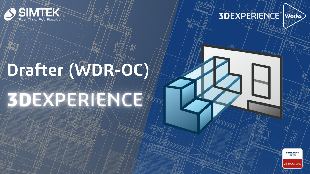
Drafter (WDR-OC) 3DEXPERIENCE
Drafter (WDR-OC) 3DEXPERIENCE Drafter WDR-OC enables rapid conversion of 3D models into accurate 2D drawings, significantly enhancing the product development cycle. With real-time updates, modifications to the 3D model are instantly reflected in the 2D drawings, minimizing errors. Users can easily annotate and dimension their drawings, facilitating clear communication among team members. Integrated with the […]
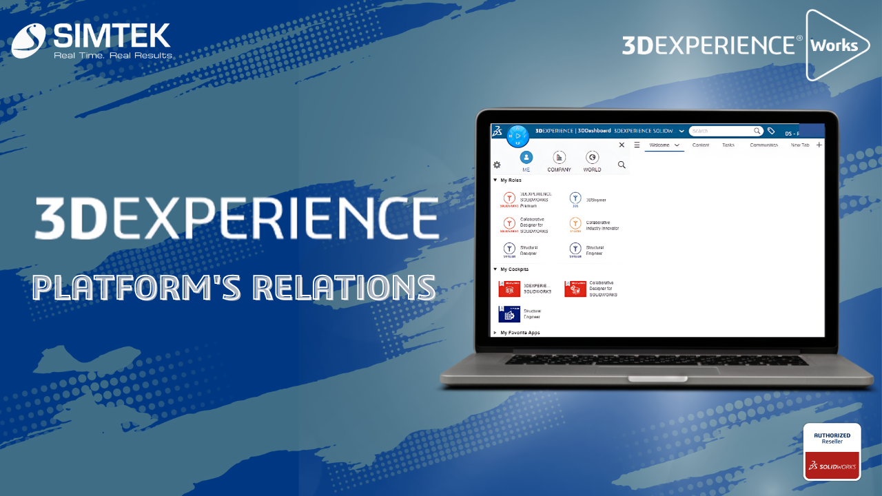
Transform Your Workflow with the 3DEXPERIENCE Platform’s Powerful Relations
The Relations app in the 3DEXPERIENCE platform is designed to help users manage and visualize relationships between various entities, such as parts, documents, and projects. This is a powerful tool for managing complex relationships in product development and ensuring that teams work cohesively. Using the Relations app: Benefits: Conclusion The Relations app in the 3DEXPERIENCE […]
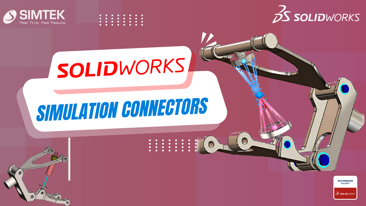
SOLIDWORKS SIMULATION CONNECTORS
Simulation Connectors may be used to simplify behaviour without including a physical part such as a bolt or pin. This is a primer on the different types of connectors available in SOLIDWORKS Simulation. Types of Connectors Springs There are 3 types of Springs: Pin An assembly consists of multiple parts connected to each other with […]

Evaluating Thermal Behavior Using SolidWorks Flow Simulation
Introduction This blog is for you if you’ve experienced Solidworks Flow Simulation but are not aware of Engineering goals or the reasons you want to use them. To address any issues, I will break this blog into 3 sections. PURPOSE OF USING GOALS: Goals primarily define your project, and you can also use them to […]
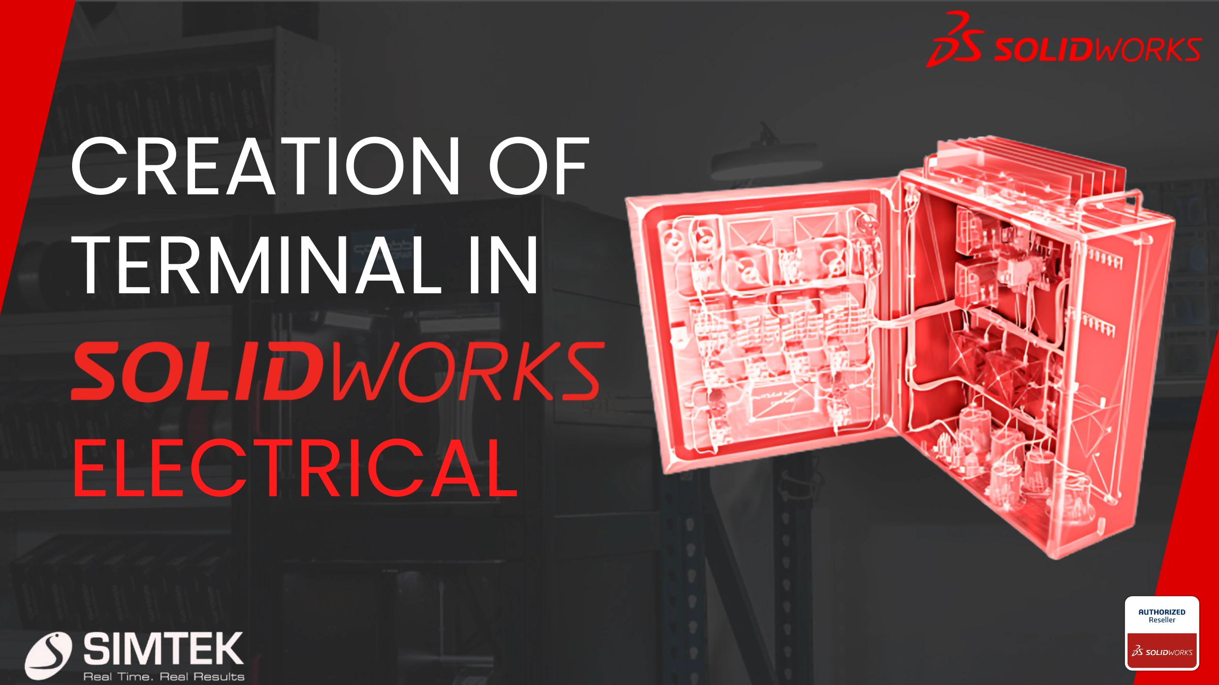
SOLIDWORKS Electrical terminal creation
SOLIDWORKS ELECTRICAL terminal Creation of a new terminal strip drawing and modifying the default terminal symbol in Solidworks electrical and customizing it according to our specification. In SOLIDWORKS Electrical, the system automatically creates terminal symbols, dynamically updating the origin and destination of wires and component details on the terminal drawing sheet.. STEP 1 Step-by-Step Guide […]
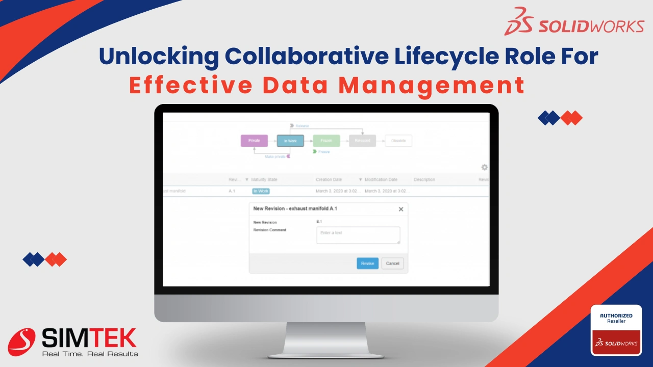
Collaborative Lifecycle Management : How to access the Collaborative Lifecycle role in order to build revision management
Imagine a world where managing revisions for your 3D projects is a breeze. No more confusion over version numbers or lost updates. This is the power of Collaborative Lifecycle Management (CLM) within the Open 3D Experience Platform. CLM empowers you to track changes, create branches, and effortlessly merge revisions, all while fostering seamless collaboration throughout […]
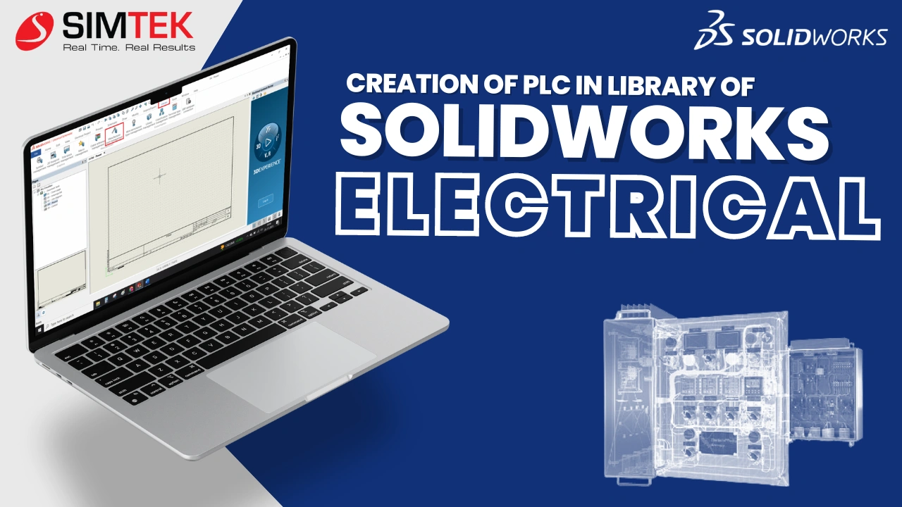
Creation of PLC in library of SOLIDWORKS ELECTRICAL
Creating a PLC in SOLIDWORKS ELECTRICAL SCHEMATICS and customizing the PLC according to our requirement. Include this connector in your schematic diagrams to connect symbols like relays, contactors, sensors, and signals. The creation of a PLC involves following a few steps. Once created, the same PLC specifications can be used for connections within SOLIDWORKS […]
- 1
- 2