Search

Creation of PLC in library of SOLIDWORKS ELECTRICAL

Creating a PLC in SOLIDWORKS ELECTRICAL SCHEMATICS and customizing the PLC according to our requirement.

Include this connector in your schematic diagrams to connect symbols like relays, contactors, sensors, and signals.

                     The creation of a PLC involves following a few steps. Once created, the same PLC specifications can be used for connections within SOLIDWORKS Electrical schematics.

STEP 1

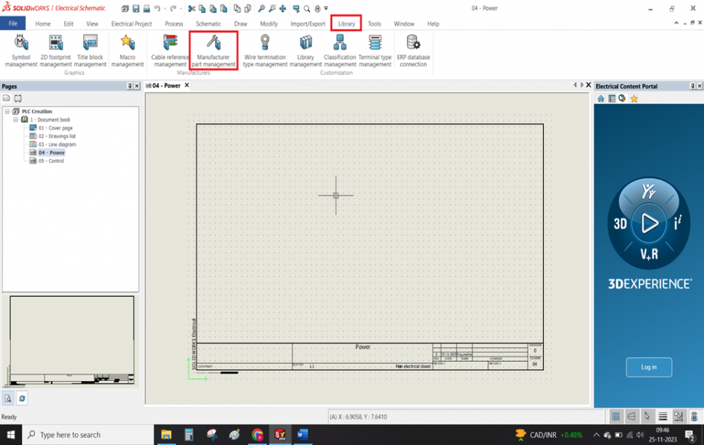
  • To create a PLC first it must store in the library. The library permanently stores created connectors until you remove them manually
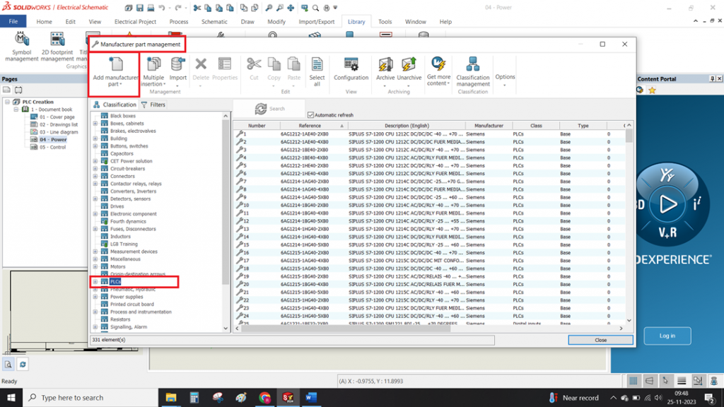
  • To create a PLC as shown in the below image first have to goto Library -> Manufacturer part management.
Windows Screen of Creating PLC in library of SOLIDWORKS ELECTRICAL

STEP 2

Manufacturer part management

  • Once the above points done.
  • Manufacturer part management will consist of more number classifications(folders). This section actively separates and organizes all components into different folders.
  • Selecting the PLC folder filters the manufacturer part management tab on the right side, displaying only PLC-related manufacturers already present in the library.
  • Selecting the "ADD MANUFACTURER PART" option allows you to create a new PLC. The system will provide a separate tab to enter details specific to the PLC.
Windows screnn of Manufacturing part management

STEP 3

New PLC details adding In Solidworks Electrical

  • Once the above points done.
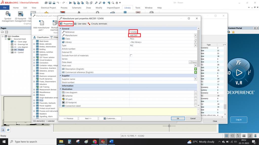
  •  The system will open a Manufacturer Part Properties tab.
  • In this section three options will be present PROPERTIES, USER DATA, CIRCUIT, TERMINALS
  • The Properties tab requires you to fill in essential details like reference and manufacturer. Scrolling down reveals additional optional specifications such as height, weight, frequencies, and supplier name.
Windows Screen of New PLC details adding In Solidworks Electrical

STEP 4

Specifications of Circuit, Terminal

  • With continuation of above points
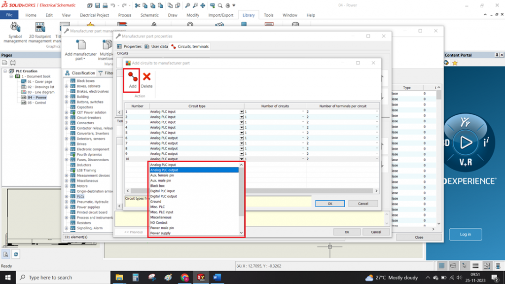
  • The third option, Circuit Terminals, lets you add circuit types.
  •  At the top circuit, terminal option will be present near to the properties tab.
  • This tab allows you to add circuits using the ADD option
  • The ADD MULTIPLE option, illustrated in the image below, allows you to efficiently add multiple circuits at once

STEP 5

Add Multiple Circuits In Solidworks Electrical

  • The image below demonstrates how to quickly and easily add multiple circuits.
  • All circuits type are present in the scroll down. Select circuits based on your specific requirements.
Windows screen of 
Add Multiple Circuits In Solidworks Electrical

Summary

  • With these above-mentioned points we can able to create a PLC in a solidworks electrical.
  • By following these steps, you will create a new connector that gets added to the SOLIDWORKS Electrical library for future use.

3DEXPERIENCE Exchange – Import and Export Package

3DEXPERIENCE Exchange

Let us see how we can Import and Export Package with 3DEXPERIENCE Exchange.

Collaborating together with users outside of your company has always been better! Assembly files can be easily bundled into a single package file by using the Export as a Package capability. You can share this file with third-party suppliers so you can track and get back their modifications. Even the files that are editable within the package can be restricted.

Similar to SOLIDWORKS Pack and Go, but with more ease of use as well as integration with 3DEXPERIENCE Platform products, is this capability.

How to Export as Package:

1. In 3DEXPERINCE SOLIDWORKS, open the assembly file you would like to share with External Stack Holder.

2. To save, pick Tools from the 3DEXPERIENCE tab on the right, choose Export, and then select Export as Package.

pick Tools from the 3DEXPERIENCE tab on the right

3. On the launch of the export window, you have the option to mark assemblies and components as read-only or editable for whoever you are sharing data with

4. Following that, providing the package a name and choose Export. The 3DEXPERIENCE Platform permits you to save the package file (.sldpkg) locally or to 3DDrive.

the package a name and choose Export

How to Import as Package with 3DEXPERIENCE Exchange for SOLIDWORKS:

1. Initially ensure certain SOLIDWORKS' "3DEXPERIENCE Exchange" Add-in is activated.

Initially ensure certain SOLIDWORKS' "3DEXPERIENCE Exchange" Add-in is activated.

2. Select the 3DEXPERIENCE Exchange tab on task plane, then pick Import Package.

3. To open the ".sldpkg" file that you received, click the "Open" icon in the "Import Package" Window. A working folder will be created when importing this package, and its default path will be taken automatically.

 To open the ".sldpkg" file that you received, click the "Open" icon in the "Import Package" Window. A working folder will be created when importing this package, and its default path will be taken automatically

4. The window on the right will display the files that are read-only or unchanged when the package has been imported.

The window on the right will display the files that are read-only or unchanged when the package has been imported

5. The window on the right will display the files that are read-only or unchanged when the package has been imported.

Export Package:

Once you've decided to send the updated package back to the the sender, select Package, Export. The revised ".sldpkg" file can be saved from here on and forwarded to the 3DEXPERIENCE user you are collaborating with.

Product Communicator (XPR)3DEXPERIENCE

Product Communicator 3DEXPERIENCE

Product Communicator role within the 3DEXPERIENCE platform serves as a pivotal facilitator for makers, designers, technical-sales personnel, and marketers, empowering them to effortlessly craft compelling digital content for product communication.

Leveraging applications such as xHighlight for interactive storytelling and xStudio for photorealistic product shots, this role minimizes time-to-market by creating content directly from the latest 3DEXPERIENCE Twin. Offering an intuitive user experience accessible on all devices and within web browsers, it enables the interactive staging of products in global illumination for cloud-based rendering.

KEY FEATURES OF Product Communicator

  • Minimize Time-to-Market:

This capability emphasizes the role's efficiency in swiftly creating content for product launches directly from the latest 3DEXPERIENCE Twin. By reducing the time, it takes to bring a product to market, organizations can stay competitive and responsive to market demands.

  • Intuitive User Experience:

The intuitive user interface ensures that individuals with varying roles, including makers, designers, technical-sales personnel, and marketers, can easily navigate and utilize the tools. The accessibility across devices and web browsers promotes widespread adoption, fostering collaboration among diverse teams.

Interactive staging capabilities 3DEXPERIENCE
  • Interactive Staging in Global Illumination:

Interactive staging capabilities directly in the web browser, coupled with global illumination, highlight the platform's commitment to providing visually stunning renderings. The on-cloud rendering service, combined with a pay-as-you-go model, optimizes resources and allows for cost-effective production of high-quality visuals.

  • Render-as-a-Service:

The Render-as-a-Service is an infrastructure solution that adapts

to project needs, offering scalability for large-scale productions and teams. It dynamically adjusts rendering resources based on requirements, providing flexibility and efficiency. This ensures optimal resource use, with the system scaling up during high-demand periods and down during lower demand, optimizing costs. Overall, it's a responsive rendering solution that enhances workflow efficiency in design and content creation.

Render 3DEXPERIENCE
technical illustrations 3DEXPERIENCE
  • Illustration and Presentation:

Enabling the creation of impactful videos and technical illustrations, this capability allows for effective storytelling. Whether showcasing Unique Selling Points (USPs), usage scenarios, or providing detailed information in user guides, the platform supports the development of visually compelling content with a focus on accuracy through vector graphic technology.

  • Create Technical Illustrations with Vector Graphic Technology:

The platform allows for the creation of technical illustrations for user guides or functional product descriptions. This capability ensures maximum accuracy through the use of vector graphic technology, enabling precise and clear communication of technical information.

Utilizing 3DEXPERIENCE SOLIDWORKS – Revisions Update

Managing Reference Component Revisions in 3DEXPERIENCE SOLIDWORKS

This blog post explains how to revise components within the SOLIDWORKS My Session Task Pane of the 3DEXPERIENCE platform. It covers the different approaches available and clarifies how to handle situations where reference components appear outdated.

This lesson demonstrates the many approaches to revising these components.

Challenges with Updating Downloaded Assemblies

When you download an assembly from the 3DEXPERIENCE platform and then update its reference components, those components might still show up in the Task Pane with the previous revision. This lesson will guide you through various methods to revise these components effectively.

Updating Individual Components

There are two main ways to update individual components:

  1. Replace by Revision: Right-click a component in the Task Pane that has a newer revision available. Select "Replace by Revision" from the menu. This brings up a dialog box showcasing all compatible revisions for that component.
    • Latest Revision: This option replaces the component with its most recent revision.
    • Important Note: This functionality only works for components that have child references (components with derived parts or contextual connections).
My Session Task Pane 3DEXPERIENCE SOLIDWORKS

2. Update Revisions in Top-Level Assembly: Selecting "Update Revision" on a top-level assembly offers a more streamlined approach. This action triggers a dialog box displaying the entire assembly structure. Next to each component, a drop-down list appears, allowing you to efficiently select the latest revision for multiple components simultaneously. This eliminates the need to update revisions one by one.

Important Considerations During Updates:

Warning Message: When replacing a file with a different revision while it still shows as updated in the Task Pane, a warning message will pop up. This message informs you that any local changes made to the file will be overwritten. It's recommended to back up your data beforehand if necessary.

Latest Revisions Update:

Selecting the "Update Revision" option on a top-level assembly streamlines the process. Consequently, a dialog box will appear, conveniently displaying the entire assembly structure. Furthermore, a drop-down list will be available next to each component, allowing you to efficiently link the most recent revisions of multiple components simultaneously. This eliminates the need to update each revision individually, as previously mentioned.

  1. Replacing a component with the most recent revision available.
  2. Replacing a component with the most recent stable revision takes it back to its most recent frozen or released lifecycle stage.
  3. Replace with Most Recent Released Revision: Replace a component exclusively with the most recent revision to be made public.

Note: The option Replace by Latest Revision will be the only one available if there are only unreleased versions.


 3DEXPERIENCE SOLIDWORKS

Updating All Components to Latest Revision

If you want to update all components within an assembly to their latest revisions at once, you don't need to use the drop-down menu for each component individually.

Simply select "Replace All" from the top right corner of the dialog box that appears when you choose "Update Revision" on the top-level assembly. This will instantly update all components to their most recent versions.

My Session Task Pane

Additional Resources

You can find all the settings mentioned above within the Lifecycle tab located at the bottom of the My Session Task Pane.

This concludes the lesson on updating revisions in SOLIDWORKS My Session Task Pane. If you'd like to learn more about the 3DEXPERIENCE platform and SOLIDWORKS, explore the articles provided below.

Von Mises Stress Plot Vs Principal Stress Plot

When analyzing stress on a structure, engineers rely on two key methods: von Mises stress and principal stress. While both visualize stress distribution, they offer distinct insights.

This comparison explores the fundamental differences between Von Mises and principal stress plots, highlighting their strengths and guiding you on which approach best suits your material and analysis goals.

Its bit tricky right ? Especially for New FEA Engineers. Lets dive to understand the difference

Von Mises Stress: A Distortion Energy Measure

While not a true stress, It represents the distortion energy density at a specific point. It helps predict failure in ductile materials (materials that deform before breaking).

Richard von Mises observed that even when individual principal stresses stay below the material's yield point, their combined effect can still cause yielding. He proposed a formula to combine the three principal stresses into an equivalent stress.

This equivalent stress is then compared to the material's yield stress to assess the risk of failure using the von Mises criterion.

Principal Stresses: The "True" Stresses

Principal stresses, on the other hand, are genuine stresses obtained by rotating a stress element to eliminate shear stress. The resulting normal stresses are called principal stresses. They represent the maximum normal (tensile or compressive) stresses an element can experience under specific loads.

A failure theory based on principal stresses is the maximum principal stress theory. This theory suggests that brittle materials fail when the largest principal stress reaches the ultimate tensile strength. While well-supported by experiments, it assumes equal tensile and compressive ultimate strengths, which isn't always the case.

Formula for Principal Stresses:

Choosing the Right Tool: Von Mises vs. Principal Stress:

For ductile materials, the von Mises theory is generally preferred due to its accuracy in predicting deformation. However, principal stress plots remain valuable for analyzing brittle materials and understanding potential fracture points.

Conclusion :

In general, It is considered to be a more accurate measure of a material's resistance to deformation, while Principle stress is more useful in predicting failure in brittle materials.

Back to Top
Product has been added to your cart