
SOLIDWORKS ELECTRICAL
Automatically interconnect electrical design elements within a 3D model
What is Solidworks Electrical and Why is it Important?
Are you stuck with archaic tools for designing and implementing electrical schematics? Do you want to save time and scale your business? Then SOLIDWORKS Electrical is your gateway to success.
SOLIDWORKS Electrical helps in creating 2D electrical schematics quickly, efficiently, and easily. Since it is based on an SQL database, report creation, design changes, speed, and performance are top-notch. Specific rules can also be set for specific applications. Further, it can be linked with the 3D SOLIDWORKS mechanical system, thereby gaining additional value in projects and investment.
TOOLS
Single Line and Schematic Design
Easy to create diagrams using intuitive schematic tools. Associated documentation can also be prepared. Minimize the need for having to split or trim lines
Terminal Strip Editor
Specify terminal part numbers easily and define multi-terminal levels. Manage the use of bridges and jumpers. Easy one-click solution to generate drawings
PLC Manager
Supports creation of different PLCs and logics. Create re-usable data sets. Racks, modules, and others can also be organized
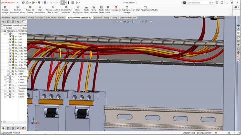
3D Integration with SOLIDWORKS
Automatic routing of electrical drawings and components to the 3D environment. Reports of wire and cable lengths can be generated and are accurate. Mockups can be created easily
Harnessing
Harnessing is a critical part since multiple components are connected. Bundling of wires helps to keep them organized. Report of all wires and cables in a harness is generated and provided by SOLIDWORKS Electrical.
Automatic Reporting
Empowers users to create customized reports. All parameters within the systems can be made a part of report generation
FREQUENTLY ASKED QUESTIONS
Can I bring in my AutoCAD DWG's or other legacy data ?
SOLIDWORKS Electrical has a plethora of ways to reuse legacy design data. By importing DWG symbols and title blocks, you can integrate your standards into SOLIDWORKS Electrical’s libraries.
Does SOLIDWORKS Electrical have a specific part or library in it ?
SOLIDWORKS Electrical comes preloaded with thousands of manufacturer parts, cables, and symbols. However, if you don’t see what you are looking for, head on over to the Electrical Content Portal for millions of downloadable parts.
Can SOLIDWORKS Electrical do wire harnessing ?
SOLIDWORKS Electrical excels at harnessing. By defining what wires, cables, and components are in a harness on the schematic, the SOLIDWORKS 3D add-in can route these harnesses in context with the overall SOLIDWORKS Mechanical assembly. Once the harness is routed, you can create a to-scale flattened harness route to aid in manufacturing.
Does the SOLIDWORKS Electrical 3D add-in need SOLIDWORKS Standard, Professional or Premium?
The SOLIDWORKS Electrical 3D add-in can work with any tier of SOLIDWORKS (Standard, Professional, or Premium).
SOLIDWORKS ELECTRICAL FEATURES
Automated Project Configurations
- Creation of project templates with pre-defined settings is available
- Micro and macro level customization is offered
- Different design demands can be met easily because of the software flexibility on offer

Fully Associative Designs
- Single point change reflects across all associated components
- Easy to make design changes, store versions, and diagrams without being lost
- Change applies even to 3D SOLIDWORKS models
Accurate Wire and Cable Lengths
- Delivers accurate wire and cable lengths
- Suitable for any project scale and type
- 3D models can also be called up into an assembly project.


Report Customization
- Unmatched report customization possibilities
- Extensive library of predefined reports
- Intuitive data management helps to connect the dots in projects easily.
COMPARE ELECTRICAL PACKAGES
| *Our software is all inclusive – not module based – hydraulics and pneumatics – 2D Cabinet layout – Harnessing – Reports – Line Diagrams – Schematics – No page limits – No component limits | Electrical 3D with electrical Schematics professional |
Electrical Schematics Professional |
Electrical schematics standard |
|
Platform Collaboration
|
|||
|
Multi-user Environment
|
|||
|
SOLIDWORKS PDM Connector
|
|||
| Electrical Component Library | |||
|
Hyperlinks |
|||
|
Electrical Design in 3D CAD
|
|||
|
3D Electrical Cabinet Design
|
|||
| Single-line Schematic | |||
| Multi-line Schematics | |||
| Mixed Schematics | |||
|
2D Cabinet Creation
|
|||
|
Design and Reuse
|
|||
|
Automated Terminal Drawing Creation
|
|||
|
Report Generation
|
|||
|
Automated Contact Cross-Referencing
|
|||
|
Advanced Formula Manager
|
|||
|
Electrical Symbol Library
|
|||
|
Marks and Wires Management
|
|||
|
Dynamic Connector Tools
|
|||
|
Customizable Reports & Documentation
|
|||
|
PLC Tools
|
|||
| Multi-level Terminals Strip Support |