SOLIDWORKS 3D Interconnect And Extracting Features
SOLIDWORKS has a capability to work with third party native CAD data files which includes ACIS, Autodesk Inventor, CATIA v5 (.CAT part, .CAT Product), IGES, PTC, SOLID EDGE, NX files as shown in Fig(A)
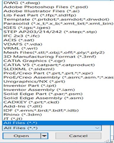
Fig(A)
IMPORTING STEP/IGES FILES AND EXTRACTING THE FEATURES
SOLIDWORKS has a special option to extract and recognize all the features from other CAD files or STEP/IGES files.
Let us see the step by step process for extracting features from a STEP file
Step1:
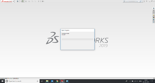
Fig (B)
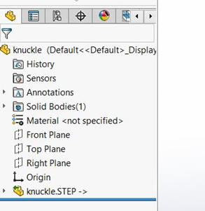
Fig(C)
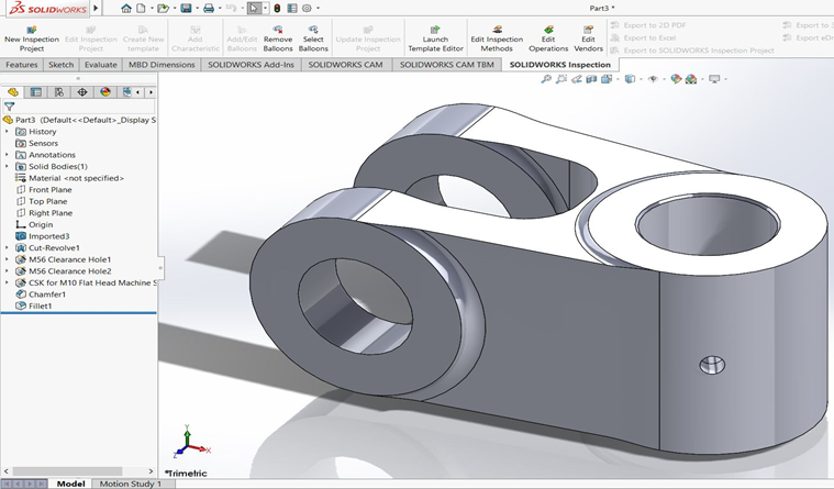
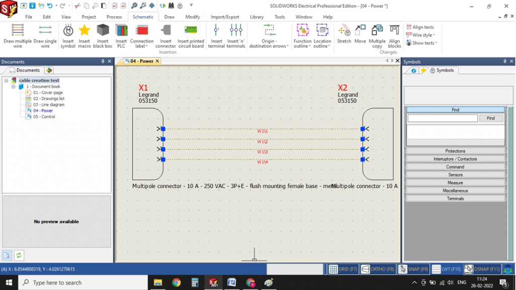
Open a STEP file directly into SOLIDWORKS. Once after opening, the part will be viewed as an imported STEP part as shown in fig (C)
Step 2:
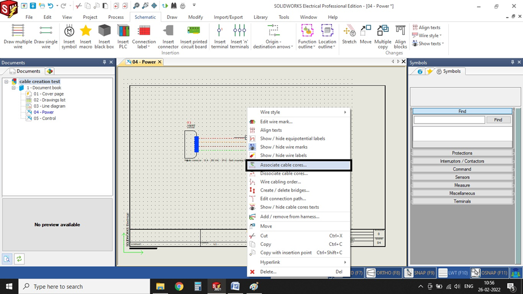
Right clicking the STEP part file allows you to click on the “Dissolve feature” option which will prompt you to break the link of the part initially as shown in Fig(D)
The below picture shows you the break link dialog box after clicking on the dissolve feature. Click on “yes, break the link” option as shown in Fig(E)
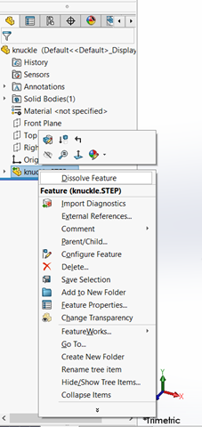
Fig (D)
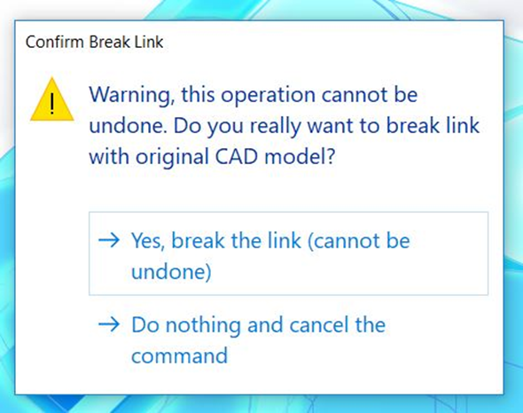
Fig(E)
Step 3:
Breaking the link from the previous step will convert the step part file into a imported geometry. You can extract feature only after converting it into a imported file.
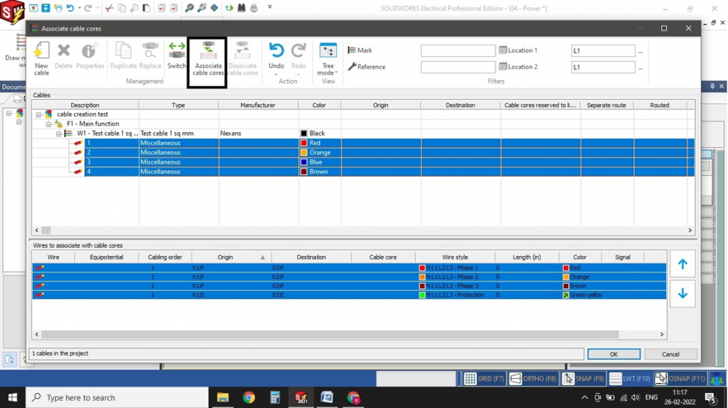
Right click the imported file and go to feature works -> Recognize features. This will induce the user to extract the standard features or sheet metal features as per the wish shown in Fig(F) and (G)
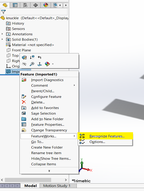
Fig(F)
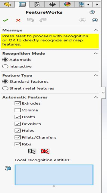
Fig(G)
Step 4:
The Complete recognition of the remaining features in the imported body. When recognition is complete, the imported body no longer appears in the SOLIDWORKS Feature Manager design tree.