Search

Build Custom Connectors for SOLIDWORKS Electrical

This blog will guide you through creating custom connectors in SOLIDWORKS Electrical Schematics libraries and using them in your schematics.

Storing Connectors in the Library

Storing connectors in the library allows for easy access and reuse. Once created, they'll remain in the library until you manually delete them.

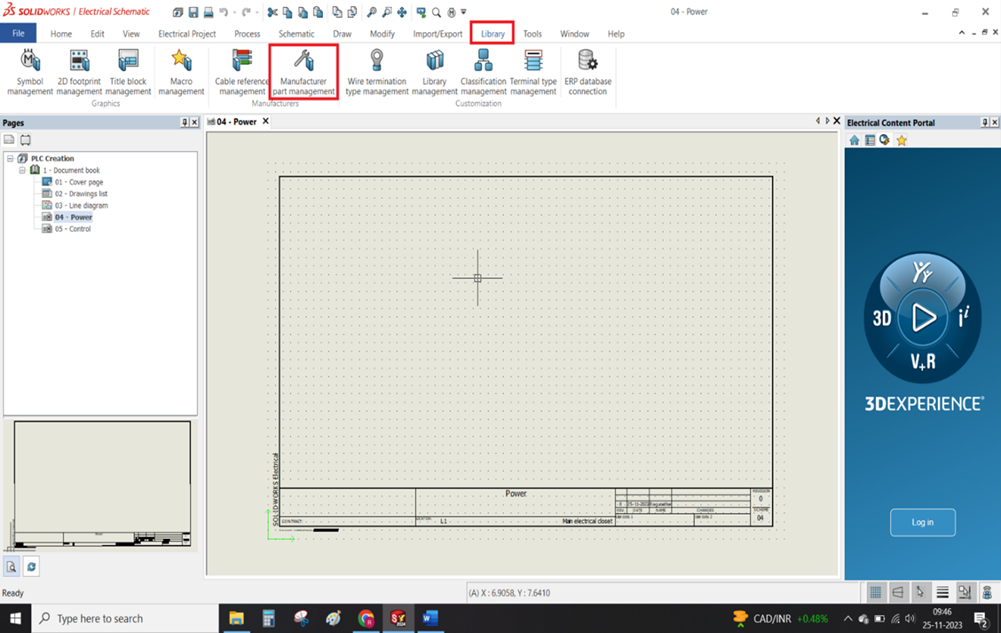
Step 1: Accessing the Library

Go to Library > Manufacturer Part Management.

 Manufacturer Part Management. custom connectirs

Step 2: Selecting the Connector Folder

The Manufacturer Part Management window displays various component categories. Select the Connector folder.

This will show connector-related manufacturers on the right side.

Selecting the Connector Folder custom connectors

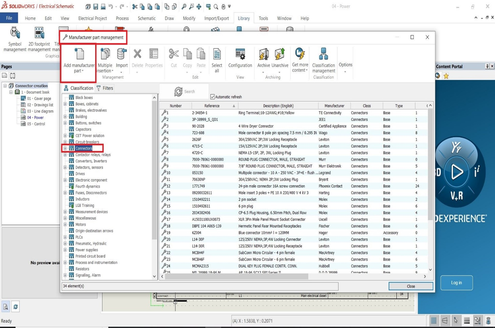
Step 3: Adding a New Connector

Click the Add Manufacturer Part button to create a new connector. You'll then be able to fill in details about the connector in a separate tab

Adding a New Connector custom connectors

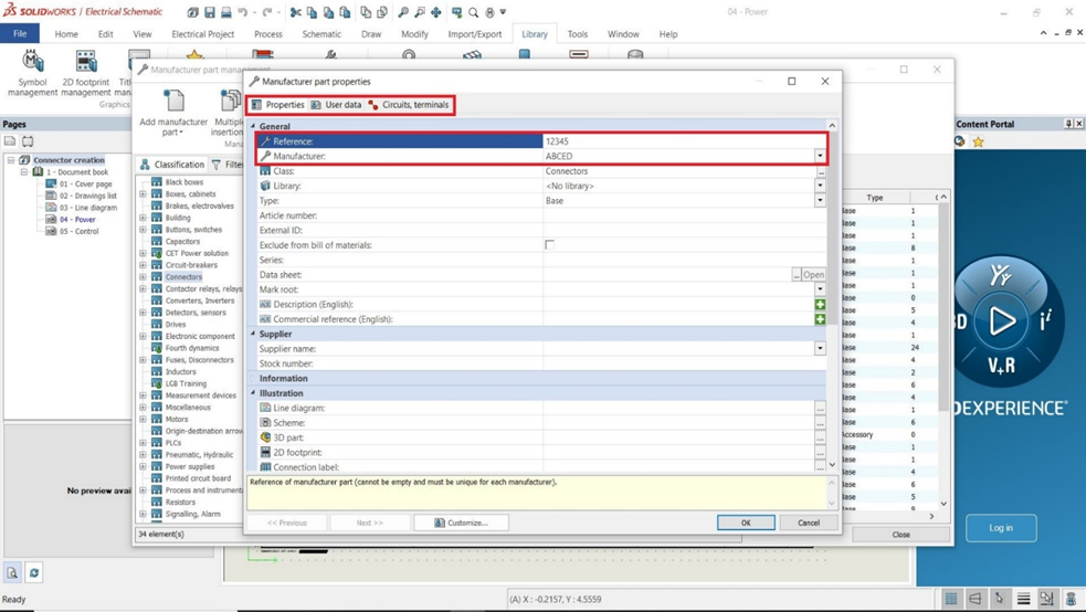
Step 4: Defining Connector Properties

The Manufacturer Part Properties tab opens with three sections: Properties, User Data, and Circuit Terminals.

In the Properties section, fill in mandatory details like reference and manufacturer. Fill in optional details like height, weight, and supplier name in the scrolling section below

Defining Connector Properties custom connector.

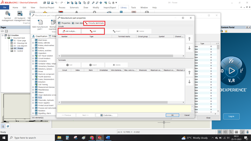
Step 5: Specifying Circuits and Terminals

Define the circuit types the connector can be used with by using the Circuit Terminals option.

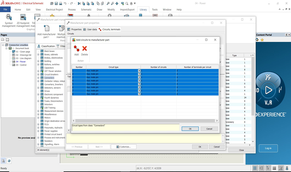
Click the Add button to add a single circuit or the Add Multiple button to add multiple circuits simultaneously.

Specifying Circuits and Terminals custom connnectors

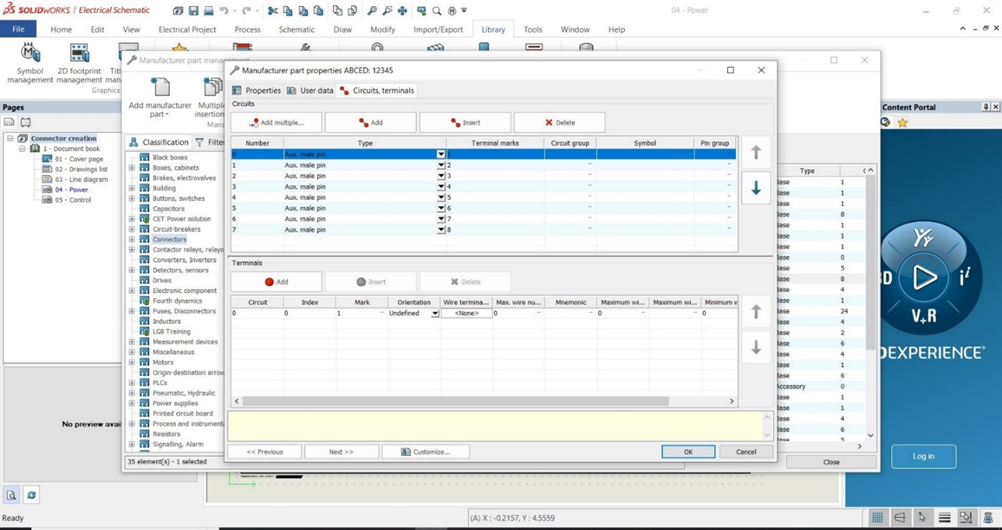
Step 6: Adding Connector Pins

Use the Add Multiple option to quickly add multiple pins to the connector. After adding the pins, manually assign terminal marks to each pin.

Adding Connector Pins custom connectors

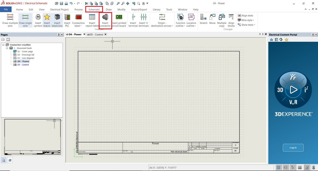
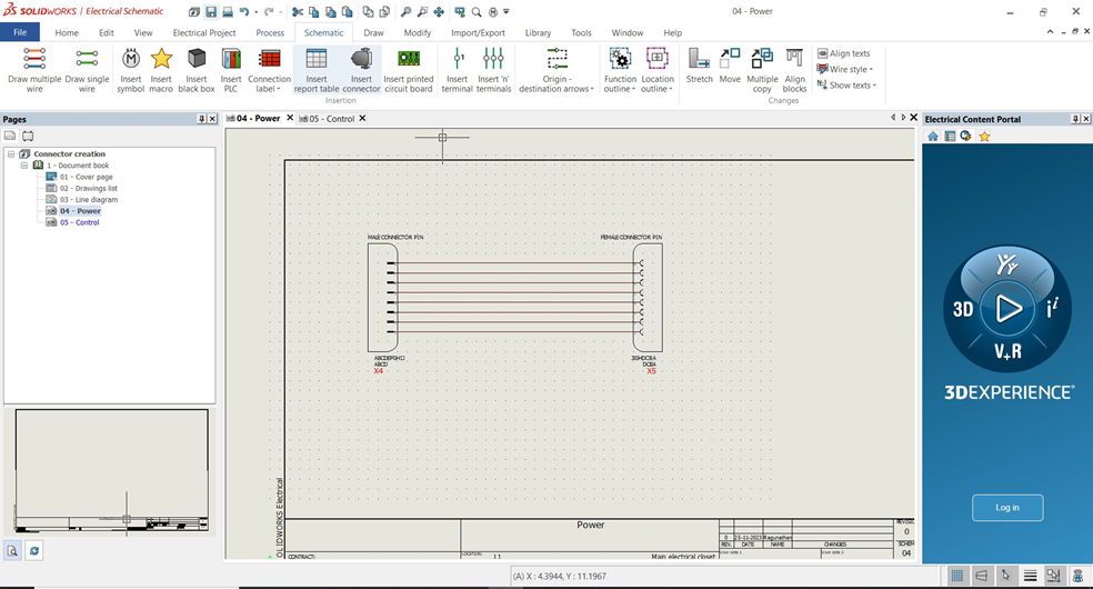
Step 7: Inserting the Connector in Schematics

Once you've created the connector for both male and female pins, you can insert them into your schematic page.

Go to Schematics > Insert Connector and select the desired connector from the options.

Inserting the Connector in Schematics custom connectors

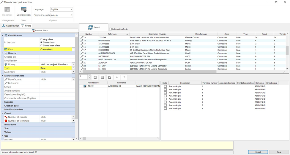
Step 8: Selecting the Manufacturer

A Manufacturer Part Selection tab will appear. Choose the manufacturer based on your circuit and terminal requirements.

The library will display your newly added manufacturer for selection. You can also use filter options to easily find the correct manufacturer.

Selecting the Manufacturer custom connectors

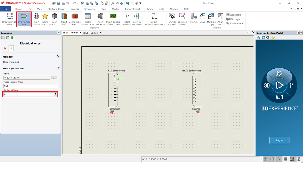
Step 9: Inserting Components and Wires

After selecting the manufacturer, insert the component and choose the wires you want to connect.

You can insert single or multiple wires by adjusting the number of lines on the left side of the window. We can also adjusted the wire spacing.

Inserting Components and Wires custom connectos

Conclusion

By following these steps, you can create custom connectors in SOLIDWORKS Electrical and use them to connect components in your schematics. These connectors will be stored in your library for future use.

Structure System In SOLIDWORKS

For designers and engineers working with frames in SOLIDWORKS, the traditional welding workflow can be time-consuming and cumbersome, especially for complex structures. If you're looking to streamline your design process and achieve significant time savings, look no further than the innovative SOLIDWORKS Structure System.

This powerful tool offers a fundamentally different approach to frame creation, empowering you to build frames faster, easier, and with greater efficiency. In this blog post, we'll delve into the SOLIDWORKS Structure System, exploring its key features and the undeniable advantages it offers over traditional welding methods.

Get ready to unlock a new level of design productivity and transform your frame creation workflow!

CREATE STRUCTURE SYSTEM

        The Structure System mode is activated for developing the primary and secondary members.

There are two structural members in the structure system.

  • Primary structural member.
  • Secondary structural member.

PRIMARY STRUCTURAL MEMBER

Including members for the sketch entity, point, reference plane, and surface requirements are possible.

Create required sketch entities, plane and axis for a primary structural member.

Use the following techniques to generate the primary structure members:

        selecting the required edge, point, or sketch entities, then define the primary member structure's profile standard, type, and size.

SECONDARY STRUCTURAL MEMBER

Secondary structural members offer the improved option of adding members between two primary structural members.

Use the following techniques to generate the secondary structure members:

        Select the required two primary structural members, Choose the secondary member type then define the profile standard, type, and size for the secondary member structure.

        Once creating a secondary structural member, Exit the structural system.

        After exiting the structure system corner management will be open for the treatment of the corner of the structure system.

CORNER MANAGEMENT

The Corner Management Property Manager has launched automatically after you exit the structure system. Corners in the Property Manager are classified based on the number of members that meet at a point and the type of joint.

        In corner management, we use the following techniques to modify the corners of the structure system.

SimpleThe point at which the ends of two members come together and the segments become collinear.
ComplexThe point at which more than three members connect.

Editing Simple corners

In the corner grouping, select the corner to treat and set the needed corner treatment type.

Trimming the complex corners

In the corner grouping, select the corner to treat and set the required trim order on the corner treatment type.

Patterning and mirroring the structure members

Using the Linear Pattern, Circular Pattern, and Mirror tools, you may pattern and mirror structure system parts.

        In the Pattern Property Manager, under Bodie’s selection, you can specify structure system features or individual members to the pattern. You can also mirror members by specifying structure system features or individual members under Bodies to Mirror in the Mirror Property Manager.

CONCLUSION

The structural member can be created faster and more easily with the SOLIDWORKS Structure system than it can with welding. In this presentation, the SOLIDWORKS Structure system was discussed. I believe you now have a more advantageous choice.

Bookmark Editor On The 3DEXPERIENCE Platform

In 3DEXPERIENCE platform, the Bookmark Editor empowers you to streamline cloud data organization and management. Imagine creating a personalized filing system based on projects, departments, products, or any other criteria that suits your workflow. This blog post delves into four key tips to unlock the full potential of the Bookmark Editor and transform your data management experience.

  1. Customise the columns on your bookmark editor.
  2. Enable Product Expansion.
  3. Remove File vs Delete File.
  4. Index and Authoring in Active Mode.

1. Customize the columns on your bookmark editor:

The Bookmark Editor displays a wealth of information about each file within its top row columns. These columns are instrumental in organizing and managing your data effectively. Tailor these columns to your specific needs by dragging and dropping them for rearrangement and selecting which ones to display.

Pro Tip: Right-click any column header and choose "Tree List View Options" to manage column visibility. This menu allows you to select the specific columns you want to display (Step 2). For even more granular control, click the settings gear in the upper right corner (Step 3) and navigate to "More Attributes" followed by "Select Attributes" (Step 4 & Step 5) to add even more columns.

2. Leverage Product Expansion for Effortless Navigation

Subassemblies and subcomponents become a breeze to navigate with product expansion enabled. Simply access the drop-down menu in the upper right corner of your Bookmark Editor Widget (Step 1) and select "Preferences" (Step 2)

. Next, activate the checkbox labelled "Enable product expansion" (Step 3). This will add a plus sign (+) to your files, allowing you to expand them and effortlessly view sub-components.

3. Understanding Remove vs. Delete: Keep Your Data Organized

The Bookmark Editor of 3DEXPERIENCE Platform offers two options for file management: Remove and Delete. It's crucial to understand the distinction between these two functions.

  • Remove: This action removes the selected file from the current Bookmark only. The file itself remains within the Collaborative Space where it was originally saved and can still be accessed through other Bookmarks.
  • Delete: This permanent action removes the selected file from your entire Platform. Use this option with caution, as deleted files cannot be recovered.

4. Switch Between Indexing and Authoring Modes for Real-time Updates

The Bookmark Editor offers two viewing modes: Indexing and Authoring. Indexing mode, the default setting, displays the latest items available from the server's database. However, there might be a slight delay in reflecting recent modifications or uploads due to the indexing process.

To view the most up-to-date changes, switch to Authoring mode. This mode allows you to see any files still being indexed. Keep in mind that the window will automatically revert to Indexing mode after a minute in Authoring mode, unless you adjust this behavior in the Preferences.

Unleash the Power of the Bookmark Editor

By incorporating these essential tips, you can transform the Bookmark Editor into a powerful tool for managing your cloud data within the 3DEXPERIENCE platform. From customized column views to seamless navigation and control over file management, the Bookmark Editor empowers you to organize and access your data with greater efficiency.

How To Create 3D Markup With The Help Of 3DEXEPERIENCE Platform

In today's fast-paced design environment, clear and efficient communication is paramount. Imagine a world where highlighting design issues, sharing feedback, and collaborating with colleagues becomes effortless.

This is the power of 3D Markup within the innovative 3DEXPERIENCE platform. It empowers users to streamline the review process, eliminate communication roadblocks, and foster seamless collaboration throughout the design cycle.

This blog post will guide you through the creation and utilization of 3D Markups, allowing you to leverage the full potential of this valuable tool within the 3DEXPERIENCE platform.

Get ready to revolutionize the way you communicate design ideas and dramatically improve project efficiency!

Accessing 3D Markup:

Before diving into creating markups, let's explore how to access the 3D Markup application within the 3DEXPERIENCE platform:

  1. Open the 3DEXPERIENCE Platform: Head to Google Chrome and launch the 3DEXPERIENCE platform webpage.
  2. Login with your Credentials: Use your 3D Passport login credentials to access the platform.
  3. Finding 3D Markup: There are two ways to access 3D Markup. You can either open it directly from the Compass icon or drag it to your dashboard for easy future access.

Creating a New Markup:

Now that you've accessed 3D Markup, let's create a new markup to highlight design elements and communicate your ideas:

  1. Initiate a New Markup: Within the Markup tab, locate and select the "Markup" icon to create a fresh markup.
  2. Select Your File: It allows you to work with various file types. Choose the component, existing markup, drawing, or any other approved file type you want to annotate.

Enriching Your Markup:

With your file selected, it's time to add value through annotations:

  • Include Notes and Annotations: Clearly communicate your ideas by incorporating essential notes, shapes, or annotations directly onto the 3D model.
  • Save as Slides: Organize your markups for clear and efficient information sharing by saving them as slides.

Additional Features of 3D Markup

3D Markup offers even more functionalities to streamline your design review process:

  • Issues and Change Actions: Facilitate efficient problem-solving by creating Issues and Change Actions directly within the markup.
  • Share with the Community: Capture screenshots of your markups with ease and share them with the 3DSwym community, fostering a platform for exchanging ideas.
  • Seamless Transition to 3DPlay: After adding notes and annotations, simply switch to the 3DPlay application for further analysis while keeping the document active.

Creating Markups Directly from 3DPlay:

Here's a bonus tip: Did you know you can also create markups directly from within 3DPlay? Simply access the "Annotations Commands" icon in the Tools menu of the 3DPlay window to generate annotations similar to those made in It.

By incorporating these steps and exploring the functionalities of 3D Markup, you can significantly enhance communication and collaboration within your design projects.

Back to Top
Product has been added to your cart