Unleashing the power of 3D in Draftsight Enterprise Plus

Introduction:

DraftSight has long been recognized for its precision 2D drafting capabilities. But with the evolution of design workflows, engineers and designers now need to visualize and model their ideas in three dimensions. The 3D Workspace in DraftSight Enterprise Plus brings exactly that — powerful 3D modeling tools integrated into a familiar drafting environment.

Unleashing the power of 3D in Draftsight Enterprise Plus Step-by-Step Guide:

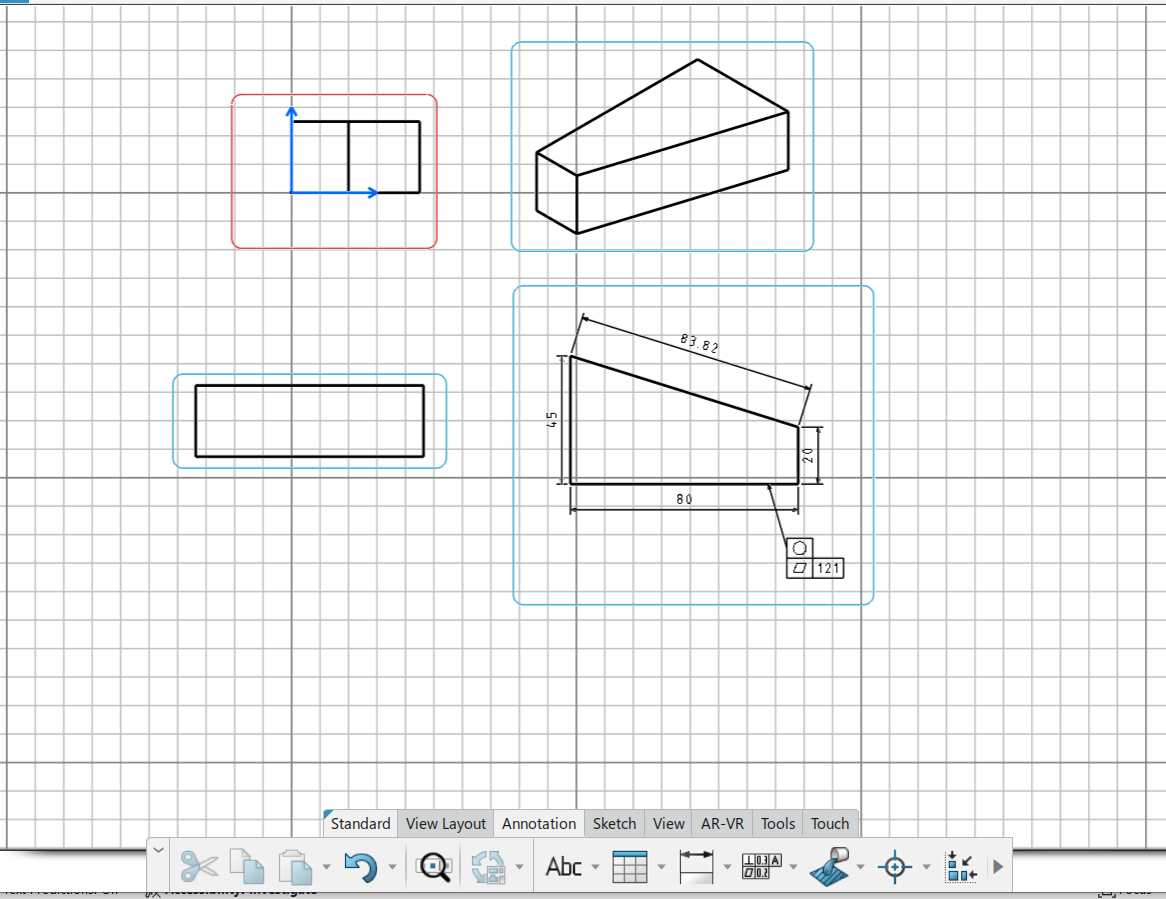
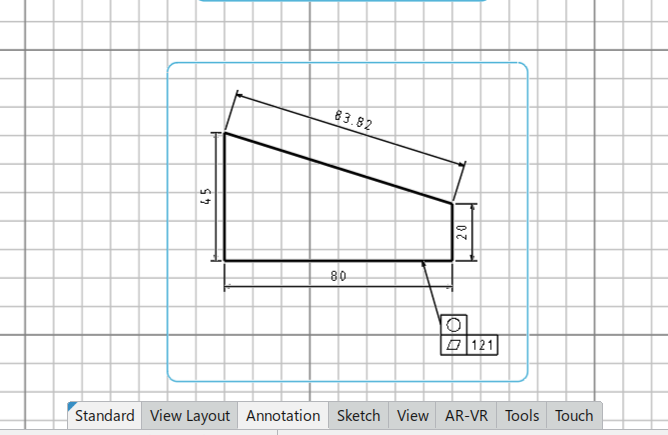
Step 1: Make a 2d sketch

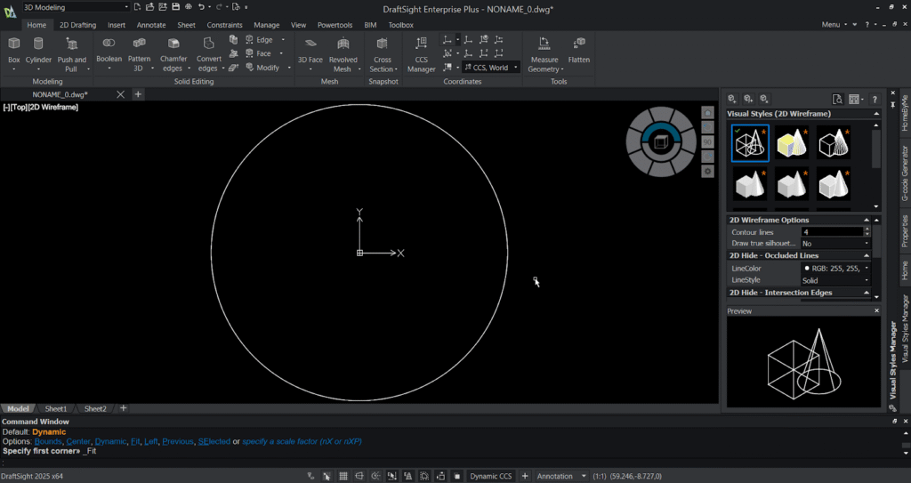
  1. Create a circle using the “cir” command and press enter.
  2. Then select (0,0) as centre point and the enter 50 as radius.
  3. Then press enter , the circle is generated in the graphical area.
Unleashing the power of 3D in Draftsight Enterprise Plus

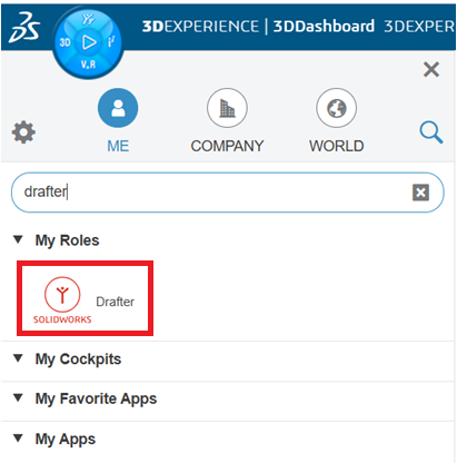
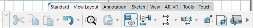
Step 2: Switch the workspace

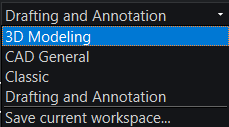
The workspace in DraftSight provides a flexible environment that adapts to your design needs, offering predefined layouts such as 2D Drafting and 3D Modeling. Users can easily switch between these workspaces depending on their tasks or customize their own by arranging toolbars, ribbons, and palettes for maximum efficiency. Customized workspaces can be saved, transferred, and reused across systems, ensuring consistency and productivity for teams. This flexibility allows designers to maintain a clean, task-specific interface and focus more on drafting, detailing, or modeling without unnecessary distractions.

  1. Switch the workspace from existing to 3D Modeling workspace.

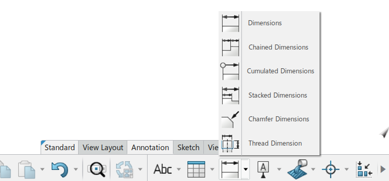
Step 3: Extrude the circle:

You can also use push and pull option to extrude your entity. The Push and Pull option in DraftSight allows users to quickly create or modify 3D geometry from 2D shapes. By selecting a face or a closed boundary, you can pull it outward to add material or push it inward to remove material, effectively extruding or cutting the solid. This intuitive tool makes 3D modeling faster and more visual, as you can dynamically adjust the height or depth of features directly in the graphics area. It’s especially useful for quickly turning 2D sketches into 3D models or refining existing designs without needing complex commands.

  1. Set the view to SW Isometric using the view option in the view tab or by the navigator wheel present in the graphical area.
  2. Then select the extrude option from the modelling ribbon in the home tab.
  3. Then select the circle and specify the height 20mm to be extruded.
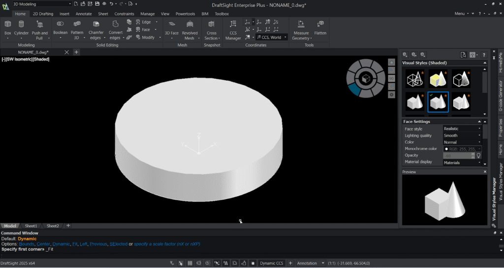
  4. The extruded circle appears in the graphical area in wireframe visuals.
  5. Go to the visual style manager from the view tab and select the shaded with edges .
  6. You can notice the wireframe visual gets converted to solid visual with shaded edges in the graphical area.

Step 4: Subtract a hole in the 3D model:

  1. Change the UCS by typing UCS ,select the top view through the navigator and select the view option.
  2. Create a cylinder in the centre of the circle.
  3. Specify the centre point and, specify Radius as 20mm and height as 20mm towards downwards.
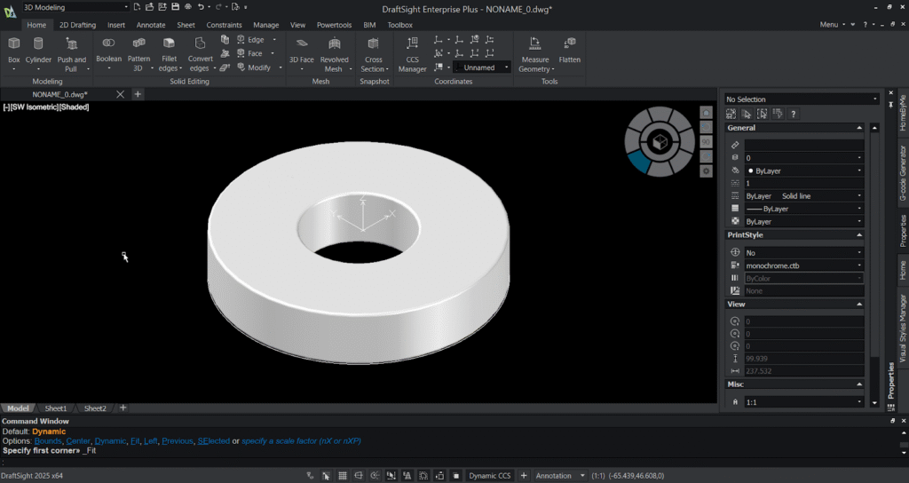
  4. You can notice the cylinder gets created in the centre of the 3D model.
  5. Select the subtract option from the solid editing ribbon in the home tab . Select the 3D circle first and select the cylinder next . You can notice the hole gets created in the 3D model.

Step 5: Fillet the edges:

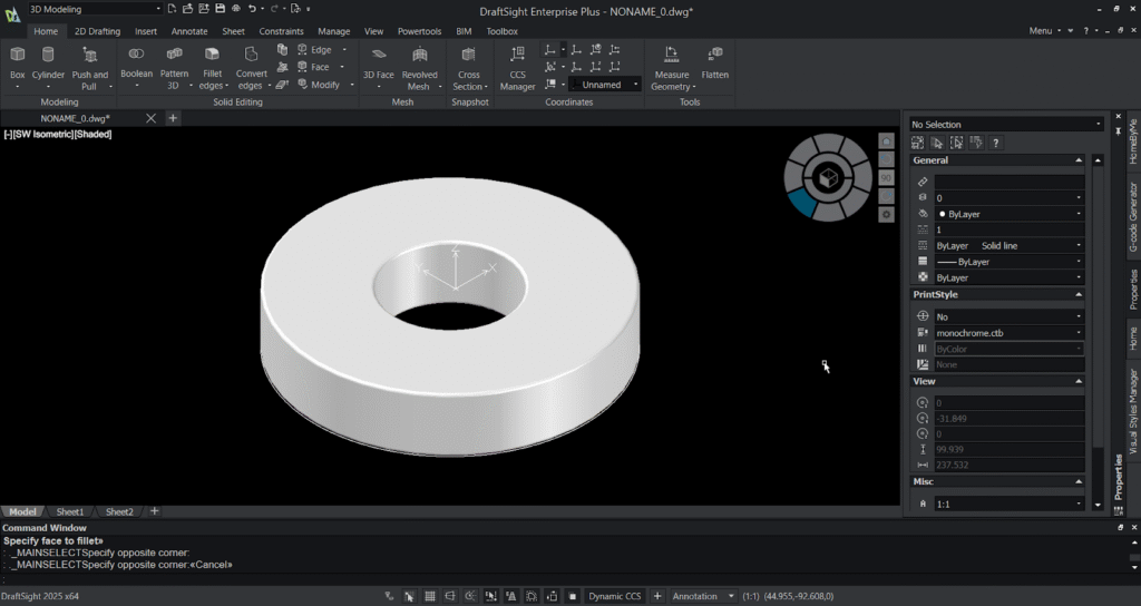
  1. Select the fillet edges or type fillet and press enter.
  2. Select the edges need to be filleted in the 3D model and specify the radius and then press enter.
  3. You’ll notice the fillet gets generated in the specified 3D model edges.

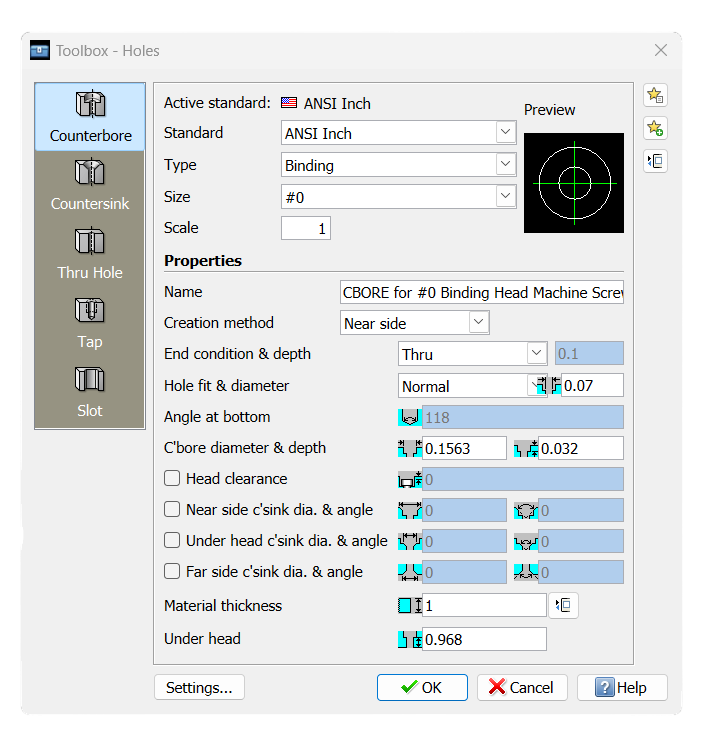
Step 6: Create holes and pattern it:

The 3D Pattern feature in DraftSight helps you quickly duplicate 3D objects in a specified arrangement, such as linear, circular, or along a path. It allows you to define the number of instances, spacing, and direction, making it easy to create repetitive features like holes, ribs, or slots. This tool saves significant modeling time by automating the duplication process instead of manually copying and positioning each object. Using 3D Pattern enhances design accuracy and consistency, especially in complex assemblies or symmetrical parts.

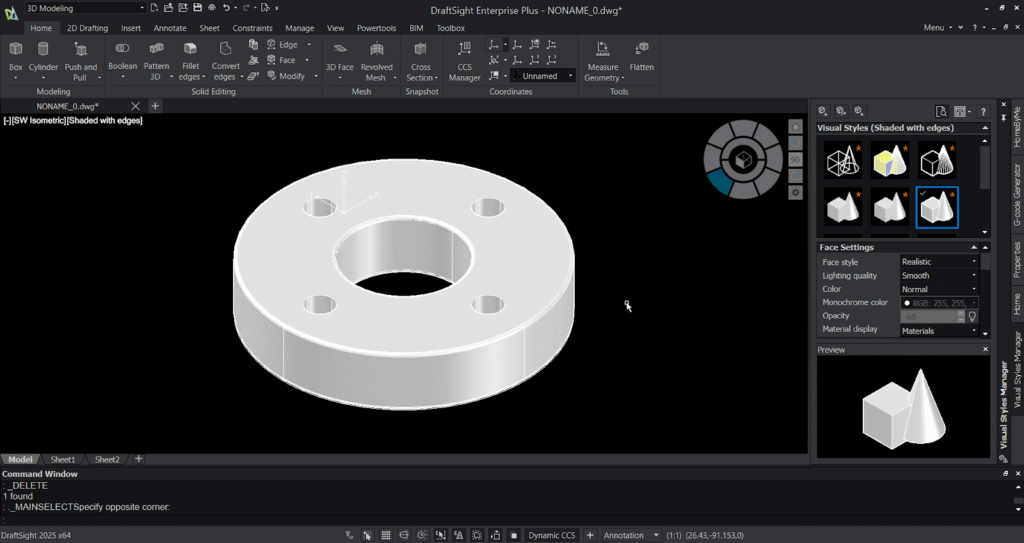
  1. Create a cylinder on the top face of the 3D model and specify its height as 20mm downwards and you’ll notice the cylinder gets created.
  2. Select the 3D pattern option and specify the entity(cylinder) ,enter the no .of components needed to be patterned as 4 , specify the angle as 360 degrees ,select the rotation of the component as “no” and specify the centre of axis (two points).
  3. Then select the subtract option and select the 3D model first and select the four patterned cylinders.

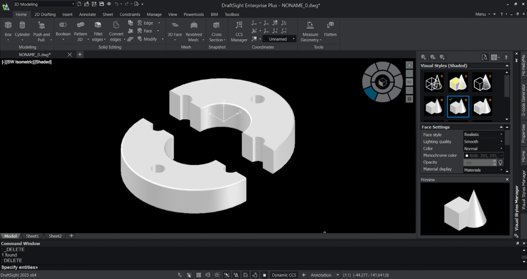
Step 7: Modify / move / rotate the solid:

  1. MOVE: select object, pick base point, pick destination.
  2. ROTATE3D (or ROTATE with axis setting): rotate around an axis by degrees .You can also rotate by just pressing “shift” +”left click” +scroll wheel” to rotate your 3D model.
  3. MIRROR3D: create symmetrical features.

Step 8: Section or slice 3D model:

  1. Select the slice option from the ribbon and specify the entity.
  2. Select the two points of your slicing plane and select the point for placing the slicing plane.
  3. And press “Enter” and you’ll notice your 3D model gets sliced or sectioned.

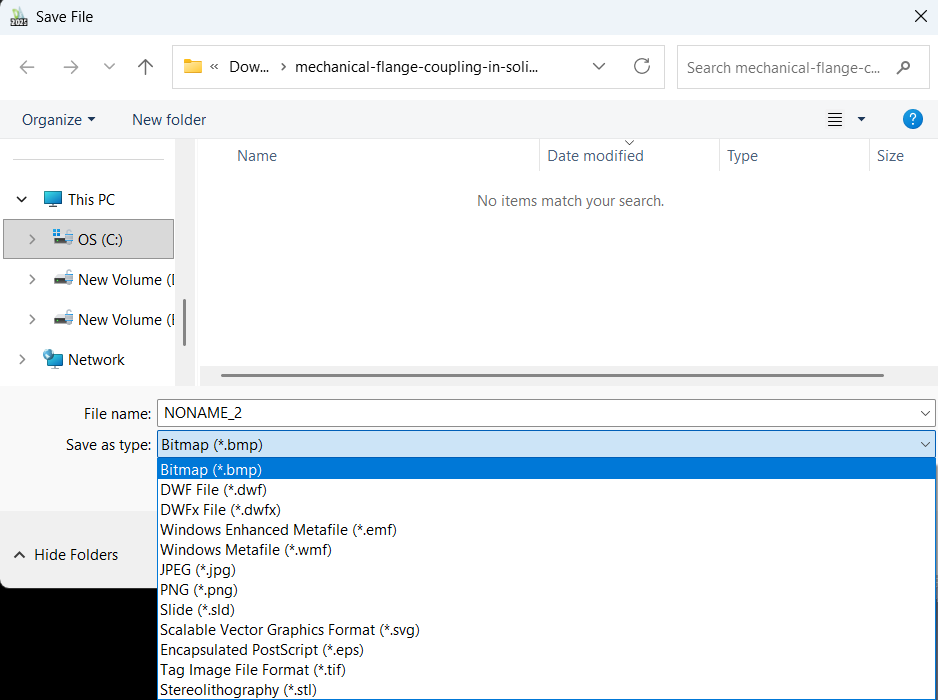
Step 9: Exporting / saving your 3D model:

The DraftSight Connector allows users to seamlessly export and manage their drawings on the 3DEXPERIENCE platform. With this integration, you can directly save your DraftSight files (.dwg or .dxf) to the cloud-based platform, ensuring secure storage and easy access from anywhere. It also enables version control, collaboration, and lifecycle management, allowing team members to review, share, and update drawings efficiently. By exporting to 3DEXPERIENCE, you bridge your DraftSight design workflow with Dassault Systèmes’ digital ecosystem, enhancing teamwork, data security, and project traceability.

  1. To save native: File → Save → .dwg (default).
  2. To export STL for 3D printing: File → Export → STL (choose mesh resolution if prompted).
  3. You can also export your 3D model as “SAT” file for using it in multiple CAD software.

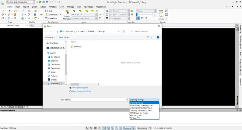
Additional feature : Importing “Step” file :

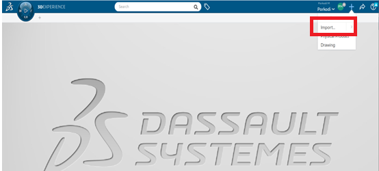
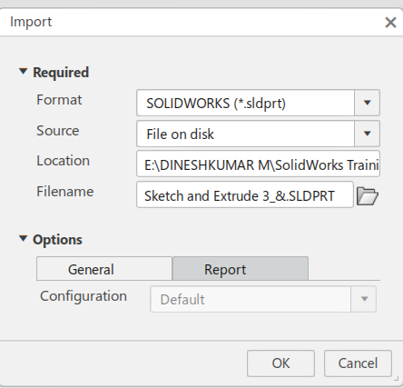
  1. File → Import → select .stp or .step file (or type IMPORT and choose STEP).
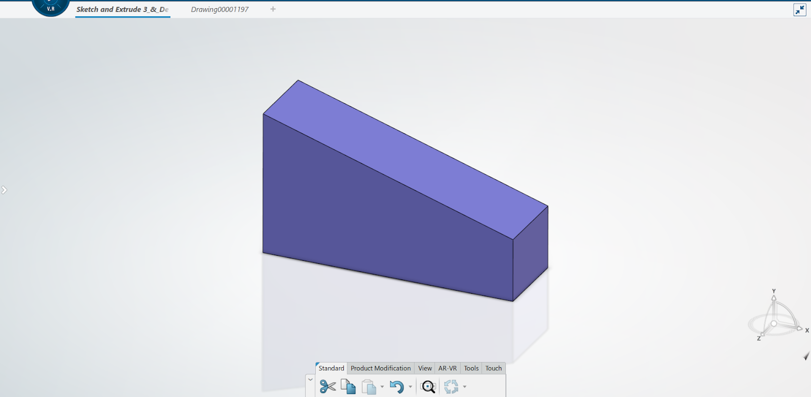
  2. DraftSight will convert the STEP geometry to native solids/surfaces.
https://youtu.be/nZkUD-GtSbs?si=DGR5pRrSDEFoQDK5

Conclusion:

The 3D Workspace in DraftSight converts 2D drafting workflows into a practical 3D modeling pipeline—letting you quickly create primitives, extrude 2D sketches, perform Boolean operations, and edit imported STEP models. By following the steps above you can set up your environment, model parts, clean imported geometry, inspect designs, and export for manufacturing or documentation. Start small (simple primitives and extrudes), practice the key edits (PRESSPULL, SLICE, FILLET), and you’ll gain confidence to handle assemblies and STEP imports effectively. Once comfortable, combine these workflows with DraftSight’s 2D drawing tools to produce complete, production-ready documentation from a single DWG-based environment.

Exploring the DraftSight BIM Module

Introduction:

DraftSight’s BIM (Building Information Modelling) module offers a powerful set of tools for architects, engineers, and construction professionals to work with BIM files in a 2D and 3D environment efficiently. One of the most important features in this module is the Plan option, which allows users to extract and generate precise floor plans from imported BIM models such as IFC or RVT files. This blog will guide you through how the Plan option works and how it can be leveraged to create detailed architectural plans quickly and accurately.

What is the BIM Module in DraftSight?

The BIM module in DraftSight enables users to import, navigate, and extract drawings from 3D BIM models. It turns BIM data into usable CAD drawings without requiring a separate BIM authoring tool. You can generate sections, elevations, and most importantly, floor plans using predefined tools.

Step-by-Step Guide: Creating a Plan in the DraftSight BIM Module:

Step 1: Import Your BIM File

  1. Open DraftSight.
  2. Go to File > Import > BIM File.
  3. Select your IFC or RVT file.
  4. The BIM model will load into the graphical area.
Master BIM Plans with DraftSight BIM Module

 Step 2: Choose the Plan Option

  1. In the BIM Navigator, click on Generate Drawing.
  2. Select Plan from the available options (Plan, Section, Elevation).
  3. Choose the floor level for which you want to generate the plan.
  4. Define the cut plane height.

Step 3:  Place the Plan in Model or Sheet Space

DraftSight gives you two options:

  1. Model Space – For editing and refinement
  2. Sheet Space – For creating ready-to-print drawings with title blocks and annotations

Step 4: Extract your data using data extraction 

  1. You can use data extraction to extract your data from the drawing created.
  2. Select the filter option and select the options you want to extract .
  3. After the table of the data is created place it in your drawing.
  4. And now your “.rvt”/”.ifc” file can be ready to export with the data and drawing you needed.

Conclusion

The Plan option in DraftSight’s BIM module is a game-changer for professionals who need accurate and quickly generated architectural drawings. Whether you are working on new construction, renovation, or facility layout projects, this feature helps you convert complex BIM data into clear and customizable 2D plans. By mastering this tool, you can dramatically enhance productivity and streamline your BIM-to-CAD workflow.

Start using the Plan option today and experience how DraftSight transforms your BIM documentation process!

Unlocking Productivity with Dynamic Blocks in DraftSight

Unlocking Productivity with Dynamic Blocks in DraftSight

In the world of 2D CAD design, efficiency and precision are everything. Whether you're an architect, mechanical engineer, or furniture designer, repetitive tasks and standard components can slow down your workflow. That's where Dynamic Blocks in DraftSight come in — a powerful feature that allows you to create intelligent, flexible symbols that adapt to your design needs.

In this blog, we’ll explore what Dynamic Blocks are, why they matter, and how you can start creating them in DraftSight to speed up your design process.

What Are Dynamic Blocks?

Dynamic Blocks are enhanced block definitions that contain adjustable parameters and actions. Unlike static blocks, which remain the same once inserted, Dynamic Blocks let you:

  • Stretch or scale objects
  • Rotate or mirror components
  • Show or hide parts of a block
  • Add visibility states for different configurations
  • Easily update blocks without recreating or re-inserting them

This means one block can do the work of many, reducing clutter and increasing efficiency.

Let’s walk through an example — creating a rectangle table with adjustable length and chairs that pattern accordingly.

Step 1: Create Your Base Geometry

  1. Create a table (Rectangle) of your desired dimensions (1000*700).
  2. Place the chair at one side of the table (take it from the tool palette).
  3. Mirror the chair to the opposite side of the table.
A screenshot of a computer

Step 2: Define the Block

  1. Select the geometry and type “BLOCK” or “Makeablock” command.
  2. Give a block name, select the base point and save it as “Dinning table”.
A screenshot of a computer menu

Step 3: Enter the Block Editor

  1. Double tap the created block to enter the block editor dialogue box.
  2. This opens the Block Editor environment with tool palettes for Parameters and Actions.
A screenshot of a computer

Step 4: Add parameters to stretch the table

  1. First explode the rectangle to make four different lines.
  2. Select the Linear customizable element from element tab.
  3. Select from one side to other side of the rectangle table and mention the distance1 as your desired name. (example: select first point as (0,0) and the second point as (1000,0)). Give grip count as 1.
  4. Now select the stretch from the activities tab.
  5. Then select the distance 1 element to link it to the activity.
  6. Select the element point to associate with the activity.
  7. Specify first and second corner of stretch frame.
  8. Specify the entities to be stretched.

Step 5: Add parameters to pattern the chairs

  1. Select the pattern option from the activity tab.
  2. Select the “distance 1”to specify the element.
  3. Now select the chair on one side to specify the selection set for the activity and press “ENTER”.
  4. Now determine the gap between the chairs(e.g:1000) and press “ENTER”.
  5. Repeat the above mentioned steps to another chair placed on other side of the table.

Step 6: Test and Save the block

  1. Now test block created using the “Test block” option and see the block behaviour whether it works properly.
  2. Then save and close the block editor.

Now, every time you insert this block, you can adjust the size and configuration without creating a new one.

A screenshot of a computer

Conclusion

Dynamic Blocks in DraftSight are more than just a convenience — they’re a productivity multiplier. With a little setup, you can create smart, scalable, and customizable components that adapt to your project needs and reduce redundant work.

So, the next time you’re building a drawing with repetitive or variable elements, think Dynamic — and let DraftSight do the heavy lifting.

Ready to streamline your 2D drafting workflow with powerful features like Dynamic Blocks in DraftSight?
Take the next step towards smarter design – click below to request a personalized quote and discover the best DraftSight licensing options for your needs.

Mastering Sheet Set Manager in DraftSight: Boost Your CAD Workflow

In the fast-paced world of drafting and design, efficiency is key. If you're a DraftSight user looking to streamline your project documentation and layout management, the Sheet Set Manager is a game-changing feature you shouldn't overlook.

Whether you're working on large architectural plans, mechanical assemblies or electrical layouts, managing dozens—or even hundreds—of sheets manually can be time-consuming and error-prone. DraftSight’s Sheet Set Manager helps you organize, automate and publish drawing sheets with ease.

What Is the Sheet Set Manager?

The Sheet Set Manager (SSM) is a tool within DraftSight that allows users to manage a collection of drawings as a single project. It provides a centralized interface to:

  • Organize drawing sheets
  • Automate title blocks
  • Manage views and layouts
  • Batch publish to PDF or plot
  • Track project information

With the SSM, you no longer need to open drawings one by one to update sheet numbers, project details, or plot settings.

How to Set Up a Sheet Set in DraftSight

  1. Launch Sheet Set Manager: Go to the Home tab or type SheetSet in the command line.
  2. Create a New Sheet Set: Use the wizard to create a new .dst file and link existing drawings or generate new ones from templates.
  3. Add Sheets: Import layouts from DWG files or create new sheets directly.
  4. Set Up Fields: Use FIELD commands in title blocks and reference areas to auto-fill information from the Sheet Set.
  5. Manage & Publish: Use the right-click menu to reorder sheets, update properties or batch plot the set.

Conclusion

If you’re not already using the Sheet Set Manager in DraftSight, now is the perfect time to integrate it into your workflow. It reduces repetition, enhances consistency and simplifies project management—especially as drawing sets grow in size and complexity.

By mastering the Sheet Set Manager, you’ll not only save hours of manual work but also increase the accuracy and professionalism of your deliverables.

Creating Custom Blocks (Dynamic) in CAD: A Step-by-Step Guide

Creating Custom Blocks (Dynamic) in CAD: A Step-by-Step Guide

Custom blocks (Known as Dynamic Blocks) are enhanced block definitions that allow for more flexible and interactive behaviour compared to standard blocks. Instead of creating multiple blocks for similar objects (like doors of different sizes or arrows pointing in different directions), you can use one Custom block with adjustable properties.

Custom blocks include Elements and Activities can allow users to:

  • Stretch parts of a block (e.g., stretch a table or wall).
  • Flip (mirror) elements with a flip action.
  • Pattern elements based on user input.
  • Rotate elements within the block.
  • Scale the block non-uniformly.
  • Move elements based on user input.
  • Visibility states: Switch between different views (e.g., open/closed door).

Creating Custom Block

In this custom block, we create circles of different radii with mirroring capability.

Step 1: Create Geometry

Draw the objects you want in your block. For example, a simple Circle.

Step 2: Define the Block

  • Select the circle and use the MakeBlock (MB) command.
  • Name the block (e.g., Circle)
  • Specify the base point (e.g., center of the circle), then click OK.
  • The geometry is now converted into a block.
Custom Blocks in CAD: A Step-by-Step Guide

Step 3: Open Block Editor

Double click the circle or use EditBlock (BE) command will open the block editor.

Custom Blocks

Step 4: Add Elements

  • Select the appropriate Element from the list. In this case, choose Mirror.
  • Select the base point and end point of the mirror axis, then specify the label location.

Step 5: Add Activities

  • From Activities, select Mirror option.
  • Then specify the element, followed by selecting the circle.

Step 6: Add Visibility Set

Visibility Set is added to switch between different views. Here, we can change the size of the circle. 

  • From Element Sets, select Visibility Set and specify element position.
  • Select the circle and press Enter.
  • Open Visibility State, then rename and add new state as required.
  • From the Visibility State drop down, select a size and draw the new geometry.
  • Add that geometry to that specified size by selecting “Select entities” from Visibility state followed by selecting geometry.
  • Hide the previously drawn circle.
  • Repeat Step 5 for each additional size.

Step 6: Save and Use Custom Block

  • Save the block and use Test Block option to check it.
  • The test block will open on a new drawing page.
  • When you select the circle, the Visibility Set and Mirror (Small arrow on the circle) icons will appear.
  • By clicking these icons, you can change the size and location of the circle.

Summary

Custom blocks in CAD provide flexible, interactive features like stretching, mirroring, rotating, and visibility states, allowing a single block to represent multiple object variations. This reduces the need for creating separate blocks for similar items. Creating a custom block involves drawing the geometry, defining the block, adding elements and activities, and setting up visibility states. These settings enable users to adjust the block's size, orientation, or appearance dynamically. Once saved, the block can be tested and used with customizable options in a drawing.

Mastering Image Tracer in DraftSight: From Raster to Vector with Ease

DraftSight is a professional grade 2D and 3D CAD software developed by Dassault Systèmes. Designed for architects, engineers, and designers, it features a user-friendly interface and supports industry-standard file formats, making it a powerful tool for precision drawing and design.

What Is an Image Tracer?

Image Tracer is a built-in tool in DraftSight that converts raster images (JPG, PNG, BMP) into vector geometry. It automatically detects outlines in scanned images, logos, or sketches and traces them into editable CAD elements like lines, arcs, and polylines.

Key Benefits:

  • Converts non-CAD images into usable vector drawings
  • Eliminates the need for manual tracing
  • Saves time and improves accuracy
  • Ideal for logos, floor plans, mechanical drawings, and sketches

What If Image Tracer Isn’t Available?

Before tools like Image Tracer, converting raster images to vector drawings was a manual and time-consuming process:

  1. Insert the Image: Import the raster image into DraftSight as a reference.
  2. Scale and Position: Resize and move the image to fit your intended design area.
  3. Manual Tracing: Use Line, Polyline, Arc, and Spline tools to trace over the image.
  4. Layering and Cleanup: Work on dedicated layers for organization and delete or hide the original image afterward.
  5. Precision Techniques: Use object snaps (OSNAP), grids, and guides for accurate tracing.

This method, while effective, required patience and a good eye for detail.

How to Use Image Tracer in DraftSight

Using Image Tracer is straightforward and is supported across all DraftSight variants:

Step 1: Insert the Image

  • Navigate to the Insert tab → Click Attach Image
  • Choose a raster file (JPG, PNG, BMP), place it in the workspace, and scale it as needed

Step 2: Launch Image Tracer and Configure Settings

  • Go to the Image Tracer tab or the Home tab and select Image Tracer
  • A settings window will appear
    • Choose the Image Type: Logo, Sketch, Mechanical, or Floor Plan
    • Adjust parameters like Detail Level, Threshold, and Noise Reduction
    • Preview the trace before applying

Step 3: Apply and Edit the Trace

  • Click Apply or OK to generate vector geometry
  • Edit the resulting lines, arcs, or polylines as needed
  • Delete or hide the original raster image to clean up the drawing

Summary

Image Tracer in DraftSight is a powerful feature that streamlines the conversion of raster images into precise vector geometry. By automating the tracing process, it saves time, improves accuracy, and makes it easier to incorporate sketches, logos, and scanned documents into professional CAD workflows.

The Function of a 3dexperience drafted in creating

THE FUNCTION OF A 3DEXPERIENCE DRAFTER IN CREATING 2D DRAWINGS

The Function of a 3dexperience drafted in creating

Drafter allows rapid creation of 2D Drawings from 3D models. Whenever you modify your 3D model, your drawings update instantly. With Drafter's comprehensive, production-quality, 2D detailing capabilities, designers can easily annotate drawings and with data saved to the cloud, can share drawings in real-time.

2d drawings

With Drafter you can:

  • Quickly generate drawings from your 3D parts and assemblies
  • Easily apply dimensions, annotations and section views to your drawings
  • Instantly update your 2D drawings to reflect any changes on your 3D models

Steps to creating the drafting:

Step 1: Access the 3DEXPERIENCE Platform

 Login: Start by logging into the 3DEXPERIENCE Platform using your credentials.

Open the Drawings App: Navigate to the 3DEXPERIENCE Dashboards. In the dashboard, look for the 3DEXPERIENCE Drawings App

Open the Drafter and install the Drawings. 

Note: Install the Drawings App 

Step 2: Import a 3D Model

Importing 3D Model: If you already have a 3D model in formats such as SOLIDWORKS or other compatible formats, you can upload it directly into the 3DEXPERIENCE platform.

Step 3: Generate 2D Drawing

Select the 3D Model: Once your model is uploaded, navigate to the Drawings App and select the model you want to generate a 2D drawing for. After that, you will immediately see the drawings' default views.

Click search and open to add views as well.

View Layout TypesView Palette, Projected, Auxiliary, Section,3D Clipping, Broken, Breakouts, Detail, Cropped.

Step 4: Add Dimensions, Annotations, and SymbolsAdd Dimensions: Use the tools in the app to add precise dimensions to the drawing. The system allows you to dimension various elements like lengths, angles, diameters, and radii.

Annotations and Callouts: Add any necessary annotations such as material specifications, part numbers, surface finishes, and any custom text or instructions for manufacturing.

GD&T Symbols: If needed, you can include Geometric Dimensioning and Tolerancing (GD&T) symbols to indicate specific tolerances or constraints for the part.

Step 5: Customize Drawing Templates and Title Blocks

  • Title Block: You can customize the title block with information like the part name, project, and revision details.

Templates: Choose or create custom drawing templates to maintain consistency with your company's standards.You can modify drawing sheets, paper sizes, and layout preferences.

Step 6: Update and Modify Drawings Automatically

  • Model Updates: If any changes are made to the 3D model, the 2D drawing will automatically update to reflect those changes.
  • No Manual Redrawing: You don't have to manually adjust your 2D drawing whenever the 3D model changes, as the app maintains the connection between them.

Advantages:

  • Time saving: Drawing creation is automated based on the 3D model, which reduces manual work.
  • Consistency: The app ensures that your 2D drawings are always aligned with the 3D model, minimizing discrepancies.
  • Real-Time Collaboration: Teams can work together, share feedback, and maintain version control in a unified system.

DraftSight Mechanical Toolbox: Enhancing Drafting Efficiency

DraftSight Mechanical Toolbox: Enhancing Drafting Efficiency

Introduction

DraftSight is a powerful software solution that offers immense value to drafters and engineers engaged in editing and creating DWG and DXF files. Specifically, DraftSight's Professional through Enterprise Plus editions feature a specialized set of tools known as the DraftSight Mechanical Toolbox.

This toolbox is meticulously designed to cater to the needs of mechanical drafters by providing essential functionalities such as standardized holes, fasteners, tables, and annotations. These tools are integral for completing detailed mechanical drawings efficiently and accurately, streamlining the design process and ensuring adherence to industry standards.

Whether it's detailing parts, assembling components, or generating precise dimensions, the DraftSight Mechanical Toolbox empowers users to achieve high-quality results in mechanical engineering tasks within a user-friendly CAD environment.

Adding the Mechanical Toolbox in DraftSight either through the Tools menu in the Workspace or by using the Command Line with the command ADDINS, which opens the same window. This gives you flexibility in accessing and using the toolbox's tools for mechanical drafting tasks.

When the Toolbox is enabled, all tools are accessible via the Mechanical pull-down menu, the Mechanical ribbon tab, or the Mechanical toolbar, depending on the Workspace configuration.

Using the Toolbox starts with accessing the Standards command, which serves as the initial step in utilizing its functionalities. Within the Toolbox, there are six fundamental standards provided. To begin, users activate the specific standard that aligns with their requirements. For more tailored needs, custom standards can be generated by duplicating a basic standard. Then modifying parameters related to holes, hardware specifications, and thread data. This flexibility allows drafters and engineers to adapt the Toolbox to suit specific project demands, ensuring precision and efficiency in mechanical drafting tasks.

STANDARD HOLES:

The Standard Holes function particularly caught my attention. It addresses the challenge of recalling specific hole sizes required for different applications. To use it, begin by choosing the hole category, such as Counterbore or Countersink. Then, select the settings for the standard, fastener type, size, and scale as needed. For custom applications, all properties are adjustable. Allowing for precise customization of hole dimensions and specifications to meet project requirements effectively. This feature not only streamlines the design process but also enhances accuracy and consistency in mechanical drafting tasks.

Placing a hole is straightforward with DraftSight. Simply click once to specify the center location and a second time to set the angle. Clicking once to specify the center location and again to set the angle creates a block containing attributes and layer data, all easily modifiable as needed. This method ensures efficient placement and customization of holes within designs, enhancing the precision and flexibility of mechanical drafting tasks.

Hole Callouts:

After incorporating various sizes of holes, the next step in the process involves adding Hole Callout annotations to the drawing. Callouts are easily placed with a simple click-and-place operation, ensuring a highly efficient workflow. With just a few mouse clicks, the callouts can be quickly and accurately completed. Enhancing the clarity and completeness of the mechanical design documentation.

Hole Tables:

As the number of holes increases, adding more hole callouts can clutter the drawing. A clear and organized method to manage and document these holes is by adding a Hole Table. This table neatly labels and lists the locations and parameters of each hole. Providing a structured overview that enhances the clarity and organization of the mechanical design.

DraftSight Mechanical Toolbox

DraftSight Mechanical Toolbox offers a comprehensive solution for enhancing mechanical drafting capabilities. From simplifying the placement of standard holes to efficiently annotating drawings with callouts and organized hole tables. The Toolbox streamlines the entire drafting process. Exploring these tools can significantly enhance productivity and precision in creating detailed mechanical designs.

Draftsight

DraftSight: Your Easy Guide to Getting Started

How To Get Started With DraftSight?

Draftsight, while hearing this word, you may have questions such as what is Draftsight software? what it will do? what its cost? how to use it? any cost benefit for buying this software to me?

Let we see...

Draftsight is a 2D and 3D Cad software for engineers, architects, cad designers, Professional cad users.

Let us see a short introduction of Draftsight, its capabilities & Its benefits in this blog. 

DraftSight empowers users to perform 2D design and annotation, along with 3D modeling.

Draftsight will let you do all the operations you are doing in present 2D software without missing the legacy. From the file extension to user interface you can feel the same feel which you felt in present 2D software.

Yes, Draftsight is works with DWG/DXF format. So reuse of legacy data is ease. User interface also same, as a familiar user one will take short time to adopt with Draftsight. In other words, you will take minimal learning curve to adopt here

How To Get Started With DraftSight?

Some of commands you can work with Draftsight are below:

  • Layer Management
  • Blocks
  • Mechanical Tool Box
  • Ballooning and BOM

1.Layer Management

You can Use the Layer command to create new Layers, set the active Layer, and specify Layer properties and behaviour.

You can create a new Layer any time. To improve efficiency, plan your layers in advance

2.Blocks

The original sentence is already in active voice. "A Block" is the subject, "is" is the verb, and "a collection of entities bound together as a single entity" is the object. After you create a Block, you can insert it whenever you need it in a drawing.

The Make Block command only recognizes the Block within the current drawing. The Export Drawing command lets you write a Block to an external drawing file for use in any drawing.

3. Mechanical Tool Box

DraftSight contains robust mechanical tools and symbols that will help you standardize your mechanical drafting practices and speed up your time to market. The Mechanical Toolbox allows you to choose which industry-standard you want to use or create your own custom standard.

4. Ballooning and BOM

Ballooning system will let you give Properties of the physical entity present. The BOM automatically populates with the properties with a single click.

Power Tools available :

  • Image Tracer
  • Drawing Compare
  1. Image Tracer

The Image Tracer tool lets you convert raster images in .bmp, .png, and .jpg formats to vector format. The images can be architectural plans, floor plans, logos, and curved images.

2. Drawing Compare

Compare drawing revisions to quickly identify and track changes. Draw Compare lets you visually compare drawings by highlighting added or removed entities in your chosen color

Yes, it’s the time to expose the commercial benefit of Draftsight over existing 2D cad software’s.

  • Draftsight is having Perpetual cum network license type. Yes, we are providing lifetime license with best in price - No need for yearly renewal.
  • Also we are providing Tech support for your license.
  • You can claim tax depreciation on your Draftsight purchase.
  • API and LISP Programs also available in Draftsight for customization.

Back to Top
Product has been added to your cart