Creation of PLC in library of SOLIDWORKS ELECTRICAL
Creating a PLC in SOLIDWORKS ELECTRICAL SCHEMATICS and customizing the PLC according to our requirement.
Include this connector in your schematic diagrams to connect symbols like relays, contactors, sensors, and signals.
The creation of a PLC involves following a few steps. Once created, the same PLC specifications can be used for connections within SOLIDWORKS Electrical schematics.
STEP 1
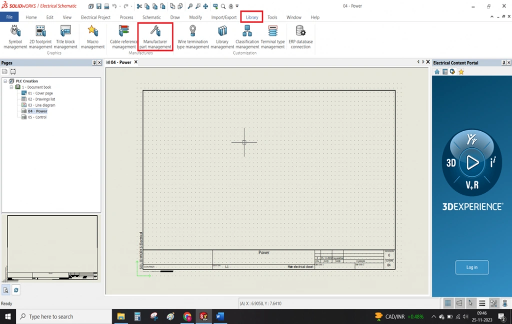
- To create a PLC first it must store in the library. The library permanently stores created connectors until you remove them manually
- To create a PLC as shown in the below image first have to goto Library -> Manufacturer part management.
STEP 2
Manufacturer part management
- Once the above points done.
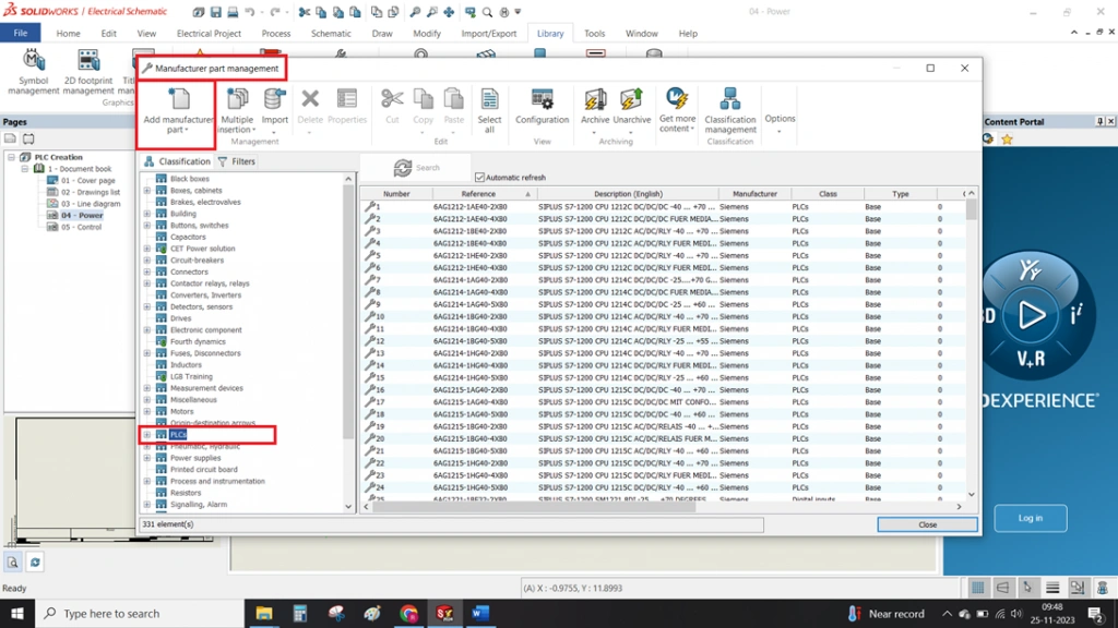
- Manufacturer part management will consist of more number classifications(folders). This section actively separates and organizes all components into different folders.
- Selecting the PLC folder filters the manufacturer part management tab on the right side, displaying only PLC-related manufacturers already present in the library.
- Selecting the "ADD MANUFACTURER PART" option allows you to create a new PLC. The system will provide a separate tab to enter details specific to the PLC.
STEP 3
New PLC details adding In Solidworks Electrical
- Once the above points done.
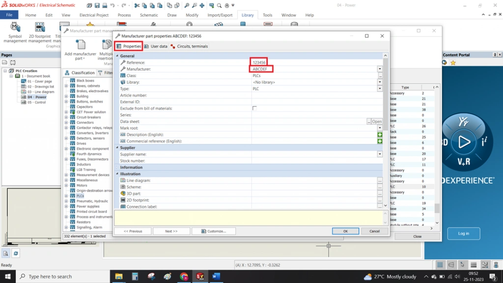
- The system will open a Manufacturer Part Properties tab.
- In this section three options will be present PROPERTIES, USER DATA, CIRCUIT, TERMINALS
- The Properties tab requires you to fill in essential details like reference and manufacturer. Scrolling down reveals additional optional specifications such as height, weight, frequencies, and supplier name.
STEP 4
Specifications of Circuit, Terminal
- With continuation of above points
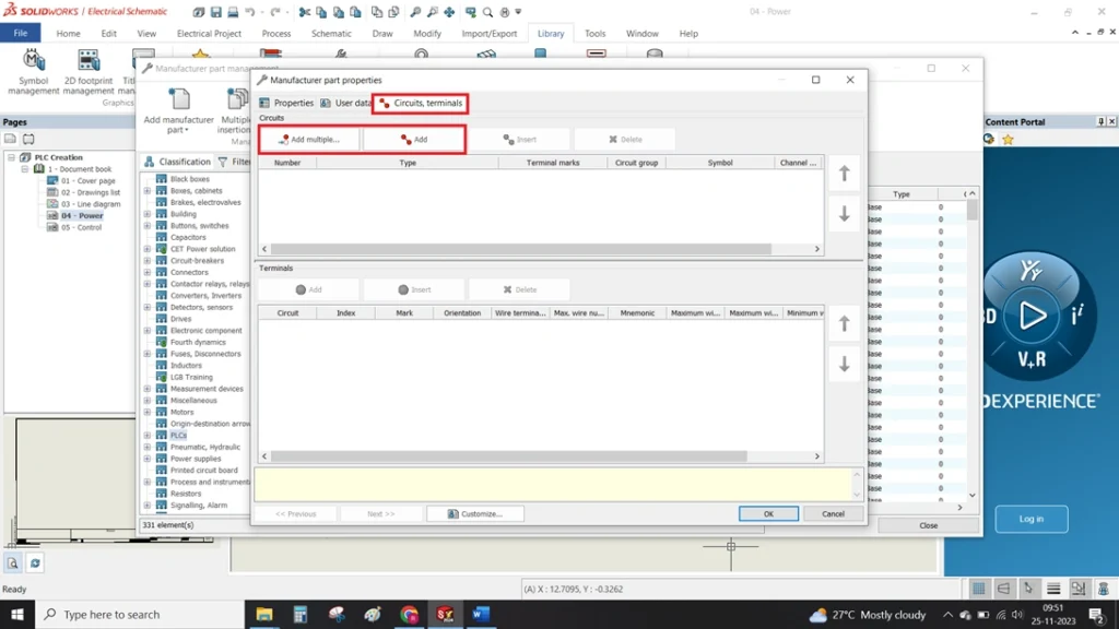
- The third option, Circuit Terminals, lets you add circuit types.
- At the top circuit, terminal option will be present near to the properties tab.
- This tab allows you to add circuits using the ADD option
- The ADD MULTIPLE option, illustrated in the image below, allows you to efficiently add multiple circuits at once
STEP 5
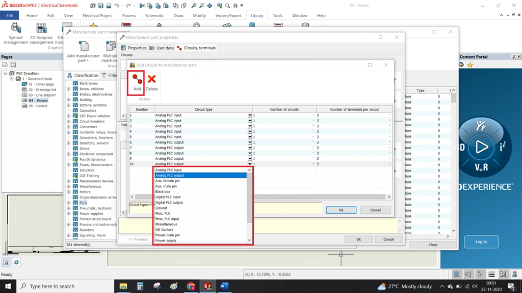
Add Multiple Circuits In Solidworks Electrical
- The image below demonstrates how to quickly and easily add multiple circuits.
- All circuits type are present in the scroll down. Select circuits based on your specific requirements.
Summary
- With these above-mentioned points we can able to create a PLC in a solidworks electrical.
- By following these steps, you will create a new connector that gets added to the SOLIDWORKS Electrical library for future use.


