Unleashing the power of 3D in Draftsight Enterprise Plus
Introduction: DraftSight has long been recognized for its precision 2D drafting capabilities. But with the evolution of design workflows, engineers and designers now need to visualize and model their ideas in three dimensions. The 3D Workspace in DraftSight Enterprise Plus brings exactly that — powerful 3D modeling tools integrated into a familiar drafting environment. Unleashing […]
Exploring the DraftSight BIM Module
Introduction: DraftSight’s BIM (Building Information Modelling) module offers a powerful set of tools for architects, engineers, and construction professionals to work with BIM files in a 2D and 3D environment efficiently. One of the most important features in this module is the Plan option, which allows users to extract and generate precise floor plans from […]
Unlocking Productivity with Dynamic Blocks in DraftSight
In the world of 2D CAD design, efficiency and precision are everything. Whether you’re an architect, mechanical engineer, or furniture designer, repetitive tasks and standard components can slow down your workflow. That’s where Dynamic Blocks in DraftSight come in — a powerful feature that allows you to create intelligent, flexible symbols that adapt to your […]
Mastering Sheet Set Manager in DraftSight: Boost Your CAD Workflow
In the fast-paced world of drafting and design, efficiency is key. If you’re a DraftSight user looking to streamline your project documentation and layout management, the Sheet Set Manager is a game-changing feature you shouldn’t overlook. Whether you’re working on large architectural plans, mechanical assemblies or electrical layouts, managing dozens—or even hundreds—of sheets manually can […]
Creating Custom Blocks (Dynamic) in CAD: A Step-by-Step Guide
Creating Custom Blocks (Dynamic) in CAD: A Step-by-Step Guide Custom blocks (Known as Dynamic Blocks) are enhanced block definitions that allow for more flexible and interactive behaviour compared to standard blocks. Instead of creating multiple blocks for similar objects (like doors of different sizes or arrows pointing in different directions), you can use one Custom […]
Mastering Image Tracer in DraftSight: From Raster to Vector with Ease
Mastering Image Tracer in Draftsight: From Raster to Vector With Ease DraftSight is a professional grade 2D and 3D CAD software developed by Dassault Systèmes. Designed for architects, engineers, and designers, it features a user-friendly interface and supports industry-standard file formats, making it a powerful tool for precision drawing and design. What Is an Image […]
THE FUNCTION OF A 3DEXPERIENCE DRAFTER IN CREATING 2D DRAWINGS
Drafter allows rapid creation of 2D Drawings from 3D models. Whenever you modify your 3D model, your drawings update instantly. With Drafter’s comprehensive, production-quality, 2D detailing capabilities, designers can easily annotate drawings and with data saved to the cloud, can share drawings in real-time. With Drafter you can: Steps to creating the drafting: Step 1: […]
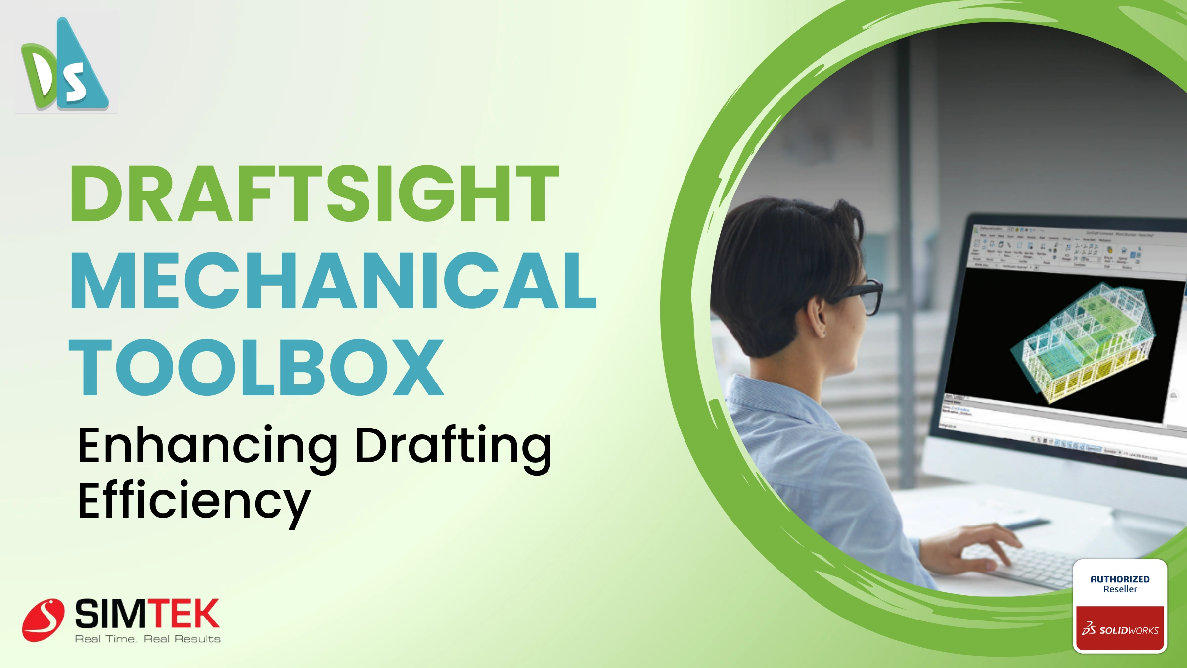
DraftSight Mechanical Toolbox: Enhancing Drafting Efficiency
Introduction DraftSight is a powerful software solution that offers immense value to drafters and engineers engaged in editing and creating DWG and DXF files. Specifically, DraftSight’s Professional through Enterprise Plus editions feature a specialized set of tools known as the DraftSight Mechanical Toolbox. This toolbox is meticulously designed to cater to the needs of mechanical […]

DraftSight: Your Easy Guide to Getting Started
Draftsight, while hearing this word, you may have questions such as what is Draftsight software? what it will do? what its cost? how to use it? any cost benefit for buying this software to me? Let we see… Draftsight is a 2D and 3D Cad software for engineers, architects, cad designers, Professional cad users. Let […]