The Electrical Components Wizard is an Electrical 3D-specific tool through which connection points, mate references, and other placement intelligence for electrical parts can be defined without manually searching for all the geometry.

Using Mate Reference in Electrical Components Wizard
When designing electrical assemblies in SOLIDWORKS, positioning components quickly and accurately is essential. This is where Mate Reference in the Component Wizard comes in. Instead of manually adding mates every time you insert a connector, terminal block, or device into an assembly, you can predefine mate references that automate the process.
Why Use Mate Reference in Electrical Design?
- Speeds up assembly creation – no need to manually mate each component.
- Ensures accuracy – consistent positioning every time.
- Standardization – once defined, the same logic applies across your project.
- Time saving in routing – wires and harnesses connect more efficiently.
1. Part Opening
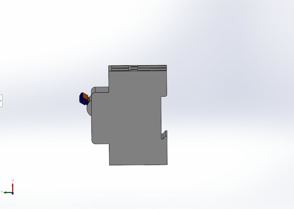
• The part (.sldprt) to be prepared (e.g., a circuit breaker, terminal block, or DIN-rail device) should be opened in SOLIDWORKS Electrical 3D.
2. Launching the Electrical Components Wizard
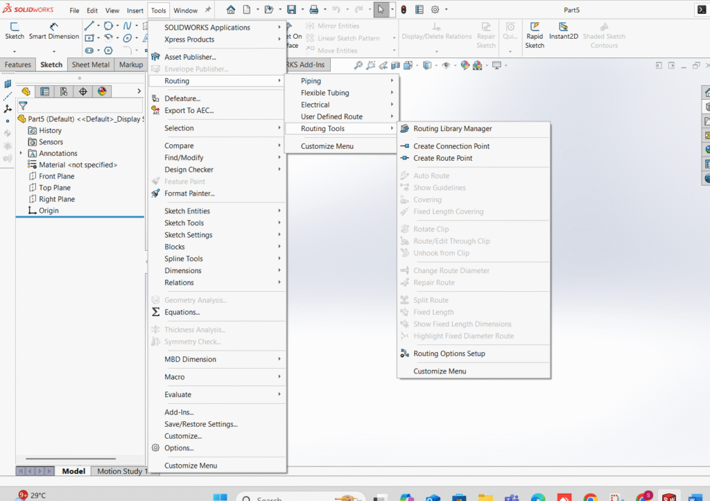
• The wizard can be launched from the menu:
Tools → Routing → Routing tools → Routing library manager
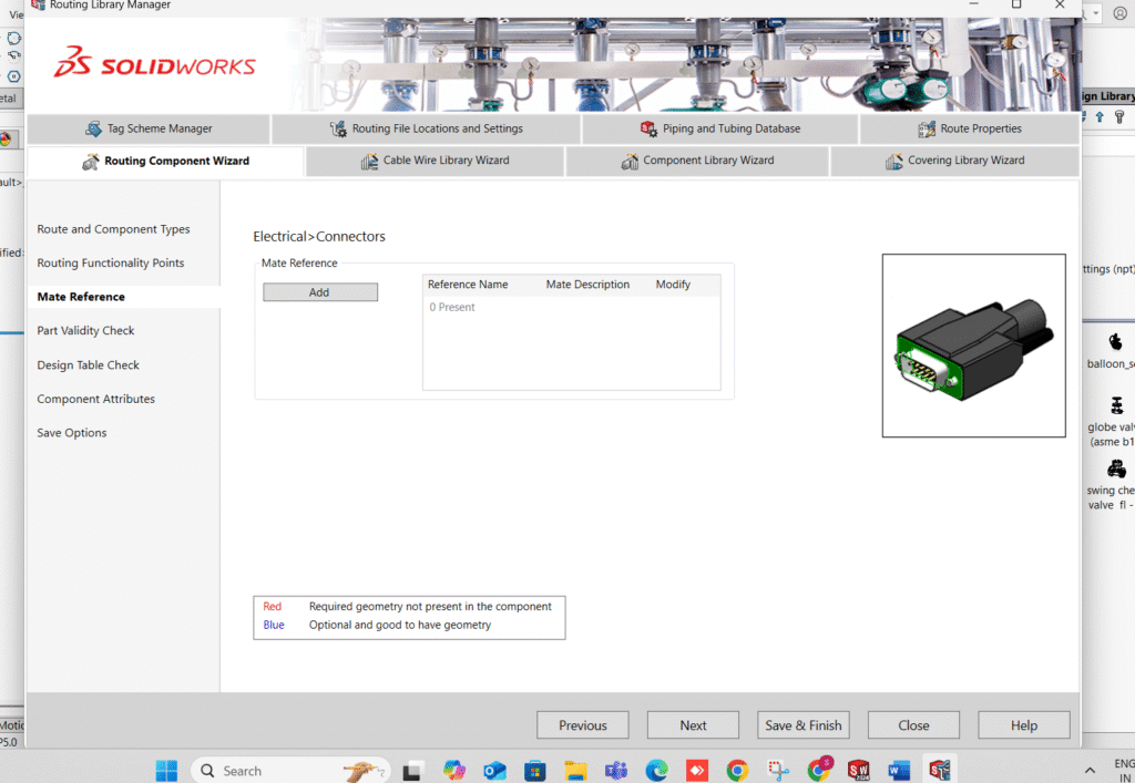
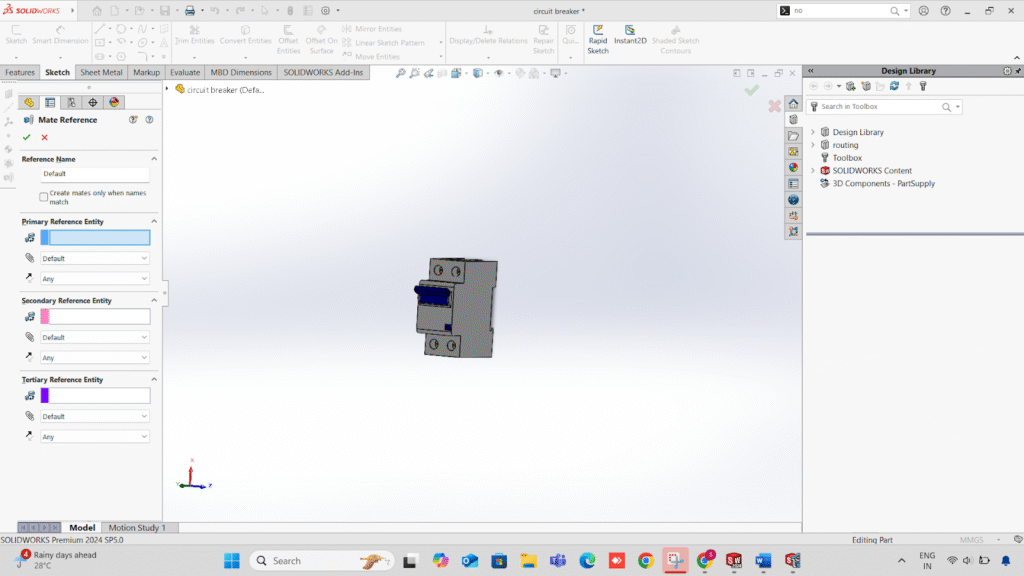
3. Accessing the Mate Reference Section
• In the wizard, the Mate Reference or Mounting tab (displayed along with terminals, connection points, and manufacturer information) should be located.
• Add should be clicked to create a new mate reference.
4. Geometry Selection for Each Mate
• Primary Mate: The geometry for the main alignment should be selected.
Example: The axis of a mounting hole or post should be set to Concentric.
• Secondary Mate: A face to set orientation should be selected.
Example: The rear face of the part should be set to Coincident with the mounting surface.
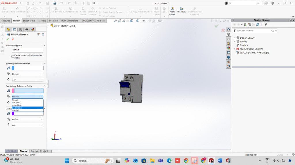
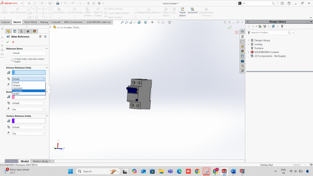
5. Reference Name Assignment
• In the wizard’s name field, a descriptive name should be assigned (e.g., DIN_RAIL_ Mount, Panel_ Front_ Hole, Connector Female).
• If automatic snapping is required only when names match, the exact same name should be used for both the part and its matching component.
6. Saving and Exiting the Wizard
• Finish should be clicked in the wizard.
• The part should be saved.

7. Mate Reference Testing
• The electrical assembly should be opened.
• The prepared part should be dragged toward the matching mounting part (e.g., DIN rail).
• If reference names and geometry match, the part will be snapped automatically into place with correct alignment.
Advantages of the Wizard Method:
• Mate reference setup is combined with electrical connection points in a single workflow.
• Standardization for multiple electrical parts is made easier.
• The process is faster compared to creating mate references manually for each part.
Conclusion
Using Mate Reference in Component Wizard is a smart way to simplify electrical assemblies in SOLIDWORKS. By predefining how components should automatically snap into place, you save time, reduce errors, and ensure consistency across your electrical projects.