

Introduction
Creation of a new terminal strip drawing in SolidWorks electrical and customizing it according to our specification.
In SOLIDWORKS ELECTRICAL, the creation of terminal drawings is automated, ensuring that the origin and destination of wires, as well as component details, are dynamically updated on the terminal drawing sheet.
STEP 1
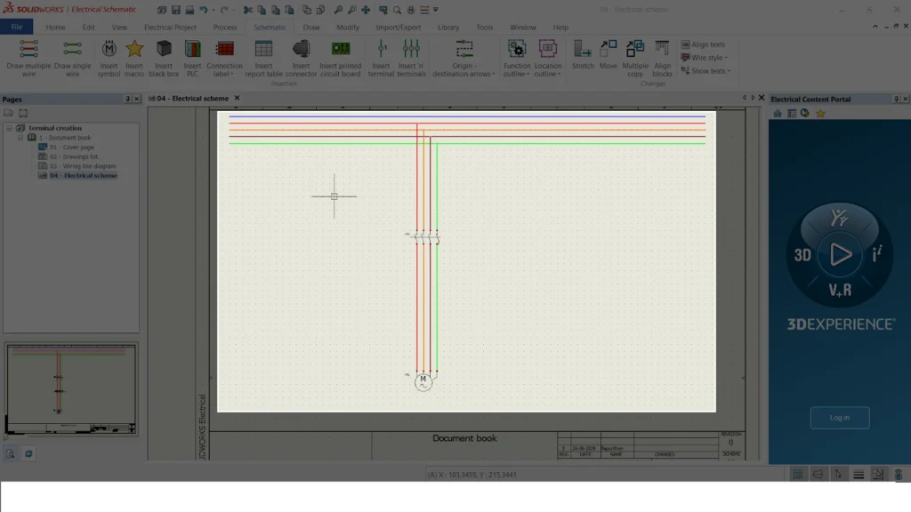
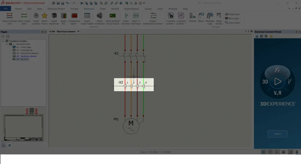
- AS shown in the below image
- Create a wire before inserting a terminal.
- To ensure automatic updates of wire origin and destination, place a component before and after the terminal.
STEP 2
TERMINAL OPTIONS
- One method allows you to place a single terminal…
- The other method is used for placing a set of multiple terminals…
- SolidWorks Electrical offers two insertion options: one for placing a single terminal and another for placing a set of multiple terminals.

STEP 3
ADDING MULTIPLE TERMINAL
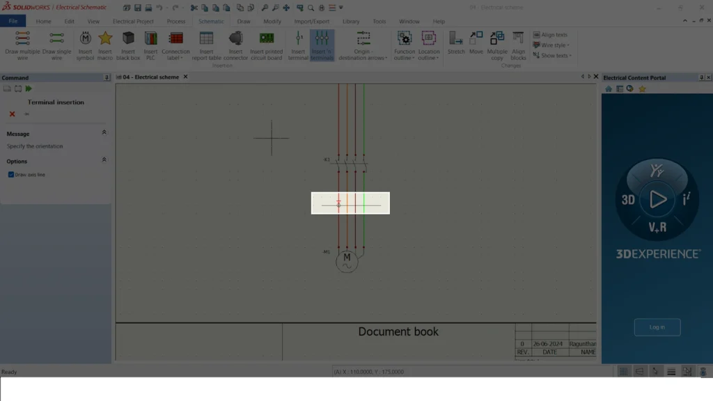
- To add a multiple set of terminals a line needed to draw and a triangle in the image represents the flow of the wire
- The line signifies that these wires function as a single group, from which you can extract a cable or a set of neutral wires.
STEP 4
TERMINAL PROPERTIES
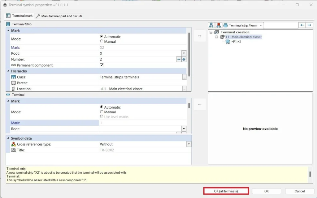
- Two important markers are displayed in the terminal properties: parent mark and terminal number.
- To clarify the terminal hierarchy, the first MARK identifies the parent mark, such as X2.
- Second MARK represents terminal number in the parent terminal i.e X2-1,2,3.
- Before clicking “OK,” ensure you haven’t added manufacturer data yet. There is an easy way of adding manufacturer data that we ll discuss in next topic.
STEP 5
MANUFACTURER DATA ADDING
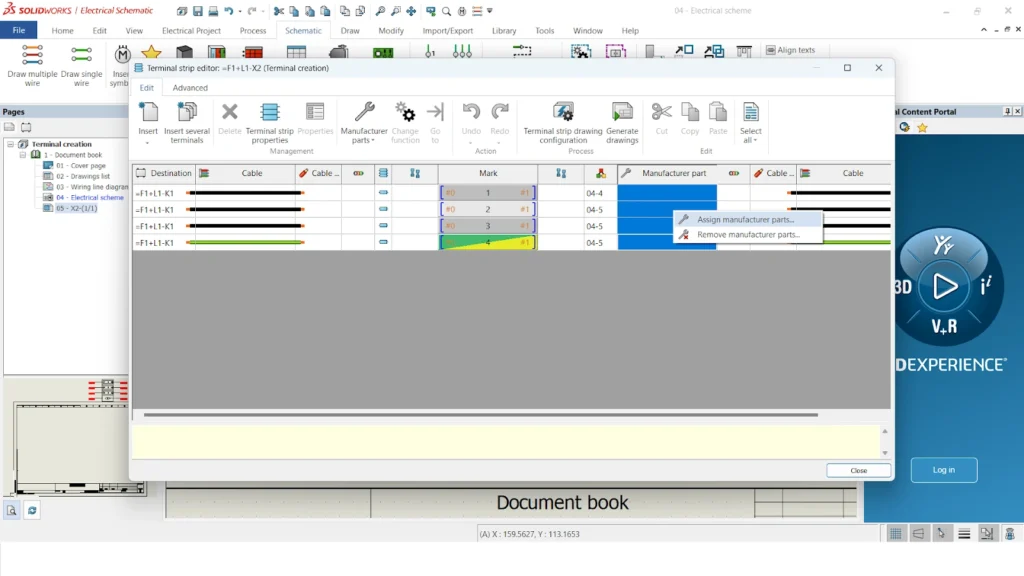
- After adding a terminal, right-click on it and navigate to “Edit Terminal Strip X2” to include manufacturer data.
- Second image shows adding the manufacturer by selecting every number of terminal and right click-> Assign manufacturer

STEP 6
MANUFACTURER PART PROPERTIES
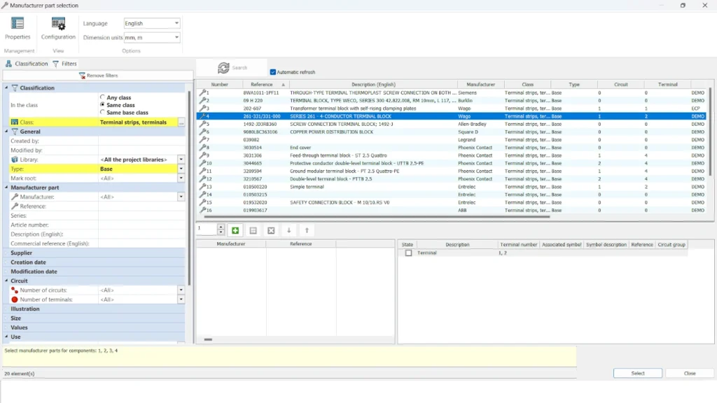
- The library will then display a list of manufacturers.
- The selection process involves choosing the ideal manufacturer based on compatibility with the circuit and terminal points.
- Completing these steps creates a terminal and assigns a manufacturer, as illustrated in the second image.
STEP 7
TERMINAL STRIP PAGE
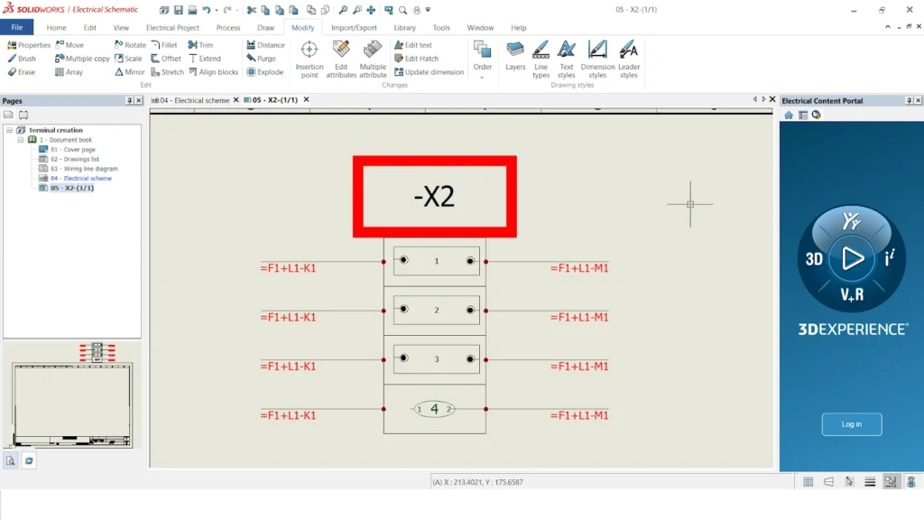
- SolidWorks Electrical can automatically generate a separate page for your terminal connection details.
- Right-clicking the X2 terminal in the image reveals a menu with various options.
- Following the image’s highlight, select the “Draw” option.
- A new page showcasing terminal strip connection details is automatically generated, as shown in the second image below.

Summary
- Building on the steps outlined above, we can now create a terminal connection in SolidWorks Electrical.
- Creating these points automatically generates a terminal connection detail page.