Search

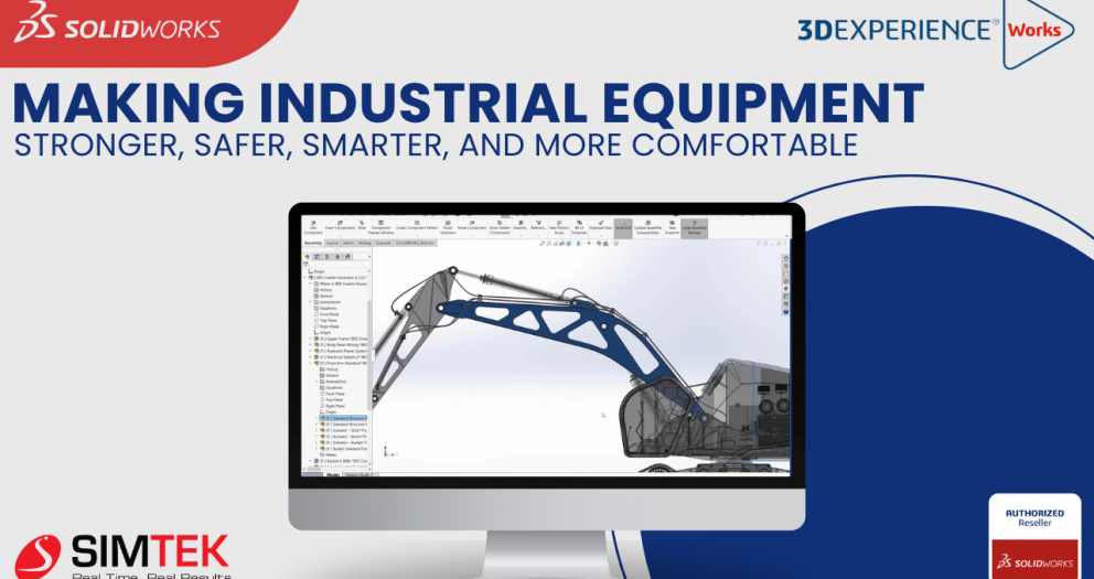
SolidWorks Simulation: Design Stronger, Safer Industrial Equipment

We have just wrapped up another successful webinar and are thrilled about the positive feedback that
we’ve received. The focus of this live webinar addressed the unique issues of industrial equipment
design. It showed how to use both SOLIDWORKS 3D modeling and cloud-based 3DEXPERIENCE Works®
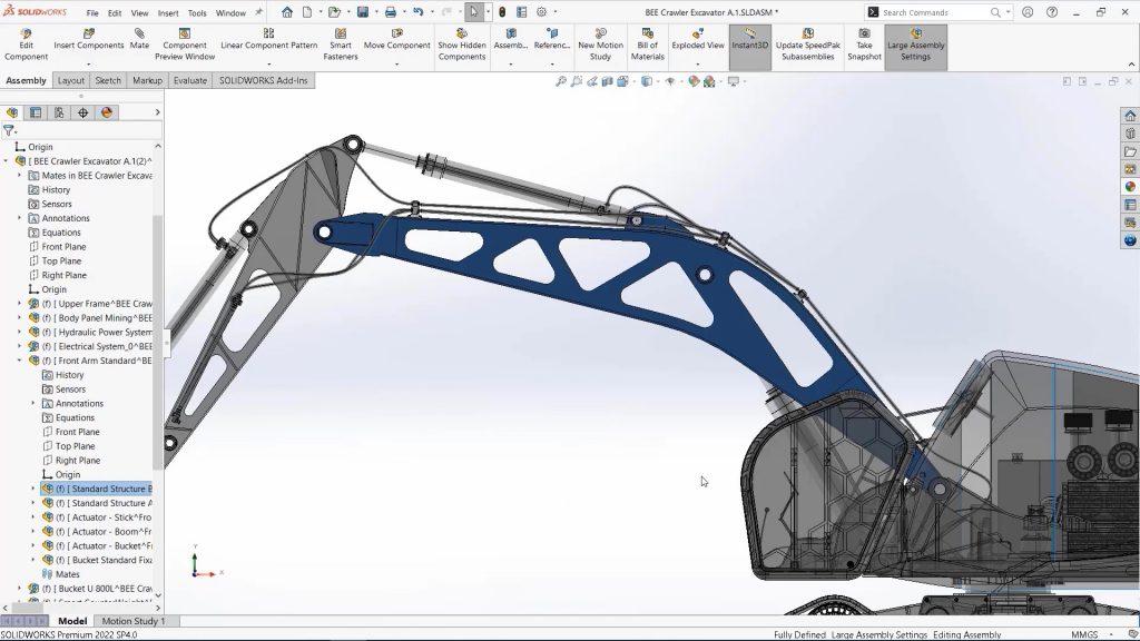
Industrial equipment manufacturers face a unique set of design challenges. Today's machines are becoming increasingly complex, with intricate electromechanical systems and large assemblies that can slow down the 3D CAD development process.

Traditional physical prototypes are often expensive and time-consuming to create, further hindering efficient design iterations.

solidworks - Traditional physical prototypes

Overcoming Industrial Equipment Design Issues

To stay competitive in a rapidly evolving market, manufacturers are embracing automation and specialized tools to achieve greater productivity and flexibility.

This is where SOLIDWORKS® 3DEXPERIENCE Works Simulation (3DEXPERIENCE Works Simulation, not SOLIDWORKS itself, should be the keyphrase in the title for SEO) comes in.

This cloud-based platform offers a powerful combination of 3D modeling and simulation (often referred to as MODSIM) that can help you address critical industrial equipment design issues, including:

Customization and Adaptability:

Industrial equipment needs often vary depending on specific customer requirements or unique processes. 3DEXPERIENCE Works Simulation empowers you to design equipment that is adaptable and customizable, meeting these diverse needs while maintaining efficiency and cost-effectiveness.

Durability and Reliability:

Industrial environments are often harsh, with extreme temperatures, vibration, dust, and corrosion being common factors. 3DEXPERIENCE Works Simulation allows you to virtually test your designs under these conditions, ensuring they are durable and reliable, minimizing downtime for maintenance or repairs.

Technological Advancements in Soliworks:

The industrial landscape is constantly evolving with advancements in automation, robotics, AI, and IoT. 3DEXPERIENCE Works Simulation helps you stay ahead of the curve by incorporating these innovations into your designs, meeting ever-changing customer expectations.pen_spark

Cost-Effectiveness:

Balancing advanced features and high-quality materials with cost control is a constant challenge for manufacturers. 3DEXPERIENCE Works Simulation allows you to optimize designs for cost-effectiveness without compromising on performance, durability, or efficiency.pen_spark

Safety and Compliance:

Stringent safety standards and regulations govern industrial equipment. 3DEXPERIENCE Works Simulation helps ensure your designs meet these safety requirements and comply with various regulations, streamlining the compliance process.

Unlocking the Power of MODSIM

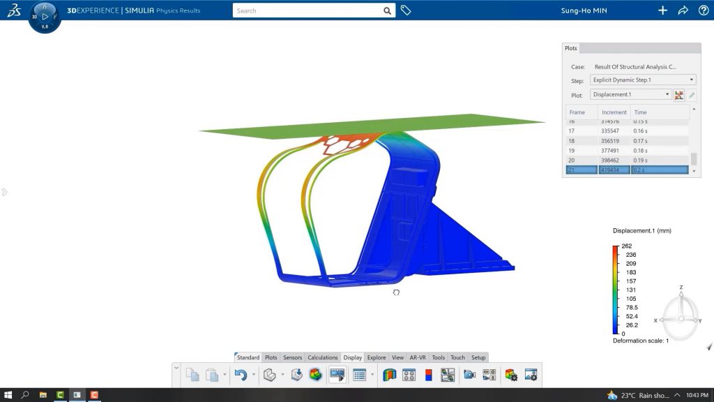
By leveraging the collaborative cloud environment of 3DEXPERIENCE Works Simulation, you gain valuable insights from embedded simulation solutions. This allows you to analyze factors like strength, durability, thermal comfort, flow, manufacturability, and electromagnetic performance throughout the design process. This digital prediction of real-world behavior empowers you to make informed decisions at every stage, potentially reducing (or even eliminating) the need for physical prototypes and ultimately leading to higher quality industrial equipment.

Gain insights on SOLIDWORKS-embedded simulation solutions while enhancing strength

Watch the Recorded Webinar

Gain insights on SOLIDWORKS-embedded simulation solutions while enhancing strength, durability,
thermal comfort, flow, manufacturability, and electromagnetic performance within a collaborative cloud
environment. The MODSIM approach to product development empowers you to make improvements at
each phase of the design by predicting real-world behavior digitally, where you can help decrease (and
sometimes eliminate) the need for prototypes and increase all aspects of product quality.

Conclusion

3DEXPERIENCE Works Simulation offers a powerful and cost-effective solution for industrial equipment manufacturers. This innovative platform allows you to overcome design challenges, optimize equipment performance, and ultimately deliver stronger, safer, smarter, and more comfortable industrial equipment to your customers.

EMBEDDING SOLIDWORKS COMPOSER PLAYER IN MICROSOFT POWER POINT PRESENTATION

Imagine captivating your audience with a presentation that transcends static images. SOLIDWORKS Composer empowers you to create dynamic, 2D and 3D visuals that bring your product or process to life. But how do you integrate these rich visuals into your existing presentations? Look no further than Microsoft PowerPoint!

This guide unlocks the secrets of embedding SOLIDWORKS Composer directly into PowerPoint. By following these steps, you'll transform your presentations from informative to interactive, fostering deeper audience engagement.

Enabling the Developer Ribbon:

  1. Open a new PowerPoint presentation.
  2. Navigate to the File menu and select Options.
  3. Within the Options window, click on Customize Ribbon.
  4. Locate the Developer checkbox and ensure it's selected. Click OK to confirm.

Inserting the Composer Player ActiveX Control:

  1. With the Developer tab now visible, locate the Controls section.
  2. Click on More Controls.
  3. Scroll down the list and select Composer Player ActiveX. Click OK.
  4. A rectangular box will appear on your slide. Resize and position it as desired.

Linking the Composer File:

  1. Right-click on the Composer Player ActiveX control and choose Composer Player ActiveX Object followed by Properties.
  2. Under the General tab, click Browse. Locate and select your SOLIDWORKS Composer file (.smg) and click Open.
  3. In the Layout tab, uncheck all options to remove unnecessary toolbars from the ActiveX player. Click OK.

Creating Interactive Buttons (Optional):

  1. While on the Developer tab, navigate to Controls and select Command Button.
  2. Place the button on your slide where desired. Right-click and choose Command Button Object followed by Edit.
  3. Rename the button text to match a specific view name within your SOLIDWORKS Composer project (e.g., Default, BOM1).
  4. Double-click the button to access the Microsoft Visual Basic for Applications window.
  5. Paste the following code, replacing "Default" with your desired view name:

Code snippet : "DSComposerplayerActiveX1.GoToConfiguration"

6. Click Save and close the VBA window. Repeat steps 3-6 for additional buttons with different view names and corresponding code.

Testing and Saving:

  1. Switch to Slide Show mode to view the embedded model.
  2. Use your mouse to zoom, pan, and rotate the 3D model for a fully interactive experience.

Important Note: When reopening the presentation, you might need to enable macros for the ActiveX player to function correctly. To ensure compatibility, save your presentation as a PowerPoint Macro-Enabled Presentation (.pptm).

By following these steps, you'll successfully embed interactive 3D models from SOLIDWORKS Composer into your PowerPoint presentations. This powerful technique allows you to showcase your designs with unparalleled clarity, fostering a more impactful and engaging audience experience.

Creation of PLC in library of SOLIDWORKS ELECTRICAL

Creating a PLC in SOLIDWORKS ELECTRICAL SCHEMATICS and customizing the PLC according to our requirement.

Include this connector in your schematic diagrams to connect symbols like relays, contactors, sensors, and signals.

                     The creation of a PLC involves following a few steps. Once created, the same PLC specifications can be used for connections within SOLIDWORKS Electrical schematics.

STEP 1

  • To create a PLC first it must store in the library. The library permanently stores created connectors until you remove them manually
  • To create a PLC as shown in the below image first have to goto Library -> Manufacturer part management.
Windows Screen of Creating PLC in library of SOLIDWORKS ELECTRICAL

STEP 2

Manufacturer part management

  • Once the above points done.
  • Manufacturer part management will consist of more number classifications(folders). This section actively separates and organizes all components into different folders.
  • Selecting the PLC folder filters the manufacturer part management tab on the right side, displaying only PLC-related manufacturers already present in the library.
  • Selecting the "ADD MANUFACTURER PART" option allows you to create a new PLC. The system will provide a separate tab to enter details specific to the PLC.
Windows screnn of Manufacturing part management

STEP 3

New PLC details adding In Solidworks Electrical

  • Once the above points done.
  •  The system will open a Manufacturer Part Properties tab.
  • In this section three options will be present PROPERTIES, USER DATA, CIRCUIT, TERMINALS
  • The Properties tab requires you to fill in essential details like reference and manufacturer. Scrolling down reveals additional optional specifications such as height, weight, frequencies, and supplier name.
Windows Screen of New PLC details adding In Solidworks Electrical

STEP 4

Specifications of Circuit, Terminal

  • With continuation of above points
  • The third option, Circuit Terminals, lets you add circuit types.
  •  At the top circuit, terminal option will be present near to the properties tab.
  • This tab allows you to add circuits using the ADD option
  • The ADD MULTIPLE option, illustrated in the image below, allows you to efficiently add multiple circuits at once

STEP 5

Add Multiple Circuits In Solidworks Electrical

  • The image below demonstrates how to quickly and easily add multiple circuits.
  • All circuits type are present in the scroll down. Select circuits based on your specific requirements.
Windows screen of 
Add Multiple Circuits In Solidworks Electrical

Summary

  • With these above-mentioned points we can able to create a PLC in a solidworks electrical.
  • By following these steps, you will create a new connector that gets added to the SOLIDWORKS Electrical library for future use.

Von Mises Stress Plot Vs Principal Stress Plot

When analyzing stress on a structure, engineers rely on two key methods: von Mises stress and principal stress. While both visualize stress distribution, they offer distinct insights.

This comparison explores the fundamental differences between Von Mises and principal stress plots, highlighting their strengths and guiding you on which approach best suits your material and analysis goals.

Its bit tricky right ? Especially for New FEA Engineers. Lets dive to understand the difference

Von Mises Stress: A Distortion Energy Measure

While not a true stress, It represents the distortion energy density at a specific point. It helps predict failure in ductile materials (materials that deform before breaking).

Richard von Mises observed that even when individual principal stresses stay below the material's yield point, their combined effect can still cause yielding. He proposed a formula to combine the three principal stresses into an equivalent stress.

This equivalent stress is then compared to the material's yield stress to assess the risk of failure using the von Mises criterion.

Principal Stresses: The "True" Stresses

Principal stresses, on the other hand, are genuine stresses obtained by rotating a stress element to eliminate shear stress. The resulting normal stresses are called principal stresses. They represent the maximum normal (tensile or compressive) stresses an element can experience under specific loads.

A failure theory based on principal stresses is the maximum principal stress theory. This theory suggests that brittle materials fail when the largest principal stress reaches the ultimate tensile strength. While well-supported by experiments, it assumes equal tensile and compressive ultimate strengths, which isn't always the case.

Formula for Principal Stresses:

Choosing the Right Tool: Von Mises vs. Principal Stress:

For ductile materials, the von Mises theory is generally preferred due to its accuracy in predicting deformation. However, principal stress plots remain valuable for analyzing brittle materials and understanding potential fracture points.

Conclusion :

In general, It is considered to be a more accurate measure of a material's resistance to deformation, while Principle stress is more useful in predicting failure in brittle materials.

Build Custom Connectors for SOLIDWORKS Electrical

This blog will guide you through creating custom connectors in SOLIDWORKS Electrical Schematics libraries and using them in your schematics.

Storing Connectors in the Library

Storing connectors in the library allows for easy access and reuse. Once created, they'll remain in the library until you manually delete them.

Step 1: Accessing the Library

Go to Library > Manufacturer Part Management.

 Manufacturer Part Management. custom connectirs

Step 2: Selecting the Connector Folder

The Manufacturer Part Management window displays various component categories. Select the Connector folder.

This will show connector-related manufacturers on the right side.

Selecting the Connector Folder custom connectors

Step 3: Adding a New Connector

Click the Add Manufacturer Part button to create a new connector. You'll then be able to fill in details about the connector in a separate tab

Adding a New Connector custom connectors

Step 4: Defining Connector Properties

The Manufacturer Part Properties tab opens with three sections: Properties, User Data, and Circuit Terminals.

In the Properties section, fill in mandatory details like reference and manufacturer. Fill in optional details like height, weight, and supplier name in the scrolling section below

Defining Connector Properties custom connector.

Step 5: Specifying Circuits and Terminals

Define the circuit types the connector can be used with by using the Circuit Terminals option.

Click the Add button to add a single circuit or the Add Multiple button to add multiple circuits simultaneously.

Specifying Circuits and Terminals custom connnectors

Step 6: Adding Connector Pins

Use the Add Multiple option to quickly add multiple pins to the connector. After adding the pins, manually assign terminal marks to each pin.

Adding Connector Pins custom connectors

Step 7: Inserting the Connector in Schematics

Once you've created the connector for both male and female pins, you can insert them into your schematic page.

Go to Schematics > Insert Connector and select the desired connector from the options.

Inserting the Connector in Schematics custom connectors

Step 8: Selecting the Manufacturer

A Manufacturer Part Selection tab will appear. Choose the manufacturer based on your circuit and terminal requirements.

The library will display your newly added manufacturer for selection. You can also use filter options to easily find the correct manufacturer.

Selecting the Manufacturer custom connectors

Step 9: Inserting Components and Wires

After selecting the manufacturer, insert the component and choose the wires you want to connect.

You can insert single or multiple wires by adjusting the number of lines on the left side of the window. We can also adjusted the wire spacing.

Inserting Components and Wires custom connectos

Conclusion

By following these steps, you can create custom connectors in SOLIDWORKS Electrical and use them to connect components in your schematics. These connectors will be stored in your library for future use.

Back to Top
Product has been added to your cart