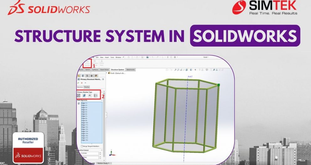
Structure System In SOLIDWORKS
For designers and engineers working with frames in SOLIDWORKS, the traditional welding workflow can be time-consuming and cumbersome, especially for complex structures. If you're looking to streamline your design process and achieve significant time savings, look no further than the innovative SOLIDWORKS Structure System.
This powerful tool offers a fundamentally different approach to frame creation, empowering you to build frames faster, easier, and with greater efficiency. In this blog post, we'll delve into the SOLIDWORKS Structure System, exploring its key features and the undeniable advantages it offers over traditional welding methods.
Get ready to unlock a new level of design productivity and transform your frame creation workflow!
CREATE STRUCTURE SYSTEM
The Structure System mode is activated for developing the primary and secondary members.
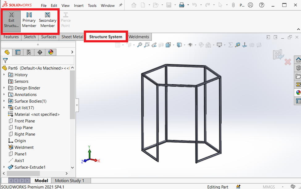
There are two structural members in the structure system.
- Primary structural member.
- Secondary structural member.
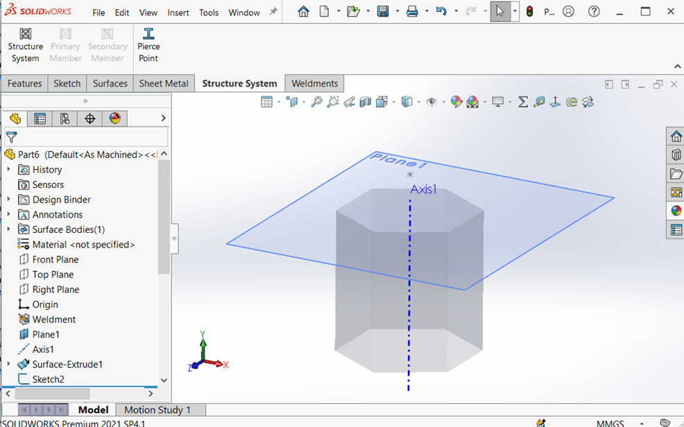
PRIMARY STRUCTURAL MEMBER
Including members for the sketch entity, point, reference plane, and surface requirements are possible.
Create required sketch entities, plane and axis for a primary structural member.
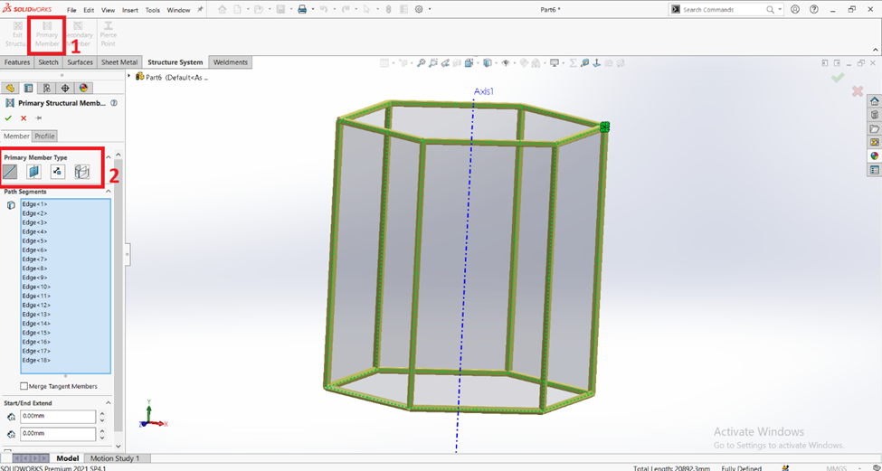
Use the following techniques to generate the primary structure members:
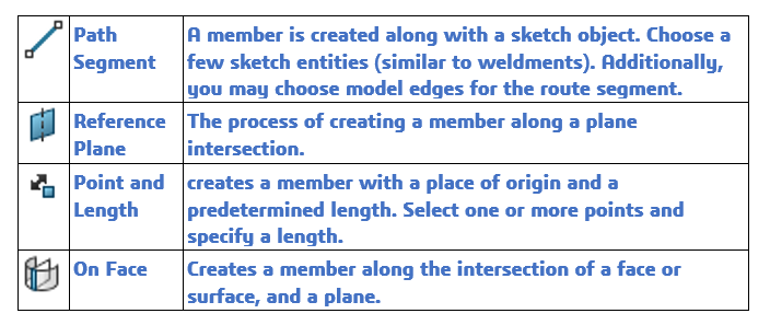
selecting the required edge, point, or sketch entities, then define the primary member structure's profile standard, type, and size.
SECONDARY STRUCTURAL MEMBER
Secondary structural members offer the improved option of adding members between two primary structural members.
Use the following techniques to generate the secondary structure members:
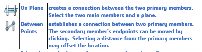
Select the required two primary structural members, Choose the secondary member type then define the profile standard, type, and size for the secondary member structure.
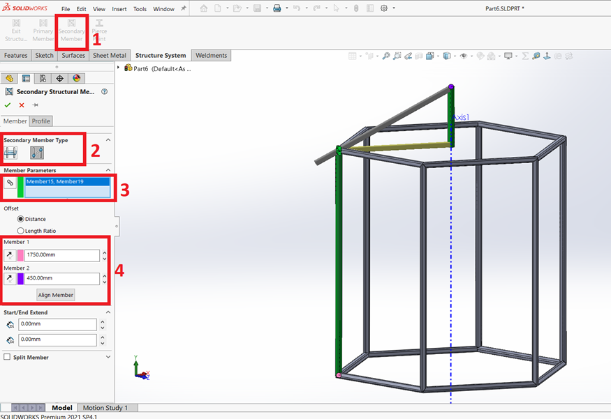
Once creating a secondary structural member, Exit the structural system.
After exiting the structure system corner management will be open for the treatment of the corner of the structure system.
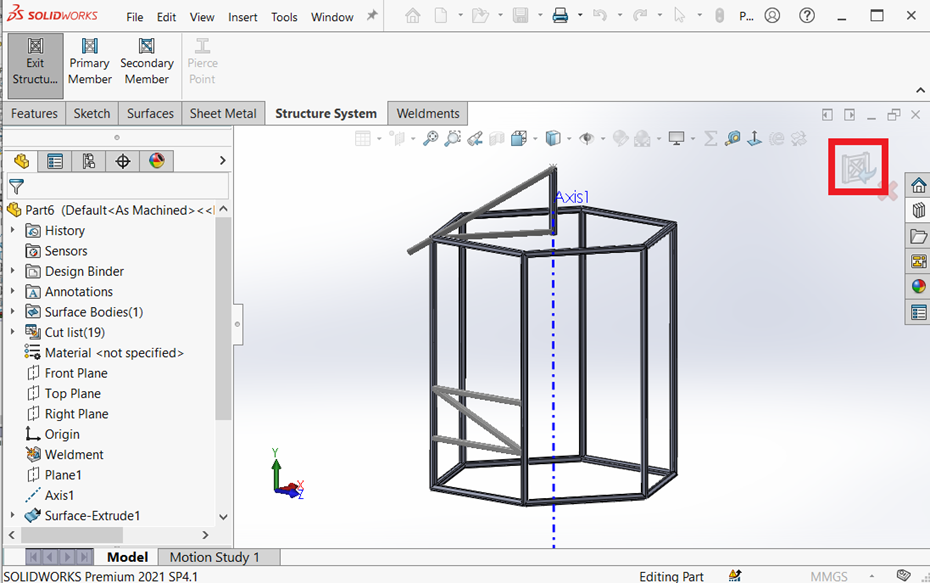
CORNER MANAGEMENT
The Corner Management Property Manager has launched automatically after you exit the structure system. Corners in the Property Manager are classified based on the number of members that meet at a point and the type of joint.
In corner management, we use the following techniques to modify the corners of the structure system.
| Simple | The point at which the ends of two members come together and the segments become collinear. |
| Complex | The point at which more than three members connect. |
Editing Simple corners
In the corner grouping, select the corner to treat and set the needed corner treatment type.
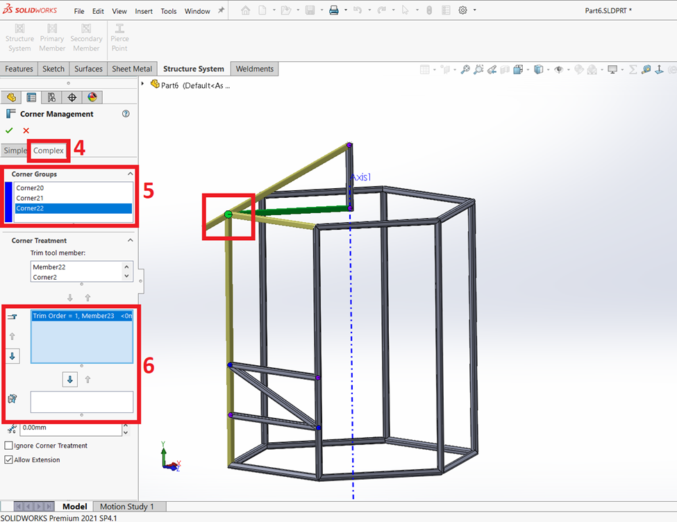
Trimming the complex corners
In the corner grouping, select the corner to treat and set the required trim order on the corner treatment type.
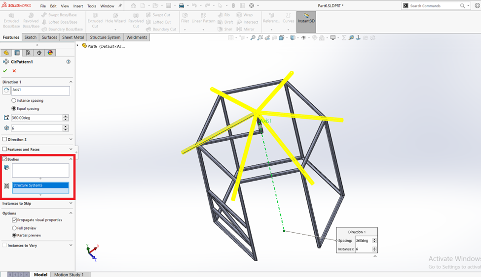
Patterning and mirroring the structure members
Using the Linear Pattern, Circular Pattern, and Mirror tools, you may pattern and mirror structure system parts.
In the Pattern Property Manager, under Bodie’s selection, you can specify structure system features or individual members to the pattern. You can also mirror members by specifying structure system features or individual members under Bodies to Mirror in the Mirror Property Manager.
CONCLUSION
The structural member can be created faster and more easily with the SOLIDWORKS Structure system than it can with welding. In this presentation, the SOLIDWORKS Structure system was discussed. I believe you now have a more advantageous choice.