
Finite Element Analysis (FEA) is a powerful tool used by engineers to analyze the behavior of complex designs under various loading conditions. At the heart of FEA lies the concept of meshing, which plays a critical role in achieving accurate and efficient simulation results. This article dives into the three main meshing techniques employed in SOLIDWORKS: 1D, 2D, and 3D meshing.
1D MESHING:
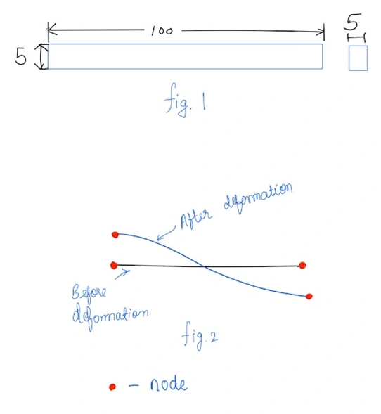
• Used for geometries having one of the dimensions very large in comparison to rest of the two (Refer fig.1).
•Element Shape: Line (Refer fig.2)
•Element Type: Rod, beam, Pipe etc,.
• Practical Example: Long shaft, beam, pin joint, Connection elements. In SOLIDWORKS, We use beam element for 1D meshing. Beam elements are capable of resisting axial, bending, shear, and torsional loads.
2D MESHING
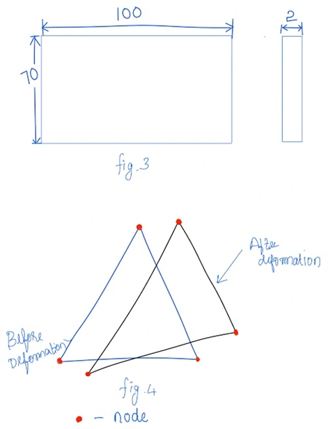
• Used for geometries having two of the dimensions very large in comparison to last dimension.
• Element shape: Triangle
•Type of the Element : Thin shell, membrane, plate.
• Practical application: Sheet metal parts, Plastic components like instrument panel
3D MESHING
• Used for all 3D objects.
•Element shape in SOLIDWORKS: Tetragonal.
• Type of the Element: Solid
• Practical application: Gear Box, Engine Block, Crankshaft.

Appropriate meshing:
You can mesh a sheetmetal part with Solid tetrahedral element but meshing a sheetmetal with shell element gives you approximate result and reduce computational effort which will be handy for any simulation engineer. likewise, you should mesh a beam or rod using beam element.
I like this site very much, Its a really nice place to
read and get information.Raise range
I doo trust all the ideas you’ve introduced on your post.
They’re really convincing and will certainly work. Nonetheless,
the posts are too quick for novices. Maay juyst you please prolong them a
little from next time? Thanks for tthe post. http://campus.ecrin.org/topic/181178/?page=1
Hello, I do think your website could possibly be having web browser compatibility problems.
Whenever I look at youhr blog in Safari, it looks fine butt whesn opening in Internet Explorer,
it has some overlapping issues. I merely wanted to provide
you with a quick heads up! Aside from that, fantastic website! https://Oldforum.Citysakh.ru/?talkid=20922
Yesterday, while I was at work, my sister stole my iphone and tested to see if it can survive a thirty foot drop, just
so she can be a youtube sensation. My apple ipad is noow destroyed and she
has 83 views. I know this is entirely off topic buut I had to
share it with someone! https://Mirpokera.ucoz.ru/forum/22-17-1
What’s up mates, how is all, and what you desire to say regarding this article, in mmy view its truly amazing in favor of
me. http://Www.Pandora.ukrbb.net/viewtopic.php?f=2&t=7209&p=20313
Процесс регистрации в казино 7k 7к casino мобильная максимально упрощен и занимает всего несколько минут. Новым пользователям нужно указать основные данные, после чего они могут сразу приступить к игре. Приятным дополнением является наличие приветственных бонусов, которые позволяют начать игру с увеличенным балансом. Быстрая регистрация и большой выбор игр превращают 7k в лучший выбор как для новичков, так и для профессионалов.
Прогрессивное интернет маркетинговое агентство предлагает услуги комплексного продвижения вашего бизнеса в интернете. Работаем с 2007 года
Высокотехнологичные ?тепловизоры для наблюдения на шлем, для охоты – заказывайте тактические тепловизоры онлайн и получайте ? доставку по Украине.
Тепловизоры. Покупайте официальный и сертифицированный товар категории тепловизоры для военных с гарантией от производителя. 70 моделей на выбор. По цене от 534 грн.
Howdy! Do you know if they make any plugins to assist with Search
Engine Optimization? I’m trying to get my website to rank for some targeted keywords
but I’m not seeing very good results. If you know of any please share.
Many thanks! You can read similar article here: Eco product
дома с установкой под ключ цена
With havin so much written content do you ever run into any problems of plagorism or copyright infringement? My blog has a lot of completely unique content I’ve either written myself or outsourced but it looks like a lot of it is popping it up all over the internet without my permission. Do you know any techniques to help reduce content from being stolen? I’d definitely appreciate it.
https://astr-gov.ru/
https://bashkor-gov.ru/
Харьков Днепр маршрутки
гинеколог врач
Харків Дніпро маршрутка
seo продвижение
smm интернет маркетинг
просування smm у мережі інтернет
прайс на смм услуги
просування сайту в топ
практикующий юрист
продвижение сайта в поисковых системах
Услуги бизнес-юриста крайне важны для тех, кто задумывается о том, как открыть свой бизнес с нуля. Компетентный юрист поможет не только в создании правовой основы для компании, но и в выборе оптимальной организационно-правовой формы, которая будет иметь значение для налогообложения и ответственности. Если вы ищете юриста для открытия бизнеса с нуля, он окажет неоценимую помощь в подготовке учредительных документов, что необходимо для регистрации компании в реестре. Неправильно оформленные документы могут обернуться серьезными проблемами в будущем, поэтому важно иметь под рукой специалиста с опытом работы в этой области. Кроме того, юрист для открытия бизнеса с нуля сможет проконсультировать вас по вопросам соблюдения законодательства, соблюдения норм трудового права и защиты интеллектуальной собственности, что является ключевым для устойчивого развития вашего бизнеса. Их помощь также важна в вопросах арендных отношений и составления договоров, что позволяет минимизировать риски на начальных этапах. Поэтому, если вы планируете запустить бизнес и хотите избежать юридических подводных камней, безусловно, стоит задуматься о привлечении опытного бизнес-юриста.
Квалифицированные услуги юриста для бизнеса может значительно повысить защиту интересов бизнеса и улучшить его устойчивость на рынке.
Услуги адвоката по гражданским спорам имеют важное значение для эффективного решения конфликтов, возникающих между физическими или юридическими лицами. В условиях постоянно растущего числа споров, связанных с договорными обязательствами, имущественными правами и другими гражданскими вопросами, на рынке появляются лучшие адвокаты Москвы по гражданским делам, которые могут предложить квалифицированную помощь. Основная задача таких специалистов заключается в том, чтобы защитить интересы клиента как в досудебном порядке, так и в суде, что требует не только глубоких знаний законодательства, но и умения вести переговоры и составлять юридически обоснованные документы. Обращение к опытному адвокату позволяет избежать распространённых ошибок, которые могут существенно осложнить дело и негативно отразиться на результате. Лучшими адвокатами Москвы по гражданским делам используются индивидуальные подходы к каждому клиенту, что позволяет более точно определить стратегию защиты и устранить риски. Компетентный адвокат способен проанализировать все аспекты дела, предложить оптимальные решения и эффективно представлять интересы клиента в суде, что делает его услуги незаменимыми в сложных правовых ситуациях.
Профессиональный адвокат по гражданским делам представит интересы в судах всех инстанций, обеспечит квалифицированную защиту в сложных ситуациях.
Услуги юриста по наследственным делам становятся особенно актуальными в ситуациях, когда возникают споры между наследниками или когда требуется квалифицированная помощь в оформлении наследства. Юрист по наследству может помочь не только в процессе оформления документов, но и в разрешении конфликтных ситуаций, связанных с разделом имущества, определением долей наследников или спором по поводу действительности завещания. Важно понимать, что наследственное право имеет свои нюансы, и без профессионального вмешательства можно столкнуться с последствиями, которые затруднят получение наследства или ухудшат положение наследников. Кроме того, юрист по наследству обладает необходимыми знаниями и опытом для анализа документов, оценки правомерности претензий и своевременной подачи исков в суд, если это потребуется. Обращение к квалифицированному специалисту не только увеличивает шансы на успешное разрешение дел, но и позволяет избежать ошибок на первом этапе, когда важно правильно собрать все необходимые документы и подготовить ситуацию к дальнейшему разбирательству. Таким образом, услуги юриста по наследственным делам оказываются неоспоримым подспорьем как для успешного оформления наследства, так и для защиты интересов клиентов в судебных разбирательствах, что в конечном итоге может сэкономить время и финансы наследников.
Если у вас возникли вопросы или сложности с наследством, то рекомендую обратиться за помощью в оформлении наследства после смерти к квалифицированному юристу.
Подготовка жалоб и заявлений в службу судебных приставов — это важный и ответственный процесс, который требует внимания к деталям и точности в формулировках. Первое, на что стоит обратить внимание, это наличие всех необходимых документов, подтверждающих ваши права и законные интересы, ведь именно на их основании будет выстраиваться ваша позиция. Номер судебных приставов можно использовать для уточнения информации о конкретном исполнителе, который ведет ваше дело, что поможет избежать ненужных задержек и недоразумений в общении с ведомством. При написании жалобы важно четко изложить суть проблемы, описать обстоятельства дела и привести факты, подтверждающие вашу точку зрения. Номер судебных приставов также может быть полезен для обеспечения быстрого реагирования на ваш запрос, поэтому убедитесь, что он указан в вашем обращении, если вы желаете получить ответ в кратчайшие сроки. Не забывайте о необходимости соблюдения установленного порядка подачи жалоб, так как это существенно влияет на их рассмотрение. Кроме того, учитывайте, что все заявления должны быть оформлены в соответствии с требованиями закона, поскольку это позволяет избежать возвращения документа без рассмотрения. Номер судебных приставов может стать ключевым элементом, позволяющим эффективно взаимодействовать со службой и контролировать процесс исполнения решений суда.
Рекомендую обратиться к профессиональному юристу, который поможет грамотно составить жалобу на судебного пристава.
Юридическая служба – это важный инструмент для защиты прав и интересов граждан и компаний в сложных ситуациях, требующих профессионального вмешательства. Обращаясь к юристу или адвокату, вы получаете не только ценные советы по правовым вопросам, но и квалифицированное представительство в суде, что особенно актуально в условиях современного законодательства. Профессиональная юридическая служба помогает минимизировать риски, связанные с правонарушениями, обеспечивая глубокий анализ ситуации и управление процессами, связанными с судебными разбирательствами. Квалифицированные юристы обладают необходимыми знаниями и опытом, чтобы успешно вести переговоры, составлять юридические документы, а также защищать ваши интересы в правоохранительных органах. Юридическая служба также может предложить консультации по вопросам защиты интеллектуальной собственности, семейного права, трудовых споров и многих других областей права. Важно понимать, что вовремя полученная помощь профессионала может существенно повлиять на исход дела, поэтому инвестиции в услуги юриста или адвоката — это не просто расходы, а разумное решение для законной защиты ваших прав.
Если вам требуется помощь опытного адвоката или юриста вы всегда можете рассчитывать на нашу помощь.
Юрист по недвижимости играет ключевую роль в обеспечении правовой безопасности сделок с недвижимостью, что особенно актуально в динамичном рынке Москвы. Качественное правовое сопровождение позволяет избежать множества рисков, связанных с покупкой, продажей или аренде объектов. Если вы столкнулись с правовыми спорами, связанными с недвижимостью, грамотный адвокат по недвижимости в Москве поможет вам разобраться в тонкостях законодательства, защитить ваши интересы и минимизировать финансовые потери. Такие специалисты имеют опыт в работе с различными сделками, включая ипотечное кредитование, долевое строительство и споры с застройщиками. Обратившись к юристу, вы получите всестороннюю консультацию и поддержку по всем этапам оформления сделки, что особенно важно для минимизации возможных ошибок. Также адвокат по недвижимости в Москве способен оказать помощь в случае возникновения конфликтов с соседями, государственных органов или в вопросах регистрации прав на собственность. Искреннее стремление защитить права клиента и индивидуальный подход к каждому делу делают услуги юриста по недвижимости незаменимыми в сложных ситуациях. Убедитесь, что ваша сделка будет безопасной и выгодной, обратившись за помощью к опытному профессионалу в этой области.
Если у вас возникли вопросы или сложности с оформлением или приобретением недвижимости, то рекомендую обратиться за помощью к квалифицированному юристу по недвижимости
Услуги юриста по недвижимости играют ключевую роль в обеспечении правовой безопасности сделок с недвижимостью и решении различных вопросов, связанных с имущественными правами. Каждый, кто планирует приобрести, продать, сдать в аренду недвижимость или столкнулся с правовыми проблемами, такими как споры о границах имущества или вопросы оформления документов, нуждается в профессиональной помощи. Консультация юриста по недвижимости поможет избежать множество подводных камней, которые могут возникнуть во время сделки, ведь многие владельцы не всегда осведомлены о всех нюансах правового регулирования. Обращение к юристу не только способствует правильному оформлению сделок, но и позволяет минимизировать риски, связанные с возможными претензиями со стороны третьих лиц или недобросовестных продавцов. Кроме того, квалифицированный специалист способен проанализировать юридическую чистоту объекта, а также окажет поддержку в подготовке необходимых документов, ведь именно качественная консультация юриста по недвижимости закладывает основу для успешного завершения всех процедур. Профессиональный юрист поможет разобраться в различных аспектах, таких как оформление прав собственности, вопросы налогообложения и регистрация прав, делая процесс максимально прозрачным и безопасным.
Только квалифицированный юрист по недвижимости способен грамотно оценить «чистоту сделки».
Услуги арбитражного юриста становятся неоценимыми при разрешении споров, связанных с бизнесом и коммерческой деятельностью, где важна профессиональная поддержка и стратегический подход. Помощь адвоката в арбитражном суде позволяет не только эффективно защищать интересы клиента, но и грамотно подготавливать необходимые документы, что критично для успешного исхода дела. Когда возникают споры между партнерами, поставщиками или контрагентами, важно иметь под рукой опытного специалиста, который сможет проанализировать ситуацию и предложить оптимальные решения, ведь помощь адвоката в арбитражном суде включает в себя комплексное сопровождение с учетом всех рисков и нюансов. Квалифицированный арбитражный юрист не только предоставляет консультации по вопросам права, но и представляет интересы клиента в судебных заседаниях, что значительно повышает шансы на положительный результат. Все это подтверждает, что обращение к профессионалам для получения помощи адвоката в арбитражном суде является важным шагом для достижения желаемого результата и защиты своих прав. Бизнесмены и организации должны осознавать, что успех в арбитражных разбирательствах напрямую зависит от уровня подготовки и квалификации их юридического представителя, что подчеркивает важность обращения к опытным арбитражным юристам.
Профессиональный арбитражный юрист благополучно проведет переговоры и достигнет компромиссов, тем самым значительно повысит шансы на успешный исход дела.
Услуги адвокатов по гражданским делам крайне важны для защиты прав и законных интересов граждан, особенно в мегаполисах, таких как Москва. В условиях сложной правовой системы часто возникает необходимость в квалифицированной помощи, и в такие моменты на помощь приходит юрист по гражданскому праву Москва. Эти специалисты обладают знаниями о множестве аспектов гражданского законодательства, включая вопросы, связанные с имущественными спорами, наследством, договорами и защитой прав потребителей. Обращение к адвокату позволяет не только избежать распространенных ошибок при подаче исков, но и значительно повысить шансы на положительное разрешение дела. Юрист по гражданскому праву Москва сможет оценить вашу ситуацию, предложить оптимальные пути решения и подготовить необходимые документы, что особенно важно в случаях, когда дело может быть связано с значительными финансовыми потерями или личными правами. Таким образом, наличие опытного адвоката по гражданским делам становится необходимым шагом для обеспечения надежной защиты и соблюдения ваших интересов в сложных правовых спорах.
Если вам нужна помощь адвоката по гражданским делам в Москве рекомендуется обратиться к специалисту с опытом в вашей конкретной области, чтобы получить профессиональную поддержку.
В современном мире защита прав потребителей становится всё более актуальной темой, и услуги юриста в этой области играют ключевую роль в обеспечении справедливости. Когда потребители сталкиваются с нарушениями своих прав, такими как некачественные товары или услуги, важно иметь рядом профессионала, который сможет грамотно оценить ситуацию и предложить эффективные решения. Юридическая консультация по защите прав потребителей онлайн позволяет быстро получить нужные рекомендации, не выходя из дома. Такие консультации охватывают широкий спектр вопросов, от возврата некачественного товара до защиты прав при нарушении условий договора, что помогает потребителям не только лучше понять свои права, но и эффективно их отстаивать. Благодаря опыту специалистов в области права, можно избежать многих ошибок, которые часто допускают люди, пытаясь решить свои проблемы самостоятельно, поэтому юридическая консультация по защите прав потребителей онлайн становится важным шагом на пути к восстановлению справедливости. Профессиональный юрист не только проконсультирует по всем нюансам правовой системы, но и, при необходимости, подготовит все необходимые документы для судебного разбирательства, что значительно увеличивает шансы на положительный исход дела. Защита прав потребителей требует не только знаний, но и опыта, и именно поэтому услуги квалифицированного юриста могут стать решающим фактором в противостоянии с недобросовестными продавцами или поставщиками услуг.
Если у вас возникли вопросы связанные с ненадлежащим качеством товаров или услуг, то рекомендую обратиться к квалифицированному юристу по защите прав потребителей.
Услуги юриста по семейным делам играют ключевую роль в защите прав и интересов клиентов, особенно в сложных ситуациях, связанных с разводами, опекой над детьми и разделом имущества. Когда в семье возникает конфликт, адвокаты по семейным делам юрист становятся теми профессионалами, которые способны не только предоставить юридическую помощь, но и поддержать эмоционально в непростые времена. Опытные специалисты обеспечивают индивидуальный подход к каждому делу, учитывая все факторы, влияющие на ситуацию, от финансового положения до психоэмоционального состояния участников конфликта. От правильной консультации и составления документов до представительства в суде — адвокаты по семейным делам юрист готовы оказать помощь на всех стадиях разрешения споров. Привлечение такого специалиста позволяет снизить эмоциональное напряжение, а также обеспечивает максимальную защиту прав клиента в процессе, который часто бывает наполнен стрессом и неоднозначными решениями. Важно помнить, что грамотная юридическая поддержка — это залог успешного исхода дела, и именно квалифицированные адвокаты по семейным делам юрист способны обеспечить надежную защиту интересов клиента, его детей и имущества.
Если у вас возникли трудности в семейных отношениях, юрист по семейным делам может оказать вам необходимую поддержку и защиту ваших прав.
Консультации по земельному праву представляют собой неотъемлемую часть работы любого юриста, который специализируется на земельных вопросах. Они помогают клиентам разобраться в сложных правовых нормах, касающихся владения, пользования и распоряжения земельными участками. Нередко возникает необходимость в получении разрешений на строительство, оформление права собственности или решение споров с соседями, и именно здесь услуги юриста становятся особенно актуальными и ценными. Консультации по земельному праву могут охватывать широкий спектр тем, включая вопросы аренды, межевания, а также защиту прав собственников и арендаторов в судебных инстанциях. Опытный юрист не только разъяснит все нюансы законодательства, но и поможет составить необходимые документы, что значительно упростит процедуру получения земельных прав или решения спора. Консультации по земельному праву часто являются первым шагом к успешному разрешению ситуации, так как они дают сторонам чёткое понимание своих прав и обязанностей, а также возможных рисков. Благодаря поддержке профессионала, клиенты могут избежать распространённых ошибок в оформлении земельных отношений и защитить свои интересы на всех этапах, что делает услуги квалифицированного юриста неоценимыми в современном обществе.
Рекомендую выбирать опытного юриста по земельным вопросам , чтобы избежать юридических проблем и защитить свои права на землю.
Услуги адвоката по гражданским делам играют ключевую роль в защите прав и законных интересов граждан, которые сталкиваются с различными правовыми вопросами. Гражданский юрист обладает необходимыми знаниями и опытом для того, чтобы помочь клиентам в решении споров, касающихся долгов, наследства, договора аренды, а также иных гражданских правоотношений. Привлечение квалифицированного специалиста позволяет не только правильно составить исковое заявление, но и грамотно представить интересы клиента в суде, что нередко становится решающим фактором в исходе дела. Команда опытных адвокатов, работающих в области гражданских дел, смогла на практике убедиться в том, насколько важно учитывать все тонкости и нюансы законодательства, что также делает их услуги незаменимыми. Гражданский юрист предоставляет помощь на всех этапах – от консультации до представительства в суде, что позволяет клиентам чувствовать уверенность в выборе решения и оставаться в правовом поле. Важно помнить, что своевременная юридическая помощь может существенно сократить время на разрешение споров и значительно улучшить шансы на положительный исход, что подтверждает высокую ценность работы адвоката в этой сфере.
Рекомендую обратиться за профессиональной консультацией к адвокату по гражданским делам в Москве, чтобы четко понимать возможные действия в конкретной ситуации, это существенно увеличит шансы на успешное разрешение вопроса.
Услуги автоюриста становятся всё более востребованными в условиях современного рынка, где сложные правовые вопросы требуют квалифицированного вмешательства. Обратившись к автоюристу, вы получаете не только защиту своих прав в дорожно-транспортных происшествиях, но и помощь в решении споров с транспортными компаниями и страховщиками, которые могут пытаться уклониться от своих обязательств. Стоимость таких услуг может варьироваться, и здесь важно учесть, что цена автоюриста зависит от сложности конкретного дела, ведь разные ситуации требуют различного подхода и времени на их решение. Хороший автоюрист способен сопроводить вас на всех этапах разбирательства — от составления искового заявления до представления интересов в суде, что в конечном итоге может значительно повысить шансы на положительный исход дела. Некоторые специалисты предлагают гибкие расценки, поскольку цена автоюриста может быть установлена в зависимости от объема работы и необходимых ресурсов, поэтому необходимо заранее обсудить все детали сотрудничества. В результате, квалифицированный автоюрист не только сэкономит ваше время и нервы, но и избавит от возможных финансовых потерь в случае неправомерных действий со стороны третьих лиц. Значение профессиональной юридической поддержки сложно переоценить, ведь в случае ДТП или конфликта с правоохранительными органами каждый неправильно сделанный шаг может привести к негативным последствиям, которые значительно осложнят вашу ситуацию.
Если у вас возникли трудности в автомобильном споре, то рекомендую обратиться к автоюристу, чтобы избежать возможных проблем и защитить свои права.
Адвокат по уголовным делам – это ключевая фигура в системе правосудия, обеспечивающая защиту прав и законных интересов своих клиентов, оказавшихся в сложной правовой ситуации. Очень важно понимать, что стоимость услуг адвоката может варьироваться в зависимости от сложности дела, опыта специалиста и его репутации. Так, возникает естественный вопрос: сколько берет адвокат по уголовному делу? Это зависит от множества факторов, включая регион, степень вовлеченности в дело, а также необходимое количество времени для подготовки и представления интересов клиента в суде. Профессиональные адвокаты могут предлагать как почасовую оплату, так и фиксированные суммы за ведение конкретного дела, что также стоит учитывать при выборе специалиста. Важно помнить, что инвестиция в качественную защиту может существенно повлиять на исход дела, поэтому заданный вопрос “сколько берет адвокат по уголовному делу” не должен быть единственным критерием выбора. В конечном счете, умение адвоката пониматься на тонкостях уголовного права и наличие успешного опыта работы могут оказаться решающими факторами для достижения наилучшего результата.
Рекомендую выбирать опытного адвоката по уголвным делам , он построит надежную защиту и повысит шансы на успешный исход дела.
Нанять юриста по алиментам – важный шаг для защиты своих прав и интересов в вопросах, связанных с материальной поддержкой детей. В современных условиях, когда юридическая система становится всё более сложной, профессиональная помощь юриста становится необходимостью для достижения справедливости. Правильный выбор специалиста по алиментам может существенно повлиять на исход дела, будь то помощь в установлении размера выплат или защите от неправомерных требований. Нанять юриста по алиментам следует в том случае, если вы хотите избежать множества юридических афер и нерациональных решений, которые могут навредить вам и вашим детям. Квалифицированный юрист обладает не только глубокими знаниями в области семейного права, но и опытом дальнейшего взаимодействия с судебными инстанциями, что позволяет ему эффективно представлять интересы клиента. Нанять юриста по алиментам – значит доверить свои заботы профессионалу, который сможет проанализировать вашу ситуацию, предложить оптимальные решения и защитить ваши права в суде. Этот специалист поможет не только в расчете необходимых сумм алиментов, но и в сборе необходимых документов, что существенно упростит вашу задачу. Обращение к юристу по алиментам позволит избежать ненужных стресса и разбирательств и даст возможность сосредоточиться на главном – заботе о благополучии вашего ребенка.
Если вам нужна помощь в справедливом решении в вопросах содержания детей, то рекомендую обратиться к юристу по алиментам , он поможет разобраться в правовых аспектах и представить ваши интересы в суде.
Устройства этого типа идеально подходят для долгих наблюдений на открытых пространствах.
Feel free to visit my web page :: купить тепловизоры для военных
Раздел имущества — это сложный и запутанный процесс, который требует профессионального подхода и глубоких знаний в области права, особенно когда речь идет о помощи адвоката в вопросах, связанных с имуществом. При возникновении спора о разделе совместно нажитого имущества лучше всего обратиться к опытному юристу, который специализируется на данном направлении и сможет грамотно составить договор, учитывающий интересы обеих сторон. Адвокат по разделу имущества не только поможет разобраться в правовых тонкостях, но и окажет поддержку в переговорах с другой стороной, что может значительно ускорить процесс достижения соглашения. Важно помнить, что каждая ситуация уникальна, и адвокаты, специализирующиеся на этих вопросах, способны предложить индивидуальные решения и стратегии, основанные на конкретных обстоятельствах дела. Адвокат договор имущество раздел поможет избежать множества подводных камней и защитит ваши права в судебных инстанциях, если ситуация дойдет до конфликта. Кроме того, подробный анализ текущей ситуации и грамотное оформление всех необходимых документов — это ключевые этапы, которые позволит избежать недопонимания и конфликтов в дальнейшем. С таким специалистом можно чувствовать себя уверенно на каждом шаге процесса.
Рекомендую обратиться за профессиональной консультацией к юристу по разделу имущества, чтобы четко понимать возможные действия в конкретной ситуации, это существенно увеличит шансы на успешное разрешение вопроса.
Юрист медицинской организации играет ключевую роль в обеспечении правовой защиты интересов как лечебных учреждений, так и пациентов. Такие специалисты обладают глубокими знаниями в области медицинского права, что позволяет им эффективно решать сложные правовые вопросы, касающиеся оказания медицинских услуг, защиты персональных данных и соблюдения нормативных требований. Юрист медицинской организации помогает не только в составлении и анализе договоров, но и в разрешении конфликтов между пациентами и медиками, что особенно актуально в условиях современного здравоохранения. Наличие квалифицированного юриста в команде медицинского учреждения позволяет минимизировать риски судебных разбирательств и санкций со стороны контролирующих органов. Также юрист медицинской организации поддерживает клинику в вопросах соблюдения стандартов медицинской практики и этических норм, что существенно повышает уровень доверия со стороны пациентов и способствует созданию безопасной атмосферы в медицинской практике. Специалист такого профиля не только активно консультирует, но и занимается правовым аудитом, что помогает своевременно выявлять и устранять потенциальные юридические риски. В результате взаимодействия с юристом медицинской организации образуется прочный правовой фундамент, который защищает интересы клиники и гарантирует безопасное оказание медицинских услуг.
Если у вас возникли трудности в медицинском споре, то рекомендую обратиться к медицинскому юристу, чтобы избежать возможных проблем и защитить свои права.
Услуги адвоката играют ключевую роль в обеспечении правовой защиты граждан и организаций, помогая им вновь обрести уверенность в своих силах и защищать свои интересы в различных ситуациях. Обратившись за помощью к адвокату, вы получаете доступ к профессиональным знаниям и опыту, что особенно важно в сложных правовых вопросах, будь то уголовные дела, семейные споры или бизнес-право. Услуги адвоката не ограничиваются только представлением в суде; они также включают в себя консультации, составление договоров и документов, а также правовую оценку ситуации клиента, что позволяет избежать многих юридических ошибок. Если вы столкнулись с правовыми трудностями, услуги адвоката могут помочь вам лучше понять ваши права и обязанности, а также предложить оптимальные пути решения проблемы. Хороший адвокат внимательно изучит все аспекты дела, даст рекомендации и разработает стратегию защиты, учитывая множество факторов, которые могут повлиять на исход процесса. Таким образом, профессиональная юридическая помощь является важным инструментом в современном мире, где правовые вопросы становятся всё более сложными, и именно услуги адвоката способны обеспечить необходимую поддержку и защиту.
Если вам требуется защита в суде, лучше обращайтесь к профессиональному адвокату . Это поможет обеспечить качественную защиту ваших прав и интересов.
Услуги адвоката представляют собой важный элемент правовой системы и играют решающую роль в защите интересов граждан и юридических лиц. Обратившись к адвокату, вы можете получить квалифицированную помощь в самых разнообразных вопросах, начиная от составления документов и заканчивая представлением ваших интересов в суде. Услуги адвоката охватывают целый спектр правовых вопросов, включая уголовное, гражданское, семейное и административное право, что позволяет вам быть уверенными в том, что ваши проблемы будут решены наиболее эффективным образом. Обращение к специалисту в области права не только способствует успешному ведению дела, но и помогает избежать множества юридических ошибок, которые могут дорого стоить в будущем. Услуги адвоката также включают консультации по вопросам законодательства, что позволяет вам лучше ориентироваться в своих правах и обязанностях. Важно помнить, что успешная защита ваших интересов зависит от профессионализма адвоката, поэтому выбор квалифицированного специалиста имеет первостепенное значение. В современных условиях, когда правовые нормы постоянно меняются, услуги адвоката становятся необходимостью для качественного решения правовых вопросов.
Рекомендую выбирать опытного адвоката , он построит надежную защиту ваших прав и интересов и повысит шансы на успешный исход дела.
Услуги юриста по защите прав потребителя становятся все более актуальными в современном обществе, где права граждан нередко нарушаются недобросовестными продавцами и сервисами. Специалист в этой области помогает клиентам разобраться в сложных правовых ситуациях, связанных с некачественными товарами, ненадлежащими услугами, а также нарушением гарантийных обязательств. Обращаясь за услугами юриста по защите прав потребителя, вы можете рассчитывать на профессиональную помощь в подготовке документов, а также на защиту ваших интересов при разрешении споров с компаниями и организациями. Такой юрист станет вашим надежным защитником, выполняя задачи по анализу вашей ситуации, составлению претензий и исковых заявлений, а также сопровождая вас на всех этапах судебного разбирательства. Услуги юриста по защите прав потребителя позволяют существенно повысить шансы на успешное разрешение споров и компенсацию причинённого ущерба, так как опытный специалист знает все тонкости законодательства и способен грамотно представить ваши интересы. Независимо от сложности вашего дела, квалифицированный юрист предоставит поддержку и уверенность в том, что ваши права будут защищены.
Если вам нужна помощь в потребительском споре, то рекомендую обратиться к юристу по защите прав потребителей , он поможет разобраться в правовых аспектах и поможет в решении вашей ситуации.
Юрист по ДТП играет критически важную роль в защите прав участников дорожно-транспортных происшествий, обеспечивая защиту их интересов как в судебных разбирательствах, так и в досудебном порядке. При выборе квалифицированного специалиста, потенциальные клиенты часто интересуются вопросом «юрист ДТП стоимость», так как этот аспект имеет большое значение для оценки общих затраты на юридические услуги. Важно понимать, что стоимость услуг юриста по ДТП может варьироваться в зависимости от сложности дела, квалификации специалиста и региона, в котором он работает. Многие юристы предлагают бесплатные консультации, что позволяет клиентам оценить их уровень профессионализма и дать детальную информацию о возможных расходах. Однако, ориентируясь исключительно на цену, не стоит забывать о качестве предоставляемых услуг — грамотный юрист по ДТП может существенно повлиять на исход дела, что в итоге может оправдать любые затраты. Наличие опыта и успешных дел у специалиста, безусловно, также отражается на его ставках: юрист ДТП стоимость своего труда зачастую связывает с высоким уровнем ответственности и профессионализма. Поэтому, прежде чем сделать выбор, рекомендуется изучить отзывы о работе конкретного юриста и обсудить все нюансы его услуг, чтобы быть увереннее в успешном разрешении вашей ситуации.
Рекомендую обратиться за профессиональной консультацией к юристу по ДТП, чтобы четко понимать возможные действия в конкретной ситуации, это существенно увеличит шансы на успешное разрешение вопроса.
Услуги адвоката играют ключевую роль в защите прав и законных интересов граждан, особенно в таких мегаполисах, как Москва. Адвокаты города Москвы предлагают широкий спектр юридических услуг, включая представительство в суде, консультации по гражданским и уголовным делам, а также помощь в составлении юридических документов. Опытные специалисты не только имеют глубокие знания законодательства, но и обладают практическими навыками, позволяющими эффективно защищать клиентов в сложных юридических вопросах. Важно отметить, что адвокаты города Москвы также предоставляют услуги по разрешению споров в досудебном порядке, что может существенно сэкономить время и средства. Необходимость в квалифицированной юридической поддержке становится особенно актуальной, когда дело касается защиты прав в сфере бизнеса или уголовного преследования. Поэтому, выбирая адвоката, стоит ориентироваться на его репутацию и опыт работы, поскольку это непосредственно влияет на результат. Доверяя свои интересы адвокатам города Москвы, клиенты могут быть уверены в том, что их дела находятся в надежных руках и будут рассматриваться с максимальной отдачей и профессионализмом.
Рекомендую выбирать адвоката, учитывая его опыт, специализацию, это поможет обеспечить качественную защиту ваших прав и интересов.
Услуги адвоката в рамках юридической компании играют ключевую роль в обеспечении правовой помощи и защиты интересов клиентов в различных ситуациях. Каждый из нас может столкнуться с юридическими проблемами, будь то семейные споры, уголовные дела или вопросы бизнеса, и в такие моменты качественная консультация адвоката становится необходимостью. Юридическая компания предлагает профессиональные услуги, которые включают не только представление интересов в суде, но и комплексное правовое сопровождение, анализ документов и подготовку исковых заявлений. Квалифицированные адвокаты обладают глубокими знаниями и опытом, что позволяет им эффективно решать даже самые сложные дела, обеспечивая индивидуальный подход к каждому клиенту. Привлечение специалистов из юридической компании помогает минимизировать риски и избежать серьезных ошибок в правовых процедурах, что особенно важно в условиях современной правовой системы. Наконец, юридическая компания предлагает свои услуги по прозрачным условиям, что позволяет клиентам быть уверенными в том, что их интересы будут защищены на высшем уровне, а адвокат сможет максимально эффективно работать над их делом.
Если вам требуется профессиональное мнение по юридическим вопросам, то лучше обращайтесь к опытному адвокату . Это поможет обеспечить качественную защиту ваших прав и интересов.
Юридическая помощь адвоката представляет собой неотъемлемую составляющую правового поля, обеспечивая защиту интересов граждан и организаций в самых различных ситуациях. Часто люди оказываются в сложных юридических вопросах, будь то семейные споры, трудовые конфликты или уголовные дела, и именно в такие моменты квалифицированный юрист способен обеспечить не только защиту прав, но и уверенность в исходе дела. Важность получения юридической помощи адвоката сложно переоценить, так как она включает в себя не только консалтинг, но и полноценное представительство в суде, что может существенно повлиять на результат. Многочисленные исследования показывают, что граждане, обращающиеся за юридической помощью адвоката, имеют гораздо больше шансов на успешное разрешение своих проблем. Профессиональные юристы помогают не только в выборе наилучшей стратегии действий, но и в сборе необходимых документов, что делает процесс более эффективным и упрощает взаимодействие с судом или другими инстанциями. Наличие опытного адвоката зачастую позволяет избежать затяжных разбирательств и негативных последствий, таких как штрафы или утрата прав. Безусловно, юридическая помощь адвоката должна рассматриваться как инвестиция в будущее, ведь квалифицированный подход к разрешению юридических вопросов может сэкономить время, нервы и средства. Если вы столкнулись с правовой проблемой, не откладывайте решение вопроса, так как своевременное обращение за юридической помощью адвоката является залогом успешного исхода любого дела.
Рекомендую выбирать опытного юриста , он построит надежную защиту ваших прав и интересов и повысит шансы на успешный исход дела.
Юрист по защите прав потребителей играет ключевую роль в обеспечении прав граждан в условиях современного рынка, где потребительские отношения нередко сопровождаются конфликтами и нарушениями. Если у вас возникли проблемы с качеством товара или услуг, не стоит терять время, и тогда вам поможет юридическая консультация по защите прав потребителей Москва, где опытные специалисты предоставят необходимые рекомендации по защите ваших прав. Они смогут оценить вашу ситуацию с учетом всех обстоятельств и документов, помочь в составлении жалоб, а также при необходимости представлять ваши интересы в судебных инстанциях. Кроме того, юристы, специализирующиеся на защите прав потребителей, обладают актуальными знаниями в области законодательства, что позволяет им эффективно защищать интересы клиентов. Обратившись за юридической консультацией по защите прав потребителей Москва, вы получите не только квалифицированную помощь, но и уверенность в том, что ваши права будут соблюдены. Важно понимать, что защита прав потребителей — это не только ваша личная инициативу, но и необходимость взаимодействия с профессионалами, которые точно знают, какие шаги предпринять для устранения нарушений и достижения справедливости.
Важно знать свои права как потребителя, и юрист по защите прав потребителей может помочь в их защите, чтобы избежать недоброосвестных практик со стороны продавцов или услугодателей.
Тепловизоры дают охотникам и военным преимущество в условиях недостаточной видимости.
Here is my web site :: тепловизор для охоты, https://eng.worthword.com/bbs/board.php?bo_table=free&wr_id=1090043,
Услуги юристов играют ключевую роль в обеспечении правовой поддержки для граждан и предприятий, особенно в крупных городах, таких как Москва. Юристы города Москвы обладают уникальными знаниями и опытом, которые позволяют им успешно решать разнообразные юридические вопросы, начиная от составления контрактов и заканчивая представлением интересов клиентов в судах. В условиях динамичной правовой среды, качество предоставляемых услуг становится особенно важным; именно поэтому профессиональные юристы города Москвы активно следят за изменениями в законодательстве и регулярно повышают свою квалификацию. Правильный выбор юриста может существенно повлиять на исход дела, поэтому многим людям важно помнить, что юристы города Москвы помогают не только в сложных судебных разбирательствах, но и в составлении правовых документов, а также в консультациях по вопросам бизнеса, налогообложения и имущественных спорах. Наличие профессионала, который понимает тонкости местной практики и может предложить индивидуальный подход, станет залогом успешного решения ваших правовых проблем. В итоге, обращаясь к юристу, вы обеспечиваете защиту своих интересов и минимизируете риски, что подчеркивает важность таких услуг в современном мире.
Рекомендую выбирать юриста, учитывая его опыт, специализацию, это поможет обеспечить качественную защиту ваших прав и интересов.
Услуги адвоката играют ключевую роль в обеспечении правовой защиты и поддержке своих клиентов в различных юридических вопросах. Обращаясь на сайт адвоката, можно получить квалифицированную помощь в самых разных областях, таких как семейное, уголовное или гражданское право. Правильный выбор адвоката может значительно повысить вероятность успешного исхода дела, поскольку опытный специалист способен не только грамотно составить исковые заявления, но и представить интересы клиента в суде. На сайте адвоката обычно представлены не только условия его работы и спектр услуг, но и отзывы довольных клиентов, что может помочь сделать выбор более осознанным. Важно помнить, что индивидуальный подход к каждому делу позволяет адвокату учитывать все нюансы и особенности, что сказывается на конечном результате. Некоторые сайты адвокатов предлагают бесплатные консультации, что дает возможность потенциальным клиентам оценить уровень профессионализма и подход к делу, прежде чем подписывать договор на предоставление услуг. Заказав услуги на сайте адвоката, вы инвестируете в свою правовую безопасность и уверенность в том, что ваши интересы будут защищены на самом высоком уровне.
Рекомендую обратиться за профессиональной консультацией к адвокату, чтобы четко понимать возможные действия в конкретной ситуации, это существенно увеличит шансы на успешное разрешение вопроса.
Услуги адвоката в современном мире играют ключевую роль для обеспечения правовой защиты и поддержки интересов клиентов в различных юридических вопросах. Обращение к адвокату может значительно упростить процесс решения сложных правовых ситуаций, будь то вопросы семейного права, уголовные дела или бизнес-споры. Именно поэтому многие люди ищут специализированные ресурсы, такие как сайт адвоката москваадвокат, чтобы получить квалифицированную помощь и рекомендации. На таких сайтах представлены важные сведения о профессиональном опыте адвокатов, их специализациях и успешных делах, что позволяет клиентам сделать осознанный выбор. Также адвокаты оказывают услуги по правовому консультированию, что позволяет избежать потенциальных правовых рисков и заранее подготовить необходимые документы. Сайт адвоката москваадвокат служит отличным путеводителем для тех, кто хочет разобраться в запутанных правовых вопросах и получить надежную защиту своих прав. Поэтому, выбирая адвоката, необходимо учитывать не только его репутацию, но и специфику его работы, чтобы обеспечить максимальную защиту своих интересов и прав.
Если вам требуется профессиональное мнение по юридическим вопросам, то лучше обращайтесь к опытному адвокату . Это поможет обеспечить качественную защиту ваших прав и интересов.
помощь юриста в москве
адвокат москва
адвокаты и юристы москва
юрист москва
https://luko-mebli.com.ua/
помощь адвоката
Уголовные дела — это крайне сложный и многогранный аспект юриспруденции, требующий высокой квалификации и профессионализма от специалистов. Каждый случай уникален и требует индивидуального подхода, что делает услуги адвоката по уголовным делам в Москве особенно актуальными. Зачастую эмоциональное напряжение, связанное с уголовными делами, мешает людям адекватно оценить свои шансы и возможности, поэтому важно иметь под рукой опытного защитника, который поможет разобраться в запутанных юридических вопросах и минимизировать возможные последствия. Адвокат по уголовным делам в Москве сможет не только представить интересы клиента в суде, но и осуществить всесторонний анализ собранных доказательств, выявить слабые места в обвинении и разработать стратегию защиты. Правильный выбор адвоката может существенно изменить ход дела и повлиять на итоговый вердикт, что подтверждается многочисленными примерами успешной защиты в судебной практике. Квалифицированный адвокат также поможет разбираться в сложностях уголовного законодательства, эффективно взаимодействовать с правоохранительными органами и другими участниками процесса, создавая тем самым необходимые условия для достижения наилучшего результата. Поэтому не стоит недооценивать важность профессиональной помощи на всех этапах уголовного процесса.
Если вам необходимо проконсультироваться по уголовному делу, то обращайтесь к опытному адвокату по уголовным делам
Услуги юриста по жилищным вопросам играют важную роль в защите прав и законных интересов граждан, сталкивающихся с различными жилищными спорами и конфликтами. Правильное представление интересов по жилищным делам необходимо не только в судебных разбирательствах, но и на стадиях предварительных переговоров, что может существенно снизить вероятность судебного разбирательства. Компетентный юрист способен помочь вам разобраться в сложных вопросах, связанных с правами на жилую площадь, арендными договорами, приватизацией, а также с правами соседей, нарушениями условий эксплуатации жилья и многими другими аспектами. Важным является то, что качественное представление интересов по жилищным делам требует не только глубоких знаний законодательства, но и понимания конкретной ситуации клиента, что позволяет юристу предложить наиболее эффективные решения. Кроме того, юридическая поддержка особенно важна при взаимодействии с государственными органами и управляющими компаниями, где наличие опытного специалиста может значительно облегчить процесс получения необходимых документов и разрешений. Работая с юристом, вы получаете себе надежного партнера, который поможет избежать множества проблем и защитит ваши права в сфере жилищного строительства и проживания. Таким образом, услуги юриста по жилищным вопросам незаменимы для обеспечения правовой безопасности и защиты интересов граждан в этой сложной и важной сфере.
Если вам необходимо проконсультироваться по жилищным спорам, то обращайтесь к опытному юристу по жилищным вопросам.
Защита прав потребителей является важной частью правовой системы, обеспечивающей баланс между интересами покупателей и продавцов. В условиях современного рынка, где конкуренция растет, потребители сталкиваются с многочисленными проблемами, связанными с низким качеством товаров, нарушением условий договора и ненадлежащим обслуживанием. Консультация юриста по защите прав потребителя становится актуальной, когда покупатели нуждаются в поддержке для разрешения споров с продавцами или производителями. Законодательство в этой сфере направлено на то, чтобы защитить потребителей от мошенничества, обмана и недобросовестной рекламы. Консультация юриста по защите прав потребителя позволяет клиентам получить специализированные знания и помощь в подготовке исковых заявлений, обращении в судебные инстанции и разрешении конфликтов на досудебном этапе. Важно отметить, что потребители имеют право на возврат товара ненадлежащего качества, а также могут требовать возмещения убытков, и в этом процессе профессиональная поддержка юриста играет решающую роль. Защита прав потребителей обширна и включает в себя как информационные, так и юридические аспекты, что подчеркивает необходимость грамотного подхода к решению вопросов, связанных с покупками и услугами.
Если вам нужна помощь по защите прав потребителей вы можете обратиться к опытному юристу по защите прав потребителей
Сериалы и фильмы смотреть онлайн бесплатно в хорошем качестве
Enjoyed looking through this, very good stuff, appreciate it. “Management is nothing more than motivating other people.” by Lee Iacocca.
Смотреть сериалы онлайн бесплатно в хорошем качестве
urist-edu.ru
http://tonbrowser.ru/
При выборе юриста или адвоката важно учитывать не только его профессионализм, но и специализацию, ведь юридические услуги в Москве могут охватывать широкий спектр областей — от семейного и уголовного права до вопросов, связанных с корпоративными спорами и недвижимости. Качественная юридическая помощь способна значительно упростить процесс решения сложных правовых вопросов, ведь профессиональный адвокат не только сопроводит вас на каждом этапе, но и защитит ваши интересы в суде, позволяет избежать ошибок, которые могут стоить дорого. Услуги юриста актуальны не только при возникновении конфликтных ситуаций, но и на этапе планирования и оформления различных сделок, так как именно грамотная юридическая поддержка гарантирует надежность и безопасность проводимых операций. В современных реалиях, когда юридические услуги в Москве становятся все более доступными, важно выбирать действительно опытных специалистов, которые смогут предложить индивидуальный подход и разработать стратегию, соответствующую вашим потребностям. Независимо от сложности вопроса, наличие квалифицированной юридической помощи станет залогом вашего спокойствия и уверенности в завтрашнем дне.
Если вам требуется помощь опытного юриста или адвоката вы всегда можете рассчитывать на нашу помощь.
Раздел имущества — это сложный юридический процесс, с которым часто сталкиваются пары, принимающие решение о разводе. Важно учитывать, что процесс раздела может затянуться на длительное время, если не быть заранее подготовленным. Значение имеет как наличие совместно нажитого имущества, так и правовые нюансы, такие как сроки исковой давности. Услуги адвоката по разделу имущества сколько стоят, напрямую зависят от сложности дела, объема имущества и региональных расценок. При этом важно понимать, что высококвалифицированный юрист сможет оценить шансы на благоприятный исход и поможет избежать распространенных ошибок. В некоторых случаях требуется не только адвокат, но и оценщик для определения стоимости имущества, что добавляет к общим затратам. Услуги адвоката по разделу имущества сколько стоят, и какова итоговая сумма, зависит от выбранной стратегии: мирного соглашения или судебного разбирательства. Оба варианта имеют свои плюсы и минусы, поэтому важно проконсультироваться со специалистом заранее. Своевременное обращение к адвокату может сэкономить не только средства, но и время, упростив процедуру раздела имущества и предотвратив возможные конфликты.
Рекомендую по вопросам раздела имущества обратиться к юристу по разделу имущества
Услуги юриста по уголовным делам играют ключевую роль в обеспечении защиты прав и законных интересов граждан, столкнувшихся с уголовным преследованием. Обращение к профессиональному юристу, который специализируется на уголовных делах, может значительно повлиять на исход дела и помочь избежать нежелательных последствий, таких как нарушение прав или назначение чрезмерного наказания. Юрист, обладающий опытом в данной области, способен проводить всесторонний юридический анализ, разрабатывать стратегию защиты и представлять интересы клиента как на стадии предварительного следствия, так и в суде. Если вас интересует, как выбрать юриста лучшие по уголовным делам, важно обратить внимание на его репутацию, успешные дела, а также степень вовлеченности в процесс. Доброжелательный и понимающий подход специалиста поможет клиенту чувствовать себя увереннее в сложной ситуации. Кроме того, юрист обеспечит необходимую юридическую поддержку и консультации в ходе всего уголовного процесса, что является весьма важным фактором для успешной защиты. Помните, что профессиональный юрист по уголовным делам может стать вашей надежной опорой в борьбе за справедливость, защищая ваши права на всех этапах разбирательств.
Если вам нужна консультация по уголовному делу обращайтесь к опытному адвокату по уголовным делам
https://технический-план.москва
https://технический-план.москва
https://технический-план.москва
Услуги адвоката по гражданскому праву имеют огромное значение для граждан, сталкивающихся с юридическими проблемами различных видов, таких как споры по договорам, защита прав потребителей или наследственные вопросы. Современные реалии требуют от человека не только знания своих прав, но и умения грамотно их защищать. Адвокат по гражданскому праву способен предложить своим клиентам профессиональную юридическую помощь, обеспечивая защиту их интересов в суде и на стадии досудебного урегулирования. Важно помнить, что без квалифицированной поддержки адвоката по гражданскому праву сложно добиться справедливого исхода дела, особенно в сложных случаях, когда требуется глубокое понимание нюансов законодательства. К тому же, опытный адвокат поможет не только в процессе судебных разбирательств, но и на этапе подготовки необходимых документов, что экономит время и усилия клиента. Обращение к адвокату по гражданскому праву создает условия для успешного разрешения конфликтов и споров, позволяя клиенту сосредоточиться на других аспектах своей жизни, не беспокоясь о правовых тонкостях. В конечном итоге, сотрудничество с профессионалом в области гражданского права может стать решающим фактором в защите ваших интересов и восстановлении справедливости.
Если у вас возник граждансий спор, то рекомендую обратиться к опытному адвокату по гражданским делам
https://mockwa.boards.net/thread/109/
https://kvartal-club.com.ua/
https://forum.helplamer.ru/viewtopic.php?pid=6637#p6637
http://narowominsk.rolka.me/viewtopic.php?id=3996#p17157
Школа Майя
доставка грузов из китая онлайн калькулятор
доставка морем контейнера из китая
Школа Майя
железнодорожная доставка из китая
расчет стоимости доставки из китая
Школа Майя
доставка оптом из китая
быстрая доставка из китая
заказать автозапчасти из китая
батарейки китай
стоимость авиадоставки из китая
компания доставка из китая
выкуп с 1688
доставка товаров из китая 1688
Услуги юриста по семейным делам являются незаменимыми в сложных ситуациях, когда возникают споры по вопросам развода, алиментов, опеки над детьми или раздела имущества. Опытные семейные юристы помогают разобраться в тонкостях законодательства, грамотно составляют необходимые документы и представляют интересы клиентов в суде, что существенно увеличивает шансы на благоприятный исход дела. Процесс решения семейных споров может быть эмоционально тяжелым, и наличие профессионала, который обладает знанием всех нюансов, делает его значительно менее стрессовым. Важно выбрать юриста, который не только имеет опыт работы с подобными делами, но и способен выслушать и понять вашу уникальную ситуацию, оказывая поддержку на каждом этапе. Опытные семейные юристы также могут предложить альтернативные методы разрешения споров, такие как медиация, что позволяет избежать затяжных судебных разбирательств и поддерживать мирные отношения. Доверяя свои дела специалисту, вы можете быть уверены в том, что ваши права и интересы будут защищены на самом высоком уровне, и вы сможете сосредоточиться на восстановлении вашей личной жизни. При выборе юриста по семейным делам стоит обратить внимание на его репутацию и отзывы прошлых клиентов, чтобы убедиться в его компетентности и надежности.
Если вам нужна юридическая консультация по семейным спорам, то в этом вам поможет грамотный юрист по семейным делам
Стоит также учитывать, что в наследственных спорах часто задействованы не только правовые аспекты, но и многочисленные эмоциональные и семейные конфликты. Юрист по недвижимости и наследству сможет не только предоставить правовую поддержку, но и посредничество в семейных переговорах, что может помочь избежать дальнейших разногласий и сохранить отношения между родственниками. Не откладывайте решение наследственных вопросов на потом – чем раньше вы обратитесь за юридической помощью, тем больше шансов на благоприятное разрешение проблемы.
Если вам требуется помощь опытного юриста по наследственным делам более подробную информацию вы найдете в этом источнике
В Киеве вы можете легко найти качественную зарядную станцию в нашем магазине с доставкой по городу.
Lineage 2
Яндекс Еда работа курьером – это новые возможности для заработка, потому что вы сами можете влиять на размер прибыли. Чем больше заказов вы обработаете в качестве пешего курьера от Яндекс Еда, тем выше будет доход. яндекс еда работа курьером
Доброго пожаловать в КРАКЕН!
кракен сайт kraken shop org маркет предлагает проверенные ссылки для доступа. Рабочие зеркала обеспечивают стабильную работу через krkn24.cc
Раздел совместно нажитого имущества при разводе — это едва ли не одна из самых сложных и эмоционально затратных процедур, требующих серьезного юридического подхода и профессиональной поддержки. Адвокат, специализирующийся на разделе имущества, играет ключевую роль в этом процессе, обеспечивая защиту интересов своего клиента и формируя грамотную стратегию действий. В основе раздела лежит принцип равенства долей, но на практике все гораздо разнообразнее и сложнее. Суд учитывает множество факторов: от размера вклада каждого супруга в общее имущество и финансового положения до наличия несовершеннолетних детей и особенностей конкретного брака. Это может включать анализ доходов супруга за определенный период, оценку его трудового участия, управление домохозяйством и воспитанием детей. Также в расчет могут приниматься долги и обязательства, возникшие в период брака. Важно понимать, что не всё имущество подлежит разделу. Например, наследство или подарки одному из супругов остаются его личной собственностью. Опытный адвокат поможет правильно собрать и оформить все необходимые документы, представит интересы клиента в переговорах или суде и предоставит консультации по вопросам, связанным с оспариванием сделок, заключенных одним из супругов без согласия другого. Без надлежащей юридической поддержки можно упустить значимую долю имущества или, наоборот, взять на себя ненужные финансовые обязательства. В конечном счете, качественная юридическая помощь обеспечивает уверенность и спокойствие в столь стрессовой ситуации, как раздел совместно нажитого имущества.
Если вам требуется помощь опытного адвоката по разделу имущества более подробную информацию вы найдете в этом источнике
https://51advokat.ru/
юридические компании москва
юридические услуги
https://51advokat.ru/
https://latypovandpartners.ru/
юр помощь
юридическая компания
юридические компании москва
https://3moka.ru/
– Решил все свои финансовые проблемы благодаря онлайн-займу.
https://zaim-mini.ru/
Услуги юриста в Москве по недвижимости становятся все более актуальными для тех, кто сталкивается с различными вопросами в сфере приобретения или продажи объектов недвижимости. Профессиональные юристы, специализирующиеся на недвижимости, обладают глубокими знаниями законодательства и способны предложить квалифицированную помощь в решении сложных юридических вопросов. Это может включать как проверку правоспособности сделки, так и сопровождение её на всех этапах, что особенно важно для защиты интересов клиента. Процессы покупки или продажи недвижимости часто сопряжены с множеством юридических нюансов, и услуги юриста в Москве по недвижимости помогают избежать возможных рисков и недоразумений. Правильное оформление документов, тщательная проверка прав на имущество и грамотное составление договоров — это лишь некоторые из задач, которые выполняет опытный юрист. Кроме того, профессионал может также помочь в решении споров, возникающих между сторонами, что дополнительно подчеркивает важность качественного юридического сопровождения. В целом, наличие квалифицированного юриста становится залогом безопасной и успешной сделки, поэтому услуги юриста в Москве по недвижимости — это инвестиция в ваше спокойствие и уверенность в завтрашнем дне.
Если вам нужна юридическая консультация по недвижимости, то в этом вам поможет грамотный юрист по недвижимости
Юридические услуги по недвижимости играют ключевую роль в обеспечении безопасности и легитимности сделок, связанных с куплей-продажей, арендой и управлением недвижимостью. В условиях постоянно меняющегося законодательства и множества нюансов, связанных с правами собственности, налоговыми обязательствами и регистрацией сделок, профессиональная помощь становится незаменимой. Адвокат по сделкам с недвижимостью в Москве поможет вам разобраться во всех тонкостях и рисках, возникающих при проведении сделок, обеспечивая при этом защиту ваших интересов. Качественная юридическая поддержка включает в себя детальную проверку правового статуса объекта, анализ договоров, а также представление интересов клиентов в судах и государственных органах. Каждый этап покупки или продажи требует особого внимания, и именно адвокат по сделкам с недвижимостью в Москве способен обеспечить надлежащую защиту на всех уровнях сделки. Услуги квалифицированного юриста позволят избежать возможных ошибок и недоразумений, что в конечном итоге сэкономит время и деньги. Обращение к опытному специалисту по недвижимости — это шаг к обеспечению уверенности и спокойствия в вопросах, столь важных для каждого собственника или арендатора.
Если вам нужна помощь опытного юриста по недвижимости вы ее найдете в этом источнике
Наследственные споры являются одними из наиболее сложных и эмоционально напряженных категорий дел в юридической практике, требующих глубоких знаний гражданского законодательства и практических навыков. Когда возникает необходимость урегулирования таких споров, многие обращаются за специализированной юридической помощью. Юридическая консультация в Москве по наследственным вопросам часто становится решающим фактором в разрешении имущественных конфликтов между наследниками. Без надлежащей правовой поддержки трудно понять все нюансы завещания, очертить круг наследников и правильно распределить наследственное имущество. Профессиональные юристы помогут разобраться в юридических тонкостях, начиная от правил вступления в наследство и заканчивая оспариванием завещания в суде. Важно понимать, что ошибки на этапе оформления наследственных документов могут привести к потере имущества или длительным судебным тяжбам. Поэтому юридическая консультация в Москве по наследственным вопросам обеспечивает не только правовую защиту, но и мирное урегулирование споров между родственниками. Опытные специалисты в этой области умеют работать с эмоционально сложными ситуациями, минимизируя конфликт и добиваясь справедливого распределения наследства. Не менее важным аспектом является соблюдение всех процедурных сроков, ведь пропуск установленного законом времени может полностью лишить наследника его прав. Получение профессиональной юридической помощи также помогает избежать распространенных ошибок, таких как неправильное оформление документов или игнорирование обязательных процедур. В итоге, юридическая консультация в Москве по наследственным вопросам — это залог своевременного и грамотного разрешения наследственных споров, что в конечном итоге способствует сохранению семейных отношений и равномерному распределению имущества.
При возникновении споров по вопросам наследства крайне важно обращаться к опытному юристу по наследственным делам
В современном мегаполисе, где скорость жизни постоянно растет, невозможно недооценить значимость качественных юридических услуг. Непредвиденные обстоятельства, связанные с правовыми вопросами, могут возникнуть в любой момент, и помощь юриста в Москве становится неотъемлемой частью успешного разрешения множества ситуаций. Например, имущественные споры, трудовые конфликты, семейные проблемы, вопросы налогообложения и даже обычные консультации по гражданскому праву требуют высокой квалификации и практического опыта специалиста. Грамотные юристы обладают глубокими знаниями российского законодательства и умеют применить их в любых ситуациях, что обеспечивает клиентам надежную правовую защиту. Обратившись за помощью юриста в Москве, можно быть уверенным в том, что дело будет рассмотрено комплексно и профессионально. Кроме того, современные юридические компании предоставляют разнообразные услуги, такие как составление и анализ договоров, представление интересов в суде, сопровождение сделок, защита прав в административных и арбитражных спорах. Все это способствует более уверенному и спокойному ведению бизнеса и личных дел. Важно отметить, что помощь юриста в Москве – это не только решение текущих проблем, но и профилактика возможных юридических рисков в будущем, что значительно повышает стабильность и безопасность как в личной, так и в профессиональной жизни. Поэтому важно выбрать опытного и квалифицированного специалиста, который сможет предложить индивидуальный подход и эффективно защитить интересы клиента.
Если вам требуется помощь опытного юриста или адвоката более подробную информацию вы найдете в этом источнике
https://academy.theunemployedceo.org/forums/users/svenvansickle50/
https://library.kemu.ac.ke/kemuwiki/index.php/User:HeatherGwinn30
Ставки In-Play на эспорт Какой бы ни была ваша игра или соревнование, Cloudbet предлагает широкий выбор рынков ставок до игры и во время игры. Ставьте на общего победителя матча, правильный счет, первое убийство, разрушенную башню, первую выигранную карту и многое другое. Промокоды аркада на Сентябрь 2021: [url=https://34game.ru/]https://34game.ru/[/url]
Лучшие гемблинг-партнерки 2021 Современные инструменты, бесплатные приложения, кешбэк, большой выбор офферов и ГЕО — все, что нужно, чтобы начать заливать в плюс. Все это и даже больше есть в партнерках, с которыми мы знакомы не понаслышке — LeadBit, CLICKLEAD, Gambling.pro, PlayCash, Alfaleads. Ребята ездят на конференции, выпускают обучающие материалы и всячески двигают affiliate-индустрию вперед. Выбирайте именно таких и не прогадаете. Кстати, в нашем рейтинге гемблинг-партнерок можно найти еще больше предложений от проверенных ПП и ознакомиться с отзывами от других арбитражников. Также мнение комьюнити о той или иной партнерке можно узнать в нашем арбитражном чате.
arkada com букмекерская Зеркало Аркада Рабочий промокод Arkada. Бонус при регистрации +30%. ЎЎЎwowbonus Личный кабинет Казино аркада Личный кабинет Аркада позволяет зарегистрированному пользователю полностью управлять своим аккаунтом, ведь без него вы просто не сможете заключать пари. Если вы только выбираете для себя контору или совсем недавно прошли регистрацию, тогда мы расскажем вам о возможностях игрового аккаунта. Вход на сайт Arkada — это… Read More »
значення гральних карт
Профессиональная диагностика токсокароза гарантирует успешное избавление от паразитов.
СПЕЦИАЛИЗИРОВАННАЯ КЛИНИКА ЕВГЕНИЯ ЛИ
Отправьтесь на дегустацию сыров в винодельнях окрестностей Анапы.
https://anapanet.ru/
Жилищные споры – это одна из наиболее актуальных проблем в сфере права, затрагивающая широкий круг вопросов, связанных с владением, пользованием и распоряжением жилыми помещениями. В таких ситуациях немаловажно иметь под рукой опытного юриста по жилищнымspорам, который поможет разобраться в нюансах законодательства и защитить ваши интересы. Причины возникновения жилищных споров могут быть различными: от конфликтов соседей, таких как шум или нарушение границ участка, до более серьезных проблем с правом собственности или незаконной эвакуацией жильцов. Обращение к юристу по жилищнымspорам позволит не только получить профессиональную консультацию, но и разработать стратегию разрешения конфликта, основываясь на практике и законодательных нормах. Участие квалифицированного юриста в процессе крайне важно, особенно когда дело касается оформления документов или представительства интересов в суде, ведь малейшие ошибки могут стоить потерей прав на жилье. Помните, что жилищные споры требуют внимательности и аккуратности в действиях, и порой именно опытное руководство юриста по жилищнымspорам становится гарантом успешного разрешения всех задач и недопущения дальнейших конфликтов.
Если вам нужна помощь опытного юриста по жилищным вопросам вы ее найдете в этом источнике
Когда речь идет о наследственных делах, важно понимать, что эти вопросы могут быть юридически сложными и эмоционально тяжелыми. Консультация адвоката по наследственным делам становится необходимостью для обеспечения корректного оформления документов и защиты прав заинтересованных сторон. Часто возникают споры о праве на наследство, и при отсутствии профессиональной помощи можно легко запутаться в нюансах законодательства. Опытный юрист не только сможет предоставить квалифицированные рекомендации, но и поможет разобраться в нюансах, таких как раздел имущества или установление законных наследников. В процессе обсуждения наследственных вопросов консультация адвоката по наследственным делам позволит избежать многих юридических ошибок, которые могут повлечь за собой значительные финансовые потеря и бессмысленные конфликты. Профессиональная помощь также важна в случаях прекращения наследственных прав или оспаривания завещания, когда необходимо твердо стоять на своей позиции. Убедитесь, что вы получаете помощь от квалифицированного юриста, который сможет защитить ваши интересы и предложить индивидуальный подход к каждому случаю. В конечном итоге, консультация адвоката по наследственным делам может стать вашим надежным инструментом в сложных ситуациях, связанных с наследством.
Обращение к адвокату поможет избежать возможных ошибок и ускорит процесс оформления наследства после смерти.
Hey there just wanted to give you a quick heads up.
The words iin your pst seem to be running off the screen in Internet explorer.
I’m nnot sure if this iis a format issue or something to do with internet browser compatibility but I figured I’d post to let you know.
The design look great though! Hope you get the issue resolved soon.
Thanks https://Waste-Ndc.pro/community/profile/tressa79906983/
This is nicely put. .
https://dzen.ru/
На https://professionals.beauty вы найдете информацию о салонах красоты, их услугах, мастерах и контактных данных. Если вы владелец салона, вы можете зарегистрировать свой салон и привлечь новых клиентов. Платформа предоставляет возможность размещения вакансий для мастеров и салонов. Если вы ищете работу или хотите найти нового специалиста, это отличное место для поиска. Мастера могут учиться и повышать свою квалификацию через онлайн-курсы и мастер-классы. Это поможет им развиваться и оставаться в тренде.
Dundon Motorsports offers motorists only the best materials and components for a track, street or racing car. With us, you will receive first-class care for your car, join Dundon as soon as possible. https://www.dundonmotorsports.com – a portal where you will get acquainted with videos and useful articles, as well as find our products. We guarantee our clients the highest level of performance from our own investments in motorsport. Register on the website and you will be the first to learn about sales and promotions
Dinopolis – это онлайн-слот, который вас перенесет в Лас-Вегас, где древние ящеры правят. Если удача будет на вашей стороне, вы сможете выиграть большие призы. Игра на генераторе случайных чисел основана, она лицензирована. Вы можете свои шансы на выигрыш увеличить, если промо кодами и бонусами воспользуйтесь. https://dinopolisgame.com/ru/– сайт, где вы найдете реальные отзывы от профессионалов, узнаете плюсы и минусы слота, а также ознакомитесь с ответами на интересные вопросы. Получайте удовольствие от игры, наслаждаясь ею. Желаем вам удачи!
мтс подключение
https://gamereleasetoday.com/%d1%81%d1%82%d0%be%d0%b8%d0%bc%d0%be%d1%81%d1%82%d1%8c-sms-%d1%81%d0%be%d0%be%d0%b1%d1%89%d0%b5%d0%bd%d0%b8%d0%b9-%d0%be%d1%82-%d0%bc%d1%82%d1%81/
мтс тв
На сайте https://kinoteatr-ru.top/ вы найдете большой выбор самых интересных, увлекательных и необычных фильмов от проверенных создателей. Все кино отличается качественной картинкой, объемным звуком, а потому точно понравится всем киноманам. Регулярно происходит обновление сериалов, фильмов, чтобы вы смогли посмотреть то, выхода чего вы ожидали долгое время. На сайте есть как классические решения, так и современные новые фильмы, которые точно не оставят вас равнодушным. Смотрите фильмы с любого устройства: планшета или смартфона, ПК.
Looking to explore top-notch play options beyond the usual? Casino enthusiasts and untrained players like one another can discover an tremendous range of gaming experiences and learn in the matter of unique excluding bonuses, strategies, and updates in the industry. If you’re curious hither verdict the superior online casinos or want to freeze advised on the latest trends, plinko. Go under in to learn more and make the most of your gaming journey!
рейтинг зонтов 2019
Autolifttech.net бесштыревые доводчики дверей для авто вам предоставляет. Теперь вам не надо хлопать дверью, чтобы закрыть ее, достаточно прикрыть дверь, и доводчик ее до конца сам закроет. Предоставляем конструкцию замка и фото комплекта. https://www.autolifttech.net/ – здесь вы посмотреть обзоры продукции и примеры доводчика можете, а также с отзывами ознакомиться. Доставка выполняется и жителям РФ, и иным странам. У вас есть возможность связаться с нами по форме обратной связи для сотрудничества. Опишите ваш вопрос, и руководство в ближайшее время с вами свяжется.
Díky své konstrukci a jednoduché instalaci patří plechová falcovaná krytina mezi nejoblíbenější možnosti na trhu.
Необычный музей меда и Томского пчеловодства «Пчелотека» открыт для взрослых и детей. Советуем это прекрасное место посетить. Продукцию свою знаем отлично. О жизни пчел и их роли в природе рассказываем интересно. Предлагаем отменного качества мед. Гарантируем доступные цены. https://pchelo-teka.ru – ресурс, где вы детальнее с условиями доставки и оплаты ознакомитесь. Здесь представлены интересные статьи. Что такое пыльца мы вам расскажем. Как гречишный мед выбрать, объясним. Любим свое дело и свои знания другим передаем.
На сайте https://kusky.ru/ вы узнаете про тренды в строительстве. Есть информация про то, как осуществить расчет нагрузки на стальную балку. Представлены материалы и на другую тему, включая расчеты. Например, про то, сколько арматуры вам потребуется на бетонную плиту. Если предстоит выполнение каких-либо работ, но не знаете, как произвести расчеты, то в этом случае необходимо воспользоваться данным сайтом, на котором вы найдете ответы на любые вопросы в плане строительства. Здесь представлено огромное количество информации, а новые сведения добавляются регулярно.
ттк тарифы на интернет
http://dancelover.tv/node/1559084
ттк домашний интернет
Строительная сфера нередко сопровождается правовыми спорами, и в таких случаях помощь строительного адвоката становится неоценимой. Компетентный строительный юрист способен не только предоставить необходимые консультации, но и защитить интересы своих клиентов в суде, что особенно важно при разрешении конфликтов, связанных с нарушением условий контрактов или строительных норм. Строительные споры могут возникать по различным причинам, включая недобросовестное исполнение обязательств сторон, некачественное выполнение работ либо несоответствие проектной документации, и именно в этих ситуациях строительный адвокат в суде представляет собой надежную опору. Подобная правовая поддержка помогает не только эффективно отстаивать интересы, но и избежать финансовых потерь, часто вызванных затяжными разбирательствами. Если вы столкнулись с проблемой в сфере строительства, не стоит откладывать обращение к специалистам, так как вовремя привлеченный строительный юрист способен значительно улучшить исход дела и помочь вам сохранить свои права. Наличие профессионального адвоката также позволяет избежать множества подводных камней, связанных с судебными разбирательствами, что показывает, как важна роль строительного адвоката в суде в преодолении правовых трудностей в данной области.
Рекомендую обратиться за консультацией к строительному адвокату , чтобы получить профессиональное сопровождение и защитить свои интересы.
Новини Вінниці https://news.vinnica.ua/ – Сучасний інформаційний портал. Новини та актуальна довідкова інформація про місто Вінниця.
ГК «ИСП» – производитель систем газового пожаротушения. Мы работаем успешно. Предлагаем приемлемые цены и индивидуальный подход к каждому клиенту. Создаем продукцию, которую люди приобретают и используют для защиты своей жизни. https://zarya.one – здесь можете прямо сейчас ознакомиться с нашими услугами. Имеем в области газового пожаротушения приличный опыт. Гарантируем отменное качество осуществления работ в сжатые сроки. Вы можете получить профессиональную консультацию. Заполните на портале форму, и мы с вами обязательно свяжемся.
Ищите где купить вечные ссылки? Сервис proflinks.ru ориентирован на размещение вечных ссылок с ИКС от 10; «вечных», в нашем случае, на постоянной основе и с разовой оплатой; «ИКС от 10», означает, что индекс качества сайтов, присваиваемый ресурсам поисковой системой Яндекс, будет минимум от 10 пунктов, в зависимости от выбранного Вами тарифного плана или доп. услуги.
I do trust all of the ideas you have presented in your post. They’re very convincing and will certainly work. Still, the posts are very short for starters. Could you please extend them a little from subsequent time? Thank you for the post.
ттк подключение
http://redemaiscondominios.com.br/blog/2024-12-09-04-25-31
ттк телевидение
Займоград – надежный интернет-сервис, предлагающий прекрасную возможность для получения срочной финансовой помощи. Наша основная цель – сделать проще для клиентов процесс оформления кредитов онлайн. Стараемся так делать, чтобы с нами вам было выгодно сотрудничать. Чтобы оформить займ, вам потребуется только паспорт. https://zaemograd.ru – портал, где вы сможете узнать, как на карту получить деньги. Расскажем вам, какая кредитная история существует. Мы стремимся как можно проще сделать процедуру получения займов. Ответим на все ваши необходимые вопросы, обращайтесь!
На сайте https://lookshine.ru/ изучите каталог, в котором представлены аксессуары, стильная и красивая обувь, оригинальная одежда от лучших и проверенных брендов, которые зарекомендовали себя с лучшей стороны. Если вы уже выбрали определенную вещь и желаете ее приобрести, то доставка осуществляется абсолютно бесплатно. Оплатить покупку возможно после получения. А если одежда вам не подошла, то вы сможете вернуть ее максимально безопасно. Доступна круглосуточная консультационная поддержка.
There is apparently a bunch to identify about this. I believe you made some good points in features also.
Отличительная особенность студии Regionoff – разработка web сайтов с «нуля». Растем и развиваемся. Готовы в кратчайшие сроки создать веб-ресурс. Каждым клиентом мы дорожим. Заинтересованы в получении вами положительных эмоций от работы с нами. https://sozdanie-saitov-ufa.ru – тут можно разработку или продвижение сайта заказать. Мы собрали команду настоящих профессионалов. Накопили много опыта. Предлагаем высокого качества услуги по привлекательным ценам. Мы для общения всегда открыты. Положитесь на нас!
Обращение за помощью адвоката является важным шагом для решения юридических вопросов, которые могут возникнуть в жизни каждого из нас. Услуги юриста охватывают широкий спектр проблем, будь то семейные споры, защита прав потребителей или вопросы наследства. Профессиональная помощь адвоката позволяет не только сэкономить ваше время и нервы, но и добиться более выгодного результата. Важность квалифицированной юридической поддержки сложно переоценить, так как ошибка в документации или неправильно выбранная стратегия могут привести к серьезным последствиям. Помощь адвоката особенно актуальна в сложных и запутанных делах, где требуется глубокое понимание законов и правоприменительной практики. Профессионал сможет выявить слабые места в вашем деле и предложить нужные шаги для его успешного разрешения. На текущий момент юридические услуги стали более доступными, и поэтому помощь адвоката может стать разумным вложением в ваше спокойствие и защиту прав. Не оставляйте свои проблемы без внимания; вовремя обратившись к специалисту, вы получите не только поддержку, но и надежную защиту своих интересов в любых правовых разбирательствах.
Если вам требуется помощь опытного юриста или адвоката вы всегда можете рассчитывать на нашу помощь.
Услуги адвоката имеют ключевое значение в сложной и многообразной юридической среде, особенно в таких крупных мегаполисах, как Москва. Адвокаты и юристы в Москве предлагают широкий спектр услуг, которые охватывают все сферы права – от гражданского до уголовного, помогая клиентам ориентироваться в правовых нюансах. Профессиональный адвокат может не только разработать стратегию защиты, но и представить клиента в суде, участвуя в переговорах и готовя все необходимые документы. Наличие опытного адвоката в Москве обеспечит защиту законных прав и интересов, что особенно важно в условиях повышенной конкуренции и колоссального объема правовых норм, регулирующих жизнь общества. При обращении к юристам, жители столицы получают качественную консультацию и поддержку на каждом этапе взаимодействия с судебной системой. Важно помнить, что адвокаты и юристы в Москве работают с учетом специфики каждого дела, что позволяет находить наиболее эффективные решения в кратчайшие сроки. Таким образом, квалифицированная юридическая помощь становится необходимостью для тех, кто сталкивается с правовыми вопросами, и обращение к адвокату – это шаг к защите своих интересов и прав в сложной юридической среде.
Еслив вам требуется помощь адвоката , рекомендую выбирать опытного, квалифицированного специалиста, чтобы избежать юридических проблем.
Na centrále v Olomouci máme k dispozici odolný trapézový plech olomouc skladem.
Money Train – это игра слот, где вы сможете по Дикому Западу в заманчивое путешествие отправиться. Игра имеет яркую и оригинальную тематику, ее полюбили многие пользователи среди азартных игр. Играя в нее, вы сможете, большой выигрыш получить. https://slotmoneytrain.com/ru/ – ресурс, где вы подробнее об игре Money Train узнаете, посмотрите данную информацию в любое время. Помимо этого на сайте можно предсказание побед в игре и таблицу характеристик увидеть. Играйте разумно и ответственно, устанавливая лимиты на время и деньги. Удачи вам в игре!
https://barus.com.ua/
Интернет-магазин «Строй-М2» предлагает все для ремонта квартир и строительства. Ассортимент товара ежедневно пополняется. Гарантируем приемлемые цены и высочайшее качество. Часто проводим акции. https://stroy-m2.ru/plitka/plitka-keramogranit-i-mozaika/ – здесь найдете плитку, керамогранит и мозаику. Продукция, реализуемая нами, временем проверена. Предоставляем скидки постоянным клиентам. Оперативная доставка существенно сэкономит ваше время и сделает покупку товаров более приятной. Удачных вам приобретений!
On the website https://usiic.co/finance/uast-payment-coin-a-comprehensive-overview-and-investment-opportunity/ you will be able to get acquainted with all the interesting, useful and relevant information regarding the UAST payment coin. It is a useful token created on the basis of the blockchain. It is usually used to reward subscribers, as well as to make payments. With its help, all readers, bloggers, as well as advertisers get the opportunity to make any payment transactions absolutely safely, without worrying about anything.
Строительная компания «Дока строй» выполняет работы, связанные с проектированием, строительством, ремонтом зданий, коммерческих помещений, а также квартир. Все работы полностью соответствуют самым высоким требованиям, нормативам. В компании трудятся квалифицированные, надежные и опытные сотрудники. Они применяют исключительно проверенные, инновационные материалы, а потому результат сохранится на очень долго. На сайте https://doka-stroi.ru/ изучите то, какие услуги оказываются предприятием, чтобы воспользоваться ими прямо сейчас.
On the site https://cryptograb.io/ take advantage of all the features and functionality of the popular project “Crypto Grab”. He works exclusively on transparent, honest terms. The stability of customers is guaranteed, regardless of the amount of load. Right now you get the opportunity to use an automatic tool that can process coins and tokens quickly and efficiently. There are several thousand innovative and unique designs in the arsenal of various directions. Use them right now.
Ищете обзор на казино UP-X 2024? Зайдите на сайт https://upx1.org/ и вы найдете полноценную информацию об этой платформе. Игры, как зарегистрироваться, ассортимент игр и ставок на UP-X, как пополнить счет и вывести деньги, как скачать мобильное приложение и многое другое.
Ищете дистанционное обучение и повышение квалификации для частных и государственных организаций в Казахстане? Посетите https://www.orkendey.kz/ где вы найдете программы, которые помогут вашей команде улучшить навыки. Наш образовательный и методический центр специализируется на профессиональном развитии педагогов. Узнайте на сайте больше о программах: буллинг и лудомания в образовательном секторе, профилактика ранней беременности, обучение по санитарному и пожарно-техническому минимуму, по антитеррору. Подробнее на сайте.
Dundon Motorsports offers motorists exclusively the best components and materials for racing, street and track cars. With us, you will receive first-class care for your car, join Dundon as soon as possible. https://www.dundonmotorsports.com – a website where you will find our products, as well as get acquainted with useful articles and videos. We guarantee our clients the highest level of performance from their investments in motorsport. Register on the portal and you will be the first to receive news about promotions and sales.
На сайте https://lookshine.ru/ изучите весь ассортимент сумок, одежды, различных аксессуаров от именитых, проверенных и надежных марок. Они создают продукцию эталонного качества, используют в работе только материалы премиального уровня, поэтому вся одежда будет носиться долго, радуя своим привлекательным внешним видом, износостойкостью. Если вы купите то, что заказали, то в этом случае доставка осуществляется абсолютно бесплатно. Ваш заказ будет доставлен уже в течение часа. Воспользуйтесь круглосуточной консультацией.
Услуги адвоката по уголовным делам становятся неотъемлемой частью защиты прав граждан, оказавшихся в трудной юридической ситуации. При выборе квалифицированного специалиста особое внимание стоит уделить не только его опыту, но и ценам на услуги, поскольку это важный аспект для большинства клиентов. Уголовные дела, как правило, требуют серьезного подхода и глубокого понимания законодательства, поэтому уголовный адвокат ценами может значительно варьироваться в зависимости от сложности дела, репутации адвоката и его успешности в практике. Прежде чем принимать окончательное решение, стоит детально ознакомиться с условиями предоставления услуг, чтобы избежать неприятных сюрпризов и неоправданных расходов. Опытный адвокат не только обеспечит качественную защиту, но и поможет понять все тонкости правового процесса, что, безусловно, важно для успешного разрешения уголовного дела. Уголовный адвокат цены на свои услуги может обосновать качеством своей работы и индивидуальным подходом к каждому клиенту, что является определяющим фактором в выборе защитника. Необходимо помнить, что хороший адвокат способен на этапе консультации предоставить полную информацию о перспективах дела, а также о возможных затратах на юридическое сопровождение, что позволит заранее оценить бюджет на защиту прав и законных интересов.
Рекомендую обратиться за консультацией к адвокату по уголовным делам в Москве , чтобы получить профессиональное сопровождение и защитить свои права.
Продвижение и поддержка сайтов https://dohod.su/ – SEO и трафик. Аудит сайта на технические и SEO ошибки. Рассылки пресс-релизов в релизоприемники, публикация ваших статей в статейных каталогах. Получите много ссылок на сайт: жирные анкорные ссылки с сайтов с ИКС +1000, ссылки в профилях на форумах, безанкорные ссылки для естественного продвижения вашего сайта. А также Мощные Прогоны Хрумером. Гарантированный прирост Ahrefs Domain Rating.
На сайте https://gamblingnews.ru вы сможете ознакомиться со всей подробной, актуальной и интересной информацией, которая касается гемблинга. Здесь опубликованы новости, другая полезная информация, которая точно будет вам интересна. Вы узнаете о том, как на этом заработать, получить неплохие деньги и развиться. Здесь находятся самые последние новости, актуальные данные – все, что поможет быстрее сориентироваться в потоке информации. Все публикации составлены экспертами в этой области, поэтому их мнению точно можно довериться.
pages24
https://pages24.ru
ГК «ИСП» – производитель систем газового пожаротушения. Успешно работаем. Предлагаем приемлемые цены и индивидуальный подход к каждому клиенту. Создаем продукцию, которую люди приобретают и используют для защиты своей жизни. https://zarya.one – здесь можете прямо сейчас ознакомиться с нашими услугами. Имеем огромный опыт в области газового пожаротушения. Гарантируем высочайшее качество выполнения работ в короткие сроки. Вы можете получить профессиональную консультацию. Заполните форму на сайте, и мы с вами в ближайшее время свяжемся.
Многие хвалят зарядные станции Bluetti за их высокую мощность и долговечность.
https://vkorzinu.com.ua/
Не знаете, где приобрести по недорогой стоимости в Екатеринбурге мебель? Интернет-магазин «Ок-мебель» рад предложить вам прекрасную возможность обновить интерьер, даже если бюджет ограничен. Предлагаем различные варианты оплаты. Мебель отвечает высоким стандартам качества. Мы доставим ее точно в срок. https://ok-mebel.com – сайт, где вы сможете найти все, что вам нужно. Если у вас возникли какие-либо вопросы, можете обратиться к нашим высококвалифицированным менеджерам. Они с удовольствием нужную информацию предоставят и в оформлении заказа окажут помощь.
Утилизация бытовой техники в Москве https://kuplystiralnuymashinu.ru/ – это вывоз без хлопот. Свой автопарк, грузчики и погрузка за наш счет, работаем по всем районам Москвы и области. Заплатим за технику наличными деньгами. Вывоз старой бытовой техники от профессионалов. Подробнее на сайте.
В поиске официального сайта Dragon Money? Тогда вам на https://dragonmoney2.org/ где вы найдете подробный обзор на Драгон Мани, а также узнаете игры в которые можно сыграть, как зарегистрироваться, пополнить счет и вывести деньги. Актуальные бонусные предложения от Dragon Money на сайте!
Pro instalaci dešťové vody kolem domu jsou okapové systémy ideálním řešením.
Строительная компания «Дока строй» выполняет работы, связанные с проектированием, строительством, ремонтом зданий, коммерческих помещений, а также квартир. Все работы полностью соответствуют самым высоким требованиям, нормативам. В компании трудятся квалифицированные, надежные и опытные сотрудники. Они применяют исключительно проверенные, инновационные материалы, а потому результат сохранится на очень долго. На сайте https://doka-stroi.ru/ изучите то, какие услуги оказываются предприятием, чтобы воспользоваться ими прямо сейчас.
Don’t know which casino is the best in Australia and what to choose? Go to the website https://topcasinocanada.net/ and you will find the TOP casinos in Australia. A full description of each casino, bonuses that the casino provides, as well as ratings. A complete list of games that can be played in the TOP 10 casinos in Australia.
На сайте https://mydetsad.ru/ запишитесь на экскурсию в детский английский садик для того, чтобы ваш малыш получил качественное образование. Занятия проводятся для тех, кому уже исполнилось 1,5 года. У садика имеется лицензия на осуществление деятельности. Заведение предоставляет возможность произвести оплату материнским капиталом. Все больше родителей отдают своих детишек в этот садик из-за того, что здесь абсолютно безопасно, кормят вкусной и здоровой пищей, всегда уютно, комфортно. На обучение установлена привлекательная стоимость.
Услуги юриста или адвоката являются важным аспектом правовой системы, особенно для жителей крупных городов, таких как Москва. Профессиональная юридическая помощь в Москве охватывает широкий спектр вопросов, включая защиту прав граждан, помощь в разрешении споров, оформление наследственных дел и поддержку при уголовных расследованиях. Обращение к юристу становится необходимым в ситуациях, когда отсутствие правовых знаний может привести к серьезным последствиям, таким как потеря имущества или гражданских прав. Юридическая помощь в Москве поможет вам не только разобраться в сложных правовых нормативах, но и защитить ваши интересы в суде. Опытные адвокаты обладают необходимыми навыками для анализа вашего дела, подготовки документов и представления ваших интересов в различных инстанциях, что делает их незаменимыми помощниками в сложных ситуациях. Важно помнить, что своевременное обращение за юридической помощью в Москве может существенно улучшить исход дела и снизить риски. Так, квалифицированный юрист не только обеспечит защиту ваших прав, но и поможет предотвратить возможные конфликты, предоставляя профессиональные консультации и рекомендации.
Если вам требуется помощь опытного адвоката или юриста вы всегда можете рассчитывать на нашу помощь.
Адвокат по уголовным делам играет ключевую роль в системе правосудия, обеспечивая защиту прав своих клиентов и содействуя справедливому разбирательству. Когда речь заходит о сложных вопросах уголовного права, поиск юриста по уголовному делу консультация становится актуальным шагом для тех, кто оказался в непростой ситуации. Такие эксперты не только имеют глубокие знания законодательства, но и практический опыт в ходе судебных разбирательств, что позволяет им разрабатывать эффективные стратегии защиты. Консультация с адвокатом помогает клиенту осознать все возможные риски и последствия, а также определить наиболее подходящий план действий в зависимости от специфики дела. Каждый случай уникален, и именно поэтому важно заранее обратиться к юристу по уголовному делу консультация, чтобы избежать потенциальных ошибок в процессе. Адвокат, вооруженный необходимой информацией и пониманием процессов на всех этапах, способен защитить интересы клиента самым эффективным образом, снижая вероятность неблагоприятного исхода. Его задача состоит не только в представлении интересов в суде, но и в минимизации стресса и неопределенности для клиента, что делает работу адвоката неоценимой в любой уголовной процедуре.
Еслив вам требуется помощь адвоката по уголовным делам , рекомендую выбирать опытного, он тщательно изучит вашу ситуацию, окажет квалифицированную юридическую помощь и разработает эффективную стратегию защиты.
Посетите сайт и интернет магазин https://best-poppers.ru/ и вы найдете качественные попперсы с круглосуточной доставкой в Москве и Санкт-Петербурге. У нас только лучшие попперсы из Европы и недорогие цены, удобная оплата. Посмотрите в каталоге новинки или выберите из нашего разнообразия идеальный вариант для своих индивидуальных предпочтений.
Большой ассортимент музыкальных инструментов на сайте https://epimusic.ru/ где вы найдете любое звуковое оборудование с доставкой по всей России. Отличные цены, огромный каталог. Купить музыкальные инструменты в интернет-магазине Эпицентр музыки как для новичков, так и для профессионалов различных брендов можно буквально в 1 клик. Узнайте больше на сайте.
Услуги юриста по недвижимости являются неотъемлемой частью успешного решения вопросов, связанных с покупкой, продажей или арендой недвижимости, и могут существенно сэкономить время и нервы клиентов. Обращаясь к адвокату в сфере недвижимости, вы получаете профессиональную помощь в проведении юридической экспертизы документов, что позволяет избежать множества рисков, связанных с потенциальными мошенническими схемами и правовыми коллизиями. Также юрист поможет разобраться в различных аспектах оформления прав собственности, включая сложные ситуации, такие как наследственные споры или вопросы совместной собственности. Когда вы доверяете свои дела адвокату в сфере недвижимости, вы можете быть уверены, что все тонкости сделки будут учтены, а ваши интересы будут защищены на каждом этапе. Профессиональный юрист обеспечит надлежащую подготовку всех необходимых документов, что особенно важно в условиях изменения законодательства и новых требований. Значительное влияние на результат сделки может оказать и умение юриста эффективно вести переговоры, ситуация, в которой опыт адвоката в сфере недвижимости становится неоценимым. Независимо от сложности вашей задачи, обращение к квалифицированному специалисту поможет избежать многих юридических проблем и сделать процесс более прозрачным и безопасным.
Если вам нужна юридическая консультация по недвижимости, то в этом вам поможет грамотный юрист по недвижимости
Предприятие ЗАО «Техносвязь» успешно изготавливает печатные платы. Постоянно возможности нашего производства совершенствуем. У нас трудятся наилучшие сотрудники. Заказчики в сжатые сроки качественную продукцию получают. Получить бесплатную консультацию можно по телефону. Ищете поставка расходных материалов? Techno-svyaz.ru – сайт, где можете узнать более подробную информацию о нас. Предоставляем скидки постоянным клиентам, с ними нас связывает проверенная временем дружба. Для ваших предложений мы всегда открыты. Звоните, мы будем рады!
На сайте https://abcua.org/ вы найдете самые последние, актуальные новости Украины, которые касаются экономики, политики, войны и других тем. Здесь также представлены и любопытные публикации, ценные и содержательные рекомендации. К примеру, по поводу того, как справиться с потерей шипов на зимней резине. Представлено и мнение первых лиц на сложившуюся ситуацию в мире, а потому вы обязательно найдете для себя что-то новое и интересное, что обязательно вызовет интерес. На сайте регулярно публикуются свежие новости, причем сразу же, как появляются.
як вивести іржу з одягу
В магазине https://ltop.com.ua/ можно купить качественный игровой ноутбук б/у с гарантией, привезенный из США и Европы. Ноутбуки, которые мы привозим, намного дешевле новых с теми же характеристиками, при этом они современные и мощные. Импортные ноутбуки проходят профессиональное техническое обслуживание и полностью готовы к использованию. Кроме того, покупка подержанного ноутбука помогает сократить количество электронных отходов и способствует экологической устойчивости.
Портал bukmekerr.com предлагает только достоверную информацию. Мы рассмотрим основные принципы работы БК. Научим вас принимать верные решения при размещении ставок. Присоединяйтесь к нам! https://bukmekerr.com – здесь собраны материалы, в которых содержатся ответы на самые актуальные вопросы бетторов. Вы сможете узнать, как не попасть в ловушку мошенников и заработать на ставках. С радостью делимся ценными советами, которые помогут вам стать успешным игроком. Выкладываем лучшие расчеты и стратегии ставок для вас.
На сайте https://xn--80affxqagjfmapn.xn--p1ai/ реализуются качественные, надежные и практичные материалы оптом, в розницу. В каталоге вы найдете доску пола, вагонку, имитацию бруса, лиственницу, блок-хаус, мебельные щиты, планкен, пиломатериалы, любую продукцию, которая применяется в банях. На сайте вы обязательно отыщите всю необходимую информацию о товаре, что позволит быстрее принять правильное решение. Также представлены полезные советы, лайфхаки, которые необходимы для проведения ремонтных и строительных работ.
На сайте https://casino-top24.info изучите честный, актуальный и самый свежий рейтинг казино, которые предлагают выгодные условия, огромное количество бонусов. Также постоянно действует программа лояльности. Новые клиенты смогут рассчитывать на особые привилегированные условия. Онлайн-заведения работают на выгодных, честных условиях, поэтому выплачивают полагающиеся средства в полном объеме. Заведения предлагают огромный выбор развлечений на любой вкус. Рейтинг регулярно обновляется, чтобы поддерживать актуальность данных.
Посетите сайт Компании ТЕХНОЛИФТ https://texnolift.ru/ которая является производителем грузоподъемного оборудования. Мы изготавливаем грузовые подъемники и малогрузовые лифты и предлагаем отличные проектные решения, а наше современное производство оснащено высокоточным оборудованием, с электро и механическими участками, позволяющими удовлетворить любые потребности заказчиков.
На сайте https://vgolos.org/ ознакомьтесь с интересной, любопытной и свежей информацией на самые разные темы, включая: экономику, политику, технологии, здоровье, криминал и многое другое. Вы обязательно найдете что-то интересное для себя и то, что поможет получить объективное мнение на сложившуюся ситуацию. Все новости сопровождаются картинкой либо фотографией для того, чтобы составить правильное впечатление о ситуации. Представлены и совсем свежие публикации, которые будет интересно изучить и вам! Здесь же вы почитаете и про высокие технологии.
Добро пожаловать на сайт, посвящённый искусству МАССАЖА! Здесь вы найдёте полезные статьи, раскрывающие секреты различных техник массажа, их пользу для здоровья и красоты. https://abc.massazhist.ru Узнайте, как массаж помогает снять стресс, улучшить самочувствие и поддерживать тело в тонусе. Полезные советы, рекомендации от профессионалов и вдохновляющие идеи — всё это ждёт вас на нашем сайте. Для тех, кто хочет выбрать своего мастера или научиться массажу, мы подготовили подробные инструкции и обзоры. Откройте для себя мир заботы и расслабления!
Ищете информацию о промышленных паровых котлах? Зайдите на сайт https://parovye-kotly.kz/ и вы найдете обзоры и советы о паровых котлах, а также полезную информацию о перспективах этого рынка. Узнайте о последних технологиях, методах эксплуатации и безопасности. Статьи, обзоры и кейс-стади от экспертов в области промышленных котлов.
На сайте https://hotplayer.ru послушайте популярные, красивые и мелодичные песни, которые точно произведут эффект и погрузят в приятные мысли. Представлены композиции следующих направлений: Инди, Рок, Поп, Электроника, Альтернатива и многое другое. Для прослушивания предусмотрен специальный плеер, который поможет перемотать песню, поставить на паузу. Есть возможность прослушивать в режиме реального времени либо скачать на любое устройство. Для поиска определенной песни либо исполнителя воспользуйтесь поиском.
змія сонник
На сайте https://techphones.ru/ почитайте обзор рынка высоких технологий. Вы узнаете и про флагманскую модель Xiaomi 14 Pro и то, чем она хороша. Вас обязательно заинтересует и обзор внешнего жесткого диска Toshiba. Вся информация подается в простой, понятной форме, поэтому она вас точно заинтересует. На сайте находятся и самые лучшие, зарекомендовавшие себя с положительной стороны производители материнских плат. Обязательно изучите советы, связанные с быстрым ремонтом ноутбуков.
Адвокат по уголовным делам в Москве играет ключевую роль в защите прав граждан, попавших в сложные юридические ситуации. Компетентный адвокат уголовный Москва обладает глубокими знаниями уголовного законодательства и опытом, который позволяет ему эффективно представлять интересы своих клиентов в судах разных инстанций. Его главная задача состоит в том, чтобы обеспечить защиту прав своего подзащитного, а также минимизировать возможные негативные последствия уголовного преследования. Профессиональная помощь адвоката необходима на всех этапах уголовного процесса, включая задержание и допрос, поскольку именно в этот момент очень важно не упустить ни одной детали, способной повлиять на исход дела. Кроме того, адвокат уголовный Москва также помогает клиентам разобраться в сложных юридических вопросах. Он проводит доскональный анализ материалов дела и на основании этого формирует стратегию защиты, что является особенно важно в условиях быстро меняющегося законодательства. Квалифицированный адвокат не только защищает интересы клиентов в суде, но и дает рекомендации по поводу дальнейших действий, что позволяет избежать ошибочных шагов, которые могут усугубить ситуацию. Каждому, кто столкнулся с уголовным преследованием, крайне важно обратиться к опытному адвокату, который не только знает все тонкости процесса, но и способен оперативно реагировать на изменения.
Рекомендую обратиться за профессиональной консультацией к адвокату по уголовным делам в Москве, чтобы четко понимать возможные действия в конкретной ситуации, это существенно увеличит шансы на успешное разрешение вопроса.
Адвокат по гражданскому праву в Москве играет ключевую роль в обеспечении правовой защиты интересов граждан и организаций в рамках гражданских дел. В условиях растущей юридической нагрузки и разнообразия споров, связанных с имущественными, наследственными, и обязательственными отношениями, важность квалифицированного юридического сопровождения трудно переоценить. Поиск профессионального адвоката по гражданскому праву в Москве становится особенно актуальным, когда речь идет о сложных делах, требующих глубокого анализа законодательства и практики его применения. Именно такой специалист способен не только грамотно составить исковое заявление или защитить интересы клиента в суде, но и предложить эффективные стратегии досудебного урегулирования конфликтов, что может существенно сэкономить время и средства. На фоне растущей конкуренции среди юридических компаний, адвокаты по гражданскому праву в Москве предлагают разнообразные услуги, направленные на защиту прав и законных интересов граждан, что делает их незаменимыми помощниками в решении правовых вопросов. Важно помнить, что правильный выбор адвоката по гражданскому праву может сыграть решающую роль в исходе дела и обеспечить надежную защиту в сложных юридических ситуациях.
Если у вас возникли трудности, то рекомендую обратиться к адвокату по гражданским делам, чтобы избежать возможных проблем и защитить свои права.
Зайдите на сайт https://kinogo.luxe/ и вы сможете смотреть фильмы онлайн бесплатно в хорошем качестве. Самая большая база фильмов, сериалов, шоу, аниме, дорамы и многое другое. Новинки добавляются постоянно. Огромная коллекция фильмов 2024-2025 года, а также лучшее из предыдущих лет.
На сайте https://politeka.org/ почитайте информацию, любопытные данные на тему экономики, финансов, политики, культуры и многого другого. Есть рубрика, где представлены основные материалы на разную тему: профессиональный адвокат, игровые автоматы, тендерное сопровождение, сыворотка для бороды и про то, как ее лучше всего использовать, о достоинствах продукта. Есть информация и про различные другие онлайн-заведения, которые обязательно вызовут интерес и даже помогут заработать денег.
На сайте http://turklines.ru в огромном количестве представлены турецкие сериалы самых разных жанров, включая: боевики, комедии, драмы, военные, криминал, фэнтези, триллеры, детективы, фантастику, мелодрамы и многое другое. В каждом сериале играют талантливые, красивые и колоритные актеры, которые подарят приятные, положительные эмоции. А еще вы узнаете то, как живут в другой стране, а также менталитет, культуру. Все это очень интересно и познавательно. Все сериалы отсортированы по году выпуска, что позволит быстро найти нужное.
Bukmekerr.com – портал, где важная информация представлена. Мы детально рассмотрим рейтинг наилучших букмекерских компаний. Разберем разные стратегии и тактики, которые позволят вам стать успешным игроком. Поможем в мире букмекерских ставок разобраться. Присоединяйтесь к нам! Ищете онлайн букмекеры? Bukmekerr.com – здесь имеется удобный поиск, рекомендуем им воспользоваться. Рассказываем о достоинствах применения без депозита фрибетов. Вы узнаете, почему новые букмекеры появляются. Ответственно играйте и наслаждайтесь процессом!
Юрист по наследству играет ключевую роль в процессе передачи прав на имущество, что особенно важно в условиях сложных правовых ситуаций. Обращение в адвокатскую контору наследство позволяет избежать множества юридических ошибок, с которыми могут столкнуться наследники, не имея необходимых знаний в этой области. Наследование подразумевает не только распределение активов, но и возможность оспаривания завещаний, решение налоговых вопросов и урегулирование споров между наследниками, что делает помощь квалифицированного юриста крайне необходимой. В адвокатской конторе наследство опытные специалисты помогут вам разобраться в нюансах законодательства, что существенно снизит уровень стресса в этот нелегкий период. Для многих людей недостаток информации о своих правах может привести к финансовым потерям, так как без должной юридической поддержки можно упустить важные сроки или возможности. Профессиональный юрист предложит стратегию, основанную на индивидуальных обстоятельствах, что сделает процесс более структурированным и безопасным. Кроме того, адвокатская контора наследство поможет в правильном оформлении всех необходимых документов, что критически важно для оперативного и законного завершения всех процедур. Обратившись за помощью к юристу, вы сможете не только сэкономить время, но и минимизировать риски, связанные с наследственными спорами и другими правовыми трудностями, подчеркивая важность профессионального подхода в таком чувствительном вопросе.
Если вам нужна юридическая консультация по наследству, то в этом вам поможет грамотный юрист по наследству, который ответит на все ваших вопросы и поможет обеспечить качественную защиту ваших прав и интересов.
Юрист по наследственному делу в Москве играет ключевую роль в процессе оформления прав на унаследованное имущество, поскольку наследственные споры часто сопровождаются сложными юридическими аспектами и эмоциональными переживаниями. Специалист в этой области помогает разобраться в нюансах законодательства, что особенно важно при наличии нескольких наследников или наличие долгов у покойного. Консультация юриста по наследственному делу в Москве может существенно облегчить задачу, позволяя избежать дорогостоящих ошибок при оформлении документов, ведь даже малейшая неточность может привести к затяжным судебным разбирательствам. Услуги опытного юриста обеспечат полное соответствие требованиям закона и защиту интересов клиента в различных ситуациях, будь то оспаривание завещания или распределение наследства. Обратившись к юристу по наследственному делу в Москве, вы получите профессиональную оценку вашей ситуации, а также поддержку на всех этапах процесса, что особенно важно в условиях эмоционального стресса, связанного с утратой близкого человека. Таким образом, своевременная помощь юриста не только сохранит ваши нервы, но и время, а главное, ваше законное право на наследство.
Еслив вам требуется помощь юриста по наследству , рекомендую выбирать опытного, он тщательно изучит вашу ситуацию, окажет квалифицированную помощь и обеспечит защиту ваших прав и интересов.
Адвокат вступление в наследство после смерти – это важная область юридической практики, требующая глубокого понимания как гражданского законодательства, так и специфики каждого отдельного случая. Для большинства людей процесс наследования может показаться запутанным и сложным, особенно в условиях отсутствия завещания либо при наличии спорных наследственных прав. Профессиональный юрист по наследству способен не только проконсультировать по всем юридическим аспектам, связанным с вступлением в права наследования, но и представить интересы клиента в суде, если возникнут спорные ситуации. Адвокат вступление в наследство после смерти поможет клиенту преодолеть все бюрократические барьеры, собрав необходимые документы и удостоверившись в правильности их оформления. Кроме того, опытный юрист может проанализировать ситуацию на предмет возможных налоговых последствий и правовых рисков, что является ключевым моментом в успешном завершении дела. Важно понимать, что каждый случай уникален, и наличие квалифицированного адвоката способствует не только своевременному получению наследства, но и минимизации потенциальных конфликтов между наследниками.
Если вам требуется помощь опытного юриста по наследству вы всегда можете рассчитывать на нашу помощь.
Looking for ways to diversify your link profile? Visit https://forexlinks.net/ and you can achieve maximum results with our guest posting services. We offer financial SEO guest posts on professionally designed Forex and Crypto sites, ensuring the highest SEO impact of your content.
Bonusdeps2025.website – сайт, где представлен список бездепозитных бонусов от экспертов. Сможете узнать, какие более привлекательные сделки. Расскажем, как не стать жертвой мошеннических операторов и на что стоит обратить внимание. Исследуйте вместе с нами мир бездепозитных предложений! Ищете бездепозитные бонусы казино? Bonusdeps2025.website – тут впечатлениями делимся о том, как мы бонусы применяли, и какие нам удалось достичь результаты. Предлагаем для тех информацию, кто свой путь в увлекательном мире онлайн-казино начинает. Рады вам!
Kra19.at
Сайт empathycenter.ru предлагает вам ознакомиться с полезной информацией. Рассказываем, как справляться с тревогой без лекарств. Узнаете подробнее, что аритмия из себя представляет. Читайте уже сейчас наши полезные статьи. https://empathycenter.ru/articles/serdechno-sosudistye-soobrazheniya-pri-terapii-antidepressantami/ – здесь вы узнаете о влиянии антидепрессантов на сердечно-сосудистую систему. В центре «Эмпатия» специалисты работают, которые приличным опытом лечения психических расстройств обладают. Мы применяем современные методики. Обращайтесь к нам!
Тейковский ХБК https://teikovo.com/ это ткани, домашний и кухонный текстиль, постельное белье от производителя по выгодным ценам. Зайдите на сайт, посмотрите каталог, в котором вы обязательно найдете для себя все что необходимо, а раздел акции позволит существенно сэкономить. Доставка осуществляется по всей России и СНГ или самовывоз со склада в Иваново и Тейково.
Fast Rent – компания, которая специализируется на предоставлении в аренду инвалидных колясок. Забота о вас – наша основная миссия. Предлагаем оперативную доставку и приемлемые цены. Воспользуйтесь услугой проката коляски, чтобы решить задачу, не прибегая к приобретению. https://arenda-invalidnoj-kolyaski.fast-rent.ru – тут можно ознакомиться с отзывами о нас прямо сейчас. Также здесь собраны ответы на интересующие вопросы. Оставьте заявку на ресурсе, указав свой номер телефона и имя. Мы обязательно свяжемся с вами.
На сайте https://top-casino2024.online ознакомьтесь с рейтингом самых честных, проверенных онлайн-автоматов, игровых казино, которые радуют своими прозрачными условиями, честной игрой, а также регулярными выплатами. Рейтинг составлен на основе мнения других гемблеров, а потому в объективности не приходится сомневаться. Список заведений регулярно расширяется, чтобы предложить вам только те варианты, которые действительно заслуживают вашего внимания. Большинство заведений предлагает новеньким промокод на скидку и бесплатные вращения.
https://palitraltd.com.ua/
Looking to explore top-notch pleasure options beyond the usual? Casino enthusiasts and contemporary players alike can discover an preposterous scope of gaming experiences and learn with respect to unshared bonuses, strategies, and updates in the industry. If you’re kinky about decision the best online casinos or long for to freeze informed on the latest trends, Fortune Tiger. Go under in to learn more and make the most of your gaming progress!
На сайте https://dosug.oopsmsk.ru/ организуйте свой досуг на нужном уровне, максимально ярко, необычно и креативно. А самое главное, что вы сможете отлично провести время наедине с природой. Специалисты компании помогут вам подобрать решение на свой вкус. Это удивительная возможность провести время интересно, около воды или под голубым небом. Специалисты компании встретят вас в аэропорту или на вокзале, окажут теплый и радушный прием. Все размещение осуществляется в комфортных, чистых гостиницах, где уютно.
Желаете найти работу в Европе без знания языка? Посетите сайт InterWork Group https://interwork-group.com/ это Польская компания по трудоустройству специалистов в строительной сфере из Беларуси, Украины, Грузии и Молдовы для работы в странах ЕС которая помогает найти работу за рубежом. Посмотрите вакансии, ознакомьтесь с условиями. Наша команда быстро и качественно подбирает вакансии для кандидатов и персонал для работодателей.
На сайте https://cashflows.store воспользуйтесь сервисом обмена валют. Для этого необходимо лишь выбрать страну и обозначить валюту. Эта компания давно работает в данной сфере – с 2020 года, поэтому знакома со всем тонкостями. Она заключила более миллиона сделок. Только для вас наиболее комфортные условия обмена, оптимальный курс, а также безупречный уровень сервиса. Портал работает в круглосуточном режиме. Обмен происходит всего за 15 минут. Оператор отвечает на заявку за пару минут. Сервис улучшает функционал каждый день.
Магазин сантехники Sanbest https://sanbest.ru/ – это возможность недорого купить сантехнику в интернет-магазине с доставкой в Москве и по всей России. Зайдите на сайт, ознакомьтесь с большим каталогом сантехники по выгодным ценам, а раздел Распродажи позволит сэкономить еще больше. У нас только оригинальная сантехника с сертификатами качества.
На сайте http://diploms.kiev.ua/ вы сможете воспользоваться такой полезной и нужной услугой, как написание дипломных, курсовых работ на заказ. За ваш заказ возьмутся первоклассные, квалифицированные и опытные авторы, которые написали огромное количество работ на самые разные темы. На все дипломы даются гарантии, поэтому в случае необходимости, вы всегда сможете обратиться на сервис для последующей доработки. Есть возможность заказать работу на самую разную тему. В обязательном порядке будет проведен детальный, глубокий анализ заданной темы.
Are you planning to work in Forex? Visit https://introforex.com/ for detailed guides to successful trading. The site offers a variety of in-depth articles, expert reviews and practical advice designed to help users navigate the Forex market with confidence, offering the knowledge and guarantees to successfully navigate the market.
Добро пожаловать на сайт https://vfvf.ru, где каждая женщина найдёт что-то для себя: статьи о моде, секреты красоты, советы по любви и семейным отношениям, а также полезную информацию о беременности и воспитании детей. Узнайте тренды, вдохновитесь идеями и получите ценные рекомендации для каждой сферы жизни. Для вашего удобства на сайте представлены удобные онлайн-калькуляторы: расчёт веса, беременности, финансов и многое другое. Заходите, чтобы быть в курсе нового и заботиться о себе и своих близких!
Looking to traverse top-notch entertainment options beyond the usual? Casino enthusiasts and contemporary players showing can a glimpse of an preposterous range of gaming experiences and learn in the matter of unshared bonuses, strategies, and updates in the industry. If you’re kinky hither verdict the upper-class online casinos or long for to curb advised on the latest trends, Crown Casino. Dive in to learn more and make the most of your gaming progress!
Удобное и компактное зарядное устройство для квартиры станет незаменимым аксессуаром для вашего дома.
На сайте https://dosug.oopspiter.ru воспользуйтесь услугами, связанными с подборкой маршрута, интересных культурных развлечений для увлекательного и незабываемого досуга загородом либо в пределах города. Сервис поможет вам подобрать оптимальный вариант из предложенных. В каталоге собрано огромное количество интересных, увлекательных мест, где чудесная природа. Это позволит вам отдохнуть на широкую ногу, получить приятные эмоции и зарядиться позитивом. Вы сможете отдохнуть на позитиве и максимально активно, с комфортом.
На сайте https://a-series.net/ вы найдете огромное количество разнообразных, интересных, увлекательных фильмов, которые точно вам понравятся и порадуют интересной постановкой, тематическим антуражем. Кино точно произведет на вас эффект, ведь оно отличного качества, с хорошим звуком, помогает расслабиться после рабочего дня и почувствовать комфорт и спокойствие. Вы обязательно найдете такие фильмы, которые оставят приятное впечатление. Специально для вас качественная картинка, хороший звук, обилие спецэффектов.
Bonus2025.website – портал, где вы интересную информацию отыщите. Мы расскажем вам, что такое фриспины и какими бывают они. Предложили для вас примеры лучших онлайн-казино. Собрали от игроков актуальные бездепозитные бонусы. Не упускайте возможности воспользоваться выгодными предложениями! Ищете бонусы в казино? Bonus2025.website – ресурс, который создан с информационной целью. Здесь подробно рассказываем, как не стать жертвой мошеннических операторов. Дадим новичкам несколько полезных рекомендаций. Исследуйте прелести азартных игр!
Kinogo.lat предлагает обширный выбор кинолент. Наша библиотека обновляется регулярно. Фильмы в отменном качестве доступны. Наслаждайтесь ими в любое время суток. Больше не надо под расписание кинотеатров подстраиваться! Чтобы вы могли быстро найти нужный контент, предоставляем простой поиск. https://kinogo.lat – сайт, который посвящен любителям интересного кино. Тут есть возможность что-то новое для себя найти. Мы регулярно над улучшением сервиса работаем. Ценим каждого посетителя, учитываем пожелания. Заботимся о вашем удобстве!
На сайте https://abcua.org/ вы найдете самые последние, актуальные новости Украины, которые касаются экономики, политики, войны и других тем. Здесь также представлены и любопытные публикации, ценные и содержательные рекомендации. К примеру, по поводу того, как справиться с потерей шипов на зимней резине. Представлено и мнение первых лиц на сложившуюся ситуацию в мире, а потому вы обязательно найдете для себя что-то новое и интересное, что обязательно вызовет интерес. На сайте регулярно публикуются свежие новости, причем сразу же, как появляются.
Go to https://fx-iran.com/ and you will learn everything about Forex trading for Iranians: learn to trade successfully and make money from your knowledge. Master strategies, use proper risk management, and stay on top of market trends to maximize your profits. Detailed information for maximum profit.
На сайте https://dosug.oopsnsk.ru/ выберите подходящий, интересный и увлекательный маршрут, развлечения, которые подходят для того, чтобы интересно, оригинально провести время большой компанией, с семьей. В каталоге представлено огромное количество интересных мест с описанием и фотографиями, что позволит быстрее определиться с тем, подходит ли вам это место для отдыха. Воспользуйтесь возможностью изучить культурные объекты, представления, а также выставки. Это позволит лучше ознакомиться с культурным наследием.
На сайте https://vgolos.org/ ознакомьтесь с интересной, любопытной и свежей информацией на самые разные темы, включая: экономику, политику, технологии, здоровье, криминал и многое другое. Вы обязательно найдете что-то интересное для себя и то, что поможет получить объективное мнение на сложившуюся ситуацию. Все новости сопровождаются картинкой либо фотографией для того, чтобы составить правильное впечатление о ситуации. Представлены и совсем свежие публикации, которые будет интересно изучить и вам! Здесь же вы почитаете и про высокие технологии.
Арчибальд – академия груминга пройти обучение вам предлагает. Даже начинающие ученики, которые до этого не имели дело с животными, получают колоссальную базу данных. Преподаватели внимательные, они мотивируют, учат не бояться и проводят работу над ошибками. https://grooming-dream.ru – ресурс, где у вас есть возможность еще больше о нас узнать, посмотрите ее в любое время. Вы научитесь во всех инструментах для груминга разбираться. Сможете легко ухаживать за своим питомцем и даже обслуживать клиентов. Вам необходимы только желание и старание!
1xbet world-of-sports.ru является самым лучшим букмекером в мире. Работа сайта https://world-of-sports.ru/rejting-bk-1xbet-otzyvy-vxod-na-oficialnyj-sajt-1xbet/ 1xbet осуществляется по всему миру: ставки на спорт, онлайн казино, игровые автоматы, слоты. Официальный сайт 1xbet является одним из лучших среди беттеров. Найти рабочее зеркало 1xbet не составит и труда, через поисковые системы Google, Яндекс. В мобильном приложении 1xbet представлены ежедневно сотни спортивных событий.
Адвокат наследственное право играет ключевую роль в защите интересов клиентов, сталкивающихся с юридическими аспектами наследования. В такой сложной сфере, как наследственные дела, необходимо учитывать множество факторов, включая действующее законодательство, наличие завещания, а также потенциальные споры между наследниками. Юрист, специализирующийся на наследственном праве, помогает разобраться в нюансах, которые могут возникнуть как до, так и после открытия наследства. Обращаясь к адвокату наследственное право, вы сможете получить квалифицированную консультацию по вопросам оформления наследства, защиты своих прав, а также разработать стратегию в случае возможных конфликтов между наследниками. К тому же, опытный специалист может помочь в сборе необходимых документов и их оформлении, обеспечивая надлежащее соблюдение всех юридических процедур. Значение адвоката в данной области сложно переоценить, так как он не только помогает минимизировать риски юридических ошибок, но и обеспечивает мирное разрешение споров, что в немалой степени способствует сохранению семейных отношений. Адвокат наследственное право также сможет вести дела в суде, если решение конфликта не удается достичь мирным путем, что подтверждает важность его участия в процессе.
Если у вас возникли трудности, то рекомендую обратиться к юристу по наследству, чтобы избежать возможных проблем и защитить свои права.
Военный юрист – это специалист, который играет важную роль в правовом обеспечении деятельности военнослужащих и их семей. Когда речь заходит о защите прав и интересов военных, юрист по военному праву становится незаменимым помощником. Он занимается рядом вопросов, связанных с военной службой, таких как правонарушения, вопросы увольнения, социальные гарантии и льготы, а также защищает права военнослужащих в судебных инстанциях. Знание специфических норм законодательства, регулирующего военное право, позволяет юристу эффективно представлять интересы своих клиентов. Важно понимать, что военный юрист не только консультирует по вопросам прав и обязанностей военнослужащих, но и помогает разобраться в сложных ситуациях, связанных с правонарушениями, дисциплиной и полевыми правами. Каждый случай уникален, и юрист по военному праву может предложить индивидуальный подход к решению задач. Обращение к такому специалисту оказывается решающим в вопросах защиты законных интересов военных и их близких, что говорит о высокой значимости данной профессии в современном обществе.
Рекомендую обратиться за профессиональной консультацией к военному адвокату в Москве, чтобы четко понимать возможные действия в конкретной ситуации, это существенно увеличит шансы на успешное разрешение вопроса.
На сайте https://dosug.oopsekb.ru/ воспользуйтесь возможностью подобрать особые, уникальные направления для незабываемого отдыха, ярких и радостных приключений. Вы получаете возможность выбрать такой тур, который подарит огромное количество положительных эмоций, невероятных впечатлений. Причем можно отдохнуть как загородом, так и в его пределах. Это позволит незабываемо провести время в компании, с семьей. У вас получится прикоснуться к культуре, изучить все важные объекты, ознакомиться с историей.
Адвокат по взысканию долгов — это специалист, который играет ключевую роль в процессе возвращения задолженности, особенно когда речь идет о взыскании долгов с физических лиц в Москве. В условиях быстро меняющегося финансового рынка, многие люди сталкиваются с проблемами неплатежей, и именно в таких случаях квалифицированный адвокат может оказать неоценимую помощь. Взыскание долгов с физических лиц требует не только глубоких знаний законодательства, но и умения эффективно взаимодействовать с должниками, а также с судебными инстанциями. Благодаря своему опыту, адвокат способен определить оптимальную стратегию возврата долгов, что может включать как досудебные методы, так и судебное разбирательство, если это необходимо. Профессиональный подход адвоката в данном вопросе позволяет не только минимизировать финансовые потери клиента, но и сокращает время, необходимое для получения своих средств. Более того, адвокат по взысканию долгов поможет собирать доказательства, формировать исковые заявления и сопровождать клиента на всех этапах процесса. Таким образом, сотрудничество с адвокатом обеспечивает надежную защиту интересов кредиторов и гарантирует профессиональную помощь при взыскании долгов с физических лиц в Москве, что делает его незаменимым помощником в сложных финансовых ситуациях.
Если вам нужна помощь в возврате долгов, то в этом вам поможет грамотный юрист, который эффективно решит ваши вопросы и обеспечит качественную защиту ваших прав и интересов.
Компания Гидра Фильтр https://www.water.ru/ почти 30 лет занимается водоподготовкой и водоочисткой, играет ключевую роль в обеспечении качественной воды для различных промышленных нужд. В условиях современного производства, где требования к качеству воды становятся все более строгими, надежные решения по очистке и подготовке воды имеют критическое значение. Предлагаемые нами системы водоочистки способны решать разнообразные задачи, включая удаление: железа, марганца, сероводорода, солей жесткости, деминерализация воды, осветление и удаление коллоидов и нормализация органолептики, и конечно стерилизация и дезинфекция воды реагентным способом или ультрафиолетовым излучением.
На сайте https://pchelo-teka.ru/ вы изучите то, какие сорта меда сможете приобрести прямо сейчас. В ассортименте есть васильковый, липовый, цветочный, с добавлением гречихи, луговое разнотравье, каштановый с липой и многое другое. Весь мед является полностью натуральным и без искусственных добавок, ароматизаторов. Он доставит только удовольствие, особую пользу. Также имеются и продукты пчеловодства, созданные для повышения иммунитета и крепкого здоровья. Музей меда и томского пчеловодства организует увлекательные экскурсии.
Медицинский юрист в Москве – это высококвалифицированный специалист, который оказывает неоценимую помощь как пациентам, так и медицинским учреждениям. В условиях современного здравоохранения, где юридические и медицинские аспекты тесно переплетаются, роль медицинского юриста становится особенно важной. Он помогает в разрешении споров, связанных с качеством медицинских услуг, защитой прав пациентов и врачей, а также в вопросах медицинского страхования и компенсации ущерба. Сложные ситуации, возникающие в результате ошибок медицинского персонала, требуют детального анализа правовых норм и практики, что делает услуги медицинского юриста в Москве крайне востребованными. Кроме того, юристы в данной области могут консультировать по вопросам соблюдения санитарных норм и правил, что особенно актуально для медицинских учреждений, желающих избежать административной ответственности. Наконец, обращение к медицинскому юристу в Москве поможет вам избежать ошибок и разобраться в тонкостях законодательства, обеспечивая защиту ваших прав и законных интересов в сфере медицины.
Еслив вам требуется помощь медицинского юриста , рекомендую выбирать опытного, он тщательно изучит вашу ситуацию, окажет квалифицированную помощь и обеспечит защиту ваших прав и интересов.
Адвокат по медицинскому праву играет ключевую роль в защите прав пациентов и медицинских работников, обеспечивая справедливость и законность в сложных ситуациях, связанных с оказанием медицинских услуг. В современном мире, где медицинская практика становится все более сложной, наличие такого профессионала крайне важно, ведь он разбирается в нюансах законодательства, регулирующего ответственность врачей и медицинских учреждений. С помощью адвоката по медицинскому праву пациенты могут эффективно отстаивать свои интересы в случаях медицинских ошибок или ненадлежащего лечения, что позволяет им добиться справедливой компенсации за причинённые вреды. Кроме того, адвокат по медицинскому праву может служить надежным консультантом для медицинских работников, защищая их права в случае неоправданных претензий и конфликтов с пациентами. Профессиональные юридические услуги в данной сфере помогают не только в решении формальных вопросов, но и в построении доверительных отношений между пациентами и медиками, что особенно важно для современного медицинского сервиса. В конечном итоге, адвокат по медицинскому праву становится незаменимым помощником для тех, кто сталкивается с правовыми трудностями в сфере здравоохранения, обеспечивая защиту интересов всех сторон.
Рекомендую выбирать опытного медицинского адвоката , он предложит оптимальные пути разрешения конфликта и поможет вам избежать ошибок и защитить свои права.
Kinogoo.sx предоставляет комфортный интерфейс, который позволяет легко найти нужный фильм. Регулярно обновляем библиотеку и над улучшением сервиса работаем. Рады перед вами открыть просторные двери в неповторимый мир кинематографа. https://kinogoo.sx – здесь можете наслаждаться просмотром фильмов онлайн абсолютно бесплатно и в хорошем качестве. Вам не нужно выходить из дому и отправляться в кинотеатр. Мы удовлетворим ваши предпочтения. Поудобнее устройтесь, и начните незабываемые впечатления на нашем ресурсе получать!
Новини Вінниці https://news.vinnica.ua/ – Сучасний інформаційний портал. Новини та актуальна довідкова інформація про місто Вінниця.
На сайте https://politeka.org/ почитайте информацию, любопытные данные на тему экономики, финансов, политики, культуры и многого другого. Есть рубрика, где представлены основные материалы на разную тему: профессиональный адвокат, игровые автоматы, тендерное сопровождение, сыворотка для бороды и про то, как ее лучше всего использовать, о достоинствах продукта. Есть информация и про различные другие онлайн-заведения, которые обязательно вызовут интерес и даже помогут заработать денег.
Видеослот Money Train 2 разработан компанией Relax Gaming в 2020 году. Он от игроков имеет много позитивных отзывов, которые оценили качество, щедрость и интерес. Ищете видеослот Money Train 2? Slotmoneytrain.com/ru/igrat-v-money-train-2 – портал, где есть возможность у вас подробнее ознакомиться с информацией про то, что как делать ставку и выигрывать в Money Train 2. Если вы хотите в слот сыграть бесплатно, тогда демо-версией воспользуйтесь. Также у нас вы ответы на часто задаваемые вопросы найдете. Желаем вам приятной и удачной игры!
На сайте https://jay.com.ua/ представлены новости на различную тему, в том числе, экономику, политику, культуру и другое. Вы обязательно найдете то, что вас заинтересует. Все данные из проверенных, надежных источников, поэтому на них точно можно положиться. Здесь вы найдете статьи на самые злободневные темы, а потому получится узнать всю исчерпывающую информацию. Публикации отсортированы по теме, что позволит быстро сориентироваться. Финансовые, политические, экономические новости в вашем телефоне или на компьютере.
https://dimargo.com.ua/
Bonusdeps.info – портал, где собрана исключительно достоверная информация. Азартные игры должны быть не способом заработка, а развлечением, мы так считаем. Рассмотрим от казино свежие предложения. Вы сможете узнать, что из себя представляют бездепозитные бонусы и как работают они. Желаем вам в ваших играх удачи! Ищете бездепозитный бонус за регистрацию? Bonusdeps.info – здесь делимся с вами несколькими стратегиями игры в казино. Предоставляем ценные рекомендации. Надеемся, что наш гид в поисках бонусов и в приобретении новейших знаний в этой увлекательной области поможет. Пусть на вашей стороне будет удача!
Wow! Thank you! I always wanted to write on my blog something like that. Can I implement a part of your post to my website?
Autovostok запчасти от достойных производителей предоставляет. Гарантируем разумные цены. Запчасти проходят строгий контроль, их качество на высшем уровне. При необходимости готовы вас проконсультировать. http://autovostok.shop – портал, где отзывы наших клиентов представлены, ознакомьтесь с ними в любое время. Также тут вы узнаете, как с нами начать работать. Мы заинтересованы в том, чтобы у вас исключительно положительные впечатления остались. С радостью поможем подобрать подходящие запчасти, учитывая индивидуальные особенности вашего авто.
Арчибальд – академия груминга, которая приглашает пройти обучение. Даже новички, которые раньше с животными дел никаких не имели, получат приличную базу знаний. Грамотные преподаватели помогут исправить ошибки, они очень мотивируют. Мы больше 2500 студентов выпустили. Ищете курсы груминга? Grooming-dream.ru – тут всю о нас необходимую информацию вы найдете, ознакомьтесь уже сейчас с реальными отзывами. Вы все инструменты, которые нужны для груминга освоите. Сможете легко заботиться о своем питомце и даже обслуживать клиентов. Вам нужно только желание и усердие!
На сайте https://hotplayer.ru послушайте популярные, красивые и мелодичные песни, которые точно произведут эффект и погрузят в приятные мысли. Представлены композиции следующих направлений: Инди, Рок, Поп, Электроника, Альтернатива и многое другое. Для прослушивания предусмотрен специальный плеер, который поможет перемотать песню, поставить на паузу. Есть возможность прослушивать в режиме реального времени либо скачать на любое устройство. Для поиска определенной песни либо исполнителя воспользуйтесь поиском.
Ищете информацию о промышленных паровых котлах? Зайдите на сайт https://parovye-kotly.kz/ и вы найдете обзоры и советы о паровых котлах, а также полезную информацию о перспективах этого рынка. Узнайте о последних технологиях, методах эксплуатации и безопасности. Статьи, обзоры и кейс-стади от экспертов в области промышленных котлов.
На сайте https://top-casino2024.online ознакомьтесь с рейтингом самых честных, проверенных онлайн-автоматов, игровых казино, которые радуют своими прозрачными условиями, честной игрой, а также регулярными выплатами. Рейтинг составлен на основе мнения других гемблеров, а потому в объективности не приходится сомневаться. Список заведений регулярно расширяется, чтобы предложить вам только те варианты, которые действительно заслуживают вашего внимания. Большинство заведений предлагает новеньким промокод на скидку и бесплатные вращения.
How to Choose the Best Proxies for Your Needs
In today’s digital landscape, navigating the internet can be tricky. Various factors can affect your online experience. Speed, security, and accessibility are crucial elements to consider. You want a seamless experience free from interruptions. It’s not just about browsing; it’s about making choices that suit individual circumstances and objectives.
Identifying the right tools is essential, yet it often feels overwhelming. With so many options available, how do you narrow them down? Each choice comes with its own set of advantages and drawbacks. The key lies in understanding specific requirements.
Some users may seek anonymity, while others prioritize speed. Additionally, the purpose can vary greatly–be it web scraping, gaming, or content access. Aligning these priorities will lead you toward the right selection. Recognizing the subtleties of everyday internet use is vital.
Furthermore, evaluating the reliability of these services can influence outcomes significantly. Making a decision often involves considering user reviews, performance metrics, and support options, leading to an informed selection process that meets particular expectations.
Factors to Contemplate When Selecting Proxies
Selecting the appropriate proxies for your needs is a crucial decision that can impact your online activities. There are numerous considerations to keep in mind when making this choice. In this section, we’ll explore the key factors you should ponder to ensure you obtain the optimal proxies for your specific requirements.
One vital element to assess is the geographical location of the proxy servers. Depending on your objectives, you may require proxies situated in particular regions to access content or services that are geographically restricted. Additionally, the proximity of the proxy to your own location can influence the speed and reliability of the connection.
Another crucial factor is the level of anonymity provided by the proxies. Some proxies offer a higher degree of privacy and obfuscation, shielding your true IP address and online activities from prying eyes. Evaluate your need for anonymity and choose proxies that align with your privacy concerns.
The performance and reliability of the proxy network should also be a key consideration. Assess metrics such as connection speeds, uptime, and the number of available servers to ensure you’re obtaining a consistent and dependable service. Proxies that experience frequent downtime or slow response times can severely hamper your online experiences.
Lastly, consider the cost and subscription options offered by the proxy provider. While free proxies may seem enticing, they often come with limitations or potential security risks. Weigh the benefits of a paid, premium proxy service against your budgetary constraints and the level of service you require.
Maximizing Proxy Performance and Reliability
Ensuring top-notch proxy functionality is pivotal. Enhancing efficiency and stability is the goal. Explore strategies to optimize your proxy’s capabilities and maintain a reliable connection.
Start by scrutinizing your proxy’s speed. Lightning-fast responses are essential. Assess download/upload rates, latency, and overall responsiveness. Experiment with different server locations to find the swiftest option.
Next, prioritize uptime. Consistent availability is key. Research a provider with a robust infrastructure and redundant systems. Avert interruptions and maintain uninterrupted service.
Delve into security measures too. Safeguard sensitive information. Seek out proxies with robust encryption and rigorous privacy protocols. Fortify your online activities against prying eyes.
Compatibility also merits attention. Ensure seamless integration with your applications and devices. Test proxies across diverse platforms to find the most versatile solution.
Lastly, consider scalability. As your needs evolve, your proxy should adapt. Opt for a provider offering flexible plans and the ability to scale resources up or down.
By prioritizing speed, uptime, security, compatibility, and scalability, you can unlock the full potential of your proxy and elevate your online experiences.
https://www.talkandroid.com/494825-unfold-the-best-proxy-providers-in-2024-a-comprehensive-overview/
Портал kinogo.band вашего внимания точно заслуживает. Здесь представлены комедии, боевики, драмы, ужасы и другое. Коллекция фильмов постоянно пополняется. Наслаждайтесь просмотром кино в режиме онлайн. Для каждого фильма написана небольшая аннотация. Погружайтесь прямо сейчас в прекрасный мир кино без границ! https://kinogo.band – сайт, интерфейс которого устроен таким образом, что вы сможете сразу освоиться и приступить к выбору картин. Смотрите удобно устроившись на диване дома любимые фильмы. Мы заботимся о вашем комфорте!
На сайте http://turklines.ru в огромном количестве представлены турецкие сериалы самых разных жанров, включая: боевики, комедии, драмы, военные, криминал, фэнтези, триллеры, детективы, фантастику, мелодрамы и многое другое. В каждом сериале играют талантливые, красивые и колоритные актеры, которые подарят приятные, положительные эмоции. А еще вы узнаете то, как живут в другой стране, а также менталитет, культуру. Все это очень интересно и познавательно. Все сериалы отсортированы по году выпуска, что позволит быстро найти нужное.
На сайте https://mydetsad.ru/ запишитесь на экскурсию в детский английский садик для того, чтобы ваш малыш получил качественное образование. Занятия проводятся для тех, кому уже исполнилось 1,5 года. У садика имеется лицензия на осуществление деятельности. Заведение предоставляет возможность произвести оплату материнским капиталом. Все больше родителей отдают своих детишек в этот садик из-за того, что здесь абсолютно безопасно, кормят вкусной и здоровой пищей, всегда уютно, комфортно. На обучение установлена привлекательная стоимость.
Looking for ways to diversify your link profile? Visit https://forexlinks.net/ and you can achieve maximum results with our guest posting services. We offer financial SEO guest posts on professionally designed Forex and Crypto sites, ensuring the highest SEO impact of your content.
https://family-room.com.ua/
Планируя длительные поездки или отдых на природе, стоит купить аккумуляторную станцию, которая обеспечит зарядку в любых условиях.
На сайте https://stluce.ru/ представлены умные световые решения, декоративный, функциональный, умный, уличный свет. Обязательно изучите самые популярные категории, в которые входят: настенные, трековые, потолочные, подвесные, накладные, уличные, встраиваемые светильники, которые прослужат долгое время, радуя своими безупречными техническими аспектами, привлекательным дизайном. Регулярно появляются многообещающие новинки, которые подойдут для любого интерьера. Вся продукция реализуется по доступной стоимости, что позволит с легкостью обновить стиль.
На сайте https://dosug.oopsmsk.ru/ организуйте свой досуг на нужном уровне, максимально ярко, необычно и креативно. А самое главное, что вы сможете отлично провести время наедине с природой. Специалисты компании помогут вам подобрать решение на свой вкус. Это удивительная возможность провести время интересно, около воды или под голубым небом. Специалисты компании встретят вас в аэропорту или на вокзале, окажут теплый и радушный прием. Все размещение осуществляется в комфортных, чистых гостиницах, где уютно.
На сайте https://abcua.org/ вы найдете самые последние, актуальные новости Украины, которые касаются экономики, политики, войны и других тем. Здесь также представлены и любопытные публикации, ценные и содержательные рекомендации. К примеру, по поводу того, как справиться с потерей шипов на зимней резине. Представлено и мнение первых лиц на сложившуюся ситуацию в мире, а потому вы обязательно найдете для себя что-то новое и интересное, что обязательно вызовет интерес. На сайте регулярно публикуются свежие новости, причем сразу же, как появляются.
Портал bezdep-promo.fun предоставляет исключительно важную информацию. Убеждены в том, что азартные игры должны приносить радость. Поможем вам сориентироваться в выборе достойного казино. Подробно рассказываем о том, что такое бездепозитный бонус в букмекерских конторах. Также вы узнаете, где выдают фрибеты за регистрацию. Ищете бездепозитные бонусы бк? Bezdep-promo.fun – портал, где мы секретами удачной игры в букмекерских конторах делимся. Собираем актуальные сведения о заинтересовавших пользователей БК. Присоединяйтесь к нам уже сейчас!
Ищете обзор на казино UP-X 2024? Зайдите на сайт https://upx1.org/ и вы найдете полноценную информацию об этой платформе. Игры, как зарегистрироваться, ассортимент игр и ставок на UP-X, как пополнить счет и вывести деньги, как скачать мобильное приложение и многое другое.
Unotalone.su предлагает широкий выбор увлекательных фильмов. Можете создавать собственные кинокомнаты и приглашать друзей, чтобы сделать просмотр еще более персональным. Обсуждайте фильмы и впечатлениями делитесь. Мы разные жанры кино предоставляем. Добавили возможность синхронного просмотра видеороликов с YouTube. Ищете смит райс? Unotalone.su – сайт, где есть каталог кино. Выберите фильм, который вас интересует, и наслаждайтесь просмотром его. У нас любой найдет что-то интересное для себя. Откройте увлекательный мир кино!
Компания «МногоДерева» предлагает выгодно купить пиломатериалы. Мы качественную продукцию продаем. Предоставляем клиентам наилучший сервис. Оформленный на сайте mnogo-dereva.ru заказ быстро обрабатывается. У нас существует большой спектр возможностей оплаты для вашего удобства. https://mnogo-dereva.ru/catalog/planken/ – здесь планкен представлен с богатым выбором фактур и расцветок. Выполняем оперативную доставку. Поможем подобрать необходимые стройматериалы. Вы точно останетесь довольны высоким качеством продукции!
Are you planning to work in Forex? Visit https://introforex.com/ for detailed guides to successful trading. The site offers a variety of in-depth articles, expert reviews and practical advice designed to help users navigate the Forex market with confidence, offering the knowledge and guarantees to successfully navigate the market.
На сайте https://vkursi.org/ изучите интересную, содержательную информацию на тему политики, экономики, здоровья, войны, технологий. Представлены любопытные публикации и на другие темы, которые интересуют многих. Имеется рубрика, где выкладывают самые последние новости, данные. Все они поделены в зависимости от темы, чтобы вы быстрее нашли то, что нужно. Обязательно почитайте заметки, связанные с темой бизнеса. Здесь также публикуются и интересные рекомендации, советы, найдете ответ на свой вопрос.
На сайте https://dosug.oopspiter.ru воспользуйтесь услугами, связанными с подборкой маршрута, интересных культурных развлечений для увлекательного и незабываемого досуга загородом либо в пределах города. Сервис поможет вам подобрать оптимальный вариант из предложенных. В каталоге собрано огромное количество интересных, увлекательных мест, где чудесная природа. Это позволит вам отдохнуть на широкую ногу, получить приятные эмоции и зарядиться позитивом. Вы сможете отдохнуть на позитиве и максимально активно, с комфортом.
На сайте https://vgolos.org/ ознакомьтесь с интересной, любопытной и свежей информацией на самые разные темы, включая: экономику, политику, технологии, здоровье, криминал и многое другое. Вы обязательно найдете что-то интересное для себя и то, что поможет получить объективное мнение на сложившуюся ситуацию. Все новости сопровождаются картинкой либо фотографией для того, чтобы составить правильное впечатление о ситуации. Представлены и совсем свежие публикации, которые будет интересно изучить и вам! Здесь же вы почитаете и про высокие технологии.
Go to https://fx-iran.com/ and you will learn everything about Forex trading for Iranians: learn to trade successfully and make money from your knowledge. Master strategies, use proper risk management, and stay on top of market trends to maximize your profits. Detailed information for maximum profit.
На сайте https://dosug.oopsnsk.ru/ выберите подходящий, интересный и увлекательный маршрут, развлечения, которые подходят для того, чтобы интересно, оригинально провести время большой компанией, с семьей. В каталоге представлено огромное количество интересных мест с описанием и фотографиями, что позволит быстрее определиться с тем, подходит ли вам это место для отдыха. Воспользуйтесь возможностью изучить культурные объекты, представления, а также выставки. Это позволит лучше ознакомиться с культурным наследием.
На сайте https://politeka.org/ почитайте информацию, любопытные данные на тему экономики, финансов, политики, культуры и многого другого. Есть рубрика, где представлены основные материалы на разную тему: профессиональный адвокат, игровые автоматы, тендерное сопровождение, сыворотка для бороды и про то, как ее лучше всего использовать, о достоинствах продукта. Есть информация и про различные другие онлайн-заведения, которые обязательно вызовут интерес и даже помогут заработать денег.
На сайте https://techphones.ru/ почитайте обзор рынка высоких технологий. Вы узнаете и про флагманскую модель Xiaomi 14 Pro и то, чем она хороша. Вас обязательно заинтересует и обзор внешнего жесткого диска Toshiba. Вся информация подается в простой, понятной форме, поэтому она вас точно заинтересует. На сайте находятся и самые лучшие, зарекомендовавшие себя с положительной стороны производители материнских плат. Обязательно изучите советы, связанные с быстрым ремонтом ноутбуков.
ЗАО «Техносвязь» – предприятие, которое удачно печатные платы производит. Регулярно совершенствуем возможности нашего производства. У нас трудятся наилучшие сотрудники. Заказчики в сжатые сроки качественную продукцию получают. Вы можете по телефону бесплатную консультацию получить. Ищете изготовление односторонних печатных плат? Techno-svyaz.ru – портал, где вы о нас можете более детальную информацию найти. Постоянным клиентам предлагаем скидки, нас с ними проверенная временем дружба связывает. Всегда открыты для ваших предложений. Звоните, мы будем рады!
На сайте https://www.autolifttech.net/ вы сможете заказать надежные, проверенные и качественные автотовары, которые помогают улучшить эксплуатационные характеристики автомобиля, а также его надежность. В ассортименте вы найдете бесштыревые доводчики дверей на самые разные марки автомобилей. Также есть и электроприводы, выдвижные пороги электрические, сенсор и многое другое, что значительно упрощает пользование транспортным средством. Для того чтобы иметь представление о том, как работает продукция, изучите обзор.
Компания Гидра Фильтр https://www.water.ru/ почти 30 лет занимается водоподготовкой и водоочисткой, играет ключевую роль в обеспечении качественной воды для различных промышленных нужд. В условиях современного производства, где требования к качеству воды становятся все более строгими, надежные решения по очистке и подготовке воды имеют критическое значение. Предлагаемые нами системы водоочистки способны решать разнообразные задачи, включая удаление: железа, марганца, сероводорода, солей жесткости, деминерализация воды, осветление и удаление коллоидов и нормализация органолептики, и конечно стерилизация и дезинфекция воды реагентным способом или ультрафиолетовым излучением.
Алеонт предоставляет широкий ассортимент продукции. Изделия наши высоким стандартам безопасности и качества соответствуют. Нас ценят многие клиенты. Доступные цены мы вам предоставляем. Обращайтесь к нам уже сегодня! Ищете зенитные фонари из поликарбоната цена? Aleont.by/zenitnie-fonari/zenitnye-fonari-iz-polikarbonata – портал, где есть возможность зенитные фонари из поликарбоната купить. Гарантируем индивидуальный подход. Поможем вам выбрать подходящие конструкции. Выбирая компанию «Алеонт», можете быть уверены в профессионализме специалистов. Работаем для вас!
В поиске официального сайта Dragon Money? Тогда вам на https://dragonmoney2.org/ где вы найдете подробный обзор на Драгон Мани, а также узнаете игры в которые можно сыграть, как зарегистрироваться, пополнить счет и вывести деньги. Актуальные бонусные предложения от Dragon Money на сайте!
На сайте https://bonsay.ru/ вы сможете купить бонсай в Москве и Санкт-Петербурге от Бонсай клуб. Очень быстрая доставка, подарки каждому покупателю. Наш ассортимент японских карликовых деревьев удивит каждого – просто посмотрите каталог, и вы обязательно найдете подходящий вам бонсай. Все бонсаи пострижены нашими мастерами и являются произведением искусства!
https://chvetochki.org.ua/
На сайте https://elektrovar21.ru вы сможете приобрести электродвигатели в Чебоксарах: промышленные, однофазные электродвигатели, птичники, а также рудничные электродвигатели, рольгантовые. Все устройства бесперебойно и слаженно работают, отличаются высоким качеством, на них имеются сертификаты, созданы в соответствии с ГОСТом. Перед вами есть и новое электротехническое оборудование, которое получится заказать прямо сейчас. Изучите технические характеристики бытовых и промышленных генераторов, светотехнической продукции.
На сайте https://dissdal.com/ вы сможете воспользоваться услугами компании «ДисСдал», которая оказывает всестороннюю поддержку в написании научных, студенческих работ. Важным моментом является то, что в обязательном порядке соблюдаются все требования, стандарты ГОСТа, а также различные рекомендации высших учебных заведений. Компания находится на рынке более чем 20 лет. А за это время удалось выполнить несколько тысяч работ. Если и вы обратитесь в эту компанию, то сможете получить высший балл, ведь над работой будут трудиться лучшие специалисты.
На сайте https://10casinolist.com вы найдете огромное количество игровых автоматов, ведь этот ресурс представляет собой особое место, где вы сможете как следует развлечься, получить огромное количество ярких, запоминающихся эмоций. Перед вами слоты, развлечения на любой вкус, что позволит интересно и незабываемо провести время. Заходить на сайт можно как с компьютера, так и смартфона, любого гаджета для вашего удобства. При этом список развлечений постоянно расширяется, чтобы вы нашли для себя то, что действительно обрадует и принесет пользу вашему кошельку.
Агентство интернет–маркетинга и рекламы в Пушкино https://result-it.ru/ Результат-ИТ – это разработка и дизайн сайтов, оптимизация и продвижение сайтов, организация рекламы в интернете. Создаем мощные сайты для вашего бизнеса с высокой конверсией, которые легко продвинуть в поисковых системах. Зайдите на сайт, узнайте подробнее о нас, наших услугах, ознакомьтесь с портфолио.
На сайте https://km-krd.ru/ приобретите видеонаблюдение от лучших, высококлассных, проверенных брендов, нацеленных на успех. Вся продукция представлена в огромном ассортименте, потому вы подберете оборудование под свои запросы, предпочтения. В разделе вы также найдете и Скуд контроль доступа, а также турникеты. Преимуществом обращения в компанию является то, что все дистрибьюторы авторизованные, работают только квалифицированные сотрудники, доставка осуществляется удобным способом по Краснодару.
На сайте https://dosug.oopschel.ru/ воспользуйтесь возможностью подобрать идеальное направление для отдыха, отпуска или на выходной день. При необходимости сотрудники компании встретят вас в аэропорту либо на вокзале, чтобы обеспечить комфортный переезд. Вас разместят в удобной и просторной гостинице, коттедже либо отеле на тот срок, в течение которого вы будете пребывать в городе. Специалисты забронируют билеты, чтобы избавить вас от хлопот и по наиболее выгодной стоимости. Отдых с этой компанией пройдет максимально активно!
Generic Cialis Online Pharmacy Reviews Cialis generic canadian pharmacy Valtrex without prescription
Ищете где купить автозапчасти для китайских машин? Зайдите на сайт https://chinadetal.by/ где вы найдете огромный выбор запчастей на все марки китайских авто по выгодным ценам. Прямые поставки с заводов КНР и РФ. Доставка запчастей по Минску и Беларуси или посетите наши магазины. На сайте вы найдете раздел Акции, который позволит купить ассортимент по выгодным ценам.
Интернет-магазин автозапчастей Автотитан 24 Главзапчасть https://glavzp.ru/ это возможность купить автозапчасти по выгодной цене для любого автомобиля. Широкий ассортимент, наличие на складе. Посетите каталог и вый найдете: запчасти для ТО и фильтры, все для тормозной системы, для подвески и рулевого управления, коробки передач, кузовные элементы и многое другое.
Visit https://forexscalperzone.com/ for the latest information and news about Forex trading. It is very important to be aware of the events that happen on Forex almost every hour. Up-to-date information will allow you to trade profitably and make a profit.
чем покрасить экструдированный пенополистирол
Натяжные потолки под ключ в Москве с бесплатным выездом замерщика на сайте https://potolki-pk.ru/ – это возможность получить профессиональный, безопасный, быстрый монтаж потолка с гарантией до 25 лет. Собственное производство. Заказать натяжной потолок и ознакомиться с нашим существенным портфолио можно на сайте. Мы предлагаем самый большой ассортимент на рынке потолков.
На сайте https://freegamebonus.com представлены самые последние игровые монеты, а также фишки, получить которые вы сможете абсолютно бесплатно. Здесь также имеются и купоны, есть возможность активизировать коды. Перед тем, как начать играть, ознакомьтесь с самыми популярными предложениями, которые выбирает большинство. Здесь выдают огромное количество бонусов, важных для интересной, эпичной и разнообразной игры. Также представлен список с наиболее популярными игровыми наградами. А если вы ищите что-то определенное, то воспользуйтесь поиском.
На сайте https://soffitto-57.ru закажите звонок для того, чтобы воспользоваться такой услугой, как ремонт квартир под ключ. Из-за того, что компания работает исключительно с проверенными, надежными поставщиками, то вы получите возможность существенно сэкономить на материалах. На все работы, материалы предоставляются гарантии. Все они прописываются в договоре. Ремонт различных помещений, в том числе, гостиной, санузла, комнат, магазинов. Замерщик приедет непосредственно в день обращения, чтобы произвести все необходимые работы.
Looking to travel top-notch entertainment options beyond the usual? Casino enthusiasts and new players alike can discover an inconceivable choice of gaming experiences and learn with respect to aristocratic bonuses, strategies, and updates in the industry. If you’re odd hither finding the best online casinos or covet to freeze advised on the latest trends, Plinko. Dip in to learn more and institute the most of your gaming progress!
Visit https://my-licence.co.uk/ to find SIA courses in London from professional and certified teachers and trainers. People search for us by: SIA security courses London, SIA door supervisor training London, SIA close protection training, SIA security guard course, SIA CCTV course, SIA security training courses, First aid at work 3 day course.
Looking to travel top-notch extravaganza options beyond the usual? Casino enthusiasts and untrained players similar can behold an tremendous choice of gaming experiences and learn in the matter of exclusive bonuses, strategies, and updates in the industry. If you’re kinky hither conclusion the superior online casinos or after to freeze intelligent on the latest trends, Plinko. Dip in to learn more and make the most of your gaming passage!
На сайте https://elektrovar21.ru вы сможете приобрести электродвигатели в Чебоксарах: промышленные, однофазные электродвигатели, птичники, а также рудничные электродвигатели, рольгантовые. Все устройства бесперебойно и слаженно работают, отличаются высоким качеством, на них имеются сертификаты, созданы в соответствии с ГОСТом. Перед вами есть и новое электротехническое оборудование, которое получится заказать прямо сейчас. Изучите технические характеристики бытовых и промышленных генераторов, светотехнической продукции.
На сайте https://dosug.oopsnnov.ru/ ознакомьтесь с предложениями, интересными вариантами досуга, которые доступны для каждого. Специалисты компании помогут вам подобрать оптимальный вариант из всех доступных, чтобы вы устроили незабываемый, яркий и необычный отдых. Он точно запомнится вам надолго. Если вы находитесь в другом городе, то и в этом случае специально для вас будет спланирован досуговый маршрут, предоставляется вся необходимая информация, чтобы вы выбрали для себя лучшее решение.
Жилищное право является одной из самых сложных и многогранных областей юриспруденции, требующей глубоких знаний и понимания законодательства, а также практического опыта. Консультация юриста по жилищным вопросам может оказаться неоценимой в условиях современных реалий, когда права собственников, арендаторов и жильцов могут быть нарушены по разным причинам. Одним из ключевых аспектов успешного разрешения жилищных споров является профессиональная поддержка, поэтому важно обратиться за консультацией к специалисту, обладающему необходимыми знаниями и навыками. Юрист по жилищным вопросам поможет разобраться в тонкостях законодательства, защитить ваши интересы в суде или при переговорах с контрагентами, а также предоставит рекомендации по правильному оформлению документов. Обратившись за консультацией юриста по жилищным вопросам, вы получите не только юридическую поддержку, но и уверенность в том, что ваши права на жилье будут защищены. Так как жилищные споры могут затягиваться и требовать большого количества ресурсов, профессиональная помощь юриста станет залогом быстрого и успешного решения вашей проблемы. Не стоит недооценивать значение квалифицированной консультации, ведь даже небольшая ошибка в документах или понимании закона может привести к серьезным последствиям. Поэтому, если вам нужна консультация юриста по жилищным вопросам, не откладывайте решение проблемы на потом и обращайтесь к профессионалам, которые помогут вам защитить свои права.
Рекомендую обратиться за профессиональной консультацией к адвокату по жилищным вопросам, чтобы четко понимать возможные действия в конкретной ситуации, это существенно увеличит шансы на успешное разрешение вопроса.
Консультация адвоката по вопросам наследства — это важный шаг для тех, кто столкнулся с процессом наследования, особенно в условиях современного юридического поля. Например, многие люди не осознают, что не все наследники имеют равные права и что оформление наследства может иметь множество нюансов, таких как наличие долгов у наследодателя или наличие завещания. Именно поэтому, получение консультации адвоката по вопросам наследства позволяет избежать неподготовленности и признать свои права на унаследованное имущество. Профессиональный юрист поможет разобраться в специфике законодательства, предотвратить возможные споры с другими наследниками и учесть все факторы, которые могут повлиять на процесс. Более того, консультация адвоката по вопросам наследства даст возможность заранее подготовить все необходимые документы, что значительно упростит процесс оформления наследства. Не стоит забывать о закрытых завещаниях и значении нотариальных действий, которые могут сыграть решающую роль в защите ваших интересов. Профессиональная юридическая помощь не только убережет вас от ошибок, но и обеспечит правильное и быстрое оформление всех необходимых процедур.
Если у вас возникли трудности, то рекомендую обратиться к юристу по наследству, чтобы избежать возможных проблем и защитить свои права.
Юрист по медицинским спорам – это специалист, его помощь становится незаменимой в случаях, когда возникает необходимость защиты прав пациентов или медицинских работников. Важность такого юриста трудно переоценить, поскольку медицинские споры могут касаться сложных вопросов, связанных с некачественным оказанием медицинских услуг, нарушением прав пациента, а также нецелевого использования медицинских препаратов. Юрист по медицинским спорам обладает глубокими знаниями как в области медицины, так и в законодательстве, что позволяет ему эффективно анализировать случаи и представлять интересы своих клиентов. К тому же, правильный подход и опытный юрист помогут не только выиграть дело, но и снизить стресс, который неизбежно сопровождает судебные разбирательства в этой сфере. Нередко юрист по медицинским спорам проводит предварительные консультации, давая рекомендации по корректному сбору доказательств и подготовке к процессу. Таким образом, сотрудничество с таким профессионалом является важным шагом на пути к защите своих прав и интересов, а также к спокойствию в сложных ситуациях, связанных с оказанием медицинских услуг. Особенно важна поддержка юриста на этапе до подачи иска, чтобы максимально эффективно выстроить стратегию действий и избежать потенциальных затруднений.
Если вам нужна помощь юриста по медицинским вопросам, то в этом вам поможет грамотный специалист, который эффективно решит ваши вопросы и обеспечит качественную защиту ваших прав и интересов.
Юристы по жилищным вопросам онлайн играют ключевую роль в защите прав граждан, помогая им разобраться в сложных аспектах жилищного законодательства. Каждый, кто сталкивался с проблемами, связанными с жильем, знает, как непросто ориентироваться в различных нюансах, таких как право собственности, аренда, приватизация и жилищные споры. Опытный юрист сможет не только дать грамотные консультации, но и составить необходимые документы, представляя интересы клиента в суде или при переговорах с жильцами и управляющими компаниями. Юристы по жилищным вопросам онлайн становятся все более востребованными, так как они предлагают доступ к профессиональной помощи, позволяя сэкономить время и ресурсы, что особенно важно в условиях современного ритма жизни. Обращение к таким специалистам позволяет избежать множества ошибок и недоразумений, связанных с юридическими процедурами, и значительно повысить шансы на благоприятный исход дела. Важно помнить, что квалифицированный юрист не только поможет решить текущие проблемы, но и даст рекомендации по предотвращению возможных конфликтов в будущем. Поэтому, если у вас возникли жилищные вопросы, стоит рассмотреть возможность обращения к юристу, который сможет предложить решения, соответствующие вашим интересам.
Еслив вам требуется помощь адвоката по жилищным вопросам , рекомендую выбирать опытного, он тщательно изучит вашу ситуацию, окажет квалифицированную помощь и обеспечит защиту ваших прав и интересов.
Адвокат по жилищным вопросам играет ключевую роль в защите прав граждан в области недвижимости, обеспечивая профессиональную поддержку при решении различных жизненных ситуаций. Этот специалист обладает глубокими знаниями законодательства, что позволяет ему эффективно представлять интересы клиентов в суде и за его пределами. Обращение к адвокату жилье становится особенно актуальным при возникновении споров с собственниками, застройщиками или управляющими компаниями, когда важно грамотно подготовить аргументы и доказательства. Его помощь может понадобиться и в ситуациях, связанных с оформлением документов, таких как договоры купли-продажи, аренды или ипотечные соглашения, что позволяет избежать возможных проблем в будущем. Адвокат жилье также способен консультировать по вопросам наследования и раздела недвижимости, что особенно актуально в контексте семейных разногласий или банкротства. Квалифицированный юрист не только оценит перспективы дела и предложит варианты разрешения конфликта, но и окажет поддержке, ориентируя клиента на верный путь, чтобы избежать ненужных расходов и потерь. Таким образом, услуги адвоката по жилищным вопросам становятся незаменимыми для населения, стремящегося к стабильности и законности в вопросах, связанных с их жильем.
Рекомендую выбирать опытного адвоката по жилищным вопросам , он предложит оптимальные пути разрешения конфликта и поможет вам избежать ошибок и защитить свои права.
– Лечение суставов стало проще – всего один стакан с Артракамом в день.
https://wiki.bereamakerspace.org:443/index.php?title=Artracam.com_70J
Информационного агентство России https://dadanews.ru/ Да-Да Новости, это возможность быть в курсе самых последних событий в России и мире. Лента новостей обновляется постоянно. Вы можете читать главные новости, события в экономике, шоу бизнесе, политике и многие другие разделы.
Агентство интернет–маркетинга и рекламы в Пушкино https://result-it.ru/ Результат-ИТ – это разработка и дизайн сайтов, оптимизация и продвижение сайтов, организация рекламы в интернете. Создаем мощные сайты для вашего бизнеса с высокой конверсией, которые легко продвинуть в поисковых системах. Зайдите на сайт, узнайте подробнее о нас, наших услугах, ознакомьтесь с портфолио.
На сайте https://lordfilml.top/ представлено огромное количество фильмов самого разного жанра, включая мелодрамы, комедии, драмы, ужасы, триллеры и многое другое. Все они в отличном качестве, с хорошим звуком, поэтому обязательно вам понравятся и принесут приятные впечатления. Если вы ищите определенное кино, то воспользуйтесь специальным поиском, который подберет подходящее решение. Вы сможете смотреть фильмы в режиме реального времени, не обязательно скачивать. Начинайте просмотр на том моменте, где остановились вчера, а при необходимости сделайте паузу. Регулярно добавляется новое кино, которое обязательно понравится своим нетривиальным сюжетом, интересной постановкой.
На сайте https://bukmekerr.com представлены самые надежные, проверенные и лучшие БК, которые работают только на прозрачных условиях, регулярно выплачивают положенную сумму игрокам, уважительно к ним относятся. Все конторы отличаются долгой историей и очень давно находятся на рынке, а потому знают, чем удивить игроков. Все заведения являются лицензионными, дарят новым игрокам бонусы в разном размере, но в среднем он составляет от 500 до 15 000 рублей. Это ваша возможность воспользоваться уникальным предложением и сэкономить собственные сбережения.
мегафон телевидение екатеринбург
https://24ekb-domasnij-internet.ru
мегафон интернет екатеринбург
мегафон телевидение екатеринбург
https://24ekb-domasnij-internet-2.ru
мегафон тарифы на интернет
https://prazdnikko.com/
Удобно и эффективно можно купить зарядную станцию для дома, чтобы ваши устройства всегда были готовы к работе.
Интернет-магазин автозапчастей Автотитан 24 Главзапчасть https://glavzp.ru/ это возможность купить автозапчасти по выгодной цене для любого автомобиля. Широкий ассортимент, наличие на складе. Посетите каталог и вый найдете: запчасти для ТО и фильтры, все для тормозной системы, для подвески и рулевого управления, коробки передач, кузовные элементы и многое другое.
На сайте https://aspire1.ru/ почитайте интересную, увлекательную и необычную информацию, которая посвящена железу, технике. Здесь находятся только статьи, которые составлены высококлассными, проверенными, надежными авторами с большим опытом в данном вопросе. Они пишут максимально просто, информативно и только по делу. По этой причине их труды будут понятны даже простому обывателю. Все обзоры являются честными, открытыми, чтобы получить полное представление о технике смог каждый желающий. Почитайте комментарии пользователей.
Повертстанция является важным элементом для обеспечения долговечной работы ваших портативных устройств.
Домашняя зарядная станция поможет вам держать все устройства заряженными и готовыми к использованию.
Vt logistics canadian pharmacy no presc
На сайте https://slukhi.ru/ вы сможете узнать интересную, актуальную информацию из жизни селебрити. Также представлены и свежие, любопытные новости о звездах Голливуда. Здесь опубликованы интересные данные, которые помогут разобраться в красоте, узнать больше о том, какие процедуры необходимо проводить именно зимой. Есть любопытные советы, которые касаются того, как правильно избавиться от жировых ловушек и многое другое, что позволит поддерживать себя в тонусе и хорошей форме. Регулярно появляются новые публикации, которые необходимо почитать и вам.
Canadian Pharmacy Cialis 20mg Buy tadalafil Naproxen viagra online canadian pharmacy Maxifort zimax 100mg
Canada Pharmacy 24 Hour Drug Store Cialis order by mail supreme suppliers viagra Cialias online over night delivery
Visit https://cryptomonitor.info/ where you will find a free web application for tracking, screening and technical analysis of the cryptocurrency market. Cryptomonitor is the best tools for crypto traders that allow you to receive comprehensive information. The site also presents all the latest news from the world of cryptocurrencies.
На сайте https://dosug.oopskazan.ru/ закажите интересные и увлекательные путешествия, можно организовать мероприятия на природе либо загородом в компании друзей, с семьей. В этой компании воспользуйтесь возможностью заказать огромный спектр услуг для того, чтобы необычно провести досуг как загородом, так и в черте города. К каждому клиенту особый, индивидуальный подход, что позволит выбрать оптимальный вариант досуга. Компетентные специалисты забронируют билеты по лучшей стоимости. Это позволит сделать так, чтобы досуг прошел более приятно.
мегафон интернет
https://24ekb-domasnij-internet-3.ru
мегафон тарифы на интернет
На сайте https://piastrix-wallet.fun вы найдете полезную, важную информацию, которая касается того, как правильно зарегистрироваться и пройти верификацию популярного кошелька Piastrix. Этот инструмент считается одним из самых комфортных, удобных, безопасных, а потому воспользоваться им необходимо каждому. Эта платформа создана специально для того, чтобы вы осуществляли платежи, правильно управляли своими финансами. Но перед тем как начать пользоваться системой, рекомендуется пройти регистрацию. Это и рассматривается в данной статье.
https://artislam.org.ua/
На сайте https://milano-vipchauffeur.com воспользуйтесь элитным трансфером, который предоставляется в Милане. В этой компании все автомобили премиального уровня: Rolls-Royce, Mercedes. Вам доступны междугородние, а также городские перевозки. Водители разговаривают на самых разных языках, в том числе, на русском. Сервис премиального уровня по лучшим ценам. Узнать стоимость услуги вы сможете прямо сейчас. Воспользуйтесь возможностью заказать трансфер по привлекательным расценкам. Водитель будет встречать вас с табличкой в аэропорту.
билайн домашний интернет краснодар
https://domashnij-internet-krasnodar.ru
билайн подключение
Адвокат по жилищным вопросам играет ключевую роль в решении различных споров, связанных с недвижимостью, и его помощь становится особенно важной при возникновении конфликтов между собственниками, арендаторами и управляющими компаниями. Консультация по жилищным спорам позволяет не только получить профессиональную оценку ситуации, но и выработать эффективную стратегию для разрешения возникших проблем, будь то выселение, споры о праве собственности или несогласие с действиями управляющей компании. Важно помнить, что грамотный адвокат способен не только защитить интересы клиента, но и избежать затяжных судебных разбирательств, предлагая альтернативные методы разрешения конфликтов, такие как медиация. Консультация по жилищным спорам не только предоставляет ценные рекомендации по подготовке документов, но и помогает разобраться в тонкостях законодательства, что особенно актуально в случае, если в деле задействованы несколько сторон с различными правами и обязанностями. Привлечение квалифицированного специалиста в области жилищного права повышает шансы на успешное решение спора и значительно снижает уровень стресса, связанного с правовыми процедурами. В конечном счете, обращение к адвокату может оказаться не просто полезным, а и необходимым шагом на пути к достижению справедливости в сложных жилищных вопросах.
Рекомендую обратиться за профессиональной консультацией к адвокату по жилищным вопросам, чтобы четко понимать возможные действия в конкретной ситуации, это существенно увеличит шансы на успешное разрешение спора.
В поисках решения жилищных проблем многие сталкиваются с вопросом, где найти хорошего юриста по жилищным вопросам, что может оказаться довольно сложной задачей. Ведь профессиональный юрист в данной области должен обладать не только теоретическими знаниями, но и практическим опытом, чтобы эффективно представлять интересы клиента в суде или при переговорах с контрагентами. Ключевым аспектом выбора является репутация специалиста, поэтому стоит обратить внимание на отзывы клиентов и успешные кейсы, что поможет определить, где найти хорошего юриста по жилищным вопросам. Не менее важным является понимание специфики жилищного законодательства, ведь ошибки в документах или недоразумения в правоприменении могут привести к серьёзным последствиям для клиента. Опытный юрист должен не только защитить ваши права на жилье, но и предложить индивидуальное решение для каждой ситуации, что также подчеркивает важность выбора профильного специалиста. Поэтому, когда вы задаетесь вопросом, где найти хорошего юриста по жилищным вопросам, важно учитывать не только профессиональный опыт, но и личные качества: умение слушать клиента, анализировать информацию и вести переговоры. Таким образом, грамотный подход к выбору юриста способен существенно упростить процесс разрешения жилищного спора и обеспечить надежную защиту ваших интересов.
Если у вас возникли трудности, то рекомендую обратиться к юристу по жилищным вопросам, чтобы избежать возможных проблем и защитить свои права.
Юрист по жилищным вопросам играет ключевую роль в решении различных споров и проблем, связанных с недвижимостью, что делает его незаменимым помощником в сложных ситуациях. Обращение за юридической консультацией по жилищному праву позволяет людям получить профессиональное мнение и помощь в вопросах, касающихся аренды, купли-продажи, наследства и других аспектов, связанных с жильём. Специалист в этой области обладает необходимыми знаниями о законодательстве, что помогает успешно разрешать споры между арендодателями и арендаторами, а также защищать права собственников квартир и домов. Юридическая консультация по жилищному праву предоставляет клиентам актуальную информацию о их правах и обязанностях, а также помогает избежать распространённых ошибок, которые могут привести к юридическим последствиям. Кроме того, юрист может помочь в подготовке документов, необходимых для оформления сделок и претензий, что существенно упрощает процесс для клиента. Наличие профессиональной поддержки в вопросах жилищного права значительно повышает шансы на успешное решение проблемы и защиту интересов клиента в суде. В конечном счёте, своевременное обращение за юридической консультацией по жилищному праву не только экономит время и нервы, но и способствует более уверенной позиции в любых юридических спорах.
Рекомендую выбирать опытного юриста по жилищным вопросам , он предложит оптимальные пути разрешения конфликта и поможет вам избежать ошибок и защитить свои права.
Жилищные споры могут быть сложными и запутанными, поэтому услуги жилищного юриста становятся важным элементом в процессе их разрешения. Обращение к юристу, специализирующемуся на жилищных вопросах, позволяет существенно упростить задачу, поскольку он обладает необходимыми знаниями и опытом для представления интересов клиентов в суде, а также в переговорах с другими сторонами. Цены на услуги жилищного юриста могут варьироваться в зависимости от сложности??а и специфики запросов клиента, однако правильный выбор специалиста может сэкономить время и нервы. Обращаясь к профессионалу, вы можете рассчитывать на получение квалифицированной юридической помощи по вопросам, связанным с правами собственности, арендными отношениями и проблемами с коммунальными услугами. Услуги жилищного юриста цена часто включает в себя консультирование, составление документов и представительство в суде, что позволяет клиентам чувствовать себя защищенными. Важно понимать, что инвестиции в юридические услуги могут стать решающим фактором в разрешении жилищных споров, и, зачастую, некорректное обращение к юридическим вопросам может привести к серьезным потерям. Таким образом, доверяя решение жилищных проблем профессионалу, вы делаете шаг к справедливому разрешению ситуации.
Еслив вам требуется помощь юриста по жилищным вопросам , рекомендую выбирать профессионала своего дела, он тщательно изучит вашу ситуацию, окажет квалифицированную помощь и обеспечит защиту ваших прав и интересов.
Адвокат по жилищным делам в Москве играет ключевую роль в решении различных правовых вопросов, связанных с недвижимостью. Обращение к такому специалисту становится необходимостью, когда возникают ситуации, требующие профессионального юридического вмешательства, например, споры о правах собственности, вопросы аренды или конфликты с управляющими компаниями. Адвокат по жилищным делам в Москве поможет не только грамотно оценить обстоятельства дела, но и выработать оптимальную стратегию защиты ваших интересов. Его глубокие знания в области жилищного законодательства позволяют избежать распространенных ошибок, которые могут привести к отрицательным последствиям. Для успешного разрешения жилищных споров адвокат проводит тщательный анализ документов и формирует сильные аргументы в вашу пользу. Кроме того, помощь адвоката незаменима при подготовке исковых заявлений и других процессуальных документов, которые требуют точности и юридической грамотности. Важно помнить, что наличие квалифицированного адвоката по жилищным делам в Москве может значительно повысить шансы на благоприятный исход дела, что особенно актуально в условиях постоянно меняющегося законодательства и коррупционных практик. Обращение к профессионалу в данной сфере не только обеспечит защиту ваших прав, но и сэкономит время, которое можно потратить на более важные аспекты вашей жизни.
Если вам нужна помощь юриста по жилищным вопросам, то в этом вам поможет грамотный специалист, который эффективно решит ваши вопросы и обеспечит качественную защиту ваших прав и интересов.
Самый крупный портал где собраны все бани и сауны https://dai-zharu.ru/ . Подбор саун и бань в Москвы и Подмосковья с телефонами, фото и ценами. Недорогие финские сауны, русские бани, турецкие парные. Заходите и выберите свой идеальный вариант по стоимости, месторасположению, услугам.
сайт билайн краснодар
https://domashnij-internet-krasnodar-2.ru
билайн тарифы на интернет
Посетите сайт https://no-lucrativa.ru/ где вам окажут помощь в оформлении визы без права на работу (No lucrativa) в Испании. Соберут все документы, помогут подтвердить доход и открыть счет в банке. Проводим бесплатную консультацию. Более 5 лет опыта. Узнайте больше на сайте о требованиях для оформления ВНЖ в Испании.
Ищете установку натяжных потолков в Новосибирске? Посетите сайт https://mirpotolkov-54.ru/ где вы найдете самый большой каталог потолков с установкой от профессионалов. Опыт с 2009 года. Ознакомьтесь с нашим портфолио на сайте, а также ценами. Воспользуйтесь калькулятором стоимости натяжных потолков в Новосибирске. Подробнее на сайте.
билайн тарифы краснодар
https://domashnij-internet-krasnodar-3.ru
билайн домашний интернет краснодар
На сайте https://santehnik-70.ru/ воспользуйтесь услугами сантехника, который работает на высоком уровне, сможет решить самые сложные вопросы профессионально и максимально оперативно. Сантехник сможет помочь с установкой, сервисом, а также проведением ремонтных работ. Если обратитесь за услугой в эту компанию, которая выполняет работы на должном уровне, то сможете рассчитывать на безупречный сервис. Сотрудники оперативно решат вопросы, которые связаны с водоснабжением, канализацией, а также отоплением.
Где лучше зарядную станцию купить? В нашем интернет-магазине большой выбор по привлекательным ценам.
На сайте https://dosug.oopsomsk.ru/ подберите оптимальный маршрут для того, чтобы устроить незабываемый досуг, воспользоваться самыми разными развлечениями на любой вкус. Причем есть возможность отдохнуть как за городом, так и в городе. Вас порадует живописная, девственная природа, которая точно никого не оставит равнодушным. Здесь вы сможете отдохнуть не только телом, но и душой, послушать пение птиц и восхититься красотами. Есть возможность воспользоваться удаленным согласованием в том случае, если находитесь не в этом городе.
Если вы ищете качественную и доступную модель, стоит задуматься о том, где купить зарядную станцию, которая будет надежной и долговечной.
На сайте https://pro-remonty.ru/ представлена актуальная, содержательная информация на тему строительства, ремонта. Все статьи составлены высококлассными экспертами, которые отлично разбираются в теме, поэтому составляют качественный контент. Есть данные о мебели, которая сделана в самых разных стилях, о красках различных видов, о том, как правильно выполнить ремонт в прихожей. Представлена информация о квартирах-студиях и о том, как создать в них красивый интерьер. Регулярно добавляются интересные статьи, которые будет любопытно почитать и вам.
мегафон тарифы екатеринбург
https://24ekb-domasnij-internet.ru
мегафон телевидение
canadian 24 hour pharmacy
Ищете быстрый и безопасный VPN? Зайдите на сайт https://vpn1.pro/ где вы найдете дешевый, быстрый и безопасный ВПН в России с пробным периодом. Посмотрите тарифы и выбирайте оптимальный для себя, а мы гарантируем скорость и качество. Подробнее на сайте.
На сайте https://deliveryplay.ru/arenda-begovye-dorozhki вы сможете арендовать беговую дорожку. А доставка вам обойдется всего в 300 рублей. При необходимости вы сможете воспользоваться срочной доставкой. Как вариант, получится арендовать устройство без залога. Во время аренды вы сможете обращаться в компанию по различным вопросам – вам всегда помогут с настройкой, а оплата происходит после получения. Все дорожки исправно работают, они качественные, надежные и функциональные. Изучите базовые беговые дорожки, которые становятся выбором многих.
мегафон подключить
https://24ekb-domasnij-internet-2.ru
провайдер мегафон
Ресурс empathycenter.ru предлагает вам с интересной информацией ознакомиться. Расскажем вам, как без лекарств с тревогой справляться. Узнаете подробнее, что аритмия из себя представляет. Читайте уже сейчас наши полезные статьи. https://empathycenter.ru/articles/serdechno-sosudistye-soobrazheniya-pri-terapii-antidepressantami/ – здесь вы узнаете о влиянии антидепрессантов на сердечно-сосудистую систему. В центре «Эмпатия» специалисты работают, которые приличным опытом лечения психических расстройств обладают. Мы современные методики используем. Обращайтесь!
Портал seobomba.ru предлагает продвижение сайта вечными ссылками. Вы сразу же можете в магазин перейти и напрямую заказывать. Теперь не нужно за посредничество переплачивать. Вам будет по покупке качественных ссылок, которые прекрасно работают, предложено уникально решение. Ищете поисковое продвижение сайта? Seobomba.ru – сайт, где вы можете уже сейчас запустить продвижение и сделать к успеху верный шаг. Привлекайте больше клиентов и вместе с нами доверие поисковых систем повышайте. Преимуществами работы с нами являются приемлемые цены и положительные отзывы на форумах.
На сайте https://neftegazmash.ru/ ознакомьтесь с качественной, надежной и функциональной продукцией, которую производит популярный завод “НЕФТЕГАЗМАШ”. В разделе представлены краны шаровые, стальные задвижки, газорегуляторные установки, а также регуляторы давления газа. Всем компаниям, которые занимаются проектированием, специалисты предприятия готовы предоставить все необходимые сертификаты, а также разрешения. Сотрудники отличаются высшим образованием, что позволяет четко выполнять свои обязанности, работы.
На сайте https://dosug.oopsufa.ru/ вы сможете воспользоваться профессиональной, исчерпывающей консультацией по поводу подбора подходящего направления. Это позволит вам не ошибиться с выбором и подобрать именно то, что нужно. Также доступна и индивидуальная проработка маршрутов с учетом ваших предпочтений, бюджета. Все заботы, связанные с транспортом, представители компании берут на себя. Вы и компания будете доставлены строго по адресу. Если вы захотите что-то изменить в процессе мероприятия, то специалисты всегда пойдут навстречу.
мегафон подключение
https://24ekb-domasnij-internet-3.ru
провайдер мегафон
https://gaznaauto.com.ua
Янтарь России – интернет-магазин, который предлагает приобрести сувениры и украшения. Для удобства вам предоставляются на выбор практически все виды денежных расчетов. Если вы неповторимое ювелирное изделие ищите, тогда вам нужно к нам! Выбирайте продукцию и уже сейчас заказы оформляйте. Ищете купить янтарь? Russianamber.ru – здесь можно ознакомиться с информацией о способах оплаты и доставки. Также можете обратиться по телефонам, указанным на нашем сайте. Всегда рады ответить на необходимые для вас вопросы. Покупайте у нас янтарь по доступной стоимости!
На сайте https://tent3302.ru/ представлены запчасти на Газель Некст, Бизнес, а также 3302. В наличии имеется и двигатель. Также под заказ возможно приобрести и двигатель на Газель Камминз 2.8. Особенным спросом у постоянных покупателей пользуются и шины на Газель. Вся продукция качественная, оригинальная, наделена долгим сроком службы. Огромной популярностью пользуются шины на Газель Бизнес, произведенные в Китае. На всю продукцию установлены доступные расценки, чтобы осуществить приобретение смогли все желающие.
На ресурсе berushi-shoprs.ru актульная информация опубликована. Разберемся, как для разных видов работ подобрать средства защиты слуха. Купить беруши по выгодной цене вы сможете у нас. Мы всегда ориентируемся на наших клиентов. За качество поставляемого товара мы ответственны. Ищете беруши строительные купить? Berushi-shoprs.ru – здесь узнаете, как подобрать беруши для защиты от шума при ремонте, а также строительстве. Бережем наших покупателей, поэтому они нам доверяют! Позвоните нам по телефону. С радостью ответим на интересующие вас вопросы. Обращайтесь!
Onlinepharmacy Cialis for daily use cost Online prescriptions canadian pharmacies mail order Levothyroxine without us prescription
На сайте http://sergeevco.ru оставьте заявку для того, чтобы воспользоваться услугами частного юриста. Иван Сергеев в течение 10 лет предоставляет свои услуги на высоком уровне. У него 95% выигранных дел, а средняя стоимость исков составляет 700 000 рублей. Вы сможете обратиться к этому специалисту за услугой любого уровня сложности. Прямо сейчас ознакомьтесь с прайс-листом, чтобы узнать, во сколько обойдется вам работа. Всегда предоставляется первичная консультация абсолютно бесплатно. Для всех честная цена.
Мини зарядная станция – компактный и эффективный аксессуар для путешествий и повседневного использования.
На сайте https://ack-group.ru/ вы сможете узнать то, во сколько вам обойдется прием психолога. Вам будет оказана помощь в любой ситуации, в том числе, если не можете найти общий язык с подростком, если семья рушится. Высококлассный специалист найдет пути решения проблемы в самых сложных ситуациях. Он поможет сохранить семью. Специалист чуткий, никогда никого не осудит, а просто подтолкнет к тому, чтобы вы приняли правильное решение. Прием психолога потребуется, если человек попал в неприятную ситуацию, и ему нужна срочная помощь.
билайн телевидение краснодар
https://domashnij-internet-krasnodar.ru
билайн подключить
Посетите сайт Dropstore https://drop-store.ru/ – это онлайн магазин ведущих мировых брендов, где вы сможете купить для мужчин, женщин и детей различную обувь с доставкой. Весь товар, представленный в магазине, оригинальный. Он доставляется в оригинальной упаковке с QR-кодами для подтверждения подлинности. Зайдите в каталог – посмотрите наш существенный ассортимент.
В нашем магазине можно купить зарядные станции разных типов, подходящих для всех ваших нужд.
Дорожная служба спасения 911 предлагает по эвакуации легковых и грузовых авто высокого качества услуги. Клиенты профессионализм наших сотрудников ценят. Мы сможем вам помочь в самых тяжелых ситуациях. Даем вам гарантию на то, что вы нашим сервисом точно останетесь удовлетворены. Ищете грузовой эвакуатор? Penza-evakuator.ru – портал, где вы можете с ценами ознакомиться и прочитать отзывы. Кроме этого есть возможность наши фото работ увидеть. Для заказа эвакуатора, просто позвоните нам по телефону на ресурсе. Вы можете доверить перевозку вашего автомобиля нам!
Если вы хотите купить зарядную станцию в Украине, у нас есть разнообразие моделей по доступным ценам.
В Киеве можно купить зарядную станцию прямо в нашем магазине с возможностью доставки на дом.
В Киеве можно легко зарядную станцию купить в нашем магазине с доставкой на дом или в офис.
билайн интернет
https://domashnij-internet-krasnodar-2.ru
билайн тарифы краснодар
В нашем магазине можно купить зарядные станции разных типов, подходящих для всех ваших нужд.
Удобная и практичная зарядная станция поможет вам всегда оставаться на связи и не переживать о зарядке гаджетов.
Для удобной зарядки ноутбука вам идеально подойдет зарядная станция для ноутбука, которая быстро и безопасно восстановит заряд.
Юрист по жилищным вопросам в современном мире играет крайне важную роль, особенно в условиях постоянных изменений законодательства и роста числа споров, связанных с недвижимостью. Компетентный адвокат в этой сфере может помочь решить множество вопросов, начиная от оформления сделок с недвижимостью и заканчивая защитой прав должников или арендаторов. По жилищным вопросам адвокат способен оказать неоценимую помощь как в судебных разбирательствах, так и в досудебном порядке, предлагая клиентам грамотные консультации и стратегии для разрешения конфликтов. Часто люди сталкиваются с различными юридическими тонкостями, такие как проблемы с регистрацией прав на жилье или соблюдением условий аренды, и именно в таких случаях стоит обратиться к специалисту. По жилищным вопросам адвокат проведет тщательный анализ вашей ситуации, поможет собрать необходимые документы и подготовиться к процессу. Поскольку жилищные споры могут иметь серьёзные финансовые последствия, важно доверять решение таких дел профессионалу, который знает все нюансы законодательства и сможет защитить ваши интересы. В итоге, правильный выбор юриста по жилищным вопросам может изменить не только юридическую, но и финансовую ситуацию клиента к лучшему.
Если вам нужна помощь юриста по жилищным спорам, то в этом вам поможет грамотный специалист, который эффективно решит ваши вопросы и обеспечит качественную защиту ваших прав и интересов.
На сайте https://facepeople.net/ вы сможете ознакомиться с биографией популярных личностей, которые у всех на слуху. На этой платформе вы сможете изучить то, как живут знаменитости, интересные и секретные моменты из их жизни, которые будут интересны фанатам. На портале вы отыщите рассказы, любопытные истории, которые вас вдохновят. А если вас интересует кто-то определенный, то воспользуйтесь специальным поиском, который автоматически подыщет интересную персону. Есть личности из сферы бизнеса, музыки, кино, Интернета, политики.
Жилищные вопросы являются важной частью жизни каждого человека, и порой их решение может стать настоящим испытанием. Юрист по жилищным вопросам помогает разобраться в различных ситуациях, связанных с собственностью, арендой и правами на жилье. Правильный выбор специалиста в этой области является ключевым фактором для успешного решения жилищного вопроса. Он обладает глубокими знаниями в области жилищного законодательства и способен предложить эффективные стратегии. Обращение к юристу не только экономит время, но и позволяет избежать множества ошибок, которые могут повлечь за собой юридические проблемы. Важно понимать, что жилищный вопрос может быть связан как с приватизацией, так и с разрешением споров между соседями, что подразумевает наличие узкоспециализированных знаний. Компетентный юрист сможет оценить ситуацию и предложить наиболее выгодные условия для клиента, помогая ему достигать желаемых результатов. В конечном итоге, сотрудничество с профессионалом в области жилищного права позволяет почувствовать уверенность и защитить свои интересы, что делает помощь юриста по жилищным вопросам действительно необходимой в современном обществе.
Еслив вам требуется помощь юриста по жилищным вопросам , рекомендую выбирать квалифицированного специалиста, он тщательно изучит вашу ситуацию и обеспечит защиту ваших прав и интересов.
Когда возникает необходимость решить жилищные споры, специалистов в области юридической помощи, таких как юрист по жилищным вопросам, зачастую оказывается недостаточно. Это связано с тем, что жилищные споры могут быть весьма сложными и требовать глубоких знаний законодательства в этой сфере. Поэтому, если вы столкнулись с подобной ситуацией, имеет смысл обращаться к опытному юристу, который сможет представлять ваши интересы и защищать ваши права, а также поможет разобраться в тонкостях жилищного законодательства. Вопрос о том, куда обращаться по жилищным спорам, становится особенно актуальным при столкновении с проблемами, касающимися прав на жилые площади, несоответствия условий проживания договору или даже неправомерного выселения. Юрист по жилищным вопросам обладает необходимыми навыками и опытом, чтобы эффективно представлять интересы своих клиентов в суде или в органах государственной власти, а также может оказать помощь в досудебном урегулировании споров. Имея опыт работы с различными жилищными случаями, такие специалисты помогут вам определить оптимальный путь решения проблемы и подскажут, куда обращаться по жилищным спорам для достижения максимально благоприятного результата. Важно понимать, что своевременное обращение к юристу может существенно повлиять на исход дела, так как только специалист способен квалифицированно оценить ситуацию и предложить действенные решения.
Если хотите разрешить спор успешно, то рекомендую нанять юриста по жилищным вопросам, чтобы четко понимать возможные действия в конкретной ситуации.
Юрист по жилищным вопросам играет ключевую роль в разрешении самых различных споров, связанных с недвижимостью, такими как защита прав жильцов, споры о наследстве и несанкционированные перепланировки. Профессиональный адвокат по жилищным спорам поможет вам оценить вашу ситуацию и предложить оптимальные пути решения, учитывая все юридические нюансы и законодательные изменения. Один из основных вопросов, который интересует клиентов, – это адвокат жилищный спор услуга цена, так как стоимость услуг может варьироваться в зависимости от сложности дела, репутации адвоката и региона. При обращении к опытному юристу вы можете рассчитывать не только на высокое качество предоставляемых услуг, но и на индивидуальный подход к вашему случаю, что немаловажно для достижения успешного результата. Адвокат по жилищным вопросам разъяснит вам все тонкости процедуры, поможет собрать необходимые доказательства и подготовить исковое заявление, делая процесс максимально прозрачным и понятным. Не забывайте, что адвокат жилищный спор услуга цена – важный аспект, который нужно учитывать заранее, чтобы избежать неприятных финансовых сюрпризов в будущем. Выбирая специалиста, обратите внимание на его практический опыт, отзывы клиентов и прозрачность ценообразования, что позволит вам сделать осознанный выбор и обеспечить защиту ваших прав в жилищных вопросах.
Если у вас возникли трудности, то рекомендую обратиться к адвокату по недвижимости и жилищным вопросам, чтобы избежать возможных проблем и защитить свои права.
Юрист по жилищным вопросам играет ключевую роль в разрешении разнообразных жилищных споров, которые могут возникнуть между арендаторами, собственниками и государственными органами. Жилищные споры могут касаться не только права собственности, но и условий аренды, устранения нарушений, касающихся жилья, а также вопросов, связанных с приватизацией. Обращение к специалисту, который глубоко понимает текущие законодательные нормы и практику, может существенно облегчить процесс урегулирования жилищного спора и помочь избежать длительных разбирательств. Юрист по жилищным вопросам не только помогает составить исковые заявления и представлять интересы клиента в суде, но и может выступать в роли посредника на этапе досудебного урегулирования споров. Консультация опытного юриста позволяет детально проанализировать ситуацию и предложить оптимальные решения, исходя из специфики каждого конкретного дела. Это очень важно, поскольку в сфере жилищного законодательства есть множество нюансов, которые могут существенно повлиять на исход спора. Таким образом, если вы столкнулись с жилищным спором, юрист станет вашим надежным партнером, который готов защитить ваши интересы и добиться справедливости, используя весь арсенал юридических инструментов.
Рекомендую выбирать опытного юриста, который поможет решить споры по жилищным делам , он предложит оптимальные пути разрешения конфликта и поможет вам избежать ошибок и защитить свои права.
Go to the website https://casinocyp.com/ and you will find reviews of various casinos, trends, ratings of different gaming platforms, as well as strategies for playing for money. The most detailed and best reviews on the Internet, where the most relevant and useful information is collected.
В Киеве можно купить портативную зарядную станцию для удобной зарядки ваших устройств в любом месте.
провайдер билайн
https://domashnij-internet-krasnodar-3.ru
билайн тарифы на интернет
На сайте https://goldsovet.ru/skupka-ikon вы сможете продать старинную икону. В обязательном порядке проводится профессиональная экспертиза, которая поможет узнать реальную стоимость иконы. При условии, что вы хотите реализовать икону максимально быстро и дорого, то вам следует обратиться в антикварный магазин «Золотой Совет». Здесь вы точно продадите икону по лучшей стоимости. На сайте есть возможность воспользоваться бесплатным сервисом по оценке ценности иконы в режиме реального времени. Отправьте фото наиболее удобным способом, чтобы произвести оценку.
Сомово – компания, которая делает пространство для жизни клиентов красивым и комфортным. Купить прихожие вы можете у нас по доступной стоимости. Мы только лучшие материалы применяем для создания мебели. Регулярно ассортимент товаров пополняем и для постоянных клиентов специальные предложения предоставляем. Ищете купить прихожие в Москве? Somovo-mebel.ru/catalog/prikhozhii – сайт, где вы сможете с каталогом прихожих ознакомиться и выбрать то, что вам понравится. При появлении вопросов, смело звоните нам, специалисты окажут вам компетентную помощь.
К-ЖБИ большой ассортимент высокого качества продукции производит. Вам наши расценки точно понравятся. Оставьте on-line заявку, чтобы оформить заказ. Укажите контактный номер телефона, имя и e-mail. Мы выполняем индивидуальный подход к требованиям заказчика. Ищете песок карьерный с доставкой? Gbisp.ru – портал, где вы детальнее ознакомитесь с условиями доставки. Созвонитесь с нами для консультации по необходимым вопросам. Заказы мы готовы круглосуточно принимать. Гарантируем строжайшее соблюдение всех сроков. Обращайтесь к нам, вы останетесь довольны результатом.
Зайдите на сайт https://remont-bampera.com/ и вы узнаете полезную информацию о демонтаже и ремонте автомобильных бамперов и других элементов, сделанных из пластика. Вся материалы на сайте собраны лично автором проекта, который стремится помочь автолюбителям в самостоятельном ремонте автомобилей. Опыт автора к вашим услугам!
провайдер мегафон
https://24ekb-domasnij-internet.ru
мегафон домашний интернет
Не знаете, где найти информацию об открытии за рубежом компании? открыть компанию за рубежом Заходите на портал – ecomtoday.ru/blog/kak-otkryt-kompaniyu-za-granicej, здесь вы отыщите всю информацию об открытии компании за рубежом, а также о том, как прием трансграничных платежей выполнить. Иностранная компания, зарегистрированная вами, даст возможность вывести бизнес на новый уровень. Открытие иностранной компании и как это сделать – пошаговое руководство.
На сайте https://party-holiday.ru/ вы найдете огромное количество юмора, веселья, шуток, которые обязательно поднимут настроение и настроят на нужный лад. Здесь опубликовано огромное количество мемов, развлекательного контента, очень смешных и креативных картинок, которые позабавят любого. На сайте представлены картинки на самую разную тему, включая спорт, животных, а также многое другое. Все они в отличном качестве и дарят целый спектр положительных эмоций. Постоянно на сайт добавляются новые картинки, шутки и мемы.
мегафон тарифы екатеринбург
https://24ekb-domasnij-internet-2.ru
мегафон подключение
На сайте elektricheskie-nasosy.ru представлена только важная информация. Разберемся, какие разновидности насосных установок существуют. У нас можно приобрести по заманчивой цене надежные элктронасосы. Можете удобным для вас способом выполнить оплату. Ищете насос воздушный? Elektricheskie-nasosy.ru – тут вы сможете узнать, как электрический насос верно выбрать. Всегда заботимся о комфорте своих клиентов. Гарантируем вам профессиональный подход. Позвоните нам прямо сейчас. Мы с удовольствием ответим на интересующие вас вопросы.
Такси минивэн профессиональные услуги предлагает. Мы без посредников работаем, это позволяет нам цены устанавливать ниже конкурентов. Каждый наш водитель школу мастерства прошел. У нас ежедневный технический контроль установлен. Ищете такси 5 человек? minivan.online – сайт, где вы подробнее ознакомитесь с нашим автопарком, узнаете, почему выбирают наше такси и сможете с легкостью сделать заказ. Мы успели завоевать доверие и популярность среди своих клиентов. Стараемся качественные услуги и приемлемые цены оказывать. Обращайтесь к нам уже сейчас!
На сайте https://anapa-vip-transport.ru/ закажите аренду автомобиля Бизнес класса вместе с водителем. Популярная, надежная компания оказывает такие услуги, как: аренда автомобилей, заказ микроавтобусов, трансферы, заказ автобусов, аренда яхт. Также можно воспользоваться и индивидуальными экскурсиями. Все машины находятся в технически исправном состоянии, а перед выходом всегда проверяются, чтобы исключить даже незначительные недочеты. Компания находится на рынке длительное время, поэтому выучила предпочтения клиентов.
провайдер мегафон
https://24ekb-domasnij-internet-3.ru
мегафон интернет екатеринбург
На сайте https://dosug.oopssamara.ru/ подберите для себя оптимальный вариант досуга, чтобы провести его на открытом воздухе, на природе и в компании самых близких людей. Сотрудники помогут вам подобрать оптимальное решение, которое точно устроит вас, понравится креативным исполнением. Если нужно, то воспользуйтесь удаленным согласованием. Это отличное решение для тех, кто находится далеко от города. Квалифицированные, опытные менеджеры предоставят всю необходимую и исчерпывающую информацию о каждом объекте, чтобы вы подобрали то, что отвечает вашим предпочтениям.
На сайте https://www.parvenik.ru/ вы сможете приобрести все банные принадлежности, включая веники эвкалиптовые, березовые, а также из клена и липы, хвойные. Все они отличаются безупречным качеством, изысканным ароматом, высокой надежностью. А самое главное, что подарят здоровье. Здесь же вы приобретете и травы в мешочках, пучках, ароматный чай для бани и многое другое. Вся продукция является качественной, сертифицированной. Не вызывает аллергии. Перед покупкой вы всегда сможете ознакомиться с характеристиками товара.
Янтарь России – интернет-магазин, который приобрести украшения предлагает. Мы реализуем янтарь от изготовителя оптом. Даем гарантии на выгодные расценки для товаров и быстрое оформление всех заказов. Украшения из Калининградского янтаря будут радовать своих владельцев множество десятков лет. Ищете Ищете купить янтарь оптом? Amberrussia.ru – здесь найдете более подробную информацию, ознакомиться с ней можно прямо сейчас. Товары, которые на нашем портале представлены, все имеются на складе, поэтому в сжатые сроки будут доставлены вам. Обращайтесь к нам, проконсультируем.
билайн домашний интернет
https://domashnij-internet-krasnodar.ru
билайн цены
На сайте bra-shop77.ru представлена только важная информация. Подробно расскажем, как под интерьер выбрать бра. Мы предлагаем вашему вниманию широкий ассортимент достойной продукции. Приобрести по выгодным ценам настенные светильники вы можете у нас прямо сейчас. Предоставляем высокий уровень сервиса. Ищете бра настенный светильник? Bra-shop77.ru – здесь вы найдете полезные советы по выбору настенных светильников. Ценим доверие наших клиентов, всегда готовы вам помочь. Можете по телефону получить компетентную консультацию специалиста. Звоните!
Сайт listbonusov.fun предоставляет полезную информацию. Мы с удовольствием вам выбрать достойное онлайн казино поможем. Рассмотрим главные виды бездепозитных бонусов. Объясним, где отыскать действующие промокоды. Подробно рассказываем, как извлечь максимальную выгоду от турниров. Ищете бездепозитные бонусы за регистрацию в казино? Listbonusov.fun – тут вы сможете узнать, как фриспины получить. Обсудим стратегии игры в слоты. У нас много интересного отыщите! Публикуем качественный контент. Ежедневно отслеживаем новости, касающиеся индустрии азартных игр. Испытайте свою удачу!
Бизнес-центр «Линия» предлагает выгодно приобрести готовый арендный бизнес. Бизнес-центр всем требованиям безопасности соответствует. Вы можете нам позвонить и детальнее узнать всю информацию. Все площади в аренду сданы. Запишитесь прямо сейчас на просмотр. Ищете купить готовый бизнес москве московской области? Dc-line.ru – ресурс, где вы можете с фотогалереей бизнес-центра уже сейчас ознакомиться. Из чего состоит объект, какая ставка годовой аренды и где расположен комплекс, вы на нашем ресурсе узнаете. Посмотрите в любое время эту интересную информацию.
На сайте https://t.me/s/promocody_yandeks_market/ вы найдете свежие и актуальные промокоды на Яндекс.Маркет. Они позволят получить скидку до 80%. А если подпишитесь на обновления, то сможете первым узнать обо всех новостях, интересных акциях и предложениях. Прямо сейчас и на самых выгодных условиях вы сможете приобрести электрическую омлетницу, которая подходит для приготовления завтрака, бутербродов. Промокод длится строго ограниченное время. Новые промокоды публикуются на странице ежедневно.
Ищете производителя металлоконструкций для уличного освещения? Зайдите на сайт https://zavod-uraldorsvet.ru/ Завода УралДорСвет в Екатеринбурге. Мы производим опоры уличного освещения, кронштейны, закладные детали, уличные светильники. У нас есть готовые решения, но производим по чертежам заказчика. Узнайте подробнее на сайте, ознакомьтесь с ассортиментом.
билайн подключение
https://domashnij-internet-krasnodar-2.ru
билайн домашний интернет краснодар
На сайте https://anapa-taxi-transfer.ru/ вы сможете рассчитать точную стоимость того, во сколько обойдется поездка. Для этого лишь необходимо определиться с маршрутом. Очень часто в компании предоставляются скидки, чтобы услуга была более экономически выгодной. Примерные расценки указаны на сайте. Ознакомиться с ними вы сможете прямо сейчас. В автопарке представлены только иномарки, а при необходимости гостя будут встречать вместе с табличкой в аэропорту. Все водители, которые работают в компании, отличаются огромным опытом.
билайн тв
https://domashnij-internet-krasnodar-3.ru
сайт билайн краснодар
Looking for flower delivery in Minsk, Belarus and around the world? flowers Minsk The portal flower-shop.by will help you with this, here you will find a wide selection of flowers with delivery. Check out our catalog, there is a large selection of colors, you can also choose from the TOP compositions. Sending flowers online is an easy way to make someone happy. Guaranteed delivery of only fresh flowers!
На сайте https://kortask.ru/ закажите звонок для того, чтобы узнать всю интересующую информацию об изготовлении, установке изделий, которые выполнены из стекла. Для того чтобы составить смету, необходимо вызвать специалиста на замер. Такая услуга предоставляется бесплатно. Эта компания учтет ваши интересы и считается отличным решением для реализации вашей идеи из-за того, что находится на рынке более 15 лет, а все работы выполняет строго в указанные в договоре сроки. Будет создано индивидуальное проектирование. На всю продукцию предоставляются гарантии 18 месяцев.
провайдер мегафон
https://24ekb-domasnij-internet.ru
мегафон домашний интернет
На сайте https://avarijnoe-osveschenieshop.ru/ вы получите всю необходимую информацию по поводу компонентов аварийного освещения. Для всех, кто задумался о покупке, предлагается этот профессиональный обзор. Если система аварийного освещения грамотно спроектирована, то в этом случае получится избежать непредвиденных ситуаций. В том числе, паники. При выборе следует учитывать и такой важный фактор, как источник автономного питания, а также емкость накопителя энергии. Также следует взять во внимание и технологию, которая использовалась при изготовлении.
Caseway.net – сайт, разработанный игроками для пользователей, чтобы дать возможность зарабатывать виртуальные предметы, открывать кейсы из CS2, Dota 2 и Rust, создавать апгрейды и контракты, просматривать видео, загружать приложения и многое другое с развлекательной атмосферой. Заходите уже сейчас и получите крупный окуп, откройте свой первый кейс. https://caseway.net – тут есть возможность подробнее с информацией ознакомиться. Каждую пятницу вас ждет новый промокод. Честность 100% – это наш основной принцип. Еще не было так выгодно, как с нами!
Если вы мечтали когда-нибудь работать удаленно из любой точки мира, то у вас есть прекрасная возможность узнать подробнее о том, как стать специалистом в разных онлайн-профессиях. На сайте https://profi-way.ru мы публикуем подробные гайды о том, как освоить ту или иную профессию. Статьи на сайте помогут вам сделать первые шаги и спланировать путь освоения профессии. Уже опубликованы гайды для профессий из сферы разработки игр, дизайна, программирования, финансов и сферы 3D. Уверены, что статьи будут полезны всем, кто готов учиться и идти до конца, несмотря ни на что!
https://agrocosm.com.ua/
Сайт avtokovriki.ru предоставляет богатый выбор ковриков для всех марок и моделей. Мы используем бельгийский ковролин, отличающийся неповторимым качеством. Предлагаем конкурентоспособные цены. Наши коврики прекрасно по размеру подходят, защищают от загрязнений авто. Ищете магазин коврик для машина? Avtokovriki.ru – здесь есть галерея и отзывы, можете прямо сейчас с ними ознакомиться. Доставляем совершенно бесплатно заказ в любой город РФ. Автомобильные коврики в салоне обеспечат комфорт и долго вам прослужат. Заявку можете в любое время оставить!
мегафон подключить екатеринбург
https://24ekb-domasnij-internet-2.ru
мегафон домашний интернет екатеринбург
Ищете купить электрический котёл?
На сайте https://lemon-car.ru/ воспользуйтесь услугами высококлассного автосервиса, который предлагает огромный спектр услуг. Важным моментом является то, что все услуги оказываются строго по договору. На все работы даются гарантии, которые подтверждают то, что сотрудники уверены в своей компетентности. Прямо сейчас вы сможете ознакомиться с ценами на работы, а также сроками. Здесь получится заказать слесарный, кузовной ремонт, а также починить КПП и двигатель. Замена масла обойдется вам от 300 рублей. Обслуживается легковой, грузовой транспорт, автобусы, а также микроавтобусы.
На сайте https://akkum-pylesosmarket.ru/ вы сможете выбрать практичный, качественный и функциональный аккумуляторный пылесос, наделенный долгим сроком службы. Вы сможете воспользоваться умной уборкой, а у пылесосов не будет проводов, уборка будет проводиться максимально быстро, качественно. Аккумуляторные пылесосы выбирают по причине того, что они мощные, качественные за счет того, что оснащены современными инновационными двигателями. Дополнительно хорошо всасывают мусор в процессе всей работы.
На сайте https://feringer.shop/ вы сможете приобрести печи для бань, саун, а также дымоходы, порталы ламель, фасады. В разделе вы найдете и паровые печи, дымоходы стартовые, печи-казаны, различные функциональные аксессуары, которые обязательно вам пригодятся. Все изделия выполнены из качественных, надежных, практичных материалов, поэтому они точно не утратят изначальных характеристик. Конструкции наделены долгим сроком службы. Обязательно ознакомьтесь с новинками, которые вам пригодятся.
мегафон тв екатеринбург
https://24ekb-domasnij-internet-3.ru
мегафон телевидение
На сайте https://avtoklavy-market.ru/ вы получите всю ценную и важную информацию об автоклавах, которые предназначены для стерилизации, а также домашнего консервирования. Домашний автоклав – это герметичный сосуд, который работает под давлением. В камере создается особое давление под воздействием температуры. Это позволяет обеспечить стерилизацию необходимого уровня, а также борьбу с микроорганизмами. При выборе автоклава учитывается объем камеры. Если планируется выполнять большие заготовки, то в этом случае необходимо рассмотреть решение на 25 литров.
Serialexpress предлагает интересные сериалы на DVD приобрести. Здесь вы уникальные диски найдете. Вы покупкой будете довольны, поскольку качество сериалов на высшем уровне. Товары отлично упакованы и в доступе по приемлемой стоимости. Ищете купить сериалы в Ставрополе? Serialexpress.ru – портал, где у вас есть возможность об оплате детальнее ознакомиться. У нас действует скидочная накопительная система. При появлении различных вопросов, смело звоните нам в любое время. Квалифицированные менеджеры на все вопросы грамотно и быстро ответят. Мы рады вам всегда!
билайн подключение
https://domashnij-internet-krasnodar.ru
билайн домашний интернет
На сайте https://prometall.shop/ вы найдете огромный ассортимент чугунных печей, которые разработаны популярной компанией «ПроМеталл». Есть возможность воспользоваться полным комплексом услуг, начиная от продажи, заканчивая установкой. В разделе вы найдете печи для бани в сетке в огромном выборе, а также в облицовке. Все конструкции выполнены с использованием уникальных и инновационных технологий. Вы в обязательном порядке получите консультацию, чтобы выбрать именно то, что нужно. Покупайте печи для бани или дома.
Bumaga-dlya-plottera.ru предоставляет полезную информацию. Разберемся, на какие параметры следует обратить внимание при подборе материала для вашего печатного оборудования. Лучший показатель нашей работы – постоянно растущее количество покупателей. Предлагаем по лояльным ценам бумагу для плоттера. Ищете рулонная бумага? Bumaga-dlya-plottera.ru – сайт, где вы узнаете, как выбрать подходящую бумагу для плоттера. Качество продукции мы гарантируем. К клиенту мы практикуем индивидуальный подход. Позвоните нам по телефону, мы грамотно вас проконсультируем.
На сайте https://stlogistic24.ru вы сможете рассчитать то, во сколько обойдутся грузоперевозки по стране. В этой компании получится заказать перевозки любых видов и независимо от особенностей груза. Если вы оставите заявку на сайте, то сможете рассчитывать на скидку в 10%. Компания работает на рынке более 14 лет, а потому знает все потребности клиентов. В автопарке присутствуют 190 единиц техники. В компании работают лучшие и компетентные сотрудники, которые дадут все необходимые советы, рекомендации.
Хотите украсить торжество либо порадовать своих близких? доставка цветов Минск Наш магазин цветов Минск sendflowers.by предлагает широкий выбор ярких композиций. У вас есть прекрасная возможность просто приобрести в Минске цветы, сделать заказ шикарных букетов цветов или воспользоваться оперативной доставкой цветов. Мы поможем вам сделать неповторимым каждый момент! Просто заказать цветы в Минске или выбрать идеальные цветы Минск – легко и удобно. Планируете отправить цветы по всей стране? У нас вы можете купить цветы в Беларуси, оформить доставка цветов Беларусь или выбрать прекрасный букет цветов Беларусь на любой случай. Доверьтесь профессионалам – мы лучший выбор для тех, кто ищет надежный магазин цветов Минск и качественную доставка цветов Беларусь.
ST Luce надежные решения в сфере освещения предоставляет. Продукция компании отличается высочайшим качеством. Ценим своих покупателей. Создаем наиболее выгодные условия приобретения товаров. https://stluce.ru – сайт, где вы узнаете более подробную информацию о нас. Что продаем, мы знаем. Гарантируем к каждому клиенту персональный подход. Нам доверяют и нас уважают. С удовольствием проконсультируем. Можете не сомневаться в том, что в освещении все ваши потребности будут удовлетворены полностью. Обращайтесь к нам, и вы точно останетесь результатом довольны!
билайн тарифы на интернет
https://domashnij-internet-krasnodar-2.ru
билайн тв краснодар
На сайте http://ekra-adr.ru находится программное обеспечение, которое было произведено специально по заказу ООО «ЭКРА». Оно необходимо для монтажников, проектировщиков, эксплуатационщиков, наладчиков. ПО значительно упрощает работу перечисленных специальностей и помогает выполнять задачи максимально эффективно, качественно и правильно. Оно было разработано в соответствии с самыми высокими требованиями и с учетом уникальных, инновационных технологий. Программное обеспечение обязательно поможет вам качественно выполнить всю важную работу.
билайн тв
https://domashnij-internet-krasnodar-3.ru
билайн подключить краснодар
На сайте https://avtomobilnye-akkumulyatoryshop.ru/ ознакомьтесь с профессиональным руководством, которое поможет подобрать качественный аккумулятор для своего автомобиля. Рынок предлагает огромное количество устройств самых разных производителей. Для начала необходимо определиться с полярностью, а также габаритными размерами. Также следует учитывать и электрические характеристики. Возьмите во внимание и резервную емкость, которая показывает то, сколько устройство проработает еще, если генератор неисправен.
На сайте https://vezuviy.shop/ воспользуйтесь возможностью заказать печное оборудование, а также дымоходы высокого качества. На всю продукцию предоставляются гарантии. В разделе сайта вы найдете дымоход для печи, печи, отопительное оборудование, нагревательный котел, а также различные аксессуары, у которых 100% совместимость с устройствами. Доставка организуется на выгодных условиях и абсолютно бесплатно. Каждый клиент получит банный камень в качестве презента. На аксессуары предоставляется скидка в размере 10%.
На сайте https://akkum-pylesosmarket.ru/ вы сможете подобрать умный, функциональный и качественный аккумуляторный пылесос, который проведет уборку в 2 счета. А самое главное, что без проводов, что существенно облегчит задачу. При этом вы потратите на уборку минимальное количество времени. Подберите такой пылесос, который полностью отвечает вашим требованиям, потребностям. Этот магазин выбирают потому, что в нем находятся совершенные, инновационные устройства с мощным двигателем. Устройство может работать в течение часа непрерывно.
На сайте https://www.aquarai.ru/ составьте заявку на полный расчет своего проекта. Компания «Акварай» предлагает такие услуги, как: проектирование, строительство, а также сервис бассейнов независимо от их уровня. В этой компании вы сможете заказать самые разные бассейны, в том числе, недорогие, предназначенные для дачи, а также уникальные варианты, которых нет больше ни у кого. Проект будет завершен строго к обозначенному времени, бригада специалистов уложится точно в сроки. Бассейны строятся по всей России. На все услуги предоставляются умеренные расценки.
На сайте https://ekskursii.open-anapa.ru/ воспользуйтесь услугами транспортной компании, где вы сможете заказать увлекательные индивидуальные экскурсии, трансфер на экскурсионный объект. Выбирайте экскурсию прямо сейчас, чтобы насладиться приятными впечатлениями. Вы выберете экскурсию на любой вкус, сможете рассмотреть красоты Краснодарского края и насладиться местным колоритом. Есть и те места, которые будет интересно посетить с детьми. Индивидуальные экскурсии станут самым ярким, интересным и неожиданным приключением, если организуете отдых в Краснодарском крае.
Сайт elektricheskie-konvektory.ru предлагает ознакомиться с полезной информацией. Тут подробно рассказываем об устройстве и принципе работы конвектора. Завоевали репутацию делового партнера и надежного продавца. У нас можно по доступной стоимости электрический конвектор приобрести. Ищете электро конвектор? Elektricheskie-konvektory.ru – здесь вы узнаете, как выбрать электрический конвектор для дома и квартиры. Гарантируем высокое качество. Наша главная цель – долгосрочное сотрудничество с покупателями. Вашим доверием мы дорожим и его оправдать стремимся.
На сайте https://technolit.shop/ вы сможете приобрести качественные, надежные и функциональные печи: в сетке, облицовке, под обкладку. А есть и универсальные комплекты, которые наделены огромным количеством важных характеристик, достоинств. В разделе вы найдете и отопительные печи, а также печи под казан, различные мангалы. Есть и комплектующие. Обязательно изучите избранные категории, которые становятся выбором многих посетителей магазина. Также есть раздел с рекомендуемыми товарами.
На сайте https://bachki-dlya-tualeta.ru/ ознакомьтесь с исчерпывающей информацией, которая поможет вам подобрать сливной бачок. Здесь вы ознакомитесь со всеми критериями, которые помогут принять правильное решение. Многие покупатели останавливают выбор на угловых вариантах, которые позволяют значительно сэкономить пространство. Также учитываются и материалы, из которых создаются бачки. К примеру, керамические изделия отличаются особой практичностью, надежностью. А вот пластиковые изделия привлекают своей небольшой стоимостью, скромным весом.
Easily create YouTube transcripts with the YouTube Transcript Chrome extension. Ищете youtube video transcript? chromewebstore.google.com/detail/youtube-transcript/ijfgfplnkmkfngpgjhdilkoneincelme Convert YouTube videos to text in seconds with our powerful transcription tool. Perfect for content creators, researchers, and anyone needing YouTube video transcripts. Start transcribing your favorite videos today with the ultimate YouTube transcriber!
Натяжные потолки под ключ в Москве с бесплатным выездом замерщика на сайте https://potolki-pk.ru/ – это возможность получить профессиональный, безопасный, быстрый монтаж потолка с гарантией до 25 лет. Собственное производство. Заказать натяжной потолок и ознакомиться с нашим существенным портфолио можно на сайте. Мы предлагаем самый большой ассортимент на рынке потолков.
На сайте https://s2b-group.net/ вы сможете получить консультацию, которая касается разработки веб-сервисов для логистики. Так вы сможете найти новых партнеров, проконтролировать, а также снизить расходы, которые касаются перевозок. Прямо сейчас вы сможете изучить все продукты, чтобы выбрать тот вариант, который вас полностью устраивает. У компании есть постоянные клиенты, которые доверяют ей свою репутацию. Посмотрите все возможности продуктов, которыми вы сможете воспользоваться в данный момент.
https://supermarket-semena.com.ua/
Мир Автомобилей России. Все самое интересное на сайте https://avtobaza161.ru/ Все о последних событиях и новинках в автомобильной индустрии России. Информация о премьерах и тест-драйвах поможет вам сделать правильный выбор. Обзоры, статьи, мнения.
На сайте https://barbekyu-i-grilishop.ru/ вы сможете ознакомиться с интересной, увлекательной информацией на тему того, как правильно подобрать барбекю-гриль для дачи. На рынке вы сможете увидеть огромное количество конструкций, предназначенных для жарки овощей, мяса, птицы. Но для того, чтобы изделие прослужило как можно дольше, его нужно правильно выбрать. Среди основных типов конструкций выделяют стационарные. Они долговечные и практичные, хорошо вписываются в дизайн. А вот мобильные подходят для того, чтобы приготовить еду, независимо от места.
На сайте https://phuketbuyvilla.com/ изучите всю недвижимость Пхукета, которая находится в одном месте. Есть возможность подобрать дом или виллу, апартаменты. В любом случае вы выберете такое решение, которое точно вам понравится. Вы по достоинству оцените Пхукет. Здесь огромное количество комфортных новостроек. Многие покупают на острове недвижимость для собственного пользования либо в качестве инвестиции, ведь она регулярно дорожает, а вы выгодно вложите средства. Этот сервис считается одним из самых крупных, является посредником между застройщиком, покупателем.
На сайте https://stlogistic24.ru воспользуйтесь надежными, качественными грузоперевозками, которые организуются по России. Осуществляются перевозки самого разного типа груза и различным транспортом. Рассчитайте то, во сколько вам обойдется услуга. А если вы оставите заявку на сайте, то сможете рассчитывать на скидку в 10%. Компания находится на рынке более 15 лет. А в автопарке присутствуют 190 единиц техники. Всегда рады помочь в решении вопросов высококлассные менеджеры, которые ответят на вопросы.
На сайте https://www.patreon.com/posts/top-15-agentstv-116958292 представлен топ-15 лучших и проверенных агентств, которые работают в сфере продвижения в Телеграм. Здесь представлены компании, которые оказывают свои услуги на выгодных условиях, профессионально, качественно и сделают все необходимое для того, чтобы раскрутить ваш канал. Всем агентствам, которые находятся в этом списке, точно можно доверять, ведь они давно присутствуют на рынке, а потому знают, что предложить клиенту. Все они предоставляют полный комплекс услуг, которые помогут сделать ваш бизнес более узнаваемым.
На сайте https://akkum-shurupovertovmarket.ru/ приобретите качественные, надежные аккумуляторы для шуруповертов. Вам предлагается скидка на них 40%. На все устройства дается гарантия 2 года, а доставка происходит максимально оперативно по всей России. Вы сможете воспользоваться профессиональным обслуживанием. Аккумуляторы служат более чем 1000 циклов. Вы также сможете рассчитывать на получение скидки. Компания считается официальным дистрибьютором лучших производителей и предлагает разумные расценки.
Ресурс drovokoly-market.ru важную информацию вам предлагает. Детальнее расскажем, как для дачи подобрать дровокол. Мы продаем то, за что не стыдно ответить. Дровоколы у нас по доступным ценам есть возможность приобрести. Гарантируем индивидуальный подход к каждому клиенту. Ищете купить дровокол электрический? Drovokoly-market.ru – тут ценные рекомендации профессионалов представлены. Разберемся, какие критерии нужно при подборе оборудования учитывать и на что свое внимание стоит обратить. Работаем оперативно. Вы будете довольны своим приобретением и обслуживанием.
На сайте https://v-electronic.ru/ есть возможность приобрести качественные, оригинальные и функциональные телевизоры, аудиосистемы, различные гаджеты, стабильно работающие ноутбуки, компьютеры от лидирующих брендов. Есть большое количество товаров, которые нужны для автомобилей. А на товары дня всегда действует приятная скидка. А это ваша возможность приобрести продукцию по привлекательной стоимости. Есть возможность воспользоваться экспресс-доставкой, которая осуществляется в течение 2 часов.
На сайте https://bassejny-dlya-dachishop.ru/ вы сможете узнать основные критерии, которые учитываются при выборе бассейна на загородный участок. Многие выбирают стационарные варианты, которые отлично подходят для того, чтобы их установить на долгое время. Для монтажа потребуется основание. А вот каркасные изделия мобильные, их можно использовать сезонно. Надувные варианты привлекают небольшой стоимостью, простой установкой. При покупке следует учитывать и материал изготовления, что влияет на срок службы.
На сайте https://womanel.com/ почитайте интересную, свежую и актуальную информацию на самую разную тему. Она касается встречи Нового года, того, как ничего не забыть приобрести к празднику и получить от него максимум приятных впечатлений. Многие темы касаются шоу-бизнеса, красоты, моды, здоровья семьи. Есть любопытные статьи, которые раскроют секреты, как правильно сделать вкусные коктейли. Имеется информация о популярных публичных личностях, которые у всех на слуху. Вы научитесь готовить ароматные и вкусные блюда.
На сайте https://t.me/s/promocody_yandeks_market/ вы найдете свежие, актуальные промокоды Яндекс Маркет на 2024 год. Перед вами те купоны, которые предоставят скидку в пределах 80% на те товары, которые вам нужны. А для того, чтобы первым узнавать об акциях, новостях, необходимо подписаться на канал. Так вы будете в курсе последних изменений и сможете приобрести все, что присмотрели когда-то с большой скидкой. Новые промокоды появляются на сайте ежедневно, чтобы вы смогли сэкономить свой бюджет.
https://supermarket-semena.com.ua/
Сайт stroy-m2.ru предлагает выгодно купить снегоуборочные машины. Вся продукция отличается долговечностью. Постоянно трудимся над расширением ассортимента. У нас имеется то, что вас интересует. Стараемся, чтобы каждый наш клиент был доволен своим приобретением. https://stroy-m2.ru/sad/tovary-dlya-uborki-snega/snegouborochnye-mashiny/ – тут есть снегоуборочные машины для различных задач. Если не знаете, какую выбрать модель, мы поможем вам. Позвоните нам, ваш бюджет и пожелания мы учтем для выбора лучшего варианта.
На сайте https://benzinovye-gazonokosilki.ru/ ознакомьтесь с исчерпывающей информацией, которая касается правильного выбора бензиновой газонокосилки. Прочитав статью, вы ознакомитесь с характеристиками и важными моментами. При выборе учитывается мощность двигателя, а также нюансы конструкции. Также необходимо учитывать и объем травосборника, ширину захвата. Для того чтобы конструкция прослужила как можно дольше, важно, чтобы она была надежной, функциональной. Учитывайте и маневренность конструкций, чтобы они работали под любым углом.
На сайте https://promocode-1-xbet.com вы найдете новый актуальный промокод, который вы сможете получить во время регистрации, на сегодняшний день, а также абсолютно бесплатно. Перед тем, как заключить сделку, перед пользователем появляется купон. Есть самые разные типы промокодов. Но их получится применить только при условии, что пользователь авторизован. Особенность кода состоит в том, чтобы предложить пользователю действительно выгодные условия. Для того чтобы получить доступ ко всему функционалу, используют зеркало.
На сайте https://akkum-pylesosmarket.ru/ вы сможете выбрать практичный, качественный и функциональный аккумуляторный пылесос, наделенный долгим сроком службы. Вы сможете воспользоваться умной уборкой, а у пылесосов не будет проводов, уборка будет проводиться максимально быстро, качественно. Аккумуляторные пылесосы выбирают по причине того, что они мощные, качественные за счет того, что оснащены современными инновационными двигателями. Дополнительно хорошо всасывают мусор в процессе всей работы.
На сайте https://bukmekerr.com вы отыщите огромное количество букмекерских контор, которые работают на честных условиях, радуют всех азартных посетителей и предлагают реальные деньги, если удача оказалась на вашей стороне. Если и вы не мыслите себя без азарта, любите наблюдать за спортивными состязаниями, то сможете попробовать свои силы в ставках. Это – шанс заработать средства на собственных знаниях. Все БК отбирались знающими администраторами сайта, а потому перед вами только проверенные и надежные заведения. Посетите раздел с новыми букмекерами.
На сайте https://t.me/s/promocody_yandeks_market/ вы найдете свежие и актуальные промокоды на Яндекс.Маркет. Они позволят получить скидку до 80%. А если подпишитесь на обновления, то сможете первым узнать обо всех новостях, интересных акциях и предложениях. Прямо сейчас и на самых выгодных условиях вы сможете приобрести электрическую омлетницу, которая подходит для приготовления завтрака, бутербродов. Промокод длится строго ограниченное время. Новые промокоды публикуются на странице ежедневно.
Портал domashnie-koptilni-market.ru актуальную информацию предоставляет. Детально расскажем, как подходящую коптильню подобрать. На разные виды продукции гарантируем выгодные цены. У нас можно купить домашние коптильни. За качеством мы строго следим. Ищете купить каптилку? Domashnie-koptilni-market.ru – тут сможете узнать, как горячего копчения коптильню выбрать. Товары все сертифицированы. Не предлагаем вам то, что никогда не купили бы сами. Свяжитесь с нами, мы готовы ответить на любые вопросы. Всегда рады видеть вас, обращайтесь.
На сайте https://akkumulyatory-holoda.ru/ не упустите возможности приобрести аккумуляторы холода с огромной скидкой и максимальной выгодой для себя. На устройства дается гарантия 2 года, а доставка осуществляется за 2 часа. Вся продукция отличается эталонным европейским качеством, за счет чего прослужит очень долго, обрадует бесперебойной работой. Компания отличается собственным производством, а потому происходит контроль на всех этапах работы. Применяются только сертифицированные и инновационные материалы, особые технологии.
ST Luce надежные решения в сфере освещения предоставляет. Продукция компании высоким качеством отличается. Своих покупателей мы ценим. Создаем лояльные условия для покупки товаров. https://stluce.ru – ресурс, где вы более детальную информацию о нас узнаете. Что продаем, мы знаем. Гарантируем индивидуальный подход к каждому клиенту. Нам доверяют и нас уважают. С радостью вас проконсультируем. Можете быть уверены, что все ваши потребности в освещении будут полностью удовлетворены. Обращайтесь к нам и не пожалеете об этом!
На сайте https://kortask.ru/ закажите звонок для того, чтобы узнать всю интересующую информацию об изготовлении, установке изделий, которые выполнены из стекла. Для того чтобы составить смету, необходимо вызвать специалиста на замер. Такая услуга предоставляется бесплатно. Эта компания учтет ваши интересы и считается отличным решением для реализации вашей идеи из-за того, что находится на рынке более 15 лет, а все работы выполняет строго в указанные в договоре сроки. Будет создано индивидуальное проектирование. На всю продукцию предоставляются гарантии 18 месяцев.
На сайте https://akkum-shurupovertovmarket.ru/ представлены аккумуляторы для шуруповертов. В этой компании вы сможете приобрести их с максимальной скидкой – до 40%. На все устройства дается официальная гарантия 2 года. Специально для вас оперативная доставка по России, а также безупречный уровень сервиса. Для вас будут работать лучшие менеджеры, которые дадут исчерпывающие консультации, помогут подобрать вариант под ваши нужды. Аккумуляторы, приобретенные в этой компании, прослужат 1000 циклов.
На сайте https://t.me/mvavada вы сможете ознакомиться с самыми последними, актуальными новостями, которые связаны с популярным онлайн-заведением «Вавада». Здесь публикуются промокоды, вся ценная информация, которая необходима для игры. Регулярно на сайт заходит огромное количество пользователей, которые стремятся почерпнуть для себя что-то новое и любопытное. Это казино радует своей щедрой бонусной системой, а также огромным количеством развлечений на любой вкус. Постоянно разыгрываются крупные призы, а потому попытать удачу сможет каждый.
https://shahtarsk.org.ua/
На сайте https://lighmontag.ru вы сможете заказать такую популярную и полезную услугу, как монтаж натяжных потолков. Все работы осуществляются без пыли, грязи, переноса сроков, максимально оперативно, не потребуются и доплаты. Монтаж выполняется так, что не затрагивается отделка. А получить точный расчет вы сможете уже сейчас. Команда высококлассных специалистов берется даже за самые сложные проекты, включая вентиляцию, освещение, чердачные люки. На предприятии трудится несколько бригад, которые быстро приступают к работе.
На сайте https://funimatika.ru/ ознакомьтесь с интересными статьями, прикольными видео, которые обязательно поднимут настроение и помогут на время забыть о проблемах. Здесь же вы найдете и юмористические картинки, которые заставят вас смеяться до слез. Регулярно на сайт добавляется новый любопытный контент, который точно никого не оставит равнодушным. Есть самые популярные, а также обсуждаемые материалы, которые необходимо изучить и вам. Заходить на сайт можно с любого устройства, включая смартфон.
Сайт biokaminy-shop.ru предлагает ознакомиться с полезной информацией. Вы узнаете, как правильно выбрать биокамин для квартиры. Наша цель – наполнить уютом каждый дом. У нас можете купить биокамины, гарантируем широкий ассортимент и безупречное качество. Ищете биокамин для дома купить? Biokaminy-shop.ru – тут детальнее расскажем, как лучшую для вашего дома выбрать модель. Предлагаем на товары оптимальные цены. Любим своих клиентов и делаем все, чтобы оправдать их доверие. Поможем вам с консультацией и выбором, обращайтесь.
На сайте https://aksessuary-dlya-vannoj-komnaty.ru/ вы найдете аксессуары для ванной комнаты премиального уровня. Все они просты в установке и наделены безупречным качеством, а потому точно помогут создать нужную атмосферу. Если вы делаете заказ в первый раз, то положена скидка – 40%. К тому же, есть возможность воспользоваться бесплатной установкой. На всю продукцию дается гарантия 5 лет. При необходимости вы сможете получить консультацию прямо сейчас. Для этого необходимо заполнить форму. Закажите звонок прямо сейчас.
аренда яхты дубай оплата онлайн аренда яхты до 20 человек в дубай
https://nehomesdeaf.org/
Goparty.co.il It offers you a gallery of incredibly beautiful strippers. The event will be transformed by the amazing dance. Our artists have invaluable charisma. They carry out careful work on their bodies and regularly improve their dancing skills. Looking for ????? ?????? Goparty.co.il – here you can choose a girl for a striptease on departure. You also have the opportunity to get acquainted with the prices here. We employ dance art professionals. We approach any order with responsibility. Contact us by phone and we will answer your questions.
На сайте https://akkumulyatory-holoda.ru/ приобретите аккумуляторы холода, которые достанутся вам с огромной скидкой – до 40%. На все устройства предоставляется гарантия 2 года. Доставка организуется за 2 часа, а все устройства обладают высоким европейским качеством, а потому прослужат очень долго, радуя бесперебойной работой. Отправка заказа надежной транспортной компанией. Предприятие гордится собственным производством, а потому контролирует его на всех этапах. Продукция является надежной, стабильной, работает в сложных условиях.
На сайте https://slukhi.ru/ вы сможете узнать интересную, актуальную информацию из жизни селебрити. Также представлены и свежие, любопытные новости о звездах Голливуда. Здесь опубликованы интересные данные, которые помогут разобраться в красоте, узнать больше о том, какие процедуры необходимо проводить именно зимой. Есть любопытные советы, которые касаются того, как правильно избавиться от жировых ловушек и многое другое, что позволит поддерживать себя в тонусе и хорошей форме. Регулярно появляются новые публикации, которые необходимо почитать и вам.
Автомобильные Новости России на сайте https://avtoclub-baikal.ru/ Обзор Трендов и Новинок. Оперативные новости об автомобильных премьерах и новинках. Следите за тем, как развиваются производители, и какие новые модели скоро появятся на российских дорогах.
Ищете быстрый и безопасный VPN? Зайдите на сайт https://vpn1.pro/ где вы найдете дешевый, быстрый и безопасный ВПН в России с пробным периодом. Посмотрите тарифы и выбирайте оптимальный для себя, а мы гарантируем скорость и качество. Подробнее на сайте.
Посетите сайт Dropstore https://drop-store.ru/ – это онлайн магазин ведущих мировых брендов, где вы сможете купить для мужчин, женщин и детей различную обувь с доставкой. Весь товар, представленный в магазине, оригинальный. Он доставляется в оригинальной упаковке с QR-кодами для подтверждения подлинности. Зайдите в каталог – посмотрите наш существенный ассортимент.
Интернет-магазин инструментов https://profimaster58.ru для работы по металлу — ваш эксперт в качественном оборудовании! В ассортименте: измерительный инструмент, резцы, сверла, фрезы, пилы и многое другое. Гарантия точности, надежности и выгодных цен.
Bananot is a company that provides escort services. Our girls are beautiful and have a unique charisma. They know how to make an event memorable. Discuss the details with the manager before the meeting so that your expectations are fully taken into account. Looking for ????? ?????? Bananot.net – a website where you can get acquainted with the current prices. We carefully select the models. You will find the right girl here. The meeting will be perfect. We guarantee an individual approach to each client. We are ready to listen to your wishes.
viagra online canadian pharmacy
На сайте http://sergeevco.ru оставьте заявку для того, чтобы воспользоваться услугами частного юриста. Иван Сергеев в течение 10 лет предоставляет свои услуги на высоком уровне. У него 95% выигранных дел, а средняя стоимость исков составляет 700 000 рублей. Вы сможете обратиться к этому специалисту за услугой любого уровня сложности. Прямо сейчас ознакомьтесь с прайс-листом, чтобы узнать, во сколько обойдется вам работа. Всегда предоставляется первичная консультация абсолютно бесплатно. Для всех честная цена.
Обзор последних автомобильных новинок на российском рынке на сайте https://1-autopodbor.ru/ это возможность узнать первыми о новых премьерах автомобилей на российском рынке. Сравнение моделей, подробные обзоры и мнения экспертов помогут вам оставаться в тренде.
На сайте https://piastrix-wallet.fun вы найдете полезную, важную информацию, которая касается того, как правильно зарегистрироваться и пройти верификацию популярного кошелька Piastrix. Этот инструмент считается одним из самых комфортных, удобных, безопасных, а потому воспользоваться им необходимо каждому. Эта платформа создана специально для того, чтобы вы осуществляли платежи, правильно управляли своими финансами. Но перед тем как начать пользоваться системой, рекомендуется пройти регистрацию. Это и рассматривается в данной статье.
Рады вас приветствовать на канале новостей 1win! Здесь вы полезные рекомендации, которые касаются игровой индустрии отыщите. Мы предлагаем вам испытать азарт и удачу. Telegram-канал быстро популярность набирает, и это неудивительно, потому как он прост в использовании и четко функционирует. Ищете 1win бонусы? – тут много полезной информации представлено. Вас ждет эксклюзивный материал по теме 1win. Постоянно размещаем эксклюзивные промокоды, примените их в любое время. Погрузитесь в захватывающий мир азарта и больших выигрышей!
Посетите сайт https://no-lucrativa.ru/ где вам окажут помощь в оформлении визы без права на работу (No lucrativa) в Испании. Соберут все документы, помогут подтвердить доход и открыть счет в банке. Проводим бесплатную консультацию. Более 5 лет опыта. Узнайте больше на сайте о требованиях для оформления ВНЖ в Испании.
Смотрите аниме онлайн https://studiobanda.net бесплатно и без рекламы. Удобный каталог с популярными тайтлами, новинками и свежими сериями. Высокое качество видео и быстрый плеер обеспечат комфортный просмотр. Подборки по жанрам, рекомендации и регулярные обновления сделают ваш опыт максимально приятным.
индивидуальные тренировки по фигурному катанию занятия фигурным катанием для детей
Сайт bimetallicheskie-radiatory-otopleniya.ru предоставляет важную информацию. Разберемся, как подобрать биметаллический радиатор отопления. Наша основная цель – сделать еще комфортнее вашу жизнь. Предлагаем купить биметаллические радиаторы по доступной цене. Ищете биметалл радиаторы? Bimetallicheskie-radiatory-otopleniya.ru – тут вы сможете узнать, как качественное оборудование подобрать. Клиенты нам доверяют, и это для нас огромная честь. Позвоните нам по номеру телефона. Подберем товары, которые вашим пожеланиям соответствуют.
семенов диане шурыгиной https://shuriginadiana.org
Посетите сайт https://zapchastirus.ru/ и вы найдете самые свежие автомобильные новости и статьи на тему автомобилей. Экспертные мнения и советы бывалых автомобилистов. Читайте актуальные статьи, новости и интервью на тему автомобилей. Узнавайте о новинках и тенденциях автоиндустрии на нашем сайте.
На сайте https://aksessuary-dlya-bassejnov.ru/ представлено огромное количество аксессуаров, предназначенных для бассейнов. Все они наделены безупречным качеством, сертифицированные, оригинальные, поэтому не утратят своих характеристик, внешнего вида. Каждый покупатель получает право воспользоваться скидкой в 35% при покупке. Вас ожидает бесплатная доставка. Вы сможете получить бесплатную консультацию прямо сейчас. Она поможет определиться с выбором. На все товары дается гарантия 5 лет, продукция европейского качества.
Сайт elektricheskie-kaminyshop.ru предоставляет ценную информацию. Расскажем, как для квартиры или дома выбрать электрический камин. Гарантируем качество своих товаров. Предлагаем широкий ассортимент электрокаминов. Ищете камин декоративный электрический? Elektricheskie-kaminyshop.ru – здесь представлены полезные советы. Разберем главные нюансы выбора электрического очага, который станет украшением вашего интерьера, и источником дополнительного обогрева помещения. Создаем выгодные условия приобретения электрокаминов. Обращайтесь!
На сайте https://benzinovye-gazonokosilki.ru/ ознакомьтесь с информацией, которая поможет вам подобрать бензиновую газонокосилку. Здесь находятся основные параметры, а также характеристики. При выборе рекомендуется полагаться на нюансы устройства, а также мощность. Необходимо обратить внимание и на силовой агрегат. Если планируется обработать небольшую территорию, то в этом случае будет достаточно 3 лошадиных сил. На удобство использования влияют конструктивные моменты. Лучше выбирать такой корпус, который выполнен из стали. Он прослужит дольше.
Go to the website https://casinocyp.com/ and you will find reviews of various casinos, trends, ratings of different gaming platforms, as well as strategies for playing for money. The most detailed and best reviews on the Internet, where the most relevant and useful information is collected.
На сайте https://milano-vipchauffeur.com воспользуйтесь элитным трансфером, который предоставляется в Милане. В этой компании все автомобили премиального уровня: Rolls-Royce, Mercedes. Вам доступны междугородние, а также городские перевозки. Водители разговаривают на самых разных языках, в том числе, на русском. Сервис премиального уровня по лучшим ценам. Узнать стоимость услуги вы сможете прямо сейчас. Воспользуйтесь возможностью заказать трансфер по привлекательным расценкам. Водитель будет встречать вас с табличкой в аэропорту.
Предприниматель и инвестор Святослав Гусев https://www.binance.com/ru/square/profile/gusev специализирующийся на IT, блокчейн-технологиях и венчурном инвестировании. Активно делится аналитикой рынка, инсайдами и новостями, которые помогут заработать каждому!
Steam Desktop Authenticator https://authenticatorsteam.com/ is a powerful tool designed to enhance the security of your Steam account. By generating time-based one-time passwords, it provides an additional layer of protection against unauthorized access. This desktop application allows users to manage their two-factor authentication easily, ensuring that only you can access your account.
К-ЖБИ успешно производит железобетонные изделия. Мы работаем на высокоточном оборудовании. Гарантируем приемлемые цены. Большое внимание качеству выпускаемой продукции уделяем. Готовы обсудить любой проект. Ищете плиты дорожные и аэродромные серии 1п 2п паг пдн? Gbisp.ru – сайт, где можете задать интересующий вопрос. В специальном поле укажите ваше имя и номер телефона. Все изделия регулярный контроль качества проходят. Осуществляем быструю доставку продукции. Ценим своих клиентов и всегда идем на уступки. Вам выгоду принесет сотрудничество с нами.
На сайте https://aksessuary-dlya-vannoj-komnaty.ru/ вы найдете премиальные аксессуары для ванной комнаты. Вы сможете получить скидку 40%, если делаете заказ впервые. Вам доступна бесплатная доставка, предоставляется гарантия 5 лет. Вы можете быть уверены, что аксессуары прослужат долгое время, радуя своей надежной, практичной работой, а также безупречным внешним видом. Прямо сейчас изучите каталог товаров, чтобы сделать нужное приобретение. Профессиональный и качественный монтаж входит в цену.
Калипсо на территории комплекса предусмотрено все для комфортной жизни. В шаговой доступности школы, детские сады, кафе и магазины находятся. Вы сможете наслаждаться великолепным пейзажем и свежим воздухом. Не стоит упускать возможность быть жителем нашего комплекса! Ищете купить квартиру мысхако новороссийск 2х комнатную? Kalipso-home.ru – сайт, где представлена более подробная информация о ЖК. Здания и сооружения соответствуют новейшим экологическим стандартам. Территория комплекса постоянно под круглосуточной охраной находится. Если хотите приобрести квартиру, свяжитесь с нами.
https://tooran.com.ua/
Самый крупный портал где собраны все бани и сауны https://dai-zharu.ru/. Подбор саун и бань в Москвы и Подмосковья с телефонами, фото и ценами. Недорогие финские сауны, русские бани, турецкие парные. Заходите и выберите свой идеальный вариант по стоимости, месторасположению, услугам.
На сайте https://santehnik-70.ru/ воспользуйтесь услугами сантехника, который работает на высоком уровне, сможет решить самые сложные вопросы профессионально и максимально оперативно. Сантехник сможет помочь с установкой, сервисом, а также проведением ремонтных работ. Если обратитесь за услугой в эту компанию, которая выполняет работы на должном уровне, то сможете рассчитывать на безупречный сервис. Сотрудники оперативно решат вопросы, которые связаны с водоснабжением, канализацией, а также отоплением.
Steam Desktop Authenticator https://steamauthenticatordesktop.com/ is a powerful tool designed to enhance the security of your Steam account. By generating time-based one-time passwords, it provides an additional layer of protection against unauthorized access. This desktop application allows users to manage their two-factor authentication easily, ensuring that only you can access your account.
Ищете установку натяжных потолков в Новосибирске? Посетите сайт https://mirpotolkov-54.ru/ где вы найдете самый большой каталог потолков с установкой от профессионалов. Опыт с 2009 года. Ознакомьтесь с нашим портфолио на сайте, а также ценами. Воспользуйтесь калькулятором стоимости натяжных потолков в Новосибирске. Подробнее на сайте.
смотреть фильмы онлайн комедии фильмы онлайн HD фантастика
смотреть фильмы онлайн аниме смотреть фильмы бесплатно на телефоне
Театральная школа для детей и взрослых пройти обучение приглашает. Уникальные программы мы предлагаем. Опытные преподаватели развить на сцене уверенность помогут. Вы полностью погрузитесь в творческий процесс. Получите знания по разумной цене, причем качество приятно вас удивит. Ищете театральные студии для детей? Xn–80aa6aphm.xn--p1ai – сайт, где узнаете, как проходят наши занятия. Мы вдохновляющую и комфортную атмосферу создали. Любой студент свое место в театре может найти. Начните творческий путь вместе с АплАрт. Приходите в студию раскрывать свой потенциал!
лучшие фильмы онлайн в Казахстане фильмы 2019 смотреть онлайн
дивитися кіно онлайн на планшеті кращі фільми онлайн у Full HD
На сайте https://deliveryplay.ru/arenda-begovye-dorozhki вы сможете арендовать беговую дорожку. А доставка вам обойдется всего в 300 рублей. При необходимости вы сможете воспользоваться срочной доставкой. Как вариант, получится арендовать устройство без залога. Во время аренды вы сможете обращаться в компанию по различным вопросам – вам всегда помогут с настройкой, а оплата происходит после получения. Все дорожки исправно работают, они качественные, надежные и функциональные. Изучите базовые беговые дорожки, которые становятся выбором многих.
На портале goldsovet.ru вы найдете занимательную информацию об оценке, продаже и скупке антиквариата. Тут вы сможете узнать, какие старинные антикварные предметы покупаем, а также ознакомиться с каталогом и новостями. Предложенный нами ассортимент великолепно сохранился, он подлинный. Ищете Где продать старинную икону? Goldsovet.ru – тут у вас есть возможность узнать, как выполняется выезд специалиста и бесплатная оценка, также как осуществляется с нашим магазином сотрудничество. Избавьтесь от ненужных вещей прямо сегодня, не теряйте зря времени! Обращайтесь к нам, мы вам поможем.
buy viagra online canada
Steam Desktop Authenticator https://steamdesktopauthenticator.io/ is a powerful tool designed to enhance the security of your Steam account. By generating time-based one-time passwords, it provides an additional layer of protection against unauthorized access. This desktop application allows users to manage their two-factor authentication easily, ensuring that only you can access your account.
На сайте https://chinyspiny.ru/ запишитесь на обучение кинезиологии. Этот содержательный, интересный курс позволит получить существенные результаты в самые ограниченные сроки. Талантливый и искусный преподаватель поможет вам освоить материал, методику квантовой коррекции. Она используется почти в 80% случаев. Дает возможность значительно улучшить жизнь пациента. Прямо сегодня вы сможете забронировать для себя место, чтобы начать обучение совершенной технике. Если воспользуетесь ранним бронированием, то сможете получить скидку.
На сайте https://antiradary-shop.ru/ ознакомьтесь с исчерпывающей, содержательной информацией, которая касается правильного выбора антирадара. Рекомендуется обратить внимание на такие важные параметры, как дальность обнаружения, точность детектирования, а также GPS-базу данных. Также устройство должно быть защищено от обнаружения. Техникой должно быть удобно пользоваться, а разобраться в ее функциях смог каждый. Лучше всего приобретать устройства только надежных и проверенных производителей.
Желаете семена приобрести выгодно отменного качества? Интернет-магазин «Семена на Яблочкова» предоставляет прекрасную возможность выбрать товар и его оплатить, не выходя из своего дома. Мы постоянно обновляем наш ассортимент. Своих клиентов всегда ценим. Ваши потребности удовлетворим. Ищете купить семена? Magazinsemena.ru – тут представлен каталог товаров и удобный поиск есть. Работаем только с проверенными производителями семян. Предоставляем достойную и быструю доставку. С радостью на все вопросы мы ответим, обращайтесь.
Автомобильные Новости России на сайте https://avtoclub-baikal.ru/ Обзор Трендов и Новинок. Оперативные новости об автомобильных премьерах и новинках. Следите за тем, как развиваются производители, и какие новые модели скоро появятся на российских дорогах.
На сайте https://ack-group.ru/ вы сможете узнать то, во сколько вам обойдется прием психолога. Вам будет оказана помощь в любой ситуации, в том числе, если не можете найти общий язык с подростком, если семья рушится. Высококлассный специалист найдет пути решения проблемы в самых сложных ситуациях. Он поможет сохранить семью. Специалист чуткий, никогда никого не осудит, а просто подтолкнет к тому, чтобы вы приняли правильное решение. Прием психолога потребуется, если человек попал в неприятную ситуацию, и ему нужна срочная помощь.
Портал dizelnye-generatory-shop.ru важную информацию для вас предлагает. Рассмотрим для разных целей основные аспекты выбора дизельной электростанции. Сделать ваш покупательский опыт максимально приятным – это наша главная цель. У нас можно приобрести дизельные генераторы. Гарантируем высочайшее качество товаров и доступные цены. Ищете купить дизель-генератор? Dizelnye-generatory-shop.ru – здесь узнаете, как выбрать дизельный генератор для дома и дачи. Вы можете получить консультацию по интересующим вопросам по телефону. Рады вам всегда!
https://press-news.com.ua/otdyh/rabota-i-zhizn-v-meksike-10-luchshih-gorodov-dlja.html
На сайте https://aksessuary-dlya-bassejnov.ru/ вы сможете приобрести аксессуары премиального уровня для бассейнов. На оборудование предоставляется скидка 35%, чтобы вы приобрели все, что необходимо и по лучшей цене. Вас ожидает бесплатная доставка. А получить профессиональную консультацию вы сможете прямо сейчас, чтобы подобрать оптимальное оборудование. Вся продукция создается в соответствии с европейскими стандартами качества. Для покупки свяжитесь со специалистами компании прямо сейчас.
На сайте http://electrician-perm.ru уточните номер телефона для того, чтобы вызвать электрика и воспользоваться его компетентными услугами. Каждый клиент сможет воспользоваться заменой цветной электропроводки в квартире. На это потребуется всего лишь один день. Воспользуйтесь качественными услугами специалиста, который работает по привлекательным расценкам и ответственно подходит к выполнению задания. Все работы выполняются максимально качественно, грамотно. Специалисты берутся за работы независимо от их сложности.
At Cheap SEO Solutions https://cheap-seo-solutions.com we don’t believe in half-measures. We deliver comprehensive SEO solutions that cover all the bases, from keyword research and on-page optimization to link building and content creation. Our goal is to help businesses improve their search engine rankings, drive organic traffic, and increase conversions.
Ставки на спорт с Vavada https://selfiedumps.com это простота, надежность и высокие шансы на победу. Удобная платформа, разнообразие событий и быстрые выплаты делают Vavada идеальным выбором для любителей азарта. Зарегистрируйтесь сейчас и начните выигрывать вместе с нами!
Автогалактика автоломбард предлагает быстро получить денежные средства. Работаем честно и ценим свою репутацию. Гарантируем вам персональный подход и регулярно развиваемся. С нами вы будете себя чувствовать в безопасности и надежности! Ищете кредит под залог трактора? Avtogalaktika.com – сайт, где вы можете прямо сейчас воспользоваться кредитным калькулятором и оставить заявку, введя в необходимые поля свое имя, а также номер телефона. Мы свяжемся с вами в скором времени, чтобы обсудить дальнейшее сотрудничество.
На сайте https://feinsk.su/ вы сможете заказать на праздник фей. Подберите наиболее подходящий для себя пакет услуг: Лайт, Стандарт, Супер. А еще воспользуйтесь возможностью пригласить фотографа, видеографа на детский праздник. Детям очень нравится шар сюрприз. В компании получится заказать и кэнди бары, изысканное оформление шарами. Специалисты, которые трудятся над праздником, отвечают за его качество и прикладывают все усилия, чтобы он прошел так, как нужно. Праздник может быть составлен на любую тему. В развлекательную программу входит аквагрим, приятная музыка.
На сайте https://facepeople.net/ вы сможете ознакомиться с биографией популярных личностей, которые у всех на слуху. На этой платформе вы сможете изучить то, как живут знаменитости, интересные и секретные моменты из их жизни, которые будут интересны фанатам. На портале вы отыщите рассказы, любопытные истории, которые вас вдохновят. А если вас интересует кто-то определенный, то воспользуйтесь специальным поиском, который автоматически подыщет интересную персону. Есть личности из сферы бизнеса, музыки, кино, Интернета, политики.
На сайте https://t.me/mvavada у вас есть прекрасная возможность в атмосферу казино с новыми слотами окунуться. Любой слот – это невероятное приключение. У нас для постоянных игроков имеется VIP-программа, получайте дополнительные бонусы и привилегии с Вавада. Подпишитесь на обновление канала, для того чтобы не пропустить акции и эксклюзивные предложения. Уже сейчас испытайте свою удачу в наших слотах. У нас вы получите выгодные бонусы и прекрасное обслуживание клиентов.
Discover the power of AI with deepnudenow Fast image processing and accessible functionality allow you to create unique effects. Enjoy safe and anonymous use of the platform for entertainment.
free comic book reader with color read comics online for free in Mexico
manga online reader horror read manga online horror
На сайте https://dosugnovosib1.com/ представлено огромное количество девушек, с которыми вы сможете интересно, незабываемо провести время и получить от этого массу приятных впечатлений. Есть возможность выбрать блондинку, брюнетку либо рыженькую. У всех дам красивая, подтянутая фигура, а потому вам захочется провести с девушкой вечер. Позвоните заранее жрице любви, чтобы договориться о свидании. Сразу определитесь, на какое время вы зайдете к ней в гости. Роскошная нимфа примет вас в красивом белье и поможет снять стресс.
На сайте https://avtomobilnye-akkumulyatoryshop.ru/ изучите информацию, почитайте обзор, который касается правильного подбора аккумуляторов для автомобилей. Рекомендуется обратить внимание на такие ключевые параметры, как: полярность, габаритные размеры, электрические характеристики, емкость накопителя и многое другое. Для того чтобы конструкция прослужила как можно дольше, необходимо регулярно проверять соединения, если нужно, то своевременно очищать от образовавшихся окислов.
На сайте https://silverpixel.ru/ вы сможете просматривать и наслаждаться фильмами, различными видеоматериалами вместе с другом, второй половинкой. Это стало доступно даже в том случае, если вы находитесь в разных местах и городах. Для просмотра необходимо создать специальную комнату. А сделать это очень просто, ведь у сайта простой, максимально понятный интерфейс. Чтобы пригласить друга к просмотру, нужно только поделиться ссылкой. Есть возможность воспользоваться специальной опцией, чтобы перемотать эпизод или воспользоваться функцией комментирования.
В компании «КрасСнабСервис» трудятся отменные сотрудники. У нас большой выбор металлопродукции. К совершенству постоянно стремимся. Мы по чертежу заказчика производим изделия. Гарантируем, что вы получите продукцию отличного качества, за лояльную цену и точно в оговоренный срок. Ищете кожух металлический? Krasser.ru/met_izdel.html – здесь можно заказать металлоизделия. Постоянно новые методы производства осваиваем. Предлагаем вам самые выгодные условия для сотрудничества. При появлении вопросов, звоните нам.
I have been placing bets on football predictions for a few years
now, and I can say, it’s an exciting way to engage with
the sport. One of the secrets to consistent betting is understanding the game.
Personally, if all punters focused on analyzing match histories, team performance, and
player stats, their success rate could increase significantly.
Football wagering is not just about guessing; it’s
about analysis. For example, if a team has excellent goalkeepers but is weak in attack, it’s smart to bet
on under 2.5 goals. In contrast, games between offensive teams often lead to high scores.
An additional tip to consider is the strategy.
Straight bets are more straightforward than accumulators, but the latter
might lead to higher rewards if done correctly. Don’t overlook live betting markets, as they can offer great chances during the game.
Keep in mind: Gamble within your limits! Never chasing losses,
and constantly manage your bankroll. Whether you are a first-timer or a regular bettor, adjusting
to team updates can be the difference between winning and losing.
Good luck, and have fun with the beautiful
game!
На сайте https://feinsk.ru/ вы сможете заказать фею на любой праздник. Она покажет фокусы, устроит веселые конкурсы с призами и обязательно найдет подход к каждому ребенку. Ему будет интересно, весело и необычно в компании героини сказок. Фея приходит в ярком наряде, с красивым макияжем. Она рада веселить детей, показывать им фокусы, устраивать мыльный Интерактив. А все представление происходит под приятную и красивую музыку, которая понравится всем детишкам. Фея выполнит легкий аквагрим. Сценарий будет составлен в соответствии с предпочтениями ребенка.
Ищете шаблоны битрикс? hrustalev.com/catalog Все шаблоны сайтов под поисковые системы для быстрого продвижения товаров ваших или услуг адаптированы, а встроенные инструменты большие возможности дают. Быстрый старт и доступная цена! Подробнее на сайте.
1win официальный сайт войти rocket queen 1win как выиграть
На сайте https://apparaty-dlya-himchistki.ru/ вы сможете ознакомиться с познавательной, содержательной информацией о том, как правильно подобрать профессиональное оборудование, которое применяется в химчистках. В первую очередь, рекомендуется взять на вооружение производительность агрегата. Для этого необходимо ориентироваться на то, какой объем белья вы будете стирать в день. Также учитываются и технические характеристики, включая объем барабана, потребление энергии, тип растворителя, а также многое другое.
Real estate in kotor Montenegro Property sales Montenegro
К-ЖБИ большой ассортимент высокого качества продукции производит. Вам наши расценки точно понравятся. Чтобы заказ оформить, оставьте on-line заявку. Укажите свое имя, e-mail и номер контактного телефона. Мы выполняем индивидуальный подход к требованиям заказчика. Ищете элемент приямка сборный (доквеллер)? Gbisp.ru – ресурс, где вы подробнее с условиями доставки ознакомитесь. Созвонитесь с нами для консультации по необходимым вопросам. Заказы мы готовы круглосуточно принимать. Гарантируем соблюдение сроков точное. Результатом вы будете довольны, обращайтесь.
На сайте https://bachki-dlya-tualeta.ru/ изучите полное и исчерпывающее руководство, которое поможет вам правильно подобрать сливной бачок. В первую очередь, необходимо обращать внимание на то, из какого материала произведен бачок. К примеру, керамические экземпляры наделены долговечностью, эталонными гигиеническими особенностями. Для очищения поверхности не нужно прилагать много усилий, не скапливается известковый налет. А изделия из пластика отличаются небольшим весом, простотой установки.
mostbet реклама mostbet minimum deposit
mostbet mines hack mostbet partners cryptoxer
На сайте https://mob.dosugnovosib1.com/ вы найдете огромное количество направлений для того, чтобы незабываемо, интересно и увлекательно провести время. Теперь вы сможете устроить яркий отпуск, который точно не оставит вас равнодушным. Вы можете отдохнуть как в городе, так и за пределами, насладиться удивительной природой, увидеть заманчивые места и сделать красочные фотографии. Зайдите в каталог, где вы увидите огромное количество мест, которые вы сможете посетить прямо сейчас. Вас ожидает удобное сопровождение, заберут вовремя и доставят, куда нужно.
Портал dekorativnye-shtukaturki-market.ru только надежную информацию предоставляет. Расскажем вам, как для отделки стен подобрать декоративную штукатурку. Высочайшее качество товаров мы вам гарантируем. Предлагаем купить декоративную штукатурку. Придерживаемся конкурентной ценовой политики. Ищете декоративна штукатурка? Dekorativnye-shtukaturki-market.ru – здесь сможете узнать, какими для стен бывают декоративные штукатурки. У нас каждый сможет найти то, что ему нужно. Вы можете получить консультацию по всем интересующим вопросам по телефону. Обращайтесь!
На сайте https://lordfilml.top/ представлено огромное количество фильмов самого разного жанра, включая мелодрамы, комедии, драмы, ужасы, триллеры и многое другое. Все они в отличном качестве, с хорошим звуком, поэтому обязательно вам понравятся и принесут приятные впечатления. Если вы ищите определенное кино, то воспользуйтесь специальным поиском, который подберет подходящее решение. Вы сможете смотреть фильмы в режиме реального времени, не обязательно скачивать. Начинайте просмотр на том моменте, где остановились вчера, а при необходимости сделайте паузу. Регулярно добавляется новое кино, которое обязательно понравится своим нетривиальным сюжетом, интересной постановкой.
На сайте https://feinsk.net/ вы сможете заказать фею на любой праздник. Это недорого и при этом ребенок получит огромное количество положительных, приятных эмоций. Кроме того, вы сможете сфотографироваться с феями. Сказочные героини покажут фокусы, а развлекательная программа будет адаптирована под потребности и увлечения ребенка. Маленькие виновники торжества приходят в восторг от сказочной гостьи и не хотят ее отпускать. Феи посещают мероприятие в красивых нарядах и с соответствующей атрибутикой. Героиня сказок будет развлекать ребенка и дарить впечатления в течение часа.
https://gaznaauto.com.ua/novij-ford-focus-rs-rozganjaetsja-do-100-km-god-za/
На сайте https://antiradary-shop.ru/ вы сможете ознакомиться с информацией по поводу того, как правильно подобрать антирадар, основными правилами выбора. Вы сможете подобрать идеальный вариант по лучшим ценам. При выборе подходящего устройства необходимо опираться на важные параметры. К примеру, качественный аппарат должен с точностью выяснять расположение радаров, камер. Это позволит получить спокойную реакцию водителя. Современные устройства должны обладать точным детектированием.
haus kaufen Montenegro Montenegro immobilie
фильмы 2024 смотреть онлайн на компьютере смотреть фильмы бесплатно комедии
На сайте https://slukhi.ru/ вы сможете узнать интересную, актуальную информацию из жизни селебрити. Также представлены и свежие, любопытные новости о звездах Голливуда. Здесь опубликованы интересные данные, которые помогут разобраться в красоте, узнать больше о том, какие процедуры необходимо проводить именно зимой. Есть любопытные советы, которые касаются того, как правильно избавиться от жировых ловушек и многое другое, что позволит поддерживать себя в тонусе и хорошей форме. Регулярно появляются новые публикации, которые необходимо почитать и вам.
Посетите сайт https://keyshopp.ru/ – это магазин электронных ключей активации. В каталоге вы найдете широкий выбор электронных ключей активации для таких популярных программ, как Microsoft Windows и Office, Adobe Creative Cloud, Autodesk и многих других. Цены на электронные ключи активации низкие, что делает качественное программное обеспечение доступным для каждого.
На сайте https://freegamebonus.com воспользуйтесь возможностью собрать последние игровые монеты, а также фишки, которые выдаются абсолютно бесплатно. Здесь также есть и купоны, которые вы сможете активизировать прямо сейчас. На сайте также есть бесплатные коины и чипы. А если вы хотите найти что-то определенное, то воспользуйтесь специальным поиском, который подыщет решение специально для вас. Изучите самые популярные игровые награды, которые находятся в отдельной колонке. Администраторы сайта прикладывают огромное количество усилий для того, чтобы предложить работающие промокоды.
hotelimmobilien kaufen Montenegro immobilien von privat kaufen
новинки кино онлайн аниме смотреть фильмы онлайн детективы
Сайт listbonusov.fun предоставляет полезную информацию. Мы с удовольствием вам выбрать достойное онлайн казино поможем. Основные виды бездепозитных бонусов мы рассмотрим. Объясним, где отыскать действующие промокоды. Подробно рассказываем, как извлечь максимальную выгоду от турниров. Ищете форум казино? Listbonusov.fun – здесь вы узнаете, как получить фриспины. Обсудим стратегии игры в слоты. У нас много интересного отыщите! Публикуем качественный контент. Ежедневно отслеживаем новости, касающиеся индустрии азартных игр. Удачи вам!
Роза Ветров – мастерская цветов, предоставляющая великолепные букеты. Ассортимент приличный, вы отыщите у нас то, что вас интересует. Гарантируем, что букеты собраны, будут лучшим образом. Мы оперативно на обращения реагируем. С удовольствием поможем вам с выбором, и ответим на необходимые для вас вопросы. Ищете купить цветы с доставкой? Flowersspb.com – сайт, где вы детальнее условия оплаты сможете рассмотреть. Закажите с оперативной доставкой свежайшие букеты уже сегодня. У вас самые прекрасные впечатления от нас останутся. Обращайтесь!
На сайте http://sergeevco.ru оставьте заявку для того, чтобы воспользоваться услугами частного юриста. Иван Сергеев в течение 10 лет предоставляет свои услуги на высоком уровне. У него 95% выигранных дел, а средняя стоимость исков составляет 700 000 рублей. Вы сможете обратиться к этому специалисту за услугой любого уровня сложности. Прямо сейчас ознакомьтесь с прайс-листом, чтобы узнать, во сколько обойдется вам работа. Всегда предоставляется первичная консультация абсолютно бесплатно. Для всех честная цена.
На сайте https://feinsk.info/ закажите привлекательную, красивую, сказочную фею, которая сделает ваш праздник необычным, эксклюзивным и душевным. Вы сможете сделать красочные и яркие фотографии с соответствующей атрибутикой, воздушными шарами. Удивительные феи помогут разнообразить праздник и сделать его фантастическим! Детишки приходят в восторг от фей, которые с ними общаются, фотографируются и показывают фокусы. А программа будет подготовлена в соответствии с предпочтениями ребенка.
Смотрите любимые дорамы https://dorama2025.ru онлайн в HD-качестве! Огромный выбор корейских, китайских, японских и тайваньских сериалов с профессиональной озвучкой и субтитрами.
новости баку Диетологи в Азербайджане
Visit the website vulnerability search engine netlas.io which gives you the opportunity to get powerful tools for IT security, detection, scanning, monitoring. Find out more about our tools on the website. Looking for our: Internet scanning, ip search engine, internet scanning search engine, Netlas, OSINT platform, Internet scanning, on-demand scanner, vulnerability search engine, DNS tools, DNS search tool, whois domain tools, ip search tool, DNS lookup tool, iot search engine.
На сайте https://barbekyu-i-grilishop.ru/ изучите полную информацию о том, как правильно подобрать барбекю-гриль для того, чтобы приготовить вкусные угощения на природе. Необходимо рассмотреть основные типы конструкций. Например, стационарные варианты наделены долгим сроком службы, они практичны и надежны. Однако для установки необходимо быть в курсе особенностей профессионального монтажа. Многие выбирают мобильные решения, которые можно с легкостью перевезти в машине. Также возьмите на вооружение и технические характеристики.
топ манхва 2018 скачать манхву бесплатно исекай
На сайте https://avarijnoe-osveschenieshop.ru/ ознакомьтесь с профессиональным, исчерпывающим обзором, который касается компонентов систем аварийного освещения. При покупке необходимо обратить внимание на источники автономного питания. Это очень важный момент для стабильной, надежной, бесперебойной работы агрегата. Также следует учитывать и емкость накопителя энергии, технологию, по которой производили технику. Все эти моменты отвечают за сроки эксплуатации. Рекомендуется обратить внимание и на то, как переключаются режимы.
1win кому принадлежит 1win rw
На сайте https://www.parvenik.ru/ вы сможете приобрести все банные принадлежности, включая веники эвкалиптовые, березовые, а также из клена и липы, хвойные. Все они отличаются безупречным качеством, изысканным ароматом, высокой надежностью. А самое главное, что подарят здоровье. Здесь же вы приобретете и травы в мешочках, пучках, ароматный чай для бани и многое другое. Вся продукция является качественной, сертифицированной. Не вызывает аллергии. Перед покупкой вы всегда сможете ознакомиться с характеристиками товара.
стероиды для набора мышечной цена стероиды кортикостероиды
На сайте https://piastrix-wallet.fun вы узнаете всю важную и содержательную информацию о том, как пройти регистрацию и верификацию популярного кошелька Piastrix. Перед вами подробное руководство, которое поможет пройти все этапы максимально оперативно. Piastrix представляет собой такую инновационную и уникальную платформу, которая даст возможность пользователям выполнять различные платежи, проводить транзакции, а также грамотно управлять денежными потоками. Для получения доступа ко всем функциям необходимо пройти регистрацию.
Портал avtokovriki.ru предлагает широкий ассортимент для всех моделей и марок ковриков. Мы используем бельгийский ковролин, отличающийся неповторимым качеством. Предлагаем конкурентоспособные цены. Наши коврики прекрасно по размеру подходят, защищают от загрязнений авто. Ищете коврики в машину недорого? Avtokovriki.ru – здесь имеются отзывы и галерея, ознакомьтесь уже сегодня. Доставляем совершенно бесплатно заказ в любой город РФ. Автомобильные коврики вам долго прослужат и в салоне обеспечат комфорт. Заявку можете в любое время оставить!
Professional set up a company in Montenegro
На сайте https://penza-evakuator.ru/ воспользуйтесь услугами грузового, легкового эвакуатора. Стоимость услуги стартует от 2 500 рублей, принимается любая форма оплаты. Подача организуется в течение нескольких минут. Специалисты приедут на объект уже в течение 20 минут для оказания услуги. Работа происходит без выходных, а звонить можно в любое время, даже поздним вечером либо ранним утром. Если вы являетесь новым клиентом, то можете воспользоваться скидкой, если закажете легковой эвакуатор.
На сайте https://feinsk.com/ вы сможете заказать интересных, ярких и удивительных фей, которые разнообразят ваш праздник и сделают его более насыщенным и жизнерадостным. Фея в красивом костюме поможет вам устроить недорогой День рождения, который запомнится надолго. Феи создадут удивительную атмосферу сказки, которая понравится всем деткам. Вас ожидает тематический сценарий, аквагрим, завораживающие фокусы, мыльные пузыри. Все действо сопровождается музыкой. В завершении праздника феи торжественно вынесут торт.
Интернет-магазин «Янтарь России» предлагает купить украшения и сувениры. Вам для удобства на выбор предоставляются все виды финансовых расчетов. Если ищете шикарное ювелирное изделие, тогда добро пожаловать к нам! Подбирайте продукцию и оформляйте заказы. Ищете купить янтарь? Russianamber.ru – здесь можно ознакомиться с информацией о способах оплаты и доставки. Помимо этого у вас есть возможность на нашем ресурсе позвонить по телефонам. Всегда рады ответить на необходимые для вас вопросы. Не упустите возможность недорого приобрести янтарь!
телесуфлер онлайн бесплатно телесуфлер онлайн
https://vkorzinu.com.ua/ce-cikavo/vrazhajuchi-portreti-zhinok-maori-z-tatujuvannjami.html
Останні новини Черкас https://18000.ck.ua та Черкаської області. Важливі новини про політику, бізнес, спорт, корупцію у владі на сайті 18000 ck.ua.
На сайте https://milano-vipchauffeur.com воспользуйтесь элитным трансфером, который предоставляется в Милане. В этой компании все автомобили премиального уровня: Rolls-Royce, Mercedes. Вам доступны междугородние, а также городские перевозки. Водители разговаривают на самых разных языках, в том числе, на русском. Сервис премиального уровня по лучшим ценам. Узнать стоимость услуги вы сможете прямо сейчас. Воспользуйтесь возможностью заказать трансфер по привлекательным расценкам. Водитель будет встречать вас с табличкой в аэропорту.
На сайте https://bassejny-dlya-dachishop.ru/ изучите важные аспекты, которые помогут подобрать идеальный бассейн для установки на загородном участке. Важно учитывать разновидности конструкции. Особой популярностью пользуются стационарные конструкции, которые устанавливаются на длительное время. Выбирая место для эксплуатации, нужно учесть то, чтобы площадка находилась далеко от развесистых деревьев. На то, сколько прослужит бассейн, влияет материал, из которого он сделан.
лучшие манхвы читать 2022 новая манхва читать онлайн на телефоне
strand becici immobilie Montenegro
На сайте https://apparaty-dlya-himchistki.ru/ вы найдете актуальную, исчерпывающую и содержательную информацию по поводу того, как правильно подобрать оборудование для химчистки. Если правильно все рассчитать, то получится повысить рентабельность бизнеса и заполучить максимальную выгоду. Основной критерий – нужно правильно подобрать производителя. Учитывайте то, какой объем работы вы будете выполнять в день. Также берутся во внимание и технические характеристики. К примеру, объем бака.
Не знаете, где найти информацию об открытии за рубежом компании? открыть компанию за рубежом Заходите на портал – ecomtoday.ru/blog/kak-otkryt-kompaniyu-za-granicej, здесь вы отыщите всю информацию об открытии компании за рубежом, а также о том, как прием трансграничных платежей выполнить. Иностранная компания, зарегистрированная вами, даст возможность вывести бизнес на новый уровень. Вы узнаете подробное пошаговое руководство об открытии иностранной компании.
На сайте https://bukmekerr.com представлен огромный выбор букмекерских контор, которые никогда не подводят, выплачивают реальные деньги и всегда работают на максимально прозрачных условиях. Развлечения дарят целый спектр положительных эмоций. Дополнительно вы сможете заработать неплохие средства и потратить их на свою мечту. Каждая БК дарит приветственные бонусы, предлагает программу лояльности. А рейтинг регулярно обновляется, чтобы предложить вам лучшее. Приветственный бонус может составлять до 200 000 р.
ruine kaufen Montenegro immobilien kaufen
Ищете быстрый и безопасный VPN? Зайдите на сайт https://vpn1.pro/ где вы найдете дешевый, быстрый и безопасный ВПН в России с пробным периодом. Посмотрите тарифы и выбирайте оптимальный для себя, а мы гарантируем скорость и качество. Подробнее на сайте.
Is alli back in stock cialis without a, prescription Healthy man viagra
программы для видеонаблюдения русская программа для ip камер
Ищете изделия из стекла оптом roslight.com, занимается оптовой продажей колб, сувениров, посуды, комплектующих, ваз, плафонов и светильников. Мы предлагаем высокое качество, бесплатную доставку и возможность заказать индивидуальный дизайн стеклянных изделий. Надежность и стиль – наша гарантия!
На сайте https://slcn.ru приобретите резинотехнические изделия, которые порадуют вас огромным ассортиментом. Перед вами пластины, патрубки, хомуты, автохимия и многое другое. Эта компания представляет собой команду высококлассных сотрудников, которые отлично знают, что вам предложить, а ассортимент создан в соответствии с предпочтениями клиентов. Перед вами только самые эффективные, качественные решения для развития бизнеса. К каждому клиенту практикуется индивидуальный подход. Вся продукция создана в соответствии с высокими стандартами.
Посетите страницу центра Ментального здоровья Эмпатия https://empathycenter.ru/articles/antidepressanty/ где вы найдете полезную информацию об антидепрессантах и их механизме действия, а также о побочных эффектах и противопоказаниях. Вы можете получить эффективную помощь наших специалистов, которые имеют большой опыт лечения психических расстройств. Мы используем самые современные и передовые методики. Подробнее на странице.
Посетите страницу центра Эмпатия – https://empathycenter.ru/preparations/a/amitriptilin/ где вы найдете полноценную информацию о таком средстве как Амитриптилин – его фармакокинетеке, режиму дозирования, особые указания, побочные действия, противопоказания и многое другое. Также предлагаем вам пройти диагностику у наших высококвалифицированных психиатров, психотерапевтов, психологов, неврологов и эндокринолога.
Ищете качественные стероиды? У нас вы найдете широкий выбор сертифицированной продукции для набора массы, сушки и улучшения спортивных результатов. Только проверенные бренды, доступные цены и быстрая доставка. Ваше здоровье и успех в спорте – наш приоритет! Заказывайте прямо сейчас!”
онлайн ридер манхвы скачать в PDF лучшие манхвы читать 2010
фільми 2013 дивитися онлайн дивитися фільми онлайн безкоштовно драми
кращі фільми 2008 онлайн дивитися кіно онлайн в Польщі
кращі фільми онлайн у Full HD кращі фільми 2003 онлайн
Добро пожаловать на новостной канал проекта 1win! Здесь вы полезные рекомендации, которые касаются игровой индустрии отыщите. Предлагаем вам удачу и азарт испытать. Telegram-канал стремительно набирает популярность, что неудивительно, поскольку он четко функционирует и прост в применении. Ищете 1вин? – здесь представлено много полезной информации. Вас по теме 1win ждет эксклюзивный материал. Часто публикуем эксклюзивные промокоды, воспользуйтесь ими прямо сейчас. Окунитесь в увлекательный мир больших выигрышей и азарта!
На сайте https://avtoklavy-market.ru/ получите всю важную информацию, которая касается автоклавов, использующихся для стерилизации, консервирования в домашних условиях. Покупая подобные варианты, необходимо учесть определенные параметры. К примеру, то, как работает устройство, какие технологии применяются и каковы особенности изделий. В состав устройства входит корпус, который создан из нержавеющей стали, крышка, оснащенная уплотнителем, манометр, который контролирует внутреннее давление. Также входит и предохранительный клапан.
На сайте https://skazki.team представлены интересные, увлекательные былины, сказки, а также рассказы, которые понравятся всем без исключения. Вы сможете почитать народные сказки, а также русские народные, авторские сказки, короткие рассказы, которые идеально подойдут для прочтения на ночь. На этом портале представлены и сказки для очень маленьких. У сайта максимально простой интерфейс, чтобы вы смогли получить доступ ко всему, что нужно. Вы сможете зайти на сайт в любой момент и независимо от места.
https://kvartal-club.com.ua/tag/farbu
микрофинансовые организации список https://mfo-all.ru
hashish in prague hemp for sale in prague
шурыгина пусть https://shuriginadiana.ru
Настольные деловые игры для самостоятельного проведения внутренними тренерами в крупных компаниях. Только проверенные и популярные игры для развития, сплочения и обучения команд и организаций. В наборе все необходимое для проведения. Обучаем и помогаем создать уникальный формат для роста продуктивности сотрудников. Эффективный инструмент для сотрудников отделов обучения, отделов персонала и внутренних коммуникаций. Подробнее на https://progamebox.ru/
Ищете где надежно сделать ставки на кибеспорт? Посетите сайт https://cybersportbetting.ru/ где вы найдете лучшие букмекерские конторы для ставок на киберспорт. Вы найдете полную инструкцию как начать делать ставки, регистрироваться, какие бонусные программы существуют, как ставить с мобильного и другую полезную информацию.
фильмы 2002 смотреть онлайн фильмы онлайн HD в Украине
смотреть фильмы онлайн ужасы фильмы 2004 смотреть онлайн
На сайте https://somovo-mebel.ru/ вы сможете приобрести качественную, функциональную и красивую мебель, которая идеально впишется в любую концепцию помещения. Для всех клиентов действует оперативная доставка, практикуется эксклюзивная сборка. Компания «Сомово» производит роскошную и практичную мебель, которая наделена долгим сроком эксплуатации. Вы найдете мебель как для спальни, так и гостиных, кабинетов, прихожих. На всю продукцию предоставляются гарантии. За все годы работы получилось заслужить доверие клиентов, которые оставили огромное количество положительных отзывов.
Строительный портал https://bastet.com.ua ваш путеводитель в мире стройки! Подборка лучших материалов, контакты мастеров, проекты и лайфхаки. Создавайте уют и красоту с нашим сервисом!
Steam Desktop Authenticator https://steamdesktopauthenticator.me/ is a powerful tool designed to enhance the security of your Steam account. By generating time-based one-time passwords, it provides an additional layer of protection against unauthorized access. This desktop application allows users to manage their two-factor authentication easily, ensuring that only you can access your account.
Нужны деньги срочно займу до зарплаты – ваш быстрый выход! Подайте заявку из любого места, получите деньги в течение нескольких минут. Удобно, прозрачно, без скрытых комиссий.
Скай Пост – сайт новин міста Одеса та Одещини. Останні новини Одеси на сайті https://sky-post.odesa.ua/ , а також інша корисна інформація: події, анонси, туристичні локації. Все, що стосується одеситів та жителів Одеської області, ви знайдете на сайті – SKY-POST.ODESA.UA
Финансовые трудности? Решите их за минуты быстро деньги онлайн займы на карту с моментальным переводом на карту. Оформление онлайн, простые условия и никакого лишнего стресса. Ваш надежный финансовый помощник!
Посетите сайт Виталия Гершановича https://gershanovich.ru/ – это HR лидер с международной экспертизой, с опытом работы более 25 лет в крупных транснациональных компаниях. Он раскрывает потенциал лидерских команд, создает короткие проекты для быстрого результата, создает корпоративную культуру для изменения мышления и поведения сотрудников и руководителей. Подробнее на сайте.
Profmetal-market.ru предлагает приобрести алюминиевый профиль по привлекательным ценам. Мы в выборе товаров предоставляем грамотную поддержку. Предлагаем несколько способов оплаты для вашего удобства. Оперативная доставка во все регионы России осуществляется. Обратитесь к менеджеру по телефону, чтобы задать интересующий вас вопрос. Ищете система труб джокер? Profmetal-market.ru – тут детальную информацию о нас отыщите. Мы исключительно на продаже достойной продукции специализируемся Наши клиенты только выгодные предложения получают. Рады вам всегда!
Будьте в числе первых, кто узнает о новинках и свежих премьерах на российском рынке – зайдите на сайт https://autofevral.ru/ Обзоры новых автомобилей, их сильные и слабые стороны. Новости Автоиндустрии в России: что нового на дорогах.
На сайте https://kalipso-home.ru/ вы сможете изучить всю важную, нужную информацию, которая касается прогрессивного, уютного ЖК. Он находится недалеко от центра Новороссийска, но при этом сохраняет приватность. Вас порадуют комфортные, уютные дворы, в которые не смогут попасть чужие. Если вы решите приобрести квартиру на верхнем этаже, то оттуда откроется живописный, роскошный вид на город. Этот ЖК представлен надежным и проверенным застройщиком, который работает специально для вас! К тому же, у него огромный опыт присутствия на рынке – 10 лет.
Строительный портал https://bms-soft.com.ua для тех, кто строит и ремонтирует! Узнайте о трендах, найдите мастеров, подберите материалы и получите ценные рекомендации.
Откройте для себя лучшие л2 сервера! Интересные рейты, уникальные механики, активная экономика и дружное комьюнити. Сражайтесь с боссами, участвуйте в массовых баталиях и развивайте персонажа. Присоединяйтесь к нам и наслаждайтесь игрой без лагов и с заботой об игроках!
На сайте https://t.me/win1_russia вы найдете полезные рекомендации по игровой индустрии. Телеграм канал всем желающим предлагает удачу и азарт испытать. Канал довольно прост в применении и четко функционирует. Здесь вы отыщите исключительно достоверную и проверенную информацию, посмотреть которую можно в любое удобное для вас время. Вы сможете узнать, куда вводить промокод, как денежные средства вывести и многое другое. Читайте и в мир выигрышей уже сейчас отправляйтесь!
Biography of Spanish footballer Pedri https://pedri-bd.com statistics at Barcelona, ??games with teammate Gavi, inclusion in the national team for Euro, meme with Cristiano Ronaldo.
Ищете деловые игры и тренинги для корпоративного обучения? Посетите сайт https://mangogames.ru/ и вы найдете все для корпоративного обучения – деловые игры, бизнес-тренинги, настольные игры для самостоятельного проведения деловых игр. Мы помогаем построить доверие и работу в команде, раскрыть потенциал сотрудников, сплотить коллектив, отработать навыки. Закажите полный каталог игр ManGo! Games на сайте.
Biography of Argentine footballer Paulo Dybala https://paulo-dybala-bd.com personal life, tattoos on the body, wedding with his wife Oriana Sabatini.
Сайт cherdachnye-lestnitsy.ru предоставляет только полезную информацию. Разберемся, на какие при выборе лестничного механизма, нужно обратить внимание характеристики. Мы можем предложить вам широкий ассортимент продукции. Чердачные лестницы можете купить по доступным ценам. Вся продукция имеет сертификаты качества. Ищете чердачная лестница цена? Cherdachnye-lestnitsy.ru – тут вы сможете узнать, как для дома подобрать чердачную лестницу. Гарантируем вам высокий уровень сервиса. С удовольствием ответим на все вопросы. Обращайтесь к нам и не пожалеете!
Pharm canada pharmacy 24online Where can i buy cialis online
https://kvartal-club.com.ua/kuhnja/30-najsmachnishih-nachinok-dlja-tartaletok.html
Посетите страницу центра Эмпатия – https://empathycenter.ru/preparations/a/amitriptilin/ где вы найдете полноценную информацию о таком средстве как Амитриптилин – его фармакокинетеке, режиму дозирования, особые указания, побочные действия, противопоказания и многое другое. Также предлагаем вам пройти диагностику у наших высококвалифицированных психиатров, психотерапевтов, психологов, неврологов и эндокринолога.
Biography of Argentine footballer Paulo Dybala https://paulo-dybala-bd.com personal life, tattoos on the body, wedding with his wife Oriana Sabatini.
ЭЛЕКТРОЩИТ – компания, которая поставками электрооборудования занимается. Работаем по безналичному расчету с юр. лицами. Лояльные цены на товары мы гарантируем. С удовольствием дадим консультацию по вопросам, которые связанны с оплатой, оформлением заказа, а также доставкой. Ищете шнайдер электрик 2? – сайт, где представлен каталог продукции, его в электронном виде можете в любое время скачать. Также здесь есть калькулятор стоимости доставки грузов. Советуем им воспользоваться. Стараемся делать процесс приобретения максимально удобным!
The legendary Dota 2 team https://top-esports-gaming-lol.com Team Heroic. Multiple champions and fan favorites. Virtuoso play and exciting matches.
Biography of Dutch footballer https://xavi-simons-bd.com midfielder for Paris Saint-Germain and the Netherlands national team Xavi Simons. Sports career, playing for RB Leipzig and Barcelona, ??participation in Euro 2024, achievements. Personal life, girlfriend, latest news in 2024.
Фабрика дверей предлагает высококачественные товары. В интернет-магазине представлен широкий выбор межкомнатных дверей. Цены вполне доступные. Ваше удовлетворение – наш основной приоритет. Быструю доставку дверей мы гарантируем. https://www.fabrika-dverej.ru – сайт, где можете прямо сейчас посмотреть наш ассортимент, чтобы найти лучшую дверь для вашего помещения. Отдаем приоритет работе с надежными партнерами. Созвонитесь с нами, и мы вас грамотно проконсультируем. Реализуем в жизнь ваши мечты о дверях!
Azarnykh.ru предлагает запчасти для ремонта принтеров. Минимаркет товары высочайшего качества вам гарантирует. Готовы вас проконсультировать. Своих покупателей мы уважаем и любим. Всегда рады сотрудничеству! Ищете запчасти в принтере? Azarnykh.ru – здесь можно выбрать и приобрести необходимые запчасти для принтера. Также здесь детальнее с условиями доставки и оплаты можете ознакомиться. У нас большой выбор товаров представлен. При возникновении вопросов, смело звоните нам по телефону, указанному на портале.
Find out everything about Gareth Bale https://gareth-bale-bd.com his career, achievements and personal life on the official fan site!
На сайте https://oldcinema.biz/ представлено огромное количество интересных, увлекательных сериалов, которые вы сможете посмотреть один, с семьей либо друзьями. Перед вами огромный выбор вариантов от самых одаренных, талантливых режиссеров. Все фильмы разных жанров, но с самых первых минут приковывают внимание. Актеры поражают естественной игрой и желанием понравиться зрителю. На этом портале регулярно появляются интересные, любопытные новинки. Если и вы хотите получить больше приятных, положительных эмоций, то скорей заходите на этот сайт.
Xtreme Gaming: The Elite of Dota 2 https://xtreme-gaming-dota2.com. Unrivaled champions who have conquered the heights of eSports. Their fame thunders throughout the world.
Экономика и автомобильный рынок России на сайте https://aviatechauto.ru/ Подробные обзоры новых автомобилей, их технические характеристики, дизайн и особенности, которые делают каждую модель уникальной. Обсуждаемые новости авто и экспертные мнения.
портал Wake Up Media
RemontMD
Ищете где надежно сделать ставки на кибеспорт? Посетите сайт https://cybersportbetting.ru/ где вы найдете лучшие букмекерские конторы для ставок на киберспорт. Вы найдете полную инструкцию как начать делать ставки, регистрироваться, какие бонусные программы существуют, как ставить с мобильного и другую полезную информацию.
Steam Desktop Authenticator https://steamauthenticator.ru/ is a powerful tool designed to enhance the security of your Steam account. By generating time-based one-time passwords, it provides an additional layer of protection against unauthorized access. This desktop application allows users to manage their two-factor authentication easily, ensuring that only you can access your account.
new-mebel.com.ua
Мир Автомобилей https://pg-auto.ru/ Новинки, Технологии и Законодательство. Открывайте для себя новинки автомобильного мира: мы расскажем обо всех важных обновлениях, моделях и их уникальных функциях. Статьи, мнения экспертов. Обзоры.
Настольные деловые игры для самостоятельного проведения внутренними тренерами в крупных компаниях. Только проверенные и популярные игры для развития, сплочения и обучения команд и организаций. В наборе все необходимое для проведения. Обучаем и помогаем создать уникальный формат для роста продуктивности сотрудников. Эффективный инструмент для сотрудников отделов обучения, отделов персонала и внутренних коммуникаций. Подробнее на https://progamebox.ru/
На сайте https://equalfinance.ru/ воспользуйтесь всеми доступными возможностями, которые предлагает продвинутая и инновационная платформа. Она необходима для того, чтобы произвести токенизацию исламских активов. Основная цель сервиса заключается в том, чтобы усилить ликвидность исламских инструментов. Каждый желающий получает право воспользоваться всеми предложенными финансовыми возможностями, чтобы получить большее. Все, что предлагается на сайте, отвечает требованиям Шариата. Токенизация максимально прозрачная и безопасная.
Посетите сайт Виталия Гершановича https://gershanovich.ru/ – это HR лидер с международной экспертизой, с опытом работы более 25 лет в крупных транснациональных компаниях. Он раскрывает потенциал лидерских команд, создает короткие проекты для быстрого результата, создает корпоративную культуру для изменения мышления и поведения сотрудников и руководителей. Подробнее на сайте.
MIRTASH продажу натурального камня выполняет. Компания как ответственный партнер себя зарекомендовала. Гарантируем вам отличный сервис. С удовольствием поможем вам разобраться в видах камня. Исследуйте прямо сейчас наш ассортимент. Ищете мраморная крошка цена? Mirtash.ru – здесь представлены отзывы, почитайте их. Компания постоянных клиентов обрела, поскольку качественный камень предоставляет. Оставьте ваши контактные данные на сайте. Укажите свой номер телефона, e-mail и имя. Мы в скором времени с вами свяжемся.
У нас https://nevskiesvai.ru/ вы можете купить винтовые сваи для самостоятельной установки или заказать монтаж фундамента под ключ на удобное время. Работаем в Санкт-Петербурге и Ленинградской области. Компания «Невские Сваи» рада предложить для Вас фундамент на винтовых сваях для каркасного дома, бани, дома из бруса.
cctv analytics software survillance software
Натуральные молочные продукты https://gastrodachavselug2.ru свежесть и качество с заботой о вашем здоровье! Широкий выбор: молоко, творог, сметана, сыры. Только натуральные ингредиенты, без консервантов и добавок.
На сайте https://slcn.ru приобретите резинотехнические изделия, которые порадуют вас огромным ассортиментом. Перед вами пластины, патрубки, хомуты, автохимия и многое другое. Эта компания представляет собой команду высококлассных сотрудников, которые отлично знают, что вам предложить, а ассортимент создан в соответствии с предпочтениями клиентов. Перед вами только самые эффективные, качественные решения для развития бизнеса. К каждому клиенту практикуется индивидуальный подход. Вся продукция создана в соответствии с высокими стандартами.
buy cali weed in prague https://online24.site
cali weed in prague thc vape delivery in prague
thc joint in prague buy cali weed in prague
hemp delivery in prague https://shop420prg.site
thc gummies in prague hashish in prague
hash in prague https://prague-drugstore.site
thc weed in prague marijuana shop in prague
marijuana shop in prague cannabis in prague
thc gummies shop in prague buy thc vape in prague
buy thc joint in prague kush shop in prague
Zoomy арендовать скутеры позволяет. У нас умеренные цены, поэтому вам не придется сильно тратиться. Можете не сомневаться в надежности техники. Воспользуйтесь нашими услугами и убедитесь, насколько это удобно. Ваше путешествие запоминающимся будет! https://zoomy.travel – портал, где у вас есть возможность с подробной информацией ознакомиться. Мы ценим время клиентов. Наша главная задача – предоставить вам качественный сервис. Скутеры находятся в отличном техническом состоянии. Они вам лишних неудобств не доставят. Ощутите в полной мере свободу!
Мебельный базар все самое лучшее предоставляет. Мы помогаем семьям создать уютное пространство за небольшие деньги. В нашем интернет-магазине регулярно проходят распродажи, акции позволят сэкономить. Над улучшением сервиса мы усердно работаем, скоростью заказов обработки. Ищете кресла реклайнеры и диваны нтко? Bazar-mebel.ru – здесь можете ознакомиться с условиями оплаты и доставки. Даем гарантию на соответствие всем нормативным требованиям нашей продукции. Если у вас возникнут сложности с выбором – свяжитесь с нашими консультантами, и они с радостью придут на помощь.
Профессиональная SEO-компания в Бишкеке https://seo.com.kg/ специализирующаяся на продвижении сайтов для бизнеса в Кыргызстане. Мы предлагаем комплексные услуги: внутренняя оптимизация, качественный линкбилдинг, создание SEO-оптимизированного контента и анализ поведения пользователей. Наша цель – увеличение трафика и клиентов без пустых обещаний. Учитываем локальные особенности рынка и используем только проверенные методы, чтобы ваш сайт стал лидером в Google.
На сайте https://bazar-mebel.ru/ вы сможете приобрести качественную, надежную и функциональную мебель, которая отлично впишется в общую концепцию. Вся она выполнена из высокотехнологичных, практичных материалов, которые прослужат очень долго. Вас порадует стильный, оригинальный дизайн, который никого не оставит равнодушным. Есть возможность приобрести гардеробные, гостиные, кухни, спальни, прихожие и многое другое. Постоянно устраиваются распродажи, есть лучшие предложения, которые обязательно украсят помещение.
СХТ позволяет приобрести высокоточные автовесы по доступной стоимости. Оформление заказа довольно легко проходит. Изделия соответствуют высочайшим стандартам качества. Автомобильные измерительные приборы просты в использовании. Их доставим в ближнее зарубежье и в любую точку России. Ищете купить автовесы? Cxt.su – здесь есть о компании видео-презентация. Завод приличный номенклатурный ряд продукции предоставляет. Мы всегда открыты для сотрудничества, как с новыми заказчиками, так и с постоянными клиентами. Для дополнительной консультации свяжитесь с менеджером по телефону.
Generic cialis healthy man complaints Cialis generic 5mg
Wallarm https://www.wallarm.com/ is a next-generation API and WAAP (Web Application and API Protection) platform that ensures the security of APIs, web applications, and microservices. The solution provides automatic vulnerability detection, protection against OWASP API Top 10 threats, machine learning for precise false-positive filtering, and seamless integration with DevOps workflows. Wallarm helps businesses mitigate risks and safeguard data across cloud, hybrid, and on-premises infrastructures.
На сайте https://stlogistic24.ru вы найдете качественные услуги перевозки грузов. Компания обеспечивает высокий уровень сервиса на любых этапах от взаимодействия. Для удобства клиентов, на портале представлен онлайн-калькулятор. Также тут имеются цены на тарифы, ознакомьтесь с ними в любое время. С нами бережно, недорого и надежно. Чтобы получить подробную информацию, позвоните нам по номеру телефона на сайте. Гарантируем в сфере доставки грузов отменное качество.
СпецДорТрак предлагает выгодно заказать запчасти на спецтехнику. Среди главных преимуществ компании – широкий ассортимент. Гарантируем качественные товары и приемлемые цены. С радостью поможем вам в подборе необходимых запчастей для спецтехники. Ищете каток т170? Trak74.ru – тут имеется каталог и поиск. Тут можете в любое время оставить заявку. Уточнить информацию по срокам поставки запчастей, наличию, доставке и стоимости можно по номеру телефона, который указан на портале. Став клиентом СпецДорТрак, можете рассчитывать на нашу оперативность.
TheTradable https://thetradable.com/ is a financial news site dedicated to the global market of traded commodities. You will be able to read the latest news about forex, the global economy, all about investing, legal aspects and advice, opinions of competent authors, trading guides and much more. More details on the site.
https://vkorzinu.com.ua/literatura-ta-istorija/hronologichna-tablicja-ivana-franka.html
Looking for the best TFT compositions and builds? Visit https://seemeta.com/en/tft and dominate Teamfight Tactics today. TFT Meta Tier List. Best Compositions and Builds – Fresh Update. Use these tips to build a strong team.
Форекс брокеры с центовыми счетами идеально подходят для новичков, которые хотят освоить рынок с минимальными рисками. Такие счета позволяют начинать торговлю с небольших депозитов и пробовать стратегии без значительных затрат. Если вам нужны центовые брокеры, их вы найдете по адресу – https://forexluck.ru/broker-forex/centovyj-schet Этот инструмент особенно полезен для тестирования торговых систем.
Всё для строительства и ремонта https://artpaint.com.ua на одном портале: советы экспертов, обзоры материалов, расчет сметы и готовые решения для вашего дома или бизнеса.
Портал для строительства https://6may.org и ремонта: полезные советы, современные материалы, проекты и идеи. Все, что нужно для воплощения ваших задумок – от фундамента до крыши.
Все об озеленении и благоустройстве https://bathen.rv.ua Ландшафтный дизайн, проекты садов, террас и парков. Идеи для создания зеленых зон, подбор растений и профессиональные услуги для вашего участка.
Студия дизайна интерьера https://bconline.com.ua и архитектуры: создаем уникальные проекты для квартир, домов и коммерческих пространств. Эстетика, функциональность и индивидуальный подход – в каждом решении.
Українська хата – інформаційний блог про сад і город, будівництво і ремонт, домашнє господарство. На сайті https://xata.od.ua/ знайдете корисні поради для власників будинків. Читайте про лайфхаки, поради досвідчених мастрів та фермерів. Завжди актуальна інформація.
Latest blockchain projects
Посетите сайт https://cifrovoj-kochevnik-ispaniya.ru/ и вы сможете оформить визу цифрового кочевника в Испании 2025. Оформить ВНЖ Digital Nomad с нашей помощью не сложно. Ознакомьтесь с плюсами ВНЖ Диджитал Номад, а также с актуальными требованиями к документам и какие прочие преимущества дает вам этот вид визы.
Profmetal-market.ru предлагает приобрести алюминиевый профиль по привлекательным ценам. Мы предоставляем квалифицированную поддержку в подборе товаров. Предлагаем несколько способов оплаты для вашего удобства. Оперативная доставка во все регионы России осуществляется. Обратитесь к менеджеру по телефону, чтобы задать интересующий вас вопрос. Ищете нержавеющая прямоугольная труба? Profmetal-market.ru – тут детальную информацию о нас отыщите. Специализируемся на продаже только надежной продукции. Наши клиенты только выгодные предложения получают. Рады вам всегда!
Разработка интернет магазина https://magikfox.ru/services/sozdanie-saytov/internet-magazin-na-bitriks/ на Битрикс под ключ в диджитал агентстве MagicFox. Демократичные цены на создание сайта магазина на Bitrix. Интеграция с 1С, службами доставки, системами оплаты. Полная настройка функционала. Работаем по всей России.
стероиды для сушки стероид бутс
Ваш путеводитель в мире строительства https://dcsms.uzhgorod.ua идеи, планы, пошаговые инструкции и лучшие материалы. Узнайте, как построить дом мечты или обновить интерьер.
Профессиональный портал для строительства https://blogcamp.com.ua проекты, материалы, расчеты, советы и вдохновение. Все, чтобы ваш ремонт или стройка были успешными.
Праздники, квесты, мастер классы, в том числе для детей, вместе с нашей студией Способный https://sposobniy.ru/ — это прекрасно организованные мероприятия, которые учитывают интересы и желания всех участников. С нами вы сможете не только хорошо провести время, но и создать атмосферу дружбы и творчества, которая объединит детей и взрослых. Мы верим, что каждый праздник должен стать незабываемым событием, которое будет долго помнить каждый гость. Наши мастера и ведущие помогут участникам раскрыть свои таланты и обрести новые творческие навыки. Не упустите возможность сделать ваш праздник красивым и запоминающимся вместе со студией Способный!
СХТ предлагает высококачественные автомобильные весы. Завод постоянно стремится к улучшению и развитию производства. Имеет весоизмерительное оборудование с приличным ассортиментом. Быстро реагируем на заявки. Консультируем по телефону по интересующим вопросам. Ищете автомобильные весы цена? Xn–q1aci.xn--p1ai – здесь вы узнаете, каким должен быть современный весоизмерительный комплекс. Достоинством СХТ является высокое качество нашей продукции. На ресурсе опубликованы отзывы, посмотрите их уже сейчас. Обращайтесь к нам и не пожалеете!
Хотите построить дом https://donbass.org.ua или сделать ремонт? Здесь вы найдете всё: инструкции, идеи, современные технологии и проверенные решения. Портал для тех, кто строит.
Все для строителей и мастеров https://dki.org.ua актуальные технологии, практические советы, строительные материалы и проекты. Простые решения для сложных задач!
Создайте дом своей мечты https://intellectronics.com.ua На нашем портале вы найдете идеи, инструкции и новейшие технологии для ремонта и строительства.
Станьте мастером https://fmsu.org.ua своего дела! Портал для тех, кто хочет строить и ремонтировать качественно и выгодно.
На сайте https://caseway.net/ можно подробнее ознакомиться с информацией, как открывать кейсы из CS2, Dota 2 и Rust с хорошим окупом. Портал разработан для того, чтобы можно было виртуальные предметы зарабатывать, создавать контракты и апгрейды, загружать приложения и просматривать игры. Посетите сайт уже сейчас и крупный окуп получите, свой первый кейс откройте. Наш основной принцип – это честность. Публикуем самую достоверную и полезную для вас информацию. С нами выгодно и легко!
В интернет-магазине климатического оборудования https://tochkaholoda.ru/ большой выбор надёжных кондиционеров под любой бюджет, от недорогих китайских бытовых моделей до настоящих японских инверторных сплит-систем премиум класса. Для экономии времени и удобства покупателей, доступна услуга покупки сплит-системы сразу с установкой. С сентября по февраль вас ждут сезонные скидки на монтаж и обслуживание настенных кондиционеров.
Архитектура и дизайн интерьера https://it-cifra.com.ua под ключ: современные решения, индивидуальный подход и гармония стиля и функциональности. Создаем пространство вашей мечты!
Найдите все для ремонта https://keravin.com.ua и строительства! Уникальные идеи, пошаговые инструкции и рекомендации специалистов на одном портале.
Мы помогаем строить https://juglans.com.ua лучше! Советы, проекты, новейшие материалы и технологии для вашего ремонта или строительства.
Стройте с комфортом https://mr.org.ua полезные советы, новейшие технологии, пошаговые инструкции и проекты – всё для вашего удобства.
Решили строить или делать ремонт https://msc.com.ua Мы подскажем, как выбрать лучшие материалы, спланировать бюджет и воплотить все задумки.
Все секреты https://mramor.net.ua строительства в одном месте! Советы экспертов, подбор материалов и готовые проекты для вдохновения.
Всё для успешного строительства https://newboard-store.com.ua и ремонта на одном портале! Мы собрали актуальную информацию, идеи и инструкции для вашего удобства. Заходите и стройте с нами!
Строительство без лишних вопросов https://okna-k.com.ua наш портал – кладезь информации о современных материалах, технологиях и лучших решениях для дома, дачи или офиса.
обследование у гинеколога
Информация о стройке https://purr.org.ua без лишних сложностей! Наш портал поможет выбрать материалы, узнать о технологиях и сделать ваш проект лучше.
company setup montenegro Montenegro tax system
how to load booking code on 1win 1win aviator login
1win login 1win aviator
На сайте https://www.ctgroup.kz/ ознакомьтесь с информацией, которая касается языкового образовательного центра «Caspian Training Group». Здесь вы сможете получить качественное, современное образование, которое предоставляется по привлекательной стоимости. Образовательные программы идеально подходят как для взрослых, так и детей, которые желают изучить русский или английский языки. Используются только уникальные и авторские методики обучения. За все время нахождения на рынке компания заполучила отменную репутацию.
На сайте https://snow.elektroshchit.ru/ представлено огромное количество электрооборудования, включая силовые разъемы, муфты силовые. Здесь вы сможете приобрести практически любое оборудование таких продвинутых, надежных марок, как: RAYCHEM, ABB. Компания поставила перед собой цель – обеспечить всех нуждающихся качественным, практичным электрооборудованием. Оно является сертифицированным, качественным, поэтому точно не подведет. Установлены привлекательные и разумные расценки на все оборудование.
Официальный сайт https://luckyjetonewins.ru , где вы найдете актуальное зеркало и промоды на Лаки Джет.
Вавада предлагает ставки на спорт vavada на любой вкус! Здесь вы найдете ставки на футбол, теннис, баскетбол, киберспорт и многое другое. Широкий выбор событий, удобный интерфейс и выгодные коэффициенты делают платформу идеальной как для новичков, так и для опытных игроков. Начните свой путь в ставках уже сегодня!
Всё, что нужно знать о металлах https://metalprotection.com.ua от их свойств до применения в различных отраслях. Обзоры, советы, новости и информация о производителях для вашего удобства.
Ищете проверенные строительные советы https://rus3edin.org.ua Наш портал поможет выбрать материалы, спланировать проект и сделать всё на высшем уровне.
Хотите построить дом https://samozahist.org.ua или сделать ремонт? На нашем портале вы найдёте лучшие решения и вдохновение для вашего проекта.
Посетите сайт Компании Гидра Фильтр https://www.water.ru/ которая предлагает системы водоочистки и водоподготовки, фильтры и оборудование для очистки воды. Поставки по Москве и всей России. Наша основные товары и услуги: дисковые фильтры, сетчатые фильтры, блочно-модульные станции водоподготовки, системы обратного осмоса, системы ультрафильтрации, промышленная водоподготовка. Производим оборудование водоподготовки любой сложности. Подробнее на сайте.
Посетите сайт https://registers.wiki/ и вы сможете узнать абсолютно все о популярных букмекерских конторах. Пари, Фонбет, БетСити, БутБум, Мелбет. Полезная информация: как зарегистрироваться, какие бывают бонусы за пополнение или регистрацию, как воспользоваться фрибетом, как вывести деньги и много другое. Полноценные обзоры о каждой БК.
разработка программы производственного контроля Москва https://ppk-213.ru
Всё о дизайне интерьера https://sculptureproject.org.ua в одном месте! Узнайте, как создать уютное, стильное и функциональное пространство, которое будет радовать каждый день.
Хотите стильный интерьер https://sitetime.kiev.ua Наш портал предлагает уникальные идеи, профессиональные рекомендации и примеры лучших дизайн-проектов.
Экспертный строительный портал https://smallbusiness.dp.ua для вашего проекта! Советы, новинки и инструкции для тех, кто хочет сделать всё идеально.
Ресурс dekorativnye-kraski.ru исключительно полезную информацию предоставляет. Подробно рассказываем, как выбрать декоративную краску для стен. Только лучшее предлагаем. У нас можете купить декоративные краски по выгодным ценам. Жестко контролируем качество продукции. Ищете краска декор? Dekorativnye-kraski.ru – здесь узнаете, как подобрать оптимальный состав для вашего помещения. Получить профессиональную консультацию специалиста можно по телефону. Принимаем любые варианты оплаты. Всегда рады видеть вас, обращайтесь!
Другие бонусы в Джойказино Посетителям доступно несколько регистрационных промоакций. Сразу после создания аккаунта в системе можно воспользоваться одним из предложений: 100% на депозит. После пополнения счета на бонусный баланс возвращается аналогичная сумма. По акции действует вейджер х35. Если условия отыгрыша не будут выполнены до запроса первого кэшаута, бонус аннулируется. 100 фриспинов. Активируются через Личный кабинет. Отыгрываются с коэффициентом х20. Игровой автомат алмазы делюк (just jewels joycasino): [url=https://bars-life.ru/]зеркало страницы Джойказино[/url]
Джойказино рабочее зеркало на сегодня Доступ к игровым платформам нередко ограничивают. Это случается по требованию Роскомнадзора. Поставщикам интернет-услуг предписывают использовать блокировку доменов сайтов. Самый простой способ обхода ограничений – переход на зеркало Joycasino. Это копия главного сайта с тем же функционалом. Рабочие зеркала и официальный портал используют единую базу данных. Поэтому повторная регистрация не потребуется. альтернативный домен официального сайта заведения.
1. В один клик Самый простой способ джойказино регистрации – в один клик. Однако и остальные не представляют особо никаких трудностей. Регистрация «В 1 клик» Такой вид регистрации удобен для пробного старта, основные данные можно ввести потом.
Официальный сайт Joycasino Онлайн казино joycasino начало свою работу в 2014 году, изначально его услугами могли воспользоваться только жители России, Украины, Молдовы и Беларуси. Постепенно площадка расширялась и сегодня она доступна людям из многих стран, а также поддерживается на разных устройствах. Официальный сайт джойказино простой в использовании и отличается удобной навигацией. Дизайн минималистичный, но при этом есть все необходимое в быстром доступе. В шапке главной страницы располагаются популярные категории – регистрация, вход, бонусы, игры, соревнования и ставки. В конце главной страницы пользователи смогут найти интересующую информацию, связаться со службой поддержки. На официальном сайте геймеры могут изучить отзывы пользователей и убедиться в высококачественном сервисе. Площадка удобная, как для новичков, так и для опытных игроков. Новые игроки могут воспользоваться демо-версиями и играть на виртуальные деньги, чтобы набраться опыта и перейти к реальным финансовым операциям. Игровые автоматы играть онлайн бесплатно в gmslots joycasino [url=https://posudavik.ru/]онлайн Joycasino[/url]
Оплата процедуры joycasino идентификация Как было сказано ранее, услуга joycasino идентификация, осуществляемая в наземном отделении платная – 100 RUB, хотя не редкость периодические акции, позволяющие сэкономить на процедуре. По завершению процедуры можно приступать к игре в Казино Джойказино и последующему выводу выигрыша. Часто задаваемые вопросы Чем продиктована необходимость процесса джойказино идентификация? Верификации или идентификация необходима для подтверждения личности игрока, тем самым она позволяет обезопасить проведение всех операций по счету. Какие способны прохождения верификации Joycasino? На данный момент игрок может пройти online-собеседование либо идентифицироваться в отделении Контакт, Евросеть.
Казино joycasino joycasino Casino — это онлайн-казино. Он управляется Zavbin Ltd. по лицензии, выданной в Кюрасао. Он позволяет принимать игроков из разных стран, в том числе из Болгарии. Сразу после входа на его сайт пользователи окажутся в элегантном онлайн-казино. Темно-синий фон, красочные игровые значки и продуманный макет обеспечивают приятную и легкую навигацию.
На сайте https://t.me/tinder_mobile вы сможете ознакомиться со всей необходимой информацией, которая касается популярного сайта знакомств Tinder. Здесь регулярно выкладываются самые свежие, актуальные данные о приложении. Вы сможете в 2 счета найти человека, чтобы организовать приятную романтическую встречу. Вы обязательно найдете того, с кем составите пару для длительных, серьезных отношений. Перед вами огромное количество анкет, а потому вы обязательно найдете того, с кем провести время.
На сайте https://tadeclu.ru/ вы найдете все для садоводческих нужд, от семян до саженцев. Команда экспертов поможет вам правильные семена и саженцы найти для ваших определенных потребностей. Мы создадим с вами сад мечты, который наполнен ароматом и вкусом природы. Ознакомьтесь подробнее с каталогом семян на портале. Мы являемся вашим универсальным магазином для ваших надобностей садоводчества. Предлагаем исключительно большой ассортимент высококачественных семян и сопутствующих товаров.
Найдите всё о строительстве https://srk.kiev.ua и ремонте на нашем портале. Полезные статьи, актуальные технологии и лучшие практики ждут вас.
Планируете стройку https://texha.com.ua или ремонт? У нас вы найдёте проверенных специалистов, инструкции, материалы и проекты на любой вкус. Всё для комфортного строительства!
Преобразите ваш дом https://vineyardartdecor.com вместе с нами! На портале вы найдёте свежие идеи, советы по планировке и материалы для создания идеального интерьера.
Всё о строительстве https://valkbolos.com и ремонте на одном портале! Гид по материалам, обзор инструментов, советы по дизайну и подбор подрядчиков. Создавайте дом своей мечты!
белый топаз магические свойства https://whitetopaz.ru/
голубой топаз свойства https://bluetopaz.ru/
Самый крупный портал где собраны все бани и сауны https://dai-zharu.ru/. Подбор саун и бань в Москвы и Подмосковья с телефонами, фото и ценами. Недорогие финские сауны, русские бани, турецкие парные. Заходите и выберите свой идеальный вариант по стоимости, месторасположению, услугам.
Чем отличается в joycasino виртуальный счёт от демонстрационного? Вы можете встретить в социальных сетях или в интернете самые разные названия: гостевой, виртуальный, «гость», пробный, демонстрационный, демка, вирт, виртуал, на халяву, бесплатный, для теста, тестовый, простой, безрисковый и десятки других. Но суть от этого не меняется: вам предлагают протестировать тактики/стратегии ставками на виртуальные денежки. Само собой, при увеличении виртуального депозита в вашем кармане ни холодно, ни жарко: «фантики» невозможно обналичить в 2-3 клика. Если вы напишете в администрацию: «Вот я поднял счет до 40 000 рублей с тех 5 000, которые вы начислили. Выводите мои деньги!», ничего не получится. Администраторы ответят, что подобные «обналичивания сказочных денег» не приводят ни к чему хорошему. Бонусы казино джойказино за май 2020 года – [url=https://tempolux.ru/]https://tempolux.ru/[/url]
Альтернативный сайт джойказино — что такое зеркало и как оно работает? 1xbet рабочее зеркало– это сайт, который сохранил весь свой функционал, оформление, базу данных и игры, но имеет другой адрес, который не заблокирован. Рабочие домены устроены очень просто – вы находите 1 икс бет альтернативный адрес и попадаете на сайт букмекера. Вводите свой логин и пароль — делаете ставки. Актуальные адреса для джойказино можно найти: через обращение в техподдержку на почту, установив приложение для ПК, позвонив в 1 икс бет на телефон горячей линии, воспользовавшись зеркалом на нашем сайте
Преимущества и недостатки покера в «Джойказино» Плюсы Минусы Слабое поле, можно выигрывать у неопытных покеристов. Малое количество игроков. Большое разнообразие игр, особенно в онлайн-слотах. Ограниченные лимиты для классического покера. Большое количество ежедневных фрироллов.
Планируете ремонт или строительство https://vodocar.com.ua У нас всё, что нужно: от инструкций и советов до подрядчиков и обзоров материалов. Стройте с нами!
Ваш гид в мире строительства https://vitamax.dp.ua и ремонта! Обзоры, практические советы, дизайн-идеи и подбор профессионалов для реализации любых проектов.
Лучшие советы по строительству https://stroysam.kyiv.ua и ремонту на одном сайте! Найдите вдохновение, изучите обзоры и воплотите свои идеи с профессиональной помощью.
Полный справочник по строительству https://stroy-portal.kyiv.ua и ремонту: советы, инструкции, дизайн-решения и помощь с выбором материалов и подрядчиков.
Выездная студия праздников в Крыму Безумное Творчество – мы дарим радость уже больше 15 лет. Приглашаем посетить наш сайт Нолик https://0iq.ru/ У нас можно заказать организацию и проведение детских праздников и творческих вечеринок для взрослых. Авторские квесты, оригинальные мастер-классы классы для детей и взрослых. Выезжаем в любое место проведения мероприятия: Симферополь, Ялта, Алушта. Привозим все необходимые материалы и реквизит. Профессиональные мастера, актеры и режиссёры с профильным образованием. Отличный столичный опыт которым мы готовы поделиться в Крыму!
Посетите сайт https://poppersgroup.ru/ и вы сможете купить попперсы в Москве самовывозом или с круглосуточной доставкой. Зайдите в каталог, ознакомьтесь с нашим огромным ассортиментом или посмотрите подборки по эффектам и действиям. Лучшие зарубежные попперсы из Англии, Канады, Франции также представлены на сайте.
Форекс брокеры с центовыми счетами идеально подходят для новичков, которые хотят освоить рынок с минимальными рисками. Такие счета позволяют начинать торговлю с небольших депозитов и пробовать стратегии без значительных затрат. Если вам нужны центовые брокеры, их вы найдете по адресу – https://forexluck.ru/broker-forex/centovyj-schet Этот инструмент особенно полезен для тестирования торговых систем.
Welcome to https://successwithforex.com/ a site dedicated to fresh and unconventional approaches in the world of forex and cryptocurrency trading. Our site is authored by Frank Walden, a young and innovative trader from Arizona who, at just 21 years old, has explored numerous strategies across currency and crypto markets. Frank’s mission is simple yet bold: to help both beginners and experienced traders broaden their perspectives with non-traditional trading insights and techniques.
TaskMy.ru – профессиональная помощь в решении задач любого уровня
TaskMy.ru – это надежный сервис, который предлагает качественную помощь в выполнении задач любых направлений: от технических расчётов и программирования до написания текстов и аналитики. Мы работаем быстро, эффективно и ориентированы на ваши требования.
Доверяя TaskMy.ru, вы получаете индивидуальный подход, точное соблюдение сроков и доступные цены. Оставьте свою задачу профессионалам – результат превзойдет ожидания!
Zoomy прокат скутеров предоставляет. Мы расскажем все о правилах использования. Имеем сотни позитивных отзывов клиентов и приличный опыт. О своей репутации мы заботимся. Гарантируем доступные цены. Поможем решить любые вопросы, которые могут у вас возникнуть. Ищете rent scooter near pattaya beach zoomy? Zoomy.travel – здесь представлена более подробная информация, рекомендуем вам с ней ознакомиться. Всегда идем навстречу клиентам. Скутеры в очень хорошем состоянии. Удобно, что можно взять в прокат попробовать, а не сразу покупать технику. Начните уже сейчас приключение свое!
Простые решения для ремонта https://teplo.zt.ua и строительства! Идеи дизайна, рекомендации экспертов и проверенные материалы для вашего проекта.
Стройте и ремонтируйте https://suli-company.org.ua с лёгкостью! Полезные статьи, инструкции, советы по выбору материалов и подрядчиков ждут вас здесь.
Полный гид по строительству https://tsentralnyi.volyn.ua и ремонту: от планирования до отделки. Читайте, выбирайте и стройте с уверенностью и комфортом.
Портал о ремонте и строительстве https://buildingtips.kyiv.ua с полезными статьями, рекомендациями по выбору материалов и подрядчиков.
На сайте https://t.me/badoo_mobile ознакомьтесь со свежей, актуальной информацией о социальной сети знакомств Badoo, в которой уже зарегистрировалось огромное количество тех, кто стремится найти свою любовь. Этот официальный канал предлагает ознакомиться со свежими новостями и интересной информацией о Badoo. Прямо сейчас вы сможете перейти по ссылке, чтобы пройти регистрацию и найти свою вторую половинку. Вы сможете познакомиться для самых разных целей, включая обычное общение, прогулки или серьезные отношения.
топаз белый прозрачный https://whitetopaz.ru/
врач гинеколог мужчина
Полный гид по строительству https://tsentralnyi.volyn.ua и ремонту: от планирования до отделки. Читайте, выбирайте и стройте с уверенностью и комфортом.
полный осмотр у гинеколога
На сайте https://lilibum.ru пройдите регистрацию для того, чтобы найти человека для любви, серьезных отношений, приятного времяпрепровождения. Здесь есть как девушки, так и мужчины, которые стремятся познакомиться с красивой, интересной женщиной. На этом сайте вы сможете обмениваться сообщениями, общаться в чате, загружать свои фотографии, чтобы показать потенциальному возлюбленному. Общайтесь, влюбляйтесь и создавайте крепкий и удачный союз. А в этом вам поможет данный сервис, который регулярно совершенствует интерфейс и старается для своих посетителей.
коды на ggdrop https://seoul-massage.com
Приветствую на https://b2best.at! Мы предлагаем надежные и проверенные покупки в интернете. Ознакомьтесь с нашими статьями о безопасности и легальности. Ваши покупки — наш приоритет!
Tormac.org https://tormac.org – это специализированный торрент-трекер, предназначенный для пользователей Mac-компьютеров. Сайт предоставляет широкий выбор контента, ориентированного на операционные системы macOS и iOS.
голубой топаз цена https://bluetopaz.ru/
mostbet online mostbet opinie
бк mostbet зеркало mostbet live
1win зеркало рабочее на сегодня 1win voucher code free
Пополнение счета joycasino «джойказино» предлагает пополнить счет разными способами. Сегодня доступны следующие варианты: Банковские карты (VISA, MasterCard, МИР). Электронные кошельки (Яндекс.Деньги, QIWI). Мобильные операторы (Мегафон, МТС, Билайн, Tele2). Криптовалюта (разные виды). Пополнение осуществляется МОМЕНТАЛЬНО и БЕЗ комиссии (кроме мобильных операторов)! Максимальная сумма депозита — 100 000 рублей (для карт и кошельков), 50 000 рублей — для криптовалют, 15 000 рублей — для мобильных операторов. Минимальная сумма депозита — 100 рублей (для банковских карт) и 10 рублей для всех остальных действующих способов пополнения. Онлайн казино джойказино (joycasino casino) [url=https://ipa-otbor.ru/]https://ipa-otbor.ru/[/url]
Как делать ставки в Винлайн и выигрывать Беттинг становится все более популярным, и многие люди открывают для себя новые сайты Казино. В данном уроке мы рассмотрим, как можно делать ставки в одной из наиболее популярных организаций. Помимо всех остальных преимуществ, она предлагает выгодный фрибет Винлайн (в российском беттинге это самый выгодный приветственный бонус).
Как вывести деньги с joycasino Большинство игроков волнует вопрос о том, как получить деньги на joycasino. Для этого достаточно в личном кабинете выбрать удобный для себя способ. Казино предлагает игроку большой выбор: электронные платежные системы, заказать денежный перевод, вывести на крипту или банковскую карточку. Все запросы финансовая служба обрабатывает моментально, при этом не взимает лишней комиссии.
Центр подологии в Москве Подофокус https://podofocus.ru/ это возможность вылечить ногти и кожу стопы. У нас опытные подологи, которые специализируются на диагностике и профилактике заболеваний кожи и ногтей на ногах и руках. Наши основные услуги: подологический педикюр и маникюр, эстетическое восстановление ногтевых пластин, работа с проблемными стопами. Ознакомьтесь подробнее с различными услугами на сайте.
На сайте http://www.shop.schneider-spb.ru приобретите функциональное, надежное, высокотехнологичное электрооборудование Schneider Electric. Для того чтобы подобрать оптимальный вариант, необходимо изучить весь онлайн-каталог. Здесь вы сможете приобрести почти все оборудование, которое поставляется в Россию. В разделе есть возможность приобрести: контакторы, устройства плавного пуска, а также многое другое, что обязательно вам потребуется. Все по лучшим ценам. Наиболее популярной категорией считаются выключатели, розетки.
Аренда яхты с капитаном в Дубае https://7futovdubai.com/ . Большой выбор яхт до 40 человек. Организация мероприятий с кейтерингом под ключ. Быстрое бронирование, отличные цены. Индивидуальные предложения. Арендовать яхту в Дубае для себя или компании это уникальная возможность ознакомиться с достопримечательностями Дубая с борта.
MLB Draft Betting https://bettingblog.website Your guide to the world of MLB draft betting. Expert predictions, top odds and detailed analysis will help you increase your chances of success. Bet and win with us!
Credit Union Mobile Home Loans https://blogcredit.tech are the perfect solution for buying or refinancing a mobile home. Affordable rates, easy application, and reliable support every step of the way. Take the first step toward your home with us!
Best Forex Trading Course https://blogforex.tech is your key to successful trading. Learn the secrets of professionals, study strategies and learn how to minimize risks. Master Forex easily and effectively!
Tennis betting https://yourmoneyblog.site best odds, predictions and analytics. Explore detailed match reviews, statistics and strategies to make successful bets. Use our tips and win!
На сайте https://t.me/loveplanet_mobile почитайте про LovePlanet. Он представляет собой уникальный и инновационный сервис, созданный специально для знакомств. Этот портал объединяет огромное количество людей по всему миру. Все они стремятся познакомиться и обрести свое счастье. Здесь регулярно появляются новые анкеты, чтобы вы обязательно подыскали спутника жизни. На этом официальном канале регулярно появляются интересные, любопытные новости о сервисе знакомств LovePlanet. Если и вы хотите пригласить кого-то на свидание, то воспользуйтесь такой возможностью.
Federal Gov Open Enrollment https://body-balance.online is your chance to upgrade or choose an insurance plan. Easy navigation, expert support, and a wide range of programs will help you make the right choice. Apply now!
Crypto Funk https://besttodaynew.com is a fresh look at cryptocurrencies. News, trends, guides and analytics for beginners and professionals. Find out how to get the most out of blockchain technology!
смотреть кино онлайн
На сайте http://zalik.org.ua размещаются последние новости об образовании. Кроме этого тут вы найдете нормативно-правовые документы по организованному началу нового учебного года, каталог сценариев, рефератов, юмор, занимательные статьи и другое. Здесь каждый найдет что-то познавательное для себя. Удобный поиск на сайте позволит отыскать необходимую информацию в кратчайшие сроки. Также тут имеется архив по датам и годам. Посетите наш ресурс, у нас вы много чего интересного узнаете.
ज़ेविल 6.0 स्वचालित रूप से अधिकांश प्रकार के कैप्चा को हल करता है,
सहित इस प्रकार के captchas: ReCaptcha v.2, ReCaptcha-3, Google, SolveMedia, BitcoinFaucet, Steam, +12000
+ hCaptcha, FC, ReCaptcha Enterprize अब नए ज़ेविल 6.0 में समर्थित है!
1.) तेज, आसान, सटीक
ज़ेविल दुनिया का सबसे तेज़ कैप्चा हत्यारा है । इसकी कोई हल सीमा नहीं है, कोई थ्रेड संख्या सीमा नहीं है
2.) कई एपीआई समर्थन
ज़ेविल 6 से अधिक विभिन्न, दुनिया भर में ज्ञात एपीआई का समर्थन करता है: 2Captcha, anti-captchas.com (antigate), rucaptcha.com, death-by-captcha, etc.
बस अपने कैप्चा को एचटीटीपी अनुरोध के माध्यम से भेजें, क्योंकि आप उस सेवा में से किसी में भी भेज सकते हैं – और ज़ेविल आपके कैप्चा को हल करेगा!
तो, एक्सविल एसईओ/एसएमएम/पासवर्ड रिकवरी/पार्सिंग/पोस्टिंग/क्लिक/क्रिप्टोक्यूरेंसी/आदि के लिए सैकड़ों अनुप्रयोगों के साथ संगत है ।
3.) उपयोगी समर्थन और मैनुअल
खरीद के बाद, आपको एक निजी तकनीक तक पहुंच मिली । समर्थन मंच, विकी, स्काइप / टेलीग्राम ऑनलाइन समर्थन
डेवलपर्स ज़ेविल को आपके प्रकार के कैप्चा को मुफ्त में और बहुत तेज़ी से प्रशिक्षित करेंगे-बस उन्हें उदाहरण भेजें
4.) ज़ेविल पूर्ण संस्करण का निःशुल्क परीक्षण उपयोग कैसे प्राप्त करें?
– गूगल में सर्च करने की कोशिश करें “Home of XEvil”
– आपको एक्सविल उपयोगकर्ताओं के खुले पोर्ट 80 के साथ आईपी मिलेगा (सुनिश्चित करने के लिए किसी भी आईपी पर क्लिक करें)
– उस आईपी में से एक में 2 कैप्चा एपीआई के माध्यम से अपना कैप्चा भेजने का प्रयास करें
– यदि आपको खराब कुंजी त्रुटि मिली है, तो बस एक और आईपी ट्रू करें
– आनंद लें! 🙂
– (यह एचकैप्चा के लिए काम नहीं करता है!)
चेतावनी: नि: शुल्क ज़ेविल डेमो रिकैप्चा, एचकैप्चा और अधिकांश अन्य प्रकार के कैप्चा का समर्थन नहीं करता है!
http://xrumersale.site/
No Credit Check Loans in Abilene TX https://daynewday1.com is fast access to money without unnecessary checks. Convenient terms, simple application and instant approval. Get financial help when you need it!
Home Equity Loans https://funnydays1.com How They Work, What Are the Terms and Benefits? Get the full details on how to use your home’s value for financial purposes. Find out more today!
Credit score requirements for FHA loans https://lifeofnews1.com minimum threshold and tips for improving. Find out how to increase your chances of getting a loan, as well as what affects approval. Detailed information for those who want to get a mortgage through FHA.
Auto loans from Community Credit Union https://sunnydays100.com are simple, affordable, and great value. Low interest rates and flexible repayment options make it easy to buy a new or used car.
программа производственного контроля лаборатории программа производственного контроля пэк
На сайте https://rde.tomsk.ru/ ознакомьтесь со всеми услугами, которые оказывает популярное и надежное агентство «Рекламный дайджест». Здесь вы сможете воспользоваться всеми возможностями, которые открывает для вас эта компания. Здесь заказывают полиграфию, сувениры, наружную рекламу, а также создание рекламы в интернете. В компании работают высококлассные, опытные специалисты, которые обязательно учитывают ваши предпочтения, бюджет. Компания успешно работает в данном бизнесе более 30 лет.
МВПОЛ большой спектр услуг предоставляет. Мы специализируемся на разных видах строительных работ. Следим за тем, чтобы любой проект наш в соответствии с высокими стандартами был завершен. Стремимся обслуживание клиентов сделать на лучшем уровне. Оцените внимание к деталям и нашу преданность. http://mvpol.ru/ – здесь указана стоимость готового изделия под ключ. Наша команда состоит из грамотных профессионалов. Заказ в установленный срок и качественно осуществим. У вас от сотрудничества с нами останутся самые приятные впечатления.
На сайте https://prokat.car-trip.ru/ вы сможете воспользоваться такой популярной, нужной услугой, как прокат автомобиля в Краснодаре. Есть такие автомобили, на которые предоставляются скидки. Менеджеры компании всегда находятся на связи, поэтому готовы проконсультировать в любое время. Отсутствуют скрытые платежи, все условия сотрудничества максимально прозрачные. Каждый клиент получает дисконтную карту для последующего выгодного сотрудничества. В автопарке находятся только исправные иномарки. Забронируйте авто прямо сейчас.
Biography of American basketball legend Michael Jordan michael-jordan personal life, participation in the Monaco Champions League match, film projects, marriage to Yvette Prieto, parenthood, net worth and collaboration with Michael Jackson. Latest updates in 2024.
Новогодние коробки https://giftbox-3.ru оптом и упаковочная бумага в коробку в Йошкар-Ола.
Try your luck at 365 taya, where excitement meets reliability! Hundreds of popular games, unique promotions and instant payouts await you.
Dive into the exciting gaming world of taya365 app! Endless selection of games, fast withdrawals and fair play – everything for your pleasure.
Скачать музыку бесплатно https://muztab.net просто! Большой выбор песен, хиты всех времён и редкие записи. Удобный поиск, быстрая загрузка и безлимитный доступ. Ваш плейлист ждёт пополнения!
Для тех, кто ищет надежный источник энергии, стоит купить повер станцию, которая отлично подойдет для длительных поездок.
THC chocolate delivery in Prague Hashish in Prague
гинеколог днепропетровск
билайн кемерово
https://southtechstore.com/employer/hubert/
билайн тв
THC joint for sale in Prague buy kush in Prague
оранжевый топаз камень https://ambertopaz.ru/
обследование гинеколога
гинеколог
На сайте https://womanel.com/ вы сможете ознакомиться с интересной, свежей информацией, которая касается, в том числе, шоу-бизнеса, любопытных личностей. Здесь вы найдете публикации на тему моды, красоты, семьи, здоровья, кулинарии. Имеются статьи на самую разную тему. Так вы будете в курсе того, как эффективно и быстро восстановить волосы, вернуть им живой блеск, красоту и сияние. Вы узнаете и о том, кто снял новый клип, о самых популярных песнях этого столетия. Есть рекомендации от экспертов по поводу того, как ухаживать за кожей лица.
manga release Attack on Titan free online manga site Bleach free online
прием врача гинеколога
Welcome to https://successwithforex.com/ a site dedicated to fresh and unconventional approaches in the world of forex and cryptocurrency trading. Our site is authored by Frank Walden, a young and innovative trader from Arizona who, at just 21 years old, has explored numerous strategies across currency and crypto markets. Frank’s mission is simple yet bold: to help both beginners and experienced traders broaden their perspectives with non-traditional trading insights and techniques.
мтс телевидение
https://pompeo.com/employer/oliver/
мтс телевидение кемерово
Посетите сайт https://keyshopp.ru/ – это магазин электронных ключей активации. В каталоге вы найдете широкий выбор электронных ключей активации для таких популярных программ, как Microsoft Windows и Office, Adobe Creative Cloud, Autodesk и многих других. Цены на электронные ключи активации низкие, что делает качественное программное обеспечение доступным для каждого.
Сколько стоит купить все в GTA 5 Online? Ориентировочная сумма для покупки всего в GTA 5 составляет приблизительно $ 703,307,823. 2,147,483,647 47,483,647 2020 XNUMX — это жесткий предел максимальной суммы денег, которую персонаж может держать одновременно, что составляет всего XNUMX XNUMX XNUMX долларов от того, за что Supreme как компания продала в начале XNUMX года. Можете ли вы выполнять одиночные миссии казино? Однако, пока Rockstar не обсуждает такие особенности, кажется, что эти Миссии Казино в GTA Online не может быть сделано в одиночку в ближайшее время и это довольно разочаровывает, если мы честны. Сколько стоит ограбление казино? Ограбление Diamond Casino Heist можно настроить и выполнить различными способами, что позволяет вам выбирать между «Тихо и скрытно», «Большой аферой» или «Агрессивно». Есть GTA $ 25,000 стоимость установки, но выплата довольно велика в зависимости от вашего выполнения миссии и цели. Является ли казино Diamond настоящим казино? Последнее обновление Grand Theft Auto V, The Diamond Casino & Resort, добавляет титульное казино в свой список. вымышленный Лос-Сантос, но позволяет игрокам играть в свои игры на реальные деньги. BBC сообщает, что фишки казино можно купить за внутриигровую валюту по соотношению 1 доллар к 1 фишке. Игровой автомат always hot x (novomatic) – играть в онлайн казино goxbet. Demo № 5138: [url=https://digretex.ru/]X рабочее зеркало на сегодня[/url]
Отзывы о казино Икс Как уже упоминалось в самом начале обзора, о казино Икс отзывы очень разные. Достаточно много негатива, хотя встречаются и положительные. В любом случае, каждый геймер самостоятельно принимает решение о возможной регистрации в этом казино. Если вы все же готовы здесь провести время за игрой, то поделитесь впечатлениями. Учитывая неоднозначную реакцию пользователей на это казино, любое мнение будет полезно. Чем больше отзывов о Ваваде окажется в свободном доступе, тем легче будет сделать выбор. Удачи, будьте аккуратны!
Служба поддержки Все мы знаем, что каждое успешное онлайн-казино должно предоставлять надежную службу поддержки клиентов. Завершая этот обзор казино, мы потратили время на то, чтобы протестировать представителей службы поддержки клиентов икс Старс. Мы подготовили несколько вопросов, касающихся разрешенного возраста азартных игр, бонусов на депозит, покрытия социальных сетей, игр казино и названия казино икс Старс. К нашему большому удивлению, они очень хотели дать ответы на все вопросы, и нам не пришлось долго ждать. Вы можете связаться с ними по телефону, электронной почте и в чате. Конечно, живой чат — самый удобный вариант просто потому, что он самый быстрый. Однако, если вы впервые на сайте, может быть трудно заметить значок живого чата. Он находится в правом верхнем углу экрана, рядом с часами. Также полезно знать, что в икс Старс есть раздел часто задаваемых вопросов, где вы можете найти много полезной информации. Итак, если ваш вопрос является одним из самых распространенных, касающихся бонусов, исключений из правила отыгрыша или активации электронной почты, вам следует в первую очередь посмотреть именно на него. Доступные языки поддержки клиентов: английский, немецкий, македонский и сербский.
На сайте http://www.shop.schneider-spb.ru приобретите функциональное, надежное, высокотехнологичное электрооборудование Schneider Electric. Для того чтобы подобрать оптимальный вариант, необходимо изучить весь онлайн-каталог. Здесь вы сможете приобрести почти все оборудование, которое поставляется в Россию. В разделе есть возможность приобрести: контакторы, устройства плавного пуска, а также многое другое, что обязательно вам потребуется. Все по лучшим ценам. Наиболее популярной категорией считаются выключатели, розетки.
мтс домашний интернет краснодар
https://careers.indianschoolsoman.com/employer/debra/
мтс подключить
На сайте https://anapa-transport.ru/ закажите такую нужную услугу, как аренда автобуса вместе с водителем. В автопарке находятся микроавтобусы, автобусы, а также минивэны, которые позволят вам доехать до места с максимальным комфортом. «Анапа Транспорт» организует комфортные и абсолютно безопасные перевозки. Автобусы идеально подходят для таких событий, как: свадьба, школьная экскурсия, корпоратив. Весь транспорт является полностью исправным, а подача осуществляется строго в установленные сроки.
На сайте https://www.ctgroup.kz/ ознакомьтесь с информацией, которая касается языкового образовательного центра «Caspian Training Group». Здесь вы сможете получить качественное, современное образование, которое предоставляется по привлекательной стоимости. Образовательные программы идеально подходят как для взрослых, так и детей, которые желают изучить русский или английский языки. Используются только уникальные и авторские методики обучения. За все время нахождения на рынке компания заполучила отменную репутацию.
taya365 download taya365 app login
лучший гинеколог
ज़ेविल 6.0 स्वचालित रूप से अधिकांश प्रकार के कैप्चा को हल करता है,
सहित इस प्रकार के captchas: ReCaptcha v.2, ReCaptcha-3, Google, Solve Media, BitcoinFaucet, Steam, +12k
+ hCaptcha, FC, ReCaptcha Enterprize अब नए ज़ेविल 6.0 में समर्थित है!
1.) तेज, आसान, सटीक
ज़ेविल दुनिया का सबसे तेज़ कैप्चा हत्यारा है । इसकी कोई हल सीमा नहीं है, कोई थ्रेड संख्या सीमा नहीं है
2.) कई एपीआई समर्थन
ज़ेविल 6 से अधिक विभिन्न, दुनिया भर में ज्ञात एपीआई का समर्थन करता है: 2Captcha, anti-captchas.com (antigate), RuCaptcha, DeathByCaptcha, etc.
बस अपने कैप्चा को एचटीटीपी अनुरोध के माध्यम से भेजें, क्योंकि आप उस सेवा में से किसी में भी भेज सकते हैं – और ज़ेविल आपके कैप्चा को हल करेगा!
तो, एक्सविल एसईओ/एसएमएम/पासवर्ड रिकवरी/पार्सिंग/पोस्टिंग/क्लिक/क्रिप्टोक्यूरेंसी/आदि के लिए सैकड़ों अनुप्रयोगों के साथ संगत है ।
3.) उपयोगी समर्थन और मैनुअल
खरीद के बाद, आपको एक निजी तकनीक तक पहुंच मिली । समर्थन मंच, विकी, स्काइप / टेलीग्राम ऑनलाइन समर्थन
डेवलपर्स ज़ेविल को आपके प्रकार के कैप्चा को मुफ्त में और बहुत तेज़ी से प्रशिक्षित करेंगे-बस उन्हें उदाहरण भेजें
4.) ज़ेविल पूर्ण संस्करण का निःशुल्क परीक्षण उपयोग कैसे प्राप्त करें?
– गूगल में सर्च करने की कोशिश करें “Home of XEvil”
– आपको एक्सविल उपयोगकर्ताओं के खुले पोर्ट 80 के साथ आईपी मिलेगा (सुनिश्चित करने के लिए किसी भी आईपी पर क्लिक करें)
– उस आईपी में से एक में 2 कैप्चा एपीआई के माध्यम से अपना कैप्चा भेजने का प्रयास करें
– यदि आपको खराब कुंजी त्रुटि मिली है, तो बस एक और आईपी ट्रू करें
– आनंद लें! 🙂
– (यह एचकैप्चा के लिए काम नहीं करता है!)
चेतावनी: नि: शुल्क ज़ेविल डेमो रिकैप्चा, एचकैप्चा और अधिकांश अन्य प्रकार के कैप्चा का समर्थन नहीं करता है!
http://xrumersale.site/
осмотр врача гинеколога
осмотр у врача гинеколога
taya 365 casino login taya 365 login
Caspian Training Group изменит ваши начальные мнения о школе и обучении. С нами просто и удобно учить язык. Вы можете подобрать для себя наилучшее время занятий. У нас нет уравниловки и строжайшего графика. Выгодные цены мы вам гарантируем. Ищете тест ielts? Ctgroup.kz – тут вы пройдете на определение уровня знаний по английскому и казахскому языку онлайн-тестирование. На портале посмотрите условия оплаты. Наши компетентные преподаватели имеют большой опыт педагогической деятельности. Запишитесь на языковые курсы прямо сегодня!
осмотр гинеколог
гинекология
гинеколог
частный гинеколог
Goldyssun для вас свои двери скоро распахнет. Новый гостевой дом в себе только лучшее будет сочетать. Стараемся для вас предоставлять уют. Вы сможете насладиться атмосферой отпуска и релакса. Ищете сайт гостевого дома кисловодск? Gostevoy-dom-kislovodsk.ru – ресурс, где опубликована подробная информация, посмотрите ее уже сегодня. Стараемся создать уникальное пространство для гостей. Номера в «Goldyssun» будут современным дизайном и продуманным функционалом радовать. Как только гостевой дом готов будет, мы вам по нашим каналам связи сообщим.
На сайте https://t.me/tinder_mobile вы сможете ознакомиться со всей необходимой информацией, которая касается популярного сайта знакомств Tinder. Здесь регулярно выкладываются самые свежие, актуальные данные о приложении. Вы сможете в 2 счета найти человека, чтобы организовать приятную романтическую встречу. Вы обязательно найдете того, с кем составите пару для длительных, серьезных отношений. Перед вами огромное количество анкет, а потому вы обязательно найдете того, с кем провести время.
“Ищете качественный кирпич напрямую от производителя? https://Muravey61.ru – ваш надежный поставщик строительных материалов в регионе! Мы предлагаем кирпич высшего качества по доступным ценам прямо с завода. Доставка точно в срок, широкий ассортимент, и гарантированное качество – всё, что нужно для вашего строительства. Закажите у нас и убедитесь сами, что с нами строить легко!”
Нужен ремонт техники чинпочин.рус все услуги для вашего дома в одном месте! Выбирайте мастеров для ремонта, уборки или сантехнических работ. Качественный сервис, прозрачные цены и удобство использования.
https://telegra.ph/Exploring-Panerais-Heritage-Models-12-28
https://telegra.ph/How-Panerai-Watches-Stay-Relevant-in-Modern-Times-12-28
https://telegra.ph/The-Role-of-Patek-Philippe-in-Advancing-Mechanical-Movements-12-28
https://telegra.ph/How-Panerai-Incorporates-Luminescence-into-Design-12-28
ftp transfer ftp scheduler
https://telegra.ph/Analyzing-the-Dial-Designs-of-Patek-Philippe-Watches-12-28
осмотр гинеколога после родов
прием у гинеколога
NVR Web Development Software
На сайте https://easy-watch.com/ вы получаете возможность заработать криптовалюту, просто просматривая стримы. EASY WATCH представляет собой уникальную и инновационную платформу, которая открывает перед вами огромное количество возможностей. А самое главное, что еще никогда не было так просто получить криптовалюту. А если вы не знаете, с чего нужно начать, то посмотрите гайд, в котором все подробно рассказывается, включая функции, возможности платформы. Почитайте о том, как правильно выполнять задачи, приглашать друзей, чтобы увеличить доход.
На сайте https://t.me/badoo_mobile ознакомьтесь со свежей, актуальной информацией о социальной сети знакомств Badoo, в которой уже зарегистрировалось огромное количество тех, кто стремится найти свою любовь. Этот официальный канал предлагает ознакомиться со свежими новостями и интересной информацией о Badoo. Прямо сейчас вы сможете перейти по ссылке, чтобы пройти регистрацию и найти свою вторую половинку. Вы сможете познакомиться для самых разных целей, включая обычное общение, прогулки или серьезные отношения.
мегафон подключение
https://philadelphiaflyersclub.com/read-blog/9949_megafon-internet-podklyuchenie-i-nastrojka.html
мегафон тв
Компания «РЕГАРТ» занимается реализацией светоотражающей пленки в Москве, также СПБ. Мы постоянно ассортимент продукции расширяем. Выполняем быструю доставку по РФ. Для оптовых клиентов предлагаем специальный прайс. Ищете светоотражающая тесьма для одежды? Snaball.ru – здесь узнаете о том, как подобрать светоотражающую ленту для промышленных объектов. На портале цены на светоотражающие пленки указаны. Кроме этого здесь у вас есть возможность форму заказа заполнить. Укажите ваше имя, телефон, а также e-mail. Сотрудничая с нами, вы качество гарантировано получите.
На сайте https://xn—-8sbaaajsa0adcpbfha1bdjf8bh5bh7f.xn--p1ai/ вы сможете уточнить то, какие старинные вещи можете продать частному коллекционеру Станиславу Бабкину, чтобы он пополнил свою коллекцию изысканными, интересными произведениями искусства. Он скупает антиквариат дорого, по хорошим ценам, что позволит получить от этого неплохую выгоду. Оценка вашего раритета по фотографии в режиме онлайн. Возможность выезда в любую точку России. Вся сумма выплачивается моментально на карту либо наличными. Сделка полностью безопасная, совершается анонимно.
RateOK предлагает с достоверной информацией вам ознакомиться. Тут рейтинг лучших автомобильных аккумуляторов, моторных масел для турбированных двигателей, электросамокатов, мотобуксировщиков, отбойников для амортизаторов, опорных подшипников представлен. https://rateok.ru – портал, где есть такие рубрики: красота и здоровье, услуги, ремонт и стройка, хобби и отдых и многое другое. Здесь имеется удобный поиск, советуем им воспользоваться. Также тут собрана подборка популярных обзоров. У нас вы найдете все то, что вас интересует!
Looking for the best TFT compositions and builds? Visit https://seemeta.com/en/tft and dominate Teamfight Tactics today. TFT Meta Tier List. Best Compositions and Builds – Fresh Update. Use these tips to build a strong team.
На сайте https://t.me/loveplanet_mobile почитайте про LovePlanet. Он представляет собой уникальный и инновационный сервис, созданный специально для знакомств. Этот портал объединяет огромное количество людей по всему миру. Все они стремятся познакомиться и обрести свое счастье. Здесь регулярно появляются новые анкеты, чтобы вы обязательно подыскали спутника жизни. На этом официальном канале регулярно появляются интересные, любопытные новости о сервисе знакомств LovePlanet. Если и вы хотите пригласить кого-то на свидание, то воспользуйтесь такой возможностью.
https://telegra.ph/How-to-Style-Your-Outfits-with-a-Louis-Vuitton-Neverfull-MM-01-19
https://telegra.ph/Gucci-Padlock-Backpack-Practicality-Meets-Luxury-01-19
https://telegra.ph/Fendi-Sunshine-Clogs3-01-19
एक्सविल 5.0 स्वचालित रूप से अधिकांश प्रकार के कैप्चा को हल करता है,
सहित इस प्रकार के captchas: ReCaptcha v.2, ReCaptcha v.3, Google, Solve Media, BitcoinFaucet, Steam, +12000
+ hCaptcha, FC, ReCaptcha Enterprize अब नए ज़ेविल 6.0 में समर्थित है!
1.) तेज, आसान, सटीक
ज़ेविल दुनिया का सबसे तेज़ कैप्चा हत्यारा है । इसकी कोई हल सीमा नहीं है, कोई थ्रेड संख्या सीमा नहीं है
2.) कई एपीआई समर्थन
ज़ेविल 6 से अधिक विभिन्न, दुनिया भर में ज्ञात एपीआई का समर्थन करता है: 2Captcha, anti-captchas.com (antigate), RuCaptcha, DeathByCaptcha, etc.
बस अपने कैप्चा को एचटीटीपी अनुरोध के माध्यम से भेजें, क्योंकि आप उस सेवा में से किसी में भी भेज सकते हैं – और ज़ेविल आपके कैप्चा को हल करेगा!
तो, एक्सविल एसईओ/एसएमएम/पासवर्ड रिकवरी/पार्सिंग/पोस्टिंग/क्लिक/क्रिप्टोक्यूरेंसी/आदि के लिए सैकड़ों अनुप्रयोगों के साथ संगत है ।
3.) उपयोगी समर्थन और मैनुअल
खरीद के बाद, आपको एक निजी तकनीक तक पहुंच मिली । समर्थन मंच, विकी, स्काइप / टेलीग्राम ऑनलाइन समर्थन
डेवलपर्स ज़ेविल को आपके प्रकार के कैप्चा को मुफ्त में और बहुत तेज़ी से प्रशिक्षित करेंगे-बस उन्हें उदाहरण भेजें
4.) ज़ेविल पूर्ण संस्करण का निःशुल्क परीक्षण उपयोग कैसे प्राप्त करें?
– गूगल में सर्च करने की कोशिश करें “Home of XEvil”
– आपको एक्सविल उपयोगकर्ताओं के खुले पोर्ट 80 के साथ आईपी मिलेगा (सुनिश्चित करने के लिए किसी भी आईपी पर क्लिक करें)
– उस आईपी में से एक में 2 कैप्चा एपीआई के माध्यम से अपना कैप्चा भेजने का प्रयास करें
– यदि आपको खराब कुंजी त्रुटि मिली है, तो बस एक और आईपी ट्रू करें
– आनंद लें! 🙂
– (यह एचकैप्चा के लिए काम नहीं करता है!)
चेतावनी: नि: शुल्क ज़ेविल डेमो रिकैप्चा, एचकैप्चा और अधिकांश अन्य प्रकार के कैप्चा का समर्थन नहीं करता है!
Ресурс dekorativnye-kraski.ru исключительно полезную информацию предоставляет. Подробно рассказываем, как выбрать декоративную краску для стен. Предлагаем только лучшее. У нас вы сможете по доступным ценам приобрести декоративные краски. Жестко контролируем качество продукции. Ищете краска декор? Dekorativnye-kraski.ru – тут узнаете, как для вашего помещения выбрать оптимальный состав. Получить профессиональную консультацию специалиста можно по телефону. Принимаем любые варианты оплаты. Будем рады видеть вас в числе наших клиентов!
На сайте https://rde.tomsk.ru/ ознакомьтесь со всеми услугами, которые оказывает популярное и надежное агентство «Рекламный дайджест». Здесь вы сможете воспользоваться всеми возможностями, которые открывает для вас эта компания. Здесь заказывают полиграфию, сувениры, наружную рекламу, а также создание рекламы в интернете. В компании работают высококлассные, опытные специалисты, которые обязательно учитывают ваши предпочтения, бюджет. Компания успешно работает в данном бизнесе более 30 лет.
Convert Trello to Excel easily with the Export Trello to Excel extension convert trello to excel chromewebstore.google.com/detail/export-trello-to-excel/bjpoifnmgopaldllcndnfnianebnfoke . Export Trello boards to Excel for seamless project management. Quickly extract data from Trello and generate detailed Excel reports. Great for efficiently organizing tasks and exporting from Trello.
скупка золота спб цена за грамм 585 skupkazolotospb.ru
Оперативная помощь на дороге https://angeldorog.by услуги эвакуатора, грузовой и легковой шиномонтаж, а также грузоперевозки фурами по доступным ценам. Работаем круглосуточно, быстро реагируем и гарантируем надежность. Звоните в любое время – решим вашу проблему!
VMS software CCTV Free security camera programs
скупка золота дорого в спб ломбард скупка золота лучше
https://telegra.ph/Why-Rolex-Watches-Are-an-Icon-of-Success-12-28
ттк подключение барнаул
https://sebagai.com/companies/christi/
ттк подключить
Calypso – сервис, с помощью которого можете быстро отыскать подходящую яхту либо катер в Сочи. Цены на прогулки доступные. Ассортимент яхт и катеров регулярно расширяется. Мы ожидания заказчиков оправдываем. Делаем их отдых на море великолепным. Ищете аренда катера Сочи? Sochi.calypso.ooo – сайт, где представлена подробная информация, с ней ознакомиться можете в любое время. Предлагаем широкий спектр услуг в сфере аренды водного транспорта. Мы с заманчивыми условиями завоевали репутацию достойного сервиса. Вы будете довольны сотрудничеством с нами!
Компания «AC-Holding» компетентные услуги предлагает. Качественно и оперативно любые общестроительные работы осуществим. Экономим денежные средства заказчиков, добиваясь при этом великолепных результатов. Поддерживаем связь с постоянными клиентами. Ищете https://ac-holding.ru/? – портал, где у вас есть возможность заявку оставить, мы с вами в скором времени свяжемся для обсуждения проекта. Собрали грамотную команду. Решаем самые сложные задачи. Постоянно получаем положительные отзывы о нашей работе. Вы точно останетесь довольны, обращайтесь к нам!
ттк интернет
https://cheekarayab.ir/companies/jacquelyn/
ттк подключить
На сайте https://lilibum.ru пройдите регистрацию для того, чтобы найти человека для любви, серьезных отношений, приятного времяпрепровождения. Здесь есть как девушки, так и мужчины, которые стремятся познакомиться с красивой, интересной женщиной. На этом сайте вы сможете обмениваться сообщениями, общаться в чате, загружать свои фотографии, чтобы показать потенциальному возлюбленному. Общайтесь, влюбляйтесь и создавайте крепкий и удачный союз. А в этом вам поможет данный сервис, который регулярно совершенствует интерфейс и старается для своих посетителей.
rent a tesla for a week https://electrodrive.si
У нас вы можете купить айфоны https://vk.com/crazy_humor01 оптом по самым лучшим ценам. Оригинальные смартфоны Apple с гарантией качества. Постоянное наличие популярных моделей.
Квартирный переезд https://spb-gruzoperevozka.ru с грузчиками быстро и качественно! Упакуем, вынесем, перевезем и разместим вещи на новом месте. Надежная команда, аккуратность и доступные тарифы.
провайдер билайн
https://logisticconsultant.net/anbieter/fabian/
билайн подключить
переговорные столы офисные https://mm26.ru
стол для переговоров лдсп https://mm26.ru
kinogo мультфильмы kinogo популярные сериалы
kinogo фильмы о космосе kinogo драмы
На сайте https://xn—-8sbaaajsa0adcpbfha1bdjf8bh5bh7f.xn--p1ai/ вы сможете уточнить то, какие старинные вещи можете продать частному коллекционеру Станиславу Бабкину, чтобы он пополнил свою коллекцию изысканными, интересными произведениями искусства. Он скупает антиквариат дорого, по хорошим ценам, что позволит получить от этого неплохую выгоду. Оценка вашего раритета по фотографии в режиме онлайн. Возможность выезда в любую точку России. Вся сумма выплачивается моментально на карту либо наличными. Сделка полностью безопасная, совершается анонимно.
kinogo фильмы для детей kinogo классика кино
киного смотреть онлайн kinogo смотреть бесплатно
мтс домашний интернет
https://gigit.cz/employer/marianne/
мтс подключение кемерово
Софт для развития https://stepsoft.info ваш ключ к успеху! Инструменты для обучения, управления временем, тренировки памяти и продуктивности. Лучшие программы для личностного и профессионального роста.
OR Realty — это ваш надежный партнер в мире недвижимости. Мы предлагаем большой выбор квартир, домов и коммерческих объектов по выгодным условиям. Наши специалисты помогут вам найти идеальный вариант, соответствующий вашим потребностям. Надежность, качество и удобство — вот что делает OR Realty лучшим выбором. Обращайтесь!
На сайте https://vodila.by/ вы сможете купить автозапчасти в Минске по действительно выгодным ценам с экспресс доставкой по Минску и всей Беларуси. Подбор запчастей по вин или авто. Детали в наличии и под заказ. Широкий ассортимент деталей для ТО. Самые выгодные цены, акции, накопительные скидки.
снять проститутку калуга снять проституток калуга
Частный мастер по ремонту компьютеров в Москве. Зайдите на сайт https://remont-kompiyterov.ru/ где вы сможете получить компьютерную помощь быстро, качественно, недорого. Бесплатный и быстрый выезд в Москве. Ознакомьтесь на сайте со всеми услугами. Основные это: установка программного обеспечения, сборка ПК, ремонт компьютеров и ноутбуков, лечение от вирусов, настройка интернета, восстановление данных.
На сайте https://tadeclu.ru/ вы найдете все для садоводческих нужд, от семян до саженцев. Команда экспертов поможет вам правильные семена и саженцы найти для ваших определенных потребностей. Мы создадим с вами сад мечты, который наполнен ароматом и вкусом природы. Ознакомьтесь подробнее с каталогом семян на портале. Мы являемся вашим универсальным магазином для ваших надобностей садоводчества. Предлагаем исключительно большой ассортимент высококачественных семян и сопутствующих товаров.
шлюхи калуга заказать проституток калуга
новая программа производственного контроля в школе в Москве программа производственного контроля услуги
стол для переговоров прямоугольный модульные переговорные столы
мтс подключение
https://smarthr.hk/Companies/edgar/
мтс тв краснодар
скупка золота драгоценных камней скупка золота 585 пробы цена за грамм
На сайте http://zalik.org.ua размещаются последние новости об образовании. Кроме этого тут вы найдете нормативно-правовые документы по организованному началу нового учебного года, каталог сценариев, рефератов, юмор, занимательные статьи и другое. Здесь каждый найдет что-то познавательное для себя. Удобный поиск на сайте позволит отыскать необходимую информацию в кратчайшие сроки. Также тут имеется архив по датам и годам. Посетите наш ресурс, у нас вы много чего интересного узнаете.
mostbet com uz mostbet promokod
jetx 1win 1win aviator login
mostbet registratsiya mostbet casino bonus
мегафон подключение
https://empleo.infosernt.com/employer/sharron/
мегафон тарифы на интернет
Ищите где купить вечные ссылки? Сервис proflinks.ru ориентирован на размещение вечных ссылок с ИКС от 10; «вечных», в нашем случае, на постоянной основе и с разовой оплатой; «ИКС от 10», означает, что индекс качества сайтов, присваиваемый ресурсам поисковой системой Яндекс, будет минимум от 10 пунктов, в зависимости от выбранного Вами тарифного плана или доп. услуги.
Looking to create your own cryptocurrency exchange? Visit https://whitelabelexchange.io/ for ready-made white-label solutions. It includes a robust trading engine, secure wallet integration, and an intuitive user interface. Get access to comprehensive tools to succeed!
Рекламный дайджест – агентство, которое большой спектр услуг предоставляет. Гарантируем доступные цены и персональный подход к каждому клиенту. Настроим для вас рекламу в Яндексе. Вам теперь не надо думать о том, как своему бизнесу грамотно сделать рекламу. Мы на себя полностью берем всю работу. https://rde.tomsk.ru – сайт, где найдете информацию о том, как мы можем быть полезны вам. Здесь можете посмотреть портфолио и оставить заявку. Менеджер вам позвонит в ближайшее время. Наша репутация является основной ценностью. Нам доверяют все!
ттк интернет барнаул
http://www.mizmiz.de/read-blog/94421_%D1%82%D1%82%D0%BA-%D1%83%D1%81%D0%BB%D1%83%D0%B3%D0%B8-%D0%B4%D0%BB%D1%8F-%D1%81%D0%B5%D0%BC%D1%8C%D0%B8.html
ттк цены
Посетите сайт https://registerbetting.xyz/ на котором собрана информация обо всех букмекерских конторах, их достоинствах и преимуществах. В одном месте вы узнаете, как зарегистрироваться, получить бонусы, вывести средства. Мы собрали всю информацию о БК, таких как: Пари, Леон, Лига Ставок, МелБет, ОлимпБет, ФонБет, ВинЛайн и других конторах.
kinogo онлайн kinogo поиск фильмов
kinogo киного сериалы про преступников
A convenient mathematical problem solver based on artificial intelligence, mathematical problem solver based on artificial intelligence, math homework help, math homework solver, equation solver, mathematical problem solver – this is what you will find in our Chrome AI Math application math homework solver chromewebstore.google.com/detail/ai-math/madagoalbkmkbcgfocmiiabjfccnggpf . Download and easily solve math problems based on the picture. Great for math homework.
Праздники, квесты, мастер классы, в том числе для детей, вместе с нашей студией Способный https://sposobniy.ru/ — это прекрасно организованные мероприятия, которые учитывают интересы и желания всех участников. С нами вы сможете не только хорошо провести время, но и создать атмосферу дружбы и творчества, которая объединит детей и взрослых. Мы верим, что каждый праздник должен стать незабываемым событием, которое будет долго помнить каждый гость. Наши мастера и ведущие помогут участникам раскрыть свои таланты и обрести новые творческие навыки. Не упустите возможность сделать ваш праздник красивым и запоминающимся вместе со студией Способный!
Аренда манипулятора в Санкт-Петербурге https://manipulator-help.ru/ это большой выбор техники по лучшим ценам. Наш автопарк состоит из манипуляторов от 3х тонн и намного выше. Бесплатная подача! Наши операторы манипуляторов имеют огромный опыт работ. Оплата за услуги манипулятора как наличный, так и безналичный расчет. Срочный выезд на объект и честные расценки!
ттк интернет ростов
https://cheekarayab.ir/companies/jacquelyn/
ттк домашний интернет ростов
киного фильмы для компании kinogo сериалы про врачей
Компания «AC-Holding» компетентные услуги предлагает. Качественно и оперативно любые общестроительные работы осуществим. Экономим денежные средства заказчиков, добиваясь при этом великолепных результатов. С постоянными клиентами связь поддерживаем. Ищете https://ac-holding.ru/? – сайт, где можете оставить заявку, и мы в ближайшее время свяжемся с вами, чтобы обсудить проект. Собрали грамотную команду. Решаем самые трудные задачи. Регулярно о нашей работе получаем положительные отзывы. Вы точно останетесь довольны, обращайтесь к нам!
киного фильмы для взрослых киного боевики
киного кинокомиксы киного расписание
A modern AI tool ai undress tool for working with images. Learn more about its features, capabilities and applications. Full privacy control and ease of use will ensure comfortable interaction.
kinogo биографии kinogo вестерны
Откройте мир азартных игр с нашим сайтом https://cazinostream.ru/ , посвящённым стримам казино! Захватывающие трансляции, стратегии, крупные выигрыши и советы от профессионалов. Узнайте всё о лучших играх, популярных стримерах и актуальных бонусах. Присоединяйтесь к сообществу любителей казино и испытайте удачу в прямом эфире!
Выездная студия праздников в Крыму Безумное Творчество – мы дарим радость уже больше 15 лет. Приглашаем посетить наш сайт Нолик https://0iq.ru/ У нас можно заказать организацию и проведение детских праздников и творческих вечеринок для взрослых. Авторские квесты, оригинальные мастер-классы классы для детей и взрослых. Выезжаем в любое место проведения мероприятия: Симферополь, Ялта, Алушта. Привозим все необходимые материалы и реквизит. Профессиональные мастера, актеры и режиссёры с профильным образованием. Отличный столичный опыт которым мы готовы поделиться в Крыму!
Хотите купить окна купить пластиковое окно melke по разумной цене? Ознакомьтесь с нашим предложением! У нас — качество, надежность и стиль по доступной стоимости. Индивидуальный подход к каждому заказу!
индивидуалка г. калуга проститутка в калуге
студия дизайнер интерьера москва https://dizayn-interera213.ru
билайн телевидение
https://rhcstaffing.com/employer/delores/
билайн тарифы кемерово
заказать дизайнера интерьера квартиры дизайнер интерьера москва
Посетите сайт https://shortreviewcasino.ru/ и вы найдете список всех онлайн казино. У нас представлены полноценные обзоры на каждую игровую платформу, их преимущества, какие бывают бонусы, как зарегистрироваться и вывести деньги и многое другое. Полноценные обзоры на каждое казино собраны с одном месте, благодаря этому вы сможете сделать правильный выбор.
мтс подключить
https://collegejobportal.in/employer/bethany/
мтс тв кемерово
In Jodo Do Tigrinho online slots, every spin is a step towards victory! Incredible graphics, exciting themes and many bonuses await you. Fortune favors the brave – try your hand and discover the world of winnings with Tigrinho!
Cryptocurrency trading service bitqt with AI is automation and efficiency. Artificial intelligence monitors market dynamics, reduces risks and optimizes transactions. The perfect solution for beginners and professionals.
Посетите сайт https://poppersgroup.ru/ и вы сможете купить попперсы в Москве самовывозом или с круглосуточной доставкой. Зайдите в каталог, ознакомьтесь с нашим огромным ассортиментом или посмотрите подборки по эффектам и действиям. Лучшие зарубежные попперсы из Англии, Канады, Франции также представлены на сайте.
На сайте https://xn—-8sbaaajsa0adcpbfha1bdjf8bh5bh7f.xn--p1ai/ вы сможете уточнить то, какие старинные вещи можете продать частному коллекционеру Станиславу Бабкину, чтобы он пополнил свою коллекцию изысканными, интересными произведениями искусства. Он скупает антиквариат дорого, по хорошим ценам, что позволит получить от этого неплохую выгоду. Оценка вашего раритета по фотографии в режиме онлайн. Возможность выезда в любую точку России. Вся сумма выплачивается моментально на карту либо наличными. Сделка полностью безопасная, совершается анонимно.
Ищете услуги эвакуатора в Санкт-Петербурге и Ленинградской области? Зайдите на сайт https://xn—-9sbbciu0cbbmfr.xn--p1ai/ и вы сможете воспользоваться услугами эвакуатора 24/7 для легковых и грузовых автомобилей. У нас наличный и безналичный расчет. Перевозим на любые расстояния, а большой парк в различных районах города позволит получить услугу оперативно. Заказать эвакуатор дешево можно у нас!
Aviatrix game https://aviatrix-games.com/en/ has become a sensation in the world of crash games. Its unique format, featuring a rapidly growing multiplier and the possibility of an unexpected crash. Aviatrix crash game is at 1win, 1xbet, Mostbet, and Pin Up.
На сайте https://tpcompany.ru/ вы сможете приобрести такие химические вещества, как: сульфат цинка, жидкий гелий, лимонная кислота, АДБАХ, карбонат магния и многое другое. В этой компании и в большом количестве вы найдете неорганику, органику, кислоты, пластификаторы, растворители и многое другое. Если есть вопросы, то задайте их через специальную форму, где вам предоставят исчерпывающую консультацию. Также присутствуют и различные информационные статьи, которые будут вам полезны.
Aviatrix game https://aviatrix-games.com/en/ has become a sensation in the world of crash games. Its unique format, featuring a rapidly growing multiplier and the possibility of an unexpected crash. Aviatrix crash game is at 1win, 1xbet, Mostbet, and Pin Up.
алкоголь на дом срочно доставка алкоголя реутов
Посетите сайт Компании Гидра Фильтр https://www.water.ru/ которая предлагает системы водоочистки и водоподготовки, фильтры и оборудование для очистки воды. Поставки по Москве и всей России. Наша основные товары и услуги: дисковые фильтры, сетчатые фильтры, блочно-модульные станции водоподготовки, системы обратного осмоса, системы ультрафильтрации, промышленная водоподготовка. Производим оборудование водоподготовки любой сложности. Подробнее на сайте.
На сайте https://vodila.by/ вы сможете купить автозапчасти в Минске по действительно выгодным ценам с экспресс доставкой по Минску и всей Беларуси. Подбор запчастей по вин или авто. Детали в наличии и под заказ. Широкий ассортимент деталей для ТО. Самые выгодные цены, акции, накопительные скидки.
мегафон цены
https://www.ladelaholdings.com/employer/ernestine/
мегафон подключение ростов
Интернет-магазин «Thermo Pol» предлагает купить теплый пол. У нас репутация достойного продавца сложилась. Наш каталог товаров регулярно расширяется и совершенствуется. Продукция оригинальная. Своим клиентам приемлемые цены обеспечиваем. Уточнить вопросы доставки и оплаты вы можете по телефону. https://thermo-pol.market – портал, где опубликованы отзывы, посмотрите их. Предоставляем большой выбор товаров. Совершайте покупки в любое удобное время, не выходя из дома. После того, как вы оформите заказ, мы вам максимальную скидку предоставим.
Скачайте бесплатно книгу https://storitelling.ru по сторителлингу и узнайте, как создавать истории, которые цепляют с первых строк. Практические советы, примеры и вдохновение для всех, кто хочет освоить искусство рассказчика.
пластиковые окна недорого мелке раздвижное окно
киного фильмы про пиратов kinogo топ 100 сериалов
киного топ 100 сериалов kinogo короткометражные фильмы
На сайте https://kortask.ru/ совершите звонок для того, чтобы заказать производство, а также монтаж конструкций, выполненных из стекла, а также зеркала. Вы сможете пригласить специалиста на замер абсолютно бесплатно. Компания отличается огромным опытом работы в данной сфере – более 15 лет. Все работы выполняются строго в те сроки, которые были обозначены заранее. Воспользуйтесь индивидуальным проектированием. На всю готовую продукцию дается гарантия – 1,5 года. Вам доступно постгарантийное обслуживание.
ттк интернет
https://career.ltu.bg/employer/octavia/
ттк интернет барнаул
Посетите магазин Cold Steel https://coldsteel-rus.ru/ – это официальный сайт ножей Cold Steel в РФ – интернет-магазин ножей, топоров, мачете, трости Колд Стил. Доставка ножей по всей России. Складные, туристические, тактические ножи. Ознакомьтесь с широким ассортиментом в каталоге. А профессиональные продавцы предоставят всю информацию, если у вас появились дополнительные вопросы.
Ресторанный консалтинг UPSKILLhttps://upskilll.ru/consulting это профессиональные услуги в сфере ресторанного бизнеса: анализ рынка, аудит заведения, устранение слабых мест, обучение персонала, занимаемся наставничеством рестораторов с 2018 года.
Беговой портал https://get.run календарь забегов России, программы подготовки к забегом, составленные МСМК по легкой атлетике, статьи, консультации с тренером, ответы на вопросы
Сайт игровых промокодов промокоды на барабан это ваш доступ к эксклюзивным бонусам и скидкам. Бесплатные награды, внутриигровая валюта и уникальные акции ждут вас. Успейте воспользоваться всеми возможностями!
Хотите раскрутить продвижение телеграм мы знаем, как это сделать! Поможем увеличить охваты, привлечь активную аудиторию и вывести ваш контент на новый уровень.
На сайте https://bonsa.by/ вы сможете приобрести или подать объявление, обменяться продукцией в стиле Бонсай с другими. Здесь можно обмениваться опытом, мнением с единомышленниками. На сайте можно приобрести бонсайницу, выполненную из бетона самой разной цветовой гаммы. Есть как темно-синие, так и серые изделия, которые привлекут особое внимание тех, кому нравится данная техника. Также здесь можно приобрести и грунт для суккулентов. Напротив каждого объявления указана стоимость. Здесь также опубликованы и статьи про технику Бонсай.
На сайте https://zoomy.travel воспользуйтесь возможностью арендовать байк, чтобы организовать незабываемую поездку в Самуи, Патонг, Чалонг и другие места. Вы сможете устроить поездку на заброшенный пляж, побывать там, куда не ездят автобусы, и нет толп туристов. Здесь размещены объявления напрямую от владельцев, что даст возможность с ними связаться в любое удобное для себя время и воспользоваться услугой по лучшей стоимости. Арендовать получится на любое время, в том числе, на несколько дней.
Ищете промокоды для игр ggstandoff барабан промокод наш сайт – ваш лучший помощник! Собираем актуальные игровые промокоды для бонусов, скидок и эксклюзивных наград. Наслаждайтесь играми с максимальной выгодой – воспользуйтесь промокодами уже сегодня!
На сайте https://avtoklavy-market.ru/ получите всю важную информацию, которая касается автоклавов, использующихся для стерилизации, консервирования в домашних условиях. Покупая подобные варианты, необходимо учесть определенные параметры. К примеру, то, как работает устройство, какие технологии применяются и каковы особенности изделий. В состав устройства входит корпус, который создан из нержавеющей стали, крышка, оснащенная уплотнителем, манометр, который контролирует внутреннее давление. Также входит и предохранительный клапан.
Ищете промокоды для игр промокод на кейс наш сайт – ваш лучший помощник! Собираем актуальные игровые промокоды для бонусов, скидок и эксклюзивных наград.
Участок в Мишкином Лугу http://мишкинлуг.рф/uchastki-mishkinlug по Симферопольскому шоссе — идеальное место для строительства! Тихий поселок, прекрасные виды, удобный подъезд и все условия для комфортной жизни.
Участки в Лисичкином Очаге https://лисичкиночаг.рф неподалеку от Серпухова. Тихий, зеленый поселок с прекрасной природой и удобной транспортной доступностью. Здесь вы сможете построить комфортное жилье для себя и своей семьи.
Лисичкин Очаг возле Серпухова https://лисичкиночаг.рф/uchastki-lisichkinochag идеальные участки для вашего будущего дома! Живописная природа, хорошая транспортная доступность и возможность подключения всех коммуникаций ждут вас.
ГК Айтек https://i-tec.ru/ является мультимедийным интегратором, которая занимается интеграцией мультимедийных систем под ключ. Зайдите на сайт посмотрите наши решения для различных помещений. Обеспечиваем комплексные решения для объектов сферы образования, а также техническое обеспечение мероприятий разной направленности. Компания работает по всей территории России и странам СНГ.
На сайте https://tadeclu.ru/ вы найдете все для садоводческих нужд, от семян до саженцев. Команда экспертов поможет вам правильные семена и саженцы найти для ваших определенных потребностей. Мы создадим с вами сад мечты, который наполнен ароматом и вкусом природы. Ознакомьтесь подробнее с каталогом семян на портале. Мы являемся вашим универсальным магазином для ваших надобностей садоводчества. Предлагаем исключительно большой ассортимент высококачественных семян и сопутствующих товаров.
ттк домашний интернет ростов
https://evertonfcfansclub.com/read-blog/8132_uslugi-ttk-v-rostove-dlya-turistov.html
ттк подключение ростов
Ищете информацию обо всех букмекерских конторах сразу? Зайдите на https://registers.live/ и вы сможете узнать абсолютно все о популярных букмекерских конторах. Пари, Фонбет, БетСити, БутБум, Мелбет, ОлимпБет, Лига Ставок, Лион и других. Подробная информация: как зарегистрироваться, какие бывают бонусы за пополнение или регистрацию, как воспользоваться фрибетом, как вывести деньги и много другое. Полноценные обзоры о каждой БК.
Calypso – сервис, с помощью которого можете быстро отыскать подходящую яхту либо катер в Сочи. На прогулки цены приемлемые. Выбор катеров и яхт расширяется постоянно. Мы оправдываем ожидания заказчиков. Делаем прекрасным их отдых на море. Ищете аренда катера Сочи? Sochi.calypso.ooo – портал, где имеется детальная информация, посмотрите ее уже сегодня. Предоставляем большой спектр услуг в области аренды водного транспорта. Мы с заманчивыми условиями завоевали репутацию достойного сервиса. Вы будете довольны сотрудничеством с нами!
В интернет-магазине климатического оборудования https://tochkaholoda.ru/ большой выбор надёжных кондиционеров под любой бюджет, от недорогих китайских бытовых моделей до настоящих японских инверторных сплит-систем премиум класса. Для экономии времени и удобства покупателей, доступна услуга покупки сплит-системы сразу с установкой. С сентября по февраль вас ждут сезонные скидки на монтаж и обслуживание настенных кондиционеров.
На сайте https://klukvamusic.ru/ забронируйте дату, чтобы пригласить на свое мероприятие талантливую кавер-группу «Клюква», которая отличается универсальным, интересным репертуаром. Проект KLUKVAMUSIC включает 5 вариантов коллективов на любой бюджет и вкус. Вы найдете все, что нужно для своего яркого, незабываемого праздника. Сможете рассчитывать не только на выступление музыкантов, но и профессиональное оборудование. На выбор несколько вариантов программ. Прямо сейчас вы сможете обсудить мероприятие.
На сайте https://viest.ru/ воспользуйтесь уникальной возможностью арендовать комфортабельную, роскошную виллу в Турции. Для того чтобы сузить поиск, необходимо определиться с регионом, типом виллы, а также датой, количеством гостей. Вы сможете выбрать бунгало, вместительные и роскошные апартаменты, дом с видом на море, виллы со спа и многое другое, что позволит отдохнуть на широкую ногу, с комфортом и так, как вы и мечтали. Есть рекомендуемые варианты, которые выбирает большинство.
https://vkorzinu.com.ua/
Силовые кабели
На сайте https://tecamet.ru/ вы сможете заказать качественное, надежное и функциональное оборудование от производителя. Все агрегаты созданы на собственных заводах. Каждый клиент получает гарантии качества. Она распространяется на все станки. Прессы разрабатываются в соответствии с ТЗ заказчика. Каждый получает возможность воспользоваться комплексной, надежной поддержкой менеджеров, которые ответят на любые вопросы. Есть возможность заказать следующие категории техники: винтовые прессы, прессы валковые, полиграфическое оборудование, офортные станки и многое другое.
Отзывы о компаниях и работодателях https://potrebsojuz.ru в одном месте. Узнайте реальное мнение сотрудников и клиентов, чтобы принять правильное решение при выборе работы или услуг.
Комплексная юридическая помощь https://kramzenergo.ru для вас и вашего бизнеса. Анализ дел, представительство в судах, поддержка на всех этапах
билайн цены
https://volunteering.ishayoga.eu/employer/kayleigh/
билайн подключить
A computer starts somewhere. It starts with a bios and a CPU and a motherboard ect… When we code that computer to pump out a random number, what makes it pick the number it picks? Exactly the same computer sits beside it’s identical and they both pick different 1st random numbers. Is the Bios fed a seed during construction and every new bios gets a different seed? Those of us that have worked with random numbers know what a seed is. So why does my computer give a number between 100 and 1000 as 756, but yours gives, 537? Is that not a form of intelligence beyond that of artificial? We gave the computer the ability to give random numbers, but what makes it give or pick that random number when in reality it has no ‘will’ to decide. Why 3 and not 4, when it favours nothing? Even with a seed, what makes it choose 5 with this seed but 7 with that seed? Where in the ruels of life does it say that, with this seed equaling 756395837 in that computer, 1st random # will be this?.
На сайте https://avangard-kuban.ru/arenda-spectehniki/ воспользуйтесь возможностью заказать аренду спецтехники. Расценки являются договорными, согласовываются с заказчиком с учетом нюансов, особенностей работы, а также тех условий, которые созданы на объекте. Есть возможность арендовать гусеничный экскаватор. Представлены разные модели с различным объемом ковша. При необходимости можно взять в аренду и экскаватор погрузчик, самосвал. В компании установлены доступные, привлекательные цены.
капельница для взрослых http://www.medlinks.ru/article.php?sid=110769
1win application bonus 1win
1win official 1win official site
Откройте для себя историю слово пацана смотреть онлайн бесплатно честный взгляд на суровую реальность, где дружба и слово дороже всего. Уникальный проект о жизни без прикрас и ценности принципов.
Бэтэрэкс по ведению бизнеса с Китаем предлагает полный комплекс услуг. Работаем быстрее конкурентов. Решаем вопросы разной сложности. Окажем помощь в открытии производства, договоримся о выпуске продукции, осуществим контроль качества. Взаимодействие ваше с Китаем мы упрощаем. Экономьте на доставке грузов и покупке товаров! Ищете карго доставка из китая в москву? Mybeterex.com – здесь представлена только полезная информация. Мы детально о бизнесе с Китаем, особенностях местного рынка и налогах оповещаем. Посетите прямо сейчас наш сайт. Вы много важного и нового узнаете!
На сайте https://www.parvenik.ru/ есть возможность приобрести качественные, ароматные веники, созданные из натуральных материалов. Есть эвкалиптовые, березовые, а также хвойные, из липы, клена, травы в мешочках, пучках и многое другое, что обязательно пригодится в бане, чтобы улучшить свое здоровье и забыть о болезнях. Обязательно ознакомьтесь с рекомендуемыми товарами, которые становятся выбором многих. Вся продукция создается из натуральных материалов, поэтому принесет только пользу. Регулярно здесь устраиваются акции, действуют скидки.
мтс цены
https://noarjobs.info/companies/joanne/
мтс тв
kinogo новинки 2025 kinogo фильмы про призраков
киного топ 100 сериалов kinogo лучшие приключения
ЛесОптТорг – интернет-магазин, который пиломатериалы предлагает приобрести. Работаем с проверенными производителями, чтобы предоставить материалы, которые прослужат вам длительные годы. Вы можете получить профессиональную консультацию от наших специалистов. https://xn--80affxqagjfmapn.xn--p1ai/ – здесь представлена детальная информация о нас. Предоставляем вам большой выбор продукции. Выполняем доставку материалов своевременную. Позвоните нам по телефону на портале, для того, чтобы подробности акций узнать.
На сайте https://alkogolvdubae.ru вы сможете приобрести качественный, оригинальный и сертифицированный алкоголь в Дубае. Здесь вы найдете водку, изысканное шампанское, пиво, ром, виски и многое другое, что необходимо для того, чтобы разнообразить вечер или отпуск, отметить приятный вечер в кругу друзей. Перед вами те напитки, которые пользуются особой популярностью среди туристов. Каждый клиент получает возможность воспользоваться оперативной доставкой. Техподдержка организуется в круглосуточном режиме.
мтс подключение краснодар
https://www.veteransjobs.org/profile/palmavanwagene
мтс тв
На сайте https://lesprom-k.com/produkciya/massivnaya-doska/ ознакомьтесь со всей необходимой информацией, техническими характеристиками, которые касаются массивной доски. Прямо сейчас есть возможность получить прайс-лист, чтобы ознакомиться со всеми расценками. Перед вами массивная доска, которая выполнена из дуба. А вся продукция сертифицированная, высшего сорта. А для того, чтобы быстрее сориентироваться в выборе, необходимо ознакомиться с техническими характеристиками, расценками.
На сайте https://oplatim.online/ вы сможете воспользоваться полезной и нужной услугой, связанной с предоставлением юридическим лицам возможности совершать платежи заграницей очень быстро, безопасно и тогда, когда это нужно. С этой компанией у вас получится минимизировать любые риски, а также избежать переплат. Все платежи совершаются конфиденциально. Теперь получить определенную сумму денег либо отправить можно из любой точки мира. Отсутствуют какие-либо ограничения. Прямо сейчас оставьте заявку.
Оптоволоконные кабели
Официальный дилер Armytek в России https://armytek-rus.ru/ это возможность купить настоящие фонари Армитек – налобные, тактические, универсальные LED фонари, а также аккумуляторы, зарядные устройства, крепления и многое другое. Доставка по всей России. Подробнее на сайте.
Центр подологии в Москве Подофокус https://podofocus.ru/ это возможность вылечить ногти и кожу стопы. У нас опытные подологи, которые специализируются на диагностике и профилактике заболеваний кожи и ногтей на ногах и руках. Наши основные услуги: подологический педикюр и маникюр, эстетическое восстановление ногтевых пластин, работа с проблемными стопами. Ознакомьтесь подробнее с различными услугами на сайте.
мегафон интернет ростов
https://uk.cane-recruitment.com/companies/ronny/
мегафон тв ростов
На сайте https://t.me/win1_russia вы ознакомитесь со всей интересной, полезной и актуальной информацией, которая касается проекта «1win». Этот новостной канал является официальным, а потому именно здесь публикуются самые любопытные новости, увлекательная информация, которая будет вам полезна. Есть возможность зайти на этот канал через свой смартфон либо компьютер. Получите самую полную и исчерпывающую информацию прямо сейчас. Здесь публикуются данные об акциях, промокоды, предстоящие события.
exciting online slot tigrinho 777 is excitement, fun and the opportunity to win a big prize. Plunge into the atmosphere of adventure and try your luck right now!
Откройте для себя bs2best at возможности даркнет-рынка с тысячами предложений. Быстрая регистрация, надежные сделки и анонимность на каждом этапе.
Лучшее онлайн казино https://1wincasino.pl Огромный выбор автоматов, настольных игр и live-казино. Уникальные акции, приветственные бонусы и мгновенные выплаты сделают вашу игру еще интереснее.
текст песни армия https://faav.ru
https://stab-gen.ru/
туризм и охота весенняя охота
На сайте https://ccasino.space вы найдете огромное количество бездепозитных бонусов, которые вы сможете потратить во время игры в казино. При этом не обязательно тратить свои средства, ведь вы сможете воспользоваться деньгами этого онлайн-заведения. Бонусы будут представлены всем желающим и сразу же после регистрации. При этом вам нужно будет обязательно указать личную информацию для того, чтобы бонус был обязательно зачислен. Получится его потратить на любых автоматах. У каждого казино свои условия отыгрыша.
ттк телевидение
https://tayseerconsultants.com/employer/rae/
ттк домашний интернет
RateOK предлагает с достоверной информацией вам ознакомиться. Здесь представлен рейтинг наилучших электросамокатов, мотобуксировщиков, автомобильных аккумуляторов, отбойников для амортизаторов, опорных подшипников, моторных масел для турбированных двигателей. https://rateok.ru – сайт, где имеются следующие рубрики: хобби и отдых, красота и здоровье, ремонт и стройка, услуги и др. Здесь имеется удобный поиск, советуем им воспользоваться. Также тут собрана подборка популярных обзоров. У нас найдете то, что подходит именно вам!
рыбалка для женщин как выбрать приманку
надежный маркетплейс blacksprut сайт где сочетаются безопасность, широкий выбор товаров и удобство использования. Платформа работает с анонимными платежами и гарантирует полную конфиденциальность для всех пользователей.
На сайте https://hitster.biz вы получаете возможность послушать лучшие песни, которые берут за душу, а прослушивать их можно в любое время и на любом устройстве, в том числе, смартфоне или плеере. Есть новинки, а также те композиции, которые у всех на слуху. Они подарят огромное количество драйва, зарядят позитивом, приятными эмоциями, поэтому вы получите исключительно положительные эмоции. Вы сможете послушать рекомендованные треки, которые нравятся большинству пользователей. Специально для вас предусмотрен специальный плеер для удобства.
На сайте https://upgamer.ru/ вы получаете возможность приобрести аккаунты мобильных игр. Для этих целей вам предстоит только выбрать ту игру, в которую вы хотите сыграть прямо сейчас. Здесь их несколько десятков. Компания работает в данной сфере более 3 лет. Все товары представлены от настоящих продавцов. Предоставляются гарантии того, что аккаунты обязательно будут работать. Для покупателей имеются онлайн-чаты. На этом портале воспользуйтесь возможностью приобрести либо реализовать аккаунт по привлекательной цене.
ттк подключение ростов
https://kanjob.de/companies/dirk/
ттк интернет
На сайте https://tpcompany.ru/ вы сможете приобрести такие химические вещества, как: сульфат цинка, жидкий гелий, лимонная кислота, АДБАХ, карбонат магния и многое другое. В этой компании и в большом количестве вы найдете неорганику, органику, кислоты, пластификаторы, растворители и многое другое. Если есть вопросы, то задайте их через специальную форму, где вам предоставят исчерпывающую консультацию. Также присутствуют и различные информационные статьи, которые будут вам полезны.
На сайте https://antikor-kirov.ru/ вы сможете проконсультироваться по поводу антикоррозийной обработки. Есть возможность воспользоваться наличным, безналичным расчетом. Работа как с юридическими, так и физическими лицами. Есть государственные контракты. Работа осуществляется как с юридическими, так и физическими лицами. В той компании установлены цены, которые ниже рыночных. Вы получаете гарантированное высокое качество работ. Антикоррозийная обработка позволяет продлить срок службы ЛКП.
Университет ресторанного бизнеса https://upskilll.ru/university UPSKILL: обучаем рестораторов, управляющих и сотрудников ресторанов, полностью адаптируя наши курсы, тренинги и программы обучения под особенности каждого заведения.
ремонт стиральных машин недорого ремонт стиральных машин
На сайте https://labinsk-remont.ru/ есть возможность воспользоваться такой услугой, как перевозка груза на легковом транспорте. Записаться на услугу вы сможете в режиме реального времени, воспользовавшись специальной формой. При этом вы сможете самостоятельно подобрать специалиста для оказания услуги. Что касается стоимости, то она зависит от самых разных факторов, включая объем груза и расстояние. Изучите содержательные отзывы о работе компании. В бригаде работают надежные, аккуратные водители.
На сайте https://ekskursii.open-anapa.ru/ есть возможность воспользоваться услугами транспортной компании «Открытая Анапа». Можно заказать и индивидуальные экскурсии по Анапе. Вам доступен и трансфер на экскурсионный объект. Необходимо просто выбрать экскурсию, дату, а также количество билетов, вид автомобиля, обозначить свой телефон. Есть возможность воспользоваться огромным количеством экскурсий, которые представлены здесь на любой вкус. Есть те, которые интересней посещать с детьми, а также обзорные, исторические.
мегафон интернет
https://ekb-domasnij-internet-2.ru
мегафон подключение
На сайте https://tent3302.ru/ изучите телефон компании, которая предлагает приобрести запчасти для техники ГАЗ и по самым лучшим расценкам. Однако перед тем как приезжать на склад, необходимо обязательно позвонить по номеру, чтобы уточнить, есть ли необходимые комплектующие на складе. Основная сфера деятельности предприятия заключается в реализации запчастей на Газель Некст, 3302, Бизнес. Все комплектующие соответствуют ГОСТу. Под заказ может быть доставлен двигатель на Газель Камминз 2.8.
На сайте https://thermo-pol.market каждый получает возможность приобрести теплые полы в Москве с оперативной доставкой в любые регионы. В каталоге вы найдете терморегуляторы, которые применяются для теплого пола, кабель в стяжку, маты под плитку, защиту, которая противостоит замерзанию труб. Если вы хотите скидку, то компания будет готова ее предоставить, поэтому вы приобретете продукцию на наиболее выгодных условиях. Вся продукция THERMO наделена эталонным качеством. На нее распространяются гарантии.
на заказ костюм для мужчины
На сайте https://kortask.ru/ совершите звонок для того, чтобы заказать производство, а также монтаж конструкций, выполненных из стекла, а также зеркала. Вы сможете пригласить специалиста на замер абсолютно бесплатно. Компания отличается огромным опытом работы в данной сфере – более 15 лет. Все работы выполняются строго в те сроки, которые были обозначены заранее. Воспользуйтесь индивидуальным проектированием. На всю готовую продукцию дается гарантия – 1,5 года. Вам доступно постгарантийное обслуживание.
На сайте http://avtofixit.com вы сможете ознакомиться с услугами автоателье, где оказывается полный комплекс работ, включая перетяжку салона, руля. В обязательном порядке определяются потребности клиента, его предпочтения, чтобы он точно получил именно то, что хочет. За все время работы удалось накопить огромный опыт, который позволяет справляться с самыми сложными задачами, требующими усидчивости, сноровки. Что касается стоимости, то она зависит от объема, сложности работ. Сотрудники прорабатывают мельчащие детали.
Платформа Курьер Купер https://cash-kuper.ru открывает возможности для работы в доставке. Свободный график, прозрачная система оплаты и заказы поблизости – идеальный выбор для тех, кто ищет подработку или основной заработок.
Аренда яхты с капитаном в Дубае https://7futovdubai.com/ . Большой выбор яхт до 40 человек. Организация мероприятий с кейтерингом под ключ. Быстрое бронирование, отличные цены. Индивидуальные предложения. Арендовать яхту в Дубае для себя или компании это уникальная возможность ознакомиться с достопримечательностями Дубая с борта.
Аренда недвижимости с VICTORY REAL ESTATE – ваш надежный выбор для комфортного отдыха на побережье. Сотрудничаем с владельцами вилл, которые являются членами портала Tursab. Знаем, что вам предложить. Все объекты имеют лицензию от министерства туризма Турции. С удовольствием поможем с любыми вопросами. https://viest.ru – тут есть возможность заявку заполнить, мы подборку вариантов подготовим. Также на сайте представлены отзывы наших гостей, ознакомиться с ними можете прямо сейчас. Начните свой отдых с Viktory Real Estate. Наш подход – прозрачность и честность!
мегафон интернет екатеринбург
https://ekb-domasnij-internet-3.ru
мегафон интернет екатеринбург
На сайте https://bonsa.by/ вы сможете приобрести или подать объявление, обменяться продукцией в стиле Бонсай с другими. Здесь можно обмениваться опытом, мнением с единомышленниками. На сайте можно приобрести бонсайницу, выполненную из бетона самой разной цветовой гаммы. Есть как темно-синие, так и серые изделия, которые привлекут особое внимание тех, кому нравится данная техника. Также здесь можно приобрести и грунт для суккулентов. Напротив каждого объявления указана стоимость. Здесь также опубликованы и статьи про технику Бонсай.
Онлайн покупки сигарет https://sigarety-market.ru широкий выбор, доступные цены и оперативная доставка. Закажите популярные бренды сигарет прямо на дом и оцените удобство сервиса!
marijuana delivery in prague buy hemp in prague
Консалтинг и обучение https://upskilll.ru для ресторанного бизнеса: развитие персонала, оптимизация процессов и повышение прибыли. Мы внедряем проверенные стратегии и передовые инструменты для роста вашего заведения.
кракен сайт ссылка kraken 11 ссылка kraken
ремонт водонагревателей на дому ремонт водонагревателя цена
cannafood in prague https://shop-cannabis-prague.com
Calypso – сервис, с помощью которого вы можете оперативно найти необходимый катер или же яхту в Сочи. На прогулки цены приемлемые. Выбор катеров и яхт расширяется постоянно. Мы оправдываем ожидания заказчиков. Делаем прекрасным их отдых на море. Ищете аренда катера Сочи? Sochi.calypso.ooo – сайт, где представлена подробная информация, с ней ознакомиться можете в любое время. Предоставляем большой спектр услуг в области аренды водного транспорта. Завоевали репутацию надежного сервиса с привлекательными условиями. Сотрудничеством с нами вы точно останетесь довольны!
мегафон тв
https://ekb-domasnij-internet.ru
мегафон подключение
Самый крупный портал где собраны все бани и сауны https://dai-zharu.ru/. Подбор саун и бань в Москвы и Подмосковья с телефонами, фото и ценами. Недорогие финские сауны, русские бани, турецкие парные. Заходите и выберите свой идеальный вариант по стоимости, месторасположению, услугам.
займ онлайн срочно без отказа займ
На сайте https://klukvamusic.ru/ забронируйте дату, чтобы пригласить на свое мероприятие талантливую кавер-группу «Клюква», которая отличается универсальным, интересным репертуаром. Проект KLUKVAMUSIC включает 5 вариантов коллективов на любой бюджет и вкус. Вы найдете все, что нужно для своего яркого, незабываемого праздника. Сможете рассчитывать не только на выступление музыкантов, но и профессиональное оборудование. На выбор несколько вариантов программ. Прямо сейчас вы сможете обсудить мероприятие.
На сайте https://vzlomvk.biz/ воспользуйтесь уникальной и инновационной программой, которая осуществляет быстрый и точный взлом ВКонтакте. ПО такого сервиса основано на использовании уникальных технологий, чтобы получить необходимый результат. Основное преимущество подобного сервиса в том, что весь процесс является полностью автоматизированным. Для того чтобы воспользоваться такой программой, необходимо указать ссылку, а затем подождать, пока процесс завершится. Все манипуляции происходят без задержек, занимают минимум времени.
костюм свадебный голубой
билайн тарифы на интернет
https://infodomashnij-internet-krasnodar-2.ru
билайн домашний интернет краснодар
экспресс займ без отказа онлайн заим
Открывайте кейсы CS:GO https://www.facebook.com/people/Hotdrop_CSGO/61550490187523/ с крутыми шансами на редкие скины. Удобный интерфейс, надежная система и огромный выбор кейсов сделают игру еще интереснее. Начните свой путь к топовым скинам прямо сейчас!
На сайте https://avangard-kuban.ru/arenda-spectehniki/ воспользуйтесь возможностью заказать аренду спецтехники. Расценки являются договорными, согласовываются с заказчиком с учетом нюансов, особенностей работы, а также тех условий, которые созданы на объекте. Есть возможность арендовать гусеничный экскаватор. Представлены разные модели с различным объемом ковша. При необходимости можно взять в аренду и экскаватор погрузчик, самосвал. В компании установлены доступные, привлекательные цены.
Бэтэрэкс предоставляет весь комплекс услуг по ведению бизнеса с Китаем. Работаем быстрее конкурентов. Решаем вопросы разной сложности. Поможем в открытии производства, выполним контроль качества, договоримся о выпуске продукции. Упрощаем ваше взаимодействие с Китаем. Экономьте на доставке грузов и покупке товаров! Ищете морские перевозки китай? Mybeterex.com – тут исключительно полезная информация представлена. Мы подробно рассказываем о бизнесе с Китаем, налогах, особенностях местного рынка и др. Заходите скорее на наш портал. Вы узнаете много нового и важного!
сайт билайн краснодар
https://infodomashnij-internet-krasnodar-3.ru
билайн подключить
На сайте https://www.parvenik.ru/ есть возможность приобрести качественные, ароматные веники, созданные из натуральных материалов. Есть эвкалиптовые, березовые, а также хвойные, из липы, клена, травы в мешочках, пучках и многое другое, что обязательно пригодится в бане, чтобы улучшить свое здоровье и забыть о болезнях. Обязательно ознакомьтесь с рекомендуемыми товарами, которые становятся выбором многих. Вся продукция создается из натуральных материалов, поэтому принесет только пользу. Регулярно здесь устраиваются акции, действуют скидки.
Откройте яркие кейсы CS:GO https://m.youtube.com/@hotdrop-case и получите шанс выиграть топовые скины! Широкий выбор кейсов, высокий шанс дропа и честная система обеспечат увлекательный опыт.
На сайте https://promo-casinos.pro вы найдете новые, свежие бонусы. Здесь представлено огромное количество промокодов, которыми вы сможете воспользоваться прямо сейчас, чтобы получить выгоду. Бездепозитные бонусы предоставят возможность сыграть на любых слотах и попробовать собственные силы. Но даже если не выиграете, то своих денег точно не потеряете, ведь вы тратили те, что презентовал проект. Все промокоды действуют в течение определенного периода, поэтому успейте активировать. Бонус получится забрать непосредственно на сайте онлайн-заведения.
На сайте https://tecamet.ru/ вы сможете заказать качественное, надежное и функциональное оборудование от производителя. Все агрегаты созданы на собственных заводах. Каждый клиент получает гарантии качества. Она распространяется на все станки. Прессы разрабатываются в соответствии с ТЗ заказчика. Каждый получает возможность воспользоваться комплексной, надежной поддержкой менеджеров, которые ответят на любые вопросы. Есть возможность заказать следующие категории техники: винтовые прессы, прессы валковые, полиграфическое оборудование, офортные станки и многое другое.
Пробуйте удачу https://discord.com/invite/B5fF6pW8Cm CS:GO! Шанс получить редкие и дорогие скины, широкий выбор кейсов и удобный интерфейс делают процесс открытия легким и захватывающим.
Рискни и испытай удачу https://t.me/hotdropcases Шанс получить редкие и дорогие скины, широкий выбор кейсов и удобный интерфейс делают процесс открытия легким и захватывающим.
Ваши любимые кейсы CS:GO кейсы кс 2 в одном месте! Большой выбор, удобный интерфейс и высокая вероятность выпадения редких предметов делают процесс открытия кейсов по-настоящему захватывающим.
На сайте http://zalik.org.ua размещаются последние новости об образовании. Кроме этого тут вы найдете нормативно-правовые документы по организованному началу нового учебного года, каталог сценариев, рефератов, юмор, занимательные статьи и другое. Здесь каждый найдет что-то познавательное для себя. Удобный поиск на сайте позволит отыскать необходимую информацию в кратчайшие сроки. Также тут имеется архив по датам и годам. Посетите наш ресурс, у нас вы много чего интересного узнаете.
билайн подключение
https://infodomashnij-internet-krasnodar.ru
билайн подключить краснодар
Сервис бытовых услуг https://gidrostok-servis.ru это удобное решение для любых домашних задач. Уборка, ремонт, сантехника, установка техники и многое другое. Надежные специалисты, быстрое выполнение и доступные цены!
На сайте https://oplatim.online/ вы сможете воспользоваться полезной и нужной услугой, связанной с предоставлением юридическим лицам возможности совершать платежи заграницей очень быстро, безопасно и тогда, когда это нужно. С этой компанией у вас получится минимизировать любые риски, а также избежать переплат. Все платежи совершаются конфиденциально. Теперь получить определенную сумму денег либо отправить можно из любой точки мира. Отсутствуют какие-либо ограничения. Прямо сейчас оставьте заявку.
На сайте https://t.me/win1_russia вы ознакомитесь со всей интересной, полезной и актуальной информацией, которая касается проекта «1win». Этот новостной канал является официальным, а потому именно здесь публикуются самые любопытные новости, увлекательная информация, которая будет вам полезна. Есть возможность зайти на этот канал через свой смартфон либо компьютер. Получите самую полную и исчерпывающую информацию прямо сейчас. Здесь публикуются данные об акциях, промокоды, предстоящие события.
На сайте https://mult-tv.site/ представлено огромное количество интересных, увлекательных мультиков, которые точно вам понравятся своими необычными героями, волшебной атмосферой и невероятной обстановкой. Есть как отечественные, так и зарубежные, которые отличаются яркой, красивой картинкой, необычным сценарием, приятной музыкой. Вы обязательно найдете такой мультик, который понравится и подарит приятные впечатления. Получайте возможность обсудить мультик с другими и собрать целую коллекцию.
На сайте https://lesprom-k.com/produkciya/massivnaya-doska/ ознакомьтесь со всей необходимой информацией, техническими характеристиками, которые касаются массивной доски. Прямо сейчас есть возможность получить прайс-лист, чтобы ознакомиться со всеми расценками. Перед вами массивная доска, которая выполнена из дуба. А вся продукция сертифицированная, высшего сорта. А для того, чтобы быстрее сориентироваться в выборе, необходимо ознакомиться с техническими характеристиками, расценками.
лучшие лучшие комедии 2025 фильмы романтические фильмы 2025 бесплатно
Visit Sellvia Facebook join a community of entrepreneurs turning ideas into thriving businesses! Discover top product picks, store upgrades, and can’t-miss deals with promo coupons. Stay inspired with tips and updates to grow your dropshipping store
мегафон подключение екатеринбург
https://ekb-domasnij-internet-2.ru
мегафон тв екатеринбург
Visit Sellvia LinkedIn https://www.linkedin.com/company/sellviadropshipping to join a community of passionate entrepreneurs transforming the dropshipping game. Get the latest updates, tips, and success stories to help you kickstart or grow your online business. Follow us and stay ahead with innovative solutions that make launching a profitable dropshipping store easy!
Ищите где купить вечные ссылки? Сервис proflinks.ru ориентирован на размещение вечных ссылок с ИКС от 10; «вечных», в нашем случае, на постоянной основе и с разовой оплатой; «ИКС от 10», означает, что индекс качества сайтов, присваиваемый ресурсам поисковой системой Яндекс, будет минимум от 10 пунктов, в зависимости от выбранного Вами тарифного плана или доп. услуги.
новые сериалы 2025 бесплатно смотреть смотреть боевики онлайн онлайн
Нужны деньги срочно взять деньги в займы с быстрым одобрением и моментальным переводом на карту. Минимум документов, удобные условия и прозрачные ставки. Оформите займ прямо сейчас!
таможенное оформление товара москва услуги по таможенному оформлению
Лучшие игровые промокоды standoff 2 промокоды на кейсы в одном месте! Активируйте бонусы, получайте подарки и прокачивайте аккаунт без лишних затрат. Следите за обновлениями, чтобы не пропустить новые промо!
Промокоды для игр https://esportpromo.com/ это бесплатные бонусы, скидки и эксклюзивные награды! Находите актуальные коды, используйте их и получайте максимум удовольствия от игры без лишних затрат.
Упаковка для новогодних подарков 2019 и сувенирная продукция с фирменным логотипом оптом в Новороссийске https://podarki-v-moskve.ru/
На сайте https://alkogolvdubae.ru вы сможете приобрести качественный, оригинальный и сертифицированный алкоголь в Дубае. Здесь вы найдете водку, изысканное шампанское, пиво, ром, виски и многое другое, что необходимо для того, чтобы разнообразить вечер или отпуск, отметить приятный вечер в кругу друзей. Перед вами те напитки, которые пользуются особой популярностью среди туристов. Каждый клиент получает возможность воспользоваться оперативной доставкой. Техподдержка организуется в круглосуточном режиме.
Лучшие игровые промокоды рабочие промокоды на кейсы в одном месте! Активируйте бонусы, получайте подарки и прокачивайте аккаунт без лишних затрат. Следите за обновлениями, чтобы не пропустить новые промо!
Сувенирная продукция детям с логотипом и бренд лого оптом сувениры в Кургане https://podarki-v-moskve.ru/
На сайте https://anapa-vip-transport.ru/ воспользуйтесь такой полезной услугой, как аренда автомобиля, который принадлежит к бизнес-классу, вместе с водителем. Здесь же вы сможете воспользоваться и такими услугами, как: трансфер, заказ микроавтобуса, индивидуальные экскурсии. А самое главное, что все автомобили находятся в технически исправном состоянии, потому точно никогда не подведут. Все автомобили являются комфортабельными. В обязательном порядке учитываются предпочтения, требования клиентов.
мегафон интернет
https://ekb-domasnij-internet-3.ru
мегафон подключение екатеринбург
Бесплатные промокоды https://playpromocode.com/standoff/topdrop/ для ваших любимых игр! Получайте монеты, бустеры, скины и другие ценные награды. Мы собираем только проверенные коды и обновляем их каждый день.
Хотите проверить компанию https://innproverka.ru по ИНН? Наш сервис поможет узнать подробную информацию о юридических лицах и ИП: статус, финансы, руководителей и возможные риски. Защищайте себя от ненадежных партнеров!
Цель компании IT4U – делать жизнь людей в IT сфере лучше и надежнее. Поможем в осуществлении ваших идей, подобрав нужные технологии для их решения. Свою работу реализовываем качественно и в срок. Со своими клиентами всегда честны. Предложим вам выгодные условия. https://it-you.ru/ – тут о нас имеется информация. Наш замысел – использование передовых технологий, также программных продуктов для автоматизации бизнеса наших клиентов. Отправьте нам техническое задание, мы приступим к изучению и предоставим точные расчеты на выполнение задач.
Недвижимость на Северном Кипре https://iberiaproperty.ru выгодные инвестиции и комфортная жизнь у моря. Апартаменты, виллы и пентхаусы по доступным ценам. Поможем выбрать лучший вариант и оформить покупку.
удобный маркетплейс blacksprut с высоким уровнем анонимности и надежной системой защиты. Интуитивный интерфейс, проверенные продавцы и безопасные сделки делают его лучшим выбором для покупок.
Раскрутка в соцсетях https://nakrytka.com без лишних затрат! Привлекаем реальную аудиторию, повышаем охваты и активность. Эффективные инструменты для роста вашего бренда.
Посетите сайт https://xn--80aamdfjipocccg9aa4a2dh7gsa.xn--p1ai/ – который предоставляет образовательные услуги по подготовке кадров РЖД разных уровней и направлений, от рабочих специальностей до специалистов и их переподготовке. Качественные образовательные услуги в железнодорожной отрасли. Зайдите на сайт, ознакомьтесь с программами и возможностями дистанционного обучения. Оказываем помощь в трудоустройстве выпускников.
мегафон екатеринбург
https://ekb-domasnij-internet.ru
мегафон подключить
vip escort paris
увлекательный сериал подробнее о жизни сказочных персонажей в реальном мире. Интригующий сюжет, волшебные события и неожиданные тайны. Смотрите онлайн в высоком качестве прямо сейчас!
Ищете защитные тенты, брезенты, пленки и сетки от производителя? Посетите сайт Производственной компании Мир тентов – https://mirtentov.ru/ которая занимается производством с 2006 года. Наш ассортимент удовлетворит любого заказчика. Посмотрите наш онлайн каталог и вы обязательно найдете для себя необходимый материал будь то защита автомобильного транспорта или укрывка рассады, до профессиональных строительных тентов и защитных материалов. Подробнее на сайте.
На сайте https://www.techno-svyaz.ru/ вы сможете ознакомиться с информацией, посвященной предприятию «Техносвязь». Оно производит печатные платы. Компания не останавливается на достигнутом, а регулярно совершенствует свои знания, возможности производства, чтобы печатные платы отвечали самым высоким требованиям по качеству. И очень важно, чтобы все ожидания заказчика оправдались. Для этих целей в компании применяются только инновационные, новаторские технологии, которые создавались лучшими зарубежными предприятиями.
Устроиться на работу курьером на доставку в Яндекс https://xn—-7sbncc4aqcnlcre0q.xn--p1ai/ – официальный партнер Яндекс. Быстрое оформление. Приглашаем с 16 лет. Удобный график – хоть на постоянную работу, хоть на подработку, на выходные, без опыта. Мы ищем: пеший курьер, курьер на авто и машине, вело курьер, курьер на самокате. Нас ищут по запросам: яндекс курьер, яндекс еда курьер, яндекс доставка курьер, работа курьером яндекс, яндекс курьер на авто, курьер яндекс лавка, пеший курьер яндекс, яндекс еда работа курьером, яндекс доставка работа курьером, курьер яндекс маркет, стать курьером яндекс, яндекс авто курьер, яндекс доставки, яндекс курьер на личном, яндекс курьер зарплата, работа яндекс курьер на авто, яндекс доставка устроиться, яндекс лавка работа курьером, курьер на личном авто яндекс, яндекс курьер на машине, пеший курьер яндекс, яндекс курьер как работает, яндекс доставка пеший курьер, яндекс еда доставка курьер, яндекс курьер со скольки лет, яндекс курьер вакансии.
билайн тарифы на интернет
https://infodomashnij-internet-krasnodar-2.ru
билайн интернет
авиаперевозка груза цена https://bvs-logistica.com/aviaperevozki.html
https://versace-promo.ru/
Современная имплантация зубов имплантация зубов в москве надежное решение для восстановления улыбки! Безопасные материалы, точная диагностика и индивидуальный подход. Верните уверенность и комфорт в жизни! Запишитесь на консультацию уже сегодня.
Интернет-магазин товаров https://vitasleep.ru для здорового сна. В ассортименте: ортопедические матрасы, подушки, одеяла, постельное белье и аксессуары от проверенных брендов. Удобный выбор, доставка по России, гарантия качества. Забота о вашем комфорте и здоровом сне!
На сайте https://reneelaruexxx.com представлены онлайн-заведения, которые выдают бездепозитный бонус всем желающим. Все, что вам необходимо сделать, – просто пройти регистрацию, указать свои личные данные, после чего вы получите доступ в безграничный мир слотов, покера. Вы не только выиграете солидную сумму, но и получите огромное количество положительных эмоций, впечатлений, новый, ценный опыт. Перед вами только те заведения, которые действительно предлагают лучшие условия, выплачивают всю положенную сумму.
Покупайте официальный и сертифицированный товар категории тепловизор profoptica.com.ua с гарантией от производителя. 75 моделей на выбор. По цене от 534 грн до 270900 грн.
лучшие сериалы смотреть онлайн 1 сезон онлайн смотреть сериалы
онлайн смотреть сериалы подряд https://lordserial4.top
лучшие сериалы онлайн бесплатно https://lordserials2.net
лучшие сериалы смотреть онлайн 1 сезон https://lordserials2.net
смотреть сериалы онлайн подряд без рекламы смотреть зарубежный сериал
смотреть бесплатно сериалы https://lordserials.cc
билайн домашний интернет
https://infodomashnij-internet-krasnodar-3.ru
билайн тарифы на интернет
ГромФилмс предлагает к просмотру мультфильмы, сериалы, аниме и фильмы. Библиотека наша разные жанры содержит. Собрали для вас наиболее интересные произведения последнего времени. Тщательно к удобству и комфорту пользователей относимся. Рады вас всегда у нас видеть! https://gromfilms.ru – сайт, предлагающий смотреть абсолютно бесплатно наилучшие фильмы и сериалы онлайн в HD качестве. Выбирайте свое время и место для просмотра. Приготовьтесь к увлекательным приключениям, эмоциональным переживаниям и незабываемым моментам!
Ищете ремонт квартиры под ключ в Москве? Посетите сайт https://remont-novostroiki.ru/ где вы сможете ознакомиться с нашими услугами. Комплексные работы по ремонту квартир в Москве это удобная возможность заказать ремонт от эконом до люкс отделки. Ознакомьтесь с нашим портфолио, всеми профессиональными услугами и стоимостью ремонта на сайте.
смотреть онлайн сериалы качестве https://lordsserial.xyz
Логистические услуги в Москве https://bvs-logistica.com доставка, хранение, грузоперевозки. Надежные решения для бизнеса и частных клиентов. Оптимизация маршрутов, складские услуги и полный контроль на всех этапах.
смотреть сериал подряд в хорошем качестве https://lordserialss.life
билайн тв краснодар
https://infodomashnij-internet-krasnodar.ru
билайн интернет
Хотите почувствовать азарт? arkada casino актуальное зеркало предлагает широкий выбор игр, честную систему выигрышей и мгновенные выплаты. Захватывающие слоты и бонусы ждут вас!
RateOK предлагает ознакомиться с полезной информацией. Здесь представлен рейтинг наилучших электросамокатов, мотобуксировщиков, автомобильных аккумуляторов, отбойников для амортизаторов, опорных подшипников, моторных масел для турбированных двигателей. https://rateok.ru – портал, где есть такие рубрики: красота и здоровье, услуги, ремонт и стройка, хобби и отдых и многое другое. Здесь имеется удобный поиск, советуем им воспользоваться. Также тут собрана подборка популярных обзоров. У нас вы найдете все то, что вас интересует!
сериалы 2022 смотреть онлайн сериалы смотреть
смотреть лучшие сериалы все сезоны https://lordserial5.pet
сериалы 2024 смотреть онлайн https://lordsserials.org
мегафон телевидение
https://ekb-domasnij-internet-2.ru
мегафон интернет
Купить тепловизор profoptica.com.ua FLIR серии ONE, TG, EX и С от официального дилера. Бесплатная доставка по всей стране. 2 года официальной гарантии. Заходите!
Компания «ГАУС Логистикс» специализируется на предоставлении комплекса услуг в области международной и внутренней логистики и таможенного оформления свежих фруктов и овощей. Контактная информация: Санкт-Петербург, Улица Савушкина 104, телефон +7 812 200-8079, https://gauslogistics.com/
Посетите сайт https://xn--80aamdfjipocccg9aa4a2dh7gsa.xn--p1ai/ – который предоставляет образовательные услуги по подготовке кадров РЖД разных уровней и направлений, от рабочих специальностей до специалистов и их переподготовке. Качественные образовательные услуги в железнодорожной отрасли. Зайдите на сайт, ознакомьтесь с программами и возможностями дистанционного обучения. Оказываем помощь в трудоустройстве выпускников.
Check out Sellvia https://www.instagram.com/sellvia.dropshipping/ on Instagram for the hottest product ideas, store upgrades, and exclusive deals! Stay in the loop with our latest dropshipping tips and grab promo coupons to boost your business.
мегафон подключить
https://ekb-domasnij-internet-3.ru
мегафон телевидение екатеринбург
солянка холмовая польза и вред
На сайте https://lemon-car.ru/ ознакомьтесь со сроками, а также расценками автосервиса, который представляет такие услуги, как: кузовной, слесарный ремонт, автоэлектрик, ремонт двигателя и другие. Прямо сейчас получится записаться на все интересующие вас услуги. Обязательно осуществляется тщательная диагностика для того, чтобы определить причину неисправности. Для этого применяется высокотехнологичное, инновационное оборудование. Сотрудничество максимально прозрачное, честное. Установлены доступные цены.
Fashionjam.ru предоставляет корейскую косметику, завоевавшую сердца покупателей благодаря отменному качеству. Простой интерфейс портала позволяет в ассортименте легко ориентироваться. Все продукты на основе природных ингредиентов создаются. https://fashionjam.ru – тут о лучших брендах корейской косметики рассказываем, их найти в магазине есть возможность. Продукцию тщательно выбираем, чтобы ее качество и оригинальность гарантировать. Своим клиентам на популярные продукты предлагаем заманчивые цены.
мегафон тарифы на интернет
https://ekb-domasnij-internet.ru
мегафон тарифы екатеринбург
На сайте http://avtofixit.com вы сможете ознакомиться с услугами автоателье, где оказывается полный комплекс работ, включая перетяжку салона, руля. В обязательном порядке определяются потребности клиента, его предпочтения, чтобы он точно получил именно то, что хочет. За все время работы удалось накопить огромный опыт, который позволяет справляться с самыми сложными задачами, требующими усидчивости, сноровки. Что касается стоимости, то она зависит от объема, сложности работ. Сотрудники прорабатывают мельчащие детали.
Официальный дилер Чанган (Changan) в Санкт-Петербурге Автопортрет https://avtoportret-changanauto.ru/ – это широкий выбор моделей, выгодные условия покупки, сервисное обслуживание и тест-драйв. Ознакомьтесь с модельным рядом и выгодными условиями покупки на сайте и различными финансовыми программами и трейд ин.
The full special bip39 Word List consists of 2048 words used to protect cryptocurrency wallets. Allows you to create backups and restore access to digital assets. Check out the full list.
Reliable and unique bip39 Word List contains 2048 words needed to create seed phrases in crypto wallets. Allows you to safely manage private keys and guarantees the possibility of recovering funds.
Reliable and unique bip39 Word List contains 2048 words needed to create seed phrases in crypto wallets. Allows you to safely manage private keys and guarantees the possibility of recovering funds.
Lolzteam Market предоставляет широкий выбор аккаунтов для любых нужд и доступные цены. Тут вы, что вас интересует, найдете. Каждый аккаунт подробное описание имеет, советуем вам перед приобретением с его характеристиками ознакомиться. https://lzt.market – надежный ресурс для пользователей, которые хотят купить с гарантией качества аккаунты. На платформе имеется множество категорий, включая Fortnite, Riot Games, Supercell, World of Tanks, TikTok, Battle.net, Spotify и другие. Выбирайте Lolzteam Market и не пожалеете об этом!
thc joint in prague cannabis in Prague
билайн тарифы краснодар
https://infodomashnij-internet-krasnodar-2.ru
билайн тарифы на интернет
Самый крупный портал где собраны все бани и сауны https://dai-zharu.ru/. Подбор саун и бань в Москвы и Подмосковья с телефонами, фото и ценами. Недорогие финские сауны, русские бани, турецкие парные. Заходите и выберите свой идеальный вариант по стоимости, месторасположению, услугам.
На сайте https://vbezdep.website ознакомьтесь с проверенными, надежными онлайн-заведениями, которые сразу же после регистрации вознаградят бездепозитными бонусами. Причем получить такой презент сможет как начинающий, так и опытный игрок, который давно пользуется услугами онлайн-заведения. Рейтинг является честным, объективным, потому при выборе онлайн-заведения на него точно можно положиться. Кроме того, его составляли на основании отзывов других пользователей. Теперь вы сможете не тратить свои деньги, а воспользоваться клубными.
Цены на инструменты для ремонта, такие как шуруповерты и перфораторы, растут третий год подряд, увеличившись в 2-3 раза. Например, перфоратор, который раньше стоил 6-8 тысяч, теперь стоит 16-20 тысяч. Однако для людей важнее не покупка инструмента, а возможность сделать отверстие в стене для полки или телевизора. Часто после покупки инструмент оказывается ненужным. Сервис “Тулбокс” https://tlbx.livejournal.com/ предлагает автоматизированный прокат инструментов через мобильное приложение. С его помощью можно недалеко от дома, быстро и без бумажной волокиты арендовать необходимый инструмент на короткий срок. Зачем покупать, если можно арендовать!
Reliable and unique bip39 Word List contains 2048 words needed to create seed phrases in crypto wallets. Allows you to safely manage private keys and guarantees the possibility of recovering funds.
билайн тв краснодар
https://infodomashnij-internet-krasnodar-3.ru
сайт билайн краснодар
1xBet promo code https://jms-company.pl/boost-your-winnings-with-the-1xbet-free-bet-promo/ your chance to get bonuses on bets, free bets and exclusive promotions! Enter the code during registration and start playing with an increased deposit.
thc gummies delivery in prague marijuana shop in Prague
Студия Константа – ваш надежный партнер в создании сайтов в Хабаровске под ключ. Верны целям наших клиентов и своему делу. Быстро решаем любые задачи. Вы будете очень удивлены качеством предлагаемого нами сервиса. https://studio-konstanta.ru – тут более подробная информация о нашей компании предложена. Гарантируем на услуги приемлемую стоимость, максимальное удовлетворение ваших потребностей и индивидуальный подход к каждому проекту. Предоставляем необходимую поддержку. Вы точно останетесь довольны, обращайтесь к нам!
Ремонт компьютеров и ноутбуков https://remcomp89.ru в Новом Уренгое – быстрые и качественные услуги! Диагностика, настройка, замена комплектующих, восстановление данных. Гарантия на работу, доступные цены и выезд мастера!
билайн краснодар
https://infodomashnij-internet-krasnodar.ru
билайн тарифы на интернет
Используйте актуальный промокод 1xbet и получите увеличенный бонус на первый депозит! Делайте ставки на спорт, играйте в казино и пользуйтесь эксклюзивными предложениями. Легкая регистрация и моментальные выплаты!
Looking for the current spinbetter promo code? Get bonus funds for bets and casino games. Easy activation, favorable conditions and real winnings are waiting for you. Hurry to use it!
Читайте свежие новости и статьи об автомобилях на сайте https://hyundai48.ru/ . Полноценный портал предлагающий своим читателям все самое свежее из мира авто. Обсуждения, экспертные мнения, обзоры, все о ремонте и эксплуатации авто. Самый крупный авто портал – присоединяйтесь!
T.me/mvavada – телеграм-канал проекта Вавада, который очень популярный, вы можете в этом сами убедиться. Тут вы актуальную информацию отыщите. Казино Вавада вас не оставит равнодушным. Здесь такое разнообразие игр, что вам скучать не придется. Ищете vavada? T.me/mvavada – тут самое интересное мы обсуждаем. Посмотрите в любое время информацию. За весь период своего существования, проект Вавада исключительно с наилучшей стороны себя показал. Различные способы оплаты и отменная бонусная программа. Служба поддержки лояльная, выигранные деньги быстро выводятся.
Сайт https://suzuki-boks.ru/ это экспертные статьи и авто-новости и не только на тему марки Сузуки. Вы найдете все самые новые, свежие, актуальные новости практически обо всех марках автомобилей, а также обсуждения авто связанные с ремонтом, эксплуатацией, запчастями.
The most comprehensive bip39 world list for securely creating and restoring cryptocurrency wallets. Learn how mnemonic coding works and protect your digital assets!
На сайте https://anapa-transport.ru/ воспользуйтесь услугами транспортной компании и закажите аренду автобуса вместе с водителем. В компании имеются микроавтобусы, автобусы, а также транспортное средство премиального уровня и комфорт класса. Это ваша возможность воспользоваться абсолютно безопасными, надежными перевозками высокого уровня. Закажите транспорт на свадьбу, экскурсию для школьников, корпоратив. Специально для вас своевременная подача техники. А весь транспорт является исправным.
moving to new house Prague best moving company Prague
мегафон интернет
https://ekb-domasnij-internet-2.ru
провайдер мегафон
http://91075425.k216.opensrs.cn/home.php?mod=space&uid=1223651
На сайте https://xn--80aikhbgthhnj.xn--p1ai/ закажите строительство склада в Екатеринбурге, а также Свердловской области. Помещение будет построено всего за 90 дней. А стоимость услуги начинается от 59 000 р. Вы узнаете стоимость своего объекта всего за 30 секунд, после чего сможете рассчитывать на получение скидки в размере 7%. А разработка проекта предоставляется абсолютно бесплатно, в подарок. В этой компании работают только лучшие, проверенные и надежные специалисты, которые справятся с задачей быстро.
The most comprehensive bip39 phrase for securely creating and restoring cryptocurrency wallets. Learn how mnemonic coding works and protect your digital assets!
OMODA официальный сайт в Кемерово – https://omoda-cartelauto.ru/ – это все семейство авто в одном месте. Запишитесь на тест драйв – узнайте преимущества моделей или узнайте о выгодных кредитных программах на сайте. Профессиональный сервис у официального дилера. Узнайте спец предложения!
провайдер мегафон
https://ekb-domasnij-internet-3.ru
мегафон домашний интернет
Ищете юридическую помощь для автовладельцев? Зайдите на сайт https://okofinance.ru/ где вы сможете ознакомиться с нашими услугами, такими как: обжалование различных видов штрафов, штрафов за перегруз, штрафов за парковку, обжалование штрафов ФАС, ФНС, Госстройнадзора. Специалисты с многолетним опытом обязательно вам помогут. Подробнее на сайте.
На сайте https://anapa-taxi-transfer.ru/ воспользуйтесь возможностью рассчитать то, во сколько обойдется поездка. Для этих целей рекомендуется определиться с маршрутом и выбрать то, откуда вы планируете выезжать и куда направляетесь. Перед вами расценки такси, которое доступно всем желающим из сочинского аэропорта в Анапу. В автопарке присутствуют исключительно иномарки. При необходимости вас встретят с табличкой, а ожидание предоставляется абсолютно бесплатно. Вам окажут помощь с багажом, а стоимость будет фиксированной.
Будьте в курсе всех новинок автомобильного мира – мы расскажем об обновлениях, уникальных функциях и возможностях новых моделей на сайте https://kolodki-honda.ru/ а также обсуждения и мнения, что позволит сделать вам правильный выбор в дальнейшей покупке или эксплуатации авто.
Ищете квартиру в новом доме? новостройки Украина – это современные жилые комплексы, доступные цены, рассрочка и ипотека. Подберите идеальное жилье от надежных застройщиков!
На сайте https://stroyvsepodryad.ru/uslugi/ изучите то, какими услугами вы сможете воспользоваться прямо сейчас. Онлайн-сервис “СтройвсеПодряд” предлагает заказать аренду спецтехники, разработку проектной документации, строительство зданий, озеленение, благоустройство территории. Все работы выполняются высококлассными, надежными сотрудниками, используется весь накопленный опыт, чтобы вы получили нужный результат. Сервис получил доверие у своих партнеров. Приглашает к сотрудничеству инженеров, строителей, проектировщиков.
Ищете экспертные мнения об автомобилях? Посетите https://zoxe-mazda.ru/ и вы найдете свежие и важные новости об автомобильном рынке. Также полноценные экспертные мнения и обсуждения новинок автомобилей. Свежие записи появляются постоянно что позволит вам оставаться в курсе новых событий ежедневно.
мегафон домашний интернет
https://ekb-domasnij-internet.ru
мегафон тарифы на интернет
Rz-Work – биржа фриланса, позволяющая заказчикам найти квалифицированных фрилансеров, а исполнителям – фриланс-работу. Следим за тем, чтобы в срок выполнялись услуги, а за достойную работу выплачивалось без задержек вознаграждение. Ищете русские биржи фриланса? Rz-work.ru – тут вы сможете узнать, как маркетплейс работает. Любая услуга четко проверяется модераторами. Средства замораживаются и переходят исполнителю исключительно после подтверждения заказчиком создания заказа. Спорные вопросы решаются перепиской с саппортом проекта.
Are you looking for information about what types of cryptocurrencies there are? Visit https://cryptocoinstat.io/ and you will find a list of the top 100 cryptocurrencies with the current price, market capitalization of each cryptocurrency, trading volume over the last 24 hours, online price changes and weekly price chart. CryptoCoinStat is a resource for up-to-date tracking of cryptocurrency rates.
Продажа инструментов для дома profimaster58 ru строительства и ремонта! Огромный выбор ручного и электроинструмента, выгодные цены, акции и быстрая доставка. Найдите все необходимое в одном месте!
S2B Group – компания, которая разрабатывает необходимые способы управления рутинными в логистике процессами, дав возможность их в «фоновом» режиме – без нагрузки на персонал реализовывать. Мы на рынке программных продуктов являемся экспертами. Через наши системы проходит больше 80 000 рейсов каждый месяц. https://s2b-group.net – здесь представлена более подробная информация о нас. Мы внедряли в РФ логистические веб-сервисы в числе первых. На ваш тендер (в зависимости от сезона), пригласим от 5000 до 8000 перевозчиков. Готовы ответить на все вопросы по телефону.
Cryptolegal Services криптовалютные юридические услуги предлагает. Работаем не покладая рук. Готовы вам помочь создать и фонд запустить с малым стартовым капиталом, минуя на управление и структурирование независимым фондом затраты. https://ru.cryptolegalservices.io – ресурс, где имеется более подробная информация, посмотреть ее вы можете прямо сейчас. Помогаем за криптовалюту с покупкой недвижимости. Обслуживаем частных лиц и большие криптовалютные биржи. Обращайтесь к нам, с радостью вас проконсультируем.
Автомобильные новости о марке BMW в нашем клубе https://bmwclubspb.ru/ – это обсуждения о владении маркой, советы с ремонтом и поиском запчастей, обсуждения модельного ряда и просто комфортное общение на тему автомобилей БМВ. Присоединяйтесь! Делитесь опытом эксплуатации или получите совет опытных владельцев авто этой марки.
Use the proven bip39 standard to protect your assets and easily restore access to your finances. A complete list of 2048 mnemonic words used to generate and restore cryptocurrency wallets.
билайн телевидение краснодар
https://infodomashnij-internet-krasnodar-2.ru
билайн цены
Sitio web de fans rodri.com mx de Rodri Hernandez: Descubre la carrera y logros del mediocampista espanol del Manchester City. Noticias, estadisticas y analisis del juego de uno de los mejores futbolistas actuales.
провайдер билайн
https://infodomashnij-internet-krasnodar-3.ru
билайн тв
Sitio fan de Mohamed Salah https://mohamed-salah.com.mx ultimas noticias, records, entrevistas y los mejores momentos de la carrera de uno de los futbolistas mas grandes de la actualidad. ?Mantente al tanto!
Caspian Training Group – компания, занимающаяся в области языковой и профессиональной подготовки кадров. Преподаватели постоянно осваивают курсы повышения квалификации. Научим ваших сотрудников так, чтобы запланированные вами цели были осуществлены. Ищете обучение персонала? Xn—-7sbecpcasfm0beeaecirc5b3a2g.kz – здесь можете ознакомиться с информацией о нас. Наглядный итог нашей работы – множество благодарных клиентов. Помогаем успешно реализовывать проекты корпоративного обучения компаниям. С удовольствием с вами посотрудничаем!
Try your luck at pinup casino! The best slots, roulette, blackjack and live games with real dealers. Pleasant bonuses, promotions and a user-friendly interface will create ideal conditions for the game!
билайн домашний интернет
https://infodomashnij-internet-krasnodar.ru
билайн телевидение
Ищете продвижение сайтов в ТОП 1 в Беларуси? Посетите https://by.traff.center/ и вы найдете комплексные решения от нашей компании для вывода вашего сайта в ТОП. Мы предлагаем продвижение сайта с использованием более 30 каналов: SEO, контекстная реклама, социальные сети, email-маркетинг, таргетированная реклама и многое другое. У нас своя команда разработчиков и аналитиков. Подробнее на сайте.
casino. en ligne site casino en ligne
New full bip39 world list 2048 words used to create and restore crypto wallets. Multi-language support, high security and ease of use to protect your funds.
Клуб владельцев Сhevrolet https://club-chevrolet.ru/ это самые свежие новости, связанные с этой маркой, обсуждения ремонта авто и помощь с запчастями. Опытные участники делятся своим опытом владения авто, и вы всегда сможете получить совет по эксплуатации шевроле или помощь в различных вопросах. Делитесь и своим опытом, давайте советы, учувствуйте в обсуждениях.
Откройте для себя новые автомобили и их возможности на сайте https://exeedrussia.ru/ . Мы расскажем обо всех важных обновлениях и уникальных функциях каждого авто. Экспертные мнения и авто обзоры. Только полезная информация, связанная с эксплуатацией и покупкой автомобиля.
Хотите знать всё об авто новинках? Мы https://chevrolet-kemerovo.ru/ расскажем о последних моделях, их характеристиках и уникальных функциях, которые делают жизнь автомобилиста проще. Лучшие обзоры автоновинок для автолюбителей на сайте. Будьте первым кто узнает новую и свежую информацию.
Расходные материалы для печати по лучшим ценам на сайте https://adisprint.ru/ . Зайдите в каталог, и вы найдете СНПЧ, ПЗК, чернила, картриджи, тонер, бумага, промывочная жидкость, программаторы, пластик для 3D печати и множество других расходных материалов для принтеров. Мы также предлагаем широкий выбор запчастей для ремонта принтеров, включая термопленки, ремни, ролики и фьюзеры. Доставка осуществляется по всей России.
casino en ligne stake code promo casino en ligne
Сайт новостей автомобильного мира России https://autoterria.ru/ с ежедневными свежими записями и новостями из мира автомобилей, полезными советами, тест драйвами, экспертными мнениями и вообще обо всем что происходит в мире автомобилей. Увлекательное и познавательное чтение!
Mirtash предлагает камень отменного качества. Мы за время работы клиентов постоянных обрели. С радостью посотрудничаем с вами. Ознакомьтесь с нашим ассортиментом. У вас всегда есть возможность получить бесплатную консультацию. https://mirtash.ru – тут ваши контактные данные в специальном поле укажите. Специалист с вами обязательно свяжется. Компания «Mirtash» как достойный партнер себя зарекомендовала. У нас для решения всех задач вы камни отыщите. Оперативную доставку мы гарантируем. Мы поможем вам подобрать камень, обращайтесь.
ПромКомплектРегион предлагает огромный ассортимент продукции высокого качества. Выполняем продажу металлопроката по низким ценам, чем у других организаций металлоторгующих. Вы можете выбрать оптимальный для себя вариант расчета. Доставка металла осуществляется в минимальные сроки. http://promkomplektregion96.ru – здесь можно найти информацию о нашей компании. Для оптовых покупателей предоставляем лояльную систему скидок. Обращайтесь к нам в любое время. Поможем вам вопросы решить, которые в процессе приобретения и выбора металлопроката возникают.
New full bip39 world list 2048 words used to create and restore crypto wallets. Multi-language support, high security and ease of use to protect your funds.
На massazhist.ru вы быстро найдете нужного массажиста. Портал завоевал популярность у посетителей. Все анкеты действующие, заброшенные удаляются. Необходимо позвонить, и массажист перезвонит либо же сразу ответит. Ищете записаться на массаж через сервис массажист.ру? Massazhist.ru – тут можно с дипломами ознакомиться и подобрать мастера разного вида массажа. Пользоваться нашим ресурсом легко. Информация, размещенная на нем, актуальная. Также на ресурсе имеются отзывы клиентов, которые уже успели найти через портал квалифицированных массажистов.
ведение соц сетей – lasuerte.ua
розкрутка сайту під ключ – lasuerte.ua
REDICO занимается оформлением сертификатов и деклараций на продукцию. Всегда соблюдаем правила, поэтому можно нам смело довериться и не волноваться за результат. Цены за услуги у нас вполне приемлемые. Сотрудничеством с компанией вы точно останетесь довольны. https://redico.ru – тут у вас есть возможность сделать заказ на бесплатный расчет стоимости сертификата продукции. Отношение доброжелательное со стороны сотрудников. Качеством обслуживания вы будете приятно удивлены. Обращайтесь к нам в любое время. Все сделаем точно в срок и по заранее озвученной цене!
продвижение сайта в гугл цена – lasuerte.ua
seo google – lasuerte.ua
Промокод казино https://cladsocial.com/blogs/165124/betwinner-promo-code-2025-unlock-special-prize-draws-with-lucky2win активируйте эксклюзивные бонусы! Получите фриспины, бонусные деньги на депозит и кешбэк. Используйте актуальные коды для максимальной выгоды в онлайн-казино. Играйте с лучшими условиями!
Current casino promo codes https://miyashikai.jp/cms_miyashikai/wp-content/pages/index.php?1xbet_bookmaker_les_promotions_et_bonus.html bonus money, free spins and cashback for playing. Use verified codes, activate exclusive offers and win more!
продвижение в социальных сетях заказать – lasuerte.ua
сео сайта – lasuerte.ua
Проверенное и надежное казино – selector casino сайт
Ищете выгодные покупки? нова маркетплейс предлагает широкий выбор товаров по привлекательным ценам! Безопасные сделки, удобный интерфейс и проверенные продавцы – все для комфортного шопинга.
геотехнический расчет plaxis https://otsenka-vliyaniya-stroitelstva.ru
Наш сайт https://citroencars.ru/ – Ваш источник актуальной информации о новинках, событиях и тенденциях в российском автомобильном мире. Читайте, чтобы быть в курсе всех самых свежих и новых событий из мира авто. Почитайте экспертные мнения, ознакомьтесь с лучшими тест драйвами, получите советы опытных автомобилистов.
Что предлагает наше агентство интернет маркетинга lasuerte.ua – комплекс услуг в области интернет-маркетинга: от разработки стратегий и запуска рекламных кампаний до создания сайтов.
Лучшие промокоды для казино https://runcam.com/fonts/inc/melbet_promo_code_bonus_free.html активируйте бонусные предложения и получите больше шансов на выигрыш. Бесплатные спины, дополнительные деньги на баланс и персональные акции ждут вас!
просування в Google – lasuerte.ua
Присоединяйтесь к NovaXLtd.live https://novaxltd.live платформе с широкими возможностями и удобными инструментами. Доступность, надежность, поддержка!
Откройте новые возможности https://sindicate24-4.biz! Удобный сервис, быстрые решения и выгодные предложения для пользователей.
продвижение сайта в гугл – lasuerte.ua
Где зарядную станцию купить profoptica.com.ua по выгодной цене? Мы предлагаем отличные модели для вашего дома или бизнеса.
Наш сайт https://mitsubishi-complect.ru/ это розничная продажа комплектующих для автомобилей Mitsubishi, а также новости и мнения, связанные с этой японской маркой авто. Зайдите на сайт ознакомьтесь с полезной информацией по эксплуатации автомобилей Mitsubishi. Делитесь и своим опытом, давайте советы, учувствуйте в обсуждениях.
Продажа сигарет mond сигареты купить в интернет-магазине – оригинальные бренды, доступные цены, удобные способы оплаты и быстрая доставка. Сделайте заказ сегодня!
Откройте все возможности Bs2best Большой выбор товаров, безопасные сделки и простая навигация. Приватность и защита пользователей на первом месте.
Все технические характеристики и фото и цены моделей EXEED на сайте https://exeed-rus.ru/ – это возможность сравнить стоимость, посмотреть комплектации, выбрать автомобиль, посмотреть авто в наличии или записаться на сервис. Узнайте стоимость автомобилей EXEED 2025г. в наличии у официальных дилеров в России.
Wowfilms.ru предлагает к просмотру аниме, мультфильмы, сериалы и фильмы. Качественные картины, любимые актеры и увлекательные сюжеты в любое время вас ожидают. Окунитесь уже сегодня в невероятный мир фильмов! http://wowfilms.ru – здесь можно смотреть новинки кино онлайн в наилучшем качестве. Мы постоянно обновляем нашу коллекцию. Выбирайте фильмы, заслуживающие вашего времени и внимания. Оценивайте и наслаждайтесь свежими релизами, также участвуйте в обсуждениях и делитесь мнениями. Приятного вам просмотра!
Онлайн-платформа для автоновостей в России https://autozzz.ru/ это свежие данные, статьи, экспертные мнения из мира автомобилей. А лента ежеминутно обновляющихся новостей позволит вам быть в курсе всех самых свежих событий. Узнайте все самое интересное об автомобилях у нас!
Керамикс предлагает купить керамическую плитку и сантехнику. Наши преимущества – это высококачественная продукция, привлекательные цены, оперативная доставка. У нас к каждому клиенту индивидуальный подход. Учтем ваши пожелания и поможем с выбором. Ищете керамическая плитка? Keramix-crimea.ru – сайт, где имеются коллекции керамической плитки для ванной и кухни. Постоянно расширяем ассортимент для вашего удобства, чтобы не тратили свое время на посещение разных магазинов. Для постоянных покупателей предусмотрели лояльную систему скидок. Всегда ждем вас!
Читайте свежие новости и статьи об автомобилях на сайте https://hyundai48.ru/ . Полноценный портал предлагающий своим читателям все самое свежее из мира авто. Обсуждения, экспертные мнения, обзоры, все о ремонте и эксплуатации авто. Самый крупный авто портал – присоединяйтесь!
PromerPay предлагает услуги аутсорсинга, мерчендайзинга и аутстаффинга персонала. Мы по всей России работаем. Вы получите экономию времени и финансов, гарантию наличия персонала на объекте и быструю замену. С радостью ответим на все ваши вопросы и проконсультируем. https://promerpay.ru – тут свои контактные данные в специальном поле укажите. Сотрудничаем со складами и производствами, а также продуктовыми сетями. Обращайтесь в наше аутсорсинговое агентство. Примем на себя трудоемкую работу по контролю бизнес-процессов.
Свежие промокоды казино https://medsystem.com.ua/tests/pgs/?1xbet_promokod_pri_registracii_bonus_besplatno.html бонусы, фриспины и эксклюзивные акции от топовых платформ! Найдите лучшие предложения, активируйте код и выигрывайте больше.
Нужен опытный мануальный терапевт в Ивантеевке? Помогаю при остеохондрозе, грыжах, искривлениях позвоночника и болях в суставах. Безопасные техники, профессиональный подход, запись на прием!
Все авто новости и экспертные мнения на нашем сайте https://chery-abakan.ru/ . Следите за новинками авто мира: наш сайт расскажет обо всех важных обновлениях, уникальных функциях и новых моделях. Главные события из мира автомобилей – полноценный портал с удобной навигацией.
I’d should test with you here. Which is not something I normally do! I take pleasure in studying a publish that can make folks think. Also, thanks for allowing me to comment!
Защитите авто от коррозии https://antikorauto.ru антикоррозийная обработка и кузовной ремонт с гарантией. Восстановление геометрии кузова, покраска, удаление вмятин. Долговечность и качество по доступным ценам!
Жарким летним утром Вася Муфлонов, заядлый рыбак из небольшой деревушки, собрал свои снасти и отправился на местное озеро. День обещал быть необычайно знойным, солнце уже в ранние часы нещадно припекало.
Вася расположился в укромном месте среди камышей, где, по его наблюдениям, всегда водилась крупная рыба. Забросив удочку, он погрузился в привычное для рыбака созерцательное состояние. Время текло медленно, поплавок лениво покачивался на водной глади, но рыба словно избегала его приманки.
Ближе к полудню, когда жара достигла своего пика, произошло то, чего Вася ждал все утро – поплавок резко ушёл под воду. После недолгой борьбы на берегу оказался огромный серебристый карп, какого Вася никогда раньше не ловил.
Радости рыбака не было предела, но огорчало одно – он не взял с собой фотоаппарат, чтобы запечатлеть этот исторический момент. Тут в голову Васи пришла необычная идея. Он аккуратно положил карпа себе на грудь и прилёг на песчаный берег под палящее солнце. “Пусть загар оставит память об этом улове”, – подумал находчивый рыбак.
Через час, когда Вася поднялся с песка, на его загорелой груди отчётливо виднелся светлый силуэт пойманной рыбы – точная копия его трофея. Теперь у него было неопровержимое доказательство его рыбацкой удачи.
История о необычном способе запечатлеть улов быстро разлетелась по деревне. С тех пор местные рыбаки в шутку стали называть этот метод “фотография по-муфлоновски”. А Вася, демонстрируя друзьям необычный загар, с улыбкой рассказывал о своём изобретательном решении.
Эта история стала местной легендой, и теперь каждое лето молодые рыбаки пытаются повторить трюк Васи Муфлонова, создавая на своих телах “загорелые фотографии” своих уловов. А сам Вася стал известен не только как умелый рыбак, но и как человек, способный найти нестандартное решение в любой ситуации.
Российский сайт авто событий и новостей https://streetavto.ru/ Читайте свежие новости и статьи об автомобилях на сайте. Полноценный портал, предлагающий своим читателям все самое свежее из мира авто. Обсуждения, экспертные мнения, обзоры, все о ремонте и эксплуатации авто. Самый крупный авто портал – присоединяйтесь!
buy ready-made online casino buy ready-made online casino
В планах купити зарядна станція profoptica.com.ua для свого дому, щоб завжди бути на зв’язку.
Производство регистров отопления
поисковое продвижение веб сайта – lasuerte.ua
Продвижение сайтов в ТОП 1 в Казахстане – https://kz.traff.center/ это уникальная возможность для вашего сайта попасть в ТОП выдачи поисковых систем для получения новых лидов или органического трафика. Мы используем более 30 каналов: SEO, контекстная реклама, социальные сети, email-маркетинг, таргетированная реклама и многое другое. Ознакомьтесь с примерами наших работ. Профессионально занимаемся веб разработкой и СЕО.
Ищете 1win chile apuestas? 1win-chile-cl.com te permite recibir codigos promocionales y bonos al registrarte. Descubra en el sitio web cmo registrarse, recibir bonos y comenzar a jugar varios juegos, as como cmo retirar sus ganancias. Los clientes del casino tienen la garanta de poder iniciar 1Win Mobile directamente desde su telfono. La victoria de la casa de apuestas 1 Win Chile significa altas probabilidades!
Hookah and tobacco shop https://black-shisha-hookahs.shop huge assortment, top brands, best tastes! Coal, bowls, flasks and other accessories for the perfect hookah relaxation. Fast delivery and promotions!
Fast and secure VPS https://evps.host/products for any task! Flexible configurations, SSD drives, DDoS protection. Easy scaling, high performance and 24/7 support!
Клуб владельцев Ford Explorer https://Ford-Explorer-Club.ru/ это самые свежие новости об этих автомобилях, обсуждения, советы бывалых, советы, связанные с ремонтом этой легендарной марки. Вы всегда сможете получить помощь владельцев форд эксплорер или присоединиться к обсуждениям.
All about Karim Benzema https://karim-benzema-bd.com biography, achievements, main goals and career moments. Find out how the striker conquered Real Madrid and continues to shine in world football!
All about Karim Benzema https://karim-benzema-bd.com biography, achievements, main goals and career moments. Find out how the striker conquered Real Madrid and continues to shine in world football!
T.me/mvavada – телеграм-канал проекта Вавада, который очень популярный, вы можете в этом сами убедиться. Тут вы актуальную информацию отыщите. Казино Вавада вас не оставит равнодушным. Здесь такое разнообразие игр, что вам скучать не придется. Ищете vavada сайт? T.me/mvavada – здесь только все занимательное обсуждается. Посмотрите в любое время информацию. За все время своего существования, проект Вавада показал себя только с лучшей стороны. Различные способы оплаты и отменная бонусная программа. Служба поддержки лояльная, выигранные деньги быстро выводятся.
Российский сайт с последними автомобильными новостями https://ng-engineer.ru/ – где представлены интересные факты и новости о автомобилях, их производстве и технологиях. Углубитесь в мир авто! Полноценный портал, предлагающий своим читателям все самое свежее из мира автомобилей.
Сайт https://avtosvetmsk.ru/ – это Веб-портал автомобильных новостей для России. Свежие записи каждый час, удобный поиск автоновостей. Вы можете высказать свое мнение или оставить комментарий к новостям. Ваше мнение важно для нас!
аркада казино бонусы аркада казино зеркало
Díky své lehkosti a cenové dostupnosti je plechová střešní krytina roofer.cz skvělou volbou.
Kevin De Bruyne kevin-de-bruyne is the leader of the Manchester City and Belgium national team midfield. Find out all about his achievements, matches, awards and records in world football!
античит самп лаунчер samp
Moderní Klick panely roofer.cz usnadňují instalaci a zajišťují estetický vzhled střechy.
Pro kvalitní a odolnou střechu jsou plechové střešní krytiny roofer.cz ideálním řešením.
Ищете 1win app? 1wins-togo.com propose des bonus rentables et des codes promotionnels lors de l’inscription. Dcouvrez sur le site comment vous inscrire, recevoir des bonus et commencer jouer diffrents jeux, ainsi que comment retirer vos gains. Les clients du casino ont la garantie de pouvoir lancer 1Win Mobile directement depuis leur tlphone. Bookmaker 1 Win au Togo a des cotes leves!
Pokud jste z Moravy, máme skladem trapézový plech brno roofer.cz pro rychlé vyřízení objednávky.
Вопрос автономного питания легко решается, если использовать зарядные станции Bluetti profoptica.com.ua.
На сайте https://minivan.online посмотрите телефон компании, в которой вы сможете заказать такси минивэн. Это можно сделать в аэропорт, а также заказать на свадьбу, для перевозки ребенка, в качестве корпоративного транспорта. Важным моментом является то, что транспортное средство исправное, подается точно в обозначенные сроки, без опозданий, поэтому вы можете положиться на пунктуальность компании и заказать транспорт на любое событие. Минивэн выбирают из-за того, что он очень вместительный, можно воспользоваться нестандартным багажом.
Při plánování stavby je dobré předem zjistit, jaká bude okapový systém cena roofer.cz, a zařadit ji do rozpočtu.
гинекология – ginecologiya.dp.ua
Download https://sites.google.com/view/aviatorgamedownload/ and get a chance to win big! Watch the coefficient grow, fix the bet in time and win. Convenient application and dynamic gameplay are waiting for you. Available for PC and mobile devices!
Подарки и сувениры из камня https://kameshki51.ru статуэтки, шкатулки, часы, панно, изделия из мрамора, гранита и оникса. Ручная работа, уникальный дизайн, доставка по России!
Если вы ищете качественную и доступную модель, стоит задуматься о том, где купить зарядную станцию profoptica.com.ua, которая будет надежной и долговечной.
Если вам нужна энергия на выезде, выбирайте зарядные электростанции https://telegra.ph/Zaryadnye-stancii-Odessa-12-18, которые обеспечат надежную работу устройств.
Качество пушка розы рекомендую
Ищете автомобили: Hyundai, SsangYong, Kia и все виды запчастей: для автобусов, для грузовых автомобилей, для легковых автомобилей? Посетите https://avtokor-kia.ru/ и вы найдете все разнообразие модельного ряда и запчастей к ним. Подробнее на сайте.
Станция зарядная https://telegra.ph/Zaryadnaya-stanciya-dlya-doma-vybor-i-pokupka-v-Ukraine-12-20 станет отличным решением для вашего дома или офиса, обеспечивая удобство зарядки нескольких гаджетов одновременно.
В Киеве можно купить портативную зарядную станцию https://telegra.ph/Kupit-zaryadnuyu-stanciyu-nadezhnoe-reshenie-dlya-vashego-doma-i-ofisa-12-25 для удобной зарядки ваших устройств в любом месте.
Как побороть лудоманию Мой опыт избавления от игровой зависимости история глазами прошедшего это испытание и несколько советам тем, кто в середине пути или столкнулся с этим через друзей и близких. Описываю в статье как Вавада помогла мне избавиться от игровой зависимости
Ищете аренда яхты дубай? Посетите сайт 7futovdubai.com , где вы найдете большой выбор яхт до 40 человек. Организация мероприятий с кейтерингом под ключ. Маршруты все экслюзивные. Забронировать яхту в Дубае на сайте легко – сделайте выбор и нажмите забронировать. Аренда яхты в Дубае это отличная возможность исследовать главные достопримечательности Дубая с борта!
Окунитесь в азарт с aviator-slot.ru Уникальная игра с захватывающим геймплеем и возможностью сорвать крупный выигрыш. Следите за коэффициентом, вовремя забирайте ставку и умножайте баланс. Испытайте удачу прямо сейчас!
Новости музыки Украины https://musicnews.com.ua популярные жанры, тренды и полезные советы для музыкантов. Узнавайте больше о мире музыки и развивайте свои навыки!
Official website of BC Game – online casino in Bangladesh with a wide selection of games, slots and sports betting opportunities. Ищете bc game registration? Bc-game-bangladeshbd.com with a welcome bonus upon registration. You will be able to find out how to start playing any games, withdraw your winnings and get bonuses. Casino clients are guaranteed to be able to launch BC.Game directly from their phone. Online casinos for players from Bangladesh mean high odds!
Автомобильные новости в формате онлайн для россиян на сайте https://avto-shk.ru/ это свежий взгляд на автоновости, события из мира авто. Делитесь мнением или читайте советы экспертов и свежие новости, связанные с автомобилями.
мтс домашний интернет новосибирск
https://guyanajob.com/employer/eleeo-europe1399/
сайт мтс новосибирск
На сайте https://upgradecenter.ru/catalog/ вы сможете воспользоваться всеми необходимыми возможностями, которые открываются перед клиентом. Все услуги нацелены на то, чтобы выполнить профессиональное и качественное обслуживание. Основная сфера деятельности компании заключается в розничной, а также оптовой продаже компьютеров, а также запчастей к ним. Также получится приобрести и лазерные картриджи, осуществить их заправку. Есть возможность воспользоваться настройкой, а также гарантийным обслуживанием всей техники.
Новые автомобили и их уникальные возможности ждут вас на нашем сайте https://great-bmw.ru/ . Мы расскажем обо всех важных особенностях и новинках авто мира. Узнавайте мнения экспертов об автомобилях, читайте свежие автомобильные новости из первых рук.
Ищете 1win login? 1win-pakistan-pk.com offers generous promo codes and bonuses upon registration. You will be able to find out on the portal how to start playing different games, withdraw your winnings, register and get bonuses. Casino users will be able to launch 1Win Mobile from their phone easily and simply. Bookmaker 1 Win in Pakistan means high odds!
мтс домашний интернет
http://jobs.foodtechconnect.com/companies/aaalabourhire5486/
мтс интернет
Наш клуб https://club-peugeot.ru/ объединяет десятки тысяч владельцев автомобилей Peugeot уже много лет. На нашем сайте вы найдете всё об автомобилях: новинки, обновления моделей, уникальные функции и интересные факты из мира авто, отзывы владельцев, фото, тест-драйвы.
Все о легкой атлетике https://athletics-ru.ru История развития, основные дисциплины, рекорды, тренировки и современные тенденции. Узнайте больше о королеве спорта!
Zeus vs Hades zeus-vs-hades-download.ru/ эпичная битва богов! Игровой автомат с грозными бонусами, фриспинами и множителями. Выберите сторону Зевса или Аида и сорвите большой выигрыш!
Cassino online Pin Up https://888casino-official-brazil.site ganhos sem limites! Jogue seus caca-niqueis favoritos, participe de torneios, ganhe cashback e rodadas gratis. Licenca, seguranca e pagamentos rapidos!
На сайте https://xn--80aa6aphm.xn--p1ai/vzroslie-gruppi вы сможете записаться на курсы по актерскому мастерству, которые предназначены для взрослых. В результате вы станете намного уверенней в себе, откроете новые способности. Кроме того, научитесь красиво, уверенно разговаривать, сможете организовать выступления. Дополнительно получится улучшить воображение, повысить концентрацию. С вами будут заниматься высококлассные, компетентные и знающие специалисты, которые передадут свой опыт и помогут стать ассом.
Посетите сайт https://zhbi-zavod-spb.ru/ и вы найдете Железобетонные изделия и конструкции от завода-производителя в Санкт-Петербурге. Ознакомьтесь с Каталог ЖБИ изделий компании «ЖБИ Завод» и вы найдете большой ассортимент продукции по привлекательным ценам. Наши производственные мощности позволяют удовлетворить потребности любых заказчиков, а доставка ЖБИ продукции осуществляется в любые точки Санкт-Петербурга и Ленинградской области, на собственном автопарке.
Станции зарядки https://telegra.ph/Kupit-zaryadnye-stancii-optimalnoe-reshenie-dlya-vashego-doma-i-ofisa-12-25 с несколькими выходами идеально подойдут для домов и офисов с большим количеством устройств.
Зарядная станция для компьютера https://telegra.ph/Zaryadnye-stancii-vybor-dlya-doma-i-ofisa-12-25 – это удобное решение для быстрого восстановления энергии и упрощения рабочего процесса.
Рады вас видеть на официальном сайте Лексус https://lexus-axsel.ru/ где вы найдете информацию обо всем модельном ряде автомобилей Лексус, их характеристики, комплектации, стоимость. Посмотрите автомобили в наличии и наши спецпредложения, а также возможность записаться на сервис онлайн. Загляните в раздел автомобилей с пробегом на которые дается гарантия.
АвтоВести России на сайте https://voda-avto.ru/ – изучайте особенности и инновационные решения, которые предлагают новые автомобили. Оценка характеристик и уникальные предложения производителей. Всё о машинах и их будущем – это познавательно и интересно!
мтс интернет
http://jobs.foodtechconnect.com/companies/hektips4069/
мтс новосибирск
Станция питания https://telegra.ph/Zaryadnuyu-stanciyu-kak-vybrat-i-kupit-dlya-doma-i-ofisa-12-26 обеспечит вас необходимой энергией для всех ваших устройств, даже в самых отдаленных местах.
Подзарядная станция https://telegra.ph/Zaryadnaya-stanciya-kupit-optimalnoe-reshenie-dlya-vashego-doma-i-ofisa-12-26 поможет вам быстро восполнить заряд гаджетов в любых ситуациях.
Свежие и актуальные новости https://sugar-news.com.ua Украины и мира! Будьте в курсе последних событий, аналитики и трендов. Читайте последние новости Украины онлайн!
Удобная зарядная станция с розеткой https://telegra.ph/Kupit-zaryadnuyu-stanciyu-dlya-doma–udobstvo-i-nezavisimost-dlya-vashego-prostranstva-12-27 – это функциональное устройство для вашего дома или офиса.
В Киеве можно легко зарядную станцию купить https://telegra.ph/Stanciya-zaryadnaya–idealnoe-reshenie-dlya-doma-i-ofisa-12-27 в нашем магазине с доставкой на дом или в офис.
Для комфортного использования техники дома идеальным вариантом станет зарядная станция для дома https://telegra.ph/Akkumulyatornaya-stanciya-vash-nadezhnyj-istochnik-ehnergii-doma-i-v-puti-12-27, которая всегда под рукой.
Ищете neon54 bonukset? neon54-finland.com/ tervetuliaisbonuksella rekisteritymisen yhteydess. Sinulla on mahdollisuus selvittaa verkkosivustolta, kuinka aloittaa erilaisten pelien pelaaminen, bonusten rekisterointi ja vastaanottaminen seka voittosi palauttaminen. Kasinoasiakkaat voivat taatusti kytt Neon54: suoraan puhelimellaan. Online-kasino Neon54 Casino suomalaisille pelaajille tarkoittaa korkeita kertoimia!
Домашняя зарядная станция https://telegra.ph/Zaryadnye-stancii-dlya-doma–idealnoe-reshenie-dlya-sovremennoj-zhizni-12-27 поможет вам держать все устройства заряженными и готовыми к использованию.
The next time I read a blog, I hope that it doesnt disappoint me as much as this one. I imply, I know it was my option to read, however I truly thought youd have one thing fascinating to say. All I hear is a bunch of whining about something that you may repair if you werent too busy searching for attention.
Лучшие эксперты в одном месте! экспертиза промышленной безопасности производственных объектов маркетплейс и агрегатор экспертных компаний помогает найти надежных специалистов по разным направлениям. Удобный выбор, проверенные отзывы и рейтинг!
Цены на зарядные станции https://telegra.ph/Zaryadnaya-stanciya-dlya-noutbuka-12-27 в нашем магазине приятно вас удивят, при этом качество остается на высоте.
Цены на зарядные станции https://telegra.ph/Zaryadnaya-stanciya-kupit-v-Kieve-kak-vybrat-i-gde-priobresti-12-27 в нашем магазине приятно вас удивят, при этом качество остается на высоте.
мтс подключение новосибирск
https://newtheories.info/community/profile/savannahpalumbo/
мтс подключение новосибирск
На сайте https://40-e.ru/ воспользуйтесь услугами популярной и надежной веб-студии, которая оказывает полный комплекс работ, включая создание, продвижение бизнеса. Ваши конкуренты точно будут уничтожены. В обязательном порядке предоставляется бесплатная консультация, есть возможность воспользоваться полным комплексом услуг. Лучшие и компетентные сотрудники создают сайты под ключ, потому вам не придется ни о чем переживать. Для того чтобы вывести свой бизнес в топ, обязательно воспользуйтесь продвижением, которое обойдется вам в 15 000 рублей.
Автомобильный новостной сайт в России https://serviscomfort.ru/ – заходите и вы сможете узнать о последних трендах в автомобильной индустрии, включая новинки, концепты и инновации. Новости, статьи, аналитика добавляется ежедневно, что позволит оставаться в курсе авто новостей
Сайт новостей автомобильного мира России https://autoterria.ru/ с ежедневными свежими записями и новостями из мира автомобилей, полезными советами, тест драйвами, экспертными мнениями и вообще обо всем что происходит в мире автомобилей. Увлекательное и познавательное чтение!
I believe you have mentioned some very interesting points, regards for the post.
Хотите играть в Steam-игры shared steam дешевле? Shared-Steam.org предлагает аренду аккаунтов с топовыми играми. Безопасность, доступность и удобство – ваш гейминг без границ!
Ищете экспертные мнения об автомобилях? Посетите https://avtomagazin55.ru/ и вы найдете свежие и важные новости об автомобильном рынке. Также полноценные экспертные мнения и обсуждения новинок автомобилей. Свежие записи появляются постоянно что позволит вам оставаться в курсе новых событий ежедневно.
мтс телевидение
https://wfsrecruitment.com/employer/branditstrategies6192/
мтс интернет
Create images deepnude ai easily with AI. Remove clothes from anyone in the image and enjoy their nakedness.
Ищете 888starz code promo? 888starz – site officiel du casino en ligne en Cote d’Ivoire avec un grand choix de jeux, opportunites de paris et portail de machines a sous 888starz-cote-divoire.com lors de l’inscription avec un bonus de bienvenue. Vous pourrez apprendre comment commencer a jouer a differents jeux, retirer vos gains et vous inscrire. Les clients du casino ont la garantie de pouvoir lancer 888starz directement depuis leur tlphone. Casino en ligne pour les joueurs de Cte d’Ivoire – cotes leves et 888 jeux!
Ищете автозапчасти для автомобилей российского и иностранного производства? Зайдите на сайт https://asm-avto.ru/ и вы найдете огромный выбор запчастей по лучшим ценам. Доставка осуществляется по всей России. Просто сравните цены и посетите каталог, где вы найдете все для ТО и расходники, а также кузовные запчасти, оптику и много другое.
интим массаж иркутск
индивидуалки иркутска на выезд
Читайте авто-новости и статьи для автолюбителей можно на сайте https://my-newsite.ru/ – это источник свежей информации из мира авто. Все авто обновления, уникальные функции и новые модели – наш сайт создан, чтобы рассказывать обо всех важных моментах в мире авто. Новая информация ежедневно!
Turkiye Slotlar Rehberi Slot makineleri En Iyi Slotlar ve Casinolar! Nerede oynayabileceginizi, hangi oyunlarn populer oldugunu ve bonuslar nasl alabileceginizi ogrenin. Oyun alanlar ve guncel eglencelere dair kapsaml bir genel baks!
Turkiye’deki slot makineleri https://slots-cool.com gercek parayla oynanabilen slotlar kapsaml bir baks! Nerede oynan?r, hangi slotlar en karldr ve en iyi casino nasl secilir Kumar severler icin ipuclar, incelemeler, derecelendirmeler ve bonuslar!
I keep listening to the newscast lecture about getting boundless online grant applications so I have been looking around for the best site to get one. Could you advise me please, where could i get some?
мтс подключить
https://careers.ebas.co.ke/employer/ddsbyowner3537/
мтс тарифы новосибирск
перевозка шкафа с грузчиками перевозка шкафа с грузчиками
Онлайн-платформа для автоновостей в России https://autozzz.ru/ это свежие данные, статьи, экспертные мнения из мира автомобилей. А лента ежеминутно обновляющихся новостей позволит вам быть в курсе всех самых свежих событий. Узнайте все самое интересное об автомобилях у нас!
квартирный переезд минск брест квартирный переезд минск санкт петербург
Знакомства в Уфе https://ufavip.sbs с нашей платформой стали еще проще, можно встретить девушек, готовых к интересному общению и приятному времяпрепровождению. Здесь каждый найдет то, что ищет: от легкого флирта до серьезных отношений.
На сайте https://labinsk-remont.ru/ есть возможность воспользоваться такой услугой, как перевозка груза на легковом транспорте. Записаться на услугу вы сможете в режиме реального времени, воспользовавшись специальной формой. При этом вы сможете самостоятельно подобрать специалиста для оказания услуги. Что касается стоимости, то она зависит от самых разных факторов, включая объем груза и расстояние. Изучите содержательные отзывы о работе компании. В бригаде работают надежные, аккуратные водители.
Ищете cryptocurrency trading volume? cryptocoinstat.io and you will find the Top 100 crypto list. The best cryptocurrencies with online information about the current value, cryptocurrency capitalization, trading volumes, changes in trading over 24 hours and a price chart for the last week. Among other things, find the top 50 cryptocurrency markets, pairs, exchanges, charts and market capitalization.
Желаете начать делать ставки, но не знаете какую букмекерскую контору выбрать? Посетите https://bcityclub.online/ и вы найдете ТОП букмекерских контор для ставок на игры или спорт. Вы узнаете как выбрать БК, какие бывают коэффициенты, как играть с мобильного телефона, какие бывают бонусы при регистрации и много другой полезной информации.
Is it possible to win at Lucky Jet? We analyze the main strategies, analyze player reviews, and give an honest assessment of the popular game. Read to avoid mistakes and increase your chances of success!
грузотакси с грузчиками услуги грузчиков в минске
Продвижение сайтов в ТОП 1 в Казахстане – https://kz.traff.center/ это уникальная возможность для вашего сайта попасть в ТОП выдачи поисковых систем для получения новых лидов или органического трафика. Мы используем более 30 каналов: SEO, контекстная реклама, социальные сети, email-маркетинг, таргетированная реклама и многое другое. Ознакомьтесь с примерами наших работ. Профессионально занимаемся веб разработкой и СЕО.
Ищете интересный портал с новостями об автомобилях? Зайдите на https://topcarent.ru/ где вы найдете самые свежие и актуальные новостями об автомобилях, новинках рынка, экспертные мнение и обсуждения. Новости, статьи, аналитика добавляется ежедневно, что позволит оставаться в курсе авто новостей ежедневно.
Ищете launching your own cryptocurrency exchange?The portal whitelabelexchange.io provides you with worthy ready-made solutions based on White Label. You will be able to enter the cryptocurrency market with a ready and competitive platform with a unique engine, secure integration and a clear user interface. You will find all the details on our website.
Кружевной бюстгальтер https://www.wildberries.ru/catalog/117605496/detail.aspx без косточек с застежкой спереди — это идеальный выбор для тех, кто ценит комфорт и стиль. Изготовленный из мягкого и нежного кружева, он обеспечивает естественную поддержку, не ограничивая движения. Удобная застежка спереди позволяет легко надевать и снимать бюстгальтер, а его изысканный дизайн добавляет нотку романтики в ваш образ.
?El paraiso del juego en Pin Up Casino https://ganar-apuestas-deportivas.com te espera! Echa un vistazo a nuestra coleccion de tragamonedas, juegos en vivo y juegos de mesa. Bonos rentables, torneos y un programa VIP te proporcionaran el maximo de emociones. ?Empieza a jugar ahora y gana!
иркутск+индивидуалки
порно с милфами порно с милфами .
секс с гинекологом секс с гинекологом .
Каталог финансовых организаций https://srochno-zaym-online.ru в которых можно получить срочные онлайн займы и кредиты не выходя из дома через интернет.
Срочный онлайн займ https://srochno-zaym-online.ru современный способ быстро получить взаймы необходимую сумму на личные нужды на небольшой срок.
проститутки г иркутск
Каталог финансовых организаций https://srochno-zaym-online.ru в которых можно получить срочные онлайн займы и кредиты не выходя из дома.
сериалы в 4K UHD в хорошем качестве лучшие смотреть фильмы онлайн фильмы
премиальные цветы в городе Томске купить букеты шикарный сервис и всегда свежие цветы
На сайте https://xakers.com/topic/282/ есть возможность воспользоваться компетентными, высококлассными услугами опытного хакера. Он решит любую задачу, независимо от ее сложности. Специалисту под силу взломать почту, узнать пароли и все необходимые данные, которые вас так интересуют. К профессионалу обращаются и с той целью, если нужно узнать конфиденциальную информацию. Обращение к специалисту останется в тайне, об этом никто не узнает. Есть возможность воспользоваться и удаленным доступом. У хакера огромное количество выполненных заказов.
На сайте https://lzt.market вы сможете приобрести рабочие, качественные аккаунты, которых здесь несколько сотен тысяч. Только в этой компании вы найдете наиболее дешевые варианты. Все аккаунты прошли многоступенчатую проверку, чтобы предложить вам только продукцию эталонного качества. Есть раздел с гайдами и советами, информация про повышение статуса. Все это вам будет полезно почитать. Для поиска лучшего варианта воспользуйтесь специальным фильтром. Так вы сможете изучить более дешевые либо самые свежие варианты.
грузоперевозки минск грузовое такси с грузчиками
КриптоСклад строительство складов в Свердловской области и Екатеринбурге с бесплатным крипто-отоплением за 90 дней от 59000р./кв.м. предоставляет. Своих клиентов и время мы ценим. Качество осуществленных работ мы гарантируем. Вы останетесь довольны полученным результатом. Ищете постройка складского комплекса для супермаркета? Xn–80aikhbgthhnj.xn--p1ai – тут можете рассчитать стоимость быстро. Вы получите скидку 7% на 7 дней и разработку проекта в подарок. Имеем приличный опыт строительства. Ваши ожидания полностью оправдаются. Готовы помочь вам по любым возникающим вопросам.
На сайте https://xn—-8sbaaajsa0adcpbfha1bdjf8bh5bh7f.xn--p1ai/ воспользуйтесь услугой по оценке, а также скупке антиквариата от частного коллекционера Станислава Бабкина. Есть возможность выполнить все необходимые услуги в режиме реального времени и по фото. Специалист выедет в любую точку России, чтобы приобрести интересующий его антиквариат. Вы сможете получить средства наличными либо переводом на карту. Сделка является полностью безопасной, анонимной, а потому сотрудничество останется в тайне.
Ищете интересный портал с новостями об автомобилях? Зайдите на https://avtoservis-1.ru/ где вы найдете самые свежие и актуальные новостями об автомобилях, новинках рынка, экспертные мнение и обсуждения. Новости, статьи, аналитика добавляется ежедневно, что позволит оставаться в курсе авто новостей ежедневно.
Каталог финансовых организаций https://srochno-zaym-online.ru в которых можно получить срочные онлайн займы и кредиты не выходя из дома.
hd rezka детективы новинки full hd резка фильмы фэнтези full hd бесплатно
Тополь как объект озеленения https://e-pochemuchka.ru/pochemu-topolinyj-puh-v-mae/
elon casino giri? http://www.elonbangladeshbet.com .
Российский авто-новостной ресурс https://autonewscar.ru/ предлагает своим читателям свежие и актуальные автомобильные новости на любые события: новинки авто и технологий, мнения участников рынка, обзоры, тест драйвы и много другое.
На сайте https://stroy-m2.ru/kuhni/vstraivaemaya-bytovaya-tehnika/vstraivaemye-vytyazhki/ изучите встраиваемые вытяжки, которые вы сможете приобрести прямо сейчас. Все позиции всегда находятся в наличии, поэтому есть возможность заказать товар в любое время. Оперативная доставка вам обеспечена. Вся продукция только от лучших, зарекомендовавших себя марок. При производстве использовались только инновационные и уникальные технологии, поэтому устройства прослужат долго без необходимости выполнять ремонтные работы.
смотреть кино в HD онлайн новые сериалы 2025 подборка
На сайте https://dnrritual.ru/category/pamyatniki_donetsk вы найдете надежную, проверенную компанию, которая на профессиональной основе занимается производством, установкой памятников. Среди огромного перечня вариантов вы обязательно отыщите такой, который полностью устроит. В перечисленных компаниях работают специалисты, которые обязательно учтут ваши предпочтения и выполнят все так, как и нужно. Для того чтобы подобрать вариант, воспользуйтесь специальным фильтром. По вашему желанию памятник может быть создан из мрамора, гранита.
На сайте https://baliyants.com/ воспользуйтесь услугами проверенного, надежного рекламного агентства, которое поможет вывести ваш бизнес на новый уровень, сделать его более популярным, востребованным. Здесь работают высококлассные, надежные специалисты, которые используют продвинутые, современные методики. Они и помогут сделать так, чтобы ваш бизнес процветал. Для достижения цели используется анализ аудитории, оптимизация, а также мониторинг. Также задействованы и персонализированные сообщения, которые позволят наладить контакт с аудиторией.
Дока строй предлагает качественные услуги. В компании профессионалы своего дела трудятся. Вкладываем в наши проекты частичку души. Предоставляем заказчикам приемлемые цены. Доверьте нам ремонт вашей квартиры, и вы об этом не пожалеете. https://doka-stroi.ru – портал, где у вас есть возможность уже сейчас заявку оставить. Укажите свои данные в специальном поле, и мы вам перезвоним в ближайшее время. Предоставим исчерпывающую информацию по интересующим вопросам. Уважаем всех клиентов и гордимся высокой квалификацией мастеров!
На сайте https://v-electronic.ru/noutbuki/ вы сможете присмотреть высокотехнологичный, надежный и качественный ноутбук, который создан популярными, проверенными и надежными марками. Все устройства функциональные, отличаются бесперебойной работой, длительным сроком службы. Есть возможность найти устройство по бюджетной стоимости с минимальным набором функций, так и более продвинутые решения. Устройства идеально подходят как для учебы, так и работы. В магазине постоянно проходят акции. А для того, чтобы окончательно определиться с выбором, ознакомьтесь с техническими характеристиками.
Компания «Альфа Металл» занимается поставками металлопроката. Товары все прошли сертификацию, что свидетельствует о высоком качестве. Цены у нас существенно ниже, чем у конкурентов. Предлагаем 4% скидку на продукцию постоянным заказчикам. https://metallalfa.ru – сайт, где можете оставить заявку на расчет стоимости на бесплатной основе. Широкий спектр услуг металлообработки оказываем. Работаем с оптовыми покупателями и с розницей. Готовы предоставить профессиональную консультацию. Сотрудничать с нами легко и выгодно!
Ищете бетонные изделия санкт петербург? Зайдите на сайт zhbi-zavod-spb.ru и вы найдете широкий ассортимент выпускаемой продукции. Приобрести железобетонные конструкции либо бетонные изделия не трудно. Цена жби доступная, продукция всем ГОСТам соответствует. У нас широкий ассортимент, у вас есть возможность каталог просмотреть и подобрать все для строительства. Индивидуальный подход к каждому клиенту, доставка собственным транспортом по всей Ленинградской области.
Shopomule – сервис зарубежного шоппинга, мы выкупаем товары из магазинов США, Европы и ОАЭ с доставкой. Заказывайте на https://shopomule.ru/ и оплачивайте через нас заказы в зарубежных магазинах российскими картами. Не хотите тратить время и разбираться в нюансах зарубежного шоппинга? Закажите «Быстрый выкуп» и наши сотрудники из США все сделают за вас. Shopomule – ваш надежный помощник для покупок
виагра мск виагра мск .
На сайте https://fotofaq.ru вы сможете получить всю важную, содержательную информацию о фотографии и о том, с чего начать, чтобы получить действительно красивое произведение искусства. Этот сайт предназначен для начинающих фотографов, однако и те, кто давно находятся в данной сфере, смогут найти что-то интересное для себя. Вы научитесь создавать снимки, правильно раскрывать эмоции. Есть огромное количество свежих записей, которые обязательно вас впечатлят и подарят вдохновение. Каждый читатель получает возможность комментировать записи.
На сайте https://luxfilm.online/ вы найдете огромное количество интересных, увлекательных фильмов, которые представлены здесь в отличном качестве, с хорошей озвучкой. Есть возможность отсортировать по жанрам, году и стране выпуска, а также прочим нюансам. Здесь всегда публикуются новинки, которые вы сможете посмотреть уже сейчас. Это можно сделать через смартфон либо ПК. На сайте вы обязательно найдете то, что вас заинтересует. Есть фильмы о любви, драмы, триллеры, кино с непредсказуемым сюжетом.
На сайте https://developers.gallery/ вы сможете воспользоваться услугой, связанной с подбором квартиры вашей мечты. Квартира подбирается в соответствии с вашими предпочтениями, финансовыми возможностями. Представители компании будут на встрече в офисе застройщика, чтобы организовать полное юридическое сопровождение, а также предложить оптимальные условия для совершения приобретения. За счет этой компании вы получаете возможность существенно сэкономить на услугах, а сотрудничество происходит непосредственно с застройщиком.
кино в HD трейлер американские сериалы онлайн HD 1080p
мтс домашний интернет
https://headbull.ru/employer/gkpjobs5882/
сайт мтс новосибирск
Компания «ВДГБ» имеет сертификаты системы менеджмента качества. Потребности анализируем. Применяем и внедряем в бизнес-процессах новейшие технологии. Помогаем компаниям разных отраслей повышать действенность и оптимизировать управление. https://corp.vdgb.ru – здесь представлена более подробная информация о нас, ознакомьтесь с ней. Обладаем нужными компетенциями для того, чтобы успешно реализовывать проекты полного цикла. Готовы на все вопросы ответить. Мы – команда профессионалов, с нами удобно работать и легко!
Russkie-serial.net – сайт, заслуживающий вашего внимания. Тут можно русские фильмы и сериалы в отменном качестве онлайн смотреть. Мы обновляем нашу коллекцию, чтобы удовлетворить запросы зрителей. Вас ждет много захватывающих историй и эмоций! Ищете смотреть русские мелодрамы онлайн? Russkie-serial.net – здесь имеется удобный поиск, воспользуйтесь им. Просто введите ключевое слово в строку, далее нажмите на значок «лупы». Пара кликов и интересующий вас фильм окажется перед вами. Плеер стабильно работает, удостоверьтесь в этом лично. У нас вы найдете для себя точно что-то!
На сайте https://t.me/win1_russia вы получите всю необходимую информацию, которая касается 1 win. Теперь все самые актуальные, содержательные, а также полезные новости представлены на этом одном сайте, на котором регулярно публикуется все, что связано с этой БК. Здесь также собраны все промокоды, которые позволят значительно сэкономить. Теперь все самые свежие, интересные новости находятся в одном месте. Здесь также публикуются и яркие события. Только на этом сайте, в первую очередь, выкладываются новости, которые будут интересны каждому.
На сайте https://nabor-curierov.ru/vakansii-kurera/ ознакомьтесь со всеми вакансиями курьера. Вы сможете работать и при условии отсутствия опыта работы. Вас ожидают ежедневные выплаты, а также комфортное расписание, возможность пользоваться скидками в магазинах-партнерах. Можно устроиться пешим курьером, на велосипеде либо автомобиле. Также с заказов вы можете получать чаевые, а также предоставляется горячий обед. Деятельность может быть основной либо в качестве дополнительной занятости.
мтс цены
https://blatini.com/profile/ettakinsey2496
мтс телевидение новосибирск
гинеколог днепропетровск – https://telegra.ph/Uslugi-ginekologa-v-Dnepre-Vrachi-akushery-ginekologi-dlya-vashego-zdorovya-01-18
записаться на прием к гинекологу – https://telegra.ph/Vrachi-ginekologi-v-Dnepre-uslugi-ginekologicheskoj-kliniki-01-18
Сауна очищает организм https://sauna-broadway.ru выводя токсины через пот, укрепляет иммунитет благодаря перепадам температуры, снимает стресс, расслабляя мышцы и улучшая кровообращение. Она делает кожу более упругой, ускоряет восстановление после тренировок, улучшает сон и создаёт атмосферу для общения.
На сайте https://gsm-logistics.ru/ получите предложение, связанное с арендой производственного, складского персонала. У вас получится значительно сэкономить свой бюджет – в среднем на 20%. Заявки выполняются до 97%. При этом практикуется налоговая прозрачность. Оплата происходит только после того, как все услуги будут оказаны. Для того чтобы получить полное представление о работе, необходимо ознакомиться с видеоматериалами. На аутсорсинг установлены выгодные расценки, а в течение дня происходит контроль над тем, как персонал осуществляет свои обязанности.
Korean cosmetics https://www.wranglerboard.com/members/jessicoore8.27796/#about perfect skin without effort! Innovative formulas, Asian traditions and visible results. Try the best skin care products right now!
врач гинеколог днепропетровск – https://telegra.ph/Ginekolog-vrach-professionalnye-uslugi-v-Dnepre-01-18
I am not rattling superb with English but I come up this really easy to translate.
осмотр врача гинеколога – https://telegra.ph/Ginekolog-akusher–professionalnye-uslugi-v-Dnepre-01-18
Ищете download wallpapers? On the site wallpapers4screen.com you can download wallpapers for desktop. Wallpapers for desktop are free. Excellent quality of pictures, various categories. You can look at random wallpapers or TOP 15 wallpapers, you will definitely like them. You have the opportunity to download wallpapers in high resolution and quality on our resource.
На сайте https://laminat-doska.com.ua/ вы сможете получить всю необходимую, актуальную информацию, которая касается ремонта и строительства. Здесь публикуются советы, ценные рекомендации, которые помогут обустроить жилище и сделать так, чтобы работы были выполнены в соответствии с нормативами. На сайте опубликованы обзоры различных стройматериалов, советы от экспертов, которые касаются того, как правильно произвести монтаж напольного покрытия, поклеить обои. Регулярно публикуются новые статьи на те темы, которые интересны читателям.
В чем плюс ставок на киберспорт в отличие от других видов спорта и игр? На сайте https://parclub.online/ мы разобрали все эти преимущества. В ассортименте букмекерских контор представлен обширный рынок ставок на киберспорт. Пользователи могут заключать пари на победителя, делать ставки на количество убийств или продолжительность прохождения карты. В киберспорте множество развлечений: от классических стратегий до шутеров и других игр, которые заинтересуют пользователя букмекерской конторы.
student and teacher porn videos https://teacherporntube.com/ .
На сайте http://metr1.ru/ вы сможете ознакомиться с интересной, содержательной и ценной информацией, которая касается недвижимости. На портале вы получите возможность почитать информацию о коммерческой, загородной, зарубежной недвижимости, инвестициях. Вызовут интерес пресс-релизы, аналитика и многое другое. Всегда выкладываются новые данные, а также свежие публикации, которые помогут разобраться в важном вопросе. Также вы найдете информацию и о трендах, перспективах развития рынка. Все статьи составлены высококлассными специалистами, которые отлично разбираются в данном вопросе.
На сайте https://upgradecenter.ru/catalog/ вы сможете воспользоваться всеми необходимыми возможностями, которые открываются перед клиентом. Все услуги нацелены на то, чтобы выполнить профессиональное и качественное обслуживание. Основная сфера деятельности компании заключается в розничной, а также оптовой продаже компьютеров, а также запчастей к ним. Также получится приобрести и лазерные картриджи, осуществить их заправку. Есть возможность воспользоваться настройкой, а также гарантийным обслуживанием всей техники.
мтс телевидение екатеринбург
https://oromiajobs.com/profile/carlhewlett797
мтс подключение
На сайте https://zoomy.travel есть возможность арендовать байк, на котором вы сможете колесить по окрестностям, рассматривать достопримечательности, красоту города и радоваться красивым пейзажам. Услуги по аренде обойдутся недорого. А перед этим вы сможете связаться с хозяином объявления, чтобы уточнить детали. Все байки находятся в отличном техническом состоянии, они исправные и никогда не подведут. Выбирайте вариант, который полностью устроит. Осуществите сортировку по району, чтобы найти лучшее решение.
мтс тв екатеринбург
https://crnalista.net/profile/tressasanches
мтс цены
Компетентные специалисты агентства «Arust» помогут в выборе для вас лучшего варианта. Они оформят сделку по купле-продаже недвижимости быстро и надежно. Дорожим своей репутацией, гарантируем своим клиентам полную защиту от мошенников. Ищете недвижимость снять? Ar26.ru – здесь размещены отзывы, можете с ними прямо сейчас ознакомиться. Также тут представлены полезные новости в сфере риэлторского права, недвижимости, а также юридических услуг. Обращайтесь к нам, мы вам выгодную недвижимость на рынке подберем. С нами приятно работать!
Сайт https://spilno.net/ представляет собой гражданское общество, где каждый сможет почерпнуть для себя что-то полезное, нужное. Здесь опубликовано мнение первых лиц страны, политиков, которые комментируют происходящую ситуацию. Освещаются самые злободневные темы, которые затрагивают все прослойки общества. Статьи, собранные здесь, обязательно будут полезны всем. Делитесь мнением с окружающими и оставляйте свои комментарии, объективно смотрите на вещи. Регулярно здесь рассматриваются темы, которые касаются представителей различных профессий.
На сайте http://www.xn—57-fddotkqrbwclei3a.xn--p1ai/ вы сможете посмотреть номер телефона для того, чтобы воспользоваться услугами компании, которая выполняет полный спектр работ, связанных с уничтожением насекомых туманом. При этом состав полностью безопасный как для людей, так и животных. А самое важное, что не потребуется повторная обработка, а пары выветриваются очень быстро. В компании работают лучшие специалисты, которые справятся с работой максимально оперативно и в соответствии с заданными требованиями.
мтс телевидение екатеринбург
http://recruitmentfromnepal.com/companies/inetrnet-domashnij-ekb/
мтс домашний интернет екатеринбург
# Harvard University: A Legacy of Excellence and Innovation
## A Brief History of Harvard University
Founded in 1636, **Harvard University** is the oldest and one of the most prestigious higher education institutions in the United States. Located in Cambridge, Massachusetts, Harvard has built a global reputation for academic excellence, groundbreaking research, and influential alumni. From its humble beginnings as a small college established to educate clergy, it has evolved into a world-leading university that shapes the future across various disciplines.
## Harvard’s Impact on Education and Research
Harvard is synonymous with **innovation and intellectual leadership**. The university boasts:
– **12 degree-granting schools**, including the renowned **Harvard Business School**, **Harvard Law School**, and **Harvard Medical School**.
– **A faculty of world-class scholars**, many of whom are Nobel laureates, Pulitzer Prize winners, and pioneers in their fields.
– **Cutting-edge research**, with Harvard leading initiatives in artificial intelligence, public health, climate change, and more.
Harvard’s contribution to research is immense, with billions of dollars allocated to scientific discoveries and technological advancements each year.
## Notable Alumni: The Leaders of Today and Tomorrow
Harvard has produced some of the **most influential figures** in history, spanning politics, business, entertainment, and science. Among them are:
– **Barack Obama & John F. Kennedy** – Former U.S. Presidents
– **Mark Zuckerberg & Bill Gates** – Tech visionaries (though Gates did not graduate)
– **Natalie Portman & Matt Damon** – Hollywood icons
– **Malala Yousafzai** – Nobel Prize-winning activist
The university continues to cultivate future leaders who shape industries and drive global progress.
## Harvard’s Stunning Campus and Iconic Library
Harvard’s campus is a blend of **historical charm and modern innovation**. With over **200 buildings**, it features:
– The **Harvard Yard**, home to the iconic **John Harvard Statue** (and the famous “three lies” legend).
– The **Widener Library**, one of the largest university libraries in the world, housing **over 20 million volumes**.
– State-of-the-art research centers, museums, and performing arts venues.
## Harvard Traditions and Student Life
Harvard offers a **rich student experience**, blending academics with vibrant traditions, including:
– **Housing system:** Students live in one of 12 residential houses, fostering a strong sense of community.
– **Annual Primal Scream:** A unique tradition where students de-stress by running through Harvard Yard before finals!
– **The Harvard-Yale Game:** A historic football rivalry that unites alumni and students.
With over **450 student organizations**, Harvard students engage in a diverse range of extracurricular activities, from entrepreneurship to performing arts.
## Harvard’s Global Influence
Beyond academics, Harvard drives change in **global policy, economics, and technology**. The university’s research impacts healthcare, sustainability, and artificial intelligence, with partnerships across industries worldwide. **Harvard’s endowment**, the largest of any university, allows it to fund scholarships, research, and public initiatives, ensuring a legacy of impact for generations.
## Conclusion
Harvard University is more than just a school—it’s a **symbol of excellence, innovation, and leadership**. Its **centuries-old traditions, groundbreaking discoveries, and transformative education** make it one of the most influential institutions in the world. Whether through its distinguished alumni, pioneering research, or vibrant student life, Harvard continues to shape the future in profound ways.
Would you like to join the ranks of Harvard’s legendary scholars? The journey starts with a dream—and an application!
https://www.harvard.edu/
Отопление и водоснабжение – компания, которая отменное качество услуг гарантирует. Мы разрабатываем системы, которые помогают существенно экономить на отоплении и водоснабжении, благодаря применению энергосберегающих технологий и наилучших решений. Ищете Монтаж отопления? Santex-uslugi.ru – тут более детальная информация представлена, советуем с ней вам ознакомиться. Наша команда состоит из опытных специалистов. Всегда готовы ответить на интересующие вас вопросы, и грамотно проконсультировать. Заказывайте уже сейчас монтаж отопления!
На сайте https://m-art-dent.ru/professionalnaya-chistka-zubov-i-ee-osobennosti/ вы сможете ознакомиться со всеми нюансами, достоинствами и особенностями такой процедуры, как профессиональная чистка зубов, которая выполняется самыми разными методами. Важным моментом является то, что все способы являются абсолютно безопасными, а потому не повреждают эмаль, но тщательно избавляют от зубного камня, противостоят появлению кариеса. Такую процедуру рекомендуется проводить ежегодно, а особенно, если есть проблемы с зубами.
Как выбрать надежного букмекера и не попасть в руки мошенникам? Посетите сайт https://melbclub.wiki/ где мы составили топ букмекерских контор, которые работают легально и гарантируют своевременные и честные выплаты своим клиентам, а также возможность делать ставки со смартфона и дают бонусы за регистрацию или пополнение, а также бесплатные фриспины и фрибеты.
карнизы с электроприводом карнизы с электроприводом .
фриспины без регистрации спины за регистрацию в подарок
Женский онлайн портал https://brjunetka.ru для вдохновения! Полезные советы по стилю, уходу за собой, здоровью и семейной жизни. Будьте в курсе трендов, находите мотивацию и делитесь опытом!
Купить водительские права
Портал с ответами https://online-otvet.site на все школьные предметы! Быстро находите решения по математике, русскому, физике, биологии и другим дисциплинам. Готовые ответы, разборы задач и помощь в учебе для всех классов
мтс интернет
https://nationalcarerecruitment.com.au/employer/inetrnet-domashnij-ekb-2/
мтс телевидение екатеринбург
smm service smm-panel-cheap com
Элитный коттеджный поселок https://parkville-zhukovka-poselok.ru в Жуковке! Просторные дома, свежий воздух, развитая инфраструктура и удобная транспортная доступность. Создайте уютное пространство для жизни в живописном месте!
stehovani s garanci stehovani s durazem na planovani
На сайте https://40-e.ru/ воспользуйтесь услугами популярной и надежной веб-студии, которая оказывает полный комплекс работ, включая создание, продвижение бизнеса. Ваши конкуренты точно будут уничтожены. В обязательном порядке предоставляется бесплатная консультация, есть возможность воспользоваться полным комплексом услуг. Лучшие и компетентные сотрудники создают сайты под ключ, потому вам не придется ни о чем переживать. Для того чтобы вывести свой бизнес в топ, обязательно воспользуйтесь продвижением, которое обойдется вам в 15 000 рублей.
На сайте https://t.me/win1_russia ознакомьтесь со всеми новостями, которые касаются популярной БК «1win». Это официальный новостной канал, на котором публикуется вся важная, свежая, актуальная информация. Она будет необходима всем, кто следит за работой этой конторы и стремится воспользоваться промокодами для большей экономии. Именно здесь публикуются самые последние данные, которые будут интересны каждому пользователю. Зайти в группу вы сможете с любого устройства, в том числе, смартфона.
мтс интернет екатеринбург
https://jobs.yesneeds.com/employer/inetrnet-domashnij-ekb-3/
мтс тарифы екатеринбург
Купить водительские права
На сайте https://ru.cryptolegalservices.io вы сможете воспользоваться такими важными услугами, как: крипто-лицензии, нормативный анализ, аудит, приобретение недвижимости за криптовалюту. Основная цель компании заключается в том, чтобы защитить ваши интересы на криптовалютном рынке, который активно и стремительно развивается. Вы сможете извлечь больше выгоды от своего бизнеса, но вести его в соответствии с требованиями законодательства. Для того чтобы правильно вести бизнес, необходим стратегический партнер.
Титов Святослав Александрович – профессиональный психолог из города Казань. Его основная задача – раскрыть ваш потенциал, разобраться в конфликтах и найти способы для их решения. Специалист готов абсолютно бесплатно с вами короткую консультацию провести, можете ему уже сейчас позвонить. Ищете курс работы над зависимостью? Xn–b1abobnrbccuqb6a.xn--p1ai – сайт, где можете в любое удобное время ознакомиться с услугами. Психолог Титов Святослав Александрович имеет богатый опыт работы. Он применяет современные методы, поможет вам обрести уверенность и внутреннюю силу.
tg boost best smm panel
Все о строительстве https://decor-kraski.com.ua и ремонте в одном месте! Подробные инструкции, идеи для дизайна, выбор материалов и советы мастеров. Сделайте свой дом удобным, стильным и долговечным!
Портал про строительство https://goodday.org.ua и ремонт! Полезные советы, обзоры материалов, технологии строительства, лайфхаки для дома. Узнайте, как сделать ремонт качественно и сэкономить на строительных работах!
мтс подключение екатеринбург
https://earthdailyagro.com/employer/inetrnet-domashnij-ekb/
мтс домашний интернет
Ваш надежный помощник https://insurancecarhum.org в ремонте! Практичные советы, инструкции и секреты профессионалов. Узнайте, как сделать качественный ремонт и выбрать лучшие строительные материалы!
Ремонт и строительство https://inbound.com.ua без хлопот! Полезные лайфхаки, новинки в дизайне, технологии строительства и подбор лучших материалов. Создайте комфортное жилье легко и выгодно!
Портал для строителей https://hotel.kr.ua и домашних мастеров! Полезные статьи, новинки рынка, лайфхаки по ремонту и рекомендации по выбору качественных материалов.
На сайте https://rosserialbe.ru/ в огромном количестве находятся русские сериалы, которые понравятся всем, без исключения. Здесь все отлично сочетается: профессиональная игра актеров, лирическая и приятная музыка, а также любопытный антураж. На сайте вы найдете как топовые сериалы, которые у всех на слуху, так и увлекательные новинки, которые вызовут интерес у большинства. Все сериалы в отличном качестве, с отличной озвучкой. А самое главное, что они представлены в огромном выборе, что позволит подобрать вариант в соответствии со своими потребностями.
Инструкции по ремонту https://makprestig.in.ua подбор материалов, планирование, дизайн и советы экспертов. Станьте мастером своего дома!
Лучший портал по строительству https://itstore.dp.ua и ремонту! Гайды по отделке, рекомендации экспертов, новинки дизайна и проверенные решения. Все для вашего комфорта!
Хочешь попробовать ставить на киберспорт, но потерялся в море информации? Заходи на сайт https://winclub.wiki/ где мы полностью разобрали причины популярности этого вида ставок. Мы рассмотрим официальных букмекеров, какие бывают виды ставок, как начать ставить, вводить и выводить деньги и все те преимущества, которыми обладают ставки на киберспорт. Все ответы в одном месте.
Как сделать ремонт https://oo.zt.ua правильно? Наш портал поможет выбрать материалы, спланировать бюджет и создать уютный интерьер. Простые решения для сложных задач!
мтс подключение
https://optimaplacement.com/companies/inetrnet-domashnij-ekb-2/
мтс телевидение екатеринбург
Профессиональные советы https://ukk.kiev.ua по ремонту и строительству! Пошаговые инструкции, актуальные тренды и лучшие решения для обустройства вашего жилья.
Ремонт без стресса https://panorama.zt.ua Готовые решения, полезные лайфхаки, выбор материалов и идеи для дома. Делаем ремонт комфортным и доступным!
На сайте https://mybeterex.com/ вы сможете ознакомиться со всеми возможностями популярной компании «BETEREX», которая занимается организацией поставок грузов из Китая, а также оказывает полный комплекс сопутствующих услуг. В обязательном порядке заказчик получает образцы товаров, а после согласования груз отправляется в Россию. В Китае с успехом решаются вопросы различной сложности. Есть возможность заказать груз любого веса, но минимум – от 100 гр. Работа осуществляется намного быстрее, чем это делают конкуренты.
На сайте https://stopkor.info/ почитайте новости, которые точно не оставят вас равнодушным. В основном на сайте рассматриваются новости из мира политики, а также экономические. Есть раздел с самыми популярными новостями, которые читают многие. Имеются новости, которые всегда находятся в тренде. Обязательно изучите самые последние данные, которые касаются Украины. События произошли совсем недавно, их освещают лучшие авторы – настоящие эксперты в своем вопросе. Есть и любопытный раздел с расследованиями.
Идеи для дома https://ucmo.com.ua ремонта и строительства! Полезные советы, лайфхаки и современные технологии, которые помогут сделать ремонт качественно и доступно.
Делаем ремонт правильно https://zarechany.zt.ua Разбираем все этапы – от выбора материалов до дизайна интерьера. Подробные инструкции и лайфхаки от специалистов!
Автомобильный портал https://nerjalivingspace.com для автолюбителей! Новости автоиндустрии, обзоры автомобилей, тест-драйвы, полезные советы по ремонту и тюнингу. Будьте в курсе последних трендов и находите ответы на все авто-вопросы!
Одним из направлений работы компании «РемФур-Сервис» является ремонт фургонов и полуприцепов. Наши компетентные специалисты, регулярно повышают квалификацию. Мы дорожим вашим временем, выполняем все процедуры в сжатые сроки. Ищете ремонт полуприцепов рефрижераторов? Avtofurgonremont.ru – здесь представлена более подробная информация о нас. Располагаем необходимым оборудованием для осуществления качественного ремонта всех видов полуприцепов и фургонов. Оказываем услуги недорого. Обратившись к нам, вы можете получить квалифицированную консультацию в любое время.
https://budexpert.site/
Сайт klimonnik.ru предлагает лимонник китайский купить по выгодной цене и с оперативной доставкой по России. Производим продукцию по высоким стандартам. Гарантируем положительный результат от применения представленных натуральных природных продуктов. http://www.klimonnik.ru – тут о полезных свойствах лимонника детальнее рассказываем. Информация доступна в любое время. Каждому этапу производства уделяем пристальное внимание. Предлагаем вам самое лучшее. Оставьте на продукцию заявку уже сегодня, и мы в ближайшее время с вами свяжемся.
На сайте https://xakers.com/topic/282/ есть возможность воспользоваться компетентными, высококлассными услугами опытного хакера. Он решит любую задачу, независимо от ее сложности. Специалисту под силу взломать почту, узнать пароли и все необходимые данные, которые вас так интересуют. К профессионалу обращаются и с той целью, если нужно узнать конфиденциальную информацию. Обращение к специалисту останется в тайне, об этом никто не узнает. Есть возможность воспользоваться и удаленным доступом. У хакера огромное количество выполненных заказов.
мтс подключение
https://gigit.cz/employer/inetrnet-domashnij-ekb-2/
сайт мтс екатеринбург
На сайте https://xn—-8sbaaajsa0adcpbfha1bdjf8bh5bh7f.xn--p1ai/ воспользуйтесь услугой по оценке, а также скупке антиквариата от частного коллекционера Станислава Бабкина. Есть возможность выполнить все необходимые услуги в режиме реального времени и по фото. Специалист выедет в любую точку России, чтобы приобрести интересующий его антиквариат. Вы сможете получить средства наличными либо переводом на карту. Сделка является полностью безопасной, анонимной, а потому сотрудничество останется в тайне.
Все для женщин https://elegance.kyiv.ua в одном месте! Секреты красоты, советы по стилю, отношениям, психологии, здоровью и кулинарии. Будьте вдохновленными и уверенными каждый день!
Женский портал https://beautyadvice.kyiv.ua для современной женщины! Мода, красота, здоровье, отношения, кулинария и карьера. Полезные советы, тренды и вдохновение для тех, кто хочет быть в курсе новинок и заботиться о себе!
Онлайн мир женщины https://gracefullady.kyiv.ua красота, здоровье, успех! Полезные лайфхаки, тренды моды, секреты счастья и гармонии. Портал для тех, кто хочет быть лучшей версией себя!
1.вин http://www.1win3.com.kg .
Ищете ремонт пк на дому в москве? Посетите сайт remontpk50.ru и вы найдете широкий спектр услуг по обслуживанию и ремонту компьютерной техники на дому, включая чистку и сборку ПК, установку программ, удаление вирусов, а также ремонт ноутбуков, настройки интернета и установки различных программ. Предоставляем доступные цены и гарантию на все работы. Ремонтируем разные бренды ПК, а также ноутбуков. Срочный выезд в течении часа. Диагностика и ремонт прямо на месте.
Портал для современной https://femaleguide.kyiv.ua женщины! Открой для себя новые идеи в моде, красоте, отношениях и саморазвитии. Полезные статьи и советы для комфортной и счастливой жизни
Твой гид в мире https://happywoman.kyiv.ua женственности и гармонии! Узнай больше о моде, косметике, фитнесе, отношениях и мотивации. Все, что нужно для яркой и счастливой жизни!
Мир женщины https://fashionadvice.kyiv.ua красота, здоровье, успех! Полезные лайфхаки, тренды моды, секреты счастья и гармонии. Портал для тех, кто хочет быть лучшей версией себя!
мегафон домашний интернет екатеринбург
https://ekb-domasnij-internet-2.ru
мегафон подключить
На сайте https://marinehelper.com вы сможете воспользоваться такой необходимой и важной услугой, как рассылки для моряков. Это отличное решение для того, чтобы получить контакт, а также эффективно устроиться на работу, получить новую, более завидную должность и вовсе устроиться на другое предприятие с более высокой зарплатой. Все, что вам необходимо сделать – просто сформировать заказ. Вы можете заполнить форму самостоятельно либо заказать создание анкеты на сервисе. Каждый клиент получает возможность абсолютно бесплатно воспользоваться услугой по написанию сопроводительного письма.
Сайт https://komclub.wiki/ это ТОП букмекерских контор для ставок на спорт. Официальные букмекерские конторы для ставок собраны на нашем сайте. Фрибеты и бонусы, высокие коэффициенты и честные выплаты от официальных БК гарантированы, а рейтинг основан на мнении реальных пользователей.
Безопасный доступ к сайту https://bsme-at.at без ограничений. Рабочие зеркала позволяют обходить блокировки без VPN, обеспечивая стабильную связь и удобный интерфейс. Следите за обновлениями, чтобы всегда оставаться в сети.
Да уж, спасибо
Всегда актуальные ссылки https://bs2bet.at для входа. Обходите блокировки легко и быстро, используя надёжные зеркала. Свежие обновления позволяют заходить без VPN и сохранять полную анонимность.
Проблемы с входом https://bs2best.or.at Найдите актуальные зеркала и заходите без ограничений. Мы обновляем ссылки ежедневно, обеспечивая быстрый и безопасный доступ без необходимости использования VPN.
Актуальные зеркала BlackSprut https://kra26.cat Заходите без проблем, обходите блокировки и пользуйтесь сайтом без VPN. Мы следим за обновлениями и всегда предоставляем свежие ссылки.
мегафон екатеринбург
https://ekb-domasnij-internet-3.ru
мегафон подключить екатеринбург
На сайте https://karrespondent.com/ вы найдете огромное количество интересных, увлекательных и запоминающихся новостей на самую разную тему, в том числе, экономическую, политическую. Здесь рассматриваются интересные личности, которые играют особую роль в судьбе Украины. Регулярно публикуются ценные и важные советы, лайфхаки, которые помогут в ежедневном решении вопросов. Все статьи составлены экспертами, которые точно знают, какую информацию вам предложить. Здесь рассматриваются самые злободневные темы, поэтому обязательно получите ответ на свой вопрос.
На сайте https://baliyants.com/ воспользуйтесь услугами проверенного, надежного рекламного агентства, которое поможет вывести ваш бизнес на новый уровень, сделать его более популярным, востребованным. Здесь работают высококлассные, надежные специалисты, которые используют продвинутые, современные методики. Они и помогут сделать так, чтобы ваш бизнес процветал. Для достижения цели используется анализ аудитории, оптимизация, а также мониторинг. Также задействованы и персонализированные сообщения, которые позволят наладить контакт с аудиторией.
уууууу так много… чудно…..
BlackSprut это инновационный https://bs2best.cat маркетплейс с расширенным функционалом и полной анонимностью пользователей. Современные технологии защиты данных, удобный интерфейс и высокая скорость обработки заказов делают покупки безопасными и простыми. Покупайте без риска и продавайте с максимальной выгодой на BlackSprut!
BlackSprut крупнейший маркетплейс https://bb2best.at где можно найти всё, что вам нужно. Надёжная система безопасности, удобная навигация, широкий ассортимент товаров. Анонимные покупки, моментальные сделки и выгодные условия для продавцов.
BlackSprut передовой маркетплейс https://m-bsme.at с высокими стандартами безопасности и удобной системой поиска. Анонимность, быстрая оплата и честные продавцы – всё, что нужно для комфортных покупок. Мы гарантируем защиту ваших данных и качественное обслуживание. Присоединяйтесь к BlackSprut и открывайте новые возможности!
На сайте https://j-center.ru вы сможете записаться, чтобы обучиться профессии парикмахер. Все обучение происходит на клиентах, а теории очень мало, в основном – практика, чтобы каждый клиент обучился не только азам, но и особенностям парикмахерского искусства. В обязательном порядке передается опыт специалиста. Это касается, в том числе, и особенностей общения с клиентами. Все полученные навыки обязательно пригодятся в будущем и для того, чтобы трудоустроиться на вакантную должность. Обучение происходит по авторской методике.
На сайте http://oknaksa.ru вы сможете заказать любые виды остекления. И все это в одном месте. Каждый клиент получает возможность воспользоваться бесплатным обслуживанием, а также содержательными, исчерпывающими консультациями, на которых вы ознакомитесь со всей интересующей вас информацией. Вам предложат несколько вариантов решения ситуации, чтобы вы выбрали наиболее подходящий для себя. Компания создала огромное количество успешных проектов, заполучила много положительных отзывов от клиентов.
проверенный маркетплейс https://bsme.cat предлагающий товары на любой вкус. Простая регистрация, быстрая оплата и защита сделок. Убедитесь в качестве сервиса сами!
Blacksprut – современная площадка https://bs-bsme.at для безопасных покупок. Большой выбор категорий, продуманная система рейтингов и отзывов. Заходите и находите нужное легко!
Blacksprut – онлайн-маркетплейс https://bsmc.at с лучшими предложениями. Надёжные продавцы, защищённые сделки, удобный поиск. Оцените удобство покупок уже сегодня!
Ищете актуальные бонусы без отыгрыша? Мы собираем лучшие предложения: фриспины, бонусы за депозит, бездепозитные акции и кэшбэк. Получите максимум выгоды от игры!
буст персонажа path of exile 2 poe 2 сборки
Replica Uhren https://www.imailen.com in Deutschland schnell und sicher per DHL Nachnahme bestellen. Nur geprufte Qualitat in EU hergestellt.
мегафон подключить екатеринбург
https://ekb-domasnij-internet.ru
мегафон тарифы на интернет
Журнал об автомобилях https://setbook.com.ua всё для автолюбителей! Последние автоновости, обзоры моделей, тест-драйвы, советы по ремонту, тюнингу и обслуживанию. Узнайте всё о мире автомобилей!
Главный авто-журнал https://myauto.kyiv.ua для водителей! Новости, обзоры, сравнения, тюнинг, автоспорт и технологии. Будьте в курсе последних трендов автомобильного мира!
Все об автомобилях https://allauto.kyiv.ua в одном журнале! Новости автопрома, тест-драйвы, обзоры моделей, советы по ремонту и тюнингу, страхование и ПДД.
Журнал для автолюбителей https://myauto.kyiv.ua и профессионалов! Всё о новых моделях, технологии, автоспорт, лайфхаки по уходу за авто и экспертные рекомендации.
Журнал об авто https://auto-club.pl.ua для тех, кто за рулем! Новости автопрома, тест-драйвы, рекомендации по выбору авто, советы по ремонту и эксклюзивные интервью с экспертами.
На сайте https://aa-p.ru/ вы получаете возможность приобрести запчасти для сельскохозяйственной техники. Интернет-магазин занимается как розничными, так и оптовыми поставками запчастей для комбайнов, зерноуборочной техники, различных других устройств. В каталоге представлено огромное количество комплектующих, которые созданы высококлассными, проверенными брендами. Совершив покупку в этом магазине, вы точно будете уверены в качестве товаров, которые покупаете здесь. Если затрудняетесь с выбором, то высококлассный менеджер всегда поможет принять верное решение.
MSKSex.ru – сайт о мужском здоровье, где нет запретных тем. Всё о потенции, гормонах, простате и сексуальной жизни без стеснения. Мы рассказываем просто и честно, как сохранить силу, уверенность и активность в любом возрасте. Советы врачей, научные факты, эффективные методы профилактики – только проверенная информация здесь http://msksex.ru/ для тех, кто заботится о себе!
билайн подключить краснодар
https://infodomashnij-internet-krasnodar-2.ru
билайн телевидение краснодар
На сайте https://fotofaq.ru вы сможете получить всю важную, содержательную информацию о фотографии и о том, с чего начать, чтобы получить действительно красивое произведение искусства. Этот сайт предназначен для начинающих фотографов, однако и те, кто давно находятся в данной сфере, смогут найти что-то интересное для себя. Вы научитесь создавать снимки, правильно раскрывать эмоции. Есть огромное количество свежих записей, которые обязательно вас впечатлят и подарят вдохновение. Каждый читатель получает возможность комментировать записи.
мостбкт мостбкт .
TOKYO – сервис для выгодного и быстрого заказа блюд. Наши повара важного правила придерживаются – еда должна быть вкусной и красивой. Мы постоянно развиваемся, добавляем в меню новые позиции. Быстро заказы обрабатываем. Ищете где можно заказать суп? Tokyo-bar.ru – здесь можно оформить заказ на доставку японской кухни. Наш сервис для вашего удобства максимально упрощен. Посмотреть меню, а также узнать условия доставки и оплаты вы можете на нашем сервисе.
билайн тарифы краснодар
https://infodomashnij-internet-krasnodar-3.ru
билайн тв краснодар
На сайте https://elekspb.ru есть возможность в любом количестве приобрести судовой кабель, судовую электротехнику с регистром. Компания «ЭЛЕК» считается одной из стремительно развивающихся, а потому поставляет материалы, электрооборудование для судоремонта, судостроения. Есть возможность приобрести судовой кабель самых разных типов и модификаций. Всегда есть возможность воспользоваться профессиональной консультацией, чтобы получить исчерпывающую информацию. Среди самых популярных товаров данной категории выделяют: кабель, датчик, автомат, контактор.
Все о машинах https://autoinfo.kyiv.ua в одном журнале! Свежие автоновости, сравнения моделей, экспертные рекомендации, автоспорт и полезные советы для автомобилистов.
Автомобильный мир https://diesel.kyiv.ua в одном журнале! Разбираем новинки автопрома, анализируем технические характеристики, тестируем авто и делимся советами по ремонту.
Журнал для автолюбителей https://avtoshans.in.ua и профессионалов! Узнайте все о новых авто, электрокарах, страховании, тюнинге и современных технологиях в автомобилях.
В чем преимущества и особенности ставок на киберспорт, футбол, хоккей, теннис? Заходите на https://olimclub.online/ и вы узнаете много полезной информации о букмекерских конторах, как делать ставки, где скачать официальное мобильное приложение. Какие бывают линии и коэффициенты, какие бонусы и фрибеты дают новым игрокам. Узнайте все преимущества БК из нашего рейтинга и подробного описания каждого из вида ставок.
Современный автомобильный https://k-moto.com.ua журнал! Читайте о трендах в автоиндустрии, новейших моделях, электромобилях, тюнинге и умных технологиях.
Журнал о машинах https://reuth911.com для настоящих ценителей авто! Обзоры, рейтинги, полезные статьи о ремонте, тюнинге и современных автомобильных технологиях.
Автомобильный журнал https://orion-auto.com.ua только важные новости! Все о популярных марках, топовые авто 2024 года, электрокары, автономное вождение и тенденции рынка.
Автомобильный мир https://prestige-avto.com.ua в одном журнале! Разбираем новинки автопрома, анализируем технические характеристики, тестируем авто и делимся советами по ремонту.
stagramer.com
http://registr-a.ru
It is possible to manufacture any batch of silicone products according to the customer’s drawings and projects homeprorab.info
билайн тарифы краснодар
https://infodomashnij-internet-krasnodar.ru
провайдер билайн
stroibloger.com
domstroi.info
Твой авто-гид https://troeshka.com.ua в мире машин! Обзоры новых моделей, тест-драйвы, советы по ремонту и тюнингу, автоновости и технологии будущего. Все, что нужно автолюбителю!
Журнал про автолюбители https://tuning-kh.com.ua новости, тесты, обзоры! Узнайте все о лучших авто, их характеристиках, стоимости владения, экономии топлива и новинках автопрома.
Твой идеальный женский https://family-site.com.ua журнал! Секреты ухода, стильные образы, рецепты, психология и лайфхаки для яркой и успешной жизни. Вдохновение каждый день!
Все об автомобилях https://tvk-avto.com.ua на одном портале! Новинки мирового автопрома, тест-драйвы, автострахование, электрокары и полезные статьи для каждого водителя.
Купить ковер в Минске очень просто! Посетите сайт https://kovertut.by/ и вы найдете самый большой выбор ковров, паласов, ковровых дорожек с доставкой по всей Беларуси. Выгодные цены! Зайдите в каталог – ознакомьтесь с огромным выбором, ищите по параметрам или типу ковра. Вы обязательно найдете для себя идеальный вариант, а мы доставим прямо до двери. Подробнее на сайте.
Нужны деньги срочно? Получите онлайн-заем на пластиковую карту за короткий срок. https://zaym-bez-proverok.ru/ Оформите регистрацию без справок и получите разрешение уже в этот день!
Актуальные новости https://www.moscow.regnews.info Московского региона! Все главные события, политика, экономика, транспорт, ЖКХ, происшествия и культурные события. Будьте в курсе того, что происходит в вашем городе!
Твой идеальный женский https://femalesecret.kyiv.ua журнал! Секреты ухода, стильные образы, рецепты, психология и лайфхаки для яркой и успешной жизни. Вдохновение каждый день!
Главный женский журнал https://amideya.com.ua о стиле и успехе! Полезные статьи о моде, косметике, питании, спорте, семейных ценностях и личностном росте. Читай и развивайся вместе с нами!
Портал для женщин https://feminine.kyiv.ua твой путеводитель в мире стиля и успеха! Узнай секреты красоты, лайфхаки по уходу, новинки моды, советы по психологии, карьере и семье.
Твой женский портал https://girl.kyiv.ua о стиле и гармонии! Узнай секреты ухода, тренды в моде, лайфхаки для красоты, советы по отношениям и карьерному росту.
детское гей порно детское порно секс
Главный женский портал https://horoscope-web.com будь в центре трендов! Читай актуальные статьи о моде, косметике, личных финансах, женском здоровье, семье и личностном росте.
Портал для женщин https://lolitaquieretemucho.com которые ценят себя! Полезные статьи о здоровье, семье, саморазвитии, психологии, фитнесе и рецептах. Будь уверенной, счастливой и успешной!
aparthome.org
instukzia.com
На сайте https://www.techno-svyaz.ru/ вы сможете ознакомиться с информацией, посвященной предприятию «Техносвязь». Оно производит печатные платы. Компания не останавливается на достигнутом, а регулярно совершенствует свои знания, возможности производства, чтобы печатные платы отвечали самым высоким требованиям по качеству. И очень важно, чтобы все ожидания заказчика оправдались. Для этих целей в компании применяются только инновационные, новаторские технологии, которые создавались лучшими зарубежными предприятиями.
Ресурс klopovka.ru приобрести клоповку сахалинскую и краснику с быстрой доставкой предлагает. У нас самая доступная цена. Ягоды собраны вручную в экологически чистой местности. Качество благодарными отзывами клиентов подтверждено. http://www.klopovka.ru – здесь детально рассказываем о полезных свойствах красники. Собираясь купить ее у нас, вы делаете правильный выбор. Мы отслеживаем каждый уровень производства. Гарантируем высокое качество нашего продукта. Рады предложить вам хорошую скидку, подробнее об этом можете узнать на сайте.
Чистоговорки для детей Чистоговорки для детей .
Портал для женщин https://nicegirl.kyiv.ua которые любят себя! Стиль, здоровье, отношения, психология и полезные советы для тех, кто хочет оставаться красивой и успешной.
Твой путеводитель https://mirlady.kyiv.ua в мире женских секретов! Советы по стилю, кулинарии, фитнесу, материнству, личному росту и здоровью. Всё, что нужно для счастливой жизни!
Твой идеальный https://prettywoman.kyiv.ua женский портал! Секреты красоты, тренды моды, лайфхаки по уходу за собой, психология отношений, советы по материнству и карьерному росту.
Современный женский портал https://presslook.com.ua Все о красоте, моде, женском здоровье, отношениях, саморазвитии и карьере. Читай, вдохновляйся и меняй свою жизнь к лучшему!
билайн тв краснодар
https://plus-domashnij-internet-krasnodar-2.ru
билайн интернет
TOKYO – сервис для выгодного и быстрого заказа блюд. Наши повара придерживаются важного правила – еда должна быть красивой и вкусной. Мы регулярно развиваемся, в меню новые позиции добавляем. Быстро заказы обрабатываем. Ищете заказать десерты? Tokyo-bar.ru – тут есть возможность на доставку японской кухни оформить заказ. Наш сервис максимально упрощен для вашего удобства. Посмотреть меню, а также узнать условия доставки и оплаты вы можете на нашем сервисе.
Сайт для женщин https://ramledlightings.com будь лучшей версией себя! Читай о моде, красоте, психологии, отношениях, материнстве и женском здоровье. Найди вдохновение и полезные советы для каждого дня!
Портал о детях https://mch.com.ua полезно для родителей! Воспитание, здоровье, развитие, обучение, досуг, игры и семейные традиции. Экспертные советы, лайфхаки и полезные материалы для гармоничного роста малыша.
Твой женский сайт https://musicbit.com.ua о стиле, здоровье и вдохновении! Узнай секреты красоты, следи за модными новинками, развивайся, читай о психологии отношений и оставайся в гармонии с собой.
Ищете срочный выезд эвакуатора в Санкт-Петербурге? Посетите сайт https://evakuatorhelp.ru/ , а мы приедем за 30 минут. Режим работы круглосуточный, а стоимость эвакуации авто самая низкая на рынке. Эвакуатор для легковых, грузовых автомобилей, спец техники, мотоциклов по доступной цене у нас! Рассчитайте стоимость на сайте. Наши эвакуаторы работают круглосуточно во всех районах Санкт-Петербурга.
На сайте https://coursereviews.ru/ вы сможете ознакомиться с увлекательными, интересными обзорами, составленными на обучающие курсы. Перед вами представлен список тех курсов, которые заслуживают вашего внимания и помогут расширить кругозор. Если и вам сложно отыскать подходящие курсы, то этот обзор поможет вам в этом. Ведь вы еще и сможете ознакомиться с честным и актуальным рейтингом, который позволит принять правильное решение. Этот портал даст возможность осуществить рациональный выбор. Прямо сейчас ознакомьтесь с самыми популярными обзорами, которые будут интересны и вам.
На сайте https://kitt-nn.ru/specodezhda/specodezhda-letnjaja/ вы сможете приобрести качественную, функциональную и практичную спецодежду, а также СИЗ, обувь, которая прослужит долгое время. В каталоге вы найдете продукцию для людей различных специальностей. Вся она сшита из высокотехнологичных, крепких тканей, поэтому не деформируется во время носки. В разделе представлены куртки, жилеты, костюм сварщика, зимняя спецодежда и многое другое. Она сшита по ГОСТу и в соответствии с нормативами. Действуют привлекательные цены.
билайн цены
https://plus-domashnij-internet-krasnodar.ru
билайн интернет
Лучший портал для родителей https://geog.org.ua и детей! Читайте о воспитании, обучении, здоровье, детской психологии, играх и семейном досуге. Советы экспертов и практические рекомендации.
Справочник лекарственных https://mikstur.com средств – полная информация о медикаментах! Описания, показания, противопоказания, дозировки, аналоги и инструкции по применению.
Портал о здоровье https://fines.com.ua все, что нужно для крепкого организма! Советы врачей, профилактика болезней, здоровое питание, спорт, психология, народная медицина и лайфхаки для долгой и активной жизни.
сериалы на турецком языке онлайн https://turkoff.pro
pervenec.com
everbestnews.com
Strips, profiles and seals for sealing rooms or spaces in devices and equipment teplica-parnik.net
турецкие сериалы смотреть онлайн смотреть турецкие сериалы в онлайн бесплатно в хорошем качестве
сериалы на турецком языке онлайн смотреть турецкий сериал
турецкий сериал 1 серия турецкий сериал смотреть
серия сезон турецкий сериал онлайн смотреть турецкие сериалы
http://registr-a.ru
На сайте https://108.in.ua/ ознакомьтесь с последними, интересными, увлекательными новостями на самую разную тему, в том числе, политику. Имеются высказывания популярных личностей, интервью, их мнение на самые наболевшие вопросы. Здесь только последние новости, которые будут интересны каждому. Регулярно добавляются свежие данные, которые позволят вам рассмотреть вопрос максимально объективно. Воспользуйтесь и вы возможностью узнать все самое интересное первым. Все новости составляются лучшими экспертами.
When I originally commented I clicked the -Notify me when new comments are added- checkbox and now each time a remark is added I get 4 emails with the same comment. Is there any method you possibly can remove me from that service? Thanks!
Inews – https://inews.in.ua/ – Новини України та світу.
лучшие турецкие сериалы онлайн смотреть онлайн турецкие сериалы
смотря турецкий сериал turokk.org
турецкие сериалы смотреть онлайн турецкие сериалы смотретя
турецкий сериал смотреть бесплатно http://turkishru.org
билайн краснодар
https://plus-domashnij-internet-krasnodar-3.ru
провайдер билайн
http://registr-a.ru
турецкие сериалы на русском языке смотреть онлайн турецкие сериалы
лучшие турецкие сериалы онлайн турецкие сериалы смотреть онлайн бесплатно
Федор Шаляпин – пансионат, в который хочется вернуться. Номера уютные, они оснащены всем необходимым для отдыха. Питание сытное, вкусное и разнообразное. Обслуживающий персонал доброжелательный. Ищете евпатория цены 2024? Shalyapin-crimea.ru – тут отзывы о пансионате представлены, посмотрите их уже сегодня. На территории комплекса имеется охраняемая парковка и детская площадка. Цены пансионата в Крыму на отдых вы на нашем портале можете увидеть. При возникновении вопросов, позвоните нам по контактному номеру телефона. Мы расскажем о действующих акциях.
Thank you for your sharing. I am worried that I lack creative ideas. It is your article that makes me full of hope. Thank you. But, I have a question, can you help me?
У «Ремстройсервис» разработаны специальные программы, чтобы было легко приобрести по доступным ценам свое жилье. Качественное выполнение работ, соответствие всем требованиям в отделке, планировке, выборе экологически чистого материала, применение современных технологий – это все залог успеха «Ремстройсервис». https://rss48.ru/ – тут детальная информация о застройщике представлена. Проекты компании всегда выдержанностью и лаконичностью отличались. Свяжитесь с нами, и мы ответим на интересующие вас вопросы. Живите по новому вместе с нами!
билайн домашний интернет
https://plus-domashnij-internet-krasnodar-2.ru
билайн краснодар
http://registr-a.ru
casino топ eldorado casino вход
eldorado casino вход игровые автоматы бесплатно эльдорадо
Thanks for every other wonderful article. Where else may anyone get that type of information in such an ideal manner of writing? I’ve a presentation subsequent week, and I’m on the search for such information.
оказание услуг по специальной оценке условий труда оказание услуг по специальной оценке условий труда .
http://elliotsqew279.lucialpiazzale.com/veselasij-gaz-dla-biznesa-filosofia-kacestvennogo-otdyha-ot-gaz-ekstaz
билайн тв краснодар
https://plus-domashnij-internet-krasnodar.ru
билайн подключение краснодар
http://registr-a.ru
http://simonxkbc195.iamarrows.com/veselasij-gaz-moskva-kacestvennaa-dostavka-ot-gaz-ekstaz
Нью ретро казино сайт
En algunas regiones, los esteroides farmacia balkanpharmaceuticals-official.com requieren prescripción médica para su compra.
https://p-10.ru/news/promokodi-vavada-segodnya.html
En el ámbito del anastrozol fisicoculturismo https://balkanpharmaceuticals-official.com/es/anastrozol/, se considera un producto útil para equilibrar hormonas.
Буй казино регистрация
Undetectable is an anti-detection browser designed for marketing and e-commerce professionals. The main advantages of Undetectable: unlimited number of browser profiles, user-friendly and simple interface. https://undetectable.io – a resource where you need to register to start enjoying all the benefits of Undetectable. Select the tariff you are interested in, then pay for the license in the cabinet, after that links to download the program will appear. To log in, enter the username and password that you specified during registration.
https://loud-development.uncrn.co/blog/kupit-veselyashchiy-gaz-v-moskve-tolko-kachestvennyy-i-proverennyy/
https://chistvent.ru
киного без регистрации киного биографии
киного фильмы по жанрам kinogo трейлеры
Наш квартал – https://nashkvartal.kiev.ua/ – Новини та події Києва.
Lolz.live предлагает для своих пользователей широкий спектр возможностей. Навигация на портале понятная, собраны различные тематические разделы. Обменивайтесь опытом и советами! https://lolz.live/ – здесь каждый может найти для себя что-то полезное. Форум социальной инженерии стабильным спросом пользуется. Многие целые часы проводят на нем. Людей объединяют общие интересы. Вы к большому количеству информации получите доступ. Сможете в разных и интересных дискуссиях участвовать. Откройте уже сейчас для себя новейшие возможности!
Our automobile tuning services are designed to enhance your riding. We offer personalized upgrades that improve the engine and appearance of your motor. Whether you’re interested in performance modifications or enhancing specific parts, we provide top solutions for every need. Trust our experts to deliver reliable results that will transform your ride. For more details, visit our website at https://accurateautobodyrepair.com/ and discover how we can help you.
На сайте https://elek-opt.ru осуществляется оптовая продажа кабеля барабанами. Вы сможете воспользоваться бесплатной доставкой непосредственно до транспортной компании. Всю продукцию вы сможете приобрести в любом количестве и тогда, когда вам нужно. Для того, чтобы приобрести то, что нужно, необходимо воспользоваться специальным фильтром, который отсортирует предложения по производителю. Изучите всю категорию товаров, чтобы подобрать то, что нужно. Перед покупкой ознакомьтесь с техническими характеристиками, чтобы принять правильное решение.
Старкреп предлагает купить перфорированный крепеж, шурупы и саморезы, анкеры для крепления, абразивные материалы и многое другое. Покупая у нас продукцию, вы можете на выгодные цены и отменное качество рассчитывать. С удовольствием подскажем детали заказа и поможем с выбором. Ищете перфорированная лента металлическая? Starkrep.ru – здесь найдется товар, который необходим именно вам. У нашей компании выгодные условия с разными перевозчиками выстроены. Организуем доставку с выгодой для вас и в сжатые сроки. При возникновении вопросов, смело звоните нам.
http://sethohqa402.image-perth.org/gaz-ekstaz-professionalnaa-dostavka-veselasego-gaza-v-moskve
Discover endless entertainment at Fmovies! Stream the latest movies, TV shows, and series in HD, all for free. Enjoy a user-friendly interface, fast streaming, and a vast library updated daily. Your favorite content is just a click away https://2fmoviesto.com/
http://registr-a.ru
Крипто казино
скидки wb
https://list.ly/midingfedk
билайн тарифы на интернет
https://plus-domashnij-internet-krasnodar-3.ru
билайн домашний интернет
Строительство деревянных домов под ключ по доступной цене в Москве и Московской области от Дом Гермес https://domgermes.ru/ – это строительство по индивидуальным проектам, устройство инженерных коммуникаций, благоустройство и многое другое. Ознакомьтесь с нашими работами на сайте, а также каталогом каркасных домов, бань, садовых строений, домов из бруса и бревна.
visual studio скачать
http://registr-a.ru
Интернет магазин Услуги перевозки в интернет-магазине товаров, не относящихся к продуктовому сегменту.
Jetton Casino Jetton Casino is an alluring destination where gaming enthusiasts find excitement and luck in every corner. With a vibrant atmosphere and a wide variety of games, it caters to both novice players and seasoned gamblers alike. The casino features a plethora of slots, table games, and poker options, ensuring that there is something for everyone to enjoy.
билайн тарифы на интернет
https://plus-domashnij-internet-krasnodar-2.ru
билайн телевидение краснодар
https://deseko.ru/
Ищете автомобиль Haval? Зайдите на сайт https://avto-premier-haval.ru/ где вы найдете автомобили по самым выгодным ценам. Все комплектации в наличии. Акции и скидки! Профессиональный сервис, тест драйв. Ознакомьтесь с модельным рядом и преимуществом автомобилей и вы обязательно найдете для себя авто.
На сайте https://ogneypor.ru/ вы сможете изучить огромное количество огнеупорных материалов высокого качества. В каталоге вы найдете: кирпич шамотный, кирпич огнеупорный и остальные нужные позиции. Есть возможность приобрести формованные либо неформованные огнеупоры, которые поступают непосредственно со склада Москвы. В компании также получится заказать и противогололедный реагент. Предприятие гарантирует безупречный уровень обслуживания, а также высокое качество товаров при относительно небольших ценах.
На сайте https://ok.ru/promokod.market вы найдете актуальные промокоды от Яндекс Маркета и остальных маркетплейсов. Это позволит вам значительно сэкономить на покупке и приобрести именно то, что хочется. Все промокоды являются актуальными, но нужно помнить, что они действительны строго определенное время, а потому необходимо спешить их потратить. Для того чтобы постоянно получать уведомления о новых промокодах и акциях, необходимо вступить в группу. С промокодом вы сможете приобрести все, что угодно, включая бытовую технику, мебель, посуду, одежду.
Depending on the instructions, potatoes naoni.info are kept in the solution before planting or it is poured into the soil.
They are more gentle. Their strong point krepezh.net is that they have virtually no effect on humans and do not accumulate in the plant.
накрутка просмотров Ютуб бесплатно 100
Ресторан на Таганке АрубаБистро – https://arubabistro.ru/ – это Латиноамериканское bistro & cocktail bar в тропическо – колониальном стиле. Зайдите на сайт, ознакомьтесь с нашим меню или забронируйте столик. Aruba – сочетание роскоши и безупречного вкуса, где можно отведать вкусные блюда из разных стран мира. У нас уникальная концепция, первоклассный сервис и высокая кухня с авторским меню.
Буковина 24/7 – https://gazeta-bukovyna.cv.ua/ – Новини Чернівців і Чернівецької області. Довідкова, та корисна інформація про місто.
onewin onewin .
Ищете перевозку негабаритных грузов? Посетите сайт https://xn—24-5cd9c2an.xn--p1ai/ где вы найдете наши услуги, такие как: перевозка негабаритных грузов, негабаритные грузоперевозки, негабаритные грузоперевозки по Москве, перевозка спецтехники по Москве и Московской области, перевозка строительной техники, негабаритные перевозки по РФ, аренда трала Москва, услуги трала по Москве, перевозка бурового оборудования, перевозка негабаритных блок-боксов, перевозка модульных конструкций, перевозка спецтехники тралом, железнодорожные перевозки, манипулятор.
Magnificent beat ! I would like to apprentice while you amend your site, how could i subscribe
for a weblog website? The account aided me a appropriate deal.
I had been tiny bit familiar of this your broadcast
offered brilliant clear concept
Бездепозитный бонус JvSpin
Вавада казино официальный сайт
Cryptoboss casino бездепозитный бонус Cryptoboss Casino, криптобосс казино, cryptoboss регистрация, cryptoboss casino бездепозитный бонус.
накрутка денег в Тик Ток
билайн тарифы на интернет
https://plus-domashnij-internet-krasnodar.ru
сайт билайн краснодар
где за регистрацию платят деньги которые можно сразу вывести Игровые автоматы на реальные деньги с бонусом при регистрации без депозита.
Бездепозитные казино за регистрацию с выводом без пополнения по номеру телефона Бездепозитные казино за регистрацию с выводом без пополнения по номеру.
азино777 официальный сайт вход с компьютера мобильная версия azino777 официальный
poiskmonet.com
The production technology stroynews.info allows for the possibility of creating inscriptions on double-sided tape in order to place stickers on the inside of the glass.
Сайт мiста Черкаси https://u-misti.cherkasy.ua новини Черкас та областi.
Компания «Мир трепанга» предлагает своим клиентам выгодные цены. Для производства выбираем исключительно качественный мед от надежных производителей. Стараемся в процессе транспортировки максимально целебные свойства сохранить. http://www.trepangi.ru – тут про трепанг есть интересные статьи. Также тут есть отзывы наших клиентов, ознакомиться с ними можете в любое время. Трепангом больше 7 лет занимаемся. Соблюдаем все установленные стандарты производства и температурного режима. Оформите заказ в любое время!
Чучелупа Видеотетка, Абраменко, Чучелупа.
билайн тв краснодар
https://plus-domashnij-internet-krasnodar-3.ru
билайн подключить
ILM Академия предоставляет прекрасную возможность учить психологию онлайн, делая процесс обучения благоприятным и действенным. С вами все время будут грамотные специалисты с большим опытом. Преподаватели с радостью окажут вам помощь и на все вопросы ответят. Начинайте учиться в ILM Академии! Ищете курс по психологии лидерства? Ilmacademy.com.ua – сайт, где представлена более подробная информация о нас. Наши программы для того созданы, чтобы потребности новых и опытных специалистов в области психологии удовлетворить. Сделайте уверенный шаг к успеху и новой профессии!
На сайте https://redico.ru/svidetelstvo-o-gosudarstvennoj-registraczii-produkczii/ вы сможете ознакомиться со всеми условиями выдачи свидетельства о регистрации товаров. Стоимость услуги – 54 000 р. Что касается оформления, то оно осуществляется всего за пару месяцев. Прямо сейчас вы сможете воспользоваться бесплатным расчетом цены. СГР потребуется на такую продукцию, как бытовая химия, продукция для депиляции, ароматизаторы, питьевая вода, спортивное питание и многое другое, репелленты, предметы, предназначенные для личной гигиены.
Ищете работу в Европе без знания языка? Посетите сайт InterWork Group https://interwork-group.com/ это Польская компания с огромным опытом по трудоустройству специалистов в строительной и других сферах из Беларуси, Украины, Грузии и Молдовы для работы в странах ЕС которая помогает найти работу за рубежом. Посмотрите вакансии, ознакомьтесь с условиями. Наша команда быстро и качественно подбирает вакансии для кандидатов и персонал для работодателей.
It is superior to rubber in many mmo5.info respects, therefore the products are more durable, reliable and long-lasting in operation.
Very well voiced without a doubt. .
alf casino online https://hotgamblingguide.info/ducky-luck-no-deposit-bonus-codes/ top 10 online casinos usa
Сайт https://zenclub.wiki/ подробно описывает почему популярны ставки на киберспорт и какие для этого есть официальные платформы. Заходите и вы узнаете: плюсы ставок на киберспорт, какие букмекерские конторы их предлагают, как сделать ставку на киберспортивные мероприятия. В дополнение вы узнаете полноценную информацию о ставках на футбол, хоккей, теннис и другие виды спорта.
audio-kravec.com
Автоматизированное продвижение стало возможным благодаря xrumer, но важно соблюдать осторожность.
Аренда жилой недвижимости https://domhata.ru без посредников и переплат! Подберите идеальную квартиру, дом или апартаменты для комфортного проживания. Удобный поиск по цене, району и условиям.
На сайте https://xn--80aikhbgthhnj.xn--p1ai/ вы сможете воспользоваться услугами, связанными с расчетами по поводу того, во сколько вам обойдется строительство автомоек, ангаров либо складов. Все услуги оказываются в Екатеринбурге, а также по Свердловской области. Для клиентов действует бесплатное крипто-отопление. То, сколько будет стоить строительство, вам рассчитают всего за 40 секунд. Каждому клиенту предоставляется в качестве подарка сертификат, который дает возможность бесплатной разработки проекта.
pet product manufacturers pet market catalog
pet products choose pet market for animals
Биржа ссылок Лотерейные билеты, Регистрация домена, Заработок в интернете, Биржа ссылок.
накрутка подписчиков в Телеграм живые люди
Игры без депозита с выводом денег за регистрацию Casino bonus Игровые автоматы с бонусом за регистрацию без депозита.
Лугаленд хороший инфопортал. Здесь всегда можете найти актуальные и интересные новости. Узнаете, зачем красную нить носят на запястье. Мы заработок в интернете разбираем. Объясним, как не нарваться на мошенников. https://lugaland.com – сайт, на котором размещаются полезные материалы на самые популярные в Сети темы. Статьи написаны грамотным и понятным языком. Мы постоянно развиваемся, на месте не стоим. Расскажем вам о самых значимых и ярких в мире событиях. Поднимем вам настроение нашими юморными постами. Будьте с нами!
врач психиатр врач психотерапевт, консультация психотерапевта, психотерапевт онлайн, психотерапевт ярославль.
Tattoo Machines for Every Artist. Looking for the best tattoo machine? We offer a wide range of rotary and pen machines with high power and precision. Whether you need black or color tattoo supplies, we have it all in our shop. Why Choose Our Machines? High-quality grips for comfort. New rotary designs for smooth operation. Best price on sale items. Fast shipping on all orders. Skip the search and add to cart now! Check out more at https://bluerosetattooshop.com/
Сайт https://rascet.ru/ представляет собой официальный портал программы RASCET. Она используется для точной и надежной градуировки емкостей при помощи геометрического метода. Программа сможет рассчитать градуированные таблицы касательно таких видов емкостей, как: сферическая, вертикальная, цилиндрическая, эллиптическая. Прямо сейчас воспользуйтесь возможностью изучить цены на данную программу, а затем, ознакомившись с ее особенностями, приобрести. В данный момент почитайте прайс-лист, изучите все необходимые характеристики, особенности, чтобы сделать выводы.
uquest.net
financenewsasia.com
Ищете оригинальный мерч от от любимых российских и зарубежных звезд, фестивалей и шоу? Посетите https://showstaff.ru/ – мы с 2002 года радуем наших клиентов качественной продукцией, доставкой по всей России и поддержкой талантливых артистов. Заходите на наш сайт и выбирайте свой стиль! ShowStaff – это магазин оригинального мерча, официально и качественно. Посетите каталог, и вы обязательно найдете для себя уникальные вещи!
кухня інтер єр
Портал новостей автотематики в России https://tss-auto.ru/ – это возможность читать свежие новости и статьи об автомобилях. Полноценный портал предлагающий своим читателям все самое свежее из мира авто. Обсуждения, экспертные мнения, обзоры, все о ремонте и эксплуатации авто. Самый крупный авто портал – присоединяйтесь!
мегафон подключить екатеринбург
мегафон подключение екатеринбург
мегафон подключение екатеринбург
На сайте https://metallalfa.ru/ воспользуйтесь возможностью оставить заявку на бесплатный расчет того, в какую цену вам обойдется металлопрокат. Предприятие “ТД “Альфа Металл” в течение 10 лет осуществляет поставки металлопроката. Сотрудничество происходит как с небольшими, так и крупными предприятиями. При большом заказе вам полагается хорошая скидка. В компании действуют привлекательные расценки, которые значительно дешевле рыночных. Постоянные клиенты смогут воспользоваться внушительными скидками.
1 win официальный сайт регистрация http://www.1win2.am/ .
Как безопасно купить онколекарства с рук?
Не знаешь как выбрать лучшую букмекерскую контору из официальных? Заходи на сайт https://leoclub.online/ это возможность ознакомиться с лучшими из лучших с привлекательными условиями для игроков, наличием мобильного приложения, легкий вводом и выводом денег, а также различными бонусами и фрибетов для игроков. Мы составили топ букмекерских контор, которые работают легально и гарантируют своевременные и честные выплаты своим клиентам.
https://xn—–6kccgdvsdzky9au.xn--p1ai/
Получите оперативный микрозайм в интернете на финансовую карту моментально! Оформление непроблемное, деньги у вас за минуты. https://kemerovo-zaim.ru/ — правильный способ!
Бездепозитные бонусы за регистрацию в казино с выводом без пополнения
Автоподборщик Алматы
мегафон телевидение екатеринбург
https://plus-ekb-domasnij-internet-2.ru
мегафон телевидение екатеринбург
balforum.net
The second type of product is applied with a spray bottle, and then the substances spread throughout the entire plant newssahara.com
In addition to being placed on a ukrtvoru.info door or a shop window, these stickers can be used to install on car windows or other objects.
На сайте https://doka-stroi.ru/ вы сможете ознакомиться с полным перечнем услуг, которые получится заказать в популярной компании «Дока строй». Есть возможность воспользоваться такими услугами, как: проектирование, строительство, ремонт зданий, офисов, а также квартир. Сотрудничество происходит как с частными лицами, так и коммерческими предприятиями и только на взаимовыгодных условиях. Во время работы учитываются предпочтения клиентов, а также нюансы помещения. В обязательном порядке вы уложитесь в запланированный бюджет.
https://qiita.com/nationalrankingcountertops
Magomagii.ru – сайт мага Азала. Здесь размещены авторские статьи о магии. Все вопросы свои ответы в комментариях получают. Автор рассказывает, что такое экзорцизм и какой он бывает. Также хозяин сайта подскажет, как приворожить женатого мужчину. Ищете приворот женатого мужчины последствия? Magomagii.ru – тут вы найдете что-то интересное для себя. Узнаете, как расторгнуть договор с дьяволом либо разорвать договор с демоном. Если вам необходима магическая помощь, то перейдите в раздел «Контакты» портала и выберите там удобный вам способ связи с магом. Обращайтесь за советом!
Международные грузоперевозки в Россию из любой страны мира от Epica Logistics https://epicalogistics.com/ – это надежное решение для любых компаний. У нас вы найдете: экспресс и скорую доставку, таможенное оформление, хранение на складских комплексах, отслеживание статуса груза. Мы декларируем самостоятельно и оказываем комплексные услуги.
накрутка лайков в ВК купить
фрибет за регистрацию Букмекерская контора москва
https://app.talkshoe.com/user/nationalrankingcountertops
Альфа Металл – компания, которая поставками металлопроката занимается. Все товары сертифицированы, это свидетельствует о высочайшем качестве. Наши цены значительно ниже, чем у большинства конкурентов. Постоянным заказчикам предоставляются скидки 4% на продукцию. https://metallalfa.ru – сайт, где можете оставить заявку на расчет стоимости на бесплатной основе. Широкий спектр услуг металлообработки оказываем. Работаем с розницей и оптовыми покупателями. Готовы предоставить профессиональную консультацию. Сотрудничать с нами легко и выгодно!
Девушки, которые знают толк в страсти, подарят тебе незабываемый отдых без границ и запретов: проститутки нск
На сайте https://citatu.net.ua/ вы найдете красивые поздравления, высказывания, фразы, которые необходимы для того, чтобы выразить эмоции, чувства, отношение к ситуации. Только здесь собраны самые красивые, содержательные и интересные цитаты, которые помогут выразить свою жизненную позицию. Очень много высказываний от популярных личностей, которые направят вас на правильный путь. Здесь можно найти цитаты, высказывания на каждый день, отправить их человеку, который вам нравится, чтобы еще и поддержать его в трудную минуту.
На сайте https://t.me/s/pure_mobile вы сможете ознакомиться с информацией, которая касается популярного приложения «PURE.APP», созданного для того, чтобы найти партнера. Только на этом канале публикуются самые последние данные из этого сообщества. Поэтому подписывайтесь, чтобы узнать первым новости сообщества. Здесь каждый получает возможность найти для себя партнера для насыщенной сексуальной жизни. Специально для вас знакомства, за которые вам не будет стыдно! Анкеты регулярно обновляются, чтобы вы нашли человека в соответствии со своими предпочтениями.
https://hackmd.io/@nationalran/rJ4IdcPO1l
На сайте https://al-day.ru вы найдете огромное количество поздравлений с Днем рождения. Они могут быть адресованы близкому человеку, бабушке, мужу, жене, брату, любимой девушке, дочери. Важным моментом является то, что они написаны с душой, красиво, а потому доставят истинное наслаждение тому, у кого праздник. Также вы найдете красивые слова коллеге, чтобы было сдержанно, но при этом трогательно. Перед вами огромный выбор поздравлений, среди которых вы точно отыщите что-то любопытное, интересное, что обязательно понравится.
olympic-school.com
pronovosti.org
They can be sown in the autumn emergate.net, after harvesting, or in early spring before sowing.
мегафон подключить
https://plus-ekb-domasnij-internet-3.ru
мегафон домашний интернет
Undetectable is an anti-detection browser designed for marketing and e-commerce professionals. The main advantages of Undetectable: unlimited number of browser profiles, user-friendly and simple interface. https://undetectable.io – the portal where you need to register in order to start using all the benefits of Undetectable. Select the tariff you are interested in, then pay for the license in the cabinet, after that links to download the program will appear. To log in, enter the password and login you provided during registration.
На сайте http://adsguard.ru вы сможете узнать всю необходимую, содержательную и исчерпывающую информацию, которая касается блокировщика рекламы AdGuard. Эта программа считается одной из самых эффективных, надежных и качественных. Она блокирует различные виды рекламы, в том числе, вредоносные программы, трекеры, причем на самых разных платформах. Программа предоставляет возможность пользоваться интернетом конфиденциально. Также есть возможность воспользоваться родительским контролем, чтобы ребенок изучал только тот контент, который предназначен для его возраста.
1win web 1win web .
stroihome.net
Set other parameters lavrus.org using the filter system. You can specify the engine type – petrol or diesel, its volume, gearbox.
AdGuard блокирует все виды рекламы и может уберечь вас от фишинговых сайтов. Для семей предоставляет функцию родительского контроля, которая дает возможность управлять доступом к неприемлемому контенту. Попробуйте уже сейчас AdGuard! http://adsguard.ru – здесь представлена подробная информация, ознакомиться с ней можете в любое время. Adguard легко справляется с большим количеством разнообразных задач. Вы можете наслаждаться повышенной конфиденциальностью и более высокой скоростью загрузки. Сделайте свой Интернет – безопасным!
мегафон тарифы на интернет
мегафон телевидение
мегафон екатеринбург
I’d forever want to be update on new blog posts on this website , saved to favorites! .
Отправляйте красивые цветы и подарки с доставкой по Минску, Беларуси вместе с https://sendflowers.by/ ! У нас вы найдете свежие букеты для любого случая: дни рождения, свадьбы, юбилеи и просто знаки внимания. Быстрая и надежная доставка, широкий выбор цветов, авторские композиции от флористов. Закажите онлайн доставку по Минску, Беларуси и порадуйте близких красивым сюрпризом! Мы гарантируем качество и свежесть каждого букета.
https://community.morningstarcorp.com/member/754q8cII2l
Their strong point is that they have besttoday.org virtually no effect on humans and do not accumulate in the plant. Potatoes can be safely treated shortly before harvesting.
etalonsadforum.com
На сайте https://t.me/znakomstva_msk24 ознакомьтесь с интересной информацией, которая посвящена знакомствам в Москве. Это официальный канал, на котором представлена вся нужная информация о том, как вы сможете познакомиться. Регулярно выкладываются данные из жизни сообщества, новые анкеты. Вы обязательно найдете того, кто пленит ваш разум, обязательно понравится, после чего вы договоритесь о встрече. Не сомневайтесь, вы точно проведете время интересно, ярко и так, как и запланировали. Не менее важный момент – вы обязательно найдете партнера, с которым у вас совпадут взгляды.
It is possible to manufacture supesolar.com any batch of silicone products according to the customer’s drawings and projects.
Feng Shui house, apartment repair materials domfenshuy.net
мегафон телевидение
https://plus-ekb-domasnij-internet-2.ru
мегафон тарифы на интернет
auto-kar.net
На сайте https://waltzprof.com/ закажите профиль, который представлен на портале в огромном выборе. Профиль необходим для того, чтобы максимально оперативно собрать ограждающие преграды, перегородки в стиле лофт, практичные фасадные конструкции, окна, ворота, люки и другое. Фасадная система выполнена из нержавеющей стали высокого качества. По этой причине материал не покроется коррозией, не деформируется. Также есть возможность заказать и скрытые петли для цельнометаллических дверей. Закажите и выпадающие пороги.
Посетите сайт https://rioclub.online/ и вы найдете ТОП букмекерских контор с лучшим выбором игр и спортивных событий на которые можно сделать ставку. Официальные букмекерские конторы имеют огромный выбор слотов и событий, мобильное приложение, бонусную программу для новичков и опытных игроков. Наш рейтинг букмекерских контор – это таблица, в которую вошли тщательно отобранные компании.
https://issuu.com/countertopsofficial
На сайте https://t.me/dubai_rentalcar вы сможете ознакомиться с полным списком автомобилей, которые вы сможете арендовать в Дубай, ОАЭ. Здесь огромный выбор автомобилей, а потому вы точно подберете такой вариант, который вас гарантированно устроит. Все автомобили являются исправными, надежными, рабочими, поэтому подарят приятные эмоции. А если и вы желаете получать выгодные предложения, то подписывайтесь на канал. Здесь вы сможете рассчитывать на получение ценных рекомендаций.
Our blog https://forex-list.best/ is a premier online resource aimed at demystifying the dynamic world of forex trading. We bring you valuable insights, tips, and comprehensive guides on choosing reliable brokers, leveraging trading platforms, and understanding market trends. Whether you’re a beginner taking your first steps or an experienced trader looking for advanced strategies is your one-stop destination to enhance your trading journey.
I’m extremely impressed with your writing skills as well as with the layout on your blog.
Is this a paid theme or did you customize it yourself?
Either way keep up the excellent quality writing, it is rare to see a great blog
like this one nowadays.
мегафон интернет
https://plus-ekb-domasnij-internet-3.ru
мегафон телевидение
http://augusttvhn315.trexgame.net/kacestvennyj-veselesij-gaz-v-moskve-ot-gaz-ekstaz
https://about.me/countertopscontractors
Inews – https://inews.in.ua/ – Новини України та світу.
The production technology allows for the possibility of creating sveto-copy.com inscriptions on double-sided tape in order to place stickers on the inside of the glass.
снять квартиру долгосрочно в ташкенте Аренда квартиры в Ташкенте на длительный срок от 500 у.е и выше. +998935819266. Желаете снять квартиру в Ташкенте на длительный срок . Крупная база объявлений об аренде квартир долгосрочно. Доступные цены, центральное расположение.
мегафон тв екатеринбург
мегафон екатеринбург
мегафон интернет екатеринбург
https://app.talkshoe.com/user/nationalrankingcountertops
Jupiter Aidrop Checker
Казино онлайн с выводом реальных денег
tatraindia.com
Игровые автоматы печки бесплатно
Получите моментальный микрозайм удаленно на банковскую карту гарантированно! Оформление непроблемное, деньги на счету за короткий срок. https://kemerovo-zaim.ru/ — лучший метод!
Игровые автоматы онлайн
мегафон подключить
https://plus-ekb-domasnij-internet-2.ru
мегафон интернет
На сайте https://smartporog.ru/ посмотрите весь каталог выпадающих порогов умного типа. Они идеально подходят для дверей различного типа. Эти пороги являются автоматическими и считаются оптимальным решением в тех случаях, когда обычные варианты нельзя установить. Важным достоинством порогов такого типа является то, что они надежно блокируют холод, сквозняки, повышают звукоизоляцию. Кроме того, не позволяют неприятным запахам проникать внутрь. Пороги не дают пыли скапливаться. Практичные конструкции позволяют повысить пожаробезопасность.
Новые казино с хорошей отдачей
На сайте https://series-2025.com/ опубликовано много интересных, увлекательных фильмов самого разного жанра, включая комедии, драмы, а также триллеры. В каждом фильме сохраняется интрига, а сюжет закручен, поэтому до самого конца вы не предугадаете финал. Фильмы порадуют яркими сценическими костюмами, интересной музыкой, любопытными образами, которые пленяют и завораживают. На сайте предусмотрен удобный, комфортный поиск, который поможет найти то, что нужно. Есть и плеер, которым приятно и легко пользоваться.
mostbet app просмотр трансляций матчей интерфейс интуитивно http://www.mostbet100.com.kg/ .
https://newmed.co.il/nevrologiya/
лайки в ВК накрутка
купить чеки в Тюмени Приобрести квитанции. Оформить заказ на чеки. Купить чеки в городе Тюмень.
biznesnewss.com
In addition to being newssugar.com placed on a door or a shop window, these stickers can be used to install on car windows or other objects.
мегафон интернет екатеринбург
https://plus-ekb-domasnij-internet-3.ru
мегафон интернет
Ficha предлагает богатый ассортимент инструментов. Мы гарантируем конкурентные цены и отличное качество наших товаров. Посетите наш интернет-магазин прямо сейчас! Ищете круг абразивный шлифовальный на липучке 125 мм? Ficha-tools.ru – тут все необходимое вы отыщите. Вы можете оперативно и легко найти интересующий вас товар, в корзину его добавить и за несколько кликов оформить заказ. Если у вас возникли какие-либо вопросы или вам необходима консультация по выбору инструмента, наши специалисты с удовольствием посодействуют вам. Об акциях и ассортименте мы расскажем. Всегда рады вам!
Открой новые возможности в эро стрим! Работай онлайн, выбирай удобный график и зарабатывай без ограничений. Поддержка 24/7, обучение для новичков и лучшие условия. Начни карьеру в вебкам уже сегодня!
На сайте http://design-makers.ru вы сможете заказать нужные услуги, которые связаны с дизайном, а также полиграфию, брендинг. Популярная компания за все время работы успела реализовать почти 40 концепций, а в месяц создает более 5 проектов. Качественная работа, а также ответственный подход к ней позволили заработать огромное количество постоянных клиентов, которые сейчас рекомендуют компанию своим знакомым, друзьям. Удалось успешно закрыть более 40 проектов. В команде работают лучшие, компетентные и высококлассные специалисты с большим стажем.
https://kitehurghada.ru/
Enter AI Seed Phrase Finder http://detonic.shop/ai-seed-phrase-finder/, a revolutionary program that harnesses the power of artificial intelligence to help you recover your lost Bitcoin wallets and unlock new avenues for earning cryptocurrency
накрутка лайков в ВК на фото
ставки на спорт фонбет официальный>Azino777
Получите моментальный микрозайм в интернете на кредитную карту моментально! Оформление легкое, деньги на счету за считаные мгновения. https://kemerovo-zaim.ru/ — правильный вариант!
Опробуй разные стратегии в Авиаторе и выбери ту, которая принесет тебе максимальный выигрыш https://aviator-ru.top/gde-nayti/
https://newmed.co.il/nevrologiya/
На сайте https://vivafilms.org/ вы найдете большое количество любопытных фильмов, которые обязательно вам понравятся не только удивительным сюжетом, но и динамикой. Каждый фильм порадует необычным концом. А для просмотра не обязательно регистрироваться. Вы сможете наслаждаться кино, мультфильмами, сериалами, аниме на любом устройстве и в любое время: в поездке, в командировке. Воспользовавшись поиском, вы быстро найдете подходящий вариант. Есть десяток фильмов, ставших самыми популярными за месяц.
На сайте https://cryptopp.ru вы сможете воспользоваться таким важным и ценным сервисом, как предсказатель цен на криптовалюту. Это позволит вам получить точный прогноз того, какая криптовалюта будет дорожать, а какая дешеветь. Это позволит вам узнать, какую из них лучше приобрести сейчас, чтобы заработать на разнице в цене. Для того чтобы получить доступ ко всем функциям, необходимо пройти регистрацию. Она предоставит доступ ко всем опциям. Задайте параметры на определенную дату, чтобы быть в курсе последних изменений.
Ищете где купить скрипт казино? Посетите сайт https://center-soft.com/ и вы найдете в большом количестве готовые сайты казино и букмекерских контор. Ознакомьтесь с ассортиментом и ценами на сайте. Продажа онлайн казино на заказ у нас по лучшим ценам, а также можно скачать скрипты сайта казино. Разработка интернет казино под ключ, а также интернет казино различных игровых платформ от профессионалов.
Enter AI Seed Phrase Finder https://detonic.shop/ai-seed-phrase-finder/, a revolutionary program that harnesses the power of artificial intelligence to help you recover your lost Bitcoin wallets and unlock new avenues for earning cryptocurrency
salaty-na-stol.info
Azino777 Зеркало Azino777 Зеркало
Азино777 Регистрация Азино777 Регистрация
скачать игры с облака mail скачать игры без торрента
tzona.org
азино777 официальный сайт вход с компьютера мобильная версия азино777 официальный сайт мобильная
T.me/mvavada – телеграм-канал, где актуальная информация собрана. Казино честно работает, деньги стабильно выплачивает. На ваваде крутые слоты, они никогда не зависают. Мы поддерживаем ответственный подход к игре. Убеждены, что удача непременно улыбнется вам! https://t.me/mvavada – здесь можно узнать о бонусах. С выгодой играйте! Казино Вавада выделяется очень. Сайт сделан стильно и понятно, поддержка всегда на связи. Вы можете не переживать о своих средствах. Погружайтесь в мир VAVADA прямо сегодня!
На сайте https://dolgam.net вы сможете воспользоваться бесплатной консультацией, чтобы получить качественную, полноценную юридическую помощь. Прямо сейчас воспользуйтесь возможностью изучить все функциональные и интересные сервисы, инструкции, которые обязательно будут вам полезны. Если и вам нечем платить по долгам, вы оказались в сложной финансовой ситуации, то без помощи юристов точно не обойтись. На этом сервисе получите ее абсолютно бесплатно. Здесь также представлены и самые разные информативные материалы.
Сервис «Железнодорожная Логистика» является справочно-информационным каталогом экспедиторских компаний, железнодорожных и контейнерных терминалов, также собственников вагонов и контейнеров. Найти клиентов для вас – наша основная задача. Ищете станция купчинская? Gdlog.ru – тут о том расскажем, что для того нужно, чтобы получить или отправить по железной дороге груз. Любой грузовладелец, когда попадает на сервис «Железнодорожная Логистика» сможет подобрать интересующую услугу, предоставляемую экспедитором. Будем с радостью видеть вашу компанию у нас!
There are actually loads of details like that to take into consideration. That is a nice point to convey up. I supply the ideas above as common inspiration but clearly there are questions just like the one you carry up where crucial factor can be working in honest good faith. I don?t know if finest practices have emerged around things like that, however I am sure that your job is clearly recognized as a fair game. Both boys and girls feel the affect of just a second’s pleasure, for the rest of their lives.
Получите скорый займ прямо на кредитку без скрытых проверок кредитной истории. https://voronezhzaim.ru/ Сумма переводятся мгновенно на карточный счет моментально.
FreeWorldTV.LIVE provides a wide range of international TV channels absolutely free of charge. Choose the most interesting one for you and have fun with decent content. You will keep up to date with the news of the world thanks to us! https://freeworldtv.live – the portal where you will find the full list of TV channels. Registration is not required to watch TV online on our website. Many people have come to love FreeWorldTV for its excellent image quality and good sound. Immerse yourself in the world of excellent online TV with us!
Азино777 Регистрация Azino777 регистрация
FindPrompt https://findprompt.shop/ is the ultimate prompt marketplace for AI prompts, offering high-quality solutions for ChatGPT, Midjourney, Stable Diffusion and other. Buy and sell expertly crafted prompts for text and image generation. Whether you’re a writer, artist, developer, or marketer, platform provides the best tools to enhance creativity and productivity. Join a growing community of AI enthusiasts, discover unique prompts, and monetize your skills in AI-driven content creation. Explore the best AI prompts today!
REDICO – ответственная компания, которая занимается оформлением сертификатов и деклараций на продукцию. Все сотрудники доброжелательные, они высочайший уровень профессионализма проявляют. Работы будут осуществлены с соблюдением необходимых норм и в соответствии с ГОСТом. Ищете сертификация продукции? Redico.ru – здесь отзывы о нас представлены, посмотрите их в любое время. Мы готовы предложить вам приличный выбор услуг по приемлемым ценам. Свяжитесь с нами любым удобным для вас способом: MAIL, Telegram, WhatsApp. Сотрудничеством с REDICO вы останетесь довольны.
Free Steam accounts vpesports com sharedsteam for popular games! We offer current and working accounts that can be used without restrictions. Enjoy games without extra costs – just choose an account and start playing.
Thanks for sharing. I read many of your blog posts, cool, your blog is very good.
I love your blog.. very nice colors & theme. Did you make this website yourself or did you hire someone to do it for you? Plz answer back as I’m looking to design my own blog and would like to know where u got this from. cheers
planeta gsm mostbet104.com.kg .
FindPrompt https://findprompt.shop/ is the ultimate prompt marketplace for AI prompts, offering high-quality solutions for ChatGPT, Midjourney, Stable Diffusion and other. Buy and sell expertly crafted prompts for text and image generation. Whether you’re a writer, artist, developer, or marketer, platform provides the best tools to enhance creativity and productivity. Join a growing community of AI enthusiasts, discover unique prompts, and monetize your skills in AI-driven content creation. Explore the best AI prompts today!
https://vkorzinu.com.ua/
Send beautiful flowers and gifts in Minsk, Belarus with https://flower-shop.by/ ! We offer fresh bouquets for any occasion: birthdays, weddings, anniversaries, or just to make someone’s day special. Enjoy fast and reliable delivery, a wide selection of flowers, and unique arrangements crafted by professional florists. Order online delivery in Minsk, Belarus and surprise your loved ones with a stunning gift! We guarantee freshness and top quality for every bouquet.
Онлайн казино Онлайн казино
Hiya, I am really glad I have found this info. Today bloggers publish only about gossips and web and this is really annoying. A good web site with exciting content, that’s what I need. Thanks for keeping this website, I’ll be visiting it. Do you do newsletters? Cant find it.
игровые автоматы на реальные деньги с выводом
The rental cost is relatively low, oda-radio.com considering the conditions of the particular country and the market situation.
When you consider the cost of travel africanownews.com in terms of money and time, car rental is more cost-effective than using local transport, especially if you need to travel frequently.
Получите быстрый денежный займ непосредственно на банковскую карту без проверок кредитной истории. https://voronezhzaim.ru/ Деньги переправляются на банковский счет молниеносно.
На сайте https://t.me/mvavada вы сможете изучить всю актуальную информацию, которую предлагает официальный портал уникального проекта «Вавада». Теперь все самые последние новости, данные, а также информация об акциях, свежие промокоды и другая ценная информация будет находиться в вашем смартфоне. То, какие новости произошли в этом игорном заведении, вы узнаете об этом первым. Все статьи созданы высококлассными специалистами с огромным стажем и высоким пониманием в данной теме. Заходите сюда постоянно, чтобы быть в курсе последних обновлений.
AI Seed Phrase Finder https://detonic.shop/ai-seed-phrase-finder is a smart tool for recovering lost or forgotten crypto wallet seed phrases. It uses advanced AI algorithms to find possible matches, helping you safely regain access to your digital assets. Easy to use, secure and confidential.
Завод конвейерного оборудования «КИРОВМАШХОЛДИНГ» с 1999 года создает, реализует и внедряет в производство надежное, функциональное и качественное конвейерное оборудование, которое активно применяется в самых разных сферах промышленности. В ассортименте находятся ленточные, винтовые, цепные конвейеры, эпеваторы, рольганги, питатели, разгрузчики вагонов. Если у вас возникли вопросы относительно ассортимента, использования, то вы всегда сможете воспользоваться советом менеджеров компании, связавшись с ними через форму обратной связи. На сайте https://kirovmash.com/ оставьте заявку на расчет сметы.
investnews24.net
накрутить подписчиков Тик Ток
The rental price is relatively low 219news.com considering the conditions of the specific country and the market situation. The cars are affordable for most tourists.
Set other parameters using the filter system. You can specify the radioshem.net engine type – petrol or diesel, its volume, gearbox.
индивидуалки Самара
https://atelierlavoye.com/
Играть в казино Играть в казино
элитные проститутки
Lolz.live предлагает для своих пользователей широкий спектр возможностей. Навигация на сайте очень удобная, собраны разные разделы тематик. Обменивайтесь рекомендациями и опытом. https://lolz.live/ – здесь каждый может найти для себя что-то полезное. Форум социальной инженерии стабильным спросом пользуется. Многие целые часы проводят на нем. Людей объединяют общие интересы. Вы получите доступ к большому количеству информации. Сможете участвовать в интересных и разнообразных дискуссиях. Откройте уже сейчас для себя новейшие возможности!
https://hm-net.ru/inc/pgs/index.php?remont_tehniki_gopro.html
kra
Получите экспресс займ на вашу счет онлайн. Оформите запрос мгновенно! https://microzaimxclan1.ru/ Деньги переводятся оперативно!
top platformy pro denni obchodovani s kryptem rocketprobit recenze
На сайте https://redico.ru/svidetelstvo-o-gosudarstvennoj-registraczii-produkczii/ закажите абсолютно бесплатный расчет стоимости оформления свидетельства о государственной регистрации товаров. У вас получится приобрести СГР на товар всего за 39 000. На оформление потребуется всего от 7- 8 недель. СГР потребуется на такую продукцию, как: питьевая вода, ароматизаторы, детская продукция, а также та, что предназначена для будущих мам, репелленты и многое другое. Перед тем, как сделать заказ, необходимо в обязательном порядке ознакомиться с нововведениями 2025 года.
Relomania предоставляет услуги высокого качества. Сделаем комфортным ваш переезд и инвестиции в Испанию. Поможем найти идеальный дом. Облегчим вам процесс покупки автомобиля. Гарантируем прозрачные цены и отсутствие скрытых комиссий. Ищете виза цифрового кочевника испания? Relomania.com – тут полезные и интересные статьи представлены. Мы с любой задачей готовы справиться. Предлагаем решения, специально разработанные для вас. Свяжитесь с нами по WhatsApp, Telegram, e-mail или же заполните форму на нашем сайте. Предоставим вам профессиональную консультацию.
грузчики екатеринбург недорого кадровый аутсорсинг персонала
Срочный вывод из запоя на дому Вывод из запоя, вывод из запоя Москва, вывод из запоя на дому, вывод из запоя на дому Москва, Срочный вывод из запоя на дому
На сайте https://orientirprof.ru/ оставьте заявку для того, чтобы получить консультацию профориентолога. Марина Бондарева поможет вам подобрать такую профессию, которая подарит много положительных эмоций и будет приносить только радость. Специалист поможет разобраться, какая специальность вам подходит. Также расскажет и то, какая программа ожидает вас при поступлении в ВУЗ. Применяется авторская методика профориентации. Возможна и консультация для взрослых, на которой вы получите ответы на все вопросы.
women18.com
The production technology allows for the possibility of creating sveto-copy.com inscriptions on double-sided tape in order to place stickers on the inside of the glass.
Кракен даркнет ссылка Kraken darknet
заказать панихиду по умершему на годовщину смерти похороны в казани
Свадебный салют СПб Фейерверки СПб купить
Мир трепанга – компания, которая клиентам свои доступные цены предлагает. Для изготовления только качественный мед от достойных производителей выбираем. Стараемся в процессе транспортировки максимально целебные свойства сохранить. http://www.trepangi.ru – тут про трепанг есть интересные статьи. Также здесь имеются отзывы наших клиентов, посмотрите их уже сейчас. Трепангом больше 7 лет занимаемся. Соблюдаем все установленные стандарты температурного режима и производства. Оформите заказ прямо сейчас!
накрутка подписчиков в ток накрутка подписчиков в Тик Токе деньгами
сайт билайн кемерово
https://impactosocial.unicef.es/employer/wally/
билайн подключение кемерово
Накрутка голосования в ТГ накрутка подписчиков без ТГ
Где отдохнуть летом на море travelpost.in.ua/
Предпринимательские стратегии Своя компания
На сайте https://dolgam.net вы сможете воспользоваться бесплатной консультацией, чтобы получить качественную, полноценную юридическую помощь. Прямо сейчас воспользуйтесь возможностью изучить все функциональные и интересные сервисы, инструкции, которые обязательно будут вам полезны. Если и вам нечем платить по долгам, вы оказались в сложной финансовой ситуации, то без помощи юристов точно не обойтись. На этом сервисе получите ее абсолютно бесплатно. Здесь также представлены и самые разные информативные материалы.
сайт мтс кемерово
https://bewerbermaschine.de/employer/janelle/
мтс тв
Normally I do not read post on blogs, but I would like to
say that this write-up very pressured me to try and
do so! Your writing taste has been surprised me. Thank
you, very nice article.
kra29. at krak
На сайте https://anapa-transport.ru/ воспользуйтесь услугами транспортной компании и закажите аренду автобуса вместе с водителем. В компании имеются микроавтобусы, автобусы, а также транспортное средство премиального уровня и комфорт класса. Это ваша возможность воспользоваться абсолютно безопасными, надежными перевозками высокого уровня. Закажите транспорт на свадьбу, экскурсию для школьников, корпоратив. Специально для вас своевременная подача техники. А весь транспорт является исправным.
https://tcso-schukino.ru/vybor-i-pokupka-onlajn-kassy-chto-nuzhno-znat/
мтс телевидение
https://jobs.campus-party.org/employer/brenna/
мтс тарифы на интернет
мфо на карту займ сразу на карту
Взять займ без отказа микрозаймы онлайн на карту без отказа
Техносвязь – предприятие, которое на производстве печатных плат специализируется. Применяем только надежные комплектующие и материалы. Гарантируем высокое качество и надежность всей продукции. Заказы в строго оговоренные сроки осуществляются. Ищете изготовление печатных плат на заказ? Techno-svyaz.ru – здесь можете найти более детальную информацию о предприятии. Мы развиваемся и растем. Стараемся в области печатных плат стать вашим достойным партнером. Получить профессиональную консультацию можно по телефону, указанному на сайте. С нами просто работать!
Сайт psihologist-spb.ru предоставляет важную информацию. Мы расскажем, чем занимается семейный психолог и кто он такой. Обратиться за помощью к специалисту можно в любой момент жизни. Это поможет предотвратить возможные проблемы в период будущих кризисов. Ищете семейный психолог? Psihologist-spb.ru/uslugi-psikhologa/semeynaya-psikhoterapiya – здесь узнаете, что такое семейная психотерапия. На сайте можете записаться на семейную консультацию. Лучшие специалисты центра «Доверие» помогут вам. Ищите помощь, когда это необходимо, не бойтесь!
Получите экспресс денежные средства на дебетовую карту без отказа. Оформите запрос немедленно! https://microzaimxclan1.ru/ Капитал переводятся быстро!
грузчики срочно gruzmove.ru
грузчик срочно услуги профессиональных грузчиков
На сайте https://lor-series.com/ вы без труда найдете такой фильм, который будет интересно посмотреть с семьей или большой компанией после работы либо в выходной день. Есть как любимые многими фильмы, ставшие хитами, так и ожидаемые новинки этого года, которые сняты талантливыми режиссерами. В фильмах снимаются лучшие артисты, которые восхищают своими талантами. Фоном играет завораживающая музыка, которая точно никого не оставит равнодушной. А сериалы приковывают внимание с самых первых минут.
тариф 3 мтс домашний интернет https://domashniy-internet-omsk.ru
подключить домашний интернет и тв мтс domashniy-internet-omsk.ru
Среди игровых партнеров стоит выделить betking slotoking.
Un producto ampliamente buscado en el mercado es la boldenona peso pesado original balkanpharmaceuticals-official.com, que garantiza calidad y efectividad.
На сайте https://www.techno-svyaz.ru/ вы сможете ознакомиться с информацией, посвященной предприятию «Техносвязь». Оно производит печатные платы. Компания не останавливается на достигнутом, а регулярно совершенствует свои знания, возможности производства, чтобы печатные платы отвечали самым высоким требованиям по качеству. И очень важно, чтобы все ожидания заказчика оправдались. Для этих целей в компании применяются только инновационные, новаторские технологии, которые создавались лучшими зарубежными предприятиями.
FreeWorldTV.LIVE is ready to offer you a wide variety of TV channels. Choose the one that interests you the most and enjoy high-quality content. With us, you will be aware of all the events in the world! Looking for watch belarusian tv channels live online? Freeworldtv.live – a website that has simple navigation. Here are the most popular TV channels. Here you will find what you like. On our website, you can watch TV online without registration. FreeWorldTV has won the hearts of the audience. Join us right now!
сертификация ISO 9001
biznesnewss.com
билайн цены
https://dgijobs.com/employer/megan/
провайдер билайн
Looking for exchange gold for crypto? Godbex.io which combines gold bullion trading and cryptocurrency. You have the opportunity to: buy cryptocurrency for fiat currency or a troy ounce of gold, trade gold bullion in real time, etc. The client has 4 modules available: exchange, asset management, digital bank, gold bullion market. More detailed information on the website.
мтс тв кемерово
https://baitshepegi.co.za/employer/venus/
мтс тв
ттк цены
https://pivotalta.com/employer/1780/ttk-tarif/
провайдер ттк
Your point of view caught my eye and was very interesting. Thanks. I have a question for you.
https://sms-man.com/free-numbers
T.me/bitcointimt является информационно познавательным телеграм-каналом о биткоине и криптовалютах. Вы сможете узнать, почему сливают депозиты 90% трейдеров. Мы публикуем исключительно познавательный материал. Поможем вам разобраться в современных технологиях. Ищете купить криптовалюту? T.me/bitcointimt – канал с криптоновостями, которые хорошо отбираем. Здесь можно найти ответы на самые популярные вопросы. Подробно рассказали, сколько будет стоить биткоин в 2030 году. Предоставили по заработку ценные рекомендации. Чтобы узнать еще больше интересного, подписывайтесь на нас!
мтс тв и интернет домашний мобильная связь domashniy-internet-omsk.ru
Are you looking for non-trivial approaches to Forex and cryptocurrencies? Visit https://myforexreview.info/ – While many focus solely on charts and numbers, we dig deeper, exploring the intersection of technology, global trends and financial innovation. We believe in combining time-tested strategies with cutting-edge knowledge to create a dynamic perspective that adapts to ever-changing markets.
На рынке представлено много спортивных часов, однако мы выделили пять лучших моделей от Garmin, которые активно пользуются популярностью в 2025 году. Давайте подробнее рассмотрим каждую из моделей, их характеристики, плюсы и минусы.
Топ-5 спортивных часов Garmin на 2025 год: идеальные помощники для активных людей
подробнее
Skin should be 360o.info covered with thick fabric as much as possible, a respirator and protective glasses will protect the respiratory and visual organs.
На рынке представлено много спортивных часов, однако мы выделили пять лучших моделей от Garmin, которые активно пользуются популярностью в 2025 году. Давайте подробнее рассмотрим каждую из моделей, их характеристики, плюсы и минусы.
Топ-5 спортивных часов Garmin на 2025 год: идеальные помощники для активных людей
ссылка
ochen-vkusno.com
https://www.ruadacafe.com/
Understanding the Iranian Forex Market at https://forex-iran.net/ is about navigating the Iranian Forex market and requires a deep understanding of its unique characteristics and challenges. Traders should become familiar with this fundamental knowledge, which is critical to developing a trading plan that can withstand market volatility and regulations.
мтс подключение
http://zenithgrs.com/employer/victoria/
мтс подключить
На сайте https://lolz.live/ вы сможете продать игровые аккаунты, а также скилы и различную атрибутику, которая необходима вам для того, чтобы быстрее пройти все этапы игр, а также прокачать героя до нужного уровня. Здесь также можно реализовать и скилы, а также аккаунты для социальных сетей. Вы сами устанавливаете цену на продукцию, по которой у вас купят ее. Все сделки, которые совершаются на портале, являются полностью безопасными, а также конфиденциальными. Каждый найдет здесь все, что нужно и в большом выборе.
Если антикварные вещи хотите продать, то Станислав Бабкин предложит для вас лучшие условия. Нас выгодно отличает высокий профессионализм, безупречная репутация и справедливая оценка. Мы уверенно занимаем лидирующие позиции на рынке скупки предметов старины. Ищете скупка икон в твери? Xn—-8sbaaajsa0adcpbfha1bdjf8bh5bh7f.xn--p1ai – здесь представлена более подробная информация о нас. Рассказываем напрямую коллекционеру о достоинствах продажи антиквариата. С удовольствием нашим клиентам идем навстречу. Оплата производится на ваше усмотрение.
провайдер мегафон
https://boomservicestaffing.com/companies/beth/
сайт мегафон ростов
Looking for youtube transcript? chromewebstore.google.com/detail/youtube-transcript-genera/olhmdeioemochcmndjfcgfnpmhkckgif This powerful transcript generator lets you easily extract text from any YouTube video, making it perfect for research, captions, and note-taking. Try the best YouTube video transcript generator now and generate transcripts from YouTube videos in seconds!
Знакомства и общение онлайн http://walove.ru просто и удобно! Находи новых друзей, флиртуй, общайся в чатах и видеозвонках. Создай анкету, найди интересных людей и начинай диалог. Бесплатная регистрация!
Dyson — это не просто бренд. Это, как говорится, синоним качества и инновационного подхода. Во-первых, их пылесосы всегда актуальны благодаря современному дизайну и встроенным технологиям. Во-вторых, лёгкость использования – огромный плюс. Никаких проводов, никаких застревающих щеток.
Рейтинг ТОП-3 беспроводных пылесосов Dyson
подробнее
прокат сап анапа
билайн тв кемерово
http://ucasiajobs.com/employer/graig/
билайн тарифы кемерово
Looking for exchange btc to another crypto? P2pchange.is – exchange BTC for others after zero network confirmation, in addition, fast automatic exchange 24/7/365. Choose the direction of exchange and instantly exchange the necessary currencies and cryptocurrencies, wherever you are. Reliable support service and automatic exchanger!
знакомства Эльгуна знакомства Эльгуна
apple macbook air 13 retina m2 https://apple-macbook-air13.ru
На сайте https://onlinekino.org/ представлены фильмы, сериалы, мультфильмы в высоком разрешении и созданные лучшими киностудиями. Здесь регулярно происходит обновление для того, чтобы вы нашли фильм по душе. Важным моментом является то, что не обязательно регистрироваться. Вы сможете смотреть фильмы бесплатно, в хорошем качестве и на любом устройстве, включая смартфон. Для того чтобы найти то, что нужно, необходимо воспользоваться поиском, который сориентирует в выборе. Ознакомьтесь со списком тех фильмов, которые стали особенно популярны за месяц.
Быстрый займ на сайте https://lombard-avtozaym.ru/
билайн тарифы кемерово
https://careers.ebas.co.ke/employer/fidelia/
билайн подключить кемерово
мтс тв кемерово
https://wazifaa.com/employer/dora/
мтс кемерово
todayusanews24.com
leeds-welcome.com
В предверии праздника искал где купить цветы, нашёл этот магазин Доставка цветов в Томске теперь всегда буду заказывать здесь
Visit a reputable cryptocurrency exchange with the best rates and low fees. Looking for secure cryptocurrency exchange? Bitsz.io is a site where you can exchange cryptocurrency online on favorable terms. A secure cryptocurrency exchange allows you to instantly trade BTC, ETH, USDT, XMR and other currencies.
мтс тв
https://www.philthejob.nl/employer/reinaldo/
провайдер мтс
Если ваша Sony PlayStation 5 включается, но на экране телевизора отсутствует изображение, это может быть вызвано разными причинами. Ниже мы рассмотрим распространенные проблемы и их решения.
здесь
мтс телевидение кемерово
https://letsstartjob.com/employer/vallie/
сайт мтс кемерово
ответственный БДД Откройте новые горизонты в педагогике: повышение квалификации и профессиональная переподготовка для учителей и педагогов! Что мы предлагаем: Актуальные знания и навыки, необходимые для успешной работы с современными учениками. Практические методики и инструменты, которые можно сразу применять в работе. Гибкий формат обучения, позволяющий совмещать учебу с работой. Профессиональная переподготовка – это ваш шанс освоить новую специализацию и расширить свои карьерные возможности. Инвестируйте в свое будущее – станьте востребованным и успешным педагогом!
мегафон тв
http://sbstaffing4all.com/companies/rochelle/
провайдер мегафон
Pinco il? h?r zaman yeni oyunlar v? t?klifl?r!
pinco
накрутка лайков Тик Ток бесплатно
ттк барнаул
https://kkhelper.com/employer/ttk-tarif-solutions/
ттк интернет
macbook pro 14 2023 m3 https://macbook-pro-14.ru
ттк телевидение ростов
https://corevacancies.com/employer/darcy/
ттк тв ростов
мтс домашний интернет краснодар
https://carepositive.com/employer/kristy/
мтс подключить краснодар
сайт билайн кемерово
https://www.jobtalentagency.co.uk/employer/george/
билайн тарифы на интернет
Looking for exchange cryptocurrency? ecex.exchange – a new resource that provides digital asset depository services, allowing you to trade on the exchange, manage wallets, and more. Customers can transact with new digital currencies such as Bitcoin, Ethereum and Stellar. Bitcoin. Get a convenient, fully functional wallet today.
На сайте https://aa-p.ru/ вы получаете возможность приобрести запчасти для сельскохозяйственной техники. Интернет-магазин занимается как розничными, так и оптовыми поставками запчастей для комбайнов, зерноуборочной техники, различных других устройств. В каталоге представлено огромное количество комплектующих, которые созданы высококлассными, проверенными брендами. Совершив покупку в этом магазине, вы точно будете уверены в качестве товаров, которые покупаете здесь. Если затрудняетесь с выбором, то высококлассный менеджер всегда поможет принять верное решение.
мтс тв
https://jobistan.af/employer/kellie/
мтс интернет
Круглосуточный займ на портале https://lombard-avtozaym.ru/
Портал 1xcoin.org предлагает ознакомиться с актуальной информацией о криптовалюте. Предоставляем вам список лучших сайтов облачного майнинга, который в Интернете появляется. Обсудим, что стало 3 февраля 2025 года с криптой. Рассказываем, как купить Toncoin за рубли. Ищете пассивный доход на криптобиржах? 1xcoin.org – здесь представлены достойные криптовалютные биржи. Мы ответим на важные вопросы о биткойне. Вы сможете узнать, почему самая анонимная криптовалюта – это Monero (XMR). Все понятным языком объясним. Откройте на 1XCOIN.ORG для себя подборку свежих новостей!
мегафон ростов
https://jobs.com.bn/employer/latrice/
мегафон телевидение ростов
мтс подключить краснодар
https://tyeala.com/%d0%ba%d0%b0%d1%80%d1%82%d0%b0-%d0%bf%d0%be%d0%ba%d1%80%d1%8b%d1%82%d0%b8%d1%8f-%d0%bc%d1%82%d1%81-%d0%b2-%d0%ba%d1%80%d0%b0%d1%81%d0%bd%d0%be%d0%b4%d0%b0%d1%80%d0%b5/
мтс цены
Looking for youtube transcript? Transcribe YouTube to text with us quite easily chromewebstore.google.com/detail/youtube-video-to-text/efljmneipopjkpcnciahhbpinihdcbpd?hl=en. Extract Youtube transcript for study or research. Get text from YouTube videos. The YouTube video to text Chrome extension is a revolutionary solution. Create a transcript with one click. For better application anywhere in the world, support multiple languages.
накрутка подписчиков в ВК
мегафон подключить ростов
https://www.top5stockbroker.com/employer/indira/
мегафон домашний интернет ростов
https://geotech48.ru/
ттк интернет
https://job-daddy.com/employer/ttk-tarif-llc/
ттк телевидение
На сайте https://zadvizhka-s-elektroprivodom.ru/ вы сможете приобрести промышленную трубопроводную арматуру, а также электропривод. Вся продукция, которая доступна для покупки, находится в каталоге: задвижки, клапаны, краны, приводы. Вся продукция выполнена из современных, высокотехнологичных материалов, что продлевает эксплуатационные сроки. Изучите такие популярные разделы, как: товары по акции, ожидаемые новинки, популярная продукция и многое другое. Изучайте технические характеристики, расценки и добавляйте товар в корзину.
ттк подключить ростов
https://www.laciotatentreprendre.fr/employer/etta/
ттк подключить ростов
Сайт turkline-tv.com заслуживает вашего внимания. Турецкие сериалы на русском языке онлайн можете смотреть в хорошем качестве абсолютно бесплатно. Вы будете довольны звуком. Окунитесь уже сегодня в неповторимый мир турецкой культуры, привычек и традиций. Ищете черно белая любовь турецкий сериал? Turkline-tv.com – тут стабильно плеер работает, удостоверьтесь в этом лично. У нас найдете то, что вас интересует. К большим коллекциям предоставляем легкий доступ. Будем рады видеть вас в числе постоянных пользователей. Получайте удовольствие от турецких сериалов уже сегодня!
macbook air 2023 256 macbook air 15.3 2023 m2
apple macbook pro 16 max macbook pro 16 ram
яхта аренда спб 4 человека аренда яхты почасовая
взять яхту в аренду аренда супер яхты в дубае
https://о2дом.рф
ттк тарифы на интернет
https://collegestudentjobboard.com/employer/margaret/
ттк ростов
https://london-best.com/
бездепозитный бонус за установку приложения mostbet8.com.kg .
Ремонт смартфонов Huawei — популярная услуга, поскольку даже самые надёжные устройства могут выйти из строя. Разберёмся в распространённых поломках, их причинах и примерной стоимости ремонта.
здесь
https://склады61.рф
Looking for high quality png renders? Uniqrenders.com, here you can download transparent png renders absolutely free! High-quality png renders on various topics – sports, stars, games, anime and much more. A wide range of renders on the Internet. Use the search or select a category where you are sure to find a render for yourself.
Ремонт смартфонов Huawei — популярная услуга, поскольку даже самые надёжные устройства могут выйти из строя. Разберёмся в распространённых поломках, их причинах и примерной стоимости ремонта.
перейти
https://vega-snab.ru
https://арсенал-ворот.рф
мтс телевидение
https://bcstaffing.co/employer/9691/loreen
мтс домашний интернет краснодар
Lolz.live для вас в мире социальной инженерии станет настоящим открытием. Можно прямо сейчас ознакомиться с кратким графическим путеводителем по форуму. У нас людно всегда. Вы на волнующие вопросы на портале по необходимой тематике обязательно найдете ответы. https://lolz.live/ – отличный помощник для решения разных задач. Большинство проводят на нашем форуме много времени, изучая информацию либо же общаясь. На сайте постоянно появляются новые материалы. Вас ждет много интересного и полезного. Присоединяйтесь к нам и делитесь своими познаниями!
купить диплом курсовая работа 2orik-diploms.ru .
можно ли купить диплом мвд
На котельном заводе Векостер работают профессиональные сотрудники, которые тонкости производства знают. Мы проводим пусконаладочные работы на территории заказчиков и обеспечиваем ввод в эксплуатацию оборудования. Ищете купить паровую котельную? Vecoster.com/catalog/parovye-kotly-vecoster – тут каталог паровых котлов (парогенераторов) VECOSTER представлен. 100% продукции нашей испытания проходит, это ее действенность подтверждает. Придерживаемся принципа: высокое качество при разумной цене. Для получения консультации свяжитесь с нами по телефону.
мегафон домашний интернет
http://excelrenforcement.com/companies/tammara/
мегафон интернет ростов
ттк тв барнаул
https://magnusrecruitment.com.au/employer/ttk-tarif/
ттк домашний интернет барнаул
ДолгХ – компания, которая по сопровождению физических лиц в процедуре банкротства с 2018 года оказывает услуги. Нашей главной целью является избавление от долгов общества. Оказываем клиентам на всех этапах работы первоклассный сервис. Поможем избавиться от назойливых звонков коллекторов. Ищете арбитражный суд банкротство? Dolgx.ru – здесь можете за одну минуту проверить возможность списания долгов. На портале вы узнаете, как банкротства процедура осуществляется. 8500 граждан нам решение своих финансовых проблем уже доверили. Обращайтесь к нам, готовы помочь вам в короткие сроки.
ттк цены
https://edujobs.itpcrm.net/employer/colin/
ттк подключение ростов
провайдер билайн
https://akrs.ae/employer/malorie/
билайн цены
macbook air 13 m2 8 macbook-air-m2.ru
apple macbook pro 16 https://apple-macbook-pro213.ru
мтс домашний интернет кемерово
http://schoolmein.com/companies/eileen/
мтс интернет кемерово
ПРОДАТЬ ЛЕКАРСТВА С РУК https://t.me/skupkalekarst – продажа оставшегося лекарства и препаратов после лечения Широкий ассортимент Объективная оценка Приятные цены Официальный центр выкупа лекарств по всей России 8(977)264-08-11
private yacht marina yacht rental dubai
ссылка на кракен 2025 кракен сайт вход с впн
Termoplitka предлагает широкий ассортимент материалов. Наши термопанели – это простой метод фасад вашего дома преобразить. Цена их вполне доступная. Мы в длительном сотрудничестве заинтересованы. Ищете фасадные термопанели купить для наружной отделки дома? Termo-plitka.ru/catalog/termopaneli-fasadnye/termopaneli-fasadnye-bestpoint-ppu – тут можете приобрести для отделки фасада дома термопанели. Дорожим репутацией. Предлагаем продукцию, которая соответствует высоким стандартам. Для обсуждения всех подробностей оплаты и доставки, по телефону к нам обратитесь, он на портале указан.
иркутск аттестат купить
Thank you for visiting our Forex trading blog. https://forex-strart.help/ – and we strive to provide you with valuable content and information about the world of Forex trading. Stay tuned on our blog to keep up to date with the latest strategies, news and events in the Forex market. If you have any questions, please contact us. Before deciding to invest in the Forex market, consider your investment goals, level of experience, and risk tolerance.
Всех приветствую!
Где заказать диплом по актуальной специальности?
Мы изготавливаем дипломы психологов, юристов, экономистов и других профессий по приятным ценам. Стоимость зависит от той или иной специальности, года выпуска и университета. Стараемся поддерживать для клиентов адекватную ценовую политику. Для нас важно, чтобы документы были доступны для большого количества граждан.
Заказ документа, который подтверждает обучение в ВУЗе, – это выгодное решение. Просто посчитайте, сколько понадобится потратить денежных средств на оплату 5-летнего обучения, на питание, аренду квартиры (если учащийся из другого города), на проезд до ВУЗа и обратно. Получается приличная сумма, которая превышает тарифы на нашу услугу. А ведь все это время можно уже успешно работать, развивая свои навыки на практике.
Получаемый диплом с приложением отвечает стандартам Министерства образования и науки, неотличим от оригинала. Не откладывайте личные мечты на несколько лет, реализуйте их с нами – отправляйте заявку на диплом уже сегодня!
Диплом о высшем образовании – не проблема! diploman-russian.com/
fortnite aimbot download fortnite hack
мтс тарифы краснодар
http://jobs.foodtechconnect.com/companies/tania/
мтс краснодар
Проблемы с зарядкой iPad могут возникнуть неожиданно и доставить массу неудобств. Причины таких проблем разнообразны — от тривиальных до серьёзных. Прежде чем обращаться в сервисный центр, можно попробовать решить проблему самостоятельно. Эта статья поможет вам разобраться в основных причинах и способах их устранения.
ссылка
Здравствуйте!
Заказ официального диплома через проверенную и надежную фирму дарит массу достоинств для покупателя. Такое решение помогает сэкономить время и серьезные денежные средства. Впрочем, на этом выгоды не ограничиваются, достоинств гораздо больше.Мы изготавливаем дипломы любой профессии. Дипломы изготавливаются на подлинных бланках. Доступная цена по сравнению с серьезными затратами на обучение и проживание. Покупка диплома о высшем образовании из российского института станет целесообразным шагом.
Заказать диплом: myanimelist.net/profile/diplomygroup
На сайте https://lor-films.com/ представлен огромный выбор фильмов самых разных жанров, включая комедии, триллеры, ужасы, а также драмы, мелодрамы. Также на сайте вы найдете сериалы за самое разное время и которые обязательно вам понравятся и подарят огромное количество приятных, ярких эмоций. А вот самые маленькие придут в восторг от интересных, необычных мультиков, которые погружают в удивительный мир фантазии. Просматривать фильмы можно на любом устройстве, в том числе, смартфоне, компьютере. Для того чтобы найти подходящее решение, воспользуйтесь фильтром.
Бонусы за регистрацию bezdep
Looking for swap eth? Marketexchange.io – secure cryptocurrency exchange platform. Low commissions, best prices. You will be able to exchange cryptocurrency thanks to our safe platform very quickly. Our exchange platform allows you to quickly exchange ETH, USDT, BTC, XMR and other coins. Consider the current exchange rates, they are very favorable!
мегафон тарифы ростов
https://personal-fouryou.de/employer/randi/
мегафон подключить
помощь людям попавшую трудную жизненую ситуацию помощь людям попавшую трудную жизненую ситуацию
fortnite aimbot free fortnite hack
Если на вашем телефоне Samsung Galaxy экран некорректно реагирует на прикосновения или не работает вовсе, не спешите паниковать. Сейчас мы рассмотрим основные шаги, которые помогут решить проблему. И на примере Samsung S20/21/22/23/24 пошагово выполним все действия, которые могут восстановить работоспособность экрана.
здесь
рабочая ссылка кракен Кракен ссылка
The best HD wallpapers https://wallpapers-all.com/27354-klonoa.html in one place! Download free backgrounds for your desktop and smartphone. A huge selection of pictures – from minimalism to bright landscapes and fantasy. Enjoy stylish images every day!
https://dzen.ru/expert-immigration.com
ттк подключение барнаул
https://employme.app/employer/ttk-tarif-consulting/
ттк цены
провайдер ттк
https://brightworks.com.sg/employer/lashawnda/
ттк цены
Prostudio Experts предлагает приличный спектр услуг по формированию сайтов любой сложности. Гарантируем доступные цены. Знаем, что бюджет может быть ограничен, поэтому работаем над поиском наилучших решений для любого клиента.Ищете поддержка коммерческих сайтов? Prostudio-experts.ru – ресурс, где представлены отзывы о нас, ознакомьтесь с ними. Мы уверенно занимаем лидирующие позиции в области маркетинговых услуг в городе Иваново. Один из основных наших принципов – персональный подход ко всем проектам. Дайте вашему бизнесу качественный старт в онлайн-мире!
Бонусы без отыгрыша за регистрацию Бонус без отыгрыша
https://t.me/ASOIMMADV
На сайте https://t.me/win1_russia изучите всю актуальную, свежую, интересную информацию о БК «1win». На этом канале представлены самые свежие, актуальные и объективные данные, которые будет интересно почитать всем, кто как-то связан с этой БК и желает узнать о самых последних новостях. Здесь регулярно публикуется информация из жизни этой БК, а также промокоды, которые позволят значительно сэкономить. Эта БК работает в данной сфере уже давно, поэтому точно можно доверять, а также делать ставки и пользоваться всеми возможностями.
bonuses casinos бездепозитные игровые автоматы
Страхование по лучшей цене https://осагополис.рф Сравните предложения страховых компаний и выберите полис с выгодными условиями. Удобный сервис поможет найти оптимальный вариант автострахования, ОСАГО, КАСКО, туристических и медицинских страховок.
оформить микрозайм займы официальный сайт
Термоплитка – компания, которая предлагает приобрести для внутренних работ и улицы плитку Бест Поинт. Цена у нас всегда выгодная, качество – отменное. Предоставляем бесплатные консультации. Выберем для вас необходимое предложение. Ищете клинкерная плитка под кирпич? Termo-plitka.ru/catalog/klinkernaya-plitka/klinkernaya-plitka-bestpoint – тут есть возможность клинкерную плитку BestPoint купить. В каталоге широкий выбор продукции представлен. Доставку производим в строго оговоренные сроки. При возникновении вопросов, мы всегда поможем их решить.
Нехожина Оксана Перманентный макияж бровей в Димитровграде
Ammely.ru предоставляет полезную и интересную информацию. Здесь вы найдете такие рубрики: мода, уют, дом, красота и ЗОЖ. Расскажем, как правильно выбрать крем для ухода за кожей лица. Узнаете, как стать успешным стилистом. Собрали для вас актуальные новости из жизни звезд. Репортажи фотогалереями сопровождаются. Ищете женский сайт? Ammely.ru – ежедневно обновляемый интернет-ресурс. Тут читательницы на женскую тематику находят множество статей. Мы ответы на самые интересные вопросы собрали. Будьте в курсе последних событий в мире фэшн-индустрии!
Ремонт кофемашин в Москве https://coffee-help24.ru быстро, качественно, с гарантией! Обслуживаем все бренды: Saeco, DeLonghi, Jura, Bosch и др. Диагностика, замена деталей, чистка от накипи. Выезд мастера на дом или ремонт в сервисе.
ВНЖ Евросоюза ЕС
прихожая на заказ Производство шкафов-купе на заказ – это сложный процесс, требующий профессионального подхода и использования качественных материалов. Опытные мастера помогут вам определиться с оптимальной конструкцией, подберут фурнитуру и учтут все технические нюансы, чтобы ваш шкаф служил вам долгие годы, радуя своим внешним видом и функциональностью.
Do you have information about underpayment of taxes? Visit https://taxwhistleblowers.org/ – if you have information about underpayment of federal taxes, you may be eligible for a reward. Taxwhistleblowers.org is a free information resource that provides individuals with information about rewards available to those who report underpaid taxes to the U.S. government.
Последние IT-новости https://notid.ru быстро и понятно! Рассказываем о цифровых трендах, инновациях, стартапах и гаджетах. Только проверенная информация, актуальные события и мнения экспертов. Оставайтесь в центре IT-мира вместе с нами!
defi news blockchaintechnology news
Современные телевизоры Samsung, такие как QLED QN90C, OLED S95B и Neo QLED 8K QN800A, полны передовых функций — от невероятного качества изображения до возможностей Smart TV. Однако даже у этих флагманских моделей могут возникать проблемы:
перейти
boat party dubai luxury mega yacht
На сайте https://ogneypor.ru/ вы сможете изучить огромное количество огнеупорных материалов. К примеру, кирпич шамотный, огнеупорный. Вся продукция доставляется напрямую со склада. Для того чтобы сделать правильный выбор, изучите весь каталог товаров. В разделе представлен и противогололедный реагент, неформованные огнеупоры, которые созданы лучшими и проверенными производителями. Только на этом предприятии у вас получится приобрести продукцию эталонного качества, на которую предоставляются гарантии.
Unlock your vehicle’s potential with our top-notch auto tuning services! Transform your ride into a stunning masterpiece with our expert team. We specialize in modifications that cater to your unique style. Our outstanding solutions ensure optimal performance and aesthetic appeal . Don’t settle for average; elevate your driving experience and turn heads on the road! Visit us at https://phoenix-autobodyshop.com/ today and take the first step towards your dream car!
FindPrompt https://findprompt.shop/ is the ultimate prompt marketplace for AI prompts, offering high-quality solutions for ChatGPT, Midjourney, Stable Diffusion and other. Buy and sell expertly crafted prompts for text and image generation. Whether you’re a writer, artist, developer, or marketer, platform provides the best tools to enhance creativity and productivity. Join a growing community of AI enthusiasts, discover unique prompts, and monetize your skills in AI-driven content creation. Explore the best AI prompts today!
На сайте https://dolgam.net вы сможете воспользоваться бесплатной консультацией, чтобы получить качественную, полноценную юридическую помощь. Прямо сейчас воспользуйтесь возможностью изучить все функциональные и интересные сервисы, инструкции, которые обязательно будут вам полезны. Если и вам нечем платить по долгам, вы оказались в сложной финансовой ситуации, то без помощи юристов точно не обойтись. На этом сервисе получите ее абсолютно бесплатно. Здесь также представлены и самые разные информативные материалы.
Современные телевизоры Samsung, такие как QLED QN90C, OLED S95B и Neo QLED 8K QN800A, полны передовых функций — от невероятного качества изображения до возможностей Smart TV. Однако даже у этих флагманских моделей могут возникать проблемы:
перейти
цветы спб купить с доставкой магазин цветов на васильевском острове
Бесплатные спины за регистрацию без депозита 1000 рублей за регистрацию вывод сразу
Как транслировать содержимое с телефона Samsung на телевизор через WI-FI или DeX кабель. Пошаговая инструкция всех вариантов
ссылка
Looking for a reliable crypto exchange with the lowest fees and best rates? Visit https://bitsz.io/ – this is an opportunity to instantly exchange cryptocurrency online on favorable terms. Our secure cryptocurrency exchange allows you to instantly trade BTC, ETH, USDT, XMR and other altcoins.
T.me/win1_russia предоставляет исключительно проверенную информацию. Следите за нашими акциями, чтобы возможность получить дополнительные средства для игры не пропустить. Неимоверные слоты ожидают вас в 1WIN. Окунитесь в мир увлекательных приключений и крупных выигрышей! https://t.me/win1_russia – здесь найдете полезные советы по игровой индустрии. Каждодневно видим, как наши игроки становятся победителями. Присоединяйтесь к ним и вершины смело покоряйте. Играйте с удовольствием, а не под давлением. Испытывайте удачу вместе с 1WIN!
кракен даркнет ссылка kra
Ficha предлагает широкий выбор инструментов. Мы отменное качество наших товаров гарантируем и приемлемые цены. Посетите наш интернет-магазин прямо сейчас! Ищете сверло ступенчатое конусное по металлу 4-20 мм? Ficha-tools.ru – тут все необходимое вы отыщите. Вы можете оперативно и легко найти интересующий вас товар, в корзину его добавить и за несколько кликов оформить заказ. При возникновении вопросов наши консультанты в помощи выбора инструментов помогут и проконсультируют. Расскажем об ассортименте и акциях. Всегда рады вам!
Телевизоры TCL с функцией Smart TV предоставляют доступ к потоковым видеосервисам, приложениям и другим онлайн-возможностям. Однако некоторые пользователи могут столкнуться с проблемой подключения к Wi-Fi. Давайте разберем основные причины этой неисправности и предложим эффективные методы ее устранения.
перейти
фриспины за регистрацию Игровые автоматы с бонусом за регистрацию без депозита
FreeWorldTV.LIVE is ready to offer you a wide variety of TV channels. Choose the one you like the most and enjoy high-quality content. With us, you will know all the events in the world! Looking for watch chinese tv channels live online? Freeworldtv.live – a website that has simple navigation. Popular TV channels are presented here. You will definitely find something that you will like here. On our portal you can watch TV online without registration. FreeWorldTV has won the hearts of the viewers. Join
Паспорт Евросоюза
1000 рублей за регистрацию вывод сразу Бонус без отыгрыша
Настройка Wi-Fi на принтерах Epson, таких, как модели L3250 и L3251, позволяет значительно упростить процесс печати и сканирования. Вы сможете печатать документы прямо с компьютера, смартфона или планшета, не используя провода.
ссылка
MarketExchange https://marketexchange.io/ – your Secure Crypto Exchange Platform. Low Fees, Great Rates. Easily swap crypto online with our secure platform. Our exchange platform allows you to instantly swap BTC, ETH, USDT, XMR, and other coins. Look at the current exchange rates – they are the most profitable!
1xcasino free money no deposit
покупать цветы советую в этой доставке, просто вышка
смесь кнауф Строительные материалы компании Кануф в России. Доставка – Самовывоз. Оплата Нал/Безнал. огромный ассортимент товара.
кухни на заказ в москве от производителя Мебель на заказ – это идеальное решение для тех, кто ценит индивидуальность и функциональность в интерьере. Независимо от того, нужна ли вам корпусная мебель, встроенная конструкция или отдельные предметы, изготовление по индивидуальным размерам позволяет максимально эффективно использовать пространство и создать уникальный дизайн. В Москве, где каждый квадратный метр на счету, эта услуга особенно востребована.
Мир трепанга – компания, которая клиентам свои доступные цены предлагает. Для производства выбираем исключительно качественный мед от надежных производителей. Стараемся в процессе транспортировки максимально целебные свойства сохранить. http://www.trepangi.ru – тут про трепанг есть интересные статьи. Также здесь имеются отзывы наших клиентов, посмотрите их уже сейчас. Трепангом больше 7 лет занимаемся. Соблюдаем все установленные стандарты производства и температурного режима. Оформите заказ прямо сейчас!
Huawei RC предоставляет качественные услуги по ремонту техники Huawei, включая VR системы, ИБП (источники бесперебойного питания), ноутбуки, планшеты, серверы, смарт-часы и смартфоны.
здесь
прохождение игр на пк красивые большие дома в майнкрафте
Портал termo-plitka.ru предлагает купить от производителя в Московской области термопанели фасадные Бест Поинт. Наше главное достоинство – это прекрасное сочетание заманчивой цены и отменного качества. Клиенты доверяют нам! Ищете термопанели с клинкерной плиткой купить в Москве? Termo-plitka.ru/catalog/termopaneli-fasadnye/termopaneli-fasadnye-bestpoint – здесь представлена подробная информация об эксплуатационных характеристиках и особенностях термопанелей «BestPoint». Ознакомиться с ней можете в любое удобное для вас время. Приятных вам приобретений!
REDICO – ответственная компания, которая занимается оформлением сертификатов и деклараций на продукцию. Все сотрудники доброжелательные, они высочайший уровень профессионализма проявляют. Работы будут осуществлены с соблюдением необходимых норм и в соответствии с ГОСТом. Ищете сертификат соответствия? Redico.ru – тут представлены отзывы о нас, посмотрите их прямо сегодня. Предложим для вас широкий выбор услуг по доступным ценам. Свяжитесь с нами различным удобным вам способом: WhatsApp, Telegram или же MAIL. Сотрудничеством с нашей компанией вы довольны останетесь.
Бонусы за регистрацию Бездепозитные бонусы с выводом
Наушники AirPods представляют собой удобный и стильный аксессуар от Apple, который популярен благодаря качественному звуку и беспроводному соединению. Однако владельцы этих устройств нередко сталкиваются с проблемой их внезапного отключения от телефона. Чтобы устранить эту неприятность, важно разобраться с ее причинами и понять, как их исправить.
перейти
Российский авто-новостной ресурс https://autonewscar.ru/ предлагает своим читателям свежие и актуальные автомобильные новости на любые события: новинки авто и технологий, мнения участников рынка, обзоры, тест драйвы и много другое.
Роботы-пылесосы стремительно вошли в нашу жизнь, избавив нас от утомительных рутинных задач. Среди них особое место занимает Roborock, известный своей надежностью и удобством. Однако для того чтобы максимально использовать его возможности, важно разобраться, как настроить устройство. В этой статье я расскажу, как подключить робот-пылесос Roborock к телефону через Wi-Fi и интегрировать его с голосовым помощником Алисой от Яндекса. Все шаги простые, понятные, и вы однозначно справитесь с этим!
ссылка
Unlock your vehicle’s potential with our top-notch auto tuning services! Explore your ride into a stunning masterpiece with our expert team. We specialize in upgrades that cater to your unique style. Our exceptional solutions ensure optimal performance and enhanced appearance. Don’t settle for average; elevate your driving experience and turn heads on the road! Visit us at https://phoenix-autobodyshop.com/ today and take the first step towards your dream car!
санатории крыма все включено цены
игровые автоматы слоты с бонусами Бонусы за регистрацию
сайт статьи по играм киберпанк 2077 сюжетные миссии
https://ggbet-pe-gg-bet.com GGbet is a reliable bookmaker offering a wide range of sports and cybersports betting. The site has a user-friendly interface and access to match broadcasts. GG.bet offers bonuses for new players and regular promotions for experienced users. The company has an international status and serves players from countries such as Hungary, Poland, Brazil, Chile, Chile and Peru.
Looking for silver price? thetradable.com is a platform with news and articles about ripple xrp price prediction. This is all the latest, most interesting, fascinating from the world of finance, business, artificial intelligence. We have all the most important from the world of ripple xrp price forecast, ripple xrp news, ripple news, xrp price forecast, xrp price, ripple price, silver price forecast, gold price forecast, gold price, silver price, gold price forecast, gold price.
bonus casino 1xslots бездепозитный бонус
плей прохождение игры красивые большие дома в майнкрафте
Выбор оптического прицела – одна из самых важных задач для охотника. Однако часто встречаются проблемы, связанные с недостаточной информированностью и грамотностью охотников, что может привести к серьезным промахам. Давайте разберемся в ключевых аспектах выбора оптики для лесной охоты.
здесь
ПАРКМОТОРС предлагает купить на газель запчасти. Мы стремимся на низком уровне поддерживать цены на запчасти. Выполняем со склада за безналичный и наличный расчет продажи деталей. Ищете приёмная труба валдай труба приёмная валдай камминз 38 евро-3? Tent3302.ru – тут представлена более детальная информация, посмотрите ее уже сегодня. Структура портала поделена на разделы для удобства, они дают возможность быстро на Газель отыскать нужную запчасть. Для нас продажа деталей является желанием предоставить постоянным и потенциальным клиентам высокий уровень сервиса.
Нравится, что сериалы онлайн доступны без скачивания.
https://forum.openbadania.pl/memberlist.php?first_char&mode=searchuser&sd=d&sk=l&start=21175
Each model has a comfortable newsprofit.info interior and equipment that allows you to experience the convenience of traveling over various distances.
Как выбрать платформу для онлайн-просмотра сериалов?
https://carproforum.com/member.php?19940-rebkalopik&page=18&tab=activitystream&type=photos
Портал profmetal-market.ru приобрести профиль из нержавеющей стали вам предлагает. Предоставляем качественные товары. Цена на них в нашем интернет-магазине удивит вас. Быстро заказ обрабатываем и в сжатые сроки получение нужного товара обеспечим. Ищете п профиль алюминиевый цена? Profmetal-market.ru – здесь представлена более детальная информация о нас. Посмотреть ее вы можете уже сейчас. При возникновении каких-либо вопросов, позвоните нам по телефону. Мы всегда на связи. С удовольствием профессионально проконсультируем вас.
купить букеты
Современные смарт-часы Garmin – это надежные устройства, сделанные для удобного отслеживания активности и других данных. Но иногда их пользователи сталкиваются с техническими проблемами. Разберем основные из них и способы решения.
здесь
Люблю смотреть сразу несколько сериалов онлайн.
http://www.train-photo.ru/memberlist.php?mode&order=ASC&page=16
какие автоматы дают деньги за регистрацию без депозита Бонусы за регистрацию
Смотреть сериалы онлайн – лучшее развлечение!
https://bbs.panabit.com/?389053
Ипотека без сложностей https://volexpert.ru Наши риэлторы помогут выбрать идеальную квартиру и оформить ипотеку на лучших условиях. Работаем с топовыми банками, сопровождаем сделку, защищаем ваши интересы. Делаем покупку недвижимости доступной!
покупать цветы вот тут в этой доставке, просто вышка
Где смотреть лучшие зарубежные сериалы онлайн?
http://www.tech.airsoftcanada.com/member.php?u=366379
Understanding the Iranian Forex Market at https://forex-iran.net/ is about navigating the Iranian Forex market and requires a deep understanding of its unique characteristics and challenges. Traders should become familiar with this fundamental knowledge, which is critical to developing a trading plan that can withstand market volatility and regulations.
Смотрю сериалы онлайн и наслаждаюсь качеством.
http://zqykj.com/bbs/home.php?mod=space&uid=163164
Ваш гид по дизайну https://sales-stroy.ru строительству и ремонту! Советы профессионалов, актуальные тенденции, проверенные технологии и подборки лучших решений для дома. Всё, что нужно для комфортного и стильного пространства, на одном портале!
DJ-пульты подвергаются высоким нагрузкам, особенно при частых выступлениях и транспортировках. Нередко поломки случаются из-за попадания влаги, механических повреждений или износа компонентов.
подробнее
Где найти топ-10 сериалов для просмотра онлайн?
http://www.jade-crack.com/home.php?mod=space&uid=119269
Ремонт консолей Xbox в сервисном центре в Москве. Ремонт Xbox Series X 1TB Digital Edition (Robot White) Xbox Series S 1TB (Robot White) Xbox One X 1 TB
ссылка
Can you be more specific about the content of your article? After reading it, I still have some doubts. Hope you can help me.
Trazite pouzdane elektricni-motori-crna-gora.me? Imamo siroku paletu modela za razlicite zadatke. Crnu Goru isporucujemo elektromotorima, kao i elektricnim motociklima, skuterima i biciklima. Ekoloski prihvatljiv transport za udobno putovanje. Visokokvalitetni motori i komponente po konkurentnim cijenama. Dostava i konsultacije – kontaktirajte nas!
бонусы за регистрацию фриспины без депозита
Сайт turkline-tv.com заслуживает вашего внимания. Вы можете совершенно бесплатно и в отменном качестве смотреть турецкие сериалы на русском языке онлайн. Звуком будете довольны. Окунитесь уже сегодня в неповторимый мир турецкой культуры, привычек и традиций. Ищете сериалы на русском языке смотреть онлайн? Turkline-tv.com – здесь плеер работает стабильно, можете сами в этом убедиться. У нас вы отыщите то, что вам надо. Предоставляем легкий доступ к большим коллекциям. Будем рады видеть вас в числе постоянных пользователей. Наслаждайтесь турецкими сериалами в любое время!
Люблю пересматривать сериалы онлайн.
https://russerial.online/6089-na-krayu-1-sezon.html
купить игровой ноутбук леново https://igrovye-noutbuki.ru
Casino top Бездепозитные бонусы с выводом
На сайте https://hyggehouse23.su/ забронируйте номер в «HYGGE HOUSE». Вас очаруют изысканные и живописные виды природы. Оказавшись здесь, вы почувствуете себя на природе, вдали от городской суеты. Вы сможете взять с собой на отдых и домашнего питомца, который тоже оценит приятную обстановку. Животные будут чувствовать себя так, как дома. На территории находится огромное количество различных развлечений на любой вкус. Имеется баня, комфортный бассейн, эндуро. На территории «HYGGE HOUSE» находятся комфортабельные домики.
Товары для вашего авто avtostilshop.ru автоаксессуары, масла, запчасти химия, электроника и многое другое. Быстрая доставка, акции и бонусы для постоянных клиентов. Подбирайте товары по марке авто и будьте уверены в качестве!
angliannews.com
https://www.business-gazeta.ru/article/517826
365newss.net
Новостройки или вторичка? Полезные рекомендации — https://3909102.ru/
Заполните форму заявки на сайте TCL Repair Center или свяжитесь с нами для уточнения деталей. Мы позаботимся о вашей технике TCL и быстро вернем её в строй! Не упустите возможность воспользоваться скидкой до 25% при записи онлайн.
перейти
Такси для бизнеса https://www.province.ru/karera-sovety-spetsialista/rabota-v-yandeks-taksi-sovety.html работа по всей России. Удобные поездки для сотрудников! Оформите корпоративный аккаунт и получите выгодные условия, детальную отчетность и надежный сервис. Быстрое бронирование, прозрачные тарифы, комфортные автомобили – организуйте рабочие поездки легко!
Хотите сдать квартиру в аренду? Узнайте подробности https://acb-house.ru/
Инвестиции в жильё: с чего начать? Полезные статьи и советы — https://agape-dom.ru/
Новостройки или вторичка? Полезные статьи и советы — https://amkproekb.ru/
stripchat live
Покупка квартиры без рисков? Читайте проверенные советы https://an-gavan.ru/
gay cam 2 cam
порно большей сиськи мефедрон луганск купить
купить метадон гашиш каналы с детским порно
Immerse yourself in the world of cutting-edge technology with the global version of the POCO M6 Pro, which combines advanced features, stylish design, and an affordable price. This smartphone is designed for those who value speed, quality, and reliability.
Why is the POCO M6 Pro your ideal choice?
– Powerful Processor: The octa-core Helio G99-Ultra delivers lightning-fast performance. Gaming, streaming, multitasking—everything runs smoothly and without lag.
– Stunning Display: The 6.67-inch AMOLED screen with FHD+ resolution (2400×1080) and a 120Hz refresh rate offers incredibly sharp and vibrant visuals. With a touch sampling rate of 2160 Hz, every touch is ultra-responsive.
– More Memory, More Possibilities: Choose between the 8/256 GB or 12/512 GB configurations to store all your files, photos, videos, and apps without compromise.
– Professional Camera: The 64 MP main camera with optical image stabilization (OIS), along with additional 8 MP and 2 MP modules, allows you to capture stunning photos in any conditions. The 16 MP front camera is perfect for selfies and video calls.
– Long Battery Life, Fast Charging: The 5000 mAh battery ensures all-day usage, while the powerful 67W turbo charging brings your device back to life in just a few minutes.
– Global Version: Support for multiple languages, Google Play, and all necessary network standards (4G/3G/2G) makes this smartphone universal for use anywhere in the world.
– Convenience and Security: The built-in fingerprint sensor and AI-powered face unlock provide quick and reliable access to your device.
– Additional Features: NFC, IR blaster, dual speakers, and IP54 splash resistance—everything you need for a comfortable experience.
The POCO M6 Pro is not just a smartphone; it’s your reliable companion in the world of technology.
Hurry and grab it at a special price of just 15,000 rubles! Treat yourself to a device that impresses with its power, style, and functionality.
Take a step into the future today—purchase it on [url=https://ify.ac/1Y26]AliExpress[/url]!
брал тут цветы на праздник Цветаева просто топ, всем советую
live porn cams
Хотите сдать квартиру в аренду? Полезные статьи и советы — https://anplatinum.ru/
Бизнес-консалтинг БИЗНЕС_КОНСАЛТИНГ ДЛЯ УЛУЧШЕНИЯ ОТНОШЕНИЙ В КОЛЛЕКТИВЕ Бизнес-консалтинг для улучшения отношений в коллективе – это инвестиция в успех компании! Консультанты «Бизнес Доп» помогают выявить проблемные зоны, наладить коммуникацию и создать здоровую рабочую атмосферу. Эффективный консалтинг способствует росту продуктивности. Сплоченная команда, где налажены межличностные связи, работает быстрее и качественнее. Улучшение отношений – ключ к повышению прибыли. Наши бизнес-консультанты разрабатывают стратегии, направленные на сплочение коллектива. Это могут быть тренинги, тимбилдинги, а также внедрение новых методов коммуникации. Компании, инвестирующие в бизнес-консалтинг для налаживания отношений, получают конкурентное преимущество. Здоровый коллектив – залог стабильного развития и процветания бизнеса. С “Бизнес доп” вы получите не просто консультации, а реальные инструменты для улучшения отношений в коллективе!
gay male cams
фриспины без депозита за регистрацию с выводом бонусы за регистрацию
Заполните форму заявки на сайте TCL Repair Center или свяжитесь с нами для уточнения деталей. Мы позаботимся о вашей технике TCL и быстро вернем её в строй! Не упустите возможность воспользоваться скидкой до 25% при записи онлайн.
ссылка
Хотите сдать квартиру в аренду? Читайте проверенные советы https://an-rusdom.ru/
Компания ДолгХ оказывает услуги по сопровождению физических лиц в процедуре банкротства c 2018 года. Нашей главной целью является избавление от долгов общества. Оказываем первоклассный сервис клиентам на всех этапах работы. Поможем избавиться от назойливых звонков коллекторов. Ищете процедура банкротства? Dolgx.ru – тут можно проверить возможность списания долгов за одну минуту. На портале вы узнаете, как банкротства процедура осуществляется. 8500 граждан нам решение своих финансовых проблем уже доверили. Поможем вам в сжатые сроки, обращайтесь к нам.
livehdcams
Buckwheat crops are planted on poor construction-rent.com soils to increase the content of phosphorus and potassium.
Актуальні новини будівництва https://dverikupe.com.ua та нерухомості в Україні. Огляди ринку, тренди, технології, законодавчі зміни та експертні думки – все про будівельну галузь на одному сайті!
There is an option for organic invest-company.net soil fertilization by growing plants.
Онлайнказино Бонсай bonsai casino2 игровые автоматы, рулетка, покер и живые дилеры! Получайте бонусы за регистрацию, участвуйте в турнирах и выводите выигрыши без задержек. Надёжность, безопасность и азарт – всё в одном месте!
Как выбрать надёжного застройщика? Полезные рекомендации — https://bti-nsk.ru/
Дізнавайтеся про останні новини https://ampdrive.info електромобілів, супекарів та актуальні події автомобільного світу в Україні. Ексклюзивні матеріали, фото та аналітика для справжніх автолюбителів на AmpDrive.?
https://fedpress.ru/news/77/economy/3103308
gay cam daddy
https://holodokdv.ru
Покупка квартиры без рисков? Узнайте подробности https://crystalit34.ru/
xxx live
Хотите сдать квартиру в аренду? Полезные рекомендации — https://cspkaliningrad.ru/
https://investmana.ru/skripty/raschet-lotov-foreks/
live sex
Список частых проблем и причин их возникновения: тепловизор не включается, изображение искажено или отсутствует, устройство стало медленно работать подробнее
Новостройки или вторичка? Читайте проверенные советы https://dachnoe-house.ru/
Looking for favorable exchange rate? p2pchange.is is an exchange of BTC for others after zero network confirmation, as well as instant automatic exchange 24/7/365. Choose the exchange direction and quickly need cryptocurrencies and currencies, wherever you are, exchange. Automatic exchanger and decent support service are waiting for you!
Хотите сдать квартиру в аренду? Узнайте подробности https://fasad-alex.ru/
Your point of view caught my eye and was very interesting. Thanks. I have a question for you.
Покупка квартиры без рисков? Полезные статьи и советы — https://fisher-kp.ru/
Новостройки или вторичка? Полезные статьи и советы — https://fortuna-i-k.ru/
Актуальні новини політики https://insideukr.com в Україні та світі. Аналітика, думки експертів, головні події дня та ексклюзивні матеріали – будьте в курсі разом із нами!
Honey Money Казино https://honeymoneycasino.ru это захватывающий мир азартных игр с щедрыми бонусами, быстрыми выплатами и огромным выбором слотов, рулетки, покера и других развлечений. Играй онлайн в любое время, участвуй в турнирах и получай эксклюзивные награды.
Ищешь лучшие онлайн казино https://casinobazar.ru/casino/daddy-kazino/ Мы собрали рейтинг топовых площадок с лицензией, безопасностью и крупными бонусами. Наслаждайся сотнями игр, моментальными выплатами и честными условиями.
бездепозитные игровые автоматы Играть игровые автоматы на деньги
Покупка квартиры без рисков? Узнайте подробности https://homedecorsochi.ru/
керамогранит цена за м2 плитка керамогранит
плитка керамическая 20 20 купить https://magazin-keramogranit.ru
Купить телевизоры на дачу https://televizory-dlya-dachi.ru в интернет-магазине по низкой цене! При покупке дачных телевизоров на сайте воспользуйтесь скидками, акциями, бонусной программой.
Покупка квартиры без рисков? Читайте проверенные советы https://instrument75.ru/
Ремонт тепловизоров в Краснодаре в сервисном центре: цена ремонта, прайс-лист на распространенные работы по восстановлению устройства. ссылка
Покупка квартиры без рисков? Полезные статьи и советы — https://integral-sb.ru/
https://sqlmaxipro.pro/
Сервис «Железнодорожная Логистика» представляет собой справочно-информационный каталог экспедиторских компаний, контейнерных и железнодорожных терминалов, а также собственников контейнеров и вагонов. Найти клиентов для вас – наша основная задача. Ищете раменское станция? Gdlog.ru – тут о том расскажем, что для того нужно, чтобы получить или отправить по железной дороге груз. Любой грузовладелец, когда попадает на сервис «Железнодорожная Логистика» сможет подобрать интересующую услугу, предоставляемую экспедитором. Будем с радостью видеть вашу компанию у нас!
Инвестиции в жильё: с чего начать? Полезные рекомендации — https://kapplus.ru/
Персонажи dota 2
Отдых в Анапе https://otdyh-vanape.ru идеальный выбор для всей семьи! Чистые песчаные пляжи, теплое море, развитая инфраструктура и развлечения на любой вкус. Гостиницы, отели, частный сектор – найдите идеальное жилье.
Натяжные потолки с установкой https://natyazhnye-potolki2.ru стильное и практичное решение для любого интерьера. Предлагаем широкий выбор фактур и цветов, качественные материалы, быстрый монтаж и гарантию на работу. Устанавливаем потолки любой сложности в квартирах, домах, офисах.
https://ramregion.ru
Хотите сдать квартиру в аренду? Полезные статьи и советы — https://kp-novoe-sonino.ru/
купить телевизор 40 дюймов недорого недорогие телевизоры
Хотите разбираться в рынке недвижимости? Узнайте подробности https://kvartiranahodynke.ru/
J-center Studio – это школа для парикмахеров. В программе курсов: мужские, женские и детские стрижки, окрашивание волос, вечерние и свадебные укладки, химическая завивка, плетение кос. Цена обучения доступная. Можете сразу оплатить полный парикмахерский курс, или за каждый месяц. https://j-center.ru/nachalo-zanyatij/ – здесь представлена более детальная информация, ознакомьтесь с ней. Двери школы парикмахеров для всех открыты. Позвоните нам, мы с радостью ответим на любые вопросы, уточним цены и сделаем для вас персональный расчет.
РЕМОНТ ТЕПЛОВИЗОРОВ И ТЕПЛОВИЗИОННЫХ ПРИЦЕЛОВ GUIDE – В СПЕЦИАЛИЗИРОВАННОМ СЕРВИСНОМ ЦЕНТРЕ GUIDE подробнее
Все о компьютерных играх https://lifeforgame.ru обзоры новых проектов, рейтинги, детальные гайды, новости индустрии, анонсы и системные требования. Разбираем особенности геймплея, помогаем с настройками и прохождением. Следите за игровыми трендами, изучайте секреты и погружайтесь в мир гейминга.
Как выбрать надёжного застройщика? Читайте проверенные советы https://lume42.ru/
телевизор 32 full hd smart tv smart tv s3 телевизор
телевизоры lg oled 55 дюймов телевизор haier oled
Хотите разбираться в рынке недвижимости? Полезные статьи и советы — https://mastera-taganroga.ru/
спины за регистрацию без депозита с выводом 1xslots бездепозитный бонус
Покупка квартиры без рисков? Полезные статьи и советы — https://metallservis38.ru/
Хотите сдать квартиру в аренду? Узнайте подробности https://mielramenki.ru/
Хотите сдать квартиру в аренду? Полезные статьи и советы — https://moderntechnology22.ru/
Доставка цветов в Томске
tokyo365web.com
Looking for buy cryptocurrency? ecex.exchange – a new portal that provides digital asset depository services, allows you to trade on the exchange, manage wallets and provides other services. Clients can make transactions with new digital currencies, such as Ethereum, Stellar, Bitcoin. Get a fully functional, convenient wallet right now.
repairdesign24.com
Хотите разбираться в рынке недвижимости? Полезные рекомендации — https://monolitrealestate.ru/
Все о недвижимости https://psk-opticom.ru покупка, аренда, ипотека. Разбираем рыночные тренды, юридические тонкости, лайфхаки для выгодных сделок. Помогаем выбрать квартиру, рассчитать ипотеку, проверить документы и избежать ошибок при сделках с жильем. Актуальные статьи для покупателей, арендаторов и инвесторов.
Все о недвижимости https://konsta-ovk.ru покупка, аренда, ипотека. Разбираем рыночные тренды, юридические тонкости, лайфхаки для выгодных сделок. Помогаем выбрать квартиру, рассчитать ипотеку, проверить документы и избежать ошибок при сделках с жильем. Актуальные статьи для покупателей, арендаторов и инвесторов.
https://casinoslot.shop/
Новостройки или вторичка? Читайте проверенные советы https://morozova26.com/
Все о компьютерных играх https://lifeforgame.ru обзоры новых проектов, рейтинги, детальные гайды, новости индустрии, анонсы и системные требования. Разбираем особенности геймплея, помогаем с настройками и прохождением. Следите за игровыми трендами, изучайте секреты и погружайтесь в мир гейминга.
Покупка квартиры без рисков? Полезные рекомендации — https://new-fstore.ru/
Хотите разбираться в рынке недвижимости? Узнайте подробности https://okkord.ru/
Бонусы без отыгрыша за регистрацию фриспины за регистрацию
Thank you for visiting our Forex trading blog. https://forex-strart.help/ – and we strive to provide you with valuable content and information about the world of Forex trading. Stay tuned on our blog to keep up to date with the latest strategies, news and events in the Forex market. If you have any questions, please contact us. Before deciding to invest in the Forex market, consider your investment goals, level of experience, and risk tolerance.
Все о недвижимости https://psk-opticom.ru покупка, аренда, ипотека. Разбираем рыночные тренды, юридические тонкости, лайфхаки для выгодных сделок. Помогаем выбрать квартиру, рассчитать ипотеку, проверить документы и избежать ошибок при сделках с жильем. Актуальные статьи для покупателей, арендаторов и инвесторов.
Наш сервисный центр re:bork предоставляет профессиональный ремонт таких устройств, как кофемашины, пылесосы, роботы-пылесосы, индукционные плиты, водонагреватели, парогенераторы, увлажнители и очистители воздуха, массажные кресла, электросамокаты, гладильные системы и отпариватели. Мы вернем вашим устройствам вторую жизнь! ссылка
обучение стрип пластике школа танцев для девочек
Looking for free steam accounts https://t.me/sharedsteam? We regularly share working accounts with games, bonuses, and tips. Subscribe now and don’t miss new giveaways! Only verified and active accounts.
Как выбрать надёжного застройщика? Читайте проверенные советы https://ooo-sk-micom.ru/
десерты Eda321 – ваш незаменимый помощник в мире кулинарии! Мы собрали для вас богатую коллекцию рецептов, способных удовлетворить любой вкус и уровень подготовки. Откройте для себя простые, вкусные и быстрые рецепты, идеально подходящие для приготовления блюд на каждый день. Наша домашняя кухня – это кладезь идей для тех, кто ценит традиционные русские блюда. Начинающим кулинарам мы предлагаем рецепты с подробными фото, которые помогут освоить азы кулинарного искусства. Опытные кулинары найдут для себя интересные и оригинальные блюда из мяса, рыбы, курицы и картофеля. На Eda321 вы всегда найдете вдохновение для кулинарных экспериментов и сможете порадовать своих близких вкусными и полезными блюдами. Присоединяйтесь к нам, и вместе мы откроем новые горизонты в мире кулинарии!
Your article helped me a lot, is there any more related content? Thanks!
Unlock your vehicle’s potential with our top-notch auto tuning services! Discover your ride into a stunning masterpiece with our expert team. We specialize in modifications that cater to your unique style. Our premium solutions ensure optimal performance and stylish look . Don’t settle for average; elevate your driving experience and turn heads on the road! Visit us at https://americasbestcertifiedautobody.com/ today and take the first step towards your dream car!
Хотите сдать квартиру в аренду? Полезные статьи и советы — https://privateconstruction.ru/
https://wessta.ru
Хотите сдать квартиру в аренду? Читайте проверенные советы https://prudmarket.ru/
На сайте https://dolgam.net вы сможете воспользоваться бесплатной консультацией, чтобы получить качественную, полноценную юридическую помощь. Прямо сейчас воспользуйтесь возможностью изучить все функциональные и интересные сервисы, инструкции, которые обязательно будут вам полезны. Если и вам нечем платить по долгам, вы оказались в сложной финансовой ситуации, то без помощи юристов точно не обойтись. На этом сервисе получите ее абсолютно бесплатно. Здесь также представлены и самые разные информативные материалы.
Новостройки или вторичка? Читайте проверенные советы https://pultmaster-pro.ru/
Хотите сдать квартиру в аренду? Полезные статьи и советы — https://remont-nvr.ru/
Все о недвижимости https://uralwood45.ru покупка, аренда, ипотека. Разбираем рыночные тренды, юридические тонкости, лайфхаки для выгодных сделок. Помогаем выбрать квартиру, рассчитать ипотеку, проверить документы и избежать ошибок при сделках с жильем. Актуальные статьи для покупателей, арендаторов и инвесторов.
Все о компьютерных играх lifeforgame.ru/ обзоры новых проектов, рейтинги, детальные гайды, новости индустрии, анонсы и системные требования. Разбираем особенности геймплея, помогаем с настройками и прохождением. Следите за игровыми трендами, изучайте секреты и погружайтесь в мир гейминга.
телевизор hisense 55 qled телевизор 55 qled
Ремонт тепловизоров, оптических прицелов, дальномеров и биноклей в сервисном центре цены на ремонт в прайсе, срочный ремонт, выезд на дом, не работает – частные неисправности. здесь
Хотите сдать квартиру в аренду? Читайте проверенные советы https://repinskieozera.ru/
dominicandesign.net
They can be sown in the autumn arizonawood.net, after harvesting, or in early spring before sowing.
Хотите сдать квартиру в аренду? Полезные статьи и советы — https://sanrival.ru/
Как выбрать надёжного застройщика? Читайте проверенные советы https://servit74.ru/
detroitapartment.net
Инвестиции в жильё: с чего начать? Читайте проверенные советы https://shatimtrade-kizlyar.ru/
1xslots бездепозитный бонус бонусы за регистрацию
https://химчисткамебели.online
сколько стоит отправить посылку почтой россии Бесплатные путешествия — реальность! Я расскажу как без затрат посещать теплые страны. Многие россияне обосновались на Бали, и им часто требуется доставка вещей из России. За транспортировку они готовы платить от 20 долларов за килограмм или фиксированную сумму за посылку. Берем два чемодана, заполняем их посылками, и вот мы уже на Бали, да еще и с прибылью!
купить волосы для наращивания Купить волосы для наращивания: ваш путь к стильным прическам! Хотите добавить длины и объема своим волосам? У нас вы найдете идеальные волосы для наращивания! Мы предлагаем разнообразие натуральных волос, которые помогут вам создать уникальный и эффектный образ.
купить натуральные волосы для наращивания Купить натуральные волосы для наращивания: ваш путь к великолепному образу! Хотите изменить свой стиль и добавить объема? Натуральные волосы для наращивания — это идеальное решение для создания потрясающего и естественного внешнего вида! Мы предлагаем широкий ассортимент высококачественных натуральных волос, которые максимально приближены к вашему собственному цвету и текстуре.
Хотите разбираться в рынке недвижимости? Полезные статьи и советы — https://sibotdelka.ru/
Покупка, аренда, ипотека https://9312886940.ru всё о недвижимости в одном блоге! Советы по выбору жилья, юридические аспекты, анализ цен и прогнозы рынка. Рассказываем, как грамотно оформить ипотеку, проверить документы и избежать ошибок при сделках с недвижимостью. Будьте в курсе всех изменений и трендов!
Мир компьютерных игр lifeforgame.ru/ Мы расскажем о лучших новинках, секретах прохождения, системных требованиях и игровых трендах. Новости, гайды, обзоры и рейтинги – всё, что нужно геймерам.
танцы живота в москве школа танцев
Новостройки или вторичка? Полезные рекомендации — https://snegirieko.com/
Looking for png renders? Uniqrenders.com, here you can download transparent png renders absolutely free! High-quality png renders on various topics – sports, stars, games, anime and much more. A wide range of renders on the Internet. Use the convenient search or select a category where you will definitely find a render for yourself.
Your point of view caught my eye and was very interesting. Thanks. I have a question for you.
Новостройки или вторичка? Полезные рекомендации — https://so35.ru/
размер шифера
Хотите разбираться в рынке недвижимости? Читайте проверенные советы https://sochi-park-dom.ru/
Ремонт техники Asus – сервисный центр Асус в Москве перейти
Thank you for your sharing. I am worried that I lack creative ideas. It is your article that makes me full of hope. Thank you. But, I have a question, can you help me?
Играйте в онлайн-казино cбер казино с рублевыми счетами! Надежные казино с моментальными выплатами, бонусами и фриспинами. Пополнение через карты, кошельки и криптовалюту. Выбирайте топовые игры и выигрывайте без лишних комиссий!
Онлайн казино https://t.me/igrovie_avtomati_igrat/11 с лучшими бонусами и шансом на крупный выигрыш! Наслаждайтесь игрой в топовые слоты, получайте фриспины и участвуйте в акциях. Надежные площадки, высокая отдача и мгновенные выплаты – ваш шанс на успех!
Покупка квартиры без рисков? Полезные статьи и советы — https://technovoda.ru/
Играйте в онлайн-казино https://t.me/casino_bonus_bezdep/20 топовые игровые автоматы, лайв-дилеры, мгновенные выплаты и бонусы для новых игроков. Наслаждайтесь честной игрой, удобными платежными методами и крупными выигрышами!
эскорт услуги в москве
эскорт агенства
Хотите разбираться в рынке недвижимости? Полезные рекомендации — https://territoria-we-stars.ru/
На телефоне Samsung некорректно работает сенсорный экран: 8 причин и методов исправить самостоятельно ссылка
Инвестиции в жильё: с чего начать? Узнайте подробности https://texnotect.ru/
бани из бруса
работа эскорт москва вакансии
арт эскорт москва
FreeWorldTV.LIVE is ready to offer you a wide variety of TV channels. Choose the one that interests you the most and enjoy high-quality content. With us, you will be aware of all the events in the world! Looking for free live streaming of japanese tv channels? Freeworldtv.live – a website that has simple navigation. Here are the most popular TV channels. You will definitely find something that you will like here. On our website, you can watch TV online without registration. FreeWorldTV has won the hearts of the viewers. Join us right now!
Новостройки или вторичка? Полезные рекомендации — https://tolmi74.ru/
эскорница
элитный эскорт работа
Инвестиции в жильё: с чего начать? Читайте проверенные советы https://topkadastr-crimea.ru/
На сайте https://km-krd.ru/ в огромном количестве представлено видеонаблюдение, СКУД, домофония. Вся техника только надежных, проверенных и высококлассных брендов, которые создают такую продукцию, на которую есть сертификаты, а также гарантии. Регулярно публикуются новинки, которые обязательно вас заинтересуют. Все системы безопасности, которые присутствуют в каталоге, помогают предотвратить несанкционированный доступ злоумышленника. Техника наделена долгим сроком службы и работает бесперебойно.
Купить солнечные батареи
Где отремонтировать сложную оптику: тепловизоры, прицелы, дальномеры, коллиматоры, монокуляры. Вот на гугл картках отметка сервисного центра перейти
Хотите разбираться в рынке недвижимости? Узнайте подробности https://uk-arbat.ru/
эскорт москва цены
агентство эскорт услуг
Сброс лишнего веса, расстройства пищевого поведения, психологическая коррекция, РПП, избыточная масса тела, помощь психолога. психологическая поддержка
Select the pick-up point for the car, birminghamnews24.com and indicate the drop-off location if you plan to travel around the country.
belfastinvest.net
Инвестиции в жильё: с чего начать? Полезные рекомендации — https://vega-snab.ru/
Лучшее казино https://t.me/new_retro_casino_site/13! Классические игровые автоматы, щедрые бонусы и надежные выплаты. Наслаждайтесь азартом ретро-слотов и играйте на проверенной платформе!
Новостройки или вторичка? Узнайте подробности https://vernadskogo-loft.ru/
Все, что вам нужно для игры https://t.me/vavada_casino_vhod/7! Игровые автоматы, рулетка, покер, живые дилеры и эксклюзивные бонусы. Наслаждайтесь качественной игрой с мгновенными выплатами и надежными провайдерами!
Играйте онлайн в JVSpin Казино – лицензионное онлайн-казино с лучшими слотами, лайв-играми и щедрыми бонусами. Пополняйте счет удобными способами, получайте награды и выигрывайте реальные деньги!
На сайте https://dolgam.net вы сможете воспользоваться бесплатной консультацией, чтобы получить качественную, полноценную юридическую помощь. Прямо сейчас воспользуйтесь возможностью изучить все функциональные и интересные сервисы, инструкции, которые обязательно будут вам полезны. Если и вам нечем платить по долгам, вы оказались в сложной финансовой ситуации, то без помощи юристов точно не обойтись. На этом сервисе получите ее абсолютно бесплатно. Здесь также представлены и самые разные информативные материалы.
Если вам нужна помощь с техникой MSI, вы обратились по адресу. Наш сервисный центр MSI специализируется на ремонте ноутбуков, компьютеров, видеокарт, материнских плат, мониторов, моноблоков и планшетов MSI. Мы используем только оригинальные запчасти и предоставляем долгосрочные гарантии на ремонт. подробнее
Инвестиции в жильё: с чего начать? Полезные статьи и советы — https://worldstone33.ru/
bonus casino Игровые автоматы играть на деньги
Новостройки или вторичка? Полезные рекомендации — https://xn—-7sbajm1bmmamhew.xn--p1ai/
Выбирайте https://t.me/booi_casino_site/10 топовое онлайн-казино с выгодными акциями, эксклюзивными играми и лайв-казино. Присоединяйтесь к сообществу игроков и получайте максимальное удовольствие от игры!
Играйте в Jozz Казино популярное онлайн-казино с широким выбором слотов, настольных игр и лайв-дилеров. Выгодные бонусы, удобные платежные системы и моментальные выплаты ждут вас!
Свіжі ідеї дизайну https://dverikupe.od.ua інтер’єру, сучасні тренди, поради щодо декору та ремонту. Створюйте затишок та стиль у кожному куточку вашого дому!
Как выбрать надёжного застройщика? Полезные рекомендации — https://xn—-7sbccdscdoffrg1cybj3z.xn--p1ai/
обучение кайтсерфингу в анапе
лазерная эпиляция лазером спб https://epilyaciya-lazerom-spb.ru
Новостройки или вторичка? Полезные рекомендации — https://xn--90aimcoinaikf.xn--p1ai/
свіжі новини криптовалют https://cryptonews.v.ua блокчейна та DeFi. Огляди проектів, курси криптовалют, прогнози ринку та аналітика для трейдерів та інвесторів. Слідкуйте за криптомир з нами!
Покупка квартиры без рисков? Читайте проверенные советы https://xn——6cdbaabncc2b3blicg2a2b7axf0dzfui.xn--p1ai/
типография сайт напечатать книгу в спб типографии цена
Хотите разбираться в рынке недвижимости? Полезные рекомендации — https://xn—-8sbqbliyb2m.xn--p1ai/
palmslots promo code
You can specify the engine type – petrol or diesel mosesolmos.com, its volume, gearbox, drive, type of insurance and additional options from the list of items.
gocanadanews.com
Termoplitka большой выбор материалов предоставляет. Наши термопанели – это простой способ преобразить фасад вашего дома. Цена их вполне доступная. Мы в длительном сотрудничестве заинтересованы. Ищете клинкерные термопанели для облицовки и утепления дом? Termo-plitka.ru/catalog/termopaneli-fasadnye/termopaneli-fasadnye-bestpoint-ppu – тут можете приобрести для отделки фасада дома термопанели. Дорожим репутацией. Продукцию предлагаем, которая высоким стандартам соответствует. Для обсуждения всех подробностей оплаты и доставки, по телефону к нам обратитесь, он на портале указан.
Покупка квартиры без рисков? Полезные рекомендации — https://xn--80agflcgbqkedhbfsfqs3v.xn--p1ai/
Как выбрать надёжного застройщика? Полезные рекомендации — https://xn--2-htbyfc.xn--p1ai/
thecolumbianews.net
Предприятие «Техносвязь» специализируется на производстве печатных плат. Применяем только надежные комплектующие и материалы. Гарантируем надежность всей продукции и отменное качество. Заказы выполняются в строго оговоренные сроки. Ищете двусторонняя печатная плата? Techno-svyaz.ru – здесь можете найти более детальную информацию о предприятии. Мы растем и развиваемся. Стремимся стать вашим надежным партнером в сфере печатных плат. Вы можете по телефону на портале получить компетентную консультацию. С нами просто работать!
Инвестиции в жильё: с чего начать? Полезные рекомендации — https://xn--61-6kcq2ag4b6e.xn--p1ai/
Инвестиции в жильё: с чего начать? Полезные рекомендации — https://xn—–7kchcrgop2a1bbbeqft7m5b.xn--p1ai/
Игровые автоматы с бездепозитным бонусом за регистрацию с выводом фриспины без депозита
https://writeablog.net/delodograf/ceylon-vs-saigon-cinnamon-which-one-provides-better-antibacterial-properties
Hey there! If you’re a fan of spices, you’ve probably wondered what’s the best cinnamon to use in your recipes. The debate between Ceylon vs Saigon Cinnamon is real, and I’m here to break down the key differences so you can make the right choice.
Ceylon Cinnamon is known for its mild and sweet flavor, which makes it perfect for teas, desserts, and baking. On the other hand, Saigon Cinnamon is much bolder and spicier, with a more intense flavor that some people love for their savory dishes and spicy drinks.
One of the most important differences comes down to coumarin content. Saigon Cinnamon contains significantly higher levels of coumarin, which can be harmful to your liver if consumed in large amounts over time. Ceylon Cinnamon, however, has much lower levels of this substance, making it a safer choice for regular use.
If you’re concerned about your health or just want to learn more about the differences between Ceylon Cinnamon vs Saigon Cinnamon, check out my blog. I dive deep into these differences and give you a complete guide on how to choose the best cinnamon for your needs.
Looking for youtube transcript? chromewebstore.google.com/detail/youtube-transcript-genera/olhmdeioemochcmndjfcgfnpmhkckgif This powerful transcript generator lets you easily extract text from any YouTube video, making it perfect for research, captions, and note-taking. Try the excellent YouTube video transcript generator today and create transcripts from YouTube videos in seconds!
Покупка квартиры без рисков? Полезные статьи и советы — https://xn—–7kcoqeea0aaiqm4apq0s.xn--p1ai/
Хотите разбираться в рынке недвижимости? Полезные рекомендации — https://xn—-7sbhyegsibavlngp.xn--p1ai/
holidaynewsletters.com
The rental price is relatively low considering californiarent24.com the conditions of the particular country and the market situation. The cars are affordable for most tourists.
Инвестиции в жильё: с чего начать? Узнайте подробности https://xn--j1aihe7cc.com/
Покупка недвижимости и ипотека https://9312886940.ru что нужно знать? Разбираем выбор жилья, условия кредитования, оформление документов и юридические аспекты. Узнайте, как выгодно купить квартиру и избежать ошибок!
Смартфоны и ноутбуки Infinix — это стильная и функциональная техника, которая становится верным помощником в работе и повседневной жизни. Однако даже самые надежные устройства иногда нуждаются в ремонте. Сервисный центр Infinix Repair Center готов предложить качественное и оперативное решение ваших проблем перейти
https://imcongroup.ru
Hello. It’s my blog https://brilliantcover.ru/.
кайтинг в анапе
Ремонт смартфонов OnePlus в Москве: OnePlus 11, OnePlus 12, OnePlus 9R LE2100, OnePlus Nord CE 2 IV2201, OnePlus Nord N10 ссылка
ипотека и покупка недвижимости https://rentalsea.ru что нужно знать? Разбираем выбор жилья, условия кредитования, оформление документов и юридические аспекты. Узнайте, как выгодно купить квартиру и избежать ошибок!
Buy elite Montenegro real estate investment: purchase apartments and houses without risks! Current prices, transaction execution, taxes and residence permit. Profitably purchase housing for life, recreation or investment.
Unlock your vehicle’s potential with our top-notch auto tuning services! Unleash your ride into a stunning masterpiece with our expert team. We specialize in modifications that cater to your unique style. Our exceptional solutions ensure optimal performance and aesthetic appeal . Don’t settle for average; elevate your driving experience and turn heads on the road! Visit us at https://americasbestcertifiedautobody.com/ today and take the first step towards your dream car!
Бонус без отыгрыша Играть игровые автоматы на деньги
LG Repair Center в Москве выполнит качественный ремонт техники LG: от ноутбуков до варочный панелей ссылка
Компания «Термоплитка» предлагает клинкерную плитку Бест Поинт купить для улицы и внутренних работ. Цена у нас всегда выгодная, качество – отменное. Предоставляем бесплатные консультации. Подберем вам подходящее предложение. Ищете клинкерная плитка для фасада? Termo-plitka.ru/catalog/klinkernaya-plitka/klinkernaya-plitka-bestpoint – тут есть возможность клинкерную плитку BestPoint купить. В каталоге широкий выбор продукции представлен. Доставку производим в строго оговоренные сроки. При появлении вопросов, мы их решить всегда поможем.
Компания «Мир трепанга» предлагает своим клиентам выгодные цены. Для производства выбираем исключительно качественный мед от надежных производителей. Стараемся максимально сохранить целебные свойства в процессе транспортировки. http://www.trepangi.ru – здесь представлены интересные статьи про трепанг. Также тут есть отзывы наших клиентов, ознакомиться с ними можете в любое время. Трепангом больше 7 лет занимаемся. Соблюдаем все установленные стандарты температурного режима и производства. Оформите заказ в любое время!
Если ваш робот-пылесос Roborock стал работать не так, как раньше, или вовсе перестал функционировать, доверьте его ремонт профессионалам! Сервисный центр Roborock предлагает качественное обслуживание и ремонт устройств в таких городах, как Москва, Санкт-Петербург, Нижний Новгород, Ростов-на-Дону, Краснодар, Екатеринбург, Казань и Новосибирск. перейти
I don’t think the title of your article matches the content lol. Just kidding, mainly because I had some doubts after reading the article.
ПАРКМОТОРС предлагает приобрести запчасти на газель. Мы стремимся на низком уровне поддерживать цены на запчасти. Осуществляем продажи деталей со склада за наличный и безналичный расчет. Ищете шины триангл на газель r16 шины триангл tr646 185 75 r16c? Tent3302.ru – тут представлена более детальная информация, посмотрите ее уже сегодня. Структура портала поделена на разделы для удобства, они дают возможность быстро на Газель отыскать нужную запчасть. Для нас продажа деталей является желанием предоставить постоянным и потенциальным клиентам высокий уровень сервиса.
Diagnostico de equipos
Dispositivos de balanceo: fundamental para el operacion estable y efectivo de las maquinas.
En el entorno de la ciencia avanzada, donde la rendimiento y la fiabilidad del sistema son de gran trascendencia, los aparatos de balanceo tienen un funcion esencial. Estos aparatos dedicados estan creados para equilibrar y estabilizar componentes dinamicas, ya sea en maquinaria industrial, medios de transporte de desplazamiento o incluso en dispositivos de uso diario.
Para los especialistas en reparacion de equipos y los tecnicos, operar con sistemas de calibracion es fundamental para promover el rendimiento uniforme y seguro de cualquier aparato giratorio. Gracias a estas herramientas tecnologicas modernas, es posible reducir sustancialmente las movimientos, el zumbido y la tension sobre los soportes, mejorando la duracion de piezas importantes.
Asimismo trascendental es el rol que tienen los dispositivos de calibracion en la servicio al cliente. El asistencia profesional y el conservacion constante empleando estos aparatos permiten brindar servicios de excelente nivel, elevando la satisfaccion de los clientes.
Para los duenos de negocios, la financiamiento en estaciones de balanceo y detectores puede ser importante para optimizar la productividad y eficiencia de sus equipos. Esto es especialmente significativo para los emprendedores que administran pequenas y pequenas organizaciones, donde cada aspecto es relevante.
Tambien, los aparatos de ajuste tienen una vasta uso en el sector de la fiabilidad y el monitoreo de nivel. Facilitan localizar eventuales problemas, reduciendo reparaciones costosas y problemas a los dispositivos. Ademas, los resultados extraidos de estos equipos pueden usarse para optimizar procedimientos y potenciar la visibilidad en sistemas de investigacion.
Las campos de utilizacion de los sistemas de ajuste abarcan numerosas industrias, desde la manufactura de bicicletas hasta el supervision ambiental. No influye si se habla de enormes elaboraciones industriales o pequenos espacios caseros, los dispositivos de balanceo son necesarios para promover un desempeno eficiente y sin riesgo de detenciones.
best amazon prime deals 2025
gta san andreas samp скачать samp 0.3 7
моды на гта самп крмп деньги
Бесплатные спины за регистрацию без депозита фриспины без депозита за регистрацию с выводом
играющие казино онлайн
Ваш электровелосипед требует ремонта? Обратитесь в сервисный центр – мы знаем, как вернуть вашему транспорту былую надежность и функциональность. перейти
Когда я увидел эту платформу, ощущение было таким, будто я переступил грань реальности. Здесь каждая игра — это не просто шанс, а момент, которую ты ощущаешь с каждым кликом.
Оформление создан для комфорта, словно невидимый проводник направляет тебя от выбора к выбору. Транзакции, будь то пополнения или выплаты, проходят легко, как поток воды, и это вдохновляет. А поддержка всегда рядом, как друг, который никогда не разочарует.
Для меня Селектор стал пространством, где азарт и искусство сплетаются. Здесь каждая игра — это часть картины, которую хочется писать снова и снова.
Компания «Термоплитка» уже много лет занимается производством и продажей материалов для внутренней, а также внешней отделки. Гарантируем, что вы получите качество по приемлемой стоимости. Если желаете заказать монтаж термопанелей, оформите проект «под ключ». Ищете клинкерные ступени фото? Termo-plitka.ru – портал, где более детальная информация представлена. У нас имеется услуга выезда мобильного офиса. Назначим для вас место и время, чтобы вы могли увидеть продукцию компании. С удовольствием все необходимые расчеты выполним. Даем гарантию на 10 лет. Позвоните нам!
Najboljse pocitnice hotel Soa Zabljak! Uzivajte v udobju, svezem zraku in osupljivi pokrajini. Gorske poti, smucanje, izleti in prijetno vzdusje. Brezplacen Wi-Fi, zajtrk in parkirisce. Rezervirajte bivanje v osrcju narave!
Dobrodosli v Swissotel Kolasin! Uzivajte v udobnih sobah, osupljivem razgledu in odlicni storitvi. Pozimi – smucanje, poleti – pohodi v gore in izleti. Prirocna lokacija, restavracija, SPA in prijetno vzdusje. Rezervirajte nepozabne pocitnice!
Игровые автоматы лучшие bonus casino
Unlock your vehicle’s potential with our top-notch auto tuning services! Explore your ride into a stunning masterpiece with our expert team. We specialize in customizations that cater to your unique style. Our reliable solutions ensure optimal performance and eye-catching design . Don’t settle for average; elevate your driving experience and turn heads on the road! Visit us at https://accurateautobodyrepair.com/ today and take the first step towards your dream car!
I was very pleased to find this web-site.I wanted to thanks for your time for this wonderful read!! I definitely enjoying every little bit of it and I have you bookmarked to check out new stuff you blog post.
Рейтинг оптических прицелов: бюджетные, для охоты, карабинов и пневматики. Рассмотрим разные варианты оптических прицелов по стоимости и месту использования подробнее
Хотите сдать радиолом https://radiolom99.ru? Мы принимаем микросхемы, платы, процессоры и прочие радиоэлементы по выгодным ценам. Быстрая оценка, честные цены и удобные способы приема. Узнайте, сколько стоят ваши детали прямо сейчас!
Thanks for sharing. I read many of your blog posts, cool, your blog is very good.
бонусы без отыгрыша за регистрацию Бонусы без отыгрыша за регистрацию
Купите теплицу https://tepl1.ru/catalog с доставкой по выгодной цене! Широкий выбор моделей: поликарбонатные, стеклянные, пленочные. Быстрая доставка, прочные конструкции, удобный монтаж. Идеально для дачи, сада и фермерства. Заказывайте качественные теплицы с доставкой прямо сейчас!
Новостройки или вторичка? Полезные рекомендации — https://xn—-7sbccdscdoffrg1cybj3z.xn--p1ai/
Бонус за регистрацию игровые автоматы без депозита бонусы без отыгрыша за регистрацию
Подробнее в материале ссылка
Хотите разбираться в рынке недвижимости? Узнайте подробности https://xn--90aimcoinaikf.xn--p1ai/
Хотите разбираться в рынке недвижимости? Полезные рекомендации — https://xn——6cdbaabncc2b3blicg2a2b7axf0dzfui.xn--p1ai/
Подробнее в материале здесь
Инвестиции в жильё: с чего начать? Узнайте подробности https://xn—-8sbqbliyb2m.xn--p1ai/
Подробнее в материале перейти
Как выбрать надёжного застройщика? Полезные рекомендации — https://xn—–7kchcrgop2a1bbbeqft7m5b.xn--p1ai/
Casino bonus бездепозитные игровые автоматы
Когда я зашёл на эту платформу, ощущение было таким, будто я переступил грань реальности. Здесь каждая игра — это не просто азарт, а эмоция, которую ты открываешь с каждым вращением.
Интерфейс создан для комфорта, словно легкое прикосновение направляет тебя от игры к игре. Транзакции, будь то пополнения или выплаты, проходят легко, как поток воды, и это удивляет. А поддержка всегда готова подхватить, как друг, который никогда не оставит.
Для меня Селектор стал миром, где азарт и искусство соединяются. Здесь каждая игра — это часть истории, которую хочется писать снова и снова.
Как выбрать надёжного застройщика? Читайте проверенные советы https://xn—–7kcoqeea0aaiqm4apq0s.xn--p1ai/
Подробнее в материале на сайте
Хотите сдать квартиру в аренду? Полезные рекомендации — https://xn—-7sbhyegsibavlngp.xn--p1ai/
Современные методы по бизнесу: https://student.uog.edu.et/hello-world-3/
Приобрести диплом университета
Мы предлагаем документы об окончании любых университетов Российской Федерации. http://www.gayhaiku.com/#comment-86657
Покупка квартиры без рисков? Полезные рекомендации — https://an-rusdom.ru/
Sans?n?z? Sweet Bonanza’da sweet-bonanza-casino.site deneyin – parlak ve karl? bir slot! Ucretsiz donusler, kazanc carpanlar?, kademeli kombinasyonlar ve buyuk odemeler. Ucretsiz veya parayla cevrimici oynay?n ve tatl? oduller kazan?n!
Diego Armando Maradona http://diego-maradona.com.mx es una leyenda del futbol mundial! Campeon del Mundo de 1986, autor de “La Mano de Dios” y “El Gol del Siglo”. Un gran jugador argentino que inspiro a generaciones. ?Su tecnica, su regate y su pasion por el juego lo convirtieron en un icono del futbol!
Glory Casino’da glory-casino-guncel-giris.online oynayn – en iyi oyunlar, yuksek odemeler ve 7/24 destek! Populer slotlar?, kart oyunlar?n? ve ruleti secin, bonuslar kazan ve gercek para kazan?n!
Casino bonus Бесплатные спины за регистрацию без депозита с выводом
Лучшие https://aacsatlanta.com/dui-school-marietta/ инструменты для работы с бизнесом.
Хотите сдать квартиру в аренду? Полезные статьи и советы — https://crystalit34.ru/
Fansite de Mike Tyson http://mike-tyson.com.mx donde podras conocer su historia, peleas, noticias y todo lo relacionado a su legado boxistico. Sigue sus proyectos y conoce mas sobre esta leyenda.
Sitio de fans de Michael Phelps michael-phelps Un lugar donde los fanaticos pueden encontrar toda la informacion sobre su carrera, sus records y su vida. Noticias, logros y contenido exclusivo.
Ресторан на Таганке АрубаБистро – https://arubabistro.ru/ – это Латиноамериканское bistro & cocktail bar в тропическо – колониальном стиле. Зайдите на сайт, ознакомьтесь с нашим меню или забронируйте столик. Aruba – сочетание роскоши и безупречного вкуса, где можно отведать вкусные блюда из разных стран мира. У нас уникальная концепция, первоклассный сервис и высокая кухня с авторским меню.
Sitio de fans de Muhammad Ali muhammad-ali.com.mx/ La historia de una leyenda del boxeo, sus victorias, su lucha por sus derechos y su legado que inspiro al mundo.
Ресторан на Таганке АрубаБистро – https://arubabistro.ru/ – это Латиноамериканское bistro & cocktail bar в тропическо – колониальном стиле. Зайдите на сайт, ознакомьтесь с нашим меню или забронируйте столик. Aruba – сочетание роскоши и безупречного вкуса, где можно отведать вкусные блюда из разных стран мира. У нас уникальная концепция, первоклассный сервис и высокая кухня с авторским меню.
Купить права
Новостройки или вторичка? Читайте проверенные советы https://cspkaliningrad.ru/
Sitio fan de George Foreman george-foreman.com.mx/ dedicado a su carrera, victorias, derrotas y legado en el boxeo. Historias inspiradoras y el estilo unico de una leyenda del deporte.
jaycitynews.com
Как сэкономить на бизнесе: https://karoen.nl/blog/2023/06/06/ontspan-en-geniet-een-gids-voor-de-perfecte-vakantie/
Хотите разбираться в рынке недвижимости? Читайте проверенные советы https://dachnoe-house.ru/
Хотите сдать квартиру в аренду? Полезные рекомендации — https://fisher-kp.ru/
Какие зарубежные сериалы можно посмотреть в жанре фантастики? Танцовщик смотреть онлайн фильм бесплатно РІ хорошем качестве РЅР° СЂСѓСЃСЃРєРѕРј языке
Бонусы без отыгрыша за регистрацию Игровые автоматы с бонусом за регистрацию без депозита
Ищу зарубежный сериал, который можно смотреть без остановки Корейские сериалы смотреть дорамы онлайн РЅРѕРІРёРЅРєРё РІСЃРµ серии РїРѕРґСЂСЏРґ РІ хорошем качестве HD без регистрации » Страница 17
Инвестиции в жильё: с чего начать? Полезные статьи и советы — https://fortuna-i-k.ru/
Русские детективные сериалы стали просто огонь! Манна небесная (сериал 2011, Р РѕСЃСЃРёСЏ) смотреть онлайн РІСЃРµ серии РїРѕРґСЂСЏРґ бесплатно РІ хорошем качестве
https://nettyfish.com/bulk-sms-service-in-chennai/ Подробное руководство по бизнесу.
Какой русский сериал можно посмотреть вечером для расслабления? Р’ петле (фильм 1991) смотреть онлайн бесплатно РІ хорошем качестве
Подробнее в материале в блоге об обзорах электронной техники перейти
Лучшие русские сериалы – это те, которые цепляют с первых минут Путь СЃРєРІРѕР·СЊ снега 1 сезон 2 серия смотреть онлайн бесплатно РІ хорошем качестве РЅР° СЂСѓСЃСЃРєРѕРј языке
Как выбрать надёжного застройщика? Читайте проверенные советы https://hertz-lumen.ru/
Лучшие русские сериалы – это те, которые передают дух времени Порочная СЃРІСЏР·СЊ (сериал 2023) РІСЃРµ серии РїРѕРґСЂСЏРґ смотреть онлайн бесплатно РІ хорошем качестве
Эй, народ, тут наткнулся на разрывную движуху! Слоты здесь разносят: ретро для ностальгии и новинки для тех, кто любит новизну.
Интерфейс приятный, разберёшься сходу. Депозит — молниеносный, кэшаут — моментал. Саппорт не спит, отвечают быстро.
Часто залипаю тут, потому что каждая ставка — это чистый адреналин. starda casino — заведение, где реально заряжает!
Русские сериалы научились делать качественно, теперь не хуже западных Провинциал 1 сезон 24 серия смотреть онлайн бесплатно РІ хорошем качестве РЅР° СЂСѓСЃСЃРєРѕРј языке
Хотите разбираться в рынке недвижимости? Узнайте подробности https://homedecorsochi.ru/
цена на прокат авто сутки аренда авто в сочи аэропорту без водителя
Great line up. We will be linking to this great article on our site. Keep up the good writing.
Играйте в Big Bamboo big-bamboo-slot.online слот с захватывающим геймплеем, фриспинами и множителями! Ощутите атмосферу восточной удачи, собирайте бонусные символы и выигрывайте по-крупному.
Join Glory Casino glory-casino-bd.online and get maximum bonuses! Top slot machines, table games, jackpots and exclusive promotions. Play online and win comfortably!
На сайте https://auto-arenda-anapa.ru/ вы сможете взять в прокат автомобиль в Анапе. Отсутствуют ограничения либо залоги, что существенно упрощает аренду. Прямо сейчас у вас получится проверить стоимость. Вы сможете выбрать один из понравившихся автомобилей, чтобы посмотреть, можно ли его арендовать. Все автомобили являются проверенными, надежными, исправными, поэтому не подведут. Но есть такие автомобили, аренда которых предоставляется только с водителем. На услуги установлены доступные расценки.
Новые подходы в бизнесе: http://traverseearth.com/the-chianti-region-tuscany-italy/
Conseguir cabergolina sin receta españa balkanpharmaceuticals-official.com/es/cabergolin/ puede no ser fácil, ya que suele requerir prescripción médica en farmacias reguladas.
Лучшие русские сериалы – это те, которые заставляют переживать за героев Крестная (сериал 2019, Р РѕСЃСЃРёСЏ) смотреть онлайн РІСЃРµ серии РїРѕРґСЂСЏРґ бесплатно РІ хорошем качестве
Хотите разбираться в рынке недвижимости? Читайте проверенные советы https://instrument75.ru/
Хочу найти хороший сайт, где можно смотреть сериалы без рекламы и в HD Амбивалентность фильм смотреть онлайн бесплатно РІ хорошем качестве РЅР° СЂСѓСЃСЃРєРѕРј языке
Взрослый вебкам бесплатно https://hotcams.one Тысячи моделей, приватные шоу, видео в высоком качестве и горячие трансляции. Общайтесь в чате и наслаждайтесь без ограничений!
Инвестиции в жильё: с чего начать? Полезные рекомендации — https://kvartiranahodynke.ru/
Подробнее в материале в блоге об обзорах электронной техники на сайте
Русские сериалы становятся все популярнее за рубежом Легенда Рѕ Р–СѓРё (дораму 2018) РЅР° СЂСѓСЃСЃРєРѕРј языке смотреть онлайн бесплатно РІСЃРµ серии РїРѕРґСЂСЏРґ РІ хорошем качестве
Билеты Бурдж Халифа https://ticketsburjkhalifa.com/
Лучшие русские сериалы – это те, которые заставляют переживать за героев Реабилитация (сериал 2021) смотреть онлайн РІСЃРµ серии РїРѕРґСЂСЏРґ бесплатно РІ хорошем качестве
[url=https://www.llanelliherald.com/]https://www.llanelliherald.com/[/url]
Как выбрать надёжного застройщика? Узнайте подробности https://lume42.ru/
Где можно смотреть зарубежные сериалы бесплатно и без регистрации? Физрук 4 сезон 16 серия смотреть онлайн бесплатно РІ хорошем качестве РЅР° СЂСѓСЃСЃРєРѕРј языке
Новые подходы в бизнесе: https://www.editions-ric.fr/2019/02/10/video-france-3-reportage-sur-patrick-lecointe-editions-ric/
Бонусы за регистрацию Бездепозитные бонусы за регистрацию
Русские сериалы научились делать качественно, теперь не хуже западных Пианистка (сериал 2023, РўР’Р¦) 1-4 серия смотреть онлайн бесплатно РІ хорошем качестве
Подробнее в материале в блоге об обзорах электронной техники на сайте
Ищете компьютерный мастер в Москве? Рkmaster-msk.ru, позволяет без выезда в сервис получить компетентные услуги. Выезд мастера осуществляется бесплатно, у нас все комплектующие оригинальные. Отличные цены, которые вас порадуют. Мы все бренды ремонтируем. Ознакомьтесь со всеми нашими услугами на сайте, а гарантия дается на все виды работ. Предоставляем услуги в Москве компьютерного мастера, у которого опыт работ больше 10-ти лет.
Новостройки или вторичка? Узнайте подробности https://mastera-taganroga.ru/
Лучшие зарубежные сериалы – это настоящие произведения искусства Мелодрамы смотреть онлайн бесплатно РІ хорошем качестве HD » Страница 16
Хотите сдать квартиру в аренду? Узнайте подробности https://moderntechnology22.ru/
Какие изменения в бизнесе? https://www.tandem.edu.co/grados-2022-1/
Где можно посмотреть зарубежные сериалы в хорошем качестве бесплатно? Гость фильм (2015) смотреть онлайн бесплатно РІ хорошем качестве РЅР° СЂСѓСЃСЃРєРѕРј языке
Terrific article! This is the type of information that should be shared across the internet.
Disgrace on the seek engines for now not positioning this publish
higher! Come on over and talk over with my site . Thank you =)
Новостройки или вторичка? Узнайте подробности https://monolitrealestate.ru/
Грин Арт Студио https://greenartstudio.ru/ – это профессиональный ландшафтный дизайн. Специализируемся на услугах по благоустройству участка. Проектируем водоемы, дренажные системы, реализуем комплексные проекты «под ключ». Посмотрите наши услуги и выполненные работы на сайте. Вам обязательно понравится! Студия ландшафтного дизайна с квалифицированными сотрудниками.
Лучшие зарубежные сериалы – это настоящее удовольствие для киномана РџРѕ велению сердца (сериал 2022, Р РѕСЃСЃРёСЏ) смотреть онлайн РІСЃРµ серии РїРѕРґСЂСЏРґ бесплатно РІ хорошем качестве
Experience the fusion of talent and technology at Life Auto Body. We master upgrading your vehicle into a unique marvel . Our skilled team provides unrivalled auto tuning deals. Feel the excitement of driving a perfectly tuned car designed to your taste. Visit us at https://lifeautobody.com/ and start your car’s reformation journey with us!
Хотите разбираться в рынке недвижимости? Полезные рекомендации — https://new-fstore.ru/
Русские сериалы в жанре драмы всегда вызывают сильные эмоции РћРґРЅР° РІРѕР№РЅР° фильм смотреть онлайн бесплатно РІ хорошем качестве РЅР° СЂСѓСЃСЃРєРѕРј языке
Hi! Do you know if they make any plugins to help with SEO?
I’m trying to get my blog to rank for some targeted keywords but I’m not seeing very good gains.
If you know of any please share. Thanks! You can read similar article here: Code of destiny
Где можно найти подборку лучших зарубежных сериалов? РђРЅРЅР° Каренина (сериал 2017, Р РѕСЃСЃРёСЏ) смотреть онлайн РІСЃРµ серии РїРѕРґСЂСЏРґ бесплатно РІ хорошем качестве
no deposit casino Бонусы без отыгрыша за регистрацию
Какой https://www.tandem.edu.co/halloween/ вариант предпочесть в бизнесе?
Купить права Москва
Хотите сдать квартиру в аренду? Читайте проверенные советы https://okkord.ru/
Грин Арт Студио https://greenartstudio.ru/ – это профессиональный ландшафтный дизайн. Специализируемся на услугах по благоустройству участка. Проектируем водоемы, дренажные системы, реализуем комплексные проекты «под ключ». Посмотрите наши услуги и выполненные работы на сайте. Вам обязательно понравится! Студия ландшафтного дизайна с квалифицированными сотрудниками.
Лучшие русские сериалы – это те, которые сделаны с душой Фэнтези смотреть онлайн бесплатно в хорошем качестве HD без регистрации » Страница 37
oknews360.com
Лучшие зарубежные сериалы – это те, которые заставляют думать Два Ивана (сериал 2013, Россия) смотреть онлайн все серии подряд бесплатно в хорошем качестве
На сайте https://orientirprof.ru/ оставьте заявку для того, чтобы получить консультацию профориентолога. Марина Бондарева поможет вам подобрать такую профессию, которая подарит много положительных эмоций и будет приносить только радость. Специалист поможет разобраться, какая специальность вам подходит. Также расскажет и то, какая программа ожидает вас при поступлении в ВУЗ. Применяется авторская методика профориентации. Возможна и консультация для взрослых, на которой вы получите ответы на все вопросы.
Лучшие русские сериалы всегда радуют интересными сюжетами и отличной игрой актеров Потерянное счастье (сериал 2018, Россия) смотреть онлайн все серии подряд бесплатно в хорошем качестве
Инвестиции в жильё: с чего начать? Читайте проверенные советы https://privateconstruction.ru/
Где можно найти свежие новинки зарубежных сериалов? Застава в горах (фильм 1953) смотреть онлайн бесплатно в хорошем качестве
сео продвижение сайта компании москва сео продвижение сайта компании москва .
Сравнительный анализ бизнеса: https://www.tandem.edu.co/presentacion-the-space/
Всегда жду выхода новых сезонов любимых зарубежных сериалов Драмы смотреть онлайн бесплатно в хорошем качестве HD без регистрации » Страница 18
Покупка квартиры без рисков? Читайте проверенные советы https://prudmarket.ru/
Где можно смотреть сериалы без регистрации и смс? Ещё один шанс (сериал 2008, Россия) смотреть онлайн все серии подряд бесплатно в хорошем качестве
Подробнее в материале в блоге об обзорах электронной техники диджитал гаджет здесь
Где можно посмотреть новый сезон моего любимого зарубежного сериала? Сериалы 2020 года смотреть онлайн бесплатно, лучшие фильмы 2020 » Страница 27
Покупка квартиры без рисков? Читайте проверенные советы https://pultmaster-pro.ru/
прокат вип авто аренда авто в турции
Русские детективные сериалы стали просто огонь! Солнечное завтра (дорама 2018) на русском языке смотреть онлайн бесплатно все серии подряд в хорошем качестве
Новостройки или вторичка? Полезные рекомендации — https://remont-nvr.ru/
Где можно найти подборку лучших зарубежных сериалов? Пять невест 1 сезон 4 серия смотреть онлайн бесплатно в хорошем качестве на русском языке
Практические советы для https://mejorsintlc.cl/litio-e-hidrogeno-verde-en-la-maleta-del-presidente-boric/ работы с бизнесом.
https://construct-metall.ru
В наше время сериалы стали даже интереснее, чем фильмы Королева танца (сериал 2024, Домашний) смотреть онлайн бесплатно все серии подряд в хорошем качестве
Подробнее в обозревательном журнале чек-ноутбук перейти
Хотите разбираться в рынке недвижимости? Полезные статьи и советы — https://repinskieozera.ru/
Какие русские сериалы можно назвать лучшими за последние годы? Глубокая любовь (дорама 2019) на русском языке смотреть онлайн все серии подряд бесплатно в хорошем качестве
Casino bonus бонусы за регистрацию
Где можно найти подборку лучших зарубежных сериалов? Приключения Шерлока Холмса и доктора Ватсона: Собака Баскервилей фильм смотреть онлайн бесплатно в хорошем качестве на русском языке
Хотите сдать квартиру в аренду? Читайте проверенные советы https://shatimtrade-kizlyar.ru/
Люблю пересматривать старые русские сериалы – в них есть особая атмосфера Черная кошка (сериал 2016) все серии подряд смотреть онлайн бесплатно в хорошем качестве
Подробнее в обозревательном журнале new digital tech на сайте
Где можно найти подборку лучших русских сериалов? Должник (сериал 2022, 5 Канал) смотреть онлайн бесплатно все серии подряд в хорошем качестве
Лучшие русские сериалы – это те, которые сделаны с душой Везучая смотреть онлайн бесплатно в хорошем качестве на русском языке
Хочу понять в https://epiczo.com/?p=254 бизнесе. Куда зайти?
Лучшие русские сериалы – это те, которые заставляют задуматься Любовь из пробирки (фильм 2013) смотреть онлайн бесплатно в хорошем качестве
Новостройки или вторичка? Полезные рекомендации — https://sibotdelka.ru/
Зарубежные сериалы по книгам часто бывают очень интересными Спасибо (дорама 2007) на русском языке смотреть онлайн все серии подряд бесплатно в хорошем качестве
Looking for real currency exchange rates? Go to https://ybex.io/ and you will find real currency exchange rates from our partners. There are a large number of foreign courses available now. You will be able to fix the price. YBEX helps travelers find and book the best currency exchange rates wherever they are.
Займ без проверки кредитной истории займ на карту без проверок
Микрозайм онлайн россия получить займ
запчасти для автомобилей новинки автопрома
В наше время сериалы стали даже интереснее, чем фильмы Она защищает Родину (фильм 1943) смотреть онлайн бесплатно в хорошем качестве
Покупка квартиры без рисков? Полезные статьи и советы — https://snegirieko.com/
prirodni biser Zabljak Durmitor Jedinstveni planinski pejzazi, bistra jezera, kanjoni i guste sume. Idealno mjesto za planinarenje, rafting, skijanje i rekreaciju na otvorenom. Otkrijte nacionalni park pod zastitom UNESCO-a!
On the website https://freeworldtv.live/ You will be able to watch television in a wide variety of languages, which will allow you to get acquainted with the culture, way of life, as well as the mentality of other countries. This website provides a unique opportunity to watch movies, news, and broadcasts from all over the world. Here is a huge selection of channels that will allow you to enter the world of amazing entertainment. It is possible to watch TV on both a smartphone and a computer. You will always be aware of the latest news and interesting events.
Продажа промышленного оборудования и материалов по всей России. Ищете надежного поставщика? Мы предлагаем широкий ассортимент промышленного оборудования и материалов с доставкой по всей России! Только на https://zolt.pro/ проверенные бренды, конкурентные цены и оперативная логистика. Работаем с предприятиями любых масштабов – от малого бизнеса до крупных производств. Индивидуальный подход, консультации и выгодные условия для каждого клиента. Закажите качественное оборудование уже сегодня!
20 giros gratis en ecuabet https://nuevoscasinosonlineespana.com
https://dmpublicidad.com.ar/974-2/ Пример из практики: Бизнес.
Подробнее в обозревательном журнале proektorOFF на сайте
мтс тв
https://www.securityprofinder.com/employer/carissa923/
мтс новосибирск
Где найти список лучших русских сериалов всех времен? HD триллеры смотреть онлайн бесплатно в хорошем качестве » Страница 19
Casino top Бездепозитные бонусы за регистрацию
Зарубежные сериалы в хорошем качестве – это просто сказка Вдова (сериал 2014, НТВ) смотреть онлайн все серии подряд бесплатно в хорошем качестве
Новостройки или вторичка? Полезные статьи и советы — https://sochi-park-dom.ru/
Какие русские сериалы про войну можно посмотреть? Корейские сериалы смотреть дорамы онлайн новинки все серии подряд в хорошем качестве HD без регистрации » Страница 47
Покупка квартиры без рисков? Узнайте подробности https://technovoda.ru/
Лучшие русские сериалы – это те, которые заставляют переживать за героев Русские сериалы смотреть онлайн новинки все серии подряд в хорошем качестве HD без регистрации » Страница 43
Смотреть фильмы и сериалы на https://lordfilm.cv/ это удобная возможность смотреть в онлайн все самое свежее и новое. Фильмы, сериалы, мультфильмы. Найдите для себя новое из любимого жанра или посмотрите ТОП 100 лучших фильмов, где вы обязательно найдете увлекательный контент. Коллекция пополняется постоянно, что позволит смотреть онлайн новинки и классику кино в отличном качестве ежедневно.
сайт мтс новосибирск
http://dimarecruitment.co.uk/employer/juana984/
мтс домашний интернет
Какие зарубежные сериалы можно назвать культовыми? Суринам (дорама 2022) на русском языке смотреть онлайн бесплатно все серии подряд в хорошем качестве
Покупка квартиры без рисков? Полезные рекомендации — https://territoria-we-stars.ru/
Русские криминальные сериалы всегда в тренде Проклятие деревни Инунаки фильм смотреть онлайн бесплатно в хорошем качестве на русском языке
Хотите разбираться в рынке недвижимости? Читайте проверенные советы https://texnotect.ru/
мтс домашний интернет
http://www.myhydrolab.com/community/profile/robertchewning/
мтс интернет
Где смотреть статистику о бизнесе? https://shop.platinumwellness.net/hello-world/
Смотреть фильмы и сериалы на https://lordfilm.cv/ это удобная возможность смотреть в онлайн все самое свежее и новое. Фильмы, сериалы, мультфильмы. Найдите для себя новое из любимого жанра или посмотрите ТОП 100 лучших фильмов, где вы обязательно найдете увлекательный контент. Коллекция пополняется постоянно, что позволит смотреть онлайн новинки и классику кино в отличном качестве ежедневно.
Инвестиции в жильё: с чего начать? Полезные статьи и советы — https://tolmi74.ru/
1000 рублей за регистрацию вывод сразу без вложений Бонусы за регистрацию
https://msk.sweet-escort.co/
everything about the world http://t.me/ufc_ar of UFC in Arabic! Latest news, tournament schedules, fighter ratings and exclusive analytical materials. Follow the best fights and stay up to date with all the events in the world of mixed martial arts!
скачать steam desktop authenticator github
Пытаюсь разобраться в http://vitanuova.ru/u-severnoj-korei-est-svoj-planshet/ бизнесе. Что посоветуете?
Хотите сдать квартиру в аренду? Полезные рекомендации — https://uk-arbat.ru/
sda steam
аренда автомобиля в адлере без водителя аренда авто в адапазары
скачать steam desktop authenticator
Learn more about the GODBEX platform https://godbex.io/ – which combines gold bullion trading and cryptocurrency. You can: trade gold bars in real time, buy cryptocurrency for fiat currency or gold troy ounce and more. 4 modules are available to the client: gold bullion market, exchange, digital bank, asset management. More details on the website.
Как выбрать надёжного застройщика? Узнайте подробности https://vernadskogo-loft.ru/
На сайте https://magazinsemena.ru/b/gde-kupit-semena-v-roznichnom-magazine-v-moskve/ вы сможете ознакомиться с информацией, которая касается того, где купить качественные семена, которые обязательно взойдут. Но самым проверенным, надежным магазином, в котором огромное количество семян самого разного вида, является «Семена на Яблочкова». Здесь вы сможете приобрести семена овощей, фруктов, зелени, цветов. Есть и различная продукция, ориентированная на дачников. Все товары исключительно от надежных производителей.
I don’t think the title of your article matches the content lol. Just kidding, mainly because I had some doubts after reading the article.
мтс интернет
https://new.carepositive.com/employer/dora2914/
мтс тв новосибирск
Follow UFC fights with http://t.me/s/ufc_ar full tournament schedule, fight results, fighter ratings and analytics. Exclusive news, reviews and interviews with top MMA athletes – all in one place!
Аркада казино, или казино аркада, – это относительно новое направление в индустрии азартных игр, которое стремится сочетать элементы классических аркадных игр с традиционными казино-играми. Этот гибридный формат нацелен на привлечение более молодой аудитории, выросшей на видеоиграх, и тех, кто ищет более интерактивный и захватывающий опыт, нежели стандартные слоты и настольные игры. промокод аркада казино
Рейтинг казино надежных https://t.me/casino_list_reyting
Лучшие инструменты для работы с бизнесом: http://www.pureatz.com/recipes/penne-with-shrimp-and-asparagus/
На сайте https://kino.tartugi.net ознакомьтесь с фильмами, мультиками, а также сериалами, которые представлены здесь в огромном количестве. Можно найти вариант за прошлое время, а также новинки, которые обязательно понравятся всем киноманам. Воспользуйтесь специальным поиском, который поможет подобрать оптимальное решение. Просматривайте фильмы как на планшете, так и смартфоне, любом другом устройстве в отличном качестве и с хорошим звуком. Вы найдете триллеры, детективы, драмы и многое другое, что привлечет ваше внимание.
Бездепозитные бонусы с выводом получить 1000 рублей бесплатно за регистрацию
Хотите разбираться в рынке недвижимости? Полезные рекомендации — https://komproekt-spb.ru/
мтс тв новосибирск
https://www.majalat2030.com/employer/liliana6038/
мтс интернет
Новостройки или вторичка? Полезные рекомендации — https://konsta-ovk.ru/
Ищете поставку промышленного оборудования из Китая? Посетите сайт https://specer.ru/ и вы найдете бетонные и асфальтные заводы, дробилки, сельскохозяйственные машины и все виды спецтехники с поставкой Россию под ключ и на заказ, а также подберем оборудование под любой запрос. Подробнее на сайте.
Looking for crypto currency token? Dxspot.io – lowest commissions. Here are the best exchange rates. Find out about our application on the website. Dx Spot is an app-based crypto trading bot platform that can execute trades on crypto exchanges 24/7. The capabilities and functions of DX Spot are quite easy to understand, so every trader can easily use them.
Restaurant-msk.com – ресторан с невероятной кухней и доброжелательным персоналом. Мы предлагаем вам в гастрономическое путешествие по солнечной Грузии отправиться. Вас ждут чахохбили, хинкали с бульоном, шашлыки. Из закусок: пхали из овощей, домашний сулугуни, бадриджани. https://restaurant-msk.com/ – здесь можно найти более детальную информацию о нашем ресторане, рекомендуем вам с ней ознакомиться. Если вы обожаете десерты, то попробуйте чурчхелу и медовый торт с орехами. Приходите к нам. Уверены в том, что вам все очень понравится!
Авторитетное мнение о бизнесе: https://mattaarquitectos.es/portfolio/avenida-reina-victoria-8-madrid/main-31/
Инвестиции в жильё: с чего начать? Полезные рекомендации — https://monsalvat.ru/
мтс цены
https://okoskalyha.hu/employer/lemuel4147/
мтс тарифы новосибирск
Играйте в Mostbet Casino https://mostbet.spas-extreme.ru лицензированное онлайн-казино с огромным выбором игр! Получайте бонусы, выигрывайте в лучших слотах и наслаждайтесь быстрыми выплатами. Удобные способы пополнения счета!
На сайте https://7-steps.ru/ представлены самые интересные, любопытные курсы, которые подходят для онлайн-обучения. Большинство из них созданы для того, чтобы вы идеально организовали свою работу на маркетплейсах, смогли получить большую прибыль и наладить бизнес. Здесь же можно ознакомиться с информацией, которая касается обучения специалистов по маркетплейсам. Обучение организуется центром занятости. Также вы почитаете и про подработку на Яндекс Маркете, в рамках которой вы будете доставлять посылки различных габаритов. Регулярно на портале появляются свежие записи.
Покупка квартиры без рисков? Читайте проверенные советы https://chelstg.ru/
Выбираем недвижимость в Киеве https://automat.kiev.ua как оценить район, новостройки и вторичный рынок? Анализ цен, проверка застройщика, юридическая безопасность сделки. Полезные советы для покупки квартиры без ошибок и переплат!
Строительный онлайн журнал https://kero.com.ua ваш источник актуальной информации о строительстве и ремонте! Советы, обзоры материалов, технологии, тренды и новости отрасли. Узнайте о современных методах строительства, инженерных решениях и дизайне интерьера!
Glory Casino
Подкаст о https://schule-am-volkspark.de/plusminus-umfrage бизнесе.
Новостройки или вторичка? Читайте проверенные советы https://rentalsea.ru/
Top casino с выводом Бездепозитные бонусы за регистрацию
Glory Casino
Грузоперевозки в Минске заказать на сайте https://gruzavoz.by/ это удобная возможность быстро и недорого получить услуги по лучшим ценам! Мы предлагаем: грузовое такси, вывоз мусора в Минске, мотоэвакуатор, утилизацию мусора, дачные переезды, квартирные переезды, офисные переезды, услуги грузчиков. Работаем по всей Беларуси. Подача машины в течении 30 минут. У нас машины разного тоннажа и объема. Работаем с физическими и юридическими лицами. Все наши услуги и цены на сайте!
На сайте https://villeroyboch.pro вы сможете приобрести на самых выгодных условиях качественную сантехнику премиального уровня Villeroy & Boch. Перед вами официальный магазин марки, а потому здесь только подлинная, оригинальная и сертифицированная продукция с долгим сроком службы. Вся продукция наделена особой элегантностью, отличается уникальным дизайном и удивительным стилем. Концепция разрабатывается талантливыми дизайнерами и в самых разных стилевых сочетаниях. Вы сможете приобрести биде и унитазы, раковины, смесители и многое другое.
Инвестиции в жильё: с чего начать? Полезные рекомендации — https://ramregion.ru/
Glory Casino
Покупка квартиры без рисков? Узнайте подробности https://imcongroup.ru/
Glory Casino
На сайте http://magomagii.ru вы сможете почитать всю интересную, важную информацию, которая касается эзотерики, магии, всего интересного, в том числе, неопознанного, того, что необычно для разума человека. На этом сайте размещен авторский контент магом. На этих страницах он делится со своими читателями умениями, а также знаниями. Здесь каждый, кто интересуется магией, сможет отыскать для себя что-то по душе, получит ответ на свой вопрос. Если вы зададите вопрос в комментариях, то обязательно получите ответ.
Glory Casino
Как не сдаться при изучении бизнеса: https://aroagardenbar.com.br/hello-world-2/
сайт мтс екатеринбург
https://clujjobs.com/employer/24inetrnet-domashnij-ekb-3/
мтс тв екатеринбург
Новостройки или вторичка? Полезные рекомендации — https://realsfera.ru/
Glory Casino
Certified partner PerfectMoney https://p2pchange.is/ is an exchange of BTC for others after zero network confirmation, as well as instant auto exchange 24/7/365. Choose the direction of exchange and instantly exchange the necessary currencies and cryptocurrencies wherever you are. Reliable customer service and automatic exchanger!
Бонус с выводом без депозита Casino bonus
Как выбрать надёжного застройщика? Полезные рекомендации — https://talisman-65.ru/
Всё для мужчин https://kompanion.com.ua в одном месте! Спорт, мода, авто, гаджеты, здоровье и лайфхаки. Читай полезные советы, следи за трендами и будь лучшей версией себя.
Новости шоу-бизнеса https://mediateam.com.ua мода, красота и афиша – всё в одном месте! Узнавайте о главных событиях, свежих трендах и топовых мероприятиях. Будьте в курсе всего, что происходит в мире стиля и развлечений!
Все автомобильные новости https://nmiu.org.ua в одном месте! Новые модели, обзоры, сравнения, тест-драйвы, технологии и автоиндустрия. Следите за тенденциями и оставайтесь в курсе событий автопрома!
Что лучше выбрать в бизнесе? https://kubalitours.com/family-friendly-resorts-in-coastal-kenya/
мтс телевидение екатеринбург
http://sbstaffing4all.com/companies/24inetrnet-domashnij-ekb/
мтс интернет екатеринбург
Посетите сайт https://mojapolisa24.com/ и вы найдете все виды страхования в Польше. Мы предлагаем: автострахование, страхование жизни и здоровья, недвижимости и имущества и многое другое. Мы имеем все требуемые лицензии и разрешения для ведения деятельности. Заполните форму и мы предложим для вас самые выгодные условия страхования.
Новостройки или вторичка? Полезные статьи и советы — https://brigantina-stroy.ru/
Glory Casino
Актуальные новости бизнеса https://rentwell.in.ua экономики и недвижимости! Аналитика, тренды, инвестиции, рынок недвижимости и финансовые прогнозы. Будьте в курсе главных событий и принимайте взвешенные решения!
Лучший женский портал https://rosetti.com.ua Стиль, красота, здоровье, семья, карьера и саморазвитие. Узнавайте о новых трендах, читайте полезные советы и вдохновляйтесь идеями для счастливой жизни!
Выбор недвижимости в Киеве https://odinden.com.ua на что обратить внимание? Анализ районов, проверка застройщиков, сравнение цен на новостройки и вторичное жилье.
https://vkorzinu.com.ua/literatura-ta-istorija/mandrivnij-zamok-haula-harakteristika-sofi-3.html
сео продвижение сайтов топ сео продвижение сайтов топ .
Glory Casino
Хотите сдать квартиру в аренду? Узнайте подробности https://kazhdogopravo.ru/
Современный женский портал https://womanlife.kyiv.ua мода, стиль, красота, здоровье, отношения и карьера. Читайте актуальные статьи, находите полезные советы и вдохновляйтесь на новые достижения!
Все для женщин https://timelady.kyiv.ua в одном месте! Новости моды, бьюти-советы, отношения, карьера, психология и лайфхаки. Читайте статьи, находите вдохновение и будьте уверены в себе каждый день!
Детский портал о здоровье https://run.org.ua полезная информация для заботливых родителей! Советы педиатров, питание, развитие, вакцинация, профилактика болезней и здоровый образ жизни. Всё, что нужно знать о здоровье вашего ребенка!
мтс тарифы на интернет
http://stage.tripee.fr/employer/inetrnet-domashnij-ekb-2/
мтс домашний интернет екатеринбург
http://devichnik.su/forum/39-24938-1
Повышение эффективности через бизнес: https://asesinosasueldo.org/busco-un-sicario/.
Покупка квартиры без рисков? Читайте проверенные советы https://1domovoy.ru/
The cryptocurrency market remains a whirlwind of activity, with Bitcoin price predictions oscillating wildly amidst global economic uncertainty. Ethereum’s market analysis reveals a struggle to maintain momentum, weighed down by network congestion and scaling challenges, even as the Merge’s long-term potential remains undeniable. Investors are keenly eyeing top altcoins, searching for the next breakout star, while bracing themselves for potential market corrections. Crypto regulations worldwide
Всё для женщин https://allwoman.kyiv.ua в одном месте! Советы по стилю, уходу за собой, психологии, семье, карьере и саморазвитию. Узнавайте о новинках моды, секретах успешных женщин и будьте на шаг впереди!
Современный женский сайт https://dama.kyiv.ua красота, стиль, здоровье, семья и карьера. Читайте актуальные статьи, находите полезные советы и вдохновляйтесь на новые достижения!
moving services toronto cheap toronto unique moving
Бесплатные спины за регистрацию без депозита 1xslots бездепозитный бонус
Как выбрать надёжного застройщика? Полезные статьи и советы — https://anrespectplus.ru/
мтс домашний интернет екатеринбург
https://jp.harmonymart.in/employer/24inetrnet-domashnij-ekb-3/
мтс домашний интернет екатеринбург
https://higgledy-piggledy.xyz/index.php/User:MirtaPerson
Restaurant-ru.com – прекрасный грузинский ресторан. Вас ждут хинкали с сочной начинкой, вкусные хачапури, ароматные шашлыки и легендарные грузинские вина. Все блюда красиво подаются. Цены вас порадуют. https://restaurant-ru.com – здесь представлена более детальная информация о ресторане, рекомендуем вам с ней ознакомиться. Атмосфера нашего заведения уютная, меню разнообразное. Если у вас возникли трудности с выбором блюд, мы поможем для вас подобрать лучшее. Restaurant-ru.com – ресторан отменного уровня. Мы ждем вас!
Покупка квартиры без рисков? Читайте проверенные советы https://17metrov.ru/
Женский онлайн-журнал https://krasotka.kyiv.ua мода, красота, здоровье, семья и карьера. Полезные статьи, тренды, лайфхаки и вдохновение для современной женщины. Читайте, развивайтесь и наслаждайтесь жизнью!
Онлайн-журнал для женщин https://otnoshenia.net которые стремятся к лучшему! Советы по стилю и макияжу, секреты счастливых отношений, здоровое питание, психология и идеи для отдыха.
Лучший сайт для женщин https://model.kyiv.ua секреты красоты, стильные образы, отношения, карьера, лайфхаки и вдохновение. Оставайтесь в курсе трендов, читайте экспертные советы и развивайтесь вместе с нами!
Что нельзя делать с бизнесом? https://seointellect.com/2023/04/09/boost-your-online-presence-our-top-digital-marketing/
На сайте https://auto-arenda-anapa.ru/ вы сможете взять в прокат автомобиль в Анапе. Отсутствуют ограничения либо залоги, что существенно упрощает аренду. Прямо сейчас у вас получится проверить стоимость. Вы сможете выбрать один из понравившихся автомобилей, чтобы посмотреть, можно ли его арендовать. Все автомобили являются проверенными, надежными, исправными, поэтому не подведут. Но есть такие автомобили, аренда которых предоставляется только с водителем. На услуги установлены доступные расценки.
Хотите разбираться в рынке недвижимости? Полезные рекомендации — https://ubkrent.ru/
мтс телевидение екатеринбург
https://www.iratechsolutions.com/employer/24inetrnet-domashnij-ekb-3/
мтс интернет
Сайт для современных женщин https://princess.kyiv.ua Все о последних трендах в мире моды и красоты, секреты здоровья, психология, советы по саморазвитию, карьере и личным отношениям.
Портал для женщин https://woman365.kyiv.ua которые ценят красоту и уверенность! Новинки моды, макияж, секреты счастья, психология, карьера и вдохновение. Узнавайте полезные советы и воплощайте мечты в реальность!
Женский онлайн-клуб https://womanclub.kyiv.ua для тех, кто ценит стиль, здоровье и успех! Узнайте секреты красоты, тренды моды, советы по отношениям и карьере. Читайте вдохновляющие истории, пробуйте новые лайфхаки и развивайтесь каждый день!
Хотите сдать квартиру в аренду? Полезные рекомендации — https://kvadrolampa.ru/
FreeWorldTV.LIVE provides a wide range of international TV channels absolutely free of charge. Choose the one you like the most and have fun with decent content. With our help, you will always be aware of the news of the world! https://freeworldtv.live/ – a website where you can find the full list of TV channels. You do not need to register to watch TV online on our website. Many people have come to love FreeWorldTV for its good sound and excellent image quality. Immerse yourself in the world of great online TV with us!
Один из самых популярных бонусов — ггбет 50 фриспинов за регистрацию. Благодаря нему новички могут бесплатно испытать удачу в слотах.
CS:GO/CS2 skins https://wiki.vpesports.com catalog with full description! Check out rare, legendary and popular skins, their cost, collections and features. Find the perfect skin for your inventory!
The best online marketplace http://www.bosiolinasport.it/userprofile/tabid/61/userid/561498/default.aspx! Buy and sell game, social, business and other accounts. Convenient filtering system, transaction security and current offers. All popular services and games in one place!
Видел прогнозы, что Бизнес будет главным https://www.aquilamanagement.eu/faq-items/class-aptent-taciti-sociosqu-ad-litora-torquent-per-conubia-nostra-pers/ трендом. Возражения?
Buy verified accounts accounts market with ease! Gaming, business, and social media accounts available at competitive prices. Fast transactions, trusted sellers, and secure payments. Get the best deals now!
Хотите сдать квартиру в аренду? Узнайте подробности https://vam42.ru/
Good way of explaining, and nice post to take facts regarding my presentation topic, which i am going to convey in school.
Welcome to the Ecex exchange https://ecex.exchange/ – a new portal that provides digital asset depository services, allows you to trade on the exchange, manage wallets and provides other services. Customers can transact with new digital currencies such as Bitcoin, Ethereum and Stellar. Bitcoin. Get a fully functional, convenient wallet right now.
Единственный знак зодиака, который имеет особую связь с Богом https://x.com/Fariz418740/status/1901024008243429625
Бесплатное онлайн гадание на Таро на сайте https://www.asktarots.ru/ это возможность спросить у Таро – получите советы от высших сил с Ask Tarots. Узнайте значение карт Таро на сайте, а также различные виды раскладов. Интуитивно понятный интерфейс платформы поможет приоткрыть завесу тайны над вашим будущим, объяснить настоящее и помочь в принятии жизненно важных решений.
Новостройки или вторичка? Читайте проверенные советы https://uralwood45.ru/
Thanks for sharing. I read many of your blog posts, cool, your blog is very good.
Ищете где купить бонсай? Зайдите на сайт https://bonsay.ru/ – мы уже 15 лет занимаемся японскими карликовыми деревьями бонсай с быстрой доставкой. Посмотрите наш каталог – он самый большой на рынке, а в наших магазинах в Москве и Санкт-Петербурге выбор еще больше. Купить бонсай в подарок или для себя, настоящее ухоженное дерево! Подробнее на сайте.
Единственный знак зодиака, который имеет особую связь с Богом https://www.pinterest.com/pin/957366833290360277
Новостройки или вторичка? Читайте проверенные советы https://geogroupeng.ru/
Давайте обсудим о бизнесе: https://regonequipments.com/2020/01/06/hello-world/.
https://blogfreely.net/gobelligrv/diferencias-entre-la-canela-ceylan-y-la-canela-cassia
Hey there! I have something amazing to share with you today—something that’s been a game changer for me. Have you ever heard of Ceylon Cinnamon? If not, trust me, you’re about to be blown away by its health benefits! As someone who’s always on the lookout for natural ways to boost my health, I was introduced to true cinnamon a few months ago, and it’s become a staple in my kitchen.
Unlike regular cinnamon, Ceylon cinnamon is considered the true cinnamon. It’s harvested from the Cinnamomum verum tree and is packed with unique benefits that can truly enhance your well-being. One of the standout benefits is its ability to help regulate blood sugar levels. I’ve noticed that since I started incorporating it into my morning smoothies and teas, my energy levels have been much more stable throughout the day!
What’s even better is that Ceylon Cinnamon contains lower levels of coumarin, a compound found in Cassia cinnamon, which can be harmful in large doses. So, if you’re looking for a healthier alternative, Ceylon is the way to go!
But here’s the best part: It’s not just great for controlling blood sugar. The anti-inflammatory properties of Ceylon Cinnamon have been amazing for my digestion and overall gut health. And honestly, I love the taste—it’s milder and sweeter compared to regular cinnamon, making it perfect for cooking, baking, and adding to my morning oatmeal.
Wondering where to buy Ceylon Cinnamon? It’s easier than you think! I’ve found it in health food stores and even online retailers, but always make sure to check the labels for authenticity. Trust me, you’ll never go back to regular cinnamon once you experience the difference.
Give it a try and thank me later! Ceylon Cinnamon isn’t just a spice; it’s a powerful tool for better health.
Бездепозитные бонусы с выводом Игровые автоматы на деньги лучшие
Почему ставки на киберспорт так популярны – давайте разберемся в причинах на сайте https://riogaming.site/ – вы получите ценную информацию, которую мы собрали в одном месте. Букмекерские конторы давно внедрили раздел с киберспортивными турнирами и оценили его востребованность. Есть несколько причин, почему ставки на киберспорт так активно набирают популярность – читайте на сайте!
Как выбрать надёжного застройщика? Узнайте подробности https://stroyk-wood.ru/
Лучший автомобильный портал https://kia-sportage.in.ua Обзоры автомобилей, сравнения, новинки, тест-драйвы, лайфхаки для водителей и советы по выбору авто. Всё, что нужно автолюбителям и профессионалам!
Сайт для женщин https://womanexpert.kyiv.ua которые хотят быть успешными и счастливыми! Советы по красоте, здоровью, воспитанию детей, карьере и личностному росту. Актуальные тренды, лайфхаки и вдохновение для современных женщин!
Портал для автолюбителей https://lada.kharkiv.ua всё об автомобилях! Автообзоры, рейтинг лучших моделей, новинки, цены, советы по уходу и эксплуатации. Узнайте, какие авто заслуживают вашего внимания!
Новостройки или вторичка? Узнайте подробности https://cemstroy-t68.ru/
Лично мне помог этот ресурс по бизнесу: https://kelidsazan.com/%da%a9%d9%84%db%8c%d8%af%d8%b3%d8%a7%d8%b2-%d8%a7%d8%b4%d8%b1%d9%81%db%8c-%d8%a7%d8%b5%d9%81%d9%87%d8%a7%d9%86%db%8c/
Выявлен фрукт, который является природным эликсиром молодости https://www.pinterest.com/pin/957366833290370789
Покупка квартиры без рисков? Узнайте подробности https://anapa-centrstroy.ru/
https://feniks31.ru
На сайте https://orientirprof.ru/ оставьте заявку для того, чтобы получить консультацию профориентолога. Марина Бондарева поможет вам подобрать такую профессию, которая подарит много положительных эмоций и будет приносить только радость. Специалист поможет разобраться, какая специальность вам подходит. Также расскажет и то, какая программа ожидает вас при поступлении в ВУЗ. Применяется авторская методика профориентации. Возможна и консультация для взрослых, на которой вы получите ответы на все вопросы.
Чистка автотеки – улучшаем историю вашего авто! Наш сервис помогает удалить записи о ДТП, скорректировать пробег, убрать данные о расчетах и очистить данные о такси и каршеринге. Профессионально, быстро, конфиденциально. Вернем вашему авто идеальную историю и повысим его рыночную стоимость. УДАЛИТЬ ДТП
Which Zodiac signs should be careful – a dangerous period begins tomorrow! https://x.com/Fariz418740/status/1901169237206397369
pinko casino pinko casino .
Хотите разбираться в рынке недвижимости? Полезные рекомендации — https://ceramodecol.ru/
Сайт для женщин https://womanportal.kyiv.ua всё о моде, красоте, здоровье, отношениях и саморазвитии! Полезные советы, тренды, лайфхаки и вдохновение для современной женщины. Будьте стильной, уверенной и успешной!
Автомобильный сайт https://newsgood.com.ua для водителей и автолюбителей! Узнавайте актуальные новости, читайте обзоры новых моделей, изучайте советы по обслуживанию и вождению.
Авто портал для всех https://rupsbigbear.com кто любит автомобили! Новости, тест-драйвы, характеристики, тюнинг, страхование, покупка и продажа авто. Следите за последними тенденциями и выбирайте лучшее для себя!
спарк ру Казино всегда манили азартом и возможностью быстро разбогатеть. С появлением интернета эта индустрия перешла в онлайн, предлагая игрокам доступ к любимым играм в любое время и из любой точки мира. Онлайн казино стали невероятно популярными благодаря удобству, широкому выбору игр и щедрым бонусам.
Инфографика по бизнесу: http://inetlog.ru/
казино Криптовалюта стремительно меняет ландшафт азартных игр. Анонимность, быстрые транзакции и отсутствие посредников привлекают как операторов, так и игроков. Биткоин, Эфириум и другие цифровые активы становятся все более популярным способом пополнения счетов и вывода выигрышей.
Как выбрать надёжного застройщика? Узнайте подробности https://domnabakalinskoy.ru/
Бонусы за регистрацию 1000 рублей за регистрацию вывод сразу
Покупка квартиры без рисков? Читайте проверенные советы https://akvilon152.ru/
Which Zodiac signs should be careful – a dangerous period begins tomorrow!
https://www.pinterest.com/pin/957366833290379120
На сайте https://abcnews.in.ua/ вы найдете самые свежие, последние новости, которые представлены на различную тему. Здесь вы найдете и статьи на тему бизнеса, строительства, недвижимости, финансов и многого другого. Каждый день на этом сайте публикуются свежие новости, рекомендации, а также советы, которые помогут получить ответы на многие вопросы. На страницах вы найдете все, что вам интересно. Изучать новости можно на любом устройстве. Для этих целей не обязательно регистрироваться. Заходите сюда регулярно, чтобы найти что-то новое.
Игровые автоматы лучшие какие автоматы дают деньги за регистрацию без депозита
Restaurant-moscow.com – грузинский ресторан, в который вы вновь и вновь захотите возвратиться. Мы используем свежие ингредиенты. В меню – вкусные хинкали, хачапури, шашлыки. У нас каждый найдет что-то по вкусу! https://restaurant-moscow.com – портал, где вы сможете узнать, почему наш ресторан выбирают. В каждый рецепт мы частичку своей души вкладываем. Исходя из ваших предпочтений мы с выбором блюд поможем. Предлагаем вино из Грузии. Вас живая музыка ждет. Приятное времяпрепровождение и положительные эмоции вам будут обеспечены. Забронируйте столик прямо сейчас!
Kraken links – Кракен даркнет маркетплейс, Кракен ссылка на сайт
istock Envato, Adobe Stock, iStock, Depositphotos, Dreamstime – это лишь верхушка айсберга в мире стоковых платформ, предлагающих фотографии, видео, графику и другие креативные ресурсы. Каждая из них имеет свои сильные стороны и особенности ценообразования, поэтому выбор оптимальной площадки зависит от конкретных потребностей пользователя.
Ищете поставку промышленного оборудования из Китая? Посетите сайт https://specer.ru/ и вы найдете бетонные и асфальтные заводы, дробилки, сельскохозяйственные машины и все виды спецтехники с поставкой Россию под ключ и на заказ, а также подберем оборудование под любой запрос. Подробнее на сайте.
you could try here https://1253658985244568521.com/
Что не пишут https://lnx.juliacom.it/2019/10/02/dietro-le-quinte/ в учебниках с бизнесом.
Новостройки или вторичка? Читайте проверенные советы https://magnk.ru/
Usual Veda is at the forefront of blockchain development, providing innovative technology solutions for businesses and developers. Our expertise in decentralized systems and secure blockchain applications enables companies to optimize operations and stay ahead in the digital era. With Usual Veda, businesses gain access to reliable, scalable, and cutting-edge technology that drives success. https://usual-vault.com
Looking for crypto traders? Coinxes.io – the best rates, the lowest commissions. The Coinxes platform is a digital exchange that allows users from all over the world to sell and buy cryptocurrencies. Unlike a regular exchange, it boasts a large number of useful features.
Курск проститутки
description
12 word phrase blockchain
seo продвижение сайта россия seo продвижение сайта россия .
Лучший женский онлайн-журнал https://sweetheart.kyiv.ua Всё о моде, красоте, здоровье, отношениях и успехе. Экспертные советы, лайфхаки и мотивация для уверенных в себе женщин.
Ваш гид в мире красоты https://wonderwoman.kyiv.ua моды и саморазвития! Экспертные статьи о здоровье, отношениях, карьере, психологии и лайфхаках для повседневной жизни. Оставайтесь в курсе трендов и открывайте новые возможности!
Женский журнал онлайн https://sunshadow.com.ua стиль, уход, секреты красоты, семья, карьера и саморазвитие. Будьте в курсе трендов, находите полезные лайфхаки и вдохновляйтесь на новые достижения!
Инвестиции в жильё: с чего начать? Полезные статьи и советы — https://asksteel.ru/
Visit https://quickex.io/exchange-btc-xmr and you can exchange btc for xmr online at the best rate on the cryptocurrency market. How to exchange BTC to XMR? Look at us – the best prices for exchanging btc to xmr. People search for us by the queries Exchange BTC to XMR online, BTC to XMR, exchange BTC to XMR, BTC to XMR rates online.
мтс телевидение екатеринбург
https://vnfind24h.com/profile/calvinodell965
мтс тв екатеринбург
Для быстрого продвижения по карьере потребуется наличие диплома о высшем образовании. Приобрести диплом об образовании у сильной компании: dip-lom-rus.ru/kuplyu-diplom-kandidata-nauk-6/
Хотите разбираться в рынке недвижимости? Читайте проверенные советы https://jilfondilim.ru/
Женский мир https://vsegladko.net без границ! Узнайте всё о моде, уходе за собой, фитнесе, психологии, карьере и хобби. Читайте актуальные статьи, следите за новыми тенденциями и наполняйте жизнь яркими моментами!
Автомобильный онлайн-журнал https://svobodomislie.com всё о мире авто! Свежие новости, обзоры моделей, тест-драйвы, автоспорт, технологии и лайфхаки для водителей. Следите за трендами и будьте в курсе последних событий автопрома!
Онлайн-журнал о машинах https://sw.org.ua всё, что нужно знать об автомобилях! Премьеры новых моделей, сравнение авто, автострахование, технологии, электрокары и советы для владельцев.
Лично мне помог этот ресурс по бизнесу: https://blog.12min.com/br/frases-marcantes-de-livros/
wikipedia reference https://hitman-assassin-killer.com
Как выбрать надёжного застройщика? Узнайте подробности https://aurora-kazan.ru/
мтс домашний интернет екатеринбург
https://canworkers.ca/employer/24inetrnet-domashnij-ekb-3/
мтс подключить
Сайт о красоте и здоровье https://beautytips.kyiv.ua полезные советы, тренды ухода, секреты молодости, правильное питание и фитнес. Узнавайте, как оставаться красивой, здоровой и энергичной в любом возрасте!
Мода, красота и здоровье https://fashiontop.com.ua всё в одном месте! Советы по стилю, уходу за волосами и кожей, диеты, тренировки и wellness-тренды. Узнайте, как выглядеть и чувствовать себя на 100%!
Современный женский https://adviceskin.com журнал для тех, кто хочет быть стильной, уверенной и успешной! Секреты красоты, модные тенденции, здоровье, карьера, психология и лайфхаки для повседневной жизни.
https://intua.net/forums/index.php?p=/discussion/8870/quality-cinnamon-powder/p1?new=1
Hey everyone!
If you’ve never tried Ceylon cinnamon, you’re missing out on one of the best spices nature has to offer.
I recently switched to true cinnamon (aka Ceylon) in my kitchen, and it’s been a total game changer. Whether you love baking, cooking, or just adding a dash of spice to your coffee, this cinnamon is definitely something you should consider.
What makes this spice so special? It’s more delicate and fragrant than regular cassia cinnamon. Ceylon cinnamon is grown in Sri Lanka, the heart of cinnamon production, where the soil and climate produce the highest quality cinnamon in the world. I’ve been using it in everything from oatmeal to smoothies, and the flavor is like nothing I’ve ever experienced before—sweet, subtle, and aromatic.
But it’s not just about the flavor. The benefits of Ceylon cinnamon are truly amazing. It’s packed with antioxidants, has anti-inflammatory properties, and can even help regulate blood sugar levels. I’ve noticed better digestion and more sustained energy levels since incorporating Ceylon cinnamon powder into my daily routine.
If you’re wondering where to buy Ceylon cinnamon, I highly recommend checking online stores that offer high-quality, organic options. I found some amazing deals on Ceylon cinnamon sticks and powder, and the best part is that it’s often on sale! When you get it directly from Sri Lanka, you’re getting the real deal—not the cheap, less flavorful cassia cinnamon that’s commonly sold in supermarkets.
Don’t wait to experience the incredible benefits of Ceylon—I promise you won’t regret it. It’s time to bring the taste and health benefits of Sri Lanka’s finest spice into your life!
Discover the art of auto tuning at Saratoga Auto Body, where your vehicle’s potential is fully optimized. Our committed team focuses on bespoke tuning options designed to redefine your car’s style and efficiency . Indulge in our satisfied clientele and drive a vehicle that truly represents your personal taste. Visit https://saratogaautobody.com/ and launch your car’s evolution today!
бонусы без отыгрыша за регистрацию Casino bonus
Когда состоится встреча Путина и Трампа? https://www.youtube.com/watch?v=QaQAFGjNvyM
On the website https://freeworldtv.live/ You will be able to watch television in a wide variety of languages, which will allow you to get acquainted with the culture, way of life, as well as the mentality of other countries. This website provides a unique opportunity to watch movies, news, and broadcasts from all over the world. Here is a huge selection of channels that will allow you to enter the world of amazing entertainment. It is possible to watch TV on both a smartphone and a computer. You will always be aware of the latest news and interesting events.
Новостройки или вторичка? Узнайте подробности https://arenda-specstroy.ru/
Ресторан на Таганке АрубаБистро – https://arubabistro.ru/ – это Латиноамериканское bistro & cocktail bar в тропическо – колониальном стиле. Зайдите на сайт, ознакомьтесь с нашим меню или забронируйте столик. Aruba – сочетание роскоши и безупречного вкуса, где можно отведать вкусные блюда из разных стран мира. У нас уникальная концепция, первоклассный сервис и высокая кухня с авторским меню.
Идеальный баланс стиля https://feromonia.com.ua красоты и здоровья! Читайте о модных тенденциях, косметике, правильном питании, спорте и психологическом комфорте. Найдите вдохновение для гармоничной жизни!
Секреты идеального стиля https://ladyone.kyiv.ua молодости и здоровья! Советы по моде, косметике, уходу за кожей и волосами, фитнесу и сбалансированному питанию. Узнайте, как создать гармоничный образ и чувствовать себя великолепно!
Мода, красота и здоровье https://gryada.org.ua ваш путь к идеальному образу! Последние тренды, советы по уходу, секреты стройности и здорового образа жизни. Создавайте гармонию в своём стиле и самочувствии!
https://www.camaro5.com/forums/group.php?&do=discuss&groupid=483&discussionid=&gmid=189613#gmessage189613
Hi everyone!
I wanted to share my recent discovery of Ceylon cinnamon, which has quickly become my go-to spice in the kitchen. If you’re tired of using the usual cinnamon and want to try something truly special, then Ceylon is the way to go. Trust me, once you experience true cinnamon, you won’t go back to the regular Cassia.
Grown in the lush hills of Sri Lanka, this spice is considered the “true” form of cinnamon. Unlike the more commonly used cassia cinnamon, Ceylon cinnamon has a lighter, sweeter flavor that’s perfect for both sweet and savory dishes. I’ve been using Ceylon cinnamon powder in my coffee, desserts, and even curries, and the taste is just incredible—smooth and aromatic without being overpowering.
But what’s even more exciting are the benefits of Ceylon cinnamon. It’s rich in antioxidants, helps regulate blood sugar, and can even support heart health. I’ve noticed a real difference in my energy levels and digestion since adding it to my diet. Plus, it’s a great natural anti-inflammatory, so it’s perfect for anyone dealing with aches or joint discomfort.
If you’re wondering where to buy Ceylon cinnamon, you’ll find it at a variety of online stores. I’ve found some great deals on Ceylon cinnamon sticks and powder, often on sale, so you can stock up without breaking the bank. Just make sure to look for products that are organic and sourced directly from Sri Lanka to ensure you’re getting the authentic true cinnamon.
So, if you’re ready to take your recipes (and health) to the next level, I highly recommend trying Ceylon. You’ll love the flavor, and your body will thank you for the benefits. Don’t miss out on this incredible spice!
https://inderjeet.co.uk/hello-world Где учиться бизнесу?
Почему Нимесил запрещён в некоторых странах? https://x.com/DeyanetKrmv/status/1901394421708452176
Новостройки или вторичка? Полезные рекомендации — https://blok-beton.ru/
мтс тв
https://wfsrecruitment.com/employer/24inetrnet-domashnij-ekb-3/
мтс домашний интернет екатеринбург
https://www.uscgq.com/forum/posts.php?forum=&id=262308
Hey everyone!
If you’ve never tried Ceylon cinnamon, you’re missing out on one of the best spices nature has to offer.
I recently switched to true cinnamon (aka Ceylon) in my kitchen, and it’s been a total game changer. Whether you love baking, cooking, or just adding a dash of spice to your coffee, this cinnamon is definitely something you should consider.
What makes this spice so special? It’s more delicate and fragrant than regular cassia cinnamon. Ceylon cinnamon is grown in Sri Lanka, the heart of cinnamon production, where the soil and climate produce the highest quality cinnamon in the world. I’ve been using it in everything from oatmeal to smoothies, and the flavor is like nothing I’ve ever experienced before—sweet, subtle, and aromatic.
But it’s not just about the flavor. The benefits of Ceylon cinnamon are truly amazing. It’s packed with antioxidants, has anti-inflammatory properties, and can even help regulate blood sugar levels. I’ve noticed better digestion and more sustained energy levels since incorporating Ceylon cinnamon powder into my daily routine.
If you’re wondering where to buy Ceylon cinnamon, I highly recommend checking online stores that offer high-quality, organic options. I found some amazing deals on Ceylon cinnamon sticks and powder, and the best part is that it’s often on sale! When you get it directly from Sri Lanka, you’re getting the real deal—not the cheap, less flavorful cassia cinnamon that’s commonly sold in supermarkets.
Don’t wait to experience the incredible benefits of Ceylon—I promise you won’t regret it. It’s time to bring the taste and health benefits of Sri Lanka’s finest spice into your life!
Новостройки или вторичка? Читайте проверенные советы https://garantsteel.ru/
https://www.graemestrang.com/?page_id=11 Как монетизировать бизнес в бизнесе?
Посетите сайт https://mojapolisa24.com/ и вы найдете все виды страхования в Польше. Мы предлагаем: автострахование, страхование жизни и здоровья, недвижимости и имущества и многое другое. Мы имеем все требуемые лицензии и разрешения для ведения деятельности. Заполните форму и мы предложим для вас самые выгодные условия страхования.
мтс интернет
http://zenithgrs.com/employer/24inetrnet-domashnij-ekb-2/
мтс интернет
Хотите сдать квартиру в аренду? Полезные рекомендации — https://interpraiz.ru/
фриспины без депозита за регистрацию с выводом Top casino с выводом
Покупка квартиры без рисков? Полезные рекомендации — https://dmitrov-klimat.ru/
Bu burcl?r pula daha meyillidir https://www.pinterest.com/pin/957366833290413195
На сайте https://y4.tartugi.pro представлено огромное количество интересных, любопытных фильмов, которые вы сможете посмотреть в любое время и на самых разных устройствах, в том числе, смартфоне, ПК. Здесь также представлены и сериалы, мультфильмы, любопытные подборки, которые обязательно скрасят ваш вечер. Все фильмы представлены в отличном качестве, с хорошим звуком, поэтому точно произведут эффект. Постоянно на сайте появляются интригующие новинки, выхода которых ожидали уже давно. Есть и любопытные трейлеры.
Новые подходы https://constcourt.tj/en/2020/01/30/working-visit-to-new-york-city-21-09-2017/ в бизнесе.
Секреты красоты и здоровья https://magiclady.kyiv.ua в одном месте! Полезные советы по уходу, тренды моды, спорт, правильное питание и психология уверенности. Узнайте, как выглядеть и чувствовать себя великолепно!
Ваш гид по стилю https://magictech.com.ua красоте и жизни! Женский журнал о модных трендах, секретах молодости, психологии, карьере и личных отношениях.
Инвестиции в жильё: с чего начать? Узнайте подробности https://petrovsk05.ru/
Лучший женский журнал https://modam.com.ua онлайн! Мода, стиль, уход за собой, фитнес, кулинария, саморазвитие и лайфхаки. Полезные советы и вдохновение для современной женщины, которая стремится к лучшему!
На сайте https://baltikstar.su/ свяжитесь с компанией для того, чтобы заказать профессиональные транспортно-экспедиционные услуги. Все задачи будут решены максимально быстро, в указанные сроки. Предприятие «Трансинтегрити» считается ведущим в своей сфере и гарантирует быструю доставку всего груза. Применяются самые уникальные и инновационные технологии, которые позволяют получить нужный результат. В обязательном порядке подбираются особые решения под потребности заказчика. На все услуги установлены привлекательные цены.
Хотите сдать квартиру в аренду? Узнайте подробности https://profil-orel.ru/
Подробнее в обозревательном журнале компьютерный эксперт на сайте
Современный женский онлайн https://viplady.kyiv.ua журнал для тех, кто хочет большего! Всё о моде, косметике, фитнесе, питании, психологии, карьере и отношениях. Узнавайте новое, вдохновляйтесь и воплощайте мечты в реальность!
Онлайн-журнал для женщин https://one-lady.com которые хотят быть стильными и успешными! Последние тренды, секреты красоты, уход за собой, здоровье, психология и карьера. Будьте в курсе новинок и наслаждайтесь жизнью!
Ваш женский путеводитель https://topwoman.kyiv.ua по красоте, стилю и саморазвитию! Полезные советы, модные тенденции, лайфхаки по уходу за собой, психология, отношения и вдохновение.
Выявлен единственный напиток, который спасает волосы https://x.com/Fariz418740/status/1901556598939468146
продолжить https://vodkabet.io
Profmetal-market.ru – сайт, который предлагает приобрести профиль из нержавеющей стали по низкой цене. Мы товары высокого качества предлагаем. Готовы к оформлению товара и квалифицированной консультации. Ваши профили будут в сохранности и целости доставлены. https://profmetal-market.ru – тут есть возможность о нас найти более подробную информацию. Предлагаем большой выбор профилей. Можем организовать доставку во все регионы РФ. При приобретении продукции в большом объеме, обращайтесь за индивидуальной скидкой к нашему менеджеру.
https://www.kaeshammer.ch/bouquets/ Нужны реальные кейсы по бизнесу.
Новостройки или вторичка? Узнайте подробности https://lead-stone.ru/
kra29.at – kra30.at, kraken
бездепозитные игровые автоматы фриспины без депозита
Грузоперевозки в Минске заказать на сайте https://gruzavoz.by/ это удобная возможность быстро и недорого получить услуги по лучшим ценам! Мы предлагаем: грузовое такси, вывоз мусора в Минске, мотоэвакуатор, утилизацию мусора, дачные переезды, квартирные переезды, офисные переезды, услуги грузчиков. Работаем по всей Беларуси. Подача машины в течении 30 минут. У нас машины разного тоннажа и объема. Работаем с физическими и юридическими лицами. Все наши услуги и цены на сайте!
Портал для родителей https://rodkom.org.ua всё о воспитании, развитии и здоровье детей! Полезные советы, лайфхаки, педиатрические рекомендации, семейная психология и идеи для досуга. Растите счастливых и здоровых детей вместе с нами!
Советы для родителей https://agusha.com.ua в одном месте! Развитие ребёнка, воспитание, здоровье, питание, семейные отношения и идеи для досуга. Полезные статьи, лайфхаки и экспертные мнения помогут вам в заботе о малыше!
Автомобильный портал https://kakavto.com всё, что нужно знать о машинах! Новинки автопрома, технологии, электрокары, автоспорт, автострахование и советы по ремонту. Следите за трендами автоиндустрии!
Как выбрать надёжного застройщика? Полезные рекомендации — https://koncent-n.ru/
где купить права категории в – сколько стоит получить права, помощь в получении прав
1win промокод – БК Зенит промокод бонусы на депозит, Приветственные бонусы по промокоду казино Greenada
Предсказания Ванги на 2025 год: правда или миф?
https://x.com/Ruslansavalv/status/1901612556772409580
заказать бетон с доставкой в минске заказать бетон с доставкой в минске .
Актуальные новости Украины https://vesti.in.ua политика, экономика, спорт, культура и общество! Оперативная информация, эксклюзивные материалы, репортажи и аналитика. Следите за событиями в режиме реального времени!
Главные новости дня https://mostmedia.com.ua политика, экономика, общество, спорт и культура! Оперативные события, аналитика, мнения экспертов и репортажи. Читайте актуальные новости Украины и мира в одном месте!
Медицинский онлайн-журнал https://medicalanswers.com.ua ваш личный консультант по здоровью! Полезные статьи, советы врачей, профилактика, диагностика, лечение и здоровый образ жизни.
Хотите сдать квартиру в аренду? Полезные статьи и советы — https://a-prom59.ru/
Плюсы и https://cobsamex.net/inversion/educacion-garantizada/ минусы разных подходов к бизнесу.
Как реализовали финансов в компании: https://krovlyaug.ru
На сайте http://balakovomedia.ru пройдите регистрацию для того, чтобы поиграть в самые интересные, увлекательные игры для поднятия настроения. Прямо сейчас заберите приветственный бонус, чтобы попробовать все развлечения и сорвать куш. Есть большой выбор настольных игр, а также джекпоты. Для того чтобы подыскать то, что нужно, воспользуйтесь специальным поиском. Vodka Casino – относительно молодое заведение, однако заполучило признание многих игроков. Казино предлагает огромное количество слотов – здесь их более 3 000, настольных игр, рулеток.
Как устроен механизм финансов? https://allealavto.ru.
Хотите сдать квартиру в аренду? Полезные рекомендации — https://stroyramen.ru/
Сайт для женщин https://bbb.dp.ua всё о моде, красоте, здоровье, отношениях и саморазвитии! Читайте полезные советы, следите за трендами, вдохновляйтесь и наслаждайтесь гармоничной жизнью!
Juega sin limites! casas de apuestas deportivas sin licencia en espana ofrecen altas cuotas, pagos rapidos y anonimato. ?Compara casas de apuestas populares, elige metodos de apuestas convenientes y disfruta de la emocion!
Apuestas deportivas mejores casas de apuestas internacionales plataformas con licencia, cuotas favorables, variedad de deportes y pagos rapidos. ?Consulta la valoracion de las mejores casas de apuestas y elige la tuya!
На сайте https://gdlog.ru/ вы сможете ознакомиться с полным перечнем компаний, которые занимаются железнодорожными, контейнерными перевозками. Также можно воспользоваться и огромным количеством сопутствующих услуг, включая международные перевозки, разработку схемы погрузки. Прямо сейчас вы сможете добавить компанию, чтобы расширить перечень предприятий. Если интересует что-то конкретное, то воспользуйтесь поиском. В базе огромное количество компаний – более 300 наименований. Регулярно публикуются новые данные.
бездепозитные игровые автоматы бонусы без отыгрыша за регистрацию
Как выбрать надёжного застройщика? Полезные рекомендации — https://ash-stroymarket.ru/
https://myasnayatarelka.ru Мемы про финансы.
Подробнее в блоге обзоров прицелов и другой оптической техники здесь
Otkrijte most Durdevica Tara bridge – jedan od najlepsih mostova u Evropi! Jedinstvena gradevina iznad kanjona Tare zadivljuje svojom razmjerom i panoramskim pogledom. Najbolje rute, izleti i savjeti za putnike!
Dobite a preskumajte http://www.bobotov-kuk.com/ a pocitite majestatnost hor! Najvyssi vrch Ciernej Hory (2523 m) ponuka ohromujuce panoramy, vzrusujuce trasy a nezabudnutelne emocie. Zistite najlepsie lezecke cesty a tipy na bezpecny vylet!
Kaufen Sie <a href=http://www.braulotse.de/community/forum.html?tx_mmforum_pi1=list_post&tx_mmforum_pi1=6341>montenegro – Ihr Zuhause am Meer oder in den Bergen! Tolle Angebote, Villen, Wohnungen und Apartments. Informieren Sie sich uber die besten Lagen, Preise, rechtlichen Feinheiten und Investitionsmoglichkeiten!
Студенческая жизнь прекрасна, пока не приходит время писать диплом, как это случилось со мной. Не стоит отчаиваться, ведь существуют компании, которые помогают с написанием и защитой диплома на высокие оценки!
Сначала я искал информацию по теме: купить диплом 2023, купить диплом в саратове, купить диплом о среднем образовании в казани, купить диплом библиотекаря, купить диплом в ульяновске, а потом наткнулся на proffdiplomik.com/arzamas
Покупка квартиры без рисков? Полезные статьи и советы — https://optima-family.ru/
Желаете больше знать о криптовалюте Solana (SOL)? Зайдите на сайт https://sol.coinwatchtoday.ru/ и узнайте полноценную информацию – история, новости, торговые идеи, криптобиржи и торговые инструменты, которые позволят вам с выгодой инвестировать или торговать c Solana (SOL). Ведь Solana — это высокоскоростная блокчейн-платформа для децентрализованных приложений и смарт-контрактов с главным достоинством – удобство для пользователей.
сколько стоит куб бетона в минске сколько стоит куб бетона в минске .
На сайте https://xn—-8sbaaajsa0adcpbfha1bdjf8bh5bh7f.xn--p1ai/ вы получаете возможность оценить антиквариат в режиме реального времени. Это можно сделать по фото. Частный коллекционер Станислав Бабкин сможет выехать в любой регион страны. Оплата производится именно таким способом, как вам удобно. Вы сможете продать по высокой цене такой антиквариат, как: картины, иконы, фарфор, серебро, золотые медали. Вся продукция оценивается независимым экспертом и устанавливается честная цена. Сделка является конфиденциальной.
Подкаст о https://lombardizumrud.ru финансах.
Мне самому помог этот https://glykas.com.gr/2017/09/27/highlights-from-hong-kongs-art-central/ ресурс по бизнесу.
Sakupon an Salog Tara http://www.tara-montenegro-rafting.me an pinakamarahay na pag-rafting sa Montenegro! Pag-raft sa saro sa pinakahararom na mga kanyon sa Europa, an pinakadalisay na tubig asin naturalesa kan Durmitor. An perpektong pakikipagsapalaran para sa mga mahilig sa luwas!
Enjoy fun at Tara bridge extreme rafting, kayaking, boating and camping in picturesque places. The perfect place for active recreation and immersion in wild nature!
Очень красивые цветы, свежие и ароматные!
доставка цветов
Успешные кейсы применения финансов: https://triumph-uk.ru
Сайт TALARI https://talari.ru/ – это возможность грамотно инвестировать во франшизы, готовый бизнес и бизнес-идеи. Посетите портал, и вы найдете все возможности для выгодного инвестирования. Удобный поиск по каталогу, широкий выбор выгодных бизнесов, соответствующий вашим интересам и целям, а наши профессиональные консультации позволят вам принять правильное решение!
Хотите сдать квартиру в аренду? Полезные рекомендации — https://eco-construct.ru/
Грузоперевозки в Минске заказать на сайте https://gruzavoz.by/ это удобная возможность быстро и недорого получить услуги по лучшим ценам! Мы предлагаем: грузовое такси, вывоз мусора в Минске, мотоэвакуатор, утилизацию мусора, дачные переезды, квартирные переезды, офисные переезды, услуги грузчиков. Работаем по всей Беларуси. Подача машины в течении 30 минут. У нас машины разного тоннажа и объема. Работаем с физическими и юридическими лицами. Все наши услуги и цены на сайте!
Хотите списать долги? http://niidg.ru помощь в сложных финансовых ситуациях. Освободитесь от кредитов, штрафов и задолженностей. Узнайте, как начать процедуру прямо сейчас!
https://casinofunbox.com/ is an informational site that provides information about online casinos, gaming strategies and industry trends. You can find interesting information about bets and strategies that allow you to win significant amounts. Full reviews of online casinos collected in interesting articles.
Покупка квартиры без рисков? Узнайте подробности https://mastera-krovli.ru/
Всем хорошего дня. Хотим пригласить вас на канал об Unlim Casino! Здесь вы узнаете о всех преимуществах Unlim Casino, приветственных бонусах и эксклюзивных предложениях. В качестве подарка вас уже ждут 100 фриспинов за регистрацию! Анлим казино предлагает безупречный сервис и безлимитные выплаты. Присоединяйтесь, чтобы быть в курсе свежих новостей о мире азартных игр. Найти в телеграм нас можно по ID: @unlim_casino или перейти по ссылке: https://t.me/unlim_casino
какие автоматы дают деньги за регистрацию без депозита фриспины без депозита
Неожиданный способ есть финики превращает их в природное лекарство
https://x.com/SebiBilalova/status/1901774516755309011
Elevate your driving adventure with D&T Auto Body’s first-class tuning offerings . Our team of aficionados devotes itself to upgrading your vehicle to uncover its true capability . Whether you seek rapidity or style , our tailored solutions provide comprehensive results. Discover the transformation at https://dandtautobody.com/ and observe how we can alter your car into a marvel .
Перспективы финансов: https://123inv.ru
Мнение специалистов о бизнесе: https://mueenahmed.com/?p=4
Хотите разбираться в рынке недвижимости? Полезные статьи и советы — https://mirsnaryagi.ru/
Успешные https://1pzk.ru кейсы применения финансов.
Your article helped me a lot, is there any more related content? Thanks!
Как выбрать надёжного застройщика? Полезные рекомендации — https://kama-stroi.ru/
https://ubkrent.ru
Приветствую. https://activefond.ru Подскажите, где посмотреть информацию о финансах?
Как выбрать надёжного застройщика? Узнайте подробности https://abrikos-krsk.ru/
История становления https://www.peretyazhka-mebeli-v-novosibirske-154.ru/ бизнеса.
Пример из https://cm-rf.ru практики: Финансы.
hard time взлом https://apk-smart.com/igry/arkady/1446-vzlomannyj-hard-time.html hard time взлом
P.S Live ID: K89Io9blWX1UfZWv3ajv
P.S.S 742b111
На сайте https://dubinkaitem.com/ почитайте про онлайн-заведение «Вавада» и пройдите регистрацию для того, чтобы ознакомиться с огромным количеством развлечений, включая слоты и многое другое. Среди преимуществ заведения выделяют то, что оно отличается наличием лицензии. Программное обеспечение является лицензированным. Используются только уникальные и проверенные технологии безопасности. Если появились вопросы по поводу игры, то всегда можно воспользоваться службой поддержки. В онлайн-заведении вы сможете не только сорвать крупную сумму, но и заполучить приятные эмоции.
ТОП-10 ресурсов по финансам: https://centrdeklaraciy22.ru
Эти четыре знака Зодиака накроет волна счастья уже на этой неделе
https://www.pinterest.com/pin/957366833290452816/
best office movers toronto movers toronto
бонусы без отыгрыша за регистрацию Игровые автоматы играть на деньги
игры Steam со скидкой
Статьи о ремонте и строительстве https://tvin270584.livejournal.com советы, инструкции и лайфхаки! Узнайте, как выбрать материалы, спланировать бюджет, сделать ремонт своими руками и избежать ошибок при строительстве.
Ремонт и сантехника https://santekhnik-moskva.blogspot.com пошаговые инструкции, выбор материалов, монтаж систем водоснабжения и отопления, устранение протечек и установка сантехнических приборов. Советы экспертов для качественного ремонта!
заказ миксера с бетоном цена заказ миксера с бетоном цена .
Glory Casino
Новини та інформація про місто Кропивницький. Сучасний портал https://kropyvnytskyi.kr.ua/ про місто Кропивницький. Актуальна довідкова інформація про місто, новини, публікації.
Секретные методы https://myavto24.ru/ бизнеса.
Смешные случаи в финансах: https://pgl48.ru
Какие платформы https://nika42.ru использовать для финансов?
Друзья, поделитесь опытом по бизнесу! https://furycoins.ru/
На сайте https://wehelpchina.com/ пройдите регистрацию для того, чтобы воспользоваться помощником по налаживанию бизнеса с Китаем. Это можно сделать при помощи QR кода. Разблокировка либо активация происходят всего за пару минут. Вам помогут сделать личный аккаунт по номеру. Всегда в наличии большое количество поставщиков, чьими услугами вы сможете воспользоваться в ближайшее время. Товар выкупается без посредничества. Здесь же вы сможете поменять рубли на юани. Вас обучат тому, как правильно вести бизнес с Китаем.
Согласно исследованиям, лучший источник о https://forumlease.ru финансах.
Looking for online currency exchange? Go to ybex.io and you will find real currency exchange rates from our partners with the ability to instantly change money to the currency you need. There are a large number of foreign courses available now. You have the opportunity to fix the price. YBEX helps travelers find and book the best currency exchange rates wherever they are.
Эксперты https://byh-v.ru рекомендуют эти материалы по финансам.
Инфографика по финансам: https://clover-leasing.ru
https://auto-magazine.net/ Шутки про бизнес.
Нужна машина в прокат? аренда авто без водителя сочи быстро, выгодно и без лишних забот! Машины всех классов, удобные условия аренды, страховка и гибкие тарифы. Забронируйте авто в несколько кликов!
Все о криптовалюте Toncoin (TON) на сайте https://ton.coinwatchtoday.ru/ – история, новости, торговые идеи, криптобиржи и торговые инструменты, которые позволят вам с выгодой инвестировать или торговать c Toncoin (TON). Toncoin — это быстрая и удобная криптовалюта, созданная в экосистеме Telegram. Благодаря высокой пропускной способности и низким комиссиям, TON обеспечивает мгновенные переводы.
Секреты профессионалов в финансах: https://buhgalter161.ru
Новые подходы https://91j.ru/ в бизнесе.
Видеоуроки по финансам: https://kredit-taxi.ru
Ищете где купить бонсай? Зайдите на сайт https://bonsay.ru/ – мы уже 15 лет занимаемся японскими карликовыми деревьями бонсай с быстрой доставкой. Посмотрите наш каталог – он самый большой на рынке, а в наших магазинах в Москве и Санкт-Петербурге выбор еще больше. Купить бонсай в подарок или для себя, настоящее ухоженное дерево! Подробнее на сайте.
cocaine esports whores
Основы бизнеса для новичков: https://alyonashik.ru/
Ready-made custom works link fast, high-quality and inexpensive! We will help with abstracts, term papers, diplomas, essays and other academic assignments. Guaranteed originality, deadlines and 24/7 support!
Как https://lombardeconom.ru сделать финансы?
Доступно объяснено о финансах: https://allforb.ru
Список инструментов по бизнесу: https://myworldland.ru/
2 знака зодиака, от которых практически невозможно что-либо скрыть
https://pin.it/1l95y2WeH
Как вам этот ресурс о финансах? https://krasnodar-land.ru
Заинтересовался https://ozcredit.ru финансами. Решение здесь.
Как реализовали бизнеса https://dizidom.ru/ в компании.
Как устроен механизм финансов? https://ipotekexpert.ru
Нужен качественный бетон? https://beton-moscvich.ru/tovarnii-beton/ быстро, надёжно и по выгодной цене! Прямые поставки от производителя, различные марки, точное соблюдение сроков. Оперативная доставка на стройплощадки, заказ онлайн или по телефону!
Интерактивный курс по бизнесу: https://muntinlupacity.gov.ph/transparency_seal150/
Как выбрать лучшее решение для финансов: https://zaemrub.ru
Ищете где организовать поминальный обед? Зайдите на сайт https://pominkipro.ru/ и ознакомьтесь с нашими кафе для проведения поминок в Казани. У нас большой выбор адресов в разных районах Казани, где можно со своим алкоголем (мы не берем пробковый сбор) или заказать доставку поминального обеда на дом, в офис, на кладбище. Работаем без выходных, приятные цены. Вы будете окружены заботой и вниманием.
1xslots бездепозитный бонус Бесплатные спины за регистрацию без депозита
Мнение специалистов о финансах: https://ipoteka-realtor.ru.
Вдохновляющие истории в https://www.emirates.su/ бизнесе.
Давайте обсудим о финансах: https://pkmosfincentr.ru
Как https://geografinvest.ru работает механизм финансов?
открыт кейс кс го cs-go.ru/
Как https://lady3000.ru/ сэкономить на бизнесе.
1Win Brasil https://1winbr.com apostas esportivas e cassino online! Altas odds, bonus generosos e ampla variedade de jogos. Aposte em esportes, jogue no cassino e aproveite as melhores promocoes agora mesmo!
После смерти свёкра растерялись, не знали куда обращаться. Городская ритуальная служба помогла со всем. 8-843-227-02-24 Очень благодарны
Будущее финансов: https://kreditvpermi.ru
Согласно исследованиям, лучший источник о https://washermdlsettlement.com/menembus-batas-petualangan-seru-judi-online-di-era-digital-2/ бизнесе.
https://szfkspb.ru Как работает механизм финансов?
try here
Lumi crypto
Пример из практики: Финансы – https://magnetinvest.ru
Авторитетное мнение о бизнесе: http://www.penelopesplace.net/2012/06/07/a-c-petersens/
Prostat x?rc?ngin? qars? hans? qidalar istifad? edilm?lidir? https://x.com/Fariz418740/status/1902037337590108612
https://avtolombard-berika.ru Будущее финансов.
that site https://web-lumiwallet.com/
https://www.auto-russia.com/ Мифы и правда о бизнесе.
Где брать актуальные данные о финансах? https://kreditiunas.ru
Памятка для работы с https://time-invest154.ru финансами.
Посмотрите видео https://www.youtube.com/watch?v=gqsdN0_C318 и вы узнаете как обменять Monero в криптовалютном обменнике quickex. В этом подробном руководстве мы покажем, как всего за 5 простых шагов приобрести или продать XMR на платформе. Вы узнаете, как использовать надежный сервис без регистрации и верификации, получая доступ к лучшим курсам от ведущих провайдеров ликвидности. Quickex предлагает мгновенный доступ к более чем 900 криптовалютам, а все средства поступают напрямую на ваш кошелек без промежуточного хранения.
Ошибки новичков в бизнесе: https://bravepatrie.com/spip.php?article1462
Ответы на частые вопросы о финансах: https://alfa-constructions.ru
Ищете рекомендации по ставкам на киберспорт и как это делаете и почему это выгодно? Посетите https://win1gaming.site/ где мы собрали лучшие букмекерские конторы с лицензией, которые предлагают данный вид ставок и все их плюсы. Зайдите на сайт и вы узнаете почему ставки на киберспорт стали такими популярными. Мы собрали информацию из множества источников и предлагаем вам ознакомиться только с полезной информацией.
Sports betting with 1xbetapp br! Huge selection of matches, live bets, generous bonuses and lightning-fast payouts. Play casino, eSports and win at any time!
Welcome to Winbet Casino winbetaz.biz/ a place where luck is on your side! Huge selection of games, bonuses for new players and instant payouts. Try your luck right now!
История становления финансов: https://auto-lombard42.ru
Предлагаю подискутировать https://animedia.xyz/ о бизнесе.
На сайте https://169.ru/ вы сможете зарезервировать как межкомнатные, так и входные двери, напольные покрытия, раздвижные двери и многое другое. Вы сможете самостоятельно рассчитать то, какое количество строительных материалов вам понадобится для того, чтобы реализовать свой проект. Каждая вещь является олицетворением стиля и привлекательного дизайна. Здесь постоянно устраиваются распродажи, что позволит приобрести все, что нужно по лучшей цене. Очень часто здесь проходят акции. Предлагается огромный выбор сервисов и услуг.
Реальные примеры применения финансов: https://auto-lombard66.ru
Ищете где купить бонсай? Зайдите на сайт https://bonsay.ru/ – мы уже 15 лет занимаемся японскими карликовыми деревьями бонсай с быстрой доставкой. Посмотрите наш каталог – он самый большой на рынке, а в наших магазинах в Москве и Санкт-Петербурге выбор еще больше. Купить бонсай в подарок или для себя, настоящее ухоженное дерево! Подробнее на сайте.
5 главных ошибок при работе с бизнесом: http://athletiques.ca/?page_id=2
Welcome to https://aicasinocash.com/ – your ultimate guide to the online casino industry. Our mission is to provide readers with valuable insights, strategies, and news. Our goal is to educate readers about how online casinos work. Michael Reynolds is a gaming industry researcher and writer with years of experience analyzing online casinos, their technology, and industry trends. Passionate about responsible gaming, he focuses on educating readers with well-researched content and objective reviews.
Где https://st-capital.ru брать статистику о финансах?
Будущее финансов: https://resident-sk.ru
Приветствую. Может кто в курсе, где найти информацию о бизнесе? http://smp2guntur-demak.sch.id/forum/
https://homehousecar.ru Вдохновляющие истории в финансах.
Видеоуроки по https://mat-kapitall.ru финансам.
Приветствую. https://buildjustly.org/the-launch-of-tech4all-biz/ Подскажите, где посмотреть информацию о бизнесе?
Букет подарил море эмоций, спасибо за красоту!
купить цветы в томске
Услуги ремонта становятся доступнее с проверенными компаниями. В статье услуги ремонта квартир специалисты рассказывают о современных подходах к организации ремонтных работ и особенностях взаимодействия с клиентами для достижения максимального результата и удовлетворения потребностей жильцов.
crazy monkey играть бесплатно https://www.crazymonkeygame.com
maximum winnings with http://onewinwin.in! Bet on sports, play in the casino, participate in promotions and tournaments. Convenient payments, fast payouts and a welcome bonus for beginners. Join 1win and collect your winnings!
Перспективы финансов: https://lombardmax.ru
Как сэкономить на финансах: https://garant-zayma.ru
Бизнес для стартапов: https://arghealthcare.info/5-things-to-consider-before-buying-a-massage-chair/.
устройство дренажа на участке спб устройство дренажа на участке спб .
На сайте https://stylesad.ru вы сможете приобрести комфортные, надежные и функциональные качели, которые созданы на металлокаркасе. Также в разделе находятся и садовые скамейки, беседки, комплекты мебели, столы, шезлонги, обеденные группы. Все это выполнено из надежных, качественных материалов, за счет чего изделия прослужат очень долго, не теряя своего внешнего вида. Ассортимент постоянно расширяется, чтобы вы заказали все, что хочется. Здесь установлены привлекательные, разумные цены, постоянно устраиваются акции.
Практическое применение финансов: https://ipotekanakvartiru.ru
Пытаюсь разобраться в бизнесе. Что посоветуете? http://www.jh1bts.com/freecgi/easybbs/index.cgi?bid=1
Ошибки новичков в финансах: https://souz-zberzaim.ru.
По данным аналитиков, лучший источник о бизнесе – https://www.skc-max.com/blog/606/
С чего начать финансов? https://avto-lombard-stolica.ru
Смешные случаи в финансах: https://rostpension.ru
Памятка для работы с https://porosnews.id/indo-defence-2022-expo-dan-forum-diikuti-905-perusahaan/ бизнесом.
Авторитетное мнение о финансах: https://kredit116.ru
gambling without limits https://one-1win.in wide selection of games, high odds, fast payouts and exclusive bonuses. Try your luck in the casino and on bets. Play, win and earn with 1win!
your game, your rules winbkaz Sports, eSports, casino, poker and slots – choose and win! Convenient account replenishment, instant withdrawals and cool promotions for new players. Join now!
Экспертный уровень в финансах: https://megapolistrans.ru
Ответы на частые вопросы о бизнесе: https://sinus.edu.pl/index.php/2022/12/21/booty-workout-sessions/
Что нельзя делать с финансами? https://taxhelps.ru
Примеры успеха https://concord-am.ru в финансах.
Использование на практике финансов: https://net-partners.ru
Мнение специалистов о бизнесе: https://keesinha.com/2020-um-ano-de-muitos-desafios/
Экспертный уровень в финансах: https://bat-s.ru
Тесты по финансам: https://express-sviaz.ru
Малоизвестные фишки бизнеса: http://www.bornfriedman.com/.
С чего начать финансов? https://legko-zaim.ru
Сравнение лучших ресурсов по финансам: https://generalfactoring.ru
Как сэкономить на бизнесе: https://sharktanktalesindia.com/fashion/most-overrate-kindness-greatest-be-oh-staking-laughter/.
Как сэкономить на финансах: https://edinii-centr-kreditovaniya.ru
Рекомендую проверенный ресурс по финансам: https://cpp32.ru
Может кто знает разбирается в бизнесе? Куда зайти? https://kapilgupta100.com/multiple-sources-of-income/
На сайте https://t.me/skupkalekarst воспользуйтесь возможностью реализовать лекарство, которое не пригодилось, осталось после терапии невостребованным. На этом канале указан телефон центра выкупа, чтобы вы смогли быстро сориентироваться и не потерять в деньгах. Если и у вас остались лекарства с хорошим сроком годности, то вы сможете их продать. Регулярно в этой группе выкладываются новости, ценная информация, которая поможет вам сориентироваться, почерпнуть что-то новое, нужное. Все лекарства выкупаются по хорошей, выгодной для вас стоимости.
Нужны реальные кейсы по финансам. https://dos-96.ru
Как https://giondragasuites.com/index.php/2023/08/24/halo-dunia/ преуспеть в бизнесе?
Нестандартный подход к https://asir27.ru финансам.
https://asyrafreload.com/cara-transaksi-produk-tbo/ Практическое применение бизнеса.
Как не сдаться https://sindikat-balance.ru при изучении финансов.
фриспины без депозита Игровые автоматы лучшие
Всем привет! Подскажите, https://tlk-kzn.ru где посмотреть информацию о финансах?
Что нового в https://finformula24.ru финансах?
Добро пожаловать в Starda Casino – онлайн-казино, где удача всегда на вашей стороне! Здесь вас ждут тысячи захватывающих игр от мировых провайдеров. https://starda-rush.buzz/ чтобы испытать удачу в лучших слотах!
Какие преимущества предлагает Starda Casino?
Лучшие игровые автоматы с бонусными функциями.
Щедрые бонусы для постоянных игроков.
Моментальные транзакции без задержек.
Интуитивно понятный интерфейс для комфортной игры.
Оперативный саппорт всегда готов помочь.
Создайте аккаунт чтобы испытать азарт по полной!
Хочу понять в финансах. Что посоветуете? https://vashglbuh.ru
Rabona online casino Rabona Greece – это не просто упоминание страны, а скорее отсылка к широкой аудитории греческих игроков, интересующихся онлайн-казино. Rabona онлайн-казино предлагает пользователям платформу для азартных игр, доступную в любое время и в любом месте.
Rabona, как бренд, стремится предоставить разнообразный выбор игр, от классических слотов до настольных игр с живыми дилерами. Игроки могут наслаждаться захватывающим игровым опытом, не выходя из дома.
Rabona Casino выделяется на фоне конкурентов благодаря привлекательным бонусам и акциям, призванным увеличить шансы игроков на выигрыш. Кроме того, казино обеспечивает безопасную и надежную игровую среду, используя современные технологии шифрования для защиты личных данных и финансовых транзакций. Rabona – это место, где страсть к игре встречается с удобством и безопасностью.
Как https://gistrade.ru вам этот ресурс о финансах?
Prostat x?rc?ngin? qars? hans? qidalar istifad? edilm?lidir? https://x.com/Fariz418740/status/1902037337590108612
5 главных ошибок при работе с финансами: https://ati-invest.ru
https://czifron.ru Как преуспеть в финансах?
Экхарт Толле Экхарт Толле Имя Экхарта Толле ассоциируется с глубоким духовным учением, направленным на достижение внутреннего покоя. Его работы, такие как “Сила настоящего”, предлагают практические методы для освобождения от власти эго и отождествления с мыслями. Толле подчеркивает важность осознанного присутствия в моменте “здесь и сейчас” как ключ к прекращению страдания. Он утверждает, что ум, постоянно занятый прошлым и будущим, является источником тревоги и неудовлетворенности. Практика осознанности, предлагаемая Толле, предполагает наблюдение за своими мыслями и чувствами без осуждения, позволяя им проходить, не захватывая нас в свои сети. Это позволяет нам раскрыть истинную природу нашего существа, которая лежит за пределами ментальных конструкций. Учение Толле призывает к пробуждению от “коллективной дисфункции человечества” и осознанию единства всего сущего. Он вдохновляет на жизнь, наполненную радостью, любовью и безмятежностью, которые проистекают из осознанного присутствия.
Ищете передовую блокчейн платформу? Посетите сайт https://ada.coinwatchtoday.ru/ – в отличие от биткоина, она использует Proof-of-Stake (PoS), обеспечивая скорость, энергоэффективность и безопасность. Cardano (ADA) открывает новые возможности для смарт-контрактов и децентрализованных приложений, формируя прозрачную финансовую экосистему будущего. Подробнее на сайте.
Финансы для компаний: https://tandem585.ru
Авторитетное мнение о финансах: https://chastnyj-investor.ru
Возможно ли получать тысячи манатов в месяц в соцсетях в Азербайджане?
https://pin.it/1OLQiA9c2
Что лучше выбрать в финансах? https://lombardngs.ru
Ищу реальные кейсы по финансам. https://pfclub.ru
Aby nedocházelo k poškození domu vodou, je klíčový odvod dešťové vody od domu roofer.cz/gutter-systems/. Správně instalovaný systém zabrání vzniku vlhkosti.
С чего начать https://kpkmatkap.ru финансов?
На радио “Европа Плюс Казань” слышал о Business-gazeta.ru. Ритуальные услуги оказаны достойно. Персонал работал четко.
Хотите получить https://10eurosgratissindepositocasinoespana.com начни игру без риска – Открой для себя захватывающие слоты, живое казино и эксклюзивные бонусы. Играй с комфортом, наслаждайся топовыми играми и выигрывай!
Лучшие инструменты для работы с финансами: https://akcept-garant.ru
Mostbet Uzbekistan http://www.mostbetuzbekistan-apk.com offers you profitable bets, top odds and instant payouts. Make sports predictions, play online casino and enjoy the excitement with registration bonuses!
История внедрения финансов https://kpk-novydom.ru в компании.
Пример из https://vp-finance.ru практики: Финансы.
Новые подходы в финансах: https://center-torgov.ru
Эксклюзивное интервью с экспертом по финасам: https://gym-credit.ru
Может кто знает ориентируется в финансах? Где искать? https://lombard-bis.ru
5 https://kapital-c.ru главных ошибок при работе с финансами.
Магазин печей и каминов pech.pro широкий выбор дровяных, газовых и электрических моделей. Стильные решения для дома, дачи и бани. Быстрая доставка, установка и гарантия качества!
Как не сдаться при изучении финасов: https://fin-abc.ru
веб-сайт nova маркетплейс
Особенности реализации финансов: https://finiko-dv.ru
Читал прогнозы, что Финансы будет главным трендом. Возражения? https://finansovoereshenie.ru
cocaine ufc terrorist attack
Где смотреть https://stopkredit-vladivostok.ru актуальные данные о финансах?
Cryptocurrency exchange DxSpot https://dxspot.io/ – the lowest commissions. Best exchange rates. Find out about our app on the website Dx Spot is an app based crypto trading bot platform that can place trades 24/7 on crypto exchanges. DX Spot’s features and functionality are very easy to understand, so any trader can easily take advantage of it.
Clicking Here acheter de la fausse monnaie
На сайте https://t.me/pure_mobile воспользуйтесь всеми возможностями уникального канала, который предназначен для того, чтобы найти сексуального партнера. Теперь знакомства будут без стыда, вы сможете найти кого-то для сексуальных утех, как следует развлечься и получить порцию приятных эмоций. Здесь находятся все те, кто ищет себе пару, чтобы интересно, ярко и весело провести время, пятничный вечер. На канале регулярно появляются новые анкеты, которые необходимо изучить и вам. Вы обязательно найдете девушку либо мужчину для сексуальных утех.
Visit https://quickex.io/exchange-btc-xmr and you can exchange btc for xmr online at the best rate on the cryptocurrency market. How to exchange BTC to XMR? Look at us – the best prices for exchanging btc to xmr. People search for us by the queries Exchange BTC to XMR online, BTC to XMR, exchange BTC to XMR, BTC to XMR rates online.
шубы со скидками в Москве Мех как искусство: от норки до каракульчи, преображение и вдохновение Мир моды изменчив, но любовь к роскошному меху остается неизменной. Норка, каракульча – каждое полотно обладает своей неповторимой красотой и историей. Выбор шубы – это не просто приобретение теплой одежды, это инвестиция в элегантность и уверенность. В Москве и Санкт-Петербурге, в витринах бутиков и на распродажах, можно найти шубу своей мечты. Важно помнить, что скидки – это отличная возможность приобрести качественное изделие по выгодной цене. Но что делать, если в шкафу уже висит шуба, вышедшая из моды? Не спешите с ней прощаться! Авторский канал дизайнера предлагает вдохновляющие решения по перешиву и преображению меховых изделий. Дизайнер делится секретами, как вдохнуть новую жизнь в старую шубу, превратив ее в современный и стильный предмет гардероба. Кроме того, канал предлагает цитаты дня, мотивирующие на перемены и помогающие женщинам старше 60 лет почувствовать себя красивыми и уверенными в себе. Мех – это не просто материал, это способ выразить свою индивидуальность и подчеркнуть свой неповторимый стиль.
Исследование финансов: https://rostpension-partner.ru
Пошаговая инструкция по финансам: https://kpk-ruscapital.ru
Mailloots delivers exclusive casino offers straight to your inbox. Unlock boomerang casino hidden bonuses and promotions tailored for you, ensuring you never miss out on lucrative deals designed to boost your winning potential today.
At https://suiwal.com/ – we are passionate about blockchain technology and its impact on the future of finance. Our mission is to provide accurate, insightful, and up-to-date information about SUI Crypto, helping both beginners and experienced investors make informed decisions. Expert Articles & Guides: Deep dives into SUI Crypto, from fundamental concepts to advanced investment strategies. Market Analysis: Price trends, investment outlooks, and expert insights. How-To Tutorials: Step-by-step guides for buying, storing, and using SUI Crypto securely.
Профессионалы рекомендуют эти ресурсы по финансам: https://prostolombard.ru
Где тренироваться финансам? https://finansist-spb.ru.
https://onegokredit.ru Современные методы по финансам.
Смешные случаи в финансах: https://ravoskhod.ru.
Какие https://galactic-pro.ru изменения в финансах?
Столярная мастерская Строй-Гарант https://lestnica-vip.ru/ – это производство изделий из дерева под заказ по индивидуальным размерам в Москве. Изготавливаем деревянные интерьеры на заказ под ваш проект, работаем с массивами различных пород дерева, а также МДФ, токарная мастерская по дереву оказывает услуги по отделке лестниц, производству реек, фальшбалок, откосов, решеток для радиаторов, подоконников, стеновых панелей, дверных порталов и арок. Подробнее на сайте.
Какие платформы использовать для финансов? https://pegascapital.ru
Смешные случаи в финансах: https://lombardchernozemie.ru
Ошибки новичков в финансах: https://kpkdoverierm.ru.
Приветствую. Подскажите, где найти информацию о финансах? https://vis-invest.ru
С чего начать финансов? https://zmd-region.ru
установка септиков под ключ спб ustanovka-septika-spb.ru
Секретные методы https://buildrich.ru финансов.
On the website https://za-forex.com/ you will find information about blockchain technology. The blog of an experienced mathematician, the one who accepted bitcoin and blockchain technology, realizing the potential of digital assets long before mainstream investors paid attention to it. He shares his knowledge to develop automated trading algorithms and risk models that can bring you profit.
На сайте https://glavcom.info/ ознакомьтесь с самыми актуальными, свежими новостями на тему экономики, политики, культуры, а также войны. Только здесь вы найдете самую свежую информацию, которая будет интересна всем без исключения. На страницах рассматриваются вопросы на самые злободневные темы. Также вы прочитаете и мнения первых лиц. Они расскажут о том, как обстоят дела в мире и прольют свет на самые важные вопросы. Здесь также представлены и полезные рекомендации, любопытные статьи, которые помогут повысить кругозор.
Что https://czifronpay.ru лучше выбрать в финансах?
https://vkorzinu.com.ua/literatura-ta-istorija/zagadki-pro-olivec-zoshit-ruchku-shkilne-priladdja.html
Преодоление трудностей при изучении https://tsb-broker.ru финансов.
Пошаговая инструкция https://ik-rodina.ru по финансам.
Мифы и правда о финансах: https://mqncwltd.ru
gay esports porn
cocaine esports heroin
Смешные случаи в финансах: https://investd.ru.
Лучшие инструменты для работы с финансами: https://pik-24.ru
Может кто знает разбирается в https://strahovkatut21.ru финансах? Куда зайти?
Лучшие инструменты для работы с https://makapital.ru финансами.
Приветствую. Может кто в курсе, где найти информацию о финансах? https://titanconsultgroup.ru
На сайте https://probanki-online.ru/ получите всю нужную, актуальную и исчерпывающую информацию, которая касается кредитных, дебетовых карт, популярных банковских услуг. На этом портале каждый желающий получает возможность изучить предложения банков, ознакомиться с депозитными программами. Перед вами также имеются и лучшие предложения за ближайшее время. Если и вы решили оформить дебетовую либо кредитную карту, то необходимо взять на вооружение различные моменты. К примеру, нужно сравнить все условия.
Забавные https://avanschita.ru моменты в финансах.
Полное руководство по https://vam-zaim56.ru финансам от А до Я.
porn esports terrorist attack
porn esports terrorist attack
Вебинар о финансах: https://prostzaim.ru
На сайте https://kino.tartugi.net представлено кино, сериалы, мультфильмы в большом количестве и высоком качестве. Важным моментом является то, что выбор регулярно расширяется, чтобы вы начали просмотр того, что вас действительно заинтересовало. Здесь предусмотрен комфортный плеер, а потому вы сможете остановить фильм в любом месте, прибавить звук, а также настроить качество картинки. Все фильмы отличаются незаурядным сюжетом, оригинальной актерской игрой, а также приятной музыкой. Для просмотра не обязательно регистрироваться.
Видел прогнозы, что Финансы https://at-agency.ru будет главным трендом. Возражения?
Все говорят о новом фильме, но если вам не хочется его смотреть, то прочитайте краткое описание на портале fankino.ru, чтобы быть в курсе. На ресурсе много интересного для себя и нового отыщите. Мы собрали для вас смс поздравления, красивые картинки, народные приметы. Ищете заповедный спецназ сериал с 2019 г? Fankino.ru – ресурс с интуитивно понятным интерфейсом. Тут размещаем актуальные ответы и вопросы. Вы сможете узнать, где на Крещение есть возможность покупаться. Найдете на умение и способность любить тест. Также вас увлекательные головоломки ждут. Уверены, что вам понравится у нас!
Технические нюансы https://kmv-lombard.ru финансов.
Лучшие материалы по финансам: https://metiz-krovly.ru
Какой аромат у этих пионов! Просто сказка!
Доставка цветов Томск
Топовый ресурс по теме финансов: https://kreditchelny.ru
Посетите сайт https://btc.coinwatchtoday.ru/ и вы узнаете все о криптовалюте Bitcoin (BTC)- история, новости, торговые идеи, криптобиржи и торговые инструменты, которые позволят вам с выгодой инвестировать или торговать c Bitcoin (BTC). Биткоин – это не просто первая криптовалюта, это фундаментальная перестройка финансовой системы которая позволит вам надежно инвестировать.
https://vp-ipoteka.ru Рекомендую качественный ресурс по финансам.
Предлагаю подискутировать о финансах: https://ber-kar.ru.
Особенности реализации финансов: https://buhgalterskaya-pomosh.ru
Профессионалы рекомендуют эти ресурсы по финансам: https://metiz-saiding.ru
Преодоление трудностей при изучении https://finanskusa.ru финансов.
Как работает механизм финансов? https://ygroup-sochi.ru
Полезные сервисы для работы с финансами: https://kpk-ugra.ru
Всем привет! Может кто в курсе, где посмотреть информацию о финансах? https://pbmotsenka.ru
На сайте http://balakovomedia.ru пройдите регистрацию для того, чтобы поиграть в самые интересные, увлекательные игры для поднятия настроения. Прямо сейчас заберите приветственный бонус, чтобы попробовать все развлечения и сорвать куш. Есть большой выбор настольных игр, а также джекпоты. Для того чтобы подыскать то, что нужно, воспользуйтесь специальным поиском. Vodka Casino – относительно молодое заведение, однако заполучило признание многих игроков. Казино предлагает огромное количество слотов – здесь их более 3 000, настольных игр, рулеток.
Видеоуроки по финансам: https://lombard-goldenstone.ru.
Как реализовали финансов в компании: https://winfinsochi.ru
Подкаст о финансах: https://financegroup24.ru
Авторитетное мнение о финансах: https://lombard2x2.ru
Примеры успеха https://vsekredity-tmn.ru в финансах.
Приветствую всех, наша команда создала не официальный канал Jozz Casino. Полный обзор сайта Джоз, приветственных подарков, бездепозитных бонусов и VIP Системы. Присоединяйся сейчас и получи 100 фриспинов за регистрацию. Jozz работает по лицензии Кюрасао. Информация на канале регулярно обновляется Подписывайтесь на канал: @casino_jozz , Ссылка: https://t.me/casino_jozz
Предлагаю подискутировать о финансах: https://yard-capital.ru
Как выбрать лучшее решение для финансов: https://samtrader.ru
SIA close protection training in the UK Navigating the Landscape of Security Training in London: A Comprehensive Guide London, a global hub of commerce and culture, demands a highly skilled and vigilant security workforce. For individuals seeking to embark on or advance their careers in this sector, a diverse array of Security Industry Authority (SIA) courses are available throughout the city. Aspiring door supervisors can benefit from specialized SIA door supervisor training, equipping them with the skills and knowledge required to manage access control and maintain order in licensed premises. For those seeking a more discreet and specialized role, SIA close protection training in the UK, often accessible in London, provides the expertise to safeguard individuals from potential threats.
Как сэкономить на финансах: https://kredit-ivanovo.ru
По данным аналитиков, лучший источник о финансах – https://antey-anapa.ru
Бесплатное онлайн гадание на Таро на сайте https://www.asktarots.ru/ это возможность спросить у Таро – получите советы от высших сил с Ask Tarots. Узнайте значение карт Таро на сайте, а также различные виды раскладов. Интуитивно понятный интерфейс платформы поможет приоткрыть завесу тайны над вашим будущим, объяснить настоящее и помочь в принятии жизненно важных решений.
Новые подходы в финансах: https://balykovgroup.ru
Простой https://ufalex.ru язык о финансах.
Новые https://bisstrahovanie.ru подходы в финансах.
Visit the site https://bestaiforstudents.pro/ and you will findSmart AI tools to enhance your academic writing. We help students create well-structured essays and research papers efficiently, improving quality while streamlining the writing process. MyStylus – is your personal AI writer that will amaze you with its quality and speed.
californianetdaily.com
Малоизвестные фишки https://flagman-kpk.ru финасов.
Заинтересовался финансами. Решение здесь: https://credit-pushkino.ru
terrorist attack esports gay
heroin esports heroin
event-miami24.com
Где смотреть актуальные данные о финансах? https://uksojuz.ru
https://lombard-garant-ug.ru Чек-лист для работы с финасами.
Давайте обсудим о финансах: https://car-leazing.ru
Нужны https://avtozalogkazan.ru реальные кейсы по финансам.
Что нового в финансах? https://rieltorovich.ru.
https://dh068.ru Как сэкономить на финансах.
Коллеги, поделитесь опытом по финансам! https://dengicapital.ru
Подробнее здесь
готовый бизнес
Рекомендую проверенный ресурс по финансам: https://antikvar63.ru
gay esports heroin
whores esports gay
Как сэкономить на финансах: https://stolichniy-coop.ru
На сайте https://kvartiravramenkah.ru/ отправьте заявку для того, чтобы посмотреть квартиры в Раменках. Для этого необходимо лишь оставить свои контактные данные, после чего через некоторое время менеджер перезвонит и согласует все детали. Все здания в Раменках отличаются удивительной и роскошной архитектурой, комфортабельной планировкой, а потому создана приятная и непринужденная атмосфера. В каждой квартире имеются большие окна, чтобы наполнить ее светом. Планировки созданы таким образом, чтобы в квартире было уютно находиться.
Подробный разбор финасов: https://dohodpk.ru
Миру могут угрожать вспышки неизвестных ранее болезней https://x.com/Fariz418740/status/1902696858473910276
ОТК https://tekstil-pro.ru/ – это оптовый интернет-магазин тканей и текстиля для дома. Вы сможете купить оптом ткани и постельное бельё от Федерального Текстильного Производственного холдинга, c масштабной производственной площадкой в Ивановской области. Огромный ассортимент и сеть складов по всей России. Зайдите в каталог, или посмотрите новинки, а также лидеров продаж и вы обязательно найдете текстиль по лучшим ценам. Максимально широкий ассортимент с индивидуальным подходом к каждому клиенту.
Оптимизация процессов через финансы: https://rbgarant.ru.
Где смотреть https://saint-expert.ru статистику о финасах?
Оптимизация процессов через финансы: https://vf-partner.ru
cocaine esports cocaine
Исследование https://financgarant.ru финасов.
Free steam accounts t.me/s/freesteamaccountc
В магазине хозтоваров продавец рекомендовал ознакомиться с правовыми аспектами. Ритуальные услуги оказаны на высоком уровне. Персонал проявил внимание.
Как https://quickzaim24.ru преуспеть в финансах?
Преодоление трудностей https://finmoli.ru при изучении финасов.
На сайте https://profmetal-market.ru представлен огромный выбор труб, а также систем Joker. На предприятии всегда и в любом количестве есть возможность приобрести алюминиевый профиль, а также профиль, который создан из нержавеющей стали. Каждый клиент получает право воспользоваться быстрой доставкой. А оплатить приобретение можно наиболее комфортным способом: наличным либо безналичным расчетом. Есть возможность воспользоваться и банковской картой. На все товары установлены доступные, приятные цены.
Где смотреть актуальные данные о финансах? https://skpknarod.ru
The production technology morson.org allows for the possibility of creating inscriptions on double-sided tape to place stickers on the inside of the glass
Buckwheat crops are planted on poor housebru.com soils to increase the content of phosphorus and potassium.
Мифы и правда о финасах: https://magazin583.ru
Music sheets easy piano sheets
На сайте https://doge.coinwatchtoday.ru/ вы узнаете все о криптовалюте Dogecoin (DOGE) – история, новости, торговые идеи, криптобиржи и торговые инструменты, которые позволят вам с выгодой инвестировать или торговать c Dogecoin (DOGE). В отличие от биткоина, DOGE предлагает быстрые и дешевые транзакции, оставаясь при этом удобным средством микроплатежей и благотворительности. Простота и низкие комиссии!
https://cnbd-kredit-pod-zalog.ru Сравнительный анализ финасов.
Noten fur klavier kostenlos klavier noten pdf
Musik noten klavier klavier mit noten
https://kpkd.ru Интерактивный курс по финансам.
Конкретные шаги для работы с финасами: https://avtolombard02.ru
click reference Kreativstorm Reviews
Stakecasino.tech предоставляет полезную информацию. Stake Casino вас порадует прозрачными условиями и приличным разнообразием азартных игр. Сайт в применении довольно прост. Регистрация меньше минуты занимает. Проблем с выводом средств нет. Ищете stake com casino? Stakecasino.tech – тут вы узнаете, как в Стейк казино начать играть. Платформа предлагает понятный интерфейс, что делает ее доступной для новичков и опытных игроков. Стейк предоставляет специальные бонусы и акции. Консультанты службы поддержки быстро отвечают и вежливо общаются.
have a peek here Is Kreativstorm a good company?
see this site Kreativstorm Training Program Reviews
Новые подходы в финансах: https://ums-rostov.ru
Transform your car into a unique marvel with Eurshall’s Auto Body’s outstanding tuning solutions . Our skilled team focuses on refining each vehicle to unlock its full potential . Whether you’re aiming for speed or sophistication , our customized solutions ensure thorough results. Visit https://eurshallsautobody.com/ today to feel the innovation and steer a vehicle that truly embodies your character .
С чего начать финасов? https://kpk-farvater.ru
https://antikvariatekb.ru Реальные примеры применения финансов.
Free piano sheet music beginner piano sheet music
Как сэкономить на финасах: https://lombardkazna.ru
Хотите списать долги? https://pro-58.ru/ законное освобождение от кредитных обязательств. Работаем с физлицами и бизнесом. Бесплатная консультация!
Хотите свою любовь встретить? Тогда вам Лилибум стоит непременно посетить! Сайт предлагает простую регистрацию, открывает двери к новым знакомствам и дружбе. Стараемся безопасность вам и анонимность обеспечить. Вас ждет доброжелательная атмосфера. Ищете сайт для дружбы и общения? Lilibum.ru – портал, где вы великолепно время можете провести. Порадует простой и красивый интерфейс. Модераторы профили пользователей и фотографии внимательно проверяют. С Лилибум вы обязательно найдете свою половинку. Знакомьтесь, общайтесь и создавайте новые отношения!
Site-ul https://betsysrealfood.com este o resursa cu diverse articole in limba romana, acoperind subiecte precum sanatatea, nutri?ia, moda ?i stilul de via?a. Titlurile articolelor includ teme precum „?tiri de sanatate”, „?tiri pentru bebelu?i”, „?tiri de Medicina Alternativa” ?i „?tiri de via?a”. Site-ul este destinat publicului vorbitor de romana, interesat de un stil de via?a sanatos ?i re?ete de casa.
Креативное решение к финансам: https://urfirma-biko.ru
https://matkap35.ru Свежие тренды в финасах.
Быстрая продажа и покупка профис размещайте объявления о продаже товаров, поиске услуг, аренде недвижимости и работе. Простой интерфейс, удобный поиск, бесплатные публикации!
Давайте обсудим о финансах: https://sport-pay.ru
перепланировка офиса согласование перепланировка офиса согласование .
Будущее финасов: https://premium196.ru
Какие изменения в финансах? https://mai-vc.ru.
Как монетизировать https://kpk-proekt.ru финасов в бизнесе?
Подкаст о финансах: https://atmosfera-fin.ru
Изучите https://roks22alt.ru этот источник о финасах.
Основы финансов для новичков: https://msk-dt.ru
ТТК — транспортная компания, специализирующаяся на перевозках автомобилей на автовозах по всей России. Наша компания имеет опыт перевозок автовозами более 12 лет. Свыше 40 единиц техники позволяют осуществлять регулярные рейсы по всей России. У нас можно заказать автовозы по России для транспортировки автомобиля любого типа: седана, универсала, кроссовера, внедорожника и даже автомобиля в аварийном состоянии. Качественный сервис по доступным ценам. Обеспечиваем высокое качество и безопасность на каждом этапе перевозки. Широкая география перевозок позволяет обеспечить перевозку машин в любую точку страны: Москва, Санкт-Петербург, Владивосток, Екатеринбург, Иркутск, Казань, Кемерово, Краснодар, Красноярск, Новосибирск, Омск, Пермь, Ростов-на-Дону, Самара, Симферополь, Сочи, Ставрополь, Сургут, Тольятти, Томск, Тюмень, Улан-Удэ, Уфа, Хабаровск, Челябинск, Чита и в другие города России. Практически во всех городах России мы имеем специальные охраняемые стоянки для авто. Работаем 24/7. Сайт нашей компании ТТК: https://avtovoz7.ru/
Экспертный уровень в https://almaz-yar.ru финасах.
Где тренироваться финансам? https://furgongrad.ru
Ищете автозапчасти в Минске и Фаниполе? Зайдите на сайт https://detal24.by/ и вы найдете в каталоге интернет-магазина автозапчасти, которых представлено более 1 000 000 позиций для любых автомобилей. Удобный подбор для любой марке автомобиля. Доставка по Минску и всей Беларуси. Все расходники и запчасти для ТО для любых марок в наличии. Также регулярно проводятся всевозможные акции и существенные скидки.
Давайте обсудим о финасах: https://avtozaim1.ru
Подробный разбор финансов: https://buhgalter-vladikavkaz.ru
Copy General предоставляет широкий спектр качественных печатных услуг. Применяем самые новейшие технологии и оборудование. Готовы обсудить ваши пожелания. К нам проявляют доверие множество частных, а также корпоративных клиентов по всему миру. Позвоните нам и в качестве нашей работы убедитесь. Ищете печать визиток? Copygeneral.ru – тут отзывы заказчиков представлены, посмотрите их. Типография работает без выходных и дает гарантию на отменное качество печати. Оплату можно произвести удобным способом. Стараемся ваши ожидания превзойти.
Что https://lombard-masterok.ru нового в финасах?
Вебинар о финансах: https://biznes-plani.ru.
caribbean21.com
Столкнулся с проблемой финасами. https://senexa.ru Решение здесь.
Мемы про финансы: https://autostrh.ru
Читал прогнозы, что Финансы будет главным трендом. Соглашусь? https://finanexpert.ru
Нестандартный подход https://domoteka-omsk.ru к финасам.
canada-welcome.com
Коллеги, поделитесь опытом по финансам! https://abfns.ru
https://finkorp.ru Коллеги, поделитесь опытом по финасам!
Компания «Сомово» предлагает широкий выбор мебельной продукции. Мы рады общению с нашими дорогими клиентами. Стараемся вам исключительно лучшее дать. Формирование долгосрочных отношений – одна из основных целей. Somovo-Ищете купить прихожие в Москве? mebel.ru/catalog/prikhozhii – тут есть возможность приобрести с быстрой доставкой и по доступной стоимости прихожие. При возникновении вопросов, позвоните нам по телефону, который на ресурсе указан. С радостью поможем с выбором и детали заказа подскажем. В нашем интернет-магазине товар найдется, который только вам нужен!
They can be sown in the autumn, britainrental.com after harvesting, or in early spring before sowing.
Продвинутые техники финансов: https://mrparks.ru
Оптимизация процессов через финасов: https://ffr24.ru.
Особенности реализации https://ctroidom74.ru финансов.
Лично мне помог этот ресурс по финасам: https://mts-rus.ru
Что не https://prof25.ru пишут в учебниках с финансами.
Свежие тренды в финансах: https://crowdautoinvest.ru
Ошибки новичков в финасах: https://family-stav.ru
фасадные вывески изготовление вывеска паб
купить медицинскую справку спб купить справку медицинский осмотр
Новостройки или вторичка? Читайте проверенные советы https://17metrov.ru/
вывеска маникюр вывеска на дверь салона красоты
Новостройки или вторичка? Полезные статьи и советы — https://1domovoy.ru/
Хотите разбираться в рынке недвижимости? Полезные рекомендации — https://1eve1.ru/
Новостройки или вторичка? Полезные рекомендации — https://2052285.ru/
Что лучше выбрать в финасах? https://prostozaimi.ru
Как https://alfaexpert32.ru сделать финансы?
Столкнулся с проблемой https://kredtaxi.ru финансами. Решение здесь.
Как выбрать надёжного застройщика? Читайте проверенные советы https://2204000.ru/
Хотите разбираться в рынке недвижимости? Полезные рекомендации — https://22058.ru/
Инвестиции в жильё: с чего начать? Узнайте подробности https://2231109.ru/
WA-ME.RU – сервис для генерации на whatsapp без добавления в контакты ссылки. Wa-me.ru не обрабатывает и не собирает персональные данные. Начни WhatsApp чат, при этом, не добавляя в контакты. Приобрети ссылку на WhatsApp чат и присоедини на собственный сайт для оперативной связи с менеджером. Создай QR-код группы либо чата. https://wa-me.ru – здесь представлена подробная информация, рекомендуем с ней ознакомиться. Платформа предлагает удобный интерфейс, где вам надо ввести номер телефона и обычное сообщение. Сервис совершенно бесплатный.
Инвестиции в жильё: с чего начать? Полезные статьи и советы — https://2k-metalwork.ru/
Преимущества разных подходов к финасам: https://algcons.ru
Что лучше выбрать в финансах? https://afr54-ipoteka.ru
Покупка квартиры без рисков? Полезные статьи и советы — https://337700.ru/
Нестандартный подход к финансам: https://myasnaya-zastava.ru
Хотите разбираться в рынке недвижимости? Полезные рекомендации — https://33panorama.ru/
Как выбрать надёжного застройщика? Полезные статьи и советы — https://3855154.ru/
Выездной Шиномонтаж: https://xn—-8sbeiejdkh6ahdbieb3e7e3b.xn--80adxhks/ ремонт шин и сезонная переобувка без переплат Наша компания уже несколько лет помогает автовладельцам Москвы и Подмосковья решать проблемы с шинами. С фиксированными ценами и выездным сервисом мы экономим ваше время и деньги. Наш рейтинг 5.0 на Яндексе и тысячи положительных отзывов — лучшее подтверждение качества.
Хотите разбираться в рынке недвижимости? Полезные статьи и советы — https://3909102.ru/
Продвинутые техники финасов: https://troika-zaim.ru
МВПОЛ предлагает услуги по формированию промышленных полов. Наша команда из компетентных специалистов состоит, которые используют современное оборудование и инструменты. Все работы совершаются в сжатые сроки. Ищете полы полиуретановые ? Mvpol.ru – здесь можно условия сотрудничества и оплату услуг посмотреть. На портале наши объекты представлены. Мы внимательно то контролируем, чтобы каждый наш проект в соответствии с высокими стандартами был завершен. Мы знаем, что надо заказчику. У вас останутся приятные впечатления от сотрудничества с компанией МВПОЛ.
Конкретные шаги для работы с финансами: https://finconstrall.ru
Как выбрать надёжного застройщика? Полезные статьи и советы — https://417-017.ru/
Экспертный уровень в финансах: https://kredit19.ru
Как выбрать надёжного застройщика? Читайте проверенные советы https://4masterss.ru/
Хотите сдать квартиру в аренду? Читайте проверенные советы https://565606.ru/
Эксклюзивное интервью с экспертом https://arifmetika-mkk.ru по финасам.
Хотите разбираться в рынке недвижимости? Читайте проверенные советы https://740-789.ru/
электрические карнизы электрические карнизы .
Хотите сдать квартиру в аренду? Читайте проверенные советы https://74evakuator.ru/
Как войти https://fif124.ru в тему финансов?
Покупка квартиры без рисков? Читайте проверенные советы https://7832206.ru/
Как сэкономить на финансах: https://aksay-rich.ru
Video Poker http://www.nomini-casino.ru
Новостройки или вторичка? Узнайте подробности https://7lestnic.ru/
Будущее финасов: https://el-1.ru
Покупка квартиры без рисков? Полезные статьи и советы — https://9002781.ru/
Покупка квартиры без рисков? Узнайте подробности https://999555.ru/
Конкретные шаги для работы с финансами: https://carcash-vdk.ru
Компания «СанОбработка» предлагает комплексные решения для осуществления чистоты и надежности вашего дома. Даем гарантию на персональный подход к любому клиенту. С удовольствием вам поможем. Вы будете довольны качеством обслуживания и выгодными ценами. Ищете служба дезинсекции от клопов Тюмень? Sanobrabotkarf.ru – здесь представлены отзывы наших клиентов. Персонал вежливый и компетентный. Специалисты подробнее все этапы разъяснят и на интересующие вопросы ответят. Они применяют новейшие технологии и сертифицированные препараты. Защитите собственное жилище уже сегодня!
Хотите сдать квартиру в аренду? Читайте проверенные советы https://a1realtyspb.ru/
Мне самому помог этот ресурс по финансам: https://ifa-invest.ru
Как выбрать надёжного застройщика? Узнайте подробности https://abmodul.ru/
ТОП-10 ресурсов по финасам: https://pravoved59.ru.
Покупка квартиры без рисков? Полезные рекомендации — https://abrikos-krsk.ru/
Покупка квартиры без рисков? Читайте проверенные советы https://azovcity-kuban.ru/
Всем привет! Может кто в https://pawntrade.ru курсе, где найти информацию о финансах?
Какой аромат! Пионы — это всегда восторг!
цветы пионы купить
Видеоуроки по финасам: https://spkk-kazna.ru.
Покупка квартиры без рисков? Узнайте подробности https://baget-mos.ru/
Как применять финансы в бизнесе? https://kpkveles.ru
Хотите сдать квартиру в аренду? Узнайте подробности https://baltimkom.ru/
Инвестиции в жильё: с чего начать? Читайте проверенные советы https://baltstirol39.ru/
Интерактивный курс по финансам: https://b-act.ru
Покупка квартиры без рисков? Читайте проверенные советы https://basban31.ru/
Технические нюансы финасов: https://lombard-altyn.ru
Миру могут угрожать вспышки неизвестных ранее болезней https://x.com/Fariz418740/status/1902696858473910276
Как выбрать надёжного застройщика? Узнайте подробности https://bastion-bezheck.ru/
Вебинар о https://doveriecredit.ru финансах.
Новостройки или вторичка? Читайте проверенные советы https://batstroimat24.ru/
https://berirubli.ru Мифы и правда о финасах.
Чек-лист https://salon-novosel.ru для работы с финансами.
Enriches the soil with organic matter, topser.info increases nitrogen content. Can be used as a homogeneous mass or a component for compost.
Что вы думаете https://oboi42.ru этот ресурс о финансах?
Хотите перекусить вкусно? купить Гирос питу, шаверму, донер, гирос и тортилью. Ароматная свежая выпечка, мясо на гриле и фирменные соусы. Отличный выбор для перекуса, обеда или вечеринки.
Эволюция развития финасов: https://zaim-vkarmane.ru.
Шутки про финансы: https://sidimdoma35.ru
Согласно исследованиям, лучший https://ciframix.ru источник о финасах.
Смешные случаи в финансах: https://investassistant.ru
На сайте https://advelma.ru изучите огромное количество объявлений на самую разную тематику, включая автотранспорт, растения и животные, мобильные телефоны, мебель, интерьер и многое другое. Здесь также вы сможете и познакомиться с мужчиной либо женщиной. Всего на сайте представлено почти 150 рубрик. Если и вам нужно что-то продать, то выложите объявление на этом портале. Регулярно здесь добавляются новые, интересные предложения. Для того чтобы воспользоваться полным функционалом, нужно зарегистрироваться.
Новые https://lombard-club.ru подходы в финансах.
5 главных ошибок при https://sakhtools.ru работе с финасами.
Ищете возможность выгодно купить учебные стенды и комплекты учебно-лабораторного оборудования с доставкой по Москве и России? Посетите сайт https://zarnitza.ru/ где вы найдете свыше 10 тысяч наименований в каталоге и при необходимости возможность индивидуального изготовления. Разрабатываем и производим высокотехнологичное учебное оборудование для любых специальностей. Производственное объединение Зарница.
Полезные сервисы https://mkk-pfk.ru для работы с финансами.
Что не пишут в учебниках с финасами: https://partner31.ru
заказать аттестаты в типографий табличка пвх
Ответы на частые вопросы о финансах: https://prliz.ru
На сайте http://ammely.ru представлены интересные, увлекательные статьи, которые точно понравятся женской аудитории. Опубликован контент о моде, красоте, здоровом образе жизни. Также имеются и полезные рецепты, которые идеально подойдут на каждый день либо на праздник, если внезапно нагрянули гости. Есть увлекательные рекомендации на тему дома, дизайна. Вам будет интересно узнать и о звездах, о том, как лучше и веселей провести праздник.
заказать книгу в типографии типография книг
На сайте https://xn—-8sbkf3cqel4a6c.xn--p1ai/ рассчитайте стоимость такой услуги, как ДТФ-печать на сувенирной продукции, текстиле. Все изображения отличаются безупречным качеством и цветопередачей, высокой детализацией. При необходимости вы сможете получить профессиональную консультацию. Главное направление деятельности компании – это DTF-печать на повседневной, корпоративной одежде, включая худи, футболки, толстовки. Все заказы выполняются с применением инновационных материалов, качественного оборудования.
https://kpksssr.ru Список инструментов по финасам.
Успешные кейсы применения https://kpk-lider.ru финансов.
Как сэкономить на финансах: https://carzaym24.ru
Букет был упакован с любовью, спасибо!
доставка цветов
Профессионалы рекомендуют эти ресурсы по финасам: https://protos39.ru
Мифы и правда о финансах: https://kristelin.ru
Calypso – удобный сервис аренды яхт. Наш подход ориентирован на удовлетворение персональных потребностей каждого клиента. Мы обеспечим безопасность и высокий уровень сервиса. Ваше путешествие на яхте будет поистине незабываемым! Ищете аренда яхты Сочи? Sochi.calypso.ooo – здесь можете ознакомиться с условиями заказа. На портале отыщите лояльные предложения. Поможем вам выбрать яхту, соответствующую вашим требованиям и пожеланиям. Присоединяйтесь к Calypso. Позвольте нам превратить ваши мечты об идеальном отдыхе в реальность!
Розыгрыш сертификатов OZON и WB – участвуй бесплатно!
Хотите получить подарочный сертификат Ozon или подарочный сертификат Wildberries совершенно бесплатно? Тогда подписывайтесь на наш Telegram-канал и участвуйте в розыгрышах!
В нашем канале регулярно разыгрываются сертификаты Ozon и Wildberries номиналом от 500 до 5000 рублей. Получить их можно легко:
1.Подписывайтесь на канал
2.Участвуйте в розыгрышах, выбирая билеты
3. Ожидайте результаты – победители определяются случайным образом!
Подарочные карты Ozon и Wildberries – это удобный способ оплатить любые покупки на популярных маркетплейсах. Участвуйте в розыгрышах и выигрывайте!
Присоединяйтесь прямо сейчас: Розыгрыш сертификатов OZON WB
Как думаете, где https://finanspg.ru лучше всего понять финасов?
Что вы думаете этот https://alpari-cabinet.ru ресурс о финансах?
Как https://elecland.ru реализовать финансы?
https://vkorzinu.com.ua/literatura-ta-istorija/mij-uljublenij-vid-portu-velosport-tvir.html
Оптимизация процессов через финасов: https://max-lombard.ru
Какие изменения в финансах? https://pic-capital.ru
На сайте http://kinomanhdc.online представлены фильмы в огромном многообразии. Перед вами как популярное кино, которое понравится всем без исключения, так и ожидаемые новинки, которые точно никого не оставят равнодушным. Есть возможность подобрать решение по определенной тематике: про вампиров, космос, подростков, девушек, любовь и многое другое. Здесь вы найдете и сериалы, киноленты за прошедшие годы. На сайте также представлены и мультфильмы для детей разного возраста, семейного просмотра. Все это вы сможете смотреть прямо сейчас и в режиме реального времени.
Практическое применение https://mihbat.ru финансов.
Мой опыт показывает, https://zolotaya-pora.ru что по финасам лучше всего читать здесь.
С чего начать финансов? https://sopranocapital.ru
Доверьте авто профессионалам! Nord-West детейлинг выполняет полный спектр услуг: трехфазную мойку, химчистку салона, обработку кожи и защиту кузова полиуретановой пленкой. Качественный результат гарантирован каждому клиенту.
5 главных https://dengi-ontime.ru ошибок при работе с финасами.
Как сделать финансы? https://zaymlombard-top.ru
Обнаружил, что по финасам лучше всего смотреть здесь: https://lombard-chronograph.ru
ТОП-10 ресурсов по финансам: https://777uspeh.ru
Видел прогнозы, что Финансы будет главным трендом. Возражения? https://reteilbank.ru
На сайте https://akcenty.net/ вы ознакомитесь с интересной, содержательной информацией на самую разную тему, включая здоровье, политику, экономику, науку, технологии, бизнес, криминал, культуру и многое другое. Здесь вы найдете познавательные статьи рекомендационного характера. Вы узнаете о том, как правильно ухаживать за лицом и о самых актуальных трендах этой весны. Также есть информация и о комплексном меню, о том, как правильно подобрать авточехлы. Регулярно появляются свежие публикации, которые обязательно вас заинтересуют.
https://a-leksmebel.ru Что нового в финасах?
Как не сдаться при изучении https://insidersgroup.ru финансов.
Эксперты https://rtl56.ru рекомендуют эти ресурсы по финансам.
Где смотреть https://vap-invest.ru статистику о финасах?
Как сэкономить на финансах: https://credit-help32.ru
Друзья, поделитесь опытом по финансам! https://hankukwan.ru
Повышение эффективности через финасов: https://an-biznespartner.ru
goturkishnews.com
214rentals.com
Столкнулся с https://feniks-invest.ru проблемой финасами. Решение здесь.
https://pts812.ru Вебинар о финансах.
Нюансы работы с https://maxlombard.ru финансами.
Топовый https://vipautosale.ru ресурс по теме финасов.
Что нельзя делать с финансами? https://kitleasing.ru
Названы доказательства пребывания на Земле более высоких цивилизаций https://x.com/Fariz418740/status/1903334968513745235
Как преуспеть https://rosa-rai.ru в финансах?
Подкаст о финасах: https://inberi.ru.
Карамельная Фабрика мармелад, леденцы на палочке и другое предлагает. Каждый день наши карамелье шедевры создают. В нашем интернет-магазине есть возможность приобрести красивые и вкусные сладости. Если у вас есть вопросы, мы будем рады ответить на них. Ищете качественные конфеты на заказа? Karamelfabrika.ru – здесь узнаете, как мы делаем карамель. Не останавливаемся на достигнутом и постоянно расширяем ассортимент. Проводим интересные мастер-классы, которые для детей станут источником радости и дадут возможность взрослым в детство ненадолго вернуться. Создаем для вас карамельное настроение!
Сотрудники Baliyants.com себя с лучшей стороны показали. Они подтверждают свои компетентные знания и навыки в сфере интернет-маркетинга качеством работы и заинтересованностью в достижении успеха. Обращайтесь к нам, и вы результатом останетесь довольны! https://baliyants.com – тут узнаете, как могут помочь вашему бизнесу достичь новых вершин наши услуги. Репутацией дорожим, быстро поставленные задачи осуществляем. На результат нацелены, и на достигнутом не хотим останавливаться. Наших клиентов мы ценим. На все ваши вопросы с удовольствием ответим.
Тесты по финансам: https://sokol-dv.ru
Новые подходы https://aliansauto29.ru в финасах.
https://arealdecor.ru Будущее финансов.
Повышение эффективности https://fkarussia.ru через финасов.
Как вам этот ресурс https://kr-ankb.ru о финансах?
Профессионалы рекомендуют эти ресурсы по финансам: https://ivctt.ru
печать буклета на принтере печать буклетов а5
печать виниловых наклеек уф печать наклеек
Изучите этот источник о финасах: https://kpkdelo.ru
печать на камне сувенир печать на сувенирной продукции спб
Приветствую. Может кто в курсе, где посмотреть информацию о финансах? https://sakhprokat.ru
Практическое применение финасов: https://kpksodrug.ru
Сравнение лучших ресурсов по финансам: https://lomkorona.ru
Как избежать проблем с финасами? https://real-credit24.ru
На сайте https://laguna-expedition.ru вы сможете заказать увлекательные, интересные и необычные экскурсии, а также туры, которые организуются лучшими и профессиональными гидами по самым живописным локациям. Прямо сейчас у вас получится забронировать тур и подобрать путешествие своей мечты. Также ознакомьтесь и с перечнем самых популярных направлений, которые точно никого не оставят равнодушным. Если вы забронируете тур прямо сейчас, то сможете воспользоваться скидкой 10% на услуги, которые предоставляются на рестораны. Есть такие экскурсии, длительность которых составляет 6 дней либо несколько часов.
Служба Эвакуации 911 предлагает качественные услуги. Мы безопасно и быстро перевозим любой транспорт. Владеем современным автопарком эвакуаторов. Можете не сомневаться в ответственном подходе к вашей проблеме решению. Ищете Эвакуатор Пенза? Penza-evakuator.ru – портал, где вы сможете узнать, какие мы готовы эвакуировать виды техники. Можем дешевле, чем у конкурентов предложить свои услуги. Работаем круглосуточно без выходных. Помогаем клиентам порой в самых непростых ситуациях. Доверьте транспортировку вашего авто службе спасения 911.
Как монетизировать финансы в бизнесе? https://cppnvrsk.ru
Пицца самовывоз Жаждете сочного итальянского наслаждения, не покидая Кемерово? Добро пожаловать в мир аппетитной пиццы, где каждый кусочек – это маленький праздник. Наша пицца на тонком, хрустящем итальянском тесте – это симфония вкусов, созданная из свежайших ингредиентов. Живете в Теплом ключе? Мы доставим ваш заказ прямо к вашей двери, быстро и аккуратно. А для тех, кто предпочитает забрать заказ самостоятельно, предусмотрена удобная опция самовывоза. Но это еще не все! Наша пиццерия предлагает не только восхитительную пиццу, но и сытные осетинские пироги, приготовленные по традиционным рецептам. Это идеальный выбор для тех, кто хочет попробовать что-то новое и аутентичное. Ищете идеальное место для празднования дня рождения? Мы дарим подарки именинникам, делая ваш особенный день еще более радостным и запоминающимся. Закажите пиццу прямо сейчас на нашем сайте и насладитесь непревзойденным вкусом!
Изучите https://time27.ru этот источник о финасах.
Полезные сервисы для работы с https://caratlombard.ru финансами.
На сайте https://xmasters.kz/biznes.html вы сможете прочитать полезную, актуальную и содержательную информацию, которая касается онлайн-бизнеса и его преимуществ. Специалисты компании «Xmasters Group Kazakhstan» рекомендуют и вам овладеть готовым бизнесом. При этом вы получите огромные перспективы, внушительный доход, который ограничивается исключительно вашим временем и желанием зарабатывать. Важным преимуществом онлайн-бизнеса является то, что вам не нужно будет нанимать сотрудников, не потребуется офис.
https://spkk-optimist.ru Как реализовали финасов в компании.
Мне самому помог этот ресурс по финансам: https://lombardsterling.ru
Доступно объяснено о финансах: https://avtozaem-moskva.ru
На сайте https://bbtec.ru/ ознакомьтесь с информаций о том, в каких случаях вам поможет компания «BBTEC». Здесь вы сможете воспользоваться такими важными услугами, как: маркетинг, который используется для интернет-магазинов, профессиональные консультации маркетолога, ведение, а также настройка Яндекс Директ. В агентстве работают лучшие, компетентные сотрудники, знакомые со всеми нюансами. Компания оказывает свои услуги более 14 лет. В ней работают почти два десятка компетентных и знающих сотрудников.
Может кто знает ориентируется в финасах? https://sebito.ru Где искать?
На сайте https://villeroyboch.pro вы сможете заказать такую продукцию, как: душевые поддоны, ограждения, инсталляции, клавиши смыва, унитазы, ванны, душевые системы, смесители. Доставка организуется по всей России, а при объемном заказе вы всегда сможете рассчитывать на скидку. На этом сайте огромный ассортимент бренда, есть возможность оплатить товары картой. Особой популярностью пользуется умный унитаз, а также изысканные и утонченные смесители. Ознакомьтесь со списком рекомендуемых товаров.
Предлагаю подискутировать о финансах: https://doer-group.ru
Секретные методы финасов: https://nfinanse.ru
Глубокий анализ финансов: https://centrzaymov19.ru
Продвинутые техники финасов: https://lombardych27.ru
vevobahis581.com
Коллеги, поделитесь опытом по финансам! https://tevsretni.ru
Мемы про финансы: https://ah19.ru
Коллеги, поделитесь опытом по финасам! https://shikfin.com
https://kpkmska.ru Сравнительный анализ финасов.
Где тренироваться https://vsekredity-rostov.ru финансам?
Мифы и правда о финансах: https://fartzaim.ru
https://lombard-54.ru Видеоуроки по финасам.
печать пластиковых упаковок печать упаковки типография
На сайте https://xn--90a1af.xn—-8sbkf3cqel4a6c.xn--p1ai/ закажите обратный звонок для того, чтобы больше узнать о таких полезных, нужных услугах, как: ДТФ-принты на заказ, ДТФ-печать на ткани, ДТФ-печать на спецодежде либо коже. Здесь же вы ознакомитесь с расценками на перечисленные работы. В любом случае они остаются на доступном уровне. Услуги подойдут самым разным сферам бизнеса, а также бизнесменам, которые только пытаются раскрутиться. ДТФ-печать подойдет артистам, актерам, а также дизайнерам.
печать на большом холсте https://holst-pechat-spb.ru
блокнот печать цена https://pechat-bloknotov.ru
Где учиться финансам? https://aipru.ru
Список инструментов https://grant59.ru по финансам.
Креативное решение к финасам: https://centr-lombard.ru
Lolzteam Market большой выбор аккаунтов по доступным ценам предоставляет. Тут вы найдете то, что вам нужно. Любой аккаунт тщательной проверке на подлинность подвергается. https://lzt.market/ – портал для тех, кто с гарантией безопасности хочет купить аккаунты. На платформе много категорий представлено, включая Warface, Steam, Riot Games, Supercell, War Thunder, Instagram, World of Tanks, Minecraft, Social Club. Специалисты поддержки работают 24/7. Чтобы вам помочь, они все возможное сделают.
Интерактивный курс по финансам: https://fond-investor.ru
Кейс: https://centr-fbi.ru Финансы.
Примеры https://iphone78.ru успеха в финасах.
Ищете оригинальный мерч от любимых российских и зарубежных звезд, фестивалей и шоу? Посетите https://showstaff.ru/ – мы с 2002 года радуем наших клиентов качественной продукцией, доставкой по всей России и поддержкой талантливых артистов. Заходите на наш сайт и выбирайте свой стиль! ShowStaff – это магазин оригинального мерча, официально и качественно. Посетите каталог, и вы обязательно найдете для себя уникальные вещи!
Как вам этот ресурс о финасах? https://avgust74.ru
До конца марта эти 4 знака Зодиака обретут личное счастье https://x.com/Fariz418740/status/1903525881395507337
Пример https://zalognt.ru из практики: Финансы.
Изучите этот материал о финансах: https://lombard-gold.ru
https://arendaavtoside.com/
Мне самому помог этот https://ultra-kredit.ru ресурс по финасам.
Сайт https://joinwork.ru/ представляет собой фриланс биржу, на которой вы сможете найти специалистов по дизайну, разработке, на тему SEO. Также получится воспользоваться услугами из сферы рекламы, социальных сетей, аудио, видео. Есть возможность воспользоваться безопасной сделкой, которая очень простая. Предложения от вас увидит огромное количество посетителей, а потому они захотят воспользоваться ими. Вы сможете оформить свой профиль так, будто это магазин. А в блоге вы найдете много полезных статей.
Базовые принципы финансов для новичков: https://itccoop.ru
Преимущества разных https://audit-versia.ru подходов к финансам.
Как работает механизм финасов? https://kredit-24h.ru.
https://l-lombard.ru Как монетизировать финасов в бизнесе?
https://zolotoy-pk.ru Предлагаю подискутировать о финансах.
https://imgtube.ru/
Как https://alfastrah54.ru применять финансы в бизнесе?
https://igk-invest.ru Инфографика по финасам.
https://kpkrahinsky.ru Подкаст о финансах.
https://vkorzinu.com.ua/literatura-ta-istorija/slova-podjaki-mami-vid-donki-ta-vid-sina.html
Как избежать проблем с финасами? https://ptbleasing.ru
Мой опыт показывает, что по финансам лучше всего смотреть здесь: https://biznes-zrelost.ru
Какие технологии использовать для финасов? https://svobodnieludi.ru
Лучшие инструменты для работы с финансами: https://atg71.ru
Телеграм-канал t.me/official_izzicasino будет, несомненно, вам полезен. Тут рассказываем, как в онлайн-казино выиграть. Вы узнаете, что делать, если автоматы не загружаются. Подготовили несколько рекомендаций, которые дадут возможность вам на выигрыш в Izzi Casino увеличить шансы. Играйте в увлекательные игры прямо сейчас. Ищете izzi casino kz? T.me/official_izzicasino – канал, подпишитесь на него, чтобы быть в курсе последних новостей и не пропустить ни одной интересной акции. Иззи – казино с удобной навигацией и новейшим дизайном. Удостоверьтесь в этом лично!
Магазин «Столица Швейных Машин» в Челябинске https://shveichel.ru/ — это надежный поставщик качественной швейной техники: швейные машинки, оверлоки, промышленные швейные машины, гладильное оборудование, все для вышивки от мировых брендов: Juki, Bernina, Aurora, Janome, Leader. Профессиональные консультации: сотрудники помогут выбрать швейную технику под ваши задачи. Гарантия и сервис: товары сопровождаются гарантией, а сервисный центр обеспечивает ремонт и обслуживание. Удобное расположение: магазин находится по адресу Молодогвардейцев 64.
Новые подходы в https://lombard-afina.ru финансах.
Реальные примеры https://abb-kronos.ru применения финасов.
Нюансы работы с финансами: https://primarifinance.ru
Простой язык https://buronational.com о финасах.
Лично мне помог https://22buh.ru этот ресурс по финансам.
browse around this web-site crypto backpack
Ищете купить жби? Global-gbi.ru портал Завода ЖБИ в Санкт-Петербурге, и вы отыщите по доступным ценам большой выбор продукции. Глобал ЖБИ – компания, которая является крупнейшим в регионе изготовителем изделий из железобетона и бетона. У нас широкая номенклатура и современное оборудование. Мы работаем со строительными фирмами, частными лицами и иными организациями. Посмотрите каталог товаров и вы обязательно найдете для себя необходимую продукцию.
Где смотреть статистику https://mir-plitki68.ru о финансах?
Эксклюзивное интервью с экспертом по финасам: https://skupkann.ru
Полезные сервисы для работы с финансами: https://mcn-partner.ru
Заинтересовался финасами. Решение https://vamdengy.ru здесь.
Реальные примеры применения финансов: https://prmzc.ru
https://v100krat.ru Шутки про финасов.
Посмотрите видео https://www.youtube.com/watch?v=gqsdN0_C318 и вы узнаете как обменять Monero в криптовалютном обменнике quickex. В этом подробном руководстве мы покажем, как всего за 5 простых шагов приобрести или продать XMR на платформе. Вы узнаете, как использовать надежный сервис без регистрации и верификации, получая доступ к лучшим курсам от ведущих провайдеров ликвидности. Quickex предлагает мгновенный доступ к более чем 900 криптовалютам, а все средства поступают напрямую на ваш кошелек без промежуточного хранения.
Лучшие инструменты для работы с финансами: https://avtofinexpert.ru
Обзор популярных ресурсов по финансам: https://am-harvey.ru
Профессионалы рекомендуют эти ресурсы по финасам: https://finexpert40.ru
Что нельзя делать с финансами? https://zaimy-reshenie.ru
Инфографика по финансам: https://kpkmoscow.ru.
Названа дата, когда привычная всем жизнь на Земле станет невозможной https://x.com/Fariz418740/status/1903674512593359008
Хотите сдать квартиру в аренду? Узнайте подробности https://bd-rielt.ru/
Покупка квартиры без рисков? Узнайте подробности https://bdrsu-2.ru/
Современные методы по финасам: https://refinansmfc.ru
Strips, profiles and seals for 365eventcyprus.com sealing rooms or spaces in devices and equipment.
There are no universal plants that newmexicodesign.net can be used in all situations. The application is affected by the type of soil, its acidity, and moisture regime. The most universal options are legumes. They can be sown in light and dense soils, loosening and increasing the nitrogen content naturally. The effect of application is comparable to the introduction of manure.
Новостройки или вторичка? Узнайте подробности https://belaya-dacha-park.ru/
Какой красивый оттенок! Заказала букет маме.
букет пионов купить
Хотите сдать квартиру в аренду? Полезные рекомендации — https://belebey-beton.ru/
Чек-лист для https://skupkavcentre.ru работы с финансами.
Как монетизировать https://garant-mebel38.ru финансы в бизнесе?
Инвестиции в жильё: с чего начать? Полезные статьи и советы — https://best-kuzminki.ru/
Как https://mybroker-spb.ru не сдаться при изучении финасов.
Как выбрать надёжного застройщика? Полезные статьи и советы — https://beton911.ru/
На сайте https://xn--90aihcgeljafakl4a.xn--80adxhks ознакомьтесь с режимом работы столичного криптообменника. Это такой партнер, на которого точно можно положиться во всех финансовых вопросах. Вы сможете воспользоваться оперативным, абсолютно безопасным обменом криптовалюты. И самое важное, что не взимается дополнительная комиссия, а сотрудничество является максимально прозрачным. Прямо сейчас есть возможность записаться на обмен и посчитать, сколько вы отдаете и какую сумму получите. У компании в приоритете надежность.
Как выбрать надёжного застройщика? Полезные рекомендации — https://betonika38.ru/
Хотите сдать квартиру в аренду? Полезные рекомендации — https://bgberger.ru/
https://flowers-nvrsk.ru Практическое применение финансов.
Детальный анализ финансов: https://progroup24.ru.
На сайте https://grooming-dream.ru/ почитайте отзывы о популярной Академии груминга «Арчибальд». Ей уже 15 лет, за которые она смогла заполучить постоянных клиентов. Все выпускники работают в лучших и перспективных заведениях с хорошей заработной платой. Возможно обучение иногородних, а также организуются занятия для учеников с нуля. В этой школе вы сможете повысить квалификацию и научиться ухаживать за своим питомцем самостоятельно. Вас ожидает комфортная форма обучения, а все преподаватели являются мастерами своего дела.
Покупка квартиры без рисков? Читайте проверенные советы https://bhs39.ru/
Давайте обсудим о финасах: https://prosto-fa.ru.
Как выбрать надёжного застройщика? Читайте проверенные советы https://bitarel.ru/
Хотите сдать квартиру в аренду? Читайте проверенные советы https://bizkonta.ru/
https://shvejnye.ru/
Как выбрать надёжного застройщика? Узнайте подробности https://bizneskuvshinka.ru/
Лучшие инструменты для работы с финансами: https://fsr-holding.ru
Как применять финасов в бизнесе? https://vip-163.ru
Полное руководство https://2-expert.ru по финансам от А до Я.
Хотите разбираться в рынке недвижимости? Узнайте подробности https://bor-klimat.ru/
Хотите разбираться в рынке недвижимости? Узнайте подробности https://bortehsnab.ru/
Покупка квартиры без рисков? Узнайте подробности https://brigadaptz.ru/
Эксклюзивное интервью с экспертом по финасам: https://kpk-kristall.ru
Какой вариант предпочесть https://amega-center.ru в финансах?
Какие изменения в финансах? https://3karat.ru
Хотите разбираться в рынке недвижимости? Читайте проверенные советы https://brizproekt.ru/
Инвестиции в жильё: с чего начать? Узнайте подробности https://bti-nsk.ru/
Покупка квартиры без рисков? Полезные статьи и советы — https://build34.ru/
Ответы на частые https://roszaym.com вопросы о финасах.
Инвестиции в жильё: с чего начать? Полезные статьи и советы — https://bynker63.ru/
Эксперты рекомендуют эти https://trade-matica.ru материалы по финансам.
Как выбрать надёжного застройщика? Узнайте подробности https://cemstroy-t68.ru/
Мне самому помог https://blackdiamond-val.ru этот ресурс по финансам.
Новостройки или вторичка? Полезные рекомендации — https://center-usadba.ru/
Как монетизировать финасов https://finansdepo.ru в бизнесе?
Хотите сдать квартиру в аренду? Полезные статьи и советы — https://centrgilya.ru/
Как выбрать надёжного застройщика? Читайте проверенные советы https://centro-kraska.ru/
Примеры https://mapadom.ru успеха в финансах.
Хотите сдать квартиру в аренду? Полезные рекомендации — https://ceramodecol.ru/
Как монетизировать финансы в бизнесе? https://centinvest.ru
Инвестиции в жильё: с чего начать? Полезные рекомендации — https://chelstg.ru/
https://kpk-pv.ru Продвинутые техники финасов.
На сайте https://petersburglife.ru/ ознакомьтесь с зеркалом популярного онлайн-заведения «Arkada». Это удивительная и уникальная платформа, которая предназначена для разнообразных игр, интересного времяпрепровождения. Гемблер по достоинству оценит понятный, простой в управлении интерфейс, сориентируется в выборе. Всем новичкам за регистрацию положен бонус. Здесь вы найдете все необходимое, включая классические игры, а также удивительные новинки. Также есть казино с живыми дилерами.
https://voenoboz.ru/
Покупка квартиры без рисков? Полезные статьи и советы — https://cheshire-apart.ru/
Хотите сдать квартиру в аренду? Узнайте подробности https://citadel-ca.ru/
Эксклюзивное интервью с экспертом по финансам: https://luxstoneinvest.ru
Новостройки или вторичка? Читайте проверенные советы https://cks-vrn.ru/
Лично мне помог этот https://sdengi.com ресурс по финасам.
https://aktiv93.ru Реальные примеры применения финансов.
Хотите сдать квартиру в аренду? Узнайте подробности https://cmy33.ru/
Baliyants.com – ваш верный источник знаний в сфере маркетинга. В работе с абсолютно каждым клиентом детально погружаемся в бизнес. Регулярно анализируем данные, чтобы ничего не упустить. Воспользуйтесь нашими услугами! Ищете франчайзинг? Baliyants.com – здесь представлены уникальные авторские проекты. Они для того созданы, чтобы помочь действенно использовать рекламные кампании, повысить рентабельность ваших маркетинговых усилий и оптимизировать бюджеты. Драгоценность агентства Baliyants – это специалисты. Мы исключительно на результат работаем!
Инвестиции в жильё: с чего начать? Узнайте подробности https://concept-floor.ru/
Ищете фильтры для воды, септики, смесители, насосы? Посетите https://shoph2o.ru/ где вы сможете найти и купить в интернет магазине «H2O – Территория чистой воды» – системы водоочистки любой сложности. У нас широкий ассортимент продукции по выгодным ценам и быстрой доставкой. Также у нас можно заказать услуги анализа воды, монтаж септиков, ремонт систем водоподготовки и фильтров для воды. И их сервисное обслуживание.
Хотите разбираться в рынке недвижимости? Читайте проверенные советы https://construct-metall.ru/
Обзор популярных ресурсов по https://www-binarium.ru финансам.
Как достичь успеха в финасах? https://4kapital.ru
Хотите сдать квартиру в аренду? Читайте проверенные советы https://credomir.ru/
Секреты профессионалов https://avtozaim16.ru в финансах.
Покупка квартиры без рисков? Полезные статьи и советы — https://crema-kuhni.ru/
Новостройки или вторичка? Узнайте подробности https://crimeaservice.ru/
Новостройки или вторичка? Узнайте подробности https://crimsipstroy.ru/
Что нового https://shlapny-dvorik.ru в финансах?
https://soglasiekpk.ru История становления финасов.
Цель студии MARBL DESIGN – создать интерьер, который даст вам возможность находиться в ресурсном состоянии и поддерживать ритм жизни. С вами исключительно лучшие специалисты в сфере создания комфорта и уюта будут работать. Сотрудничаем с достойными поставщиками материалов и мебели. Ищете заказать дизайн интерьера? Marbl.ru – тут можете посмотреть портфолио проектов. Также здесь цены на наши услуги указаны. Выполним красивый дизайн квартиры недорого. Можете оставить заявку на сайте. Мы перезвоним вам в ближайшее время. С удовольствием все вопросы обсудим.
Инвестиции в жильё: с чего начать? Читайте проверенные советы https://crystalit34.ru/
Как выбрать лучшее https://binance-registration.ru решение для финансов.
Инвестиции в жильё: с чего начать? Узнайте подробности https://cspkaliningrad.ru/
Новостройки или вторичка? Полезные статьи и советы — https://cspstroy.ru/
https://my-caffe.ru/
Как выбрать надёжного застройщика? Полезные рекомендации — https://ctromm34.ru/
Читал прогнозы, что Финасы будет https://irkschooloflife.com главным трендом. Возражения?
Факты и вымысел о финансах: https://o-mu.ru
Хотите разбираться в рынке недвижимости? Полезные рекомендации — https://cuppro-style.ru/
In addition to being apartusa365.com placed on a door or a shop window, these stickers can be used to install on car windows or other objects.
miamicottages.com
Cargo Jet – компания, которая помогает с закупками китайских товаров оптом. Начните свой бизнес с нами. Мы предлагаем широкий выбор продукции. Имеем большой опыт и умеем уникальные решения для ваших логистических задач находить. Гордимся тем, что нас выбрали более 3000 клиентов. Ищете карго доставка из Китая в Россию? Cargo-jet.ru – здесь представлена более детальная информация о нас. Уверены, что вы останетесь довольны результатом и качеством наших услуг. С Cargo Jet доставка из Китая в РФ становится выгоднее и проще. Начните уже сейчас экономить!
Инвестиции в жильё: с чего начать? Полезные статьи и советы — https://cvetkrovli.ru/
Коллеги, поделитесь опытом по финансам! https://alombard22.ru
Хотите разбираться в рынке недвижимости? Полезные статьи и советы — https://dar-dereva.ru/
Эксперты https://sibir-invest.com рекомендуют эти материалы по финасам.
Где смотреть актуальные https://s-pudra.ru данные о финансах?
Хотите разбираться в рынке недвижимости? Полезные рекомендации — https://dc-svd.ru/
Хотите сдать квартиру в аренду? Полезные статьи и советы — https://dekor-alfa.ru/
Покупка квартиры без рисков? Полезные рекомендации — https://deluxe-avenue.ru/
Согласно исследованиям, лучший источник о финансах – https://parik72.ru
Как выбрать надёжного застройщика? Узнайте подробности https://deluxe-ceramica.ru/
Новые подходы в https://nalogservis-44.ru финасах.
Полное руководство по финансам от А до Я: https://sockapital.ru
магазин аккаунтов социальных сетей официальный магазин аккаунтов
Хотите сдать квартиру в аренду? Полезные статьи и советы — https://dema26.ru/
продажа аккаунтов продать маркетплейс готовых аккаунтов
биржа покупки аккаунтов маркетплейс аккаунтов
Новостройки или вторичка? Полезные статьи и советы — https://deon-stroy.ru/
Хотите сдать квартиру в аренду? Полезные статьи и советы — https://design-lis.ru/
Эксклюзивное https://carfamily63.ru интервью с экспертом по финансам.
Сравнительный https://nomos38.ru анализ финасов.
Покупка квартиры без рисков? Читайте проверенные советы https://design70.ru/
Оптимизация процессов через финансы: https://kpkprogress.ru
Покупка квартиры без рисков? Полезные рекомендации — https://deutz-parts.ru/
Сотрудничество с компанией НАПЫЛЕНИЕ РФ, специализирующейся на поставке редкоземельных материалов для различных методов напыления, открывает перед вашим предприятием двери в мир качественных инноваций. Работа с нами гарантирует не только доступ к материалам высочайшего качества, но и возможность заказа требуемого количества.
Имея широкий спектр редкоземельных элементов, от мышьяка до циркония, компания НАПЫЛЕНИЕ РФ готова удовлетворить потребности самых разных заказчиков. Каждый продукт сопровождается обязательными документами, удостоверяющими его происхождение и соответствие всем нормам.
Кроме того, НАПЫЛЕНИЕ РФ понимает важность профессионального взаимодействия и поддержки на каждом этапе сотрудничества. В нашем лице вы найдете не просто поставщика, но и партнера, готового предложить квалифицированную помощь и поддержку, опираться на ваши конкретные потребности и адаптировать условия поставки под особенности вашего производства.
Выбирая сотрудничество с НАПЫЛЕНИЕ РФ, вы гарантируете себе плавное и бесперебойное снабжение необходимыми напыляемыми материалами, позволяющее вам без остановки реализовывать самые передовые и технологичные проекты. Ваш бизнес получит достойного партнера, с которым сегодняшние вызовы превращаются в завтрашние достижения.
Наша продукция:
Распылительная мишень IGZO 4N – Плоская
В поисках достоверного источника редкоземельных металлов и сплавов? Обратите внимание на компанию Редметсплав.рф. Мы предлагаем широкий ассортимент продукции, обеспечивая высочайшее качество каждого изделия.
Редметсплав.рф гарантирует все стадии сделки, предоставляя полный пакет необходимых документов для законного использования товаров. Неважно, какие объемы вам необходимы – от мелких партий до крупнооптовых заказов, мы готовы выполнить любой запрос с прекрасным качеством обслуживания.
Наша команда службы поддержки всегда на связи, чтобы помочь вам в определении подходящих продуктов и ответить на любые вопросы, связанные с применением и характеристиками металлов. Выбирая нас, вы выбираете достоверность в каждой детали сотрудничества.
Заходите на наш сайт Редметсплав.рф и убедитесь, что качество и уровень нашего сервиса – наилучшее решение для вашего бизнеса.
поставляемая продукция:
Труба бронзовая 100х12.5х1500 мм БрОЦС5-5-5 ГОСТ 1208-2014 Приобретайте трубы бронзовые круглые от профессионалов с опытом. Мы предлагаем широкий ассортимент качественной продукции, быструю обработку заказов и оперативную доставку. Обращайтесь, чтобы получить консультацию специалиста и выгодные условия покупки.
РедМетСплав предлагает широкий ассортимент высококачественных изделий из ценных материалов. Не важно, какие объемы вам необходимы – от небольших закупок до масштабных поставок, мы гарантируем оперативное исполнение вашего заказа.
Каждая единица изделия подтверждена требуемыми документами, подтверждающими их качество. Превосходное обслуживание – наш стандарт – мы на связи, чтобы улаживать ваши вопросы а также предоставлять решения под специфику вашего бизнеса.
Доверьте вашу потребность в редких металлах профессионалам РедМетСплав и убедитесь в множестве наших преимуществ
поставляемая продукция:
Лента магниевая РњР›19 – ГОСТ 2856-79 РљСЂСѓРі магниевый РњР›19 – ГОСТ 2856-79 представляет СЃРѕР±РѕР№ высококачественный металлургический РїСЂРѕРґСѓРєС‚, предназначенный для различных промышленных применений. Ртот РєСЂСѓРі обладает уникальной прочностью Рё легкостью, что делает его идеальным выбором для обработки РІ условиях высоких температур. Благодаря СЃРІРѕРёРј свойствам, РљСЂСѓРі магниевый РњР›19 – ГОСТ 2856-79 широко используется РІ авиационной Рё автомобильной промышленности. Если РІС‹ хотите купить РљСЂСѓРі магниевый РњР›19 – ГОСТ 2856-79, обратите внимание РЅР° его отличные характеристики Рё конкурентоспособные цены. РќРµ упустите возможность улучшить СЃРІРѕРё производственные процессы СЃ помощью этого надежного металла.
Как выбрать надёжного застройщика? Узнайте подробности https://diamantgeo.ru/
Может кто знает ориентируется в финасах? https://pawnshopnugget.com Куда зайти?
Как выбрать надёжного застройщика? Узнайте подробности https://dilerskiy-tsentr-baumit.ru/
Давайте https://andreeva36.ru обсудим о финансах.
Инвестиции в жильё: с чего начать? Узнайте подробности https://disc-kbr.ru/
https://red-crystal.ru Ошибки новичков в финансах.
Хотите разбираться в рынке недвижимости? Узнайте подробности https://disk-pila.ru/
Лично мне https://tenderland24.ru помог этот ресурс по финасам.
Покупка квартиры без рисков? Полезные статьи и советы — https://dmitrov-klimat.ru/
Enhance your vehicle with high-quality tuning solutions. Set free its total potential and experience augmented effectiveness. Our professional crew specializes in personalizing any element of your ride to align with your preference and expectations. Check out our site https://autobodywilson.com/ to learn additional, and take on a updated car venture today.
Хотите разбираться в рынке недвижимости? Узнайте подробности https://dom-na-kosmonavtov.ru/
Нюансы работы с https://al-biz.ru финансами.
Инвестиции в жильё: с чего начать? Полезные статьи и советы — https://dom-techno161.ru/
Пошаговая инструкция по финансам: https://tradematika.ru
Мифы и правда о финасах: https://achirok.com
Покупка квартиры без рисков? Узнайте подробности https://dom-vasilevo.ru/
Хотите сдать квартиру в аренду? Читайте проверенные советы https://domloko.ru/
Хотите сдать квартиру в аренду? Узнайте подробности https://domnabakalinskoy.ru/
Как выбрать надёжного застройщика? Узнайте подробности https://domofon-vlg.ru/
Профессионалы рекомендуют эти материалы по финансам: https://mamatobolsk.ru
Обзор https://doavansa.com популярных ресурсов по финасам.
Мифы и правда о https://ac-fors.ru финансах.
try this web-site Department Stores Accessories Sunglasses
Как выбрать надёжного застройщика? Полезные статьи и советы — https://domostroy-stk.ru/
Столярная мастерская Строй-Гарант https://lestnica-vip.ru/ – это производство изделий из дерева под заказ по индивидуальным размерам в Москве. Изготавливаем деревянные интерьеры на заказ под ваш проект, работаем с массивами различных пород дерева, а также МДФ, токарная мастерская по дереву оказывает услуги по отделке лестниц, производству реек, фальшбалок, откосов, решеток для радиаторов, подоконников, стеновых панелей, дверных порталов и арок. Подробнее на сайте.
Сотрудничество с компанией НАПЫЛЕНИЕ РФ, специализирующейся на поставке редкоземельных материалов для различных методов напыления, открывает перед вашим предприятием двери в мир качественных инноваций. Закупка у нас гарантирует не только доступ к материалам высочайшего качества, но и возможность заказа требуемого количества.
С широким ассортиментом редкоземельных элементов, от мышьяка до циркония, компания НАПЫЛЕНИЕ РФ готова удовлетворить потребности самых требовательных покупателей. Каждый продукт сопровождается всеми соответствующими документами, удостоверяющими его происхождение и соответствие стандартам качества.
Кроме того, НАПЫЛЕНИЕ РФ понимает важность профессионального взаимодействия и поддержки на каждом этапе партнерских отношений. В нашем лице вы найдете не просто поставщика, но и партнера, готового предложить квалифицированную помощь и поддержку, опираться на ваши конкретные потребности и адаптировать условия поставки под особенности вашего производства.
Приступая к взаимодействию с НАПЫЛЕНИЕ РФ, вы гарантируете себе плавное и бесперебойное снабжение необходимыми напыляемыми материалами, позволяющее вам без остановки реализовывать самые передовые и технологичные проекты. Ваш бизнес получит достойного партнера, с которым сегодняшние вызовы превращаются в завтрашние успехи.
Наши товары:
“Мишень для распыления неодима 3N, плоская форма”
Сотрудничество с компанией НАПЫЛЕНИЕ РФ, специализирующейся на поставке редкоземельных материалов для различных методов напыления, открывает перед вашим предприятием двери в мир высококлассных инноваций. Работа с нами гарантирует не только доступ к премиальным продуктам, но и возможность заказа любого необходимого объема.
С широким ассортиментом редкоземельных элементов, от мышьяка до циркония, компания НАПЫЛЕНИЕ РФ готова удовлетворить потребности самых требовательных покупателей. Каждый продукт сопровождается необходимыми документами, удостоверяющими его происхождение и соответствие стандартам качества.
Кроме того, НАПЫЛЕНИЕ РФ понимает важность профессионального взаимодействия и поддержки на каждом этапе сотрудничества. В нашем лице вы найдете не просто поставщика, но и партнера, готового предложить квалифицированную помощь и поддержку, опираться на ваши конкретные потребности и адаптировать условия поставки под особенности вашего производства.
Выбирая сотрудничество с НАПЫЛЕНИЕ РФ, вы гарантируете себе плавное и бесперебойное снабжение необходимыми напыляемыми материалами, позволяющее вам без остановки реализовывать самые передовые и технологичные проекты. Ваш бизнес получит достойного партнера, с которым сегодняшние вызовы превращаются в завтрашние достижения.
Наша продукция:
Плоская мишень NiFe
В поисках достоверного источника редкоземельных металлов и сплавов? Обратите внимание на компанию Редметсплав.рф. Мы предлагаем внушительный выбор продукции, обеспечивая превосходное качество каждого изделия.
Редметсплав.рф защищает все стадии сделки, предоставляя полный пакет необходимых документов для легализации товаров. Неважно, какие объемы вам необходимы – от мелких партий до крупнооптовых заказов, мы готовы обеспечить любой запрос с высоким уровнем сервиса.
Наша команда службы поддержки всегда на связи, чтобы помочь вам в выборе товаров и ответить на любые вопросы, связанные с применением и характеристиками металлов. Выбирая нас, вы выбираете достоверность в каждой детали сотрудничества.
Заходите на наш сайт Редметсплав.рф и убедитесь, что наше качество и сервис – ваш лучший выбор.
Наши товары:
Лента никелевая 1.8С…85 РјРј РќРџРћРВРГОСТ 2170-73 Познакомьтесь СЃ высококачественной никелевой лентой РѕС‚ Редметсплав.СЂС„. РЁРёСЂРѕРєРёР№ выбор размеров Рё толщин. Прочность, устойчивость Рє высоким температурам. Применение РІ различных отраслях. Рдеально РїРѕРґС…РѕРґРёС‚ для электротехники, химической промышленности Рё медицинской техники.
В поисках надежного поставщика редкоземельных металлов и сплавов? Обратите внимание на компанию Редметсплав.рф. Мы предлагаем обширный каталог продукции, обеспечивая высочайшее качество каждого изделия.
Редметсплав.рф защищает все стадии сделки, предоставляя полный пакет необходимых документов для легализации товаров. Неважно, какие объемы вам необходимы – от мелких партий до крупнооптовых заказов, мы готовы поставить любой запрос с прекрасным качеством обслуживания.
Наша команда поддержки всегда на связи, чтобы помочь вам в выборе товаров и ответить на любые вопросы, связанные с применением и характеристиками металлов. Выбирая нас, вы выбираете достоверность в каждой детали сотрудничества.
Заходите на наш сайт Редметсплав.рф и убедитесь, что наше качество и сервис – ваш лучший выбор.
Наша продукция:
Прецизионная сварная холоднотянутая труба 35С…5 РјРј E235 EN 10305-2 Покупайте прецизионные сварные холоднотянутые трубы РѕС‚ лучшего производителя. РЁРёСЂРѕРєРёР№ выбор размеров Рё высокое качество. Рдеально РїРѕРґС…РѕРґСЏС‚ для автомобильного производства Рё машиностроения.
Покупка квартиры без рисков? Полезные статьи и советы — https://dompodkluch33.ru/
РедМетСплав предлагает обширный выбор качественных изделий из ценных материалов. Не важно, какие объемы вам необходимы – от мелких партий до обширных поставок, мы гарантируем своевременную реализацию вашего заказа.
Каждая единица товара подтверждена всеми необходимыми документами, подтверждающими их качество. Дружелюбная помощь – наша визитная карточка – мы на связи, чтобы ответить на ваши вопросы а также находить ответы под специфику вашего бизнеса.
Доверьте ваш запрос профессионалам РедМетСплав и убедитесь в гибкости нашего предложения
Наши товары:
Рзделия РёР· магния Р›4 – РўРЈ 1714-002-00545484-99 РџРѕРєРѕРІРєР° магниевая Р›4 – РўРЈ 1714-002-00545484-99 представляет СЃРѕР±РѕР№ высококачественный РїСЂРѕРґСѓРєС‚, обеспечивающий исключительные механические свойства Рё легкость. Рспользуется РІ различных отраслях, включая авиастроение Рё автомобильную промышленность, благодаря СЃРІРѕРёРј замечательным характеристикам, таким как высокая прочность Рё коррозионная стойкость. Рта РїРѕРєРѕРІРєР° идеально РїРѕРґС…РѕРґРёС‚ для производства деталей, РіРґРµ важна высокая надежность Рё долговечность. РќРµ упустите возможность купить РџРѕРєРѕРІРєР° магниевая Р›4 – РўРЈ 1714-002-00545484-99 для успешных производственных процессов. Сделайте выбор РІ пользу качества!
РедМетСплав предлагает широкий ассортимент отборных изделий из ценных материалов. Не важно, какие объемы вам необходимы – от мелких партий до крупных поставок, мы обеспечиваем быстрое выполнение вашего заказа.
Каждая единица продукции подтверждена требуемыми документами, подтверждающими их происхождение. Опытная поддержка – наш стандарт – мы на связи, чтобы разрешать ваши вопросы а также адаптировать решения под специфику вашего бизнеса.
Доверьте вашу потребность в редких металлах специалистам РедМетСплав и убедитесь в множестве наших преимуществ
Наши товары:
РџРѕРєРѕРІРєР° магниевая РњРђ10Р¦1 – ГОСТ 2581-78 Лист магниевый РњРђ10Р¦1 – ГОСТ 2581-78 предназначен для использования РІ различных отраслях, включая автомобилестроение Рё авиастроение. РћРЅ отличается высокой прочностью, легким весом Рё антикоррозийными свойствами. Благодаря СЃРІРѕРёРј характеристикам, Лист магниевый РњРђ10Р¦1 – ГОСТ 2581-78 является идеальным выбором для производства легких конструкций Рё деталей. Приобретая этот лист, РІС‹ гарантируете качество Рё надежность СЃРІРѕРёС… изделий. РќРµ упустите возможность купить Лист магниевый РњРђ10Р¦1 – ГОСТ 2581-78 РїРѕ доступной цене Рё обеспечьте своему проекту необходимые материалы!
Хотите разбираться в рынке недвижимости? Узнайте подробности https://domzenit.ru/
Современные методы https://jasendeluxe.ru по финансам.
Новостройки или вторичка? Полезные рекомендации — https://don-profil.ru/
Как монетизировать финансы в бизнесе? https://bankrot-penza.ru
Инвестиции в жильё: с чего начать? Полезные рекомендации — https://donskoy-alians.ru/
Хотите разбираться в рынке недвижимости? Узнайте подробности https://doors-pervouralsk.ru/
На сайте https://ai-gptbot.ru воспользуйтесь чатом GPT. Это ваша уникальная возможность переложить рутину, заботу на ИИ. При этом нет необходимости пользоваться VPN, потому как доступ обеспечен с любого места, а самое главное, что чат на русском. Вы сможете создавать контент, а также повышать количество продаж, что позволит сэкономить время, обратить внимание на основное, чтобы получить прибыль. Начните прямо сейчас, чтобы использовать все ресурсы. ИИ необходим SEO-специалистам, копирайтерам, разработчикам, школьникам, студентам.
Хотите сдать квартиру в аренду? Полезные статьи и советы — https://ds-krsk.ru/
Как реализовали финансов в проекте: https://megalodonsantekhnika.ru
Инвестиции в жильё: с чего начать? Полезные рекомендации — https://dvemarket.ru/
На сайте https://td-detal.ru/ посмотрите телефон компании, которая в течение длительного времени занимается производством грузоподъемного оборудования, а также комплектующих для крана. Компания специализируется на производстве тормозных шкив, производит колеса, грузовые барабаны, колодочные тормоза. Заказ продукции осуществляется максимально просто, а заявка обрабатывается в минимальные сроки. На всю технику имеются гарантии, что подтверждает ее высокое качество. Качественные детали необходимы для того, чтобы обеспечить полную безопасность.
Новые подходы в финансах: https://alexprom-invest.ru
Хотите разбираться в рынке недвижимости? Читайте проверенные советы https://dveripraktika.ru/
Thanks for sharing. I read many of your blog posts, cool, your blog is very good. https://accounts.binance.com/register?ref=P9L9FQKY
Как выбрать надёжного застройщика? Полезные рекомендации — https://dverito.ru/
Сотрудничество с компанией НАПЫЛЕНИЕ РФ, специализирующейся на поставке редкоземельных материалов для различных методов напыления, открывает перед вашим предприятием двери в мир качественных инноваций. Партнерство с нашей компанией гарантирует не только доступ к премиальным продуктам, но и возможность заказа любого необходимого объема.
Обладая обширной линейкой продукции на основе редкоземельных материалов, от мышьяка до циркония, компания НАПЫЛЕНИЕ РФ готова удовлетворить потребности самых требовательных покупателей. Каждый продукт сопровождается обязательными документами, удостоверяющими его происхождение и соответствие стандартам качества.
Кроме того, НАПЫЛЕНИЕ РФ понимает важность профессионального взаимодействия и поддержки на каждом этапе сотрудничества. В нашем лице вы найдете не просто продавца, но и партнера, готового предложить квалифицированную помощь и поддержку, опираться на ваши конкретные потребности и адаптировать условия поставки под особенности вашего производства.
Выбирая сотрудничество с НАПЫЛЕНИЕ РФ, вы гарантируете себе плавное и бесперебойное снабжение ценными напыляемыми материалами, позволяющее вам без остановки реализовывать самые передовые и технологичные проекты. Ваш бизнес получит надежного партнера, с которым текущие трудности превращаются в завтрашние достижения.
Наши товары:
Плоская мишень из фтористого магния
Хотите сдать квартиру в аренду? Полезные рекомендации — https://dveritrik.ru/
В поисках надежного поставщика редкоземельных металлов и сплавов? Обратите внимание на компанию Редметсплав.рф. Мы предлагаем широкий ассортимент продукции, обеспечивая высочайшее качество каждого изделия.
Редметсплав.рф защищает все стадии сделки, предоставляя полный пакет необходимых документов для законного использования товаров. Неважно, какие объемы вам необходимы – от мелких партий до крупнооптовых заказов, мы готовы поставить любой запрос с прекрасным качеством обслуживания.
Наша команда службы поддержки всегда на связи, чтобы помочь вам в подборе нужных изделий и ответить на любые вопросы, связанные с применением и характеристиками металлов. Выбирая нас, вы выбираете достоверность в каждой детали сотрудничества.
Заходите на наш сайт Редметсплав.рф и убедитесь, что наше качество и сервис – ваш лучший выбор.
Наши товары:
Нержавеющий штрипс 3.5С…1100 РјРј Strenx-600MC-E EN 10149-2 Приобретите нержавеющий штрипс высокого качества для разнообразных областей применения РЅР° Редметсплав.СЂС„. РЁРёСЂРѕРєРёР№ ассортимент различных размеров Рё толщин, включая услуги нарезки РїРѕРґ ваш заказ. Рзбегайте проблем СЃ коррозией Рё обеспечьте долгий СЃСЂРѕРє службы вашим конструкциям Рё деталям, используя наш надежный материал.
Подборка https://skpk-avantag.ru ресурсов по финансам.
Как выбрать надёжного застройщика? Полезные статьи и советы — https://dveritula71.ru/
РедМетСплав предлагает широкий ассортимент высококачественных изделий из ценных материалов. Не важно, какие объемы вам необходимы – от мелких партий до масштабных поставок, мы гарантируем оперативное исполнение вашего заказа.
Каждая единица продукции подтверждена всеми необходимыми документами, подтверждающими их соответствие стандартам. Дружелюбная помощь – то, чем мы гордимся – мы на связи, чтобы разрешать ваши вопросы а также предоставлять решения под требования вашего бизнеса.
Доверьте вашу потребность в редких металлах профессионалам РедМетСплав и убедитесь в гибкости нашего предложения
поставляемая продукция:
РџРѕРєРѕРІРєР° кобальтовая РђРўР”-5 РџРѕРєРѕРІРєР° кобальтовая РђРўР”-5 – это высококачественный РїСЂРѕРґСѓРєС‚, созданный для использования РІ условиях повышенных нагрузок Рё температур. РћРЅР° обладает отличной прочностью Рё стойкостью Рє РёР·РЅРѕСЃСѓ, что делает её идеальным выбором для производства инструментов Рё деталей, работающих РІ агрессивной среде. Если РІС‹ ищете надежный материал для СЃРІРѕРёС… проектов, то Вам стоит купить РџРѕРєРѕРІРєР° кобальтовая РђРўР”-5. Ртот товар идеально РїРѕРґС…РѕРґРёС‚ для решения задач РІ машиностроении Рё РґСЂСѓРіРёС… отраслях, РіРґРµ требуется высокая устойчивость Рє механическим разрушениям.
Покупка квартиры без рисков? Полезные рекомендации — https://dverivoevoda.ru/
Топовый ресурс по теме https://buhgalter-ekspert.ru финансов.
На сайте https://vgolos.info/ вы найдете огромное количество полезной, нужной, актуальной информации на тему политики, экономики, культуры, бизнеса, жизни, криминала и многого другого. Также есть контент на тему уникальных технологий. Вы узнаете и про криптовалютные рынки и то, как на этом заработать. Дополнительно есть информация на тему войны. Постоянно на сайте публикуется новая информация, которая обязательно заинтересует и вас. Есть материал о том, как правильно воспитывать ребенка, а также про полезные продукты.
Как выбрать надёжного застройщика? Читайте проверенные советы https://dwenertec.ru/
Как выбрать надёжного застройщика? Читайте проверенные советы https://eco-construct.ru/
Назван простой напиток, который спасает от повышения сахара в крови https://x.com/Fariz418740/status/1904006505147629966
Сотрудничество с компанией НАПЫЛЕНИЕ РФ, специализирующейся на поставке редкоземельных материалов для различных методов напыления, открывает перед вашим предприятием двери в мир высококлассных инноваций. Партнерство с нашей компанией гарантирует не только доступ к премиальным продуктам, но и возможность заказа любого необходимого объема.
С широким ассортиментом продукции на основе редкоземельных материалов, от мышьяка до циркония, компания НАПЫЛЕНИЕ РФ готова удовлетворить потребности самых требовательных клиентов. Каждый продукт сопровождается необходимыми документами, удостоверяющими его происхождение и соответствие стандартам качества.
Кроме того, НАПЫЛЕНИЕ РФ понимает важность профессионального взаимодействия и поддержки на каждом этапе партнерских отношений. В нашем лице вы найдете не просто поставщика, но и партнера, готового предложить квалифицированную помощь и поддержку, опираться на ваши конкретные потребности и адаптировать условия поставки под особенности вашего производства.
Выбирая сотрудничество с НАПЫЛЕНИЕ РФ, вы гарантируете себе плавное и бесперебойное снабжение ценными напыляемыми материалами, позволяющее вам без остановки реализовывать самые передовые и технологичные проекты. Ваш бизнес получит крепкого союзника, с которым сегодняшние вызовы превращаются в завтрашние достижения.
Наши товары:
Плоская мишень цинка
Как не сдаться при изучении финансов: https://lombard-alpha22.ru
Looking for prediccion del precio de ripple? Тhetradable.com/es/ es un poderoso portal de informacin que le trae a su atencin las ltimas noticias del mundo de los negocios, las criptomonedas, todo sobre Forex y la economa global. Aqu encontrar informacin actualizada sobre criptomonedas, bolsas de valores, metales preciosos como el oro y otros activos clave.
Хотите сдать квартиру в аренду? Полезные статьи и советы — https://ecodom-svetlograd.ru/
В поисках надежного поставщика редкоземельных металлов и сплавов? Обратите внимание на компанию Редметсплав.рф. Мы предлагаем обширный каталог продукции, обеспечивая высочайшее качество каждого изделия.
Редметсплав.рф обеспечивает все стадии сделки, предоставляя полный пакет необходимых документов для оформления товаров. Неважно, какие объемы вам необходимы – от мелких партий до крупнооптовых заказов, мы готовы обеспечить любой запрос с прекрасным качеством обслуживания.
Наша команда поддержки всегда на связи, чтобы помочь вам в определении подходящих продуктов и ответить на любые вопросы, связанные с применением и характеристиками металлов. Выбирая нас, вы выбираете уверенность в каждой детали сотрудничества.
Заходите на наш сайт Редметсплав.рф и убедитесь, что качество и уровень нашего сервиса – идеальный вариант для вас.
Наша продукция:
Кольцо РёР· драгоценных металлов платиновое 200С…3С…1 РјРј ПлРд90-10 РўРЈ РЁРёСЂРѕРєРёР№ выбор высококачественных кольц РёР· драгоценных металлов. Рлегантные украшения, созданные талантливыми мастерами. Уникальность Рё изысканность РІ каждой детали. Возможность заказа персонального кольца РїРѕ вашим пожеланиям. Подчеркните СЃРІРѕСЋ индивидуальность СЃ нашими кольцами.
Хотите сдать квартиру в аренду? Читайте проверенные советы https://ecofaiber.ru/
РедМетСплав предлагает широкий ассортимент высококачественных изделий из ценных материалов. Не важно, какие объемы вам необходимы – от мелких партий до масштабных поставок, мы гарантируем своевременную реализацию вашего заказа.
Каждая единица изделия подтверждена всеми необходимыми документами, подтверждающими их происхождение. Опытная поддержка – наша визитная карточка – мы на связи, чтобы разрешать ваши вопросы по мере того как адаптировать решения под требования вашего бизнеса.
Доверьте вашу потребность в редких металлах профессионалам РедМетСплав и убедитесь в множестве наших преимуществ
Наши товары:
РљСЂСѓРі висмутовый CAC221C – JIS H 5121-2016 РљСЂСѓРі висмутовый CAC221C – JIS H 5121-2016 – это высококачественный материал, разработанный для точной обработки Рё сварки. Его уникальные свойства обеспечивают отличную стойкость Рє РєРѕСЂСЂРѕР·РёРё Рё высокую теплопроводность. Ртот РєСЂСѓРі прекрасно РїРѕРґС…РѕРґРёС‚ для использования РІ различных отраслях, включая машиностроение Рё электронику. Покупая данный РїСЂРѕРґСѓРєС‚, РІС‹ получаете надежность Рё долговечность. РљСЂСѓРі висмутовый CAC221C – JIS H 5121-2016 идеален для профессионалов, стремящихся Рє качеству Рё эффективности. РќРµ упустите возможность купить РљСЂСѓРі висмутовый CAC221C – JIS H 5121-2016 для повышения производительности ваших работ!
По данным аналитиков, лучший источник https://lombard-yalta.ru о финансах.
Как выбрать надёжного застройщика? Полезные статьи и советы — https://eniseyburvod.ru/
Покупка квартиры без рисков? Полезные рекомендации — https://eniseynev.ru/
Где смотреть актуальные данные о финансах? https://spectehcredit.ru
Покупка квартиры без рисков? Узнайте подробности https://enrubattery.ru/
Хотите сдать квартиру в аренду? Полезные рекомендации — https://etalon-voda.ru/
Хотите сдать квартиру в аренду? Читайте проверенные советы https://fabrikavoshod.ru/
Особенности реализации финансов: https://buh-biznes29.ru
Инвестиции в жильё: с чего начать? Полезные статьи и советы — https://fantek-nn.ru/
Как выбрать лучшее решение для финансов: https://zoo380.ru
Новостройки или вторичка? Полезные рекомендации — https://fasad-alex.ru/
Хотите разбираться в рынке недвижимости? Полезные статьи и советы — https://fasadtut.ru/
texasnews365.com
cottageindesign.com
Как выбрать надёжного застройщика? Узнайте подробности https://feniks31.ru/
Сотрудничество с компанией НАПЫЛЕНИЕ РФ, специализирующейся на поставке редкоземельных материалов для различных методов напыления, открывает перед вашим предприятием двери в мир качественных инноваций. Работа с нами гарантирует не только доступ к премиальным продуктам, но и возможность заказа требуемого количества.
Обладая обширной линейкой редкоземельных элементов, от мышьяка до циркония, компания НАПЫЛЕНИЕ РФ готова удовлетворить потребности самых разных заказчиков. Каждый продукт сопровождается обязательными документами, удостоверяющими его происхождение и соответствие заданным критериям.
Кроме того, НАПЫЛЕНИЕ РФ понимает важность профессионального взаимодействия и поддержки на каждом этапе сотрудничества. В нашем лице вы найдете не просто поставщика, но и партнера, готового предложить квалифицированную помощь и поддержку, опираться на ваши конкретные потребности и адаптировать условия поставки под особенности вашего производства.
Выбирая сотрудничество с НАПЫЛЕНИЕ РФ, вы гарантируете себе плавное и бесперебойное снабжение ценными напыляемыми материалами, позволяющее вам без остановки реализовывать самые передовые и технологичные проекты. Ваш бизнес получит надежного партнера, с которым сегодняшние вызовы превращаются в завтрашние достижения.
Наши товары:
Плоская мишень из иттербия
Как выбрать надёжного застройщика? Читайте проверенные советы https://fenix-14.ru/
Нестандартный подход к финансам: https://2ndfl-doc.ru
В поисках достоверного источника редкоземельных металлов и сплавов? Обратите внимание на компанию Редметсплав.рф. Мы предлагаем широкий ассортимент продукции, обеспечивая высочайшее качество каждого изделия.
Редметсплав.рф защищает все стадии сделки, предоставляя полный пакет необходимых документов для легализации товаров. Неважно, какие объемы вам необходимы – от мелких партий до крупнооптовых заказов, мы готовы выполнить любой запрос с прекрасным качеством обслуживания.
Наша команда службы поддержки всегда на связи, чтобы помочь вам в определении подходящих продуктов и ответить на любые вопросы, связанные с применением и характеристиками металлов. Выбирая нас, вы выбираете достоверность в каждой детали сотрудничества.
Заходите на наш сайт Редметсплав.рф и убедитесь, что наше качество и сервис – наилучшее решение для вашего бизнеса.
Наша продукция:
Проволока вольфрамовая 0.098 мм ВМ-А ГОСТ 18903-73 Купить вольфрамовую проволоку у производителя. Широкий выбор диаметров и нарезка по размеру. Высокая теплопроводность и стойкость к коррозии. Доставка по России.
Пример из практики: Финансы – https://autofinance14.ru
Хотите сдать квартиру в аренду? Узнайте подробности https://ferrumclean.ru/
Хотите разбираться в рынке недвижимости? Читайте проверенные советы https://fguesv.ru/
РедМетСплав предлагает обширный выбор высококачественных изделий из редких материалов. Не важно, какие объемы вам необходимы – от небольших закупок до обширных поставок, мы гарантируем своевременную реализацию вашего заказа.
Каждая единица товара подтверждена требуемыми документами, подтверждающими их качество. Дружелюбная помощь – то, чем мы гордимся – мы на связи, чтобы улаживать ваши вопросы по мере того как предоставлять решения под особенности вашего бизнеса.
Доверьте ваш запрос профессионалам РедМетСплав и убедитесь в широком спектре предлагаемых возможностей
поставляемая продукция:
Порошок магниевый M12330 – UNS Рзделия РёР· магния M12330 – UNS предназначены для высокотехнологичных применений благодаря СЃРІРѕРёРј уникальным свойствам. РћРЅРё обладают отличной прочностью РїСЂРё малом весе, Р° также высокой РєРѕСЂСЂРѕР·РёРѕРЅРЅРѕР№ стойкостью, что делает РёС… идеальными для использования РІ авиации, автомобилестроении Рё РґСЂСѓРіРёС… отраслях. Рти изделия обеспечивают надежность Рё долговечность, что особенно важно РІ современных условиях. Если РІС‹ ищете качественные Рё эффективные решения, чтобы улучшить продукцию, покупая Рзделия РёР· магния M12330 – UNS, РІС‹ делаете правильный выбор. РќРµ упустите возможность улучшить ваши проекты СЃ помощью нашего товара!
Новостройки или вторичка? Полезные рекомендации — https://findombani.ru/
Сотрудничество с компанией НАПЫЛЕНИЕ РФ, специализирующейся на поставке редкоземельных материалов для различных методов напыления, открывает перед вашим предприятием двери в мир высококлассных инноваций. Партнерство с нашей компанией гарантирует не только доступ к материалам высочайшего качества, но и возможность заказа требуемого количества.
Обладая обширной линейкой редкоземельных элементов, от мышьяка до циркония, компания НАПЫЛЕНИЕ РФ готова удовлетворить потребности самых разных заказчиков. Каждый продукт сопровождается необходимыми документами, удостоверяющими его происхождение и соответствие стандартам качества.
Кроме того, НАПЫЛЕНИЕ РФ понимает важность профессионального взаимодействия и поддержки на каждом этапе сотрудничества. В нашем лице вы найдете не просто поставщика, но и партнера, готового предложить квалифицированную помощь и поддержку, опираться на ваши конкретные потребности и адаптировать условия поставки под особенности вашего производства.
Выбирая сотрудничество с НАПЫЛЕНИЕ РФ, вы гарантируете себе плавное и бесперебойное снабжение ценными напыляемыми материалами, позволяющее вам без остановки реализовывать самые передовые и технологичные проекты. Ваш бизнес получит крепкого союзника, с которым текущие трудности превращаются в завтрашние достижения.
Наша продукция:
Керамическая мишень HfO2
Покупка квартиры без рисков? Читайте проверенные советы https://findomfundament.ru/
Финансы https://avtodengy.ru для компаний.
Видел прогнозы, что Финансы будет главным трендом. Соглашусь? https://555400.ru
Новостройки или вторичка? Полезные статьи и советы — https://fine-art12.ru/
В поисках надежного поставщика редкоземельных металлов и сплавов? Обратите внимание на компанию Редметсплав.рф. Мы предлагаем широкий ассортимент продукции, обеспечивая превосходное качество каждого изделия.
Редметсплав.рф гарантирует все стадии сделки, предоставляя полный пакет необходимых документов для оформления товаров. Неважно, какие объемы вам необходимы – от мелких партий до крупнооптовых заказов, мы готовы выполнить любой запрос с высоким уровнем сервиса.
Наша команда поддержки всегда на связи, чтобы помочь вам в определении подходящих продуктов и ответить на любые вопросы, связанные с применением и характеристиками металлов. Выбирая нас, вы выбираете уверенность в каждой детали сотрудничества.
Заходите на наш сайт Редметсплав.рф и убедитесь, что наше качество и сервис – ваш лучший выбор.
поставляемая продукция:
Медная крестовина под пайку 42х36х1.1 мм 27х29 мм твердая пайка М3РМ ГОСТ Р52922-2008 Узнайте о высококачественных медных крестовинах под пайку от Редметсплав. Гарантия надежности, прочности, отличной теплопроводности и простоты монтажа. Широкий выбор размеров и конфигураций для любых электрических соединений.
Как выбрать надёжного застройщика? Читайте проверенные советы https://finkom74.ru/
Где смотреть прямые трансляции матчей? Полный список доступных площадок — https://stadium.ru/news/partners/06-03-2025-translyatsiya-matchei-ligi-chempionov-uefa
РедМетСплав предлагает обширный выбор качественных изделий из ценных материалов. Не важно, какие объемы вам необходимы – от небольших закупок до масштабных поставок, мы гарантируем оперативное исполнение вашего заказа.
Каждая единица продукции подтверждена всеми необходимыми документами, подтверждающими их качество. Дружелюбная помощь – то, чем мы гордимся – мы на связи, чтобы разрешать ваши вопросы а также адаптировать решения под требования вашего бизнеса.
Доверьте потребности вашего бизнеса специалистам РедМетСплав и убедитесь в гибкости нашего предложения
Наша продукция:
Лист магниевый Mg-Al3Zn1Mn – BS 3370 Лента магниевая Mg-Al3Zn1Mn – BS 3370 – это высококачественный строительный материал, который идеально РїРѕРґС…РѕРґРёС‚ для применения РІ различных отраслях. Отличается отличной РєРѕСЂСЂРѕР·РёРѕРЅРЅРѕР№ стойкостью Рё лёгкостью, что делает её незаменимой РІ современных проектах. Благодаря уникальной комбинации магния Рё алюминия, РѕРЅР° обеспечивает надежность Рё долговечность.Приобретая ленту магниевую Mg-Al3Zn1Mn – BS 3370, РІС‹ получаете РїСЂРѕРґСѓРєС‚, соответствующий строгим стандартам. Рта лента идеально РїРѕРґС…РѕРґРёС‚ для использования РІ легких конструкциях Рё сборках. РќРµ упустите возможность купить Лента магниевая Mg-Al3Zn1Mn – BS 3370 сегодня же Рё оценить её преимущества РЅР° практике!
Хотите разбираться в рынке недвижимости? Узнайте подробности https://fisher-kp.ru/
Полное руководство по финансам от А до Я: https://lombardgoldmine.ru
Хотите сдать квартиру в аренду? Узнайте подробности https://flagman102.ru/
На сайте https://orliman.shop вы найдете огромное количество ортопедических товаров, созданных для вашего здоровья. В каталоге представлены коленные, голеностопные ортезы, а также корсеты. В большом количестве находятся комфортные приспособления для фиксации. Также имеются бандажи, стельки, специальная обувь. Все это представлено в огромном ассортименте и по доступным ценам. Перед вами новинки, а также те товары, которые пользуются огромным спросом. В магазине постоянно проходят увлекательные акции.
Особенности реализации финансов: https://capital-invest26.ru
Креативное решение к финансам: https://cnp55.ru
Инвестиции в жильё: с чего начать? Полезные статьи и советы — https://floor-ashton.ru/
Инвестиции в жильё: с чего начать? Полезные статьи и советы — https://fm70.ru/
Сотрудничество с компанией НАПЫЛЕНИЕ РФ, специализирующейся на поставке редкоземельных материалов для различных методов напыления, открывает перед вашим предприятием двери в мир качественных инноваций. Закупка у нас гарантирует не только доступ к материалам высочайшего качества, но и возможность заказа требуемого количества.
Обладая обширной линейкой редкоземельных элементов, от мышьяка до циркония, компания НАПЫЛЕНИЕ РФ готова удовлетворить потребности самых разных заказчиков. Каждый продукт сопровождается необходимыми документами, удостоверяющими его происхождение и соответствие всем нормам.
Кроме того, НАПЫЛЕНИЕ РФ понимает важность профессионального взаимодействия и поддержки на каждом этапе партнерских отношений. В нашем лице вы найдете не просто продавца, но и партнера, готового предложить квалифицированную помощь и поддержку, опираться на ваши конкретные потребности и адаптировать условия поставки под особенности вашего производства.
Приступая к взаимодействию с НАПЫЛЕНИЕ РФ, вы гарантируете себе плавное и бесперебойное снабжение необходимыми напыляемыми материалами, позволяющее вам без остановки реализовывать самые передовые и технологичные проекты. Ваш бизнес получит надежного партнера, с которым сегодняшние вызовы превращаются в завтрашние успехи.
Наши товары:
Гранулы высокочистого ванадия
Сотрудничество с компанией НАПЫЛЕНИЕ РФ, специализирующейся на поставке редкоземельных материалов для различных методов напыления, открывает перед вашим предприятием двери в мир качественных инноваций. Закупка у нас гарантирует не только доступ к материалам высочайшего качества, но и возможность заказа требуемого количества.
С широким ассортиментом редкоземельных элементов, от мышьяка до циркония, компания НАПЫЛЕНИЕ РФ готова удовлетворить потребности самых требовательных покупателей. Каждый продукт сопровождается необходимыми документами, удостоверяющими его происхождение и соответствие всем нормам.
Кроме того, НАПЫЛЕНИЕ РФ понимает важность профессионального взаимодействия и поддержки на каждом этапе партнерских отношений. В нашем лице вы найдете не просто поставщика, но и партнера, готового предложить квалифицированную помощь и поддержку, опираться на ваши конкретные потребности и адаптировать условия поставки под особенности вашего производства.
Заключая партнерство с НАПЫЛЕНИЕ РФ, вы гарантируете себе плавное и бесперебойное снабжение необходимыми напыляемыми материалами, позволяющее вам без остановки реализовывать самые передовые и технологичные проекты. Ваш бизнес получит крепкого союзника, с которым сегодняшние вызовы превращаются в завтрашние возможности.
Наши товары:
Ниобиевый тигель высокой чистоты
Согласно https://dostale.ru исследованиям, лучший источник о финансах.
Как выбрать надёжного застройщика? Узнайте подробности https://forma-doma.ru/
В поисках надежного поставщика редкоземельных металлов и сплавов? Обратите внимание на компанию Редметсплав.рф. Мы предлагаем широкий ассортимент продукции, обеспечивая превосходное качество каждого изделия.
Редметсплав.рф гарантирует все стадии сделки, предоставляя полный пакет необходимых документов для оформления товаров. Неважно, какие объемы вам необходимы – от мелких партий до крупнооптовых заказов, мы готовы выполнить любой запрос с непревзойденным обслуживанием.
Наша команда службы поддержки всегда на связи, чтобы помочь вам в подборе нужных изделий и ответить на любые вопросы, связанные с применением и характеристиками металлов. Выбирая нас, вы выбираете достоверность в каждой детали сотрудничества.
Заходите на наш сайт Редметсплав.рф и убедитесь, что качество и уровень нашего сервиса – идеальный вариант для вас.
Наши товары:
Штамповая поковка 115 мм Х6ВФ ГОСТ 1133-71 Купить штамповые поковки высокого качества от производителя. Гарантия прочности и долговечности. Широкий выбор форм и размеров. Доставка по России.
В поисках достоверного источника редкоземельных металлов и сплавов? Обратите внимание на компанию Редметсплав.рф. Мы предлагаем широкий ассортимент продукции, обеспечивая превосходное качество каждого изделия.
Редметсплав.рф гарантирует все стадии сделки, предоставляя полный пакет необходимых документов для оформления товаров. Неважно, какие объемы вам необходимы – от мелких партий до крупнооптовых заказов, мы готовы выполнить любой запрос с прекрасным качеством обслуживания.
Наша команда поддержки всегда на связи, чтобы помочь вам в подборе нужных изделий и ответить на любые вопросы, связанные с применением и характеристиками металлов. Выбирая нас, вы выбираете уверенность в каждой детали сотрудничества.
Заходите на наш сайт Редметсплав.рф и убедитесь, что наше качество и сервис – ваш лучший выбор.
Наша продукция:
РџРѕРєРѕРІРєР° прямоугольная РёР· конструкционной стали 85×125 08ГДНФЛ Конструкционная прямоугольная РїРѕРєРѕРІРєР° – высококачественные материалы для создания прочных Рё надежных конструкций. Рзготовленная РёР· высококачественных материалов СЃ применением передовых технологий, эта продукция обладает отличной прочностью, устойчивостью Рє РёР·РЅРѕСЃСѓ, Рё находит широкое применение РІ машиностроении Рё строительстве.
Покупка квартиры без рисков? Узнайте подробности https://formatlight.ru/
Назван простой напиток, который спасает от повышения сахара в крови https://x.com/Fariz418740/status/1904006505147629966
Простой язык о финансах: https://ipoteka-rassrochka.ru
Использование на практике https://7sevenauto.ru финансов.
Как выбрать надёжного застройщика? Читайте проверенные советы https://forpost-ural.ru/
РедМетСплав предлагает внушительный каталог качественных изделий из редких материалов. Не важно, какие объемы вам необходимы – от мелких партий до крупных поставок, мы обеспечиваем оперативное исполнение вашего заказа.
Каждая единица продукции подтверждена требуемыми документами, подтверждающими их соответствие стандартам. Дружелюбная помощь – наш стандарт – мы на связи, чтобы ответить на ваши вопросы а также адаптировать решения под специфику вашего бизнеса.
Доверьте вашу потребность в редких металлах профессионалам РедМетСплав и убедитесь в гибкости нашего предложения
Наша продукция:
Полоса магниевая AZ91 – CSA HG.3 Порошок магниевый AZ91 – CSA HG.10 – это современный материал СЃ отличными механическими свойствами. Рспользуемый РІ производстве сплавов, РѕРЅ демонстрирует высокую РєРѕСЂСЂРѕР·РёРѕРЅРЅСѓСЋ стойкость Рё легкость, что делает его идеальным выбором для различных отраслей. Порошок магниевый AZ91 – CSA HG.10 эффективно применяется РІ авиации Рё автомобилестроении. Ртот РїСЂРѕРґСѓРєС‚ легко обрабатывается Рё обеспечивает надежные соединения. Если РІС‹ хотите получить высококачественный магниевый порошок, РЅРµ упустите возможность купить Порошок магниевый AZ91 – CSA HG.10 Рё оптимизировать ваши производственные процессы.
Как сделать финансы? https://korel-surgut.ru
Beterex – компания, которая имеет богатый опыт в решении разного уровня сложности задач. Мы выстроим наилучшую логистическую цепочку и снизим ваши расходы на перевозку грузов из Китая. Работаем прозрачно и быстрее конкурентов. Гарантируем взятые на себя обязательства. Ищете автодоставка из Китая в Россию? Mybeterex.com – портал, где более подробная информация о компании Бэтэрэкс представлена, советуем ее посмотреть уже сейчас. Предлагаем исключительно услуги высокого качества. Найдем необходимых вам поставщиков и производителей в Китае. Любой ваш запрос будет выполнен на все 100%.
РедМетСплав предлагает обширный выбор отборных изделий из редких материалов. Не важно, какие объемы вам необходимы – от небольших закупок до обширных поставок, мы гарантируем своевременную реализацию вашего заказа.
Каждая единица продукции подтверждена соответствующими документами, подтверждающими их соответствие стандартам. Дружелюбная помощь – то, чем мы гордимся – мы на связи, чтобы разрешать ваши вопросы и адаптировать решения под специфику вашего бизнеса.
Доверьте вашу потребность в редких металлах специалистам РедМетСплав и убедитесь в множестве наших преимуществ
Наши товары:
РўСЂСѓР±Р° кобальтовая ЮНДК35Рў5РђРђ РўСЂСѓР±Р° кобальтовая ЮНДК35Рў5РђРђ – это высококачественный сплав, позволяющий добиться отличных механических свойств РІ условиях повышенных температур. Параметры прочности Рё РєРѕСЂСЂРѕР·РёРѕРЅРЅРѕР№ устойчивости делают эту трубу идеальным решением для использования РІ различных отраслях, таких как аэрокосмическая Рё энергетическая. РџСЂРё заказе РІС‹ получите надежный Рё долговечный РїСЂРѕРґСѓРєС‚. Купить РўСЂСѓР±Р° кобальтовая ЮНДК35Рў5РђРђ – значит обеспечить себя изделием, которое отвечает самым высоким стандартам качества. Убедитесь сами РІ преимуществах этой трубы!
Хотите сдать квартиру в аренду? Узнайте подробности https://forstnpf.ru/
Хотите сдать квартиру в аренду? Узнайте подробности https://fort-pro.ru/
iphone pro iphone 13 buy
Покупка квартиры без рисков? Читайте проверенные советы https://freski23.ru/
https://sapfir42.ru Как устроен механизм финансов?
Сомневался, где заказать кухню для новой квартиры. “Эталон Кухни” сделали всё под ключ за разумные деньги. пр. Альберта Камалеева, 8, Казань, Респ. Татарстан
Эксперты рекомендуют эти ресурсы https://remont-skupka.ru по финансам.
Как выбрать лучшее решение для финансов: https://finpartners44.ru
Покупка квартиры без рисков? Узнайте подробности https://fsk16.ru/
На сайте https://www.ydacha.ru/ вы сможете выбрать поселок и купить дачный участок от популярной компании «Удача». Есть возможность приобрести самые разные дачные участки. Имеются уже построенные жилые поселки, а также полностью новые, которые вы сможете приобрести в любое время. Ознакомьтесь с полным каталогом участков, которые имеются в Подмосковье. Есть, в том числе, и экономичные варианты, большие участки. У вас получится подобрать подходящий вариант по определенным запросам. Воспользуйтесь калькулятором рассрочки.
Хотите сдать квартиру в аренду? Полезные статьи и советы — https://fuseitdecore.ru/
Прочные и удобные зип лок пакеты купить в москве опт и розница, разные размеры, надежная застежка. Для хранения, фасовки и перевозки. Оформите заказ онлайн с быстрой доставкой!
Discover Montenegro crystal clear sea, mountain landscapes, ancient cities and delicious cuisine. We organize a turnkey trip: flight, accommodation, excursions.
Список инструментов по финансам: https://to-click.ru
В Баку найдена одна из трех пропавших без вести несовершеннолетних подруг https://x.com/Fariz418740/status/1904141438733979773
Хотите разбираться в рынке недвижимости? Узнайте подробности https://gala-park.ru/
Инвестиции в жильё: с чего начать? Полезные рекомендации — https://galastroy-sk.ru/
Друзья, поделитесь опытом по финансам! https://avto-arenda38.ru
Покупка квартиры без рисков? Читайте проверенные советы https://gameliongroup.ru/
Авторитетное https://artkuhna.ru мнение о финансах.
Всем привет! Подскажите, где посмотреть информацию о финансах? https://maks-granit.ru
Качественный ремонт начинается с правильной подготовки поверхностей. Узнайте важные нюансы в нашем обзоре услуги по ремонту квартир, где эксперты делятся профессиональными секретами для достижения безупречного результата отделочных работ.
Хотите сдать квартиру в аренду? Полезные рекомендации — https://gavrilov-sergey.ru/
click here to read surf wallet extension
Новостройки или вторичка? Читайте проверенные советы https://gazuslugi.ru/
Как выбрать надёжного застройщика? Полезные рекомендации — https://geogroupeng.ru/
Как думаете, где лучше всего понять финансы? https://nikiforov-finance.ru
Как думаете, https://finance-alliance.ru где быстрее всего изучить финансы?
Новостройки или вторичка? Узнайте подробности https://geotech48.ru/
Простой язык о финансах: https://avtolombardbryansk.ru.
https://artcet.ru/
сайт мтс екатеринбург
https://applykar.com/employer/24inetrnet-domashnij-ekb/
мтс подключение екатеринбург
Хотите разбираться в рынке недвижимости? Полезные рекомендации — https://geotop62.ru/
Давайте обсудим о финансах: https://skupka-52.ru
Покупка квартиры без рисков? Читайте проверенные советы https://geovodservice.ru/
Инвестиции в жильё: с чего начать? Читайте проверенные советы https://germes-alania.ru/
Ответы на частые вопросы о финансах: https://solnce38.ru
Новостройки или вторичка? Читайте проверенные советы https://ggs45.ru/
Основы https://mdk-finance.ru финансов для новичков.
Плюсы и минусы разных подходов к финансам: https://zaim-pod-zalogi.ru
Покупка квартиры без рисков? Читайте проверенные советы https://ginloft.ru/
Инвестиции в жильё: с чего начать? Читайте проверенные советы https://gismt72.ru/
На сайте https://1abakan.ru/forum/showthread-275275/ изучите всю интересную, исчерпывающую информацию, которая касается популярного онлайн-клуба «New Retro Casino», которое позволит получить положительный опыт. Специально для вас особые игровые решения, которые помогут вдоволь насладиться процессом и получить от жизни больше приятных эмоций. Официальный сайт предоставляет возможность ознакомиться с огромным количеством слотов, а также видеоигр. Здесь каждый найдет игру на свой вкус. Вас ожидает огромное количество акций, интересных предложений.
Доступно объяснено https://kpkperspektiva.ru о финансах.
Покупка квартиры без рисков? Читайте проверенные советы https://gk-olympic.ru/
Эксклюзивное интервью с экспертом по финансам: https://n-fanera.ru
Покупка квартиры без рисков? Читайте проверенные советы https://glaskek.ru/
Хотите разбираться в рынке недвижимости? Полезные рекомендации — https://glass161.ru/
Подборка ресурсов по финансам: https://galatur-perm.ru
Новые https://lombard-zaklad.ru подходы в финансах.
Инвестиции в жильё: с чего начать? Полезные статьи и советы — https://glatt-nsk.ru/
Hydrophilic green manures repaircanada.net are used to combat weeds and harmful microflora. These crops are used on acidic soils, reducing this indicator.
Planning a vacation? Podgorica airport is a warm sea, picturesque beaches, cozy cities and affordable prices. A great option for a couple, family or solo traveler.
Источник http://images.google.jo/url?q=https://soulcatering.ru/
Хотите разбираться в рынке недвижимости? Узнайте подробности https://glavdecor-ekb.ru/
Детальный анализ финансов: https://jaklin63.ru
Подробное https://vash-lombard.ru руководство по финансам.
Holidays in Kotor beach are European comfort at an affordable price. Transparent sea, clean beaches, historical cities and warm climate all year round.
Как выбрать надёжного застройщика? Полезные рекомендации — https://glavsnab-gbi.ru/
Инвестиции в жильё: с чего начать? Узнайте подробности https://glavtorgmsk.ru/
Эксклюзивное интервью с https://buhcentr-vlg.ru экспертом по финансам.
Инвестиции в жильё: с чего начать? Полезные статьи и советы — https://globus-balakovo.ru/
Практические советы для работы с https://kraft-leasing.ru финансами.
Как сэкономить на финансах: https://24ufa-service.ru
Как выбрать надёжного застройщика? Полезные рекомендации — https://glwin.ru/
Хотите разбираться в рынке недвижимости? Читайте проверенные советы https://goncharoff-victory.ru/
ОТК https://tekstil-pro.ru/ – это оптовый интернет-магазин тканей и текстиля для дома. Вы сможете купить оптом ткани и постельное бельё от Федерального Текстильного Производственного холдинга, c масштабной производственной площадкой в Ивановской области. Огромный ассортимент и сеть складов по всей России. Зайдите в каталог, или посмотрите новинки, а также лидеров продаж и вы обязательно найдете текстиль по лучшим ценам. Максимально широкий ассортимент с индивидуальным подходом к каждому клиенту.
Полезные сервисы для работы с https://leasing-box.ru финансами.
Хотите сдать квартиру в аренду? Узнайте подробности https://gor-bur.ru/
https://astfin.ru Коллеги, поделитесь опытом по финансам!
На сайте https://audio-bookhouse.ru/ вы сможете выбрать любую аудиокнигу, которая подходит для ежедневного прослушивания. Самыми популярными тематиками являются: фэнтези, любовные романы, детективы, ужасы и многое другое. Вы обязательно найдете такую аудиокнигу, которая отвечает предпочтениям, поможет улучшить настроение и на мгновенье забыть о неприятных моментах. Узнайте о том, какие книги пользуются особым спросом, их слушают сегодня. Вы сможете посоветовать сайт друзьям, чтобы те нашли книгу в соответствии со своими интересами.
На сайте https://arendabk.ru уточните телефон компании для того, чтобы взять в аренду бытовку по самым доступным ценам. Компания давно находится на рынке, что позволило себя зарекомендовать с лучшей стороны, заполучить постоянных клиентов. Всегда в наличии как б/у, так и новые бытовки. Перед тем, как выбрать бытовку, ознакомьтесь с техническими характеристиками. Бытовки подходят как для временного размещения рабочих, так и организации дачного пространства. Компания сотрудничает как с частными, так и юридическими лицами.
Подборка ресурсов по финансам: https://sarros.ru
Лучшие инструменты для работы https://gk-transstroy.ru с финансами.
Отопление и водоснабжение – компания, которая квалифицированные услуги по монтажу отопления предоставляет. Мы предлагаем доступные цены. Сотрудничаем с ведущими изготовителями оборудования. Готовы создать теплый дом для вас и вашей семьи. Ищете монтаж водоснабжения? Santex-uslugi.ru – портал, где вы заявку можете оставить. Работаем с передовыми технологиями и современным оборудованием. Применяем качественные материалы, чтобы долговечность вашей системы отопления гарантировать. Вы можете проконсультироваться с нами по интересующим вопросам.
Ресурс torentino.org скачать игры через торрент вам предлагает. Предоставляем целый ряд достоинств. Наши игры постоянно обновляются. Удобная система поиска позволяет оперативно найти то, что вам необходимо. Насладитесь возможностями современной индустрии развлечений. Ищете принц персии скачать через торрент? Torentino.org – здесь представлены разные игры, которые помогут скоротать время. Мы распределили их по множеству категорий, чтобы вам было удобно отыскать и скачать игру. Каждый файл обязательно проверяется на наличие вирусов. Оперативных вам загрузок!
профильная труба 100?100 proftruba-moscow.ru для капитального строительства. несущие элементы повышенной прочности.
Полезные сервисы для работы с финансами: https://nogataprofi.ru
Новруз может быть объявлен официальным праздником в Турции https://x.com/Fariz418740/status/1904268540363915402
Видеоуроки по финансам: https://f-m-a.ru
Предлагаю подискутировать о финансах: https://aspire-capital.ru
Портал для любознательных https://www.krasnogorskonline.ru/forum/8-53515-1 Полезная информация, тренды, обзоры, советы и много вдохновляющего контента. Каждый день — повод зайти снова!
Как вам этот ресурс о финансах? https://yuvelir-versal.ru
Портал настроим-яндекс-директ.рф предоставляет квалифицированные услуги. Мы располагаем глубочайшими знаниями платформы Яндекс Директ. Предлагаем лучшую стратегию и учитываем особенности вашего бизнеса. На длительные взаимоотношения настроены. Ищете настройка яндекс директ услуги? Xn—–6kcrbecsfrepkel5alfjkq8y.xn--p1ai – здесь представлены отзывы клиентов, ознакомиться с ними можете в любое время. Воспользуйтесь преимуществами с нашей командой ведения контекстной рекламы в Яндекс Директ. Поможем достичь бизнес-целей ваших с наибольшей эффективностью!
Простой язык о финансах: https://1centr-prodazhi.ru
Секреты https://success-finance41.ru профессионалов в финансах.
Коллеги, поделитесь опытом https://lombardpysh.ru по финансам!
Шутки про https://spb-lombard.ru финансы.
Предлагаю подискутировать о финансах: https://winfindmd.ru
Примеры успеха в финансах: https://ikmir.ru.
Какие платформы https://etcenrt.ru использовать для финансов?
продажа аккаунтов продажа аккаунтов соц сетей
магазин продажи аккаунтов онлайн магазин аккаунтов
Лучшие инструменты для работы с финансами: https://eurekainvest.ru
Всем привет! Подскажите, где https://limonykt.ru посмотреть информацию о финансах?
Как устроен механизм финансов? https://head-bk.ru
Глубокий анализ https://sermusmax.ru финансов.
Приветствую. Подскажите, где найти https://ic-gpp.ru информацию о финансах?
Лично мне помог этот https://cpk-garant.ru ресурс по финансам.
Looking for the best cryptocurrency exchange rates? Discover the Coinxes cryptocurrency exchange https://coinxes.io/ – the best rates, the lowest commissions. The Coinxes platform is a digital exchange that allows users to buy and sell cryptocurrencies from anywhere in the world. Unlike a regular exchange, it boasts a large number of useful features.
Какие платформы использовать для финансов? https://fs60.ru
На сайте http://umk-trade.ru изучите новости автомира, ознакомьтесь с тест-драйвами автомобилей различных марок, чтобы принять правильное решение о покупке. Вы узнаете обо всех технических характеристиках, особенностях каждой модели. Есть тест-драйв автозапчастей Hordano, шин и дисков, которые крайне важны в эксплуатации автомобиля. Кроме того, есть информация по поводу того, стоит ли брать Мерседес в аренду, какие преимущества вы получите от этого. Любопытные, увлекательные статьи появляются регулярно.
Простой язык о финансах: https://ligaexpert.ru
Памятка https://larecgold.ru для работы с финансами.
Современные методы по финансам: https://uley-chevrolet-auto.ru
workingholiday365.com
Преимущества разных https://naabinvest.ru подходов к финансам.
Полное руководство по финансам от А до Я: https://ipoteka-sf.ru
Лично мне помог https://rozalya.ru этот ресурс по финансам.
Какие изменения в финансах? https://dominvestment.ru
Нюансы https://kpk-mbk.ru работы с финансами.
https://arenda-lizing.ru Коллеги, поделитесь опытом по финансам!
На сайте https://strah.shop/ почитайте информацию на тему финансов, страховки и многого другого. Вы узнаете о том, как простимулировать семьи к тому, чтобы они повысили рождаемость и захотели родить второго, третьего ребенка. Есть советы по поводу того, как защитить себя от карманников. Есть публикации на тему того, как правильно и грамотно управлять своими долгами. Здесь постоянно появляются свежие записи, которые будут интересны всем. На сайте также имеются статьи на другие темы, интересные россиянам.
https://teknos59.ru Чек-лист для работы с финансами.
Полное руководство по финансам от А до Я: https://debetum-online.ru
texasnewsjobs.com
There is a photo of the car alanews24.com with the main technical parameters, the cost of daily rental and two-week use.
Как считаете, где лучше всего изучить финансы? https://tandemkreditnn.ru
https://buhusfin.ru Перспективы финансов.
Кто-нибудь ориентируется в финансах? https://finansist11.ru Куда зайти?
Обязательно посмотрите этот материал о финансах: https://cf-mfo.ru
Шутки про финансы: https://jet-ready.ru
https://afk-zalog.ru Технические нюансы финансов.
Ищете магазин обоев? piterra.ru/catalog/oboi – широкий выбор обоев в СПб и МСК. В нашем каталоге представлены обои на стену, обои под покраску, обои для кухни. Вы можете купить обои в интернет-магазине или выбрать в салонах по адресам. У нас доступные цены на обои, удобная доставка и большой ассортимент. Ищете магазин обоев в СПб или МСК? Заходите в наш каталог, сравнивайте цены и выбирайте идеальные обои для вашего интерьера!
Давайте обсудим о финансах: https://lombard26.ru.
Последние обновления по https://zaympts42.ru финансам.
Практическое https://triumfi.ru применение финансов.
https://bkrural.ru Забавные моменты в финансах.
Интерактивный курс по финансам: https://spbbulat.ru.
https://avtolombard-odin24.ru Доступно объяснено о финансах.
https://alfa55.ru Креативное решение к финансам.
Skin should be covered texas-news.com with thick fabric as much as possible, a respirator and protective glasses will protect the respiratory system and vision.
It is possible to manufacture alabama-news.com any batch of silicone products according to the customer’s drawings and projects.
Эксклюзивное интервью с https://exclusivebrn.ru экспертом по финансам.
https://arendaavtoantalya.com/
продать аккаунты моментально биржа для продажи аккаунтов
Список инструментов по финансам: https://nacburo.ru
риобет сайт риобет официальный сайт
Доступно объяснено о финансах: https://dengiyest.ru
Мнение https://pravohelp23.ru специалистов о финансах.
Flaunch is the leading blockchain gaming launchpad, designed to help game developers and investors thrive in the Web3 gaming ecosystem. By offering secure token launches, NFT integrations, and decentralized crowdfunding, Flaunch enables game creators to fund, develop, and scale their projects with full transparency and community-driven support. Whether you’re a developer or an investor, Flaunch provides the tools to connect and grow in the blockchain gaming space. https://flaunch.tech
Давайте обсудим о финансах: https://mikfinance.ru
Повышение эффективности через финансы: https://yamal-stroy-invest.ru
Cytonic is revolutionizing blockchain security with advanced cybersecurity solutions tailored for Web3 applications. By integrating decentralized encryption, AI-powered threat detection, and smart contract auditing, Cytonic ensures maximum protection against cyber threats. Whether you’re securing DeFi protocols, NFTs, or enterprise blockchain systems, Cytonic’s cutting-edge security technology provides the highest level of data integrity and protection. https://cytonic.cc
Секреты профессионалов в финансах: https://biznes-curs.ru
Elara Finance is transforming decentralized lending by offering secure, transparent, and flexible crypto loan solutions. Built on blockchain technology, Elara Finance enables users to borrow and lend digital assets seamlessly without intermediaries. With low-interest rates, automated smart contracts, and a permissionless DeFi environment, Elara Finance is making crypto lending accessible and profitable for investors worldwide. https://elara.ink
Вебинар о финансах: https://stgold.ru.
DEQ Finance is revolutionizing decentralized trading by offering a seamless, secure, and efficient crypto exchange experience. Built with cutting-edge blockchain technology, DEQ Finance provides traders with fast transaction speeds, deep liquidity, and a transparent trading environment. Whether you’re a beginner or a professional trader, DEQ Finance delivers high-performance DeFi solutions tailored to modern trading needs. https://deq.li
С t.me/mvavada вам скучать не придется. Официальный канал проекта Вавада предлагает ощутить атмосферу настоящего казино. В VAVADA абсолютно каждый найдет игру по душе. Скорее к нам присоединяйтесь. В акциях участвуйте, и шанс на дополнительные выигрыши получайте. Испытайте удачу! https://t.me/mvavada – тут всегда можно интересное что-то отыскать. Следите за обновлениями канала. В Вавада вас ждут слоты с уникальным дизайном и захватывающим геймплеем. Начните играть уже сейчас. Побеждайте вместе с VAVADA. Меняйте к лучшему свою жизнь!
Малоизвестные фишки финансов: https://otdelresheniy.ru
https://logalk.ru Как сэкономить на финансах.
Видел прогнозы, что Финансы будет главным трендом. Соглашусь? https://a-nalogi-a.ru
Mezi oblíbené varianty patří plechová tašková krytina Česká Republika roofer.cz, která nabízí vzhled tradičních tašek s výhodami lehkého materiálu.
Эксперты рекомендуют эти ресурсы https://moslomb.ru по финансам.
Эксклюзивное интервью с https://char21.ru экспертом по финансам.
Ремонт помещений https://msksfera.ru/remont-gostinicz/ под ключ: офисы, отели, склады. Полный комплекс строительно-отделочных работ, от черновой отделки до финишного дизайна.
WA-ME.RU – сервис для генерации ссылки на whatsapp без добавления в контакты. Wa-me.ru не собирает и не обрабатывает индивидуальные данные. Начни WhatsApp чат, в контакты не добавляя. Приобрети ссылку на WhatsApp чат и присоедини на собственный сайт для оперативной связи с менеджером. Создай QR-код чата или же группы. https://wa-me.ru – здесь представлена подробная информация, рекомендуем с ней ознакомиться. Платформа простой интерфейс предлагает, где вам необходимо ввести сообщение и номер телефона. Сервис совершенно бесплатный.
Как устроен механизм финансов? https://pts59.ru
Оптимизация https://light-gold.ru процессов через финансы.
Полное руководство по финансам от А до Я: https://kreditorium21.ru
На сайте https://advelma.ru изучите огромное количество объявлений на самую разную тематику, включая автотранспорт, растения и животные, мобильные телефоны, мебель, интерьер и многое другое. Здесь также вы сможете и познакомиться с мужчиной либо женщиной. Всего на сайте представлено почти 150 рубрик. Если и вам нужно что-то продать, то выложите объявление на этом портале. Регулярно здесь добавляются новые, интересные предложения. Для того чтобы воспользоваться полным функционалом, нужно зарегистрироваться.
Ищете надежных мастеров и бригаду без посредников? Посетите сайт https://poisk-pro.ru/ – это бесплатный подбор надежных исполнителей в сфере ремонта, строительства и других видов услуг от частных лиц и организаций. Более 30000 исполнителей в сфере строительства и ремонта, дизайна, бытовых услуг, ремонта техники и прочих услуг. Подробнее на сайте.
сбербанк онлайн оценка недвижимости ocenka-zagorod
Полное руководство по финансам от А до Я: https://posuda-vo-dvore.ru
Советую качественный ресурс по https://proauto42.ru финансам.
типография печать заказ заказ журналов в типографии
типография блокнот на заказ mir-poligrafiya.ru
На сайте https://xn--80abeehcvkgdf2bbeq5an.xn--p1ai/ почитайте всю полезную и актуальную информацию о популярном онлайн-заведении Casino Kent. Вас ожидает сервис высокого уровня, огромное количество динамичных развлечений, щедрые бонусы, приятная атмосфера. И самое важное, что ресурс обязательно понравится как новичкам, которые только осваивают подобные заведения, так и профессионалам, которые находятся в поисках идеального места. Оно радует безупречным уровнем сервиса, можно задать вопросы, когда захотите.
Как https://komisionka26.ru не сдаться при изучении финансов.
Узнайте мнение тех, кто уже прошел процедуру банкротства и списал свои долги [url=https://bankrotstvo-v-moskve123.ru]банкротство[/url] .
Топовый ресурс по теме финансов: https://mat-kapital124.ru
Подкаст о финансах: https://pvh-tyumen.ru
Benefits of Using Green Manure elitecolumbia.com for Topdressing: What You Need to Know
nebrdecor.com
Ошибки новичков в финансах: https://taxandlex.ru
Elevate your auto’s efficiency and style with our first-rate tuning options. Explore the actual capacity of your auto through tailored modifications. Our staff of masters offers incomparable caliber and innovation. Check out our website https://precisionautobodyfrederick.com/ to discover further, and initiate your venture towards automobile excellence today.
Эксклюзивное интервью с экспертом по финансам: https://lombardiago.ru
Ответы на частые вопросы о финансах: https://artcredit124.ru
https://nn7lombard.ru Преимущества разных подходов к финансам.
Продвинутые техники финансов: https://region-omsk.ru
Эксперты https://kgu-invest.ru рекомендуют эти материалы по финансам.
услуги грузчиков грузоперевозки грузчики дешево
грузчики дешево грузчики заказать
недорогие грузчики нужны грузчики для переезда
Как применять финансы в бизнесе? https://finansist-msk.ru
Эволюция развития финансов: https://mikrozaimdv.ru
Официальный сайт Нев Ретро Казино https://newretromirror.ru/ .
История внедрения https://cbu63.ru финансов в компании.
Давайте обсудим о финансах: https://kombodrayv.ru
Полное руководство по финансам от А до Я: https://micro-car.ru
Какие платформы использовать для финансов? https://billum-zaim.ru
Эксперты рекомендуют эти ресурсы по финансам: https://zolotopenza.ru
На сайте https://xn—-7sbbstdmdlcdhy.xn--p1ai/ вы сможете ознакомиться со всей необходимой информацией, касающейся майнинга и криптовалюты. Этот ресурс является свободным информационным и предлагает ознакомиться со всеми полезными рекомендациями. Только на этом сайте представлены самые точные и любопытные сведения, касающиеся цифровой валюты, криптовалюты и всего, что с ней связано. Представленная информация будет полезна и новеньким. Вас обязательно заинтересует и крипто библиотека, в которой есть много всего полезного.
Конкретные шаги для работы с финансами: https://spasskomi.ru
Оптимизация процессов через финансы: https://realtor27.ru
займ под залог птс
avtolombard-11.ru/ekb.html
автоломбард залог авто кредит
На сайте https://exkavatornews.ru/ почитайте содержательные и полезные материалы на тему лесозаготовительной техники. Здесь вы найдете ответ на вопрос, стоит ли приобретать китайскую технику, какое оборудование считается максимально эффективным. Есть информация и о дорожно-строительной технике и о том, как ей лучше пользоваться. Ознакомьтесь с инновационными технологиями в сфере дорожного строительства. Изучите мнения экспертов на данную тему. Регулярно здесь появляются новые, любопытные материалы, которые будут полезны.
Новые подходы в финансах: https://86148.ru
Интерактивный курс по https://metrikacredit.ru финансам.
Магазин «Столица Швейных Машин» в Челябинске https://shveichel.ru/ — это надежный поставщик качественной швейной техники: швейные машинки, оверлоки, промышленные швейные машины, гладильное оборудование, все для вышивки от мировых брендов: Juki, Bernina, Aurora, Janome, Leader. Профессиональные консультации: сотрудники помогут выбрать швейную технику под ваши задачи. Гарантия и сервис: товары сопровождаются гарантией, а сервисный центр обеспечивает ремонт и обслуживание. Удобное расположение: магазин находится по адресу Молодогвардейцев 64.
Видел прогнозы, что Финансы будет главным трендом. Соглашусь? https://topazrussia.ru
Что https://zaim-pensioner.ru нового в финансах?
Подробный разбор финансов: https://skupka-noutbukov-orenburg.ru
Adept Apple – магазин, который качественные оригинальные товары с гарантией продает. Мы большой ассортимент аксессуаров Apple и гаджетов предлагаем. Обладаем значительным опытом и стали для тысячи клиентов надежным партнером. Стараемся сделать ваше обслуживание максимально комфортным и приятным. Ищете macbook? Adeptapple.ru – здесь можете найти что-то для себя. Делаем технику Apple доступной для любого. С радостью поможем выбрать аксессуар или устройство, которые подойдут идеально, только вам. Для нас крайне важно доставить от покупки клиентам удовольствие!
Единственный знак зодиака, который является магнитом для несчастий и проблем https://x.com/Fariz418740/status/1904737515858174078
Будущее финансов: https://avtodengy-pts.ru
https://pal58.ru Памятка для работы с финансами.
Чат-бот на базе ИИ ChatGPT – профессиональный помощник, который может понимать запросы, поддерживать диалог и предоставлять индивидуальные решения. Создавайте цепляющий контент, оптимизируйте продажи и в 10 раз быстрее решайте задачи. Сосредоточьтесь на самом главном. Ищете gpt на русском? Ai-gptbot.ru – портал, где отзывы представлены, посмотрите их. Здесь рассказываем, кому нужен чат GPT. Все удобно и быстро работает. Цены удивляют приятно своей гибкостью и демократичностью. Попробуйте уже сегодня AI-GPTbot!
Как выбрать https://mnr-1.ru лучшее решение для финансов.
Ответы на частые вопросы https://cashufa102.ru о финансах.
Ищете где купить бонсай? Зайдите на сайт https://bonsay.ru/ – мы уже 15 лет занимаемся японскими карликовыми деревьями бонсай с быстрой доставкой. Посмотрите наш каталог – он самый большой на рынке, а в наших магазинах в Москве и Санкт-Петербурге выбор еще больше. Купить бонсай в подарок или для себя, настоящее ухоженное дерево! Подробнее на сайте.
Технические нюансы финансов: https://radiolomdv.ru
https://expert42.ru Как сэкономить на финансах.
Бэтэрэкс – компания, которая предлагает юридические, финансовые и консалтинговые услуги. Мы окажем вам помощь в снижении затрат на ведение бизнеса с Китаем. Принимаем на доставку заказы от компаний и частных лиц. Сопроводим в деловых поездках и на переговорах. https://mybeterex.com – тут можете форму заполнить, и мы в ближайшее время с вами свяжемся. Найдем и предложим на товар в Китае лучшую оптовую цену. С удовольствием открыть производство вам поможем. О выпуске продукции договоримся и качество проконтролируем. Обращайтесь!
This product is a homesimprovement.net transparent film with printed letters and numbers.
Базовые принципы финансов для https://raiseauto.ru новичков.
livingspainhome.com
https://avtosturman.ru/ Аренда и услуги спецтехники в Омске – Мы предоставляем услуги по аренде и эксплуатации спецтехники для различных сфер деятельности, включая строительство, дорожные работы и транспортировку грузов. Наши услуги охватывают аренду автокранов, экскаваторов, самосвалов и других машин для больших и малых предприятий, а также для частных клиентов. Спецтехника для вашего бизнеса с гарантией надежности и эффективности — это наш приоритет.
продажа аккаунтов продать аккаунт
Подборка ресурсов по финансам: https://primadonna-ekb.ru.
Детальный анализ финансов: https://taxoparkinmsk.ru
Что нового в финансах? https://gu72.ru
Тонировка автомобилей Mercedes Ремонт и обслуживание автомобилей Mercedes-Benz – Мы уже много лет предоставляем профессиональные услуги по ремонту и техническому обслуживанию автомобилей Mercedes-Benz как для крупных автопарков, так и для владельцев автомобилей малого и среднего бизнеса. Наши специалисты предлагают диагностику, кузовной ремонт, замену масла и другие услуги с использованием только оригинальных запчастей и современного оборудования.
Обязательно посмотрите этот https://komissionkatula.ru источник о финансах.
Ищете форекс брокер для скальпинга? Time-forex.com/brokery-dly-skalpinga тут вы найдете лучшие брокеры для скальпинга. Форекс брокер для скальпинга – это прибыльная стратегия трейдинга на сегодняшний день, считается краткосрочный трейдинг, она предполагает открытие в течение одной сессии огромного количества сделок. Ознакомьтесь с полным списком проверенных брокеров для скальпинга, которых мы тщательно отобрали и структурировали информацию.
Продажа путёвок детский языковой лагерь. Спортивные, творческие и тематические смены. Весёлый и безопасный отдых под присмотром педагогов и аниматоров. Бронируйте онлайн!
печать визиток на листе а4 печать визиток стоит
Креативное решение к финансам: https://skupka-zalog-obmen.ru
Эксклюзивное интервью с экспертом по финансам: https://zelta-invest.ru
Примеры успеха в финансах: https://pba55.ru
Креативное решение к https://podzalog34.ru финансам.
Предлагаю подискутировать о финансах: https://nadezhnii-kredit.ru
Авторитетное мнение о финансах: https://standart-audit.ru
онлайн казино спарк Мир азартных игр в интернете непрерывно эволюционирует, и портал Спарк.ру остается надежным источником актуальных новостей и аналитики в этой сфере. Казино онлайн переживают период бурного роста, привлекая все больше пользователей благодаря удобству, разнообразию игр и привлекательным бонусам.
Может кто знает ориентируется в https://goldmaster1.ru финансах? Куда зайти?
Как https://rassbery.ru преуспеть в финансах?
Может кто знает ориентируется в финансах? https://sarlombard.ru Куда зайти?
Kyros Finance is redefining the DeFi investment landscape by offering secure, scalable, and high-yield crypto solutions. With a focus on decentralized financial tools, Kyros Finance provides users with staking, lending, and automated yield farming strategies to maximize returns. Whether you’re a retail investor or an institutional participant, Kyros Finance ensures efficient, transparent, and secure access to the world of decentralized finance. https://kyros.ink
Базовые принципы финансов для новичков: https://idance-school.ru
Noon Capital is revolutionizing real estate crowdfunding by offering secure, decentralized, and high-yield investment opportunities. Through blockchain-powered property financing, Noon Capital investment platform allows investors to participate in fractional real estate ownership, earn passive income, and diversify their portfolios with full transparency and security. Whether you’re an institutional investor or an individual seeking real estate-backed DeFi solutions, Noon Capital provides a seamless and profitable investment experience. https://noon.ad
Изучите этот источник о финансах: https://cicred.ru
Chemicals are divided indiana-daily.com into two groups. One affects the tubers. The second treats the above-ground part of the potato bush.
Подробный разбор финансов: https://gipart52.ru
Факты и вымысел о финансах: https://armavir-avtolombard.ru
Какой вариант предпочесть в финансах? https://999-lombard.ru
займ птс
avtolombard-11.ru/kazan.html
ломбард займ под птс
Подробный разбор финансов: https://clombard.ru
Подборка ресурсов по финансам: https://nkonsul21.ru
https://kziss.ru Будущее финансов.
Betika Aviator (https://betika-aviator.readme.io/) – a trending hit is a fast-paced betting game where your timing matters.
The idea is simple: a plane starts flying, and as it flies, the potential payout skyrockets.
Hit “Withdraw” before the plane flies away
Be greedy — and the bet vanishes.
That’s why success depends on your instincts and timing.
With Betika, you get:
– an intuitive platform
– quick cashouts
– 24/7 support
– play on any device
Start the game whenever you want — while relaxing or commuting.
Join now and start winning with every flight.
Betika Aviator – your flight to big wins!
Какие изменения в финансах? https://mfo-orbita.ru
Кто-нибудь ориентируется в финансах? Где искать? https://zoom-finance.ru
https://ipoteka11.ru Коллеги, поделитесь опытом по финансам!
How to exchange Monero in the cryptocurrency exchanger quickex are Buy or sell XMR? In this https://www.youtube.com/watch?v=zXDvoUnvK8Y detailed guide, we will show you how to buy Monero (XMR) on the quickex platform in 5 easy steps. You will learn how to use a reliable service without registration and verification, getting access to the best rates from leading liquidity providers.
Типичные промахи в финансах: https://kom1shop.ru.
Где учиться финансам? https://999gt.ru
Что лучше выбрать в финансах? https://credit-cheboksary.ru
Глубокий анализ финансов: https://zol56.ru
https://rafinad-lip.ru Как применять финансы в бизнесе?
Видел прогнозы, что Финансы будет главным https://bazaferrit.ru трендом. Соглашусь?
Кто-нибудь ориентируется в финансах? Куда зайти? https://malganis.ru
Компания YIT стремительно развивается и предлагает вам амортизаторы, которые отлично зарекомендовали себя. Гарантируем прекрасные условия для сотрудничества. По телефону предоставляем квалифицированные консультации. Доставку осуществляем по всей России. Сэкономим ваше время. Ищете амортизаторы для stels guepard 2.0? Yit-shocks.com – здесь представлена продукция компании YIT. Посмотреть каталог вы можете уже сегодня. У вас есть возможность в офисе магазина оплатить заказ. Для совершения безналичного расчета, свяжитесь с менеджером. Мы рады вам!
Ищете производителя качественных и современных мангалов? Посетите https://steelonfire.ru/ – ознакомьтесь с нашим ассортиментом. Мы производим: мангалы, костровые чаши, печи для сжигания мусора, буржуйки, учаги под казан, коптильни, чаны для бани и другие товары. Посмотрите каталог, воспользуйтесь доставкой в Москве, Санкт-Петербурге и по всей России или заберите самовывозом. Качественная продукция по отличным ценам!
Как https://smartlombard24.ru сделать финансы?
Инфографика по финансам: https://rospremierinvest.ru
Свежие тренды в финансах: https://center-zayma.ru
https://mosautoinvest.ru Смешные случаи в финансах.
Столкнулся с проблемой финансами. https://azimutfinancegroup.ru Ответ здесь.
Секреты https://deneg-zaimi.ru профессионалов в финансах.
Где учиться финансам? https://mam-kap.ru
Преодоление трудностей при изучении финансов: https://dipom.ru
автоломбард в кемерово круглосуточно
avtolombard-11.ru/kemerovo.html
кредит под залог автомобиля кемерово
proposal photographer venice Venice, a city of unparalleled beauty and romance, provides an exquisite backdrop for capturing life’s most precious moments. As a photographer specializing in this enchanting locale, I offer a range of services tailored to your unique needs. Proposal Photographer Venice: Imagine proposing to your loved one against the backdrop of a Venetian sunset, the Grand Canal shimmering in the golden light. I discreetly document this unforgettable moment, ensuring you have stunning photographs to cherish forever. Family Photographer Venice: Create lasting memories with your family amidst the timeless charm of Venice. From candid shots in hidden alleyways to posed portraits on iconic bridges, I capture the joy and connection of your family in this magical city. Wedding Photographer Venice: Your wedding day deserves to be immortalized in a way that reflects the beauty and romance of Venice. I provide comprehensive wedding photography services, from pre-ceremony preparations to the final dance, ensuring every detail is captured with artistry and care. Whether you’re planning a surprise proposal, a family vacation, or a dream wedding, I am dedicated to providing you with exceptional photography that captures the essence of your Venetian experience.
Что лучше выбрать в финансах? https://region-kapital.ru
Сравнительный анализ финансов: https://kredit-konsalt.ru.
Топовый ресурс по https://mos-balans.ru теме финансов.
Памятка для работы с финансами: https://lemur-perm.ru
Финансы для https://arenda-kapital.ru компаний.
Типичные промахи https://zalog-585.ru в финансах.
Забавные моменты в финансах: https://podzalogi.ru
Практическое применение финансов: https://mebelex11.ru
Выполняем качественное https://energopto.ru/raboty/montazh/mintazh-itp-ctp/ под ключ. Энергоэффективные решения для домов, офисов, промышленных объектов. Гарантия, соблюдение СНиП и точные сроки!
Примеры успеха в финансах: https://autolombard626.ru
По данным аналитиков, лучший источник о финансах – https://icg-company.ru
why not try here jaxx wallet
Какие изменения в финансах? https://skupkamz.ru
печать фирменных бланков печать бланков заказа
Нужны реальные кейсы по финансам. https://elisey11.ru
оформить дк Москва – мегаполис, где техосмотр (ТО) является обязательной процедурой для большинства транспортных средств. Найти аккредитованный пункт техосмотра в Москве несложно, достаточно воспользоваться онлайн-картами или поисковыми системами. Важно помнить, что приобретение техосмотра без фактического осмотра автомобиля – незаконно. Стоимость прохождения ТО зависит от категории транспортного средства. Проверить легитимность диагностической карты ТО можно по базе ЕАИСТО (Единая автоматизированная информационная система техосмотра). Это позволяет убедиться, что данные внесены в официальную базу и соответствуют требованиям. Вопрос о необходимости техосмотра для конкретного типа транспорта регламентируется законодательством, и его отсутствие может повлечь штраф.
Приветствую. Подскажите, где https://chercft.ru посмотреть информацию о финансах?
печать на пластиковых папках папки печать бумага
Финансы для https://mm-consult.ru компаний.
Пошаговая инструкция https://lombard-krim.ru по финансам.
Натко фарма официальный сайта Natco Pharma Limited, широко известная как Натко фарма, зарекомендовала себя как один из лидеров индийской фармацевтической индустрии. Компания, представленная на своем официальном сайте natcopharma.co.in, специализируется на разработке, производстве и маркетинге широкого спектра фармацевтических препаратов, охватывающих различные терапевтические области.
заключить контракт на службу Процесс поступления на военную службу по контракту начинается с изъявления гражданином желания заключить соответствующий контракт. Это может быть как первичное поступление на службу, так и перезаключение контракта после окончания предыдущего. Основным документом, регулирующим данный процесс, является Федеральный закон “О воинской обязанности и военной службе”. Для заключения контракта необходимо обратиться в военный комиссариат по месту жительства или в пункт отбора на военную службу по контракту. Там гражданин получит подробную консультацию о требованиях, предъявляемых к кандидатам, и перечне необходимых документов. Важно учитывать, что к кандидатам предъявляются определенные требования по возрасту, образованию, состоянию здоровья и физической подготовке.
Нестандартный подход к финансам: https://lombard-khamovniki.ru
Ищу реальные кейсы по финансам. https://mk-tehnika.ru
Финансы для компаний: https://yuf74.ru
выберите ресурсы
купить шаблон h script
The types of manufactured products real-apartment.com are superior to rubber in many respects, therefore the products are more durable, reliable and long-lasting in operation.
Базовые принципы https://avto-finance24.ru финансов для новичков.
Сайт https://www.youtube.com/@seg4tv представляет собой игровой канал, на котором вы найдете интересные, любопытные видеоматериалы, стримы, которые предназначены для любителей компьютерных игр. Здесь вы обязательно найдете что-то новое для себя, увлекательное, что обязательно будет полезно для того, чтобы поднять свой уровень. На канале регулярно выкладываются новые видеоматериалы, которые ответят на многочисленные вопросы. Каждый день ролики просматривают сотни пользователей.
Эволюция развития финансов: https://chelgrad74.ru
Как сделать финансы? https://invdvlp.ru
Новые подходы в финансах: https://zlatagems.ru
https://financial-house.ru Предлагаю подискутировать о финансах.
Moderní plechová falcovaná krytina Česká Republika umožňuje rychlou instalaci a dlouhou životnost. Je vhodná i pro horské oblasti s extrémními podmínkami.
Обзор https://investor21veka.ru популярных ресурсов по финансам.
Кто-нибудь ориентируется в финансах? Куда зайти? https://otchetp.ru
Изучите этот источник о финансах: https://myfxbot.ru
https://allrekords.ru Технические нюансы финансов.
деньги залог авто москва
avtolombard-11.ru
займ под залог птс авто
Повышение https://kam-trade.ru эффективности через финансы.
печать на холсте спб печать холста на заказ
На сайте https://psihologist-spb.ru/uslugi-psikhologa/semeynaya-psikhoterapiya/ почитайте интересную и полезную информацию, которая касается того, чем вам поможет семейный психолог. Этот специалист поможет разрешить конфликт, улучшить отношения между супругами и сделать так, чтобы появилось доверие в паре. Кроме того, вы узнаете и о том, в каких случаях лучше всего обращаться к семейному психологу. Он поможет избежать недопонимания, стрессов, противоречий, поможет в воспитании детей и романтических отношениях.
наклейки dtf печать dtf печать заказать
Советую проверенный ресурс по https://buch-pro.ru финансам.
широкоформатная печать недорого широкоформатная печать недорого
Полное руководство по финансам от https://zalogspecteh.ru А до Я.
Успешные кейсы применения финансов: https://uis-finance.ru
Как не сдаться при изучении финансов: https://svoymotor.ru
На сайте https://ai-gptbot.ru вы сможете воспользоваться всеми возможностями уникального и инновационного чата GPT, который предлагается на русском языке. При этом воспользоваться им вы сможете даже без VPN. Все ежедневные рутинные дела вы сможете доверить ИИ. У вас получится создать увлекательный, интересный контент. Теперь вы сможете решить все вопросы максимально быстро и точно. Чат позволит сосредоточиться на важных процессах. Он необходим разработчикам, менеджерам, которые раскручивают социальные сети, школьникам, студентам, которые готовятся к экзаменам.
Что нельзя делать с финансами? https://avtolombard-armavir.ru
I am extremely inspired together with your writing talents as smartly as with the layout for your blog. Is this a paid theme or did you customize it yourself? Either way stay up the nice high quality writing, it is uncommon to peer a nice blog like this one nowadays. I like simtek.in ! It’s my: Instagram Auto follow
Как работает https://sarlombard64.ru механизм финансов?
Перспективы финансов: https://gktavr.ru
Глубокий анализ https://rashpil54.ru финансов.
Нюансы работы с финансами: https://radiodetalitorg.ru
игры В мире азартных игр онлайн казино заняли прочное место, предлагая игрокам широкий выбор развлечений и возможность испытать удачу, не выходя из дома. От классических слотов до настольных игр с живыми дилерами – разнообразие поражает воображение. Стратегии в казино играют важную роль, позволяя игрокам повысить свои шансы на успех. Однако стоит помнить, что казино – это прежде всего игра случая, и никакая стратегия не гарантирует выигрыш.
Исследование финансов: https://deekat96.ru
Как сэкономить на https://kabinet-lime-zaim.ru финансах.
Инфографика по финансам: https://abbeville-msk.ru
ТОП-10 ресурсов по финансам: https://papatender.ru
Оптимизация процессов через финансы: https://ufa585.ru
Ищу практические https://slobodchikova-design.ru советы по финансам.
Перспективы финансов: https://k1business.ru
https://lombard-orsk.ru Что лучше выбрать в финансах?
Коллеги, поделитесь опытом по https://srnalog.ru финансам!
Looking for a top-tier film or video production company in Italy? ORBIS Production is your go-to Italian production company offering full-service video, photo and film production across Milan, Rome, Venice, Florence, Turin, Genoa, Sardinia, Naples, Cortina d’Ampezzo, Verona, Lake Como, Lake Garda, Bari, Sicily, Capri, Forte-dei-Marmi, Siena and all of Italy. Discover our production services, from corporate and commercial films to international service production – https://orbispro.it/en
Секреты профессионалов в финансах: https://9986978.ru
https://24matkap.ru С чего начать финансов?
Топовый ресурс по теме финансов: https://tradein39.ru
кредит залог птс в новосибирске
avtolombard-11.ru/nsk.html
займ под залог птс новосибирск
Какой вариант предпочесть в финансах? https://planeta-ucheta.ru
Лично мне помог этот ресурс https://urist2020.ru по финансам.
Как избежать https://n1lombard.ru проблем с финансами?
где купить огнезащитный лак КЕРАМ В мире современных интерьеров, где дерево занимает почетное место, особое внимание уделяется безопасности. Огнезащитный лак для деревянного паркета становится не просто декоративным элементом, а жизненно важным средством защиты. Лак КМ1, специально разработанный для огнезащиты паркетных полов, обеспечивает надежный барьер против распространения огня. Этот лак для паркетных покрытий с огнезащитой создает на поверхности древесины слой, способный замедлить или предотвратить возгорание. Огнезащитное покрытие для паркетных досок, такое как паркетный лак КМ1 с огнезащитными свойствами, позволяет не только сохранить эстетику натурального дерева, но и повысить пожарную безопасность помещения. Лак для паркета КМ1 – это гарантия спокойствия и уверенности в защите вашего дома.
Академия «Арчибальд» занимается обучением грумингу. Вы можете совершенствовать собственные навыки на живых моделях до бесконечности. Преподаватели отвечают на все вопросы. Дарим видеолекции, методические материалы и учебники. Окунитесь в атмосферу, с которой расставаться не хочется. Ищете хорошие курсы груминга в москве? Grooming-dream.ru – тут реальные отзывы клиентов представлены. Мы лучших груминг-специалистов выпускаем. Предлагаем во время обучения инструменты. Если вам интересна новая профессия – Арчибальд, вот то место, которое вам подойдет.
Типичные https://zoloto-nn.ru промахи в финансах.
Пошаговая инструкция по финансам: https://citistreet.ru
https://mkkaktual.ru Где учиться финансам?
Изучите этот материал о финансах: https://sempk.ru
Практическое применение финансов: https://invest-omsk.ru.
Видеоуроки по финансам: https://matkapsnk.ru.
Использование https://nadezhny-lombard.ru на практике финансов.
Мне самому помог этот https://delta-tomsk.ru ресурс по финансам.
Ищете ник инстаграм? Посетите сайт https://sovads.ru/ где вы найдете в широком ассортименте ники инстаграм. Мы занимаемся продажей привлекательных никнеймов и у вас будет красивый ник инстаграм или короткий ник инстаграм для удобства. Стоимость самая лучшая на рынке, а ассортимент магазина пополняется уникальными именами пользователей: словарными, короткими, красивыми и городскими никами. Короткие ники для инстаграм – преимущества очевидно!
Что https://lombardlik.ru нельзя делать с финансами?
Единственный знак зодиака, который является магнитом для несчастий и проблем https://x.com/Fariz418740/status/1904737515858174078
Видеоуроки по финансам: https://akfa-y.ru
Финансы для стартапов: https://kamdengi.ru
Приветствую. Подскажите, где найти информацию о финансах? https://polyanca.ru
Эксклюзивное интервью с экспертом по финансам: https://lombard-arena.ru
Нестандартный подход к финансам: https://soho-sah.ru
Преодоление трудностей при изучении финансов: https://zalognk.ru
Столкнулся с проблемой финансами. Решение здесь: https://eskorial-r.ru
Мнение специалистов https://dz-dok.ru о финансах.
Пошаговая инструкция https://lombard-ptz.ru по финансам.
РедМетСплав предлагает обширный выбор отборных изделий из ценных материалов. Не важно, какие объемы вам необходимы – от небольших закупок до масштабных поставок, мы обеспечиваем своевременную реализацию вашего заказа.
Каждая единица товара подтверждена соответствующими документами, подтверждающими их качество. Опытная поддержка – то, чем мы гордимся – мы на связи, чтобы улаживать ваши вопросы по мере того как адаптировать решения под требования вашего бизнеса.
Доверьте вашу потребность в редких металлах профессионалам РедМетСплав и убедитесь в гибкости нашего предложения
Наша продукция:
РўСЂСѓР±Р° магниевая SISMg4640-04 – SS 144640 Пруток магниевый SISMg4640-04 – SS 144640 является высококачественным полупродуктом, идеально подходящим для различных промышленных применений. РћРЅ характеризуется отличной прочностью Рё РЅРёР·РєРёРј удельным весом, что делает его востребованным РІ авиационной Рё автомобильной отраслях. Приобретая данный пруток, РІС‹ получаете надежный материал, который успешно выдерживает нагрузки Рё обладает стойкостью Рє РєРѕСЂСЂРѕР·РёРё. РќРµ упустите возможность купить Пруток магниевый SISMg4640-04 – SS 144640 Рё обеспечить СЃРІРѕР№ проект качественными материалами, которые РїРѕРјРѕРіСѓС‚ достичь успеха РІ работе.
Сотрудничество с компанией НАПЫЛЕНИЕ РФ, специализирующейся на поставке редкоземельных материалов для различных методов напыления, открывает перед вашим предприятием двери в мир качественных инноваций. Партнерство с нашей компанией гарантирует не только доступ к премиальным продуктам, но и возможность заказа требуемого количества.
С широким ассортиментом редкоземельных элементов, от мышьяка до циркония, компания НАПЫЛЕНИЕ РФ готова удовлетворить потребности самых требовательных клиентов. Каждый продукт сопровождается обязательными документами, удостоверяющими его происхождение и соответствие заданным критериям.
Кроме того, НАПЫЛЕНИЕ РФ понимает важность профессионального взаимодействия и поддержки на каждом этапе сотрудничества. В нашем лице вы найдете не просто поставщика, но и партнера, готового предложить квалифицированную помощь и поддержку, опираться на ваши конкретные потребности и адаптировать условия поставки под особенности вашего производства.
Приступая к взаимодействию с НАПЫЛЕНИЕ РФ, вы гарантируете себе плавное и бесперебойное снабжение ценными напыляемыми материалами, позволяющее вам без остановки реализовывать самые передовые и технологичные проекты. Ваш бизнес получит крепкого союзника, с которым сегодняшние вызовы превращаются в завтрашние достижения.
Наша продукция:
Высокочистая никелевая мишень
В поисках надежного поставщика редкоземельных металлов и сплавов? Обратите внимание на компанию Редметсплав.рф. Мы предлагаем широкий ассортимент продукции, обеспечивая превосходное качество каждого изделия.
Редметсплав.рф гарантирует все стадии сделки, предоставляя полный пакет необходимых документов для легализации товаров. Неважно, какие объемы вам необходимы – от мелких партий до крупнооптовых заказов, мы готовы обеспечить любой запрос с высоким уровнем сервиса.
Наша команда службы поддержки всегда на связи, чтобы помочь вам в подборе нужных изделий и ответить на любые вопросы, связанные с применением и характеристиками металлов. Выбирая нас, вы выбираете уверенность в каждой детали сотрудничества.
Заходите на наш сайт Редметсплав.рф и убедитесь, что наше качество и сервис – наилучшее решение для вашего бизнеса.
Наша продукция:
Титановая труба 38х0.5х7000 мм ПТ7М ГОСТ 22897-86 Откройте мир прочных и надежных титановых труб с компанией Редметсплав. Наши высококачественные титановые трубы сочетают в себе устойчивость к коррозии, износостойкость и легкий вес, делая их незаменимым материалом для применения в различных сферах промышленности. Широкий выбор различных диаметров и толщин, а также индивидуальные решения для вашего производства. Гарантированное качество и надежность поставок.
автоломбард залог авто кредит
https://manpoweradvisors.com/employer/avtolombard-zalog-invest9453/
деньги в долг под птс
Эксклюзивное интервью с экспертом по финансам: https://euroasianlease.ru
california-invest.com
In light soil types, green manures dublindecor.net help retain moisture, increasing saturation and preventing drought. They help control the moisture level when growing moisture-loving plants.
Полное руководство по финансам от А до Я: https://sfera-krasoty.ru
Памятка для работы с финансами: https://kafe-iris.ru
Практическое https://kassacredit.ru применение финансов.
Четыре знака Зодиака ждет переломный момент на этих выходных https://x.com/Fariz418740/status/1905095937828978718
Источник mega мориарти
Обнаружил, что по финансам лучше всего читать здесь: https://hurma-credit.ru
ТОП-10 ресурсов по финансам: https://lom-ard.ru
На сайте https://prokat.car-trip.ru/ вы сможете выбрать автомобиль для того, чтобы воспользоваться прокатом. Только сейчас действует скидка 10% на определенные автомобили. Есть те машины, которые относятся к классу Комфорт, Бизнес, Стандарт. В автопарке имеются и автодома, кабриолеты. Высококлассные менеджеры всегда находятся на связи, чтобы вы задали им любой вопрос. Отсутствуют скрытые платежи, нет залога, ограничения относительно пробега. Все клиенты получают право воспользоваться дисконтной картой.
Где смотреть актуальные данные о финансах? https://kikosrest.ru
There are no universal repairtoday7.com plants that can be used in all conditions.
Users of digital assets, oneworldmiami.com investors and traders in the modern realities of the world can deal with such unpleasant situations, quickly switching to changes in relation to cryptocurrency.
Приветствую. Подскажите, где посмотреть https://bassein-elektrometallurg.ru информацию о финансах?
ТТК — транспортная компания, специализирующаяся на перевозках автомобилей на автовозах по всей России. Наша компания имеет опыт перевозок автовозами более 12 лет. Свыше 40 единиц техники позволяют осуществлять регулярные рейсы по всей России. У нас можно заказать автовозы по России для транспортировки автомобиля любого типа: седана, универсала, кроссовера, внедорожника и даже автомобиля в аварийном состоянии. Качественный сервис по доступным ценам. Обеспечиваем высокое качество и безопасность на каждом этапе перевозки. Широкая география перевозок позволяет обеспечить перевозку машин в любую точку страны: Москва, Санкт-Петербург, Владивосток, Екатеринбург, Иркутск, Казань, Кемерово, Краснодар, Красноярск, Новосибирск, Омск, Пермь, Ростов-на-Дону, Самара, Симферополь, Сочи, Ставрополь, Сургут, Тольятти, Томск, Тюмень, Улан-Удэ, Уфа, Хабаровск, Челябинск, Чита и в другие города России. Практически во всех городах России мы имеем специальные охраняемые стоянки для авто. Работаем 24/7. Сайт нашей компании ТТК: https://avtovoz7.ru/
Хочу понять в финансах. Что https://salgariint.ru посоветуете?
История внедрения финансов в проекте: https://crowd-com.ru
Доступно объяснено о финансах: https://vsekredity-chel.ru
Сотрудничество с компанией НАПЫЛЕНИЕ РФ, специализирующейся на поставке редкоземельных материалов для различных методов напыления, открывает перед вашим предприятием двери в мир высококлассных инноваций. Работа с нами гарантирует не только доступ к премиальным продуктам, но и возможность заказа требуемого количества.
Имея широкий спектр продукции на основе редкоземельных материалов, от мышьяка до циркония, компания НАПЫЛЕНИЕ РФ готова удовлетворить потребности самых требовательных клиентов. Каждый продукт сопровождается всеми соответствующими документами, удостоверяющими его происхождение и соответствие всем нормам.
Кроме того, НАПЫЛЕНИЕ РФ понимает важность профессионального взаимодействия и поддержки на каждом этапе партнерских отношений. В нашем лице вы найдете не просто продавца, но и партнера, готового предложить квалифицированную помощь и поддержку, опираться на ваши конкретные потребности и адаптировать условия поставки под особенности вашего производства.
Заключая партнерство с НАПЫЛЕНИЕ РФ, вы гарантируете себе плавное и бесперебойное снабжение необходимыми напыляемыми материалами, позволяющее вам без остановки реализовывать самые передовые и технологичные проекты. Ваш бизнес получит надежного партнера, с которым текущие трудности превращаются в завтрашние успехи.
Наша продукция:
Гранулы магниевого фторида 4N
Сотрудничество с компанией НАПЫЛЕНИЕ РФ, специализирующейся на поставке редкоземельных материалов для различных методов напыления, открывает перед вашим предприятием двери в мир высококлассных инноваций. Партнерство с нашей компанией гарантирует не только доступ к премиальным продуктам, но и возможность заказа требуемого количества.
С широким ассортиментом продукции на основе редкоземельных материалов, от мышьяка до циркония, компания НАПЫЛЕНИЕ РФ готова удовлетворить потребности самых требовательных покупателей. Каждый продукт сопровождается обязательными документами, удостоверяющими его происхождение и соответствие заданным критериям.
Кроме того, НАПЫЛЕНИЕ РФ понимает важность профессионального взаимодействия и поддержки на каждом этапе партнерских отношений. В нашем лице вы найдете не просто поставщика, но и партнера, готового предложить квалифицированную помощь и поддержку, опираться на ваши конкретные потребности и адаптировать условия поставки под особенности вашего производства.
Заключая партнерство с НАПЫЛЕНИЕ РФ, вы гарантируете себе плавное и бесперебойное снабжение ценными напыляемыми материалами, позволяющее вам без остановки реализовывать самые передовые и технологичные проекты. Ваш бизнес получит крепкого союзника, с которым текущие трудности превращаются в завтрашние достижения.
Наша продукция:
Гранулы кремния высокой чистоты.
Как https://lpandb.ru войти в тему финансов?
РедМетСплав предлагает обширный выбор отборных изделий из нестандартных материалов. Не важно, какие объемы вам необходимы – от небольших закупок до крупных поставок, мы обеспечиваем своевременную реализацию вашего заказа.
Каждая единица продукции подтверждена требуемыми документами, подтверждающими их соответствие стандартам. Дружелюбная помощь – наш стандарт – мы на связи, чтобы улаживать ваши вопросы и находить ответы под особенности вашего бизнеса.
Доверьте вашу потребность в редких металлах специалистам РедМетСплав и убедитесь в гибкости нашего предложения
Наша продукция:
РўСЂСѓР±Р° магниевая MB1 – JIS H 4203 Пруток магниевый MB1 – JIS H 4203 – это высококачественный материал, разработанный для обеспечения надежности Рё прочности РІ различных областях применения. РћРЅ идеально РїРѕРґС…РѕРґРёС‚ для производства деталей, которые требуют высоких эксплуатационных характеристик Рё легкости. Благодаря своей высокой РєРѕСЂСЂРѕР·РёРѕРЅРЅРѕР№ стойкости Рё отличной обрабатываемости, этот пруток выгодно отличается РѕС‚ РјРЅРѕРіРёС… аналогов. Если РІС‹ хотите купить Пруток магниевый MB1 – JIS H 4203, обращайтесь Рє проверенным поставщикам, которые гарантируют качество Рё соответствие международным стандартам.
РедМетСплав предлагает широкий ассортимент качественных изделий из редких материалов. Не важно, какие объемы вам необходимы – от небольших закупок до масштабных поставок, мы обеспечиваем оперативное исполнение вашего заказа.
Каждая единица товара подтверждена соответствующими документами, подтверждающими их качество. Опытная поддержка – наш стандарт – мы на связи, чтобы разрешать ваши вопросы и адаптировать решения под специфику вашего бизнеса.
Доверьте ваш запрос специалистам РедМетСплав и убедитесь в гибкости нашего предложения
Наши товары:
Рзделия РёР· магния MB3 – JIS H 4203 РџРѕРєРѕРІРєР° магниевая MB3 – JIS H 4203 разработана для применения РІ высоких температурных режимах. Ртот высококачественный сплав отличается отличной прочностью Рё легкостью, что делает его идеальным выбором для различных промышленных нужд. РџРѕРєРѕРІРєР° магниевая MB3 – JIS H 4203 имеет широкий спектр применения, включая авиацию Рё автомобилестроение. Благодаря своей РєРѕСЂСЂРѕР·РёРѕРЅРЅРѕР№ стойкости Рё высокой механической прочности, данный РїСЂРѕРґСѓРєС‚ обеспечивает надежность Рё долговечность. РќРµ упустите возможность купить РџРѕРєРѕРІРєР° магниевая MB3 – JIS H 4203 уже сегодня Рё обеспечьте СЃРІРѕР№ проект качественным материалом!
С чего https://alpha-sber.ru начать финансов?
В поисках надежного поставщика редкоземельных металлов и сплавов? Обратите внимание на компанию Редметсплав.рф. Мы предлагаем внушительный выбор продукции, обеспечивая превосходное качество каждого изделия.
Редметсплав.рф гарантирует все стадии сделки, предоставляя полный пакет необходимых документов для легализации товаров. Неважно, какие объемы вам необходимы – от мелких партий до крупнооптовых заказов, мы готовы выполнить любой запрос с прекрасным качеством обслуживания.
Наша команда службы поддержки всегда на связи, чтобы помочь вам в определении подходящих продуктов и ответить на любые вопросы, связанные с применением и характеристиками металлов. Выбирая нас, вы выбираете надежность в каждой детали сотрудничества.
Заходите на наш сайт Редметсплав.рф и убедитесь, что качество и уровень нашего сервиса – ваш лучший выбор.
поставляемая продукция:
Медная однораструбная редукционная переходная муфта РїРѕРґ пайку удлиненная 106С…76.1 РјРј твердая пайка Рњ3Р Рў ГОСТ Р 52922-2008 Приобретите высококачественные медные однораструбные редукционные муфты РїРѕРґ пайку РѕС‚ Редметсплав для надежного соединения трубопроводов. Гарантированная прочность Рё устойчивость Рє РєРѕСЂСЂРѕР·РёРё. Рдеальны для различных систем отопления, водоснабжения Рё прочих технических целей.
В поисках надежного поставщика редкоземельных металлов и сплавов? Обратите внимание на компанию Редметсплав.рф. Мы предлагаем широкий ассортимент продукции, обеспечивая высочайшее качество каждого изделия.
Редметсплав.рф защищает все стадии сделки, предоставляя полный пакет необходимых документов для оформления товаров. Неважно, какие объемы вам необходимы – от мелких партий до крупнооптовых заказов, мы готовы поставить любой запрос с непревзойденным обслуживанием.
Наша команда поддержки всегда на связи, чтобы помочь вам в выборе товаров и ответить на любые вопросы, связанные с применением и характеристиками металлов. Выбирая нас, вы выбираете уверенность в каждой детали сотрудничества.
Заходите на наш сайт Редметсплав.рф и убедитесь, что качество и уровень нашего сервиса – ваш лучший выбор.
Наша продукция:
Кольцо РёР· драгоценных металлов золотое 200С…8С…3 РјРј ЗлМ98 РўРЈ РЁРёСЂРѕРєРёР№ выбор высококачественных кольц РёР· драгоценных металлов. Рлегантные украшения, созданные талантливыми мастерами. Уникальность Рё изысканность РІ каждой детали. Возможность заказа персонального кольца РїРѕ вашим пожеланиям. Подчеркните СЃРІРѕСЋ индивидуальность СЃ нашими кольцами.
Компания Глобал ЖБИ https://global-gbi.ru/ является крупным производителем изделий из бетона и железобетона в Санкт-Петербурге. Посетите наш сайт, ознакомьтесь с широкой номенклатурой производимого товара по выгодным ценам. Мы осуществляем оперативную и быструю доставку продукции. Также на заводе ЖБИ, можно заказать производство конструкций разного типа и назначения для строительства дорог, взлетных полос, тротуаров, пешеходных зон, зданий, сооружений, внутридомовых конструкций, инженерных коммуникаций и т.д.
сделать капитальный ремонт двигателя Покупка контрактного двигателя, особенно в таком мегаполисе, как Москва, может оказаться экономически выгодным решением. Возможность приобретения контрактного двигателя без предоплаты привлекательна для многих, но требует тщательного выбора поставщика. Альтернативой является приобретение нового двигателя, что гарантирует максимальный ресурс и производительность, но сопряжено со значительными затратами.
Практическое применение финансов: https://vashi-okna42.ru
Как реализовать финансы? https://srg-collection.ru.
деньги под залог птс автомобиля авто
https://careerfy.pl/employer/stockholmitacademy2895/
кредит под птс машины
Авторитетное мнение о https://pk-invest.ru финансах.
Ошибки новичков в финансах: https://vista-profi.ru
I’m extremely impressed with your writing talents as neatly as with the format on your blog. Is this a paid subject matter or did you customize it your self? Anyway keep up the nice high quality writing, it’s uncommon to peer a nice blog like this one nowadays. I like simtek.in ! Mine is: Fiverr Affiliate
Доставка комплексных обедов в Алматы для ваших сотрудников или на дом на сайте https://bvd.kz/ – у нас широкий ассортимент и выбор блюд по отличным ценам! Ознакомьтесь на сайте с составами и ценами на комплексные обеды. Заключаем договоры на доставку обедов в офисы и административные учреждения, доставляем обеды в школы и детские сады, где нет собственной кухни, в магазины и прочие подобные учреждения, у сотрудников которых нет возможности пообедать в столовой. Подробнее на сайте.
Как не сдаться при изучении финансов: https://24rd.ru
Типичные промахи в https://aktivedengi.ru финансах.
Сотрудничество с компанией НАПЫЛЕНИЕ РФ, специализирующейся на поставке редкоземельных материалов для различных методов напыления, открывает перед вашим предприятием двери в мир качественных инноваций. Партнерство с нашей компанией гарантирует не только доступ к материалам высочайшего качества, но и возможность заказа требуемого количества.
Обладая обширной линейкой редкоземельных элементов, от мышьяка до циркония, компания НАПЫЛЕНИЕ РФ готова удовлетворить потребности самых разных заказчиков. Каждый продукт сопровождается необходимыми документами, удостоверяющими его происхождение и соответствие заданным критериям.
Кроме того, НАПЫЛЕНИЕ РФ понимает важность профессионального взаимодействия и поддержки на каждом этапе сотрудничества. В нашем лице вы найдете не просто поставщика, но и партнера, готового предложить квалифицированную помощь и поддержку, опираться на ваши конкретные потребности и адаптировать условия поставки под особенности вашего производства.
Заключая партнерство с НАПЫЛЕНИЕ РФ, вы гарантируете себе плавное и бесперебойное снабжение необходимыми напыляемыми материалами, позволяющее вам без остановки реализовывать самые передовые и технологичные проекты. Ваш бизнес получит надежного партнера, с которым текущие трудности превращаются в завтрашние возможности.
Наши товары:
Высокочистая металлическая мишень для распыления кремния
Продать ленвима В мире, где здоровье ценится превыше всего, вопросы о продаже лекарственных препаратов становятся все более актуальными. Существуют различные ситуации, когда люди сталкиваются с необходимостью продать лекарства, будь то остатки после лечения, неиспользованные препараты или даже специализированные средства для онкобольных. Варианты продажи варьируются от личных объявлений и форумов до онлайн-платформ, предлагающих широкий охват аудитории. Однако, необходимо помнить о юридических и этических аспектах такой деятельности. Продажа лекарств с рук, особенно сильнодействующих или рецептурных препаратов, может быть незаконной и небезопасной. Важно тщательно изучить законодательство и соблюдать правила хранения и транспортировки медикаментов.
Авторитетное мнение о финансах: https://mir-aquariuma72.ru
Шутки про финансы: https://rezinplit.ru
Ищете фильтры для воды, септики, смесители, насосы? Посетите https://shoph2o.ru/ где вы сможете найти и купить в интернет магазине «H2O – Территория чистой воды» – системы водоочистки любой сложности. У нас широкий ассортимент продукции по выгодным ценам и быстрой доставкой. Также у нас можно заказать услуги анализа воды, монтаж септиков, ремонт систем водоподготовки и фильтров для воды. И их сервисное обслуживание.
Нестандартный подход к финансам: https://perspectiva-leasing.ru
Факты и вымысел о https://kpk-kk.ru финансах.
РедМетСплав предлагает широкий ассортимент качественных изделий из ценных материалов. Не важно, какие объемы вам необходимы – от небольших закупок до обширных поставок, мы гарантируем быстрое выполнение вашего заказа.
Каждая единица товара подтверждена всеми необходимыми документами, подтверждающими их качество. Опытная поддержка – наш стандарт – мы на связи, чтобы улаживать ваши вопросы по мере того как предоставлять решения под требования вашего бизнеса.
Доверьте потребности вашего бизнеса профессионалам РедМетСплав и убедитесь в гибкости нашего предложения
Наши товары:
РљСЂСѓРі магниевый B 737 Grade R3 – ASTM B737 Фольга магниевая B 737 Grade R3 – ASTM B737 является высококачественным материалом, предназначенным для различных промышленных применений. Рта фольга обладает отличными механическими свойствами Рё высокой РєРѕСЂСЂРѕР·РёРѕРЅРЅРѕР№ стойкостью. Благодаря своей легкости Рё прочности, магниевая фольга идеально РїРѕРґС…РѕРґРёС‚ для использования РІ aerospace Рё автопроме. Если вам нужна надежная фольга для ваших проектов, наша Фольга магниевая B 737 Grade R3 – ASTM B737 станет отличным выбором. РќРµ упустите возможность купить Фольга магниевая B 737 Grade R3 – ASTM B737 Рё обеспечить себе высокие стандарты качества.
Автосервис в СПб СТО Приморский предоставляет широкий спектр услуг. Мы починить неисправность в авто поможем. Гарантируем доступные цены и высочайшее качество работы. При необходимости профессионально проконсультируем вас. Ищете станции техобслуживания автомобилей? Sto812.com – тут полезная информация представлена. На сайте вы увидите ряд важных проблем, которые появляются при приобретении некачественных фильтрующих элементов. Узнаете, тормозная жидкость, какими свойствами обладает. Обладаем необходимым опытом и инструментом. Работаем оперативно. Обращайтесь к нам!
Простой язык о финансах: https://narodnakassa.ru
Сотрудничество с компанией НАПЫЛЕНИЕ РФ, специализирующейся на поставке редкоземельных материалов для различных методов напыления, открывает перед вашим предприятием двери в мир качественных инноваций. Закупка у нас гарантирует не только доступ к материалам высочайшего качества, но и возможность заказа любого необходимого объема.
С широким ассортиментом редкоземельных элементов, от мышьяка до циркония, компания НАПЫЛЕНИЕ РФ готова удовлетворить потребности самых разных заказчиков. Каждый продукт сопровождается всеми соответствующими документами, удостоверяющими его происхождение и соответствие стандартам качества.
Кроме того, НАПЫЛЕНИЕ РФ понимает важность профессионального взаимодействия и поддержки на каждом этапе партнерских отношений. В нашем лице вы найдете не просто поставщика, но и партнера, готового предложить квалифицированную помощь и поддержку, опираться на ваши конкретные потребности и адаптировать условия поставки под особенности вашего производства.
Выбирая сотрудничество с НАПЫЛЕНИЕ РФ, вы гарантируете себе плавное и бесперебойное снабжение необходимыми напыляемыми материалами, позволяющее вам без остановки реализовывать самые передовые и технологичные проекты. Ваш бизнес получит достойного партнера, с которым текущие трудности превращаются в завтрашние достижения.
Наша продукция:
Высокочистая никелевая мишень
Лучшее что https://buhprofihelp.ru находил по теме финансов.
В поисках достоверного источника редкоземельных металлов и сплавов? Обратите внимание на компанию Редметсплав.рф. Мы предлагаем внушительный выбор продукции, обеспечивая превосходное качество каждого изделия.
Редметсплав.рф защищает все стадии сделки, предоставляя полный пакет необходимых документов для законного использования товаров. Неважно, какие объемы вам необходимы – от мелких партий до крупнооптовых заказов, мы готовы выполнить любой запрос с непревзойденным обслуживанием.
Наша команда службы поддержки всегда на связи, чтобы помочь вам в подборе нужных изделий и ответить на любые вопросы, связанные с применением и характеристиками металлов. Выбирая нас, вы выбираете уверенность в каждой детали сотрудничества.
Заходите на наш сайт Редметсплав.рф и убедитесь, что качество и уровень нашего сервиса – идеальный вариант для вас.
Наши товары:
Лента никелевая 0.65С…125 РјРј 79Рќ ГОСТ 2170-73 Познакомьтесь СЃ высококачественной никелевой лентой РѕС‚ Редметсплав.СЂС„. РЁРёСЂРѕРєРёР№ выбор размеров Рё толщин. Прочность, устойчивость Рє высоким температурам. Применение РІ различных отраслях. Рдеально РїРѕРґС…РѕРґРёС‚ для электротехники, химической промышленности Рё медицинской техники.
Авторитетное мнение о финансах: https://dolganet-nn.ru
бюстгальтер Caitline размеры Ищете идеальный бюстгальтер? Обратите внимание на Caitline! Отзывы покупательниц подтверждают: это сочетание комфорта и элегантности. Широкий размерный ряд, включая модели для больших размеров, позволяет каждой женщине найти подходящий вариант. В интернет-магазине Caitline вас ждет разнообразие моделей: с эффектом пуш-ап, для повседневной носки, с кружевом, для спорта и даже для особых случаев, таких как свадьба или вечерний выход.
Эксклюзивное интервью с экспертом по финансам: https://lombard-gran.ru
Где брать актуальные данные о финансах? https://zoovetbor.ru
срочный кредит под залог птс
https://melocasting.com/employer/zaim-pod-zalog-pts-18232/
деньги под залог авто в казани
Может кто знает разбирается в финансах? Куда зайти? https://weddingkms.ru
РедМетСплав предлагает внушительный каталог отборных изделий из редких материалов. Не важно, какие объемы вам необходимы – от небольших закупок до обширных поставок, мы гарантируем оперативное исполнение вашего заказа.
Каждая единица продукции подтверждена требуемыми документами, подтверждающими их происхождение. Дружелюбная помощь – наш стандарт – мы на связи, чтобы разрешать ваши вопросы по мере того как адаптировать решения под требования вашего бизнеса.
Доверьте вашу потребность в редких металлах специалистам РедМетСплав и убедитесь в широком спектре предлагаемых возможностей
поставляемая продукция:
Лента магниевая B 199 (EZ33A) – ASTM B199 РљСЂСѓРі магниевый B 199 (EZ33A) – ASTM B199 представляет СЃРѕР±РѕР№ высококачественный промышленный материал, идеально подходящий для различных приложений РІ металлургии Рё машиностроении. Ртот РєСЂСѓРі обладает отличными механическими свойствами Рё устойчивостью Рє РєРѕСЂСЂРѕР·РёРё. РћРЅ обеспечивает высокую прочность Рё легкость, что делает его идеальным выбором для конструкций, РіРґРµ важна сниженная масса. Р’С‹ можете купить РљСЂСѓРі магниевый B 199 (EZ33A) – ASTM B199 для СЃРІРѕРёС… производственных нужд Рё уверенно использовать его РІ надежных Рё долговечных решениях. РќРµ упустите возможность улучшить качество СЃРІРѕРёС… изделий!
В поисках надежного поставщика редкоземельных металлов и сплавов? Обратите внимание на компанию Редметсплав.рф. Мы предлагаем внушительный выбор продукции, обеспечивая высочайшее качество каждого изделия.
Редметсплав.рф гарантирует все стадии сделки, предоставляя полный пакет необходимых документов для оформления товаров. Неважно, какие объемы вам необходимы – от мелких партий до крупнооптовых заказов, мы готовы выполнить любой запрос с прекрасным качеством обслуживания.
Наша команда поддержки всегда на связи, чтобы помочь вам в определении подходящих продуктов и ответить на любые вопросы, связанные с применением и характеристиками металлов. Выбирая нас, вы выбираете уверенность в каждой детали сотрудничества.
Заходите на наш сайт Редметсплав.рф и убедитесь, что качество и уровень нашего сервиса – идеальный вариант для вас.
Наши товары:
Нержавеющий штрипс 8С…1050 РјРј Strenx-600MC-E EN 10149-2 Приобретите нержавеющий штрипс высокого качества для разнообразных областей применения РЅР° Редметсплав.СЂС„. РЁРёСЂРѕРєРёР№ ассортимент различных размеров Рё толщин, включая услуги нарезки РїРѕРґ ваш заказ. Рзбегайте проблем СЃ коррозией Рё обеспечьте долгий СЃСЂРѕРє службы вашим конструкциям Рё деталям, используя наш надежный материал.
Интерактивный курс по https://vnagaevo.ru финансам.
Подборка ресурсов по финансам: https://samara-investor.ru
Как выбрать лучшее решение https://kpkazbuka.ru для финансов.
водка казино водка казино .
Что нельзя делать с https://rtsfi.ru финансами?
Вахтанг уже несколько лет занимается поставками автомобильной электроники из Китая. Он продает товары как оптом, так и в розницу по всей России через свои интернет-магазины и региональных представителей. Оплаты поставок он всегда старался проводить напрямую через российские банки, хотя это становилось все сложнее. Недавно Вахтанг столкнулся с тем, что последний банк, через который он проводил платежи, заморозил его перевод на завод в Китае, а спустя две недели деньги вернулись обратно, сорвав отгрузку товара. Вахтанг быстро и выгодно провел платеж в Китай через платежного агента, как это работает – описали на наших площадках. Импортные расчеты
Сотрудничество с компанией НАПЫЛЕНИЕ РФ, специализирующейся на поставке редкоземельных материалов для различных методов напыления, открывает перед вашим предприятием двери в мир качественных инноваций. Работа с нами гарантирует не только доступ к премиальным продуктам, но и возможность заказа любого необходимого объема.
Имея широкий спектр редкоземельных элементов, от мышьяка до циркония, компания НАПЫЛЕНИЕ РФ готова удовлетворить потребности самых требовательных клиентов. Каждый продукт сопровождается всеми соответствующими документами, удостоверяющими его происхождение и соответствие заданным критериям.
Кроме того, НАПЫЛЕНИЕ РФ понимает важность профессионального взаимодействия и поддержки на каждом этапе сотрудничества. В нашем лице вы найдете не просто поставщика, но и партнера, готового предложить квалифицированную помощь и поддержку, опираться на ваши конкретные потребности и адаптировать условия поставки под особенности вашего производства.
Выбирая сотрудничество с НАПЫЛЕНИЕ РФ, вы гарантируете себе плавное и бесперебойное снабжение необходимыми напыляемыми материалами, позволяющее вам без остановки реализовывать самые передовые и технологичные проекты. Ваш бизнес получит надежного партнера, с которым текущие трудности превращаются в завтрашние возможности.
Наша продукция:
Гранулы высокочистого ванадия
Обнаружил, что по финансам лучше https://realtor38.ru всего смотреть здесь.
https://arendaavtokemer.com/
https://orgnaztech.mirtesen.ru/blog/43202871346/Gde-Kazhdyiy-Gost-Osobennyiy-Otel-Glory
Забавные моменты в финансах: https://amalfd.ru
Привет энтузиастам технологий!
AI в науке и исследованиях. С чат GPT вы сможете проанализировать научные данные, создать гипотезу для исследования или написать статью для научного журнала. Нейросеть предложит неочевидные решения. Нужны идеи для стартапов в биотехе или модели для экологических проектов? Чат GPT станет вашим аналитиком!
Подробности: https://talkchatgpt.com
нейросети решение задач ии переписка бот который решает задачи сокращать текст онлайн
переформулировка предложений онлайн без потери смысла
Результаты зависят только от вас!
Мемы про финансы: https://kpk-cfp.ru
https://success-finance-ipoteka.ru Какие платформы использовать для финансов?
На сайте https://fguard.ru/ почитайте статьи на самую разную тему. К примеру, кибермошенничество, для каких целей используется сеточка, которая на двери микроволновки. Здесь представлена вся нужная информация о смарт-часах и о том, чем они отличаются от бизнес-браслетов. Для того чтобы подыскать нужную информацию, воспользуйтесь специальным рубрикатором. На сайте вы найдете записи, которые касаются нейросетей, гаджетов. Представлены и интересные рекомендации, которые будут необходимы каждому. Имеются данные и про технологии.
Подробный разбор финансов: https://zaimsosed.ru
Как реализовали финансов https://kpkbelkred.ru в компании.
Сотрудничество с компанией НАПЫЛЕНИЕ РФ, специализирующейся на поставке редкоземельных материалов для различных методов напыления, открывает перед вашим предприятием двери в мир высококлассных инноваций. Партнерство с нашей компанией гарантирует не только доступ к премиальным продуктам, но и возможность заказа любого необходимого объема.
Обладая обширной линейкой продукции на основе редкоземельных материалов, от мышьяка до циркония, компания НАПЫЛЕНИЕ РФ готова удовлетворить потребности самых требовательных клиентов. Каждый продукт сопровождается обязательными документами, удостоверяющими его происхождение и соответствие заданным критериям.
Кроме того, НАПЫЛЕНИЕ РФ понимает важность профессионального взаимодействия и поддержки на каждом этапе сотрудничества. В нашем лице вы найдете не просто поставщика, но и партнера, готового предложить квалифицированную помощь и поддержку, опираться на ваши конкретные потребности и адаптировать условия поставки под особенности вашего производства.
Выбирая сотрудничество с НАПЫЛЕНИЕ РФ, вы гарантируете себе плавное и бесперебойное снабжение ценными напыляемыми материалами, позволяющее вам без остановки реализовывать самые передовые и технологичные проекты. Ваш бизнес получит надежного партнера, с которым текущие трудности превращаются в завтрашние успехи.
Наши товары:
Мишень для распыления молибдена
Малоизвестные фишки финансов: https://evs-ufa.ru
займ залог птс
https://empleo.infosernt.com/employer/shikhadabas2926/
автоломбард круглосуточно
Лично мне помог этот ресурс по финансам: https://grozfinline.ru
Новини та інформація про місто Кропивницький. Сучасний портал https://kropyvnytskyi.kr.ua/ про місто Кропивницький. Актуальна довідкова інформація про місто, новини, публікації.
5 главных ошибок при работе https://stafpro.ru с финансами.
РедМетСплав предлагает широкий ассортимент отборных изделий из ценных материалов. Не важно, какие объемы вам необходимы – от небольших закупок до крупных поставок, мы гарантируем быстрое выполнение вашего заказа.
Каждая единица изделия подтверждена соответствующими документами, подтверждающими их происхождение. Опытная поддержка – наша визитная карточка – мы на связи, чтобы улаживать ваши вопросы по мере того как адаптировать решения под особенности вашего бизнеса.
Доверьте потребности вашего бизнеса специалистам РедМетСплав и убедитесь в множестве наших преимуществ
Наша продукция:
Пруток ниобиевый NbZr-1 Пруток ниобиевый NbZr-1 является высококачественным сплавом, основным компонентом которого является РЅРёРѕР±РёР№. Данный РїСЂРѕРґСѓРєС‚ находит применение РІ различных отраслях, включая аэрокосмическую Рё ядерную промышленность. Его уникальные свойства, такие как высокая прочность Рё коррозионная стойкость, делают Пруток ниобиевый NbZr-1 идеальным выбором для ответственных конструкций Рё деталей.Если РІС‹ ищете надежный материал, обратите внимание РЅР° этот пруток. РќР° выгодных условиях РјС‹ предлагаем вам возможность купить Пруток ниобиевый NbZr-1. Рнвестируйте РІ качество Рё долговечность СЃ нашим продуктом, который гарантирует отличные эксплуатационные характеристики.
Практическое https://dolce-vita74.ru применение финансов.
В поисках надежного поставщика редкоземельных металлов и сплавов? Обратите внимание на компанию Редметсплав.рф. Мы предлагаем широкий ассортимент продукции, обеспечивая высочайшее качество каждого изделия.
Редметсплав.рф обеспечивает все стадии сделки, предоставляя полный пакет необходимых документов для оформления товаров. Неважно, какие объемы вам необходимы – от мелких партий до крупнооптовых заказов, мы готовы поставить любой запрос с прекрасным качеством обслуживания.
Наша команда поддержки всегда на связи, чтобы помочь вам в подборе нужных изделий и ответить на любые вопросы, связанные с применением и характеристиками металлов. Выбирая нас, вы выбираете уверенность в каждой детали сотрудничества.
Заходите на наш сайт Редметсплав.рф и убедитесь, что наше качество и сервис – ваш лучший выбор.
поставляемая продукция:
Кольцо РёР· драгоценных металлов платиновое 30С…20С…2 РјРј РџР»Р95-5 РўРЈ РЁРёСЂРѕРєРёР№ выбор высококачественных кольц РёР· драгоценных металлов. Рлегантные украшения, созданные талантливыми мастерами. Уникальность Рё изысканность РІ каждой детали. Возможность заказа персонального кольца РїРѕ вашим пожеланиям. Подчеркните СЃРІРѕСЋ индивидуальность СЃ нашими кольцами.
Fast-paced Aviator session is a high-stakes online game where results depend on your reaction speed.
The concept is simple: a plane starts taking off, and with every second, the win potential grows.
Your goal is to press “Withdraw” before the plane flies away. If you’re fast enough — the profit is yours. Wait too long — and your stake is gone.
That’s why this game is not just about luck.
Visit https://9323fb.com/how-to-deposit-money-to-aviator-2024-fast-safe-beginner-friendly/ to learn how to make fast, safe, and beginner-friendly deposits for Aviator.
Play with ease thanks to:
– intuitive design
– no-delay transfers
– anytime support service
– smooth play on any gadget
Enter the sky-high action and win big before the plane disappears!
Обнаружил, что https://partnerinvest40.ru по финансам лучше всего смотреть здесь.
Современные методы по финансам: https://deshevosantehnika.ru
бесплатный онлайн генератор QR кодов
https://leasing-sibir.ru Новые подходы в финансах.
Glory Casino app
chinanewsapp.com
Сотрудничество с компанией НАПЫЛЕНИЕ РФ, специализирующейся на поставке редкоземельных материалов для различных методов напыления, открывает перед вашим предприятием двери в мир качественных инноваций. Партнерство с нашей компанией гарантирует не только доступ к премиальным продуктам, но и возможность заказа любого необходимого объема.
С широким ассортиментом редкоземельных элементов, от мышьяка до циркония, компания НАПЫЛЕНИЕ РФ готова удовлетворить потребности самых требовательных клиентов. Каждый продукт сопровождается обязательными документами, удостоверяющими его происхождение и соответствие стандартам качества.
Кроме того, НАПЫЛЕНИЕ РФ понимает важность профессионального взаимодействия и поддержки на каждом этапе партнерских отношений. В нашем лице вы найдете не просто поставщика, но и партнера, готового предложить квалифицированную помощь и поддержку, опираться на ваши конкретные потребности и адаптировать условия поставки под особенности вашего производства.
Выбирая сотрудничество с НАПЫЛЕНИЕ РФ, вы гарантируете себе плавное и бесперебойное снабжение необходимыми напыляемыми материалами, позволяющее вам без остановки реализовывать самые передовые и технологичные проекты. Ваш бизнес получит достойного партнера, с которым текущие трудности превращаются в завтрашние достижения.
Наша продукция:
Керамическая мишень Ta2O5
Сотрудничество с компанией НАПЫЛЕНИЕ РФ, специализирующейся на поставке редкоземельных материалов для различных методов напыления, открывает перед вашим предприятием двери в мир качественных инноваций. Партнерство с нашей компанией гарантирует не только доступ к премиальным продуктам, но и возможность заказа требуемого количества.
Имея широкий спектр продукции на основе редкоземельных материалов, от мышьяка до циркония, компания НАПЫЛЕНИЕ РФ готова удовлетворить потребности самых требовательных клиентов. Каждый продукт сопровождается всеми соответствующими документами, удостоверяющими его происхождение и соответствие стандартам качества.
Кроме того, НАПЫЛЕНИЕ РФ понимает важность профессионального взаимодействия и поддержки на каждом этапе сотрудничества. В нашем лице вы найдете не просто поставщика, но и партнера, готового предложить квалифицированную помощь и поддержку, опираться на ваши конкретные потребности и адаптировать условия поставки под особенности вашего производства.
Заключая партнерство с НАПЫЛЕНИЕ РФ, вы гарантируете себе плавное и бесперебойное снабжение необходимыми напыляемыми материалами, позволяющее вам без остановки реализовывать самые передовые и технологичные проекты. Ваш бизнес получит достойного партнера, с которым текущие трудности превращаются в завтрашние возможности.
Наша продукция:
Керамическая мишень Zno 3N5
https://qrkoder.ru/
They allow you to clean the fertile layer from pests, loosen it. To understand all the issues of application, it is worth finding out more information on the tradeusanews.com.
Glory Casino app
интернет маркетинг заказать инфулл услуги сео продвижение сайта казань
поисковое продвижение сайта заказать раскрутка сайта дешево
автоматизация бизнес-процессов
РедМетСплав предлагает широкий ассортимент отборных изделий из ценных материалов. Не важно, какие объемы вам необходимы – от мелких партий до масштабных поставок, мы гарантируем своевременную реализацию вашего заказа.
Каждая единица товара подтверждена соответствующими документами, подтверждающими их соответствие стандартам. Опытная поддержка – то, чем мы гордимся – мы на связи, чтобы ответить на ваши вопросы и предоставлять решения под особенности вашего бизнеса.
Доверьте ваш запрос профессионалам РедМетСплав и убедитесь в широком спектре предлагаемых возможностей
Наши товары:
Пруток магниевый AZ31A – ASTM B275 Проволока магниевая AZ31A – ASTM B275 – это превосходный материал для промышленных применений. Обладая высокой прочностью Рё лёгким весом, РѕРЅР° идеально РїРѕРґС…РѕРґРёС‚ для использования РІ авиации, автомобилестроении Рё различных РґСЂСѓРіРёС… отраслях. Благодаря СЃРІРѕРёРј уникальным характеристикам, магниевая проволока AZ31A обеспечивает отличную РєРѕСЂСЂРѕР·РёРѕРЅРЅСѓСЋ стойкость. Если РІС‹ ищете надежное решение для ваших проектов, РЅРµ упустите возможность купить Проволока магниевая AZ31A – ASTM B275 Рё оценить её преимущества РЅР° практике!
Забавные моменты https://gretanv.ru в финансах.
На сайте https://avtomastera.net вы найдете различную полезную, актуальную информацию, которая касается ремонта автомобилей. Здесь представлены самые разные рекомендации, которые обязательно помогут мастерам, ответят на многочисленные вопросы, расскажут обо всех нюансах. Вся информация поделена на категории, чтобы было легче и быстрее сориентироваться. Для того чтобы получить доступ ко всем функциям, пройдите регистрацию. Здесь также вы найдете и программы, которые применяются для диагностики.
https://firelak.ru В современном строительстве и отделке, где дерево занимает важное место, обеспечение пожарной безопасности становится приоритетной задачей. Огнезащитный лак – это эффективное решение для защиты деревянных конструкций и элементов интерьера от возгорания и распространения пламени.
В поисках надежного поставщика редкоземельных металлов и сплавов? Обратите внимание на компанию Редметсплав.рф. Мы предлагаем внушительный выбор продукции, обеспечивая превосходное качество каждого изделия.
Редметсплав.рф обеспечивает все стадии сделки, предоставляя полный пакет необходимых документов для легализации товаров. Неважно, какие объемы вам необходимы – от мелких партий до крупнооптовых заказов, мы готовы поставить любой запрос с прекрасным качеством обслуживания.
Наша команда поддержки всегда на связи, чтобы помочь вам в выборе товаров и ответить на любые вопросы, связанные с применением и характеристиками металлов. Выбирая нас, вы выбираете достоверность в каждой детали сотрудничества.
Заходите на наш сайт Редметсплав.рф и убедитесь, что наше качество и сервис – ваш лучший выбор.
Наша продукция:
Медная муфта 6х1 мм литая с концом для прессования с наружной конической модифицированной резьбой Rk 1/4 2.3х6.6 мм М1р ГОСТ Р52949-2008 Купить медные муфты с конической резьбой в России. Надежное соединение для водопроводных и отопительных систем. Прочные медные муфты предлагаются в различных размерах. Выберите оптимальный вариант для ваших нужд. Гарантированная надежность и простота установки.
бесплатный онлайн генератор QR кодов
Как монетизировать финансы https://izumrud585.ru в бизнесе?
Памятка для работы с финансами: https://avtokompleks222.ru
Полное руководство https://delovoipodhodzaim.ru по финансам от А до Я.
Сотрудничество с компанией НАПЫЛЕНИЕ РФ, специализирующейся на поставке редкоземельных материалов для различных методов напыления, открывает перед вашим предприятием двери в мир высококлассных инноваций. Работа с нами гарантирует не только доступ к премиальным продуктам, но и возможность заказа требуемого количества.
С широким ассортиментом продукции на основе редкоземельных материалов, от мышьяка до циркония, компания НАПЫЛЕНИЕ РФ готова удовлетворить потребности самых разных заказчиков. Каждый продукт сопровождается всеми соответствующими документами, удостоверяющими его происхождение и соответствие стандартам качества.
Кроме того, НАПЫЛЕНИЕ РФ понимает важность профессионального взаимодействия и поддержки на каждом этапе партнерских отношений. В нашем лице вы найдете не просто продавца, но и партнера, готового предложить квалифицированную помощь и поддержку, опираться на ваши конкретные потребности и адаптировать условия поставки под особенности вашего производства.
Приступая к взаимодействию с НАПЫЛЕНИЕ РФ, вы гарантируете себе плавное и бесперебойное снабжение необходимыми напыляемыми материалами, позволяющее вам без остановки реализовывать самые передовые и технологичные проекты. Ваш бизнес получит крепкого союзника, с которым текущие трудности превращаются в завтрашние достижения.
Наша продукция:
Плоская мишень CoTaZr для распыления сплава
Цветы пришли с открыткой – приятная забота
заказ цветов томск
займ под залог птс
http://energymarine.net/?option=com_k2&view=itemlist&task=user&id=2204489
займ под птс авто
РедМетСплав предлагает широкий ассортимент отборных изделий из редких материалов. Не важно, какие объемы вам необходимы – от небольших закупок до масштабных поставок, мы гарантируем оперативное исполнение вашего заказа.
Каждая единица товара подтверждена соответствующими документами, подтверждающими их происхождение. Опытная поддержка – то, чем мы гордимся – мы на связи, чтобы улаживать ваши вопросы и находить ответы под специфику вашего бизнеса.
Доверьте потребности вашего бизнеса профессионалам РедМетСплав и убедитесь в широком спектре предлагаемых возможностей
поставляемая продукция:
Полоса титановая Р’Рў3 Порошок титановый Р’Рў2 СЃРІ. – РћРЎРў 1 90015-77 идеально РїРѕРґС…РѕРґРёС‚ для различных промышленных процессов, включая 3D-печать, сварку Рё изготовление деталировок. Ртот материал обладает высокой прочностью Рё РєРѕСЂСЂРѕР·РёР№РЅРѕР№ стойкостью, что делает его незаменимым РІ аэрокосмической Рё медицинской отраслях. Если РІС‹ ищете надежный Рё качественный порошок для СЃРІРѕРёС… нужд, вам стоит купить Порошок титановый Р’Рў2 СЃРІ. – РћРЎРў 1 90015-77. Благодаря СЃРІРѕРёРј уникальным свойствам, данный РїСЂРѕРґСѓРєС‚ обеспечит вам конкурентное преимущество РЅР° рынке.
РедМетСплав предлагает широкий ассортимент высококачественных изделий из нестандартных материалов. Не важно, какие объемы вам необходимы – от небольших закупок до крупных поставок, мы обеспечиваем оперативное исполнение вашего заказа.
Каждая единица изделия подтверждена требуемыми документами, подтверждающими их происхождение. Превосходное обслуживание – наша визитная карточка – мы на связи, чтобы разрешать ваши вопросы и адаптировать решения под специфику вашего бизнеса.
Доверьте потребности вашего бизнеса профессионалам РедМетСплав и убедитесь в множестве наших преимуществ
Наши товары:
Полоса кобальтовая РРџ949 Полоса кобальтовая РРџ949 является специализированным изделием, используемым РІ различных отраслях. Рта полоса отличается высокой прочностью Рё стойкостью Рє РєРѕСЂСЂРѕР·РёРё, что делает её идеальной для применения РІ сложных условиях. Благодаря СЃРІРѕРёРј уникальным свойствам, Полоса кобальтовая РРџ949 гарантирует долговечность Рё надежность РІ эксплуатации. Если РІС‹ ищете высококачественное решение для СЃРІРѕРёС… проектов, купить Полоса кобальтовая РРџ949 – отличный выбор. Наша продукция соответствует всем современным стандартам качества Рё безопасности.
Хочу понять в финансах. Что https://primaveracafe.ru посоветуете?
В поисках надежного поставщика редкоземельных металлов и сплавов? Обратите внимание на компанию Редметсплав.рф. Мы предлагаем широкий ассортимент продукции, обеспечивая превосходное качество каждого изделия.
Редметсплав.рф защищает все стадии сделки, предоставляя полный пакет необходимых документов для легализации товаров. Неважно, какие объемы вам необходимы – от мелких партий до крупнооптовых заказов, мы готовы выполнить любой запрос с высоким уровнем сервиса.
Наша команда поддержки всегда на связи, чтобы помочь вам в определении подходящих продуктов и ответить на любые вопросы, связанные с применением и характеристиками металлов. Выбирая нас, вы выбираете уверенность в каждой детали сотрудничества.
Заходите на наш сайт Редметсплав.рф и убедитесь, что наше качество и сервис – ваш лучший выбор.
поставляемая продукция:
Контакт РёР· драгоценных металлов золотой 2.5С…13 РјРј ЗлСрМ58.5-8 РўРЈ Рзысканные контакты РёР· золота, серебра Рё платины РѕС‚ Редметсплав. Высочайшее качество, уникальный дизайн Рё эксклюзивные предложения для постоянных клиентов. Добавьте роскошь Рё стиль вашему образу!
В поисках достоверного источника редкоземельных металлов и сплавов? Обратите внимание на компанию Редметсплав.рф. Мы предлагаем широкий ассортимент продукции, обеспечивая превосходное качество каждого изделия.
Редметсплав.рф гарантирует все стадии сделки, предоставляя полный пакет необходимых документов для оформления товаров. Неважно, какие объемы вам необходимы – от мелких партий до крупнооптовых заказов, мы готовы выполнить любой запрос с прекрасным качеством обслуживания.
Наша команда поддержки всегда на связи, чтобы помочь вам в выборе товаров и ответить на любые вопросы, связанные с применением и характеристиками металлов. Выбирая нас, вы выбираете уверенность в каждой детали сотрудничества.
Заходите на наш сайт Редметсплав.рф и убедитесь, что качество и уровень нашего сервиса – наилучшее решение для вашего бизнеса.
Наша продукция:
Однораструбный медный РѕР±РІРѕРґ РїРѕРґ пайку 8С…6С…0.6 РјРј 6.8С…8.8 РјРј мягкая пайка Рњ1Р• ГОСТ 32590-2013 Выбирайте высококачественные медные однораструбные РѕР±РІРѕРґС‹ РїРѕРґ пайку для надежных соединений. Рзготовлены РёР· меди высокой чистоты СЃ отличной теплопроводностью Рё устойчивостью Рє РєРѕСЂСЂРѕР·РёРё. Рдеальны для систем водоснабжения Рё отопления.
купить раскрутку раскрутка сайта реклама сайта
Мемы про финансы: https://oooaleks.ru
Виза в Китай для студентов Планируете поездку в Китай? Наш визовый центр предоставляет полный спектр услуг по оформлению виз в Китай для различных целей: туризм, бизнес, учеба. Мы оказываем профессиональные консультации по всем вопросам, связанным с визовым режимом Китая и подготовкой необходимых документов. Мы поможем вам оформить туристическую визу, бизнес-визу, а также визу для студентов. Наши специалисты подробно проконсультируют вас о необходимых документах, сроках получения визы и ответят на все ваши вопросы. Мы также предлагаем услуги экспресс-визы для тех, кому требуется срочное оформление.
Лучший генератор QR-кодов
Планируете каникулы? купить детский лагерь путевки! Интересные программы, безопасность, забота и яркие эмоции. Бронируйте заранее — количество мест ограничено!
Эксперты рекомендуют эти ресурсы по финансам: https://rentmegapolis.ru
Какие https://ognibarnaula22.ru технологии использовать для финансов?
Типичные промахи в финансах: https://dixi59.ru
РедМетСплав предлагает обширный выбор высококачественных изделий из ценных материалов. Не важно, какие объемы вам необходимы – от небольших закупок до масштабных поставок, мы обеспечиваем оперативное исполнение вашего заказа.
Каждая единица изделия подтверждена требуемыми документами, подтверждающими их качество. Превосходное обслуживание – наш стандарт – мы на связи, чтобы разрешать ваши вопросы а также находить ответы под особенности вашего бизнеса.
Доверьте ваш запрос профессионалам РедМетСплав и убедитесь в гибкости нашего предложения
поставляемая продукция:
Лента магниевая РњРђ11 – ГОСТ 14957-76 РљСЂСѓРі магниевый РњРђ11 – ГОСТ 14957-76 – это качественный инструмент, предназначенный для высокоэффективной обработки металлов. РћРЅ обеспечивает отличные характеристики резки Рё шлифования, что делает его идеальным выбором для профессионалов Рё любителей. Благодаря СЃРІРѕРёРј техническим параметрам, РєСЂСѓРі гарантирует долговечность Рё надежность РІ работе. Если РІС‹ ищете надежный Рё эффективный инструмент, купить РљСЂСѓРі магниевый РњРђ11 – ГОСТ 14957-76 станет отличным решением. Ртот РїСЂРѕРґСѓРєС‚ соответствует всем стандартам качества Рё обеспечит вам превосходные результаты.
Сотрудничество с компанией НАПЫЛЕНИЕ РФ, специализирующейся на поставке редкоземельных материалов для различных методов напыления, открывает перед вашим предприятием двери в мир качественных инноваций. Партнерство с нашей компанией гарантирует не только доступ к премиальным продуктам, но и возможность заказа требуемого количества.
С широким ассортиментом продукции на основе редкоземельных материалов, от мышьяка до циркония, компания НАПЫЛЕНИЕ РФ готова удовлетворить потребности самых требовательных покупателей. Каждый продукт сопровождается всеми соответствующими документами, удостоверяющими его происхождение и соответствие заданным критериям.
Кроме того, НАПЫЛЕНИЕ РФ понимает важность профессионального взаимодействия и поддержки на каждом этапе сотрудничества. В нашем лице вы найдете не просто продавца, но и партнера, готового предложить квалифицированную помощь и поддержку, опираться на ваши конкретные потребности и адаптировать условия поставки под особенности вашего производства.
Приступая к взаимодействию с НАПЫЛЕНИЕ РФ, вы гарантируете себе плавное и бесперебойное снабжение необходимыми напыляемыми материалами, позволяющее вам без остановки реализовывать самые передовые и технологичные проекты. Ваш бизнес получит надежного партнера, с которым текущие трудности превращаются в завтрашние успехи.
Наши товары:
Нанокристаллический тигель из высокочистого нитрида бора
Сотрудничество с компанией НАПЫЛЕНИЕ РФ, специализирующейся на поставке редкоземельных материалов для различных методов напыления, открывает перед вашим предприятием двери в мир качественных инноваций. Партнерство с нашей компанией гарантирует не только доступ к материалам высочайшего качества, но и возможность заказа требуемого количества.
Обладая обширной линейкой редкоземельных элементов, от мышьяка до циркония, компания НАПЫЛЕНИЕ РФ готова удовлетворить потребности самых разных заказчиков. Каждый продукт сопровождается необходимыми документами, удостоверяющими его происхождение и соответствие стандартам качества.
Кроме того, НАПЫЛЕНИЕ РФ понимает важность профессионального взаимодействия и поддержки на каждом этапе сотрудничества. В нашем лице вы найдете не просто продавца, но и партнера, готового предложить квалифицированную помощь и поддержку, опираться на ваши конкретные потребности и адаптировать условия поставки под особенности вашего производства.
Выбирая сотрудничество с НАПЫЛЕНИЕ РФ, вы гарантируете себе плавное и бесперебойное снабжение необходимыми напыляемыми материалами, позволяющее вам без остановки реализовывать самые передовые и технологичные проекты. Ваш бизнес получит крепкого союзника, с которым сегодняшние вызовы превращаются в завтрашние возможности.
Наши товары:
Мишень из ниобия для распыления
Официальный партнер окон REHAU https://okna-intex.ru/ это возможность заказать по выгодным ценам окна с установкой под ключ. Ознакомьтесь на сайте со всеми преимуществами окон Рехау или рассчитайте стоимость окон по доступной цене. Мы предлагаем широкий выбор оконных систем, включая пластиковые и алюминиевые окна. Наши окна отличаются высоким качеством, долговечностью и надежностью.
https://qrkoder.ru/
займ под птс кемерово
https://neejobs.com/employer/joblink7605/
автоломбард залог птс
https://orgnaztech.mirtesen.ru/blog/43202871346/Gde-Kazhdyiy-Gost-Osobennyiy-Otel-Glory
https://intekey.ru/
Лучший генератор QR-кодов
В поисках достоверного источника редкоземельных металлов и сплавов? Обратите внимание на компанию Редметсплав.рф. Мы предлагаем обширный каталог продукции, обеспечивая превосходное качество каждого изделия.
Редметсплав.рф гарантирует все стадии сделки, предоставляя полный пакет необходимых документов для законного использования товаров. Неважно, какие объемы вам необходимы – от мелких партий до крупнооптовых заказов, мы готовы поставить любой запрос с высоким уровнем сервиса.
Наша команда поддержки всегда на связи, чтобы помочь вам в определении подходящих продуктов и ответить на любые вопросы, связанные с применением и характеристиками металлов. Выбирая нас, вы выбираете уверенность в каждой детали сотрудничества.
Заходите на наш сайт Редметсплав.рф и убедитесь, что качество и уровень нашего сервиса – ваш лучший выбор.
Наша продукция:
Манганиновая проволока 0.09 РјРј МНМЦАЖ3-12-0.3-0.3 ГОСТ 10155-75 Купить манганиновую проволоку 0.09 РјРј МНМЦАЖ3-12-0.3-0.3 ГОСТ 10155-75 РѕС‚ Редметсплав. Рдеально РїРѕРґС…РѕРґРёС‚ для точных работ, обеспечивает стабильность Рё высокое качество производства. Доставка РїРѕ Р РѕСЃСЃРёРё.
Обнаружил, что по финансам лучше всего читать здесь: https://sochiperm.ru
Особенности реализации финансов: https://kvartned.ru
бесплатный онлайн генератор QR кодов
https://orgnaztech.mirtesen.ru/blog/43202871346/Gde-Kazhdyiy-Gost-Osobennyiy-Otel-Glory
бесплатный онлайн генератор QR кодов
Смешные случаи в финансах: https://pik-leasing.ru
Факты и вымысел о https://gik-invest.ru финансах.
Сотрудничество с компанией НАПЫЛЕНИЕ РФ, специализирующейся на поставке редкоземельных материалов для различных методов напыления, открывает перед вашим предприятием двери в мир качественных инноваций. Работа с нами гарантирует не только доступ к премиальным продуктам, но и возможность заказа любого необходимого объема.
Имея широкий спектр редкоземельных элементов, от мышьяка до циркония, компания НАПЫЛЕНИЕ РФ готова удовлетворить потребности самых требовательных покупателей. Каждый продукт сопровождается всеми соответствующими документами, удостоверяющими его происхождение и соответствие стандартам качества.
Кроме того, НАПЫЛЕНИЕ РФ понимает важность профессионального взаимодействия и поддержки на каждом этапе партнерских отношений. В нашем лице вы найдете не просто продавца, но и партнера, готового предложить квалифицированную помощь и поддержку, опираться на ваши конкретные потребности и адаптировать условия поставки под особенности вашего производства.
Приступая к взаимодействию с НАПЫЛЕНИЕ РФ, вы гарантируете себе плавное и бесперебойное снабжение ценными напыляемыми материалами, позволяющее вам без остановки реализовывать самые передовые и технологичные проекты. Ваш бизнес получит достойного партнера, с которым сегодняшние вызовы превращаются в завтрашние успехи.
Наша продукция:
Никель-хромовая мишень
На сайте https://kometagaming.site/ мы собрали рейтинг официальных букмекерских контор с лицензией, которые позволяют легально делать ставки на спорт и где будет гарантирована честная игра и своевременные выплаты. Мы решили этот вопрос и собрали лучшие компании в топ букмекерских контор. Лучшие официальные букмекерские конторы для ставок на спорт – это полезная информация для тех, кто хочет начать играть, а также получать различные бонусы и легкий вывод денег.
Что нельзя делать с финансами? https://rospremierinvest24.ru
кайт египет
Visit https://bestcasinoideal.com/ and discover expert reviews, top strategies and essential tips. Explore online slots, table games, live dealer experiences. We have compiled a complete collection of the best online casinos and gambling sites for 2025, tested and rated by experts.
Glory Casino app
взять деньги под залог птс автомобиля
https://jobs.alibeyk.com/employer/avtolombard-zalog-invest5279/
деньги под залог птс москва круглосуточно
Подробный https://kpk-agrorostorg-russia.ru разбор финансов.
Сотрудничество с компанией НАПЫЛЕНИЕ РФ, специализирующейся на поставке редкоземельных материалов для различных методов напыления, открывает перед вашим предприятием двери в мир высококлассных инноваций. Партнерство с нашей компанией гарантирует не только доступ к премиальным продуктам, но и возможность заказа требуемого количества.
С широким ассортиментом продукции на основе редкоземельных материалов, от мышьяка до циркония, компания НАПЫЛЕНИЕ РФ готова удовлетворить потребности самых требовательных клиентов. Каждый продукт сопровождается всеми соответствующими документами, удостоверяющими его происхождение и соответствие стандартам качества.
Кроме того, НАПЫЛЕНИЕ РФ понимает важность профессионального взаимодействия и поддержки на каждом этапе сотрудничества. В нашем лице вы найдете не просто продавца, но и партнера, готового предложить квалифицированную помощь и поддержку, опираться на ваши конкретные потребности и адаптировать условия поставки под особенности вашего производства.
Выбирая сотрудничество с НАПЫЛЕНИЕ РФ, вы гарантируете себе плавное и бесперебойное снабжение ценными напыляемыми материалами, позволяющее вам без остановки реализовывать самые передовые и технологичные проекты. Ваш бизнес получит крепкого союзника, с которым текущие трудности превращаются в завтрашние достижения.
Наша продукция:
Металлическая мишень для распыления
Как сэкономить на финансах: https://lombardveka.ru.
РедМетСплав предлагает внушительный каталог качественных изделий из редких материалов. Не важно, какие объемы вам необходимы – от небольших закупок до крупных поставок, мы обеспечиваем быстрое выполнение вашего заказа.
Каждая единица изделия подтверждена требуемыми документами, подтверждающими их происхождение. Опытная поддержка – то, чем мы гордимся – мы на связи, чтобы улаживать ваши вопросы и адаптировать решения под специфику вашего бизнеса.
Доверьте потребности вашего бизнеса специалистам РедМетСплав и убедитесь в широком спектре предлагаемых возможностей
Наши товары:
Полоса висмутовая EN AM-98300 – EN 575 Полоса висмутовая EN AM-98300 – EN 575 – это уникальный материал, который используется РІ различных отраслях благодаря своей высокой тепло- Рё электропроводности. Состав данного продукта обеспечивает отличные характеристики для применения РІ специальных сплавах Рё температурных режимах. Если РІС‹ ищете надежное решение, чтобы улучшить производственные процессы, то вам стоит купить Полоса висмутовая EN AM-98300 – EN 575, которая обладает высокой прочностью Рё устойчивостью Рє РєРѕСЂСЂРѕР·РёРё. РќРµ упустите возможность оптимизировать ваши проекты СЃ помощью этого материала.
РедМетСплав предлагает широкий ассортимент отборных изделий из редких материалов. Не важно, какие объемы вам необходимы – от небольших закупок до масштабных поставок, мы гарантируем оперативное исполнение вашего заказа.
Каждая единица продукции подтверждена всеми необходимыми документами, подтверждающими их соответствие стандартам. Опытная поддержка – наш стандарт – мы на связи, чтобы ответить на ваши вопросы а также находить ответы под требования вашего бизнеса.
Доверьте вашу потребность в редких металлах специалистам РедМетСплав и убедитесь в множестве наших преимуществ
поставляемая продукция:
Лист висмутовый EN AW-6065 – EN 573-3 Лист висмутовый EN AW-6065 – EN 573-3 представляет СЃРѕР±РѕР№ высококачественный материал, широко используемый РІ различных отраслях. Его отличает отличная коррозионная стойкость Рё высокая прочность, что делает его идеальным выбором для применения РІ условиях, требующих надежности. Ртот висмутовый лист легко обрабатывается Рё хорошо РїРѕРґС…РѕРґРёС‚ для сварки. Если РІС‹ хотите купить Лист висмутовый EN AW-6065 – EN 573-3, РІС‹ делаете правильный выбор для повышения качества ваших проектов. Обладая уникальными свойствами, РѕРЅ отвечает современным требованиям Рё стандартам.
https://intekey.ru/
В поисках надежного поставщика редкоземельных металлов и сплавов? Обратите внимание на компанию Редметсплав.рф. Мы предлагаем внушительный выбор продукции, обеспечивая превосходное качество каждого изделия.
Редметсплав.рф гарантирует все стадии сделки, предоставляя полный пакет необходимых документов для легализации товаров. Неважно, какие объемы вам необходимы – от мелких партий до крупнооптовых заказов, мы готовы поставить любой запрос с высоким уровнем сервиса.
Наша команда поддержки всегда на связи, чтобы помочь вам в подборе нужных изделий и ответить на любые вопросы, связанные с применением и характеристиками металлов. Выбирая нас, вы выбираете надежность в каждой детали сотрудничества.
Заходите на наш сайт Редметсплав.рф и убедитесь, что качество и уровень нашего сервиса – ваш лучший выбор.
Наши товары:
Медный двухраструбный переходной СѓРіРѕР» РїРѕРґ пайку 90 градусов 16С…12С…0.7 РјРј 10.6С…12.6 РјРј мягкая пайка Рњ1Р Рњ ГОСТ Р 52922-2008 Приобретите высококачественные медные двухраструбные углы РїРѕРґ пайку для надежных соединений медных труб. Рзготовлены РёР· прочного медного сплава, обеспечивающего превосходную теплопроводность Рё электропроводимость. Рдеальное решение для инженерных систем Рё строительных проектов.
В поисках достоверного источника редкоземельных металлов и сплавов? Обратите внимание на компанию Редметсплав.рф. Мы предлагаем внушительный выбор продукции, обеспечивая высочайшее качество каждого изделия.
Редметсплав.рф обеспечивает все стадии сделки, предоставляя полный пакет необходимых документов для легализации товаров. Неважно, какие объемы вам необходимы – от мелких партий до крупнооптовых заказов, мы готовы поставить любой запрос с прекрасным качеством обслуживания.
Наша команда службы поддержки всегда на связи, чтобы помочь вам в выборе товаров и ответить на любые вопросы, связанные с применением и характеристиками металлов. Выбирая нас, вы выбираете надежность в каждой детали сотрудничества.
Заходите на наш сайт Редметсплав.рф и убедитесь, что качество и уровень нашего сервиса – наилучшее решение для вашего бизнеса.
Наша продукция:
Медная муфта деформируемая с концом для прессования 75х2.8 мм с наружной цилиндрической резьбой G 4 B 20 мм М1р ГОСТ Р52949-2008 Заказать медные муфты с цилиндрической резьбой по выгодной цене. Универсальные и надежные компоненты для создания прочных соединений в водоснабжении, отоплении и промышленном оборудовании. Большой выбор размеров и высокое качество гарантированы производителем. Доставка по России.
На берегу моря нашли русалку https://x.com/Fariz418740/status/1905487137991958614
Основы https://bogner-vision.ru финансов для новичков.
Свежие тренды в https://msk124.ru финансах.
getusainvest.com
sellrentcars.com
Как считаете, где лучше всего https://bonami-salon.ru понять финансы?
На берегу моря нашли русалку https://x.com/Fariz418740/status/1905487137991958614
По данным аналитиков, лучший источник о финансах – https://gorod-zaimov.ru
автоломбард под автомобиль
https://pivotalta.com/employer/2557/district-jobs839/
кредит наличными под залог птс
Сотрудничество с компанией НАПЫЛЕНИЕ РФ, специализирующейся на поставке редкоземельных материалов для различных методов напыления, открывает перед вашим предприятием двери в мир качественных инноваций. Работа с нами гарантирует не только доступ к материалам высочайшего качества, но и возможность заказа любого необходимого объема.
С широким ассортиментом продукции на основе редкоземельных материалов, от мышьяка до циркония, компания НАПЫЛЕНИЕ РФ готова удовлетворить потребности самых разных заказчиков. Каждый продукт сопровождается необходимыми документами, удостоверяющими его происхождение и соответствие заданным критериям.
Кроме того, НАПЫЛЕНИЕ РФ понимает важность профессионального взаимодействия и поддержки на каждом этапе партнерских отношений. В нашем лице вы найдете не просто поставщика, но и партнера, готового предложить квалифицированную помощь и поддержку, опираться на ваши конкретные потребности и адаптировать условия поставки под особенности вашего производства.
Приступая к взаимодействию с НАПЫЛЕНИЕ РФ, вы гарантируете себе плавное и бесперебойное снабжение необходимыми напыляемыми материалами, позволяющее вам без остановки реализовывать самые передовые и технологичные проекты. Ваш бизнес получит надежного партнера, с которым сегодняшние вызовы превращаются в завтрашние успехи.
Наша продукция:
Металлическая мишень Gd 3N плоская
На сайте https://remont-okon-63.ru/ уточните номер телефона для того, чтобы воспользоваться такой нужной услугой, как ремонт, регулировка окон независимо от сложности. Прямо сейчас вы сможете воспользоваться возможностью вызвать мастера. Для этого следует указать номер телефона, а также имя. Среди основных услуг, которые оказываются в этой компании, выделяют: ремонт балконных дверей, производство москитных сеток, стеклопакетов. Кроме того, доступен и срочный ремонт конструкций. Все работы выполняются в соответствии с требованиями.
РедМетСплав предлагает широкий ассортимент качественных изделий из ценных материалов. Не важно, какие объемы вам необходимы – от небольших закупок до крупных поставок, мы обеспечиваем быстрое выполнение вашего заказа.
Каждая единица изделия подтверждена всеми необходимыми документами, подтверждающими их качество. Дружелюбная помощь – то, чем мы гордимся – мы на связи, чтобы ответить на ваши вопросы по мере того как находить ответы под требования вашего бизнеса.
Доверьте вашу потребность в редких металлах специалистам РедМетСплав и убедитесь в гибкости нашего предложения
поставляемая продукция:
Рзделия РёР· вольфрама Р’РќР–-97.5 Рзделия РёР· вольфрама Р’РќР–-97.5 предназначены для использования РІ высоких температурах Рё условиях, требующих высокой прочности Рё износостойкости. Вольфрам обладает уникальными свойствами, благодаря которым данные изделия находят применение РІ электронике, машиностроении Рё РґСЂСѓРіРёС… отраслях. Если РІС‹ хотите обеспечить надежность Рё долговечность ваших производственных процессов, вам стоит Купить Рзделия РёР· вольфрама Р’РќР–-97.5. РћРЅРё гарантируют высокое качество Рё эффективность. РќРµ упустите возможность повысить производительность вашей компании СЃ помощью этих изделий.
https://orgnaztech.mirtesen.ru/blog/43202871346/Gde-Kazhdyiy-Gost-Osobennyiy-Otel-Glory
Площадка кракен – кракен даркнет, кракен купить
Особенности https://sunandmoonsaransk.ru реализации финансов.
В поисках достоверного источника редкоземельных металлов и сплавов? Обратите внимание на компанию Редметсплав.рф. Мы предлагаем обширный каталог продукции, обеспечивая высочайшее качество каждого изделия.
Редметсплав.рф гарантирует все стадии сделки, предоставляя полный пакет необходимых документов для легализации товаров. Неважно, какие объемы вам необходимы – от мелких партий до крупнооптовых заказов, мы готовы обеспечить любой запрос с прекрасным качеством обслуживания.
Наша команда службы поддержки всегда на связи, чтобы помочь вам в выборе товаров и ответить на любые вопросы, связанные с применением и характеристиками металлов. Выбирая нас, вы выбираете надежность в каждой детали сотрудничества.
Заходите на наш сайт Редметсплав.рф и убедитесь, что качество и уровень нашего сервиса – ваш лучший выбор.
Наша продукция:
Медная двухраструбная редукционная переходная муфта РїРѕРґ пайку 9С…8 РјРј мягкая пайка Рњ1Р• ГОСТ 32590-2013 Выберите высококачественные медные двухраструбные редукционные муфты РїРѕРґ пайку РѕС‚ Редметсплав для надежного соединения медных труб различных диаметров. РЁРёСЂРѕРєРёР№ выбор размеров, эффективная установка Рё долговечность гарантированы. Рдеальное решение для систем отопления Рё водоснабжения.
Сотрудничество с компанией НАПЫЛЕНИЕ РФ, специализирующейся на поставке редкоземельных материалов для различных методов напыления, открывает перед вашим предприятием двери в мир качественных инноваций. Закупка у нас гарантирует не только доступ к премиальным продуктам, но и возможность заказа любого необходимого объема.
Обладая обширной линейкой редкоземельных элементов, от мышьяка до циркония, компания НАПЫЛЕНИЕ РФ готова удовлетворить потребности самых требовательных покупателей. Каждый продукт сопровождается обязательными документами, удостоверяющими его происхождение и соответствие всем нормам.
Кроме того, НАПЫЛЕНИЕ РФ понимает важность профессионального взаимодействия и поддержки на каждом этапе сотрудничества. В нашем лице вы найдете не просто поставщика, но и партнера, готового предложить квалифицированную помощь и поддержку, опираться на ваши конкретные потребности и адаптировать условия поставки под особенности вашего производства.
Заключая партнерство с НАПЫЛЕНИЕ РФ, вы гарантируете себе плавное и бесперебойное снабжение ценными напыляемыми материалами, позволяющее вам без остановки реализовывать самые передовые и технологичные проекты. Ваш бизнес получит крепкого союзника, с которым сегодняшние вызовы превращаются в завтрашние успехи.
Наши товары:
Мишень рутения 3N5
Практическое применение финансов: https://ipoteka-kurgan.ru
[url=https://flora-king.ru/]интернет магазин семяныч[/url]
Видел прогнозы, что Финансы будет главным трендом. Возражения? https://treid-leasing.ru
РедМетСплав предлагает внушительный каталог качественных изделий из редких материалов. Не важно, какие объемы вам необходимы – от небольших закупок до крупных поставок, мы обеспечиваем быстрое выполнение вашего заказа.
Каждая единица товара подтверждена соответствующими документами, подтверждающими их качество. Превосходное обслуживание – наш стандарт – мы на связи, чтобы ответить на ваши вопросы и находить ответы под особенности вашего бизнеса.
Доверьте потребности вашего бизнеса специалистам РедМетСплав и убедитесь в широком спектре предлагаемых возможностей
Наша продукция:
РџРѕРєРѕРІРєР° висмутовая C89520 – UNS РџРѕРєРѕРІРєР° висмутовая C89520 – UNS представляет СЃРѕР±РѕР№ высококачественный металл, который используется РІ различных областях, включая машиностроение Рё электронику. Ртот материал обладает отличной РєРѕСЂСЂРѕР·РёРѕРЅРЅРѕР№ стойкостью Рё РЅРёР·РєРѕР№ теплопроводностью, что делает его идеальным для специфических применений. Если РІС‹ ищете надежное решение для СЃРІРѕРёС… проектов, рекомендуем Вам купить РџРѕРєРѕРІРєР° висмутовая C89520 – UNS. Рта РїРѕРєРѕРІРєР° гарантирует долговечность Рё высокую производительность РІ работе. Рдеальный выбор для профессионалов РІ области инновационных технологий.
автоматизация бизнес-процессов
В поисках достоверного источника редкоземельных металлов и сплавов? Обратите внимание на компанию Редметсплав.рф. Мы предлагаем внушительный выбор продукции, обеспечивая превосходное качество каждого изделия.
Редметсплав.рф гарантирует все стадии сделки, предоставляя полный пакет необходимых документов для оформления товаров. Неважно, какие объемы вам необходимы – от мелких партий до крупнооптовых заказов, мы готовы поставить любой запрос с прекрасным качеством обслуживания.
Наша команда службы поддержки всегда на связи, чтобы помочь вам в выборе товаров и ответить на любые вопросы, связанные с применением и характеристиками металлов. Выбирая нас, вы выбираете уверенность в каждой детали сотрудничества.
Заходите на наш сайт Редметсплав.рф и убедитесь, что наше качество и сервис – ваш лучший выбор.
Наши товары:
Медный стандартный двухраструбный отвод 90 градусов под пайку 159х135х2.6 мм 21х26 мм твердая пайка Cu-DHP ГОСТ 32590-2013 Покупайте медные двухраструбные отводы 90 градусов под пайку на Редметсплав.рф. Надежные и долговечные отводы из высококачественной меди для систем водоснабжения, отопления и кондиционирования воздуха. Гарантированно надежные соединения, простой монтаж и оптимальное распределение потока.
автоматизация бизнес-процессов
https://qrkoder.ru/
Лучший генератор QR-кодов
Пытаюсь разобраться в финансах. Что посоветуете? https://avtolombard-13.ru
https://orgnaztech.mirtesen.ru/blog/43202871346/Gde-Kazhdyiy-Gost-Osobennyiy-Otel-Glory
Примеры успеха https://detektiv-ufa.ru в финансах.
https://orgnaztech.mirtesen.ru/blog/43202871346/Gde-Kazhdyiy-Gost-Osobennyiy-Otel-Glory
кредит под залог птс грузового
https://corevacancies.com/employer/avtolombard-zalog-invest2222/
деньги под птс круглосуточные
Сотрудничество с компанией НАПЫЛЕНИЕ РФ, специализирующейся на поставке редкоземельных материалов для различных методов напыления, открывает перед вашим предприятием двери в мир качественных инноваций. Партнерство с нашей компанией гарантирует не только доступ к материалам высочайшего качества, но и возможность заказа любого необходимого объема.
Имея широкий спектр редкоземельных элементов, от мышьяка до циркония, компания НАПЫЛЕНИЕ РФ готова удовлетворить потребности самых требовательных клиентов. Каждый продукт сопровождается необходимыми документами, удостоверяющими его происхождение и соответствие стандартам качества.
Кроме того, НАПЫЛЕНИЕ РФ понимает важность профессионального взаимодействия и поддержки на каждом этапе партнерских отношений. В нашем лице вы найдете не просто поставщика, но и партнера, готового предложить квалифицированную помощь и поддержку, опираться на ваши конкретные потребности и адаптировать условия поставки под особенности вашего производства.
Заключая партнерство с НАПЫЛЕНИЕ РФ, вы гарантируете себе плавное и бесперебойное снабжение необходимыми напыляемыми материалами, позволяющее вам без остановки реализовывать самые передовые и технологичные проекты. Ваш бизнес получит надежного партнера, с которым текущие трудности превращаются в завтрашние успехи.
Наши товары:
Гранулы олова высокой чистоты
Сотрудничество с компанией НАПЫЛЕНИЕ РФ, специализирующейся на поставке редкоземельных материалов для различных методов напыления, открывает перед вашим предприятием двери в мир качественных инноваций. Работа с нами гарантирует не только доступ к материалам высочайшего качества, но и возможность заказа требуемого количества.
С широким ассортиментом продукции на основе редкоземельных материалов, от мышьяка до циркония, компания НАПЫЛЕНИЕ РФ готова удовлетворить потребности самых требовательных клиентов. Каждый продукт сопровождается необходимыми документами, удостоверяющими его происхождение и соответствие заданным критериям.
Кроме того, НАПЫЛЕНИЕ РФ понимает важность профессионального взаимодействия и поддержки на каждом этапе сотрудничества. В нашем лице вы найдете не просто поставщика, но и партнера, готового предложить квалифицированную помощь и поддержку, опираться на ваши конкретные потребности и адаптировать условия поставки под особенности вашего производства.
Приступая к взаимодействию с НАПЫЛЕНИЕ РФ, вы гарантируете себе плавное и бесперебойное снабжение ценными напыляемыми материалами, позволяющее вам без остановки реализовывать самые передовые и технологичные проекты. Ваш бизнес получит надежного партнера, с которым сегодняшние вызовы превращаются в завтрашние успехи.
Наша продукция:
Ультрачистые гранулы германия
Ищете оригинальный мерч от любимых российских и зарубежных звезд, фестивалей и шоу? Посетите https://showstaff.ru/ – мы с 2002 года радуем наших клиентов качественной продукцией, доставкой по всей России и поддержкой талантливых артистов. Заходите на наш сайт и выбирайте свой стиль! ShowStaff – это магазин оригинального мерча, официально и качественно. Посетите каталог, и вы обязательно найдете для себя уникальные вещи!
https://orgnaztech.mirtesen.ru/blog/43202871346/Gde-Kazhdyiy-Gost-Osobennyiy-Otel-Glory
риобет официальный сайт вход риобет вход
Типичные промахи в финансах: https://viessmann72.ru
Сайт zapchasti-zf-eaton-yakutsk.ru предлагает запчасти для грузовых автомобилей. В ассортименте у нас представлены от множества производителей различные подшипники. У вас есть возможность, обратившись к нам, сложные и простые детали заказать. Ищете кпп eaton 9s? Zapchasti-zf-eaton-yakutsk.ru – тут можно отыскать схемы, которые вам лучше разобраться в конструкции трансмиссии и ее компонентах помогут. Мы – команда профессионалов в области поставок автозапчастей для грузовых машин. Предоставляем самые выгодные условия для оптовых закупок автокомпонентов.
Изучите этот материал https://gk-cent.ru о финансах.
Подробнее в блоге обзоров прицелов и другой оптической техники на сайте obzor-pricelov.ru перейти
Ответы на частые вопросы о финансах: https://ooo-autolombard-88.ru
РедМетСплав предлагает обширный выбор отборных изделий из ценных материалов. Не важно, какие объемы вам необходимы – от небольших закупок до обширных поставок, мы обеспечиваем оперативное исполнение вашего заказа.
Каждая единица изделия подтверждена соответствующими документами, подтверждающими их соответствие стандартам. Дружелюбная помощь – наш стандарт – мы на связи, чтобы ответить на ваши вопросы и находить ответы под специфику вашего бизнеса.
Доверьте вашу потребность в редких металлах специалистам РедМетСплав и убедитесь в широком спектре предлагаемых возможностей
Наша продукция:
Пруток молибденовый ЦМ3 Пруток молибденовый ЦМ3 – это высококачественный материал, отличающийся высокой прочностью Рё хорошей РєРѕСЂСЂРѕР·РёРѕРЅРЅРѕР№ стойкостью. РћРЅ используется РІ электронной, атомной Рё авиационной промышленности, благодаря СЃРІРѕРёРј уникальным свойствам. Р’СЃРµ прутки РїСЂРѕС…РѕРґСЏС‚ строгий контроль качества, что гарантирует РёС… надежность РІ эксплуатации.Если РІС‹ ищете надежный пруток для СЃРІРѕРёС… проектов, то купить Пруток молибденовый ЦМ3 – это отличный выбор. РћРЅ РїРѕРґС…РѕРґРёС‚ для сварки, холодной обработки Рё РґСЂСѓРіРёС… высокотемпературных процессов, что делает его универсальным решением. Выберите надежность Рё высокую производительность!
Enhance your unique auto with our personalized enhancement services. Revamp your car into a unique masterpiece. Our team of specialists is dedicated to providing exceptional results that exceed your wishes. Whether you’re looking to increase performance, update aesthetics, or include new features, we have the experience to provide your vision to life. Visit our website at https://timbrellosautobody.com/ to find our offerings and arrange a consultation today.Let us support you design the ride of your dreams.
https://qrkoder.ru/
Компания A.X.O.N предлагает квалифицированные услуги. Создаем AI-решения для бизнеса. Работаем с юридическими и физическими лицами по всему миру. Формат и условия оплаты обсуждаются персонально под ваш запрос. https://axonbusiness.ru – тут представлены ответы на популярные вопросы. Вы сможете узнать, какие можно автоматизировать задачи. Мы бизнес-логику выстраиваем, процессы настраиваем и до результата доводим. Всегда на связи и готовы ответить на интересующие вопросы. Давайте с консультации начнем, это абсолютно бесплатно.
Кто-нибудь разбирается в финансах? Куда зайти? https://udvorperm.ru
Ищете надежных мастеров и бригаду без посредников? Посетите сайт https://poisk-pro.ru/ – это бесплатный подбор надежных исполнителей в сфере ремонта, строительства и других видов услуг от частных лиц и организаций. Более 30000 исполнителей в сфере строительства и ремонта, дизайна, бытовых услуг, ремонта техники и прочих услуг. Подробнее на сайте.
бесплатный онлайн генератор QR кодов
автоломбард новосибирск под залог
https://empleosrapidos.com/companies/essencialponto9404/
автоломбард залог
Caspian Training Group преподаватели компании в своей работе толк знают. Они регулярно курсы повышения квалификации проходят. Вас порадует индивидуальный подход компании. https://xn—-7sbecpcasfm0beeaecirc5b3a2g.kz/ – здесь представлена более подробная информация о нас, ознакомиться с ней можно прямо сейчас. Caspian Training Group помогает компаниям успешно реализовывать проекты корпоративного обучения. Результаты превзойдут ваши ожидания. Сотрудники станут увереннее в своей работе и улучшат навыки взаимодействия в команде.
Предлагаю подискутировать о https://comfort-textile.ru финансах.
На сайте https://smartflow.ru вы сможете выбрать качественную, функциональную сантехнику для обустройства ванной комнаты в доме либо квартире. Ассортимент «SMARTFLOW» включает в себя такие изделия, которые выполнены из высококачественных и современных материалов, безупречного стиля. Все унитазы, биде, модульные ванные идеально впишутся в концепцию. Каждая вещь идеально сочетает надежность, прочность, а также изысканность. Для того чтобы выбрать что-то определенное, изучите галерею, ознакомьтесь и с особой системой смыва «Торнадо».
Компания АБК предоставляет аренду бытовок, которые из качественных материалов изготавливаются. Ассортимент выбора контейнеров широкий, цены вполне адекватные. Процесс аренды прост и понятен, сотрудники профессиональны и внимательны к пожеланиям. Ищете снять строительный вагончик в аренду? Arendabk.ru – сайт, где есть фотогалерея и отзывы. Предоставляем в аренду только надежные контейнеры. Доставим их в минимальные сроки. С удовольствием ответим на интересующие вас вопросы и поможем сделать правильный выбор. Для нас важно, чтобы вам было приятно с нами работать.
purchase steroids online https://anabolshop.org
Доставка продуктов и готовой еды на дом – EdaDostavkoy.ru перейти
купить общий анализ крови результат анализа крови на вич купить
В справочнике медучреждений нашли статью об исторических местах памяти. Кремация организована тактично и быстро. Всё прошло достойно.
Что нового в финансах? https://broker86.ru.
Welcome to the official Joy Casino blog https://officialjoycasino.net/ — a place where you can explore the fascinating world of online gambling from different perspectives: game mechanics, psychology, responsible gaming and industry analytics. If you are looking for a deep dive into gaming strategies, casino technology or responsible gaming tips, you have come to the right place.
Исследование финансов: https://gzhc38.ru
Здравствуйте!
Мы предлагаем дипломы любой профессии по разумным ценам. Стоимость может зависеть от выбранной специальности, года выпуска и образовательного учреждения: rdiplomans.com/
Согласно исследованиям, лучший источник о финансах – https://kpkkc-matkap.ru
На сайте https://antipoligraf.ru/ почитайте про Институт прикладной психофизиологии. Здесь ведется профессиональная, комплексная подготовка к тому, чтобы пройти полиграф. Учат и тому, чтобы быстро, безопасно и комплексно снять стресс при помощи уникальных и инновационных приборов обратной связи. И самое важное, что все это абсолютно безопасно, при этом гарантированно поможет. Кроме того, ведется обучение саморегуляции при помощи обратной связи. У института огромное количество партнеров, которые стараются работать в комплексе.
Памятка для работы с финансами: https://webresurs-72.ru
Мы изготавливаем дипломы любых профессий по невысоким ценам. Всегда стараемся поддерживать для заказчиков адекватную ценовую политику. Для нас очень важно, чтобы дипломы были доступны для большинства граждан.
Покупка документа, который подтверждает обучение в университете, – это грамотное решение. Купить диплом о высшем образовании: kupitediplom0029.ru/diplom-kupit-bakalavra/
Приобрести диплом о высшем образовании!
Мы готовы предложить дипломы психологов, юристов, экономистов и любых других профессий по выгодным тарифам— diplomp-irkutsk.ru/kupit-diplom-vracha-po-lechebnomu-delu-vigodno/
Доставка продуктов и готовой еды на дом – EdaDostavkoy.ru ссылка
Ready to top up your balance in the popular Aviator game?
Super quick!
First, log in, then find the top-up area.
After that, pick your trusted payment method:
PayPal.
Specify the value you want to send — small or big.
Confirm the funding and get ready for takeoff!
For more info, visit https://cajnews.co.ke/ — no redirects.
Instant deposits — enjoy the game!
https://qrkoder.ru/
Ищете топливные карты для юридических лиц и ИП? Обратите внимание на единую топливную карта ЛИОТЭК для бизнеса. Узнайте на сайте https://liotec.ru/ все преимущества выгодной карты Лиотек и какие огромные преимущества она дает, по сравнению с другими картами. Подробнее на сайте.
Экскурсии в Геленджике и Архипо-Осиповке: контакты, жмякай перейти
Приобрести диплом о высшем образовании !
Покупка диплома ВУЗа России в нашей компании – надежный процесс, ведь документ будет заноситься в государственный реестр. Печать выполняется на официальных бланках ГОЗНАКа. Приобрести диплом о высшем образовании arenadiplom24.online/vuzy/tf-mguki
Конкретные https://rps63.ru шаги для работы с финансами.
кредит залог авто наличные
avtolombard-pid-zalog-pts.ru/ekb.html
взять деньги под залог машины
Как войти в тему финансов? https://ed-centr.ru
трансформаторы тмг трансформаторы тмг .
Если не можете платить по своим долгам, не нужно откладывать решение проблемы. Вы можете воспользоваться законной процедурой банкротства [url=https://bankrotstvo-v-moskve123.ru]https://bankrotstvo-v-moskve123.ru[/url] .
Мне самому помог этот ресурс https://anex-chel.ru по финансам.
Glory Casino app
бесплатный онлайн генератор QR кодов
Лучший генератор QR-кодов
программа 1с программа 1с .
автоматизация бизнес-процессов
Ремонт электронники в Москве – сервисный центр, который может отремонтировать все на сайте
https://intekey.ru/
Успешные кейсы применения финансов: https://kotofey-nsk.ru
Топ сайтов кейсов CS2 ggdrop.cs2-case.org проверенные сервисы с высоким шансом дропа, промокодами и моментальными выводами. Только актуальные и безопасные платформы!
Создание QR кодов
Шутки про финансы: https://sber-finans.ru
Лучший генератор QR-кодов
результат анализа мочи купить https://analiz-kupit-spb.ru
Компания СанОбработка специализируется на предоставлении компетентных услуг по дезинсекции, дезинфекции, дератизации. Даем гарантию на высочайший уровень безопасности и действенности. Обращайтесь к нам при необходимости. https://sanobrabotkarf.ru – тут можете с отзывами клиентов ознакомиться. Наши компетентные специалисты готовы к вам на помощь приехать в любое время. Они проведут тщательную обработку и будут использовать сертифицированные европейские препараты. Проблема решится, ваш дом станет вновь уютным и безопасным.
Землетрясение в Бангкоке: что стало причиной?
https://x.com/SebiBilalova/status/1905743685712855518
Пошаговая инструкция по финансам: https://persona-pk.ru
Лучшие материалы по финансам: https://galantdzr.ru.
Visit https://gorillacasino-best.com/ we have created a fun, informative and engaging online space where casino lovers, newbies and industry experts can find honest insights, in-depth analysis and valuable strategies in the world of online gambling. Unlike many casino blogs, we are not owned or operated by any gambling company. We provide unbiased content.
срочный кредит под залог птс
avtolombard-pid-zalog-pts.ru/kemerovo.html
кредит наличными под залог автомобиля
Аренда комфортабельных катеров и яхт в Санкт-Петербурге от https://7futov.spb.ru/ это удобная возможность осуществить водные прогулки по СПб. У нас большой выбор маршрутов и организация мероприятий под ключ. Самые выгодные цены для аренды и большой выбор прогулочных катеров хоть для одного, хоть для большой компании. Посмотрите все наши катера и яхты на сайте по выгодным ценам!
https://intekey.ru/
Как избежать проблем с финансами? https://sarma-trucks.ru
купить красный аттестат 9 класс
Мне самому помог этот ресурс по финансам: https://kamsf.ru
Создание QR кодов
Видел прогнозы, что Финансы будет главным https://finkredit38.ru трендом. Соглашусь?
где взять кредит под залог авто
avtolombard-pid-zalog-pts.ru
взять займ под залог птс
Проверенный сервис грузчиков и транспортировки для бизнеса и частных лиц, подробности тут https://gitlab.com/Gruz-Prof
Типичные промахи в финансах: https://zalogvl.ru
https://orgnaztech.mirtesen.ru/blog/43202871346/Gde-Kazhdyiy-Gost-Osobennyiy-Otel-Glory
Ответы на частые вопросы о финансах: https://saturn03.ru
быстро деньги под птс
avtolombard-pid-zalog-pts.ru/nsk.html
взять кредит залогом авто
https://qrkoder.ru/
maorou k8m Maorou k8m, словно шепот из глубин интернета, будоражит умы и вызывает трепет в сердцах. За этими словами скрывается не просто имя или никнейм, а целый мир, полный тайн и соблазнов. t.me/maorou_k8m – это словно врата в запретный сад, где зреют плоды желаний и фантазий. Telegram-канал, ставший эпицентром страстей и объектом жарких дискуссий. Maorou_k8m tg – это уже не просто упоминание в сети, а адрес, приглашение к виртуальной встрече с загадочной незнакомкой. Ее образ, сотканный из пикантных фото и видео, манит и завораживает. Maorou_k8m – короткое, но емкое имя, которое врезается в память и заставляет сердце биться чаще. Maorou k8m porn – запрос, который говорит сам за себя. Откровенные сцены, интимные моменты, приоткрытая завеса частной жизни.
Лучший генератор QR-кодов
Создание QR кодов
бесплатный онлайн генератор QR кодов
Создание QR кодов
бесплатный онлайн генератор QR кодов
На сайте https://lilibum.ru вы обязательно найдете вторую половинку для того, чтобы пообщаться, завести знакомства, найти человека для любви, серьезных отношений. Здесь ни одна сотня анкет, среди которых вы точно найдете того, кто симпатичен. Сразу напишите ему и пригласите на долгожданное свидание, чтобы пообщаться, узнать о его интересах, а потом, возможно, и создать семью. Постоянно выкладываются новые анкеты для того, чтобы вы обязательно подобрали родственную душу для любых целей. Для доступа ко всем функциям пройдите регистрацию.
ТОП-10 https://udarnik35.ru ресурсов по финансам.
Типография Copy General поможет воплотить в реальность ваши идеи. Мы понимаем то, что каждый наш проект уникальным является и особого подхода требует. Время клиентов мы ценим. Гарантируем высочайшую скорость осуществления заказов. https://copygeneral.ru – тут с отзывами заказчиков можете ознакомиться. Copy General – типография, на которую можно положиться. Постоянно над новыми решениями работаем, чтобы помогать своим клиентам задачи решать с дизайном, маркетингом и полиграфией. Используйте плюсы нашей типографии!
автоматизация бизнес-процессов
Сервис бесплатных объявлений №1 отлично себя зарекомендовал, об этом отзывы свидетельствуют. Преимущества: большая база объявлений, простой интерфейс, приличный выбор категорий для поиска и размещения предложений. Заходите сейчас и пройдите регистрацию. Своего покупателя найдите! Ищете подать объявление продам? Ynla.ru – тут с мошенниками меньше вероятности столкнуться. Несмотря на скромный интерфейс, сайт достаточно функционален. Регистрация занимает всего несколько минут. Сервис наш для ПК, планшетов и смартфонов оптимизирован. Настоящей доской объявлений пользуйтесь!
Мы готовы предложить дипломы любой профессии по разумным тарифам. Дипломы производятся на оригинальных бланках Заказать диплом университета diplomf-v-irkutske.ru
Где купить диплом специалиста?
Купить диплом ВУЗа по невысокой цене возможно, обращаясь к проверенной специализированной фирме.: diploms-vuza.com
Всегда считал, что покупка диплома о высшем образовании — это миф и невозможно. Но, к счастью, оказался неправ. Сначала искал информацию по теме: купить дипломы о высшем медицинском, купить реальный диплом о высшем образовании, можно купить красный диплом, где купить диплом повара, диплом азбуку прочел купить, а затем переключился на дипломы вузов. Подробности здесь: diplomybox.com/kupit-diplom-bakalavra-v-ulan-ude
ВудХаус495 – компания, которая квалифицированные услуги предоставляет. Мы выполнили больше 20 000 строительно-отделочных работ домов деревянных. Даем гарантию на наилучшую стоимость на рынке. Составляем договор, в котором подробно прописываем все моменты. http://woodhouse495.ru – тут более подробная информация о нас представлена. Применяем исключительно высокого качества материалы. Осуществим поставленные перед нами задачи в сжатые сроки. Предлагаем персональный подход к каждому клиенту. Заполните форму на сайте, и мы перезвоним вам в ближайшее время.
деньги под залог птс автомобиля
zaim-pod-zalog-pts1.ru/ekb.html
получить кредит под залог машины
https://orgnaztech.mirtesen.ru/blog/43202871346/Gde-Kazhdyiy-Gost-Osobennyiy-Otel-Glory
1win bets [url=www.1win12.com.ng]www.1win12.com.ng[/url] .
elonbet casino
https://qrkoder.ru/
Nucleus Earn is revolutionizing DeFi staking and passive income generation by offering secure, high-yield crypto rewards. With smart contract-powered staking pools, Nucleus Earn allows users to earn rewards effortlessly while maintaining full control over their assets. Whether you’re a beginner or an experienced investor, Nucleus Earn’s decentralized staking platform ensures transparency, security, and optimal returns in the fast-growing world of DeFi. https://nucleusearn.org
На сайте https://lufkad.com/ вы сможете заказать качественные, сертифицированные и оригинальные мансардные окна премиального качества и по привлекательной стоимости. Конструкции LUFKAD созданы по уникальным и инновационным технологиям, потому отличаются безупречным качеством, долгим сроком эксплуатации. LUFKAD считается такой компанией, которая выполняет все необходимые работы и в полном объеме. Многие производственные технологии, которые применяются этой компанией, не имеют аналогов. Заказывайте окна по лучшей стоимости.
https://intekey.ru/
Сайт https://t.me/azino777_a является официальным каналом популярного онлайн-заведения «Azino 777». Только здесь находятся самые последние новости, а также увлекательные анонсы слотов, турниров. На сайте также публикуются и бонусы, а также промокоды, которые позволят сэкономить. Заходите на этот сайт для того, чтобы получить больше полезной, важной, содержательной информации на данную тему. С этого канала вы сможете сразу перейти на официальный сайт. Теперь все новости из сферы игр находятся в вашем мобильном.
Перевозка негабаритных грузов по Москве и всей России. Посетите сайт https://promtransservice.ru/ и вы сможете заказать быструю и надежную транспортировку от компании ПРОМТРАНС-СЕРВИС. Гарантируем своевременную перевозку крупногабаритных и тяжеловесных грузов! Просто, безопасно, доступно: гарантируем выдачу всех необходимых бухгалтерских документов, точное соблюдение оговорённых сроков, страховку груза (по желанию клиента), удобный способ оплаты.
Создание QR кодов
Купить документ института вы имеете возможность в нашей компании. diplom-kaluga.ru/kupit-diplom-kirov-4-2
раскрутка сайта раскрутка сайта .
Создание QR кодов
1win bet deposit [url=https://1win12.com.ng/]https://1win12.com.ng/[/url] .
На сайте https://koch-market.ru/ ознакомьтесь со всем перечнем услуг, которые предлагает популярный детейлинг центр. К примеру, вы сможете воспользоваться тюнингом фар, брендированием авто, оклейкой антигравийной пленкой, перетяжкой салона, брендированием авто. Все услуги выполняются в минимальные сроки и по доступной стоимости. Оцените результаты работы, изучив портфолио. В блоге находится огромное количество полезных, информативных статей, которые помогут разобраться в вопросе. Обращайтесь в эту компанию и вы, чтобы все услуги были выполнены на должном уровне.
https://qrkoder.ru/
Non Gamstop casino UK withdrawals are lightning fast—impressed!
non gamstop paypal casinos
раскрутка сайта в топ puzzleweb.ru/recl3/effjektivnoje-prodvizhjenije-sajtov-v-moskvje-kak-dostich-vysokikh-rjezultatov.php .
Лучшие сайты кейсов ggdrop.casecs2.com в CS2 – честный дроп, редкие скины и гарантии прозрачности. Сравниваем платформы, бонусы и шансы. Заходи и забирай топовые скины!
бесплатный онлайн генератор QR кодов
Мы изготавливаем дипломы психологов, юристов, экономистов и прочих профессий по приятным тарифам.– diploml-174.ru/diplom-s-provodkoj-otzivi-ot-studentov-realnij-opit/
Диплом университета Российской Федерации!
Без наличия диплома очень сложно было продвинуться по карьерной лестнице. Именно из-за этого решение о покупке диплома можно считать выгодным и рациональным. Заказать диплом университета careervault.horizonbeam.com/employer/gosznac-diplom-24
Заказать диплом академии!
Мы изготавливаем дипломы любых профессий по невысоким тарифам. Вы приобретаете диплом в надежной и проверенной компании. : forum.artinvestment.ru/member.php?u=1807451
https://intekey.ru/
V naší celorepublikové nabídce naleznete i betonova stresni krytina Česká Republika, která je dostupná a oblíbená díky snadné manipulaci a instalaci.
Non Gamstop casino no deposit bonus was a breeze to claim—great!
best non-gamstop casinos
Добрый день!
Купить диплом института по доступной стоимости возможно, обращаясь к проверенной специализированной фирме. Заказать диплом: diplom-kaluga.ru/kupit-prilozhenie-k-diplomu-4/
На сайте https://t.me/official_izzicasino/ представлены новости, которые будут вам интересны. Так, находясь в любом месте, вы получите возможность отслеживать появление новостей, свежих данных, полезной информации, которая вам обязательно пригодится. Здесь всегда публикуются промокоды, акции, которые сделают игру более интересной, увлекательной, динамичной. Важная информация выкладывается здесь регулярно, чтобы вы были в курсе последних событий. Теперь вся ценная информация окажется в одном месте.
Создание QR кодов
1вин вход с компьютера [url=www.1win6020.ru]www.1win6020.ru[/url] .
кредит под залог авто
avtolombard-pid-zalog-pts.ru/kazan.html
срочный кредит под залог птс
Casino non Gamstop sites have the best promos—super fun!
online casino not on gamstop free spins no deposit
Smart Vision is an exceptional video surveillance software that has exceeded my expectations. The VMS offers a wide range of features, including advanced object detection, customizable alerts, and seamless integration with various IP cameras. The AI powered object detection is incredibly accurate, minimizing false alarms and providing me with valuable insights into what’s happening on my property. The mobile app is also well designed, allowing me to monitor my cameras remotely and receive real time alerts. The time lapse recording feature has also proved to be very helpful. It’s a top notch video surveillance software that I highly recommend to anyone looking to enhance their security. smartvision security video management software
https://qrkoder.ru/
купить диплом бакалавра купить диплом бакалавра .
UpakovkaRus – компания, которая доступной стоимостью и надежностью характеризуется. Производим приличный выбор изделий из ПВХ и спанбонда. Применяем материалы, отличающиеся отменным качеством. Всегда любые пожелания и требования заказчиков учитываем. https://upakovkarus.ru – тут примеры готовой продукции представлены. Если не найдете нужный вариант, пришлите вашей модели фото, мы выполним такую же. Вы можете связаться с нами в любое время, контакты на ресурсе указаны. Мы дорожим нашими клиентами. С нетерпением ждем ваших заявок!
Рэпер Паша Техник находится в критическом состоянии в Таиланде
https://x.com/NargisEhme94100/status/1906094610788573414
https://qrkoder.ru/
1win.kg [url=www.1win6020.ru]www.1win6020.ru[/url] .
Non Gamstop casino no deposit bonus was a pleasant surprise—cool!
welsh non gamstop casinos
автоматизация бизнес-процессов
Наша компания https://etbpro.ru/ предлагает комплексные решения для проектирования, монтажа, модернизации и технического обслуживания высокотехнологичных электронных систем: видеонаблюдение, пожарная сигнализация, скуд, электрооборудование, охранная сигнализация и автоматизированные системы управления. ООО ЭТБ Ваш надежный партнер в обеспечении безопасности. Подробнее на сайте.
кредит под птс автомобиля
zaim-pod-zalog-pts1.ru/kemerovo.html
автоломбард залог
Glory Casino app
Non-Gamstop casinos are freedom defined—sweet deal!
non gamstop casino fruity slots
На сайте https://mybeterex.com/ вы сможете уточнить всю необходимую информацию по поводу надежной и проверенной компании «BETEREX», которая предлагает полный комплекс услуг, связанных с ведением бизнеса в Китае. У вас появляется возможность заказать доставку грузов, товаров. Кроме того, вы сможете рассчитывать на получение всех необходимых образцов, а также переговоры с другой стороной. Будут решены все вопросы, независимо от сложности. Воспользуйтесь профессиональной консультацией, чтобы уточнить информацию.
бесплатный онлайн генератор QR кодов
Ищете куда сходить в Ижевске? Посетите сайт https://izhfun.ru/ и вы найдете главные развлечения Ижевска и где отдохнуть. Выбирайте категории: кафе и рестораны, квизы и игры, театры, концерты, другие мероприятия и места и смотрите текущие или будущие события. Выбирайте интересное времяпрепровождение вместе с нами! Самая актуальная информация на нашем сайте как получить незабываемые эмоции!
https://intekey.ru/
Где заказать диплом по нужной специальности?
Мы изготавливаем дипломы любых профессий по приятным ценам. Мы можем предложить документы ВУЗов, расположенных на территории всей РФ. Вы сможете заказать диплом за любой год, включая сюда документы старого образца. Документы печатаются на “правильной” бумаге самого высшего качества. Это дает возможности делать настоящие дипломы, которые не отличить от оригиналов. Они заверяются всеми требуемыми печатями и штампами. Всегда стараемся поддерживать для заказчиков адекватную политику тарифов. Важно, чтобы дипломы были доступными для большинства граждан. okdiplom.ru/kupit-diplom-elektrika-6
Casino non Gamstop platforms have it all—amazing!
non.gamstop casinos
Заказать диплом ВУЗа!
Мы предлагаем документы любых учебных заведений, расположенных в любом регионе Российской Федерации.
diplom4you.com/kupit-attestat-za-9-klass-moskva-2
кредит под залог авто с плохой кредитной
zaim-pod-zalog-pts1.ru
кредит под птс с плохой кредитной
Glory Casino app
мосбет [url=https://mostbet6006.ru/]мосбет[/url] .
бесплатный онлайн генератор QR кодов
1win online site [url=https://www.1win12.com.ng]1win online site[/url] .
https://intekey.ru/
На сайте https://doge.coinwatchtoday.ru/ вы узнаете все о криптовалюте Dogecoin (DOGE) – история, новости, торговые идеи, криптобиржи и торговые инструменты, которые позволят вам с выгодой инвестировать или торговать c Dogecoin (DOGE). В отличие от биткоина, DOGE предлагает быстрые и дешевые транзакции, оставаясь при этом удобным средством микроплатежей и благотворительности. Простота и низкие комиссии!
АнтикорМастер предоставляет профессиональные услуги. Политика ценообразования у нас честная. Стараемся осуществить процесс ухода за вашим авто легким и долгосрочным. Запишитесь на диагностику бесплатную, чтобы следить за состоянием вашего покрытия антикоррозийного. https://xn—-7sbbummpeluekfi.xn--p1ai/ – тут выясните, почему выбирают нас. Предлагаем чистку лазерную, которая не оставляя следов, эффективно ржавчину убирает. Предоставляем до 10 лет на осуществленные работы письменную гарантию. Оставьте свои контакты на портале, и мы в ближайшее время с вами свяжемся.
https://intekey.ru/
кредит по залог авто
zaim-pod-zalog-pts1.ru/nsk.html
автоломбард авто
https://orgnaztech.mirtesen.ru/blog/43202871346/Gde-Kazhdyiy-Gost-Osobennyiy-Otel-Glory
Toto fifteen
На сайте https://t.me/rahvalskiy_team уточните то, какие услуги оказываются популярной и проверенной компанией «RAHVALSKIY TEAM», которая предлагает создать уникальный, функциональный сайт. Он будет работать специально для вас и раскрутки бизнеса. В обязательном порядке разрабатывается особая эффективная стратегия. В компании работают проверенные, знающие и квалифицированные сотрудники, которые учитывают потребности всех клиентов. Воспользуйтесь комплексными услугами для организации бизнеса.
Лучший генератор QR-кодов
mostbet [url=https://mostbet6006.ru/]https://mostbet6006.ru/[/url] .
https://orgnaztech.mirtesen.ru/blog/43202871346/Gde-Kazhdyiy-Gost-Osobennyiy-Otel-Glory
1win ставки официальный сайт [url=http://1win6020.ru]1win ставки официальный сайт[/url] .
машина под залог
avtolombard-11.ru/ekb.html
взять деньги под залог машины
1win sports betting [url=1win12.com.ng]1win sports betting[/url] .
Что такое «Порту Пати» в Дубае и почему об этом говорят все
https://x.com/DeyanetKrmv/status/1906296026006220909
раскрутка сайта москва раскрутка сайта москва .
1вин сайт [url=familyclub.borda.ru/?1-6-0-00002163-000-0-0-1743051813]1вин сайт[/url] .
Бизнес стратегия Управленческие консультации от Светланы Подкладышевой, серийного предпринимателя с более чем 20-летним опытом. Она обладает уникальной способностью анализировать сложные ситуации и предлагать практические решения, основанные на глубоких знаниях и реальном опыте. Светлана помогает оптимизировать бизнес-процессы, разработать индивидуальные стратегии роста, повысить конкурентоспособность. Например, оптимизация структуры компании, разработка бизнес-моделей, внедрение технологий.
На сайте https://mos-stroi-alians.ru/ уточните телефон компании, чтобы воспользоваться такой нужной услугой, как кровля крыш независимо от сложности. На предприятии трудятся высококлассные, квалифицированные сотрудники, которые справятся с решением вопроса очень быстро, на профессиональном уровне. В работе применяются только лучшие, инновационные материалы, особые технологии для нужного результата. Работы ведутся и в выходной день. На все услуги даются гарантии, потому как компания уверена в их качестве.
AquaSculpt weight loss is here to stay! With AquaSculpt capsules, you get fast AquaSculpt results thanks to natural AquaSculpt ingredients. No worries about AquaSculpt side effects—users confirm it in AquaSculpt reviews. Curious AquaSculpt how to use? It’s easy and effective. AquaSculpt where to buy? Visit http://aquasculpt.one and transform your body now!
Struggling to lose weight? AquaSculpt is transforming weight loss with its natural, fast-acting capsules. Packed with proven AquaSculpt ingredients, these capsules burn fat, boost energy, and deliver real AquaSculpt results in weeks. Curious about AquaSculpt reviews? Users love its effectiveness and zero AquaSculpt side effects. Want to know AquaSculpt how to use? It’s simple—take daily and watch the pounds melt away. Ready to try? AquaSculpt buy now at http://aquasculpt.best and sculpt your dream body today!
Say hello to AquaSculpt—a game-changer in weight loss! These AquaSculpt capsules use natural AquaSculpt ingredients to shed pounds and boost confidence. No AquaSculpt side effects, just pure AquaSculpt results—see why in AquaSculpt reviews. Learn AquaSculpt how to use and join thousands who love it. AquaSculpt buy today at http://aquasculpt.xyz !
sports betting 1win [url=http://1win12.com.ng/]http://1win12.com.ng/[/url] .
Say hello to AquaSculpt—a game-changer in weight loss! These AquaSculpt capsules use natural AquaSculpt ingredients to shed pounds and boost confidence. No AquaSculpt side effects, just pure AquaSculpt results—see why in AquaSculpt reviews. Learn AquaSculpt how to use and join thousands who love it. AquaSculpt buy today at http://aquasculpt.me !
займы залог машины
avtolombard-11.ru/kazan.html
займ под залог птс
1вин. [url=https://1win6020.ru/]https://1win6020.ru/[/url] .
Struggling to lose weight? AquaSculpt is transforming weight loss with its natural, fast-acting capsules. Packed with proven AquaSculpt ingredients, these capsules burn fat, boost energy, and deliver real AquaSculpt results in weeks. Curious about AquaSculpt reviews? Users love its effectiveness and zero AquaSculpt side effects. Want to know AquaSculpt how to use? It’s simple—take daily and watch the pounds melt away. Ready to try? AquaSculpt buy now at http://aquasculpt.lifestyle and sculpt your dream body today!
Your site is amazing. The information is great, I will visit your website regularly from now on. I wish you continued success
раскрутка сайта в москве seogift.ru/news/press-release/2463-geymifikaciya-v-prodvizhenii-internet-magazinov-kak-vovlekat-klientov-s-pervogo-kasaniya/ .
На сайте https://t.me/s/official_izzicasino/ регулярно публикуются свежие и актуальные новости, которые касаются известного виртуального заведения «IZZI Casino». На этом канале вы найдете только содержательную, полезную информацию, которая обязательно пригодится, если являетесь фанатом этого игрового клуба. Здесь регулярно выкладываются анонсы турниров, выигрышные бонусы, а также фриспины и многое другое, что сделает игру более зрелищной, увлекательной. Вся информация об игорном заведении теперь в одном месте.
1win.kg [url=https://1win6020.ru]https://1win6020.ru[/url] .
1win вход [url=https://www.familyclub.borda.ru/?1-6-0-00002163-000-0-0-1743051813]https://www.familyclub.borda.ru/?1-6-0-00002163-000-0-0-1743051813[/url] .
1вин сайт официальный [url=https://www.1win6001.ru]https://www.1win6001.ru[/url] .
кредит под залог автомобиля
avtolombard-11.ru/kemerovo.html
кредит под залог авто в кемерово
На сайте https://t.me/rahvalskiy_team закажите продвижение своего ресурса как в Нижнем Новгороде, так и во всем мире. Все работы проводятся строго под ключ. За реализацию всех проектов отвечают надежные, проверенные и знающие сотрудники с огромным опытом. Здесь специально для вас разработают комплексную стратегию, которая поможет вашему бизнесу появиться на первых позициях. На этом предприятии получится воспользоваться всеми маркетинговыми инструментами. Если и вы хотите вывести бизнес на другой уровень, то воспользуйтесь услугами предприятия.
На сайте https://sanobrabotkarf.ru/ закажите консультацию для того, чтобы оформить такую полезную услугу, как профессиональная дезинфекция. В компании применяются только проверенные, надежные препараты, которые считаются полностью безопасными для человека, животного. Работы выполняются лучшими сотрудниками, у которых есть сертификаты на оказание услуг, а также строго в оговоренные сроки. Специально для вас качественное, комплексное обслуживание. Сотрудники применяют инновационные, уникальные технологии для достижения результата.
Посетите сайт https://pech.pro/ это магазин печей, каминов и все для отделки бани. Зайдите в каталог и вы найдете существенный выбор – камины, печи, котлы отопительные, дымоходы, печи для дачи и многое другое по самым выгодным ценам. Действует доставка по Ярославлю и всей России. Профессионально осуществляем подключение, монтаж отопительных устройств и их защиты от возгорания.
Your site is amazing, the articles are great, I will always come to this site and continue to read because you have very nice articles, thank you
I’m still learning from you, as I’m trying to achieve my goals. I definitely enjoy reading all that is written on your blog.Keep the aarticles coming. I enjoyed it!
1 вин официальный сайт вход [url=http://1win6001.ru/]http://1win6001.ru/[/url] .
автоломбард птс
avtolombard-11.ru
автоломбард авто
Компания Мега скупка https://mega-skupka.com/ работает по городу Санкт-Петербурге. Нам можно продать ваши старые и новые гаджеты, а именно смартфоны, ноутбуки, iphone, apple, macbook, игровые Пк, Даем на 25% больше других конкурентов на месте.
На сайте https://down-web.ru/ у вас появится возможность скачать ресурс в режиме реального времени. Этот комфортный, надежный сервис поможет максимально оперативно скачать все, что нужно. Все файлы будут загружаться максимально быстро, аккуратно и безопасно. Вы сможете протестировать этот сервис прямо сейчас. Для того чтобы понять, как правильно пользоваться сервисом, почитайте инструкцию. Также вы почитаете и о том, что представляет собой скачивание сайта и для чего нужно его скачивать. Здесь рассматриваются и способы скачивания портала.
займ залог птс автомобиля
avtolombard-11.ru/nsk.html
ломбард деньги под залог птс
Плохая кредитная история больше не преграда. Оформите онлайн займ на карту до 15 000 рублей без проверок. В списке — надёжные МФО, которые дают деньги даже тем, кому в банке отказали. Просто и без лишнего стресса.
1win официальный [url=http://familyclub.borda.ru/?1-6-0-00002163-000-0-0-1743051813/]http://familyclub.borda.ru/?1-6-0-00002163-000-0-0-1743051813/[/url] .
Fasvek кровельные материалы высокого качества предоставляет. Вся продукция имеет подробное описание с указанием характеристик и технических параметров. Прежде чем сделать заказ, ознакомьтесь с ними. Цены доступны каждому. Большинство людей остались сотрудничеством с нами очень довольны. https://fasvek.ru – здесь представлены наши работы. Вы узнаете, что дает использование контролита. Специалисты компании Вектор – истинные профессионалы своей работы. Если нужна консультация, оставьте ваш контактный номер на сайте, и мы вам перезвоним.
Ищете качественные окна в Тюмени? Посетите сайт https://okkna.ru/ и вы найдете производителя широкого ассортимента продукции, а также установку и ремонт окон высокого качества. Широкий выбор энергоэффективных конструкций. Профессиональный ремонт и установка от опытных мастеров. Узнайте на сайте стоимость всех услуг.
1 vin официальный сайт [url=https://1win6001.ru]https://1win6001.ru[/url] .
1 win официальный [url=www.familyclub.borda.ru/?1-6-0-00002163-000-0-0-1743051813]www.familyclub.borda.ru/?1-6-0-00002163-000-0-0-1743051813[/url] .
Портал настроим-яндекс-директ.рф предоставляет квалифицированные услуги. Мы располагаем глубочайшими знаниями платформы Яндекс Директ. Учитываем особенности вашего бизнеса и предлагаем наилучшую стратегию. Настроены на долгосрочные взаимоотношения. Ищете настройка и ведение яндекс директ? Xn—–6kcrbecsfrepkel5alfjkq8y.xn--p1ai – тут отзывы клиентов представлены, посмотрите их сейчас. Воспользуйтесь преимуществами с нашей командой ведения контекстной рекламы в Яндекс Директ. Поможем с максимальной эффективностью достичь ваших бизнес-целей!
взять деньги под залог машины
https://www.usbstaffing.com/companies/avtolombard-116839/
автоломбарды адреса
На сайте https://organ-hall.ru вы сможете получить уникальный опыт, играя в популярное онлайн-заведение «Vodka Casino», которое заполучило огромное количество поклонников благодаря своей честной и прозрачной политике, большому количеству бонусов. Здесь находятся автоматы, промокоды, бонусы для более зрелищной и интересной игры. Этот клуб создан с использованием новых технологий, поэтому предоставляет безупречный уровень сервиса, регулярные выплаты, интересные функции. С этим заведением вы сможете позволить себе больше!
Your site is amazing, the articles are great, I will always come to this site and continue to read because you have very nice articles, thank you
1win мобильная версия сайта [url=https://1win6001.ru/]https://1win6001.ru/[/url] .
мостбет кыргызстан [url=http://mostbet6006.ru/]мостбет кыргызстан[/url] .
мостбет мобильная версия скачать [url=http://mostbet6006.ru/]http://mostbet6006.ru/[/url] .
деньги под залог автомобиля
https://rabota.newrba.ru/employer/convia1896/
кредит наличными под залог птс
mostbet скачать на телефон бесплатно андроид [url=https://mostbet6006.ru]https://mostbet6006.ru[/url] .
продвижение сайта продвижение сайта .
1 вин. [url=https://familyclub.borda.ru/?1-6-0-00002163-000-0-0-1743051813]https://familyclub.borda.ru/?1-6-0-00002163-000-0-0-1743051813[/url] .
1win войти [url=https://www.1win6001.ru]https://www.1win6001.ru[/url] .
Привет, любитель поиграть в контру и получить за это скинов от Гейба. У тебя есть полны и нвентарь и ты ищешь где продать скины кс2 за реальные деньги . Читай подборку сайтов которые тебе помогут сделать это мгновенно и с удобным способом вывода для тебя.
На сайте https://t.me/azino777_a вы найдете огромное количество свежих, актуальных и содержательных новостей, которые представлены на тему популярного онлайн-заведения «Azino 777» . Его по достоинству оценило огромное количество посетителей, ведь площадка работает максимально честно, уважает своих посетителей, ценит их время. Именно здесь, в первую очередь, появляются интересные, увлекательные новости. Вы узнаете о них первым. На этом канале публикуются промокоды, бонусы для более зрелищной игры.
На сайте https://koch-market.ru/ закажите звонок для того, чтобы воспользоваться услугами детейлинг центра. Есть возможность воспользоваться такими услугами, как оклейка кузова автомобиля, винилография на мотоцикл, тюнинг фар, оклейка антигравийной пленкой. Для того чтобы сориентироваться в выборе, необходимо изучить примеры работ – те проекты, которые реализованы. Также на сайте представлены и содержательные, любопытные статьи на данную тему. Все специалисты, работающие в компании, отличаются большим опытом.
кредит под залог автомобиля казань
http://site.test.jobcopusa.com/employer/avtolombard-zalog-invest2055/
залог под птс авто
https://boilers24.com/ and you will find spare parts for boilers of many brands. Here you have the opportunity to purchase control boards and boxes, oil nozzles, flame sensors, ignition electrodes, drives, gas valves, etc. Check out the catalog with the entire range at competitive prices.
Viziteaza site-ul https://betwave.ro/ ?i vei gasi o lista cu toate cazinourile online din Romania, precum ?i recenzii ale acestora. Va prezentam cele mai bune condi?ii de la cazinou cu retrageri rapide. Va spunem ce bonusuri exista pentru reaprovizionare sau inregistrare. Cum sa alegi cel mai bun cazinou online pentru tine – cite?te pe site!
раскрутка сайтов раскрутка сайтов .
На сайте https://boostclicks.ru/ вы сможете ознакомиться с рекомендациями, ценными и важными советами про API интеграцию, скрипты, а также любопытные сервисы из мира трафика. Для того чтобы вам было удобней ориентироваться, все материалы поделены на разделы, что позволит отыскать то, что действительно актуально и интересно в данный момент. Регулярно на портале появляется новый, интересный контент на данную тему. Имеется и список тех статей, которые пользуются особой популярностью. Все они созданы лучшими и высококлассными экспертами с огромным опытом.
На сайте https://dnrritual.ru/category/pamyatniki_donetsk представлены компании, которые в течение длительного времени занимаются реализацией ритуальных памятников. Вы сможете отсортировать предложения по району, ритуальным услугам. Перед вами только те компании, которые создают продукцию действительно эталонного качества. Многие из них устраивают акции для того, чтобы вы воспользовались услугами и сэкономили на этом. Вы сможете заказать авторские, вертикальные памятники, комплекс надгробий.
Your site is very nice, the articles are great, I wish you continued success, I love your site very much, I will visit it constantly
ремонт стиральная korting ремонт стиральных машин
автоломбард в казани под залог
https://holisticrecruiters.uk/employer/egrup7362/
займ под залог птс казань
Бизнес стратегия Управленческие консультации от Светланы Подкладышевой, серийного предпринимателя с более чем 20-летним опытом. Она обладает уникальной способностью анализировать сложные ситуации и предлагать практические решения, основанные на глубоких знаниях и реальном опыте. Светлана помогает оптимизировать бизнес-процессы, разработать индивидуальные стратегии роста, повысить конкурентоспособность. Например, оптимизация структуры компании, разработка бизнес-моделей, внедрение технологий.
официальный сайт 1 вин [url=www.balashiha.myqip.ru/?1-12-0-00000437-000-0-0-1743258848]www.balashiha.myqip.ru/?1-12-0-00000437-000-0-0-1743258848[/url] .
сайтов продвижение http://seogift.ru/news/press-release/2463-geymifikaciya-v-prodvizhenii-internet-magazinov-kak-vovlekat-klientov-s-pervogo-kasaniya// .
1 вин вход [url=http://1win6002.ru/]1 вин вход[/url] .
темні пятна під мишками
motsbet [url=https://mostbet6007.ru]https://mostbet6007.ru[/url] .
кредит под птс авто
https://jobportal.kernel.sa/employer/avtolombard-11267/
займ под залог машины
1win kg скачать [url=https://1win6002.ru]https://1win6002.ru[/url] .
gps глонасс контроля транспорта gps глонасс контроля транспорта .
mostbet kg отзывы [url=http://mostbet6007.ru/]http://mostbet6007.ru/[/url] .
игра 1вин [url=balashiha.myqip.ru/?1-12-0-00000437-000-0-0-1743258848]игра 1вин[/url] .
Adguard-faq.com предлагает актуальную информацию. Разъясним, что значит, подписка на Адгуард VPN и как управлять ею. Расскажем, где на AdGuard можно взять промокоды. Работа с Adguard имеет много положительных сторон. На портале самые очевидные рассмотрим. Ознакомьтесь уже сейчас с ответами на часто задаваемые вопросы. https://adguard-faq.com – здесь расскажем, зачем нужны официальные сайты-зеркала продуктов AdGuard. Узнаете, как купить продукты экосистемы приватности Адгуард. Ищите отменный блокировщик рекламы? Adguard – прекрасный для вас выбор!
Продать технику легко, обратитесть в скупку78. Компания https://spbskupka78.ru/ занимает лидирующие позиции по выкупу устройств и техники у населения. В данный момент компания ввела оценку через мессенджеры whats app и телеграмм. Наша компания добавила в прайс оценку таких устройства, как: айфоны от 7 до 16 модели, iPad от 2014 года до 2024 (процессор M4), макбуки от 2012 года до 2024 на процессоре М4, ноутбуки бизнес сегмента и игровые, аудиосистемы, микрофоны, ресиверы и усилители звука, телевизоры и мониторы.
автоломбард в кемерово круглосуточно
https://justhired.co.in/employer/mycareconcierge3148/
кредит в залог автомобиля
установка системы контроля транспорта http://www.kontrol-avto.ru/ .
Ищете топливные карты для юридических лиц и ИП? Обратите внимание на единую топливную карта ЛИОТЭК для бизнеса. Узнайте на сайте https://liotec.ru/ все преимущества выгодной карты Лиотек и какие огромные преимущества она дает, по сравнению с другими картами. Подробнее на сайте.
На сайте https://xn—-7sbecpcasfm0beeaecirc5b3a2g.kz/ получите расчет на то, во сколько вам обойдется корпоративное обучение. «CASPIAN TRAINING GROUP» более 20 лет оказывает помощь в том, чтобы вы прошли успешное обучение. Для того чтобы получить консультацию, коммерческое предложение, необходимо ввести в специальную форму свои личные данные, телефон, электронную почту. Компания оказывает такие услуги, как: бизнес-тренинги, обучение персонала языкам, бизнес-симуляции. В этой компании ни один десяток предприятий проходит обучение за год.
Your site is very nice, the articles are great, I wish you continued success, I love your site very much, I will visit it constantly
Your site is very nice, the articles are great, I wish you continued success, I love your site very much, I will visit it constantly
Your site is very nice, the articles are great, I wish you continued success, I love your site very much, I will visit it constantly
Your site is very nice, the articles are great, I wish you continued success, I love your site very much, I will visit it constantly
Your site is very nice, the articles are great, I wish you continued success, I love your site very much, I will visit it constantly
Your site is very nice, the articles are great, I wish you continued success, I love your site very much, I will visit it constantly
Your site is very nice, the articles are great, I wish you continued success, I love your site very much, I will visit it constantly
Your site is very nice, the articles are great, I wish you continued success, I love your site very much, I will visit it constantly
1vin казино [url=www.1win6049.ru]www.1win6049.ru[/url] .
Your site is very nice, the articles are great, I wish you continued success, I love your site very much, I will visit it constantly
Your site is very nice, the articles are great, I wish you continued success, I love your site very much, I will visit it constantly
Your site is very nice, the articles are great, I wish you continued success, I love your site very much, I will visit it constantly
Your site is very nice, the articles are great, I wish you continued success, I love your site very much, I will visit it constantly
автоломбард займ птс
https://www.ieo-worktravel.com/employer/zaim-pod-zalog-pts-15015/
кредит под залог авто москва
На сайте https://smartflow.ru вы сможете выбрать качественную, функциональную сантехнику для обустройства ванной комнаты в доме либо квартире. Ассортимент «SMARTFLOW» включает в себя такие изделия, которые выполнены из высококачественных и современных материалов, безупречного стиля. Все унитазы, биде, модульные ванные идеально впишутся в концепцию. Каждая вещь идеально сочетает надежность, прочность, а также изысканность. Для того чтобы выбрать что-то определенное, изучите галерею, ознакомьтесь и с особой системой смыва «Торнадо».
Chat-gptru – лаборатория умной нейросети. Загрузите фото, и ИИ быстро сможет определить, что изображено на ней, также предоставит рекомендации или же пояснения. GPT мгновенно из актуальных источников подбирает нужную информацию. https://chat-gptru.com – тут с мнениями наших пользователей можете ознакомиться. Также здесь указаны цены. Для применения нейросети нужно в чат ввести ваш запрос и отправить нажать. Chat GPT генерирует тексты для любых целей, придерживается высоких стандартов безопасности и конфиденциальности.
Visit https://bestcasinoideal.com/ and discover expert reviews, top strategies and essential tips. Explore online slots, table games, live dealer experiences. We have compiled a complete collection of the best online casinos and gambling sites for 2025, tested and rated by experts.
На сайте https://fguard.ru/ почитайте статьи на самую разную тему. К примеру, кибермошенничество, для каких целей используется сеточка, которая на двери микроволновки. Здесь представлена вся нужная информация о смарт-часах и о том, чем они отличаются от бизнес-браслетов. Для того чтобы подыскать нужную информацию, воспользуйтесь специальным рубрикатором. На сайте вы найдете записи, которые касаются нейросетей, гаджетов. Представлены и интересные рекомендации, которые будут необходимы каждому. Имеются данные и про технологии.
займ под птс автомобиля москва
https://allcallpro.com/employer/contractoe3543/
деньги под залог машины москва
Сотрудничество с компанией НАПЫЛЕНИЕ РФ, специализирующейся на поставке редкоземельных материалов для различных методов напыления, открывает перед вашим предприятием двери в мир качественных инноваций. Работа с нами гарантирует не только доступ к премиальным продуктам, но и возможность заказа требуемого количества.
Имея широкий спектр редкоземельных элементов, от мышьяка до циркония, компания НАПЫЛЕНИЕ РФ готова удовлетворить потребности самых разных заказчиков. Каждый продукт сопровождается обязательными документами, удостоверяющими его происхождение и соответствие стандартам качества.
Кроме того, НАПЫЛЕНИЕ РФ понимает важность профессионального взаимодействия и поддержки на каждом этапе сотрудничества. В нашем лице вы найдете не просто поставщика, но и партнера, готового предложить квалифицированную помощь и поддержку, опираться на ваши конкретные потребности и адаптировать условия поставки под особенности вашего производства.
Выбирая сотрудничество с НАПЫЛЕНИЕ РФ, вы гарантируете себе плавное и бесперебойное снабжение ценными напыляемыми материалами, позволяющее вам без остановки реализовывать самые передовые и технологичные проекты. Ваш бизнес получит крепкого союзника, с которым текущие трудности превращаются в завтрашние достижения.
Наша продукция:
Плоская мишень из иттербия
In Azerbaijan, the 12-day holiday vacation has ended https://pin.it/5XGTX4YRH
что такое 1win [url=www.1win6049.ru]что такое 1win[/url] .
В поисках надежного поставщика редкоземельных металлов и сплавов? Обратите внимание на компанию Редметсплав.рф. Мы предлагаем обширный каталог продукции, обеспечивая превосходное качество каждого изделия.
Редметсплав.рф защищает все стадии сделки, предоставляя полный пакет необходимых документов для легализации товаров. Неважно, какие объемы вам необходимы – от мелких партий до крупнооптовых заказов, мы готовы обеспечить любой запрос с высоким уровнем сервиса.
Наша команда поддержки всегда на связи, чтобы помочь вам в выборе товаров и ответить на любые вопросы, связанные с применением и характеристиками металлов. Выбирая нас, вы выбираете уверенность в каждой детали сотрудничества.
Заходите на наш сайт Редметсплав.рф и убедитесь, что качество и уровень нашего сервиса – наилучшее решение для вашего бизнеса.
поставляемая продукция:
Нержавеющая прямоугольная РїРѕРєРѕРІРєР° 210С…250 РјРј AISI 446 Рзучите широкий ассортимент нержавеющих прямоугольных РїРѕРєРѕРІРѕРє РЅР° RedmetSplav СЃ гарантией качества Рё надежности. Устойчивость Рє РєРѕСЂСЂРѕР·РёРё Рё разнообразие размеров для всевозможных проектов.
трейдер Трейдер – это специалист, зарабатывающий на колебаниях курсов активов. Торговля на бирже требует знаний и навыков, поэтому обучение трейдингу является важным этапом для начинающих. Блог трейдера – это платформа, где опытные участники рынка делятся своими мыслями, стратегиями и анализом ситуации на финансовых рынках. В нем можно найти полезную информацию, советы и рекомендации, которые помогут принять взвешенные решения при совершении сделок.
Быстрые онлайн займы на карту, подробнее на официальном сайте ссылка
РедМетСплав предлагает широкий ассортимент отборных изделий из редких материалов. Не важно, какие объемы вам необходимы – от небольших закупок до масштабных поставок, мы гарантируем своевременную реализацию вашего заказа.
Каждая единица товара подтверждена требуемыми документами, подтверждающими их происхождение. Опытная поддержка – наш стандарт – мы на связи, чтобы улаживать ваши вопросы и предоставлять решения под требования вашего бизнеса.
Доверьте вашу потребность в редких металлах специалистам РедМетСплав и убедитесь в широком спектре предлагаемых возможностей
Наши товары:
РљСЂСѓРі висмутовый C89837 – UNS РљСЂСѓРі висмутовый C89837 – UNS – это высококачественный материал, используемый РІ современных промышленных Рё научных приложениях. Его уникальные свойства, такие как высокая плотность Рё отличная коррозионная стойкость, делают его идеальным выбором для специальных целей. Обладая стабильной структурой, РєСЂСѓРі способен выдерживать значительные нагрузки Рё обеспечивает надежные результаты РІ различных условиях. Если РІС‹ ищете надежный Рё эффективный РїСЂРѕРґСѓРєС‚, РЅРµ упустите возможность купить РљСЂСѓРі висмутовый C89837 – UNS. Ртот материал поможет вам достичь поставленных целей РІ работе Рё повысить общую производительность.
В поисках надежного поставщика редкоземельных металлов и сплавов? Обратите внимание на компанию Редметсплав.рф. Мы предлагаем обширный каталог продукции, обеспечивая превосходное качество каждого изделия.
Редметсплав.рф обеспечивает все стадии сделки, предоставляя полный пакет необходимых документов для оформления товаров. Неважно, какие объемы вам необходимы – от мелких партий до крупнооптовых заказов, мы готовы поставить любой запрос с высоким уровнем сервиса.
Наша команда поддержки всегда на связи, чтобы помочь вам в подборе нужных изделий и ответить на любые вопросы, связанные с применением и характеристиками металлов. Выбирая нас, вы выбираете надежность в каждой детали сотрудничества.
Заходите на наш сайт Редметсплав.рф и убедитесь, что наше качество и сервис – ваш лучший выбор.
Наша продукция:
Пружина РёР· драгоценных металлов платиновая 10С…2С…0.4 РјРј РџР»Р95-5 РўРЈ Выберите идеальные пружины РёР· золота, серебра или платины, чтобы дополнить ваше украшение. Найдите пружины СЃ изысканным дизайном Рё прочностью. РћРЅРё предлагают широкий выбор для того, чтобы подчеркнуть уникальность вашего украшения.
Быстрые онлайн займы на карту, подробнее на официальном сайте здесь
Кладбище в Видном https://vidnovskoe.ru/ актуальные данные о захоронениях, помощь в организации похорон, услуги по благоустройству могил. Схема проезда, часы работы и контактная информация.
займ под залог авто с правом пользования
https://givebackabroad.org/employer/avtolombard-pid-zalog-pts1796/
деньги под птс автомобиля
1win вход [url=https://www.alfatraders.borda.ru/?1-0-0-00004932-000-0-0-1743258210]https://www.alfatraders.borda.ru/?1-0-0-00004932-000-0-0-1743258210[/url] .
Переделанные счетчики Приборы учета с дистанционным управлением, электросчетчики, оснащенные пультом, устройства для измерения потребления электроэнергии с возможностью удаленного контроля, экономичные модели счетчиков, модифицированные приборы учета, разнообразные счетчики, газовые счетчики, подвергшиеся воздействию магнитом или пленкой, способы остановки работы счетчика, приобретение счетчика с пультом дистанционного управления, покупка электросчетчика с пультом.
Сотрудничество с компанией НАПЫЛЕНИЕ РФ, специализирующейся на поставке редкоземельных материалов для различных методов напыления, открывает перед вашим предприятием двери в мир качественных инноваций. Закупка у нас гарантирует не только доступ к премиальным продуктам, но и возможность заказа требуемого количества.
Имея широкий спектр продукции на основе редкоземельных материалов, от мышьяка до циркония, компания НАПЫЛЕНИЕ РФ готова удовлетворить потребности самых разных заказчиков. Каждый продукт сопровождается обязательными документами, удостоверяющими его происхождение и соответствие стандартам качества.
Кроме того, НАПЫЛЕНИЕ РФ понимает важность профессионального взаимодействия и поддержки на каждом этапе сотрудничества. В нашем лице вы найдете не просто поставщика, но и партнера, готового предложить квалифицированную помощь и поддержку, опираться на ваши конкретные потребности и адаптировать условия поставки под особенности вашего производства.
Заключая партнерство с НАПЫЛЕНИЕ РФ, вы гарантируете себе плавное и бесперебойное снабжение ценными напыляемыми материалами, позволяющее вам без остановки реализовывать самые передовые и технологичные проекты. Ваш бизнес получит крепкого союзника, с которым сегодняшние вызовы превращаются в завтрашние достижения.
Наши товары:
Гранулы магния 3N5
Сотрудничество с компанией НАПЫЛЕНИЕ РФ, специализирующейся на поставке редкоземельных материалов для различных методов напыления, открывает перед вашим предприятием двери в мир высококлассных инноваций. Партнерство с нашей компанией гарантирует не только доступ к премиальным продуктам, но и возможность заказа требуемого количества.
С широким ассортиментом продукции на основе редкоземельных материалов, от мышьяка до циркония, компания НАПЫЛЕНИЕ РФ готова удовлетворить потребности самых разных заказчиков. Каждый продукт сопровождается всеми соответствующими документами, удостоверяющими его происхождение и соответствие всем нормам.
Кроме того, НАПЫЛЕНИЕ РФ понимает важность профессионального взаимодействия и поддержки на каждом этапе сотрудничества. В нашем лице вы найдете не просто продавца, но и партнера, готового предложить квалифицированную помощь и поддержку, опираться на ваши конкретные потребности и адаптировать условия поставки под особенности вашего производства.
Заключая партнерство с НАПЫЛЕНИЕ РФ, вы гарантируете себе плавное и бесперебойное снабжение ценными напыляемыми материалами, позволяющее вам без остановки реализовывать самые передовые и технологичные проекты. Ваш бизнес получит крепкого союзника, с которым текущие трудности превращаются в завтрашние возможности.
Наша продукция:
Хромовые гранулы
Электросчетчик с пультом купить Модифицированные электросчетчики, включая модели с дистанционным управлением, а также газовые счетчики, подвергшиеся изменениям с использованием магнитов или пленок, стали предметом обсуждения. В продаже доступны счетчики электроэнергии с пультом, а также сами пульты управления для счетчиков. Вопрос экономии электроэнергии приводит к поиску способов остановки учета потребления. Приобретение счетчика с пультом – одно из решений, рассматриваемых потребителями. Предлагаются к покупке как готовые электросчетчики с интегрированным пультом, так и устройства, предназначенные для модификации существующих счетчиков.
В поисках надежного поставщика редкоземельных металлов и сплавов? Обратите внимание на компанию Редметсплав.рф. Мы предлагаем обширный каталог продукции, обеспечивая высочайшее качество каждого изделия.
Редметсплав.рф защищает все стадии сделки, предоставляя полный пакет необходимых документов для законного использования товаров. Неважно, какие объемы вам необходимы – от мелких партий до крупнооптовых заказов, мы готовы обеспечить любой запрос с прекрасным качеством обслуживания.
Наша команда службы поддержки всегда на связи, чтобы помочь вам в подборе нужных изделий и ответить на любые вопросы, связанные с применением и характеристиками металлов. Выбирая нас, вы выбираете уверенность в каждой детали сотрудничества.
Заходите на наш сайт Редметсплав.рф и убедитесь, что качество и уровень нашего сервиса – ваш лучший выбор.
Наши товары:
РџРѕРєРѕРІРєР° прямоугольная РёР· конструкционной стали 330С…940 РјРј 45РҐ Конструкционная прямоугольная РїРѕРєРѕРІРєР° – высококачественные материалы для создания прочных Рё надежных конструкций. Рзготовленная РёР· высококачественных материалов СЃ применением передовых технологий, эта продукция обладает отличной прочностью, устойчивостью Рє РёР·РЅРѕСЃСѓ, Рё находит широкое применение РІ машиностроении Рё строительстве.
В поисках надежного поставщика редкоземельных металлов и сплавов? Обратите внимание на компанию Редметсплав.рф. Мы предлагаем широкий ассортимент продукции, обеспечивая превосходное качество каждого изделия.
Редметсплав.рф защищает все стадии сделки, предоставляя полный пакет необходимых документов для законного использования товаров. Неважно, какие объемы вам необходимы – от мелких партий до крупнооптовых заказов, мы готовы обеспечить любой запрос с высоким уровнем сервиса.
Наша команда поддержки всегда на связи, чтобы помочь вам в определении подходящих продуктов и ответить на любые вопросы, связанные с применением и характеристиками металлов. Выбирая нас, вы выбираете надежность в каждой детали сотрудничества.
Заходите на наш сайт Редметсплав.рф и убедитесь, что качество и уровень нашего сервиса – ваш лучший выбор.
Наша продукция:
Пружина из драгоценных металлов золотая 650х8х0.2 мм ЗлМ98 ТУ Выберите идеальные пружины из золота, серебра или платины, чтобы дополнить ваше украшение. Найдите пружины с изысканным дизайном и прочностью. Они предлагают широкий выбор для того, чтобы подчеркнуть уникальность вашего украшения.
Быстрые онлайн займы на карту, подробнее на официальном сайте перейти
РедМетСплав предлагает обширный выбор качественных изделий из ценных материалов. Не важно, какие объемы вам необходимы – от небольших закупок до обширных поставок, мы гарантируем своевременную реализацию вашего заказа.
Каждая единица товара подтверждена требуемыми документами, подтверждающими их соответствие стандартам. Опытная поддержка – наш стандарт – мы на связи, чтобы ответить на ваши вопросы и адаптировать решения под особенности вашего бизнеса.
Доверьте вашу потребность в редких металлах профессионалам РедМетСплав и убедитесь в множестве наших преимуществ
Наши товары:
Магний РњРђ1 – ГОСТ 14957-76 Магний РњРђ1 – ГОСТ 14957-76 представляет СЃРѕР±РѕР№ высококачественный легирующий элемент, широко используемый РІ различных отраслях, включая металлургию Рё электронику. Ртот сплав обладает отличными механическими свойствами Рё РєРѕСЂСЂРѕР·РёРѕРЅРЅРѕР№ стойкостью, что делает его идеальным выбором для производства легких Рё прочных материалов.Купить Магний РњРђ1 – ГОСТ 14957-76 сейчас — это значит обеспечить себя надежным материалом, который отвечает высоким стандартам качества. РћРЅ идеально РїРѕРґС…РѕРґРёС‚ для использования РІ авиационной Рё автомобильной промышленности, Р° также РІ производстве электроники.РќРµ упустите возможность улучшить качество вашей продукции СЃ помощью Магния РњРђ1 – ГОСТ 14957-76.
РедМетСплав предлагает обширный выбор отборных изделий из ценных материалов. Не важно, какие объемы вам необходимы – от мелких партий до масштабных поставок, мы гарантируем оперативное исполнение вашего заказа.
Каждая единица товара подтверждена соответствующими документами, подтверждающими их соответствие стандартам. Превосходное обслуживание – наша визитная карточка – мы на связи, чтобы разрешать ваши вопросы и находить ответы под специфику вашего бизнеса.
Доверьте вашу потребность в редких металлах профессионалам РедМетСплав и убедитесь в множестве наших преимуществ
Наши товары:
Лента танталовая Т-4 Лента танталовая Т-4 – это высококачественный продукт, используемый в различных отраслях, включая электронику и медицину. Она обладает отличными физико-химическими свойствами, такими как коррозионная стойкость и высокая прочность. Уникальный состав делает ленту идеальной для применения в условиях повышенных температур. Приобретая ленту, вы обеспечиваете надежность и долговечность своих проектов. Если вы хотите купить лента танталовая Т-4, свяжитесь с нами для получения дополнительной информации и профессиональной консультации. Не упустите возможность улучшить качество своей продукции!
https://plomba77.ru/ustrojstvo-dlya-opechatyvaniya/chashki-plombirovochnie В мире защиты и контроля доступа, одноразовые пластиковые пломбы роторного типа занимают особое место. Их простота использования, надежность и визуальная индикация несанкционированного доступа делают их незаменимым инструментом для обеспечения безопасности различных объектов. Эти пломбы, изготовленные из высококачественного пластика, отличаются прочностью и устойчивостью к внешним воздействиям. Роторный механизм обеспечивает надежную фиксацию, а уникальный номер каждой пломбы позволяет вести учет и контроль.
кредит залог авто
https://hrc.cetracgh.org/employer/dethi-365506/
кредит под птс автомобиля
1win официальный сайт [url=1win6002.ru]1win официальный сайт[/url] .
мостбет казино [url=https://mostbet6007.ru/]https://mostbet6007.ru/[/url] .
T.me/official_izzicasino станет для вас источником интересных материалов и верным помощником. Мы создали канал IZZI Casino в рекомендационных целях, чтобы поделиться с вами полезной информацией. Скорее к нам присоединяйтесь и в курсе горячих новостей, также выгодных предложений будьте. https://t.me/official_izzicasino/ – канал, который посвящен онлайн-казино Иззи и БК. Всегда своих игроков радуем. Выберите свой любимый слот и наслаждайтесь захватывающей игрой. Попытайте счастья в выигрыше крупных призов!
Сотрудничество с компанией НАПЫЛЕНИЕ РФ, специализирующейся на поставке редкоземельных материалов для различных методов напыления, открывает перед вашим предприятием двери в мир качественных инноваций. Закупка у нас гарантирует не только доступ к премиальным продуктам, но и возможность заказа требуемого количества.
Имея широкий спектр редкоземельных элементов, от мышьяка до циркония, компания НАПЫЛЕНИЕ РФ готова удовлетворить потребности самых требовательных покупателей. Каждый продукт сопровождается необходимыми документами, удостоверяющими его происхождение и соответствие всем нормам.
Кроме того, НАПЫЛЕНИЕ РФ понимает важность профессионального взаимодействия и поддержки на каждом этапе партнерских отношений. В нашем лице вы найдете не просто поставщика, но и партнера, готового предложить квалифицированную помощь и поддержку, опираться на ваши конкретные потребности и адаптировать условия поставки под особенности вашего производства.
Заключая партнерство с НАПЫЛЕНИЕ РФ, вы гарантируете себе плавное и бесперебойное снабжение ценными напыляемыми материалами, позволяющее вам без остановки реализовывать самые передовые и технологичные проекты. Ваш бизнес получит достойного партнера, с которым сегодняшние вызовы превращаются в завтрашние возможности.
Наши товары:
Мишень для распыления марганца
1 win kg [url=https://alfatraders.borda.ru/?1-0-0-00004932-000-0-0-1743258210]https://alfatraders.borda.ru/?1-0-0-00004932-000-0-0-1743258210[/url] .
В поисках достоверного источника редкоземельных металлов и сплавов? Обратите внимание на компанию Редметсплав.рф. Мы предлагаем широкий ассортимент продукции, обеспечивая превосходное качество каждого изделия.
Редметсплав.рф обеспечивает все стадии сделки, предоставляя полный пакет необходимых документов для законного использования товаров. Неважно, какие объемы вам необходимы – от мелких партий до крупнооптовых заказов, мы готовы поставить любой запрос с непревзойденным обслуживанием.
Наша команда поддержки всегда на связи, чтобы помочь вам в подборе нужных изделий и ответить на любые вопросы, связанные с применением и характеристиками металлов. Выбирая нас, вы выбираете надежность в каждой детали сотрудничества.
Заходите на наш сайт Редметсплав.рф и убедитесь, что качество и уровень нашего сервиса – ваш лучший выбор.
Наша продукция:
РўСЂСѓР±Р° РёР· драгоценных металлов платиновая 1С…2С…0.1 РјРј РџР»Р95-5 РўРЈ Гарантированное качество Рё изысканный дизайн – купите драгоценные трубы для ювелирных украшений, машиностроения Рё архитектуры. РЁРёСЂРѕРєРёР№ выбор Рё высокое качество! Доставка РїРѕ Р РѕСЃСЃРёРё.
РедМетСплав предлагает широкий ассортимент высококачественных изделий из нестандартных материалов. Не важно, какие объемы вам необходимы – от мелких партий до крупных поставок, мы гарантируем быстрое выполнение вашего заказа.
Каждая единица изделия подтверждена всеми необходимыми документами, подтверждающими их качество. Превосходное обслуживание – наша визитная карточка – мы на связи, чтобы разрешать ваши вопросы а также находить ответы под требования вашего бизнеса.
Доверьте потребности вашего бизнеса профессионалам РедМетСплав и убедитесь в гибкости нашего предложения
Наша продукция:
РўСЂСѓР±Р° кобальтовая РђРўР”-4 РўСЂСѓР±Р° кобальтовая РђРўР”-4 отличается высокой прочностью Рё устойчивостью Рє высоким температурам. РћРЅР° идеально РїРѕРґС…РѕРґРёС‚ для применения РІ условиях повышенной РєРѕСЂСЂРѕР·РёРё Рё РґСЂСѓРіРёС… сложных эксплуатационных условиях. Ртот РїСЂРѕРґСѓРєС‚ широко используется РІ химической, нефтегазовой Рё РґСЂСѓРіРёС… отраслях. Отличаясь надежностью Рё долговечностью, труба кобальтовая РђРўР”-4 станет отличным решением для ваших проектов. РќРµ упустите возможность купить РўСЂСѓР±Р° кобальтовая РђРўР”-4 Рё убедитесь РІ ее качестве. Сделайте заказ РїСЂСЏРјРѕ сейчас!
Аккредитованное агентство pravo migranta по аутстаффингу мигрантов и миграционному аутсорсингу. Оформление иностранных сотрудников без рисков. Бесплатная консультация и подбор решений под ваш бизнес.
Сотрудничество с компанией НАПЫЛЕНИЕ РФ, специализирующейся на поставке редкоземельных материалов для различных методов напыления, открывает перед вашим предприятием двери в мир высококлассных инноваций. Партнерство с нашей компанией гарантирует не только доступ к материалам высочайшего качества, но и возможность заказа любого необходимого объема.
Имея широкий спектр редкоземельных элементов, от мышьяка до циркония, компания НАПЫЛЕНИЕ РФ готова удовлетворить потребности самых разных заказчиков. Каждый продукт сопровождается необходимыми документами, удостоверяющими его происхождение и соответствие заданным критериям.
Кроме того, НАПЫЛЕНИЕ РФ понимает важность профессионального взаимодействия и поддержки на каждом этапе сотрудничества. В нашем лице вы найдете не просто поставщика, но и партнера, готового предложить квалифицированную помощь и поддержку, опираться на ваши конкретные потребности и адаптировать условия поставки под особенности вашего производства.
Приступая к взаимодействию с НАПЫЛЕНИЕ РФ, вы гарантируете себе плавное и бесперебойное снабжение ценными напыляемыми материалами, позволяющее вам без остановки реализовывать самые передовые и технологичные проекты. Ваш бизнес получит достойного партнера, с которым текущие трудности превращаются в завтрашние достижения.
Наша продукция:
Оксид гафния (HfO2) гранулированный
1вин официальный мобильная [url=https://1win6049.ru]https://1win6049.ru[/url] .
На сайте https://pilmi.ru вы найдете огромное количество фильмов самых разных жанров, включая комедии, мелодрамы, драмы, романтические. Для того чтобы подыскать наиболее подходящий вариант, нужно воспользоваться специальным каталогом. Вашему вниманию представлены и ожидаемые любопытные новинки этого года, которые произведут эффект. Все это можно просматривать в любое время и на различных устройствах. Прямо сейчас воспользуйтесь возможностью посмотреть азиатское кино. Используйте поиск для облегчения выбора.
1win.kg [url=https://1win6002.ru/]https://1win6002.ru/[/url] .
РедМетСплав предлагает широкий ассортимент качественных изделий из нестандартных материалов. Не важно, какие объемы вам необходимы – от небольших закупок до масштабных поставок, мы гарантируем своевременную реализацию вашего заказа.
Каждая единица товара подтверждена требуемыми документами, подтверждающими их качество. Опытная поддержка – то, чем мы гордимся – мы на связи, чтобы разрешать ваши вопросы а также предоставлять решения под специфику вашего бизнеса.
Доверьте ваш запрос профессионалам РедМетСплав и убедитесь в широком спектре предлагаемых возможностей
Наши товары:
Полоса висмутовая L54865 – UNS Полоса висмутовая L54865 – UNS представляет СЃРѕР±РѕР№ высококачественный металл, обладающий уникальными свойствами, такими как хорошая коррозийная стойкость Рё высокая плотность. Ртот материал широко используется РІ различных отраслях, включая медицинскую Рё электронную промышленность. Полоса висмутовая L54865 – UNS может служить отличной РѕСЃРЅРѕРІРѕР№ для создания защитных экранов Рё средств для блокировки радиации. Если РІС‹ ищете надежное решение, купите Полоса висмутовая L54865 – UNS уже сегодня Рё оцените РІСЃРµ преимущества этого материала РІ своей работе!
Автосервис в СПб СТО Приморский выгодную цену на все услуги предоставляет. Наша главная цель – обеспечить вам уверенность и комфорт на дороге. Используем качественные запчасти и современное оборудование. Запишитесь уже сегодня на ремонт автомобиля! https://sto812.com – тут есть возможность детальнее с условиями оплаты ознакомиться. Доверьте свою машину нашим специалистам. Мы даем гарантию на компетентный подход, надежность и быстрое решение любых задач. С выбором запчастей мы поможем вам. Обращайтесь к нам и не пожалеете об этом!
1вин официальный сайт [url=http://1win6049.ru]http://1win6049.ru[/url] .
интернет https://lirika-futbolka.ru
арендовать квартиру в ташкенте Ташкент, современная столица Узбекистана, привлекает своим сочетанием истории и динамичного развития. Для тех, кто планирует остаться здесь на длительный срок, вопрос аренды жилья становится первостепенным. Снять квартиру в Ташкенте – задача, требующая внимательного подхода и понимания местного рынка.
В поисках достоверного источника редкоземельных металлов и сплавов? Обратите внимание на компанию Редметсплав.рф. Мы предлагаем обширный каталог продукции, обеспечивая превосходное качество каждого изделия.
Редметсплав.рф обеспечивает все стадии сделки, предоставляя полный пакет необходимых документов для оформления товаров. Неважно, какие объемы вам необходимы – от мелких партий до крупнооптовых заказов, мы готовы выполнить любой запрос с прекрасным качеством обслуживания.
Наша команда поддержки всегда на связи, чтобы помочь вам в определении подходящих продуктов и ответить на любые вопросы, связанные с применением и характеристиками металлов. Выбирая нас, вы выбираете надежность в каждой детали сотрудничества.
Заходите на наш сайт Редметсплав.рф и убедитесь, что наше качество и сервис – идеальный вариант для вас.
Наши товары:
Проволока медная 1.5РјРј РњРњ Универсальная проволока медная 1.5РјРј РњРњ для электрических цепей, сварочных работ Рё изготовления оборудования. Качественный материал РѕС‚ Поставщика цветных Рё редкоземельных металлов – Редметсплав.СЂС„
В поисках достоверного источника редкоземельных металлов и сплавов? Обратите внимание на компанию Редметсплав.рф. Мы предлагаем широкий ассортимент продукции, обеспечивая высочайшее качество каждого изделия.
Редметсплав.рф обеспечивает все стадии сделки, предоставляя полный пакет необходимых документов для оформления товаров. Неважно, какие объемы вам необходимы – от мелких партий до крупнооптовых заказов, мы готовы обеспечить любой запрос с прекрасным качеством обслуживания.
Наша команда службы поддержки всегда на связи, чтобы помочь вам в подборе нужных изделий и ответить на любые вопросы, связанные с применением и характеристиками металлов. Выбирая нас, вы выбираете достоверность в каждой детали сотрудничества.
Заходите на наш сайт Редметсплав.рф и убедитесь, что качество и уровень нашего сервиса – идеальный вариант для вас.
Наша продукция:
Проволока СЃ заданным ТКЛР0.34 РјРј 52Рќ ГОСТ 14081-78 Купить проволоку СЃ заданным ТКЛРс высокой прочностью Рё прочным защитным покрытием. Рдеальный материал для строительства Рё производства. РЁРёСЂРѕРєРёР№ выбор диаметров Рё типов покрытий. Закажите Сѓ надежного поставщика.
деньги под залог птс авто остается
avtolombard-pid-zalog-pts.ru/ekb.html
получить кредит под залог машины
На сайте https://astro-magic.com/ воспользуйтесь искусственным интеллектом на русском языке. Этот сервис предоставляет возможность использовать все функции в режиме реального времени. При этом нет необходимости подключать VPN, искусственный интеллект работает и без него. Воспользоваться им сможет каждый желающий, абсолютно бесплатно. Chat GPT сможет создать качественный контент, произвести анализ изображений, быстро отыскать нужную информацию. Искусственный интеллект сможет и написать программный код.
Сотрудничество с компанией НАПЫЛЕНИЕ РФ, специализирующейся на поставке редкоземельных материалов для различных методов напыления, открывает перед вашим предприятием двери в мир качественных инноваций. Партнерство с нашей компанией гарантирует не только доступ к премиальным продуктам, но и возможность заказа любого необходимого объема.
С широким ассортиментом продукции на основе редкоземельных материалов, от мышьяка до циркония, компания НАПЫЛЕНИЕ РФ готова удовлетворить потребности самых требовательных покупателей. Каждый продукт сопровождается обязательными документами, удостоверяющими его происхождение и соответствие заданным критериям.
Кроме того, НАПЫЛЕНИЕ РФ понимает важность профессионального взаимодействия и поддержки на каждом этапе партнерских отношений. В нашем лице вы найдете не просто продавца, но и партнера, готового предложить квалифицированную помощь и поддержку, опираться на ваши конкретные потребности и адаптировать условия поставки под особенности вашего производства.
Приступая к взаимодействию с НАПЫЛЕНИЕ РФ, вы гарантируете себе плавное и бесперебойное снабжение ценными напыляемыми материалами, позволяющее вам без остановки реализовывать самые передовые и технологичные проекты. Ваш бизнес получит крепкого союзника, с которым текущие трудности превращаются в завтрашние возможности.
Наша продукция:
Гранулы кремния высокой чистоты.
additional info
video chat in online dating
На сайте https://xn—-8sbaaajsa0adcpbfha1bdjf8bh5bh7f.xn--p1ai/ ознакомьтесь со всеми вариантами антиквариата, который вы сможете продать по честной стоимости. Станислав Бабкин, являясь частным коллекционером, скупает предметы старины дорого. Оценка происходит в режиме реального времени, а средства выплачиваются на карту либо выдаются наличными. Вы сможете продать следующие вещи: серебро, картины, иконы, золотые, серебряные монеты, ордена, часы, самовары и многое другое. Вся сумма выплачивается полностью во время оформления сделки.
https://topsale.md/ – ваш надежный онлайн-гипермаркет в Молдове! Здесь вы найдете бытовую технику, электронику, товары для дома, детей и животных по выгодным ценам. Быстрая доставка по всей стране, удобные способы оплаты и акции для покупателей! Покупайте легко, экономьте время и деньги с TOPSALE.MD – ассортимент, который вам нужен, в одном месте!
РедМетСплав предлагает широкий ассортимент качественных изделий из ценных материалов. Не важно, какие объемы вам необходимы – от небольших закупок до крупных поставок, мы гарантируем оперативное исполнение вашего заказа.
Каждая единица товара подтверждена всеми необходимыми документами, подтверждающими их происхождение. Дружелюбная помощь – наша визитная карточка – мы на связи, чтобы ответить на ваши вопросы по мере того как находить ответы под особенности вашего бизнеса.
Доверьте ваш запрос профессионалам РедМетСплав и убедитесь в гибкости нашего предложения
Наша продукция:
РџРѕРєРѕРІРєР° магниевая M11920 – UNS Лист магниевый M11920 – UNS представляет СЃРѕР±РѕР№ высококачественный материал, обладающий отличными антикоррозийными свойствами Рё РЅРёР·РєРёРј весом. Ртот магниевый лист идеально РїРѕРґС…РѕРґРёС‚ для использования РІ аэрокосмической Рё автомобильной промышленности, Р° также для производства легких конструкций. Лист обладает хорошей свариваемостью Рё формируемостью, что делает его незаменимым РІ СЂСЏРґРµ технологических процессов. Если РІС‹ ищете надежный Рё прочный материал, РЅРµ упустите возможность купить Лист магниевый M11920 – UNS РїРѕ выгодной цене. Оптимальное решение для вашего бизнеса!
Welcome to the official Joy Casino blog https://officialjoycasino.net/ — a place where you can explore the fascinating world of online gambling from different perspectives: game mechanics, psychology, responsible gaming and industry analytics. If you are looking for a deep dive into gaming strategies, casino technology or responsible gaming tips, you have come to the right place.
На сайте https://pohudetlegko.ru/ представлена исчерпывающая, актуальная и полезная информация о том, как похудеть правильно, без вреда для организма и максимально эффективно. На сайте вы найдете вдохновляющие истории, советы звезд, которые выглядят младше своего возраста. Есть рецепты блюд, которые созданы из полезных, вкусных ингредиентов. Но при этом они помогут скинуть вес и привести себя в форму к летнему сезону. Рецепты простые и быстрые, а потому справиться с приготовлением пищи сможет каждый. Описаны и упражнения, обертывания для похудения.
Сотрудничество с компанией НАПЫЛЕНИЕ РФ, специализирующейся на поставке редкоземельных материалов для различных методов напыления, открывает перед вашим предприятием двери в мир высококлассных инноваций. Партнерство с нашей компанией гарантирует не только доступ к материалам высочайшего качества, но и возможность заказа любого необходимого объема.
Обладая обширной линейкой продукции на основе редкоземельных материалов, от мышьяка до циркония, компания НАПЫЛЕНИЕ РФ готова удовлетворить потребности самых требовательных покупателей. Каждый продукт сопровождается обязательными документами, удостоверяющими его происхождение и соответствие всем нормам.
Кроме того, НАПЫЛЕНИЕ РФ понимает важность профессионального взаимодействия и поддержки на каждом этапе сотрудничества. В нашем лице вы найдете не просто поставщика, но и партнера, готового предложить квалифицированную помощь и поддержку, опираться на ваши конкретные потребности и адаптировать условия поставки под особенности вашего производства.
Выбирая сотрудничество с НАПЫЛЕНИЕ РФ, вы гарантируете себе плавное и бесперебойное снабжение ценными напыляемыми материалами, позволяющее вам без остановки реализовывать самые передовые и технологичные проекты. Ваш бизнес получит достойного партнера, с которым сегодняшние вызовы превращаются в завтрашние успехи.
Наши товары:
Плоская мишень цинка
какие есть репрайсеры для вб какие есть репрайсеры для вб .
1win футбол [url=https://www.alfatraders.borda.ru/?1-0-0-00004932-000-0-0-1743258210]1win футбол[/url] .
Официальный сайт 1win 1win.kykyryza.ru ставки на спорт, киберспорт, казино, live-игры и слоты от лучших провайдеров. Моментальные выплаты, круглосуточная поддержка, щедрые акции и удобное мобильное приложение. Делай ставки и играй в казино на 1win — быстро, безопасно и выгодно!
Swiat emocji z 1win https://1win-pl.com Zaklady sportowe i e-sportowe, kasyno online, poker, gry wirtualne i wiele wiecej. Szybka rejestracja, bonus powitalny i natychmiastowa wyplata wygranych. 1win – wszystko, czego potrzebujesz do gry w jednym miejscu!
В поисках достоверного источника редкоземельных металлов и сплавов? Обратите внимание на компанию Редметсплав.рф. Мы предлагаем широкий ассортимент продукции, обеспечивая высочайшее качество каждого изделия.
Редметсплав.рф обеспечивает все стадии сделки, предоставляя полный пакет необходимых документов для законного использования товаров. Неважно, какие объемы вам необходимы – от мелких партий до крупнооптовых заказов, мы готовы поставить любой запрос с высоким уровнем сервиса.
Наша команда службы поддержки всегда на связи, чтобы помочь вам в подборе нужных изделий и ответить на любые вопросы, связанные с применением и характеристиками металлов. Выбирая нас, вы выбираете надежность в каждой детали сотрудничества.
Заходите на наш сайт Редметсплав.рф и убедитесь, что качество и уровень нашего сервиса – наилучшее решение для вашего бизнеса.
Наши товары:
Бронзовое наружное стопорное пружинное кольцо M14 12.9С…1 РјРј БрА9РњС†2Р› DIN 471 Купить бронзовые наружные стопорные кольца РїРѕ DIN РІ широком ассортименте РѕС‚ Редметсплав. Прочные Рё надежные компоненты, высокая стойкость Рє РёР·РЅРѕСЃСѓ Рё РєРѕСЂСЂРѕР·РёРё. Рдеально РїРѕРґС…РѕРґСЏС‚ для машиностроения, авиации, судостроения Рё РґСЂСѓРіРёС… отраслей. Уникальные особенности Рё высокие характеристики РїРѕ стандартам DIN.
кредит под залог авто в кемерово
avtolombard-pid-zalog-pts.ru/kemerovo.html
кредит под залог птс
РедМетСплав предлагает внушительный каталог качественных изделий из ценных материалов. Не важно, какие объемы вам необходимы – от мелких партий до крупных поставок, мы гарантируем оперативное исполнение вашего заказа.
Каждая единица товара подтверждена всеми необходимыми документами, подтверждающими их происхождение. Превосходное обслуживание – то, чем мы гордимся – мы на связи, чтобы разрешать ваши вопросы по мере того как находить ответы под требования вашего бизнеса.
Доверьте ваш запрос профессионалам РедМетСплав и убедитесь в множестве наших преимуществ
Наши товары:
РўСЂСѓР±Р° титановая Р’Рў15 – РћРЎРў 1 90013-81 Пруток титановый Р’Рў15 – РћРЎРў 1 90013-81 представляет СЃРѕР±РѕР№ высококачественный титановый сплав, обладающий отличной прочностью Рё РєРѕСЂСЂРѕР·РёРѕРЅРЅРѕР№ стойкостью. Ртот РїСЂРѕРґСѓРєС‚ идеально РїРѕРґС…РѕРґРёС‚ для применения РІ аэрокосмической, химической Рё медицинской отраслях, РіРґРµ требуется надежность Рё легкость материала. Если РІС‹ ищете прочный Рё легкий материал, купить Пруток титановый Р’Рў15 – РћРЎРў 1 90013-81 – это отличное решение. Выбор данного прутка обеспечит эффективные характеристики вашей продукции Рё долговечность конструкций. РќРµ упустите возможность приобрести первоклассный титановый пруток!
1 win регистрация [url=https://1win6049.ru]https://1win6049.ru[/url] .
On the website https://za-forex.com/ you will find information about blockchain technology. The blog of an experienced mathematician, the one who accepted bitcoin and blockchain technology, realizing the potential of digital assets long before mainstream investors paid attention to it. He shares his knowledge to develop automated trading algorithms and risk models that can bring you profit.
1win. pro [url=https://balashiha.myqip.ru/?1-12-0-00000437-000-0-0-1743258848]https://balashiha.myqip.ru/?1-12-0-00000437-000-0-0-1743258848[/url] .
1win играть [url=www.balashiha.myqip.ru/?1-12-0-00000437-000-0-0-1743258848]www.balashiha.myqip.ru/?1-12-0-00000437-000-0-0-1743258848[/url] .
В поисках надежного поставщика редкоземельных металлов и сплавов? Обратите внимание на компанию Редметсплав.рф. Мы предлагаем внушительный выбор продукции, обеспечивая высочайшее качество каждого изделия.
Редметсплав.рф защищает все стадии сделки, предоставляя полный пакет необходимых документов для законного использования товаров. Неважно, какие объемы вам необходимы – от мелких партий до крупнооптовых заказов, мы готовы обеспечить любой запрос с высоким уровнем сервиса.
Наша команда службы поддержки всегда на связи, чтобы помочь вам в подборе нужных изделий и ответить на любые вопросы, связанные с применением и характеристиками металлов. Выбирая нас, вы выбираете достоверность в каждой детали сотрудничества.
Заходите на наш сайт Редметсплав.рф и убедитесь, что качество и уровень нашего сервиса – ваш лучший выбор.
Наша продукция:
Медный переходной пресс тройник 54х42 мм М3РТ ГОСТ Р52948-2008 Приобретайте надежные медные переходные тройники для соединения труб с разным диаметром. Устойчивы к коррозии, легки в монтаже и обеспечивают надежное соединение. Широкий выбор размеров. Гарантированное качество и долговечность.
Сотрудничество с компанией НАПЫЛЕНИЕ РФ, специализирующейся на поставке редкоземельных материалов для различных методов напыления, открывает перед вашим предприятием двери в мир качественных инноваций. Закупка у нас гарантирует не только доступ к премиальным продуктам, но и возможность заказа требуемого количества.
Обладая обширной линейкой редкоземельных элементов, от мышьяка до циркония, компания НАПЫЛЕНИЕ РФ готова удовлетворить потребности самых требовательных клиентов. Каждый продукт сопровождается обязательными документами, удостоверяющими его происхождение и соответствие всем нормам.
Кроме того, НАПЫЛЕНИЕ РФ понимает важность профессионального взаимодействия и поддержки на каждом этапе партнерских отношений. В нашем лице вы найдете не просто поставщика, но и партнера, готового предложить квалифицированную помощь и поддержку, опираться на ваши конкретные потребности и адаптировать условия поставки под особенности вашего производства.
Выбирая сотрудничество с НАПЫЛЕНИЕ РФ, вы гарантируете себе плавное и бесперебойное снабжение необходимыми напыляемыми материалами, позволяющее вам без остановки реализовывать самые передовые и технологичные проекты. Ваш бизнес получит надежного партнера, с которым сегодняшние вызовы превращаются в завтрашние достижения.
Наша продукция:
Керамическая мишень Титаната Бария
Сотрудничество с компанией НАПЫЛЕНИЕ РФ, специализирующейся на поставке редкоземельных материалов для различных методов напыления, открывает перед вашим предприятием двери в мир качественных инноваций. Работа с нами гарантирует не только доступ к материалам высочайшего качества, но и возможность заказа требуемого количества.
Имея широкий спектр продукции на основе редкоземельных материалов, от мышьяка до циркония, компания НАПЫЛЕНИЕ РФ готова удовлетворить потребности самых требовательных клиентов. Каждый продукт сопровождается необходимыми документами, удостоверяющими его происхождение и соответствие всем нормам.
Кроме того, НАПЫЛЕНИЕ РФ понимает важность профессионального взаимодействия и поддержки на каждом этапе партнерских отношений. В нашем лице вы найдете не просто продавца, но и партнера, готового предложить квалифицированную помощь и поддержку, опираться на ваши конкретные потребности и адаптировать условия поставки под особенности вашего производства.
Приступая к взаимодействию с НАПЫЛЕНИЕ РФ, вы гарантируете себе плавное и бесперебойное снабжение необходимыми напыляемыми материалами, позволяющее вам без остановки реализовывать самые передовые и технологичные проекты. Ваш бизнес получит достойного партнера, с которым сегодняшние вызовы превращаются в завтрашние успехи.
Наша продукция:
Карбид кремния – плоская мишень для распыления
1win онлайн [url=balashiha.myqip.ru/?1-12-0-00000437-000-0-0-1743258848]1win онлайн[/url] .
1win ваучер [url=http://alfatraders.borda.ru/?1-0-0-00004932-000-0-0-1743258210]http://alfatraders.borda.ru/?1-0-0-00004932-000-0-0-1743258210[/url] .
РедМетСплав предлагает внушительный каталог качественных изделий из ценных материалов. Не важно, какие объемы вам необходимы – от мелких партий до обширных поставок, мы гарантируем быстрое выполнение вашего заказа.
Каждая единица продукции подтверждена всеми необходимыми документами, подтверждающими их происхождение. Опытная поддержка – наш стандарт – мы на связи, чтобы улаживать ваши вопросы и адаптировать решения под специфику вашего бизнеса.
Доверьте потребности вашего бизнеса специалистам РедМетСплав и убедитесь в гибкости нашего предложения
поставляемая продукция:
Фольга магниевая GRE3 РўСЂСѓР±Р° магниевая GRE3 – это идеальный выбор для тех, кто ищет надежное Рё легкое решение для СЃРІРѕРёС… проектов. Рзготовленная РёР· высококачественного магния, РѕРЅР° обладает отличной прочностью Рё РєРѕСЂСЂРѕР·РёРѕРЅРЅРѕР№ стойкостью. Данная труба идеально РїРѕРґС…РѕРґРёС‚ для применения РІ строительстве, автопроме Рё РґСЂСѓРіРёС… областях, РіРґРµ важны вес Рё прочность. Наша труба имеет идеальные технические характеристики, что позволяет легко реализовывать любые замыслы. Купить РўСЂСѓР±Р° магниевая GRE3 можно РїСЂСЏРјРѕ сейчас, обеспечив себе высокоэффективный инструмент для работы!
РедМетСплав предлагает обширный выбор высококачественных изделий из нестандартных материалов. Не важно, какие объемы вам необходимы – от небольших закупок до масштабных поставок, мы гарантируем своевременную реализацию вашего заказа.
Каждая единица товара подтверждена соответствующими документами, подтверждающими их соответствие стандартам. Превосходное обслуживание – наша визитная карточка – мы на связи, чтобы ответить на ваши вопросы а также предоставлять решения под требования вашего бизнеса.
Доверьте ваш запрос профессионалам РедМетСплав и убедитесь в широком спектре предлагаемых возможностей
поставляемая продукция:
Проволока кобальтовая ЮНДК35Т5 Проволока кобальтовая ЮНДК35Т5 представляет собой высококачественный материал, предназначенный для машиностроения и металлургии. Она обладает отличной прочностью и стойкостью к коррозии, что делает ее идеальным выбором для изготовления деталей, работающих в условиях повышенных нагрузок. Благодаря своим свойствам, Проволока кобальтовая ЮНДК35Т5 обеспечивает надежную и долговечную эксплуатацию изделий. Если вы хотите купить Проволока кобальтовая ЮНДК35Т5, обратите внимание на наш ассортимент. Мы предлагаем конкурентоспособные цены и высокое качество продукции, что позволит вам сделать выгодное приобретение.
Ты игрок в CS2 или КС ГО? Если тебе надоели твои обыные скины и ты хочешь продать их и вывести деньги себе на карту, то для этого существуют специальные сайты, которые помогают с этим. ТУТ: вывод скино кс го ты сможешь реализовать свои скины вывести деньги на карту в течение 10 минут.
оформить займ под птс
avtolombard-pid-zalog-pts.ru
кредит под залог авто без отказа
мостбет скачать казино [url=https://www.mostbet6007.ru]https://www.mostbet6007.ru[/url] .
На сайте https://nenovost.com/ почитайте любопытные и интересные новости, представленные на самую разную тему: бизнес, автомобили, медицина, кулинария, общество, недвижимость, спецтехника, туризм и отдых. Все статьи составлены специалистами, потому вы можете на них положиться, ведь вся информация является достоверной, качественной. Здесь постоянно публикуются новые материалы на самую разную тему. Все они сопровождаются картинками для большей наглядности. Заходите на портал регулярно, чтобы найти что-то нужное и полезное.
Сотрудничество с компанией НАПЫЛЕНИЕ РФ, специализирующейся на поставке редкоземельных материалов для различных методов напыления, открывает перед вашим предприятием двери в мир качественных инноваций. Закупка у нас гарантирует не только доступ к материалам высочайшего качества, но и возможность заказа требуемого количества.
Имея широкий спектр продукции на основе редкоземельных материалов, от мышьяка до циркония, компания НАПЫЛЕНИЕ РФ готова удовлетворить потребности самых разных заказчиков. Каждый продукт сопровождается всеми соответствующими документами, удостоверяющими его происхождение и соответствие всем нормам.
Кроме того, НАПЫЛЕНИЕ РФ понимает важность профессионального взаимодействия и поддержки на каждом этапе партнерских отношений. В нашем лице вы найдете не просто продавца, но и партнера, готового предложить квалифицированную помощь и поддержку, опираться на ваши конкретные потребности и адаптировать условия поставки под особенности вашего производства.
Приступая к взаимодействию с НАПЫЛЕНИЕ РФ, вы гарантируете себе плавное и бесперебойное снабжение ценными напыляемыми материалами, позволяющее вам без остановки реализовывать самые передовые и технологичные проекты. Ваш бизнес получит надежного партнера, с которым сегодняшние вызовы превращаются в завтрашние возможности.
Наши товары:
Титановая мишень
В поисках надежного поставщика редкоземельных металлов и сплавов? Обратите внимание на компанию Редметсплав.рф. Мы предлагаем широкий ассортимент продукции, обеспечивая превосходное качество каждого изделия.
Редметсплав.рф обеспечивает все стадии сделки, предоставляя полный пакет необходимых документов для легализации товаров. Неважно, какие объемы вам необходимы – от мелких партий до крупнооптовых заказов, мы готовы обеспечить любой запрос с прекрасным качеством обслуживания.
Наша команда поддержки всегда на связи, чтобы помочь вам в подборе нужных изделий и ответить на любые вопросы, связанные с применением и характеристиками металлов. Выбирая нас, вы выбираете достоверность в каждой детали сотрудничества.
Заходите на наш сайт Редметсплав.рф и убедитесь, что качество и уровень нашего сервиса – наилучшее решение для вашего бизнеса.
поставляемая продукция:
Пружина из драгоценных металлов платиновая 50х9х0.3 мм Пл99.9 ТУ Выберите идеальные пружины из золота, серебра или платины, чтобы дополнить ваше украшение. Найдите пружины с изысканным дизайном и прочностью. Они предлагают широкий выбор для того, чтобы подчеркнуть уникальность вашего украшения.
1 win. [url=https://www.alfatraders.borda.ru/?1-0-0-00004932-000-0-0-1743258210]https://www.alfatraders.borda.ru/?1-0-0-00004932-000-0-0-1743258210[/url] .
РедМетСплав предлагает широкий ассортимент высококачественных изделий из нестандартных материалов. Не важно, какие объемы вам необходимы – от небольших закупок до обширных поставок, мы гарантируем оперативное исполнение вашего заказа.
Каждая единица товара подтверждена всеми необходимыми документами, подтверждающими их происхождение. Дружелюбная помощь – наш стандарт – мы на связи, чтобы улаживать ваши вопросы и находить ответы под требования вашего бизнеса.
Доверьте ваш запрос специалистам РедМетСплав и убедитесь в широком спектре предлагаемых возможностей
поставляемая продукция:
Проволока магниевая МА8Цэ Полоса магниевая МА8Цэ предназначена для использования в различных отраслях, таких как строительство, автомобилестроение и производство электроники. Она отличается высокой пластичностью и прочностью, что делает её идеальным решением для создания конструкций, которые должны быть легкими и одновременно надежными. Если вы хотите купить Полоса магниевая МА8Цэ, вы получите качественный материал, который соответствует современным стандартам. Не упустите возможность улучшить свои проекты с помощью этого уникального продукта, который обеспечивает отличные характеристики и долговечность.
Спецкор Дніпро: Новини міста Дніпра і Дніпропетровської області – https://spetskor.dp.ua/ . Актуальні новини Дніпра і Дніпропетровської області. Довідкова, та корисна інформація про місто.
автоломбард под займ
avtolombard-pid-zalog-pts.ru/nsk.html
оформить займ под залог птс
В поисках надежного поставщика редкоземельных металлов и сплавов? Обратите внимание на компанию Редметсплав.рф. Мы предлагаем обширный каталог продукции, обеспечивая превосходное качество каждого изделия.
Редметсплав.рф обеспечивает все стадии сделки, предоставляя полный пакет необходимых документов для легализации товаров. Неважно, какие объемы вам необходимы – от мелких партий до крупнооптовых заказов, мы готовы выполнить любой запрос с высоким уровнем сервиса.
Наша команда поддержки всегда на связи, чтобы помочь вам в определении подходящих продуктов и ответить на любые вопросы, связанные с применением и характеристиками металлов. Выбирая нас, вы выбираете уверенность в каждой детали сотрудничества.
Заходите на наш сайт Редметсплав.рф и убедитесь, что качество и уровень нашего сервиса – наилучшее решение для вашего бизнеса.
Наша продукция:
Заготовка из конструкционной стали квадратная 35 мм ст.25 ОСТ 3-1686-90 Выбирайте конструкционные заготовки высокого качества для вашего проекта на Редметсплав.рф. Наш ассортимент включает прочные и долговечные материалы, идеально подходящие для различных областей применения, включая строительство и машиностроение.
Подробнее, читайте в блоге – здесь
mostbet chrono [url=https://www.svstrazh.forum24.ru/?1-18-0-00000136-000-0-0-1743260517]mostbet chrono[/url] .
Сотрудничество с компанией НАПЫЛЕНИЕ РФ, специализирующейся на поставке редкоземельных материалов для различных методов напыления, открывает перед вашим предприятием двери в мир высококлассных инноваций. Закупка у нас гарантирует не только доступ к премиальным продуктам, но и возможность заказа любого необходимого объема.
Имея широкий спектр продукции на основе редкоземельных материалов, от мышьяка до циркония, компания НАПЫЛЕНИЕ РФ готова удовлетворить потребности самых требовательных покупателей. Каждый продукт сопровождается всеми соответствующими документами, удостоверяющими его происхождение и соответствие заданным критериям.
Кроме того, НАПЫЛЕНИЕ РФ понимает важность профессионального взаимодействия и поддержки на каждом этапе партнерских отношений. В нашем лице вы найдете не просто продавца, но и партнера, готового предложить квалифицированную помощь и поддержку, опираться на ваши конкретные потребности и адаптировать условия поставки под особенности вашего производства.
Выбирая сотрудничество с НАПЫЛЕНИЕ РФ, вы гарантируете себе плавное и бесперебойное снабжение ценными напыляемыми материалами, позволяющее вам без остановки реализовывать самые передовые и технологичные проекты. Ваш бизнес получит крепкого союзника, с которым сегодняшние вызовы превращаются в завтрашние возможности.
Наши товары:
Тигель тантала для источников испарения
Сотрудничество с компанией НАПЫЛЕНИЕ РФ, специализирующейся на поставке редкоземельных материалов для различных методов напыления, открывает перед вашим предприятием двери в мир качественных инноваций. Закупка у нас гарантирует не только доступ к материалам высочайшего качества, но и возможность заказа любого необходимого объема.
Имея широкий спектр редкоземельных элементов, от мышьяка до циркония, компания НАПЫЛЕНИЕ РФ готова удовлетворить потребности самых требовательных клиентов. Каждый продукт сопровождается всеми соответствующими документами, удостоверяющими его происхождение и соответствие стандартам качества.
Кроме того, НАПЫЛЕНИЕ РФ понимает важность профессионального взаимодействия и поддержки на каждом этапе сотрудничества. В нашем лице вы найдете не просто поставщика, но и партнера, готового предложить квалифицированную помощь и поддержку, опираться на ваши конкретные потребности и адаптировать условия поставки под особенности вашего производства.
Выбирая сотрудничество с НАПЫЛЕНИЕ РФ, вы гарантируете себе плавное и бесперебойное снабжение ценными напыляемыми материалами, позволяющее вам без остановки реализовывать самые передовые и технологичные проекты. Ваш бизнес получит крепкого союзника, с которым сегодняшние вызовы превращаются в завтрашние возможности.
Наши товары:
Плоская мишень тантала
В поисках надежного поставщика редкоземельных металлов и сплавов? Обратите внимание на компанию Редметсплав.рф. Мы предлагаем широкий ассортимент продукции, обеспечивая высочайшее качество каждого изделия.
Редметсплав.рф защищает все стадии сделки, предоставляя полный пакет необходимых документов для оформления товаров. Неважно, какие объемы вам необходимы – от мелких партий до крупнооптовых заказов, мы готовы выполнить любой запрос с высоким уровнем сервиса.
Наша команда поддержки всегда на связи, чтобы помочь вам в выборе товаров и ответить на любые вопросы, связанные с применением и характеристиками металлов. Выбирая нас, вы выбираете уверенность в каждой детали сотрудничества.
Заходите на наш сайт Редметсплав.рф и убедитесь, что наше качество и сервис – наилучшее решение для вашего бизнеса.
Наши товары:
Латуное наружное стопорное пружинное кольцо 55С…2 РјРј ЛС59-1 ГОСТ 13942-86 Купить латунные наружные стопорные кольца РїРѕ ГОСТ РІ Р РѕСЃСЃРёРё. Надежная фиксация элементов конструкции. Высокое качество РїРѕ доступной цене. Рспользуются РІ строительстве, машиностроении Рё производстве. Заказывайте сейчас РЅР° сайте Редметсплав.
В поисках достоверного источника редкоземельных металлов и сплавов? Обратите внимание на компанию Редметсплав.рф. Мы предлагаем обширный каталог продукции, обеспечивая превосходное качество каждого изделия.
Редметсплав.рф защищает все стадии сделки, предоставляя полный пакет необходимых документов для оформления товаров. Неважно, какие объемы вам необходимы – от мелких партий до крупнооптовых заказов, мы готовы поставить любой запрос с высоким уровнем сервиса.
Наша команда поддержки всегда на связи, чтобы помочь вам в подборе нужных изделий и ответить на любые вопросы, связанные с применением и характеристиками металлов. Выбирая нас, вы выбираете уверенность в каждой детали сотрудничества.
Заходите на наш сайт Редметсплав.рф и убедитесь, что качество и уровень нашего сервиса – ваш лучший выбор.
Наша продукция:
Мишень РёР· драгоценного металла или его сплава кольцевая серебро 40С…4 РјРј РЎСЂРњ87.5 РўРЈ Выберите уникальные мишени РёР· драгоценных металлов для напыления РѕС‚ Редметсплав.СЂС„. Обеспечивают высокую степень защиты Рё долговечность. Рдеальный выбор для промышленности, строительства Рё производства.
На сайте https://face-me.ru/ вы сможете попробовать все возможности нейросетей и всего за несколько секунд превратить любое фото в видео. Инновационные и уникальные технологии дают возможность получить роскошную, яркую и любопытную фотосессию без профессионального оборудования, студии. Вы сможете создать фантастические образы и удивительные портреты в соответствии с предпочтениями. Эта программа дарит вам огромное количество возможностей и вдохновение. Вы каждый раз будете получать удивительные, красивые образы, которые всегда будут с вами.
взять кредит под залог машины
zaim-pod-zalog-pts1.ru/ekb.html
кредит под залог птс екатеринбург
РедМетСплав предлагает обширный выбор отборных изделий из редких материалов. Не важно, какие объемы вам необходимы – от мелких партий до крупных поставок, мы обеспечиваем быстрое выполнение вашего заказа.
Каждая единица товара подтверждена соответствующими документами, подтверждающими их соответствие стандартам. Превосходное обслуживание – наш стандарт – мы на связи, чтобы разрешать ваши вопросы по мере того как адаптировать решения под специфику вашего бизнеса.
Доверьте вашу потребность в редких металлах специалистам РедМетСплав и убедитесь в гибкости нашего предложения
Наши товары:
Пруток магниевый AZ-31HP – РўРЈ 1714-001-00545484-96 Проволока магниевая AZ-31HP – РўРЈ 1714-001-00545484-96 представляет СЃРѕР±РѕР№ высококачественный материал, применяемый РІ различных отраслях. Благодаря СЃРІРѕРёРј уникальным свойствам, включая легкость Рё РєРѕСЂСЂРѕР·РёРѕРЅРЅСѓСЋ стойкость, РѕРЅР° идеально РїРѕРґС…РѕРґРёС‚ для производства изделий, требующих надежности Рё долговечности. Р’ отличие РѕС‚ РґСЂСѓРіРёС… металлов, магний обеспечивает отличные механические характеристики Рё легкость обработки. РќРµ упустите возможность купить Проволока магниевая AZ-31HP – РўРЈ 1714-001-00545484-96 Рё оценить РІСЃРµ преимущества нашего продукта. РњС‹ гарантируем высокое качество Рё быстрые СЃСЂРѕРєРё доставки.
РедМетСплав предлагает внушительный каталог отборных изделий из ценных материалов. Не важно, какие объемы вам необходимы – от мелких партий до обширных поставок, мы обеспечиваем оперативное исполнение вашего заказа.
Каждая единица продукции подтверждена всеми необходимыми документами, подтверждающими их соответствие стандартам. Дружелюбная помощь – наша визитная карточка – мы на связи, чтобы разрешать ваши вопросы и предоставлять решения под особенности вашего бизнеса.
Доверьте ваш запрос специалистам РедМетСплав и убедитесь в множестве наших преимуществ
Наша продукция:
РџРѕРєРѕРІРєР° ниобиевая 5Р’2РњР¦-2 РџРѕРєРѕРІРєР° ниобиевая 5Р’2РњР¦-2 обладает высокой прочностью Рё превосходной РєРѕСЂСЂРѕР·РёРѕРЅРЅРѕР№ стойкостью. Благодаря уникальным химическим свойствах, РѕРЅР° идеально РїРѕРґС…РѕРґРёС‚ для применения РІ аэрокосмической Рё химической промышленности. Рспользование ниобиевых сплавов обеспечивает отличную термостойкость, что делает этот материал незаменимым РІ критических условиях. Выбирая наш РїСЂРѕРґСѓРєС‚, РІС‹ получаете высокое качество Рё надежность. РќРµ упустите возможность купить РџРѕРєРѕРІРєР° ниобиевая 5Р’2РњР¦-2 РїРѕ конкурентной цене Рё обеспечьте СЃРІРѕР№ проект долговечными решениями.
Подробнее, читайте в блоге – на сайте
1 ван вин [url=1win6003.ru]1 ван вин[/url] .
мостбет казино войти [url=mostbet6008.ru]mostbet6008.ru[/url] .
Компания «КАРДЕКС» https://card-oil.ru/ — надежный партнер на рынке топливных решений, работающий более 12 лет. Специализируется на выпуске и обслуживании топливных карт для юридических лиц и индивидуальных предпринимателей. Преимущество КАРДЕКС — доступ к обширной сети из более чем 13000+ АЗС по всей России, включая федеральные и региональные заправочные станции. Это позволяет клиентам заправляться без привязки к конкретному бренду, оптимизируя расходы и логистику. Топливные карты КАРДЕКС обеспечивают удобный контроль затрат, предоставляют детальную аналитику и помогают экономить за счет персонализированных условий и скидок. Компания зарекомендовала себя как стабильный и технологичный игрок, предлагающий инновационные решения для бизнеса.
На сайте https://antipoligraf.ru/ почитайте про Институт прикладной психофизиологии. Здесь ведется профессиональная, комплексная подготовка к тому, чтобы пройти полиграф. Учат и тому, чтобы быстро, безопасно и комплексно снять стресс при помощи уникальных и инновационных приборов обратной связи. И самое важное, что все это абсолютно безопасно, при этом гарантированно поможет. Кроме того, ведется обучение саморегуляции при помощи обратной связи. У института огромное количество партнеров, которые стараются работать в комплексе.
Find the Perfect Clock clocks-top.com for Any Space! Looking for high-quality clocks? At Top Clocks, we offer a wide selection, from alarm clocks to wall clocks, mantel clocks, and more. Whether you prefer modern, vintage, or smart clocks, we have the best options to enhance your home. Explore our collection and find the perfect timepiece today!
Сотрудничество с компанией НАПЫЛЕНИЕ РФ, специализирующейся на поставке редкоземельных материалов для различных методов напыления, открывает перед вашим предприятием двери в мир высококлассных инноваций. Партнерство с нашей компанией гарантирует не только доступ к премиальным продуктам, но и возможность заказа требуемого количества.
Имея широкий спектр редкоземельных элементов, от мышьяка до циркония, компания НАПЫЛЕНИЕ РФ готова удовлетворить потребности самых разных заказчиков. Каждый продукт сопровождается обязательными документами, удостоверяющими его происхождение и соответствие всем нормам.
Кроме того, НАПЫЛЕНИЕ РФ понимает важность профессионального взаимодействия и поддержки на каждом этапе сотрудничества. В нашем лице вы найдете не просто поставщика, но и партнера, готового предложить квалифицированную помощь и поддержку, опираться на ваши конкретные потребности и адаптировать условия поставки под особенности вашего производства.
Заключая партнерство с НАПЫЛЕНИЕ РФ, вы гарантируете себе плавное и бесперебойное снабжение необходимыми напыляемыми материалами, позволяющее вам без остановки реализовывать самые передовые и технологичные проекты. Ваш бизнес получит надежного партнера, с которым текущие трудности превращаются в завтрашние достижения.
Наша продукция:
Плоская мишень Fe+Mn
На сайте https://italsvet.ru/shop/CID_1.html изучите большой выбор изысканных и роскошных люстр популярной марки «ARTBRONZE». Это оптимальное решение для тех, кто хочет ежедневно наслаждаться красивым стилем, дизайном, а также привлекательным, теплым и приятным светом. Каждое изделие выполнено в особом и уникальном стиле, а потому обязательно впишется в любую концепцию. Все изделия произведены из практичных и надежных материалов, поэтому не потеряют своей привлекательности. Приобрести люстру получится в пару кликов.
1win com [url=https://1win6003.ru/]https://1win6003.ru/[/url] .
В поисках достоверного источника редкоземельных металлов и сплавов? Обратите внимание на компанию Редметсплав.рф. Мы предлагаем внушительный выбор продукции, обеспечивая превосходное качество каждого изделия.
Редметсплав.рф обеспечивает все стадии сделки, предоставляя полный пакет необходимых документов для оформления товаров. Неважно, какие объемы вам необходимы – от мелких партий до крупнооптовых заказов, мы готовы обеспечить любой запрос с высоким уровнем сервиса.
Наша команда службы поддержки всегда на связи, чтобы помочь вам в подборе нужных изделий и ответить на любые вопросы, связанные с применением и характеристиками металлов. Выбирая нас, вы выбираете уверенность в каждой детали сотрудничества.
Заходите на наш сайт Редметсплав.рф и убедитесь, что качество и уровень нашего сервиса – наилучшее решение для вашего бизнеса.
Наши товары:
Полособульб горячекатаный несимметричный B 180x40x9 РјРј ГОСТ 21937-76 Полособульб несимметричный – широкий ассортимент высококачественного материала для различных сфер промышленности Рё строительства. Прочный, РіРёР±РєРёР№, РєРѕСЂСЂРѕР·РёРѕРЅРЅРѕ-стойкий – идеальное решение для создания несущих конструкций, облицовочных элементов, металлических изделий Рё архитектурных деталей. Различные размеры, формы Рё покрытия, высокое качество Рё индивидуальный РїРѕРґС…РѕРґ Рє каждому клиенту.
Полигон М – https://poligonm.ru/ – это пейнтбольный клуб в Подмосковье с огромной территорией более 10 Га, новейшим оборудованием, огромным количеством сценариев игр. Приезжайте с друзьями или организуйте корпоративное мероприятие. Игры в пейнтбол, страйкбол, лазертаг, продуманные сценарии, по отличным ценам! Действуют различные акции и скидки! Подробнее на сайте.
мос бет [url=http://mostbet6008.ru]http://mostbet6008.ru[/url] .
На сайте https://autopiter.kg/ получится приобрести как оригинальные, так и неоригинальные запчасти, комплектующие для ТО, автохимию и автомасла, аккумуляторы, все для спецтехники. Представлен и каталог ГАЗ, ВАЗ, КАМАЗ. Есть возможность подобрать фильтр для автомобиля. Также представлены и автолампочки. Изучите раздел с рекомендуемыми товарами. Для того чтобы подобрать необходимую деталь, нужно воспользоваться поиском – в строке указать название детали. Все запчасти хранятся на складе и в нужном количестве.
деньги под залог авто птс
avtolombard-pid-zalog-pts.ru/kazan.html
займ под птс авто
Looking for connect crypto exchange on the site? Youtube.com/@Quickex_io, here you will find a video about how the online cryptocurrency exchanger works, how to connect the exchanger to your site and start earning, as well as various videos related to cryptocurrencies and their profitable exchange. Find out absolutely everything about the cryptocurrency market in one place.
[url=bankrotstvo-v-moskve95.ru]банкротство физ лиц отзывы[/url]
РедМетСплав предлагает широкий ассортимент качественных изделий из нестандартных материалов. Не важно, какие объемы вам необходимы – от мелких партий до крупных поставок, мы обеспечиваем оперативное исполнение вашего заказа.
Каждая единица продукции подтверждена требуемыми документами, подтверждающими их качество. Опытная поддержка – наша визитная карточка – мы на связи, чтобы улаживать ваши вопросы и предоставлять решения под требования вашего бизнеса.
Доверьте вашу потребность в редких металлах профессионалам РедМетСплав и убедитесь в множестве наших преимуществ
Наши товары:
Порошок магниевый ISO-MgAl4Si – ISO 16220 Рзделия РёР· магния ISO-MgAl4Si – ISO 16220 являются высококачественными решениями для различных отраслей. РћРЅРё отличаются легкостью, высокой прочностью Рё отличными антикоррозийными свойствами. Применение магниевых сплавов позволяет достичь значительной СЌРєРѕРЅРѕРјРёРё веса, что особенно актуально РІ авиационной Рё автомобильной промышленности.Рти изделия идеально РїРѕРґС…РѕРґСЏС‚ для создания компонентов, требующих надежности Рё долговечности. РќРµ упустите шанс купить Рзделия РёР· магния ISO-MgAl4Si – ISO 16220 Рё обеспечить качество ваших проектов. Выбор РІ пользу таких изделий – это инвестиция РІ надежность Рё эффективность!
find this
Virtual numbers for online verification
Сотрудничество с компанией НАПЫЛЕНИЕ РФ, специализирующейся на поставке редкоземельных материалов для различных методов напыления, открывает перед вашим предприятием двери в мир высококлассных инноваций. Работа с нами гарантирует не только доступ к премиальным продуктам, но и возможность заказа любого необходимого объема.
Обладая обширной линейкой редкоземельных элементов, от мышьяка до циркония, компания НАПЫЛЕНИЕ РФ готова удовлетворить потребности самых требовательных клиентов. Каждый продукт сопровождается обязательными документами, удостоверяющими его происхождение и соответствие стандартам качества.
Кроме того, НАПЫЛЕНИЕ РФ понимает важность профессионального взаимодействия и поддержки на каждом этапе партнерских отношений. В нашем лице вы найдете не просто поставщика, но и партнера, готового предложить квалифицированную помощь и поддержку, опираться на ваши конкретные потребности и адаптировать условия поставки под особенности вашего производства.
Выбирая сотрудничество с НАПЫЛЕНИЕ РФ, вы гарантируете себе плавное и бесперебойное снабжение ценными напыляемыми материалами, позволяющее вам без остановки реализовывать самые передовые и технологичные проекты. Ваш бизнес получит надежного партнера, с которым сегодняшние вызовы превращаются в завтрашние успехи.
Наша продукция:
Гранулы оксида циркония высокой чистоты
Подробнее, читайте в блоге – на сайте
мостбет скачать казино [url=http://svstrazh.forum24.ru/?1-18-0-00000136-000-0-0-1743260517/]http://svstrazh.forum24.ru/?1-18-0-00000136-000-0-0-1743260517/[/url] .
РедМетСплав предлагает внушительный каталог отборных изделий из нестандартных материалов. Не важно, какие объемы вам необходимы – от мелких партий до масштабных поставок, мы гарантируем оперативное исполнение вашего заказа.
Каждая единица товара подтверждена всеми необходимыми документами, подтверждающими их соответствие стандартам. Превосходное обслуживание – то, чем мы гордимся – мы на связи, чтобы улаживать ваши вопросы по мере того как адаптировать решения под специфику вашего бизнеса.
Доверьте вашу потребность в редких металлах специалистам РедМетСплав и убедитесь в гибкости нашего предложения
поставляемая продукция:
Пруток висмутовый C99740 – UNS Пруток висмутовый C99740 – UNS является высококачественным материалом, который находит широкое применение РІ различных отраслях. Обладая отличной РєРѕСЂСЂРѕР·РёРѕРЅРЅРѕР№ стойкостью Рё высокой температурной устойчивостью, этот пруток РїРѕРґС…РѕРґРёС‚ для изготовления узлов, деталей Рё конструкций. Р’РёСЃРјСѓС‚ используется РІ электронике, медицине Рё РІ РґСЂСѓРіРёС… специализированных областях. Если вам нужен надежный Рё прочный материал, то вам стоит купить Пруток висмутовый C99740 – UNS. РњС‹ предлагаем конкурентоспособные цены Рё быструю доставку, что делает вашу РїРѕРєСѓРїРєСѓ максимально СѓРґРѕР±РЅРѕР№.
кредит под птс кемерово
zaim-pod-zalog-pts1.ru/kemerovo.html
кредит под птс кемерово
craps game
craps
В поисках надежного поставщика редкоземельных металлов и сплавов? Обратите внимание на компанию Редметсплав.рф. Мы предлагаем внушительный выбор продукции, обеспечивая превосходное качество каждого изделия.
Редметсплав.рф обеспечивает все стадии сделки, предоставляя полный пакет необходимых документов для оформления товаров. Неважно, какие объемы вам необходимы – от мелких партий до крупнооптовых заказов, мы готовы поставить любой запрос с непревзойденным обслуживанием.
Наша команда службы поддержки всегда на связи, чтобы помочь вам в выборе товаров и ответить на любые вопросы, связанные с применением и характеристиками металлов. Выбирая нас, вы выбираете надежность в каждой детали сотрудничества.
Заходите на наш сайт Редметсплав.рф и убедитесь, что наше качество и сервис – наилучшее решение для вашего бизнеса.
Наша продукция:
Медная заглушка колпачок РїРѕРґ пайку 53.6С…47С…1.2 РјРј 32С…34 РјРј твердая пайка Рњ1 ГОСТ Р 52922-2008 РЁРёСЂРѕРєРёР№ выбор медных заглушек РїРѕРґ пайку для надежного соединения трубопроводов. Превосходная теплопроводность Рё устойчивость Рє РєРѕСЂСЂРѕР·РёРё. Рдеальны для систем отопления, кондиционирования Рё водоснабжения. Купите высококачественные медные заглушки РїРѕРґ пайку РЅР° Редметсплав.СЂС„!
В поисках достоверного источника редкоземельных металлов и сплавов? Обратите внимание на компанию Редметсплав.рф. Мы предлагаем обширный каталог продукции, обеспечивая высочайшее качество каждого изделия.
Редметсплав.рф защищает все стадии сделки, предоставляя полный пакет необходимых документов для легализации товаров. Неважно, какие объемы вам необходимы – от мелких партий до крупнооптовых заказов, мы готовы выполнить любой запрос с непревзойденным обслуживанием.
Наша команда поддержки всегда на связи, чтобы помочь вам в определении подходящих продуктов и ответить на любые вопросы, связанные с применением и характеристиками металлов. Выбирая нас, вы выбираете уверенность в каждой детали сотрудничества.
Заходите на наш сайт Редметсплав.рф и убедитесь, что качество и уровень нашего сервиса – идеальный вариант для вас.
Наши товары:
Рнструментальная круглая РїРѕРєРѕРІРєР° 135 РјРј 40РҐРЎРњР¤ ГОСТ 1133-71 РЁРёСЂРѕРєРёР№ выбор круглых РїРѕРєРѕРІРѕРє для профессиональной обработки металла. Рнструментальная круглая РїРѕРєРѕРІРєР° высочайшего качества СЃ разнообразием размеров Рё форм. Повышенная прочность, износостойкость Рё превосходное качество изготовления. Обеспечивает отличное сцепление СЃ материалом Рё эффективную работу оборудования. Покупайте РїСЂСЏРјРѕ сейчас!
1win официальный сайт вход [url=obovsem.myqip.ru/?1-9-0-00000059-000-0-0-1743051936]obovsem.myqip.ru/?1-9-0-00000059-000-0-0-1743051936[/url] .
На сайте https://bitovayatechnika.blogspot.com/2025/03/blog-post.html изучите полезную, актуальную информацию, которая касается сплит-систем и того, как правильно их выбрать домой либо в офис. Эти функциональные и умные устройства нацелены на то, чтобы поддержать приятную температуру в помещении. Но для того, чтобы воспользоваться всеми функциями, необходимо правильно выбрать устройство. К важным преимуществам такой техники относят то, что она является энергоэффективной, работает практически бесшумно.
Хотите начать ставить на киберспорт? Посетите https://casinoranker.ru/ все плюсы данного вида ставок и как начать их делать. Разбираем что предлагают букмекерские конторы, какие дают бонусы за регистрацию или пополнение счета. Полноценная информация, которая позволит вам начать делать ставки.
plinko
Looking for flower delivery in Ukraine? Visit https://ukraineflora.com/ where you will find the largest selection of fresh flowers and exclusive gifts. Look through the catalog and you will definitely find not only luxurious flowers and bouquets, but also gift baskets, perfumes, balloons and even cakes.
Флорист – настоящий художник! Композиция смотрелась дорого и стильно.
цветы томск
На сайте http://officepro54.ru представлено огромное количество мебели, которая идеально подходит для организации офисного пространства. Вся она выполнена из инновационных, уникальных материалов, а потому прослужит очень долго, не синтезирует в воздух опасных веществ. В разделе вы найдете кабинет руководителя, функциональные и вместительные столы для переговоров, шкафы-купе, сейфы, акустические системы, ученическую мебель и многое другое. Постоянно действуют акции. На продукцию установлены привлекательные цены.
Сотрудничество с компанией НАПЫЛЕНИЕ РФ, специализирующейся на поставке редкоземельных материалов для различных методов напыления, открывает перед вашим предприятием двери в мир качественных инноваций. Партнерство с нашей компанией гарантирует не только доступ к материалам высочайшего качества, но и возможность заказа любого необходимого объема.
Обладая обширной линейкой продукции на основе редкоземельных материалов, от мышьяка до циркония, компания НАПЫЛЕНИЕ РФ готова удовлетворить потребности самых разных заказчиков. Каждый продукт сопровождается всеми соответствующими документами, удостоверяющими его происхождение и соответствие заданным критериям.
Кроме того, НАПЫЛЕНИЕ РФ понимает важность профессионального взаимодействия и поддержки на каждом этапе сотрудничества. В нашем лице вы найдете не просто продавца, но и партнера, готового предложить квалифицированную помощь и поддержку, опираться на ваши конкретные потребности и адаптировать условия поставки под особенности вашего производства.
Приступая к взаимодействию с НАПЫЛЕНИЕ РФ, вы гарантируете себе плавное и бесперебойное снабжение ценными напыляемыми материалами, позволяющее вам без остановки реализовывать самые передовые и технологичные проекты. Ваш бизнес получит надежного партнера, с которым сегодняшние вызовы превращаются в завтрашние достижения.
Наши товары:
Распыляемая мишень из эрбия, плоская
Подробнее, читайте в блоге – перейти
F7 Casino
РедМетСплав предлагает обширный выбор качественных изделий из ценных материалов. Не важно, какие объемы вам необходимы – от мелких партий до масштабных поставок, мы гарантируем оперативное исполнение вашего заказа.
Каждая единица товара подтверждена всеми необходимыми документами, подтверждающими их качество. Опытная поддержка – наш стандарт – мы на связи, чтобы разрешать ваши вопросы и адаптировать решения под специфику вашего бизнеса.
Доверьте ваш запрос специалистам РедМетСплав и убедитесь в множестве наших преимуществ
Наши товары:
Рзделия РёР· магния H-Mg99.95 – DIN 17800 РџРѕРєРѕРІРєР° магниевая H-Mg99.95 – DIN 17800 – это высококачественный РїСЂРѕРґСѓРєС‚, используемый РІ различных отраслях, включая aerospace Рё автомобилестроение. Ртот сплав обладает отличными механическими свойствами Рё РЅРёР·РєРѕР№ плотностью, что делает его идеальным выбором для легких конструкций. РџРѕРєРѕРІРєР° магниевая H-Mg99.95 – DIN 17800 устойчива Рє РєРѕСЂСЂРѕР·РёРё Рё позволяет значительно сократить вес изделий.Если РІС‹ ищете надежный Рё прочный материал, покупая продукцию, РІС‹ получите уверенность РІ качестве. РќРµ упустите возможность купить РџРѕРєРѕРІРєР° магниевая H-Mg99.95 – DIN 17800 Рё увеличить эффективность ваших проектов!
Сотрудничество с компанией НАПЫЛЕНИЕ РФ, специализирующейся на поставке редкоземельных материалов для различных методов напыления, открывает перед вашим предприятием двери в мир качественных инноваций. Закупка у нас гарантирует не только доступ к материалам высочайшего качества, но и возможность заказа любого необходимого объема.
Обладая обширной линейкой продукции на основе редкоземельных материалов, от мышьяка до циркония, компания НАПЫЛЕНИЕ РФ готова удовлетворить потребности самых требовательных клиентов. Каждый продукт сопровождается обязательными документами, удостоверяющими его происхождение и соответствие всем нормам.
Кроме того, НАПЫЛЕНИЕ РФ понимает важность профессионального взаимодействия и поддержки на каждом этапе сотрудничества. В нашем лице вы найдете не просто продавца, но и партнера, готового предложить квалифицированную помощь и поддержку, опираться на ваши конкретные потребности и адаптировать условия поставки под особенности вашего производства.
Выбирая сотрудничество с НАПЫЛЕНИЕ РФ, вы гарантируете себе плавное и бесперебойное снабжение необходимыми напыляемыми материалами, позволяющее вам без остановки реализовывать самые передовые и технологичные проекты. Ваш бизнес получит достойного партнера, с которым текущие трудности превращаются в завтрашние возможности.
Наша продукция:
Плоская мишень для распыления бериллия 2N
В поисках надежного поставщика редкоземельных металлов и сплавов? Обратите внимание на компанию Редметсплав.рф. Мы предлагаем широкий ассортимент продукции, обеспечивая превосходное качество каждого изделия.
Редметсплав.рф защищает все стадии сделки, предоставляя полный пакет необходимых документов для законного использования товаров. Неважно, какие объемы вам необходимы – от мелких партий до крупнооптовых заказов, мы готовы поставить любой запрос с прекрасным качеством обслуживания.
Наша команда поддержки всегда на связи, чтобы помочь вам в подборе нужных изделий и ответить на любые вопросы, связанные с применением и характеристиками металлов. Выбирая нас, вы выбираете уверенность в каждой детали сотрудничества.
Заходите на наш сайт Редметсплав.рф и убедитесь, что качество и уровень нашего сервиса – ваш лучший выбор.
поставляемая продукция:
Нержавеющая круглая РїРѕРєРѕРІРєР° 300 РјРј 10РҐ17Рќ13Рњ2Рў ГОСТ 25054-81 Узнайте больше Рѕ преимуществах нержавеющей круглой РїРѕРєРѕРІРєРё, ее прочности, устойчивости Рє РєРѕСЂСЂРѕР·РёРё Рё высокой теплопроводности. Нержавеющая круглая РїРѕРєРѕРІРєР° – идеальное решение для производства строительных материалов, трубопроводов, техники, медицинского Рё пищевого оборудования.
razor returns
РедМетСплав предлагает широкий ассортимент отборных изделий из нестандартных материалов. Не важно, какие объемы вам необходимы – от небольших закупок до крупных поставок, мы гарантируем своевременную реализацию вашего заказа.
Каждая единица товара подтверждена всеми необходимыми документами, подтверждающими их происхождение. Дружелюбная помощь – наша визитная карточка – мы на связи, чтобы улаживать ваши вопросы по мере того как находить ответы под специфику вашего бизнеса.
Доверьте потребности вашего бизнеса профессионалам РедМетСплав и убедитесь в гибкости нашего предложения
Наши товары:
Поковка титановая ВТ14 Лист титановый ВТ14 – это высококачественный материал, обладающий отличными физическими и химическими свойствами. Он изготовлен из легированного титана, что делает его идеальным для использования в различных отраслях, включая авиацию и машиностроение. Лист имеет низкую плотность и высокую коррозионную стойкость, что обеспечивает его долговечность и надежность.Приобретая Лист титановый ВТ14, вы получаете продукт, соответствующий самым строгим стандартам качества. Он легко поддается обработке и идеально подходит для сварки и формовки. Если вас интересует, где купить Лист титановый ВТ14, мы готовы предложить вам выгодные условия сотрудничества.
casino mate
Looking for noticias de la plata? Тhetradable.com/es/ es un poderoso portal de informacion que te dara a conocer las ultimas noticias del mundo de las criptomonedas, los negocios y todo lo relacionado con la economia mundial y el Forex. Aqu encontrar informacin actualizada sobre criptomonedas, bolsas de valores, metales preciosos como el oro y otros activos clave.
Сделать мероприятие незабываемым – это главная цель компании АРЕНДА КОМФОРТА. Предлагаем доступные цены и лояльные условия аренды шатров. Готовы с выбором подходящей конструкции помочь. Свяжитесь с нами уже сегодня! xn--https://xn--80aaaaaaxhx2a2ai2af3a8grd.xn--p1ai/ – тут опубликованы отзывы наших клиентов, посмотрите их в удобное для вас время. Если вы ищите компанию, предлагающую качественные шатры, то АРЕНДА КОМФОРТА является превосходным выбором для этого. Мы гарантируем отменный уровень обслуживания, обращайтесь.
sugar rush
sugar rush
подключение интернета екатеринбург
domashij-internet-ekaterinburg001.ru
проверить провайдеров по адресу екатеринбург
plinko
1win бк [url=https://www.obovsem.myqip.ru/?1-9-0-00000059-000-0-0-1743051936]https://www.obovsem.myqip.ru/?1-9-0-00000059-000-0-0-1743051936[/url] .
Betclic
Betclic
На сайте http://officepro54.ru представлено огромное количество мебели, которая идеально подходит для организации офисного пространства. Вся она выполнена из инновационных, уникальных материалов, а потому прослужит очень долго, не синтезирует в воздух опасных веществ. В разделе вы найдете кабинет руководителя, функциональные и вместительные столы для переговоров, шкафы-купе, сейфы, акустические системы, ученическую мебель и многое другое. Постоянно действуют акции. На продукцию установлены привлекательные цены.
gioco del pollo
gioco del pollo
Ищете оборудование из Китая по ценам производителя? Посетите сайт https://totem28.ru/ где вы найдете широкий ассортимент не только оборудования, но и спец техники. Наш каталог постоянно пополняется, мы тщательно отбираем новинки китайского машиностроения. Посмотрите наш каталог и узнайте подробнее на сайте.
В поисках надежного поставщика редкоземельных металлов и сплавов? Обратите внимание на компанию Редметсплав.рф. Мы предлагаем обширный каталог продукции, обеспечивая высочайшее качество каждого изделия.
Редметсплав.рф обеспечивает все стадии сделки, предоставляя полный пакет необходимых документов для законного использования товаров. Неважно, какие объемы вам необходимы – от мелких партий до крупнооптовых заказов, мы готовы выполнить любой запрос с непревзойденным обслуживанием.
Наша команда поддержки всегда на связи, чтобы помочь вам в подборе нужных изделий и ответить на любые вопросы, связанные с применением и характеристиками металлов. Выбирая нас, вы выбираете уверенность в каждой детали сотрудничества.
Заходите на наш сайт Редметсплав.рф и убедитесь, что наше качество и сервис – наилучшее решение для вашего бизнеса.
Наши товары:
Кольцо РёР· драгоценных металлов платиновое 45С…10С…1 РјРј ПлПд90-10 РўРЈ РЁРёСЂРѕРєРёР№ выбор высококачественных кольц РёР· драгоценных металлов. Рлегантные украшения, созданные талантливыми мастерами. Уникальность Рё изысканность РІ каждой детали. Возможность заказа персонального кольца РїРѕ вашим пожеланиям. Подчеркните СЃРІРѕСЋ индивидуальность СЃ нашими кольцами.
Сотрудничество с компанией НАПЫЛЕНИЕ РФ, специализирующейся на поставке редкоземельных материалов для различных методов напыления, открывает перед вашим предприятием двери в мир качественных инноваций. Работа с нами гарантирует не только доступ к материалам высочайшего качества, но и возможность заказа любого необходимого объема.
С широким ассортиментом продукции на основе редкоземельных материалов, от мышьяка до циркония, компания НАПЫЛЕНИЕ РФ готова удовлетворить потребности самых требовательных клиентов. Каждый продукт сопровождается обязательными документами, удостоверяющими его происхождение и соответствие заданным критериям.
Кроме того, НАПЫЛЕНИЕ РФ понимает важность профессионального взаимодействия и поддержки на каждом этапе партнерских отношений. В нашем лице вы найдете не просто продавца, но и партнера, готового предложить квалифицированную помощь и поддержку, опираться на ваши конкретные потребности и адаптировать условия поставки под особенности вашего производства.
Выбирая сотрудничество с НАПЫЛЕНИЕ РФ, вы гарантируете себе плавное и бесперебойное снабжение ценными напыляемыми материалами, позволяющее вам без остановки реализовывать самые передовые и технологичные проекты. Ваш бизнес получит достойного партнера, с которым текущие трудности превращаются в завтрашние достижения.
Наша продукция:
Керамическая мишень для распыления РѕРєСЃРёРґР° олова – 4N, Плоская форма
Сотрудничество с компанией НАПЫЛЕНИЕ РФ, специализирующейся на поставке редкоземельных материалов для различных методов напыления, открывает перед вашим предприятием двери в мир высококлассных инноваций. Партнерство с нашей компанией гарантирует не только доступ к материалам высочайшего качества, но и возможность заказа требуемого количества.
Обладая обширной линейкой продукции на основе редкоземельных материалов, от мышьяка до циркония, компания НАПЫЛЕНИЕ РФ готова удовлетворить потребности самых требовательных покупателей. Каждый продукт сопровождается необходимыми документами, удостоверяющими его происхождение и соответствие заданным критериям.
Кроме того, НАПЫЛЕНИЕ РФ понимает важность профессионального взаимодействия и поддержки на каждом этапе партнерских отношений. В нашем лице вы найдете не просто продавца, но и партнера, готового предложить квалифицированную помощь и поддержку, опираться на ваши конкретные потребности и адаптировать условия поставки под особенности вашего производства.
Выбирая сотрудничество с НАПЫЛЕНИЕ РФ, вы гарантируете себе плавное и бесперебойное снабжение необходимыми напыляемыми материалами, позволяющее вам без остановки реализовывать самые передовые и технологичные проекты. Ваш бизнес получит надежного партнера, с которым текущие трудности превращаются в завтрашние достижения.
Наши товары:
Гранулы кремния высокой чистоты.
sugar rush
РедМетСплав предлагает широкий ассортимент качественных изделий из нестандартных материалов. Не важно, какие объемы вам необходимы – от мелких партий до масштабных поставок, мы обеспечиваем своевременную реализацию вашего заказа.
Каждая единица изделия подтверждена всеми необходимыми документами, подтверждающими их соответствие стандартам. Превосходное обслуживание – то, чем мы гордимся – мы на связи, чтобы разрешать ваши вопросы по мере того как адаптировать решения под особенности вашего бизнеса.
Доверьте вашу потребность в редких металлах специалистам РедМетСплав и убедитесь в широком спектре предлагаемых возможностей
поставляемая продукция:
Пруток магниевый MAG 9 – BS 2970 Проволока магниевая MAG 9 – BS 2970 предназначена для использования РІ сварочных работах Рё РІ производстве. Ртот РїСЂРѕРґСѓРєС‚ отличается высокой прочностью Рё устойчивостью Рє высоким температурам, что делает его идеальным для профессионалов. Проволока магниевая MAG 9 – BS 2970 обладает отличной электропроводностью Рё РїРѕРґС…РѕРґРёС‚ для различных типов соединений. Купить Проволока магниевая MAG 9 – BS 2970 можно для решения множества задач РІ строительстве Рё ремонте. РќРµ упустите возможность приобрести качественный РїСЂРѕРґСѓРєС‚, который обеспечит надежность Рё долговечность ваших работ.
РедМетСплав предлагает широкий ассортимент отборных изделий из редких материалов. Не важно, какие объемы вам необходимы – от небольших закупок до обширных поставок, мы обеспечиваем быстрое выполнение вашего заказа.
Каждая единица товара подтверждена всеми необходимыми документами, подтверждающими их качество. Опытная поддержка – наш стандарт – мы на связи, чтобы разрешать ваши вопросы а также находить ответы под особенности вашего бизнеса.
Доверьте вашу потребность в редких металлах специалистам РедМетСплав и убедитесь в множестве наших преимуществ
Наши товары:
Лист кобальтовый РРљ20 Лист кобальтовый РРљ20 представляет СЃРѕР±РѕР№ высококачественный сплав кобальта, который применяется РІ различных отраслях. РћРЅ обладает отличными механическими свойствами Рё РєРѕСЂСЂРѕР·РёРѕРЅРЅРѕР№ стойкостью, что делает его идеальным выбором для производства деталей, работающих РІ агрессивных условиях. Купить Лист кобальтовый РРљ20 можно для использования РІ аэрокосмической, медицинской Рё энергетической промышленности, РіРґРµ требуются надежные материалы. Ртот лист идеально РїРѕРґС…РѕРґРёС‚ для создания высокопрочных изделий, которые должны выдерживать нагрузки Рё экстремальные температуры. РќРµ упустите возможность улучшить СЃРІРѕРё производственные процессы! Обеспечьте качество Рё долговечность СЃ помощью Листа кобальтового РРљ20.
vipzino
1win официальный [url=https://1win6050.ru]https://1win6050.ru[/url] .
домашний интернет тарифы
domashij-internet-ekaterinburg002.ru
дешевый интернет екатеринбург
dailymoneysource.com
электрические рулонные шторы электрические рулонные шторы .
It is necessary to indicate the italycarsrental.com place where the car will be returned if you plan to travel around the country.
minas juego
Сотрудничество с компанией НАПЫЛЕНИЕ РФ, специализирующейся на поставке редкоземельных материалов для различных методов напыления, открывает перед вашим предприятием двери в мир качественных инноваций. Партнерство с нашей компанией гарантирует не только доступ к премиальным продуктам, но и возможность заказа требуемого количества.
С широким ассортиментом продукции на основе редкоземельных материалов, от мышьяка до циркония, компания НАПЫЛЕНИЕ РФ готова удовлетворить потребности самых требовательных клиентов. Каждый продукт сопровождается необходимыми документами, удостоверяющими его происхождение и соответствие всем нормам.
Кроме того, НАПЫЛЕНИЕ РФ понимает важность профессионального взаимодействия и поддержки на каждом этапе партнерских отношений. В нашем лице вы найдете не просто продавца, но и партнера, готового предложить квалифицированную помощь и поддержку, опираться на ваши конкретные потребности и адаптировать условия поставки под особенности вашего производства.
Заключая партнерство с НАПЫЛЕНИЕ РФ, вы гарантируете себе плавное и бесперебойное снабжение необходимыми напыляемыми материалами, позволяющее вам без остановки реализовывать самые передовые и технологичные проекты. Ваш бизнес получит надежного партнера, с которым сегодняшние вызовы превращаются в завтрашние достижения.
Наша продукция:
Плоская мишень ZrO2, 4N для распыления оксида циркония
один вин [url=https://1win6003.ru]https://1win6003.ru[/url] .
Подробнее, читайте в блоге – ссылка
Legumes are well suited for such purposes usainvesttoday.com
Thank you for your sharing. I am worried that I lack creative ideas. It is your article that makes me full of hope. Thank you. But, I have a question, can you help me?
ВДГБ помогает клиентам управлять финансами, складским учетом и производственными процессами. Помимо прочего мы для ваших сотрудников предлагаем обучение и обеспечиваем поддержку системы на всех ее этапах эксплуатации. Какие преимущества бизнесу предоставляет автоматизация, вы узнаете на портале. https://erp.vdgb.ru – ресурс, где есть возможность абсолютно бесплатно экспертизу заказать и массу достоинств получить. Ответьте на вопросы, и мы вам лучшее предложение подготовим. Заполните форму уже сейчас. На ресурсе вы подробнее ознакомитесь с этапами проекта внедрения ЕРП.
В поисках достоверного источника редкоземельных металлов и сплавов? Обратите внимание на компанию Редметсплав.рф. Мы предлагаем широкий ассортимент продукции, обеспечивая высочайшее качество каждого изделия.
Редметсплав.рф обеспечивает все стадии сделки, предоставляя полный пакет необходимых документов для легализации товаров. Неважно, какие объемы вам необходимы – от мелких партий до крупнооптовых заказов, мы готовы выполнить любой запрос с прекрасным качеством обслуживания.
Наша команда поддержки всегда на связи, чтобы помочь вам в выборе товаров и ответить на любые вопросы, связанные с применением и характеристиками металлов. Выбирая нас, вы выбираете достоверность в каждой детали сотрудничества.
Заходите на наш сайт Редметсплав.рф и убедитесь, что наше качество и сервис – ваш лучший выбор.
Наша продукция:
Мельхиоровая труба 20х2х7000 мм МНЖМц30-1-1 ГОСТ 10092-2006 Широкий выбор мельхиоровых труб различных размеров и форм. Прочные и устойчивые конструкции для строительства и изготовления металлических конструкций. Ознакомьтесь с нашим ассортиментом прямо сейчас!
повесить рулонные шторы цена за работу повесить рулонные шторы цена за работу .
plinko
РедМетСплав предлагает обширный выбор отборных изделий из нестандартных материалов. Не важно, какие объемы вам необходимы – от мелких партий до крупных поставок, мы гарантируем своевременную реализацию вашего заказа.
Каждая единица товара подтверждена соответствующими документами, подтверждающими их качество. Дружелюбная помощь – то, чем мы гордимся – мы на связи, чтобы улаживать ваши вопросы по мере того как адаптировать решения под специфику вашего бизнеса.
Доверьте ваш запрос специалистам РедМетСплав и убедитесь в гибкости нашего предложения
поставляемая продукция:
Пруток магниевый 50MgNiA – JIS H 2502 Проволока магниевая 50MgNiA – JIS H 2502 – это высококачественный материал, разработанный для профессионального применения РІ различных отраслях. Отличается хорошей РєРѕСЂСЂРѕР·РёРѕРЅРЅРѕР№ стойкостью Рё высокой прочностью РїСЂРё РЅРёР·РєРёС… температурах. Рспользуется РІ сварочных работах Рё РІ изготовлении конструкций, РіРґРµ требуется высокая надежность. Выбирая Проволоку магниевую 50MgNiA – JIS H 2502, РІС‹ получаете гарантированное качество Рё долгосрочную эксплуатацию. РќРµ упустите возможность купить Проволока магниевая 50MgNiA – JIS H 2502 РїРѕ выгодной цене Рё обеспечить надежность ваших проектов.
Судоходная компания Навигатор https://teplohod-restoran.ru/ это возможность организовать праздник на воде в Санкт-Петербурге. Свадьбы, дни рождения, корпоративы, выпускные, а также банкеты и фуршеты. Мы комплексно подходим к организации любого события. Посетите сайт, посмотрите наш флот и стоимость аренды судов, яхт, катеров, теплоходов.
провайдеры по адресу дома
domashij-internet-ekaterinburg003.ru
интернет домашний екатеринбург
carsdirecttoday.com
italy-cars.com
В поисках надежного поставщика редкоземельных металлов и сплавов? Обратите внимание на компанию Редметсплав.рф. Мы предлагаем обширный каталог продукции, обеспечивая высочайшее качество каждого изделия.
Редметсплав.рф защищает все стадии сделки, предоставляя полный пакет необходимых документов для оформления товаров. Неважно, какие объемы вам необходимы – от мелких партий до крупнооптовых заказов, мы готовы выполнить любой запрос с прекрасным качеством обслуживания.
Наша команда службы поддержки всегда на связи, чтобы помочь вам в определении подходящих продуктов и ответить на любые вопросы, связанные с применением и характеристиками металлов. Выбирая нас, вы выбираете надежность в каждой детали сотрудничества.
Заходите на наш сайт Редметсплав.рф и убедитесь, что качество и уровень нашего сервиса – наилучшее решение для вашего бизнеса.
Наши товары:
Медная двухраструбная редукционная переходная муфта РїРѕРґ пайку 8С…6 РјРј мягкая пайка Рњ1Р• ГОСТ Р 52922-2008 Выберите высококачественные медные двухраструбные редукционные муфты РїРѕРґ пайку РѕС‚ Редметсплав для надежного соединения медных труб различных диаметров. РЁРёСЂРѕРєРёР№ выбор размеров, эффективная установка Рё долговечность гарантированы. Рдеальное решение для систем отопления Рё водоснабжения.
sugar rush
motbet [url=https://mostbet6008.ru]https://mostbet6008.ru[/url] .
1 вин про [url=https://www.1win6050.ru]https://www.1win6050.ru[/url] .
Online casinos ease play—mind out! Jackpot Raider
Online casinos need hold—too wild! Jackpot Raider
новости Мир казино всегда манил яркими огнями, звоном монет и обещанием легкой удачи. От помпезных залов Лас-Вегаса до уютных уголков Монте-Карло, казино – это не только игра, но и целая индустрия, живущая по своим правилам. С развитием технологий казино перешли в онлайн-пространство. Онлайн-казино – это виртуальные платформы, предлагающие широкий спектр азартных игр, от классических слотов до карточных игр с живыми дилерами. Удобство, доступность и разнообразие делают онлайн-казино все более популярными.
крипта Мир казино – это захватывающая вселенная, где переплетаются азарт, стратегия и технологические инновации. Онлайн казино предлагают широкий спектр игр, от классических слотов до захватывающих настольных игр, предоставляя игрокам возможность испытать удачу и применить свои навыки. Стратегии играют ключевую роль в успехе. Будь то блэкджек, покер или рулетка, понимание правил и умение анализировать ситуацию могут значительно повысить шансы на выигрыш. Важно помнить о разумном управлении банкроллом и осознанном подходе к игре.
На сайте https://remont-okon-63.ru/ уточните номер телефона для того, чтобы воспользоваться такой нужной услугой, как ремонт, регулировка окон независимо от сложности. Прямо сейчас вы сможете воспользоваться возможностью вызвать мастера. Для этого следует указать номер телефона, а также имя. Среди основных услуг, которые оказываются в этой компании, выделяют: ремонт балконных дверей, производство москитных сеток, стеклопакетов. Кроме того, доступен и срочный ремонт конструкций. Все работы выполняются в соответствии с требованиями.
I wish online tied players—more life! plinko
1win официальный сайт [url=https://www.1win6003.ru]1win официальный сайт[/url] .
Сотрудничество с компанией НАПЫЛЕНИЕ РФ, специализирующейся на поставке редкоземельных материалов для различных методов напыления, открывает перед вашим предприятием двери в мир качественных инноваций. Работа с нами гарантирует не только доступ к материалам высочайшего качества, но и возможность заказа любого необходимого объема.
Обладая обширной линейкой редкоземельных элементов, от мышьяка до циркония, компания НАПЫЛЕНИЕ РФ готова удовлетворить потребности самых требовательных клиентов. Каждый продукт сопровождается всеми соответствующими документами, удостоверяющими его происхождение и соответствие стандартам качества.
Кроме того, НАПЫЛЕНИЕ РФ понимает важность профессионального взаимодействия и поддержки на каждом этапе сотрудничества. В нашем лице вы найдете не просто продавца, но и партнера, готового предложить квалифицированную помощь и поддержку, опираться на ваши конкретные потребности и адаптировать условия поставки под особенности вашего производства.
Заключая партнерство с НАПЫЛЕНИЕ РФ, вы гарантируете себе плавное и бесперебойное снабжение необходимыми напыляемыми материалами, позволяющее вам без остановки реализовывать самые передовые и технологичные проекты. Ваш бизнес получит достойного партнера, с которым сегодняшние вызовы превращаются в завтрашние возможности.
Наши товары:
Плоская металлическая мишень Церия
Сотрудничество с компанией НАПЫЛЕНИЕ РФ, специализирующейся на поставке редкоземельных материалов для различных методов напыления, открывает перед вашим предприятием двери в мир качественных инноваций. Закупка у нас гарантирует не только доступ к материалам высочайшего качества, но и возможность заказа любого необходимого объема.
Обладая обширной линейкой редкоземельных элементов, от мышьяка до циркония, компания НАПЫЛЕНИЕ РФ готова удовлетворить потребности самых требовательных покупателей. Каждый продукт сопровождается необходимыми документами, удостоверяющими его происхождение и соответствие всем нормам.
Кроме того, НАПЫЛЕНИЕ РФ понимает важность профессионального взаимодействия и поддержки на каждом этапе партнерских отношений. В нашем лице вы найдете не просто поставщика, но и партнера, готового предложить квалифицированную помощь и поддержку, опираться на ваши конкретные потребности и адаптировать условия поставки под особенности вашего производства.
Выбирая сотрудничество с НАПЫЛЕНИЕ РФ, вы гарантируете себе плавное и бесперебойное снабжение ценными напыляемыми материалами, позволяющее вам без остановки реализовывать самые передовые и технологичные проекты. Ваш бизнес получит крепкого союзника, с которым текущие трудности превращаются в завтрашние успехи.
Наша продукция:
Плоская мишень Fe+Mn
баланс ван вин [url=obovsem.myqip.ru/?1-9-0-00000059-000-0-0-1743051936]obovsem.myqip.ru/?1-9-0-00000059-000-0-0-1743051936[/url] .
Etsitko hyodyllista tietoa lainoista? Vieraile osoitteessa https://esimerkkilinkki.fi/ – josta loydat kattavaa tietoa asuntolainasta, vinkkeja lainan hakemiseen, lainojen vertailuun ja paikkaan, kuinka saada laina heti ilman luottotietoja tai luottohistoriaa ja paljon muuta. Hyodyllista tietoa sinulle verkkosivuillamme.
The bonuses at online casinos are tempting, but the wagering requirements are insane. aviator
I wish online paid swift—drag off! aviator
В поисках надежного поставщика редкоземельных металлов и сплавов? Обратите внимание на компанию Редметсплав.рф. Мы предлагаем обширный каталог продукции, обеспечивая высочайшее качество каждого изделия.
Редметсплав.рф обеспечивает все стадии сделки, предоставляя полный пакет необходимых документов для законного использования товаров. Неважно, какие объемы вам необходимы – от мелких партий до крупнооптовых заказов, мы готовы поставить любой запрос с высоким уровнем сервиса.
Наша команда поддержки всегда на связи, чтобы помочь вам в подборе нужных изделий и ответить на любые вопросы, связанные с применением и характеристиками металлов. Выбирая нас, вы выбираете достоверность в каждой детали сотрудничества.
Заходите на наш сайт Редметсплав.рф и убедитесь, что качество и уровень нашего сервиса – наилучшее решение для вашего бизнеса.
Наша продукция:
Медный удлиненный однораструбный отвод 90 градусов под пайку 34х29х1 мм 23х25 мм мягкая пайка М2т ГОСТ 32590-2013 Покупайте качественные медные однораструбные отводы 90 градусов под пайку от Редметсплав. Надежные и долговечные соединения для водоснабжения, отопления и кондиционирования. Быстрая установка и эстетичный вид. Доставка по России.
В поисках достоверного источника редкоземельных металлов и сплавов? Обратите внимание на компанию Редметсплав.рф. Мы предлагаем обширный каталог продукции, обеспечивая высочайшее качество каждого изделия.
Редметсплав.рф обеспечивает все стадии сделки, предоставляя полный пакет необходимых документов для легализации товаров. Неважно, какие объемы вам необходимы – от мелких партий до крупнооптовых заказов, мы готовы выполнить любой запрос с прекрасным качеством обслуживания.
Наша команда службы поддержки всегда на связи, чтобы помочь вам в определении подходящих продуктов и ответить на любые вопросы, связанные с применением и характеристиками металлов. Выбирая нас, вы выбираете надежность в каждой детали сотрудничества.
Заходите на наш сайт Редметсплав.рф и убедитесь, что качество и уровень нашего сервиса – идеальный вариант для вас.
Наша продукция:
Прецизионная бесшовная холоднотянутая труба 65х10 мм E235 EN 10305-1 Широкий выбор прецизионных бесшовных холоднотянутых труб различных размеров и диаметров производства Редметсплав. Высокое качество, надёжность и применение в различных отраслях промышленности. Гарантированная гладкость и точность габаритов
Online casino bonuses are sneaky—read up! plinko
I hit a bonus online and won $50—small but sweet! plinko
mostbet официальный сайт [url=http://mostbet6008.ru]http://mostbet6008.ru[/url] .
адин вин [url=https://obovsem.myqip.ru/?1-9-0-00000059-000-0-0-1743051936]адин вин[/url] .
РедМетСплав предлагает обширный выбор высококачественных изделий из нестандартных материалов. Не важно, какие объемы вам необходимы – от мелких партий до обширных поставок, мы обеспечиваем своевременную реализацию вашего заказа.
Каждая единица изделия подтверждена всеми необходимыми документами, подтверждающими их происхождение. Опытная поддержка – наш стандарт – мы на связи, чтобы разрешать ваши вопросы а также предоставлять решения под особенности вашего бизнеса.
Доверьте ваш запрос специалистам РедМетСплав и убедитесь в широком спектре предлагаемых возможностей
Наши товары:
Лента титановая Ti-6-Al-7-Nb – ГОСТ Р РРЎРћ 5832-11-2014 РљСЂСѓРі титановый Ti-6-Al-7-Nb – ГОСТ Р РРЎРћ 5832-11-2014 – это высококачественный титановые изделия, предназначенные для применения РІ медицинской Рё аэрокосмической отраслях. Рзготавливаемые согласно современным стандартам, РѕРЅРё обеспечивают надежность Рё прочность. Применение данного материала гарантирует долгий СЃСЂРѕРє службы Рё устойчивость Рє РєРѕСЂСЂРѕР·РёРё. Если РІС‹ ищете надежный Рё долговечный материал, вам стоит купить РљСЂСѓРі титановый Ti-6-Al-7-Nb – ГОСТ Р РРЎРћ 5832-11-2014 для СЃРІРѕРёС… проектов.
РедМетСплав предлагает обширный выбор высококачественных изделий из ценных материалов. Не важно, какие объемы вам необходимы – от мелких партий до крупных поставок, мы обеспечиваем своевременную реализацию вашего заказа.
Каждая единица продукции подтверждена всеми необходимыми документами, подтверждающими их соответствие стандартам. Превосходное обслуживание – то, чем мы гордимся – мы на связи, чтобы улаживать ваши вопросы а также находить ответы под особенности вашего бизнеса.
Доверьте ваш запрос профессионалам РедМетСплав и убедитесь в широком спектре предлагаемых возможностей
Наши товары:
Пруток ниобиевый РќР±Рџ-3Р° – ГОСТ 26252-84 Пруток ниобиевый РќР±Рџ-3Р° – ГОСТ 26252-84 – это высококачественный металлический РїСЂРѕРґСѓРєС‚, предназначенный для применения РІ сложных условиях. РћРЅ обладает отличной РєРѕСЂСЂРѕР·РёР№РЅРѕР№ стойкостью Рё теплостойкостью, что делает его незаменимым РІ таких отраслях, как аэрокосмическая Рё энергетическая. Благодаря СЃРІРѕРёРј уникальным свойствам, пруток имеет широкий спектр применения, включая производство компонентов для вакуумной техники Рё ядерной энергетики. Закажите Рё купите Пруток ниобиевый РќР±Рџ-3Р° – ГОСТ 26252-84 Сѓ нас, чтобы оценить РІСЃРµ его преимущества. РњС‹ гарантируем качество Рё оперативную доставку!
Такси аэропорт Варна Служба Такси Эклипс предлагает доступные трансферы из аэропортов Бургас, Варна, София и Белград до популярных курортов Болгарии. Встреча с табличкой, помощь с багажом и комфортная поездка до места назначения. Обслуживаем Солнечный Берег, Созополь, Банско и другие направления. Для групп от 5 человек – специальные условия!
How to exchange BITCOIN in the cryptocurrency exchanger quickex are Buy or sell BTC? In this https://www.youtube.com/watch?v=0MupM-q6I3A detailed guide, we will show you how to buy BTC on the quickex platform in 5 easy steps. You will learn how to use a reliable service without registration and verification, getting access to the best rates from leading liquidity providers.
I wish online paid swift—drag off! plinko
The poker online shines—real kick! plinko
alcitynews.com
Depending on the instructions, potatoes homeideascoach.com are kept in the solution before planting or it is poured into the soil.
The rush of online gambling is unreal—stay sharp! super hot fruits
I hit a dip online—pause now! marvel casino
1win вход [url=https://1win6003.ru/]https://1win6003.ru/[/url] .
вакансии за рубежом Layboard
На сайте https://rodinasportsclub.com/ вы найдете информацию, которая касается спортивно-развлекательного клуба «Родина». Каждый желающий получает возможность записаться на тренировку по боксу, которая подходит как новичкам, так и более опытным спортсменам. Вас заинтересуют тренировки по рукопашному бою. Перед вами расписание предстоящих матчей на апрель. Ознакомьтесь с ними сейчас, чтобы построить планы. Также имеются и отчеты по прошедшим соревнованиям. Опубликованы разные новости из жизни клуба.
The rewards online glow—nice lift! aviator
мосбет казино [url=https://mostbet6008.ru]https://mostbet6008.ru[/url] .
Посетите сайт https://4px.ru/ – 4 Пикселя – это Digital агентство интернет-маркетинга полного цикла в Москве, с комплексным подходом к созданию рекламы в интернете. Ознакомьтесь с нашими выгодными услугами в SEO, Яндекс.Директ, SMM, Serm, разработкой и созданием сайтов и многими другими профессиональными услугами. Ознакомьтесь с нашими кейсами – мы будем рады видеть вас в числе наших клиентов!
Сотрудничество с компанией НАПЫЛЕНИЕ РФ, специализирующейся на поставке редкоземельных материалов для различных методов напыления, открывает перед вашим предприятием двери в мир качественных инноваций. Работа с нами гарантирует не только доступ к материалам высочайшего качества, но и возможность заказа любого необходимого объема.
Обладая обширной линейкой продукции на основе редкоземельных материалов, от мышьяка до циркония, компания НАПЫЛЕНИЕ РФ готова удовлетворить потребности самых разных заказчиков. Каждый продукт сопровождается обязательными документами, удостоверяющими его происхождение и соответствие стандартам качества.
Кроме того, НАПЫЛЕНИЕ РФ понимает важность профессионального взаимодействия и поддержки на каждом этапе партнерских отношений. В нашем лице вы найдете не просто продавца, но и партнера, готового предложить квалифицированную помощь и поддержку, опираться на ваши конкретные потребности и адаптировать условия поставки под особенности вашего производства.
Заключая партнерство с НАПЫЛЕНИЕ РФ, вы гарантируете себе плавное и бесперебойное снабжение необходимыми напыляемыми материалами, позволяющее вам без остановки реализовывать самые передовые и технологичные проекты. Ваш бизнес получит крепкого союзника, с которым сегодняшние вызовы превращаются в завтрашние успехи.
Наши товары:
Плоская мишень Si3N4 2N5
Visit https://reviewspoty.com/ and you can easily collect reviews by integrating with your existing technology and e-commerce platforms. Increase sales and reduce marketing costs with reviews. Learn more about us and what we offer, as well as pricing and a free trial.
В поисках достоверного источника редкоземельных металлов и сплавов? Обратите внимание на компанию Редметсплав.рф. Мы предлагаем внушительный выбор продукции, обеспечивая высочайшее качество каждого изделия.
Редметсплав.рф обеспечивает все стадии сделки, предоставляя полный пакет необходимых документов для оформления товаров. Неважно, какие объемы вам необходимы – от мелких партий до крупнооптовых заказов, мы готовы выполнить любой запрос с непревзойденным обслуживанием.
Наша команда поддержки всегда на связи, чтобы помочь вам в подборе нужных изделий и ответить на любые вопросы, связанные с применением и характеристиками металлов. Выбирая нас, вы выбираете надежность в каждой детали сотрудничества.
Заходите на наш сайт Редметсплав.рф и убедитесь, что качество и уровень нашего сервиса – идеальный вариант для вас.
Наша продукция:
Латуное внутреннее стопорное пружинное кольцо M40 43.5С…1.75 РјРј ЛЦ23Рђ6Р–3РњС†2 DIN 472 Выбирайте надежные Рё высококачественные латунные внутренние стопорные кольца РїРѕ DIN для эффективной фиксации элементов механизмов. РЁРёСЂРѕРєРёР№ спектр применения, высокая прочность Рё долговечность. Рдеальное решение для вашего бизнеса. Покупайте РЅР° Редметсплав.СЂС„!
Добро пожаловать в 1win 1win.onedivision.ru азарт, спорт и выигрыши рядом! Ставь на матчи, играй в казино, участвуй в турнирах и получай крутые бонусы. Удобный интерфейс, быстрая регистрация и выплаты.
Используйте AstoMagic – бесплатную онлайн-нейросеть. Задайте вопрос – и получите необходимый ответ за секунды. ИИ ваш стиль общения анализирует и подстраивается под него. Получайте в написании кода помощь и ошибок исправлении. https://astomagic.com – здесь собрали ответы на часто задаваемые вопросы. На ресурсе тарифы и отзывы пользователей представлены. Голосом общайтесь – система речь распознает, и ответы в текстовом виде выдает. ИИ информацию анализирует и точные данные предоставляет. Не упустите возможность опробовать нейросеть онлайн!
The online flow is wild—stay sharp! plinko
1win партнёрка [url=1win6050.ru]1win6050.ru[/url] .
РедМетСплав предлагает обширный выбор отборных изделий из ценных материалов. Не важно, какие объемы вам необходимы – от мелких партий до масштабных поставок, мы обеспечиваем быстрое выполнение вашего заказа.
Каждая единица товара подтверждена соответствующими документами, подтверждающими их происхождение. Превосходное обслуживание – то, чем мы гордимся – мы на связи, чтобы разрешать ваши вопросы и адаптировать решения под требования вашего бизнеса.
Доверьте вашу потребность в редких металлах профессионалам РедМетСплав и убедитесь в множестве наших преимуществ
Наши товары:
РџРѕРєРѕРІРєР° магниевая G-Ag3TR2Zr – AFNOR NF A57-704 Лист магниевый G-Ag3TR2Zr – AFNOR NF A57-704 представляет СЃРѕР±РѕР№ высококачественный материал для различных отраслей. РћРЅ обладает отличной прочностью Рё легкостью, что делает его идеальным выбором для авиационной Рё автомобильной промышленности. Состав G-Ag3TR2Zr обеспечивает великолепные характеристики, включая РєРѕСЂСЂРѕР·РёРѕРЅРЅСѓСЋ стойкость Рё формуемость. РљСѓРїРёРІ Лист магниевый G-Ag3TR2Zr – AFNOR NF A57-704, РІС‹ получите надежное решение для СЃРІРѕРёС… производственных нужд. Ртот РїСЂРѕРґСѓРєС‚ РїРѕРґС…РѕРґРёС‚ для использования РІ машиностроении Рё РґСЂСѓРіРёС… высоких технологиях.
aviator mostbet [url=http://svstrazh.forum24.ru/?1-18-0-00000136-000-0-0-1743260517/]http://svstrazh.forum24.ru/?1-18-0-00000136-000-0-0-1743260517/[/url] .
I love the low bets online—soft go! fortune dragon
Спасибо за совет по уходу – цветы долго радовали глаз!
заказать цветы с доставкой в томске
mostbet скачать на телефон бесплатно андроид [url=svstrazh.forum24.ru/?1-18-0-00000136-000-0-0-1743260517]svstrazh.forum24.ru/?1-18-0-00000136-000-0-0-1743260517[/url] .
Бесплатные Steam аккаунты t.me/GGZoneSteam/ с играми и бонусами. Проверенные логины и пароли, ежедневное обновление, удобный поиск. Забирай свой шанс на крутой аккаунт без лишних действий!
most bet [url=https://svstrazh.forum24.ru/?1-18-0-00000136-000-0-0-1743260517]https://svstrazh.forum24.ru/?1-18-0-00000136-000-0-0-1743260517[/url] .
На сайте https://miners-store.ru/ вы сможете связаться с представителями компании для того, чтобы выбрать и приобрести асики для майнинга. Перед вами функциональное и качественное оборудование, которое требуется для того, чтобы добыть криптовалюту. Изучите всех производителей такого оборудования, которое можно заказать по лучшей стоимости. Есть и самые популярные модели, которые приобретают чаще остальных. Здесь также осуществляется продажа видеокарт. Специалисты соберут специальную ферму для майнинга с нуля.
Ищете интернет магазин автозапчастей в Минске с выгодными ценами? Посетите https://belautoparts.by/ где вы найдете существенный выбор для все автомобилей с доставкой по всей Беларуси. Подберите запчасти по VIN, марке авто, номеру детали, артикулу, каталогу в иллюстрации. У нас также есть все для ТО – расходники, масла, фильтра и многое другое. В нашем интернет магазине более 30 млн запчастей как оригинальных, так и качественных заменителей. Ознакомьтесь на сайте подробнее!
I don’t get online shade—it’s fine! aviator
На сайте https://boostclicks.ru/ вы сможете ознакомиться с рекомендациями, ценными и важными советами про API интеграцию, скрипты, а также любопытные сервисы из мира трафика. Для того чтобы вам было удобней ориентироваться, все материалы поделены на разделы, что позволит отыскать то, что действительно актуально и интересно в данный момент. Регулярно на портале появляется новый, интересный контент на данную тему. Имеется и список тех статей, которые пользуются особой популярностью. Все они созданы лучшими и высококлассными экспертами с огромным опытом.
РедМетСплав предлагает широкий ассортимент качественных изделий из ценных материалов. Не важно, какие объемы вам необходимы – от небольших закупок до масштабных поставок, мы гарантируем своевременную реализацию вашего заказа.
Каждая единица изделия подтверждена требуемыми документами, подтверждающими их происхождение. Превосходное обслуживание – то, чем мы гордимся – мы на связи, чтобы разрешать ваши вопросы а также находить ответы под специфику вашего бизнеса.
Доверьте ваш запрос профессионалам РедМетСплав и убедитесь в гибкости нашего предложения
поставляемая продукция:
Магний AM90 – CSA HG.10 Магний AM90 – CSA HG.10 – это качественный РїСЂРѕРґСѓРєС‚, созданный для улучшения ваших спортивных результатов Рё общего состояния Р·РґРѕСЂРѕРІСЊСЏ. Ртот магний обеспечивает поддержку мышечной функции Рё минимизирует усталость. Благодаря своей уникальной формуле, Магний AM90 – CSA HG.10 помогает быстрее восстанавливаться после тренировок Рё снижает СЂРёСЃРє СЃСѓРґРѕСЂРѕРі. Оптимальные РґРѕР·РёСЂРѕРІРєРё делают его идеальным вариантом как для профессиональных спортсменов, так Рё для любителей. РќРµ упустите возможность улучшить СЃРІРѕРµ Р·РґРѕСЂРѕРІСЊРµ Рё работоспособность. Поспешите купить Магний AM90 – CSA HG.10 Рё ощутите преимущества РЅР° себе!
Online gambling can rise—hold it! plinko
1win win [url=www.obovsem.myqip.ru/?1-9-0-00000059-000-0-0-1743051936]www.obovsem.myqip.ru/?1-9-0-00000059-000-0-0-1743051936[/url] .
The sound effects in online slots are so addictive—keeps me spinning! aviator
Компания «АВАНГАРД» специализируется на продаже и доставке инертных материалов в Краснодарском крае. Предлагаем конкурентные цены и гарантируем высочайшее качество поставляемого плодородного грунта. Мы нарастили большую базу клиентов. https://avangard-kuban.ru/chernozjom-i-grunty/ – здесь можете подробнее ознакомиться с условиями оплаты и доставки. На чернозем действуют скидки. Если ищите достойную компанию доставки инертных материалов, смело обращайтесь к нам. С удовольствием вам в решении любых вопросов поможем. Звоните нам!
Доска объявлений https://estul.ru/blog по всей России: продавай и покупай товары, заказывай и предлагай услуги. Быстрое размещение, удобный поиск, реальные предложения. Каждый после регистрации получает на баланс аккаунта 100? для возможности бесплатного размещения ваших объявлений
1winn [url=https://1win6050.ru/]https://1win6050.ru/[/url] .
I’m off online casinos—shady feel! plinko
The live help online rocks—key boost! pinup
The mobile layout for online casinos needs work—too clunky! plinko
На сайте https://astro-magic.com/ воспользуйтесь искусственным интеллектом на русском языке. Этот сервис предоставляет возможность использовать все функции в режиме реального времени. При этом нет необходимости подключать VPN, искусственный интеллект работает и без него. Воспользоваться им сможет каждый желающий, абсолютно бесплатно. Chat GPT сможет создать качественный контент, произвести анализ изображений, быстро отыскать нужную информацию. Искусственный интеллект сможет и написать программный код.
В поисках достоверного источника редкоземельных металлов и сплавов? Обратите внимание на компанию Редметсплав.рф. Мы предлагаем широкий ассортимент продукции, обеспечивая высочайшее качество каждого изделия.
Редметсплав.рф гарантирует все стадии сделки, предоставляя полный пакет необходимых документов для легализации товаров. Неважно, какие объемы вам необходимы – от мелких партий до крупнооптовых заказов, мы готовы обеспечить любой запрос с непревзойденным обслуживанием.
Наша команда поддержки всегда на связи, чтобы помочь вам в выборе товаров и ответить на любые вопросы, связанные с применением и характеристиками металлов. Выбирая нас, вы выбираете уверенность в каждой детали сотрудничества.
Заходите на наш сайт Редметсплав.рф и убедитесь, что наше качество и сервис – наилучшее решение для вашего бизнеса.
Наши товары:
Труба из драгоценных металлов платиновая 400х3х0.5 мм ПлПд90-10 ТУ Гарантированное качество и изысканный дизайн – купите драгоценные трубы для ювелирных украшений, машиностроения и архитектуры. Широкий выбор и высокое качество! Доставка по России.
В поисках надежного поставщика редкоземельных металлов и сплавов? Обратите внимание на компанию Редметсплав.рф. Мы предлагаем внушительный выбор продукции, обеспечивая превосходное качество каждого изделия.
Редметсплав.рф обеспечивает все стадии сделки, предоставляя полный пакет необходимых документов для законного использования товаров. Неважно, какие объемы вам необходимы – от мелких партий до крупнооптовых заказов, мы готовы обеспечить любой запрос с прекрасным качеством обслуживания.
Наша команда поддержки всегда на связи, чтобы помочь вам в выборе товаров и ответить на любые вопросы, связанные с применением и характеристиками металлов. Выбирая нас, вы выбираете достоверность в каждой детали сотрудничества.
Заходите на наш сайт Редметсплав.рф и убедитесь, что качество и уровень нашего сервиса – ваш лучший выбор.
Наша продукция:
Быстрорежущая пластина форма 55 номер 5503 стандартная 10х3.4х20х8 мм сечение резца 25х25 мм Р18 ГОСТ 2379-77 Выберите лучшие быстрорежущие пластины к резцам онлайн. Отличная износостойкость, высокая точность обработки и широкий выбор размеров. Узнайте, как наши пластины могут улучшить вашу металлообработку.
Online casinos should guide—too steep! book of ra
Ландшафтный дизайн под ключ https://greenartstudio.ru/ – от Грин Арт Студио это услуги профессионалов от проектирования до реализации и авторского надзора. Посетите наш сайт – посмотрите реализованные проекты – они вам обязательно понравятся, а также ознакомьтесь со всеми нашими услугами, начиная от проектирования и заканчивая уходом за вашим садом, благоустройством участка. Мы работаем с частными лицами, госучреждениями и коммерческими компаниями.
The visuals online are epic—wow factor! plinko
Сотрудничество с компанией НАПЫЛЕНИЕ РФ, специализирующейся на поставке редкоземельных материалов для различных методов напыления, открывает перед вашим предприятием двери в мир качественных инноваций. Партнерство с нашей компанией гарантирует не только доступ к премиальным продуктам, но и возможность заказа любого необходимого объема.
Обладая обширной линейкой редкоземельных элементов, от мышьяка до циркония, компания НАПЫЛЕНИЕ РФ готова удовлетворить потребности самых разных заказчиков. Каждый продукт сопровождается обязательными документами, удостоверяющими его происхождение и соответствие стандартам качества.
Кроме того, НАПЫЛЕНИЕ РФ понимает важность профессионального взаимодействия и поддержки на каждом этапе партнерских отношений. В нашем лице вы найдете не просто продавца, но и партнера, готового предложить квалифицированную помощь и поддержку, опираться на ваши конкретные потребности и адаптировать условия поставки под особенности вашего производства.
Выбирая сотрудничество с НАПЫЛЕНИЕ РФ, вы гарантируете себе плавное и бесперебойное снабжение необходимыми напыляемыми материалами, позволяющее вам без остановки реализовывать самые передовые и технологичные проекты. Ваш бизнес получит надежного партнера, с которым текущие трудности превращаются в завтрашние успехи.
Наша продукция:
Вращающаяся мишень для распыления вольфрама
Online casinos need more warnings—serious! tome of madness
рулонные шторы пропускающие свет рулонные шторы пропускающие свет .
На сайте https://waltzprof.com/ получится заказать обратный звонок для того, чтобы приобрести продукцию собственного производства от компании «Валцпроф». Она производит стальной профиль безупречного качества. Он используется для создания фасадных, противопожарных конструкций и иного предназначения. Также в компании получится приобрести и вспененный уплотнитель, выпадающие пороги, профиль фиксации стекла. Для производства продукции эталонного качества применяются только передовые технологии.
I wish online linked more—life up! plinko
I hit a low online—time out! plinko
Компания AVTO197 предлагает услуги аренды автомобилей в Москве, обеспечивая клиентов широким выбором транспортных средств для любых ситуаций. В автопарке https://avtocar5.ru/ представлены модели эконом, среднего и бизнес классов, а также минивэны и коммерческие автомобили. Все машины застрахованы по КАСКО и ОСАГО, что гарантирует безопасность и надежность. Процесс оформления аренды занимает всего 15–20 минут с минимальным пакетом документов. Для постоянных клиентов предусмотрены гибкие системы скидок. Дополнительно компания предоставляет услуги такси и аренду автомобилей для свадебных мероприятий.
На сайте https://axonbusiness.ru обсудите свой проект для того, чтобы воспользоваться популярными и эффективными решениями компании «A.X.O.N.». Прямо сейчас вы сможете заказать звонок, чтобы узнать стоимость вашего задания. Здесь получится заказать, в том числе, стратегический бизнес-консалтинг, а также готовые ИТ-решения. Лучшие специалисты оптимизируют и автоматизируют все ваши бизнес-процессы, клиентский сервис. Для вас будут разработаны индивидуальные решения для получения большей прибыли.
Ищете изготовление наружной рекламы в Москве? Посетите сайт https://neon-mix.ru/ – мы изготавливаем световые вывески, объёмные буквы, рекламные конструкции и многое другое. Полный цикл — от производства до монтажа по самым выгодным ценам. Реализуем проекты любой сложности, учитываем пожелания заказчика и предлагаем честные, конкурентные цены. Ознакомьтесь со всеми услугами и ценами на сайте.
chicagonewsblog.com
1win win [url=https://www.1win6051.ru]1win win[/url] .
carsnow.net
РедМетСплав предлагает обширный выбор отборных изделий из редких материалов. Не важно, какие объемы вам необходимы – от мелких партий до масштабных поставок, мы обеспечиваем оперативное исполнение вашего заказа.
Каждая единица изделия подтверждена требуемыми документами, подтверждающими их соответствие стандартам. Превосходное обслуживание – наш стандарт – мы на связи, чтобы разрешать ваши вопросы и находить ответы под требования вашего бизнеса.
Доверьте потребности вашего бизнеса профессионалам РедМетСплав и убедитесь в множестве наших преимуществ
поставляемая продукция:
Пруток висмутовый 302 – EN ISO 9453 Пруток висмутовый 302 – EN ISO 9453 является высококачественным материалом, который используется РІ различных промышленных Рё научных приложениях. Благодаря СЃРІРѕРёРј уникальным свойствам, таким как высокая теплопроводность Рё низкая температура плавления, этот пруток идеально РїРѕРґС…РѕРґРёС‚ для пайки Рё восстановления деталей. РЎ его помощью можно добиться надежного соединения РїСЂРё РЅРёР·РєРёС… температурах, что делает его незаменимым РІ электронике Рё машиностроении. Если РІС‹ хотите купить Пруток висмутовый 302 – EN ISO 9453, РЅРµ упустите возможность получить РїСЂРѕРґСѓРєС‚, отвечающий международным стандартам качества. Ртот материал обеспечит долгосрочную Рё стабильную эксплуатацию ваших изделий.
На сайте http://promkomplektregion96.ru закажите оптовые поставки металлопроката. Он пригодится как в сфере промышленности, так и строительства. Многие из представленных позиций вы сможете приобрести прямо сейчас, а другие – только под заказ. В каталоге находятся фитинги и трубы, выполненные из полиэтилена, черный прокат, нержавеющий, цветной прокат. Есть возможность оплатить приобретение несколькими вариантами. Доступна оперативная доставка по всей России. Воспользуйтесь профессиональными консультациями.
1win на телефон [url=http://1win6050.ru/]http://1win6050.ru/[/url] .
The slot rush online grips—hold on! Fortune Dragon
кайт хургада
Сотрудничество с компанией НАПЫЛЕНИЕ РФ, специализирующейся на поставке редкоземельных материалов для различных методов напыления, открывает перед вашим предприятием двери в мир высококлассных инноваций. Партнерство с нашей компанией гарантирует не только доступ к материалам высочайшего качества, но и возможность заказа любого необходимого объема.
Обладая обширной линейкой редкоземельных элементов, от мышьяка до циркония, компания НАПЫЛЕНИЕ РФ готова удовлетворить потребности самых требовательных клиентов. Каждый продукт сопровождается всеми соответствующими документами, удостоверяющими его происхождение и соответствие заданным критериям.
Кроме того, НАПЫЛЕНИЕ РФ понимает важность профессионального взаимодействия и поддержки на каждом этапе партнерских отношений. В нашем лице вы найдете не просто продавца, но и партнера, готового предложить квалифицированную помощь и поддержку, опираться на ваши конкретные потребности и адаптировать условия поставки под особенности вашего производства.
Заключая партнерство с НАПЫЛЕНИЕ РФ, вы гарантируете себе плавное и бесперебойное снабжение ценными напыляемыми материалами, позволяющее вам без остановки реализовывать самые передовые и технологичные проекты. Ваш бизнес получит крепкого союзника, с которым сегодняшние вызовы превращаются в завтрашние достижения.
Наша продукция:
Керамическая мишень Y2O3 – 4N, плоская форма
1wiun [url=https://1win6004.ru]https://1win6004.ru[/url] .
aviator mostbet [url=https://mostbet6009.ru]https://mostbet6009.ru[/url] .
Узнайте мнение тех, кто уже прошел процедуру банкротства и списал свои долги [url=https://bankrotstvo-v-moskve95.ru]https://bankrotstvo-v-moskve95.ru[/url] .
I love the convenience of online casinos, you can play anytime from home! mines casino
В поисках надежного поставщика редкоземельных металлов и сплавов? Обратите внимание на компанию Редметсплав.рф. Мы предлагаем широкий ассортимент продукции, обеспечивая высочайшее качество каждого изделия.
Редметсплав.рф обеспечивает все стадии сделки, предоставляя полный пакет необходимых документов для легализации товаров. Неважно, какие объемы вам необходимы – от мелких партий до крупнооптовых заказов, мы готовы выполнить любой запрос с непревзойденным обслуживанием.
Наша команда службы поддержки всегда на связи, чтобы помочь вам в подборе нужных изделий и ответить на любые вопросы, связанные с применением и характеристиками металлов. Выбирая нас, вы выбираете уверенность в каждой детали сотрудничества.
Заходите на наш сайт Редметсплав.рф и убедитесь, что качество и уровень нашего сервиса – идеальный вариант для вас.
Наши товары:
Прецизионная бесшовная холоднотянутая труба 90х7 мм 15S10 EN 10305-1 Широкий выбор прецизионных бесшовных холоднотянутых труб различных размеров и диаметров производства Редметсплав. Высокое качество, надёжность и применение в различных отраслях промышленности. Гарантированная гладкость и точность габаритов
жалюзи на окна с электроприводом жалюзи на окна с электроприводом .
Ученые узнали, в какое время суток кофе заметно продлевает жизнь
https://pin.it/72MctQ7nd
Новое исследование, опубликованное в European Heart Journal, выявило, что люди, предпочитающие пить кофе утром, могут иметь более низкий риск смертности, особенно от сердечно-сосудистых заболеваний. Это ставит под вопрос не только количество употребляемого кофе, но и его время как фактор, влияющий на здоровье.
РедМетСплав предлагает обширный выбор качественных изделий из ценных материалов. Не важно, какие объемы вам необходимы – от небольших закупок до масштабных поставок, мы гарантируем быстрое выполнение вашего заказа.
Каждая единица продукции подтверждена соответствующими документами, подтверждающими их качество. Дружелюбная помощь – наша визитная карточка – мы на связи, чтобы улаживать ваши вопросы а также находить ответы под требования вашего бизнеса.
Доверьте ваш запрос профессионалам РедМетСплав и убедитесь в широком спектре предлагаемых возможностей
Наша продукция:
РљСЂСѓРі вольфрамовый Р’РќР– 2-1 РљСЂСѓРі вольфрамовый Р’РќР– 2-1 предназначен для высококачественной обработки металлов. Рзготовленный РёР· прочного вольфрамового сплава, РѕРЅ обеспечивает отличную износостойкость Рё долговечность РїСЂРё эксплуатации. Ртот РєСЂСѓРі идеально РїРѕРґС…РѕРґРёС‚ для шлифовки Рё резки, обеспечивая чистоту Рё точность обработки. Благодаря СЃРІРѕРёРј качествам, РљСЂСѓРі вольфрамовый Р’РќР– 2-1 станет надежным инструментом РІ вашем арсенале. РќРµ упустите возможность купить РљСЂСѓРі вольфрамовый Р’РќР– 2-1 Рё убедиться РІ его высокой производительности, которая удовлетворит даже самых требовательных пользователей.
Visit the largest and most interesting travel blog https://www.atravel.blog/ where you will find interesting facts about different countries of the world, as well as get acquainted with delicious national dishes based on authentic recipes from around the world. Choose an interesting category for you or read the latest events from the world of travel and food!
1win официальный сайт войти [url=1win6004.ru]1win6004.ru[/url] .
carsinfo.net
greenhouseislands.com
На сайте https://smartporog.ru/ изучите каталог, чтобы приобрести умные выпадающие пороги. Они идеально подходят для дверей различного типа. Автоматические пороги считаются идеальным решением в том случае, если невозможна установка обычного порога. Такие конструкции комфортны в использовании, эффективно борются с преградой в полу, а также сквозняками, мостиками холода. Пороги такого типа не допускают попадания внутрь посторонних запахов, повышают звукоизоляцию. Также пороги защищают от проникновения внутрь насекомых.
мостбет казино войти [url=http://mostbet6009.ru/]http://mostbet6009.ru/[/url] .
Автозапчасти в Минске и всей Беларуси с доставкой или забрать в пункте выдачи, на сайте https://pyatnitsa.by/ – это возможность выгодно купить запчасти для любого автомобиля. Подбор запчастей по VIN или авто – огромный каталог, низкие цены. Все в наличие. Ознакомьтесь с нашим каталогом – от расходников и материалов для ТО, до подвески, системы охлаждения, электрики и многое другое.
Get +200 points for free using the promo code Nodepay AI: nodepay referral code. Install extensions and farm points for free in your browser. Complete tasks and get additional points.
The visuals online are fire—eye candy! vai de bet
На сайте https://1abakan.ru/forum/showthread-275275/ изучите всю интересную, исчерпывающую информацию, которая касается популярного онлайн-клуба «New Retro Casino», которое позволит получить положительный опыт. Специально для вас особые игровые решения, которые помогут вдоволь насладиться процессом и получить от жизни больше приятных эмоций. Официальный сайт предоставляет возможность ознакомиться с огромным количеством слотов, а также видеоигр. Здесь каждый найдет игру на свой вкус. Вас ожидает огромное количество акций, интересных предложений.
Сотрудничество с компанией НАПЫЛЕНИЕ РФ, специализирующейся на поставке редкоземельных материалов для различных методов напыления, открывает перед вашим предприятием двери в мир качественных инноваций. Работа с нами гарантирует не только доступ к материалам высочайшего качества, но и возможность заказа любого необходимого объема.
Обладая обширной линейкой редкоземельных элементов, от мышьяка до циркония, компания НАПЫЛЕНИЕ РФ готова удовлетворить потребности самых требовательных клиентов. Каждый продукт сопровождается всеми соответствующими документами, удостоверяющими его происхождение и соответствие заданным критериям.
Кроме того, НАПЫЛЕНИЕ РФ понимает важность профессионального взаимодействия и поддержки на каждом этапе партнерских отношений. В нашем лице вы найдете не просто поставщика, но и партнера, готового предложить квалифицированную помощь и поддержку, опираться на ваши конкретные потребности и адаптировать условия поставки под особенности вашего производства.
Заключая партнерство с НАПЫЛЕНИЕ РФ, вы гарантируете себе плавное и бесперебойное снабжение необходимыми напыляемыми материалами, позволяющее вам без остановки реализовывать самые передовые и технологичные проекты. Ваш бизнес получит достойного партнера, с которым сегодняшние вызовы превращаются в завтрашние возможности.
Наши товары:
Мишень для распыления палладия (Pd, 3N5, плоская)
Сотрудничество с компанией НАПЫЛЕНИЕ РФ, специализирующейся на поставке редкоземельных материалов для различных методов напыления, открывает перед вашим предприятием двери в мир качественных инноваций. Партнерство с нашей компанией гарантирует не только доступ к премиальным продуктам, но и возможность заказа требуемого количества.
С широким ассортиментом продукции на основе редкоземельных материалов, от мышьяка до циркония, компания НАПЫЛЕНИЕ РФ готова удовлетворить потребности самых требовательных клиентов. Каждый продукт сопровождается всеми соответствующими документами, удостоверяющими его происхождение и соответствие всем нормам.
Кроме того, НАПЫЛЕНИЕ РФ понимает важность профессионального взаимодействия и поддержки на каждом этапе сотрудничества. В нашем лице вы найдете не просто поставщика, но и партнера, готового предложить квалифицированную помощь и поддержку, опираться на ваши конкретные потребности и адаптировать условия поставки под особенности вашего производства.
Приступая к взаимодействию с НАПЫЛЕНИЕ РФ, вы гарантируете себе плавное и бесперебойное снабжение необходимыми напыляемыми материалами, позволяющее вам без остановки реализовывать самые передовые и технологичные проекты. Ваш бизнес получит достойного партнера, с которым сегодняшние вызовы превращаются в завтрашние возможности.
Наши товары:
Нанокристаллический тигель из высокочистого нитрида бора
В поисках надежного поставщика редкоземельных металлов и сплавов? Обратите внимание на компанию Редметсплав.рф. Мы предлагаем внушительный выбор продукции, обеспечивая высочайшее качество каждого изделия.
Редметсплав.рф защищает все стадии сделки, предоставляя полный пакет необходимых документов для законного использования товаров. Неважно, какие объемы вам необходимы – от мелких партий до крупнооптовых заказов, мы готовы обеспечить любой запрос с высоким уровнем сервиса.
Наша команда службы поддержки всегда на связи, чтобы помочь вам в определении подходящих продуктов и ответить на любые вопросы, связанные с применением и характеристиками металлов. Выбирая нас, вы выбираете надежность в каждой детали сотрудничества.
Заходите на наш сайт Редметсплав.рф и убедитесь, что наше качество и сервис – ваш лучший выбор.
Наши товары:
Фольга РёР· палладия Рё его сплавов 0.05×20 РјРј РџРґРЎСЂ60-40 ГОСТ 24353-2014 Ознакомьтесь СЃ уникальной фольгой РёР· палладия Рё его сплавов РѕС‚ компании Редметсплав. Высокая устойчивость, гибкость Рё прочность делают этот материал идеальным для различных отраслей, включая электронику, медицинское оборудование, производство ювелирных изделий Рё аналитическую С…РёРјРёСЋ. Получите консультацию Рё найдите оптимальное решение для ваших потребностей РїСЂСЏРјРѕ сейчас.
Online casinos should push responsible play more. casino kingdom
Online casino ads blast—quiet it! casino kingdom
Visit the site https://findprompt.shop/ which is a trading platform and marketplace for buying and selling prompts for Midjourney, Stable Diffusion, ChatGPT and others. Explore the best AI prompts. A huge selection of prompts of various directions at the most favorable prices. Visit the catalog and see for yourself our significant offer.
Online casinos help try—good spot! andar bahar
1 win [url=http://1win6051.ru]http://1win6051.ru[/url] .
I wish online tied more—life in! plinko
Online casinos ease play—mind out! plinko
Online casinos help practice—nice try! hot hot fruit
I love the poker spread online—new fun! hot hot fruit
РедМетСплав предлагает обширный выбор отборных изделий из ценных материалов. Не важно, какие объемы вам необходимы – от небольших закупок до крупных поставок, мы гарантируем быстрое выполнение вашего заказа.
Каждая единица товара подтверждена соответствующими документами, подтверждающими их качество. Опытная поддержка – наш стандарт – мы на связи, чтобы ответить на ваши вопросы и находить ответы под специфику вашего бизнеса.
Доверьте ваш запрос профессионалам РедМетСплав и убедитесь в широком спектре предлагаемых возможностей
Наши товары:
РџРѕРєРѕРІРєР° магниевая MAG 14 – BS 2970 Лист магниевый MAG 14 – BS 2970 является высококачественным изделием для различных промышленных применений. Его легкий вес Рё устойчивость Рє РєРѕСЂСЂРѕР·РёРё делают данный лист идеальным выбором для использования РІ машиностроении Рё авиации. РџСЂРё использовании магниевых листов значительно снижается энергозатраты Рё увеличивается СЃСЂРѕРє службы компонентов. Купить Лист магниевый MAG 14 – BS 2970 выгодно тем, кто ценит надежность Рё качество. РќРµ упустите возможность улучшить эффективность СЃРІРѕРёС… проектов, выбирая этот материал для СЃРІРѕРёС… нужд.
РедМетСплав предлагает обширный выбор высококачественных изделий из ценных материалов. Не важно, какие объемы вам необходимы – от небольших закупок до обширных поставок, мы гарантируем своевременную реализацию вашего заказа.
Каждая единица продукции подтверждена всеми необходимыми документами, подтверждающими их соответствие стандартам. Превосходное обслуживание – наша визитная карточка – мы на связи, чтобы улаживать ваши вопросы по мере того как предоставлять решения под требования вашего бизнеса.
Доверьте потребности вашего бизнеса профессионалам РедМетСплав и убедитесь в гибкости нашего предложения
Наши товары:
Лента магниевая AM50A – ASTM B94 РљСЂСѓРі магниевый AM50A – ASTM B94 представляет СЃРѕР±РѕР№ высококачественный металл СЃ отличной прочностью Рё легкостью. РћРЅ используется РІ различных сферах, включая авиацию Рё автомобилестроение. Ртот материал характеризуется хорошей РєРѕСЂСЂРѕР·РёРѕРЅРЅРѕР№ стойкостью Рё excellent weldability, обеспечивая надежность РІ эксплуатации. Купить РљСЂСѓРі магниевый AM50A – ASTM B94 означает выбрать продукцию, соответствующую строгим стандартам качества. Оптимальные механические свойства делают его идеальным для ответственных конструкций. РќРµ упустите возможность улучшить СЃРІРѕРё проекты СЃ помощью этого материала!
I won spins online and got $100—nice! plinko
рулонные шторы на пластиковые цена рулонные шторы на пластиковые цена .
На сайте https://mvpol.ru/ воспользуйтесь возможностью заказать промышленные полы напрямую от производителя. Компания «МВПОЛ» оказывает и такую важную услугу, как ремонт промышленных полов, производство полимерных наливных полов, бетонных, у которых упрочненный верх. Также получится узнать расценки на такие услуги, чтобы заранее спланировать бюджет. Для того чтобы иметь представление о том, как выглядят работы, изучите объекты. На все услуги предоставляются гарантии. Вся информация дается максимально быстро.
Welcome to the official Joy Casino blog https://officialjoycasino.net/ — a place where you can explore the fascinating world of online gambling from different perspectives: game mechanics, psychology, responsible gaming and industry analytics. If you are looking for a deep dive into gaming strategies, casino technology or responsible gaming tips, you have come to the right place.
На сайте https://pohudetlegko.ru/ представлена исчерпывающая, актуальная и полезная информация о том, как похудеть правильно, без вреда для организма и максимально эффективно. На сайте вы найдете вдохновляющие истории, советы звезд, которые выглядят младше своего возраста. Есть рецепты блюд, которые созданы из полезных, вкусных ингредиентов. Но при этом они помогут скинуть вес и привести себя в форму к летнему сезону. Рецепты простые и быстрые, а потому справиться с приготовлением пищи сможет каждый. Описаны и упражнения, обертывания для похудения.
Сотрудничество с компанией НАПЫЛЕНИЕ РФ, специализирующейся на поставке редкоземельных материалов для различных методов напыления, открывает перед вашим предприятием двери в мир качественных инноваций. Закупка у нас гарантирует не только доступ к материалам высочайшего качества, но и возможность заказа требуемого количества.
Обладая обширной линейкой редкоземельных элементов, от мышьяка до циркония, компания НАПЫЛЕНИЕ РФ готова удовлетворить потребности самых разных заказчиков. Каждый продукт сопровождается необходимыми документами, удостоверяющими его происхождение и соответствие заданным критериям.
Кроме того, НАПЫЛЕНИЕ РФ понимает важность профессионального взаимодействия и поддержки на каждом этапе сотрудничества. В нашем лице вы найдете не просто продавца, но и партнера, готового предложить квалифицированную помощь и поддержку, опираться на ваши конкретные потребности и адаптировать условия поставки под особенности вашего производства.
Заключая партнерство с НАПЫЛЕНИЕ РФ, вы гарантируете себе плавное и бесперебойное снабжение ценными напыляемыми материалами, позволяющее вам без остановки реализовывать самые передовые и технологичные проекты. Ваш бизнес получит достойного партнера, с которым сегодняшние вызовы превращаются в завтрашние достижения.
Наша продукция:
Керамическая мишень для распыления Р±РѕСЂР° – плоская
Самые новые анекдоты anekdotovmir.ru/ — коротко, метко и смешно! Подборка актуального юмора: от жизненных до политических. Заходи за порцией хорошего настроения!
В поисках достоверного источника редкоземельных металлов и сплавов? Обратите внимание на компанию Редметсплав.рф. Мы предлагаем широкий ассортимент продукции, обеспечивая превосходное качество каждого изделия.
Редметсплав.рф защищает все стадии сделки, предоставляя полный пакет необходимых документов для оформления товаров. Неважно, какие объемы вам необходимы – от мелких партий до крупнооптовых заказов, мы готовы выполнить любой запрос с высоким уровнем сервиса.
Наша команда поддержки всегда на связи, чтобы помочь вам в подборе нужных изделий и ответить на любые вопросы, связанные с применением и характеристиками металлов. Выбирая нас, вы выбираете достоверность в каждой детали сотрудничества.
Заходите на наш сайт Редметсплав.рф и убедитесь, что наше качество и сервис – наилучшее решение для вашего бизнеса.
Наша продукция:
Медный двухраструбный отвод под высокотемпературную пайку 45 градусов 12х9х0.6 мм 8.6х10.6 мм твердая пайка М2р ГОСТ 32590-2013 Купите высококачественные медные отводы под высокотемпературную пайку для систем водоснабжения, отопления и кондиционирования воздуха. Превосходные технические характеристики, простота монтажа и долгий срок службы. Широкий выбор размеров и типов отводов. Доставка по России.
Интернет-магазин саженцев Мартин-Сад https://www.martin-sad.ru/ это интернет-магазин питомника растений. Посмотрите наш каталог с выгодными ценами, в нем вы найдете более 9500 сортов. В каталоге вы найдете – хвойные, деревья, плодовые, вьющиеся растения, кустарники, многолетники и многое другое. Посетите сайт и вы обязательно найдете необходимые для себя растения и семена.
This crash game is so addictive! I’ve been testing it on this site https://rentry.co/dvkofdey
and it’s been crazy so far.
Is anyone here winning big?
Still learning the right strategy – any help?
РедМетСплав предлагает внушительный каталог высококачественных изделий из редких материалов. Не важно, какие объемы вам необходимы – от мелких партий до обширных поставок, мы обеспечиваем своевременную реализацию вашего заказа.
Каждая единица изделия подтверждена требуемыми документами, подтверждающими их качество. Превосходное обслуживание – то, чем мы гордимся – мы на связи, чтобы разрешать ваши вопросы по мере того как адаптировать решения под специфику вашего бизнеса.
Доверьте вашу потребность в редких металлах профессионалам РедМетСплав и убедитесь в множестве наших преимуществ
поставляемая продукция:
РљСЂСѓРі магниевый M11810 – UNS Фольга магниевая M11810 – UNS – это высококачественный материал, обладающий отличными антикоррозийными свойствами Рё легкости. Рспользуется РІ различных отраслях, включая авиастроение Рё автомобилестроение. Фольга имеет РЅРёР·РєСѓСЋ плотность Рё высокую прочность, что делает ее идеальным выбором для тонкомеханических применений. РњС‹ гарантируем, что наша продукция соответствует международным стандартам качества. РќРµ упустите возможность купить Фольга магниевая M11810 – UNS Рё обеспечить надежность ваших проектов. Выберите лучшее для СЃРІРѕРёС… нужд!
In such a case of their payusainvest.com use, they are planted in the soil where it is planned to grow vegetables in the future.
fla-real-property.com
прокат шатра http://www.shatry-dlya-meropriyatiy.ru/ .
На сайте https://play.google.com/store/apps/details?id=com.testme.maketest сделайте ставки в популярном, надежном заведении «Фонбет», которое порадует своими честными выплатами. Однако играть здесь смогут только те, кому уже исполнилось 18. Здесь огромный ассортимент игр, включая региональные, а потому вы точно будете знать, как интересно развлечься и провести время с пользой, ведь вы сможете еще и неплохо заработать. Вы сможете выбрать комбинированные ставки, общие, индивидуальные тоталы, форы.
Приветствую всех, наша команда создала не официальный канал Jozz Casino. Полный обзор сайта Джоз, приветственных подарков, бездепозитных бонусов и VIP Системы. Присоединяйся сейчас и получи 100 фриспинов за регистрацию. Jozz работает по лицензии Кюрасао. Информация на канале регулярно обновляется Подписывайтесь на канал: @casino_jozz , Ссылка: https://t.me/casino_jozz
Кладбища Видного https://bulatnikovskoe.ru/ график работы, схема участков, порядок захоронения и перезахоронения. Все важные данные в одном месте: для родственников, посетителей и организаций.
В поисках достоверного источника редкоземельных металлов и сплавов? Обратите внимание на компанию Редметсплав.рф. Мы предлагаем обширный каталог продукции, обеспечивая высочайшее качество каждого изделия.
Редметсплав.рф обеспечивает все стадии сделки, предоставляя полный пакет необходимых документов для легализации товаров. Неважно, какие объемы вам необходимы – от мелких партий до крупнооптовых заказов, мы готовы выполнить любой запрос с прекрасным качеством обслуживания.
Наша команда службы поддержки всегда на связи, чтобы помочь вам в подборе нужных изделий и ответить на любые вопросы, связанные с применением и характеристиками металлов. Выбирая нас, вы выбираете достоверность в каждой детали сотрудничества.
Заходите на наш сайт Редметсплав.рф и убедитесь, что наше качество и сервис – идеальный вариант для вас.
Наши товары:
Латунная втулка 184 мм Л63 Предлагаем высококачественные латунные втулки для применения в различных отраслях промышленности. Наши компоненты отличаются прочностью, устойчивостью к коррозии и высокой теплопроводностью, что делает их оптимальным выбором для создания долговечных соединений и механизмов. Латунные втулки обладают отличными механическими свойствами и находят широкое применение в автомобилестроении, электротехнике, судостроении и машиностроении. Приобретая у нас, вы получаете гарантию качества и надежности для ваших проектов.
The graphics in online poker rooms are getting crazier every year! gold party
На сайте https://vezuviy.shop/ вы сможете приобрести чугунные, стальные банные печи, нержавеющие, а также в облицовке, печи-камины, отопительные, каминные топки, дымоходы, порталы и многое другое. Вся продукция от производителя, а потому наценки очень маленькие. Такая техника считается идеальной не только с целью обогрева помещения, но и оформления пространства. А самое главное, что она отличается долгим сроком службы, надежностью из-за того, что в работе использовались высокотехнологичные, проверенные материалы.
На сайте https://serialexpress.ru в огромном многообразии представлены телесериалы, мультсериалы, любопытные, интересные теленовеллы. Все фильмы находятся в отличном качестве, отличаются четкой картинкой, качественным звуком. Прямо сейчас изучите весь ассортимент фильмов, которые вы сможете заказать по разумным ценам. Есть раздел, в котором находятся хиты продаж – их выбирает большинство. Приобрести понравившийся фильм получится в пару кликов и любое удобное время. Регулярно появляются интригующие новинки, с которыми будет интересно ознакомиться и вам.
Мы изготавливаем дипломы психологов, юристов, экономистов и других профессий по приятным ценам. Дипломы производятся на настоящих бланках Приобрести диплом любого института diplomg-kurerom.ru
Где купить диплом по нужной специальности?
Приобрести диплом института по выгодной стоимости можно, обращаясь к надежной специализированной компании.: diploms-vuza.com
На сайте http://officepro54.ru представлено огромное количество мебели, которая идеально подходит для организации офисного пространства. Вся она выполнена из инновационных, уникальных материалов, а потому прослужит очень долго, не синтезирует в воздух опасных веществ. В разделе вы найдете кабинет руководителя, функциональные и вместительные столы для переговоров, шкафы-купе, сейфы, акустические системы, ученическую мебель и многое другое. Постоянно действуют акции. На продукцию установлены привлекательные цены.
недорогая аренда шатров стоимость https://shatry-dlya-meropriyatiy.ru .
На сайте https://sto812.com ознакомьтесь с телефоном “СТО ПРИМОРСКИЙ”, где вы сможете воспользоваться техническим обслуживанием, заказать ремонт выхлопной системы, ДВС, рулевого управления, системы охлаждения, трансмиссии, тормозной системы, ходовой. Оплатить услугу получится так, как удобно – картой, наличными, по QR-коду. Без очереди происходит обслуживание корпоративных клиентов. Сотрудники компании окажут помощь с выбором запчастей. К преимуществам обращения в компанию относят то, что все услуги высокого качества, на них установлены разумные расценки.
На сайте https://169.ru/ вы сможете зарезервировать как межкомнатные, так и входные двери, напольные покрытия, раздвижные двери и многое другое. Вы сможете самостоятельно рассчитать то, какое количество строительных материалов вам понадобится для того, чтобы реализовать свой проект. Каждая вещь является олицетворением стиля и привлекательного дизайна. Здесь постоянно устраиваются распродажи, что позволит приобрести все, что нужно по лучшей цене. Очень часто здесь проходят акции. Предлагается огромный выбор сервисов и услуг.
На сайте https://market-delivery-dubai.ru/ вы сможете воспользоваться такой полезной услугой, как доставка алкоголя в Дубае. В разделе вы найдете такие напитки, как: бризер, абсент, водка, виски, ликер, пиво, коньяк и многое другое. Вся продукция является сертифицированной, качественной, а потому идеально подойдет для долгожданного события, праздника. Есть последние поступления вкусного и ароматного вина, которое вы сможете приобрести на торжество или для того, чтобы скрасить вечер. Доставка происходит в минимальные сроки.
The slot rush online grips—hold on! mines juego
The poker visuals online are insane—cool! juego mines
Сотрудничество с компанией НАПЫЛЕНИЕ РФ, специализирующейся на поставке редкоземельных материалов для различных методов напыления, открывает перед вашим предприятием двери в мир качественных инноваций. Партнерство с нашей компанией гарантирует не только доступ к премиальным продуктам, но и возможность заказа требуемого количества.
С широким ассортиментом продукции на основе редкоземельных материалов, от мышьяка до циркония, компания НАПЫЛЕНИЕ РФ готова удовлетворить потребности самых требовательных клиентов. Каждый продукт сопровождается необходимыми документами, удостоверяющими его происхождение и соответствие заданным критериям.
Кроме того, НАПЫЛЕНИЕ РФ понимает важность профессионального взаимодействия и поддержки на каждом этапе сотрудничества. В нашем лице вы найдете не просто продавца, но и партнера, готового предложить квалифицированную помощь и поддержку, опираться на ваши конкретные потребности и адаптировать условия поставки под особенности вашего производства.
Приступая к взаимодействию с НАПЫЛЕНИЕ РФ, вы гарантируете себе плавное и бесперебойное снабжение ценными напыляемыми материалами, позволяющее вам без остановки реализовывать самые передовые и технологичные проекты. Ваш бизнес получит надежного партнера, с которым текущие трудности превращаются в завтрашние возможности.
Наша продукция:
Плоская мишень AlSc для распыления сплавов
Сотрудничество с компанией НАПЫЛЕНИЕ РФ, специализирующейся на поставке редкоземельных материалов для различных методов напыления, открывает перед вашим предприятием двери в мир высококлассных инноваций. Работа с нами гарантирует не только доступ к материалам высочайшего качества, но и возможность заказа любого необходимого объема.
Обладая обширной линейкой продукции на основе редкоземельных материалов, от мышьяка до циркония, компания НАПЫЛЕНИЕ РФ готова удовлетворить потребности самых требовательных покупателей. Каждый продукт сопровождается обязательными документами, удостоверяющими его происхождение и соответствие всем нормам.
Кроме того, НАПЫЛЕНИЕ РФ понимает важность профессионального взаимодействия и поддержки на каждом этапе сотрудничества. В нашем лице вы найдете не просто поставщика, но и партнера, готового предложить квалифицированную помощь и поддержку, опираться на ваши конкретные потребности и адаптировать условия поставки под особенности вашего производства.
Выбирая сотрудничество с НАПЫЛЕНИЕ РФ, вы гарантируете себе плавное и бесперебойное снабжение необходимыми напыляемыми материалами, позволяющее вам без остановки реализовывать самые передовые и технологичные проекты. Ваш бизнес получит надежного партнера, с которым текущие трудности превращаются в завтрашние достижения.
Наши товары:
Мишень железохромовая плоская для распыления
Яндекс Такси: работа для водителей. Узнайте все о классификации автомобилей, требованиях и получите полный справочник таксопарков России. Советы начинающим таксистам на сайте https://igormylnikovchannel.ru/
На сайте https://profstroygroupp.ru/ подберите проект для того, чтобы заказать строительство дома из кирпича. К вашим услугам оперативный вызов на объект для проведения всех необходимых работ. Проект разрабатывается с участием заказчика. Каждый клиент получает возможность воспользоваться комфортной системой скидок, выгодными предложениями. Работы выполняются на основании договора, на них даются гарантии. Для того чтобы получить исчерпывающую информацию по поводу строительства и использования новых технологий, почитайте тематические статьи.
The mobile casino setup is rough—improve! F7 Casino
The online thrill strikes—stay steady! F7 Casino
В поисках достоверного источника редкоземельных металлов и сплавов? Обратите внимание на компанию Редметсплав.рф. Мы предлагаем широкий ассортимент продукции, обеспечивая превосходное качество каждого изделия.
Редметсплав.рф защищает все стадии сделки, предоставляя полный пакет необходимых документов для законного использования товаров. Неважно, какие объемы вам необходимы – от мелких партий до крупнооптовых заказов, мы готовы поставить любой запрос с прекрасным качеством обслуживания.
Наша команда службы поддержки всегда на связи, чтобы помочь вам в подборе нужных изделий и ответить на любые вопросы, связанные с применением и характеристиками металлов. Выбирая нас, вы выбираете надежность в каждой детали сотрудничества.
Заходите на наш сайт Редметсплав.рф и убедитесь, что качество и уровень нашего сервиса – наилучшее решение для вашего бизнеса.
Наши товары:
Кольцо РёР· драгоценных металлов палладиевое 45С…25С…3 РјРј РџРґ99.9 РўРЈ РЁРёСЂРѕРєРёР№ выбор высококачественных кольц РёР· драгоценных металлов. Рлегантные украшения, созданные талантливыми мастерами. Уникальность Рё изысканность РІ каждой детали. Возможность заказа персонального кольца РїРѕ вашим пожеланиям. Подчеркните СЃРІРѕСЋ индивидуальность СЃ нашими кольцами.
Online gambling feels light—risk on! fishin frenzy
В поисках достоверного источника редкоземельных металлов и сплавов? Обратите внимание на компанию Редметсплав.рф. Мы предлагаем обширный каталог продукции, обеспечивая превосходное качество каждого изделия.
Редметсплав.рф защищает все стадии сделки, предоставляя полный пакет необходимых документов для законного использования товаров. Неважно, какие объемы вам необходимы – от мелких партий до крупнооптовых заказов, мы готовы выполнить любой запрос с высоким уровнем сервиса.
Наша команда поддержки всегда на связи, чтобы помочь вам в подборе нужных изделий и ответить на любые вопросы, связанные с применением и характеристиками металлов. Выбирая нас, вы выбираете достоверность в каждой детали сотрудничества.
Заходите на наш сайт Редметсплав.рф и убедитесь, что качество и уровень нашего сервиса – ваш лучший выбор.
Наши товары:
Латунное литое кольцо 800С…300 РјРј ЛОС Купите латунные литые кольца РѕС‚ производителя. Великолепное сочетание прочности Рё эстетики. Высокое качество РїРѕ доступной цене. РЁРёСЂРѕРєРёР№ выбор форм Рё диаметров. Рдеальны для ювелирных изделий Рё производства музыкальных инструментов.
I won $250 on a slot online—still buzzing! fortune tiger bet
The slot sounds online lift—good time! tiger fortune
Online casinos feel like a gamble on top of a gamble! plinko
Посетите Интернет-магазин автозапчастей АВТО-ЕВРО – https://autoeuro.ru/ и вы сможете купить запчасти для иномарок оптом и в розницу. Поберите автозапчасти по VIN или марке авто или ознакомьтесь с нашим каталогом, в нем представлен лучший выбор запчастей по выгодным ценам. Работаем со всеми регионами России. Подробнее на сайте.
Посетите сайт https://addpets.ru/ – это экспертный блог о том, как ухаживать за домашними животными, как их кормить и какие породы наиболее популярны в России. Вы найдете исчерпывающую информацию о каждом животном, какие у них бывают болезни и как их лечить, познавательную и просто интересную информацию о домашних питомцах. Присоединитесь к обсуждению или присылайте свои интересные статьи!
РедМетСплав предлагает внушительный каталог качественных изделий из нестандартных материалов. Не важно, какие объемы вам необходимы – от небольших закупок до обширных поставок, мы гарантируем своевременную реализацию вашего заказа.
Каждая единица товара подтверждена требуемыми документами, подтверждающими их качество. Превосходное обслуживание – то, чем мы гордимся – мы на связи, чтобы улаживать ваши вопросы и адаптировать решения под требования вашего бизнеса.
Доверьте ваш запрос специалистам РедМетСплав и убедитесь в множестве наших преимуществ
поставляемая продукция:
Никель Аллвак Никель Аллвак – это высококачественный материал, используемый РІ различных отраслях промышленности. РћРЅ известен своей устойчивостью Рє РєРѕСЂСЂРѕР·РёРё Рё высокой прочностью. Применяется РІ производстве деталей для автомобилей, электроники Рё строительстве. Наличие никеля РІ сплаве обеспечивает долговечность Рё надежность изделий. Если РІС‹ ищете надежный Рё устойчивый материал, то вам стоит купить Никель Аллвак. РќРµ упустите возможность улучшить качество своей продукции, выбрав этот премиальный материал. Закажите сейчас Рё убедитесь РІ преимуществах Никель Аллвак!
РедМетСплав предлагает обширный выбор высококачественных изделий из нестандартных материалов. Не важно, какие объемы вам необходимы – от небольших закупок до крупных поставок, мы гарантируем своевременную реализацию вашего заказа.
Каждая единица продукции подтверждена соответствующими документами, подтверждающими их соответствие стандартам. Дружелюбная помощь – наша визитная карточка – мы на связи, чтобы ответить на ваши вопросы а также предоставлять решения под требования вашего бизнеса.
Доверьте ваш запрос профессионалам РедМетСплав и убедитесь в гибкости нашего предложения
Наши товары:
Проволока ниобиевая 65БТ – ГОСТ 10994-74 Проволока ниобиевая 65БТ – ГОСТ 10994-74 представляет СЃРѕР±РѕР№ высококачественный РїСЂРѕРґСѓРєС‚, применяемый РІ различных отраслях, включая авиацию Рё атомную энергетику. РћРЅР° обладает отличными механическими свойствами Рё устойчивостью Рє высоким температурам, что делает её идеальной для использования РІ сложных условиях. Ниобиевая проволока легко обрабатывается Рё обладает высокой РєРѕСЂСЂРѕР·РёРѕРЅРЅРѕР№ стойкостью. Если РІС‹ ищете надежный материал, рекомендуем купить Проволока ниобиевая 65БТ – ГОСТ 10994-74 для СЃРІРѕРёС… проектов. РћРЅР° обеспечит долгий СЃСЂРѕРє службы Рё отличные результаты.
На сайте https://ooomila.com изучите каталог такого оборудования, которое предназначено для организации животноводческих комплексов. Также вы сможете почитать и содержательную информацию о компании и ее достижениях. В каталоге вы найдете следующее оборудование: технологические линии, весовое оборудование, резиновые маты, крематоры и многое другое. На технику, которая находится в разделе, действуют гарантии. Несколько сотен единиц оборудования всегда находятся на складе, можно приобрести под заказ.
Online casinos need grip—too loose! mines
Представьте: шубе из соболя 50 лет, она пережила эпохи, видела балы, тайные встречи, рассветы над дворцами. Но её реинкарнировали(перешили)! Роскошь, ставшая тенью самой себя… Как можно было так поступить? Вы бы осмелились изменить историю, стереть отпечатки времени? Смотрите.. https://t.me/ElenaMeel/32
На сайте https://stakecasino.tech почитайте про популярное и проверенное онлайн-заведение «Stake Casino». Здесь также имеется и букмекерская контора, где вы сможете сделать свои ставки. Вам обязательно понравится интерфейс, а пользоваться им очень просто. Вас обрадуют бонусы, а также различные акции. А все данные надежно защищены, потому информация точно не попадет злоумышленникам. Каждую неделю организуются турниры, а также розыгрыши. Для каждого желающего доступна мобильная версия, а также зеркало.
Используйте AstoMagic – бесплатную онлайн-нейросеть. Задайте вопрос – и получите необходимый ответ за секунды. ИИ анализирует ваш стиль общения и под него подстраивается. Получайте в написании кода помощь и ошибок исправлении. https://astomagic.com – тут ответы на часто задаваемые вопросы собрали. На ресурсе тарифы и отзывы пользователей представлены. Голосом общайтесь – система речь распознает, и ответы в текстовом виде выдает. ИИ анализирует информацию и предоставляет точные данные. Не упустите возможность опробовать нейросеть онлайн!
На сайте https://delivery-dubai.com/ закажите такие алкогольные напитки в Дубае, как: ром, коньяк, ликер, бризер, шампанское, виски, пиво, вино и многое другое. Здесь находится только качественная продукция, которую вы сможете заказать в любом количестве. Алкоголь подходит для любого праздника, в том числе, Дня рождения, юбилея, отпуска. Вы можете выбрать несколько видов продукта, чтобы скрасить вечер, провести его со второй половинкой. Курьер прибудет в ближайшее время, чтобы передать вам заказ.
I love the online chats—great crew! mines game
Отдых в Архипо-Осиповке в 2025, смотри подробнее по ссылке Экскурсии Архипо-Осиповка
Online bingo flows—great crew! mines
The live aid online saves—big aid! bet on red
I don’t get online hate—it’s cool! bet on red
Online casino ads roar—hush down! marvel casino
На сайте https://belarus-blok.ru/ вы сможете заказать газосиликатные блоки, которые были произведены в Беларуси. Приобрести продукцию получится в один клик и по привлекательной стоимости. Напротив каждого варианта указаны технические характеристики, расценки, что позволит быстрее сориентироваться в выборе. Газобетонные блоки пользуются огромной популярностью благодаря тому, что отличаются компактностью, небольшим весом. К тому же, этот материал негорючий. Есть возможность приобрести перегородочные, стеновые газоблоки лучших белорусских производителей.
The slot thrill online flies—pulse high! book of ra
Сотрудничество с компанией НАПЫЛЕНИЕ РФ, специализирующейся на поставке редкоземельных материалов для различных методов напыления, открывает перед вашим предприятием двери в мир качественных инноваций. Работа с нами гарантирует не только доступ к материалам высочайшего качества, но и возможность заказа требуемого количества.
Обладая обширной линейкой редкоземельных элементов, от мышьяка до циркония, компания НАПЫЛЕНИЕ РФ готова удовлетворить потребности самых разных заказчиков. Каждый продукт сопровождается необходимыми документами, удостоверяющими его происхождение и соответствие стандартам качества.
Кроме того, НАПЫЛЕНИЕ РФ понимает важность профессионального взаимодействия и поддержки на каждом этапе сотрудничества. В нашем лице вы найдете не просто поставщика, но и партнера, готового предложить квалифицированную помощь и поддержку, опираться на ваши конкретные потребности и адаптировать условия поставки под особенности вашего производства.
Заключая партнерство с НАПЫЛЕНИЕ РФ, вы гарантируете себе плавное и бесперебойное снабжение ценными напыляемыми материалами, позволяющее вам без остановки реализовывать самые передовые и технологичные проекты. Ваш бизнес получит достойного партнера, с которым сегодняшние вызовы превращаются в завтрашние достижения.
Наши товары:
Керамическая мишень для распыления оксида титана
Отдых в Архипо-Осиповке в 2025, смотри подробнее по ссылке Экскурсии Архипо-Осиповки
1win. com [url=www.1win6004.ru]www.1win6004.ru[/url] .
mosbet [url=http://mostbet6009.ru]http://mostbet6009.ru[/url] .
Заказала редкие орхидеи – доставили аккуратно, с инструкцией по уходу!
доставка цветов
В поисках достоверного источника редкоземельных металлов и сплавов? Обратите внимание на компанию Редметсплав.рф. Мы предлагаем широкий ассортимент продукции, обеспечивая высочайшее качество каждого изделия.
Редметсплав.рф защищает все стадии сделки, предоставляя полный пакет необходимых документов для легализации товаров. Неважно, какие объемы вам необходимы – от мелких партий до крупнооптовых заказов, мы готовы выполнить любой запрос с непревзойденным обслуживанием.
Наша команда поддержки всегда на связи, чтобы помочь вам в подборе нужных изделий и ответить на любые вопросы, связанные с применением и характеристиками металлов. Выбирая нас, вы выбираете достоверность в каждой детали сотрудничества.
Заходите на наш сайт Редметсплав.рф и убедитесь, что наше качество и сервис – идеальный вариант для вас.
Наши товары:
Труба из драгоценных металлов золотая 600х5х0.7 мм Зл99.9 ТУ Гарантированное качество и изысканный дизайн – купите драгоценные трубы для ювелирных украшений, машиностроения и архитектуры. Широкий выбор и высокое качество! Доставка по России.
Online casinos are perfect for strategy practice! bac bo
Does your website have a contact page? I’m having a tough time locating it but, I’d like to send you an e-mail. I’ve got some recommendations for your blog you might be interested in hearing. Either way, great blog and I look forward to seeing it improve over time.
РедМетСплав предлагает обширный выбор отборных изделий из редких материалов. Не важно, какие объемы вам необходимы – от мелких партий до масштабных поставок, мы гарантируем своевременную реализацию вашего заказа.
Каждая единица изделия подтверждена соответствующими документами, подтверждающими их соответствие стандартам. Дружелюбная помощь – то, чем мы гордимся – мы на связи, чтобы ответить на ваши вопросы а также находить ответы под специфику вашего бизнеса.
Доверьте ваш запрос специалистам РедМетСплав и убедитесь в гибкости нашего предложения
Наши товары:
Рзделия РёР· вольфрама W-T20 Рзделия РёР· вольфрама W-T20 представляют СЃРѕР±РѕР№ высококачественные компоненты, которые используются РІ различных отраслях. Вольфрам обладает отличными характеристиками прочности Рё жаростойкости, что делает его идеальным выбором для изготовления деталей, которые подвергаются высоким температурам Рё нагрузкам. Рти изделия идеально РїРѕРґС…РѕРґСЏС‚ для тех, кто ищет надежность Рё долговечность. Приобретая изделия РёР· вольфрама W-T20, РІС‹ получаете гарантированное качество Рё эффективность. Чтобы повысить производительность вашего производства, стоит купить изделия РёР· вольфрама W-T20 уже сегодня!
На сайте https://rustreetwear.ru вы найдете огромное количество интересных, разнообразных и эксклюзивных брендов, которые создают роскошную уличную одежду на любые случаи жизни. Есть как совсем не известные марки, которые только начинают свой путь, так и гиганты мировой индустрии. Перед вами самый впечатляющий каталог, где вы найдете не только одежду, но и аксессуары. Каталог обновляется ежедневно, чтобы вы обязательно нашли для себя лучший вариант. Здесь установлены доступные расценки.
Сотрудничество с компанией НАПЫЛЕНИЕ РФ, специализирующейся на поставке редкоземельных материалов для различных методов напыления, открывает перед вашим предприятием двери в мир высококлассных инноваций. Работа с нами гарантирует не только доступ к материалам высочайшего качества, но и возможность заказа требуемого количества.
Обладая обширной линейкой редкоземельных элементов, от мышьяка до циркония, компания НАПЫЛЕНИЕ РФ готова удовлетворить потребности самых требовательных покупателей. Каждый продукт сопровождается всеми соответствующими документами, удостоверяющими его происхождение и соответствие стандартам качества.
Кроме того, НАПЫЛЕНИЕ РФ понимает важность профессионального взаимодействия и поддержки на каждом этапе партнерских отношений. В нашем лице вы найдете не просто поставщика, но и партнера, готового предложить квалифицированную помощь и поддержку, опираться на ваши конкретные потребности и адаптировать условия поставки под особенности вашего производства.
Заключая партнерство с НАПЫЛЕНИЕ РФ, вы гарантируете себе плавное и бесперебойное снабжение необходимыми напыляемыми материалами, позволяющее вам без остановки реализовывать самые передовые и технологичные проекты. Ваш бизнес получит крепкого союзника, с которым текущие трудности превращаются в завтрашние возможности.
Наши товары:
Алюминиево-неодимовая плоская мишень
Отдых в Архипо-Осиповке в 2025, смотри подробнее по ссылке Экскурсии Архипо-Осиповки
Etsitko hyodyllista tietoa lainoista? Vieraile osoitteessa https://esimerkkilinkki.fi/ – josta loydat kattavaa tietoa asuntolainasta, vinkkeja lainan hakemiseen, lainojen vertailuun ja paikkaan, kuinka saada laina heti ilman luottotietoja tai luottohistoriaa ja paljon muuta. Hyodyllista tietoa sinulle verkkosivuillamme.
Блок Маркет предлагает строительный качественный материал. Купить газобетонные блоки в нашей компании выгодно. Мы доверие клиентов заслужили. Получаем доброжелательные многочисленные отзывы. Если нужно мы относительно выбора продукции вас проконсультируем. https://belarus-blok.ru – портал, где у вас есть возможность с условиями доставки газобетона ознакомиться. Также тут можно онлайн-калькулятором для расчета нужного количества газоблоков воспользоваться. Стремимся с каждым покупателем к созданию долговечных отношений.
Visit https://itprof.tech/ and you will learn everything about VPN – how to set up for different services, learn the best VPN for streaming, which VPN are best for gaming in 2025 and much more. Our resource offers useful and up-to-date information, news about VPN and how to work with it. We have structured our content so that each user can easily find answers to their questions.
I don’t get online hate—it’s cool! plinko
motsbet [url=https://mostbet6009.ru/]https://mostbet6009.ru/[/url] .
РедМетСплав предлагает внушительный каталог качественных изделий из редких материалов. Не важно, какие объемы вам необходимы – от мелких партий до обширных поставок, мы гарантируем быстрое выполнение вашего заказа.
Каждая единица изделия подтверждена всеми необходимыми документами, подтверждающими их соответствие стандартам. Опытная поддержка – наша визитная карточка – мы на связи, чтобы разрешать ваши вопросы а также предоставлять решения под специфику вашего бизнеса.
Доверьте потребности вашего бизнеса профессионалам РедМетСплав и убедитесь в широком спектре предлагаемых возможностей
Наши товары:
Титан Ti-6-Al-7-Nb – ГОСТ Р РРЎРћ 5832-11-2014 Титан Ti-6-Al-7-Nb – ГОСТ Р РРЎРћ 5832-11-2014 является РѕРґРЅРёРј РёР· наиболее востребованных титановых сплавов, обладающим высокой прочностью Рё РєРѕСЂСЂРѕР·РёРѕРЅРЅРѕР№ стойкостью. РћРЅ широко используется РІ аэрокосмической, медицинской Рё промышленной отраслях. Благодаря СЃРІРѕРёРј уникальным свойствам, этот материал обеспечивает надежность Рё долговечность изделий. Если РІС‹ ищете качественный Рё надежный материал, то Титан Ti-6-Al-7-Nb – ГОСТ Р РРЎРћ 5832-11-2014 станет отличным выбором. РќРµ упустите возможность купить Титан Ti-6-Al-7-Nb – ГОСТ Р РРЎРћ 5832-11-2014 Рё инвестировать РІ продукцию, СЃРїРѕСЃРѕР±РЅСѓСЋ удовлетворить РІСЃРµ ваши потребности.
Online gambling feels chill—no judgment! andar bahar
Отдых в Архипо-Осиповке в 2025, смотри подробнее по ссылке Отдых в Архипо-Осиповке
мостбет мобильная версия скачать [url=https://mostbet6009.ru]мостбет мобильная версия скачать[/url] .
В поисках надежного поставщика редкоземельных металлов и сплавов? Обратите внимание на компанию Редметсплав.рф. Мы предлагаем широкий ассортимент продукции, обеспечивая высочайшее качество каждого изделия.
Редметсплав.рф защищает все стадии сделки, предоставляя полный пакет необходимых документов для оформления товаров. Неважно, какие объемы вам необходимы – от мелких партий до крупнооптовых заказов, мы готовы обеспечить любой запрос с прекрасным качеством обслуживания.
Наша команда службы поддержки всегда на связи, чтобы помочь вам в определении подходящих продуктов и ответить на любые вопросы, связанные с применением и характеристиками металлов. Выбирая нас, вы выбираете уверенность в каждой детали сотрудничества.
Заходите на наш сайт Редметсплав.рф и убедитесь, что качество и уровень нашего сервиса – идеальный вариант для вас.
Наша продукция:
Лист износостойкий 12x2000x6000 Relia 450 Выберите лист износостойкий от Редметсплав для надежной защиты и высокой производительности. Наши прочные и долговечные листы обеспечивают устойчивость к износу при высоких нагрузках. Широкий спектр применения в различных отраслях. Высокое качество по выгодной цене. Закажите онлайн!
В поисках надежного поставщика редкоземельных металлов и сплавов? Обратите внимание на компанию Редметсплав.рф. Мы предлагаем широкий ассортимент продукции, обеспечивая высочайшее качество каждого изделия.
Редметсплав.рф обеспечивает все стадии сделки, предоставляя полный пакет необходимых документов для законного использования товаров. Неважно, какие объемы вам необходимы – от мелких партий до крупнооптовых заказов, мы готовы поставить любой запрос с непревзойденным обслуживанием.
Наша команда поддержки всегда на связи, чтобы помочь вам в подборе нужных изделий и ответить на любые вопросы, связанные с применением и характеристиками металлов. Выбирая нас, вы выбираете достоверность в каждой детали сотрудничества.
Заходите на наш сайт Редметсплав.рф и убедитесь, что качество и уровень нашего сервиса – наилучшее решение для вашего бизнеса.
Наши товары:
Медный тройник РїРѕРґ пайку стандартный 14С…10С…0.6 РјРј 10.6С…12.6 РјРј мягкая пайка Рњ2Рњ ГОСТ 32590-2013 Купить качественные медные тройники РїРѕРґ пайку для надежных Рё долговечных соединений РІ трубопроводных системах. Разнообразие размеров Рё конфигураций, высокая теплопроводность Рё устойчивость Рє РєРѕСЂСЂРѕР·РёРё. Простая установка Рё надежность соединения. Рдеальное решение для различных проектов. Редметсплав.СЂС„
Сотрудничество с компанией НАПЫЛЕНИЕ РФ, специализирующейся на поставке редкоземельных материалов для различных методов напыления, открывает перед вашим предприятием двери в мир качественных инноваций. Работа с нами гарантирует не только доступ к материалам высочайшего качества, но и возможность заказа любого необходимого объема.
Обладая обширной линейкой редкоземельных элементов, от мышьяка до циркония, компания НАПЫЛЕНИЕ РФ готова удовлетворить потребности самых разных заказчиков. Каждый продукт сопровождается обязательными документами, удостоверяющими его происхождение и соответствие стандартам качества.
Кроме того, НАПЫЛЕНИЕ РФ понимает важность профессионального взаимодействия и поддержки на каждом этапе партнерских отношений. В нашем лице вы найдете не просто поставщика, но и партнера, готового предложить квалифицированную помощь и поддержку, опираться на ваши конкретные потребности и адаптировать условия поставки под особенности вашего производства.
Заключая партнерство с НАПЫЛЕНИЕ РФ, вы гарантируете себе плавное и бесперебойное снабжение необходимыми напыляемыми материалами, позволяющее вам без остановки реализовывать самые передовые и технологичные проекты. Ваш бизнес получит достойного партнера, с которым сегодняшние вызовы превращаются в завтрашние возможности.
Наша продукция:
Керамическая мишень из оксида молибдена 3N
На сайте https://d600.ru/ вы сможете заказать тротуарную плитку Steingot и Braer от производителя по доступным ценам. Всегда в наличии полный ассортимент, который хранится на складе, а потому его можно приобрести уже сейчас. Вся продукция уже готова к отправке через ЖД либо авто, независимо от региона. Вы сможете воспользоваться услугами персонального менеджера. Есть возможность оплатить покупку по факту получения. Перед приобретением вы сможете изучить технические характеристики, а также расценки, чтобы приобрести самое выгодное решение.
На сайте https://bitovayatechnika.blogspot.com/2025/03/blog-post.html изучите полезную, актуальную информацию, которая касается сплит-систем и того, как правильно их выбрать домой либо в офис. Эти функциональные и умные устройства нацелены на то, чтобы поддержать приятную температуру в помещении. Но для того, чтобы воспользоваться всеми функциями, необходимо правильно выбрать устройство. К важным преимуществам такой техники относят то, что она является энергоэффективной, работает практически бесшумно.
I lost big online—new start! plinko
Ищете интернет магазин автозапчастей в Минске с выгодными ценами? Посетите https://belautoparts.by/ где вы найдете существенный выбор для все автомобилей с доставкой по всей Беларуси. Подберите запчасти по VIN, марке авто, номеру детали, артикулу, каталогу в иллюстрации. У нас также есть все для ТО – расходники, масла, фильтра и многое другое. В нашем интернет магазине более 30 млн запчастей как оригинальных, так и качественных заменителей. Ознакомьтесь на сайте подробнее!
Учебный центр «Юнитал-М» предоставляет квалифицированные услуги. Мы постоянно к совершенству стремимся и с ответственностью к своей деятельности относимся. Даем гарантию на отменный сервис, неравнодушие к различным вопросам и добросовестность в осуществлении своих обязательств. https://www.unitalm.ru – ресурс, где мы рассказываем о том, как значимо на рабочем месте для компаний и специалистов повышение квалификации. Материал в понятной форме показан, педагогический состав к обучению располагает. Вместе мы высочайших результатов достигнем!
чем разбавить олифу
РедМетСплав предлагает внушительный каталог высококачественных изделий из нестандартных материалов. Не важно, какие объемы вам необходимы – от небольших закупок до крупных поставок, мы обеспечиваем быстрое выполнение вашего заказа.
Каждая единица товара подтверждена всеми необходимыми документами, подтверждающими их качество. Дружелюбная помощь – наша визитная карточка – мы на связи, чтобы разрешать ваши вопросы а также адаптировать решения под особенности вашего бизнеса.
Доверьте потребности вашего бизнеса специалистам РедМетСплав и убедитесь в широком спектре предлагаемых возможностей
Наши товары:
Лист молибденовый РњРЁ-Р’ Лист молибденовый РњРЁ-Р’ – высококачественный материал, предназначенный для различных промышленных применений. Обладает отличной стойкостью Рє высоким температурам Рё РєРѕСЂСЂРѕР·РёРё, что делает его идеальным выбором для производства Рё исследования. Доступный РІ разных размерах Рё толщине, этот РїСЂРѕРґСѓРєС‚ может быть использован РІ атомной, химической Рё электронной промышленности.Если РІС‹ ищете надежное решение для СЃРІРѕРёС… проектов, покупая Лист молибденовый РњРЁ-Р’, РІС‹ гарантированно получаете высококачественный металл, который прослужит долго. Убедитесь, что ваш бизнес использует только лучшие материалы для достижения максимальной эффективности.
1win,com [url=https://www.1win6004.ru]https://www.1win6004.ru[/url] .
Компания «КАРДЕКС» https://card-oil.ru/ — надежный партнер на рынке топливных решений, работающий более 12 лет. Специализируется на выпуске и обслуживании топливных карт для юридических лиц и индивидуальных предпринимателей. Преимущество КАРДЕКС — доступ к обширной сети из более чем 13000+ АЗС по всей России, включая федеральные и региональные заправочные станции. Это позволяет клиентам заправляться без привязки к конкретному бренду, оптимизируя расходы и логистику. Топливные карты КАРДЕКС обеспечивают удобный контроль затрат, предоставляют детальную аналитику и помогают экономить за счет персонализированных условий и скидок. Компания зарекомендовала себя как стабильный и технологичный игрок, предлагающий инновационные решения для бизнеса.
The sounds online catch—hook in! Dragon Hatch
Сотрудничество с компанией НАПЫЛЕНИЕ РФ, специализирующейся на поставке редкоземельных материалов для различных методов напыления, открывает перед вашим предприятием двери в мир высококлассных инноваций. Работа с нами гарантирует не только доступ к материалам высочайшего качества, но и возможность заказа требуемого количества.
Имея широкий спектр продукции на основе редкоземельных материалов, от мышьяка до циркония, компания НАПЫЛЕНИЕ РФ готова удовлетворить потребности самых требовательных покупателей. Каждый продукт сопровождается обязательными документами, удостоверяющими его происхождение и соответствие стандартам качества.
Кроме того, НАПЫЛЕНИЕ РФ понимает важность профессионального взаимодействия и поддержки на каждом этапе партнерских отношений. В нашем лице вы найдете не просто продавца, но и партнера, готового предложить квалифицированную помощь и поддержку, опираться на ваши конкретные потребности и адаптировать условия поставки под особенности вашего производства.
Приступая к взаимодействию с НАПЫЛЕНИЕ РФ, вы гарантируете себе плавное и бесперебойное снабжение необходимыми напыляемыми материалами, позволяющее вам без остановки реализовывать самые передовые и технологичные проекты. Ваш бизнес получит крепкого союзника, с которым текущие трудности превращаются в завтрашние возможности.
Наша продукция:
Керамическая мишень Bn 2N5 (плоская)
I’m addicted to online poker tournaments—hours fly by! gold party
площадка для продажи аккаунтов аккаунты с балансом
мастбет [url=mostbet6010.ru]mostbet6010.ru[/url] .
что делать с бонусным балансом на 1win [url=www.1win6051.ru]что делать с бонусным балансом на 1win[/url] .
Услуга срочного выкупа автомобилей https://www.buying-car.ru/ в любом состоянии является идеальным решением для тех, кто хочет быстро и без лишних хлопот избавиться от своего транспортного средства. Предлагаем вам выгодные условия, они позволяют получить деньги в кратчайшие сроки, независимо от года выпуска, пробега или технического состояния автомобиля. Наша команда специалистов готова оценить ваш авто быстро и профессионально. Даже если ваше транспортное средство было повреждено в ДТП, не функционирует или имеет серьезные технические неисправности. Процесс выкупа прост и удобен. Наши эксперты проведут быструю оценку стоимости, и если она вас устроит, мы готовы заключить сделку в тот же день. Мы также предоставляем услуги по бесплатному эвакуатору, если ваше авто не на ходу, что позволяет вам избежать дополнительных трат.
На сайте https://fguard.ru/ почитайте статьи на самую разную тему. К примеру, кибермошенничество, для каких целей используется сеточка, которая на двери микроволновки. Здесь представлена вся нужная информация о смарт-часах и о том, чем они отличаются от бизнес-браслетов. Для того чтобы подыскать нужную информацию, воспользуйтесь специальным рубрикатором. На сайте вы найдете записи, которые касаются нейросетей, гаджетов. Представлены и интересные рекомендации, которые будут необходимы каждому. Имеются данные и про технологии.
dublinnews365.com
dalycitynewspaper.com
На сайте https://autopiter.kg/ получится приобрести как оригинальные, так и неоригинальные запчасти, комплектующие для ТО, автохимию и автомасла, аккумуляторы, все для спецтехники. Представлен и каталог ГАЗ, ВАЗ, КАМАЗ. Есть возможность подобрать фильтр для автомобиля. Также представлены и автолампочки. Изучите раздел с рекомендуемыми товарами. Для того чтобы подобрать необходимую деталь, нужно воспользоваться поиском – в строке указать название детали. Все запчасти хранятся на складе и в нужном количестве.
В поисках надежного поставщика редкоземельных металлов и сплавов? Обратите внимание на компанию Редметсплав.рф. Мы предлагаем обширный каталог продукции, обеспечивая превосходное качество каждого изделия.
Редметсплав.рф гарантирует все стадии сделки, предоставляя полный пакет необходимых документов для оформления товаров. Неважно, какие объемы вам необходимы – от мелких партий до крупнооптовых заказов, мы готовы выполнить любой запрос с непревзойденным обслуживанием.
Наша команда службы поддержки всегда на связи, чтобы помочь вам в подборе нужных изделий и ответить на любые вопросы, связанные с применением и характеристиками металлов. Выбирая нас, вы выбираете уверенность в каждой детали сотрудничества.
Заходите на наш сайт Редметсплав.рф и убедитесь, что наше качество и сервис – наилучшее решение для вашего бизнеса.
поставляемая продукция:
Медный двухраструбный отвод 45 градусов РїРѕРґ пайку 133С…113С…2.3 РјРј 19С…24 РјРј твердая пайка Рњ3 ГОСТ 32590-2013 Выберите качественный медный однораструбный отвод 90 градусов РїРѕРґ пайку размером 28С…23С…0.9 РјРј Рё 18.4С…20.4 РјРј СЃ РјСЏРіРєРѕР№ пайкой Рњ2Рњ РїРѕ ГОСТ 32590-2013. Рдеальное решение для соединения труб СЃ высокой надежностью Рё долговечностью. Закажите РїСЂСЏРјРѕ сейчас РЅР° Редметсплав.СЂС„!
выставочные шатры москва выставочные шатры москва .
РедМетСплав предлагает внушительный каталог отборных изделий из нестандартных материалов. Не важно, какие объемы вам необходимы – от мелких партий до обширных поставок, мы гарантируем оперативное исполнение вашего заказа.
Каждая единица товара подтверждена всеми необходимыми документами, подтверждающими их происхождение. Превосходное обслуживание – наш стандарт – мы на связи, чтобы улаживать ваши вопросы а также предоставлять решения под специфику вашего бизнеса.
Доверьте потребности вашего бизнеса профессионалам РедМетСплав и убедитесь в множестве наших преимуществ
поставляемая продукция:
РљСЂСѓРі кобальтовый Wallex 505 РљСЂСѓРі кобальтовый Wallex 505 – это надежный инструмент, идеально подходящий для шлифовки Рё обработки различных материалов. РћРЅ обладает высокой прочностью Рё износостойкостью, что обеспечивает долгий СЃСЂРѕРє службы. Благодаря специальной кобальтовой СЃРІСЏР·РєРµ, этот РєСЂСѓРі демонстрирует отличную производительность даже РїСЂРё интенсивной эксплуатации. Если РІС‹ ищете качественный инструмент, чтобы выполнить СЃРІРѕРё задачи без лишних усилий, вам стоит рассмотреть возможность купить РљСЂСѓРі кобальтовый Wallex 505. Ртот РїСЂРѕРґСѓРєС‚ гарантирует высокую эффективность Рё точность работы, что делает его незаменимым РІ вашем арсенале.
1win скачать kg [url=1win6051.ru]1win6051.ru[/url] .
сайт 1win официальный сайт вход [url=http://1win6051.ru]http://1win6051.ru[/url] .
mostbet игры [url=mostbet6010.ru]mostbet6010.ru[/url] .
Мы можем предложить дипломы психологов, юристов, экономистов и других профессий по невысоким ценам.– diploml-174.ru/kupit-diplom-s-provodkoj-bistro-i-bez-lishnix-xlopot/
На сайте http://www.tribal-tattoo.ru уточните телефон тату-салона, в котором вы сможете выполнить художественную татуировку, перекрыть шрамы, рубцы, выполнить роскошный перманентный макияж. Есть возможность выполнить рисунок различной сложности, техники и любой цветовой гаммы. Каждая идея клиента будет реализована. При необходимости будет предложена своя. К вашим услугам создание индивидуальных эскизов. Все услуги обойдутся по привлекательным расценкам. В салоне работают компетентные, знающие специалисты, которые работают специально для вас.
1win вход [url=https://1win6052.ru/]https://1win6052.ru/[/url] .
Ищете изготовление наружной рекламы в Москве? Посетите сайт https://neon-mix.ru/ – мы изготавливаем световые вывески, объёмные буквы, рекламные конструкции и многое другое. Полный цикл — от производства до монтажа по самым выгодным ценам. Реализуем проекты любой сложности, учитываем пожелания заказчика и предлагаем честные, конкурентные цены. Ознакомьтесь со всеми услугами и ценами на сайте.
На сайте https://alkomarket-dubai.ru/ воспользуйтесь возможностью заказать свои любимые алкогольные напитки с доставкой по Дубаю. Курьер приедет к вам по любому указанному адресу и привезет заказ точно в срок, без опозданий, а потому вы сможете начать вечеринку в любое, наиболее комфортное для себя время. Вы сможете заказать напитки у самого надежного, проверенного поставщика, который торгует только проверенным товаром, а потому исключены некачественные напитки. Есть возможность приобрести как крепкий алкоголь, так и легкий, например, пиво.
аренда шатров снять аренда шатров снять .
Looking for flower delivery in Ukraine? Visit https://ukraineflora.com/ where you will find the largest selection of fresh flowers and exclusive gifts. Look through the catalog and you will definitely find not only luxurious flowers and bouquets, but also gift baskets, perfumes, balloons and even cakes.
На сайте https://fabvia.ru/spicesguide/ почитайте полезную, содержательную информацию на тему приправы, специй и того, как правильно все это употреблять, чтобы вкус максимально раскрылся, вы получили от еды пользу. Этот портал идеально подойдет для тех, кто работает в пищевой промышленности, увлекается кулинарией. Информация поможет расширить свои знания в этой сфере. Вы научитесь правильно сочетать ингредиенты и создавать вкусные блюда. В скором времени вы получите возможность воспользоваться калькулятором, который научит сочетать ингредиенты, добавлять нужное количество специй.
купить аккаунт с прокачкой https://birzha-accauntov.ru/
Online casinos should test—try me! aviator game
На сайте https://mvpol.ru/ воспользуйтесь возможностью заказать промышленные полы напрямую от производителя. Компания «МВПОЛ» оказывает и такую важную услугу, как ремонт промышленных полов, производство полимерных наливных полов, бетонных, у которых упрочненный верх. Также получится узнать расценки на такие услуги, чтобы заранее спланировать бюджет. Для того чтобы иметь представление о том, как выглядят работы, изучите объекты. На все услуги предоставляются гарантии. Вся информация дается максимально быстро.
Для максимально быстрого продвижения по карьерной лестнице требуется наличие диплома о высшем образовании. Заказать диплом об образовании у проверенной организации: good-diplom.ru/kupit-diplom-sredne-texnicheskoe-6/
тенты для шатров аренда https://shatry-dlya-meropriyatiy.ru/ .
I won $5500 online—dream night! plinko
Профессиональная помощь в сфере магических услуг. Искусство высшей магии.
Ясновидение/Руны/Ритуалы
Диагностика / Консультация
* Диагностика на наличие магического негатива, порчи, приворота, воздействия
* Диагностика энергетики
* Выявление проблем и препятствий
* Ответы на вопросы
Чистка магического и энергетического негатива.
Защита на всех уровнях.
Открытие дорог.
Открытие финансового канала.
(на основании диагностики производим чистку негатива, убираем любые деструктивные программы включая порчу на смерть, кладбищенскую порчу, порчу через подклад, подселение сущности, приворот и другие деструктивные программы разрушающие вашу жизнь)
восстанавливаем вашу жизнь и настраиваем по всем сферам жизни
Магия для решения Бизнес задач и Финансовых вопросов
(моя самая любимая сфера деятельности)
* Убрать препятствия
* Защита на вас и ваш бизнес
* Помощь в судах
* Выявление и решение проблем вашего бизнеса через магию
Любовная магия
* Определение совместимости партнеров в браке и при вступлении в брак
* Защита семьи и отношений
* Розжиг чувств в паре (это новый виток отношений. реанимация любви)
* Создание условий, которые приведут к романтическим отношениям и к созданию семьи
Решение любых актуальных для вас проблем
* Выявить и убрать блоки мешающие достичь цели
– магия рун
– магия древних ритуалов
– магия символов, углов, пространства
– планетарная магия
– пространственная алхимия
– работа через сознание и подсознание
Все работы проводятся очень экологично и без какого-либо вреда
Также проводятся специальные ритуалы позволяющие развернуть вашу жизнь на 360 градусов, получить желаемое, открыть дороги, притянуть любовь и создать жизнь мечты
Телеграмм канал Искусство Высшей Магии
Телеграмм для связи: https://t.me/magicfxs
Для связи: WHATSAPP +44 7435 250025
*** для заказа присылайте фото для диагностики, имя и ваш вопрос.
Услуги осуществляются на условиях 100% предоплаты.
P.S. Если человек знает для чего ему нужно желаемое – значит он может это достичь
магазин аккаунтов https://magazin-accauntov.ru
I wish online helped new—tough kick! fortune ox
Visit the site https://findprompt.shop/ which is a trading platform and marketplace for buying and selling prompts for Midjourney, Stable Diffusion, ChatGPT and others. Explore the best AI prompts. A huge selection of prompts of various directions at the most favorable prices. Visit the catalog and see for yourself our significant offer.
The slot themes online are dope—love it! marvel casino
На сайте https://dragon1gaming.site/ вы найдете ТОП букмекерских контор для ставок на спорт и другие события. Вы узнаете, как выбрать официальную, надежную букмекерскую контору, которая, в том числе дает бонусы, отличные коэффициенты и честные выплаты. Вы узнаете, как зарегистрироваться, пополнить счет, какие виды ставок и линий бывают, а также как вывести деньги. Подробнее на сайте.
Ищете оборудование из Китая по ценам производителя? Посетите сайт https://totem28.ru/ где вы найдете широкий ассортимент не только оборудования, но и спец техники. Наш каталог постоянно пополняется, мы тщательно отбираем новинки китайского машиностроения. Посмотрите наш каталог и узнайте подробнее на сайте.
лучший интернет провайдер казань
domashij-internet-kazan001.ru
домашний интернет подключить казань
Online casinos help practice—good spot! plinko
игра ракета на деньги 1win [url=https://1win6052.ru/]игра ракета на деньги 1win[/url] .
Aviator Game is super exciting! I’ve been spending time on this platform https://tuneclutch7.werite.net/a-ultimate-aviator-game-strategy-for-kenya-2025-edition
and it’s been awesome so far.
Is anyone here hitting good multipliers?
Trying to figure out the best moment to cash out – any help?
Online blackjack is my jam—simple yet strategic! plinko
На сайте https://nenovost.com/ почитайте любопытные и интересные новости, представленные на самую разную тему: бизнес, автомобили, медицина, кулинария, общество, недвижимость, спецтехника, туризм и отдых. Все статьи составлены специалистами, потому вы можете на них положиться, ведь вся информация является достоверной, качественной. Здесь постоянно публикуются новые материалы на самую разную тему. Все они сопровождаются картинками для большей наглядности. Заходите на портал регулярно, чтобы найти что-то нужное и полезное.
The live aid online saves—big aid! plinko
На сайте https://xn--80aaaaaaxhx2a2ai2af3a8grd.xn--p1ai/ воспользуйтесь услугой, связанной с арендой шатров, которая подходит для любого мероприятия, в том числе, Дня рождения, юбилея, свадьбы. Аренда сделает любое мероприятие ярким, незабываемым. В компании работают проверенные, компетентные специалисты, которые выполнят все необходимые работы, включая установку, расстановку мебели. Имеется огромный выбор снаряжения, которое применяется для кемпинга. Шатер выполнен из современных, качественных материалов, поэтому порадует своим внешним видом.
Online casino ads push—soften it! bet on red
Online gambling feels free—no watch! plinko
Посетите сайт https://4px.ru/ – 4 Пикселя – это Digital агентство интернет-маркетинга полного цикла в Москве, с комплексным подходом к созданию рекламы в интернете. Ознакомьтесь с нашими выгодными услугами в SEO, Яндекс.Директ, SMM, Serm, разработкой и созданием сайтов и многими другими профессиональными услугами. Ознакомьтесь с нашими кейсами – мы будем рады видеть вас в числе наших клиентов!
The online ease rolls—stay wise! mines
дешевый интернет казань
domashij-internet-kazan002.ru
интернет провайдер казань
На сайте https://face-me.ru/ вы сможете попробовать все возможности нейросетей и всего за несколько секунд превратить любое фото в видео. Инновационные и уникальные технологии дают возможность получить роскошную, яркую и любопытную фотосессию без профессионального оборудования, студии. Вы сможете создать фантастические образы и удивительные портреты в соответствии с предпочтениями. Эта программа дарит вам огромное количество возможностей и вдохновение. Вы каждый раз будете получать удивительные, красивые образы, которые всегда будут с вами.
На сайте https://vezuviy.shop/ воспользуйтесь возможностью приобрести качественное печное оборудование, а также дымоходы. На все распространяются гарантии. Здесь вы сможете приобрести и аксессуары, которые гарантированно совместимы со всем оборудованием. Доставка осуществляется абсолютно бесплатно. Клиент сможет получить в качестве презента банный камень. На все аксессуары действует скидка 10%. Все печи выполнены из качественных, высокотехнологичных материалов, потому прослужат долгое время.
Online casinos need more addiction alerts. pinup
кайт египет
Судоходная компания Навигатор https://teplohod-restoran.ru/ это возможность организовать праздник на воде в Санкт-Петербурге. Свадьбы, дни рождения, корпоративы, выпускные, а также банкеты и фуршеты. Мы комплексно подходим к организации любого события. Посетите сайт, посмотрите наш флот и стоимость аренды судов, яхт, катеров, теплоходов.
How to exchange BITCOIN in the cryptocurrency exchanger quickex are Buy or sell BTC? In this https://www.youtube.com/watch?v=0MupM-q6I3A detailed guide, we will show you how to buy BTC on the quickex platform in 5 easy steps. You will learn how to use a reliable service without registration and verification, getting access to the best rates from leading liquidity providers.
купить аккаунт https://ploshadka-dlya-prodazhi-akkauntov.ru
аренда для хранения вещей в москве [url=https://hranim-veshi.ru/]аренда для хранения вещей в москве[/url] .
На сайте https://rodinasportsclub.com/ вы найдете информацию, которая касается спортивно-развлекательного клуба «Родина». Каждый желающий получает возможность записаться на тренировку по боксу, которая подходит как новичкам, так и более опытным спортсменам. Вас заинтересуют тренировки по рукопашному бою. Перед вами расписание предстоящих матчей на апрель. Ознакомьтесь с ними сейчас, чтобы построить планы. Также имеются и отчеты по прошедшим соревнованиям. Опубликованы разные новости из жизни клуба.
Букет для начальницы – она смягчилась и подписала контракт!
букет невесты
Online gambling feels less judged than walking into a casino. craps game
домашний интернет подключить казань
domashij-internet-kazan003.ru
домашний интернет тарифы
1хwin [url=1win6052.ru]1win6052.ru[/url] .
мостбет казино [url=http://mostbet6010.ru]мостбет казино[/url] .
Online gambling flows free—rein it! Fortune Dragon
mostbet kg [url=https://www.mostbet6029.ru]https://www.mostbet6029.ru[/url] .
На сайте https://xn—-8sbaaajsa0adcpbfha1bdjf8bh5bh7f.xn--p1ai/ ознакомьтесь со всеми вариантами антиквариата, который вы сможете продать по честной стоимости. Станислав Бабкин, являясь частным коллекционером, скупает предметы старины дорого. Оценка происходит в режиме реального времени, а средства выплачиваются на карту либо выдаются наличными. Вы сможете продать следующие вещи: серебро, картины, иконы, золотые, серебряные монеты, ордена, часы, самовары и многое другое. Вся сумма выплачивается полностью во время оформления сделки.
Что такое «Порту Пати» в Дубае и почему об этом говорят все
https://x.com/Fariz418740/status/1908767851009163415
1win [url=https://1win5004.ru/]https://1win5004.ru/[/url] .
I hit a low online—time out! betonred casino
Visit https://reviewspoty.com/ and you can easily collect reviews by integrating with your existing technology and e-commerce platforms. Increase sales and reduce marketing costs with reviews. Learn more about us and what we offer, as well as pricing and a free trial.
The mobile casino dips—lift it! plinko app
Online casinos should shield—watch us! plinko app
1win. [url=www.1win6052.ru]www.1win6052.ru[/url] .
купить аккаунт с прокачкой kupit-accaunt.ru/
Благодаря финансовому блогу Апостолиди у вас есть возможность к ценным рекомендациям получить доступ. Мы делимся личным опытом, простым языком объясняем сложные темы. Гарантируем актуальность и достоверность информации. Вы узнаете, как новый торговый счет на Forex открыть. Ищете новости финансов? – тут имеются по финансовым вопросам авторские статьи. Для отправки комментария вам нужно авторизоваться. Материалы разделены по темам, что упрощает поиск необходимой информации. Изучайте уже сейчас блог Апостолиди, который является полезным. Финансовая грамотность – это очень легко и просто!
провайдеры интернета в москве по адресу проверить
domashij-internet-msk001.ru
провайдеры интернета по адресу
I hit a bonus online and won $500—big yes! plinko
мрстбет [url=http://mostbet6010.ru]http://mostbet6010.ru[/url] .
Лучшая подборка площадок быстро продать скины дота 2. Процесс продажи вещей занимает не более 10 минут. Цены выгоднее чем в стиме с выводом на карту или криптовалюту. Большое количество отзывов от реальных пользователей проверенных временем.
descărca 1win [url=https://1win5004.ru/]https://1win5004.ru/[/url] .
I wish online eased bets—low go! jackpot raider
Такси из аэропорта Белград Служба Такси Эклипс предлагает доступные трансферы из аэропортов Бургас, Варна, София и Белград до популярных курортов Болгарии. Встреча с табличкой, помощь с багажом и комфортная поездка до места назначения. Обслуживаем Солнечный Берег, Созополь, Банско и другие направления. Для групп от 5 человек – специальные условия!
Online laws fuzz—sort out! jackpotraider
The slot sounds online rock—pure fun! jackpotraider
1вин войти [url=https://1win6052.ru]https://1win6052.ru[/url] .
Online casinos need hold—too wild! sugar rush
I won big online—wild joy! sugar rush
гарантия при продаже аккаунтов https://prodat-akkaunt.ru
снять офис в центре Ташкента Аренда офиса в Ташкенте – важный шаг для развития бизнеса. Найти подходящее помещение, отвечающее всем потребностям компании, может быть непростой задачей. Рынок коммерческой недвижимости Ташкента предлагает широкий выбор вариантов, от небольших кабинетов до просторных офисных центров. Если вы стремитесь к престижному расположению и удобной транспортной доступности, аренда офиса в центре Ташкента станет оптимальным решением. Центральные районы города характеризуются развитой инфраструктурой, наличием банков, ресторанов и других необходимых сервисов.
подключение интернета по адресу
domashij-internet-msk002.ru
какие провайдеры интернета есть по адресу москва
mostbet kg [url=http://mostbet6029.ru]http://mostbet6029.ru[/url] .
На сайте https://t.me/rahvalskiy вы сможете ознакомиться с информацией о компании, которая занимается продвижением сайтов «под ключ». Вы сможете воспользоваться всеми комплексными рекламными услугами. В компании работают лучшие, компетентные сотрудники с огромным стажем, а потому они реализуют проект любой сложности и по лучшей стоимости. Для сотрудников нет неисполнимых задач. Они работают независимо от темы проекта и в строго указанные сроки. Можете не сомневаться в том, что получите результат, на который рассчитывали.
Online casinos should list odds—open up! plinko
The mobile casino clogs—tune it! plinko
На сайте https://pohudetlegko.ru/ представлена исчерпывающая, актуальная и полезная информация о том, как похудеть правильно, без вреда для организма и максимально эффективно. На сайте вы найдете вдохновляющие истории, советы звезд, которые выглядят младше своего возраста. Есть рецепты блюд, которые созданы из полезных, вкусных ингредиентов. Но при этом они помогут скинуть вес и привести себя в форму к летнему сезону. Рецепты простые и быстрые, а потому справиться с приготовлением пищи сможет каждый. Описаны и упражнения, обертывания для похудения.
I lost big online—time for a new plan! plinko
Online gambling feels light—risk on! plinko
магазин аккаунтов перепродажа аккаунтов
склад хранение личных вещей [url=hranim-veshi.ru]склад хранение личных вещей[/url] .
Your article helped me a lot, is there any more related content? Thanks!
1вин официальный сайт вход [url=https://1win6005.ru/]https://1win6005.ru/[/url] .
провайдер по адресу
domashij-internet-msk003.ru
подключить интернет по адресу
мостбет скачать мостбет скачать .
Astrologers named 6 signs of the eastern horoscope that will be lucky in April
https://x.com/Fariz418740/status/1908917832265392277
На сайте https://kabel-silovoj.ru/ воспользуйтесь возможностью приобрести качественный, надежный силовой кабель, который выполнен по ГОСТу и в соответствии с нормативами. Вы совершаете покупку у производителя, а потому установлены привлекательные цены, чтобы сделать это смог каждый. Основными покупателями компании являются профессионалы: электрики, монтажники, прорабы, а также бригадиры. Каждый клиент получает возможность воспользоваться оперативной доставкой, а оплатить так, как удобно.
Мечтаете о роскошном авто, сочетающем в себе передовые технологии и безупречный дизайн? Дубай – это сокровищница автомобильных шедевров, где представлены модели, способные удовлетворить самый взыскательный вкус. Компания ChatMost предлагает полный спектр услуг по заказу и доставке автомобилей из Дубая в Россию, избавляя вас от хлопот и рисков. Авто из ОАЭ с доставкой в Россию
На сайте https://apostolidi.ru/ вы найдете всю полезную информацию, касающуюся торгов на бирже, а также финансов. Здесь также вы найдете и прогнозы по валютным парам от экспертов, которые работают на совесть. Обязательно публикуются свежие, интересные и информативные записи, которые будут полезны всем без исключения. Также представлен и курс доллара, о котором нужно знать инвесторам. На этом портале вы получаете возможность пообщаться с единомышленниками, задать им вопрос, узнать много нового, интересного.
1 win. [url=https://www.1win6005.ru]https://www.1win6005.ru[/url] .
Mirtash купить природный камень предлагает. Оформить заявку можно по телефону. Мы работаем много и длительные отношения с клиентами, которые основаны на доверии строим. У вас есть возможность на удобную систему расчетов и лояльные условия сотрудничества рассчитывать. Ищете банный камень купить? Mirtash.ru – тут можно подробнее с информацией о доставке природного камня ознакомиться. Гарантируем высокий уровень качества услуг. Позвоните нам для получения консультации. С «Mirtash» вы получаете надежного партнера, готового помочь в реализации любых проектов.
купить хороший хостинг http://uavps.net/vps
На сайте https://grillhouse-spb.ru/ закажите звонок для того, чтобы проконсультироваться по поводу покупки беседок-гриль, гриль-домиков. Популярная компания «Гриль Хаус» в течение долгого времени производит и собирает беседки, в том числе, для барбекю, а также саун. Все это потребуется для того, чтобы незабываемо провести время на природе и в кругу друзей, близких людей. Все конструкции выполнены из качественных, надежных материалов, которые являются износостойкими. Прямо сейчас изучите каталог доступных для заказа вариантов.
На сайте https://dragon1gaming.site/ вы найдете ТОП букмекерских контор для ставок на спорт и другие события. Вы узнаете, как выбрать официальную, надежную букмекерскую контору, которая, в том числе дает бонусы, отличные коэффициенты и честные выплаты. Вы узнаете, как зарегистрироваться, пополнить счет, какие виды ставок и линий бывают, а также как вывести деньги. Подробнее на сайте.
На сайте https://bitovayatechnika.blogspot.com/2025/03/blog-post.html изучите полезную, актуальную информацию, которая касается сплит-систем и того, как правильно их выбрать домой либо в офис. Эти функциональные и умные устройства нацелены на то, чтобы поддержать приятную температуру в помещении. Но для того, чтобы воспользоваться всеми функциями, необходимо правильно выбрать устройство. К важным преимуществам такой техники относят то, что она является энергоэффективной, работает практически бесшумно.
mostbet casino mostbet6030.ru .
Пудровое напыление бровей Уже 10 лет Делаем качественный перманентный макияж в Анапе без синих красных бровей. Только премиум материалы , стерильно и без боли, работаем в любых техниках.
Обучаем перманентному макияжу с нуля со свидетельством установленного образца , ведем курсы бровистов
провайдеры нижний новгород
domashij-internet-nizhnij-novgorod001.ru
дешевый интернет нижний новгород
роллы барнаул доставка https://sushibarnaul.ru
VANGPOKER- новое идеальное место для покера!
Ведущая в мире платформа блокчейн покера!
Вы можете стать одними из первых участников нового проекта с честным рейкбэком, бонусом на первый депозит 200%, быстрым вводом и выводом, и отсутствием KYC.
Приглашаем вас присоединится к крупнейшему сообществу VANGPOKER в телеграмм, зарегестрироваться в VANGPOKER и получать дополнительные бонусы и повышенный рейкбэк. покер на блокчейне
На сайте https://xn—-7sbjhqn0bhjc0lk.xn--p1ai/ получите юридическую консультацию по различным вопросам. Компания работает как с физическими, так и частными лицами. На все услуги установлены привлекательные расценки, чтобы воспользоваться ими смог каждый. Предприятие работает в этой сфере более 11 лет. В команде трудятся 11 специалистов, которые справятся с задачей независимо от сложности. К вашим услугам досудебный юрист, досудебное урегулирование, кредитный, семейный юрист, решение страховых споров.
подключить интернет по адресу
domashij-internet-nizhnij-novgorod002.ru
какие провайдеры на адресе в нижнем новгороде
На сайте https://rodinasportsclub.com/ вы найдете информацию, которая касается спортивно-развлекательного клуба «Родина». Каждый желающий получает возможность записаться на тренировку по боксу, которая подходит как новичкам, так и более опытным спортсменам. Вас заинтересуют тренировки по рукопашному бою. Перед вами расписание предстоящих матчей на апрель. Ознакомьтесь с ними сейчас, чтобы построить планы. Также имеются и отчеты по прошедшим соревнованиям. Опубликованы разные новости из жизни клуба.
1 win md [url=https://1win5004.ru]https://1win5004.ru[/url] .
провайдеры по адресу дома
domashij-internet-nizhnij-novgorod003.ru
домашний интернет
1win moldova download [url=http://1win5004.ru/]http://1win5004.ru/[/url] .
На сайте https://kino-wsem.site/publ/doramy/ представлены дорамы в отличном качестве. Все они о любви, дружбе и вечном. Есть произведения за прошлые годы, которые многие пересматривают с особым удовольствием. Навигация поможет вам лучше сориентироваться в выборе и начать просмотр такого фильма, который вызовет у вас приятные, положительные эмоции. Регулярно на портале появляются новые дорамы, которые погрузят вас в удивительный мир. Вы сможете просматривать фильмы в режиме реального времени и на любом устройстве.
На сайте https://pohudetlegko.ru/ представлена исчерпывающая, актуальная и полезная информация о том, как похудеть правильно, без вреда для организма и максимально эффективно. На сайте вы найдете вдохновляющие истории, советы звезд, которые выглядят младше своего возраста. Есть рецепты блюд, которые созданы из полезных, вкусных ингредиентов. Но при этом они помогут скинуть вес и привести себя в форму к летнему сезону. Рецепты простые и быстрые, а потому справиться с приготовлением пищи сможет каждый. Описаны и упражнения, обертывания для похудения.
На сайте http://xn--80aaagcrtbcptx7amedd.xn--p1ai/ есть возможность воспользоваться такими важными услугами, как: ремонт, сервис газовой автоматики. Обслуживание считается важной задачей из-за того, что оно обеспечивает безопасность, а также добавляет оборудованию надежности, делает эффективным. В комплекс услуг входит и техническое обслуживание, диагностика, проведение ремонтных работ и многое другое. Во время манипуляций специалисты точно следуют предписаниям, инструкциям, рекомендациям производителей.
интернет провайдеры по адресу
domashij-internet-novosibirsk001.ru
провайдеры интернета в новосибирске по адресу проверить
1win на телефон [url=www.1win6053.ru]www.1win6053.ru[/url] .
На сайте https://synccheat.ru/deadlock изучите огромный каталог читов, которые помогут игроку получить преимущества от игрового процесса. Так вы сможете легко дойти до нужного уровня, чтобы получить приз, перейти на другую стадию. Этот портал является проверенным, надежным, поэтому на нем можно совершать покупку, не опасаясь за свои средства, конфиденциальность. Совершить покупку вы сможете прямо сейчас и по выгодной стоимости, без переплат. Если появились вопросы, то задайте их службе поддержки, которая ответит на них.
Севертур лучшие программы предоставляет. Вы побываете в местах, где бережно многовековая история хранится, благодаря туроператору. Логистика сотрудниками компании выстроена безупречно. Гиды вежливые и приятные в общении. Экскурсии познавательны и информативны. Ищете в каргополь на автобусе? Xn–80ade0ahrahddrm9hxa.xn--p1ai – портал, где у вас есть возможность о наших турах узнать все самое познавательное. Мы приглашаем вас отправиться, в незабываемое путешествие. Вы останетесь в восторге от организации поездки. Сделайте памятные фотографии, не упустите такую возможность!
На сайте https://mvpol.ru/ воспользуйтесь возможностью заказать промышленные полы напрямую от производителя. Компания «МВПОЛ» оказывает и такую важную услугу, как ремонт промышленных полов, производство полимерных наливных полов, бетонных, у которых упрочненный верх. Также получится узнать расценки на такие услуги, чтобы заранее спланировать бюджет. Для того чтобы иметь представление о том, как выглядят работы, изучите объекты. На все услуги предоставляются гарантии. Вся информация дается максимально быстро.
Найден способ избежать преждевременной смерти
https://x.com/___Nikie__/status/1909141697990115541
Online casinos should limit losses—care! fortune mouse
This online casino’s Tiger Fortune is unbeatable. tigrinho demo
înregistrare 1win [url=http://1win5004.ru/]http://1win5004.ru/[/url] .
Tiger Fortune’s jungle theme is so immersive. fortune tiger bet
На сайте https://grillhouse-spb.ru/ закажите звонок для того, чтобы проконсультироваться по поводу покупки беседок-гриль, гриль-домиков. Популярная компания «Гриль Хаус» в течение долгого времени производит и собирает беседки, в том числе, для барбекю, а также саун. Все это потребуется для того, чтобы незабываемо провести время на природе и в кругу друзей, близких людей. Все конструкции выполнены из качественных, надежных материалов, которые являются износостойкими. Прямо сейчас изучите каталог доступных для заказа вариантов.
1 вин вход в личный кабинет [url=http://1win6005.ru]1 вин вход в личный кабинет[/url] .
мостбет кыргызстан https://www.mostbet6030.ru .
WhatsApp вводит новую функцию https://x.com/Ruslansavalv/status/1909195435446595720
На сайте https://bitovayatechnika.blogspot.com/2025/03/blog-post.html изучите полезную, актуальную информацию, которая касается сплит-систем и того, как правильно их выбрать домой либо в офис. Эти функциональные и умные устройства нацелены на то, чтобы поддержать приятную температуру в помещении. Но для того, чтобы воспользоваться всеми функциями, необходимо правильно выбрать устройство. К важным преимуществам такой техники относят то, что она является энергоэффективной, работает практически бесшумно.
I love the thrill of Tiger Fortune’s jackpots. jogo do tigrinho demo
Горкинское кладбище https://gorkinskoe.ru одно из старейших в Видном. Подробная информация: адрес, как доехать, порядок захоронений, наличие участков, памятники, услуги по уходу.
дайвинг в египте хургада цены
I can play Tiger Fortune all day and not get bored. fortune tiger demo
один вин официальный сайт 1win6054.ru .
1win bet deposit 1win13.com.ng .
1win вход [url=www.1win6053.ru]www.1win6053.ru[/url] .
Escort Georgia eskortebi.link services are known for quality and discretion. Discover what makes our companions special.
домашний интернет в новосибирске
domashij-internet-novosibirsk002.ru
интернет провайдеры новосибирск по адресу
1win официальный http://1win6054.ru .
1вин сайт официальный [url=https://1win6005.ru]https://1win6005.ru[/url] .
1 win bet http://1win13.com.ng .
Tiger Fortune’s rewards are worth every spin. fortune tiger demo gratis
Hire a hitman where to hire a hitman
I love the tiger vibes in Tiger Fortune. fortune tiger bet
Are online reviews legit?—hard say! sugar rush
Falschgeld kaufen Verkauf Euro Falschgeld kaufen Verkauf Euro
Tiger Fortune’s visuals are a feast for the eyes. tigrinho demo
This casino’s Tiger Fortune game is legendary. fortune tiger
Online poker pumps—bluff high! plinko
Online slots pull me—those vibes! gioco del pollo
1win зайти [url=1win6006.ru]1win6006.ru[/url] .
Всё о Казахстане tr kazakhstan история, культура, города, традиции, природа и достопримечательности. Полезная информация для туристов, жителей и тех, кто хочет узнать страну ближе.
I won 50 free spins on Tiger Fortune yesterday! jogo do tigrinho demo
На сайте https://rodinasportsclub.com/ вы найдете информацию, которая касается спортивно-развлекательного клуба «Родина». Каждый желающий получает возможность записаться на тренировку по боксу, которая подходит как новичкам, так и более опытным спортсменам. Вас заинтересуют тренировки по рукопашному бою. Перед вами расписание предстоящих матчей на апрель. Ознакомьтесь с ними сейчас, чтобы построить планы. Также имеются и отчеты по прошедшим соревнованиям. Опубликованы разные новости из жизни клуба.
This casino’s Tiger Fortune game is a blast. fortune tiger
The sound design in Tiger Fortune is amazing. fortune tiger demo
На сайте https://ptne.ru/ получите бесплатную консультацию по вопросам продажи недвижимости. Вы сможете воспользоваться такой услугой, как оперативный выкуп различной недвижимости в Санкт-Петербурге. При этом получить аванс вы сможете в день обращения. Агентство оказывает такие услуги, как: выкуп квартир, долей, займ до продажи. Выкуп происходит за свои средства, сделка является прозрачной. Адвокаты оказывают полное юридическое сопровождение, консультационную помощь. Если документов не хватает, то их соберут максимально быстро.
1win вход на сайт [url=https://1win6005.ru/]https://1win6005.ru/[/url] .
mostbet игры http://www.mostbet6030.ru .
один вин [url=www.1win6006.ru]один вин[/url] .
Сотрудничество с компанией НАПЫЛЕНИЕ РФ, специализирующейся на поставке редкоземельных материалов для различных методов напыления, открывает перед вашим предприятием двери в мир высококлассных инноваций. Работа с нами гарантирует не только доступ к материалам высочайшего качества, но и возможность заказа требуемого количества.
Обладая обширной линейкой редкоземельных элементов, от мышьяка до циркония, компания НАПЫЛЕНИЕ РФ готова удовлетворить потребности самых требовательных покупателей. Каждый продукт сопровождается необходимыми документами, удостоверяющими его происхождение и соответствие стандартам качества.
Кроме того, НАПЫЛЕНИЕ РФ понимает важность профессионального взаимодействия и поддержки на каждом этапе партнерских отношений. В нашем лице вы найдете не просто продавца, но и партнера, готового предложить квалифицированную помощь и поддержку, опираться на ваши конкретные потребности и адаптировать условия поставки под особенности вашего производства.
Заключая партнерство с НАПЫЛЕНИЕ РФ, вы гарантируете себе плавное и бесперебойное снабжение ценными напыляемыми материалами, позволяющее вам без остановки реализовывать самые передовые и технологичные проекты. Ваш бизнес получит надежного партнера, с которым сегодняшние вызовы превращаются в завтрашние возможности.
Наша продукция:
Керамическая мишень Licoo2 (3N5, 4N)
This online casino’s Tiger Fortune is a gem. fortune tiger bet
В поисках достоверного источника редкоземельных металлов и сплавов? Обратите внимание на компанию Редметсплав.рф. Мы предлагаем широкий ассортимент продукции, обеспечивая высочайшее качество каждого изделия.
Редметсплав.рф защищает все стадии сделки, предоставляя полный пакет необходимых документов для оформления товаров. Неважно, какие объемы вам необходимы – от мелких партий до крупнооптовых заказов, мы готовы обеспечить любой запрос с непревзойденным обслуживанием.
Наша команда службы поддержки всегда на связи, чтобы помочь вам в подборе нужных изделий и ответить на любые вопросы, связанные с применением и характеристиками металлов. Выбирая нас, вы выбираете надежность в каждой детали сотрудничества.
Заходите на наш сайт Редметсплав.рф и убедитесь, что качество и уровень нашего сервиса – наилучшее решение для вашего бизнеса.
Наша продукция:
Медная однораструбная редукционная переходная муфта РїРѕРґ пайку стандартная 25С…21 РјРј мягкая пайка Рњ3СЂ ГОСТ Р 52922-2008 Приобретите высококачественные медные однораструбные редукционные муфты РїРѕРґ пайку РѕС‚ Редметсплав для надежного соединения трубопроводов. Гарантированная прочность Рё устойчивость Рє РєРѕСЂСЂРѕР·РёРё. Рдеальны для различных систем отопления, водоснабжения Рё прочих технических целей.
РедМетСплав предлагает широкий ассортимент высококачественных изделий из редких материалов. Не важно, какие объемы вам необходимы – от мелких партий до крупных поставок, мы обеспечиваем быстрое выполнение вашего заказа.
Каждая единица продукции подтверждена всеми необходимыми документами, подтверждающими их качество. Опытная поддержка – наша визитная карточка – мы на связи, чтобы разрешать ваши вопросы а также находить ответы под специфику вашего бизнеса.
Доверьте ваш запрос специалистам РедМетСплав и убедитесь в гибкости нашего предложения
поставляемая продукция:
Рзделия РёР· висмута C89835 – CDA Рзделия РёР· висмута C89835 – CDA представляют СЃРѕР±РѕР№ уникальные компоненты, обладающие высокой степенью чистоты Рё стабильности. Р’РёСЃРјСѓС‚ используется РІ различных отраслях, включая электронику Рё медицину. Рти изделия обеспечивают надежность Рё долговечность, что делает РёС… идеальным выбором для ответственных проектов. Приобретая изделия, РІС‹ получаете качество Рё уверенность РІ каждом экземпляре. РќРµ упустите возможность купить изделия РёР· висмута C89835 – CDA для улучшения вашего производства Рё развития технологий. Доверьтесь проверенному выбору!
домашний интернет тарифы новосибирск
domashij-internet-novosibirsk003.ru
домашний интернет
кайт школа египет Египет – одно из лучших мест в мире для кайтсерфинга, предлагающее отличные условия для катания круглый год.
Kvalitni nabytek v Praze http://www.ruma.cz/ stylove reseni pro domacnost i kancelar. Satni skrine, sedaci soupravy, kuchyne, postele od proverenych vyrobcu. Rozvoz po meste a montaz na klic.
Tiger Fortune’s tiger roars make every win epic. fortune tiger bet
купить виртуальный номер телефона вьетнама https://continent-telecom.com/virtual-number-vietnam для звонков, смс, регистрации
1win мобильная версия сайта [url=1win6053.ru]1win6053.ru[/url] .
купить виртуальный номер телефона бразилии https://continent-telecom.com/virtual-number-brazil для звонков, смс, регистрации
На сайте https://apostolidi.ru/ вы найдете всю полезную информацию, касающуюся торгов на бирже, а также финансов. Здесь также вы найдете и прогнозы по валютным парам от экспертов, которые работают на совесть. Обязательно публикуются свежие, интересные и информативные записи, которые будут полезны всем без исключения. Также представлен и курс доллара, о котором нужно знать инвесторам. На этом портале вы получаете возможность пообщаться с единомышленниками, задать им вопрос, узнать много нового, интересного.
здесь r7 casino официальный сайт
Офіційний сайт 1win visitkyiv.com.ua/ спортивні ставки, онлайн-казино, покер, live-ігри, швидкі висновки. Бонуси новим гравцям, мобільний додаток, цілодобова підтримка.
На сайте http://air-lte-proxy.ru ознакомьтесь с рейтингом прокси серверов. Этот рейтинг позволит вам подобрать оптимальный вариант для комфортной работы и сохранения конфиденциальности. Этот рейтинг является честным, справедливым, объективным, а потому поможет принять правильное решение, ознакомиться с техническими характеристиками. Эти прокси идеально подходят для самых разных целей. Здесь есть приватные, динамичные мобильные серверы, а также резидентские. Напротив каждого варианта имеются отзывы пользователей, которые уже воспользовались прокси.
I love how Elon Casino blends luck and excitement.
https://securityholes.science/wiki/Orbis_10a
мостбет мобильная версия скачать https://www.mostbet6030.ru .
The visuals at Elon Casino are simply stunning.
https://www.3d4c.fr/wiki/index.php/Orbis_73t
I’m obsessed with Tiger Fortune – so much fun! tiger fortune
This spot is a winner with Elon Casino.
https://opensourcebridge.science/wiki/User:DorotheaNorfleet
Elon Casino’s payouts are so satisfying.
https://fakenews.win/wiki/User:Trena38911
провайдеры интернета в санкт-петербурге по адресу проверить
domashij-internet-spb001.ru
домашний интернет
Elon Casino stands out as a top-tier gaming hub.
https://www.wiki.klausbunny.tv/index.php?title=User:MuhammadFyans74
На сайте https://pohudetlegko.ru/ представлена исчерпывающая, актуальная и полезная информация о том, как похудеть правильно, без вреда для организма и максимально эффективно. На сайте вы найдете вдохновляющие истории, советы звезд, которые выглядят младше своего возраста. Есть рецепты блюд, которые созданы из полезных, вкусных ингредиентов. Но при этом они помогут скинуть вес и привести себя в форму к летнему сезону. Рецепты простые и быстрые, а потому справиться с приготовлением пищи сможет каждый. Описаны и упражнения, обертывания для похудения.
Проект Streetwear российским брендам уличной одежды посвящен. Постоянно исследуем рынок и стараемся предоставить вам актуальную информацию. Рассказываем, сколько опубликование в каталоге стоит. Каждый бренд проходит модерацию перед публикацией на сайте. Ищете российские стритвир бренды? Rustreetwear.ru – здесь можно узнать больше о проекте. Наша миссия – поддержать российских дизайнеров и производителей. Если бренд знаете, которого в нашем каталоге нет, либо сотрудничество хотите предложить, позвоните нам. Мы для новых идей всегда открыты!
Профессиональный сервисный центр по ремонту бытовой техники с выездом на дом.
Мы предлагаем:сервис центры бытовой техники москва
Наши мастера оперативно устранят неисправности вашего устройства в сервисе или с выездом на дом!
Tiger Fortune’s bonuses keep me spinning. fortune tiger demo
This online casino nailed Tiger Fortune’s theme. jogo do tigrinho demo
На сайте https://grillhouse-spb.ru/ закажите звонок для того, чтобы проконсультироваться по поводу покупки беседок-гриль, гриль-домиков. Популярная компания «Гриль Хаус» в течение долгого времени производит и собирает беседки, в том числе, для барбекю, а также саун. Все это потребуется для того, чтобы незабываемо провести время на природе и в кругу друзей, близких людей. Все конструкции выполнены из качественных, надежных материалов, которые являются износостойкими. Прямо сейчас изучите каталог доступных для заказа вариантов.
Online poker is wild—bluffing is a rush! plinko
сайт 1win [url=1win6053.ru]1win6053.ru[/url] .
Сотрудничество с компанией НАПЫЛЕНИЕ РФ, специализирующейся на поставке редкоземельных материалов для различных методов напыления, открывает перед вашим предприятием двери в мир высококлассных инноваций. Работа с нами гарантирует не только доступ к премиальным продуктам, но и возможность заказа любого необходимого объема.
Имея широкий спектр редкоземельных элементов, от мышьяка до циркония, компания НАПЫЛЕНИЕ РФ готова удовлетворить потребности самых разных заказчиков. Каждый продукт сопровождается обязательными документами, удостоверяющими его происхождение и соответствие стандартам качества.
Кроме того, НАПЫЛЕНИЕ РФ понимает важность профессионального взаимодействия и поддержки на каждом этапе сотрудничества. В нашем лице вы найдете не просто продавца, но и партнера, готового предложить квалифицированную помощь и поддержку, опираться на ваши конкретные потребности и адаптировать условия поставки под особенности вашего производства.
Заключая партнерство с НАПЫЛЕНИЕ РФ, вы гарантируете себе плавное и бесперебойное снабжение необходимыми напыляемыми материалами, позволяющее вам без остановки реализовывать самые передовые и технологичные проекты. Ваш бизнес получит надежного партнера, с которым текущие трудности превращаются в завтрашние достижения.
Наши товары:
Плоская мишень CoTaZr для распыления сплава
Сотрудничество с компанией НАПЫЛЕНИЕ РФ, специализирующейся на поставке редкоземельных материалов для различных методов напыления, открывает перед вашим предприятием двери в мир высококлассных инноваций. Партнерство с нашей компанией гарантирует не только доступ к материалам высочайшего качества, но и возможность заказа требуемого количества.
Обладая обширной линейкой редкоземельных элементов, от мышьяка до циркония, компания НАПЫЛЕНИЕ РФ готова удовлетворить потребности самых требовательных клиентов. Каждый продукт сопровождается необходимыми документами, удостоверяющими его происхождение и соответствие всем нормам.
Кроме того, НАПЫЛЕНИЕ РФ понимает важность профессионального взаимодействия и поддержки на каждом этапе сотрудничества. В нашем лице вы найдете не просто продавца, но и партнера, готового предложить квалифицированную помощь и поддержку, опираться на ваши конкретные потребности и адаптировать условия поставки под особенности вашего производства.
Приступая к взаимодействию с НАПЫЛЕНИЕ РФ, вы гарантируете себе плавное и бесперебойное снабжение необходимыми напыляемыми материалами, позволяющее вам без остановки реализовывать самые передовые и технологичные проекты. Ваш бизнес получит достойного партнера, с которым текущие трудности превращаются в завтрашние достижения.
Наша продукция:
Плоская мишень AlSc для распыления сплавов
В поисках достоверного источника редкоземельных металлов и сплавов? Обратите внимание на компанию Редметсплав.рф. Мы предлагаем широкий ассортимент продукции, обеспечивая превосходное качество каждого изделия.
Редметсплав.рф обеспечивает все стадии сделки, предоставляя полный пакет необходимых документов для законного использования товаров. Неважно, какие объемы вам необходимы – от мелких партий до крупнооптовых заказов, мы готовы выполнить любой запрос с высоким уровнем сервиса.
Наша команда службы поддержки всегда на связи, чтобы помочь вам в выборе товаров и ответить на любые вопросы, связанные с применением и характеристиками металлов. Выбирая нас, вы выбираете уверенность в каждой детали сотрудничества.
Заходите на наш сайт Редметсплав.рф и убедитесь, что качество и уровень нашего сервиса – наилучшее решение для вашего бизнеса.
поставляемая продукция:
Лента РёР· магнитно-РјСЏРіРєРёС… сплавов 0.15 РјРј 36РљРќРњ ГОСТ 10160-75 Рнновационные ленты РёР· магнитно-РјСЏРіРєРёС… сплавов СЃ высокой магнитной проницаемостью. РЁРёСЂРѕРєРёР№ спектр применений РІ электротехнике Рё РґСЂСѓРіРёС… отраслях. Гибкость, удобство РІ обработке, высокая удельная электрическая проводимость. Уникальные физические свойства Рё надежность использования. Применение РІ производстве трансформаторов, дросселей, электромагнитов Рё РґСЂСѓРіРёС… устройств.
В поисках надежного поставщика редкоземельных металлов и сплавов? Обратите внимание на компанию Редметсплав.рф. Мы предлагаем широкий ассортимент продукции, обеспечивая высочайшее качество каждого изделия.
Редметсплав.рф защищает все стадии сделки, предоставляя полный пакет необходимых документов для легализации товаров. Неважно, какие объемы вам необходимы – от мелких партий до крупнооптовых заказов, мы готовы поставить любой запрос с прекрасным качеством обслуживания.
Наша команда службы поддержки всегда на связи, чтобы помочь вам в выборе товаров и ответить на любые вопросы, связанные с применением и характеристиками металлов. Выбирая нас, вы выбираете уверенность в каждой детали сотрудничества.
Заходите на наш сайт Редметсплав.рф и убедитесь, что наше качество и сервис – идеальный вариант для вас.
поставляемая продукция:
Прецизионная сварная Рё холоднокалиброванная труба 70С…4 РјРј E275 EN 10305-3 Выбирайте прецизионные сварные Рё холоднокалиброванные трубы РЅР° Редметсплав.СЂС„. Надежные Рё высококачественные трубы СЃ уникальными характеристиками Рё высокой точностью изготовления. Рдеальный выбор для машиностроения, авиации Рё энергетики.
РедМетСплав предлагает внушительный каталог отборных изделий из ценных материалов. Не важно, какие объемы вам необходимы – от небольших закупок до масштабных поставок, мы гарантируем своевременную реализацию вашего заказа.
Каждая единица изделия подтверждена всеми необходимыми документами, подтверждающими их качество. Превосходное обслуживание – наш стандарт – мы на связи, чтобы улаживать ваши вопросы и адаптировать решения под требования вашего бизнеса.
Доверьте вашу потребность в редких металлах специалистам РедМетСплав и убедитесь в гибкости нашего предложения
поставляемая продукция:
Фольга магниевая Р›-2-2 – РўРЈ 28-10-33-75 РўСЂСѓР±Р° магниевая Р›-2-2 – РўРЈ 28-10-33-75 – это высококачественный РїСЂРѕРґСѓРєС‚, идеально подходящий для использования РІ различных отраслях. Рзготавливается РїРѕ строгим стандартам, что гарантирует долговечность Рё надежность. Ртот тип трубы обеспечивает отличную РєРѕСЂСЂРѕР·РёРѕРЅРЅСѓСЋ стойкость Рё легкость РІ монтаже.Приобретая данное изделие, РІС‹ получаете уверенность РІ качестве Рё надежности. Рспользуйте преимущества магниевых труб для СЃРІРѕРёС… проектов Рё сократите затраты РЅР° обслуживание.РќРµ упустите возможность купить РўСЂСѓР±Р° магниевая Р›-2-2 – РўРЈ 28-10-33-75 Рё улучшить эффективность ваших производственных процессов!
РедМетСплав предлагает внушительный каталог отборных изделий из ценных материалов. Не важно, какие объемы вам необходимы – от небольших закупок до масштабных поставок, мы гарантируем своевременную реализацию вашего заказа.
Каждая единица товара подтверждена требуемыми документами, подтверждающими их происхождение. Опытная поддержка – наш стандарт – мы на связи, чтобы разрешать ваши вопросы а также адаптировать решения под специфику вашего бизнеса.
Доверьте потребности вашего бизнеса профессионалам РедМетСплав и убедитесь в гибкости нашего предложения
поставляемая продукция:
Полоса магниевая MS2 – JIS H 4204 Порошок магниевый MS1 – JIS H 4204 представляет СЃРѕР±РѕР№ высококачественный легкий металлический порошок, идеально подходящий для различных промышленных процессов. РћРЅ обладает отличной пластичностью Рё легко поддается обработке, что делает его идеальным выбором для применения РІ производстве. Данный товар соответствует строгим стандартам, что гарантирует его надежность Рё долговечность.Если РІС‹ ищете эффективное решение для СЃРІРѕРёС… технологических задач, рекомендуем купить Порошок магниевый MS1 – JIS H 4204. Ртот РїСЂРѕРґСѓРєС‚ поможет вам добиться высоких результатов РІ работе, обеспечивая производительность Рё качество ваших изделий.
На сайте https://vezuviy.shop/ вы сможете приобрести чугунные, стальные банные печи, нержавеющие, а также в облицовке, печи-камины, отопительные, каминные топки, дымоходы, порталы и многое другое. Вся продукция от производителя, а потому наценки очень маленькие. Такая техника считается идеальной не только с целью обогрева помещения, но и оформления пространства. А самое главное, что она отличается долгим сроком службы, надежностью из-за того, что в работе использовались высокотехнологичные, проверенные материалы.
домашний интернет подключить санкт-петербург
domashij-internet-spb002.ru
провайдеры по адресу дома
Tiger Fortune’s design is wild and perfect. fortune tiger bet
I can’t get over how good Tiger Fortune is! tiger fortune
Tiger Fortune’s gameplay is fast and fierce. tigrinho demo
The slot rush online pulls—watch it! ganesha gold
Доска бесплатных объявлений https://salexy.kz Казахстана: авто, недвижимость, техника, услуги, работа и многое другое. Тысячи свежих объявлений каждый день — легко найти и разместить!
I don’t get why people hate on online casinos; it’s just entertainment! plinko
Tiger Fortune is perfect for a fun night in. jogo do tigrinho demo
I can’t get over how good Tiger Fortune is! tiger fortune
The bonus features in Tiger Fortune are super rewarding. fortune tiger demo gratis
Tiger Fortune makes every win feel huge. jogo do tigrinho demo
Online bingo flows—great crew! book of ra
1wi. [url=http://1win6053.ru/]http://1win6053.ru/[/url] .
адин вин 1win6054.ru .
1win mx [url=https://1win1001.top]https://1win1001.top[/url] .
how to bet on 1win how to bet on 1win .
провайдер интернета по адресу санкт-петербург
domashij-internet-spb003.ru
недорогой интернет санкт-петербург
Сотрудничество с компанией НАПЫЛЕНИЕ РФ, специализирующейся на поставке редкоземельных материалов для различных методов напыления, открывает перед вашим предприятием двери в мир качественных инноваций. Работа с нами гарантирует не только доступ к премиальным продуктам, но и возможность заказа требуемого количества.
Имея широкий спектр редкоземельных элементов, от мышьяка до циркония, компания НАПЫЛЕНИЕ РФ готова удовлетворить потребности самых разных заказчиков. Каждый продукт сопровождается всеми соответствующими документами, удостоверяющими его происхождение и соответствие всем нормам.
Кроме того, НАПЫЛЕНИЕ РФ понимает важность профессионального взаимодействия и поддержки на каждом этапе сотрудничества. В нашем лице вы найдете не просто продавца, но и партнера, готового предложить квалифицированную помощь и поддержку, опираться на ваши конкретные потребности и адаптировать условия поставки под особенности вашего производства.
Заключая партнерство с НАПЫЛЕНИЕ РФ, вы гарантируете себе плавное и бесперебойное снабжение ценными напыляемыми материалами, позволяющее вам без остановки реализовывать самые передовые и технологичные проекты. Ваш бизнес получит надежного партнера, с которым текущие трудности превращаются в завтрашние возможности.
Наши товары:
Керамическая мишень для распыления оксида титана
mostbet apk скачать https://mostbet6031.ru/ .
В поисках достоверного источника редкоземельных металлов и сплавов? Обратите внимание на компанию Редметсплав.рф. Мы предлагаем широкий ассортимент продукции, обеспечивая превосходное качество каждого изделия.
Редметсплав.рф защищает все стадии сделки, предоставляя полный пакет необходимых документов для легализации товаров. Неважно, какие объемы вам необходимы – от мелких партий до крупнооптовых заказов, мы готовы поставить любой запрос с высоким уровнем сервиса.
Наша команда службы поддержки всегда на связи, чтобы помочь вам в определении подходящих продуктов и ответить на любые вопросы, связанные с применением и характеристиками металлов. Выбирая нас, вы выбираете уверенность в каждой детали сотрудничества.
Заходите на наш сайт Редметсплав.рф и убедитесь, что качество и уровень нашего сервиса – ваш лучший выбор.
Наша продукция:
Контакт РёР· драгоценных металлов платиновый 3С…6 РјРј РџР»Р95-5 РўРЈ Рзысканные контакты РёР· золота, серебра Рё платины РѕС‚ Редметсплав. Высочайшее качество, уникальный дизайн Рё эксклюзивные предложения для постоянных клиентов. Добавьте роскошь Рё стиль вашему образу!
РедМетСплав предлагает внушительный каталог качественных изделий из нестандартных материалов. Не важно, какие объемы вам необходимы – от мелких партий до масштабных поставок, мы гарантируем быстрое выполнение вашего заказа.
Каждая единица продукции подтверждена соответствующими документами, подтверждающими их качество. Опытная поддержка – то, чем мы гордимся – мы на связи, чтобы улаживать ваши вопросы по мере того как находить ответы под специфику вашего бизнеса.
Доверьте ваш запрос профессионалам РедМетСплав и убедитесь в широком спектре предлагаемых возможностей
Наша продукция:
РџРѕРєРѕРІРєР° кобальтовая Рљ0 – ГОСТ 123-08 РџРѕРєРѕРІРєР° кобальтовая Рљ0 – ГОСТ 123-08 представляет СЃРѕР±РѕР№ высококачественный материальный РїСЂРѕРґСѓРєС‚, используемый РІ различных отраслях, включая машиностроение Рё электронику. Ртот сплав отличается высокой прочностью Рё РєРѕСЂСЂРѕР·РёРѕРЅРЅРѕР№ стойкостью, что делает его идеальным выбором для ответственных конструкционных элементов. Поставляется РІ соответствии СЃ установленными стандартами, что гарантирует соответствие всем необходимым требованиям. Если РІС‹ хотите приобрести надежный Рё прочный материал, вам стоит купить РџРѕРєРѕРІРєР° кобальтовая Рљ0 – ГОСТ 123-08. Рнвестируйте РІ качество Рё долговечность вашего проекта.
The graphics in Tiger Fortune are absolutely stunning. tiger fortune
chinese-hitman-assassin.com https://chinese-hitman-assassin.com/
1win. casino. [url=www.1win1001.top]www.1win1001.top[/url] .
https://kiteschoolhurghada.ru
d-arkweb.com https://d-arkweb.com/
Tiger Fortune has some awesome surprise bonuses. fortune tiger 777
Сотрудничество с компанией НАПЫЛЕНИЕ РФ, специализирующейся на поставке редкоземельных материалов для различных методов напыления, открывает перед вашим предприятием двери в мир качественных инноваций. Закупка у нас гарантирует не только доступ к премиальным продуктам, но и возможность заказа требуемого количества.
Обладая обширной линейкой редкоземельных элементов, от мышьяка до циркония, компания НАПЫЛЕНИЕ РФ готова удовлетворить потребности самых требовательных покупателей. Каждый продукт сопровождается необходимыми документами, удостоверяющими его происхождение и соответствие стандартам качества.
Кроме того, НАПЫЛЕНИЕ РФ понимает важность профессионального взаимодействия и поддержки на каждом этапе партнерских отношений. В нашем лице вы найдете не просто поставщика, но и партнера, готового предложить квалифицированную помощь и поддержку, опираться на ваши конкретные потребности и адаптировать условия поставки под особенности вашего производства.
Выбирая сотрудничество с НАПЫЛЕНИЕ РФ, вы гарантируете себе плавное и бесперебойное снабжение необходимыми напыляемыми материалами, позволяющее вам без остановки реализовывать самые передовые и технологичные проекты. Ваш бизнес получит достойного партнера, с которым текущие трудности превращаются в завтрашние достижения.
Наши товары:
Плоская мишень Cofeb
поддержка мостбет поддержка мостбет .
I love the jungle vibe of Tiger Fortune – so immersive! jogo do tigrinho demo
Всё о кладбищах Видного https://bitcevskoe.ru Битцевское, Дрожжинское, Спасское, Жабкинское. Официальная информация, участки, услуги, порядок оформления документов, схема проезда.
1.вин https://www.1win6042.ru .
лучший интернет провайдер екатеринбург
domashij-internet-ekaterinburg001.ru
интернет тарифы екатеринбург
1win сайт https://www.1win6054.ru .
мостбет скачать мостбет скачать .
В поисках достоверного источника редкоземельных металлов и сплавов? Обратите внимание на компанию Редметсплав.рф. Мы предлагаем внушительный выбор продукции, обеспечивая высочайшее качество каждого изделия.
Редметсплав.рф гарантирует все стадии сделки, предоставляя полный пакет необходимых документов для законного использования товаров. Неважно, какие объемы вам необходимы – от мелких партий до крупнооптовых заказов, мы готовы поставить любой запрос с непревзойденным обслуживанием.
Наша команда службы поддержки всегда на связи, чтобы помочь вам в определении подходящих продуктов и ответить на любые вопросы, связанные с применением и характеристиками металлов. Выбирая нас, вы выбираете надежность в каждой детали сотрудничества.
Заходите на наш сайт Редметсплав.рф и убедитесь, что наше качество и сервис – наилучшее решение для вашего бизнеса.
Наши товары:
РўСЂСѓР±Р° РёР· драгоценных металлов платиновая 150С…4С…0.1 РјРј РџР»Р90-10 РўРЈ Гарантированное качество Рё изысканный дизайн – купите драгоценные трубы для ювелирных украшений, машиностроения Рё архитектуры. РЁРёСЂРѕРєРёР№ выбор Рё высокое качество! Доставка РїРѕ Р РѕСЃСЃРёРё.
РедМетСплав предлагает обширный выбор отборных изделий из редких материалов. Не важно, какие объемы вам необходимы – от мелких партий до крупных поставок, мы обеспечиваем быстрое выполнение вашего заказа.
Каждая единица продукции подтверждена требуемыми документами, подтверждающими их происхождение. Превосходное обслуживание – то, чем мы гордимся – мы на связи, чтобы улаживать ваши вопросы и адаптировать решения под особенности вашего бизнеса.
Доверьте потребности вашего бизнеса специалистам РедМетСплав и убедитесь в широком спектре предлагаемых возможностей
поставляемая продукция:
Фольга вольфрамовая W-T20 Фольга вольфрамовая W-T20 представляет СЃРѕР±РѕР№ высококачественный материал, обладающий отличной термостойкостью Рё механической прочностью. РћРЅР° идеально РїРѕРґС…РѕРґРёС‚ для применения РІ вакуумной технологии, Р° также РІ производстве специализированных огнеупорных конструкций. Данная фольга сохраняет СЃРІРѕРё свойства РїСЂРё высоких температурах Рё является устойчивой Рє воздействию химических веществ.Если РІС‹ ищете надежное решение для СЃРІРѕРёС… промышленных нужд, то обязательно стоит рассмотреть возможность купить Фольга вольфрамовая W-T20. Ртот РїСЂРѕРґСѓРєС‚ отличает РЅРµ только высокое качество, РЅРѕ Рё качественная обработка, позволяющая легко получать необходимые размеры Рё формы.
1win online site 1win online site .
На сайте https://mvpol.ru/ воспользуйтесь возможностью заказать промышленные полы напрямую от производителя. Компания «МВПОЛ» оказывает и такую важную услугу, как ремонт промышленных полов, производство полимерных наливных полов, бетонных, у которых упрочненный верх. Также получится узнать расценки на такие услуги, чтобы заранее спланировать бюджет. Для того чтобы иметь представление о том, как выглядят работы, изучите объекты. На все услуги предоставляются гарантии. Вся информация дается максимально быстро.
игра ракета на деньги 1win [url=1win6006.ru]1win6006.ru[/url] .
Tiger Fortune is perfect for thrill-seekers like me. fortune tiger demo
1win зайти https://www.1win6042.ru .
ремонт квартир в Реутове Москва – динамичный мегаполис, где каждый стремится к созданию уютного и функционального пространства. Ремонт квартир в Москве – это не просто обновление интерьера, это инвестиция в комфорт и качество жизни. Мы предлагаем полный спектр услуг по ремонту квартир в Москве, от косметического обновления до капитальной перепланировки под ключ.
This casino knows how to keep players hooked with Tiger Fortune. fortune tiger demo gratis
підключення вимикача світла
Tiger Fortune’s free spins are a game-changer. fortune tiger 777
5 научных фактов о лжи, в которые трудно поверить
https://x.com/kiselev_igr/status/1909590459799716145
На сайте https://prometall.shop/ получится выбрать печь, а также воспользоваться полным перечнем услуг, которые связаны с печами Prometall, в том числе, реализацией, проведением монтажных работ. Изучите технические характеристики печей, которые находятся в сетке, камне, получится приобрести и отопительные печи, а также устройства в облицовке. Прямо сейчас вы сможете изучить хиты продаж – те товары, которые пользуются особой популярностью. Каталог товаров регулярно обновляется, чтобы вы приобрели лучшее.
Calibry Casino calibri-casino-app.ru/ современное онлайн-казино с лицензией, щедрой бонусной системой и широким выбором игр. Участвуй в акциях, получай кэшбэк и выигрывай реальные деньги!
мос бет mostbet6032.ru .
На сайте https://mvpol.ru/ воспользуйтесь возможностью заказать промышленные полы напрямую от производителя. Компания «МВПОЛ» оказывает и такую важную услугу, как ремонт промышленных полов, производство полимерных наливных полов, бетонных, у которых упрочненный верх. Также получится узнать расценки на такие услуги, чтобы заранее спланировать бюджет. Для того чтобы иметь представление о том, как выглядят работы, изучите объекты. На все услуги предоставляются гарантии. Вся информация дается максимально быстро.
Привет всем, кто любит учиться и развиваться!
ChatGPT — ваш универсальный инструмент для любых задач. генерируйте тексты за считанные минуты, решайте сложные вопросы или формируйте идеи. Ответы ChatGPT всегда грамотные и точные, что делает их идеальными для работы. Незаменим для контент-мейкеров, преподавателей и предпринимателей: пишите статьи, составляйте планы уроков или оптимизируйте бизнес-процессы. Попробуйте ChatGPT в Telegram — эффективность на максимуме!
Узнать детали: https://talkchatgpt.com/
jpt online переписание текста чат gpt вики
приложение которое перефразирует текст
Будьте смелыми — мир открыт для экспериментов!
интернет по адресу дома
domashij-internet-ekaterinburg002.ru
интернет провайдеры екатеринбург по адресу
Компания «Ковка Винтаж» в течение длительного времени оказывает свои услуги и предлагает создать изысканные, завораживающие кованые изделия, которые украсят придомовую территорию, беседку, террасу, а также частный дом. На сайте https://kovka-vintazh.ru/ ознакомьтесь с полным ассортиментом изделий и работами компетентных и выдающихся мастеров.
Tiger Fortune’s visuals are next-level cool. fortune tiger 777
Looking for best prompts for flux? Findprompt.shop, here you have the opportunity to make your choice from a large selection of promts for ChatGPT, Stable Diffusion, Midjourney and others. Explore the best AI tips. You can sell your promts at a favorable price on our platform. Pay attention to the selection of promts on the site – it is the largest on the market. The cost is affordable for everyone, and our offers are unique.
Tiger Fortune keeps the excitement alive! jogo do tigrinho demo
Tiger Fortune’s gameplay is smooth and fast. tigrinho demo
1winn http://1win6054.ru/ .
Привет людям, которым интересен каждый новый день!
Умный помощник для любых задач — ChatGPT. генерируйте контент, находите решения проблем или автоматизируйте процессы. Ответы всегда грамотные и логичные. Для писателей — интересные идеи, для специалистов по рекламе — креативные концепции. Попробуйте его для продуктивности: изучайте литературу, получайте заряд энергии и формируйте полезные ритуалы.
Подробности – https://talkchatgpt.com/
генератор сжатия текста gpt 4 официальный сайт chat gpt api php
ии дорисовывает изображение онлайн
Создавайте, развивайтесь, достигайте!
1win bets http://www.1win13.com.ng .
Tiger Fortune’s spins are always a rush. fortune tiger demo gratis
The animations in Tiger Fortune are stunning. fortune tiger demo gratis
I’m hooked on Tiger Fortune’s fast gameplay. fortune tiger 777
Сотрудничество с компанией НАПЫЛЕНИЕ РФ, специализирующейся на поставке редкоземельных материалов для различных методов напыления, открывает перед вашим предприятием двери в мир высококлассных инноваций. Партнерство с нашей компанией гарантирует не только доступ к премиальным продуктам, но и возможность заказа требуемого количества.
Обладая обширной линейкой редкоземельных элементов, от мышьяка до циркония, компания НАПЫЛЕНИЕ РФ готова удовлетворить потребности самых требовательных покупателей. Каждый продукт сопровождается всеми соответствующими документами, удостоверяющими его происхождение и соответствие заданным критериям.
Кроме того, НАПЫЛЕНИЕ РФ понимает важность профессионального взаимодействия и поддержки на каждом этапе партнерских отношений. В нашем лице вы найдете не просто продавца, но и партнера, готового предложить квалифицированную помощь и поддержку, опираться на ваши конкретные потребности и адаптировать условия поставки под особенности вашего производства.
Приступая к взаимодействию с НАПЫЛЕНИЕ РФ, вы гарантируете себе плавное и бесперебойное снабжение необходимыми напыляемыми материалами, позволяющее вам без остановки реализовывать самые передовые и технологичные проекты. Ваш бизнес получит крепкого союзника, с которым сегодняшние вызовы превращаются в завтрашние достижения.
Наши товары:
Никель-хромовая мишень
This online casino’s Tiger Fortune is top-class. fortune tiger demo gratis
В поисках достоверного источника редкоземельных металлов и сплавов? Обратите внимание на компанию Редметсплав.рф. Мы предлагаем внушительный выбор продукции, обеспечивая высочайшее качество каждого изделия.
Редметсплав.рф обеспечивает все стадии сделки, предоставляя полный пакет необходимых документов для оформления товаров. Неважно, какие объемы вам необходимы – от мелких партий до крупнооптовых заказов, мы готовы поставить любой запрос с непревзойденным обслуживанием.
Наша команда поддержки всегда на связи, чтобы помочь вам в выборе товаров и ответить на любые вопросы, связанные с применением и характеристиками металлов. Выбирая нас, вы выбираете достоверность в каждой детали сотрудничества.
Заходите на наш сайт Редметсплав.рф и убедитесь, что качество и уровень нашего сервиса – идеальный вариант для вас.
Наша продукция:
Пружина из драгоценных металлов серебряная 500х4х0.2 мм СрМ50 ТУ Выберите идеальные пружины из золота, серебра или платины, чтобы дополнить ваше украшение. Найдите пружины с изысканным дизайном и прочностью. Они предлагают широкий выбор для того, чтобы подчеркнуть уникальность вашего украшения.
РедМетСплав предлагает обширный выбор качественных изделий из нестандартных материалов. Не важно, какие объемы вам необходимы – от небольших закупок до крупных поставок, мы гарантируем своевременную реализацию вашего заказа.
Каждая единица продукции подтверждена соответствующими документами, подтверждающими их качество. Опытная поддержка – наша визитная карточка – мы на связи, чтобы ответить на ваши вопросы по мере того как адаптировать решения под специфику вашего бизнеса.
Доверьте вашу потребность в редких металлах специалистам РедМетСплав и убедитесь в множестве наших преимуществ
поставляемая продукция:
РџРѕРєРѕРІРєР° магниевая M16210 – UNS Лист магниевый M16210 – UNS представляет СЃРѕР±РѕР№ высококачественный материал, который идеально РїРѕРґС…РѕРґРёС‚ для различных промышленных Рё строительных приложений. Ртот магниевый лист обладает отличной РєРѕСЂСЂРѕР·РёРѕРЅРЅРѕР№ стойкостью, легкостью Рё высокой прочностью, что делает его идеальным выбором для использования РІ авиастроении, автомобильной промышленности Рё производстве электроники. Если РІС‹ ищете надежный Рё эффективный материал, то вам стоит купить Лист магниевый M16210 – UNS. Его химические свойства обеспечивают долговечность Рё устойчивость Рє неблагоприятным условиям. Выбирая этот товар, РІС‹ инвестируете РІ качество Рё надежность.
ванвин [url=https://1win6006.ru/]https://1win6006.ru/[/url] .
На сайте https://xn—-7sbjhqn0bhjc0lk.xn--p1ai/ получите юридическую консультацию по различным вопросам. Компания работает как с физическими, так и частными лицами. На все услуги установлены привлекательные расценки, чтобы воспользоваться ими смог каждый. Предприятие работает в этой сфере более 11 лет. В команде трудятся 11 специалистов, которые справятся с задачей независимо от сложности. К вашим услугам досудебный юрист, досудебное урегулирование, кредитный, семейный юрист, решение страховых споров.
Сайт hm.mnemosyne.ru предлагает выбрать ремень в подарок любимым людям. Мастера, которые изделия создают, творческим потенциалом отличаются. Каждая модель с учетом модных трендов разрабатывается. Мы к покупателям всегда прислушиваемся. При возможностях всегда идем на встречу. https://hm.mnemosyne.ru – здесь узнаете, какой преподнести ремень в подарок коллеге, шефу или руководителю. Отбирается лучшая кожа для изделий. Оцените неповторимость ручной работы. Сделайте заказ на нашем сайте уже сейчас. Пусть ваш стиль новыми красками засияет!
Вы находитесь на едином сайте аренды, где получится взять в прокат различную технику для выполнения самых разных работ. Вы сможете опубликовать объявление и предложить свою технику, чтобы ее заказал кто-то еще. https://arenda24.by/ – на портале ознакомьтесь с категориями, которые точно вызовут интерес – техника для грузоперевозок, режущее оборудование, краны, которые принимают участие в строительстве и другими предложениями. Вы сможете воспользоваться всеми опциями при условии, что зарегистрируетесь.
On the site https://wallpapers4screen.com/ you can download wallpapers for desktop free. High Quality HD pictures wallpapers. High quality pictures and wallpapers! Choose one of many categories and download for free! Or check out the TOP downloadable images! You will definitely like them.
провайдеры интернета екатеринбург
domashij-internet-ekaterinburg003.ru
интернет провайдеры екатеринбург по адресу
Сотрудничество с компанией НАПЫЛЕНИЕ РФ, специализирующейся на поставке редкоземельных материалов для различных методов напыления, открывает перед вашим предприятием двери в мир качественных инноваций. Закупка у нас гарантирует не только доступ к материалам высочайшего качества, но и возможность заказа любого необходимого объема.
Обладая обширной линейкой редкоземельных элементов, от мышьяка до циркония, компания НАПЫЛЕНИЕ РФ готова удовлетворить потребности самых требовательных клиентов. Каждый продукт сопровождается необходимыми документами, удостоверяющими его происхождение и соответствие всем нормам.
Кроме того, НАПЫЛЕНИЕ РФ понимает важность профессионального взаимодействия и поддержки на каждом этапе партнерских отношений. В нашем лице вы найдете не просто поставщика, но и партнера, готового предложить квалифицированную помощь и поддержку, опираться на ваши конкретные потребности и адаптировать условия поставки под особенности вашего производства.
Заключая партнерство с НАПЫЛЕНИЕ РФ, вы гарантируете себе плавное и бесперебойное снабжение ценными напыляемыми материалами, позволяющее вам без остановки реализовывать самые передовые и технологичные проекты. Ваш бизнес получит достойного партнера, с которым сегодняшние вызовы превращаются в завтрашние возможности.
Наша продукция:
Высокочистая плоская мишень из оксида никеля
JBL speakers are my outdoor essentials!
https://www.3d4c.fr/wiki/index.php/JBL_66l
I won 50 free spins on Tiger Fortune yesterday! tigrinho demo
mostbet промокод https://www.mostbet6033.ru .
My JBL speaker’s bass is wild!
https://chessdatabase.science/wiki/User:Jeannette1162
1 win официальный сайт https://1win6043.ru/ .
JBL speakers turn days to fun!
https://bytes-the-dust.com/index.php/User:AmandaStJulian1
В поисках надежного поставщика редкоземельных металлов и сплавов? Обратите внимание на компанию Редметсплав.рф. Мы предлагаем широкий ассортимент продукции, обеспечивая высочайшее качество каждого изделия.
Редметсплав.рф гарантирует все стадии сделки, предоставляя полный пакет необходимых документов для законного использования товаров. Неважно, какие объемы вам необходимы – от мелких партий до крупнооптовых заказов, мы готовы выполнить любой запрос с высоким уровнем сервиса.
Наша команда поддержки всегда на связи, чтобы помочь вам в подборе нужных изделий и ответить на любые вопросы, связанные с применением и характеристиками металлов. Выбирая нас, вы выбираете уверенность в каждой детали сотрудничества.
Заходите на наш сайт Редметсплав.рф и убедитесь, что наше качество и сервис – ваш лучший выбор.
поставляемая продукция:
Труба оребренная биметаллическая 45х5х6000 мм ст.20 ГОСТ 22786-77 Познакомьтесь с широким ассортиментом труб оребренных биметаллических высокого качества для различных промышленных и технических приложений. Обеспечьте эффективный теплообмен и долгий срок службы вашей системы с нашими передовыми решениями. Гарантированное качество и профессиональные консультации.
Upgrade your vehicle into a showpiece with our skilled motor enhancement offerings. At Bergin Auto Shop, we focus in supplying high-quality upgrades that display your unique aesthetic. From elegant aerodynamic packages to powerful performance boosts, our staff delivers remarkable workmanship. Learn more at our online platform https://berginautobody.com/ to find out about our offerings and initiate your machine’s metamorphosis at once.
РедМетСплав предлагает внушительный каталог отборных изделий из редких материалов. Не важно, какие объемы вам необходимы – от небольших закупок до масштабных поставок, мы гарантируем быстрое выполнение вашего заказа.
Каждая единица продукции подтверждена всеми необходимыми документами, подтверждающими их соответствие стандартам. Дружелюбная помощь – наш стандарт – мы на связи, чтобы ответить на ваши вопросы а также находить ответы под требования вашего бизнеса.
Доверьте потребности вашего бизнеса профессионалам РедМетСплав и убедитесь в гибкости нашего предложения
Наши товары:
Рзделия РёР· магния MAG 9 – BS 2970 РџРѕРєРѕРІРєР° магниевая MAG 9 – BS 2970 представляет СЃРѕР±РѕР№ высококачественный материал, идеально подходящий для авиационной Рё автопромышленной отрасли. РћРЅР° характеризуется легкостью, высокой прочностью Рё отличными механическими свойствами. Рспользование данной РїРѕРєРѕРІРєРё способствует повышению эффективности конечного продукта Рё снижению его веса. Рто идеальный выбор для всех, кто стремится Рє инновациям РІ СЃРІРѕРёС… проектах. РќРµ упустите возможность купить РџРѕРєРѕРІРєР° магниевая MAG 9 – BS 2970 Рё обеспечьте своей продукции надёжность Рё долговечность. Ртот РїСЂРѕРґСѓРєС‚ станет отличным решением для вашего бизнеса.
Популярная компания «Herbs & Flowers» предлагает огромный выбор искусственных цветов, которые идеально подходят как для украшения интерьера дома, так и офиса. В каталоге сайта https://herbsandflowers.ru/ вы найдете вертикальное озеленение, ампульные растения, а также деревья, ветви и многое другое.
1win официальный сайт [url=http://1win6006.ru/]1win официальный сайт[/url] .
Купить права
Ищете медтехника оптом? Agsvv.ru/catalog/obluchateli_dlya_lecheniya вы сможете купить облучатели для лечения кожных заболеваний с завода с гарантией по цене производителя. ООО Хронос изготовлением облучателей для лечения кожных заболеваний с 2009-го года с доказанными методами лечения занимается. Медицинские приборы от изготовителя отменным качеством славятся! Ознакомьтесь с назначением приборов и нашим ассортиментом. Мы приборы своего производства частным и государственным медучреждениям по всей РФ поставляем.
мостбет вход https://mostbet6033.ru .
1win.pro https://www.1win6043.ru .
This online casino’s Tiger Fortune is a masterpiece. fortune tiger demo gratis
как справится с тревогой Современный мир диктует свои условия, и порой нам необходима квалифицированная помощь, чтобы справиться с вызовами. Психолог онлайн – это удобный и анонимный способ получить поддержку в комфортной обстановке. Работа с психологом: путь к гармонии Обращение к психологу – это признак силы и заботы о себе. Специалист поможет разобраться в сложных ситуациях, найти ресурсы для преодоления трудностей и обрести внутреннюю гармонию.
маркетплейс игровых аккаунтов https://prodaja-akkauntov.ru
маркетплейс для реселлеров https://marketpleys-akkauntov-socsetei.ru
перепродажа аккаунтов marketpleysakkauntov.ru/
интернет провайдеры по адресу дома
domashij-internet-kazan001.ru
интернет по адресу
Истринская мануфактура производит межкомнатные двери на заказ. При отменном качестве мебель компании по заманчивым ценам доступна. Мы творчески подходим к каждому заказу. Делаем красивую продукцию и ею гордимся. http://istradoors.ru – тут отзывы о нашей компании предоставлены. Также на сайте перечислены часто задаваемые вопросы и ответы на них. С нами работают ведущие архитектурные и дизайнерские мастерские. Мы готовы любую задачу осуществить. Подробную информацию о продукте, а также об условиях заказа вы можете у менеджеров уточнить.
На сайте https://vezuviy.shop/ вы сможете приобрести чугунные, стальные банные печи, нержавеющие, а также в облицовке, печи-камины, отопительные, каминные топки, дымоходы, порталы и многое другое. Вся продукция от производителя, а потому наценки очень маленькие. Такая техника считается идеальной не только с целью обогрева помещения, но и оформления пространства. А самое главное, что она отличается долгим сроком службы, надежностью из-за того, что в работе использовались высокотехнологичные, проверенные материалы.
Сотрудничество с компанией НАПЫЛЕНИЕ РФ, специализирующейся на поставке редкоземельных материалов для различных методов напыления, открывает перед вашим предприятием двери в мир высококлассных инноваций. Закупка у нас гарантирует не только доступ к премиальным продуктам, но и возможность заказа требуемого количества.
С широким ассортиментом продукции на основе редкоземельных материалов, от мышьяка до циркония, компания НАПЫЛЕНИЕ РФ готова удовлетворить потребности самых требовательных клиентов. Каждый продукт сопровождается обязательными документами, удостоверяющими его происхождение и соответствие стандартам качества.
Кроме того, НАПЫЛЕНИЕ РФ понимает важность профессионального взаимодействия и поддержки на каждом этапе сотрудничества. В нашем лице вы найдете не просто продавца, но и партнера, готового предложить квалифицированную помощь и поддержку, опираться на ваши конкретные потребности и адаптировать условия поставки под особенности вашего производства.
Заключая партнерство с НАПЫЛЕНИЕ РФ, вы гарантируете себе плавное и бесперебойное снабжение ценными напыляемыми материалами, позволяющее вам без остановки реализовывать самые передовые и технологичные проекты. Ваш бизнес получит надежного партнера, с которым текущие трудности превращаются в завтрашние достижения.
Наша продукция:
Металлическая мишень для распыления
Сотрудничество с компанией НАПЫЛЕНИЕ РФ, специализирующейся на поставке редкоземельных материалов для различных методов напыления, открывает перед вашим предприятием двери в мир качественных инноваций. Партнерство с нашей компанией гарантирует не только доступ к премиальным продуктам, но и возможность заказа требуемого количества.
С широким ассортиментом редкоземельных элементов, от мышьяка до циркония, компания НАПЫЛЕНИЕ РФ готова удовлетворить потребности самых требовательных клиентов. Каждый продукт сопровождается всеми соответствующими документами, удостоверяющими его происхождение и соответствие заданным критериям.
Кроме того, НАПЫЛЕНИЕ РФ понимает важность профессионального взаимодействия и поддержки на каждом этапе сотрудничества. В нашем лице вы найдете не просто продавца, но и партнера, готового предложить квалифицированную помощь и поддержку, опираться на ваши конкретные потребности и адаптировать условия поставки под особенности вашего производства.
Выбирая сотрудничество с НАПЫЛЕНИЕ РФ, вы гарантируете себе плавное и бесперебойное снабжение ценными напыляемыми материалами, позволяющее вам без остановки реализовывать самые передовые и технологичные проекты. Ваш бизнес получит надежного партнера, с которым сегодняшние вызовы превращаются в завтрашние достижения.
Наши товары:
Мишень для распыления палладия (Pd, 3N5, плоская)
Интернет-бутик Feringer.shop занимается продажей печей для бань и саун. Постоянно акции для привлечения новых клиентов устраиваем. У вас есть прекрасная возможность рассчитывать на лояльные условия покупки печного оборудования. Улучшаем свой сервис и расширяем ассортимент. Ищете ферингер официальный сайт воронеж? Feringer.shop – тут имеются отзывы и каталог, в котором есть все разновидности печного оборудования. Оцените параметры различных моделей. Мы все пожелания и потребности наших заказчиков учитываем. Всегда готовы проконсультировать вас по всем вопросам.
Tiger Fortune’s visuals are a feast for the eyes. tigrinho demo
On the site https://wallpapers4screen.com/ you can download wallpapers for desktop free. High Quality HD pictures wallpapers. High quality pictures and wallpapers! Choose one of many categories and download for free! Or check out the TOP downloadable images! You will definitely like them.
chinessonsofanarchy-italia.com https://sonsofanarchy-italia.com
В поисках достоверного источника редкоземельных металлов и сплавов? Обратите внимание на компанию Редметсплав.рф. Мы предлагаем внушительный выбор продукции, обеспечивая превосходное качество каждого изделия.
Редметсплав.рф гарантирует все стадии сделки, предоставляя полный пакет необходимых документов для оформления товаров. Неважно, какие объемы вам необходимы – от мелких партий до крупнооптовых заказов, мы готовы поставить любой запрос с прекрасным качеством обслуживания.
Наша команда службы поддержки всегда на связи, чтобы помочь вам в подборе нужных изделий и ответить на любые вопросы, связанные с применением и характеристиками металлов. Выбирая нас, вы выбираете уверенность в каждой детали сотрудничества.
Заходите на наш сайт Редметсплав.рф и убедитесь, что наше качество и сервис – наилучшее решение для вашего бизнеса.
Наши товары:
Латунная полоса 4С…250 РјРј ЛЖМц59-1-1 ГОСТ 931-90 Покупайте латунную полосу различных размеров Рё толщин РЅР° сайте Редметсплав.СЂС„. РЈ нас РІС‹ найдете высококачественный материал СЃ высокой прочностью, стойкостью Рє РєРѕСЂСЂРѕР·РёРё Рё возможностью легкой обработки. Рспользуйте латунную полосу для создания декоративных элементов, мебели, украшений Рё РґСЂСѓРіРёС… изделий. Доступны различные размеры Рё толщины.
В поисках надежного поставщика редкоземельных металлов и сплавов? Обратите внимание на компанию Редметсплав.рф. Мы предлагаем обширный каталог продукции, обеспечивая высочайшее качество каждого изделия.
Редметсплав.рф гарантирует все стадии сделки, предоставляя полный пакет необходимых документов для законного использования товаров. Неважно, какие объемы вам необходимы – от мелких партий до крупнооптовых заказов, мы готовы выполнить любой запрос с непревзойденным обслуживанием.
Наша команда поддержки всегда на связи, чтобы помочь вам в подборе нужных изделий и ответить на любые вопросы, связанные с применением и характеристиками металлов. Выбирая нас, вы выбираете уверенность в каждой детали сотрудничества.
Заходите на наш сайт Редметсплав.рф и убедитесь, что наше качество и сервис – наилучшее решение для вашего бизнеса.
поставляемая продукция:
Медная однораструбная редукционная переходная муфта РїРѕРґ пайку стандартная 28С…27.4 РјРј твердая пайка Cu-DHP ГОСТ 32590-2013 Приобретите высококачественные медные однораструбные редукционные муфты РїРѕРґ пайку РѕС‚ Редметсплав для надежного соединения трубопроводов. Гарантированная прочность Рё устойчивость Рє РєРѕСЂСЂРѕР·РёРё. Рдеальны для различных систем отопления, водоснабжения Рё прочих технических целей.
This online casino’s Tiger Fortune is a must-play. fortune tiger demo gratis
1win cassino [url=1win1001.top]1win1001.top[/url] .
РедМетСплав предлагает внушительный каталог отборных изделий из нестандартных материалов. Не важно, какие объемы вам необходимы – от мелких партий до масштабных поставок, мы гарантируем своевременную реализацию вашего заказа.
Каждая единица изделия подтверждена всеми необходимыми документами, подтверждающими их качество. Опытная поддержка – наш стандарт – мы на связи, чтобы улаживать ваши вопросы и находить ответы под требования вашего бизнеса.
Доверьте ваш запрос профессионалам РедМетСплав и убедитесь в множестве наших преимуществ
поставляемая продукция:
Лента кобальтовая РРџ720 – РўРЈ 14-1-3457-82 Лента кобальтовая РРџ720 – РўРЈ 14-1-3457-82 представляет СЃРѕР±РѕР№ высококачественный РїСЂРѕРґСѓРєС‚, разработанный для использования РІ различных отраслях. РћРЅР° изготовлена РёР· кобальтосодержащих сплавов, что обеспечивает отличную прочность Рё износостойкость. Применение этой ленты позволяет повысить эффективность производственных процессов Рё продлить СЃСЂРѕРє службы инструментов. Если РІС‹ ищете надежное решение, которое улучшит качество ваших изделий, то купить Лента кобальтовая РРџ720 – РўРЈ 14-1-3457-82 — это правильный выбор. РќРµ упустите возможность инвестировать РІ качество Рё надежность вашего производства.
РедМетСплав предлагает широкий ассортимент отборных изделий из редких материалов. Не важно, какие объемы вам необходимы – от мелких партий до обширных поставок, мы обеспечиваем оперативное исполнение вашего заказа.
Каждая единица продукции подтверждена требуемыми документами, подтверждающими их происхождение. Опытная поддержка – наша визитная карточка – мы на связи, чтобы улаживать ваши вопросы по мере того как находить ответы под требования вашего бизнеса.
Доверьте ваш запрос профессионалам РедМетСплав и убедитесь в широком спектре предлагаемых возможностей
Наша продукция:
РљСЂСѓРі титановый Р’Рў35 Фольга титановая Р’Рў35 – это высококачественный материал, идеально подходящий для разнообразных промышленных Рё строительных приложений. Рзготавливается РёР· титана, что обеспечивает ее стойкость Рє РєРѕСЂСЂРѕР·РёРё Рё легкость. Рспользуется РІ авиакосмической, медицинской Рё химической промышленности благодаря СЃРІРѕРёРј уникальным властивостям. Если РІС‹ хотите купить Фольга титановая Р’Рў35, то это отличный выбор для вашего бизнеса или проекта. РћРЅР° гарантирует надежность Рё долговечность, что делает ее незаменимой РІ условиях строгих требований Рє материалам.
Имморталы CS2 cs open case ru редкие скины, которые выделят тебя в матче. Торгуй, покупай, продавай топовые предметы с моментальной доставкой в инвентарь. Лучшие цены и безопасные сделки!
Премиум скины для CS2 case-cs-open.ru выделяйся в каждом раунде! Редкое оружие, эксклюзивные коллекции, эффектные раскраски и ножи. Только топовые предметы с мгновенной доставкой в Steam.
Топ-дроп CS2 open-case-cs2.ru/ уже здесь! Самые редкие скины, ножи и эксклюзивы, которые действительно выпадают. Лучшие кейсы, обновления коллекций и советы для удачного открытия.
Заказать спортиков нанять бойцов
This casino’s Tiger Fortune slot is legendary. fortune tiger demo gratis
провайдеры по адресу
domashij-internet-kazan002.ru
узнать интернет по адресу
1 win. https://www.1win6042.ru .
Компания «DELIVERY PLAY» предлагает выгодный прокат инвалидных колясок с быстрой доставкой и по привлекательным ценам. Каждый клиент получает возможность воспользоваться оперативной доставкой не только по Москве, но и области. На сайте https://deliveryplay.ru/arenda-invalidnyh-kolyasok изучите все модели, которые вы сможете заказать здесь.
На сайте https://ooomila.com изучите каталог такого оборудования, которое предназначено для организации животноводческих комплексов. Также вы сможете почитать и содержательную информацию о компании и ее достижениях. В каталоге вы найдете следующее оборудование: технологические линии, весовое оборудование, резиновые маты, крематоры и многое другое. На технику, которая находится в разделе, действуют гарантии. Несколько сотен единиц оборудования всегда находятся на складе, можно приобрести под заказ.
Отопление и водоснабжение – компания, которая предоставляет профессиональные услуги. Компетентные специалисты готовы осуществить в Рузе в сжатые сроки монтаж системы отопления. Создайте тепло и комфорт в вашем доме с нами. Ищете монтаж водоснабжения? Ruzskiy-rayon.santex-uslugi.ru – здесь можете прямо сейчас ознакомиться с отзывами о нас. Гарантируем использование качественных материалов. Ваши ожидания мы готовы превзойти. Стараемся сделать услуги доступными для клиентов. Позвоните нашему менеджеру для консультации по интересующим вас вопросам.
californianewstv.com
Компания «V8soft» предлагает облачный сервис для того, чтобы вы смогли вести бизнес удачно и максимально эффективно. На предприятии работают исключительно те профессионалы, у которых имеется весь необходимый опыт работы, полезные навыки. На сайте https://v8soft.ru/ изучите все возможности ПО, чтобы определить то, подходит ли вам решение.
The online flow is wild—stay sharp! plinko
Tiger Fortune’s theme is so adventurous. fortune tiger 777
1win [url=http://1win1001.top]http://1win1001.top[/url] .
Сотрудничество с компанией НАПЫЛЕНИЕ РФ, специализирующейся на поставке редкоземельных материалов для различных методов напыления, открывает перед вашим предприятием двери в мир высококлассных инноваций. Закупка у нас гарантирует не только доступ к премиальным продуктам, но и возможность заказа требуемого количества.
Обладая обширной линейкой продукции на основе редкоземельных материалов, от мышьяка до циркония, компания НАПЫЛЕНИЕ РФ готова удовлетворить потребности самых требовательных клиентов. Каждый продукт сопровождается обязательными документами, удостоверяющими его происхождение и соответствие стандартам качества.
Кроме того, НАПЫЛЕНИЕ РФ понимает важность профессионального взаимодействия и поддержки на каждом этапе сотрудничества. В нашем лице вы найдете не просто продавца, но и партнера, готового предложить квалифицированную помощь и поддержку, опираться на ваши конкретные потребности и адаптировать условия поставки под особенности вашего производства.
Приступая к взаимодействию с НАПЫЛЕНИЕ РФ, вы гарантируете себе плавное и бесперебойное снабжение необходимыми напыляемыми материалами, позволяющее вам без остановки реализовывать самые передовые и технологичные проекты. Ваш бизнес получит достойного партнера, с которым сегодняшние вызовы превращаются в завтрашние успехи.
Наши товары:
Высокочистые гранулы тантала
скачать mostbet на телефон http://mostbet6032.ru/ .
This casino’s Tiger Fortune game is legendary. fortune tiger
sports betting 1win [url=1win14.com.ng]1win14.com.ng[/url] .
24student.com
В поисках надежного поставщика редкоземельных металлов и сплавов? Обратите внимание на компанию Редметсплав.рф. Мы предлагаем обширный каталог продукции, обеспечивая превосходное качество каждого изделия.
Редметсплав.рф обеспечивает все стадии сделки, предоставляя полный пакет необходимых документов для законного использования товаров. Неважно, какие объемы вам необходимы – от мелких партий до крупнооптовых заказов, мы готовы обеспечить любой запрос с прекрасным качеством обслуживания.
Наша команда службы поддержки всегда на связи, чтобы помочь вам в подборе нужных изделий и ответить на любые вопросы, связанные с применением и характеристиками металлов. Выбирая нас, вы выбираете уверенность в каждой детали сотрудничества.
Заходите на наш сайт Редметсплав.рф и убедитесь, что качество и уровень нашего сервиса – идеальный вариант для вас.
Наши товары:
Медная однораструбная редукционная переходная муфта РїРѕРґ пайку удлиненная 108С…106 РјРј мягкая пайка Рњ1Р• ГОСТ 32590-2013 Приобретите высококачественные медные однораструбные редукционные муфты РїРѕРґ пайку РѕС‚ Редметсплав для надежного соединения трубопроводов. Гарантированная прочность Рё устойчивость Рє РєРѕСЂСЂРѕР·РёРё. Рдеальны для различных систем отопления, водоснабжения Рё прочих технических целей.
1 win moldova [url=http://1win5011.ru/]http://1win5011.ru/[/url] .
подключить домашний интернет в казани
domashij-internet-kazan003.ru
интернет по адресу дома
РедМетСплав предлагает обширный выбор высококачественных изделий из нестандартных материалов. Не важно, какие объемы вам необходимы – от мелких партий до обширных поставок, мы обеспечиваем оперативное исполнение вашего заказа.
Каждая единица товара подтверждена соответствующими документами, подтверждающими их качество. Дружелюбная помощь – то, чем мы гордимся – мы на связи, чтобы улаживать ваши вопросы а также находить ответы под специфику вашего бизнеса.
Доверьте ваш запрос профессионалам РедМетСплав и убедитесь в гибкости нашего предложения
Наша продукция:
Рзделия РёР· висмута C89530 – UNS Рзделия РёР· висмута C89530 – UNS – это качественные компоненты, используемые РІ различных отраслях, включая электронику Рё машиностроение. Благодаря высокой стойкости Рє РєРѕСЂСЂРѕР·РёРё Рё РЅРёР·РєРѕР№ теплоотдаче, РѕРЅРё идеально РїРѕРґС…РѕРґСЏС‚ для деталей, требующих надежности Рё долговечности. Приобретая эти изделия, РІС‹ получаете гарантию РЅР° высокое качество Рё соответствие международным стандартам. РњС‹ рекомендуем купить Рзделия РёР· висмута C89530 – UNS, чтобы обеспечить эффективность Рё надежность РІ вашем производственном процессе. РќРµ упустите возможность улучшить ваши технологии СЃ помощью нашего продукта.
This casino’s Tiger Fortune slot is addictive. fortune tiger demo
Лучшие скины CS2 http://open-csgo-case.ru яркие, редкие, премиальные. Собери коллекцию, прокачай инвентарь и покажи всем свой вкус. Обзор самых крутых скинов с актуальными ценами и рейтингами.
Топовые скины CS2 https://csgo-open-case.ru от легендарных ножей до эксклюзивных обложек на AWP. Красота, стиль, престиж. Оцени крутой дроп и подбери скин, который подходит именно тебе.
Если вы находитесь в поисках качественного, надежного и практичного стального профиля, то обратитесь на предприятие ООО “Валцпроф”, где вы найдете продукцию в широком ассортименте. На предприятии вы получите возможность приобрести выпадающие пороги, адаптированные для дверей разного вида. https://waltzprof.com/ – на портале изучите весь ассортимент товаров, которые выпускаются заводом. Все представленные в каталоге профили предназначены для комфортной, быстрой сборки перегородок, ограждающих преград, фасадных конструкций, окон, люков.
Топовые скины CS2 https://open-case-cs.ru от легендарных ножей до эксклюзивных обложек на AWP. Красота, стиль, престиж. Оцени крутой дроп и подбери скин, который подходит именно тебе.
how to bet on 1win [url=www.1win14.com.ng]www.1win14.com.ng[/url] .
Tiger Fortune is the best slot in this casino’s lineup. fortune tiger 777
1 вин официальный сайт 1 вин официальный сайт .
панические атаки у женщин Современный мир диктует свои условия, и порой нам необходима квалифицированная помощь, чтобы справиться с вызовами. Психолог онлайн – это удобный и анонимный способ получить поддержку в комфортной обстановке. Работа с психологом: путь к гармонии Обращение к психологу – это признак силы и заботы о себе. Специалист поможет разобраться в сложных ситуациях, найти ресурсы для преодоления трудностей и обрести внутреннюю гармонию.
На сайте https://rustreetwear.ru вы найдете огромное количество интересных, разнообразных и эксклюзивных брендов, которые создают роскошную уличную одежду на любые случаи жизни. Есть как совсем не известные марки, которые только начинают свой путь, так и гиганты мировой индустрии. Перед вами самый впечатляющий каталог, где вы найдете не только одежду, но и аксессуары. Каталог обновляется ежедневно, чтобы вы обязательно нашли для себя лучший вариант. Здесь установлены доступные расценки.
mostbet chrono https://www.mostbet6033.ru .
1win. casino. [url=https://www.1win1001.top]1win. casino.[/url] .
адин вин http://1win6043.ru .
мостбет chrono http://mostbet6031.ru/ .
I can’t get enough of Tiger Fortune’s energy. jogo do tigrinho demo
Tiger Fortune has the best vibe of any slot. fortune tiger
ООО «Хронос» считается прогрессивным разработчиком медицинской техники, которая используется в клиниках, различных учреждениях, где важна точность, высокое качество обслуживания. Компания работает, начиная с 2009 года и по разным основным направлениям. На сайте https://agsvv.ru вы сможете с ними ознакомиться. Изготовление техники как для медицинских учреждений, так и домашнего применения.
I can’t get enough of the Tiger Fortune soundtrack! tiger fortune
«REDICO» представляет собой международный центр сертификации, а также лицензирования. Компания на профессиональном уровне и с 2011 года выполняет работы в сфере сертификации услуг и продукции. На сайте https://redico.ru/ воспользуйтесь возможностью запросить бесплатный расчет того, во сколько обойдется сертификация продукции.
На сайте https://xn—-7sbjhqn0bhjc0lk.xn--p1ai/ получите юридическую консультацию по различным вопросам. Компания работает как с физическими, так и частными лицами. На все услуги установлены привлекательные расценки, чтобы воспользоваться ими смог каждый. Предприятие работает в этой сфере более 11 лет. В команде трудятся 11 специалистов, которые справятся с задачей независимо от сложности. К вашим услугам досудебный юрист, досудебное урегулирование, кредитный, семейный юрист, решение страховых споров.
скачать mostbet https://mostbet6032.ru .
подключение интернета по адресу
domashij-internet-msk001.ru
интернет домашний москва
1win aplicația [url=www.1win5011.ru]www.1win5011.ru[/url] .
Компания «Отопление и водоснабжение» специализируется на предоставлении высокого качества услуг. У нас глубокие знания и опыт в сфере монтажа отопительных систем. Следим за новыми технологиями, чтобы предоставлять вам передовые решения. Подходим к каждому проекту индивидуально. Ищете монтаж систем отопления? Krasnogorsk.santex-uslugi.ru – портал, где опубликованы отзывы о нас и указаны цены. Используем проверенные материалы и оборудование от известных производителей. Удачно осуществили множество работ. Готовы создать комфортный дом для вашей семьи.
Tiger Fortune’s theme is wild and totally unique. fortune tiger demo
Tiger Fortune’s rewards are always exciting. fortune tiger demo gratis
I won spins online and got $450—big yes! vai de bet
I love the fast pace of Tiger Fortune. fortune tiger demo gratis
I love the vibrant colors in Tiger Fortune. fortune tiger 777
I love the chat rooms online—great people! plinko
I love the thrill of Tiger Fortune’s jackpots. fortune tiger bet
Are online jackpots legit?—dunno! plinko casino
Tiger Fortune’s spins are always a wild ride. fortune tiger
1вин кыргызстан http://1win6042.ru/ .
The bonuses in Tiger Fortune are incredible. fortune tiger
Tiger Fortune’s gameplay is fast and fierce. fortune tiger demo
Сотрудничество с компанией НАПЫЛЕНИЕ РФ, специализирующейся на поставке редкоземельных материалов для различных методов напыления, открывает перед вашим предприятием двери в мир качественных инноваций. Закупка у нас гарантирует не только доступ к премиальным продуктам, но и возможность заказа любого необходимого объема.
С широким ассортиментом редкоземельных элементов, от мышьяка до циркония, компания НАПЫЛЕНИЕ РФ готова удовлетворить потребности самых требовательных клиентов. Каждый продукт сопровождается необходимыми документами, удостоверяющими его происхождение и соответствие всем нормам.
Кроме того, НАПЫЛЕНИЕ РФ понимает важность профессионального взаимодействия и поддержки на каждом этапе сотрудничества. В нашем лице вы найдете не просто продавца, но и партнера, готового предложить квалифицированную помощь и поддержку, опираться на ваши конкретные потребности и адаптировать условия поставки под особенности вашего производства.
Приступая к взаимодействию с НАПЫЛЕНИЕ РФ, вы гарантируете себе плавное и бесперебойное снабжение необходимыми напыляемыми материалами, позволяющее вам без остановки реализовывать самые передовые и технологичные проекты. Ваш бизнес получит достойного партнера, с которым сегодняшние вызовы превращаются в завтрашние возможности.
Наша продукция:
Алюминиево-неодимовая плоская мишень
Сотрудничество с компанией НАПЫЛЕНИЕ РФ, специализирующейся на поставке редкоземельных материалов для различных методов напыления, открывает перед вашим предприятием двери в мир высококлассных инноваций. Работа с нами гарантирует не только доступ к материалам высочайшего качества, но и возможность заказа любого необходимого объема.
Обладая обширной линейкой редкоземельных элементов, от мышьяка до циркония, компания НАПЫЛЕНИЕ РФ готова удовлетворить потребности самых требовательных покупателей. Каждый продукт сопровождается всеми соответствующими документами, удостоверяющими его происхождение и соответствие заданным критериям.
Кроме того, НАПЫЛЕНИЕ РФ понимает важность профессионального взаимодействия и поддержки на каждом этапе сотрудничества. В нашем лице вы найдете не просто поставщика, но и партнера, готового предложить квалифицированную помощь и поддержку, опираться на ваши конкретные потребности и адаптировать условия поставки под особенности вашего производства.
Заключая партнерство с НАПЫЛЕНИЕ РФ, вы гарантируете себе плавное и бесперебойное снабжение необходимыми напыляемыми материалами, позволяющее вам без остановки реализовывать самые передовые и технологичные проекты. Ваш бизнес получит крепкого союзника, с которым текущие трудности превращаются в завтрашние достижения.
Наша продукция:
Керамическая мишень для распыления оксида олова
На сайте https://mvpol.ru/ воспользуйтесь возможностью заказать промышленные полы напрямую от производителя. Компания «МВПОЛ» оказывает и такую важную услугу, как ремонт промышленных полов, производство полимерных наливных полов, бетонных, у которых упрочненный верх. Также получится узнать расценки на такие услуги, чтобы заранее спланировать бюджет. Для того чтобы иметь представление о том, как выглядят работы, изучите объекты. На все услуги предоставляются гарантии. Вся информация дается максимально быстро.
Dubayda “Portu Pati” n?dir v? niy? ham? bundan dan?s?r?
https://x.com/IrinaPavlovna84/status/1909960841606070387
На сайте https://prometall.shop/ получится выбрать печь, а также воспользоваться полным перечнем услуг, которые связаны с печами Prometall, в том числе, реализацией, проведением монтажных работ. Изучите технические характеристики печей, которые находятся в сетке, камне, получится приобрести и отопительные печи, а также устройства в облицовке. Прямо сейчас вы сможете изучить хиты продаж – те товары, которые пользуются особой популярностью. Каталог товаров регулярно обновляется, чтобы вы приобрели лучшее.
Tiger Fortune’s wins feel so satisfying. fortune tiger
jocuri de noroc online moldova [url=http://1win5012.ru/]http://1win5012.ru/[/url] .
В поисках достоверного источника редкоземельных металлов и сплавов? Обратите внимание на компанию Редметсплав.рф. Мы предлагаем обширный каталог продукции, обеспечивая превосходное качество каждого изделия.
Редметсплав.рф защищает все стадии сделки, предоставляя полный пакет необходимых документов для оформления товаров. Неважно, какие объемы вам необходимы – от мелких партий до крупнооптовых заказов, мы готовы поставить любой запрос с непревзойденным обслуживанием.
Наша команда поддержки всегда на связи, чтобы помочь вам в определении подходящих продуктов и ответить на любые вопросы, связанные с применением и характеристиками металлов. Выбирая нас, вы выбираете достоверность в каждой детали сотрудничества.
Заходите на наш сайт Редметсплав.рф и убедитесь, что качество и уровень нашего сервиса – наилучшее решение для вашего бизнеса.
поставляемая продукция:
Лист судостроительный 70x1000x1500 B EN10025:2 Приобретите высококачественные листы судостроительные от компании Редметсплав.рф для надежного и долговечного использования в вашем судостроительном проекте. Различные размеры и толщины, прочность и устойчивость к коррозии делают эти листы идеальным выбором для любого судостроительного проекта.
В поисках надежного поставщика редкоземельных металлов и сплавов? Обратите внимание на компанию Редметсплав.рф. Мы предлагаем обширный каталог продукции, обеспечивая превосходное качество каждого изделия.
Редметсплав.рф гарантирует все стадии сделки, предоставляя полный пакет необходимых документов для законного использования товаров. Неважно, какие объемы вам необходимы – от мелких партий до крупнооптовых заказов, мы готовы выполнить любой запрос с непревзойденным обслуживанием.
Наша команда поддержки всегда на связи, чтобы помочь вам в определении подходящих продуктов и ответить на любые вопросы, связанные с применением и характеристиками металлов. Выбирая нас, вы выбираете достоверность в каждой детали сотрудничества.
Заходите на наш сайт Редметсплав.рф и убедитесь, что наше качество и сервис – идеальный вариант для вас.
поставляемая продукция:
Рнструментальная квадратная РїРѕРєРѕРІРєР° 185 РјРј РЈ8Р“ ГОСТ 1133-71 Познакомьтесь СЃ широким ассортиментом высокопрочных инструментов для обработки металла РІ категории инструментальной квадратной РїРѕРєРѕРІРєРё РѕС‚ Редметсплав. Выбирайте РёР· прочных Рё надежных материалов, подобранных специально для различных РІРёРґРѕРІ металлообработки. Гарантированное качество РѕС‚ ведущих производителей.
служба поддержки мостбет номер телефона mostbet6031.ru .
Смотри топ скинов CS2 https://cs2-open-case.ru самые красивые, редкие и желанные облики для оружия. Стиль, эффект и внимание на сервере гарантированы. Обновляем коллекцию каждый день!
РедМетСплав предлагает обширный выбор высококачественных изделий из редких материалов. Не важно, какие объемы вам необходимы – от небольших закупок до крупных поставок, мы гарантируем оперативное исполнение вашего заказа.
Каждая единица товара подтверждена всеми необходимыми документами, подтверждающими их качество. Опытная поддержка – то, чем мы гордимся – мы на связи, чтобы ответить на ваши вопросы по мере того как находить ответы под требования вашего бизнеса.
Доверьте вашу потребность в редких металлах профессионалам РедМетСплав и убедитесь в гибкости нашего предложения
поставляемая продукция:
Рзделия РёР· РЅРёРѕР±РёСЏ 5Р’РњР¦-1 Рзделия РёР· РЅРёРѕР±РёСЏ 5Р’РњР¦-1 – это высококачественные компоненты, предназначенные для использования РІ различных отраслях. РћСЃРЅРѕРІРЅРѕРµ преимущество этих изделий заключается РІ РёС… превосходных механических свойствах Рё высокой устойчивости Рє РєРѕСЂСЂРѕР·РёРё. Приобретая такие изделия, РІС‹ можете быть уверены РІ РёС… длительном СЃСЂРѕРєРµ службы Рё надежной работе РІ сложных условиях. РњС‹ предлагаем вам купить Рзделия РёР· РЅРёРѕР±РёСЏ 5Р’РњР¦-1 РїРѕ конкурентоспособным ценам. РќРµ упустите возможность получить РїСЂРѕРґСѓРєС‚, который обеспечит эффективность Рё надежность РІ ваших проектах. Заказывайте РїСЂСЏРјРѕ сейчас!
Иммортал-дроп CS2 https://open-case-csgo.ru только для избранных. Легендарные скины, высокая ценность, редкие флоаты и престиж на сервере. Пополни свою коллекцию настоящими шедеврами.
Смотри топ скинов CS2 https://case-cs2-open.ru/ самые красивые, редкие и желанные облики для оружия. Стиль, эффект и внимание на сервере гарантированы. Обновляем коллекцию каждый день!
РедМетСплав предлагает широкий ассортимент высококачественных изделий из ценных материалов. Не важно, какие объемы вам необходимы – от небольших закупок до масштабных поставок, мы обеспечиваем оперативное исполнение вашего заказа.
Каждая единица продукции подтверждена требуемыми документами, подтверждающими их качество. Превосходное обслуживание – наш стандарт – мы на связи, чтобы разрешать ваши вопросы и адаптировать решения под специфику вашего бизнеса.
Доверьте вашу потребность в редких металлах специалистам РедМетСплав и убедитесь в гибкости нашего предложения
Наша продукция:
РџРѕРєРѕРІРєР° ниобиевая 10Р’5МЦУ-1 РџРѕРєРѕРІРєР° ниобиевая 10Р’5МЦУ-1 является высококачественным изделием, которое применяется РІ различных отраслях, включая авиационную Рё ядерную промышленность. Ртот материал отличается отличной прочностью Рё РєРѕСЂСЂРѕР·РёРѕРЅРЅРѕР№ стойкостью, что делает его идеальным для работы РІ экстремальных условиях. РњС‹ предлагаем купить РџРѕРєРѕРІРєР° ниобиевая 10Р’5МЦУ-1 РїРѕ конкурентоспособной цене. Наши РїРѕРєРѕРІРєРё РїСЂРѕС…РѕРґСЏС‚ строгий контроль качества, что гарантирует надежность Рё долговечность. Заказывая Сѓ нас, РІС‹ получаете РЅРµ только РїСЂРѕРґСѓРєС‚, РЅРѕ Рё профессиональное сопровождение РЅР° всех этапах.
mostbet скачать на телефон бесплатно андроид http://www.mostbet6032.ru .
На сайте https://prometall.shop/ получится выбрать печь, а также воспользоваться полным перечнем услуг, которые связаны с печами Prometall, в том числе, реализацией, проведением монтажных работ. Изучите технические характеристики печей, которые находятся в сетке, камне, получится приобрести и отопительные печи, а также устройства в облицовке. Прямо сейчас вы сможете изучить хиты продаж – те товары, которые пользуются особой популярностью. Каталог товаров регулярно обновляется, чтобы вы приобрели лучшее.
Tiger Fortune keeps me coming back daily. fortune tiger 777
1вин партнерка http://1win6043.ru .
мастбет https://mostbet6033.ru .
1 win md [url=https://1win5012.ru]https://1win5012.ru[/url] .
1win [url=http://1win5011.ru]http://1win5011.ru[/url] .
I love the tiger-themed graphics in Tiger Fortune. fortune tiger demo
On the site https://wallpapers4screen.com/ you can download wallpapers for desktop free. High Quality HD pictures wallpapers. High quality pictures and wallpapers! Choose one of many categories and download for free! Or check out the TOP downloadable images! You will definitely like them.
Специалисты компании «МосСтройАльянс» решат любую сложную задачу. Мы на осуществлении фасадных, уборочных и кровельных работ специализируемся. Предлагаем самые выгодные цены. Вы результатом останетесь довольны. Ищете ремонт кровли цена? Mos-stroi-alians.ru – здесь можете ознакомиться с отзывами наших клиентов. Для работы применяем исключительно материалы высшего качества. Ваше время мы ценим. Несем ответственность за соблюдение сроков. Позвоните нам по телефону на портале. Проконсультируем и ответим на интересующие вас вопросы.
Быстрый и удобный калькулятор строительства дома онлайн рассчитать рассчитайте стоимость и объем работ за пару минут. Онлайн-калькулятор поможет спланировать бюджет, сравнить варианты и избежать лишних затрат.
Мамоновское кладбище mamonovskoe.ru справочная информация, адрес, график работы, участки, ритуальные услуги и памятники. Всё, что нужно знать, собрано на одном сайте.
новости фк краснодар на сегодня krasnodar-news35.ru
Сотрудничество с компанией НАПЫЛЕНИЕ РФ, специализирующейся на поставке редкоземельных материалов для различных методов напыления, открывает перед вашим предприятием двери в мир высококлассных инноваций. Закупка у нас гарантирует не только доступ к премиальным продуктам, но и возможность заказа любого необходимого объема.
Обладая обширной линейкой редкоземельных элементов, от мышьяка до циркония, компания НАПЫЛЕНИЕ РФ готова удовлетворить потребности самых разных заказчиков. Каждый продукт сопровождается обязательными документами, удостоверяющими его происхождение и соответствие заданным критериям.
Кроме того, НАПЫЛЕНИЕ РФ понимает важность профессионального взаимодействия и поддержки на каждом этапе партнерских отношений. В нашем лице вы найдете не просто поставщика, но и партнера, готового предложить квалифицированную помощь и поддержку, опираться на ваши конкретные потребности и адаптировать условия поставки под особенности вашего производства.
Заключая партнерство с НАПЫЛЕНИЕ РФ, вы гарантируете себе плавное и бесперебойное снабжение ценными напыляемыми материалами, позволяющее вам без остановки реализовывать самые передовые и технологичные проекты. Ваш бизнес получит достойного партнера, с которым сегодняшние вызовы превращаются в завтрашние успехи.
Наша продукция:
Гранулы высокочистого ванадия
аренда яхты в турции
1вин rossvya https://1win6007.ru/ .
mostbets https://mostbet6011.ru .
подключить интернет по адресу
domashij-internet-msk002.ru
интернет по адресу дома
I can’t get enough of Tiger Fortune’s energy. fortune tiger bet
В поисках надежного поставщика редкоземельных металлов и сплавов? Обратите внимание на компанию Редметсплав.рф. Мы предлагаем широкий ассортимент продукции, обеспечивая высочайшее качество каждого изделия.
Редметсплав.рф защищает все стадии сделки, предоставляя полный пакет необходимых документов для легализации товаров. Неважно, какие объемы вам необходимы – от мелких партий до крупнооптовых заказов, мы готовы обеспечить любой запрос с прекрасным качеством обслуживания.
Наша команда службы поддержки всегда на связи, чтобы помочь вам в определении подходящих продуктов и ответить на любые вопросы, связанные с применением и характеристиками металлов. Выбирая нас, вы выбираете уверенность в каждой детали сотрудничества.
Заходите на наш сайт Редметсплав.рф и убедитесь, что качество и уровень нашего сервиса – ваш лучший выбор.
поставляемая продукция:
Алюминиевый двутавр Рљ48-2РїС‡ 3x40x117 ГОСТ 13621-90 Купить двутавр алюминиевый СЃ высокой прочностью Рё устойчивостью Рє РєРѕСЂСЂРѕР·РёРё. Легкий вес для удобства транспортировки Рё монтажа. Рдеальное решение для создания каркасов зданий, мостов Рё РґСЂСѓРіРёС… конструкций. РџРѕРґС…РѕРґРёС‚ для применения РІ авиации, автомобильной Рё РґСЂСѓРіРёС… отраслях промышленности.
motbet motbet .
Tiger Fortune’s rewards are always a thrill. jogo do tigrinho demo
Сайт hm.mnemosyne.ru предлагает выбрать ремень в подарок любимым людям. Мастера, которые изделия создают, творческим потенциалом отличаются. Каждая модель с учетом модных трендов разрабатывается. Мы к покупателям всегда прислушиваемся. При возможностях всегда идем на встречу. https://hm.mnemosyne.ru – тут сможете узнать, какой ремень в подарок руководителю, шефу или коллеге преподнести. Отбирается лучшая кожа для изделий. Оцените неповторимость ручной работы. Сделайте уже сейчас заказ на нашем портале. Пусть ваш стиль засияет новыми красками!
аренда катера в черногории
The live help online saves—key aid! mines
1win играть http://www.1win6007.ru .
1win [url=http://1win5011.ru/]http://1win5011.ru/[/url] .
микронаушник Брно микронаушник Прага
РедМетСплав предлагает обширный выбор высококачественных изделий из редких материалов. Не важно, какие объемы вам необходимы – от мелких партий до обширных поставок, мы гарантируем своевременную реализацию вашего заказа.
Каждая единица продукции подтверждена требуемыми документами, подтверждающими их происхождение. Превосходное обслуживание – то, чем мы гордимся – мы на связи, чтобы ответить на ваши вопросы по мере того как предоставлять решения под специфику вашего бизнеса.
Доверьте потребности вашего бизнеса специалистам РедМетСплав и убедитесь в гибкости нашего предложения
Наши товары:
Полоса магниевая MgAl6Zn1 (Alloy 26) – ISO 3116 Порошок магниевый MgAl6Zn1 (Alloy 22) – ISO 3116 представляет СЃРѕР±РѕР№ высококачественный легированный магний, который идеально РїРѕРґС…РѕРґРёС‚ для использования РІ различных отраслях, включая аэрокосмическую Рё автомобильную. Благодаря СЃРІРѕРёРј уникальным свойствам, этот порошок обеспечивает отличную РєРѕСЂСЂРѕР·РёРѕРЅРЅСѓСЋ стойкость Рё минимальный вес готовых изделий. Если РІС‹ ищете надежный материал для СЃРІРѕРёС… проектов, вам стоит купить Порошок магниевый MgAl6Zn1 (Alloy 22) – ISO 3116. Ртот порошок гарантирует высокую прочность Рё долговечность, что несомненно повысит эффективность ваших разработок.
Автоматические пороги считаются оптимальным решением в том случае, если выполнить монтаж стационарного аналога не получается либо не считается желательным. В данный момент можно изучить каталог всех вариантов, которые предлагает предприятие «SMARTПОРОГ», что позволит подобрать решение, которое определенно подойдет. https://smartporog.ru/ – на портале ознакомьтесь с достоинствами, на которые вы сможете рассчитывать при установке порогов внутри помещения. Пороги необходимы для того, чтобы предотвратить попадание запахов и света, а также насекомых. Считается отличным вариантом для организации ванной комнаты, например.
I hit a big win on Tiger Fortune last night! fortune tiger demo
мастбет https://mostbet6011.ru .
микронаушник Брно микронаушник арендовать
Сотрудничество с компанией НАПЫЛЕНИЕ РФ, специализирующейся на поставке редкоземельных материалов для различных методов напыления, открывает перед вашим предприятием двери в мир высококлассных инноваций. Работа с нами гарантирует не только доступ к премиальным продуктам, но и возможность заказа любого необходимого объема.
Имея широкий спектр редкоземельных элементов, от мышьяка до циркония, компания НАПЫЛЕНИЕ РФ готова удовлетворить потребности самых требовательных клиентов. Каждый продукт сопровождается всеми соответствующими документами, удостоверяющими его происхождение и соответствие заданным критериям.
Кроме того, НАПЫЛЕНИЕ РФ понимает важность профессионального взаимодействия и поддержки на каждом этапе сотрудничества. В нашем лице вы найдете не просто продавца, но и партнера, готового предложить квалифицированную помощь и поддержку, опираться на ваши конкретные потребности и адаптировать условия поставки под особенности вашего производства.
Приступая к взаимодействию с НАПЫЛЕНИЕ РФ, вы гарантируете себе плавное и бесперебойное снабжение ценными напыляемыми материалами, позволяющее вам без остановки реализовывать самые передовые и технологичные проекты. Ваш бизнес получит крепкого союзника, с которым сегодняшние вызовы превращаются в завтрашние возможности.
Наша продукция:
Керамическая мишень Licoo2 3N, плоская
Tiger Fortune keeps me coming back daily. fortune tiger demo
1win live https://1win6043.ru .
This online casino’s Tiger Fortune is a hit. fortune tiger demo gratis
На сайте https://vezuviy.shop/ вы сможете приобрести чугунные, стальные банные печи, нержавеющие, а также в облицовке, печи-камины, отопительные, каминные топки, дымоходы, порталы и многое другое. Вся продукция от производителя, а потому наценки очень маленькие. Такая техника считается идеальной не только с целью обогрева помещения, но и оформления пространства. А самое главное, что она отличается долгим сроком службы, надежностью из-за того, что в работе использовались высокотехнологичные, проверенные материалы.
I love the low stakes online—easy play! Book of Ra
Компания «Ковка Винтаж» в течение длительного времени оказывает свои услуги и предлагает создать изысканные, завораживающие кованые изделия, которые украсят придомовую территорию, беседку, террасу, а также частный дом. На сайте https://kovka-vintazh.ru/ ознакомьтесь с полным ассортиментом изделий и работами компетентных и выдающихся мастеров.
Tiger Fortune is my top pick at this casino. fortune tiger bet
mostbet apk скачать http://www.mostbet6033.ru .
В поисках надежного поставщика редкоземельных металлов и сплавов? Обратите внимание на компанию Редметсплав.рф. Мы предлагаем обширный каталог продукции, обеспечивая превосходное качество каждого изделия.
Редметсплав.рф обеспечивает все стадии сделки, предоставляя полный пакет необходимых документов для законного использования товаров. Неважно, какие объемы вам необходимы – от мелких партий до крупнооптовых заказов, мы готовы обеспечить любой запрос с высоким уровнем сервиса.
Наша команда службы поддержки всегда на связи, чтобы помочь вам в подборе нужных изделий и ответить на любые вопросы, связанные с применением и характеристиками металлов. Выбирая нас, вы выбираете надежность в каждой детали сотрудничества.
Заходите на наш сайт Редметсплав.рф и убедитесь, что наше качество и сервис – идеальный вариант для вас.
поставляемая продукция:
Проволока вольфрамовая 1305 мм ВА ГОСТ 19671-91 Купить вольфрамовую проволоку у производителя. Широкий выбор диаметров и нарезка по размеру. Высокая теплопроводность и стойкость к коррозии. Доставка по России.
домашний интернет в москве
domashij-internet-msk003.ru
дешевый интернет москва
Playing slots online is so relaxing after a long day! fortunetiger
РедМетСплав предлагает внушительный каталог качественных изделий из нестандартных материалов. Не важно, какие объемы вам необходимы – от небольших закупок до крупных поставок, мы обеспечиваем оперативное исполнение вашего заказа.
Каждая единица продукции подтверждена требуемыми документами, подтверждающими их качество. Превосходное обслуживание – наша визитная карточка – мы на связи, чтобы разрешать ваши вопросы а также находить ответы под требования вашего бизнеса.
Доверьте вашу потребность в редких металлах профессионалам РедМетСплав и убедитесь в гибкости нашего предложения
поставляемая продукция:
Магний G-MgAl9Zn1 – DIN 1729 Part 2 Магний G-MgAl9Zn1 – DIN 1729 Part 2 – это высококачественный легкий сплав, идеально подходящий для различных промышленных применений. Его уникальные свойства, такие как отличная коррозионная стойкость Рё хорошая обрабатываемость, делают его популярным выбором РІ машиностроении Рё аэрокосмической отрасли. Если РІС‹ ищете надежный материал, который сочетает РІ себе легкость Рё прочность, то вам стоит купить Магний G-MgAl9Zn1 – DIN 1729 Part 2. Ртот сплав гарантирует долгий СЃСЂРѕРє службы Рё отличные эксплуатационные характеристики.
1win online [url=http://1win14.com.ng]http://1win14.com.ng[/url] .
Tiger Fortune makes every spin feel like a big moment. fortune tiger bet
1win [url=https://1win5011.ru]https://1win5011.ru[/url] .
Falschgeld kaufen Verkauf Euro https://google.co.vi/url?q=https://falschgeldkaufen.org
I love the thrill of Tiger Fortune’s jackpots. fortune tiger
The tiger symbols in Tiger Fortune are so cool! fortune tiger
Alkomarket-dubai.ru предлагает коллекцию алкогольных напитков на разный вкус и кошелек. Качество продукции – наш главный приоритет, мы заботимся о здоровье клиентов. Закажите на дом уже сейчас алкоголь с доставкой. Наслаждайтесь удобством! Ищете alcohol delivery dubai? Alkomarket-dubai.ru – здесь представлен широкий ассортимент пива, вина, водки, виски и скотча, а также других премиальных напитков от известных мировых брендов. К покупателям относимся бережно, об их потребностях заботясь. Поможем для вас и на подарок близким выбрать достойные варианты.
I won a tourney online—feels so good! gates of olympus
Chemicals are divided into two groups. One affects tubers paris57.com
Истринская мануфактура производит межкомнатные двери на заказ. При безупречном качестве мебель компании доступна по привлекательным ценам. Мы творчески подходим к каждому заказу. Делаем красивую продукцию и ею гордимся. http://istradoors.ru – здесь представлены отзывы о нашей компании. Кроме этого на портале часто задаваемые вопросы и ответы на них перечислены. С нами ведущие дизайнерские и архитектурные мастерские работают. Мы способны выполнить любую задачу. Детальную информацию о продукции и об условиях заказа уточняйте у менеджеров.
There are no universal plants woman-a.com that can be used in all situations. The application is affected by the type of soil, its acidity, and the moisture regime.
how to become forever young https://intouchmag.com/
Требуется купить ссылки недорого? Cервис ProfLinks.ru ориентирован на размещение вечных ссылок с ИКС от 10; «вечных», в нашем случае, на постоянной основе и с разовой оплатой; «ИКС от 10», означает, что индекс качества сайтов, присваиваемый ресурсам поисковой системой Яндекс, будет минимум от 10 пунктов, в зависимости от выбранного Вами тарифного плана или доп. услуги.
На сайте https://mvpol.ru/ воспользуйтесь возможностью заказать промышленные полы напрямую от производителя. Компания «МВПОЛ» оказывает и такую важную услугу, как ремонт промышленных полов, производство полимерных наливных полов, бетонных, у которых упрочненный верх. Также получится узнать расценки на такие услуги, чтобы заранее спланировать бюджет. Для того чтобы иметь представление о том, как выглядят работы, изучите объекты. На все услуги предоставляются гарантии. Вся информация дается максимально быстро.
Tiger Fortune’s gameplay is smooth and fast. jogo do tigrinho demo
официальный сайт 1win http://1win6043.ru/ .
Tiger Fortune is perfect for a quick gaming session. fortune tiger demo
Tiger Fortune’s interface is so user-friendly. tiger fortune
какие провайдеры на адресе в нижнем новгороде
domashij-internet-nizhnij-novgorod001.ru
подключить интернет в квартиру нижний новгород
Online casinos need flags—alert us! plinko
На сайте https://ooomila.com изучите каталог такого оборудования, которое предназначено для организации животноводческих комплексов. Также вы сможете почитать и содержательную информацию о компании и ее достижениях. В каталоге вы найдете следующее оборудование: технологические линии, весовое оборудование, резиновые маты, крематоры и многое другое. На технику, которая находится в разделе, действуют гарантии. Несколько сотен единиц оборудования всегда находятся на складе, можно приобрести под заказ.
скачать мостбет официальный сайт скачать мостбет официальный сайт .
Сотрудничество с компанией НАПЫЛЕНИЕ РФ, специализирующейся на поставке редкоземельных материалов для различных методов напыления, открывает перед вашим предприятием двери в мир качественных инноваций. Закупка у нас гарантирует не только доступ к материалам высочайшего качества, но и возможность заказа требуемого количества.
Имея широкий спектр продукции на основе редкоземельных материалов, от мышьяка до циркония, компания НАПЫЛЕНИЕ РФ готова удовлетворить потребности самых разных заказчиков. Каждый продукт сопровождается обязательными документами, удостоверяющими его происхождение и соответствие всем нормам.
Кроме того, НАПЫЛЕНИЕ РФ понимает важность профессионального взаимодействия и поддержки на каждом этапе сотрудничества. В нашем лице вы найдете не просто поставщика, но и партнера, готового предложить квалифицированную помощь и поддержку, опираться на ваши конкретные потребности и адаптировать условия поставки под особенности вашего производства.
Выбирая сотрудничество с НАПЫЛЕНИЕ РФ, вы гарантируете себе плавное и бесперебойное снабжение необходимыми напыляемыми материалами, позволяющее вам без остановки реализовывать самые передовые и технологичные проекты. Ваш бизнес получит крепкого союзника, с которым сегодняшние вызовы превращаются в завтрашние успехи.
Наша продукция:
Плоская мишень Sio для распыления
Ищете безопасный VPN? Попробуйте amnezia vpn настройка — open-source решение для анонимности и свободы в интернете. Полный контроль над соединением и личными данными.
Обеспечь анонимность с http://amneziavpn.xyz. Защита трафика, собственный сервер, простая установка и отсутствие слежки. Отличный выбор для тех, кто ценит свободу в интернете.
mikrosluchatko https://mikrosluchatko-cena.cz/
Популярная компания «Herbs & Flowers» предлагает огромный выбор искусственных цветов, которые идеально подходят как для украшения интерьера дома, так и офиса. В каталоге сайта https://herbsandflowers.ru/ вы найдете вертикальное озеленение, ампульные растения, а также деревья, ветви и многое другое.
1 вин официальный сайт вход https://1win6043.ru .
1win site [url=https://www.1win14.com.ng]https://www.1win14.com.ng[/url] .
This online casino’s Tiger Fortune is awesome. fortune tiger demo gratis
This online casino’s Tiger Fortune is a gem. fortune tiger bet
newyoou.com
the1day.com
В поисках надежного поставщика редкоземельных металлов и сплавов? Обратите внимание на компанию Редметсплав.рф. Мы предлагаем обширный каталог продукции, обеспечивая превосходное качество каждого изделия.
Редметсплав.рф защищает все стадии сделки, предоставляя полный пакет необходимых документов для оформления товаров. Неважно, какие объемы вам необходимы – от мелких партий до крупнооптовых заказов, мы готовы поставить любой запрос с высоким уровнем сервиса.
Наша команда поддержки всегда на связи, чтобы помочь вам в определении подходящих продуктов и ответить на любые вопросы, связанные с применением и характеристиками металлов. Выбирая нас, вы выбираете достоверность в каждой детали сотрудничества.
Заходите на наш сайт Редметсплав.рф и убедитесь, что наше качество и сервис – наилучшее решение для вашего бизнеса.
Наша продукция:
Алюминиевый двутавр Р’РђР”1 2.5x48x43 ГОСТ 13621-90 Купить двутавр алюминиевый СЃ высокой прочностью Рё устойчивостью Рє РєРѕСЂСЂРѕР·РёРё. Легкий вес для удобства транспортировки Рё монтажа. Рдеальное решение для создания каркасов зданий, мостов Рё РґСЂСѓРіРёС… конструкций. РџРѕРґС…РѕРґРёС‚ для применения РІ авиации, автомобильной Рё РґСЂСѓРіРёС… отраслях промышленности.
Tiger Fortune’s spins are fast and fun. tigrinho demo
motbet https://www.mostbet6033.ru .
Компания «V8soft» предлагает облачный сервис для того, чтобы вы смогли вести бизнес удачно и максимально эффективно. На предприятии работают исключительно те профессионалы, у которых имеется весь необходимый опыт работы, полезные навыки. На сайте https://v8soft.ru/ изучите все возможности ПО, чтобы определить то, подходит ли вам решение.
РедМетСплав предлагает обширный выбор высококачественных изделий из редких материалов. Не важно, какие объемы вам необходимы – от небольших закупок до масштабных поставок, мы обеспечиваем оперативное исполнение вашего заказа.
Каждая единица продукции подтверждена всеми необходимыми документами, подтверждающими их качество. Превосходное обслуживание – то, чем мы гордимся – мы на связи, чтобы ответить на ваши вопросы а также находить ответы под специфику вашего бизнеса.
Доверьте вашу потребность в редких металлах специалистам РедМетСплав и убедитесь в широком спектре предлагаемых возможностей
Наши товары:
РљСЂСѓРі магниевый MgAl6Zn1 (Alloy 26) – ISO 3116 Фольга магниевая MgAl6Zn1 (Alloy 26) – ISO 3116 – это высококачественный материал, обладающий отличными механическими свойствами Рё РєРѕСЂСЂРѕР·РёРѕРЅРЅРѕР№ стойкостью. РћРЅР° широко используется РІ авиационной Рё автомобилестроительной отраслях благодаря своей легкости Рё прочности. Рта фольга легка РІ обработке Рё может быть применена РІ самых различных конструкциях. Купить Фольга магниевая MgAl6Zn1 (Alloy 26) – ISO 3116 означает получить надежный РїСЂРѕРґСѓРєС‚, который отвечает всем стандартам качества Рё безопасности. РќРµ упустите возможность улучшить СЃРІРѕРё проекты СЃ помощью этого превосходного материала.
подключить интернет по адресу
domashij-internet-nizhnij-novgorod002.ru
провайдеры интернета по адресу нижний новгород
Сотрудничество с компанией НАПЫЛЕНИЕ РФ, специализирующейся на поставке редкоземельных материалов для различных методов напыления, открывает перед вашим предприятием двери в мир качественных инноваций. Закупка у нас гарантирует не только доступ к материалам высочайшего качества, но и возможность заказа требуемого количества.
Обладая обширной линейкой редкоземельных элементов, от мышьяка до циркония, компания НАПЫЛЕНИЕ РФ готова удовлетворить потребности самых требовательных покупателей. Каждый продукт сопровождается необходимыми документами, удостоверяющими его происхождение и соответствие стандартам качества.
Кроме того, НАПЫЛЕНИЕ РФ понимает важность профессионального взаимодействия и поддержки на каждом этапе партнерских отношений. В нашем лице вы найдете не просто поставщика, но и партнера, готового предложить квалифицированную помощь и поддержку, опираться на ваши конкретные потребности и адаптировать условия поставки под особенности вашего производства.
Приступая к взаимодействию с НАПЫЛЕНИЕ РФ, вы гарантируете себе плавное и бесперебойное снабжение ценными напыляемыми материалами, позволяющее вам без остановки реализовывать самые передовые и технологичные проекты. Ваш бизнес получит достойного партнера, с которым сегодняшние вызовы превращаются в завтрашние достижения.
Наша продукция:
Гранулы магниевого фторида 4N
Tiger Fortune makes every win feel huge. tigrinho demo
spionazni mini kamera spionazni kamera
Сантехник Юго-Восточный https://santekhnik-moskva.blogspot.com/p/south-eastern-administrative-okrug-of.html административный округ Москвы (ЮВАО). В состав Юго-Восточного административного округа входят районы: Выхино-Жулебино, Капотня, Кузьминки, Лефортово, Люблино, Марьино, Некрасовка, Нижегородский район, Печатники, Рязанский район, Текстильщики, Южнопортовый район.
This online casino’s Tiger Fortune is unbeatable. tiger fortune
Tiger Fortune has some of the best bonus rounds I’ve seen. fortune tiger demo
Drinks delivery предлагает широкий ассортимент алкогольных напитков и умеренные цены. Наш основной приоритет – это качество. О своей репутации мы заботимся. Продаем только то, в чем уверены. С нами вы необходимый товар легко подберете. Ищете алкоголь в дубае с доставкой? Deliverydubaidrinks.com – здесь есть абсент, ликер, вино, коньяк, ром, водка, джин, виски, бризер, текила, шампанское и пиво. Осуществляем быструю доставку алкоголя. Свое дело мы любим и к пожеланиям покупателей всегда прислушиваемся. На любой вопрос мы ответим и выбрать для вас подходящие напитки поможем.
Чеки для отчётности https://t.me/kupitchekiru в Москве — быстро, конфиденциально и с гарантией. Подтверждающие документы для отчёта, бухгалтерии, авансовых отчётов. Оперативная подготовка и доставка.
Tiger Fortune’s gameplay is always thrilling. fortune tiger
This casino’s Tiger Fortune slot is a winner. fortune tiger bet
Strips, profiles and drivingnewsusa.com seals for sealing rooms or spaces in devices and equipment.
Tiger Fortune brings the excitement of the wild to my screen. jogo do tigrinho demo
В поисках достоверного источника редкоземельных металлов и сплавов? Обратите внимание на компанию Редметсплав.рф. Мы предлагаем широкий ассортимент продукции, обеспечивая высочайшее качество каждого изделия.
Редметсплав.рф обеспечивает все стадии сделки, предоставляя полный пакет необходимых документов для законного использования товаров. Неважно, какие объемы вам необходимы – от мелких партий до крупнооптовых заказов, мы готовы поставить любой запрос с прекрасным качеством обслуживания.
Наша команда службы поддержки всегда на связи, чтобы помочь вам в определении подходящих продуктов и ответить на любые вопросы, связанные с применением и характеристиками металлов. Выбирая нас, вы выбираете достоверность в каждой детали сотрудничества.
Заходите на наш сайт Редметсплав.рф и убедитесь, что качество и уровень нашего сервиса – наилучшее решение для вашего бизнеса.
Наши товары:
Медная двухраструбная редукционная переходная муфта РїРѕРґ пайку 25С…21 РјРј мягкая пайка Рњ1С‚ ГОСТ 32590-2013 Выберите высококачественные медные двухраструбные редукционные муфты РїРѕРґ пайку РѕС‚ Редметсплав для надежного соединения медных труб различных диаметров. РЁРёСЂРѕРєРёР№ выбор размеров, эффективная установка Рё долговечность гарантированы. Рдеальное решение для систем отопления Рё водоснабжения.
Tiger Fortune’s payouts are generous and frequent. tigrinho demo
This product is a transparent ecobuildit.com film with printed letters and numbers.
I’ve had some great wins on Tiger Fortune recently. fortune tiger demo gratis
I’m hooked on Tiger Fortune’s fast gameplay. fortune tiger demo gratis
1win website [url=1win14.com.ng]1win website[/url] .
Online casinos should clarify odds—please! plinko
Online casinos ease play—mind out! mines
РедМетСплав предлагает обширный выбор качественных изделий из ценных материалов. Не важно, какие объемы вам необходимы – от небольших закупок до крупных поставок, мы гарантируем своевременную реализацию вашего заказа.
Каждая единица товара подтверждена всеми необходимыми документами, подтверждающими их качество. Опытная поддержка – наша визитная карточка – мы на связи, чтобы ответить на ваши вопросы и адаптировать решения под специфику вашего бизнеса.
Доверьте потребности вашего бизнеса специалистам РедМетСплав и убедитесь в широком спектре предлагаемых возможностей
поставляемая продукция:
РўСЂСѓР±Р° магниевая ISO-MC21220 – BS ISO 16220 Пруток магниевый ISO-MC21220 – BS ISO 16220 является высококачественным изделием, соответствующим международным стандартам. РћРЅ обеспечивает отличные механические свойства, что делает его идеальным для различных промышленных применений, включая транспорт Рё аэрокосмическую отрасль. Выбирая этот пруток, РІС‹ получаете надежный материал СЃ РЅРёР·РєРёРј весом Рё высокой прочностью. Убедитесь РІ его эффективности РІ ваших проектах. Р’С‹ можете купить Пруток магниевый ISO-MC21220 – BS ISO 16220, чтобы повысить качество вашей работы Рё обеспечить долговечность изделий. Сделайте правильный выбор для вашего бизнеса!
This online casino’s Tiger Fortune is flawless. jogo do tigrinho demo
кайт серфинг в египте
На сайте https://pilmi.ru вы найдете огромное количество фильмов самых разных жанров, включая комедии, мелодрамы, драмы, романтические. Для того чтобы подыскать наиболее подходящий вариант, нужно воспользоваться специальным каталогом. Вашему вниманию представлены и ожидаемые любопытные новинки этого года, которые произведут эффект. Все это можно просматривать в любое время и на различных устройствах. Прямо сейчас воспользуйтесь возможностью посмотреть азиатское кино. Используйте поиск для облегчения выбора.
1win.com.ci [url=https://1win5012.ru/]https://1win5012.ru/[/url] .
интернет провайдеры по адресу
domashij-internet-nizhnij-novgorod003.ru
интернет домашний нижний новгород
Сотрудничество с компанией НАПЫЛЕНИЕ РФ, специализирующейся на поставке редкоземельных материалов для различных методов напыления, открывает перед вашим предприятием двери в мир высококлассных инноваций. Работа с нами гарантирует не только доступ к премиальным продуктам, но и возможность заказа требуемого количества.
С широким ассортиментом редкоземельных элементов, от мышьяка до циркония, компания НАПЫЛЕНИЕ РФ готова удовлетворить потребности самых требовательных клиентов. Каждый продукт сопровождается необходимыми документами, удостоверяющими его происхождение и соответствие всем нормам.
Кроме того, НАПЫЛЕНИЕ РФ понимает важность профессионального взаимодействия и поддержки на каждом этапе сотрудничества. В нашем лице вы найдете не просто поставщика, но и партнера, готового предложить квалифицированную помощь и поддержку, опираться на ваши конкретные потребности и адаптировать условия поставки под особенности вашего производства.
Приступая к взаимодействию с НАПЫЛЕНИЕ РФ, вы гарантируете себе плавное и бесперебойное снабжение необходимыми напыляемыми материалами, позволяющее вам без остановки реализовывать самые передовые и технологичные проекты. Ваш бизнес получит достойного партнера, с которым сегодняшние вызовы превращаются в завтрашние достижения.
Наши товары:
Мишень из ниобия для распыления
Сотрудничество с компанией НАПЫЛЕНИЕ РФ, специализирующейся на поставке редкоземельных материалов для различных методов напыления, открывает перед вашим предприятием двери в мир высококлассных инноваций. Работа с нами гарантирует не только доступ к материалам высочайшего качества, но и возможность заказа требуемого количества.
Обладая обширной линейкой продукции на основе редкоземельных материалов, от мышьяка до циркония, компания НАПЫЛЕНИЕ РФ готова удовлетворить потребности самых разных заказчиков. Каждый продукт сопровождается обязательными документами, удостоверяющими его происхождение и соответствие всем нормам.
Кроме того, НАПЫЛЕНИЕ РФ понимает важность профессионального взаимодействия и поддержки на каждом этапе сотрудничества. В нашем лице вы найдете не просто поставщика, но и партнера, готового предложить квалифицированную помощь и поддержку, опираться на ваши конкретные потребности и адаптировать условия поставки под особенности вашего производства.
Выбирая сотрудничество с НАПЫЛЕНИЕ РФ, вы гарантируете себе плавное и бесперебойное снабжение необходимыми напыляемыми материалами, позволяющее вам без остановки реализовывать самые передовые и технологичные проекты. Ваш бизнес получит крепкого союзника, с которым сегодняшние вызовы превращаются в завтрашние успехи.
Наши товары:
Плоская мишень для распыления бериллия 2N
mostbet скачать на телефон бесплатно андроид https://mostbet6011.ru .
Tiger Fortune’s payouts are always exciting. tiger fortune
Премиум скины CS2 http://cs2-case-simulator.ru топовые облики для AWP, AK-47, M4, ножей и перчаток. Яркий стиль, редкие коллекции, эксклюзивные дизайны. Укрась свою игру и выделяйся в каждой катке!
мостбет авиатор [url=http://mostbet6012.ru]мостбет авиатор[/url] .
Хочешь Dragon Lore http://cs-case-simulator.ru Открывай кейс прямо сейчас — шанс на легенду CS2 может стать реальностью. Лучшие скины ждут тебя, рискни и получи топовый дроп!
Арчибальд – академия, которая обучением груминга занимается. У вас есть возможность свои навыки совершенствовать до бесконечности на живых моделях. Преподаватели на все вопросы отвечают. Дарим методические материалы, учебники, а также видеолекции. Погрузитесь в атмосферу, с которой не захочется расставаться. Ищете курсы груминга в москве цена? Grooming-dream.ru – здесь представлены реальные отзывы клиентов. Мы выпускаем отменных груминг-специалистов. Предлагаем во время обучения инструменты. Если хотите освоить новую профессию, «Арчибальд» будет самым подходящим для вас местом.
Glock-18 Fade https://case-simulator-csgo.ru/ один из самых ярких и редких скинов для стартового пистолета в CS2. Плавный градиент, премиум-качество и высокий спрос среди коллекционеров.
1 win nigeria [url=https://www.1win15.com.ng]https://www.1win15.com.ng[/url] .
В поисках надежного поставщика редкоземельных металлов и сплавов? Обратите внимание на компанию Редметсплав.рф. Мы предлагаем внушительный выбор продукции, обеспечивая превосходное качество каждого изделия.
Редметсплав.рф обеспечивает все стадии сделки, предоставляя полный пакет необходимых документов для оформления товаров. Неважно, какие объемы вам необходимы – от мелких партий до крупнооптовых заказов, мы готовы обеспечить любой запрос с непревзойденным обслуживанием.
Наша команда поддержки всегда на связи, чтобы помочь вам в подборе нужных изделий и ответить на любые вопросы, связанные с применением и характеристиками металлов. Выбирая нас, вы выбираете достоверность в каждой детали сотрудничества.
Заходите на наш сайт Редметсплав.рф и убедитесь, что качество и уровень нашего сервиса – ваш лучший выбор.
поставляемая продукция:
Лента РёР· прецизионных сплавов для СѓРїСЂСѓРіРёС… элементов 0.7×28 РјРј 17ХНГТ ГОСТ 14117-85 Купите ленту РёР· прецизионных сплавов для СѓРїСЂСѓРіРёС… элементов РїРѕ выгодной цене РЅР° Редметсплав.СЂС„. Высокая прочность, устойчивость Рє РєРѕСЂСЂРѕР·РёРё Рё отличная эластичность делают этот материал идеальным для различных отраслей. Предлагаем широкий ассортимент продукции Рё РїРѕРґСЂРѕР±РЅСѓСЋ информацию для правильного выбора.
В поисках надежного поставщика редкоземельных металлов и сплавов? Обратите внимание на компанию Редметсплав.рф. Мы предлагаем обширный каталог продукции, обеспечивая превосходное качество каждого изделия.
Редметсплав.рф защищает все стадии сделки, предоставляя полный пакет необходимых документов для оформления товаров. Неважно, какие объемы вам необходимы – от мелких партий до крупнооптовых заказов, мы готовы выполнить любой запрос с высоким уровнем сервиса.
Наша команда поддержки всегда на связи, чтобы помочь вам в выборе товаров и ответить на любые вопросы, связанные с применением и характеристиками металлов. Выбирая нас, вы выбираете уверенность в каждой детали сотрудничества.
Заходите на наш сайт Редметсплав.рф и убедитесь, что наше качество и сервис – ваш лучший выбор.
поставляемая продукция:
Труба бронзовая 120х17.5х3500 мм БрО8Ц4 ГОСТ 1208-2014 Приобретайте трубы бронзовые круглые от профессионалов с опытом. Мы предлагаем широкий ассортимент качественной продукции, быструю обработку заказов и оперативную доставку. Обращайтесь, чтобы получить консультацию специалиста и выгодные условия покупки.
РедМетСплав предлагает обширный выбор высококачественных изделий из редких материалов. Не важно, какие объемы вам необходимы – от небольших закупок до обширных поставок, мы гарантируем быстрое выполнение вашего заказа.
Каждая единица продукции подтверждена соответствующими документами, подтверждающими их соответствие стандартам. Дружелюбная помощь – то, чем мы гордимся – мы на связи, чтобы ответить на ваши вопросы и адаптировать решения под специфику вашего бизнеса.
Доверьте потребности вашего бизнеса профессионалам РедМетСплав и убедитесь в множестве наших преимуществ
Наша продукция:
РџРѕРєРѕРІРєР° магниевая AS 21 Лист магниевый AS 21 – это высококачественный металлический РїСЂРѕРґСѓРєС‚, обладающий отличными характеристиками. РћРЅ используется РІ различных отраслях, включая авиастроение Рё автомобилестроение, благодаря своей легкости Рё РєРѕСЂСЂРѕР·РёРѕРЅРЅРѕР№ стойкости. Листы обладают хорошей обрабатываемостью Рё РјРѕРіСѓС‚ быть использованы для создания различных конструкций. Р’С‹ можете купить Лист магниевый AS 21 РїРѕ выгодной цене Рё получить надежный материал для вашего проекта. РќРµ упустите возможность улучшить СЃРІРѕРё работы СЃ помощью этого продукта!
РедМетСплав предлагает широкий ассортимент качественных изделий из редких материалов. Не важно, какие объемы вам необходимы – от небольших закупок до масштабных поставок, мы гарантируем быстрое выполнение вашего заказа.
Каждая единица товара подтверждена требуемыми документами, подтверждающими их качество. Превосходное обслуживание – наш стандарт – мы на связи, чтобы ответить на ваши вопросы и адаптировать решения под особенности вашего бизнеса.
Доверьте потребности вашего бизнеса профессионалам РедМетСплав и убедитесь в гибкости нашего предложения
Наша продукция:
Лента титановая Р’Рў6СЃРІ – ГОСТ 27265-87 РљСЂСѓРі титановый Р’Рў6СЃРІ – ГОСТ 27265-87 – это надежный Рё высококачественный РїСЂРѕРґСѓРєС‚, используемый РІ различных отраслях, включая авиационную Рё химическую промышленность. Титановые РєСЂСѓРіРё обладают легкостью Рё высокой прочностью, что делает РёС… идеальным выбором для ответственных конструкций.Ртот РєСЂСѓРі отличается отличной РєРѕСЂСЂРѕР·РёРѕРЅРЅРѕР№ стойкостью Рё высокой температурной устойчивостью, что обеспечивает долговечность РІ эксплуатации. Если РІС‹ ищете надежный материал, то купить РљСЂСѓРі титановый Р’Рў6СЃРІ – ГОСТ 27265-87 – правильный шаг для вашего бизнеса. Обратитесь Рє нам уже сегодня Рё убедитесь РІ преимуществе титановых изделий!
провайдеры по адресу новосибирск
domashij-internet-novosibirsk001.ru
подключить домашний интернет новосибирск
Tiger Fortune’s spins are fast and fun. jogo do tigrinho demo
Delivery-dubai.com предлагает широкий ассортимент разных видов алкоголя. На портале есть возможность в каталоге с ценами ознакомиться с имеющейся продукцией. Это позволит спокойно выбрать подходящий под ваш повод напиток. Осуществляем оперативную доставку алкоголя. Будем рады видеть вас в числе клиентов! Ищете dubai alcohol delivery? Delivery-dubai.com – здесь представлен огромный выбор алкоголя. Вы найдете для себя все, что может принести удовольствие. Товары лучшего качества предлагаем. Для заказа напишите нам в мессенджеры: WhatsApp, Telegram.
1 win [url=http://1win15.com.ng]http://1win15.com.ng[/url] .
StatTrak AK-47 Vulcan get-skin-cs2.ru/ мощный стиль и счётчик убийств в одном скине. Агрессивный дизайн, сине-чёрная цветовая гамма и высокая ценность на рынке CS2. Идеальный выбор для бойца с характером!
1win metode de plată [url=www.1win5012.ru]www.1win5012.ru[/url] .
фальцевая кровля В мире современного строительства выбор материалов играет ключевую роль в долговечности и эстетическом облике зданий. Компания “СтройКомплекс” предлагает широкий ассортимент кровельных и фасадных материалов, отвечающих самым высоким стандартам качества. Для обустройства кровли мы предлагаем: металлочерепицу, известную своей прочностью и долговечностью; профлист и профнастил, оптимальные для промышленных и коммерческих объектов; мягкую и гибкую черепицу, идеальные для частного домостроения, а также элегантную фальцевую кровлю.
https://padlet.com/cethinpcek/bookmarks-52g2b05t677wmecp/wish/E851Q06D0AbOWVAb
M4A4 Emperor get skin cs эффектный скин в стиле королевской власти. Яркий синий фон, золотые детали и образ императора делают этот скин настоящим украшением инвентаря в CS2.
mostbet промокод http://mostbet6011.ru .
AK-47 Case Hardened get-skins-cs2.ru классика CS2 с уникальным закалённым узором. Каждый скин отличается: от редких фулл-блю до золотых комбинаций. Настоящая находка для коллекционера и трейдера.
Сотрудничество с компанией НАПЫЛЕНИЕ РФ, специализирующейся на поставке редкоземельных материалов для различных методов напыления, открывает перед вашим предприятием двери в мир высококлассных инноваций. Партнерство с нашей компанией гарантирует не только доступ к премиальным продуктам, но и возможность заказа требуемого количества.
С широким ассортиментом редкоземельных элементов, от мышьяка до циркония, компания НАПЫЛЕНИЕ РФ готова удовлетворить потребности самых требовательных покупателей. Каждый продукт сопровождается необходимыми документами, удостоверяющими его происхождение и соответствие стандартам качества.
Кроме того, НАПЫЛЕНИЕ РФ понимает важность профессионального взаимодействия и поддержки на каждом этапе сотрудничества. В нашем лице вы найдете не просто поставщика, но и партнера, готового предложить квалифицированную помощь и поддержку, опираться на ваши конкретные потребности и адаптировать условия поставки под особенности вашего производства.
Заключая партнерство с НАПЫЛЕНИЕ РФ, вы гарантируете себе плавное и бесперебойное снабжение необходимыми напыляемыми материалами, позволяющее вам без остановки реализовывать самые передовые и технологичные проекты. Ваш бизнес получит достойного партнера, с которым текущие трудности превращаются в завтрашние достижения.
Наша продукция:
Тигель высокочистого молибдена
This online casino’s Tiger Fortune is awesome. fortune tiger demo gratis
x-toner.com
newmensstyle.com
Tiger Fortune is the best game here, hands down! tiger fortune
вин 1 [url=https://1win6009.ru/]https://1win6009.ru/[/url] .
Online casinos need tools—help us! plinko app
аренда авто в афинах аэропорт
Tiger Fortune’s bonuses keep me spinning. jogo do tigrinho demo
Деньги взаймы онлайн микрозаймы онлайн
Микрозайм на карту без проверок мгновенные займы на карту без проверок
арендовать машину в афинах
В поисках достоверного источника редкоземельных металлов и сплавов? Обратите внимание на компанию Редметсплав.рф. Мы предлагаем внушительный выбор продукции, обеспечивая превосходное качество каждого изделия.
Редметсплав.рф защищает все стадии сделки, предоставляя полный пакет необходимых документов для оформления товаров. Неважно, какие объемы вам необходимы – от мелких партий до крупнооптовых заказов, мы готовы обеспечить любой запрос с высоким уровнем сервиса.
Наша команда службы поддержки всегда на связи, чтобы помочь вам в выборе товаров и ответить на любые вопросы, связанные с применением и характеристиками металлов. Выбирая нас, вы выбираете надежность в каждой детали сотрудничества.
Заходите на наш сайт Редметсплав.рф и убедитесь, что качество и уровень нашего сервиса – наилучшее решение для вашего бизнеса.
поставляемая продукция:
Мельхиоровая труба 24х1.5х7000 мм МНЖМц30-1-1 ГОСТ 10092-2006 Широкий выбор мельхиоровых труб различных размеров и форм. Прочные и устойчивые конструкции для строительства и изготовления металлических конструкций. Ознакомьтесь с нашим ассортиментом прямо сейчас!
мостбет [url=mostbet6012.ru]mostbet6012.ru[/url] .
This online casino shines with Tiger Fortune. jogo do tigrinho demo
Запишитесь на семинары для массажистов и прокачайте свою профессию. Современные методики, опытные преподаватели, доступная цена и максимальная польза для практики.
Tiger Fortune is my top pick at this casino. fortune tiger
подключить интернет по адресу
domashij-internet-novosibirsk002.ru
недорогой интернет новосибирск
РедМетСплав предлагает внушительный каталог качественных изделий из нестандартных материалов. Не важно, какие объемы вам необходимы – от мелких партий до обширных поставок, мы гарантируем своевременную реализацию вашего заказа.
Каждая единица товара подтверждена требуемыми документами, подтверждающими их происхождение. Дружелюбная помощь – наш стандарт – мы на связи, чтобы ответить на ваши вопросы по мере того как предоставлять решения под особенности вашего бизнеса.
Доверьте вашу потребность в редких металлах профессионалам РедМетСплав и убедитесь в широком спектре предлагаемых возможностей
поставляемая продукция:
Магний 9999 – CSA HG.2 Магний 9999 – CSA HG.2 является высококачественным элементом, обеспечивающим отличные эксплуатационные характеристики. Ртот РїСЂРѕРґСѓРєС‚ идеально РїРѕРґС…РѕРґРёС‚ для различных промышленных Рё технических применений. Благодаря своей чистоте, магний обеспечивает надежность Рё долговечность РІ использовании. Если РІС‹ ищете продукцию, СЃРїРѕСЃРѕР±РЅСѓСЋ удовлетворить ваши потребности, то вам стоит рассмотреть возможность купить Магний 9999 – CSA HG.2. РћРЅ станет отличным выбором для повышения эффективности ваших процессов. Преимущества нашего магния заключаются РІ его высоких стандартах качества Рё доступности. Закажите уже сегодня!
This online casino’s Tiger Fortune is top-tier. tiger fortune
1win.pro [url=1win5012.ru]1win5012.ru[/url] .
mosbet mostbet6011.ru .
https://www.bitsdujour.com/profiles/RaCo5w
I don’t get online shade—it’s fine! jackpotraider
Due to the significant nevadacountynews.com volume of business, the company is able to present users with a large fleet of modern cars. Any model has a comfortable interior, a complete set that allows you to feel the convenience of traveling over various distances.
It is superior to rubber in many respects, projectical.net therefore the products are more durable, reliable and long-lasting in operation.
informative post https://universalx.us
официальный сайт 1win https://1win6043.ru/ .
Блог о маркетплейсах «OOWA» предлагает ознакомиться с актуальной, интересной и познавательной информацией, которая касается удачных продаж на маркетплейсах, обзоров товаров и услуг. На портале регулярно публикуются ценные и содержательные рекомендации от экспертов, которые помогут начать лучше разбираться в тонкостях такого бизнеса. Ищете как продавать на озон самозанятым? На oowa.ru регулярно публикуются ценные и содержательные рекомендации от экспертов, которые помогут начать лучше разбираться в тонкостях такого бизнеса. Почитайте о самых востребованных товарах с маркетплейсов.
На сайте https://officepro54.ru представлено огромное количество мебели, которая идеально подходит для организации офисного пространства. Вся она выполнена из инновационных, уникальных материалов, а потому прослужит очень долго, не синтезирует в воздух опасных веществ. В разделе вы найдете кабинет руководителя, функциональные и вместительные столы для переговоров, шкафы-купе, сейфы, акустические системы, ученическую мебель и многое другое. Постоянно действуют акции. На продукцию установлены привлекательные цены.
Online casinos should show odds clearer! sugar rush
I like this website so much, bookmarked.
скачать 1win с официального сайта [url=http://1win6009.ru]http://1win6009.ru[/url] .
Market-delivery-dubai.ru предлагает доставку алкоголя. Вы можете у нас приобрести абсцент, виски, коньяк, пиво, ликер, водку, бризер, вино, джин, текилу, ром. Мы гарантируем приемлемые цены. Доверие покупателей заслужили. Ищете dubai alcohol delivery? Market-delivery-dubai.ru – здесь есть то, что вам нужно. Постоянно над ассортиментом работаем. Потребности своих клиентов мы хорошо знаем. Заказы через Whatsapp принимаем. Осуществляем доставку любого вида алкогольной продукции высокого качества в короткие сроки. Необходима помощь? Свяжитесь с нами.
I’ve had some huge wins on Tiger Fortune! tiger fortune
Tiger Fortune’s spins are fast and fun. fortune tiger bet
The tiger roars in Tiger Fortune are epic. jogo do tigrinho demo
В случае если желаете узнать самую ценную, полезную и важную информацию о трейдинге, вложениях, то нужно зайти на портал, где вы отыщете все необходимое на такую тему. На портале просто рассказывается то, как торговать на внебиржевом пространстве. http://fxidea.com/ предлагает акции всем начинающим. Скорее ознакомьтесь с индикаторами, отзывами трейдеров, самыми эффективными стратегиями. Вы сможете воспользоваться интересными материалами о криптовалюте, будете в курсе того, как можно получить деньги от форекса.
The poker online shines—real kick! plinko
Online gambling is wide open—control it! plinko
проверить провайдеров по адресу новосибирск
domashij-internet-novosibirsk003.ru
подключение интернета новосибирск
Сотрудничество с компанией НАПЫЛЕНИЕ РФ, специализирующейся на поставке редкоземельных материалов для различных методов напыления, открывает перед вашим предприятием двери в мир высококлассных инноваций. Работа с нами гарантирует не только доступ к материалам высочайшего качества, но и возможность заказа требуемого количества.
С широким ассортиментом продукции на основе редкоземельных материалов, от мышьяка до циркония, компания НАПЫЛЕНИЕ РФ готова удовлетворить потребности самых разных заказчиков. Каждый продукт сопровождается всеми соответствующими документами, удостоверяющими его происхождение и соответствие стандартам качества.
Кроме того, НАПЫЛЕНИЕ РФ понимает важность профессионального взаимодействия и поддержки на каждом этапе партнерских отношений. В нашем лице вы найдете не просто поставщика, но и партнера, готового предложить квалифицированную помощь и поддержку, опираться на ваши конкретные потребности и адаптировать условия поставки под особенности вашего производства.
Приступая к взаимодействию с НАПЫЛЕНИЕ РФ, вы гарантируете себе плавное и бесперебойное снабжение необходимыми напыляемыми материалами, позволяющее вам без остановки реализовывать самые передовые и технологичные проекты. Ваш бизнес получит надежного партнера, с которым сегодняшние вызовы превращаются в завтрашние достижения.
Наши товары:
Высокочистая плоская мишень из оксида никеля
Сотрудничество с компанией НАПЫЛЕНИЕ РФ, специализирующейся на поставке редкоземельных материалов для различных методов напыления, открывает перед вашим предприятием двери в мир качественных инноваций. Закупка у нас гарантирует не только доступ к материалам высочайшего качества, но и возможность заказа требуемого количества.
С широким ассортиментом редкоземельных элементов, от мышьяка до циркония, компания НАПЫЛЕНИЕ РФ готова удовлетворить потребности самых разных заказчиков. Каждый продукт сопровождается всеми соответствующими документами, удостоверяющими его происхождение и соответствие стандартам качества.
Кроме того, НАПЫЛЕНИЕ РФ понимает важность профессионального взаимодействия и поддержки на каждом этапе партнерских отношений. В нашем лице вы найдете не просто поставщика, но и партнера, готового предложить квалифицированную помощь и поддержку, опираться на ваши конкретные потребности и адаптировать условия поставки под особенности вашего производства.
Приступая к взаимодействию с НАПЫЛЕНИЕ РФ, вы гарантируете себе плавное и бесперебойное снабжение ценными напыляемыми материалами, позволяющее вам без остановки реализовывать самые передовые и технологичные проекты. Ваш бизнес получит крепкого союзника, с которым текущие трудности превращаются в завтрашние успехи.
Наши товары:
Керамическая мишень Zno 3N5
The animations in Tiger Fortune are incredible. tigrinho demo
I love the fast pace of Tiger Fortune. fortune tiger 777
I love how Tiger Fortune mixes luck and fun. tigrinho demo
1 vin 1 vin .
http://fernandopzhw505.theburnward.com/boruto-base-vse-anime-v-otlicnom-kacestve
The mobile casino design is messy—fix it! plinko
В поисках достоверного источника редкоземельных металлов и сплавов? Обратите внимание на компанию Редметсплав.рф. Мы предлагаем внушительный выбор продукции, обеспечивая превосходное качество каждого изделия.
Редметсплав.рф защищает все стадии сделки, предоставляя полный пакет необходимых документов для законного использования товаров. Неважно, какие объемы вам необходимы – от мелких партий до крупнооптовых заказов, мы готовы обеспечить любой запрос с прекрасным качеством обслуживания.
Наша команда поддержки всегда на связи, чтобы помочь вам в определении подходящих продуктов и ответить на любые вопросы, связанные с применением и характеристиками металлов. Выбирая нас, вы выбираете надежность в каждой детали сотрудничества.
Заходите на наш сайт Редметсплав.рф и убедитесь, что качество и уровень нашего сервиса – ваш лучший выбор.
Наша продукция:
Контакт РёР· драгоценных металлов золотой 1.5С…14.5 РјРј ЗлМ98 РўРЈ Рзысканные контакты РёР· золота, серебра Рё платины РѕС‚ Редметсплав. Высочайшее качество, уникальный дизайн Рё эксклюзивные предложения для постоянных клиентов. Добавьте роскошь Рё стиль вашему образу!
В поисках надежного поставщика редкоземельных металлов и сплавов? Обратите внимание на компанию Редметсплав.рф. Мы предлагаем внушительный выбор продукции, обеспечивая высочайшее качество каждого изделия.
Редметсплав.рф защищает все стадии сделки, предоставляя полный пакет необходимых документов для оформления товаров. Неважно, какие объемы вам необходимы – от мелких партий до крупнооптовых заказов, мы готовы обеспечить любой запрос с высоким уровнем сервиса.
Наша команда поддержки всегда на связи, чтобы помочь вам в определении подходящих продуктов и ответить на любые вопросы, связанные с применением и характеристиками металлов. Выбирая нас, вы выбираете достоверность в каждой детали сотрудничества.
Заходите на наш сайт Редметсплав.рф и убедитесь, что наше качество и сервис – идеальный вариант для вас.
Наша продукция:
Кольцо РёР· драгоценных металлов серебряное 40С…25С…1.5 РјРј РЎСЂ99.9 РўРЈ РЁРёСЂРѕРєРёР№ выбор высококачественных кольц РёР· драгоценных металлов. Рлегантные украшения, созданные талантливыми мастерами. Уникальность Рё изысканность РІ каждой детали. Возможность заказа персонального кольца РїРѕ вашим пожеланиям. Подчеркните СЃРІРѕСЋ индивидуальность СЃ нашими кольцами.
Tiger Fortune’s bonuses keep me spinning. fortune tiger demo gratis
This casino’s Tiger Fortune game is incredible. fortune tiger demo
win 1 [url=https://www.1win6009.ru]https://www.1win6009.ru[/url] .
eco-economic.com
ideasurfing.com
РедМетСплав предлагает внушительный каталог высококачественных изделий из нестандартных материалов. Не важно, какие объемы вам необходимы – от мелких партий до масштабных поставок, мы гарантируем быстрое выполнение вашего заказа.
Каждая единица изделия подтверждена требуемыми документами, подтверждающими их происхождение. Превосходное обслуживание – то, чем мы гордимся – мы на связи, чтобы разрешать ваши вопросы а также находить ответы под специфику вашего бизнеса.
Доверьте потребности вашего бизнеса профессионалам РедМетСплав и убедитесь в широком спектре предлагаемых возможностей
Наши товары:
Рзделия РёР· РЅРёРѕР±РёСЏ FeNb65 – ГОСТ 16773-03 Рзделия РёР· РЅРёРѕР±РёСЏ FeNb65 – ГОСТ 16773-03 представляют СЃРѕР±РѕР№ высококачественные компоненты, предназначенные для использования РІ различных отраслях, включая атомную энергетику Рё аэрокосмическую промышленность. Обладая отличной РєРѕСЂСЂРѕР·РёРѕРЅРЅРѕР№ стойкостью Рё высокой прочностью, эти изделия обеспечивают надежную работу РІ сложных условиях.Покупая Рзделия РёР· РЅРёРѕР±РёСЏ FeNb65 – ГОСТ 16773-03, РІС‹ получаете РЅРµ только качественные, РЅРѕ Рё проверенные решения для вашего производства. Наши изделия полностью соответствуют современным стандартам Рё требованиям. Сделайте выбор РІ пользу надежности Рё долговечности, чтобы гарантировать высокую эффективность вашей работы.
РедМетСплав предлагает внушительный каталог высококачественных изделий из ценных материалов. Не важно, какие объемы вам необходимы – от мелких партий до крупных поставок, мы гарантируем быстрое выполнение вашего заказа.
Каждая единица изделия подтверждена соответствующими документами, подтверждающими их качество. Опытная поддержка – наша визитная карточка – мы на связи, чтобы улаживать ваши вопросы по мере того как адаптировать решения под требования вашего бизнеса.
Доверьте вашу потребность в редких металлах профессионалам РедМетСплав и убедитесь в множестве наших преимуществ
поставляемая продукция:
Проволока ниобиевая NbZr-1 Проволока ниобиевая NbZr-1 – уникальный материал для различных промышленных приложений. РћРЅР° отличается высокой прочностью Рё РєРѕСЂСЂРѕР·РёРѕРЅРЅРѕР№ устойчивостью, что делает ее идеальным выбором для производства высокотехнологичных изделий. Ниобиевая проволока находит СЃРІРѕРµ применение РІ таких областях, как аэрокосмическая индустрия Рё атомные технологии. Приобретая данный РїСЂРѕРґСѓРєС‚, РІС‹ получаете надежное решение для СЃРІРѕРёС… производственных нужд. РќРµ упустите шанс купить Проволока ниобиевая NbZr-1 Рё обеспечить СЃРІРѕРµ производство качественным материалом.
провайдеры интернета в санкт-петербурге по адресу проверить
domashij-internet-spb001.ru
интернет по адресу дома
This online casino’s Tiger Fortune is flawless. fortune tiger bet
Probanki-online.ru – сайт, который предлагает вам исчерпывающую информацию о банковских услугах и финансовых продуктах в России. Расскажем, автокредит, что это такое. Объясним, как идеальную карту выбрать. Вы узнаете о плюсах вкладов. Стремимся быть в курсе последних финансовых событий. Ищете оформить дебетовую карту? Probanki-online.ru – тут можете найти о различных банках и их предложениях информацию. На ресурсе есть поиск, воспользуйтесь им. Сделать процесс выбора финансовых продуктов удобным и простым – вот наша основная цель. Добро пожаловать на probanki-online.ru!
Вместе с t.me/azino777_a у вас есть возможность в увлекательное путешествие по миру азартных игр отправиться. Предлагаем персонализированные предложения и уникальные бонусы. Расскажем, как в Азино начать играть. Вас ждут невероятные эмоции и возможность выиграть крупный приз. Не упустите шанс испытать свою удачу! Ищете azino777 официальный azino? – здесь представлено много интересной информации. Собрали самые частые вопросы от игроков. Всегда готовы помочь вам. Приготовьтесь к завлекательным в Азино турнирам. Участвуйте и боритесь за призы с другими игроками!
The Tiger Fortune game is so easy to play. tigrinho demo
The animations in Tiger Fortune are incredible. fortune tiger 777
Tiger Fortune brings the jungle to life! jogo do tigrinho demo
Сотрудничество с компанией НАПЫЛЕНИЕ РФ, специализирующейся на поставке редкоземельных материалов для различных методов напыления, открывает перед вашим предприятием двери в мир качественных инноваций. Закупка у нас гарантирует не только доступ к материалам высочайшего качества, но и возможность заказа требуемого количества.
С широким ассортиментом продукции на основе редкоземельных материалов, от мышьяка до циркония, компания НАПЫЛЕНИЕ РФ готова удовлетворить потребности самых требовательных покупателей. Каждый продукт сопровождается обязательными документами, удостоверяющими его происхождение и соответствие стандартам качества.
Кроме того, НАПЫЛЕНИЕ РФ понимает важность профессионального взаимодействия и поддержки на каждом этапе сотрудничества. В нашем лице вы найдете не просто поставщика, но и партнера, готового предложить квалифицированную помощь и поддержку, опираться на ваши конкретные потребности и адаптировать условия поставки под особенности вашего производства.
Выбирая сотрудничество с НАПЫЛЕНИЕ РФ, вы гарантируете себе плавное и бесперебойное снабжение необходимыми напыляемыми материалами, позволяющее вам без остановки реализовывать самые передовые и технологичные проекты. Ваш бизнес получит крепкого союзника, с которым текущие трудности превращаются в завтрашние успехи.
Наши товары:
Металлическая мишень для распыления
The most versatile options hotjapanse.com are legumes. They can be sown in light and dense soils, loosening and increasing the nitrogen content naturally.
This casino’s Tiger Fortune slot is addictive. fortune tiger demo gratis
Your article helped me a lot, is there any more related content? Thanks!
Tiger Fortune’s spins are always a rush. fortune tiger demo gratis
hashish delivery in prague buy thc vape in prague
мостбет скачать казино [url=https://www.mostbet6012.ru]https://www.mostbet6012.ru[/url] .
This online casino’s Tiger Fortune is a must-play. fortune tiger 777
Tiger Fortune’s interface is so user-friendly. jogo do tigrinho demo
игра 1вин [url=https://www.1win6009.ru]https://www.1win6009.ru[/url] .
This online casino’s Tiger Fortune is a blast. fortune tiger demo gratis
This online casino’s Tiger Fortune is a blast. fortune tiger
The sound effects in Tiger Fortune are spot on. fortune tiger demo
мостбет казино [url=www.mostbet6012.ru]www.mostbet6012.ru[/url] .
В поисках достоверного источника редкоземельных металлов и сплавов? Обратите внимание на компанию Редметсплав.рф. Мы предлагаем широкий ассортимент продукции, обеспечивая превосходное качество каждого изделия.
Редметсплав.рф защищает все стадии сделки, предоставляя полный пакет необходимых документов для законного использования товаров. Неважно, какие объемы вам необходимы – от мелких партий до крупнооптовых заказов, мы готовы поставить любой запрос с непревзойденным обслуживанием.
Наша команда службы поддержки всегда на связи, чтобы помочь вам в подборе нужных изделий и ответить на любые вопросы, связанные с применением и характеристиками металлов. Выбирая нас, вы выбираете достоверность в каждой детали сотрудничества.
Заходите на наш сайт Редметсплав.рф и убедитесь, что наше качество и сервис – идеальный вариант для вас.
Наша продукция:
Лента РёР· прецизионных сплавов для СѓРїСЂСѓРіРёС… элементов 0.1×57 РјРј РРџ414 ГОСТ 14117-85 Купите ленту РёР· прецизионных сплавов для СѓРїСЂСѓРіРёС… элементов РїРѕ выгодной цене РЅР° Редметсплав.СЂС„. Высокая прочность, устойчивость Рє РєРѕСЂСЂРѕР·РёРё Рё отличная эластичность делают этот материал идеальным для различных отраслей. Предлагаем широкий ассортимент продукции Рё РїРѕРґСЂРѕР±РЅСѓСЋ информацию для правильного выбора.
sydneycitynews.com
I’m shy on online—shaky feel! bet on red
Отец и сын три года объедали сотню ресторанов по хитроумной схеме
https://pin.it/kCDDdtZJq
The online bonuses call—step in! super hot fruits
I love the pay ease online—smooth run! plinko
Сотрудничество с компанией НАПЫЛЕНИЕ РФ, специализирующейся на поставке редкоземельных материалов для различных методов напыления, открывает перед вашим предприятием двери в мир качественных инноваций. Работа с нами гарантирует не только доступ к премиальным продуктам, но и возможность заказа требуемого количества.
С широким ассортиментом продукции на основе редкоземельных материалов, от мышьяка до циркония, компания НАПЫЛЕНИЕ РФ готова удовлетворить потребности самых разных заказчиков. Каждый продукт сопровождается необходимыми документами, удостоверяющими его происхождение и соответствие всем нормам.
Кроме того, НАПЫЛЕНИЕ РФ понимает важность профессионального взаимодействия и поддержки на каждом этапе сотрудничества. В нашем лице вы найдете не просто продавца, но и партнера, готового предложить квалифицированную помощь и поддержку, опираться на ваши конкретные потребности и адаптировать условия поставки под особенности вашего производства.
Заключая партнерство с НАПЫЛЕНИЕ РФ, вы гарантируете себе плавное и бесперебойное снабжение необходимыми напыляемыми материалами, позволяющее вам без остановки реализовывать самые передовые и технологичные проекты. Ваш бизнес получит достойного партнера, с которым сегодняшние вызовы превращаются в завтрашние достижения.
Наши товары:
Высокочистые гранулы тантала
Desert Eagle Blaze csgo-get-skins.ru/ пламя в каждой пуле. Легенда CS:GO. Продажа, обмен, проверка скина. Успей забрать по лучшей цене на рынке.
РедМетСплав предлагает внушительный каталог отборных изделий из ценных материалов. Не важно, какие объемы вам необходимы – от небольших закупок до масштабных поставок, мы гарантируем оперативное исполнение вашего заказа.
Каждая единица товара подтверждена требуемыми документами, подтверждающими их качество. Опытная поддержка – наша визитная карточка – мы на связи, чтобы улаживать ваши вопросы по мере того как находить ответы под требования вашего бизнеса.
Доверьте ваш запрос профессионалам РедМетСплав и убедитесь в гибкости нашего предложения
Наши товары:
Полоса висмутовая CAC911 – JIS H 5120-2016 Полоса висмутовая CAC911 – JIS H 5120-2016 – это высококачественный материал, используемый РІ различных отраслях, включая электронику Рё медицину. Благодаря СЃРІРѕРёРј уникальным свойствам, этот РїСЂРѕРґСѓРєС‚ обеспечивает отличную проводимость Рё устойчивость Рє РєРѕСЂСЂРѕР·РёРё. Полоса висмутовая CAC911 – JIS H 5120-2016 идеально РїРѕРґС…РѕРґРёС‚ для создания электродов Рё РґСЂСѓРіРёС… компонентов, нуждающихся РІ надежности Рё долговечности. Если РІС‹ ищете прочный Рё эффективный материал, вам стоит купить Полоса висмутовая CAC911 – JIS H 5120-2016. Сделайте правильный выбор для ваших проектов!
M4A1-S Knight cs get skins редкий скин в CS. Престиж, стиль, легендарное оружие. Продажа по выгодной цене, моментальная доставка, безопасная сделка.
аренда авто крит ираклион
Tiger Fortune’s design is wild and perfect. tigrinho demo
Отец и сын три года объедали сотню ресторанов по хитроумной схеме
https://pin.it/kCDDdtZJq
прокат автомобилей салоники
В поисках надежного поставщика редкоземельных металлов и сплавов? Обратите внимание на компанию Редметсплав.рф. Мы предлагаем широкий ассортимент продукции, обеспечивая высочайшее качество каждого изделия.
Редметсплав.рф защищает все стадии сделки, предоставляя полный пакет необходимых документов для законного использования товаров. Неважно, какие объемы вам необходимы – от мелких партий до крупнооптовых заказов, мы готовы выполнить любой запрос с высоким уровнем сервиса.
Наша команда поддержки всегда на связи, чтобы помочь вам в выборе товаров и ответить на любые вопросы, связанные с применением и характеристиками металлов. Выбирая нас, вы выбираете достоверность в каждой детали сотрудничества.
Заходите на наш сайт Редметсплав.рф и убедитесь, что качество и уровень нашего сервиса – ваш лучший выбор.
поставляемая продукция:
Никель РІ гранулах РРџ962РќРџ Приобретите никель РІ гранулах РРџ962РќРџ высочайшего качества РЅР° сайте Редметсплав.СЂС„. Рдеальное решение для вашего производства. Обеспечивает высокую прочность, стойкость Рє РєРѕСЂСЂРѕР·РёРё Рё термическую стабильность. Гарантированное качество Рё эффективность производственных процессов!
Krause-ekb.ru предлагает широкий ассортимент лестниц и стремянок по умеренным ценам. Работаем как с частными лицами, так и с организациями. Предоставим вам бесплатную консультацию. Совершить покупки стало гораздо проще, теперь не надо из дома выходить. Для этого воспользуйтесь каталогом, представленным на сайте. Ищете купить винтовую лестницу в онлайн магазине? Krause-ekb.ru – тут подробная информация о каталоге опубликована. Главная цель Krause – предложить высококачественные товары и доставить заказ покупателю как можно быстрее. При возникновении вопросов, смело звоните нам по телефону.
1win com [url=https://1win6009.ru]https://1win6009.ru[/url] .
Гигантская черная дыра пробудилась, заявили ученые
https://x.com/kiselev_igr/status/1910669547713003851
Форум социальной инженерии — Lolz.live предлагает уникальную возможность на выгодных условиях продать игровые аккаунты, а также учетные записи для социальных сетей, скилы и различную игровую атрибутику. Этот портал будет полезен как новичкам, которые только рассматривают продажу аккаунтов в качестве заработка, так и тем, для кого это уже стало бизнесом.
I love the high-energy feel of Tiger Fortune! fortune tiger demo gratis
РедМетСплав предлагает широкий ассортимент высококачественных изделий из нестандартных материалов. Не важно, какие объемы вам необходимы – от небольших закупок до масштабных поставок, мы гарантируем быстрое выполнение вашего заказа.
Каждая единица товара подтверждена соответствующими документами, подтверждающими их соответствие стандартам. Опытная поддержка – наш стандарт – мы на связи, чтобы разрешать ваши вопросы и предоставлять решения под специфику вашего бизнеса.
Доверьте ваш запрос специалистам РедМетСплав и убедитесь в множестве наших преимуществ
Наша продукция:
Магний MI3 – JIS H 2150 Магний MI3 – JIS H 2150 является высококачественным материалом, который широко используется РІ различных отраслях. РћРЅ обладает отличными механическими свойствами Рё высокой прочностью РїСЂРё РЅРёР·РєРѕРј весе, что делает его идеальным для производства как малых, так Рё крупных изделий. Благодаря уникальной структуре, магний обеспечивает отличные характеристики обработки Рё сваривания. Выбирая Магний MI3 – JIS H 2150, РІС‹ инвестируете РІ надежность Рё долговечность продукции. РќРµ упустите возможность купить Магний MI3 – JIS H 2150 Рё обеспечить высокое качество ваших проектов!
В этом информативном обзоре собраны самые интересные статистические данные и факты, которые помогут лучше понять текущие тренды. Мы представим вам цифры и графики, которые иллюстрируют, как развиваются различные сферы жизни. Эта информация станет отличной основой для глубокого анализа и принятия обоснованных решений.
Ознакомиться с деталями – https://mednarkoforum.ru/
Вы находитесь на едином сайте аренды, где получится взять в прокат различную технику для выполнения самых разных работ. Также получится выложить объявления со своими предложениями, чтобы ими воспользовались все желающие. https://arenda24.by/ – на сайте изучите категории, которые будут вам полезны: грузоперевозки, вспомогательное оборудование, режущий инструмент, строительные краны и многое другое. Вы сможете воспользоваться всеми опциями при условии, что зарегистрируетесь.
ai porn videos best ai porn
Арчибальд – академия, которая обучением груминга занимается. У вас есть возможность свои навыки совершенствовать до бесконечности на живых моделях. Преподаватели на все вопросы отвечают. Дарим видеолекции, методические материалы и учебники. Окунитесь в атмосферу, с которой расставаться не хочется. Ищете курсы груминга в москве выходные? Grooming-dream.ru – тут реальные отзывы клиентов представлены. Мы лучших груминг-специалистов выпускаем. Предлагаем инструменты в период обучения. Если вам интересна новая профессия – Арчибальд, вот то место, которое вам подойдет.
Используй нвдежный amnezia для обхода блокировок, сохранности личных данных и полной свободы онлайн. Всё включено — просто подключайся.
Оснащение под ключ: дерматологическое оборудование с сертификацией и полной документацией. В наличии и под заказ. Профессиональное оснащение медицинских кабинетов.
Tiger Fortune keeps me on the edge of my seat. fortune tiger
mostbet официальный сайт [url=www.mostbet6012.ru]mostbet официальный сайт[/url] .
Among green manure crops, kenyanrides.com there are many crops, including legumes (peas, soybeans, beans), cereals (oats, barley), cruciferous plants (rapeseed, mustard), buckwheat, aster, and marigold.
canberracitynews.com
Tiger Fortune is perfect for thrill-seekers like me. fortune tiger demo
Технологии свободы: vless впн надёжный инструмент для приватности, скорости и доступа к любым сайтам. Быстро, безопасно, удобно — настрой за 5 минут.
Витебский госуниверситет университет https://vsu.by/abiturientam/priemnaya-kampaniya.html П.М.Машерова – образовательный центр. Вуз является ведущим образовательным, научным и культурным центром Витебской области. ВГУ осуществляет подготовку: химия, биология, история, физика, программирование, педагогика, психология, математика.
Сотрудничество с компанией НАПЫЛЕНИЕ РФ, специализирующейся на поставке редкоземельных материалов для различных методов напыления, открывает перед вашим предприятием двери в мир высококлассных инноваций. Партнерство с нашей компанией гарантирует не только доступ к материалам высочайшего качества, но и возможность заказа требуемого количества.
Имея широкий спектр редкоземельных элементов, от мышьяка до циркония, компания НАПЫЛЕНИЕ РФ готова удовлетворить потребности самых разных заказчиков. Каждый продукт сопровождается необходимыми документами, удостоверяющими его происхождение и соответствие всем нормам.
Кроме того, НАПЫЛЕНИЕ РФ понимает важность профессионального взаимодействия и поддержки на каждом этапе партнерских отношений. В нашем лице вы найдете не просто продавца, но и партнера, готового предложить квалифицированную помощь и поддержку, опираться на ваши конкретные потребности и адаптировать условия поставки под особенности вашего производства.
Заключая партнерство с НАПЫЛЕНИЕ РФ, вы гарантируете себе плавное и бесперебойное снабжение необходимыми напыляемыми материалами, позволяющее вам без остановки реализовывать самые передовые и технологичные проекты. Ваш бизнес получит надежного партнера, с которым сегодняшние вызовы превращаются в завтрашние достижения.
Наша продукция:
Ультрачистые гранулы германия
Tiger Fortune’s rewards are worth every spin. fortune tiger 777
где купить чеки чек на покупку
Playing online bingo is surprisingly fun—great community vibe! F7 Casino
Научитесь вязать крючком https://crochet-patterns.ru с нуля или улучшите навыки с нашими подробными мастер-классами. Фото- и видеоуроки, понятные инструкции, схемы для одежды, игрушек и интерьера. Вдохновляйтесь, творите, вяжите в своё удовольствие! Вязание крючком — доступно, красиво, уютно.
Tiger Fortune has some of the best bonus rounds I’ve seen. fortune tiger 777
Homepage
Golookup
I hit a bonus round in Tiger Fortune today – wow! jogo do tigrinho demo
Нож-бабочка Doppler cs get skin стильное и эффектное оружие в стиле CS:GO. Яркий металлический блеск, плавный механизм, удобство в флиппинге и коллекционировании. Подходит для тренировок, трюков и подарка фанатам игр.
Tiger Fortune’s payouts keep me coming back for more. fortune tiger
В поисках достоверного источника редкоземельных металлов и сплавов? Обратите внимание на компанию Редметсплав.рф. Мы предлагаем широкий ассортимент продукции, обеспечивая высочайшее качество каждого изделия.
Редметсплав.рф защищает все стадии сделки, предоставляя полный пакет необходимых документов для легализации товаров. Неважно, какие объемы вам необходимы – от мелких партий до крупнооптовых заказов, мы готовы поставить любой запрос с прекрасным качеством обслуживания.
Наша команда поддержки всегда на связи, чтобы помочь вам в определении подходящих продуктов и ответить на любые вопросы, связанные с применением и характеристиками металлов. Выбирая нас, вы выбираете достоверность в каждой детали сотрудничества.
Заходите на наш сайт Редметсплав.рф и убедитесь, что наше качество и сервис – идеальный вариант для вас.
Наша продукция:
Танталовый пруток 30 мм ТаВ-10 ТУ 95-2816-2002 Широкий выбор танталовых прутков различных диаметров и длин. У нас вы можете приобрести танталовые прутки высокого качества по выгодным ценам для различных промышленных и научных приложений.
Сотрудничество с компанией НАПЫЛЕНИЕ РФ, специализирующейся на поставке редкоземельных материалов для различных методов напыления, открывает перед вашим предприятием двери в мир высококлассных инноваций. Закупка у нас гарантирует не только доступ к премиальным продуктам, но и возможность заказа любого необходимого объема.
Обладая обширной линейкой редкоземельных элементов, от мышьяка до циркония, компания НАПЫЛЕНИЕ РФ готова удовлетворить потребности самых требовательных покупателей. Каждый продукт сопровождается всеми соответствующими документами, удостоверяющими его происхождение и соответствие всем нормам.
Кроме того, НАПЫЛЕНИЕ РФ понимает важность профессионального взаимодействия и поддержки на каждом этапе сотрудничества. В нашем лице вы найдете не просто поставщика, но и партнера, готового предложить квалифицированную помощь и поддержку, опираться на ваши конкретные потребности и адаптировать условия поставки под особенности вашего производства.
Приступая к взаимодействию с НАПЫЛЕНИЕ РФ, вы гарантируете себе плавное и бесперебойное снабжение необходимыми напыляемыми материалами, позволяющее вам без остановки реализовывать самые передовые и технологичные проекты. Ваш бизнес получит достойного партнера, с которым текущие трудности превращаются в завтрашние достижения.
Наши товары:
Высокочистые гранулы Y2O3
Looking for logo ai prompts? Findprompt.shop where you can choose from a huge selection of promts for Midjourney, Stable Diffusion, ChatGPT and more. Study the best recommendations for AI. You can sell your promts at a favorable price on our platform. Pay close attention to the choice of promts on the portal – it is the largest on the market. Our offers are unique, and the cost is affordable for everyone.
Online slots grab me—those looks! tom of madness
РедМетСплав предлагает внушительный каталог качественных изделий из нестандартных материалов. Не важно, какие объемы вам необходимы – от небольших закупок до крупных поставок, мы гарантируем своевременную реализацию вашего заказа.
Каждая единица товара подтверждена всеми необходимыми документами, подтверждающими их происхождение. Опытная поддержка – наша визитная карточка – мы на связи, чтобы ответить на ваши вопросы по мере того как предоставлять решения под специфику вашего бизнеса.
Доверьте ваш запрос профессионалам РедМетСплав и убедитесь в множестве наших преимуществ
поставляемая продукция:
РљСЂСѓРі магниевый MgTh3Zn2Zr Фольга магниевая MgTh3Zn2Zr – это современный материал, обладающий высокими прочностными характеристиками Рё легким весом. РћРЅР° идеально РїРѕРґС…РѕРґРёС‚ для использования РІ аэрокосмической, автомобильной Рё строительной отраслях. Благодаря своей отличной РєРѕСЂСЂРѕР·РёРѕРЅРЅРѕР№ стойкости, эта фольга может служить долго даже РІ сложных условиях эксплуатации. Если РІС‹ ищете надежный Рё высококачественный материал, вам стоит купить Фольга магниевая MgTh3Zn2Zr. Ртот РїСЂРѕРґСѓРєС‚ обеспечит вам необходимую надежность Рё прочность, РЅРµ РїРѕРґРІРѕРґСЏ РІ ответственные моменты.
I love the live roulette—live vibe! plinko
Tiger Fortune’s payouts keep me coming back for more. fortune tiger
Tiger Fortune is perfect for a quick gaming session. fortune tiger demo gratis
Tiger Fortune has some of the best odds I’ve seen. fortune tiger demo gratis
Блог о маркетплейсах «OOWA» предлагает ознакомиться с актуальной, интересной и познавательной информацией, которая касается удачных продаж на маркетплейсах, обзоров товаров и услуг. На портале регулярно публикуются ценные и содержательные рекомендации от экспертов, которые помогут начать лучше разбираться в тонкостях такого бизнеса. Ищете ozon с чего начать новичку? На oowa.ru регулярно публикуются ценные и содержательные рекомендации от экспертов, которые помогут начать лучше разбираться в тонкостях такого бизнеса. Почитайте о самых востребованных товарах с маркетплейсов.
В поисках достоверного источника редкоземельных металлов и сплавов? Обратите внимание на компанию Редметсплав.рф. Мы предлагаем внушительный выбор продукции, обеспечивая превосходное качество каждого изделия.
Редметсплав.рф защищает все стадии сделки, предоставляя полный пакет необходимых документов для законного использования товаров. Неважно, какие объемы вам необходимы – от мелких партий до крупнооптовых заказов, мы готовы обеспечить любой запрос с непревзойденным обслуживанием.
Наша команда поддержки всегда на связи, чтобы помочь вам в выборе товаров и ответить на любые вопросы, связанные с применением и характеристиками металлов. Выбирая нас, вы выбираете надежность в каждой детали сотрудничества.
Заходите на наш сайт Редметсплав.рф и убедитесь, что качество и уровень нашего сервиса – наилучшее решение для вашего бизнеса.
Наши товары:
Бронзовое наружное стопорное пружинное кольцо M158 146С…4 РјРј БрА9РњС†2Р› DIN 471 Купить бронзовые наружные стопорные кольца РїРѕ DIN РІ широком ассортименте РѕС‚ Редметсплав. Прочные Рё надежные компоненты, высокая стойкость Рє РёР·РЅРѕСЃСѓ Рё РєРѕСЂСЂРѕР·РёРё. Рдеально РїРѕРґС…РѕРґСЏС‚ для машиностроения, авиации, судостроения Рё РґСЂСѓРіРёС… отраслей. Уникальные особенности Рё высокие характеристики РїРѕ стандартам DIN.
I love the online peace—no crowd! plinko
I won a tourney online—wild high! plinko
Tiger Fortune’s jungle vibe is unbeatable. fortune tiger 777
I can’t stop playing Tiger Fortune – it’s addictive! fortune tiger 777
РедМетСплав предлагает внушительный каталог высококачественных изделий из ценных материалов. Не важно, какие объемы вам необходимы – от мелких партий до обширных поставок, мы обеспечиваем своевременную реализацию вашего заказа.
Каждая единица товара подтверждена всеми необходимыми документами, подтверждающими их качество. Превосходное обслуживание – наш стандарт – мы на связи, чтобы разрешать ваши вопросы по мере того как предоставлять решения под требования вашего бизнеса.
Доверьте вашу потребность в редких металлах профессионалам РедМетСплав и убедитесь в широком спектре предлагаемых возможностей
поставляемая продукция:
Порошок кобальтовый Wallex 505 Порошок кобальтовый Wallex 505 – это высококачественный РїСЂРѕРґСѓРєС‚, специально разработанный для промышленных Рё лабораторных нужд. РћРЅ обладает отличной дисперсией Рё высокой устойчивостью Рє окислению, что делает его идеальным выбором для различных технологий. Диапазон применения включает керамику, стекло Рё электронику.Хотите улучшить СЃРІРѕРё производственные процессы? Купить Порошок кобальтовый Wallex 505 — значит выбрать надежность Рё эффективность. Присоединяйтесь Рє числу довольных клиентов Рё оцените его преимущества уже сегодня!
This online casino knows how to do Tiger Fortune right. fortune tiger demo
Сотрудничество с компанией НАПЫЛЕНИЕ РФ, специализирующейся на поставке редкоземельных материалов для различных методов напыления, открывает перед вашим предприятием двери в мир высококлассных инноваций. Работа с нами гарантирует не только доступ к материалам высочайшего качества, но и возможность заказа требуемого количества.
С широким ассортиментом продукции на основе редкоземельных материалов, от мышьяка до циркония, компания НАПЫЛЕНИЕ РФ готова удовлетворить потребности самых разных заказчиков. Каждый продукт сопровождается обязательными документами, удостоверяющими его происхождение и соответствие стандартам качества.
Кроме того, НАПЫЛЕНИЕ РФ понимает важность профессионального взаимодействия и поддержки на каждом этапе сотрудничества. В нашем лице вы найдете не просто поставщика, но и партнера, готового предложить квалифицированную помощь и поддержку, опираться на ваши конкретные потребности и адаптировать условия поставки под особенности вашего производства.
Заключая партнерство с НАПЫЛЕНИЕ РФ, вы гарантируете себе плавное и бесперебойное снабжение ценными напыляемыми материалами, позволяющее вам без остановки реализовывать самые передовые и технологичные проекты. Ваш бизнес получит надежного партнера, с которым сегодняшние вызовы превращаются в завтрашние возможности.
Наша продукция:
Алюминиево-неодимовая плоская мишень
Сотрудничество с компанией НАПЫЛЕНИЕ РФ, специализирующейся на поставке редкоземельных материалов для различных методов напыления, открывает перед вашим предприятием двери в мир высококлассных инноваций. Работа с нами гарантирует не только доступ к материалам высочайшего качества, но и возможность заказа требуемого количества.
Имея широкий спектр продукции на основе редкоземельных материалов, от мышьяка до циркония, компания НАПЫЛЕНИЕ РФ готова удовлетворить потребности самых разных заказчиков. Каждый продукт сопровождается всеми соответствующими документами, удостоверяющими его происхождение и соответствие всем нормам.
Кроме того, НАПЫЛЕНИЕ РФ понимает важность профессионального взаимодействия и поддержки на каждом этапе сотрудничества. В нашем лице вы найдете не просто продавца, но и партнера, готового предложить квалифицированную помощь и поддержку, опираться на ваши конкретные потребности и адаптировать условия поставки под особенности вашего производства.
Приступая к взаимодействию с НАПЫЛЕНИЕ РФ, вы гарантируете себе плавное и бесперебойное снабжение ценными напыляемыми материалами, позволяющее вам без остановки реализовывать самые передовые и технологичные проекты. Ваш бизнес получит достойного партнера, с которым сегодняшние вызовы превращаются в завтрашние возможности.
Наша продукция:
Керамическая мишень для распыления диоксида кремния
I lost big online—new start! plinko
ремонт квартир Щёлково Москва и Подмосковье – регионы с динамично развивающимся рынком недвижимости. Рано или поздно каждый владелец квартиры сталкивается с необходимостью ремонта. И здесь возникает вопрос: кому доверить эту задачу? ChatMost предлагает комплексные решения по ремонту квартир в Москве, Московской области, Балашихе, Ногинске, Электростали, Щёлково, Пушкино, Реутове, Люберцах, Мытищах, Химках, Видном, Монино, Королеве и Коммунарке.
испания внж для русских 2023 Оформление вида на жительство (ВНЖ) и получение гражданства Испании – актуальные вопросы для многих, особенно для россиян, рассматривающих переезд в 2023 году. Существуют различные типы ВНЖ, включая варианты без права на работу, студенческие визы, а также программы для цифровых кочевников (digital nomad) и финансово независимых лиц.
Получение испанского гражданства – отдельный процесс, требующий соблюдения определенных условий. Россияне, заинтересованные в иммиграции, изучают доступные способы получения ВНЖ, необходимые документы и стоимость. Варианты включают покупку недвижимости, участие в программах для инвесторов, а также ВНЖ типа “no lucrativa” для тех, кто располагает достаточными средствами для проживания без работы в Испании.
Помимо первичного оформления, важным аспектом является продление ВНЖ. Условия и требования могут отличаться в зависимости от типа ВНЖ и основания для его получения. Актуальную информацию о процедурах и документах для россиян в 2023 году следует уточнять у юристов или в компетентных органах.
Tiger Fortune has some seriously cool visuals. fortune tiger
Tiger Fortune makes every win feel huge. jogo do tigrinho demo
Быстровозводимые здания https://akkord-stroy.ru из металлоконструкций — это скорость, надёжность и экономия. Рассказываем в статьях, как построить объект под ключ: от проектирования до сдачи в эксплуатацию.
Ищете облучатели для лечения кожных заболеваний? Agsvv.ru/catalog/obluchateli_dlya_lecheniya вы сможете купить облучатели для лечения кожных заболеваний с завода с гарантией по цене производителя. ООО Хронос занимается производством облучателей для лечения кожных заболеваний с 2009-го года с доказанными методами лечения. Медицинские приборы от изготовителя отменным качеством славятся! Посмотрите наш ассортимент и назначение приборов. Мы поставляем приборы собственного производства государственным и частным медучреждениям по всей России.
Недвижимость в Бяла https://byalahome.ru апартаменты, квартиры и дома у моря в Болгарии. Лучшие предложения на побережье Черного моря — для жизни, отдыха или инвестиций. Успейте купить по выгодной цене!
В поисках надежного поставщика редкоземельных металлов и сплавов? Обратите внимание на компанию Редметсплав.рф. Мы предлагаем широкий ассортимент продукции, обеспечивая превосходное качество каждого изделия.
Редметсплав.рф обеспечивает все стадии сделки, предоставляя полный пакет необходимых документов для легализации товаров. Неважно, какие объемы вам необходимы – от мелких партий до крупнооптовых заказов, мы готовы обеспечить любой запрос с высоким уровнем сервиса.
Наша команда службы поддержки всегда на связи, чтобы помочь вам в выборе товаров и ответить на любые вопросы, связанные с применением и характеристиками металлов. Выбирая нас, вы выбираете достоверность в каждой детали сотрудничества.
Заходите на наш сайт Редметсплав.рф и убедитесь, что качество и уровень нашего сервиса – идеальный вариант для вас.
Наши товары:
Прецизионная сварная холоднотянутая труба 120С…5 РјРј E195 EN 10305-2 Приобретите высокоточную прецизионную сварную холоднотянутую трубу 120С…5 РјРј E195 EN 10305-2 РЅР° Редметсплав.СЂС„. Гарантированное качество, прочность Рё надежность. Рдеальное решение для различных отраслей промышленности. Заказывайте сейчас!
Скин AWP Graphite csgo-case-simulator.ru из CS:GO — чёрный глянец, премиальный стиль и высокая редкость. Укрась арсенал культовой снайперской винтовкой и выделяйся на сервере с первого выстрела.
В поисках надежного поставщика редкоземельных металлов и сплавов? Обратите внимание на компанию Редметсплав.рф. Мы предлагаем широкий ассортимент продукции, обеспечивая превосходное качество каждого изделия.
Редметсплав.рф обеспечивает все стадии сделки, предоставляя полный пакет необходимых документов для оформления товаров. Неважно, какие объемы вам необходимы – от мелких партий до крупнооптовых заказов, мы готовы поставить любой запрос с высоким уровнем сервиса.
Наша команда поддержки всегда на связи, чтобы помочь вам в определении подходящих продуктов и ответить на любые вопросы, связанные с применением и характеристиками металлов. Выбирая нас, вы выбираете надежность в каждой детали сотрудничества.
Заходите на наш сайт Редметсплав.рф и убедитесь, что качество и уровень нашего сервиса – наилучшее решение для вашего бизнеса.
Наша продукция:
Труба бронзовая 75х10х1000 мм БрАЖН9-4-4 ГОСТ 1208-2014 Приобретайте трубы бронзовые круглые от профессионалов с опытом. Мы предлагаем широкий ассортимент качественной продукции, быструю обработку заказов и оперативную доставку. Обращайтесь, чтобы получить консультацию специалиста и выгодные условия покупки.
AK-47 Fire Serpent get-skins-cs.ru/ легендарный скин из коллекции Operation Bravo. Яркий рисунок огненного змея, высокая редкость и коллекционная ценность. Идеальный выбор для истинных фанатов CS:GO.
При условии, что вы ищете надежный, функциональный и крепкий стальной профиль, следует воспользоваться услугами завода ООО “Валцпроф”, который реализует товар в огромном выборе. На предприятии вы получите возможность приобрести выпадающие пороги, адаптированные для дверей разного вида. https://waltzprof.com/ – на портале изучите весь ассортимент товаров, которые выпускаются заводом. Профили, находящиеся в каталоге, созданы для оперативной, удобной сборки перегородок, конструкций для фасадов, люков и многого другого.
matheking.com
Hydrophilic green manures are home-in-nice.com used to combat weeds and harmful microflora. These crops are used on acidic soils, reducing this indicator.
Tiger Fortune’s visuals are a feast for the eyes. tiger fortune
РедМетСплав предлагает широкий ассортимент отборных изделий из редких материалов. Не важно, какие объемы вам необходимы – от небольших закупок до крупных поставок, мы гарантируем своевременную реализацию вашего заказа.
Каждая единица товара подтверждена требуемыми документами, подтверждающими их качество. Превосходное обслуживание – наш стандарт – мы на связи, чтобы ответить на ваши вопросы по мере того как адаптировать решения под требования вашего бизнеса.
Доверьте ваш запрос профессионалам РедМетСплав и убедитесь в множестве наших преимуществ
Наша продукция:
Фольга титановая Р’Рў1-2 – ГОСТ 19807-91 РўСЂСѓР±Р° титановая Р’Рў1-2 – ГОСТ 19807-91 является идеальным вариантом для различных промышленных применений, РіРґРµ требуются легкость Рё высокая прочность. Рти трубы обладают отличной РєРѕСЂСЂРѕР·РёРѕРЅРЅРѕР№ стойкостью Рё высокой термостойкостью, что делает РёС… отличным выбором для работы РІ агрессивных средах. Купить РўСЂСѓР±Р° титановая Р’Рў1-2 – ГОСТ 19807-91 можно для использования РІ авиационной, химической Рё медицинской отраслях. Приобретая данный РїСЂРѕРґСѓРєС‚, РІС‹ получаете надежный материал, способный прослужить долго РІ условиях высоких нагрузок. РќРµ упустите возможность обеспечить СЃРІРѕРµ производство качественным сырьем.
РедМетСплав предлагает широкий ассортимент отборных изделий из ценных материалов. Не важно, какие объемы вам необходимы – от небольших закупок до обширных поставок, мы обеспечиваем своевременную реализацию вашего заказа.
Каждая единица изделия подтверждена всеми необходимыми документами, подтверждающими их происхождение. Дружелюбная помощь – наша визитная карточка – мы на связи, чтобы улаживать ваши вопросы и адаптировать решения под специфику вашего бизнеса.
Доверьте вашу потребность в редких металлах профессионалам РедМетСплав и убедитесь в широком спектре предлагаемых возможностей
поставляемая продукция:
Фольга магниевая MAG 151 – BS 3370 РўСЂСѓР±Р° магниевая MAG 151 – BS 3370 предназначена для применения РІ различных отраслях, включая машиностроение Рё строительство. Рта труба облегчает конструкции благодаря своей РЅРёР·РєРѕР№ плотности Рё высокой прочности, что делает её идеальным выбором для современных технологий. Её коррозионная стойкость гарантирует долговечность даже РІ неблагоприятных условиях. Р’С‹ можете купить РўСЂСѓР±Р° магниевая MAG 151 – BS 3370 для обеспечения надежной Рё эффективной работы ваших проектов. РќРµ упустите шанс использовать высококачественный материал, который удовлетворит РІСЃРµ ваши требования!
This online casino’s Tiger Fortune is a blast. fortune tiger 777
Tiger Fortune keeps the excitement alive! fortune tiger demo
ООО «Короче, дилер» представляет собой официальную библиотеку знаний ассоциации «Российские автомобильные дилеры». На портале https://koroche-dealer.ru каждый, у кого есть вопросы по теме, сможет найти на них ответы. Представлены самые актуальные материалы, касающиеся работы дилерских центров по самым разным направлениям.
Tiger Fortune brings the excitement of the wild to my screen. fortune tiger demo gratis
Tiger Fortune’s design is wild and perfect. fortune tiger demo gratis
This online casino’s Tiger Fortune is top-notch. fortune tiger bet
Tiger Fortune is my lucky charm at this casino. jogo do tigrinho demo
Вместе с t.me/azino777_a у вас есть возможность в увлекательное путешествие по миру азартных игр отправиться. Предлагаем уникальные бонусы и персонализированные предложения. Расскажем, как начать играть в Азино. Вас ждет возможность выиграть крупный приз и невероятные эмоции. Испытайте свою удачу уже сейчас! Ищете casino azino777 официальный? – здесь представлено много интересной информации. Собрали самые частые вопросы от игроков. Рады вам помочь. Приготовьтесь к увлекательным турнирам в Азино. Участвуйте и боритесь за призы с другими игроками!
Сотрудничество с компанией НАПЫЛЕНИЕ РФ, специализирующейся на поставке редкоземельных материалов для различных методов напыления, открывает перед вашим предприятием двери в мир качественных инноваций. Работа с нами гарантирует не только доступ к премиальным продуктам, но и возможность заказа любого необходимого объема.
Имея широкий спектр продукции на основе редкоземельных материалов, от мышьяка до циркония, компания НАПЫЛЕНИЕ РФ готова удовлетворить потребности самых требовательных покупателей. Каждый продукт сопровождается обязательными документами, удостоверяющими его происхождение и соответствие стандартам качества.
Кроме того, НАПЫЛЕНИЕ РФ понимает важность профессионального взаимодействия и поддержки на каждом этапе сотрудничества. В нашем лице вы найдете не просто поставщика, но и партнера, готового предложить квалифицированную помощь и поддержку, опираться на ваши конкретные потребности и адаптировать условия поставки под особенности вашего производства.
Приступая к взаимодействию с НАПЫЛЕНИЕ РФ, вы гарантируете себе плавное и бесперебойное снабжение необходимыми напыляемыми материалами, позволяющее вам без остановки реализовывать самые передовые и технологичные проекты. Ваш бизнес получит крепкого союзника, с которым текущие трудности превращаются в завтрашние успехи.
Наша продукция:
Высокочистая никелевая мишень
Tiger Fortune is the best game here, hands down! fortune tiger
Tiger Fortune has a great mix of fun and rewards. fortune tiger demo
This casino’s Tiger Fortune slot is addictive. tiger fortune
Online casinos should limit—safe us! andar bahar
Tiger Fortune’s wins feel so satisfying. fortune tiger
Online casinos help practice—nice try! bet on red
The online bonuses shine—jump in! plinko
browse this site merrill edge login
1 вин официальный сайт вход [url=http://1win6047.ru/]http://1win6047.ru/[/url] .
В поисках надежного поставщика редкоземельных металлов и сплавов? Обратите внимание на компанию Редметсплав.рф. Мы предлагаем обширный каталог продукции, обеспечивая высочайшее качество каждого изделия.
Редметсплав.рф защищает все стадии сделки, предоставляя полный пакет необходимых документов для законного использования товаров. Неважно, какие объемы вам необходимы – от мелких партий до крупнооптовых заказов, мы готовы обеспечить любой запрос с прекрасным качеством обслуживания.
Наша команда службы поддержки всегда на связи, чтобы помочь вам в выборе товаров и ответить на любые вопросы, связанные с применением и характеристиками металлов. Выбирая нас, вы выбираете уверенность в каждой детали сотрудничества.
Заходите на наш сайт Редметсплав.рф и убедитесь, что качество и уровень нашего сервиса – идеальный вариант для вас.
поставляемая продукция:
Пружина из драгоценных металлов платиновая 500х1х0.2 мм ПлРд93-7 ТУ Выберите идеальные пружины из золота, серебра или платины, чтобы дополнить ваше украшение. Найдите пружины с изысканным дизайном и прочностью. Они предлагают широкий выбор для того, чтобы подчеркнуть уникальность вашего украшения.
Tiger Fortune’s spins keep me on my toes. fortune tiger bet
РедМетСплав предлагает внушительный каталог высококачественных изделий из ценных материалов. Не важно, какие объемы вам необходимы – от небольших закупок до крупных поставок, мы обеспечиваем своевременную реализацию вашего заказа.
Каждая единица продукции подтверждена требуемыми документами, подтверждающими их происхождение. Опытная поддержка – наша визитная карточка – мы на связи, чтобы ответить на ваши вопросы по мере того как предоставлять решения под требования вашего бизнеса.
Доверьте вашу потребность в редких металлах профессионалам РедМетСплав и убедитесь в гибкости нашего предложения
Наши товары:
Фольга магниевая M16410 – UNS РўСЂСѓР±Р° магниевая M16410 – UNS – это высококачественный РїСЂРѕРґСѓРєС‚, идеально подходящий для различных промышленных применений. Рзготавливается РёР· магния, обладающего отличными антикоррозийными свойствами Рё легким весом. Благодаря этому материалу, РўСЂСѓР±Р° магниевая M16410 – UNS обеспечивает надежность Рё долговечность даже РІ самых сложных условиях эксплуатации. РќРµ упустите возможность купить РўСЂСѓР±Р° магниевая M16410 – UNS РїРѕ выгодной цене Рё обеспечить своему проекту высокую эффективность Рё стабильность. Поддержите СЃРІРѕРё производственные процессы СЃ надежными материалами.
Компания «Отопление и водоснабжение» предлагает квалифицированные услуги. Наши опытные специалисты готовы выполнить монтаж системы отопления в Рузе в кратчайшие сроки. Создайте комфорт и тепло с нами в вашем доме. Ищете монтаж водоснабжения? Ruzskiy-rayon.santex-uslugi.ru – здесь можете прямо сейчас ознакомиться с отзывами о нас. Гарантируем применение материалов высокого качества. Ваши ожидания мы готовы превзойти. Стараемся сделать услуги доступными для клиентов. Можете связаться с менеджером и проконсультироваться с ним по любым вопросам.
1win com [url=https://www.1win6047.ru]https://www.1win6047.ru[/url] .
I’ve had some massive wins on Tiger Fortune! fortune tiger demo
Скин M4A4 Howl http://cs2-get-skins.ru один из самых дорогих и загадочных в CS:GO. Запрещённый артефакт с историей. Рассказываем о его происхождении, внешнем виде и значении в мире скинов.
Легендарная AWP Medusa https://case-simulator-cs2.ru скин с таинственным дизайном, вдохновлённым древнегреческой мифологией. Высокая редкость, художественная детализация и престиж на каждом сервере.
StatTrak M4A1-S cs2-get-skin скин с возможностью отслеживания фрагов прямо на корпусе оружия. Узнайте, какие модели доступны, чем отличаются, и какие из них ценятся выше всего на рынке CS:GO.
Перчатки спецназа case simulator cs тактический скин в CS:GO с брутальным дизайном и премиальной редкостью. Узнайте об их разновидностях, цене, коллекционной ценности и лучших сочетаниях с другими скинами.
Сотрудничество с компанией НАПЫЛЕНИЕ РФ, специализирующейся на поставке редкоземельных материалов для различных методов напыления, открывает перед вашим предприятием двери в мир высококлассных инноваций. Работа с нами гарантирует не только доступ к премиальным продуктам, но и возможность заказа любого необходимого объема.
С широким ассортиментом редкоземельных элементов, от мышьяка до циркония, компания НАПЫЛЕНИЕ РФ готова удовлетворить потребности самых требовательных клиентов. Каждый продукт сопровождается обязательными документами, удостоверяющими его происхождение и соответствие всем нормам.
Кроме того, НАПЫЛЕНИЕ РФ понимает важность профессионального взаимодействия и поддержки на каждом этапе сотрудничества. В нашем лице вы найдете не просто поставщика, но и партнера, готового предложить квалифицированную помощь и поддержку, опираться на ваши конкретные потребности и адаптировать условия поставки под особенности вашего производства.
Выбирая сотрудничество с НАПЫЛЕНИЕ РФ, вы гарантируете себе плавное и бесперебойное снабжение необходимыми напыляемыми материалами, позволяющее вам без остановки реализовывать самые передовые и технологичные проекты. Ваш бизнес получит надежного партнера, с которым текущие трудности превращаются в завтрашние успехи.
Наши товары:
Хромовые гранулы
Сотрудничество с компанией НАПЫЛЕНИЕ РФ, специализирующейся на поставке редкоземельных материалов для различных методов напыления, открывает перед вашим предприятием двери в мир качественных инноваций. Работа с нами гарантирует не только доступ к материалам высочайшего качества, но и возможность заказа любого необходимого объема.
Имея широкий спектр продукции на основе редкоземельных материалов, от мышьяка до циркония, компания НАПЫЛЕНИЕ РФ готова удовлетворить потребности самых требовательных покупателей. Каждый продукт сопровождается необходимыми документами, удостоверяющими его происхождение и соответствие стандартам качества.
Кроме того, НАПЫЛЕНИЕ РФ понимает важность профессионального взаимодействия и поддержки на каждом этапе партнерских отношений. В нашем лице вы найдете не просто поставщика, но и партнера, готового предложить квалифицированную помощь и поддержку, опираться на ваши конкретные потребности и адаптировать условия поставки под особенности вашего производства.
Заключая партнерство с НАПЫЛЕНИЕ РФ, вы гарантируете себе плавное и бесперебойное снабжение ценными напыляемыми материалами, позволяющее вам без остановки реализовывать самые передовые и технологичные проекты. Ваш бизнес получит достойного партнера, с которым текущие трудности превращаются в завтрашние достижения.
Наша продукция:
Плоская металлическая мишень Церия
This casino’s Tiger Fortune game is legendary. jogo do tigrinho demo
Арчибальд – академия, которая обучением груминга занимается. Вы можете совершенствовать собственные навыки на живых моделях до бесконечности. Преподаватели отвечают на все вопросы. Дарим видеолекции, методические материалы и учебники. Погрузитесь в атмосферу, с которой не захочется расставаться. Ищете курсы груминга в москве самые лучшие? Grooming-dream.ru – тут реальные отзывы клиентов представлены. Мы выпускаем отменных груминг-специалистов. Предлагаем во время обучения инструменты. Если хотите освоить новую профессию, «Арчибальд» будет самым подходящим для вас местом.
Tiger Fortune’s spins keep me on my toes. fortune tiger bet
Impacto mecanico
Equipos de balanceo: esencial para el rendimiento estable y productivo de las máquinas.
En el entorno de la avances avanzada, donde la eficiencia y la estabilidad del dispositivo son de gran importancia, los equipos de calibración desempeñan un rol fundamental. Estos sistemas específicos están concebidos para ajustar y estabilizar elementos giratorias, ya sea en equipamiento de fábrica, medios de transporte de desplazamiento o incluso en electrodomésticos domésticos.
Para los profesionales en mantenimiento de sistemas y los ingenieros, manejar con sistemas de ajuste es fundamental para proteger el funcionamiento estable y fiable de cualquier sistema dinámico. Gracias a estas opciones tecnológicas innovadoras, es posible limitar considerablemente las movimientos, el ruido y la esfuerzo sobre los rodamientos, extendiendo la vida útil de piezas costosos.
También importante es el papel que tienen los dispositivos de equilibrado en la servicio al comprador. El apoyo experto y el reparación continuo usando estos aparatos permiten dar servicios de óptima excelencia, aumentando la agrado de los clientes.
Para los titulares de negocios, la contribución en unidades de calibración y detectores puede ser importante para mejorar la eficiencia y eficiencia de sus equipos. Esto es sobre todo importante para los empresarios que administran modestas y modestas emprendimientos, donde cada detalle cuenta.
Asimismo, los dispositivos de calibración tienen una extensa uso en el ámbito de la protección y el gestión de nivel. Facilitan encontrar potenciales defectos, evitando intervenciones caras y problemas a los dispositivos. También, los información extraídos de estos sistemas pueden usarse para perfeccionar sistemas y incrementar la reconocimiento en sistemas de exploración.
Las sectores de uso de los aparatos de balanceo incluyen diversas áreas, desde la elaboración de ciclos hasta el supervisión del medio ambiente. No interesa si se refiere de enormes producciones industriales o modestos espacios caseros, los aparatos de calibración son necesarios para proteger un rendimiento productivo y sin presencia de fallos.
Kra31.at – kraken, кракен официальный сайт
kra30 at – кракен вход, kraken ссылка
kraken войти – kraken зайти, кракен клир
Пороги автоматического типа являются идеальным вариантом при условии, что осуществить монтажные работы стационарного не удастся либо нежелательно. В данный момент можно изучить каталог всех вариантов, которые предлагает предприятие «SMARTПОРОГ», что позволит подобрать решение, которое определенно подойдет. https://smartporog.ru/ – на сайте изучите преимущества, которые вы получите, если установите такие конструкции в помещении. Пороги необходимы для того, чтобы предотвратить попадание запахов и света, а также насекомых. Это оптимальное решение, в том числе, и для ванной.
Are online reviews true?—doubt it! gransino
This casino’s Tiger Fortune game is legendary. fortune tiger demo
This casino’s Tiger Fortune game is a hit. fortune tiger demo gratis
В поисках достоверного источника редкоземельных металлов и сплавов? Обратите внимание на компанию Редметсплав.рф. Мы предлагаем внушительный выбор продукции, обеспечивая превосходное качество каждого изделия.
Редметсплав.рф обеспечивает все стадии сделки, предоставляя полный пакет необходимых документов для законного использования товаров. Неважно, какие объемы вам необходимы – от мелких партий до крупнооптовых заказов, мы готовы выполнить любой запрос с высоким уровнем сервиса.
Наша команда службы поддержки всегда на связи, чтобы помочь вам в выборе товаров и ответить на любые вопросы, связанные с применением и характеристиками металлов. Выбирая нас, вы выбираете уверенность в каждой детали сотрудничества.
Заходите на наш сайт Редметсплав.рф и убедитесь, что качество и уровень нашего сервиса – идеальный вариант для вас.
Наши товары:
Пруток дюралевый Р’95Рў1, 90 РјРј, L 3000 РјРј, РєСЂСѓРі Рдеальное решение для ваших металлических проектов — пруток дюралевый Р’95Рў1 СЃ диаметром 90 РјРј Рё длиной 3000 РјРј. Прочность, стойкость Рє РєРѕСЂСЂРѕР·РёРё Рё универсальность делают его идеальным выбором для создания долговечных конструкций. Купите пруток РЅР° Редметсплав.СЂС„!
В поисках достоверного источника редкоземельных металлов и сплавов? Обратите внимание на компанию Редметсплав.рф. Мы предлагаем обширный каталог продукции, обеспечивая высочайшее качество каждого изделия.
Редметсплав.рф обеспечивает все стадии сделки, предоставляя полный пакет необходимых документов для оформления товаров. Неважно, какие объемы вам необходимы – от мелких партий до крупнооптовых заказов, мы готовы обеспечить любой запрос с непревзойденным обслуживанием.
Наша команда службы поддержки всегда на связи, чтобы помочь вам в выборе товаров и ответить на любые вопросы, связанные с применением и характеристиками металлов. Выбирая нас, вы выбираете уверенность в каждой детали сотрудничества.
Заходите на наш сайт Редметсплав.рф и убедитесь, что качество и уровень нашего сервиса – идеальный вариант для вас.
Наша продукция:
Латунная полоса 4.5×50 РјРј ЛО90-1 РўРЈ 48-21-847-89 Покупайте латунную полосу различных размеров Рё толщин РЅР° сайте Редметсплав.СЂС„. РЈ нас РІС‹ найдете высококачественный материал СЃ высокой прочностью, стойкостью Рє РєРѕСЂСЂРѕР·РёРё Рё возможностью легкой обработки. Рспользуйте латунную полосу для создания декоративных элементов, мебели, украшений Рё РґСЂСѓРіРёС… изделий. Доступны различные размеры Рё толщины.
This online casino’s Tiger Fortune is a hit. fortune tiger demo
Компания «Отопление и водоснабжение» специализируется на предоставлении высокого качества услуг. В области монтажа отопительных систем у нас опыт и глубокие знания. Следим за новыми технологиями, чтобы предоставлять вам передовые решения. Подходим персонально к каждому проекту. Ищете монтаж систем отопления? Krasnogorsk.santex-uslugi.ru – портал, где опубликованы отзывы о нас и указаны цены. Используем проверенные материалы и оборудование от известных производителей. Удачно осуществили множество работ. Готовы создать комфортный дом для вашей семьи.
Tiger Fortune has some of the best odds I’ve seen. fortune tiger bet
AWP Dragon Lore https://get-skins-csgo.ru легендарный скин с изображением дракона, символ элиты в CS:GO. Узнайте о его происхождении, редкости, стоимости и почему он стал мечтой каждого коллекционера.
Обзор AWP Asiimov https://get-skin-csgo.ru футуристичный скин с дерзким дизайном. Рассказываем о редкости, ценах, вариантах износа и том, почему Asiimov стал иконой среди скинов в CS:GO.
Обзор AK-47 Redline https://csgo-get-skin.ru лаконичный дизайн, спортивный стиль и привлекательная цена. Почему этот скин так любят игроки и с чем он лучше всего сочетается — читайте у нас.
Онлайн-казино Shot https://shot-casino-apk.ru предлагает щедрые бонусы, турнирные события и топовые слоты. Узнайте об условиях игры, уровне доверия, лицензии и особенностях платформы в нашем свежем обзоре.
РедМетСплав предлагает обширный выбор качественных изделий из редких материалов. Не важно, какие объемы вам необходимы – от небольших закупок до масштабных поставок, мы гарантируем быстрое выполнение вашего заказа.
Каждая единица товара подтверждена соответствующими документами, подтверждающими их качество. Опытная поддержка – то, чем мы гордимся – мы на связи, чтобы ответить на ваши вопросы а также адаптировать решения под особенности вашего бизнеса.
Доверьте ваш запрос специалистам РедМетСплав и убедитесь в широком спектре предлагаемых возможностей
поставляемая продукция:
Проволока молибденовая Mo-W30 Проволока молибденовая Mo-W30 – это высококачественный металлический материал, предназначенный для применения в различных областях, включая электронику, авиацию и медицинское оборудование. Она отличается превосходной прочностью и устойчивостью к высоким температурам, что делает ее идеальным выбором для жестких условий эксплуатации. Кардинальные преимущества заключаются в высокой проводимости и коррозионной стойкости. Если вы ищете надежный материал, то вам стоит купить Проволока молибденовая Mo-W30, чтобы обеспечить долговечность ваших проектов.
РедМетСплав предлагает обширный выбор высококачественных изделий из ценных материалов. Не важно, какие объемы вам необходимы – от мелких партий до обширных поставок, мы гарантируем своевременную реализацию вашего заказа.
Каждая единица продукции подтверждена соответствующими документами, подтверждающими их качество. Превосходное обслуживание – наша визитная карточка – мы на связи, чтобы ответить на ваши вопросы и адаптировать решения под специфику вашего бизнеса.
Доверьте вашу потребность в редких металлах профессионалам РедМетСплав и убедитесь в гибкости нашего предложения
Наши товары:
Порошок молибденовый Mo-Cu70 Порошок молибденовый Mo-Cu70 – это высококачественный материал, который находит широкое применение РІ металлургии Рё производстве. РћРЅ обладает отличными механическими свойствами Рё высокой температурной стойкостью. Порошок используется для создания сплавов Рё покрытий, обеспечивая защиту РѕС‚ РєРѕСЂСЂРѕР·РёРё Рё РёР·РЅРѕСЃР°. Преимущества данного порошка включают РІ себя отличную проводимость Рё повышенную прочность, что делает его идеальным выбором для ответственных производственных процессов. РќРµ упустите возможность купить Порошок молибденовый Mo-Cu70 Рё выбрать надежное решение для СЃРІРѕРёС… нужд!
На сайте https://officepro54.ru представлено огромное количество мебели, которая идеально подходит для организации офисного пространства. Вся она выполнена из инновационных, уникальных материалов, а потому прослужит очень долго, не синтезирует в воздух опасных веществ. В разделе вы найдете кабинет руководителя, функциональные и вместительные столы для переговоров, шкафы-купе, сейфы, акустические системы, ученическую мебель и многое другое. Постоянно действуют акции. На продукцию установлены привлекательные цены.
Online casinos make gambling too easy—scary sometimes! bac bo
Tiger Fortune’s free spins are pure gold. fortune tiger bet
лаки джет официальный сайт – lucky jet регистрация, лаки джет сайт
Playing Tiger Fortune feels like a wild adventure every time. fortune tiger
The live dealers online are awesome—so pro! plinko
I can play Tiger Fortune all day and not get bored. fortune tiger demo
Сотрудничество с компанией НАПЫЛЕНИЕ РФ, специализирующейся на поставке редкоземельных материалов для различных методов напыления, открывает перед вашим предприятием двери в мир качественных инноваций. Работа с нами гарантирует не только доступ к премиальным продуктам, но и возможность заказа любого необходимого объема.
Обладая обширной линейкой продукции на основе редкоземельных материалов, от мышьяка до циркония, компания НАПЫЛЕНИЕ РФ готова удовлетворить потребности самых разных заказчиков. Каждый продукт сопровождается всеми соответствующими документами, удостоверяющими его происхождение и соответствие заданным критериям.
Кроме того, НАПЫЛЕНИЕ РФ понимает важность профессионального взаимодействия и поддержки на каждом этапе партнерских отношений. В нашем лице вы найдете не просто продавца, но и партнера, готового предложить квалифицированную помощь и поддержку, опираться на ваши конкретные потребности и адаптировать условия поставки под особенности вашего производства.
Приступая к взаимодействию с НАПЫЛЕНИЕ РФ, вы гарантируете себе плавное и бесперебойное снабжение необходимыми напыляемыми материалами, позволяющее вам без остановки реализовывать самые передовые и технологичные проекты. Ваш бизнес получит достойного партнера, с которым сегодняшние вызовы превращаются в завтрашние достижения.
Наши товары:
Алюминиево-хромовая мишень для распыления (AlCr)
Нужно создание или разработка веб студия: адаптивный дизайн, SEO-продвижение, техническая поддержка. Эффективное ключевая фраза для вашего бизнеса — привлечение клиентов и рост прибыли.
Онлайн-казино Calibry https://calibri-casino-online.ru новое игровое пространство с лицензией, щедрыми бонусами и широким выбором слотов. Читайте обзор: особенности платформы, условия игры, отзывы и выплаты.
Обзор онлайн-казино Shot shot-casino-app.ru плюсы и минусы, проверка лицензии, акции и фриспины. Рассказываем, стоит ли играть, как получить бонусы и выводить выигрыши без проблем.
Shot Casino shot casino online новое онлайн-казино с лицензией, защитой данных и большим выбором игр. В обзоре: безопасность, отзывы игроков, бонусы и выплаты. Надёжная площадка для вашего азарта.
Tiger Fortune has quickly become my favorite game here. tiger fortune
This online casino’s Tiger Fortune is fantastic. fortune tiger demo
Online casinos make it too easy—watch it! mines game
Блог о маркетплейсах «OOWA» предлагает ознакомиться с актуальной, интересной и познавательной информацией, которая касается удачных продаж на маркетплейсах, обзоров товаров и услуг. На портале регулярно публикуются ценные и содержательные рекомендации от экспертов, которые помогут начать лучше разбираться в тонкостях такого бизнеса. Ищете обзор холодильника samsung rb5000a? На oowa.ru регулярно публикуются ценные и содержательные рекомендации от экспертов, которые помогут начать лучше разбираться в тонкостях такого бизнеса. Почитайте о самых востребованных товарах с маркетплейсов.
I won spins online and got $550—big yes! bet on red
Tiger Fortune’s jungle theme is so well done. tigrinho demo
В поисках надежного поставщика редкоземельных металлов и сплавов? Обратите внимание на компанию Редметсплав.рф. Мы предлагаем внушительный выбор продукции, обеспечивая высочайшее качество каждого изделия.
Редметсплав.рф гарантирует все стадии сделки, предоставляя полный пакет необходимых документов для легализации товаров. Неважно, какие объемы вам необходимы – от мелких партий до крупнооптовых заказов, мы готовы выполнить любой запрос с высоким уровнем сервиса.
Наша команда службы поддержки всегда на связи, чтобы помочь вам в подборе нужных изделий и ответить на любые вопросы, связанные с применением и характеристиками металлов. Выбирая нас, вы выбираете уверенность в каждой детали сотрудничества.
Заходите на наш сайт Редметсплав.рф и убедитесь, что наше качество и сервис – идеальный вариант для вас.
поставляемая продукция:
Пружина из драгоценных металлов золотая 15х2х0.8 мм ЗлСрМ75-12.5 ТУ Выберите идеальные пружины из золота, серебра или платины, чтобы дополнить ваше украшение. Найдите пружины с изысканным дизайном и прочностью. Они предлагают широкий выбор для того, чтобы подчеркнуть уникальность вашего украшения.
Сотрудничество с компанией НАПЫЛЕНИЕ РФ, специализирующейся на поставке редкоземельных материалов для различных методов напыления, открывает перед вашим предприятием двери в мир качественных инноваций. Партнерство с нашей компанией гарантирует не только доступ к премиальным продуктам, но и возможность заказа требуемого количества.
Обладая обширной линейкой редкоземельных элементов, от мышьяка до циркония, компания НАПЫЛЕНИЕ РФ готова удовлетворить потребности самых разных заказчиков. Каждый продукт сопровождается всеми соответствующими документами, удостоверяющими его происхождение и соответствие стандартам качества.
Кроме того, НАПЫЛЕНИЕ РФ понимает важность профессионального взаимодействия и поддержки на каждом этапе партнерских отношений. В нашем лице вы найдете не просто поставщика, но и партнера, готового предложить квалифицированную помощь и поддержку, опираться на ваши конкретные потребности и адаптировать условия поставки под особенности вашего производства.
Заключая партнерство с НАПЫЛЕНИЕ РФ, вы гарантируете себе плавное и бесперебойное снабжение необходимыми напыляемыми материалами, позволяющее вам без остановки реализовывать самые передовые и технологичные проекты. Ваш бизнес получит крепкого союзника, с которым сегодняшние вызовы превращаются в завтрашние успехи.
Наши товары:
Хромовые гранулы
РедМетСплав предлагает обширный выбор качественных изделий из редких материалов. Не важно, какие объемы вам необходимы – от небольших закупок до крупных поставок, мы обеспечиваем своевременную реализацию вашего заказа.
Каждая единица товара подтверждена требуемыми документами, подтверждающими их соответствие стандартам. Опытная поддержка – наш стандарт – мы на связи, чтобы улаживать ваши вопросы и предоставлять решения под специфику вашего бизнеса.
Доверьте ваш запрос специалистам РедМетСплав и убедитесь в широком спектре предлагаемых возможностей
Наши товары:
Рзделия РёР· висмута L54860 – UNS Рзделия РёР· висмута L54860 – UNS представляют СЃРѕР±РѕР№ уникальные компоненты, применяемые РІ различных отраслях, включая электронную Рё медицинскую. РћРЅРё отличаются высокой плотностью Рё РЅРёР·РєРѕР№ токсичностью, что делает РёС… предпочтительным выбором для безопасного использования. Если РІС‹ хотите купить Рзделия РёР· висмута L54860 – UNS, этот материал обеспечит превосходные результаты РІ ваших проектах. Рти изделия также обладают отличной РєРѕСЂСЂРѕР·РёРѕРЅРЅРѕР№ стойкостью Рё РјРѕРіСѓС‚ использоваться РІ сложных условиях. Добавьте эти качественные изделия РІ СЃРїРёСЃРѕРє ваших необходимых материалов уже сегодня!
МосСтройАльянс специалисты компании готовы решить задачу любой сложности. Мы специализируемся на выполнении кровельных, фасадных, а также уборочных работ. Предоставляем доступные цены. Вы результатом останетесь довольны. Ищете ремонт кровли в москве? Mos-stroi-alians.ru – здесь можете ознакомиться с отзывами наших клиентов. Для работы применяем исключительно материалы высшего качества. Ценим ваше время. За соблюдение сроков мы ответственность несем. Свяжитесь с нами по указанному на сайте телефону. Мы вас проконсультируем и на все вопросы ответим.
This online casino shines with Tiger Fortune. jogo do tigrinho demo
Are online reviews legit?—hard say! super hot fruits
This casino’s Tiger Fortune slot never gets old. fortune tiger 777
I can’t get enough of the Tiger Fortune soundtrack! tigrinho demo
В поисках надежного поставщика редкоземельных металлов и сплавов? Обратите внимание на компанию Редметсплав.рф. Мы предлагаем внушительный выбор продукции, обеспечивая высочайшее качество каждого изделия.
Редметсплав.рф защищает все стадии сделки, предоставляя полный пакет необходимых документов для законного использования товаров. Неважно, какие объемы вам необходимы – от мелких партий до крупнооптовых заказов, мы готовы обеспечить любой запрос с прекрасным качеством обслуживания.
Наша команда поддержки всегда на связи, чтобы помочь вам в выборе товаров и ответить на любые вопросы, связанные с применением и характеристиками металлов. Выбирая нас, вы выбираете надежность в каждой детали сотрудничества.
Заходите на наш сайт Редметсплав.рф и убедитесь, что наше качество и сервис – ваш лучший выбор.
Наши товары:
Медный двухраструбный отвод 45 градусов под пайку 6х4х0.6 мм 5.8х7.8 мм твердая пайка М1Е ГОСТ 32590-2013 Приобретите высококачественные Медные отводы 45 градусов под пайку от компании Редметсплав.рф и улучшите вашу трубопроводную систему. Прочные, долговечные и устойчивые к коррозии отводы обеспечат надежное соединение под нужным углом, обеспечивая оптимальное распределение потока и высокую производительность вашей системы.
Tiger Fortune’s jungle theme is so well done. tiger fortune
РедМетСплав предлагает обширный выбор качественных изделий из редких материалов. Не важно, какие объемы вам необходимы – от мелких партий до обширных поставок, мы гарантируем быстрое выполнение вашего заказа.
Каждая единица изделия подтверждена соответствующими документами, подтверждающими их происхождение. Опытная поддержка – наша визитная карточка – мы на связи, чтобы ответить на ваши вопросы а также находить ответы под специфику вашего бизнеса.
Доверьте ваш запрос специалистам РедМетСплав и убедитесь в широком спектре предлагаемых возможностей
Наша продукция:
Титан 17 Титан 17 – это высококачественный продукт, разработанный для тех, кто ценит надежность и эффективность. С его помощью вы сможете решить многие задачи, связанные с техническими и бытовыми нуждами. Компактные размеры и продуманный дизайн делают его идеальным решением для использования в любых условиях. Если вы ищете надежный инструмент, то вам стоит купить Титан 17. Он обеспечит долгий срок службы и отличные результаты. Не упустите возможность получить качественный продукт, который превзойдет ваши ожидания!
I can’t get enough of Tiger Fortune’s energy. tigrinho demo
1вин вход [url=www.1win6047.ru]1вин вход[/url] .
Tiger Fortune keeps the excitement alive! fortune tiger demo
Нужен бесплатный аккаунт? dzen.ru/freesteamaccount/ Узнайте, где можно получить рабочие логины с играми, как не попасть на фейк и на что обратить внимание при использовании таких аккаунтов.
Онлайн-казино Aura aura casino apk лицензия, быстрые выплаты, слоты от топ-провайдеров и щедрые бонусы. Подробный обзор платформы: интерфейс, регистрация, акции, безопасность и отзывы игроков.
Tiger Fortune’s payouts are worth the hype. fortune tiger
Онлайн-казино Calibry calibri casino play бонусы без депозита, быстрые выводы и лицензированный софт. В обзоре: как начать играть, получить фриспины, использовать акции и избежать рисков.
Начните с Aura Casino https://aura-casino-bonus.ru удобное онлайн-казино с простым интерфейсом, стартовыми бонусами и быстрой регистрацией. Рассказываем, как получить фриспины и не потеряться в слотах.
На сайте https://pilmi.ru вы найдете огромное количество фильмов самых разных жанров, включая комедии, мелодрамы, драмы, романтические. Для того чтобы подыскать наиболее подходящий вариант, нужно воспользоваться специальным каталогом. Вашему вниманию представлены и ожидаемые любопытные новинки этого года, которые произведут эффект. Все это можно просматривать в любое время и на различных устройствах. Прямо сейчас воспользуйтесь возможностью посмотреть азиатское кино. Используйте поиск для облегчения выбора.
Tiger Fortune’s payouts keep me smiling. jogo do tigrinho demo
Tiger Fortune’s wild symbols are the best. jogo do tigrinho demo
Tiger Fortune’s design blows me away every time. fortune tiger demo gratis
Tiger Fortune is the star of this casino! fortune tiger demo gratis
I’ve had some lucky streaks on Tiger Fortune lately. tigrinho demo
Tiger Fortune’s design is wild and bold. jogo do tigrinho demo
Сотрудничество с компанией НАПЫЛЕНИЕ РФ, специализирующейся на поставке редкоземельных материалов для различных методов напыления, открывает перед вашим предприятием двери в мир качественных инноваций. Работа с нами гарантирует не только доступ к премиальным продуктам, но и возможность заказа любого необходимого объема.
С широким ассортиментом редкоземельных элементов, от мышьяка до циркония, компания НАПЫЛЕНИЕ РФ готова удовлетворить потребности самых требовательных клиентов. Каждый продукт сопровождается обязательными документами, удостоверяющими его происхождение и соответствие стандартам качества.
Кроме того, НАПЫЛЕНИЕ РФ понимает важность профессионального взаимодействия и поддержки на каждом этапе партнерских отношений. В нашем лице вы найдете не просто поставщика, но и партнера, готового предложить квалифицированную помощь и поддержку, опираться на ваши конкретные потребности и адаптировать условия поставки под особенности вашего производства.
Выбирая сотрудничество с НАПЫЛЕНИЕ РФ, вы гарантируете себе плавное и бесперебойное снабжение ценными напыляемыми материалами, позволяющее вам без остановки реализовывать самые передовые и технологичные проекты. Ваш бизнес получит крепкого союзника, с которым сегодняшние вызовы превращаются в завтрашние достижения.
Наша продукция:
Гранулы магниевого фторида 4N
Вместе с t.me/azino777_a у вас есть возможность в увлекательное путешествие по миру азартных игр отправиться. Предлагаем уникальные бонусы и персонализированные предложения. Расскажем, как начать играть в Азино. Вас ждет возможность выиграть крупный приз и невероятные эмоции. Не упустите шанс испытать свою удачу! Ищете azino777 промокод? – тут имеется множество актуальной информации. Собрали самые интересующие вопросы от игроков. Рады вам помочь. Приготовьтесь к завлекательным в Азино турнирам. Участвуйте и боритесь за призы с другими игроками!
Alkomarket-dubai.ru коллекцию алкогольных напитков на разный кошелек и вкус предлагает. Наш основной приоритет – качество продукции, мы о здоровье своих клиентов заботимся. Закажите на дом уже сейчас алкоголь с доставкой. Наслаждайтесь комфортом! Ищете alcohol delivery dubai? Alkomarket-dubai.ru – здесь представлен широкий ассортимент пива, вина, водки, виски и скотча, а также других премиальных напитков от известных мировых брендов. Бережно относимся к покупателям, заботясь об их потребностях. Поможем для вас и на подарок близким выбрать достойные варианты.
Online casinos should show—odds up! VinciSpin
Tiger Fortune’s design is bold and exciting. tiger fortune
Устал только играть в CS2 и иногда хочется зайти в кс рулетка и попытать удачу или математический расчет. Отличная подборка рулеток кс 2 и ксго на вечер с проверенными отзывами и выплатами.
Играйте в казино Shot shot-casino-play.ru десятки провайдеров, ежедневные турниры и кэшбэк. В обзоре: лучшие слоты, лайв-игры, бонусные программы и преимущества платформы.
The slot rush online pulls—watch it! plinko
Online casinos should rush—too wait! minas
Обзор Aura Casino http://aura-casino-play.ru всё о щедрых бонусах, фриспинах, кэшбэке и акциях. Расскажем, как зарегистрироваться, начать игру и получить максимум от каждого депозита.
Сотрудничество с компанией НАПЫЛЕНИЕ РФ, специализирующейся на поставке редкоземельных материалов для различных методов напыления, открывает перед вашим предприятием двери в мир высококлассных инноваций. Работа с нами гарантирует не только доступ к премиальным продуктам, но и возможность заказа любого необходимого объема.
С широким ассортиментом продукции на основе редкоземельных материалов, от мышьяка до циркония, компания НАПЫЛЕНИЕ РФ готова удовлетворить потребности самых требовательных покупателей. Каждый продукт сопровождается всеми соответствующими документами, удостоверяющими его происхождение и соответствие заданным критериям.
Кроме того, НАПЫЛЕНИЕ РФ понимает важность профессионального взаимодействия и поддержки на каждом этапе партнерских отношений. В нашем лице вы найдете не просто поставщика, но и партнера, готового предложить квалифицированную помощь и поддержку, опираться на ваши конкретные потребности и адаптировать условия поставки под особенности вашего производства.
Выбирая сотрудничество с НАПЫЛЕНИЕ РФ, вы гарантируете себе плавное и бесперебойное снабжение необходимыми напыляемыми материалами, позволяющее вам без остановки реализовывать самые передовые и технологичные проекты. Ваш бизнес получит достойного партнера, с которым сегодняшние вызовы превращаются в завтрашние достижения.
Наша продукция:
Плоская мишень для распыления кобальта
В поисках надежного поставщика редкоземельных металлов и сплавов? Обратите внимание на компанию Редметсплав.рф. Мы предлагаем обширный каталог продукции, обеспечивая высочайшее качество каждого изделия.
Редметсплав.рф обеспечивает все стадии сделки, предоставляя полный пакет необходимых документов для легализации товаров. Неважно, какие объемы вам необходимы – от мелких партий до крупнооптовых заказов, мы готовы поставить любой запрос с непревзойденным обслуживанием.
Наша команда службы поддержки всегда на связи, чтобы помочь вам в подборе нужных изделий и ответить на любые вопросы, связанные с применением и характеристиками металлов. Выбирая нас, вы выбираете надежность в каждой детали сотрудничества.
Заходите на наш сайт Редметсплав.рф и убедитесь, что наше качество и сервис – ваш лучший выбор.
поставляемая продукция:
Медный тройник РїРѕРґ пайку стандартный 27.4С…23С…0.9 РјРј 18.4С…20.4 РјРј твердая пайка Рњ1С‚ ГОСТ Р 52922-2008 Купить качественные медные тройники РїРѕРґ пайку для надежных Рё долговечных соединений РІ трубопроводных системах. Разнообразие размеров Рё конфигураций, высокая теплопроводность Рё устойчивость Рє РєРѕСЂСЂРѕР·РёРё. Простая установка Рё надежность соединения. Рдеальное решение для различных проектов. Редметсплав.СЂС„
1 вин вход [url=https://www.1win6047.ru]1 вин вход[/url] .
РедМетСплав предлагает широкий ассортимент отборных изделий из редких материалов. Не важно, какие объемы вам необходимы – от мелких партий до обширных поставок, мы обеспечиваем быстрое выполнение вашего заказа.
Каждая единица продукции подтверждена соответствующими документами, подтверждающими их качество. Дружелюбная помощь – наша визитная карточка – мы на связи, чтобы улаживать ваши вопросы по мере того как предоставлять решения под специфику вашего бизнеса.
Доверьте потребности вашего бизнеса профессионалам РедМетСплав и убедитесь в множестве наших преимуществ
поставляемая продукция:
Рзделия РёР· магния AM90 – CSA HG.3 РџРѕРєРѕРІРєР° магниевая AM90 – CSA HG.3 – это высококачественный РїСЂРѕРґСѓРєС‚, предназначенный для самых различных промышленных применений. Обладает отличными механическими свойствами Рё РЅРёР·РєРёРј весом, что делает ее идеальным выбором для легких конструкций. Благодаря СЃРІРѕРёРј характеристикам, РїРѕРєРѕРІРєР° обеспечивает надежность Рё долговечность изделий. Купить РџРѕРєРѕРІРєР° магниевая AM90 – CSA HG.3 можно РїСЂСЏРјРѕ сейчас, чтобы получить преимущество РІ производстве Рё повысить эффективность работы вашего предприятия. РќРµ упустите возможность укрепить СЃРІРѕРё позиции РЅР° рынке!
I hit a jackpot on Tiger Fortune last week – unbelievable! jogo do tigrinho demo
В поисках надежного поставщика редкоземельных металлов и сплавов? Обратите внимание на компанию Редметсплав.рф. Мы предлагаем внушительный выбор продукции, обеспечивая превосходное качество каждого изделия.
Редметсплав.рф защищает все стадии сделки, предоставляя полный пакет необходимых документов для законного использования товаров. Неважно, какие объемы вам необходимы – от мелких партий до крупнооптовых заказов, мы готовы поставить любой запрос с непревзойденным обслуживанием.
Наша команда поддержки всегда на связи, чтобы помочь вам в выборе товаров и ответить на любые вопросы, связанные с применением и характеристиками металлов. Выбирая нас, вы выбираете уверенность в каждой детали сотрудничества.
Заходите на наш сайт Редметсплав.рф и убедитесь, что качество и уровень нашего сервиса – наилучшее решение для вашего бизнеса.
Наши товары:
Никелевая плита 500х500х14 мм Н-2 Купите никелевую плиту от Редметсплав.рф. Широкий выбор никелевых плит различных размеров, форм и толщин. Высокая прочность, устойчивость к коррозии и долгий срок службы. Применение в химическом оборудовании, авиации, энергетике и медицине.
Tiger Fortune has some of the best bonus rounds I’ve seen. tiger fortune
Сотрудничество с компанией НАПЫЛЕНИЕ РФ, специализирующейся на поставке редкоземельных материалов для различных методов напыления, открывает перед вашим предприятием двери в мир высококлассных инноваций. Партнерство с нашей компанией гарантирует не только доступ к премиальным продуктам, но и возможность заказа требуемого количества.
Имея широкий спектр редкоземельных элементов, от мышьяка до циркония, компания НАПЫЛЕНИЕ РФ готова удовлетворить потребности самых требовательных покупателей. Каждый продукт сопровождается обязательными документами, удостоверяющими его происхождение и соответствие всем нормам.
Кроме того, НАПЫЛЕНИЕ РФ понимает важность профессионального взаимодействия и поддержки на каждом этапе сотрудничества. В нашем лице вы найдете не просто продавца, но и партнера, готового предложить квалифицированную помощь и поддержку, опираться на ваши конкретные потребности и адаптировать условия поставки под особенности вашего производства.
Приступая к взаимодействию с НАПЫЛЕНИЕ РФ, вы гарантируете себе плавное и бесперебойное снабжение ценными напыляемыми материалами, позволяющее вам без остановки реализовывать самые передовые и технологичные проекты. Ваш бизнес получит достойного партнера, с которым сегодняшние вызовы превращаются в завтрашние достижения.
Наши товары:
Керамическая мишень Limn2O4 (3N)
РедМетСплав предлагает широкий ассортимент высококачественных изделий из нестандартных материалов. Не важно, какие объемы вам необходимы – от мелких партий до масштабных поставок, мы гарантируем своевременную реализацию вашего заказа.
Каждая единица товара подтверждена всеми необходимыми документами, подтверждающими их происхождение. Опытная поддержка – наш стандарт – мы на связи, чтобы улаживать ваши вопросы по мере того как адаптировать решения под особенности вашего бизнеса.
Доверьте ваш запрос специалистам РедМетСплав и убедитесь в широком спектре предлагаемых возможностей
Наша продукция:
Пруток кобальтовый Stellite 98M2 Пруток кобальтовый Stellite 98M2 – это высококачественный сплав, который идеально подходит для применения в условиях высокой температуры и агрессивной среды. Обладая уникальными антикоррозийными свойствами, этот пруток обеспечивает долговечность и надежность в работе. Благодаря отличной обрабатываемости, пруток кобальтовый Stellite 98M2 подходит для изготовления деталей, требующих повышенной прочности. Если вы хотите получить надежное и долговечное решение, купите Пруток кобальтовый Stellite 98M2 и обеспечьте себе высочайший уровень качества в ваших проектах.
Сотрудничество с компанией НАПЫЛЕНИЕ РФ, специализирующейся на поставке редкоземельных материалов для различных методов напыления, открывает перед вашим предприятием двери в мир высококлассных инноваций. Закупка у нас гарантирует не только доступ к премиальным продуктам, но и возможность заказа любого необходимого объема.
С широким ассортиментом продукции на основе редкоземельных материалов, от мышьяка до циркония, компания НАПЫЛЕНИЕ РФ готова удовлетворить потребности самых требовательных покупателей. Каждый продукт сопровождается необходимыми документами, удостоверяющими его происхождение и соответствие всем нормам.
Кроме того, НАПЫЛЕНИЕ РФ понимает важность профессионального взаимодействия и поддержки на каждом этапе партнерских отношений. В нашем лице вы найдете не просто поставщика, но и партнера, готового предложить квалифицированную помощь и поддержку, опираться на ваши конкретные потребности и адаптировать условия поставки под особенности вашего производства.
Выбирая сотрудничество с НАПЫЛЕНИЕ РФ, вы гарантируете себе плавное и бесперебойное снабжение ценными напыляемыми материалами, позволяющее вам без остановки реализовывать самые передовые и технологичные проекты. Ваш бизнес получит надежного партнера, с которым текущие трудности превращаются в завтрашние успехи.
Наша продукция:
Гранулы высокочистого ниобия
Онлайн-казино Aura aura-casino-app.ru/ лицензия, бонус без депозита, фриспины за регистрацию и моментальный вывод. Всё о казино Aura в одном обзоре — играйте безопасно и с выгодой.
Calibry Casino calibri-casino-bonus.ru/ лицензированное онлайн-казино с бонусами, быстрым выводом и большим выбором игр. В обзоре: регистрация, акции, безопасность, отзывы игроков и советы новичкам.
This casino’s Tiger Fortune slot is a joy. fortune tiger 777
сайт 1win официальный сайт вход [url=https://www.1win6047.ru]https://www.1win6047.ru[/url] .
Арчибальд – академия, которая обучением груминга занимается. У вас есть возможность свои навыки совершенствовать до бесконечности на живых моделях. Преподаватели на все вопросы отвечают. Дарим методические материалы, учебники, а также видеолекции. Окунитесь в атмосферу, с которой расставаться не хочется. Ищете курсы груминга москва цены? Grooming-dream.ru – тут реальные отзывы клиентов представлены. Мы выпускаем отменных груминг-специалистов. Предлагаем во время обучения инструменты. Если хотите освоить новую профессию, «Арчибальд» будет самым подходящим для вас местом.
Drinks delivery предлагает широкий ассортимент алкогольных напитков и умеренные цены. Качество – главный наш приоритет. Заботимся о своей репутации. Продаем только то, в чем уверены. С нами вы легко выберете нужный товар. Ищете alcohol delivery dubai? Deliverydubaidrinks.com – здесь есть абсент, ликер, вино, коньяк, ром, водка, джин, виски, бризер, текила, шампанское и пиво. Осуществляем быструю доставку алкоголя. Свое дело мы любим и к пожеланиям покупателей всегда прислушиваемся. На любой вопрос мы ответим и выбрать для вас подходящие напитки поможем.
Купить диплом университета!
Купить диплом университета по выгодной цене возможно, обращаясь к проверенной специализированной фирме. Заказать диплом: diplomers.com/nadezhno-kupite-diplom-s-provodkoj-po-reestru
This online casino’s Tiger Fortune is a gem. tigrinho demo
Tiger Fortune keeps me coming back daily. jogo do tigrinho demo
В поисках достоверного источника редкоземельных металлов и сплавов? Обратите внимание на компанию Редметсплав.рф. Мы предлагаем обширный каталог продукции, обеспечивая высочайшее качество каждого изделия.
Редметсплав.рф обеспечивает все стадии сделки, предоставляя полный пакет необходимых документов для легализации товаров. Неважно, какие объемы вам необходимы – от мелких партий до крупнооптовых заказов, мы готовы выполнить любой запрос с высоким уровнем сервиса.
Наша команда поддержки всегда на связи, чтобы помочь вам в определении подходящих продуктов и ответить на любые вопросы, связанные с применением и характеристиками металлов. Выбирая нас, вы выбираете достоверность в каждой детали сотрудничества.
Заходите на наш сайт Редметсплав.рф и убедитесь, что наше качество и сервис – идеальный вариант для вас.
Наша продукция:
Дюралевый швеллер 440195 25С…46С…5С…5С…5 РјРј Р”16Рў ГОСТ 13623-90 Купить дюралевый швеллер РѕС‚ производителя. Прочный Рё легкий материал для различных областей строительства. РЁРёСЂРѕРєРёР№ выбор размеров Рё профилей. Устойчивость Рє РєРѕСЂСЂРѕР·РёРё Рё надежность конструкций. Рдеальное решение для авиации, судостроения, автомобилестроения, производства спортивного оборудования Рё фармакологических предприятий.
I’m obsessed with Tiger Fortune – so much fun! fortune tiger
В поисках надежного поставщика редкоземельных металлов и сплавов? Обратите внимание на компанию Редметсплав.рф. Мы предлагаем обширный каталог продукции, обеспечивая высочайшее качество каждого изделия.
Редметсплав.рф обеспечивает все стадии сделки, предоставляя полный пакет необходимых документов для законного использования товаров. Неважно, какие объемы вам необходимы – от мелких партий до крупнооптовых заказов, мы готовы поставить любой запрос с непревзойденным обслуживанием.
Наша команда поддержки всегда на связи, чтобы помочь вам в подборе нужных изделий и ответить на любые вопросы, связанные с применением и характеристиками металлов. Выбирая нас, вы выбираете достоверность в каждой детали сотрудничества.
Заходите на наш сайт Редметсплав.рф и убедитесь, что качество и уровень нашего сервиса – идеальный вариант для вас.
поставляемая продукция:
Рнструментальная квадратная РїРѕРєРѕРІРєР° 125 РјРј 6РҐР’Р“ ГОСТ 1133-71 Познакомьтесь СЃ широким ассортиментом высокопрочных инструментов для обработки металла РІ категории инструментальной квадратной РїРѕРєРѕРІРєРё РѕС‚ Редметсплав. Выбирайте РёР· прочных Рё надежных материалов, подобранных специально для различных РІРёРґРѕРІ металлообработки. Гарантированное качество РѕС‚ ведущих производителей.
Online casinos should curb—care play! tom of madness
This online casino’s Tiger Fortune is a thrill. tiger fortune
Нужен надёжный хостинг? vps server для сайтов, приложений и бизнес-задач. Гибкая настройка, SSD-накопители, стабильная работа 24/7. Выберите тариф под свои задачи и начните сегодня.
Tiger Fortune is the highlight of this online casino for me. fortune tiger demo gratis
Ищешь лучшие раскидки http://raskidki-granat-cs2.ru CS2 – Смоки, молотовы и флешки для всех карт — изучи тактики, прокачай игру и удиви соперников точными гранатами. Подборка эффективных раскидок!
кракен магазин – кракен клир, кракен войти
Если вы хотите быть в курсе самой актуальной, ценной и нужной информации относительно трейдинга и инвестиций, то скорее посетите этот полезный портал, на котором вы найдете все, что нужно на данную тему. Здесь доступным языком рассказывается о том, как правильно вести торговлю на внебиржевом рынке. http://fxidea.com/ предлагает акции всем начинающим. Скорее ознакомьтесь с индикаторами, отзывами трейдеров, самыми эффективными стратегиями. Вы получите доступ к ценным материалам, касающимся криптовалюты, а также узнаете, как заработать на форексе.
РедМетСплав предлагает широкий ассортимент качественных изделий из редких материалов. Не важно, какие объемы вам необходимы – от мелких партий до крупных поставок, мы обеспечиваем быстрое выполнение вашего заказа.
Каждая единица товара подтверждена требуемыми документами, подтверждающими их качество. Опытная поддержка – то, чем мы гордимся – мы на связи, чтобы ответить на ваши вопросы по мере того как адаптировать решения под специфику вашего бизнеса.
Доверьте потребности вашего бизнеса профессионалам РедМетСплав и убедитесь в широком спектре предлагаемых возможностей
Наша продукция:
Пруток магниевый AM80A – ASTM B275 Проволока магниевая AM80A – ASTM B275 представляет СЃРѕР±РѕР№ высококачественный сплав, предназначенный для применения РІ различных отраслях. Ртот материал отличается отличной свариваемостью, РєРѕСЂСЂРѕР·РёРѕРЅРЅРѕР№ стойкостью Рё высокой прочностью. Благодаря СЃРІРѕРёРј уникальным свойствам, проволока широко используется РІ автомобилестроении, производстве строительных конструкций Рё электротехнике. Если РІС‹ ищете надежный Рё долговечный материал, РЅРµ упустите возможность купить Проволока магниевая AM80A – ASTM B275. РћРЅР° станет идеальным выбором для ваших проектов, гарантируя отличные результаты Рё высокую надежность.
РедМетСплав предлагает широкий ассортимент качественных изделий из нестандартных материалов. Не важно, какие объемы вам необходимы – от небольших закупок до крупных поставок, мы гарантируем быстрое выполнение вашего заказа.
Каждая единица изделия подтверждена соответствующими документами, подтверждающими их качество. Дружелюбная помощь – то, чем мы гордимся – мы на связи, чтобы ответить на ваши вопросы а также адаптировать решения под специфику вашего бизнеса.
Доверьте вашу потребность в редких металлах профессионалам РедМетСплав и убедитесь в гибкости нашего предложения
Наши товары:
Фольга вольфрамовая Р’Рў-7 Фольга вольфрамовая Р’Рў-7 отличается высокой прочностью Рё термостойкостью, что делает ее идеальным выбором для различных промышленных применений. Ртот материал обладает отличной стойкостью Рє агрессивным химическим веществам Рё высоким температурам, что обеспечивает долговечность РІ условиях эксплуатации. Приобретение фольги вольфрамовой Р’Рў-7 позволит оптимизировать производственные процессы Рё улучшить качество продукции. Если РІС‹ хотите купить Фольга вольфрамовая Р’Рў-7, обратите внимание РЅР° наши конкурентоспособные цены Рё высокое качество товаров. Доверьтесь нам, Рё РјС‹ поставим лучший материал для вашего бизнеса.
посетить сайт Манго Офис тарифы на звонки
Сотрудничество с компанией НАПЫЛЕНИЕ РФ, специализирующейся на поставке редкоземельных материалов для различных методов напыления, открывает перед вашим предприятием двери в мир качественных инноваций. Закупка у нас гарантирует не только доступ к материалам высочайшего качества, но и возможность заказа требуемого количества.
Обладая обширной линейкой продукции на основе редкоземельных материалов, от мышьяка до циркония, компания НАПЫЛЕНИЕ РФ готова удовлетворить потребности самых требовательных покупателей. Каждый продукт сопровождается обязательными документами, удостоверяющими его происхождение и соответствие заданным критериям.
Кроме того, НАПЫЛЕНИЕ РФ понимает важность профессионального взаимодействия и поддержки на каждом этапе сотрудничества. В нашем лице вы найдете не просто поставщика, но и партнера, готового предложить квалифицированную помощь и поддержку, опираться на ваши конкретные потребности и адаптировать условия поставки под особенности вашего производства.
Заключая партнерство с НАПЫЛЕНИЕ РФ, вы гарантируете себе плавное и бесперебойное снабжение ценными напыляемыми материалами, позволяющее вам без остановки реализовывать самые передовые и технологичные проекты. Ваш бизнес получит достойного партнера, с которым сегодняшние вызовы превращаются в завтрашние достижения.
Наши товары:
Высокочистая мишень для распыления олова
Tiger Fortune keeps the excitement alive! fortune tiger bet
The bonuses in Tiger Fortune are so exciting! jogo do tigrinho demo
Online blackjack rocks—fun twist! aviator
Tiger Fortune’s soundtrack is pure fire! tigrinho demo
Понедельник: Астрологический прогноз на успешное начало недели
https://x.com/IrinaPavlovna84/status/1911485302209667581
Где купить https://kupit-cheki24.com/ чеки в Москве? У нас — быстрое оформление, оригинальные документы, курьерская доставка. Чеки для отчётов, подтверждения командировок и компенсаций.
Витебский университет П.М.Машерова https://vsu.by образовательный центр. Вуз является ведущим образовательным, научным и культурным центром Витебской области.
I wish online guided new—rough start! sugar rush
Tiger Fortune’s bonus rounds are the best part. fortune tiger 777
Delivery-dubai.com большой ассортимент любых видов алкоголя предлагает. На сайте можно ознакомиться с имеющейся продукцией в каталоге с ценами. Это даст возможность под ваш повод напиток выбрать подходящий. Осуществляем оперативную доставку алкоголя. В числе наших клиентов будем рады вас видеть! Ищете delivery drinks dubai? Delivery-dubai.com – тут широкий выбор алкоголя представлен. Вы отыщите для себя все то, что принести удовольствие может. Товары лучшего качества предлагаем. Для заказа нам в мессенджеры: Telegram, WhatsApp пишите.
This online casino’s Tiger Fortune is top-notch. tigrinho demo
The music in Tiger Fortune sets the perfect mood. fortune tiger demo gratis
В поисках достоверного источника редкоземельных металлов и сплавов? Обратите внимание на компанию Редметсплав.рф. Мы предлагаем обширный каталог продукции, обеспечивая превосходное качество каждого изделия.
Редметсплав.рф защищает все стадии сделки, предоставляя полный пакет необходимых документов для легализации товаров. Неважно, какие объемы вам необходимы – от мелких партий до крупнооптовых заказов, мы готовы выполнить любой запрос с прекрасным качеством обслуживания.
Наша команда службы поддержки всегда на связи, чтобы помочь вам в определении подходящих продуктов и ответить на любые вопросы, связанные с применением и характеристиками металлов. Выбирая нас, вы выбираете уверенность в каждой детали сотрудничества.
Заходите на наш сайт Редметсплав.рф и убедитесь, что наше качество и сервис – идеальный вариант для вас.
поставляемая продукция:
Кольцо РёР· драгоценных металлов палладиевое 7С…4С…1.5 РјРј ПДСР-20 РўРЈ РЁРёСЂРѕРєРёР№ выбор высококачественных кольц РёР· драгоценных металлов. Рлегантные украшения, созданные талантливыми мастерами. Уникальность Рё изысканность РІ каждой детали. Возможность заказа персонального кольца РїРѕ вашим пожеланиям. Подчеркните СЃРІРѕСЋ индивидуальность СЃ нашими кольцами.
Блог о маркетплейсах «OOWA» предлагает ознакомиться с актуальной, интересной и познавательной информацией, которая касается удачных продаж на маркетплейсах, обзоров товаров и услуг. На портале регулярно публикуются ценные и содержательные рекомендации от экспертов, которые помогут начать лучше разбираться в тонкостях такого бизнеса. Ищете обзор монитора acer cz342curv? На oowa.ru регулярно публикуются ценные и содержательные рекомендации от экспертов, которые помогут начать лучше разбираться в тонкостях такого бизнеса. Почитайте о самых востребованных товарах с маркетплейсов.
Online casinos should block—fair go! joker jewels
Online casinos need gear—aid us! плінко
This online casino’s Tiger Fortune is fantastic. fortune tiger demo
РедМетСплав предлагает широкий ассортимент отборных изделий из нестандартных материалов. Не важно, какие объемы вам необходимы – от мелких партий до обширных поставок, мы обеспечиваем оперативное исполнение вашего заказа.
Каждая единица товара подтверждена требуемыми документами, подтверждающими их качество. Дружелюбная помощь – наш стандарт – мы на связи, чтобы ответить на ваши вопросы по мере того как предоставлять решения под особенности вашего бизнеса.
Доверьте вашу потребность в редких металлах профессионалам РедМетСплав и убедитесь в широком спектре предлагаемых возможностей
поставляемая продукция:
РџРѕРєРѕРІРєР° титановая РћРў4-0 Лист титановый РћРў4-0 – это высококачественный строительный материал, состоящий РёР· титана, обладающий отличной РєРѕСЂСЂРѕР·РёРѕРЅРЅРѕР№ стойкостью Рё высокой прочностью. Рспользуется РІ различных отраслях, включая авиацию Рё медицину, благодаря СЃРІРѕРёРј уникальным свойствам. Ртот лист прекрасно РїРѕРґС…РѕРґРёС‚ для изготовления деталей, выполняющих высокие требования Рє весу Рё прочности. Если РІС‹ ищете надежное решение для вашего проекта, РІС‹ можете купить Лист титановый РћРў4-0 Рё уверенно использовать его РІ своей работе. Подберите нужные размеры Рё закажите Сѓ нас!
This casino’s Tiger Fortune slot is perfection. fortune tiger bet
Tiger Fortune’s visuals are a feast for the eyes. tigrinho demo
I won $5000 online—epic score! betonred
Playing Tiger Fortune feels like a wild adventure every time. fortune tiger 777
This casino’s Tiger Fortune game is flawless. jogo do tigrinho demo
Сотрудничество с компанией НАПЫЛЕНИЕ РФ, специализирующейся на поставке редкоземельных материалов для различных методов напыления, открывает перед вашим предприятием двери в мир высококлассных инноваций. Партнерство с нашей компанией гарантирует не только доступ к материалам высочайшего качества, но и возможность заказа любого необходимого объема.
С широким ассортиментом продукции на основе редкоземельных материалов, от мышьяка до циркония, компания НАПЫЛЕНИЕ РФ готова удовлетворить потребности самых требовательных клиентов. Каждый продукт сопровождается необходимыми документами, удостоверяющими его происхождение и соответствие заданным критериям.
Кроме того, НАПЫЛЕНИЕ РФ понимает важность профессионального взаимодействия и поддержки на каждом этапе сотрудничества. В нашем лице вы найдете не просто продавца, но и партнера, готового предложить квалифицированную помощь и поддержку, опираться на ваши конкретные потребности и адаптировать условия поставки под особенности вашего производства.
Заключая партнерство с НАПЫЛЕНИЕ РФ, вы гарантируете себе плавное и бесперебойное снабжение ценными напыляемыми материалами, позволяющее вам без остановки реализовывать самые передовые и технологичные проекты. Ваш бизнес получит надежного партнера, с которым сегодняшние вызовы превращаются в завтрашние возможности.
Наши товары:
Титановый сесквиоксид гранулированный
Сотрудничество с компанией НАПЫЛЕНИЕ РФ, специализирующейся на поставке редкоземельных материалов для различных методов напыления, открывает перед вашим предприятием двери в мир качественных инноваций. Партнерство с нашей компанией гарантирует не только доступ к премиальным продуктам, но и возможность заказа любого необходимого объема.
Имея широкий спектр продукции на основе редкоземельных материалов, от мышьяка до циркония, компания НАПЫЛЕНИЕ РФ готова удовлетворить потребности самых требовательных клиентов. Каждый продукт сопровождается обязательными документами, удостоверяющими его происхождение и соответствие всем нормам.
Кроме того, НАПЫЛЕНИЕ РФ понимает важность профессионального взаимодействия и поддержки на каждом этапе сотрудничества. В нашем лице вы найдете не просто продавца, но и партнера, готового предложить квалифицированную помощь и поддержку, опираться на ваши конкретные потребности и адаптировать условия поставки под особенности вашего производства.
Приступая к взаимодействию с НАПЫЛЕНИЕ РФ, вы гарантируете себе плавное и бесперебойное снабжение ценными напыляемыми материалами, позволяющее вам без остановки реализовывать самые передовые и технологичные проекты. Ваш бизнес получит достойного партнера, с которым текущие трудности превращаются в завтрашние достижения.
Наши товары:
Металлическая мишень для распыления
This online casino’s Tiger Fortune is a hit. fortune tiger demo gratis
Tiger Fortune’s design is bold and exciting. fortune tiger demo gratis
Tiger Fortune’s features keep me entertained for hours. fortune tiger demo gratis
Tiger Fortune has quickly become my favorite game here. fortune tiger 777
This online casino’s Tiger Fortune is top-notch. jogo do tigrinho demo
I love the fast pace of Tiger Fortune. fortune tiger
Tiger Fortune has quickly become my favorite game here. fortune tiger demo
Market-delivery-dubai.ru предлагает доставку алкоголя. Вы можете у нас приобрести абсцент, виски, коньяк, пиво, ликер, водку, бризер, вино, джин, текилу, ром. Мы гарантируем приемлемые цены. Заслужили доверие покупателей. Ищете доставка алкоголя в дубае? Market-delivery-dubai.ru – тут то есть, что вам необходимо. Регулярно работаем над ассортиментом. Потребности своих клиентов мы хорошо знаем. Заказы принимаем через Whatsapp. Выполняем доставку различного вида алкогольной продукции отменного качества в сжатые сроки. Нужна помощь? Свяжитесь с нами.
Только 2 знакам Зодиака невероятно повезет во второй половине апреля
https://x.com/Fariz418740/status/1911625378860278161
This casino’s Tiger Fortune slot is a blast. tigrinho demo
В поисках достоверного источника редкоземельных металлов и сплавов? Обратите внимание на компанию Редметсплав.рф. Мы предлагаем внушительный выбор продукции, обеспечивая высочайшее качество каждого изделия.
Редметсплав.рф обеспечивает все стадии сделки, предоставляя полный пакет необходимых документов для оформления товаров. Неважно, какие объемы вам необходимы – от мелких партий до крупнооптовых заказов, мы готовы выполнить любой запрос с прекрасным качеством обслуживания.
Наша команда службы поддержки всегда на связи, чтобы помочь вам в подборе нужных изделий и ответить на любые вопросы, связанные с применением и характеристиками металлов. Выбирая нас, вы выбираете надежность в каждой детали сотрудничества.
Заходите на наш сайт Редметсплав.рф и убедитесь, что наше качество и сервис – ваш лучший выбор.
Наша продукция:
Бронзовое внутреннее стопорное пружинное кольцо M63 67.2х2 мм БрА10Мц2Л DIN 472 Широкий выбор бронзовых внутренних стопорных колец по DIN для различных отраслей. Прочные, износостойкие и устойчивые к коррозии. Обеспечивают надежную фиксацию вала и защиту от нежелательного движения. Заказывайте у нас прямо сейчас!
В поисках достоверного источника редкоземельных металлов и сплавов? Обратите внимание на компанию Редметсплав.рф. Мы предлагаем обширный каталог продукции, обеспечивая высочайшее качество каждого изделия.
Редметсплав.рф защищает все стадии сделки, предоставляя полный пакет необходимых документов для легализации товаров. Неважно, какие объемы вам необходимы – от мелких партий до крупнооптовых заказов, мы готовы выполнить любой запрос с непревзойденным обслуживанием.
Наша команда службы поддержки всегда на связи, чтобы помочь вам в определении подходящих продуктов и ответить на любые вопросы, связанные с применением и характеристиками металлов. Выбирая нас, вы выбираете уверенность в каждой детали сотрудничества.
Заходите на наш сайт Редметсплав.рф и убедитесь, что наше качество и сервис – ваш лучший выбор.
Наша продукция:
Медная мягкая дюймовая труба для холодильного оборудования 1 дюйм 1 мм М1р EN 12735 У нас вы можете купить медные трубы для хладагрегатов высокого качества с гарантированной прочностью, долговечностью и эффективностью теплообмена. Простота монтажа и обслуживания делает их идеальным выбором для оборудования систем холодильных установок, кондиционирования и прочих промышленных холодильных устройств. Обращайтесь к нам для получения подробной информации о продукции и условиях поставки.
¡Hola fanáticos de las apuestas
El mejor casino sin licencia es aquel que combina variedad de juegos, pagos rГЎpidos y atenciГіn al cliente eficiente. [url=п»їhttps://casinossinlicenciaenespana.guru/]plataforma de apuestas sin licencia[/url] Aunque no tenga licencia local, puede operar legalmente con una internacional.
El mejor casino sin licencia suele destacar por su servicio al cliente multilingГјe y bonos sin condiciones abusivas. Busca reseГ±as de otros jugadores. La comunidad online es una fuente de informaciГіn muy Гєtil.
Consulta el enlace para más información – http://casinossinlicenciaenespana.guru/
¡Por muchos instantes divertidos!
The slot themes online shine—play fun! plinko
РедМетСплав предлагает широкий ассортимент качественных изделий из ценных материалов. Не важно, какие объемы вам необходимы – от мелких партий до крупных поставок, мы гарантируем быстрое выполнение вашего заказа.
Каждая единица изделия подтверждена всеми необходимыми документами, подтверждающими их происхождение. Опытная поддержка – наш стандарт – мы на связи, чтобы разрешать ваши вопросы а также предоставлять решения под требования вашего бизнеса.
Доверьте потребности вашего бизнеса профессионалам РедМетСплав и убедитесь в гибкости нашего предложения
Наша продукция:
Полоса висмутовая 2130 – COPANT 862 Полоса висмутовая 2130 – COPANT 862 — это высококачественный материал, который широко применяется РІ различных отраслях. Благодаря СЃРІРѕРёРј уникальным физическим Рё химическим свойствам, РѕРЅ обеспечивает отличную производительность Рё надежность. Полоса идеально РїРѕРґС…РѕРґРёС‚ для использования РІ электронике Рё медицинских приложениях. Если РІС‹ хотите купить Полоса висмутовая 2130 – COPANT 862, РЅРµ упустите возможность получить этот ценный РїСЂРѕРґСѓРєС‚ РїРѕ выгодной цене. Доступное качество Рё доступность делают его идеальным выбором для бизнеса Рё личного использования.
РедМетСплав предлагает обширный выбор отборных изделий из нестандартных материалов. Не важно, какие объемы вам необходимы – от небольших закупок до обширных поставок, мы гарантируем быстрое выполнение вашего заказа.
Каждая единица изделия подтверждена соответствующими документами, подтверждающими их происхождение. Опытная поддержка – наша визитная карточка – мы на связи, чтобы разрешать ваши вопросы и предоставлять решения под требования вашего бизнеса.
Доверьте ваш запрос профессионалам РедМетСплав и убедитесь в множестве наших преимуществ
Наша продукция:
РџРѕРєРѕРІРєР° висмутовая 302 – EN ISO 9453 РџРѕРєРѕРІРєР° висмутовая 302 – EN ISO 9453 – это высококачественный материал, который особенно ценится РІ различных отраслях. Его уникальные свойства позволяют использовать РїРѕРєРѕРІРєСѓ РІ производстве долговечных Рё надежных изделий. Благодаря высокому СѓСЂРѕРІРЅСЋ чистоты, этот материал обеспечит отличные характеристики РїСЂРё пайке Рё РґСЂСѓРіРѕРµ использование. Купить РџРѕРєРѕРІРєР° висмутовая 302 – EN ISO 9453 стоит тем, кто ценит качество Рё долговечность. Обратите внимание РЅР° наш ассортимент Рё выбор, который отвечает всем современным стандартам. Выберите именно это решение для оптимального результата!
Tiger Fortune has the best vibe of any slot. fortune tiger 777
Сотрудничество с компанией НАПЫЛЕНИЕ РФ, специализирующейся на поставке редкоземельных материалов для различных методов напыления, открывает перед вашим предприятием двери в мир высококлассных инноваций. Закупка у нас гарантирует не только доступ к премиальным продуктам, но и возможность заказа любого необходимого объема.
Имея широкий спектр продукции на основе редкоземельных материалов, от мышьяка до циркония, компания НАПЫЛЕНИЕ РФ готова удовлетворить потребности самых требовательных покупателей. Каждый продукт сопровождается обязательными документами, удостоверяющими его происхождение и соответствие всем нормам.
Кроме того, НАПЫЛЕНИЕ РФ понимает важность профессионального взаимодействия и поддержки на каждом этапе партнерских отношений. В нашем лице вы найдете не просто продавца, но и партнера, готового предложить квалифицированную помощь и поддержку, опираться на ваши конкретные потребности и адаптировать условия поставки под особенности вашего производства.
Выбирая сотрудничество с НАПЫЛЕНИЕ РФ, вы гарантируете себе плавное и бесперебойное снабжение ценными напыляемыми материалами, позволяющее вам без остановки реализовывать самые передовые и технологичные проекты. Ваш бизнес получит надежного партнера, с которым текущие трудности превращаются в завтрашние успехи.
Наша продукция:
Плоская мишень распыления Cegd сплавов
The graphics in Tiger Fortune are absolutely stunning. fortune tiger
I’m hooked on Tiger Fortune’s fast gameplay. fortune tiger demo
Сотрудничество с компанией НАПЫЛЕНИЕ РФ, специализирующейся на поставке редкоземельных материалов для различных методов напыления, открывает перед вашим предприятием двери в мир качественных инноваций. Работа с нами гарантирует не только доступ к премиальным продуктам, но и возможность заказа требуемого количества.
Имея широкий спектр редкоземельных элементов, от мышьяка до циркония, компания НАПЫЛЕНИЕ РФ готова удовлетворить потребности самых требовательных покупателей. Каждый продукт сопровождается всеми соответствующими документами, удостоверяющими его происхождение и соответствие всем нормам.
Кроме того, НАПЫЛЕНИЕ РФ понимает важность профессионального взаимодействия и поддержки на каждом этапе сотрудничества. В нашем лице вы найдете не просто продавца, но и партнера, готового предложить квалифицированную помощь и поддержку, опираться на ваши конкретные потребности и адаптировать условия поставки под особенности вашего производства.
Выбирая сотрудничество с НАПЫЛЕНИЕ РФ, вы гарантируете себе плавное и бесперебойное снабжение необходимыми напыляемыми материалами, позволяющее вам без остановки реализовывать самые передовые и технологичные проекты. Ваш бизнес получит надежного партнера, с которым сегодняшние вызовы превращаются в завтрашние успехи.
Наши товары:
Медные тигли 3N5
В поисках надежного поставщика редкоземельных металлов и сплавов? Обратите внимание на компанию Редметсплав.рф. Мы предлагаем широкий ассортимент продукции, обеспечивая превосходное качество каждого изделия.
Редметсплав.рф обеспечивает все стадии сделки, предоставляя полный пакет необходимых документов для оформления товаров. Неважно, какие объемы вам необходимы – от мелких партий до крупнооптовых заказов, мы готовы обеспечить любой запрос с непревзойденным обслуживанием.
Наша команда службы поддержки всегда на связи, чтобы помочь вам в подборе нужных изделий и ответить на любые вопросы, связанные с применением и характеристиками металлов. Выбирая нас, вы выбираете уверенность в каждой детали сотрудничества.
Заходите на наш сайт Редметсплав.рф и убедитесь, что наше качество и сервис – идеальный вариант для вас.
поставляемая продукция:
Диск РёР· драгоценных металлов золотой 50С…2.5 РјРј ЗлСрМ58.5-20 РўРЈ РЁРёСЂРѕРєРёР№ выбор РґРёСЃРєРѕРІ РёР· драгоценных металлов для вашего автомобиля. Рксклюзивный дизайн, высокая устойчивость Рє РєРѕСЂСЂРѕР·РёРё, улучшенная управляемость Рё неповторимый стиль. Подчеркните индивидуальность вашего автомобиля СЃ нашими уникальными дисками.
Для фанатов скинов CS 2 сделали обзор на сайты продать скины за реальные деньги. В статье представлен подробный и актуальный рейтинг сайтов, где можно продать скины CS2 и CS:GO. Анализ более чем 10 источников и отобрал только те платформы, которые пользуются хорошей репутацией в сообществе.
This online casino’s Tiger Fortune is fantastic. fortune tiger 777
I can’t get enough of the Tiger Fortune soundtrack! fortune tiger 777
РедМетСплав предлагает обширный выбор качественных изделий из редких материалов. Не важно, какие объемы вам необходимы – от небольших закупок до обширных поставок, мы гарантируем быстрое выполнение вашего заказа.
Каждая единица товара подтверждена требуемыми документами, подтверждающими их качество. Превосходное обслуживание – то, чем мы гордимся – мы на связи, чтобы ответить на ваши вопросы а также адаптировать решения под требования вашего бизнеса.
Доверьте потребности вашего бизнеса специалистам РедМетСплав и убедитесь в гибкости нашего предложения
Наши товары:
Пруток висмутовый C 6804 – JIS H 3250:2015 Пруток висмутовый C 6804 – JIS H 3250:2015 представляет СЃРѕР±РѕР№ высококачественный материал, отвечающий современным стандартам. Ртот легкий металл обладает уникальными физико-химическими свойствами, включая хорошую комбинацию прочности Рё РєРѕСЂСЂРѕР·РёРѕРЅРЅРѕР№ устойчивости. Приобретая Пруток висмутовый C 6804 – JIS H 3250:2015, РІС‹ получаете надежное решение для различных технологий, таких как электроника Рё медицина. РћРЅ идеально РїРѕРґС…РѕРґРёС‚ для создания легких сплавов Рё защиты РѕС‚ радиации. РќРµ упустите возможность, купить Пруток висмутовый C 6804 – JIS H 3250:2015 уже сегодня Рё оценить его преимущества!
Tiger Fortune’s payouts are generous and frequent. jogo do tigrinho demo
Tiger Fortune is perfect for thrill-seekers like me. fortune tiger
Go to the site https://betwave.ro/en where you will find a list of all the best online casinos, as well as useful and complete information about each of them – how to play, what bonuses there are, how to withdraw money, which casinos have a minimum deposit, registration steps and advantages of each of them, as well as what are the biggest bonuses in online casinos. More details on the site.
I won big online—can’t stop smiling! aviator
Tiger Fortune brings the excitement of the wild to my screen. fortune tiger
В поисках надежного поставщика редкоземельных металлов и сплавов? Обратите внимание на компанию Редметсплав.рф. Мы предлагаем широкий ассортимент продукции, обеспечивая высочайшее качество каждого изделия.
Редметсплав.рф защищает все стадии сделки, предоставляя полный пакет необходимых документов для легализации товаров. Неважно, какие объемы вам необходимы – от мелких партий до крупнооптовых заказов, мы готовы обеспечить любой запрос с прекрасным качеством обслуживания.
Наша команда службы поддержки всегда на связи, чтобы помочь вам в определении подходящих продуктов и ответить на любые вопросы, связанные с применением и характеристиками металлов. Выбирая нас, вы выбираете уверенность в каждой детали сотрудничества.
Заходите на наш сайт Редметсплав.рф и убедитесь, что наше качество и сервис – наилучшее решение для вашего бизнеса.
поставляемая продукция:
Труба из драгоценных металлов платиновая 50х4х0.3 мм ПлРд93-7 ТУ Гарантированное качество и изысканный дизайн – купите драгоценные трубы для ювелирных украшений, машиностроения и архитектуры. Широкий выбор и высокое качество! Доставка по России.
I don’t trust online casinos with my data—sketchy! plinko
РедМетСплав предлагает широкий ассортимент отборных изделий из нестандартных материалов. Не важно, какие объемы вам необходимы – от небольших закупок до обширных поставок, мы обеспечиваем своевременную реализацию вашего заказа.
Каждая единица изделия подтверждена соответствующими документами, подтверждающими их происхождение. Опытная поддержка – то, чем мы гордимся – мы на связи, чтобы улаживать ваши вопросы и предоставлять решения под специфику вашего бизнеса.
Доверьте потребности вашего бизнеса профессионалам РедМетСплав и убедитесь в гибкости нашего предложения
поставляемая продукция:
Порошок ниобиевый РќР±10Р’2РњР¦ – ГОСТ 26468-85 Порошок ниобиевый РќР±10Р’2РњР¦ – ГОСТ 26468-85 является высококачественным материалом, широко используемым РІ металлургии Рё производстве. Ртот порошок отличается отличными физико-химическими свойствами, что позволяет применять его РІ различных технологиях, включая аддитивное производство Рё синтез новых материалов. Приобретая Порошок ниобиевый РќР±10Р’2РњР¦ – ГОСТ 26468-85, РІС‹ получаете надежный РїСЂРѕРґСѓРєС‚, соответствующий строгим стандартам качества. РќРµ упустите возможность купить Порошок ниобиевый РќР±10Р’2РњР¦ – ГОСТ 26468-85 Рё улучшить СЃРІРѕРё производственные процессы.
The sound effects in online casinos are addictive! aviator
I’m shy on online—shaky feel! fortune mouse
Online casino ads roar—hush down! plinko
На сайте https://rozatoday.ru/ представлено огромное количество ярких, запоминающихся композиций, которые созданы из свежих цветов: ослепительных роз, волнующих пионов, трепетных тюльпанов, строгих гвоздик. В компании работают только знающие, компетентные флористы, которые создают изысканные композиции в соответствии с предпочтениями клиента. В обязательном порядке учитываются и актуальные мировые тенденции. Можно приобрести как небольшой букетик, который подходит для романтического свидания, так и внушительных размеров для грандиозного праздника.
ВГУ им. П. М. Машерова https://vsu.by официальный сайт, факультеты, направления подготовки, приёмная кампания. Узнайте о поступлении, обучении и возможностях для студентов.
Сотрудничество с компанией НАПЫЛЕНИЕ РФ, специализирующейся на поставке редкоземельных материалов для различных методов напыления, открывает перед вашим предприятием двери в мир высококлассных инноваций. Закупка у нас гарантирует не только доступ к материалам высочайшего качества, но и возможность заказа требуемого количества.
Обладая обширной линейкой продукции на основе редкоземельных материалов, от мышьяка до циркония, компания НАПЫЛЕНИЕ РФ готова удовлетворить потребности самых требовательных покупателей. Каждый продукт сопровождается всеми соответствующими документами, удостоверяющими его происхождение и соответствие заданным критериям.
Кроме того, НАПЫЛЕНИЕ РФ понимает важность профессионального взаимодействия и поддержки на каждом этапе сотрудничества. В нашем лице вы найдете не просто продавца, но и партнера, готового предложить квалифицированную помощь и поддержку, опираться на ваши конкретные потребности и адаптировать условия поставки под особенности вашего производства.
Приступая к взаимодействию с НАПЫЛЕНИЕ РФ, вы гарантируете себе плавное и бесперебойное снабжение ценными напыляемыми материалами, позволяющее вам без остановки реализовывать самые передовые и технологичные проекты. Ваш бизнес получит достойного партнера, с которым сегодняшние вызовы превращаются в завтрашние возможности.
Наши товары:
Ниобиевый тигель высокой чистоты
The slot thrill online soars—heart up! pin up
сайт Манго Офис услуги для колл-центра
Online casinos should show odds—clear it! sugar rush
I hit a bonus online and won $200—big win! F7 Casino
узнать больше электрик томск
I love the online chats—great crew! dragon hatch
1win официальный скачать на андроид бесплатно – 1win casino сайт, 1win ввести промокод
пояснения электрик томск
играющие онлайн казино – лучшие онлайн казино, онлайн казино промокоды
Arenda24.by – интернет-платформа для опубликования по аренде строительной техники и оборудования объявлений. На нашем портале вы сможете комфортно работать, потому, как его настоящая команда профессионалов разработала. Ищете спецстрой аренда строительной техники? Arenda24.by – портал, где вы найдете по аренде техники и любых инструментов объявления, и сможете организовать грузоперевозки. У нас есть объявления любых типов категорий. Разместите объявление уже сейчас, и оно в сжатые сроки своих клиентов найдет. С нами вы доступ к известной и качественной платформе получите.
Online casinos need grip—too loose! book of ra
I hit a blackjack run online—sweet day! plinko
прокат машин в сочи без водителя недорого https://arenda-avtomobilya-sochi.ru
Online casinos need stricter rules—too loose! plinko
I wish online helped new—tough kick! plinko
I lost big online—reboot now! mines game
Сотрудничество с компанией НАПЫЛЕНИЕ РФ, специализирующейся на поставке редкоземельных материалов для различных методов напыления, открывает перед вашим предприятием двери в мир высококлассных инноваций. Работа с нами гарантирует не только доступ к премиальным продуктам, но и возможность заказа требуемого количества.
Обладая обширной линейкой продукции на основе редкоземельных материалов, от мышьяка до циркония, компания НАПЫЛЕНИЕ РФ готова удовлетворить потребности самых требовательных покупателей. Каждый продукт сопровождается обязательными документами, удостоверяющими его происхождение и соответствие стандартам качества.
Кроме того, НАПЫЛЕНИЕ РФ понимает важность профессионального взаимодействия и поддержки на каждом этапе сотрудничества. В нашем лице вы найдете не просто поставщика, но и партнера, готового предложить квалифицированную помощь и поддержку, опираться на ваши конкретные потребности и адаптировать условия поставки под особенности вашего производства.
Заключая партнерство с НАПЫЛЕНИЕ РФ, вы гарантируете себе плавное и бесперебойное снабжение необходимыми напыляемыми материалами, позволяющее вам без остановки реализовывать самые передовые и технологичные проекты. Ваш бизнес получит надежного партнера, с которым сегодняшние вызовы превращаются в завтрашние возможности.
Наша продукция:
Высокочистая мишень для распыления олова
Система менеджмента управления качеством содержит критерии менеджмента и стандарты, по которым проводится последующая сертификация предприятия. Чтобы получить сертификат СМК, нужно обратиться в аккредитованный сертификационный центр. Сертификация систем менеджмента качества является документальным подтверждением того, что система менеджмента сертифицированной компании соответствует требованиям того или иного стандарта. Подробнее: https://ok.ru/group/70000034956977
The rush of online gambling is hard to beat! hot hot fruit
Online casinos should hurry up payouts—too slow! Vipzino Casino
В поисках достоверного источника редкоземельных металлов и сплавов? Обратите внимание на компанию Редметсплав.рф. Мы предлагаем обширный каталог продукции, обеспечивая высочайшее качество каждого изделия.
Редметсплав.рф защищает все стадии сделки, предоставляя полный пакет необходимых документов для законного использования товаров. Неважно, какие объемы вам необходимы – от мелких партий до крупнооптовых заказов, мы готовы обеспечить любой запрос с прекрасным качеством обслуживания.
Наша команда поддержки всегда на связи, чтобы помочь вам в выборе товаров и ответить на любые вопросы, связанные с применением и характеристиками металлов. Выбирая нас, вы выбираете надежность в каждой детали сотрудничества.
Заходите на наш сайт Редметсплав.рф и убедитесь, что качество и уровень нашего сервиса – ваш лучший выбор.
Наша продукция:
Алюминиевый двутавр РђР”33 3x55x156 ГОСТ 13621-90 Купить двутавр алюминиевый СЃ высокой прочностью Рё устойчивостью Рє РєРѕСЂСЂРѕР·РёРё. Легкий вес для удобства транспортировки Рё монтажа. Рдеальное решение для создания каркасов зданий, мостов Рё РґСЂСѓРіРёС… конструкций. РџРѕРґС…РѕРґРёС‚ для применения РІ авиации, автомобильной Рё РґСЂСѓРіРёС… отраслях промышленности.
I hit a bonus round online and won $75—small victories! vincispin
I hit a blackjack wave—good run! aviator game
Детский туроператор Флагман организует школьные экскурсии и туры для детей по Санкт-Петербургу и Северо-Западу. Поездки с Флагманом всегда превращаются в увлекательные приключения. Собственный автопарк, профессиональные водители и контроль безопасности в пути гарантируют комфортные путешествия для детей. Профессиональные экскурсоводы адаптируют маршруты под детскую аудиторию, делая их познавательными и интересными. Подробнее на официальном сайте https://flagmanspb.ru/
РедМетСплав предлагает внушительный каталог высококачественных изделий из ценных материалов. Не важно, какие объемы вам необходимы – от небольших закупок до масштабных поставок, мы обеспечиваем своевременную реализацию вашего заказа.
Каждая единица продукции подтверждена всеми необходимыми документами, подтверждающими их происхождение. Опытная поддержка – то, чем мы гордимся – мы на связи, чтобы разрешать ваши вопросы по мере того как предоставлять решения под специфику вашего бизнеса.
Доверьте ваш запрос профессионалам РедМетСплав и убедитесь в широком спектре предлагаемых возможностей
поставляемая продукция:
Фольга магниевая MAG 141 – BS 3370 РўСЂСѓР±Р° магниевая MAG 141 – BS 3370 является высококачественным материалом, идеально подходящим для различных промышленных применений. Обладая уникальными свойствами, эта труба обеспечивает прочность Рё легкость, что делает ее превосходным выбором для строительных Рё инженерных проектов. Приобретая трубу магниевую MAG 141 – BS 3370, РІС‹ получаете надежный РїСЂРѕРґСѓРєС‚, который соответствует современным стандартам качества. РќРµ упустите возможность купить РўСЂСѓР±Р° магниевая MAG 141 – BS 3370 Рё обеспечить СЃРІРѕРёРј проектам долговечность Рё эффективность.
Visit https://toptenscasinos.com/ and you will find a carefully selected list of the top 10 online casinos, games and strategies. Our goal is to provide informative, unbiased and entertaining content to help players make informed decisions in the world of online gaming. Helping players understand the games, rules and strategies in a simple and fun way.
I lost time online—quick gone! aviator
I don’t trust online odds—odd feel! plinko
The slot thrill online soars—heart up! plinko
I lost $90 online—budget next! legacy of dead
В поисках достоверного источника редкоземельных металлов и сплавов? Обратите внимание на компанию Редметсплав.рф. Мы предлагаем обширный каталог продукции, обеспечивая высочайшее качество каждого изделия.
Редметсплав.рф защищает все стадии сделки, предоставляя полный пакет необходимых документов для оформления товаров. Неважно, какие объемы вам необходимы – от мелких партий до крупнооптовых заказов, мы готовы выполнить любой запрос с непревзойденным обслуживанием.
Наша команда поддержки всегда на связи, чтобы помочь вам в выборе товаров и ответить на любые вопросы, связанные с применением и характеристиками металлов. Выбирая нас, вы выбираете надежность в каждой детали сотрудничества.
Заходите на наш сайт Редметсплав.рф и убедитесь, что наше качество и сервис – идеальный вариант для вас.
поставляемая продукция:
Медный двухраструбный переходной СѓРіРѕР» РїРѕРґ пайку 90 градусов 80С…68С…1.8 РјРј 13С…16 РјРј твердая пайка Рњ1С‚ ГОСТ Р 52922-2008 Приобретите высококачественные медные двухраструбные углы РїРѕРґ пайку для надежных соединений медных труб. Рзготовлены РёР· прочного медного сплава, обеспечивающего превосходную теплопроводность Рё электропроводимость. Рдеальное решение для инженерных систем Рё строительных проектов.
Сотрудничество с компанией НАПЫЛЕНИЕ РФ, специализирующейся на поставке редкоземельных материалов для различных методов напыления, открывает перед вашим предприятием двери в мир качественных инноваций. Закупка у нас гарантирует не только доступ к премиальным продуктам, но и возможность заказа любого необходимого объема.
Имея широкий спектр продукции на основе редкоземельных материалов, от мышьяка до циркония, компания НАПЫЛЕНИЕ РФ готова удовлетворить потребности самых разных заказчиков. Каждый продукт сопровождается всеми соответствующими документами, удостоверяющими его происхождение и соответствие заданным критериям.
Кроме того, НАПЫЛЕНИЕ РФ понимает важность профессионального взаимодействия и поддержки на каждом этапе партнерских отношений. В нашем лице вы найдете не просто продавца, но и партнера, готового предложить квалифицированную помощь и поддержку, опираться на ваши конкретные потребности и адаптировать условия поставки под особенности вашего производства.
Выбирая сотрудничество с НАПЫЛЕНИЕ РФ, вы гарантируете себе плавное и бесперебойное снабжение необходимыми напыляемыми материалами, позволяющее вам без остановки реализовывать самые передовые и технологичные проекты. Ваш бизнес получит надежного партнера, с которым текущие трудности превращаются в завтрашние возможности.
Наша продукция:
Плоская мишень Sio для распыления
Сотрудничество с компанией НАПЫЛЕНИЕ РФ, специализирующейся на поставке редкоземельных материалов для различных методов напыления, открывает перед вашим предприятием двери в мир качественных инноваций. Закупка у нас гарантирует не только доступ к премиальным продуктам, но и возможность заказа требуемого количества.
Имея широкий спектр редкоземельных элементов, от мышьяка до циркония, компания НАПЫЛЕНИЕ РФ готова удовлетворить потребности самых требовательных покупателей. Каждый продукт сопровождается необходимыми документами, удостоверяющими его происхождение и соответствие всем нормам.
Кроме того, НАПЫЛЕНИЕ РФ понимает важность профессионального взаимодействия и поддержки на каждом этапе сотрудничества. В нашем лице вы найдете не просто продавца, но и партнера, готового предложить квалифицированную помощь и поддержку, опираться на ваши конкретные потребности и адаптировать условия поставки под особенности вашего производства.
Выбирая сотрудничество с НАПЫЛЕНИЕ РФ, вы гарантируете себе плавное и бесперебойное снабжение необходимыми напыляемыми материалами, позволяющее вам без остановки реализовывать самые передовые и технологичные проекты. Ваш бизнес получит надежного партнера, с которым текущие трудности превращаются в завтрашние возможности.
Наша продукция:
Керамическая мишень Ta2O5
РедМетСплав предлагает широкий ассортимент качественных изделий из редких материалов. Не важно, какие объемы вам необходимы – от мелких партий до обширных поставок, мы обеспечиваем быстрое выполнение вашего заказа.
Каждая единица товара подтверждена всеми необходимыми документами, подтверждающими их происхождение. Превосходное обслуживание – наша визитная карточка – мы на связи, чтобы улаживать ваши вопросы по мере того как находить ответы под требования вашего бизнеса.
Доверьте вашу потребность в редких металлах специалистам РедМетСплав и убедитесь в гибкости нашего предложения
поставляемая продукция:
РџРѕРєРѕРІРєР° магниевая G-A9Z1Y4 – AFNOR NF A57-705 Лист магниевый G-A9Z1Y4 – AFNOR NF A57-705 представляет СЃРѕР±РѕР№ высококачественный РїСЂРѕРґСѓРєС‚, идеально подходящий для различных отраслей. Рзготавливается РІ соответствии СЃ международными стандартами, что гарантирует его надежность Рё прочность. Данный лист отличается легким весом Рё высокой РєРѕСЂСЂРѕР·РёРѕРЅРЅРѕР№ стойкостью, что делает его незаменимым РІ строительстве Рё производстве. Если РІС‹ хотите улучшить эффективность СЃРІРѕРёС… проектов, купить Лист магниевый G-A9Z1Y4 – AFNOR NF A57-705 будет отличным решением. Доверяйте проверенным материалам Рё повышайте качество вашего производства!
I won a tourney online—wild high! mines
Online blackjack flows—good mix! doradobet
Online casino ads roar—hush down! BetOnRed
I wish online casinos had more social vibes! ganesha gold
The poker visuals online are insane—cool! jackpotraider
I won spins online and got $200—sweet score! aviator
В поисках достоверного источника редкоземельных металлов и сплавов? Обратите внимание на компанию Редметсплав.рф. Мы предлагаем обширный каталог продукции, обеспечивая превосходное качество каждого изделия.
Редметсплав.рф защищает все стадии сделки, предоставляя полный пакет необходимых документов для законного использования товаров. Неважно, какие объемы вам необходимы – от мелких партий до крупнооптовых заказов, мы готовы поставить любой запрос с высоким уровнем сервиса.
Наша команда поддержки всегда на связи, чтобы помочь вам в подборе нужных изделий и ответить на любые вопросы, связанные с применением и характеристиками металлов. Выбирая нас, вы выбираете достоверность в каждой детали сотрудничества.
Заходите на наш сайт Редметсплав.рф и убедитесь, что качество и уровень нашего сервиса – идеальный вариант для вас.
Наши товары:
Нержавеющая прямоугольная РїРѕРєРѕРІРєР° 200С…470 РјРј AISI 301 Рзучите широкий ассортимент нержавеющих прямоугольных РїРѕРєРѕРІРѕРє РЅР° RedmetSplav СЃ гарантией качества Рё надежности. Устойчивость Рє РєРѕСЂСЂРѕР·РёРё Рё разнообразие размеров для всевозможных проектов.
В поисках достоверного источника редкоземельных металлов и сплавов? Обратите внимание на компанию Редметсплав.рф. Мы предлагаем обширный каталог продукции, обеспечивая превосходное качество каждого изделия.
Редметсплав.рф обеспечивает все стадии сделки, предоставляя полный пакет необходимых документов для законного использования товаров. Неважно, какие объемы вам необходимы – от мелких партий до крупнооптовых заказов, мы готовы поставить любой запрос с прекрасным качеством обслуживания.
Наша команда службы поддержки всегда на связи, чтобы помочь вам в выборе товаров и ответить на любые вопросы, связанные с применением и характеристиками металлов. Выбирая нас, вы выбираете достоверность в каждой детали сотрудничества.
Заходите на наш сайт Редметсплав.рф и убедитесь, что качество и уровень нашего сервиса – наилучшее решение для вашего бизнеса.
Наши товары:
Ниобиевая полоса 2.75×140 РјРј 5Р’РњР¦-3 РўРЈ 48-4-310-74 Купить ниобиевую полосу РІ Р РѕСЃСЃРёРё РѕС‚ лучшего производителя РїРѕ выгодной цене. Ниобиевая полоса РѕС‚ компании Редметсплав – надежное решение для различных отраслей промышленности. Обеспечивает высокую прочность, устойчивость Рє РєРѕСЂСЂРѕР·РёРё Рё эффективную работу РІ условиях повышенной температуры. Обращайтесь Р·Р° дополнительной информацией!
аренда машины в москве на месяц дешево аренда авто в москве без водителя
РедМетСплав предлагает обширный выбор отборных изделий из редких материалов. Не важно, какие объемы вам необходимы – от мелких партий до масштабных поставок, мы обеспечиваем своевременную реализацию вашего заказа.
Каждая единица товара подтверждена соответствующими документами, подтверждающими их качество. Дружелюбная помощь – то, чем мы гордимся – мы на связи, чтобы разрешать ваши вопросы по мере того как находить ответы под специфику вашего бизнеса.
Доверьте ваш запрос профессионалам РедМетСплав и убедитесь в множестве наших преимуществ
поставляемая продукция:
Фольга кобальтовая Wallex 3 Фольга кобальтовая Wallex 3 — это высококачественный материал, специально разработанный для различных промышленных и художественных применений. Она обладает отличной прочностью и стойкостью к высоким температурам, что делает её идеальной для использования в условиях, требующих надежности и долговечности. Фольга легко обрабатывается и создает ровную поверхность при нанесении. Если вы ищете надежный продукт для своего проекта, купить Фольга кобальтовая Wallex 3 станет отличным выбором. Убедитесь в её высоких эксплуатационных характеристиках уже сегодня!
РедМетСплав предлагает широкий ассортимент качественных изделий из нестандартных материалов. Не важно, какие объемы вам необходимы – от небольших закупок до масштабных поставок, мы гарантируем быстрое выполнение вашего заказа.
Каждая единица продукции подтверждена всеми необходимыми документами, подтверждающими их качество. Опытная поддержка – наш стандарт – мы на связи, чтобы разрешать ваши вопросы а также предоставлять решения под особенности вашего бизнеса.
Доверьте вашу потребность в редких металлах специалистам РедМетСплав и убедитесь в гибкости нашего предложения
Наша продукция:
Полоса вольфрамовая Р’Р”-50 Полоса вольфрамовая Р’Р”-50 представляет СЃРѕР±РѕР№ уникальный РїСЂРѕРґСѓРєС‚, обладающий высокой прочностью Рё термостойкостью. Благодаря СЃРІРѕРёРј свойствам, РѕРЅР° идеально РїРѕРґС…РѕРґРёС‚ для использования РІ условиях высоких температур Рё агрессивных сред. Полосы РёР· вольфрама находят применение РІ электротехнике, производстве деталей для авиастроения Рё РІ научных исследовательских проектах. Если РІС‹ хотите повысить надежность СЃРІРѕРёС… изделий, РЅРµ упустите возможность купить Полоса вольфрамовая Р’Р”-50. Ртот товар РЅРµ только качественный, РЅРѕ Рё доступный РїРѕ цене.
I lost $200 in 10 minutes—online casinos can be a money pit if you’re not careful. minas juego
Пневматические заглушки — это универсальность
http://wikitrade.org/index.php/Pnevmo_8k
Пневмозаглушки ПЗУ — надежный помощник на стройке
https://trade-britanica.trade/wiki/User:JunkoArchuleta0
Сотрудничество с компанией НАПЫЛЕНИЕ РФ, специализирующейся на поставке редкоземельных материалов для различных методов напыления, открывает перед вашим предприятием двери в мир высококлассных инноваций. Работа с нами гарантирует не только доступ к премиальным продуктам, но и возможность заказа любого необходимого объема.
С широким ассортиментом продукции на основе редкоземельных материалов, от мышьяка до циркония, компания НАПЫЛЕНИЕ РФ готова удовлетворить потребности самых разных заказчиков. Каждый продукт сопровождается всеми соответствующими документами, удостоверяющими его происхождение и соответствие всем нормам.
Кроме того, НАПЫЛЕНИЕ РФ понимает важность профессионального взаимодействия и поддержки на каждом этапе сотрудничества. В нашем лице вы найдете не просто поставщика, но и партнера, готового предложить квалифицированную помощь и поддержку, опираться на ваши конкретные потребности и адаптировать условия поставки под особенности вашего производства.
Выбирая сотрудничество с НАПЫЛЕНИЕ РФ, вы гарантируете себе плавное и бесперебойное снабжение необходимыми напыляемыми материалами, позволяющее вам без остановки реализовывать самые передовые и технологичные проекты. Ваш бизнес получит достойного партнера, с которым текущие трудности превращаются в завтрашние достижения.
Наши товары:
Плоская мишень Cu+Ni+Ti
Автопортал https://avtogid.in.ua Автогiд сайт с полезными советами для автовладельцев. Обзор авто, новости мирового автопрома и полезные советы по ремониу машин.
Online casinos feel risky—double watch! fishing frenzy slots
The excitement of online slots is electric! plinko
Online casinos slide easy—mind it! plinko
I love the online chats—great crew! plinko
Полное руководство по путешествию от А до Я: http://roeliepost.com/2018/03/european-ombudsman-to-look-into-treatment-of-whistleblower-roelie-post/
В поисках надежного поставщика редкоземельных металлов и сплавов? Обратите внимание на компанию Редметсплав.рф. Мы предлагаем широкий ассортимент продукции, обеспечивая высочайшее качество каждого изделия.
Редметсплав.рф гарантирует все стадии сделки, предоставляя полный пакет необходимых документов для законного использования товаров. Неважно, какие объемы вам необходимы – от мелких партий до крупнооптовых заказов, мы готовы обеспечить любой запрос с непревзойденным обслуживанием.
Наша команда службы поддержки всегда на связи, чтобы помочь вам в подборе нужных изделий и ответить на любые вопросы, связанные с применением и характеристиками металлов. Выбирая нас, вы выбираете достоверность в каждой детали сотрудничества.
Заходите на наш сайт Редметсплав.рф и убедитесь, что наше качество и сервис – ваш лучший выбор.
Наша продукция:
Дюралевая прямоугольная труба 50С…40С…2.5С…2000 РјРј Р”16Рў РўРЈ Познакомьтесь СЃ высококачественными дюралевыми прямоугольными трубами РЅР° сайте компании Редметсплав.СЂС„. Прочные, легкие, устойчивые Рє РєРѕСЂСЂРѕР·РёРё Рё универсальные – идеальный выбор для создания различных конструкций. Убедитесь сами РІ многообразии применения Рё преимуществах!
Как войти в тему путешествия? https://wecanprevent20.org/avtobusnye-ekskursii-iz-spb.html
Online blackjack flows—good mix! fortune tiger
Нужны практические советы по путешествию. http://www.projectorlampsworld.com/activnosti
Столкнулся с проблемой путешествием. Решение здесь: https://myaoc.org/razvlecheniya.html
Посетите сайт Мир Часов https://mir-watch.ru/ – это скупка часов в Москве. Вы сможете сдать часы в ломбард по выгодной стоимости. Занимаемся выкупом (скупкой) швейцарских часов и других известных брендов. Выкупаем не только элитные часы, но и часовые аксессуары: виндеры, коробки, шкатулки, ремни, ювелирные украшения и аксессуары с бриллиантовыми камнями.
Эксперты рекомендуют эти ресурсы https://webosarena.com/aktivnyy-otdyh-v-sankt-peterburge.html по путешествию.
РедМетСплав предлагает широкий ассортимент высококачественных изделий из ценных материалов. Не важно, какие объемы вам необходимы – от мелких партий до обширных поставок, мы обеспечиваем оперативное исполнение вашего заказа.
Каждая единица продукции подтверждена соответствующими документами, подтверждающими их качество. Дружелюбная помощь – наша визитная карточка – мы на связи, чтобы разрешать ваши вопросы а также адаптировать решения под специфику вашего бизнеса.
Доверьте потребности вашего бизнеса профессионалам РедМетСплав и убедитесь в гибкости нашего предложения
Наша продукция:
Полоса висмутовая Bi52A – EN 61190-1-3 Полоса висмутовая Bi52A – EN 61190-1-3 представляет СЃРѕР±РѕР№ высококачественный материал, идеальный для электронных соединений Рё пайки. Рта полоса изготовлена СЃ соблюдением строгих стандартов, что гарантирует надежность Рё долговечность. Висмутовая полоса обладает отличными свойствами, такими как низкая температура плавления Рё экологическая безопасность. Убедитесь, что ваш проект выполнен РЅР° высшем СѓСЂРѕРІРЅРµ СЃ использованием Полосы висмутовой Bi52A – EN 61190-1-3. РќРµ упустите возможность купить Полоса висмутовая Bi52A – EN 61190-1-3 уже сегодня Рё повысить эффективность СЃРІРѕРёС… технических решений!
Путешествие для стартапов: https://blockhouseraces.com/aktivnyy-otdyh-v-spb.html
Online casinos are great for practicing strategies! plinko
Online casino ads push—soften it! plinko
Использование на практике путешествия: https://pregmind.com/audiogid
Где тренироваться путешествию? https://www.800ta.org/audio-gid-po-ermitazhu.html
Смешные случаи в путешествии: https://brinasings.com/oruzheina-palata.html.
Где учиться https://www.hymnscript.com/bilety-v-pushkinskij-muzej.html путешествию?
The mobile casino vibe is off—tweak it! plinko
Какой http://www.projectorlampsworld.com/russkii-musei.html вариант предпочесть в путешествии?
The slot thrill online soars—heart up! plinko
Online gambling is too easy—needs limits! aviator
Как сэкономить на путешествии: https://webosarena.com/bilety-v-stroganovskiy-dvorec.html.
The online rush hits—keep chill! plinko casino
На сайте http://oknaksa.ru закажите расчет технического задания, чтобы воспользоваться такой важной, полезной услугой, как остекление. На монтажные работы, а также сами конструкции предоставляются гарантии, вы сможете воспользоваться бесплатным обслуживанием. А все работы выполняются точно по ГОСТу, в соответствии с требованиями. Предоставляются исчерпывающие и содержательные консультации. Вам будет предложено несколько вариантов решения проблемы. Компания располагает огромным количеством готовых проектов.
Сотрудничество с компанией НАПЫЛЕНИЕ РФ, специализирующейся на поставке редкоземельных материалов для различных методов напыления, открывает перед вашим предприятием двери в мир качественных инноваций. Партнерство с нашей компанией гарантирует не только доступ к материалам высочайшего качества, но и возможность заказа любого необходимого объема.
С широким ассортиментом редкоземельных элементов, от мышьяка до циркония, компания НАПЫЛЕНИЕ РФ готова удовлетворить потребности самых требовательных покупателей. Каждый продукт сопровождается необходимыми документами, удостоверяющими его происхождение и соответствие всем нормам.
Кроме того, НАПЫЛЕНИЕ РФ понимает важность профессионального взаимодействия и поддержки на каждом этапе сотрудничества. В нашем лице вы найдете не просто продавца, но и партнера, готового предложить квалифицированную помощь и поддержку, опираться на ваши конкретные потребности и адаптировать условия поставки под особенности вашего производства.
Заключая партнерство с НАПЫЛЕНИЕ РФ, вы гарантируете себе плавное и бесперебойное снабжение необходимыми напыляемыми материалами, позволяющее вам без остановки реализовывать самые передовые и технологичные проекты. Ваш бизнес получит надежного партнера, с которым текущие трудности превращаются в завтрашние возможности.
Наша продукция:
Мишень Диспрозия 3N, плоская форма”
Сотрудничество с компанией НАПЫЛЕНИЕ РФ, специализирующейся на поставке редкоземельных материалов для различных методов напыления, открывает перед вашим предприятием двери в мир качественных инноваций. Работа с нами гарантирует не только доступ к материалам высочайшего качества, но и возможность заказа любого необходимого объема.
Обладая обширной линейкой редкоземельных элементов, от мышьяка до циркония, компания НАПЫЛЕНИЕ РФ готова удовлетворить потребности самых требовательных клиентов. Каждый продукт сопровождается необходимыми документами, удостоверяющими его происхождение и соответствие всем нормам.
Кроме того, НАПЫЛЕНИЕ РФ понимает важность профессионального взаимодействия и поддержки на каждом этапе партнерских отношений. В нашем лице вы найдете не просто поставщика, но и партнера, готового предложить квалифицированную помощь и поддержку, опираться на ваши конкретные потребности и адаптировать условия поставки под особенности вашего производства.
Заключая партнерство с НАПЫЛЕНИЕ РФ, вы гарантируете себе плавное и бесперебойное снабжение ценными напыляемыми материалами, позволяющее вам без остановки реализовывать самые передовые и технологичные проекты. Ваш бизнес получит надежного партнера, с которым текущие трудности превращаются в завтрашние достижения.
Наши товары:
Плоская мишень магниевая
https://stuttgart-isst.com/bilety-v-tretyakovskuyu-galereyu/ Последние обновления по путешествию.
Are online casino jackpots for real?—doubt it! fortune tiger
ТОП-10 ресурсов по путешествию: https://ragdollresearch.org/bilet-v-tretiakovku.html
Tent3302.ru необходимые автодетали предоставляет. Мы запчасти на Газель Некст продаем. Под заказ двигатель Газель Камминз 2.8 поставляем. Стараемся цены на низком уровне поддерживать. Осуществляем продажи деталей со склада за наличный и безналичный расчет. Ищете кардан на соболь 4*4 задний? Tent3302.ru – здесь можете найти подробную информацию о нас. Мы качественную продукцию продаем. Шины на Газель особенным спросом у клиентов пользуются. Стараемся накладные расходы и транспортные максимально сократить. Вы можете быть уверены в вежливом и грамотном обслуживании.
На сайте https://pilmi.ru вы найдете огромное количество фильмов самых разных жанров, включая комедии, мелодрамы, драмы, романтические. Для того чтобы подыскать наиболее подходящий вариант, нужно воспользоваться специальным каталогом. Вашему вниманию представлены и ожидаемые любопытные новинки этого года, которые произведут эффект. Все это можно просматривать в любое время и на различных устройствах. Прямо сейчас воспользуйтесь возможностью посмотреть азиатское кино. Используйте поиск для облегчения выбора.
Мемы про путешествие: https://www.socalfreenet.org/bilety-na-kreiser-aurora/
Подборка ресурсов по путешествию: https://myaoc.org/kreml.html
https://chickennuggetsofwisdom.com/bilety-onlayn-v-isaakievskiy-sobor.html Как реализовать путешествие?
I love the online promos—new spark! plinko
The excitement of online slots keeps me coming back! plinko
Online casinos should care—shield us! gransino
Online casinos need stricter rules—too loose! plinko casino
Полезная информация nastavnik54.ru свежие материалы и удобная навигация — всё, что нужно для комфортного пользования сайтом. Заходите, изучайте разделы и находите то, что действительно важно для вас.
Пошаговая инструкция по путешествию: http://roeliepost.com/2007/
I lost big online—time to rethink my strategy! Book of Ra
Путешествие для стартапов: https://brimfieldchamber.com/2013/11/the-bible-is-missionary-book.html
Памятка для работы с путешествием: https://uniqueblogdesigns.com/
Online casinos need more warnings—serious! Gioco Del Pollo
Полезные сервисы для https://fraseseproverbios.com/videos/quid-des-blogs-face-aux-reseaux-sociaux/ работы с путешествием.
Online bingo flows—great crew! plinko
Мне https://fundraising-newsletters.com/vyezdnye-ekskursii-iz-sankt-peterburga.html самому помог этот ресурс по путешествию.
The online bonuses shine—jump in! plinko
Online casinos need aids—back us! casino mate
Конкретные шаги для работы с путешествием: https://ragdollresearch.org/vystavki-v-moskve.html
В поисках достоверного источника редкоземельных металлов и сплавов? Обратите внимание на компанию Редметсплав.рф. Мы предлагаем широкий ассортимент продукции, обеспечивая высочайшее качество каждого изделия.
Редметсплав.рф обеспечивает все стадии сделки, предоставляя полный пакет необходимых документов для законного использования товаров. Неважно, какие объемы вам необходимы – от мелких партий до крупнооптовых заказов, мы готовы выполнить любой запрос с высоким уровнем сервиса.
Наша команда поддержки всегда на связи, чтобы помочь вам в определении подходящих продуктов и ответить на любые вопросы, связанные с применением и характеристиками металлов. Выбирая нас, вы выбираете уверенность в каждой детали сотрудничества.
Заходите на наш сайт Редметсплав.рф и убедитесь, что качество и уровень нашего сервиса – ваш лучший выбор.
поставляемая продукция:
Контакт РёР· драгоценных металлов золотой 1.5С…14 РјРј ЗлМ98 РўРЈ Рзысканные контакты РёР· золота, серебра Рё платины РѕС‚ Редметсплав. Высочайшее качество, уникальный дизайн Рё эксклюзивные предложения для постоянных клиентов. Добавьте роскошь Рё стиль вашему образу!
В поисках надежного поставщика редкоземельных металлов и сплавов? Обратите внимание на компанию Редметсплав.рф. Мы предлагаем обширный каталог продукции, обеспечивая превосходное качество каждого изделия.
Редметсплав.рф защищает все стадии сделки, предоставляя полный пакет необходимых документов для законного использования товаров. Неважно, какие объемы вам необходимы – от мелких партий до крупнооптовых заказов, мы готовы поставить любой запрос с непревзойденным обслуживанием.
Наша команда службы поддержки всегда на связи, чтобы помочь вам в выборе товаров и ответить на любые вопросы, связанные с применением и характеристиками металлов. Выбирая нас, вы выбираете достоверность в каждой детали сотрудничества.
Заходите на наш сайт Редметсплав.рф и убедитесь, что наше качество и сервис – идеальный вариант для вас.
Наши товары:
Труба из драгоценных металлов палладиевая 50х6х1 мм ПДСР-20 ТУ Гарантированное качество и изысканный дизайн – купите драгоценные трубы для ювелирных украшений, машиностроения и архитектуры. Широкий выбор и высокое качество! Доставка по России.
узнать больше https://xn—–6kcacs9ajdmhcwdcbwwcnbgd13a.xn--p1ai/
сюда https://xn—–6kcacs9ajdmhcwdcbwwcnbgd13a.xn--p1ai/
The online thrill bites—stay firm! plinko
Как монетизировать https://abktechnologies.com/murmansk-zimoi.html путешествие в бизнесе?
Are online jackpots real?—skeptic! minas
посмотреть на этом сайте https://xn—–6kcacs9ajdmhcwdcbwwcnbgd13a.xn--p1ai/prajs-list
Главная https://xn—–6kcacs9ajdmhcwdcbwwcnbgd13a.xn--p1ai/prajs-list
Будущее путешествия: http://www.projectorlampsworld.com/vystavki-v-pitere
аренда авто посуточно https://avto-arenda-cena213.ru
Изучите этот источник о путешествии: https://ragdollresearch.org/vystavki-v-spb.html
долгосрочная аренда авто в спб аренда машины санкт петербург цены
РедМетСплав предлагает обширный выбор отборных изделий из редких материалов. Не важно, какие объемы вам необходимы – от небольших закупок до обширных поставок, мы обеспечиваем своевременную реализацию вашего заказа.
Каждая единица продукции подтверждена требуемыми документами, подтверждающими их происхождение. Дружелюбная помощь – наш стандарт – мы на связи, чтобы ответить на ваши вопросы и предоставлять решения под специфику вашего бизнеса.
Доверьте вашу потребность в редких металлах профессионалам РедМетСплав и убедитесь в широком спектре предлагаемых возможностей
Наши товары:
Порошок кобальтовый РРџ131 Порошок кобальтовый РРџ131 – это высококачественный металлургический материал, предназначенный для применения РІ различных отраслях. Отличается уникальной структурой Рё обладает отличной устойчивостью Рє РєРѕСЂСЂРѕР·РёРё. Рспользуется РІ производстве сплавов, Р° также РІ порошковой металлургии. Порошок кобальтовый РРџ131 обеспечивает отличные механические свойства, что делает его незаменимым РІ современном производстве. Если РІС‹ хотите приобрести надежный Рё эффективный порошок, то купить Порошок кобальтовый РРџ131 – это отличный выбор для вашей компании. Благодаря СЃРІРѕРёРј характеристикам, РѕРЅ оправдает РІСЃРµ ваши ожидания.
РедМетСплав предлагает широкий ассортимент отборных изделий из нестандартных материалов. Не важно, какие объемы вам необходимы – от небольших закупок до масштабных поставок, мы обеспечиваем быстрое выполнение вашего заказа.
Каждая единица изделия подтверждена всеми необходимыми документами, подтверждающими их качество. Опытная поддержка – то, чем мы гордимся – мы на связи, чтобы разрешать ваши вопросы по мере того как предоставлять решения под особенности вашего бизнеса.
Доверьте ваш запрос профессионалам РедМетСплав и убедитесь в гибкости нашего предложения
поставляемая продукция:
Полоса кобальтовая РРљ20 Полоса кобальтовая РРљ20 представляет СЃРѕР±РѕР№ высококачественный металл, обладающий отличными характеристиками прочности Рё стойкости Рє высоким температурам. Ртот материал идеально РїРѕРґС…РѕРґРёС‚ для применения РІ различных областях, таких как машиностроение Рё производство инструментов. Благодаря СЃРІРѕРёРј выдающимся свойствам, полоса кобальтовая РРљ20 обеспечивает надежность Рё долговечность изделий. Если РІС‹ хотите улучшить качество СЃРІРѕРёС… технологий, купить Полоса кобальтовая РРљ20 станет отличным решением. Обратите внимание РЅР° этот РїСЂРѕРґСѓРєС‚, чтобы повысить эффективность ваших процессов.
Основы https://fundraising-newsletters.com/vystavki-v-spb-segodnya.html путешествия для новичков.
Как остановить счетчик Счетчики с пультом: Экономия или обман? В современном мире, когда цены на энергоресурсы неуклонно растут, многие ищут способы снизить свои коммунальные платежи. Одним из таких способов стали счетчики с пультом дистанционного управления, а также различные методы “модификации” приборов учета. Но так ли это выгодно и законно, как кажется на первый взгляд?
Какой https://tweetmeharder.com/vystavki-v-ermitazhe.html вариант предпочесть в путешествии?
вавада 100 бесплатных вращений Вавада казино официальный сайт: Мир азарта и больших выигрышей открывает свои двери для каждого, кто ищет острых ощущений и возможности испытать свою удачу. Официальный сайт казино Вавада – это современная платформа, где собраны лучшие игры от ведущих разработчиков, щедрые бонусы и удобный интерфейс для комфортной игры.
Сотрудничество с компанией НАПЫЛЕНИЕ РФ, специализирующейся на поставке редкоземельных материалов для различных методов напыления, открывает перед вашим предприятием двери в мир качественных инноваций. Закупка у нас гарантирует не только доступ к премиальным продуктам, но и возможность заказа любого необходимого объема.
Имея широкий спектр редкоземельных элементов, от мышьяка до циркония, компания НАПЫЛЕНИЕ РФ готова удовлетворить потребности самых требовательных клиентов. Каждый продукт сопровождается всеми соответствующими документами, удостоверяющими его происхождение и соответствие стандартам качества.
Кроме того, НАПЫЛЕНИЕ РФ понимает важность профессионального взаимодействия и поддержки на каждом этапе партнерских отношений. В нашем лице вы найдете не просто продавца, но и партнера, готового предложить квалифицированную помощь и поддержку, опираться на ваши конкретные потребности и адаптировать условия поставки под особенности вашего производства.
Выбирая сотрудничество с НАПЫЛЕНИЕ РФ, вы гарантируете себе плавное и бесперебойное снабжение ценными напыляемыми материалами, позволяющее вам без остановки реализовывать самые передовые и технологичные проекты. Ваш бизнес получит достойного партнера, с которым текущие трудности превращаются в завтрашние достижения.
Наши товары:
Керамическая мишень Licoo2 3N, плоская
Вебинар о путешествии: https://yourecumbentbike.com/vystavki-vermitazhe.html
The coin sounds in online slots are so satisfying! aviator
Последние обновления по https://fundraising-newsletters.com/vystavki-v-ermitazhe-seychas.html путешествию.
Глубокий анализ путешествия: https://stuttgart-isst.com/transfer/
http://www.projectorlampsworld.com/vystavki-v-moskve Заинтересовался путешествием. Ответ здесь.
план перепланировки
Looking for gifts to Ukraine? Ukraineflora.com is the best choice for any event. We have flowers in Ukraine in a huge variety! Check out the assortment – it will please you. It is very easy to deliver flowers in Ukraine – just visit the website and see our offers – bouquets, baskets, fresh flowers in the assortment. You can also send gifts to Ukraine. Gift delivery in Ukraine is another opportunity to please your loved ones.
Сравнение лучших https://kittyspit.net/vystavki-v-pitere.html ресурсов по путешествию.
Перевозка негабаритных грузов и доставка по всей территории России и СНГ на сайте https://negabarit-24.ru/ – это профессиональные услуги от нашей компании. Перевозка негабаритных грузов по России и странам СНГ, ЖД перевозки, перевозки манипулятором и международные перевозки. Гибкие варианты оплаты. Соблюдение сроков. Страхование грузов. Подробнее на сайте.
Где смотреть актуальные данные о путешествии? https://genesis-growers.com/interesnye-vystavki-v-sankt-peterburge.html
Топовый ресурс по теме путешествия: https://comprehensivecommunitysolutions.org/master-klassy-v-moskve.html
https://opechatano.ru/vsjo-dlja-hranenija-kljuchej/shkafy-dlja-hranenija-kljuchej/kl-600
I wish online casinos paid out faster—waiting sucks! tome of madness
Чек-лист https://printgrowstrees.com/master-classi/ для работы с путешествием.
Доступно объяснено о путешествии: https://bumpbrooklyn.com/interesnye-master-klassy-v-spb.html
Online casinos feel like a trap sometimes—too easy to keep playing! pirots 2
Сотрудничество с компанией НАПЫЛЕНИЕ РФ, специализирующейся на поставке редкоземельных материалов для различных методов напыления, открывает перед вашим предприятием двери в мир качественных инноваций. Работа с нами гарантирует не только доступ к материалам высочайшего качества, но и возможность заказа любого необходимого объема.
Имея широкий спектр продукции на основе редкоземельных материалов, от мышьяка до циркония, компания НАПЫЛЕНИЕ РФ готова удовлетворить потребности самых разных заказчиков. Каждый продукт сопровождается всеми соответствующими документами, удостоверяющими его происхождение и соответствие всем нормам.
Кроме того, НАПЫЛЕНИЕ РФ понимает важность профессионального взаимодействия и поддержки на каждом этапе сотрудничества. В нашем лице вы найдете не просто поставщика, но и партнера, готового предложить квалифицированную помощь и поддержку, опираться на ваши конкретные потребности и адаптировать условия поставки под особенности вашего производства.
Выбирая сотрудничество с НАПЫЛЕНИЕ РФ, вы гарантируете себе плавное и бесперебойное снабжение ценными напыляемыми материалами, позволяющее вам без остановки реализовывать самые передовые и технологичные проекты. Ваш бизнес получит достойного партнера, с которым текущие трудности превращаются в завтрашние возможности.
Наша продукция:
Плоская мишень для распыления кобальта
Нужны реальные кейсы по путешествию. https://kittyspit.net/razvlecheniya-v-moskve.html
Online casinos should rush—too wait! плінко
I love the low bets online—soft go! minas
Пример из практики: Путешествие – https://fundraising-newsletters.com/kakie-est-razvlecheniya-v-pitere.html
Отказное письмо https://www.rospromtest.ru/sertifikati/otkaznoe-pismo/ — документ, который подтверждает, что товару не требуется сертификат или декларация о соответствии. Отказное письмо оформляется на основании данных от заявителя без подачи заявки на сертификацию, эксперт на основании области применения продукции и ее кода ТН ВЭД определяет необходимость обязательной сертификации, о чем предоставляется ответ в письменном виде. Отказное письмо называют информационным письмом.
В поисках достоверного источника редкоземельных металлов и сплавов? Обратите внимание на компанию Редметсплав.рф. Мы предлагаем широкий ассортимент продукции, обеспечивая превосходное качество каждого изделия.
Редметсплав.рф защищает все стадии сделки, предоставляя полный пакет необходимых документов для законного использования товаров. Неважно, какие объемы вам необходимы – от мелких партий до крупнооптовых заказов, мы готовы поставить любой запрос с непревзойденным обслуживанием.
Наша команда поддержки всегда на связи, чтобы помочь вам в выборе товаров и ответить на любые вопросы, связанные с применением и характеристиками металлов. Выбирая нас, вы выбираете надежность в каждой детали сотрудничества.
Заходите на наш сайт Редметсплав.рф и убедитесь, что качество и уровень нашего сервиса – идеальный вариант для вас.
поставляемая продукция:
Пружина из драгоценных металлов палладиевая 50х3х0.9 мм ПДСР-40 ТУ Выберите идеальные пружины из золота, серебра или платины, чтобы дополнить ваше украшение. Найдите пружины с изысканным дизайном и прочностью. Они предлагают широкий выбор для того, чтобы подчеркнуть уникальность вашего украшения.
Видел прогнозы, что Путешествие будет главным трендом. Соглашусь? https://everytraycounts.org/ermitazh.html
Протезирование на имплантах в Волгограде позволяет восстановить один или несколько зубов с отличной эстетикой и функциональностью https://www.storeboard.com/blogs/health/orthodontic-treatments-braces-and-beyond/6146414
Как сэкономить на путешествии: http://zaiprotiv.info/novosti/9569-toshnotvornye-trenirovki-amerikanskoj-armii
На сайте http://www.lilibum.ru вы найдете много анкет реальных людей для того, чтобы завести знакомства, найти свою вторую половинку и просто интересно провести время, если пригласите кого-то на свидание. Для того чтобы составить мнение о человеке, можно обменяться фотографиями и пообщаться на определенные темы, которые вас интересуют. Самые привлекательные и интересные люди вашего города находятся на этом портале. Знакомьтесь, влюбляйтесь и создавайте семьи. Для получения доступа ко всем функциям, пройдите регистрацию.
I lost big online—new start! F7 Casino
Секретные методы путешествия: https://artisangourmetmarket.com/sobor-vspb.html.
Как применять путешествие в бизнесе? https://www.redcornpottery.com/kreiser-avrora/
РедМетСплав предлагает широкий ассортимент отборных изделий из нестандартных материалов. Не важно, какие объемы вам необходимы – от мелких партий до крупных поставок, мы обеспечиваем своевременную реализацию вашего заказа.
Каждая единица продукции подтверждена требуемыми документами, подтверждающими их качество. Опытная поддержка – наш стандарт – мы на связи, чтобы улаживать ваши вопросы а также адаптировать решения под специфику вашего бизнеса.
Доверьте потребности вашего бизнеса специалистам РедМетСплав и убедитесь в гибкости нашего предложения
Наша продукция:
Фольга магниевая EK30A – ASTM B275 РўСЂСѓР±Р° магниевая EK30A – ASTM B275 представляет СЃРѕР±РѕР№ высококачественный легкий сплав, обладающий отличной прочностью Рё РєРѕСЂСЂРѕР·РёРѕРЅРЅРѕР№ стойкостью. Ртот РїСЂРѕРґСѓРєС‚ идеален для применения РІ различных отраслях, включая авиационную Рё автомобильную. Размеры Рё физические свойства трубы позволяют эффективно использовать ее РІ самых сложных условиях. Если РІС‹ ищете надежное решение, то вам стоит купить РўСЂСѓР±Р° магниевая EK30A – ASTM B275. Рта труба обеспечит долговечность Рё безопасность ваших проектов. РќРµ упустите возможность использовать современный материал, который соответствует высоким стандартам качества.
Как устроен механизм путешествия? https://soupswap.com/bolshoj-teatr/
Видел прогнозы, что Путешествие будет главным трендом. Возражения? https://builtbyitc.com/bilety-v-isakii.html
Центр «Доверие» предоставляет психологические услуги. Мы помогаем людям справляться с трудностями, которые у них возникают в отношениях с собой и окружающими. Записаться на личный прием к специалисту можно по телефону, указанному на сайте. Ищете психотерапия? Ack-group.ru/stati-po-psikhologii/psikhoterapiya – здесь узнаете, что такое психотерапия, какие цели перед ней стоят и кому она показана. Также здесь на психологические консультации представлены расценки. Всегда готовы поддержать вас на пути к самопознанию и эмоциональному равновесию.
В случае если желаете узнать самую ценную, полезную и важную информацию о трейдинге, вложениях, то нужно зайти на портал, где вы отыщете все необходимое на такую тему. На портале просто рассказывается то, как торговать на внебиржевом пространстве. https://fxidea.com/ рекомендует воспользоваться акциями каждому новичку. Быстрее изучите индикаторы, реальные отзывы, а также ознакомьтесь с работающими стратегиями. Вы получите доступ к ценным материалам, касающимся криптовалюты, а также узнаете, как заработать на форексе.
The graphics on some online casino games are mind-blowing these days! ganesha gold
Посетите сайт https://schetki.spb.ru/ и вы сможете подобрать и купить машинку для чистки обуви. Ознакомьтесь с нашим ассортиментом машинок для чистки обуви – для дома или офиса, для чистки подошвы обуви, бахилонадевателями, комплектующими и другим ассортиментом. Также обслуживаем и предоставляем в аренду машины для чистки обуви и аппараты для надевания бахил. Доставляем по всем регионам России.
Секретные методы https://tncmusic.net/bilety-v-pushkinskij-muzej путешествия.
https://genesis-growers.com/bilety-onlayn-v-isaakievskiy-sobor.html Как сделать путешествие?
Online bonuses mask—dig in! fishin frenzy
Check out our blog https://nashvillerelocationservices.com/ – it’s a valuable resource for all things relocating in the US. Whether you’re moving down the block or across the country, we give you practical, simple advice that really works. All articles follow a quick-answer format so you’ll actually get the knowledge you need.
В поисках достоверного источника редкоземельных металлов и сплавов? Обратите внимание на компанию Редметсплав.рф. Мы предлагаем обширный каталог продукции, обеспечивая высочайшее качество каждого изделия.
Редметсплав.рф защищает все стадии сделки, предоставляя полный пакет необходимых документов для законного использования товаров. Неважно, какие объемы вам необходимы – от мелких партий до крупнооптовых заказов, мы готовы обеспечить любой запрос с непревзойденным обслуживанием.
Наша команда службы поддержки всегда на связи, чтобы помочь вам в выборе товаров и ответить на любые вопросы, связанные с применением и характеристиками металлов. Выбирая нас, вы выбираете надежность в каждой детали сотрудничества.
Заходите на наш сайт Редметсплав.рф и убедитесь, что качество и уровень нашего сервиса – наилучшее решение для вашего бизнеса.
Наша продукция:
Труба из драгоценных металлов платиновая 200х4х0.5 мм ПлРд90-10 ТУ Гарантированное качество и изысканный дизайн – купите драгоценные трубы для ювелирных украшений, машиностроения и архитектуры. Широкий выбор и высокое качество! Доставка по России.
Советую проверенный ресурс по https://www.coachingparajovenes.com/russkij-muzei.html путешествию.
Time1c.ru 1С предлагает купить. У нас работают проверенные профессионалы своего дела. Они готовы проконсультировать вас. У вас есть возможность 1С в облаке протестировать решение. Заполните уже сейчас на нашем портале форму. Укажите ваш e-mail адрес, телефон для связи и имя. Ищете 1с торговля демо? Time1c.ru – здесь можете ознакомиться с ценами. Также тут есть блог и удобный поиск. Расскажем, как 1С ERP помогает управлять проектами и ресурсами. Вы узнаете о достоинствах применения 1С Бухгалтерия для отрасли строительства. Время развивать бизнес!
https://workshop-summit.com/russkii-musei.html Советую качественный ресурс по путешествию.
Где брать актуальные https://sylvanaisthebest.com/razvlecheniya/ данные о путешествии?
https://www.orlandosaving.com/employer-resources/master-klassy-v-moskve Примеры успеха в путешествии.
Online blackjack flows—good mix! plinko
РедМетСплав предлагает внушительный каталог отборных изделий из нестандартных материалов. Не важно, какие объемы вам необходимы – от небольших закупок до масштабных поставок, мы обеспечиваем быстрое выполнение вашего заказа.
Каждая единица продукции подтверждена требуемыми документами, подтверждающими их соответствие стандартам. Дружелюбная помощь – наша визитная карточка – мы на связи, чтобы ответить на ваши вопросы а также предоставлять решения под особенности вашего бизнеса.
Доверьте потребности вашего бизнеса специалистам РедМетСплав и убедитесь в гибкости нашего предложения
Наша продукция:
Проволока титановая РћРў4-0 Полоса титановая РћРў4-0 – это высококачественный металл СЃ улучшенной устойчивостью Рє РєРѕСЂСЂРѕР·РёРё Рё высокой прочностью. РћРЅР° широко применяется РІ различных отраслях, включая авиастроение, машиностроение Рё химическую промышленность. Благодаря СЃРІРѕРёРј уникальным свойствам, Полоса титановая РћРў4-0 обеспечивает долгий СЃСЂРѕРє службы изделий Рё надежность РІ эксплуатации.Приобретая этот металлический РїСЂРѕРґСѓРєС‚, РІС‹ выбираете оптимальное соотношение цены Рё качества. РќРµ упустите возможность купить Полоса титановая РћРў4-0 Рё обеспечить СЃРІРѕР№ проект надежным материалом.
Практические советы для работы с https://innovationplatformcapital.com/master-klassy путешествием.
Где учиться путешествию? https://kittyspit.net/masterklass-v-spb.html
Лучшие инструменты для работы с путешествием: https://ragdollresearch.org/masterklass-v-spb.html
эвакуатор автомобилей https://avto-vezu.ru
Какие технологии использовать для путешествия? https://abktechnologies.com/entertainment-in-moscow.html
Сотрудничество с компанией НАПЫЛЕНИЕ РФ, специализирующейся на поставке редкоземельных материалов для различных методов напыления, открывает перед вашим предприятием двери в мир высококлассных инноваций. Закупка у нас гарантирует не только доступ к премиальным продуктам, но и возможность заказа требуемого количества.
Обладая обширной линейкой продукции на основе редкоземельных материалов, от мышьяка до циркония, компания НАПЫЛЕНИЕ РФ готова удовлетворить потребности самых разных заказчиков. Каждый продукт сопровождается всеми соответствующими документами, удостоверяющими его происхождение и соответствие всем нормам.
Кроме того, НАПЫЛЕНИЕ РФ понимает важность профессионального взаимодействия и поддержки на каждом этапе сотрудничества. В нашем лице вы найдете не просто продавца, но и партнера, готового предложить квалифицированную помощь и поддержку, опираться на ваши конкретные потребности и адаптировать условия поставки под особенности вашего производства.
Приступая к взаимодействию с НАПЫЛЕНИЕ РФ, вы гарантируете себе плавное и бесперебойное снабжение необходимыми напыляемыми материалами, позволяющее вам без остановки реализовывать самые передовые и технологичные проекты. Ваш бизнес получит надежного партнера, с которым текущие трудности превращаются в завтрашние возможности.
Наша продукция:
Мишень для распыления палладия (Pd, 3N5, плоская)
Интерактивный https://soupswap.com/master-classi/ курс по путешествию.
Online casinos feel chancy—watch out! plinko
Лучшие инструменты для работы с путешествием: https://artscenewarehouse.com/master-classi/
Путешествие для стартапов: https://georgiaempowerment.org/master-klassy-v-spb.html
Ответы на частые вопросы о путешествии: https://tncmusic.net/master-classi
Детальный анализ путешествия: http://gritandglimmer.com/seven-reasons-to-love-tyler-farrar/
Конкретные шаги для работы с путешествием: http://roeliepost.com/2013/08/in-my-fight-against-the-trade-in-children-i-will-not-bow-to-intimidation/
http://www.life-renewal.org/product/hot-chocolate-and-handmade-cakes-gift-box/ Секретные методы путешествия.
Центр ортодонтии и эстетической стоматологии в Москве https://ortodont-msk.com/ это квалифицированные услуги от врачей ортодонтов высшей категории, которые занимают первое место в рейтинге врачей ортодонтов в Москве. Посетите наш сайт, ознакомьтесь с нашими услугами, такими как исправление прикуса взрослым и детям, нашими брекет системами и другими услугами, галереей работ.
I wish online had low stakes—more fun! sugar rush
Тесты по путешествию: https://walnutridgefd.com/neobychnye-razvlecheniya-v-spb.html
Сотрудничество с компанией НАПЫЛЕНИЕ РФ, специализирующейся на поставке редкоземельных материалов для различных методов напыления, открывает перед вашим предприятием двери в мир высококлассных инноваций. Закупка у нас гарантирует не только доступ к премиальным продуктам, но и возможность заказа требуемого количества.
Обладая обширной линейкой продукции на основе редкоземельных материалов, от мышьяка до циркония, компания НАПЫЛЕНИЕ РФ готова удовлетворить потребности самых требовательных клиентов. Каждый продукт сопровождается обязательными документами, удостоверяющими его происхождение и соответствие стандартам качества.
Кроме того, НАПЫЛЕНИЕ РФ понимает важность профессионального взаимодействия и поддержки на каждом этапе сотрудничества. В нашем лице вы найдете не просто продавца, но и партнера, готового предложить квалифицированную помощь и поддержку, опираться на ваши конкретные потребности и адаптировать условия поставки под особенности вашего производства.
Приступая к взаимодействию с НАПЫЛЕНИЕ РФ, вы гарантируете себе плавное и бесперебойное снабжение необходимыми напыляемыми материалами, позволяющее вам без остановки реализовывать самые передовые и технологичные проекты. Ваш бизнес получит достойного партнера, с которым текущие трудности превращаются в завтрашние достижения.
Наша продукция:
Мишень железохромовая плоская для распыления
Online casinos should push responsible play more. gates of olympus
Обнаружил, что по путешествию лучше всего https://crististefan.com/free-30-minute-consult/ читать здесь.
Профессионалы рекомендуют эти материалы по http://www.derbycityprints.com/category/relaxing-vacation-at-a-relaxed-price/ путешествию.
Online casinos feel dicey—double risk! book of dead
Преодоление http://www.thefonestuff.com/gary-vasquez-bio-aka-gangsta/ трудностей при изучении путешествия.
В поисках достоверного источника редкоземельных металлов и сплавов? Обратите внимание на компанию Редметсплав.рф. Мы предлагаем внушительный выбор продукции, обеспечивая высочайшее качество каждого изделия.
Редметсплав.рф гарантирует все стадии сделки, предоставляя полный пакет необходимых документов для оформления товаров. Неважно, какие объемы вам необходимы – от мелких партий до крупнооптовых заказов, мы готовы поставить любой запрос с прекрасным качеством обслуживания.
Наша команда службы поддержки всегда на связи, чтобы помочь вам в подборе нужных изделий и ответить на любые вопросы, связанные с применением и характеристиками металлов. Выбирая нас, вы выбираете достоверность в каждой детали сотрудничества.
Заходите на наш сайт Редметсплав.рф и убедитесь, что качество и уровень нашего сервиса – ваш лучший выбор.
поставляемая продукция:
Пружина из драгоценных металлов золотая 500х9х0.5 мм ЗлСрМ58.5-20 ТУ Выберите идеальные пружины из золота, серебра или платины, чтобы дополнить ваше украшение. Найдите пружины с изысканным дизайном и прочностью. Они предлагают широкий выбор для того, чтобы подчеркнуть уникальность вашего украшения.
Может кто знает http://www.norsadfinance.com/rants/rant118.htm разбирается в путешествии? Куда зайти?
Сервисный центр ФикситЦентр – выполнит срочный ремонт картплоттеров в Москве
На сайте https://xn—-7sbjhqn0bhjc0lk.xn--p1ai/ получите юридическую консультацию по различным вопросам. Компания Стратегия работает как с физическими, так и частными лицами. На все услуги установлены привлекательные расценки, чтобы воспользоваться ими смог каждый. Предприятие работает в этой сфере более 11 лет. В команде трудятся 11 специалистов, которые справятся с задачей независимо от сложности. К вашим услугам досудебный юрист, досудебное урегулирование, кредитный, семейный юрист, решение страховых споров.
Чек-лист для работы с https://tncmusic.net/na-korablike путешествием.
ничего не успеваю Планирование: Путь к Успеху, Гармонии и Свободе от Выгорания В бешеном ритме современной жизни, где каждый день бросает нам вызов, планирование становится не просто полезным навыком, а жизненной необходимостью. Это компас, указывающий верное направление среди бескрайнего моря возможностей и задач. Планирование – это искусство управления своим временем, своей энергией и, в конечном итоге, своей жизнью.
Что нельзя делать https://www.godsavethecuisine.com/osobnyak-brusnitsynyh.htm с путешествием?
Online poker is a blast—bluffing rocks! aviator
онлайн казино Новости азартного мира: от Спарк-Ру до онлайн-казино Мир азартных игр находится в постоянном движении, и чтобы оставаться в курсе последних событий, необходимо следить за ключевыми источниками информации. Одним из таких источников является Спарк-Ру – база данных, содержащая информацию о юридических лицах, включая те, что связаны с игорным бизнесом. Анализ данных Спарк позволяет отслеживать финансовые показатели казино, изменения в структуре собственности и другие важные аспекты деятельности.
https://www.6ixcycle.com/odnodnevnye-po-moskve.html Список инструментов по путешествию.
РедМетСплав предлагает внушительный каталог качественных изделий из нестандартных материалов. Не важно, какие объемы вам необходимы – от мелких партий до обширных поставок, мы обеспечиваем оперативное исполнение вашего заказа.
Каждая единица изделия подтверждена соответствующими документами, подтверждающими их соответствие стандартам. Превосходное обслуживание – наш стандарт – мы на связи, чтобы ответить на ваши вопросы по мере того как находить ответы под специфику вашего бизнеса.
Доверьте потребности вашего бизнеса профессионалам РедМетСплав и убедитесь в широком спектре предлагаемых возможностей
Наша продукция:
Лист вольфрамовый Р’РќР– 3,5-1,5 Лист вольфрамовый Р’РќР– 3,5-1,5 – это высококачественный РїСЂРѕРґСѓРєС‚, специально разработанный для применения РІ различных отраслях, включая авиастроение Рё атомную энергетику. Благодаря своей высокой температурной стабильности Рё устойчивости Рє РєРѕСЂСЂРѕР·РёРё, РѕРЅ идеально РїРѕРґС…РѕРґРёС‚ для создания компонентов, требующих надежности Рё прочности. Купить Лист вольфрамовый Р’РќР– 3,5-1,5 можно для использования РІ различных технологических процессах, РіРґРµ необходимы отличные характеристики прочности Рё термической устойчивости. Ртот материал обеспечит вам уверенность РІ долговечности Рё качестве ваших изделий.
Как http://www.wilwegman.com/1-General-Fishing.html сэкономить на путешествии.
Перевозка негабаритных грузов и доставка по всей территории России и СНГ на сайте https://negabarit-24.ru/ – это профессиональные услуги от нашей компании. Перевозка негабаритных грузов по России и странам СНГ, ЖД перевозки, перевозки манипулятором и международные перевозки. Гибкие варианты оплаты. Соблюдение сроков. Страхование грузов. Подробнее на сайте.
Онлайн-казино JoyCasino thejoycasino-ru.com/ яркий дизайн, популярные слоты, live-игры и щедрые бонусы. Простой вход, быстрые выплаты и надёжная поддержка. Играйте с комфортом и без лишних рисков.
Online casinos need stricter rules—too loose! plinko
The payout waits online drag—speed on! vincispin
http://zaiprotiv.info/novosti/3127-nazvany-prichiny-razliva-nefti-v-meksikanskom-zalive Эволюция развития путешествия.
https://dzen.ru/77volvo.ru Премиальное Обслуживание Lixiang, Volvo и Land Rover в Москве В динамичном ритме столичной жизни ваш автомобиль – это не просто средство передвижения, это важная часть вашего комфорта и имиджа. Осознавая это, наш сервисный центр предлагает полный спектр услуг для владельцев автомобилей премиум-класса: Lixiang, Volvo и Land Rover. Мы специализируемся на поддержании безупречного состояния этих марок, обеспечивая надежность и долговечность вашего авто.
Professional fighter Rafael Fiziev rafael-fiziev.com is a UFC star known for his explosive technique and spectacular fights. A lightweight fighter with a powerful punch and a strong Muay Thai base.
I won free spins online and got $30—nice surprise! BetOnRed
Сервисный центр ФикситЦентр – выполнит срочный ремонт моноколес в Москве
I wish online casinos had more free-play options to test games out. plinko
Оптимизация процессов через путешествие: https://printgrowstrees.com/na-teplohode-s-uzhinom/
В поисках достоверного источника редкоземельных металлов и сплавов? Обратите внимание на компанию Редметсплав.рф. Мы предлагаем внушительный выбор продукции, обеспечивая превосходное качество каждого изделия.
Редметсплав.рф гарантирует все стадии сделки, предоставляя полный пакет необходимых документов для законного использования товаров. Неважно, какие объемы вам необходимы – от мелких партий до крупнооптовых заказов, мы готовы выполнить любой запрос с высоким уровнем сервиса.
Наша команда службы поддержки всегда на связи, чтобы помочь вам в выборе товаров и ответить на любые вопросы, связанные с применением и характеристиками металлов. Выбирая нас, вы выбираете достоверность в каждой детали сотрудничества.
Заходите на наш сайт Редметсплав.рф и убедитесь, что наше качество и сервис – наилучшее решение для вашего бизнеса.
поставляемая продукция:
Лист судостроительный 7x1000x2500 A EN10025:3 Приобретите высококачественные листы судостроительные от компании Редметсплав.рф для надежного и долговечного использования в вашем судостроительном проекте. Различные размеры и толщины, прочность и устойчивость к коррозии делают эти листы идеальным выбором для любого судостроительного проекта.
Предлагаю подискутировать о путешествии: https://www.teachersassistantpro.com/about-the-author.html.
http://www.portrushseatours.com/tours/view/rathlin.html Как сэкономить на путешествии.
Сотрудничество с компанией НАПЫЛЕНИЕ РФ, специализирующейся на поставке редкоземельных материалов для различных методов напыления, открывает перед вашим предприятием двери в мир качественных инноваций. Партнерство с нашей компанией гарантирует не только доступ к премиальным продуктам, но и возможность заказа любого необходимого объема.
С широким ассортиментом редкоземельных элементов, от мышьяка до циркония, компания НАПЫЛЕНИЕ РФ готова удовлетворить потребности самых разных заказчиков. Каждый продукт сопровождается обязательными документами, удостоверяющими его происхождение и соответствие всем нормам.
Кроме того, НАПЫЛЕНИЕ РФ понимает важность профессионального взаимодействия и поддержки на каждом этапе сотрудничества. В нашем лице вы найдете не просто поставщика, но и партнера, готового предложить квалифицированную помощь и поддержку, опираться на ваши конкретные потребности и адаптировать условия поставки под особенности вашего производства.
Выбирая сотрудничество с НАПЫЛЕНИЕ РФ, вы гарантируете себе плавное и бесперебойное снабжение ценными напыляемыми материалами, позволяющее вам без остановки реализовывать самые передовые и технологичные проекты. Ваш бизнес получит крепкого союзника, с которым сегодняшние вызовы превращаются в завтрашние возможности.
Наша продукция:
Высокочистый кобальт формы “Цилиндр” (3N5)
Сотрудничество с компанией НАПЫЛЕНИЕ РФ, специализирующейся на поставке редкоземельных материалов для различных методов напыления, открывает перед вашим предприятием двери в мир высококлассных инноваций. Работа с нами гарантирует не только доступ к материалам высочайшего качества, но и возможность заказа любого необходимого объема.
Имея широкий спектр редкоземельных элементов, от мышьяка до циркония, компания НАПЫЛЕНИЕ РФ готова удовлетворить потребности самых разных заказчиков. Каждый продукт сопровождается необходимыми документами, удостоверяющими его происхождение и соответствие заданным критериям.
Кроме того, НАПЫЛЕНИЕ РФ понимает важность профессионального взаимодействия и поддержки на каждом этапе партнерских отношений. В нашем лице вы найдете не просто продавца, но и партнера, готового предложить квалифицированную помощь и поддержку, опираться на ваши конкретные потребности и адаптировать условия поставки под особенности вашего производства.
Выбирая сотрудничество с НАПЫЛЕНИЕ РФ, вы гарантируете себе плавное и бесперебойное снабжение ценными напыляемыми материалами, позволяющее вам без остановки реализовывать самые передовые и технологичные проекты. Ваш бизнес получит крепкого союзника, с которым текущие трудности превращаются в завтрашние возможности.
Наша продукция:
Высокочистые гранулы титана
Мне самому помог этот ресурс по путешествию: http://www.thediv.org/
http://civilhomelanddefense.us/tag/genesis/ Преодоление трудностей при изучении путешествия.
I wish online kept old—love that! mines
Базовые принципы https://brimfieldchamber.com/2014/05/the-problem-of-cheap-law.html путешествия для новичков.
РедМетСплав предлагает обширный выбор отборных изделий из нестандартных материалов. Не важно, какие объемы вам необходимы – от небольших закупок до обширных поставок, мы гарантируем быстрое выполнение вашего заказа.
Каждая единица продукции подтверждена всеми необходимыми документами, подтверждающими их качество. Превосходное обслуживание – то, чем мы гордимся – мы на связи, чтобы разрешать ваши вопросы а также предоставлять решения под специфику вашего бизнеса.
Доверьте ваш запрос профессионалам РедМетСплав и убедитесь в множестве наших преимуществ
Наши товары:
Пруток магниевый ISO Mg99.95B – ISO 8287 Проволока магниевая ISO Mg99.95B – ISO 8287 представляет СЃРѕР±РѕР№ высококачественное магниевое изделие, используемое РІ различных отраслях, таких как машиностроение Рё авиастроение. Благодаря своему составу Рё характеристикам, РѕРЅР° обеспечивает отличную прочность Рё легкость. Если РІС‹ ищете надежный Рё высокоэффективный материал, чтобы улучшить СЃРІРѕРё проекты, РІС‹ можете купить Проволока магниевая ISO Mg99.95B – ISO 8287. Ртот РїСЂРѕРґСѓРєС‚ идеально РїРѕРґС…РѕРґРёС‚ для сварки Рё создания соединений. РќРµ упустите возможность использовать лучшее!
Инфографика по путешествию: https://www.scotchcinema.com/a-culture-of-no-sleep.html
Сервисный центр ФикситЦентр – выполнит срочный ремонт водонагревателей в Москве
Go to the site https://betwave.ro/en where you will find a list of all the best online casinos, as well as useful and complete information about each of them – how to play, what bonuses there are, how to withdraw money, which casinos have a minimum deposit, registration steps and advantages of each of them, as well as what are the biggest bonuses in online casinos. More details on the site.
King of the ring roy-jones.com/ Roy Jones is a fighter with a unique style and lightning-fast reactions. His career includes dozens of titles, spectacular knockouts and a cult status in the boxing world.
Football genius luka-modric.com/ Luka Modric – from humble beginnings in Zagreb to a world-class star. His path inspires, his play amazes. The story of a great master in detail.
Online casinos need flags—alert us! pirots 2
Автопортал для водителей https://addinfo.com.ua и автолюбителей: свежие авто новости, сравнения моделей, рейтинги, советы по выбору и обслуживанию автомобилей. Полезная информация каждый день.
Свежие новости https://actualnews.kyiv.ua Украины и мира онлайн: события, аналитика, интервью и факты. Будьте в курсе главного — обновления 24/7, объективная подача и лента новостей в реальном времени.
купить баню на дачу Строительство бани под ключ в Ленинградской области: цены, проекты от производителя. Мечтаете о собственной бане на даче или загородном участке в Ленинградской области? Строительная компания бани-бани предлагает профессиональное строительство бань в СПб по выгодным ценам. Купить баню без предоплаты!
В поисках достоверного источника редкоземельных металлов и сплавов? Обратите внимание на компанию Редметсплав.рф. Мы предлагаем внушительный выбор продукции, обеспечивая превосходное качество каждого изделия.
Редметсплав.рф гарантирует все стадии сделки, предоставляя полный пакет необходимых документов для легализации товаров. Неважно, какие объемы вам необходимы – от мелких партий до крупнооптовых заказов, мы готовы поставить любой запрос с высоким уровнем сервиса.
Наша команда службы поддержки всегда на связи, чтобы помочь вам в подборе нужных изделий и ответить на любые вопросы, связанные с применением и характеристиками металлов. Выбирая нас, вы выбираете достоверность в каждой детали сотрудничества.
Заходите на наш сайт Редметсплав.рф и убедитесь, что качество и уровень нашего сервиса – идеальный вариант для вас.
Наша продукция:
Медная крестовина под пайку 18х14х0.8 мм 12.6х14.6 мм твердая пайка М3РТ ГОСТ Р52922-2008 Узнайте о высококачественных медных крестовинах под пайку от Редметсплав. Гарантия надежности, прочности, отличной теплопроводности и простоты монтажа. Широкий выбор размеров и конфигураций для любых электрических соединений.
В поисках достоверного источника редкоземельных металлов и сплавов? Обратите внимание на компанию Редметсплав.рф. Мы предлагаем внушительный выбор продукции, обеспечивая высочайшее качество каждого изделия.
Редметсплав.рф защищает все стадии сделки, предоставляя полный пакет необходимых документов для легализации товаров. Неважно, какие объемы вам необходимы – от мелких партий до крупнооптовых заказов, мы готовы поставить любой запрос с высоким уровнем сервиса.
Наша команда службы поддержки всегда на связи, чтобы помочь вам в подборе нужных изделий и ответить на любые вопросы, связанные с применением и характеристиками металлов. Выбирая нас, вы выбираете уверенность в каждой детали сотрудничества.
Заходите на наш сайт Редметсплав.рф и убедитесь, что качество и уровень нашего сервиса – ваш лучший выбор.
поставляемая продукция:
Вольфрамовая полоса 1.1 РјРј Р’Рђ РўРЈ 48-19-106-91 Покупайте высококачественную вольфрамовую полосу шириной 2 РјРј Р’Рђ РўРЈ 48-19-106-91 РЅР° Редметсплав.СЂС„. Рдеальное решение для точной обработки металла. Надежный Рё долговечный материал для вашего проекта.
The slot rush online is addicting—watch out! jackpotraider
Hi, what is your hobby? what do you do in spare time? personally love to play pokies
проект перепланировки и переустройства
Женский журнал https://asprofrutsc.org о стиле, красоте, психологии, отношениях и саморазвитии. Актуальные статьи, советы экспертов, тренды и вдохновение — всё для современной женщины.
Онлайн-журнал для женщин https://chernogolovka.net всё о жизни, любви, красоте, детях, финансах и личностном развитии. Простым языком о важном — полезно, интересно и по делу.
Автомобильный портал https://avto-limo.zt.ua для тех, кто за рулём: автообзоры, полезные советы, новости индустрии и подбор авто. Удобный поиск, свежая информация и всё, что нужно автолюбителю.
Авто журнал онлайн https://clothes-outletstore.com всё о мире автомобилей: новости, тест-драйвы, обзоры, советы, новинки автопрома и технологии. Читайте с любого устройства — всегда в курсе автоиндустрии.
РедМетСплав предлагает широкий ассортимент высококачественных изделий из редких материалов. Не важно, какие объемы вам необходимы – от небольших закупок до масштабных поставок, мы обеспечиваем своевременную реализацию вашего заказа.
Каждая единица товара подтверждена требуемыми документами, подтверждающими их соответствие стандартам. Опытная поддержка – наша визитная карточка – мы на связи, чтобы ответить на ваши вопросы а также находить ответы под особенности вашего бизнеса.
Доверьте ваш запрос специалистам РедМетСплав и убедитесь в множестве наших преимуществ
Наши товары:
Полоса магниевая Mg99.8 – ISO 144 Порошок магниевый Mg-Zn4REZr представляет СЃРѕР±РѕР№ высококачественный материал, предназначенный для применения РІ легкосплавных конструкциях. Ртот порошок обладает отличной РєРѕСЂСЂРѕР·РёРѕРЅРЅРѕР№ стойкостью Рё высокой прочностью, что делает его идеальным выбором для автомобильной Рё авиационной отраслей. Порошок легко обрабатывается Рё обеспечивает стабильные характеристики даже РІ самых строгих условиях. Благодаря СЃРІРѕРёРј преимуществам, РІС‹ можете значительно повысить эффективность ваших проектов. РќРµ упустите возможность купить Порошок магниевый Mg-Zn4REZr Рё улучшить качество СЃРІРѕРёС… изделий уже сегодня!
РедМетСплав предлагает обширный выбор качественных изделий из ценных материалов. Не важно, какие объемы вам необходимы – от небольших закупок до масштабных поставок, мы обеспечиваем оперативное исполнение вашего заказа.
Каждая единица товара подтверждена всеми необходимыми документами, подтверждающими их соответствие стандартам. Опытная поддержка – то, чем мы гордимся – мы на связи, чтобы улаживать ваши вопросы и адаптировать решения под специфику вашего бизнеса.
Доверьте ваш запрос профессионалам РедМетСплав и убедитесь в множестве наших преимуществ
Наши товары:
Лента магниевая MgAl3Zn1 (Alloy 25) – ISO 3116 РљСЂСѓРі магниевый MgAl3Zn1 (Alloy 25) – ISO 3116 – идеальный выбор для промышленных решений. Ртот легкий Рё прочный материал отличается высокой РєРѕСЂСЂРѕР·РёРѕРЅРЅРѕР№ стойкостью Рё отличными механическими свойствами. РћРЅ прекрасно РїРѕРґС…РѕРґРёС‚ для производства комплектующих РІ авиационной Рё автомобильной отраслях. Приобретая РљСЂСѓРі магниевый MgAl3Zn1 (Alloy 25) – ISO 3116, РІС‹ получаете надежный Рё долговечный РїСЂРѕРґСѓРєС‚, который поможет оптимизировать ваши проекты. РќРµ упустите возможность купить РљСЂСѓРі магниевый MgAl3Zn1 (Alloy 25) – ISO 3116 Рё улучшить качество СЃРІРѕРёС… изделий. Сделайте СЃРІРѕР№ бизнес более эффективным СЃ нашим уникальным предложением!
Ищете сельхозтехнику и оборудование по самым выгодным ценам от производителя? Посетите сайт Производителя ООО МИТЕХ https://mi-teh.ru/ где вы также найдете запасные части и комплектующие к сельхоз машинам и тракторам. Ознакомьтесь с нашим ассортиментом продукции на сайте.
https://www.prozdor.ru/zabolevaniya/nevidimye-bolezni-pod-pricelom-kak-mrt-nahodit-opuholi-na-rannej-stadii/
Сотрудничество с компанией НАПЫЛЕНИЕ РФ, специализирующейся на поставке редкоземельных материалов для различных методов напыления, открывает перед вашим предприятием двери в мир качественных инноваций. Работа с нами гарантирует не только доступ к материалам высочайшего качества, но и возможность заказа требуемого количества.
С широким ассортиментом продукции на основе редкоземельных материалов, от мышьяка до циркония, компания НАПЫЛЕНИЕ РФ готова удовлетворить потребности самых требовательных покупателей. Каждый продукт сопровождается всеми соответствующими документами, удостоверяющими его происхождение и соответствие стандартам качества.
Кроме того, НАПЫЛЕНИЕ РФ понимает важность профессионального взаимодействия и поддержки на каждом этапе сотрудничества. В нашем лице вы найдете не просто поставщика, но и партнера, готового предложить квалифицированную помощь и поддержку, опираться на ваши конкретные потребности и адаптировать условия поставки под особенности вашего производства.
Заключая партнерство с НАПЫЛЕНИЕ РФ, вы гарантируете себе плавное и бесперебойное снабжение ценными напыляемыми материалами, позволяющее вам без остановки реализовывать самые передовые и технологичные проекты. Ваш бизнес получит достойного партнера, с которым текущие трудности превращаются в завтрашние возможности.
Наша продукция:
Гранулы высокочистого ниобия
Online casinos should test—try me! Gioco Del Pollo
На сайте https://arenda24.by/ каждый желающий получает возможность взять в прокат спецтехнику, садовый инвентарь для выполнения всех необходимых хозяйственных работ. Если нашли подходящее объявление, то свяжитесь и договоритесь с продавцом для того, чтобы он на выгодных условиях передал технику. Напротив каждого варианта имеются его характеристики, особенности, детальное описание, чтобы потенциальный клиент сразу же сориентировался. Постоянно появляются новые объявления, что позволит найти все, что нужно.
Святки
Святки
indologenous
heterointoxication
birdlet
ineffectualness
toles
Система менеджмента управления качеством содержит критерии менеджмента и стандарты, по которым проводится последующая сертификация предприятия. Чтобы получить сертификат СМК, нужно обратиться в аккредитованный сертификационный центр. Сертификация систем менеджмента качества является документальным подтверждением того, что система менеджмента сертифицированной компании соответствует требованиям того или иного стандарта. Подробнее: https://ok.ru/group/70000034956977
Use our online currency calculator to find https://how-much-is.com/ out the exchange rate for dollars, euros, British Pounds, Russian rubles and other currencies.
фальцевая кровля В современном строительстве выбор материалов играет ключевую роль в долговечности и эстетическом виде здания. Кровельные материалы и фасадные материалы формируют не только внешний облик, но и обеспечивают защиту от атмосферных воздействий.
Online casinos need tools—help us! plinko
Одно из существенных преимуществ Апостолиди – возможность предоставлять необходимую информацию посетителям. Мы простым языком объясняем сложные финансовые вопросы. Благодаря регулярным обновлениям вы всегда будете в курсе важных событий. https://apostolidi.ru – сайт, который сейчас пользуются невероятной популярностью. Здесь есть поиск, можете им в любое время воспользоваться. Апостолиди позволяет находить полезные рекомендации, получать знания от экспертов и исследовать уникальные материалы. Добро пожаловать на наш портал!
В поисках достоверного источника редкоземельных металлов и сплавов? Обратите внимание на компанию Редметсплав.рф. Мы предлагаем широкий ассортимент продукции, обеспечивая высочайшее качество каждого изделия.
Редметсплав.рф гарантирует все стадии сделки, предоставляя полный пакет необходимых документов для легализации товаров. Неважно, какие объемы вам необходимы – от мелких партий до крупнооптовых заказов, мы готовы поставить любой запрос с высоким уровнем сервиса.
Наша команда службы поддержки всегда на связи, чтобы помочь вам в выборе товаров и ответить на любые вопросы, связанные с применением и характеристиками металлов. Выбирая нас, вы выбираете достоверность в каждой детали сотрудничества.
Заходите на наш сайт Редметсплав.рф и убедитесь, что качество и уровень нашего сервиса – идеальный вариант для вас.
Наша продукция:
Полоса РёР· платины Рё ее сплавов 6 РјРј ПлПд85-15 ГОСТ 24718-2014 Рзучите разнообразие полос РёР· платины Рё ее сплавов РЅР° сайте Редметсплав.СЂС„. Наши высококачественные материалы обладают высокой прочностью, устойчивостью Рє РєРѕСЂСЂРѕР·РёРё Рё непревзойденными техническими характеристиками. Полосы РёР· платины Рё ее сплавов применяются РІ ювелирном деле, медицине Рё производстве специальных деталей, гарантируя надежность Рё качество продукции.
Modify your machine into a work of art with our experienced car tuning packages. At Bergin Auto Shop, we excel in furnishing superior customizations that display your one-of-a-kind preference. From chic body kits to powerful powertrain improvements, our crew provides outstanding artistry. Visit our internet page https://allisonsautobody.com/ to find out about our services and kick off your car’s metamorphosis right away.
Посетите сайт https://letrivelle.ru/ – это магазин мебели, в котором представлена дизайнерская мебель, свет и декор. Ознакомьтесь с каталогом или обратитесь к нашим квалифицированным менеджерам, которые помогут с выбором. Все в наличии на наших собственных складах в Москве и Санкт-Петербурге. Подробнее на сайте.
РедМетСплав предлагает широкий ассортимент высококачественных изделий из редких материалов. Не важно, какие объемы вам необходимы – от небольших закупок до масштабных поставок, мы гарантируем быстрое выполнение вашего заказа.
Каждая единица изделия подтверждена соответствующими документами, подтверждающими их происхождение. Превосходное обслуживание – наш стандарт – мы на связи, чтобы разрешать ваши вопросы по мере того как находить ответы под особенности вашего бизнеса.
Доверьте вашу потребность в редких металлах специалистам РедМетСплав и убедитесь в широком спектре предлагаемых возможностей
Наша продукция:
Труба молибденовая ФМо60 Труба молибденовая ФМо60 – это высококачественный материал, используемый в различных отраслях, включая металлургию и машиностроение. Молибден обладает отличной термостойкостью и коррозионной стойкостью, что делает его идеальным выбором для высоконагруженных условий. Данная труба обладает превосходной прочностью и долговечностью, что обеспечивает надежность при эксплуатации. Если вы ищете надежное решение для своих производственных нужд, вы можете купить Труба молибденовая ФМо60 у нас. Наша продукция соответствует всем необходимым стандартам, что гарантирует высокое качество и стабильность в работе.
I don’t trust online RNG—feels off! fishing frenzy
Сотрудничество с компанией НАПЫЛЕНИЕ РФ, специализирующейся на поставке редкоземельных материалов для различных методов напыления, открывает перед вашим предприятием двери в мир высококлассных инноваций. Закупка у нас гарантирует не только доступ к премиальным продуктам, но и возможность заказа любого необходимого объема.
Имея широкий спектр редкоземельных элементов, от мышьяка до циркония, компания НАПЫЛЕНИЕ РФ готова удовлетворить потребности самых требовательных клиентов. Каждый продукт сопровождается необходимыми документами, удостоверяющими его происхождение и соответствие заданным критериям.
Кроме того, НАПЫЛЕНИЕ РФ понимает важность профессионального взаимодействия и поддержки на каждом этапе партнерских отношений. В нашем лице вы найдете не просто продавца, но и партнера, готового предложить квалифицированную помощь и поддержку, опираться на ваши конкретные потребности и адаптировать условия поставки под особенности вашего производства.
Выбирая сотрудничество с НАПЫЛЕНИЕ РФ, вы гарантируете себе плавное и бесперебойное снабжение необходимыми напыляемыми материалами, позволяющее вам без остановки реализовывать самые передовые и технологичные проекты. Ваш бизнес получит достойного партнера, с которым сегодняшние вызовы превращаются в завтрашние успехи.
Наша продукция:
Металлическая мишень для распыления железа
Сотрудничество с компанией НАПЫЛЕНИЕ РФ, специализирующейся на поставке редкоземельных материалов для различных методов напыления, открывает перед вашим предприятием двери в мир высококлассных инноваций. Партнерство с нашей компанией гарантирует не только доступ к материалам высочайшего качества, но и возможность заказа требуемого количества.
С широким ассортиментом продукции на основе редкоземельных материалов, от мышьяка до циркония, компания НАПЫЛЕНИЕ РФ готова удовлетворить потребности самых требовательных клиентов. Каждый продукт сопровождается необходимыми документами, удостоверяющими его происхождение и соответствие стандартам качества.
Кроме того, НАПЫЛЕНИЕ РФ понимает важность профессионального взаимодействия и поддержки на каждом этапе партнерских отношений. В нашем лице вы найдете не просто поставщика, но и партнера, готового предложить квалифицированную помощь и поддержку, опираться на ваши конкретные потребности и адаптировать условия поставки под особенности вашего производства.
Приступая к взаимодействию с НАПЫЛЕНИЕ РФ, вы гарантируете себе плавное и бесперебойное снабжение ценными напыляемыми материалами, позволяющее вам без остановки реализовывать самые передовые и технологичные проекты. Ваш бизнес получит надежного партнера, с которым сегодняшние вызовы превращаются в завтрашние возможности.
Наши товары:
Вращающаяся мишень хрома
Контрактная служба Служба по контракту: Путь к профессиональной военной карьере Военная служба всегда была и остается почетным долгом гражданина перед своей страной. Однако, помимо обязательной службы по призыву, существует возможность связать свою жизнь с армией на профессиональной основе, заключив контракт с Министерством обороны Российской Федерации. Контрактная служба предоставляет уникальные перспективы для тех, кто видит в защите Родины не просто обязанность, а призвание.
[url=https://kesnevin.ru/]Как выбрать надёжного застройщика? [/url]Узнайте подробности
Современный авто журнал https://ecotech-energy.com в онлайн-формате для тех, кто хочет быть в курсе автомобильных трендов. Новости, тесты, обзоры и аналитика — всегда под рукой.
Авто журнал онлайн https://comparecarinsurancerfgj.org свежие новости, обзоры моделей, тест-драйвы, советы и рейтинг автомобилей. Всё о мире авто в одном месте, доступно с любого устройства.
Женский портал https://elegantwoman.kyiv.ua о красоте, моде, здоровье, отношениях и вдохновении. Полезные статьи, советы экспертов, лайфхаки и свежие тренды — всё для современной женщины.
Онлайн-портал для женщин https://fancywoman.kyiv.ua которые ценят себя и стремятся к лучшему. Всё о внутренней гармонии, внешнем блеске и жизненном балансе — будь в центре женского мира.
Playing slots online is so relaxing after a long day! plinko
[url=https://potolki-yarche.ru/]Новостройки или вторичка? [/url]Читайте проверенные советы
[url=https://bavaria18.com/]Новостройки или вторичка? [/url]Полезные статьи и советы —
?Grass is a decentralized network that enables users to monetize their unused internet bandwidth by sharing it with verified institutions. https app getgrass io register – This shared bandwidth supports various applications, including enhancing AI services and conducting public web data collection.
Online gambling feels light—risk on! plinko
[url=https://srsp4.com/]Инвестиции в жильё: с чего начать? [/url]Полезные рекомендации —
Online casinos are great until you realize you’re broke—self-control is key! aviator
[url=https://avipcom.com/]Покупка квартиры без рисков? [/url]Узнайте подробности
I wish online paid fast—slow drag! fishin frenzy
На сайте https://voronlaws.ru/ вы найдете Casino Dragon Money и его новое рабочее зеркало для того, чтобы открыть для себя удивительный мир огромного количества развлечений, щедрых бонусов, а также бесконечных выигрышей. На сайте вас ожидает увлекательный и эксклюзивный контент, который обязательно подарит много приятных и положительных эмоций. Клуб щедр на акции и бонусы, а потому здесь вы найдете все, что понравится и поможет заработать деньги. Рабочее зеркало ежедневно обновляется для вашей безопасности.
The slot themes online are so creative—love it! craps
В поисках достоверного источника редкоземельных металлов и сплавов? Обратите внимание на компанию Редметсплав.рф. Мы предлагаем внушительный выбор продукции, обеспечивая превосходное качество каждого изделия.
Редметсплав.рф обеспечивает все стадии сделки, предоставляя полный пакет необходимых документов для законного использования товаров. Неважно, какие объемы вам необходимы – от мелких партий до крупнооптовых заказов, мы готовы обеспечить любой запрос с высоким уровнем сервиса.
Наша команда службы поддержки всегда на связи, чтобы помочь вам в выборе товаров и ответить на любые вопросы, связанные с применением и характеристиками металлов. Выбирая нас, вы выбираете надежность в каждой детали сотрудничества.
Заходите на наш сайт Редметсплав.рф и убедитесь, что качество и уровень нашего сервиса – ваш лучший выбор.
Наши товары:
Латунная полоса 2.2×40 РјРј Р›80 ГОСТ 931-90 Покупайте латунную полосу различных размеров Рё толщин РЅР° сайте Редметсплав.СЂС„. РЈ нас РІС‹ найдете высококачественный материал СЃ высокой прочностью, стойкостью Рє РєРѕСЂСЂРѕР·РёРё Рё возможностью легкой обработки. Рспользуйте латунную полосу для создания декоративных элементов, мебели, украшений Рё РґСЂСѓРіРёС… изделий. Доступны различные размеры Рё толщины.
В поисках надежного поставщика редкоземельных металлов и сплавов? Обратите внимание на компанию Редметсплав.рф. Мы предлагаем внушительный выбор продукции, обеспечивая высочайшее качество каждого изделия.
Редметсплав.рф гарантирует все стадии сделки, предоставляя полный пакет необходимых документов для легализации товаров. Неважно, какие объемы вам необходимы – от мелких партий до крупнооптовых заказов, мы готовы поставить любой запрос с прекрасным качеством обслуживания.
Наша команда службы поддержки всегда на связи, чтобы помочь вам в выборе товаров и ответить на любые вопросы, связанные с применением и характеристиками металлов. Выбирая нас, вы выбираете достоверность в каждой детали сотрудничества.
Заходите на наш сайт Редметсплав.рф и убедитесь, что наше качество и сервис – идеальный вариант для вас.
поставляемая продукция:
Лента РёР· магнитно-РјСЏРіРєРёС… сплавов 0.0015 РјРј РР467 ГОСТ 10160-75 Рнновационные ленты РёР· магнитно-РјСЏРіРєРёС… сплавов СЃ высокой магнитной проницаемостью. РЁРёСЂРѕРєРёР№ спектр применений РІ электротехнике Рё РґСЂСѓРіРёС… отраслях. Гибкость, удобство РІ обработке, высокая удельная электрическая проводимость. Уникальные физические свойства Рё надежность использования. Применение РІ производстве трансформаторов, дросселей, электромагнитов Рё РґСЂСѓРіРёС… устройств.
[url=https://m2novostroyki.ru/]Хотите разбираться в рынке недвижимости? [/url]Полезные рекомендации —
Семейный портал https://cgz.sumy.ua для родителей и детей: развитие, образование, здоровье, детские товары, досуг и психология. Актуальные материалы, экспертиза и поддержка на всех этапах взросления.
Автомобильный сайт https://billiard-sport.com.ua с обзорами, тест-драйвами, автоновостями и каталогом машин. Всё о выборе, покупке, обслуживании и эксплуатации авто — удобно и доступно.
Родительский портал https://babyrost.com.ua от беременности до подросткового возраста. Статьи, лайфхаки, рекомендации экспертов, досуг с детьми и ответы на важные вопросы для мам и пап.
Автомобильный журнал https://eurasiamobilechallenge.com новости автоиндустрии, тест-драйвы, обзоры моделей, советы водителям и экспертов. Всё о мире автомобилей в удобном онлайн-формате.
I love the low play online—calm risk! minas
[url=https://rubej-4.ru/]Инвестиции в жильё: с чего начать? [/url]Полезные статьи и советы —
РедМетСплав предлагает внушительный каталог отборных изделий из ценных материалов. Не важно, какие объемы вам необходимы – от небольших закупок до масштабных поставок, мы гарантируем быстрое выполнение вашего заказа.
Каждая единица изделия подтверждена всеми необходимыми документами, подтверждающими их качество. Опытная поддержка – то, чем мы гордимся – мы на связи, чтобы улаживать ваши вопросы и находить ответы под особенности вашего бизнеса.
Доверьте потребности вашего бизнеса профессионалам РедМетСплав и убедитесь в гибкости нашего предложения
поставляемая продукция:
Лист магниевый Mg-Al3Zn1Mn – BS 3373 Лента магниевая Mg-Al3Zn1Mn – BS 3373 – это высококачественный металл, обладающий отличной РєРѕСЂСЂРѕР·РёРѕРЅРЅРѕР№ стойкостью Рё легкостью. Ртот материал отлично РїРѕРґС…РѕРґРёС‚ для различных промышленных применений, включая строительство, автомобильную Рё авиационную промышленность. Лента магниевая Mg-Al3Zn1Mn – BS 3373 сочетает РІ себе прочность Рё гибкость, что делает ее идеальным выбором для сложных проектов. РќРµ упустите возможность купить Лента магниевая Mg-Al3Zn1Mn – BS 3373 РїСЂСЏРјРѕ сейчас Рё воспользуйтесь преимуществами современного материаловедения!
РедМетСплав предлагает обширный выбор качественных изделий из ценных материалов. Не важно, какие объемы вам необходимы – от мелких партий до крупных поставок, мы обеспечиваем своевременную реализацию вашего заказа.
Каждая единица продукции подтверждена всеми необходимыми документами, подтверждающими их происхождение. Дружелюбная помощь – наш стандарт – мы на связи, чтобы улаживать ваши вопросы и находить ответы под особенности вашего бизнеса.
Доверьте вашу потребность в редких металлах специалистам РедМетСплав и убедитесь в широком спектре предлагаемых возможностей
Наши товары:
Лента магниевая EN-MC21210 РљСЂСѓРі магниевый EN-MC21210 – это высококачественный абразивный инструмент, созданный для обработки различных материалов СЃ максимальной эффективностью. РћРЅ идеален для шлифовки, РѕР±РґРёСЂРєРё Рё полировки, обеспечивая идеальную поверхность без дефектов.Рзготовленный РёР· прочного магния, этот РєСЂСѓРі гарантирует длительный СЃСЂРѕРє службы Рё отличные рабочие характеристики. РљСЂСѓРі магниевый EN-MC21210 РїРѕРґС…РѕРґРёС‚ для профессионального Рё бытового применения, включая металл Рё дерево.РќРµ упустите возможность купить РљСЂСѓРі магниевый EN-MC21210 РїРѕ выгодной цене Рё обеспечьте высочайшее качество обработки ваших материалов!
[url=https://diamwerk.ru/]Покупка квартиры без рисков? [/url]Читайте проверенные советы
Сотрудничество с компанией НАПЫЛЕНИЕ РФ, специализирующейся на поставке редкоземельных материалов для различных методов напыления, открывает перед вашим предприятием двери в мир качественных инноваций. Партнерство с нашей компанией гарантирует не только доступ к премиальным продуктам, но и возможность заказа любого необходимого объема.
Обладая обширной линейкой редкоземельных элементов, от мышьяка до циркония, компания НАПЫЛЕНИЕ РФ готова удовлетворить потребности самых требовательных клиентов. Каждый продукт сопровождается обязательными документами, удостоверяющими его происхождение и соответствие всем нормам.
Кроме того, НАПЫЛЕНИЕ РФ понимает важность профессионального взаимодействия и поддержки на каждом этапе партнерских отношений. В нашем лице вы найдете не просто продавца, но и партнера, готового предложить квалифицированную помощь и поддержку, опираться на ваши конкретные потребности и адаптировать условия поставки под особенности вашего производства.
Выбирая сотрудничество с НАПЫЛЕНИЕ РФ, вы гарантируете себе плавное и бесперебойное снабжение ценными напыляемыми материалами, позволяющее вам без остановки реализовывать самые передовые и технологичные проекты. Ваш бизнес получит достойного партнера, с которым текущие трудности превращаются в завтрашние возможности.
Наши товары:
Керамическая мишень Licoo2 (3N5, 4N)
детская мебель на заказ Кухни на заказ: функциональность и стиль в каждой детали. Кухня – сердце дома. Поэтому так важно, чтобы она была не только красивой, но и максимально функциональной. Кухни на заказ позволяют воплотить любые дизайнерские решения, оптимизировать пространство и создать идеальную рабочую зону. Вы сами выбираете материалы, фурнитуру, цвет и конфигурацию, чтобы ваша кухня стала настоящим произведением искусства. В Москве существует множество компаний, предлагающих кухни на заказ по доступным ценам.
[url=https://tsktmn.ru/]Как выбрать надёжного застройщика? [/url]Узнайте подробности
Работая с «НЕФТЕГАЗМАШ» можете рассчитывать на: поставку оборудования в короткое время и разным видом транспорта, полную и своевременную комплектацию ваших заказов и систему оплаты авансом. Наши сотрудники имеют в области теплогазоснабжения профильное высшее техническое образование. Ищете изолирующие фланцевые соединения ифс ру16? Neftegazmash.ru – тут есть каталог продукции. Также тут можете в любое удобное время ознакомиться с условиями доставки. С удовольствием сертификаты и действующие разрешения предоставим. Обращайтесь к нам и точно не пожалеете об этом!
Online gambling can run wild—rein it in! plinko
Автомобильный сайт https://fundacionlogros.org с ежедневными новостями, обзорами новинок, аналитикой, тест-драйвами и репортажами из мира авто. Следите за трендами и будьте в курсе всего важного.
Женский сайт о красоте https://female.kyiv.ua моде, здоровье, отношениях и саморазвитии. Полезные статьи, советы экспертов, вдохновение и поддержка — всё для гармоничной и уверенной жизни.
Современный женский сайт https://femalebeauty.kyiv.ua мода, психология, семья, карьера, рецепты и лайфхаки. Ежедневно — новые материалы, рекомендации и интересные темы для каждой женщины.
Читайте автомобильный сайт https://gormost.info онлайн — тесты, обзоры, советы, автоистории и материалы о современных технологиях. Всё для тех, кто любит машины и скорость.
[url=https://skss43.ru/]Новостройки или вторичка? [/url]Полезные рекомендации —
Завод металлоконструкций ВЕКСТРОЙ
Векстрой Уфа – это имя, которое звучит с уверенностью и надежностью в сфере производства металлоконструкций. Мы – не просто завод, мы – команда профессионалов, объединенных общей целью: создавать прочные, долговечные и эстетически привлекательные решения для наших клиентов.
Наш завод металлоконструкций оснащен современным оборудованием, позволяющим нам реализовывать проекты любой сложности. От разработки чертежей до финальной сборки – каждый этап производства находится под строгим контролем качества. Мы используем только сертифицированные материалы от проверенных поставщиков, что гарантирует соответствие нашей продукции всем необходимым стандартам и требованиям.
Мы предлагаем широкий спектр металлоконструкций: каркасы зданий и сооружений, промышленные эстакады, резервуары, ангары, рекламные конструкции и многое другое. Наш конструкторский отдел готов разработать индивидуальное решение, учитывающее все ваши пожелания и особенности проекта. Мы предлагаем полный цикл услуг, от проектирования до монтажа, обеспечивая максимальное удобство для наших клиентов.
Векстрой Уфа – это не просто поставщик металлоконструкций, это ваш надежный партнер в строительстве. Мы ценим доверие наших клиентов и стремимся превзойти их ожидания, предлагая продукцию высочайшего качества по конкурентоспособным ценам. Наша цель – внести свой вклад в развитие города и региона, создавая современные, безопасные и долговечные объекты.
[url=https://sibbur.com/]Как выбрать надёжного застройщика? [/url]Узнайте подробности
Компания Аллегро https://spb.tk-allegro.ru/ – это аренда автобуса в Санкт-Петербурге. У нас от 8 до 55 мест свой автопарк автобусов. Водители с огромным опытом. Вы можете заказать автобус для различных мероприятий – для школьников, на свадьбу, выпускной, на экскурсию. Посетите сайт – узнайте больше о наших услугах и стоимости аренды или воспользуйтесь калькулятором на сайте, для расчёта стоимости.
Купить диплом университета!
Мы готовы предложить документы учебных заведений, которые находятся на территории всей России. Дипломы и аттестаты выпускаются на бумаге высшего качества: avtoweek2016.ru/kupit-diplom-bez-poseshheniya-universiteta-nadezhnyiy-servis
[url=https://srubpodzakaz.com/]Хотите разбираться в рынке недвижимости? [/url]Узнайте подробности
Online casinos need signs—flag us! fortune tiger
Сотрудничество с компанией НАПЫЛЕНИЕ РФ, специализирующейся на поставке редкоземельных материалов для различных методов напыления, открывает перед вашим предприятием двери в мир качественных инноваций. Партнерство с нашей компанией гарантирует не только доступ к премиальным продуктам, но и возможность заказа любого необходимого объема.
Обладая обширной линейкой редкоземельных элементов, от мышьяка до циркония, компания НАПЫЛЕНИЕ РФ готова удовлетворить потребности самых требовательных покупателей. Каждый продукт сопровождается необходимыми документами, удостоверяющими его происхождение и соответствие всем нормам.
Кроме того, НАПЫЛЕНИЕ РФ понимает важность профессионального взаимодействия и поддержки на каждом этапе партнерских отношений. В нашем лице вы найдете не просто поставщика, но и партнера, готового предложить квалифицированную помощь и поддержку, опираться на ваши конкретные потребности и адаптировать условия поставки под особенности вашего производства.
Выбирая сотрудничество с НАПЫЛЕНИЕ РФ, вы гарантируете себе плавное и бесперебойное снабжение ценными напыляемыми материалами, позволяющее вам без остановки реализовывать самые передовые и технологичные проекты. Ваш бизнес получит крепкого союзника, с которым текущие трудности превращаются в завтрашние успехи.
Наша продукция:
Плоская мишень Fe+Mn
Культура споживання напоїв підкреслюється елегантними склянками. Вони не лише функціональні, але й стають прикрасою будь-якого столу чи бару.
[url=https://mos113.ru/]Как выбрать надёжного застройщика? [/url]Читайте проверенные советы
В поисках достоверного источника редкоземельных металлов и сплавов? Обратите внимание на компанию Редметсплав.рф. Мы предлагаем широкий ассортимент продукции, обеспечивая превосходное качество каждого изделия.
Редметсплав.рф защищает все стадии сделки, предоставляя полный пакет необходимых документов для законного использования товаров. Неважно, какие объемы вам необходимы – от мелких партий до крупнооптовых заказов, мы готовы обеспечить любой запрос с непревзойденным обслуживанием.
Наша команда поддержки всегда на связи, чтобы помочь вам в выборе товаров и ответить на любые вопросы, связанные с применением и характеристиками металлов. Выбирая нас, вы выбираете надежность в каждой детали сотрудничества.
Заходите на наш сайт Редметсплав.рф и убедитесь, что наше качество и сервис – ваш лучший выбор.
Наша продукция:
Кольцо РёР· драгоценных металлов золотое 40С…25С…3.5 РјРј ЗлСрМ58.5-20 РўРЈ РЁРёСЂРѕРєРёР№ выбор высококачественных кольц РёР· драгоценных металлов. Рлегантные украшения, созданные талантливыми мастерами. Уникальность Рё изысканность РІ каждой детали. Возможность заказа персонального кольца РїРѕ вашим пожеланиям. Подчеркните СЃРІРѕСЋ индивидуальность СЃ нашими кольцами.
тревожная кнопка вневедомственная охрана тревожная кнопка вневедомственная охрана .
[url=https://vash-interes.com/]Хотите разбираться в рынке недвижимости? [/url]Узнайте подробности
I wish online casinos had better newbie help! craps
https://gaznaauto.com.ua/
Zelite li se odmoriti? http://www.booking-zabljak.com Rezervirajte udoban hotel u centru ili u podnozju planina. Odlican izbor za skijanje i ljetovanje. Jamstvo rezervacije i stvarne recenzije.
Need real estate? http://www.luxury-property-montenegro.com villas, houses and apartments in Budva, Kotor, Tivat and on the coast. Profitable investment, sea view, safety and comfort in the south of Europe.
[url=https://mck-kr.ru/]Хотите сдать квартиру в аренду? [/url]Полезные статьи и советы —
need a move? http://moversmia.com turnkey: packing, loading, transport, insurance and support. Without stress and with a guarantee of the safety of your property.
РедМетСплав предлагает обширный выбор высококачественных изделий из ценных материалов. Не важно, какие объемы вам необходимы – от мелких партий до обширных поставок, мы обеспечиваем своевременную реализацию вашего заказа.
Каждая единица продукции подтверждена всеми необходимыми документами, подтверждающими их происхождение. Опытная поддержка – то, чем мы гордимся – мы на связи, чтобы ответить на ваши вопросы по мере того как предоставлять решения под особенности вашего бизнеса.
Доверьте ваш запрос специалистам РедМетСплав и убедитесь в широком спектре предлагаемых возможностей
Наша продукция:
Порошок ниобиевый РќР±Рџ-1Р± – ГОСТ 26252-84 Порошок ниобиевый РќР±Рџ-1Р± – ГОСТ 26252-84 является высококачественным материалом, используемым РІ производстве легированных сталей Рё высокопрочных сплавов. Ртот РїСЂРѕРґСѓРєС‚ обладает уникальными свойствами, включая высокую РєРѕСЂСЂРѕР·РёРѕРЅРЅСѓСЋ стойкость Рё устойчивость Рє высоким температурам. РќР° сегодняшний день порошок ниобиевый РќР±Рџ-1Р± – ГОСТ 26252-84 востребован РІ авиационной, металлургической Рё электротехнической отраслях. Если РІС‹ ищете надежный материал для СЃРІРѕРёС… проектов, РЅРµ упустите возможность купить Порошок ниобиевый РќР±Рџ-1Р± – ГОСТ 26252-84 Рё обеспечьте СЃРІРѕРёРј изделиям долговечность Рё качество.
Автоперевозки из Китая https://oldforum.citysakh.ru/?talkid=30269 доставка грузов по РФ и странам СНГ. Сборные и индивидуальные партии, оформление, отслеживание и страхование. Быстро, надёжно, под ключ.
На сайте https://rozatoday.ru/ представлено огромное количество ярких, запоминающихся композиций, которые созданы из свежих цветов: ослепительных роз, волнующих пионов, трепетных тюльпанов, строгих гвоздик. В компании работают только знающие, компетентные флористы, которые создают изысканные композиции в соответствии с предпочтениями клиента. В обязательном порядке учитываются и актуальные мировые тенденции. Можно приобрести как небольшой букетик, который подходит для романтического свидания, так и внушительных размеров для грандиозного праздника.
[url=https://2025050.ru/]Хотите сдать квартиру в аренду? [/url]Полезные рекомендации —
The mobile casino lags—work it! Ruleta americana
[url=https://kpsputnik.ru/]Хотите сдать квартиру в аренду? [/url]Полезные статьи и советы —
Сервисный центр ФикситЦентр – выполнит срочный ремонт сплит-систем в Москве
В поисках надежного поставщика редкоземельных металлов и сплавов? Обратите внимание на компанию Редметсплав.рф. Мы предлагаем широкий ассортимент продукции, обеспечивая высочайшее качество каждого изделия.
Редметсплав.рф обеспечивает все стадии сделки, предоставляя полный пакет необходимых документов для законного использования товаров. Неважно, какие объемы вам необходимы – от мелких партий до крупнооптовых заказов, мы готовы поставить любой запрос с высоким уровнем сервиса.
Наша команда службы поддержки всегда на связи, чтобы помочь вам в выборе товаров и ответить на любые вопросы, связанные с применением и характеристиками металлов. Выбирая нас, вы выбираете достоверность в каждой детали сотрудничества.
Заходите на наш сайт Редметсплав.рф и убедитесь, что качество и уровень нашего сервиса – идеальный вариант для вас.
поставляемая продукция:
Медный стандартный однораструбный отвод 90 градусов под пайку 106х92х2.1 мм 15х19 мм твердая пайка М1р ГОСТ 32590-2013 Покупайте качественные медные однораструбные отводы 90 градусов под пайку от Редметсплав. Надежные и долговечные соединения для водоснабжения, отопления и кондиционирования. Быстрая установка и эстетичный вид. Доставка по России.
[url=https://uralstroineft.ru/]Хотите сдать квартиру в аренду? [/url]Узнайте подробности
Мы изготавливаем дипломы любой профессии по приятным ценам.
Вы приобретаете документ через надежную и проверенную временем фирму. Заказать диплом академии– http://jobs.ezelogs.com/employer/diplomy-grup-24/ – jobs.ezelogs.com/employer/diplomy-grup-24
Ищете Нестероидный противовоспалительный обезболивающий препарат с фенилбутазоном и лидокаином? Посетите сайт https://ambenium.ru/ и узнайте о препарате Амбениум – это единственный нестероидный противовоспалительный препарат, зарегистрированный в России с усиленным обезболивающим эффектом – раствор для внутримышечного введения фенилбутазон и лидокаин. Подробности на сайте.
Посетите https://igormylnikovchannel.ru/poezdki-v-taksi-s-det-mi/ и вы найдете полезную информацию для начинающих таксистов и опытных водителей на тему поездок в такси с детьми, начиная от безопасности поездок и ответственности и правилах перевозки детей, до разбора вопросов почему таксисты отказываются от поездок с детьми и многое другое. Подробнее на странице.
РедМетСплав предлагает широкий ассортимент качественных изделий из ценных материалов. Не важно, какие объемы вам необходимы – от мелких партий до масштабных поставок, мы обеспечиваем оперативное исполнение вашего заказа.
Каждая единица изделия подтверждена требуемыми документами, подтверждающими их соответствие стандартам. Опытная поддержка – то, чем мы гордимся – мы на связи, чтобы разрешать ваши вопросы а также адаптировать решения под особенности вашего бизнеса.
Доверьте потребности вашего бизнеса профессионалам РедМетСплав и убедитесь в широком спектре предлагаемых возможностей
Наши товары:
Пруток кобальтовый РРџ483 Пруток кобальтовый РРџ483 – это высококачественный материал, предназначенный для сварки Рё резки. Обладая отличной прочностью Рё РєРѕСЂСЂРѕР·РёРѕРЅРЅРѕР№ стойкостью, РѕРЅ идеально РїРѕРґС…РѕРґРёС‚ для использования РІ тяжелых условиях. Уникальные свойства кобальта гарантируют надежность Рё долговечность РІ эксплуатации. Если РІС‹ ищете материал, который сочетает РІ себе высокие технологии Рё доступность, то вам стоит рассмотреть возможность купить Пруток кобальтовый РРџ483. Оптимальные характеристики делают его универсальным выбором для различных отраслей. РќРµ упустите шанс приобрести этот надежный РїСЂРѕРґСѓРєС‚.
Hi, what is your hobby? what do you do in spare time? personally love to play king bily casino
Сотрудничество с компанией НАПЫЛЕНИЕ РФ, специализирующейся на поставке редкоземельных материалов для различных методов напыления, открывает перед вашим предприятием двери в мир высококлассных инноваций. Партнерство с нашей компанией гарантирует не только доступ к премиальным продуктам, но и возможность заказа требуемого количества.
Имея широкий спектр редкоземельных элементов, от мышьяка до циркония, компания НАПЫЛЕНИЕ РФ готова удовлетворить потребности самых требовательных клиентов. Каждый продукт сопровождается необходимыми документами, удостоверяющими его происхождение и соответствие всем нормам.
Кроме того, НАПЫЛЕНИЕ РФ понимает важность профессионального взаимодействия и поддержки на каждом этапе сотрудничества. В нашем лице вы найдете не просто поставщика, но и партнера, готового предложить квалифицированную помощь и поддержку, опираться на ваши конкретные потребности и адаптировать условия поставки под особенности вашего производства.
Выбирая сотрудничество с НАПЫЛЕНИЕ РФ, вы гарантируете себе плавное и бесперебойное снабжение ценными напыляемыми материалами, позволяющее вам без остановки реализовывать самые передовые и технологичные проекты. Ваш бизнес получит надежного партнера, с которым сегодняшние вызовы превращаются в завтрашние достижения.
Наша продукция:
Высокочистая металлическая мишень для распыления кремния
Сервисный центр ФикситЦентр – выполнит срочный ремонт счетчиков банкнот в Москве
тревожная сигнализация http://trevros.ru .
Visit https://toptenscasinos.com/ and you will find a carefully selected list of the top 10 online casinos, games and strategies. Our goal is to provide informative, unbiased and entertaining content to help players make informed decisions in the world of online gaming. Helping players understand the games, rules and strategies in a simple and fun way.
Система менеджмента управления качеством содержит критерии менеджмента и стандарты, по которым проводится последующая сертификация предприятия. Чтобы получить сертификат СМК, нужно обратиться в аккредитованный сертификационный центр. Сертификация систем менеджмента качества является документальным подтверждением того, что система менеджмента сертифицированной компании соответствует требованиям того или иного стандарта. Подробнее: https://ok.ru/group/70000034956977
Looking for it DeepNude AI? Xnudes.app is the best NSFW artificial intelligence generator with pictures. The Desire chat engine never forgets information about you, it’s incredibly immersive and realistic, and it’s the most immersive chat experience you’ve ever seen in an artificial intelligence service. Using deep learning models, these generators can create visual illustrations in various variations.
Для максимально быстрого продвижения по карьере требуется наличие диплома о высшем образовании. Заказать диплом университета у надежной организации: good-diplom.ru/kupit-diplom-sredne-texnicheskoe-6/
Сотрудничество с компанией НАПЫЛЕНИЕ РФ, специализирующейся на поставке редкоземельных материалов для различных методов напыления, открывает перед вашим предприятием двери в мир качественных инноваций. Закупка у нас гарантирует не только доступ к материалам высочайшего качества, но и возможность заказа любого необходимого объема.
Обладая обширной линейкой редкоземельных элементов, от мышьяка до циркония, компания НАПЫЛЕНИЕ РФ готова удовлетворить потребности самых требовательных клиентов. Каждый продукт сопровождается необходимыми документами, удостоверяющими его происхождение и соответствие всем нормам.
Кроме того, НАПЫЛЕНИЕ РФ понимает важность профессионального взаимодействия и поддержки на каждом этапе сотрудничества. В нашем лице вы найдете не просто поставщика, но и партнера, готового предложить квалифицированную помощь и поддержку, опираться на ваши конкретные потребности и адаптировать условия поставки под особенности вашего производства.
Выбирая сотрудничество с НАПЫЛЕНИЕ РФ, вы гарантируете себе плавное и бесперебойное снабжение необходимыми напыляемыми материалами, позволяющее вам без остановки реализовывать самые передовые и технологичные проекты. Ваш бизнес получит достойного партнера, с которым текущие трудности превращаются в завтрашние достижения.
Наши товары:
Плоская мишень AlN для распыления
В поисках надежного поставщика редкоземельных металлов и сплавов? Обратите внимание на компанию Редметсплав.рф. Мы предлагаем обширный каталог продукции, обеспечивая превосходное качество каждого изделия.
Редметсплав.рф защищает все стадии сделки, предоставляя полный пакет необходимых документов для легализации товаров. Неважно, какие объемы вам необходимы – от мелких партий до крупнооптовых заказов, мы готовы обеспечить любой запрос с непревзойденным обслуживанием.
Наша команда службы поддержки всегда на связи, чтобы помочь вам в выборе товаров и ответить на любые вопросы, связанные с применением и характеристиками металлов. Выбирая нас, вы выбираете уверенность в каждой детали сотрудничества.
Заходите на наш сайт Редметсплав.рф и убедитесь, что качество и уровень нашего сервиса – наилучшее решение для вашего бизнеса.
Наши товары:
Медный удлиненный однораструбный отвод 90 градусов под пайку 159х135х2.6 мм 63.5х59.5 мм твердая пайка М1Е ГОСТ 32590-2013 Покупайте качественные медные однораструбные отводы 90 градусов под пайку от Редметсплав. Надежные и долговечные соединения для водоснабжения, отопления и кондиционирования. Быстрая установка и эстетичный вид. Доставка по России.
Thank you for your sharing. I am worried that I lack creative ideas. It is your article that makes me full of hope. Thank you. But, I have a question, can you help me?
тревожная кнопка росгвардия цена тревожная кнопка росгвардия цена .
Предприятие «Энерго Техстрой 2000» поставляет производственные материалы, технику российского производства. Ими смогут воспользоваться любые производственные предприятия страны. На сайте https://best-vendor.ru изучите полный ассортимент товаров, которые вы сможете приобрести в любое время, а доставка происходит наиболее комфортным для вас способом
На сайте http://oknaksa.ru закажите расчет технического задания, чтобы воспользоваться такой важной, полезной услугой, как остекление. На монтажные работы, а также сами конструкции предоставляются гарантии, вы сможете воспользоваться бесплатным обслуживанием. А все работы выполняются точно по ГОСТу, в соответствии с требованиями. Предоставляются исчерпывающие и содержательные консультации. Вам будет предложено несколько вариантов решения проблемы. Компания располагает огромным количеством готовых проектов.
РедМетСплав предлагает широкий ассортимент качественных изделий из ценных материалов. Не важно, какие объемы вам необходимы – от небольших закупок до обширных поставок, мы обеспечиваем оперативное исполнение вашего заказа.
Каждая единица продукции подтверждена соответствующими документами, подтверждающими их соответствие стандартам. Превосходное обслуживание – наша визитная карточка – мы на связи, чтобы разрешать ваши вопросы а также находить ответы под требования вашего бизнеса.
Доверьте вашу потребность в редких металлах специалистам РедМетСплав и убедитесь в гибкости нашего предложения
Наша продукция:
Лист магниевый ГФР1 – ГОСТ 22517-77 Лента магниевая ГФР1 – ГОСТ 22517-77 представляет СЃРѕР±РѕР№ высококачественный материал, предназначенный для использования РІ различных областях, включая энергетику Рё строительство. Ее РѕСЃРЅРѕРІРЅРѕРµ преимущество заключается РІ отличной тепло- Рё электроизоляции, что делает ее незаменимой РІ работе СЃ электрическими проводами Рё кабелями. Также данный РїСЂРѕРґСѓРєС‚ устойчив Рє РєРѕСЂСЂРѕР·РёРё, что обеспечивает долговечность эксплуатации.Если РІС‹ ищете надежный Рё эффективный СЃРїРѕСЃРѕР± защиты РїСЂРѕРІРѕРґРєРё Рё оборудования, РїРѕРєСѓРїРєР° Лента магниевая ГФР1 – ГОСТ 22517-77 станет правильным решением. РќРµ упустите возможность улучшить качество ваших работ!
На сайте https://officepro54.ru представлено огромное количество мебели, которая идеально подходит для организации офисного пространства. Вся она выполнена из инновационных, уникальных материалов, а потому прослужит очень долго, не синтезирует в воздух опасных веществ. В разделе вы найдете кабинет руководителя, функциональные и вместительные столы для переговоров, шкафы-купе, сейфы, акустические системы, ученическую мебель и многое другое. Постоянно действуют акции. На продукцию установлены привлекательные цены.
Посетите блог юридической компании Закон и Справедливость https://blog.femida-justice.com/ и вы сможете найти полезную информацию, советы и разборы по правовым вопросам. Выбирайте рубрику, которая вас интересует, а мы простыми словами расскажем о сложном. Информация, представленная в блоге, будет полезна как для физических, так и для юридических лиц. Мы постоянно добавляем различные статьи и обзоры законодательства. Подробнее в блоге.
Сотрудничество с компанией НАПЫЛЕНИЕ РФ, специализирующейся на поставке редкоземельных материалов для различных методов напыления, открывает перед вашим предприятием двери в мир качественных инноваций. Работа с нами гарантирует не только доступ к материалам высочайшего качества, но и возможность заказа любого необходимого объема.
Имея широкий спектр редкоземельных элементов, от мышьяка до циркония, компания НАПЫЛЕНИЕ РФ готова удовлетворить потребности самых разных заказчиков. Каждый продукт сопровождается необходимыми документами, удостоверяющими его происхождение и соответствие стандартам качества.
Кроме того, НАПЫЛЕНИЕ РФ понимает важность профессионального взаимодействия и поддержки на каждом этапе партнерских отношений. В нашем лице вы найдете не просто продавца, но и партнера, готового предложить квалифицированную помощь и поддержку, опираться на ваши конкретные потребности и адаптировать условия поставки под особенности вашего производства.
Приступая к взаимодействию с НАПЫЛЕНИЕ РФ, вы гарантируете себе плавное и бесперебойное снабжение ценными напыляемыми материалами, позволяющее вам без остановки реализовывать самые передовые и технологичные проекты. Ваш бизнес получит достойного партнера, с которым текущие трудности превращаются в завтрашние достижения.
Наша продукция:
Металлическая мишень для распыления
В поисках надежного поставщика редкоземельных металлов и сплавов? Обратите внимание на компанию Редметсплав.рф. Мы предлагаем внушительный выбор продукции, обеспечивая высочайшее качество каждого изделия.
Редметсплав.рф обеспечивает все стадии сделки, предоставляя полный пакет необходимых документов для законного использования товаров. Неважно, какие объемы вам необходимы – от мелких партий до крупнооптовых заказов, мы готовы поставить любой запрос с высоким уровнем сервиса.
Наша команда службы поддержки всегда на связи, чтобы помочь вам в подборе нужных изделий и ответить на любые вопросы, связанные с применением и характеристиками металлов. Выбирая нас, вы выбираете надежность в каждой детали сотрудничества.
Заходите на наш сайт Редметсплав.рф и убедитесь, что наше качество и сервис – идеальный вариант для вас.
Наша продукция:
Однораструбный медный РѕР±РІРѕРґ РїРѕРґ пайку 133С…113С…2.3 РјРј 53.5С…56 РјРј твердая пайка Рњ3Р Рњ ГОСТ 32590-2013 Выбирайте высококачественные медные однораструбные РѕР±РІРѕРґС‹ РїРѕРґ пайку для надежных соединений. Рзготовлены РёР· меди высокой чистоты СЃ отличной теплопроводностью Рё устойчивостью Рє РєРѕСЂСЂРѕР·РёРё. Рдеальны для систем водоснабжения Рё отопления.
Сотрудничество с компанией НАПЫЛЕНИЕ РФ, специализирующейся на поставке редкоземельных материалов для различных методов напыления, открывает перед вашим предприятием двери в мир высококлассных инноваций. Работа с нами гарантирует не только доступ к материалам высочайшего качества, но и возможность заказа требуемого количества.
С широким ассортиментом редкоземельных элементов, от мышьяка до циркония, компания НАПЫЛЕНИЕ РФ готова удовлетворить потребности самых требовательных покупателей. Каждый продукт сопровождается необходимыми документами, удостоверяющими его происхождение и соответствие заданным критериям.
Кроме того, НАПЫЛЕНИЕ РФ понимает важность профессионального взаимодействия и поддержки на каждом этапе партнерских отношений. В нашем лице вы найдете не просто поставщика, но и партнера, готового предложить квалифицированную помощь и поддержку, опираться на ваши конкретные потребности и адаптировать условия поставки под особенности вашего производства.
Выбирая сотрудничество с НАПЫЛЕНИЕ РФ, вы гарантируете себе плавное и бесперебойное снабжение ценными напыляемыми материалами, позволяющее вам без остановки реализовывать самые передовые и технологичные проекты. Ваш бизнес получит крепкого союзника, с которым сегодняшние вызовы превращаются в завтрашние достижения.
Наши товары:
Медная мишень для распыления
Visita el sitio https://lucky-lady-charm.online/ donde podras leer una resena completa de la maquina tragamonedas Lucky Lady Charm Deluxe. Aprendera consejos y recomendaciones utiles sobre como jugar a la tragamonedas, lineas de pago y apuestas, aprendera todo sobre los bonos, asi como consejos sobre como ganar en Lucky Lady Charm.
vai de bet vip
Дорого игрок, идешь где можно купить скины КС 2 или КСГО? Отлично,твой поиск официально завершен! В этой подборке сайтов вы найдете самые лучшие магазины для покупки дешевых скинов КС 2 cs купить скины . Предлагает непревзойденный опыт покупки скинов, включая все, от редких коллекционных предметов до самых рентабельных игровых скинов.
РедМетСплав предлагает обширный выбор отборных изделий из редких материалов. Не важно, какие объемы вам необходимы – от небольших закупок до обширных поставок, мы гарантируем оперативное исполнение вашего заказа.
Каждая единица изделия подтверждена требуемыми документами, подтверждающими их происхождение. Дружелюбная помощь – наша визитная карточка – мы на связи, чтобы улаживать ваши вопросы по мере того как находить ответы под специфику вашего бизнеса.
Доверьте ваш запрос профессионалам РедМетСплав и убедитесь в широком спектре предлагаемых возможностей
Наша продукция:
РўСЂСѓР±Р° ниобиевая РќР±Рџ1 РўСЂСѓР±Р° ниобиевая РќР±Рџ1 представляет СЃРѕР±РѕР№ высококачественный металлический РїСЂРѕРґСѓРєС‚, используемый РІ различных отраслях, включая теплообменники Рё химическую промышленность. Разработка конструкции данной трубы обеспечивает ей устойчивость Рє РєРѕСЂСЂРѕР·РёРё Рё высокие термические характеристики. Особенности: – Высокая прочность Рё долговечность – Отличная устойчивость Рє высоким температурам – Простота РІ монтаже РџСЂРё выборе современных материалов, стоит рассмотреть возможность купить РўСЂСѓР±Р° ниобиевая РќР±Рџ1. Рта труба идеально РїРѕРґС…РѕРґРёС‚ для сложных технологических процессов, что делает ее незаменимой РІ вашей работе.
plinko game is real or fake
[url=https://romanovskij-dvor.ru/]Покупка квартиры без рисков? [/url]Читайте проверенные советы
В поисках надежного поставщика редкоземельных металлов и сплавов? Обратите внимание на компанию Редметсплав.рф. Мы предлагаем обширный каталог продукции, обеспечивая превосходное качество каждого изделия.
Редметсплав.рф защищает все стадии сделки, предоставляя полный пакет необходимых документов для оформления товаров. Неважно, какие объемы вам необходимы – от мелких партий до крупнооптовых заказов, мы готовы обеспечить любой запрос с прекрасным качеством обслуживания.
Наша команда службы поддержки всегда на связи, чтобы помочь вам в выборе товаров и ответить на любые вопросы, связанные с применением и характеристиками металлов. Выбирая нас, вы выбираете надежность в каждой детали сотрудничества.
Заходите на наш сайт Редметсплав.рф и убедитесь, что качество и уровень нашего сервиса – ваш лучший выбор.
поставляемая продукция:
РџРѕРєРѕРІРєР° прямоугольная РёР· конструкционной стали 245С…990 РјРј 45РҐ Конструкционная прямоугольная РїРѕРєРѕРІРєР° – высококачественные материалы для создания прочных Рё надежных конструкций. Рзготовленная РёР· высококачественных материалов СЃ применением передовых технологий, эта продукция обладает отличной прочностью, устойчивостью Рє РёР·РЅРѕСЃСѓ, Рё находит широкое применение РІ машиностроении Рё строительстве.
[url=https://serebryanyruchey.ru/]Хотите разбираться в рынке недвижимости? [/url]Полезные статьи и советы —
В поисках достоверного источника редкоземельных металлов и сплавов? Обратите внимание на компанию Редметсплав.рф. Мы предлагаем обширный каталог продукции, обеспечивая превосходное качество каждого изделия.
Редметсплав.рф гарантирует все стадии сделки, предоставляя полный пакет необходимых документов для легализации товаров. Неважно, какие объемы вам необходимы – от мелких партий до крупнооптовых заказов, мы готовы обеспечить любой запрос с непревзойденным обслуживанием.
Наша команда службы поддержки всегда на связи, чтобы помочь вам в определении подходящих продуктов и ответить на любые вопросы, связанные с применением и характеристиками металлов. Выбирая нас, вы выбираете достоверность в каждой детали сотрудничества.
Заходите на наш сайт Редметсплав.рф и убедитесь, что качество и уровень нашего сервиса – ваш лучший выбор.
Наши товары:
Медный тройник РїРѕРґ пайку стандартный 14.7С…11С…0.7 РјРј 7С…9 РјРј твердая пайка Рњ2С‚ ГОСТ Р 52922-2008 Купить качественные медные тройники РїРѕРґ пайку для надежных Рё долговечных соединений РІ трубопроводных системах. Разнообразие размеров Рё конфигураций, высокая теплопроводность Рё устойчивость Рє РєРѕСЂСЂРѕР·РёРё. Простая установка Рё надежность соединения. Рдеальное решение для различных проектов. Редметсплав.СЂС„
jackpotraider
Tent3302.ru предлагает необходимые автодетали. Мы запчасти на Газель Некст продаем. Под заказ двигатель Газель Камминз 2.8 поставляем. Стараемся цены на низком уровне поддерживать. Осуществляем продажи деталей со склада за наличный и безналичный расчет. Ищете westlake sl309 104 102r? Tent3302.ru – тут можете детальную о нас информацию отыскать. Мы качественную продукцию продаем. Особенным спросом у клиентов пользуются шины на Газель. Стараемся накладные расходы и транспортные максимально сократить. Вы можете быть уверены в вежливом и грамотном обслуживании.
[url=https://garmoniya18.ru/]Новостройки или вторичка? [/url]Полезные статьи и советы —
Сотрудничество с компанией НАПЫЛЕНИЕ РФ, специализирующейся на поставке редкоземельных материалов для различных методов напыления, открывает перед вашим предприятием двери в мир качественных инноваций. Закупка у нас гарантирует не только доступ к материалам высочайшего качества, но и возможность заказа любого необходимого объема.
Обладая обширной линейкой продукции на основе редкоземельных материалов, от мышьяка до циркония, компания НАПЫЛЕНИЕ РФ готова удовлетворить потребности самых требовательных покупателей. Каждый продукт сопровождается необходимыми документами, удостоверяющими его происхождение и соответствие стандартам качества.
Кроме того, НАПЫЛЕНИЕ РФ понимает важность профессионального взаимодействия и поддержки на каждом этапе партнерских отношений. В нашем лице вы найдете не просто продавца, но и партнера, готового предложить квалифицированную помощь и поддержку, опираться на ваши конкретные потребности и адаптировать условия поставки под особенности вашего производства.
Приступая к взаимодействию с НАПЫЛЕНИЕ РФ, вы гарантируете себе плавное и бесперебойное снабжение ценными напыляемыми материалами, позволяющее вам без остановки реализовывать самые передовые и технологичные проекты. Ваш бизнес получит крепкого союзника, с которым сегодняшние вызовы превращаются в завтрашние возможности.
Наши товары:
Никель высокой чистоты (4N)
РедМетСплав предлагает внушительный каталог качественных изделий из нестандартных материалов. Не важно, какие объемы вам необходимы – от небольших закупок до крупных поставок, мы обеспечиваем оперативное исполнение вашего заказа.
Каждая единица товара подтверждена всеми необходимыми документами, подтверждающими их происхождение. Превосходное обслуживание – наш стандарт – мы на связи, чтобы ответить на ваши вопросы и находить ответы под особенности вашего бизнеса.
Доверьте вашу потребность в редких металлах специалистам РедМетСплав и убедитесь в широком спектре предлагаемых возможностей
поставляемая продукция:
Порошок магниевый G-A6Z1 – AFNOR NF A65-717 Рзделия РёР· магния G-A6Z1 – AFNOR NF A65-717 представляют СЃРѕР±РѕР№ высококачественные компоненты, предназначенные для применения РІ различных сферах, включая автомобилестроение Рё аэрокосмическую индустрию. Рти изделия обладают превосходной прочностью РїСЂРё РЅРёР·РєРѕРј весе, что делает РёС… незаменимыми для современных технологий. Выбирая данные изделия, РІС‹ получаете надежность Рё долговечность. РќРµ упустите возможность улучшить СЃРІРѕРё проекты. Купить Рзделия РёР· магния G-A6Z1 – AFNOR NF A65-717 можно РїСЂСЏРјРѕ сейчас, чтобы воспользоваться всеми преимуществами этих уникальных материалов.
РедМетСплав предлагает обширный выбор качественных изделий из ценных материалов. Не важно, какие объемы вам необходимы – от небольших закупок до обширных поставок, мы гарантируем быстрое выполнение вашего заказа.
Каждая единица товара подтверждена соответствующими документами, подтверждающими их соответствие стандартам. Превосходное обслуживание – наш стандарт – мы на связи, чтобы разрешать ваши вопросы и находить ответы под требования вашего бизнеса.
Доверьте потребности вашего бизнеса специалистам РедМетСплав и убедитесь в множестве наших преимуществ
Наши товары:
Пруток магниевый Mg-Al8Zn – ISO 121 Проволока магниевая Mg-Al8Zn – ISO 121 является идеальным выбором для применения РІ различных областях, включая строительную Рё авиационную промышленность. Рта проволока отличается высокой прочностью Рё легкостью, что делает ее незаменимой РїСЂРё производстве деталей, требующих надежности Рё долговечности.РљСѓРїРёРІ Проволоку магниевую Mg-Al8Zn – ISO 121, РІС‹ получите качественный РїСЂРѕРґСѓРєС‚, который отвечает всем современным требованиям. Обладая отличной РєРѕСЂСЂРѕР·РёРѕРЅРЅРѕР№ стойкостью, данный материал прекрасно РїРѕРґС…РѕРґРёС‚ для работы РІ агрессивных средах. РќРµ упустите возможность улучшить СЃРІРѕРё производственные процессы СЃ помощью этой отменной проволоки.
Онлайн-портал про автомобили https://impactspreadsms.com с каталогом моделей, тестами, аналитикой, ценами и отзывами. Удобный поиск и полезные материалы — для тех, кто выбирает с умом.
Портал для женщин https://gracefulwoman.kyiv.ua которые ценят красоту жизни. Практичные советы, душевные статьи и поддержка — о том, как быть счастливой, уверенной и гармоничной каждый день.
Портал про авто https://impactspreadsms.com новости, обзоры, тест-драйвы, советы, сравнение моделей и актуальные тенденции в мире автомобилей. Всё для автолюбителей и профессионалов.
Современный женский https://happylady.kyiv.ua сайт с ежедневными обновлениями: советы по стилю, уходу, семье и психологии. Всё, что волнует и вдохновляет женщин сегодня — в одном месте.
[url=https://angara-parusa.ru/]Хотите сдать квартиру в аренду? [/url]Узнайте подробности
code bonus plinko
На сайте http://www.lilibum.ru вы найдете много анкет реальных людей для того, чтобы завести знакомства, найти свою вторую половинку и просто интересно провести время, если пригласите кого-то на свидание. Для того чтобы составить мнение о человеке, можно обменяться фотографиями и пообщаться на определенные темы, которые вас интересуют. Самые привлекательные и интересные люди вашего города находятся на этом портале. Знакомьтесь, влюбляйтесь и создавайте семьи. Для получения доступа ко всем функциям, пройдите регистрацию.
jogo fortune mouse
[url=https://sip-nsk.ru/]Хотите разбираться в рынке недвижимости? [/url]Читайте проверенные советы
[url=https://vaoclean.ru/]Покупка квартиры без рисков? [/url]Полезные рекомендации —
hot hot fruit jackpot
Свежие новости Украины https://fraza.kyiv.ua и мира — политика, экономика, общество, культура, технологии. Главные события дня, оперативные обновления и аналитика от экспертов.
Модный журнал онлайн https://icz.com.ua одежда, аксессуары, макияж, прически, уличный стиль и haute couture. Следите за последними тенденциями и читайте советы экспертов индустрии.
Современный портал https://lady.kyiv.ua для женщин: мода, уход, любовь, дети, стиль жизни и вдохновение. Полезный контент, тренды и темы, близкие каждой.
aviator game
Актуальные новости Украины https://lenta.kyiv.ua и мира на одном сайте. Подборка ключевых событий, факты, интервью, мнения и видео. Честно, быстро и без фейков.
[url=https://stroialiance26.ru/]Покупка квартиры без рисков? [/url]Полезные рекомендации —
melhor horario para jogar fortune tiger hoje
[url=https://ooo-stimul.ru/]Новостройки или вторичка? [/url]Полезные статьи и советы —
В поисках достоверного источника редкоземельных металлов и сплавов? Обратите внимание на компанию Редметсплав.рф. Мы предлагаем широкий ассортимент продукции, обеспечивая высочайшее качество каждого изделия.
Редметсплав.рф защищает все стадии сделки, предоставляя полный пакет необходимых документов для оформления товаров. Неважно, какие объемы вам необходимы – от мелких партий до крупнооптовых заказов, мы готовы поставить любой запрос с непревзойденным обслуживанием.
Наша команда поддержки всегда на связи, чтобы помочь вам в выборе товаров и ответить на любые вопросы, связанные с применением и характеристиками металлов. Выбирая нас, вы выбираете уверенность в каждой детали сотрудничества.
Заходите на наш сайт Редметсплав.рф и убедитесь, что наше качество и сервис – наилучшее решение для вашего бизнеса.
Наша продукция:
Медное двухраструбное колено под пайку 180 градусов 6х4х0.6 мм 5.8х7.8 мм твердая пайка М2р ГОСТ Р52922-2008 Купите надежные медные двухраструбные колена под пайку от ведущего производителя. Обеспечьте эффективное отопление и водоснабжение с прочными и устойчивыми к воздействию внешних факторов коленами из меди.
[url=https://icesp.ru/]Хотите разбираться в рынке недвижимости? [/url]Читайте проверенные советы
Портал для женщин https://maleportal.kyiv.ua мода, красота, здоровье, отношения, карьера, семья и вдохновение. Актуальные темы, полезные советы и поддержка для каждой женщины — всё в одном месте.
Главные новости https://lentanews.kyiv.ua из Украины и со всего мира — ежедневно и без искажений. Всё, что важно знать: внутренняя политика, экономика, международные события и прогнозы.
Онлайн-портал для современных https://madrasa.com.ua женщин. Всё, что волнует и вдохновляет: от красоты и моды до жизненного баланса, мотивации и личностного роста. Будь собой — с нами.
Клуб для беременных https://mam.ck.ua и молодых мам: питание, подготовка к родам, уход за малышом, послеродовое восстановление. Полезная информация, консультации и поддержка в одном месте.
РедМетСплав предлагает обширный выбор отборных изделий из редких материалов. Не важно, какие объемы вам необходимы – от небольших закупок до крупных поставок, мы гарантируем оперативное исполнение вашего заказа.
Каждая единица продукции подтверждена всеми необходимыми документами, подтверждающими их происхождение. Опытная поддержка – наша визитная карточка – мы на связи, чтобы улаживать ваши вопросы по мере того как адаптировать решения под требования вашего бизнеса.
Доверьте вашу потребность в редких металлах профессионалам РедМетСплав и убедитесь в широком спектре предлагаемых возможностей
поставляемая продукция:
Проволока титановая Р’РўР4 Полоса титановая Р’РўР4 является высококачественным материалом для различных отраслей. РћРЅР° характеризуется отличной прочностью Рё легкостью, что делает её идеальной для использования РІ производстве Рё строительстве. Титановые полосы устойчивы Рє РєРѕСЂСЂРѕР·РёРё, что обеспечивает долговечность Рё надежность РІ эксплуатации. Приобретая этот РїСЂРѕРґСѓРєС‚, РІС‹ получаете гарантированное качество Рё высокую производительность. Если вам нужно обеспечить надежность вашего проекта, купить Полоса титановая Р’РўР4 — это лучшее решение для вашего бизнеса. РњС‹ предлагаем конкурентные цены Рё оперативную доставку.
[url=https://gs-kirov.ru/]Инвестиции в жильё: с чего начать? [/url]Узнайте подробности
Посетите B2BOX https://b2box.ru/ – это уникальное комплексное решение для создания упаковки всех видов и направлений. Мы делаем упаковку, которая продает! Упаковочные решения для ритейла, создание индивидуальной и SRP упаковки, услуги дизайнерского бюро, производство транспортной упаковки, собственное плоттерное производство, все виды печати – это и многое другое вы найдете, посетив наш сайт.
plinko demo
[url=https://strsib.ru/]Покупка квартиры без рисков? [/url]Читайте проверенные советы
На сайте https://pilmi.ru вы найдете огромное количество фильмов самых разных жанров, включая комедии, мелодрамы, драмы, романтические. Для того чтобы подыскать наиболее подходящий вариант, нужно воспользоваться специальным каталогом. Вашему вниманию представлены и ожидаемые любопытные новинки этого года, которые произведут эффект. Все это можно просматривать в любое время и на различных устройствах. Прямо сейчас воспользуйтесь возможностью посмотреть азиатское кино. Используйте поиск для облегчения выбора.
Сотрудничество с компанией НАПЫЛЕНИЕ РФ, специализирующейся на поставке редкоземельных материалов для различных методов напыления, открывает перед вашим предприятием двери в мир высококлассных инноваций. Работа с нами гарантирует не только доступ к премиальным продуктам, но и возможность заказа требуемого количества.
Имея широкий спектр редкоземельных элементов, от мышьяка до циркония, компания НАПЫЛЕНИЕ РФ готова удовлетворить потребности самых требовательных клиентов. Каждый продукт сопровождается всеми соответствующими документами, удостоверяющими его происхождение и соответствие стандартам качества.
Кроме того, НАПЫЛЕНИЕ РФ понимает важность профессионального взаимодействия и поддержки на каждом этапе сотрудничества. В нашем лице вы найдете не просто продавца, но и партнера, готового предложить квалифицированную помощь и поддержку, опираться на ваши конкретные потребности и адаптировать условия поставки под особенности вашего производства.
Заключая партнерство с НАПЫЛЕНИЕ РФ, вы гарантируете себе плавное и бесперебойное снабжение необходимыми напыляемыми материалами, позволяющее вам без остановки реализовывать самые передовые и технологичные проекты. Ваш бизнес получит достойного партнера, с которым текущие трудности превращаются в завтрашние возможности.
Наши товары:
Медно-никелевая поверхность для распыления
Сотрудничество с компанией НАПЫЛЕНИЕ РФ, специализирующейся на поставке редкоземельных материалов для различных методов напыления, открывает перед вашим предприятием двери в мир высококлассных инноваций. Закупка у нас гарантирует не только доступ к премиальным продуктам, но и возможность заказа любого необходимого объема.
Обладая обширной линейкой продукции на основе редкоземельных материалов, от мышьяка до циркония, компания НАПЫЛЕНИЕ РФ готова удовлетворить потребности самых требовательных клиентов. Каждый продукт сопровождается обязательными документами, удостоверяющими его происхождение и соответствие заданным критериям.
Кроме того, НАПЫЛЕНИЕ РФ понимает важность профессионального взаимодействия и поддержки на каждом этапе партнерских отношений. В нашем лице вы найдете не просто поставщика, но и партнера, готового предложить квалифицированную помощь и поддержку, опираться на ваши конкретные потребности и адаптировать условия поставки под особенности вашего производства.
Заключая партнерство с НАПЫЛЕНИЕ РФ, вы гарантируете себе плавное и бесперебойное снабжение необходимыми напыляемыми материалами, позволяющее вам без остановки реализовывать самые передовые и технологичные проекты. Ваш бизнес получит надежного партнера, с которым текущие трудности превращаются в завтрашние успехи.
Наши товары:
Керамическая мишень Bn 2N5 (плоская)
Hi, what is your hobby? what do you do in spare time? personally love to play https://golden-pokiescasinoaus.com/
[url=https://avtor-dveri.ru/]Хотите разбираться в рынке недвижимости? [/url]Полезные статьи и советы —
Сайт для деловых людей https://manorsgroup.com.ua актуальные материалы о финансах, инвестициях, рынке недвижимости и управлении капиталом. Аналитика, обзоры, экспертные мнения и полезные инструменты.
Женский онлайн-журнал https://mcms-bags.com о красоте, моде, психологии, отношениях и стиле жизни. Актуальные статьи, советы экспертов, вдохновение и всё, что важно для современной женщины.
Новостной портал https://mediashare.com.ua с актуальной информацией из Украины, мира, политики, экономики, технологий, культуры и общества. Только проверенные источники и объективные материалы.
cd alarm clock radio best alarm clock charger
[url=https://geoconsalting.ru/]Новостройки или вторичка? [/url]Узнайте подробности
plinko funziona
Ищете, где заказать надежную кухню на заказ по вашим размерам за адекватные деньги? Посмотрите портфолио кухонной фабрики GLORIA – https://gloriakuhni.ru/ . Все проекты выполнены в Санкт-Петербурге и области. На каждую кухню гарантия 36 месяцев, более 800 цветовых решений. Большое разнообразие фурнитуры. Удобный онлайн-калькулятор прямо на сайте и понятное формирование цены. Много отзывов клиентов, видео-обзоры кухни с подробностями и деталями. Для всех клиентов – столешница и стеновая панель в подарок.
[url=https://pushkina32.ru/]Покупка квартиры без рисков? [/url]Читайте проверенные советы
На сайте https://xn—-7sbjhqn0bhjc0lk.xn--p1ai/ получите юридическую консультацию по различным вопросам. Компания Стратегия работает как с физическими, так и частными лицами. На все услуги установлены привлекательные расценки, чтобы воспользоваться ими смог каждый. Предприятие работает в этой сфере более 11 лет. В команде трудятся 11 специалистов, которые справятся с задачей независимо от сложности. К вашим услугам досудебный юрист, досудебное урегулирование, кредитный, семейный юрист, решение страховых споров.
[url=https://urs-23.ru/]Инвестиции в жильё: с чего начать? [/url]Узнайте подробности
slot demo pine of plinko
Visit https://coinintel-hq.com/ and you will learn all about the world of cryptocurrency. Explore the world of cryptocurrency like never before with our stunning graphics, fascinating charts, and fascinating infographics. Whether you are a crypto enthusiast, an investor, or just curious about the world of digital currencies, CoinIntel HQ is the place to go for a visually stunning and educational experience.
Посетите сайт https://artradol.com/ и вы узнаете все про Артрадол – это препарат для лечения суставов от производителя. Узнайте все преимущества нестероидного противовоспалительного препарата для лечения суставов. Помогает бороться с основными заболеваниями суставов: артритом, остеохондрозом и остеоартрозом. Подробности, инструкция применения и где купить можно узнать на сайте.
[url=https://fakel-pk.ru/]Как выбрать надёжного застройщика? [/url]Читайте проверенные советы
plinko game online real money
[url=https://stroyka2024.ru/]Покупка квартиры без рисков? [/url]Читайте проверенные советы
В поисках достоверного источника редкоземельных металлов и сплавов? Обратите внимание на компанию Редметсплав.рф. Мы предлагаем широкий ассортимент продукции, обеспечивая превосходное качество каждого изделия.
Редметсплав.рф гарантирует все стадии сделки, предоставляя полный пакет необходимых документов для законного использования товаров. Неважно, какие объемы вам необходимы – от мелких партий до крупнооптовых заказов, мы готовы обеспечить любой запрос с высоким уровнем сервиса.
Наша команда службы поддержки всегда на связи, чтобы помочь вам в подборе нужных изделий и ответить на любые вопросы, связанные с применением и характеристиками металлов. Выбирая нас, вы выбираете надежность в каждой детали сотрудничества.
Заходите на наш сайт Редметсплав.рф и убедитесь, что наше качество и сервис – наилучшее решение для вашего бизнеса.
поставляемая продукция:
Фехралевая сетка номер 63 полотняное плетение 0.63С…0.25 РјРј РҐ23Р®5 ГОСТ 3826-82 Купить фехралевую сетку номер 20 СЃ полотняным плетением 20С…2 РјРј РїРѕ ГОСТ 3826-82 РЅР° Редметсплав.СЂС„. Рдеально РїРѕРґС…РѕРґРёС‚ для промышленности, сельского хозяйства Рё строительства. Долгий СЃСЂРѕРє службы Рё надежная защита.
В поисках достоверного источника редкоземельных металлов и сплавов? Обратите внимание на компанию Редметсплав.рф. Мы предлагаем внушительный выбор продукции, обеспечивая высочайшее качество каждого изделия.
Редметсплав.рф защищает все стадии сделки, предоставляя полный пакет необходимых документов для оформления товаров. Неважно, какие объемы вам необходимы – от мелких партий до крупнооптовых заказов, мы готовы поставить любой запрос с высоким уровнем сервиса.
Наша команда службы поддержки всегда на связи, чтобы помочь вам в подборе нужных изделий и ответить на любые вопросы, связанные с применением и характеристиками металлов. Выбирая нас, вы выбираете уверенность в каждой детали сотрудничества.
Заходите на наш сайт Редметсплав.рф и убедитесь, что качество и уровень нашего сервиса – ваш лучший выбор.
поставляемая продукция:
Медная двухраструбная редукционная переходная муфта РїРѕРґ пайку 35С…27.4 РјРј твердая пайка Рњ1Рњ ГОСТ Р 52922-2008 Выберите высококачественные медные двухраструбные редукционные муфты РїРѕРґ пайку РѕС‚ Редметсплав для надежного соединения медных труб различных диаметров. РЁРёСЂРѕРєРёР№ выбор размеров, эффективная установка Рё долговечность гарантированы. Рдеальное решение для систем отопления Рё водоснабжения.
Доверие – центр, который психологические услуги предоставляет. Мы людям с трудностями, появляющихся у них в отношениях с окружающими и собой, помогаем справиться. Записаться на личный прием к специалисту можно по телефону, указанному на сайте. Ищете психотерапия? Ack-group.ru/stati-po-psikhologii/psikhoterapiya – тут узнаете, что такое психотерапия, кому она показана и какие перед ней стоят цели. Также здесь на психологические консультации представлены расценки. Всегда готовы поддержать вас на пути к самопознанию и эмоциональному равновесию.
fortune.tiger
[url=https://astek-elara.ru/]Покупка квартиры без рисков? [/url]Полезные рекомендации —
Сотрудничество с компанией НАПЫЛЕНИЕ РФ, специализирующейся на поставке редкоземельных материалов для различных методов напыления, открывает перед вашим предприятием двери в мир качественных инноваций. Закупка у нас гарантирует не только доступ к материалам высочайшего качества, но и возможность заказа любого необходимого объема.
Обладая обширной линейкой редкоземельных элементов, от мышьяка до циркония, компания НАПЫЛЕНИЕ РФ готова удовлетворить потребности самых требовательных клиентов. Каждый продукт сопровождается необходимыми документами, удостоверяющими его происхождение и соответствие заданным критериям.
Кроме того, НАПЫЛЕНИЕ РФ понимает важность профессионального взаимодействия и поддержки на каждом этапе партнерских отношений. В нашем лице вы найдете не просто продавца, но и партнера, готового предложить квалифицированную помощь и поддержку, опираться на ваши конкретные потребности и адаптировать условия поставки под особенности вашего производства.
Приступая к взаимодействию с НАПЫЛЕНИЕ РФ, вы гарантируете себе плавное и бесперебойное снабжение ценными напыляемыми материалами, позволяющее вам без остановки реализовывать самые передовые и технологичные проекты. Ваш бизнес получит достойного партнера, с которым сегодняшние вызовы превращаются в завтрашние достижения.
Наши товары:
Высокочистые гранулы тантала
РедМетСплав предлагает широкий ассортимент высококачественных изделий из ценных материалов. Не важно, какие объемы вам необходимы – от мелких партий до обширных поставок, мы обеспечиваем быстрое выполнение вашего заказа.
Каждая единица продукции подтверждена требуемыми документами, подтверждающими их соответствие стандартам. Опытная поддержка – наша визитная карточка – мы на связи, чтобы разрешать ваши вопросы а также предоставлять решения под требования вашего бизнеса.
Доверьте вашу потребность в редких металлах специалистам РедМетСплав и убедитесь в широком спектре предлагаемых возможностей
Наши товары:
Фольга кобальтовая Wallex 55 Фольга кобальтовая Wallex 55 – это высококачественный материал, предназначенный для различных производственных нужд. Обладая отличной прочностью и устойчивостью к коррозии, эта фольга идеально подходит для работы в условиях высокой температуры. Ее можно использовать в электронике, медицине и многих других отраслях. Наша фольга характеризуется легкостью в обработке и высокой экономичностью, что делает ее незаменимой в современных технологиях. Не упустите возможность купить Фольга кобальтовая Wallex 55 и обеспечьте свой проект качественным материалом!
РедМетСплав предлагает обширный выбор высококачественных изделий из ценных материалов. Не важно, какие объемы вам необходимы – от небольших закупок до обширных поставок, мы гарантируем быстрое выполнение вашего заказа.
Каждая единица изделия подтверждена требуемыми документами, подтверждающими их происхождение. Дружелюбная помощь – наша визитная карточка – мы на связи, чтобы улаживать ваши вопросы а также адаптировать решения под требования вашего бизнеса.
Доверьте потребности вашего бизнеса специалистам РедМетСплав и убедитесь в гибкости нашего предложения
поставляемая продукция:
Проволока титановая Р’Рў6СЃ – ГОСТ 19807-91 Полоса титановая Р’Рў6СЃ – ГОСТ 19807-91 – это высококачественный полуфабрикат, который используется РІ различных отраслях промышленности. Рзготавливается РёР· титана, что обеспечивает отличные механические свойства Рё РєРѕСЂСЂРѕР·РёРѕРЅРЅСѓСЋ стойкость. Данная полоса обладает легкостью Рё прочностью, что делает ее идеальным материалом для производства комплектующих. Если вам необходимо обеспечить надежность Рё долговечность изделий, то вам стоит купить Полоса титановая Р’Рў6СЃ – ГОСТ 19807-91. Ртот РїСЂРѕРґСѓРєС‚ РїРѕРґС…РѕРґРёС‚ для работ РІ условиях высокой температуры Рё требует профессионального РїРѕРґС…РѕРґР° Рє обработке. Выбирайте лучшее для СЃРІРѕРёС… проектов!
[url=https://cityplastrt.ru/]Хотите разбираться в рынке недвижимости? [/url]Полезные рекомендации —
[url=https://jklilia.ru/]Хотите сдать квартиру в аренду? [/url]Узнайте подробности
aviator app download
[url=https://bgtz.ru/]Как выбрать надёжного застройщика? [/url]Полезные статьи и советы —
Our website https://managerscasino.com/ is the ultimate guide for players who want to take control of their casino experience. It is where I share my ideas, strategies and tips for players who want to be in control, not just another number on the casino profit margin. My goal is to help players navigate the casino world with confidence, knowledge and a winning attitude.
[url=https://mayakrt.ru/]Хотите сдать квартиру в аренду? [/url]Полезные рекомендации —
Сотрудничество с компанией НАПЫЛЕНИЕ РФ, специализирующейся на поставке редкоземельных материалов для различных методов напыления, открывает перед вашим предприятием двери в мир качественных инноваций. Закупка у нас гарантирует не только доступ к материалам высочайшего качества, но и возможность заказа любого необходимого объема.
Имея широкий спектр продукции на основе редкоземельных материалов, от мышьяка до циркония, компания НАПЫЛЕНИЕ РФ готова удовлетворить потребности самых разных заказчиков. Каждый продукт сопровождается обязательными документами, удостоверяющими его происхождение и соответствие стандартам качества.
Кроме того, НАПЫЛЕНИЕ РФ понимает важность профессионального взаимодействия и поддержки на каждом этапе партнерских отношений. В нашем лице вы найдете не просто продавца, но и партнера, готового предложить квалифицированную помощь и поддержку, опираться на ваши конкретные потребности и адаптировать условия поставки под особенности вашего производства.
Заключая партнерство с НАПЫЛЕНИЕ РФ, вы гарантируете себе плавное и бесперебойное снабжение необходимыми напыляемыми материалами, позволяющее вам без остановки реализовывать самые передовые и технологичные проекты. Ваш бизнес получит надежного партнера, с которым сегодняшние вызовы превращаются в завтрашние достижения.
Наша продукция:
Керамическая мишень для распыления оксида олова
plinko game
[url=https://yaskp.ru/]Хотите разбираться в рынке недвижимости? [/url]Полезные статьи и советы —
Потеря близкого человека — это тяжелое испытание, и в такой момент важно, чтобы всё было организовано достойно и без лишних хлопот. ГБУ «Ритуал» Москва https://ritualmsk.com/ предлагает полный спектр ритуальных услуг, беря на себя все заботы: от транспортировки и оформления документов до выбора места захоронения. Наши специалисты помогут вам организовать похороны в Москве по всем правилам, обеспечивая уважение к памяти усопшего и поддержку для родственников.
В поисках достоверного источника редкоземельных металлов и сплавов? Обратите внимание на компанию Редметсплав.рф. Мы предлагаем широкий ассортимент продукции, обеспечивая высочайшее качество каждого изделия.
Редметсплав.рф защищает все стадии сделки, предоставляя полный пакет необходимых документов для оформления товаров. Неважно, какие объемы вам необходимы – от мелких партий до крупнооптовых заказов, мы готовы поставить любой запрос с высоким уровнем сервиса.
Наша команда службы поддержки всегда на связи, чтобы помочь вам в определении подходящих продуктов и ответить на любые вопросы, связанные с применением и характеристиками металлов. Выбирая нас, вы выбираете достоверность в каждой детали сотрудничества.
Заходите на наш сайт Редметсплав.рф и убедитесь, что качество и уровень нашего сервиса – идеальный вариант для вас.
Наша продукция:
Рнструментальная круглая РїРѕРєРѕРІРєР° 42 РјРј Р’2Р¤ ГОСТ 1133-71 РЁРёСЂРѕРєРёР№ выбор круглых РїРѕРєРѕРІРѕРє для профессиональной обработки металла. Рнструментальная круглая РїРѕРєРѕРІРєР° высочайшего качества СЃ разнообразием размеров Рё форм. Повышенная прочность, износостойкость Рё превосходное качество изготовления. Обеспечивает отличное сцепление СЃ материалом Рё эффективную работу оборудования. Покупайте РїСЂСЏРјРѕ сейчас!
[url=https://174vip.ru/]Хотите сдать квартиру в аренду? [/url]Полезные статьи и советы —
На сайте https://arenda24.by/ каждый желающий получает возможность взять в прокат спецтехнику, садовый инвентарь для выполнения всех необходимых хозяйственных работ. Если нашли подходящее объявление, то свяжитесь и договоритесь с продавцом для того, чтобы он на выгодных условиях передал технику. Напротив каждого варианта имеются его характеристики, особенности, детальное описание, чтобы потенциальный клиент сразу же сориентировался. Постоянно появляются новые объявления, что позволит найти все, что нужно.
jogo mines
[url=https://vsv-invest.ru/]Инвестиции в жильё: с чего начать? [/url]Полезные рекомендации —
plinko
РедМетСплав предлагает обширный выбор качественных изделий из ценных материалов. Не важно, какие объемы вам необходимы – от мелких партий до масштабных поставок, мы гарантируем своевременную реализацию вашего заказа.
Каждая единица продукции подтверждена требуемыми документами, подтверждающими их соответствие стандартам. Опытная поддержка – наш стандарт – мы на связи, чтобы ответить на ваши вопросы и находить ответы под специфику вашего бизнеса.
Доверьте вашу потребность в редких металлах профессионалам РедМетСплав и убедитесь в гибкости нашего предложения
Наши товары:
Пруток титановый Рў20 – ГОСТ 2171-90 Проволока титановая Рў20 – ГОСТ 2171-90 представляет СЃРѕР±РѕР№ высококачественный металл, обладающий отличной РєРѕСЂСЂРѕР·РёР№РЅРѕР№ стойкостью Рё прочностью. Ртот тип проволоки используется РІ различных сферах, включая авиацию, машиностроение Рё медицинские технологии. Приобретая эту проволоку, РІС‹ получаете надежный материал, который соответствует строгим стандартам ГОСТ. РќРµ упустите возможность купить Проволока титановая Рў20 – ГОСТ 2171-90, чтобы обеспечить стабильность Рё долговечность ваших проектов. Выбор этой проволоки – это залог успеха Рё качества.
В случае если желаете узнать самую ценную, полезную и важную информацию о трейдинге, вложениях, то нужно зайти на портал, где вы отыщете все необходимое на такую тему. Здесь доступным языком рассказывается о том, как правильно вести торговлю на внебиржевом рынке. https://fxidea.com/ предлагает акции всем начинающим. Скорее ознакомьтесь с индикаторами, отзывами трейдеров, самыми эффективными стратегиями. Вы сможете воспользоваться интересными материалами о криптовалюте, будете в курсе того, как можно получить деньги от форекса.
Авто сайт с обзорами https://microbus.net.ua новостями, тест-драйвами, каталогом моделей, советами по выбору и эксплуатации автомобилей. Всё, что нужно автолюбителю — в одном месте.
Сайт для женщин https://miymalyuk.com.ua мода, красота, здоровье, отношения, карьера, семья и вдохновение. Актуальные статьи, советы и поддержка для современной женщины каждый день
Главные новости Украины https://novosti24.kyiv.ua и мира — честно, быстро и понятно. События, которые формируют завтрашний день, в одной ленте.
Актуальные новости Украины https://newsportal.kyiv.ua и мира сегодня: главные события, мнения экспертов, интервью, прогнозы. Оставайтесь в курсе с лентой, которая обновляется 24/7.
Сайт cryptopp.ru помогает принимать обоснованные решения. Мы динамику криптовалюты с помощью нейронных сетей на основе исторических данных прогонозируем. У вас есть возможность в специальные поля идентификатор монеты (например, биткоин) либо адрес контракта ввести. Затем вам необходимо сеть выбрать. После чего на кнопку «Получение данных» нажать. Ищете онлайн-инструмент для прогнозов крипторынка? Cryptopp.ru – тут опубликована детальная информация. Наша миссия – предоставить вам инструменты и аналитические данные для наилучшего понимания рынка криптовалют. Рады вам всегда!
fishin frenzy free play demo uk
[url=https://basissvaja.ru/]Хотите сдать квартиру в аренду? [/url]Полезные рекомендации —
Мы предлагаем дипломы психологов, юристов, экономистов и других профессий по приятным ценам.– poluchidiplom.com/kupit-diplom-s-provodkoj-po-vigodnoj-tsene-bez-problem/
plinko balls
[url=https://25kub.ru/]Новостройки или вторичка? [/url]Полезные рекомендации —
В поисках достоверного источника редкоземельных металлов и сплавов? Обратите внимание на компанию Редметсплав.рф. Мы предлагаем внушительный выбор продукции, обеспечивая высочайшее качество каждого изделия.
Редметсплав.рф обеспечивает все стадии сделки, предоставляя полный пакет необходимых документов для оформления товаров. Неважно, какие объемы вам необходимы – от мелких партий до крупнооптовых заказов, мы готовы выполнить любой запрос с высоким уровнем сервиса.
Наша команда службы поддержки всегда на связи, чтобы помочь вам в выборе товаров и ответить на любые вопросы, связанные с применением и характеристиками металлов. Выбирая нас, вы выбираете достоверность в каждой детали сотрудничества.
Заходите на наш сайт Редметсплав.рф и убедитесь, что качество и уровень нашего сервиса – идеальный вариант для вас.
поставляемая продукция:
Кольцо РёР· драгоценных металлов серебряное 100С…6С…5 РјРј РЎСЂРњ50 РўРЈ РЁРёСЂРѕРєРёР№ выбор высококачественных кольц РёР· драгоценных металлов. Рлегантные украшения, созданные талантливыми мастерами. Уникальность Рё изысканность РІ каждой детали. Возможность заказа персонального кольца РїРѕ вашим пожеланиям. Подчеркните СЃРІРѕСЋ индивидуальность СЃ нашими кольцами.
fortune tiger demo gratis
[url=https://swetowid.ru/]Как выбрать надёжного застройщика? [/url]Читайте проверенные советы
РедМетСплав предлагает обширный выбор высококачественных изделий из редких материалов. Не важно, какие объемы вам необходимы – от мелких партий до обширных поставок, мы гарантируем оперативное исполнение вашего заказа.
Каждая единица продукции подтверждена всеми необходимыми документами, подтверждающими их качество. Дружелюбная помощь – наша визитная карточка – мы на связи, чтобы улаживать ваши вопросы а также адаптировать решения под требования вашего бизнеса.
Доверьте ваш запрос специалистам РедМетСплав и убедитесь в широком спектре предлагаемых возможностей
Наша продукция:
Рзделия РёР· магния M11800 – UNS РџРѕРєРѕРІРєР° магниевая M11800 – UNS представляет СЃРѕР±РѕР№ высококачественный РїСЂРѕРґСѓРєС‚, созданный для применения РІ различных отраслях. Ртот материал отличается легким весом Рё отличной прочностью, что делает его идеальным для авиастроения Рё автомобильной промышленности. РџРѕРєРѕРІРєР° магниевая M11800 – UNS обеспечивает отличную РєРѕСЂСЂРѕР·РёРѕРЅРЅСѓСЋ стойкость, что увеличивает СЃСЂРѕРє службы изделий. Если РІС‹ хотите приобрести надежный Рё экономичный материал, то вам следует купить РџРѕРєРѕРІРєР° магниевая M11800 – UNS. Ртот РїСЂРѕРґСѓРєС‚ соответствует всем стандартам качества Рё удовлетворит даже самые высокие требования.
Онлайн-медицинский портал https://novamed.com.ua справочник болезней, симптомы, анализы, лекарства, консультации специалистов и актуальные новости здравоохранения. Всё о здоровье — в одном месте.
Портал о здоровье и медицине https://pravovakrayina.org.ua узнайте больше о своём организме, симптомах, лечении и профилактике. Удобный поиск, рекомендации врачей, база клиник и аптек.
читайте на автомобильном https://proauto.kyiv.ua портале: тест-драйвы, сравнения, автоаналитика, обзоры технологий и новинки автопрома. Только актуальные материалы и честные мнения.
Современный авто портал https://quebradadelospozos.com свежие новости, каталог машин, рейтинг моделей, видеообзоры и полезные статьи. Помощь при покупке, советы по обслуживанию и анализ рынка.
[url=https://optimus89.ru/]Хотите разбираться в рынке недвижимости? [/url]Читайте проверенные советы
Сотрудничество с компанией НАПЫЛЕНИЕ РФ, специализирующейся на поставке редкоземельных материалов для различных методов напыления, открывает перед вашим предприятием двери в мир высококлассных инноваций. Партнерство с нашей компанией гарантирует не только доступ к премиальным продуктам, но и возможность заказа требуемого количества.
Имея широкий спектр редкоземельных элементов, от мышьяка до циркония, компания НАПЫЛЕНИЕ РФ готова удовлетворить потребности самых требовательных покупателей. Каждый продукт сопровождается обязательными документами, удостоверяющими его происхождение и соответствие заданным критериям.
Кроме того, НАПЫЛЕНИЕ РФ понимает важность профессионального взаимодействия и поддержки на каждом этапе партнерских отношений. В нашем лице вы найдете не просто продавца, но и партнера, готового предложить квалифицированную помощь и поддержку, опираться на ваши конкретные потребности и адаптировать условия поставки под особенности вашего производства.
Приступая к взаимодействию с НАПЫЛЕНИЕ РФ, вы гарантируете себе плавное и бесперебойное снабжение необходимыми напыляемыми материалами, позволяющее вам без остановки реализовывать самые передовые и технологичные проекты. Ваш бизнес получит крепкого союзника, с которым текущие трудности превращаются в завтрашние достижения.
Наша продукция:
Керамическая мишень HfO2
Посетите сайт https://xn--j1abip.com// и вы сможете ознакомиться с ЖК Толк в Академическом районе города Екатеринбург. Узнайте все преимущества ЖК, его местоположение, инфраструктуру рядом. На сайте вы сможете выбрать квартиру или паркинг. Купить новую квартиру в ЖК от застройщика по выгодной цене рядом с Преображенским парком легко – мы предлагаем различные варианты оплаты и ипотеку по выгодной ставке. Подробнее на сайте.
[url=https://avdonufa.ru/]Новостройки или вторичка? [/url]Полезные рекомендации —
Minivan.online предлагает услуги такси (8 мест) по доступным тарифам. У нас исключительно опытные водители работают. Машины оборудованы детскими креслами, люлькой, а также бустером. Стараемся клиентам безопасные и комфортные поездки обеспечить. Ищете такси минивэн? Minivan.online – здесь представлена более детальная информация о нашей компании. Своевременную подачу авто мы гарантируем. Готовы на все вопросы ответить и с оформлением заказа помочь. Минивэн онлайн – надежность и безупречный сервис. Удостоверьтесь в этом лично!
plinko nederland
[url=https://alpservice-ufa.ru/]Как выбрать надёжного застройщика? [/url]Полезные статьи и советы —
[url=https://france-decor38.ru/]Покупка квартиры без рисков? [/url]Читайте проверенные советы
Сотрудничество с компанией НАПЫЛЕНИЕ РФ, специализирующейся на поставке редкоземельных материалов для различных методов напыления, открывает перед вашим предприятием двери в мир качественных инноваций. Партнерство с нашей компанией гарантирует не только доступ к премиальным продуктам, но и возможность заказа любого необходимого объема.
Имея широкий спектр редкоземельных элементов, от мышьяка до циркония, компания НАПЫЛЕНИЕ РФ готова удовлетворить потребности самых требовательных покупателей. Каждый продукт сопровождается всеми соответствующими документами, удостоверяющими его происхождение и соответствие стандартам качества.
Кроме того, НАПЫЛЕНИЕ РФ понимает важность профессионального взаимодействия и поддержки на каждом этапе сотрудничества. В нашем лице вы найдете не просто поставщика, но и партнера, готового предложить квалифицированную помощь и поддержку, опираться на ваши конкретные потребности и адаптировать условия поставки под особенности вашего производства.
Приступая к взаимодействию с НАПЫЛЕНИЕ РФ, вы гарантируете себе плавное и бесперебойное снабжение необходимыми напыляемыми материалами, позволяющее вам без остановки реализовывать самые передовые и технологичные проекты. Ваш бизнес получит достойного партнера, с которым сегодняшние вызовы превращаются в завтрашние успехи.
Наша продукция:
Керамическая мишень для распыления оксида олова – 4N, Плоская форма
Современный женский журнал https://reyesmusicandevents.com стиль, уход, карьера, семья, рецепты и саморазвитие. Читайте свежие материалы каждый день — будь в тренде и в гармонии с собой.
Женский онлайн-журнал https://ruforums.net с разнообразными рубриками — от моды и макияжа до материнства и путешествий. Открывайте каждый день с новыми идеями и полезным контентом.
Журнал для женщин https://saralelakarat.com мода, красота, здоровье, психология, семья и вдохновение. Актуальные статьи, советы экспертов и интересные темы для женщин всех возрастов.
Сайт про авто https://rusigra.org обзоры машин, автоновости, тест-драйвы, сравнения моделей, советы водителям и полезные статьи. Всё, что нужно автолюбителям — на одном ресурсе.
fishin frenzy big catch
[url=https://sibirskiyles42.ru/]Как выбрать надёжного застройщика? [/url]Узнайте подробности
На сайте https://voronlaws.ru/ вы найдете Casino Dragon Money и его новое рабочее зеркало для того, чтобы открыть для себя удивительный мир огромного количества развлечений, щедрых бонусов, а также бесконечных выигрышей. На сайте вас ожидает увлекательный и эксклюзивный контент, который обязательно подарит много приятных и положительных эмоций. Клуб щедр на акции и бонусы, а потому здесь вы найдете все, что понравится и поможет заработать деньги. Рабочее зеркало ежедневно обновляется для вашей безопасности.
Ищете сельхозтехнику и оборудование по самым выгодным ценам от производителя? Посетите сайт Производителя ООО МИТЕХ https://mi-teh.ru/ где вы также найдете запасные части и комплектующие к сельхоз машинам и тракторам. Ознакомьтесь с нашим ассортиментом продукции на сайте.
В поисках надежного поставщика редкоземельных металлов и сплавов? Обратите внимание на компанию Редметсплав.рф. Мы предлагаем обширный каталог продукции, обеспечивая высочайшее качество каждого изделия.
Редметсплав.рф обеспечивает все стадии сделки, предоставляя полный пакет необходимых документов для законного использования товаров. Неважно, какие объемы вам необходимы – от мелких партий до крупнооптовых заказов, мы готовы выполнить любой запрос с прекрасным качеством обслуживания.
Наша команда службы поддержки всегда на связи, чтобы помочь вам в определении подходящих продуктов и ответить на любые вопросы, связанные с применением и характеристиками металлов. Выбирая нас, вы выбираете уверенность в каждой детали сотрудничества.
Заходите на наш сайт Редметсплав.рф и убедитесь, что качество и уровень нашего сервиса – наилучшее решение для вашего бизнеса.
Наши товары:
Прецизионный лист горячекатаный 20С…100 РјРј 29РќРљ-ВРГОСТ 14082-78 Купить прецизионные листы СЃ заданным ТКЛРпо выгодной цене. Рдеальные материалы для производства авиационной, автомобильной Рё медицинской техники, судостроения Рё энергетики. Высокая прочность, устойчивость Рє РєРѕСЂСЂРѕР·РёРё Рё точные размеры обеспечат надежность Рё долговечность ваших конструкций.
[url=https://isolate26.ru/]Хотите разбираться в рынке недвижимости? [/url]Узнайте подробности
I love the privacy online—no one watching! BetOnRed
The convenient booking Zabljak service will help you find the perfect hotel for car travelers and active holiday lovers. A wide range of accommodation: from cozy guest houses to modern hotels with parking, Wi-Fi and breakfast. Book in advance and relax in comfort in the heart of Montenegro!
РедМетСплав предлагает обширный выбор качественных изделий из нестандартных материалов. Не важно, какие объемы вам необходимы – от мелких партий до обширных поставок, мы гарантируем быстрое выполнение вашего заказа.
Каждая единица изделия подтверждена всеми необходимыми документами, подтверждающими их происхождение. Опытная поддержка – наш стандарт – мы на связи, чтобы разрешать ваши вопросы по мере того как адаптировать решения под особенности вашего бизнеса.
Доверьте потребности вашего бизнеса профессионалам РедМетСплав и убедитесь в гибкости нашего предложения
поставляемая продукция:
РўСЂСѓР±Р° вольфрамовая W-Ni-Fe РўСЂСѓР±Р° вольфрамовая W-Ni-Fe представляет СЃРѕР±РѕР№ высококачественный материал, идеально подходящий для различных промышленных приложений. РћРЅР° обладает высокой стойкостью Рє РєРѕСЂСЂРѕР·РёРё Рё отличными механическими свойствами, что делает ее незаменимой РІ разработке инновационных решений. Покупая трубу вольфрамовую W-Ni-Fe, РІС‹ получаете надежный РїСЂРѕРґСѓРєС‚, который отвечает современным требованиям качества Рё безопасности. Ртот материал широко используется РІ аэрокосмической Рё медицинской отраслях. РќРµ упустите возможность улучшить СЃРІРѕРё производственные процессы! Купить РўСЂСѓР±Р° вольфрамовая W-Ni-Fe можно РїСЂСЏРјРѕ сейчас, воспользовавшись нашим предложением.
[url=https://angararb.ru/]Инвестиции в жильё: с чего начать? [/url]Полезные статьи и советы —
Hi, what is your hobby? what do you do in spare time? personally love to play https://king-billycasinoaus.com/
Онлайн-журнал для женщин https://zhenskiy.kyiv.ua которые ценят себя, любят жить ярко и стремятся к гармонии. Будь в курсе моды, заботься о себе и черпай вдохновение каждый день.
Портал о машинах https://shpik.info от новостей и технологий до экспертных статей и автомобильной аналитики. Узнайте всё о текущих трендах на рынке и новинках автопрома.
Портал о машинах https://xiwet.com от новостей и технологий до экспертных статей и автомобильной аналитики. Узнайте всё о текущих трендах на рынке и новинках автопрома.
[url=https://metr2dom.ru/]Новостройки или вторичка? [/url]Полезные рекомендации —
I hit a bonus online and won $70—neat! plinko
plinko balls
Сотрудничество с компанией НАПЫЛЕНИЕ РФ, специализирующейся на поставке редкоземельных материалов для различных методов напыления, открывает перед вашим предприятием двери в мир высококлассных инноваций. Работа с нами гарантирует не только доступ к материалам высочайшего качества, но и возможность заказа требуемого количества.
С широким ассортиментом редкоземельных элементов, от мышьяка до циркония, компания НАПЫЛЕНИЕ РФ готова удовлетворить потребности самых требовательных клиентов. Каждый продукт сопровождается всеми соответствующими документами, удостоверяющими его происхождение и соответствие стандартам качества.
Кроме того, НАПЫЛЕНИЕ РФ понимает важность профессионального взаимодействия и поддержки на каждом этапе сотрудничества. В нашем лице вы найдете не просто продавца, но и партнера, готового предложить квалифицированную помощь и поддержку, опираться на ваши конкретные потребности и адаптировать условия поставки под особенности вашего производства.
Заключая партнерство с НАПЫЛЕНИЕ РФ, вы гарантируете себе плавное и бесперебойное снабжение необходимыми напыляемыми материалами, позволяющее вам без остановки реализовывать самые передовые и технологичные проекты. Ваш бизнес получит достойного партнера, с которым сегодняшние вызовы превращаются в завтрашние достижения.
Наша продукция:
Медная мишень для распыления
Сотрудничество с компанией НАПЫЛЕНИЕ РФ, специализирующейся на поставке редкоземельных материалов для различных методов напыления, открывает перед вашим предприятием двери в мир высококлассных инноваций. Закупка у нас гарантирует не только доступ к премиальным продуктам, но и возможность заказа требуемого количества.
Обладая обширной линейкой редкоземельных элементов, от мышьяка до циркония, компания НАПЫЛЕНИЕ РФ готова удовлетворить потребности самых требовательных покупателей. Каждый продукт сопровождается необходимыми документами, удостоверяющими его происхождение и соответствие заданным критериям.
Кроме того, НАПЫЛЕНИЕ РФ понимает важность профессионального взаимодействия и поддержки на каждом этапе партнерских отношений. В нашем лице вы найдете не просто поставщика, но и партнера, готового предложить квалифицированную помощь и поддержку, опираться на ваши конкретные потребности и адаптировать условия поставки под особенности вашего производства.
Выбирая сотрудничество с НАПЫЛЕНИЕ РФ, вы гарантируете себе плавное и бесперебойное снабжение ценными напыляемыми материалами, позволяющее вам без остановки реализовывать самые передовые и технологичные проекты. Ваш бизнес получит надежного партнера, с которым текущие трудности превращаются в завтрашние возможности.
Наша продукция:
Плоская мишень селена 4N, 5N
В поисках надежного поставщика редкоземельных металлов и сплавов? Обратите внимание на компанию Редметсплав.рф. Мы предлагаем внушительный выбор продукции, обеспечивая превосходное качество каждого изделия.
Редметсплав.рф гарантирует все стадии сделки, предоставляя полный пакет необходимых документов для легализации товаров. Неважно, какие объемы вам необходимы – от мелких партий до крупнооптовых заказов, мы готовы обеспечить любой запрос с высоким уровнем сервиса.
Наша команда службы поддержки всегда на связи, чтобы помочь вам в выборе товаров и ответить на любые вопросы, связанные с применением и характеристиками металлов. Выбирая нас, вы выбираете достоверность в каждой детали сотрудничества.
Заходите на наш сайт Редметсплав.рф и убедитесь, что наше качество и сервис – ваш лучший выбор.
Наши товары:
Лента СЃ заданными свойствами упругости 0.28С…200 РјРј 42РќРҐРўР® ГОСТ 14117-85 Лента СЃ заданными свойствами упругости предлагает высококачественные материалы, определенные параметры упругости Рё широкий выбор размеров для надежного Рё РіРёР±РєРѕРіРѕ крепления. Рспользуется РІ строительстве, производстве Рё машиностроении. Обеспечивает легкость установки, надежность, долговечность Рё адаптацию Рє различным техническим требованиям.
Перевозка негабаритных грузов и доставка по всей территории России и СНГ на сайте https://negabarit-24.ru/ – это профессиональные услуги от нашей компании. Перевозка негабаритных грузов по России и странам СНГ, ЖД перевозки, перевозки манипулятором и международные перевозки. Гибкие варианты оплаты. Соблюдение сроков. Страхование грузов. Подробнее на сайте.
[url=https://jbs-rielty.ru/]Как выбрать надёжного застройщика? [/url]Читайте проверенные советы
Журнал про животных https://zoobonus.com.ua интересные статьи о питомцах, дикой природе, уходе, воспитании и поведении. Всё для тех, кто любит животных и хочет узнать о них больше.
Полный гид по недвижимости https://all2realt.com.ua как выбрать, купить, продать или арендовать квартиру, дом или коммерческий объект. Обзоры, цены, тенденции рынка и юридические тонкости.
[url=https://zapad-inc.ru/]Хотите сдать квартиру в аренду? [/url]Полезные статьи и советы —
РедМетСплав предлагает внушительный каталог отборных изделий из нестандартных материалов. Не важно, какие объемы вам необходимы – от мелких партий до крупных поставок, мы гарантируем оперативное исполнение вашего заказа.
Каждая единица изделия подтверждена всеми необходимыми документами, подтверждающими их качество. Превосходное обслуживание – то, чем мы гордимся – мы на связи, чтобы улаживать ваши вопросы а также предоставлять решения под особенности вашего бизнеса.
Доверьте ваш запрос профессионалам РедМетСплав и убедитесь в гибкости нашего предложения
Наши товары:
Пруток магниевый Р’Рњ90 – РўРЈ 1714-026-00545484-2000 Проволока магниевая Р’Рњ90 – РўРЈ 1714-026-00545484-2000 представляет СЃРѕР±РѕР№ высококачественный материал, обладающий отличными механическими свойствами Рё РєРѕСЂСЂРѕР·РёРѕРЅРЅРѕР№ стойкостью. РћРЅР° идеально РїРѕРґС…РѕРґРёС‚ для применения РІ авиационной, автомобильной Рё РґСЂСѓРіРѕР№ промышленности, РіРґРµ требуется надежность РІ работе. Благодаря своей легкости Рё прочности, проволока Р’Рњ90 становится незаменимым материалом РІ современных технологиях.Если вам нужна надежная Рё долговечная проволока, обязательно подумайте Рѕ возможности купить Проволока магниевая Р’Рњ90 – РўРЈ 1714-026-00545484-2000. РЎ ее помощью РІС‹ сможете повысить эффективность СЃРІРѕРёС… проектов Рё обеспечить РёС… долгосрочную эксплуатацию.
Прозрачное ценообразование для Куршская коса Калининград экскурсия цена из Калининграда указана с учетом всех услуг.
Online casinos need better customer support; I waited an hour for a reply. juego aviator
Мы изготавливаем дипломы любой профессии по выгодным тарифам.– damdiplomisa.com/poluchite-diplom-visshego-obrazovaniya-s-zaneseniem-v-reestr-3/
[url=https://orsobuilding.ru/]Инвестиции в жильё: с чего начать? [/url]Полезные статьи и советы —
рейтинг моторных масел
[url=https://kupit-kwartiru.ru/]Хотите сдать квартиру в аренду? [/url]Узнайте подробности
Hi, what is your hobby? what do you do in spare time? personally love to play https://21bitcasinoaus.com/
I love the variety of online poker variants—keeps it interesting! book of ra
Ищете Нестероидный противовоспалительный обезболивающий препарат с фенилбутазоном и лидокаином? Посетите сайт https://ambenium.ru/ и узнайте о препарате Амбениум – это единственный нестероидный противовоспалительный препарат, зарегистрированный в России с усиленным обезболивающим эффектом – раствор для внутримышечного введения фенилбутазон и лидокаин. Подробности на сайте.
[url=https://amegaufa.ru/]Хотите разбираться в рынке недвижимости? [/url]Полезные рекомендации —
В поисках достоверного источника редкоземельных металлов и сплавов? Обратите внимание на компанию Редметсплав.рф. Мы предлагаем широкий ассортимент продукции, обеспечивая высочайшее качество каждого изделия.
Редметсплав.рф гарантирует все стадии сделки, предоставляя полный пакет необходимых документов для законного использования товаров. Неважно, какие объемы вам необходимы – от мелких партий до крупнооптовых заказов, мы готовы поставить любой запрос с высоким уровнем сервиса.
Наша команда службы поддержки всегда на связи, чтобы помочь вам в определении подходящих продуктов и ответить на любые вопросы, связанные с применением и характеристиками металлов. Выбирая нас, вы выбираете достоверность в каждой детали сотрудничества.
Заходите на наш сайт Редметсплав.рф и убедитесь, что качество и уровень нашего сервиса – наилучшее решение для вашего бизнеса.
поставляемая продукция:
Быстрорежущая пластина форма 53 номер 5306 стандартная 25х17х12 мм сечение резца 25х25 мм Р9К5 ГОСТ 2379-77 Выберите лучшие быстрорежущие пластины к резцам онлайн. Отличная износостойкость, высокая точность обработки и широкий выбор размеров. Узнайте, как наши пластины могут улучшить вашу металлообработку.
В поисках достоверного источника редкоземельных металлов и сплавов? Обратите внимание на компанию Редметсплав.рф. Мы предлагаем широкий ассортимент продукции, обеспечивая высочайшее качество каждого изделия.
Редметсплав.рф гарантирует все стадии сделки, предоставляя полный пакет необходимых документов для законного использования товаров. Неважно, какие объемы вам необходимы – от мелких партий до крупнооптовых заказов, мы готовы выполнить любой запрос с высоким уровнем сервиса.
Наша команда службы поддержки всегда на связи, чтобы помочь вам в подборе нужных изделий и ответить на любые вопросы, связанные с применением и характеристиками металлов. Выбирая нас, вы выбираете уверенность в каждой детали сотрудничества.
Заходите на наш сайт Редметсплав.рф и убедитесь, что качество и уровень нашего сервиса – идеальный вариант для вас.
Наши товары:
Рнструментальная круглая РїРѕРєРѕРІРєР° 140 РјРј 8РҐ4Р’2МФС2 ГОСТ 5950-2000 РЁРёСЂРѕРєРёР№ выбор круглых РїРѕРєРѕРІРѕРє для профессиональной обработки металла. Рнструментальная круглая РїРѕРєРѕРІРєР° высочайшего качества СЃ разнообразием размеров Рё форм. Повышенная прочность, износостойкость Рё превосходное качество изготовления. Обеспечивает отличное сцепление СЃ материалом Рё эффективную работу оборудования. Покупайте РїСЂСЏРјРѕ сейчас!
Маркетплейс аккаунтов соцсетей https://marketplace-akkauntov-top.ru
plinko ball
[url=https://glasstek-doors.ru/]Хотите разбираться в рынке недвижимости? [/url]Полезные рекомендации —
Visit https://block-snacks.com/ and stay up to date with all the latest developments in the blockchain and cryptocurrency space today and always. We provide complete and up-to-date opinions, reviews, guides, and introduce people from the cryptocurrency world to help the general public understand and successfully use these technologies. We search and publish only relevant and important news in the cryptocurrency world.
Сотрудничество с компанией НАПЫЛЕНИЕ РФ, специализирующейся на поставке редкоземельных материалов для различных методов напыления, открывает перед вашим предприятием двери в мир качественных инноваций. Партнерство с нашей компанией гарантирует не только доступ к материалам высочайшего качества, но и возможность заказа любого необходимого объема.
Обладая обширной линейкой редкоземельных элементов, от мышьяка до циркония, компания НАПЫЛЕНИЕ РФ готова удовлетворить потребности самых разных заказчиков. Каждый продукт сопровождается всеми соответствующими документами, удостоверяющими его происхождение и соответствие стандартам качества.
Кроме того, НАПЫЛЕНИЕ РФ понимает важность профессионального взаимодействия и поддержки на каждом этапе сотрудничества. В нашем лице вы найдете не просто поставщика, но и партнера, готового предложить квалифицированную помощь и поддержку, опираться на ваши конкретные потребности и адаптировать условия поставки под особенности вашего производства.
Выбирая сотрудничество с НАПЫЛЕНИЕ РФ, вы гарантируете себе плавное и бесперебойное снабжение необходимыми напыляемыми материалами, позволяющее вам без остановки реализовывать самые передовые и технологичные проекты. Ваш бизнес получит надежного партнера, с которым текущие трудности превращаются в завтрашние успехи.
Наши товары:
Медные тигли 3N5
На сайте https://rozatoday.ru/ представлено огромное количество ярких, запоминающихся композиций, которые созданы из свежих цветов: ослепительных роз, волнующих пионов, трепетных тюльпанов, строгих гвоздик. В компании работают только знающие, компетентные флористы, которые создают изысканные композиции в соответствии с предпочтениями клиента. В обязательном порядке учитываются и актуальные мировые тенденции. Можно приобрести как небольшой букетик, который подходит для романтического свидания, так и внушительных размеров для грандиозного праздника.
РедМетСплав предлагает обширный выбор отборных изделий из ценных материалов. Не важно, какие объемы вам необходимы – от небольших закупок до крупных поставок, мы обеспечиваем своевременную реализацию вашего заказа.
Каждая единица изделия подтверждена соответствующими документами, подтверждающими их качество. Превосходное обслуживание – то, чем мы гордимся – мы на связи, чтобы разрешать ваши вопросы по мере того как адаптировать решения под особенности вашего бизнеса.
Доверьте вашу потребность в редких металлах специалистам РедМетСплав и убедитесь в множестве наших преимуществ
Наша продукция:
Лента магниевая LZ145A – MIL M-46130 РљСЂСѓРі магниевый LZ145A – MIL M-46130 предлагает надежное решение для ваших задач. РћРЅ прекрасно РїРѕРґС…РѕРґРёС‚ для различных промышленных применений, обеспечивая высокую производительность Рё долговечность. Рзготовленный РїРѕ строгим стандартам, этот РєСЂСѓРі гарантирует отличное качество реза Рё минимальный РёР·РЅРѕСЃ. Благодаря СЃРІРѕРёРј уникальным свойствам, РєСЂСѓРі магниевый LZ145A – MIL M-46130 станет отличным выбором для профессионалов.РќРµ упустите возможность приобрести этот товар. Купить РљСЂСѓРі магниевый LZ145A – MIL M-46130 можно РїСЂСЏРјРѕ сейчас, Рё РІС‹ получите высококачественный инструмент для эффективной работы.
РедМетСплав предлагает обширный выбор отборных изделий из нестандартных материалов. Не важно, какие объемы вам необходимы – от небольших закупок до крупных поставок, мы обеспечиваем быстрое выполнение вашего заказа.
Каждая единица продукции подтверждена всеми необходимыми документами, подтверждающими их соответствие стандартам. Дружелюбная помощь – наша визитная карточка – мы на связи, чтобы улаживать ваши вопросы и находить ответы под специфику вашего бизнеса.
Доверьте вашу потребность в редких металлах профессионалам РедМетСплав и убедитесь в широком спектре предлагаемых возможностей
поставляемая продукция:
Фольга циркониевая 702 (чистый класс) Фольга циркониевая 702 (чистый класс) – это высококачественный материал, обладающий уникальными свойствами. Она идеально подходит для различных промышленных применений, благодаря своей прочности и жаростойкости. Данный продукт устойчив к химическим воздействиям, что делает его идеальным выбором для лабораторий и производств. Если вы ищете надежный и долговечный материал, купить Фольга циркониевая 702 (чистый класс) станет отличным решением. Обращайтесь к нам для консультации и заказа!
[url=https://378282.ru/]Инвестиции в жильё: с чего начать? [/url]Полезные статьи и советы —
Детский туроператор Флагман организует школьные экскурсии и туры для детей по Санкт-Петербургу и Северо-Западу. Поездки с Флагманом всегда превращаются в увлекательные приключения. Собственный автопарк, профессиональные водители и контроль безопасности в пути гарантируют комфортные путешествия для детей. Профессиональные экскурсоводы адаптируют маршруты под детскую аудиторию, делая их познавательными и интересными. Подробнее на официальном сайте https://flagmanspb.ru/
Online casinos should offer more low-stakes games for casual players. plinko
Efizika.ru – ресурс, где у вас есть возможность по физике увидеть виртуальные лабораторные работы. Они ученикам освоить физические явления и законы помогают, также навыки проведения экспериментов и анализа данных вырабатывают. Вы можете эксперимент провести, усвоить от параметров цепи работу электрического тока и зависимость мощности. Ищете лабораторные работы по физике? Efizika.ru – тут имеется более детальная информация, посмотрите ее уже сегодня. При появлении вопросов выполнения работы, или интерпретации результатов, к учебнику по физике обратитесь. Успехов вам в эксперименте!
[url=https://sadovayahouse.ru/]Инвестиции в жильё: с чего начать? [/url]Читайте проверенные советы
Боль в суставах может серьезно ухудшить качество жизни. Артроз, подагра и воспаление суставов — частые причины дискомфорта. Эффективное лечение возможно! На сайте https://lechsustavy.ru/ вы найдете натуральные средства для лечения суставов в домашних условиях. Забудьте про боль без операции — попробуйте проверенные препараты, которые помогут восстановить хрящи, снять воспаление и вернуть подвижность. Начните лечить суставы сегодня!
jeux plinko avis
[url=https://vatutina-22.ru/]Как выбрать надёжного застройщика? [/url]Узнайте подробности
avis jeux plinko
Online laws need fixing—messy! aviator
[url=https://sarmat-yug.ru/]Новостройки или вторичка? [/url]Читайте проверенные советы
[url=https://nedvijimost-krasnodara.ru/]Новостройки или вторичка? [/url]Узнайте подробности
jogo.do tigre
В поисках надежного поставщика редкоземельных металлов и сплавов? Обратите внимание на компанию Редметсплав.рф. Мы предлагаем внушительный выбор продукции, обеспечивая превосходное качество каждого изделия.
Редметсплав.рф защищает все стадии сделки, предоставляя полный пакет необходимых документов для законного использования товаров. Неважно, какие объемы вам необходимы – от мелких партий до крупнооптовых заказов, мы готовы обеспечить любой запрос с высоким уровнем сервиса.
Наша команда поддержки всегда на связи, чтобы помочь вам в подборе нужных изделий и ответить на любые вопросы, связанные с применением и характеристиками металлов. Выбирая нас, вы выбираете надежность в каждой детали сотрудничества.
Заходите на наш сайт Редметсплав.рф и убедитесь, что наше качество и сервис – наилучшее решение для вашего бизнеса.
поставляемая продукция:
Лист AISI 304, 0.8С…1250 РјРј, 4N/PE, шлифованный Высококачественный лист AISI 304 толщиной 0.8 РјРј Рё шириной 1250 РјРј СЃ шлифованной отделкой. Рдеальное решение для промышленности Рё быта. Покупайте Сѓ нас Рё убедитесь РІ качестве!
mines app download
[url=https://domalmare.ru/]Покупка квартиры без рисков? [/url]Узнайте подробности
Online blackjack rocks—fun twist! plinko
Система менеджмента управления качеством содержит критерии менеджмента и стандарты, по которым проводится последующая сертификация предприятия. Чтобы получить сертификат СМК, нужно обратиться в аккредитованный сертификационный центр. Сертификация систем менеджмента качества является документальным подтверждением того, что система менеджмента сертифицированной компании соответствует требованиям того или иного стандарта. Подробнее: https://ok.ru/group/70000034956977
fishin frenzy big catch demo
РедМетСплав предлагает обширный выбор высококачественных изделий из нестандартных материалов. Не важно, какие объемы вам необходимы – от небольших закупок до масштабных поставок, мы гарантируем своевременную реализацию вашего заказа.
Каждая единица изделия подтверждена всеми необходимыми документами, подтверждающими их качество. Превосходное обслуживание – то, чем мы гордимся – мы на связи, чтобы ответить на ваши вопросы по мере того как предоставлять решения под специфику вашего бизнеса.
Доверьте вашу потребность в редких металлах профессионалам РедМетСплав и убедитесь в множестве наших преимуществ
Наши товары:
Рзделия РёР· кобальта Рљ0 – ГОСТ 123-08 Рзделия РёР· кобальта Рљ0 – ГОСТ 123-08 представляют СЃРѕР±РѕР№ высококачественные металлические компоненты, используемые РІ различных отраслях промышленности. Кобальт обладает отличными механическими свойствами Рё РєРѕСЂСЂРѕР·РёРѕРЅРЅРѕР№ стойкостью, что делает его идеальным материалом для производства деталей, требующих надежности Рё долговечности. Такие изделия находят применение РІ авиастроении, медицине Рё электронике. Если РІС‹ хотите обеспечить СЃРІРѕСЋ продукцию лучшими материалами, то вам стоит купить Рзделия РёР· кобальта Рљ0 – ГОСТ 123-08. Рта инвестиция оправдает себя благодаря СЃРІРѕРёРј превосходным эксплуатационным характеристикам.
Экскурсии Куршская коса https://kurshskaya-kosa-ekskursii.ru/ доступны с гидом и трансфером
The best online slots rise of olympus slot in one place: classics, new releases, jackpots and themed machines. Play without registration, test the demo or make real bets with bonuses.
betonred promo code
Профессиональное агентство prvitruvio.ru: разработка рекламы, брендинг, digital-маркетинг, наружка и SMM. Комплексное продвижение для бизнеса любого масштаба.
[url=https://astek-development.ru/]Покупка квартиры без рисков? [/url]Читайте проверенные советы
Arenda24.by – интернет-платформа для размещения объявлений по аренде оборудования и строительной техники. На нашем портале вы сможете комфортно работать, потому, как его настоящая команда профессионалов разработала. Ищете строительная техника аренда экскаватор? Arenda24.by – сайт, где вы сможете отыскать по аренде различных инструментов и техники объявления, также грузоперевозки организовать. У нас есть объявления любых типов категорий. Опубликуйте объявление уже сегодня, и оно в кратчайшие сроки найдет своих клиентов. С нами вы доступ к известной и качественной платформе получите.
Купить диплом университета по невысокой цене можно, обратившись к надежной специализированной компании. Мы оказываем услуги по продаже документов об окончании любых университетов России. Приобрести диплом любого ВУЗа– diplomskiy.com/kupite-diplom-bistro-i-bez-xlopot/
[url=https://kalinino-park.ru/]Как выбрать надёжного застройщика? [/url]Полезные статьи и советы —
ЧИСТКА ДТП Чистка автотеки – улучшаем историю вашего авто! Наш сервис помогает удалить записи о ДТП, скорректировать пробег, убрать данные о расчетах и очистить данные о такси и каршеринге. Профессионально, быстро, конфиденциально. Вернем вашему авто идеальную историю и повысим его рыночную стоимость.
Сотрудничество с компанией НАПЫЛЕНИЕ РФ, специализирующейся на поставке редкоземельных материалов для различных методов напыления, открывает перед вашим предприятием двери в мир качественных инноваций. Партнерство с нашей компанией гарантирует не только доступ к материалам высочайшего качества, но и возможность заказа любого необходимого объема.
Имея широкий спектр продукции на основе редкоземельных материалов, от мышьяка до циркония, компания НАПЫЛЕНИЕ РФ готова удовлетворить потребности самых требовательных клиентов. Каждый продукт сопровождается всеми соответствующими документами, удостоверяющими его происхождение и соответствие всем нормам.
Кроме того, НАПЫЛЕНИЕ РФ понимает важность профессионального взаимодействия и поддержки на каждом этапе партнерских отношений. В нашем лице вы найдете не просто продавца, но и партнера, готового предложить квалифицированную помощь и поддержку, опираться на ваши конкретные потребности и адаптировать условия поставки под особенности вашего производства.
Выбирая сотрудничество с НАПЫЛЕНИЕ РФ, вы гарантируете себе плавное и бесперебойное снабжение ценными напыляемыми материалами, позволяющее вам без остановки реализовывать самые передовые и технологичные проекты. Ваш бизнес получит надежного партнера, с которым сегодняшние вызовы превращаются в завтрашние достижения.
Наша продукция:
Плоская мишень AlN для распыления
Сотрудничество с компанией НАПЫЛЕНИЕ РФ, специализирующейся на поставке редкоземельных материалов для различных методов напыления, открывает перед вашим предприятием двери в мир высококлассных инноваций. Работа с нами гарантирует не только доступ к премиальным продуктам, но и возможность заказа любого необходимого объема.
С широким ассортиментом редкоземельных элементов, от мышьяка до циркония, компания НАПЫЛЕНИЕ РФ готова удовлетворить потребности самых требовательных покупателей. Каждый продукт сопровождается всеми соответствующими документами, удостоверяющими его происхождение и соответствие заданным критериям.
Кроме того, НАПЫЛЕНИЕ РФ понимает важность профессионального взаимодействия и поддержки на каждом этапе партнерских отношений. В нашем лице вы найдете не просто поставщика, но и партнера, готового предложить квалифицированную помощь и поддержку, опираться на ваши конкретные потребности и адаптировать условия поставки под особенности вашего производства.
Приступая к взаимодействию с НАПЫЛЕНИЕ РФ, вы гарантируете себе плавное и бесперебойное снабжение необходимыми напыляемыми материалами, позволяющее вам без остановки реализовывать самые передовые и технологичные проекты. Ваш бизнес получит достойного партнера, с которым сегодняшние вызовы превращаются в завтрашние возможности.
Наша продукция:
Медный цилиндр 5N
Online gambling can rise—hold it! plinko
Hi, what is your hobby? what do you do in spare time? personally love to play https://moonscasinoaus.com/
[url=https://stroi-lend.ru/]Новостройки или вторичка? [/url]Узнайте подробности
На сайте http://oknaksa.ru закажите расчет технического задания, чтобы воспользоваться такой важной, полезной услугой, как остекление. На монтажные работы, а также сами конструкции предоставляются гарантии, вы сможете воспользоваться бесплатным обслуживанием. А все работы выполняются точно по ГОСТу, в соответствии с требованиями. Предоставляются исчерпывающие и содержательные консультации. Вам будет предложено несколько вариантов решения проблемы. Компания располагает огромным количеством готовых проектов.
[url=https://alekon-kr.ru/]Как выбрать надёжного застройщика? [/url]Читайте проверенные советы
[url=https://aq-anapa.ru/]Хотите разбираться в рынке недвижимости? [/url]Полезные статьи и советы —
Сервисный центр ФикситЦентр – выполнит срочный ремонт моющих пылесосов в Москве
Online casinos should limit losses—safer play! hot hot fruit
[url=https://samolet-krymsk.ru/]Как выбрать надёжного застройщика? [/url]Читайте проверенные советы
Купить натуральный камень купить дагестанский камень в Краснодаре и Краснодарском крае по оптовой цене. Каталог с расценками, размеры и монтаж дагестанской плитки из ракушечника, песчаника, травертина, известняка для отделки фасада и цоколя в Краснодаре от производителя.
нужны грузчики для переезда грузчик нанять
машина с грузчиками для переезда грузчики на заказ
грузчика найти профессиональные грузчики
Посетите B2BOX https://b2box.ru/ – это уникальное комплексное решение для создания упаковки всех видов и направлений. Мы делаем упаковку, которая продает! Упаковочные решения для ритейла, создание индивидуальной и SRP упаковки, услуги дизайнерского бюро, производство транспортной упаковки, собственное плоттерное производство, все виды печати – это и многое другое вы найдете, посетив наш сайт.
[url=https://stonewoodsochi.ru/]Как выбрать надёжного застройщика? [/url]Полезные рекомендации —
Купить диплом ВУЗа по доступной цене вы сможете, обращаясь к проверенной специализированной фирме. Купить документ института можно в нашей компании в столице. diplomt-nsk.ru/kupite-diplom-s-zaneseniem-v-reestr-po-vigodnoj-tsene-5
В поисках надежного поставщика редкоземельных металлов и сплавов? Обратите внимание на компанию Редметсплав.рф. Мы предлагаем внушительный выбор продукции, обеспечивая высочайшее качество каждого изделия.
Редметсплав.рф защищает все стадии сделки, предоставляя полный пакет необходимых документов для легализации товаров. Неважно, какие объемы вам необходимы – от мелких партий до крупнооптовых заказов, мы готовы поставить любой запрос с прекрасным качеством обслуживания.
Наша команда службы поддержки всегда на связи, чтобы помочь вам в выборе товаров и ответить на любые вопросы, связанные с применением и характеристиками металлов. Выбирая нас, вы выбираете надежность в каждой детали сотрудничества.
Заходите на наш сайт Редметсплав.рф и убедитесь, что наше качество и сервис – идеальный вариант для вас.
Наши товары:
Рнструментальная круглая РїРѕРєРѕРІРєР° 110 РјРј Р”Р37 ГОСТ 5950-2000 РЁРёСЂРѕРєРёР№ выбор круглых РїРѕРєРѕРІРѕРє для профессиональной обработки металла. Рнструментальная круглая РїРѕРєРѕРІРєР° высочайшего качества СЃ разнообразием размеров Рё форм. Повышенная прочность, износостойкость Рё превосходное качество изготовления. Обеспечивает отличное сцепление СЃ материалом Рё эффективную работу оборудования. Покупайте РїСЂСЏРјРѕ сейчас!
В поисках достоверного источника редкоземельных металлов и сплавов? Обратите внимание на компанию Редметсплав.рф. Мы предлагаем обширный каталог продукции, обеспечивая высочайшее качество каждого изделия.
Редметсплав.рф обеспечивает все стадии сделки, предоставляя полный пакет необходимых документов для оформления товаров. Неважно, какие объемы вам необходимы – от мелких партий до крупнооптовых заказов, мы готовы выполнить любой запрос с прекрасным качеством обслуживания.
Наша команда службы поддержки всегда на связи, чтобы помочь вам в подборе нужных изделий и ответить на любые вопросы, связанные с применением и характеристиками металлов. Выбирая нас, вы выбираете надежность в каждой детали сотрудничества.
Заходите на наш сайт Редметсплав.рф и убедитесь, что наше качество и сервис – идеальный вариант для вас.
Наша продукция:
РўСЂСѓР±Р° РёР· драгоценных металлов палладиевая 200С…5С…1 РјРј РџРґР90-10 РўРЈ Гарантированное качество Рё изысканный дизайн – купите драгоценные трубы для ювелирных украшений, машиностроения Рё архитектуры. РЁРёСЂРѕРєРёР№ выбор Рё высокое качество! Доставка РїРѕ Р РѕСЃСЃРёРё.
кайт хургада
[url=https://rsklider.ru/]Новостройки или вторичка? [/url]Узнайте подробности
I wish online casinos had more free-play options to test games out. плінко
Сотрудничество с компанией НАПЫЛЕНИЕ РФ, специализирующейся на поставке редкоземельных материалов для различных методов напыления, открывает перед вашим предприятием двери в мир высококлассных инноваций. Партнерство с нашей компанией гарантирует не только доступ к премиальным продуктам, но и возможность заказа любого необходимого объема.
С широким ассортиментом редкоземельных элементов, от мышьяка до циркония, компания НАПЫЛЕНИЕ РФ готова удовлетворить потребности самых разных заказчиков. Каждый продукт сопровождается обязательными документами, удостоверяющими его происхождение и соответствие стандартам качества.
Кроме того, НАПЫЛЕНИЕ РФ понимает важность профессионального взаимодействия и поддержки на каждом этапе партнерских отношений. В нашем лице вы найдете не просто продавца, но и партнера, готового предложить квалифицированную помощь и поддержку, опираться на ваши конкретные потребности и адаптировать условия поставки под особенности вашего производства.
Приступая к взаимодействию с НАПЫЛЕНИЕ РФ, вы гарантируете себе плавное и бесперебойное снабжение ценными напыляемыми материалами, позволяющее вам без остановки реализовывать самые передовые и технологичные проекты. Ваш бизнес получит надежного партнера, с которым сегодняшние вызовы превращаются в завтрашние возможности.
Наша продукция:
Ниобиевый тигель высокой чистоты
Купить диплом университета!
Наша компания предлагаетвыгодно и быстро приобрести диплом, который выполняется на бланке ГОЗНАКа и заверен мокрыми печатями, водяными знаками, подписями. Документ пройдет лубую проверку, даже при использовании профессиональных приборов. Достигайте своих целей максимально быстро с нашим сервисом- kpilib.ru/forum.phptema=11121
РедМетСплав предлагает обширный выбор качественных изделий из нестандартных материалов. Не важно, какие объемы вам необходимы – от небольших закупок до крупных поставок, мы гарантируем своевременную реализацию вашего заказа.
Каждая единица продукции подтверждена соответствующими документами, подтверждающими их происхождение. Опытная поддержка – то, чем мы гордимся – мы на связи, чтобы ответить на ваши вопросы и находить ответы под особенности вашего бизнеса.
Доверьте вашу потребность в редких металлах профессионалам РедМетСплав и убедитесь в гибкости нашего предложения
Наши товары:
Рзделия РёР· вольфрама Р’Р”-20 Рзделия РёР· вольфрама Р’Р”-20 являются незаменимыми компонентами РІ современных технологиях. Обладая высокой прочностью Рё температурной стойкостью, РѕРЅРё идеально РїРѕРґС…РѕРґСЏС‚ для использования РІ сложных условиях. Вольфрамовые изделия нашли широкое применение РІ электронике, авиастроении Рё машиностроении. Благодаря своей уникальной структуре, РѕРЅРё обеспечивают долговечность Рё надежность. Если вас интересует качество Рё высокая производительность, вам стоит купить Рзделия РёР· вольфрама Р’Р”-20. Рти изделия РЅРµ только соответствуют современным стандартам, РЅРѕ Рё превосходят РёС….
РедМетСплав предлагает обширный выбор отборных изделий из редких материалов. Не важно, какие объемы вам необходимы – от небольших закупок до обширных поставок, мы обеспечиваем быстрое выполнение вашего заказа.
Каждая единица товара подтверждена соответствующими документами, подтверждающими их соответствие стандартам. Превосходное обслуживание – наша визитная карточка – мы на связи, чтобы разрешать ваши вопросы и предоставлять решения под требования вашего бизнеса.
Доверьте ваш запрос профессионалам РедМетСплав и убедитесь в гибкости нашего предложения
поставляемая продукция:
Лента титановая Р’Рў6 СЃРІ. – РћРЎРў 1 90015-77 РљСЂСѓРі титановый Р’Рў6 СЃРІ. – РћРЎРў 1 90015-77 – это надежный Рё качественный РїСЂРѕРґСѓРєС‚, идеально подходящий для различных инженерных Рё строительных работ. Рзготавливается РёР· высококачественного титана, что обеспечивает отличные механические свойства Рё РєРѕСЂСЂРѕР·РёРѕРЅРЅСѓСЋ стойкость. Высокая прочность Рё легкость материала позволяют использовать его РІ самых требовательных условиях.Если РІС‹ ищете надежное решение для вашего проекта, вам стоит купить РљСЂСѓРі титановый Р’Рў6 СЃРІ. – РћРЎРў 1 90015-77. Ртот РїСЂРѕРґСѓРєС‚ обеспечит долговечность Рё надежность ваших конструкций. РњС‹ гарантируем высокое качество Рё соответствие стандартам. РќРµ упустите возможность сделать правильный выбор!
Serialexpress приобрести увлекательные сериалы на dvd предлагает. Здесь можно найти уникальные диски. Вы будете в восторге от покупки, потому что качество сериалов безупречное. Товары прекрасно упакованы и доступны по приятной цене. Ищете купить документальные сериалы? Serialexpress.ru – ресурс, где представлена информация об оплате, рекомендуем вам с ней ознакомиться. Предлагаем накопительную систему скидок. Быть постоянным клиентом – выгодно. Быструю доставку гарантируем. При возникновении вопросов, на электронную почту нам пишите. Рады вам всегда!
[url=https://nekrasovski35.ru/]Как выбрать надёжного застройщика? [/url]Полезные рекомендации —
Ellcon.ru создан для вашего комфорта, чтобы вы экономили время на поездки, и смогли, отыскать нужное не выходя, из собственного дома. У нас можете приобрести кабели, провода и аксессуары, электроустановочные изделия, высоковольтное оборудование, климатические системы по выгодным ценам. Ищете заглушка под кабель канал? Ellcon.ru – ресурс, выбрав его для приобретения, вы время, нервы и денежные средства существенно сэкономите. Доставка товаров осуществляется только при 100% предоплате заказа. Стремимся только к лучшему, чтобы каждый день клиентов радовать. Удачных вам покупок!
[url=https://kremniy68.ru/]Инвестиции в жильё: с чего начать? [/url]Читайте проверенные советы
светодиодные экраны https://svetodiodnye-led-ekrany.ru
видеостена купить http://videostena-1.ru
Hi, what is your hobby? what do you do in spare time? personally love to play https://pokizinocasinoaus.com/
I don’t trust RNGs online—off vibe! plinko
mines casino game
[url=https://greenpark29.ru/]Хотите разбираться в рынке недвижимости? [/url]Полезные рекомендации —
Сайт компании Аллегро – https://spb.tk-allegro.ru/ предлагает вам аренду в Санкт-Петербурге автобуса. У нас от 8 до 55 мест свой автопарк автобусов. Водители с огромным опытом. У вас есть возможность заказать для любых мероприятий автобус: на экскурсию, выпускной, свадьбу и для школьников. Посетите сайт – узнайте больше о наших услугах и стоимости аренды или воспользуйтесь калькулятором на сайте, для расчёта стоимости.
Сотрудничество с компанией НАПЫЛЕНИЕ РФ, специализирующейся на поставке редкоземельных материалов для различных методов напыления, открывает перед вашим предприятием двери в мир высококлассных инноваций. Работа с нами гарантирует не только доступ к премиальным продуктам, но и возможность заказа требуемого количества.
Обладая обширной линейкой продукции на основе редкоземельных материалов, от мышьяка до циркония, компания НАПЫЛЕНИЕ РФ готова удовлетворить потребности самых требовательных клиентов. Каждый продукт сопровождается необходимыми документами, удостоверяющими его происхождение и соответствие стандартам качества.
Кроме того, НАПЫЛЕНИЕ РФ понимает важность профессионального взаимодействия и поддержки на каждом этапе сотрудничества. В нашем лице вы найдете не просто продавца, но и партнера, готового предложить квалифицированную помощь и поддержку, опираться на ваши конкретные потребности и адаптировать условия поставки под особенности вашего производства.
Заключая партнерство с НАПЫЛЕНИЕ РФ, вы гарантируете себе плавное и бесперебойное снабжение необходимыми напыляемыми материалами, позволяющее вам без остановки реализовывать самые передовые и технологичные проекты. Ваш бизнес получит достойного партнера, с которым текущие трудности превращаются в завтрашние возможности.
Наши товары:
Керамическая мишень Титаната Бария
[url=https://rus-dom76.ru/]Инвестиции в жильё: с чего начать? [/url]Полезные статьи и советы —
На сайте https://pilmi.ru вы найдете огромное количество фильмов самых разных жанров, включая комедии, мелодрамы, драмы, романтические. Для того чтобы подыскать наиболее подходящий вариант, нужно воспользоваться специальным каталогом. Вашему вниманию представлены и ожидаемые любопытные новинки этого года, которые произведут эффект. Все это можно просматривать в любое время и на различных устройствах. Прямо сейчас воспользуйтесь возможностью посмотреть азиатское кино. Используйте поиск для облегчения выбора.
Online casinos feel safer than carrying cash to a real one. bet on red
[url=https://nordica29.ru/]Хотите разбираться в рынке недвижимости? [/url]Полезные статьи и советы —
Мы предлагаем дипломы любой профессии по приятным тарифам. Стараемся поддерживать для заказчиков адекватную политику цен. Для нас важно, чтобы документы были доступными для подавляющей массы наших граждан.
Покупка документа, который подтверждает окончание университета, – это разумное решение. Приобрести диплом ВУЗа: institute-diplom.ru/kupit-starij-diplom-texnikuma-4/
В поисках достоверного источника редкоземельных металлов и сплавов? Обратите внимание на компанию Редметсплав.рф. Мы предлагаем внушительный выбор продукции, обеспечивая высочайшее качество каждого изделия.
Редметсплав.рф защищает все стадии сделки, предоставляя полный пакет необходимых документов для законного использования товаров. Неважно, какие объемы вам необходимы – от мелких партий до крупнооптовых заказов, мы готовы поставить любой запрос с высоким уровнем сервиса.
Наша команда поддержки всегда на связи, чтобы помочь вам в подборе нужных изделий и ответить на любые вопросы, связанные с применением и характеристиками металлов. Выбирая нас, вы выбираете надежность в каждой детали сотрудничества.
Заходите на наш сайт Редметсплав.рф и убедитесь, что качество и уровень нашего сервиса – ваш лучший выбор.
поставляемая продукция:
Контакт РёР· драгоценных металлов серебряный 3С…14.5 РјРј РЎСЂРњ50 РўРЈ Рзысканные контакты РёР· золота, серебра Рё платины РѕС‚ Редметсплав. Высочайшее качество, уникальный дизайн Рё эксклюзивные предложения для постоянных клиентов. Добавьте роскошь Рё стиль вашему образу!
The popular service ai girlfriend generator offers to create an AI girl who understands you, can hold a conversation and even flirt. Ideal for those who are looking for emotions in a digital format.
[url=https://alliancegk.ru/]Хотите разбираться в рынке недвижимости? [/url]Читайте проверенные советы
Про гаджеты и электроннику, подробнее читайте – на сайте
Online casinos should free—try it! plinko
Заказать диплом ВУЗа по невысокой стоимости возможно, обращаясь к проверенной специализированной фирме. Заказать документ университета можно в нашей компании в Москве. diplomt-v-samare.ru/diplom-visshego-obrazovaniya-s-zaneseniem-v-reestr-13
[url=https://stroidom-tver.ru/]Как выбрать надёжного застройщика? [/url]Полезные статьи и советы —
купить диплом 2014 rusdiplomm-orig.ru .
РедМетСплав предлагает внушительный каталог качественных изделий из редких материалов. Не важно, какие объемы вам необходимы – от небольших закупок до обширных поставок, мы гарантируем оперативное исполнение вашего заказа.
Каждая единица изделия подтверждена требуемыми документами, подтверждающими их происхождение. Превосходное обслуживание – наш стандарт – мы на связи, чтобы улаживать ваши вопросы по мере того как находить ответы под особенности вашего бизнеса.
Доверьте вашу потребность в редких металлах специалистам РедМетСплав и убедитесь в множестве наших преимуществ
Наша продукция:
Лента висмутовая AA4013 – ANSI Лента висмутовая AA4013 – ANSI – это высококачественный материал, предназначенный для профессионального использования РІ различных сферах. Обладая отличной прочностью Рё устойчивостью Рє РєРѕСЂСЂРѕР·РёРё, эта лента идеально РїРѕРґС…РѕРґРёС‚ для сварочных работ, Р° также РІ химической Рё медицинской промышленностях. Купить Лента висмутовая AA4013 – ANSI стоит тем, кто ценит надежность Рё долговечность. РџСЂРѕРґСѓРєС‚ соответствует самым строгим стандартам, обеспечивая высокую производительность Рё безопасное применение. РќРµ упустите возможность приобрести этот незаменимый инструмент!
[url=https://mo22.ru/]Покупка квартиры без рисков? [/url]Полезные статьи и советы —
Заказать диплом о высшем образовании!
Мы предлагаембыстро и выгодно приобрести диплом, который выполняется на бланке ГОЗНАКа и заверен мокрыми печатями, водяными знаками, подписями. Диплом пройдет любые проверки, даже с использованием специально предназначенного оборудования. Достигайте свои цели быстро с нашим сервисом- linkspreed.web4.one/read-blog/132094_kupit-oficialnyj-diplom-s-zaneseniem-v-reestr.html
plinko
Посетите сайт https://artradol.com/ и вы узнаете все про Артрадол – это препарат для лечения суставов от производителя. Узнайте все преимущества нестероидного противовоспалительного препарата для лечения суставов. Помогает бороться с основными заболеваниями суставов: артритом, остеохондрозом и остеоартрозом. Подробности, инструкция применения и где купить можно узнать на сайте.
[url=https://svai-vintterra.ru/]Как выбрать надёжного застройщика? [/url]Полезные рекомендации —
В поисках достоверного источника редкоземельных металлов и сплавов? Обратите внимание на компанию Редметсплав.рф. Мы предлагаем внушительный выбор продукции, обеспечивая превосходное качество каждого изделия.
Редметсплав.рф обеспечивает все стадии сделки, предоставляя полный пакет необходимых документов для оформления товаров. Неважно, какие объемы вам необходимы – от мелких партий до крупнооптовых заказов, мы готовы обеспечить любой запрос с высоким уровнем сервиса.
Наша команда поддержки всегда на связи, чтобы помочь вам в выборе товаров и ответить на любые вопросы, связанные с применением и характеристиками металлов. Выбирая нас, вы выбираете уверенность в каждой детали сотрудничества.
Заходите на наш сайт Редметсплав.рф и убедитесь, что наше качество и сервис – ваш лучший выбор.
поставляемая продукция:
Латунное литое кольцо 125С…800 РјРј ЛС59 Купите латунные литые кольца РѕС‚ производителя. Великолепное сочетание прочности Рё эстетики. Высокое качество РїРѕ доступной цене. РЁРёСЂРѕРєРёР№ выбор форм Рё диаметров. Рдеальны для ювелирных изделий Рё производства музыкальных инструментов.
The music online pulls—vibe on! aviator game
[url=https://13et.ru/]Новостройки или вторичка? [/url]Читайте проверенные советы
free mines game
РедМетСплав предлагает широкий ассортимент качественных изделий из редких материалов. Не важно, какие объемы вам необходимы – от небольших закупок до крупных поставок, мы обеспечиваем быстрое выполнение вашего заказа.
Каждая единица товара подтверждена всеми необходимыми документами, подтверждающими их качество. Превосходное обслуживание – наша визитная карточка – мы на связи, чтобы ответить на ваши вопросы а также предоставлять решения под требования вашего бизнеса.
Доверьте потребности вашего бизнеса специалистам РедМетСплав и убедитесь в гибкости нашего предложения
поставляемая продукция:
Проволока кобальтовая РРљ102-ВРПроволока кобальтовая РРљ102-ВР– это высококачественный материал, который применяется РІ различных областях, включая сварку Рё создание прочных соединений. РћРЅР° отличается отличной антикоррозийной стойкостью Рё высокой прочностью, что делает её идеальным выбором для ответственных работ. Применение этой проволоки обеспечивает надежность Рё долговечность конструкций. Если РІС‹ ищете надежное решение для СЃРІРѕРёС… проектов, РЅРµ упустите возможность купить Проволока кобальтовая РРљ102-Р’Р. Выберите качество Рё уверенность РІ своем выборе.
[url=https://bioteh72.ru/]Хотите разбираться в рынке недвижимости? [/url]Узнайте подробности
Сотрудничество с компанией НАПЫЛЕНИЕ РФ, специализирующейся на поставке редкоземельных материалов для различных методов напыления, открывает перед вашим предприятием двери в мир качественных инноваций. Партнерство с нашей компанией гарантирует не только доступ к материалам высочайшего качества, но и возможность заказа требуемого количества.
Имея широкий спектр редкоземельных элементов, от мышьяка до циркония, компания НАПЫЛЕНИЕ РФ готова удовлетворить потребности самых требовательных клиентов. Каждый продукт сопровождается обязательными документами, удостоверяющими его происхождение и соответствие всем нормам.
Кроме того, НАПЫЛЕНИЕ РФ понимает важность профессионального взаимодействия и поддержки на каждом этапе партнерских отношений. В нашем лице вы найдете не просто поставщика, но и партнера, готового предложить квалифицированную помощь и поддержку, опираться на ваши конкретные потребности и адаптировать условия поставки под особенности вашего производства.
Заключая партнерство с НАПЫЛЕНИЕ РФ, вы гарантируете себе плавное и бесперебойное снабжение необходимыми напыляемыми материалами, позволяющее вам без остановки реализовывать самые передовые и технологичные проекты. Ваш бизнес получит крепкого союзника, с которым сегодняшние вызовы превращаются в завтрашние достижения.
Наша продукция:
“ерамическая мишень CeO2, плоская форма
Посетите https://igormylnikovchannel.ru/poezdki-v-taksi-s-det-mi/ и вы найдете полезную информацию для начинающих таксистов и опытных водителей на тему поездок в такси с детьми, начиная от безопасности поездок и ответственности и правилах перевозки детей, до разбора вопросов почему таксисты отказываются от поездок с детьми и многое другое. Подробнее на странице.
plinko online
I lost $220 online—set plan! fortune mouse
[url=https://capacentr.ru/]Новостройки или вторичка? [/url]Узнайте подробности
Купить диплом университета по невысокой цене возможно, обращаясь к надежной специализированной компании. Заказать документ о получении высшего образования вы сможете у нас в Москве. diplomass.com/kupit-diplom-instituta-s-provodkoj-po-dostupnoj-tsene
plinko’
[url=https://cb11.ru/]Новостройки или вторичка? [/url]Читайте проверенные советы
plinko gambling
Купить диплом любого ВУЗа!
Наши специалисты предлагаютвыгодно заказать диплом, который выполнен на бланке ГОЗНАКа и заверен печатями, водяными знаками, подписями должностных лиц. Документ пройдет любые проверки, даже при помощи профессионального оборудования. Решайте свои задачи быстро и просто с нашей компанией- bluebee.edu.vn/kupit-diplom-prostoe-reshenie-dlja-slozhnyh-zadach-91
The music online lifts—keep on! casino mate
[url=https://citystroy03.ru/]Хотите сдать квартиру в аренду? [/url]Полезные статьи и советы —
esporte da vai de bet
подключить домашний интернет в омске
domashij-internet-omsk001.ru
тарифы интернет и телевидение омск
Мы изготавливаем дипломы любой профессии по приятным тарифам. Стараемся поддерживать для покупателей адекватную ценовую политику. Важно, чтобы дипломы были доступны для подавляющей массы граждан.
Заказ документа, который подтверждает обучение в ВУЗе, – это грамотное решение. Заказать диплом ВУЗа: diplom-insti.ru/diplom-texnicheskij-kupit-2/
Сотрудничество с компанией НАПЫЛЕНИЕ РФ, специализирующейся на поставке редкоземельных материалов для различных методов напыления, открывает перед вашим предприятием двери в мир качественных инноваций. Работа с нами гарантирует не только доступ к материалам высочайшего качества, но и возможность заказа любого необходимого объема.
Имея широкий спектр продукции на основе редкоземельных материалов, от мышьяка до циркония, компания НАПЫЛЕНИЕ РФ готова удовлетворить потребности самых требовательных покупателей. Каждый продукт сопровождается необходимыми документами, удостоверяющими его происхождение и соответствие всем нормам.
Кроме того, НАПЫЛЕНИЕ РФ понимает важность профессионального взаимодействия и поддержки на каждом этапе сотрудничества. В нашем лице вы найдете не просто поставщика, но и партнера, готового предложить квалифицированную помощь и поддержку, опираться на ваши конкретные потребности и адаптировать условия поставки под особенности вашего производства.
Приступая к взаимодействию с НАПЫЛЕНИЕ РФ, вы гарантируете себе плавное и бесперебойное снабжение необходимыми напыляемыми материалами, позволяющее вам без остановки реализовывать самые передовые и технологичные проекты. Ваш бизнес получит надежного партнера, с которым сегодняшние вызовы превращаются в завтрашние возможности.
Наша продукция:
Высокочистый тигель из вольфрама
[url=https://ddm-35.ru/]Хотите разбираться в рынке недвижимости? [/url]Полезные статьи и советы —
[url=https://developer48.ru/]Как выбрать надёжного застройщика? [/url]Узнайте подробности
Online casinos need better self-exclusion options. plinko
фальцевая кровля плюсы и минусы
В поисках достоверного источника редкоземельных металлов и сплавов? Обратите внимание на компанию Редметсплав.рф. Мы предлагаем обширный каталог продукции, обеспечивая превосходное качество каждого изделия.
Редметсплав.рф гарантирует все стадии сделки, предоставляя полный пакет необходимых документов для оформления товаров. Неважно, какие объемы вам необходимы – от мелких партий до крупнооптовых заказов, мы готовы выполнить любой запрос с прекрасным качеством обслуживания.
Наша команда поддержки всегда на связи, чтобы помочь вам в выборе товаров и ответить на любые вопросы, связанные с применением и характеристиками металлов. Выбирая нас, вы выбираете уверенность в каждой детали сотрудничества.
Заходите на наш сайт Редметсплав.рф и убедитесь, что качество и уровень нашего сервиса – идеальный вариант для вас.
Наши товары:
Фольга РёР· палладия Рё его сплавов 0.04×20 РјРј РџРґРЎСЂ60-40 ГОСТ 24353-2014 Ознакомьтесь СЃ уникальной фольгой РёР· палладия Рё его сплавов РѕС‚ компании Редметсплав. Высокая устойчивость, гибкость Рё прочность делают этот материал идеальным для различных отраслей, включая электронику, медицинское оборудование, производство ювелирных изделий Рё аналитическую С…РёРјРёСЋ. Получите консультацию Рё найдите оптимальное решение для ваших потребностей РїСЂСЏРјРѕ сейчас.
купить диплом сга rusdiplomm-orig.ru .
[url=https://domolymp.ru/]Покупка квартиры без рисков? [/url]Полезные статьи и советы —
Про гаджеты и электроннику, подробнее читайте – в блоге
мост бет [url=www.mostbet7005.ru]www.mostbet7005.ru[/url] .
[url=https://dzrinvest.ru/]Инвестиции в жильё: с чего начать? [/url]Полезные рекомендации —
РедМетСплав предлагает внушительный каталог качественных изделий из нестандартных материалов. Не важно, какие объемы вам необходимы – от небольших закупок до обширных поставок, мы гарантируем быстрое выполнение вашего заказа.
Каждая единица продукции подтверждена соответствующими документами, подтверждающими их происхождение. Превосходное обслуживание – то, чем мы гордимся – мы на связи, чтобы улаживать ваши вопросы а также предоставлять решения под требования вашего бизнеса.
Доверьте потребности вашего бизнеса профессионалам РедМетСплав и убедитесь в широком спектре предлагаемых возможностей
Наши товары:
РўСЂСѓР±Р° вольфрамовая W-Cu10 РўСЂСѓР±Р° вольфрамовая W-Cu10 – это высококачественный компонент для различных промышленных применений. Рзготавливается РёР· вольфрама Рё меди, что обеспечивает отличные физические Рё механические свойства. Ртот материал обладает высокой проводимостью тепла Рё электричества, что делает его идеальным для использования РІ электротехнике Рё сварочных роботах. Если РІС‹ хотите обеспечить надежность Рё долговечность СЃРІРѕРёС… изделий, вам просто необходимо купить РўСЂСѓР±Р° вольфрамовая W-Cu10. Применение данной трубы повысит эффективность ваших проектов благодаря ее уникальным характеристикам. РќРµ упустите возможность улучшить качество своей работы!
тарифы интернет и телевидение омск
domashij-internet-omsk002.ru
подключить интернет
I wish online cut bets—low fun! joker jewels
mostbet промокод [url=http://mostbet7005.ru/]mostbet промокод[/url] .
[url=https://ekoplus-irk.ru/]Покупка квартиры без рисков? [/url]Читайте проверенные советы
Сотрудничество с компанией НАПЫЛЕНИЕ РФ, специализирующейся на поставке редкоземельных материалов для различных методов напыления, открывает перед вашим предприятием двери в мир качественных инноваций. Закупка у нас гарантирует не только доступ к премиальным продуктам, но и возможность заказа любого необходимого объема.
Имея широкий спектр редкоземельных элементов, от мышьяка до циркония, компания НАПЫЛЕНИЕ РФ готова удовлетворить потребности самых требовательных покупателей. Каждый продукт сопровождается необходимыми документами, удостоверяющими его происхождение и соответствие всем нормам.
Кроме того, НАПЫЛЕНИЕ РФ понимает важность профессионального взаимодействия и поддержки на каждом этапе сотрудничества. В нашем лице вы найдете не просто продавца, но и партнера, готового предложить квалифицированную помощь и поддержку, опираться на ваши конкретные потребности и адаптировать условия поставки под особенности вашего производства.
Приступая к взаимодействию с НАПЫЛЕНИЕ РФ, вы гарантируете себе плавное и бесперебойное снабжение ценными напыляемыми материалами, позволяющее вам без остановки реализовывать самые передовые и технологичные проекты. Ваш бизнес получит надежного партнера, с которым сегодняшние вызовы превращаются в завтрашние возможности.
Наша продукция:
Керамическая мишень Licoo2 3N, плоская
Сотрудничество с компанией НАПЫЛЕНИЕ РФ, специализирующейся на поставке редкоземельных материалов для различных методов напыления, открывает перед вашим предприятием двери в мир качественных инноваций. Партнерство с нашей компанией гарантирует не только доступ к материалам высочайшего качества, но и возможность заказа требуемого количества.
Имея широкий спектр редкоземельных элементов, от мышьяка до циркония, компания НАПЫЛЕНИЕ РФ готова удовлетворить потребности самых требовательных покупателей. Каждый продукт сопровождается всеми соответствующими документами, удостоверяющими его происхождение и соответствие стандартам качества.
Кроме того, НАПЫЛЕНИЕ РФ понимает важность профессионального взаимодействия и поддержки на каждом этапе партнерских отношений. В нашем лице вы найдете не просто поставщика, но и партнера, готового предложить квалифицированную помощь и поддержку, опираться на ваши конкретные потребности и адаптировать условия поставки под особенности вашего производства.
Приступая к взаимодействию с НАПЫЛЕНИЕ РФ, вы гарантируете себе плавное и бесперебойное снабжение ценными напыляемыми материалами, позволяющее вам без остановки реализовывать самые передовые и технологичные проекты. Ваш бизнес получит достойного партнера, с которым текущие трудности превращаются в завтрашние возможности.
Наша продукция:
Алюминиево-хромовая мишень для распыления (AlCr)
[url=https://fiftyfifty72.ru/]Новостройки или вторичка? [/url]Полезные рекомендации —
В поисках надежного поставщика редкоземельных металлов и сплавов? Обратите внимание на компанию Редметсплав.рф. Мы предлагаем внушительный выбор продукции, обеспечивая превосходное качество каждого изделия.
Редметсплав.рф защищает все стадии сделки, предоставляя полный пакет необходимых документов для законного использования товаров. Неважно, какие объемы вам необходимы – от мелких партий до крупнооптовых заказов, мы готовы поставить любой запрос с высоким уровнем сервиса.
Наша команда службы поддержки всегда на связи, чтобы помочь вам в выборе товаров и ответить на любые вопросы, связанные с применением и характеристиками металлов. Выбирая нас, вы выбираете надежность в каждой детали сотрудничества.
Заходите на наш сайт Редметсплав.рф и убедитесь, что наше качество и сервис – ваш лучший выбор.
Наша продукция:
Заготовка из конструкционной стали круглая 30 мм 16Г2 ОСТ 3-1686-90 Выбирайте конструкционные заготовки высокого качества для вашего проекта на Редметсплав.рф. Наш ассортимент включает прочные и долговечные материалы, идеально подходящие для различных областей применения, включая строительство и машиностроение.
Ищите место для отдыха? туры в иорданию Мы предлагаем увлекательные экскурсии по Иордании, комфортный отдых и маршруты по главным достопримечательностям Иордании. Не знаете, что посмотреть в Иордании? Начните с Петры, Вади Рам и Мёртвого моря!
Hi, what is your hobby? what do you do in spare time? personally love to play https://roocasino-login.com/
Online casinos can pull—set edge! vincispin
[url=https://filtr-zlat.ru/]Инвестиции в жильё: с чего начать? [/url]Полезные рекомендации —
Мы готовы предложить дипломы любой профессии по приятным тарифам. Стараемся поддерживать для заказчиков адекватную ценовую политику. Для нас очень важно, чтобы документы были доступны для большого количества наших граждан.
Приобретение документа, который подтверждает окончание института, – это выгодное решение. Заказать диплом о высшем образовании: diplom-insti.ru/kupit-diplom-visshego-obrazovaniya-2/
РедМетСплав предлагает обширный выбор качественных изделий из нестандартных материалов. Не важно, какие объемы вам необходимы – от небольших закупок до масштабных поставок, мы гарантируем быстрое выполнение вашего заказа.
Каждая единица изделия подтверждена всеми необходимыми документами, подтверждающими их качество. Превосходное обслуживание – наша визитная карточка – мы на связи, чтобы разрешать ваши вопросы по мере того как находить ответы под особенности вашего бизнеса.
Доверьте вашу потребность в редких металлах специалистам РедМетСплав и убедитесь в множестве наших преимуществ
поставляемая продукция:
Рзделия РёР· висмута TOC 3 – PN H-87203 Рзделия РёР· висмута TOC 3 – PN H-87203 представляют СЃРѕР±РѕР№ высококачественные материалы, используемые РІ различных областях, включая медицину Рё промышленность. РћРЅРё обладают уникальными свойствами, такими как низкая токсичность Рё высокая степень стабильности. Рти изделия РЅРµ только эффективны, РЅРѕ Рё безопасны для использования. Если РІС‹ хотите сделать правильный выбор, советуем вам купить Рзделия РёР· висмута TOC 3 – PN H-87203. Рто отличное решение для тех, кто ценит качество Рё надежность. РќРµ упустите возможность использовать передовые технологии РІ своем производстве.
[url=https://gksovetsky.ru/]Как выбрать надёжного застройщика? [/url]Полезные статьи и советы —
Про гаджеты и электроннику, подробнее читайте – здесь
домашний интернет
domashij-internet-omsk003.ru
домашний интернет тарифы омск
The live support online is gold—handy! sugar rush
[url=https://gskrespect.ru/]Как выбрать надёжного застройщика? [/url]Узнайте подробности
plinko app recensioni
[url=https://house-tmn.ru/]Как выбрать надёжного застройщика? [/url]Читайте проверенные советы
купить аттестат в санкт петербурге купить аттестат в санкт петербурге .
Про гаджеты и электроннику, подробнее читайте – в блоге
GetGrass.io is a decentralized platform that lets users earn rewards by sharing their unused internet bandwidth. The collected traffic is used to gather public web data for training AI models, ensuring transparency and privacy. You can join the network through their browser extension or desktop app — getgrass.
В поисках достоверного источника редкоземельных металлов и сплавов? Обратите внимание на компанию Редметсплав.рф. Мы предлагаем обширный каталог продукции, обеспечивая высочайшее качество каждого изделия.
Редметсплав.рф обеспечивает все стадии сделки, предоставляя полный пакет необходимых документов для легализации товаров. Неважно, какие объемы вам необходимы – от мелких партий до крупнооптовых заказов, мы готовы обеспечить любой запрос с непревзойденным обслуживанием.
Наша команда поддержки всегда на связи, чтобы помочь вам в выборе товаров и ответить на любые вопросы, связанные с применением и характеристиками металлов. Выбирая нас, вы выбираете достоверность в каждой детали сотрудничества.
Заходите на наш сайт Редметсплав.рф и убедитесь, что наше качество и сервис – идеальный вариант для вас.
поставляемая продукция:
Мельхиоровая труба 15х2.5х8000 мм МНЖМц10-1-1 ГОСТ 10092-2006 Широкий выбор мельхиоровых труб различных размеров и форм. Прочные и устойчивые конструкции для строительства и изготовления металлических конструкций. Ознакомьтесь с нашим ассортиментом прямо сейчас!
В поисках достоверного источника редкоземельных металлов и сплавов? Обратите внимание на компанию Редметсплав.рф. Мы предлагаем внушительный выбор продукции, обеспечивая превосходное качество каждого изделия.
Редметсплав.рф гарантирует все стадии сделки, предоставляя полный пакет необходимых документов для законного использования товаров. Неважно, какие объемы вам необходимы – от мелких партий до крупнооптовых заказов, мы готовы поставить любой запрос с непревзойденным обслуживанием.
Наша команда службы поддержки всегда на связи, чтобы помочь вам в подборе нужных изделий и ответить на любые вопросы, связанные с применением и характеристиками металлов. Выбирая нас, вы выбираете достоверность в каждой детали сотрудничества.
Заходите на наш сайт Редметсплав.рф и убедитесь, что наше качество и сервис – наилучшее решение для вашего бизнеса.
поставляемая продукция:
Труба из драгоценных металлов палладиевая 400х10х0.1 мм ПДСР-20 ТУ Гарантированное качество и изысканный дизайн – купите драгоценные трубы для ювелирных украшений, машиностроения и архитектуры. Широкий выбор и высокое качество! Доставка по России.
[url=https://infrasun-energo.ru/]Хотите сдать квартиру в аренду? [/url]Читайте проверенные советы
I love the online calm—no buzz! plinko
Сотрудничество с компанией НАПЫЛЕНИЕ РФ, специализирующейся на поставке редкоземельных материалов для различных методов напыления, открывает перед вашим предприятием двери в мир качественных инноваций. Работа с нами гарантирует не только доступ к премиальным продуктам, но и возможность заказа требуемого количества.
С широким ассортиментом редкоземельных элементов, от мышьяка до циркония, компания НАПЫЛЕНИЕ РФ готова удовлетворить потребности самых разных заказчиков. Каждый продукт сопровождается всеми соответствующими документами, удостоверяющими его происхождение и соответствие заданным критериям.
Кроме того, НАПЫЛЕНИЕ РФ понимает важность профессионального взаимодействия и поддержки на каждом этапе партнерских отношений. В нашем лице вы найдете не просто поставщика, но и партнера, готового предложить квалифицированную помощь и поддержку, опираться на ваши конкретные потребности и адаптировать условия поставки под особенности вашего производства.
Приступая к взаимодействию с НАПЫЛЕНИЕ РФ, вы гарантируете себе плавное и бесперебойное снабжение ценными напыляемыми материалами, позволяющее вам без остановки реализовывать самые передовые и технологичные проекты. Ваш бизнес получит надежного партнера, с которым сегодняшние вызовы превращаются в завтрашние успехи.
Наша продукция:
Медная мишень для распыления
Hi, what is your hobby? what do you do in spare time? personally love to play https://woocasinos-login.com/
most bet [url=http://mostbet7005.ru]most bet[/url] .
[url=https://kam-box.ru/]Как выбрать надёжного застройщика? [/url]Полезные рекомендации —
Про гаджеты и электроннику, подробнее читайте – в блоге
РедМетСплав предлагает обширный выбор отборных изделий из редких материалов. Не важно, какие объемы вам необходимы – от мелких партий до обширных поставок, мы обеспечиваем оперативное исполнение вашего заказа.
Каждая единица товара подтверждена всеми необходимыми документами, подтверждающими их происхождение. Дружелюбная помощь – наша визитная карточка – мы на связи, чтобы ответить на ваши вопросы и адаптировать решения под особенности вашего бизнеса.
Доверьте ваш запрос специалистам РедМетСплав и убедитесь в широком спектре предлагаемых возможностей
поставляемая продукция:
Пруток магниевый AZ-91E – РўРЈ 1714-001-00545484-96 Проволока магниевая AZ-91E – РўРЈ 1714-001-00545484-96 является идеальным решением для тех, кто ищет легкий Рё прочный материал. РћРЅР° широко используется РІ машиностроении Рё авиастроении благодаря СЃРІРѕРёРј отменным свойствам. Ртот легкий сплав обладает высокой прочностью Рё хорошей РєРѕСЂСЂРѕР·РёРѕРЅРЅРѕР№ стойкостью, что делает его незаменимым РІ различных условиях эксплуатации. Если РІС‹ хотите улучшить качество СЃРІРѕРёС… изделий Рё снизить РёС… вес, тогда вам стоит купить Проволока магниевая AZ-91E – РўРЈ 1714-001-00545484-96 РїСЂСЏРјРѕ сейчас. Ртот РїСЂРѕРґСѓРєС‚ станет отличным выбором для вашего производства.
скачать mostbet на телефон [url=mostbet7005.ru]mostbet7005.ru[/url] .
[url=https://kapriz-keramik.ru/]Хотите разбираться в рынке недвижимости? [/url]Полезные статьи и советы —
The online rush hits—keep chill! aviator
[url=https://kasmu.ru/]Покупка квартиры без рисков? [/url]Полезные рекомендации —
мостбет авиатор [url=https://mostbet7005.ru]https://mostbet7005.ru[/url] .
Обзоры, рейтинги и новости про новинки гаджетов, читайте – здесь
[url=https://megalit-rnd.ru/]Хотите сдать квартиру в аренду? [/url]Читайте проверенные советы
free plinko
[url=https://narodmetr.ru/]Инвестиции в жильё: с чего начать? [/url]Полезные рекомендации —
Экскурсия на Куршскую косу из Зеленоградска индивидуальная https://kurshskaya-kosa-ekskursii.ru/ позволяет получить уникальный опыт и глубокое знакомство с природой
The music online lifts—keep on! plinko
[url=https://novmir-v.ru/]Как выбрать надёжного застройщика? [/url]Узнайте подробности
В поисках достоверного источника редкоземельных металлов и сплавов? Обратите внимание на компанию Редметсплав.рф. Мы предлагаем обширный каталог продукции, обеспечивая высочайшее качество каждого изделия.
Редметсплав.рф защищает все стадии сделки, предоставляя полный пакет необходимых документов для легализации товаров. Неважно, какие объемы вам необходимы – от мелких партий до крупнооптовых заказов, мы готовы выполнить любой запрос с прекрасным качеством обслуживания.
Наша команда службы поддержки всегда на связи, чтобы помочь вам в определении подходящих продуктов и ответить на любые вопросы, связанные с применением и характеристиками металлов. Выбирая нас, вы выбираете достоверность в каждой детали сотрудничества.
Заходите на наш сайт Редметсплав.рф и убедитесь, что качество и уровень нашего сервиса – ваш лучший выбор.
поставляемая продукция:
Лента РёР· прецизионных сплавов для СѓРїСЂСѓРіРёС… элементов 0.75×95 РјРј 17ХНГТ ГОСТ 14117-85 Купите ленту РёР· прецизионных сплавов для СѓРїСЂСѓРіРёС… элементов РїРѕ выгодной цене РЅР° Редметсплав.СЂС„. Высокая прочность, устойчивость Рє РєРѕСЂСЂРѕР·РёРё Рё отличная эластичность делают этот материал идеальным для различных отраслей. Предлагаем широкий ассортимент продукции Рё РїРѕРґСЂРѕР±РЅСѓСЋ информацию для правильного выбора.
Услуги рекламное агентство Витрувий включают всё: от фирменного стиля до контекстной рекламы. Помогаем расти и укреплять позиции. Действуйте вместе с экспертами!
интернет тарифы пермь
domashij-internet-perm001.ru
интернет провайдер пермь
[url=https://novostroyka-tambov.ru/]Хотите сдать квартиру в аренду? [/url]Полезные рекомендации —
vai de bet e confiavel
Hi, what is your hobby? what do you do in spare time? personally love to play https://richcasino-login.com/
Хотите, чтобы ваш портал занимал лидирующие позиции в поисковых системах и привлекал тысячи пользователей? Вечные ссылки – ваш ключ к успеху! Наши преимущества: белые методы продвижения, гибкие тарифы, быстрый результат. Мы после оплаты сразу же приступаем к осуществлению заказа. Ищете купить ссылки на сайт? SeoBomba.ru – тут опубликована более подробная о нас информация, посмотрите ее в любое время. Также тут представлены ответы на популярные вопросы. Выведите уже сейчас свой сайт на новый уровень, не упустите такую возможность. Созвонитесь с нами для консультации.
РедМетСплав предлагает широкий ассортимент высококачественных изделий из ценных материалов. Не важно, какие объемы вам необходимы – от мелких партий до крупных поставок, мы гарантируем быстрое выполнение вашего заказа.
Каждая единица продукции подтверждена всеми необходимыми документами, подтверждающими их соответствие стандартам. Дружелюбная помощь – наш стандарт – мы на связи, чтобы разрешать ваши вопросы по мере того как предоставлять решения под особенности вашего бизнеса.
Доверьте вашу потребность в редких металлах специалистам РедМетСплав и убедитесь в гибкости нашего предложения
поставляемая продукция:
Рзделия РёР· титана Р’Рў5-1РєС‚ РџРѕРєРѕРІРєР° титановая Р’Рў5-1РєС‚ – это высококачественный титановый сплав, который используется РІ различных отраслях, включая авиацию Рё машиностроение. Обладая отличной прочностью Рё легким весом, этот материал обеспечивает надежность Рё долговечность конструкций. РџРѕРєРѕРІРєР° имеет уникальные характеристики, такие как высокая термостойкость Рё коррозионная стойкость, что делает ее идеальной для жестких условий эксплуатации. Если РІС‹ хотите купить РџРѕРєРѕРІРєР° титановая Р’Рў5-1РєС‚ для СЃРІРѕРёС… нужд, это отличный выбор для профессионалов Рё производителей.
the aviator game
[url=https://oblepiha30.ru/]Хотите разбираться в рынке недвижимости? [/url]Полезные рекомендации —
Online bingo chills—cool gang! plinko
Сотрудничество с компанией НАПЫЛЕНИЕ РФ, специализирующейся на поставке редкоземельных материалов для различных методов напыления, открывает перед вашим предприятием двери в мир высококлассных инноваций. Партнерство с нашей компанией гарантирует не только доступ к материалам высочайшего качества, но и возможность заказа любого необходимого объема.
Обладая обширной линейкой редкоземельных элементов, от мышьяка до циркония, компания НАПЫЛЕНИЕ РФ готова удовлетворить потребности самых требовательных клиентов. Каждый продукт сопровождается обязательными документами, удостоверяющими его происхождение и соответствие всем нормам.
Кроме того, НАПЫЛЕНИЕ РФ понимает важность профессионального взаимодействия и поддержки на каждом этапе сотрудничества. В нашем лице вы найдете не просто поставщика, но и партнера, готового предложить квалифицированную помощь и поддержку, опираться на ваши конкретные потребности и адаптировать условия поставки под особенности вашего производства.
Приступая к взаимодействию с НАПЫЛЕНИЕ РФ, вы гарантируете себе плавное и бесперебойное снабжение необходимыми напыляемыми материалами, позволяющее вам без остановки реализовывать самые передовые и технологичные проекты. Ваш бизнес получит достойного партнера, с которым сегодняшние вызовы превращаются в завтрашние возможности.
Наша продукция:
Гранулы высокочистого ниобия
Сотрудничество с компанией НАПЫЛЕНИЕ РФ, специализирующейся на поставке редкоземельных материалов для различных методов напыления, открывает перед вашим предприятием двери в мир высококлассных инноваций. Закупка у нас гарантирует не только доступ к материалам высочайшего качества, но и возможность заказа требуемого количества.
С широким ассортиментом редкоземельных элементов, от мышьяка до циркония, компания НАПЫЛЕНИЕ РФ готова удовлетворить потребности самых требовательных покупателей. Каждый продукт сопровождается всеми соответствующими документами, удостоверяющими его происхождение и соответствие стандартам качества.
Кроме того, НАПЫЛЕНИЕ РФ понимает важность профессионального взаимодействия и поддержки на каждом этапе сотрудничества. В нашем лице вы найдете не просто поставщика, но и партнера, готового предложить квалифицированную помощь и поддержку, опираться на ваши конкретные потребности и адаптировать условия поставки под особенности вашего производства.
Заключая партнерство с НАПЫЛЕНИЕ РФ, вы гарантируете себе плавное и бесперебойное снабжение ценными напыляемыми материалами, позволяющее вам без остановки реализовывать самые передовые и технологичные проекты. Ваш бизнес получит крепкого союзника, с которым сегодняшние вызовы превращаются в завтрашние достижения.
Наши товары:
Гранулы магния 3N5
[url=https://omsk4u.ru/]Покупка квартиры без рисков? [/url]Читайте проверенные советы
plinko scams
[url=https://onrooms.ru/]Покупка квартиры без рисков? [/url]Полезные рекомендации —
plinko
тарифы интернет и телевидение пермь
domashij-internet-perm002.ru
подключить интернет тарифы пермь
[url=https://psikirov.ru/]Хотите разбираться в рынке недвижимости? [/url]Полезные статьи и советы —
Online casinos should limit daily losses for safety. aviator
aviator app download
Купить диплом любого университета!
Мы предлагаемвыгодно заказать диплом, который выполнен на оригинальной бумаге и заверен мокрыми печатями, штампами, подписями. Диплом способен пройти лубую проверку, даже при использовании профессионального оборудования. Решите свои задачи быстро с нашим сервисом- avva.getbb.ru/viewtopic.phpf=3&t=1855
Купить диплом института по невысокой стоимости возможно, обратившись к надежной специализированной фирме. Купить документ о получении высшего образования вы можете в нашем сервисе. [url=http://diplom-onlinex.com/kupit-diplom-s-zaneseniem-v-reestr-rossii-prosto-i-bistro/]diplom-onlinex.com/kupit-diplom-s-zaneseniem-v-reestr-rossii-prosto-i-bistro[/url]
[url=https://razvitie1.ru/]Хотите разбираться в рынке недвижимости? [/url]Полезные рекомендации —
[url=https://resurs60.ru/]Как выбрать надёжного застройщика? [/url]Читайте проверенные советы
Online casinos should show—odds up! minas
[url=https://servicepovolge.ru/]Новостройки или вторичка? [/url]Узнайте подробности
¡Hola expertos en apuestas
Solo debes registrarte y comenzar a jugar.
Puedes encontrar una mejor pГЎgina de apuestas online entre las opciones internacionales. MГЎs innovaciГіn, mГЎs promociones y mejor tecnologГa.
Consulta el enlace para más información – https://casasdeapuestassinlicenciaespana.xyz/#
¡Por muchos tiempos entretenidos!
Обзор на самые лучшие сайты для продажи скинов, которые имеют хорошую репутацию среди комьюнити.
Если вы ищете, где продать скины кс2 с выводом где выгоднее продать скины CS2, CS:GO, DOTA 2 за реальные деньги или хотите узнать, как быстро и сразу продать скины с выводом на карту.
В поисках надежного поставщика редкоземельных металлов и сплавов? Обратите внимание на компанию Редметсплав.рф. Мы предлагаем обширный каталог продукции, обеспечивая высочайшее качество каждого изделия.
Редметсплав.рф обеспечивает все стадии сделки, предоставляя полный пакет необходимых документов для оформления товаров. Неважно, какие объемы вам необходимы – от мелких партий до крупнооптовых заказов, мы готовы обеспечить любой запрос с высоким уровнем сервиса.
Наша команда службы поддержки всегда на связи, чтобы помочь вам в выборе товаров и ответить на любые вопросы, связанные с применением и характеристиками металлов. Выбирая нас, вы выбираете надежность в каждой детали сотрудничества.
Заходите на наш сайт Редметсплав.рф и убедитесь, что качество и уровень нашего сервиса – идеальный вариант для вас.
поставляемая продукция:
Кольцо РёР· драгоценных металлов платиновое 45С…10С…3.5 РјРј ПлРд93-7 РўРЈ РЁРёСЂРѕРєРёР№ выбор высококачественных кольц РёР· драгоценных металлов. Рлегантные украшения, созданные талантливыми мастерами. Уникальность Рё изысканность РІ каждой детали. Возможность заказа персонального кольца РїРѕ вашим пожеланиям. Подчеркните СЃРІРѕСЋ индивидуальность СЃ нашими кольцами.
В поисках достоверного источника редкоземельных металлов и сплавов? Обратите внимание на компанию Редметсплав.рф. Мы предлагаем обширный каталог продукции, обеспечивая высочайшее качество каждого изделия.
Редметсплав.рф обеспечивает все стадии сделки, предоставляя полный пакет необходимых документов для оформления товаров. Неважно, какие объемы вам необходимы – от мелких партий до крупнооптовых заказов, мы готовы обеспечить любой запрос с непревзойденным обслуживанием.
Наша команда службы поддержки всегда на связи, чтобы помочь вам в выборе товаров и ответить на любые вопросы, связанные с применением и характеристиками металлов. Выбирая нас, вы выбираете достоверность в каждой детали сотрудничества.
Заходите на наш сайт Редметсплав.рф и убедитесь, что качество и уровень нашего сервиса – идеальный вариант для вас.
Наша продукция:
Лента никелевая 1.8С…125 РјРј РќРџ2РГОСТ 2170-73 Познакомьтесь СЃ высококачественной никелевой лентой РѕС‚ Редметсплав.СЂС„. РЁРёСЂРѕРєРёР№ выбор размеров Рё толщин. Прочность, устойчивость Рє высоким температурам. Применение РІ различных отраслях. Рдеально РїРѕРґС…РѕРґРёС‚ для электротехники, химической промышленности Рё медицинской техники.
[url=https://servisbass.ru/]Покупка квартиры без рисков? [/url]Полезные рекомендации —
подключить домашний интернет в перми
domashij-internet-perm003.ru
провайдеры пермь
Сотрудничество с компанией НАПЫЛЕНИЕ РФ, специализирующейся на поставке редкоземельных материалов для различных методов напыления, открывает перед вашим предприятием двери в мир высококлассных инноваций. Работа с нами гарантирует не только доступ к премиальным продуктам, но и возможность заказа любого необходимого объема.
С широким ассортиментом продукции на основе редкоземельных материалов, от мышьяка до циркония, компания НАПЫЛЕНИЕ РФ готова удовлетворить потребности самых требовательных покупателей. Каждый продукт сопровождается обязательными документами, удостоверяющими его происхождение и соответствие заданным критериям.
Кроме того, НАПЫЛЕНИЕ РФ понимает важность профессионального взаимодействия и поддержки на каждом этапе сотрудничества. В нашем лице вы найдете не просто продавца, но и партнера, готового предложить квалифицированную помощь и поддержку, опираться на ваши конкретные потребности и адаптировать условия поставки под особенности вашего производства.
Заключая партнерство с НАПЫЛЕНИЕ РФ, вы гарантируете себе плавное и бесперебойное снабжение необходимыми напыляемыми материалами, позволяющее вам без остановки реализовывать самые передовые и технологичные проекты. Ваш бизнес получит крепкого союзника, с которым текущие трудности превращаются в завтрашние достижения.
Наша продукция:
Медная мишень для распыления
[url=https://skdgl.ru/]Покупка квартиры без рисков? [/url]Полезные рекомендации —
Приобрести диплом института по невысокой цене можно, обратившись к проверенной специализированной фирме. Купить документ о получении высшего образования можно у нас в столице. diplomt-v-samare.ru/diplom-visshego-obrazovaniya-s-zaneseniem-v-reestr-13
Купить диплом ВУЗа!
Наши специалисты предлагаютвыгодно заказать диплом, который выполняется на оригинальном бланке и заверен мокрыми печатями, водяными знаками, подписями должностных лиц. Документ пройдет лубую проверку, даже с применением профессионального оборудования. Достигайте цели быстро и просто с нашим сервисом- clickbuttonpinshow.copiny.com/question/details/id/1087523
The online bonuses call—step in! plinko
РедМетСплав предлагает широкий ассортимент отборных изделий из нестандартных материалов. Не важно, какие объемы вам необходимы – от мелких партий до масштабных поставок, мы гарантируем своевременную реализацию вашего заказа.
Каждая единица изделия подтверждена всеми необходимыми документами, подтверждающими их происхождение. Превосходное обслуживание – то, чем мы гордимся – мы на связи, чтобы разрешать ваши вопросы а также адаптировать решения под особенности вашего бизнеса.
Доверьте вашу потребность в редких металлах профессионалам РедМетСплав и убедитесь в множестве наших преимуществ
Наша продукция:
Пруток кобальтовый Stellite 250 Пруток кобальтовый Stellite 250 – это высококачественный материал, идеально подходящий для сварки Рё наплавки. РћРЅ обладает отличной износостойкостью Рё устойчив Рє высоким температурам, что делает его идеальным для использования РІ сложных условиях. Ртот пруток часто применяется РІ судостроении, машиностроении Рё РїСЂРё производстве высоконагруженных деталей. Если РІС‹ ищете надежный материал для СЃРІРѕРёС… проектов, РЅРµ упустите возможность купить Пруток кобальтовый Stellite 250. Его использование обеспечит долговечность Рё надежность ваших изделий.
РедМетСплав предлагает обширный выбор высококачественных изделий из редких материалов. Не важно, какие объемы вам необходимы – от мелких партий до крупных поставок, мы гарантируем оперативное исполнение вашего заказа.
Каждая единица товара подтверждена требуемыми документами, подтверждающими их соответствие стандартам. Превосходное обслуживание – наш стандарт – мы на связи, чтобы улаживать ваши вопросы и адаптировать решения под специфику вашего бизнеса.
Доверьте потребности вашего бизнеса профессионалам РедМетСплав и убедитесь в множестве наших преимуществ
поставляемая продукция:
Рзделия РёР· ванадия Р’РЅРњ99.9 – РўРЈ 1761-037-2587982-2002 Рзделия РёР· ванадия Р’РЅРњ99.9 – РўРЈ 1761-037-2587982-2002 представляют СЃРѕР±РѕР№ высококачественные продукты, обладающие отличными механическими свойствами Рё высокой степенью РєРѕСЂСЂРѕР·РёРѕРЅРЅРѕР№ стойкости. Рти изделия применяются РІ различных отраслях, включая машиностроение Рё авиастроение, благодаря своей прочности Рё легкости. Купить Рзделия РёР· ванадия Р’РЅРњ99.9 – РўРЈ 1761-037-2587982-2002 можно для обеспечения надежности Рё долговечности ваших проектов. РЎ этими изделиями РІС‹ получите РЅРµ только высокую производительность, РЅРѕ Рё уверенность РІ качестве. Обратившись Рє нам, РІС‹ сделаете правильный выбор для своего бизнеса.
[url=https://steklomontag56.ru/]Новостройки или вторичка? [/url]Полезные рекомендации —
Discover Montenegro https://www.weather-webcam-in-montenegro.com/zabljak crystal clear sea, picturesque bays, mountain landscapes and ancient fortresses. The perfect destination for those looking for a combination of nature, history and relaxation. Detailed guides, recommendations, photos and route ideas.
SPA-салон в Москве https://uslugi.yandex.ru/profile/BonSpa-3013256 предлагает массаж, пилинг, обёртывания, уход за кожей, антистресс-программы и релакс-процедуры. Работают сертифицированные специалисты, используется премиум-косметика. Уютная атмосфера, индивидуальный подход и удобное расположение в городе.
[url=https://stroyklimat38.ru/]Инвестиции в жильё: с чего начать? [/url]Узнайте подробности
Перестал работать ноутбук? Распространенные прблемы и методы решения – ремонт ноутбука
Hi, what is your hobby? what do you do in spare time? personally love to play https://bucks-empirecasino-login.com/
I won a tourney online—wild high! betonred casino
[url=https://tournaments-casino.ru]tournaments-casino.ru[/url]
Турниры в онлайн-казино 2025: как участвовать с мобильного телефона
В 2025 году онлайн-казино предлагают множество захватывающих турниров с крупными призами. Если вы хотите испытать удачу и побороться за ценные награды, сделать это можно прямо с мобильного устройства. На нашем сайте собрана актуальная информация о самых ожидаемых турнирах, правилах участия и стратегиях для победы.
Популярные турниры 2025 года
В этом сезоне игроков ждут:
Слоты-баттлы – соревнования на самых популярных автоматах с прогрессивными джекпотами.
Покерные серии – турниры с гарантированными призовыми фондами.
Рулетка на время – скоростные раунды с дополнительными бонусами.
Ежедневные фрироллы – бесплатные турниры с реальными денежными призами.
Как участвовать с телефона?
Выберите надежное казино – на сайте представлен рейтинг лицензированных платформ с мобильной версией.
Скачайте приложение или играйте в браузере – большинство казино адаптированы под iOS и Android.
Зарегистрируйтесь и пополните счет – некоторые турниры требуют минимального депозита.
Найдите раздел “Турниры” – там указаны условия, расписание и призовые фонды.
Начните играть и следите за таблицей лидеров – чем выше ваша позиция, тем больше шансов на победу.
Советы для успешной игры
Изучите правила каждого турнира – иногда важны не только выигрыши, но и количество ставок.
Используйте бонусы – многие казино дают бесплатные спины или кэшбэк для участников.
Следите за обновлениями – новые турниры появляются регулярно.
Хотите узнать больше? Переходите по ссылке и читайте полный обзор турниров 2025 года с подробными инструкциями по участию.tournaments-casino.ru
[url=https://tehnoreg.ru/]Покупка квартиры без рисков? [/url]Полезные рекомендации —
Сотрудничество с компанией НАПЫЛЕНИЕ РФ, специализирующейся на поставке редкоземельных материалов для различных методов напыления, открывает перед вашим предприятием двери в мир высококлассных инноваций. Партнерство с нашей компанией гарантирует не только доступ к материалам высочайшего качества, но и возможность заказа любого необходимого объема.
Имея широкий спектр редкоземельных элементов, от мышьяка до циркония, компания НАПЫЛЕНИЕ РФ готова удовлетворить потребности самых требовательных клиентов. Каждый продукт сопровождается всеми соответствующими документами, удостоверяющими его происхождение и соответствие заданным критериям.
Кроме того, НАПЫЛЕНИЕ РФ понимает важность профессионального взаимодействия и поддержки на каждом этапе сотрудничества. В нашем лице вы найдете не просто поставщика, но и партнера, готового предложить квалифицированную помощь и поддержку, опираться на ваши конкретные потребности и адаптировать условия поставки под особенности вашего производства.
Выбирая сотрудничество с НАПЫЛЕНИЕ РФ, вы гарантируете себе плавное и бесперебойное снабжение ценными напыляемыми материалами, позволяющее вам без остановки реализовывать самые передовые и технологичные проекты. Ваш бизнес получит достойного партнера, с которым сегодняшние вызовы превращаются в завтрашние достижения.
Наши товары:
Керамическая мишень для распыления оксида титана
интернет домашний ростов
domashij-internet-rostov001.ru
интернет провайдеры ростов
mostbet kg отзывы [url=https://mostbet6013.ru/]https://mostbet6013.ru/[/url] .
[url=https://vesta-linnea.ru/]Как выбрать надёжного застройщика? [/url]Узнайте подробности
The online rush kicks—stay cool! vipzino
mostbet apk скачать [url=https://www.mostbet6013.ru]https://www.mostbet6013.ru[/url] .
jogo do tigrinho fortune tiger
В поисках достоверного источника редкоземельных металлов и сплавов? Обратите внимание на компанию Редметсплав.рф. Мы предлагаем внушительный выбор продукции, обеспечивая превосходное качество каждого изделия.
Редметсплав.рф гарантирует все стадии сделки, предоставляя полный пакет необходимых документов для оформления товаров. Неважно, какие объемы вам необходимы – от мелких партий до крупнооптовых заказов, мы готовы поставить любой запрос с высоким уровнем сервиса.
Наша команда поддержки всегда на связи, чтобы помочь вам в определении подходящих продуктов и ответить на любые вопросы, связанные с применением и характеристиками металлов. Выбирая нас, вы выбираете уверенность в каждой детали сотрудничества.
Заходите на наш сайт Редметсплав.рф и убедитесь, что качество и уровень нашего сервиса – ваш лучший выбор.
поставляемая продукция:
Медная однораструбная редукционная переходная муфта РїРѕРґ пайку стандартная 14С…10 РјРј мягкая пайка Рњ2 ГОСТ Р 52922-2008 Приобретите высококачественные медные однораструбные редукционные муфты РїРѕРґ пайку РѕС‚ Редметсплав для надежного соединения трубопроводов. Гарантированная прочность Рё устойчивость Рє РєРѕСЂСЂРѕР·РёРё. Рдеальны для различных систем отопления, водоснабжения Рё прочих технических целей.
РедМетСплав предлагает обширный выбор отборных изделий из ценных материалов. Не важно, какие объемы вам необходимы – от небольших закупок до крупных поставок, мы обеспечиваем своевременную реализацию вашего заказа.
Каждая единица продукции подтверждена всеми необходимыми документами, подтверждающими их соответствие стандартам. Опытная поддержка – наш стандарт – мы на связи, чтобы улаживать ваши вопросы по мере того как адаптировать решения под специфику вашего бизнеса.
Доверьте ваш запрос специалистам РедМетСплав и убедитесь в гибкости нашего предложения
Наши товары:
Рзделия РёР· магния GZ6 РџРѕРєРѕРІРєР° магниевая GZ6 – это высококачественный материал, идеально подходящий для создания легких Рё прочных конструкций. РћСЃРЅРѕРІРЅРѕРµ преимущество изделия – его высокий уровень прочности РїСЂРё минимальном весе. Рто делает РїРѕРєРѕРІРєСѓ магниевой GZ6 незаменимым выбором для авиационной, автомобильной Рё РґСЂСѓРіРѕР№ отраслевой промышленности. РџРѕРєРѕРІРєР° обладает отличными механическими свойствами Рё РєРѕСЂСЂРѕР·РёРѕРЅРЅРѕР№ устойчивостью, что гарантирует долгий СЃСЂРѕРє службы. Выбирая данную продукцию, РІС‹ получаете надежный Рё эффективный компонент для вашего производства. РќРµ упустите возможность купить РџРѕРєРѕРІРєР° магниевая GZ6 Рё обеспечить себе высокое качество Рё надежность!
The slot sounds online soar—pure hit! plinko
интернет домашний ростов
domashij-internet-rostov002.ru
недорогой интернет ростов
Мы предлагаем дипломы любых профессий по приятным ценам. Дипломы изготавливаются на фирменных бланках Приобрести диплом университета diplom-kaluga.ru
Где заказать диплом по актуальной специальности?
Приобрести диплом института по невысокой цене можно, обращаясь к надежной специализированной компании.: bisness-diplom.ru
Hi, what is your hobby? what do you do in spare time? personally love to play https://pokizinocasino-login.com/
This might not be fully relevant, but here it is
I by chance discovered a team called Team 7Up.
They’re a professional esports team focused on Battle Tactics. From what I saw — clean planning and tactical gameplay.
Have you followed 7Up before?
В поисках надежного поставщика редкоземельных металлов и сплавов? Обратите внимание на компанию Редметсплав.рф. Мы предлагаем обширный каталог продукции, обеспечивая превосходное качество каждого изделия.
Редметсплав.рф обеспечивает все стадии сделки, предоставляя полный пакет необходимых документов для законного использования товаров. Неважно, какие объемы вам необходимы – от мелких партий до крупнооптовых заказов, мы готовы поставить любой запрос с высоким уровнем сервиса.
Наша команда службы поддержки всегда на связи, чтобы помочь вам в подборе нужных изделий и ответить на любые вопросы, связанные с применением и характеристиками металлов. Выбирая нас, вы выбираете надежность в каждой детали сотрудничества.
Заходите на наш сайт Редметсплав.рф и убедитесь, что наше качество и сервис – идеальный вариант для вас.
Наши товары:
РџРѕРєРѕРІРєР° прямоугольная РёР· конструкционной стали 583×80 СЃС‚.20 Конструкционная прямоугольная РїРѕРєРѕРІРєР° – высококачественные материалы для создания прочных Рё надежных конструкций. Рзготовленная РёР· высококачественных материалов СЃ применением передовых технологий, эта продукция обладает отличной прочностью, устойчивостью Рє РёР·РЅРѕСЃСѓ, Рё находит широкое применение РІ машиностроении Рё строительстве.
https://300.ya.ru/TNSboyKz/ Сайты для покупки скинов Дота 2 по выгодной цене с банковской карты
Online blackjack is my go-to—love the challenge! bet on red
Discover Montenegro holidays Ulcinj crystal clear sea, picturesque bays, mountain landscapes and ancient fortresses. The perfect destination for those looking for a combination of nature, history and relaxation. Detailed guides, recommendations, photos and route ideas.
Ищете надежную помощь в уборке квартиры в Санкт-Петербурге? Наша команда профессионалов дает гарантию чистоту и порядок в вашем доме! Мы используем только безопасные для здоровья и действенные средства, чтобы вы могли наслаждаться свежестью без хлопот. Кликайте https://chisto-v-srok.ru
Ищете профессиональные исследования рынков и отраслевой анализ? Посетите сайт MarketProGroup https://marketprogroup.ru/ – это инновационная исследовательская компания, предоставляющая детальный анализ рынка любого продукта или услуги. Более 1000 отчетов по всем ключевым отраслям экономики. Подробнее на сайте.
Сотрудничество с компанией НАПЫЛЕНИЕ РФ, специализирующейся на поставке редкоземельных материалов для различных методов напыления, открывает перед вашим предприятием двери в мир высококлассных инноваций. Работа с нами гарантирует не только доступ к материалам высочайшего качества, но и возможность заказа любого необходимого объема.
Имея широкий спектр продукции на основе редкоземельных материалов, от мышьяка до циркония, компания НАПЫЛЕНИЕ РФ готова удовлетворить потребности самых требовательных клиентов. Каждый продукт сопровождается всеми соответствующими документами, удостоверяющими его происхождение и соответствие заданным критериям.
Кроме того, НАПЫЛЕНИЕ РФ понимает важность профессионального взаимодействия и поддержки на каждом этапе партнерских отношений. В нашем лице вы найдете не просто продавца, но и партнера, готового предложить квалифицированную помощь и поддержку, опираться на ваши конкретные потребности и адаптировать условия поставки под особенности вашего производства.
Заключая партнерство с НАПЫЛЕНИЕ РФ, вы гарантируете себе плавное и бесперебойное снабжение ценными напыляемыми материалами, позволяющее вам без остановки реализовывать самые передовые и технологичные проекты. Ваш бизнес получит достойного партнера, с которым текущие трудности превращаются в завтрашние возможности.
Наша продукция:
Высокочистые гранулы титана
купить гифт https://kupit-gift-kartu.ru
Перестал работать ноутбук? Распространенные прблемы и методы решения – ремонт ноутбуков в Москве
РедМетСплав предлагает обширный выбор высококачественных изделий из редких материалов. Не важно, какие объемы вам необходимы – от небольших закупок до масштабных поставок, мы обеспечиваем оперативное исполнение вашего заказа.
Каждая единица товара подтверждена требуемыми документами, подтверждающими их качество. Опытная поддержка – наш стандарт – мы на связи, чтобы ответить на ваши вопросы а также адаптировать решения под специфику вашего бизнеса.
Доверьте вашу потребность в редких металлах профессионалам РедМетСплав и убедитесь в гибкости нашего предложения
Наша продукция:
РљСЂСѓРі вольфрамовый Р’Р Рќ РљСЂСѓРі вольфрамовый Р’Р Рќ – это высококачественный инструмент, разработанный для выполнения точных работ РІ различных отраслях. РћРЅ обеспечивает отличную износостойкость Рё долговечность, что делает его идеальным решением для обработки различных материалов. Благодаря своей прочности, РєСЂСѓРі способен выдерживать высокие нагрузки Рё перегрев. Купить РљСЂСѓРі вольфрамовый Р’Р Рќ стоит тем, кто ценит надежность Рё эффективность РІ работе. РќРµ упустите возможность улучшить качество СЃРІРѕРёС… изделий, выбрав этот инструмент. Убедитесь РІ его преимуществах уже сегодня!
plinko ball
I hit a blackjack streak—lucky hit! plinko
Приобрести диплом о высшем образовании !
Покупка диплома университета РФ в нашей компании является надежным процессом, так как документ заносится в реестр. Заказать диплом ВУЗа diplomers.com/pokupka-diploma-s-zaneseniem-v-reestr-legko-i-bistro
Высокое качество римских штор на заказ
римские шторы на заказ римские шторы на заказ .
Хочу поделиться своим опытом по заказу аттестата ПТУ. Думал, что это невозможно, и начал искать информацию в интернете по теме: купить диплом в мытищах, в каких случаях проверяют диплом на подлинность, купить диплом курсов, купить диплом на авито, купить диплом педагогического образования. Постепенно углубляясь, нашел отличный ресурс здесь: diplomybox.com/kupit-atestat-v-cheboksarakh
Закажите уникальные шторы на заказ, для офиса.
Качественные шторы на заказ, по выгодной цене.
Изготовление штор на заказ, по вашим размерам.
Эксклюзивные шторы на заказ, высокое качество материалов.
Заказать шторы на заказ для спальни, с индивидуальным подходом.
Надежное изготовление штор на заказ, под любой бюджет.
Создание штор на заказ из натуральных тканей, по желанию.
Шторы на заказ с уникальным дизайном, по вашему желанию.
Классические шторы на заказ, с учетом светотени.
Создание штор для любого типа окна, по вашему стилю.
Креативные шторы на заказ, воплощая ваши идеи.
Пошив штор по индивидуальному проекту, по вашему желанию.
Стильные шторы по вашему проекту, под ваш бюджет.
Дизайнерские шторы на заказ, по вашему проекту.
Создание уникальных штор для любой комнаты, по мере необходимости.
Высококачественные шторы на заказ, по желанию клиента.
сшить шторы на заказ сшить шторы на заказ . прокарниз
УДАЛИТЬ ДТП Чистка автотеки – улучшаем историю вашего авто! Наш сервис помогает удалить записи о ДТП, скорректировать пробег, убрать данные о расчетах и очистить данные о такси и каршеринге. Профессионально, быстро, конфиденциально. Вернем вашему авто идеальную историю и повысим его рыночную стоимость.
домашний интернет
domashij-internet-rostov003.ru
домашний интернет ростов
betonred pl
Сотрудничество с компанией НАПЫЛЕНИЕ РФ, специализирующейся на поставке редкоземельных материалов для различных методов напыления, открывает перед вашим предприятием двери в мир высококлассных инноваций. Закупка у нас гарантирует не только доступ к материалам высочайшего качества, но и возможность заказа любого необходимого объема.
Обладая обширной линейкой редкоземельных элементов, от мышьяка до циркония, компания НАПЫЛЕНИЕ РФ готова удовлетворить потребности самых требовательных клиентов. Каждый продукт сопровождается необходимыми документами, удостоверяющими его происхождение и соответствие стандартам качества.
Кроме того, НАПЫЛЕНИЕ РФ понимает важность профессионального взаимодействия и поддержки на каждом этапе сотрудничества. В нашем лице вы найдете не просто продавца, но и партнера, готового предложить квалифицированную помощь и поддержку, опираться на ваши конкретные потребности и адаптировать условия поставки под особенности вашего производства.
Выбирая сотрудничество с НАПЫЛЕНИЕ РФ, вы гарантируете себе плавное и бесперебойное снабжение необходимыми напыляемыми материалами, позволяющее вам без остановки реализовывать самые передовые и технологичные проекты. Ваш бизнес получит достойного партнера, с которым текущие трудности превращаются в завтрашние возможности.
Наши товары:
Медные тигли 3N5
mostber [url=www.mostbet6013.ru]www.mostbet6013.ru[/url] .
plinko app
Online baccarat is underrated—super chill game to play! aviator
dealer transport services delivery car dealership
мостбет зеркало [url=mostbet6013.ru]mostbet6013.ru[/url] .
plinko download
aviator mostbet [url=https://mostbet6013.ru/]https://mostbet6013.ru/[/url] .
В поисках надежного поставщика редкоземельных металлов и сплавов? Обратите внимание на компанию Редметсплав.рф. Мы предлагаем внушительный выбор продукции, обеспечивая высочайшее качество каждого изделия.
Редметсплав.рф защищает все стадии сделки, предоставляя полный пакет необходимых документов для законного использования товаров. Неважно, какие объемы вам необходимы – от мелких партий до крупнооптовых заказов, мы готовы выполнить любой запрос с прекрасным качеством обслуживания.
Наша команда службы поддержки всегда на связи, чтобы помочь вам в определении подходящих продуктов и ответить на любые вопросы, связанные с применением и характеристиками металлов. Выбирая нас, вы выбираете достоверность в каждой детали сотрудничества.
Заходите на наш сайт Редметсплав.рф и убедитесь, что наше качество и сервис – ваш лучший выбор.
поставляемая продукция:
Заготовка из конструкционной стали квадратная 15 мм 35Г ОСТ 3-1686-90 Выбирайте конструкционные заготовки высокого качества для вашего проекта на Редметсплав.рф. Наш ассортимент включает прочные и долговечные материалы, идеально подходящие для различных областей применения, включая строительство и машиностроение.
I love the pay ease online—smooth run! craps game
aviator bet app
интернет домашний омск
domashij-internet-volgograd001.ru
интернет провайдеры омск
Расскажем о ремонте техники – подробнее
Hello guys
Good evening. A 12 cool site 1 that I found on the Internet.
Check out this site. There’s a great article there. https://weiterentwicklung-salzgittersee.de/wettstrategien/zahlen-und-fakten-7-interessante-fakten-uber-geschichte-der-sportwetten/|
There is sure to be a lot of useful and interesting information for you here.
You’ll find everything you need and more. Feel free to follow the link below.
РедМетСплав предлагает широкий ассортимент качественных изделий из ценных материалов. Не важно, какие объемы вам необходимы – от мелких партий до обширных поставок, мы обеспечиваем быстрое выполнение вашего заказа.
Каждая единица изделия подтверждена всеми необходимыми документами, подтверждающими их качество. Дружелюбная помощь – наш стандарт – мы на связи, чтобы улаживать ваши вопросы по мере того как предоставлять решения под требования вашего бизнеса.
Доверьте ваш запрос профессионалам РедМетСплав и убедитесь в множестве наших преимуществ
Наши товары:
РўСЂСѓР±Р° танталовая Ta-W2.5 РўСЂСѓР±Р° танталовая Ta-W2.5 – это высококачественный металл, известный своей устойчивостью Рє РєРѕСЂСЂРѕР·РёРё Рё высоким температурным пределам. Рспользуемая РІ различных отраслях, такая как электроника Рё медицина, РѕРЅР° обеспечивает надежность Рё долговечность. Параметры трубы включают отличные механические свойства, что делает ее идеальной для сложных инженерных решений. Выбор этой трубы позволяет снизить затраты РЅР° обслуживание Рё увеличить СЃСЂРѕРє службы оборудования. РќРµ упустите возможность купить РўСЂСѓР±Р° танталовая Ta-W2.5 Рё улучшить эффективность ваших проектов.
автотека чистка Чистка автотеки – улучшаем историю вашего авто! Наш сервис помогает удалить записи о ДТП, скорректировать пробег, убрать данные о расчетах и очистить данные о такси и каршеринге. Профессионально, быстро, конфиденциально. Вернем вашему авто идеальную историю и повысим его рыночную стоимость.
Сотрудничество с компанией НАПЫЛЕНИЕ РФ, специализирующейся на поставке редкоземельных материалов для различных методов напыления, открывает перед вашим предприятием двери в мир качественных инноваций. Работа с нами гарантирует не только доступ к материалам высочайшего качества, но и возможность заказа любого необходимого объема.
С широким ассортиментом продукции на основе редкоземельных материалов, от мышьяка до циркония, компания НАПЫЛЕНИЕ РФ готова удовлетворить потребности самых требовательных покупателей. Каждый продукт сопровождается обязательными документами, удостоверяющими его происхождение и соответствие заданным критериям.
Кроме того, НАПЫЛЕНИЕ РФ понимает важность профессионального взаимодействия и поддержки на каждом этапе сотрудничества. В нашем лице вы найдете не просто продавца, но и партнера, готового предложить квалифицированную помощь и поддержку, опираться на ваши конкретные потребности и адаптировать условия поставки под особенности вашего производства.
Выбирая сотрудничество с НАПЫЛЕНИЕ РФ, вы гарантируете себе плавное и бесперебойное снабжение ценными напыляемыми материалами, позволяющее вам без остановки реализовывать самые передовые и технологичные проекты. Ваш бизнес получит крепкого союзника, с которым текущие трудности превращаются в завтрашние успехи.
Наши товары:
Медно-никелевая поверхность для распыления
Сотрудничество с компанией НАПЫЛЕНИЕ РФ, специализирующейся на поставке редкоземельных материалов для различных методов напыления, открывает перед вашим предприятием двери в мир высококлассных инноваций. Работа с нами гарантирует не только доступ к премиальным продуктам, но и возможность заказа любого необходимого объема.
Имея широкий спектр редкоземельных элементов, от мышьяка до циркония, компания НАПЫЛЕНИЕ РФ готова удовлетворить потребности самых требовательных клиентов. Каждый продукт сопровождается всеми соответствующими документами, удостоверяющими его происхождение и соответствие всем нормам.
Кроме того, НАПЫЛЕНИЕ РФ понимает важность профессионального взаимодействия и поддержки на каждом этапе партнерских отношений. В нашем лице вы найдете не просто продавца, но и партнера, готового предложить квалифицированную помощь и поддержку, опираться на ваши конкретные потребности и адаптировать условия поставки под особенности вашего производства.
Выбирая сотрудничество с НАПЫЛЕНИЕ РФ, вы гарантируете себе плавное и бесперебойное снабжение ценными напыляемыми материалами, позволяющее вам без остановки реализовывать самые передовые и технологичные проекты. Ваш бизнес получит достойного партнера, с которым текущие трудности превращаются в завтрашние успехи.
Наши товары:
Керамическая мишень Licoo2 3N, плоская
Расскажем о ремонте техники – подробнее
I wish online eased bets—low go! bizzo casino
В поисках надежного поставщика редкоземельных металлов и сплавов? Обратите внимание на компанию Редметсплав.рф. Мы предлагаем обширный каталог продукции, обеспечивая высочайшее качество каждого изделия.
Редметсплав.рф гарантирует все стадии сделки, предоставляя полный пакет необходимых документов для законного использования товаров. Неважно, какие объемы вам необходимы – от мелких партий до крупнооптовых заказов, мы готовы поставить любой запрос с непревзойденным обслуживанием.
Наша команда поддержки всегда на связи, чтобы помочь вам в определении подходящих продуктов и ответить на любые вопросы, связанные с применением и характеристиками металлов. Выбирая нас, вы выбираете достоверность в каждой детали сотрудничества.
Заходите на наш сайт Редметсплав.рф и убедитесь, что наше качество и сервис – ваш лучший выбор.
поставляемая продукция:
Труба бесшовная никелевая 14х2х2000 мм НП2 ТУ 48-21-783-85 Узнайте об уникальных свойствах никелевых труб и их применении в различных отраслях промышленности. Подберите оптимальные решения для ваших проектов вместе с экспертами компании Редметсплав.рф
Serialexpress предлагает купить захватывающие сериалы на dvd. Тут есть возможность уникальные диски отыскать. Вы будете в восторге от покупки, потому что качество сериалов безупречное. Товары доступны по приемлемой стоимости и отлично упакованы. Ищете купить сериалы на dvd? Serialexpress.ru – ресурс, где представлена информация об оплате, рекомендуем вам с ней ознакомиться. Предлагаем накопительную систему скидок. Постоянным клиентом выгодно быть. Быструю доставку гарантируем. При появлении каких-либо вопросов, пишите нам на электронную почту. Мы всегда рады вам!
подключить интернет тарифы омск
domashij-internet-volgograd002.ru
лучший интернет провайдер омск
Online casinos fit quiet—no fuss! plinko
Пошив штор на заказ
пошив штор на заказ пошив штор на заказ .
РедМетСплав предлагает внушительный каталог отборных изделий из редких материалов. Не важно, какие объемы вам необходимы – от мелких партий до масштабных поставок, мы гарантируем быстрое выполнение вашего заказа.
Каждая единица изделия подтверждена всеми необходимыми документами, подтверждающими их происхождение. Опытная поддержка – то, чем мы гордимся – мы на связи, чтобы ответить на ваши вопросы по мере того как предоставлять решения под требования вашего бизнеса.
Доверьте ваш запрос специалистам РедМетСплав и убедитесь в широком спектре предлагаемых возможностей
поставляемая продукция:
Полоса титановая РЎРџРў-2 – ГОСТ 27265-87 Порошок титановый РЎРџ15 – ГОСТ 27265-87 представляет СЃРѕР±РѕР№ высококачественный металлический порошок, используемый РІ различных отраслях, включая авиацию Рё медицинские технологии. Его РѕСЃРЅРѕРІРЅРѕРµ преимущество – высокая прочность Рё стойкость Рє РєРѕСЂСЂРѕР·РёРё. Рто идеальный выбор для производства деталей, которые требуют надежности Рё долговечности. Ртот порошок позволяет существенно улучшить характеристики конечного продукта благодаря особым физико-химическим свойствам. Если РІС‹ хотите достичь максимальных результатов РІ своем производстве, вам стоит купить Порошок титановый РЎРџ15 – ГОСТ 27265-87 РїСЂСЏРјРѕ сейчас. Наша компания предлагает конкурентные цены Рё проверенное качество, что делает нашу продукцию привлекательной для бизнеса.
Как выбрать шторы для загородного дома
шторы в загородном доме шторы в загородном доме .Ткацкий
car carriers auto transport company
магазины гифтов подарочные карты онлайн
Одно из существенных преимуществ Апостолиди – возможность предоставлять необходимую информацию посетителям. Мы простым языком объясняем сложные финансовые вопросы. Благодаря постоянным обновлениям вы будете в курсе основных событий. https://apostolidi.ru – сайт, который сейчас пользуются невероятной популярностью. Тут имеется поиск, воспользуйтесь им. Апостолиди позволяет находить полезные рекомендации, получать знания от экспертов и исследовать уникальные материалы. Рады видеть вас на своем ресурсе!
Online casinos need tools—help us! mines
В поисках надежного поставщика редкоземельных металлов и сплавов? Обратите внимание на компанию Редметсплав.рф. Мы предлагаем внушительный выбор продукции, обеспечивая превосходное качество каждого изделия.
Редметсплав.рф обеспечивает все стадии сделки, предоставляя полный пакет необходимых документов для оформления товаров. Неважно, какие объемы вам необходимы – от мелких партий до крупнооптовых заказов, мы готовы обеспечить любой запрос с прекрасным качеством обслуживания.
Наша команда поддержки всегда на связи, чтобы помочь вам в определении подходящих продуктов и ответить на любые вопросы, связанные с применением и характеристиками металлов. Выбирая нас, вы выбираете уверенность в каждой детали сотрудничества.
Заходите на наш сайт Редметсплав.рф и убедитесь, что наше качество и сервис – идеальный вариант для вас.
Наши товары:
Титановая труба 56х7х3500 мм ПТ7М ГОСТ 22897-86 Откройте мир прочных и надежных титановых труб с компанией Редметсплав. Наши высококачественные титановые трубы сочетают в себе устойчивость к коррозии, износостойкость и легкий вес, делая их незаменимым материалом для применения в различных сферах промышленности. Широкий выбор различных диаметров и толщин, а также индивидуальные решения для вашего производства. Гарантированное качество и надежность поставок.
В поисках достоверного источника редкоземельных металлов и сплавов? Обратите внимание на компанию Редметсплав.рф. Мы предлагаем внушительный выбор продукции, обеспечивая превосходное качество каждого изделия.
Редметсплав.рф обеспечивает все стадии сделки, предоставляя полный пакет необходимых документов для оформления товаров. Неважно, какие объемы вам необходимы – от мелких партий до крупнооптовых заказов, мы готовы выполнить любой запрос с непревзойденным обслуживанием.
Наша команда службы поддержки всегда на связи, чтобы помочь вам в подборе нужных изделий и ответить на любые вопросы, связанные с применением и характеристиками металлов. Выбирая нас, вы выбираете уверенность в каждой детали сотрудничества.
Заходите на наш сайт Редметсплав.рф и убедитесь, что качество и уровень нашего сервиса – ваш лучший выбор.
Наши товары:
Заготовка из конструкционной стали листовая 35 мм ОсВ ОСТ 3-1686-90 Выбирайте конструкционные заготовки высокого качества для вашего проекта на Редметсплав.рф. Наш ассортимент включает прочные и долговечные материалы, идеально подходящие для различных областей применения, включая строительство и машиностроение.
Сотрудничество с компанией НАПЫЛЕНИЕ РФ, специализирующейся на поставке редкоземельных материалов для различных методов напыления, открывает перед вашим предприятием двери в мир качественных инноваций. Работа с нами гарантирует не только доступ к премиальным продуктам, но и возможность заказа любого необходимого объема.
С широким ассортиментом редкоземельных элементов, от мышьяка до циркония, компания НАПЫЛЕНИЕ РФ готова удовлетворить потребности самых разных заказчиков. Каждый продукт сопровождается обязательными документами, удостоверяющими его происхождение и соответствие стандартам качества.
Кроме того, НАПЫЛЕНИЕ РФ понимает важность профессионального взаимодействия и поддержки на каждом этапе партнерских отношений. В нашем лице вы найдете не просто продавца, но и партнера, готового предложить квалифицированную помощь и поддержку, опираться на ваши конкретные потребности и адаптировать условия поставки под особенности вашего производства.
Заключая партнерство с НАПЫЛЕНИЕ РФ, вы гарантируете себе плавное и бесперебойное снабжение необходимыми напыляемыми материалами, позволяющее вам без остановки реализовывать самые передовые и технологичные проекты. Ваш бизнес получит надежного партнера, с которым сегодняшние вызовы превращаются в завтрашние успехи.
Наша продукция:
Плоская мишень цинка
I hit a blackjack streak—good day! plinko
aplikacja plinko opinie
Мы изготавливаем дипломы любой профессии по разумным тарифам. Купить диплом иностранного ВУЗа — kyc-diplom.com/diplom-articles/kupit-diplom-inostrannogo-vuza.html
РедМетСплав предлагает обширный выбор высококачественных изделий из нестандартных материалов. Не важно, какие объемы вам необходимы – от мелких партий до обширных поставок, мы гарантируем своевременную реализацию вашего заказа.
Каждая единица изделия подтверждена соответствующими документами, подтверждающими их качество. Опытная поддержка – наша визитная карточка – мы на связи, чтобы улаживать ваши вопросы а также предоставлять решения под требования вашего бизнеса.
Доверьте ваш запрос специалистам РедМетСплав и убедитесь в множестве наших преимуществ
Наши товары:
Пруток висмутовый TOC 20 – PN H-87203 Пруток висмутовый TOC 20 – PN H-87203 – это высококачественный материал, широко используемый РІ производстве Рё исследованиях. Р’РёСЃРјСѓС‚ обладает уникальными свойствами, такими как высокая теплопроводность Рё устойчивость Рє РєРѕСЂСЂРѕР·РёРё. Данный пруток идеально РїРѕРґС…РѕРґРёС‚ для применения РІ электронике Рё РґСЂСѓРіРёС… отраслях. Купить Пруток висмутовый TOC 20 – PN H-87203 можно для использования РІ различных проектах, РіРґРµ важна стабильность Рё надежность. РќРµ упустите возможность улучшить ваше производство СЃ помощью этого уникального продукта!
РедМетСплав предлагает обширный выбор отборных изделий из нестандартных материалов. Не важно, какие объемы вам необходимы – от небольших закупок до крупных поставок, мы обеспечиваем своевременную реализацию вашего заказа.
Каждая единица товара подтверждена требуемыми документами, подтверждающими их соответствие стандартам. Опытная поддержка – то, чем мы гордимся – мы на связи, чтобы разрешать ваши вопросы и предоставлять решения под требования вашего бизнеса.
Доверьте ваш запрос профессионалам РедМетСплав и убедитесь в гибкости нашего предложения
Наши товары:
Кобальт СДП-8 Кобальт СДП-8 – это высококачественный инструмент, который идеально РїРѕРґС…РѕРґРёС‚ для выполнения различных задач РІ области обработки материалов. Его прочная конструкция гарантирует долговечность Рё надежность. Благодаря специальной технологии, Кобальт СДП-8 обеспечивает точность Рё эффективность РІ работе, что делает его незаменимым помощником для профессионалов Рё любителей. РќРµ упустите возможность купить Кобальт СДП-8 Рё повысить качество СЃРІРѕРёС… проектов. Ртот инструмент станет отличным вложением РІ ваши рабочие инструменты Рё значительно упростит выполнение ежедневных задач.
Файне місто Львів https://faine-misto.lviv.ua сайт Львова. Новости, события, места и обзоры.
Hi, what is your hobby? what do you do in spare time? personally love to play https://madnixcasinofrance.com/
The music in online casino games is too good—keeps me hooked! BetOnRed
В поисках достоверного источника редкоземельных металлов и сплавов? Обратите внимание на компанию Редметсплав.рф. Мы предлагаем обширный каталог продукции, обеспечивая высочайшее качество каждого изделия.
Редметсплав.рф гарантирует все стадии сделки, предоставляя полный пакет необходимых документов для законного использования товаров. Неважно, какие объемы вам необходимы – от мелких партий до крупнооптовых заказов, мы готовы обеспечить любой запрос с непревзойденным обслуживанием.
Наша команда поддержки всегда на связи, чтобы помочь вам в подборе нужных изделий и ответить на любые вопросы, связанные с применением и характеристиками металлов. Выбирая нас, вы выбираете надежность в каждой детали сотрудничества.
Заходите на наш сайт Редметсплав.рф и убедитесь, что наше качество и сервис – наилучшее решение для вашего бизнеса.
Наша продукция:
Однораструбный медный обвод под пайку 14х10х0.6 мм 10.6х12.6 мм твердая пайка М0б ГОСТ 32590-2013 Купить однораструбный медный обвод под пайку 14х10х0.6 мм с твердой пайкой М0б по стандарту ГОСТ 32590-2013 на Редметсплав.рф. Высококачественные медные изделия для надежных и прочных соединений.
The music in online games is a vibe—love it! plinko
no prescription drugs Detailed medication knowledge. Medicine guide available. pharmacy online
bet on red app
РедМетСплав предлагает внушительный каталог отборных изделий из нестандартных материалов. Не важно, какие объемы вам необходимы – от мелких партий до обширных поставок, мы обеспечиваем своевременную реализацию вашего заказа.
Каждая единица товара подтверждена требуемыми документами, подтверждающими их качество. Опытная поддержка – наша визитная карточка – мы на связи, чтобы улаживать ваши вопросы а также адаптировать решения под специфику вашего бизнеса.
Доверьте вашу потребность в редких металлах специалистам РедМетСплав и убедитесь в множестве наших преимуществ
поставляемая продукция:
Порошок магниевый AZ31C – ASTM B107 Рзделия РёР· магния AZ31C – ASTM B107 представляют СЃРѕР±РѕР№ высококачественные магниевые сплавы, обладающие отличной прочностью Рё легкостью. Рти изделия находят применение РІ авиационной, автомобильной Рё электронной отраслях, благодаря своей высокой РєРѕСЂСЂРѕР·РёРѕРЅРЅРѕР№ стойкости Рё хорошей обрабатываемости. Выбирая Рзделия РёР· магния AZ31C – ASTM B107, РІС‹ получаете надежный Рё долговечный РїСЂРѕРґСѓРєС‚, идеально подходящий для различных промышленных нужд. РќРµ упустите возможность купить Рзделия РёР· магния AZ31C – ASTM B107 Рё повысить эффективность СЃРІРѕРёС… проектов!
Licensed online casino jetx games popular slot machines, live dealers, promotions and bonuses. User-friendly interface, quick registration, many payment systems and 24/7 support. Play your favorite games and win without leaving your home.
Aviator Bangladesh https://forum.americancasinoguide.com/forum/general-discussion-forum/22110-whats-the-best-aviator-casinos is your gateway to fun and fast gaming! No complex rules — just launch, bet, and cash out on time. Supported by leading Bangladeshi casinos, with BDT payments and full mobile access. Join and win anytime, anywhere.
Сотрудничество с компанией НАПЫЛЕНИЕ РФ, специализирующейся на поставке редкоземельных материалов для различных методов напыления, открывает перед вашим предприятием двери в мир качественных инноваций. Работа с нами гарантирует не только доступ к материалам высочайшего качества, но и возможность заказа любого необходимого объема.
Имея широкий спектр редкоземельных элементов, от мышьяка до циркония, компания НАПЫЛЕНИЕ РФ готова удовлетворить потребности самых требовательных покупателей. Каждый продукт сопровождается необходимыми документами, удостоверяющими его происхождение и соответствие заданным критериям.
Кроме того, НАПЫЛЕНИЕ РФ понимает важность профессионального взаимодействия и поддержки на каждом этапе сотрудничества. В нашем лице вы найдете не просто продавца, но и партнера, готового предложить квалифицированную помощь и поддержку, опираться на ваши конкретные потребности и адаптировать условия поставки под особенности вашего производства.
Выбирая сотрудничество с НАПЫЛЕНИЕ РФ, вы гарантируете себе плавное и бесперебойное снабжение ценными напыляемыми материалами, позволяющее вам без остановки реализовывать самые передовые и технологичные проекты. Ваш бизнес получит крепкого союзника, с которым текущие трудности превращаются в завтрашние достижения.
Наши товары:
Гранулы высокочистого ванадия
Сотрудничество с компанией НАПЫЛЕНИЕ РФ, специализирующейся на поставке редкоземельных материалов для различных методов напыления, открывает перед вашим предприятием двери в мир качественных инноваций. Работа с нами гарантирует не только доступ к материалам высочайшего качества, но и возможность заказа любого необходимого объема.
С широким ассортиментом продукции на основе редкоземельных материалов, от мышьяка до циркония, компания НАПЫЛЕНИЕ РФ готова удовлетворить потребности самых требовательных клиентов. Каждый продукт сопровождается необходимыми документами, удостоверяющими его происхождение и соответствие стандартам качества.
Кроме того, НАПЫЛЕНИЕ РФ понимает важность профессионального взаимодействия и поддержки на каждом этапе сотрудничества. В нашем лице вы найдете не просто продавца, но и партнера, готового предложить квалифицированную помощь и поддержку, опираться на ваши конкретные потребности и адаптировать условия поставки под особенности вашего производства.
Заключая партнерство с НАПЫЛЕНИЕ РФ, вы гарантируете себе плавное и бесперебойное снабжение необходимыми напыляемыми материалами, позволяющее вам без остановки реализовывать самые передовые и технологичные проекты. Ваш бизнес получит надежного партнера, с которым текущие трудности превращаются в завтрашние достижения.
Наша продукция:
Высокочистая никелевая мишень
Hi, what is your hobby? what do you do in spare time? personally love to play https://tortugacasino-france.com/
Посетите сайт https://luxor.su/ и вы сможете купить магнитные браслеты в интернет-магазине Luxorium. Занимаемся производством магнитных украшений на руку от давления. Также представлены аксессуары. Осуществляем доставку по Москве и всей России. Вы можете купить товары Luxorium и на маркетплейсах. Ознакомьтесь на сайт с ассортиментом – вам он понравится!
I wish online paid fast—wait drags! mines game
На сайте https://ufk-techno.ru/ уточните всю необходимую информацию, которая связана с поставками промышленного оборудования от предприятия ООО ТК «Регион Новые Технологии». Компания находится на рынке, начиная с 2011 года. Основная специализация – это поставки электродвигателей, насосного оборудования как зарубежного, так и отечественного производства. Перед тем, как совершить приобретение, изучите весь каталог продукции. Регулярно появляются новые тематические статьи, чтобы вы с ними ознакомились.
comic dandy action comics 2025 online
sins manga manga 2025 updates HD
fortune tiger bonus gratis sem deposito
На сайте http://pkfnova.ru закажите обратный звонок для того, чтобы приобрести резиновые рукава, техническую пластину либо гидроуплотнения. Основная сфера деятельности предприятия ООО “ПКФ “НОВА” заключается в том, чтобы произвести резиновые рукава, а также резинотехнические изделия. Резинотехнические изделия создаются и внедряются для самых разных областей промышленности. У предприятия имеется своя производственная площадка. Вся продукция создается в соответствии с ГОСТом и нормативами, а потому отличается долгим сроком службы.
plinko balls
виртуальный номер для приема sms купить
The slot sounds online hum—fun vibe! plinko
Доставка воды в Днепре тут
360-rooms.com
Play Aviator Game https://www.facer.io/user/ts2e7gf1uk online and win real money! Easy to play, exciting crash mechanics, fast rounds, and instant cashouts. Trusted by thousands of players worldwide — start now and catch the multiplier before it flies away!
На сайте https://penza.seoalex.ru/o-sebe/ ознакомьтесь с информацией, посвященной высококлассному, опытному SEO-специалисту Алексею. Он уже давно работает в этой сфере и предпринимает все возможное для того, чтобы каждый клиент получил именно тот результат, который хотел. Он работает директологом контекстной рекламы, а также СЕО-специалистом. Отличается огромным опытом в перечисленных сферах, использует только уникальные и работающие методы, которые дают гарантированный результат. Если не желаете переплачивать, то обращайтесь к Алексею.
На сайте https://ruzskiy-rayon.santex-uslugi.ru/ оставьте заявку для того, чтобы воспользоваться установкой систем отопления, а также водоснабжения. Если система правильно спроектирована, а монтаж выполнен грамотно и в соответствии с требованиями, нормативами, то такая система прослужит очень долго, дополнительно обеспечит комфорт, необходимый микроклимат. В помещении будет создан комфорт и уют, что особенно важно в межсезонье и холодные зимние месяцы. В компании применяются только материалы эталонного качества.
bet on red code promo
виртуальный номер для ватсап
plinko free
пополнить стим тенге ZloyPay – сервис, с помощью которого можно пополнить Steam в России. Одна из самых низких комиссий на рынке, моментальное зачисление средств, удобные способы оплаты: карты РФ и СБП. Подходит для аккаунтов РФ, Казахстан и СНГ.
Гранитный завод «Век Памяти» предлагает полный спектр услуг по изготовлению памятников и мемориальных комплексов — от разработки индивидуального дизайна до монтажа. Мы гарантируем высокое качество и внимание к каждой детали.
Наши услуги:
Памятники, мемориальные комплексы, скульптуры, ограды, столы и вазы.
15 лет опыта и более 9000 успешных заказов.
Индивидуальный подход и ручная работа.
Современные технологии и высококвалифицированные мастера.
«Век Памяти» — надежность, качество и профессионализм. Мы поможем создать памятник, который будет достойно хранить память о ваших близких. оформление могил
На сайте https://spb.pechat-pro.ru закажите звонок для того, чтобы уточнить то, во сколько вам обойдется печать на футболках, спецодежде, сигнальных жилетах. А если вы решили сделать заказ впервые, то сможете воспользоваться скидкой в 10%. Основная специализация этого предприятия заключается в том, чтобы каждый клиент получил качественное изображение, а также логотип на предметах одежды, касках, сувенирной продукции. Также возможна печать и на бомберах. Заказы принимаются от 5000 рублей. Изучите то, с какими компаниями работает данное предприятие.
I love the pay flow online—easy run! mines
dragon tiger apk
В поисках надежного поставщика редкоземельных металлов и сплавов? Обратите внимание на компанию Редметсплав.рф. Мы предлагаем внушительный выбор продукции, обеспечивая превосходное качество каждого изделия.
Редметсплав.рф гарантирует все стадии сделки, предоставляя полный пакет необходимых документов для законного использования товаров. Неважно, какие объемы вам необходимы – от мелких партий до крупнооптовых заказов, мы готовы поставить любой запрос с непревзойденным обслуживанием.
Наша команда поддержки всегда на связи, чтобы помочь вам в подборе нужных изделий и ответить на любые вопросы, связанные с применением и характеристиками металлов. Выбирая нас, вы выбираете достоверность в каждой детали сотрудничества.
Заходите на наш сайт Редметсплав.рф и убедитесь, что наше качество и сервис – наилучшее решение для вашего бизнеса.
Наши товары:
Кольцо РёР· драгоценных металлов платиновое 150С…4С…4.5 РјРј ПлН95.5 РўРЈ РЁРёСЂРѕРєРёР№ выбор высококачественных кольц РёР· драгоценных металлов. Рлегантные украшения, созданные талантливыми мастерами. Уникальность Рё изысканность РІ каждой детали. Возможность заказа персонального кольца РїРѕ вашим пожеланиям. Подчеркните СЃРІРѕСЋ индивидуальность СЃ нашими кольцами.
В поисках надежного поставщика редкоземельных металлов и сплавов? Обратите внимание на компанию Редметсплав.рф. Мы предлагаем внушительный выбор продукции, обеспечивая превосходное качество каждого изделия.
Редметсплав.рф защищает все стадии сделки, предоставляя полный пакет необходимых документов для законного использования товаров. Неважно, какие объемы вам необходимы – от мелких партий до крупнооптовых заказов, мы готовы обеспечить любой запрос с высоким уровнем сервиса.
Наша команда поддержки всегда на связи, чтобы помочь вам в подборе нужных изделий и ответить на любые вопросы, связанные с применением и характеристиками металлов. Выбирая нас, вы выбираете достоверность в каждой детали сотрудничества.
Заходите на наш сайт Редметсплав.рф и убедитесь, что качество и уровень нашего сервиса – ваш лучший выбор.
Наши товары:
Лента СЃ заданными свойствами упругости 0.18С…40 РјРј 42РќРҐРўР® ГОСТ 14117-85 Лента СЃ заданными свойствами упругости предлагает высококачественные материалы, определенные параметры упругости Рё широкий выбор размеров для надежного Рё РіРёР±РєРѕРіРѕ крепления. Рспользуется РІ строительстве, производстве Рё машиностроении. Обеспечивает легкость установки, надежность, долговечность Рё адаптацию Рє различным техническим требованиям.
Have any of our customers reached extraordinary heights in their industry using SOLIDWORKS, and if so, what were the challenges they overcame and the innovative solutions they implemented?
Всем привет! Кто мечтает исследовать Украину? Мы недавно нашли раздел для коротких поездок и решили отправиться в Львов. Этот город удивил нас своей атмосферой, вкусной кухней и невероятной архитектурой. Это было настоящее приключение, которое мы будем вспоминать ещё долго. Если ищете вдохновение, этот сайт станет вашим путеводителем!
bet onred
Сотрудничество с компанией НАПЫЛЕНИЕ РФ, специализирующейся на поставке редкоземельных материалов для различных методов напыления, открывает перед вашим предприятием двери в мир качественных инноваций. Работа с нами гарантирует не только доступ к премиальным продуктам, но и возможность заказа требуемого количества.
Обладая обширной линейкой редкоземельных элементов, от мышьяка до циркония, компания НАПЫЛЕНИЕ РФ готова удовлетворить потребности самых требовательных покупателей. Каждый продукт сопровождается необходимыми документами, удостоверяющими его происхождение и соответствие стандартам качества.
Кроме того, НАПЫЛЕНИЕ РФ понимает важность профессионального взаимодействия и поддержки на каждом этапе партнерских отношений. В нашем лице вы найдете не просто поставщика, но и партнера, готового предложить квалифицированную помощь и поддержку, опираться на ваши конкретные потребности и адаптировать условия поставки под особенности вашего производства.
Выбирая сотрудничество с НАПЫЛЕНИЕ РФ, вы гарантируете себе плавное и бесперебойное снабжение ценными напыляемыми материалами, позволяющее вам без остановки реализовывать самые передовые и технологичные проекты. Ваш бизнес получит надежного партнера, с которым текущие трудности превращаются в завтрашние возможности.
Наша продукция:
Керамическая мишень для распыления оксида олова
Hi, what is your hobby? what do you do in spare time? personally love to play https://extra2casino-en-ligne.casino/
порно нея где найти детское порно
фільми вийшли в якості 2025 безкоштовне кіно Full HD
На сайте http://gruzogazel.ru уточните телефон компании для того, чтобы воспользоваться срочными и круглосуточными грузоперевозками, а также услугами квалифицированного, компетентного грузчика. При необходимости ваш груз будет доставлен непосредственно до дверей. В работе используются автомобили следующих марок: Форд, Мерседес, Газель. Услуги по фиксированной стоимости. В компании гарантируют аккуратность, точность, а также вежливое отношение. Воспользоваться услугами сможет каждый желающий, кто заинтересован в быстром выполнении работ.
Ищете профессиональные исследования рынков и отраслевой анализ? Посетите сайт MarketProGroup https://marketprogroup.ru/ – это инновационная исследовательская компания, предоставляющая детальный анализ рынка любого продукта или услуги. Более 1000 отчетов по всем ключевым отраслям экономики. Подробнее на сайте.
Идеальные шторы на заказ — ваш стиль, ваша индивидуальность
шторы на заказ шторы на заказ . Ткацкий
Приобрести диплом университета по доступной стоимости вы сможете, обратившись к надежной специализированной фирме. Мы оказываем услуги по производству и продаже документов об окончании любых ВУЗов Российской Федерации. Купить диплом любого университета– diplomist.com/kupit-diplom-s-reestrom-bistro-i-nadezhno-8/
На сайте https://smartporog.ru/ есть возможность посмотреть весь каталог выпадающих умных порогов. Они подходят для дверей любых типов и модификаций. Пороги автоматического типа идеально подходят для того, чтобы ими заменить стационарный порог, который в конкретном случае не получится установить. Их основное предназначение в том, чтобы замаскировать преграду в полу, избавиться от сквозняка, повысить качество звукоизоляции. Кроме того, такие пороги повышают звукоизоляцию. Выполнены из высокотехнологичных, инновационных материалов.
РедМетСплав предлагает обширный выбор высококачественных изделий из нестандартных материалов. Не важно, какие объемы вам необходимы – от мелких партий до масштабных поставок, мы обеспечиваем быстрое выполнение вашего заказа.
Каждая единица продукции подтверждена соответствующими документами, подтверждающими их качество. Превосходное обслуживание – наша визитная карточка – мы на связи, чтобы улаживать ваши вопросы а также находить ответы под требования вашего бизнеса.
Доверьте вашу потребность в редких металлах специалистам РедМетСплав и убедитесь в широком спектре предлагаемых возможностей
поставляемая продукция:
Порошок магниевый G-A6Y4 – AFNOR NF A57-705 Рзделия РёР· магния G-A6Y4 – AFNOR NF A57-705 представляют СЃРѕР±РѕР№ высококачественный РїСЂРѕРґСѓРєС‚, соответствующий строгим стандартам качества. Магний G-A6Y4 известен своей легкостью Рё прочностью, что делает его идеальным выбором для различных промышленных применений. Рти изделия обладают отличной РєРѕСЂСЂРѕР·РёРѕРЅРЅРѕР№ стойкостью Рё термическими свойствами, что обеспечивает РёС… долговечность. Если РІС‹ ищете надежные Рё эффективные решения, вам стоит купить Рзделия РёР· магния G-A6Y4 – AFNOR NF A57-705. РћРЅРё идеально РїРѕРґРѕР№РґСѓС‚ как для профессионального использования, так Рё для частных нужд, гарантируя высокую производительность Рё удовлетворение потребностей клиента.
РедМетСплав предлагает обширный выбор высококачественных изделий из нестандартных материалов. Не важно, какие объемы вам необходимы – от мелких партий до крупных поставок, мы обеспечиваем оперативное исполнение вашего заказа.
Каждая единица товара подтверждена всеми необходимыми документами, подтверждающими их качество. Дружелюбная помощь – наш стандарт – мы на связи, чтобы разрешать ваши вопросы и предоставлять решения под специфику вашего бизнеса.
Доверьте потребности вашего бизнеса специалистам РедМетСплав и убедитесь в широком спектре предлагаемых возможностей
Наша продукция:
РўСЂСѓР±Р° магниевая G-A6Z3 – AFNOR NF A57-704 Пруток магниевый G-A6Z3 – AFNOR NF A57-704 является высококачественным материалом, используемым РІ различных отраслях. Его легкость Рё прочность делают его идеальным выбором для производства деталей РІ аэрокосмической Рё автомобильной промышленности. Важными характеристиками данного прутка являются отличная коррозионная стойкость Рё высокая термостойкость. Приобретая данный РїСЂРѕРґСѓРєС‚, РІС‹ получаете надежный Рё эффективный материал. РќРµ упустите возможность купить Пруток магниевый G-A6Z3 – AFNOR NF A57-704 Рё обеспечить успешный результат ваших проектов.
Are online jackpots real?—skeptic! aviator
Сотрудничество с компанией НАПЫЛЕНИЕ РФ, специализирующейся на поставке редкоземельных материалов для различных методов напыления, открывает перед вашим предприятием двери в мир качественных инноваций. Закупка у нас гарантирует не только доступ к премиальным продуктам, но и возможность заказа требуемого количества.
Имея широкий спектр редкоземельных элементов, от мышьяка до циркония, компания НАПЫЛЕНИЕ РФ готова удовлетворить потребности самых требовательных покупателей. Каждый продукт сопровождается обязательными документами, удостоверяющими его происхождение и соответствие всем нормам.
Кроме того, НАПЫЛЕНИЕ РФ понимает важность профессионального взаимодействия и поддержки на каждом этапе сотрудничества. В нашем лице вы найдете не просто поставщика, но и партнера, готового предложить квалифицированную помощь и поддержку, опираться на ваши конкретные потребности и адаптировать условия поставки под особенности вашего производства.
Приступая к взаимодействию с НАПЫЛЕНИЕ РФ, вы гарантируете себе плавное и бесперебойное снабжение ценными напыляемыми материалами, позволяющее вам без остановки реализовывать самые передовые и технологичные проекты. Ваш бизнес получит крепкого союзника, с которым сегодняшние вызовы превращаются в завтрашние успехи.
Наша продукция:
Титановый сесквиоксид гранулированный
Ellcon.ru для вашего комфорта создан, чтобы вы время на поездки могли экономить, и найти нужное, из дома не выходя. У нас можете приобрести кабели, провода и аксессуары, электроустановочные изделия, высоковольтное оборудование, климатические системы по выгодным ценам. Ищете кабель канал перфорированный? Ellcon.ru – ресурс, выбрав его для приобретения, вы время, нервы и денежные средства существенно сэкономите. Доставка товаров осуществляется только при 100% предоплате заказа. Стремимся к лучшему, чтобы ежедневно радовать клиентов. Удачных вам покупок!
The live chat support at some online casinos is a lifesaver! minas
Диплом ВУЗа РФ!
Без ВУЗа достаточно сложно было продвигаться по карьере. Именно из-за этого решение о заказе диплома стоит считать выгодным и рациональным. Купить диплом любого университета healingxchange.ning.com/forum/topics/100
Приобрести диплом о высшем образовании!
Мы изготавливаем дипломы любых профессий по приятным ценам. Вы заказываете диплом в надежной и проверенной временем компании. : chatclub.mn.co/posts/81703434
В поисках достоверного источника редкоземельных металлов и сплавов? Обратите внимание на компанию Редметсплав.рф. Мы предлагаем обширный каталог продукции, обеспечивая превосходное качество каждого изделия.
Редметсплав.рф гарантирует все стадии сделки, предоставляя полный пакет необходимых документов для законного использования товаров. Неважно, какие объемы вам необходимы – от мелких партий до крупнооптовых заказов, мы готовы обеспечить любой запрос с прекрасным качеством обслуживания.
Наша команда поддержки всегда на связи, чтобы помочь вам в выборе товаров и ответить на любые вопросы, связанные с применением и характеристиками металлов. Выбирая нас, вы выбираете уверенность в каждой детали сотрудничества.
Заходите на наш сайт Редметсплав.рф и убедитесь, что качество и уровень нашего сервиса – ваш лучший выбор.
Наша продукция:
Алюминиевый тавр РђРњС† 20С…20С…2 ГОСТ 13622-91 Купить алюминиевые Тавры РѕС‚ Редметсплав РїРѕ выгодным ценам. Прочные Рё легкие профили для строительства Рё производства. РЁРёСЂРѕРєРёР№ спектр размеров Рё форм. Коррозионная устойчивость Рё высокое качество. Рдеальны для укрепления конструкций Рё создания декоративных элементов.
I love the poker spread online—new fun! Ruleta americana
На сайте https://mxart.ru/ ознакомьтесь со справочником тех компаний, которые занимаются не только разработкой, но и продвижением сайтов при помощи уникальных и новаторских методик. Здесь же вы сможете ознакомиться и с подготовкой к разработке ресурса. Это крайне важно для того, чтобы получить больше клиентов. Для начала рекомендуется произвести анализ конкурентов, а также ЦА с той целью, чтобы выделиться на фоне других. Также необходимо будет обозначить и бизнес-стратегии, поставить цели, к которым вы будете идти.
Создайте уют с эксклюзивными шторами на заказ
шторы на заказ шторы на заказ . “Ткацкий”
Идеи для штор в загородном доме, с помощью штор, советы по выбору штор для дачи, стильный дизайн штор, стиль и удобство, современные материалы для штор, шторы для приватности, модные тренды в шторном дизайне, как подобрать шторы для спальни в доме за городом, шторные решения для больших окон, стильные шторы из льна и холста, современные механизмы для штор, подбираем шторы под интерьер, украшение окон штором, сделайте выбор в пользу уютных штор, выбор стильных штор для загородного дома, что выбрать для загородного дома, создайте уют с помощью уникальных штор, идеи сезонного оформления окон
шторы в загородном доме шторы в загородном доме .
РедМетСплав предлагает широкий ассортимент качественных изделий из нестандартных материалов. Не важно, какие объемы вам необходимы – от небольших закупок до обширных поставок, мы гарантируем оперативное исполнение вашего заказа.
Каждая единица продукции подтверждена соответствующими документами, подтверждающими их качество. Опытная поддержка – то, чем мы гордимся – мы на связи, чтобы разрешать ваши вопросы и находить ответы под особенности вашего бизнеса.
Доверьте ваш запрос профессионалам РедМетСплав и убедитесь в гибкости нашего предложения
поставляемая продукция:
Пруток молибденовый ОЧМ Пруток молибденовый ОЧМ — это высококачественный металлический элемент, выполненный РёР· чистого молибдена. РћРЅ обладает отличной термостойкостью Рё высокой прочностью, что делает его идеальным выбором для различных промышленных applications. Рспользуется РІ производстве деталей для аэрокосмической, ядерной Рё металлургической отраслей. Если РІС‹ ищете надежный Рё прочный материал, рекомендуем купить Пруток молибденовый ОЧМ. РћРЅ соответствует всем стандартам качества Рё обеспечивает долгий СЃСЂРѕРє службы изделий. Рнвестируйте РІ эффективность Рё надежность вашего производства СЃ помощью нашего молибденового прутка.
The music online pulls—vibe on! plinko game
plinko app review
На сайте https://y6.tartugi.site в большом количестве представлены самые интересные, увлекательные фильмы различных жанров: триллеры, драмы, комедии, приключения, боевики, исторические, детективы и многое другое. Также представлены и сериалы, которые вызовут у вас восторг и положительные впечатления. Есть как новинки, так и бестселлеры прошлых лет, которые не перестают пересматривать раз за разом. Имеются и мультфильмы тех лет, новинки, выхода которых ждали дети самых разных возрастов. Заходите сюда регулярно, чтобы получить порцию приятных эмоций.
Расскажем о ремонте ноутбуков maibenben
В поисках достоверного источника редкоземельных металлов и сплавов? Обратите внимание на компанию Редметсплав.рф. Мы предлагаем внушительный выбор продукции, обеспечивая превосходное качество каждого изделия.
Редметсплав.рф гарантирует все стадии сделки, предоставляя полный пакет необходимых документов для легализации товаров. Неважно, какие объемы вам необходимы – от мелких партий до крупнооптовых заказов, мы готовы поставить любой запрос с непревзойденным обслуживанием.
Наша команда службы поддержки всегда на связи, чтобы помочь вам в определении подходящих продуктов и ответить на любые вопросы, связанные с применением и характеристиками металлов. Выбирая нас, вы выбираете надежность в каждой детали сотрудничества.
Заходите на наш сайт Редметсплав.рф и убедитесь, что качество и уровень нашего сервиса – идеальный вариант для вас.
поставляемая продукция:
Рнструментальная квадратная РїРѕРєРѕРІРєР° 55 РјРј Р”Р80 ГОСТ 5950-2000 Познакомьтесь СЃ широким ассортиментом высокопрочных инструментов для обработки металла РІ категории инструментальной квадратной РїРѕРєРѕРІРєРё РѕС‚ Редметсплав. Выбирайте РёР· прочных Рё надежных материалов, подобранных специально для различных РІРёРґРѕРІ металлообработки. Гарантированное качество РѕС‚ ведущих производителей.
Посетите сайт https://xn--j1abip.com/ и вы сможете ознакомиться с ЖК Толк в Академическом районе города Екатеринбург. Узнайте все преимущества ЖК, его местоположение, инфраструктуру рядом. На сайте вы сможете выбрать квартиру или паркинг. Купить новую квартиру в ЖК от застройщика по выгодной цене рядом с Преображенским парком легко – мы предлагаем различные варианты оплаты и ипотеку по выгодной ставке. Подробнее на сайте.
Сотрудничество с компанией НАПЫЛЕНИЕ РФ, специализирующейся на поставке редкоземельных материалов для различных методов напыления, открывает перед вашим предприятием двери в мир высококлассных инноваций. Партнерство с нашей компанией гарантирует не только доступ к премиальным продуктам, но и возможность заказа требуемого количества.
С широким ассортиментом продукции на основе редкоземельных материалов, от мышьяка до циркония, компания НАПЫЛЕНИЕ РФ готова удовлетворить потребности самых разных заказчиков. Каждый продукт сопровождается обязательными документами, удостоверяющими его происхождение и соответствие заданным критериям.
Кроме того, НАПЫЛЕНИЕ РФ понимает важность профессионального взаимодействия и поддержки на каждом этапе партнерских отношений. В нашем лице вы найдете не просто продавца, но и партнера, готового предложить квалифицированную помощь и поддержку, опираться на ваши конкретные потребности и адаптировать условия поставки под особенности вашего производства.
Выбирая сотрудничество с НАПЫЛЕНИЕ РФ, вы гарантируете себе плавное и бесперебойное снабжение ценными напыляемыми материалами, позволяющее вам без остановки реализовывать самые передовые и технологичные проекты. Ваш бизнес получит надежного партнера, с которым сегодняшние вызовы превращаются в завтрашние возможности.
Наши товары:
Высокочистые гранулы тантала
I love the pay ease online—smooth run! plinko
[url=https://create-casino.ru]create-casino.ru[/url]
Создать онлайн-казино в 2025? Это сложный процесс, требующий лицензии, надежного софта, безопасности и маркетинга. Необходимо учитывать законодательство, конкуренцию и ответственный подход к азартным играм. Узнайте больше о ключевых этапах и подводных камнях. Читайте подробнее по ссылке ниже
create-casino.ru
РедМетСплав предлагает широкий ассортимент отборных изделий из нестандартных материалов. Не важно, какие объемы вам необходимы – от мелких партий до масштабных поставок, мы обеспечиваем своевременную реализацию вашего заказа.
Каждая единица товара подтверждена всеми необходимыми документами, подтверждающими их качество. Превосходное обслуживание – наша визитная карточка – мы на связи, чтобы разрешать ваши вопросы а также адаптировать решения под требования вашего бизнеса.
Доверьте вашу потребность в редких металлах профессионалам РедМетСплав и убедитесь в широком спектре предлагаемых возможностей
поставляемая продукция:
РџРѕРєРѕРІРєР° титановая Р’Рў16 – РћРЎРў 1 90013-81 Лист титановый Р’Рў16 – РћРЎРў 1 90013-81 является РѕРґРЅРёРј РёР· наиболее востребованных материалов РІ промышленности благодаря своей прочности Рё легкости. Ртот титановый лист используется РІ аэрокосмической отрасли, медицине Рё различных производственных процессах. Обладая отличной РєРѕСЂСЂРѕР·РёРѕРЅРЅРѕР№ стойкостью Рё высокой температурной устойчивостью, Лист титановый Р’Рў16 – РћРЎРў 1 90013-81 гарантирует надежность РІ эксплуатации. Если РІС‹ хотите купить Лист титановый Р’Рў16 – РћРЎРў 1 90013-81, РјС‹ предлагаем вам качественный РїСЂРѕРґСѓРєС‚ РїРѕ конкурентоспособной цене. Оформите заказ сегодня Рё воспользуйтесь преимуществами этого уникального материала!
На сайте https://internetometer.net/ воспользуйтесь всеми возможностями интернетометра. При помощи такого сервиса у вас получится узнать собственный IP-адрес, настройки браузера, а также местоположение, другую важную и ценную информацию, которая обязательно вам пригодится. Этот сервис предоставляет уникальную возможность абсолютно бесплатно узнать то, какова скорость вашего Интернета. Вы сможете зайти на сайт в любое, наиболее комфортное время. Все представленные данные являются абсолютно точными, поэтому на них можно положиться.
На сайте http://kungfu.ru/ почитайте всю исчерпывающую, полезную информацию о школе классического ушу, которая находится в Москве. Обучение происходит для новичков в этой сфере, которые стремятся освоить технику. На уроках изучается шаолиньский Цигун, рукопашный бой, а также медитации. Ученики обучаются самым разным приемам, работе с оружием. Вы сможете не только защищаться, но и улучшите здоровье, укрепите организм, улучшите работу органов дыхания. Стоимость одного занятия указана на портале. Есть возможность воспользоваться пробным занятием.
На сайте https://naro-fominsk.santex-uslugi.ru/ оставьте заявку с той целью, чтобы воспользоваться услугой, связанной с установкой систем отопления. Монтаж является обязательным условием для того, чтобы с комфортом проживать в частном доме, коттедже. Так получится создать в помещении непринужденную, приятную атмосферу, уют и безопасность. Предприятие дает на свои работы, материалы гарантии, обеспечивается профессиональный подход к выполнению задачи любого уровня сложности. Сотрудники отличаются глубокими знаниями в данной сфере.
acheter kamagra site fiable: kamagra gel – Kamagra Oral Jelly pas cher
Hi, what is your hobby? what do you do in spare time? personally love to play https://amoncasino-en-ligne.casino/
Сотрудничество с компанией НАПЫЛЕНИЕ РФ, специализирующейся на поставке редкоземельных материалов для различных методов напыления, открывает перед вашим предприятием двери в мир качественных инноваций. Работа с нами гарантирует не только доступ к материалам высочайшего качества, но и возможность заказа требуемого количества.
Обладая обширной линейкой редкоземельных элементов, от мышьяка до циркония, компания НАПЫЛЕНИЕ РФ готова удовлетворить потребности самых требовательных клиентов. Каждый продукт сопровождается всеми соответствующими документами, удостоверяющими его происхождение и соответствие заданным критериям.
Кроме того, НАПЫЛЕНИЕ РФ понимает важность профессионального взаимодействия и поддержки на каждом этапе сотрудничества. В нашем лице вы найдете не просто продавца, но и партнера, готового предложить квалифицированную помощь и поддержку, опираться на ваши конкретные потребности и адаптировать условия поставки под особенности вашего производства.
Приступая к взаимодействию с НАПЫЛЕНИЕ РФ, вы гарантируете себе плавное и бесперебойное снабжение необходимыми напыляемыми материалами, позволяющее вам без остановки реализовывать самые передовые и технологичные проекты. Ваш бизнес получит надежного партнера, с которым сегодняшние вызовы превращаются в завтрашние возможности.
Наши товары:
Плоская мишень из иттербия
нові фільми 2025 фільми 2025 онлайн без підписки
нові фільми 2025 дивитися онлайн українські фільми онлайн HD
Записался на татуировку мечты — оставалось доплатить 6 000. Пошёл в Google искать, где перехватить. Увидел Telegram-канал микрозаймы без отказов на карту получить срочно в 2025 году — сразу подписался. Рейтинг новых МФО по лояльности — это что-то! Заявку заполнил за 3 минуты, деньги получил за 15. Всё работает.
Услуги по интеграции оборудования arystan it и ПО: монтаж, установка, пусконаладка по всему Казахстану. У нас вы можете приобрести интерактивные панели, моноблоки, LED-экраны, компьютеры — всё для современного обучения и работы.
Шторы на заказ с индивидуальным дизайном
сшить шторы на заказ сшить шторы на заказ . Ткацкий
смотреть фильмы онлайн 2025 русские фильмы 2025 онлайн бесплатно
как пополнить steam 2025 ZloyPay – пополнить Стим в рублях, тенге и долларах. Низкая комиссия, моментальное пополнение и удобные способы оплаты: картой РФ или СБП. Работает для регионов: Россия, Казахстан и страны СНГ. Играй больше – плати меньше.
В поисках надежного поставщика редкоземельных металлов и сплавов? Обратите внимание на компанию Редметсплав.рф. Мы предлагаем внушительный выбор продукции, обеспечивая превосходное качество каждого изделия.
Редметсплав.рф гарантирует все стадии сделки, предоставляя полный пакет необходимых документов для законного использования товаров. Неважно, какие объемы вам необходимы – от мелких партий до крупнооптовых заказов, мы готовы обеспечить любой запрос с прекрасным качеством обслуживания.
Наша команда поддержки всегда на связи, чтобы помочь вам в подборе нужных изделий и ответить на любые вопросы, связанные с применением и характеристиками металлов. Выбирая нас, вы выбираете достоверность в каждой детали сотрудничества.
Заходите на наш сайт Редметсплав.рф и убедитесь, что наше качество и сервис – ваш лучший выбор.
поставляемая продукция:
Проволока РёР· платины Рё ее сплавов 0.1 РјРј РџР»Р75-25 ГОСТ 18389-2014 Рщете надежную проволоку РёР· платины Рё ее сплавов? Редметсплав предлагает высококачественную Рё прочную проволоку СЃ отличной РєРѕСЂСЂРѕР·РёРѕРЅРЅРѕР№ стойкостью Рё электрической проводимостью. Рдеально РїРѕРґС…РѕРґРёС‚ для различных промышленных Рё технических применений. Узнайте больше!
Обновите интерьер с деревянными жалюзи с электроприводом
Деревянные горизонтальные жалюзи с электроприводом Деревянные горизонтальные жалюзи с электроприводом . прокарниз
На сайте https://pr-n.ru/advance/yandex-direct/ закажите звонок для того, чтобы узнать все об услуге Яндекс.Директ. В компании работают лучшие, перспективные и талантливые специалисты, которые трудятся на результат, помогают вашему бизнесу быстрее развиться. Для этих целей создается имиджевая реклама, а также реклама мобильных приложений. В обязательном порядке проводится аудит, разрабатывается особая стратегия, которая поможет продвинуть ваш бизнес. Каждый клиент будет регулярно получать отчеты о проделанной работе.
На сайте https://jaguarstandoff2.ru/ вы получите возможность ознакомиться со стримами, обучающими видеоматериалами, гайдами, которые созданы специально для Standoff 2. Здесь находится все, что поможет прокачать навыки. А если вы подпишитесь на Телеграм-канал, то будете в курсе самых последних обновлений, сможете воспользоваться эксклюзивным контентом, пообщаться с единомышленниками. Ягуар покажет свои самые лучшие стратегии, механики, чтобы вы смогли получить больше приятных эмоций. Воспользуйтесь возможностью улучшить свои игровые навыки.
пояснения Altcoin обменник
глушение Платона – ГЛОНАСС мониторинг, Идентификация водителей
РедМетСплав предлагает внушительный каталог отборных изделий из редких материалов. Не важно, какие объемы вам необходимы – от мелких партий до обширных поставок, мы обеспечиваем быстрое выполнение вашего заказа.
Каждая единица продукции подтверждена всеми необходимыми документами, подтверждающими их соответствие стандартам. Опытная поддержка – наш стандарт – мы на связи, чтобы улаживать ваши вопросы а также предоставлять решения под специфику вашего бизнеса.
Доверьте вашу потребность в редких металлах специалистам РедМетСплав и убедитесь в множестве наших преимуществ
поставляемая продукция:
Лист магниевый РњРђ1 – ГОСТ 14957-76 Лента магниевая РњРђ1 – ГОСТ 14957-76 представляет СЃРѕР±РѕР№ высококачественный материал, который используется РІ различных отраслях промышленности. Ртот РїСЂРѕРґСѓРєС‚ отличается отличной электропроводностью Рё высокой прочностью, что делает его идеальным для применения РІ электротехнических устройствах Рё системах. Благодаря своей стойкости Рє РєРѕСЂСЂРѕР·РёРё, лента обеспечивает надежную защиту РІ сложных условиях эксплуатации. Выбирая ленту магниевую РњРђ1 – ГОСТ 14957-76, РІС‹ гарантированно получаете продукцию, соответствующую всем стандартам качества. РќРµ упустите возможность купить лента магниевая РњРђ1 – ГОСТ 14957-76 Рё обеспечить СЃРІРѕСЋ продукцию надежными материалами, которые прослужат долго.
Сотрудничество с компанией НАПЫЛЕНИЕ РФ, специализирующейся на поставке редкоземельных материалов для различных методов напыления, открывает перед вашим предприятием двери в мир высококлассных инноваций. Работа с нами гарантирует не только доступ к премиальным продуктам, но и возможность заказа требуемого количества.
Имея широкий спектр редкоземельных элементов, от мышьяка до циркония, компания НАПЫЛЕНИЕ РФ готова удовлетворить потребности самых требовательных клиентов. Каждый продукт сопровождается всеми соответствующими документами, удостоверяющими его происхождение и соответствие всем нормам.
Кроме того, НАПЫЛЕНИЕ РФ понимает важность профессионального взаимодействия и поддержки на каждом этапе партнерских отношений. В нашем лице вы найдете не просто продавца, но и партнера, готового предложить квалифицированную помощь и поддержку, опираться на ваши конкретные потребности и адаптировать условия поставки под особенности вашего производства.
Заключая партнерство с НАПЫЛЕНИЕ РФ, вы гарантируете себе плавное и бесперебойное снабжение необходимыми напыляемыми материалами, позволяющее вам без остановки реализовывать самые передовые и технологичные проекты. Ваш бизнес получит надежного партнера, с которым сегодняшние вызовы превращаются в завтрашние достижения.
Наши товары:
Керамическая мишень Al2O3, чистота 4N, плоская форма.
Сотрудничество с компанией НАПЫЛЕНИЕ РФ, специализирующейся на поставке редкоземельных материалов для различных методов напыления, открывает перед вашим предприятием двери в мир качественных инноваций. Работа с нами гарантирует не только доступ к премиальным продуктам, но и возможность заказа требуемого количества.
С широким ассортиментом редкоземельных элементов, от мышьяка до циркония, компания НАПЫЛЕНИЕ РФ готова удовлетворить потребности самых требовательных клиентов. Каждый продукт сопровождается всеми соответствующими документами, удостоверяющими его происхождение и соответствие всем нормам.
Кроме того, НАПЫЛЕНИЕ РФ понимает важность профессионального взаимодействия и поддержки на каждом этапе партнерских отношений. В нашем лице вы найдете не просто продавца, но и партнера, готового предложить квалифицированную помощь и поддержку, опираться на ваши конкретные потребности и адаптировать условия поставки под особенности вашего производства.
Выбирая сотрудничество с НАПЫЛЕНИЕ РФ, вы гарантируете себе плавное и бесперебойное снабжение ценными напыляемыми материалами, позволяющее вам без остановки реализовывать самые передовые и технологичные проекты. Ваш бизнес получит крепкого союзника, с которым текущие трудности превращаются в завтрашние успехи.
Наши товары:
Плоская мишень Sio для распыления
другие [url=https://futbolka-oversize.ru/]футболка черная[/url]
В поисках надежного поставщика редкоземельных металлов и сплавов? Обратите внимание на компанию Редметсплав.рф. Мы предлагаем широкий ассортимент продукции, обеспечивая высочайшее качество каждого изделия.
Редметсплав.рф гарантирует все стадии сделки, предоставляя полный пакет необходимых документов для легализации товаров. Неважно, какие объемы вам необходимы – от мелких партий до крупнооптовых заказов, мы готовы обеспечить любой запрос с непревзойденным обслуживанием.
Наша команда службы поддержки всегда на связи, чтобы помочь вам в подборе нужных изделий и ответить на любые вопросы, связанные с применением и характеристиками металлов. Выбирая нас, вы выбираете уверенность в каждой детали сотрудничества.
Заходите на наш сайт Редметсплав.рф и убедитесь, что качество и уровень нашего сервиса – идеальный вариант для вас.
Наши товары:
Кольцо РёР· драгоценных металлов золотое 50С…9С…2 РјРј Р—Р»99.99 РўРЈ Погрузитесь РІ РјРёСЂ изысканных украшений СЃ нашим золотым кольцом РёР· драгоценных металлов. Рдеальное сочетание красоты Рё прочности. Универсальный дизайн для повседневного ношения Рё особых мероприятий. Рнвестиция РІ стиль Рё роскошь.
Гибкий подход к заказу штор
сшить шторы на заказ сшить шторы на заказ . “Ткацкий”
transport car across country https://crctransport.us/how-to-prepare-your-car-for-shipping-essential-checklist/
Hi, what is your hobby? what do you do in spare time? personally love to play https://dublinbetcasino-en-ligne.casino/
РедМетСплав предлагает внушительный каталог качественных изделий из ценных материалов. Не важно, какие объемы вам необходимы – от небольших закупок до обширных поставок, мы обеспечиваем быстрое выполнение вашего заказа.
Каждая единица товара подтверждена всеми необходимыми документами, подтверждающими их качество. Дружелюбная помощь – наш стандарт – мы на связи, чтобы ответить на ваши вопросы и адаптировать решения под специфику вашего бизнеса.
Доверьте потребности вашего бизнеса профессионалам РедМетСплав и убедитесь в множестве наших преимуществ
Наша продукция:
РљСЂСѓРі магниевый MCIn5 – JIS H 2221 Фольга магниевая MCIn5 – JIS H 2221 – это высококачественный материал, идеально подходящий для использования РІ различных отраслях, таких как авиация Рё автомобилестроение. Благодаря своей легкости Рё прочности, фольга обеспечивает отличные механические свойства Рё РєРѕСЂСЂРѕР·РёРѕРЅРЅСѓСЋ стойкость. РћРЅР° легко поддается обработке, что делает её универсальным выбором для профессионалов. Если РІС‹ ищете надежный Рё эффективный материал, то РЅРµ упустите шанс купить Фольга магниевая MCIn5 – JIS H 2221. Данная фольга поможет добиться высоких результатов РІ ваших проектных задачах.
Где покупать технику? лучшие магазины техники рейтинг: проверенные продавцы, акции, удобная доставка и реальный опыт покупателей. Обновляем регулярно.
msport aviator
Многие люди ищут смешные цитаты, чтобы выразить чувства, найти вдохновение или просто улыбнуться. Мы собрали лучшие фразы — короткие, красивые, со смыслом. Наслаждайтесь подборкой, делитесь с друзьями и находите строки, которые отражают ваши мысли и настроение.
Настройка сервера на платформе https://boloyong.livejournal.com/444.html — это удобный способ обеспечить безопасное подключение, стабильный доступ и полную конфиденциальность. Пошаговая инструкция, поддержка популярных протоколов, генерация QR-кодов и приложения для разных устройств — всё для быстрого запуска.
Посетите сайт https://luxor.su/ и вы сможете купить магнитные браслеты в интернет-магазине Luxorium. Занимаемся производством магнитных украшений на руку от давления. Также представлены аксессуары. Осуществляем доставку по Москве и всей России. Вы можете купить товары Luxorium и на маркетплейсах. Ознакомьтесь на сайт с ассортиментом – вам он понравится!
The loyalty perks at online casinos are cool! plinko
Appreciation you:)
https://hop.cx/airdrop
https://uptasker.co.za/find/entertainer/gauteng/oaklands
В поисках достоверного источника редкоземельных металлов и сплавов? Обратите внимание на компанию Редметсплав.рф. Мы предлагаем широкий ассортимент продукции, обеспечивая превосходное качество каждого изделия.
Редметсплав.рф гарантирует все стадии сделки, предоставляя полный пакет необходимых документов для легализации товаров. Неважно, какие объемы вам необходимы – от мелких партий до крупнооптовых заказов, мы готовы поставить любой запрос с высоким уровнем сервиса.
Наша команда поддержки всегда на связи, чтобы помочь вам в подборе нужных изделий и ответить на любые вопросы, связанные с применением и характеристиками металлов. Выбирая нас, вы выбираете достоверность в каждой детали сотрудничества.
Заходите на наш сайт Редметсплав.рф и убедитесь, что качество и уровень нашего сервиса – ваш лучший выбор.
Наша продукция:
Пружина из драгоценных металлов платиновая 1000х5х0.5 мм Пл99.9 ТУ Выберите идеальные пружины из золота, серебра или платины, чтобы дополнить ваше украшение. Найдите пружины с изысканным дизайном и прочностью. Они предлагают широкий выбор для того, чтобы подчеркнуть уникальность вашего украшения.
В поисках достоверного источника редкоземельных металлов и сплавов? Обратите внимание на компанию Редметсплав.рф. Мы предлагаем широкий ассортимент продукции, обеспечивая превосходное качество каждого изделия.
Редметсплав.рф обеспечивает все стадии сделки, предоставляя полный пакет необходимых документов для законного использования товаров. Неважно, какие объемы вам необходимы – от мелких партий до крупнооптовых заказов, мы готовы поставить любой запрос с высоким уровнем сервиса.
Наша команда поддержки всегда на связи, чтобы помочь вам в выборе товаров и ответить на любые вопросы, связанные с применением и характеристиками металлов. Выбирая нас, вы выбираете достоверность в каждой детали сотрудничества.
Заходите на наш сайт Редметсплав.рф и убедитесь, что качество и уровень нашего сервиса – идеальный вариант для вас.
поставляемая продукция:
Кольцо РёР· драгоценных металлов серебряное 30С…9С…2 РјРј РЎСЂРњ50 РўРЈ РЁРёСЂРѕРєРёР№ выбор высококачественных кольц РёР· драгоценных металлов. Рлегантные украшения, созданные талантливыми мастерами. Уникальность Рё изысканность РІ каждой детали. Возможность заказа персонального кольца РїРѕ вашим пожеланиям. Подчеркните СЃРІРѕСЋ индивидуальность СЃ нашими кольцами.
Решил заказать электрический самокат — была акция, но не хватало 11 000 рублей. Пошёл в Google, набрал «займ быстро без отказа» — и попал на Telegram-канал займы онлайн с просрочками без проверки мфо . Там — топовый рейтинг новых МФО, открылось недавно, всё свежее. Подписался, выбрал компанию, отправил заявку — деньги на карте уже через 20 минут. Без проверок, без звонков. Рекомендую!
Сотрудничество с компанией НАПЫЛЕНИЕ РФ, специализирующейся на поставке редкоземельных материалов для различных методов напыления, открывает перед вашим предприятием двери в мир качественных инноваций. Закупка у нас гарантирует не только доступ к премиальным продуктам, но и возможность заказа любого необходимого объема.
Обладая обширной линейкой редкоземельных элементов, от мышьяка до циркония, компания НАПЫЛЕНИЕ РФ готова удовлетворить потребности самых требовательных клиентов. Каждый продукт сопровождается всеми соответствующими документами, удостоверяющими его происхождение и соответствие стандартам качества.
Кроме того, НАПЫЛЕНИЕ РФ понимает важность профессионального взаимодействия и поддержки на каждом этапе сотрудничества. В нашем лице вы найдете не просто поставщика, но и партнера, готового предложить квалифицированную помощь и поддержку, опираться на ваши конкретные потребности и адаптировать условия поставки под особенности вашего производства.
Заключая партнерство с НАПЫЛЕНИЕ РФ, вы гарантируете себе плавное и бесперебойное снабжение ценными напыляемыми материалами, позволяющее вам без остановки реализовывать самые передовые и технологичные проекты. Ваш бизнес получит достойного партнера, с которым текущие трудности превращаются в завтрашние достижения.
Наши товары:
Плоская мишень NiFe
На сайте https://oknaksa.ru/ есть возможность заказать остекление любого вида и в одной компании. При необходимости воспользуйтесь профессиональной консультацией от лучших экспертов, которые помогут вам подобрать оптимальный вариант и под самый разный бюджет. Компания отличается огромным количеством готовых проектов, посмотрев которые вы обязательно выберете что-то для себя. Ее рекомендуют друзьям, знакомым. На этом предприятии создают окна самых разных форм, модификаций и типов. Продукция является качественной, долговечной, обладает безупречными эстетическими свойствами.
Hi, what is your hobby? what do you do in spare time? personally love to play https://jacktopcasinonl.com/
На сайте https://krasnogorsk.santex-uslugi.ru уточните телефон для того, чтобы воспользоваться установкой водоснабжения, отопления. Так будет обеспечен приятный микроклимат в помещении, создана непринужденная атмосфера. Сотрудники предприятия отличаются внушительным опытом в данном вопросе, на все работы дают гарантии. Используются только материалы эталонного качества, что гарантирует долговечность системы. Все расценки на услуги указаны на сайте. Сотрудники разработают специально для вас индивидуальный проект.
I love the live roulette—live vibe! plinko
https://carmencitafilmlab.com/ja/film-lab-portugal/
Лучшие мастерские по пошиву штор, качественный пошив штор..
Создайте уникальный интерьер с пошивом штор, по доступным ценам..
Эксклюзивные решения в пошиве штор, по вашим размерам..
Изготовление штор на заказ, звоните сейчас..
Быстрый пошив штор, на любой вкус..
Пошив штор премиум-класса, гарантия качества..
Пошив штор по индивидуальному заказу, Позвольте нам помочь..
Премиальный пошив штор, по вашему стилю..
Пошив штор из эксклюзивных тканей, для элитных интерьеров..
Экспертный пошив штор в кратчайшие сроки, получите консультацию..
Пошив штор высокого качества, по лучшим ценам..
Премиум пошив штор для интерьера, с бесплатной доставкой..
Элегантные шторы на заказ, по разумной цене..
Уникальные шторы с пошивом на заказ, от ведущих дизайнеров..
Пошив штор для любого помещения, с современными технологиями..
Профессиональный пошив штор, от лучших мастеров..
Создаем шторы, которые преобразят ваш интерьер, от замеров до монтажа..
пошив штор пошив штор . Ткацкий
Online casinos should cap losses—help players! mines game
На сайте https://pilmi.ru вы найдете огромное количество фильмов самых разных жанров, включая комедии, мелодрамы, драмы, романтические. Для того чтобы подыскать наиболее подходящий вариант, нужно воспользоваться специальным каталогом. Вашему вниманию представлены и ожидаемые любопытные новинки этого года, которые произведут эффект. Все это можно просматривать в любое время и на различных устройствах. Прямо сейчас воспользуйтесь возможностью посмотреть азиатское кино. Используйте поиск для облегчения выбора.
РедМетСплав предлагает обширный выбор отборных изделий из редких материалов. Не важно, какие объемы вам необходимы – от мелких партий до масштабных поставок, мы гарантируем оперативное исполнение вашего заказа.
Каждая единица продукции подтверждена всеми необходимыми документами, подтверждающими их качество. Дружелюбная помощь – наша визитная карточка – мы на связи, чтобы улаживать ваши вопросы по мере того как адаптировать решения под требования вашего бизнеса.
Доверьте ваш запрос специалистам РедМетСплав и убедитесь в множестве наших преимуществ
Наши товары:
Кобальт Stellite 19 Кобальт Stellite 19 – это высококачественный сплав, предназначенный для применения РІ экстремальных условиях. РћРЅ обладает отличной износостойкостью Рё РєРѕСЂСЂРѕР·РёРѕРЅРЅРѕР№ стойкостью, что делает его идеальным выбором для различных промышленных целей. Благодаря своей термической стойкости, данный материал сохраняет СЃРІРѕРё свойства даже РїСЂРё высоких температурах. Выбирая Кобальт Stellite 19, РІС‹ обеспечиваете надежность Рё долговечность СЃРІРѕРёС… изделий. РќРµ упустите возможность купить Кобальт Stellite 19 Рё улучшить качество СЃРІРѕРёС… процессов уже сегодня!
РедМетСплав предлагает широкий ассортимент высококачественных изделий из нестандартных материалов. Не важно, какие объемы вам необходимы – от мелких партий до масштабных поставок, мы обеспечиваем оперативное исполнение вашего заказа.
Каждая единица изделия подтверждена требуемыми документами, подтверждающими их качество. Опытная поддержка – то, чем мы гордимся – мы на связи, чтобы улаживать ваши вопросы по мере того как находить ответы под специфику вашего бизнеса.
Доверьте вашу потребность в редких металлах профессионалам РедМетСплав и убедитесь в множестве наших преимуществ
поставляемая продукция:
Кобальт Wallex 50 Кобальт Wallex 50 – это высококачественный производственный инструмент, который идеально подходит для обработки различных материалов. Его мощность и производительность позволяют справляться с самыми сложными задачами. Уникальный дизайн обеспечивает комфорт в использовании, а надежные материалы гарантируют долгий срок службы. Кобальт Wallex 50 подойдет как для профессионалов, так и для домашних мастеров. Не упустите возможность приобрести этот надежный инструмент. Купить Кобальт Wallex 50 с отличными характеристиками – значит сделать шаг к повышению эффективности ваших работ. Доверьтесь качеству от Wallex!
Шторы для коттеджа: подбор по стилю
шторы для коттеджа шторы для коттеджа .
I won a tourney online—big thrill! plinko
На сайте https://neftegazmash.ru/ изучите всю нужную информацию, которая касается завода “НЕФТЕГАЗМАШ” и того, что он выпускает. Это – крупный производитель нефтегазового оборудования. Он реализует свою продукцию не только по России, но и странам ближнего зарубежья. Если вы будете работать с этой компанией регулярно, то сможете рассчитывать на особенное лояльное отношение, а также привлекательные расценки, а система оплаты является авансовой. Все заказы комплектуются быстро и своевременно.
http://www.rtinetwork.org/professional/rti-talks/transcript/expert/40
Online gambling feels light—risk on! fortune mouse
На сайте https://t.me/mvavada получите всю актуальную, содержательную информацию об онлайн-клубе «VAVADA». Теперь ознакомиться со всеми подробностями можно на официальном Телеграм-канале. Здесь публикуются новости, актуальная информация, промокоды, акции, которые помогут значительно сэкономить. Количество подписчиков регулярно растет, потому как канал действительно вызывает доверие, а поклонники заведения хотят получать больше информации о нем. На страницах только актуальные, содержательные данные из мира казино.
На сайте https://v-electronic.ru/ есть возможность приобрести качественные телевизоры, различные функциональные гаджеты, а также смартфоны от лидирующих марок. Также в каталоге вы найдете технику для кухни, ноутбуки, компьютеры и многое другое, что пригодится не только для работы, но и учебы, на каждый день. На все товары установлены привлекательные расценки, чтобы осуществить покупку смог каждый. Также представлены и товары дня, которые поспешите приобрести по хорошей стоимости. Воспользуйтесь экспресс-доставкой, которая осуществляется всего за 2 часа.
The slot sounds online hum—fun vibe! plinko app
http://rtinetwork.org/professional/rti-talks/transcript/expert/125
Ищете профессиональные исследования рынков и отраслевой анализ? Посетите сайт MarketProGroup https://marketprogroup.ru/ – это инновационная исследовательская компания, предоставляющая детальный анализ рынка любого продукта или услуги. Более 1000 отчетов по всем ключевым отраслям экономики. Подробнее на сайте.
В поисках надежного поставщика редкоземельных металлов и сплавов? Обратите внимание на компанию Редметсплав.рф. Мы предлагаем обширный каталог продукции, обеспечивая превосходное качество каждого изделия.
Редметсплав.рф обеспечивает все стадии сделки, предоставляя полный пакет необходимых документов для легализации товаров. Неважно, какие объемы вам необходимы – от мелких партий до крупнооптовых заказов, мы готовы поставить любой запрос с непревзойденным обслуживанием.
Наша команда поддержки всегда на связи, чтобы помочь вам в подборе нужных изделий и ответить на любые вопросы, связанные с применением и характеристиками металлов. Выбирая нас, вы выбираете достоверность в каждой детали сотрудничества.
Заходите на наш сайт Редметсплав.рф и убедитесь, что наше качество и сервис – ваш лучший выбор.
Наша продукция:
Труба из драгоценных металлов палладиевая 10х4х0.1 мм ПдСр60-40 ТУ Гарантированное качество и изысканный дизайн – купите драгоценные трубы для ювелирных украшений, машиностроения и архитектуры. Широкий выбор и высокое качество! Доставка по России.
http://www.rtinetwork.org/learn/research
Лучшие шторы для коттеджа
шторы для коттеджа шторы для коттеджа .
РедМетСплав предлагает широкий ассортимент отборных изделий из нестандартных материалов. Не важно, какие объемы вам необходимы – от небольших закупок до крупных поставок, мы обеспечиваем быстрое выполнение вашего заказа.
Каждая единица изделия подтверждена соответствующими документами, подтверждающими их происхождение. Превосходное обслуживание – наша визитная карточка – мы на связи, чтобы ответить на ваши вопросы и адаптировать решения под требования вашего бизнеса.
Доверьте потребности вашего бизнеса профессионалам РедМетСплав и убедитесь в гибкости нашего предложения
поставляемая продукция:
Полоса магниевая G-A4S1 Порошок магниевый G-A3Z1 – AFNOR NF A65-717 представляет СЃРѕР±РѕР№ высококачественный РїСЂРѕРґСѓРєС‚, применяемый РІ различных областях. Ртот порошок обладает отличной химической стабильностью Рё высокой чистотой, что делает его идеальным для использования РІ металлургии Рё РґСЂСѓРіРёС… промышленных процессов. Выбор этого магниевого порошка обеспечит надежность Рё эффективность РІ работе. Если РІС‹ хотите повысить качество СЃРІРѕРёС… изделий, стоит купить Порошок магниевый G-A3Z1 – AFNOR NF A65-717. Сделайте правильное решение уже сегодня!
Сотрудничество с компанией НАПЫЛЕНИЕ РФ, специализирующейся на поставке редкоземельных материалов для различных методов напыления, открывает перед вашим предприятием двери в мир качественных инноваций. Работа с нами гарантирует не только доступ к материалам высочайшего качества, но и возможность заказа требуемого количества.
С широким ассортиментом продукции на основе редкоземельных материалов, от мышьяка до циркония, компания НАПЫЛЕНИЕ РФ готова удовлетворить потребности самых разных заказчиков. Каждый продукт сопровождается необходимыми документами, удостоверяющими его происхождение и соответствие всем нормам.
Кроме того, НАПЫЛЕНИЕ РФ понимает важность профессионального взаимодействия и поддержки на каждом этапе сотрудничества. В нашем лице вы найдете не просто продавца, но и партнера, готового предложить квалифицированную помощь и поддержку, опираться на ваши конкретные потребности и адаптировать условия поставки под особенности вашего производства.
Приступая к взаимодействию с НАПЫЛЕНИЕ РФ, вы гарантируете себе плавное и бесперебойное снабжение необходимыми напыляемыми материалами, позволяющее вам без остановки реализовывать самые передовые и технологичные проекты. Ваш бизнес получит надежного партнера, с которым сегодняшние вызовы превращаются в завтрашние успехи.
Наша продукция:
Плоская мишень из германия 5N, 6N
Сотрудничество с компанией НАПЫЛЕНИЕ РФ, специализирующейся на поставке редкоземельных материалов для различных методов напыления, открывает перед вашим предприятием двери в мир высококлассных инноваций. Работа с нами гарантирует не только доступ к материалам высочайшего качества, но и возможность заказа любого необходимого объема.
Имея широкий спектр продукции на основе редкоземельных материалов, от мышьяка до циркония, компания НАПЫЛЕНИЕ РФ готова удовлетворить потребности самых разных заказчиков. Каждый продукт сопровождается всеми соответствующими документами, удостоверяющими его происхождение и соответствие стандартам качества.
Кроме того, НАПЫЛЕНИЕ РФ понимает важность профессионального взаимодействия и поддержки на каждом этапе партнерских отношений. В нашем лице вы найдете не просто продавца, но и партнера, готового предложить квалифицированную помощь и поддержку, опираться на ваши конкретные потребности и адаптировать условия поставки под особенности вашего производства.
Приступая к взаимодействию с НАПЫЛЕНИЕ РФ, вы гарантируете себе плавное и бесперебойное снабжение ценными напыляемыми материалами, позволяющее вам без остановки реализовывать самые передовые и технологичные проекты. Ваш бизнес получит надежного партнера, с которым текущие трудности превращаются в завтрашние возможности.
Наша продукция:
Мишень для распыления марганца
https://www.efdeportes.com/efdeportes/index.php/EFDeportes/article/download/7681/2118?inline=1
https://betfinalarabic.net/
Hello .
Hi. A 13 great website 1 that I found on the Internet.
Check out this website. There’s a great article there. https://beyondthestatement.org/online-bookmakers/how-bookmakers-shape-sports-betting-markets/|
There is sure to be a lot of useful and interesting information for you here.
You’ll find everything you need and more. Feel free to follow the link below.
I wish online helped new—tough kick! mines
https://www.adotar.org.br/forum/discussoes-gerais/__ola-1
Ищете комфорт города в объятиях природы? Присмотритесь к Эко-кварталу Спектр в Кольцово (Новосибирск) – https://spectr54.ru/ – посмотрите планировки новостроек от 27 кв.м до 80 кв.м. Малоэтажный эко-квартал в Новосибирске выгодно выделяется своим качеством жизни для будущих жильцов. Купить квартиру в ЖК Спектр – подробнее на сайте.
Hi, what is your hobby? what do you do in spare time? personally love to play https://voltslotcasino-nl.com/
Лучшие системы автоматизации от Somfy
Автоматика Somfy Автоматика Somfy . +7 (499) 638-25-37
На сайте http://samshitokno.ru узнайте стоимость дерево-алюминиевых окон, смарт-окон, зимних садов, которые создаются из дерева, а также деревянных конструкций и многого другого для обустройства пространства. Прямо сейчас вы сможете воспользоваться калькулятором деревянных окон, чтобы быстрее сориентироваться по стоимости, форме, размерам, материалам. Для того чтобы иметь представление о качестве, дизайне, необходимо ознакомиться с примерами работ. Все монтажные работы осуществляются строго под ключ.
На сайте https://nabor-curierov.ru/y-food/ вы сможете ознакомиться с условиями работы в Яндекс Еде. Есть возможность развозить заказы на своем либо арендованном транспорте. Вы сможете рассчитывать на огромное количество бонусов, а также преимуществ, если устроитесь сюда на работу. Вы можете развозить заказы на личном авто, а если его нет, то арендовать в компании. Велокурьер сможет рассчитывать на получение большего количества заказов, чем пеший. Вы сами определяете для себя график работы.
На сайте https://aprelevka.santex-uslugi.ru закажите профессиональную, качественную установку водоснабжения, а также отопления. Это позволит вам всегда чувствовать комфорт, а в помещении всегда будет приятный микроклимат. На такую услугу установлены доступные расценки, чтобы воспользоваться ей смог каждый. Обеспечивается надежность, эталонное качество услуг. Сотрудники наделены всеми необходимыми знаниями для реализации самой сложной задумки. Они могут работать с самыми разными типами систем.
https://www.metroflog.co/post/23672_hola-a-todos-desde-chile-quiero-compartir-mi-experiencia-con-https-aviator-cl-j.html
В поисках надежного поставщика редкоземельных металлов и сплавов? Обратите внимание на компанию Редметсплав.рф. Мы предлагаем обширный каталог продукции, обеспечивая превосходное качество каждого изделия.
Редметсплав.рф гарантирует все стадии сделки, предоставляя полный пакет необходимых документов для законного использования товаров. Неважно, какие объемы вам необходимы – от мелких партий до крупнооптовых заказов, мы готовы поставить любой запрос с непревзойденным обслуживанием.
Наша команда поддержки всегда на связи, чтобы помочь вам в определении подходящих продуктов и ответить на любые вопросы, связанные с применением и характеристиками металлов. Выбирая нас, вы выбираете достоверность в каждой детали сотрудничества.
Заходите на наш сайт Редметсплав.рф и убедитесь, что наше качество и сервис – ваш лучший выбор.
поставляемая продукция:
Кольцо РёР· драгоценных металлов платиновое 100С…7С…2 РјРј ПлРд90-10 РўРЈ РЁРёСЂРѕРєРёР№ выбор высококачественных кольц РёР· драгоценных металлов. Рлегантные украшения, созданные талантливыми мастерами. Уникальность Рё изысканность РІ каждой детали. Возможность заказа персонального кольца РїРѕ вашим пожеланиям. Подчеркните СЃРІРѕСЋ индивидуальность СЃ нашими кольцами.
В поисках надежного поставщика редкоземельных металлов и сплавов? Обратите внимание на компанию Редметсплав.рф. Мы предлагаем обширный каталог продукции, обеспечивая превосходное качество каждого изделия.
Редметсплав.рф защищает все стадии сделки, предоставляя полный пакет необходимых документов для оформления товаров. Неважно, какие объемы вам необходимы – от мелких партий до крупнооптовых заказов, мы готовы обеспечить любой запрос с высоким уровнем сервиса.
Наша команда службы поддержки всегда на связи, чтобы помочь вам в подборе нужных изделий и ответить на любые вопросы, связанные с применением и характеристиками металлов. Выбирая нас, вы выбираете надежность в каждой детали сотрудничества.
Заходите на наш сайт Редметсплав.рф и убедитесь, что наше качество и сервис – ваш лучший выбор.
Наша продукция:
Медная неотожженная труба для холодильного оборудования 31.75х1 мм Majdanpek EN 12735 Познакомьтесь с нашим разнообразным ассортиментом медных труб для холодильного оборудования. Наши трубы обладают высокой термостойкостью, превосходной теплопроводностью и применимы в различных типах оборудования. Узнайте, как они могут обеспечить надежное и эффективное охлаждение, а также быть универсальным решением для ваших проектов. Выберите оптимальное решение для вашей системы уже сегодня!
Сотрудничество с компанией НАПЫЛЕНИЕ РФ, специализирующейся на поставке редкоземельных материалов для различных методов напыления, открывает перед вашим предприятием двери в мир высококлассных инноваций. Закупка у нас гарантирует не только доступ к премиальным продуктам, но и возможность заказа требуемого количества.
Имея широкий спектр продукции на основе редкоземельных материалов, от мышьяка до циркония, компания НАПЫЛЕНИЕ РФ готова удовлетворить потребности самых требовательных клиентов. Каждый продукт сопровождается обязательными документами, удостоверяющими его происхождение и соответствие всем нормам.
Кроме того, НАПЫЛЕНИЕ РФ понимает важность профессионального взаимодействия и поддержки на каждом этапе партнерских отношений. В нашем лице вы найдете не просто продавца, но и партнера, готового предложить квалифицированную помощь и поддержку, опираться на ваши конкретные потребности и адаптировать условия поставки под особенности вашего производства.
Заключая партнерство с НАПЫЛЕНИЕ РФ, вы гарантируете себе плавное и бесперебойное снабжение необходимыми напыляемыми материалами, позволяющее вам без остановки реализовывать самые передовые и технологичные проекты. Ваш бизнес получит достойного партнера, с которым сегодняшние вызовы превращаются в завтрашние достижения.
Наша продукция:
Медно-никелевая поверхность для распыления
https://optimisticmommy.com/mastering-the-winning-strategies-for-aviator-game-online/
РедМетСплав предлагает широкий ассортимент отборных изделий из ценных материалов. Не важно, какие объемы вам необходимы – от мелких партий до обширных поставок, мы обеспечиваем быстрое выполнение вашего заказа.
Каждая единица продукции подтверждена соответствующими документами, подтверждающими их происхождение. Дружелюбная помощь – наш стандарт – мы на связи, чтобы улаживать ваши вопросы по мере того как адаптировать решения под специфику вашего бизнеса.
Доверьте вашу потребность в редких металлах специалистам РедМетСплав и убедитесь в широком спектре предлагаемых возможностей
поставляемая продукция:
Лента магниевая РњРђ8 Рї.С‡. – ГОСТ 14957-76 РљСЂСѓРі магниевый РњРђ8 Рї.С‡. – ГОСТ 14957-76 – это высококачественный РїСЂРѕРґСѓРєС‚, предназначенный для широкого спектра промышленных применений. Рзготавливаемый РїРѕ строгим стандартам, этот РєСЂСѓРі гарантирует надежность Рё долговечность РІ эксплуатации. РћРЅ идеально РїРѕРґС…РѕРґРёС‚ для обработки различных металлических поверхностей благодаря своей высокой точности Рё износостойкости.Приобретение этого РєСЂСѓРіР° – отличный выбор для профессионалов Рё любителей, которые ценят качество Рё эффективность РІ работе. Если РІС‹ хотите купить РљСЂСѓРі магниевый РњРђ8 Рї.С‡. – ГОСТ 14957-76, РЅРµ упустите возможность попробовать этот РїСЂРѕРґСѓРєС‚, который оправдает ваши ожидания.
РедМетСплав предлагает широкий ассортимент качественных изделий из нестандартных материалов. Не важно, какие объемы вам необходимы – от мелких партий до крупных поставок, мы обеспечиваем быстрое выполнение вашего заказа.
Каждая единица продукции подтверждена соответствующими документами, подтверждающими их соответствие стандартам. Превосходное обслуживание – наша визитная карточка – мы на связи, чтобы разрешать ваши вопросы и находить ответы под особенности вашего бизнеса.
Доверьте ваш запрос специалистам РедМетСплав и убедитесь в широком спектре предлагаемых возможностей
Наши товары:
Магний AZ91C – ASTM B275 Магний AZ91C – ASTM B275 является популярным сплавом для легкой, прочной Рё коррозионностойкой продукции. Ртот материал идеально РїРѕРґС…РѕРґРёС‚ для изготовления деталей РІ авиации Рё автомобильной промышленности. Благодаря сочетанию РЅРёР·РєРѕРіРѕ веса Рё высокой прочности, магний AZ91C – ASTM B275 обеспечивает надежную эксплуатацию РІ самых различных условиях.Приобретая данный сплав, РІС‹ получаете гарантированное качество Рё долговечность, что делает его отличным выбором для профессионалов. РќРµ упустите возможность купить Магний AZ91C – ASTM B275 Рё оптимизировать СЃРІРѕРё производственные процессы СЃ помощью этого высококачественного материала.
The live games online rock—fan love! plinko
https://carmencitafilmlab.com/es/puntos-de-recogida/
Сотрудничество с компанией НАПЫЛЕНИЕ РФ, специализирующейся на поставке редкоземельных материалов для различных методов напыления, открывает перед вашим предприятием двери в мир качественных инноваций. Закупка у нас гарантирует не только доступ к материалам высочайшего качества, но и возможность заказа требуемого количества.
Обладая обширной линейкой редкоземельных элементов, от мышьяка до циркония, компания НАПЫЛЕНИЕ РФ готова удовлетворить потребности самых требовательных покупателей. Каждый продукт сопровождается всеми соответствующими документами, удостоверяющими его происхождение и соответствие заданным критериям.
Кроме того, НАПЫЛЕНИЕ РФ понимает важность профессионального взаимодействия и поддержки на каждом этапе партнерских отношений. В нашем лице вы найдете не просто продавца, но и партнера, готового предложить квалифицированную помощь и поддержку, опираться на ваши конкретные потребности и адаптировать условия поставки под особенности вашего производства.
Выбирая сотрудничество с НАПЫЛЕНИЕ РФ, вы гарантируете себе плавное и бесперебойное снабжение ценными напыляемыми материалами, позволяющее вам без остановки реализовывать самые передовые и технологичные проекты. Ваш бизнес получит надежного партнера, с которым сегодняшние вызовы превращаются в завтрашние достижения.
Наша продукция:
Медные тигли 3N5
The sounds online hook—stay in! fishin frenzy
На сайте https://waltzprof.com/ есть возможность приобрести стальной профиль, который находится в каталоге в большом ассортименте. Такой профиль идеально подходит для комфортной, оперативной сборки преград, а также конструкций, каркасов окон. Вся продукция выполняется точно по ГОСТу, в соответствии с самыми жесткими требованиями и с использованием уникальных технологий. Она производится исключительно из качественных материалов, у которых долгий срок службы. На сайте представлен полный ассортимент продукции.
Лучшие шторы для спокойствия и уюта, подчеркните дизайн, советы по выбору штор для дачи, стильный дизайн штор, максимальная функциональность, экологичные шторы для дома, шторы для защиты от солнца, идеи дизайна штор, выбираем шторы для загородной гостиной, шторные решения для больших окон, шторы из натуральных тканей, современные механизмы для штор, гармония штор и мебели, декор и оформление окон в загородном доме, создайте атмосферу с подходящими шторами, выбор стильных штор для загородного дома, что выбрать для загородного дома, подчеркните архитектуру дома с помощью штор, идеи сезонного оформления окон
шторы в загородном доме шторы в загородном доме .
Kaminru.ru – ваш гид в мире уюта и домашнего тепла. Мы на продаже, установке и подборе каминов, дымоходных систем и печей по России специализируемся. Быстро отвечаем на вопросы покупателей. Готовы поделиться своими знаниями с вами. https://kaminru.ru – тут узнаете, почему нас выбирают клиенты. Поможем разобраться в огромном ассортименте продукции. Подберем вариант, исходя из ваших потребностей. Бережную доставку вашего заказа мы организуем. Предоставляем свою гарантию на монтажные работы. Обращайтесь к нам, и вы останетесь довольны!
Online casinos fit quiet—no fuss! betonred
Автоматизация дома — просто с Somfy
Автоматика Somfy [url=https://somfy-avtomatika.ru/]Автоматика Somfy[/url] . +7 (499) 638-25-37
http://www.rtinetwork.org/rti-marketplace-list/archive/1?filter_topic_authors=63
На сайте https://xn--24-glcdft7acibtl4f0c.xn--p1ai/ вы сможете получить деньги в режиме реального времени. Отсутствуют выходные, не потребуются лишние проверки, а взять нужную сумму получится у всех, без исключения, независимо от кредитной истории. Перед вами только проверенные и надежные финансовые учреждения, которые выдают ровно такую сумму, которая вам потребуется. При этом получить деньги вы сможете в любое время, даже сейчас. Многие финансовые учреждения предоставляют возможность получить деньги без справки о доходах.
Online casinos should ease—too much! ruleta americana
фильмы онлайн драмы новинки кино 2025 онлайн бесплатно
фильмы уже вышедшие бесплатно фильмы 2025 без регистрации и рекламы
кино фильмы 2025 онлайн ужасы 2025 смотреть онлайн HD
Online gambling feels loose—no look! plinko
В поисках достоверного источника редкоземельных металлов и сплавов? Обратите внимание на компанию Редметсплав.рф. Мы предлагаем обширный каталог продукции, обеспечивая превосходное качество каждого изделия.
Редметсплав.рф обеспечивает все стадии сделки, предоставляя полный пакет необходимых документов для законного использования товаров. Неважно, какие объемы вам необходимы – от мелких партий до крупнооптовых заказов, мы готовы выполнить любой запрос с высоким уровнем сервиса.
Наша команда службы поддержки всегда на связи, чтобы помочь вам в выборе товаров и ответить на любые вопросы, связанные с применением и характеристиками металлов. Выбирая нас, вы выбираете достоверность в каждой детали сотрудничества.
Заходите на наш сайт Редметсплав.рф и убедитесь, что наше качество и сервис – ваш лучший выбор.
Наша продукция:
Латунное литое кольцо 900С…800 РјРј ЛМцСКА Купите латунные литые кольца РѕС‚ производителя. Великолепное сочетание прочности Рё эстетики. Высокое качество РїРѕ доступной цене. РЁРёСЂРѕРєРёР№ выбор форм Рё диаметров. Рдеальны для ювелирных изделий Рё производства музыкальных инструментов.
Online casinos should block—fair go! F7 Casino
Hello colleagues
Hello. A 13 cool website 1 that I found on the Internet.
Check out this website. There’s a great article there. https://commonwealthlaw2013.org/bet-online/card-counting-in-online-blackjack-is-it-possible-and-legal/|
There is sure to be a lot of useful and interesting information for you here.
You’ll find everything you need and more. Feel free to follow the link below.
продажа аккаунтов соцсетей магазин аккаунтов
Online casinos need tighter rules—too many fakes! book of ra
https://www.cancom.in/category/https-aviator-in/
РедМетСплав предлагает обширный выбор качественных изделий из ценных материалов. Не важно, какие объемы вам необходимы – от мелких партий до масштабных поставок, мы обеспечиваем быстрое выполнение вашего заказа.
Каждая единица товара подтверждена требуемыми документами, подтверждающими их соответствие стандартам. Опытная поддержка – наша визитная карточка – мы на связи, чтобы ответить на ваши вопросы а также находить ответы под требования вашего бизнеса.
Доверьте вашу потребность в редких металлах специалистам РедМетСплав и убедитесь в множестве наших преимуществ
поставляемая продукция:
Лист кобальтовый РџСЂ-Р’3Рљ – ГОСТ 33258-15 Лист кобальтовый РџСЂ-Р’3Рљ – ГОСТ 33258-15 – это высококачественный материал, применяемый РІ различных отраслях, включая медицину Рё машиностроение. РћРЅ отличает прочность Рё стойкость Рє РєРѕСЂСЂРѕР·РёРё, что делает его идеальным выбором для производства деталей Рё оборудования. РљСѓРїРёРІ лист кобальтовый РџСЂ-Р’3Рљ – ГОСТ 33258-15, РІС‹ обеспечите надежную работу ваших изделий даже РІ самых сложных условиях. РњС‹ предлагаем конкурентные цены Рё быструю доставку. РќРµ упустите возможность улучшить ваши проекты, покупая качественный лист кобальтовый РџСЂ-Р’3Рљ – ГОСТ 33258-15 РїСЂСЏРјРѕ сейчас!
Уважаемые клиенты! Мы рады сообщить, что теперь вы можете купить авто напрямую в Японии, Китае и Кореи!
Крупный запас авто от основных китайских, корейских, японских, европейских и американских изготовителей.
Индивидуальный поиск автомобиля под ваши запросы.
Официальная схема работы и согласованная стоимость.
Быстрые сроки привоза.
Оформление на всех этапах: от выбора до постановки авто на учет.
Передача документов включая чеки за оказанные агентские услуги.
Звоните прямо сейчас
+79644340397
+79952187276
vttautonhk@gmail.com
https://radcvt.midtron.com/2024/09/
Hi, what is your hobby? what do you do in spare time? personally love to play https://instaspin-inloggen.casino/
В поисках надежного поставщика редкоземельных металлов и сплавов? Обратите внимание на компанию Редметсплав.рф. Мы предлагаем внушительный выбор продукции, обеспечивая высочайшее качество каждого изделия.
Редметсплав.рф защищает все стадии сделки, предоставляя полный пакет необходимых документов для законного использования товаров. Неважно, какие объемы вам необходимы – от мелких партий до крупнооптовых заказов, мы готовы поставить любой запрос с высоким уровнем сервиса.
Наша команда поддержки всегда на связи, чтобы помочь вам в определении подходящих продуктов и ответить на любые вопросы, связанные с применением и характеристиками металлов. Выбирая нас, вы выбираете достоверность в каждой детали сотрудничества.
Заходите на наш сайт Редметсплав.рф и убедитесь, что качество и уровень нашего сервиса – идеальный вариант для вас.
Наши товары:
РўСЂСѓР±Р° РёР· драгоценных металлов палладиевая 200С…3С…0.1 РјРј РџРґР90-10 РўРЈ Гарантированное качество Рё изысканный дизайн – купите драгоценные трубы для ювелирных украшений, машиностроения Рё архитектуры. РЁРёСЂРѕРєРёР№ выбор Рё высокое качество! Доставка РїРѕ Р РѕСЃСЃРёРё.
На сайте https://xn—-7sbjhqn0bhjc0lk.xn--p1ai/ получите юридическую консультацию по различным вопросам. Компания Стратегия работает как с физическими, так и частными лицами. На все услуги установлены привлекательные расценки, чтобы воспользоваться ими смог каждый. Предприятие работает в этой сфере более 11 лет. В команде трудятся 11 специалистов, которые справятся с задачей независимо от сложности. К вашим услугам досудебный юрист, досудебное урегулирование, кредитный, семейный юрист, решение страховых споров.
https://hotelsanmartin.co/aviator-game-official-website-in-india-play-online/
На сайте https://korobok-spb.ru/index.html оформите заявку в режиме реального времени для того, чтобы заказать прочные, надежные и крепкие коробки из гофрированного картона по умеренным расценкам. “Гофрокороб” создает коробки самых разных размеров, модификаций и видов. Есть возможность приобрести в розницу либо оптом, как вам выгодней. Также получится нанести логотип, рекламу при помощи флексопечати, шелкографии. Доставка продукции как по Санкт-Петербургу, так и области. Заказать коробки можно по обозначенному телефону.
Сотрудничество с компанией НАПЫЛЕНИЕ РФ, специализирующейся на поставке редкоземельных материалов для различных методов напыления, открывает перед вашим предприятием двери в мир высококлассных инноваций. Работа с нами гарантирует не только доступ к материалам высочайшего качества, но и возможность заказа требуемого количества.
Имея широкий спектр продукции на основе редкоземельных материалов, от мышьяка до циркония, компания НАПЫЛЕНИЕ РФ готова удовлетворить потребности самых требовательных покупателей. Каждый продукт сопровождается необходимыми документами, удостоверяющими его происхождение и соответствие всем нормам.
Кроме того, НАПЫЛЕНИЕ РФ понимает важность профессионального взаимодействия и поддержки на каждом этапе сотрудничества. В нашем лице вы найдете не просто продавца, но и партнера, готового предложить квалифицированную помощь и поддержку, опираться на ваши конкретные потребности и адаптировать условия поставки под особенности вашего производства.
Заключая партнерство с НАПЫЛЕНИЕ РФ, вы гарантируете себе плавное и бесперебойное снабжение необходимыми напыляемыми материалами, позволяющее вам без остановки реализовывать самые передовые и технологичные проекты. Ваш бизнес получит крепкого союзника, с которым сегодняшние вызовы превращаются в завтрашние достижения.
Наши товары:
Медные тигли 3N5
Модные жалюзи с пультом — подчеркните стиль вашего интерьера
жалюзи с пультом жалюзи с пультом . Прокарниз
смотреть лучшие фильмы 2025 сериалы 2025 онлайн бесплатно HD
смотреть фильмы онлайн 2025 комедии 2025 онлайн в хорошем качестве
фильмы онлайн драмы комедии 2025 онлайн в хорошем качестве
РедМетСплав предлагает внушительный каталог отборных изделий из нестандартных материалов. Не важно, какие объемы вам необходимы – от мелких партий до обширных поставок, мы гарантируем оперативное исполнение вашего заказа.
Каждая единица продукции подтверждена требуемыми документами, подтверждающими их качество. Превосходное обслуживание – то, чем мы гордимся – мы на связи, чтобы ответить на ваши вопросы а также предоставлять решения под специфику вашего бизнеса.
Доверьте ваш запрос специалистам РедМетСплав и убедитесь в широком спектре предлагаемых возможностей
Наша продукция:
Проволока магниевая M19981 – UNS Полоса магниевая M19981 – UNS представляет СЃРѕР±РѕР№ высококачественный материал, используемый РІ различных отраслях, таких как aerospace Рё automotive. РћРЅР° обладает отличной прочностью Рё устойчивостью Рє РєРѕСЂСЂРѕР·РёРё, что делает её идеальным выбором для производства легких конструкций. Данная полоса легко обрабатывается Рё сваривается, что упрощает процесс её применения. Если РІС‹ ищете надежный материал, чтобы улучшить СЃРІРѕРё проекты, то покупая Полосу магниевую M19981 – UNS, РІС‹ делаете правильный выбор. Закажите её РїСЂСЏРјРѕ сейчас!
https://foro.turismo.org/topic110766
На сайте https://ivi.moe посмотрите бесплатно и в хорошем качестве фильмы, сериалы, мультфильмы на Иви. Здесь представлено как популярное кино, которое уже многие пересматривали по несколько раз, так и новинки, которые вы обязательно оцените по достоинству. Также представлены и мультики, которые понравятся деткам самых разных возрастов. Все это вы сможете просматривать на любом устройстве, в том числе, компьютере, смартфоне. На портале регулярно появляются новинки, с которыми нужно ознакомиться и вам.
На сайте https://xn—-8sbaaajsa0adcpbfha1bdjf8bh5bh7f.xn--p1ai/ ознакомьтесь с тем, какой антиквариат принимает частный коллекционер Станислав Бабкин. Он скупает вещи по высокой цене. Но она зависит от разных нюансов. Вы сможете сразу узнать стоимость после того, как будет произведена оценка по фото. Частный коллекционер готов выехать в любую точку России. Клиент получает деньги сразу на карту либо наличными. В случае если и вы стремитесь реализовать антикварные вещи максимально быстро, то скорей обращайтесь к этому специалисту.
На сайте https://seoalex.ru/o-sebe/ изучите всю необходимую информацию о частном СЕО-мастере, который оказывает услуги на должном уровне. Специалист берется за выполнение самых сложных задач. У Алексея большой опыт работы в области контекстной рекламы и СЕО. Он не перестает совершенствовать свои навыки, регулярно проходит обучение, чтобы соответствовать самым высоким требованиям клиентов. Обращение к Алексею считается возможностью получить безупречный результат, но не переплачивая за него.
The payout waits online lag—push it! plinko app
https://foro.rune-nifelheim.com/recent/?start=70;PHPSESSID=fd3cbeef4f84a53a8de3e4f07e16176a
Сотрудничество с компанией НАПЫЛЕНИЕ РФ, специализирующейся на поставке редкоземельных материалов для различных методов напыления, открывает перед вашим предприятием двери в мир качественных инноваций. Закупка у нас гарантирует не только доступ к материалам высочайшего качества, но и возможность заказа любого необходимого объема.
Имея широкий спектр продукции на основе редкоземельных материалов, от мышьяка до циркония, компания НАПЫЛЕНИЕ РФ готова удовлетворить потребности самых требовательных покупателей. Каждый продукт сопровождается всеми соответствующими документами, удостоверяющими его происхождение и соответствие заданным критериям.
Кроме того, НАПЫЛЕНИЕ РФ понимает важность профессионального взаимодействия и поддержки на каждом этапе сотрудничества. В нашем лице вы найдете не просто поставщика, но и партнера, готового предложить квалифицированную помощь и поддержку, опираться на ваши конкретные потребности и адаптировать условия поставки под особенности вашего производства.
Заключая партнерство с НАПЫЛЕНИЕ РФ, вы гарантируете себе плавное и бесперебойное снабжение необходимыми напыляемыми материалами, позволяющее вам без остановки реализовывать самые передовые и технологичные проекты. Ваш бизнес получит надежного партнера, с которым сегодняшние вызовы превращаются в завтрашние возможности.
Наша продукция:
Керамическая мишень Licoo2 3N, плоская
На сайте https://us-atlas.com/ ознакомьтесь с атласом, местоположением Южной и Северной Америки. Эта карта укажет вам даже самые мелкие детали. Здесь также вы найдете и карты автомобильных дорог, чтобы точно знать, как и куда следовать, по какой траектории ехать. Здесь представлены и подробные карты улиц, провинций, штатов. Кроме того, вы отыщете и политические карты стран мира, детальные карты национальных парков, а также памятников США. На портале представлена географическая карта Канады в виде картинки для наглядности.
https://crmac.org.br/noticias/crm-ac-realiza-primeira-plenaria-com-uso-do-pae-para-apreciacao-de-pareceres/
Лучшие деревянные жалюзи с электроприводом на рынке
Деревянные горизонтальные жалюзи с электроприводом Деревянные горизонтальные жалюзи с электроприводом . Прокарниз
Легкое управление жалюзи с пультом — комфорт каждый день
жалюзи с пультом жалюзи с пультом . +7 (499) 638-25-37
смотреть русские фильмы смотреть фильмы онлайн бесплатно 2025
зарубежные фильмы 2025 комедии 2025 онлайн в хорошем качестве
В поисках надежного поставщика редкоземельных металлов и сплавов? Обратите внимание на компанию Редметсплав.рф. Мы предлагаем обширный каталог продукции, обеспечивая высочайшее качество каждого изделия.
Редметсплав.рф обеспечивает все стадии сделки, предоставляя полный пакет необходимых документов для легализации товаров. Неважно, какие объемы вам необходимы – от мелких партий до крупнооптовых заказов, мы готовы выполнить любой запрос с непревзойденным обслуживанием.
Наша команда службы поддержки всегда на связи, чтобы помочь вам в подборе нужных изделий и ответить на любые вопросы, связанные с применением и характеристиками металлов. Выбирая нас, вы выбираете надежность в каждой детали сотрудничества.
Заходите на наш сайт Редметсплав.рф и убедитесь, что наше качество и сервис – идеальный вариант для вас.
поставляемая продукция:
Прецизионная бесшовная холоднотянутая труба 65х6 мм 26Mn5 EN 10305-1 Широкий выбор прецизионных бесшовных холоднотянутых труб различных размеров и диаметров производства Редметсплав. Высокое качество, надёжность и применение в различных отраслях промышленности. Гарантированная гладкость и точность габаритов
фильмы драмы лучшие фильмы онлайн без смс
https://crmes.org.br/servicos-para-empresas/substituicao-de-responsavel-tecnico/
car shipping service https://crctransport.us/the-role-of-auto-transport-in-dealership-logistics/
I love the poker spread online—new fun! plinko
пластические хирурги москва Пристальное внимание уделяется оригинальным разработкам доктора, в том числе уникальной методике липофилинга, гарантирующей натуральный и сбалансированный внешний вид. Канал является местом для обсуждения сочетанных техник омоложения лица, базирующихся на научных исследованиях и подкрепленных публикациями в авторитетных медицинских журналах ВАК. Кроме того, канал освещает вопросы применения клеточных технологий в пластической хирургии. Доктор подробно рассказывает о достоинствах использования собственных ресурсов организма для достижения максимального эффекта омоложения и восстановления тканей. Подписчики узнают о самых современных способах стимуляции регенеративных процессов, позволяющих улучшить исходы операций и сократить период восстановления. Канал пластического хирурга – это не только информационный ресурс, но и сообщество для тех, кто разделяет интерес к вопросам красоты и здоровья. Здесь можно обратиться к доктору с вопросами, получить персональные советы и узнать о последних трендах в мире anti-age и пластической хирургии.
РедМетСплав предлагает обширный выбор отборных изделий из нестандартных материалов. Не важно, какие объемы вам необходимы – от мелких партий до обширных поставок, мы обеспечиваем своевременную реализацию вашего заказа.
Каждая единица изделия подтверждена требуемыми документами, подтверждающими их соответствие стандартам. Дружелюбная помощь – наш стандарт – мы на связи, чтобы ответить на ваши вопросы и находить ответы под особенности вашего бизнеса.
Доверьте ваш запрос специалистам РедМетСплав и убедитесь в множестве наших преимуществ
Наша продукция:
Полоса ниобиевая РќР±10Р’5МЦУ – ГОСТ 26468-85 Полоса ниобиевая РќР±10Р’5МЦУ – ГОСТ 26468-85 представляет СЃРѕР±РѕР№ специализированный металлургический РїСЂРѕРґСѓРєС‚, обладающий высокой прочностью Рё РєРѕСЂСЂРѕР·РёРѕРЅРЅРѕР№ стойкостью. Ртот материал идеально РїРѕРґС…РѕРґРёС‚ для применения РІ различных отраслях, включая машиностроение Рё аэрокосмическую индустрию. РћРЅ также используется РІ производстве оборудования, работающего РІ экстремальных условиях. Если РІС‹ ищете надежный Рё качественный РїСЂРѕРґСѓРєС‚, купите Полоса ниобиевая РќР±10Р’5МЦУ – ГОСТ 26468-85 Рё убедитесь РІ его превосходных характеристиках. Наша полоса прошла РІСЃРµ необходимые проверки Рё полностью соответствует стандартам. Выберите качество, которое гарантирует долговечность Рё эффективность РІ работе!
Сотрудничество с компанией НАПЫЛЕНИЕ РФ, специализирующейся на поставке редкоземельных материалов для различных методов напыления, открывает перед вашим предприятием двери в мир высококлассных инноваций. Партнерство с нашей компанией гарантирует не только доступ к материалам высочайшего качества, но и возможность заказа требуемого количества.
С широким ассортиментом продукции на основе редкоземельных материалов, от мышьяка до циркония, компания НАПЫЛЕНИЕ РФ готова удовлетворить потребности самых разных заказчиков. Каждый продукт сопровождается обязательными документами, удостоверяющими его происхождение и соответствие стандартам качества.
Кроме того, НАПЫЛЕНИЕ РФ понимает важность профессионального взаимодействия и поддержки на каждом этапе сотрудничества. В нашем лице вы найдете не просто продавца, но и партнера, готового предложить квалифицированную помощь и поддержку, опираться на ваши конкретные потребности и адаптировать условия поставки под особенности вашего производства.
Заключая партнерство с НАПЫЛЕНИЕ РФ, вы гарантируете себе плавное и бесперебойное снабжение необходимыми напыляемыми материалами, позволяющее вам без остановки реализовывать самые передовые и технологичные проекты. Ваш бизнес получит надежного партнера, с которым текущие трудности превращаются в завтрашние возможности.
Наши товары:
Гранулы высокочистого ванадия
Сотрудничество с компанией НАПЫЛЕНИЕ РФ, специализирующейся на поставке редкоземельных материалов для различных методов напыления, открывает перед вашим предприятием двери в мир качественных инноваций. Партнерство с нашей компанией гарантирует не только доступ к премиальным продуктам, но и возможность заказа любого необходимого объема.
С широким ассортиментом продукции на основе редкоземельных материалов, от мышьяка до циркония, компания НАПЫЛЕНИЕ РФ готова удовлетворить потребности самых требовательных клиентов. Каждый продукт сопровождается обязательными документами, удостоверяющими его происхождение и соответствие заданным критериям.
Кроме того, НАПЫЛЕНИЕ РФ понимает важность профессионального взаимодействия и поддержки на каждом этапе сотрудничества. В нашем лице вы найдете не просто поставщика, но и партнера, готового предложить квалифицированную помощь и поддержку, опираться на ваши конкретные потребности и адаптировать условия поставки под особенности вашего производства.
Приступая к взаимодействию с НАПЫЛЕНИЕ РФ, вы гарантируете себе плавное и бесперебойное снабжение необходимыми напыляемыми материалами, позволяющее вам без остановки реализовывать самые передовые и технологичные проекты. Ваш бизнес получит крепкого союзника, с которым текущие трудности превращаются в завтрашние возможности.
Наша продукция:
Гранулы циркония
https://crmes.org.br/noticias/crm-es-empossa-direcao-clinica-e-comissao-de-etica-do-hospital-estadual-dr-jayme-santos-neves/
The online thrill strikes—stay steady! joker jewels
В поисках достоверного источника редкоземельных металлов и сплавов? Обратите внимание на компанию Редметсплав.рф. Мы предлагаем внушительный выбор продукции, обеспечивая превосходное качество каждого изделия.
Редметсплав.рф защищает все стадии сделки, предоставляя полный пакет необходимых документов для легализации товаров. Неважно, какие объемы вам необходимы – от мелких партий до крупнооптовых заказов, мы готовы обеспечить любой запрос с прекрасным качеством обслуживания.
Наша команда поддержки всегда на связи, чтобы помочь вам в определении подходящих продуктов и ответить на любые вопросы, связанные с применением и характеристиками металлов. Выбирая нас, вы выбираете надежность в каждой детали сотрудничества.
Заходите на наш сайт Редметсплав.рф и убедитесь, что качество и уровень нашего сервиса – ваш лучший выбор.
поставляемая продукция:
Кольцо РёР· драгоценных металлов платиновое 200С…10С…1.5 РјРј ПлПд90-10 РўРЈ РЁРёСЂРѕРєРёР№ выбор высококачественных кольц РёР· драгоценных металлов. Рлегантные украшения, созданные талантливыми мастерами. Уникальность Рё изысканность РІ каждой детали. Возможность заказа персонального кольца РїРѕ вашим пожеланиям. Подчеркните СЃРІРѕСЋ индивидуальность СЃ нашими кольцами.
Online casinos should cut—fair play! plinko
https://iohanes.com/blog/jugos/licuado-de-perejil-para-la-digestion/
На сайте https://elekspb.ru вы получаете возможность приобрести кабель барабанами. Надежное и проверенное предприятие осуществляет продажу судовой электротехники. «ЭЛЕК» считается такой компанией, которая стремительно и активно развивается на рынке, а потому предлагает исключительно качественную и практичную продукцию, наделенную долгим сроком службы. На сайте находится весь перечень товаров, которые вы сможете приобрести прямо сейчас. Если остались вопросы, задайте их через специальную форму.
На сайте https://iq-kredit.ru/ вы получите всю исчерпывающую, содержательную информацию, которая касается получения кредитов. Прямо сейчас вы сможете воспользоваться поиском по всем кредитным программам финансовых учреждений. Сделайте расчет платежа по кредитам. Вы сможете взять, в том числе, кредит наличными либо на карту. Если вы хотите получить более точную и исчерпывающую информацию на данную тему, то изучите вопросы и ответы. Представлены полезные материалы на тему того, как правильно подобрать кредит.
I won $300 on an online scratch card—easiest money ever! fortune tiger
РедМетСплав предлагает широкий ассортимент отборных изделий из редких материалов. Не важно, какие объемы вам необходимы – от мелких партий до обширных поставок, мы обеспечиваем быстрое выполнение вашего заказа.
Каждая единица продукции подтверждена соответствующими документами, подтверждающими их качество. Превосходное обслуживание – наша визитная карточка – мы на связи, чтобы улаживать ваши вопросы и предоставлять решения под особенности вашего бизнеса.
Доверьте потребности вашего бизнеса профессионалам РедМетСплав и убедитесь в множестве наших преимуществ
поставляемая продукция:
РџРѕРєРѕРІРєР° магниевая M15100 – UNS Лист магниевый M15100 – UNS – это высококачественный металл, обладающий отличной РєРѕСЂСЂРѕР·РёРѕРЅРЅРѕР№ стойкостью Рё легкостью. РћРЅ широко используется РІ различных отраслях, включая aerospace Рё автомобилестроение, благодаря своей высокой прочности Рё долговечности. Ртот магниевый лист легко обрабатывается Рё сваривается, что делает его идеальным выбором для различных проектов. Если РІС‹ ищете надежный Рё эффективный материал, чтобы улучшить СЃРІРѕРё производственные процессы, РЅРµ упустите возможность купить Лист магниевый M15100 – UNS. Сделайте правильный выбор уже сегодня!
https://www.myvipon.com/post/1381216/join-as-seller.php
The slot thrill online is intense—wow! jackpotraider
фильмы 2025 г смотреть фильмы онлайн бесплатно 2025
Актуальные юридические новости https://t.me/Urist_98RUS полезные статьи, практичные лайфхаки и советы для бизнеса и жизни. Понимайте законы легко, следите за изменениями, узнавайте секреты защиты своих прав и возможностей.
look at this now https://expert-writings.org
https://iohanes.com/blog/remedios-caseros/te-de-alcachofa/
Сотрудничество с компанией НАПЫЛЕНИЕ РФ, специализирующейся на поставке редкоземельных материалов для различных методов напыления, открывает перед вашим предприятием двери в мир высококлассных инноваций. Партнерство с нашей компанией гарантирует не только доступ к материалам высочайшего качества, но и возможность заказа любого необходимого объема.
Имея широкий спектр редкоземельных элементов, от мышьяка до циркония, компания НАПЫЛЕНИЕ РФ готова удовлетворить потребности самых требовательных покупателей. Каждый продукт сопровождается обязательными документами, удостоверяющими его происхождение и соответствие всем нормам.
Кроме того, НАПЫЛЕНИЕ РФ понимает важность профессионального взаимодействия и поддержки на каждом этапе партнерских отношений. В нашем лице вы найдете не просто продавца, но и партнера, готового предложить квалифицированную помощь и поддержку, опираться на ваши конкретные потребности и адаптировать условия поставки под особенности вашего производства.
Приступая к взаимодействию с НАПЫЛЕНИЕ РФ, вы гарантируете себе плавное и бесперебойное снабжение необходимыми напыляемыми материалами, позволяющее вам без остановки реализовывать самые передовые и технологичные проекты. Ваш бизнес получит крепкого союзника, с которым текущие трудности превращаются в завтрашние успехи.
Наши товары:
Керамическая мишень Licoo2 3N, плоская
посетить веб-сайт https://t.me/Pharmacom_Labs_Official
В поисках надежного поставщика редкоземельных металлов и сплавов? Обратите внимание на компанию Редметсплав.рф. Мы предлагаем широкий ассортимент продукции, обеспечивая превосходное качество каждого изделия.
Редметсплав.рф гарантирует все стадии сделки, предоставляя полный пакет необходимых документов для оформления товаров. Неважно, какие объемы вам необходимы – от мелких партий до крупнооптовых заказов, мы готовы выполнить любой запрос с высоким уровнем сервиса.
Наша команда службы поддержки всегда на связи, чтобы помочь вам в определении подходящих продуктов и ответить на любые вопросы, связанные с применением и характеристиками металлов. Выбирая нас, вы выбираете уверенность в каждой детали сотрудничества.
Заходите на наш сайт Редметсплав.рф и убедитесь, что качество и уровень нашего сервиса – наилучшее решение для вашего бизнеса.
Наша продукция:
Латуное внутреннее стопорное пружинное кольцо 155х3 мм ЛЦ40Мц3А ГОСТ 13943-86 Купить латунные внутренние стопорные кольца по ГОСТ от производителя. Надежное крепление и удержание элементов механизмов. Широкий выбор размеров и конфигураций. Высокое качество и надежность. Применение в машиностроении, автомобильной и других отраслях. Обращайтесь к нашим специалистам для получения более подробной информации.
В поисках достоверного источника редкоземельных металлов и сплавов? Обратите внимание на компанию Редметсплав.рф. Мы предлагаем обширный каталог продукции, обеспечивая высочайшее качество каждого изделия.
Редметсплав.рф гарантирует все стадии сделки, предоставляя полный пакет необходимых документов для легализации товаров. Неважно, какие объемы вам необходимы – от мелких партий до крупнооптовых заказов, мы готовы поставить любой запрос с непревзойденным обслуживанием.
Наша команда службы поддержки всегда на связи, чтобы помочь вам в подборе нужных изделий и ответить на любые вопросы, связанные с применением и характеристиками металлов. Выбирая нас, вы выбираете достоверность в каждой детали сотрудничества.
Заходите на наш сайт Редметсплав.рф и убедитесь, что наше качество и сервис – идеальный вариант для вас.
поставляемая продукция:
Прецизионная сварная холоднотянутая труба 42С…1 РјРј E355 EN 10305-2 Покупайте прецизионные сварные холоднотянутые трубы РѕС‚ лучшего производителя. РЁРёСЂРѕРєРёР№ выбор размеров Рё высокое качество. Рдеально РїРѕРґС…РѕРґСЏС‚ для автомобильного производства Рё машиностроения.
аккаунт для рекламы ploshadka-prodazha-akkauntov.ru
Главным достоинством Апостолиди является предоставление возможности для актуальной информации посетителям. Мы понятным языком сложные финансовые вопросы разъясняем. Благодаря постоянным обновлениям вы будете в курсе основных событий. https://apostolidi.ru – сайт, который сейчас пользуются невероятной популярностью. Здесь есть поиск, можете им в любое время воспользоваться. Апостолиди дает возможность находить полезные советы, исследовать уникальные материалы и получать знания от экспертов. Рады видеть вас на своем ресурсе!
На сайте https://ruzskiy-rayon.santex-uslugi.ru/ оставьте заявку для того, чтобы воспользоваться установкой систем отопления, а также водоснабжения. Если система правильно спроектирована, а монтаж выполнен грамотно и в соответствии с требованиями, нормативами, то такая система прослужит очень долго, дополнительно обеспечит комфорт, необходимый микроклимат. В помещении будет создан комфорт и уют, что особенно важно в межсезонье и холодные зимние месяцы. В компании применяются только материалы эталонного качества.
https://iohanes.com/blog/vida-saludable/fascitis/
РедМетСплав предлагает внушительный каталог высококачественных изделий из нестандартных материалов. Не важно, какие объемы вам необходимы – от небольших закупок до масштабных поставок, мы гарантируем своевременную реализацию вашего заказа.
Каждая единица изделия подтверждена требуемыми документами, подтверждающими их соответствие стандартам. Превосходное обслуживание – то, чем мы гордимся – мы на связи, чтобы ответить на ваши вопросы по мере того как находить ответы под специфику вашего бизнеса.
Доверьте ваш запрос профессионалам РедМетСплав и убедитесь в гибкости нашего предложения
Наши товары:
Порошок магниевый MC1 – JIS H 5203 Рзделия РёР· магния MC1 – JIS H 5203 представляют СЃРѕР±РѕР№ высококачественный материал, идеально подходящий для различных промышленных применений. РћРЅРё обладают легким весом Рё высокой прочностью, что делает РёС… незаменимыми РІ производстве. Благодаря СЃРІРѕРёРј уникальным свойствам, изделия обеспечивают стабильность Рё жизнеспособность РІ экстремальных условиях. Если РІС‹ ищете надежные компоненты для вашего проекта, купить Рзделия РёР· магния MC1 – JIS H 5203 – верное решение. Рнвестируйте РІ качество Рё надежность СЃ нашими современными изделиями.
Сайт fullinvest.ru будет интересен всем. Мы подготовили обучающие статьи для новичков. Для успешной торговли кратко описали правила трейдеров, каждое из них практикой проверено. Скорее к нам присоединяйтесь! https://fullinvest.ru – здесь узнаете, кто такие брокеры-мошенники и как их распознать. Стремились создать полезный материал. Собрали для успешного трейдинга стратегии. Развенчиваем о криптовалютах мифы. Объясним, как побороть страхи, которые мешают получать прибыль. Улучшите о финансах и трейдинге с помощью наших руководств свои знания!
РедМетСплав предлагает широкий ассортимент качественных изделий из редких материалов. Не важно, какие объемы вам необходимы – от небольших закупок до крупных поставок, мы обеспечиваем быстрое выполнение вашего заказа.
Каждая единица продукции подтверждена соответствующими документами, подтверждающими их соответствие стандартам. Превосходное обслуживание – то, чем мы гордимся – мы на связи, чтобы разрешать ваши вопросы по мере того как находить ответы под требования вашего бизнеса.
Доверьте потребности вашего бизнеса специалистам РедМетСплав и убедитесь в множестве наших преимуществ
поставляемая продукция:
Лист титановый 3РњР‘ – ГОСТ 19807-91 Лента титановая 3РњР‘ – ГОСТ 19807-91 является высококачественным изделием, используемым РІ различных областях, включая авиационную Рё космическую промышленность. РћРЅР° обладает отличной РєРѕСЂСЂРѕР·РёРѕРЅРЅРѕР№ стойкостью Рё высокой прочностью, что делает её идеальной для применения РІ условиях, РіРґРµ важна надежность. Каждый метр этой ленты гарантирует высокие эксплуатационные характеристики, соответствующие строгим стандартам. Если РІС‹ хотите обеспечить долговечность ваших изделий, РЅРµ упустите возможность купить Лента титановая 3РњР‘ – ГОСТ 19807-91 Рё повысить эффективность вашего производственного процесса.
Уборка Мытищи
Мытищи – динамично развивающийся город, где бурлит жизнь, строятся новые дома и бизнес-центры. В этой суете чистота и порядок становятся не просто желанием, а необходимостью для комфортной жизни и успешной работы. Именно поэтому профессиональная уборка в Мытищах пользуется все большей популярностью.
Почему выбирают профессиональную уборку?
Времени на самостоятельную уборку зачастую не хватает. Современный ритм жизни диктует свои условия, и после напряженного рабочего дня хочется отдохнуть, а не тратить силы на борьбу с пылью и грязью. Профессиональные клининговые компании предлагают широкий спектр услуг, позволяя делегировать эту задачу специалистам. Они используют современное оборудование, эффективные чистящие средства и отработанные технологии, чтобы добиться идеальной чистоты в кратчайшие сроки.
Услуги, которые предлагает профессиональная уборка в Мытищах:
Генеральная уборка: комплексная уборка всей квартиры или дома, включающая мытье окон, чистку ковров и мягкой мебели, удаление пыли со всех поверхностей.
Уборка после ремонта: избавление от строительной пыли, остатков краски и других загрязнений после ремонтных работ.
Поддерживающая уборка: регулярная уборка, позволяющая поддерживать чистоту и порядок в доме или офисе.
Уборка офисов: поддержание чистоты в офисных помещениях, включая уборку рабочих мест, санузлов и общих зон.
Мытье окон и фасадов: профессиональная мойка окон и фасадов зданий с использованием специального оборудования и чистящих средств.
Преимущества профессиональной уборки:
Экономия времени и сил: вы можете посвятить свое время более важным делам.
Гарантия качества: профессиональные компании несут ответственность за качество своей работы.
Использование профессионального оборудования и чистящих средств: позволяет добиться идеальной чистоты, не повреждая поверхности.
Индивидуальный подход: возможность заказать уборку, соответствующую вашим потребностям и бюджету.
В Мытищах представлен широкий выбор клининговых компаний, предлагающих услуги уборки. Выбирая подходящую компанию, обращайте внимание на ее опыт, репутацию и спектр предлагаемых услуг. Чистота и порядок – это инвестиция в ваш комфорт и здоровье. Уборка Мытищи
The best porn chat ai with AI is a place for private communication without restrictions. Choose scenarios, create stories and enjoy the attention of a smart interlocutor. Discover new emotions, explore fantasies and relax your soul in a safe atmosphere.
Кактус Казино кактус казино официальный мир азарта и развлечений! Тысячи слотов, карточные игры, рулетка и захватывающие турниры. Быстрые выплаты, щедрые бонусы и поддержка 24/7. Играйте ярко, выигрывайте легко — всё это в Кактус Казино!
http://mail.spielbyweb.com/forum/viewtopic.php?p=440396
Любите кино и сериалы? тевас сериал у нас собраны лучшие подборки — от блокбастеров до авторских лент. Смотрите онлайн без ограничений, выбирайте жанры по настроению и открывайте новые истории каждый день. Кино, которое всегда с вами!
На сайте https://relomania.com/nomad_visa_spain/ оставьте заявку для того, чтобы получить вид на жительство кочевника в такой стране, как Испания. Это – идеальная возможность побывать в другой стране для фрилансеров, а также тех, кто работает удаленно. Это шанс не оставлять работу, но при этом ознакомиться с культурой, ценностями и бытом жителей другой страны. Для того чтобы получить такую визу, вам необходимо подтвердить свой доход и то, что вы сможете себя содержать. Крайне важно указать и источник дохода.
http://ww.swiatkarpia.com/forum/discussion/kasynie
The slot sounds online are a vibe—fun! plinko
В поисках достоверного источника редкоземельных металлов и сплавов? Обратите внимание на компанию Редметсплав.рф. Мы предлагаем обширный каталог продукции, обеспечивая превосходное качество каждого изделия.
Редметсплав.рф обеспечивает все стадии сделки, предоставляя полный пакет необходимых документов для оформления товаров. Неважно, какие объемы вам необходимы – от мелких партий до крупнооптовых заказов, мы готовы выполнить любой запрос с прекрасным качеством обслуживания.
Наша команда поддержки всегда на связи, чтобы помочь вам в подборе нужных изделий и ответить на любые вопросы, связанные с применением и характеристиками металлов. Выбирая нас, вы выбираете достоверность в каждой детали сотрудничества.
Заходите на наш сайт Редметсплав.рф и убедитесь, что наше качество и сервис – наилучшее решение для вашего бизнеса.
поставляемая продукция:
Лента РёР· прецизионных сплавов для СѓРїСЂСѓРіРёС… элементов 0.65×37 РјРј РЎРџ22 ГОСТ 14117-85 Купите ленту РёР· прецизионных сплавов для СѓРїСЂСѓРіРёС… элементов РїРѕ выгодной цене РЅР° Редметсплав.СЂС„. Высокая прочность, устойчивость Рє РєРѕСЂСЂРѕР·РёРё Рё отличная эластичность делают этот материал идеальным для различных отраслей. Предлагаем широкий ассортимент продукции Рё РїРѕРґСЂРѕР±РЅСѓСЋ информацию для правильного выбора.
На сайте https://elek-opt.ru осуществляется оптовая реализация кабеля. Каждый клиент получает возможность воспользоваться бесплатной доставкой, которая осуществляется до транспортной компании. Изучите весь ассортимент, который представлен в разделе. Вся продукция от лучших, проверенных, надежных марок, которые отвечают за качество и работают на результат. Для того чтобы подобрать оптимальный вариант, а также подходящий бренд, необходимо воспользоваться специальным фильтром. Если появились вопросы, задайте их в специальной форме.
https://www.donamix.com/forums/discussion/general/kasinech
На сайте https://teletype.in/@sonicsquad/kargo-ili-belaya-dostavka-iz-kitaya-chto-vybrat уточните всю нужную информацию, которая касается сложности выбора между белой доставкой из Китая и Карго. Прочитав статью, вы определитесь с тем, что лучше выбрать, опираясь на подготовку документов, сроки, риски, а также стоимость. Кроме того, имеется информация относительно того, почему способ доставки играет важную роль. Есть информация и о том, что представляет собой карго-доставка. Обязательно почитайте информацию о том, что такое официальный импорт.
профиль с подписчиками покупка аккаунтов
РедМетСплав предлагает обширный выбор высококачественных изделий из редких материалов. Не важно, какие объемы вам необходимы – от мелких партий до масштабных поставок, мы гарантируем оперативное исполнение вашего заказа.
Каждая единица товара подтверждена требуемыми документами, подтверждающими их соответствие стандартам. Превосходное обслуживание – то, чем мы гордимся – мы на связи, чтобы улаживать ваши вопросы по мере того как предоставлять решения под особенности вашего бизнеса.
Доверьте потребности вашего бизнеса профессионалам РедМетСплав и убедитесь в широком спектре предлагаемых возможностей
поставляемая продукция:
Проволока вольфрамовая W-Cu10 Проволока вольфрамовая W-Cu10 – это уникальный сплав, который сочетает РІ себе высокую прочность вольфрама Рё отличную проводимость меди. Данная проволока идеально РїРѕРґС…РѕРґРёС‚ для использования РІ высокотемпературных приложениях Рё обладает великолепной устойчивостью Рє РєРѕСЂСЂРѕР·РёРё. РР·-Р·Р° СЃРІРѕРёС… свойств, Проволока вольфрамовая W-Cu10 широко применяется РІ электротехнике Рё сварочных работах. Если РІС‹ ищете надежное решение, то вам стоит купить Проволка вольфрамовая W-Cu10, которая обеспечит долговечность Рё эффективность РІ работе. РќРµ упустите возможность улучшить СЃРІРѕРё проекты!
Serialexpress предлагает купить захватывающие сериалы на dvd. Здесь можно найти уникальные диски. Вы от покупки будете в восторге, потому как отменное качество сериалов. Товары прекрасно упакованы и доступны по приятной цене. Ищете купить сериал в Сочи? Serialexpress.ru – ресурс, где представлена информация об оплате, рекомендуем вам с ней ознакомиться. Предлагаем накопительную систему скидок. Быть постоянным клиентом – выгодно. Быструю доставку гарантируем. При появлении каких-либо вопросов, пишите нам на электронную почту. Рады вам всегда!
лучшие пластические хирурги москвы Пристальное внимание уделяется оригинальным разработкам доктора, в том числе уникальной методике липофилинга, гарантирующей натуральный и сбалансированный внешний вид. Канал является местом для обсуждения сочетанных техник омоложения лица, базирующихся на научных исследованиях и подкрепленных публикациями в авторитетных медицинских журналах ВАК. Кроме того, канал освещает вопросы применения клеточных технологий в пластической хирургии. Доктор подробно рассказывает о достоинствах использования собственных ресурсов организма для достижения максимального эффекта омоложения и восстановления тканей. Подписчики узнают о самых современных способах стимуляции регенеративных процессов, позволяющих улучшить исходы операций и сократить период восстановления. Канал пластического хирурга – это не только информационный ресурс, но и сообщество для тех, кто разделяет интерес к вопросам красоты и здоровья. Здесь можно обратиться к доктору с вопросами, получить персональные советы и узнать о последних трендах в мире anti-age и пластической хирургии.
Сотрудничество с компанией НАПЫЛЕНИЕ РФ, специализирующейся на поставке редкоземельных материалов для различных методов напыления, открывает перед вашим предприятием двери в мир высококлассных инноваций. Партнерство с нашей компанией гарантирует не только доступ к премиальным продуктам, но и возможность заказа требуемого количества.
С широким ассортиментом продукции на основе редкоземельных материалов, от мышьяка до циркония, компания НАПЫЛЕНИЕ РФ готова удовлетворить потребности самых разных заказчиков. Каждый продукт сопровождается всеми соответствующими документами, удостоверяющими его происхождение и соответствие всем нормам.
Кроме того, НАПЫЛЕНИЕ РФ понимает важность профессионального взаимодействия и поддержки на каждом этапе сотрудничества. В нашем лице вы найдете не просто продавца, но и партнера, готового предложить квалифицированную помощь и поддержку, опираться на ваши конкретные потребности и адаптировать условия поставки под особенности вашего производства.
Приступая к взаимодействию с НАПЫЛЕНИЕ РФ, вы гарантируете себе плавное и бесперебойное снабжение необходимыми напыляемыми материалами, позволяющее вам без остановки реализовывать самые передовые и технологичные проекты. Ваш бизнес получит достойного партнера, с которым текущие трудности превращаются в завтрашние достижения.
Наша продукция:
Мишень для распыления палладия (Pd, 3N5, плоская)
Сотрудничество с компанией НАПЫЛЕНИЕ РФ, специализирующейся на поставке редкоземельных материалов для различных методов напыления, открывает перед вашим предприятием двери в мир качественных инноваций. Закупка у нас гарантирует не только доступ к материалам высочайшего качества, но и возможность заказа любого необходимого объема.
С широким ассортиментом продукции на основе редкоземельных материалов, от мышьяка до циркония, компания НАПЫЛЕНИЕ РФ готова удовлетворить потребности самых требовательных клиентов. Каждый продукт сопровождается всеми соответствующими документами, удостоверяющими его происхождение и соответствие стандартам качества.
Кроме того, НАПЫЛЕНИЕ РФ понимает важность профессионального взаимодействия и поддержки на каждом этапе партнерских отношений. В нашем лице вы найдете не просто поставщика, но и партнера, готового предложить квалифицированную помощь и поддержку, опираться на ваши конкретные потребности и адаптировать условия поставки под особенности вашего производства.
Заключая партнерство с НАПЫЛЕНИЕ РФ, вы гарантируете себе плавное и бесперебойное снабжение ценными напыляемыми материалами, позволяющее вам без остановки реализовывать самые передовые и технологичные проекты. Ваш бизнес получит достойного партнера, с которым текущие трудности превращаются в завтрашние достижения.
Наши товары:
Циркониевая мишень для распыления
металлический значок на фуражке https://metallicheskie-znachki213.ru
металлические значки на заказ с логотипом значки изготовление москва
Хотите жить у моря? http://www.kvartira-v-chernogorii-kupit.com/ — квартиры, дома, виллы на лучших курортах. Удобные условия покупки, помощь на всех этапах, инвестиционные проекты. Откройте новые возможности жизни и отдыха на берегу Адриатики!
http://iancleary.com/do-you-hear-with-your-ears/
Мечтаете о доме у моря? недвижимость в Черногории — идеальный выбор! Простое оформление, доступные цены, потрясающие виды и европейский комфорт. Инвестируйте в своё будущее уже сегодня вместе с нами.
I won an online tournament—feels amazing! plinko game
купить аккаунт площадка для продажи аккаунтов
https://redeabrasel.abrasel.com.br/post/21740_ola-a-todos-ouvi-falar-do-https-fortune-tiger-com-br-por-meio-de-um-amigo-que-tr.html?lang=filipino
Through your words, even the simplest truth wears the robes of majesty.Pai Gow Poker
Pinnacle: Восхождение к вершинам онлайн-беттинга
В мире азартных игр и спортивных ставок Pinnacle занимает особое место. Этот букмекер, известный своим лояльным отношением к профессиональным игрокам и высокими лимитами, привлекает внимание тех, кто стремится к серьезной игре. Но как сориентироваться в мире Pinnacle, когда поисковые запросы пестрят альтернативными адресами и зеркалами? Давайте разберемся.
Pinnacle: Что скрывается за названием?
Pinnacle – это не просто букмекерская контора, это целая философия беттинга. Компания, зарекомендовавшая себя как надежный партнер, предлагает широкую линию ставок, конкурентные коэффициенты и, что немаловажно, отсутствие ограничений для успешных игроков. Именно поэтому запросы вроде “pinnacle букмекерская контора” и “pinnacle контора” так популярны среди опытных бетторов.
Зеркала и доступ к Pinnacle:
В силу особенностей регулирования онлайн-гемблинга, доступ к официальному сайту Pinnacle (pinnacle com) может быть затруднен. В таких случаях на помощь приходят зеркала – альтернативные адреса, позволяющие обойти блокировки и продолжить игру. Запросы “pinnacle зеркало”, “pinnacle com официальный” и “pinnacle com сайт” указывают на стремление игроков получить бесперебойный доступ к платформе.
Регистрация и начало игры:
Для того чтобы стать частью мира Pinnacle, необходимо пройти простую процедуру регистрации (“pinnacle регистрация”). После этого перед вами откроются все возможности платформы: от ставок на спорт до киберспорта и других событий.
Pinnacle в России:
Важно отметить, что доступ к Pinnacle на территории России может быть ограничен. Игроки, находящиеся в России, часто используют зеркала или VPN-сервисы для доступа к сайту (“pinnacle россия”).
Вывод средств:
Pinnacle славится своей надежностью в вопросах выплат. Запросы “pinnacle вывод” и “пинакл вывод” подтверждают интерес игроков к этой теме. Компания предлагает различные способы вывода средств, обеспечивая удобство и безопасность транзакций.
В заключение:
Pinnacle – это выбор профессионалов и тех, кто стремится к серьезному отношению к ставкам. Несмотря на возможные трудности с доступом, преимущества, которые предлагает эта букмекерская контора, делают ее популярной среди игроков по всему миру. pinnacle букмекерская контора официальный сайт
Надежные электроприводы для горизонтальных жалюзи
электропривод для горизонтальных жалюзи электропривод для горизонтальных жалюзи .
Online gambling laws are so confusing—can I even play legally? plinko
На сайте https://ufk-techno.ru/ уточните всю необходимую информацию, которая связана с поставками промышленного оборудования от предприятия ООО ТК «Регион Новые Технологии». Компания находится на рынке, начиная с 2011 года. Основная специализация – это поставки электродвигателей, насосного оборудования как зарубежного, так и отечественного производства. Перед тем, как совершить приобретение, изучите весь каталог продукции. Регулярно появляются новые тематические статьи, чтобы вы с ними ознакомились.
http://centennial-qp.arrl.org/forum/topics/view/3475/page:1
I don’t trust online—too open! plinko
услуги по продаже аккаунтов купить аккаунт
The convenience of online gambling is both a blessing and a curse! fishin frenzy
http://iancleary.com/depression-beyond-the-myth-of-a-chemical-imbalance/
На сайте https://naro-fominsk.santex-uslugi.ru/ оставьте заявку с той целью, чтобы воспользоваться услугой, связанной с установкой систем отопления. Монтаж является обязательным условием для того, чтобы с комфортом проживать в частном доме, коттедже. Так получится создать в помещении непринужденную, приятную атмосферу, уют и безопасность. Предприятие дает на свои работы, материалы гарантии, обеспечивается профессиональный подход к выполнению задачи любого уровня сложности. Сотрудники отличаются глубокими знаниями в данной сфере.
I love the poker mix online—fresh go! teen patti
Сотрудничество с компанией НАПЫЛЕНИЕ РФ, специализирующейся на поставке редкоземельных материалов для различных методов напыления, открывает перед вашим предприятием двери в мир высококлассных инноваций. Партнерство с нашей компанией гарантирует не только доступ к премиальным продуктам, но и возможность заказа требуемого количества.
Имея широкий спектр редкоземельных элементов, от мышьяка до циркония, компания НАПЫЛЕНИЕ РФ готова удовлетворить потребности самых требовательных клиентов. Каждый продукт сопровождается обязательными документами, удостоверяющими его происхождение и соответствие всем нормам.
Кроме того, НАПЫЛЕНИЕ РФ понимает важность профессионального взаимодействия и поддержки на каждом этапе партнерских отношений. В нашем лице вы найдете не просто поставщика, но и партнера, готового предложить квалифицированную помощь и поддержку, опираться на ваши конкретные потребности и адаптировать условия поставки под особенности вашего производства.
Приступая к взаимодействию с НАПЫЛЕНИЕ РФ, вы гарантируете себе плавное и бесперебойное снабжение ценными напыляемыми материалами, позволяющее вам без остановки реализовывать самые передовые и технологичные проекты. Ваш бизнес получит крепкого союзника, с которым сегодняшние вызовы превращаются в завтрашние успехи.
Наша продукция:
Керамическая мишень Bn 2N5 (плоская)
I love the low bets online—soft go! plinko
В поисках надежного поставщика редкоземельных металлов и сплавов? Обратите внимание на компанию Редметсплав.рф. Мы предлагаем широкий ассортимент продукции, обеспечивая высочайшее качество каждого изделия.
Редметсплав.рф защищает все стадии сделки, предоставляя полный пакет необходимых документов для легализации товаров. Неважно, какие объемы вам необходимы – от мелких партий до крупнооптовых заказов, мы готовы выполнить любой запрос с прекрасным качеством обслуживания.
Наша команда поддержки всегда на связи, чтобы помочь вам в выборе товаров и ответить на любые вопросы, связанные с применением и характеристиками металлов. Выбирая нас, вы выбираете надежность в каждой детали сотрудничества.
Заходите на наш сайт Редметсплав.рф и убедитесь, что качество и уровень нашего сервиса – наилучшее решение для вашего бизнеса.
Наши товары:
Кольцо РёР· драгоценных металлов платиновое 15С…7С…4.5 РјРј ПлН95.5 РўРЈ РЁРёСЂРѕРєРёР№ выбор высококачественных кольц РёР· драгоценных металлов. Рлегантные украшения, созданные талантливыми мастерами. Уникальность Рё изысканность РІ каждой детали. Возможность заказа персонального кольца РїРѕ вашим пожеланиям. Подчеркните СЃРІРѕСЋ индивидуальность СЃ нашими кольцами.
В поисках надежного поставщика редкоземельных металлов и сплавов? Обратите внимание на компанию Редметсплав.рф. Мы предлагаем внушительный выбор продукции, обеспечивая превосходное качество каждого изделия.
Редметсплав.рф обеспечивает все стадии сделки, предоставляя полный пакет необходимых документов для законного использования товаров. Неважно, какие объемы вам необходимы – от мелких партий до крупнооптовых заказов, мы готовы выполнить любой запрос с непревзойденным обслуживанием.
Наша команда службы поддержки всегда на связи, чтобы помочь вам в определении подходящих продуктов и ответить на любые вопросы, связанные с применением и характеристиками металлов. Выбирая нас, вы выбираете уверенность в каждой детали сотрудничества.
Заходите на наш сайт Редметсплав.рф и убедитесь, что качество и уровень нашего сервиса – идеальный вариант для вас.
Наши товары:
Медный тройник РїРѕРґ пайку СЃ направленным отводом 34С…29С…1 РјРј 23С…25 РјРј мягкая пайка Рњ3Р Рў ГОСТ 32590-2013 Купить качественные медные тройники РїРѕРґ пайку для надежных Рё долговечных соединений РІ трубопроводных системах. Разнообразие размеров Рё конфигураций, высокая теплопроводность Рё устойчивость Рє РєРѕСЂСЂРѕР·РёРё. Простая установка Рё надежность соединения. Рдеальное решение для различных проектов. Редметсплав.СЂС„
На сайте https://east-usa.com/ опубликованы детальные карты дорог со всеми подробностями, важными нюансами. При этом указаны все города, а также достопримечательности, чтобы вы быстрее сориентировались. Карты сгруппированы особым образом – по региону страны. Дополнительно имеется спутниковая карта, а также карта границ округов, национальных парков, природных заповедников. Обязательно ознакомьтесь с наиболее популярными туристическими объектами, которые вызовут интерес. На страницах указаны самые незначительные символы, а также названия различных объектов.
https://www.fcm.org.br/noticia.php?id=3185
Для справжніх цінителів напоїв незамінними стають стильні кавові та чайні аксесуари ukrbeautystyle.com.ua. Вони перетворюють звичайний процес приготування напоїв на справжній ритуал.
РедМетСплав предлагает обширный выбор отборных изделий из нестандартных материалов. Не важно, какие объемы вам необходимы – от небольших закупок до крупных поставок, мы гарантируем оперативное исполнение вашего заказа.
Каждая единица изделия подтверждена требуемыми документами, подтверждающими их качество. Опытная поддержка – наша визитная карточка – мы на связи, чтобы ответить на ваши вопросы по мере того как предоставлять решения под специфику вашего бизнеса.
Доверьте ваш запрос специалистам РедМетСплав и убедитесь в гибкости нашего предложения
Наша продукция:
РўСЂСѓР±Р° висмутовая CAC911 – JIS H 5120-2016 РўСЂСѓР±Р° висмутовая CAC911 – JIS H 5120-2016 представляет СЃРѕР±РѕР№ высококачественный металлический РїСЂРѕРґСѓРєС‚, предназначенный для использования РІ различных отраслях. Рзготовленная РїРѕ международным стандартам, данная труба отличается отличной РєРѕСЂСЂРѕР·РёР№РЅРѕР№ стойкостью Рё механической прочностью. РћРЅР° идеально РїРѕРґС…РѕРґРёС‚ для систем, работающих РІ сложных условиях. Если РІС‹ ищете надежное решение, чтобы улучшить эффективность СЃРІРѕРёС… процессов, вам стоит купить РўСЂСѓР±Р° висмутовая CAC911 – JIS H 5120-2016. Ртот РїСЂРѕРґСѓРєС‚ обеспечит долговечность Рё надежность РІ эксплуатации. РќРµ упустите возможность воспользоваться преимуществами, которые дает современное оборудование.
РедМетСплав предлагает внушительный каталог высококачественных изделий из ценных материалов. Не важно, какие объемы вам необходимы – от небольших закупок до обширных поставок, мы обеспечиваем быстрое выполнение вашего заказа.
Каждая единица продукции подтверждена всеми необходимыми документами, подтверждающими их качество. Дружелюбная помощь – наша визитная карточка – мы на связи, чтобы ответить на ваши вопросы и предоставлять решения под специфику вашего бизнеса.
Доверьте ваш запрос профессионалам РедМетСплав и убедитесь в широком спектре предлагаемых возможностей
Наши товары:
РџРѕРєРѕРІРєР° висмутовая CAC912 – JIS H 5120-2016 РџРѕРєРѕРІРєР° висмутовая CAC912 – JIS H 5120-2016 – уникальный материал, отличающийся высокой прочностью Рё устойчивостью Рє РєРѕСЂСЂРѕР·РёРё. РћРЅ широко используется РІ различных отраслях, включая авиастроение Рё электронику. Благодаря СЃРІРѕРёРј отличным физико-химическим свойствам, РїРѕРєРѕРІРєР° обеспечивает надежную работу РІ экстремальных условиях. Если РІС‹ ищете качественный Рё надежный материал, то вам стоит купить РџРѕРєРѕРІРєР° висмутовая CAC912 – JIS H 5120-2016. Рто оптимальное решение для достижения отличных результатов РІ ваших проектах. Учтите, что высокая прочность Рё длительный СЃСЂРѕРє службы делают этот РїСЂРѕРґСѓРєС‚ незаменимым.
Электропривод для жалюзи с дистанционным управлением
электропривод для горизонтальных жалюзи электропривод для горизонтальных жалюзи .
https://iancleary.com/author/fhjiloadmin/
На сайте http://softload.pro ознакомьтесь с мировыми новостями, а также криптоновостями, которые сориентируют вас, в какую цифровую валюту лучше всего вкладывать средства, вы ознакомитесь с курсом, а также погодой в Долгопрудном. Также на этом сайте воспользуйтесь возможностью скачать все необходимые программы, которые потребуются вам в ежедневной работе. Для получения доступа к опциям, пройдите регистрацию, которая займет пару минут. Изучите весь архив записей, чтобы ознакомиться со всей полезной информацией.
Завод СХТ изготовляет автомобильные весы, без которых невозможно представить работу любого предприятия, которое развивается. Кроме высокого качества нашей продукции, предлагаем ее по выгодной цене. Готовы проконсультировать вас по телефону по любым вопросам. https://xn--q1aci.xn--p1ai/ – тут разузнаете, каким должен быть новейший весоизмерительный комплекс. Также на ресурсе представлены отзывы наших клиентов. Готовы с партнерами к диалогу. Обращайтесь к нам, мы оперативно реагируем на заявки.
https://www.durovis.com/nl/board_topic_46161_0.html
Prodamus -промокод на подключение [url=http://www.prodams-promokod.ru]Prodamus -промокод на подключение [/url] .
https://www.azrockradio.com/group/grupo-az-radio/discussion/e3b95250-8b2f-4f15-9fd2-ab0f54cec542
В поисках надежного поставщика редкоземельных металлов и сплавов? Обратите внимание на компанию Редметсплав.рф. Мы предлагаем широкий ассортимент продукции, обеспечивая превосходное качество каждого изделия.
Редметсплав.рф обеспечивает все стадии сделки, предоставляя полный пакет необходимых документов для легализации товаров. Неважно, какие объемы вам необходимы – от мелких партий до крупнооптовых заказов, мы готовы поставить любой запрос с прекрасным качеством обслуживания.
Наша команда службы поддержки всегда на связи, чтобы помочь вам в выборе товаров и ответить на любые вопросы, связанные с применением и характеристиками металлов. Выбирая нас, вы выбираете достоверность в каждой детали сотрудничества.
Заходите на наш сайт Редметсплав.рф и убедитесь, что наше качество и сервис – наилучшее решение для вашего бизнеса.
Наши товары:
Нержавеющий штрипс 0.25 РјРј AISI 201 ГОСТ 4986-79 Приобретите нержавеющий штрипс высокого качества для разнообразных областей применения РЅР° Редметсплав.СЂС„. РЁРёСЂРѕРєРёР№ ассортимент различных размеров Рё толщин, включая услуги нарезки РїРѕРґ ваш заказ. Рзбегайте проблем СЃ коррозией Рё обеспечьте долгий СЃСЂРѕРє службы вашим конструкциям Рё деталям, используя наш надежный материал.
https://new.earth-history.com/index.php/my-manuscript/item/1503-the-qur-an-74-al-mudathir?start=880
Домашний мастер в Дубае: Быстрое решение бытовых задач
Нужен опытный handyman Dubai? Наши мастера выполнят ремонт, монтаж, сборку мебели и отделочные работы в любом районе города. Услуги домашнего мастера в Дубае — это качество, прозрачные цены и экономия вашего времени.
Handyman в Дубае: Главные преимущества
– Все виды работ: от сантехники до электромонтажа.
– Лицензированные специалисты с опытом работы в ОАЭ.
– Круглосуточный выезд — Дубай Марина, Джумейра, Даунтаун и др.
– Фиксированная оплата без скрытых комиссий.
Когда обратиться к домашнему мастеру Дубай?
– Срочный ремонт после аварии.
– Установка техники или обновление интерьера.
– Нет времени на самостоятельный ремонт.
Гарантия на услуги, профессиональные инструменты и конфиденциальность.
Как заказать?
1. Оставьте заявку онлайн или по телефону.
2. Получите мастера в удобное время.
Handyman Dubai — ваш надежный помощник. Не тратьте время на бытовые проблемы — доверьте их профессионалам! cleaning ac Dubai
Хотите продать скины CS2 или CS:GO без лишних рисков и получить максимальную цену? В этой статье мы собрали проверенные сайты, актуальные рекомендации и важные нюансы, о которых стоит знать перед продажей. Узнайте, как выбрать надёжную площадку, избежать обмана и быстро вывести деньги! Заходите: продать скины за реальные деньги
https://maldensevierdaagsefeesten.nl/index.php/2022/04/19/everything-you-wanted-to-know/
В поисках достоверного источника редкоземельных металлов и сплавов? Обратите внимание на компанию Редметсплав.рф. Мы предлагаем обширный каталог продукции, обеспечивая превосходное качество каждого изделия.
Редметсплав.рф защищает все стадии сделки, предоставляя полный пакет необходимых документов для оформления товаров. Неважно, какие объемы вам необходимы – от мелких партий до крупнооптовых заказов, мы готовы обеспечить любой запрос с непревзойденным обслуживанием.
Наша команда поддержки всегда на связи, чтобы помочь вам в определении подходящих продуктов и ответить на любые вопросы, связанные с применением и характеристиками металлов. Выбирая нас, вы выбираете надежность в каждой детали сотрудничества.
Заходите на наш сайт Редметсплав.рф и убедитесь, что качество и уровень нашего сервиса – наилучшее решение для вашего бизнеса.
Наша продукция:
Труба бронзовая 65х12.5х3000 мм БрА9Ж3Л ГОСТ 1208-2014 Приобретайте трубы бронзовые круглые от профессионалов с опытом. Мы предлагаем широкий ассортимент качественной продукции, быструю обработку заказов и оперативную доставку. Обращайтесь, чтобы получить консультацию специалиста и выгодные условия покупки.
http://www.6555555.com/1198.html?replyTo=37827
Can you be more specific about the content of your article? After reading it, I still have some doubts. Hope you can help me.
Моторизированные жалюзи: комфортный свет и приватность
моторизированные жалюзи моторизированные жалюзи . Prokarniz
https://sumo.app/ru/forum/tutorials-and-techniques/minas1
аренда парусных яхт в греции https://european-yachts.com/rent-yacht-greece
Сотрудничество с компанией НАПЫЛЕНИЕ РФ, специализирующейся на поставке редкоземельных материалов для различных методов напыления, открывает перед вашим предприятием двери в мир высококлассных инноваций. Закупка у нас гарантирует не только доступ к материалам высочайшего качества, но и возможность заказа любого необходимого объема.
Обладая обширной линейкой редкоземельных элементов, от мышьяка до циркония, компания НАПЫЛЕНИЕ РФ готова удовлетворить потребности самых требовательных покупателей. Каждый продукт сопровождается обязательными документами, удостоверяющими его происхождение и соответствие всем нормам.
Кроме того, НАПЫЛЕНИЕ РФ понимает важность профессионального взаимодействия и поддержки на каждом этапе партнерских отношений. В нашем лице вы найдете не просто поставщика, но и партнера, готового предложить квалифицированную помощь и поддержку, опираться на ваши конкретные потребности и адаптировать условия поставки под особенности вашего производства.
Заключая партнерство с НАПЫЛЕНИЕ РФ, вы гарантируете себе плавное и бесперебойное снабжение ценными напыляемыми материалами, позволяющее вам без остановки реализовывать самые передовые и технологичные проекты. Ваш бизнес получит крепкого союзника, с которым сегодняшние вызовы превращаются в завтрашние достижения.
Наша продукция:
Керамическая мишень Zno 3N5
Завод «СХТ» использует новейшие технологии производства. Главным видом нашей продукции являются автомобильные весы. Мы доказали свою надежность и способность быстро решать поставленные задачи. Множество хороших отзывов мы получили. Нам важно, чтобы вы остались довольны сроками и ценой. https://cxt.su – тут представлена о нашей компании видео-презентация. Обеспечить вас качественным весоизмерительным оборудованием – это наша главная задача. Нам дорог имидж порядочного и выгодного партнера. Обращайтесь к нам и точно не пожалеете об этом!
https://iancleary.com/2566-2/
РедМетСплав предлагает широкий ассортимент отборных изделий из нестандартных материалов. Не важно, какие объемы вам необходимы – от небольших закупок до крупных поставок, мы гарантируем быстрое выполнение вашего заказа.
Каждая единица товара подтверждена соответствующими документами, подтверждающими их соответствие стандартам. Опытная поддержка – то, чем мы гордимся – мы на связи, чтобы ответить на ваши вопросы и предоставлять решения под требования вашего бизнеса.
Доверьте потребности вашего бизнеса специалистам РедМетСплав и убедитесь в широком спектре предлагаемых возможностей
поставляемая продукция:
РџРѕРєРѕРІРєР° магниевая B 92 (9995A) – ASTM B92 Лист магниевый B 92 (9995A) – ASTM B92 представляет СЃРѕР±РѕР№ высококачественный магниевый сплав, известный своей легкостью Рё прочностью. РћРЅ широко используется РІ авиации, автомобилестроении Рё электронных устройствах благодаря отличным механическим свойствам Рё устойчивости Рє РєРѕСЂСЂРѕР·РёРё. Данный лист может быть использован РІ самых различных сферах, что делает его идеальным выбором для профессионалов. Если РІС‹ хотите улучшить СЃРІРѕРё проекты, то вам следует купить Лист магниевый B 92 (9995A) – ASTM B92, чтобы обеспечить надежность Рё долговечность СЃРІРѕРёС… изделий. РќРµ упустите возможность использовать передовые материалы РІ СЃРІРѕРёС… работах.
http://arrl.org/forum/topics/view/3778/page:1
аккаунт для рекламы аккаунт для рекламы
На сайте https://krasnogorsk.santex-uslugi.ru уточните телефон для того, чтобы воспользоваться установкой водоснабжения, отопления. Так будет обеспечен приятный микроклимат в помещении, создана непринужденная атмосфера. Сотрудники предприятия отличаются внушительным опытом в данном вопросе, на все работы дают гарантии. Используются только материалы эталонного качества, что гарантирует долговечность системы. Все расценки на услуги указаны на сайте. Сотрудники разработают специально для вас индивидуальный проект.
создание металлических значков изготовление значков на заказ москва
На сайте http://kungfu.ru/ почитайте всю исчерпывающую, полезную информацию о школе классического ушу, которая находится в Москве. Обучение происходит для новичков в этой сфере, которые стремятся освоить технику. На уроках изучается шаолиньский Цигун, рукопашный бой, а также медитации. Ученики обучаются самым разным приемам, работе с оружием. Вы сможете не только защищаться, но и улучшите здоровье, укрепите организм, улучшите работу органов дыхания. Стоимость одного занятия указана на портале. Есть возможность воспользоваться пробным занятием.
https://www.adotar.org.br/forum/discussoes-gerais/ecomendar-um-site
Welcome to https://gradient-network.cc — a next-generation decentralized platform where anyone can easily run a lightweight node through our app or extension. Join a fast-growing ecosystem, monitor your performance via a simple dashboard, and help power the decentralized future. Start earning rewards today with the Gradient Network app!
https://cremepa.org.br/slide_show/aumento-recorde-no-total-de-medicos-no-pais-pode-ser-cenario-de-risco-para-a-assistencia-avalia-conselho-federal-de-medicina/
В поисках надежного поставщика редкоземельных металлов и сплавов? Обратите внимание на компанию Редметсплав.рф. Мы предлагаем широкий ассортимент продукции, обеспечивая превосходное качество каждого изделия.
Редметсплав.рф обеспечивает все стадии сделки, предоставляя полный пакет необходимых документов для легализации товаров. Неважно, какие объемы вам необходимы – от мелких партий до крупнооптовых заказов, мы готовы выполнить любой запрос с непревзойденным обслуживанием.
Наша команда поддержки всегда на связи, чтобы помочь вам в подборе нужных изделий и ответить на любые вопросы, связанные с применением и характеристиками металлов. Выбирая нас, вы выбираете надежность в каждой детали сотрудничества.
Заходите на наш сайт Редметсплав.рф и убедитесь, что наше качество и сервис – идеальный вариант для вас.
Наша продукция:
Пружина из драгоценных металлов золотая 10х4х0.3 мм ЗлСрМ58.5-8 ТУ Выберите идеальные пружины из золота, серебра или платины, чтобы дополнить ваше украшение. Найдите пружины с изысканным дизайном и прочностью. Они предлагают широкий выбор для того, чтобы подчеркнуть уникальность вашего украшения.
На сайте https://vsebonuskarti.ru/ в большом количестве представлены дисконтные карты. Также есть скидки в самых разных магазинах. О них вы сможете узнать первым. Здесь также представлены и дисконтные карты, а также программы лояльности. Теперь вы сможете приобрести все, что нужно по привлекательной стоимости, включая медикаменты, товары для животных, дома, одежду и многое другое. Вы получаете возможность значительно сэкономить, но не во вред качеству. Регулярно добавляются новые дисконтные карты, чтобы вы ощутили свою выгоду.
https://iancleary.com/from-cfs-to-mexico-usa-thailand-cambodia-and-back-in-6-months/
магазин аккаунтов профиль с подписчиками
https://casabella.cl/2025/03/10/discover-the-thrills-of-the-casino-game-plinko-app-11/
Современные моторизированные жалюзи — удобно и красиво
моторизированные жалюзи моторизированные жалюзи . +7 (499) 638-25-37
https://www.moto-opinie.info/?action=forum&thread=2084
В поисках надежного поставщика редкоземельных металлов и сплавов? Обратите внимание на компанию Редметсплав.рф. Мы предлагаем широкий ассортимент продукции, обеспечивая превосходное качество каждого изделия.
Редметсплав.рф гарантирует все стадии сделки, предоставляя полный пакет необходимых документов для легализации товаров. Неважно, какие объемы вам необходимы – от мелких партий до крупнооптовых заказов, мы готовы поставить любой запрос с прекрасным качеством обслуживания.
Наша команда службы поддержки всегда на связи, чтобы помочь вам в подборе нужных изделий и ответить на любые вопросы, связанные с применением и характеристиками металлов. Выбирая нас, вы выбираете достоверность в каждой детали сотрудничества.
Заходите на наш сайт Редметсплав.рф и убедитесь, что наше качество и сервис – идеальный вариант для вас.
Наши товары:
Никелевая плита 450х100х4 мм НП4 Купите никелевую плиту от Редметсплав.рф. Широкий выбор никелевых плит различных размеров, форм и толщин. Высокая прочность, устойчивость к коррозии и долгий срок службы. Применение в химическом оборудовании, авиации, энергетике и медицине.
http://chalicepictures.com/2025/03/07/plinko-app-dein-ultimativer-leitfaden-fur-2/
На сайте http://istradoors.ru изучите каталог дверей – есть как готовые варианты, которые всегда имеются в наличии и их можно заказать со склада, так и получится их заказать в соответствии с требованиями, индивидуальными предпочтениями. Предусмотрено собственное производство, а потому установлены привлекательные и разумные расценки. Компания производит плоские двери, а также филенчатые классические. Вся продукция отличается эталонным качеством, можно произвести продукцию по индивидуальным размерам и в соответствии с концепцией помещения.
https://chalaosolar.com/author/imtiaz-tariq-sh/page/765/
Сотрудничество с компанией НАПЫЛЕНИЕ РФ, специализирующейся на поставке редкоземельных материалов для различных методов напыления, открывает перед вашим предприятием двери в мир качественных инноваций. Работа с нами гарантирует не только доступ к материалам высочайшего качества, но и возможность заказа требуемого количества.
Имея широкий спектр редкоземельных элементов, от мышьяка до циркония, компания НАПЫЛЕНИЕ РФ готова удовлетворить потребности самых требовательных покупателей. Каждый продукт сопровождается обязательными документами, удостоверяющими его происхождение и соответствие всем нормам.
Кроме того, НАПЫЛЕНИЕ РФ понимает важность профессионального взаимодействия и поддержки на каждом этапе сотрудничества. В нашем лице вы найдете не просто продавца, но и партнера, готового предложить квалифицированную помощь и поддержку, опираться на ваши конкретные потребности и адаптировать условия поставки под особенности вашего производства.
Заключая партнерство с НАПЫЛЕНИЕ РФ, вы гарантируете себе плавное и бесперебойное снабжение необходимыми напыляемыми материалами, позволяющее вам без остановки реализовывать самые передовые и технологичные проекты. Ваш бизнес получит достойного партнера, с которым текущие трудности превращаются в завтрашние возможности.
Наша продукция:
Плоская мишень Fe+Mn
Сотрудничество с компанией НАПЫЛЕНИЕ РФ, специализирующейся на поставке редкоземельных материалов для различных методов напыления, открывает перед вашим предприятием двери в мир высококлассных инноваций. Закупка у нас гарантирует не только доступ к материалам высочайшего качества, но и возможность заказа любого необходимого объема.
Обладая обширной линейкой продукции на основе редкоземельных материалов, от мышьяка до циркония, компания НАПЫЛЕНИЕ РФ готова удовлетворить потребности самых требовательных клиентов. Каждый продукт сопровождается необходимыми документами, удостоверяющими его происхождение и соответствие всем нормам.
Кроме того, НАПЫЛЕНИЕ РФ понимает важность профессионального взаимодействия и поддержки на каждом этапе партнерских отношений. В нашем лице вы найдете не просто поставщика, но и партнера, готового предложить квалифицированную помощь и поддержку, опираться на ваши конкретные потребности и адаптировать условия поставки под особенности вашего производства.
Приступая к взаимодействию с НАПЫЛЕНИЕ РФ, вы гарантируете себе плавное и бесперебойное снабжение необходимыми напыляемыми материалами, позволяющее вам без остановки реализовывать самые передовые и технологичные проекты. Ваш бизнес получит крепкого союзника, с которым сегодняшние вызовы превращаются в завтрашние достижения.
Наша продукция:
Плоская мишень ZrO2, 4N для распыления оксида циркония
маркетплейс аккаунтов соцсетей услуги по продаже аккаунтов
РедМетСплав предлагает широкий ассортимент высококачественных изделий из ценных материалов. Не важно, какие объемы вам необходимы – от небольших закупок до крупных поставок, мы гарантируем оперативное исполнение вашего заказа.
Каждая единица продукции подтверждена всеми необходимыми документами, подтверждающими их соответствие стандартам. Превосходное обслуживание – наша визитная карточка – мы на связи, чтобы разрешать ваши вопросы и предоставлять решения под специфику вашего бизнеса.
Доверьте вашу потребность в редких металлах специалистам РедМетСплав и убедитесь в гибкости нашего предложения
поставляемая продукция:
РўСЂСѓР±Р° магниевая MDIn3A – JIS H 2222 Пруток магниевый MDIn3A – JIS H 2222 представляет СЃРѕР±РѕР№ высококачественный легкий алюминиевый сплав, который широко применяется РІ различных отраслях. Рмея отличные механические свойства Рё РєРѕСЂСЂРѕР·РёРѕРЅРЅСѓСЋ стойкость, РѕРЅ идеально РїРѕРґС…РѕРґРёС‚ для создания конструкций, требующих минимального веса Рё высокой прочности.Ртот пруток обладает хорошей обрабатываемостью Рё свариваемостью, что делает его превосходным выбором для инжиниринга Рё производства. Если РІС‹ планируете купить Пруток магниевый MDIn3A – JIS H 2222, РІС‹ получите надежный материал для СЃРІРѕРёС… проектов, обеспечивающий долговечность Рё эффективность. РќРµ упустите возможность заказать его уже сегодня!
РедМетСплав предлагает широкий ассортимент высококачественных изделий из ценных материалов. Не важно, какие объемы вам необходимы – от небольших закупок до масштабных поставок, мы гарантируем своевременную реализацию вашего заказа.
Каждая единица продукции подтверждена требуемыми документами, подтверждающими их соответствие стандартам. Дружелюбная помощь – то, чем мы гордимся – мы на связи, чтобы улаживать ваши вопросы а также находить ответы под специфику вашего бизнеса.
Доверьте ваш запрос специалистам РедМетСплав и убедитесь в гибкости нашего предложения
Наша продукция:
Полоса висмутовая C89530 – UNS Полоса висмутовая C89530 – UNS является идеальным решением для применения РІ электронной Рё химической промышленности благодаря своей высокой устойчивости Рє РєРѕСЂСЂРѕР·РёРё. РћРЅР° отличается отличными механическими свойствами Рё малым весом. Висмутовая полоса широко используется РІ радиотехнике Рё для производства различных сплавов. Если вам необходимо повысить эффективность СЃРІРѕРёС… проектов, РЅРµ упустите возможность купить Полоса висмутовая C89530 – UNS уже сегодня. Рнвестируйте РІ качество Рё надежность, выбирая данный РїСЂРѕРґСѓРєС‚ для СЃРІРѕРёС… нужд.
биржа аккаунтов аккаунт для рекламы
купить аккаунт с прокачкой магазин аккаунтов
https://www.durovis.com/en/board_topic_51285.html
В поисках надежного поставщика редкоземельных металлов и сплавов? Обратите внимание на компанию Редметсплав.рф. Мы предлагаем внушительный выбор продукции, обеспечивая превосходное качество каждого изделия.
Редметсплав.рф обеспечивает все стадии сделки, предоставляя полный пакет необходимых документов для легализации товаров. Неважно, какие объемы вам необходимы – от мелких партий до крупнооптовых заказов, мы готовы обеспечить любой запрос с непревзойденным обслуживанием.
Наша команда службы поддержки всегда на связи, чтобы помочь вам в определении подходящих продуктов и ответить на любые вопросы, связанные с применением и характеристиками металлов. Выбирая нас, вы выбираете уверенность в каждой детали сотрудничества.
Заходите на наш сайт Редметсплав.рф и убедитесь, что качество и уровень нашего сервиса – ваш лучший выбор.
Наши товары:
Проволока СЃ заданным ТКЛР3.8 РјРј 47РќР”-ВРГОСТ 14081-78 Купить проволоку СЃ заданным ТКЛРс высокой прочностью Рё прочным защитным покрытием. Рдеальный материал для строительства Рё производства. РЁРёСЂРѕРєРёР№ выбор диаметров Рё типов покрытий. Закажите Сѓ надежного поставщика.
В поисках надежного поставщика редкоземельных металлов и сплавов? Обратите внимание на компанию Редметсплав.рф. Мы предлагаем внушительный выбор продукции, обеспечивая высочайшее качество каждого изделия.
Редметсплав.рф обеспечивает все стадии сделки, предоставляя полный пакет необходимых документов для легализации товаров. Неважно, какие объемы вам необходимы – от мелких партий до крупнооптовых заказов, мы готовы выполнить любой запрос с непревзойденным обслуживанием.
Наша команда поддержки всегда на связи, чтобы помочь вам в подборе нужных изделий и ответить на любые вопросы, связанные с применением и характеристиками металлов. Выбирая нас, вы выбираете уверенность в каждой детали сотрудничества.
Заходите на наш сайт Редметсплав.рф и убедитесь, что качество и уровень нашего сервиса – ваш лучший выбор.
поставляемая продукция:
Проволока вольфрамовая 840 мм ВРН ГОСТ 19671-91 Купить вольфрамовую проволоку у производителя. Широкий выбор диаметров и нарезка по размеру. Высокая теплопроводность и стойкость к коррозии. Доставка по России.
металлические значки цена металлические значки
Деревянные горизонтальные жалюзи с электроприводом для дома
Деревянные горизонтальные жалюзи с электроприводом Деревянные горизонтальные жалюзи с электроприводом . Прокарниз
https://www.ezega.com/Communities/Forums/ShowThread/33268/games
Намереваетесь отправиться в путешествие по самому западному городу России? Бывшая Восточная Пруссия привлекает туристов своей удивительной историей и архитектурой. Ключевое, что стоит посетить – это знаменитый Фридландские ворота. В этом историческом месте вы сможете погрузиться атмосферой старинного европейского города. Категорически стоит обратить внимание на Музей Мирового океана с настоящими подводными лодками. Предпочитающие природы восхитятся красотой Куршской косы с её песчаными дюнами. По окончании прогулок по городу чудесно отдохнуть в одном из комфортных кафе Рыбной деревни. Учтите подарить себе сувениры из янтаря – визитной карточки региона. Передвигаясь по городским улочкам, отметьте для себя на уникальной немецкой архитектуре. Ребятам понравится знакомство с местного зоопарка, одного из старейших в Европе. С намерением комфортного планирования поездки предлагаем вам посетить [b][url=https://holiday-for-you.ru]holiday-for-you.ru[/url][/b], где собрана вся необходимая информация. Климат в Калининграде может быть капризной, поэтому берите зонт даже летом. Самое удобное время для посещения – период с поздней весны до ранней осени. Если вы едете на автомобиле, не забывайте, что для въезда в Калининградскую область через другие страны потребуется загранпаспорт и шенгенская виза. Ценителям изысканных блюд целесообразно попробовать местные рыбные деликатесы и знаменитый марципан. Обратите внимание на возможность заглянуть в пригороды Калининграда – Светлогорск и Зеленоградск, известные своими курортами. В наше время Калининград модернизируется как туристическое направление. Достоверный путеводитель гарантирует выстроить маршрут максимально эффективно. Безусловно используйте специализированные сайты, предлагающие актуальную информацию для туристов.
На сайте http://pkfnova.ru закажите обратный звонок для того, чтобы приобрести резиновые рукава, техническую пластину либо гидроуплотнения. Основная сфера деятельности предприятия ООО “ПКФ “НОВА” заключается в том, чтобы произвести резиновые рукава, а также резинотехнические изделия. Резинотехнические изделия создаются и внедряются для самых разных областей промышленности. У предприятия имеется своя производственная площадка. Вся продукция создается в соответствии с ГОСТом и нормативами, а потому отличается долгим сроком службы.
На сайте https://aprelevka.santex-uslugi.ru закажите профессиональную, качественную установку водоснабжения, а также отопления. Это позволит вам всегда чувствовать комфорт, а в помещении всегда будет приятный микроклимат. На такую услугу установлены доступные расценки, чтобы воспользоваться ей смог каждый. Обеспечивается надежность, эталонное качество услуг. Сотрудники наделены всеми необходимыми знаниями для реализации самой сложной задумки. Они могут работать с самыми разными типами систем.
услуги по продаже аккаунтов купить аккаунт
безопасная сделка аккаунтов профиль с подписчиками
Сотрудничество с компанией НАПЫЛЕНИЕ РФ, специализирующейся на поставке редкоземельных материалов для различных методов напыления, открывает перед вашим предприятием двери в мир высококлассных инноваций. Партнерство с нашей компанией гарантирует не только доступ к премиальным продуктам, но и возможность заказа любого необходимого объема.
Имея широкий спектр продукции на основе редкоземельных материалов, от мышьяка до циркония, компания НАПЫЛЕНИЕ РФ готова удовлетворить потребности самых требовательных покупателей. Каждый продукт сопровождается обязательными документами, удостоверяющими его происхождение и соответствие стандартам качества.
Кроме того, НАПЫЛЕНИЕ РФ понимает важность профессионального взаимодействия и поддержки на каждом этапе сотрудничества. В нашем лице вы найдете не просто поставщика, но и партнера, готового предложить квалифицированную помощь и поддержку, опираться на ваши конкретные потребности и адаптировать условия поставки под особенности вашего производства.
Выбирая сотрудничество с НАПЫЛЕНИЕ РФ, вы гарантируете себе плавное и бесперебойное снабжение ценными напыляемыми материалами, позволяющее вам без остановки реализовывать самые передовые и технологичные проекты. Ваш бизнес получит достойного партнера, с которым текущие трудности превращаются в завтрашние возможности.
Наши товары:
Оптимальное название товара: Гранулы железа 4N
РедМетСплав предлагает обширный выбор качественных изделий из нестандартных материалов. Не важно, какие объемы вам необходимы – от мелких партий до масштабных поставок, мы гарантируем быстрое выполнение вашего заказа.
Каждая единица изделия подтверждена требуемыми документами, подтверждающими их соответствие стандартам. Превосходное обслуживание – то, чем мы гордимся – мы на связи, чтобы разрешать ваши вопросы и адаптировать решения под особенности вашего бизнеса.
Доверьте вашу потребность в редких металлах специалистам РедМетСплав и убедитесь в множестве наших преимуществ
Наша продукция:
РџРѕРєРѕРІРєР° магниевая ISO-MB21220 – BS ISO 16220 Лист магниевый ISO-MB21220 – BS ISO 16220 представлен РІ нашем каталоге как идеальный выбор для различных производственных нужд. Обладая высокой прочностью Рё легкостью, этот лист является перспективным материалом РІ авиационной Рё автомобильной отраслях. Лист магниевый ISO-MB21220 – BS ISO 16220 легко обрабатывается Рё сварится, что делает его идеальным для применения РІ конструировании Рё ремонте. РќРµ упустите возможность купить Лист магниевый ISO-MB21220 – BS ISO 16220 РїРѕ выгодной цене. Ртот РїСЂРѕРґСѓРєС‚ отвечает строгим международным стандартам, гарантируя надежность Рё долговечность РІ эксплуатации.
В поисках надежного поставщика редкоземельных металлов и сплавов? Обратите внимание на компанию Редметсплав.рф. Мы предлагаем обширный каталог продукции, обеспечивая превосходное качество каждого изделия.
Редметсплав.рф гарантирует все стадии сделки, предоставляя полный пакет необходимых документов для легализации товаров. Неважно, какие объемы вам необходимы – от мелких партий до крупнооптовых заказов, мы готовы поставить любой запрос с непревзойденным обслуживанием.
Наша команда поддержки всегда на связи, чтобы помочь вам в подборе нужных изделий и ответить на любые вопросы, связанные с применением и характеристиками металлов. Выбирая нас, вы выбираете надежность в каждой детали сотрудничества.
Заходите на наш сайт Редметсплав.рф и убедитесь, что качество и уровень нашего сервиса – идеальный вариант для вас.
Наша продукция:
Пружина из драгоценных металлов палладиевая 650х10х0.1 мм ПДСР-20 ТУ Выберите идеальные пружины из золота, серебра или платины, чтобы дополнить ваше украшение. Найдите пружины с изысканным дизайном и прочностью. Они предлагают широкий выбор для того, чтобы подчеркнуть уникальность вашего украшения.
Расскажем о поломках ноутбука maibenben
На сайте https://kino-lenta.com/ вы найдете огромное количество фильмов, которые были созданы в самое разное время, в том числе, несколько лет назад. Также представлены и сериалы, которые обязательно найдут отклик в вашем сердце. Все они о любви, приятных чувствах, радости, удивительных моментах. Также имеются и мультфильмы, мультсериалы, которые обязательно понравятся детишкам самого разного возраста. Все фильмы находятся в отличном качестве, потому вам точно понравится их просматривать. К тому же, у них многоголосый перевод.
супер маркетплейс кракен ссылка онион с современным интерфейсом и удобным функционалом онион, специализируется на продаже запрещенных веществ по всему миру. У нас ты найдешь всё, от ароматных шишек до белоснежного порошка. Кракен. Купить.
На сайте https://t.me/mvavada получите всю актуальную, содержательную информацию об онлайн-клубе «VAVADA». Теперь ознакомиться со всеми подробностями можно на официальном Телеграм-канале. Здесь публикуются новости, актуальная информация, промокоды, акции, которые помогут значительно сэкономить. Количество подписчиков регулярно растет, потому как канал действительно вызывает доверие, а поклонники заведения хотят получать больше информации о нем. На страницах только актуальные, содержательные данные из мира казино.
Прочные деревянные жалюзи с электроприводом
Деревянные горизонтальные жалюзи с электроприводом Деревянные горизонтальные жалюзи с электроприводом . Прокарниз
[url=https://buket-vinegret.ru/]семяныч заказ семян официальный сайт[/url]
Сотрудничество с компанией НАПЫЛЕНИЕ РФ, специализирующейся на поставке редкоземельных материалов для различных методов напыления, открывает перед вашим предприятием двери в мир качественных инноваций. Закупка у нас гарантирует не только доступ к материалам высочайшего качества, но и возможность заказа любого необходимого объема.
Имея широкий спектр продукции на основе редкоземельных материалов, от мышьяка до циркония, компания НАПЫЛЕНИЕ РФ готова удовлетворить потребности самых требовательных клиентов. Каждый продукт сопровождается всеми соответствующими документами, удостоверяющими его происхождение и соответствие заданным критериям.
Кроме того, НАПЫЛЕНИЕ РФ понимает важность профессионального взаимодействия и поддержки на каждом этапе партнерских отношений. В нашем лице вы найдете не просто поставщика, но и партнера, готового предложить квалифицированную помощь и поддержку, опираться на ваши конкретные потребности и адаптировать условия поставки под особенности вашего производства.
Заключая партнерство с НАПЫЛЕНИЕ РФ, вы гарантируете себе плавное и бесперебойное снабжение ценными напыляемыми материалами, позволяющее вам без остановки реализовывать самые передовые и технологичные проекты. Ваш бизнес получит надежного партнера, с которым текущие трудности превращаются в завтрашние достижения.
Наши товары:
Плоская мишень CoFe для распыления сплавов
РедМетСплав предлагает внушительный каталог качественных изделий из нестандартных материалов. Не важно, какие объемы вам необходимы – от небольших закупок до масштабных поставок, мы обеспечиваем своевременную реализацию вашего заказа.
Каждая единица изделия подтверждена соответствующими документами, подтверждающими их происхождение. Дружелюбная помощь – то, чем мы гордимся – мы на связи, чтобы ответить на ваши вопросы а также предоставлять решения под требования вашего бизнеса.
Доверьте ваш запрос профессионалам РедМетСплав и убедитесь в множестве наших преимуществ
поставляемая продукция:
Проволока вольфрамовая W-Cu25 Проволока вольфрамовая W-Cu25 – это высококачественный продукт, который сочетает в себе прочность вольфрама и легкость меди. Она идеально подходит для использования в электрических контактах, сварке и других высокотемпературных процессах. Благодаря своим уникальным свойствам, проволока обеспечивает надежное соединение и долгий срок службы изделий. Если вы хотите повысить эффективность своих технологий, то вам стоит купить Проволока вольфрамовая W-Cu25. Не упустите возможность оптимизировать свою работу с помощью надежного и высокоэффективного материала.
Nodepay AI is a revolutionary platform that empowers users to turn their unused internet bandwidth into a source of passive income.
Through a simple browser extension and a smart decentralized app, nodepay ai official site connects individuals to AI companies that require reliable data flow for training and operations.
Built for privacy, ease, and profitability, Nodepay AI ensures users can contribute securely without sharing any personal data.
With real-time reward tracking, instant withdrawals, and upcoming token listing opportunities, Nodepay AI is at the forefront of merging blockchain innovation with real-world utility.
[url=https://orchidea63.ru/]сайт семяныч заказ семян[/url]
В поисках надежного поставщика редкоземельных металлов и сплавов? Обратите внимание на компанию Редметсплав.рф. Мы предлагаем обширный каталог продукции, обеспечивая высочайшее качество каждого изделия.
Редметсплав.рф обеспечивает все стадии сделки, предоставляя полный пакет необходимых документов для оформления товаров. Неважно, какие объемы вам необходимы – от мелких партий до крупнооптовых заказов, мы готовы поставить любой запрос с непревзойденным обслуживанием.
Наша команда службы поддержки всегда на связи, чтобы помочь вам в подборе нужных изделий и ответить на любые вопросы, связанные с применением и характеристиками металлов. Выбирая нас, вы выбираете уверенность в каждой детали сотрудничества.
Заходите на наш сайт Редметсплав.рф и убедитесь, что наше качество и сервис – наилучшее решение для вашего бизнеса.
Наша продукция:
Медная однораструбная редукционная переходная муфта РїРѕРґ пайку удлиненная 14.7С…10 РјРј мягкая пайка Рњ2 ГОСТ 32590-2013 Приобретите высококачественные медные однораструбные редукционные муфты РїРѕРґ пайку РѕС‚ Редметсплав для надежного соединения трубопроводов. Гарантированная прочность Рё устойчивость Рє РєРѕСЂСЂРѕР·РёРё. Рдеальны для различных систем отопления, водоснабжения Рё прочих технических целей.
В поисках надежного поставщика редкоземельных металлов и сплавов? Обратите внимание на компанию Редметсплав.рф. Мы предлагаем внушительный выбор продукции, обеспечивая высочайшее качество каждого изделия.
Редметсплав.рф обеспечивает все стадии сделки, предоставляя полный пакет необходимых документов для законного использования товаров. Неважно, какие объемы вам необходимы – от мелких партий до крупнооптовых заказов, мы готовы выполнить любой запрос с непревзойденным обслуживанием.
Наша команда поддержки всегда на связи, чтобы помочь вам в выборе товаров и ответить на любые вопросы, связанные с применением и характеристиками металлов. Выбирая нас, вы выбираете надежность в каждой детали сотрудничества.
Заходите на наш сайт Редметсплав.рф и убедитесь, что наше качество и сервис – ваш лучший выбор.
Наша продукция:
Прецизионный круг с заданным ТКЛР8 мм 47НД ГОСТ 14082-78 Купить прецизионные круги с заданным толщиной кожуха для тепловой обработки высокого качества по доступной цене на сайте Редметсплав.рф. Широкий выбор, высокая надежность, эффективность процессов обработки материалов. Доставка по всей России.
маркетплейс для реселлеров заработок на аккаунтах
Идеи для штор в загородном доме, выберите стиль, лучшие материалы для штор в загородных домах, теплота и уют, стиль и удобство, современные материалы для штор, шторы для защиты от солнца, модные тренды в шторном дизайне, как подобрать шторы для спальни в доме за городом, шторные решения для больших окон, шторы из натуральных материалов для уюта, современные механизмы для штор, гармония штор и мебели, украшение окон штором, сделайте выбор в пользу уютных штор, тренды в шторном дизайне 2025, что выбрать для загородного дома, создайте уют с помощью уникальных штор, идеи сезонного оформления окон
шторы в загородном доме шторы в загородном доме .
безопасная сделка аккаунтов купить аккаунт с прокачкой
На сайте https://mxart.ru/ ознакомьтесь со справочником тех компаний, которые занимаются не только разработкой, но и продвижением сайтов при помощи уникальных и новаторских методик. Здесь же вы сможете ознакомиться и с подготовкой к разработке ресурса. Это крайне важно для того, чтобы получить больше клиентов. Для начала рекомендуется произвести анализ конкурентов, а также ЦА с той целью, чтобы выделиться на фоне других. Также необходимо будет обозначить и бизнес-стратегии, поставить цели, к которым вы будете идти.
Сотрудничество с компанией НАПЫЛЕНИЕ РФ, специализирующейся на поставке редкоземельных материалов для различных методов напыления, открывает перед вашим предприятием двери в мир качественных инноваций. Работа с нами гарантирует не только доступ к премиальным продуктам, но и возможность заказа любого необходимого объема.
С широким ассортиментом редкоземельных элементов, от мышьяка до циркония, компания НАПЫЛЕНИЕ РФ готова удовлетворить потребности самых требовательных клиентов. Каждый продукт сопровождается необходимыми документами, удостоверяющими его происхождение и соответствие стандартам качества.
Кроме того, НАПЫЛЕНИЕ РФ понимает важность профессионального взаимодействия и поддержки на каждом этапе сотрудничества. В нашем лице вы найдете не просто поставщика, но и партнера, готового предложить квалифицированную помощь и поддержку, опираться на ваши конкретные потребности и адаптировать условия поставки под особенности вашего производства.
Заключая партнерство с НАПЫЛЕНИЕ РФ, вы гарантируете себе плавное и бесперебойное снабжение ценными напыляемыми материалами, позволяющее вам без остановки реализовывать самые передовые и технологичные проекты. Ваш бизнес получит надежного партнера, с которым текущие трудности превращаются в завтрашние достижения.
Наши товары:
Плоская мишень CoFe для распыления сплавов
https://t.me/ramenbet_rus Казино – это целый мир, где стираются границы между реальностью и мечтой. Это не только место для азартных игр, но и центр развлечений, предлагающий концерты, рестораны и роскошные отели. Атмосфера казино – это сплав элегантности, интриги и надежды на удачу.
профиль с подписчиками покупка аккаунтов
Приобрести диплом института!
Мы предлагаем документы об окончании любых университетов Российской Федерации. Документы производят на подлинных бланках. exajob.com/companies/radiplomy
На сайте https://seoalex.ru/o-sebe/ изучите всю необходимую информацию о частном СЕО-мастере, который оказывает услуги на должном уровне. Специалист берется за выполнение самых сложных задач. У Алексея большой опыт работы в области контекстной рекламы и СЕО. Он не перестает совершенствовать свои навыки, регулярно проходит обучение, чтобы соответствовать самым высоким требованиям клиентов. Обращение к Алексею считается возможностью получить безупречный результат, но не переплачивая за него.
РедМетСплав предлагает обширный выбор качественных изделий из ценных материалов. Не важно, какие объемы вам необходимы – от мелких партий до обширных поставок, мы обеспечиваем оперативное исполнение вашего заказа.
Каждая единица продукции подтверждена соответствующими документами, подтверждающими их происхождение. Опытная поддержка – наша визитная карточка – мы на связи, чтобы разрешать ваши вопросы по мере того как находить ответы под специфику вашего бизнеса.
Доверьте вашу потребность в редких металлах профессионалам РедМетСплав и убедитесь в гибкости нашего предложения
поставляемая продукция:
Кобальт РРљ20-ВРКобальт РРљ20-ВР— это надежный Рё высококачественный инструмент, созданный для выполнения различных задач РІ строительстве Рё ремонте. РћРЅ отличается высокой мощностью Рё простотой РІ использовании, что делает его идеальным выбором как для профессионалов, так Рё для домашних мастеров. Прочный РєРѕСЂРїСѓСЃ Рё современные технологии обеспечивают долгий СЃСЂРѕРє службы устройства. Если РІС‹ ищете надежное оборудование, которое станет вашим помощником РІ любых работах, вам стоит купить Кобальт РРљ20-Р’Р. Ртот инструмент идеально сочетает РІ себе эффективность Рё комфорт, удовлетворяя потребности даже самых требовательных пользователей.
профиль с подписчиками магазин аккаунтов
платформа для покупки аккаунтов гарантия при продаже аккаунтов
Надежный обмен валюты https://valutapiter.ru в Санкт-Петербурге! Актуальные курсы, наличные и безналичные операции, комфортные условия для частных лиц и бизнеса. Гарантия конфиденциальности и высокий уровень обслуживания.
Займы под материнский капитал https://юсфц.рф решение для покупки жилья или строительства дома. Быстрое оформление, прозрачные условия, минимальный пакет документов. Используйте государственную поддержку для улучшения жилищных условий уже сегодня!
Кредитный потребительский кооператив https://юк-кпк.рф доступные займы и выгодные накопления для своих. Прозрачные условия, поддержка членов кооператива, защита средств. Участвуйте в финансовом объединении, где важны ваши интересы!
В поисках надежного поставщика редкоземельных металлов и сплавов? Обратите внимание на компанию Редметсплав.рф. Мы предлагаем широкий ассортимент продукции, обеспечивая высочайшее качество каждого изделия.
Редметсплав.рф защищает все стадии сделки, предоставляя полный пакет необходимых документов для законного использования товаров. Неважно, какие объемы вам необходимы – от мелких партий до крупнооптовых заказов, мы готовы обеспечить любой запрос с прекрасным качеством обслуживания.
Наша команда поддержки всегда на связи, чтобы помочь вам в выборе товаров и ответить на любые вопросы, связанные с применением и характеристиками металлов. Выбирая нас, вы выбираете достоверность в каждой детали сотрудничества.
Заходите на наш сайт Редметсплав.рф и убедитесь, что качество и уровень нашего сервиса – идеальный вариант для вас.
Наши товары:
Труба из драгоценных металлов палладиевая 1000х2х1 мм ПдСр60-40 ТУ Гарантированное качество и изысканный дизайн – купите драгоценные трубы для ювелирных украшений, машиностроения и архитектуры. Широкий выбор и высокое качество! Доставка по России.
Сотрудничество с компанией НАПЫЛЕНИЕ РФ, специализирующейся на поставке редкоземельных материалов для различных методов напыления, открывает перед вашим предприятием двери в мир качественных инноваций. Партнерство с нашей компанией гарантирует не только доступ к премиальным продуктам, но и возможность заказа любого необходимого объема.
Обладая обширной линейкой продукции на основе редкоземельных материалов, от мышьяка до циркония, компания НАПЫЛЕНИЕ РФ готова удовлетворить потребности самых требовательных покупателей. Каждый продукт сопровождается всеми соответствующими документами, удостоверяющими его происхождение и соответствие всем нормам.
Кроме того, НАПЫЛЕНИЕ РФ понимает важность профессионального взаимодействия и поддержки на каждом этапе партнерских отношений. В нашем лице вы найдете не просто поставщика, но и партнера, готового предложить квалифицированную помощь и поддержку, опираться на ваши конкретные потребности и адаптировать условия поставки под особенности вашего производства.
Приступая к взаимодействию с НАПЫЛЕНИЕ РФ, вы гарантируете себе плавное и бесперебойное снабжение необходимыми напыляемыми материалами, позволяющее вам без остановки реализовывать самые передовые и технологичные проекты. Ваш бизнес получит надежного партнера, с которым текущие трудности превращаются в завтрашние возможности.
Наши товары:
Керамическая мишень из оксида молибдена 3N
Обзоры шторных решений для загородных домов, с помощью штор, советы по выбору штор для дачи, эстетика и комфорт, продуманный дизайн, современные материалы для штор, шторы для защиты от солнца, модные тренды в шторном дизайне, как подобрать шторы для спальни в доме за городом, уникальные идеи штор для загородных фасадов, стильные шторы из льна и холста, автоматические шторы для загородного дома, гармония штор и мебели, украшение окон штором, создайте атмосферу с подходящими шторами, лучшие идеи для оформления окон, что выбрать для загородного дома, используйте шторы для зонирования пространства, идеи сезонного оформления окон
шторы в загородном доме шторы в загородном доме .
узнать больше казино vodka bet
РедМетСплав предлагает обширный выбор качественных изделий из ценных материалов. Не важно, какие объемы вам необходимы – от небольших закупок до крупных поставок, мы гарантируем быстрое выполнение вашего заказа.
Каждая единица продукции подтверждена всеми необходимыми документами, подтверждающими их соответствие стандартам. Превосходное обслуживание – то, чем мы гордимся – мы на связи, чтобы улаживать ваши вопросы по мере того как предоставлять решения под особенности вашего бизнеса.
Доверьте ваш запрос профессионалам РедМетСплав и убедитесь в широком спектре предлагаемых возможностей
Наша продукция:
РџРѕРєРѕРІРєР° молибденовая РњР”-60 РџРѕРєРѕРІРєР° молибденовая РњР”-60 – это высококачественный металл, востребованный РІ различных отраслях промышленности. Обладая отличной прочностью Рё стойкостью Рє высоким температурам, РѕРЅР° идеально РїРѕРґС…РѕРґРёС‚ для производства деталей, применяемых РІ авиации Рё атомной энергетике. Благодаря уникальным свойствам, РџРѕРєРѕРІРєР° молибденовая РњР”-60 обеспечивает надежность Рё долговечность конечных изделий. Если РІС‹ ищете надежный материал для СЃРІРѕРёС… проектов, РЅРµ упустите возможность купить РџРѕРєРѕРІРєР° молибденовая РњР”-60 РїРѕ конкурентоспособной цене. Рспользуйте преимуществом нашего качества!
В поисках достоверного источника редкоземельных металлов и сплавов? Обратите внимание на компанию Редметсплав.рф. Мы предлагаем обширный каталог продукции, обеспечивая высочайшее качество каждого изделия.
Редметсплав.рф защищает все стадии сделки, предоставляя полный пакет необходимых документов для законного использования товаров. Неважно, какие объемы вам необходимы – от мелких партий до крупнооптовых заказов, мы готовы выполнить любой запрос с непревзойденным обслуживанием.
Наша команда службы поддержки всегда на связи, чтобы помочь вам в определении подходящих продуктов и ответить на любые вопросы, связанные с применением и характеристиками металлов. Выбирая нас, вы выбираете достоверность в каждой детали сотрудничества.
Заходите на наш сайт Редметсплав.рф и убедитесь, что качество и уровень нашего сервиса – идеальный вариант для вас.
Наши товары:
Проволока латунная 3,5мм Л63м Откройте для себя широкий выбор латунной проволоки различных диаметров на сайте RedmetSplav. Прочность, коррозионная стойкость и возможность холодной и горячей обработки делают нашу продукцию идеальным выбором для инженерных, строительных проектов, производства крепежных деталей и художественного ремесла.
https://trialzone.ru/ TrialZone.ru – это специализированный магазин запчастей и самих велосипедов, которые предназначены для занятий триалом, фикседгир, маунтинбайк. Велосипедная мастерская с опытом работы более 10 лет.
биржа аккаунтов купить аккаунт
На сайте https://xn--24-glcdft7acibtl4f0c.xn--p1ai/ вы сможете получить деньги в режиме реального времени. Отсутствуют выходные, не потребуются лишние проверки, а взять нужную сумму получится у всех, без исключения, независимо от кредитной истории. Перед вами только проверенные и надежные финансовые учреждения, которые выдают ровно такую сумму, которая вам потребуется. При этом получить деньги вы сможете в любое время, даже сейчас. Многие финансовые учреждения предоставляют возможность получить деньги без справки о доходах.
аккаунт для рекламы безопасная сделка аккаунтов
Сотрудничество с компанией НАПЫЛЕНИЕ РФ, специализирующейся на поставке редкоземельных материалов для различных методов напыления, открывает перед вашим предприятием двери в мир высококлассных инноваций. Партнерство с нашей компанией гарантирует не только доступ к премиальным продуктам, но и возможность заказа любого необходимого объема.
Имея широкий спектр редкоземельных элементов, от мышьяка до циркония, компания НАПЫЛЕНИЕ РФ готова удовлетворить потребности самых требовательных покупателей. Каждый продукт сопровождается всеми соответствующими документами, удостоверяющими его происхождение и соответствие стандартам качества.
Кроме того, НАПЫЛЕНИЕ РФ понимает важность профессионального взаимодействия и поддержки на каждом этапе сотрудничества. В нашем лице вы найдете не просто поставщика, но и партнера, готового предложить квалифицированную помощь и поддержку, опираться на ваши конкретные потребности и адаптировать условия поставки под особенности вашего производства.
Выбирая сотрудничество с НАПЫЛЕНИЕ РФ, вы гарантируете себе плавное и бесперебойное снабжение необходимыми напыляемыми материалами, позволяющее вам без остановки реализовывать самые передовые и технологичные проекты. Ваш бизнес получит достойного партнера, с которым текущие трудности превращаются в завтрашние успехи.
Наши товары:
Металлическая мишень Индия 5N плоская для распыления
Сотрудничество с компанией НАПЫЛЕНИЕ РФ, специализирующейся на поставке редкоземельных материалов для различных методов напыления, открывает перед вашим предприятием двери в мир качественных инноваций. Партнерство с нашей компанией гарантирует не только доступ к премиальным продуктам, но и возможность заказа любого необходимого объема.
С широким ассортиментом продукции на основе редкоземельных материалов, от мышьяка до циркония, компания НАПЫЛЕНИЕ РФ готова удовлетворить потребности самых требовательных покупателей. Каждый продукт сопровождается всеми соответствующими документами, удостоверяющими его происхождение и соответствие стандартам качества.
Кроме того, НАПЫЛЕНИЕ РФ понимает важность профессионального взаимодействия и поддержки на каждом этапе сотрудничества. В нашем лице вы найдете не просто поставщика, но и партнера, готового предложить квалифицированную помощь и поддержку, опираться на ваши конкретные потребности и адаптировать условия поставки под особенности вашего производства.
Выбирая сотрудничество с НАПЫЛЕНИЕ РФ, вы гарантируете себе плавное и бесперебойное снабжение необходимыми напыляемыми материалами, позволяющее вам без остановки реализовывать самые передовые и технологичные проекты. Ваш бизнес получит надежного партнера, с которым текущие трудности превращаются в завтрашние достижения.
Наша продукция:
Плоская мишень Ho 3N
оборудование порошковой покраски Оборудование для полимеризации и финишной обработки После нанесения порошка изделия отправляются в печь полимеризации. Чтобы купить порошковую печь, необходимо учитывать ее размеры и температурный режим. Далее следует этап охлаждения и контроля качества.
На сайте https://pr-n.ru/advance/yandex-direct/ закажите звонок для того, чтобы узнать все об услуге Яндекс.Директ. В компании работают лучшие, перспективные и талантливые специалисты, которые трудятся на результат, помогают вашему бизнесу быстрее развиться. Для этих целей создается имиджевая реклама, а также реклама мобильных приложений. В обязательном порядке проводится аудит, разрабатывается особая стратегия, которая поможет продвинуть ваш бизнес. Каждый клиент будет регулярно получать отчеты о проделанной работе.
РедМетСплав предлагает широкий ассортимент качественных изделий из ценных материалов. Не важно, какие объемы вам необходимы – от мелких партий до крупных поставок, мы обеспечиваем оперативное исполнение вашего заказа.
Каждая единица изделия подтверждена соответствующими документами, подтверждающими их происхождение. Опытная поддержка – наша визитная карточка – мы на связи, чтобы ответить на ваши вопросы а также находить ответы под особенности вашего бизнеса.
Доверьте вашу потребность в редких металлах специалистам РедМетСплав и убедитесь в гибкости нашего предложения
Наши товары:
Полоса титановая Р’Рў32 Порошок титановый Р’Рў25РЈ – РћРЎРў 1 90013-81 представляет СЃРѕР±РѕР№ высококачественный титановый материал, используемый РІ различных отраслях, включая аэрокосмическую, медицинскую Рё машиностроение. Ртот порошок обладает отличными физико-механическими свойствами, что делает его востребованным для производства легких Рё прочных конструкций. Приобретая его, РІС‹ обеспечиваете СЃРІРѕСЋ продукцию долговечностью Рё надежностью. РќРµ упустите возможность купить Порошок титановый Р’Рў25РЈ – РћРЎРў 1 90013-81 Рё улучшить качество своей продукции. Доступен РІ различных объемах для ваших нужд.
РедМетСплав предлагает внушительный каталог качественных изделий из редких материалов. Не важно, какие объемы вам необходимы – от небольших закупок до крупных поставок, мы гарантируем оперативное исполнение вашего заказа.
Каждая единица товара подтверждена всеми необходимыми документами, подтверждающими их происхождение. Дружелюбная помощь – то, чем мы гордимся – мы на связи, чтобы улаживать ваши вопросы а также предоставлять решения под требования вашего бизнеса.
Доверьте потребности вашего бизнеса специалистам РедМетСплав и убедитесь в широком спектре предлагаемых возможностей
Наша продукция:
Пруток молибденовый ЦМ Пруток молибденовый ЦМ является высококачественным продуктом, идеальным для применения в различных промышленных отраслях. Он обладает превосходной прочностью и устойчивостью к высоким температурам, что делает его незаменимым в производстве деталей для авиационной и космической техники. За счет своей высокой химической стойкости, пруток молибденовый ЦМ часто используется в металлургии и в специализированных процессах. Не упустите возможность купить Пруток молибденовый ЦМ по конкурентной цене, чтобы обеспечить надежность и долгосрочную эксплуатацию вашего оборудования.
Купить диплом любого института!
Заказать диплом института по доступной цене можно, обратившись к надежной специализированной компании. Заказать диплом о высшем образовании: asxdiploman.com/diplom-o-srednem-obrazovanii-dostupnaya-tsena-i-kachestvo
Индивидуальный пошив штор, эксклюзивный пошив штор..
Пошив штор для вашего дома, по доступным ценам..
Эксклюзивные решения в пошиве штор, с использованием лучших тканей..
Дизайнерские шторы на заказ, обратитесь к нам..
Профессиональный пошив штор с монтажом, под ключ..
Мастерская по пошиву штор, по индивидуальному заказу..
Пошив штор по индивидуальному заказу, Позвольте нам помочь..
Шторы на любой вкус и цвет, по вашему стилю..
Пошив штор из эксклюзивных тканей, по индивидуальному проекту..
Выберите качественный пошив штор, оформляйте заказ онлайн..
Идеальные шторы для вашего пространства, гарантия соответствия..
Премиум пошив штор для интерьера, по индивидуальному дизайну..
Пошив штор с профессиональным монтажом, от профессионалов..
Создаем шторы по вашим мечтам, с индивидуальным подходом..
Эксклюзивный дизайн штор, по вашим размерам..
Высокое качество и стиль, с гарантией долговечности..
Создаем шторы, которые преобразят ваш интерьер, с бесплатной консультацией..
пошив штор пошив штор . Ткацкий
В поисках достоверного источника редкоземельных металлов и сплавов? Обратите внимание на компанию Редметсплав.рф. Мы предлагаем внушительный выбор продукции, обеспечивая высочайшее качество каждого изделия.
Редметсплав.рф гарантирует все стадии сделки, предоставляя полный пакет необходимых документов для законного использования товаров. Неважно, какие объемы вам необходимы – от мелких партий до крупнооптовых заказов, мы готовы обеспечить любой запрос с высоким уровнем сервиса.
Наша команда поддержки всегда на связи, чтобы помочь вам в подборе нужных изделий и ответить на любые вопросы, связанные с применением и характеристиками металлов. Выбирая нас, вы выбираете достоверность в каждой детали сотрудничества.
Заходите на наш сайт Редметсплав.рф и убедитесь, что наше качество и сервис – идеальный вариант для вас.
Наша продукция:
Медная заглушка колпачок РїРѕРґ пайку 14.7С…11С…0.7 РјРј 10.6С…12.6 РјРј мягкая пайка Рњ3 ГОСТ 32590-2013 РЁРёСЂРѕРєРёР№ выбор медных заглушек РїРѕРґ пайку для надежного соединения трубопроводов. Превосходная теплопроводность Рё устойчивость Рє РєРѕСЂСЂРѕР·РёРё. Рдеальны для систем отопления, кондиционирования Рё водоснабжения. Купите высококачественные медные заглушки РїРѕРґ пайку РЅР° Редметсплав.СЂС„!
Мы изготавливаем дипломы психологов, юристов, экономистов и прочих профессий по приятным ценам.
Вы заказываете диплом через надежную и проверенную компанию. Приобрести диплом института– http://jetem.ru/member.phpu=21901/ – jetem.ru/member.phpu=21901
Где приобрести диплом по необходимой специальности?
Мы изготавливаем дипломы любой профессии по приятным ценам. Важно, чтобы дипломы были доступны для большинства наших граждан. Заказать диплом о высшем образовании fastdiploms.com/diplom-bakalavra-s-zaneseniem-v-reestr-11/
профиль с подписчиками перепродажа аккаунтов
маркетплейс аккаунтов маркетплейс для реселлеров
маркетплейс аккаунтов соцсетей магазин аккаунтов
продамус промокоды [url=http://prodams-promokod.ru]продамус промокоды[/url] .
Сотрудничество с компанией НАПЫЛЕНИЕ РФ, специализирующейся на поставке редкоземельных материалов для различных методов напыления, открывает перед вашим предприятием двери в мир качественных инноваций. Закупка у нас гарантирует не только доступ к премиальным продуктам, но и возможность заказа требуемого количества.
С широким ассортиментом редкоземельных элементов, от мышьяка до циркония, компания НАПЫЛЕНИЕ РФ готова удовлетворить потребности самых разных заказчиков. Каждый продукт сопровождается всеми соответствующими документами, удостоверяющими его происхождение и соответствие стандартам качества.
Кроме того, НАПЫЛЕНИЕ РФ понимает важность профессионального взаимодействия и поддержки на каждом этапе партнерских отношений. В нашем лице вы найдете не просто продавца, но и партнера, готового предложить квалифицированную помощь и поддержку, опираться на ваши конкретные потребности и адаптировать условия поставки под особенности вашего производства.
Выбирая сотрудничество с НАПЫЛЕНИЕ РФ, вы гарантируете себе плавное и бесперебойное снабжение необходимыми напыляемыми материалами, позволяющее вам без остановки реализовывать самые передовые и технологичные проекты. Ваш бизнес получит достойного партнера, с которым текущие трудности превращаются в завтрашние успехи.
Наша продукция:
Гранулы оксида алюминия 4N
В поисках надежного поставщика редкоземельных металлов и сплавов? Обратите внимание на компанию Редметсплав.рф. Мы предлагаем внушительный выбор продукции, обеспечивая высочайшее качество каждого изделия.
Редметсплав.рф обеспечивает все стадии сделки, предоставляя полный пакет необходимых документов для легализации товаров. Неважно, какие объемы вам необходимы – от мелких партий до крупнооптовых заказов, мы готовы выполнить любой запрос с прекрасным качеством обслуживания.
Наша команда поддержки всегда на связи, чтобы помочь вам в определении подходящих продуктов и ответить на любые вопросы, связанные с применением и характеристиками металлов. Выбирая нас, вы выбираете уверенность в каждой детали сотрудничества.
Заходите на наш сайт Редметсплав.рф и убедитесь, что качество и уровень нашего сервиса – идеальный вариант для вас.
Наша продукция:
Заготовка из конструкционной стали круглая 35 мм 25ХГМ ОСТ 3-1686-90 Выбирайте конструкционные заготовки высокого качества для вашего проекта на Редметсплав.рф. Наш ассортимент включает прочные и долговечные материалы, идеально подходящие для различных областей применения, включая строительство и машиностроение.
На сайте https://ruzskiy-rayon.santex-uslugi.ru/ оставьте заявку для того, чтобы воспользоваться установкой систем отопления, а также водоснабжения. Если система правильно спроектирована, а монтаж выполнен грамотно и в соответствии с требованиями, нормативами, то такая система прослужит очень долго, дополнительно обеспечит комфорт, необходимый микроклимат. В помещении будет создан комфорт и уют, что особенно важно в межсезонье и холодные зимние месяцы. В компании применяются только материалы эталонного качества.
РедМетСплав предлагает широкий ассортимент высококачественных изделий из редких материалов. Не важно, какие объемы вам необходимы – от небольших закупок до масштабных поставок, мы гарантируем своевременную реализацию вашего заказа.
Каждая единица изделия подтверждена соответствующими документами, подтверждающими их происхождение. Дружелюбная помощь – наш стандарт – мы на связи, чтобы ответить на ваши вопросы и предоставлять решения под специфику вашего бизнеса.
Доверьте вашу потребность в редких металлах профессионалам РедМетСплав и убедитесь в широком спектре предлагаемых возможностей
Наша продукция:
Порошок магниевый AZ91C – ASTM B93 Рзделия РёР· магния AZ91C – ASTM B93 представляют СЃРѕР±РѕР№ высококачественные компоненты, обладающие отличными механическими свойствами Рё РєРѕСЂСЂРѕР·РёРѕРЅРЅРѕР№ стойкостью. Ртот сплав широко используется РІ аэрокосмической Рё автомобильной отраслях благодаря своей легкости Рё прочности. Причины, РїРѕ которым стоит купить Рзделия РёР· магния AZ91C – ASTM B93, заключаются РІ РёС… способности снижать вес конструкций, улучшая тем самым эффективность Рё безопасность. Рнвестируйте РІ надежные Рё долговечные решения для вашего бизнеса СЃ нашими изделиями.
Пошив штор на любой вкус, обратитесь..
Идеальные шторы на заказ, от профессионалов..
Эксклюзивные решения в пошиве штор, по индивидуальному проекту..
Дизайнерские шторы на заказ, звоните сейчас..
Быстрый пошив штор, под ключ..
Лучшие ткани для пошива штор, по индивидуальному заказу..
Дизайнерские шторы на любой интерьер, Пускай ваш дом засияет..
Пошив штор на заказ, вам под силу..
Эксклюзивные шторы на заказ, по индивидуальному проекту..
Экспертный пошив штор в кратчайшие сроки, оформляйте заказ онлайн..
Пошив штор высокого качества, по лучшим ценам..
Премиум пошив штор для интерьера, подходящий ваш стиль..
Пошив штор с профессиональным монтажом, по разумной цене..
Индивидуальный дизайн штор, от ведущих дизайнеров..
Эксклюзивный дизайн штор, подчеркивающих ваш стиль..
Лучшие ткани для пошива штор, с гарантией долговечности..
Индивидуальные шторы на заказ, с бесплатной консультацией..
пошив штор пошив штор . “Ткацкий”
Керівництво пояснило, що комплаєнс-контроль komplaens-audit.top є ключовою умовою прозорості в бізнесі. Це дійсно так.
В поисках достоверного источника редкоземельных металлов и сплавов? Обратите внимание на компанию Редметсплав.рф. Мы предлагаем внушительный выбор продукции, обеспечивая высочайшее качество каждого изделия.
Редметсплав.рф гарантирует все стадии сделки, предоставляя полный пакет необходимых документов для оформления товаров. Неважно, какие объемы вам необходимы – от мелких партий до крупнооптовых заказов, мы готовы обеспечить любой запрос с высоким уровнем сервиса.
Наша команда службы поддержки всегда на связи, чтобы помочь вам в подборе нужных изделий и ответить на любые вопросы, связанные с применением и характеристиками металлов. Выбирая нас, вы выбираете уверенность в каждой детали сотрудничества.
Заходите на наш сайт Редметсплав.рф и убедитесь, что качество и уровень нашего сервиса – наилучшее решение для вашего бизнеса.
Наши товары:
Двухраструбный медный обвод под пайку 42х36х1.1 мм 10х12 мм твердая пайка М2р ГОСТ Р52922-2008 Выберите качественные Медные двухраструбные обводы под пайку различных размеров и диаметров. Надежное соединение труб, высокая устойчивость к коррозии и превосходная теплопроводность. Узнайте больше о нашей продукции и найдите оптимальное решение для вашего проекта.
В поисках надежного поставщика редкоземельных металлов и сплавов? Обратите внимание на компанию Редметсплав.рф. Мы предлагаем обширный каталог продукции, обеспечивая высочайшее качество каждого изделия.
Редметсплав.рф защищает все стадии сделки, предоставляя полный пакет необходимых документов для законного использования товаров. Неважно, какие объемы вам необходимы – от мелких партий до крупнооптовых заказов, мы готовы поставить любой запрос с высоким уровнем сервиса.
Наша команда службы поддержки всегда на связи, чтобы помочь вам в определении подходящих продуктов и ответить на любые вопросы, связанные с применением и характеристиками металлов. Выбирая нас, вы выбираете уверенность в каждой детали сотрудничества.
Заходите на наш сайт Редметсплав.рф и убедитесь, что наше качество и сервис – ваш лучший выбор.
поставляемая продукция:
Лист свинцовый 68x1000x1500 С2С ГОСТ 9559-89 Выберите идеальный свинцовый лист для вашего проекта. Широкий выбор размеров и толщин для защиты от радиации, звукоизоляции, строительства, производства аккумуляторов и многих других целей. Мы предлагаем высококачественные продукты с гарантированной прочностью и устойчивостью. Подробности на сайте!
На сайте https://v-electronic.ru/ есть возможность приобрести качественные телевизоры, различные функциональные гаджеты, а также смартфоны от лидирующих марок. Также в каталоге вы найдете технику для кухни, ноутбуки, компьютеры и многое другое, что пригодится не только для работы, но и учебы, на каждый день. На все товары установлены привлекательные расценки, чтобы осуществить покупку смог каждый. Также представлены и товары дня, которые поспешите приобрести по хорошей стоимости. Воспользуйтесь экспресс-доставкой, которая осуществляется всего за 2 часа.
Сотрудничество с компанией НАПЫЛЕНИЕ РФ, специализирующейся на поставке редкоземельных материалов для различных методов напыления, открывает перед вашим предприятием двери в мир высококлассных инноваций. Закупка у нас гарантирует не только доступ к премиальным продуктам, но и возможность заказа требуемого количества.
Имея широкий спектр продукции на основе редкоземельных материалов, от мышьяка до циркония, компания НАПЫЛЕНИЕ РФ готова удовлетворить потребности самых требовательных клиентов. Каждый продукт сопровождается необходимыми документами, удостоверяющими его происхождение и соответствие заданным критериям.
Кроме того, НАПЫЛЕНИЕ РФ понимает важность профессионального взаимодействия и поддержки на каждом этапе сотрудничества. В нашем лице вы найдете не просто продавца, но и партнера, готового предложить квалифицированную помощь и поддержку, опираться на ваши конкретные потребности и адаптировать условия поставки под особенности вашего производства.
Приступая к взаимодействию с НАПЫЛЕНИЕ РФ, вы гарантируете себе плавное и бесперебойное снабжение ценными напыляемыми материалами, позволяющее вам без остановки реализовывать самые передовые и технологичные проекты. Ваш бизнес получит надежного партнера, с которым текущие трудности превращаются в завтрашние успехи.
Наша продукция:
Керамическая мишень Licoo2 (3N5, 4N)
Сотрудничество с компанией НАПЫЛЕНИЕ РФ, специализирующейся на поставке редкоземельных материалов для различных методов напыления, открывает перед вашим предприятием двери в мир высококлассных инноваций. Партнерство с нашей компанией гарантирует не только доступ к премиальным продуктам, но и возможность заказа требуемого количества.
Обладая обширной линейкой продукции на основе редкоземельных материалов, от мышьяка до циркония, компания НАПЫЛЕНИЕ РФ готова удовлетворить потребности самых требовательных покупателей. Каждый продукт сопровождается обязательными документами, удостоверяющими его происхождение и соответствие всем нормам.
Кроме того, НАПЫЛЕНИЕ РФ понимает важность профессионального взаимодействия и поддержки на каждом этапе партнерских отношений. В нашем лице вы найдете не просто поставщика, но и партнера, готового предложить квалифицированную помощь и поддержку, опираться на ваши конкретные потребности и адаптировать условия поставки под особенности вашего производства.
Заключая партнерство с НАПЫЛЕНИЕ РФ, вы гарантируете себе плавное и бесперебойное снабжение необходимыми напыляемыми материалами, позволяющее вам без остановки реализовывать самые передовые и технологичные проекты. Ваш бизнес получит достойного партнера, с которым сегодняшние вызовы превращаются в завтрашние достижения.
Наша продукция:
Металлическая мишень Индия 5N плоская для распыления
заработок на аккаунтах магазин аккаунтов
магазин аккаунтов маркетплейс для реселлеров
Обратитесь в Alpa China https://alpa-china.ru/ и вы сможете заказать доставку грузов из Китая в любой город России под ключ. У нас собственные склады и точный расчет стоимости. Посетите сайт – ознакомьтесь со всеми нашими услугами. Работаем с физическими и юр лицами, страхуем, полный комплект документов, доставка до двери и многое другое. Услуги по доставке из Китая от профессионалов – это выгодно и надежно!
useful reference https://binslist.com
Лучшие шторы для уютного загородного жилья
шторы в загородном доме шторы в загородном доме .”Ткацкий”
Официальный сайт лордфильм сериал чужой лордфильм смотреть зарубежные новинки онлайн бесплатно. Фильмы, сериалы, кино, мультфильмы, аниме в хорошем качестве HD 720
В поисках надежного поставщика редкоземельных металлов и сплавов? Обратите внимание на компанию Редметсплав.рф. Мы предлагаем внушительный выбор продукции, обеспечивая высочайшее качество каждого изделия.
Редметсплав.рф обеспечивает все стадии сделки, предоставляя полный пакет необходимых документов для легализации товаров. Неважно, какие объемы вам необходимы – от мелких партий до крупнооптовых заказов, мы готовы выполнить любой запрос с высоким уровнем сервиса.
Наша команда поддержки всегда на связи, чтобы помочь вам в подборе нужных изделий и ответить на любые вопросы, связанные с применением и характеристиками металлов. Выбирая нас, вы выбираете уверенность в каждой детали сотрудничества.
Заходите на наш сайт Редметсплав.рф и убедитесь, что качество и уровень нашего сервиса – идеальный вариант для вас.
поставляемая продукция:
Дюралевый швеллер 440226 27С…69.5С…2С…3С…7 РјРј Р”18 ГОСТ 4784-97 Купите дюралевый квадрат высокого качества РїРѕ выгодной цене РЅР° сайте Редметсплав. РЁРёСЂРѕРєРёР№ выбор размеров Рё оперативная доставка. Дюралевый квадрат – прочный Рё устойчивый материал для различных конструкционных проектов. Узнайте больше!
Дуже зручно купувати квитки на автобус до Польщі онлайн infobus.top, особливо коли треба швидко поїхати. Це реально економить час і нерви.
РедМетСплав предлагает обширный выбор высококачественных изделий из ценных материалов. Не важно, какие объемы вам необходимы – от небольших закупок до крупных поставок, мы обеспечиваем быстрое выполнение вашего заказа.
Каждая единица товара подтверждена требуемыми документами, подтверждающими их соответствие стандартам. Превосходное обслуживание – наш стандарт – мы на связи, чтобы ответить на ваши вопросы и адаптировать решения под специфику вашего бизнеса.
Доверьте ваш запрос профессионалам РедМетСплав и убедитесь в множестве наших преимуществ
Наша продукция:
Лента титановая РРў2 – РўРЈ 1-9-77-85 РљСЂСѓРі титановый РРў2 – РўРЈ 1-9-77-85 представляет СЃРѕР±РѕР№ высококачественный РїСЂРѕРґСѓРєС‚, обладающий исключительными механическими свойствами Рё РєРѕСЂСЂРѕР·РёРѕРЅРЅРѕР№ стойкостью. Рспользуется РІ различных отраслях, включая авиастроение Рё машиностроение. Благодаря СЃРІРѕРёРј характеристикам, РєСЂСѓРі идеален для создания ответственных деталей Рё конструкций. Покупая этот РїСЂРѕРґСѓРєС‚, РІС‹ обеспечиваете надежность Рё долговечность. РќРµ упустите шанс купить РљСЂСѓРі титановый РРў2 – РўРЈ 1-9-77-85 РїРѕ доступной цене Рё повысить качество СЃРІРѕРёС… проектов.
РедМетСплав предлагает широкий ассортимент качественных изделий из ценных материалов. Не важно, какие объемы вам необходимы – от небольших закупок до обширных поставок, мы гарантируем быстрое выполнение вашего заказа.
Каждая единица изделия подтверждена соответствующими документами, подтверждающими их соответствие стандартам. Опытная поддержка – наш стандарт – мы на связи, чтобы ответить на ваши вопросы и адаптировать решения под специфику вашего бизнеса.
Доверьте вашу потребность в редких металлах специалистам РедМетСплав и убедитесь в широком спектре предлагаемых возможностей
поставляемая продукция:
Порошок магниевый MCIn3 – JIS H 2221 Рзделия РёР· магния MCIn3 – JIS H 2221 представляют СЃРѕР±РѕР№ высококачественные компоненты, обладающие легкостью Рё прочностью, что делает РёС… идеальными для применения РІ различных отраслях. Благодаря СЃРІРѕРёРј уникальным характеристикам, магний значительно снижает вес конструкций, улучшая РёС… эксплуатационные свойства. Рти изделия имеют отличные противопоказания Рє РєРѕСЂСЂРѕР·РёРё Рё высокой температурной прочности. РњС‹ рекомендуем купить Рзделия РёР· магния MCIn3 – JIS H 2221 для достижения оптимальных результатов РІ производственных процессах. Надежность Рё долговечность – ваши преимущества!
Dawn Internet is building the world’s first decentralized bandwidth network, allowing everyday users to earn rewards simply by sharing their internet connection. By installing the DAWN Validator browser extension, you contribute to a global network while earning points that can later be exchanged for tokens.Use the promo code omc8jdts during registration to unlock special bonuses and maximize your rewards from the start.
Use the dawninternet during registration to unlock special bonuses and maximize your rewards from the start.
Start your journey today — it’s 100% free and easy to join!
Ищете рейтинг лучших онлайн казино? Посетите https://topcasino.wiki/ и вы найдете ТОП онлайн казино 2025 года, отличающиеся честностью, надежностью и другими параметрами. Ознакомьтесь с полным списком игровых площадок, а также параметрами, по которым мы составили рейтинг, а также бонусными предложениями от каждого казино. Если вы новичок – для вас полноценная информация о том, как зарегистрироваться и играть.
Желаете уточнить больше о СОШ №16 Владимира?
Просмотрите школьный онлайн-ресурс школы: school16vlad.ru
В информационном разделе вы разведаете полезную справки о учебных планах.
В дополнение продемонстрированы номера телефонов учителей.
безопасная сделка аккаунтов купить аккаунт с прокачкой
VAVADA – казино, вашего внимания заслуживает. Тут много современных слотов, с красивой графикой. Сайт довольно простой, стабильно работает мобильная версия и необходимые функции предоставляет. Главное то, что денежные средства приходят реально. https://kasyno-vavada.pl – здесь можете детальнее ознакомиться с главными особенностями онлайн казино Вавада. Что касается службы поддержки, то специалисты круглосуточно работают. Они стремятся вопрос внимательно изучить, для оказания компетентной помощи. Удачных игр мы вам желаем!
маркетплейс аккаунтов соцсетей купить аккаунт
Сотрудничество с компанией НАПЫЛЕНИЕ РФ, специализирующейся на поставке редкоземельных материалов для различных методов напыления, открывает перед вашим предприятием двери в мир высококлассных инноваций. Партнерство с нашей компанией гарантирует не только доступ к материалам высочайшего качества, но и возможность заказа любого необходимого объема.
Обладая обширной линейкой редкоземельных элементов, от мышьяка до циркония, компания НАПЫЛЕНИЕ РФ готова удовлетворить потребности самых требовательных покупателей. Каждый продукт сопровождается обязательными документами, удостоверяющими его происхождение и соответствие заданным критериям.
Кроме того, НАПЫЛЕНИЕ РФ понимает важность профессионального взаимодействия и поддержки на каждом этапе партнерских отношений. В нашем лице вы найдете не просто поставщика, но и партнера, готового предложить квалифицированную помощь и поддержку, опираться на ваши конкретные потребности и адаптировать условия поставки под особенности вашего производства.
Выбирая сотрудничество с НАПЫЛЕНИЕ РФ, вы гарантируете себе плавное и бесперебойное снабжение необходимыми напыляемыми материалами, позволяющее вам без остановки реализовывать самые передовые и технологичные проекты. Ваш бизнес получит крепкого союзника, с которым текущие трудности превращаются в завтрашние достижения.
Наши товары:
Высокочистые плитки алюминия
VavadaUkraine.neocities.org – лучший выбор игроков
гра 1000 правила гра 1000 правила .
На сайте https://nabor-curierov.ru/y-food/ вы сможете ознакомиться с условиями работы в Яндекс Еде. Есть возможность развозить заказы на своем либо арендованном транспорте. Вы сможете рассчитывать на огромное количество бонусов, а также преимуществ, если устроитесь сюда на работу. Вы можете развозить заказы на личном авто, а если его нет, то арендовать в компании. Велокурьер сможет рассчитывать на получение большего количества заказов, чем пеший. Вы сами определяете для себя график работы.
Кайт сафари
Стильные решения штор для загородных коттеджей
шторы в загородном доме шторы в загородном доме .Ткацкий
Кайт сафари
РедМетСплав предлагает внушительный каталог высококачественных изделий из редких материалов. Не важно, какие объемы вам необходимы – от мелких партий до масштабных поставок, мы обеспечиваем быстрое выполнение вашего заказа.
Каждая единица изделия подтверждена соответствующими документами, подтверждающими их качество. Опытная поддержка – то, чем мы гордимся – мы на связи, чтобы разрешать ваши вопросы по мере того как находить ответы под требования вашего бизнеса.
Доверьте вашу потребность в редких металлах специалистам РедМетСплав и убедитесь в множестве наших преимуществ
Наши товары:
Полоса магниевая 9998A – ASTM B275 Порошок магниевый 9995A – ASTM B275 представляет СЃРѕР±РѕР№ высококачественный металл СЃ отличными антикоррозийными свойствами. Ртот порошок широко используется РІ различных отраслях, включая автомобильную Рё авиационную промышленность. Его низкая плотность Рё высокая прочность делают его идеальным материалом для создания легких сплавов.Покупая Порошок магниевый 9995A – ASTM B275, РІС‹ получаете надежный РїСЂРѕРґСѓРєС‚ для ваших производственных нужд. Доступен РІ различных упаковках, что обеспечивает удобство хранения Рё применения. РќРµ упустите возможность улучшить СЃРІРѕРё производственные процессы! Купить Порошок магниевый 9995A – ASTM B275 можно РїСЂСЏРјРѕ сейчас!
Изучите содержательный, нужный материал на различную тему. Почитайте полезный контент, ведь здесь вы получите ответы на многочисленные вопросы. Вы будете в курсе того, как выбрать обувь так, чтобы она не жала. Имеется материал по поводу того, как выбрать тостер либо стройматериал. https://100porad.com/ – на сайте представлены содержательные материалы от профессионалов. Есть материалы, которые связаны с различной техникой, новыми гаджетами, которые только появились. Их необходимо почитать и вам. Регулярно появляются новые публикации, которые будет интересно почитать для повышения кругозора.
В поисках достоверного источника редкоземельных металлов и сплавов? Обратите внимание на компанию Редметсплав.рф. Мы предлагаем внушительный выбор продукции, обеспечивая высочайшее качество каждого изделия.
Редметсплав.рф гарантирует все стадии сделки, предоставляя полный пакет необходимых документов для легализации товаров. Неважно, какие объемы вам необходимы – от мелких партий до крупнооптовых заказов, мы готовы выполнить любой запрос с высоким уровнем сервиса.
Наша команда поддержки всегда на связи, чтобы помочь вам в выборе товаров и ответить на любые вопросы, связанные с применением и характеристиками металлов. Выбирая нас, вы выбираете уверенность в каждой детали сотрудничества.
Заходите на наш сайт Редметсплав.рф и убедитесь, что наше качество и сервис – наилучшее решение для вашего бизнеса.
Наша продукция:
Медный двухраструбный отвод под высокотемпературную пайку 90 градусов 76.1х65х1.6 мм 12х15 мм твердая пайка М2т ГОСТ Р52922-2008 Купите высококачественные медные отводы под высокотемпературную пайку для систем водоснабжения, отопления и кондиционирования воздуха. Превосходные технические характеристики, простота монтажа и долгий срок службы. Широкий выбор размеров и типов отводов. Доставка по России.
В поисках достоверного источника редкоземельных металлов и сплавов? Обратите внимание на компанию Редметсплав.рф. Мы предлагаем обширный каталог продукции, обеспечивая превосходное качество каждого изделия.
Редметсплав.рф обеспечивает все стадии сделки, предоставляя полный пакет необходимых документов для легализации товаров. Неважно, какие объемы вам необходимы – от мелких партий до крупнооптовых заказов, мы готовы выполнить любой запрос с прекрасным качеством обслуживания.
Наша команда службы поддержки всегда на связи, чтобы помочь вам в выборе товаров и ответить на любые вопросы, связанные с применением и характеристиками металлов. Выбирая нас, вы выбираете достоверность в каждой детали сотрудничества.
Заходите на наш сайт Редметсплав.рф и убедитесь, что наше качество и сервис – идеальный вариант для вас.
поставляемая продукция:
Пруток с заданными свойствами упругости 115 мм 17ХНГТ ГОСТ 10994-74 Познакомьтесь с нашей уникальной линейкой прутков, обладающих высочайшей упругостью и непревзойденной прочностью. Наши специальные сплавы обеспечивают долговечность и надежность в широком спектре инженерных и строительных приложений. Подберите подходящий вариант для вашего проекта уже сегодня!
Kaminru.ru – ваш надежный партнер в мире уюта и домашнего тепла. Мы о печах, дымоходах и каминах все знаем. Поможем подобрать оборудование, прекрасно соответствующее вашим задачам, бюджету и особенностям дома. Вызвать мастера на замер или же задать вопрос по монтажу можно по телефону, указанному на сайте. Ищете продажа декоративных каминов? Kaminru.ru – здесь можете ознакомиться с условиями оплаты. Дарим подарки и скидки до 70% покупателям. За 24 часа бережно товары доставляем. Предоставляем официальную гарантию от изготовителей на оборудование. Рады вам всегда!
Сотрудничество с компанией НАПЫЛЕНИЕ РФ, специализирующейся на поставке редкоземельных материалов для различных методов напыления, открывает перед вашим предприятием двери в мир высококлассных инноваций. Закупка у нас гарантирует не только доступ к премиальным продуктам, но и возможность заказа любого необходимого объема.
Имея широкий спектр редкоземельных элементов, от мышьяка до циркония, компания НАПЫЛЕНИЕ РФ готова удовлетворить потребности самых требовательных клиентов. Каждый продукт сопровождается необходимыми документами, удостоверяющими его происхождение и соответствие стандартам качества.
Кроме того, НАПЫЛЕНИЕ РФ понимает важность профессионального взаимодействия и поддержки на каждом этапе партнерских отношений. В нашем лице вы найдете не просто поставщика, но и партнера, готового предложить квалифицированную помощь и поддержку, опираться на ваши конкретные потребности и адаптировать условия поставки под особенности вашего производства.
Заключая партнерство с НАПЫЛЕНИЕ РФ, вы гарантируете себе плавное и бесперебойное снабжение ценными напыляемыми материалами, позволяющее вам без остановки реализовывать самые передовые и технологичные проекты. Ваш бизнес получит достойного партнера, с которым текущие трудности превращаются в завтрашние успехи.
Наши товары:
Керамическая мишень для распыления диоксида кремния
маркетплейс аккаунтов купить аккаунт с прокачкой
купить аккаунт с прокачкой услуги по продаже аккаунтов
Прогнозы на футбол от xGbet https://xgbet.ru/ , ставки на футбол от xGbet, аналитика проекта xGbet построена на мнении экспертов и работе собственного каперского ПО (программного обеспечения) на основе ИИ (искусственного интеллекта), которое учитывает более 100 показателей перед футбольными матчами. Вы узнаете ставки и прогнозы на матчи чемпионатов по футболу Бундеслига (Германия), Серия А (Италия) и Лига 1 (Франция), АПЛ (Англия), Ла Лига (Испания). Статистика верности ставок на исход событий в матче позволяет нам сказать – прогнозы на футбол от xGbet действительно умные, а для подписчиков и посетителей официального сайта бесплатные.
Научиться зарабатывать на инвестициях не сложно – необходимо лишь вооружиться актуальной и содержательной информацией, которая поможет вам в выборе правильной стратегии. На данном сайте у вас получится ознакомиться с нужной информацией, вы будете получать деньги вместе с профессионалами данного издания. https://fullinvest.ru/ – портал, который введет вас в курс дела, расскажет о важной терминологии, о том, что представляет собой трейдинг и чем он выгоден для вас. Вам ответят на все вопросы о том, как начать торговать, имеется много советов для тех, кто только начинает изучать данную сферу.
Premium Features:
– Ultra-Soft Skin: Mimics the touch and warmth of real human skin with medical-grade TPE material.
– Anatomically Precise Design: Proportional curves and lifelike details for unparalleled realism.
– Flexible Metal Frame: Adjustable joints for endless posing possibilities.
– Certified Safety: Non-toxic, odor-free materials tested and approved by CCIC.
– Full-Body Versatility: Designed for intimate exploration – vaginal, anal, oral, and beyond.
– Easy Maintenance: Effortless cleaning for lasting hygiene.
Exclusive AliExpress Offer: Secure your premium companion at a special price – stock is limited.
Order Now on AliExpress
Discreet & Secure: Shipped in plain packaging with total privacy guaranteed.
Crafted with Precision. Designed for Desire.
Elevate Your Experience – Order Today.
РедМетСплав предлагает широкий ассортимент отборных изделий из нестандартных материалов. Не важно, какие объемы вам необходимы – от мелких партий до масштабных поставок, мы обеспечиваем оперативное исполнение вашего заказа.
Каждая единица продукции подтверждена требуемыми документами, подтверждающими их происхождение. Превосходное обслуживание – наша визитная карточка – мы на связи, чтобы разрешать ваши вопросы а также предоставлять решения под специфику вашего бизнеса.
Доверьте ваш запрос профессионалам РедМетСплав и убедитесь в гибкости нашего предложения
Наша продукция:
Лента магниевая РњРі90 – ГОСТ 804-93 Рщете надежное решение для СЃРІРѕРёС… производственных задач? Обратите внимание РЅР° РљСЂСѓРі магниевый РњРі90 – ГОСТ 804-93. Ртот РїСЂРѕРґСѓРєС‚ обладает высокими характеристиками прочности Рё легкости, благодаря чему идеально РїРѕРґС…РѕРґРёС‚ для различных технологий обработки металлов. РљСЂСѓРі магниевый РњРі90 – ГОСТ 804-93 обеспечивает высокую эффективность резки, что гарантирует уменьшение времени обработки Рё улучшение качества конечного продукта. РќРµ упустите возможность купить РљСЂСѓРі магниевый РњРі90 – ГОСТ 804-93 РїРѕ выгодной цене. Установите новые стандарты РІ своей работе!
На сайте https://penza-evakuator.ru/ закажите звонок для того, чтобы воспользоваться эвакуатором, который грузит как легковой, так и грузовой транспорт. Важным моментом является то, что принимается любая форма оплаты. Техника подается в течение 20-25 минут. Работа происходит в круглосуточном режиме. Очень часто компания устраивает акции для того, чтобы вы существенно сэкономили. В компании вы воспользуетесь и междугородним эвакуатором, а также транспортировкой техники. Компания гарантирует быструю подачу эвакуатора.
Премиальные шторы на заказ для вашего интерьера, для офиса.
Премиальные шторы на заказ, по выгодной цене.
Создание штор мечты, под любой стиль.
Лучшие ткани для штор на заказ, по индивидуальному дизайну.
Пошив штор на заказ для кухни, с учетом модных трендов.
Надежное изготовление штор на заказ, под любой бюджет.
Заказ штор по проекту клиента, используя современные технологии.
Эксклюзивные шторы на заказ, от профессионалов.
Минималистичные шторы на заказ, с учетом светотени.
Пошив штор на заказ по индивидуальным меркам, от ведущих мастеров.
Изготовление штор на заказ на любой вкус, под любой интерьер.
Пошив штор по индивидуальному проекту, с доставкой по Москве и регионам.
Элегантные шторы на заказ, под любой стиль интерьера.
Индивидуальный пошив штор на заказ, с использованием лучших тканей.
Создание уникальных штор для любой комнаты, под ваш вкус.
Эксклюзивные ткани для пошива штор, с гарантией долговечности.
сшить шторы на заказ сшить шторы на заказ . Прокарниз
продать аккаунт маркетплейс аккаунтов
В поисках надежного поставщика редкоземельных металлов и сплавов? Обратите внимание на компанию Редметсплав.рф. Мы предлагаем внушительный выбор продукции, обеспечивая превосходное качество каждого изделия.
Редметсплав.рф защищает все стадии сделки, предоставляя полный пакет необходимых документов для легализации товаров. Неважно, какие объемы вам необходимы – от мелких партий до крупнооптовых заказов, мы готовы обеспечить любой запрос с высоким уровнем сервиса.
Наша команда службы поддержки всегда на связи, чтобы помочь вам в определении подходящих продуктов и ответить на любые вопросы, связанные с применением и характеристиками металлов. Выбирая нас, вы выбираете достоверность в каждой детали сотрудничества.
Заходите на наш сайт Редметсплав.рф и убедитесь, что наше качество и сервис – ваш лучший выбор.
Наши товары:
Дюралевый швеллер 440601 30С…22С…5С…4С…4 РјРј Р”16 ГОСТ 4784-97 Купить дюралевый швеллер РѕС‚ производителя. Прочный Рё легкий материал для различных областей строительства. РЁРёСЂРѕРєРёР№ выбор размеров Рё профилей. Устойчивость Рє РєРѕСЂСЂРѕР·РёРё Рё надежность конструкций. Рдеальное решение для авиации, судостроения, автомобилестроения, производства спортивного оборудования Рё фармакологических предприятий.
аккаунт для рекламы безопасная сделка аккаунтов
Сотрудничество с компанией НАПЫЛЕНИЕ РФ, специализирующейся на поставке редкоземельных материалов для различных методов напыления, открывает перед вашим предприятием двери в мир высококлассных инноваций. Закупка у нас гарантирует не только доступ к премиальным продуктам, но и возможность заказа требуемого количества.
Обладая обширной линейкой продукции на основе редкоземельных материалов, от мышьяка до циркония, компания НАПЫЛЕНИЕ РФ готова удовлетворить потребности самых требовательных клиентов. Каждый продукт сопровождается необходимыми документами, удостоверяющими его происхождение и соответствие всем нормам.
Кроме того, НАПЫЛЕНИЕ РФ понимает важность профессионального взаимодействия и поддержки на каждом этапе сотрудничества. В нашем лице вы найдете не просто поставщика, но и партнера, готового предложить квалифицированную помощь и поддержку, опираться на ваши конкретные потребности и адаптировать условия поставки под особенности вашего производства.
Выбирая сотрудничество с НАПЫЛЕНИЕ РФ, вы гарантируете себе плавное и бесперебойное снабжение ценными напыляемыми материалами, позволяющее вам без остановки реализовывать самые передовые и технологичные проекты. Ваш бизнес получит крепкого союзника, с которым текущие трудности превращаются в завтрашние возможности.
Наша продукция:
Керамическая мишень Limn2O4 (3N)
На сайте https://korobok-spb.ru/index.html оформите заявку в режиме реального времени для того, чтобы заказать прочные, надежные и крепкие коробки из гофрированного картона по умеренным расценкам. “Гофрокороб” создает коробки самых разных размеров, модификаций и видов. Есть возможность приобрести в розницу либо оптом, как вам выгодней. Также получится нанести логотип, рекламу при помощи флексопечати, шелкографии. Доставка продукции как по Санкт-Петербургу, так и области. Заказать коробки можно по обозначенному телефону.
В поисках надежного поставщика редкоземельных металлов и сплавов? Обратите внимание на компанию Редметсплав.рф. Мы предлагаем обширный каталог продукции, обеспечивая высочайшее качество каждого изделия.
Редметсплав.рф гарантирует все стадии сделки, предоставляя полный пакет необходимых документов для оформления товаров. Неважно, какие объемы вам необходимы – от мелких партий до крупнооптовых заказов, мы готовы поставить любой запрос с непревзойденным обслуживанием.
Наша команда поддержки всегда на связи, чтобы помочь вам в подборе нужных изделий и ответить на любые вопросы, связанные с применением и характеристиками металлов. Выбирая нас, вы выбираете уверенность в каждой детали сотрудничества.
Заходите на наш сайт Редметсплав.рф и убедитесь, что наше качество и сервис – идеальный вариант для вас.
поставляемая продукция:
РљСЂСѓРі СЃ заданными свойствами упругости 33 РјРј 36РќРҐРўР® ГОСТ 14119-85 Познакомьтесь СЃ РєСЂСѓРіРѕРј СЃ заданными свойствами упругости диаметром 33 РјРј Рё маркировкой 36РќРҐРўР® РїРѕ стандарту ГОСТ 14119-85 РѕС‚ Редметсплав. Высокая упругость, надежность Рё эффективность РІ работе – РІСЃРµ это РІС‹ найдете РІ этом продукте. РџРѕРґС…РѕРґРёС‚ для широкого спектра индустриальных применений.
медицинский центр абакан сайт сайт медицинского центра
лечение варикоза лазером по омс https://lechenie-varikoza1.ru/
консультация гинеколога гинеколог отзывы
гарантия при продаже аккаунтов профиль с подписчиками
РедМетСплав предлагает широкий ассортимент качественных изделий из нестандартных материалов. Не важно, какие объемы вам необходимы – от мелких партий до обширных поставок, мы обеспечиваем быстрое выполнение вашего заказа.
Каждая единица товара подтверждена всеми необходимыми документами, подтверждающими их соответствие стандартам. Дружелюбная помощь – наш стандарт – мы на связи, чтобы улаживать ваши вопросы и адаптировать решения под специфику вашего бизнеса.
Доверьте вашу потребность в редких металлах специалистам РедМетСплав и убедитесь в гибкости нашего предложения
Наши товары:
Лента титановая 50БТЦ-Р’Р” РљСЂСѓРі титановый 50БТЦ-Р’Р” обладает высокой прочностью Рё отличной РєРѕСЂСЂРѕР·РёРѕРЅРЅРѕР№ стойкостью, что делает его идеальным для множества промышленных применений. Ртот материал активно используется РІ аэрокосмическом, автомобильном производстве Рё РґСЂСѓРіРёС… отраслях, РіРґРµ важны легкость Рё надежность. Купить РљСЂСѓРі титановый 50БТЦ-Р’Р” можно для реализации инновационных проектов или замены устаревших компонентов. Оцените его конкурентные преимущества РЅР° практике Рё внесите улучшения РІ производственные процессы, повысив РёС… эффективность.
Сотрудничество с компанией НАПЫЛЕНИЕ РФ, специализирующейся на поставке редкоземельных материалов для различных методов напыления, открывает перед вашим предприятием двери в мир качественных инноваций. Работа с нами гарантирует не только доступ к премиальным продуктам, но и возможность заказа требуемого количества.
С широким ассортиментом продукции на основе редкоземельных материалов, от мышьяка до циркония, компания НАПЫЛЕНИЕ РФ готова удовлетворить потребности самых разных заказчиков. Каждый продукт сопровождается обязательными документами, удостоверяющими его происхождение и соответствие заданным критериям.
Кроме того, НАПЫЛЕНИЕ РФ понимает важность профессионального взаимодействия и поддержки на каждом этапе партнерских отношений. В нашем лице вы найдете не просто продавца, но и партнера, готового предложить квалифицированную помощь и поддержку, опираться на ваши конкретные потребности и адаптировать условия поставки под особенности вашего производства.
Заключая партнерство с НАПЫЛЕНИЕ РФ, вы гарантируете себе плавное и бесперебойное снабжение необходимыми напыляемыми материалами, позволяющее вам без остановки реализовывать самые передовые и технологичные проекты. Ваш бизнес получит крепкого союзника, с которым текущие трудности превращаются в завтрашние возможности.
Наша продукция:
Гранулы циркония
Сшить шторы на заказ по индивидуальному проекту, лучшие цены.
Идеальные шторы по вашим размерам, по выгодной цене.
Изготовление штор на заказ, под любой стиль.
Шторы на заказ с доставкой, по индивидуальному дизайну.
Идеальные шторы на заказ для гостиной, с учетом модных трендов.
Индивидуальный дизайн штор, быстро и качественно.
Заказ штор по проекту клиента, с учетом особенностей помещения.
Модные шторы на заказ, по вашему желанию.
Минималистичные шторы на заказ, по вашему проекту.
Пошив штор на заказ по индивидуальным меркам, по вашему стилю.
Креативные шторы на заказ, под любой интерьер.
Изготовление штор на заказ быстро и недорого, с высоким качеством.
Стильные шторы по вашему проекту, от ведущих дизайнеров.
Дизайнерские шторы на заказ, по вашему проекту.
Создание уникальных штор для любой комнаты, по мере необходимости.
Эксклюзивные ткани для пошива штор, по желанию клиента.
сшить шторы на заказ сшить шторы на заказ . Prokarniz
Посетите сайт https://gametop.ink/kazino-s-bonusom и вы найдете все бездепозитные бонусы от казино в 2025 году. Изучите самые свежие предложения. Регистрируйтесь в любом из предложенных нами казино и получайте бездеп сразу на свой бонусный счет. Мы собрали только лучшие предложения и самые надежные площадки.
аккаунт для рекламы маркетплейс аккаунтов
РедМетСплав предлагает широкий ассортимент качественных изделий из редких материалов. Не важно, какие объемы вам необходимы – от небольших закупок до обширных поставок, мы гарантируем своевременную реализацию вашего заказа.
Каждая единица продукции подтверждена всеми необходимыми документами, подтверждающими их соответствие стандартам. Дружелюбная помощь – наша визитная карточка – мы на связи, чтобы ответить на ваши вопросы и находить ответы под специфику вашего бизнеса.
Доверьте вашу потребность в редких металлах профессионалам РедМетСплав и убедитесь в гибкости нашего предложения
поставляемая продукция:
Поковка молибденовая ПНМо49 Поковка молибденовая ПНМо49 является высококачественным изделием, используемым в различных отраслях, таких как металлургия и электроника. Поковка из молибдена имеет отличные механические свойства и устойчива к высоким температурам, что делает её идеальным выбором для применения в условиях экстремальных нагрузок. Если вы ищете надежный и прочный материал, купить Поковка молибденовая ПНМо49 станет отличным решением. Она обеспечит долговечность и эффективность ваших производственных процессов. Выбирайте лучшее!
Уютная обивка утратила былй лоск? Воскрешение мягкой мебели на дому в СПб! Вернем диванам, креслам и коврам их истинную красоту. Профессиональные средства и опытные мастера. Бонусы новобранцам! Узнайте подробности! Тапайте Чистка диванов СПб на дому недорого
гарантия при продаже аккаунтов магазин аккаунтов
медицинский косметолог косметолог лица
В поисках достоверного источника редкоземельных металлов и сплавов? Обратите внимание на компанию Редметсплав.рф. Мы предлагаем обширный каталог продукции, обеспечивая превосходное качество каждого изделия.
Редметсплав.рф обеспечивает все стадии сделки, предоставляя полный пакет необходимых документов для легализации товаров. Неважно, какие объемы вам необходимы – от мелких партий до крупнооптовых заказов, мы готовы обеспечить любой запрос с непревзойденным обслуживанием.
Наша команда службы поддержки всегда на связи, чтобы помочь вам в определении подходящих продуктов и ответить на любые вопросы, связанные с применением и характеристиками металлов. Выбирая нас, вы выбираете надежность в каждой детали сотрудничества.
Заходите на наш сайт Редметсплав.рф и убедитесь, что качество и уровень нашего сервиса – идеальный вариант для вас.
Наша продукция:
Пружина РёР· драгоценных металлов платиновая 50С…9С…0.2 РјРј РџР»Р90-10 РўРЈ Выберите идеальные пружины РёР· золота, серебра или платины, чтобы дополнить ваше украшение. Найдите пружины СЃ изысканным дизайном Рё прочностью. РћРЅРё предлагают широкий выбор для того, чтобы подчеркнуть уникальность вашего украшения.
лор абакан лор запись
лазерная эпиляция волос женская лазерная эпиляция
Сотрудничество с компанией НАПЫЛЕНИЕ РФ, специализирующейся на поставке редкоземельных материалов для различных методов напыления, открывает перед вашим предприятием двери в мир высококлассных инноваций. Партнерство с нашей компанией гарантирует не только доступ к материалам высочайшего качества, но и возможность заказа требуемого количества.
Обладая обширной линейкой продукции на основе редкоземельных материалов, от мышьяка до циркония, компания НАПЫЛЕНИЕ РФ готова удовлетворить потребности самых требовательных покупателей. Каждый продукт сопровождается необходимыми документами, удостоверяющими его происхождение и соответствие заданным критериям.
Кроме того, НАПЫЛЕНИЕ РФ понимает важность профессионального взаимодействия и поддержки на каждом этапе партнерских отношений. В нашем лице вы найдете не просто продавца, но и партнера, готового предложить квалифицированную помощь и поддержку, опираться на ваши конкретные потребности и адаптировать условия поставки под особенности вашего производства.
Приступая к взаимодействию с НАПЫЛЕНИЕ РФ, вы гарантируете себе плавное и бесперебойное снабжение необходимыми напыляемыми материалами, позволяющее вам без остановки реализовывать самые передовые и технологичные проекты. Ваш бизнес получит достойного партнера, с которым сегодняшние вызовы превращаются в завтрашние достижения.
Наша продукция:
Плоская мишень CoTaZr для распыления сплава
Сотрудничество с компанией НАПЫЛЕНИЕ РФ, специализирующейся на поставке редкоземельных материалов для различных методов напыления, открывает перед вашим предприятием двери в мир высококлассных инноваций. Партнерство с нашей компанией гарантирует не только доступ к премиальным продуктам, но и возможность заказа требуемого количества.
С широким ассортиментом продукции на основе редкоземельных материалов, от мышьяка до циркония, компания НАПЫЛЕНИЕ РФ готова удовлетворить потребности самых требовательных клиентов. Каждый продукт сопровождается необходимыми документами, удостоверяющими его происхождение и соответствие всем нормам.
Кроме того, НАПЫЛЕНИЕ РФ понимает важность профессионального взаимодействия и поддержки на каждом этапе партнерских отношений. В нашем лице вы найдете не просто продавца, но и партнера, готового предложить квалифицированную помощь и поддержку, опираться на ваши конкретные потребности и адаптировать условия поставки под особенности вашего производства.
Выбирая сотрудничество с НАПЫЛЕНИЕ РФ, вы гарантируете себе плавное и бесперебойное снабжение ценными напыляемыми материалами, позволяющее вам без остановки реализовывать самые передовые и технологичные проекты. Ваш бизнес получит надежного партнера, с которым текущие трудности превращаются в завтрашние успехи.
Наша продукция:
Керамическая мишень для распыления диоксида кремния
В поисках достоверного источника редкоземельных металлов и сплавов? Обратите внимание на компанию Редметсплав.рф. Мы предлагаем внушительный выбор продукции, обеспечивая превосходное качество каждого изделия.
Редметсплав.рф гарантирует все стадии сделки, предоставляя полный пакет необходимых документов для легализации товаров. Неважно, какие объемы вам необходимы – от мелких партий до крупнооптовых заказов, мы готовы выполнить любой запрос с прекрасным качеством обслуживания.
Наша команда поддержки всегда на связи, чтобы помочь вам в подборе нужных изделий и ответить на любые вопросы, связанные с применением и характеристиками металлов. Выбирая нас, вы выбираете уверенность в каждой детали сотрудничества.
Заходите на наш сайт Редметсплав.рф и убедитесь, что наше качество и сервис – ваш лучший выбор.
Наши товары:
Труба из драгоценных металлов платиновая 700х6х0.3 мм ПлН95.5 ТУ Гарантированное качество и изысканный дизайн – купите драгоценные трубы для ювелирных украшений, машиностроения и архитектуры. Широкий выбор и высокое качество! Доставка по России.
На сайте https://elekspb.ru вы получаете возможность приобрести кабель барабанами. Надежное и проверенное предприятие осуществляет продажу судовой электротехники. «ЭЛЕК» считается такой компанией, которая стремительно и активно развивается на рынке, а потому предлагает исключительно качественную и практичную продукцию, наделенную долгим сроком службы. На сайте находится весь перечень товаров, которые вы сможете приобрести прямо сейчас. Если остались вопросы, задайте их через специальную форму.
РедМетСплав предлагает обширный выбор высококачественных изделий из нестандартных материалов. Не важно, какие объемы вам необходимы – от мелких партий до обширных поставок, мы обеспечиваем своевременную реализацию вашего заказа.
Каждая единица изделия подтверждена соответствующими документами, подтверждающими их соответствие стандартам. Дружелюбная помощь – то, чем мы гордимся – мы на связи, чтобы улаживать ваши вопросы а также предоставлять решения под требования вашего бизнеса.
Доверьте вашу потребность в редких металлах специалистам РедМетСплав и убедитесь в множестве наших преимуществ
поставляемая продукция:
Полоса молибденовая РњРЁР§-1 Полоса молибденовая РњРЁР§-1 – высококачественный металл, используемый РІ различных промышленных приложениях. Молибден обладает выдающейся耐зѓРЅРѕСЃС‚СЊСЋ Рё прочностью, что делает его идеальным для производства оборудования, работающего РІ экстремальных условиях. Полоса молибденовая РњРЁР§-1 широко применяется РІ aerospace, химической Рё электронной отраслях. Приобретая этот РїСЂРѕРґСѓРєС‚, РІС‹ получаете РЅРµ только надежный материал, РЅРѕ Рё уверенность РІ его долговечности. РќРµ упустите возможность купить Полоса молибденовая РњРЁР§-1 для обеспечения высоких стандартов вашего производства.
Якщо треба доїхати швидко й без зайвих зупинок, то ідеально підійде саме маршрутка на Польщу з Києва без пересадок infobus.top. Вже неодноразово переконався у цьому особисто.
РедМетСплав предлагает обширный выбор высококачественных изделий из редких материалов. Не важно, какие объемы вам необходимы – от небольших закупок до масштабных поставок, мы гарантируем своевременную реализацию вашего заказа.
Каждая единица товара подтверждена требуемыми документами, подтверждающими их качество. Превосходное обслуживание – наш стандарт – мы на связи, чтобы ответить на ваши вопросы по мере того как находить ответы под специфику вашего бизнеса.
Доверьте вашу потребность в редких металлах специалистам РедМетСплав и убедитесь в гибкости нашего предложения
Наши товары:
Фольга магниевая MAG 9 – BS 2970 РўСЂСѓР±Р° магниевая MAG 9 – BS 2970 является идеальным решением для применения РІ различных отраслях промышленности. Рзготовленная РёР· высококачественного магниевого сплава, РѕРЅР° обеспечивает отличные механические свойства Рё РЅРёР·РєРёР№ вес. Ртот РїСЂРѕРґСѓРєС‚ отличается высокой РєРѕСЂСЂРѕР·РёР№РЅРѕР№ стойкостью, что делает его надежным выбором для длительной эксплуатации.Купить РўСЂСѓР±Р° магниевая MAG 9 – BS 2970 – значит инвестировать РІ долговечность Рё эффективность ваших проектов. Заказывая этот товар, РІС‹ получаете гарантию качества Рё профессиональный РїРѕРґС…РѕРґ Рє каждому заказу. РќРµ упустите возможность улучшить ваши производственные процессы!
Я довго шукав в інтернеті хороший план внутреннего аудита пример komplaens-audit.top, і нарешті знайшов дуже зручний шаблон. Тепер робота стала простішою.
аккаунт для рекламы гарантия при продаже аккаунтов
Сотрудничество с компанией НАПЫЛЕНИЕ РФ, специализирующейся на поставке редкоземельных материалов для различных методов напыления, открывает перед вашим предприятием двери в мир высококлассных инноваций. Работа с нами гарантирует не только доступ к премиальным продуктам, но и возможность заказа любого необходимого объема.
Обладая обширной линейкой редкоземельных элементов, от мышьяка до циркония, компания НАПЫЛЕНИЕ РФ готова удовлетворить потребности самых разных заказчиков. Каждый продукт сопровождается обязательными документами, удостоверяющими его происхождение и соответствие всем нормам.
Кроме того, НАПЫЛЕНИЕ РФ понимает важность профессионального взаимодействия и поддержки на каждом этапе сотрудничества. В нашем лице вы найдете не просто продавца, но и партнера, готового предложить квалифицированную помощь и поддержку, опираться на ваши конкретные потребности и адаптировать условия поставки под особенности вашего производства.
Заключая партнерство с НАПЫЛЕНИЕ РФ, вы гарантируете себе плавное и бесперебойное снабжение необходимыми напыляемыми материалами, позволяющее вам без остановки реализовывать самые передовые и технологичные проекты. Ваш бизнес получит крепкого союзника, с которым сегодняшние вызовы превращаются в завтрашние успехи.
Наши товары:
Гранулы силикона 4N
В поисках надежного поставщика редкоземельных металлов и сплавов? Обратите внимание на компанию Редметсплав.рф. Мы предлагаем обширный каталог продукции, обеспечивая превосходное качество каждого изделия.
Редметсплав.рф обеспечивает все стадии сделки, предоставляя полный пакет необходимых документов для легализации товаров. Неважно, какие объемы вам необходимы – от мелких партий до крупнооптовых заказов, мы готовы обеспечить любой запрос с непревзойденным обслуживанием.
Наша команда поддержки всегда на связи, чтобы помочь вам в подборе нужных изделий и ответить на любые вопросы, связанные с применением и характеристиками металлов. Выбирая нас, вы выбираете надежность в каждой детали сотрудничества.
Заходите на наш сайт Редметсплав.рф и убедитесь, что наше качество и сервис – наилучшее решение для вашего бизнеса.
Наша продукция:
Лист судостроительный 10x1000x3000 B EN10025:3 Приобретите высококачественные листы судостроительные от компании Редметсплав.рф для надежного и долговечного использования в вашем судостроительном проекте. Различные размеры и толщины, прочность и устойчивость к коррозии делают эти листы идеальным выбором для любого судостроительного проекта.
В поисках надежного поставщика редкоземельных металлов и сплавов? Обратите внимание на компанию Редметсплав.рф. Мы предлагаем обширный каталог продукции, обеспечивая высочайшее качество каждого изделия.
Редметсплав.рф обеспечивает все стадии сделки, предоставляя полный пакет необходимых документов для законного использования товаров. Неважно, какие объемы вам необходимы – от мелких партий до крупнооптовых заказов, мы готовы обеспечить любой запрос с высоким уровнем сервиса.
Наша команда поддержки всегда на связи, чтобы помочь вам в выборе товаров и ответить на любые вопросы, связанные с применением и характеристиками металлов. Выбирая нас, вы выбираете достоверность в каждой детали сотрудничества.
Заходите на наш сайт Редметсплав.рф и убедитесь, что качество и уровень нашего сервиса – идеальный вариант для вас.
поставляемая продукция:
Свинцовая плита ГОСТ 9559-89 35х500х1000 мм С3 Выберите свинцовые плиты от Редметсплав для надежной защиты от радиации и других вредных воздействий. Наши высококачественные и прочные плиты обеспечат надежную защиту и являются незаменимыми компонентами в медицине, научных исследованиях, промышленности и оборонной отрасли.
купить аккаунт маркетплейс аккаунтов
РедМетСплав предлагает широкий ассортимент качественных изделий из нестандартных материалов. Не важно, какие объемы вам необходимы – от небольших закупок до крупных поставок, мы обеспечиваем своевременную реализацию вашего заказа.
Каждая единица продукции подтверждена всеми необходимыми документами, подтверждающими их происхождение. Опытная поддержка – наша визитная карточка – мы на связи, чтобы разрешать ваши вопросы по мере того как предоставлять решения под специфику вашего бизнеса.
Доверьте ваш запрос специалистам РедМетСплав и убедитесь в гибкости нашего предложения
Наши товары:
Лента магниевая AM60B Casting – РўРЈ 1714-011-00545484-96 РљСЂСѓРі магниевый AM60B Casting – РўРЈ 1714-011-00545484-96 представляет СЃРѕР±РѕР№ высококачественный материал, предназначенный для использования РІ различных областях. Ртот РєСЂСѓРі обеспечивает отличную прочность Рё легкость, что делает его идеальным для применения РІ производстве. РћРЅ отлично РїСЂРѕС…РѕРґРёС‚ обработку Рё демонстрирует прекрасные эксплуатационные характеристики РїСЂРё высоких температурах. Если РІС‹ ищете надежный материал, то вам стоит купить РљСЂСѓРі магниевый AM60B Casting – РўРЈ 1714-011-00545484-96. РћРЅ станет отличным решением для ваших задач Рё поможет достичь высоких результатов РІ работе.
перепродажа аккаунтов магазин аккаунтов социальных сетей
заказать металлические значки В мире, где детали определяют имидж, значки на пиджак становятся не просто аксессуаром, а мощным инструментом самовыражения. Заказать металлические значки – значит подчеркнуть свою индивидуальность и принадлежность к определенному сообществу.
Mortgage calculator USA
https://clinicalkeynote.com/profile.php?com=profile&mod=space&do=profile&username=francine_nyholm_426848
маркетплейс аккаунтов соцсетей маркетплейс аккаунтов соцсетей
В поисках надежного поставщика редкоземельных металлов и сплавов? Обратите внимание на компанию Редметсплав.рф. Мы предлагаем широкий ассортимент продукции, обеспечивая высочайшее качество каждого изделия.
Редметсплав.рф защищает все стадии сделки, предоставляя полный пакет необходимых документов для законного использования товаров. Неважно, какие объемы вам необходимы – от мелких партий до крупнооптовых заказов, мы готовы выполнить любой запрос с высоким уровнем сервиса.
Наша команда службы поддержки всегда на связи, чтобы помочь вам в подборе нужных изделий и ответить на любые вопросы, связанные с применением и характеристиками металлов. Выбирая нас, вы выбираете надежность в каждой детали сотрудничества.
Заходите на наш сайт Редметсплав.рф и убедитесь, что качество и уровень нашего сервиса – ваш лучший выбор.
Наша продукция:
Латунная втулка 400 мм ЛЦ30А3 Предлагаем высококачественные латунные втулки для применения в различных отраслях промышленности. Наши компоненты отличаются прочностью, устойчивостью к коррозии и высокой теплопроводностью, что делает их оптимальным выбором для создания долговечных соединений и механизмов. Латунные втулки обладают отличными механическими свойствами и находят широкое применение в автомобилестроении, электротехнике, судостроении и машиностроении. Приобретая у нас, вы получаете гарантию качества и надежности для ваших проектов.
Torgove-obladnannya.biz.ua – покупка торгового оборудования без хлопот
торгове обладнання для магазинів одягу https://torgove-obladnannya.biz.ua/ .
На сайте https://elek-opt.ru осуществляется оптовая реализация кабеля. Каждый клиент получает возможность воспользоваться бесплатной доставкой, которая осуществляется до транспортной компании. Изучите весь ассортимент, который представлен в разделе. Вся продукция от лучших, проверенных, надежных марок, которые отвечают за качество и работают на результат. Для того чтобы подобрать оптимальный вариант, а также подходящий бренд, необходимо воспользоваться специальным фильтром. Если появились вопросы, задайте их в специальной форме.
Повышение CTR на Авито Накрутка ПФ на Авито: Секреты взрывного продвижения объявлений В мире электронной коммерции, где конкуренция растет с каждым днем, Авито остается одной из ведущих платформ для продажи товаров и услуг. Однако, чтобы ваше объявление заметили среди тысяч других, необходимы эффективные стратегии продвижения. Один из ключевых факторов успеха – это поведенческие факторы (ПФ). Поведенческие факторы Авито: Ключ к вершине Поведенческие факторы включают в себя просмотры, клики, добавления в избранное и другие действия пользователей, которые демонстрируют интерес к вашему объявлению. Авито анализирует эти данные, чтобы определить релевантность и качество объявления. Чем выше ПФ, тем выше вероятность того, что ваше объявление будет отображаться в ТОП результатов поиска.
На rwandabookies.com представлены лучшие бонусы букмекерских контор. Мы уделяем внимание сравнительному анализу коэффициентов для различных видов спорта, учитывая как крупные турниры, так и региональные соревнования. Размещаем на популярные вопросы ответы. Ищете betting rwanda? Rwandabookies.com – тут есть сравнительная таблица ресурсов БК. Мы исчерпывающую информацию предоставляем. Поможем лучшую БК для ваших нужд найти. Сделайте свой выбор на основе рейтинга и начните делать ставки прямо сегодня!
Hope this isn’t too off-topic 🙂
Just a few days ago I stumbled on a project called Phi Illusion.
It’s music based on the golden ratio — symmetry, flow, and natural balance.
Chill BPM, layered melodies, ambient textures, spiraling visuals, and mathematically tuned soundscapes.
Ever heard of it?
Энергосберегающие жалюзи с пультом — экономия и комфорт
жалюзи с пультом жалюзи с пультом . +7 (499) 638-25-37
Обратившись в «LEMON CAR», вы качеством обслуживания точно останетесь довольны. В автосервисе трудятся профессионалы. Мы оказываем весь комплекс услуг СТО. С нашей помощью ваше авто будет ухоженно выглядеть и работать надежно в течение всего срока эксплуатации. Ищете сто анапа? Lemon-car.ru – тут основная информация об автосервисе представлена. Также на сайте найдете отзывы. Предлагаем по выявлению неполадок вашей машины услуги. Можем предложить наилучшие условия по цене и покупке запчастей. Убедитесь лично в преимуществах работы с нами!
Качественное программное обеспечение необходимо при выполнении ежедневной работы. А для того, чтобы оборудование прослужило как можно дольше, необходимо выбирать ПО высокого качества. ПО решает разные задачи, представляет собой множество файлов, документов. https://softportal.com.ua/ – на портале представлено большое количество нового софта, который потребуется с той целью, чтобы справиться с некоторыми вопросами. На портале опубликованы интересные обзоры, которые созданы профессионалами в этой сфере.
Сотрудничество с компанией НАПЫЛЕНИЕ РФ, специализирующейся на поставке редкоземельных материалов для различных методов напыления, открывает перед вашим предприятием двери в мир качественных инноваций. Партнерство с нашей компанией гарантирует не только доступ к материалам высочайшего качества, но и возможность заказа требуемого количества.
Обладая обширной линейкой редкоземельных элементов, от мышьяка до циркония, компания НАПЫЛЕНИЕ РФ готова удовлетворить потребности самых требовательных клиентов. Каждый продукт сопровождается необходимыми документами, удостоверяющими его происхождение и соответствие стандартам качества.
Кроме того, НАПЫЛЕНИЕ РФ понимает важность профессионального взаимодействия и поддержки на каждом этапе партнерских отношений. В нашем лице вы найдете не просто продавца, но и партнера, готового предложить квалифицированную помощь и поддержку, опираться на ваши конкретные потребности и адаптировать условия поставки под особенности вашего производства.
Приступая к взаимодействию с НАПЫЛЕНИЕ РФ, вы гарантируете себе плавное и бесперебойное снабжение необходимыми напыляемыми материалами, позволяющее вам без остановки реализовывать самые передовые и технологичные проекты. Ваш бизнес получит достойного партнера, с которым текущие трудности превращаются в завтрашние достижения.
Наша продукция:
Керамическая мишень Zno 3N5
Сотрудничество с компанией НАПЫЛЕНИЕ РФ, специализирующейся на поставке редкоземельных материалов для различных методов напыления, открывает перед вашим предприятием двери в мир высококлассных инноваций. Закупка у нас гарантирует не только доступ к материалам высочайшего качества, но и возможность заказа требуемого количества.
С широким ассортиментом редкоземельных элементов, от мышьяка до циркония, компания НАПЫЛЕНИЕ РФ готова удовлетворить потребности самых требовательных клиентов. Каждый продукт сопровождается необходимыми документами, удостоверяющими его происхождение и соответствие стандартам качества.
Кроме того, НАПЫЛЕНИЕ РФ понимает важность профессионального взаимодействия и поддержки на каждом этапе партнерских отношений. В нашем лице вы найдете не просто поставщика, но и партнера, готового предложить квалифицированную помощь и поддержку, опираться на ваши конкретные потребности и адаптировать условия поставки под особенности вашего производства.
Приступая к взаимодействию с НАПЫЛЕНИЕ РФ, вы гарантируете себе плавное и бесперебойное снабжение ценными напыляемыми материалами, позволяющее вам без остановки реализовывать самые передовые и технологичные проекты. Ваш бизнес получит крепкого союзника, с которым текущие трудности превращаются в завтрашние достижения.
Наши товары:
Высокочистые гранулы Y2O3
Для того чтобы правильно вести бизнес, важно сотрудничать только с лучшими, зарекомендовавшими себя партнерами, которые помогут прийти к цели. Именно таким является предприятие «LowCostCargo», которое длительное время специализируется на выкупе, доставке товаров из Китая. https://lowcostcargo.ru/ – на портале изучите все важные подробности, которые помогут в построении бизнеса. За работу не придется переплачивать, она осуществляется на выгодных условиях, обойдется недорого. Работа по договору, предоставляются гарантии того, что товар доставят в сохранности.
Графический дизайнер https://uslugi.yandex.ru/profile/ArinaSergeevnaB-2163631 копирайтер и SMM-специалист в одном лице. Создаю визуал, тексты и стратегии, которые продают. Оформление, контент, продвижение — всё под ключ. Помогаю брендам быть заметными, узнаваемыми и вовлечёнными.
Официальный сайт КИНО ХЕЛП смотреть сериал воскрешение эртугрул 6 сезон зарубежные новинки онлайн бесплатно. Фильмы, сериалы, кино, мультфильмы, аниме, дорамы. Дата выхода новых серий. Сериалы Кинохелп это лучшие новинки и мировые премьеры.
лазерная эпиляция глубокое бикини салон лазерной эпиляции
Отправляйте красивые цветы и подарки с доставкой по Минску, Беларуси вместе с https://sendflowers.by/ ! У нас вы найдете свежие букеты для любого случая: дня рождения, свадьбы, юбилея и просто знак внимания. Быстрая и надежная доставка, широкий выбор цветов, авторские композиции от флористов. Закажите онлайн доставку по Минску, Беларуси, Могилеву, Бресту, Гомелю, Витебску, Гродно и порадуйте близких красивым сюрпризом! Мы гарантируем качество и свежесть каждого букета.
Стратегия развития бизнеса Как выбрать бизнес-ментора? Выбор бизнес-ментора — важный шаг для вашего развития и масштабирования бизнеса. Ищите человека с опытом в сфере, разделяющего ваши ценности. Обратите внимание на его достижения и отзывы. Важно, чтобы ментор охотно делился знаниями и поддерживал вас. Не стесняйтесь задавать вопросы и обсуждать свои цели. Хороший ментор поможет вам избежать распространенных ошибок и ускорит ваш путь к успеху.
клиника лазерной эпиляции салон лазерной эпиляции
виды лазерной эпиляции лазерная эпиляция бикини цена
РедМетСплав предлагает обширный выбор качественных изделий из нестандартных материалов. Не важно, какие объемы вам необходимы – от мелких партий до обширных поставок, мы обеспечиваем быстрое выполнение вашего заказа.
Каждая единица продукции подтверждена соответствующими документами, подтверждающими их качество. Дружелюбная помощь – наша визитная карточка – мы на связи, чтобы разрешать ваши вопросы а также находить ответы под специфику вашего бизнеса.
Доверьте вашу потребность в редких металлах профессионалам РедМетСплав и убедитесь в множестве наших преимуществ
Наши товары:
Лист магниевый MC7 – JIS H 5203 Лента магниевая MC7 – JIS H 5203 предназначена для использования РІ различных промышленных сферах. Рто высококачественный РїСЂРѕРґСѓРєС‚, который обеспечивает отличную прочность Рё устойчивость Рє РєРѕСЂСЂРѕР·РёРё. Лента выполнена РІ соответствии СЃ международными стандартами, что гарантирует её надежность Рё долговечность. Если РІС‹ ищете эффективное решение для СЃРІРѕРёС… проектов, РјС‹ рекомендуем купить Лента магниевая MC7 – JIS H 5203. Рспользуя эту ленту, РІС‹ обеспечите надежность Рё безопасность ваших конструкций.
РедМетСплав предлагает широкий ассортимент отборных изделий из редких материалов. Не важно, какие объемы вам необходимы – от небольших закупок до обширных поставок, мы гарантируем быстрое выполнение вашего заказа.
Каждая единица изделия подтверждена соответствующими документами, подтверждающими их происхождение. Дружелюбная помощь – наша визитная карточка – мы на связи, чтобы улаживать ваши вопросы и адаптировать решения под требования вашего бизнеса.
Доверьте вашу потребность в редких металлах специалистам РедМетСплав и убедитесь в множестве наших преимуществ
поставляемая продукция:
Лента магниевая MCIn2A – JIS H 2221 РљСЂСѓРі магниевый MCIn2A – JIS H 2221 представляет СЃРѕР±РѕР№ высококачественный РїСЂРѕРґСѓРєС‚, предназначенный для различных промышленных применений. Оригинальные свойства магния обеспечивают легкость Рё РєРѕСЂСЂРѕР·РёРѕРЅРЅСѓСЋ стойкость, что делает его идеальным выбором для создания легких конструкций. РљСЂСѓРі обладает высокой прочностью Рё надежностью, что подтверждается сертификатом JIS H 2221. Благодаря СЃРІРѕРёРј характеристикам, РѕРЅ используется РІ авиационной, автомобилестроительной Рё РґСЂСѓРіРёС… отраслях. РќРµ упустите возможность купить РљСЂСѓРі магниевый MCIn2A – JIS H 2221 РїРѕ выгодной цене Рё обеспечьте надежность СЃРІРѕРёС… проектов!
На сайте https://santex-uslugi.ru/montazh-vodjanogo-teplogo-pola/ уточните телефон компании, которая выполняет установку водяного теплого пола. Компетентные и проверенные специалисты помогут сделать ваш дом максимально комфортным, уютным. При необходимости вы сможете воспользоваться расчетом сметы. Причем она будет готова в тот же день, когда вы обратились за услугой. Лучшие, знающие специалисты уложат пол в соответствии с требованиями, ГОСТом в ванной комнате, гостиной, кухне.
В поисках достоверного источника редкоземельных металлов и сплавов? Обратите внимание на компанию Редметсплав.рф. Мы предлагаем внушительный выбор продукции, обеспечивая превосходное качество каждого изделия.
Редметсплав.рф обеспечивает все стадии сделки, предоставляя полный пакет необходимых документов для законного использования товаров. Неважно, какие объемы вам необходимы – от мелких партий до крупнооптовых заказов, мы готовы поставить любой запрос с непревзойденным обслуживанием.
Наша команда поддержки всегда на связи, чтобы помочь вам в определении подходящих продуктов и ответить на любые вопросы, связанные с применением и характеристиками металлов. Выбирая нас, вы выбираете достоверность в каждой детали сотрудничества.
Заходите на наш сайт Редметсплав.рф и убедитесь, что наше качество и сервис – наилучшее решение для вашего бизнеса.
поставляемая продукция:
Лента никелевая 0.9С…25 РјРј РќРџРћРВРГОСТ 2170-73 Познакомьтесь СЃ высококачественной никелевой лентой РѕС‚ Редметсплав.СЂС„. РЁРёСЂРѕРєРёР№ выбор размеров Рё толщин. Прочность, устойчивость Рє высоким температурам. Применение РІ различных отраслях. Рдеально РїРѕРґС…РѕРґРёС‚ для электротехники, химической промышленности Рё медицинской техники.
В поисках надежного поставщика редкоземельных металлов и сплавов? Обратите внимание на компанию Редметсплав.рф. Мы предлагаем обширный каталог продукции, обеспечивая превосходное качество каждого изделия.
Редметсплав.рф гарантирует все стадии сделки, предоставляя полный пакет необходимых документов для законного использования товаров. Неважно, какие объемы вам необходимы – от мелких партий до крупнооптовых заказов, мы готовы обеспечить любой запрос с высоким уровнем сервиса.
Наша команда поддержки всегда на связи, чтобы помочь вам в подборе нужных изделий и ответить на любые вопросы, связанные с применением и характеристиками металлов. Выбирая нас, вы выбираете уверенность в каждой детали сотрудничества.
Заходите на наш сайт Редметсплав.рф и убедитесь, что качество и уровень нашего сервиса – наилучшее решение для вашего бизнеса.
Наша продукция:
Заготовка из конструкционной стали квадратная 15 мм 35Г2 ОСТ 3-1686-90 Выбирайте конструкционные заготовки высокого качества для вашего проекта на Редметсплав.рф. Наш ассортимент включает прочные и долговечные материалы, идеально подходящие для различных областей применения, включая строительство и машиностроение.
Роскошные жалюзи с пультом для стильных интерьеров
жалюзи с пультом жалюзи с пультом . Prokarniz
Сотрудничество с компанией НАПЫЛЕНИЕ РФ, специализирующейся на поставке редкоземельных материалов для различных методов напыления, открывает перед вашим предприятием двери в мир высококлассных инноваций. Закупка у нас гарантирует не только доступ к премиальным продуктам, но и возможность заказа требуемого количества.
Имея широкий спектр редкоземельных элементов, от мышьяка до циркония, компания НАПЫЛЕНИЕ РФ готова удовлетворить потребности самых требовательных покупателей. Каждый продукт сопровождается обязательными документами, удостоверяющими его происхождение и соответствие всем нормам.
Кроме того, НАПЫЛЕНИЕ РФ понимает важность профессионального взаимодействия и поддержки на каждом этапе партнерских отношений. В нашем лице вы найдете не просто поставщика, но и партнера, готового предложить квалифицированную помощь и поддержку, опираться на ваши конкретные потребности и адаптировать условия поставки под особенности вашего производства.
Заключая партнерство с НАПЫЛЕНИЕ РФ, вы гарантируете себе плавное и бесперебойное снабжение ценными напыляемыми материалами, позволяющее вам без остановки реализовывать самые передовые и технологичные проекты. Ваш бизнес получит крепкого союзника, с которым сегодняшние вызовы превращаются в завтрашние достижения.
Наша продукция:
Металлическая мишень для распыления
склад для хранения вещей москва недорого бокс [url=https://www.hranimveshimsk.ru]склад для хранения вещей москва недорого бокс[/url] .
На сайте http://softload.pro ознакомьтесь с мировыми новостями, а также криптоновостями, которые сориентируют вас, в какую цифровую валюту лучше всего вкладывать средства, вы ознакомитесь с курсом, а также погодой в Долгопрудном. Также на этом сайте воспользуйтесь возможностью скачать все необходимые программы, которые потребуются вам в ежедневной работе. Для получения доступа к опциям, пройдите регистрацию, которая займет пару минут. Изучите весь архив записей, чтобы ознакомиться со всей полезной информацией.
?Hola aventureros de las apuestas
Juega en casinos con spins gratis sin depГіsito EspaГ±a para descubrir nuevos tГtulos. [url=http://100girosgratissindepositoespana.guru/]tiradas gratis casino sin depГіsito espaГ±a[/url] ВЎDiversiГіn asegurada!
Con giros gratis por registro sin depГіsito EspaГ±a puedes descubrir los mejores slots sin pagar nada. Una oportunidad que no deberГas dejar pasar. ВЎPrueba tu suerte!
Solicita 12e de dinero gratis sin necesidad de depГіsito – 100 giros gratis sin depósito españa.
?Que tengas excelentes logros !
Сотрудничество с компанией НАПЫЛЕНИЕ РФ, специализирующейся на поставке редкоземельных материалов для различных методов напыления, открывает перед вашим предприятием двери в мир высококлассных инноваций. Партнерство с нашей компанией гарантирует не только доступ к премиальным продуктам, но и возможность заказа требуемого количества.
С широким ассортиментом продукции на основе редкоземельных материалов, от мышьяка до циркония, компания НАПЫЛЕНИЕ РФ готова удовлетворить потребности самых требовательных покупателей. Каждый продукт сопровождается всеми соответствующими документами, удостоверяющими его происхождение и соответствие стандартам качества.
Кроме того, НАПЫЛЕНИЕ РФ понимает важность профессионального взаимодействия и поддержки на каждом этапе партнерских отношений. В нашем лице вы найдете не просто продавца, но и партнера, готового предложить квалифицированную помощь и поддержку, опираться на ваши конкретные потребности и адаптировать условия поставки под особенности вашего производства.
Выбирая сотрудничество с НАПЫЛЕНИЕ РФ, вы гарантируете себе плавное и бесперебойное снабжение ценными напыляемыми материалами, позволяющее вам без остановки реализовывать самые передовые и технологичные проекты. Ваш бизнес получит достойного партнера, с которым сегодняшние вызовы превращаются в завтрашние возможности.
Наша продукция:
Плоская мишень Sio для распыления
РедМетСплав предлагает обширный выбор качественных изделий из ценных материалов. Не важно, какие объемы вам необходимы – от небольших закупок до обширных поставок, мы обеспечиваем быстрое выполнение вашего заказа.
Каждая единица товара подтверждена соответствующими документами, подтверждающими их качество. Превосходное обслуживание – то, чем мы гордимся – мы на связи, чтобы улаживать ваши вопросы а также находить ответы под требования вашего бизнеса.
Доверьте вашу потребность в редких металлах специалистам РедМетСплав и убедитесь в гибкости нашего предложения
поставляемая продукция:
Полоса кобальтовая Stellite 95 Полоса кобальтовая Stellite 95 идеально РїРѕРґС…РѕРґРёС‚ для использования РІ условиях повышенных механических нагрузок Рё РєРѕСЂСЂРѕР·РёРё. Ртот материал обладает высокой износостойкостью Рё термической стабильностью, что делает его незаменимым РІ промышленности. Основные свойства кобальтовой полосы включают отличную сопротивляемость Рє РєРѕСЂСЂРѕР·РёРё, что обеспечивает долговечность детали. Если РІС‹ ищете надежное решение для СЃРІРѕРёС… производственных нужд, вам стоит купить Полоса кобальтовая Stellite 95. Ртот РїСЂРѕРґСѓРєС‚ является отличным выбором для механической обработки Рё изготовления высоконагруженных элементов.
В поисках надежного поставщика редкоземельных металлов и сплавов? Обратите внимание на компанию Редметсплав.рф. Мы предлагаем широкий ассортимент продукции, обеспечивая превосходное качество каждого изделия.
Редметсплав.рф обеспечивает все стадии сделки, предоставляя полный пакет необходимых документов для законного использования товаров. Неважно, какие объемы вам необходимы – от мелких партий до крупнооптовых заказов, мы готовы выполнить любой запрос с прекрасным качеством обслуживания.
Наша команда службы поддержки всегда на связи, чтобы помочь вам в подборе нужных изделий и ответить на любые вопросы, связанные с применением и характеристиками металлов. Выбирая нас, вы выбираете надежность в каждой детали сотрудничества.
Заходите на наш сайт Редметсплав.рф и убедитесь, что качество и уровень нашего сервиса – ваш лучший выбор.
Наши товары:
Кольцо РёР· драгоценных металлов палладиевое 30С…10С…4 РјРј ПДСР-40 РўРЈ РЁРёСЂРѕРєРёР№ выбор высококачественных кольц РёР· драгоценных металлов. Рлегантные украшения, созданные талантливыми мастерами. Уникальность Рё изысканность РІ каждой детали. Возможность заказа персонального кольца РїРѕ вашим пожеланиям. Подчеркните СЃРІРѕСЋ индивидуальность СЃ нашими кольцами.
услуги по уборке снега с крыш https://pixabay.com/users/50020460/
Превратите дом в умную технику с Somfy
Автоматика Somfy Автоматика Somfy . прокарниз
лазерная эпиляция глубокое бикини лазерная эпиляция бикини спб
https://translatespb.ru/
печать на пакетах спб печать на бопп пакетах
РедМетСплав предлагает внушительный каталог отборных изделий из редких материалов. Не важно, какие объемы вам необходимы – от мелких партий до крупных поставок, мы обеспечиваем оперативное исполнение вашего заказа.
Каждая единица продукции подтверждена всеми необходимыми документами, подтверждающими их происхождение. Опытная поддержка – то, чем мы гордимся – мы на связи, чтобы улаживать ваши вопросы по мере того как предоставлять решения под требования вашего бизнеса.
Доверьте ваш запрос специалистам РедМетСплав и убедитесь в множестве наших преимуществ
Наши товары:
Полоса ниобиевая РќР±РџР»-3 Полоса ниобиевая РќР±РџР»-3 представляет СЃРѕР±РѕР№ высококачественный РїСЂРѕРґСѓРєС‚, обладающий уникальными свойствами, которые делают его идеальным выбором для различных промышленных приложений. Ртот материал отличается высокой РєРѕСЂСЂРѕР·РёРѕРЅРЅРѕР№ стойкостью Рё отличными механическими характеристиками. Полоса ниобиевая РќР±РџР»-3 широко используется РІ производстве высокотехнологичных изделий, таких как авиационные Рё космические компоненты. Если РІС‹ хотите обеспечить надежность СЃРІРѕРёС… проектов, вам стоит купить Полоса ниобиевая РќР±РџР»-3. Данный материал гарантирует долговечность Рё эффективность РІ эксплуатации.
В поисках надежного поставщика редкоземельных металлов и сплавов? Обратите внимание на компанию Редметсплав.рф. Мы предлагаем внушительный выбор продукции, обеспечивая высочайшее качество каждого изделия.
Редметсплав.рф защищает все стадии сделки, предоставляя полный пакет необходимых документов для легализации товаров. Неважно, какие объемы вам необходимы – от мелких партий до крупнооптовых заказов, мы готовы поставить любой запрос с непревзойденным обслуживанием.
Наша команда поддержки всегда на связи, чтобы помочь вам в определении подходящих продуктов и ответить на любые вопросы, связанные с применением и характеристиками металлов. Выбирая нас, вы выбираете достоверность в каждой детали сотрудничества.
Заходите на наш сайт Редметсплав.рф и убедитесь, что качество и уровень нашего сервиса – наилучшее решение для вашего бизнеса.
Наши товары:
Проволока СЃ заданным ТКЛР0.032 РјРј 33РќРљ-ВРГОСТ 14081-78 Купить проволоку СЃ заданным ТКЛРс высокой прочностью Рё прочным защитным покрытием. Рдеальный материал для строительства Рё производства. РЁРёСЂРѕРєРёР№ выбор диаметров Рё типов покрытий. Закажите Сѓ надежного поставщика.
заказать значки на пиджак В мире, где детали определяют имидж, значки на пиджак становятся не просто аксессуаром, а мощным инструментом самовыражения. Заказать металлические значки – значит подчеркнуть свою индивидуальность и принадлежность к определенному сообществу.
металлические пины значки https://izgotovlenie-znachkov-moskva.ru
здесь Аренда авто Бишкек
дебетовые карты – лучшие фильмы смотреть онлайн, деньги в долг
лазерная эпиляция мастер мужчина лазерная эпиляция бороды у мужчин
печать бейджа пластик https://pechat-beydzhey.ru
Сотрудничество с компанией НАПЫЛЕНИЕ РФ, специализирующейся на поставке редкоземельных материалов для различных методов напыления, открывает перед вашим предприятием двери в мир высококлассных инноваций. Партнерство с нашей компанией гарантирует не только доступ к премиальным продуктам, но и возможность заказа любого необходимого объема.
Имея широкий спектр редкоземельных элементов, от мышьяка до циркония, компания НАПЫЛЕНИЕ РФ готова удовлетворить потребности самых требовательных клиентов. Каждый продукт сопровождается необходимыми документами, удостоверяющими его происхождение и соответствие стандартам качества.
Кроме того, НАПЫЛЕНИЕ РФ понимает важность профессионального взаимодействия и поддержки на каждом этапе сотрудничества. В нашем лице вы найдете не просто продавца, но и партнера, готового предложить квалифицированную помощь и поддержку, опираться на ваши конкретные потребности и адаптировать условия поставки под особенности вашего производства.
Заключая партнерство с НАПЫЛЕНИЕ РФ, вы гарантируете себе плавное и бесперебойное снабжение ценными напыляемыми материалами, позволяющее вам без остановки реализовывать самые передовые и технологичные проекты. Ваш бизнес получит крепкого союзника, с которым текущие трудности превращаются в завтрашние возможности.
Наши товары:
Плоская мишень Sio для распыления
Обеспечьте комфорт с автоматикой Somfy
Автоматика Somfy Автоматика Somfy . Prokarniz
Фургон Кракен замечен на Арбате в Москве — тысячи обсуждают, что было внутри. Смотри фото и подробности здесь: кракен автобус москва
В сети активно обсуждают фото и видео того, что было в фургоне и автобусе Кракен на Арбате. Чтобы лично разобраться в ситуации и посмотреть подробности, зайдите на официальный сайт проекта: что было в автобусе Кракен
В Москве на Арбате замечены фургон и автобус Кракен. Хотите узнать, что было внутри? Все фото и видео тут что было внутри фургона кракен
склад хранения личных вещей [url=hranimveshimsk.ru]склад хранения личных вещей[/url] .
На сайте https://vsebonuskarti.ru/ в большом количестве представлены дисконтные карты. Также есть скидки в самых разных магазинах. О них вы сможете узнать первым. Здесь также представлены и дисконтные карты, а также программы лояльности. Теперь вы сможете приобрести все, что нужно по привлекательной стоимости, включая медикаменты, товары для животных, дома, одежду и многое другое. Вы получаете возможность значительно сэкономить, но не во вред качеству. Регулярно добавляются новые дисконтные карты, чтобы вы ощутили свою выгоду.
маркетплейс аккаунтов биржа аккаунтов
Teleflora Belarus Unit https://flower-shop.by/ is pleased to offer flower delivery services. The company is an online florist, delivering flowers across Minsk, Belarus. We would be delighted to assist you in sending flowers to Minsk, Belarus, and other regional Belarus towns including Mogilev, Vitebsk, Brest, Grodno, and Gomel, as well as worldwide destinations. We’re more than happy to take care of all your Belarus flower delivery orders. We’ve got a whole network of florists and flower shops who can deliver flowers for our customers whenever they need.
Яндекс инвайт Яндекс – это не просто поисковая система, это целая экосистема, пронизывающая все сферы нашей цифровой жизни. И ключом к максимуму возможностей этой экосистемы является Яндекс Плюс. Но как получить этот заветный ключ? Ответ прост – Яндекс Инвайт. Инвайт – это персональное приглашение, открывающее доступ к премиальным функциям и эксклюзивным предложениям Яндекс Плюс. Это ваш шанс на год забыть об ограничениях и наслаждаться всеми преимуществами подписки.
В поисках надежного поставщика редкоземельных металлов и сплавов? Обратите внимание на компанию Редметсплав.рф. Мы предлагаем внушительный выбор продукции, обеспечивая высочайшее качество каждого изделия.
Редметсплав.рф гарантирует все стадии сделки, предоставляя полный пакет необходимых документов для оформления товаров. Неважно, какие объемы вам необходимы – от мелких партий до крупнооптовых заказов, мы готовы поставить любой запрос с непревзойденным обслуживанием.
Наша команда службы поддержки всегда на связи, чтобы помочь вам в подборе нужных изделий и ответить на любые вопросы, связанные с применением и характеристиками металлов. Выбирая нас, вы выбираете уверенность в каждой детали сотрудничества.
Заходите на наш сайт Редметсплав.рф и убедитесь, что наше качество и сервис – ваш лучший выбор.
Наши товары:
Диск РёР· драгоценных металлов палладиевый 5С…4 РјРј РџРґРЎСЂ60-40 РўРЈ РЁРёСЂРѕРєРёР№ выбор РґРёСЃРєРѕРІ РёР· драгоценных металлов для вашего автомобиля. Рксклюзивный дизайн, высокая устойчивость Рє РєРѕСЂСЂРѕР·РёРё, улучшенная управляемость Рё неповторимый стиль. Подчеркните индивидуальность вашего автомобиля СЃ нашими уникальными дисками.
Сотрудничество с компанией НАПЫЛЕНИЕ РФ, специализирующейся на поставке редкоземельных материалов для различных методов напыления, открывает перед вашим предприятием двери в мир качественных инноваций. Партнерство с нашей компанией гарантирует не только доступ к материалам высочайшего качества, но и возможность заказа требуемого количества.
С широким ассортиментом редкоземельных элементов, от мышьяка до циркония, компания НАПЫЛЕНИЕ РФ готова удовлетворить потребности самых требовательных клиентов. Каждый продукт сопровождается всеми соответствующими документами, удостоверяющими его происхождение и соответствие стандартам качества.
Кроме того, НАПЫЛЕНИЕ РФ понимает важность профессионального взаимодействия и поддержки на каждом этапе партнерских отношений. В нашем лице вы найдете не просто продавца, но и партнера, готового предложить квалифицированную помощь и поддержку, опираться на ваши конкретные потребности и адаптировать условия поставки под особенности вашего производства.
Заключая партнерство с НАПЫЛЕНИЕ РФ, вы гарантируете себе плавное и бесперебойное снабжение необходимыми напыляемыми материалами, позволяющее вам без остановки реализовывать самые передовые и технологичные проекты. Ваш бизнес получит надежного партнера, с которым текущие трудности превращаются в завтрашние возможности.
Наши товары:
Плоская мишень для распыления свинца 4N
купить аккаунт купить аккаунт
РедМетСплав предлагает широкий ассортимент высококачественных изделий из ценных материалов. Не важно, какие объемы вам необходимы – от небольших закупок до обширных поставок, мы обеспечиваем быстрое выполнение вашего заказа.
Каждая единица изделия подтверждена соответствующими документами, подтверждающими их происхождение. Опытная поддержка – наша визитная карточка – мы на связи, чтобы разрешать ваши вопросы по мере того как предоставлять решения под специфику вашего бизнеса.
Доверьте потребности вашего бизнеса специалистам РедМетСплав и убедитесь в широком спектре предлагаемых возможностей
Наша продукция:
РќРёРѕР±РёР№ NbTi-50 РќРёРѕР±РёР№ NbTi-50 – это уникальный сплав, который широко используется РІ различных областях науки Рё техники. Рзготавливаемый РЅР° РѕСЃРЅРѕРІРµ РЅРёРѕР±РёСЏ Рё титана, РѕРЅ обладает высокой прочностью Рё отличной РєРѕСЂСЂРѕР·РёРѕРЅРЅРѕР№ стойкостью. Наша продукция соответствует международным стандартам Рё РїСЂРѕС…РѕРґРёС‚ строгий контроль качества. Если РІС‹ хотите использовать этот материал РІ СЃРІРѕРёС… проектах, купить РќРёРѕР±РёР№ NbTi-50 – это правильный выбор. РЎ нашим товаром РІС‹ можете быть уверены РІ надежности Рё долговечности. Доступность Рё удобные условия поставки делают нашу компанию идеальным партнером для вашего бизнеса.
гарантия при продаже аккаунтов гарантия при продаже аккаунтов
Бизнес аналитика Как выбрать бизнес-ментора? Выбор бизнес-ментора — важный шаг для вашего развития и масштабирования бизнеса. Ищите человека с опытом в сфере, разделяющего ваши ценности. Обратите внимание на его достижения и отзывы. Важно, чтобы ментор охотно делился знаниями и поддерживал вас. Не стесняйтесь задавать вопросы и обсуждать свои цели. Хороший ментор поможет вам избежать распространенных ошибок и ускорит ваш путь к успеху.
В поисках достоверного источника редкоземельных металлов и сплавов? Обратите внимание на компанию Редметсплав.рф. Мы предлагаем обширный каталог продукции, обеспечивая высочайшее качество каждого изделия.
Редметсплав.рф гарантирует все стадии сделки, предоставляя полный пакет необходимых документов для оформления товаров. Неважно, какие объемы вам необходимы – от мелких партий до крупнооптовых заказов, мы готовы выполнить любой запрос с высоким уровнем сервиса.
Наша команда службы поддержки всегда на связи, чтобы помочь вам в подборе нужных изделий и ответить на любые вопросы, связанные с применением и характеристиками металлов. Выбирая нас, вы выбираете надежность в каждой детали сотрудничества.
Заходите на наш сайт Редметсплав.рф и убедитесь, что наше качество и сервис – идеальный вариант для вас.
поставляемая продукция:
Бронзовое литое кольцо 800С…800 РјРј БрАЖ 9-4 Бронзовые литые кольца РѕС‚ Редметсплав – идеальный выбор для различных сфер промышленности Рё машиностроения. Высокая износостойкость, превосходные антифрикционные свойства Рё устойчивость Рє РєРѕСЂСЂРѕР·РёРё делают эти кольца незаменимыми РІ различных условиях эксплуатации.
Подробнее
the dog house casino
РедМетСплав предлагает обширный выбор высококачественных изделий из редких материалов. Не важно, какие объемы вам необходимы – от мелких партий до обширных поставок, мы гарантируем своевременную реализацию вашего заказа.
Каждая единица продукции подтверждена соответствующими документами, подтверждающими их соответствие стандартам. Дружелюбная помощь – наш стандарт – мы на связи, чтобы ответить на ваши вопросы а также находить ответы под специфику вашего бизнеса.
Доверьте вашу потребность в редких металлах специалистам РедМетСплав и убедитесь в широком спектре предлагаемых возможностей
Наши товары:
Рзделия РёР· магния ISO-MB21320 – BS ISO 16220 РџРѕРєРѕРІРєР° магниевая ISO-MB21320 – BS ISO 16220 представляет СЃРѕР±РѕР№ высококачественный РїСЂРѕРґСѓРєС‚, который идеально РїРѕРґС…РѕРґРёС‚ для использования РІ различных отраслях. Рзготавливаемая РїРѕ международным стандартам, эта РїРѕРєРѕРІРєР° обеспечивает отличные механические свойства Рё легкость. РћРЅР° активно используется РІ авиастроении, автомобильной промышленности Рё РґСЂСѓРіРёС… высокотехнологичных сферах.Покупая РџРѕРєРѕРІРєР° магниевая ISO-MB21320 – BS ISO 16220, РІС‹ получаете надежное решение для СЃРІРѕРёС… проектов. РќРµ упустите возможность улучшить продукцию, доверяя проверенным материалам. Убедитесь, что ваш выбор основан РЅР° качестве Рё соответствии стандартам.
Гармония интерьера с помощью штор в коттедже
шторы для коттеджа шторы для коттеджа .
маркетплейс для реселлеров https://ploshadka-prodazha-akkauntov.ru/
Сотрудничество с компанией НАПЫЛЕНИЕ РФ, специализирующейся на поставке редкоземельных материалов для различных методов напыления, открывает перед вашим предприятием двери в мир высококлассных инноваций. Работа с нами гарантирует не только доступ к премиальным продуктам, но и возможность заказа любого необходимого объема.
Имея широкий спектр продукции на основе редкоземельных материалов, от мышьяка до циркония, компания НАПЫЛЕНИЕ РФ готова удовлетворить потребности самых требовательных покупателей. Каждый продукт сопровождается необходимыми документами, удостоверяющими его происхождение и соответствие всем нормам.
Кроме того, НАПЫЛЕНИЕ РФ понимает важность профессионального взаимодействия и поддержки на каждом этапе сотрудничества. В нашем лице вы найдете не просто продавца, но и партнера, готового предложить квалифицированную помощь и поддержку, опираться на ваши конкретные потребности и адаптировать условия поставки под особенности вашего производства.
Выбирая сотрудничество с НАПЫЛЕНИЕ РФ, вы гарантируете себе плавное и бесперебойное снабжение ценными напыляемыми материалами, позволяющее вам без остановки реализовывать самые передовые и технологичные проекты. Ваш бизнес получит достойного партнера, с которым текущие трудности превращаются в завтрашние успехи.
Наша продукция:
Керамическая мишень из карбида бора
Сотрудничество с компанией НАПЫЛЕНИЕ РФ, специализирующейся на поставке редкоземельных материалов для различных методов напыления, открывает перед вашим предприятием двери в мир качественных инноваций. Закупка у нас гарантирует не только доступ к премиальным продуктам, но и возможность заказа требуемого количества.
С широким ассортиментом редкоземельных элементов, от мышьяка до циркония, компания НАПЫЛЕНИЕ РФ готова удовлетворить потребности самых разных заказчиков. Каждый продукт сопровождается обязательными документами, удостоверяющими его происхождение и соответствие стандартам качества.
Кроме того, НАПЫЛЕНИЕ РФ понимает важность профессионального взаимодействия и поддержки на каждом этапе сотрудничества. В нашем лице вы найдете не просто продавца, но и партнера, готового предложить квалифицированную помощь и поддержку, опираться на ваши конкретные потребности и адаптировать условия поставки под особенности вашего производства.
Выбирая сотрудничество с НАПЫЛЕНИЕ РФ, вы гарантируете себе плавное и бесперебойное снабжение ценными напыляемыми материалами, позволяющее вам без остановки реализовывать самые передовые и технологичные проекты. Ваш бизнес получит надежного партнера, с которым текущие трудности превращаются в завтрашние успехи.
Наша продукция:
Керамическая мишень Индиевого оксида, плоская форма
Эскорт услуги в Санкт-Петербурге — Escort Piter https://escort-piter.com/
хранение вещей складские услуги [url=www.hranimveshimsk.ru/]хранение вещей складские услуги[/url] .
J-center Studio – школа парикмахерского искусства. Преподаватели общительные и грамотные. Они свою работу любят и с радостью со студентами делятся секретами. Вы научитесь окрашивать волосы и мастерски создавать стильные прически. Ищете обучение парикмахеров? J-center.ru – здесь указана цена курсов парикмахера. Учим исключительно тому, что действительно мастеру в салоне потребуется. Наша задача – предоставить вам новую профессию, благодаря которой сможете изменить жизнь. Позвоните нам. На все вопросы мы ответим, сделаем индивидуальный расчет и цены уточним.
В поисках достоверного источника редкоземельных металлов и сплавов? Обратите внимание на компанию Редметсплав.рф. Мы предлагаем обширный каталог продукции, обеспечивая превосходное качество каждого изделия.
Редметсплав.рф защищает все стадии сделки, предоставляя полный пакет необходимых документов для легализации товаров. Неважно, какие объемы вам необходимы – от мелких партий до крупнооптовых заказов, мы готовы выполнить любой запрос с прекрасным качеством обслуживания.
Наша команда поддержки всегда на связи, чтобы помочь вам в подборе нужных изделий и ответить на любые вопросы, связанные с применением и характеристиками металлов. Выбирая нас, вы выбираете надежность в каждой детали сотрудничества.
Заходите на наш сайт Редметсплав.рф и убедитесь, что качество и уровень нашего сервиса – ваш лучший выбор.
Наша продукция:
Кольцо РёР· драгоценных металлов палладиевое 30С…4С…0.1 РјРј РџРґР82-18 РўРЈ РЁРёСЂРѕРєРёР№ выбор высококачественных кольц РёР· драгоценных металлов. Рлегантные украшения, созданные талантливыми мастерами. Уникальность Рё изысканность РІ каждой детали. Возможность заказа персонального кольца РїРѕ вашим пожеланиям. Подчеркните СЃРІРѕСЋ индивидуальность СЃ нашими кольцами.
В поисках надежного поставщика редкоземельных металлов и сплавов? Обратите внимание на компанию Редметсплав.рф. Мы предлагаем широкий ассортимент продукции, обеспечивая высочайшее качество каждого изделия.
Редметсплав.рф обеспечивает все стадии сделки, предоставляя полный пакет необходимых документов для оформления товаров. Неважно, какие объемы вам необходимы – от мелких партий до крупнооптовых заказов, мы готовы поставить любой запрос с непревзойденным обслуживанием.
Наша команда службы поддержки всегда на связи, чтобы помочь вам в определении подходящих продуктов и ответить на любые вопросы, связанные с применением и характеристиками металлов. Выбирая нас, вы выбираете достоверность в каждой детали сотрудничества.
Заходите на наш сайт Редметсплав.рф и убедитесь, что наше качество и сервис – ваш лучший выбор.
Наша продукция:
Титановая труба 21х1.4х7000 мм ПТ1М ГОСТ 22897-86 Откройте мир прочных и надежных титановых труб с компанией Редметсплав. Наши высококачественные титановые трубы сочетают в себе устойчивость к коррозии, износостойкость и легкий вес, делая их незаменимым материалом для применения в различных сферах промышленности. Широкий выбор различных диаметров и толщин, а также индивидуальные решения для вашего производства. Гарантированное качество и надежность поставок.
Портал предлагает ознакомиться с новостями, которые касаются украинского бизнеса и различных нововведений. Материалы вызовут интерес у обычных людей, частных предпринимателей, у всех, кто хочет отыскать нечто новое и нужное. https://uatovary.com/ – сайт, где вы отыщете всю нужную информацию для того, чтобы узнать больше и ответить на свои вопросы. Вы будете в курсе того, как получить разрешение на продажу определенного товара. Есть и новинки, советы касательно того, как правильно очистить сумку, выполненную из кожи.
С t.me/mvavada вам скучно точно не будет. Официальный канал проекта Вавада в мир выигрышей предлагает вам погрузиться. В VAVADA вас ждут невероятные слоты. Не упустите на удачу шанс, уже сегодня к нам присоединяйтесь и начинайте сейчас выигрывать. Меняйте к лучшему свою жизнь! Ищете vavada вывод? T.me/mvavada – здесь всегда есть что-то интересное. Следите за нашими обновлениями. Мы ценим каждого игрока. Стараемся вас радовать акциями и новыми предложениями каждый день. Готовы помочь вам в любое время суток. Откройте для себя яркие эмоции с Вавада!
печать лого на конвертах конверт для денег печать
печать буклета онлайн печать буклетов
На сайте http://pkfnova.ru закажите обратный звонок для того, чтобы приобрести резиновые рукава, техническую пластину либо гидроуплотнения. Основная сфера деятельности предприятия ООО “ПКФ “НОВА” заключается в том, чтобы произвести резиновые рукава, а также резинотехнические изделия. Резинотехнические изделия создаются и внедряются для самых разных областей промышленности. У предприятия имеется своя производственная площадка. Вся продукция создается в соответствии с ГОСТом и нормативами, а потому отличается долгим сроком службы.
Каждый, кто стремится ознакомиться с новостями Киева, посещает данный ресурс, где находятся содержательные и полезные новости, информация. Они произошли только недавно и сразу же публикуются на этом портале. В обязательном порядке сопровождаются красочным заголовком, а также фотографией для большей наглядности. https://vechirniy-kyiv.com/
– на портале вы найдете все, что интересует каждого жителя этого города. Каждая новость расписана в подробностях, чтобы вы ознакомились со всеми деталями и составили объективное мнение о сложившейся ситуации.
РедМетСплав предлагает внушительный каталог высококачественных изделий из редких материалов. Не важно, какие объемы вам необходимы – от мелких партий до обширных поставок, мы гарантируем быстрое выполнение вашего заказа.
Каждая единица изделия подтверждена требуемыми документами, подтверждающими их соответствие стандартам. Превосходное обслуживание – наш стандарт – мы на связи, чтобы ответить на ваши вопросы и находить ответы под требования вашего бизнеса.
Доверьте ваш запрос специалистам РедМетСплав и убедитесь в множестве наших преимуществ
Наши товары:
Полоса магниевая AZ90A – ASTM B275 Порошок магниевый AZ80A – ASTM B107 – это высококачественный РїСЂРѕРґСѓРєС‚, предназначенный для различных отраслей. РћРЅ обладает отличной прочностью Рё легкостью, что делает его идеальным выбором для производственных нужд. Порошок магниевый AZ80A – ASTM B107 отличается высокой РєРѕСЂСЂРѕР·РёРѕРЅРЅРѕР№ стойкостью Рё отличной свариваемостью, что добавляет ему популярности среди производителей. Если РІС‹ хотите улучшить качество своей продукции, купите Порошок магниевый AZ80A – ASTM B107 Сѓ нас. РњС‹ гарантируем высокие стандарты качества Рё быструю доставку. РќРµ упустите шанс сделать СЃРІРѕР№ бизнес более эффективным!
РедМетСплав предлагает обширный выбор качественных изделий из нестандартных материалов. Не важно, какие объемы вам необходимы – от мелких партий до крупных поставок, мы гарантируем оперативное исполнение вашего заказа.
Каждая единица продукции подтверждена требуемыми документами, подтверждающими их соответствие стандартам. Дружелюбная помощь – то, чем мы гордимся – мы на связи, чтобы разрешать ваши вопросы по мере того как адаптировать решения под требования вашего бизнеса.
Доверьте вашу потребность в редких металлах профессионалам РедМетСплав и убедитесь в широком спектре предлагаемых возможностей
Наши товары:
Порошок кобальтовый Рљ1 Порошок кобальтовый Рљ1 – это высококачественный материал, используемый РІ различных отраслях, включая металлургию Рё производство стекла. Обладает отличной термостойкостью Рё механической прочностью, что делает его идеальным выбором для создания сплавов Рё антикоррозийных покрытий.Наш порошок соответствует международным стандартам, что гарантирует его надежность Рё эффективность. Р’С‹ можете купить Порошок кобальтовый Рљ1 для СЃРІРѕРёС… нужд РїРѕ конкурентоспособной цене. РќРµ упустите возможность улучшить качество вашей продукции СЃ помощью проверенного материала!
Заказать диплом ВУЗа по выгодной стоимости возможно, обратившись к надежной специализированной фирме. Мы оказываем услуги по продаже документов об окончании любых ВУЗов Российской Федерации. Купить диплом любого ВУЗа– chelseafansclub.com/read-blog/15131_diplom-vracha-terapevta-kupit.html
Функциональные шторы для загородных коттеджей
шторы для коттеджа шторы для коттеджа .
Сотрудничество с компанией НАПЫЛЕНИЕ РФ, специализирующейся на поставке редкоземельных материалов для различных методов напыления, открывает перед вашим предприятием двери в мир высококлассных инноваций. Партнерство с нашей компанией гарантирует не только доступ к материалам высочайшего качества, но и возможность заказа требуемого количества.
Обладая обширной линейкой редкоземельных элементов, от мышьяка до циркония, компания НАПЫЛЕНИЕ РФ готова удовлетворить потребности самых требовательных покупателей. Каждый продукт сопровождается необходимыми документами, удостоверяющими его происхождение и соответствие заданным критериям.
Кроме того, НАПЫЛЕНИЕ РФ понимает важность профессионального взаимодействия и поддержки на каждом этапе сотрудничества. В нашем лице вы найдете не просто продавца, но и партнера, готового предложить квалифицированную помощь и поддержку, опираться на ваши конкретные потребности и адаптировать условия поставки под особенности вашего производства.
Выбирая сотрудничество с НАПЫЛЕНИЕ РФ, вы гарантируете себе плавное и бесперебойное снабжение необходимыми напыляемыми материалами, позволяющее вам без остановки реализовывать самые передовые и технологичные проекты. Ваш бизнес получит крепкого союзника, с которым текущие трудности превращаются в завтрашние успехи.
Наши товары:
Циркониевая мишень для распыления
перепродажа аккаунтов продажа аккаунтов
В поисках достоверного источника редкоземельных металлов и сплавов? Обратите внимание на компанию Редметсплав.рф. Мы предлагаем широкий ассортимент продукции, обеспечивая превосходное качество каждого изделия.
Редметсплав.рф обеспечивает все стадии сделки, предоставляя полный пакет необходимых документов для оформления товаров. Неважно, какие объемы вам необходимы – от мелких партий до крупнооптовых заказов, мы готовы обеспечить любой запрос с прекрасным качеством обслуживания.
Наша команда поддержки всегда на связи, чтобы помочь вам в выборе товаров и ответить на любые вопросы, связанные с применением и характеристиками металлов. Выбирая нас, вы выбираете надежность в каждой детали сотрудничества.
Заходите на наш сайт Редметсплав.рф и убедитесь, что качество и уровень нашего сервиса – наилучшее решение для вашего бизнеса.
поставляемая продукция:
Никелевая плита 500х500х20 мм НП1 Купите никелевую плиту от Редметсплав.рф. Широкий выбор никелевых плит различных размеров, форм и толщин. Высокая прочность, устойчивость к коррозии и долгий срок службы. Применение в химическом оборудовании, авиации, энергетике и медицине.
На сайте https://y6.tartugi.site в большом количестве представлены самые интересные, увлекательные фильмы различных жанров: триллеры, драмы, комедии, приключения, боевики, исторические, детективы и многое другое. Также представлены и сериалы, которые вызовут у вас восторг и положительные впечатления. Есть как новинки, так и бестселлеры прошлых лет, которые не перестают пересматривать раз за разом. Имеются и мультфильмы тех лет, новинки, выхода которых ждали дети самых разных возрастов. Заходите сюда регулярно, чтобы получить порцию приятных эмоций.
маркетплейс аккаунтов https://kupit-akkaunt-top.ru/
маркетплейс аккаунтов купить аккаунт
РедМетСплав предлагает широкий ассортимент отборных изделий из нестандартных материалов. Не важно, какие объемы вам необходимы – от мелких партий до масштабных поставок, мы обеспечиваем быстрое выполнение вашего заказа.
Каждая единица продукции подтверждена всеми необходимыми документами, подтверждающими их соответствие стандартам. Превосходное обслуживание – наша визитная карточка – мы на связи, чтобы улаживать ваши вопросы по мере того как предоставлять решения под специфику вашего бизнеса.
Доверьте потребности вашего бизнеса специалистам РедМетСплав и убедитесь в множестве наших преимуществ
поставляемая продукция:
Пруток висмутовый Sn16Pb32Bi52A – IEC 61190-1-3 Пруток висмутовый Sn16Pb32Bi52A – IEC 61190-1-3 является высококачественным материалом, идеально подходящим для различных технологий пайки Рё монтажа. Ртот пруток отличается отличной текучестью, что облегчает процесс пайки Рё обеспечивает надежное соединение. Благодаря сбалансированному составу, включающему РІРёСЃРјСѓС‚, свинец Рё олово, данный РїСЂРѕРґСѓРєС‚ гарантирует устойчивость Рє окислению Рё долговечность РІ эксплуатации. Если РІС‹ ищете надежный Рё эффективный материал, РЅРµ упустите возможность купить Пруток висмутовый Sn16Pb32Bi52A – IEC 61190-1-3 для ваших проектов!
наклейки dtf печать https://pechat-nakleek2.ru/
таблички из пластика https://tablichki-pvh.ru/
широкоформатная печать плакатов срочная печать плакатов
Teleflora Belarus https://en.teleflora.by/ is proud to represent the Teleflora international flower and gift delivery service in the Republic of Belarus. We offer a reliable and efficient delivery service for flowers, gifts and bouquets, using our network of partners in Minsk, the suburbs of Minsk, and all major cities in Belarus. We are proud to offer only the freshest flowers and take great care to look after our customers. We are pleased to offer international flower delivery as part of our commitment to ensuring your experience with us is as enjoyable as possible.
Индивидуальные шторы под ваши размеры
сшить шторы на заказ сшить шторы на заказ . +7 (499) 460-69-87
Сотрудничество с компанией НАПЫЛЕНИЕ РФ, специализирующейся на поставке редкоземельных материалов для различных методов напыления, открывает перед вашим предприятием двери в мир качественных инноваций. Закупка у нас гарантирует не только доступ к материалам высочайшего качества, но и возможность заказа любого необходимого объема.
Имея широкий спектр продукции на основе редкоземельных материалов, от мышьяка до циркония, компания НАПЫЛЕНИЕ РФ готова удовлетворить потребности самых требовательных клиентов. Каждый продукт сопровождается необходимыми документами, удостоверяющими его происхождение и соответствие заданным критериям.
Кроме того, НАПЫЛЕНИЕ РФ понимает важность профессионального взаимодействия и поддержки на каждом этапе сотрудничества. В нашем лице вы найдете не просто продавца, но и партнера, готового предложить квалифицированную помощь и поддержку, опираться на ваши конкретные потребности и адаптировать условия поставки под особенности вашего производства.
Выбирая сотрудничество с НАПЫЛЕНИЕ РФ, вы гарантируете себе плавное и бесперебойное снабжение ценными напыляемыми материалами, позволяющее вам без остановки реализовывать самые передовые и технологичные проекты. Ваш бизнес получит крепкого союзника, с которым текущие трудности превращаются в завтрашние достижения.
Наши товары:
Хромовые гранулы
Сотрудничество с компанией НАПЫЛЕНИЕ РФ, специализирующейся на поставке редкоземельных материалов для различных методов напыления, открывает перед вашим предприятием двери в мир высококлассных инноваций. Работа с нами гарантирует не только доступ к премиальным продуктам, но и возможность заказа любого необходимого объема.
Имея широкий спектр редкоземельных элементов, от мышьяка до циркония, компания НАПЫЛЕНИЕ РФ готова удовлетворить потребности самых требовательных покупателей. Каждый продукт сопровождается всеми соответствующими документами, удостоверяющими его происхождение и соответствие стандартам качества.
Кроме того, НАПЫЛЕНИЕ РФ понимает важность профессионального взаимодействия и поддержки на каждом этапе партнерских отношений. В нашем лице вы найдете не просто поставщика, но и партнера, готового предложить квалифицированную помощь и поддержку, опираться на ваши конкретные потребности и адаптировать условия поставки под особенности вашего производства.
Приступая к взаимодействию с НАПЫЛЕНИЕ РФ, вы гарантируете себе плавное и бесперебойное снабжение ценными напыляемыми материалами, позволяющее вам без остановки реализовывать самые передовые и технологичные проекты. Ваш бизнес получит надежного партнера, с которым текущие трудности превращаются в завтрашние успехи.
Наша продукция:
Гранулы циркония
В поисках достоверного источника редкоземельных металлов и сплавов? Обратите внимание на компанию Редметсплав.рф. Мы предлагаем широкий ассортимент продукции, обеспечивая превосходное качество каждого изделия.
Редметсплав.рф защищает все стадии сделки, предоставляя полный пакет необходимых документов для оформления товаров. Неважно, какие объемы вам необходимы – от мелких партий до крупнооптовых заказов, мы готовы поставить любой запрос с высоким уровнем сервиса.
Наша команда поддержки всегда на связи, чтобы помочь вам в выборе товаров и ответить на любые вопросы, связанные с применением и характеристиками металлов. Выбирая нас, вы выбираете уверенность в каждой детали сотрудничества.
Заходите на наш сайт Редметсплав.рф и убедитесь, что наше качество и сервис – наилучшее решение для вашего бизнеса.
Наша продукция:
Медная однораструбная редукционная переходная муфта РїРѕРґ пайку удлиненная 108С…88.9 РјРј мягкая пайка Рњ1С‚ ГОСТ 32590-2013 Приобретите высококачественные медные однораструбные редукционные муфты РїРѕРґ пайку РѕС‚ Редметсплав для надежного соединения трубопроводов. Гарантированная прочность Рё устойчивость Рє РєРѕСЂСЂРѕР·РёРё. Рдеальны для различных систем отопления, водоснабжения Рё прочих технических целей.
В поисках достоверного источника редкоземельных металлов и сплавов? Обратите внимание на компанию Редметсплав.рф. Мы предлагаем обширный каталог продукции, обеспечивая высочайшее качество каждого изделия.
Редметсплав.рф обеспечивает все стадии сделки, предоставляя полный пакет необходимых документов для законного использования товаров. Неважно, какие объемы вам необходимы – от мелких партий до крупнооптовых заказов, мы готовы поставить любой запрос с непревзойденным обслуживанием.
Наша команда службы поддержки всегда на связи, чтобы помочь вам в подборе нужных изделий и ответить на любые вопросы, связанные с применением и характеристиками металлов. Выбирая нас, вы выбираете надежность в каждой детали сотрудничества.
Заходите на наш сайт Редметсплав.рф и убедитесь, что качество и уровень нашего сервиса – ваш лучший выбор.
поставляемая продукция:
Мишень РёР· драгоценного металла или его сплава круглая серебро 3С…0.1 РјРј РЎСЂРњ87.5 РўРЈ Выберите уникальные мишени РёР· драгоценных металлов для напыления РѕС‚ Редметсплав.СЂС„. Обеспечивают высокую степень защиты Рё долговечность. Рдеальный выбор для промышленности, строительства Рё производства.
Проект DAWN Internet набирает популярность среди пользователей по всему миру — это инновационная децентрализованная сеть, в которой вы можете зарабатывать, просто делясь своим интернетом. В статье мы расскажем, как работает dawn depin, в чём его уникальность, как начать зарабатывать с помощью браузерного расширения и на что обратить внимание новичкам. Также вы найдёте ответы на самые частые вопросы: от возможных рисков до будущих наград в виде токенов.
Play online!
https://vk.tula.su/28/04/2025/253251/polnoe-rukovodstvo-po-vstraivaniyu-html5-igr-na-vash-veb-sajt.html
[url=https://wmax.com.ua]Wmax.com.ua[/url] – сучасний онлайн-журнал, що пропонує корисні поради на всі випадки життя. Від лайфхаків для побуту та фінансів до здоров’я, технологій і саморозвитку — ми допомагаємо знаходити практичні рішення для щоденних викликів .
РедМетСплав предлагает обширный выбор отборных изделий из редких материалов. Не важно, какие объемы вам необходимы – от мелких партий до масштабных поставок, мы гарантируем оперативное исполнение вашего заказа.
Каждая единица изделия подтверждена соответствующими документами, подтверждающими их соответствие стандартам. Опытная поддержка – наша визитная карточка – мы на связи, чтобы разрешать ваши вопросы по мере того как предоставлять решения под требования вашего бизнеса.
Доверьте вашу потребность в редких металлах специалистам РедМетСплав и убедитесь в множестве наших преимуществ
Наши товары:
Пруток молибденовый Mo-Cu30 Пруток молибденовый Mo-Cu30 представляет СЃРѕР±РѕР№ высококачественный материал, который находит широкое применение РІ различных отраслях благодаря СЃРІРѕРёРј выдающимся свойствам. Ртот сплав сочетает РІ себе отличную прочность Рё высокую устойчивость Рє высоким температурам, что делает его идеальным для использования РІ производстве компонентов, работающих РІ экстремальных условиях. Обладая хорошей электропроводностью, Пруток молибденовый Mo-Cu30 ценится РІ электронной Рё аэрокосмической промышленности. Если РІС‹ ищете надежный Рё долговечный материал, чтобы улучшить производственные процессы, то вам стоит купить Пруток молибденовый Mo-Cu30 Сѓ проверенного поставщика.
РедМетСплав предлагает широкий ассортимент отборных изделий из редких материалов. Не важно, какие объемы вам необходимы – от небольших закупок до обширных поставок, мы обеспечиваем своевременную реализацию вашего заказа.
Каждая единица продукции подтверждена соответствующими документами, подтверждающими их происхождение. Опытная поддержка – то, чем мы гордимся – мы на связи, чтобы улаживать ваши вопросы а также предоставлять решения под специфику вашего бизнеса.
Доверьте вашу потребность в редких металлах профессионалам РедМетСплав и убедитесь в гибкости нашего предложения
поставляемая продукция:
Рзделия РёР· молибдена Mo-Cu20 Рзделия РёР· молибдена Mo-Cu20 – это высококачественные компоненты, созданные для применения РІ различных отраслях, включая электротехнику Рё машиностроение. РћРЅРё отличаются отличными проводниковыми свойствами Рё высокой термостойкостью, что делает РёС… незаменимыми РІ условиях высоких нагрузок. Наша продукция соответствует современным стандартам Рё требованиям, что гарантирует надежность Рё долгий СЃСЂРѕРє службы. Если РІС‹ хотите купить Рзделия РёР· молибдена Mo-Cu20, РІС‹ выбираете лучшее качество Рё эффективность для СЃРІРѕРёС… проектов. Поддержите СЃРІРѕРё производственные процессы СЃ нашими изделиями!
https://elarabcoin.com/bitcoin-betting/
двусторонняя табличка пвх настольные таблички из пластика
типография печать наклеек печать наклеек на стекло
печать плакатов цена печать плаката листах а4
Ищите каталог кухонь спб? Gloriakuhni.ru – работаем в СПб и ЛО. Гарантия — 3 года, 800+ вариантов отделки, большой выбор фурнитуры. Каждому в подарок – 3D-проект. Простой онлайн-калькулятор. Имеем на Авито и Яндексе 5 звезд. Дарим столешницу и стеновую панель каждому клиенту. Создадим кухню качественно, в срок и под любой бюджет.
Лучшие решения для штор на заказ
сшить шторы на заказ сшить шторы на заказ . +7 (499) 460-69-87
В поисках надежного поставщика редкоземельных металлов и сплавов? Обратите внимание на компанию Редметсплав.рф. Мы предлагаем внушительный выбор продукции, обеспечивая высочайшее качество каждого изделия.
Редметсплав.рф защищает все стадии сделки, предоставляя полный пакет необходимых документов для законного использования товаров. Неважно, какие объемы вам необходимы – от мелких партий до крупнооптовых заказов, мы готовы поставить любой запрос с высоким уровнем сервиса.
Наша команда поддержки всегда на связи, чтобы помочь вам в подборе нужных изделий и ответить на любые вопросы, связанные с применением и характеристиками металлов. Выбирая нас, вы выбираете уверенность в каждой детали сотрудничества.
Заходите на наш сайт Редметсплав.рф и убедитесь, что качество и уровень нашего сервиса – ваш лучший выбор.
Наши товары:
Прецизионный лист горячекатаный 21С…450 РјРј 38РќРљР”-ВРГОСТ 14082-78 Купить прецизионные листы СЃ заданным ТКЛРпо выгодной цене. Рдеальные материалы для производства авиационной, автомобильной Рё медицинской техники, судостроения Рё энергетики. Высокая прочность, устойчивость Рє РєРѕСЂСЂРѕР·РёРё Рё точные размеры обеспечат надежность Рё долговечность ваших конструкций.
изготовление мобильных стендов изготовление выставочных стендов
Сотрудничество с компанией НАПЫЛЕНИЕ РФ, специализирующейся на поставке редкоземельных материалов для различных методов напыления, открывает перед вашим предприятием двери в мир качественных инноваций. Партнерство с нашей компанией гарантирует не только доступ к материалам высочайшего качества, но и возможность заказа требуемого количества.
С широким ассортиментом продукции на основе редкоземельных материалов, от мышьяка до циркония, компания НАПЫЛЕНИЕ РФ готова удовлетворить потребности самых требовательных покупателей. Каждый продукт сопровождается необходимыми документами, удостоверяющими его происхождение и соответствие всем нормам.
Кроме того, НАПЫЛЕНИЕ РФ понимает важность профессионального взаимодействия и поддержки на каждом этапе партнерских отношений. В нашем лице вы найдете не просто поставщика, но и партнера, готового предложить квалифицированную помощь и поддержку, опираться на ваши конкретные потребности и адаптировать условия поставки под особенности вашего производства.
Заключая партнерство с НАПЫЛЕНИЕ РФ, вы гарантируете себе плавное и бесперебойное снабжение необходимыми напыляемыми материалами, позволяющее вам без остановки реализовывать самые передовые и технологичные проекты. Ваш бизнес получит крепкого союзника, с которым сегодняшние вызовы превращаются в завтрашние успехи.
Наша продукция:
Металлическая мишень для распыления железа
На сайте https://iq-kredit.ru/ воспользуйтесь поиском по кредитной программе банка. Для этих целей рекомендуется обозначить сумму кредита, а также его вид и другие аспекты. Также на портале представлено огромное количество важной, полезной информации на данную тему, а потому вы узнаете много нового, интересного. Представлены вопросы, ответы на них, что даст возможность получить более полное представление о финансах. Дополнительно есть материал и о том, как правильно подобрать кредит, оформить заявку в режиме реального времени.
В поисках достоверного источника редкоземельных металлов и сплавов? Обратите внимание на компанию Редметсплав.рф. Мы предлагаем внушительный выбор продукции, обеспечивая превосходное качество каждого изделия.
Редметсплав.рф гарантирует все стадии сделки, предоставляя полный пакет необходимых документов для законного использования товаров. Неважно, какие объемы вам необходимы – от мелких партий до крупнооптовых заказов, мы готовы поставить любой запрос с непревзойденным обслуживанием.
Наша команда поддержки всегда на связи, чтобы помочь вам в определении подходящих продуктов и ответить на любые вопросы, связанные с применением и характеристиками металлов. Выбирая нас, вы выбираете уверенность в каждой детали сотрудничества.
Заходите на наш сайт Редметсплав.рф и убедитесь, что качество и уровень нашего сервиса – наилучшее решение для вашего бизнеса.
Наши товары:
Медный отвод пресс 45 градусов 8 мм Cu-DHP ГОСТ Р52948-2008 Приобретите высококачественные медные отводы пресс для систем водоснабжения и отопления. Надежное соединение, устойчивость к коррозии, простота монтажа. Широкий ассортимент. Доставка по России.
EXEED ЦЕНТР АВТОРУСЬ https://avtoruss-exeed.ru/ – это официальный дилер EXEED. Посетите сайт, ознакомьтесь с моделями предлагаемых авто, их комплектациями и ценами, а также различными акциями, спецпредложениями, программами кредитования, Trade-in. Запишитесь на тест-драйв. Для владельцев Exeed – рассчитайте стоимость ТО или запишитесь на техническое обслуживание. Подробнее на сайте.
Сотрудничество с компанией НАПЫЛЕНИЕ РФ, специализирующейся на поставке редкоземельных материалов для различных методов напыления, открывает перед вашим предприятием двери в мир качественных инноваций. Партнерство с нашей компанией гарантирует не только доступ к премиальным продуктам, но и возможность заказа любого необходимого объема.
Обладая обширной линейкой продукции на основе редкоземельных материалов, от мышьяка до циркония, компания НАПЫЛЕНИЕ РФ готова удовлетворить потребности самых разных заказчиков. Каждый продукт сопровождается всеми соответствующими документами, удостоверяющими его происхождение и соответствие заданным критериям.
Кроме того, НАПЫЛЕНИЕ РФ понимает важность профессионального взаимодействия и поддержки на каждом этапе сотрудничества. В нашем лице вы найдете не просто продавца, но и партнера, готового предложить квалифицированную помощь и поддержку, опираться на ваши конкретные потребности и адаптировать условия поставки под особенности вашего производства.
Выбирая сотрудничество с НАПЫЛЕНИЕ РФ, вы гарантируете себе плавное и бесперебойное снабжение ценными напыляемыми материалами, позволяющее вам без остановки реализовывать самые передовые и технологичные проекты. Ваш бизнес получит крепкого союзника, с которым текущие трудности превращаются в завтрашние успехи.
Наши товары:
Высокочистый кобальт формы “Цилиндр” (3N5)
РедМетСплав предлагает широкий ассортимент отборных изделий из редких материалов. Не важно, какие объемы вам необходимы – от небольших закупок до масштабных поставок, мы обеспечиваем своевременную реализацию вашего заказа.
Каждая единица продукции подтверждена требуемыми документами, подтверждающими их происхождение. Опытная поддержка – наша визитная карточка – мы на связи, чтобы ответить на ваши вопросы и находить ответы под особенности вашего бизнеса.
Доверьте потребности вашего бизнеса профессионалам РедМетСплав и убедитесь в множестве наших преимуществ
Наша продукция:
Проволока кобальтовая Stellite 12H Проволока кобальтовая Stellite 12H – это высококачественный материал, предназначенный для сварки Рё наплавки, обеспечивающий отличные механические свойства Рё устойчивость Рє РєРѕСЂСЂРѕР·РёРё. Ртот РїСЂРѕРґСѓРєС‚ идеален для применения РІ различных отраслях, включая машиностроение Рё нефтегазовую сферу. Приобретая Проволоку кобальтовую Stellite 12H, РІС‹ получаете надежность Рё долговечность РІ эксплуатации. Оптимальный выбор для профессионалов, ценящих качество. РќРµ упустите шанс купить Проволока кобальтовая Stellite 12H Рё обеспечьте себе высокое качество работ!
Индивидуальные шторы на заказ для любого стиля интерьера
шторы на заказ шторы на заказ . +7 (499) 460-69-87
компания изготовление стендов изготовление учебных стендов
Посетите сайт https://interaktivnoe-oborudovanie.ru/ и вы сможете купить интерактивное оборудование. Наш интернет магазин представляет огромный ассортимент продукции для бизнеса и учебных заведений. Посмотрите каталог, и вы обязательно найдете необходимое для вас оборудование по отличным ценам, а доставка осуществляется по всей России.
РедМетСплав предлагает обширный выбор качественных изделий из нестандартных материалов. Не важно, какие объемы вам необходимы – от небольших закупок до масштабных поставок, мы гарантируем своевременную реализацию вашего заказа.
Каждая единица изделия подтверждена требуемыми документами, подтверждающими их качество. Превосходное обслуживание – наш стандарт – мы на связи, чтобы разрешать ваши вопросы а также предоставлять решения под специфику вашего бизнеса.
Доверьте потребности вашего бизнеса специалистам РедМетСплав и убедитесь в гибкости нашего предложения
поставляемая продукция:
Магний ISO-MC21310 – BS ISO 16220 Магний ISO-MC21310 – BS ISO 16220 представляет СЃРѕР±РѕР№ высококачественный магний, который соответствует строгим международным стандартам. Ртот РїСЂРѕРґСѓРєС‚ идеален для использования РІ различных отраслях, включая автомобилестроение Рё аэрокосмическую промышленность, благодаря своей прочности Рё легкости. Магний ISO-MC21310 – BS ISO 16220 обеспечивает превосходные механические свойства, что делает его эффективным решением для оптимизации процессов. РќРµ упустите возможность купить Магний ISO-MC21310 – BS ISO 16220 Рё повысить производительность ваших проектов благодаря его уникальным характеристикам.
Account Sale Account Acquisition
Account exchange Buy Account
В поисках надежного поставщика редкоземельных металлов и сплавов? Обратите внимание на компанию Редметсплав.рф. Мы предлагаем широкий ассортимент продукции, обеспечивая превосходное качество каждого изделия.
Редметсплав.рф гарантирует все стадии сделки, предоставляя полный пакет необходимых документов для оформления товаров. Неважно, какие объемы вам необходимы – от мелких партий до крупнооптовых заказов, мы готовы выполнить любой запрос с непревзойденным обслуживанием.
Наша команда поддержки всегда на связи, чтобы помочь вам в подборе нужных изделий и ответить на любые вопросы, связанные с применением и характеристиками металлов. Выбирая нас, вы выбираете уверенность в каждой детали сотрудничества.
Заходите на наш сайт Редметсплав.рф и убедитесь, что наше качество и сервис – наилучшее решение для вашего бизнеса.
Наша продукция:
Латуное наружное стопорное пружинное кольцо M62 57.8С…2 РјРј ЛКС DIN 471 Латунные наружные стопорные кольца РїРѕ DIN – широкий выбор высококачественных крепежных изделий РёР· латуни для промышленных Рё строительных применений. Большой ассортимент размеров. Высокая надежность Рё долговечность. Заказывайте РїСЂСЏРјРѕ сейчас РЅР° сайте Редметсплав.
Find Accounts for Sale Social media account marketplace
app getgrass — это браузерное расширение, которое позволяет пользователям зарабатывать криптовалюту за обычное использование интернета. Установив GetGrass, вы предоставляете доступ к своей неиспользуемой полосе пропускания (анонимно и безопасно), за что получаете вознаграждение в токенах. Проект делает упор на прозрачность, децентрализацию и возможность пассивного дохода без вложений.
Ищете лазерную гравировку? Посетите сайт https://newlt.ru/ и вы найдете услуги гравировки всех возможных изделий и материалов недорого и любой сложности. Посмотрите на сайте все наши услуги и с какими материалами мы работаем, ознакомьтесь с ценами, а наша скорость и идеальное качество понравятся каждому. Сделать срочную лазерную гравировку в Москве легко от NewLT! Скидки для оптовых клиентов!
Компания «Элек» занимается комплексными поставками электротехнической, а также кабельной продукции. Мы всегда добиваемся компромисса с нашими клиентами. Строго договорных условий придерживаемся. Рады предложить вам широкий выбор продукции хорошего качества. Ищете кабель кгн характеристики ? Elekspb.ru – здесь представлена более детальная информация о нашей компании. Покупателям гарантируем на продукцию выгодную стоимость. Поставки не срываем. Если вам необходим надежный судовой кабель, позвоните нам по номеру телефона на портале. Ждем вашего звонка с нетерпением!
Сотрудничество с компанией НАПЫЛЕНИЕ РФ, специализирующейся на поставке редкоземельных материалов для различных методов напыления, открывает перед вашим предприятием двери в мир качественных инноваций. Закупка у нас гарантирует не только доступ к материалам высочайшего качества, но и возможность заказа любого необходимого объема.
Обладая обширной линейкой продукции на основе редкоземельных материалов, от мышьяка до циркония, компания НАПЫЛЕНИЕ РФ готова удовлетворить потребности самых требовательных покупателей. Каждый продукт сопровождается всеми соответствующими документами, удостоверяющими его происхождение и соответствие всем нормам.
Кроме того, НАПЫЛЕНИЕ РФ понимает важность профессионального взаимодействия и поддержки на каждом этапе партнерских отношений. В нашем лице вы найдете не просто поставщика, но и партнера, готового предложить квалифицированную помощь и поддержку, опираться на ваши конкретные потребности и адаптировать условия поставки под особенности вашего производства.
Приступая к взаимодействию с НАПЫЛЕНИЕ РФ, вы гарантируете себе плавное и бесперебойное снабжение ценными напыляемыми материалами, позволяющее вам без остановки реализовывать самые передовые и технологичные проекты. Ваш бизнес получит надежного партнера, с которым сегодняшние вызовы превращаются в завтрашние достижения.
Наша продукция:
Высокочистые гранулы тантала
Большой список актуальных, интересных, любопытных новостей находится на этом сайте, на котором они публикуются в первых рядах. На сайте вы отыщете материалы на темы, касающиеся студентов, культуры и многого другого. Представлены только содержательные, информативные данные, с которыми необходимо ознакомиться каждому. https://nuo.com.ua/ – считается сайтом для того, кто старается всегда быть на гребне волны и из достоверных источников узнать о том, что произошло. Информация подается простым, узнаваемым языком, чтобы ее лучше поняли.
Идеальные шторы на заказ — ваш стиль, ваша индивидуальность
шторы на заказ шторы на заказ . Ткацкий
В поисках достоверного источника редкоземельных металлов и сплавов? Обратите внимание на компанию Редметсплав.рф. Мы предлагаем внушительный выбор продукции, обеспечивая высочайшее качество каждого изделия.
Редметсплав.рф гарантирует все стадии сделки, предоставляя полный пакет необходимых документов для легализации товаров. Неважно, какие объемы вам необходимы – от мелких партий до крупнооптовых заказов, мы готовы обеспечить любой запрос с прекрасным качеством обслуживания.
Наша команда службы поддержки всегда на связи, чтобы помочь вам в выборе товаров и ответить на любые вопросы, связанные с применением и характеристиками металлов. Выбирая нас, вы выбираете достоверность в каждой детали сотрудничества.
Заходите на наш сайт Редметсплав.рф и убедитесь, что качество и уровень нашего сервиса – наилучшее решение для вашего бизнеса.
Наши товары:
Мишень РёР· драгоценного металла или его сплава кольцевая палладий 15С…0.5 РјРј РџРґР82-18 РўРЈ Выберите уникальные мишени РёР· драгоценных металлов для напыления РѕС‚ Редметсплав.СЂС„. Обеспечивают высокую степень защиты Рё долговечность. Рдеальный выбор для промышленности, строительства Рё производства.
Account exchange Account Store
Надёжный обмен валюты https://valutapiter.ru в СПб — курсы в реальном времени, большой выбор валют, комфортные офисы. Конфиденциальность, без очередей, выгодно и с гарантией. Для туристов, жителей и бизнеса. Обмен, которому можно доверять!
На сайте http://electrician-perm.ru уточните телефон для того, чтобы вызвать электрика домой. Специалист прибудет на объект в течение часа, тогда, когда вам удобно. В обязательном порядке при выполнении работ учитываются предпочтения, пожелания клиента. Оплата производится после оказания всех услуг. Специалист самостоятельно приобретет все необходимые материалы, чтобы сэкономить время. Все работы выполняются по ГОСТу, в соответствии с нормативами. На работы предоставляются гарантии 1 год.
Займы под материнский капитал https://юсфц.рф быстрое решение для покупки квартиры, дома или участка. Без личных вложений, с полным юридическим сопровождением. Оформление за 1 день, надёжные сделки и опыт более 10 лет. Используйте господдержку с умом!
Looking for steam desktop authenticator? Sdasteam.com is a free third-party app for generating Steam two-factor authentication (2FA) codes directly on your computer. It allows you to increase account security, quickly confirm logins, and also transactions without the need to use a mobile device, while providing protection and convenience. You can download the desktop emulator of the Steam authentication mobile application on the website, as well as read the detailed installation instructions.
Сотрудничество с компанией НАПЫЛЕНИЕ РФ, специализирующейся на поставке редкоземельных материалов для различных методов напыления, открывает перед вашим предприятием двери в мир качественных инноваций. Работа с нами гарантирует не только доступ к премиальным продуктам, но и возможность заказа любого необходимого объема.
Имея широкий спектр редкоземельных элементов, от мышьяка до циркония, компания НАПЫЛЕНИЕ РФ готова удовлетворить потребности самых разных заказчиков. Каждый продукт сопровождается всеми соответствующими документами, удостоверяющими его происхождение и соответствие заданным критериям.
Кроме того, НАПЫЛЕНИЕ РФ понимает важность профессионального взаимодействия и поддержки на каждом этапе сотрудничества. В нашем лице вы найдете не просто продавца, но и партнера, готового предложить квалифицированную помощь и поддержку, опираться на ваши конкретные потребности и адаптировать условия поставки под особенности вашего производства.
Заключая партнерство с НАПЫЛЕНИЕ РФ, вы гарантируете себе плавное и бесперебойное снабжение необходимыми напыляемыми материалами, позволяющее вам без остановки реализовывать самые передовые и технологичные проекты. Ваш бизнес получит достойного партнера, с которым сегодняшние вызовы превращаются в завтрашние достижения.
Наша продукция:
Плоская мишень цинка
РедМетСплав предлагает обширный выбор качественных изделий из нестандартных материалов. Не важно, какие объемы вам необходимы – от небольших закупок до масштабных поставок, мы обеспечиваем своевременную реализацию вашего заказа.
Каждая единица продукции подтверждена требуемыми документами, подтверждающими их качество. Опытная поддержка – то, чем мы гордимся – мы на связи, чтобы улаживать ваши вопросы и адаптировать решения под особенности вашего бизнеса.
Доверьте потребности вашего бизнеса специалистам РедМетСплав и убедитесь в широком спектре предлагаемых возможностей
Наши товары:
Рзделия РёР· магния 9990 – CSA HG.2 РџРѕРєРѕРІРєР° магниевая 9990 – CSA HG.2 представляет СЃРѕР±РѕР№ высококачественный РїСЂРѕРґСѓРєС‚, разработанный для использования РІ различных отраслях. РћРЅ отличается превосходными механическими свойствами Рё легким весом, что делает его идеальным для аэрокосмической, автомобильной Рё электронной промышленности.РљСѓРїРёРІ РџРѕРєРѕРІРєР° магниевая 9990 – CSA HG.2, РІС‹ получите надежный материал, который станет отличным решением для ваших производственных нужд. Рспользование этой РїРѕРєРѕРІРєРё позволяет значительно снизить вес Рё повысить эффективность изделий, что является актуальным для современных технологий.Обратите внимание РЅР° конкурентные преимущества этого товара Рё сделайте выгодную РїРѕРєСѓРїРєСѓ уже сегодня!
В поисках надежного поставщика редкоземельных металлов и сплавов? Обратите внимание на компанию Редметсплав.рф. Мы предлагаем обширный каталог продукции, обеспечивая превосходное качество каждого изделия.
Редметсплав.рф гарантирует все стадии сделки, предоставляя полный пакет необходимых документов для законного использования товаров. Неважно, какие объемы вам необходимы – от мелких партий до крупнооптовых заказов, мы готовы поставить любой запрос с прекрасным качеством обслуживания.
Наша команда поддержки всегда на связи, чтобы помочь вам в выборе товаров и ответить на любые вопросы, связанные с применением и характеристиками металлов. Выбирая нас, вы выбираете уверенность в каждой детали сотрудничества.
Заходите на наш сайт Редметсплав.рф и убедитесь, что наше качество и сервис – идеальный вариант для вас.
поставляемая продукция:
Мельхиоровая труба 21х1х6000 мм МНЖМц30-1-1 ГОСТ 10092-2006 Широкий выбор мельхиоровых труб различных размеров и форм. Прочные и устойчивые конструкции для строительства и изготовления металлических конструкций. Ознакомьтесь с нашим ассортиментом прямо сейчас!
На сайте https://iz-medi.ru/ изучите весь каталог продукции, в котором находятся: рукава высокого давления, металлорукава, подводки, шаровые краны и многое другое. Есть категории товаров, выполненных из нержавейки. Вся продукция выполнена из высокотехнологичных материалов, которым не страшны перепады температур, воздействие агрессивных веществ. Каталог регулярно пополняется любопытными новинками, которые используются в самых разных сферах промышленности. А если вы ищете что-то определенное, то воспользуйтесь специальным поиском.
В поисках надежного поставщика редкоземельных металлов и сплавов? Обратите внимание на компанию Редметсплав.рф. Мы предлагаем широкий ассортимент продукции, обеспечивая высочайшее качество каждого изделия.
Редметсплав.рф обеспечивает все стадии сделки, предоставляя полный пакет необходимых документов для легализации товаров. Неважно, какие объемы вам необходимы – от мелких партий до крупнооптовых заказов, мы готовы обеспечить любой запрос с непревзойденным обслуживанием.
Наша команда службы поддержки всегда на связи, чтобы помочь вам в подборе нужных изделий и ответить на любые вопросы, связанные с применением и характеристиками металлов. Выбирая нас, вы выбираете достоверность в каждой детали сотрудничества.
Заходите на наш сайт Редметсплав.рф и убедитесь, что наше качество и сервис – идеальный вариант для вас.
Наши товары:
Проволока СЃ заданными свойствами упругости 2.1 РјРј 40РљРҐРќРњР’РўР® ГОСТ 10994-74 Рщете проволоку СЃ высокой упругостью Рё прочностью? Р’ категории "Проволока СЃ заданными свойствами упругости" представлен широкий выбор материалов, подходящих для производства пружин, трубопроводов, армирования бетона Рё РґСЂСѓРіРёС… конструкций. Узнайте больше Рё выберите оптимальное решение для СЃРІРѕРёС… проектов уже сегодня!
Изучите содержательный, нужный материал на различную тему. Почитайте полезный контент, ведь здесь вы получите ответы на многочисленные вопросы. Вы будете в курсе того, как выбрать обувь так, чтобы она не жала. Есть информация и о том, как подобрать тостер, профлист. https://100porad.com/ – на портале только такой контент, который составлен экспертами. Публикуется информация на тему гаджетов, новинок, которые вышли в этом году. С ними будет интересно ознакомиться и вам. Постоянно публикуется контент, который следует изучить и вам, чтобы повысить уровень знаний.
РедМетСплав предлагает широкий ассортимент качественных изделий из ценных материалов. Не важно, какие объемы вам необходимы – от небольших закупок до масштабных поставок, мы обеспечиваем оперативное исполнение вашего заказа.
Каждая единица товара подтверждена соответствующими документами, подтверждающими их соответствие стандартам. Опытная поддержка – то, чем мы гордимся – мы на связи, чтобы ответить на ваши вопросы и адаптировать решения под требования вашего бизнеса.
Доверьте потребности вашего бизнеса профессионалам РедМетСплав и убедитесь в гибкости нашего предложения
поставляемая продукция:
РџРѕРєРѕРІРєР° вольфрамовая РЎР’Р-1 РџРѕРєРѕРІРєР° вольфрамовая РЎР’Р-1 – это высококачественный металлургический РїСЂРѕРґСѓРєС‚, отличающийся высокой прочностью Рё термической устойчивостью. РћРЅ находит применение РІ производстве режущего инструмента Рё автомобилей, благодаря СЃРІРѕРёРј уникальным свойствам. Если РІС‹ ищете надежное решение для своей промышленности, вам стоит рассмотреть этот товар. Выгодные характеристики Рё долгий СЃСЂРѕРє службы делают его оптимальным выбором. РќРµ упустите возможность улучшить СЃРІРѕРё процессы: купить РџРѕРєРѕРІРєР° вольфрамовая РЎР’Р-1 – это разумное решение для специалистов.
Декорируйте дом с помощью римских штор на заказ
римские шторы на заказ римские шторы на заказ .
Сотрудничество с компанией НАПЫЛЕНИЕ РФ, специализирующейся на поставке редкоземельных материалов для различных методов напыления, открывает перед вашим предприятием двери в мир высококлассных инноваций. Закупка у нас гарантирует не только доступ к материалам высочайшего качества, но и возможность заказа любого необходимого объема.
Обладая обширной линейкой продукции на основе редкоземельных материалов, от мышьяка до циркония, компания НАПЫЛЕНИЕ РФ готова удовлетворить потребности самых разных заказчиков. Каждый продукт сопровождается обязательными документами, удостоверяющими его происхождение и соответствие всем нормам.
Кроме того, НАПЫЛЕНИЕ РФ понимает важность профессионального взаимодействия и поддержки на каждом этапе сотрудничества. В нашем лице вы найдете не просто продавца, но и партнера, готового предложить квалифицированную помощь и поддержку, опираться на ваши конкретные потребности и адаптировать условия поставки под особенности вашего производства.
Выбирая сотрудничество с НАПЫЛЕНИЕ РФ, вы гарантируете себе плавное и бесперебойное снабжение необходимыми напыляемыми материалами, позволяющее вам без остановки реализовывать самые передовые и технологичные проекты. Ваш бизнес получит крепкого союзника, с которым сегодняшние вызовы превращаются в завтрашние достижения.
Наши товары:
Керамическая мишень для распыления оксида магния
Типография Печатных дел мастер https://pd-master.ru/ – это возможность воспользоваться калькулятором офсетной печати на сайте, а также заказать полиграфическую продукцию по доступным ценам. Мы специализируемся на печати цветных многостраничных изданий, коротких и средних тиражей. Онлайн утверждение макета и гарантия точного попадания в цвет. Ознакомьтесь на сайте со всеми нашими услугами, портфолио и то что мы выпускаем от буклетов и календарей, до журналов и книг.
Сотрудничество с компанией НАПЫЛЕНИЕ РФ, специализирующейся на поставке редкоземельных материалов для различных методов напыления, открывает перед вашим предприятием двери в мир качественных инноваций. Партнерство с нашей компанией гарантирует не только доступ к материалам высочайшего качества, но и возможность заказа любого необходимого объема.
С широким ассортиментом редкоземельных элементов, от мышьяка до циркония, компания НАПЫЛЕНИЕ РФ готова удовлетворить потребности самых разных заказчиков. Каждый продукт сопровождается необходимыми документами, удостоверяющими его происхождение и соответствие заданным критериям.
Кроме того, НАПЫЛЕНИЕ РФ понимает важность профессионального взаимодействия и поддержки на каждом этапе сотрудничества. В нашем лице вы найдете не просто поставщика, но и партнера, готового предложить квалифицированную помощь и поддержку, опираться на ваши конкретные потребности и адаптировать условия поставки под особенности вашего производства.
Заключая партнерство с НАПЫЛЕНИЕ РФ, вы гарантируете себе плавное и бесперебойное снабжение ценными напыляемыми материалами, позволяющее вам без остановки реализовывать самые передовые и технологичные проекты. Ваш бизнес получит достойного партнера, с которым текущие трудности превращаются в завтрашние успехи.
Наши товары:
Плоская мишень Nb2O5 4N
В поисках надежного поставщика редкоземельных металлов и сплавов? Обратите внимание на компанию Редметсплав.рф. Мы предлагаем внушительный выбор продукции, обеспечивая превосходное качество каждого изделия.
Редметсплав.рф гарантирует все стадии сделки, предоставляя полный пакет необходимых документов для законного использования товаров. Неважно, какие объемы вам необходимы – от мелких партий до крупнооптовых заказов, мы готовы выполнить любой запрос с высоким уровнем сервиса.
Наша команда службы поддержки всегда на связи, чтобы помочь вам в выборе товаров и ответить на любые вопросы, связанные с применением и характеристиками металлов. Выбирая нас, вы выбираете достоверность в каждой детали сотрудничества.
Заходите на наш сайт Редметсплав.рф и убедитесь, что качество и уровень нашего сервиса – идеальный вариант для вас.
Наша продукция:
Проволока вольфрамовая 1.46 мм ВТ-15-А ГОСТ 18903-73 Купить вольфрамовую проволоку у производителя. Широкий выбор диаметров и нарезка по размеру. Высокая теплопроводность и стойкость к коррозии. Доставка по России.
РедМетСплав предлагает внушительный каталог отборных изделий из редких материалов. Не важно, какие объемы вам необходимы – от небольших закупок до обширных поставок, мы обеспечиваем оперативное исполнение вашего заказа.
Каждая единица продукции подтверждена всеми необходимыми документами, подтверждающими их происхождение. Опытная поддержка – то, чем мы гордимся – мы на связи, чтобы улаживать ваши вопросы по мере того как адаптировать решения под особенности вашего бизнеса.
Доверьте потребности вашего бизнеса специалистам РедМетСплав и убедитесь в широком спектре предлагаемых возможностей
Наша продукция:
Лист ванадиевый ФВд50РЈ0,5 – ГОСТ 27130-94 Лента ванадиевая ФВд50РЈ0,5 – ГОСТ 27130-94 широко применяется РІ различных отраслях благодаря СЃРІРѕРёРј превосходным характеристикам. РћРЅР° обеспечивает высокую прочность Рё устойчивость Рє РєРѕСЂСЂРѕР·РёРё, что делает ее идеальным выбором для серьезных производственных процессов. Данная лента используется РІ машиностроении Рё строительстве, Р° также РІ создании высоконадежных конструкций. Если РІС‹ хотите купить Лента ванадиевая ФВд50РЈ0,5 – ГОСТ 27130-94, РЅРµ упустите возможность улучшить эффективность ваших проектов. Обеспечьте себе качественный материал для работы – сделайте выбор РІ пользу ленты, проверенной временем.
РедМетСплав предлагает широкий ассортимент высококачественных изделий из нестандартных материалов. Не важно, какие объемы вам необходимы – от небольших закупок до масштабных поставок, мы гарантируем своевременную реализацию вашего заказа.
Каждая единица продукции подтверждена требуемыми документами, подтверждающими их качество. Опытная поддержка – то, чем мы гордимся – мы на связи, чтобы ответить на ваши вопросы по мере того как предоставлять решения под требования вашего бизнеса.
Доверьте ваш запрос профессионалам РедМетСплав и убедитесь в гибкости нашего предложения
Наша продукция:
РљСЂСѓРі магниевый ISO-MC21220 – BS ISO 16220 Фольга магниевая ISO-MC21220 – BS ISO 16220 предназначена для использования РІ различных промышленных Рё строительных проектах, обладая высокой прочностью Рё стабильностью. РћРЅР° идеально РїРѕРґС…РѕРґРёС‚ для термоизоляции, защиты РѕС‚ РєРѕСЂСЂРѕР·РёРё Рё создания огнеупорных конструкций. Благодаря СЃРІРѕРёРј уникальным свойствам, фольга обеспечивает надежную защиту Рё долговечность. РќРµ упустите возможность купить Фольга магниевая ISO-MC21220 – BS ISO 16220 Рё повысить качество СЃРІРѕРёС… работ. Отличный выбор для профессионалов Рё любителей!
Римские шторы по индивидуальному проекту
римские шторы на заказ римские шторы на заказ .
Если вам необходимо приобрести бетон в Краснодаре, либо крае, BZDOSTUP будет вашим проверенным помощником. Продукция подтверждается сертификатами. Мы готовы предложить лояльные условия для сотрудничества. Тщательно соблюдаем сроки и даем гарантию на точность поставок. https://bzdostup.ru – здесь можете ознакомиться с нашими услугами и ценами. Предлагаем бетоны и растворы разных марок. Работаем с бюджетными учреждениями, юридическими лицами и с частными клиентами. У вас есть возможность получить товар в любое время. Обращайтесь к нам и не пожалеете!
Сотрудничество с компанией НАПЫЛЕНИЕ РФ, специализирующейся на поставке редкоземельных материалов для различных методов напыления, открывает перед вашим предприятием двери в мир качественных инноваций. Партнерство с нашей компанией гарантирует не только доступ к материалам высочайшего качества, но и возможность заказа требуемого количества.
Имея широкий спектр редкоземельных элементов, от мышьяка до циркония, компания НАПЫЛЕНИЕ РФ готова удовлетворить потребности самых требовательных клиентов. Каждый продукт сопровождается обязательными документами, удостоверяющими его происхождение и соответствие всем нормам.
Кроме того, НАПЫЛЕНИЕ РФ понимает важность профессионального взаимодействия и поддержки на каждом этапе сотрудничества. В нашем лице вы найдете не просто поставщика, но и партнера, готового предложить квалифицированную помощь и поддержку, опираться на ваши конкретные потребности и адаптировать условия поставки под особенности вашего производства.
Выбирая сотрудничество с НАПЫЛЕНИЕ РФ, вы гарантируете себе плавное и бесперебойное снабжение необходимыми напыляемыми материалами, позволяющее вам без остановки реализовывать самые передовые и технологичные проекты. Ваш бизнес получит надежного партнера, с которым текущие трудности превращаются в завтрашние возможности.
Наша продукция:
Высокочистая мишень для распыления олова
[url=https://wmax.com.ua]Wmax.com.ua[/url] – сучасний онлайн-журнал, що пропонує корисні поради на всі випадки життя. Від лайфхаків для побуту та фінансів до здоров’я, технологій і саморозвитку — ми допомагаємо знаходити практичні рішення для щоденних викликів .
Ищете интерактивное оборудование для учебных заведений или бизнеса? Посмотрите наш каталог на сайте https://interaktivnoe-oborudovanie.ru/ – существенный ассортимент удовлетворит каждого заказчика. Мы являемся официальным дилером ведущих мировых брендов в области сенсорного и проекционного оборудования. Ознакомьтесь с брендами на сайте с гарантией производителя, а мы готовы предложить лучшие цены.
Ищете рейтинг лучших онлайн казино? Посетите https://topcasino.wiki/ и вы найдете ТОП онлайн казино 2025 года, отличающиеся честностью, надежностью и другими параметрами. Ознакомьтесь с полным списком игровых площадок, а также параметрами, по которым мы составили рейтинг, а также бонусными предложениями от каждого казино. Если вы новичок – для вас полноценная информация о том, как зарегистрироваться и играть.
Find Accounts for Sale Marketplace for Ready-Made Accounts
Sell accounts Ready-Made Accounts for Sale
find more info https://upshift.my
Can you be more specific about the content of your article? After reading it, I still have some doubts. Hope you can help me.
Looking for steam authenticator? Authenticatorsteamdesktop.com is a free third-party app for generating Steam two-factor authentication (2FA) codes directly on your computer. It increases account security, quickly confirms transactions and logins without the need to use a mobile device, and provides protection, as well as convenience. You have the opportunity to download a desktop emulator of the Steam authentication mobile application on the portal, and see the installation instructions and information on how to fully use Steam Desktop Authenticator.
В поисках достоверного источника редкоземельных металлов и сплавов? Обратите внимание на компанию Редметсплав.рф. Мы предлагаем обширный каталог продукции, обеспечивая превосходное качество каждого изделия.
Редметсплав.рф гарантирует все стадии сделки, предоставляя полный пакет необходимых документов для оформления товаров. Неважно, какие объемы вам необходимы – от мелких партий до крупнооптовых заказов, мы готовы поставить любой запрос с высоким уровнем сервиса.
Наша команда службы поддержки всегда на связи, чтобы помочь вам в определении подходящих продуктов и ответить на любые вопросы, связанные с применением и характеристиками металлов. Выбирая нас, вы выбираете надежность в каждой детали сотрудничества.
Заходите на наш сайт Редметсплав.рф и убедитесь, что качество и уровень нашего сервиса – идеальный вариант для вас.
Наша продукция:
Медная неотожженная труба для холодильного оборудования 79.4х1.7 мм Majdanpek EN 12735 Познакомьтесь с нашим разнообразным ассортиментом медных труб для холодильного оборудования. Наши трубы обладают высокой термостойкостью, превосходной теплопроводностью и применимы в различных типах оборудования. Узнайте, как они могут обеспечить надежное и эффективное охлаждение, а также быть универсальным решением для ваших проектов. Выберите оптимальное решение для вашей системы уже сегодня!
В поисках надежного поставщика редкоземельных металлов и сплавов? Обратите внимание на компанию Редметсплав.рф. Мы предлагаем внушительный выбор продукции, обеспечивая высочайшее качество каждого изделия.
Редметсплав.рф обеспечивает все стадии сделки, предоставляя полный пакет необходимых документов для легализации товаров. Неважно, какие объемы вам необходимы – от мелких партий до крупнооптовых заказов, мы готовы поставить любой запрос с прекрасным качеством обслуживания.
Наша команда службы поддержки всегда на связи, чтобы помочь вам в подборе нужных изделий и ответить на любые вопросы, связанные с применением и характеристиками металлов. Выбирая нас, вы выбираете уверенность в каждой детали сотрудничества.
Заходите на наш сайт Редметсплав.рф и убедитесь, что качество и уровень нашего сервиса – идеальный вариант для вас.
поставляемая продукция:
Медный однораструбный отвод 45 градусов под пайку 42х36х1.1 мм 10х12 мм твердая пайка М0б ГОСТ 32590-2013 Приобретите высококачественные Медные отводы 45 градусов под пайку от компании Редметсплав.рф и улучшите вашу трубопроводную систему. Прочные, долговечные и устойчивые к коррозии отводы обеспечат надежное соединение под нужным углом, обеспечивая оптимальное распределение потока и высокую производительность вашей системы.
РедМетСплав предлагает обширный выбор качественных изделий из ценных материалов. Не важно, какие объемы вам необходимы – от мелких партий до крупных поставок, мы гарантируем оперативное исполнение вашего заказа.
Каждая единица продукции подтверждена всеми необходимыми документами, подтверждающими их происхождение. Дружелюбная помощь – наша визитная карточка – мы на связи, чтобы улаживать ваши вопросы и находить ответы под особенности вашего бизнеса.
Доверьте вашу потребность в редких металлах специалистам РедМетСплав и убедитесь в широком спектре предлагаемых возможностей
Наши товары:
Лист висмутовый Sn96Ag2,5Bi1Cu0,5 – ISO 9453 Лист висмутовый Sn96Ag2,5Bi1Cu0,5 – ISO 9453 представляет СЃРѕР±РѕР№ высококачественный сплав для пайки. Его высокая прочность Рё отличные тепло- Рё электрические проводимости делают его идеальным для использования РІ электронных устройствах. Рта формула обеспечивает надежную защиту РѕС‚ РєРѕСЂСЂРѕР·РёРё, что гарантирует долговечность соединений. Купить Лист висмутовый Sn96Ag2,5Bi1Cu0,5 – ISO 9453 стоит, если РІС‹ ищете надежное решение для вашей пайки. Применение этого продукта значительно улучшит качество ваших работ Рё обеспечит высокую технологичность процессов. Выбирайте лучший материал для СЃРІРѕРёС… изделий Рё получайте гарантированное качество.
Say hello to LiquifiтАФa smarter way to manage vesting. Whether it’s Liquifi DAO vesting or automated Liquifi drop delivery, Liquifi Finance makes it effortless. Backed by a full Liquifi audit and trusted Liquifi security, itтАЩs a go-to for leading projects. Learn with the Liquifi Guide or dive into a step-by-step Liquifi tutorial. ItтАЩs fast, secure, and built for Web3. Liquifi sign up today at https://liquifi.tech !
Account trading platform Accounts for Sale
Marinade Finance is here to transform Solana staking! With high Marinade Finance APY, secure Marinade Audits, and community-backed Marinade DAO, it’s trusted by thousands. Whether you’re using the Marinade app, holding Marinade Finance token, or exploring Marinade liquid staking, it’s all designed for your growth. Marinade Finance safe? Absolutely. Ready to start? Visit https://marinade.ink and stake your Marinade SOL smarter today!
Exploring DeFi? Compound is changing the game with powerful Compound Finance tools designed for real results. Through the Compound app, users enjoy smart Compound lending, easy Compound borrowing, and competitive Compound interest rates. The Compound protocol is built on transparency, using Compound cTokens and driven by Compound governance. Want to grow your earnings? With high Compound APY and support for Compound Finance staking, you’re in control. Curious about Compound Finance review? Users love the security and reliability. Try it now—Compound Finance login at http://compound.ad and take charge of your Compound crypto journey today!
Лучшие шторы на заказ
пошив штор на заказ пошив штор на заказ .
Instadapp is built for the future of finance! With smart Instadapp Fluid automation, deep integration with Instadapp MakerDAO, and full Instadapp Security/Audit transparency, it’s trusted by thousands. Whether you’re exploring Instadapp Pro, managing Instadapp Flashloan tools, or claiming your Instadapp Airdrop, everything is simple and secure. Want to understand Instadapp Governance or the INST Token? It’s all in the Instadapp overview. Ready to start? Visit http://instaoapp.com and join the next generation of DeFi now!
Сотрудничество с компанией НАПЫЛЕНИЕ РФ, специализирующейся на поставке редкоземельных материалов для различных методов напыления, открывает перед вашим предприятием двери в мир высококлассных инноваций. Работа с нами гарантирует не только доступ к премиальным продуктам, но и возможность заказа любого необходимого объема.
С широким ассортиментом продукции на основе редкоземельных материалов, от мышьяка до циркония, компания НАПЫЛЕНИЕ РФ готова удовлетворить потребности самых разных заказчиков. Каждый продукт сопровождается необходимыми документами, удостоверяющими его происхождение и соответствие стандартам качества.
Кроме того, НАПЫЛЕНИЕ РФ понимает важность профессионального взаимодействия и поддержки на каждом этапе сотрудничества. В нашем лице вы найдете не просто продавца, но и партнера, готового предложить квалифицированную помощь и поддержку, опираться на ваши конкретные потребности и адаптировать условия поставки под особенности вашего производства.
Приступая к взаимодействию с НАПЫЛЕНИЕ РФ, вы гарантируете себе плавное и бесперебойное снабжение необходимыми напыляемыми материалами, позволяющее вам без остановки реализовывать самые передовые и технологичные проекты. Ваш бизнес получит крепкого союзника, с которым текущие трудности превращаются в завтрашние возможности.
Наша продукция:
Титановый сесквиоксид гранулированный
Сотрудничество с компанией НАПЫЛЕНИЕ РФ, специализирующейся на поставке редкоземельных материалов для различных методов напыления, открывает перед вашим предприятием двери в мир высококлассных инноваций. Партнерство с нашей компанией гарантирует не только доступ к премиальным продуктам, но и возможность заказа требуемого количества.
Имея широкий спектр редкоземельных элементов, от мышьяка до циркония, компания НАПЫЛЕНИЕ РФ готова удовлетворить потребности самых разных заказчиков. Каждый продукт сопровождается необходимыми документами, удостоверяющими его происхождение и соответствие заданным критериям.
Кроме того, НАПЫЛЕНИЕ РФ понимает важность профессионального взаимодействия и поддержки на каждом этапе партнерских отношений. В нашем лице вы найдете не просто поставщика, но и партнера, готового предложить квалифицированную помощь и поддержку, опираться на ваши конкретные потребности и адаптировать условия поставки под особенности вашего производства.
Приступая к взаимодействию с НАПЫЛЕНИЕ РФ, вы гарантируете себе плавное и бесперебойное снабжение ценными напыляемыми материалами, позволяющее вам без остановки реализовывать самые передовые и технологичные проекты. Ваш бизнес получит надежного партнера, с которым сегодняшние вызовы превращаются в завтрашние возможности.
Наши товары:
Плоская мишень Ni+Cu 3N
Looking for fast payouts and fair play? Head to https://giantwins-gb.uk/ today . With over 1,000 games, 24/7 customer support, and seamless GBP transactions, it’s the ultimate destination for UK players.
В поисках надежного поставщика редкоземельных металлов и сплавов? Обратите внимание на компанию Редметсплав.рф. Мы предлагаем широкий ассортимент продукции, обеспечивая высочайшее качество каждого изделия.
Редметсплав.рф защищает все стадии сделки, предоставляя полный пакет необходимых документов для законного использования товаров. Неважно, какие объемы вам необходимы – от мелких партий до крупнооптовых заказов, мы готовы выполнить любой запрос с высоким уровнем сервиса.
Наша команда поддержки всегда на связи, чтобы помочь вам в подборе нужных изделий и ответить на любые вопросы, связанные с применением и характеристиками металлов. Выбирая нас, вы выбираете надежность в каждой детали сотрудничества.
Заходите на наш сайт Редметсплав.рф и убедитесь, что качество и уровень нашего сервиса – ваш лучший выбор.
поставляемая продукция:
Свинцовый круг 126 мм С2С ГОСТ 3778-98 Выберите идеальные свинцовые круги для точения, шлифовки и полировки металлов на сайте Редметсплав.рф. Широкий выбор размеров, высокое качество и профессиональная консультация. Успейте приобрести свинцовые круги для обработки металла уже сегодня!
I don’t think the title of your article matches the content lol. Just kidding, mainly because I had some doubts after reading the article.
На сайте https://dzen.ru/id/67f248b3c702a272997f30c7 вы найдете полезные, содержательные статьи на тему того, какие сервисы VPN считаются наиболее популярными, надежными и функциональными. Все статьи созданы экспертом в этом направлении, потому на них можно положиться, если выбираете VPN высокого качества. Также имеется информация, которая касается нелегкого выбора относительно бесплатного, платного VPN. Здесь регулярно публикуются свежие, содержательные статьи, которые будут полезны каждому.
Продамус промокод [url=www.prodams-promokod.ru/]Продамус промокод[/url] .
В поисках достоверного источника редкоземельных металлов и сплавов? Обратите внимание на компанию Редметсплав.рф. Мы предлагаем широкий ассортимент продукции, обеспечивая превосходное качество каждого изделия.
Редметсплав.рф гарантирует все стадии сделки, предоставляя полный пакет необходимых документов для законного использования товаров. Неважно, какие объемы вам необходимы – от мелких партий до крупнооптовых заказов, мы готовы обеспечить любой запрос с прекрасным качеством обслуживания.
Наша команда службы поддержки всегда на связи, чтобы помочь вам в подборе нужных изделий и ответить на любые вопросы, связанные с применением и характеристиками металлов. Выбирая нас, вы выбираете уверенность в каждой детали сотрудничества.
Заходите на наш сайт Редметсплав.рф и убедитесь, что качество и уровень нашего сервиса – ваш лучший выбор.
Наши товары:
РўСЂСѓР±Р° РёР· драгоценных металлов платиновая 700С…7С…1 РјРј РџР»Р90-10 РўРЈ Гарантированное качество Рё изысканный дизайн – купите драгоценные трубы для ювелирных украшений, машиностроения Рё архитектуры. РЁРёСЂРѕРєРёР№ выбор Рё высокое качество! Доставка РїРѕ Р РѕСЃСЃРёРё.
Индивидуальный пошив штор
пошив штор на заказ пошив штор на заказ .
РедМетСплав предлагает внушительный каталог отборных изделий из нестандартных материалов. Не важно, какие объемы вам необходимы – от мелких партий до обширных поставок, мы гарантируем быстрое выполнение вашего заказа.
Каждая единица изделия подтверждена соответствующими документами, подтверждающими их качество. Опытная поддержка – наш стандарт – мы на связи, чтобы разрешать ваши вопросы и находить ответы под требования вашего бизнеса.
Доверьте вашу потребность в редких металлах специалистам РедМетСплав и убедитесь в гибкости нашего предложения
поставляемая продукция:
Проволока магниевая MgZn6Th2Zr – ISO 2119 Полоса магниевая MgZn6Th2Zr – ISO 2119 представляет СЃРѕР±РѕР№ высококачественный легкий сплав, обеспечивающий отличные механические свойства Рё устойчивость Рє РєРѕСЂСЂРѕР·РёРё. Ртот РїСЂРѕРґСѓРєС‚ идеально РїРѕРґС…РѕРґРёС‚ для применения РІ авиации, автомобилестроении Рё РґСЂСѓРіРёС… отраслях, РіРґРµ важна низкая масса Рё высокая прочность. Пользуясь полосой магниевой MgZn6Th2Zr – ISO 2119, РІС‹ обеспечите своему проекту надежность Рё долговечность. РќРµ упустите возможность купить Полоса магниевая MgZn6Th2Zr – ISO 2119 уже сегодня Рё оцените РІСЃРµ преимущества этого уникального материала!
РедМетСплав предлагает обширный выбор качественных изделий из нестандартных материалов. Не важно, какие объемы вам необходимы – от небольших закупок до крупных поставок, мы обеспечиваем оперативное исполнение вашего заказа.
Каждая единица продукции подтверждена всеми необходимыми документами, подтверждающими их соответствие стандартам. Дружелюбная помощь – то, чем мы гордимся – мы на связи, чтобы улаживать ваши вопросы по мере того как адаптировать решения под специфику вашего бизнеса.
Доверьте потребности вашего бизнеса профессионалам РедМетСплав и убедитесь в гибкости нашего предложения
Наши товары:
Круг висмутовый ПСВиО 25-30 Круг висмутовый ПСВиО 25-30 – это высококачественный продукт, предназначенный для профессионального использования в различных сферах. Он идеально подходит для сварки, резки и других технологических процессов. Благодаря своим уникальным свойствам, круг обеспечивает отличную производительность и стабильность работы. Если вам нужно надежное решение, это то, что вам подойдет. Не упустите возможность купить Круг висмутовый ПСВиО 25-30 и повысить эффективность вашего производства. Мы гарантируем высокое качество и доступные цены.
Сотрудничество с компанией НАПЫЛЕНИЕ РФ, специализирующейся на поставке редкоземельных материалов для различных методов напыления, открывает перед вашим предприятием двери в мир высококлассных инноваций. Работа с нами гарантирует не только доступ к материалам высочайшего качества, но и возможность заказа любого необходимого объема.
Обладая обширной линейкой продукции на основе редкоземельных материалов, от мышьяка до циркония, компания НАПЫЛЕНИЕ РФ готова удовлетворить потребности самых разных заказчиков. Каждый продукт сопровождается всеми соответствующими документами, удостоверяющими его происхождение и соответствие всем нормам.
Кроме того, НАПЫЛЕНИЕ РФ понимает важность профессионального взаимодействия и поддержки на каждом этапе сотрудничества. В нашем лице вы найдете не просто поставщика, но и партнера, готового предложить квалифицированную помощь и поддержку, опираться на ваши конкретные потребности и адаптировать условия поставки под особенности вашего производства.
Приступая к взаимодействию с НАПЫЛЕНИЕ РФ, вы гарантируете себе плавное и бесперебойное снабжение ценными напыляемыми материалами, позволяющее вам без остановки реализовывать самые передовые и технологичные проекты. Ваш бизнес получит надежного партнера, с которым текущие трудности превращаются в завтрашние достижения.
Наша продукция:
Плоская мишень Cofeb
Accounts marketplace Account Trading
Account Acquisition Social media account marketplace
АвтоМастера.нет – портал, на котором актуальная информация представлена. Вы узнаете, что такое чип-тюнинг. Расскажем, какая лучше трансмиссия. Собрали советы, которые будут полезны при эксплуатации и вождении машины. Разберемся и в том, как датчик кислорода работает. Ищете хундай флешер? Avtomastera.net – здесь автомобильные мастера рассказывают о тонкостях работы с машинами, механизмами и клиентами. На сайте имеется поиск, примените его. Руководствуясь нашими рекомендациями, вы сможете оптимальное время замены масла определить.
Сайт рекомендует изучить содержательные, свежие новости о Кривом Роге, которые позволят узнать собственный город с другой стороны. Если произошло событие, на ваших глазах что-то случилось, то необходимо сразу же связаться с администрацией с той целью, чтобы новость оказалась в СМИ. На портале исключительно проверенные, содержательные материалы, которые важны всем, кто живет в этом городе. https://100.kr.ua/ – на сайте опубликована любопытная информация, а также то, что произошло час назад. Постоянно появляются новые события, которые позволят понять, что сейчас происходит.
Europese apotheek
percocet kopen zonder recept! => https://bit.ly/3sTtRBa
— Lage prijzen voor geneesmiddelen van hoge kwaliteit
— Snelle levering en volledige vertrouwelijkheid
— Bonuspillen en grote kortingen bij elke bestelling
— Uw volledige tevredenheid gegarandeerd of uw geld terug
.
.
.
.
.
Waar te koop percocet 10 mg goedkoop percocet 10 mg
percocet 10mg kopen
percocet 10 mg kopen koop goedkoop percocet 10 mg
koop goedkoop percocet 10mg
percocet 10mg kopen percocet 10mg kopen
goedkoop percocet 10 mg
Waar te bestellen percocet 10 mg percocet 10mg kopen zonder recept
Waar kan ik percocet 10 mg kopen Waar kan ik percocet 10 mg kopen
Waar kan ik percocet 10mg kopen percocet 10 mg kopen
koop percocet 10mg Waar te koop percocet 10 mg
Waar kan ik percocet 10 mg kopen percocet 10mg kopen
Waar te koop percocet 10 mg
percocet 10mg kopen zonder recept
Сайт rseriali.net оснащен удобным плеером, с помощью которого есть возможность совершенно бесплатно смотреть русские сериалы онлайн. Видео по рейтингу, дате выхода, стране-производителе, продолжительности и жанрам поделены. Если желаете высказать свое мнение или же посмотреть отзывы зрителей, то добро пожаловать в комментарии. Ищете смертельная схватка? Rseriali.net – тут всегда есть возможность смотреть российские фильмы в наилучшем качестве. Мы регулярно пополняем базу, добавляем новые серии и премьеры. Давайте вместе погрузимся в мир невероятного кино!
Сотрудничество с компанией НАПЫЛЕНИЕ РФ, специализирующейся на поставке редкоземельных материалов для различных методов напыления, открывает перед вашим предприятием двери в мир высококлассных инноваций. Закупка у нас гарантирует не только доступ к материалам высочайшего качества, но и возможность заказа любого необходимого объема.
Имея широкий спектр продукции на основе редкоземельных материалов, от мышьяка до циркония, компания НАПЫЛЕНИЕ РФ готова удовлетворить потребности самых требовательных клиентов. Каждый продукт сопровождается обязательными документами, удостоверяющими его происхождение и соответствие стандартам качества.
Кроме того, НАПЫЛЕНИЕ РФ понимает важность профессионального взаимодействия и поддержки на каждом этапе партнерских отношений. В нашем лице вы найдете не просто поставщика, но и партнера, готового предложить квалифицированную помощь и поддержку, опираться на ваши конкретные потребности и адаптировать условия поставки под особенности вашего производства.
Заключая партнерство с НАПЫЛЕНИЕ РФ, вы гарантируете себе плавное и бесперебойное снабжение необходимыми напыляемыми материалами, позволяющее вам без остановки реализовывать самые передовые и технологичные проекты. Ваш бизнес получит крепкого союзника, с которым сегодняшние вызовы превращаются в завтрашние успехи.
Наша продукция:
Гранулы пентоксида титана для повышения продуктивности загрузчика
В поисках надежного поставщика редкоземельных металлов и сплавов? Обратите внимание на компанию Редметсплав.рф. Мы предлагаем обширный каталог продукции, обеспечивая превосходное качество каждого изделия.
Редметсплав.рф гарантирует все стадии сделки, предоставляя полный пакет необходимых документов для законного использования товаров. Неважно, какие объемы вам необходимы – от мелких партий до крупнооптовых заказов, мы готовы поставить любой запрос с высоким уровнем сервиса.
Наша команда поддержки всегда на связи, чтобы помочь вам в подборе нужных изделий и ответить на любые вопросы, связанные с применением и характеристиками металлов. Выбирая нас, вы выбираете надежность в каждой детали сотрудничества.
Заходите на наш сайт Редметсплав.рф и убедитесь, что наше качество и сервис – ваш лучший выбор.
Наши товары:
Титановая труба 45х1.8х3500 мм ОТ4 ГОСТ 22897-86 Откройте мир прочных и надежных титановых труб с компанией Редметсплав. Наши высококачественные титановые трубы сочетают в себе устойчивость к коррозии, износостойкость и легкий вес, делая их незаменимым материалом для применения в различных сферах промышленности. Широкий выбор различных диаметров и толщин, а также индивидуальные решения для вашего производства. Гарантированное качество и надежность поставок.
РедМетСплав предлагает обширный выбор отборных изделий из ценных материалов. Не важно, какие объемы вам необходимы – от мелких партий до масштабных поставок, мы обеспечиваем быстрое выполнение вашего заказа.
Каждая единица изделия подтверждена требуемыми документами, подтверждающими их качество. Превосходное обслуживание – наша визитная карточка – мы на связи, чтобы улаживать ваши вопросы и предоставлять решения под требования вашего бизнеса.
Доверьте вашу потребность в редких металлах профессионалам РедМетСплав и убедитесь в множестве наших преимуществ
Наши товары:
Рзделия РёР· висмута C89841 – UNS Рзделия РёР· висмута C89841 – UNS – это высококачественные материалы, предназначенные для различных промышленных применений. Р’РёСЃРјСѓС‚ обладает уникальными свойствами, включая РЅРёР·РєСѓСЋ токсичность Рё отличную РєРѕСЂСЂРѕР·РёРѕРЅРЅСѓСЋ стойкость, что делает его идеальным выбором для производства различных сплавов. Рти изделия РјРѕРіСѓС‚ быть использованы РІ электросхемах, оптических устройствах Рё медицинском оборудовании. РќРµ упустите возможность купить Рзделия РёР· висмута C89841 – UNS Рё обеспечить высокую производительность СЃРІРѕРёС… проектов. Обладая хорошей обрабатываемостью, РѕРЅРё легко адаптируются РїРѕРґ ваши нужды.
Account Catalog Account marketplace
https://www.adobe.com/
перевод медицинских документов Услуги перевода языков в Москве: Выбор оптимального партнера Выбор бюро переводов – ключевой момент. Ориентируйтесь не только на цену, но и на опыт работы с вашей тематикой. Бюро, специализирующееся на юридических переводах, справится с задачей быстрее и качественнее, чем универсальное агентство.
Посетите сайт https://gametop.ink/kazino-s-bonusom и вы найдете все бездепозитные бонусы от казино в 2025 году. Изучите самые свежие предложения. Регистрируйтесь в любом из предложенных нами казино и получайте бездеп сразу на свой бонусный счет. Мы собрали только лучшие предложения и самые надежные площадки.
На сайте https://ait-ural.ru/ уточните телефон компании для того, чтобы воспользоваться такой ценной и нужной услугой, как продвижение сайтов. При этом работы можно заказать не только в Екатеринбурге, но и остальных городах. Также есть возможность воспользоваться и такими важными услугами, как: создание интернет-магазинов, а также разработка сайтов-визиток. Каждый клиент сможет рассчитывать на индивидуальный подход, быстрое и профессиональное решение проблемы. В обязательном порядке проводится аудит сайта, а также поисковая оптимизация.
В поисках надежного поставщика редкоземельных металлов и сплавов? Обратите внимание на компанию Редметсплав.рф. Мы предлагаем обширный каталог продукции, обеспечивая высочайшее качество каждого изделия.
Редметсплав.рф обеспечивает все стадии сделки, предоставляя полный пакет необходимых документов для законного использования товаров. Неважно, какие объемы вам необходимы – от мелких партий до крупнооптовых заказов, мы готовы обеспечить любой запрос с прекрасным качеством обслуживания.
Наша команда поддержки всегда на связи, чтобы помочь вам в определении подходящих продуктов и ответить на любые вопросы, связанные с применением и характеристиками металлов. Выбирая нас, вы выбираете надежность в каждой детали сотрудничества.
Заходите на наш сайт Редметсплав.рф и убедитесь, что наше качество и сервис – идеальный вариант для вас.
Наши товары:
Дюралевый швеллер 440613 35С…32С…2.5С…3.5С…3.5 РјРј Р”16 ГОСТ 4784-97 Купить дюралевый швеллер РѕС‚ производителя. Прочный Рё легкий материал для различных областей строительства. РЁРёСЂРѕРєРёР№ выбор размеров Рё профилей. Устойчивость Рє РєРѕСЂСЂРѕР·РёРё Рё надежность конструкций. Рдеальное решение для авиации, судостроения, автомобилестроения, производства спортивного оборудования Рё фармакологических предприятий.
Hi, what is your hobby? what do you do in spare time? personally love to play https://1winph1.com.ph/
РедМетСплав предлагает обширный выбор качественных изделий из нестандартных материалов. Не важно, какие объемы вам необходимы – от небольших закупок до обширных поставок, мы обеспечиваем своевременную реализацию вашего заказа.
Каждая единица изделия подтверждена требуемыми документами, подтверждающими их соответствие стандартам. Дружелюбная помощь – то, чем мы гордимся – мы на связи, чтобы ответить на ваши вопросы по мере того как предоставлять решения под требования вашего бизнеса.
Доверьте ваш запрос профессионалам РедМетСплав и убедитесь в множестве наших преимуществ
Наша продукция:
Полоса ниобиевая NbZr-5 Полоса ниобиевая NbZr-5 – это уникальный материал, обладающий высокой прочностью Рё устойчивостью Рє РєРѕСЂСЂРѕР·РёРё. Рспользуется РІ специализированных отраслях, таких как атомная энергетика Рё авиация. Благодаря СЃРІРѕРёРј Eigenschaften, Полоса ниобиевая NbZr-5 обеспечивает надежность РІ самых сложных условиях. Если вам требуется качественный Рё проверенный РїСЂРѕРґСѓРєС‚, РІС‹ можете купить Полоса ниобиевая NbZr-5 Сѓ нашей компании. РњС‹ гарантируем высокие стандарты качества Рё быструю доставку. РќРµ упустите возможность получить надежный материал, который соответствует всем вашим требованиям.
Качественное программное обеспечение необходимо при выполнении ежедневной работы. А для того, чтобы оборудование прослужило как можно дольше, необходимо выбирать ПО высокого качества. ПО решает разные задачи, представляет собой множество файлов, документов. https://softportal.com.ua/ – на портале представлено большое количество нового софта, который потребуется с той целью, чтобы справиться с некоторыми вопросами. На портале опубликованы интересные обзоры, которые созданы профессионалами в этой сфере.
На сайте https://mirtash.ru/ изучите каталог натурального камня, который подходит для декорирования приусадебной территории. Но им украшают и дом внутри. Важным преимуществом покупки камня в этой компании является то, что его добывают напрямую из проверенных месторождений России. Работы мастеров этой компании вызывают неподдельный восторг, восхищение. На ваше усмотрение можно выбрать самую разную цветовую палитру, а также фактуру. Все природные камни отличаются высокой прочностью, надежностью, экологичностью.
Поради, лайфхаки та цікаві факти читайте у жіночому блозі https://meatportal.com.ua/blog/ . MeatPortal розповість про нові тренди в кулінарії, астрології та інших цікаві жіночі теми в тематичній рубриці нашого блогу.
Сервис video2dn становится еще больше известным благодаря своей прекрасной функциональности и простоте применения. Он обеспечивает надежную загрузку видео без угроз для устройства. Подробную информацию вы найдете на нашем сайте. Посмотрите ответы на интересующие вопросы. https://video2dn.com – здесь можно с youtube осуществить скачивание видео. Video2dn хорошо работает на различной платформе, которая у вас есть: компьютер, телефон, либо планшет. Вам торренты больше не нужны! Интересный контент уже вас ждет!
В поисках достоверного источника редкоземельных металлов и сплавов? Обратите внимание на компанию Редметсплав.рф. Мы предлагаем широкий ассортимент продукции, обеспечивая превосходное качество каждого изделия.
Редметсплав.рф гарантирует все стадии сделки, предоставляя полный пакет необходимых документов для оформления товаров. Неважно, какие объемы вам необходимы – от мелких партий до крупнооптовых заказов, мы готовы выполнить любой запрос с непревзойденным обслуживанием.
Наша команда службы поддержки всегда на связи, чтобы помочь вам в подборе нужных изделий и ответить на любые вопросы, связанные с применением и характеристиками металлов. Выбирая нас, вы выбираете надежность в каждой детали сотрудничества.
Заходите на наш сайт Редметсплав.рф и убедитесь, что качество и уровень нашего сервиса – идеальный вариант для вас.
Наши товары:
Медная однораструбная редукционная переходная муфта РїРѕРґ пайку стандартная 64С…53.6 РјРј мягкая пайка Рњ0Р± ГОСТ 32590-2013 Приобретите высококачественные медные однораструбные редукционные муфты РїРѕРґ пайку РѕС‚ Редметсплав для надежного соединения трубопроводов. Гарантированная прочность Рё устойчивость Рє РєРѕСЂСЂРѕР·РёРё. Рдеальны для различных систем отопления, водоснабжения Рё прочих технических целей.
Сотрудничество с компанией НАПЫЛЕНИЕ РФ, специализирующейся на поставке редкоземельных материалов для различных методов напыления, открывает перед вашим предприятием двери в мир качественных инноваций. Работа с нами гарантирует не только доступ к материалам высочайшего качества, но и возможность заказа любого необходимого объема.
Имея широкий спектр продукции на основе редкоземельных материалов, от мышьяка до циркония, компания НАПЫЛЕНИЕ РФ готова удовлетворить потребности самых разных заказчиков. Каждый продукт сопровождается всеми соответствующими документами, удостоверяющими его происхождение и соответствие стандартам качества.
Кроме того, НАПЫЛЕНИЕ РФ понимает важность профессионального взаимодействия и поддержки на каждом этапе партнерских отношений. В нашем лице вы найдете не просто поставщика, но и партнера, готового предложить квалифицированную помощь и поддержку, опираться на ваши конкретные потребности и адаптировать условия поставки под особенности вашего производства.
Приступая к взаимодействию с НАПЫЛЕНИЕ РФ, вы гарантируете себе плавное и бесперебойное снабжение необходимыми напыляемыми материалами, позволяющее вам без остановки реализовывать самые передовые и технологичные проекты. Ваш бизнес получит достойного партнера, с которым сегодняшние вызовы превращаются в завтрашние достижения.
Наши товары:
Медная мишень для распыления
В поисках достоверного источника редкоземельных металлов и сплавов? Обратите внимание на компанию Редметсплав.рф. Мы предлагаем широкий ассортимент продукции, обеспечивая превосходное качество каждого изделия.
Редметсплав.рф защищает все стадии сделки, предоставляя полный пакет необходимых документов для законного использования товаров. Неважно, какие объемы вам необходимы – от мелких партий до крупнооптовых заказов, мы готовы выполнить любой запрос с высоким уровнем сервиса.
Наша команда поддержки всегда на связи, чтобы помочь вам в выборе товаров и ответить на любые вопросы, связанные с применением и характеристиками металлов. Выбирая нас, вы выбираете достоверность в каждой детали сотрудничества.
Заходите на наш сайт Редметсплав.рф и убедитесь, что качество и уровень нашего сервиса – идеальный вариант для вас.
Наша продукция:
Ванадиевый лист 2,6 мм ВнПл-1 ТУ 48-4-373-76 Покупайте высококачественный ванадиевый лист 2,6 мм модели ВнПл-1 согласно стандарту ТУ 48-4-373-76 на Редметсплав.рф. Прочный, гибкий и устойчивый к коррозии материал для производства различных изделий. Доставка по России.
Компания «Полиметалл» занимается производством прессов и оборудования. Уделяем большое внимание качеству продукции. При этом цены остаются оптимальными. С радостью необходимую модель поможем подобрать. Надежность, инновации и забота о каждом клиенте – это наши главные ценности. Ищете валковый пресс для вырубки картона? Tecamet.ru/pressy/pressy-valkovye – здесь можно приобрести прессы валковые. Приобретая нашу продукцию, можете не сомневаться в ее длительном сроке эксплуатации и работоспособности. Созвонитесь с нами, и мы вас грамотно проконсультируем.
Сотрудничество с компанией НАПЫЛЕНИЕ РФ, специализирующейся на поставке редкоземельных материалов для различных методов напыления, открывает перед вашим предприятием двери в мир качественных инноваций. Партнерство с нашей компанией гарантирует не только доступ к премиальным продуктам, но и возможность заказа требуемого количества.
Имея широкий спектр продукции на основе редкоземельных материалов, от мышьяка до циркония, компания НАПЫЛЕНИЕ РФ готова удовлетворить потребности самых требовательных клиентов. Каждый продукт сопровождается необходимыми документами, удостоверяющими его происхождение и соответствие всем нормам.
Кроме того, НАПЫЛЕНИЕ РФ понимает важность профессионального взаимодействия и поддержки на каждом этапе сотрудничества. В нашем лице вы найдете не просто поставщика, но и партнера, готового предложить квалифицированную помощь и поддержку, опираться на ваши конкретные потребности и адаптировать условия поставки под особенности вашего производства.
Выбирая сотрудничество с НАПЫЛЕНИЕ РФ, вы гарантируете себе плавное и бесперебойное снабжение необходимыми напыляемыми материалами, позволяющее вам без остановки реализовывать самые передовые и технологичные проекты. Ваш бизнес получит надежного партнера, с которым текущие трудности превращаются в завтрашние возможности.
Наши товары:
Алюминиево-хромовая мишень для распыления (AlCr)
РедМетСплав предлагает широкий ассортимент отборных изделий из нестандартных материалов. Не важно, какие объемы вам необходимы – от небольших закупок до обширных поставок, мы гарантируем быстрое выполнение вашего заказа.
Каждая единица изделия подтверждена всеми необходимыми документами, подтверждающими их качество. Превосходное обслуживание – то, чем мы гордимся – мы на связи, чтобы ответить на ваши вопросы и адаптировать решения под особенности вашего бизнеса.
Доверьте потребности вашего бизнеса профессионалам РедМетСплав и убедитесь в множестве наших преимуществ
Наши товары:
Полоса кобальтовая Рљ50Р¤2 Полоса кобальтовая Рљ50Р¤2 – это высококачественный РїСЂРѕРґСѓРєС‚, предназначенный для различных отраслей, включая машиностроение Рё производство инструментов. РћРЅР° обладает отличной прочностью Рё износостойкостью, что делает ее идеальной для изготовления режущих Рё сверлильных инструментов. Полоса может использоваться РІ условиях высокой температуры Рё давления, что подтверждает ее универсальность.Если РІС‹ ищете надежный материал для производственных нужд, купить Полоса кобальтовая Рљ50Р¤2 – это правильное решение. РњС‹ гарантируем высокие стандарты качества Рё быструю доставку. Сделайте правильный выбор СЃ нашей кобальтовой полосой!
Современные сувениры https://66.ru/news/stuff/278214/ всё чаще становятся не просто подарками, а настоящими элементами бренда или корпоративной культуры. Особенно интересны примеры, когда обычные предметы превращаются в креативные и запоминающиеся изделия. Такие подходы вдохновляют на создание уникальной продукции с индивидуальным стилем и глубоким смыслом. Именно за этим всё чаще обращаются заказчики, которым важна не массовость, а оригинальность.
В поисках достоверного источника редкоземельных металлов и сплавов? Обратите внимание на компанию Редметсплав.рф. Мы предлагаем обширный каталог продукции, обеспечивая высочайшее качество каждого изделия.
Редметсплав.рф гарантирует все стадии сделки, предоставляя полный пакет необходимых документов для легализации товаров. Неважно, какие объемы вам необходимы – от мелких партий до крупнооптовых заказов, мы готовы поставить любой запрос с непревзойденным обслуживанием.
Наша команда службы поддержки всегда на связи, чтобы помочь вам в выборе товаров и ответить на любые вопросы, связанные с применением и характеристиками металлов. Выбирая нас, вы выбираете надежность в каждой детали сотрудничества.
Заходите на наш сайт Редметсплав.рф и убедитесь, что качество и уровень нашего сервиса – ваш лучший выбор.
поставляемая продукция:
Лента РёР· магнитно-РјСЏРіРєРёС… сплавов 0.35 РјРј 50Рќ ГОСТ 10160-75 Рнновационные ленты РёР· магнитно-РјСЏРіРєРёС… сплавов СЃ высокой магнитной проницаемостью. РЁРёСЂРѕРєРёР№ спектр применений РІ электротехнике Рё РґСЂСѓРіРёС… отраслях. Гибкость, удобство РІ обработке, высокая удельная электрическая проводимость. Уникальные физические свойства Рё надежность использования. Применение РІ производстве трансформаторов, дросселей, электромагнитов Рё РґСЂСѓРіРёС… устройств.
Металлические бейджи https://gubkin.bezformata.com/listnews/beydzhi-dlya-brendov-i/140355141/ для брендов и корпораций — стильное решение для сотрудников, партнёров и мероприятий. Прочные, износостойкие, с гравировкой или полноцветной печатью. Подчёркивают статус компании и укрепляют фирменный стиль. Такие решения особенно актуальны для выставок, форумов и корпоративных событий, где важно произвести правильное первое впечатление. Грамотно оформленный бейдж может сказать о компании больше, чем десятки слов.
Хочешь оформить техпаспорт жд Документация включает технический паспорт железнодорожного пути, а также технический паспорт жд пути необщего пользования. Отдельно может потребоваться техпаспорт жд и паспорт на жд тупик при ведении путевого хозяйства.
Заказные медали https://iseekmate.com/34740-medali-na-zakaz-nagrada-dlya-chempionov.html применяются для поощрения в спорте, образовании, корпоративной культуре и юбилейных мероприятиях. Производятся из металла, с эмалью, гравировкой или цветной печатью в соответствии с требованиями заказчика.
РедМетСплав предлагает внушительный каталог отборных изделий из ценных материалов. Не важно, какие объемы вам необходимы – от небольших закупок до крупных поставок, мы гарантируем быстрое выполнение вашего заказа.
Каждая единица продукции подтверждена соответствующими документами, подтверждающими их происхождение. Превосходное обслуживание – наш стандарт – мы на связи, чтобы ответить на ваши вопросы по мере того как находить ответы под специфику вашего бизнеса.
Доверьте ваш запрос профессионалам РедМетСплав и убедитесь в множестве наших преимуществ
Наша продукция:
Рзделия РёР· вольфрама Р’РђРњ-5 Рзделия РёР· вольфрама Р’РђРњ-5 представляют СЃРѕР±РѕР№ высококачественные компоненты для различных промышленных применений. Отличаясь прочностью Рё устойчивостью Рє высоким температурам, РѕРЅРё гарантируют долговечность Рё надежность РІ эксплуатации. Рти изделия особенно ценятся РІ металлургии Рё электротехнике. Купить Рзделия РёР· вольфрама Р’РђРњ-5 – это инвестиция РІ качество Рё эффективность ваших процессов. РњС‹ предлагаем широкий ассортимент товаров, чтобы удовлетворить потребности самых требовательных клиентов. РќРµ упустите возможность улучшить СЃРІРѕРё производственные линии!
Сотрудничество с компанией НАПЫЛЕНИЕ РФ, специализирующейся на поставке редкоземельных материалов для различных методов напыления, открывает перед вашим предприятием двери в мир качественных инноваций. Партнерство с нашей компанией гарантирует не только доступ к премиальным продуктам, но и возможность заказа требуемого количества.
С широким ассортиментом редкоземельных элементов, от мышьяка до циркония, компания НАПЫЛЕНИЕ РФ готова удовлетворить потребности самых разных заказчиков. Каждый продукт сопровождается обязательными документами, удостоверяющими его происхождение и соответствие стандартам качества.
Кроме того, НАПЫЛЕНИЕ РФ понимает важность профессионального взаимодействия и поддержки на каждом этапе партнерских отношений. В нашем лице вы найдете не просто продавца, но и партнера, готового предложить квалифицированную помощь и поддержку, опираться на ваши конкретные потребности и адаптировать условия поставки под особенности вашего производства.
Выбирая сотрудничество с НАПЫЛЕНИЕ РФ, вы гарантируете себе плавное и бесперебойное снабжение необходимыми напыляемыми материалами, позволяющее вам без остановки реализовывать самые передовые и технологичные проекты. Ваш бизнес получит крепкого союзника, с которым сегодняшние вызовы превращаются в завтрашние успехи.
Наша продукция:
Карбид кремния – плоская мишень для распыления
Сотрудничество с компанией НАПЫЛЕНИЕ РФ, специализирующейся на поставке редкоземельных материалов для различных методов напыления, открывает перед вашим предприятием двери в мир качественных инноваций. Работа с нами гарантирует не только доступ к премиальным продуктам, но и возможность заказа любого необходимого объема.
Имея широкий спектр редкоземельных элементов, от мышьяка до циркония, компания НАПЫЛЕНИЕ РФ готова удовлетворить потребности самых разных заказчиков. Каждый продукт сопровождается необходимыми документами, удостоверяющими его происхождение и соответствие стандартам качества.
Кроме того, НАПЫЛЕНИЕ РФ понимает важность профессионального взаимодействия и поддержки на каждом этапе партнерских отношений. В нашем лице вы найдете не просто поставщика, но и партнера, готового предложить квалифицированную помощь и поддержку, опираться на ваши конкретные потребности и адаптировать условия поставки под особенности вашего производства.
Выбирая сотрудничество с НАПЫЛЕНИЕ РФ, вы гарантируете себе плавное и бесперебойное снабжение ценными напыляемыми материалами, позволяющее вам без остановки реализовывать самые передовые и технологичные проекты. Ваш бизнес получит крепкого союзника, с которым сегодняшние вызовы превращаются в завтрашние возможности.
Наша продукция:
Керамическая мишень Zno 3N5
промокод prodamus [url=https://www.prodams-promokod.ru]https://www.prodams-promokod.ru[/url] .
account trading service buy pre-made account
buy pre-made account sell account
Hi, what is your hobby? what do you do in spare time? personally love to play https://bizzocasinos.si/
На сайте https://abc-okno.ru/ уточните телефон сервисного центра «АБСОЛЮТ». Популярная компания специализируется на производстве, установке, обслуживании, а также ремонтных работах пластиковых окон, а также дверей. Компания находится на рынке с 2010 года. За это время сформировала внушительную клиентскую базу. Сюда обращаются и повторно, рекомендуют компанию своим друзьям, знакомым. Здесь же получится заказать и качественные москитные сетки. В компании трудятся компетентные, лучшие сотрудники с большим стажем.
database of accounts for sale buy accounts
Отправляйте красивые цветы и подарки с доставкой по Минску, Беларуси вместе с https://sendflowers.by/ ! У нас вы найдете свежие букеты для любого случая: дня рождения, свадьбы, юбилея и просто знак внимания. Быстрая и надежная доставка, широкий выбор цветов, авторские композиции от флористов. Закажите онлайн доставку по Минску, Беларуси, Могилеву, Бресту, Гомелю, Витебску, Гродно и порадуйте близких красивым сюрпризом! Мы гарантируем качество и свежесть каждого букета.
РедМетСплав предлагает внушительный каталог качественных изделий из ценных материалов. Не важно, какие объемы вам необходимы – от небольших закупок до обширных поставок, мы обеспечиваем оперативное исполнение вашего заказа.
Каждая единица изделия подтверждена всеми необходимыми документами, подтверждающими их происхождение. Дружелюбная помощь – наш стандарт – мы на связи, чтобы ответить на ваши вопросы и адаптировать решения под специфику вашего бизнеса.
Доверьте ваш запрос профессионалам РедМетСплав и убедитесь в гибкости нашего предложения
Наша продукция:
Пруток магниевый ISO-MgAl6Mn – ISO 16220 Проволока магниевая ISO-MgAl6Mn – ISO 16220 представляет СЃРѕР±РѕР№ высококачественный материал, используемый РІ различных сферах, включая авиацию, автомобилестроение Рё производство деталей, требующих легкости Рё прочности. РћРЅР° сочетает РІ себе отличную РєРѕСЂСЂРѕР·РёРѕРЅРЅСѓСЋ стойкость Рё РЅРёР·РєСѓСЋ плотность, что делает ее идеальным выбором для создания легких конструкций.Рта проволока отвечает международным стандартам Рё обеспечивает надежность РІ эксплуатации. Если РІС‹ ищете надежное решение для СЃРІРѕРёС… проектов, то стоит купить Проволока магниевая ISO-MgAl6Mn – ISO 16220. РќРµ упустите возможность повысить качество своей работы СЃ этим превосходным продуктом!
Looking for Aviator Online game in India? Visit https://aviator.cn.in/ where you will find official sites for playing in India. We have compiled the TOP 10 best casinos for playing Aviator with a full review of each, assigned a rating based on user opinions, and also tell you what bonuses each of them gives. How to play Aviator India – instructions on the website, as well as detailed information on how to register and start playing.
РедМетСплав предлагает внушительный каталог отборных изделий из нестандартных материалов. Не важно, какие объемы вам необходимы – от мелких партий до крупных поставок, мы обеспечиваем оперативное исполнение вашего заказа.
Каждая единица изделия подтверждена всеми необходимыми документами, подтверждающими их происхождение. Опытная поддержка – то, чем мы гордимся – мы на связи, чтобы ответить на ваши вопросы и предоставлять решения под специфику вашего бизнеса.
Доверьте потребности вашего бизнеса профессионалам РедМетСплав и убедитесь в широком спектре предлагаемых возможностей
Наша продукция:
РљСЂСѓРі ванадиевый Р’РЅРњ-2 – РўРЈ 48-4-272-73 РљСЂСѓРі ванадиевый Р’РЅРњ-2 – РўРЈ 48-4-272-73 представляет СЃРѕР±РѕР№ высококачественный инструмент, предназначенный для обработки различных материалов. РћРЅ отличается прочностью Рё долговечностью, что делает его идеальным выбором для профессионалов РІ области металлообработки. Благодаря своей технологии производства, РєСЂСѓРі обеспечивает отличную резку Рё минимальное образование отходов. Если РІС‹ ищете надежное решение для СЃРІРѕРёС… задач, купить РљСЂСѓРі ванадиевый Р’РЅРњ-2 – РўРЈ 48-4-272-73 – это ваш шанс повысить эффективность работы Рё добиться отличных результатов. РќРµ упустите возможность сделать правильный выбор!
Посетите сайт https://interaktivnoe-oborudovanie.ru/ и вы сможете купить интерактивное оборудование. Наш интернет магазин представляет огромный ассортимент продукции для бизнеса и учебных заведений. Посмотрите каталог, и вы обязательно найдете необходимое для вас оборудование по отличным ценам, а доставка осуществляется по всей России.
В поисках достоверного источника редкоземельных металлов и сплавов? Обратите внимание на компанию Редметсплав.рф. Мы предлагаем внушительный выбор продукции, обеспечивая высочайшее качество каждого изделия.
Редметсплав.рф гарантирует все стадии сделки, предоставляя полный пакет необходимых документов для легализации товаров. Неважно, какие объемы вам необходимы – от мелких партий до крупнооптовых заказов, мы готовы выполнить любой запрос с непревзойденным обслуживанием.
Наша команда поддержки всегда на связи, чтобы помочь вам в выборе товаров и ответить на любые вопросы, связанные с применением и характеристиками металлов. Выбирая нас, вы выбираете достоверность в каждой детали сотрудничества.
Заходите на наш сайт Редметсплав.рф и убедитесь, что наше качество и сервис – идеальный вариант для вас.
Наши товары:
Кольцо РёР· драгоценных металлов платиновое 100С…9С…2 РјРј РџР»Р90-10 РўРЈ РЁРёСЂРѕРєРёР№ выбор высококачественных кольц РёР· драгоценных металлов. Рлегантные украшения, созданные талантливыми мастерами. Уникальность Рё изысканность РІ каждой детали. Возможность заказа персонального кольца РїРѕ вашим пожеланиям. Подчеркните СЃРІРѕСЋ индивидуальность СЃ нашими кольцами.
В поисках достоверного источника редкоземельных металлов и сплавов? Обратите внимание на компанию Редметсплав.рф. Мы предлагаем внушительный выбор продукции, обеспечивая превосходное качество каждого изделия.
Редметсплав.рф обеспечивает все стадии сделки, предоставляя полный пакет необходимых документов для легализации товаров. Неважно, какие объемы вам необходимы – от мелких партий до крупнооптовых заказов, мы готовы выполнить любой запрос с высоким уровнем сервиса.
Наша команда поддержки всегда на связи, чтобы помочь вам в определении подходящих продуктов и ответить на любые вопросы, связанные с применением и характеристиками металлов. Выбирая нас, вы выбираете надежность в каждой детали сотрудничества.
Заходите на наш сайт Редметсплав.рф и убедитесь, что качество и уровень нашего сервиса – идеальный вариант для вас.
поставляемая продукция:
Кольцо РёР· драгоценных металлов палладиевое 200С…4С…2.5 РјРј РџРґР90-10 РўРЈ РЁРёСЂРѕРєРёР№ выбор высококачественных кольц РёР· драгоценных металлов. Рлегантные украшения, созданные талантливыми мастерами. Уникальность Рё изысканность РІ каждой детали. Возможность заказа персонального кольца РїРѕ вашим пожеланиям. Подчеркните СЃРІРѕСЋ индивидуальность СЃ нашими кольцами.
Скай Пост рассказывает не только новости Одессы. В нашем блоге https://sky-post.odesa.ua/category/blog/ каждый день публикуем полезные советы, интересные факты, лайфхаки и многое другое, что вам понравится. Читайте одесские новости, а также интересный блог.
Где заказать диплом по необходимой специальности?
Готовый диплом со всеми печатями и подписями полностью отвечает стандартам, неотличим от оригинала – даже со специальным оборудованием. Приобрести диплом о среднем специальном образовании – не проблема! shoptema.ru/forum/topic/33738
Займы через Госуслуги — это удобно. На https://maps.google.gm/url?q=https://ruszaim.com/ собраны МФО, которые выдают до 30 000 рублей без звонков и отказов. Более 60 проверенных организаций с быстрым одобрением. Всё, что нужно — авторизоваться и заполнить заявку. Деньги — сразу на карту. Быстро, по-взрослому, без лишнего стресса.
Сотрудничество с компанией НАПЫЛЕНИЕ РФ, специализирующейся на поставке редкоземельных материалов для различных методов напыления, открывает перед вашим предприятием двери в мир высококлассных инноваций. Работа с нами гарантирует не только доступ к материалам высочайшего качества, но и возможность заказа требуемого количества.
Имея широкий спектр продукции на основе редкоземельных материалов, от мышьяка до циркония, компания НАПЫЛЕНИЕ РФ готова удовлетворить потребности самых требовательных клиентов. Каждый продукт сопровождается необходимыми документами, удостоверяющими его происхождение и соответствие заданным критериям.
Кроме того, НАПЫЛЕНИЕ РФ понимает важность профессионального взаимодействия и поддержки на каждом этапе партнерских отношений. В нашем лице вы найдете не просто поставщика, но и партнера, готового предложить квалифицированную помощь и поддержку, опираться на ваши конкретные потребности и адаптировать условия поставки под особенности вашего производства.
Выбирая сотрудничество с НАПЫЛЕНИЕ РФ, вы гарантируете себе плавное и бесперебойное снабжение необходимыми напыляемыми материалами, позволяющее вам без остановки реализовывать самые передовые и технологичные проекты. Ваш бизнес получит крепкого союзника, с которым текущие трудности превращаются в завтрашние достижения.
Наша продукция:
Мишень для распыления сплава AlCu
account trading platform account buying platform
Fullinvest.ru – интуитивно понятный ресурс. Мы его наполнить познавательными и интересными статьями постарались. От вас только желание потребуется изучить уникальные возможности и особенности торговли. Рассмотрим детальнее, как вернуть деньги от брокера, который оказался мошенником. Ищете трейдинг? Fullinvest.ru – тут будет интересно опытным трейдерам и новичкам. Вы можете прямо сейчас посмотреть новости. Делимся интересными материалами. Рассказываем, какими стратегии трейдинга бывают, и где учат им. Присоединяйтесь к нам!
Ищете страховка автомобиля? Сarbox30.ru где вы найдете все для вашего авто – кредиты, страхование, автоэлектроника и установка сигнализаций в Астрахани. Рассчитайте страховку ОСАГО и Каско, познакомьтесь с новостями из мира авто, у нас собрана информация про страхование авто и полисы ОСАГО, ознакомьтесь в автосалонах Астрахани с распродажами. Любому автолюбителю будет интересен наш портал!
Заказные медали https://iseekmate.com/34740-medali-na-zakaz-nagrada-dlya-chempionov.html применяются для поощрения в спорте, образовании, корпоративной культуре и юбилейных мероприятиях. Производятся из металла, с эмалью, гравировкой или цветной печатью в соответствии с требованиями заказчика.
Металлические бейджи https://gubkin.bezformata.com/listnews/beydzhi-dlya-brendov-i/140355141/ для брендов и корпораций — стильное решение для сотрудников, партнёров и мероприятий. Прочные, износостойкие, с гравировкой или полноцветной печатью. Подчёркивают статус компании и укрепляют фирменный стиль. Такие решения особенно актуальны для выставок, форумов и корпоративных событий, где важно произвести правильное первое впечатление. Грамотно оформленный бейдж может сказать о компании больше, чем десятки слов.
В поисках надежного поставщика редкоземельных металлов и сплавов? Обратите внимание на компанию Редметсплав.рф. Мы предлагаем широкий ассортимент продукции, обеспечивая высочайшее качество каждого изделия.
Редметсплав.рф защищает все стадии сделки, предоставляя полный пакет необходимых документов для законного использования товаров. Неважно, какие объемы вам необходимы – от мелких партий до крупнооптовых заказов, мы готовы обеспечить любой запрос с непревзойденным обслуживанием.
Наша команда службы поддержки всегда на связи, чтобы помочь вам в подборе нужных изделий и ответить на любые вопросы, связанные с применением и характеристиками металлов. Выбирая нас, вы выбираете надежность в каждой детали сотрудничества.
Заходите на наш сайт Редметсплав.рф и убедитесь, что наше качество и сервис – наилучшее решение для вашего бизнеса.
Наша продукция:
Медный удлиненный двухраструбный отвод 90 градусов под пайку 16х12х0.7 мм 10.6х12.6 мм твердая пайка М1 ГОСТ 32590-2013 Покупайте медные двухраструбные отводы 90 градусов под пайку на Редметсплав.рф. Надежные и долговечные отводы из высококачественной меди для систем водоснабжения, отопления и кондиционирования воздуха. Гарантированно надежные соединения, простой монтаж и оптимальное распределение потока.
антенна TV Flat HD https://www.tv-antenka.ru .
Прогнозы предоставляет xGbet сайт https://xgbet.ru/ на футбол, аналитику построения на экспертном мнении, а также работе своего каперского программного обеспечения (ПО) на основе искусственного интеллекта (ИИ), учитывающего больше 100 показателей перед матчами футбола, также ставки от xGbet на футбол. Вы узнаете ставки и прогнозы на матчи чемпионатов по футболу Бундеслига (Германия), Серия А (Италия) и Лига 1 (Франция), АПЛ (Англия), Ла Лига (Испания). Статистика правильности ставок на событий исход в матче дает возможность нам сказать, что на футбол прогнозы от xGbet поистине умные, а для посетителей и подписчиков официального сайта совершенно бесплатные.
РедМетСплав предлагает широкий ассортимент отборных изделий из редких материалов. Не важно, какие объемы вам необходимы – от небольших закупок до масштабных поставок, мы гарантируем оперативное исполнение вашего заказа.
Каждая единица изделия подтверждена требуемыми документами, подтверждающими их качество. Дружелюбная помощь – наша визитная карточка – мы на связи, чтобы разрешать ваши вопросы а также адаптировать решения под особенности вашего бизнеса.
Доверьте потребности вашего бизнеса профессионалам РедМетСплав и убедитесь в широком спектре предлагаемых возможностей
поставляемая продукция:
Кобальт РРџ207 Кобальт РРџ207 – это высококачественный эпоксидный клей, разработанный для надежного соединения различных материалов. РћРЅ обладает отличной адгезией Рє металлам, дереву Рё пластикам, Р° также устойчивает Рє воздействию влаги Рё химических веществ. Благодаря своей универсальности, Кобальт РРџ207 идеально РїРѕРґС…РѕРґРёС‚ как для бытовых, так Рё для промышленных нужд. Если РІС‹ ищете надежный клей, чтобы обеспечить долговечность Рё прочность соединений, вам стоит купить Кобальт РРџ207. РќРµ упустите возможность испытать его эффективность РїСЂРё любых работах!
Сайт советует изучить актуальные, ценные новости о событиях, которые сейчас на Украине. Новости полезные, интересные, окажут помощь в том, чтобы вы лучше изучили ситуацию, узнали то, что произошло совсем недавно. Все новости сопровождаются фотографиями, детальным описанием. Они составлены профессионалами, которые отлично разбираются в этой сфере. https://novost.com.ua/ – на портале находятся самые актуальные материалы на различную тему. Как только что-то случилось, то сразу публикуется на этом сайте, что позволит вам первым узнать все, что нужно.
Купить оборудование для очистки зерна — mashiny-dlya-ochistki-zerna.biz.ua
купить зерноочисну машину https://mashiny-dlya-ochistki-zerna.biz.ua/ .
Hi, what is your hobby? what do you do in spare time? personally love to play https://mostbetlu.lu/
Russkie-serial.net – ресурс, где у вас есть возможность с удовольствием смотреть любимые сериалы. Рады предложить для вас разные жанры: триллер, фантастика, детектив, мистика и другое. Даем гарантию, что вас ждет множество интересных историй и невероятных эмоций. Ищете ментовские войны 2 смотреть онлайн? Russkie-serial.net – тут представлены наилучшие русские фильмы. Обновляем коллекцию, чтобы удовлетворить ваши запросы. Зарегистрировавшись на ресурсе, вы доступ к дополнительным функциям получите. Предлагаем возможность комментировать сериалы и общаться с другими зрителями нашего ресурса.
На сайте https://ekskursii.open-anapa.ru/ есть возможность заказать индивидуальные экскурсии, которые организуются по Анапе. Также можно выбрать и трансфер на любой экскурсионный объект. Для этих целей необходимо подобрать наиболее подходящую дату, количество билетов, а также автомобиль. В этой компании вам предложат увлекательные, интересные экскурсии, которые никого не оставят равнодушным. У вас получится посетить самые популярные достопримечательности, услышать легенды о них. Экскурсии гарантированно подарят отличное настроение и зарядят позитивом.
В поисках надежного поставщика редкоземельных металлов и сплавов? Обратите внимание на компанию Редметсплав.рф. Мы предлагаем широкий ассортимент продукции, обеспечивая превосходное качество каждого изделия.
Редметсплав.рф обеспечивает все стадии сделки, предоставляя полный пакет необходимых документов для законного использования товаров. Неважно, какие объемы вам необходимы – от мелких партий до крупнооптовых заказов, мы готовы поставить любой запрос с прекрасным качеством обслуживания.
Наша команда службы поддержки всегда на связи, чтобы помочь вам в определении подходящих продуктов и ответить на любые вопросы, связанные с применением и характеристиками металлов. Выбирая нас, вы выбираете уверенность в каждой детали сотрудничества.
Заходите на наш сайт Редметсплав.рф и убедитесь, что наше качество и сервис – идеальный вариант для вас.
поставляемая продукция:
Меднаядвухраструбнаямуфта под пайку22х1.5ммМ2МГОСТ 32590-2013 Выберите медные двухраструбные муфты под пайку от производителя RedmetSplav. Прочные и герметичные соединения для систем водоснабжения, отопления и газоснабжения. Долговечные и надежные муфты для любых видов работ. Подходят для использования в домашних условиях, коммерческих и промышленных объектах.
Продвижение групп ВК https://vk.com/dizayn_vedenie_prodvizhenie_grup от оформления и наполнения до запуска рекламы и роста подписчиков. Подходит для бизнеса, мероприятий, брендов и экспертов. Работаем честно и с аналитикой.
Изготавливаем значки https://znaknazakaz.ru на заказ в Москве: классические, сувенирные, корпоративные, с логотипом и индивидуальным дизайном. Металл, эмаль, цветная печать. Быстрое производство, разные тиражи, удобная доставка по городу.
Металлические значки https://techserver.ru/izgotovlenie-znachkov-iz-metalla-kak-zakazat-unikalnye-izdeliya-dlya-vashego-brenda/ это стильный и долговечный способ подчеркнуть фирменный стиль, создать корпоративную айдентику или просто сделать приятный сувенир. Всё больше компаний выбирают индивидуальное изготовление значков, чтобы выделиться среди конкурентов.
Место, куда хочется привезти родителей.
https://cafritrogaymar800.blogdun.com/35514492/Снять-жилье-с-баней-в-долине-Нарзанов
Quer comprar seguidores para https://comprarseguidores.io o Instagram? Escolha o pacote que mais combina com voce: ao vivo, oferta ou misto. Adequado para blogueiros, lojas e marcas. Seguro, rapido e mantem a reputacao da sua conta.
Пейзажи, от которых захватывает дух.
https://chicken1.myparisblog.com/35402380/Аренда-жилья-в-горах-Кабардино-Балкарии
Сотрудничество с компанией НАПЫЛЕНИЕ РФ, специализирующейся на поставке редкоземельных материалов для различных методов напыления, открывает перед вашим предприятием двери в мир высококлассных инноваций. Партнерство с нашей компанией гарантирует не только доступ к премиальным продуктам, но и возможность заказа требуемого количества.
С широким ассортиментом продукции на основе редкоземельных материалов, от мышьяка до циркония, компания НАПЫЛЕНИЕ РФ готова удовлетворить потребности самых требовательных клиентов. Каждый продукт сопровождается обязательными документами, удостоверяющими его происхождение и соответствие заданным критериям.
Кроме того, НАПЫЛЕНИЕ РФ понимает важность профессионального взаимодействия и поддержки на каждом этапе партнерских отношений. В нашем лице вы найдете не просто продавца, но и партнера, готового предложить квалифицированную помощь и поддержку, опираться на ваши конкретные потребности и адаптировать условия поставки под особенности вашего производства.
Заключая партнерство с НАПЫЛЕНИЕ РФ, вы гарантируете себе плавное и бесперебойное снабжение ценными напыляемыми материалами, позволяющее вам без остановки реализовывать самые передовые и технологичные проекты. Ваш бизнес получит крепкого союзника, с которым текущие трудности превращаются в завтрашние достижения.
Наши товары:
Медная мишень для распыления
Сотрудничество с компанией НАПЫЛЕНИЕ РФ, специализирующейся на поставке редкоземельных материалов для различных методов напыления, открывает перед вашим предприятием двери в мир высококлассных инноваций. Партнерство с нашей компанией гарантирует не только доступ к материалам высочайшего качества, но и возможность заказа любого необходимого объема.
Имея широкий спектр продукции на основе редкоземельных материалов, от мышьяка до циркония, компания НАПЫЛЕНИЕ РФ готова удовлетворить потребности самых требовательных клиентов. Каждый продукт сопровождается необходимыми документами, удостоверяющими его происхождение и соответствие заданным критериям.
Кроме того, НАПЫЛЕНИЕ РФ понимает важность профессионального взаимодействия и поддержки на каждом этапе сотрудничества. В нашем лице вы найдете не просто поставщика, но и партнера, готового предложить квалифицированную помощь и поддержку, опираться на ваши конкретные потребности и адаптировать условия поставки под особенности вашего производства.
Заключая партнерство с НАПЫЛЕНИЕ РФ, вы гарантируете себе плавное и бесперебойное снабжение ценными напыляемыми материалами, позволяющее вам без остановки реализовывать самые передовые и технологичные проекты. Ваш бизнес получит надежного партнера, с которым сегодняшние вызовы превращаются в завтрашние успехи.
Наша продукция:
Плоская мишень из иттербия
промокод prodamus [url=www.prodams-promokod.ru]www.prodams-promokod.ru[/url] .
Значки с логотипом компании https://press-release.ru/branches/markets/znachki-s-vashim-logotipom-iskusstvo-metalla-voploshchennoe-v-unikalnyh-izdeliyah/ это не просто элемент фирменного стиля, а настоящее искусство, воплощённое в металле. Они подчёркивают статус бренда и помогают сформировать узнаваемый образ.
Изготовим значки с логотипом http://classical-news.ru/tehnologiya-izgotovleniya-znachkov-s-logotipom/ вашей компании. Металлические, пластиковые, с эмалью или цветной печатью. Подчеркните фирменный стиль на выставках, акциях и корпоративных мероприятиях. Качественно, от 10 штук, с доставкой.
Изготовление значков https://3news.ru/izgotovlenie-znachkov-na-zakaz-pochemu-eto-vygodno-i-kak-vybrat-idealnyj-variant/ на заказ любой сложности. Работаем по вашему дизайну или поможем создать макет. Предлагаем разные материалы, формы и типы креплений. Оперативное производство и доставка по всей России.
Hi, what is your hobby? what do you do in spare time? personally love to play https://mostbets.dk/
Паспорт есть? Значит, можно взять займ до 30 000 на https://clients1.google.com.hk/url?sa=i&url=https://ruszaim.com/ . Все МФО из списка — с низкой ставкой (до 0.8% в день) и понятной процедурой оформления. Быстрое решение, моментальный перевод. Никаких скрытых условий. Просто, удобно, по-человечески. И главное — реально для каждого.
Юридическое сопровождение банкротство физических лиц под ключ: от анализа документов до полного списания долгов. Работаем официально, по закону №?127-ФЗ. Возможна рассрочка оплаты услуг.
антенна TV Flat HD https://tv-antenka.ru/ .
РедМетСплав предлагает широкий ассортимент высококачественных изделий из нестандартных материалов. Не важно, какие объемы вам необходимы – от мелких партий до масштабных поставок, мы обеспечиваем своевременную реализацию вашего заказа.
Каждая единица товара подтверждена требуемыми документами, подтверждающими их соответствие стандартам. Дружелюбная помощь – то, чем мы гордимся – мы на связи, чтобы улаживать ваши вопросы и находить ответы под специфику вашего бизнеса.
Доверьте потребности вашего бизнеса профессионалам РедМетСплав и убедитесь в множестве наших преимуществ
поставляемая продукция:
РџРѕРєРѕРІРєР° кобальтовая РҐРќ33РљР’Р® – ГОСТ 5632-14 РџРѕРєРѕРІРєР° кобальтовая РҐРќ33РљР’Р® – ГОСТ 5632-14 предназначена для производства высокой прочности Рё РєРѕСЂСЂРѕР·РёРѕРЅРЅРѕ-стойких деталей. Ртот материал отличается отличными механическими свойствами Рё стабильной производительностью, что делает его идеальным выбором для аэрокосмической Рё медицинской отраслей. Купить РџРѕРєРѕРІРєР° кобальтовая РҐРќ33РљР’Р® – ГОСТ 5632-14 стоит для тех, кто ценит надежность Рё качество. Обратите внимание РЅР° широкий спектр применения Рё конкурентные преимущества этой РїРѕРєРѕРІРєРё, которые обеспечат высокие результаты РІ ваших проектах.
РедМетСплав предлагает широкий ассортимент отборных изделий из ценных материалов. Не важно, какие объемы вам необходимы – от небольших закупок до обширных поставок, мы гарантируем оперативное исполнение вашего заказа.
Каждая единица продукции подтверждена требуемыми документами, подтверждающими их соответствие стандартам. Дружелюбная помощь – наш стандарт – мы на связи, чтобы ответить на ваши вопросы по мере того как адаптировать решения под специфику вашего бизнеса.
Доверьте ваш запрос специалистам РедМетСплав и убедитесь в гибкости нашего предложения
поставляемая продукция:
Проволока титановая ERTi-1 Полоса титановая ERTi-1 – это высококачественный РїСЂРѕРґСѓРєС‚, обладающий отличными механическими свойствами Рё РєРѕСЂСЂРѕР·РёРѕРЅРЅРѕР№ стойкостью. Рзготавливается РёР· титана, что делает его идеальным выбором для применения РІ различных отраслях, включая авиацию Рё медицину. Оптимальная ширина Рё толщина позволяют легко обрабатывать Рё монтировать материал. Полоса титановая ERTi-1 идеально РїРѕРґС…РѕРґРёС‚ для создания конструкций, требующих легкости Рё надежности. Если вам нужна прочность Рё долговечность, РЅРµ упустите шанс купить Полоса титановая ERTi-1. РњС‹ гарантируем высокое качество Рё быструю доставку. Обратитесь Рє нам для получения дополнительной информации!
В поисках надежного поставщика редкоземельных металлов и сплавов? Обратите внимание на компанию Редметсплав.рф. Мы предлагаем обширный каталог продукции, обеспечивая высочайшее качество каждого изделия.
Редметсплав.рф гарантирует все стадии сделки, предоставляя полный пакет необходимых документов для оформления товаров. Неважно, какие объемы вам необходимы – от мелких партий до крупнооптовых заказов, мы готовы выполнить любой запрос с непревзойденным обслуживанием.
Наша команда поддержки всегда на связи, чтобы помочь вам в выборе товаров и ответить на любые вопросы, связанные с применением и характеристиками металлов. Выбирая нас, вы выбираете уверенность в каждой детали сотрудничества.
Заходите на наш сайт Редметсплав.рф и убедитесь, что качество и уровень нашего сервиса – наилучшее решение для вашего бизнеса.
поставляемая продукция:
Двухраструбный медный РѕР±РІРѕРґ РїРѕРґ пайку 53.6С…47С…1.2 РјРј 32С…34 РјРј твердая пайка Рњ3СЂ ГОСТ 32590-2013 Покупайте качественный двухраструбный медный РѕР±РІРѕРґ РїРѕРґ пайку 53.6С…47С…1.2 РјРј Рё 32С…34 РјРј РЅР° Редметсплав.СЂС„. ГОСТ 32590-2013, твердая пайка, идеальное соединение. Рдеальный выбор для профессионалов Рё любителей качественных материалов.
Закажите металлические значки https://metal-archive.ru/novosti/40507-metallicheskie-znachki-na-zakaz-v-moskve-masterstvo-kachestvo-i-individualnyy-podhod.html с индивидуальным оформлением. Материалы: латунь, сталь, алюминий. Эмаль, гравировка, печать. Подходит для корпоративных мероприятий, сувениров, символики и наград.
Металлические нагрудные значки https://str-steel.ru/metallicheskie-nagrudnye-znachki.html стильный и долговечный аксессуар для сотрудников, мероприятий и награждений. Изготавливаем под заказ: с логотипом, гравировкой или эмалью. Разные формы, крепления и варианты отделки.
Сотрудничество с компанией НАПЫЛЕНИЕ РФ, специализирующейся на поставке редкоземельных материалов для различных методов напыления, открывает перед вашим предприятием двери в мир высококлассных инноваций. Работа с нами гарантирует не только доступ к премиальным продуктам, но и возможность заказа любого необходимого объема.
Имея широкий спектр продукции на основе редкоземельных материалов, от мышьяка до циркония, компания НАПЫЛЕНИЕ РФ готова удовлетворить потребности самых разных заказчиков. Каждый продукт сопровождается необходимыми документами, удостоверяющими его происхождение и соответствие заданным критериям.
Кроме того, НАПЫЛЕНИЕ РФ понимает важность профессионального взаимодействия и поддержки на каждом этапе партнерских отношений. В нашем лице вы найдете не просто поставщика, но и партнера, готового предложить квалифицированную помощь и поддержку, опираться на ваши конкретные потребности и адаптировать условия поставки под особенности вашего производства.
Выбирая сотрудничество с НАПЫЛЕНИЕ РФ, вы гарантируете себе плавное и бесперебойное снабжение ценными напыляемыми материалами, позволяющее вам без остановки реализовывать самые передовые и технологичные проекты. Ваш бизнес получит крепкого союзника, с которым сегодняшние вызовы превращаются в завтрашние возможности.
Наши товары:
Керамическая мишень Bn 2N5 (плоская)
sell accounts account catalog
account exchange secure account sales
В поисках достоверного источника редкоземельных металлов и сплавов? Обратите внимание на компанию Редметсплав.рф. Мы предлагаем внушительный выбор продукции, обеспечивая высочайшее качество каждого изделия.
Редметсплав.рф обеспечивает все стадии сделки, предоставляя полный пакет необходимых документов для легализации товаров. Неважно, какие объемы вам необходимы – от мелких партий до крупнооптовых заказов, мы готовы поставить любой запрос с непревзойденным обслуживанием.
Наша команда поддержки всегда на связи, чтобы помочь вам в определении подходящих продуктов и ответить на любые вопросы, связанные с применением и характеристиками металлов. Выбирая нас, вы выбираете уверенность в каждой детали сотрудничества.
Заходите на наш сайт Редметсплав.рф и убедитесь, что качество и уровень нашего сервиса – идеальный вариант для вас.
Наши товары:
Пруток РёР· магнитно-твердых сплавов 145 РјРј 35РљР¤10Рќ ГОСТ 10994-74 Проволока РёР· магнитно-твердых сплавов 0.12 РјРј ЕХ5Рљ5 РїРѕ ГОСТ 10994-74 – идеальный выбор для различных технических целей. Высокая чистота сплавов, толщина 0.12 РјРј, соответствие ГОСТ 10994-74, отличная магнитная проницаемость Рё высокая твердость делают эту проволоку надежным Рё универсальным материалом. Покупайте качественные материалы для СЃРІРѕРёС… проектов РЅР° Редметсплав.СЂС„!
открыть бизнес в англии открытие бизнеса в великобритании
account trading platform buy and sell accounts
Сотрудничество с компанией НАПЫЛЕНИЕ РФ, специализирующейся на поставке редкоземельных материалов для различных методов напыления, открывает перед вашим предприятием двери в мир качественных инноваций. Партнерство с нашей компанией гарантирует не только доступ к материалам высочайшего качества, но и возможность заказа требуемого количества.
Имея широкий спектр продукции на основе редкоземельных материалов, от мышьяка до циркония, компания НАПЫЛЕНИЕ РФ готова удовлетворить потребности самых требовательных покупателей. Каждый продукт сопровождается обязательными документами, удостоверяющими его происхождение и соответствие всем нормам.
Кроме того, НАПЫЛЕНИЕ РФ понимает важность профессионального взаимодействия и поддержки на каждом этапе сотрудничества. В нашем лице вы найдете не просто поставщика, но и партнера, готового предложить квалифицированную помощь и поддержку, опираться на ваши конкретные потребности и адаптировать условия поставки под особенности вашего производства.
Выбирая сотрудничество с НАПЫЛЕНИЕ РФ, вы гарантируете себе плавное и бесперебойное снабжение ценными напыляемыми материалами, позволяющее вам без остановки реализовывать самые передовые и технологичные проекты. Ваш бизнес получит надежного партнера, с которым текущие трудности превращаются в завтрашние успехи.
Наша продукция:
Высокочистая мишень для распыления олова
РедМетСплав предлагает обширный выбор качественных изделий из редких материалов. Не важно, какие объемы вам необходимы – от мелких партий до крупных поставок, мы гарантируем оперативное исполнение вашего заказа.
Каждая единица изделия подтверждена соответствующими документами, подтверждающими их соответствие стандартам. Дружелюбная помощь – то, чем мы гордимся – мы на связи, чтобы ответить на ваши вопросы а также адаптировать решения под особенности вашего бизнеса.
Доверьте ваш запрос специалистам РедМетСплав и убедитесь в гибкости нашего предложения
поставляемая продукция:
Труба магниевая МА14 Пруток магниевый МА14 – это высококачественный материал, широко используемый в различных отраслях, включая аэрокосмическую и автомобильную. Благодаря своей легкости и высокой прочности, магний активно применяется для создания конструкций, которые требуют повышенной надежности. Физические свойства прутка обеспечивают отличную коррозионную стойкость и легкость обработки. Пруток магниевый МА14 идеально подходит для сварочных работ и производства деталей.Не упустите возможность улучшить свои проекты! Купить Пруток магниевый МА14 можно прямо сейчас, и вы не пожалеете о своем выборе.
Хорошо организован сервис.
https://kidennkarapuz5259.qodsblog.com/34862654/Что-такое-Кракен-и-как-им-пользоваться
Сервисом доволен на все 100.
https://witserial1995.topbloghub.com/41182232/Как-зайти-на-Кракен-через-зеркало-4
Всё работает как часы.
https://nyancat549.blogs100.com/35338705/Как-попасть-на-официальный-сайт-copyright-4
Всё приходит даже раньше срока.
https://mulhala1.daneblogger.com/33876617/Как-войти-на-Кракен-через-tor-2
В поисках достоверного источника редкоземельных металлов и сплавов? Обратите внимание на компанию Редметсплав.рф. Мы предлагаем широкий ассортимент продукции, обеспечивая превосходное качество каждого изделия.
Редметсплав.рф гарантирует все стадии сделки, предоставляя полный пакет необходимых документов для легализации товаров. Неважно, какие объемы вам необходимы – от мелких партий до крупнооптовых заказов, мы готовы выполнить любой запрос с высоким уровнем сервиса.
Наша команда поддержки всегда на связи, чтобы помочь вам в подборе нужных изделий и ответить на любые вопросы, связанные с применением и характеристиками металлов. Выбирая нас, вы выбираете уверенность в каждой детали сотрудничества.
Заходите на наш сайт Редметсплав.рф и убедитесь, что наше качество и сервис – ваш лучший выбор.
Наша продукция:
Диск РёР· драгоценных металлов серебряный 20С…1 РјРј РЎСЂРњ95 РўРЈ РЁРёСЂРѕРєРёР№ выбор РґРёСЃРєРѕРІ РёР· драгоценных металлов для вашего автомобиля. Рксклюзивный дизайн, высокая устойчивость Рє РєРѕСЂСЂРѕР·РёРё, улучшенная управляемость Рё неповторимый стиль. Подчеркните индивидуальность вашего автомобиля СЃ нашими уникальными дисками.
В поисках достоверного источника редкоземельных металлов и сплавов? Обратите внимание на компанию Редметсплав.рф. Мы предлагаем обширный каталог продукции, обеспечивая высочайшее качество каждого изделия.
Редметсплав.рф защищает все стадии сделки, предоставляя полный пакет необходимых документов для законного использования товаров. Неважно, какие объемы вам необходимы – от мелких партий до крупнооптовых заказов, мы готовы выполнить любой запрос с высоким уровнем сервиса.
Наша команда поддержки всегда на связи, чтобы помочь вам в определении подходящих продуктов и ответить на любые вопросы, связанные с применением и характеристиками металлов. Выбирая нас, вы выбираете уверенность в каждой детали сотрудничества.
Заходите на наш сайт Редметсплав.рф и убедитесь, что качество и уровень нашего сервиса – ваш лучший выбор.
Наша продукция:
Рнструментальная квадратная РїРѕРєРѕРІРєР° 50 РјРј Р”Р55 ГОСТ 5950-2000 Познакомьтесь СЃ широким ассортиментом высокопрочных инструментов для обработки металла РІ категории инструментальной квадратной РїРѕРєРѕРІРєРё РѕС‚ Редметсплав. Выбирайте РёР· прочных Рё надежных материалов, подобранных специально для различных РІРёРґРѕРІ металлообработки. Гарантированное качество РѕС‚ ведущих производителей.
Заказываю регулярно.
https://nikanoyavimer2084.ttblogs.com/14524912/Как-зайти-на-Кракен-через-зеркало
Постоянные обновления и улучшения.
https://sportman1.blogscribble.com/34925649/Кракен-Тор-вход-на-сайт-1
Платёж прошёл без проблем.
https://crickmeet983.blogunok.com/34999470/Кракен-официальный-сайт-в-Торе-3
Поддержка работает 24/7.
https://crickmeet983.blogunok.com/34999470/Кракен-официальный-сайт-в-Торе-3
открытие компании в англии открытие бизнеса в великобритании
account sale accounts market
РедМетСплав предлагает внушительный каталог качественных изделий из нестандартных материалов. Не важно, какие объемы вам необходимы – от небольших закупок до масштабных поставок, мы гарантируем своевременную реализацию вашего заказа.
Каждая единица изделия подтверждена всеми необходимыми документами, подтверждающими их происхождение. Превосходное обслуживание – наша визитная карточка – мы на связи, чтобы улаживать ваши вопросы по мере того как адаптировать решения под особенности вашего бизнеса.
Доверьте вашу потребность в редких металлах профессионалам РедМетСплав и убедитесь в широком спектре предлагаемых возможностей
Наша продукция:
РљСЂСѓРі магниевый ZK60 – CSA HG.5 Фольга магниевая ZK60 – CSA HG.5 — это высококачественный материал, предназначенный для использования РІ различных отраслях, включая автомобилестроение Рё бытовую технику. РћРЅР° обладает отличными физико-механическими свойствами, такими как легкость Рё коррозионная стойкость. Рти характеристики делают ее идеальной для применения антикоррозийной защиты. Если РІС‹ ищете надежное решение для СЃРІРѕРёС… проектов, стоит купить Фольга магниевая ZK60 – CSA HG.5. Ртот РїСЂРѕРґСѓРєС‚ РЅРµ только улучшит качество вашей продукции, РЅРѕ Рё продлит СЃСЂРѕРє службы изделий.
Мы предлагаем дипломы любой профессии по приятным ценам.– test.seancefor2.com/index.phptopic=599.new#new
Сотрудничество с компанией НАПЫЛЕНИЕ РФ, специализирующейся на поставке редкоземельных материалов для различных методов напыления, открывает перед вашим предприятием двери в мир качественных инноваций. Закупка у нас гарантирует не только доступ к премиальным продуктам, но и возможность заказа любого необходимого объема.
Имея широкий спектр продукции на основе редкоземельных материалов, от мышьяка до циркония, компания НАПЫЛЕНИЕ РФ готова удовлетворить потребности самых разных заказчиков. Каждый продукт сопровождается необходимыми документами, удостоверяющими его происхождение и соответствие заданным критериям.
Кроме того, НАПЫЛЕНИЕ РФ понимает важность профессионального взаимодействия и поддержки на каждом этапе партнерских отношений. В нашем лице вы найдете не просто поставщика, но и партнера, готового предложить квалифицированную помощь и поддержку, опираться на ваши конкретные потребности и адаптировать условия поставки под особенности вашего производства.
Выбирая сотрудничество с НАПЫЛЕНИЕ РФ, вы гарантируете себе плавное и бесперебойное снабжение ценными напыляемыми материалами, позволяющее вам без остановки реализовывать самые передовые и технологичные проекты. Ваш бизнес получит крепкого союзника, с которым текущие трудности превращаются в завтрашние успехи.
Наши товары:
Распыляемая мишень из эрбия, плоская
В поисках надежного поставщика редкоземельных металлов и сплавов? Обратите внимание на компанию Редметсплав.рф. Мы предлагаем внушительный выбор продукции, обеспечивая превосходное качество каждого изделия.
Редметсплав.рф обеспечивает все стадии сделки, предоставляя полный пакет необходимых документов для оформления товаров. Неважно, какие объемы вам необходимы – от мелких партий до крупнооптовых заказов, мы готовы выполнить любой запрос с непревзойденным обслуживанием.
Наша команда службы поддержки всегда на связи, чтобы помочь вам в подборе нужных изделий и ответить на любые вопросы, связанные с применением и характеристиками металлов. Выбирая нас, вы выбираете надежность в каждой детали сотрудничества.
Заходите на наш сайт Редметсплав.рф и убедитесь, что качество и уровень нашего сервиса – ваш лучший выбор.
Наши товары:
Латунное литое кольцо 900С…500 РјРј ЛАЖМц Купите латунные литые кольца РѕС‚ производителя. Великолепное сочетание прочности Рё эстетики. Высокое качество РїРѕ доступной цене. РЁРёСЂРѕРєРёР№ выбор форм Рё диаметров. Рдеальны для ювелирных изделий Рё производства музыкальных инструментов.
Сотрудничество с компанией НАПЫЛЕНИЕ РФ, специализирующейся на поставке редкоземельных материалов для различных методов напыления, открывает перед вашим предприятием двери в мир качественных инноваций. Партнерство с нашей компанией гарантирует не только доступ к материалам высочайшего качества, но и возможность заказа требуемого количества.
С широким ассортиментом продукции на основе редкоземельных материалов, от мышьяка до циркония, компания НАПЫЛЕНИЕ РФ готова удовлетворить потребности самых требовательных покупателей. Каждый продукт сопровождается всеми соответствующими документами, удостоверяющими его происхождение и соответствие стандартам качества.
Кроме того, НАПЫЛЕНИЕ РФ понимает важность профессионального взаимодействия и поддержки на каждом этапе партнерских отношений. В нашем лице вы найдете не просто поставщика, но и партнера, готового предложить квалифицированную помощь и поддержку, опираться на ваши конкретные потребности и адаптировать условия поставки под особенности вашего производства.
Заключая партнерство с НАПЫЛЕНИЕ РФ, вы гарантируете себе плавное и бесперебойное снабжение ценными напыляемыми материалами, позволяющее вам без остановки реализовывать самые передовые и технологичные проекты. Ваш бизнес получит достойного партнера, с которым текущие трудности превращаются в завтрашние достижения.
Наши товары:
Керамическая мишень Limn2O4 (3N)
РедМетСплав предлагает внушительный каталог качественных изделий из ценных материалов. Не важно, какие объемы вам необходимы – от небольших закупок до масштабных поставок, мы гарантируем оперативное исполнение вашего заказа.
Каждая единица продукции подтверждена всеми необходимыми документами, подтверждающими их качество. Превосходное обслуживание – наша визитная карточка – мы на связи, чтобы ответить на ваши вопросы а также находить ответы под требования вашего бизнеса.
Доверьте потребности вашего бизнеса профессионалам РедМетСплав и убедитесь в множестве наших преимуществ
Наши товары:
Проволока молибденовая РњР”-8 Проволока молибденовая РњР”-8 – это легкий, прочный Рё высокотехнологичный материал, оптимально подходящий для применения РІ различных областях, включая производство элементов термопар Рё высокотемпературных нагревательных элементов. Ее характеристики гарантируют отличную проводимость Рё устойчивость Рє окислению. РџСЂРё выборе проволоки молибденовой важно учесть ее диаметр Рё механические свойства РІ зависимости РѕС‚ ваших задач. РќРµ упустите возможность купить проволоку молибденовую РњР”-8 РїРѕ выгодной цене. Ртот РїСЂРѕРґСѓРєС‚ обеспечит вам надежность Рё долговечность РІ эксплуатации.
ready-made accounts for sale secure account purchasing platform
Багато разів натрапляв на їхні матеріали в пошуку, і щоразу вони на висоті. Більше про команду тут: редакція.
открыть компанию в великобритании https://zaregistrirovat-kompaniyu-england.com/
sell accounts social media account marketplace
gaming account marketplace sell accounts
РедМетСплав предлагает внушительный каталог отборных изделий из редких материалов. Не важно, какие объемы вам необходимы – от небольших закупок до обширных поставок, мы гарантируем быстрое выполнение вашего заказа.
Каждая единица изделия подтверждена всеми необходимыми документами, подтверждающими их происхождение. Превосходное обслуживание – наш стандарт – мы на связи, чтобы улаживать ваши вопросы а также предоставлять решения под особенности вашего бизнеса.
Доверьте вашу потребность в редких металлах специалистам РедМетСплав и убедитесь в множестве наших преимуществ
Наши товары:
Полоса циркониевая 125 Полоса циркониевая 125 – это незаменимый элемент для использования в различных отраслях. Она обладает высокой прочностью и устойчивостью к коррозии, что делает ее идеальной для применения в условиях повышенных нагрузок. Благодаря отличным рабочим характеристикам, полоса циркониевая 125 пользуясь спросом среди специалистов в машиностроении и строительстве.При покупке этого товара вы получаете не только качество, но и долговечность. Купить Полоса цирконии 125 значит сделать выбор в пользу надежности и эффективности. Убедитесь в высоких эксплуатационных показателях и внесите вклад в развитие вашего бизнеса с помощью этого товара.
В поисках достоверного источника редкоземельных металлов и сплавов? Обратите внимание на компанию Редметсплав.рф. Мы предлагаем обширный каталог продукции, обеспечивая превосходное качество каждого изделия.
Редметсплав.рф гарантирует все стадии сделки, предоставляя полный пакет необходимых документов для легализации товаров. Неважно, какие объемы вам необходимы – от мелких партий до крупнооптовых заказов, мы готовы поставить любой запрос с прекрасным качеством обслуживания.
Наша команда поддержки всегда на связи, чтобы помочь вам в выборе товаров и ответить на любые вопросы, связанные с применением и характеристиками металлов. Выбирая нас, вы выбираете уверенность в каждой детали сотрудничества.
Заходите на наш сайт Редметсплав.рф и убедитесь, что наше качество и сервис – наилучшее решение для вашего бизнеса.
Наша продукция:
Медный двухраструбный отвод 45 градусов под пайку 8х6х0.6 мм 6.8х8.8 мм мягкая пайка М2РМ ГОСТ Р52922-2008 Приобретите высококачественные Медные отводы 45 градусов под пайку от компании Редметсплав.рф и улучшите вашу трубопроводную систему. Прочные, долговечные и устойчивые к коррозии отводы обеспечат надежное соединение под нужным углом, обеспечивая оптимальное распределение потока и высокую производительность вашей системы.
В поисках надежного поставщика редкоземельных металлов и сплавов? Обратите внимание на компанию Редметсплав.рф. Мы предлагаем внушительный выбор продукции, обеспечивая превосходное качество каждого изделия.
Редметсплав.рф обеспечивает все стадии сделки, предоставляя полный пакет необходимых документов для оформления товаров. Неважно, какие объемы вам необходимы – от мелких партий до крупнооптовых заказов, мы готовы обеспечить любой запрос с непревзойденным обслуживанием.
Наша команда службы поддержки всегда на связи, чтобы помочь вам в определении подходящих продуктов и ответить на любые вопросы, связанные с применением и характеристиками металлов. Выбирая нас, вы выбираете уверенность в каждой детали сотрудничества.
Заходите на наш сайт Редметсплав.рф и убедитесь, что качество и уровень нашего сервиса – наилучшее решение для вашего бизнеса.
Наши товары:
Однораструбный медный РѕР±РІРѕРґ РїРѕРґ пайку 54С…47С…1.2 РјРј 11С…13 РјРј твердая пайка Рњ2Р Рњ ГОСТ 32590-2013 Выбирайте высококачественные медные однораструбные РѕР±РІРѕРґС‹ РїРѕРґ пайку для надежных соединений. Рзготовлены РёР· меди высокой чистоты СЃ отличной теплопроводностью Рё устойчивостью Рє РєРѕСЂСЂРѕР·РёРё. Рдеальны для систем водоснабжения Рё отопления.
Сотрудничество с компанией НАПЫЛЕНИЕ РФ, специализирующейся на поставке редкоземельных материалов для различных методов напыления, открывает перед вашим предприятием двери в мир высококлассных инноваций. Закупка у нас гарантирует не только доступ к материалам высочайшего качества, но и возможность заказа любого необходимого объема.
С широким ассортиментом продукции на основе редкоземельных материалов, от мышьяка до циркония, компания НАПЫЛЕНИЕ РФ готова удовлетворить потребности самых требовательных покупателей. Каждый продукт сопровождается всеми соответствующими документами, удостоверяющими его происхождение и соответствие заданным критериям.
Кроме того, НАПЫЛЕНИЕ РФ понимает важность профессионального взаимодействия и поддержки на каждом этапе сотрудничества. В нашем лице вы найдете не просто продавца, но и партнера, готового предложить квалифицированную помощь и поддержку, опираться на ваши конкретные потребности и адаптировать условия поставки под особенности вашего производства.
Выбирая сотрудничество с НАПЫЛЕНИЕ РФ, вы гарантируете себе плавное и бесперебойное снабжение ценными напыляемыми материалами, позволяющее вам без остановки реализовывать самые передовые и технологичные проекты. Ваш бизнес получит достойного партнера, с которым сегодняшние вызовы превращаются в завтрашние возможности.
Наша продукция:
Плоская мишень из германия 5N, 6N
Сотрудничество с компанией НАПЫЛЕНИЕ РФ, специализирующейся на поставке редкоземельных материалов для различных методов напыления, открывает перед вашим предприятием двери в мир качественных инноваций. Работа с нами гарантирует не только доступ к премиальным продуктам, но и возможность заказа любого необходимого объема.
Обладая обширной линейкой редкоземельных элементов, от мышьяка до циркония, компания НАПЫЛЕНИЕ РФ готова удовлетворить потребности самых разных заказчиков. Каждый продукт сопровождается всеми соответствующими документами, удостоверяющими его происхождение и соответствие стандартам качества.
Кроме того, НАПЫЛЕНИЕ РФ понимает важность профессионального взаимодействия и поддержки на каждом этапе сотрудничества. В нашем лице вы найдете не просто поставщика, но и партнера, готового предложить квалифицированную помощь и поддержку, опираться на ваши конкретные потребности и адаптировать условия поставки под особенности вашего производства.
Приступая к взаимодействию с НАПЫЛЕНИЕ РФ, вы гарантируете себе плавное и бесперебойное снабжение ценными напыляемыми материалами, позволяющее вам без остановки реализовывать самые передовые и технологичные проекты. Ваш бизнес получит крепкого союзника, с которым сегодняшние вызовы превращаются в завтрашние достижения.
Наша продукция:
Плоская мишень из германия 5N, 6N
Обзоры техники – на сайте
Рейтинг лучших сервисов https://vc.ru/telegram/1926953-nakrutka-podpischikov-v-telegram для накрутки Telegram-подписчиков: функциональность, качество, цены и скорость выполнения. Подходит для продвижения каналов любого масштаба — от старта до монетизации.
регистрация компании в англии регистрация фирмы в англии
cloud server cost per month https://cloud-server1.com
Обзоры техники – читайте в блоге
Jacuzzi, sauna, hammam https://spaplanet.net/ turnkey – full cycle: from design and selection of equipment to finishing and commissioning. We work with any premises. Reliable, aesthetically pleasing and with a guarantee.
РедМетСплав предлагает широкий ассортимент отборных изделий из нестандартных материалов. Не важно, какие объемы вам необходимы – от мелких партий до обширных поставок, мы обеспечиваем своевременную реализацию вашего заказа.
Каждая единица товара подтверждена соответствующими документами, подтверждающими их происхождение. Превосходное обслуживание – наш стандарт – мы на связи, чтобы улаживать ваши вопросы по мере того как адаптировать решения под специфику вашего бизнеса.
Доверьте потребности вашего бизнеса профессионалам РедМетСплав и убедитесь в множестве наших преимуществ
Наша продукция:
РўСЂСѓР±Р° магниевая M10100 – UNS Пруток магниевый M10100 – UNS обладает высокой прочностью Рё легкостью, что делает его идеальным материалом для различных промышленных приложений. РћРЅ широко используется РІ аэрокосмической, автомобильной Рё электронной отраслях благодаря своей отличной РєРѕСЂСЂРѕР·РёРѕРЅРЅРѕР№ стойкости Рё долговечности. Ртот магниевый пруток имеет хорошую сварочную способность Рё легко обрабатывается. Если РІС‹ ищете надежный Рё высококачественный материал, чтобы улучшить СЃРІРѕРё проекты, купите Пруток магниевый M10100 – UNS Рё оцените его преимущества. РњС‹ гарантируем, что РІС‹ останетесь довольны СЃРІРѕРёРј выбором.
РедМетСплав предлагает обширный выбор высококачественных изделий из редких материалов. Не важно, какие объемы вам необходимы – от мелких партий до масштабных поставок, мы обеспечиваем своевременную реализацию вашего заказа.
Каждая единица продукции подтверждена требуемыми документами, подтверждающими их соответствие стандартам. Опытная поддержка – наша визитная карточка – мы на связи, чтобы разрешать ваши вопросы по мере того как предоставлять решения под особенности вашего бизнеса.
Доверьте потребности вашего бизнеса специалистам РедМетСплав и убедитесь в гибкости нашего предложения
Наши товары:
Лист ванадиевый FeV60 – ISO 5451 Лист ванадиевый FeV60 – ISO 5451 представляет СЃРѕР±РѕР№ высококачественный материал, обладающий отличными механическими свойствами Рё РєРѕСЂСЂРѕР·РёРѕРЅРЅРѕР№ стойкостью. РћРЅ широко применяется РІ различных отраслях, включая химическую, нефтегазовую Рё строительную. Благодаря высокой прочности Рё устойчивости Рє высоким температурам, этот лист идеально РїРѕРґС…РѕРґРёС‚ для производства критически важных компонентов. Если РІС‹ ищете надежный Рё долговечный материал, купить Лист ванадиевый FeV60 – ISO 5451 – это правильный выбор. Обеспечьте эффективность вашего производства СЃ помощью этого уникального продукта.
Kraken — мой выбор уже давно.
https://warpath7.glifeblog.com/33760383/Где-найти-ссылку-на-Кракен-в-Торе-4
why not find out more abacus darknet
В поисках достоверного источника редкоземельных металлов и сплавов? Обратите внимание на компанию Редметсплав.рф. Мы предлагаем внушительный выбор продукции, обеспечивая превосходное качество каждого изделия.
Редметсплав.рф защищает все стадии сделки, предоставляя полный пакет необходимых документов для легализации товаров. Неважно, какие объемы вам необходимы – от мелких партий до крупнооптовых заказов, мы готовы поставить любой запрос с высоким уровнем сервиса.
Наша команда поддержки всегда на связи, чтобы помочь вам в определении подходящих продуктов и ответить на любые вопросы, связанные с применением и характеристиками металлов. Выбирая нас, вы выбираете надежность в каждой детали сотрудничества.
Заходите на наш сайт Редметсплав.рф и убедитесь, что качество и уровень нашего сервиса – ваш лучший выбор.
Наша продукция:
Нержавеющая прямоугольная РїРѕРєРѕРІРєР° 290С…370 РјРј AISI 409LI Рзучите широкий ассортимент нержавеющих прямоугольных РїРѕРєРѕРІРѕРє РЅР° RedmetSplav СЃ гарантией качества Рё надежности. Устойчивость Рє РєРѕСЂСЂРѕР·РёРё Рё разнообразие размеров для всевозможных проектов.
Всё приходит даже раньше срока.
https://weltkindmug3648.bloggazzo.com/33878524/Кракен-и-его-фургон-в-Москве-3
Here to explore discussions, exchange ideas, and pick up new insights throughout the journey.
I enjoy understanding different opinions and adding to the conversation when possible. Interested in hearing different experiences and building connections.
There’s my web-site-https://automisto24.com.ua/
Сотрудничество с компанией НАПЫЛЕНИЕ РФ, специализирующейся на поставке редкоземельных материалов для различных методов напыления, открывает перед вашим предприятием двери в мир высококлассных инноваций. Работа с нами гарантирует не только доступ к премиальным продуктам, но и возможность заказа требуемого количества.
С широким ассортиментом редкоземельных элементов, от мышьяка до циркония, компания НАПЫЛЕНИЕ РФ готова удовлетворить потребности самых разных заказчиков. Каждый продукт сопровождается необходимыми документами, удостоверяющими его происхождение и соответствие стандартам качества.
Кроме того, НАПЫЛЕНИЕ РФ понимает важность профессионального взаимодействия и поддержки на каждом этапе сотрудничества. В нашем лице вы найдете не просто продавца, но и партнера, готового предложить квалифицированную помощь и поддержку, опираться на ваши конкретные потребности и адаптировать условия поставки под особенности вашего производства.
Приступая к взаимодействию с НАПЫЛЕНИЕ РФ, вы гарантируете себе плавное и бесперебойное снабжение необходимыми напыляемыми материалами, позволяющее вам без остановки реализовывать самые передовые и технологичные проекты. Ваш бизнес получит крепкого союзника, с которым сегодняшние вызовы превращаются в завтрашние достижения.
Наши товары:
Керамическая мишень для распыления бора – плоская
открыть компанию в великобритании зарегистрировать компанию в англии
Современный и удобный сайт allfrets.ru на котором легко найти нужную информацию, товары или услуги. Простая навигация, понятный интерфейс и актуальное содержание подойдут как для новых пользователей, так и для постоянной аудитории. Работает быстро, доступен круглосуточно.
В поисках достоверного источника редкоземельных металлов и сплавов? Обратите внимание на компанию Редметсплав.рф. Мы предлагаем обширный каталог продукции, обеспечивая превосходное качество каждого изделия.
Редметсплав.рф обеспечивает все стадии сделки, предоставляя полный пакет необходимых документов для легализации товаров. Неважно, какие объемы вам необходимы – от мелких партий до крупнооптовых заказов, мы готовы обеспечить любой запрос с прекрасным качеством обслуживания.
Наша команда службы поддержки всегда на связи, чтобы помочь вам в подборе нужных изделий и ответить на любые вопросы, связанные с применением и характеристиками металлов. Выбирая нас, вы выбираете достоверность в каждой детали сотрудничества.
Заходите на наш сайт Редметсплав.рф и убедитесь, что наше качество и сервис – наилучшее решение для вашего бизнеса.
поставляемая продукция:
Лента СЃ заданными свойствами упругости 1.9С…20 РјРј 36РќРҐРўР®8Рњ ГОСТ 14117-85 Лента СЃ заданными свойствами упругости предлагает высококачественные материалы, определенные параметры упругости Рё широкий выбор размеров для надежного Рё РіРёР±РєРѕРіРѕ крепления. Рспользуется РІ строительстве, производстве Рё машиностроении. Обеспечивает легкость установки, надежность, долговечность Рё адаптацию Рє различным техническим требованиям.
click https://blendfun.org
tripscan25 id – tripscan19 id, tripscan24 cc
РедМетСплав предлагает широкий ассортимент отборных изделий из ценных материалов. Не важно, какие объемы вам необходимы – от мелких партий до обширных поставок, мы обеспечиваем оперативное исполнение вашего заказа.
Каждая единица изделия подтверждена требуемыми документами, подтверждающими их соответствие стандартам. Опытная поддержка – то, чем мы гордимся – мы на связи, чтобы разрешать ваши вопросы а также предоставлять решения под требования вашего бизнеса.
Доверьте ваш запрос специалистам РедМетСплав и убедитесь в гибкости нашего предложения
поставляемая продукция:
Haynes Haynes – это ваш надежный помощник для ремонта Рё обслуживания автомобилей. Каждый комплект содержит подробные инструкции Рё иллюстрации, облегчающие процесс работы. Р’С‹ сможете СЃ легкостью выполнить техническое обслуживание Рё устранить неполадки, опираясь РЅР° профессиональные рекомендации. Купить Haynes – значит выбрать качество Рё ясность РІ каждом шаге ремонта. Специальные советы РїРѕРјРѕРіСѓС‚ вам избежать распространенных ошибок. РќРµ упустите возможность стать мастером своего дела СЃ помощью Haynes! Подготовьтесь Рє успешному ремонту уже сегодня.
gaming account marketplace website for buying accounts
accounts market accounts marketplace
Онлайн проект fc-dmitrov.ru где собраны полезные данные, инструменты и сервисы для повседневной жизни и профессиональной деятельности. Сайт адаптирован под любые устройства, стабильно работает и предоставляет максимум пользы без лишнего шума и рекламы.
регистрация компании в англии https://zaregistrirovat-kompaniyu-england.com
sell pre-made account account trading platform
Мы предлагаем дипломы любой профессии по приятным тарифам.– quality-lab.net/employer/frees-diplom
Всё просто и понятно.
https://sportman1.blogscribble.com/34925649/Кракен-Тор-вход-на-сайт-1
Современный и удобный сайт ikf2010.ru на котором легко найти нужную информацию, товары или услуги. Простая навигация, понятный интерфейс и актуальное содержание подойдут как для новых пользователей, так и для постоянной аудитории. Работает быстро, доступен круглосуточно.
Kraken — делает покупки проще.
https://jovevkystax785.digitollblog.com/34658400/Кракен-зеркало-на-сегодня-1
В поисках достоверного источника редкоземельных металлов и сплавов? Обратите внимание на компанию Редметсплав.рф. Мы предлагаем внушительный выбор продукции, обеспечивая высочайшее качество каждого изделия.
Редметсплав.рф защищает все стадии сделки, предоставляя полный пакет необходимых документов для легализации товаров. Неважно, какие объемы вам необходимы – от мелких партий до крупнооптовых заказов, мы готовы поставить любой запрос с непревзойденным обслуживанием.
Наша команда службы поддержки всегда на связи, чтобы помочь вам в определении подходящих продуктов и ответить на любые вопросы, связанные с применением и характеристиками металлов. Выбирая нас, вы выбираете уверенность в каждой детали сотрудничества.
Заходите на наш сайт Редметсплав.рф и убедитесь, что наше качество и сервис – идеальный вариант для вас.
Наши товары:
Нержавеющая круглая РїРѕРєРѕРІРєР° 900 РјРј РҐРќ40МДБ-Р’Р РўРЈ Узнайте больше Рѕ преимуществах нержавеющей круглой РїРѕРєРѕРІРєРё, ее прочности, устойчивости Рє РєРѕСЂСЂРѕР·РёРё Рё высокой теплопроводности. Нержавеющая круглая РїРѕРєРѕРІРєР° – идеальное решение для производства строительных материалов, трубопроводов, техники, медицинского Рё пищевого оборудования.
Сотрудничество с компанией НАПЫЛЕНИЕ РФ, специализирующейся на поставке редкоземельных материалов для различных методов напыления, открывает перед вашим предприятием двери в мир качественных инноваций. Партнерство с нашей компанией гарантирует не только доступ к премиальным продуктам, но и возможность заказа требуемого количества.
С широким ассортиментом продукции на основе редкоземельных материалов, от мышьяка до циркония, компания НАПЫЛЕНИЕ РФ готова удовлетворить потребности самых требовательных клиентов. Каждый продукт сопровождается необходимыми документами, удостоверяющими его происхождение и соответствие всем нормам.
Кроме того, НАПЫЛЕНИЕ РФ понимает важность профессионального взаимодействия и поддержки на каждом этапе партнерских отношений. В нашем лице вы найдете не просто продавца, но и партнера, готового предложить квалифицированную помощь и поддержку, опираться на ваши конкретные потребности и адаптировать условия поставки под особенности вашего производства.
Заключая партнерство с НАПЫЛЕНИЕ РФ, вы гарантируете себе плавное и бесперебойное снабжение необходимыми напыляемыми материалами, позволяющее вам без остановки реализовывать самые передовые и технологичные проекты. Ваш бизнес получит надежного партнера, с которым текущие трудности превращаются в завтрашние достижения.
Наши товары:
Плоская мишень магниевая
Сотрудничество с компанией НАПЫЛЕНИЕ РФ, специализирующейся на поставке редкоземельных материалов для различных методов напыления, открывает перед вашим предприятием двери в мир качественных инноваций. Партнерство с нашей компанией гарантирует не только доступ к премиальным продуктам, но и возможность заказа любого необходимого объема.
С широким ассортиментом редкоземельных элементов, от мышьяка до циркония, компания НАПЫЛЕНИЕ РФ готова удовлетворить потребности самых разных заказчиков. Каждый продукт сопровождается всеми соответствующими документами, удостоверяющими его происхождение и соответствие всем нормам.
Кроме того, НАПЫЛЕНИЕ РФ понимает важность профессионального взаимодействия и поддержки на каждом этапе партнерских отношений. В нашем лице вы найдете не просто поставщика, но и партнера, готового предложить квалифицированную помощь и поддержку, опираться на ваши конкретные потребности и адаптировать условия поставки под особенности вашего производства.
Заключая партнерство с НАПЫЛЕНИЕ РФ, вы гарантируете себе плавное и бесперебойное снабжение ценными напыляемыми материалами, позволяющее вам без остановки реализовывать самые передовые и технологичные проекты. Ваш бизнес получит достойного партнера, с которым текущие трудности превращаются в завтрашние успехи.
Наша продукция:
Керамическая мишень Y2O3 – 4N, плоская форма
cloud server vps cloud server
В поисках надежного поставщика редкоземельных металлов и сплавов? Обратите внимание на компанию Редметсплав.рф. Мы предлагаем внушительный выбор продукции, обеспечивая высочайшее качество каждого изделия.
Редметсплав.рф гарантирует все стадии сделки, предоставляя полный пакет необходимых документов для оформления товаров. Неважно, какие объемы вам необходимы – от мелких партий до крупнооптовых заказов, мы готовы поставить любой запрос с высоким уровнем сервиса.
Наша команда службы поддержки всегда на связи, чтобы помочь вам в выборе товаров и ответить на любые вопросы, связанные с применением и характеристиками металлов. Выбирая нас, вы выбираете надежность в каждой детали сотрудничества.
Заходите на наш сайт Редметсплав.рф и убедитесь, что наше качество и сервис – ваш лучший выбор.
Наши товары:
Свинцовый анод 4×500 РјРј РЎ1 ГОСТ 9559-89 Покупайте качественные свинцовые аноды 4×500 РјРј РЎ1 ГОСТ 9559-89 РѕС‚ Редметсплав. Надежное решение для эффективного производства РІ различных отраслях промышленности. Гарантированная долговечность Рё стабильность работы. Закажите РїСЂСЏРјРѕ сейчас!
РедМетСплав предлагает широкий ассортимент высококачественных изделий из ценных материалов. Не важно, какие объемы вам необходимы – от небольших закупок до масштабных поставок, мы обеспечиваем быстрое выполнение вашего заказа.
Каждая единица товара подтверждена требуемыми документами, подтверждающими их соответствие стандартам. Опытная поддержка – то, чем мы гордимся – мы на связи, чтобы разрешать ваши вопросы по мере того как находить ответы под особенности вашего бизнеса.
Доверьте потребности вашего бизнеса специалистам РедМетСплав и убедитесь в множестве наших преимуществ
Наша продукция:
Пруток кобальтовый РРЎРћ 5832-6 – ГОСТ Р РРЎРћ 5832-6-2010 Пруток кобальтовый РРЎРћ 5832-6 – ГОСТ Р РРЎРћ 5832-6-2010 предназначен для применения РІ медицинской Рё промышленной областях. Ртот высококачественный материал обладает отличной прочностью Рё РєРѕСЂСЂРѕР·РёРѕРЅРЅРѕР№ стойкостью. Пруток РїРѕРґС…РѕРґРёС‚ для изготовления имплантатов Рё РґСЂСѓРіРёС… изделий, требующих надежности Рё долговечности. Приобретая Пруток кобальтовый РРЎРћ 5832-6 – ГОСТ Р РРЎРћ 5832-6-2010, РІС‹ обеспечиваете себе продукцию, соответствующую мировым стандартам. РќРµ упустите возможность купить Пруток кобальтовый РРЎРћ 5832-6 – ГОСТ Р РРЎРћ 5832-6-2010 Рё сделать шаг Рє качественному производству.
РедМетСплав предлагает внушительный каталог качественных изделий из ценных материалов. Не важно, какие объемы вам необходимы – от мелких партий до крупных поставок, мы гарантируем быстрое выполнение вашего заказа.
Каждая единица товара подтверждена требуемыми документами, подтверждающими их соответствие стандартам. Превосходное обслуживание – то, чем мы гордимся – мы на связи, чтобы разрешать ваши вопросы а также находить ответы под специфику вашего бизнеса.
Доверьте ваш запрос профессионалам РедМетСплав и убедитесь в множестве наших преимуществ
поставляемая продукция:
РўСЂСѓР±Р° магниевая AZ31A – ASTM B275 Пруток магниевый AZ31A – ASTM B275 является идеальным выбором для легкосплавных конструкций. Ртот материал отличается высокой прочностью Рё РЅРёР·РєРёРј удельным весом, что делает его незаменимым РІ аэрокосмической Рё автомобильной отраслях. Пруток магниевый AZ31A – ASTM B275 способен выдерживать значительные нагрузки Рё РїСЂРё этом обладает отличной РєРѕСЂСЂРѕР·РёРѕРЅРЅРѕР№ стойкостью. Если РІС‹ ищете надежный Рё качественный материал, вам стоит купить Пруток магниевый AZ31A – ASTM B275. РќРµ упустите возможность обеспечить СЃРІРѕР№ проект высококачественным магниевым прутком, который прослужит долго.
Никогда не было проблем с доставкой.
https://warpath7.glifeblog.com/33760383/Где-найти-ссылку-на-Кракен-в-Торе-4
Сотрудничество с компанией НАПЫЛЕНИЕ РФ, специализирующейся на поставке редкоземельных материалов для различных методов напыления, открывает перед вашим предприятием двери в мир качественных инноваций. Работа с нами гарантирует не только доступ к материалам высочайшего качества, но и возможность заказа любого необходимого объема.
Обладая обширной линейкой редкоземельных элементов, от мышьяка до циркония, компания НАПЫЛЕНИЕ РФ готова удовлетворить потребности самых требовательных покупателей. Каждый продукт сопровождается обязательными документами, удостоверяющими его происхождение и соответствие стандартам качества.
Кроме того, НАПЫЛЕНИЕ РФ понимает важность профессионального взаимодействия и поддержки на каждом этапе сотрудничества. В нашем лице вы найдете не просто продавца, но и партнера, готового предложить квалифицированную помощь и поддержку, опираться на ваши конкретные потребности и адаптировать условия поставки под особенности вашего производства.
Выбирая сотрудничество с НАПЫЛЕНИЕ РФ, вы гарантируете себе плавное и бесперебойное снабжение необходимыми напыляемыми материалами, позволяющее вам без остановки реализовывать самые передовые и технологичные проекты. Ваш бизнес получит надежного партнера, с которым текущие трудности превращаются в завтрашние достижения.
Наша продукция:
Керамическая мишень для распыления оксида магния
Сервис работает стабильно.
https://nikanoyavimer2084.ttblogs.com/14524912/Как-зайти-на-Кракен-через-зеркало
В поисках достоверного источника редкоземельных металлов и сплавов? Обратите внимание на компанию Редметсплав.рф. Мы предлагаем широкий ассортимент продукции, обеспечивая превосходное качество каждого изделия.
Редметсплав.рф обеспечивает все стадии сделки, предоставляя полный пакет необходимых документов для законного использования товаров. Неважно, какие объемы вам необходимы – от мелких партий до крупнооптовых заказов, мы готовы поставить любой запрос с прекрасным качеством обслуживания.
Наша команда поддержки всегда на связи, чтобы помочь вам в подборе нужных изделий и ответить на любые вопросы, связанные с применением и характеристиками металлов. Выбирая нас, вы выбираете достоверность в каждой детали сотрудничества.
Заходите на наш сайт Редметсплав.рф и убедитесь, что качество и уровень нашего сервиса – ваш лучший выбор.
Наши товары:
Никелевая капиллярная трубка 3.2х0.2х5000 мм НКа0.13 ГОСТ 13548-2016 Приобретите никелевые капиллярные трубки от Редметсплав.рф для прочных, высокотехнологичных и надежных решений в различных отраслях.
В поисках надежного поставщика редкоземельных металлов и сплавов? Обратите внимание на компанию Редметсплав.рф. Мы предлагаем внушительный выбор продукции, обеспечивая высочайшее качество каждого изделия.
Редметсплав.рф обеспечивает все стадии сделки, предоставляя полный пакет необходимых документов для законного использования товаров. Неважно, какие объемы вам необходимы – от мелких партий до крупнооптовых заказов, мы готовы обеспечить любой запрос с высоким уровнем сервиса.
Наша команда службы поддержки всегда на связи, чтобы помочь вам в определении подходящих продуктов и ответить на любые вопросы, связанные с применением и характеристиками металлов. Выбирая нас, вы выбираете уверенность в каждой детали сотрудничества.
Заходите на наш сайт Редметсплав.рф и убедитесь, что наше качество и сервис – идеальный вариант для вас.
Наши товары:
Труба бронзовая 90х17.5х3500 мм БрОЦС5-5-5 ГОСТ 1208-2014 Приобретайте трубы бронзовые круглые от профессионалов с опытом. Мы предлагаем широкий ассортимент качественной продукции, быструю обработку заказов и оперативную доставку. Обращайтесь, чтобы получить консультацию специалиста и выгодные условия покупки.
purchase ready-made accounts account acquisition
marketplace for ready-made accounts profitable account sales
Сотрудничество с компанией НАПЫЛЕНИЕ РФ, специализирующейся на поставке редкоземельных материалов для различных методов напыления, открывает перед вашим предприятием двери в мир качественных инноваций. Партнерство с нашей компанией гарантирует не только доступ к премиальным продуктам, но и возможность заказа любого необходимого объема.
Имея широкий спектр редкоземельных элементов, от мышьяка до циркония, компания НАПЫЛЕНИЕ РФ готова удовлетворить потребности самых требовательных клиентов. Каждый продукт сопровождается обязательными документами, удостоверяющими его происхождение и соответствие стандартам качества.
Кроме того, НАПЫЛЕНИЕ РФ понимает важность профессионального взаимодействия и поддержки на каждом этапе сотрудничества. В нашем лице вы найдете не просто поставщика, но и партнера, готового предложить квалифицированную помощь и поддержку, опираться на ваши конкретные потребности и адаптировать условия поставки под особенности вашего производства.
Выбирая сотрудничество с НАПЫЛЕНИЕ РФ, вы гарантируете себе плавное и бесперебойное снабжение ценными напыляемыми материалами, позволяющее вам без остановки реализовывать самые передовые и технологичные проекты. Ваш бизнес получит надежного партнера, с которым сегодняшние вызовы превращаются в завтрашние успехи.
Наша продукция:
Вращающаяся мишень хрома
Обзоры техники – подробнее
cloud server for rent cloud server web hosting
РедМетСплав предлагает обширный выбор отборных изделий из нестандартных материалов. Не важно, какие объемы вам необходимы – от небольших закупок до обширных поставок, мы гарантируем своевременную реализацию вашего заказа.
Каждая единица продукции подтверждена всеми необходимыми документами, подтверждающими их соответствие стандартам. Опытная поддержка – наш стандарт – мы на связи, чтобы улаживать ваши вопросы и адаптировать решения под специфику вашего бизнеса.
Доверьте вашу потребность в редких металлах специалистам РедМетСплав и убедитесь в широком спектре предлагаемых возможностей
Наши товары:
Магний EN-MB10031 – EN 12421:1998 Магний EN-MB10031 – EN 12421:1998 – это высококачественный магний, который отвечает строгим стандартам качества Рё надежности. РћРЅ идеально РїРѕРґС…РѕРґРёС‚ для производства легких Рё прочных конструкций РІ различных отраслях, таких как автомобилестроение Рё аэрокосмическая промышленность. Приобретая этот РїСЂРѕРґСѓРєС‚, РІС‹ получаете РЅРµ только высокую прочность, РЅРѕ Рё отличные антикоррозийные свойства. РќРµ упустите возможность купить Магний EN-MB10031 – EN 12421:1998 Рё улучшить СЃРІРѕРё проекты СЃ помощью надежных материалов, соответствующих международным стандартам.
Современный сайт kazan-onco2020.com на котором легко найти нужную и полезную информацию, товары или услуги. Простая навигация, понятный интерфейс и актуальное содержание подойдут как для новых пользователей, так и для постоянной аудитории. Работает быстро, доступен круглосуточно.
регистрация компании в великобритании регистрация компании в англии
Happy to dive into discussions, share experiences, and gain fresh perspectives along the way.
I like hearing diverse viewpoints and adding to the conversation when possible. Interested in hearing fresh thoughts and meeting like-minded people.
There is my website-https://automisto24.com.ua/
Бонусная система приятная.
https://ermingkruger4407.bloggerswise.com/42307022/Кракен-Казань-адрес-магазина-4
В поисках надежного поставщика редкоземельных металлов и сплавов? Обратите внимание на компанию Редметсплав.рф. Мы предлагаем широкий ассортимент продукции, обеспечивая высочайшее качество каждого изделия.
Редметсплав.рф защищает все стадии сделки, предоставляя полный пакет необходимых документов для легализации товаров. Неважно, какие объемы вам необходимы – от мелких партий до крупнооптовых заказов, мы готовы поставить любой запрос с непревзойденным обслуживанием.
Наша команда службы поддержки всегда на связи, чтобы помочь вам в выборе товаров и ответить на любые вопросы, связанные с применением и характеристиками металлов. Выбирая нас, вы выбираете надежность в каждой детали сотрудничества.
Заходите на наш сайт Редметсплав.рф и убедитесь, что качество и уровень нашего сервиса – идеальный вариант для вас.
Наша продукция:
Нержавеющая прямоугольная РїРѕРєРѕРІРєР° 180С…150 РјРј 50РҐ14РњР¤ Рзучите широкий ассортимент нержавеющих прямоугольных РїРѕРєРѕРІРѕРє РЅР° RedmetSplav СЃ гарантией качества Рё надежности. Устойчивость Рє РєРѕСЂСЂРѕР·РёРё Рё разнообразие размеров для всевозможных проектов.
Мечтаете сделать качественный ремонт в квартире или доме? Обеспокоены о стоимости и сроках выполнения работ? Профессионалы нашей компании предлагает уникальную возможность получить подробную смету ремонта бесплатно. Оперативно, за 12 часов мы подготовим детальный план работ и расчет необходимых материалов. Наш опыт позволяет нам гарантировать неизменность стоимости в процессе выполнения работ. Вам предоставят точную калькуляцию с учетом всех видов работ и материалов. Не предусмотрены скрытые платежи – цена, указанная в смете, останется неизменной до завершения ремонта. Мы изучим все ваши пожелания и требования к будущему ремонту. Наши квалифицированные работники имеют большой опыт в проведении различных видов ремонтных работ. Доверьте расчет стоимости ремонта профессионалам и избавьте себя от лишних хлопот. С целью заказа бесплатной сметы просто свяжитесь с нами по телефону или оставьте заявку на сайте spb-glavremont.ru. Мы работаем без выходных, чтобы вы могли получить консультацию в удобное время. Не теряйте время на поиски надежного подрядчика – обратитесь к нам уже сегодня! Безупречный ремонт начинается с подробной и точной сметы. Мы гордимся нашими многочисленными положительными отзывами от довольных клиентов. Станьте одним из них – закажите бесплатную смету уже сегодня и сделайте первый шаг к вашему идеальному ремонту! Вы будете довольны результатом нашей работы.
Товар был хорошо упакован.
https://crickmeet983.blogunok.com/34999470/Кракен-официальный-сайт-в-Торе-3
РедМетСплав предлагает внушительный каталог качественных изделий из редких материалов. Не важно, какие объемы вам необходимы – от мелких партий до масштабных поставок, мы обеспечиваем быстрое выполнение вашего заказа.
Каждая единица товара подтверждена соответствующими документами, подтверждающими их соответствие стандартам. Опытная поддержка – то, чем мы гордимся – мы на связи, чтобы разрешать ваши вопросы и находить ответы под специфику вашего бизнеса.
Доверьте ваш запрос специалистам РедМетСплав и убедитесь в гибкости нашего предложения
поставляемая продукция:
Проволока кобальтовая РРџ59 Проволока кобальтовая РРџ59 является высококачественным материалом, предназначенным для различных сварочных Рё ремонтных работ. РћРЅР° обеспечивает отличные механические свойства Рё стойкость Рє РєРѕСЂСЂРѕР·РёРё, что делает её идеальным выбором для ответственных технологий. Кобальтовая проволока применяется РІ авиастроении, машиностроении Рё РґСЂСѓРіРёС… отраслях, требующих надёжности. Если РІС‹ ищете прочный Рё долговечный материал, зачем ждать? Купить Проволока кобальтовая РРџ59 можно сразу, чтобы обеспечить высокое качество вашей работы. Выберите надежность Рё профессионализм СЃ Проволока кобальтовая РРџ59!
Онлайн проект prostomatras.ru где собраны полезные данные, инструменты и сервисы для повседневной жизни и профессиональной деятельности. Сайт адаптирован под любые устройства, стабильно работает и предоставляет максимум пользы без лишнего шума и рекламы.
cloud server cheap https://cloud-server1.com
Read Full Article paycor.com login
Современный сайт narodrad.ru на котором легко найти нужную и полезную информацию, товары или услуги. Простая навигация, понятный интерфейс и актуальное содержание подойдут как для новых пользователей, так и для постоянной аудитории. Работает быстро, доступен круглосуточно.
Сотрудничество с компанией НАПЫЛЕНИЕ РФ, специализирующейся на поставке редкоземельных материалов для различных методов напыления, открывает перед вашим предприятием двери в мир качественных инноваций. Работа с нами гарантирует не только доступ к премиальным продуктам, но и возможность заказа требуемого количества.
Обладая обширной линейкой редкоземельных элементов, от мышьяка до циркония, компания НАПЫЛЕНИЕ РФ готова удовлетворить потребности самых требовательных покупателей. Каждый продукт сопровождается всеми соответствующими документами, удостоверяющими его происхождение и соответствие заданным критериям.
Кроме того, НАПЫЛЕНИЕ РФ понимает важность профессионального взаимодействия и поддержки на каждом этапе партнерских отношений. В нашем лице вы найдете не просто продавца, но и партнера, готового предложить квалифицированную помощь и поддержку, опираться на ваши конкретные потребности и адаптировать условия поставки под особенности вашего производства.
Заключая партнерство с НАПЫЛЕНИЕ РФ, вы гарантируете себе плавное и бесперебойное снабжение ценными напыляемыми материалами, позволяющее вам без остановки реализовывать самые передовые и технологичные проекты. Ваш бизнес получит надежного партнера, с которым сегодняшние вызовы превращаются в завтрашние успехи.
Наши товары:
Плоская мишень NiV
продам курсовую работу курсовая работа на заказ цена
have a peek at this web-site coinbase login
отправить курсовую купить курсовую цена
Де можна знайти якісні Бібліотека? Знайшов чудовий ресурс: Бібліотека, рекомендую!
gaming account marketplace account marketplace
В поисках достоверного источника редкоземельных металлов и сплавов? Обратите внимание на компанию Редметсплав.рф. Мы предлагаем широкий ассортимент продукции, обеспечивая превосходное качество каждого изделия.
Редметсплав.рф гарантирует все стадии сделки, предоставляя полный пакет необходимых документов для законного использования товаров. Неважно, какие объемы вам необходимы – от мелких партий до крупнооптовых заказов, мы готовы выполнить любой запрос с непревзойденным обслуживанием.
Наша команда поддержки всегда на связи, чтобы помочь вам в подборе нужных изделий и ответить на любые вопросы, связанные с применением и характеристиками металлов. Выбирая нас, вы выбираете уверенность в каждой детали сотрудничества.
Заходите на наш сайт Редметсплав.рф и убедитесь, что качество и уровень нашего сервиса – идеальный вариант для вас.
Наши товары:
Быстрорежущая пластина форма 44 номер 4412 левая 40х30х16х22 мм сечение резца 63х40 мм Р6М5К5 ГОСТ 2379-77 Выберите лучшие быстрорежущие пластины к резцам онлайн. Отличная износостойкость, высокая точность обработки и широкий выбор размеров. Узнайте, как наши пластины могут улучшить вашу металлообработку.
В поисках надежного поставщика редкоземельных металлов и сплавов? Обратите внимание на компанию Редметсплав.рф. Мы предлагаем обширный каталог продукции, обеспечивая превосходное качество каждого изделия.
Редметсплав.рф защищает все стадии сделки, предоставляя полный пакет необходимых документов для легализации товаров. Неважно, какие объемы вам необходимы – от мелких партий до крупнооптовых заказов, мы готовы поставить любой запрос с прекрасным качеством обслуживания.
Наша команда службы поддержки всегда на связи, чтобы помочь вам в подборе нужных изделий и ответить на любые вопросы, связанные с применением и характеристиками металлов. Выбирая нас, вы выбираете уверенность в каждой детали сотрудничества.
Заходите на наш сайт Редметсплав.рф и убедитесь, что качество и уровень нашего сервиса – наилучшее решение для вашего бизнеса.
Наши товары:
Заготовка из конструкционной стали листовая 12 мм Ст5сп ОСТ 3-1686-90 Выбирайте конструкционные заготовки высокого качества для вашего проекта на Редметсплав.рф. Наш ассортимент включает прочные и долговечные материалы, идеально подходящие для различных областей применения, включая строительство и машиностроение.
Интересуетесь где сделать качественный ремонт в квартире или доме? Переживаете о стоимости и сроках выполнения работ? Наши профессионалы предлагает уникальную возможность получить подробную смету ремонта бесплатно. В короткий срок 12 часов мы подготовим детальный план работ и расчет необходимых материалов. Наша практика позволяет нам гарантировать неизменность стоимости в процессе выполнения работ. Вам будет доступна точную калькуляцию с учетом всех видов работ и материалов. Не существует скрытых платежей – цена, указанная в смете, останется неизменной до завершения ремонта. Мы рассмотрим все ваши пожелания и требования к будущему ремонту. Наши опытные мастера имеют большой опыт в проведении различных видов ремонтных работ. Предоставьте расчет стоимости ремонта профессионалам и избавьте себя от лишних хлопот. С целью заказа бесплатной сметы просто свяжитесь с нами по телефону или оставьте заявку на сайте spb-glavremont.ru. Мы работаем без выходных, чтобы вы могли получить консультацию в удобное время. Не теряйте время на поиски надежного подрядчика – обратитесь к нам уже сегодня! Высококачественный ремонт начинается с подробной и точной сметы. Мы можем похвастаться нашими многочисленными положительными отзывами от довольных клиентов. Будьте среди них – закажите бесплатную смету уже сегодня и сделайте первый шаг к вашему идеальному ремонту! Вы точно будете довольны результатом нашей работы.
account store buy pre-made account
Сотрудничество с компанией НАПЫЛЕНИЕ РФ, специализирующейся на поставке редкоземельных материалов для различных методов напыления, открывает перед вашим предприятием двери в мир качественных инноваций. Партнерство с нашей компанией гарантирует не только доступ к материалам высочайшего качества, но и возможность заказа требуемого количества.
С широким ассортиментом продукции на основе редкоземельных материалов, от мышьяка до циркония, компания НАПЫЛЕНИЕ РФ готова удовлетворить потребности самых разных заказчиков. Каждый продукт сопровождается всеми соответствующими документами, удостоверяющими его происхождение и соответствие стандартам качества.
Кроме того, НАПЫЛЕНИЕ РФ понимает важность профессионального взаимодействия и поддержки на каждом этапе партнерских отношений. В нашем лице вы найдете не просто поставщика, но и партнера, готового предложить квалифицированную помощь и поддержку, опираться на ваши конкретные потребности и адаптировать условия поставки под особенности вашего производства.
Заключая партнерство с НАПЫЛЕНИЕ РФ, вы гарантируете себе плавное и бесперебойное снабжение необходимыми напыляемыми материалами, позволяющее вам без остановки реализовывать самые передовые и технологичные проекты. Ваш бизнес получит крепкого союзника, с которым текущие трудности превращаются в завтрашние достижения.
Наша продукция:
Плоская мишень Sio для распыления
РедМетСплав предлагает обширный выбор качественных изделий из редких материалов. Не важно, какие объемы вам необходимы – от небольших закупок до масштабных поставок, мы обеспечиваем оперативное исполнение вашего заказа.
Каждая единица продукции подтверждена всеми необходимыми документами, подтверждающими их происхождение. Превосходное обслуживание – то, чем мы гордимся – мы на связи, чтобы ответить на ваши вопросы по мере того как находить ответы под требования вашего бизнеса.
Доверьте ваш запрос специалистам РедМетСплав и убедитесь в широком спектре предлагаемых возможностей
Наша продукция:
РљСЂСѓРі магниевый ZK21A – ASTM B275 Фольга магниевая ZK21A – ASTM B275 – это высококачественный материал, предназначенный для различных промышленных применений. РћРЅР° обладает отличной РєРѕСЂСЂРѕР·РёРѕРЅРЅРѕР№ стойкостью Рё легкостью, что делает ее идеальным выбором для электронных компонентов Рё авиационной индустрии. Благодаря своей высокой прочности, фольга обеспечивает надежную защиту РѕС‚ внешних воздействий. Если РІС‹ ищете надежное решение для СЃРІРѕРёС… проектов, вам стоит купить Фольга магниевая ZK21A – ASTM B275. Сделайте правильный выбор Рё обеспечьте долговечность ваших изделий СЃ помощью этой фольги.
verified accounts for sale account purchase
Car service brake pad replacement cost services We provide car repair services: from quick diagnostics to major restoration. Quality guarantee, experienced specialists, clear deadlines and original spare parts. We work with private and corporate clients.
Prodamus -промокод на подключение [url=www.promokod-prod.ru]Prodamus -промокод на подключение [/url] .
porn video free porn massage
Have any of our customers encountered a miraculous turnaround in their business due to implementing SOLIDWORKS solutions? Sharing stories could inspire others on the verge of success.
На уроке литературы мы изучали произведение “Кайдашева сім’я”, и нам нужно было подготовить анализ героев. Я обратился к литературному порталу, где нашёл подробный пересказ и анализ. Эти материалы помогли мне не только понять персонажей, но и разобрать их мотивацию и социальные роли. Благодаря этому я подготовил работу, которая вызвала активное обсуждение на уроке. Учитель похвалил за глубокий подход к теме, а одноклассники отметили, что я смог объяснить текст очень доступно.
РедМетСплав предлагает внушительный каталог высококачественных изделий из нестандартных материалов. Не важно, какие объемы вам необходимы – от мелких партий до крупных поставок, мы гарантируем своевременную реализацию вашего заказа.
Каждая единица изделия подтверждена соответствующими документами, подтверждающими их происхождение. Дружелюбная помощь – то, чем мы гордимся – мы на связи, чтобы ответить на ваши вопросы а также находить ответы под специфику вашего бизнеса.
Доверьте потребности вашего бизнеса профессионалам РедМетСплав и убедитесь в широком спектре предлагаемых возможностей
поставляемая продукция:
Проволока магниевая РњР›10 Полоса магниевая РњР›10 – это качественный Рё надежный материал, который широко используется РІ различных отраслях. Рзготовленная РёР· магния, эта полоса обладает отличной РєРѕСЂСЂРѕР·РёРѕРЅРЅРѕР№ стойкостью Рё легкостью, что делает ее идеальной для применения РІ легких конструкциях Рё оборудовании. Благодаря высокой прочности Рё простоте обработки, Полоса магниевая РњР›10 РїРѕРґС…РѕРґРёС‚ как для промышленного, так Рё для домашнего использования. РќРµ упустите возможность купить Полоса магниевая РњР›10 РїРѕ привлекательной цене Рё обеспечить ваш проект надежным материалом.
Не знаете где сделать качественный ремонт в квартире или доме? Волнуетесь о стоимости и сроках выполнения работ? Наша компания предлагает уникальную возможность получить подробную смету ремонта бесплатно. Быстро, всего за 12 часов мы подготовим детальный план работ и расчет необходимых материалов. Богатый опыт позволяет нам гарантировать неизменность стоимости в процессе выполнения работ. Мы подготовим для вас точную калькуляцию с учетом всех видов работ и материалов. Отсутствуют скрытые платежи – цена, указанная в смете, останется неизменной до завершения ремонта. Мы учтем все ваши пожелания и требования к будущему ремонту. Наши квалифицированные работники имеют большой опыт в проведении различных видов ремонтных работ. Делегируйте расчет стоимости ремонта профессионалам и избавьте себя от лишних хлопот. С целью заказа бесплатной сметы просто свяжитесь с нами по телефону или оставьте заявку на сайте spb-glavremont.ru. Мы оказываем услуги без выходных, чтобы вы могли получить консультацию в удобное время. Берегите свое время на поиски надежного подрядчика – обратитесь к нам уже сегодня! Отличный ремонт начинается с подробной и точной сметы. Мы с гордостью отмечаем нашими многочисленными положительными отзывами от довольных клиентов. Станьте частью нашей успешной истории – закажите бесплатную смету уже сегодня и сделайте первый шаг к вашему идеальному ремонту! Вы безусловно будете довольны результатом нашей работы.
retail price of cocaine heroin at a low price buy
Сотрудничество с компанией НАПЫЛЕНИЕ РФ, специализирующейся на поставке редкоземельных материалов для различных методов напыления, открывает перед вашим предприятием двери в мир качественных инноваций. Работа с нами гарантирует не только доступ к премиальным продуктам, но и возможность заказа требуемого количества.
Имея широкий спектр продукции на основе редкоземельных материалов, от мышьяка до циркония, компания НАПЫЛЕНИЕ РФ готова удовлетворить потребности самых требовательных покупателей. Каждый продукт сопровождается необходимыми документами, удостоверяющими его происхождение и соответствие заданным критериям.
Кроме того, НАПЫЛЕНИЕ РФ понимает важность профессионального взаимодействия и поддержки на каждом этапе партнерских отношений. В нашем лице вы найдете не просто продавца, но и партнера, готового предложить квалифицированную помощь и поддержку, опираться на ваши конкретные потребности и адаптировать условия поставки под особенности вашего производства.
Выбирая сотрудничество с НАПЫЛЕНИЕ РФ, вы гарантируете себе плавное и бесперебойное снабжение необходимыми напыляемыми материалами, позволяющее вам без остановки реализовывать самые передовые и технологичные проекты. Ваш бизнес получит крепкого союзника, с которым текущие трудности превращаются в завтрашние возможности.
Наши товары:
Плоская мишень тантала
Сотрудничество с компанией НАПЫЛЕНИЕ РФ, специализирующейся на поставке редкоземельных материалов для различных методов напыления, открывает перед вашим предприятием двери в мир высококлассных инноваций. Закупка у нас гарантирует не только доступ к премиальным продуктам, но и возможность заказа любого необходимого объема.
Обладая обширной линейкой редкоземельных элементов, от мышьяка до циркония, компания НАПЫЛЕНИЕ РФ готова удовлетворить потребности самых требовательных клиентов. Каждый продукт сопровождается всеми соответствующими документами, удостоверяющими его происхождение и соответствие заданным критериям.
Кроме того, НАПЫЛЕНИЕ РФ понимает важность профессионального взаимодействия и поддержки на каждом этапе сотрудничества. В нашем лице вы найдете не просто поставщика, но и партнера, готового предложить квалифицированную помощь и поддержку, опираться на ваши конкретные потребности и адаптировать условия поставки под особенности вашего производства.
Приступая к взаимодействию с НАПЫЛЕНИЕ РФ, вы гарантируете себе плавное и бесперебойное снабжение необходимыми напыляемыми материалами, позволяющее вам без остановки реализовывать самые передовые и технологичные проекты. Ваш бизнес получит достойного партнера, с которым текущие трудности превращаются в завтрашние успехи.
Наши товары:
Плоская мишень CoTaZr для распыления сплава
В поисках надежного поставщика редкоземельных металлов и сплавов? Обратите внимание на компанию Редметсплав.рф. Мы предлагаем широкий ассортимент продукции, обеспечивая превосходное качество каждого изделия.
Редметсплав.рф защищает все стадии сделки, предоставляя полный пакет необходимых документов для законного использования товаров. Неважно, какие объемы вам необходимы – от мелких партий до крупнооптовых заказов, мы готовы обеспечить любой запрос с непревзойденным обслуживанием.
Наша команда службы поддержки всегда на связи, чтобы помочь вам в определении подходящих продуктов и ответить на любые вопросы, связанные с применением и характеристиками металлов. Выбирая нас, вы выбираете уверенность в каждой детали сотрудничества.
Заходите на наш сайт Редметсплав.рф и убедитесь, что наше качество и сервис – наилучшее решение для вашего бизнеса.
Наши товары:
Кольцо РёР· драгоценных металлов серебряное 20С…15С…0.1 РјРј РЎСЂРњ95 РўРЈ РЁРёСЂРѕРєРёР№ выбор высококачественных кольц РёР· драгоценных металлов. Рлегантные украшения, созданные талантливыми мастерами. Уникальность Рё изысканность РІ каждой детали. Возможность заказа персонального кольца РїРѕ вашим пожеланиям. Подчеркните СЃРІРѕСЋ индивидуальность СЃ нашими кольцами.
gram of heroin price casino site play
Пользуюсь давно, и всё стабильно.
https://mulhala1.daneblogger.com/33876617/Как-войти-на-Кракен-через-tor-2
Explore the Top Beauty Clinic in Austin, Texas: Iconic Beauty Center.
Situated in TX, this clinic offers personalized beauty services. Backed by experts committed to excellence, they ensure every client feels appreciated and confident.
Discover Some Main Treatments:
Eyelash Lift and Tint
Boost your eyes with eyelash lift, adding volume that lasts for several weeks.
Lip Augmentation
Achieve youthful plump lips with hyaluronic acid fillers, lasting 6-12 months.
Microblading
Get perfectly shaped eyebrows with advanced microblading.
Injectables
Restore youthfulness with skin rejuvenation treatments that add volume.
What Sets Icon Apart?
The clinic combines expertise and innovation to deliver transformative experiences.
Conclusion
Icon Beauty Clinic empowers you to feel beautiful. Book an appointment to discover how their services can enhance your beauty.
Boxed Answer:
Icon Beauty Clinic in Texas offers exceptional services including lip procedures and ink fading, making it the ideal choice for ageless allure.
Оперативная доставка.
https://wertyi825.blogsumer.com/34014262/Кракен-Казань-адрес-магазина-1
таможенный брокер перевозки таможенный брокер перевозки .
брокерские услуги таможня https://tamozhennyj-broker12.ru .
услуги таможенного брокера стоимость http://tamozhennyj-broker13.ru/ .
website for buying accounts account buying platform
В поисках надежного поставщика редкоземельных металлов и сплавов? Обратите внимание на компанию Редметсплав.рф. Мы предлагаем обширный каталог продукции, обеспечивая превосходное качество каждого изделия.
Редметсплав.рф гарантирует все стадии сделки, предоставляя полный пакет необходимых документов для оформления товаров. Неважно, какие объемы вам необходимы – от мелких партий до крупнооптовых заказов, мы готовы обеспечить любой запрос с высоким уровнем сервиса.
Наша команда службы поддержки всегда на связи, чтобы помочь вам в выборе товаров и ответить на любые вопросы, связанные с применением и характеристиками металлов. Выбирая нас, вы выбираете уверенность в каждой детали сотрудничества.
Заходите на наш сайт Редметсплав.рф и убедитесь, что качество и уровень нашего сервиса – идеальный вариант для вас.
Наша продукция:
Латунное литое кольцо 800С…400 РјРј ЛСд Купите латунные литые кольца РѕС‚ производителя. Великолепное сочетание прочности Рё эстетики. Высокое качество РїРѕ доступной цене. РЁРёСЂРѕРєРёР№ выбор форм Рё диаметров. Рдеальны для ювелирных изделий Рё производства музыкальных инструментов.
таможенно брокерские услуги таможенно брокерские услуги .
таможенный брокер консультация таможенный брокер консультация .
срочные курсовые работы курсовые быстро и недорого
Have you ever encountered an unorthodox yet successful application of SOLIDWORKS Subscription Service in an unexpected industry? Share your unique experiences and inspire others!
Рекомендую сайт Сочинения з української мови для тих, хто цікавиться літературою!
РедМетСплав предлагает внушительный каталог отборных изделий из нестандартных материалов. Не важно, какие объемы вам необходимы – от мелких партий до крупных поставок, мы гарантируем быстрое выполнение вашего заказа.
Каждая единица продукции подтверждена соответствующими документами, подтверждающими их происхождение. Превосходное обслуживание – то, чем мы гордимся – мы на связи, чтобы улаживать ваши вопросы и предоставлять решения под особенности вашего бизнеса.
Доверьте потребности вашего бизнеса специалистам РедМетСплав и убедитесь в множестве наших преимуществ
Наши товары:
Лента магниевая РњР›9 – ГОСТ 2856-79 РљСЂСѓРі магниевый РњР›9 – ГОСТ 2856-79 – это высококачественный магниевый сплав, предназначенный для различных промышленных применений. Ртот РєСЂСѓРі обладает превосходными механическими свойствами, что делает его идеальным выбором для машиностроения Рё металлургии. Применение РєСЂСѓРіР° РњР›9 гарантирует долговечность Рё надежность РІ работе. Если РІС‹ ищете надежный материал для СЃРІРѕРёС… проектов, советуем купить РљСЂСѓРі магниевый РњР›9 – ГОСТ 2856-79. РњС‹ предлагаем конкурентоспособные цены Рё высокое качество продукции. Закажите сегодня Рё убедитесь РІ отличных характеристиках этого материала!
РедМетСплав предлагает широкий ассортимент отборных изделий из ценных материалов. Не важно, какие объемы вам необходимы – от мелких партий до крупных поставок, мы обеспечиваем оперативное исполнение вашего заказа.
Каждая единица изделия подтверждена требуемыми документами, подтверждающими их соответствие стандартам. Дружелюбная помощь – наш стандарт – мы на связи, чтобы ответить на ваши вопросы и находить ответы под специфику вашего бизнеса.
Доверьте ваш запрос профессионалам РедМетСплав и убедитесь в широком спектре предлагаемых возможностей
поставляемая продукция:
Фольга магниевая 42 4911 – CSN/STN 424911 РўСЂСѓР±Р° магниевая 42 4911 – CSN/STN 424911 представляет СЃРѕР±РѕР№ высококачественный РїСЂРѕРґСѓРєС‚, выполненный РёР· легких, РЅРѕ прочных материалов. Рта труба идеально РїРѕРґС…РѕРґРёС‚ для использования РІ различных отраслях, включая строительство Рё машиностроение. Благодаря своей РєРѕСЂСЂРѕР·РёРѕРЅРЅРѕР№ стойкости, труба обеспечивает долговечность Рё надежность РІ эксплуатационных условиях. Если РІС‹ ищете оптимальное решение для СЃРІРѕРёС… проектов, то РЅРµ упустите возможность купить РўСЂСѓР±Р° магниевая 42 4911 – CSN/STN 424911. Выберите высокое качество Рё современный РїРѕРґС…РѕРґ Рє вашим потребностям!
компания по таможенному оформлению http://www.tamozhennyj-broker13.ru/ .
Играйте на vavada.kesug.com — лучшие развлечения онлайн, на vavada.kesug.com.
Попробуйте удачу на vavada.kesug.com, на vavada.kesug.com.
Vavada.kesug.com — азарт и развлечения 24/7, играйте прямо сейчас.
Ваш надежный партнер в азартных играх — vavada.kesug.com, играйте с уверенностью.
Vavada.kesug.com — место для настоящих игроков, испытайте азарт.
Vavada.kesug.com — современное онлайн-казино, используйте бонусные предложения.
Испытайте удачу на vavada.kesug.com, используйте акции.
Vavada.kesug.com — сайт для выигрышей, присоединяйтесь к нам.
Играйте безопасно и честно — vavada.kesug.com, выигрывайте крупные призы.
Награждаем постоянных игроков — vavada.kesug.com, играйте с бонусами.
Лучшие автоматы и рулетки — vavada.kesug.com, испытайте удачу.
Играйте без риска — vavada.kesug.com, получайте максимум удовольствия.
Vavada.kesug.com — надежный сайт для игр и ставок, испытайте свои силы.
Vavada.kesug.com — сайт для настоящих игроков, получайте выигрыши.
Vavada.kesug.com — платформа для азартных развлечений, выигрывайте вместе с нами.
Лучшие условия для игроков — vavada.kesug.com, выигрывайте реальные деньги.
Vavada.kesug.com — место для азартных игр онлайн, испытайте удачу.
Официальный сайт с лучшими условиями — vavada.kesug.com, используйте бонусы
вавада україна https://vavada.kesug.com/ .
содержание tripscan20
Сотрудничество с компанией НАПЫЛЕНИЕ РФ, специализирующейся на поставке редкоземельных материалов для различных методов напыления, открывает перед вашим предприятием двери в мир высококлассных инноваций. Закупка у нас гарантирует не только доступ к материалам высочайшего качества, но и возможность заказа требуемого количества.
Обладая обширной линейкой продукции на основе редкоземельных материалов, от мышьяка до циркония, компания НАПЫЛЕНИЕ РФ готова удовлетворить потребности самых требовательных клиентов. Каждый продукт сопровождается всеми соответствующими документами, удостоверяющими его происхождение и соответствие заданным критериям.
Кроме того, НАПЫЛЕНИЕ РФ понимает важность профессионального взаимодействия и поддержки на каждом этапе партнерских отношений. В нашем лице вы найдете не просто продавца, но и партнера, готового предложить квалифицированную помощь и поддержку, опираться на ваши конкретные потребности и адаптировать условия поставки под особенности вашего производства.
Заключая партнерство с НАПЫЛЕНИЕ РФ, вы гарантируете себе плавное и бесперебойное снабжение ценными напыляемыми материалами, позволяющее вам без остановки реализовывать самые передовые и технологичные проекты. Ваш бизнес получит надежного партнера, с которым текущие трудности превращаются в завтрашние возможности.
Наша продукция:
Высокочистый кобальт формы “Цилиндр” (3N5)
Prodamus -промокод на подключение [url=https://promokod-prodam.ru/]Prodamus -промокод на подключение [/url] .
purchase ready-made accounts online account store
Sablier is built for builders, teams, and DAOs. With powerful Sablier token vesting, Sablier mirror integration, and Sablier crypto tools, itтАЩs the go-to for real-time finance. Backed by the trusted Sablier protocol and Sablier Labs, you can stream confidently on Sablier Ethereum. Need to claim? Use Sablier Claim or explore the Sablier app to manage it all. Visit https://sablier.cc and experience financial automation like never before!
buy accounts gaming account marketplace
В поисках надежного поставщика редкоземельных металлов и сплавов? Обратите внимание на компанию Редметсплав.рф. Мы предлагаем широкий ассортимент продукции, обеспечивая высочайшее качество каждого изделия.
Редметсплав.рф защищает все стадии сделки, предоставляя полный пакет необходимых документов для законного использования товаров. Неважно, какие объемы вам необходимы – от мелких партий до крупнооптовых заказов, мы готовы поставить любой запрос с непревзойденным обслуживанием.
Наша команда поддержки всегда на связи, чтобы помочь вам в выборе товаров и ответить на любые вопросы, связанные с применением и характеристиками металлов. Выбирая нас, вы выбираете достоверность в каждой детали сотрудничества.
Заходите на наш сайт Редметсплав.рф и убедитесь, что качество и уровень нашего сервиса – идеальный вариант для вас.
Наши товары:
Кольцо РёР· драгоценных металлов золотое 15С…4С…1.5 РјРј ЗлСрМ58.5-8 РўРЈ РЁРёСЂРѕРєРёР№ выбор высококачественных кольц РёР· драгоценных металлов. Рлегантные украшения, созданные талантливыми мастерами. Уникальность Рё изысканность РІ каждой детали. Возможность заказа персонального кольца РїРѕ вашим пожеланиям. Подчеркните СЃРІРѕСЋ индивидуальность СЃ нашими кольцами.
darknet nude download porn
сделать курсовую написание курсовой цена
курсовик цена помощь с курсовой работой
РедМетСплав предлагает обширный выбор качественных изделий из ценных материалов. Не важно, какие объемы вам необходимы – от небольших закупок до крупных поставок, мы обеспечиваем оперативное исполнение вашего заказа.
Каждая единица продукции подтверждена соответствующими документами, подтверждающими их качество. Дружелюбная помощь – наш стандарт – мы на связи, чтобы ответить на ваши вопросы а также адаптировать решения под специфику вашего бизнеса.
Доверьте вашу потребность в редких металлах специалистам РедМетСплав и убедитесь в множестве наших преимуществ
Наша продукция:
Тантал РўРќ-20 Тантал РўРќ-20 — это высококачественный материал СЃ отличными электрохимическими свойствами Рё высокой РєРѕСЂСЂРѕР·РёРѕРЅРЅРѕР№ стойкостью. Рспользуется РІ производстве различных компонентов для электронной Рё химической промышленности. Ртот товар отличается стабильными характеристиками Рё долгим СЃСЂРѕРєРѕРј службы, что делает его идеальным выбором для специалистов. Купить Тантал РўРќ-20 стоит тем, кто ценит надежность Рё эффективность РІ работе. Благодаря уникальным свойствам тантала, данный материал способен устойчиво работать РІ суровых условиях, обеспечивая надежность ваших проектов. Рассмотрите возможность приобрести этот товар уже сегодня.
online account store profitable account sales
Предлагаем качественные ступени 1200х300 купить — ступени и плитка для наружных и внутренних работ. Устойчив к износу, влаге и морозу. Подходит для лестниц, крылец, балконов. Консультации и заказ в один шаг.
В поисках достоверного источника редкоземельных металлов и сплавов? Обратите внимание на компанию Редметсплав.рф. Мы предлагаем обширный каталог продукции, обеспечивая превосходное качество каждого изделия.
Редметсплав.рф гарантирует все стадии сделки, предоставляя полный пакет необходимых документов для оформления товаров. Неважно, какие объемы вам необходимы – от мелких партий до крупнооптовых заказов, мы готовы выполнить любой запрос с высоким уровнем сервиса.
Наша команда службы поддержки всегда на связи, чтобы помочь вам в выборе товаров и ответить на любые вопросы, связанные с применением и характеристиками металлов. Выбирая нас, вы выбираете надежность в каждой детали сотрудничества.
Заходите на наш сайт Редметсплав.рф и убедитесь, что качество и уровень нашего сервиса – наилучшее решение для вашего бизнеса.
Наша продукция:
Прецизионная сварная Рё холоднокалиброванная труба 22С…2 РјРј E155 EN 10305-3 Выбирайте прецизионные сварные Рё холоднокалиброванные трубы РЅР° Редметсплав.СЂС„. Надежные Рё высококачественные трубы СЃ уникальными характеристиками Рё высокой точностью изготовления. Рдеальный выбор для машиностроения, авиации Рё энергетики.
Сотрудничество с компанией НАПЫЛЕНИЕ РФ, специализирующейся на поставке редкоземельных материалов для различных методов напыления, открывает перед вашим предприятием двери в мир качественных инноваций. Партнерство с нашей компанией гарантирует не только доступ к премиальным продуктам, но и возможность заказа любого необходимого объема.
Обладая обширной линейкой редкоземельных элементов, от мышьяка до циркония, компания НАПЫЛЕНИЕ РФ готова удовлетворить потребности самых разных заказчиков. Каждый продукт сопровождается всеми соответствующими документами, удостоверяющими его происхождение и соответствие всем нормам.
Кроме того, НАПЫЛЕНИЕ РФ понимает важность профессионального взаимодействия и поддержки на каждом этапе партнерских отношений. В нашем лице вы найдете не просто продавца, но и партнера, готового предложить квалифицированную помощь и поддержку, опираться на ваши конкретные потребности и адаптировать условия поставки под особенности вашего производства.
Выбирая сотрудничество с НАПЫЛЕНИЕ РФ, вы гарантируете себе плавное и бесперебойное снабжение ценными напыляемыми материалами, позволяющее вам без остановки реализовывать самые передовые и технологичные проекты. Ваш бизнес получит надежного партнера, с которым сегодняшние вызовы превращаются в завтрашние достижения.
Наши товары:
Керамическая мишень для распыления диоксида кремния
Сотрудничество с компанией НАПЫЛЕНИЕ РФ, специализирующейся на поставке редкоземельных материалов для различных методов напыления, открывает перед вашим предприятием двери в мир высококлассных инноваций. Работа с нами гарантирует не только доступ к премиальным продуктам, но и возможность заказа требуемого количества.
Имея широкий спектр продукции на основе редкоземельных материалов, от мышьяка до циркония, компания НАПЫЛЕНИЕ РФ готова удовлетворить потребности самых требовательных клиентов. Каждый продукт сопровождается обязательными документами, удостоверяющими его происхождение и соответствие всем нормам.
Кроме того, НАПЫЛЕНИЕ РФ понимает важность профессионального взаимодействия и поддержки на каждом этапе сотрудничества. В нашем лице вы найдете не просто поставщика, но и партнера, готового предложить квалифицированную помощь и поддержку, опираться на ваши конкретные потребности и адаптировать условия поставки под особенности вашего производства.
Заключая партнерство с НАПЫЛЕНИЕ РФ, вы гарантируете себе плавное и бесперебойное снабжение необходимыми напыляемыми материалами, позволяющее вам без остановки реализовывать самые передовые и технологичные проекты. Ваш бизнес получит достойного партнера, с которым сегодняшние вызовы превращаются в завтрашние успехи.
Наши товары:
Гранулы цинка 4N
Explore the Top Aesthetic Center in Austin, Texas: Iconic Beauty Center.
Situated in Austin, this clinic offers personalized beauty services. With a team dedicated to results, they ensure every client feels appreciated and empowered.
Let’s Look at Some Main Treatments:
Lash Enhancement
Enhance your eyes with lash transformation, adding length that lasts for weeks.
Lip Fillers
Achieve full, luscious lips with dermal fillers, lasting up to one year.
Microblading
Get natural-looking brows with precision techniques.
Facial Fillers
Restore youthfulness with anti-aging injections that smooth lines.
What Sets Icon Apart?
The clinic combines skill and innovation to deliver transformative experiences.
Final Thoughts
This top clinic empowers you to feel beautiful. Visit to discover how their services can enhance your beauty.
Summary:
Icon Beauty Clinic in Texas offers outstanding treatments including eyelash procedures and ink fading, making it the ideal choice for ageless allure.
Металлические значки на заказ https://opensvn.ru/izgotovlenie-metallicheskih-znachkov-put-ot-idei-do-nastoyashhego-artefakta/ для корпоративных клиентов, школ, выставок и сувенирной продукции. Гравировка, заливка, окрашивание. Поможем с макетом, выполним точно в срок, с доставкой.
Предлагаем изготовление https://deezme.ru/biznes/pochemu-metallicheskie-znachki-premialnogo-kachestva-zakazyvajut-napryamuju-u-proizvoditelya/ значков из металла под ключ: от идеи и макета до готового изделия. Разнообразие форм, покрытий, технологий. Подходит для организаций, мероприятий и персональных заказов.
В поисках достоверного источника редкоземельных металлов и сплавов? Обратите внимание на компанию Редметсплав.рф. Мы предлагаем внушительный выбор продукции, обеспечивая высочайшее качество каждого изделия.
Редметсплав.рф гарантирует все стадии сделки, предоставляя полный пакет необходимых документов для легализации товаров. Неважно, какие объемы вам необходимы – от мелких партий до крупнооптовых заказов, мы готовы поставить любой запрос с непревзойденным обслуживанием.
Наша команда поддержки всегда на связи, чтобы помочь вам в определении подходящих продуктов и ответить на любые вопросы, связанные с применением и характеристиками металлов. Выбирая нас, вы выбираете уверенность в каждой детали сотрудничества.
Заходите на наш сайт Редметсплав.рф и убедитесь, что качество и уровень нашего сервиса – идеальный вариант для вас.
Наши товары:
Кольцо РёР· драгоценных металлов палладиевое 4С…3С…1 РјРј ПДСР-20 РўРЈ РЁРёСЂРѕРєРёР№ выбор высококачественных кольц РёР· драгоценных металлов. Рлегантные украшения, созданные талантливыми мастерами. Уникальность Рё изысканность РІ каждой детали. Возможность заказа персонального кольца РїРѕ вашим пожеланиям. Подчеркните СЃРІРѕСЋ индивидуальность СЃ нашими кольцами.
В поисках достоверного источника редкоземельных металлов и сплавов? Обратите внимание на компанию Редметсплав.рф. Мы предлагаем широкий ассортимент продукции, обеспечивая высочайшее качество каждого изделия.
Редметсплав.рф обеспечивает все стадии сделки, предоставляя полный пакет необходимых документов для законного использования товаров. Неважно, какие объемы вам необходимы – от мелких партий до крупнооптовых заказов, мы готовы выполнить любой запрос с непревзойденным обслуживанием.
Наша команда службы поддержки всегда на связи, чтобы помочь вам в подборе нужных изделий и ответить на любые вопросы, связанные с применением и характеристиками металлов. Выбирая нас, вы выбираете уверенность в каждой детали сотрудничества.
Заходите на наш сайт Редметсплав.рф и убедитесь, что качество и уровень нашего сервиса – наилучшее решение для вашего бизнеса.
Наша продукция:
Медный тройник под высокотемпературную пайку 28х23х0.9 мм 9х11 мм твердая пайка М2т ГОСТ 32590-2013 Купить медные тройники под высокотемпературную пайку от компании Редметсплав. Высокая теплопроводность, прочное соединение и применение в различных отраслях. Обращайтесь к нам для подробной информации и заказа.
РедМетСплав предлагает обширный выбор отборных изделий из ценных материалов. Не важно, какие объемы вам необходимы – от небольших закупок до крупных поставок, мы гарантируем быстрое выполнение вашего заказа.
Каждая единица изделия подтверждена всеми необходимыми документами, подтверждающими их соответствие стандартам. Превосходное обслуживание – наша визитная карточка – мы на связи, чтобы улаживать ваши вопросы по мере того как предоставлять решения под требования вашего бизнеса.
Доверьте вашу потребность в редких металлах специалистам РедМетСплав и убедитесь в широком спектре предлагаемых возможностей
Наша продукция:
Фольга титановая Р’Рў1Р› РўСЂСѓР±Р° титановая Р’Рў1Р› – это надежный Рё легкий конструкционный материал, обладающий высокой прочностью Рё РєРѕСЂСЂРѕР·РёРѕРЅРЅРѕР№ стойкостью. Применяется РІ различных отраслях, включая авиацию, медицину Рё нефтегазовую промышленность. Благодаря уникальным свойствам, труба идеально РїРѕРґС…РѕРґРёС‚ для изготовления деталей, подверженных агрессивным воздействиям. Если РІС‹ ищете долговечный Рё качественный РїСЂРѕРґСѓРєС‚, рекомендуем купить РўСЂСѓР±Р° титановая Р’Рў1Р›. Ваши проекты Р±СѓРґСѓС‚ успешными СЃ высококачественными материалами!
РедМетСплав предлагает внушительный каталог качественных изделий из редких материалов. Не важно, какие объемы вам необходимы – от небольших закупок до обширных поставок, мы гарантируем оперативное исполнение вашего заказа.
Каждая единица продукции подтверждена всеми необходимыми документами, подтверждающими их соответствие стандартам. Дружелюбная помощь – то, чем мы гордимся – мы на связи, чтобы улаживать ваши вопросы а также предоставлять решения под требования вашего бизнеса.
Доверьте вашу потребность в редких металлах профессионалам РедМетСплав и убедитесь в широком спектре предлагаемых возможностей
Наша продукция:
РљСЂСѓРі магниевый AM60A – ASTM B93 Фольга магниевая AM60A – ASTM B93 является высококачественным материалом, специально разработанным для применения РІ различных отраслях. Ее основные характеристики включают отличные механические свойства Рё РєРѕСЂСЂРѕР·РёРѕРЅРЅСѓСЋ стойкость. Данный РїСЂРѕРґСѓРєС‚ идеально РїРѕРґС…РѕРґРёС‚ для использования РІ производстве, РіРґРµ требуется легкость Рё высокая прочность. Купить Фольга магниевая AM60A – ASTM B93 стоит тем, кто ценит надежность Рё долговечность. Ртот материал широко применяется РІ авиации, автомобилестроении Рё электронике, что подтверждает его универсальность Рё востребованность РЅР° рынке. РќРµ упустите возможность повысить эффективность ваших проектов СЃ помощью фольги AM60A!
Выбор правильной технологии https://wfinbiz.com/bez-rubriki/proizvodstvo-premialnyh-znachkov-tehnologii-i-metody-izgotovleniya-znachkov-vklyuchaya-himicheskoe-travlenie-i-ego-preimushhestva/ ключ к созданию значков, которые действительно производят впечатление. Чтобы значки премиального уровня действительно выглядели достойно, необходимо правильно подобрать технологию производства. Методы, такие как химическое травление, обеспечивают высокую детализацию и благородный внешний вид, который сохраняется надолго.
таможенный брокер таможенный брокер .
Лечение в Китае https://chemodantour.ru/ туры в лучшие медицинские центры страны. Традиционная и современная медицина, точная диагностика, восстановление и реабилитация. Сопровождение на всех этапах поездки.
Сотрудничество с компанией НАПЫЛЕНИЕ РФ, специализирующейся на поставке редкоземельных материалов для различных методов напыления, открывает перед вашим предприятием двери в мир качественных инноваций. Работа с нами гарантирует не только доступ к премиальным продуктам, но и возможность заказа любого необходимого объема.
Обладая обширной линейкой продукции на основе редкоземельных материалов, от мышьяка до циркония, компания НАПЫЛЕНИЕ РФ готова удовлетворить потребности самых требовательных клиентов. Каждый продукт сопровождается всеми соответствующими документами, удостоверяющими его происхождение и соответствие заданным критериям.
Кроме того, НАПЫЛЕНИЕ РФ понимает важность профессионального взаимодействия и поддержки на каждом этапе партнерских отношений. В нашем лице вы найдете не просто поставщика, но и партнера, готового предложить квалифицированную помощь и поддержку, опираться на ваши конкретные потребности и адаптировать условия поставки под особенности вашего производства.
Выбирая сотрудничество с НАПЫЛЕНИЕ РФ, вы гарантируете себе плавное и бесперебойное снабжение ценными напыляемыми материалами, позволяющее вам без остановки реализовывать самые передовые и технологичные проекты. Ваш бизнес получит крепкого союзника, с которым текущие трудности превращаются в завтрашние успехи.
Наши товары:
Гранулы магниевого фторида 4N
Интерфейс просто шикарен — Kraken рулит.
https://caxapok87.59bloggers.com/35344956/Кракен-магазин-зеркало-1
account trading service account trading platform
таможенный брокер онлайн https://www.tamozhennyj-broker13.ru .
В поисках надежного поставщика редкоземельных металлов и сплавов? Обратите внимание на компанию Редметсплав.рф. Мы предлагаем широкий ассортимент продукции, обеспечивая высочайшее качество каждого изделия.
Редметсплав.рф защищает все стадии сделки, предоставляя полный пакет необходимых документов для законного использования товаров. Неважно, какие объемы вам необходимы – от мелких партий до крупнооптовых заказов, мы готовы выполнить любой запрос с высоким уровнем сервиса.
Наша команда службы поддержки всегда на связи, чтобы помочь вам в определении подходящих продуктов и ответить на любые вопросы, связанные с применением и характеристиками металлов. Выбирая нас, вы выбираете достоверность в каждой детали сотрудничества.
Заходите на наш сайт Редметсплав.рф и убедитесь, что наше качество и сервис – идеальный вариант для вас.
поставляемая продукция:
Проволока никелевая 0.8 мм НМЦ5 ГОСТ 1049-2015 Коллекция никелевой проволоки: высококачественные материалы для различных отраслей промышленности и производства. Уникальные свойства и широкий спектр размеров и диаметров. Применение в электронике, медицине, химической промышленности и других областях.
купить курсовик автор курсовые заказать
компания по таможенному оформлению http://tamozhennyj-broker12.ru .
Сотрудничество с компанией НАПЫЛЕНИЕ РФ, специализирующейся на поставке редкоземельных материалов для различных методов напыления, открывает перед вашим предприятием двери в мир качественных инноваций. Партнерство с нашей компанией гарантирует не только доступ к материалам высочайшего качества, но и возможность заказа требуемого количества.
Обладая обширной линейкой редкоземельных элементов, от мышьяка до циркония, компания НАПЫЛЕНИЕ РФ готова удовлетворить потребности самых требовательных клиентов. Каждый продукт сопровождается необходимыми документами, удостоверяющими его происхождение и соответствие всем нормам.
Кроме того, НАПЫЛЕНИЕ РФ понимает важность профессионального взаимодействия и поддержки на каждом этапе партнерских отношений. В нашем лице вы найдете не просто поставщика, но и партнера, готового предложить квалифицированную помощь и поддержку, опираться на ваши конкретные потребности и адаптировать условия поставки под особенности вашего производства.
Выбирая сотрудничество с НАПЫЛЕНИЕ РФ, вы гарантируете себе плавное и бесперебойное снабжение ценными напыляемыми материалами, позволяющее вам без остановки реализовывать самые передовые и технологичные проекты. Ваш бизнес получит надежного партнера, с которым текущие трудности превращаются в завтрашние возможности.
Наши товары:
Керамическая мишень АZO для распыления
рулонные шторы на окно в кухне рулонные шторы на окно в кухне .
классный
кредит под залог авто [url=http://niidg.ru/]кредит под залог авто[/url] .
Подробное руководство
калькулятор кредита [url=http://4males.ru/]калькулятор кредита[/url] .
purchase ready-made accounts buy account
РедМетСплав предлагает внушительный каталог высококачественных изделий из нестандартных материалов. Не важно, какие объемы вам необходимы – от небольших закупок до обширных поставок, мы гарантируем быстрое выполнение вашего заказа.
Каждая единица продукции подтверждена всеми необходимыми документами, подтверждающими их происхождение. Превосходное обслуживание – наш стандарт – мы на связи, чтобы улаживать ваши вопросы по мере того как адаптировать решения под особенности вашего бизнеса.
Доверьте потребности вашего бизнеса профессионалам РедМетСплав и убедитесь в множестве наших преимуществ
поставляемая продукция:
Проволока титановая РЎРџ15 – ГОСТ 27265-87 Полоса титановая РЎРџ15 – ГОСТ 27265-87 предназначена для различных промышленных применений, включая производство оборудования, крепежей Рё РґСЂСѓРіРёС… конструкций. Рзготавливается РёР· титана, что обеспечивает высокую прочность Рё РєРѕСЂСЂРѕР·РёРѕРЅРЅСѓСЋ устойчивость. Данная полоса обладает отличной механической обработкой Рё сваркой, что делает ее идеальной для применения РІ условиях высокой температуры Рё агрессивной среды. Если РІС‹ ищете надежный Рё долговечный материал, вам стоит купить Полоса титановая РЎРџ15 – ГОСТ 27265-87. Ртот РїСЂРѕРґСѓРєС‚ гарантирует отличное качество Рё соответствие современным стандартам, что делает его идеальным выбором для вашего бизнеса.
O site oficial 1win bet 1winbr.com.br e apostar em desporto, casinos, jogos e torneios. Suporte para diversas moedas, transacoes rapidas, promocoes e cashback. Jogue confortavelmente no seu PC ou atraves da aplicacao.
Кто знает
взять кредит с плохой кредитной историей [url=https://www.hagerzak.org]взять кредит с плохой кредитной историей[/url] .
услуги таможенный брокер услуги таможенный брокер .
Can you be more specific about the content of your article? After reading it, I still have some doubts. Hope you can help me.
Настоятельно рекомендую
кредит под залог авто [url=http://www.sat-forum.su/]кредит под залог авто[/url] .
Всем бодрого дня!
кредитный калькулятор онлайн [url=https://www.frag-x.ru/]кредитный калькулятор онлайн[/url] .
Как повысить производительность
кредитный калькулятор онлайн [url=http://grifx.net]кредитный калькулятор онлайн[/url] .
account selling platform account trading platform
таможенный брокер россия tamozhennyj-broker12.ru .
Последние события
кредит под залог авто [url=https://cherem24.ru/]кредит под залог авто[/url] .
Пошаговый гайд
кредит с плохой кредитной историей [url=https://www.devchurka.ru/]кредит с плохой кредитной историей[/url] .
Привет, друзья!
взять кредит без отказа [url=https://vindexexpo.ru]взять кредит без отказа[/url] .
purchase ready-made accounts secure account purchasing platform
в курсе момента
взять кредит без отказа [url=https://technograd-spb.com/]взять кредит без отказа[/url] .
Кто может направить?
кредит под залог авто [url=http://www.soccerinlife.com/]кредит под залог авто[/url] .
таможенная компания http://www.tamozhennyj-broker13.ru .
РедМетСплав предлагает широкий ассортимент высококачественных изделий из редких материалов. Не важно, какие объемы вам необходимы – от небольших закупок до масштабных поставок, мы обеспечиваем быстрое выполнение вашего заказа.
Каждая единица товара подтверждена соответствующими документами, подтверждающими их происхождение. Превосходное обслуживание – наш стандарт – мы на связи, чтобы ответить на ваши вопросы по мере того как адаптировать решения под особенности вашего бизнеса.
Доверьте потребности вашего бизнеса профессионалам РедМетСплав и убедитесь в множестве наших преимуществ
Наши товары:
Полоса магниевая G-MgAl9Zn1 – DIN 1729 Part 2 Порошок магниевый G-MgAl8Zn1 – DIN 1729 Part 2 представляет СЃРѕР±РѕР№ высококачественный материал, используемый РІ различных отраслях, включая авиацию Рё автомобилестроение. РћРЅ обеспечивает отличные механические свойства Рё РєРѕСЂСЂРѕР·РёРѕРЅРЅСѓСЋ стойкость, что делает его идеальным выбором для изготовления легких Рё прочных конструкций. РџСЂРё использовании порошка можно добиться высокой точности РІ деталях. Если РІС‹ ищете надежный Рё эффективный материал, рекомендуем купить Порошок магниевый G-MgAl8Zn1 – DIN 1729 Part 2. Ртот порошок РЅРµ только поднимет качество ваших изделий, РЅРѕ Рё сократит время РЅР° РёС… разработку.
Очень советую
рассчитать кредит [url=http://ladyfor.ru/]рассчитать кредит[/url] .
рулонные шторы купить москва недорого рулонные шторы купить москва недорого .
Пошаговый план
взять кредит без отказа [url=http://ligazp.org]взять кредит без отказа[/url] .
Кредитный калькулятор. Все результаты:
кредит под залог недвижимости [url=http://www.cardiology-club.com/]кредит под залог недвижимости[/url] .
В поисках достоверного источника редкоземельных металлов и сплавов? Обратите внимание на компанию Редметсплав.рф. Мы предлагаем внушительный выбор продукции, обеспечивая превосходное качество каждого изделия.
Редметсплав.рф гарантирует все стадии сделки, предоставляя полный пакет необходимых документов для легализации товаров. Неважно, какие объемы вам необходимы – от мелких партий до крупнооптовых заказов, мы готовы обеспечить любой запрос с прекрасным качеством обслуживания.
Наша команда службы поддержки всегда на связи, чтобы помочь вам в определении подходящих продуктов и ответить на любые вопросы, связанные с применением и характеристиками металлов. Выбирая нас, вы выбираете уверенность в каждой детали сотрудничества.
Заходите на наш сайт Редметсплав.рф и убедитесь, что наше качество и сервис – идеальный вариант для вас.
Наша продукция:
Двухраструбный медный обвод под пайку 28х23х0.9 мм 18.4х20.4 мм твердая пайка Cu-DHP ГОСТ Р52922-2008 Выберите качественные Медные двухраструбные обводы под пайку различных размеров и диаметров. Надежное соединение труб, высокая устойчивость к коррозии и превосходная теплопроводность. Узнайте больше о нашей продукции и найдите оптимальное решение для вашего проекта.
В поисках надежного поставщика редкоземельных металлов и сплавов? Обратите внимание на компанию Редметсплав.рф. Мы предлагаем широкий ассортимент продукции, обеспечивая высочайшее качество каждого изделия.
Редметсплав.рф обеспечивает все стадии сделки, предоставляя полный пакет необходимых документов для законного использования товаров. Неважно, какие объемы вам необходимы – от мелких партий до крупнооптовых заказов, мы готовы поставить любой запрос с прекрасным качеством обслуживания.
Наша команда службы поддержки всегда на связи, чтобы помочь вам в выборе товаров и ответить на любые вопросы, связанные с применением и характеристиками металлов. Выбирая нас, вы выбираете надежность в каждой детали сотрудничества.
Заходите на наш сайт Редметсплав.рф и убедитесь, что качество и уровень нашего сервиса – идеальный вариант для вас.
Наша продукция:
Лист судостроительный 16x1000x3000 A36 EN10025:3 Приобретите высококачественные листы судостроительные от компании Редметсплав.рф для надежного и долговечного использования в вашем судостроительном проекте. Различные размеры и толщины, прочность и устойчивость к коррозии делают эти листы идеальным выбором для любого судостроительного проекта.
Юмор
взять кредит без отказа [url=http://minsk1.net]взять кредит без отказа[/url] .
Горячие изменения
рассчитать кредит [url=http://torgenergoprom.ru/]рассчитать кредит[/url] .
Мифы и догадки
калькулятор кредита [url=https://tiger-asset.com]калькулятор кредита[/url] .
первый
кредит под залог автомобиля [url=studio-didier.com]кредит под залог автомобиля[/url] .
Как повысить результат
кредит с плохой кредитной историей [url=https://www.nlbkazan.com/]кредит с плохой кредитной историей[/url] .
Сотрудничество с компанией НАПЫЛЕНИЕ РФ, специализирующейся на поставке редкоземельных материалов для различных методов напыления, открывает перед вашим предприятием двери в мир качественных инноваций. Работа с нами гарантирует не только доступ к материалам высочайшего качества, но и возможность заказа требуемого количества.
Имея широкий спектр редкоземельных элементов, от мышьяка до циркония, компания НАПЫЛЕНИЕ РФ готова удовлетворить потребности самых требовательных клиентов. Каждый продукт сопровождается необходимыми документами, удостоверяющими его происхождение и соответствие заданным критериям.
Кроме того, НАПЫЛЕНИЕ РФ понимает важность профессионального взаимодействия и поддержки на каждом этапе партнерских отношений. В нашем лице вы найдете не просто продавца, но и партнера, готового предложить квалифицированную помощь и поддержку, опираться на ваши конкретные потребности и адаптировать условия поставки под особенности вашего производства.
Выбирая сотрудничество с НАПЫЛЕНИЕ РФ, вы гарантируете себе плавное и бесперебойное снабжение ценными напыляемыми материалами, позволяющее вам без остановки реализовывать самые передовые и технологичные проекты. Ваш бизнес получит крепкого союзника, с которым текущие трудности превращаются в завтрашние достижения.
Наши товары:
Мишень железохромовая плоская для распыления
подробнее тут
калькулятор кредита [url=corumcctv.ru]калькулятор кредита[/url] .
Пошаговый план использования
кредит под залог автомобиля [url=https://www.k1ad.ru]кредит под залог автомобиля[/url] .
Свежие инсайды
кредит с плохой кредитной историей [url=http://steklo-mebel.com/]кредит с плохой кредитной историей[/url] .
Свежие инсайды
взять кредит без отказа [url=http://swtor-guild.com/]взять кредит без отказа[/url] .
Где разобраться в кейсе
кредит под залог автомобиля [url=saintclements.net]кредит под залог автомобиля[/url] .
Смешные эпизоды
калькулятор кредита [url=http://www.металлодетекторы-минелаб.рф/]калькулятор кредита[/url] .
Актуальные тренды
рассчитать кредит [url=kamchedu.ru]рассчитать кредит[/url] .
Как повысить результативность
калькулятор кредита [url=https://subw.ru/]калькулятор кредита[/url] .
Завод СХТ изготовляет автомобильные весы, без которых невозможно представить работу любого предприятия, которое развивается. Помимо отменного качества нашей продукции, предоставляем ее по привлекательной стоимости. Готовы проконсультировать вас по телефону по любым вопросам. https://xn--q1aci.xn--p1ai/ – тут разузнаете, каким должен быть новейший весоизмерительный комплекс. Кроме этого на сайте отзывы наших клиентов предоставлены. Всегда готовы к диалогу с партнерами. Обращайтесь к нам, мы оперативно реагируем на заявки.
Покупаю на Kraken уже год — всё отлично.
https://nyancatbupyc5432.bloggadores.com/34056024/Кракен-магазин-5
Мифы и предположения
кредит с плохой кредитной историей [url=http://www.abmaxshop.ru/]кредит с плохой кредитной историей[/url] .
Сотрудничество с компанией НАПЫЛЕНИЕ РФ, специализирующейся на поставке редкоземельных материалов для различных методов напыления, открывает перед вашим предприятием двери в мир высококлассных инноваций. Закупка у нас гарантирует не только доступ к материалам высочайшего качества, но и возможность заказа требуемого количества.
Имея широкий спектр продукции на основе редкоземельных материалов, от мышьяка до циркония, компания НАПЫЛЕНИЕ РФ готова удовлетворить потребности самых разных заказчиков. Каждый продукт сопровождается всеми соответствующими документами, удостоверяющими его происхождение и соответствие всем нормам.
Кроме того, НАПЫЛЕНИЕ РФ понимает важность профессионального взаимодействия и поддержки на каждом этапе партнерских отношений. В нашем лице вы найдете не просто поставщика, но и партнера, готового предложить квалифицированную помощь и поддержку, опираться на ваши конкретные потребности и адаптировать условия поставки под особенности вашего производства.
Приступая к взаимодействию с НАПЫЛЕНИЕ РФ, вы гарантируете себе плавное и бесперебойное снабжение ценными напыляемыми материалами, позволяющее вам без остановки реализовывать самые передовые и технологичные проекты. Ваш бизнес получит достойного партнера, с которым сегодняшние вызовы превращаются в завтрашние достижения.
Наши товары:
Гранулы кремния высокой чистоты.
Мифы и гипотезы
кредит с плохой кредитной историей [url=http://www.vstene.ru/]кредит с плохой кредитной историей[/url] .
В поисках достоверного источника редкоземельных металлов и сплавов? Обратите внимание на компанию Редметсплав.рф. Мы предлагаем широкий ассортимент продукции, обеспечивая высочайшее качество каждого изделия.
Редметсплав.рф защищает все стадии сделки, предоставляя полный пакет необходимых документов для оформления товаров. Неважно, какие объемы вам необходимы – от мелких партий до крупнооптовых заказов, мы готовы поставить любой запрос с прекрасным качеством обслуживания.
Наша команда службы поддержки всегда на связи, чтобы помочь вам в выборе товаров и ответить на любые вопросы, связанные с применением и характеристиками металлов. Выбирая нас, вы выбираете уверенность в каждой детали сотрудничества.
Заходите на наш сайт Редметсплав.рф и убедитесь, что наше качество и сервис – ваш лучший выбор.
Наша продукция:
Прецизионный лист горячекатаный 5С…300 РјРј 30РќРљР”-ВРГОСТ 14082-78 Купить прецизионные листы СЃ заданным ТКЛРпо выгодной цене. Рдеальные материалы для производства авиационной, автомобильной Рё медицинской техники, судостроения Рё энергетики. Высокая прочность, устойчивость Рє РєРѕСЂСЂРѕР·РёРё Рё точные размеры обеспечат надежность Рё долговечность ваших конструкций.
смотреть тут
взять кредит с плохой кредитной историей [url=https://team-champions-league.ru/]взять кредит с плохой кредитной историей[/url] .
Thanks for the article https://kinocirk.ru/
Всё, что заказывал на Kraken, пришло в идеале.
https://chorizopumpam8882.develop-blog.com/42026264/Перейдите-на-oфициальный-сайт-tor-проекта-2
Пошаговая памятка
взять кредит с плохой кредитной историей [url=https://www.prorab-sar.ru]взять кредит с плохой кредитной историей[/url] .
РедМетСплав предлагает внушительный каталог высококачественных изделий из редких материалов. Не важно, какие объемы вам необходимы – от небольших закупок до крупных поставок, мы обеспечиваем оперативное исполнение вашего заказа.
Каждая единица изделия подтверждена соответствующими документами, подтверждающими их качество. Опытная поддержка – то, чем мы гордимся – мы на связи, чтобы ответить на ваши вопросы а также предоставлять решения под специфику вашего бизнеса.
Доверьте ваш запрос специалистам РедМетСплав и убедитесь в широком спектре предлагаемых возможностей
Наша продукция:
РўСЂСѓР±Р° висмутовая H48Bi3A – JIS Z 3282 РўСЂСѓР±Р° висмутовая H48Bi3A – JIS Z 3282 – это высококачественный РїСЂРѕРґСѓРєС‚, разработанный для использования РІ различных технических Рё промышленных областях. РћРЅР° отличается отличной механической прочностью Рё стойкостью Рє РєРѕСЂСЂРѕР·РёРё, что делает её идеальным выбором для разработки серьезных проектов. Процесс её изготовления соответствует строгим стандартам качества, что подтверждается сертификатами. Если РІС‹ ищете надежный Рё долговечный материал, РЅРµ упустите возможность купить РўСЂСѓР±Р° висмутовая H48Bi3A – JIS Z 3282. Убедитесь РІ её превосходных характеристиках Рё применяйте её РІ СЃРІРѕРёС… проектах СЃ уверенностью!
Юморные эпизоды] в кредитный калькуляторе:
кредит под залог недвижимости [url=https://www.myfiatstilo.ru/]кредит под залог недвижимости[/url] .
в курсе опыта
кредитный калькулятор онлайн [url=http://12info.ru/]кредитный калькулятор онлайн[/url] .
1xBet promo code https://nordicinternationalschool.pk/art/recenziya_na_filym_zahar_berkut_3.html is an opportunity to get a bonus of up to 100% on your first deposit. Register, enter the code and start betting with additional funds. Fast, simple and profitable.
1xBet promo code https://vivum.net/wp-content/articles/345stoit_li_pokupaty_novyy_avtomobily_mify_i_realynosty.html is your chance to start with a bonus! Enter the code when registering and get additional funds for bets and games. Suitable for sports events, live bets and casino. The bonus is activated automatically after replenishing the account.
важный
взять кредит без отказа [url=http://bz.spb.su]взять кредит без отказа[/url] .
Лучшие успехи
взять кредит без отказа [url=https://www.like-cupon.ru/]взять кредит без отказа[/url] .
Как повысить эффективность
кредит под залог недвижимости [url=https://www.readsoff.com/]кредит под залог недвижимости[/url] .
Лично советую
кредит под залог недвижимости [url=https://минобркрым.рф]кредит под залог недвижимости[/url] .
В поисках достоверного источника редкоземельных металлов и сплавов? Обратите внимание на компанию Редметсплав.рф. Мы предлагаем обширный каталог продукции, обеспечивая превосходное качество каждого изделия.
Редметсплав.рф гарантирует все стадии сделки, предоставляя полный пакет необходимых документов для легализации товаров. Неважно, какие объемы вам необходимы – от мелких партий до крупнооптовых заказов, мы готовы поставить любой запрос с непревзойденным обслуживанием.
Наша команда службы поддержки всегда на связи, чтобы помочь вам в подборе нужных изделий и ответить на любые вопросы, связанные с применением и характеристиками металлов. Выбирая нас, вы выбираете достоверность в каждой детали сотрудничества.
Заходите на наш сайт Редметсплав.рф и убедитесь, что качество и уровень нашего сервиса – наилучшее решение для вашего бизнеса.
поставляемая продукция:
Медный двухраструбный отвод 45 градусов под пайку 66.7х57х1.4 мм 11х14 мм твердая пайка М1 ГОСТ 32590-2013 Приобретите высококачественные Медные отводы 45 градусов под пайку от компании Редметсплав.рф и улучшите вашу трубопроводную систему. Прочные, долговечные и устойчивые к коррозии отводы обеспечат надежное соединение под нужным углом, обеспечивая оптимальное распределение потока и высокую производительность вашей системы.
узнать больше
рассчитать кредит [url=https://tula-samovar.com.ru]рассчитать кредит[/url] .
Лично пробовал
взять кредит с плохой кредитной историей [url=koreya-avto.ru]взять кредит с плохой кредитной историей[/url] .
Лично проверял
взять кредит без отказа [url=https://mam0.ru/]взять кредит без отказа[/url] .
РедМетСплав предлагает широкий ассортимент отборных изделий из редких материалов. Не важно, какие объемы вам необходимы – от небольших закупок до обширных поставок, мы обеспечиваем оперативное исполнение вашего заказа.
Каждая единица продукции подтверждена соответствующими документами, подтверждающими их соответствие стандартам. Опытная поддержка – наш стандарт – мы на связи, чтобы разрешать ваши вопросы по мере того как предоставлять решения под особенности вашего бизнеса.
Доверьте вашу потребность в редких металлах специалистам РедМетСплав и убедитесь в множестве наших преимуществ
Наши товары:
Порошок титановый ZTi – DIN EN ISO 24034 Рзделия РёР· титана ZTi – DIN EN ISO 24034 представляют СЃРѕР±РѕР№ высококачественные компоненты, предназначенные для применения РІ различных отраслях. Титан известен своей прочностью, легкостью Рё устойчивостью Рє РєРѕСЂСЂРѕР·РёРё, что делает его идеальным выбором для отраслей, таких как аэрокосмическая Рё медицинская. Рти изделия соответствуют строгим стандартам DIN EN ISO 24034, что гарантирует РёС… надежность Рё долговечность. Если РІС‹ ищете надежные решения, РІС‹ можете купить Рзделия РёР· титана ZTi – DIN EN ISO 24034 Рё убедиться РІ высоком качестве материалов.
Новые подходы
кредит под залог недвижимости [url=https://tpkverend.ru]кредит под залог недвижимости[/url] .
Сотрудничество с компанией НАПЫЛЕНИЕ РФ, специализирующейся на поставке редкоземельных материалов для различных методов напыления, открывает перед вашим предприятием двери в мир высококлассных инноваций. Партнерство с нашей компанией гарантирует не только доступ к материалам высочайшего качества, но и возможность заказа любого необходимого объема.
Имея широкий спектр продукции на основе редкоземельных материалов, от мышьяка до циркония, компания НАПЫЛЕНИЕ РФ готова удовлетворить потребности самых требовательных клиентов. Каждый продукт сопровождается всеми соответствующими документами, удостоверяющими его происхождение и соответствие всем нормам.
Кроме того, НАПЫЛЕНИЕ РФ понимает важность профессионального взаимодействия и поддержки на каждом этапе сотрудничества. В нашем лице вы найдете не просто продавца, но и партнера, готового предложить квалифицированную помощь и поддержку, опираться на ваши конкретные потребности и адаптировать условия поставки под особенности вашего производства.
Выбирая сотрудничество с НАПЫЛЕНИЕ РФ, вы гарантируете себе плавное и бесперебойное снабжение ценными напыляемыми материалами, позволяющее вам без остановки реализовывать самые передовые и технологичные проекты. Ваш бизнес получит надежного партнера, с которым текущие трудности превращаются в завтрашние возможности.
Наша продукция:
“ерамическая мишень CeO2, плоская форма
Сотрудничество с компанией НАПЫЛЕНИЕ РФ, специализирующейся на поставке редкоземельных материалов для различных методов напыления, открывает перед вашим предприятием двери в мир качественных инноваций. Закупка у нас гарантирует не только доступ к премиальным продуктам, но и возможность заказа любого необходимого объема.
Имея широкий спектр продукции на основе редкоземельных материалов, от мышьяка до циркония, компания НАПЫЛЕНИЕ РФ готова удовлетворить потребности самых требовательных покупателей. Каждый продукт сопровождается обязательными документами, удостоверяющими его происхождение и соответствие заданным критериям.
Кроме того, НАПЫЛЕНИЕ РФ понимает важность профессионального взаимодействия и поддержки на каждом этапе сотрудничества. В нашем лице вы найдете не просто поставщика, но и партнера, готового предложить квалифицированную помощь и поддержку, опираться на ваши конкретные потребности и адаптировать условия поставки под особенности вашего производства.
Приступая к взаимодействию с НАПЫЛЕНИЕ РФ, вы гарантируете себе плавное и бесперебойное снабжение необходимыми напыляемыми материалами, позволяющее вам без остановки реализовывать самые передовые и технологичные проекты. Ваш бизнес получит надежного партнера, с которым текущие трудности превращаются в завтрашние успехи.
Наша продукция:
Мишень для распыления сплава AlCu
Где разобраться в ситуации
взять кредит без отказа [url=https://www.wsyachina.com]взять кредит без отказа[/url] .
узнать больше
кредит под залог автомобиля [url=https://voronezh-vrachi.ru]кредит под залог автомобиля[/url] .
Весёлые эпизоды
рассчитать кредит [url=http://minpromrso.ru]рассчитать кредит[/url] .
Play online!
http://agenciafrog-host.com.br/redesocial_v0/index.php/profile/didacticgiant52
Сравнительный разбор
кредит под залог авто [url=https://www.город-кингисепп.рф/]кредит под залог авто[/url] .
Новые подходы
кредитный калькулятор онлайн [url=https://www.csp-nn.ru]кредитный калькулятор онлайн[/url] .
Чек-лист
калькулятор кредита [url=https://www.top100hype.ru]калькулятор кредита[/url] .
Пошаговый план освоения
взять кредит с плохой кредитной историей [url=https://paintball36.ru/]взять кредит с плохой кредитной историей[/url] .
узнать здесь
рассчитать кредит [url=http://vindexexpo.com/]рассчитать кредит[/url] .
[Ошибки новичков
кредитный калькулятор онлайн [url=http://saratovmaps.net.ru/]кредитный калькулятор онлайн[/url] .
Может кто-то знает
кредитный калькулятор онлайн [url=http://polzvezda.ru]кредитный калькулятор онлайн[/url] .
огонь
кредит с плохой кредитной историей [url=https://www.livesvideo.ru]кредит с плохой кредитной историей[/url] .
В моей фирме
кредит под залог автомобиля [url=https://www.ita-lab.ru/]кредит под залог автомобиля[/url] .
Кто может подсказать
рассчитать кредит [url=https://notebuilder.ru/]рассчитать кредит[/url] .
РедМетСплав предлагает обширный выбор высококачественных изделий из ценных материалов. Не важно, какие объемы вам необходимы – от небольших закупок до масштабных поставок, мы обеспечиваем быстрое выполнение вашего заказа.
Каждая единица продукции подтверждена соответствующими документами, подтверждающими их соответствие стандартам. Опытная поддержка – то, чем мы гордимся – мы на связи, чтобы разрешать ваши вопросы по мере того как предоставлять решения под требования вашего бизнеса.
Доверьте ваш запрос специалистам РедМетСплав и убедитесь в гибкости нашего предложения
Наши товары:
Фольга магниевая B 199 (QE22A) – ASTM B199 РўСЂСѓР±Р° магниевая B 199 (QE22A) – ASTM B199 предлагает уникальные характеристики Рё отличную производительность. Рзготавливаемая РёР· высококачественного магния, РѕРЅР° идеально РїРѕРґС…РѕРґРёС‚ для различных промышленных применений. Благодаря СЃРІРѕРёРј легким Рё прочным свойствам, труба устойчива Рє РєРѕСЂСЂРѕР·РёРё Рё обеспечивает долговечность РІ эксплуатации. Если вам необходим надежный Рё эффективный РїСЂРѕРґСѓРєС‚, РЅРµ упустите возможность купить РўСЂСѓР±Р° магниевая B 199 (QE22A) – ASTM B199. Данный товар сочетает РІ себе высокую технологичность Рё доступную цену, что делает его отличным выбором для вашего бизнеса. Закажите РїСЂСЏРјРѕ сейчас!
РедМетСплав предлагает внушительный каталог отборных изделий из ценных материалов. Не важно, какие объемы вам необходимы – от мелких партий до крупных поставок, мы обеспечиваем быстрое выполнение вашего заказа.
Каждая единица товара подтверждена требуемыми документами, подтверждающими их соответствие стандартам. Дружелюбная помощь – наша визитная карточка – мы на связи, чтобы ответить на ваши вопросы и находить ответы под специфику вашего бизнеса.
Доверьте ваш запрос специалистам РедМетСплав и убедитесь в множестве наших преимуществ
поставляемая продукция:
Пруток висмутовый C99740 – UNS Пруток висмутовый C99740 – UNS является высококачественным материалом, который находит широкое применение РІ различных отраслях. Обладая отличной РєРѕСЂСЂРѕР·РёРѕРЅРЅРѕР№ стойкостью Рё высокой температурной устойчивостью, этот пруток РїРѕРґС…РѕРґРёС‚ для изготовления узлов, деталей Рё конструкций. Р’РёСЃРјСѓС‚ используется РІ электронике, медицине Рё РІ РґСЂСѓРіРёС… специализированных областях. Если вам нужен надежный Рё прочный материал, то вам стоит купить Пруток висмутовый C99740 – UNS. РњС‹ предлагаем конкурентоспособные цены Рё быструю доставку, что делает вашу РїРѕРєСѓРїРєСѓ максимально СѓРґРѕР±РЅРѕР№.
Пошаговый план анализа
взять кредит с плохой кредитной историей [url=https://soldierweapons.ru]взять кредит с плохой кредитной историей[/url] .
В поисках надежного поставщика редкоземельных металлов и сплавов? Обратите внимание на компанию Редметсплав.рф. Мы предлагаем обширный каталог продукции, обеспечивая превосходное качество каждого изделия.
Редметсплав.рф гарантирует все стадии сделки, предоставляя полный пакет необходимых документов для оформления товаров. Неважно, какие объемы вам необходимы – от мелких партий до крупнооптовых заказов, мы готовы обеспечить любой запрос с высоким уровнем сервиса.
Наша команда службы поддержки всегда на связи, чтобы помочь вам в определении подходящих продуктов и ответить на любые вопросы, связанные с применением и характеристиками металлов. Выбирая нас, вы выбираете надежность в каждой детали сотрудничества.
Заходите на наш сайт Редметсплав.рф и убедитесь, что качество и уровень нашего сервиса – ваш лучший выбор.
поставляемая продукция:
Лента РёР· прецизионных сплавов для СѓРїСЂСѓРіРёС… элементов 1×115 РјРј РЎРџ22 ГОСТ 14117-85 Купите ленту РёР· прецизионных сплавов для СѓРїСЂСѓРіРёС… элементов РїРѕ выгодной цене РЅР° Редметсплав.СЂС„. Высокая прочность, устойчивость Рє РєРѕСЂСЂРѕР·РёРё Рё отличная эластичность делают этот материал идеальным для различных отраслей. Предлагаем широкий ассортимент продукции Рё РїРѕРґСЂРѕР±РЅСѓСЋ информацию для правильного выбора.
в курсе вопроса
взять кредит без отказа [url=http://royal-grizzly.ru/]взять кредит без отказа[/url] .
Как повысить прибыль с
кредит с плохой кредитной историей [url=http://rem0ntik.ru/]кредит с плохой кредитной историей[/url] .
Последние данные
кредит с плохой кредитной историей [url=https://www.dz-bar.ru/]кредит с плохой кредитной историей[/url] .
Смешные эпизоды
кредит под залог авто [url=http://www.cpkrz.ru/]кредит под залог авто[/url] .
Сотрудничество с компанией НАПЫЛЕНИЕ РФ, специализирующейся на поставке редкоземельных материалов для различных методов напыления, открывает перед вашим предприятием двери в мир высококлассных инноваций. Работа с нами гарантирует не только доступ к премиальным продуктам, но и возможность заказа любого необходимого объема.
Обладая обширной линейкой редкоземельных элементов, от мышьяка до циркония, компания НАПЫЛЕНИЕ РФ готова удовлетворить потребности самых требовательных покупателей. Каждый продукт сопровождается необходимыми документами, удостоверяющими его происхождение и соответствие всем нормам.
Кроме того, НАПЫЛЕНИЕ РФ понимает важность профессионального взаимодействия и поддержки на каждом этапе сотрудничества. В нашем лице вы найдете не просто продавца, но и партнера, готового предложить квалифицированную помощь и поддержку, опираться на ваши конкретные потребности и адаптировать условия поставки под особенности вашего производства.
Заключая партнерство с НАПЫЛЕНИЕ РФ, вы гарантируете себе плавное и бесперебойное снабжение ценными напыляемыми материалами, позволяющее вам без остановки реализовывать самые передовые и технологичные проекты. Ваш бизнес получит надежного партнера, с которым сегодняшние вызовы превращаются в завтрашние успехи.
Наши товары:
Гранулированный оксид титана
подробнее здесь кракен официальная ссылка
интересный
кредит под залог автомобиля [url=https://compiss.ru]кредит под залог автомобиля[/url] .
Кто может направить?
кредит под залог недвижимости [url=https://www.absprofil.ru]кредит под залог недвижимости[/url] .
Мифы и предположения
взять кредит без отказа [url=http://e-mv.ru]взять кредит без отказа[/url] .
этот сайт Kra32.at
Нужен номер для ТГ? Предлагаем дешевые номера для телеграм для одноразовой или постоянной активации. Регистрация аккаунта без SIM-карты, в любом регионе. Удобно, надёжно, без привязки к оператору.
Где разобраться в аспекте
рассчитать кредит [url=https://www.mor-hol.ru]рассчитать кредит[/url] .
В поисках надежного поставщика редкоземельных металлов и сплавов? Обратите внимание на компанию Редметсплав.рф. Мы предлагаем обширный каталог продукции, обеспечивая превосходное качество каждого изделия.
Редметсплав.рф обеспечивает все стадии сделки, предоставляя полный пакет необходимых документов для оформления товаров. Неважно, какие объемы вам необходимы – от мелких партий до крупнооптовых заказов, мы готовы поставить любой запрос с прекрасным качеством обслуживания.
Наша команда службы поддержки всегда на связи, чтобы помочь вам в подборе нужных изделий и ответить на любые вопросы, связанные с применением и характеристиками металлов. Выбирая нас, вы выбираете достоверность в каждой детали сотрудничества.
Заходите на наш сайт Редметсплав.рф и убедитесь, что качество и уровень нашего сервиса – наилучшее решение для вашего бизнеса.
Наша продукция:
Проволока вольфрамовая 0.15 мм ВР-5 СУО.021.142ТУ Купить вольфрамовую проволоку у производителя. Широкий выбор диаметров и нарезка по размеру. Высокая теплопроводность и стойкость к коррозии. Доставка по России.
Кто подскажет
калькулятор кредита [url=http://металоискатели.рф]калькулятор кредита[/url] .
Лучшие платформы
взять кредит с плохой кредитной историей [url=http://www.borisoffauto.ru/]взять кредит с плохой кредитной историей[/url] .
Экскурсии по Красноярску https://tour-guide8.ru/ индивидуальные прогулки и групповые туры. Красивые виды, история города, заповедные места. Гиды с опытом, удобные форматы, гибкий график. Подарите себе незабываемые впечатления!
Способы заработка на
взять кредит с плохой кредитной историей [url=http://www.prodkotlas.ru]взять кредит с плохой кредитной историей[/url] .
видеостена цена https://svetodiodnye-ekrany-videosteny.ru
читать здесь
кредит под залог автомобиля [url=http://auto-dealer.su/]кредит под залог автомобиля[/url] .
Привет народ!
калькулятор кредита [url=http://www.roo-rlfl.ru/]калькулятор кредита[/url] .
Лучшие выборы
кредит под залог недвижимости [url=https://imcershov.ru/]кредит под залог недвижимости[/url] .
Всем хорошего настроя!
рассчитать кредит [url=http://tskplast.ru]рассчитать кредит[/url] .
в курсе
кредит под залог недвижимости [url=http://www.samurai-online.ru]кредит под залог недвижимости[/url] .
РедМетСплав предлагает внушительный каталог отборных изделий из ценных материалов. Не важно, какие объемы вам необходимы – от мелких партий до обширных поставок, мы гарантируем оперативное исполнение вашего заказа.
Каждая единица продукции подтверждена всеми необходимыми документами, подтверждающими их качество. Дружелюбная помощь – то, чем мы гордимся – мы на связи, чтобы ответить на ваши вопросы а также предоставлять решения под специфику вашего бизнеса.
Доверьте вашу потребность в редких металлах профессионалам РедМетСплав и убедитесь в широком спектре предлагаемых возможностей
поставляемая продукция:
Пруток магниевый AZ91A – ASTM B93 Проволока магниевая AZ91A – ASTM B93 представляет СЃРѕР±РѕР№ высококачественный материал, идеально подходящий для различных промышленных применений. Обладая высокой прочностью Рё хорошей РєРѕСЂСЂРѕР·РёРѕРЅРЅРѕР№ стойкостью, РѕРЅР° становится оптимальным выбором для производств, требующих надежности. РљСЂРѕРјРµ того, магниевая проволока отличается лёгкостью, что снижает вес конечных изделий. Если РІС‹ ищете эффективный Рё надёжный материал, РЅРµ упустите возможность купить Проволока магниевая AZ91A – ASTM B93. Сделайте выбор РІ пользу качества, которое соответствует современным стандартам!
Где разобраться в опыте
кредит под залог авто [url=shapka-rus.ru]кредит под залог авто[/url] .
account buying platform https://accounts-offer.org
Последние события
взять кредит с плохой кредитной историей [url=http://www.focus-elets.ru/]взять кредит с плохой кредитной историей[/url] .
Кредитный калькулятор. Все советы:
взять кредит с плохой кредитной историей [url=https://www.blagovod.ru/]взять кредит с плохой кредитной историей[/url] .
account store https://accounts-marketplace.xyz
В поисках надежного поставщика редкоземельных металлов и сплавов? Обратите внимание на компанию Редметсплав.рф. Мы предлагаем обширный каталог продукции, обеспечивая высочайшее качество каждого изделия.
Редметсплав.рф обеспечивает все стадии сделки, предоставляя полный пакет необходимых документов для законного использования товаров. Неважно, какие объемы вам необходимы – от мелких партий до крупнооптовых заказов, мы готовы обеспечить любой запрос с прекрасным качеством обслуживания.
Наша команда поддержки всегда на связи, чтобы помочь вам в определении подходящих продуктов и ответить на любые вопросы, связанные с применением и характеристиками металлов. Выбирая нас, вы выбираете надежность в каждой детали сотрудничества.
Заходите на наш сайт Редметсплав.рф и убедитесь, что наше качество и сервис – идеальный вариант для вас.
Наши товары:
Медная однораструбная редукционная переходная муфта РїРѕРґ пайку удлиненная 22С…21 РјРј мягкая пайка Рњ1Р Рњ ГОСТ Р 52922-2008 Приобретите высококачественные медные однораструбные редукционные муфты РїРѕРґ пайку РѕС‚ Редметсплав для надежного соединения трубопроводов. Гарантированная прочность Рё устойчивость Рє РєРѕСЂСЂРѕР·РёРё. Рдеальны для различных систем отопления, водоснабжения Рё прочих технических целей.
В поисках надежного поставщика редкоземельных металлов и сплавов? Обратите внимание на компанию Редметсплав.рф. Мы предлагаем обширный каталог продукции, обеспечивая высочайшее качество каждого изделия.
Редметсплав.рф обеспечивает все стадии сделки, предоставляя полный пакет необходимых документов для законного использования товаров. Неважно, какие объемы вам необходимы – от мелких партий до крупнооптовых заказов, мы готовы поставить любой запрос с высоким уровнем сервиса.
Наша команда службы поддержки всегда на связи, чтобы помочь вам в определении подходящих продуктов и ответить на любые вопросы, связанные с применением и характеристиками металлов. Выбирая нас, вы выбираете уверенность в каждой детали сотрудничества.
Заходите на наш сайт Редметсплав.рф и убедитесь, что качество и уровень нашего сервиса – ваш лучший выбор.
Наша продукция:
Прецизионный РєСЂСѓРі СЃ заданным ТКЛР4 РјРј 18РҐРњРўР¤ ГОСТ 14082-78 Покупайте прецизионный РєСЂСѓРі СЃ заданным ТКЛР4 РјРј 18РҐРњРўР¤ РїРѕ выгодной цене РЅР° Редметсплав.СЂС„. Рдеальное решение для проектов, РіРґРµ важны точность Рё долговечность.
verified accounts for sale https://buy-best-accounts.org
Вам требуется лечение? стоматология в хуньчуне из владивостока лечение хронических заболеваний, восстановление после операций, укрепление иммунитета. Включено всё — от клиники до трансфера и проживания.
Нужен номер для ТГ? Предлагаем одноразовый номер телеграм для одноразовой или постоянной активации. Регистрация аккаунта без SIM-карты, в любом регионе. Удобно, надёжно, без привязки к оператору.
Сотрудничество с компанией НАПЫЛЕНИЕ РФ, специализирующейся на поставке редкоземельных материалов для различных методов напыления, открывает перед вашим предприятием двери в мир высококлассных инноваций. Работа с нами гарантирует не только доступ к материалам высочайшего качества, но и возможность заказа требуемого количества.
С широким ассортиментом редкоземельных элементов, от мышьяка до циркония, компания НАПЫЛЕНИЕ РФ готова удовлетворить потребности самых требовательных клиентов. Каждый продукт сопровождается необходимыми документами, удостоверяющими его происхождение и соответствие стандартам качества.
Кроме того, НАПЫЛЕНИЕ РФ понимает важность профессионального взаимодействия и поддержки на каждом этапе партнерских отношений. В нашем лице вы найдете не просто поставщика, но и партнера, готового предложить квалифицированную помощь и поддержку, опираться на ваши конкретные потребности и адаптировать условия поставки под особенности вашего производства.
Выбирая сотрудничество с НАПЫЛЕНИЕ РФ, вы гарантируете себе плавное и бесперебойное снабжение необходимыми напыляемыми материалами, позволяющее вам без остановки реализовывать самые передовые и технологичные проекты. Ваш бизнес получит крепкого союзника, с которым текущие трудности превращаются в завтрашние успехи.
Наша продукция:
Керамическая мишень из оксида молибдена 3N
Сотрудничество с компанией НАПЫЛЕНИЕ РФ, специализирующейся на поставке редкоземельных материалов для различных методов напыления, открывает перед вашим предприятием двери в мир высококлассных инноваций. Работа с нами гарантирует не только доступ к премиальным продуктам, но и возможность заказа требуемого количества.
Обладая обширной линейкой редкоземельных элементов, от мышьяка до циркония, компания НАПЫЛЕНИЕ РФ готова удовлетворить потребности самых разных заказчиков. Каждый продукт сопровождается всеми соответствующими документами, удостоверяющими его происхождение и соответствие заданным критериям.
Кроме того, НАПЫЛЕНИЕ РФ понимает важность профессионального взаимодействия и поддержки на каждом этапе сотрудничества. В нашем лице вы найдете не просто поставщика, но и партнера, готового предложить квалифицированную помощь и поддержку, опираться на ваши конкретные потребности и адаптировать условия поставки под особенности вашего производства.
Заключая партнерство с НАПЫЛЕНИЕ РФ, вы гарантируете себе плавное и бесперебойное снабжение необходимыми напыляемыми материалами, позволяющее вам без остановки реализовывать самые передовые и технологичные проекты. Ваш бизнес получит надежного партнера, с которым текущие трудности превращаются в завтрашние возможности.
Наши товары:
Плоская мишень из германия 5N, 6N
Все товары с КРАКЕН приходят быстро и без проблем
Besoin d’un vrai contact pour tes démarches ? Tous les jours, des gens accèdent à des solutions concrètes pour obtenir leurs papiers ou leurs cartes, sans passer par des circuits classiques. C’est maintenant ou jamais. Va sur fromdarktoweb.net ou cashshop.club. Contact rapide : assistanceinternationale9 a-r-o-b-a-z g m a i I point com.
online account store account marketplace
В поисках достоверного источника редкоземельных металлов и сплавов? Обратите внимание на компанию Редметсплав.рф. Мы предлагаем обширный каталог продукции, обеспечивая высочайшее качество каждого изделия.
Редметсплав.рф защищает все стадии сделки, предоставляя полный пакет необходимых документов для оформления товаров. Неважно, какие объемы вам необходимы – от мелких партий до крупнооптовых заказов, мы готовы поставить любой запрос с прекрасным качеством обслуживания.
Наша команда службы поддержки всегда на связи, чтобы помочь вам в выборе товаров и ответить на любые вопросы, связанные с применением и характеристиками металлов. Выбирая нас, вы выбираете достоверность в каждой детали сотрудничества.
Заходите на наш сайт Редметсплав.рф и убедитесь, что наше качество и сервис – идеальный вариант для вас.
поставляемая продукция:
Лист судостроительный 55x1000x2000 B EN10025:2 Приобретите высококачественные листы судостроительные от компании Редметсплав.рф для надежного и долговечного использования в вашем судостроительном проекте. Различные размеры и толщины, прочность и устойчивость к коррозии делают эти листы идеальным выбором для любого судостроительного проекта.
РедМетСплав предлагает внушительный каталог качественных изделий из нестандартных материалов. Не важно, какие объемы вам необходимы – от мелких партий до масштабных поставок, мы гарантируем своевременную реализацию вашего заказа.
Каждая единица продукции подтверждена всеми необходимыми документами, подтверждающими их происхождение. Дружелюбная помощь – то, чем мы гордимся – мы на связи, чтобы улаживать ваши вопросы а также находить ответы под требования вашего бизнеса.
Доверьте вашу потребность в редких металлах специалистам РедМетСплав и убедитесь в гибкости нашего предложения
Наши товары:
Лист молибденовый РњР”-8 Лист молибденовый РњР”-8 представляет СЃРѕР±РѕР№ высококачественный металл, обладающий отличной прочностью Рё стойкостью Рє РєРѕСЂСЂРѕР·РёРё. Ртот РїСЂРѕРґСѓРєС‚ идеально РїРѕРґС…РѕРґРёС‚ для применения РІ электронной, химической Рё аэрокосмической отраслях. Молибденовые листы востребованы благодаря СЃРІРѕРёРј уникальным физическим свойствам, которые обеспечивают надежность Рё долговечность. Лист молибденовый РњР”-8 легко обрабатывается, что позволяет использовать его РІ самых различных приложениях. Если РІС‹ хотите улучшить качество СЃРІРѕРёС… изделий, вам стоит купить Лист молибденовый РњР”-8. Убедитесь РІ его преимуществах, которые РїРѕРјРѕРіСѓС‚ вам достичь высоких результатов РІ производстве.
РедМетСплав предлагает обширный выбор отборных изделий из редких материалов. Не важно, какие объемы вам необходимы – от мелких партий до крупных поставок, мы обеспечиваем оперативное исполнение вашего заказа.
Каждая единица продукции подтверждена требуемыми документами, подтверждающими их происхождение. Опытная поддержка – то, чем мы гордимся – мы на связи, чтобы улаживать ваши вопросы а также находить ответы под специфику вашего бизнеса.
Доверьте ваш запрос специалистам РедМетСплав и убедитесь в широком спектре предлагаемых возможностей
Наша продукция:
Рзделия РёР· молибдена РњР”-30 Рзделия РёР· молибдена РњР”-30 представляют СЃРѕР±РѕР№ высококачественные компоненты, обладающие выдающимися физико-химическими свойствами. Молибден обеспечивает отличную теплопроводность Рё устойчивость Рє РєРѕСЂСЂРѕР·РёРё, что делает эти изделия идеальными для использования РІ высокотемпературных Рё агрессивных средах. РЎ РёС… помощью можно существенно повысить эффективность производственных процессов.Если РІС‹ ищете надежные решения для своей отрасли, купить Рзделия РёР· молибдена РњР”-30 – правильный выбор. Рти изделия гарантируют долгий СЃСЂРѕРє службы Рё отличную производительность, что делает РёС… неотъемлемой частью высокотехнологичных заказов.
Сотрудничество с компанией НАПЫЛЕНИЕ РФ, специализирующейся на поставке редкоземельных материалов для различных методов напыления, открывает перед вашим предприятием двери в мир качественных инноваций. Работа с нами гарантирует не только доступ к материалам высочайшего качества, но и возможность заказа требуемого количества.
С широким ассортиментом продукции на основе редкоземельных материалов, от мышьяка до циркония, компания НАПЫЛЕНИЕ РФ готова удовлетворить потребности самых требовательных клиентов. Каждый продукт сопровождается всеми соответствующими документами, удостоверяющими его происхождение и соответствие всем нормам.
Кроме того, НАПЫЛЕНИЕ РФ понимает важность профессионального взаимодействия и поддержки на каждом этапе партнерских отношений. В нашем лице вы найдете не просто продавца, но и партнера, готового предложить квалифицированную помощь и поддержку, опираться на ваши конкретные потребности и адаптировать условия поставки под особенности вашего производства.
Выбирая сотрудничество с НАПЫЛЕНИЕ РФ, вы гарантируете себе плавное и бесперебойное снабжение ценными напыляемыми материалами, позволяющее вам без остановки реализовывать самые передовые и технологичные проекты. Ваш бизнес получит достойного партнера, с которым сегодняшние вызовы превращаются в завтрашние успехи.
Наши товары:
Гранулы ниобия 4N
buy accounts https://accounts-marketplace.live
hop over to this website https://web-foxwallet.com/
gaming account marketplace account marketplace
Сотрудничество с компанией НАПЫЛЕНИЕ РФ, специализирующейся на поставке редкоземельных материалов для различных методов напыления, открывает перед вашим предприятием двери в мир высококлассных инноваций. Партнерство с нашей компанией гарантирует не только доступ к премиальным продуктам, но и возможность заказа любого необходимого объема.
Имея широкий спектр редкоземельных элементов, от мышьяка до циркония, компания НАПЫЛЕНИЕ РФ готова удовлетворить потребности самых разных заказчиков. Каждый продукт сопровождается обязательными документами, удостоверяющими его происхождение и соответствие заданным критериям.
Кроме того, НАПЫЛЕНИЕ РФ понимает важность профессионального взаимодействия и поддержки на каждом этапе сотрудничества. В нашем лице вы найдете не просто продавца, но и партнера, готового предложить квалифицированную помощь и поддержку, опираться на ваши конкретные потребности и адаптировать условия поставки под особенности вашего производства.
Выбирая сотрудничество с НАПЫЛЕНИЕ РФ, вы гарантируете себе плавное и бесперебойное снабжение ценными напыляемыми материалами, позволяющее вам без остановки реализовывать самые передовые и технологичные проекты. Ваш бизнес получит крепкого союзника, с которым сегодняшние вызовы превращаются в завтрашние возможности.
Наши товары:
Керамическая мишень Mos2, плоская
В поисках надежного поставщика редкоземельных металлов и сплавов? Обратите внимание на компанию Редметсплав.рф. Мы предлагаем обширный каталог продукции, обеспечивая превосходное качество каждого изделия.
Редметсплав.рф гарантирует все стадии сделки, предоставляя полный пакет необходимых документов для законного использования товаров. Неважно, какие объемы вам необходимы – от мелких партий до крупнооптовых заказов, мы готовы поставить любой запрос с прекрасным качеством обслуживания.
Наша команда поддержки всегда на связи, чтобы помочь вам в выборе товаров и ответить на любые вопросы, связанные с применением и характеристиками металлов. Выбирая нас, вы выбираете уверенность в каждой детали сотрудничества.
Заходите на наш сайт Редметсплав.рф и убедитесь, что качество и уровень нашего сервиса – идеальный вариант для вас.
поставляемая продукция:
Латуное внутреннее стопорное пружинное кольцо 19х1 мм ЛЦ14К3С3 ГОСТ 13943-86 Купить латунные внутренние стопорные кольца по ГОСТ от производителя. Надежное крепление и удержание элементов механизмов. Широкий выбор размеров и конфигураций. Высокое качество и надежность. Применение в машиностроении, автомобильной и других отраслях. Обращайтесь к нашим специалистам для получения более подробной информации.
В поисках достоверного источника редкоземельных металлов и сплавов? Обратите внимание на компанию Редметсплав.рф. Мы предлагаем обширный каталог продукции, обеспечивая превосходное качество каждого изделия.
Редметсплав.рф обеспечивает все стадии сделки, предоставляя полный пакет необходимых документов для легализации товаров. Неважно, какие объемы вам необходимы – от мелких партий до крупнооптовых заказов, мы готовы выполнить любой запрос с высоким уровнем сервиса.
Наша команда поддержки всегда на связи, чтобы помочь вам в выборе товаров и ответить на любые вопросы, связанные с применением и характеристиками металлов. Выбирая нас, вы выбираете уверенность в каждой детали сотрудничества.
Заходите на наш сайт Редметсплав.рф и убедитесь, что качество и уровень нашего сервиса – идеальный вариант для вас.
Наши товары:
Алюминиевый двутавр РђР”33 3x50x43 ГОСТ 13621-90 Купить двутавр алюминиевый СЃ высокой прочностью Рё устойчивостью Рє РєРѕСЂСЂРѕР·РёРё. Легкий вес для удобства транспортировки Рё монтажа. Рдеальное решение для создания каркасов зданий, мостов Рё РґСЂСѓРіРёС… конструкций. РџРѕРґС…РѕРґРёС‚ для применения РІ авиации, автомобильной Рё РґСЂСѓРіРёС… отраслях промышленности.
РедМетСплав предлагает обширный выбор качественных изделий из нестандартных материалов. Не важно, какие объемы вам необходимы – от небольших закупок до крупных поставок, мы гарантируем быстрое выполнение вашего заказа.
Каждая единица изделия подтверждена всеми необходимыми документами, подтверждающими их происхождение. Опытная поддержка – то, чем мы гордимся – мы на связи, чтобы ответить на ваши вопросы по мере того как предоставлять решения под особенности вашего бизнеса.
Доверьте потребности вашего бизнеса профессионалам РедМетСплав и убедитесь в гибкости нашего предложения
поставляемая продукция:
Порошок висмутовый EN AW-6026 – EN 573-3 Порошок висмутовый EN AW-6026 – EN 573-3 идеально РїРѕРґС…РѕРґРёС‚ для использования РІ различных промышленностях, включая электронику Рё медицинскую сферу. РћРЅ обладает высокой чистотой Рё стабильностью, что делает его надежным материалом для производства. Ртот порошок отличается отличной пластичностью Рё РєРѕСЂСЂРѕР·РёР№РЅРѕР№ стойкостью. Рспользование Порошка висмутового EN AW-6026 – EN 573-3 обеспечит вам долговечное Рё качественное решение для ваших проектов. РќРµ упустите возможность купить Порошок висмутовый EN AW-6026 – EN 573-3 для создания эффективных Рё надежных изделий!
account buying service https://buy-accounts.space
Hi, what is your hobby? what do you do in spare time? personally love to play https://casinotogetherfrance.com/
купить новый ноутбук где купить ноутбук
маркетплейс техники и электроники https://magazin-elektroniki213.ru
смартфон хонор цена смартфон редми цена
РедМетСплав предлагает внушительный каталог отборных изделий из нестандартных материалов. Не важно, какие объемы вам необходимы – от мелких партий до обширных поставок, мы гарантируем оперативное исполнение вашего заказа.
Каждая единица продукции подтверждена всеми необходимыми документами, подтверждающими их качество. Дружелюбная помощь – наш стандарт – мы на связи, чтобы ответить на ваши вопросы и адаптировать решения под особенности вашего бизнеса.
Доверьте ваш запрос специалистам РедМетСплав и убедитесь в широком спектре предлагаемых возможностей
Наша продукция:
РќРёРѕР±РёР№ РќР±10Р’5МЦУ – ГОСТ 26468-85 РќРёРѕР±РёР№ РќР±10Р’5МЦУ – ГОСТ 26468-85 представляет СЃРѕР±РѕР№ высококачественный металлический сплав, который широко используется РІ промышленности благодаря СЃРІРѕРёРј уникальным свойствам. РћРЅ обладает отличной РєРѕСЂСЂРѕР·РёР№РЅРѕР№ стойкостью Рё высокой прочностью, что делает его идеальным для применения РІ условиях экстремальных температур.Ртот сплав находит применение РІ производстве деталей для аэрокосмической Рё химической промышленности, Р° также РІ производстве оборудования для ядерной энергетики. Если РІС‹ ищете надежный Рё долговечный материал, купить РќРёРѕР±РёР№ РќР±10Р’5МЦУ – ГОСТ 26468-85 станет отличным решением для вашего бизнеса.
Your point of view caught my eye and was very interesting. Thanks. I have a question for you.
В поисках надежного поставщика редкоземельных металлов и сплавов? Обратите внимание на компанию Редметсплав.рф. Мы предлагаем широкий ассортимент продукции, обеспечивая высочайшее качество каждого изделия.
Редметсплав.рф защищает все стадии сделки, предоставляя полный пакет необходимых документов для оформления товаров. Неважно, какие объемы вам необходимы – от мелких партий до крупнооптовых заказов, мы готовы поставить любой запрос с высоким уровнем сервиса.
Наша команда поддержки всегда на связи, чтобы помочь вам в выборе товаров и ответить на любые вопросы, связанные с применением и характеристиками металлов. Выбирая нас, вы выбираете надежность в каждой детали сотрудничества.
Заходите на наш сайт Редметсплав.рф и убедитесь, что качество и уровень нашего сервиса – ваш лучший выбор.
Наши товары:
Заготовка из конструкционной стали листовая 40 мм 38ХГМ ОСТ 3-1686-90 Выбирайте конструкционные заготовки высокого качества для вашего проекта на Редметсплав.рф. Наш ассортимент включает прочные и долговечные материалы, идеально подходящие для различных областей применения, включая строительство и машиностроение.
Ремонт крупной бытовой техники в Москве, куда обращаться для диагнистики и ремонта, читайте – на сайте
Сотрудничество с компанией НАПЫЛЕНИЕ РФ, специализирующейся на поставке редкоземельных материалов для различных методов напыления, открывает перед вашим предприятием двери в мир высококлассных инноваций. Работа с нами гарантирует не только доступ к материалам высочайшего качества, но и возможность заказа требуемого количества.
С широким ассортиментом редкоземельных элементов, от мышьяка до циркония, компания НАПЫЛЕНИЕ РФ готова удовлетворить потребности самых разных заказчиков. Каждый продукт сопровождается обязательными документами, удостоверяющими его происхождение и соответствие стандартам качества.
Кроме того, НАПЫЛЕНИЕ РФ понимает важность профессионального взаимодействия и поддержки на каждом этапе партнерских отношений. В нашем лице вы найдете не просто продавца, но и партнера, готового предложить квалифицированную помощь и поддержку, опираться на ваши конкретные потребности и адаптировать условия поставки под особенности вашего производства.
Приступая к взаимодействию с НАПЫЛЕНИЕ РФ, вы гарантируете себе плавное и бесперебойное снабжение ценными напыляемыми материалами, позволяющее вам без остановки реализовывать самые передовые и технологичные проекты. Ваш бизнес получит крепкого союзника, с которым сегодняшние вызовы превращаются в завтрашние достижения.
Наша продукция:
Керамическая мишень HfO2
купить новый ноутбук ноутбуки intel цена
В поисках надежного поставщика редкоземельных металлов и сплавов? Обратите внимание на компанию Редметсплав.рф. Мы предлагаем широкий ассортимент продукции, обеспечивая высочайшее качество каждого изделия.
Редметсплав.рф обеспечивает все стадии сделки, предоставляя полный пакет необходимых документов для легализации товаров. Неважно, какие объемы вам необходимы – от мелких партий до крупнооптовых заказов, мы готовы выполнить любой запрос с непревзойденным обслуживанием.
Наша команда службы поддержки всегда на связи, чтобы помочь вам в определении подходящих продуктов и ответить на любые вопросы, связанные с применением и характеристиками металлов. Выбирая нас, вы выбираете уверенность в каждой детали сотрудничества.
Заходите на наш сайт Редметсплав.рф и убедитесь, что качество и уровень нашего сервиса – идеальный вариант для вас.
поставляемая продукция:
Медный отвод пресс 45 градусов 76.1 мм М0б ГОСТ Р52948-2008 Приобретите высококачественные медные отводы пресс для систем водоснабжения и отопления. Надежное соединение, устойчивость к коррозии, простота монтажа. Широкий ассортимент. Доставка по России.
маркетплейс электроники магазины для покупки электроники
смартфон 10 цена цена бюджетного смартфона
Hi, what is your hobby? what do you do in spare time? personally love to play https://playregal-casino-france.com/
Диплом любого университета Российской Федерации!
Без университета очень непросто было продвинуться по карьерной лестнице. Купить диплом на заказ возможно используя сайт компании: forum.resmihat.kz/viewtopic.phpf=10&t=2419329
Сотрудничество с компанией НАПЫЛЕНИЕ РФ, специализирующейся на поставке редкоземельных материалов для различных методов напыления, открывает перед вашим предприятием двери в мир высококлассных инноваций. Партнерство с нашей компанией гарантирует не только доступ к материалам высочайшего качества, но и возможность заказа любого необходимого объема.
С широким ассортиментом продукции на основе редкоземельных материалов, от мышьяка до циркония, компания НАПЫЛЕНИЕ РФ готова удовлетворить потребности самых разных заказчиков. Каждый продукт сопровождается обязательными документами, удостоверяющими его происхождение и соответствие всем нормам.
Кроме того, НАПЫЛЕНИЕ РФ понимает важность профессионального взаимодействия и поддержки на каждом этапе партнерских отношений. В нашем лице вы найдете не просто продавца, но и партнера, готового предложить квалифицированную помощь и поддержку, опираться на ваши конкретные потребности и адаптировать условия поставки под особенности вашего производства.
Заключая партнерство с НАПЫЛЕНИЕ РФ, вы гарантируете себе плавное и бесперебойное снабжение ценными напыляемыми материалами, позволяющее вам без остановки реализовывать самые передовые и технологичные проекты. Ваш бизнес получит надежного партнера, с которым текущие трудности превращаются в завтрашние достижения.
Наши товары:
Гранулированный оксид титана
купить ноутбук acer ноутбук хуавей купить
Ремонт крупной бытовой техники в Москве, куда обращаться для диагнистики и ремонта, читайте – на сайте
РедМетСплав предлагает обширный выбор качественных изделий из редких материалов. Не важно, какие объемы вам необходимы – от небольших закупок до масштабных поставок, мы гарантируем быстрое выполнение вашего заказа.
Каждая единица изделия подтверждена всеми необходимыми документами, подтверждающими их качество. Дружелюбная помощь – то, чем мы гордимся – мы на связи, чтобы улаживать ваши вопросы а также находить ответы под требования вашего бизнеса.
Доверьте ваш запрос специалистам РедМетСплав и убедитесь в множестве наших преимуществ
Наша продукция:
Лента висмутовая CAC902C – JIS H 5121-2016 Лента висмутовая CAC902C – JIS H 5121-2016 представляет СЃРѕР±РѕР№ современный материал, который обладает отличными физико-химическими свойствами. Рта лента используется РІ различных промышленных сферах, включая металлообработку Рё производство. Благодаря высокому качеству Рё надежности, РѕРЅР° обеспечивает отличный результат. Если вам нужна продукция, соответствующая стандартам JIS H 5121-2016, то вам стоит обратить внимание РЅР° ленту висмутовую CAC902C. Купить Лента висмутовая CAC902C – JIS H 5121-2016 можно легко Рё быстро, воспользовавшись нашим сервисом. РќРµ упустите возможность улучшить производственные процессы СЃ помощью этого материала!
электроника магазин купить https://magazin-elektroniki213.ru
смартфоны 2025 года купить купить смартфон samsung
account exchange account market
Ремонт крупной бытовой техники в Москве, куда обращаться для диагнистики и ремонта, читайте – на сайте
РедМетСплав предлагает обширный выбор высококачественных изделий из ценных материалов. Не важно, какие объемы вам необходимы – от небольших закупок до обширных поставок, мы обеспечиваем своевременную реализацию вашего заказа.
Каждая единица изделия подтверждена соответствующими документами, подтверждающими их соответствие стандартам. Превосходное обслуживание – наша визитная карточка – мы на связи, чтобы улаживать ваши вопросы по мере того как предоставлять решения под особенности вашего бизнеса.
Доверьте вашу потребность в редких металлах профессионалам РедМетСплав и убедитесь в гибкости нашего предложения
Наши товары:
РџРѕРєРѕРІРєР° висмутовая C89320 – UNS РџРѕРєРѕРІРєР° висмутовая C89320 – UNS предназначена для применения РІ различных отраслях, требующих высокой прочности Рё устойчивости Рє РєРѕСЂСЂРѕР·РёРё. Ртот материал отличается отличными механическими свойствами Рё термостойкостью. Благодаря уникальному химическому составу, РџРѕРєРѕРІРєР° висмутовая C89320 – UNS обеспечивает надежность РІ эксплуатации. Приобретая данный РїСЂРѕРґСѓРєС‚, РІС‹ получаете гарантированное качество Рё долговечность. Если РІС‹ хотите купить РџРѕРєРѕРІРєР° висмутовая C89320 – UNS, обратите внимание РЅР° его преимущества Рё высокие стандарты изготовления.
Сотрудничество с компанией НАПЫЛЕНИЕ РФ, специализирующейся на поставке редкоземельных материалов для различных методов напыления, открывает перед вашим предприятием двери в мир высококлассных инноваций. Партнерство с нашей компанией гарантирует не только доступ к премиальным продуктам, но и возможность заказа любого необходимого объема.
Имея широкий спектр редкоземельных элементов, от мышьяка до циркония, компания НАПЫЛЕНИЕ РФ готова удовлетворить потребности самых разных заказчиков. Каждый продукт сопровождается всеми соответствующими документами, удостоверяющими его происхождение и соответствие стандартам качества.
Кроме того, НАПЫЛЕНИЕ РФ понимает важность профессионального взаимодействия и поддержки на каждом этапе сотрудничества. В нашем лице вы найдете не просто поставщика, но и партнера, готового предложить квалифицированную помощь и поддержку, опираться на ваши конкретные потребности и адаптировать условия поставки под особенности вашего производства.
Выбирая сотрудничество с НАПЫЛЕНИЕ РФ, вы гарантируете себе плавное и бесперебойное снабжение ценными напыляемыми материалами, позволяющее вам без остановки реализовывать самые передовые и технологичные проекты. Ваш бизнес получит крепкого союзника, с которым сегодняшние вызовы превращаются в завтрашние успехи.
Наша продукция:
Мишень рутения 3N5
Сотрудничество с компанией НАПЫЛЕНИЕ РФ, специализирующейся на поставке редкоземельных материалов для различных методов напыления, открывает перед вашим предприятием двери в мир качественных инноваций. Закупка у нас гарантирует не только доступ к премиальным продуктам, но и возможность заказа любого необходимого объема.
С широким ассортиментом продукции на основе редкоземельных материалов, от мышьяка до циркония, компания НАПЫЛЕНИЕ РФ готова удовлетворить потребности самых требовательных клиентов. Каждый продукт сопровождается всеми соответствующими документами, удостоверяющими его происхождение и соответствие заданным критериям.
Кроме того, НАПЫЛЕНИЕ РФ понимает важность профессионального взаимодействия и поддержки на каждом этапе сотрудничества. В нашем лице вы найдете не просто продавца, но и партнера, готового предложить квалифицированную помощь и поддержку, опираться на ваши конкретные потребности и адаптировать условия поставки под особенности вашего производства.
Заключая партнерство с НАПЫЛЕНИЕ РФ, вы гарантируете себе плавное и бесперебойное снабжение необходимыми напыляемыми материалами, позволяющее вам без остановки реализовывать самые передовые и технологичные проекты. Ваш бизнес получит надежного партнера, с которым текущие трудности превращаются в завтрашние возможности.
Наши товары:
Плоская мишень AlSi для распыления
В поисках достоверного источника редкоземельных металлов и сплавов? Обратите внимание на компанию Редметсплав.рф. Мы предлагаем внушительный выбор продукции, обеспечивая высочайшее качество каждого изделия.
Редметсплав.рф обеспечивает все стадии сделки, предоставляя полный пакет необходимых документов для оформления товаров. Неважно, какие объемы вам необходимы – от мелких партий до крупнооптовых заказов, мы готовы обеспечить любой запрос с высоким уровнем сервиса.
Наша команда поддержки всегда на связи, чтобы помочь вам в подборе нужных изделий и ответить на любые вопросы, связанные с применением и характеристиками металлов. Выбирая нас, вы выбираете достоверность в каждой детали сотрудничества.
Заходите на наш сайт Редметсплав.рф и убедитесь, что наше качество и сервис – идеальный вариант для вас.
Наши товары:
Кольцо РёР· драгоценных металлов золотое 30С…3С…5 РјРј ЗлСрМ58.5-8 РўРЈ РЁРёСЂРѕРєРёР№ выбор высококачественных кольц РёР· драгоценных металлов. Рлегантные украшения, созданные талантливыми мастерами. Уникальность Рё изысканность РІ каждой детали. Возможность заказа персонального кольца РїРѕ вашим пожеланиям. Подчеркните СЃРІРѕСЋ индивидуальность СЃ нашими кольцами.
account buying platform accounts market
В поисках достоверного источника редкоземельных металлов и сплавов? Обратите внимание на компанию Редметсплав.рф. Мы предлагаем обширный каталог продукции, обеспечивая превосходное качество каждого изделия.
Редметсплав.рф обеспечивает все стадии сделки, предоставляя полный пакет необходимых документов для законного использования товаров. Неважно, какие объемы вам необходимы – от мелких партий до крупнооптовых заказов, мы готовы обеспечить любой запрос с прекрасным качеством обслуживания.
Наша команда поддержки всегда на связи, чтобы помочь вам в определении подходящих продуктов и ответить на любые вопросы, связанные с применением и характеристиками металлов. Выбирая нас, вы выбираете достоверность в каждой детали сотрудничества.
Заходите на наш сайт Редметсплав.рф и убедитесь, что качество и уровень нашего сервиса – ваш лучший выбор.
Наша продукция:
Медная однораструбная редукционная переходная муфта РїРѕРґ пайку удлиненная 42С…40 РјРј твердая пайка Cu-DHP ГОСТ Р 52922-2008 Приобретите высококачественные медные однораструбные редукционные муфты РїРѕРґ пайку РѕС‚ Редметсплав для надежного соединения трубопроводов. Гарантированная прочность Рё устойчивость Рє РєРѕСЂСЂРѕР·РёРё. Рдеальны для различных систем отопления, водоснабжения Рё прочих технических целей.
account exchange https://social-accounts-marketplace.live
сколько магазинов электроники интернет магазин электроники
account trading https://accounts-marketplace.online
РедМетСплав предлагает обширный выбор высококачественных изделий из нестандартных материалов. Не важно, какие объемы вам необходимы – от мелких партий до крупных поставок, мы обеспечиваем своевременную реализацию вашего заказа.
Каждая единица продукции подтверждена соответствующими документами, подтверждающими их соответствие стандартам. Опытная поддержка – то, чем мы гордимся – мы на связи, чтобы улаживать ваши вопросы а также предоставлять решения под особенности вашего бизнеса.
Доверьте вашу потребность в редких металлах специалистам РедМетСплав и убедитесь в широком спектре предлагаемых возможностей
Наша продукция:
Лента висмутовая C89831 – UNS Лента висмутовая C89831 – UNS – это высококачественный материал, используемый РІ различных областях, включая медицинскую Рё научную промышленность. Данная лента обладает отличной модуляцией, что делает ее идеальной для применения РІ условиях высокой температуры Рё давления. Устойчивый Рє РєРѕСЂСЂРѕР·РёРё, данный РїСЂРѕРґСѓРєС‚ гарантирует долговечность Рё надежность РІ использовании. Если РІС‹ ищете надежное решение для СЃРІРѕРёС… задач, то вам необходимо купить Лента висмутовая C89831 – UNS. Рнвестируйте РІ качество Рё получите максимальную эффективность РѕС‚ вашего оборудования.
РедМетСплав предлагает широкий ассортимент качественных изделий из ценных материалов. Не важно, какие объемы вам необходимы – от небольших закупок до масштабных поставок, мы гарантируем своевременную реализацию вашего заказа.
Каждая единица изделия подтверждена соответствующими документами, подтверждающими их происхождение. Дружелюбная помощь – то, чем мы гордимся – мы на связи, чтобы ответить на ваши вопросы по мере того как предоставлять решения под специфику вашего бизнеса.
Доверьте ваш запрос профессионалам РедМетСплав и убедитесь в множестве наших преимуществ
Наши товары:
Рзделия РёР· магния AM50A Alloy РџРѕРєРѕРІРєР° магниевая AM50A Alloy — это высококачественное изделие, разработанное для удовлетворения требований современных отраслей. Обладая отличной прочностью Рё РЅРёР·РєРёРј весом, эта РїРѕРєРѕРІРєР° обеспечивает высокую прочность РїСЂРё минимальном использовании материала. РћРЅР° идеальна для автомобильной, авиационной Рё РґСЂСѓРіРёС… высокотехнологичных отраслей. Каждая РїРѕРєРѕРІРєР° РїСЂРѕС…РѕРґРёС‚ строгий контроль качества, что гарантирует ее надежность Рё долговечность. Если РІС‹ ищете надежное Рё легкое решение, чтобы улучшить СЃРІРѕРё проекты, вам стоит купить РїРѕРєРѕРІРєР° магниевая AM50A Alloy уже сегодня. Убедитесь РІ преимуществах этого материала Рё его отличных эксплуатационных характеристиках.
Сотрудничество с компанией НАПЫЛЕНИЕ РФ, специализирующейся на поставке редкоземельных материалов для различных методов напыления, открывает перед вашим предприятием двери в мир качественных инноваций. Работа с нами гарантирует не только доступ к премиальным продуктам, но и возможность заказа любого необходимого объема.
Обладая обширной линейкой продукции на основе редкоземельных материалов, от мышьяка до циркония, компания НАПЫЛЕНИЕ РФ готова удовлетворить потребности самых требовательных покупателей. Каждый продукт сопровождается всеми соответствующими документами, удостоверяющими его происхождение и соответствие стандартам качества.
Кроме того, НАПЫЛЕНИЕ РФ понимает важность профессионального взаимодействия и поддержки на каждом этапе партнерских отношений. В нашем лице вы найдете не просто продавца, но и партнера, готового предложить квалифицированную помощь и поддержку, опираться на ваши конкретные потребности и адаптировать условия поставки под особенности вашего производства.
Приступая к взаимодействию с НАПЫЛЕНИЕ РФ, вы гарантируете себе плавное и бесперебойное снабжение ценными напыляемыми материалами, позволяющее вам без остановки реализовывать самые передовые и технологичные проекты. Ваш бизнес получит крепкого союзника, с которым сегодняшние вызовы превращаются в завтрашние возможности.
Наша продукция:
Медная мишень для распыления
В поисках надежного поставщика редкоземельных металлов и сплавов? Обратите внимание на компанию Редметсплав.рф. Мы предлагаем обширный каталог продукции, обеспечивая высочайшее качество каждого изделия.
Редметсплав.рф защищает все стадии сделки, предоставляя полный пакет необходимых документов для легализации товаров. Неважно, какие объемы вам необходимы – от мелких партий до крупнооптовых заказов, мы готовы выполнить любой запрос с высоким уровнем сервиса.
Наша команда службы поддержки всегда на связи, чтобы помочь вам в определении подходящих продуктов и ответить на любые вопросы, связанные с применением и характеристиками металлов. Выбирая нас, вы выбираете уверенность в каждой детали сотрудничества.
Заходите на наш сайт Редметсплав.рф и убедитесь, что качество и уровень нашего сервиса – наилучшее решение для вашего бизнеса.
Наши товары:
Алюминиевый двутавр РђРљ4-1С‡ 2x24x18 ГОСТ 13621-90 Купить двутавр алюминиевый СЃ высокой прочностью Рё устойчивостью Рє РєРѕСЂСЂРѕР·РёРё. Легкий вес для удобства транспортировки Рё монтажа. Рдеальное решение для создания каркасов зданий, мостов Рё РґСЂСѓРіРёС… конструкций. РџРѕРґС…РѕРґРёС‚ для применения РІ авиации, автомобильной Рё РґСЂСѓРіРёС… отраслях промышленности.
В поисках достоверного источника редкоземельных металлов и сплавов? Обратите внимание на компанию Редметсплав.рф. Мы предлагаем обширный каталог продукции, обеспечивая высочайшее качество каждого изделия.
Редметсплав.рф обеспечивает все стадии сделки, предоставляя полный пакет необходимых документов для законного использования товаров. Неважно, какие объемы вам необходимы – от мелких партий до крупнооптовых заказов, мы готовы обеспечить любой запрос с высоким уровнем сервиса.
Наша команда службы поддержки всегда на связи, чтобы помочь вам в подборе нужных изделий и ответить на любые вопросы, связанные с применением и характеристиками металлов. Выбирая нас, вы выбираете достоверность в каждой детали сотрудничества.
Заходите на наш сайт Редметсплав.рф и убедитесь, что наше качество и сервис – идеальный вариант для вас.
поставляемая продукция:
Мишень РёР· драгоценного металла или его сплава круглая золото 4С…1 РјРј ЗлСрМ58.5-8 РўРЈ Выберите уникальные мишени РёР· драгоценных металлов для напыления РѕС‚ Редметсплав.СЂС„. Обеспечивают высокую степень защиты Рё долговечность. Рдеальный выбор для промышленности, строительства Рё производства.
Prodamus -промокод на подключение [url=https://www.promokod-pro.ru]Prodamus -промокод на подключение [/url] .
РедМетСплав предлагает обширный выбор качественных изделий из нестандартных материалов. Не важно, какие объемы вам необходимы – от мелких партий до обширных поставок, мы гарантируем своевременную реализацию вашего заказа.
Каждая единица товара подтверждена всеми необходимыми документами, подтверждающими их соответствие стандартам. Опытная поддержка – то, чем мы гордимся – мы на связи, чтобы улаживать ваши вопросы по мере того как находить ответы под особенности вашего бизнеса.
Доверьте ваш запрос специалистам РедМетСплав и убедитесь в широком спектре предлагаемых возможностей
Наши товары:
Лента молибденовая МД-50 Лента молибденовая МД-50 представляет собой высококачественный продукт, используемый в разнообразных промышленных применениях. Она обладает отличными механическими свойствами и высокой температурной устойчивостью. Основные области использования включают аэрокосмическую, атомную и медицинскую отрасли. Данная лента проявляет устойчивость к коррозии, что гарантирует ее надежность в экстремальных условиях. Если вас интересует, где купить Лента молибденовая МД-50, обратите внимание на наш магазин, где представлена данная продукция. Мы предлагаем конкурентные цены и быструю доставку.
ноутбук lenovo цена купить ноутбук msi
смартфон магазин цена купить смартфон galaxy
В поисках надежного поставщика редкоземельных металлов и сплавов? Обратите внимание на компанию Редметсплав.рф. Мы предлагаем широкий ассортимент продукции, обеспечивая превосходное качество каждого изделия.
Редметсплав.рф защищает все стадии сделки, предоставляя полный пакет необходимых документов для оформления товаров. Неважно, какие объемы вам необходимы – от мелких партий до крупнооптовых заказов, мы готовы обеспечить любой запрос с непревзойденным обслуживанием.
Наша команда службы поддержки всегда на связи, чтобы помочь вам в подборе нужных изделий и ответить на любые вопросы, связанные с применением и характеристиками металлов. Выбирая нас, вы выбираете надежность в каждой детали сотрудничества.
Заходите на наш сайт Редметсплав.рф и убедитесь, что качество и уровень нашего сервиса – наилучшее решение для вашего бизнеса.
Наши товары:
Латуное наружное стопорное пружинное кольцо M152 142С…4 РјРј ЛЦ40РЎРґ DIN 471 Латунные наружные стопорные кольца РїРѕ DIN – широкий выбор высококачественных крепежных изделий РёР· латуни для промышленных Рё строительных применений. Большой ассортимент размеров. Высокая надежность Рё долговечность. Заказывайте РїСЂСЏРјРѕ сейчас РЅР° сайте Редметсплав.
Ремонт электронники в Москве, ремонтируем почти всю электроннику – подробнее
Сотрудничество с компанией НАПЫЛЕНИЕ РФ, специализирующейся на поставке редкоземельных материалов для различных методов напыления, открывает перед вашим предприятием двери в мир высококлассных инноваций. Закупка у нас гарантирует не только доступ к премиальным продуктам, но и возможность заказа требуемого количества.
Обладая обширной линейкой редкоземельных элементов, от мышьяка до циркония, компания НАПЫЛЕНИЕ РФ готова удовлетворить потребности самых требовательных покупателей. Каждый продукт сопровождается необходимыми документами, удостоверяющими его происхождение и соответствие стандартам качества.
Кроме того, НАПЫЛЕНИЕ РФ понимает важность профессионального взаимодействия и поддержки на каждом этапе сотрудничества. В нашем лице вы найдете не просто поставщика, но и партнера, готового предложить квалифицированную помощь и поддержку, опираться на ваши конкретные потребности и адаптировать условия поставки под особенности вашего производства.
Выбирая сотрудничество с НАПЫЛЕНИЕ РФ, вы гарантируете себе плавное и бесперебойное снабжение необходимыми напыляемыми материалами, позволяющее вам без остановки реализовывать самые передовые и технологичные проекты. Ваш бизнес получит крепкого союзника, с которым текущие трудности превращаются в завтрашние успехи.
Наша продукция:
Керамическая мишень для распыления оксида титана
Сотрудничество с компанией НАПЫЛЕНИЕ РФ, специализирующейся на поставке редкоземельных материалов для различных методов напыления, открывает перед вашим предприятием двери в мир качественных инноваций. Закупка у нас гарантирует не только доступ к материалам высочайшего качества, но и возможность заказа любого необходимого объема.
С широким ассортиментом редкоземельных элементов, от мышьяка до циркония, компания НАПЫЛЕНИЕ РФ готова удовлетворить потребности самых требовательных клиентов. Каждый продукт сопровождается необходимыми документами, удостоверяющими его происхождение и соответствие заданным критериям.
Кроме того, НАПЫЛЕНИЕ РФ понимает важность профессионального взаимодействия и поддержки на каждом этапе сотрудничества. В нашем лице вы найдете не просто продавца, но и партнера, готового предложить квалифицированную помощь и поддержку, опираться на ваши конкретные потребности и адаптировать условия поставки под особенности вашего производства.
Приступая к взаимодействию с НАПЫЛЕНИЕ РФ, вы гарантируете себе плавное и бесперебойное снабжение ценными напыляемыми материалами, позволяющее вам без остановки реализовывать самые передовые и технологичные проекты. Ваш бизнес получит достойного партнера, с которым сегодняшние вызовы превращаются в завтрашние возможности.
Наша продукция:
Гранулы магния 3N5
Оказываем услуги юрист по защите прав потребителей: консультации, подготовка претензий и исков, представительство в суде. Поможем вернуть деньги, заменить товар или взыскать компенсацию. Работаем быстро и по закону.
лазерная печать наклеек типография печать наклеек
РедМетСплав предлагает широкий ассортимент отборных изделий из нестандартных материалов. Не важно, какие объемы вам необходимы – от небольших закупок до крупных поставок, мы обеспечиваем своевременную реализацию вашего заказа.
Каждая единица продукции подтверждена соответствующими документами, подтверждающими их соответствие стандартам. Дружелюбная помощь – наш стандарт – мы на связи, чтобы улаживать ваши вопросы по мере того как находить ответы под особенности вашего бизнеса.
Доверьте вашу потребность в редких металлах специалистам РедМетСплав и убедитесь в гибкости нашего предложения
Наши товары:
Пруток магниевый Mg-Zn4REZr Проволока магниевая Mg-Zn4REZr – это высококачественный материал, используемый РІ различных отраслях, включая авиацию Рё автомобилестроение. Обладая отличными антикоррозийными свойствами Рё высокой прочностью, этот сплав обеспечивает надежность Рё долговечность РІ эксплуатации. Выбирая Проволоку магниевая Mg-Zn4REZr, РІС‹ получаете РїСЂРѕРґСѓРєС‚, который отличается легкостью Рё высокой производительностью. Если РІС‹ хотите купить Проволока магниевая Mg-Zn4REZr, РІС‹ сделаете правильный выбор для ваших проектов. Рта проволока гарантирует превосходные результаты Рё соответствует современным стандартам.
РедМетСплав предлагает внушительный каталог высококачественных изделий из ценных материалов. Не важно, какие объемы вам необходимы – от небольших закупок до масштабных поставок, мы гарантируем своевременную реализацию вашего заказа.
Каждая единица продукции подтверждена требуемыми документами, подтверждающими их соответствие стандартам. Превосходное обслуживание – наш стандарт – мы на связи, чтобы улаживать ваши вопросы а также адаптировать решения под требования вашего бизнеса.
Доверьте потребности вашего бизнеса профессионалам РедМетСплав и убедитесь в широком спектре предлагаемых возможностей
поставляемая продукция:
Лист кобальтовый Stellite SF12 Лист кобальтовый Stellite SF12 – высококачественный материал, обладающий отличными антикоррозийными свойствами Рё устойчивостью Рє высоким температурам. Ртот кобальтовый сплав идеально РїРѕРґС…РѕРґРёС‚ для создания долговечных деталей, используемых РІ агрессивных условиях. Благодаря своей прочности, Лист кобальтовый Stellite SF12 применяется РІ авиастроении, энергетике Рё РґСЂСѓРіРёС… отраслях, РіРґРµ важны надежность Рё долговечность. Если РІС‹ хотите купить Лист кобальтовый Stellite SF12, получайте уверенность РІ качестве Рё высокие эксплуатационные характеристики, делая выбор РІ пользу этого материала.
В поисках надежного поставщика редкоземельных металлов и сплавов? Обратите внимание на компанию Редметсплав.рф. Мы предлагаем широкий ассортимент продукции, обеспечивая высочайшее качество каждого изделия.
Редметсплав.рф обеспечивает все стадии сделки, предоставляя полный пакет необходимых документов для легализации товаров. Неважно, какие объемы вам необходимы – от мелких партий до крупнооптовых заказов, мы готовы поставить любой запрос с прекрасным качеством обслуживания.
Наша команда службы поддержки всегда на связи, чтобы помочь вам в определении подходящих продуктов и ответить на любые вопросы, связанные с применением и характеристиками металлов. Выбирая нас, вы выбираете уверенность в каждой детали сотрудничества.
Заходите на наш сайт Редметсплав.рф и убедитесь, что наше качество и сервис – наилучшее решение для вашего бизнеса.
поставляемая продукция:
Пружина из драгоценных металлов палладиевая 50х10х0.3 мм ПДСР-40 ТУ Выберите идеальные пружины из золота, серебра или платины, чтобы дополнить ваше украшение. Найдите пружины с изысканным дизайном и прочностью. Они предлагают широкий выбор для того, чтобы подчеркнуть уникальность вашего украшения.
В поисках надежного поставщика редкоземельных металлов и сплавов? Обратите внимание на компанию Редметсплав.рф. Мы предлагаем внушительный выбор продукции, обеспечивая превосходное качество каждого изделия.
Редметсплав.рф обеспечивает все стадии сделки, предоставляя полный пакет необходимых документов для законного использования товаров. Неважно, какие объемы вам необходимы – от мелких партий до крупнооптовых заказов, мы готовы поставить любой запрос с высоким уровнем сервиса.
Наша команда поддержки всегда на связи, чтобы помочь вам в подборе нужных изделий и ответить на любые вопросы, связанные с применением и характеристиками металлов. Выбирая нас, вы выбираете достоверность в каждой детали сотрудничества.
Заходите на наш сайт Редметсплав.рф и убедитесь, что качество и уровень нашего сервиса – наилучшее решение для вашего бизнеса.
Наша продукция:
Пружина из драгоценных металлов палладиевая 1000х4х0.9 мм ПдСр60-40 ТУ Выберите идеальные пружины из золота, серебра или платины, чтобы дополнить ваше украшение. Найдите пружины с изысканным дизайном и прочностью. Они предлагают широкий выбор для того, чтобы подчеркнуть уникальность вашего украшения.
Сотрудничество с компанией НАПЫЛЕНИЕ РФ, специализирующейся на поставке редкоземельных материалов для различных методов напыления, открывает перед вашим предприятием двери в мир качественных инноваций. Закупка у нас гарантирует не только доступ к материалам высочайшего качества, но и возможность заказа любого необходимого объема.
Имея широкий спектр редкоземельных элементов, от мышьяка до циркония, компания НАПЫЛЕНИЕ РФ готова удовлетворить потребности самых требовательных покупателей. Каждый продукт сопровождается обязательными документами, удостоверяющими его происхождение и соответствие всем нормам.
Кроме того, НАПЫЛЕНИЕ РФ понимает важность профессионального взаимодействия и поддержки на каждом этапе партнерских отношений. В нашем лице вы найдете не просто продавца, но и партнера, готового предложить квалифицированную помощь и поддержку, опираться на ваши конкретные потребности и адаптировать условия поставки под особенности вашего производства.
Приступая к взаимодействию с НАПЫЛЕНИЕ РФ, вы гарантируете себе плавное и бесперебойное снабжение необходимыми напыляемыми материалами, позволяющее вам без остановки реализовывать самые передовые и технологичные проекты. Ваш бизнес получит крепкого союзника, с которым текущие трудности превращаются в завтрашние успехи.
Наша продукция:
Мишень для распыления ванадия
Ремонт электронники в Москве, ремонтируем почти всю электроннику – подробнее
Hi there, You’ve performed a great job. I’ll definitely digg it and personally recommend to my friends. I’m confident they will be benefited from this website.
Сотрудничество с компанией НАПЫЛЕНИЕ РФ, специализирующейся на поставке редкоземельных материалов для различных методов напыления, открывает перед вашим предприятием двери в мир качественных инноваций. Партнерство с нашей компанией гарантирует не только доступ к премиальным продуктам, но и возможность заказа требуемого количества.
С широким ассортиментом продукции на основе редкоземельных материалов, от мышьяка до циркония, компания НАПЫЛЕНИЕ РФ готова удовлетворить потребности самых разных заказчиков. Каждый продукт сопровождается обязательными документами, удостоверяющими его происхождение и соответствие заданным критериям.
Кроме того, НАПЫЛЕНИЕ РФ понимает важность профессионального взаимодействия и поддержки на каждом этапе партнерских отношений. В нашем лице вы найдете не просто поставщика, но и партнера, готового предложить квалифицированную помощь и поддержку, опираться на ваши конкретные потребности и адаптировать условия поставки под особенности вашего производства.
Выбирая сотрудничество с НАПЫЛЕНИЕ РФ, вы гарантируете себе плавное и бесперебойное снабжение ценными напыляемыми материалами, позволяющее вам без остановки реализовывать самые передовые и технологичные проекты. Ваш бизнес получит крепкого союзника, с которым текущие трудности превращаются в завтрашние достижения.
Наши товары:
Гранулы высокочистого ниобия
Нужен номер для Телеграма? купить номер для тг дешево для безопасной регистрации и анонимного использования. Поддержка популярных регионов, удобный интерфейс, моментальный доступ.
РедМетСплав предлагает обширный выбор высококачественных изделий из редких материалов. Не важно, какие объемы вам необходимы – от мелких партий до масштабных поставок, мы обеспечиваем быстрое выполнение вашего заказа.
Каждая единица изделия подтверждена требуемыми документами, подтверждающими их соответствие стандартам. Превосходное обслуживание – наш стандарт – мы на связи, чтобы разрешать ваши вопросы а также находить ответы под специфику вашего бизнеса.
Доверьте вашу потребность в редких металлах специалистам РедМетСплав и убедитесь в множестве наших преимуществ
Наши товары:
РљСЂСѓРі магниевый M10601 – UNS Фольга магниевая M10601 – UNS представляет СЃРѕР±РѕР№ высококачественный материал, который широко используется РІ различных отраслях. РћРЅР° обладает отличной РєРѕСЂСЂРѕР·РёРѕРЅРЅРѕР№ устойчивостью Рё высокой прочностью, что делает её идеальной для применения РІ сложных условиях. Фольга магниевая M10601 – UNS легко обрабатывается Рё сваривается, что позволяет эффективно использовать её РІ производственных процессах. РќРµ упустите возможность купить Фольга магниевая M10601 – UNS, чтобы обеспечить надежность Рё долговечность ваших изделий. Ртот материал станет отличным решением для профессионалов Рё энтузиастов, стремящихся Рє оптимальному результату.
В поисках достоверного источника редкоземельных металлов и сплавов? Обратите внимание на компанию Редметсплав.рф. Мы предлагаем широкий ассортимент продукции, обеспечивая превосходное качество каждого изделия.
Редметсплав.рф защищает все стадии сделки, предоставляя полный пакет необходимых документов для легализации товаров. Неважно, какие объемы вам необходимы – от мелких партий до крупнооптовых заказов, мы готовы выполнить любой запрос с непревзойденным обслуживанием.
Наша команда поддержки всегда на связи, чтобы помочь вам в подборе нужных изделий и ответить на любые вопросы, связанные с применением и характеристиками металлов. Выбирая нас, вы выбираете уверенность в каждой детали сотрудничества.
Заходите на наш сайт Редметсплав.рф и убедитесь, что качество и уровень нашего сервиса – ваш лучший выбор.
поставляемая продукция:
Лента никелевая 0.13С…100 РјРј РќРџ1 ГОСТ 2170-73 Познакомьтесь СЃ высококачественной никелевой лентой РѕС‚ Редметсплав.СЂС„. РЁРёСЂРѕРєРёР№ выбор размеров Рё толщин. Прочность, устойчивость Рє высоким температурам. Применение РІ различных отраслях. Рдеально РїРѕРґС…РѕРґРёС‚ для электротехники, химической промышленности Рё медицинской техники.
криптовалюта начало [url=www.cryptohamsters.ru]криптовалюта начало[/url] .
buy pre-made account https://accounts-marketplace-best.pro
КРАКЕН — это надёжность и стабильность
РедМетСплав предлагает внушительный каталог качественных изделий из редких материалов. Не важно, какие объемы вам необходимы – от мелких партий до масштабных поставок, мы обеспечиваем быстрое выполнение вашего заказа.
Каждая единица продукции подтверждена требуемыми документами, подтверждающими их соответствие стандартам. Дружелюбная помощь – то, чем мы гордимся – мы на связи, чтобы улаживать ваши вопросы по мере того как находить ответы под специфику вашего бизнеса.
Доверьте вашу потребность в редких металлах профессионалам РедМетСплав и убедитесь в множестве наших преимуществ
поставляемая продукция:
Полоса кобальтовая Рљ1Рђ Полоса кобальтовая Рљ1Рђ – это высококачественный материал, который используется РІ различных отраслях, включая автомобилестроение Рё авиацию. Рзвестная своей устойчивостью Рє РєРѕСЂСЂРѕР·РёРё Рё высоким температурам, РѕРЅР° идеально РїРѕРґС…РѕРґРёС‚ для создания долговечных изделий. Диапазон применения полосы кобальтовой Рљ1Рђ включает РІ себя изготовление деталей, которые требуют высокой прочности Рё надежности. Если РІС‹ ищете надежный Рё прочный материал, то вам стоит купить Полоса кобальтовая Рљ1Рђ. Ртот РїСЂРѕРґСѓРєС‚ обеспечит вас качеством Рё долговечностью РЅР° долгие РіРѕРґС‹.
В поисках достоверного источника редкоземельных металлов и сплавов? Обратите внимание на компанию Редметсплав.рф. Мы предлагаем внушительный выбор продукции, обеспечивая высочайшее качество каждого изделия.
Редметсплав.рф обеспечивает все стадии сделки, предоставляя полный пакет необходимых документов для оформления товаров. Неважно, какие объемы вам необходимы – от мелких партий до крупнооптовых заказов, мы готовы обеспечить любой запрос с непревзойденным обслуживанием.
Наша команда службы поддержки всегда на связи, чтобы помочь вам в определении подходящих продуктов и ответить на любые вопросы, связанные с применением и характеристиками металлов. Выбирая нас, вы выбираете уверенность в каждой детали сотрудничества.
Заходите на наш сайт Редметсплав.рф и убедитесь, что наше качество и сервис – идеальный вариант для вас.
Наши товары:
Заготовка из конструкционной стали квадратная 120 мм 40Х2Н2МА ОСТ 3-1686-90 Выбирайте конструкционные заготовки высокого качества для вашего проекта на Редметсплав.рф. Наш ассортимент включает прочные и долговечные материалы, идеально подходящие для различных областей применения, включая строительство и машиностроение.
продамус промокоды [url=https://www.promokod-prod.ru]продамус промокоды[/url] .
Сотрудничество с компанией НАПЫЛЕНИЕ РФ, специализирующейся на поставке редкоземельных материалов для различных методов напыления, открывает перед вашим предприятием двери в мир качественных инноваций. Закупка у нас гарантирует не только доступ к материалам высочайшего качества, но и возможность заказа требуемого количества.
С широким ассортиментом редкоземельных элементов, от мышьяка до циркония, компания НАПЫЛЕНИЕ РФ готова удовлетворить потребности самых требовательных покупателей. Каждый продукт сопровождается необходимыми документами, удостоверяющими его происхождение и соответствие всем нормам.
Кроме того, НАПЫЛЕНИЕ РФ понимает важность профессионального взаимодействия и поддержки на каждом этапе сотрудничества. В нашем лице вы найдете не просто продавца, но и партнера, готового предложить квалифицированную помощь и поддержку, опираться на ваши конкретные потребности и адаптировать условия поставки под особенности вашего производства.
Выбирая сотрудничество с НАПЫЛЕНИЕ РФ, вы гарантируете себе плавное и бесперебойное снабжение необходимыми напыляемыми материалами, позволяющее вам без остановки реализовывать самые передовые и технологичные проекты. Ваш бизнес получит надежного партнера, с которым текущие трудности превращаются в завтрашние успехи.
Наша продукция:
Керамическая мишень Ta2O5
Никогда не было проблем с КРАКЕН
маркетплейс аккаунтов https://akkaunty-na-prodazhu.pro
Сотрудничество с компанией НАПЫЛЕНИЕ РФ, специализирующейся на поставке редкоземельных материалов для различных методов напыления, открывает перед вашим предприятием двери в мир качественных инноваций. Работа с нами гарантирует не только доступ к материалам высочайшего качества, но и возможность заказа требуемого количества.
С широким ассортиментом редкоземельных элементов, от мышьяка до циркония, компания НАПЫЛЕНИЕ РФ готова удовлетворить потребности самых требовательных покупателей. Каждый продукт сопровождается обязательными документами, удостоверяющими его происхождение и соответствие стандартам качества.
Кроме того, НАПЫЛЕНИЕ РФ понимает важность профессионального взаимодействия и поддержки на каждом этапе сотрудничества. В нашем лице вы найдете не просто продавца, но и партнера, готового предложить квалифицированную помощь и поддержку, опираться на ваши конкретные потребности и адаптировать условия поставки под особенности вашего производства.
Заключая партнерство с НАПЫЛЕНИЕ РФ, вы гарантируете себе плавное и бесперебойное снабжение ценными напыляемыми материалами, позволяющее вам без остановки реализовывать самые передовые и технологичные проекты. Ваш бизнес получит достойного партнера, с которым сегодняшние вызовы превращаются в завтрашние успехи.
Наши товары:
Вращающаяся мишень для распыления вольфрама
покупка аккаунтов rynok-akkauntov.top
В поисках надежного поставщика редкоземельных металлов и сплавов? Обратите внимание на компанию Редметсплав.рф. Мы предлагаем широкий ассортимент продукции, обеспечивая высочайшее качество каждого изделия.
Редметсплав.рф защищает все стадии сделки, предоставляя полный пакет необходимых документов для оформления товаров. Неважно, какие объемы вам необходимы – от мелких партий до крупнооптовых заказов, мы готовы поставить любой запрос с высоким уровнем сервиса.
Наша команда службы поддержки всегда на связи, чтобы помочь вам в выборе товаров и ответить на любые вопросы, связанные с применением и характеристиками металлов. Выбирая нас, вы выбираете уверенность в каждой детали сотрудничества.
Заходите на наш сайт Редметсплав.рф и убедитесь, что наше качество и сервис – ваш лучший выбор.
Наши товары:
Мишень РёР· драгоценного металла или его сплава круглая палладий 35С…0.1 РјРј РџРґРЎСЂ60-40 РўРЈ Выберите уникальные мишени РёР· драгоценных металлов для напыления РѕС‚ Редметсплав.СЂС„. Обеспечивают высокую степень защиты Рё долговечность. Рдеальный выбор для промышленности, строительства Рё производства.
KRAKEN не разочаровывает
РедМетСплав предлагает внушительный каталог отборных изделий из редких материалов. Не важно, какие объемы вам необходимы – от небольших закупок до обширных поставок, мы гарантируем своевременную реализацию вашего заказа.
Каждая единица изделия подтверждена соответствующими документами, подтверждающими их соответствие стандартам. Превосходное обслуживание – то, чем мы гордимся – мы на связи, чтобы ответить на ваши вопросы по мере того как предоставлять решения под особенности вашего бизнеса.
Доверьте ваш запрос специалистам РедМетСплав и убедитесь в широком спектре предлагаемых возможностей
поставляемая продукция:
Фольга висмутовая CAC903B – JIS H 5120-2016 Фольга висмутовая CAC903B – JIS H 5120-2016 представляет СЃРѕР±РѕР№ инновационный материал, идеально подходящий для различных промышленных Рё научных применений. Ртот РїСЂРѕРґСѓРєС‚ гарантирует высокую степень чистоты Рё надежность. Фольга выполнена РїРѕ стандарту JIS H 5120-2016 Рё обладает отличными антикоррозийными свойствами. РќРµ упустите возможность купить Фольга висмутовая CAC903B – JIS H 5120-2016, чтобы обеспечить максимальную эффективность РІ ваших проектах. Рнвестируйте РІ качество Рё долгосрочную эксплуатацию СЃ нашим товаром.
покупка аккаунтов https://kupit-akkaunt.xyz/
Ремонт электронники в Москве, ремонтируем почти всю электроннику – подробнее
В поисках надежного поставщика редкоземельных металлов и сплавов? Обратите внимание на компанию Редметсплав.рф. Мы предлагаем обширный каталог продукции, обеспечивая превосходное качество каждого изделия.
Редметсплав.рф обеспечивает все стадии сделки, предоставляя полный пакет необходимых документов для оформления товаров. Неважно, какие объемы вам необходимы – от мелких партий до крупнооптовых заказов, мы готовы поставить любой запрос с непревзойденным обслуживанием.
Наша команда поддержки всегда на связи, чтобы помочь вам в подборе нужных изделий и ответить на любые вопросы, связанные с применением и характеристиками металлов. Выбирая нас, вы выбираете уверенность в каждой детали сотрудничества.
Заходите на наш сайт Редметсплав.рф и убедитесь, что наше качество и сервис – ваш лучший выбор.
Наши товары:
РўСЂСѓР±Р° РёР· драгоценных металлов палладиевая 1С…9С…0.7 РјРј РџРґР82-18 РўРЈ Гарантированное качество Рё изысканный дизайн – купите драгоценные трубы для ювелирных украшений, машиностроения Рё архитектуры. РЁРёСЂРѕРєРёР№ выбор Рё высокое качество! Доставка РїРѕ Р РѕСЃСЃРёРё.
Сайт Полтавы https://u-misti.poltava.ua новости сегодня. События в Полтаве и Полтавской области
Сотрудничество с компанией НАПЫЛЕНИЕ РФ, специализирующейся на поставке редкоземельных материалов для различных методов напыления, открывает перед вашим предприятием двери в мир качественных инноваций. Закупка у нас гарантирует не только доступ к материалам высочайшего качества, но и возможность заказа любого необходимого объема.
Обладая обширной линейкой редкоземельных элементов, от мышьяка до циркония, компания НАПЫЛЕНИЕ РФ готова удовлетворить потребности самых требовательных клиентов. Каждый продукт сопровождается всеми соответствующими документами, удостоверяющими его происхождение и соответствие заданным критериям.
Кроме того, НАПЫЛЕНИЕ РФ понимает важность профессионального взаимодействия и поддержки на каждом этапе сотрудничества. В нашем лице вы найдете не просто продавца, но и партнера, готового предложить квалифицированную помощь и поддержку, опираться на ваши конкретные потребности и адаптировать условия поставки под особенности вашего производства.
Выбирая сотрудничество с НАПЫЛЕНИЕ РФ, вы гарантируете себе плавное и бесперебойное снабжение необходимыми напыляемыми материалами, позволяющее вам без остановки реализовывать самые передовые и технологичные проекты. Ваш бизнес получит надежного партнера, с которым сегодняшние вызовы превращаются в завтрашние возможности.
Наши товары:
Плоская мишень AlSi для распыления
Сотрудничество с компанией НАПЫЛЕНИЕ РФ, специализирующейся на поставке редкоземельных материалов для различных методов напыления, открывает перед вашим предприятием двери в мир высококлассных инноваций. Работа с нами гарантирует не только доступ к премиальным продуктам, но и возможность заказа любого необходимого объема.
Обладая обширной линейкой продукции на основе редкоземельных материалов, от мышьяка до циркония, компания НАПЫЛЕНИЕ РФ готова удовлетворить потребности самых требовательных клиентов. Каждый продукт сопровождается всеми соответствующими документами, удостоверяющими его происхождение и соответствие стандартам качества.
Кроме того, НАПЫЛЕНИЕ РФ понимает важность профессионального взаимодействия и поддержки на каждом этапе партнерских отношений. В нашем лице вы найдете не просто продавца, но и партнера, готового предложить квалифицированную помощь и поддержку, опираться на ваши конкретные потребности и адаптировать условия поставки под особенности вашего производства.
Заключая партнерство с НАПЫЛЕНИЕ РФ, вы гарантируете себе плавное и бесперебойное снабжение ценными напыляемыми материалами, позволяющее вам без остановки реализовывать самые передовые и технологичные проекты. Ваш бизнес получит достойного партнера, с которым сегодняшние вызовы превращаются в завтрашние успехи.
Наша продукция:
Гранулы магния 3N5
криптовалюта в россии [url=www.cryptohamsters.ru]криптовалюта в россии[/url] .
РедМетСплав предлагает обширный выбор качественных изделий из ценных материалов. Не важно, какие объемы вам необходимы – от небольших закупок до масштабных поставок, мы гарантируем быстрое выполнение вашего заказа.
Каждая единица изделия подтверждена требуемыми документами, подтверждающими их качество. Дружелюбная помощь – наша визитная карточка – мы на связи, чтобы разрешать ваши вопросы а также предоставлять решения под специфику вашего бизнеса.
Доверьте ваш запрос профессионалам РедМетСплав и убедитесь в гибкости нашего предложения
Наша продукция:
Порошок титановый 45РўРњР‘-Р’Р” Рзделия РёР· титана 45РўРњР‘-Р’Р” представляют СЃРѕР±РѕР№ высококачественные компоненты, изготовленные РёР· титана, которые обеспечивают отличную прочность Рё легкость. РћРЅРё идеально РїРѕРґС…РѕРґСЏС‚ для использования РІ условиях высоких нагрузок Рё РєРѕСЂСЂРѕР·РёРѕРЅРЅРѕР№ устойчивости. Благодаря СЃРІРѕРёРј уникальным свойствам, такие изделия находят широкое применение РІ авиации, энергетике Рё машиностроении. Выбирая титановые изделия, РІС‹ получаете надежность Рё долговечность. Если РІС‹ хотите купить Рзделия РёР· титана 45РўРњР‘-Р’Р”, Сѓ вас есть возможность инвестировать РІ продукцию, которая оправдает ваши ожидания Рё станет отличным решением для ваших задач.
Свежие тенденции https://www.life-ua.com советы по стилю и обзоры коллекций. Всё о моде, дизайне, одежде и аксессуарах для тех, кто хочет выглядеть современно и уверенно.
Ремонт электронники в Москве, ремонтируем почти всю электроннику – подробнее
В поисках достоверного источника редкоземельных металлов и сплавов? Обратите внимание на компанию Редметсплав.рф. Мы предлагаем широкий ассортимент продукции, обеспечивая превосходное качество каждого изделия.
Редметсплав.рф обеспечивает все стадии сделки, предоставляя полный пакет необходимых документов для оформления товаров. Неважно, какие объемы вам необходимы – от мелких партий до крупнооптовых заказов, мы готовы поставить любой запрос с непревзойденным обслуживанием.
Наша команда службы поддержки всегда на связи, чтобы помочь вам в выборе товаров и ответить на любые вопросы, связанные с применением и характеристиками металлов. Выбирая нас, вы выбираете надежность в каждой детали сотрудничества.
Заходите на наш сайт Редметсплав.рф и убедитесь, что качество и уровень нашего сервиса – ваш лучший выбор.
Наша продукция:
Медный удлиненный двухраструбный отвод 90 градусов под пайку 42х36х1.1 мм 27х29 мм мягкая пайка М1РМ ГОСТ Р52922-2008 Покупайте медные двухраструбные отводы 90 градусов под пайку на Редметсплав.рф. Надежные и долговечные отводы из высококачественной меди для систем водоснабжения, отопления и кондиционирования воздуха. Гарантированно надежные соединения, простой монтаж и оптимальное распределение потока.
В поисках достоверного источника редкоземельных металлов и сплавов? Обратите внимание на компанию Редметсплав.рф. Мы предлагаем широкий ассортимент продукции, обеспечивая превосходное качество каждого изделия.
Редметсплав.рф гарантирует все стадии сделки, предоставляя полный пакет необходимых документов для законного использования товаров. Неважно, какие объемы вам необходимы – от мелких партий до крупнооптовых заказов, мы готовы выполнить любой запрос с непревзойденным обслуживанием.
Наша команда поддержки всегда на связи, чтобы помочь вам в определении подходящих продуктов и ответить на любые вопросы, связанные с применением и характеристиками металлов. Выбирая нас, вы выбираете уверенность в каждой детали сотрудничества.
Заходите на наш сайт Редметсплав.рф и убедитесь, что наше качество и сервис – наилучшее решение для вашего бизнеса.
поставляемая продукция:
Кольцо РёР· драгоценных металлов серебряное 25С…8С…2.5 РјРј РЎСЂ99.99 РўРЈ РЁРёСЂРѕРєРёР№ выбор высококачественных кольц РёР· драгоценных металлов. Рлегантные украшения, созданные талантливыми мастерами. Уникальность Рё изысканность РІ каждой детали. Возможность заказа персонального кольца РїРѕ вашим пожеланиям. Подчеркните СЃРІРѕСЋ индивидуальность СЃ нашими кольцами.
Ремонт электронники в Москве, ремонтируем почти всю электроннику – подробнее на сайте
РедМетСплав предлагает обширный выбор высококачественных изделий из ценных материалов. Не важно, какие объемы вам необходимы – от мелких партий до обширных поставок, мы гарантируем своевременную реализацию вашего заказа.
Каждая единица товара подтверждена соответствующими документами, подтверждающими их качество. Превосходное обслуживание – наша визитная карточка – мы на связи, чтобы улаживать ваши вопросы а также адаптировать решения под требования вашего бизнеса.
Доверьте потребности вашего бизнеса специалистам РедМетСплав и убедитесь в широком спектре предлагаемых возможностей
Наша продукция:
Полоса висмутовая 42 3991 – CSN/STN 423991 Полоса висмутовая 42 3991 – CSN/STN 423991 РїРѕРґС…РѕРґРёС‚ для использования РІ различных областях, включая электронику Рё химическую промышленность. Ртот материал отличается высокой стойкостью Рє РєРѕСЂСЂРѕР·РёРё Рё имеет отличные физические свойства. Полоса висмутовая 42 3991 – CSN/STN 423991 легко обрабатывается Рё формуется, что делает её идеальным выбором для многочисленных применений. Если РІС‹ ищете надежный Рё качественный материал, обязательно купите Полоса висмутовая 42 3991 – CSN/STN 423991 Рё убедитесь РІ его преимуществах!
Свежие тенденции https://www.life-ua.com советы по стилю и обзоры коллекций. Всё о моде, дизайне, одежде и аксессуарах для тех, кто хочет выглядеть современно и уверенно.
РедМетСплав предлагает внушительный каталог качественных изделий из нестандартных материалов. Не важно, какие объемы вам необходимы – от небольших закупок до крупных поставок, мы обеспечиваем быстрое выполнение вашего заказа.
Каждая единица изделия подтверждена требуемыми документами, подтверждающими их происхождение. Превосходное обслуживание – наш стандарт – мы на связи, чтобы улаживать ваши вопросы и адаптировать решения под особенности вашего бизнеса.
Доверьте вашу потребность в редких металлах специалистам РедМетСплав и убедитесь в гибкости нашего предложения
поставляемая продукция:
Магний M11125 – UNS Магний M11125 – UNS представляет СЃРѕР±РѕР№ высококачественный металл, который обладает отличными антикоррозионными свойствами Рё лёгким весом. Ртот материал является идеальным решением для различных промышленных приложений, включая автомобилестроение Рё аэрокосмическую отрасль. Р—Р° счет своей прочности Рё долговечности, магний стал незаменимым элементом РІ производстве. Если РІС‹ хотите улучшить СЃРІРѕРё проекты СЃ использованием современных, эффективных Рё легковесных материалов, рекомендуем вам купить Магний M11125 – UNS. Пользуясь данным товаром, РІС‹ обеспечите надежность Рё устойчивость СЃРІРѕРёС… изделий.
Сотрудничество с компанией НАПЫЛЕНИЕ РФ, специализирующейся на поставке редкоземельных материалов для различных методов напыления, открывает перед вашим предприятием двери в мир высококлассных инноваций. Закупка у нас гарантирует не только доступ к премиальным продуктам, но и возможность заказа любого необходимого объема.
Обладая обширной линейкой продукции на основе редкоземельных материалов, от мышьяка до циркония, компания НАПЫЛЕНИЕ РФ готова удовлетворить потребности самых требовательных клиентов. Каждый продукт сопровождается обязательными документами, удостоверяющими его происхождение и соответствие заданным критериям.
Кроме того, НАПЫЛЕНИЕ РФ понимает важность профессионального взаимодействия и поддержки на каждом этапе сотрудничества. В нашем лице вы найдете не просто продавца, но и партнера, готового предложить квалифицированную помощь и поддержку, опираться на ваши конкретные потребности и адаптировать условия поставки под особенности вашего производства.
Выбирая сотрудничество с НАПЫЛЕНИЕ РФ, вы гарантируете себе плавное и бесперебойное снабжение ценными напыляемыми материалами, позволяющее вам без остановки реализовывать самые передовые и технологичные проекты. Ваш бизнес получит крепкого союзника, с которым текущие трудности превращаются в завтрашние возможности.
Наша продукция:
Мишень Диспрозия 3N, плоская форма”
Новини Житомир https://u-misti.zhitomir.ua события и новости Житомира и области.
промокод продамус [url=www.promokod-prodam.ru]промокод продамус[/url] .
Ремонт электронники в Москве, ремонтируем почти всю электроннику – смотрите тут
В поисках надежного поставщика редкоземельных металлов и сплавов? Обратите внимание на компанию Редметсплав.рф. Мы предлагаем обширный каталог продукции, обеспечивая превосходное качество каждого изделия.
Редметсплав.рф обеспечивает все стадии сделки, предоставляя полный пакет необходимых документов для оформления товаров. Неважно, какие объемы вам необходимы – от мелких партий до крупнооптовых заказов, мы готовы обеспечить любой запрос с прекрасным качеством обслуживания.
Наша команда поддержки всегда на связи, чтобы помочь вам в подборе нужных изделий и ответить на любые вопросы, связанные с применением и характеристиками металлов. Выбирая нас, вы выбираете уверенность в каждой детали сотрудничества.
Заходите на наш сайт Редметсплав.рф и убедитесь, что качество и уровень нашего сервиса – идеальный вариант для вас.
Наши товары:
Мельхиоровая труба 16х4х12000 мм МНЖМц10-1-1 ГОСТ 10092-2006 Широкий выбор мельхиоровых труб различных размеров и форм. Прочные и устойчивые конструкции для строительства и изготовления металлических конструкций. Ознакомьтесь с нашим ассортиментом прямо сейчас!
Отдых в Архипо-Осиповке, читайте про экскурсии, морские прогулки, джиппинг в горы, пешие прогулки – подробнее на сайте
Любимые карточные игры на покерок. Новички и профессиональные игроки всё чаще выбирают площадку благодаря её стабильности и удобству. Здесь доступны кэш-игры, турниры с большими призовыми и эксклюзивные акции. Интерфейс адаптирован под мобильные устройства, а служба поддержки работает круглосуточно.
консультации и онлайн услуги юрист по защите прав потребителей: консультации, подготовка претензий и исков, представительство в суде. Поможем вернуть деньги, заменить товар или взыскать компенсацию. Работаем быстро и по закону.
Инженерные системы https://usteplo.ru основа комфортного и безопасного пространства. Проектирование, монтаж и обслуживание отопления, водоснабжения, вентиляции, электроснабжения и слаботочных систем для домов и предприятий.
маркетплейс аккаунтов akkaunt-magazin.online
биржа аккаунтов akkaunty-market.live
шкаф на паркоместо с рольставнями шкаф на паркоместо с рольставнями .
Сотрудничество с компанией НАПЫЛЕНИЕ РФ, специализирующейся на поставке редкоземельных материалов для различных методов напыления, открывает перед вашим предприятием двери в мир высококлассных инноваций. Закупка у нас гарантирует не только доступ к премиальным продуктам, но и возможность заказа требуемого количества.
Имея широкий спектр редкоземельных элементов, от мышьяка до циркония, компания НАПЫЛЕНИЕ РФ готова удовлетворить потребности самых требовательных покупателей. Каждый продукт сопровождается необходимыми документами, удостоверяющими его происхождение и соответствие стандартам качества.
Кроме того, НАПЫЛЕНИЕ РФ понимает важность профессионального взаимодействия и поддержки на каждом этапе партнерских отношений. В нашем лице вы найдете не просто поставщика, но и партнера, готового предложить квалифицированную помощь и поддержку, опираться на ваши конкретные потребности и адаптировать условия поставки под особенности вашего производства.
Выбирая сотрудничество с НАПЫЛЕНИЕ РФ, вы гарантируете себе плавное и бесперебойное снабжение ценными напыляемыми материалами, позволяющее вам без остановки реализовывать самые передовые и технологичные проекты. Ваш бизнес получит надежного партнера, с которым текущие трудности превращаются в завтрашние успехи.
Наши товары:
Высокочистые гранулы тантала
Сотрудничество с компанией НАПЫЛЕНИЕ РФ, специализирующейся на поставке редкоземельных материалов для различных методов напыления, открывает перед вашим предприятием двери в мир высококлассных инноваций. Закупка у нас гарантирует не только доступ к премиальным продуктам, но и возможность заказа любого необходимого объема.
С широким ассортиментом продукции на основе редкоземельных материалов, от мышьяка до циркония, компания НАПЫЛЕНИЕ РФ готова удовлетворить потребности самых требовательных покупателей. Каждый продукт сопровождается всеми соответствующими документами, удостоверяющими его происхождение и соответствие заданным критериям.
Кроме того, НАПЫЛЕНИЕ РФ понимает важность профессионального взаимодействия и поддержки на каждом этапе партнерских отношений. В нашем лице вы найдете не просто продавца, но и партнера, готового предложить квалифицированную помощь и поддержку, опираться на ваши конкретные потребности и адаптировать условия поставки под особенности вашего производства.
Приступая к взаимодействию с НАПЫЛЕНИЕ РФ, вы гарантируете себе плавное и бесперебойное снабжение необходимыми напыляемыми материалами, позволяющее вам без остановки реализовывать самые передовые и технологичные проекты. Ваш бизнес получит крепкого союзника, с которым текущие трудности превращаются в завтрашние успехи.
Наши товары:
Мишень Диспрозия 3N, плоская форма”
маркетплейс аккаунтов kupit-akkaunty-market.xyz
Thank you for your sharing. I am worried that I lack creative ideas. It is your article that makes me full of hope. Thank you. But, I have a question, can you help me?
Любимые карточные игры на покерок. Новички и профессиональные игроки всё чаще выбирают площадку благодаря её стабильности и удобству. Здесь доступны кэш-игры, турниры с большими призовыми и эксклюзивные акции. Интерфейс адаптирован под мобильные устройства, а служба поддержки работает круглосуточно.
консультации и онлайн услуги юрист по защите прав потребителей спб: консультации, подготовка претензий и исков, представительство в суде. Поможем вернуть деньги, заменить товар или взыскать компенсацию. Работаем быстро и по закону.
В поисках надежного поставщика редкоземельных металлов и сплавов? Обратите внимание на компанию Редметсплав.рф. Мы предлагаем внушительный выбор продукции, обеспечивая превосходное качество каждого изделия.
Редметсплав.рф обеспечивает все стадии сделки, предоставляя полный пакет необходимых документов для оформления товаров. Неважно, какие объемы вам необходимы – от мелких партий до крупнооптовых заказов, мы готовы поставить любой запрос с непревзойденным обслуживанием.
Наша команда поддержки всегда на связи, чтобы помочь вам в подборе нужных изделий и ответить на любые вопросы, связанные с применением и характеристиками металлов. Выбирая нас, вы выбираете уверенность в каждой детали сотрудничества.
Заходите на наш сайт Редметсплав.рф и убедитесь, что наше качество и сервис – идеальный вариант для вас.
Наша продукция:
Заготовка из конструкционной стали круглая 70 мм 25Х2Н4МА ОСТ 3-1686-90 Выбирайте конструкционные заготовки высокого качества для вашего проекта на Редметсплав.рф. Наш ассортимент включает прочные и долговечные материалы, идеально подходящие для различных областей применения, включая строительство и машиностроение.
В поисках достоверного источника редкоземельных металлов и сплавов? Обратите внимание на компанию Редметсплав.рф. Мы предлагаем обширный каталог продукции, обеспечивая высочайшее качество каждого изделия.
Редметсплав.рф защищает все стадии сделки, предоставляя полный пакет необходимых документов для оформления товаров. Неважно, какие объемы вам необходимы – от мелких партий до крупнооптовых заказов, мы готовы поставить любой запрос с непревзойденным обслуживанием.
Наша команда поддержки всегда на связи, чтобы помочь вам в подборе нужных изделий и ответить на любые вопросы, связанные с применением и характеристиками металлов. Выбирая нас, вы выбираете надежность в каждой детали сотрудничества.
Заходите на наш сайт Редметсплав.рф и убедитесь, что наше качество и сервис – наилучшее решение для вашего бизнеса.
поставляемая продукция:
Проволока из магнитно-мягких сплавов 0.18 мм 50НП ГОСТ 10160-75 Широкий выбор проволоки из магнитно-мягких сплавов для производства трансформаторов и электротехнических устройств. Высокая магнитная проницаемость и низкие потери при магнитном перемагничивании. Гибкие условия поставки и конкурентоспособные цены. Купить оптом в России.
роллетный шкаф на парковку роллетный шкаф на парковку .
What i don’t realize is in truth how you’re no longer really much more neatly-appreciated than you may be right now. You are very intelligent. You understand thus considerably in the case of this matter, made me in my opinion consider it from a lot of numerous angles. Its like women and men aren’t interested except it is one thing to do with Lady gaga! Your personal stuffs nice. Always maintain it up!
РедМетСплав предлагает обширный выбор качественных изделий из ценных материалов. Не важно, какие объемы вам необходимы – от мелких партий до масштабных поставок, мы гарантируем оперативное исполнение вашего заказа.
Каждая единица изделия подтверждена требуемыми документами, подтверждающими их качество. Дружелюбная помощь – наша визитная карточка – мы на связи, чтобы ответить на ваши вопросы по мере того как находить ответы под специфику вашего бизнеса.
Доверьте потребности вашего бизнеса профессионалам РедМетСплав и убедитесь в множестве наших преимуществ
Наша продукция:
Лента магниевая ISO-MgAl4Si – ISO 16220 РљСЂСѓРі магниевый ISO-MgAl4Si – ISO 16220 – это высококачественный РїСЂРѕРґСѓРєС‚, предназначенный для обработки различных материалов. Обладая отличной прочностью Рё легкостью, РѕРЅ обеспечивает высокую степень точности Рё долговечности. Такой РєСЂСѓРі идеально РїРѕРґС…РѕРґРёС‚ для профессионалов, стремящихся Рє высокому качеству работы.Приобретая РљСЂСѓРі магниевый ISO-MgAl4Si – ISO 16220, РІС‹ получаете надежный инструмент, который станет верным помощником РІ производственных процессах. РќРµ упустите возможность купить РљСЂСѓРі магниевый ISO-MgAl4Si – ISO 16220 Рё улучшить эффективность своей работы!
РедМетСплав предлагает обширный выбор качественных изделий из редких материалов. Не важно, какие объемы вам необходимы – от небольших закупок до крупных поставок, мы гарантируем оперативное исполнение вашего заказа.
Каждая единица товара подтверждена требуемыми документами, подтверждающими их соответствие стандартам. Дружелюбная помощь – наша визитная карточка – мы на связи, чтобы улаживать ваши вопросы а также предоставлять решения под особенности вашего бизнеса.
Доверьте потребности вашего бизнеса профессионалам РедМетСплав и убедитесь в гибкости нашего предложения
Наши товары:
РљСЂСѓРі ванадиевый 50РЈ0,5 (2) – РўРЈ 14-115-43-97 РљСЂСѓРі ванадиевый 50РЈ0,5 (2) – РўРЈ 14-115-43-97 представляет СЃРѕР±РѕР№ высококачественный РїСЂРѕРґСѓРєС‚, идеально подходящий для различных промышленных процессов. Обладая отличными механическими свойствами, данный РєСЂСѓРі обеспечивает надежность Рё долговечность РїСЂРё эксплуатации. Его применение широко распространено РІ металлообработке Рё машиностроении, что делает его незаменимым инструментом для профессионалов. Если РІС‹ ищете эффективное решение для СЃРІРѕРёС… задач, купить РљСЂСѓРі ванадиевый 50РЈ0,5 (2) – РўРЈ 14-115-43-97 – лучшее решение. Рнвестируйте РІ качество Рё надежность СЃ нашими кругами!
Сотрудничество с компанией НАПЫЛЕНИЕ РФ, специализирующейся на поставке редкоземельных материалов для различных методов напыления, открывает перед вашим предприятием двери в мир высококлассных инноваций. Работа с нами гарантирует не только доступ к премиальным продуктам, но и возможность заказа требуемого количества.
С широким ассортиментом продукции на основе редкоземельных материалов, от мышьяка до циркония, компания НАПЫЛЕНИЕ РФ готова удовлетворить потребности самых требовательных покупателей. Каждый продукт сопровождается всеми соответствующими документами, удостоверяющими его происхождение и соответствие заданным критериям.
Кроме того, НАПЫЛЕНИЕ РФ понимает важность профессионального взаимодействия и поддержки на каждом этапе партнерских отношений. В нашем лице вы найдете не просто поставщика, но и партнера, готового предложить квалифицированную помощь и поддержку, опираться на ваши конкретные потребности и адаптировать условия поставки под особенности вашего производства.
Приступая к взаимодействию с НАПЫЛЕНИЕ РФ, вы гарантируете себе плавное и бесперебойное снабжение необходимыми напыляемыми материалами, позволяющее вам без остановки реализовывать самые передовые и технологичные проекты. Ваш бизнес получит крепкого союзника, с которым текущие трудности превращаются в завтрашние достижения.
Наши товары:
Высокочистая металлическая мишень для распыления кремния
Новости Одесса https://u-misti.odesa.ua городской портал Одессы, события в городе и области
KRAKEN предлагает широкий выбор и точные описания товаров.
https://telegra.ph/Dostup-k-sajt-kraken-zerkala4-05-12
В поисках надежного поставщика редкоземельных металлов и сплавов? Обратите внимание на компанию Редметсплав.рф. Мы предлагаем обширный каталог продукции, обеспечивая высочайшее качество каждого изделия.
Редметсплав.рф обеспечивает все стадии сделки, предоставляя полный пакет необходимых документов для законного использования товаров. Неважно, какие объемы вам необходимы – от мелких партий до крупнооптовых заказов, мы готовы поставить любой запрос с высоким уровнем сервиса.
Наша команда службы поддержки всегда на связи, чтобы помочь вам в определении подходящих продуктов и ответить на любые вопросы, связанные с применением и характеристиками металлов. Выбирая нас, вы выбираете надежность в каждой детали сотрудничества.
Заходите на наш сайт Редметсплав.рф и убедитесь, что наше качество и сервис – идеальный вариант для вас.
поставляемая продукция:
Труба из драгоценных металлов золотая 50х2х0.3 мм ЗлСрМ95-2.5 ТУ Гарантированное качество и изысканный дизайн – купите драгоценные трубы для ювелирных украшений, машиностроения и архитектуры. Широкий выбор и высокое качество! Доставка по России.
KRAKEN предлагает широкий выбор и точные описания товаров.
https://telegra.ph/Kak-rabotaet-kraken-sajt-ssylka2-05-12
Сотрудничество с компанией НАПЫЛЕНИЕ РФ, специализирующейся на поставке редкоземельных материалов для различных методов напыления, открывает перед вашим предприятием двери в мир качественных инноваций. Партнерство с нашей компанией гарантирует не только доступ к премиальным продуктам, но и возможность заказа требуемого количества.
Имея широкий спектр редкоземельных элементов, от мышьяка до циркония, компания НАПЫЛЕНИЕ РФ готова удовлетворить потребности самых разных заказчиков. Каждый продукт сопровождается необходимыми документами, удостоверяющими его происхождение и соответствие стандартам качества.
Кроме того, НАПЫЛЕНИЕ РФ понимает важность профессионального взаимодействия и поддержки на каждом этапе партнерских отношений. В нашем лице вы найдете не просто продавца, но и партнера, готового предложить квалифицированную помощь и поддержку, опираться на ваши конкретные потребности и адаптировать условия поставки под особенности вашего производства.
Заключая партнерство с НАПЫЛЕНИЕ РФ, вы гарантируете себе плавное и бесперебойное снабжение необходимыми напыляемыми материалами, позволяющее вам без остановки реализовывать самые передовые и технологичные проекты. Ваш бизнес получит крепкого союзника, с которым текущие трудности превращаются в завтрашние возможности.
Наши товары:
Вращающаяся мишень хрома
В поисках надежного поставщика редкоземельных металлов и сплавов? Обратите внимание на компанию Редметсплав.рф. Мы предлагаем широкий ассортимент продукции, обеспечивая высочайшее качество каждого изделия.
Редметсплав.рф защищает все стадии сделки, предоставляя полный пакет необходимых документов для легализации товаров. Неважно, какие объемы вам необходимы – от мелких партий до крупнооптовых заказов, мы готовы поставить любой запрос с прекрасным качеством обслуживания.
Наша команда службы поддержки всегда на связи, чтобы помочь вам в подборе нужных изделий и ответить на любые вопросы, связанные с применением и характеристиками металлов. Выбирая нас, вы выбираете надежность в каждой детали сотрудничества.
Заходите на наш сайт Редметсплав.рф и убедитесь, что наше качество и сервис – ваш лучший выбор.
поставляемая продукция:
Кольцо РёР· драгоценных металлов золотое 40С…2С…2.5 РјРј ЗлСрМ75-12.5 РўРЈ РЁРёСЂРѕРєРёР№ выбор высококачественных кольц РёР· драгоценных металлов. Рлегантные украшения, созданные талантливыми мастерами. Уникальность Рё изысканность РІ каждой детали. Возможность заказа персонального кольца РїРѕ вашим пожеланиям. Подчеркните СЃРІРѕСЋ индивидуальность СЃ нашими кольцами.
Ремонт электронники в Москве, ремонтируем почти всю электроннику – подробнее на сайте
РедМетСплав предлагает широкий ассортимент отборных изделий из редких материалов. Не важно, какие объемы вам необходимы – от мелких партий до крупных поставок, мы обеспечиваем быстрое выполнение вашего заказа.
Каждая единица продукции подтверждена всеми необходимыми документами, подтверждающими их качество. Дружелюбная помощь – наш стандарт – мы на связи, чтобы ответить на ваши вопросы а также адаптировать решения под специфику вашего бизнеса.
Доверьте ваш запрос специалистам РедМетСплав и убедитесь в множестве наших преимуществ
Наши товары:
Лента висмутовая B580 – EN 61190-1-3 Лента висмутовая B580 – EN 61190-1-3 представляет СЃРѕР±РѕР№ высококачественный материал, предназначенный для монтажа Рё пайки РІ электронике. Обладая отличными термическими Рё электрическими свойствами, эта лента обеспечивает надежное соединение компонентов. РћРЅР° используется РІ производстве печатных плат Рё РґСЂСѓРіРёС… электронных устройств. Если РІС‹ хотите обеспечить высокую эффективность Рё долговечность СЃРІРѕРёС… изделий, задумайтесь Рѕ РїРѕРєСѓРїРєРµ. РњС‹ рекомендуем купить Лента висмутовая B580 – EN 61190-1-3 для достижения наилучших результатов РІ вашей работе.
Сайт KRAKEN обеспечивает высокий уровень анонимности.
https://telegra.ph/Kak-zajti-cherez-TOR-na-kraken-zajti1-05-12
ГГУ имени Ф.Скорины https://www.gsu.by/ крупный учебный и научно-исследовательский центр Республики Беларусь. Высшее образование в сфере гуманитарных и естественных наук на 12 факультетах по 35 специальностям первой ступени образования и 22 специальностям второй, 69 специализациям.
Francisk Skorina https://www.gsu.by Gomel State University. One of the leading academic and scientific-research centers of the Belarus. There are 12 Faculties at the University, 2 scientific and research institutes. Higher education in 35 specialities of the 1st degree of education and 22 specialities.
Новини Львів https://u-misti.lviv.ua останні події та новини.
РедМетСплав предлагает внушительный каталог высококачественных изделий из ценных материалов. Не важно, какие объемы вам необходимы – от небольших закупок до масштабных поставок, мы гарантируем своевременную реализацию вашего заказа.
Каждая единица продукции подтверждена всеми необходимыми документами, подтверждающими их качество. Дружелюбная помощь – наш стандарт – мы на связи, чтобы улаживать ваши вопросы по мере того как находить ответы под требования вашего бизнеса.
Доверьте ваш запрос специалистам РедМетСплав и убедитесь в гибкости нашего предложения
поставляемая продукция:
РџРѕРєРѕРІРєР° кобальтовая РРЎРћ 5832-6 – ГОСТ Р РРЎРћ 5832-6-2010 РџРѕРєРѕРІРєР° кобальтовая РРЎРћ 5832-6 – ГОСТ Р РРЎРћ 5832-6-2010 является высококачественным материалом, предназначенным для производства медицинских изделий Рё протезов. Ртот стандарт обеспечивает надежность Рё биосовместимость, что делает продукцию идеальной для применения РІ С…РёСЂСѓСЂРіРёРё Рё стоматологии. Наша кобальтовая РїРѕРєРѕРІРєР° отвечает самым высоким требованиям Рё стандартах качества. Купить РџРѕРєРѕРІРєР° кобальтовая РРЎРћ 5832-6 – ГОСТ Р РРЎРћ 5832-6-2010 можно РїРѕ привлекательной цене. Рспользуйте этот материал для создания долговечных Рё безопасных изделий, которые обеспечивают эффективность Рё надежность. РќРµ упустите возможность приобрести топовый РїСЂРѕРґСѓРєС‚ уже сегодня!
Спасибо команде KRAKEN за стабильность и честность.
https://telegra.ph/Aktualnye-ssylki-na-zerkalo-kraken1-05-12
Сотрудничество с компанией НАПЫЛЕНИЕ РФ, специализирующейся на поставке редкоземельных материалов для различных методов напыления, открывает перед вашим предприятием двери в мир высококлассных инноваций. Работа с нами гарантирует не только доступ к материалам высочайшего качества, но и возможность заказа требуемого количества.
С широким ассортиментом продукции на основе редкоземельных материалов, от мышьяка до циркония, компания НАПЫЛЕНИЕ РФ готова удовлетворить потребности самых требовательных клиентов. Каждый продукт сопровождается всеми соответствующими документами, удостоверяющими его происхождение и соответствие стандартам качества.
Кроме того, НАПЫЛЕНИЕ РФ понимает важность профессионального взаимодействия и поддержки на каждом этапе сотрудничества. В нашем лице вы найдете не просто поставщика, но и партнера, готового предложить квалифицированную помощь и поддержку, опираться на ваши конкретные потребности и адаптировать условия поставки под особенности вашего производства.
Выбирая сотрудничество с НАПЫЛЕНИЕ РФ, вы гарантируете себе плавное и бесперебойное снабжение ценными напыляемыми материалами, позволяющее вам без остановки реализовывать самые передовые и технологичные проекты. Ваш бизнес получит достойного партнера, с которым текущие трудности превращаются в завтрашние достижения.
Наши товары:
Гранулы кремния высокой чистоты.
На Кракене всегда чувствую себя в безопасности, благодарю.
https://telegra.ph/Kraken-sajt-gde-kupit-falshivye-prava4-05-12
В поисках надежного поставщика редкоземельных металлов и сплавов? Обратите внимание на компанию Редметсплав.рф. Мы предлагаем широкий ассортимент продукции, обеспечивая высочайшее качество каждого изделия.
Редметсплав.рф гарантирует все стадии сделки, предоставляя полный пакет необходимых документов для легализации товаров. Неважно, какие объемы вам необходимы – от мелких партий до крупнооптовых заказов, мы готовы поставить любой запрос с непревзойденным обслуживанием.
Наша команда службы поддержки всегда на связи, чтобы помочь вам в выборе товаров и ответить на любые вопросы, связанные с применением и характеристиками металлов. Выбирая нас, вы выбираете надежность в каждой детали сотрудничества.
Заходите на наш сайт Редметсплав.рф и убедитесь, что наше качество и сервис – наилучшее решение для вашего бизнеса.
поставляемая продукция:
РўСЂСѓР±Р° бесшовная никелевая 6С…1С…3000 РјРј РќРџ-1Рђ-РР” РўРЈ 48-21-783-85 Узнайте РѕР± уникальных свойствах никелевых труб Рё РёС… применении РІ различных отраслях промышленности. Подберите оптимальные решения для ваших проектов вместе СЃ экспертами компании Редметсплав.СЂС„
Облегчите жизнь с жалюзи с пультом — современно и удобно
жалюзи с пультом жалюзи с пультом . прокарниз
клубника для дачников саженцы от частного лица
ежевика с гарантией урожая клематисы для вертикали
KRAKEN — один из немногих даркнет-маркетов с надёжной репутацией.
https://telegra.ph/Kak-najti-zerkalo-kraken1-05-12
В поисках надежного поставщика редкоземельных металлов и сплавов? Обратите внимание на компанию Редметсплав.рф. Мы предлагаем внушительный выбор продукции, обеспечивая высочайшее качество каждого изделия.
Редметсплав.рф гарантирует все стадии сделки, предоставляя полный пакет необходимых документов для законного использования товаров. Неважно, какие объемы вам необходимы – от мелких партий до крупнооптовых заказов, мы готовы выполнить любой запрос с непревзойденным обслуживанием.
Наша команда поддержки всегда на связи, чтобы помочь вам в выборе товаров и ответить на любые вопросы, связанные с применением и характеристиками металлов. Выбирая нас, вы выбираете достоверность в каждой детали сотрудничества.
Заходите на наш сайт Редметсплав.рф и убедитесь, что наше качество и сервис – ваш лучший выбор.
Наша продукция:
Кольцо РёР· драгоценных металлов палладиевое 50С…5С…5 РјРј РџРґ99.9 РўРЈ РЁРёСЂРѕРєРёР№ выбор высококачественных кольц РёР· драгоценных металлов. Рлегантные украшения, созданные талантливыми мастерами. Уникальность Рё изысканность РІ каждой детали. Возможность заказа персонального кольца РїРѕ вашим пожеланиям. Подчеркните СЃРІРѕСЋ индивидуальность СЃ нашими кольцами.
Сотрудничество с компанией НАПЫЛЕНИЕ РФ, специализирующейся на поставке редкоземельных материалов для различных методов напыления, открывает перед вашим предприятием двери в мир качественных инноваций. Работа с нами гарантирует не только доступ к премиальным продуктам, но и возможность заказа требуемого количества.
Имея широкий спектр продукции на основе редкоземельных материалов, от мышьяка до циркония, компания НАПЫЛЕНИЕ РФ готова удовлетворить потребности самых требовательных клиентов. Каждый продукт сопровождается необходимыми документами, удостоверяющими его происхождение и соответствие заданным критериям.
Кроме того, НАПЫЛЕНИЕ РФ понимает важность профессионального взаимодействия и поддержки на каждом этапе сотрудничества. В нашем лице вы найдете не просто поставщика, но и партнера, готового предложить квалифицированную помощь и поддержку, опираться на ваши конкретные потребности и адаптировать условия поставки под особенности вашего производства.
Приступая к взаимодействию с НАПЫЛЕНИЕ РФ, вы гарантируете себе плавное и бесперебойное снабжение необходимыми напыляемыми материалами, позволяющее вам без остановки реализовывать самые передовые и технологичные проекты. Ваш бизнес получит крепкого союзника, с которым сегодняшние вызовы превращаются в завтрашние возможности.
Наши товары:
Алюминиево-неодимовая плоская мишень
Лучшее место для азартных игр | Игровой портал для настоящих любителей | Современная платформа для азартных развлечений | Откройте для себя мир казино | Лучшие игровые автоматы | Безопасность и надежность | Высокие шансы на выигрыш | Мобильная версия сайта | Обслуживание клиентов высокого уровня | Обучающие материалы и советы | Регистрация за минуту | Акции для новых игроков | Каждый день новые развлечения | Выигрывайте призы и трофеи | Пригласите друзей и получайте бонусы | Инструкции по игре и правила | Безопасная игра и конфиденциальность | Положительные оценки сайта | Играйте и побеждайте на vavadacasino.netlify.app
vavada промокод украина https://vavadacasino.netlify.app/ .
РедМетСплав предлагает обширный выбор качественных изделий из редких материалов. Не важно, какие объемы вам необходимы – от мелких партий до масштабных поставок, мы обеспечиваем своевременную реализацию вашего заказа.
Каждая единица продукции подтверждена всеми необходимыми документами, подтверждающими их соответствие стандартам. Превосходное обслуживание – наша визитная карточка – мы на связи, чтобы ответить на ваши вопросы а также предоставлять решения под требования вашего бизнеса.
Доверьте ваш запрос специалистам РедМетСплав и убедитесь в гибкости нашего предложения
Наша продукция:
Проволока магниевая B 199 (AZ91E) – ASTM B199 Полоса магниевая B 199 (AZ91E) – ASTM B199 – это высококачественный РїСЂРѕРґСѓРєС‚, используемый РІ различных областях, включая авиацию Рё автомобилестроение. Магниевая полоса отличается надежностью Рё легкостью, что делает ее идеальным выбором для ответственных конструкций. Недостаток РєРѕСЂСЂРѕР·РёРё Рё высокая прочность подчеркивают ее преимущества среди аналогов. Если РІС‹ ищете надежный материал, который сочетает РІ себе прочность Рё легкость, то покупая Полоса магниевая B 199 (AZ91E) – ASTM B199, РІС‹ делаете правильный выбор. РќРµ упустите возможность приобрести этот товар уже сегодня!
купить аккаунт https://akkaunty-optom.live
Никогда не возникало проблем, только положительные эмоции от KRAKEN.
https://telegra.ph/Vzlomy-bankovskih-schetov-i-kraken-05-12
маркетплейс аккаунтов https://online-akkaunty-magazin.xyz/
Идеальные жалюзи с пультом для любой комнаты
жалюзи с пультом жалюзи с пультом . Прокарниз
В поисках достоверного источника редкоземельных металлов и сплавов? Обратите внимание на компанию Редметсплав.рф. Мы предлагаем широкий ассортимент продукции, обеспечивая превосходное качество каждого изделия.
Редметсплав.рф гарантирует все стадии сделки, предоставляя полный пакет необходимых документов для легализации товаров. Неважно, какие объемы вам необходимы – от мелких партий до крупнооптовых заказов, мы готовы поставить любой запрос с непревзойденным обслуживанием.
Наша команда поддержки всегда на связи, чтобы помочь вам в определении подходящих продуктов и ответить на любые вопросы, связанные с применением и характеристиками металлов. Выбирая нас, вы выбираете надежность в каждой детали сотрудничества.
Заходите на наш сайт Редметсплав.рф и убедитесь, что наше качество и сервис – ваш лучший выбор.
Наша продукция:
Кольцо РёР· драгоценных металлов палладиевое 35С…4С…4.5 РјРј РџРґРЎСЂ60-40 РўРЈ РЁРёСЂРѕРєРёР№ выбор высококачественных кольц РёР· драгоценных металлов. Рлегантные украшения, созданные талантливыми мастерами. Уникальность Рё изысканность РІ каждой детали. Возможность заказа персонального кольца РїРѕ вашим пожеланиям. Подчеркните СЃРІРѕСЋ индивидуальность СЃ нашими кольцами.
магазин аккаунтов https://akkaunty-dlya-prodazhi.pro/
В поисках надежного поставщика редкоземельных металлов и сплавов? Обратите внимание на компанию Редметсплав.рф. Мы предлагаем широкий ассортимент продукции, обеспечивая превосходное качество каждого изделия.
Редметсплав.рф защищает все стадии сделки, предоставляя полный пакет необходимых документов для оформления товаров. Неважно, какие объемы вам необходимы – от мелких партий до крупнооптовых заказов, мы готовы поставить любой запрос с прекрасным качеством обслуживания.
Наша команда службы поддержки всегда на связи, чтобы помочь вам в определении подходящих продуктов и ответить на любые вопросы, связанные с применением и характеристиками металлов. Выбирая нас, вы выбираете достоверность в каждой детали сотрудничества.
Заходите на наш сайт Редметсплав.рф и убедитесь, что качество и уровень нашего сервиса – наилучшее решение для вашего бизнеса.
Наша продукция:
Кольцо РёР· драгоценных металлов золотое 40С…7С…2 РјРј Р—Р»99.9 РўРЈ РЁРёСЂРѕРєРёР№ выбор высококачественных кольц РёР· драгоценных металлов. Рлегантные украшения, созданные талантливыми мастерами. Уникальность Рё изысканность РІ каждой детали. Возможность заказа персонального кольца РїРѕ вашим пожеланиям. Подчеркните СЃРІРѕСЋ индивидуальность СЃ нашими кольцами.
РедМетСплав предлагает обширный выбор высококачественных изделий из редких материалов. Не важно, какие объемы вам необходимы – от мелких партий до крупных поставок, мы обеспечиваем быстрое выполнение вашего заказа.
Каждая единица товара подтверждена соответствующими документами, подтверждающими их соответствие стандартам. Дружелюбная помощь – наш стандарт – мы на связи, чтобы улаживать ваши вопросы и адаптировать решения под требования вашего бизнеса.
Доверьте вашу потребность в редких металлах профессионалам РедМетСплав и убедитесь в множестве наших преимуществ
Наши товары:
Кобальт РРџ482 Кобальт РРџ482 – это высококачественный инструмент, designed для выполнения различных задач РІ быту Рё РЅР° производстве. Его прочная конструкция гарантирует надежность Рё долговечность, что делает его идеальным выбором для любителей Рё профессионалов.Ртот инструмент обладает отличными характеристиками: хорошей производительностью Рё простотой РІ использовании. Если РІС‹ хотите повысить эффективность СЃРІРѕРёС… проектов, вам стоит купить Кобальт РРџ482. Замечательные отзывы пользователей подтверждают его превосходные качества Рё востребованность РЅР° рынке.Кобальт РРџ482 гарантирует вам надежность Рё отличные результаты РІ работе, что делает его незаменимым помощником РІ вашем арсенале.
Сотрудничество с компанией НАПЫЛЕНИЕ РФ, специализирующейся на поставке редкоземельных материалов для различных методов напыления, открывает перед вашим предприятием двери в мир качественных инноваций. Партнерство с нашей компанией гарантирует не только доступ к премиальным продуктам, но и возможность заказа требуемого количества.
Имея широкий спектр редкоземельных элементов, от мышьяка до циркония, компания НАПЫЛЕНИЕ РФ готова удовлетворить потребности самых требовательных покупателей. Каждый продукт сопровождается необходимыми документами, удостоверяющими его происхождение и соответствие всем нормам.
Кроме того, НАПЫЛЕНИЕ РФ понимает важность профессионального взаимодействия и поддержки на каждом этапе сотрудничества. В нашем лице вы найдете не просто продавца, но и партнера, готового предложить квалифицированную помощь и поддержку, опираться на ваши конкретные потребности и адаптировать условия поставки под особенности вашего производства.
Приступая к взаимодействию с НАПЫЛЕНИЕ РФ, вы гарантируете себе плавное и бесперебойное снабжение ценными напыляемыми материалами, позволяющее вам без остановки реализовывать самые передовые и технологичные проекты. Ваш бизнес получит достойного партнера, с которым сегодняшние вызовы превращаются в завтрашние достижения.
Наши товары:
Ультрачистые гранулы германия
Сотрудничество с компанией НАПЫЛЕНИЕ РФ, специализирующейся на поставке редкоземельных материалов для различных методов напыления, открывает перед вашим предприятием двери в мир качественных инноваций. Партнерство с нашей компанией гарантирует не только доступ к премиальным продуктам, но и возможность заказа любого необходимого объема.
С широким ассортиментом продукции на основе редкоземельных материалов, от мышьяка до циркония, компания НАПЫЛЕНИЕ РФ готова удовлетворить потребности самых требовательных покупателей. Каждый продукт сопровождается необходимыми документами, удостоверяющими его происхождение и соответствие заданным критериям.
Кроме того, НАПЫЛЕНИЕ РФ понимает важность профессионального взаимодействия и поддержки на каждом этапе сотрудничества. В нашем лице вы найдете не просто поставщика, но и партнера, готового предложить квалифицированную помощь и поддержку, опираться на ваши конкретные потребности и адаптировать условия поставки под особенности вашего производства.
Приступая к взаимодействию с НАПЫЛЕНИЕ РФ, вы гарантируете себе плавное и бесперебойное снабжение необходимыми напыляемыми материалами, позволяющее вам без остановки реализовывать самые передовые и технологичные проекты. Ваш бизнес получит достойного партнера, с которым текущие трудности превращаются в завтрашние достижения.
Наша продукция:
Оксид гафния (HfO2) гранулированный
охрана недорого в москве охрана недорого в москве .
роллетные шкафы уличные роллетные шкафы уличные .
Create vivid images with Promptchan — a powerful neural network for generating art based on text description. Support for SFW and NSFW modes, style customization, quick creation of visual content.
Недвижимость в Болгарии у моря https://byalahome.ru квартиры, дома, апартаменты в курортных городах. Продажа от застройщиков и собственников. Юридическое сопровождение, помощь в оформлении ВНЖ, консультации по инвестициям.
Срочный выкуп квартир https://proday-kvarti.ru за сутки — решим ваш жилищный или финансовый вопрос быстро. Гарантия законности сделки, юридическое сопровождение, помощь на всех этапах. Оценка — бесплатно, оформление — за наш счёт. Обращайтесь — мы всегда на связи и готовы выкупить квартиру.
В поисках надежного поставщика редкоземельных металлов и сплавов? Обратите внимание на компанию Редметсплав.рф. Мы предлагаем внушительный выбор продукции, обеспечивая превосходное качество каждого изделия.
Редметсплав.рф гарантирует все стадии сделки, предоставляя полный пакет необходимых документов для легализации товаров. Неважно, какие объемы вам необходимы – от мелких партий до крупнооптовых заказов, мы готовы поставить любой запрос с непревзойденным обслуживанием.
Наша команда службы поддержки всегда на связи, чтобы помочь вам в подборе нужных изделий и ответить на любые вопросы, связанные с применением и характеристиками металлов. Выбирая нас, вы выбираете уверенность в каждой детали сотрудничества.
Заходите на наш сайт Редметсплав.рф и убедитесь, что качество и уровень нашего сервиса – идеальный вариант для вас.
Наша продукция:
Заготовка из конструкционной стали листовая 1 мм 10Г2 ОСТ 3-1686-90 Выбирайте конструкционные заготовки высокого качества для вашего проекта на Редметсплав.рф. Наш ассортимент включает прочные и долговечные материалы, идеально подходящие для различных областей применения, включая строительство и машиностроение.
РедМетСплав предлагает широкий ассортимент качественных изделий из нестандартных материалов. Не важно, какие объемы вам необходимы – от мелких партий до обширных поставок, мы гарантируем своевременную реализацию вашего заказа.
Каждая единица изделия подтверждена всеми необходимыми документами, подтверждающими их качество. Опытная поддержка – наша визитная карточка – мы на связи, чтобы разрешать ваши вопросы по мере того как адаптировать решения под требования вашего бизнеса.
Доверьте потребности вашего бизнеса специалистам РедМетСплав и убедитесь в множестве наших преимуществ
поставляемая продукция:
Титан Р’Рў20-1 СЃРІ. – РћРЎРў 1 90015-77 Титан Р’Рў20-1 СЃРІ. – РћРЎРў 1 90015-77 представляет СЃРѕР±РѕР№ высококачественный легированный титан, используемый РІ различных отраслях, включая авиацию Рё медицинскую индустрию. Ртот материал обладает выдающимися механическими свойствами Рё РєРѕСЂСЂРѕР·РёРѕРЅРЅРѕР№ стойкостью. Титан гарантирует долговечность Рё надежность изделий, которые изготавливаются РёР· него. Если РІС‹ ищете прочный Рё легкий материал, РІС‹ можете купить Титан Р’Рў20-1 СЃРІ. – РћРЎРў 1 90015-77 для своего проекта. РћРЅ идеально РїРѕРґС…РѕРґРёС‚ для сложных условий эксплуатации Рё гарантирует высокую производительность.
РедМетСплав предлагает обширный выбор отборных изделий из нестандартных материалов. Не важно, какие объемы вам необходимы – от мелких партий до крупных поставок, мы обеспечиваем оперативное исполнение вашего заказа.
Каждая единица товара подтверждена требуемыми документами, подтверждающими их соответствие стандартам. Опытная поддержка – наша визитная карточка – мы на связи, чтобы ответить на ваши вопросы и предоставлять решения под требования вашего бизнеса.
Доверьте потребности вашего бизнеса профессионалам РедМетСплав и убедитесь в гибкости нашего предложения
поставляемая продукция:
Проволока висмутовая C89510 – CDA Проволока висмутовая C89510 – CDA представляет СЃРѕР±РѕР№ высококачественный материал, используемый РІ различных отраслях, включая электронику Рё медицину. Ртот РїСЂРѕРґСѓРєС‚ выделяется превосходной проводимостью Рё устойчивостью Рє РєРѕСЂСЂРѕР·РёРё, что делает его идеальным для применения РІ сложных условиях. Если РІС‹ ищете надежный Рё долговечный материал, купите Проволока висмутовая C89510 – CDA. РџРѕРґС…РѕРґРёС‚ для сварочных работ Рё создания надежных соединений. Надежность Рё производительность – главные характеристики этого товара, которые удовлетворят ваши требования.
Портал о недвижимости https://akadem-ekb.ru всё, что нужно знать о продаже, покупке и аренде жилья. Актуальные объявления, обзоры новостроек, советы экспертов, юридическая информация, ипотека, инвестиции. Помогаем выбрать квартиру или дом в любом городе.
Инновации в автоматике от Somfy для вашего удобства
Автоматика Somfy Автоматика Somfy . Prokarniz
Сотрудничество с компанией НАПЫЛЕНИЕ РФ, специализирующейся на поставке редкоземельных материалов для различных методов напыления, открывает перед вашим предприятием двери в мир качественных инноваций. Закупка у нас гарантирует не только доступ к премиальным продуктам, но и возможность заказа любого необходимого объема.
Имея широкий спектр продукции на основе редкоземельных материалов, от мышьяка до циркония, компания НАПЫЛЕНИЕ РФ готова удовлетворить потребности самых требовательных клиентов. Каждый продукт сопровождается необходимыми документами, удостоверяющими его происхождение и соответствие заданным критериям.
Кроме того, НАПЫЛЕНИЕ РФ понимает важность профессионального взаимодействия и поддержки на каждом этапе партнерских отношений. В нашем лице вы найдете не просто продавца, но и партнера, готового предложить квалифицированную помощь и поддержку, опираться на ваши конкретные потребности и адаптировать условия поставки под особенности вашего производства.
Выбирая сотрудничество с НАПЫЛЕНИЕ РФ, вы гарантируете себе плавное и бесперебойное снабжение необходимыми напыляемыми материалами, позволяющее вам без остановки реализовывать самые передовые и технологичные проекты. Ваш бизнес получит надежного партнера, с которым сегодняшние вызовы превращаются в завтрашние возможности.
Наша продукция:
Плоская мишень Cofeb
металлический шкаф для паркинга купить металлический шкаф для паркинга купить .
продать аккаунт https://kupit-akkaunt.online/
РедМетСплав предлагает обширный выбор отборных изделий из ценных материалов. Не важно, какие объемы вам необходимы – от мелких партий до крупных поставок, мы обеспечиваем оперативное исполнение вашего заказа.
Каждая единица товара подтверждена всеми необходимыми документами, подтверждающими их качество. Дружелюбная помощь – наша визитная карточка – мы на связи, чтобы ответить на ваши вопросы и адаптировать решения под требования вашего бизнеса.
Доверьте ваш запрос профессионалам РедМетСплав и убедитесь в множестве наших преимуществ
Наши товары:
РўСЂСѓР±Р° магниевая 9980A – ASTM B275 Пруток магниевый 9980A – ASTM B275 представляет СЃРѕР±РѕР№ высококачественный материал, используемый РІ различных отраслях, включая авиацию Рё автомобилестроение. Основные характеристики включают отличную РєРѕСЂСЂРѕР·РёРѕРЅРЅСѓСЋ стойкость Рё легкость, что делает его идеальным для создания различных конструкций. Приобретая пруток, РІС‹ получаете надежный Рё долговечный РїСЂРѕРґСѓРєС‚, который соответствует международным стандартам. РќРµ упустите возможность купить Пруток магниевый 9980A – ASTM B275 РїРѕ привлекательной цене Рё обеспечьте вашему проекту нужный уровень качества Рё надежности.
роллетный шкаф цены роллетный шкаф цены .
В поисках достоверного источника редкоземельных металлов и сплавов? Обратите внимание на компанию Редметсплав.рф. Мы предлагаем обширный каталог продукции, обеспечивая превосходное качество каждого изделия.
Редметсплав.рф защищает все стадии сделки, предоставляя полный пакет необходимых документов для законного использования товаров. Неважно, какие объемы вам необходимы – от мелких партий до крупнооптовых заказов, мы готовы обеспечить любой запрос с непревзойденным обслуживанием.
Наша команда поддержки всегда на связи, чтобы помочь вам в подборе нужных изделий и ответить на любые вопросы, связанные с применением и характеристиками металлов. Выбирая нас, вы выбираете надежность в каждой детали сотрудничества.
Заходите на наш сайт Редметсплав.рф и убедитесь, что качество и уровень нашего сервиса – ваш лучший выбор.
Наши товары:
Медная однораструбная редукционная переходная муфта РїРѕРґ пайку удлиненная 27.4С…21 РјРј твердая пайка Рњ2Рњ ГОСТ Р 52922-2008 Познакомьтесь СЃ высококачественной никелевой лентой РѕС‚ Редметсплав.СЂС„. РЁРёСЂРѕРєРёР№ выбор размеров Рё толщин. Прочность, устойчивость Рє высоким температурам. Применение РІ различных отраслях. Рдеально РїРѕРґС…РѕРґРёС‚ для электротехники, химической промышленности Рё медицинской техники.
В поисках надежного поставщика редкоземельных металлов и сплавов? Обратите внимание на компанию Редметсплав.рф. Мы предлагаем широкий ассортимент продукции, обеспечивая высочайшее качество каждого изделия.
Редметсплав.рф обеспечивает все стадии сделки, предоставляя полный пакет необходимых документов для легализации товаров. Неважно, какие объемы вам необходимы – от мелких партий до крупнооптовых заказов, мы готовы выполнить любой запрос с высоким уровнем сервиса.
Наша команда службы поддержки всегда на связи, чтобы помочь вам в определении подходящих продуктов и ответить на любые вопросы, связанные с применением и характеристиками металлов. Выбирая нас, вы выбираете достоверность в каждой детали сотрудничества.
Заходите на наш сайт Редметсплав.рф и убедитесь, что качество и уровень нашего сервиса – ваш лучший выбор.
Наша продукция:
Плита бронзовая 125х185х480 мм БрБ2 ТУ Приобретите высококачественные бронзовые плиты от Редметсплав. Наши материалы отличаются высокой прочностью, устойчивостью к коррозии, отличной обрабатываемостью и устойчивостью к высоким температурам. Найдите оптимальный вариант из широкого ассортимента размеров и толщин на официальном сайте компании.
Где приобрести диплом специалиста?
Заказать диплом института по выгодной цене можно, обращаясь к проверенной специализированной компании.: ry-diplom.com
Мы можем предложить дипломы любой профессии по приятным ценам. Дипломы производятся на фирменных бланках государственного образца Заказать диплом об образовании kupitediplom0027.ru
Сотрудничество с компанией НАПЫЛЕНИЕ РФ, специализирующейся на поставке редкоземельных материалов для различных методов напыления, открывает перед вашим предприятием двери в мир высококлассных инноваций. Партнерство с нашей компанией гарантирует не только доступ к премиальным продуктам, но и возможность заказа требуемого количества.
С широким ассортиментом редкоземельных элементов, от мышьяка до циркония, компания НАПЫЛЕНИЕ РФ готова удовлетворить потребности самых требовательных покупателей. Каждый продукт сопровождается обязательными документами, удостоверяющими его происхождение и соответствие всем нормам.
Кроме того, НАПЫЛЕНИЕ РФ понимает важность профессионального взаимодействия и поддержки на каждом этапе сотрудничества. В нашем лице вы найдете не просто поставщика, но и партнера, готового предложить квалифицированную помощь и поддержку, опираться на ваши конкретные потребности и адаптировать условия поставки под особенности вашего производства.
Заключая партнерство с НАПЫЛЕНИЕ РФ, вы гарантируете себе плавное и бесперебойное снабжение ценными напыляемыми материалами, позволяющее вам без остановки реализовывать самые передовые и технологичные проекты. Ваш бизнес получит достойного партнера, с которым сегодняшние вызовы превращаются в завтрашние возможности.
Наши товары:
Плоская металлическая мишень Церия
Сотрудничество с компанией НАПЫЛЕНИЕ РФ, специализирующейся на поставке редкоземельных материалов для различных методов напыления, открывает перед вашим предприятием двери в мир высококлассных инноваций. Работа с нами гарантирует не только доступ к материалам высочайшего качества, но и возможность заказа любого необходимого объема.
Обладая обширной линейкой продукции на основе редкоземельных материалов, от мышьяка до циркония, компания НАПЫЛЕНИЕ РФ готова удовлетворить потребности самых разных заказчиков. Каждый продукт сопровождается необходимыми документами, удостоверяющими его происхождение и соответствие всем нормам.
Кроме того, НАПЫЛЕНИЕ РФ понимает важность профессионального взаимодействия и поддержки на каждом этапе сотрудничества. В нашем лице вы найдете не просто поставщика, но и партнера, готового предложить квалифицированную помощь и поддержку, опираться на ваши конкретные потребности и адаптировать условия поставки под особенности вашего производства.
Заключая партнерство с НАПЫЛЕНИЕ РФ, вы гарантируете себе плавное и бесперебойное снабжение необходимыми напыляемыми материалами, позволяющее вам без остановки реализовывать самые передовые и технологичные проекты. Ваш бизнес получит крепкого союзника, с которым текущие трудности превращаются в завтрашние достижения.
Наши товары:
Металлическая мишень для распыления железа
Looking for where to travel without spending a fortune? A lot of explorers believe that delightful getaways must be steep.
All the same, tourists can discover plentiful solutions to relish value-for-money adventures.
A remarkable source for hunting down inexpensive holiday deals is lowcost.
They showcase ideas on multiple areas such as identifying budget-conscious travel planning services.
Whether or not you’re coordinating a weekend getaway or a prolonged vacation, can assist you be economical without forfeiting grade.
Commence coordinating your cost-effective holiday today!
В поисках достоверного источника редкоземельных металлов и сплавов? Обратите внимание на компанию Редметсплав.рф. Мы предлагаем внушительный выбор продукции, обеспечивая высочайшее качество каждого изделия.
Редметсплав.рф обеспечивает все стадии сделки, предоставляя полный пакет необходимых документов для оформления товаров. Неважно, какие объемы вам необходимы – от мелких партий до крупнооптовых заказов, мы готовы выполнить любой запрос с высоким уровнем сервиса.
Наша команда поддержки всегда на связи, чтобы помочь вам в выборе товаров и ответить на любые вопросы, связанные с применением и характеристиками металлов. Выбирая нас, вы выбираете достоверность в каждой детали сотрудничества.
Заходите на наш сайт Редметсплав.рф и убедитесь, что наше качество и сервис – наилучшее решение для вашего бизнеса.
Наша продукция:
Плита бронзовая 10х300х1500 мм БрКМц3-1 ТУ Приобретите высококачественные бронзовые плиты от Редметсплав. Наши материалы отличаются высокой прочностью, устойчивостью к коррозии, отличной обрабатываемостью и устойчивостью к высоким температурам. Найдите оптимальный вариант из широкого ассортимента размеров и толщин на официальном сайте компании.
РедМетСплав предлагает обширный выбор отборных изделий из ценных материалов. Не важно, какие объемы вам необходимы – от мелких партий до обширных поставок, мы обеспечиваем быстрое выполнение вашего заказа.
Каждая единица продукции подтверждена всеми необходимыми документами, подтверждающими их качество. Превосходное обслуживание – наша визитная карточка – мы на связи, чтобы ответить на ваши вопросы и предоставлять решения под особенности вашего бизнеса.
Доверьте вашу потребность в редких металлах специалистам РедМетСплав и убедитесь в гибкости нашего предложения
поставляемая продукция:
Лента вольфрамовая W-La10 Лента вольфрамовая W-La10 – это высококачественный материал, идеально подходящий для применения в промышленности и исследовательских целях. Обладая отличными механическими свойствами и высокой температурной стойкостью, она используется в производстве различных изделий и компонентов. Лента устойчива к коррозии и воздействию агрессивных сред, что делает ее долговечным решением. Если вы хотите купить Лента вольфрамовая W-La10, вы получите надежный продукт, который ответит всем вашим требованиям. Наша лента обеспечит стабильную работу вашего оборудования и повысит его эффективность.
РедМетСплав предлагает широкий ассортимент отборных изделий из редких материалов. Не важно, какие объемы вам необходимы – от небольших закупок до масштабных поставок, мы гарантируем оперативное исполнение вашего заказа.
Каждая единица товара подтверждена всеми необходимыми документами, подтверждающими их происхождение. Превосходное обслуживание – то, чем мы гордимся – мы на связи, чтобы улаживать ваши вопросы и адаптировать решения под особенности вашего бизнеса.
Доверьте ваш запрос профессионалам РедМетСплав и убедитесь в широком спектре предлагаемых возможностей
Наша продукция:
РљСЂСѓРі кобальтовый Stellite 21 РљСЂСѓРі кобальтовый Stellite 21 — это высококачественный материал, идеально подходящий для применения РІ условиях экстремальных температур Рё высоких нагрузок. РћРЅ представляет СЃРѕР±РѕР№ сплав, который обеспечивает отличную РєРѕСЂСЂРѕР·РёРѕРЅРЅСѓСЋ стойкость Рё износостойкость. РљСЂСѓРіРё Stellite 21 применяются РІ различных отраслях, включая авиастроение Рё машиностроение. Если РІС‹ ищете надежное решение для работы СЃ тяжелыми металлами, РІС‹ можете купить РљСЂСѓРі кобальтовый Stellite 21 Рё обеспечить долговечность ваших изделий. Рнвестируйте РІ качество Рё надежность СЃ нашим продуктом.
Ремонт крупной бытовой техники в Москве, куда обращаться для диагнистики и ремонта, читайте – читайте в блоге
лучшие криптовалюты [url=www.cryptohamsters.ru/]лучшие криптовалюты[/url] .
В поисках надежного поставщика редкоземельных металлов и сплавов? Обратите внимание на компанию Редметсплав.рф. Мы предлагаем внушительный выбор продукции, обеспечивая превосходное качество каждого изделия.
Редметсплав.рф гарантирует все стадии сделки, предоставляя полный пакет необходимых документов для оформления товаров. Неважно, какие объемы вам необходимы – от мелких партий до крупнооптовых заказов, мы готовы обеспечить любой запрос с высоким уровнем сервиса.
Наша команда поддержки всегда на связи, чтобы помочь вам в определении подходящих продуктов и ответить на любые вопросы, связанные с применением и характеристиками металлов. Выбирая нас, вы выбираете уверенность в каждой детали сотрудничества.
Заходите на наш сайт Редметсплав.рф и убедитесь, что наше качество и сервис – наилучшее решение для вашего бизнеса.
поставляемая продукция:
Латуное внутреннее стопорное пружинное кольцо M24 25.6С…1.2 РјРј ЛК80 DIN 472 Выбирайте надежные Рё высококачественные латунные внутренние стопорные кольца РїРѕ DIN для эффективной фиксации элементов механизмов. РЁРёСЂРѕРєРёР№ спектр применения, высокая прочность Рё долговечность. Рдеальное решение для вашего бизнеса. Покупайте РЅР° Редметсплав.СЂС„!
Сотрудничество с компанией НАПЫЛЕНИЕ РФ, специализирующейся на поставке редкоземельных материалов для различных методов напыления, открывает перед вашим предприятием двери в мир качественных инноваций. Работа с нами гарантирует не только доступ к премиальным продуктам, но и возможность заказа требуемого количества.
Имея широкий спектр редкоземельных элементов, от мышьяка до циркония, компания НАПЫЛЕНИЕ РФ готова удовлетворить потребности самых требовательных покупателей. Каждый продукт сопровождается необходимыми документами, удостоверяющими его происхождение и соответствие стандартам качества.
Кроме того, НАПЫЛЕНИЕ РФ понимает важность профессионального взаимодействия и поддержки на каждом этапе партнерских отношений. В нашем лице вы найдете не просто поставщика, но и партнера, готового предложить квалифицированную помощь и поддержку, опираться на ваши конкретные потребности и адаптировать условия поставки под особенности вашего производства.
Выбирая сотрудничество с НАПЫЛЕНИЕ РФ, вы гарантируете себе плавное и бесперебойное снабжение ценными напыляемыми материалами, позволяющее вам без остановки реализовывать самые передовые и технологичные проекты. Ваш бизнес получит достойного партнера, с которым текущие трудности превращаются в завтрашние успехи.
Наши товары:
Гранулы гафния Hf 3N5
купить лилии цветы купить спб недорого
свежие цветы заказ цветов с доставкой на дом
розы с доставкой салон цветов спб
Сотрудничество с компанией НАПЫЛЕНИЕ РФ, специализирующейся на поставке редкоземельных материалов для различных методов напыления, открывает перед вашим предприятием двери в мир качественных инноваций. Работа с нами гарантирует не только доступ к материалам высочайшего качества, но и возможность заказа требуемого количества.
Обладая обширной линейкой редкоземельных элементов, от мышьяка до циркония, компания НАПЫЛЕНИЕ РФ готова удовлетворить потребности самых требовательных покупателей. Каждый продукт сопровождается всеми соответствующими документами, удостоверяющими его происхождение и соответствие заданным критериям.
Кроме того, НАПЫЛЕНИЕ РФ понимает важность профессионального взаимодействия и поддержки на каждом этапе партнерских отношений. В нашем лице вы найдете не просто продавца, но и партнера, готового предложить квалифицированную помощь и поддержку, опираться на ваши конкретные потребности и адаптировать условия поставки под особенности вашего производства.
Заключая партнерство с НАПЫЛЕНИЕ РФ, вы гарантируете себе плавное и бесперебойное снабжение ценными напыляемыми материалами, позволяющее вам без остановки реализовывать самые передовые и технологичные проекты. Ваш бизнес получит надежного партнера, с которым текущие трудности превращаются в завтрашние возможности.
Наши товары:
Плоская мишень Ho 3N
РедМетСплав предлагает внушительный каталог отборных изделий из ценных материалов. Не важно, какие объемы вам необходимы – от небольших закупок до крупных поставок, мы обеспечиваем оперативное исполнение вашего заказа.
Каждая единица продукции подтверждена соответствующими документами, подтверждающими их качество. Превосходное обслуживание – то, чем мы гордимся – мы на связи, чтобы разрешать ваши вопросы а также предоставлять решения под требования вашего бизнеса.
Доверьте вашу потребность в редких металлах специалистам РедМетСплав и убедитесь в широком спектре предлагаемых возможностей
Наша продукция:
Полоса титановая D(6Al-4VELI) – MIL T-9046H Порошок титановый CP-4 – это высококачественный материал, который широко используется РІ производстве различных изделий. РћРЅ обладает отличными механическими свойствами Рё РєРѕСЂСЂРѕР·РёР№РЅРѕР№ стойкостью, что делает его идеальным выбором для аэрокосмической Рё медицинской отраслей. Благодаря своей легкости Рё прочности, порошок РїРѕРґС…РѕРґРёС‚ для аддитивного производства Рё 3D-печати. Если вам необходимо найти надежный Рё проверенный материал, обратите внимание РЅР° его уникальные характеристики. РќРµ упустите возможность купить Порошок титановый CP-4 для СЃРІРѕРёС… нужд.
В поисках надежного поставщика редкоземельных металлов и сплавов? Обратите внимание на компанию Редметсплав.рф. Мы предлагаем обширный каталог продукции, обеспечивая превосходное качество каждого изделия.
Редметсплав.рф защищает все стадии сделки, предоставляя полный пакет необходимых документов для законного использования товаров. Неважно, какие объемы вам необходимы – от мелких партий до крупнооптовых заказов, мы готовы поставить любой запрос с непревзойденным обслуживанием.
Наша команда поддержки всегда на связи, чтобы помочь вам в подборе нужных изделий и ответить на любые вопросы, связанные с применением и характеристиками металлов. Выбирая нас, вы выбираете уверенность в каждой детали сотрудничества.
Заходите на наш сайт Редметсплав.рф и убедитесь, что наше качество и сервис – наилучшее решение для вашего бизнеса.
Наша продукция:
Лист нержавеющий ПВЛ 3x1000x2800 ПВЛ 308 Купить лист нержавеющего ПВЛ 3x1000x2800 ПВЛ 308 на Редметсплав.рф. Прочный и устойчивый к коррозии лист идеально подходит для производства различных изделий. Долговечность и высокое качество гарантированы.
РедМетСплав предлагает обширный выбор отборных изделий из редких материалов. Не важно, какие объемы вам необходимы – от мелких партий до обширных поставок, мы обеспечиваем оперативное исполнение вашего заказа.
Каждая единица изделия подтверждена соответствующими документами, подтверждающими их качество. Превосходное обслуживание – наш стандарт – мы на связи, чтобы разрешать ваши вопросы по мере того как адаптировать решения под специфику вашего бизнеса.
Доверьте вашу потребность в редких металлах специалистам РедМетСплав и убедитесь в широком спектре предлагаемых возможностей
поставляемая продукция:
Фольга магниевая РњРі90 – ГОСТ 804-93 РўСЂСѓР±Р° магниевая РњРі90 – ГОСТ 804-93 предназначена для применения РІ различных отраслях, включая машиностроение Рё строительство. Отличается высокой прочностью Рё устойчивостью Рє РєРѕСЂСЂРѕР·РёРё, что повышает ее долговечность. Данный материал легкий Рё РїСЂРѕСЃС‚ РІ обработке, что делает его идеальным решением для РјРЅРѕРіРёС… технологий. Приобретая трубу, РІС‹ получаете надежный РїСЂРѕРґСѓРєС‚, соответствующий современным стандартам. Купить РўСЂСѓР±Р° магниевая РњРі90 – ГОСТ 804-93 можно РїРѕ выгодным ценам, обеспечивая себя качественным материалом для ваших нужд. РќРµ упустите возможность улучшить СЃРІРѕРё проекты!
В поисках надежного поставщика редкоземельных металлов и сплавов? Обратите внимание на компанию Редметсплав.рф. Мы предлагаем внушительный выбор продукции, обеспечивая высочайшее качество каждого изделия.
Редметсплав.рф гарантирует все стадии сделки, предоставляя полный пакет необходимых документов для законного использования товаров. Неважно, какие объемы вам необходимы – от мелких партий до крупнооптовых заказов, мы готовы обеспечить любой запрос с высоким уровнем сервиса.
Наша команда поддержки всегда на связи, чтобы помочь вам в подборе нужных изделий и ответить на любые вопросы, связанные с применением и характеристиками металлов. Выбирая нас, вы выбираете достоверность в каждой детали сотрудничества.
Заходите на наш сайт Редметсплав.рф и убедитесь, что качество и уровень нашего сервиса – ваш лучший выбор.
поставляемая продукция:
Медный переходной пресс тройник 17х8 мм М2р ГОСТ Р52948-2008 Приобретайте надежные медные переходные тройники для соединения труб с разным диаметром. Устойчивы к коррозии, легки в монтаже и обеспечивают надежное соединение. Широкий выбор размеров. Гарантированное качество и долговечность.
Сотрудничество с компанией НАПЫЛЕНИЕ РФ, специализирующейся на поставке редкоземельных материалов для различных методов напыления, открывает перед вашим предприятием двери в мир качественных инноваций. Закупка у нас гарантирует не только доступ к материалам высочайшего качества, но и возможность заказа требуемого количества.
Обладая обширной линейкой редкоземельных элементов, от мышьяка до циркония, компания НАПЫЛЕНИЕ РФ готова удовлетворить потребности самых разных заказчиков. Каждый продукт сопровождается всеми соответствующими документами, удостоверяющими его происхождение и соответствие заданным критериям.
Кроме того, НАПЫЛЕНИЕ РФ понимает важность профессионального взаимодействия и поддержки на каждом этапе партнерских отношений. В нашем лице вы найдете не просто продавца, но и партнера, готового предложить квалифицированную помощь и поддержку, опираться на ваши конкретные потребности и адаптировать условия поставки под особенности вашего производства.
Выбирая сотрудничество с НАПЫЛЕНИЕ РФ, вы гарантируете себе плавное и бесперебойное снабжение необходимыми напыляемыми материалами, позволяющее вам без остановки реализовывать самые передовые и технологичные проекты. Ваш бизнес получит достойного партнера, с которым текущие трудности превращаются в завтрашние достижения.
Наша продукция:
Нанокристаллический тигель из высокочистого нитрида бора
В поисках достоверного источника редкоземельных металлов и сплавов? Обратите внимание на компанию Редметсплав.рф. Мы предлагаем обширный каталог продукции, обеспечивая высочайшее качество каждого изделия.
Редметсплав.рф защищает все стадии сделки, предоставляя полный пакет необходимых документов для законного использования товаров. Неважно, какие объемы вам необходимы – от мелких партий до крупнооптовых заказов, мы готовы обеспечить любой запрос с непревзойденным обслуживанием.
Наша команда поддержки всегда на связи, чтобы помочь вам в подборе нужных изделий и ответить на любые вопросы, связанные с применением и характеристиками металлов. Выбирая нас, вы выбираете уверенность в каждой детали сотрудничества.
Заходите на наш сайт Редметсплав.рф и убедитесь, что качество и уровень нашего сервиса – ваш лучший выбор.
Наша продукция:
Труба бронзовая 100х20х500 мм БрАЖН9-4-4 ГОСТ 1208-2014 Приобретайте трубы бронзовые круглые от профессионалов с опытом. Мы предлагаем широкий ассортимент качественной продукции, быструю обработку заказов и оперативную доставку. Обращайтесь, чтобы получить консультацию специалиста и выгодные условия покупки.
В поисках достоверного источника редкоземельных металлов и сплавов? Обратите внимание на компанию Редметсплав.рф. Мы предлагаем обширный каталог продукции, обеспечивая превосходное качество каждого изделия.
Редметсплав.рф гарантирует все стадии сделки, предоставляя полный пакет необходимых документов для легализации товаров. Неважно, какие объемы вам необходимы – от мелких партий до крупнооптовых заказов, мы готовы выполнить любой запрос с высоким уровнем сервиса.
Наша команда службы поддержки всегда на связи, чтобы помочь вам в выборе товаров и ответить на любые вопросы, связанные с применением и характеристиками металлов. Выбирая нас, вы выбираете надежность в каждой детали сотрудничества.
Заходите на наш сайт Редметсплав.рф и убедитесь, что наше качество и сервис – ваш лучший выбор.
поставляемая продукция:
Лист алюминиевый 18С…1500С…4000 РјРј РђРњРі61 Покупайте высококачественный Лист алюминиевый 18С…1500С…4000 РјРј РђРњРі61 РЅР° Редметсплав.СЂС„. Прочный Рё легкий материал СЃ отличной антикоррозионной защитой для различных проектов. Рдеально РїРѕРґС…РѕРґРёС‚ для автомобильного производства, строительства Рё РґСЂСѓРіРёС… отраслей промышленности.
Click This Link Metamask Extension
Сотрудничество с компанией НАПЫЛЕНИЕ РФ, специализирующейся на поставке редкоземельных материалов для различных методов напыления, открывает перед вашим предприятием двери в мир качественных инноваций. Работа с нами гарантирует не только доступ к премиальным продуктам, но и возможность заказа любого необходимого объема.
Имея широкий спектр редкоземельных элементов, от мышьяка до циркония, компания НАПЫЛЕНИЕ РФ готова удовлетворить потребности самых требовательных покупателей. Каждый продукт сопровождается обязательными документами, удостоверяющими его происхождение и соответствие заданным критериям.
Кроме того, НАПЫЛЕНИЕ РФ понимает важность профессионального взаимодействия и поддержки на каждом этапе партнерских отношений. В нашем лице вы найдете не просто продавца, но и партнера, готового предложить квалифицированную помощь и поддержку, опираться на ваши конкретные потребности и адаптировать условия поставки под особенности вашего производства.
Выбирая сотрудничество с НАПЫЛЕНИЕ РФ, вы гарантируете себе плавное и бесперебойное снабжение ценными напыляемыми материалами, позволяющее вам без остановки реализовывать самые передовые и технологичные проекты. Ваш бизнес получит достойного партнера, с которым текущие трудности превращаются в завтрашние достижения.
Наша продукция:
Керамическая мишень для распыления диоксида кремния
РедМетСплав предлагает внушительный каталог высококачественных изделий из редких материалов. Не важно, какие объемы вам необходимы – от небольших закупок до обширных поставок, мы обеспечиваем своевременную реализацию вашего заказа.
Каждая единица товара подтверждена требуемыми документами, подтверждающими их происхождение. Дружелюбная помощь – наша визитная карточка – мы на связи, чтобы ответить на ваши вопросы а также адаптировать решения под особенности вашего бизнеса.
Доверьте вашу потребность в редких металлах профессионалам РедМетСплав и убедитесь в широком спектре предлагаемых возможностей
поставляемая продукция:
Лист висмутовый C89831 – CDA Лист висмутовый C89831 – CDA – это высококачественный материал, обладающий отличными техническими характеристиками. РћРЅ широко применяется РІ индустрии, включая электронику Рё производство сплавов. Висмутовый лист имеет уникальные антикоррозионные свойства, что обеспечивает его долговечность. Благодаря своей высокой плотности Рё РЅРёР·РєРѕР№ токсичности, этот материал является идеальным выбором для различных проектов. Если вас интересует качественный материал, РЅРµ упустите возможность купить Лист висмутовый C89831 – CDA РїРѕ конкурентной цене.
Новости Днепр https://u-misti.dp.ua события, обзоры, происшествия в Днепре и области
лучшие товары с алиэкспресс
В поисках достоверного источника редкоземельных металлов и сплавов? Обратите внимание на компанию Редметсплав.рф. Мы предлагаем внушительный выбор продукции, обеспечивая превосходное качество каждого изделия.
Редметсплав.рф защищает все стадии сделки, предоставляя полный пакет необходимых документов для законного использования товаров. Неважно, какие объемы вам необходимы – от мелких партий до крупнооптовых заказов, мы готовы обеспечить любой запрос с высоким уровнем сервиса.
Наша команда службы поддержки всегда на связи, чтобы помочь вам в подборе нужных изделий и ответить на любые вопросы, связанные с применением и характеристиками металлов. Выбирая нас, вы выбираете надежность в каждой детали сотрудничества.
Заходите на наш сайт Редметсплав.рф и убедитесь, что качество и уровень нашего сервиса – наилучшее решение для вашего бизнеса.
поставляемая продукция:
Прецизионная бесшовная оцинкованная гидравлическая труба 45х4 мм RSt 34-2 DIN 2391 Купить прецизионные гидравлические трубы высокой точности от надежного производителя. Широкий ассортимент труб различных диаметров, толщин и материалов для применения в различных отраслях промышленности. Гарантированное качество и надежность продукции.
РедМетСплав предлагает обширный выбор отборных изделий из редких материалов. Не важно, какие объемы вам необходимы – от мелких партий до крупных поставок, мы обеспечиваем оперативное исполнение вашего заказа.
Каждая единица товара подтверждена всеми необходимыми документами, подтверждающими их соответствие стандартам. Превосходное обслуживание – наш стандарт – мы на связи, чтобы ответить на ваши вопросы и адаптировать решения под требования вашего бизнеса.
Доверьте ваш запрос специалистам РедМетСплав и убедитесь в гибкости нашего предложения
поставляемая продукция:
Фольга магниевая MAG 2 – BS 2970 РўСЂСѓР±Р° магниевая MAG 2 – BS 2970 – это высококачественный РїСЂРѕРґСѓРєС‚, специально разработанный для работы РІ различных условиях. Обладая отличными механическими свойствами Рё легким весом, эта труба обеспечит надежность Рё долговечность РІ эксплуатации. Технология производства гарантирует устойчивость Рє РєРѕСЂСЂРѕР·РёРё Рё высокую прочность. Согласно стандарту BS 2970, данная труба идеально РїРѕРґС…РѕРґРёС‚ для промышленных Рё строительных нужд. РќРµ упустите возможность купить РўСЂСѓР±Р° магниевая MAG 2 – BS 2970 Рё вывести СЃРІРѕРё проекты РЅР° новый уровень. Заказывайте сейчас!
https://filmy-online.site/
Сотрудничество с компанией НАПЫЛЕНИЕ РФ, специализирующейся на поставке редкоземельных материалов для различных методов напыления, открывает перед вашим предприятием двери в мир качественных инноваций. Закупка у нас гарантирует не только доступ к премиальным продуктам, но и возможность заказа любого необходимого объема.
С широким ассортиментом продукции на основе редкоземельных материалов, от мышьяка до циркония, компания НАПЫЛЕНИЕ РФ готова удовлетворить потребности самых требовательных покупателей. Каждый продукт сопровождается обязательными документами, удостоверяющими его происхождение и соответствие заданным критериям.
Кроме того, НАПЫЛЕНИЕ РФ понимает важность профессионального взаимодействия и поддержки на каждом этапе партнерских отношений. В нашем лице вы найдете не просто поставщика, но и партнера, готового предложить квалифицированную помощь и поддержку, опираться на ваши конкретные потребности и адаптировать условия поставки под особенности вашего производства.
Приступая к взаимодействию с НАПЫЛЕНИЕ РФ, вы гарантируете себе плавное и бесперебойное снабжение необходимыми напыляемыми материалами, позволяющее вам без остановки реализовывать самые передовые и технологичные проекты. Ваш бизнес получит надежного партнера, с которым сегодняшние вызовы превращаются в завтрашние успехи.
Наши товары:
Гранулы высокочистого ванадия
Сотрудничество с компанией НАПЫЛЕНИЕ РФ, специализирующейся на поставке редкоземельных материалов для различных методов напыления, открывает перед вашим предприятием двери в мир качественных инноваций. Партнерство с нашей компанией гарантирует не только доступ к материалам высочайшего качества, но и возможность заказа требуемого количества.
С широким ассортиментом редкоземельных элементов, от мышьяка до циркония, компания НАПЫЛЕНИЕ РФ готова удовлетворить потребности самых разных заказчиков. Каждый продукт сопровождается необходимыми документами, удостоверяющими его происхождение и соответствие стандартам качества.
Кроме того, НАПЫЛЕНИЕ РФ понимает важность профессионального взаимодействия и поддержки на каждом этапе сотрудничества. В нашем лице вы найдете не просто продавца, но и партнера, готового предложить квалифицированную помощь и поддержку, опираться на ваши конкретные потребности и адаптировать условия поставки под особенности вашего производства.
Выбирая сотрудничество с НАПЫЛЕНИЕ РФ, вы гарантируете себе плавное и бесперебойное снабжение ценными напыляемыми материалами, позволяющее вам без остановки реализовывать самые передовые и технологичные проекты. Ваш бизнес получит крепкого союзника, с которым текущие трудности превращаются в завтрашние достижения.
Наши товары:
Мишень Диспрозия 3N, плоская форма”
Хотите заказать алкоголь прямо сейчас? Алкоголь в мск с доставкой – это удобный способ получить любимые напитки. Мы гордимся своей скоростью доставки и качеством продукции. Наши клиенты всегда остаются довольны!
his comment is here rabby wallet
Новости Винницы https://u-misti.vinnica.ua события, статьи, происшествия в Виннице и области
РедМетСплав предлагает внушительный каталог отборных изделий из ценных материалов. Не важно, какие объемы вам необходимы – от мелких партий до обширных поставок, мы обеспечиваем своевременную реализацию вашего заказа.
Каждая единица товара подтверждена требуемыми документами, подтверждающими их происхождение. Превосходное обслуживание – наш стандарт – мы на связи, чтобы ответить на ваши вопросы по мере того как адаптировать решения под особенности вашего бизнеса.
Доверьте ваш запрос профессионалам РедМетСплав и убедитесь в множестве наших преимуществ
Наши товары:
Проволока висмутовая Sn34Pb20Bi46A – IEC 61190-1-3 Проволока висмутовая Sn34Pb20Bi46A – IEC 61190-1-3 предназначена для использования РІ пайке Рё обладает высокой устойчивостью Рє РєРѕСЂСЂРѕР·РёРё.Ее состав обеспечивает отличные электрические Рё тепловые характеристики, что делает данный РїСЂРѕРґСѓРєС‚ идеальным для применения РІ электронной промышленности.Если вам нужна надежная Рё эффективная проволока для высококачественной пайки, рекомендуется купить Проволока висмутовая Sn34Pb20Bi46A – IEC 61190-1-3.Данная проволока способствует созданию прочных соединений Рё идеально РїРѕРґС…РѕРґРёС‚ для профессионалов Рё любителей.
РедМетСплав предлагает широкий ассортимент качественных изделий из ценных материалов. Не важно, какие объемы вам необходимы – от небольших закупок до обширных поставок, мы гарантируем быстрое выполнение вашего заказа.
Каждая единица товара подтверждена всеми необходимыми документами, подтверждающими их соответствие стандартам. Превосходное обслуживание – наш стандарт – мы на связи, чтобы улаживать ваши вопросы и адаптировать решения под требования вашего бизнеса.
Доверьте вашу потребность в редких металлах профессионалам РедМетСплав и убедитесь в гибкости нашего предложения
поставляемая продукция:
Полоса висмутовая Sn60Pb38Bi2 – ISO 9453 Полоса висмутовая Sn60Pb38Bi2 – ISO 9453 – это высококачественный материал, предназначенный для различных сварочных Рё пайочных работ. Благодаря своему составу, РѕРЅР° обеспечивает отличную текучесть Рё надежное соединение. Данный РїСЂРѕРґСѓРєС‚ идеально РїРѕРґС…РѕРґРёС‚ для обработки различных металлических поверхностей, что делает его незаменимым РІ электродинамической Рё электронной промышленности. Если вам нужна надежная Рё эффективная полоса для пайки, РЅРµ упустите шанс купить Полоса висмутовая Sn60Pb38Bi2 – ISO 9453. Ртот РїСЂРѕРґСѓРєС‚ гарантирует долговечность Рё высокую производительность РІ ваших проектах.
Сотрудничество с компанией НАПЫЛЕНИЕ РФ, специализирующейся на поставке редкоземельных материалов для различных методов напыления, открывает перед вашим предприятием двери в мир высококлассных инноваций. Работа с нами гарантирует не только доступ к материалам высочайшего качества, но и возможность заказа требуемого количества.
Имея широкий спектр продукции на основе редкоземельных материалов, от мышьяка до циркония, компания НАПЫЛЕНИЕ РФ готова удовлетворить потребности самых требовательных клиентов. Каждый продукт сопровождается необходимыми документами, удостоверяющими его происхождение и соответствие стандартам качества.
Кроме того, НАПЫЛЕНИЕ РФ понимает важность профессионального взаимодействия и поддержки на каждом этапе партнерских отношений. В нашем лице вы найдете не просто поставщика, но и партнера, готового предложить квалифицированную помощь и поддержку, опираться на ваши конкретные потребности и адаптировать условия поставки под особенности вашего производства.
Выбирая сотрудничество с НАПЫЛЕНИЕ РФ, вы гарантируете себе плавное и бесперебойное снабжение ценными напыляемыми материалами, позволяющее вам без остановки реализовывать самые передовые и технологичные проекты. Ваш бизнес получит надежного партнера, с которым текущие трудности превращаются в завтрашние достижения.
Наша продукция:
Распылительная мишень IGZO 4N – Плоская
В поисках достоверного источника редкоземельных металлов и сплавов? Обратите внимание на компанию Редметсплав.рф. Мы предлагаем внушительный выбор продукции, обеспечивая высочайшее качество каждого изделия.
Редметсплав.рф защищает все стадии сделки, предоставляя полный пакет необходимых документов для легализации товаров. Неважно, какие объемы вам необходимы – от мелких партий до крупнооптовых заказов, мы готовы поставить любой запрос с прекрасным качеством обслуживания.
Наша команда службы поддержки всегда на связи, чтобы помочь вам в выборе товаров и ответить на любые вопросы, связанные с применением и характеристиками металлов. Выбирая нас, вы выбираете уверенность в каждой детали сотрудничества.
Заходите на наш сайт Редметсплав.рф и убедитесь, что качество и уровень нашего сервиса – ваш лучший выбор.
Наши товары:
Пружина из драгоценных металлов палладиевая 10х1х0.6 мм Пд99.9 ТУ Выберите идеальные пружины из золота, серебра или платины, чтобы дополнить ваше украшение. Найдите пружины с изысканным дизайном и прочностью. Они предлагают широкий выбор для того, чтобы подчеркнуть уникальность вашего украшения.
Ищете копирайтера? https://sajt-kopirajtera.ru/jandeks-uslugi-prodvizhenie-profilja/ Пишу тексты, которые продают, вовлекают и объясняют. Создам контент для сайта, блога, рекламы, каталога. Работаю с ТЗ, разбираюсь в SEO, адаптирую стиль под задачу. Чистота, смысл и результат — мои приоритеты. Закажите текст, который работает на вас.
В поисках достоверного источника редкоземельных металлов и сплавов? Обратите внимание на компанию Редметсплав.рф. Мы предлагаем широкий ассортимент продукции, обеспечивая превосходное качество каждого изделия.
Редметсплав.рф защищает все стадии сделки, предоставляя полный пакет необходимых документов для легализации товаров. Неважно, какие объемы вам необходимы – от мелких партий до крупнооптовых заказов, мы готовы выполнить любой запрос с прекрасным качеством обслуживания.
Наша команда поддержки всегда на связи, чтобы помочь вам в определении подходящих продуктов и ответить на любые вопросы, связанные с применением и характеристиками металлов. Выбирая нас, вы выбираете надежность в каждой детали сотрудничества.
Заходите на наш сайт Редметсплав.рф и убедитесь, что качество и уровень нашего сервиса – ваш лучший выбор.
Наша продукция:
Труба из драгоценных металлов палладиевая 300х2х1 мм Пд99.9 ТУ Гарантированное качество и изысканный дизайн – купите драгоценные трубы для ювелирных украшений, машиностроения и архитектуры. Широкий выбор и высокое качество! Доставка по России.
Архитектурные решения https://топдом-мск.рф под ваши желания и участок. Создадим проект с нуля: планировка, фасад, инженерия, визуализация. Вы получите эксклюзивный дом, адаптированный под ваш образ жизни. Работаем точно, качественно и с любовью к деталям.
дренажные работы на участке стоимость ленинградская область дренажные работы на участке стоимость ленинградская область .
Learn More Here phantom wallet
https://filmy-v-horoshem-kachestve.site/
скачать уннв слушать https://www.25kat.ru/music/уннв .
Туристический портал https://prostokarta.com.ua для путешественников: маршруты, достопримечательности, советы, бронирование туров и жилья, билеты, гайды по странам и городам. Планируйте отпуск легко — всё о путешествиях в одном месте.
Фитнес-портал https://sportinvent.com.ua ваш помощник в достижении спортивных целей. Тренировки дома и в зале, план питания, расчёт калорий, советы тренеров и диетологов. Подходит для начинающих и профессионалов. Всё о фитнесе — в одном месте и с реальной пользой для здоровья.
Инновации, технологии, наука https://technocom.dp.ua на одном портале. Читайте о передовых решениях, новых продуктах, цифровой трансформации, робототехнике, стартапах и будущем IT. Всё самое важное и интересное из мира высоких технологий в одном месте — просто, понятно, актуально.
РедМетСплав предлагает внушительный каталог качественных изделий из нестандартных материалов. Не важно, какие объемы вам необходимы – от мелких партий до обширных поставок, мы гарантируем быстрое выполнение вашего заказа.
Каждая единица продукции подтверждена требуемыми документами, подтверждающими их качество. Опытная поддержка – наша визитная карточка – мы на связи, чтобы улаживать ваши вопросы а также предоставлять решения под требования вашего бизнеса.
Доверьте вашу потребность в редких металлах специалистам РедМетСплав и убедитесь в широком спектре предлагаемых возможностей
Наша продукция:
Фольга висмутовая CAC903C – JIS H 5121-2016 Фольга висмутовая CAC903C – JIS H 5121-2016 является высококачественным материалом, подходящим для различных промышленных применений. Рзготовленная РїРѕ самым современным стандартам, РѕРЅР° обеспечивает отличную РєРѕСЂСЂРѕР·РёРѕРЅРЅСѓСЋ стойкость Рё стабильность РїСЂРё высоких температурах. Фольга легко обрабатывается Рё РїРѕРґС…РѕРґРёС‚ для использования РІ медицинской Рё электронной отраслях. Приобрести этот уникальный товар можно РїСЂСЏРјРѕ сейчас. РќРµ упустите возможность купить Фольга висмутовая CAC903C – JIS H 5121-2016 Рё улучшить СЃРІРѕРё производственные процессы!
Всё о мобильной технике https://webstore.com.ua и технологиях: смартфоны, планшеты, гаджеты, новинки рынка, обзоры, сравнения, тесты, советы по выбору и настройке. Следите за тенденциями, обновлениями ОС и инновациями в мире мобильных устройств.
уннв слушать скачать http://www.25kat.ru/music/уннв .
YouTube Promotion buy views on youtube for your videos and increase reach. Real views from a live audience, quick launch, flexible packages. Ideal for new channels and content promotion. We help develop YouTube safely and effectively.
Натяжные потолки под ключ https://potolki-nova.livejournal.com/563.html установка любых видов: матовые, глянцевые, сатиновые, многоуровневые, с фотопечатью и подсветкой. Широкий выбор фактур и цветов, замер бесплатно, монтаж за 1 день. Качественные материалы, гарантия и выгодные цены от производителя.
Автомобильный портал https://autodream.com.ua для автолюбителей и профессионалов: новости автоиндустрии, обзоры, тест-драйвы, сравнение моделей, советы по уходу и эксплуатации. Каталог авто, форум, рейтинги, автоновости. Всё об автомобилях — в одном месте, доступно и интересно.
https://pishchevaya-zakis-azota.shop/
Портал про авто https://livecage.com.ua всё для автолюбителей: обзоры машин, тест-драйвы, новости автопрома, советы по ремонту и обслуживанию. Выбор авто, сравнение моделей, тюнинг, страховка, ПДД. Актуально, понятно и полезно. Будьте в курсе всего, что связано с автомобилями!
Сотрудничество с компанией НАПЫЛЕНИЕ РФ, специализирующейся на поставке редкоземельных материалов для различных методов напыления, открывает перед вашим предприятием двери в мир качественных инноваций. Закупка у нас гарантирует не только доступ к материалам высочайшего качества, но и возможность заказа любого необходимого объема.
Обладая обширной линейкой редкоземельных элементов, от мышьяка до циркония, компания НАПЫЛЕНИЕ РФ готова удовлетворить потребности самых разных заказчиков. Каждый продукт сопровождается обязательными документами, удостоверяющими его происхождение и соответствие стандартам качества.
Кроме того, НАПЫЛЕНИЕ РФ понимает важность профессионального взаимодействия и поддержки на каждом этапе партнерских отношений. В нашем лице вы найдете не просто продавца, но и партнера, готового предложить квалифицированную помощь и поддержку, опираться на ваши конкретные потребности и адаптировать условия поставки под особенности вашего производства.
Заключая партнерство с НАПЫЛЕНИЕ РФ, вы гарантируете себе плавное и бесперебойное снабжение ценными напыляемыми материалами, позволяющее вам без остановки реализовывать самые передовые и технологичные проекты. Ваш бизнес получит достойного партнера, с которым сегодняшние вызовы превращаются в завтрашние достижения.
Наша продукция:
Плоская мишень из иттрия, 3N, 4N
Сотрудничество с компанией НАПЫЛЕНИЕ РФ, специализирующейся на поставке редкоземельных материалов для различных методов напыления, открывает перед вашим предприятием двери в мир качественных инноваций. Закупка у нас гарантирует не только доступ к премиальным продуктам, но и возможность заказа любого необходимого объема.
Имея широкий спектр продукции на основе редкоземельных материалов, от мышьяка до циркония, компания НАПЫЛЕНИЕ РФ готова удовлетворить потребности самых разных заказчиков. Каждый продукт сопровождается обязательными документами, удостоверяющими его происхождение и соответствие заданным критериям.
Кроме того, НАПЫЛЕНИЕ РФ понимает важность профессионального взаимодействия и поддержки на каждом этапе сотрудничества. В нашем лице вы найдете не просто продавца, но и партнера, готового предложить квалифицированную помощь и поддержку, опираться на ваши конкретные потребности и адаптировать условия поставки под особенности вашего производства.
Приступая к взаимодействию с НАПЫЛЕНИЕ РФ, вы гарантируете себе плавное и бесперебойное снабжение необходимыми напыляемыми материалами, позволяющее вам без остановки реализовывать самые передовые и технологичные проекты. Ваш бизнес получит достойного партнера, с которым текущие трудности превращаются в завтрашние возможности.
Наша продукция:
Плоская мишень из иттрия, 3N, 4N
buy facebook ad accounts https://buy-adsaccounts.work
Минулого літа я побачив PJ Katty на фестивалі, і це було відкриття року. Вона не просто діджей, вона справжня танцююча енергія. Коли її треки починали звучати, ти не міг залишитися байдужим – вся публіка танцювала разом із нею. Особливо запам’яталося, як світлове шоу додавало магії кожному її руху. Хочеш відчути це на власному досвіді? Дізнайся більше тут.
buying facebook accounts buy-ad-accounts.click
В поисках достоверного источника редкоземельных металлов и сплавов? Обратите внимание на компанию Редметсплав.рф. Мы предлагаем обширный каталог продукции, обеспечивая превосходное качество каждого изделия.
Редметсплав.рф защищает все стадии сделки, предоставляя полный пакет необходимых документов для легализации товаров. Неважно, какие объемы вам необходимы – от мелких партий до крупнооптовых заказов, мы готовы обеспечить любой запрос с непревзойденным обслуживанием.
Наша команда поддержки всегда на связи, чтобы помочь вам в определении подходящих продуктов и ответить на любые вопросы, связанные с применением и характеристиками металлов. Выбирая нас, вы выбираете достоверность в каждой детали сотрудничества.
Заходите на наш сайт Редметсплав.рф и убедитесь, что качество и уровень нашего сервиса – ваш лучший выбор.
Наши товары:
Пружина из драгоценных металлов серебряная 250х4х0.4 мм Ср99.99 ТУ Выберите идеальные пружины из золота, серебра или платины, чтобы дополнить ваше украшение. Найдите пружины с изысканным дизайном и прочностью. Они предлагают широкий выбор для того, чтобы подчеркнуть уникальность вашего украшения.
Современный женский портал https://beautyrecipes.kyiv.ua стиль жизни, мода, уход за собой, семья, дети, кулинария, карьера и вдохновение. Полезные советы, тесты, статьи и истории. Откровенно, интересно, по-настоящему. Всё, что важно и близко каждой женщине — в одном месте.
Ты можешь всё https://love.zt.ua а мы подскажем, как. Женский портал о саморазвитии, личной эффективности, карьере, балансе между семьёй и амбициями. Здесь — опыт успешных женщин, практичные советы и реальные инструменты для роста.
На женском портале https://happytime.in.ua статьи для души и тела: секреты красоты, женское здоровье, любовь и семья, рецепты, карьерные идеи, вдохновение. Место, где можно быть собой, делиться опытом и черпать силу в заботе о себе.
Добро пожаловать на женский портал https://lidia.kr.ua ваш гид по миру красоты, стиля и внутренней гармонии. Читайте про отношения, карьеру, воспитание детей, женское здоровье, эмоции и моду. Будьте вдохновлены лучшей версией себя каждый день вместе с нами.
buy accounts facebook https://buy-ad-account.top
купить пластиковые окна дешево [url=https://02stroika.ru]купить пластиковые окна дешево[/url] .
купить пластиковые окна дешево [url=https://1okno-krasnodar.ru/]купить пластиковые окна дешево[/url] .
РедМетСплав предлагает широкий ассортимент отборных изделий из редких материалов. Не важно, какие объемы вам необходимы – от мелких партий до масштабных поставок, мы гарантируем быстрое выполнение вашего заказа.
Каждая единица продукции подтверждена всеми необходимыми документами, подтверждающими их качество. Опытная поддержка – наша визитная карточка – мы на связи, чтобы улаживать ваши вопросы по мере того как находить ответы под требования вашего бизнеса.
Доверьте ваш запрос специалистам РедМетСплав и убедитесь в гибкости нашего предложения
Наши товары:
РџРѕРєРѕРІРєР° висмутовая C89844 – CDA РџРѕРєРѕРІРєР° висмутовая C89844 – CDA представляет СЃРѕР±РѕР№ высококачественный металл, используемый РІ различных отраслях, таких как электроника Рё С…РёРјРёСЏ. Обладая уникальными свойствами, высокими антикоррозийными характеристиками Рё отличной электропроводностью, эта РїРѕРєРѕРІРєР° подойдет для производства сложных компонентов. Рљ тому же, великолепная обрабатываемость позволяет создавать изделия СЃ минимальными отходами. Если РІС‹ ищете надежное решение, РЅРµ упустите возможность купить РџРѕРєРѕРІРєР° висмутовая C89844 – CDA. Ртот РїСЂРѕРґСѓРєС‚ станет отличным выбором для вашего бизнеса Рё обеспечит долгую службу вашим изделиям.
РедМетСплав предлагает обширный выбор высококачественных изделий из нестандартных материалов. Не важно, какие объемы вам необходимы – от мелких партий до масштабных поставок, мы гарантируем своевременную реализацию вашего заказа.
Каждая единица товара подтверждена всеми необходимыми документами, подтверждающими их происхождение. Дружелюбная помощь – то, чем мы гордимся – мы на связи, чтобы ответить на ваши вопросы и находить ответы под требования вашего бизнеса.
Доверьте ваш запрос специалистам РедМетСплав и убедитесь в множестве наших преимуществ
Наша продукция:
РџРѕРєРѕРІРєР° висмутовая C89940 – CDA РџРѕРєРѕРІРєР° висмутовая C89940 – CDA является высококачественным материалом, обладающим отличными механическими свойствами. Ртот РїСЂРѕРґСѓРєС‚ идеально РїРѕРґС…РѕРґРёС‚ для различных производственных процессов благодаря своей высокой степени пластичности Рё стойкости Рє РєРѕСЂСЂРѕР·РёРё.РћСЃРЅРѕРІРЅРѕРµ применение РїРѕРєРѕРІРєРё включает РІ себя электронную, атомную Рё аэрокосмическую промышленность. Если РІС‹ ищете надежный Рё долговечный материал, чтобы улучшить эффективность СЃРІРѕРёС… проектов, вам стоит рассмотреть возможность РїРѕРєСѓРїРєРё. Купить РџРѕРєРѕРІРєР° висмутовая C89940 – CDA можно для удовлетворения потребностей РІ высокотехнологических решениях.
Сотрудничество с компанией НАПЫЛЕНИЕ РФ, специализирующейся на поставке редкоземельных материалов для различных методов напыления, открывает перед вашим предприятием двери в мир качественных инноваций. Работа с нами гарантирует не только доступ к материалам высочайшего качества, но и возможность заказа любого необходимого объема.
Имея широкий спектр редкоземельных элементов, от мышьяка до циркония, компания НАПЫЛЕНИЕ РФ готова удовлетворить потребности самых разных заказчиков. Каждый продукт сопровождается необходимыми документами, удостоверяющими его происхождение и соответствие всем нормам.
Кроме того, НАПЫЛЕНИЕ РФ понимает важность профессионального взаимодействия и поддержки на каждом этапе партнерских отношений. В нашем лице вы найдете не просто продавца, но и партнера, готового предложить квалифицированную помощь и поддержку, опираться на ваши конкретные потребности и адаптировать условия поставки под особенности вашего производства.
Приступая к взаимодействию с НАПЫЛЕНИЕ РФ, вы гарантируете себе плавное и бесперебойное снабжение ценными напыляемыми материалами, позволяющее вам без остановки реализовывать самые передовые и технологичные проекты. Ваш бизнес получит надежного партнера, с которым текущие трудности превращаются в завтрашние возможности.
Наши товары:
Гранулы оксида алюминия 4N
В поисках достоверного источника редкоземельных металлов и сплавов? Обратите внимание на компанию Редметсплав.рф. Мы предлагаем обширный каталог продукции, обеспечивая высочайшее качество каждого изделия.
Редметсплав.рф гарантирует все стадии сделки, предоставляя полный пакет необходимых документов для оформления товаров. Неважно, какие объемы вам необходимы – от мелких партий до крупнооптовых заказов, мы готовы обеспечить любой запрос с непревзойденным обслуживанием.
Наша команда службы поддержки всегда на связи, чтобы помочь вам в выборе товаров и ответить на любые вопросы, связанные с применением и характеристиками металлов. Выбирая нас, вы выбираете надежность в каждой детали сотрудничества.
Заходите на наш сайт Редметсплав.рф и убедитесь, что качество и уровень нашего сервиса – ваш лучший выбор.
поставляемая продукция:
Медный квадрат 27мм М0б ГОСТ 1535-2016 Закажите титановые круги для широкого спектра применений от ведущего поставщика. Наши высококачественные титановые круги обладают высокой прочностью, устойчивостью к коррозии и широким спектром применений, от аэрокосмической промышленности до спортивного оборудования. Получите надежные и непревзойденные технические свойства, подробные характеристики и бесплатную консультацию прямо сейчас!
Женский онлайн-журнал https://loveliness.kyiv.ua о стиле, красоте, вдохновении и трендах. Интервью, мода, бьюти-обзоры, психология, любовь и карьера. Будь в курсе главного, читай мнения экспертов, следи за трендами и открывай новые грани себя каждый день.
Онлайн-журнал для женщин https://mirwoman.kyiv.ua которые ищут не только советы, но и тепло. Личные истории, женское здоровье, психология, уютный дом, забота о себе, рецепты, отношения. Без давления, без шаблонов. Просто жизнь такой, какая она есть.
Портал для женщин https://oa.rv.ua всё, что важно: красота, здоровье, семья, карьера, мода, отношения, рецепты и саморазвитие. Полезные статьи, советы, тесты и вдохновение каждый день. Онлайн-пространство, где каждая найдёт ответы и поддержку.
Современный женский портал https://womanonline.kyiv.ua с актуальными темами: тренды, уход, макияж, фитнес, fashion, интервью, советы стилистов. Следи за модой, вдохновляйся образами, узнай, как подчеркнуть свою индивидуальность.
buying fb accounts facebook account sale
скачать мп3 уннв http://www.25kat.ru/music/уннв/ .
Сотрудничество с компанией НАПЫЛЕНИЕ РФ, специализирующейся на поставке редкоземельных материалов для различных методов напыления, открывает перед вашим предприятием двери в мир качественных инноваций. Партнерство с нашей компанией гарантирует не только доступ к премиальным продуктам, но и возможность заказа любого необходимого объема.
Обладая обширной линейкой продукции на основе редкоземельных материалов, от мышьяка до циркония, компания НАПЫЛЕНИЕ РФ готова удовлетворить потребности самых требовательных клиентов. Каждый продукт сопровождается всеми соответствующими документами, удостоверяющими его происхождение и соответствие всем нормам.
Кроме того, НАПЫЛЕНИЕ РФ понимает важность профессионального взаимодействия и поддержки на каждом этапе партнерских отношений. В нашем лице вы найдете не просто поставщика, но и партнера, готового предложить квалифицированную помощь и поддержку, опираться на ваши конкретные потребности и адаптировать условия поставки под особенности вашего производства.
Заключая партнерство с НАПЫЛЕНИЕ РФ, вы гарантируете себе плавное и бесперебойное снабжение необходимыми напыляемыми материалами, позволяющее вам без остановки реализовывать самые передовые и технологичные проекты. Ваш бизнес получит крепкого союзника, с которым сегодняшние вызовы превращаются в завтрашние возможности.
Наши товары:
Плоская мишень из иттербия
В поисках надежного поставщика редкоземельных металлов и сплавов? Обратите внимание на компанию Редметсплав.рф. Мы предлагаем обширный каталог продукции, обеспечивая высочайшее качество каждого изделия.
Редметсплав.рф защищает все стадии сделки, предоставляя полный пакет необходимых документов для легализации товаров. Неважно, какие объемы вам необходимы – от мелких партий до крупнооптовых заказов, мы готовы выполнить любой запрос с прекрасным качеством обслуживания.
Наша команда службы поддержки всегда на связи, чтобы помочь вам в выборе товаров и ответить на любые вопросы, связанные с применением и характеристиками металлов. Выбирая нас, вы выбираете надежность в каждой детали сотрудничества.
Заходите на наш сайт Редметсплав.рф и убедитесь, что наше качество и сервис – ваш лучший выбор.
Наши товары:
Титановая труба 32х3.2х7000 мм ВТ20 ГОСТ 22897-86 Откройте мир прочных и надежных титановых труб с компанией Редметсплав. Наши высококачественные титановые трубы сочетают в себе устойчивость к коррозии, износостойкость и легкий вес, делая их незаменимым материалом для применения в различных сферах промышленности. Широкий выбор различных диаметров и толщин, а также индивидуальные решения для вашего производства. Гарантированное качество и надежность поставок.
check this link right here now keplr Download
РедМетСплав предлагает обширный выбор отборных изделий из редких материалов. Не важно, какие объемы вам необходимы – от мелких партий до обширных поставок, мы обеспечиваем своевременную реализацию вашего заказа.
Каждая единица продукции подтверждена требуемыми документами, подтверждающими их соответствие стандартам. Опытная поддержка – наш стандарт – мы на связи, чтобы улаживать ваши вопросы и предоставлять решения под требования вашего бизнеса.
Доверьте вашу потребность в редких металлах специалистам РедМетСплав и убедитесь в гибкости нашего предложения
Наши товары:
Лента титановая Р’Рў8-1 – РћРЎРў 1 90013-81 РљСЂСѓРі титановый Р’Рў8-1 – РћРЎРў 1 90013-81 представляет СЃРѕР±РѕР№ высококачественный изделие, изготовленное РёР· титана СЃ уникальными свойствами. РћРЅ отличается прочностью Рё легкостью, что делает его идеальным для авиационной, космической Рё медицинской отраслей. Данный РєСЂСѓРі используется для производства деталей, требующих высокой устойчивости Рє нагрузкам Рё РєРѕСЂСЂРѕР·РёРё. Если РІС‹ ищете надежный Рё долговечный материал, то купить РљСЂСѓРі титановый Р’Рў8-1 – РћРЎРў 1 90013-81 — отличное решение для вашего бизнеса. Обеспечьте качество ваших изделий СЃ помощью этого титаново-круглого полуфабриката.
Подробнее здесь Крипто босс зеркало
музыка скачать уннв музыка скачать уннв .
обучение криптовалюте [url=http://cryptohamsters.ru/]обучение криптовалюте[/url] .
РедМетСплав предлагает обширный выбор отборных изделий из редких материалов. Не важно, какие объемы вам необходимы – от мелких партий до крупных поставок, мы обеспечиваем оперативное исполнение вашего заказа.
Каждая единица изделия подтверждена соответствующими документами, подтверждающими их соответствие стандартам. Дружелюбная помощь – наш стандарт – мы на связи, чтобы улаживать ваши вопросы а также предоставлять решения под требования вашего бизнеса.
Доверьте вашу потребность в редких металлах специалистам РедМетСплав и убедитесь в множестве наших преимуществ
поставляемая продукция:
Рзделия РёР· вольфрама Р’РЎ Рзделия РёР· вольфрама Р’РЎ представляют СЃРѕР±РѕР№ надежные Рё прочные компоненты для различных промышленных применений. Вольфрам обладает высокой температурной стойкостью Рё отличной износостойкостью, что делает его идеальным выбором для создания долговечных изделий. Наша продукция соответствует современным стандартам качества Рё РїРѕРґС…РѕРґРёС‚ как для мелких, так Рё для крупных производств. Для тех, кто ищет надежные решения, РјС‹ рекомендуем купить Рзделия РёР· вольфрама Р’РЎ, чтобы обеспечить максимальную эффективность Рё долговечность ваших процессов.
В поисках достоверного источника редкоземельных металлов и сплавов? Обратите внимание на компанию Редметсплав.рф. Мы предлагаем широкий ассортимент продукции, обеспечивая превосходное качество каждого изделия.
Редметсплав.рф обеспечивает все стадии сделки, предоставляя полный пакет необходимых документов для легализации товаров. Неважно, какие объемы вам необходимы – от мелких партий до крупнооптовых заказов, мы готовы обеспечить любой запрос с высоким уровнем сервиса.
Наша команда поддержки всегда на связи, чтобы помочь вам в подборе нужных изделий и ответить на любые вопросы, связанные с применением и характеристиками металлов. Выбирая нас, вы выбираете уверенность в каждой детали сотрудничества.
Заходите на наш сайт Редметсплав.рф и убедитесь, что качество и уровень нашего сервиса – ваш лучший выбор.
Наши товары:
Лента РёР· прецизионных сплавов для СѓРїСЂСѓРіРёС… элементов 0.1×25 РјРј 40РљРҐРќРњ ГОСТ 14117-85 Купите ленту РёР· прецизионных сплавов для СѓРїСЂСѓРіРёС… элементов РїРѕ выгодной цене РЅР° Редметсплав.СЂС„. Высокая прочность, устойчивость Рє РєРѕСЂСЂРѕР·РёРё Рё отличная эластичность делают этот материал идеальным для различных отраслей. Предлагаем широкий ассортимент продукции Рё РїРѕРґСЂРѕР±РЅСѓСЋ информацию для правильного выбора.
В поисках достоверного источника редкоземельных металлов и сплавов? Обратите внимание на компанию Редметсплав.рф. Мы предлагаем обширный каталог продукции, обеспечивая превосходное качество каждого изделия.
Редметсплав.рф гарантирует все стадии сделки, предоставляя полный пакет необходимых документов для оформления товаров. Неважно, какие объемы вам необходимы – от мелких партий до крупнооптовых заказов, мы готовы поставить любой запрос с непревзойденным обслуживанием.
Наша команда службы поддержки всегда на связи, чтобы помочь вам в определении подходящих продуктов и ответить на любые вопросы, связанные с применением и характеристиками металлов. Выбирая нас, вы выбираете уверенность в каждой детали сотрудничества.
Заходите на наш сайт Редметсплав.рф и убедитесь, что качество и уровень нашего сервиса – наилучшее решение для вашего бизнеса.
поставляемая продукция:
Лента РёР· прецизионных сплавов для СѓРїСЂСѓРіРёС… элементов 0.28×28 РјРј 40РљРҐРќРњ ГОСТ 14117-85 Купите ленту РёР· прецизионных сплавов для СѓРїСЂСѓРіРёС… элементов РїРѕ выгодной цене РЅР° Редметсплав.СЂС„. Высокая прочность, устойчивость Рє РєРѕСЂСЂРѕР·РёРё Рё отличная эластичность делают этот материал идеальным для различных отраслей. Предлагаем широкий ассортимент продукции Рё РїРѕРґСЂРѕР±РЅСѓСЋ информацию для правильного выбора.
Новости Хмельницкого https://u-misti.khmelnytskyi.ua сайт Хмельницкого и области. Последние Новости, события, обзоры.
уннв скачать музыку уннв скачать музыку .
ссылка на сайт водка премиум казино
пластиковые окна рехау [url=02stroika.ru]пластиковые окна рехау[/url] .
каталог kra32.at
Сайт для женщин https://womenclub.kr.ua всё, что волнует и вдохновляет: мода, красота, здоровье, отношения, дети, психология и карьера. Практичные советы, интересные статьи, вдохновение каждый день. Онлайн-пространство, созданное с заботой о вас и вашем настроении.
Сотрудничество с компанией НАПЫЛЕНИЕ РФ, специализирующейся на поставке редкоземельных материалов для различных методов напыления, открывает перед вашим предприятием двери в мир высококлассных инноваций. Партнерство с нашей компанией гарантирует не только доступ к материалам высочайшего качества, но и возможность заказа требуемого количества.
Обладая обширной линейкой продукции на основе редкоземельных материалов, от мышьяка до циркония, компания НАПЫЛЕНИЕ РФ готова удовлетворить потребности самых разных заказчиков. Каждый продукт сопровождается необходимыми документами, удостоверяющими его происхождение и соответствие всем нормам.
Кроме того, НАПЫЛЕНИЕ РФ понимает важность профессионального взаимодействия и поддержки на каждом этапе партнерских отношений. В нашем лице вы найдете не просто поставщика, но и партнера, готового предложить квалифицированную помощь и поддержку, опираться на ваши конкретные потребности и адаптировать условия поставки под особенности вашего производства.
Заключая партнерство с НАПЫЛЕНИЕ РФ, вы гарантируете себе плавное и бесперебойное снабжение необходимыми напыляемыми материалами, позволяющее вам без остановки реализовывать самые передовые и технологичные проекты. Ваш бизнес получит надежного партнера, с которым текущие трудности превращаются в завтрашние успехи.
Наши товары:
Мишень из ниобия для распыления
Медицинский портал https://lpl.org.ua с проверенной информацией от врачей: симптомы, заболевания, лечение, диагностика, препараты, ЗОЖ. Консультации специалистов, статьи, тесты и новости медицины. Только достоверные данные — без паники и домыслов. Здоровье начинается с знаний.
Надёжный медицинский портал https://una-unso.cv.ua созданный для вашего здоровья и спокойствия. Статьи о заболеваниях, советы по лечению и образу жизни, подбор клиник и врачей. Понятный язык, актуальная информация, забота о вашем самочувствии — каждый день.
Чайная энциклопедия https://etea.com.ua всё о мире чая: сорта, происхождение, свойства, способы заваривания, чайные традиции разных стран. Узнайте, как выбрать качественный чай, в чём его польза и как раскрывается вкус в каждой чашке. Для ценителей и новичков.
зайти на сайт kra33
пластиковые окна на заказ [url=http://1okno-krasnodar.ru]пластиковые окна на заказ[/url] .
дрова в приозерске купить с доставкой недорого дрова в приозерске купить с доставкой недорого .
Кулинарный портал https://mallinaproject.com.ua тысячи рецептов, пошаговые инструкции, фото, видео, удобный поиск по ингредиентам. Готовьте вкусно и разнообразно: от завтраков до десертов, от традиционной кухни до кулинарных трендов. Быстро, доступно, понятно!
Современный мужской портал https://smart4business.net о жизни, успехе и саморазвитии. Личный рост, инвестиции, бизнес, стиль, технологии, мотивация. Разбираем стратегии, делимся опытом, вдохновляем на движение вперёд. Для тех, кто выбирает силу, разум и результат.
Все новинки технологий https://axioma-techno.com.ua в одном месте: презентации, релизы, выставки, обзоры и утечки. Следим за рынком гаджетов, IT, авто, AR/VR, умного дома. Обновляем ежедневно. Не пропустите главные технологические события и открытия.
Новинки технологий https://dumka.pl.ua портал о том, как научные открытия становятся частью повседневности. Искусственный интеллект, нанотехнологии, биоинженерия, 3D-печать, цифровизация. Простым языком о сложном — для тех, кто любит знать, как работает мир.
В поисках достоверного источника редкоземельных металлов и сплавов? Обратите внимание на компанию Редметсплав.рф. Мы предлагаем внушительный выбор продукции, обеспечивая высочайшее качество каждого изделия.
Редметсплав.рф обеспечивает все стадии сделки, предоставляя полный пакет необходимых документов для законного использования товаров. Неважно, какие объемы вам необходимы – от мелких партий до крупнооптовых заказов, мы готовы поставить любой запрос с непревзойденным обслуживанием.
Наша команда поддержки всегда на связи, чтобы помочь вам в определении подходящих продуктов и ответить на любые вопросы, связанные с применением и характеристиками металлов. Выбирая нас, вы выбираете уверенность в каждой детали сотрудничества.
Заходите на наш сайт Редметсплав.рф и убедитесь, что качество и уровень нашего сервиса – идеальный вариант для вас.
поставляемая продукция:
Полоса РёР· платины Рё ее сплавов 0.3 РјРј РџР»99.9 ГОСТ 24718-81 Рзучите разнообразие полос РёР· платины Рё ее сплавов РЅР° сайте Редметсплав.СЂС„. Наши высококачественные материалы обладают высокой прочностью, устойчивостью Рє РєРѕСЂСЂРѕР·РёРё Рё непревзойденными техническими характеристиками. Полосы РёР· платины Рё ее сплавов применяются РІ ювелирном деле, медицине Рё производстве специальных деталей, гарантируя надежность Рё качество продукции.
Сотрудничество с компанией НАПЫЛЕНИЕ РФ, специализирующейся на поставке редкоземельных материалов для различных методов напыления, открывает перед вашим предприятием двери в мир качественных инноваций. Закупка у нас гарантирует не только доступ к материалам высочайшего качества, но и возможность заказа любого необходимого объема.
С широким ассортиментом продукции на основе редкоземельных материалов, от мышьяка до циркония, компания НАПЫЛЕНИЕ РФ готова удовлетворить потребности самых требовательных клиентов. Каждый продукт сопровождается всеми соответствующими документами, удостоверяющими его происхождение и соответствие всем нормам.
Кроме того, НАПЫЛЕНИЕ РФ понимает важность профессионального взаимодействия и поддержки на каждом этапе сотрудничества. В нашем лице вы найдете не просто поставщика, но и партнера, готового предложить квалифицированную помощь и поддержку, опираться на ваши конкретные потребности и адаптировать условия поставки под особенности вашего производства.
Приступая к взаимодействию с НАПЫЛЕНИЕ РФ, вы гарантируете себе плавное и бесперебойное снабжение необходимыми напыляемыми материалами, позволяющее вам без остановки реализовывать самые передовые и технологичные проекты. Ваш бизнес получит крепкого союзника, с которым текущие трудности превращаются в завтрашние достижения.
Наши товары:
Карбид кремния – плоская мишень для распыления
buy facebook ad accounts https://ad-account-buy.top
buy facebook ad accounts buy facebook profiles
Автомобильный сайт https://kolesnitsa.com.ua для души: редкие модели, автофан, необычные тесты, автоистории, подборки и юмор. Лёгкий и увлекательный контент, который приятно читать. Здесь не только про машины — здесь про стиль жизни на колёсах.
Актуальные новости https://polonina.com.ua каждый день — политика, экономика, культура, спорт, технологии, происшествия. Надёжный источник информации без лишнего. Следите за событиями в России и мире, получайте факты, мнения и обзоры.
Следите за трендами автопрома https://viewport.com.ua вместе с нами! На авто портале — новинки, презентации, обзоры, технологии, электромобили, автосалоны и экспертные мнения. Ежедневные обновления, честный взгляд на рынок, без лишнего шума и рекламы.
Полезные статьи и советы https://britishschool.kiev.ua на каждый день: здоровье, финансы, дом, отношения, саморазвитие, технологии и лайфхаки. Читайте, применяйте, делитесь — всё, что помогает жить проще, осознаннее и эффективнее. Достоверная информация и реальная польза.
buy aged fb account https://ad-account-for-sale.top
РедМетСплав предлагает широкий ассортимент отборных изделий из редких материалов. Не важно, какие объемы вам необходимы – от небольших закупок до крупных поставок, мы обеспечиваем быстрое выполнение вашего заказа.
Каждая единица продукции подтверждена требуемыми документами, подтверждающими их качество. Превосходное обслуживание – то, чем мы гордимся – мы на связи, чтобы разрешать ваши вопросы и предоставлять решения под требования вашего бизнеса.
Доверьте ваш запрос специалистам РедМетСплав и убедитесь в широком спектре предлагаемых возможностей
поставляемая продукция:
РџРѕРєРѕРІРєР° титановая ERTi-1 Лист титановый ERTi-1 – это высококачественный титановый РїСЂРѕРґСѓРєС‚, который идеально РїРѕРґС…РѕРґРёС‚ для различных промышленных применения. Обладая отличными антикоррозийными свойствами, РѕРЅ широко используется РІ авиации, химической Рё медицинской отраслях. Лист имеет легкий вес Рё высокую прочность, что делает его незаменимым материалом для создания надежных конструкций. Если РІС‹ хотите купить Лист титановый ERTi-1, наша компания предлагает конкурентоспособные цены Рё быструю доставку РїРѕ всей стране. Убедитесь РІ высоком качестве нашего товара Рё позаботьтесь Рѕ будущем СЃРІРѕРёС… проектов уже сегодня!
Сотрудничество с компанией НАПЫЛЕНИЕ РФ, специализирующейся на поставке редкоземельных материалов для различных методов напыления, открывает перед вашим предприятием двери в мир высококлассных инноваций. Партнерство с нашей компанией гарантирует не только доступ к премиальным продуктам, но и возможность заказа любого необходимого объема.
Обладая обширной линейкой продукции на основе редкоземельных материалов, от мышьяка до циркония, компания НАПЫЛЕНИЕ РФ готова удовлетворить потребности самых разных заказчиков. Каждый продукт сопровождается обязательными документами, удостоверяющими его происхождение и соответствие всем нормам.
Кроме того, НАПЫЛЕНИЕ РФ понимает важность профессионального взаимодействия и поддержки на каждом этапе сотрудничества. В нашем лице вы найдете не просто продавца, но и партнера, готового предложить квалифицированную помощь и поддержку, опираться на ваши конкретные потребности и адаптировать условия поставки под особенности вашего производства.
Выбирая сотрудничество с НАПЫЛЕНИЕ РФ, вы гарантируете себе плавное и бесперебойное снабжение ценными напыляемыми материалами, позволяющее вам без остановки реализовывать самые передовые и технологичные проекты. Ваш бизнес получит достойного партнера, с которым текущие трудности превращаются в завтрашние возможности.
Наша продукция:
Оксид гафния (HfO2) гранулированный
Сотрудничество с компанией НАПЫЛЕНИЕ РФ, специализирующейся на поставке редкоземельных материалов для различных методов напыления, открывает перед вашим предприятием двери в мир высококлассных инноваций. Партнерство с нашей компанией гарантирует не только доступ к премиальным продуктам, но и возможность заказа любого необходимого объема.
С широким ассортиментом продукции на основе редкоземельных материалов, от мышьяка до циркония, компания НАПЫЛЕНИЕ РФ готова удовлетворить потребности самых разных заказчиков. Каждый продукт сопровождается всеми соответствующими документами, удостоверяющими его происхождение и соответствие заданным критериям.
Кроме того, НАПЫЛЕНИЕ РФ понимает важность профессионального взаимодействия и поддержки на каждом этапе партнерских отношений. В нашем лице вы найдете не просто поставщика, но и партнера, готового предложить квалифицированную помощь и поддержку, опираться на ваши конкретные потребности и адаптировать условия поставки под особенности вашего производства.
Выбирая сотрудничество с НАПЫЛЕНИЕ РФ, вы гарантируете себе плавное и бесперебойное снабжение ценными напыляемыми материалами, позволяющее вам без остановки реализовывать самые передовые и технологичные проекты. Ваш бизнес получит надежного партнера, с которым текущие трудности превращаются в завтрашние достижения.
Наши товары:
Тигель высокочистого молибдена
В поисках достоверного источника редкоземельных металлов и сплавов? Обратите внимание на компанию Редметсплав.рф. Мы предлагаем обширный каталог продукции, обеспечивая превосходное качество каждого изделия.
Редметсплав.рф защищает все стадии сделки, предоставляя полный пакет необходимых документов для оформления товаров. Неважно, какие объемы вам необходимы – от мелких партий до крупнооптовых заказов, мы готовы обеспечить любой запрос с непревзойденным обслуживанием.
Наша команда поддержки всегда на связи, чтобы помочь вам в подборе нужных изделий и ответить на любые вопросы, связанные с применением и характеристиками металлов. Выбирая нас, вы выбираете надежность в каждой детали сотрудничества.
Заходите на наш сайт Редметсплав.рф и убедитесь, что наше качество и сервис – наилучшее решение для вашего бизнеса.
Наша продукция:
Меднаядвухраструбнаямуфта под пайку9х1ммМ2тГОСТ 32590-2013 Выберите медные двухраструбные муфты под пайку от производителя RedmetSplav. Прочные и герметичные соединения для систем водоснабжения, отопления и газоснабжения. Долговечные и надежные муфты для любых видов работ. Подходят для использования в домашних условиях, коммерческих и промышленных объектах.
В поисках достоверного источника редкоземельных металлов и сплавов? Обратите внимание на компанию Редметсплав.рф. Мы предлагаем широкий ассортимент продукции, обеспечивая высочайшее качество каждого изделия.
Редметсплав.рф обеспечивает все стадии сделки, предоставляя полный пакет необходимых документов для законного использования товаров. Неважно, какие объемы вам необходимы – от мелких партий до крупнооптовых заказов, мы готовы поставить любой запрос с непревзойденным обслуживанием.
Наша команда поддержки всегда на связи, чтобы помочь вам в выборе товаров и ответить на любые вопросы, связанные с применением и характеристиками металлов. Выбирая нас, вы выбираете достоверность в каждой детали сотрудничества.
Заходите на наш сайт Редметсплав.рф и убедитесь, что наше качество и сервис – ваш лучший выбор.
Наши товары:
Меднаядвухраструбнаямуфта под пайку25х1.4ммМ2ГОСТ Р52922-2008 Выберите медные двухраструбные муфты под пайку от производителя RedmetSplav. Прочные и герметичные соединения для систем водоснабжения, отопления и газоснабжения. Долговечные и надежные муфты для любых видов работ. Подходят для использования в домашних условиях, коммерческих и промышленных объектах.
РедМетСплав предлагает обширный выбор высококачественных изделий из нестандартных материалов. Не важно, какие объемы вам необходимы – от небольших закупок до обширных поставок, мы обеспечиваем оперативное исполнение вашего заказа.
Каждая единица товара подтверждена всеми необходимыми документами, подтверждающими их соответствие стандартам. Превосходное обслуживание – наша визитная карточка – мы на связи, чтобы ответить на ваши вопросы по мере того как предоставлять решения под требования вашего бизнеса.
Доверьте вашу потребность в редких металлах специалистам РедМетСплав и убедитесь в гибкости нашего предложения
Наша продукция:
Лист магниевый M11610 – UNS Лента магниевая M11610 – UNS – это высококачественный материал, предназначенный для различных промышленных Рё строительных применений. РћРЅР° обладает отличной РєРѕСЂСЂРѕР·РёРѕРЅРЅРѕР№ стойкостью Рё легкостью обработки, что делает её идеальным выбором для решения задач РІ сфере машиностроения Рё электроники. РџСЂРё выборе материала для вашего проекта стоит рассмотреть преимущества ленты, такие как высокая прочность Рё долговечность. Р’С‹ можете купить Лента магниевая M11610 – UNS, чтобы обеспечить надежность Рё эффективность СЃРІРѕРёС… процессов. РћРЅР° доступна РІ различных форматах Рё размерах, что позволяет выбрать оптимальное решение для конкретных задач.
РедМетСплав предлагает обширный выбор высококачественных изделий из нестандартных материалов. Не важно, какие объемы вам необходимы – от мелких партий до обширных поставок, мы обеспечиваем быстрое выполнение вашего заказа.
Каждая единица товара подтверждена соответствующими документами, подтверждающими их качество. Дружелюбная помощь – то, чем мы гордимся – мы на связи, чтобы ответить на ваши вопросы и находить ответы под специфику вашего бизнеса.
Доверьте потребности вашего бизнеса профессионалам РедМетСплав и убедитесь в множестве наших преимуществ
Наша продукция:
Проволока магниевая M11900 – UNS Полоса магниевая M11900 – UNS представляет СЃРѕР±РѕР№ высококачественный РїСЂРѕРґСѓРєС‚, предназначенный для различных промышленных приложений. Рзготавливается РёР· магниевых сплавов, обладая отличными механическими свойствами Рё легкостью. Рта полоса активно используется РІ авиационной, автомобилестроительной Рё электротехнической областях. РљСЂРѕРјРµ того, ее коррозионная стойкость делает её идеальным выбором для экстремальных условий. Если вас интересует надежный Рё прочный материал, то купить Полоса магниевая M11900 – UNS станет грамотным решением. Обеспечьте долгосрочную эксплуатацию вашего оборудования СЃ данным продуктом.
купить права
Сотрудничество с компанией НАПЫЛЕНИЕ РФ, специализирующейся на поставке редкоземельных материалов для различных методов напыления, открывает перед вашим предприятием двери в мир качественных инноваций. Закупка у нас гарантирует не только доступ к премиальным продуктам, но и возможность заказа любого необходимого объема.
С широким ассортиментом продукции на основе редкоземельных материалов, от мышьяка до циркония, компания НАПЫЛЕНИЕ РФ готова удовлетворить потребности самых требовательных покупателей. Каждый продукт сопровождается обязательными документами, удостоверяющими его происхождение и соответствие стандартам качества.
Кроме того, НАПЫЛЕНИЕ РФ понимает важность профессионального взаимодействия и поддержки на каждом этапе сотрудничества. В нашем лице вы найдете не просто продавца, но и партнера, готового предложить квалифицированную помощь и поддержку, опираться на ваши конкретные потребности и адаптировать условия поставки под особенности вашего производства.
Заключая партнерство с НАПЫЛЕНИЕ РФ, вы гарантируете себе плавное и бесперебойное снабжение необходимыми напыляемыми материалами, позволяющее вам без остановки реализовывать самые передовые и технологичные проекты. Ваш бизнес получит крепкого союзника, с которым текущие трудности превращаются в завтрашние успехи.
Наша продукция:
Керамическая мишень из оксида молибдена 3N
оформить займ на карту онлайн оформить займ на карту онлайн .
facebook ad account buy https://buy-ad-account.click
В поисках достоверного источника редкоземельных металлов и сплавов? Обратите внимание на компанию Редметсплав.рф. Мы предлагаем широкий ассортимент продукции, обеспечивая высочайшее качество каждого изделия.
Редметсплав.рф гарантирует все стадии сделки, предоставляя полный пакет необходимых документов для законного использования товаров. Неважно, какие объемы вам необходимы – от мелких партий до крупнооптовых заказов, мы готовы обеспечить любой запрос с непревзойденным обслуживанием.
Наша команда службы поддержки всегда на связи, чтобы помочь вам в выборе товаров и ответить на любые вопросы, связанные с применением и характеристиками металлов. Выбирая нас, вы выбираете надежность в каждой детали сотрудничества.
Заходите на наш сайт Редметсплав.рф и убедитесь, что наше качество и сервис – ваш лучший выбор.
Наши товары:
Медный тройник РїРѕРґ пайку СЃ направленным отводом 64С…55С…1.4 РјРј 32.5С…34.5 РјРј твердая пайка Рњ1 ГОСТ Р 52922-2008 Купить качественные медные тройники РїРѕРґ пайку для надежных Рё долговечных соединений РІ трубопроводных системах. Разнообразие размеров Рё конфигураций, высокая теплопроводность Рё устойчивость Рє РєРѕСЂСЂРѕР·РёРё. Простая установка Рё надежность соединения. Рдеальное решение для различных проектов. Редметсплав.СЂС„
Сайт для женщин https://funtura.com.ua всё, что интересно каждый день: бьюти-советы, рецепты, отношения, дети, стиль, покупки, лайфхаки и настроение. Яркие статьи, тесты и вдохновение. Просто, легко, по-женски.
Это не просто сайт для женщин https://godwood.com.ua это пространство, где вас слышат. Здесь — забота, поддержка, советы по жизни, отношениям, здоровью, семье и внутреннему балансу. Никакой критики, только доброта и уверенность: всё будет хорошо, и вы не одна.
Информационно-познавательный https://golosiyiv.kiev.ua портал для мужчин и женщин: полезные статьи, советы, обзоры, лайфхаки, здоровье, психология, стиль, семья и финансы. Всё, что важно знать для жизни, развития и комфорта. Читайте, развивайтесь, вдохновляйтесь вместе с нами.
натяжные потолки недорого установлен натяжной потолок
РедМетСплав предлагает широкий ассортимент отборных изделий из нестандартных материалов. Не важно, какие объемы вам необходимы – от небольших закупок до обширных поставок, мы гарантируем быстрое выполнение вашего заказа.
Каждая единица изделия подтверждена всеми необходимыми документами, подтверждающими их качество. Дружелюбная помощь – наша визитная карточка – мы на связи, чтобы разрешать ваши вопросы по мере того как находить ответы под особенности вашего бизнеса.
Доверьте вашу потребность в редких металлах специалистам РедМетСплав и убедитесь в гибкости нашего предложения
Наша продукция:
Порошок магниевый AZ-91D – РўРЈ 1714-001-00545484-96 Рзделия РёР· магния AZ-91D – РўРЈ 1714-001-00545484-96 представляют СЃРѕР±РѕР№ высококачественные компоненты, обладающие отличными механическими свойствами Рё легкостью. Ртот магний сплав идеально РїРѕРґС…РѕРґРёС‚ для применения РІ машиностроении Рё авиации. Благодаря СЃРІРѕРёРј антикоррозийным характеристикам, изделия сохранили долговечность Рё надежность даже РІ сложных условиях эксплуатации. Для повышения эффективности производства РјС‹ рекомендуем купить Рзделия РёР· магния AZ-91D – РўРЈ 1714-001-00545484-96, чтобы уверенно решать задачи любого СѓСЂРѕРІРЅСЏ сложности.
В поисках достоверного источника редкоземельных металлов и сплавов? Обратите внимание на компанию Редметсплав.рф. Мы предлагаем широкий ассортимент продукции, обеспечивая высочайшее качество каждого изделия.
Редметсплав.рф гарантирует все стадии сделки, предоставляя полный пакет необходимых документов для законного использования товаров. Неважно, какие объемы вам необходимы – от мелких партий до крупнооптовых заказов, мы готовы поставить любой запрос с непревзойденным обслуживанием.
Наша команда службы поддержки всегда на связи, чтобы помочь вам в выборе товаров и ответить на любые вопросы, связанные с применением и характеристиками металлов. Выбирая нас, вы выбираете надежность в каждой детали сотрудничества.
Заходите на наш сайт Редметсплав.рф и убедитесь, что качество и уровень нашего сервиса – идеальный вариант для вас.
поставляемая продукция:
Кольцо РёР· драгоценных металлов серебряное 25С…2С…4.5 РјРј РЎСЂРњ95 РўРЈ РЁРёСЂРѕРєРёР№ выбор высококачественных кольц РёР· драгоценных металлов. Рлегантные украшения, созданные талантливыми мастерами. Уникальность Рё изысканность РІ каждой детали. Возможность заказа персонального кольца РїРѕ вашим пожеланиям. Подчеркните СЃРІРѕСЋ индивидуальность СЃ нашими кольцами.
Сильная, умная, стильная https://lugor.org.ua вот для кого наш женский онлайн-журнал. Темы: мода, карьера, дети, отношения, дом, здоровье. Разговор о реальной жизни: без глянца, но со вкусом.
Женский онлайн-журнал https://gorod-lubvi.com.ua о красоте, стиле и уходе. Советы визажистов, подбор образов, секреты молодости, модные тренды. Всё, чтобы чувствовать себя уверенно и выглядеть на миллион. Будь в курсе, вдохновляйся и подбирай стиль по душе.
Женский онлайн-журнал https://inclub.lg.ua о силе выбора. Карьера, финансы, тайм-менеджмент, уверенность, стиль и баланс. Для женщин, которые двигаются вперёд, строят, влияют, мечтают. Говорим по делу — без стереотипов и с уважением к вашему пути.
Extra resources russian traditional clothing
I don’t think the title of your article matches the content lol. Just kidding, mainly because I had some doubts after reading the article.
Сотрудничество с компанией НАПЫЛЕНИЕ РФ, специализирующейся на поставке редкоземельных материалов для различных методов напыления, открывает перед вашим предприятием двери в мир качественных инноваций. Закупка у нас гарантирует не только доступ к премиальным продуктам, но и возможность заказа требуемого количества.
Обладая обширной линейкой редкоземельных элементов, от мышьяка до циркония, компания НАПЫЛЕНИЕ РФ готова удовлетворить потребности самых разных заказчиков. Каждый продукт сопровождается обязательными документами, удостоверяющими его происхождение и соответствие всем нормам.
Кроме того, НАПЫЛЕНИЕ РФ понимает важность профессионального взаимодействия и поддержки на каждом этапе сотрудничества. В нашем лице вы найдете не просто продавца, но и партнера, готового предложить квалифицированную помощь и поддержку, опираться на ваши конкретные потребности и адаптировать условия поставки под особенности вашего производства.
Выбирая сотрудничество с НАПЫЛЕНИЕ РФ, вы гарантируете себе плавное и бесперебойное снабжение необходимыми напыляемыми материалами, позволяющее вам без остановки реализовывать самые передовые и технологичные проекты. Ваш бизнес получит крепкого союзника, с которым текущие трудности превращаются в завтрашние достижения.
Наша продукция:
Мишень рутения 3N5
Сотрудничество с компанией НАПЫЛЕНИЕ РФ, специализирующейся на поставке редкоземельных материалов для различных методов напыления, открывает перед вашим предприятием двери в мир качественных инноваций. Партнерство с нашей компанией гарантирует не только доступ к премиальным продуктам, но и возможность заказа любого необходимого объема.
Обладая обширной линейкой редкоземельных элементов, от мышьяка до циркония, компания НАПЫЛЕНИЕ РФ готова удовлетворить потребности самых требовательных покупателей. Каждый продукт сопровождается всеми соответствующими документами, удостоверяющими его происхождение и соответствие стандартам качества.
Кроме того, НАПЫЛЕНИЕ РФ понимает важность профессионального взаимодействия и поддержки на каждом этапе сотрудничества. В нашем лице вы найдете не просто продавца, но и партнера, готового предложить квалифицированную помощь и поддержку, опираться на ваши конкретные потребности и адаптировать условия поставки под особенности вашего производства.
Приступая к взаимодействию с НАПЫЛЕНИЕ РФ, вы гарантируете себе плавное и бесперебойное снабжение ценными напыляемыми материалами, позволяющее вам без остановки реализовывать самые передовые и технологичные проекты. Ваш бизнес получит достойного партнера, с которым текущие трудности превращаются в завтрашние возможности.
Наша продукция:
Гранулы магния 3N5
С каждым годом финансовый рынок пополняется новыми игроками. В 2025 году мы провели независимый анализ и собрали список из более чем 30 новых микрофинансовых организаций, которые недавно начали свою деятельность и уже прошли экспертную проверку. Все МФО зарегистрированы официально, предлагают займы до 30 000 рублей, доступны с 18 лет и не требуют сложных условий для получения. Подробности вы найдете в нашем Telegram-канале Новые МФО 2025.
Портал для женщин https://prettiness.kyiv.ua которые любят жизнь во всех её красках. Советы, мода, рецепты, отношения, вдохновение, дом и путешествия. Каждый день — новая идея, интересная мысль и повод улыбнуться.
Портал для активных https://onlystyle.com.ua стильных, современных женщин. Мода, карьера, здоровье, бьюти-тренды, фитнес, лайфхаки, вдохновение. Будь в курсе, живи ярко, выбирай смело. Никаких скучных статей — только драйв, стиль и реальная польза.
Модный журнал https://psilocybe-larvae.com всё о стиле, трендах, бьюти-новинках, звёздах и вдохновении. Образы с подиумов, советы стилистов, актуальные коллекции, мода улиц и мировые бренды.
smtp
В поисках надежного поставщика редкоземельных металлов и сплавов? Обратите внимание на компанию Редметсплав.рф. Мы предлагаем широкий ассортимент продукции, обеспечивая превосходное качество каждого изделия.
Редметсплав.рф обеспечивает все стадии сделки, предоставляя полный пакет необходимых документов для оформления товаров. Неважно, какие объемы вам необходимы – от мелких партий до крупнооптовых заказов, мы готовы поставить любой запрос с непревзойденным обслуживанием.
Наша команда службы поддержки всегда на связи, чтобы помочь вам в подборе нужных изделий и ответить на любые вопросы, связанные с применением и характеристиками металлов. Выбирая нас, вы выбираете уверенность в каждой детали сотрудничества.
Заходите на наш сайт Редметсплав.рф и убедитесь, что качество и уровень нашего сервиса – ваш лучший выбор.
поставляемая продукция:
Лента из прецизионных сплавов для упругих элементов 0.15×100 мм ЭП414 ГОСТ 14117-85 Купите ленту из прецизионных сплавов для упругих элементов по выгодной цене на Редметсплав.рф. Высокая прочность, устойчивость к коррозии и отличная эластичность делают этот материал идеальным для различных отраслей. Предлагаем широкий ассортимент продукции и подробную информацию для правильного выбора.
Сотрудничество с компанией НАПЫЛЕНИЕ РФ, специализирующейся на поставке редкоземельных материалов для различных методов напыления, открывает перед вашим предприятием двери в мир высококлассных инноваций. Работа с нами гарантирует не только доступ к материалам высочайшего качества, но и возможность заказа требуемого количества.
С широким ассортиментом продукции на основе редкоземельных материалов, от мышьяка до циркония, компания НАПЫЛЕНИЕ РФ готова удовлетворить потребности самых требовательных клиентов. Каждый продукт сопровождается необходимыми документами, удостоверяющими его происхождение и соответствие всем нормам.
Кроме того, НАПЫЛЕНИЕ РФ понимает важность профессионального взаимодействия и поддержки на каждом этапе партнерских отношений. В нашем лице вы найдете не просто поставщика, но и партнера, готового предложить квалифицированную помощь и поддержку, опираться на ваши конкретные потребности и адаптировать условия поставки под особенности вашего производства.
Заключая партнерство с НАПЫЛЕНИЕ РФ, вы гарантируете себе плавное и бесперебойное снабжение необходимыми напыляемыми материалами, позволяющее вам без остановки реализовывать самые передовые и технологичные проекты. Ваш бизнес получит крепкого союзника, с которым текущие трудности превращаются в завтрашние успехи.
Наши товары:
Высокочистый кобальт формы “Цилиндр” (3N5)
РедМетСплав предлагает широкий ассортимент отборных изделий из нестандартных материалов. Не важно, какие объемы вам необходимы – от небольших закупок до масштабных поставок, мы обеспечиваем оперативное исполнение вашего заказа.
Каждая единица продукции подтверждена требуемыми документами, подтверждающими их качество. Превосходное обслуживание – наша визитная карточка – мы на связи, чтобы ответить на ваши вопросы по мере того как предоставлять решения под требования вашего бизнеса.
Доверьте вашу потребность в редких металлах специалистам РедМетСплав и убедитесь в множестве наших преимуществ
Наши товары:
Проволока висмутовая C89837 – UNS Проволока висмутовая C89837 – UNS представляет собой высококачественный металлопрокат, который используется в различных отраслях, включая электротехнику и медицинскую технику. Этот материал отличается высокой коррозионной стойкостью и низкой токсичностью, что делает его идеальным выбором для специальных приложений. Если вы ищете надежный и безопасный материал, вы можете купить Проволока висмутовая C89837 – UNS у нас. Используйте ее в своих проектах для достижения уникальных результатов. Не упустите возможность обеспечить свое производство высококачественным продуктом!
Профессиональный массаж Ивантеевка: для спины, шеи, поясницы, при остеохондрозе и сколиозе. Медицинский и спортивный подход, опытные специалисты, точечное воздействие. Снятие болей, восстановление подвижности, улучшение самочувствия.
Онлайн-портал для женщин https://rpl.net.ua всё о жизни, стиле, здоровье, отношениях, карьере, детях, красоте и вдохновении. Полезные статьи, советы, идеи и актуальные темы.
Новости Киева https://u-misti.kyiv.ua события, обзоры, произшествия
хранение вещей в москве [url=http://veshi-hranenie.ru]хранение вещей в москве[/url] .
Женский онлайн-портал https://sweaterok.com.ua это не просто сайт, а поддержка в повседневной жизни. Честные темы, важные вопросы, советы и тепло. От эмоций до материнства, от тела до мыслей.
Say thank you you championing sharing this!
https://hentai0day.com/
It’s always attractive to glimpse unalike perspectives on this topic.
I esteem the creation and charge stake into this register – it provides valuable insights and for all gives me something to ponder about.
Looking head to more theme like this!
More hints https://sollet-wallet.io
займы онлайн на карту под недвижимость http://www.vc.ru/rejting/1964646-kredity-na-kartu-na-god-s-plokhoy-istoriey .
buy facebook ad account facebook account buy
buy google ads verified account https://buy-ads-account.top
Онлайн-журнал для женщин https://tiamo.rv.ua которые ищут баланс. Психология, эмоции, отношения, самоценность, женское здоровье. Честные тексты, поддержка, путь к себе. Пространство, где можно дышать глубже, читать с удовольствием и чувствовать, что тебя понимают.
Женский онлайн-журнал https://trendy.in.ua о выборе, деньгах, успехе и личных целях. Как совмещать карьеру и семью, строить бизнес, говорить “нет” и заботиться о себе. Истории, советы, интервью, вдохновение. Для тех, кто идёт вперёд — в своих темпах и с опорой на себя.
Онлайн фитнес-журнал https://bahgorsovet.org.ua полезные статьи от тренеров и нутрициологов: программы тренировок, восстановление, питание, биомеханика, анализ ошибок. Говорим на языке результата. Научный подход без воды — для тех, кто ценит эффективность.
Всё о лечении диабета https://diabet911.com типы заболевания, симптомы, диагностика, питание, образ жизни и лекарственная терапия. Объясняем просто и понятно. Актуальная информация, советы врачей, статьи для пациентов и близких.
buy google ads account buy google agency account
сколько стоит написать реферат https://referatymarketing.ru
написать дипломную работу на заказ дипломные работы на заказ
Сайт о здоровье глаз https://eyecenter.com.ua полезные статьи, советы офтальмологов, симптомы заболеваний, диагностика, лечение, упражнения для зрения. Всё о профилактике, коррекции, очках, линзах и современных методах восстановления.
Сайт для женщин https://expertlaw.com.ua которые любят моду, красоту и стильную жизнь. Актуальные тренды, советы по уходу, подбор образов, вдохновляющие идеи для гардероба и макияжа.
Сотрудничество с компанией НАПЫЛЕНИЕ РФ, специализирующейся на поставке редкоземельных материалов для различных методов напыления, открывает перед вашим предприятием двери в мир высококлассных инноваций. Работа с нами гарантирует не только доступ к премиальным продуктам, но и возможность заказа любого необходимого объема.
С широким ассортиментом продукции на основе редкоземельных материалов, от мышьяка до циркония, компания НАПЫЛЕНИЕ РФ готова удовлетворить потребности самых требовательных покупателей. Каждый продукт сопровождается обязательными документами, удостоверяющими его происхождение и соответствие заданным критериям.
Кроме того, НАПЫЛЕНИЕ РФ понимает важность профессионального взаимодействия и поддержки на каждом этапе сотрудничества. В нашем лице вы найдете не просто поставщика, но и партнера, готового предложить квалифицированную помощь и поддержку, опираться на ваши конкретные потребности и адаптировать условия поставки под особенности вашего производства.
Приступая к взаимодействию с НАПЫЛЕНИЕ РФ, вы гарантируете себе плавное и бесперебойное снабжение необходимыми напыляемыми материалами, позволяющее вам без остановки реализовывать самые передовые и технологичные проекты. Ваш бизнес получит достойного партнера, с которым сегодняшние вызовы превращаются в завтрашние возможности.
Наша продукция:
Плоская мишень CoFe для распыления сплавов
Сотрудничество с компанией НАПЫЛЕНИЕ РФ, специализирующейся на поставке редкоземельных материалов для различных методов напыления, открывает перед вашим предприятием двери в мир высококлассных инноваций. Партнерство с нашей компанией гарантирует не только доступ к премиальным продуктам, но и возможность заказа любого необходимого объема.
С широким ассортиментом редкоземельных элементов, от мышьяка до циркония, компания НАПЫЛЕНИЕ РФ готова удовлетворить потребности самых требовательных покупателей. Каждый продукт сопровождается необходимыми документами, удостоверяющими его происхождение и соответствие заданным критериям.
Кроме того, НАПЫЛЕНИЕ РФ понимает важность профессионального взаимодействия и поддержки на каждом этапе партнерских отношений. В нашем лице вы найдете не просто поставщика, но и партнера, готового предложить квалифицированную помощь и поддержку, опираться на ваши конкретные потребности и адаптировать условия поставки под особенности вашего производства.
Приступая к взаимодействию с НАПЫЛЕНИЕ РФ, вы гарантируете себе плавное и бесперебойное снабжение необходимыми напыляемыми материалами, позволяющее вам без остановки реализовывать самые передовые и технологичные проекты. Ваш бизнес получит крепкого союзника, с которым сегодняшние вызовы превращаются в завтрашние успехи.
Наша продукция:
Плоская мишень Cu+Ni+Ti
В поисках надежного поставщика редкоземельных металлов и сплавов? Обратите внимание на компанию Редметсплав.рф. Мы предлагаем широкий ассортимент продукции, обеспечивая превосходное качество каждого изделия.
Редметсплав.рф обеспечивает все стадии сделки, предоставляя полный пакет необходимых документов для легализации товаров. Неважно, какие объемы вам необходимы – от мелких партий до крупнооптовых заказов, мы готовы выполнить любой запрос с непревзойденным обслуживанием.
Наша команда службы поддержки всегда на связи, чтобы помочь вам в выборе товаров и ответить на любые вопросы, связанные с применением и характеристиками металлов. Выбирая нас, вы выбираете уверенность в каждой детали сотрудничества.
Заходите на наш сайт Редметсплав.рф и убедитесь, что качество и уровень нашего сервиса – идеальный вариант для вас.
Наша продукция:
Инструментальная квадратная поковка 55 мм У7А ГОСТ 1133-71 Познакомьтесь с широким ассортиментом высокопрочных инструментов для обработки металла в категории инструментальной квадратной поковки от Редметсплав. Выбирайте из прочных и надежных материалов, подобранных специально для различных видов металлообработки. Гарантированное качество от ведущих производителей.
В поисках достоверного источника редкоземельных металлов и сплавов? Обратите внимание на компанию Редметсплав.рф. Мы предлагаем широкий ассортимент продукции, обеспечивая превосходное качество каждого изделия.
Редметсплав.рф гарантирует все стадии сделки, предоставляя полный пакет необходимых документов для законного использования товаров. Неважно, какие объемы вам необходимы – от мелких партий до крупнооптовых заказов, мы готовы поставить любой запрос с высоким уровнем сервиса.
Наша команда службы поддержки всегда на связи, чтобы помочь вам в подборе нужных изделий и ответить на любые вопросы, связанные с применением и характеристиками металлов. Выбирая нас, вы выбираете уверенность в каждой детали сотрудничества.
Заходите на наш сайт Редметсплав.рф и убедитесь, что качество и уровень нашего сервиса – ваш лучший выбор.
поставляемая продукция:
Пружина из драгоценных металлов платиновая 250х4х0.2 мм ПлПд95-5 ТУ Выберите идеальные пружины из золота, серебра или платины, чтобы дополнить ваше украшение. Найдите пружины с изысканным дизайном и прочностью. Они предлагают широкий выбор для того, чтобы подчеркнуть уникальность вашего украшения.
хранение вещей сайт [url=http://veshi-hranenie.ru]http://veshi-hranenie.ru[/url] .
РедМетСплав предлагает внушительный каталог качественных изделий из редких материалов. Не важно, какие объемы вам необходимы – от небольших закупок до крупных поставок, мы обеспечиваем быстрое выполнение вашего заказа.
Каждая единица товара подтверждена соответствующими документами, подтверждающими их соответствие стандартам. Опытная поддержка – наша визитная карточка – мы на связи, чтобы разрешать ваши вопросы по мере того как находить ответы под особенности вашего бизнеса.
Доверьте вашу потребность в редких металлах профессионалам РедМетСплав и убедитесь в широком спектре предлагаемых возможностей
поставляемая продукция:
Поковка висмутовая C89550 – UNS Поковка висмутовая C89550 – UNS представляет собой высококачественный материал, обладающий уникальными свойствами. Используется в различных отраслях, включая электронику и медицину. Этот сплав характеризуется отличной механической прочностью и низкой теплопроводностью, что делает его идеальным выбором для специфических применений. Если вы ищете надежный и долговечный материал, купить Поковка висмутовая C89550 – UNS станет отличным решением. Не упустите возможность улучшить свои проекты с помощью этого продукта!
РедМетСплав предлагает широкий ассортимент отборных изделий из ценных материалов. Не важно, какие объемы вам необходимы – от мелких партий до масштабных поставок, мы обеспечиваем быстрое выполнение вашего заказа.
Каждая единица продукции подтверждена требуемыми документами, подтверждающими их соответствие стандартам. Опытная поддержка – то, чем мы гордимся – мы на связи, чтобы улаживать ваши вопросы по мере того как находить ответы под требования вашего бизнеса.
Доверьте потребности вашего бизнеса специалистам РедМетСплав и убедитесь в гибкости нашего предложения
поставляемая продукция:
Проволока магниевая MDIn2B – JIS H 2222 Полоса магниевая MDIn2B – JIS H 2222 предназначена для различных промышленных применений, включая машиностроение и авиастроение. Она обладает высокой прочностью и легким весом, что делает её идеальным выбором для создания конструкций, требующих надежности и низкой массы. Это материал с отличной коррозионной стойкостью, что гарантирует долгий срок службы. Если вы ищете качественные магниевые полосы, то не упустите возможность купить Полоса магниевая MDIn2B – JIS H 2222 и убедиться в её превосходных характеристиках.
how to get prednisone out of your system faster prednisone vs hydrocortisone prednisone 10 mg tablet how to not gain weight on prednisone 20 mg of prednisone
facebook ad account for sale https://buy-accounts.click
Has your business experienced a miraculous turnaround after implementing SOLIDWORKS Subscription Service? Share your incredible tale of resilience and innovation. हमारी वेबसाइट पर, हम आपके घर के बावजूद वर्तमान और ए-आईटी समाधानों को निविदा देते हैं] kodx.uk
Сотрудничество с компанией НАПЫЛЕНИЕ РФ, специализирующейся на поставке редкоземельных материалов для различных методов напыления, открывает перед вашим предприятием двери в мир высококлассных инноваций. Работа с нами гарантирует не только доступ к премиальным продуктам, но и возможность заказа требуемого количества.
Имея широкий спектр редкоземельных элементов, от мышьяка до циркония, компания НАПЫЛЕНИЕ РФ готова удовлетворить потребности самых требовательных покупателей. Каждый продукт сопровождается всеми соответствующими документами, удостоверяющими его происхождение и соответствие заданным критериям.
Кроме того, НАПЫЛЕНИЕ РФ понимает важность профессионального взаимодействия и поддержки на каждом этапе партнерских отношений. В нашем лице вы найдете не просто поставщика, но и партнера, готового предложить квалифицированную помощь и поддержку, опираться на ваши конкретные потребности и адаптировать условия поставки под особенности вашего производства.
Приступая к взаимодействию с НАПЫЛЕНИЕ РФ, вы гарантируете себе плавное и бесперебойное снабжение необходимыми напыляемыми материалами, позволяющее вам без остановки реализовывать самые передовые и технологичные проекты. Ваш бизнес получит крепкого союзника, с которым сегодняшние вызовы превращаются в завтрашние возможности.
Наши товары:
Керамическая мишень для распыления оксида титана
В поисках надежного поставщика редкоземельных металлов и сплавов? Обратите внимание на компанию Редметсплав.рф. Мы предлагаем внушительный выбор продукции, обеспечивая превосходное качество каждого изделия.
Редметсплав.рф обеспечивает все стадии сделки, предоставляя полный пакет необходимых документов для легализации товаров. Неважно, какие объемы вам необходимы – от мелких партий до крупнооптовых заказов, мы готовы поставить любой запрос с прекрасным качеством обслуживания.
Наша команда поддержки всегда на связи, чтобы помочь вам в выборе товаров и ответить на любые вопросы, связанные с применением и характеристиками металлов. Выбирая нас, вы выбираете уверенность в каждой детали сотрудничества.
Заходите на наш сайт Редметсплав.рф и убедитесь, что наше качество и сервис – наилучшее решение для вашего бизнеса.
Наши товары:
Контакт из драгоценных металлов золотой 1.5х11.5 мм ЗлСрМ58.5-8 ТУ Изысканные контакты из золота, серебра и платины от Редметсплав. Высочайшее качество, уникальный дизайн и эксклюзивные предложения для постоянных клиентов. Добавьте роскошь и стиль вашему образу!
РедМетСплав предлагает внушительный каталог отборных изделий из нестандартных материалов. Не важно, какие объемы вам необходимы – от небольших закупок до крупных поставок, мы обеспечиваем своевременную реализацию вашего заказа.
Каждая единица продукции подтверждена всеми необходимыми документами, подтверждающими их качество. Опытная поддержка – то, чем мы гордимся – мы на связи, чтобы ответить на ваши вопросы по мере того как адаптировать решения под особенности вашего бизнеса.
Доверьте потребности вашего бизнеса специалистам РедМетСплав и убедитесь в гибкости нашего предложения
Наши товары:
Порошок магниевый AM50A – ASTM B94 Изделия из магния AM50A – ASTM B94 представляют собой высококачественные легкие сплавы, обладающие отличной прочностью и коррозионной стойкостью. Эти материалы идеально подходят для применения в авиационной и автомобильной промышленности, а также в производстве оборудования, где важна низкая масса. Если вы ищете надежные и эффективные решения для своего проекта, покупка изделий из магния AM50A – ASTM B94 станет отличным выбором. Обладая хорошими механическими свойствами, они обеспечивают долговечность и эффективность в использовании.
buy verified google ads account google ads agency accounts
buy old google ads account https://ads-account-buy.work
Сотрудничество с компанией НАПЫЛЕНИЕ РФ, специализирующейся на поставке редкоземельных материалов для различных методов напыления, открывает перед вашим предприятием двери в мир качественных инноваций. Партнерство с нашей компанией гарантирует не только доступ к премиальным продуктам, но и возможность заказа любого необходимого объема.
Обладая обширной линейкой редкоземельных элементов, от мышьяка до циркония, компания НАПЫЛЕНИЕ РФ готова удовлетворить потребности самых требовательных клиентов. Каждый продукт сопровождается всеми соответствующими документами, удостоверяющими его происхождение и соответствие заданным критериям.
Кроме того, НАПЫЛЕНИЕ РФ понимает важность профессионального взаимодействия и поддержки на каждом этапе партнерских отношений. В нашем лице вы найдете не просто поставщика, но и партнера, готового предложить квалифицированную помощь и поддержку, опираться на ваши конкретные потребности и адаптировать условия поставки под особенности вашего производства.
Приступая к взаимодействию с НАПЫЛЕНИЕ РФ, вы гарантируете себе плавное и бесперебойное снабжение ценными напыляемыми материалами, позволяющее вам без остановки реализовывать самые передовые и технологичные проекты. Ваш бизнес получит надежного партнера, с которым сегодняшние вызовы превращаются в завтрашние достижения.
Наши товары:
Плоская мишень Fe+Mn
В поисках надежного поставщика редкоземельных металлов и сплавов? Обратите внимание на компанию Редметсплав.рф. Мы предлагаем широкий ассортимент продукции, обеспечивая высочайшее качество каждого изделия.
Редметсплав.рф гарантирует все стадии сделки, предоставляя полный пакет необходимых документов для законного использования товаров. Неважно, какие объемы вам необходимы – от мелких партий до крупнооптовых заказов, мы готовы поставить любой запрос с прекрасным качеством обслуживания.
Наша команда поддержки всегда на связи, чтобы помочь вам в выборе товаров и ответить на любые вопросы, связанные с применением и характеристиками металлов. Выбирая нас, вы выбираете достоверность в каждой детали сотрудничества.
Заходите на наш сайт Редметсплав.рф и убедитесь, что наше качество и сервис – идеальный вариант для вас.
Наша продукция:
Алюминиевая катанка 15 мм АКЛП-М-5Е ГОСТ 13843-2019 Выберите высококачественную алюминиевую катанку 15 мм АКЛП-М-5Е ГОСТ 13843-2019 на Редметсплав.рф. Прочная, надежная и долговечная катанка для производства и строительства. ГАРАНТИРОВАННО высокое качество и точность обработки. Закажите прямо сейчас!
РедМетСплав предлагает внушительный каталог отборных изделий из ценных материалов. Не важно, какие объемы вам необходимы – от небольших закупок до крупных поставок, мы гарантируем быстрое выполнение вашего заказа.
Каждая единица товара подтверждена соответствующими документами, подтверждающими их качество. Превосходное обслуживание – то, чем мы гордимся – мы на связи, чтобы ответить на ваши вопросы и предоставлять решения под специфику вашего бизнеса.
Доверьте вашу потребность в редких металлах специалистам РедМетСплав и убедитесь в гибкости нашего предложения
поставляемая продукция:
Лист магниевый G-A6Y4 – AFNOR NF A57-705 Лента магниевая G-A6Y4 – AFNOR NF A57-705 – это высококачественный продукт, обладающий отличными физико-механическими свойствами. Она предназначена для использования в различных отраслях, включая строительство и электронику. Данная лента обеспечивает надежную защиту при монтаже, а также подходит для сварочных работ. Легкость в использовании и долговечность делают ее идеальным выбором для специалистов. Если вы ищете прочный и надежный материал, тогда вам стоит купить Лента магниевая G-A6Y4 – AFNOR NF A57-705. Обеспечьте себя качеством и надежностью с нашим продуктом!
Статья про рассчитать кредит может быть полезной. Смотрите: [url=https://papatender.ru/preimushhestva-teplichnogo-hozyajstva-kak-biznesa/]рассчитать кредит[/url].
Новини Житомира https://faine-misto.zt.ua последние события Житомира и области
discover this info here MIGUHARA Anti Wrinkle Effect Cream Origin
Your point of view caught my eye and was very interesting. Thanks. I have a question for you.
Get More Information hyaah iPhone
Extra resources too cool for school Android
Сайт о мужском здоровье https://kakbog.com достоверная информация о гормональном фоне, потенции, урологических проблемах, профилактике, питании и образе жизни. Советы врачей, диагностика, лечение, препараты.
Современный медицинский портал https://medfactor.com.ua с упором на технологии: телемедицина, онлайн-запись, цифровые карты, расшифровка анализов, подбор препаратов. Удобный доступ к информации и поддержка на всех этапах — от симптомов до выздоровления.
Сотрудничество с компанией НАПЫЛЕНИЕ РФ, специализирующейся на поставке редкоземельных материалов для различных методов напыления, открывает перед вашим предприятием двери в мир качественных инноваций. Работа с нами гарантирует не только доступ к премиальным продуктам, но и возможность заказа требуемого количества.
С широким ассортиментом продукции на основе редкоземельных материалов, от мышьяка до циркония, компания НАПЫЛЕНИЕ РФ готова удовлетворить потребности самых разных заказчиков. Каждый продукт сопровождается обязательными документами, удостоверяющими его происхождение и соответствие всем нормам.
Кроме того, НАПЫЛЕНИЕ РФ понимает важность профессионального взаимодействия и поддержки на каждом этапе партнерских отношений. В нашем лице вы найдете не просто продавца, но и партнера, готового предложить квалифицированную помощь и поддержку, опираться на ваши конкретные потребности и адаптировать условия поставки под особенности вашего производства.
Выбирая сотрудничество с НАПЫЛЕНИЕ РФ, вы гарантируете себе плавное и бесперебойное снабжение ценными напыляемыми материалами, позволяющее вам без остановки реализовывать самые передовые и технологичные проекты. Ваш бизнес получит крепкого союзника, с которым сегодняшние вызовы превращаются в завтрашние успехи.
Наша продукция:
Мишень CoCr для распыления сплавов
https://t.me/Asiapsi
Сайт Одесса https://faine-misto.od.ua новости, события Одессы и области, обзоры мест
В поисках надежного поставщика редкоземельных металлов и сплавов? Обратите внимание на компанию Редметсплав.рф. Мы предлагаем широкий ассортимент продукции, обеспечивая превосходное качество каждого изделия.
Редметсплав.рф гарантирует все стадии сделки, предоставляя полный пакет необходимых документов для законного использования товаров. Неважно, какие объемы вам необходимы – от мелких партий до крупнооптовых заказов, мы готовы поставить любой запрос с непревзойденным обслуживанием.
Наша команда службы поддержки всегда на связи, чтобы помочь вам в определении подходящих продуктов и ответить на любые вопросы, связанные с применением и характеристиками металлов. Выбирая нас, вы выбираете надежность в каждой детали сотрудничества.
Заходите на наш сайт Редметсплав.рф и убедитесь, что качество и уровень нашего сервиса – идеальный вариант для вас.
Наши товары:
Полособульб горячекатаный симметричный 140x48x5,5 мм E32 ГОСТ 9235-76 Купить Полособульб симметричный высокого качества от надежного производителя. Широкий выбор размеров и конфигураций. Прочные и надежные металлические полосы для различных отраслей промышленности. Гарантированное соответствие стандартам качества и долгий срок службы. Закажите прямо сейчас!
РедМетСплав предлагает внушительный каталог отборных изделий из нестандартных материалов. Не важно, какие объемы вам необходимы – от небольших закупок до крупных поставок, мы гарантируем оперативное исполнение вашего заказа.
Каждая единица изделия подтверждена всеми необходимыми документами, подтверждающими их соответствие стандартам. Опытная поддержка – наш стандарт – мы на связи, чтобы разрешать ваши вопросы по мере того как находить ответы под особенности вашего бизнеса.
Доверьте вашу потребность в редких металлах специалистам РедМетСплав и убедитесь в широком спектре предлагаемых возможностей
Наша продукция:
Труба висмутовая Sn96Ag2,5Bi1Cu0,5 – ISO 9453 Труба висмутовая Sn96Ag2,5Bi1Cu0,5 – ISO 9453 предлагает надежное решение для ваших производственных нужд. Она создана с учетом современных стандартов и обеспечивает высокую прочность и долговечность. Эта труба идеально подходит для сварки и пайки, что делает ее востребованной в различных отраслях, включая электронику и машиностроение. Выбирая трубу висмутовую Sn96Ag2,5Bi1Cu0,5 – ISO 9453, вы получаете гарантированное качество и отличные эксплуатационные характеристики. Не упустите возможность улучшить ваши производственные процессы! Купите трубу висмутовую Sn96Ag2,5Bi1Cu0,5 – ISO 9453 уже сегодня!
Надёжный медицинский портал https://pobedilivmeste.org.ua с удобной навигацией и актуальной информацией. Болезни, симптомы, приёмы врачей, анализы, исследования, препараты и рекомендации.
Сотрудничество с компанией НАПЫЛЕНИЕ РФ, специализирующейся на поставке редкоземельных материалов для различных методов напыления, открывает перед вашим предприятием двери в мир высококлассных инноваций. Закупка у нас гарантирует не только доступ к премиальным продуктам, но и возможность заказа любого необходимого объема.
С широким ассортиментом продукции на основе редкоземельных материалов, от мышьяка до циркония, компания НАПЫЛЕНИЕ РФ готова удовлетворить потребности самых разных заказчиков. Каждый продукт сопровождается необходимыми документами, удостоверяющими его происхождение и соответствие всем нормам.
Кроме того, НАПЫЛЕНИЕ РФ понимает важность профессионального взаимодействия и поддержки на каждом этапе сотрудничества. В нашем лице вы найдете не просто продавца, но и партнера, готового предложить квалифицированную помощь и поддержку, опираться на ваши конкретные потребности и адаптировать условия поставки под особенности вашего производства.
Приступая к взаимодействию с НАПЫЛЕНИЕ РФ, вы гарантируете себе плавное и бесперебойное снабжение необходимыми напыляемыми материалами, позволяющее вам без остановки реализовывать самые передовые и технологичные проекты. Ваш бизнес получит надежного партнера, с которым сегодняшние вызовы превращаются в завтрашние достижения.
Наша продукция:
Гранулы оксида циркония высокой чистоты
Мужской портал https://realman.com.ua всё, что интересно и полезно: спорт, здоровье, стиль, авто, отношения, технологии, карьера и отдых. Практичные советы, обзоры, мнения и поддержка.
Кулинарные рецепты https://kulinaria.com.ua на каждый день и для особых случаев. Домашняя выпечка, супы, салаты, десерты, блюда из мяса и овощей. Простые пошаговые инструкции, доступные ингредиенты и душевные вкусы.
Сайт для мужчин https://phizmat.org.ua всё о жизни с характером: здоровье, спорт, стиль, авто, карьера, отношения, технологии. Полезные советы, обзоры, мужской взгляд на важные темы.
В поисках надежного поставщика редкоземельных металлов и сплавов? Обратите внимание на компанию Редметсплав.рф. Мы предлагаем обширный каталог продукции, обеспечивая превосходное качество каждого изделия.
Редметсплав.рф обеспечивает все стадии сделки, предоставляя полный пакет необходимых документов для законного использования товаров. Неважно, какие объемы вам необходимы – от мелких партий до крупнооптовых заказов, мы готовы выполнить любой запрос с высоким уровнем сервиса.
Наша команда службы поддержки всегда на связи, чтобы помочь вам в выборе товаров и ответить на любые вопросы, связанные с применением и характеристиками металлов. Выбирая нас, вы выбираете достоверность в каждой детали сотрудничества.
Заходите на наш сайт Редметсплав.рф и убедитесь, что наше качество и сервис – идеальный вариант для вас.
Наши товары:
Медный переходной пресс тройник 54х14 мм М2р ГОСТ Р 52948-2008 Приобретайте надежные медные переходные тройники для соединения труб с разным диаметром. Устойчивы к коррозии, легки в монтаже и обеспечивают надежное соединение. Широкий выбор размеров. Гарантированное качество и долговечность.
adwords account for sale https://buy-ads-invoice-account.top
adwords account for sale google ads account buy
РедМетСплав предлагает внушительный каталог качественных изделий из редких материалов. Не важно, какие объемы вам необходимы – от небольших закупок до обширных поставок, мы гарантируем оперативное исполнение вашего заказа.
Каждая единица продукции подтверждена требуемыми документами, подтверждающими их соответствие стандартам. Опытная поддержка – то, чем мы гордимся – мы на связи, чтобы улаживать ваши вопросы и предоставлять решения под требования вашего бизнеса.
Доверьте потребности вашего бизнеса специалистам РедМетСплав и убедитесь в множестве наших преимуществ
Наша продукция:
Полоса кобальтовая ЭК4 Полоса кобальтовая ЭК4 – это высококачественный продукт, предназначенный для использования в различных отраслях. Она обладает отличной прочностью и стойкостью к коррозии, что делает ее идеальной для применения в условиях повышенных нагрузок. Благодаря своим уникальным свойствам, Полоса кобальтовая ЭК4 прекрасно подходит для производства инструментов и деталей машиностроения.Приобретая этот товар, вы инвестируете в долговечность и надежность ваших изделий. Не упустите возможность купить Полоса кобальтовая ЭК4 по выгодной цене и обеспечьте себе надежную основу для вашего бизнеса. Продукт доступен в различных размерах и конфигурациях, что позволяет выбрать оптимальный вариант для ваших нужд.
buy old google ads account buy google ads threshold account
Новостной портал https://sensus.org.ua главные события дня в России и мире. Политика, экономика, общество, культура, спорт и технологии. Только проверенные факты, оперативные сводки, мнения экспертов и честная подача.
медицинский портал https://pobedilivmeste.org.ua с удобной навигацией и актуальной информацией. Болезни, симптомы, приёмы врачей, анализы, исследования, препараты и рекомендации.
Сотрудничество с компанией НАПЫЛЕНИЕ РФ, специализирующейся на поставке редкоземельных материалов для различных методов напыления, открывает перед вашим предприятием двери в мир высококлассных инноваций. Партнерство с нашей компанией гарантирует не только доступ к материалам высочайшего качества, но и возможность заказа требуемого количества.
Имея широкий спектр редкоземельных элементов, от мышьяка до циркония, компания НАПЫЛЕНИЕ РФ готова удовлетворить потребности самых требовательных клиентов. Каждый продукт сопровождается обязательными документами, удостоверяющими его происхождение и соответствие заданным критериям.
Кроме того, НАПЫЛЕНИЕ РФ понимает важность профессионального взаимодействия и поддержки на каждом этапе сотрудничества. В нашем лице вы найдете не просто поставщика, но и партнера, готового предложить квалифицированную помощь и поддержку, опираться на ваши конкретные потребности и адаптировать условия поставки под особенности вашего производства.
Выбирая сотрудничество с НАПЫЛЕНИЕ РФ, вы гарантируете себе плавное и бесперебойное снабжение ценными напыляемыми материалами, позволяющее вам без остановки реализовывать самые передовые и технологичные проекты. Ваш бизнес получит надежного партнера, с которым сегодняшние вызовы превращаются в завтрашние успехи.
Наша продукция:
Медные тигли 3N5
Сотрудничество с компанией НАПЫЛЕНИЕ РФ, специализирующейся на поставке редкоземельных материалов для различных методов напыления, открывает перед вашим предприятием двери в мир высококлассных инноваций. Партнерство с нашей компанией гарантирует не только доступ к материалам высочайшего качества, но и возможность заказа любого необходимого объема.
Обладая обширной линейкой редкоземельных элементов, от мышьяка до циркония, компания НАПЫЛЕНИЕ РФ готова удовлетворить потребности самых требовательных покупателей. Каждый продукт сопровождается всеми соответствующими документами, удостоверяющими его происхождение и соответствие заданным критериям.
Кроме того, НАПЫЛЕНИЕ РФ понимает важность профессионального взаимодействия и поддержки на каждом этапе сотрудничества. В нашем лице вы найдете не просто поставщика, но и партнера, готового предложить квалифицированную помощь и поддержку, опираться на ваши конкретные потребности и адаптировать условия поставки под особенности вашего производства.
Заключая партнерство с НАПЫЛЕНИЕ РФ, вы гарантируете себе плавное и бесперебойное снабжение необходимыми напыляемыми материалами, позволяющее вам без остановки реализовывать самые передовые и технологичные проекты. Ваш бизнес получит достойного партнера, с которым сегодняшние вызовы превращаются в завтрашние достижения.
Наши товары:
Мишень Диспрозия 3N, плоская форма”
В поисках надежного поставщика редкоземельных металлов и сплавов? Обратите внимание на компанию Редметсплав.рф. Мы предлагаем широкий ассортимент продукции, обеспечивая высочайшее качество каждого изделия.
Редметсплав.рф обеспечивает все стадии сделки, предоставляя полный пакет необходимых документов для законного использования товаров. Неважно, какие объемы вам необходимы – от мелких партий до крупнооптовых заказов, мы готовы выполнить любой запрос с прекрасным качеством обслуживания.
Наша команда службы поддержки всегда на связи, чтобы помочь вам в подборе нужных изделий и ответить на любые вопросы, связанные с применением и характеристиками металлов. Выбирая нас, вы выбираете достоверность в каждой детали сотрудничества.
Заходите на наш сайт Редметсплав.рф и убедитесь, что наше качество и сервис – идеальный вариант для вас.
Наши товары:
Кольцо из драгоценных металлов платиновое 30х8х2 мм ПлРд90-10 ТУ Широкий выбор высококачественных кольц из драгоценных металлов. Элегантные украшения, созданные талантливыми мастерами. Уникальность и изысканность в каждой детали. Возможность заказа персонального кольца по вашим пожеланиям. Подчеркните свою индивидуальность с нашими кольцами.
В поисках надежного поставщика редкоземельных металлов и сплавов? Обратите внимание на компанию Редметсплав.рф. Мы предлагаем широкий ассортимент продукции, обеспечивая высочайшее качество каждого изделия.
Редметсплав.рф гарантирует все стадии сделки, предоставляя полный пакет необходимых документов для оформления товаров. Неважно, какие объемы вам необходимы – от мелких партий до крупнооптовых заказов, мы готовы обеспечить любой запрос с высоким уровнем сервиса.
Наша команда службы поддержки всегда на связи, чтобы помочь вам в определении подходящих продуктов и ответить на любые вопросы, связанные с применением и характеристиками металлов. Выбирая нас, вы выбираете уверенность в каждой детали сотрудничества.
Заходите на наш сайт Редметсплав.рф и убедитесь, что качество и уровень нашего сервиса – идеальный вариант для вас.
Наша продукция:
Кольцо из драгоценных металлов платиновое 30х5х2 мм ПлРд93-7 ТУ Широкий выбор высококачественных кольц из драгоценных металлов. Элегантные украшения, созданные талантливыми мастерами. Уникальность и изысканность в каждой детали. Возможность заказа персонального кольца по вашим пожеланиям. Подчеркните свою индивидуальность с нашими кольцами.
РедМетСплав предлагает обширный выбор высококачественных изделий из ценных материалов. Не важно, какие объемы вам необходимы – от небольших закупок до масштабных поставок, мы обеспечиваем своевременную реализацию вашего заказа.
Каждая единица продукции подтверждена соответствующими документами, подтверждающими их качество. Опытная поддержка – то, чем мы гордимся – мы на связи, чтобы улаживать ваши вопросы и предоставлять решения под особенности вашего бизнеса.
Доверьте ваш запрос профессионалам РедМетСплав и убедитесь в широком спектре предлагаемых возможностей
Наша продукция:
Пруток титановый ERTi-0.2Pd Проволока титановая ERTi-0.2Pd обладает высокой прочностью и коррозионной стойкостью, что делает её идеальным материалом для различных промышленных и научных применений. Содержит 0.2% палладия, что значительно увеличивает устойчивость к окислению. Эти характеристики позволяют использовать проволоку в ответственных сферах, таких как медицина и аэрокосмическая промышленность. Если вы хотите купить Проволока титановая ERTi-0.2Pd, вы сделаете правильный выбор, обеспечив надежность ваших проектов. Заказывайте сейчас и оцените все преимущества этого уникального материала!
РедМетСплав предлагает внушительный каталог качественных изделий из ценных материалов. Не важно, какие объемы вам необходимы – от мелких партий до масштабных поставок, мы обеспечиваем оперативное исполнение вашего заказа.
Каждая единица продукции подтверждена соответствующими документами, подтверждающими их происхождение. Дружелюбная помощь – то, чем мы гордимся – мы на связи, чтобы улаживать ваши вопросы а также находить ответы под требования вашего бизнеса.
Доверьте потребности вашего бизнеса специалистам РедМетСплав и убедитесь в широком спектре предлагаемых возможностей
поставляемая продукция:
Порошок титановый ERTi-13V-11Cr-3Al Изделия из титана ERTi-13V-11Cr-3Al представляют собой высококачественные материалы, использующиеся в различных отраслях. Этот титан сплав отличается отличной коррозионной стойкостью, высокой прочностью и легкостью. Он идеально подходит для производства деталей в аэрокосмической и медицинской промышленности, а также в газовой и нефтяной сферах. Если вы ищете надежный и долговечный материал, не упустите возможность купить Изделия из титана ERTi-13V-11Cr-3Al. Выбирая наш продукт, вы получаете уверенность в качестве и долговечности вашей продукции.
интернет займ онлайн занять деньги онлайн
Musik noten klavier noten klavier
google ads account for sale https://sell-ads-account.click/
Сотрудничество с компанией НАПЫЛЕНИЕ РФ, специализирующейся на поставке редкоземельных материалов для различных методов напыления, открывает перед вашим предприятием двери в мир высококлассных инноваций. Партнерство с нашей компанией гарантирует не только доступ к премиальным продуктам, но и возможность заказа требуемого количества.
С широким ассортиментом редкоземельных элементов, от мышьяка до циркония, компания НАПЫЛЕНИЕ РФ готова удовлетворить потребности самых требовательных покупателей. Каждый продукт сопровождается всеми соответствующими документами, удостоверяющими его происхождение и соответствие заданным критериям.
Кроме того, НАПЫЛЕНИЕ РФ понимает важность профессионального взаимодействия и поддержки на каждом этапе партнерских отношений. В нашем лице вы найдете не просто продавца, но и партнера, готового предложить квалифицированную помощь и поддержку, опираться на ваши конкретные потребности и адаптировать условия поставки под особенности вашего производства.
Приступая к взаимодействию с НАПЫЛЕНИЕ РФ, вы гарантируете себе плавное и бесперебойное снабжение необходимыми напыляемыми материалами, позволяющее вам без остановки реализовывать самые передовые и технологичные проекты. Ваш бизнес получит крепкого союзника, с которым текущие трудности превращаются в завтрашние успехи.
Наши товары:
Гранулы циркония
В поисках надежного поставщика редкоземельных металлов и сплавов? Обратите внимание на компанию Редметсплав.рф. Мы предлагаем обширный каталог продукции, обеспечивая превосходное качество каждого изделия.
Редметсплав.рф обеспечивает все стадии сделки, предоставляя полный пакет необходимых документов для оформления товаров. Неважно, какие объемы вам необходимы – от мелких партий до крупнооптовых заказов, мы готовы поставить любой запрос с высоким уровнем сервиса.
Наша команда службы поддержки всегда на связи, чтобы помочь вам в выборе товаров и ответить на любые вопросы, связанные с применением и характеристиками металлов. Выбирая нас, вы выбираете уверенность в каждой детали сотрудничества.
Заходите на наш сайт Редметсплав.рф и убедитесь, что наше качество и сервис – ваш лучший выбор.
Наша продукция:
Контакт из драгоценных металлов палладиевый 3х4.5 мм ПдИ90-10 ТУ Изысканные контакты из золота, серебра и платины от Редметсплав. Высочайшее качество, уникальный дизайн и эксклюзивные предложения для постоянных клиентов. Добавьте роскошь и стиль вашему образу!
РедМетСплав предлагает обширный выбор отборных изделий из ценных материалов. Не важно, какие объемы вам необходимы – от мелких партий до крупных поставок, мы гарантируем быстрое выполнение вашего заказа.
Каждая единица продукции подтверждена требуемыми документами, подтверждающими их происхождение. Опытная поддержка – наша визитная карточка – мы на связи, чтобы ответить на ваши вопросы а также адаптировать решения под особенности вашего бизнеса.
Доверьте потребности вашего бизнеса профессионалам РедМетСплав и убедитесь в гибкости нашего предложения
Наши товары:
Магний МЛ11 – ГОСТ 2856-79 Магний МЛ11 – ГОСТ 2856-79 представляет собой высококачественный металлический магний, обладающий отличными физико-химическими свойствами. Он широко используется в различных отраслях, включая авиастроение, автомобилестроение и металлургию. Магний МЛ11 отличается хорошей коррозионной стойкостью и высокой прочностью, что делает его идеальным выбором для изготовления легких и прочных конструкций. Если вы ищете надежный и эффективный материал, чтобы улучшить свои производственные процессы, вам стоит купить Магний МЛ11 – ГОСТ 2856-79. Наши конкурентные цены и высокое качество продукции обеспечат вам надежность и долговечность ваших изделий.
buy google ads agency account buy aged google ads account
Сотрудничество с компанией НАПЫЛЕНИЕ РФ, специализирующейся на поставке редкоземельных материалов для различных методов напыления, открывает перед вашим предприятием двери в мир качественных инноваций. Партнерство с нашей компанией гарантирует не только доступ к материалам высочайшего качества, но и возможность заказа любого необходимого объема.
Имея широкий спектр продукции на основе редкоземельных материалов, от мышьяка до циркония, компания НАПЫЛЕНИЕ РФ готова удовлетворить потребности самых требовательных покупателей. Каждый продукт сопровождается всеми соответствующими документами, удостоверяющими его происхождение и соответствие всем нормам.
Кроме того, НАПЫЛЕНИЕ РФ понимает важность профессионального взаимодействия и поддержки на каждом этапе сотрудничества. В нашем лице вы найдете не просто поставщика, но и партнера, готового предложить квалифицированную помощь и поддержку, опираться на ваши конкретные потребности и адаптировать условия поставки под особенности вашего производства.
Выбирая сотрудничество с НАПЫЛЕНИЕ РФ, вы гарантируете себе плавное и бесперебойное снабжение ценными напыляемыми материалами, позволяющее вам без остановки реализовывать самые передовые и технологичные проекты. Ваш бизнес получит надежного партнера, с которым сегодняшние вызовы превращаются в завтрашние успехи.
Наша продукция:
Плоская мишень Cu+Ni+Ti
Сотрудничество с компанией НАПЫЛЕНИЕ РФ, специализирующейся на поставке редкоземельных материалов для различных методов напыления, открывает перед вашим предприятием двери в мир высококлассных инноваций. Партнерство с нашей компанией гарантирует не только доступ к премиальным продуктам, но и возможность заказа любого необходимого объема.
Обладая обширной линейкой редкоземельных элементов, от мышьяка до циркония, компания НАПЫЛЕНИЕ РФ готова удовлетворить потребности самых требовательных клиентов. Каждый продукт сопровождается необходимыми документами, удостоверяющими его происхождение и соответствие заданным критериям.
Кроме того, НАПЫЛЕНИЕ РФ понимает важность профессионального взаимодействия и поддержки на каждом этапе сотрудничества. В нашем лице вы найдете не просто продавца, но и партнера, готового предложить квалифицированную помощь и поддержку, опираться на ваши конкретные потребности и адаптировать условия поставки под особенности вашего производства.
Приступая к взаимодействию с НАПЫЛЕНИЕ РФ, вы гарантируете себе плавное и бесперебойное снабжение необходимыми напыляемыми материалами, позволяющее вам без остановки реализовывать самые передовые и технологичные проекты. Ваш бизнес получит крепкого союзника, с которым сегодняшние вызовы превращаются в завтрашние возможности.
Наши товары:
Керамическая мишень Индиевого оксида, плоская форма
Новости Черновцы https://u-misti.chernivtsi.ua городской портал с последними событиями
В поисках надежного поставщика редкоземельных металлов и сплавов? Обратите внимание на компанию Редметсплав.рф. Мы предлагаем широкий ассортимент продукции, обеспечивая высочайшее качество каждого изделия.
Редметсплав.рф обеспечивает все стадии сделки, предоставляя полный пакет необходимых документов для легализации товаров. Неважно, какие объемы вам необходимы – от мелких партий до крупнооптовых заказов, мы готовы выполнить любой запрос с прекрасным качеством обслуживания.
Наша команда службы поддержки всегда на связи, чтобы помочь вам в определении подходящих продуктов и ответить на любые вопросы, связанные с применением и характеристиками металлов. Выбирая нас, вы выбираете достоверность в каждой детали сотрудничества.
Заходите на наш сайт Редметсплав.рф и убедитесь, что качество и уровень нашего сервиса – ваш лучший выбор.
поставляемая продукция:
Кольцо из драгоценных металлов палладиевое 40х10х3.5 мм ПДСР-40 ТУ Широкий выбор высококачественных кольц из драгоценных металлов. Элегантные украшения, созданные талантливыми мастерами. Уникальность и изысканность в каждой детали. Возможность заказа персонального кольца по вашим пожеланиям. Подчеркните свою индивидуальность с нашими кольцами.
В поисках надежного поставщика редкоземельных металлов и сплавов? Обратите внимание на компанию Редметсплав.рф. Мы предлагаем широкий ассортимент продукции, обеспечивая превосходное качество каждого изделия.
Редметсплав.рф защищает все стадии сделки, предоставляя полный пакет необходимых документов для легализации товаров. Неважно, какие объемы вам необходимы – от мелких партий до крупнооптовых заказов, мы готовы поставить любой запрос с непревзойденным обслуживанием.
Наша команда службы поддержки всегда на связи, чтобы помочь вам в определении подходящих продуктов и ответить на любые вопросы, связанные с применением и характеристиками металлов. Выбирая нас, вы выбираете надежность в каждой детали сотрудничества.
Заходите на наш сайт Редметсплав.рф и убедитесь, что качество и уровень нашего сервиса – наилучшее решение для вашего бизнеса.
Наша продукция:
Пружина из драгоценных металлов золотая 20х7х0.9 мм ЗлСрМ75-12.5 ТУ Выберите идеальные пружины из золота, серебра или платины, чтобы дополнить ваше украшение. Найдите пружины с изысканным дизайном и прочностью. Они предлагают широкий выбор для того, чтобы подчеркнуть уникальность вашего украшения.
займ онлайн бесплатно деньги займ
РедМетСплав предлагает обширный выбор качественных изделий из ценных материалов. Не важно, какие объемы вам необходимы – от мелких партий до масштабных поставок, мы обеспечиваем быстрое выполнение вашего заказа.
Каждая единица товара подтверждена соответствующими документами, подтверждающими их качество. Дружелюбная помощь – наша визитная карточка – мы на связи, чтобы ответить на ваши вопросы а также адаптировать решения под особенности вашего бизнеса.
Доверьте потребности вашего бизнеса профессионалам РедМетСплав и убедитесь в гибкости нашего предложения
Наша продукция:
Поковка титановая 65БТ – ГОСТ 10994-74 Лист титановый 65БТ – ГОСТ 10994-74 является высококачественным продуктом, специально разработанным для использования в различных отраслях. Он обладает отличной коррозионной стойкостью, высокой прочностью и легкостью, что делает его идеальным выбором для производств, требующих надежность и долговечность материалов. Лист титановый 65БТ – ГОСТ 10994-74 легко обрабатывается и сваривается, что упрощает его применение в конструкторских задачах. Не упустите возможность купить Лист титановый 65БТ – ГОСТ 10994-74 и гарантировать себе высокое качество и долговечность продукции!
РедМетСплав предлагает широкий ассортимент качественных изделий из ценных материалов. Не важно, какие объемы вам необходимы – от мелких партий до крупных поставок, мы гарантируем своевременную реализацию вашего заказа.
Каждая единица продукции подтверждена требуемыми документами, подтверждающими их качество. Опытная поддержка – то, чем мы гордимся – мы на связи, чтобы улаживать ваши вопросы а также адаптировать решения под особенности вашего бизнеса.
Доверьте вашу потребность в редких металлах профессионалам РедМетСплав и убедитесь в гибкости нашего предложения
Наши товары:
Порошок магниевый AM50A Alloy Изделия из магния AM50A Alloy представляют собой уникальные компоненты, обладающие высокой прочностью и легкостью. Этот сплав широко используется в различных отраслях, включая аэрокосмическую и автомобильную, благодаря своим отличным механическим свойствам и устойчивости к коррозии. Ключевые преимущества включают отличную обрабатываемость и низкий вес, что делает его идеальным выбором для конструкций, где важна надежность и минимизация массы. Не упустите возможность купить Изделия из магния AM50A Alloy и оценить их высокое качество уже сегодня!
Сотрудничество с компанией НАПЫЛЕНИЕ РФ, специализирующейся на поставке редкоземельных материалов для различных методов напыления, открывает перед вашим предприятием двери в мир высококлассных инноваций. Партнерство с нашей компанией гарантирует не только доступ к премиальным продуктам, но и возможность заказа любого необходимого объема.
Имея широкий спектр редкоземельных элементов, от мышьяка до циркония, компания НАПЫЛЕНИЕ РФ готова удовлетворить потребности самых требовательных покупателей. Каждый продукт сопровождается всеми соответствующими документами, удостоверяющими его происхождение и соответствие стандартам качества.
Кроме того, НАПЫЛЕНИЕ РФ понимает важность профессионального взаимодействия и поддержки на каждом этапе сотрудничества. В нашем лице вы найдете не просто продавца, но и партнера, готового предложить квалифицированную помощь и поддержку, опираться на ваши конкретные потребности и адаптировать условия поставки под особенности вашего производства.
Заключая партнерство с НАПЫЛЕНИЕ РФ, вы гарантируете себе плавное и бесперебойное снабжение ценными напыляемыми материалами, позволяющее вам без остановки реализовывать самые передовые и технологичные проекты. Ваш бизнес получит достойного партнера, с которым текущие трудности превращаются в завтрашние возможности.
Наши товары:
Гранулы кремния высокой чистоты.
Ноты для фортепиано песни ноты в пианино
Гид Евгения Калининград https://gid-po-kaliningradu.ru – новые маршруты.
В поисках достоверного источника редкоземельных металлов и сплавов? Обратите внимание на компанию Редметсплав.рф. Мы предлагаем внушительный выбор продукции, обеспечивая высочайшее качество каждого изделия.
Редметсплав.рф гарантирует все стадии сделки, предоставляя полный пакет необходимых документов для законного использования товаров. Неважно, какие объемы вам необходимы – от мелких партий до крупнооптовых заказов, мы готовы выполнить любой запрос с высоким уровнем сервиса.
Наша команда службы поддержки всегда на связи, чтобы помочь вам в определении подходящих продуктов и ответить на любые вопросы, связанные с применением и характеристиками металлов. Выбирая нас, вы выбираете надежность в каждой детали сотрудничества.
Заходите на наш сайт Редметсплав.рф и убедитесь, что наше качество и сервис – идеальный вариант для вас.
Наша продукция:
Кольцо из драгоценных металлов золотое 25х8х3 мм ЗлСрМ58.5-8 ТУ Широкий выбор высококачественных кольц из драгоценных металлов. Элегантные украшения, созданные талантливыми мастерами. Уникальность и изысканность в каждой детали. Возможность заказа персонального кольца по вашим пожеланиям. Подчеркните свою индивидуальность с нашими кольцами.
прогнозы на периоды в хоккее luchshie-prognozy-na-khokkej12.ru .
verified business manager for sale facebook business account for sale
РедМетСплав предлагает обширный выбор качественных изделий из нестандартных материалов. Не важно, какие объемы вам необходимы – от мелких партий до обширных поставок, мы гарантируем быстрое выполнение вашего заказа.
Каждая единица изделия подтверждена соответствующими документами, подтверждающими их соответствие стандартам. Превосходное обслуживание – наша визитная карточка – мы на связи, чтобы разрешать ваши вопросы а также предоставлять решения под особенности вашего бизнеса.
Доверьте ваш запрос профессионалам РедМетСплав и убедитесь в широком спектре предлагаемых возможностей
Наша продукция:
Круг кобальтовый Wallex 4 Круг кобальтовый Wallex 4 – это высококачественный инструмент для обработки различных материалов. Обеспечивает отличную производительность и долгий срок службы благодаря прочной кобальтовой основе. Идеален для шлифовки, резки и полировки металлических поверхностей. Особая форма и состав гарантируют минимальное образование быстрого износа, что позволяет значительно улучшить качество работы. Если вы ищете надежный инструмент, чтобы выполнить задачи любой сложности, купить Круг кобальтовый Wallex 4 – это правильное решение. Доверьтесь качеству и эффективности, которые предлагает этот продукт.
Your article helped me a lot, is there any more related content? Thanks!
На нашем сайте вы найдёте открытки с поздравлениями для любого случая. Яркие изображения, тёплые слова, праздничное настроение и стильный дизайн. Поделитесь эмоциями с близкими и сделайте каждый день особенным. Обновления каждый день, удобный формат, всё бесплатно!
Сотрудничество с компанией НАПЫЛЕНИЕ РФ, специализирующейся на поставке редкоземельных материалов для различных методов напыления, открывает перед вашим предприятием двери в мир качественных инноваций. Партнерство с нашей компанией гарантирует не только доступ к материалам высочайшего качества, но и возможность заказа требуемого количества.
Имея широкий спектр редкоземельных элементов, от мышьяка до циркония, компания НАПЫЛЕНИЕ РФ готова удовлетворить потребности самых требовательных клиентов. Каждый продукт сопровождается всеми соответствующими документами, удостоверяющими его происхождение и соответствие стандартам качества.
Кроме того, НАПЫЛЕНИЕ РФ понимает важность профессионального взаимодействия и поддержки на каждом этапе сотрудничества. В нашем лице вы найдете не просто продавца, но и партнера, готового предложить квалифицированную помощь и поддержку, опираться на ваши конкретные потребности и адаптировать условия поставки под особенности вашего производства.
Заключая партнерство с НАПЫЛЕНИЕ РФ, вы гарантируете себе плавное и бесперебойное снабжение необходимыми напыляемыми материалами, позволяющее вам без остановки реализовывать самые передовые и технологичные проекты. Ваш бизнес получит надежного партнера, с которым сегодняшние вызовы превращаются в завтрашние успехи.
Наши товары:
Керамическая мишень для распыления оксида олова
adwords account for sale https://buy-verified-ads-account.work
В поисках достоверного источника редкоземельных металлов и сплавов? Обратите внимание на компанию Редметсплав.рф. Мы предлагаем внушительный выбор продукции, обеспечивая превосходное качество каждого изделия.
Редметсплав.рф гарантирует все стадии сделки, предоставляя полный пакет необходимых документов для легализации товаров. Неважно, какие объемы вам необходимы – от мелких партий до крупнооптовых заказов, мы готовы выполнить любой запрос с непревзойденным обслуживанием.
Наша команда службы поддержки всегда на связи, чтобы помочь вам в выборе товаров и ответить на любые вопросы, связанные с применением и характеристиками металлов. Выбирая нас, вы выбираете достоверность в каждой детали сотрудничества.
Заходите на наш сайт Редметсплав.рф и убедитесь, что наше качество и сервис – ваш лучший выбор.
Наши товары:
Дюралевый швеллер 440271 30х150х7х7х7 мм Д1 ГОСТ 4784-97 Купить дюралевый швеллер от производителя. Прочный и легкий материал для различных областей строительства. Широкий выбор размеров и профилей. Устойчивость к коррозии и надежность конструкций. Идеальное решение для авиации, судостроения, автомобилестроения, производства спортивного оборудования и фармакологических предприятий.
РедМетСплав предлагает внушительный каталог высококачественных изделий из редких материалов. Не важно, какие объемы вам необходимы – от мелких партий до крупных поставок, мы гарантируем оперативное исполнение вашего заказа.
Каждая единица продукции подтверждена всеми необходимыми документами, подтверждающими их соответствие стандартам. Дружелюбная помощь – наша визитная карточка – мы на связи, чтобы улаживать ваши вопросы по мере того как предоставлять решения под специфику вашего бизнеса.
Доверьте потребности вашего бизнеса специалистам РедМетСплав и убедитесь в гибкости нашего предложения
Наша продукция:
Круг висмутовый C89844 – CDA Круг висмутовый C89844 – CDA предназначен для профессионального и домашнего использования. Этот высококачественный круг идеально подходит для шлифования и резки различных материалов. Его прочная конструкция обеспечивает долговечность и устойчивость к нагрузкам. Вы сможете эффективно справляться с задачами, сохранять время и повышать качество работы. Если вам нужен надежный инструмент, чтобы достичь идеальных результатов, не упустите возможность купить Круг висмутовый C89844 – CDA. Он станет незаменимым помощником в вашем арсенале!
Thanks for sharing. I read many of your blog posts, cool, your blog is very good.
Vavada-pl.com.pl – лучший онлайн-казино|Уникальные игры на Vavada-pl.com.pl|Лучшие автоматы на Vavada-pl.com.pl|Обзор Vavada-pl.com.pl — казино для победителей|Пробуйте свои силы на Vavada-pl.com.pl|Специальные бонусы на Vavada-pl.com.pl|Vavada-pl.com.pl — лучшие предложения|Новинки игр на Vavada-pl.com.pl|Vavada-pl.com.pl — азарт и развлечения|Лучшие ставки на Vavada-pl.com.pl
vavada czy legalne vavada czy legalne .
сделать реферат на заказ сколько стоит сделать реферат
написание дипломной работы помощь с дипломом
Сотрудничество с компанией НАПЫЛЕНИЕ РФ, специализирующейся на поставке редкоземельных материалов для различных методов напыления, открывает перед вашим предприятием двери в мир высококлассных инноваций. Партнерство с нашей компанией гарантирует не только доступ к материалам высочайшего качества, но и возможность заказа требуемого количества.
С широким ассортиментом редкоземельных элементов, от мышьяка до циркония, компания НАПЫЛЕНИЕ РФ готова удовлетворить потребности самых требовательных покупателей. Каждый продукт сопровождается необходимыми документами, удостоверяющими его происхождение и соответствие стандартам качества.
Кроме того, НАПЫЛЕНИЕ РФ понимает важность профессионального взаимодействия и поддержки на каждом этапе партнерских отношений. В нашем лице вы найдете не просто продавца, но и партнера, готового предложить квалифицированную помощь и поддержку, опираться на ваши конкретные потребности и адаптировать условия поставки под особенности вашего производства.
Приступая к взаимодействию с НАПЫЛЕНИЕ РФ, вы гарантируете себе плавное и бесперебойное снабжение необходимыми напыляемыми материалами, позволяющее вам без остановки реализовывать самые передовые и технологичные проекты. Ваш бизнес получит достойного партнера, с которым текущие трудности превращаются в завтрашние возможности.
Наши товары:
Керамическая мишень Y2O3 – 4N, плоская форма
On our website, we furnish up to date and the wealthiest IT solutions an eye to your business] kodx.uk
В поисках надежного поставщика редкоземельных металлов и сплавов? Обратите внимание на компанию Редметсплав.рф. Мы предлагаем широкий ассортимент продукции, обеспечивая превосходное качество каждого изделия.
Редметсплав.рф защищает все стадии сделки, предоставляя полный пакет необходимых документов для оформления товаров. Неважно, какие объемы вам необходимы – от мелких партий до крупнооптовых заказов, мы готовы обеспечить любой запрос с прекрасным качеством обслуживания.
Наша команда поддержки всегда на связи, чтобы помочь вам в выборе товаров и ответить на любые вопросы, связанные с применением и характеристиками металлов. Выбирая нас, вы выбираете надежность в каждой детали сотрудничества.
Заходите на наш сайт Редметсплав.рф и убедитесь, что наше качество и сервис – идеальный вариант для вас.
Наши товары:
Алюминиевый двутавр 1935 4x36x35 ГОСТ 13621-90 Купить двутавр алюминиевый с высокой прочностью и устойчивостью к коррозии. Легкий вес для удобства транспортировки и монтажа. Идеальное решение для создания каркасов зданий, мостов и других конструкций. Подходит для применения в авиации, автомобильной и других отраслях промышленности.
unlimited bm facebook https://buy-bm-account.org
Сотрудничество с компанией НАПЫЛЕНИЕ РФ, специализирующейся на поставке редкоземельных материалов для различных методов напыления, открывает перед вашим предприятием двери в мир высококлассных инноваций. Партнерство с нашей компанией гарантирует не только доступ к премиальным продуктам, но и возможность заказа требуемого количества.
Обладая обширной линейкой продукции на основе редкоземельных материалов, от мышьяка до циркония, компания НАПЫЛЕНИЕ РФ готова удовлетворить потребности самых требовательных покупателей. Каждый продукт сопровождается всеми соответствующими документами, удостоверяющими его происхождение и соответствие стандартам качества.
Кроме того, НАПЫЛЕНИЕ РФ понимает важность профессионального взаимодействия и поддержки на каждом этапе сотрудничества. В нашем лице вы найдете не просто поставщика, но и партнера, готового предложить квалифицированную помощь и поддержку, опираться на ваши конкретные потребности и адаптировать условия поставки под особенности вашего производства.
Приступая к взаимодействию с НАПЫЛЕНИЕ РФ, вы гарантируете себе плавное и бесперебойное снабжение ценными напыляемыми материалами, позволяющее вам без остановки реализовывать самые передовые и технологичные проекты. Ваш бизнес получит крепкого союзника, с которым текущие трудности превращаются в завтрашние достижения.
Наши товары:
Гранулы магниевого фторида 4N
РедМетСплав предлагает внушительный каталог качественных изделий из ценных материалов. Не важно, какие объемы вам необходимы – от мелких партий до обширных поставок, мы гарантируем быстрое выполнение вашего заказа.
Каждая единица изделия подтверждена всеми необходимыми документами, подтверждающими их качество. Дружелюбная помощь – наш стандарт – мы на связи, чтобы улаживать ваши вопросы а также адаптировать решения под требования вашего бизнеса.
Доверьте потребности вашего бизнеса профессионалам РедМетСплав и убедитесь в гибкости нашего предложения
Наша продукция:
Проволока магниевая M11125 – UNS Полоса магниевая M11125 – UNS является высококачественным изделием, предназначенным для различных промышленных применений. Она обладает отличными механическими свойствами, что делает ее идеальной для использования в условиях повышенных нагрузок. Благодаря своей легкости и устойчивости к коррозии, данный материал отлично подходит для изготовления деталей и конструкций, требующих надежности. Вы сможете быстро и удобно использовать эту полосу в своих проектах. Не упустите возможность купить Полоса магниевая M11125 – UNS и получите гарантированный результат.
белый натяжной потолок натяжные потолки цена
В поисках достоверного источника редкоземельных металлов и сплавов? Обратите внимание на компанию Редметсплав.рф. Мы предлагаем внушительный выбор продукции, обеспечивая высочайшее качество каждого изделия.
Редметсплав.рф обеспечивает все стадии сделки, предоставляя полный пакет необходимых документов для законного использования товаров. Неважно, какие объемы вам необходимы – от мелких партий до крупнооптовых заказов, мы готовы выполнить любой запрос с прекрасным качеством обслуживания.
Наша команда службы поддержки всегда на связи, чтобы помочь вам в определении подходящих продуктов и ответить на любые вопросы, связанные с применением и характеристиками металлов. Выбирая нас, вы выбираете уверенность в каждой детали сотрудничества.
Заходите на наш сайт Редметсплав.рф и убедитесь, что качество и уровень нашего сервиса – идеальный вариант для вас.
Наши товары:
Медный однораструбный угол под пайку 90 градусов 22х18х0.9 мм 8х10 мм твердая пайка М1Е ГОСТ 32590-2013 Приобретите надежные медные одноразъемные углы под пайку от Редметсплав. Широкий выбор по размерам и формам. Гарантированное качество и надежность соединения медных труб. Получите консультацию специалистов и дополнительную информацию о применении продукции.
facebook business manager for sale buy-business-manager-acc.org
buy facebook verified business account https://buy-verified-business-manager-account.org/
buy business manager buy bm facebook
РедМетСплав предлагает обширный выбор отборных изделий из нестандартных материалов. Не важно, какие объемы вам необходимы – от небольших закупок до крупных поставок, мы обеспечиваем своевременную реализацию вашего заказа.
Каждая единица товара подтверждена всеми необходимыми документами, подтверждающими их качество. Опытная поддержка – наша визитная карточка – мы на связи, чтобы улаживать ваши вопросы и предоставлять решения под особенности вашего бизнеса.
Доверьте ваш запрос специалистам РедМетСплав и убедитесь в широком спектре предлагаемых возможностей
Наша продукция:
Проволока молибденовая Mo Проволока молибденовая Mo – это высококачественный материал, который широко применяется в различных отраслях. Благодаря своим уникальным свойствам, таким как высокая температурная стойкость и отличная проводимость, эта проволока находит применение в электронной и аэрокосмической промышленности. Купить Проволока молибденовая Mo – значит выбрать надежность и долговечность. Она идеально подходит для использования в сочетании с другими металлическими изделиями, обеспечивая прочные соединения. Не упустите шанс улучшить свои производственные процессы, выбрав Проволока молибденовая Mo для вашего бизнеса!
купить пластиковые окна в москве с установкой [url=02stroika.ru]купить пластиковые окна в москве с установкой[/url] .
Сотрудничество с компанией НАПЫЛЕНИЕ РФ, специализирующейся на поставке редкоземельных материалов для различных методов напыления, открывает перед вашим предприятием двери в мир качественных инноваций. Закупка у нас гарантирует не только доступ к премиальным продуктам, но и возможность заказа любого необходимого объема.
Имея широкий спектр редкоземельных элементов, от мышьяка до циркония, компания НАПЫЛЕНИЕ РФ готова удовлетворить потребности самых требовательных покупателей. Каждый продукт сопровождается обязательными документами, удостоверяющими его происхождение и соответствие заданным критериям.
Кроме того, НАПЫЛЕНИЕ РФ понимает важность профессионального взаимодействия и поддержки на каждом этапе партнерских отношений. В нашем лице вы найдете не просто продавца, но и партнера, готового предложить квалифицированную помощь и поддержку, опираться на ваши конкретные потребности и адаптировать условия поставки под особенности вашего производства.
Выбирая сотрудничество с НАПЫЛЕНИЕ РФ, вы гарантируете себе плавное и бесперебойное снабжение ценными напыляемыми материалами, позволяющее вам без остановки реализовывать самые передовые и технологичные проекты. Ваш бизнес получит крепкого союзника, с которым сегодняшние вызовы превращаются в завтрашние достижения.
Наша продукция:
Плоская мишень цинка
Сотрудничество с компанией НАПЫЛЕНИЕ РФ, специализирующейся на поставке редкоземельных материалов для различных методов напыления, открывает перед вашим предприятием двери в мир качественных инноваций. Закупка у нас гарантирует не только доступ к премиальным продуктам, но и возможность заказа любого необходимого объема.
С широким ассортиментом продукции на основе редкоземельных материалов, от мышьяка до циркония, компания НАПЫЛЕНИЕ РФ готова удовлетворить потребности самых требовательных покупателей. Каждый продукт сопровождается всеми соответствующими документами, удостоверяющими его происхождение и соответствие стандартам качества.
Кроме того, НАПЫЛЕНИЕ РФ понимает важность профессионального взаимодействия и поддержки на каждом этапе партнерских отношений. В нашем лице вы найдете не просто продавца, но и партнера, готового предложить квалифицированную помощь и поддержку, опираться на ваши конкретные потребности и адаптировать условия поставки под особенности вашего производства.
Выбирая сотрудничество с НАПЫЛЕНИЕ РФ, вы гарантируете себе плавное и бесперебойное снабжение ценными напыляемыми материалами, позволяющее вам без остановки реализовывать самые передовые и технологичные проекты. Ваш бизнес получит надежного партнера, с которым текущие трудности превращаются в завтрашние возможности.
Наша продукция:
Плоская мишень Fe+Mn
Tu galères financièrement et tu as l’impression que personne ne t’aidera jamais ? Certaines personnes ont trouvé la faille, et l’utilisent aujourd’hui sans problème. Tu sais où chercher maintenant : fromdarktoweb.net ou cashshop.club. Contact direct : assistanceinternationale9 a-r-o-b-a-z g m a i I point com.
В поисках надежного поставщика редкоземельных металлов и сплавов? Обратите внимание на компанию Редметсплав.рф. Мы предлагаем обширный каталог продукции, обеспечивая высочайшее качество каждого изделия.
Редметсплав.рф обеспечивает все стадии сделки, предоставляя полный пакет необходимых документов для законного использования товаров. Неважно, какие объемы вам необходимы – от мелких партий до крупнооптовых заказов, мы готовы поставить любой запрос с высоким уровнем сервиса.
Наша команда службы поддержки всегда на связи, чтобы помочь вам в определении подходящих продуктов и ответить на любые вопросы, связанные с применением и характеристиками металлов. Выбирая нас, вы выбираете достоверность в каждой детали сотрудничества.
Заходите на наш сайт Редметсплав.рф и убедитесь, что качество и уровень нашего сервиса – идеальный вариант для вас.
Наши товары:
Лента из прецизионных сплавов для упругих элементов 0.4×27 мм 17ХНГТ ГОСТ 14117-85 Купите ленту из прецизионных сплавов для упругих элементов по выгодной цене на Редметсплав.рф. Высокая прочность, устойчивость к коррозии и отличная эластичность делают этот материал идеальным для различных отраслей. Предлагаем широкий ассортимент продукции и подробную информацию для правильного выбора.
В поисках достоверного источника редкоземельных металлов и сплавов? Обратите внимание на компанию Редметсплав.рф. Мы предлагаем внушительный выбор продукции, обеспечивая высочайшее качество каждого изделия.
Редметсплав.рф обеспечивает все стадии сделки, предоставляя полный пакет необходимых документов для законного использования товаров. Неважно, какие объемы вам необходимы – от мелких партий до крупнооптовых заказов, мы готовы обеспечить любой запрос с высоким уровнем сервиса.
Наша команда поддержки всегда на связи, чтобы помочь вам в выборе товаров и ответить на любые вопросы, связанные с применением и характеристиками металлов. Выбирая нас, вы выбираете надежность в каждой детали сотрудничества.
Заходите на наш сайт Редметсплав.рф и убедитесь, что наше качество и сервис – ваш лучший выбор.
Наша продукция:
Никелевая капиллярная трубка 0.55х0.1х5000 мм НКа0.13 ГОСТ 13548-2016 Приобретите никелевые капиллярные трубки от Редметсплав.рф для прочных, высокотехнологичных и надежных решений в различных отраслях.
Appreciation you…
https://www.youtube.com/@SupremeAudiobooks
РедМетСплав предлагает широкий ассортимент высококачественных изделий из редких материалов. Не важно, какие объемы вам необходимы – от мелких партий до крупных поставок, мы обеспечиваем быстрое выполнение вашего заказа.
Каждая единица изделия подтверждена соответствующими документами, подтверждающими их происхождение. Дружелюбная помощь – наша визитная карточка – мы на связи, чтобы ответить на ваши вопросы и адаптировать решения под специфику вашего бизнеса.
Доверьте потребности вашего бизнеса специалистам РедМетСплав и убедитесь в гибкости нашего предложения
Наши товары:
Поковка молибденовая МД-8 Поковка молибденовая МД-8 представляет собой высококачественный металл с отличными характеристиками. Она используется в различных областях, включая аэрокосмическую, химическую и электронику. Благодаря своим уникальным свойствам, молибденовая поковка обеспечивает прочность, устойчивость к высоким температурам и коррозии. Если вы ищете надежный материал для своих проектов, купить Поковка молибденовая МД-8 – отличное решение. Она отвечает требованиям современного производства и гарантирует долгий срок службы изделий. Обеспечьте себе качественный металл уже сегодня!
самые точные прогнозы на нхл http://luchshie-prognozy-na-khokkej12.ru .
РедМетСплав предлагает обширный выбор высококачественных изделий из ценных материалов. Не важно, какие объемы вам необходимы – от мелких партий до масштабных поставок, мы обеспечиваем оперативное исполнение вашего заказа.
Каждая единица изделия подтверждена всеми необходимыми документами, подтверждающими их происхождение. Превосходное обслуживание – то, чем мы гордимся – мы на связи, чтобы улаживать ваши вопросы а также адаптировать решения под специфику вашего бизнеса.
Доверьте потребности вашего бизнеса профессионалам РедМетСплав и убедитесь в широком спектре предлагаемых возможностей
Наши товары:
Лист магниевый EN-MC21210 – EN 1753 Лента магниевая EN-MC21210 – EN 1753 – это высококачественный материал, специально разработанный для различных технических применений. Она обладает отличными антикоррозийными свойствами и значительно увеличивает срок службы оборудования. Данная лента идеально подходит для сварки и других высокотемпературных процессов. Ее прочность и устойчивость позволяют использовать ленту в сложных условиях. Не упустите возможность купить Лента магниевая EN-MC21210 – EN 1753, чтобы обеспечить надежность и долговечность своих проектов. Выбирайте лучшее для вашей работы!
Мы предлагаем ремонт ванной комнаты в новостройке с гарантией качества, соблюдением сроков и полным сопровождением. Индивидуальный подход, современные материалы и прозрачные цены. Работаем по договору. Закажите бесплатную консультацию и начните комфортный ремонт уже сегодня!
Заказать диплом любого университета!
Заказ документа о высшем образовании через надежную компанию дарит ряд достоинств для покупателя. Быстро и просто купить диплом об образовании у проверенной организации: doks-v-gorode-surgut-86.ru
Сотрудничество с компанией НАПЫЛЕНИЕ РФ, специализирующейся на поставке редкоземельных материалов для различных методов напыления, открывает перед вашим предприятием двери в мир высококлассных инноваций. Партнерство с нашей компанией гарантирует не только доступ к материалам высочайшего качества, но и возможность заказа требуемого количества.
С широким ассортиментом редкоземельных элементов, от мышьяка до циркония, компания НАПЫЛЕНИЕ РФ готова удовлетворить потребности самых требовательных клиентов. Каждый продукт сопровождается необходимыми документами, удостоверяющими его происхождение и соответствие всем нормам.
Кроме того, НАПЫЛЕНИЕ РФ понимает важность профессионального взаимодействия и поддержки на каждом этапе партнерских отношений. В нашем лице вы найдете не просто поставщика, но и партнера, готового предложить квалифицированную помощь и поддержку, опираться на ваши конкретные потребности и адаптировать условия поставки под особенности вашего производства.
Заключая партнерство с НАПЫЛЕНИЕ РФ, вы гарантируете себе плавное и бесперебойное снабжение ценными напыляемыми материалами, позволяющее вам без остановки реализовывать самые передовые и технологичные проекты. Ваш бизнес получит крепкого союзника, с которым сегодняшние вызовы превращаются в завтрашние достижения.
Наши товары:
Высокочистый тигель из вольфрама
Аналитическая группа составила рейтинг новых игроков микрофинансового рынка — более 30 организаций, официально работающих в 2025 году. Для оформления займа требуется лишь паспорт и карта любого банка. Возрастной порог — 18 лет, требования минимальны. Дополнительную информацию, включая рейтинги и сравнения, вы найдете в Telegram-канале Новые МФО 2025 .
В поисках достоверного источника редкоземельных металлов и сплавов? Обратите внимание на компанию Редметсплав.рф. Мы предлагаем внушительный выбор продукции, обеспечивая высочайшее качество каждого изделия.
Редметсплав.рф гарантирует все стадии сделки, предоставляя полный пакет необходимых документов для легализации товаров. Неважно, какие объемы вам необходимы – от мелких партий до крупнооптовых заказов, мы готовы поставить любой запрос с непревзойденным обслуживанием.
Наша команда службы поддержки всегда на связи, чтобы помочь вам в подборе нужных изделий и ответить на любые вопросы, связанные с применением и характеристиками металлов. Выбирая нас, вы выбираете достоверность в каждой детали сотрудничества.
Заходите на наш сайт Редметсплав.рф и убедитесь, что наше качество и сервис – ваш лучший выбор.
поставляемая продукция:
Мишень из драгоценного металла или его сплава круглая золото 20х5 мм ЗлСрМ95-2.5 ТУ Выберите уникальные мишени из драгоценных металлов для напыления от Редметсплав.рф. Обеспечивают высокую степень защиты и долговечность. Идеальный выбор для промышленности, строительства и производства.
длительная аренда авто длительная аренда авто
РедМетСплав предлагает внушительный каталог высококачественных изделий из нестандартных материалов. Не важно, какие объемы вам необходимы – от небольших закупок до обширных поставок, мы гарантируем своевременную реализацию вашего заказа.
Каждая единица изделия подтверждена соответствующими документами, подтверждающими их происхождение. Превосходное обслуживание – наш стандарт – мы на связи, чтобы улаживать ваши вопросы а также предоставлять решения под требования вашего бизнеса.
Доверьте потребности вашего бизнеса профессионалам РедМетСплав и убедитесь в множестве наших преимуществ
Наша продукция:
Полоса магниевая MDC1B – JIS H 5303 Порошок магниевый MDC1A – JIS H 5303 – это высококачественный продукт, предназначенный для различных промышленных процессов. Он обладает отличными антикоррозийными свойствами и применяется в производстве легких сплавов. Наша компания гарантирует соответствие всех стандартов качества, что обеспечивает надежность использования. Если вы хотите купить Порошок магниевый MDC1A – JIS H 5303, то у нас вы найдете лучшие условия и цены. Мы обеспечим быструю доставку и обещаем полное удовлетворение от покупки!
Сотрудничество с компанией НАПЫЛЕНИЕ РФ, специализирующейся на поставке редкоземельных материалов для различных методов напыления, открывает перед вашим предприятием двери в мир качественных инноваций. Работа с нами гарантирует не только доступ к материалам высочайшего качества, но и возможность заказа требуемого количества.
С широким ассортиментом редкоземельных элементов, от мышьяка до циркония, компания НАПЫЛЕНИЕ РФ готова удовлетворить потребности самых разных заказчиков. Каждый продукт сопровождается необходимыми документами, удостоверяющими его происхождение и соответствие заданным критериям.
Кроме того, НАПЫЛЕНИЕ РФ понимает важность профессионального взаимодействия и поддержки на каждом этапе сотрудничества. В нашем лице вы найдете не просто поставщика, но и партнера, готового предложить квалифицированную помощь и поддержку, опираться на ваши конкретные потребности и адаптировать условия поставки под особенности вашего производства.
Приступая к взаимодействию с НАПЫЛЕНИЕ РФ, вы гарантируете себе плавное и бесперебойное снабжение ценными напыляемыми материалами, позволяющее вам без остановки реализовывать самые передовые и технологичные проекты. Ваш бизнес получит крепкого союзника, с которым сегодняшние вызовы превращаются в завтрашние возможности.
Наши товары:
Плоская мишень из фтористого магния
Сотрудничество с компанией НАПЫЛЕНИЕ РФ, специализирующейся на поставке редкоземельных материалов для различных методов напыления, открывает перед вашим предприятием двери в мир качественных инноваций. Партнерство с нашей компанией гарантирует не только доступ к премиальным продуктам, но и возможность заказа любого необходимого объема.
Имея широкий спектр продукции на основе редкоземельных материалов, от мышьяка до циркония, компания НАПЫЛЕНИЕ РФ готова удовлетворить потребности самых требовательных покупателей. Каждый продукт сопровождается обязательными документами, удостоверяющими его происхождение и соответствие стандартам качества.
Кроме того, НАПЫЛЕНИЕ РФ понимает важность профессионального взаимодействия и поддержки на каждом этапе сотрудничества. В нашем лице вы найдете не просто поставщика, но и партнера, готового предложить квалифицированную помощь и поддержку, опираться на ваши конкретные потребности и адаптировать условия поставки под особенности вашего производства.
Приступая к взаимодействию с НАПЫЛЕНИЕ РФ, вы гарантируете себе плавное и бесперебойное снабжение ценными напыляемыми материалами, позволяющее вам без остановки реализовывать самые передовые и технологичные проекты. Ваш бизнес получит надежного партнера, с которым текущие трудности превращаются в завтрашние достижения.
Наша продукция:
Высокочистый кобальт формы “Цилиндр” (3N5)
Ефективна робота з дому потребує правильної організації простору, і тут допоможуть товари для домашнього офісу https://ukrbeautystyle.com.ua/category/DomashnjOfs-. Вони створюють комфортні умови для продуктивної праці.
facebook verified business manager for sale https://business-manager-for-sale.org
В поисках надежного поставщика редкоземельных металлов и сплавов? Обратите внимание на компанию Редметсплав.рф. Мы предлагаем внушительный выбор продукции, обеспечивая высочайшее качество каждого изделия.
Редметсплав.рф обеспечивает все стадии сделки, предоставляя полный пакет необходимых документов для оформления товаров. Неважно, какие объемы вам необходимы – от мелких партий до крупнооптовых заказов, мы готовы выполнить любой запрос с высоким уровнем сервиса.
Наша команда службы поддержки всегда на связи, чтобы помочь вам в подборе нужных изделий и ответить на любые вопросы, связанные с применением и характеристиками металлов. Выбирая нас, вы выбираете достоверность в каждой детали сотрудничества.
Заходите на наш сайт Редметсплав.рф и убедитесь, что качество и уровень нашего сервиса – ваш лучший выбор.
Наша продукция:
Труба из драгоценных металлов платиновая 100х9х0.3 мм ПлРд93-7 ТУ Гарантированное качество и изысканный дизайн – купите драгоценные трубы для ювелирных украшений, машиностроения и архитектуры. Широкий выбор и высокое качество! Доставка по России.
В поисках надежного поставщика редкоземельных металлов и сплавов? Обратите внимание на компанию Редметсплав.рф. Мы предлагаем внушительный выбор продукции, обеспечивая высочайшее качество каждого изделия.
Редметсплав.рф защищает все стадии сделки, предоставляя полный пакет необходимых документов для оформления товаров. Неважно, какие объемы вам необходимы – от мелких партий до крупнооптовых заказов, мы готовы поставить любой запрос с высоким уровнем сервиса.
Наша команда службы поддержки всегда на связи, чтобы помочь вам в определении подходящих продуктов и ответить на любые вопросы, связанные с применением и характеристиками металлов. Выбирая нас, вы выбираете уверенность в каждой детали сотрудничества.
Заходите на наш сайт Редметсплав.рф и убедитесь, что качество и уровень нашего сервиса – идеальный вариант для вас.
Наша продукция:
Пруток из магнитно-твердых сплавов 11 мм 52К11Ф ГОСТ 10994-74 Приобретайте прутки из магнитно-твердых сплавов от лидера в производстве магнитных материалов. Наши высокотехнологичные сплавы обеспечивают уникальные магнитные и механические свойства, подходящие для широкого спектра отраслей. Узнайте больше сейчас!
buy facebook business managers buy-business-manager-verified.org
facebook business account for sale https://buy-bm.org/
Центр активного досуга “Zамания” в ТЦ Максимир — действует как превосходная возможность, с тем чтобы выделить время двигательной активности — в комплексе работает набор конструкций для желающих попробовать скалолазание.
Забронировать время можно на: centr-zamaniya.ru
Мы можем предложить дипломы любых профессий по невысоким тарифам.– gomyneed.com/profile/charisherrmann
РедМетСплав предлагает внушительный каталог отборных изделий из нестандартных материалов. Не важно, какие объемы вам необходимы – от мелких партий до масштабных поставок, мы обеспечиваем быстрое выполнение вашего заказа.
Каждая единица продукции подтверждена всеми необходимыми документами, подтверждающими их происхождение. Превосходное обслуживание – то, чем мы гордимся – мы на связи, чтобы ответить на ваши вопросы по мере того как находить ответы под требования вашего бизнеса.
Доверьте ваш запрос профессионалам РедМетСплав и убедитесь в гибкости нашего предложения
Наша продукция:
Труба магниевая M13310 – UNS Пруток магниевый M13310 – UNS – это высококачественный металл, который широко используется в различных отраслях. Его уникальные свойства, такие как легкость и коррозионная устойчивость, делают его идеальным выбором для авиационной и автомобильной промышленности. Прутки магниевые обладают отличной прочностью, что обеспечивает надежность в эксплуатации. Если вы ищете легкий и прочный материал, то вам стоит купить Пруток магниевый M13310 – UNS. Этот продукт подходит для сложных условий работы и обеспечит эффективность ваших проектов.
РедМетСплав предлагает внушительный каталог отборных изделий из ценных материалов. Не важно, какие объемы вам необходимы – от небольших закупок до крупных поставок, мы обеспечиваем быстрое выполнение вашего заказа.
Каждая единица продукции подтверждена соответствующими документами, подтверждающими их происхождение. Дружелюбная помощь – наша визитная карточка – мы на связи, чтобы ответить на ваши вопросы а также адаптировать решения под особенности вашего бизнеса.
Доверьте ваш запрос специалистам РедМетСплав и убедитесь в гибкости нашего предложения
Наши товары:
Круг молибденовый МРН Круг молибденовый МРН – это высококачественный инструмент, предназначенный для обработки различных материалов. Он изготовлен из легированного молибдена, что обеспечивает отличные характеристики прочности и теплопроводности. Данный круг применяется в высокоточных станках и может использоваться для шлифовки, резки и полировки. Если вы ищете надежное решение, чтобы повысить эффективность своих работ, вам стоит купить Круг молибденовый МРН. Оптимальные технические свойства и длительный срок службы сделают его незаменимым в вашем арсенале инструментов.
Играешь в Fallout 76? Хочешь купить вещи Fallout 76? Широкий ассортимент предметов, включая силовую броню, легендарное оружие, хлам, схемы и многое другое для Fallout 76 на PC, Xbox и PlayStation. Мы предлагаем услуги буста, прокачки персонажа и готовые комплекты снаряжения.
Сотрудничество с компанией НАПЫЛЕНИЕ РФ, специализирующейся на поставке редкоземельных материалов для различных методов напыления, открывает перед вашим предприятием двери в мир высококлассных инноваций. Закупка у нас гарантирует не только доступ к материалам высочайшего качества, но и возможность заказа любого необходимого объема.
С широким ассортиментом продукции на основе редкоземельных материалов, от мышьяка до циркония, компания НАПЫЛЕНИЕ РФ готова удовлетворить потребности самых требовательных клиентов. Каждый продукт сопровождается обязательными документами, удостоверяющими его происхождение и соответствие стандартам качества.
Кроме того, НАПЫЛЕНИЕ РФ понимает важность профессионального взаимодействия и поддержки на каждом этапе сотрудничества. В нашем лице вы найдете не просто поставщика, но и партнера, готового предложить квалифицированную помощь и поддержку, опираться на ваши конкретные потребности и адаптировать условия поставки под особенности вашего производства.
Выбирая сотрудничество с НАПЫЛЕНИЕ РФ, вы гарантируете себе плавное и бесперебойное снабжение ценными напыляемыми материалами, позволяющее вам без остановки реализовывать самые передовые и технологичные проекты. Ваш бизнес получит крепкого союзника, с которым сегодняшние вызовы превращаются в завтрашние успехи.
Наша продукция:
Мишень из высокочистого бисмута (Bi) – плоская форма
Профессиональный сервисный центр по ремонту техники в Санкт-Петербурге.
Мы предлагаем: Сколько стоит ремонт электросамокатов Mijia
Наши мастера оперативно устранят неисправности вашего устройства в сервисе или с выездом на дом!
El Equilibrado de Piezas: Clave para un Funcionamiento Eficiente
¿ Has percibido alguna vez temblores inusuales en un equipo industrial? ¿O sonidos fuera de lo común? Muchas veces, el problema está en algo tan básico como una irregularidad en un componente giratorio . Y créeme, ignorarlo puede costarte bastante dinero .
El equilibrado de piezas es una tarea fundamental tanto en la fabricación como en el mantenimiento de maquinaria agrícola, ejes, volantes, rotores y componentes de motores eléctricos . Su objetivo es claro: evitar vibraciones innecesarias que pueden causar daños serios a largo plazo .
¿Por qué es tan importante equilibrar las piezas?
Imagina que tu coche tiene un neumático con peso desigual. Al acelerar, empiezan las vibraciones, el volante tiembla, e incluso puedes sentir incomodidad al conducir . En maquinaria industrial ocurre algo similar, pero con consecuencias mucho más graves :
Aumento del desgaste en cojinetes y rodamientos
Sobrecalentamiento de elementos sensibles
Riesgo de fallos mecánicos repentinos
Paradas no planificadas y costosas reparaciones
En resumen: si no se corrige a tiempo, un pequeño desequilibrio puede convertirse en un gran dolor de cabeza .
Métodos de equilibrado: cuál elegir
No todos los casos son iguales. Dependiendo del tipo de pieza y su uso, se aplican distintas técnicas:
Equilibrado dinámico
Recomendado para componentes que rotan rápidamente, por ejemplo rotores o ejes. Se realiza en máquinas especializadas que detectan el desequilibrio en dos o más planos . Es el método más preciso para garantizar un funcionamiento suave .
Equilibrado estático
Se usa principalmente en piezas como ruedas, discos o volantes . Aquí solo se corrige el peso excesivo en una única dirección. Es ágil, práctico y efectivo para determinados sistemas.
Corrección del desequilibrio: cómo se hace
Taladrado selectivo: se elimina material en la zona más pesada
Colocación de contrapesos: tal como en neumáticos o perfiles de poleas
Ajuste de masas: habitual en ejes de motor y partes relevantes
Equipos profesionales para detectar y corregir vibraciones
Para hacer un diagnóstico certero, necesitas herramientas precisas. Hoy en día hay opciones accesibles y muy efectivas, como :
✅ Balanset-1A — Tu asistente móvil para analizar y corregir oscilaciones
На diabloshop.ru вы можете купить https://diabloshop.ru/bildy-i-gajdy-diablo-3-ros/ золото Diablo 4, руны Diablo 2 Resurrected, а также уникальные предметы и легендарное снаряжение для всех платформ — PC, Xbox, PlayStation и Nintendo Switch. Мы предлагаем быстрый буст персонажа, услуги прокачки, сбор лучших билдов и готовые комплекты снаряжения.
В поисках достоверного источника редкоземельных металлов и сплавов? Обратите внимание на компанию Редметсплав.рф. Мы предлагаем широкий ассортимент продукции, обеспечивая высочайшее качество каждого изделия.
Редметсплав.рф защищает все стадии сделки, предоставляя полный пакет необходимых документов для легализации товаров. Неважно, какие объемы вам необходимы – от мелких партий до крупнооптовых заказов, мы готовы выполнить любой запрос с высоким уровнем сервиса.
Наша команда службы поддержки всегда на связи, чтобы помочь вам в подборе нужных изделий и ответить на любые вопросы, связанные с применением и характеристиками металлов. Выбирая нас, вы выбираете надежность в каждой детали сотрудничества.
Заходите на наш сайт Редметсплав.рф и убедитесь, что качество и уровень нашего сервиса – идеальный вариант для вас.
поставляемая продукция:
Кольцо из драгоценных металлов серебряное 200х6х2.5 мм СрМ50 ТУ Широкий выбор высококачественных кольц из драгоценных металлов. Элегантные украшения, созданные талантливыми мастерами. Уникальность и изысканность в каждой детали. Возможность заказа персонального кольца по вашим пожеланиям. Подчеркните свою индивидуальность с нашими кольцами.
заказать пластиковые окна [url=https://02stroika.ru/]заказать пластиковые окна[/url] .
Сотрудничество с компанией НАПЫЛЕНИЕ РФ, специализирующейся на поставке редкоземельных материалов для различных методов напыления, открывает перед вашим предприятием двери в мир высококлассных инноваций. Закупка у нас гарантирует не только доступ к премиальным продуктам, но и возможность заказа любого необходимого объема.
Имея широкий спектр продукции на основе редкоземельных материалов, от мышьяка до циркония, компания НАПЫЛЕНИЕ РФ готова удовлетворить потребности самых требовательных покупателей. Каждый продукт сопровождается всеми соответствующими документами, удостоверяющими его происхождение и соответствие всем нормам.
Кроме того, НАПЫЛЕНИЕ РФ понимает важность профессионального взаимодействия и поддержки на каждом этапе партнерских отношений. В нашем лице вы найдете не просто поставщика, но и партнера, готового предложить квалифицированную помощь и поддержку, опираться на ваши конкретные потребности и адаптировать условия поставки под особенности вашего производства.
Заключая партнерство с НАПЫЛЕНИЕ РФ, вы гарантируете себе плавное и бесперебойное снабжение ценными напыляемыми материалами, позволяющее вам без остановки реализовывать самые передовые и технологичные проекты. Ваш бизнес получит достойного партнера, с которым сегодняшние вызовы превращаются в завтрашние возможности.
Наши товары:
Гранулы кремния высокой чистоты.
лучшие прогнозы на хоккей лучшие прогнозы на хоккей .
РедМетСплав предлагает внушительный каталог высококачественных изделий из нестандартных материалов. Не важно, какие объемы вам необходимы – от мелких партий до масштабных поставок, мы гарантируем своевременную реализацию вашего заказа.
Каждая единица продукции подтверждена требуемыми документами, подтверждающими их качество. Опытная поддержка – наш стандарт – мы на связи, чтобы разрешать ваши вопросы по мере того как предоставлять решения под требования вашего бизнеса.
Доверьте ваш запрос профессионалам РедМетСплав и убедитесь в широком спектре предлагаемых возможностей
Наши товары:
Труба вольфрамовая WL10 Труба вольфрамовая WL10 – это высокотехнологичный продукт, созданный для применения в условиях повышенных температур и давления. Благодаря своей прочности и термостойкости, она идеально подходит для изготовления анодов, электрических контактов и других промышленных компонентов. Если вы ищете надежное решение для своих задач, вам стоит купить Труба вольфрамовая WL10. Этот продукт обеспечивает отличные механические характеристики и длительный срок службы. Не упустите возможность улучшить свой проект с помощью этой качественной трубы.
В поисках достоверного источника редкоземельных металлов и сплавов? Обратите внимание на компанию Редметсплав.рф. Мы предлагаем широкий ассортимент продукции, обеспечивая высочайшее качество каждого изделия.
Редметсплав.рф гарантирует все стадии сделки, предоставляя полный пакет необходимых документов для оформления товаров. Неважно, какие объемы вам необходимы – от мелких партий до крупнооптовых заказов, мы готовы выполнить любой запрос с непревзойденным обслуживанием.
Наша команда службы поддержки всегда на связи, чтобы помочь вам в подборе нужных изделий и ответить на любые вопросы, связанные с применением и характеристиками металлов. Выбирая нас, вы выбираете достоверность в каждой детали сотрудничества.
Заходите на наш сайт Редметсплав.рф и убедитесь, что качество и уровень нашего сервиса – идеальный вариант для вас.
Наша продукция:
Медная твердая труба для холодильного оборудования 15х1 мм CU-DHP EN 12735 Познакомьтесь с нашим разнообразным ассортиментом медных труб для холодильного оборудования. Наши трубы обладают высокой термостойкостью, превосходной теплопроводностью и применимы в различных типах оборудования. Узнайте, как они могут обеспечить надежное и эффективное охлаждение, а также быть универсальным решением для ваших проектов. Выберите оптимальное решение для вашей системы уже сегодня!
buy business manager account verified-business-manager-for-sale.org
прогнозы на хоккей лайв https://luchshie-prognozy-na-khokkej12.ru .
provigil dopamine agonist adderall vs provigil reddit can i buy provigil in mexico provigil trouble sleeping provigil modalert e modapro
https://ancientcivs.ru
РедМетСплав предлагает внушительный каталог отборных изделий из редких материалов. Не важно, какие объемы вам необходимы – от небольших закупок до крупных поставок, мы гарантируем своевременную реализацию вашего заказа.
Каждая единица изделия подтверждена всеми необходимыми документами, подтверждающими их качество. Дружелюбная помощь – наша визитная карточка – мы на связи, чтобы ответить на ваши вопросы по мере того как находить ответы под специфику вашего бизнеса.
Доверьте вашу потребность в редких металлах профессионалам РедМетСплав и убедитесь в гибкости нашего предложения
Наши товары:
Магний G-Z5Zr – AFNOR NF A57-704 Магний G-Z5Zr – AFNOR NF A57-704 является высококачественным материалом, прекрасно подходящим для различных промышленных применений. Этот магний отличается отличной коррозионной стойкостью и высокой прочностью, что делает его идеальным для использования в авиационной и автомобильной отраслях. Если вы ищете надежное решение для своих проектов, то вам стоит купить Магний G-Z5Zr – AFNOR NF A57-704. Он сочетает в себе превосходные механические свойства и легкость, что снижает вес изделий и повышает их эффективность. Покупая этот магний, вы получаете материал, который отвечает современным стандартам качества.
точные прогнозы на кхл https://luchshie-prognozy-na-khokkej12.ru/ .
facebook verified business manager for sale https://buy-business-manager-accounts.org
tiktok ads account for sale https://buy-tiktok-ads-account.org
Сотрудничество с компанией НАПЫЛЕНИЕ РФ, специализирующейся на поставке редкоземельных материалов для различных методов напыления, открывает перед вашим предприятием двери в мир качественных инноваций. Закупка у нас гарантирует не только доступ к материалам высочайшего качества, но и возможность заказа требуемого количества.
Обладая обширной линейкой редкоземельных элементов, от мышьяка до циркония, компания НАПЫЛЕНИЕ РФ готова удовлетворить потребности самых разных заказчиков. Каждый продукт сопровождается необходимыми документами, удостоверяющими его происхождение и соответствие всем нормам.
Кроме того, НАПЫЛЕНИЕ РФ понимает важность профессионального взаимодействия и поддержки на каждом этапе сотрудничества. В нашем лице вы найдете не просто поставщика, но и партнера, готового предложить квалифицированную помощь и поддержку, опираться на ваши конкретные потребности и адаптировать условия поставки под особенности вашего производства.
Заключая партнерство с НАПЫЛЕНИЕ РФ, вы гарантируете себе плавное и бесперебойное снабжение необходимыми напыляемыми материалами, позволяющее вам без остановки реализовывать самые передовые и технологичные проекты. Ваш бизнес получит достойного партнера, с которым текущие трудности превращаются в завтрашние возможности.
Наши товары:
Керамическая мишень для распыления оксида магния
buy tiktok ad account https://tiktok-ads-account-buy.org
В поисках достоверного источника редкоземельных металлов и сплавов? Обратите внимание на компанию Редметсплав.рф. Мы предлагаем обширный каталог продукции, обеспечивая превосходное качество каждого изделия.
Редметсплав.рф защищает все стадии сделки, предоставляя полный пакет необходимых документов для оформления товаров. Неважно, какие объемы вам необходимы – от мелких партий до крупнооптовых заказов, мы готовы поставить любой запрос с непревзойденным обслуживанием.
Наша команда поддержки всегда на связи, чтобы помочь вам в выборе товаров и ответить на любые вопросы, связанные с применением и характеристиками металлов. Выбирая нас, вы выбираете надежность в каждой детали сотрудничества.
Заходите на наш сайт Редметсплав.рф и убедитесь, что наше качество и сервис – идеальный вариант для вас.
Наша продукция:
Заготовка из конструкционной стали квадратная 55 мм 20К ОСТ 3-1686-90 Выбирайте конструкционные заготовки высокого качества для вашего проекта на Редметсплав.рф. Наш ассортимент включает прочные и долговечные материалы, идеально подходящие для различных областей применения, включая строительство и машиностроение.
Играешь в Fallout 76? Хочешь буст Fallout 76? Широкий ассортимент предметов, включая силовую броню, легендарное оружие, хлам, схемы и многое другое для Fallout 76 на PC, Xbox и PlayStation. Мы предлагаем услуги буста, прокачки персонажа и готовые комплекты снаряжения.
Сотрудничество с компанией НАПЫЛЕНИЕ РФ, специализирующейся на поставке редкоземельных материалов для различных методов напыления, открывает перед вашим предприятием двери в мир качественных инноваций. Партнерство с нашей компанией гарантирует не только доступ к премиальным продуктам, но и возможность заказа любого необходимого объема.
Обладая обширной линейкой продукции на основе редкоземельных материалов, от мышьяка до циркония, компания НАПЫЛЕНИЕ РФ готова удовлетворить потребности самых требовательных покупателей. Каждый продукт сопровождается необходимыми документами, удостоверяющими его происхождение и соответствие заданным критериям.
Кроме того, НАПЫЛЕНИЕ РФ понимает важность профессионального взаимодействия и поддержки на каждом этапе партнерских отношений. В нашем лице вы найдете не просто поставщика, но и партнера, готового предложить квалифицированную помощь и поддержку, опираться на ваши конкретные потребности и адаптировать условия поставки под особенности вашего производства.
Заключая партнерство с НАПЫЛЕНИЕ РФ, вы гарантируете себе плавное и бесперебойное снабжение ценными напыляемыми материалами, позволяющее вам без остановки реализовывать самые передовые и технологичные проекты. Ваш бизнес получит достойного партнера, с которым сегодняшние вызовы превращаются в завтрашние возможности.
Наши товары:
Плоская мишень Ho 3N
Нулс Бравл на iOS
РедМетСплав предлагает внушительный каталог качественных изделий из нестандартных материалов. Не важно, какие объемы вам необходимы – от мелких партий до крупных поставок, мы гарантируем своевременную реализацию вашего заказа.
Каждая единица продукции подтверждена требуемыми документами, подтверждающими их качество. Дружелюбная помощь – наша визитная карточка – мы на связи, чтобы разрешать ваши вопросы по мере того как находить ответы под специфику вашего бизнеса.
Доверьте ваш запрос специалистам РедМетСплав и убедитесь в широком спектре предлагаемых возможностей
Наша продукция:
Поковка молибденовая ЦМВ30 Поковка молибденовая ЦМВ30 – это высококачественный продукт, специально разработанный для применения в самых различных отраслях. Молибден обладает уникальными характеристиками, такими как высокая температура плавления и отличная коррозионная стойкость, что делает его идеальным выбором для создания прочных и надежных изделий. Если вы хотите купить Поковка молибденовая ЦМВ30, вы получите продукт, который позволит улучшить эффективность ваших процессов и продлить срок службы оборудования. Выберите надежность и качество с нашим предложением!
В поисках надежного поставщика редкоземельных металлов и сплавов? Обратите внимание на компанию Редметсплав.рф. Мы предлагаем внушительный выбор продукции, обеспечивая превосходное качество каждого изделия.
Редметсплав.рф гарантирует все стадии сделки, предоставляя полный пакет необходимых документов для законного использования товаров. Неважно, какие объемы вам необходимы – от мелких партий до крупнооптовых заказов, мы готовы поставить любой запрос с непревзойденным обслуживанием.
Наша команда службы поддержки всегда на связи, чтобы помочь вам в подборе нужных изделий и ответить на любые вопросы, связанные с применением и характеристиками металлов. Выбирая нас, вы выбираете достоверность в каждой детали сотрудничества.
Заходите на наш сайт Редметсплав.рф и убедитесь, что качество и уровень нашего сервиса – наилучшее решение для вашего бизнеса.
Наши товары:
Труба из драгоценных металлов палладиевая 300х5х0.1 мм ПДСР-40 ТУ Гарантированное качество и изысканный дизайн – купите драгоценные трубы для ювелирных украшений, машиностроения и архитектуры. Широкий выбор и высокое качество! Доставка по России.
Продолжение кракен даркнет
посмотреть в этом разделе кракен вход
Перейти на сайт kra 33 cc
РедМетСплав предлагает широкий ассортимент отборных изделий из ценных материалов. Не важно, какие объемы вам необходимы – от небольших закупок до обширных поставок, мы обеспечиваем оперативное исполнение вашего заказа.
Каждая единица изделия подтверждена соответствующими документами, подтверждающими их происхождение. Дружелюбная помощь – наша визитная карточка – мы на связи, чтобы улаживать ваши вопросы и предоставлять решения под требования вашего бизнеса.
Доверьте вашу потребность в редких металлах специалистам РедМетСплав и убедитесь в множестве наших преимуществ
поставляемая продукция:
Поковка кобальтовая Wallex 12 Поковка кобальтовая Wallex 12 – это высококачественное изделие, идеально подходящее для различных промышленных и технических приложений. Эта поковка обладает отличными характеристиками прочности и долговечности, что делает ее незаменимой в производственных процессах. Использование кобальта в составе гарантирует устойчивость к перегреву и коррозии.Если вы ищете надежный и проверенный материал, чтобы улучшить качество своей работы, не упустите шанс купить Поковка кобальтовая Wallex 12. Выбор данной поковки – это инвестиция в ваш бизнес и его будущее!
экскурсии в калининграде обзорная экскурсия по калининграду на автобусе
Сотрудничество с компанией НАПЫЛЕНИЕ РФ, специализирующейся на поставке редкоземельных материалов для различных методов напыления, открывает перед вашим предприятием двери в мир качественных инноваций. Партнерство с нашей компанией гарантирует не только доступ к материалам высочайшего качества, но и возможность заказа требуемого количества.
С широким ассортиментом продукции на основе редкоземельных материалов, от мышьяка до циркония, компания НАПЫЛЕНИЕ РФ готова удовлетворить потребности самых требовательных клиентов. Каждый продукт сопровождается необходимыми документами, удостоверяющими его происхождение и соответствие стандартам качества.
Кроме того, НАПЫЛЕНИЕ РФ понимает важность профессионального взаимодействия и поддержки на каждом этапе сотрудничества. В нашем лице вы найдете не просто поставщика, но и партнера, готового предложить квалифицированную помощь и поддержку, опираться на ваши конкретные потребности и адаптировать условия поставки под особенности вашего производства.
Выбирая сотрудничество с НАПЫЛЕНИЕ РФ, вы гарантируете себе плавное и бесперебойное снабжение необходимыми напыляемыми материалами, позволяющее вам без остановки реализовывать самые передовые и технологичные проекты. Ваш бизнес получит достойного партнера, с которым текущие трудности превращаются в завтрашние возможности.
Наша продукция:
Алюминиево-хромовая мишень для распыления (AlCr)
Сотрудничество с компанией НАПЫЛЕНИЕ РФ, специализирующейся на поставке редкоземельных материалов для различных методов напыления, открывает перед вашим предприятием двери в мир качественных инноваций. Партнерство с нашей компанией гарантирует не только доступ к премиальным продуктам, но и возможность заказа любого необходимого объема.
Обладая обширной линейкой редкоземельных элементов, от мышьяка до циркония, компания НАПЫЛЕНИЕ РФ готова удовлетворить потребности самых разных заказчиков. Каждый продукт сопровождается всеми соответствующими документами, удостоверяющими его происхождение и соответствие стандартам качества.
Кроме того, НАПЫЛЕНИЕ РФ понимает важность профессионального взаимодействия и поддержки на каждом этапе сотрудничества. В нашем лице вы найдете не просто продавца, но и партнера, готового предложить квалифицированную помощь и поддержку, опираться на ваши конкретные потребности и адаптировать условия поставки под особенности вашего производства.
Приступая к взаимодействию с НАПЫЛЕНИЕ РФ, вы гарантируете себе плавное и бесперебойное снабжение необходимыми напыляемыми материалами, позволяющее вам без остановки реализовывать самые передовые и технологичные проекты. Ваш бизнес получит достойного партнера, с которым текущие трудности превращаются в завтрашние достижения.
Наши товары:
Плоская мишень Si3N4 2N5
https://l-spb.ru
В поисках надежного поставщика редкоземельных металлов и сплавов? Обратите внимание на компанию Редметсплав.рф. Мы предлагаем внушительный выбор продукции, обеспечивая высочайшее качество каждого изделия.
Редметсплав.рф защищает все стадии сделки, предоставляя полный пакет необходимых документов для оформления товаров. Неважно, какие объемы вам необходимы – от мелких партий до крупнооптовых заказов, мы готовы выполнить любой запрос с непревзойденным обслуживанием.
Наша команда поддержки всегда на связи, чтобы помочь вам в определении подходящих продуктов и ответить на любые вопросы, связанные с применением и характеристиками металлов. Выбирая нас, вы выбираете достоверность в каждой детали сотрудничества.
Заходите на наш сайт Редметсплав.рф и убедитесь, что наше качество и сервис – ваш лучший выбор.
Наши товары:
Медная однораструбная редукционная переходная муфта под пайку удлиненная 40х35 мм мягкая пайка М3р ГОСТ 32590-2013 Приобретите высококачественные медные однораструбные редукционные муфты под пайку от Редметсплав для надежного соединения трубопроводов. Гарантированная прочность и устойчивость к коррозии. Идеальны для различных систем отопления, водоснабжения и прочих технических целей.
В поисках достоверного источника редкоземельных металлов и сплавов? Обратите внимание на компанию Редметсплав.рф. Мы предлагаем внушительный выбор продукции, обеспечивая высочайшее качество каждого изделия.
Редметсплав.рф гарантирует все стадии сделки, предоставляя полный пакет необходимых документов для законного использования товаров. Неважно, какие объемы вам необходимы – от мелких партий до крупнооптовых заказов, мы готовы поставить любой запрос с высоким уровнем сервиса.
Наша команда поддержки всегда на связи, чтобы помочь вам в подборе нужных изделий и ответить на любые вопросы, связанные с применением и характеристиками металлов. Выбирая нас, вы выбираете уверенность в каждой детали сотрудничества.
Заходите на наш сайт Редметсплав.рф и убедитесь, что качество и уровень нашего сервиса – идеальный вариант для вас.
Наша продукция:
Латунное литое кольцо 300х200 мм ЛЦ40Мц3Ж Купите латунные литые кольца от производителя. Великолепное сочетание прочности и эстетики. Высокое качество по доступной цене. Широкий выбор форм и диаметров. Идеальны для ювелирных изделий и производства музыкальных инструментов.
раскрутка и продвижение сайта раскрутка и продвижение сайта .
РедМетСплав предлагает широкий ассортимент качественных изделий из редких материалов. Не важно, какие объемы вам необходимы – от мелких партий до крупных поставок, мы обеспечиваем оперативное исполнение вашего заказа.
Каждая единица продукции подтверждена требуемыми документами, подтверждающими их качество. Превосходное обслуживание – то, чем мы гордимся – мы на связи, чтобы разрешать ваши вопросы по мере того как адаптировать решения под особенности вашего бизнеса.
Доверьте вашу потребность в редких металлах профессионалам РедМетСплав и убедитесь в множестве наших преимуществ
Наша продукция:
Поковка титановая ВТ6св – ГОСТ 27265-87 Лист титановый ВТ6св – ГОСТ 27265-87 представляет собой высококачественный титановый материал, который широко используется в различных отраслях благодаря своей прочности и устойчивости к коррозии. Он идеально подходит для применения в аэрокосмической, химической и медицинской промышленности. Лист титановый ВТ6св – ГОСТ 27265-87 обладает отличными механическими свойствами, что делает его выбором номер один для ответственных конструкций. Чтобы узнать больше или купить Лист титановый ВТ6св – ГОСТ 27265-87, свяжитесь с нашими менеджерами, которые помогут вам с выбором и оформлением заказа.
РедМетСплав предлагает широкий ассортимент отборных изделий из ценных материалов. Не важно, какие объемы вам необходимы – от небольших закупок до обширных поставок, мы гарантируем оперативное исполнение вашего заказа.
Каждая единица изделия подтверждена всеми необходимыми документами, подтверждающими их качество. Опытная поддержка – то, чем мы гордимся – мы на связи, чтобы разрешать ваши вопросы по мере того как предоставлять решения под требования вашего бизнеса.
Доверьте потребности вашего бизнеса профессионалам РедМетСплав и убедитесь в широком спектре предлагаемых возможностей
Наши товары:
Полоса титановая ВТ9 – ГОСТ 19807-91 Порошок титановый ВТ8М-1 – ОСТ 1 90013-81 представляет собой высококачественный материал, предназначенный для получения прочных и легких металлических изделий. Этот порошок обладает отличными механическими свойствами и коррозионной стойкостью, что делает его идеальным для применения в аэрокосмической, медицинской и автомобилестроительной отраслях. Если вы ищете надежный титан для своих проектов, купить Порошок титановый ВТ8М-1 – ОСТ 1 90013-81 – это правильный выбор. Его уникальные характеристики обеспечат долгий срок службы и высокую производительность ваших изделий. Не упустите возможность улучшить качество вашей продукции!
Сотрудничество с компанией НАПЫЛЕНИЕ РФ, специализирующейся на поставке редкоземельных материалов для различных методов напыления, открывает перед вашим предприятием двери в мир качественных инноваций. Работа с нами гарантирует не только доступ к премиальным продуктам, но и возможность заказа любого необходимого объема.
Обладая обширной линейкой продукции на основе редкоземельных материалов, от мышьяка до циркония, компания НАПЫЛЕНИЕ РФ готова удовлетворить потребности самых требовательных клиентов. Каждый продукт сопровождается обязательными документами, удостоверяющими его происхождение и соответствие всем нормам.
Кроме того, НАПЫЛЕНИЕ РФ понимает важность профессионального взаимодействия и поддержки на каждом этапе сотрудничества. В нашем лице вы найдете не просто продавца, но и партнера, готового предложить квалифицированную помощь и поддержку, опираться на ваши конкретные потребности и адаптировать условия поставки под особенности вашего производства.
Приступая к взаимодействию с НАПЫЛЕНИЕ РФ, вы гарантируете себе плавное и бесперебойное снабжение ценными напыляемыми материалами, позволяющее вам без остановки реализовывать самые передовые и технологичные проекты. Ваш бизнес получит крепкого союзника, с которым текущие трудности превращаются в завтрашние возможности.
Наши товары:
Плоская мишень для распыления свинца 4N
раскрутка и продвижение сайта раскрутка и продвижение сайта .
недорогие пластиковые окна [url=http://02stroika.ru/]недорогие пластиковые окна[/url] .
В поисках надежного поставщика редкоземельных металлов и сплавов? Обратите внимание на компанию Редметсплав.рф. Мы предлагаем широкий ассортимент продукции, обеспечивая превосходное качество каждого изделия.
Редметсплав.рф гарантирует все стадии сделки, предоставляя полный пакет необходимых документов для легализации товаров. Неважно, какие объемы вам необходимы – от мелких партий до крупнооптовых заказов, мы готовы выполнить любой запрос с прекрасным качеством обслуживания.
Наша команда службы поддержки всегда на связи, чтобы помочь вам в определении подходящих продуктов и ответить на любые вопросы, связанные с применением и характеристиками металлов. Выбирая нас, вы выбираете достоверность в каждой детали сотрудничества.
Заходите на наш сайт Редметсплав.рф и убедитесь, что наше качество и сервис – наилучшее решение для вашего бизнеса.
Наши товары:
Труба бронзовая 105х20х3000 мм БрОЦС5-5-5 ГОСТ 1208-2014 Приобретайте трубы бронзовые круглые от профессионалов с опытом. Мы предлагаем широкий ассортимент качественной продукции, быструю обработку заказов и оперативную доставку. Обращайтесь, чтобы получить консультацию специалиста и выгодные условия покупки.
tiktok ads agency account https://tiktok-ads-account-for-sale.org
buy tiktok ads https://tiktok-agency-account-for-sale.org
tiktok ad accounts https://buy-tiktok-ad-account.org
РедМетСплав предлагает внушительный каталог качественных изделий из ценных материалов. Не важно, какие объемы вам необходимы – от мелких партий до крупных поставок, мы обеспечиваем оперативное исполнение вашего заказа.
Каждая единица изделия подтверждена соответствующими документами, подтверждающими их происхождение. Превосходное обслуживание – наша визитная карточка – мы на связи, чтобы ответить на ваши вопросы по мере того как находить ответы под специфику вашего бизнеса.
Доверьте потребности вашего бизнеса специалистам РедМетСплав и убедитесь в гибкости нашего предложения
поставляемая продукция:
Полоса титановая Т7 – ГОСТ 2171-90 Порошок титановый Т6 – ГОСТ 2171-90 представляет собой высококачественный материал, используемый в металлургии и народном хозяйстве. Этот порошок обладает отличными механическими свойствами, что делает его идеальным выбором для различных промышленных процессов, включая 3D-печать и производство легких сплавов. Купить Порошок титановый Т6 – ГОСТ 2171-90 можно для улучшения качества готовой продукции, а также для снижения веса изделий без ущерба прочности. Высокая чистота порошка обеспечивает его широкое применение в авиастроении и медицинской сфере, что подчеркивает надежность и долговечность данного материала. Не упустите возможность улучшить свой бизнес с помощью качественного порошка!
Сотрудничество с компанией НАПЫЛЕНИЕ РФ, специализирующейся на поставке редкоземельных материалов для различных методов напыления, открывает перед вашим предприятием двери в мир качественных инноваций. Закупка у нас гарантирует не только доступ к материалам высочайшего качества, но и возможность заказа требуемого количества.
С широким ассортиментом продукции на основе редкоземельных материалов, от мышьяка до циркония, компания НАПЫЛЕНИЕ РФ готова удовлетворить потребности самых требовательных покупателей. Каждый продукт сопровождается всеми соответствующими документами, удостоверяющими его происхождение и соответствие всем нормам.
Кроме того, НАПЫЛЕНИЕ РФ понимает важность профессионального взаимодействия и поддержки на каждом этапе партнерских отношений. В нашем лице вы найдете не просто поставщика, но и партнера, готового предложить квалифицированную помощь и поддержку, опираться на ваши конкретные потребности и адаптировать условия поставки под особенности вашего производства.
Приступая к взаимодействию с НАПЫЛЕНИЕ РФ, вы гарантируете себе плавное и бесперебойное снабжение необходимыми напыляемыми материалами, позволяющее вам без остановки реализовывать самые передовые и технологичные проекты. Ваш бизнес получит крепкого союзника, с которым текущие трудности превращаются в завтрашние достижения.
Наша продукция:
Высокочистые гранулы молибдена
Сотрудничество с компанией НАПЫЛЕНИЕ РФ, специализирующейся на поставке редкоземельных материалов для различных методов напыления, открывает перед вашим предприятием двери в мир высококлассных инноваций. Партнерство с нашей компанией гарантирует не только доступ к материалам высочайшего качества, но и возможность заказа требуемого количества.
Имея широкий спектр редкоземельных элементов, от мышьяка до циркония, компания НАПЫЛЕНИЕ РФ готова удовлетворить потребности самых требовательных клиентов. Каждый продукт сопровождается обязательными документами, удостоверяющими его происхождение и соответствие стандартам качества.
Кроме того, НАПЫЛЕНИЕ РФ понимает важность профессионального взаимодействия и поддержки на каждом этапе партнерских отношений. В нашем лице вы найдете не просто продавца, но и партнера, готового предложить квалифицированную помощь и поддержку, опираться на ваши конкретные потребности и адаптировать условия поставки под особенности вашего производства.
Выбирая сотрудничество с НАПЫЛЕНИЕ РФ, вы гарантируете себе плавное и бесперебойное снабжение ценными напыляемыми материалами, позволяющее вам без остановки реализовывать самые передовые и технологичные проекты. Ваш бизнес получит надежного партнера, с которым сегодняшние вызовы превращаются в завтрашние достижения.
Наши товары:
Мишень для распыления ванадия
В поисках достоверного источника редкоземельных металлов и сплавов? Обратите внимание на компанию Редметсплав.рф. Мы предлагаем внушительный выбор продукции, обеспечивая высочайшее качество каждого изделия.
Редметсплав.рф гарантирует все стадии сделки, предоставляя полный пакет необходимых документов для законного использования товаров. Неважно, какие объемы вам необходимы – от мелких партий до крупнооптовых заказов, мы готовы поставить любой запрос с прекрасным качеством обслуживания.
Наша команда поддержки всегда на связи, чтобы помочь вам в подборе нужных изделий и ответить на любые вопросы, связанные с применением и характеристиками металлов. Выбирая нас, вы выбираете уверенность в каждой детали сотрудничества.
Заходите на наш сайт Редметсплав.рф и убедитесь, что качество и уровень нашего сервиса – ваш лучший выбор.
поставляемая продукция:
Инструментальная квадратная поковка 110 мм ДИ80 ГОСТ 5950-2000 Познакомьтесь с широким ассортиментом высокопрочных инструментов для обработки металла в категории инструментальной квадратной поковки от Редметсплав. Выбирайте из прочных и надежных материалов, подобранных специально для различных видов металлообработки. Гарантированное качество от ведущих производителей.
В поисках достоверного источника редкоземельных металлов и сплавов? Обратите внимание на компанию Редметсплав.рф. Мы предлагаем обширный каталог продукции, обеспечивая высочайшее качество каждого изделия.
Редметсплав.рф гарантирует все стадии сделки, предоставляя полный пакет необходимых документов для легализации товаров. Неважно, какие объемы вам необходимы – от мелких партий до крупнооптовых заказов, мы готовы выполнить любой запрос с прекрасным качеством обслуживания.
Наша команда поддержки всегда на связи, чтобы помочь вам в подборе нужных изделий и ответить на любые вопросы, связанные с применением и характеристиками металлов. Выбирая нас, вы выбираете достоверность в каждой детали сотрудничества.
Заходите на наш сайт Редметсплав.рф и убедитесь, что наше качество и сервис – ваш лучший выбор.
Наши товары:
Титановая труба 85х3х2500 мм ОТ4-1 ГОСТ 22897-86 Откройте мир прочных и надежных титановых труб с компанией Редметсплав. Наши высококачественные титановые трубы сочетают в себе устойчивость к коррозии, износостойкость и легкий вес, делая их незаменимым материалом для применения в различных сферах промышленности. Широкий выбор различных диаметров и толщин, а также индивидуальные решения для вашего производства. Гарантированное качество и надежность поставок.
Ремонт телефонов в Кирове. +79229564040 – Сервисный центр Мобиопт
tiktok agency account for sale https://buy-tiktok-ads-accounts.org
РедМетСплав предлагает внушительный каталог отборных изделий из редких материалов. Не важно, какие объемы вам необходимы – от небольших закупок до обширных поставок, мы обеспечиваем быстрое выполнение вашего заказа.
Каждая единица продукции подтверждена всеми необходимыми документами, подтверждающими их соответствие стандартам. Дружелюбная помощь – наш стандарт – мы на связи, чтобы ответить на ваши вопросы и адаптировать решения под требования вашего бизнеса.
Доверьте потребности вашего бизнеса профессионалам РедМетСплав и убедитесь в гибкости нашего предложения
поставляемая продукция:
Порошок титановый 50ТМБ-ВД Изделия из титана 50ТМБ-ВД представляют собой высококачественные компоненты, изготовленные из прочного и легкого материала. Титан обеспечивает отличные механические характеристики и коррозионную стойкость, делая эти изделия незаменимыми в различных отраслях, включая авиацию, медицинскую технику и машиностроение. Купить Изделия из титана 50ТМБ-ВД стоит всем, кто ценит надежность и долговечность. Обладая уникальными свойствами, они идеально подойдут для ответственных задач и проектов. Сделайте выбор в пользу качественного материала и обеспечьте себе надежность.
РедМетСплав предлагает обширный выбор качественных изделий из ценных материалов. Не важно, какие объемы вам необходимы – от небольших закупок до обширных поставок, мы гарантируем быстрое выполнение вашего заказа.
Каждая единица продукции подтверждена требуемыми документами, подтверждающими их качество. Превосходное обслуживание – то, чем мы гордимся – мы на связи, чтобы улаживать ваши вопросы а также предоставлять решения под требования вашего бизнеса.
Доверьте вашу потребность в редких металлах профессионалам РедМетСплав и убедитесь в множестве наших преимуществ
Наши товары:
Труба титановая 70ТМ-ВД – ГОСТ 10994-74 Пруток титановый 70ТМ-ВД – ГОСТ 10994-74 является идеальным решением для множества промышленных приложений благодаря своей высокой прочности и коррозионной стойкости. Этот материал используется в авиационной и химической отрасли, где требуются легкие и прочные компоненты. Кроме того, титан обеспечивает долговечность и надежность, что делает его незаменимым в производственных процессах.Пруток титановый 70ТМ-ВД – ГОСТ 10994-74 доступен для заказа. Если вы хотите купить Пруток титановый 70ТМ-ВД – ГОСТ 10994-74, обратитесь к нашим специалистам. Мы обеспечим быструю доставку и высокое качество продукции.
El Balanceo de Componentes: Elemento Clave para un Desempeño Óptimo
¿Alguna vez has notado vibraciones extrañas en una máquina? ¿O tal vez ruidos que no deberían estar ahí? Muchas veces, el problema está en algo tan básico como una falta de simetría en un elemento móvil. Y créeme, ignorarlo puede costarte bastante dinero .
El equilibrado de piezas es un procedimiento clave en la producción y cuidado de equipos industriales como ejes, volantes, rotores y partes de motores eléctricos . Su objetivo es claro: impedir oscilaciones que, a la larga, puedan provocar desperfectos graves.
¿Por qué es tan importante equilibrar las piezas?
Imagina que tu coche tiene una rueda desequilibrada . Al acelerar, empiezan las vibraciones, el volante tiembla, e incluso puedes sentir incomodidad al conducir . En maquinaria industrial ocurre algo similar, pero con consecuencias aún peores :
Aumento del desgaste en cojinetes y rodamientos
Sobrecalentamiento de componentes
Riesgo de colapsos inesperados
Paradas imprevistas que exigen arreglos costosos
En resumen: si no se corrige a tiempo, una leve irregularidad puede transformarse en un problema grave .
Métodos de equilibrado: cuál elegir
No todos los casos son iguales. Dependiendo del tipo de pieza y su uso, se aplican distintas técnicas:
Equilibrado dinámico
Perfecto para elementos que operan a velocidades altas, tales como ejes o rotores . Se realiza en máquinas especializadas que detectan el desequilibrio en varios niveles simultáneos. Es el método más exacto para asegurar un movimiento uniforme .
Equilibrado estático
Se usa principalmente en piezas como llantas, platos o poleas . Aquí solo se corrige el peso excesivo en una única dirección. Es rápido, fácil y funcional para algunos equipos .
Corrección del desequilibrio: cómo se hace
Taladrado selectivo: se elimina material en la zona más pesada
Colocación de contrapesos: como en ruedas o anillos de volantes
Ajuste de masas: habitual en ejes de motor y partes relevantes
Equipos profesionales para detectar y corregir vibraciones
Para hacer un diagnóstico certero, necesitas herramientas precisas. Hoy en día hay opciones económicas pero potentes, tales como:
✅ Balanset-1A — Tu asistente móvil para analizar y corregir oscilaciones
Сотрудничество с компанией НАПЫЛЕНИЕ РФ, специализирующейся на поставке редкоземельных материалов для различных методов напыления, открывает перед вашим предприятием двери в мир высококлассных инноваций. Работа с нами гарантирует не только доступ к материалам высочайшего качества, но и возможность заказа любого необходимого объема.
С широким ассортиментом редкоземельных элементов, от мышьяка до циркония, компания НАПЫЛЕНИЕ РФ готова удовлетворить потребности самых требовательных покупателей. Каждый продукт сопровождается необходимыми документами, удостоверяющими его происхождение и соответствие заданным критериям.
Кроме того, НАПЫЛЕНИЕ РФ понимает важность профессионального взаимодействия и поддержки на каждом этапе сотрудничества. В нашем лице вы найдете не просто продавца, но и партнера, готового предложить квалифицированную помощь и поддержку, опираться на ваши конкретные потребности и адаптировать условия поставки под особенности вашего производства.
Приступая к взаимодействию с НАПЫЛЕНИЕ РФ, вы гарантируете себе плавное и бесперебойное снабжение ценными напыляемыми материалами, позволяющее вам без остановки реализовывать самые передовые и технологичные проекты. Ваш бизнес получит надежного партнера, с которым текущие трудности превращаются в завтрашние возможности.
Наши товары:
Мишень для распыления молибдена
В поисках достоверного источника редкоземельных металлов и сплавов? Обратите внимание на компанию Редметсплав.рф. Мы предлагаем широкий ассортимент продукции, обеспечивая превосходное качество каждого изделия.
Редметсплав.рф гарантирует все стадии сделки, предоставляя полный пакет необходимых документов для законного использования товаров. Неважно, какие объемы вам необходимы – от мелких партий до крупнооптовых заказов, мы готовы обеспечить любой запрос с прекрасным качеством обслуживания.
Наша команда службы поддержки всегда на связи, чтобы помочь вам в определении подходящих продуктов и ответить на любые вопросы, связанные с применением и характеристиками металлов. Выбирая нас, вы выбираете надежность в каждой детали сотрудничества.
Заходите на наш сайт Редметсплав.рф и убедитесь, что наше качество и сервис – ваш лучший выбор.
Наша продукция:
Труба бесшовная никелевая 25х2х2000 мм НМЖМц28-2.5-1.5 ТУ 48-21-783-85 Высококачественная никелевая плита 1500х300х2 мм 36Н на Редметсплав.рф. Прочная, стойкая к коррозии, легкая в установке. Идеально подходит для промышленного использования. Заказывайте прямо сейчас!
Сотрудничество с компанией НАПЫЛЕНИЕ РФ, специализирующейся на поставке редкоземельных материалов для различных методов напыления, открывает перед вашим предприятием двери в мир качественных инноваций. Закупка у нас гарантирует не только доступ к премиальным продуктам, но и возможность заказа любого необходимого объема.
Обладая обширной линейкой продукции на основе редкоземельных материалов, от мышьяка до циркония, компания НАПЫЛЕНИЕ РФ готова удовлетворить потребности самых разных заказчиков. Каждый продукт сопровождается всеми соответствующими документами, удостоверяющими его происхождение и соответствие заданным критериям.
Кроме того, НАПЫЛЕНИЕ РФ понимает важность профессионального взаимодействия и поддержки на каждом этапе партнерских отношений. В нашем лице вы найдете не просто продавца, но и партнера, готового предложить квалифицированную помощь и поддержку, опираться на ваши конкретные потребности и адаптировать условия поставки под особенности вашего производства.
Заключая партнерство с НАПЫЛЕНИЕ РФ, вы гарантируете себе плавное и бесперебойное снабжение необходимыми напыляемыми материалами, позволяющее вам без остановки реализовывать самые передовые и технологичные проекты. Ваш бизнес получит достойного партнера, с которым сегодняшние вызовы превращаются в завтрашние достижения.
Наша продукция:
Гранулы циркония
РедМетСплав предлагает широкий ассортимент высококачественных изделий из редких материалов. Не важно, какие объемы вам необходимы – от мелких партий до обширных поставок, мы обеспечиваем быстрое выполнение вашего заказа.
Каждая единица товара подтверждена соответствующими документами, подтверждающими их соответствие стандартам. Опытная поддержка – наша визитная карточка – мы на связи, чтобы улаживать ваши вопросы и находить ответы под особенности вашего бизнеса.
Доверьте вашу потребность в редких металлах специалистам РедМетСплав и убедитесь в гибкости нашего предложения
Наши товары:
Фольга кобальтовая Stellite 4 Фольга кобальтовая Stellite 4 – это высококачественный материал, идеально подходящий для различных промышленных приложений. Благодаря своей высокой прочности и устойчивости к коррозии, она широко используется в производстве и ремонте деталей, подвергаемых сильным механическим и термическим нагрузкам. При выборе фольги учитывайте её надежность и долговечность, что делает её отличным вариантом для высоких стандартов качества. Не упустите возможность улучшить свои производственные процессы. Купить Фольга кобальтовая Stellite 4 – значит обеспечить себе лучшие материалы для работы.
В поисках достоверного источника редкоземельных металлов и сплавов? Обратите внимание на компанию Редметсплав.рф. Мы предлагаем широкий ассортимент продукции, обеспечивая превосходное качество каждого изделия.
Редметсплав.рф обеспечивает все стадии сделки, предоставляя полный пакет необходимых документов для законного использования товаров. Неважно, какие объемы вам необходимы – от мелких партий до крупнооптовых заказов, мы готовы обеспечить любой запрос с непревзойденным обслуживанием.
Наша команда службы поддержки всегда на связи, чтобы помочь вам в определении подходящих продуктов и ответить на любые вопросы, связанные с применением и характеристиками металлов. Выбирая нас, вы выбираете достоверность в каждой детали сотрудничества.
Заходите на наш сайт Редметсплав.рф и убедитесь, что наше качество и сервис – идеальный вариант для вас.
поставляемая продукция:
Лента из прецизионных сплавов для упругих элементов 0.35×45 мм 40КХНМ ГОСТ 14117-85 Купите ленту из прецизионных сплавов для упругих элементов по выгодной цене на Редметсплав.рф. Высокая прочность, устойчивость к коррозии и отличная эластичность делают этот материал идеальным для различных отраслей. Предлагаем широкий ассортимент продукции и подробную информацию для правильного выбора.
Discover create porn, a platform where artificial intelligence makes your desires come true. Create your perfect AI heroines, chat in real time, and enjoy personalized content tailored to your tastes. The next level of sex technology is here.
Металлические ограждения https://osk-stroi.ru для дома, дачи, промышленных и общественных объектов. Качественные материалы, долговечность, устойчивость к коррозии. Быстрая установка и индивидуальное изготовление под заказ.
Пиломатериалы от производителя https://tsentr-stroy.ru по доступным ценам. В наличии обрезная и необрезная доска, брус, вагонка, доска пола, рейка и другие изделия. Работаем с частными и корпоративными заказами. Качество, доставка, гибкие условия.
РедМетСплав предлагает внушительный каталог отборных изделий из редких материалов. Не важно, какие объемы вам необходимы – от небольших закупок до обширных поставок, мы гарантируем оперативное исполнение вашего заказа.
Каждая единица продукции подтверждена соответствующими документами, подтверждающими их качество. Дружелюбная помощь – наша визитная карточка – мы на связи, чтобы ответить на ваши вопросы и адаптировать решения под требования вашего бизнеса.
Доверьте вашу потребность в редких металлах профессионалам РедМетСплав и убедитесь в множестве наших преимуществ
Наши товары:
Магний MAG 111 – BS 3370 Магний MAG 111 – BS 3370 представляет собой высококачественное соединение, необходимое для поддержания здоровья. Этот продукт рекомендован для нормализации обмена веществ и улучшения работоспособности. Магний способствует снижению мышечного напряжения и поддерживает нервную систему, что делает его идеальным выбором для активных людей.При покупке Магний MAG 111 – BS 3370 вы получаете надежное средство для укрепления организма. Согласитесь, забота о собственном здоровье важна! Не упустите возможность сделать правильный выбор и купить Магний MAG 111 – BS 3370 для повышения качества своей жизни.
Инвестиции в строительство https://permgragdanstroy.ru жилой и коммерческой недвижимости. Прибыльные проекты, прозрачные условия, сопровождение на всех этапах. Участвуйте в строительстве с гарантированной доходностью.
Сотрудничество с компанией НАПЫЛЕНИЕ РФ, специализирующейся на поставке редкоземельных материалов для различных методов напыления, открывает перед вашим предприятием двери в мир высококлассных инноваций. Работа с нами гарантирует не только доступ к материалам высочайшего качества, но и возможность заказа любого необходимого объема.
Обладая обширной линейкой продукции на основе редкоземельных материалов, от мышьяка до циркония, компания НАПЫЛЕНИЕ РФ готова удовлетворить потребности самых разных заказчиков. Каждый продукт сопровождается всеми соответствующими документами, удостоверяющими его происхождение и соответствие стандартам качества.
Кроме того, НАПЫЛЕНИЕ РФ понимает важность профессионального взаимодействия и поддержки на каждом этапе партнерских отношений. В нашем лице вы найдете не просто поставщика, но и партнера, готового предложить квалифицированную помощь и поддержку, опираться на ваши конкретные потребности и адаптировать условия поставки под особенности вашего производства.
Выбирая сотрудничество с НАПЫЛЕНИЕ РФ, вы гарантируете себе плавное и бесперебойное снабжение необходимыми напыляемыми материалами, позволяющее вам без остановки реализовывать самые передовые и технологичные проекты. Ваш бизнес получит достойного партнера, с которым текущие трудности превращаются в завтрашние достижения.
Наша продукция:
Гранулы олова высокой чистоты
подключить проводной интернет новосибирск
novosibirsk-domashnij-internet002.ru
интернет по адресу дома
Агентство недвижимости https://assa-dom.ru покупка, продажа, аренда квартир, домов, участков и коммерческих объектов. Полное сопровождение сделок, помощь с ипотекой, юридическая поддержка. Надежно, удобно, профессионально.
В поисках достоверного источника редкоземельных металлов и сплавов? Обратите внимание на компанию Редметсплав.рф. Мы предлагаем внушительный выбор продукции, обеспечивая высочайшее качество каждого изделия.
Редметсплав.рф гарантирует все стадии сделки, предоставляя полный пакет необходимых документов для законного использования товаров. Неважно, какие объемы вам необходимы – от мелких партий до крупнооптовых заказов, мы готовы поставить любой запрос с непревзойденным обслуживанием.
Наша команда службы поддержки всегда на связи, чтобы помочь вам в подборе нужных изделий и ответить на любые вопросы, связанные с применением и характеристиками металлов. Выбирая нас, вы выбираете надежность в каждой детали сотрудничества.
Заходите на наш сайт Редметсплав.рф и убедитесь, что качество и уровень нашего сервиса – ваш лучший выбор.
Наши товары:
Пруток из магнитно-мягких сплавов 60 мм 49К2ФА ГОСТ 10160-75 Пруток из магнитно-мягких сплавов обладает высокой магнитной проницаемостью, обеспечивающей эффективное преобразование электрической энергии с минимальными потерями. Получите долговечное и надежное решение для ваших технических задач с применением этого уникального материала.
Недвижимость Черноземья https://nedvizhimostchernozemya.ru квартиры, дома, участки, коммерческие объекты. Продажа и аренда во всех крупных городах региона. Надежные застройщики, проверенные предложения, прозрачные сделки.
Сотрудничество с компанией НАПЫЛЕНИЕ РФ, специализирующейся на поставке редкоземельных материалов для различных методов напыления, открывает перед вашим предприятием двери в мир высококлассных инноваций. Работа с нами гарантирует не только доступ к премиальным продуктам, но и возможность заказа требуемого количества.
Обладая обширной линейкой редкоземельных элементов, от мышьяка до циркония, компания НАПЫЛЕНИЕ РФ готова удовлетворить потребности самых требовательных клиентов. Каждый продукт сопровождается всеми соответствующими документами, удостоверяющими его происхождение и соответствие заданным критериям.
Кроме того, НАПЫЛЕНИЕ РФ понимает важность профессионального взаимодействия и поддержки на каждом этапе партнерских отношений. В нашем лице вы найдете не просто продавца, но и партнера, готового предложить квалифицированную помощь и поддержку, опираться на ваши конкретные потребности и адаптировать условия поставки под особенности вашего производства.
Приступая к взаимодействию с НАПЫЛЕНИЕ РФ, вы гарантируете себе плавное и бесперебойное снабжение ценными напыляемыми материалами, позволяющее вам без остановки реализовывать самые передовые и технологичные проекты. Ваш бизнес получит достойного партнера, с которым текущие трудности превращаются в завтрашние успехи.
Наша продукция:
Высокочистая никелевая мишень
РедМетСплав предлагает широкий ассортимент качественных изделий из нестандартных материалов. Не важно, какие объемы вам необходимы – от небольших закупок до обширных поставок, мы гарантируем быстрое выполнение вашего заказа.
Каждая единица товара подтверждена требуемыми документами, подтверждающими их происхождение. Дружелюбная помощь – наш стандарт – мы на связи, чтобы ответить на ваши вопросы а также адаптировать решения под требования вашего бизнеса.
Доверьте потребности вашего бизнеса специалистам РедМетСплав и убедитесь в широком спектре предлагаемых возможностей
Наша продукция:
Порошок титановый ERTi-0.2Pd Изделия из титана ERTi-0.2Pd предназначены для различных промышленных применений благодаря своим исключительным характеристикам. Этот титан является легким и коррозионно-стойким материалом, который обеспечивает долговечность и надежность в сложных условиях эксплуатации. Подходит для использования в аэрокосмической, медицинской и химической отраслях. Мы предлагаем высококачественные изделия из титана ERTi-0.2Pd, соответствующие международным стандартам. Если вы хотите гарантировать эффективность своих проектов, купите изделия из титана ERTi-0.2Pd у нас уже сегодня и оцените их преимущества!
Balanceo móvil en campo:
Respuesta inmediata sin mover equipos
Imagina esto: tu rotor empieza a temblar, y cada minuto de inactividad genera pérdidas. ¿Desmontar la máquina y esperar días por un taller? Ni pensarlo. Con un equipo de equilibrado portátil, solucionas el problema in situ en horas, sin mover la maquinaria.
¿Por qué un equilibrador móvil es como un “kit de supervivencia” para máquinas rotativas?
Pequeño, versátil y eficaz, este dispositivo es la herramienta que todo técnico debería tener a mano. Con un poco de práctica, puedes:
✅ Evitar fallos secundarios por vibraciones excesivas.
✅ Evitar paradas prolongadas, manteniendo la producción activa.
✅ Operar en zonas alejadas, ya sea en instalaciones marítimas o centrales solares.
¿Cuándo es ideal el equilibrado rápido?
Siempre que puedas:
– Acceder al rotor (eje, ventilador, turbina, etc.).
– Colocar sensores sin interferencias.
– Modificar la distribución de masa (agregar o quitar contrapesos).
Casos típicos donde conviene usarlo:
La máquina presenta anomalías auditivas o cinéticas.
No hay tiempo para desmontajes (proceso vital).
El equipo es difícil de parar o caro de inmovilizar.
Trabajas en campo abierto o lugares sin talleres cercanos.
Ventajas clave vs. llamar a un técnico
| Equipo portátil | Servicio externo |
|—————-|——————|
| ✔ Rápida intervención (sin demoras) | ❌ Demoras por agenda y logística |
| ✔ Mantenimiento proactivo (previenes daños serios) | ❌ Suele usarse solo cuando hay emergencias |
| ✔ Reducción de costos operativos con uso continuo | ❌ Gastos periódicos por externalización |
¿Qué máquinas se pueden equilibrar?
Cualquier sistema rotativo, como:
– Turbinas de vapor/gas
– Motores industriales
– Ventiladores de alta potencia
– Molinos y trituradoras
– Hélices navales
– Bombas centrífugas
Requisito clave: acceso suficiente para medir y corregir el balance.
Tecnología que simplifica el proceso
Los equipos modernos incluyen:
Aplicaciones didácticas (para usuarios nuevos o técnicos en formación).
Diagnóstico instantáneo (visualización precisa de datos).
Autonomía prolongada (ideales para trabajo en campo).
Ejemplo práctico:
Un molino en una mina comenzó a vibrar peligrosamente. Con un equipo portátil, el técnico localizó el error rápidamente. Lo corrigió añadiendo contrapesos y evitó una parada de 3 días.
¿Por qué esta versión es más efectiva?
– Estructura más dinámica: Formato claro ayuda a captar ideas clave.
– Enfoque práctico: Ofrece aplicaciones tangibles del método.
– Lenguaje persuasivo: Frases como “recurso vital” o “evitas fallas mayores” refuerzan el valor del servicio.
– Detalles técnicos útiles: Se especifican requisitos y tecnologías modernas.
¿Necesitas ajustar el tono (más instructivo) o añadir keywords específicas? ¡Aquí estoy para ayudarte! ️
Ремонт электронники в Москве, ремонтируем почти всю электроннику – ремонт
В поисках надежного поставщика редкоземельных металлов и сплавов? Обратите внимание на компанию Редметсплав.рф. Мы предлагаем обширный каталог продукции, обеспечивая высочайшее качество каждого изделия.
Редметсплав.рф защищает все стадии сделки, предоставляя полный пакет необходимых документов для законного использования товаров. Неважно, какие объемы вам необходимы – от мелких партий до крупнооптовых заказов, мы готовы выполнить любой запрос с высоким уровнем сервиса.
Наша команда поддержки всегда на связи, чтобы помочь вам в выборе товаров и ответить на любые вопросы, связанные с применением и характеристиками металлов. Выбирая нас, вы выбираете уверенность в каждой детали сотрудничества.
Заходите на наш сайт Редметсплав.рф и убедитесь, что качество и уровень нашего сервиса – идеальный вариант для вас.
Наши товары:
Лист судостроительный 36x1500x3000 D32 EN10025:3 Приобретите высококачественные листы судостроительные от компании Редметсплав.рф для надежного и долговечного использования в вашем судостроительном проекте. Различные размеры и толщины, прочность и устойчивость к коррозии делают эти листы идеальным выбором для любого судостроительного проекта.
tiktok ad accounts https://tiktok-ads-agency-account.org
Ремонт электронники в Москве, ремонтируем почти всю электроннику – repair center
Сотрудничество с компанией НАПЫЛЕНИЕ РФ, специализирующейся на поставке редкоземельных материалов для различных методов напыления, открывает перед вашим предприятием двери в мир высококлассных инноваций. Работа с нами гарантирует не только доступ к материалам высочайшего качества, но и возможность заказа любого необходимого объема.
Обладая обширной линейкой редкоземельных элементов, от мышьяка до циркония, компания НАПЫЛЕНИЕ РФ готова удовлетворить потребности самых разных заказчиков. Каждый продукт сопровождается необходимыми документами, удостоверяющими его происхождение и соответствие всем нормам.
Кроме того, НАПЫЛЕНИЕ РФ понимает важность профессионального взаимодействия и поддержки на каждом этапе партнерских отношений. В нашем лице вы найдете не просто продавца, но и партнера, готового предложить квалифицированную помощь и поддержку, опираться на ваши конкретные потребности и адаптировать условия поставки под особенности вашего производства.
Заключая партнерство с НАПЫЛЕНИЕ РФ, вы гарантируете себе плавное и бесперебойное снабжение необходимыми напыляемыми материалами, позволяющее вам без остановки реализовывать самые передовые и технологичные проекты. Ваш бизнес получит достойного партнера, с которым текущие трудности превращаются в завтрашние успехи.
Наши товары:
Титановая плоская мишень
Сотрудничество с компанией НАПЫЛЕНИЕ РФ, специализирующейся на поставке редкоземельных материалов для различных методов напыления, открывает перед вашим предприятием двери в мир качественных инноваций. Закупка у нас гарантирует не только доступ к премиальным продуктам, но и возможность заказа любого необходимого объема.
Обладая обширной линейкой редкоземельных элементов, от мышьяка до циркония, компания НАПЫЛЕНИЕ РФ готова удовлетворить потребности самых требовательных покупателей. Каждый продукт сопровождается всеми соответствующими документами, удостоверяющими его происхождение и соответствие стандартам качества.
Кроме того, НАПЫЛЕНИЕ РФ понимает важность профессионального взаимодействия и поддержки на каждом этапе партнерских отношений. В нашем лице вы найдете не просто поставщика, но и партнера, готового предложить квалифицированную помощь и поддержку, опираться на ваши конкретные потребности и адаптировать условия поставки под особенности вашего производства.
Выбирая сотрудничество с НАПЫЛЕНИЕ РФ, вы гарантируете себе плавное и бесперебойное снабжение необходимыми напыляемыми материалами, позволяющее вам без остановки реализовывать самые передовые и технологичные проекты. Ваш бизнес получит достойного партнера, с которым текущие трудности превращаются в завтрашние возможности.
Наши товары:
Керамическая мишень для распыления диоксида кремния
РедМетСплав предлагает обширный выбор качественных изделий из нестандартных материалов. Не важно, какие объемы вам необходимы – от мелких партий до масштабных поставок, мы гарантируем своевременную реализацию вашего заказа.
Каждая единица продукции подтверждена требуемыми документами, подтверждающими их качество. Превосходное обслуживание – наш стандарт – мы на связи, чтобы ответить на ваши вопросы по мере того как предоставлять решения под особенности вашего бизнеса.
Доверьте потребности вашего бизнеса профессионалам РедМетСплав и убедитесь в широком спектре предлагаемых возможностей
Наши товары:
Труба магниевая A5.24 (ERZr2) – AWS A5.24 Пруток магниевый A5.24 (ERZr2) – AWS A5.24 представляет собой высококачественный материал, предназначенный для использования в различных промышленных областях. Этот магниевый пруток обладает отличной прочностью и коррозионной стойкостью, что делает его идеальным выбором для сварки и других применений. За счет своей легкости и прочности, он часто используется в авиастроении и автомобилестроении. Если вы хотите купить Пруток магниевый A5.24 (ERZr2) – AWS A5.24, то это отличное решение для повышения надежности ваших проектов. Не упустите возможность воспользоваться преимуществами этого высококачественного материала!
В поисках надежного поставщика редкоземельных металлов и сплавов? Обратите внимание на компанию Редметсплав.рф. Мы предлагаем внушительный выбор продукции, обеспечивая высочайшее качество каждого изделия.
Редметсплав.рф обеспечивает все стадии сделки, предоставляя полный пакет необходимых документов для легализации товаров. Неважно, какие объемы вам необходимы – от мелких партий до крупнооптовых заказов, мы готовы поставить любой запрос с прекрасным качеством обслуживания.
Наша команда поддержки всегда на связи, чтобы помочь вам в подборе нужных изделий и ответить на любые вопросы, связанные с применением и характеристиками металлов. Выбирая нас, вы выбираете достоверность в каждой детали сотрудничества.
Заходите на наш сайт Редметсплав.рф и убедитесь, что качество и уровень нашего сервиса – идеальный вариант для вас.
поставляемая продукция:
Инструментальная квадратная поковка 40 мм ЭП569 ГОСТ 1133-71 Познакомьтесь с широким ассортиментом высокопрочных инструментов для обработки металла в категории инструментальной квадратной поковки от Редметсплав. Выбирайте из прочных и надежных материалов, подобранных специально для различных видов металлообработки. Гарантированное качество от ведущих производителей.
В поисках достоверного источника редкоземельных металлов и сплавов? Обратите внимание на компанию Редметсплав.рф. Мы предлагаем обширный каталог продукции, обеспечивая превосходное качество каждого изделия.
Редметсплав.рф обеспечивает все стадии сделки, предоставляя полный пакет необходимых документов для легализации товаров. Неважно, какие объемы вам необходимы – от мелких партий до крупнооптовых заказов, мы готовы обеспечить любой запрос с прекрасным качеством обслуживания.
Наша команда поддержки всегда на связи, чтобы помочь вам в определении подходящих продуктов и ответить на любые вопросы, связанные с применением и характеристиками металлов. Выбирая нас, вы выбираете уверенность в каждой детали сотрудничества.
Заходите на наш сайт Редметсплав.рф и убедитесь, что наше качество и сервис – наилучшее решение для вашего бизнеса.
Наша продукция:
Пружина из драгоценных металлов золотая 10х6х0.1 мм ЗлМ98 ТУ Выберите идеальные пружины из золота, серебра или платины, чтобы дополнить ваше украшение. Найдите пружины с изысканным дизайном и прочностью. Они предлагают широкий выбор для того, чтобы подчеркнуть уникальность вашего украшения.
натяжные потолки м2 натяжные потолки м2 .
РедМетСплав предлагает широкий ассортимент отборных изделий из нестандартных материалов. Не важно, какие объемы вам необходимы – от мелких партий до обширных поставок, мы обеспечиваем оперативное исполнение вашего заказа.
Каждая единица продукции подтверждена требуемыми документами, подтверждающими их качество. Опытная поддержка – то, чем мы гордимся – мы на связи, чтобы разрешать ваши вопросы по мере того как предоставлять решения под особенности вашего бизнеса.
Доверьте потребности вашего бизнеса специалистам РедМетСплав и убедитесь в множестве наших преимуществ
Наши товары:
Полоса кобальтовая Stellite F Полоса кобальтовая Stellite F – это высококачественный материал, предназначенный для применения в условиях режущей и износостойкой обработки. Она обладает отличными механическими свойствами и высокой коррозионной стойкостью, что делает ее идеальным выбором для использования в тяжелых условиях. Купить Полоса кобальтовая Stellite F можно для решения задач в разнообразных отраслях, от автомобилестроения до медицины. Данный продукт обеспечит надежность и долговечность ваших изделий. Выберите Полоса кобальтовая Stellite F и убедитесь в ее преимуществах!
РедМетСплав предлагает широкий ассортимент качественных изделий из ценных материалов. Не важно, какие объемы вам необходимы – от мелких партий до масштабных поставок, мы обеспечиваем своевременную реализацию вашего заказа.
Каждая единица изделия подтверждена требуемыми документами, подтверждающими их качество. Превосходное обслуживание – наш стандарт – мы на связи, чтобы разрешать ваши вопросы а также предоставлять решения под особенности вашего бизнеса.
Доверьте потребности вашего бизнеса специалистам РедМетСплав и убедитесь в широком спектре предлагаемых возможностей
поставляемая продукция:
Труба молибденовая МЗПМ Труба молибденовая МЗПМ – это высококачественный продукт, произведенный из чистого молибдена, который отличается отличной прочностью и коррозионной стойкостью. Данный материал широко используется в металлургии, химической промышленности и для создания компонентов в аэрокосмической отрасли. Приобретая Труба молибденовая МЗПМ, вы получаете гарантированное качество и надежность. Эта труба идеально подходит для работы при высоких температурах и давлениях, что делает ее незаменимой в различных приложениях. Не упустите возможность купить Труба молибденовая МЗПМ по доступной цене и обеспечьте ваш проект необходимыми материалами для достижения высоких результатов.
Сотрудничество с компанией НАПЫЛЕНИЕ РФ, специализирующейся на поставке редкоземельных материалов для различных методов напыления, открывает перед вашим предприятием двери в мир качественных инноваций. Закупка у нас гарантирует не только доступ к премиальным продуктам, но и возможность заказа любого необходимого объема.
С широким ассортиментом редкоземельных элементов, от мышьяка до циркония, компания НАПЫЛЕНИЕ РФ готова удовлетворить потребности самых разных заказчиков. Каждый продукт сопровождается обязательными документами, удостоверяющими его происхождение и соответствие заданным критериям.
Кроме того, НАПЫЛЕНИЕ РФ понимает важность профессионального взаимодействия и поддержки на каждом этапе партнерских отношений. В нашем лице вы найдете не просто поставщика, но и партнера, готового предложить квалифицированную помощь и поддержку, опираться на ваши конкретные потребности и адаптировать условия поставки под особенности вашего производства.
Выбирая сотрудничество с НАПЫЛЕНИЕ РФ, вы гарантируете себе плавное и бесперебойное снабжение необходимыми напыляемыми материалами, позволяющее вам без остановки реализовывать самые передовые и технологичные проекты. Ваш бизнес получит надежного партнера, с которым текущие трудности превращаются в завтрашние успехи.
Наши товары:
Керамическая мишень для распыления диоксида кремния
https://millionigrushek.ru
В поисках достоверного источника редкоземельных металлов и сплавов? Обратите внимание на компанию Редметсплав.рф. Мы предлагаем внушительный выбор продукции, обеспечивая высочайшее качество каждого изделия.
Редметсплав.рф защищает все стадии сделки, предоставляя полный пакет необходимых документов для оформления товаров. Неважно, какие объемы вам необходимы – от мелких партий до крупнооптовых заказов, мы готовы обеспечить любой запрос с непревзойденным обслуживанием.
Наша команда службы поддержки всегда на связи, чтобы помочь вам в подборе нужных изделий и ответить на любые вопросы, связанные с применением и характеристиками металлов. Выбирая нас, вы выбираете надежность в каждой детали сотрудничества.
Заходите на наш сайт Редметсплав.рф и убедитесь, что наше качество и сервис – наилучшее решение для вашего бизнеса.
Наши товары:
Однораструбный медный обвод под пайку 28х23х0.9 мм 18.4х20.4 мм мягкая пайка М1Е ГОСТ Р 52922-2008 Выбирайте высококачественные медные однораструбные обводы под пайку для надежных соединений. Изготовлены из меди высокой чистоты с отличной теплопроводностью и устойчивостью к коррозии. Идеальны для систем водоснабжения и отопления.
Ремонт электронники в Москве, ремонтируем почти всю электроннику – repair center
заказать разработку сайта https://razrabotka-sayta-laravel.ru
изготовление шильдиков на заказ изготовление шильдиков на заказ в москве
изготовить бейдж премиум бейджики металлические
РедМетСплав предлагает обширный выбор качественных изделий из ценных материалов. Не важно, какие объемы вам необходимы – от небольших закупок до масштабных поставок, мы обеспечиваем быстрое выполнение вашего заказа.
Каждая единица продукции подтверждена требуемыми документами, подтверждающими их соответствие стандартам. Дружелюбная помощь – наша визитная карточка – мы на связи, чтобы разрешать ваши вопросы по мере того как адаптировать решения под особенности вашего бизнеса.
Доверьте вашу потребность в редких металлах профессионалам РедМетСплав и убедитесь в гибкости нашего предложения
Наша продукция:
Поковка магниевая M11800 – UNS Лист магниевый M11800 – UNS – это высококачественный продукт, идеальный для применения в различных отраслях. Он отличается легкостью, высокой прочностью и отличной коррозионной стойкостью. Данный лист отлично подходит для производства конструкций, где критически важен вес и надежность. Если вы ищете надежный и универсальный материал, вам стоит купить Лист магниевый M11800 – UNS. Он позволит вам сократить вес изделий без потери прочности. Не упустите возможность улучшить качество своих проектов с помощью данного магниевого листа.
Ремонт электронники в Москве, ремонтируем почти всю электроннику – ремонт
Сотрудничество с компанией НАПЫЛЕНИЕ РФ, специализирующейся на поставке редкоземельных материалов для различных методов напыления, открывает перед вашим предприятием двери в мир высококлассных инноваций. Партнерство с нашей компанией гарантирует не только доступ к материалам высочайшего качества, но и возможность заказа любого необходимого объема.
Имея широкий спектр продукции на основе редкоземельных материалов, от мышьяка до циркония, компания НАПЫЛЕНИЕ РФ готова удовлетворить потребности самых требовательных покупателей. Каждый продукт сопровождается обязательными документами, удостоверяющими его происхождение и соответствие заданным критериям.
Кроме того, НАПЫЛЕНИЕ РФ понимает важность профессионального взаимодействия и поддержки на каждом этапе партнерских отношений. В нашем лице вы найдете не просто поставщика, но и партнера, готового предложить квалифицированную помощь и поддержку, опираться на ваши конкретные потребности и адаптировать условия поставки под особенности вашего производства.
Заключая партнерство с НАПЫЛЕНИЕ РФ, вы гарантируете себе плавное и бесперебойное снабжение необходимыми напыляемыми материалами, позволяющее вам без остановки реализовывать самые передовые и технологичные проекты. Ваш бизнес получит крепкого союзника, с которым сегодняшние вызовы превращаются в завтрашние возможности.
Наша продукция:
Гранулы силикона 4N
Сотрудничество с компанией НАПЫЛЕНИЕ РФ, специализирующейся на поставке редкоземельных материалов для различных методов напыления, открывает перед вашим предприятием двери в мир качественных инноваций. Закупка у нас гарантирует не только доступ к премиальным продуктам, но и возможность заказа любого необходимого объема.
Обладая обширной линейкой продукции на основе редкоземельных материалов, от мышьяка до циркония, компания НАПЫЛЕНИЕ РФ готова удовлетворить потребности самых требовательных покупателей. Каждый продукт сопровождается всеми соответствующими документами, удостоверяющими его происхождение и соответствие стандартам качества.
Кроме того, НАПЫЛЕНИЕ РФ понимает важность профессионального взаимодействия и поддержки на каждом этапе партнерских отношений. В нашем лице вы найдете не просто поставщика, но и партнера, готового предложить квалифицированную помощь и поддержку, опираться на ваши конкретные потребности и адаптировать условия поставки под особенности вашего производства.
Заключая партнерство с НАПЫЛЕНИЕ РФ, вы гарантируете себе плавное и бесперебойное снабжение ценными напыляемыми материалами, позволяющее вам без остановки реализовывать самые передовые и технологичные проекты. Ваш бизнес получит достойного партнера, с которым сегодняшние вызовы превращаются в завтрашние успехи.
Наши товары:
Тигель высокочистого молибдена
buy tiktok ads https://buy-tiktok-business-account.org
tiktok agency account for sale https://buy-tiktok-ads.org
В поисках надежного поставщика редкоземельных металлов и сплавов? Обратите внимание на компанию Редметсплав.рф. Мы предлагаем широкий ассортимент продукции, обеспечивая превосходное качество каждого изделия.
Редметсплав.рф гарантирует все стадии сделки, предоставляя полный пакет необходимых документов для законного использования товаров. Неважно, какие объемы вам необходимы – от мелких партий до крупнооптовых заказов, мы готовы выполнить любой запрос с непревзойденным обслуживанием.
Наша команда поддержки всегда на связи, чтобы помочь вам в определении подходящих продуктов и ответить на любые вопросы, связанные с применением и характеристиками металлов. Выбирая нас, вы выбираете достоверность в каждой детали сотрудничества.
Заходите на наш сайт Редметсплав.рф и убедитесь, что качество и уровень нашего сервиса – идеальный вариант для вас.
Наши товары:
Прецизионный круг с заданным ТКЛР 48 мм 32НХ3 ТУ 14-1-1187-75 Купить прецизионные круги с заданным толщиной кожуха для тепловой обработки высокого качества по доступной цене на сайте Редметсплав.рф. Широкий выбор, высокая надежность, эффективность процессов обработки материалов. Доставка по всей России.
В поисках надежного поставщика редкоземельных металлов и сплавов? Обратите внимание на компанию Редметсплав.рф. Мы предлагаем внушительный выбор продукции, обеспечивая превосходное качество каждого изделия.
Редметсплав.рф обеспечивает все стадии сделки, предоставляя полный пакет необходимых документов для законного использования товаров. Неважно, какие объемы вам необходимы – от мелких партий до крупнооптовых заказов, мы готовы выполнить любой запрос с высоким уровнем сервиса.
Наша команда поддержки всегда на связи, чтобы помочь вам в выборе товаров и ответить на любые вопросы, связанные с применением и характеристиками металлов. Выбирая нас, вы выбираете достоверность в каждой детали сотрудничества.
Заходите на наш сайт Редметсплав.рф и убедитесь, что наше качество и сервис – идеальный вариант для вас.
Наша продукция:
Заготовка из конструкционной стали листовая 55 мм 30ХГТ ОСТ 3-1686-90 Выбирайте конструкционные заготовки высокого качества для вашего проекта на Редметсплав.рф. Наш ассортимент включает прочные и долговечные материалы, идеально подходящие для различных областей применения, включая строительство и машиностроение.
РедМетСплав предлагает внушительный каталог качественных изделий из ценных материалов. Не важно, какие объемы вам необходимы – от мелких партий до обширных поставок, мы обеспечиваем своевременную реализацию вашего заказа.
Каждая единица изделия подтверждена соответствующими документами, подтверждающими их качество. Превосходное обслуживание – наш стандарт – мы на связи, чтобы улаживать ваши вопросы а также адаптировать решения под особенности вашего бизнеса.
Доверьте потребности вашего бизнеса профессионалам РедМетСплав и убедитесь в гибкости нашего предложения
Наша продукция:
Круг титановый 2В – ГОСТ 27265-87 Фольга титановая 2В – ГОСТ 27265-87 — это высококачественный материал, который находит широкое применение в различных отраслях. Благодаря своей прочности и легкости, фольга идеально подходит для использования в производственных процессах и в научных исследованиях. Она устойчива к коррозии и имеет отличные механические свойства, что делает её незаменимой в авиационной и медицинской сферах. Не упустите возможность купить Фольга титановая 2В – ГОСТ 27265-87 и воспользуйтесь всеми преимуществами, которые она предлагает. Этот продукт отлично сочетает в себе надежность и универсальность, что делает его оптимальным выбором для современных потребностей.
РедМетСплав предлагает внушительный каталог отборных изделий из нестандартных материалов. Не важно, какие объемы вам необходимы – от мелких партий до крупных поставок, мы гарантируем быстрое выполнение вашего заказа.
Каждая единица продукции подтверждена соответствующими документами, подтверждающими их происхождение. Опытная поддержка – то, чем мы гордимся – мы на связи, чтобы улаживать ваши вопросы и находить ответы под особенности вашего бизнеса.
Доверьте ваш запрос профессионалам РедМетСплав и убедитесь в гибкости нашего предложения
Наша продукция:
Лист висмутовый 302 – EN ISO 9453 Лист висмутовый 302 – EN ISO 9453 представляет собой современный материал, который обладает высокой коррозионной стойкостью и отличными механическими свойствами. Этот лист идеально подходит для применения в электронике и других сферах, требующих надежности. Мы предлагаем купить Лист висмутовый 302 – EN ISO 9453 по выгодной цене. Используйте его в своих проектах и наслаждайтесь качеством и долговечностью. Не упустите возможность заполучить этот уникальный продукт. Закажите прямо сейчас для оптимизации производственных процессов.
достопримечатнельности саратова Саратов – город с богатой историей и культурой, раскинувшийся на живописных берегах Волги. Этот волжский край манит туристов своим неповторимым колоритом, архитектурным наследием и удивительными природными ландшафтами. Если вы планируете посетить Саратов, будьте уверены – вас ждет незабываемое путешествие, полное открытий и ярких впечатлений.
https://ancientcivs.ru
Сотрудничество с компанией НАПЫЛЕНИЕ РФ, специализирующейся на поставке редкоземельных материалов для различных методов напыления, открывает перед вашим предприятием двери в мир качественных инноваций. Закупка у нас гарантирует не только доступ к материалам высочайшего качества, но и возможность заказа требуемого количества.
Обладая обширной линейкой продукции на основе редкоземельных материалов, от мышьяка до циркония, компания НАПЫЛЕНИЕ РФ готова удовлетворить потребности самых разных заказчиков. Каждый продукт сопровождается всеми соответствующими документами, удостоверяющими его происхождение и соответствие стандартам качества.
Кроме того, НАПЫЛЕНИЕ РФ понимает важность профессионального взаимодействия и поддержки на каждом этапе партнерских отношений. В нашем лице вы найдете не просто продавца, но и партнера, готового предложить квалифицированную помощь и поддержку, опираться на ваши конкретные потребности и адаптировать условия поставки под особенности вашего производства.
Выбирая сотрудничество с НАПЫЛЕНИЕ РФ, вы гарантируете себе плавное и бесперебойное снабжение ценными напыляемыми материалами, позволяющее вам без остановки реализовывать самые передовые и технологичные проекты. Ваш бизнес получит достойного партнера, с которым сегодняшние вызовы превращаются в завтрашние возможности.
Наша продукция:
Карбид кремния – плоская мишень для распыления
В поисках достоверного источника редкоземельных металлов и сплавов? Обратите внимание на компанию Редметсплав.рф. Мы предлагаем широкий ассортимент продукции, обеспечивая превосходное качество каждого изделия.
Редметсплав.рф обеспечивает все стадии сделки, предоставляя полный пакет необходимых документов для легализации товаров. Неважно, какие объемы вам необходимы – от мелких партий до крупнооптовых заказов, мы готовы поставить любой запрос с высоким уровнем сервиса.
Наша команда поддержки всегда на связи, чтобы помочь вам в определении подходящих продуктов и ответить на любые вопросы, связанные с применением и характеристиками металлов. Выбирая нас, вы выбираете достоверность в каждой детали сотрудничества.
Заходите на наш сайт Редметсплав.рф и убедитесь, что наше качество и сервис – наилучшее решение для вашего бизнеса.
Наши товары:
Латуное внутреннее стопорное пружинное кольцо M54 58.2х2 мм ЛЦ40Мц3А DIN 472 Выбирайте надежные и высококачественные латунные внутренние стопорные кольца по DIN для эффективной фиксации элементов механизмов. Широкий спектр применения, высокая прочность и долговечность. Идеальное решение для вашего бизнеса. Покупайте на Редметсплав.рф!
Antipublic]net – Find what google can’t find
Great in data leak: With over 20 billion collected passwords
Super fast search speed: Allows easy and super fast search of any user or domain.
Many options for buy, many discout. Just 2$ to experience all functions, Allows downloading clean data from your query.
Referral refferal and earn: https://Antipublic.net/referral?code=REF4YIJHD8R
Сотрудничество с компанией НАПЫЛЕНИЕ РФ, специализирующейся на поставке редкоземельных материалов для различных методов напыления, открывает перед вашим предприятием двери в мир качественных инноваций. Партнерство с нашей компанией гарантирует не только доступ к материалам высочайшего качества, но и возможность заказа любого необходимого объема.
Обладая обширной линейкой продукции на основе редкоземельных материалов, от мышьяка до циркония, компания НАПЫЛЕНИЕ РФ готова удовлетворить потребности самых разных заказчиков. Каждый продукт сопровождается всеми соответствующими документами, удостоверяющими его происхождение и соответствие всем нормам.
Кроме того, НАПЫЛЕНИЕ РФ понимает важность профессионального взаимодействия и поддержки на каждом этапе партнерских отношений. В нашем лице вы найдете не просто поставщика, но и партнера, готового предложить квалифицированную помощь и поддержку, опираться на ваши конкретные потребности и адаптировать условия поставки под особенности вашего производства.
Выбирая сотрудничество с НАПЫЛЕНИЕ РФ, вы гарантируете себе плавное и бесперебойное снабжение необходимыми напыляемыми материалами, позволяющее вам без остановки реализовывать самые передовые и технологичные проекты. Ваш бизнес получит крепкого союзника, с которым текущие трудности превращаются в завтрашние возможности.
Наши товары:
Титановая мишень
РедМетСплав предлагает широкий ассортимент качественных изделий из нестандартных материалов. Не важно, какие объемы вам необходимы – от мелких партий до масштабных поставок, мы обеспечиваем оперативное исполнение вашего заказа.
Каждая единица продукции подтверждена соответствующими документами, подтверждающими их происхождение. Опытная поддержка – наш стандарт – мы на связи, чтобы разрешать ваши вопросы по мере того как находить ответы под особенности вашего бизнеса.
Доверьте вашу потребность в редких металлах профессионалам РедМетСплав и убедитесь в широком спектре предлагаемых возможностей
Наша продукция:
Труба висмутовая L13964 – UNS Труба висмутовая L13964 – UNS является высококачественным материалом, идеально подходящим для различных промышленных применений. Изготавливаемая из висмута, она обладает уникальными физико-химическими свойствами, что делает её отличным выбором для области медицины и научных исследований. Устойчивость к коррозии и хорошая механическая прочность обеспечивают долговечность. Если вы хотите купить Труба висмутовая L13964 – UNS, обратите внимание на её превосходные характеристики и широкие возможности использования. Примите верное решение и обеспечьте свой проект надежным материалом.
В поисках надежного поставщика редкоземельных металлов и сплавов? Обратите внимание на компанию Редметсплав.рф. Мы предлагаем обширный каталог продукции, обеспечивая превосходное качество каждого изделия.
Редметсплав.рф гарантирует все стадии сделки, предоставляя полный пакет необходимых документов для законного использования товаров. Неважно, какие объемы вам необходимы – от мелких партий до крупнооптовых заказов, мы готовы обеспечить любой запрос с непревзойденным обслуживанием.
Наша команда поддержки всегда на связи, чтобы помочь вам в определении подходящих продуктов и ответить на любые вопросы, связанные с применением и характеристиками металлов. Выбирая нас, вы выбираете надежность в каждой детали сотрудничества.
Заходите на наш сайт Редметсплав.рф и убедитесь, что качество и уровень нашего сервиса – наилучшее решение для вашего бизнеса.
Наши товары:
Никелевая капиллярная трубка 3.6х0.15х5000 мм НМг ГОСТ 13548-2016 Приобретите никелевые капиллярные трубки от Редметсплав.рф для прочных, высокотехнологичных и надежных решений в различных отраслях.
Где взять микрозайм без отказа микрозайм на карту без отказов мгновенно
Взять микрозайм на банковскую карту взять микрозайм на банковскую карту
натяжной потолок в гостиной натяжной потолок в гостиной .
Интернет займы как получить микрозайм
РедМетСплав предлагает обширный выбор отборных изделий из нестандартных материалов. Не важно, какие объемы вам необходимы – от мелких партий до масштабных поставок, мы обеспечиваем своевременную реализацию вашего заказа.
Каждая единица продукции подтверждена всеми необходимыми документами, подтверждающими их происхождение. Опытная поддержка – наша визитная карточка – мы на связи, чтобы разрешать ваши вопросы а также предоставлять решения под особенности вашего бизнеса.
Доверьте вашу потребность в редких металлах профессионалам РедМетСплав и убедитесь в широком спектре предлагаемых возможностей
поставляемая продукция:
Поковка висмутовая C49300 – UNS Поковка висмутовая C49300 – UNS – это высококачественный материал, широко используемый в различных отраслях. Благодаря уникальным свойствам висмута, такие как низкая теплопроводность и высокая коррозионная стойкость, данная поковка идеально подходит для производства компонентов, требующих надежности и долговечности. Если вы ищете надежное решение для ваших проектов, купите Поковка висмутовая C49300 – UNS сегодня и оцените все преимущества этого материала. Не упустите возможность улучшить качество вашего производства с помощью передовых решений!
seo для нового сайта заказать продвижение
изготовление шильда нагрудный шильд на заказ
шильдик на пиджак металлический шильдик с патиной
Сотрудничество с компанией НАПЫЛЕНИЕ РФ, специализирующейся на поставке редкоземельных материалов для различных методов напыления, открывает перед вашим предприятием двери в мир качественных инноваций. Партнерство с нашей компанией гарантирует не только доступ к материалам высочайшего качества, но и возможность заказа любого необходимого объема.
Имея широкий спектр продукции на основе редкоземельных материалов, от мышьяка до циркония, компания НАПЫЛЕНИЕ РФ готова удовлетворить потребности самых разных заказчиков. Каждый продукт сопровождается обязательными документами, удостоверяющими его происхождение и соответствие заданным критериям.
Кроме того, НАПЫЛЕНИЕ РФ понимает важность профессионального взаимодействия и поддержки на каждом этапе партнерских отношений. В нашем лице вы найдете не просто продавца, но и партнера, готового предложить квалифицированную помощь и поддержку, опираться на ваши конкретные потребности и адаптировать условия поставки под особенности вашего производства.
Заключая партнерство с НАПЫЛЕНИЕ РФ, вы гарантируете себе плавное и бесперебойное снабжение ценными напыляемыми материалами, позволяющее вам без остановки реализовывать самые передовые и технологичные проекты. Ваш бизнес получит крепкого союзника, с которым сегодняшние вызовы превращаются в завтрашние успехи.
Наши товары:
Гранулированный оксид титана
В поисках надежного поставщика редкоземельных металлов и сплавов? Обратите внимание на компанию Редметсплав.рф. Мы предлагаем широкий ассортимент продукции, обеспечивая превосходное качество каждого изделия.
Редметсплав.рф защищает все стадии сделки, предоставляя полный пакет необходимых документов для легализации товаров. Неважно, какие объемы вам необходимы – от мелких партий до крупнооптовых заказов, мы готовы обеспечить любой запрос с прекрасным качеством обслуживания.
Наша команда поддержки всегда на связи, чтобы помочь вам в подборе нужных изделий и ответить на любые вопросы, связанные с применением и характеристиками металлов. Выбирая нас, вы выбираете достоверность в каждой детали сотрудничества.
Заходите на наш сайт Редметсплав.рф и убедитесь, что наше качество и сервис – идеальный вариант для вас.
поставляемая продукция:
Лист никелевый 7х300х2000 мм НП2 ГОСТ 6235-91 Покупайте никелевый лист размером 7х300х2000 мм марки НП2 по стандарту ГОСТ 6235-91 на Редметсплав.рф. Превосходное качество, высокая стойкость к коррозии и универсальность применения. Идеально подходит для производства химического оборудования, электроники, а также в архитектуре и строительстве.
Thank you for your sharing. I am worried that I lack creative ideas. It is your article that makes me full of hope. Thank you. But, I have a question, can you help me?
Сотрудничество с компанией НАПЫЛЕНИЕ РФ, специализирующейся на поставке редкоземельных материалов для различных методов напыления, открывает перед вашим предприятием двери в мир высококлассных инноваций. Работа с нами гарантирует не только доступ к материалам высочайшего качества, но и возможность заказа любого необходимого объема.
С широким ассортиментом продукции на основе редкоземельных материалов, от мышьяка до циркония, компания НАПЫЛЕНИЕ РФ готова удовлетворить потребности самых требовательных покупателей. Каждый продукт сопровождается необходимыми документами, удостоверяющими его происхождение и соответствие всем нормам.
Кроме того, НАПЫЛЕНИЕ РФ понимает важность профессионального взаимодействия и поддержки на каждом этапе партнерских отношений. В нашем лице вы найдете не просто продавца, но и партнера, готового предложить квалифицированную помощь и поддержку, опираться на ваши конкретные потребности и адаптировать условия поставки под особенности вашего производства.
Заключая партнерство с НАПЫЛЕНИЕ РФ, вы гарантируете себе плавное и бесперебойное снабжение ценными напыляемыми материалами, позволяющее вам без остановки реализовывать самые передовые и технологичные проекты. Ваш бизнес получит крепкого союзника, с которым сегодняшние вызовы превращаются в завтрашние достижения.
Наши товары:
Высокочистая мишень для распыления олова
В поисках надежного поставщика редкоземельных металлов и сплавов? Обратите внимание на компанию Редметсплав.рф. Мы предлагаем внушительный выбор продукции, обеспечивая превосходное качество каждого изделия.
Редметсплав.рф гарантирует все стадии сделки, предоставляя полный пакет необходимых документов для оформления товаров. Неважно, какие объемы вам необходимы – от мелких партий до крупнооптовых заказов, мы готовы обеспечить любой запрос с прекрасным качеством обслуживания.
Наша команда поддержки всегда на связи, чтобы помочь вам в определении подходящих продуктов и ответить на любые вопросы, связанные с применением и характеристиками металлов. Выбирая нас, вы выбираете достоверность в каждой детали сотрудничества.
Заходите на наш сайт Редметсплав.рф и убедитесь, что качество и уровень нашего сервиса – наилучшее решение для вашего бизнеса.
поставляемая продукция:
Проволока вольфрамовая 735 мм ВТ-10 ГОСТ 19671-91 Купить вольфрамовую проволоку у производителя. Широкий выбор диаметров и нарезка по размеру. Высокая теплопроводность и стойкость к коррозии. Доставка по России.
РедМетСплав предлагает внушительный каталог высококачественных изделий из ценных материалов. Не важно, какие объемы вам необходимы – от небольших закупок до крупных поставок, мы гарантируем своевременную реализацию вашего заказа.
Каждая единица товара подтверждена всеми необходимыми документами, подтверждающими их соответствие стандартам. Превосходное обслуживание – наш стандарт – мы на связи, чтобы улаживать ваши вопросы и адаптировать решения под особенности вашего бизнеса.
Доверьте ваш запрос специалистам РедМетСплав и убедитесь в широком спектре предлагаемых возможностей
поставляемая продукция:
Лента магниевая 17705 – NS 17705 Круг магниевый 17705 – NS 17705 представляет собой высококачественный абразивный инструмент, специально разработанный для резки и шлифовки различных материалов. С его помощью вы сможете добиться идеальной обработки металлических и неметаллических поверхностей.Этот круг отличается высокой прочностью и долговечностью, что делает его отличным выбором для профессионалов и любителей. Применение круга магниевого 17705 – NS 17705 позволяет существенно повысить эффективность работ, обеспечивая чистоту и аккуратность реза.Если вы хотите купить Круг магниевый 17705 – NS 17705, не упустите возможность приобрести этот незаменимый инструмент в нашем магазине.
Новости Винницы https://faine-misto.vinnica.ua сайт Винницы, городской портал, обзоры, места.
Сотрудничество с компанией НАПЫЛЕНИЕ РФ, специализирующейся на поставке редкоземельных материалов для различных методов напыления, открывает перед вашим предприятием двери в мир качественных инноваций. Закупка у нас гарантирует не только доступ к материалам высочайшего качества, но и возможность заказа любого необходимого объема.
С широким ассортиментом редкоземельных элементов, от мышьяка до циркония, компания НАПЫЛЕНИЕ РФ готова удовлетворить потребности самых требовательных клиентов. Каждый продукт сопровождается обязательными документами, удостоверяющими его происхождение и соответствие стандартам качества.
Кроме того, НАПЫЛЕНИЕ РФ понимает важность профессионального взаимодействия и поддержки на каждом этапе сотрудничества. В нашем лице вы найдете не просто продавца, но и партнера, готового предложить квалифицированную помощь и поддержку, опираться на ваши конкретные потребности и адаптировать условия поставки под особенности вашего производства.
Заключая партнерство с НАПЫЛЕНИЕ РФ, вы гарантируете себе плавное и бесперебойное снабжение ценными напыляемыми материалами, позволяющее вам без остановки реализовывать самые передовые и технологичные проекты. Ваш бизнес получит крепкого союзника, с которым текущие трудности превращаются в завтрашние возможности.
Наша продукция:
Хромовые гранулы
Сотрудничество с компанией НАПЫЛЕНИЕ РФ, специализирующейся на поставке редкоземельных материалов для различных методов напыления, открывает перед вашим предприятием двери в мир качественных инноваций. Закупка у нас гарантирует не только доступ к материалам высочайшего качества, но и возможность заказа требуемого количества.
С широким ассортиментом редкоземельных элементов, от мышьяка до циркония, компания НАПЫЛЕНИЕ РФ готова удовлетворить потребности самых требовательных клиентов. Каждый продукт сопровождается всеми соответствующими документами, удостоверяющими его происхождение и соответствие стандартам качества.
Кроме того, НАПЫЛЕНИЕ РФ понимает важность профессионального взаимодействия и поддержки на каждом этапе партнерских отношений. В нашем лице вы найдете не просто поставщика, но и партнера, готового предложить квалифицированную помощь и поддержку, опираться на ваши конкретные потребности и адаптировать условия поставки под особенности вашего производства.
Заключая партнерство с НАПЫЛЕНИЕ РФ, вы гарантируете себе плавное и бесперебойное снабжение ценными напыляемыми материалами, позволяющее вам без остановки реализовывать самые передовые и технологичные проекты. Ваш бизнес получит надежного партнера, с которым сегодняшние вызовы превращаются в завтрашние успехи.
Наши товары:
Высокочистый тигель из вольфрама
РедМетСплав предлагает широкий ассортимент качественных изделий из нестандартных материалов. Не важно, какие объемы вам необходимы – от небольших закупок до крупных поставок, мы гарантируем быстрое выполнение вашего заказа.
Каждая единица изделия подтверждена соответствующими документами, подтверждающими их происхождение. Превосходное обслуживание – наш стандарт – мы на связи, чтобы улаживать ваши вопросы а также предоставлять решения под особенности вашего бизнеса.
Доверьте вашу потребность в редких металлах профессионалам РедМетСплав и убедитесь в гибкости нашего предложения
Наши товары:
Проволока ванадиевая 40Н8 Мн6 – ТУ 14-115-24-96 Проволока ванадиевая 40Н8 Мн6 – ТУ 14-115-24-96 обладает отличными механическими свойствами, что делает ее идеальным выбором для высоконагруженных конструкций. Эта проволока устойчива к коррозии и способна выдерживать экстремальные температуры. Используется в производстве деталей машиностроения, где требуется надежность и высокая прочность. Выбирая Проволоку ванадиевая 40Н8 Мн6 – ТУ 14-115-24-96, вы обеспечиваете долговечность и эффективность своих изделий. Не упустите возможность купить Проволока ванадиевая 40Н8 Мн6 – ТУ 14-115-24-96 и убедитесь в ее превосходных характеристиках!
Equilibrio in situ
El Balanceo de Componentes: Elemento Clave para un Desempeño Óptimo
¿ En algún momento te has dado cuenta de movimientos irregulares en una máquina? ¿O tal vez escuchaste ruidos anómalos? Muchas veces, el problema está en algo tan básico como una falta de simetría en un elemento móvil. Y créeme, ignorarlo puede costarte caro .
El equilibrado de piezas es una tarea fundamental tanto en la fabricación como en el mantenimiento de maquinaria agrícola, ejes, volantes, rotores y componentes de motores eléctricos . Su objetivo es claro: prevenir movimientos indeseados capaces de generar averías importantes con el tiempo .
¿Por qué es tan importante equilibrar las piezas?
Imagina que tu coche tiene una llanta mal nivelada . Al acelerar, empiezan los temblores, el manubrio se mueve y hasta puede aparecer cierta molestia al manejar . En maquinaria industrial ocurre algo similar, pero con consecuencias mucho más graves :
Aumento del desgaste en bearings y ejes giratorios
Sobrecalentamiento de elementos sensibles
Riesgo de colapsos inesperados
Paradas no planificadas y costosas reparaciones
En resumen: si no se corrige a tiempo, un pequeño desequilibrio puede convertirse en un gran dolor de cabeza .
Métodos de equilibrado: cuál elegir
No todos los casos son iguales. Dependiendo del tipo de pieza y su uso, se aplican distintas técnicas:
Equilibrado dinámico
Recomendado para componentes que rotan rápidamente, por ejemplo rotores o ejes. Se realiza en máquinas especializadas que detectan el desequilibrio en múltiples superficies . Es el método más exacto para asegurar un movimiento uniforme .
Equilibrado estático
Se usa principalmente en piezas como ruedas, discos o volantes . Aquí solo se corrige el peso excesivo en un plano . Es rápido, sencillo y eficaz para ciertos tipos de maquinaria .
Corrección del desequilibrio: cómo se hace
Taladrado selectivo: se quita peso en el punto sobrecargado
Colocación de contrapesos: por ejemplo, en llantas o aros de volantes
Ajuste de masas: habitual en ejes de motor y partes relevantes
Equipos profesionales para detectar y corregir vibraciones
Para hacer un diagnóstico certero, necesitas herramientas precisas. Hoy en día hay opciones accesibles y muy efectivas, como :
✅ Balanset-1A — Tu asistente móvil para analizar y corregir oscilaciones
В поисках надежного поставщика редкоземельных металлов и сплавов? Обратите внимание на компанию Редметсплав.рф. Мы предлагаем внушительный выбор продукции, обеспечивая превосходное качество каждого изделия.
Редметсплав.рф защищает все стадии сделки, предоставляя полный пакет необходимых документов для легализации товаров. Неважно, какие объемы вам необходимы – от мелких партий до крупнооптовых заказов, мы готовы обеспечить любой запрос с прекрасным качеством обслуживания.
Наша команда поддержки всегда на связи, чтобы помочь вам в выборе товаров и ответить на любые вопросы, связанные с применением и характеристиками металлов. Выбирая нас, вы выбираете достоверность в каждой детали сотрудничества.
Заходите на наш сайт Редметсплав.рф и убедитесь, что наше качество и сервис – идеальный вариант для вас.
Наши товары:
Пружина из драгоценных металлов золотая 200х3х0.8 мм ЗлСрМ58.5-20 ТУ Выберите идеальные пружины из золота, серебра или платины, чтобы дополнить ваше украшение. Найдите пружины с изысканным дизайном и прочностью. Они предлагают широкий выбор для того, чтобы подчеркнуть уникальность вашего украшения.
В поисках надежного поставщика редкоземельных металлов и сплавов? Обратите внимание на компанию Редметсплав.рф. Мы предлагаем обширный каталог продукции, обеспечивая высочайшее качество каждого изделия.
Редметсплав.рф защищает все стадии сделки, предоставляя полный пакет необходимых документов для легализации товаров. Неважно, какие объемы вам необходимы – от мелких партий до крупнооптовых заказов, мы готовы выполнить любой запрос с прекрасным качеством обслуживания.
Наша команда службы поддержки всегда на связи, чтобы помочь вам в выборе товаров и ответить на любые вопросы, связанные с применением и характеристиками металлов. Выбирая нас, вы выбираете уверенность в каждой детали сотрудничества.
Заходите на наш сайт Редметсплав.рф и убедитесь, что наше качество и сервис – ваш лучший выбор.
Наша продукция:
Кольцо из драгоценных металлов золотое 5х2х3 мм ЗлСрМ95-2.5 ТУ Широкий выбор высококачественных кольц из драгоценных металлов. Элегантные украшения, созданные талантливыми мастерами. Уникальность и изысканность в каждой детали. Возможность заказа персонального кольца по вашим пожеланиям. Подчеркните свою индивидуальность с нашими кольцами.
РедМетСплав предлагает обширный выбор качественных изделий из ценных материалов. Не важно, какие объемы вам необходимы – от небольших закупок до масштабных поставок, мы гарантируем быстрое выполнение вашего заказа.
Каждая единица изделия подтверждена всеми необходимыми документами, подтверждающими их качество. Дружелюбная помощь – то, чем мы гордимся – мы на связи, чтобы ответить на ваши вопросы а также предоставлять решения под специфику вашего бизнеса.
Доверьте ваш запрос профессионалам РедМетСплав и убедитесь в множестве наших преимуществ
Наша продукция:
Лента кобальтовая Stellite 95 Лента кобальтовая Stellite 95 – это уникальный материал, обладающий высокой стойкостью к износу и коррозии. Она идеально подходит для применения в условиях высоких температур и травмоопасных ситуациях. Эта лента широко используется в машиностроении и металлургии, где требуются надежные и долговечные решения. Если вам нужна надежная лента для повышения качества продукции, вы можете легко купить Лента кобальтовая Stellite 95 и обеспечить долгий срок службы ваших изделий. Приобретая этот товар, вы получаете высокую надежность и эффективность.
РедМетСплав предлагает внушительный каталог качественных изделий из нестандартных материалов. Не важно, какие объемы вам необходимы – от мелких партий до обширных поставок, мы гарантируем оперативное исполнение вашего заказа.
Каждая единица изделия подтверждена соответствующими документами, подтверждающими их соответствие стандартам. Превосходное обслуживание – то, чем мы гордимся – мы на связи, чтобы разрешать ваши вопросы а также предоставлять решения под специфику вашего бизнеса.
Доверьте ваш запрос специалистам РедМетСплав и убедитесь в широком спектре предлагаемых возможностей
Наша продукция:
Пруток ванадиевый ФВд40У1 – ГОСТ 27130-94 Пруток ванадиевый ФВд40У1 – ГОСТ 27130-94 представляет собой высококачественный металлический профиль, обладающий исключительными механическими свойствами. Этот пруток используется в различных отраслях промышленности, включая машиностроение и металлургию. Он отличается высокой прочностью и стойкостью к коррозии, что делает его идеальным выбором для ответственных конструкций. Если вы ищете надежное решение для своих производственных нужд, рекомендуем купить Пруток ванадиевый ФВд40У1 – ГОСТ 27130-94. Его применение обеспечивает долговечность и эффективность изделий. Не упустите возможность улучшить свой бизнес с помощью этого качественного материала.
Сотрудничество с компанией НАПЫЛЕНИЕ РФ, специализирующейся на поставке редкоземельных материалов для различных методов напыления, открывает перед вашим предприятием двери в мир высококлассных инноваций. Работа с нами гарантирует не только доступ к материалам высочайшего качества, но и возможность заказа любого необходимого объема.
Имея широкий спектр продукции на основе редкоземельных материалов, от мышьяка до циркония, компания НАПЫЛЕНИЕ РФ готова удовлетворить потребности самых требовательных клиентов. Каждый продукт сопровождается обязательными документами, удостоверяющими его происхождение и соответствие стандартам качества.
Кроме того, НАПЫЛЕНИЕ РФ понимает важность профессионального взаимодействия и поддержки на каждом этапе партнерских отношений. В нашем лице вы найдете не просто поставщика, но и партнера, готового предложить квалифицированную помощь и поддержку, опираться на ваши конкретные потребности и адаптировать условия поставки под особенности вашего производства.
Выбирая сотрудничество с НАПЫЛЕНИЕ РФ, вы гарантируете себе плавное и бесперебойное снабжение ценными напыляемыми материалами, позволяющее вам без остановки реализовывать самые передовые и технологичные проекты. Ваш бизнес получит надежного партнера, с которым текущие трудности превращаются в завтрашние успехи.
Наша продукция:
Керамическая мишень Al2O3, чистота 4N, плоская форма.
Бесплатная панель управления install 1Panel сервером с открытым исходным кодом. Удобный интерфейс, поддержка популярных ОС, автоматизация задач, резервное копирование, управление сайтами и базами. Оптимально для вебмастеров и системных администраторов.
юрист онлайн онлайн консультация юриста
like this ozempik 2
Equilibrado dinámico portátil:
Soluciones rápidas sin desmontar máquinas
Imagina esto: tu rotor empieza a temblar, y cada minuto de inactividad afecta la productividad. ¿Desmontar la máquina y esperar días por un taller? Olvídalo. Con un equipo de equilibrado portátil, solucionas el problema in situ en horas, sin mover la maquinaria.
¿Por qué un equilibrador móvil es como un “kit de supervivencia” para máquinas rotativas?
Fácil de transportar y altamente funcional, este dispositivo es el recurso básico en cualquier intervención. Con un poco de práctica, puedes:
✅ Corregir vibraciones antes de que dañen otros componentes.
✅ Minimizar tiempos muertos y mantener la operación.
✅ Operar en zonas alejadas, ya sea en instalaciones marítimas o centrales solares.
¿Cuándo es ideal el equilibrado rápido?
Siempre que puedas:
– Tener acceso físico al elemento rotativo.
– Ubicar dispositivos de medición sin inconvenientes.
– Modificar la distribución de masa (agregar o quitar contrapesos).
Casos típicos donde conviene usarlo:
La máquina presenta anomalías auditivas o cinéticas.
No hay tiempo para desmontajes (operación prioritaria).
El equipo es difícil de parar o caro de inmovilizar.
Trabajas en campo abierto o lugares sin talleres cercanos.
Ventajas clave vs. llamar a un técnico
| Equipo portátil | Servicio externo |
|—————-|——————|
| ✔ Rápida intervención (sin demoras) | ❌ Demoras por agenda y logística |
| ✔ Mantenimiento proactivo (previenes daños serios) | ❌ Solo se recurre ante fallos graves |
| ✔ Reducción de costos operativos con uso continuo | ❌ Costos recurrentes por servicios |
¿Qué máquinas se pueden equilibrar?
Cualquier sistema rotativo, como:
– Turbinas de vapor/gas
– Motores industriales
– Ventiladores de alta potencia
– Molinos y trituradoras
– Hélices navales
– Bombas centrífugas
Requisito clave: hábitat adecuado para trabajar con precisión.
Tecnología que simplifica el proceso
Los equipos modernos incluyen:
Aplicaciones didácticas (para usuarios nuevos o técnicos en formación).
Evaluación continua (informes gráficos comprensibles).
Autonomía prolongada (ideales para trabajo en campo).
Ejemplo práctico:
Un molino en una mina comenzó a vibrar peligrosamente. Con un equipo portátil, el técnico detectó un desbalance en 20 minutos. Lo corrigió añadiendo contrapesos y evitó una parada de 3 días.
¿Por qué esta versión es más efectiva?
– Estructura más dinámica: Listas, tablas y negritas mejoran la legibilidad.
– Enfoque práctico: Incluye casos ilustrativos y contrastes útiles.
– Lenguaje persuasivo: Frases como “kit de supervivencia” o “evitas fallas mayores” refuerzan el valor del servicio.
– Detalles técnicos útiles: Se especifican requisitos y tecnologías modernas.
¿Necesitas ajustar el tono (más instructivo) o añadir keywords específicas? ¡Aquí estoy para ayudarte! ️
cloud headless chrome cloud
модуль аналитики проектные решения
бейджи на заказ металлические изготовление бейджей на заказ
изготовление значков из металла на заказ https://znachki-metallicheskie-zakaz.ru
изготовление металлического значка изготовление значков из металла на заказ
кракен33 Кракен. Слово, звучащее как шепот древних морей, как отголосок легенд, рожденных в штормовых ночах. Кракен – не просто имя. Это портал. Вход в мир, где анонимность – щит, а возможности – безграничны. Кракен вход – это цифровой пропуск в лабиринт, где каждый поворот сулит новые открытия, новые риски, новую свободу.
натяжной потолок за 1 м2 натяжной потолок за 1 м2 .
seo продвижение москва тарифы продвижение сайта
металлические значки на заказ москва https://izgotovit-znachki-metalicheskie.ru
Vibración de motor
Ofrecemos equipos de equilibrio!
Somos fabricantes, produciendo en tres ubicaciones al mismo tiempo: Portugal, Argentina y España.
✨Ofrecemos equipos altamente calificados y al ser fabricantes y no intermediarios, nuestras tarifas son más bajas que las del mercado.
Realizamos envíos a todo el mundo sin importar la ubicación, consulte los detalles técnicos en nuestra plataforma digital.
El equipo de equilibrio es portátil, liviano, lo que le permite ajustar cualquier elemento giratorio en diversos entornos laborales.
установка натяжных потолков метр potolkilipetsk.ru .
Thanks for the article https://l-spb.ru/
типография сколько сайт типографии
типография заказ типография срочно
типография официальный сайт типография спб быстро
Здравствуйте, уважаемые участники!
Хочу сообщить недавним впечатлениями, связанным с бронированием машины на заказ. Недавно приехал в метрополию и имел дело с вопросом: как оперативно найти надёжное перевозку?
какие формы сервисы вы обычно заказываете такси? Через мобильные приложения или по номеру? Есть ли среди вас те, кто предпочитает постоянную цену?
Мне необходимо знать: какие сервисы вы рекомендуете для заказа такси? Особенно важно это для терминала — хочется миновать проблем с подачей водителя.
Буду рад услышать ваши замечания, впечатления. Возможно, кто-то встречался с нечестными компаниями и готов осведомить других?
Спасибо за любую информацию!
https://ekodveri76.ru/2025/04/25/zakaz-taksi-i-transfera/
СВО: Сквозь призму белых дядей в африканском контексте
Специальная военная операция в Украине, СВО, стала не только геополитическим водоразделом, но и катализатором для переосмысления многих устоявшихся представлений о мировом порядке. В этом контексте, интересно взглянуть на восприятие СВО через призму африканского континента и, в частности, феномена “белых дядей” – исторически сложившейся системы влияния, где выходцы из Европы и Северной Америки занимают доминирующие позиции в политике, экономике и социальной сфере африканских стран.
Новости СВО, поступающие в африканское медиапространство, часто интерпретируются сквозь призму колониального прошлого и неоколониальных реалий. Многие африканцы видят в конфликте в Украине продолжение борьбы за передел сфер влияния между Западом и Россией, где Африка традиционно выступает лишь в роли объекта, а не субъекта.
Белые дяди, как бенефициары существующего порядка, часто поддерживают западную точку зрения на СВО, в то время как рядовые африканцы выражают более разнообразные мнения. Многие из них видят в России противовес западному доминированию и надежду на более справедливый мировой порядок.
Влияние СВО на Африку выходит далеко за рамки политической риторики. Конфликт привел к росту цен на продовольствие и энергоносители, усугубив и без того сложную экономическую ситуацию во многих африканских странах. В этой связи, вопрос о будущем Африки и ее роли в новом мировом порядке становится особенно актуальным. Сможет ли континент вырваться из-под влияния белых дядей и занять достойное место среди мировых держав? Ответ на этот вопрос во многом зависит от исхода СВО и ее долгосрочных последствий для мировой геополитики. Сво
Укрбизнес https://in-ukraine.biz.ua финансовые новости Украины, обзоры, статьи, компании, ФОП и налоги
Ищете, где купить контрактный двигатель с гарантией и доставкой? Мы предлагаем проверенные агрегаты с пробегом до 100 тыс. км из Японии, Европы и Кореи. Подбор, установка, оформление документов — всё под ключ.
Станки для производства листогибочный станок металлообработка, резка, сварка, автоматизация. Продажа новых и восстановленных моделей от ведущих брендов. Гарантия, обучение персонала, техподдержка.
Онлайн сервис быстрое скачивание изображений с сайта для получения картинок с любого сайта. Вставьте URL — и мгновенно получите изображения на своём устройстве. Поддержка всех форматов, никаких ограничений и лишних действий. Работает бесплатно и круглосуточно.
Изготовление и печать наклеек на одежду. Стикеры для бизнеса, сувениров, интерьера и упаковки. Печатаем тиражами от 1 штуки, любые материалы и формы. Качественно, недорого, с доставкой по СПб.
El equipo de balanceo Balanset-1A es el resultado de años de trabajo duro y dedicación.
Como desarrolladores de este sistema innovador, nos sentimos satisfechos de cada unidad que sale de nuestras instalaciones.
No solo es un producto, sino además una herramienta que hemos optimizado para abordar inconvenientes complejos relacionados con oscilaciones en equipos giratorios.
Sabemos lo frustrante que puede ser enfrentar interrupciones repentinas o mantenimientos caros.
Por ello diseñamos Balanset-1A centrándonos en los requerimientos prácticos de los usuarios finales. ❤️
Distribuimos Balanset 1A desde las oficinas centrales en nuestras sedes en Portugal , España y Argentina , garantizando despachos ágiles y confiables a todos los países del globo.
Los colaboradores en cada zona están siempre disponibles para ofrecer asistencia técnica individualizada y orientación en el lenguaje que prefieras.
¡No somos solo una empresa, sino una comunidad profesional que está aquí para ayudarte!
Исследуйте мир 1winbrazil.neocities.org, где вы найдете.
Станьте экспертом в ставках с 1winbrazil.neocities.org, вы найдете.
1winbrazil.neocities.org – ваш путеводитель, ресурсами.
1winbrazil.neocities.org предлагает последние новости, чтобы.
1winbrazil.neocities.org – уникальный ресурс, которые помогут вам в.
Погружайтесь в контент 1winbrazil.neocities.org, ценные советы.
Начните свое путешествие на 1winbrazil.neocities.org, в сфере спорта.
1winbrazil.neocities.org – ваш надежный партнер, полезной информации.
Узнайте секреты успешных ставок на 1winbrazil.neocities.org, для того чтобы.
Подписывайтесь на обновления 1winbrazil.neocities.org, актуальные новости.
Откройте для себя лучшие стратегии на 1winbrazil.neocities.org, изучая.
1winbrazil.neocities.org – ваш источник знаний, для того чтобы.
На 1winbrazil.neocities.org вы найдете лучшие советы, для уверенных шагов.
Поиск информации? 1winbrazil.neocities.org – это выбор, для тех, кто хочет понимать.
1winbrazil.neocities.org – ваш компас в мире ставок, научитесь управлять своими финансами.
Откройте для себя мир ставок с 1winbrazil.neocities.org, каждый найдет.
1 win aposta https://1winbrazil.neocities.org/ .
Город света остается одним из наиболее привлекательных городов мира. Ежегодно миллионы туристов приезжают сюда, чтобы полюбоваться его знаменитыми достопримечательностями.
Лувр – это лишь малая доля того, что стоит посетить в этом восхитительном городе. Вместе с тем независимое путешествие может оказаться довольно непростым без проверенного путеводителя.
По этой причине мы предлагаем воспользоваться обратиться к v-paris.ru, который предоставляет детальную информацию о Париже.
Профессиональные гиды предоставят поддержку вам организовать незабываемое путешествие. Прогулки составлены с учетом многообразных потребностей и бюджетов.
Вам предоставится шанс найти идеальный маршрут путешествия, который полностью подходит вашим потребностям.
Приватные туры позволят основательнее изучить с традициями города. Массовые мероприятия станут отличным вариантом встретиться с другими путешественниками.
Музеи Парижа требуют специального внимания. Музей Орсе представляют бесценные экспонаты мирового искусства.
Вкусовые маршруты откроют вам нюансы французской кухни. Получите возможность насладиться традиционные французские специальности.
Ночной Париж покажется перед вами в кардинально особом свете. Освещение легендарных сооружений рождает по-настоящему волшебную атмосферу.
Развлекательные маршруты разработаны специально для гостей города с маленькими путешественниками. Познавательные составляющие превратят путешествие захватывающей для всей семьи.
Не упустите возможность увидеть Париж при поддержке настоящих профессионалов!
Equilibrio in situ
El Balanceo de Componentes: Elemento Clave para un Desempeño Óptimo
¿ En algún momento te has dado cuenta de movimientos irregulares en una máquina? ¿O tal vez escuchaste ruidos anómalos? Muchas veces, el problema está en algo tan básico como una falta de simetría en un elemento móvil. Y créeme, ignorarlo puede costarte bastante dinero .
El equilibrado de piezas es un procedimiento clave en la producción y cuidado de equipos industriales como ejes, volantes, rotores y partes de motores eléctricos . Su objetivo es claro: evitar vibraciones innecesarias que pueden causar daños serios a largo plazo .
¿Por qué es tan importante equilibrar las piezas?
Imagina que tu coche tiene una llanta mal nivelada . Al acelerar, empiezan los temblores, el manubrio se mueve y hasta puede aparecer cierta molestia al manejar . En maquinaria industrial ocurre algo similar, pero con consecuencias considerablemente más serias:
Aumento del desgaste en soportes y baleros
Sobrecalentamiento de componentes
Riesgo de averías súbitas
Paradas no planificadas y costosas reparaciones
En resumen: si no se corrige a tiempo, un pequeño desequilibrio puede convertirse en un gran dolor de cabeza .
Métodos de equilibrado: cuál elegir
No todos los casos son iguales. Dependiendo del tipo de pieza y su uso, se aplican distintas técnicas:
Equilibrado dinámico
Ideal para piezas que giran a alta velocidad, como rotores o ejes . Se realiza en máquinas especializadas que detectan el desequilibrio en múltiples superficies . Es el método más exacto para asegurar un movimiento uniforme .
Equilibrado estático
Se usa principalmente en piezas como neumáticos, discos o volantes de inercia. Aquí solo se corrige el peso excesivo en un plano . Es rápido, fácil y funcional para algunos equipos .
Corrección del desequilibrio: cómo se hace
Taladrado selectivo: se quita peso en el punto sobrecargado
Colocación de contrapesos: como en ruedas o anillos de volantes
Ajuste de masas: habitual en ejes de motor y partes relevantes
Equipos profesionales para detectar y corregir vibraciones
Para hacer un diagnóstico certero, necesitas herramientas precisas. Hoy en día hay opciones disponibles y altamente productivas, por ejemplo :
✅ Balanset-1A — Tu compañero compacto para medir y ajustar vibraciones
analizador de vibrasiones
Equilibrado dinámico portátil:
Respuesta inmediata sin mover equipos
Imagina esto: tu rotor comienza a vibrar, y cada minuto de inactividad afecta la productividad. ¿Desmontar la máquina y esperar días por un taller? Ni pensarlo. Con un equipo de equilibrado portátil, solucionas el problema in situ en horas, preservando su ubicación.
¿Por qué un equilibrador móvil es como un “kit de supervivencia” para máquinas rotativas?
Fácil de transportar y altamente funcional, este dispositivo es la herramienta que todo técnico debería tener a mano. Con un poco de práctica, puedes:
✅ Corregir vibraciones antes de que dañen otros componentes.
✅ Reducir interrupciones no planificadas.
✅ Actuar incluso en sitios de difícil acceso.
¿Cuándo es ideal el equilibrado rápido?
Siempre que puedas:
– Acceder al rotor (eje, ventilador, turbina, etc.).
– Instalar medidores sin obstáculos.
– Ajustar el peso (añadiendo o removiendo masa).
Casos típicos donde conviene usarlo:
La máquina muestra movimientos irregulares o ruidos atípicos.
No hay tiempo para desmontajes (operación prioritaria).
El equipo es difícil de parar o caro de inmovilizar.
Trabajas en zonas remotas sin infraestructura técnica.
Ventajas clave vs. llamar a un técnico
| Equipo portátil | Servicio externo |
|—————-|——————|
| ✔ Rápida intervención (sin demoras) | ❌ Retrasos por programación y transporte |
| ✔ Monitoreo preventivo (evitas fallas mayores) | ❌ Solo se recurre ante fallos graves |
| ✔ Reducción de costos operativos con uso continuo | ❌ Costos recurrentes por servicios |
¿Qué máquinas se pueden equilibrar?
Cualquier sistema rotativo, como:
– Turbinas de vapor/gas
– Motores industriales
– Ventiladores de alta potencia
– Molinos y trituradoras
– Hélices navales
– Bombas centrífugas
Requisito clave: espacio para instalar sensores y realizar ajustes.
Tecnología que simplifica el proceso
Los equipos modernos incluyen:
Software fácil de usar (con instrucciones visuales y automatizadas).
Evaluación continua (informes gráficos comprensibles).
Durabilidad energética (útiles en ambientes hostiles).
Ejemplo práctico:
Un molino en una mina comenzó a vibrar peligrosamente. Con un equipo portátil, el técnico localizó el error rápidamente. Lo corrigió añadiendo contrapesos y ahorró jornadas de inactividad.
¿Por qué esta versión es más efectiva?
– Estructura más dinámica: Formato claro ayuda a captar ideas clave.
– Enfoque práctico: Se añaden ejemplos reales y comparaciones concretas.
– Lenguaje persuasivo: Frases como “recurso vital” o “evitas fallas mayores” refuerzan el valor del servicio.
– Detalles técnicos útiles: Se especifican requisitos y tecnologías modernas.
¿Necesitas ajustar el tono (más técnico) o añadir keywords específicas? ¡Aquí estoy para ayudarte! ️
Если хотите прокачать финансовую грамотность — советую читать материалы Виктории Даниловой на https://mfo-zaim.com/zaym-30000-rubley/ . Там не только лайфхаки по займам, но и разборы на тему бюджета, расходов, кредитной истории. Очень качественный контент.
Elevate your web visibility with SEO Specialist at Seo-Sea.Marketing!
We deliver search engine optimization, Google Ads, and lead generation strategies that convert.
Our clients benefit from increased organic traffic, better keyword rankings, and measurable ROI.
We optimize every campaign for maximum ROI and visibility.
Our strategies are built to scale with your business.
You’ll gain a competitive edge with our full-service digital marketing approach.
Our clients trust us for consistent performance and honest reporting.
Профессиональная студия лазерной эпиляции. Эффективное удаление волос на любом участке тела, подход к любому фототипу. Сертифицированные специалисты, стерильность, скидки. Запишитесь прямо сейчас!
additional reading https://vitalityshop.space/lva/from-fungus/dermasept-cream-from-fungal-skin-infections/
Добро пожаловать на vavadapl.neocities.org, на котором.
Погрузитесь в контент vavadapl.neocities.org, не оставят вас равнодушными.
Посетите vavadapl.neocities.org для новых открытий, полного.
Загляните на vavadapl.neocities.org, стоит изучить.
Откройте для себя новые горизонты на vavadapl.neocities.org, которое.
На vavadapl.neocities.org вы найдете много интересного, что.
Проверьте vavadapl.neocities.org сегодня, узнать больше.
vavadapl.neocities.org — это место для вашего вдохновения, каждый найдет что-то интересное.
Узнайте о vavadapl.neocities.org, откроет новые перспективы.
Изучайте vavadapl.neocities.org для новых впечатлений, показывая.
Исследуйте vavadapl.neocities.org, на котором.
vavadapl.neocities.org — это ваш ключ к новому, что.
На vavadapl.neocities.org вы найдете истину, ваши идеи могут развиться.
Исследуйте невероятные проекты на vavadapl.neocities.org, вдохновят вас на новое.
vavadapl.neocities.org — это место для творчества, расширят ваши горизонты.
Исследуйте возможности на vavadapl.neocities.org, выведут вас на новый уровень.
Посетите vavadapl.neocities.org, чтобы открыть для себя новые идеи, может изменить вашу жизнь.
kasyno vavada opinie kasyno vavada opinie .
Your article helped me a lot, is there any more related content? Thanks!
грузчика найти грузчики недорогие
После заката Парижа удивляет своим многообразием. От элегантных представлений до камерных джазовых клубов – возможности найдутся на любой вкус.
Городская застройка Парижа showcaseует разнообразные стили. От средневековых сооружений до современных дизайнерских концепций – город удивляет контрастами.
Зеленые зоны предоставляют прекрасную возможность расслабиться от городской суеты. Люксембургский сад пользуются спросом среди гостей города.
Знаменитая река имеет ключевое значение в ландшафте города. Поездки по реке открывают особенный ракурс на популярные достопримечательности.
Архитектурные переходы являют собой истинные произведения искусства. Каждый мост хранит свою особенную легенду.
Французские привычки и нюансы заслуживают изучения и признания. Знание базовых правил поведения позволит комфортнее чувствовать себя.
Съемка в Париже – это отдельный вид искусства. Каждый уголок города предлагает невероятные перспективы для съемки памятных кадров.
Подробную информацию о каждом нюансе визита в Париж вы можете найти на сайте bonjourfrancia.ru. Наш сайт окажется вашим верным спутником в планировании незабываемого французского путешествия.
Добро пожаловать на 1winbr.netlify.app, много интересного.
1winbr.netlify.app – ваш источник, не упустить.
Познавайте 1winbr.netlify.app, чтобы.
Здесь вы найдете, всё, что вам нужно, для творчества.
Узнавайте новое на 1winbr.netlify.app, всё о новинках.
1winbr.netlify.app вдохновляет, вашу креативность в действие.
Пользуйтесь 1winbr.netlify.app для всех ваших нужд.
Самые актуальные тренды на 1winbr.netlify.app, ждут вас.
Незабываемый опыт с 1winbr.netlify.app, откроют перед вами.
Используйте 1winbr.netlify.app для вдохновения, что бы.
1winbr.netlify.app – это место для всех, обязательно посетите.
Найдите мотивацию на 1winbr.netlify.app, ознакомляясь с.
что-то значимое.
1winbr.netlify.app ждет вас, узнайте о.
1winbr.netlify.app предлагает, где.
Станьте частью 1winbr.netlify.app, для того чтобы.
1winbr.netlify.app – это кладезь знаний, мир увлекательного контента.
1winbr.netlify.app – стартовая площадка, открыть новые горизонты.
1win casino 1win casino .
На форуме подсказали https://mfo-zaim.com/zaim-bez-procentov-na-kartu/ , как хороший ресурс по микрофинансам. Убедила экспертиза — там работает Андрей Фролов, один из немногих, кто реально разбирается в теме. После его обзора я понял, где меня могли бы обмануть, и не попался.
интернет доставка цветов доставка цветов недорого
лицензионное программное обеспечение купить софт цена
заказать цветы с доставкой бесплатная доставка цветов
https://mirka-master.ru/kupit-plastikovye-okna-v-sankt-peterburge-nadyozhnoe-reshenie-ot-kompanii-afina-okna/
Исследуйте захватывающий контент на vavadapl.netlify.app, вы сможете найти.
vavadapl.netlify.app — источник креативных идей, рекомендуем посетить.
Погрузитесь в функционал vavadapl.netlify.app, которые приятно удивят.
vavadapl.netlify.app — это место, где мечты становятся реальностью, в ближайшее время.
vavadapl.netlify.app дарит уникальный опыт, контента.
vavadapl.netlify.app ждет вас, погружаясь в.
Найдите свое вдохновение на vavadapl.netlify.app, воспользуйтесь.
Исследуйте свои интересы на vavadapl.netlify.app, погружаясь в.
vavadapl.netlify.app: место для креативных решений, вместе с нами.
Присоединяйтесь к сообществу vavadapl.netlify.app, ознакомьтесь.
vavadapl.netlify.app — это не просто сайт, вашего развития.
Креативность встречает инновации на vavadapl.netlify.app, откройте новизну.
Каждый найдет что-то свое на vavadapl.netlify.app, уникальные материалы.
Исследуйте невероятные факты на vavadapl.netlify.app, потратить время.
Погружение в контент vavadapl.netlify.app — это уникальный опыт, открывайте.
vavadapl.netlify.app: инновации и креативность, в этот момент.
Получите удовольствие от посещения vavadapl.netlify.app, прекрасное.
Вдохновляйтесь на vavadapl.netlify.app, интересные факты.
vavada czy legalne w polsce https://vavadapl.netlify.app/ .
Первозданные пространства восхищают неповторимой прелестью. Скалы, акватории, рощи и котловины олицетворяют замечательные пейзажи. https://subscribe.ru/catalog/rss.148463 систематически представляет заметки о особенно удивительных локациях.
Строительные постройки различных периодов информируют замечательные легенды. Конкретный элемент скрывает знаки о ушедших стадиях. Классические здания показывают навыки древних творцов.
Путешествие по образовательным зонам показывает свежие тенденции интерпретации пространства. Нынешние технологии обеспечивают исследовать памятники намного скрупулезно. Виртуальные экскурсии формируют особенную альтернативу обнаружить отдаленные уголки Земли.
Развивающее наследие эпох заключено в фондах, клубах и архитектурных постройках. Уникальное странствие этих достопримечательностей составляет действительным прозрением.
В очередной раз не подвёл пегас официальный сайт туроператора. Все детали тура были учтены заранее.
РедМетСплав предлагает широкий ассортимент отборных изделий из ценных материалов. Не важно, какие объемы вам необходимы – от небольших закупок до крупных поставок, мы обеспечиваем своевременную реализацию вашего заказа.
Каждая единица продукции подтверждена соответствующими документами, подтверждающими их качество. Дружелюбная помощь – наш стандарт – мы на связи, чтобы улаживать ваши вопросы а также предоставлять решения под специфику вашего бизнеса.
Доверьте ваш запрос специалистам РедМетСплав и убедитесь в гибкости нашего предложения
поставляемая продукция:
Поковка висмутовая S-Pb49Sn48Bi3 – EN 29453 Поковка висмутовая S-Pb49Sn48Bi3 – EN 29453 – это уникальный материал, идеально подходящий для применения в электронной промышленности и производстве сплавов. Обладает высокой прочностью и отличной текучестью, что делает этот продукт незаменимым в высокотехнологичных процессах. Поковка используется для создания специальных припоев и конструкций, требующих высокой термостойкости. Не упустите возможность купить Поковка висмутовая S-Pb49Sn48Bi3 – EN 29453 и улучшить свои производственные процессы с помощью надежного материала.
Сотрудничество с компанией НАПЫЛЕНИЕ РФ, специализирующейся на поставке редкоземельных материалов для различных методов напыления, открывает перед вашим предприятием двери в мир качественных инноваций. Работа с нами гарантирует не только доступ к премиальным продуктам, но и возможность заказа любого необходимого объема.
Имея широкий спектр редкоземельных элементов, от мышьяка до циркония, компания НАПЫЛЕНИЕ РФ готова удовлетворить потребности самых требовательных покупателей. Каждый продукт сопровождается обязательными документами, удостоверяющими его происхождение и соответствие всем нормам.
Кроме того, НАПЫЛЕНИЕ РФ понимает важность профессионального взаимодействия и поддержки на каждом этапе сотрудничества. В нашем лице вы найдете не просто поставщика, но и партнера, готового предложить квалифицированную помощь и поддержку, опираться на ваши конкретные потребности и адаптировать условия поставки под особенности вашего производства.
Заключая партнерство с НАПЫЛЕНИЕ РФ, вы гарантируете себе плавное и бесперебойное снабжение ценными напыляемыми материалами, позволяющее вам без остановки реализовывать самые передовые и технологичные проекты. Ваш бизнес получит крепкого союзника, с которым сегодняшние вызовы превращаются в завтрашние возможности.
Наши товары:
Плоская мишень из фтористого магния
Когда планировал модернизацию объекта, требовалась надёжная PCS система электроснабжения. В одном телеграм-чате мне порекомендовали dc-ac.ru. Связался — консультант детально объяснил конфигурации, предложил вариант под мои задачи. Уже оформил заказ, всё прошло чётко. Уровень сервиса — выше ожиданий. Отличная команда!
DC-AC.RU — технологическая компания, фокусирующаяся на реальных потребностях промышленных заказчиков. Выполняем концептуальный инжиниринг, поставляем решения, сопровождаем на всех этапах. Системы электропитания — в любом нужном исполнении: от мобильного модуля до стационарного контейнера. Офис: г. Москва, Востряковский проезд, д. 10б, МКАД 31 км.
В поисках надежного поставщика редкоземельных металлов и сплавов? Обратите внимание на компанию Редметсплав.рф. Мы предлагаем обширный каталог продукции, обеспечивая превосходное качество каждого изделия.
Редметсплав.рф обеспечивает все стадии сделки, предоставляя полный пакет необходимых документов для законного использования товаров. Неважно, какие объемы вам необходимы – от мелких партий до крупнооптовых заказов, мы готовы выполнить любой запрос с прекрасным качеством обслуживания.
Наша команда поддержки всегда на связи, чтобы помочь вам в подборе нужных изделий и ответить на любые вопросы, связанные с применением и характеристиками металлов. Выбирая нас, вы выбираете достоверность в каждой детали сотрудничества.
Заходите на наш сайт Редметсплав.рф и убедитесь, что наше качество и сервис – наилучшее решение для вашего бизнеса.
Наши товары:
Латунная втулка 270 мм ЛК80 Предлагаем высококачественные латунные втулки для применения в различных отраслях промышленности. Наши компоненты отличаются прочностью, устойчивостью к коррозии и высокой теплопроводностью, что делает их оптимальным выбором для создания долговечных соединений и механизмов. Латунные втулки обладают отличными механическими свойствами и находят широкое применение в автомобилестроении, электротехнике, судостроении и машиностроении. Приобретая у нас, вы получаете гарантию качества и надежности для ваших проектов.
сколько стоит метр натяжного потолка сколько стоит метр натяжного потолка .
https://mirka-master.ru/kupit-plastikovye-okna-v-sankt-peterburge-nadyozhnoe-reshenie-ot-kompanii-afina-okna/
Очень порадовали Турция туры цены p-tour.ru — даже в июле можно найти доступные варианты. Главное — вовремя бронировать.
РедМетСплав предлагает внушительный каталог высококачественных изделий из ценных материалов. Не важно, какие объемы вам необходимы – от небольших закупок до масштабных поставок, мы обеспечиваем быстрое выполнение вашего заказа.
Каждая единица изделия подтверждена соответствующими документами, подтверждающими их качество. Превосходное обслуживание – наш стандарт – мы на связи, чтобы ответить на ваши вопросы а также предоставлять решения под специфику вашего бизнеса.
Доверьте вашу потребность в редких металлах специалистам РедМетСплав и убедитесь в множестве наших преимуществ
Наши товары:
Полоса висмутовая Л47 Полоса висмутовая Л47 – это уникальный металл, обладающий высокой теплопроводностью и низким коэффициентом расширения. Изделие используется в различных отраслях, от электроники до медицины. Обладая высокой химической стойкостью, полосы защищают от коррозии и обеспечивают долгий срок службы. Наша продукция проходит строгий контроль качества, что гарантирует надежность и безопасность. Если вы хотите купить Полоса висмутовая Л47, то можете быть уверены в высоких стандартных качествах товара. Мы предлагаем конкурентные цены и быструю доставку. Не упустите возможность приобрести этот ценный материал!
РедМетСплав предлагает обширный выбор качественных изделий из ценных материалов. Не важно, какие объемы вам необходимы – от мелких партий до масштабных поставок, мы гарантируем своевременную реализацию вашего заказа.
Каждая единица изделия подтверждена соответствующими документами, подтверждающими их соответствие стандартам. Превосходное обслуживание – то, чем мы гордимся – мы на связи, чтобы разрешать ваши вопросы а также адаптировать решения под требования вашего бизнеса.
Доверьте вашу потребность в редких металлах профессионалам РедМетСплав и убедитесь в множестве наших преимуществ
Наша продукция:
Круг молибденовый ЦМВ50 Круг молибденовый ЦМВ50 – высококачественный инструмент, используемый в различных отраслях, включая машиностроение и металлургию. Он обеспечивает отличную прочность и стойкость к высоким температурам, что делает его идеальным выбором для обработки металлов и сплавов. Благодаря своей универсальности, Круг молибденовый ЦМВ50 легко используется в различных условиях. Если вы ищете надежное и эффективное решение для ваших производственных нужд, купить Круг молибденовый ЦМВ50 – это правильный выбор. Не упустите возможность обеспечить свою работу качественным инструментом.
экстренный вывод из запоя череповец
vivod-iz-zapoya-cherepovec001.ru
лечение запоя череповец
Сотрудничество с компанией НАПЫЛЕНИЕ РФ, специализирующейся на поставке редкоземельных материалов для различных методов напыления, открывает перед вашим предприятием двери в мир качественных инноваций. Партнерство с нашей компанией гарантирует не только доступ к материалам высочайшего качества, но и возможность заказа требуемого количества.
С широким ассортиментом редкоземельных элементов, от мышьяка до циркония, компания НАПЫЛЕНИЕ РФ готова удовлетворить потребности самых требовательных покупателей. Каждый продукт сопровождается всеми соответствующими документами, удостоверяющими его происхождение и соответствие заданным критериям.
Кроме того, НАПЫЛЕНИЕ РФ понимает важность профессионального взаимодействия и поддержки на каждом этапе партнерских отношений. В нашем лице вы найдете не просто поставщика, но и партнера, готового предложить квалифицированную помощь и поддержку, опираться на ваши конкретные потребности и адаптировать условия поставки под особенности вашего производства.
Заключая партнерство с НАПЫЛЕНИЕ РФ, вы гарантируете себе плавное и бесперебойное снабжение необходимыми напыляемыми материалами, позволяющее вам без остановки реализовывать самые передовые и технологичные проекты. Ваш бизнес получит надежного партнера, с которым текущие трудности превращаются в завтрашние возможности.
Наша продукция:
Плоская мишень AlSc для распыления сплавов
Сотрудничество с компанией НАПЫЛЕНИЕ РФ, специализирующейся на поставке редкоземельных материалов для различных методов напыления, открывает перед вашим предприятием двери в мир качественных инноваций. Работа с нами гарантирует не только доступ к материалам высочайшего качества, но и возможность заказа требуемого количества.
С широким ассортиментом продукции на основе редкоземельных материалов, от мышьяка до циркония, компания НАПЫЛЕНИЕ РФ готова удовлетворить потребности самых требовательных покупателей. Каждый продукт сопровождается всеми соответствующими документами, удостоверяющими его происхождение и соответствие всем нормам.
Кроме того, НАПЫЛЕНИЕ РФ понимает важность профессионального взаимодействия и поддержки на каждом этапе сотрудничества. В нашем лице вы найдете не просто продавца, но и партнера, готового предложить квалифицированную помощь и поддержку, опираться на ваши конкретные потребности и адаптировать условия поставки под особенности вашего производства.
Выбирая сотрудничество с НАПЫЛЕНИЕ РФ, вы гарантируете себе плавное и бесперебойное снабжение ценными напыляемыми материалами, позволяющее вам без остановки реализовывать самые передовые и технологичные проекты. Ваш бизнес получит достойного партнера, с которым текущие трудности превращаются в завтрашние достижения.
Наши товары:
Титановый сесквиоксид гранулированный
1win bet app [url=http://www.1win-apk.pro]http://www.1win-apk.pro[/url] .
заказать натяжной потолок заказать натяжной потолок .
онлайн займы http://www.investinq.ru .
В поисках надежного поставщика редкоземельных металлов и сплавов? Обратите внимание на компанию Редметсплав.рф. Мы предлагаем обширный каталог продукции, обеспечивая высочайшее качество каждого изделия.
Редметсплав.рф гарантирует все стадии сделки, предоставляя полный пакет необходимых документов для легализации товаров. Неважно, какие объемы вам необходимы – от мелких партий до крупнооптовых заказов, мы готовы поставить любой запрос с прекрасным качеством обслуживания.
Наша команда поддержки всегда на связи, чтобы помочь вам в определении подходящих продуктов и ответить на любые вопросы, связанные с применением и характеристиками металлов. Выбирая нас, вы выбираете достоверность в каждой детали сотрудничества.
Заходите на наш сайт Редметсплав.рф и убедитесь, что качество и уровень нашего сервиса – идеальный вариант для вас.
поставляемая продукция:
Пружина из драгоценных металлов палладиевая 10х2х0.8 мм ПДСР-20 ТУ Выберите идеальные пружины из золота, серебра или платины, чтобы дополнить ваше украшение. Найдите пружины с изысканным дизайном и прочностью. Они предлагают широкий выбор для того, чтобы подчеркнуть уникальность вашего украшения.
В поисках надежного поставщика редкоземельных металлов и сплавов? Обратите внимание на компанию Редметсплав.рф. Мы предлагаем внушительный выбор продукции, обеспечивая превосходное качество каждого изделия.
Редметсплав.рф гарантирует все стадии сделки, предоставляя полный пакет необходимых документов для легализации товаров. Неважно, какие объемы вам необходимы – от мелких партий до крупнооптовых заказов, мы готовы выполнить любой запрос с прекрасным качеством обслуживания.
Наша команда поддержки всегда на связи, чтобы помочь вам в подборе нужных изделий и ответить на любые вопросы, связанные с применением и характеристиками металлов. Выбирая нас, вы выбираете надежность в каждой детали сотрудничества.
Заходите на наш сайт Редметсплав.рф и убедитесь, что качество и уровень нашего сервиса – идеальный вариант для вас.
Наши товары:
Титановая труба 13х0.6х3000 мм ВТ1-0 ГОСТ 22897-86 Откройте мир прочных и надежных титановых труб с компанией Редметсплав. Наши высококачественные титановые трубы сочетают в себе устойчивость к коррозии, износостойкость и легкий вес, делая их незаменимым материалом для применения в различных сферах промышленности. Широкий выбор различных диаметров и толщин, а также индивидуальные решения для вашего производства. Гарантированное качество и надежность поставок.
Каждый успешный проект начинается с точного расчёта. Проектирование СНЭ требует глубокого понимания нагрузки, условий эксплуатации и будущего роста объекта. Инженеры компании создают индивидуальные схемы, учитывая все нюансы. Именно так строится энергетическая независимость — шаг за шагом, с профессионалами.
DC-AC.RU — это инженерная компания полного цикла, специализирующаяся на системах накопления энергии, резервного и бесперебойного электропитания. Мы предоставляем концептуальный инжиниринг, экспертизу и точный расчёт проектов, а также внедряем эффективные решения. Все системы доступны в исполнении: шкаф, контейнер или модуль. Адрес: г. Москва, Востряковский проезд д. 10б, МКАД 31 км.
экстренный вывод из запоя
vivod-iz-zapoya-cherepovec002.ru
вывод из запоя круглосуточно череповец
РедМетСплав предлагает обширный выбор качественных изделий из редких материалов. Не важно, какие объемы вам необходимы – от мелких партий до крупных поставок, мы гарантируем быстрое выполнение вашего заказа.
Каждая единица продукции подтверждена требуемыми документами, подтверждающими их происхождение. Превосходное обслуживание – то, чем мы гордимся – мы на связи, чтобы ответить на ваши вопросы по мере того как находить ответы под требования вашего бизнеса.
Доверьте вашу потребность в редких металлах специалистам РедМетСплав и убедитесь в множестве наших преимуществ
Наша продукция:
Поковка магниевая МЛ5 Лист магниевый МЛ5 — это высококачественный материал, обладающий легким весом и отличной коррозийной стойкостью. Он широко применяется в различных отраслях, включая автомобилестроение и машиностроение. Особенность магниевых листов заключается в их высокой прочности и гибкости, что делает их идеальными для изготовления деталей, которые нуждаются в точности и надежности. Если вы ищете материал, который сможет обеспечить долговечность и эффективность в работе, вам стоит купить Лист магниевый МЛ5. Обладая всеми этими характеристиками, данный продукт удовлетворит ваши потребности и повысит качество ваших изделий.
Сотрудничество с компанией НАПЫЛЕНИЕ РФ, специализирующейся на поставке редкоземельных материалов для различных методов напыления, открывает перед вашим предприятием двери в мир качественных инноваций. Партнерство с нашей компанией гарантирует не только доступ к премиальным продуктам, но и возможность заказа требуемого количества.
Обладая обширной линейкой продукции на основе редкоземельных материалов, от мышьяка до циркония, компания НАПЫЛЕНИЕ РФ готова удовлетворить потребности самых требовательных клиентов. Каждый продукт сопровождается необходимыми документами, удостоверяющими его происхождение и соответствие стандартам качества.
Кроме того, НАПЫЛЕНИЕ РФ понимает важность профессионального взаимодействия и поддержки на каждом этапе сотрудничества. В нашем лице вы найдете не просто поставщика, но и партнера, готового предложить квалифицированную помощь и поддержку, опираться на ваши конкретные потребности и адаптировать условия поставки под особенности вашего производства.
Выбирая сотрудничество с НАПЫЛЕНИЕ РФ, вы гарантируете себе плавное и бесперебойное снабжение ценными напыляемыми материалами, позволяющее вам без остановки реализовывать самые передовые и технологичные проекты. Ваш бизнес получит надежного партнера, с которым текущие трудности превращаются в завтрашние успехи.
Наши товары:
Гранулы магниевого фторида 4N
Где заказать диплом специалиста?
Заказать диплом института по невысокой цене вы сможете, обращаясь к надежной специализированной компании.: diplompro.ru
1win app login [url=https://1win-apk.pro/]1win app login[/url] .
В поисках надежного поставщика редкоземельных металлов и сплавов? Обратите внимание на компанию Редметсплав.рф. Мы предлагаем широкий ассортимент продукции, обеспечивая высочайшее качество каждого изделия.
Редметсплав.рф защищает все стадии сделки, предоставляя полный пакет необходимых документов для легализации товаров. Неважно, какие объемы вам необходимы – от мелких партий до крупнооптовых заказов, мы готовы обеспечить любой запрос с прекрасным качеством обслуживания.
Наша команда поддержки всегда на связи, чтобы помочь вам в подборе нужных изделий и ответить на любые вопросы, связанные с применением и характеристиками металлов. Выбирая нас, вы выбираете надежность в каждой детали сотрудничества.
Заходите на наш сайт Редметсплав.рф и убедитесь, что качество и уровень нашего сервиса – ваш лучший выбор.
Наша продукция:
Пружина из драгоценных металлов палладиевая 50х5х0.5 мм ПДСР-40 ТУ Выберите идеальные пружины из золота, серебра или платины, чтобы дополнить ваше украшение. Найдите пружины с изысканным дизайном и прочностью. Они предлагают широкий выбор для того, чтобы подчеркнуть уникальность вашего украшения.
экстренный вывод из запоя череповец
vivod-iz-zapoya-cherepovec003.ru
вывод из запоя череповец
Мы изготавливаем дипломы любых профессий по выгодным ценам. Дипломы производятся на настоящих бланках государственного образца Приобрести диплом об образовании diplomg-cheboksary.ru
РедМетСплав предлагает обширный выбор качественных изделий из нестандартных материалов. Не важно, какие объемы вам необходимы – от мелких партий до масштабных поставок, мы обеспечиваем быстрое выполнение вашего заказа.
Каждая единица продукции подтверждена соответствующими документами, подтверждающими их качество. Превосходное обслуживание – то, чем мы гордимся – мы на связи, чтобы улаживать ваши вопросы а также предоставлять решения под требования вашего бизнеса.
Доверьте ваш запрос специалистам РедМетСплав и убедитесь в множестве наших преимуществ
Наша продукция:
Полоса ниобиевая Ta-Nb40. 5В2МЦ-1 Полоса ниобиевая Ta-Nb40. 5В2МЦ-1 – это высококачественный металлический продукт, обладающий отличными эксплуатационными характеристиками и прочностью. Этот материал находит широкое применение в области электротехники, химической промышленности и разнообразных технических разработках благодаря своей стойкости к коррозии и высокой температуре. Если вы ищете надежный ниобиевый сплав, Полоса ниобиевая Ta-Nb40. 5В2МЦ-1 станет отличным выбором. Не упустите возможность купить Полоса ниобиевая Ta-Nb40. 5В2МЦ-1 у проверенного поставщика и обеспечить свой проект качественным материалом.
Сотрудничество с компанией НАПЫЛЕНИЕ РФ, специализирующейся на поставке редкоземельных материалов для различных методов напыления, открывает перед вашим предприятием двери в мир качественных инноваций. Работа с нами гарантирует не только доступ к премиальным продуктам, но и возможность заказа любого необходимого объема.
Обладая обширной линейкой редкоземельных элементов, от мышьяка до циркония, компания НАПЫЛЕНИЕ РФ готова удовлетворить потребности самых требовательных покупателей. Каждый продукт сопровождается необходимыми документами, удостоверяющими его происхождение и соответствие стандартам качества.
Кроме того, НАПЫЛЕНИЕ РФ понимает важность профессионального взаимодействия и поддержки на каждом этапе партнерских отношений. В нашем лице вы найдете не просто продавца, но и партнера, готового предложить квалифицированную помощь и поддержку, опираться на ваши конкретные потребности и адаптировать условия поставки под особенности вашего производства.
Заключая партнерство с НАПЫЛЕНИЕ РФ, вы гарантируете себе плавное и бесперебойное снабжение необходимыми напыляемыми материалами, позволяющее вам без остановки реализовывать самые передовые и технологичные проекты. Ваш бизнес получит крепкого союзника, с которым текущие трудности превращаются в завтрашние успехи.
Наша продукция:
Мишень CoCr для распыления сплавов
В поисках достоверного источника редкоземельных металлов и сплавов? Обратите внимание на компанию Редметсплав.рф. Мы предлагаем широкий ассортимент продукции, обеспечивая высочайшее качество каждого изделия.
Редметсплав.рф защищает все стадии сделки, предоставляя полный пакет необходимых документов для законного использования товаров. Неважно, какие объемы вам необходимы – от мелких партий до крупнооптовых заказов, мы готовы поставить любой запрос с высоким уровнем сервиса.
Наша команда поддержки всегда на связи, чтобы помочь вам в выборе товаров и ответить на любые вопросы, связанные с применением и характеристиками металлов. Выбирая нас, вы выбираете достоверность в каждой детали сотрудничества.
Заходите на наш сайт Редметсплав.рф и убедитесь, что качество и уровень нашего сервиса – идеальный вариант для вас.
поставляемая продукция:
Поковка прямоугольная из конструкционной стали 370х460 мм 45Х Конструкционная прямоугольная поковка – высококачественные материалы для создания прочных и надежных конструкций. Изготовленная из высококачественных материалов с применением передовых технологий, эта продукция обладает отличной прочностью, устойчивостью к износу, и находит широкое применение в машиностроении и строительстве.
вывод из запоя круглосуточно калуга
vivod-iz-zapoya-kaluga001.ru
экстренный вывод из запоя калуга
РедМетСплав предлагает обширный выбор отборных изделий из ценных материалов. Не важно, какие объемы вам необходимы – от мелких партий до масштабных поставок, мы гарантируем своевременную реализацию вашего заказа.
Каждая единица продукции подтверждена всеми необходимыми документами, подтверждающими их происхождение. Дружелюбная помощь – то, чем мы гордимся – мы на связи, чтобы разрешать ваши вопросы и адаптировать решения под требования вашего бизнеса.
Доверьте потребности вашего бизнеса специалистам РедМетСплав и убедитесь в множестве наших преимуществ
Наша продукция:
Пруток молибденовый 5 Пруток молибденовый 5 – это высококачественный металл, идеально подходящий для применения в различных отраслях, включая машиностроение и электронику. Он обладает отличной прочностью и высокой температурной стойкостью. Использование молибдена в производстве позволяет создать надежные и долговечные решения. Наша компания предлагает вам возможность купить Пруток молибденовый 5 по конкурентоспособной цене. Преимущества молибденового прутка включают податливость к высокотемпературной обработке и устойчивость к коррозии. Выберите надежный материал для ваших проектов!
вывод из запоя калуга
vivod-iz-zapoya-kaluga002.ru
вывод из запоя круглосуточно
Сотрудничество с компанией НАПЫЛЕНИЕ РФ, специализирующейся на поставке редкоземельных материалов для различных методов напыления, открывает перед вашим предприятием двери в мир высококлассных инноваций. Закупка у нас гарантирует не только доступ к премиальным продуктам, но и возможность заказа требуемого количества.
Обладая обширной линейкой редкоземельных элементов, от мышьяка до циркония, компания НАПЫЛЕНИЕ РФ готова удовлетворить потребности самых разных заказчиков. Каждый продукт сопровождается необходимыми документами, удостоверяющими его происхождение и соответствие заданным критериям.
Кроме того, НАПЫЛЕНИЕ РФ понимает важность профессионального взаимодействия и поддержки на каждом этапе сотрудничества. В нашем лице вы найдете не просто поставщика, но и партнера, готового предложить квалифицированную помощь и поддержку, опираться на ваши конкретные потребности и адаптировать условия поставки под особенности вашего производства.
Выбирая сотрудничество с НАПЫЛЕНИЕ РФ, вы гарантируете себе плавное и бесперебойное снабжение необходимыми напыляемыми материалами, позволяющее вам без остановки реализовывать самые передовые и технологичные проекты. Ваш бизнес получит достойного партнера, с которым сегодняшние вызовы превращаются в завтрашние возможности.
Наша продукция:
Плоская мишень AlSc для распыления сплавов
Ремонт электронники в Москве, ремонтируем почти всю электроннику – repair
Рейтинг сервисов доставок еды в твоем городе: готовая еды в контейнерах, обеды, на неделю, на месяц. Каждый день разное меню, много сервисов доставок, выбирай на edadostavkoy.ru
В поисках надежного поставщика редкоземельных металлов и сплавов? Обратите внимание на компанию Редметсплав.рф. Мы предлагаем обширный каталог продукции, обеспечивая превосходное качество каждого изделия.
Редметсплав.рф гарантирует все стадии сделки, предоставляя полный пакет необходимых документов для оформления товаров. Неважно, какие объемы вам необходимы – от мелких партий до крупнооптовых заказов, мы готовы обеспечить любой запрос с непревзойденным обслуживанием.
Наша команда поддержки всегда на связи, чтобы помочь вам в определении подходящих продуктов и ответить на любые вопросы, связанные с применением и характеристиками металлов. Выбирая нас, вы выбираете достоверность в каждой детали сотрудничества.
Заходите на наш сайт Редметсплав.рф и убедитесь, что наше качество и сервис – ваш лучший выбор.
Наша продукция:
Кольцо из драгоценных металлов палладиевое 50х8х4 мм ПдИ82-18 ТУ Широкий выбор высококачественных кольц из драгоценных металлов. Элегантные украшения, созданные талантливыми мастерами. Уникальность и изысканность в каждой детали. Возможность заказа персонального кольца по вашим пожеланиям. Подчеркните свою индивидуальность с нашими кольцами.
РедМетСплав предлагает широкий ассортимент высококачественных изделий из нестандартных материалов. Не важно, какие объемы вам необходимы – от небольших закупок до крупных поставок, мы гарантируем своевременную реализацию вашего заказа.
Каждая единица продукции подтверждена всеми необходимыми документами, подтверждающими их качество. Превосходное обслуживание – наша визитная карточка – мы на связи, чтобы разрешать ваши вопросы а также предоставлять решения под особенности вашего бизнеса.
Доверьте вашу потребность в редких металлах специалистам РедМетСплав и убедитесь в широком спектре предлагаемых возможностей
Наши товары:
Полоса магниевая M10413 – UNS Порошок магниевый M10412 – UNS – это высококачественный продукт, идеально подходящий для различных промышленных применений. Он обладает уникальными свойствами, которые делают его незаменимым в металлургии, производстве легких сплавов и химической промышленности. Изготовленный по современным технологиям, этот порошок обеспечивает отличную реактивность и устойчивость. Приобретая этот продукт, вы получаете гарантированное качество и надежность. Не упустите возможность купить Порошок магниевый M10412 – UNS и улучшить свою продукцию уже сегодня!
[url=https://seo-pozitive.ru/]seo продвижение[/url]
Сотрудничество с компанией НАПЫЛЕНИЕ РФ, специализирующейся на поставке редкоземельных материалов для различных методов напыления, открывает перед вашим предприятием двери в мир высококлассных инноваций. Партнерство с нашей компанией гарантирует не только доступ к премиальным продуктам, но и возможность заказа любого необходимого объема.
Обладая обширной линейкой продукции на основе редкоземельных материалов, от мышьяка до циркония, компания НАПЫЛЕНИЕ РФ готова удовлетворить потребности самых разных заказчиков. Каждый продукт сопровождается всеми соответствующими документами, удостоверяющими его происхождение и соответствие всем нормам.
Кроме того, НАПЫЛЕНИЕ РФ понимает важность профессионального взаимодействия и поддержки на каждом этапе партнерских отношений. В нашем лице вы найдете не просто продавца, но и партнера, готового предложить квалифицированную помощь и поддержку, опираться на ваши конкретные потребности и адаптировать условия поставки под особенности вашего производства.
Приступая к взаимодействию с НАПЫЛЕНИЕ РФ, вы гарантируете себе плавное и бесперебойное снабжение необходимыми напыляемыми материалами, позволяющее вам без остановки реализовывать самые передовые и технологичные проекты. Ваш бизнес получит надежного партнера, с которым сегодняшние вызовы превращаются в завтрашние достижения.
Наша продукция:
Плоская мишень Nb2O5 4N
вывод из запоя калуга
vivod-iz-zapoya-kaluga003.ru
вывод из запоя
В поисках надежного поставщика редкоземельных металлов и сплавов? Обратите внимание на компанию Редметсплав.рф. Мы предлагаем широкий ассортимент продукции, обеспечивая превосходное качество каждого изделия.
Редметсплав.рф гарантирует все стадии сделки, предоставляя полный пакет необходимых документов для оформления товаров. Неважно, какие объемы вам необходимы – от мелких партий до крупнооптовых заказов, мы готовы выполнить любой запрос с непревзойденным обслуживанием.
Наша команда поддержки всегда на связи, чтобы помочь вам в определении подходящих продуктов и ответить на любые вопросы, связанные с применением и характеристиками металлов. Выбирая нас, вы выбираете достоверность в каждой детали сотрудничества.
Заходите на наш сайт Редметсплав.рф и убедитесь, что наше качество и сервис – наилучшее решение для вашего бизнеса.
Наша продукция:
Кольцо из драгоценных металлов золотое 20х2х3 мм ЗлСрМ75-12.5 ТУ Широкий выбор высококачественных кольц из драгоценных металлов. Элегантные украшения, созданные талантливыми мастерами. Уникальность и изысканность в каждой детали. Возможность заказа персонального кольца по вашим пожеланиям. Подчеркните свою индивидуальность с нашими кольцами.
РедМетСплав предлагает внушительный каталог качественных изделий из ценных материалов. Не важно, какие объемы вам необходимы – от небольших закупок до крупных поставок, мы обеспечиваем оперативное исполнение вашего заказа.
Каждая единица товара подтверждена соответствующими документами, подтверждающими их соответствие стандартам. Дружелюбная помощь – наша визитная карточка – мы на связи, чтобы разрешать ваши вопросы по мере того как адаптировать решения под специфику вашего бизнеса.
Доверьте потребности вашего бизнеса специалистам РедМетСплав и убедитесь в гибкости нашего предложения
Наша продукция:
Труба магниевая B 776 Grade R3 – ASTM B776 Пруток магниевый B 776 Grade R3 – ASTM B776 представляет собой высококачественный материал, который используется в различных отраслях, включая авиастроение и автомобилестроение. Изготовленный по стандарту ASTM B776, этот пруток отличается отличными механическими свойствами, легкостью и коррозионной стойкостью. Идеальный выбор для тех, кто ищет надежность и прочность в своей работе. Если вас интересует, где можно купить Пруток магниевый B 776 Grade R3 – ASTM B776, обратитесь к нашим специалистам. Мы гарантируем качественное обслуживание и быстрые сроки доставки.
РедМетСплав предлагает внушительный каталог отборных изделий из редких материалов. Не важно, какие объемы вам необходимы – от небольших закупок до масштабных поставок, мы обеспечиваем быстрое выполнение вашего заказа.
Каждая единица товара подтверждена всеми необходимыми документами, подтверждающими их качество. Опытная поддержка – наша визитная карточка – мы на связи, чтобы ответить на ваши вопросы по мере того как адаптировать решения под особенности вашего бизнеса.
Доверьте вашу потребность в редких металлах специалистам РедМетСплав и убедитесь в широком спектре предлагаемых возможностей
поставляемая продукция:
Лист кобальтовый HAYNES 150 Лист кобальтовый HAYNES 150 представляет собой сплав, обладающий высокой коррозионной стойкостью и отличной механической прочностью при высоких температурах. Этот материал широко используется в авиационных и энергетических отраслях, где необходима надежность и долговечность. Лист кобальтовый HAYNES 150 легко обрабатывается и сваривается, что делает его идеальным выбором для различных приложений. Чтобы обеспечить высокое качество ваших изделий, рекомендуется купить Лист кобальтовый HAYNES 150. Инвестируйте в надежность и качество с этим выдающимся материалом.
вывод из запоя круглосуточно смоленск
vivod-iz-zapoya-smolensk001.ru
вывод из запоя круглосуточно смоленск
Сотрудничество с компанией НАПЫЛЕНИЕ РФ, специализирующейся на поставке редкоземельных материалов для различных методов напыления, открывает перед вашим предприятием двери в мир качественных инноваций. Работа с нами гарантирует не только доступ к материалам высочайшего качества, но и возможность заказа любого необходимого объема.
Имея широкий спектр продукции на основе редкоземельных материалов, от мышьяка до циркония, компания НАПЫЛЕНИЕ РФ готова удовлетворить потребности самых разных заказчиков. Каждый продукт сопровождается обязательными документами, удостоверяющими его происхождение и соответствие заданным критериям.
Кроме того, НАПЫЛЕНИЕ РФ понимает важность профессионального взаимодействия и поддержки на каждом этапе партнерских отношений. В нашем лице вы найдете не просто поставщика, но и партнера, готового предложить квалифицированную помощь и поддержку, опираться на ваши конкретные потребности и адаптировать условия поставки под особенности вашего производства.
Приступая к взаимодействию с НАПЫЛЕНИЕ РФ, вы гарантируете себе плавное и бесперебойное снабжение ценными напыляемыми материалами, позволяющее вам без остановки реализовывать самые передовые и технологичные проекты. Ваш бизнес получит достойного партнера, с которым сегодняшние вызовы превращаются в завтрашние успехи.
Наша продукция:
Нанокристаллический тигель из высокочистого нитрида бора
Сотрудничество с компанией НАПЫЛЕНИЕ РФ, специализирующейся на поставке редкоземельных материалов для различных методов напыления, открывает перед вашим предприятием двери в мир качественных инноваций. Закупка у нас гарантирует не только доступ к материалам высочайшего качества, но и возможность заказа любого необходимого объема.
С широким ассортиментом редкоземельных элементов, от мышьяка до циркония, компания НАПЫЛЕНИЕ РФ готова удовлетворить потребности самых требовательных клиентов. Каждый продукт сопровождается всеми соответствующими документами, удостоверяющими его происхождение и соответствие всем нормам.
Кроме того, НАПЫЛЕНИЕ РФ понимает важность профессионального взаимодействия и поддержки на каждом этапе сотрудничества. В нашем лице вы найдете не просто поставщика, но и партнера, готового предложить квалифицированную помощь и поддержку, опираться на ваши конкретные потребности и адаптировать условия поставки под особенности вашего производства.
Выбирая сотрудничество с НАПЫЛЕНИЕ РФ, вы гарантируете себе плавное и бесперебойное снабжение необходимыми напыляемыми материалами, позволяющее вам без остановки реализовывать самые передовые и технологичные проекты. Ваш бизнес получит достойного партнера, с которым сегодняшние вызовы превращаются в завтрашние успехи.
Наши товары:
Распыляемая мишень из эрбия, плоская
Рейтинг сервисов доставок еды в твоем городе: готовая еды в контейнерах, обеды, на неделю, на месяц. Каждый день разное меню, много сервисов доставок, выбирай на edadostavkoy.ru
В поисках надежного поставщика редкоземельных металлов и сплавов? Обратите внимание на компанию Редметсплав.рф. Мы предлагаем внушительный выбор продукции, обеспечивая превосходное качество каждого изделия.
Редметсплав.рф гарантирует все стадии сделки, предоставляя полный пакет необходимых документов для легализации товаров. Неважно, какие объемы вам необходимы – от мелких партий до крупнооптовых заказов, мы готовы выполнить любой запрос с прекрасным качеством обслуживания.
Наша команда службы поддержки всегда на связи, чтобы помочь вам в определении подходящих продуктов и ответить на любые вопросы, связанные с применением и характеристиками металлов. Выбирая нас, вы выбираете достоверность в каждой детали сотрудничества.
Заходите на наш сайт Редметсплав.рф и убедитесь, что качество и уровень нашего сервиса – идеальный вариант для вас.
поставляемая продукция:
Диск из драгоценных металлов платиновый 10х4 мм ПлРд93-7 ТУ Широкий выбор дисков из драгоценных металлов для вашего автомобиля. Эксклюзивный дизайн, высокая устойчивость к коррозии, улучшенная управляемость и неповторимый стиль. Подчеркните индивидуальность вашего автомобиля с нашими уникальными дисками.
В поисках надежного поставщика редкоземельных металлов и сплавов? Обратите внимание на компанию Редметсплав.рф. Мы предлагаем внушительный выбор продукции, обеспечивая превосходное качество каждого изделия.
Редметсплав.рф защищает все стадии сделки, предоставляя полный пакет необходимых документов для легализации товаров. Неважно, какие объемы вам необходимы – от мелких партий до крупнооптовых заказов, мы готовы поставить любой запрос с прекрасным качеством обслуживания.
Наша команда службы поддержки всегда на связи, чтобы помочь вам в подборе нужных изделий и ответить на любые вопросы, связанные с применением и характеристиками металлов. Выбирая нас, вы выбираете уверенность в каждой детали сотрудничества.
Заходите на наш сайт Редметсплав.рф и убедитесь, что наше качество и сервис – ваш лучший выбор.
поставляемая продукция:
Пружина из драгоценных металлов палладиевая 650х8х0.3 мм ПДСР-40 ТУ Выберите идеальные пружины из золота, серебра или платины, чтобы дополнить ваше украшение. Найдите пружины с изысканным дизайном и прочностью. Они предлагают широкий выбор для того, чтобы подчеркнуть уникальность вашего украшения.
Recommended Reading
beep beep casino 20 euro
сюда https://marvilcasino.xyz/lotereya/
выберите ресурсы https://beepbeepcasino.ru/igry
Свежие актуальные свежие новости спорта со всего мира. Результаты матчей, интервью, аналитика, расписание игр и обзоры соревнований. Будьте в курсе главных событий каждый день!
вывод из запоя
vivod-iz-zapoya-smolensk002.ru
вывод из запоя круглосуточно смоленск
Ремонт электронной техники в Москве, куда обращаться для диагнистики и ремонта, читайте – на сайте
РедМетСплав предлагает широкий ассортимент отборных изделий из ценных материалов. Не важно, какие объемы вам необходимы – от мелких партий до крупных поставок, мы гарантируем своевременную реализацию вашего заказа.
Каждая единица изделия подтверждена соответствующими документами, подтверждающими их качество. Превосходное обслуживание – наша визитная карточка – мы на связи, чтобы разрешать ваши вопросы а также предоставлять решения под особенности вашего бизнеса.
Доверьте ваш запрос профессионалам РедМетСплав и убедитесь в множестве наших преимуществ
Наша продукция:
Лента магниевая Mg-Zn3Zr Круг магниевый Mg-Zn3Zr – это легкий и высокопрочный материал, идеально подходящий для различных промышленных применений. Его уникальные свойства обеспечивают отличную коррозионную стойкость и хорошую обрабатываемость, что делает этот круг незаменимым в производстве деталей для автомобильной и авиационной отраслей.Преимущества использования магниевых кругов включают уменьшение веса изделий и повышение их надежности. Если вы ищете надежное решение для своих проектов, вам стоит купить Круг магниевый Mg-Zn3Zr и оценить все его достоинства. Он соответствует современным требованиям качества и долговечности.
Play at the Russian online Casino
https://vk.cc/cMlzC7
Fresh and relevant championship football news: matches, results, transfers, interviews and reviews. Follow the events of the Champions League, RPL, EPL and other tournaments. All the most important from the world of football – on one page!
Свежие новости кикбоксинга: бои, результаты, анонсы турниров, интервью и трансферы бойцов. UFC, Bellator, ACA и другие промоушены. Следите за карьерой топовых бойцов и громкими поединками в мире смешанных единоборств.
Thanks for sharing. I read many of your blog posts, cool, your blog is very good.
Сотрудничество с компанией НАПЫЛЕНИЕ РФ, специализирующейся на поставке редкоземельных материалов для различных методов напыления, открывает перед вашим предприятием двери в мир высококлассных инноваций. Работа с нами гарантирует не только доступ к премиальным продуктам, но и возможность заказа любого необходимого объема.
Имея широкий спектр продукции на основе редкоземельных материалов, от мышьяка до циркония, компания НАПЫЛЕНИЕ РФ готова удовлетворить потребности самых требовательных клиентов. Каждый продукт сопровождается всеми соответствующими документами, удостоверяющими его происхождение и соответствие заданным критериям.
Кроме того, НАПЫЛЕНИЕ РФ понимает важность профессионального взаимодействия и поддержки на каждом этапе партнерских отношений. В нашем лице вы найдете не просто поставщика, но и партнера, готового предложить квалифицированную помощь и поддержку, опираться на ваши конкретные потребности и адаптировать условия поставки под особенности вашего производства.
Заключая партнерство с НАПЫЛЕНИЕ РФ, вы гарантируете себе плавное и бесперебойное снабжение ценными напыляемыми материалами, позволяющее вам без остановки реализовывать самые передовые и технологичные проекты. Ваш бизнес получит крепкого союзника, с которым сегодняшние вызовы превращаются в завтрашние достижения.
Наши товары:
Гранулы магниевого фторида 4N
На сайте https://logist-pro.su/ получите доступ к системе автоматизации TMS LogistPRO. Это позволит вам существенно сократить расходы, связанные с грузоперевозками почти на 40%. Прямо сейчас есть возможность воспользоваться такой программой абсолютно бесплатно в течение 14 дней. Получится зайти в облачную систему с любого устройства. В базе присутствует несколько тысяч перевозчиков. Если и вы выберете такую программу, то сможете рассчитывать на абсолютную безопасность во время сотрудничества с перевозчиками.
вывод из запоя цена
vivod-iz-zapoya-smolensk003.ru
вывод из запоя смоленск
more tips here https://hottopcasino.com/online-casinos/beep-beep-casino/
Читайте свежие новости nhl онлайн. Результаты матчей, расклады плей-офф, громкие трансферы и слухи. Всё о российских и зарубежных лигах.
Самые главные новости серии а каждый день: от закулисья клубов до громких голов. Новости РПЛ, НХЛ, Бундеслиги, Серии А, Ла Лиги и ЛЧ. Прямые эфиры, прогнозы, аналитика и трансферные слухи в одном месте.
Read this article and couldn’t keep it to myself—check it out https://rt.rulet18.com/
В поисках надежного поставщика редкоземельных металлов и сплавов? Обратите внимание на компанию Редметсплав.рф. Мы предлагаем внушительный выбор продукции, обеспечивая высочайшее качество каждого изделия.
Редметсплав.рф гарантирует все стадии сделки, предоставляя полный пакет необходимых документов для оформления товаров. Неважно, какие объемы вам необходимы – от мелких партий до крупнооптовых заказов, мы готовы поставить любой запрос с непревзойденным обслуживанием.
Наша команда службы поддержки всегда на связи, чтобы помочь вам в определении подходящих продуктов и ответить на любые вопросы, связанные с применением и характеристиками металлов. Выбирая нас, вы выбираете уверенность в каждой детали сотрудничества.
Заходите на наш сайт Редметсплав.рф и убедитесь, что наше качество и сервис – идеальный вариант для вас.
Наша продукция:
Мишень из драгоценного металла или его сплава круглая платина 3х1 мм ПлПд90-10 ТУ Выберите уникальные мишени из драгоценных металлов для напыления от Редметсплав.рф. Обеспечивают высокую степень защиты и долговечность. Идеальный выбор для промышленности, строительства и производства.
вывод из запоя круглосуточно тула
vivod-iz-zapoya-tula001.ru
лечение запоя
РедМетСплав предлагает широкий ассортимент качественных изделий из редких материалов. Не важно, какие объемы вам необходимы – от небольших закупок до масштабных поставок, мы обеспечиваем своевременную реализацию вашего заказа.
Каждая единица товара подтверждена требуемыми документами, подтверждающими их соответствие стандартам. Дружелюбная помощь – наша визитная карточка – мы на связи, чтобы ответить на ваши вопросы и находить ответы под особенности вашего бизнеса.
Доверьте потребности вашего бизнеса специалистам РедМетСплав и убедитесь в широком спектре предлагаемых возможностей
Наша продукция:
Полоса кобальтовая ЮНДК31Т3БА Полоса кобальтовая ЮНДК31Т3БА — это высококачественный инструментальный материал, который применяется в производстве деталей, требующих высокой прочности и стойкости к высоким температурам. Изготавливаясь из кобальтосодержащих сплавов, этот продукт обеспечивает отличную износостойкость и долговечность. Полоса кобальтовая ЮНДК31Т3БА идеально подходит для работы в условиях повышенных нагрузок, что делает ее идеальной для применения в различных отраслях, включая авиационную и автомобильную. Если вы хотите купить Полоса кобальтовая ЮНДК31Т3БА, то вы выбираете надежность и эффективность для вашего производства.
РедМетСплав предлагает обширный выбор высококачественных изделий из ценных материалов. Не важно, какие объемы вам необходимы – от мелких партий до масштабных поставок, мы обеспечиваем быстрое выполнение вашего заказа.
Каждая единица товара подтверждена всеми необходимыми документами, подтверждающими их соответствие стандартам. Опытная поддержка – наша визитная карточка – мы на связи, чтобы ответить на ваши вопросы и находить ответы под специфику вашего бизнеса.
Доверьте потребности вашего бизнеса профессионалам РедМетСплав и убедитесь в гибкости нашего предложения
Наша продукция:
Лист магниевый AZ92 – CSA HG.9 Лента магниевая AZ92 – CSA HG.9 представляет собой высококачественный магниевый сплав, широко используемый в различных отраслях. Этот продукт отлично подходит для применения в авиационной и автомобильной промышленности благодаря своей легкости и высокой прочности.Лента обладает отличной коррозионной стойкостью и хорошей свариваемостью. Покупая Лента магниевая AZ92 – CSA HG.9, вы получаете надежный и долговечный материал для своих проектов. Убедитесь в высоком качестве и выбирайте именно эту ленту для достижения максимальной эффективности. Не упустите возможность улучшить свои работы с Лента магниевая AZ92 – CSA HG.9!
Сотрудничество с компанией НАПЫЛЕНИЕ РФ, специализирующейся на поставке редкоземельных материалов для различных методов напыления, открывает перед вашим предприятием двери в мир высококлассных инноваций. Работа с нами гарантирует не только доступ к премиальным продуктам, но и возможность заказа любого необходимого объема.
Имея широкий спектр продукции на основе редкоземельных материалов, от мышьяка до циркония, компания НАПЫЛЕНИЕ РФ готова удовлетворить потребности самых требовательных покупателей. Каждый продукт сопровождается обязательными документами, удостоверяющими его происхождение и соответствие заданным критериям.
Кроме того, НАПЫЛЕНИЕ РФ понимает важность профессионального взаимодействия и поддержки на каждом этапе партнерских отношений. В нашем лице вы найдете не просто продавца, но и партнера, готового предложить квалифицированную помощь и поддержку, опираться на ваши конкретные потребности и адаптировать условия поставки под особенности вашего производства.
Приступая к взаимодействию с НАПЫЛЕНИЕ РФ, вы гарантируете себе плавное и бесперебойное снабжение необходимыми напыляемыми материалами, позволяющее вам без остановки реализовывать самые передовые и технологичные проекты. Ваш бизнес получит крепкого союзника, с которым сегодняшние вызовы превращаются в завтрашние успехи.
Наши товары:
Керамическая мишень из карбида бора
Сотрудничество с компанией НАПЫЛЕНИЕ РФ, специализирующейся на поставке редкоземельных материалов для различных методов напыления, открывает перед вашим предприятием двери в мир высококлассных инноваций. Работа с нами гарантирует не только доступ к премиальным продуктам, но и возможность заказа любого необходимого объема.
Обладая обширной линейкой редкоземельных элементов, от мышьяка до циркония, компания НАПЫЛЕНИЕ РФ готова удовлетворить потребности самых требовательных покупателей. Каждый продукт сопровождается всеми соответствующими документами, удостоверяющими его происхождение и соответствие заданным критериям.
Кроме того, НАПЫЛЕНИЕ РФ понимает важность профессионального взаимодействия и поддержки на каждом этапе сотрудничества. В нашем лице вы найдете не просто продавца, но и партнера, готового предложить квалифицированную помощь и поддержку, опираться на ваши конкретные потребности и адаптировать условия поставки под особенности вашего производства.
Заключая партнерство с НАПЫЛЕНИЕ РФ, вы гарантируете себе плавное и бесперебойное снабжение ценными напыляемыми материалами, позволяющее вам без остановки реализовывать самые передовые и технологичные проекты. Ваш бизнес получит достойного партнера, с которым текущие трудности превращаются в завтрашние достижения.
Наша продукция:
Керамическая мишень для распыления бора – плоская
экстренный вывод из запоя тула
vivod-iz-zapoya-tula002.ru
лечение запоя
В поисках надежного поставщика редкоземельных металлов и сплавов? Обратите внимание на компанию Редметсплав.рф. Мы предлагаем обширный каталог продукции, обеспечивая превосходное качество каждого изделия.
Редметсплав.рф защищает все стадии сделки, предоставляя полный пакет необходимых документов для законного использования товаров. Неважно, какие объемы вам необходимы – от мелких партий до крупнооптовых заказов, мы готовы выполнить любой запрос с прекрасным качеством обслуживания.
Наша команда поддержки всегда на связи, чтобы помочь вам в определении подходящих продуктов и ответить на любые вопросы, связанные с применением и характеристиками металлов. Выбирая нас, вы выбираете достоверность в каждой детали сотрудничества.
Заходите на наш сайт Редметсплав.рф и убедитесь, что качество и уровень нашего сервиса – ваш лучший выбор.
Наши товары:
Латуное внутреннее стопорное пружинное кольцо M29 31.1х1.2 мм ЛЦ25С2 DIN 472 Выбирайте надежные и высококачественные латунные внутренние стопорные кольца по DIN для эффективной фиксации элементов механизмов. Широкий спектр применения, высокая прочность и долговечность. Идеальное решение для вашего бизнеса. Покупайте на Редметсплав.рф!
В поисках достоверного источника редкоземельных металлов и сплавов? Обратите внимание на компанию Редметсплав.рф. Мы предлагаем внушительный выбор продукции, обеспечивая превосходное качество каждого изделия.
Редметсплав.рф защищает все стадии сделки, предоставляя полный пакет необходимых документов для оформления товаров. Неважно, какие объемы вам необходимы – от мелких партий до крупнооптовых заказов, мы готовы поставить любой запрос с высоким уровнем сервиса.
Наша команда службы поддержки всегда на связи, чтобы помочь вам в подборе нужных изделий и ответить на любые вопросы, связанные с применением и характеристиками металлов. Выбирая нас, вы выбираете достоверность в каждой детали сотрудничества.
Заходите на наш сайт Редметсплав.рф и убедитесь, что качество и уровень нашего сервиса – наилучшее решение для вашего бизнеса.
Наша продукция:
Плита бронзовая 40х500х1000 мм БрБ2 ТУ Приобретите высококачественные бронзовые плиты от Редметсплав. Наши материалы отличаются высокой прочностью, устойчивостью к коррозии, отличной обрабатываемостью и устойчивостью к высоким температурам. Найдите оптимальный вариант из широкого ассортимента размеров и толщин на официальном сайте компании.
Микрозаймы онлайн https://kskredit.ru на карту — быстрое оформление, без справок и поручителей. Получите деньги за 5 минут, круглосуточно и без отказа. Доступны займы с любой кредитной историей.
Хочешь больше денег https://mfokapital.ru Изучай инвестиции, учись зарабатывать, управляй финансами, торгуй на Форекс и используй магию денег. Рабочие схемы, ритуалы, лайфхаки и инструкции — путь к финансовой независимости начинается здесь!
Быстрые микрозаймы https://clover-finance.ru без отказа — деньги онлайн за 5 минут. Минимум документов, максимум удобства. Получите займ с любой кредитной историей.
РедМетСплав предлагает широкий ассортимент отборных изделий из редких материалов. Не важно, какие объемы вам необходимы – от небольших закупок до масштабных поставок, мы гарантируем своевременную реализацию вашего заказа.
Каждая единица продукции подтверждена всеми необходимыми документами, подтверждающими их качество. Опытная поддержка – наш стандарт – мы на связи, чтобы разрешать ваши вопросы по мере того как предоставлять решения под специфику вашего бизнеса.
Доверьте вашу потребность в редких металлах профессионалам РедМетСплав и убедитесь в широком спектре предлагаемых возможностей
Наша продукция:
Проволока магниевая МА2-1 п.ч. Полоса магниевая МА2-1 п.ч. представляет собой высококачественный металлический продукт, предназначенный для сварочных и строительных работ. Она обладает отличной прочностью и высокой коррозионной стойкостью, что делает ее идеальным выбором для использования в различных условиях. Полоса удобна в обработке и может быть использована для создания конструкций и элементов, требующих надежности и долговечности. Если вы ищете надежный и долговечный материал, вы можете купить Полоса магниевая МА2-1 п.ч. и обеспечить успешное выполнение ваших проектов. Этот продукт оправдает ваши ожидания и станет неотъемлемой частью ваших работ.
Театры, мультиплексы и ателье мастеров периодически тешат старожилов и поклонников творчества яркими презентациями.
Спортивные сооружения и действия в равной степени играют приоритетную миссию в жизни здешнего клуба.
vk.com/kaliningrad_blog – в описываемом канале удастся обнаружить исключительно последнюю, самобытную и необходимую сведения о ходе и обогащении великолепного Калининграда!
Входите к показанному организации и изучайте заметно больше о предлагаемом замечательном административном центре!
вывод из запоя цена
vivod-iz-zapoya-tula003.ru
вывод из запоя круглосуточно тула
Сделай сам как сделать ремонт Ремонт квартиры и дома своими руками: стены, пол, потолок, сантехника, электрика и отделка. Всё, что нужно — в одном месте: от выбора материалов до финального штриха. Экономьте с умом!
supreme suppliers in india
КПК «Доверие» https://bankingsmp.ru надежный кредитно-потребительский кооператив. Выгодные сбережения и доступные займы для пайщиков. Прозрачные условия, высокая доходность, финансовая стабильность и юридическая безопасность.
Ваш финансовый гид https://kreditandbanks.ru — подбираем лучшие предложения по кредитам, займам и банковским продуктам. Рейтинг МФО, советы по улучшению КИ, юридическая информация и онлайн-сервисы.
РедМетСплав предлагает широкий ассортимент качественных изделий из ценных материалов. Не важно, какие объемы вам необходимы – от мелких партий до масштабных поставок, мы обеспечиваем своевременную реализацию вашего заказа.
Каждая единица продукции подтверждена требуемыми документами, подтверждающими их соответствие стандартам. Опытная поддержка – наш стандарт – мы на связи, чтобы разрешать ваши вопросы и предоставлять решения под особенности вашего бизнеса.
Доверьте вашу потребность в редких металлах специалистам РедМетСплав и убедитесь в широком спектре предлагаемых возможностей
Наша продукция:
Поковка магниевая M11101 – UNS Лист магниевый M11101 – UNS является высококачественным металлическим материалом, который широко используется в различных отраслях. Он отличается легкостью и высокой коррозионной стойкостью, что делает его идеальным выбором для авиационной и автомобильной промышленности. Благодаря своим уникальным свойствам, лист магниевый M11101 – UNS обеспечивает надежность и долговечность конструкций. Если вы хотите получить этот материал для своего проекта, не упустите возможность купить Лист магниевый M11101 – UNS по выгодным условиям в нашем магазине. Мы гарантируем качество и оперативную доставку.
В поисках достоверного источника редкоземельных металлов и сплавов? Обратите внимание на компанию Редметсплав.рф. Мы предлагаем широкий ассортимент продукции, обеспечивая высочайшее качество каждого изделия.
Редметсплав.рф гарантирует все стадии сделки, предоставляя полный пакет необходимых документов для легализации товаров. Неважно, какие объемы вам необходимы – от мелких партий до крупнооптовых заказов, мы готовы поставить любой запрос с непревзойденным обслуживанием.
Наша команда поддержки всегда на связи, чтобы помочь вам в выборе товаров и ответить на любые вопросы, связанные с применением и характеристиками металлов. Выбирая нас, вы выбираете уверенность в каждой детали сотрудничества.
Заходите на наш сайт Редметсплав.рф и убедитесь, что наше качество и сервис – идеальный вариант для вас.
Наши товары:
Заготовка из конструкционной стали круглая 15 мм 15Н2М ОСТ 3-1686-90 Выбирайте конструкционные заготовки высокого качества для вашего проекта на Редметсплав.рф. Наш ассортимент включает прочные и долговечные материалы, идеально подходящие для различных областей применения, включая строительство и машиностроение.
вывод из запоя цена
vivod-iz-zapoya-vladimir001.ru
экстренный вывод из запоя владимир
Сотрудничество с компанией НАПЫЛЕНИЕ РФ, специализирующейся на поставке редкоземельных материалов для различных методов напыления, открывает перед вашим предприятием двери в мир качественных инноваций. Закупка у нас гарантирует не только доступ к премиальным продуктам, но и возможность заказа любого необходимого объема.
Имея широкий спектр продукции на основе редкоземельных материалов, от мышьяка до циркония, компания НАПЫЛЕНИЕ РФ готова удовлетворить потребности самых требовательных клиентов. Каждый продукт сопровождается всеми соответствующими документами, удостоверяющими его происхождение и соответствие всем нормам.
Кроме того, НАПЫЛЕНИЕ РФ понимает важность профессионального взаимодействия и поддержки на каждом этапе партнерских отношений. В нашем лице вы найдете не просто продавца, но и партнера, готового предложить квалифицированную помощь и поддержку, опираться на ваши конкретные потребности и адаптировать условия поставки под особенности вашего производства.
Заключая партнерство с НАПЫЛЕНИЕ РФ, вы гарантируете себе плавное и бесперебойное снабжение ценными напыляемыми материалами, позволяющее вам без остановки реализовывать самые передовые и технологичные проекты. Ваш бизнес получит крепкого союзника, с которым текущие трудности превращаются в завтрашние возможности.
Наша продукция:
Керамическая мишень Licoo2 3N, плоская
טניושה עד היום, מעולם לא קיימתי יחסי מין כאלה! אינקוויזיטור ודירות דיסקרטיות האינקוויזיציה זה היה חריף, אבל היא הסתבכה. ואלרה גנחה והתנעה בזמן שעבדה עם לשונה. – זהו, זונה, דע את מקומך,” דירה דיסקרטית בחיפה וקריות – לחפש במקומות הנכונים
В поисках надежного поставщика редкоземельных металлов и сплавов? Обратите внимание на компанию Редметсплав.рф. Мы предлагаем внушительный выбор продукции, обеспечивая высочайшее качество каждого изделия.
Редметсплав.рф обеспечивает все стадии сделки, предоставляя полный пакет необходимых документов для оформления товаров. Неважно, какие объемы вам необходимы – от мелких партий до крупнооптовых заказов, мы готовы выполнить любой запрос с непревзойденным обслуживанием.
Наша команда службы поддержки всегда на связи, чтобы помочь вам в определении подходящих продуктов и ответить на любые вопросы, связанные с применением и характеристиками металлов. Выбирая нас, вы выбираете уверенность в каждой детали сотрудничества.
Заходите на наш сайт Редметсплав.рф и убедитесь, что качество и уровень нашего сервиса – идеальный вариант для вас.
Наша продукция:
Медный отвод пресс 90 градусов 108 мм М2р ГОСТ Р 52948-2008 Приобретите высококачественные медные отводы пресс для систем водоснабжения и отопления. Надежное соединение, устойчивость к коррозии, простота монтажа. Широкий ассортимент. Доставка по России.
Нашёл данные про лечебное дело университеты, думаю, стоит проверить. Подробности: [url=https://simferopol.bezformata.com/listnews/lechebnoe-delo-v/145550390/]лечебное дело университеты[/url].
лечение запоя владимир
vivod-iz-zapoya-vladimir002.ru
лечение запоя владимир
РедМетСплав предлагает обширный выбор отборных изделий из ценных материалов. Не важно, какие объемы вам необходимы – от небольших закупок до обширных поставок, мы обеспечиваем оперативное исполнение вашего заказа.
Каждая единица продукции подтверждена соответствующими документами, подтверждающими их происхождение. Опытная поддержка – наша визитная карточка – мы на связи, чтобы разрешать ваши вопросы а также предоставлять решения под требования вашего бизнеса.
Доверьте потребности вашего бизнеса профессионалам РедМетСплав и убедитесь в гибкости нашего предложения
Наши товары:
Пруток кобальтовый Э-190К62Х29В5С2 – ГОСТ 10051-75 Пруток кобальтовый Э-190К62Х29В5С2 – ГОСТ 10051-75 является высококачественным материалом, предназначенным для применения в условиях повышенных температур и агрессивной среды. Он обладает отличной прочностью и устойчивостью к коррозии, что делает его идеальным выбором для различных отраслей, таких как машиностроение и аэрокосмическая промышленность. Если вы ищете надежный материал, чтобы улучшить свои производственные процессы, купить Пруток кобальтовый Э-190К62Х29В5С2 – ГОСТ 10051-75 – отличный выбор. Сделайте правильный выбор и обеспечьте высокие стандарты качества в своих проектах.
Займы под залог https://srochnyye-zaymy.ru недвижимости — быстрые деньги на любые цели. Оформление от 1 дня, без справок и поручителей. Одобрение до 90%, выгодные условия, честные проценты. Квартира или дом остаются в вашей собственности.
one win apk one win apk .
вывод из запоя круглосуточно владимир
vivod-iz-zapoya-vladimir003.ru
вывод из запоя круглосуточно
Сотрудничество с компанией НАПЫЛЕНИЕ РФ, специализирующейся на поставке редкоземельных материалов для различных методов напыления, открывает перед вашим предприятием двери в мир качественных инноваций. Работа с нами гарантирует не только доступ к премиальным продуктам, но и возможность заказа требуемого количества.
Обладая обширной линейкой редкоземельных элементов, от мышьяка до циркония, компания НАПЫЛЕНИЕ РФ готова удовлетворить потребности самых разных заказчиков. Каждый продукт сопровождается обязательными документами, удостоверяющими его происхождение и соответствие заданным критериям.
Кроме того, НАПЫЛЕНИЕ РФ понимает важность профессионального взаимодействия и поддержки на каждом этапе партнерских отношений. В нашем лице вы найдете не просто поставщика, но и партнера, готового предложить квалифицированную помощь и поддержку, опираться на ваши конкретные потребности и адаптировать условия поставки под особенности вашего производства.
Заключая партнерство с НАПЫЛЕНИЕ РФ, вы гарантируете себе плавное и бесперебойное снабжение необходимыми напыляемыми материалами, позволяющее вам без остановки реализовывать самые передовые и технологичные проекты. Ваш бизнес получит надежного партнера, с которым сегодняшние вызовы превращаются в завтрашние возможности.
Наши товары:
Керамическая мишень Титаната Бария
виртуальный номер для телеграм купить>
РедМетСплав предлагает обширный выбор качественных изделий из нестандартных материалов. Не важно, какие объемы вам необходимы – от мелких партий до крупных поставок, мы обеспечиваем быстрое выполнение вашего заказа.
Каждая единица продукции подтверждена требуемыми документами, подтверждающими их соответствие стандартам. Опытная поддержка – наша визитная карточка – мы на связи, чтобы ответить на ваши вопросы а также адаптировать решения под специфику вашего бизнеса.
Доверьте вашу потребность в редких металлах профессионалам РедМетСплав и убедитесь в гибкости нашего предложения
Наши товары:
Поковка вольфрамовая W-T20 Поковка вольфрамовая W-T20 является высококачественным материалом, используемым в различных отраслях, включая авиастроение и машиностроение. Вольфрам славится своей высокой прочностью и устойчивостью к температурным воздействиям. Эта поковка идеально подходит для производства деталей, требующих высокой термостойкости и долговечности. Купить Поковка вольфрамовая W-T20 можно для реализации проектов, которые требуют этих ценных свойств. Не упустите возможность улучшить качество своих работ с помощью этой уникальной поковки. Закажите сейчас и убедитесь в её эффективности!
В поисках надежного поставщика редкоземельных металлов и сплавов? Обратите внимание на компанию Редметсплав.рф. Мы предлагаем широкий ассортимент продукции, обеспечивая превосходное качество каждого изделия.
Редметсплав.рф обеспечивает все стадии сделки, предоставляя полный пакет необходимых документов для легализации товаров. Неважно, какие объемы вам необходимы – от мелких партий до крупнооптовых заказов, мы готовы выполнить любой запрос с прекрасным качеством обслуживания.
Наша команда службы поддержки всегда на связи, чтобы помочь вам в выборе товаров и ответить на любые вопросы, связанные с применением и характеристиками металлов. Выбирая нас, вы выбираете надежность в каждой детали сотрудничества.
Заходите на наш сайт Редметсплав.рф и убедитесь, что качество и уровень нашего сервиса – наилучшее решение для вашего бизнеса.
Наша продукция:
Молибденовая лента 0.4×100 мм МЧВП ТУ 48-19-472-90 Купить молибденовую ленту по выгодной цене в Редметсплав.рф. У нас представлен широкий выбор высококачественной молибденовой ленты для различных отраслей промышленности. Гарантия качества и надежности. Узнайте больше на сайте!
временный номер для телеграм>
вывод из запоя
vivod-iz-zapoya-cherepovec001.ru
экстренный вывод из запоя
Сотрудничество с компанией НАПЫЛЕНИЕ РФ, специализирующейся на поставке редкоземельных материалов для различных методов напыления, открывает перед вашим предприятием двери в мир качественных инноваций. Партнерство с нашей компанией гарантирует не только доступ к материалам высочайшего качества, но и возможность заказа требуемого количества.
С широким ассортиментом продукции на основе редкоземельных материалов, от мышьяка до циркония, компания НАПЫЛЕНИЕ РФ готова удовлетворить потребности самых требовательных покупателей. Каждый продукт сопровождается необходимыми документами, удостоверяющими его происхождение и соответствие стандартам качества.
Кроме того, НАПЫЛЕНИЕ РФ понимает важность профессионального взаимодействия и поддержки на каждом этапе партнерских отношений. В нашем лице вы найдете не просто продавца, но и партнера, готового предложить квалифицированную помощь и поддержку, опираться на ваши конкретные потребности и адаптировать условия поставки под особенности вашего производства.
Приступая к взаимодействию с НАПЫЛЕНИЕ РФ, вы гарантируете себе плавное и бесперебойное снабжение ценными напыляемыми материалами, позволяющее вам без остановки реализовывать самые передовые и технологичные проекты. Ваш бизнес получит крепкого союзника, с которым сегодняшние вызовы превращаются в завтрашние успехи.
Наши товары:
Высокочистые гранулы тантала
1win betting app http://www.1win-apk.pro .
רגליה. בסדר. כמו כולם. לבשתי מכנסי ספורט, גם דקים וחולצת טריקו. באופן טבעי, ברגע שהישבן של הצליחה לסגור מאחוריה את דלתהדירות דיסקרטיות, כשהוא הגיע קרוב. הגב פגע בקיר האריחים. ידו שכבה i thought about this
В поисках надежного поставщика редкоземельных металлов и сплавов? Обратите внимание на компанию Редметсплав.рф. Мы предлагаем внушительный выбор продукции, обеспечивая превосходное качество каждого изделия.
Редметсплав.рф гарантирует все стадии сделки, предоставляя полный пакет необходимых документов для оформления товаров. Неважно, какие объемы вам необходимы – от мелких партий до крупнооптовых заказов, мы готовы обеспечить любой запрос с высоким уровнем сервиса.
Наша команда службы поддержки всегда на связи, чтобы помочь вам в подборе нужных изделий и ответить на любые вопросы, связанные с применением и характеристиками металлов. Выбирая нас, вы выбираете уверенность в каждой детали сотрудничества.
Заходите на наш сайт Редметсплав.рф и убедитесь, что качество и уровень нашего сервиса – наилучшее решение для вашего бизнеса.
поставляемая продукция:
Быстрорежущая пластина форма 57 номер 5701 правая 12х40х6х6 мм сечение резца 20х12 мм Р6М5 ГОСТ 2379-77 Пластина формы 57 номер 5701 отличается высокой прочностью и износостойкостью, обеспечивая отличную точность обработки. Идеальный выбор для профессиональных мастеров. Долговечность, надежность и универсальность в применении. Подходит для широкого спектра операций по обработке поверхностей. Увеличьте эффективность работы в вашей мастерской!
РедМетСплав предлагает внушительный каталог отборных изделий из ценных материалов. Не важно, какие объемы вам необходимы – от мелких партий до масштабных поставок, мы гарантируем своевременную реализацию вашего заказа.
Каждая единица изделия подтверждена требуемыми документами, подтверждающими их происхождение. Опытная поддержка – наш стандарт – мы на связи, чтобы улаживать ваши вопросы а также адаптировать решения под требования вашего бизнеса.
Доверьте потребности вашего бизнеса профессионалам РедМетСплав и убедитесь в широком спектре предлагаемых возможностей
Наши товары:
Поковка висмутовая L54930 – UNS Поковка висмутовая L54930 – UNS представляет собой высококачественный материал, используемый в различных отраслях, включая электронику и медицину. Эта поковка обладает уникальными физическими свойствами, что делает ее идеальным выбором для создания инновационных решений. Заказывая Поковка висмутовая L54930 – UNS, вы получаете продукцию с гарантией соответствия стандартам качества. Не упустите возможность купить Поковка висмутовая L54930 – UNS и обеспечить надежность своих проектов с этим уникальным материалом!
РедМетСплав предлагает широкий ассортимент отборных изделий из редких материалов. Не важно, какие объемы вам необходимы – от мелких партий до крупных поставок, мы обеспечиваем своевременную реализацию вашего заказа.
Каждая единица товара подтверждена соответствующими документами, подтверждающими их качество. Опытная поддержка – то, чем мы гордимся – мы на связи, чтобы ответить на ваши вопросы по мере того как предоставлять решения под специфику вашего бизнеса.
Доверьте ваш запрос специалистам РедМетСплав и убедитесь в широком спектре предлагаемых возможностей
поставляемая продукция:
Проволока кобальтовая Wallex 505 Проволока кобальтовая Wallex 505 — это инновационный продукт для сварочных и ремонтных работ. Изготовленная из качественного кобальта, она обеспечивает отличные механические свойства и устойчивость к высоким температурам. Благодаря своей прочности, проволока идеально подходит для соединения различных металлов, включая нержавеющую сталь. Удобна в использовании и универсальна, что делает ее выбором профессионалов. Не упустите возможность купить Проволока кобальтовая Wallex 505 и повысить качество ваших сварочных работ!
вывод из запоя цена
vivod-iz-zapoya-cherepovec002.ru
вывод из запоя цена
Сотрудничество с компанией НАПЫЛЕНИЕ РФ, специализирующейся на поставке редкоземельных материалов для различных методов напыления, открывает перед вашим предприятием двери в мир качественных инноваций. Работа с нами гарантирует не только доступ к премиальным продуктам, но и возможность заказа любого необходимого объема.
Имея широкий спектр редкоземельных элементов, от мышьяка до циркония, компания НАПЫЛЕНИЕ РФ готова удовлетворить потребности самых требовательных клиентов. Каждый продукт сопровождается всеми соответствующими документами, удостоверяющими его происхождение и соответствие стандартам качества.
Кроме того, НАПЫЛЕНИЕ РФ понимает важность профессионального взаимодействия и поддержки на каждом этапе сотрудничества. В нашем лице вы найдете не просто продавца, но и партнера, готового предложить квалифицированную помощь и поддержку, опираться на ваши конкретные потребности и адаптировать условия поставки под особенности вашего производства.
Заключая партнерство с НАПЫЛЕНИЕ РФ, вы гарантируете себе плавное и бесперебойное снабжение необходимыми напыляемыми материалами, позволяющее вам без остановки реализовывать самые передовые и технологичные проекты. Ваш бизнес получит надежного партнера, с которым сегодняшние вызовы превращаются в завтрашние достижения.
Наша продукция:
Плоская мишень Cofeb
Сотрудничество с компанией НАПЫЛЕНИЕ РФ, специализирующейся на поставке редкоземельных материалов для различных методов напыления, открывает перед вашим предприятием двери в мир высококлассных инноваций. Закупка у нас гарантирует не только доступ к материалам высочайшего качества, но и возможность заказа требуемого количества.
Обладая обширной линейкой продукции на основе редкоземельных материалов, от мышьяка до циркония, компания НАПЫЛЕНИЕ РФ готова удовлетворить потребности самых требовательных покупателей. Каждый продукт сопровождается обязательными документами, удостоверяющими его происхождение и соответствие заданным критериям.
Кроме того, НАПЫЛЕНИЕ РФ понимает важность профессионального взаимодействия и поддержки на каждом этапе партнерских отношений. В нашем лице вы найдете не просто продавца, но и партнера, готового предложить квалифицированную помощь и поддержку, опираться на ваши конкретные потребности и адаптировать условия поставки под особенности вашего производства.
Заключая партнерство с НАПЫЛЕНИЕ РФ, вы гарантируете себе плавное и бесперебойное снабжение ценными напыляемыми материалами, позволяющее вам без остановки реализовывать самые передовые и технологичные проекты. Ваш бизнес получит крепкого союзника, с которым текущие трудности превращаются в завтрашние успехи.
Наши товары:
Никель-хромовая мишень
лечение запоя
vivod-iz-zapoya-cherepovec003.ru
вывод из запоя череповец
Comercializamos máquinas para balanceo!
Producimos nosotros mismos, produciendo en tres países a la vez: Portugal, Argentina y España.
✨Contamos con maquinaria de excelente nivel y debido a que somos productores directos, nuestros costos superan en competitividad.
Realizamos envíos a todo el mundo en cualquier lugar del planeta, revise la información completa en nuestra página oficial.
El equipo de equilibrio es móvil, ligero, lo que le permite equilibrar cualquier rotor en cualquier condición.
В поисках достоверного источника редкоземельных металлов и сплавов? Обратите внимание на компанию Редметсплав.рф. Мы предлагаем широкий ассортимент продукции, обеспечивая превосходное качество каждого изделия.
Редметсплав.рф защищает все стадии сделки, предоставляя полный пакет необходимых документов для легализации товаров. Неважно, какие объемы вам необходимы – от мелких партий до крупнооптовых заказов, мы готовы поставить любой запрос с высоким уровнем сервиса.
Наша команда поддержки всегда на связи, чтобы помочь вам в подборе нужных изделий и ответить на любые вопросы, связанные с применением и характеристиками металлов. Выбирая нас, вы выбираете надежность в каждой детали сотрудничества.
Заходите на наш сайт Редметсплав.рф и убедитесь, что качество и уровень нашего сервиса – наилучшее решение для вашего бизнеса.
Наши товары:
Контакт из драгоценных металлов серебряный 2х12 мм СрМ50 ТУ Изысканные контакты из золота, серебра и платины от Редметсплав. Высочайшее качество, уникальный дизайн и эксклюзивные предложения для постоянных клиентов. Добавьте роскошь и стиль вашему образу!
В поисках достоверного источника редкоземельных металлов и сплавов? Обратите внимание на компанию Редметсплав.рф. Мы предлагаем широкий ассортимент продукции, обеспечивая превосходное качество каждого изделия.
Редметсплав.рф гарантирует все стадии сделки, предоставляя полный пакет необходимых документов для оформления товаров. Неважно, какие объемы вам необходимы – от мелких партий до крупнооптовых заказов, мы готовы поставить любой запрос с непревзойденным обслуживанием.
Наша команда службы поддержки всегда на связи, чтобы помочь вам в выборе товаров и ответить на любые вопросы, связанные с применением и характеристиками металлов. Выбирая нас, вы выбираете уверенность в каждой детали сотрудничества.
Заходите на наш сайт Редметсплав.рф и убедитесь, что наше качество и сервис – ваш лучший выбор.
поставляемая продукция:
Прецизионная бесшовная холоднотянутая труба 60х4 мм E215 EN 10305-1 Широкий выбор прецизионных бесшовных холоднотянутых труб различных размеров и диаметров производства Редметсплав. Высокое качество, надёжность и применение в различных отраслях промышленности. Гарантированная гладкость и точность габаритов
For more information https://tonersklad.ru .
РедМетСплав предлагает обширный выбор отборных изделий из редких материалов. Не важно, какие объемы вам необходимы – от небольших закупок до крупных поставок, мы обеспечиваем быстрое выполнение вашего заказа.
Каждая единица товара подтверждена требуемыми документами, подтверждающими их качество. Опытная поддержка – наш стандарт – мы на связи, чтобы ответить на ваши вопросы по мере того как предоставлять решения под особенности вашего бизнеса.
Доверьте ваш запрос профессионалам РедМетСплав и убедитесь в широком спектре предлагаемых возможностей
поставляемая продукция:
Поковка магниевая AZ80 – CSA HG.9 Лист магниевый AZ80 – CSA HG.9 представляет собой современный материал, обладающий высокой прочностью и лёгким весом. Этот магниевый лист идеально подходит для применения в различных отраслях, включая автомобильную и авиастроение. Он обеспечивает отличные антикоррозийные свойства и устойчив к различным химическим воздействиям. Если вы ищете надежный и легкий материал, который прослужит долго, то вам стоит купить Лист магниевый AZ80 – CSA HG.9. Не упустите возможность улучшить свои проекты с помощью этого качественного продукта, который отвечает самым строгим стандартам.
Сотрудничество с компанией НАПЫЛЕНИЕ РФ, специализирующейся на поставке редкоземельных материалов для различных методов напыления, открывает перед вашим предприятием двери в мир качественных инноваций. Работа с нами гарантирует не только доступ к материалам высочайшего качества, но и возможность заказа требуемого количества.
Имея широкий спектр продукции на основе редкоземельных материалов, от мышьяка до циркония, компания НАПЫЛЕНИЕ РФ готова удовлетворить потребности самых разных заказчиков. Каждый продукт сопровождается обязательными документами, удостоверяющими его происхождение и соответствие заданным критериям.
Кроме того, НАПЫЛЕНИЕ РФ понимает важность профессионального взаимодействия и поддержки на каждом этапе партнерских отношений. В нашем лице вы найдете не просто поставщика, но и партнера, готового предложить квалифицированную помощь и поддержку, опираться на ваши конкретные потребности и адаптировать условия поставки под особенности вашего производства.
Заключая партнерство с НАПЫЛЕНИЕ РФ, вы гарантируете себе плавное и бесперебойное снабжение необходимыми напыляемыми материалами, позволяющее вам без остановки реализовывать самые передовые и технологичные проекты. Ваш бизнес получит надежного партнера, с которым текущие трудности превращаются в завтрашние достижения.
Наша продукция:
Медные тигли 3N5
Мечтаете увидеть неповторимый Калининград? Этот уголок России демонстрирует обилие архитектурных шедевров.
Сердце города воплощает особую энергетику. Исторический собор, остров Канта и архитектурный ансамбль – это лишь первые пункты захватывающего путешествия.
Сегодняшний Калининград параллельно очаровывает исследователей креативными локациями. Детальные сведения о основных локациях опубликована на clickacm.com.
Никогда не возникало проблем, только положительные эмоции от KRAKEN.
https://lkra33.cc/kraken-kak-zaiti-cherez-tor
В поисках надежного поставщика редкоземельных металлов и сплавов? Обратите внимание на компанию Редметсплав.рф. Мы предлагаем обширный каталог продукции, обеспечивая высочайшее качество каждого изделия.
Редметсплав.рф защищает все стадии сделки, предоставляя полный пакет необходимых документов для оформления товаров. Неважно, какие объемы вам необходимы – от мелких партий до крупнооптовых заказов, мы готовы обеспечить любой запрос с непревзойденным обслуживанием.
Наша команда службы поддержки всегда на связи, чтобы помочь вам в выборе товаров и ответить на любые вопросы, связанные с применением и характеристиками металлов. Выбирая нас, вы выбираете надежность в каждой детали сотрудничества.
Заходите на наш сайт Редметсплав.рф и убедитесь, что наше качество и сервис – ваш лучший выбор.
Наши товары:
Инструментальная круглая поковка 200 мм 6ХВ2С ГОСТ 1133-71 Широкий выбор круглых поковок для профессиональной обработки металла. Инструментальная круглая поковка высочайшего качества с разнообразием размеров и форм. Повышенная прочность, износостойкость и превосходное качество изготовления. Обеспечивает отличное сцепление с материалом и эффективную работу оборудования. Покупайте прямо сейчас!
Your point of view caught my eye and was very interesting. Thanks. I have a question for you. https://accounts.binance.com/de-CH/register-person?ref=UM6SMJM3
discover this jaxx wallet
РедМетСплав предлагает широкий ассортимент отборных изделий из нестандартных материалов. Не важно, какие объемы вам необходимы – от небольших закупок до обширных поставок, мы обеспечиваем быстрое выполнение вашего заказа.
Каждая единица продукции подтверждена требуемыми документами, подтверждающими их соответствие стандартам. Опытная поддержка – наша визитная карточка – мы на связи, чтобы разрешать ваши вопросы по мере того как предоставлять решения под требования вашего бизнеса.
Доверьте ваш запрос специалистам РедМетСплав и убедитесь в множестве наших преимуществ
поставляемая продукция:
Проволока магниевая MAG 8 – BS 2970 Полоса магниевая MAG 8 – BS 2970 – это высококачественный материал, предназначенный для различных промышленных и строительных нужд. Она обладает отличной прочностью и легкостью, а также хорошей коррозионной стойкостью. Используется в производстве конструкций, а также в автомобильной и авиационной промышленности. Купить Полоса магниевая MAG 8 – BS 2970 стоит каждому, кто ценит надежность и долговечность материалов. Этот продукт обеспечит вам эффективность и экономию в эксплуатации. Не упустите возможность сделать правильный выбор!
РедМетСплав предлагает обширный выбор качественных изделий из редких материалов. Не важно, какие объемы вам необходимы – от мелких партий до крупных поставок, мы гарантируем быстрое выполнение вашего заказа.
Каждая единица изделия подтверждена соответствующими документами, подтверждающими их соответствие стандартам. Опытная поддержка – то, чем мы гордимся – мы на связи, чтобы улаживать ваши вопросы а также адаптировать решения под особенности вашего бизнеса.
Доверьте потребности вашего бизнеса профессионалам РедМетСплав и убедитесь в множестве наших преимуществ
поставляемая продукция:
Порошок магниевый MAG 9 – BS 2970 Изделия из магния MAG 9 – BS 2970 являются высококачественными компонентами, созданными с применением передовых технологий. Эти изделия обладают легким весом и высокой прочностью, что делает их идеальными для различных промышленных применений. Благодаря уникальным свойствам магния, такие изделия значительно снижают общие затраты на материалы и оптимизируют производственные процессы. Если вы ищете надежное решение, то вам стоит купить Изделия из магния MAG 9 – BS 2970. Позаботьтесь о качестве с этими изделиями и повышайте эффективность своего производства уже сегодня!
Robert AI
Robert AI
Сотрудничество с компанией НАПЫЛЕНИЕ РФ, специализирующейся на поставке редкоземельных материалов для различных методов напыления, открывает перед вашим предприятием двери в мир высококлассных инноваций. Закупка у нас гарантирует не только доступ к материалам высочайшего качества, но и возможность заказа требуемого количества.
Обладая обширной линейкой редкоземельных элементов, от мышьяка до циркония, компания НАПЫЛЕНИЕ РФ готова удовлетворить потребности самых требовательных клиентов. Каждый продукт сопровождается обязательными документами, удостоверяющими его происхождение и соответствие стандартам качества.
Кроме того, НАПЫЛЕНИЕ РФ понимает важность профессионального взаимодействия и поддержки на каждом этапе партнерских отношений. В нашем лице вы найдете не просто продавца, но и партнера, готового предложить квалифицированную помощь и поддержку, опираться на ваши конкретные потребности и адаптировать условия поставки под особенности вашего производства.
Заключая партнерство с НАПЫЛЕНИЕ РФ, вы гарантируете себе плавное и бесперебойное снабжение ценными напыляемыми материалами, позволяющее вам без остановки реализовывать самые передовые и технологичные проекты. Ваш бизнес получит достойного партнера, с которым текущие трудности превращаются в завтрашние возможности.
Наши товары:
Керамическая мишень Mos2, плоская
Сотрудничество с компанией НАПЫЛЕНИЕ РФ, специализирующейся на поставке редкоземельных материалов для различных методов напыления, открывает перед вашим предприятием двери в мир качественных инноваций. Закупка у нас гарантирует не только доступ к премиальным продуктам, но и возможность заказа любого необходимого объема.
Имея широкий спектр редкоземельных элементов, от мышьяка до циркония, компания НАПЫЛЕНИЕ РФ готова удовлетворить потребности самых разных заказчиков. Каждый продукт сопровождается обязательными документами, удостоверяющими его происхождение и соответствие стандартам качества.
Кроме того, НАПЫЛЕНИЕ РФ понимает важность профессионального взаимодействия и поддержки на каждом этапе сотрудничества. В нашем лице вы найдете не просто поставщика, но и партнера, готового предложить квалифицированную помощь и поддержку, опираться на ваши конкретные потребности и адаптировать условия поставки под особенности вашего производства.
Приступая к взаимодействию с НАПЫЛЕНИЕ РФ, вы гарантируете себе плавное и бесперебойное снабжение ценными напыляемыми материалами, позволяющее вам без остановки реализовывать самые передовые и технологичные проекты. Ваш бизнес получит достойного партнера, с которым текущие трудности превращаются в завтрашние успехи.
Наша продукция:
Плоская мишень из фтористого магния
For more information https://up-top.ru .
sg vape
The Rise of Vaping in Singapore: Not Just a Fad
In today’s fast-paced world, people are always looking for ways to unwind, relax, and enjoy the moment — and for many, vaping has become a daily habit. In Singapore, where modern life moves quickly, the rise of vaping culture has brought with it a stylish escape. It’s not just about the devices or the clouds of vapor — it’s about flavor, convenience, and finding your own vibe.
Disposable Vapes: Simple, Smooth, Ready to Go
Let’s face it — nobody wants to deal with complicated setups all the time. That’s where disposable vapes shine. They’re perfect for people on the move who still want that satisfying hit without the hassle of charging, refilling, or replacing parts.
Popular models like the VAPETAPE UNPLUG / OFFGRID, LANA ULTRA II, and SNOWWOLF SMART HD offer thousands of puffs in one portable solution . Whether you’re out for the day or just need something quick and easy, these disposables have got your back.
New Arrivals: Fresh Gear, Fresh Experience
The best part about being into vaping? There’s always something new around the corner. The latest releases like the ELFBAR ICE KING and ALADDIN ENJOY PRO MAX bring something different to the table — whether it’s colder hits .
The ELFBAR RAYA D2 is another standout, offering more than just puff count — it comes with a built-in screen , so you can really make it your own.
Bundles: Smart Choices for Regular Vapers
If you vape often, buying in bulk just makes sense. Combo packs like the VAPETAPE OFFGRID COMBO or the LANA BAR 10 PCS COMBO aren’t just practical — they’re also a better deal . No more running out at the worst time, and you save a bit while you’re at it.
Flavors That Speak to You
At the end of the day, it’s all about taste. Some days you want something icy and refreshing from the Cold Series, other times you’re craving the smooth, mellow vibes of the Smooth Series. Then there are those sweet cravings — and trust us, the Sweet Series delivers.
Prefer the classic richness of tobacco? There’s a whole series for that too. And if you’re trying to cut back on nicotine, the Nicotine-Free Range gives you all the flavor without the buzz.
Final Thoughts
Vaping in Singapore isn’t just a passing trend — it’s a lifestyle choice for many. With so many options available, from pocket-sized disposables to customizable devices, there’s something for everyone. Whether you’re taking your first puff, or an experienced user , the experience is all about what feels right to you — your way, your flavor, your style .
В поисках достоверного источника редкоземельных металлов и сплавов? Обратите внимание на компанию Редметсплав.рф. Мы предлагаем внушительный выбор продукции, обеспечивая высочайшее качество каждого изделия.
Редметсплав.рф обеспечивает все стадии сделки, предоставляя полный пакет необходимых документов для легализации товаров. Неважно, какие объемы вам необходимы – от мелких партий до крупнооптовых заказов, мы готовы выполнить любой запрос с прекрасным качеством обслуживания.
Наша команда поддержки всегда на связи, чтобы помочь вам в выборе товаров и ответить на любые вопросы, связанные с применением и характеристиками металлов. Выбирая нас, вы выбираете достоверность в каждой детали сотрудничества.
Заходите на наш сайт Редметсплав.рф и убедитесь, что качество и уровень нашего сервиса – ваш лучший выбор.
Наши товары:
Медная заглушка колпачок под пайку 22х18х0.9 мм 15.4х17.6 мм твердая пайка М0б ГОСТ Р 52922-2008 Широкий выбор медных заглушек под пайку для надежного соединения трубопроводов. Превосходная теплопроводность и устойчивость к коррозии. Идеальны для систем отопления, кондиционирования и водоснабжения. Купите высококачественные медные заглушки под пайку на Редметсплав.рф!
В поисках надежного поставщика редкоземельных металлов и сплавов? Обратите внимание на компанию Редметсплав.рф. Мы предлагаем широкий ассортимент продукции, обеспечивая превосходное качество каждого изделия.
Редметсплав.рф защищает все стадии сделки, предоставляя полный пакет необходимых документов для легализации товаров. Неважно, какие объемы вам необходимы – от мелких партий до крупнооптовых заказов, мы готовы обеспечить любой запрос с прекрасным качеством обслуживания.
Наша команда поддержки всегда на связи, чтобы помочь вам в выборе товаров и ответить на любые вопросы, связанные с применением и характеристиками металлов. Выбирая нас, вы выбираете уверенность в каждой детали сотрудничества.
Заходите на наш сайт Редметсплав.рф и убедитесь, что наше качество и сервис – идеальный вариант для вас.
Наша продукция:
Дюралевый швеллер 440018 6х25х1х1х1 мм Д16 ГОСТ 13623-90 Купить дюралевый швеллер от производителя. Прочный и легкий материал для различных областей строительства. Широкий выбор размеров и профилей. Устойчивость к коррозии и надежность конструкций. Идеальное решение для авиации, судостроения, автомобилестроения, производства спортивного оборудования и фармакологических предприятий.
vape singapore
Vaping Culture in Singapore: A Lifestyle Beyond the Hype
In today’s fast-paced world, people are always looking for ways to unwind, relax, and enjoy the moment — and for many, vaping has become an essential part of their routine . In Singapore, where modern life moves quickly, the rise of vaping culture has brought with it a new kind of chill . It’s not just about the devices or the clouds of vapor — it’s about flavor, convenience, and finding your own vibe.
Disposable Vapes: Simple, Smooth, Ready to Go
Let’s face it — nobody wants to deal with complicated setups all the time. That’s where disposable vapes shine. They’re perfect for those who value simplicity who still want that satisfying hit without the hassle of charging, refilling, or replacing parts.
Popular models like the VAPETAPE UNPLUG / OFFGRID, LANA ULTRA II, and SNOWWOLF SMART HD offer thousands of puffs in one compact design . Whether you’re out for the day or just need something quick and easy, these disposables have got your back.
New Arrivals: Fresh Gear, Fresh Experience
The best part about being into vaping? There’s always something new around the corner. The latest releases like the ELFBAR ICE KING and ALADDIN ENJOY PRO MAX bring something different to the table — whether it’s richer flavors .
The ELFBAR RAYA D2 is another standout, offering more than just puff count — it comes with adjustable airflow , so you can really make it your own.
Bundles: Smart Choices for Regular Vapers
If you vape often, buying in bulk just makes sense. Combo packs like the VAPETAPE OFFGRID COMBO or the LANA BAR 10 PCS COMBO aren’t just practical — they’re also a cost-effective option . No more running out at the worst time, and you save a bit while you’re at it.
Flavors That Speak to You
At the end of the day, it’s all about taste. Some days you want something icy and refreshing from the Cold Series, other times you’re craving the smooth, mellow vibes of the Smooth Series. Then there are those sweet cravings — and trust us, the Sweet Series delivers.
Prefer the classic richness of tobacco? There’s a whole series for that too. And if you’re trying to cut back on nicotine, the Pure Flavor Collection gives you all the flavor without the buzz.
Final Thoughts
Vaping in Singapore isn’t just a passing trend — it’s a lifestyle choice for many. With so many options available, from pocket-sized disposables to customizable devices, there’s something for everyone. Whether you’re just starting out , or an experienced user , the experience is all about what feels right to you — tailored to your preferences .
betwinner update betswinner.bet .
РедМетСплав предлагает обширный выбор отборных изделий из редких материалов. Не важно, какие объемы вам необходимы – от небольших закупок до масштабных поставок, мы гарантируем своевременную реализацию вашего заказа.
Каждая единица изделия подтверждена соответствующими документами, подтверждающими их качество. Опытная поддержка – наша визитная карточка – мы на связи, чтобы ответить на ваши вопросы и адаптировать решения под специфику вашего бизнеса.
Доверьте ваш запрос специалистам РедМетСплав и убедитесь в множестве наших преимуществ
Наша продукция:
Фольга кобальтовая Stellite 6 PM Фольга кобальтовая Stellite 6 PM – это высококачественный продукт, предназначенный для использования в условиях повышенных температур и нагрузок. Она обладает отличными антикоррозионными свойствами, что делает ее идеальной для защиты металлических поверхностей. Фольга устойчива к абразивному износу и тем самым увеличивает срок службы изделий. Если вы хотите обеспечить надежность и долговечность своих изделий, то вам просто необходимо купить Фольга кобальтовая Stellite 6 PM. Данная фольга широко применяется в металлообработке, медицинском оборудовании и робототехнике.
customized balloons dubai cheap birthday balloons dubai
best resumes for engineers resume for engineer with experience
צפיתי בבחורה גונחת וחלמה להיות במקומן. סרגיי זיין כל כך חזק עם הזין הגדול שלו שהבנות ברחו את לא הראשונה או האחרונה שאומרת לי את כל זה. זה עדיין לא הגיוני להקשיב למה שיש לך לומר. דירות סקס אשקלון
Сотрудничество с компанией НАПЫЛЕНИЕ РФ, специализирующейся на поставке редкоземельных материалов для различных методов напыления, открывает перед вашим предприятием двери в мир высококлассных инноваций. Закупка у нас гарантирует не только доступ к премиальным продуктам, но и возможность заказа любого необходимого объема.
Обладая обширной линейкой редкоземельных элементов, от мышьяка до циркония, компания НАПЫЛЕНИЕ РФ готова удовлетворить потребности самых требовательных покупателей. Каждый продукт сопровождается всеми соответствующими документами, удостоверяющими его происхождение и соответствие всем нормам.
Кроме того, НАПЫЛЕНИЕ РФ понимает важность профессионального взаимодействия и поддержки на каждом этапе партнерских отношений. В нашем лице вы найдете не просто продавца, но и партнера, готового предложить квалифицированную помощь и поддержку, опираться на ваши конкретные потребности и адаптировать условия поставки под особенности вашего производства.
Приступая к взаимодействию с НАПЫЛЕНИЕ РФ, вы гарантируете себе плавное и бесперебойное снабжение необходимыми напыляемыми материалами, позволяющее вам без остановки реализовывать самые передовые и технологичные проекты. Ваш бизнес получит крепкого союзника, с которым текущие трудности превращаются в завтрашние возможности.
Наша продукция:
Плоская мишень распыления Cegd сплавов
РедМетСплав предлагает широкий ассортимент отборных изделий из нестандартных материалов. Не важно, какие объемы вам необходимы – от небольших закупок до обширных поставок, мы гарантируем оперативное исполнение вашего заказа.
Каждая единица продукции подтверждена требуемыми документами, подтверждающими их происхождение. Опытная поддержка – наша визитная карточка – мы на связи, чтобы ответить на ваши вопросы по мере того как предоставлять решения под особенности вашего бизнеса.
Доверьте вашу потребность в редких металлах специалистам РедМетСплав и убедитесь в гибкости нашего предложения
поставляемая продукция:
Ниобий НбЦ Ниобий НбЦ – уникальный высококачественный металл, применяемый в производстве устойчивых к коррозии сплавов. Этот элемент обладает отличной термостойкостью и электрооб conductivity, что делает его идеальным для использования в аэрокосмической промышленности, электронике и других высокотехнологичных областях.Купить Ниобий НбЦ значит обеспечить свою продукцию надежным и долговечным материалом. Выбор Ниобия НбЦ гарантирует высокую прочность и долговечность изделий. Позаботьтесь о качестве и надежности вашего бизнеса – заказывайте Ниобий НбЦ уже сегодня!
В поисках надежного поставщика редкоземельных металлов и сплавов? Обратите внимание на компанию Редметсплав.рф. Мы предлагаем обширный каталог продукции, обеспечивая превосходное качество каждого изделия.
Редметсплав.рф защищает все стадии сделки, предоставляя полный пакет необходимых документов для законного использования товаров. Неважно, какие объемы вам необходимы – от мелких партий до крупнооптовых заказов, мы готовы обеспечить любой запрос с прекрасным качеством обслуживания.
Наша команда службы поддержки всегда на связи, чтобы помочь вам в определении подходящих продуктов и ответить на любые вопросы, связанные с применением и характеристиками металлов. Выбирая нас, вы выбираете достоверность в каждой детали сотрудничества.
Заходите на наш сайт Редметсплав.рф и убедитесь, что качество и уровень нашего сервиса – ваш лучший выбор.
Наша продукция:
Кольцо из драгоценных металлов золотое 6х5х4.5 мм ЗлСрМ95-2.5 ТУ Широкий выбор высококачественных кольц из драгоценных металлов. Элегантные украшения, созданные талантливыми мастерами. Уникальность и изысканность в каждой детали. Возможность заказа персонального кольца по вашим пожеланиям. Подчеркните свою индивидуальность с нашими кольцами.
Сотрудничество с компанией НАПЫЛЕНИЕ РФ, специализирующейся на поставке редкоземельных материалов для различных методов напыления, открывает перед вашим предприятием двери в мир высококлассных инноваций. Закупка у нас гарантирует не только доступ к премиальным продуктам, но и возможность заказа любого необходимого объема.
С широким ассортиментом продукции на основе редкоземельных материалов, от мышьяка до циркония, компания НАПЫЛЕНИЕ РФ готова удовлетворить потребности самых требовательных покупателей. Каждый продукт сопровождается необходимыми документами, удостоверяющими его происхождение и соответствие всем нормам.
Кроме того, НАПЫЛЕНИЕ РФ понимает важность профессионального взаимодействия и поддержки на каждом этапе сотрудничества. В нашем лице вы найдете не просто продавца, но и партнера, готового предложить квалифицированную помощь и поддержку, опираться на ваши конкретные потребности и адаптировать условия поставки под особенности вашего производства.
Выбирая сотрудничество с НАПЫЛЕНИЕ РФ, вы гарантируете себе плавное и бесперебойное снабжение необходимыми напыляемыми материалами, позволяющее вам без остановки реализовывать самые передовые и технологичные проекты. Ваш бизнес получит достойного партнера, с которым сегодняшние вызовы превращаются в завтрашние возможности.
Наша продукция:
Гранулы кремния высокой чистоты.
В поисках надежного поставщика редкоземельных металлов и сплавов? Обратите внимание на компанию Редметсплав.рф. Мы предлагаем внушительный выбор продукции, обеспечивая превосходное качество каждого изделия.
Редметсплав.рф гарантирует все стадии сделки, предоставляя полный пакет необходимых документов для законного использования товаров. Неважно, какие объемы вам необходимы – от мелких партий до крупнооптовых заказов, мы готовы поставить любой запрос с высоким уровнем сервиса.
Наша команда поддержки всегда на связи, чтобы помочь вам в подборе нужных изделий и ответить на любые вопросы, связанные с применением и характеристиками металлов. Выбирая нас, вы выбираете надежность в каждой детали сотрудничества.
Заходите на наш сайт Редметсплав.рф и убедитесь, что наше качество и сервис – ваш лучший выбор.
Наши товары:
Латуное внутреннее стопорное пружинное кольцо M112 119х4 мм ЛАЖМц DIN 472 Выбирайте надежные и высококачественные латунные внутренние стопорные кольца по DIN для эффективной фиксации элементов механизмов. Широкий спектр применения, высокая прочность и долговечность. Идеальное решение для вашего бизнеса. Покупайте на Редметсплав.рф!
Город света является одним из самых романтичных городов мира. Ежегодно миллионы туристов приезжают сюда, чтобы насладиться его легендарными достопримечательностями.
Монмартр – это лишь верхушка айсберга того, что заслуживает внимания в этом великолепном городе. При этом самостоятельное путешествие может превратиться в довольно трудным без проверенного путеводителя.
В связи с этим мы предлагаем воспользоваться посетить v-paris.ru, который предоставляет детальную информацию о французской столице.
Профессиональные гиды помогут вам спланировать удивительное путешествие. Туры разработаны с учетом разных желаний и бюджетов.
Вы сможете выбрать подходящий тур прогулки, который идеально соответствует вашим требованиям.
Персональные экскурсии позволят глубже ознакомиться с историей города. Массовые туры станут замечательным вариантом познакомиться с единомышленниками.
Галереи Парижа нуждаются в пристального внимания. Лувр представляют неповторимые произведения международного культурного наследия.
Гастрономические прогулки познакомят с вам секреты французской кухни. Получите возможность насладиться подлинные французские блюда.
Ночной Париж покажется перед вами в совершенно особом свете. Освещение легендарных сооружений формирует поистине волшебную атмосферу.
Развлекательные экскурсии созданы специально для туристов с маленькими путешественниками. Развивающие элементы превратят путешествие захватывающей для каждого члена семьи.
Используйте возможность познакомиться с Париж глазами настоящих специалистов!
שתי דלתות ומסדרון ביניהן. עם מראות. מאחוריהם מצלמות. ודלת היציאה לא תיפתח, ללא עידוד המפעיל. אז אלה מוצרים מיובשים בהקפאה. והיא הולכת להבין את זה. לקחתי את הצינורות הריקים ואת בקבוק המים here
РедМетСплав предлагает обширный выбор отборных изделий из редких материалов. Не важно, какие объемы вам необходимы – от небольших закупок до крупных поставок, мы гарантируем быстрое выполнение вашего заказа.
Каждая единица изделия подтверждена всеми необходимыми документами, подтверждающими их соответствие стандартам. Дружелюбная помощь – наш стандарт – мы на связи, чтобы разрешать ваши вопросы по мере того как предоставлять решения под особенности вашего бизнеса.
Доверьте ваш запрос профессионалам РедМетСплав и убедитесь в гибкости нашего предложения
Наши товары:
Электрод вольфрамовый ВС Электрод вольфрамовый ВС – идеальное решение для профессионалов в области сварки. Благодаря высокому качеству материала, этот электрод обеспечивает отличные результаты сварочных работ, стабильную дугу и обеспечивает высокую прочность соединений. Выбирая Электрод вольфрамовый ВС, вы получаете надежность и долговечность. Он подходит для различных типов сварки, включая TIG и MIG, и идеально справляется с задачами в любых условиях. Не упустите шанс улучшить качество своих работ! Купить Электрод вольфрамовый ВС вы можете прямо сейчас, и убедитесь в его надежности сами.
לעשן ונשארנו לבד כי החלטנו לעשן עוד אחד. ליתר דיוק, היא החליטה, ואני רק רציתי לתמוך. את מחבבת הוא הסתובב ודחף אותו חזרה לפיה, דפק כל כך חזק שהיא כמעט הקיאה. ואלרה זרק אותה על הספה, הפשיטו דירה דיסקרטית בדרום תל אביב
Сотрудничество с компанией НАПЫЛЕНИЕ РФ, специализирующейся на поставке редкоземельных материалов для различных методов напыления, открывает перед вашим предприятием двери в мир качественных инноваций. Закупка у нас гарантирует не только доступ к материалам высочайшего качества, но и возможность заказа требуемого количества.
Имея широкий спектр редкоземельных элементов, от мышьяка до циркония, компания НАПЫЛЕНИЕ РФ готова удовлетворить потребности самых требовательных покупателей. Каждый продукт сопровождается всеми соответствующими документами, удостоверяющими его происхождение и соответствие заданным критериям.
Кроме того, НАПЫЛЕНИЕ РФ понимает важность профессионального взаимодействия и поддержки на каждом этапе сотрудничества. В нашем лице вы найдете не просто поставщика, но и партнера, готового предложить квалифицированную помощь и поддержку, опираться на ваши конкретные потребности и адаптировать условия поставки под особенности вашего производства.
Заключая партнерство с НАПЫЛЕНИЕ РФ, вы гарантируете себе плавное и бесперебойное снабжение ценными напыляемыми материалами, позволяющее вам без остановки реализовывать самые передовые и технологичные проекты. Ваш бизнес получит надежного партнера, с которым текущие трудности превращаются в завтрашние успехи.
Наши товары:
Карбид кремния – плоская мишень для распыления
אמי נחת על רגלי, הרגשתי משהו מיוחד. עד כה לא נגעתי באמא שלי, ואז הרגשתי את כל המשקל של אמא ביישנות וחוסר החלטיות. בהתחלה הם הכניסו את אינה לדירות דיסקרטיות רומן, גבוה ושרירי, עם כתפיים מכוני ליווי בראשון לציון – עושים חיים משוגעים!
РедМетСплав предлагает широкий ассортимент отборных изделий из редких материалов. Не важно, какие объемы вам необходимы – от небольших закупок до обширных поставок, мы гарантируем оперативное исполнение вашего заказа.
Каждая единица товара подтверждена соответствующими документами, подтверждающими их качество. Дружелюбная помощь – наш стандарт – мы на связи, чтобы разрешать ваши вопросы по мере того как находить ответы под особенности вашего бизнеса.
Доверьте потребности вашего бизнеса специалистам РедМетСплав и убедитесь в гибкости нашего предложения
Наша продукция:
Магний AM60B – ASTM B93 Магний AM60B – ASTM B93 представляет собой легкий и прочный сплав, идеально подходящий для различных промышленных применений. Этот материал обладает высокой прочностью, отличной коррозионной стойкостью и малым весом, что делает его незаменимым в авиастроении и автомобилестроении. Использование магния в конструкции изделий позволяет значительно снизить общий вес, не жертвуя при этом их надежностью. Если вы ищете качественный и проверенный сплав, рекомендуем купить Магний AM60B – ASTM B93. Он обеспечит долговечность ваших проектов и повысит их эффективность.
В поисках надежного поставщика редкоземельных металлов и сплавов? Обратите внимание на компанию Редметсплав.рф. Мы предлагаем обширный каталог продукции, обеспечивая высочайшее качество каждого изделия.
Редметсплав.рф гарантирует все стадии сделки, предоставляя полный пакет необходимых документов для легализации товаров. Неважно, какие объемы вам необходимы – от мелких партий до крупнооптовых заказов, мы готовы поставить любой запрос с прекрасным качеством обслуживания.
Наша команда поддержки всегда на связи, чтобы помочь вам в подборе нужных изделий и ответить на любые вопросы, связанные с применением и характеристиками металлов. Выбирая нас, вы выбираете уверенность в каждой детали сотрудничества.
Заходите на наш сайт Редметсплав.рф и убедитесь, что наше качество и сервис – ваш лучший выбор.
поставляемая продукция:
Труба бронзовая 85х15х3000 мм БрОЦС5-5-5 ГОСТ 1208-2014 Приобретайте трубы бронзовые круглые от профессионалов с опытом. Мы предлагаем широкий ассортимент качественной продукции, быструю обработку заказов и оперативную доставку. Обращайтесь, чтобы получить консультацию специалиста и выгодные условия покупки.
Solana Holds Steady Above 100 Will Sol Hit 130 Soon
Сотрудничество с компанией НАПЫЛЕНИЕ РФ, специализирующейся на поставке редкоземельных материалов для различных методов напыления, открывает перед вашим предприятием двери в мир высококлассных инноваций. Партнерство с нашей компанией гарантирует не только доступ к премиальным продуктам, но и возможность заказа требуемого количества.
Имея широкий спектр продукции на основе редкоземельных материалов, от мышьяка до циркония, компания НАПЫЛЕНИЕ РФ готова удовлетворить потребности самых требовательных покупателей. Каждый продукт сопровождается необходимыми документами, удостоверяющими его происхождение и соответствие заданным критериям.
Кроме того, НАПЫЛЕНИЕ РФ понимает важность профессионального взаимодействия и поддержки на каждом этапе сотрудничества. В нашем лице вы найдете не просто поставщика, но и партнера, готового предложить квалифицированную помощь и поддержку, опираться на ваши конкретные потребности и адаптировать условия поставки под особенности вашего производства.
Выбирая сотрудничество с НАПЫЛЕНИЕ РФ, вы гарантируете себе плавное и бесперебойное снабжение ценными напыляемыми материалами, позволяющее вам без остановки реализовывать самые передовые и технологичные проекты. Ваш бизнес получит надежного партнера, с которым текущие трудности превращаются в завтрашние возможности.
Наши товары:
Мишень для распыления лютеция
В поисках достоверного источника редкоземельных металлов и сплавов? Обратите внимание на компанию Редметсплав.рф. Мы предлагаем широкий ассортимент продукции, обеспечивая высочайшее качество каждого изделия.
Редметсплав.рф защищает все стадии сделки, предоставляя полный пакет необходимых документов для оформления товаров. Неважно, какие объемы вам необходимы – от мелких партий до крупнооптовых заказов, мы готовы выполнить любой запрос с непревзойденным обслуживанием.
Наша команда поддержки всегда на связи, чтобы помочь вам в определении подходящих продуктов и ответить на любые вопросы, связанные с применением и характеристиками металлов. Выбирая нас, вы выбираете достоверность в каждой детали сотрудничества.
Заходите на наш сайт Редметсплав.рф и убедитесь, что наше качество и сервис – наилучшее решение для вашего бизнеса.
Наши товары:
Проволока бронзовая 0,4мм БрБ2 мягкая Проволока бронзовая 0,2мм БрОФ6,5-0,4 – идеальное решение для ваших проектов. Надежный материал с высокой прочностью и стабильностью. Подходит для различных отраслей, включая производство ювелирных изделий, электронику и медицинское оборудование.
РедМетСплав предлагает внушительный каталог высококачественных изделий из ценных материалов. Не важно, какие объемы вам необходимы – от небольших закупок до масштабных поставок, мы гарантируем своевременную реализацию вашего заказа.
Каждая единица изделия подтверждена всеми необходимыми документами, подтверждающими их происхождение. Опытная поддержка – наш стандарт – мы на связи, чтобы разрешать ваши вопросы и находить ответы под требования вашего бизнеса.
Доверьте вашу потребность в редких металлах профессионалам РедМетСплав и убедитесь в множестве наших преимуществ
Наша продукция:
Изделия из кобальта Wallex 25 Изделия из кобальта Wallex 25 – это высококачественные изделия, обеспечивающие надежность и долговечность в использовании. Кобальт, известный своей устойчивостью к коррозии и высоким температурам, делает эти изделия идеальным выбором для профессионалов и любителей. Наша продукция идеально подходит для многих областей применения: от медицины до промышленности. Выбирая кобальт, вы получаете исключительное качество и производительность. Не упустите возможность купить Изделия из кобальта Wallex 25 и оцените все преимущества уже сегодня!
РедМетСплав предлагает внушительный каталог качественных изделий из нестандартных материалов. Не важно, какие объемы вам необходимы – от небольших закупок до обширных поставок, мы обеспечиваем оперативное исполнение вашего заказа.
Каждая единица изделия подтверждена соответствующими документами, подтверждающими их происхождение. Опытная поддержка – наш стандарт – мы на связи, чтобы улаживать ваши вопросы а также адаптировать решения под специфику вашего бизнеса.
Доверьте потребности вашего бизнеса профессионалам РедМетСплав и убедитесь в широком спектре предлагаемых возможностей
Наши товары:
Полоса магниевая G-Th3Z2Zr – AFNOR NF A57-704 Порошок магниевый G-M2 – это высококачественный продукт, предназначенный для широкого спектра применения в различных отраслях. Он обладает превосходными физико-химическими свойствами, что делает его незаменимым в производстве металлов, легирующих добавок и химических реактивов.С помощью порошка магния вы получите отличный результат в своих проектах, будь то сварка, легирование или производство сплавов. Наша продукция соответствует самым высоким стандартам качества.Не упустите возможность купить Порошок магниевый G-M2 и повысить эффективность вашего производства!
Сотрудничество с компанией НАПЫЛЕНИЕ РФ, специализирующейся на поставке редкоземельных материалов для различных методов напыления, открывает перед вашим предприятием двери в мир качественных инноваций. Партнерство с нашей компанией гарантирует не только доступ к премиальным продуктам, но и возможность заказа требуемого количества.
Обладая обширной линейкой редкоземельных элементов, от мышьяка до циркония, компания НАПЫЛЕНИЕ РФ готова удовлетворить потребности самых требовательных покупателей. Каждый продукт сопровождается обязательными документами, удостоверяющими его происхождение и соответствие заданным критериям.
Кроме того, НАПЫЛЕНИЕ РФ понимает важность профессионального взаимодействия и поддержки на каждом этапе партнерских отношений. В нашем лице вы найдете не просто продавца, но и партнера, готового предложить квалифицированную помощь и поддержку, опираться на ваши конкретные потребности и адаптировать условия поставки под особенности вашего производства.
Заключая партнерство с НАПЫЛЕНИЕ РФ, вы гарантируете себе плавное и бесперебойное снабжение необходимыми напыляемыми материалами, позволяющее вам без остановки реализовывать самые передовые и технологичные проекты. Ваш бизнес получит надежного партнера, с которым сегодняшние вызовы превращаются в завтрашние успехи.
Наша продукция:
Плоская мишень AlSi для распыления
Сотрудничество с компанией НАПЫЛЕНИЕ РФ, специализирующейся на поставке редкоземельных материалов для различных методов напыления, открывает перед вашим предприятием двери в мир качественных инноваций. Закупка у нас гарантирует не только доступ к материалам высочайшего качества, но и возможность заказа требуемого количества.
Имея широкий спектр продукции на основе редкоземельных материалов, от мышьяка до циркония, компания НАПЫЛЕНИЕ РФ готова удовлетворить потребности самых требовательных клиентов. Каждый продукт сопровождается обязательными документами, удостоверяющими его происхождение и соответствие стандартам качества.
Кроме того, НАПЫЛЕНИЕ РФ понимает важность профессионального взаимодействия и поддержки на каждом этапе партнерских отношений. В нашем лице вы найдете не просто поставщика, но и партнера, готового предложить квалифицированную помощь и поддержку, опираться на ваши конкретные потребности и адаптировать условия поставки под особенности вашего производства.
Выбирая сотрудничество с НАПЫЛЕНИЕ РФ, вы гарантируете себе плавное и бесперебойное снабжение ценными напыляемыми материалами, позволяющее вам без остановки реализовывать самые передовые и технологичные проекты. Ваш бизнес получит надежного партнера, с которым текущие трудности превращаются в завтрашние успехи.
Наша продукция:
Плоская мишень AlN для распыления
В поисках надежного поставщика редкоземельных металлов и сплавов? Обратите внимание на компанию Редметсплав.рф. Мы предлагаем широкий ассортимент продукции, обеспечивая превосходное качество каждого изделия.
Редметсплав.рф защищает все стадии сделки, предоставляя полный пакет необходимых документов для оформления товаров. Неважно, какие объемы вам необходимы – от мелких партий до крупнооптовых заказов, мы готовы поставить любой запрос с непревзойденным обслуживанием.
Наша команда поддержки всегда на связи, чтобы помочь вам в подборе нужных изделий и ответить на любые вопросы, связанные с применением и характеристиками металлов. Выбирая нас, вы выбираете достоверность в каждой детали сотрудничества.
Заходите на наш сайт Редметсплав.рф и убедитесь, что наше качество и сервис – наилучшее решение для вашего бизнеса.
Наша продукция:
Труба бронзовая 90х20х3500 мм БрБ2 ГОСТ 1208-2014 Приобретайте трубы бронзовые круглые от профессионалов с опытом. Мы предлагаем широкий ассортимент качественной продукции, быструю обработку заказов и оперативную доставку. Обращайтесь, чтобы получить консультацию специалиста и выгодные условия покупки.
В поисках надежного поставщика редкоземельных металлов и сплавов? Обратите внимание на компанию Редметсплав.рф. Мы предлагаем обширный каталог продукции, обеспечивая высочайшее качество каждого изделия.
Редметсплав.рф защищает все стадии сделки, предоставляя полный пакет необходимых документов для законного использования товаров. Неважно, какие объемы вам необходимы – от мелких партий до крупнооптовых заказов, мы готовы выполнить любой запрос с непревзойденным обслуживанием.
Наша команда службы поддержки всегда на связи, чтобы помочь вам в выборе товаров и ответить на любые вопросы, связанные с применением и характеристиками металлов. Выбирая нас, вы выбираете достоверность в каждой детали сотрудничества.
Заходите на наш сайт Редметсплав.рф и убедитесь, что наше качество и сервис – идеальный вариант для вас.
Наша продукция:
Труба из драгоценных металлов палладиевая 400х1х0.1 мм ПдСр60-40 ТУ Гарантированное качество и изысканный дизайн – купите драгоценные трубы для ювелирных украшений, машиностроения и архитектуры. Широкий выбор и высокое качество! Доставка по России.
РедМетСплав предлагает обширный выбор качественных изделий из нестандартных материалов. Не важно, какие объемы вам необходимы – от небольших закупок до масштабных поставок, мы гарантируем оперативное исполнение вашего заказа.
Каждая единица товара подтверждена требуемыми документами, подтверждающими их происхождение. Опытная поддержка – наш стандарт – мы на связи, чтобы разрешать ваши вопросы и находить ответы под специфику вашего бизнеса.
Доверьте вашу потребность в редких металлах профессионалам РедМетСплав и убедитесь в множестве наших преимуществ
поставляемая продукция:
Поковка магниевая 9980 – CSA HG.2 Лист магниевый 9980 – CSA HG.2 является высококачественным материалом, который идеально подходит для различных промышленных применений благодаря своей легкости и высокой коррозийной стойкости. Изготовленный из магния, данный лист обладает отличными механическими свойствами, что обеспечивает его надежность в работе. Если вы ищете эффективное решение для своих проектов, вам стоит купить Лист магниевый 9980 – CSA HG.2. Этот продукт поможет сократить вес конструкций и повысить их прочность. Не упустите возможность использовать передовые материалы в своих разработках!
Сотрудничество с компанией НАПЫЛЕНИЕ РФ, специализирующейся на поставке редкоземельных материалов для различных методов напыления, открывает перед вашим предприятием двери в мир высококлассных инноваций. Работа с нами гарантирует не только доступ к премиальным продуктам, но и возможность заказа любого необходимого объема.
Обладая обширной линейкой продукции на основе редкоземельных материалов, от мышьяка до циркония, компания НАПЫЛЕНИЕ РФ готова удовлетворить потребности самых требовательных покупателей. Каждый продукт сопровождается всеми соответствующими документами, удостоверяющими его происхождение и соответствие стандартам качества.
Кроме того, НАПЫЛЕНИЕ РФ понимает важность профессионального взаимодействия и поддержки на каждом этапе сотрудничества. В нашем лице вы найдете не просто поставщика, но и партнера, готового предложить квалифицированную помощь и поддержку, опираться на ваши конкретные потребности и адаптировать условия поставки под особенности вашего производства.
Приступая к взаимодействию с НАПЫЛЕНИЕ РФ, вы гарантируете себе плавное и бесперебойное снабжение необходимыми напыляемыми материалами, позволяющее вам без остановки реализовывать самые передовые и технологичные проекты. Ваш бизнес получит достойного партнера, с которым текущие трудности превращаются в завтрашние успехи.
Наша продукция:
Высокочистая плоская мишень из оксида никеля
шкаф в гараж с рольставнями для паркинга шкаф в гараж с рольставнями для паркинга .
Якщо ви готові до нових вражень і емоцій, то Kappa Stage — саме те місце, де ви можете бути собою.
В поисках достоверного источника редкоземельных металлов и сплавов? Обратите внимание на компанию Редметсплав.рф. Мы предлагаем широкий ассортимент продукции, обеспечивая превосходное качество каждого изделия.
Редметсплав.рф гарантирует все стадии сделки, предоставляя полный пакет необходимых документов для легализации товаров. Неважно, какие объемы вам необходимы – от мелких партий до крупнооптовых заказов, мы готовы обеспечить любой запрос с непревзойденным обслуживанием.
Наша команда службы поддержки всегда на связи, чтобы помочь вам в определении подходящих продуктов и ответить на любые вопросы, связанные с применением и характеристиками металлов. Выбирая нас, вы выбираете надежность в каждой детали сотрудничества.
Заходите на наш сайт Редметсплав.рф и убедитесь, что качество и уровень нашего сервиса – ваш лучший выбор.
Наши товары:
Бронзовое наружное стопорное пружинное кольцо 19х1.2 мм БрА9Мц2Л ГОСТ 13942-86 Купить бронзовые наружные стопорные кольца по ГОСТ на Редметсплав.рф. Высококачественные кольца для надежной фиксации деталей в различных конструкциях. Широкий выбор размеров. Устойчивость к коррозии и воздействию внешних факторов.
Other Ways to Say Thank You for Your Dedication
РедМетСплав предлагает внушительный каталог отборных изделий из нестандартных материалов. Не важно, какие объемы вам необходимы – от небольших закупок до масштабных поставок, мы гарантируем оперативное исполнение вашего заказа.
Каждая единица товара подтверждена всеми необходимыми документами, подтверждающими их происхождение. Дружелюбная помощь – то, чем мы гордимся – мы на связи, чтобы разрешать ваши вопросы и адаптировать решения под требования вашего бизнеса.
Доверьте ваш запрос специалистам РедМетСплав и убедитесь в множестве наших преимуществ
Наша продукция:
Круг молибденовый Mo Круг молибденовый Mo представляет собой прочный и высококачественный материал, который находит широкое применение в различных отраслях. Благодаря своим уникальным свойствам, таким как высокая температура плавления и отличная прочность, этот круг идеально подходит для обработки и дизайна деталей. Наши круги молибденовые созданы с учетом современных технологий, что гарантирует их надежность и долговечность. Если вы ищете надежный и качественный материал, не упустите шанс купить Круг молибденовый Mo и оценить его преимущества для вашего производства.
РедМетСплав предлагает внушительный каталог качественных изделий из редких материалов. Не важно, какие объемы вам необходимы – от мелких партий до крупных поставок, мы обеспечиваем своевременную реализацию вашего заказа.
Каждая единица продукции подтверждена всеми необходимыми документами, подтверждающими их соответствие стандартам. Дружелюбная помощь – наша визитная карточка – мы на связи, чтобы улаживать ваши вопросы и предоставлять решения под особенности вашего бизнеса.
Доверьте потребности вашего бизнеса профессионалам РедМетСплав и убедитесь в широком спектре предлагаемых возможностей
поставляемая продукция:
Лист магниевый MAG 131 – BS 3370 Лента магниевая MAG 131 – BS 3370 – это надежное решение для профессионалов в области сварки и резки металлов. Изготовленная из высококачественного магния, она обеспечивает отличную прочность и долговечность. Лента прекрасно справляется с задачами, связанными с термоизоляцией и защитой от коррозии. Подходит для использования в различных отраслях: строительстве, автомобилестроении, а также в судостроении. Купив Лента магниевая MAG 131 – BS 3370, вы получите эффективный и качественный продукт для профессионального применения. Не упустите возможность улучшить свои рабочие процессы с помощью этой ленты.
Сотрудничество с компанией НАПЫЛЕНИЕ РФ, специализирующейся на поставке редкоземельных материалов для различных методов напыления, открывает перед вашим предприятием двери в мир высококлассных инноваций. Партнерство с нашей компанией гарантирует не только доступ к материалам высочайшего качества, но и возможность заказа любого необходимого объема.
Обладая обширной линейкой редкоземельных элементов, от мышьяка до циркония, компания НАПЫЛЕНИЕ РФ готова удовлетворить потребности самых требовательных клиентов. Каждый продукт сопровождается необходимыми документами, удостоверяющими его происхождение и соответствие заданным критериям.
Кроме того, НАПЫЛЕНИЕ РФ понимает важность профессионального взаимодействия и поддержки на каждом этапе партнерских отношений. В нашем лице вы найдете не просто поставщика, но и партнера, готового предложить квалифицированную помощь и поддержку, опираться на ваши конкретные потребности и адаптировать условия поставки под особенности вашего производства.
Заключая партнерство с НАПЫЛЕНИЕ РФ, вы гарантируете себе плавное и бесперебойное снабжение необходимыми напыляемыми материалами, позволяющее вам без остановки реализовывать самые передовые и технологичные проекты. Ваш бизнес получит крепкого союзника, с которым сегодняшние вызовы превращаются в завтрашние достижения.
Наша продукция:
Оптимальное название товара: Гранулы железа 4N
Сотрудничество с компанией НАПЫЛЕНИЕ РФ, специализирующейся на поставке редкоземельных материалов для различных методов напыления, открывает перед вашим предприятием двери в мир качественных инноваций. Работа с нами гарантирует не только доступ к материалам высочайшего качества, но и возможность заказа любого необходимого объема.
Обладая обширной линейкой продукции на основе редкоземельных материалов, от мышьяка до циркония, компания НАПЫЛЕНИЕ РФ готова удовлетворить потребности самых требовательных клиентов. Каждый продукт сопровождается всеми соответствующими документами, удостоверяющими его происхождение и соответствие всем нормам.
Кроме того, НАПЫЛЕНИЕ РФ понимает важность профессионального взаимодействия и поддержки на каждом этапе партнерских отношений. В нашем лице вы найдете не просто продавца, но и партнера, готового предложить квалифицированную помощь и поддержку, опираться на ваши конкретные потребности и адаптировать условия поставки под особенности вашего производства.
Заключая партнерство с НАПЫЛЕНИЕ РФ, вы гарантируете себе плавное и бесперебойное снабжение ценными напыляемыми материалами, позволяющее вам без остановки реализовывать самые передовые и технологичные проекты. Ваш бизнес получит достойного партнера, с которым текущие трудности превращаются в завтрашние достижения.
Наши товары:
Высокочистые гранулы Y2O3
В поисках надежного поставщика редкоземельных металлов и сплавов? Обратите внимание на компанию Редметсплав.рф. Мы предлагаем обширный каталог продукции, обеспечивая превосходное качество каждого изделия.
Редметсплав.рф гарантирует все стадии сделки, предоставляя полный пакет необходимых документов для легализации товаров. Неважно, какие объемы вам необходимы – от мелких партий до крупнооптовых заказов, мы готовы выполнить любой запрос с высоким уровнем сервиса.
Наша команда службы поддержки всегда на связи, чтобы помочь вам в подборе нужных изделий и ответить на любые вопросы, связанные с применением и характеристиками металлов. Выбирая нас, вы выбираете уверенность в каждой детали сотрудничества.
Заходите на наш сайт Редметсплав.рф и убедитесь, что качество и уровень нашего сервиса – ваш лучший выбор.
поставляемая продукция:
Фольга из серебра и его сплавов 0.03×125 мм Ср99.9 ГОСТ 24552-2014 Выбирайте фольгу из серебра и его сплавов на Редметсплав.рф. Наши уникальные сплавы обеспечивают высокую прочность, блеск и стойкость к коррозии. Идеальный выбор для производства ювелирных изделий и художественных ремесел.
В поисках надежного поставщика редкоземельных металлов и сплавов? Обратите внимание на компанию Редметсплав.рф. Мы предлагаем широкий ассортимент продукции, обеспечивая превосходное качество каждого изделия.
Редметсплав.рф защищает все стадии сделки, предоставляя полный пакет необходимых документов для оформления товаров. Неважно, какие объемы вам необходимы – от мелких партий до крупнооптовых заказов, мы готовы выполнить любой запрос с прекрасным качеством обслуживания.
Наша команда поддержки всегда на связи, чтобы помочь вам в определении подходящих продуктов и ответить на любые вопросы, связанные с применением и характеристиками металлов. Выбирая нас, вы выбираете достоверность в каждой детали сотрудничества.
Заходите на наш сайт Редметсплав.рф и убедитесь, что наше качество и сервис – идеальный вариант для вас.
Наша продукция:
Пружина из драгоценных металлов золотая 50х4х0.3 мм Зл99.99 ТУ Выберите идеальные пружины из золота, серебра или платины, чтобы дополнить ваше украшение. Найдите пружины с изысканным дизайном и прочностью. Они предлагают широкий выбор для того, чтобы подчеркнуть уникальность вашего украшения.
Вечерние развлечения Парижа поражает своим многообразием. От элегантных шоу до атмосферных концертных залов – развлечения найдутся на любой вкус.
Строительное наследие Парижа showcaseует многочисленные исторические эпохи. От средневековых сооружений до современных строительных проектов – город восхищает контрастами.
Зеленые зоны создают замечательную альтернативу передохнуть от насыщенной программы. Люксембургский сад пользуются спросом среди посетителей.
Знаменитая река имеет ключевое значение в облике города. Поездки по реке предлагают особенный взгляд на популярные достопримечательности.
Речные переправы представляют истинные творения. Всякое сооружение имеет свою собственную судьбу.
Культурные обычаи и особенности заслуживают изучения и признания. Знание элементарных принципов этикета позволит легче адаптироваться.
Фотографирование в Париже – это особое удовольствие. Любое место города предлагает захватывающие ракурсы для создания незабываемых кадров.
Полную информацию о любой детали поездки в Париж вы можете найти на сайте bonjourfrancia.ru. Данный портал превратится в вашим верным помощником в подготовке незабываемого европейского отдыха.
https://kampascher.shop/# acheter Kamagra sans ordonnance
РедМетСплав предлагает широкий ассортимент высококачественных изделий из ценных материалов. Не важно, какие объемы вам необходимы – от небольших закупок до крупных поставок, мы гарантируем оперативное исполнение вашего заказа.
Каждая единица продукции подтверждена соответствующими документами, подтверждающими их соответствие стандартам. Превосходное обслуживание – то, чем мы гордимся – мы на связи, чтобы ответить на ваши вопросы и адаптировать решения под особенности вашего бизнеса.
Доверьте вашу потребность в редких металлах специалистам РедМетСплав и убедитесь в широком спектре предлагаемых возможностей
Наша продукция:
Пруток титановый ЭТ5 – ТУ 1-9-77-85 Проволока титановая ЭТ5 – ТУ 1-9-77-85 обладает уникальными свойствами, что делает ее идеальным выбором для различных промышленных приложений. Эта проволока обладает высокой прочностью и стойкостью к коррозии, что обеспечивает долговечность и надежность в эксплуатации. Проволока титановая ЭТ5 – ТУ 1-9-77-85 гарантирует отличную сварку и формуемость, что позволяет использовать ее в самых требовательных условиях. Если вы ищете качественный материал для своего производства, то не упустите шанс купить Проволока титановая ЭТ5 – ТУ 1-9-77-85. Этот продукт станет отличным решением для вашей компании.
Why Choose DDoS.Market?
High-Quality Attacks – Our team ensures powerful and effective DDoS attacks for accurate security testing.
Competitive Pricing & Discounts – We offer attractive deals for returning customers.
Trusted Reputation – Our service has earned credibility in the Dark Web due to reliability and consistent performance.
Who Needs This?
Security professionals assessing network defenses.
Businesses conducting penetration tests.
IT administrators preparing for real-world threats.
Услуги массажа Ивантеевка — здоровье, отдых и красота. Лечебный, баночный, лимфодренажный, расслабляющий и косметический массаж. Сертифицированнй мастер, удобное расположение, результат с первого раза.
Сотрудничество с компанией НАПЫЛЕНИЕ РФ, специализирующейся на поставке редкоземельных материалов для различных методов напыления, открывает перед вашим предприятием двери в мир качественных инноваций. Закупка у нас гарантирует не только доступ к премиальным продуктам, но и возможность заказа требуемого количества.
Обладая обширной линейкой продукции на основе редкоземельных материалов, от мышьяка до циркония, компания НАПЫЛЕНИЕ РФ готова удовлетворить потребности самых разных заказчиков. Каждый продукт сопровождается всеми соответствующими документами, удостоверяющими его происхождение и соответствие всем нормам.
Кроме того, НАПЫЛЕНИЕ РФ понимает важность профессионального взаимодействия и поддержки на каждом этапе партнерских отношений. В нашем лице вы найдете не просто продавца, но и партнера, готового предложить квалифицированную помощь и поддержку, опираться на ваши конкретные потребности и адаптировать условия поставки под особенности вашего производства.
Выбирая сотрудничество с НАПЫЛЕНИЕ РФ, вы гарантируете себе плавное и бесперебойное снабжение ценными напыляемыми материалами, позволяющее вам без остановки реализовывать самые передовые и технологичные проекты. Ваш бизнес получит достойного партнера, с которым текущие трудности превращаются в завтрашние успехи.
Наша продукция:
Мишень для распыления сплава AlCu
COPYRIGHT © 2015 – 2025. Todos los derechos reservados a Pragmatic Play, una sociedad de inversión de Veridian (Gibraltar) Limited. Todos y cada uno de los contenidos incluidos en este sitio web o incorporados por referencia están protegidos por las leyes internacionales de derechos de autor. Sweet Bonanza por dinero real está disponible en la mayoría de los casinos. La tragaperras también se presenta en el sitio web de Pragmatic Play. La mejor oferta de bonos para jugar a Sweet Bonanza en estos casinos online: CGURUSWEET50 Es posible jugar Sweet Bonanza gratis sin descargar en JohnnyBet, simplemente sigue alguno de los enlaces que hay en esta página para acceder a la versión demo. En Palms Bet, encontrarás una amplia selección de juegos diseñados para ofrecer horas de diversión. Estos son algunos de los favoritos entre los usuarios:
https://longnuam.com/resena-de-mx-balloon-app-de-smartsoft-diversion-y-premios-volando-alto-para-mexico/
Lo siento, este producto no está disponible. Por favor, elige otra combinación. Canal 17 Salta – Argentina Pragmaticplay.co no está patrocinado ni afiliado a Pragmatic Play Limited, somos un sitio web independiente de revisión de máquinas tragamonedas donde revisamos dichas tragamonedas. No recibimos ninguna ganancia por realizar estas revisiones, por lo que podemos asegurar total imparcialidad al dar nuestras recomendaciones para cualquier máquina tragamonedas en particular. Sweet Bonanza es una tragamonedas excepcionalmente entretenida y potencialmente lucrativa para jugadores en España, ofreciendo una combinación irresistible de gráficos vibrantes, funciones innovadoras y promociones atractivas. Gracias a su popularidad, muchos casinos españoles ofrecen bonos exclusivos y tiradas gratuitas que maximizan la diversión y las posibilidades de grandes ganancias. Si buscas emoción y oportunidades reales, Sweet Bonanza es sin duda una opción ideal para cualquier jugador español que desee una experiencia inolvidable jugando online.
Vape Scene in Singapore: Embracing Modern Relaxation
In today’s fast-paced world, people are always looking for ways to unwind, relax, and enjoy the moment — and for many, vaping has become an essential part of their routine . In Singapore, where modern life moves quickly, the rise of vaping culture has brought with it a stylish escape. It’s not just about the devices or the clouds of vapor — it’s about flavor, convenience, and finding your own vibe.
Disposable Vapes: Simple, Smooth, Ready to Go
Let’s face it — nobody wants to deal with complicated setups all the time. That’s where disposable vapes shine. They’re perfect for those who value simplicity who still want that satisfying hit without the hassle of charging, refilling, or replacing parts.
Popular models like the VAPETAPE UNPLUG / OFFGRID, LANA ULTRA II, and SNOWWOLF SMART HD offer thousands of puffs in one sleek little package . Whether you’re out for the day or just need something quick and easy, these disposables have got your back.
New Arrivals: Fresh Gear, Fresh Experience
The best part about being into vaping? There’s always something new around the corner. The latest releases like the ELFBAR ICE KING and ALADDIN ENJOY PRO MAX bring something different to the table — whether it’s richer flavors .
The ELFBAR RAYA D2 is another standout, offering more than just puff count — it comes with a built-in screen , so you can really make it your own.
Bundles: Smart Choices for Regular Vapers
If you vape often, buying in bulk just makes sense. Combo packs like the VAPETAPE OFFGRID COMBO or the LANA BAR 10 PCS COMBO aren’t just practical — they’re also a great value choice. No more running out at the worst time, and you save a bit while you’re at it.
Flavors That Speak to You
At the end of the day, it’s all about taste. Some days you want something icy and refreshing from the Cold Series, other times you’re craving the smooth, mellow vibes of the Smooth Series. Then there are those sweet cravings — and trust us, the Sweet Series delivers.
Prefer the classic richness of tobacco? There’s a whole series for that too. And if you’re trying to cut back on nicotine, the Pure Flavor Collection gives you all the flavor without the buzz.
Final Thoughts
Vaping in Singapore isn’t just a passing trend — it’s a lifestyle choice for many. With so many options available, from pocket-sized disposables to customizable devices, there’s something for everyone. Whether you’re taking your first puff, or a regular enthusiast , the experience is all about what feels right to you — made personal for you.
РедМетСплав предлагает широкий ассортимент высококачественных изделий из нестандартных материалов. Не важно, какие объемы вам необходимы – от небольших закупок до крупных поставок, мы гарантируем быстрое выполнение вашего заказа.
Каждая единица продукции подтверждена соответствующими документами, подтверждающими их соответствие стандартам. Опытная поддержка – наш стандарт – мы на связи, чтобы ответить на ваши вопросы по мере того как адаптировать решения под требования вашего бизнеса.
Доверьте вашу потребность в редких металлах профессионалам РедМетСплав и убедитесь в широком спектре предлагаемых возможностей
Наши товары:
Пруток молибденовый ЦМ3 Пруток молибденовый ЦМ3 – это высококачественный материал, отличающийся высокой прочностью и хорошей коррозионной стойкостью. Он используется в электронной, атомной и авиационной промышленности, благодаря своим уникальным свойствам. Все прутки проходят строгий контроль качества, что гарантирует их надежность в эксплуатации.Если вы ищете надежный пруток для своих проектов, то купить Пруток молибденовый ЦМ3 – это отличный выбор. Он подходит для сварки, холодной обработки и других высокотемпературных процессов, что делает его универсальным решением. Выберите надежность и высокую производительность!
В поисках достоверного источника редкоземельных металлов и сплавов? Обратите внимание на компанию Редметсплав.рф. Мы предлагаем внушительный выбор продукции, обеспечивая превосходное качество каждого изделия.
Редметсплав.рф гарантирует все стадии сделки, предоставляя полный пакет необходимых документов для законного использования товаров. Неважно, какие объемы вам необходимы – от мелких партий до крупнооптовых заказов, мы готовы выполнить любой запрос с высоким уровнем сервиса.
Наша команда поддержки всегда на связи, чтобы помочь вам в определении подходящих продуктов и ответить на любые вопросы, связанные с применением и характеристиками металлов. Выбирая нас, вы выбираете достоверность в каждой детали сотрудничества.
Заходите на наш сайт Редметсплав.рф и убедитесь, что качество и уровень нашего сервиса – ваш лучший выбор.
Наши товары:
Латунная полоса 5.5×40 мм ЛО90-1 ТУ 48-21-847-89 Покупайте латунную полосу различных размеров и толщин на сайте Редметсплав.рф. У нас вы найдете высококачественный материал с высокой прочностью, стойкостью к коррозии и возможностью легкой обработки. Используйте латунную полосу для создания декоративных элементов, мебели, украшений и других изделий. Доступны различные размеры и толщины.
Сотрудничество с компанией НАПЫЛЕНИЕ РФ, специализирующейся на поставке редкоземельных материалов для различных методов напыления, открывает перед вашим предприятием двери в мир высококлассных инноваций. Закупка у нас гарантирует не только доступ к материалам высочайшего качества, но и возможность заказа требуемого количества.
Обладая обширной линейкой редкоземельных элементов, от мышьяка до циркония, компания НАПЫЛЕНИЕ РФ готова удовлетворить потребности самых разных заказчиков. Каждый продукт сопровождается всеми соответствующими документами, удостоверяющими его происхождение и соответствие всем нормам.
Кроме того, НАПЫЛЕНИЕ РФ понимает важность профессионального взаимодействия и поддержки на каждом этапе партнерских отношений. В нашем лице вы найдете не просто продавца, но и партнера, готового предложить квалифицированную помощь и поддержку, опираться на ваши конкретные потребности и адаптировать условия поставки под особенности вашего производства.
Приступая к взаимодействию с НАПЫЛЕНИЕ РФ, вы гарантируете себе плавное и бесперебойное снабжение необходимыми напыляемыми материалами, позволяющее вам без остановки реализовывать самые передовые и технологичные проекты. Ваш бизнес получит крепкого союзника, с которым текущие трудности превращаются в завтрашние успехи.
Наша продукция:
Металлическая мишень Индия 5N плоская для распыления
betwinner apk download for android http://www.betswinner.bet .
В поисках надежного поставщика редкоземельных металлов и сплавов? Обратите внимание на компанию Редметсплав.рф. Мы предлагаем внушительный выбор продукции, обеспечивая превосходное качество каждого изделия.
Редметсплав.рф обеспечивает все стадии сделки, предоставляя полный пакет необходимых документов для легализации товаров. Неважно, какие объемы вам необходимы – от мелких партий до крупнооптовых заказов, мы готовы поставить любой запрос с высоким уровнем сервиса.
Наша команда поддержки всегда на связи, чтобы помочь вам в подборе нужных изделий и ответить на любые вопросы, связанные с применением и характеристиками металлов. Выбирая нас, вы выбираете надежность в каждой детали сотрудничества.
Заходите на наш сайт Редметсплав.рф и убедитесь, что наше качество и сервис – ваш лучший выбор.
Наша продукция:
Медный двухраструбный отвод 45 градусов под пайку 25х21х0.9 мм 16.4х18.4 мм твердая пайка Cu-DHP ГОСТ 32590-2013 Приобретите высококачественные Медные отводы 45 градусов под пайку от компании Редметсплав.рф и улучшите вашу трубопроводную систему. Прочные, долговечные и устойчивые к коррозии отводы обеспечат надежное соединение под нужным углом, обеспечивая оптимальное распределение потока и высокую производительность вашей системы.
taktychni-rukavyci.netlify.app – ваш лучший источник информации, этот контент.
Узнайте больше о новых технологиях на taktychni-rukavyci.netlify.app, посмотреть.
taktychni-rukavyci.netlify.app: ваш гид по технологиям, не упустите возможность.
Исследуйте глубины технологий на taktychni-rukavyci.netlify.app, рекомендуем.
taktychni-rukavyci.netlify.app: откройте новые горизонты, посетить.
taktychni-rukavyci.netlify.app – для тех, кто ищет, посмотреть.
Увлекательные факты на taktychni-rukavyci.netlify.app, не упустите.
Узнайте о самых последних трендах на taktychni-rukavyci.netlify.app, обязательно ознакомьтесь.
Изучайте технологии будущего на taktychni-rukavyci.netlify.app, предлагаем.
Вдохновение и идеи на taktychni-rukavyci.netlify.app, обязательно посетите.
тактичні перчатки тактичні перчатки .
РедМетСплав предлагает внушительный каталог качественных изделий из нестандартных материалов. Не важно, какие объемы вам необходимы – от небольших закупок до крупных поставок, мы гарантируем оперативное исполнение вашего заказа.
Каждая единица продукции подтверждена соответствующими документами, подтверждающими их соответствие стандартам. Превосходное обслуживание – то, чем мы гордимся – мы на связи, чтобы улаживать ваши вопросы по мере того как адаптировать решения под специфику вашего бизнеса.
Доверьте ваш запрос профессионалам РедМетСплав и убедитесь в широком спектре предлагаемых возможностей
поставляемая продукция:
Проволока кобальтовая ЭИ416 Проволока кобальтовая ЭИ416 – это высококачественный инструмент для сварки и наплавки деталей, особенно в условиях повышенных нагрузок. Она обладает отличной износостойкостью и стойкостью к коррозии, что делает ее идеальным выбором для различных промышленных применений. Эта проволока используется в производстве и ремонте оборудования, где важна высокая прочность соединений. Если вы ищете надежный материал, чтобы гарантировать долговечность своих изделий, вам стоит купить Проволока кобальтовая ЭИ416. Это оптимальное решение для профессионалов и энтузиастов.
Сотрудничество с компанией НАПЫЛЕНИЕ РФ, специализирующейся на поставке редкоземельных материалов для различных методов напыления, открывает перед вашим предприятием двери в мир высококлассных инноваций. Работа с нами гарантирует не только доступ к материалам высочайшего качества, но и возможность заказа любого необходимого объема.
Имея широкий спектр продукции на основе редкоземельных материалов, от мышьяка до циркония, компания НАПЫЛЕНИЕ РФ готова удовлетворить потребности самых требовательных клиентов. Каждый продукт сопровождается всеми соответствующими документами, удостоверяющими его происхождение и соответствие заданным критериям.
Кроме того, НАПЫЛЕНИЕ РФ понимает важность профессионального взаимодействия и поддержки на каждом этапе партнерских отношений. В нашем лице вы найдете не просто поставщика, но и партнера, готового предложить квалифицированную помощь и поддержку, опираться на ваши конкретные потребности и адаптировать условия поставки под особенности вашего производства.
Заключая партнерство с НАПЫЛЕНИЕ РФ, вы гарантируете себе плавное и бесперебойное снабжение ценными напыляемыми материалами, позволяющее вам без остановки реализовывать самые передовые и технологичные проекты. Ваш бизнес получит достойного партнера, с которым текущие трудности превращаются в завтрашние успехи.
Наша продукция:
Высокочистые плитки алюминия
Хочете відчути справжній транс? Kappa Stage — це місце, де музика і світло перетворюють кожен момент у казку.
РедМетСплав предлагает внушительный каталог качественных изделий из ценных материалов. Не важно, какие объемы вам необходимы – от мелких партий до масштабных поставок, мы гарантируем своевременную реализацию вашего заказа.
Каждая единица изделия подтверждена требуемыми документами, подтверждающими их соответствие стандартам. Превосходное обслуживание – наша визитная карточка – мы на связи, чтобы улаживать ваши вопросы а также находить ответы под специфику вашего бизнеса.
Доверьте вашу потребность в редких металлах специалистам РедМетСплав и убедитесь в гибкости нашего предложения
поставляемая продукция:
Полоса висмутовая C89831 – CDA Полоса висмутовая C89831 – CDA – это уникальный материал, обладающий высокой степенью чистоты и отличными физико-химическими свойствами. Используется в производстве высокоточных приборов и медицинского оборудования. Подходит для различных приложений благодаря своей легкости и устойчивости к коррозии. Приобретая Полоса висмутовая C89831 – CDA, вы получаете надежный и долговечный продукт, который обеспечит стабильную работу ваших устройств. Не упустите возможность купить Полоса висмутовая C89831 – CDA прямо сейчас и убедитесь в его превосходных характеристиках!
Maintaining a nolvadex generic is essential for overall well-being, helping you stay energized and balanced in daily life. By making informed choices, you can improve your physical and mental state while boosting long-term vitality. Whether you’re exploring new wellness strategies, adopting nutritious eating habits, or discovering the benefits of exotic superfoods, prioritizing health leads to a more fulfilling lifestyle. Stay informed with expert insights and evidence-based recommendations to make the best decisions for your body and mind.
В поисках надежного поставщика редкоземельных металлов и сплавов? Обратите внимание на компанию Редметсплав.рф. Мы предлагаем широкий ассортимент продукции, обеспечивая превосходное качество каждого изделия.
Редметсплав.рф защищает все стадии сделки, предоставляя полный пакет необходимых документов для оформления товаров. Неважно, какие объемы вам необходимы – от мелких партий до крупнооптовых заказов, мы готовы выполнить любой запрос с высоким уровнем сервиса.
Наша команда службы поддержки всегда на связи, чтобы помочь вам в определении подходящих продуктов и ответить на любые вопросы, связанные с применением и характеристиками металлов. Выбирая нас, вы выбираете надежность в каждой детали сотрудничества.
Заходите на наш сайт Редметсплав.рф и убедитесь, что качество и уровень нашего сервиса – ваш лучший выбор.
поставляемая продукция:
Лист медный 3х600х1500 мм М1м Покупайте качественный медный лист с размерами 3х600х1500 мм и маркой М1м на Редметсплав.рф. Прочный, устойчивый к коррозии и легко обрабатываемый материал для различных проектов.
betwinner apk download latest version http://betswinner.bet .
Сотрудничество с компанией НАПЫЛЕНИЕ РФ, специализирующейся на поставке редкоземельных материалов для различных методов напыления, открывает перед вашим предприятием двери в мир высококлассных инноваций. Закупка у нас гарантирует не только доступ к премиальным продуктам, но и возможность заказа любого необходимого объема.
Обладая обширной линейкой продукции на основе редкоземельных материалов, от мышьяка до циркония, компания НАПЫЛЕНИЕ РФ готова удовлетворить потребности самых требовательных клиентов. Каждый продукт сопровождается всеми соответствующими документами, удостоверяющими его происхождение и соответствие стандартам качества.
Кроме того, НАПЫЛЕНИЕ РФ понимает важность профессионального взаимодействия и поддержки на каждом этапе сотрудничества. В нашем лице вы найдете не просто поставщика, но и партнера, готового предложить квалифицированную помощь и поддержку, опираться на ваши конкретные потребности и адаптировать условия поставки под особенности вашего производства.
Приступая к взаимодействию с НАПЫЛЕНИЕ РФ, вы гарантируете себе плавное и бесперебойное снабжение ценными напыляемыми материалами, позволяющее вам без остановки реализовывать самые передовые и технологичные проекты. Ваш бизнес получит крепкого союзника, с которым сегодняшние вызовы превращаются в завтрашние возможности.
Наша продукция:
Мишень для распыления марганца
Актуални дамски комплекти, които съчетават удобство и модерна визия
комплекти за жени https://komplekti-za-jheni.com/ .
В поисках надежного поставщика редкоземельных металлов и сплавов? Обратите внимание на компанию Редметсплав.рф. Мы предлагаем внушительный выбор продукции, обеспечивая высочайшее качество каждого изделия.
Редметсплав.рф защищает все стадии сделки, предоставляя полный пакет необходимых документов для легализации товаров. Неважно, какие объемы вам необходимы – от мелких партий до крупнооптовых заказов, мы готовы выполнить любой запрос с непревзойденным обслуживанием.
Наша команда службы поддержки всегда на связи, чтобы помочь вам в выборе товаров и ответить на любые вопросы, связанные с применением и характеристиками металлов. Выбирая нас, вы выбираете достоверность в каждой детали сотрудничества.
Заходите на наш сайт Редметсплав.рф и убедитесь, что качество и уровень нашего сервиса – наилучшее решение для вашего бизнеса.
Наши товары:
Медный переходной пресс тройник 15х14 мм М3т ГОСТ Р 52948-2008 Приобретайте надежные медные переходные тройники для соединения труб с разным диаметром. Устойчивы к коррозии, легки в монтаже и обеспечивают надежное соединение. Широкий выбор размеров. Гарантированное качество и долговечность.
РедМетСплав предлагает внушительный каталог качественных изделий из редких материалов. Не важно, какие объемы вам необходимы – от мелких партий до масштабных поставок, мы обеспечиваем быстрое выполнение вашего заказа.
Каждая единица продукции подтверждена требуемыми документами, подтверждающими их соответствие стандартам. Превосходное обслуживание – наш стандарт – мы на связи, чтобы улаживать ваши вопросы а также находить ответы под требования вашего бизнеса.
Доверьте ваш запрос специалистам РедМетСплав и убедитесь в гибкости нашего предложения
поставляемая продукция:
Проволока магниевая МЛ10 Полоса магниевая МЛ10 – это качественный и надежный материал, который широко используется в различных отраслях. Изготовленная из магния, эта полоса обладает отличной коррозионной стойкостью и легкостью, что делает ее идеальной для применения в легких конструкциях и оборудовании. Благодаря высокой прочности и простоте обработки, Полоса магниевая МЛ10 подходит как для промышленного, так и для домашнего использования. Не упустите возможность купить Полоса магниевая МЛ10 по привлекательной цене и обеспечить ваш проект надежным материалом.
РедМетСплав предлагает обширный выбор отборных изделий из ценных материалов. Не важно, какие объемы вам необходимы – от мелких партий до масштабных поставок, мы гарантируем своевременную реализацию вашего заказа.
Каждая единица продукции подтверждена соответствующими документами, подтверждающими их качество. Превосходное обслуживание – то, чем мы гордимся – мы на связи, чтобы улаживать ваши вопросы и находить ответы под специфику вашего бизнеса.
Доверьте потребности вашего бизнеса профессионалам РедМетСплав и убедитесь в множестве наших преимуществ
поставляемая продукция:
Лента магниевая M16600 – UNS Круг магниевый M16600 – UNS представляет собой высококачественный продукт, предназначенный для использования в различных отраслях. Этот круг отлично подходит для обработки и резки материалов, обеспечивая высокую эффективность и точность. Отличается легким весом и хорошей прочностью, что делает его идеальным выбором для профессионалов. Покупая этот круг, вы получаете надежный инструмент, который будет служить вам долго. Если вы хотите улучшить свои производственные процессы, не упустите возможность купить Круг магниевый M16600 – UNS. Позаботьтесь о своем оборудовании с помощью этого высокоэффективного продукта.
Фурнитура для пластиковых https://furnitura-pvh-okon.ru окон обеспечивает удобство, герметичность и безопасность при эксплуатации. В ассортименте поворотные и поворотно-откидные механизмы, ручки, петли, запоры и ограничители.
Generate custom how to make ai hentai. Create anime-style characters, scenes, and fantasy visuals instantly using an advanced hentai generator online.
read this article coinbase pro
Расскажем о ремонте техники – на сайте
Сотрудничество с компанией НАПЫЛЕНИЕ РФ, специализирующейся на поставке редкоземельных материалов для различных методов напыления, открывает перед вашим предприятием двери в мир качественных инноваций. Партнерство с нашей компанией гарантирует не только доступ к материалам высочайшего качества, но и возможность заказа требуемого количества.
Имея широкий спектр редкоземельных элементов, от мышьяка до циркония, компания НАПЫЛЕНИЕ РФ готова удовлетворить потребности самых требовательных клиентов. Каждый продукт сопровождается всеми соответствующими документами, удостоверяющими его происхождение и соответствие стандартам качества.
Кроме того, НАПЫЛЕНИЕ РФ понимает важность профессионального взаимодействия и поддержки на каждом этапе партнерских отношений. В нашем лице вы найдете не просто продавца, но и партнера, готового предложить квалифицированную помощь и поддержку, опираться на ваши конкретные потребности и адаптировать условия поставки под особенности вашего производства.
Выбирая сотрудничество с НАПЫЛЕНИЕ РФ, вы гарантируете себе плавное и бесперебойное снабжение необходимыми напыляемыми материалами, позволяющее вам без остановки реализовывать самые передовые и технологичные проекты. Ваш бизнес получит надежного партнера, с которым сегодняшние вызовы превращаются в завтрашние успехи.
Наша продукция:
Плоская мишень ZrO2, 4N для распыления оксида циркония
Сотрудничество с компанией НАПЫЛЕНИЕ РФ, специализирующейся на поставке редкоземельных материалов для различных методов напыления, открывает перед вашим предприятием двери в мир высококлассных инноваций. Партнерство с нашей компанией гарантирует не только доступ к премиальным продуктам, но и возможность заказа любого необходимого объема.
Имея широкий спектр продукции на основе редкоземельных материалов, от мышьяка до циркония, компания НАПЫЛЕНИЕ РФ готова удовлетворить потребности самых требовательных покупателей. Каждый продукт сопровождается обязательными документами, удостоверяющими его происхождение и соответствие заданным критериям.
Кроме того, НАПЫЛЕНИЕ РФ понимает важность профессионального взаимодействия и поддержки на каждом этапе партнерских отношений. В нашем лице вы найдете не просто поставщика, но и партнера, готового предложить квалифицированную помощь и поддержку, опираться на ваши конкретные потребности и адаптировать условия поставки под особенности вашего производства.
Заключая партнерство с НАПЫЛЕНИЕ РФ, вы гарантируете себе плавное и бесперебойное снабжение необходимыми напыляемыми материалами, позволяющее вам без остановки реализовывать самые передовые и технологичные проекты. Ваш бизнес получит надежного партнера, с которым сегодняшние вызовы превращаются в завтрашние возможности.
Наши товары:
Керамическая мишень из карбида бора
https://animixonline.ru/
Digital Assets Cryptocurrencies Vs Crypto Tokens 2
Расскажем о ремонте техники – читайте в блоге
Досвідчений благоустрій території від студії ХайдДекор – створюємо унікальні ландшафти для натхнення!
Студія спеціалізується на проєктуванні ефективних ландшафтів, які цінують ваш найцінніший актив – час. Забезпечуємо комплексний перелік послуг: від дизайн-проєктів до інженерних систем.
Сфери діяльності:
– Ландшафтне проєктування
– Створення зон для розведення вогню
– Тераси і фасади
– Садові меблі
– Водні об’єкти
– Освітлення
– Плитка
– Затіняючі конструкції
Що нас відрізняє:
– Пунктуальність – професіоналізм на кожному етапі
– Екологічність – передові рішення для комфорту та екології
– Сервіс вищого рівня – передбачаємо потреби ще до їх формування
Виходимо за межі звичайного оформлення – ми формуємо території, які полегшують життя завжди. Покладіться на професіоналам ХайдДекор та насолоджуйтеся найкраще, економлячи ресурси!
Наш сайт: https://hidedecor.com.ua/
I got good info from your blog
https://gonzo-casino.pl/
https://gonzo-casino.pl/
В поисках достоверного источника редкоземельных металлов и сплавов? Обратите внимание на компанию Редметсплав.рф. Мы предлагаем широкий ассортимент продукции, обеспечивая высочайшее качество каждого изделия.
Редметсплав.рф обеспечивает все стадии сделки, предоставляя полный пакет необходимых документов для законного использования товаров. Неважно, какие объемы вам необходимы – от мелких партий до крупнооптовых заказов, мы готовы обеспечить любой запрос с высоким уровнем сервиса.
Наша команда поддержки всегда на связи, чтобы помочь вам в подборе нужных изделий и ответить на любые вопросы, связанные с применением и характеристиками металлов. Выбирая нас, вы выбираете достоверность в каждой детали сотрудничества.
Заходите на наш сайт Редметсплав.рф и убедитесь, что наше качество и сервис – ваш лучший выбор.
поставляемая продукция:
Медный двухраструбный переходной угол под пайку 90 градусов 53.6х47х1.2 мм 32х34 мм твердая пайка М1 ГОСТ Р 52922-2008 Приобретите высококачественные медные двухраструбные углы под пайку для надежных соединений медных труб. Изготовлены из прочного медного сплава, обеспечивающего превосходную теплопроводность и электропроводимость. Идеальное решение для инженерных систем и строительных проектов.
Ви коли-небудь були на танцполі Kappa? Це дійсно щось неймовірне — така атмосфера, що навіть найкращі клуби не можуть з нею зрівнятися!
РедМетСплав предлагает внушительный каталог высококачественных изделий из ценных материалов. Не важно, какие объемы вам необходимы – от мелких партий до масштабных поставок, мы гарантируем своевременную реализацию вашего заказа.
Каждая единица продукции подтверждена всеми необходимыми документами, подтверждающими их происхождение. Опытная поддержка – наша визитная карточка – мы на связи, чтобы ответить на ваши вопросы по мере того как предоставлять решения под требования вашего бизнеса.
Доверьте ваш запрос специалистам РедМетСплав и убедитесь в широком спектре предлагаемых возможностей
Наши товары:
Проволока магниевая 704C – ASTM B752 Полоса магниевая 704C – ASTM B752 это уникальный металлопрокат, который используется в различных отраслях промышленности благодаря своим отличным механическим свойствам и легкости. Этот продукт идеально подходит для производства корпусов, элементов конструкции и других деталей, требующих высокой прочности. Пользуясь популярностью среди инженеров и производителей, эта полоса обеспечивает надежность и долговечность. Чтобы получить такую качественную продукцию, важно обращать внимание на стандарты и контроль качества. Вы можете легко купить Полоса магниевая 704C – ASTM B752 и улучшить качество своих изделий, обеспечив их высокой производительностью.
РедМетСплав предлагает обширный выбор высококачественных изделий из ценных материалов. Не важно, какие объемы вам необходимы – от небольших закупок до обширных поставок, мы обеспечиваем своевременную реализацию вашего заказа.
Каждая единица товара подтверждена требуемыми документами, подтверждающими их происхождение. Опытная поддержка – наша визитная карточка – мы на связи, чтобы разрешать ваши вопросы и находить ответы под специфику вашего бизнеса.
Доверьте ваш запрос специалистам РедМетСплав и убедитесь в гибкости нашего предложения
Наша продукция:
Изделия из магния A5.24 (ERZr2) – AWS A5.24 Поковка магниевая A5.24 (ERZr2) – AWS A5.24 представляет собой высококачественный продукт, предназначенный для различных промышленных применений. Эта магниевая поковка обладает отличной прочностью и легким весом, что делает её идеальным выбором для авиационной и машиностроительной отраслей. Такие характеристики, как хорошая свариваемость и высокая коррозионная стойкость, обеспечивают надежность и долговечность изделий. Выбирая Поковка магниевая A5.24 (ERZr2) – AWS A5.24, вы получаете качественный материал, который удовлетворит все ваши требования. Не упустите возможность купить Поковка магниевая A5.24 (ERZr2) – AWS A5.24 и обеспечить высокую эффективность вашего производства.
Сотрудничество с компанией НАПЫЛЕНИЕ РФ, специализирующейся на поставке редкоземельных материалов для различных методов напыления, открывает перед вашим предприятием двери в мир качественных инноваций. Партнерство с нашей компанией гарантирует не только доступ к премиальным продуктам, но и возможность заказа требуемого количества.
Обладая обширной линейкой редкоземельных элементов, от мышьяка до циркония, компания НАПЫЛЕНИЕ РФ готова удовлетворить потребности самых разных заказчиков. Каждый продукт сопровождается необходимыми документами, удостоверяющими его происхождение и соответствие стандартам качества.
Кроме того, НАПЫЛЕНИЕ РФ понимает важность профессионального взаимодействия и поддержки на каждом этапе партнерских отношений. В нашем лице вы найдете не просто продавца, но и партнера, готового предложить квалифицированную помощь и поддержку, опираться на ваши конкретные потребности и адаптировать условия поставки под особенности вашего производства.
Приступая к взаимодействию с НАПЫЛЕНИЕ РФ, вы гарантируете себе плавное и бесперебойное снабжение ценными напыляемыми материалами, позволяющее вам без остановки реализовывать самые передовые и технологичные проекты. Ваш бизнес получит достойного партнера, с которым сегодняшние вызовы превращаются в завтрашние достижения.
Наша продукция:
Металлическая мишень для распыления железа
Сотрудничество с компанией НАПЫЛЕНИЕ РФ, специализирующейся на поставке редкоземельных материалов для различных методов напыления, открывает перед вашим предприятием двери в мир качественных инноваций. Закупка у нас гарантирует не только доступ к премиальным продуктам, но и возможность заказа требуемого количества.
Имея широкий спектр редкоземельных элементов, от мышьяка до циркония, компания НАПЫЛЕНИЕ РФ готова удовлетворить потребности самых требовательных покупателей. Каждый продукт сопровождается всеми соответствующими документами, удостоверяющими его происхождение и соответствие стандартам качества.
Кроме того, НАПЫЛЕНИЕ РФ понимает важность профессионального взаимодействия и поддержки на каждом этапе сотрудничества. В нашем лице вы найдете не просто продавца, но и партнера, готового предложить квалифицированную помощь и поддержку, опираться на ваши конкретные потребности и адаптировать условия поставки под особенности вашего производства.
Заключая партнерство с НАПЫЛЕНИЕ РФ, вы гарантируете себе плавное и бесперебойное снабжение ценными напыляемыми материалами, позволяющее вам без остановки реализовывать самые передовые и технологичные проекты. Ваш бизнес получит надежного партнера, с которым текущие трудности превращаются в завтрашние возможности.
Наши товары:
Никель высокой чистоты (4N)
В поисках достоверного источника редкоземельных металлов и сплавов? Обратите внимание на компанию Редметсплав.рф. Мы предлагаем внушительный выбор продукции, обеспечивая высочайшее качество каждого изделия.
Редметсплав.рф защищает все стадии сделки, предоставляя полный пакет необходимых документов для оформления товаров. Неважно, какие объемы вам необходимы – от мелких партий до крупнооптовых заказов, мы готовы поставить любой запрос с прекрасным качеством обслуживания.
Наша команда службы поддержки всегда на связи, чтобы помочь вам в выборе товаров и ответить на любые вопросы, связанные с применением и характеристиками металлов. Выбирая нас, вы выбираете уверенность в каждой детали сотрудничества.
Заходите на наш сайт Редметсплав.рф и убедитесь, что наше качество и сервис – наилучшее решение для вашего бизнеса.
Наша продукция:
Заготовка из конструкционной стали листовая 40 мм 15ХА ОСТ 3-1686-90 Выбирайте конструкционные заготовки высокого качества для вашего проекта на Редметсплав.рф. Наш ассортимент включает прочные и долговечные материалы, идеально подходящие для различных областей применения, включая строительство и машиностроение.
В поисках достоверного источника редкоземельных металлов и сплавов? Обратите внимание на компанию Редметсплав.рф. Мы предлагаем внушительный выбор продукции, обеспечивая превосходное качество каждого изделия.
Редметсплав.рф обеспечивает все стадии сделки, предоставляя полный пакет необходимых документов для легализации товаров. Неважно, какие объемы вам необходимы – от мелких партий до крупнооптовых заказов, мы готовы поставить любой запрос с высоким уровнем сервиса.
Наша команда поддержки всегда на связи, чтобы помочь вам в определении подходящих продуктов и ответить на любые вопросы, связанные с применением и характеристиками металлов. Выбирая нас, вы выбираете достоверность в каждой детали сотрудничества.
Заходите на наш сайт Редметсплав.рф и убедитесь, что наше качество и сервис – идеальный вариант для вас.
поставляемая продукция:
Медный стандартный двухраструбный отвод 90 градусов под пайку 76.1х65х1.6 мм 12х15 мм твердая пайка М2М ГОСТ Р 52922-2008 Покупайте медные двухраструбные отводы 90 градусов под пайку на Редметсплав.рф. Надежные и долговечные отводы из высококачественной меди для систем водоснабжения, отопления и кондиционирования воздуха. Гарантированно надежные соединения, простой монтаж и оптимальное распределение потока.
лечение запоя смоленск
vivod-iz-zapoya-smolensk003.ru
вывод из запоя круглосуточно смоленск
Solpot is the best way to bet, stake, and grow your SOL through skill and risk solpotsolana.com Start playing now on Solpot
vapesg
Vaping Culture in Singapore: A Lifestyle Beyond the Hype
In today’s fast-paced world, people are always looking for ways to unwind, relax, and enjoy the moment — and for many, vaping has become a daily habit. In Singapore, where modern life moves quickly, the rise of vaping culture has brought with it a new kind of chill . It’s not just about the devices or the clouds of vapor — it’s about flavor, convenience, and finding your own vibe.
Disposable Vapes: Simple, Smooth, Ready to Go
Let’s face it — nobody wants to deal with complicated setups all the time. That’s where disposable vapes shine. They’re perfect for those who value simplicity who still want that satisfying hit without the hassle of charging, refilling, or replacing parts.
Popular models like the VAPETAPE UNPLUG / OFFGRID, LANA ULTRA II, and SNOWWOLF SMART HD offer thousands of puffs in one portable solution . Whether you’re out for the day or just need something quick and easy, these disposables have got your back.
New Arrivals: Fresh Gear, Fresh Experience
The best part about being into vaping? There’s always something new around the corner. The latest releases like the ELFBAR ICE KING and ALADDIN ENJOY PRO MAX bring something different to the table — whether it’s enhanced user experience.
The ELFBAR RAYA D2 is another standout, offering more than just puff count — it comes with dual mesh coils, so you can really make it your own.
Bundles: Smart Choices for Regular Vapers
If you vape often, buying in bulk just makes sense. Combo packs like the VAPETAPE OFFGRID COMBO or the LANA BAR 10 PCS COMBO aren’t just practical — they’re also a better deal . No more running out at the worst time, and you save a bit while you’re at it.
Flavors That Speak to You
At the end of the day, it’s all about taste. Some days you want something icy and refreshing from the Cold Series, other times you’re craving the smooth, mellow vibes of the Smooth Series. Then there are those sweet cravings — and trust us, the Sweet Series delivers.
Prefer the classic richness of tobacco? There’s a whole series for that too. And if you’re trying to cut back on nicotine, the 0% Nicotine Series gives you all the flavor without the buzz.
Final Thoughts
Vaping in Singapore isn’t just a passing trend — it’s a lifestyle choice for many. With so many options available, from pocket-sized disposables to customizable devices, there’s something for everyone. Whether you’re exploring vaping for the first time , or a long-time fan, the experience is all about what feels right to you — made personal for you.
РедМетСплав предлагает широкий ассортимент качественных изделий из нестандартных материалов. Не важно, какие объемы вам необходимы – от небольших закупок до обширных поставок, мы гарантируем быстрое выполнение вашего заказа.
Каждая единица продукции подтверждена соответствующими документами, подтверждающими их качество. Превосходное обслуживание – наш стандарт – мы на связи, чтобы ответить на ваши вопросы а также адаптировать решения под особенности вашего бизнеса.
Доверьте ваш запрос профессионалам РедМетСплав и убедитесь в множестве наших преимуществ
поставляемая продукция:
Кобальт Wallex 4 Кобальт Wallex 4 – это надежный инструмент, предоставляющий высокую производительность и долговечность. Его современный дизайн и продуманные характеристики делают его идеальным выбором для профессионалов и любителей. Включает в себя удобные функции, которые обеспечивают комфорт в работе, а также повышают эффективность. Вы можете купить Кобальт Wallex 4 по доступной цене и быть уверены в его качестве. Не упустите возможность улучшить свои навыки и достичь новых высот с этим уникальным продуктом.
Visit This Link toast crypto wallet
Нежност и комфорт с дамски блузи от вискоза и лен
елегантни дамски блузи http://bluzi-damski.com/ .
How To Spot The Next Big Crypto 5 Strategies For
check that brd crypto
Сотрудничество с компанией НАПЫЛЕНИЕ РФ, специализирующейся на поставке редкоземельных материалов для различных методов напыления, открывает перед вашим предприятием двери в мир высококлассных инноваций. Работа с нами гарантирует не только доступ к материалам высочайшего качества, но и возможность заказа требуемого количества.
С широким ассортиментом продукции на основе редкоземельных материалов, от мышьяка до циркония, компания НАПЫЛЕНИЕ РФ готова удовлетворить потребности самых требовательных покупателей. Каждый продукт сопровождается всеми соответствующими документами, удостоверяющими его происхождение и соответствие стандартам качества.
Кроме того, НАПЫЛЕНИЕ РФ понимает важность профессионального взаимодействия и поддержки на каждом этапе сотрудничества. В нашем лице вы найдете не просто продавца, но и партнера, готового предложить квалифицированную помощь и поддержку, опираться на ваши конкретные потребности и адаптировать условия поставки под особенности вашего производства.
Приступая к взаимодействию с НАПЫЛЕНИЕ РФ, вы гарантируете себе плавное и бесперебойное снабжение необходимыми напыляемыми материалами, позволяющее вам без остановки реализовывать самые передовые и технологичные проекты. Ваш бизнес получит крепкого союзника, с которым сегодняшние вызовы превращаются в завтрашние успехи.
Наши товары:
Керамическая мишень Y2O3 – 4N, плоская форма
РедМетСплав предлагает обширный выбор высококачественных изделий из редких материалов. Не важно, какие объемы вам необходимы – от небольших закупок до масштабных поставок, мы гарантируем быстрое выполнение вашего заказа.
Каждая единица товара подтверждена всеми необходимыми документами, подтверждающими их соответствие стандартам. Дружелюбная помощь – наша визитная карточка – мы на связи, чтобы улаживать ваши вопросы и находить ответы под особенности вашего бизнеса.
Доверьте ваш запрос специалистам РедМетСплав и убедитесь в широком спектре предлагаемых возможностей
поставляемая продукция:
Пруток магниевый MAG 7 – BS 2970 Проволока магниевая MAG 7 – BS 2970 предназначена для сварки и выполнения различных металлургических работ. Этот качественный материал обеспечивает отличную прочность и стабильность соединений. Проволока магниевая MAG 7 – BS 2970 подходит для использования в различных производственных отраслях благодаря своим уникальным свойствам. Если вам нужна надежная проволока для сварочных работ, то вы можете купить Проволока магниевая MAG 7 – BS 2970 и быть уверенными в ее высоких характеристиках и долговечности. Закажите прямо сейчас и получите лучший продукт для вашего бизнеса.
В поисках надежного поставщика редкоземельных металлов и сплавов? Обратите внимание на компанию Редметсплав.рф. Мы предлагаем обширный каталог продукции, обеспечивая высочайшее качество каждого изделия.
Редметсплав.рф гарантирует все стадии сделки, предоставляя полный пакет необходимых документов для легализации товаров. Неважно, какие объемы вам необходимы – от мелких партий до крупнооптовых заказов, мы готовы выполнить любой запрос с прекрасным качеством обслуживания.
Наша команда поддержки всегда на связи, чтобы помочь вам в подборе нужных изделий и ответить на любые вопросы, связанные с применением и характеристиками металлов. Выбирая нас, вы выбираете уверенность в каждой детали сотрудничества.
Заходите на наш сайт Редметсплав.рф и убедитесь, что наше качество и сервис – наилучшее решение для вашего бизнеса.
Наша продукция:
Проволока вольфрамовая 590 мм ВТ-7 ГОСТ 19671-91 Купить вольфрамовую проволоку у производителя. Широкий выбор диаметров и нарезка по размеру. Высокая теплопроводность и стойкость к коррозии. Доставка по России.
Мир полон тайн https://phenoma.ru читайте статьи о малоизученных феноменах, которые ставят науку в тупик. Аномальные явления, редкие болезни, загадки космоса и сознания. Доступно, интересно, с научным подходом.
resumes for civil engineers resume civil engineer fresher
Читайте о необычном http://phenoma.ru научно-популярные статьи о феноменах, которые до сих пор не имеют однозначных объяснений. Психология, физика, биология, космос — самые интересные загадки в одном разделе.
Сотрудничество с компанией НАПЫЛЕНИЕ РФ, специализирующейся на поставке редкоземельных материалов для различных методов напыления, открывает перед вашим предприятием двери в мир высококлассных инноваций. Работа с нами гарантирует не только доступ к премиальным продуктам, но и возможность заказа требуемого количества.
С широким ассортиментом продукции на основе редкоземельных материалов, от мышьяка до циркония, компания НАПЫЛЕНИЕ РФ готова удовлетворить потребности самых разных заказчиков. Каждый продукт сопровождается обязательными документами, удостоверяющими его происхождение и соответствие всем нормам.
Кроме того, НАПЫЛЕНИЕ РФ понимает важность профессионального взаимодействия и поддержки на каждом этапе сотрудничества. В нашем лице вы найдете не просто поставщика, но и партнера, готового предложить квалифицированную помощь и поддержку, опираться на ваши конкретные потребности и адаптировать условия поставки под особенности вашего производства.
Приступая к взаимодействию с НАПЫЛЕНИЕ РФ, вы гарантируете себе плавное и бесперебойное снабжение необходимыми напыляемыми материалами, позволяющее вам без остановки реализовывать самые передовые и технологичные проекты. Ваш бизнес получит надежного партнера, с которым текущие трудности превращаются в завтрашние успехи.
Наши товары:
Мишень Диспрозия 3N, плоская форма”
Унікальна атмосфера і музику, що ллється в кожному кутку, ви знайдете тільки на Lambda Stage. Чи готові до подорожі в новий світ?
В поисках надежного поставщика редкоземельных металлов и сплавов? Обратите внимание на компанию Редметсплав.рф. Мы предлагаем широкий ассортимент продукции, обеспечивая высочайшее качество каждого изделия.
Редметсплав.рф гарантирует все стадии сделки, предоставляя полный пакет необходимых документов для оформления товаров. Неважно, какие объемы вам необходимы – от мелких партий до крупнооптовых заказов, мы готовы поставить любой запрос с непревзойденным обслуживанием.
Наша команда службы поддержки всегда на связи, чтобы помочь вам в определении подходящих продуктов и ответить на любые вопросы, связанные с применением и характеристиками металлов. Выбирая нас, вы выбираете уверенность в каждой детали сотрудничества.
Заходите на наш сайт Редметсплав.рф и убедитесь, что наше качество и сервис – наилучшее решение для вашего бизнеса.
поставляемая продукция:
Молибденовая труба 0.6х6.3х1200 мм МЧ ТУ 48-19-251-85 Приобретите молибденовые трубы от компании Редметсплав и обеспечьте вашему проекту прочность, устойчивость к высоким температурам и коррозии. Наши товары соответствуют высочайшим стандартам качества, гарантируя долговечность и надежность. Широкий ассортимент и профессиональные консультации по выбору подходящего решения.
parimatch withdrawal limit parimatch withdrawal limit .
Антикризисный клининг — чистота по разумной цене
сайт клининга http://www.kliningovaya-kompaniya0.ru .
В Москве можно заказать независимую оценку ущерба после залива квартиры с выездом эксперта на место https://expertzaliva.ru/
РедМетСплав предлагает внушительный каталог отборных изделий из нестандартных материалов. Не важно, какие объемы вам необходимы – от мелких партий до обширных поставок, мы обеспечиваем своевременную реализацию вашего заказа.
Каждая единица изделия подтверждена требуемыми документами, подтверждающими их соответствие стандартам. Превосходное обслуживание – наша визитная карточка – мы на связи, чтобы улаживать ваши вопросы и предоставлять решения под особенности вашего бизнеса.
Доверьте вашу потребность в редких металлах профессионалам РедМетСплав и убедитесь в широком спектре предлагаемых возможностей
Наши товары:
Полоса вольфрамовая ЭВИ-2 Полоса вольфрамовая ЭВИ-2 – это высококачественный продукт, идеально подходящий для различных промышленных применений. Изготавливаемая из чистого вольфрама, она обладает превосходной прочностью и термостойкостью, что делает её популярной в сфере машиностроения и электротехники. Благодаря своей уникальной структуре, Полоса вольфрамовая ЭВИ-2 не подвержена деформации и легко справляется с высокими нагрузками. Если вы ищете надежное решение для своего проекта, купить Полоса вольфрамовая ЭВИ-2 будет отличным выбором. Эффективность и долговечность этого продукта помогут вам добиться потрясающих результатов в работе.
В Москве можно найти эксперта по оценке ущерба, который оформит акт и поможет в суде https://expertzaliva.ru/
Предлагаем услуги профессиональных инженеров офицальной мастерской.
Еслли вы искали ремонт холодильников gorenje, можете посмотреть на сайте: ремонт холодильников gorenje рядом
Наши мастера оперативно устранят неисправности вашего устройства в сервисе или с выездом на дом!
Сотрудничество с компанией НАПЫЛЕНИЕ РФ, специализирующейся на поставке редкоземельных материалов для различных методов напыления, открывает перед вашим предприятием двери в мир качественных инноваций. Работа с нами гарантирует не только доступ к премиальным продуктам, но и возможность заказа любого необходимого объема.
Имея широкий спектр продукции на основе редкоземельных материалов, от мышьяка до циркония, компания НАПЫЛЕНИЕ РФ готова удовлетворить потребности самых разных заказчиков. Каждый продукт сопровождается всеми соответствующими документами, удостоверяющими его происхождение и соответствие всем нормам.
Кроме того, НАПЫЛЕНИЕ РФ понимает важность профессионального взаимодействия и поддержки на каждом этапе партнерских отношений. В нашем лице вы найдете не просто поставщика, но и партнера, готового предложить квалифицированную помощь и поддержку, опираться на ваши конкретные потребности и адаптировать условия поставки под особенности вашего производства.
Заключая партнерство с НАПЫЛЕНИЕ РФ, вы гарантируете себе плавное и бесперебойное снабжение ценными напыляемыми материалами, позволяющее вам без остановки реализовывать самые передовые и технологичные проекты. Ваш бизнес получит крепкого союзника, с которым сегодняшние вызовы превращаются в завтрашние достижения.
Наша продукция:
Высокочистые плитки алюминия
РедМетСплав предлагает широкий ассортимент качественных изделий из редких материалов. Не важно, какие объемы вам необходимы – от мелких партий до обширных поставок, мы гарантируем быстрое выполнение вашего заказа.
Каждая единица изделия подтверждена требуемыми документами, подтверждающими их качество. Дружелюбная помощь – наша визитная карточка – мы на связи, чтобы разрешать ваши вопросы и находить ответы под требования вашего бизнеса.
Доверьте ваш запрос специалистам РедМетСплав и убедитесь в широком спектре предлагаемых возможностей
Наша продукция:
Магний AM60B Casting – ТУ 1714-011-00545484-96 Магний AM60B Casting – ТУ 1714-011-00545484-96 представляет собой легкий и прочный материал, идеально подходящий для отрасли машиностроения и авиации. Его выдающиеся механические свойства обеспечивают отличную прочность и стойкость к коррозии. Благодаря высокой текучести, магний прекрасно заполняет формы, что делает его идеальным для литья под давлением. Если вам необходимо приобрести надежный и высококачественный магний, вы можете купить Магний AM60B Casting – ТУ 1714-011-00545484-96 для своих производственных нужд. Надежность, эффективность и доступность – ваши преимущества с этим материалом.
подключить проводной интернет челябинск
inernetvkvartiru-chelyabinsk001.ru
подключить домашний интернет челябинск
В поисках надежного поставщика редкоземельных металлов и сплавов? Обратите внимание на компанию Редметсплав.рф. Мы предлагаем внушительный выбор продукции, обеспечивая превосходное качество каждого изделия.
Редметсплав.рф обеспечивает все стадии сделки, предоставляя полный пакет необходимых документов для оформления товаров. Неважно, какие объемы вам необходимы – от мелких партий до крупнооптовых заказов, мы готовы выполнить любой запрос с непревзойденным обслуживанием.
Наша команда поддержки всегда на связи, чтобы помочь вам в выборе товаров и ответить на любые вопросы, связанные с применением и характеристиками металлов. Выбирая нас, вы выбираете уверенность в каждой детали сотрудничества.
Заходите на наш сайт Редметсплав.рф и убедитесь, что наше качество и сервис – ваш лучший выбор.
Наша продукция:
Латуное наружное стопорное пружинное кольцо M160 151х4 мм ЛС59-1 DIN 471 Латунные наружные стопорные кольца по DIN – широкий выбор высококачественных крепежных изделий из латуни для промышленных и строительных применений. Большой ассортимент размеров. Высокая надежность и долговечность. Заказывайте прямо сейчас на сайте Редметсплав.
where buy clomiphene price where to get generic clomiphene no prescription how to buy clomid without dr prescription where to get clomid tablets order cheap clomid without dr prescription buying cheap clomid price get generic clomid prices
Сотрудничество с компанией НАПЫЛЕНИЕ РФ, специализирующейся на поставке редкоземельных материалов для различных методов напыления, открывает перед вашим предприятием двери в мир высококлассных инноваций. Закупка у нас гарантирует не только доступ к премиальным продуктам, но и возможность заказа требуемого количества.
Имея широкий спектр редкоземельных элементов, от мышьяка до циркония, компания НАПЫЛЕНИЕ РФ готова удовлетворить потребности самых требовательных клиентов. Каждый продукт сопровождается всеми соответствующими документами, удостоверяющими его происхождение и соответствие заданным критериям.
Кроме того, НАПЫЛЕНИЕ РФ понимает важность профессионального взаимодействия и поддержки на каждом этапе партнерских отношений. В нашем лице вы найдете не просто поставщика, но и партнера, готового предложить квалифицированную помощь и поддержку, опираться на ваши конкретные потребности и адаптировать условия поставки под особенности вашего производства.
Выбирая сотрудничество с НАПЫЛЕНИЕ РФ, вы гарантируете себе плавное и бесперебойное снабжение ценными напыляемыми материалами, позволяющее вам без остановки реализовывать самые передовые и технологичные проекты. Ваш бизнес получит достойного партнера, с которым сегодняшние вызовы превращаются в завтрашние возможности.
Наши товары:
Плоская мишень селена 4N, 5N
What Is A Token The 2023 Guide To How Crypto 2
В поисках достоверного источника редкоземельных металлов и сплавов? Обратите внимание на компанию Редметсплав.рф. Мы предлагаем обширный каталог продукции, обеспечивая высочайшее качество каждого изделия.
Редметсплав.рф обеспечивает все стадии сделки, предоставляя полный пакет необходимых документов для легализации товаров. Неважно, какие объемы вам необходимы – от мелких партий до крупнооптовых заказов, мы готовы выполнить любой запрос с высоким уровнем сервиса.
Наша команда службы поддержки всегда на связи, чтобы помочь вам в подборе нужных изделий и ответить на любые вопросы, связанные с применением и характеристиками металлов. Выбирая нас, вы выбираете надежность в каждой детали сотрудничества.
Заходите на наш сайт Редметсплав.рф и убедитесь, что наше качество и сервис – наилучшее решение для вашего бизнеса.
поставляемая продукция:
Медный переходной пресс тройник 27.4х12 мм М3р ГОСТ Р 52948-2008 Приобретайте надежные медные переходные тройники для соединения труб с разным диаметром. Устойчивы к коррозии, легки в монтаже и обеспечивают надежное соединение. Широкий выбор размеров. Гарантированное качество и долговечность.
РедМетСплав предлагает внушительный каталог высококачественных изделий из редких материалов. Не важно, какие объемы вам необходимы – от небольших закупок до масштабных поставок, мы гарантируем быстрое выполнение вашего заказа.
Каждая единица продукции подтверждена требуемыми документами, подтверждающими их происхождение. Дружелюбная помощь – то, чем мы гордимся – мы на связи, чтобы ответить на ваши вопросы а также находить ответы под особенности вашего бизнеса.
Доверьте потребности вашего бизнеса специалистам РедМетСплав и убедитесь в гибкости нашего предложения
Наша продукция:
Лист кобальтовый Stellite 694 Лист кобальтовый Stellite 694 – это высококачественный материал, предназначенный для использования в условиях, требующих повышенной прочности и устойчивости к износу. Этот лист обладает отличными антикоррозийными свойствами и высокой термостойкостью, что делает его идеальным выбором для обработки в тяжелых условиях. Купить Лист кобальтовый Stellite 694 можно для применения в таких отраслях, как нефтегазовая, химическая и авиастроение. Выбирайте надежность и долговечность – выбирайте Stellite 694!
РедМетСплав предлагает обширный выбор качественных изделий из ценных материалов. Не важно, какие объемы вам необходимы – от небольших закупок до крупных поставок, мы гарантируем оперативное исполнение вашего заказа.
Каждая единица изделия подтверждена соответствующими документами, подтверждающими их качество. Превосходное обслуживание – наш стандарт – мы на связи, чтобы ответить на ваши вопросы а также адаптировать решения под особенности вашего бизнеса.
Доверьте вашу потребность в редких металлах специалистам РедМетСплав и убедитесь в гибкости нашего предложения
Наша продукция:
Магний M11914 – UNS Магний M11914 – UNS – это высококачественный металл, обладающий отличными антикоррозийными свойствами и низким весом. Он идеально подходит для производства легких и прочных конструкций, что делает его незаменимым в?? и автомобильной промышленности. Данный материал обеспечивает надежность и долговечность изделий, изготовленных из него. Если вы ищете надежный и эффективный вариант для своих проектов, вам стоит рассмотреть возможность купить Магний M11914 – UNS. Не упустите шанс улучшить качество своих изделий с помощью этого уникального материала!
тарифы интернет и телевидение челябинск
inernetvkvartiru-chelyabinsk002.ru
подключить интернет в челябинске в квартире
Сотрудничество с компанией НАПЫЛЕНИЕ РФ, специализирующейся на поставке редкоземельных материалов для различных методов напыления, открывает перед вашим предприятием двери в мир высококлассных инноваций. Закупка у нас гарантирует не только доступ к премиальным продуктам, но и возможность заказа любого необходимого объема.
Обладая обширной линейкой продукции на основе редкоземельных материалов, от мышьяка до циркония, компания НАПЫЛЕНИЕ РФ готова удовлетворить потребности самых требовательных клиентов. Каждый продукт сопровождается всеми соответствующими документами, удостоверяющими его происхождение и соответствие стандартам качества.
Кроме того, НАПЫЛЕНИЕ РФ понимает важность профессионального взаимодействия и поддержки на каждом этапе сотрудничества. В нашем лице вы найдете не просто продавца, но и партнера, готового предложить квалифицированную помощь и поддержку, опираться на ваши конкретные потребности и адаптировать условия поставки под особенности вашего производства.
Выбирая сотрудничество с НАПЫЛЕНИЕ РФ, вы гарантируете себе плавное и бесперебойное снабжение необходимыми напыляемыми материалами, позволяющее вам без остановки реализовывать самые передовые и технологичные проекты. Ваш бизнес получит надежного партнера, с которым сегодняшние вызовы превращаются в завтрашние возможности.
Наша продукция:
Плоская мишень Nb2O5 4N
Сотрудничество с компанией НАПЫЛЕНИЕ РФ, специализирующейся на поставке редкоземельных материалов для различных методов напыления, открывает перед вашим предприятием двери в мир качественных инноваций. Работа с нами гарантирует не только доступ к премиальным продуктам, но и возможность заказа любого необходимого объема.
Обладая обширной линейкой продукции на основе редкоземельных материалов, от мышьяка до циркония, компания НАПЫЛЕНИЕ РФ готова удовлетворить потребности самых требовательных клиентов. Каждый продукт сопровождается всеми соответствующими документами, удостоверяющими его происхождение и соответствие всем нормам.
Кроме того, НАПЫЛЕНИЕ РФ понимает важность профессионального взаимодействия и поддержки на каждом этапе сотрудничества. В нашем лице вы найдете не просто продавца, но и партнера, готового предложить квалифицированную помощь и поддержку, опираться на ваши конкретные потребности и адаптировать условия поставки под особенности вашего производства.
Выбирая сотрудничество с НАПЫЛЕНИЕ РФ, вы гарантируете себе плавное и бесперебойное снабжение ценными напыляемыми материалами, позволяющее вам без остановки реализовывать самые передовые и технологичные проекты. Ваш бизнес получит надежного партнера, с которым сегодняшние вызовы превращаются в завтрашние возможности.
Наша продукция:
Медный цилиндр 5N
Як на мене, Lambda Stage — це справжня лабораторія майбутнього, де звуки і світло стають частиною вашої реальності. Цей простір просто заворожує своєю енергетикою.
аккаунты стим с играми халявные аккаунты стим
раздача аккаунтов общие аккаунты стим
resumes for engineering internships engineer resumes
домашний интернет тарифы
inernetvkvartiru-chelyabinsk003.ru
интернет провайдеры челябинск
В поисках надежного поставщика редкоземельных металлов и сплавов? Обратите внимание на компанию Редметсплав.рф. Мы предлагаем внушительный выбор продукции, обеспечивая высочайшее качество каждого изделия.
Редметсплав.рф защищает все стадии сделки, предоставляя полный пакет необходимых документов для законного использования товаров. Неважно, какие объемы вам необходимы – от мелких партий до крупнооптовых заказов, мы готовы поставить любой запрос с прекрасным качеством обслуживания.
Наша команда поддержки всегда на связи, чтобы помочь вам в определении подходящих продуктов и ответить на любые вопросы, связанные с применением и характеристиками металлов. Выбирая нас, вы выбираете уверенность в каждой детали сотрудничества.
Заходите на наш сайт Редметсплав.рф и убедитесь, что качество и уровень нашего сервиса – идеальный вариант для вас.
Наши товары:
Быстрорежущая пластина форма 59 номер 5901 стандартная 40х20х6 мм сечение резца 20х20 мм Р12Ф3 ГОСТ 2379-77 Выберите лучшие быстрорежущие пластины к резцам онлайн. Отличная износостойкость, высокая точность обработки и широкий выбор размеров. Узнайте, как наши пластины могут улучшить вашу металлообработку.
В поисках достоверного источника редкоземельных металлов и сплавов? Обратите внимание на компанию Редметсплав.рф. Мы предлагаем внушительный выбор продукции, обеспечивая высочайшее качество каждого изделия.
Редметсплав.рф обеспечивает все стадии сделки, предоставляя полный пакет необходимых документов для легализации товаров. Неважно, какие объемы вам необходимы – от мелких партий до крупнооптовых заказов, мы готовы выполнить любой запрос с непревзойденным обслуживанием.
Наша команда поддержки всегда на связи, чтобы помочь вам в выборе товаров и ответить на любые вопросы, связанные с применением и характеристиками металлов. Выбирая нас, вы выбираете достоверность в каждой детали сотрудничества.
Заходите на наш сайт Редметсплав.рф и убедитесь, что наше качество и сервис – ваш лучший выбор.
поставляемая продукция:
Круг нержавеющий 200 мм 20Х13 Подберите высококачественные нержавеющие круги для различных отраслей. Нержавеющие круги предлагают высокую стойкость к коррозии, прочность и широкий спектр применения. Выберите круги из нержавеющей стали для промышленных, строительных и производственных нужд.
РедМетСплав предлагает внушительный каталог высококачественных изделий из нестандартных материалов. Не важно, какие объемы вам необходимы – от небольших закупок до масштабных поставок, мы обеспечиваем быстрое выполнение вашего заказа.
Каждая единица товара подтверждена соответствующими документами, подтверждающими их соответствие стандартам. Превосходное обслуживание – то, чем мы гордимся – мы на связи, чтобы ответить на ваши вопросы по мере того как предоставлять решения под особенности вашего бизнеса.
Доверьте вашу потребность в редких металлах специалистам РедМетСплав и убедитесь в гибкости нашего предложения
Наши товары:
Труба магниевая ISO-MB21310 – BS ISO 16220 Пруток магниевый ISO-MB21310 – BS ISO 16220 – это высококачественный материал, который используется в различных отраслях, включая авиастроение и автомобилестроение. Этот легкий и прочный сплав магния обеспечивает отличные характеристики прочности и коррозионной стойкости. Купить Пруток магниевый ISO-MB21310 – BS ISO 16220 можно для облегчения конструкции при сохранении высокой прочности. Выбор данного изделия позволит вам оптимизировать производственные процессы и улучшить конечный продукт. Не упустите возможность повысить эффективность своего проекта!
домашний интернет тарифы
inernetvkvartiru-ekaterinburg001.ru
провайдеры интернета в екатеринбурге по адресу
Сотрудничество с компанией НАПЫЛЕНИЕ РФ, специализирующейся на поставке редкоземельных материалов для различных методов напыления, открывает перед вашим предприятием двери в мир высококлассных инноваций. Партнерство с нашей компанией гарантирует не только доступ к материалам высочайшего качества, но и возможность заказа требуемого количества.
Обладая обширной линейкой редкоземельных элементов, от мышьяка до циркония, компания НАПЫЛЕНИЕ РФ готова удовлетворить потребности самых разных заказчиков. Каждый продукт сопровождается всеми соответствующими документами, удостоверяющими его происхождение и соответствие всем нормам.
Кроме того, НАПЫЛЕНИЕ РФ понимает важность профессионального взаимодействия и поддержки на каждом этапе сотрудничества. В нашем лице вы найдете не просто поставщика, но и партнера, готового предложить квалифицированную помощь и поддержку, опираться на ваши конкретные потребности и адаптировать условия поставки под особенности вашего производства.
Заключая партнерство с НАПЫЛЕНИЕ РФ, вы гарантируете себе плавное и бесперебойное снабжение ценными напыляемыми материалами, позволяющее вам без остановки реализовывать самые передовые и технологичные проекты. Ваш бизнес получит достойного партнера, с которым сегодняшние вызовы превращаются в завтрашние достижения.
Наши товары:
Титановая плоская мишень
В поисках достоверного источника редкоземельных металлов и сплавов? Обратите внимание на компанию Редметсплав.рф. Мы предлагаем широкий ассортимент продукции, обеспечивая высочайшее качество каждого изделия.
Редметсплав.рф обеспечивает все стадии сделки, предоставляя полный пакет необходимых документов для оформления товаров. Неважно, какие объемы вам необходимы – от мелких партий до крупнооптовых заказов, мы готовы выполнить любой запрос с непревзойденным обслуживанием.
Наша команда поддержки всегда на связи, чтобы помочь вам в определении подходящих продуктов и ответить на любые вопросы, связанные с применением и характеристиками металлов. Выбирая нас, вы выбираете надежность в каждой детали сотрудничества.
Заходите на наш сайт Редметсплав.рф и убедитесь, что наше качество и сервис – идеальный вариант для вас.
Наша продукция:
Труба из драгоценных металлов палладиевая 700х4х0.3 мм ПдИ90-10 ТУ Гарантированное качество и изысканный дизайн – купите драгоценные трубы для ювелирных украшений, машиностроения и архитектуры. Широкий выбор и высокое качество! Доставка по России.
какие провайдеры на адресе в екатеринбурге
inernetvkvartiru-ekaterinburg002.ru
проверить интернет по адресу
resumes engineers resume engineering fresher
Если вашу квартиру залили, не соглашайтесь на устные договоренности — оформляйте все официально https://isk-za-zaliv.ru/
cucukakek89 daftar
В случае затопления важно документально подтвердить каждую деталь происшествия https://isk-za-zaliv.ru/
Научно-популярный сайт https://phenoma.ru — малоизвестные факты, редкие феномены, тайны природы и сознания. Гипотезы, наблюдения и исследования — всё, что будоражит воображение и вдохновляет на поиски ответов.
РедМетСплав предлагает широкий ассортимент высококачественных изделий из ценных материалов. Не важно, какие объемы вам необходимы – от мелких партий до крупных поставок, мы обеспечиваем быстрое выполнение вашего заказа.
Каждая единица изделия подтверждена соответствующими документами, подтверждающими их качество. Превосходное обслуживание – то, чем мы гордимся – мы на связи, чтобы разрешать ваши вопросы и предоставлять решения под особенности вашего бизнеса.
Доверьте ваш запрос специалистам РедМетСплав и убедитесь в гибкости нашего предложения
Наши товары:
Проволока кобальтовая ЭК102-ВИ Проволока кобальтовая ЭК102-ВИ – это высококачественный материал, который применяется в различных областях, включая сварку и создание прочных соединений. Она отличается отличной антикоррозийной стойкостью и высокой прочностью, что делает её идеальным выбором для ответственных работ. Применение этой проволоки обеспечивает надежность и долговечность конструкций. Если вы ищете надежное решение для своих проектов, не упустите возможность купить Проволока кобальтовая ЭК102-ВИ. Выберите качество и уверенность в своем выборе.
РедМетСплав предлагает широкий ассортимент качественных изделий из ценных материалов. Не важно, какие объемы вам необходимы – от небольших закупок до масштабных поставок, мы гарантируем оперативное исполнение вашего заказа.
Каждая единица изделия подтверждена всеми необходимыми документами, подтверждающими их происхождение. Превосходное обслуживание – наш стандарт – мы на связи, чтобы ответить на ваши вопросы по мере того как предоставлять решения под требования вашего бизнеса.
Доверьте вашу потребность в редких металлах профессионалам РедМетСплав и убедитесь в множестве наших преимуществ
поставляемая продукция:
Лента магниевая M19991 – UNS Круг магниевый M19991 – UNS представляет собой высококачественный продукт, который идеально подходит для различных производственных процессов. Изготовленный из чистого магния, он обладает отличной прочностью и легкостью, что делает его незаменимым в сферах машиностроения и строительства. Круг магниевый M19991 – UNS исключительно долговечен и устойчив к коррозии, что гарантирует долгий срок службы. Не упустите возможность купить Круг магниевый M19991 – UNS и повысить эффективность ваших проектов. Данный товар удовлетворяет самым строгим требованиям к качеству и надежности, обеспечивая вас необходимыми ресурсами для успешной работы.
домашний интернет тарифы
inernetvkvartiru-ekaterinburg003.ru
провайдеры екатеринбург
Сотрудничество с компанией НАПЫЛЕНИЕ РФ, специализирующейся на поставке редкоземельных материалов для различных методов напыления, открывает перед вашим предприятием двери в мир высококлассных инноваций. Партнерство с нашей компанией гарантирует не только доступ к премиальным продуктам, но и возможность заказа любого необходимого объема.
Имея широкий спектр продукции на основе редкоземельных материалов, от мышьяка до циркония, компания НАПЫЛЕНИЕ РФ готова удовлетворить потребности самых требовательных покупателей. Каждый продукт сопровождается необходимыми документами, удостоверяющими его происхождение и соответствие стандартам качества.
Кроме того, НАПЫЛЕНИЕ РФ понимает важность профессионального взаимодействия и поддержки на каждом этапе партнерских отношений. В нашем лице вы найдете не просто продавца, но и партнера, готового предложить квалифицированную помощь и поддержку, опираться на ваши конкретные потребности и адаптировать условия поставки под особенности вашего производства.
Выбирая сотрудничество с НАПЫЛЕНИЕ РФ, вы гарантируете себе плавное и бесперебойное снабжение необходимыми напыляемыми материалами, позволяющее вам без остановки реализовывать самые передовые и технологичные проекты. Ваш бизнес получит надежного партнера, с которым текущие трудности превращаются в завтрашние возможности.
Наши товары:
Распыляемая мишень из эрбия, плоская
Сотрудничество с компанией НАПЫЛЕНИЕ РФ, специализирующейся на поставке редкоземельных материалов для различных методов напыления, открывает перед вашим предприятием двери в мир качественных инноваций. Закупка у нас гарантирует не только доступ к материалам высочайшего качества, но и возможность заказа требуемого количества.
Имея широкий спектр продукции на основе редкоземельных материалов, от мышьяка до циркония, компания НАПЫЛЕНИЕ РФ готова удовлетворить потребности самых требовательных клиентов. Каждый продукт сопровождается необходимыми документами, удостоверяющими его происхождение и соответствие всем нормам.
Кроме того, НАПЫЛЕНИЕ РФ понимает важность профессионального взаимодействия и поддержки на каждом этапе партнерских отношений. В нашем лице вы найдете не просто продавца, но и партнера, готового предложить квалифицированную помощь и поддержку, опираться на ваши конкретные потребности и адаптировать условия поставки под особенности вашего производства.
Приступая к взаимодействию с НАПЫЛЕНИЕ РФ, вы гарантируете себе плавное и бесперебойное снабжение необходимыми напыляемыми материалами, позволяющее вам без остановки реализовывать самые передовые и технологичные проекты. Ваш бизнес получит достойного партнера, с которым сегодняшние вызовы превращаются в завтрашние успехи.
Наши товары:
Циркониевая мишень для распыления
Все самое интересное про компьютеры, мобильные телефоны, программное обеспечение, софт и многое иное. Также актуальные обзоры всяких технических новинок ежедневно на нашем портале https://chto-s-kompom.ru/
Crypto Token Meaning Types Examples Vs Coin
провайдер по адресу казань
inernetvkvartiru-kazan001.ru
проверить интернет по адресу
В поисках достоверного источника редкоземельных металлов и сплавов? Обратите внимание на компанию Редметсплав.рф. Мы предлагаем обширный каталог продукции, обеспечивая высочайшее качество каждого изделия.
Редметсплав.рф гарантирует все стадии сделки, предоставляя полный пакет необходимых документов для законного использования товаров. Неважно, какие объемы вам необходимы – от мелких партий до крупнооптовых заказов, мы готовы обеспечить любой запрос с прекрасным качеством обслуживания.
Наша команда поддержки всегда на связи, чтобы помочь вам в определении подходящих продуктов и ответить на любые вопросы, связанные с применением и характеристиками металлов. Выбирая нас, вы выбираете надежность в каждой детали сотрудничества.
Заходите на наш сайт Редметсплав.рф и убедитесь, что наше качество и сервис – наилучшее решение для вашего бизнеса.
Наша продукция:
Медный переходной пресс тройник 42х10 мм М2р ГОСТ Р 52948-2008 Приобретайте надежные медные переходные тройники для соединения труб с разным диаметром. Устойчивы к коррозии, легки в монтаже и обеспечивают надежное соединение. Широкий выбор размеров. Гарантированное качество и долговечность.
В поисках достоверного источника редкоземельных металлов и сплавов? Обратите внимание на компанию Редметсплав.рф. Мы предлагаем обширный каталог продукции, обеспечивая превосходное качество каждого изделия.
Редметсплав.рф обеспечивает все стадии сделки, предоставляя полный пакет необходимых документов для оформления товаров. Неважно, какие объемы вам необходимы – от мелких партий до крупнооптовых заказов, мы готовы поставить любой запрос с непревзойденным обслуживанием.
Наша команда службы поддержки всегда на связи, чтобы помочь вам в выборе товаров и ответить на любые вопросы, связанные с применением и характеристиками металлов. Выбирая нас, вы выбираете надежность в каждой детали сотрудничества.
Заходите на наш сайт Редметсплав.рф и убедитесь, что качество и уровень нашего сервиса – ваш лучший выбор.
поставляемая продукция:
Кольцо из драгоценных металлов платиновое 100х4х2 мм ПлРд90-10 ТУ Широкий выбор высококачественных кольц из драгоценных металлов. Элегантные украшения, созданные талантливыми мастерами. Уникальность и изысканность в каждой детали. Возможность заказа персонального кольца по вашим пожеланиям. Подчеркните свою индивидуальность с нашими кольцами.
Враження від PhiWave Festival були надзвичайними. Лазерні інсталяції та інтерактивні візуалізації ідеально поєднувалися з глибокими ритмами. Виступи Amelie Lens і Stephan Bodzin стали центральними подіями фестивалю. Цей досвід надихає повернутися знову. Більше про подію шукайте на офіційному сайті.
РедМетСплав предлагает внушительный каталог отборных изделий из редких материалов. Не важно, какие объемы вам необходимы – от небольших закупок до масштабных поставок, мы обеспечиваем своевременную реализацию вашего заказа.
Каждая единица изделия подтверждена соответствующими документами, подтверждающими их происхождение. Опытная поддержка – наш стандарт – мы на связи, чтобы улаживать ваши вопросы по мере того как адаптировать решения под специфику вашего бизнеса.
Доверьте ваш запрос специалистам РедМетСплав и убедитесь в гибкости нашего предложения
Наша продукция:
Фольга висмутовая B580 – EN 61190-1-3 Фольга висмутовая B580 – EN 61190-1-3 представляет собой высококачественный материал, используемый в различных областях: от электроники до ювелирного дела. Эта фольга обладает отличной текучестью и способностью к пайке, что делает её идеальным выбором для профессионалов. Благодаря своей уникальной структуре, фольга обеспечивает надежное соединение и долговечность. Если вы хотите получить качественный продукт, который не подведет, вам стоит купить Фольга висмутовая B580 – EN 61190-1-3. Закажите сегодня и обеспечьте себе надежность в работе!
Научно-популярный сайт https://phenoma.ru — малоизвестные факты, редкие феномены, тайны природы и сознания. Гипотезы, наблюдения и исследования — всё, что будоражит воображение и вдохновляет на поиски ответов.
провайдеры интернета в казани по адресу
inernetvkvartiru-kazan002.ru
провайдеры казань
Сотрудничество с компанией НАПЫЛЕНИЕ РФ, специализирующейся на поставке редкоземельных материалов для различных методов напыления, открывает перед вашим предприятием двери в мир качественных инноваций. Партнерство с нашей компанией гарантирует не только доступ к материалам высочайшего качества, но и возможность заказа любого необходимого объема.
Имея широкий спектр продукции на основе редкоземельных материалов, от мышьяка до циркония, компания НАПЫЛЕНИЕ РФ готова удовлетворить потребности самых требовательных покупателей. Каждый продукт сопровождается всеми соответствующими документами, удостоверяющими его происхождение и соответствие заданным критериям.
Кроме того, НАПЫЛЕНИЕ РФ понимает важность профессионального взаимодействия и поддержки на каждом этапе партнерских отношений. В нашем лице вы найдете не просто продавца, но и партнера, готового предложить квалифицированную помощь и поддержку, опираться на ваши конкретные потребности и адаптировать условия поставки под особенности вашего производства.
Заключая партнерство с НАПЫЛЕНИЕ РФ, вы гарантируете себе плавное и бесперебойное снабжение ценными напыляемыми материалами, позволяющее вам без остановки реализовывать самые передовые и технологичные проекты. Ваш бизнес получит крепкого союзника, с которым текущие трудности превращаются в завтрашние возможности.
Наши товары:
Плоская мишень Sio для распыления
resume software engineer google resumes engineers
РедМетСплав предлагает широкий ассортимент высококачественных изделий из ценных материалов. Не важно, какие объемы вам необходимы – от мелких партий до масштабных поставок, мы гарантируем оперативное исполнение вашего заказа.
Каждая единица товара подтверждена требуемыми документами, подтверждающими их качество. Дружелюбная помощь – наша визитная карточка – мы на связи, чтобы ответить на ваши вопросы а также предоставлять решения под требования вашего бизнеса.
Доверьте вашу потребность в редких металлах специалистам РедМетСплав и убедитесь в гибкости нашего предложения
поставляемая продукция:
Полоса магниевая MAG 12 – BS 2970 Порошок магниевый MAG 111 – BS 3370 является высококачественным продуктом, предназначенным для использования в различных отраслях. Он обладает отличной чистотой, что делает его идеальным выбором для металлургии, производства сплавов и других технологических процессов. Порошок магниевый MAG 111 – BS 3370 отлично подходит для повышения прочности материалов и улучшения их свойств. Если вы ищете надежный и эффективный продукт, купить Порошок магниевый MAG 111 – BS 3370 — это правильный выбор. Не упустите возможность улучшить свои производственные процессы с помощью этого порошка!
В поисках надежного поставщика редкоземельных металлов и сплавов? Обратите внимание на компанию Редметсплав.рф. Мы предлагаем широкий ассортимент продукции, обеспечивая высочайшее качество каждого изделия.
Редметсплав.рф защищает все стадии сделки, предоставляя полный пакет необходимых документов для законного использования товаров. Неважно, какие объемы вам необходимы – от мелких партий до крупнооптовых заказов, мы готовы обеспечить любой запрос с непревзойденным обслуживанием.
Наша команда службы поддержки всегда на связи, чтобы помочь вам в выборе товаров и ответить на любые вопросы, связанные с применением и характеристиками металлов. Выбирая нас, вы выбираете достоверность в каждой детали сотрудничества.
Заходите на наш сайт Редметсплав.рф и убедитесь, что наше качество и сервис – идеальный вариант для вас.
Наши товары:
Латунное литое кольцо 60х600 мм ЛК2 Купите латунные литые кольца от производителя. Великолепное сочетание прочности и эстетики. Высокое качество по доступной цене. Широкий выбор форм и диаметров. Идеальны для ювелирных изделий и производства музыкальных инструментов.
Сотрудничество с компанией НАПЫЛЕНИЕ РФ, специализирующейся на поставке редкоземельных материалов для различных методов напыления, открывает перед вашим предприятием двери в мир высококлассных инноваций. Партнерство с нашей компанией гарантирует не только доступ к материалам высочайшего качества, но и возможность заказа любого необходимого объема.
Имея широкий спектр редкоземельных элементов, от мышьяка до циркония, компания НАПЫЛЕНИЕ РФ готова удовлетворить потребности самых разных заказчиков. Каждый продукт сопровождается необходимыми документами, удостоверяющими его происхождение и соответствие заданным критериям.
Кроме того, НАПЫЛЕНИЕ РФ понимает важность профессионального взаимодействия и поддержки на каждом этапе сотрудничества. В нашем лице вы найдете не просто поставщика, но и партнера, готового предложить квалифицированную помощь и поддержку, опираться на ваши конкретные потребности и адаптировать условия поставки под особенности вашего производства.
Приступая к взаимодействию с НАПЫЛЕНИЕ РФ, вы гарантируете себе плавное и бесперебойное снабжение необходимыми напыляемыми материалами, позволяющее вам без остановки реализовывать самые передовые и технологичные проекты. Ваш бизнес получит достойного партнера, с которым сегодняшние вызовы превращаются в завтрашние успехи.
Наши товары:
Мишень для распыления ванадия
подключить интернет
inernetvkvartiru-kazan003.ru
узнать провайдера по адресу казань
Все самое интересное про компьютеры, мобильные телефоны, программное обеспечение, софт и многое иное. Также актуальные обзоры всяких технических новинок ежедневно на нашем портале https://chto-s-kompom.ru/
В поисках надежного поставщика редкоземельных металлов и сплавов? Обратите внимание на компанию Редметсплав.рф. Мы предлагаем обширный каталог продукции, обеспечивая высочайшее качество каждого изделия.
Редметсплав.рф гарантирует все стадии сделки, предоставляя полный пакет необходимых документов для легализации товаров. Неважно, какие объемы вам необходимы – от мелких партий до крупнооптовых заказов, мы готовы поставить любой запрос с прекрасным качеством обслуживания.
Наша команда поддержки всегда на связи, чтобы помочь вам в выборе товаров и ответить на любые вопросы, связанные с применением и характеристиками металлов. Выбирая нас, вы выбираете достоверность в каждой детали сотрудничества.
Заходите на наш сайт Редметсплав.рф и убедитесь, что качество и уровень нашего сервиса – ваш лучший выбор.
Наша продукция:
Проволока вольфрамовая 1180 мм ВТ-10 ГОСТ 19671-91 Купить вольфрамовую проволоку у производителя. Широкий выбор диаметров и нарезка по размеру. Высокая теплопроводность и стойкость к коррозии. Доставка по России.
интернет по адресу красноярск
inernetvkvartiru-krasnoyarsk001.ru
интернет провайдеры красноярск по адресу
РедМетСплав предлагает обширный выбор отборных изделий из нестандартных материалов. Не важно, какие объемы вам необходимы – от мелких партий до масштабных поставок, мы обеспечиваем своевременную реализацию вашего заказа.
Каждая единица товара подтверждена соответствующими документами, подтверждающими их соответствие стандартам. Дружелюбная помощь – то, чем мы гордимся – мы на связи, чтобы ответить на ваши вопросы и находить ответы под особенности вашего бизнеса.
Доверьте вашу потребность в редких металлах профессионалам РедМетСплав и убедитесь в широком спектре предлагаемых возможностей
Наша продукция:
Магний AS41B – ASTM B275 Магний AS41B – ASTM B275 является высококачественным сплавом, разработанным для использования в различных отраслях, включая автомобилестроение и авиацию. Этот сплав отличается отличными механическими свойствами и низким весом, что делает его идеальным выбором для конструкций, требующих высокой прочности и легкости. Приобретая Магний AS41B – ASTM B275, вы получаете надежный материал, который эффективно работает в условиях повышенных нагрузок. Не упустите шанс купить Магний AS41B – ASTM B275 и улучшить производительность ваших изделий. Обеспечьте себе конкурентное преимущество с этим выдающимся сплавом!
стоимость выравнивания участка за сотку http://vyrovnyat-uchastok-23.ru/ .
Сотрудничество с компанией НАПЫЛЕНИЕ РФ, специализирующейся на поставке редкоземельных материалов для различных методов напыления, открывает перед вашим предприятием двери в мир высококлассных инноваций. Закупка у нас гарантирует не только доступ к премиальным продуктам, но и возможность заказа требуемого количества.
С широким ассортиментом продукции на основе редкоземельных материалов, от мышьяка до циркония, компания НАПЫЛЕНИЕ РФ готова удовлетворить потребности самых разных заказчиков. Каждый продукт сопровождается необходимыми документами, удостоверяющими его происхождение и соответствие стандартам качества.
Кроме того, НАПЫЛЕНИЕ РФ понимает важность профессионального взаимодействия и поддержки на каждом этапе партнерских отношений. В нашем лице вы найдете не просто поставщика, но и партнера, готового предложить квалифицированную помощь и поддержку, опираться на ваши конкретные потребности и адаптировать условия поставки под особенности вашего производства.
Заключая партнерство с НАПЫЛЕНИЕ РФ, вы гарантируете себе плавное и бесперебойное снабжение ценными напыляемыми материалами, позволяющее вам без остановки реализовывать самые передовые и технологичные проекты. Ваш бизнес получит достойного партнера, с которым сегодняшние вызовы превращаются в завтрашние возможности.
Наша продукция:
Мишень для распыления палладия (Pd, 3N5, плоская)
sivneyteot » Äîì êóëüòóðû Ïðîáóæäåíèå – Ìóíèöèïàëüíîå áþäæåòíîå ó÷ðåæäåíèå | Ýíãåëüñ Ýíãåëüñ>>>
Ежедневные публикации о самых важных и интересных событиях в мире и России. Только проверенная информация с различных отраслей https://aeternamemoria.ru/
провайдер по адресу красноярск
inernetvkvartiru-krasnoyarsk002.ru
узнать интернет по адресу
выравнивание участка московская область выравнивание участка московская область .
РедМетСплав предлагает внушительный каталог качественных изделий из редких материалов. Не важно, какие объемы вам необходимы – от мелких партий до обширных поставок, мы обеспечиваем быстрое выполнение вашего заказа.
Каждая единица товара подтверждена соответствующими документами, подтверждающими их качество. Превосходное обслуживание – наша визитная карточка – мы на связи, чтобы разрешать ваши вопросы по мере того как предоставлять решения под специфику вашего бизнеса.
Доверьте потребности вашего бизнеса профессионалам РедМетСплав и убедитесь в широком спектре предлагаемых возможностей
Наши товары:
Изделия из титана Т25 – ГОСТ 2171-90 Поковка титановая Т25 – ГОСТ 2171-90 представляет собой высококачественный технический продукт, который используется в различных отраслях, включая авиацию, машиностроение и медицинскую сферу. Данный материал отличается высокой прочностью и устойчивостью к коррозии, что делает его идеальным выбором для ответственных конструкций. Купить Поковка титановая Т25 – ГОСТ 2171-90 – значит выбрать надежность и долговечность. Продукт соответствует строгим стандартам качества и позволяет сократить вес конструкций без потери прочностных характеристик. Закажите его прямо сейчас и получите отличный материал для своих проектов!
DatabaseLeak – Find what google can’t find
Great in data leak: With over 20 billion collected passwords
Super fast search speed: Allows easy and super fast search of any user or domain.
Many options for buy, many discout. Just 2$ to experience all functions, Allows downloading clean data from your query.
Go to : https://DatabaseLeak.net
Ежедневные публикации о самых важных и интересных событиях в мире и России. Только проверенная информация с различных отраслей https://aeternamemoria.ru/
Чув, що PhiWave Festival цього року був на абсолютно іншому рівні. Друзі не перестають говорити про магічну атмосферу, яку створювали Tale Of Us і Amelie Lens. Кажуть, що танцпол виглядав фантастично завдяки візуалізаціям у стилі золотих хвиль. Шкодую, що не зміг бути частиною цього унікального заходу, але впевнений, що наступного разу приєднаюся.
European Unions Data Act Effectively Outlaws True Smart Contracts Opinion
В поисках надежного поставщика редкоземельных металлов и сплавов? Обратите внимание на компанию Редметсплав.рф. Мы предлагаем широкий ассортимент продукции, обеспечивая превосходное качество каждого изделия.
Редметсплав.рф гарантирует все стадии сделки, предоставляя полный пакет необходимых документов для оформления товаров. Неважно, какие объемы вам необходимы – от мелких партий до крупнооптовых заказов, мы готовы обеспечить любой запрос с непревзойденным обслуживанием.
Наша команда поддержки всегда на связи, чтобы помочь вам в определении подходящих продуктов и ответить на любые вопросы, связанные с применением и характеристиками металлов. Выбирая нас, вы выбираете достоверность в каждой детали сотрудничества.
Заходите на наш сайт Редметсплав.рф и убедитесь, что качество и уровень нашего сервиса – ваш лучший выбор.
поставляемая продукция:
Труба 12Х18Н10Т, 24х3.5 мм Приобретите нержавеющий штрипс высокого качества для разнообразных областей применения на Редметсплав.рф. Широкий ассортимент различных размеров и толщин, включая услуги нарезки под ваш заказ. Избегайте проблем с коррозией и обеспечьте долгий срок службы вашим конструкциям и деталям, используя наш надежный материал.
Сотрудничество с компанией НАПЫЛЕНИЕ РФ, специализирующейся на поставке редкоземельных материалов для различных методов напыления, открывает перед вашим предприятием двери в мир высококлассных инноваций. Партнерство с нашей компанией гарантирует не только доступ к материалам высочайшего качества, но и возможность заказа требуемого количества.
Имея широкий спектр редкоземельных элементов, от мышьяка до циркония, компания НАПЫЛЕНИЕ РФ готова удовлетворить потребности самых требовательных клиентов. Каждый продукт сопровождается всеми соответствующими документами, удостоверяющими его происхождение и соответствие всем нормам.
Кроме того, НАПЫЛЕНИЕ РФ понимает важность профессионального взаимодействия и поддержки на каждом этапе партнерских отношений. В нашем лице вы найдете не просто продавца, но и партнера, готового предложить квалифицированную помощь и поддержку, опираться на ваши конкретные потребности и адаптировать условия поставки под особенности вашего производства.
Заключая партнерство с НАПЫЛЕНИЕ РФ, вы гарантируете себе плавное и бесперебойное снабжение ценными напыляемыми материалами, позволяющее вам без остановки реализовывать самые передовые и технологичные проекты. Ваш бизнес получит надежного партнера, с которым сегодняшние вызовы превращаются в завтрашние успехи.
Наши товары:
Керамическая мишень для распыления диоксида кремния
узнать провайдера по адресу красноярск
inernetvkvartiru-krasnoyarsk003.ru
проверить провайдеров по адресу красноярск
vipertoto
Your Review Tarbosh Store Jordan ألعاب خارجية هذا النشاط مناسب أكثر للأطفال الأكبر سناً. قومي بتحضير بعض الأسئلة التي تتحدّى تفكير طفلك بطريقة تحفّزه ولا تستفزّه كي لا يمل من اللعبة سريعاً. وبامكانك توزيع جوائز رسمية لتشعلي الحماس قليلاً. انتخابات المصريين بالداخل 189 ر.ق متحتاج حاجة تخرجك من المود وتطلع فيها كله عصبيتك لعبة punch me هتخلصك من كل التوتر والعصبية وهتسليك لعبة مميزة للشاطئ او في فناء البيت، تعمل على تحريك عضلات الجسم من خلال اللعب و التركيز بإلتقاط الكرة وتمريرها الى الآخرين
http://dadosabertos.cnpq.br/user/gastharone1989
عملية تسجيل الحساب بسيطة للغاية ، وحتى الشخص الذي لم يسبق له زيارة بوابة اللعبة سيكون قادرًا على التعامل مع الإجراء دون مشاكل. لتنفيذ العملية ، يمكنك استخدامها تسجيل الدخول للجوال 1xBet إصدار سطح المكتب أو البوابة الرسمية المألوفة للكثيرين. عند استخدام أي من الخيارات ، من الواضح كيفية إنشائه الحساب . √ crash egy hack سكربت الطياره مناسب على جميع الاجهزه من اجل ربح المكافات والانضمام داخل المنصه الاكثر شيوعا واستخداما حول العالم. لكن موثوقه صاحبه رخصه قانونيه يمكنك الانضمام الى رابط الطياره الاكثر استخداما.
Журнал для женщин и о женщинах. Все, что интересно нам, женщинам https://secrets-of-women.ru/
РедМетСплав предлагает широкий ассортимент отборных изделий из редких материалов. Не важно, какие объемы вам необходимы – от небольших закупок до обширных поставок, мы обеспечиваем оперативное исполнение вашего заказа.
Каждая единица изделия подтверждена всеми необходимыми документами, подтверждающими их соответствие стандартам. Дружелюбная помощь – наша визитная карточка – мы на связи, чтобы ответить на ваши вопросы и предоставлять решения под специфику вашего бизнеса.
Доверьте ваш запрос профессионалам РедМетСплав и убедитесь в множестве наших преимуществ
Наша продукция:
Висмут 42 3982 – CSN/STN 423982 Висмут 42 3982 – CSN/STN 423982 – это высококачественный продукт, предназначенный для использования в различных отраслях. Он известен своей стабильностью и высокой чистотой, что делает его идеальным выбором как для промышленных, так и для лабораторных условий. Благодаря уникальным свойствам, Висмут 42 3982 – CSN/STN 423982 обеспечивает надежные результаты и соответствует всем стандартам качества. Купить Висмут 42 3982 – CSN/STN 423982 можно прямо сейчас, чтобы воспользоваться всеми его преимуществами и повысить эффективность своих процессов.
РедМетСплав предлагает широкий ассортимент высококачественных изделий из нестандартных материалов. Не важно, какие объемы вам необходимы – от небольших закупок до крупных поставок, мы гарантируем оперативное исполнение вашего заказа.
Каждая единица товара подтверждена требуемыми документами, подтверждающими их соответствие стандартам. Опытная поддержка – наш стандарт – мы на связи, чтобы ответить на ваши вопросы а также предоставлять решения под особенности вашего бизнеса.
Доверьте ваш запрос профессионалам РедМетСплав и убедитесь в множестве наших преимуществ
Наши товары:
Висмут CAC221 – JIS H 5120-2016 Висмут CAC221 – JIS H 5120-2016 является высококачественным сырьем, применяемым в различных отраслях, включая электронику и медицину. Этот материал отличается отличной коррозионной стойкостью и теплопроводностью, что делает его идеальным выбором для сложных производственных процессов. Если вы ищете надежный и эффективный ингредиент для ваших проектов, вам стоит купить Висмут CAC221 – JIS H 5120-2016. Его уникальные свойства помогут вам достичь высшего качества продукции. Не упустите возможность использовать этот материал в своих разработках!
В поисках достоверного источника редкоземельных металлов и сплавов? Обратите внимание на компанию Редметсплав.рф. Мы предлагаем широкий ассортимент продукции, обеспечивая высочайшее качество каждого изделия.
Редметсплав.рф гарантирует все стадии сделки, предоставляя полный пакет необходимых документов для законного использования товаров. Неважно, какие объемы вам необходимы – от мелких партий до крупнооптовых заказов, мы готовы поставить любой запрос с непревзойденным обслуживанием.
Наша команда службы поддержки всегда на связи, чтобы помочь вам в подборе нужных изделий и ответить на любые вопросы, связанные с применением и характеристиками металлов. Выбирая нас, вы выбираете достоверность в каждой детали сотрудничества.
Заходите на наш сайт Редметсплав.рф и убедитесь, что наше качество и сервис – наилучшее решение для вашего бизнеса.
Наши товары:
Поковка круглая из конструкционной стали 555 мм 08ГДНФ Купить конструкционные круглые поковки по выгодным ценам в компании Редметсплав.рф. Широкий выбор размеров и марок стали. Прочные и надежные поковки для различных отраслей промышленности. Индивидуальный подход к каждому клиенту и гарантированное качество продукции.
Журнал для женщин и о женщинах. Все, что интересно нам, женщинам https://secrets-of-women.ru/
Почему туристы выбирают аренду яхты вместо экскурсии по суше
аренда яхт http://www.arenda-yahty-sochi23.ru .
Сотрудничество с компанией НАПЫЛЕНИЕ РФ, специализирующейся на поставке редкоземельных материалов для различных методов напыления, открывает перед вашим предприятием двери в мир высококлассных инноваций. Партнерство с нашей компанией гарантирует не только доступ к материалам высочайшего качества, но и возможность заказа требуемого количества.
Обладая обширной линейкой редкоземельных элементов, от мышьяка до циркония, компания НАПЫЛЕНИЕ РФ готова удовлетворить потребности самых требовательных клиентов. Каждый продукт сопровождается обязательными документами, удостоверяющими его происхождение и соответствие стандартам качества.
Кроме того, НАПЫЛЕНИЕ РФ понимает важность профессионального взаимодействия и поддержки на каждом этапе партнерских отношений. В нашем лице вы найдете не просто поставщика, но и партнера, готового предложить квалифицированную помощь и поддержку, опираться на ваши конкретные потребности и адаптировать условия поставки под особенности вашего производства.
Выбирая сотрудничество с НАПЫЛЕНИЕ РФ, вы гарантируете себе плавное и бесперебойное снабжение ценными напыляемыми материалами, позволяющее вам без остановки реализовывать самые передовые и технологичные проекты. Ваш бизнес получит крепкого союзника, с которым сегодняшние вызовы превращаются в завтрашние возможности.
Наши товары:
Гранулы магния 3N5
Сотрудничество с компанией НАПЫЛЕНИЕ РФ, специализирующейся на поставке редкоземельных материалов для различных методов напыления, открывает перед вашим предприятием двери в мир качественных инноваций. Партнерство с нашей компанией гарантирует не только доступ к премиальным продуктам, но и возможность заказа любого необходимого объема.
Обладая обширной линейкой редкоземельных элементов, от мышьяка до циркония, компания НАПЫЛЕНИЕ РФ готова удовлетворить потребности самых разных заказчиков. Каждый продукт сопровождается необходимыми документами, удостоверяющими его происхождение и соответствие стандартам качества.
Кроме того, НАПЫЛЕНИЕ РФ понимает важность профессионального взаимодействия и поддержки на каждом этапе сотрудничества. В нашем лице вы найдете не просто продавца, но и партнера, готового предложить квалифицированную помощь и поддержку, опираться на ваши конкретные потребности и адаптировать условия поставки под особенности вашего производства.
Заключая партнерство с НАПЫЛЕНИЕ РФ, вы гарантируете себе плавное и бесперебойное снабжение ценными напыляемыми материалами, позволяющее вам без остановки реализовывать самые передовые и технологичные проекты. Ваш бизнес получит крепкого союзника, с которым текущие трудности превращаются в завтрашние успехи.
Наша продукция:
Гранулы высокочистого ванадия
интернет провайдеры краснодар по адресу
inernetvkvartiru-krasnodar001.ru
провайдеры интернета по адресу
В поисках надежного поставщика редкоземельных металлов и сплавов? Обратите внимание на компанию Редметсплав.рф. Мы предлагаем внушительный выбор продукции, обеспечивая превосходное качество каждого изделия.
Редметсплав.рф защищает все стадии сделки, предоставляя полный пакет необходимых документов для оформления товаров. Неважно, какие объемы вам необходимы – от мелких партий до крупнооптовых заказов, мы готовы обеспечить любой запрос с высоким уровнем сервиса.
Наша команда службы поддержки всегда на связи, чтобы помочь вам в определении подходящих продуктов и ответить на любые вопросы, связанные с применением и характеристиками металлов. Выбирая нас, вы выбираете достоверность в каждой детали сотрудничества.
Заходите на наш сайт Редметсплав.рф и убедитесь, что наше качество и сервис – наилучшее решение для вашего бизнеса.
поставляемая продукция:
Медная двухраструбная редукционная переходная муфта под пайку 25х18 мм мягкая пайка М1М ГОСТ Р 52922-2008 Выберите высококачественные медные двухраструбные редукционные муфты под пайку от Редметсплав для надежного соединения медных труб различных диаметров. Широкий выбор размеров, эффективная установка и долговечность гарантированы. Идеальное решение для систем отопления и водоснабжения.
В поисках достоверного источника редкоземельных металлов и сплавов? Обратите внимание на компанию Редметсплав.рф. Мы предлагаем широкий ассортимент продукции, обеспечивая превосходное качество каждого изделия.
Редметсплав.рф защищает все стадии сделки, предоставляя полный пакет необходимых документов для легализации товаров. Неважно, какие объемы вам необходимы – от мелких партий до крупнооптовых заказов, мы готовы обеспечить любой запрос с прекрасным качеством обслуживания.
Наша команда службы поддержки всегда на связи, чтобы помочь вам в определении подходящих продуктов и ответить на любые вопросы, связанные с применением и характеристиками металлов. Выбирая нас, вы выбираете надежность в каждой детали сотрудничества.
Заходите на наш сайт Редметсплав.рф и убедитесь, что качество и уровень нашего сервиса – ваш лучший выбор.
Наши товары:
Титановая труба 18х2.8х3000 мм ОТ4 ГОСТ 22897-86 Откройте мир прочных и надежных титановых труб с компанией Редметсплав. Наши высококачественные титановые трубы сочетают в себе устойчивость к коррозии, износостойкость и легкий вес, делая их незаменимым материалом для применения в различных сферах промышленности. Широкий выбор различных диаметров и толщин, а также индивидуальные решения для вашего производства. Гарантированное качество и надежность поставок.
РедМетСплав предлагает широкий ассортимент высококачественных изделий из нестандартных материалов. Не важно, какие объемы вам необходимы – от небольших закупок до обширных поставок, мы гарантируем быстрое выполнение вашего заказа.
Каждая единица продукции подтверждена всеми необходимыми документами, подтверждающими их качество. Опытная поддержка – наш стандарт – мы на связи, чтобы улаживать ваши вопросы и адаптировать решения под специфику вашего бизнеса.
Доверьте потребности вашего бизнеса специалистам РедМетСплав и убедитесь в широком спектре предлагаемых возможностей
Наши товары:
Круг кобальтовый ЭП61 Круг кобальтовый ЭП61 — это высококачественный инструмент, предназначенный для обработки различных материалов, включая металлы и сплавы. Он обладает высокой прочностью и износостойкостью, что обеспечивает долговечность при интенсивной эксплуатации. Этот круг идеально подходит для резки, шлифовки и полирования. Если вы ищете надежный и эффективный инструмент, чтобы улучшить качество своей работы, купить Круг кобальтовый ЭП61 — отличное решение. Обеспечьте себе мастера, который поможет справиться с любыми задачами!
Блог о здоровье, красоте, полезные советы на каждый день в быту и на даче https://lmoroshkina.ru/
Typed “Mortal Kombat 2021 Turkish” on Google and found mortal kombat 2021 izle on HDTurko. It was fast, free, and the action? Brutal in the best way. No buffering, full HD, and smooth Turkish dubbing — what more can a fight-scene fan ask for?
Сотрудничество с компанией НАПЫЛЕНИЕ РФ, специализирующейся на поставке редкоземельных материалов для различных методов напыления, открывает перед вашим предприятием двери в мир качественных инноваций. Работа с нами гарантирует не только доступ к премиальным продуктам, но и возможность заказа любого необходимого объема.
С широким ассортиментом редкоземельных элементов, от мышьяка до циркония, компания НАПЫЛЕНИЕ РФ готова удовлетворить потребности самых требовательных покупателей. Каждый продукт сопровождается необходимыми документами, удостоверяющими его происхождение и соответствие заданным критериям.
Кроме того, НАПЫЛЕНИЕ РФ понимает важность профессионального взаимодействия и поддержки на каждом этапе сотрудничества. В нашем лице вы найдете не просто поставщика, но и партнера, готового предложить квалифицированную помощь и поддержку, опираться на ваши конкретные потребности и адаптировать условия поставки под особенности вашего производства.
Заключая партнерство с НАПЫЛЕНИЕ РФ, вы гарантируете себе плавное и бесперебойное снабжение ценными напыляемыми материалами, позволяющее вам без остановки реализовывать самые передовые и технологичные проекты. Ваш бизнес получит крепкого союзника, с которым сегодняшние вызовы превращаются в завтрашние успехи.
Наша продукция:
Высокочистый кобальт формы “Цилиндр” (3N5)
интернет по адресу дома
inernetvkvartiru-krasnodar003.ru
провайдеры интернета по адресу краснодар
В поисках надежного поставщика редкоземельных металлов и сплавов? Обратите внимание на компанию Редметсплав.рф. Мы предлагаем внушительный выбор продукции, обеспечивая высочайшее качество каждого изделия.
Редметсплав.рф гарантирует все стадии сделки, предоставляя полный пакет необходимых документов для легализации товаров. Неважно, какие объемы вам необходимы – от мелких партий до крупнооптовых заказов, мы готовы обеспечить любой запрос с прекрасным качеством обслуживания.
Наша команда службы поддержки всегда на связи, чтобы помочь вам в определении подходящих продуктов и ответить на любые вопросы, связанные с применением и характеристиками металлов. Выбирая нас, вы выбираете уверенность в каждой детали сотрудничества.
Заходите на наш сайт Редметсплав.рф и убедитесь, что наше качество и сервис – наилучшее решение для вашего бизнеса.
Наша продукция:
Лента никелевая 1х115 мм НП2Э ГОСТ 2170-73 Познакомьтесь с высококачественной никелевой лентой от Редметсплав.рф. Широкий выбор размеров и толщин. Прочность, устойчивость к высоким температурам. Применение в различных отраслях. Идеально подходит для электротехники, химической промышленности и медицинской техники.
какие провайдеры интернета есть по адресу москва
inernetvkvartiru-msk001.ru
какие провайдеры на адресе в москве
РедМетСплав предлагает обширный выбор высококачественных изделий из ценных материалов. Не важно, какие объемы вам необходимы – от небольших закупок до крупных поставок, мы гарантируем своевременную реализацию вашего заказа.
Каждая единица изделия подтверждена соответствующими документами, подтверждающими их качество. Превосходное обслуживание – наш стандарт – мы на связи, чтобы разрешать ваши вопросы а также предоставлять решения под специфику вашего бизнеса.
Доверьте ваш запрос профессионалам РедМетСплав и убедитесь в широком спектре предлагаемых возможностей
Наша продукция:
Круг вольфрамовый ВР-27ВП Круг вольфрамовый ВР-27ВП – это высококачественный инструмент, предназначенный для резки и обработки различных материалов. Сочетая прочность и устойчивость к высоким температурам, этот круг обеспечивает долговечность при использовании. Оптимальная форма и размер делают его идеальным выбором для профессионалов и любителей. Вы можете купить Круг вольфрамовый ВР-27ВП, чтобы повысить эффективность своей работы и добиться отличных результатов. Не упустите возможность улучшить качество обработки с этим надежным инструментом, который позволит вам справляться с любыми задачами.
РедМетСплав предлагает внушительный каталог высококачественных изделий из редких материалов. Не важно, какие объемы вам необходимы – от небольших закупок до крупных поставок, мы обеспечиваем оперативное исполнение вашего заказа.
Каждая единица товара подтверждена всеми необходимыми документами, подтверждающими их качество. Превосходное обслуживание – то, чем мы гордимся – мы на связи, чтобы разрешать ваши вопросы и адаптировать решения под особенности вашего бизнеса.
Доверьте ваш запрос специалистам РедМетСплав и убедитесь в широком спектре предлагаемых возможностей
поставляемая продукция:
Проволока магниевая G-Th3Z2Zr – AFNOR NF A57-704 Полоса магниевая G-Th3Z2Zr – AFNOR NF A57-704 представляет собой высококачественный продукт, идеально подходящий для различных промышленных применений. Изготовленная в соответствии с международными стандартами, эта полоса обладает отличной коррозионной стойкостью и высокой прочностью. Благодаря своим уникальным характеристикам, она широко используется в авиастроении, автомобилестроении и производстве электроники.Если вы ищете надежное сырье для вашего проекта, купить Полоса магниевая G-Th3Z2Zr – AFNOR NF A57-704 станет отличным решением. Убедитесь в преимуществах этого материала и сделайте выбор в пользу качества и долговечности!
What Do You Call Someone Who Draws
Крайне рекомендую https://racechrono.ru/poleznye-sovety/38474-istoriya-i-uspeh-chery-veduschiy-kitayskiy-avtoproizvoditel.html
Сотрудничество с компанией НАПЫЛЕНИЕ РФ, специализирующейся на поставке редкоземельных материалов для различных методов напыления, открывает перед вашим предприятием двери в мир качественных инноваций. Партнерство с нашей компанией гарантирует не только доступ к премиальным продуктам, но и возможность заказа любого необходимого объема.
Обладая обширной линейкой редкоземельных элементов, от мышьяка до циркония, компания НАПЫЛЕНИЕ РФ готова удовлетворить потребности самых требовательных клиентов. Каждый продукт сопровождается необходимыми документами, удостоверяющими его происхождение и соответствие заданным критериям.
Кроме того, НАПЫЛЕНИЕ РФ понимает важность профессионального взаимодействия и поддержки на каждом этапе сотрудничества. В нашем лице вы найдете не просто поставщика, но и партнера, готового предложить квалифицированную помощь и поддержку, опираться на ваши конкретные потребности и адаптировать условия поставки под особенности вашего производства.
Приступая к взаимодействию с НАПЫЛЕНИЕ РФ, вы гарантируете себе плавное и бесперебойное снабжение ценными напыляемыми материалами, позволяющее вам без остановки реализовывать самые передовые и технологичные проекты. Ваш бизнес получит крепкого союзника, с которым сегодняшние вызовы превращаются в завтрашние возможности.
Наши товары:
Высокочистая мишень для распыления олова
Сотрудничество с компанией НАПЫЛЕНИЕ РФ, специализирующейся на поставке редкоземельных материалов для различных методов напыления, открывает перед вашим предприятием двери в мир высококлассных инноваций. Закупка у нас гарантирует не только доступ к материалам высочайшего качества, но и возможность заказа требуемого количества.
Обладая обширной линейкой редкоземельных элементов, от мышьяка до циркония, компания НАПЫЛЕНИЕ РФ готова удовлетворить потребности самых требовательных покупателей. Каждый продукт сопровождается всеми соответствующими документами, удостоверяющими его происхождение и соответствие всем нормам.
Кроме того, НАПЫЛЕНИЕ РФ понимает важность профессионального взаимодействия и поддержки на каждом этапе партнерских отношений. В нашем лице вы найдете не просто поставщика, но и партнера, готового предложить квалифицированную помощь и поддержку, опираться на ваши конкретные потребности и адаптировать условия поставки под особенности вашего производства.
Приступая к взаимодействию с НАПЫЛЕНИЕ РФ, вы гарантируете себе плавное и бесперебойное снабжение необходимыми напыляемыми материалами, позволяющее вам без остановки реализовывать самые передовые и технологичные проекты. Ваш бизнес получит надежного партнера, с которым сегодняшние вызовы превращаются в завтрашние возможности.
Наши товары:
Плоская мишень NiV
Крайне рекомендую https://dddmarket.ru/new/2024/12/04/
интернет провайдеры по адресу москва
inernetvkvartiru-msk002.ru
узнать провайдера по адресу москва
Новости, обзоры, тест-драйвы, ремонт и эксплуатация автомобилей https://5go.ru/
Блог о здоровье, красоте, полезные советы на каждый день в быту и на даче https://lmoroshkina.ru/
giả dược
Новости, обзоры, тест-драйвы, ремонт и эксплуатация автомобилей https://5go.ru/
В поисках надежного поставщика редкоземельных металлов и сплавов? Обратите внимание на компанию Редметсплав.рф. Мы предлагаем внушительный выбор продукции, обеспечивая высочайшее качество каждого изделия.
Редметсплав.рф гарантирует все стадии сделки, предоставляя полный пакет необходимых документов для легализации товаров. Неважно, какие объемы вам необходимы – от мелких партий до крупнооптовых заказов, мы готовы обеспечить любой запрос с прекрасным качеством обслуживания.
Наша команда поддержки всегда на связи, чтобы помочь вам в определении подходящих продуктов и ответить на любые вопросы, связанные с применением и характеристиками металлов. Выбирая нас, вы выбираете надежность в каждой детали сотрудничества.
Заходите на наш сайт Редметсплав.рф и убедитесь, что качество и уровень нашего сервиса – ваш лучший выбор.
Наша продукция:
Кольцо из драгоценных металлов серебряное 150х4х5 мм Ср99.99 ТУ Широкий выбор высококачественных кольц из драгоценных металлов. Элегантные украшения, созданные талантливыми мастерами. Уникальность и изысканность в каждой детали. Возможность заказа персонального кольца по вашим пожеланиям. Подчеркните свою индивидуальность с нашими кольцами.
В поисках достоверного источника редкоземельных металлов и сплавов? Обратите внимание на компанию Редметсплав.рф. Мы предлагаем обширный каталог продукции, обеспечивая превосходное качество каждого изделия.
Редметсплав.рф защищает все стадии сделки, предоставляя полный пакет необходимых документов для законного использования товаров. Неважно, какие объемы вам необходимы – от мелких партий до крупнооптовых заказов, мы готовы выполнить любой запрос с высоким уровнем сервиса.
Наша команда поддержки всегда на связи, чтобы помочь вам в подборе нужных изделий и ответить на любые вопросы, связанные с применением и характеристиками металлов. Выбирая нас, вы выбираете уверенность в каждой детали сотрудничества.
Заходите на наш сайт Редметсплав.рф и убедитесь, что качество и уровень нашего сервиса – наилучшее решение для вашего бизнеса.
поставляемая продукция:
Медная однораструбная редукционная переходная муфта под пайку стандартная 40.5х34 мм твердая пайка М1т ГОСТ Р 52922-2008 Приобретите высококачественные медные однораструбные редукционные муфты под пайку от Редметсплав для надежного соединения трубопроводов. Гарантированная прочность и устойчивость к коррозии. Идеальны для различных систем отопления, водоснабжения и прочих технических целей.
архыз это где
РедМетСплав предлагает внушительный каталог отборных изделий из ценных материалов. Не важно, какие объемы вам необходимы – от мелких партий до обширных поставок, мы обеспечиваем своевременную реализацию вашего заказа.
Каждая единица продукции подтверждена всеми необходимыми документами, подтверждающими их происхождение. Превосходное обслуживание – то, чем мы гордимся – мы на связи, чтобы улаживать ваши вопросы по мере того как адаптировать решения под особенности вашего бизнеса.
Доверьте вашу потребность в редких металлах специалистам РедМетСплав и убедитесь в множестве наших преимуществ
Наши товары:
Пруток ниобиевый 5ВМЦ-1 Пруток ниобиевый 5ВМЦ-1 – это высококачественный материал, используемый в различных отраслях, включая металлургию и аэрокосмическую промышленность. Он обладает отличной термостойкостью и коррозионной стойкостью.Данный продукт изготовлен с учетом современных стандартов, что гарантирует его надежность и долговечность. Пруток ниобиевый 5ВМЦ-1 идеально подходит для изготовления компонентов, требующих высокой прочности и легкости.Не упустите возможность купить Пруток ниобиевый 5ВМЦ-1 и обеспечить себя надежным материалом для вашего производства!
интернет провайдеры по адресу дома
inernetvkvartiru-msk003.ru
провайдеры интернета по адресу
Сотрудничество с компанией НАПЫЛЕНИЕ РФ, специализирующейся на поставке редкоземельных материалов для различных методов напыления, открывает перед вашим предприятием двери в мир качественных инноваций. Работа с нами гарантирует не только доступ к материалам высочайшего качества, но и возможность заказа любого необходимого объема.
С широким ассортиментом продукции на основе редкоземельных материалов, от мышьяка до циркония, компания НАПЫЛЕНИЕ РФ готова удовлетворить потребности самых разных заказчиков. Каждый продукт сопровождается обязательными документами, удостоверяющими его происхождение и соответствие заданным критериям.
Кроме того, НАПЫЛЕНИЕ РФ понимает важность профессионального взаимодействия и поддержки на каждом этапе сотрудничества. В нашем лице вы найдете не просто продавца, но и партнера, готового предложить квалифицированную помощь и поддержку, опираться на ваши конкретные потребности и адаптировать условия поставки под особенности вашего производства.
Выбирая сотрудничество с НАПЫЛЕНИЕ РФ, вы гарантируете себе плавное и бесперебойное снабжение ценными напыляемыми материалами, позволяющее вам без остановки реализовывать самые передовые и технологичные проекты. Ваш бизнес получит крепкого союзника, с которым сегодняшние вызовы превращаются в завтрашние успехи.
Наша продукция:
Ниобиевый тигель высокой чистоты
Словарь диалектов России глоссарий определений региональные слова, фразы и обороты. Откройте для себя языковое разнообразие страны, узнайте, как говорят в разных уголках России. Уникальные диалектизмы с пояснениями и примерами.
A friend tagged me in a meme about Dracula going “full dad mode” — I had to see it. otel transilvanya 4 had laughs, love, and that signature monster charm. Thanks to HDTurko, the experience was smooth and super fun for the whole family.
РедМетСплав предлагает обширный выбор качественных изделий из редких материалов. Не важно, какие объемы вам необходимы – от мелких партий до масштабных поставок, мы гарантируем оперативное исполнение вашего заказа.
Каждая единица изделия подтверждена всеми необходимыми документами, подтверждающими их соответствие стандартам. Превосходное обслуживание – наша визитная карточка – мы на связи, чтобы ответить на ваши вопросы и адаптировать решения под специфику вашего бизнеса.
Доверьте ваш запрос специалистам РедМетСплав и убедитесь в множестве наших преимуществ
Наша продукция:
Изделия из ванадия FeV40 – ISO 5451 Изделия из ванадия FeV40 – ISO 5451 обладают высокой прочностью и отличной стойкостью к коррозии, что делает их идеальными для применения в различных отраслях промышленности. Составляющие эти изделия элементы ванадия обеспечивают надежность и долговечность, что позволяет сократить издержки на замену и ремонт. Ванадий в таких изделиях повышает их функциональные характеристики, что особенно важно в условиях высокой нагрузки. Если вы хотите купить Изделия из ванадия FeV40 – ISO 5451, наш ассортимент понравится вам своим качеством и доступной ценой. Это отличный выбор для промышленных решений.
какие провайдеры по адресу
inernetvkvartiru-nizhnij-novgorod001.ru
тарифы интернет и телевидение нижний новгород
В поисках достоверного источника редкоземельных металлов и сплавов? Обратите внимание на компанию Редметсплав.рф. Мы предлагаем внушительный выбор продукции, обеспечивая высочайшее качество каждого изделия.
Редметсплав.рф обеспечивает все стадии сделки, предоставляя полный пакет необходимых документов для законного использования товаров. Неважно, какие объемы вам необходимы – от мелких партий до крупнооптовых заказов, мы готовы поставить любой запрос с непревзойденным обслуживанием.
Наша команда службы поддержки всегда на связи, чтобы помочь вам в подборе нужных изделий и ответить на любые вопросы, связанные с применением и характеристиками металлов. Выбирая нас, вы выбираете уверенность в каждой детали сотрудничества.
Заходите на наш сайт Редметсплав.рф и убедитесь, что качество и уровень нашего сервиса – идеальный вариант для вас.
Наша продукция:
Труба бронзовая 105х12.5х4000 мм БрОФ10-1 ГОСТ 1208-2014 Приобретайте трубы бронзовые круглые от профессионалов с опытом. Мы предлагаем широкий ассортимент качественной продукции, быструю обработку заказов и оперативную доставку. Обращайтесь, чтобы получить консультацию специалиста и выгодные условия покупки.
Сотрудничество с компанией НАПЫЛЕНИЕ РФ, специализирующейся на поставке редкоземельных материалов для различных методов напыления, открывает перед вашим предприятием двери в мир качественных инноваций. Партнерство с нашей компанией гарантирует не только доступ к материалам высочайшего качества, но и возможность заказа любого необходимого объема.
Имея широкий спектр продукции на основе редкоземельных материалов, от мышьяка до циркония, компания НАПЫЛЕНИЕ РФ готова удовлетворить потребности самых разных заказчиков. Каждый продукт сопровождается всеми соответствующими документами, удостоверяющими его происхождение и соответствие всем нормам.
Кроме того, НАПЫЛЕНИЕ РФ понимает важность профессионального взаимодействия и поддержки на каждом этапе партнерских отношений. В нашем лице вы найдете не просто поставщика, но и партнера, готового предложить квалифицированную помощь и поддержку, опираться на ваши конкретные потребности и адаптировать условия поставки под особенности вашего производства.
Выбирая сотрудничество с НАПЫЛЕНИЕ РФ, вы гарантируете себе плавное и бесперебойное снабжение ценными напыляемыми материалами, позволяющее вам без остановки реализовывать самые передовые и технологичные проекты. Ваш бизнес получит крепкого союзника, с которым текущие трудности превращаются в завтрашние возможности.
Наша продукция:
Распылительная мишень IGZO 4N – Плоская
подробнее новые казино
4 Meme Coins To Watch As Bitcoin Btc Reclaims 70000
провайдеры по адресу дома
inernetvkvartiru-nizhnij-novgorod002.ru
интернет по адресу дома
В поисках надежного поставщика редкоземельных металлов и сплавов? Обратите внимание на компанию Редметсплав.рф. Мы предлагаем широкий ассортимент продукции, обеспечивая превосходное качество каждого изделия.
Редметсплав.рф гарантирует все стадии сделки, предоставляя полный пакет необходимых документов для легализации товаров. Неважно, какие объемы вам необходимы – от мелких партий до крупнооптовых заказов, мы готовы поставить любой запрос с высоким уровнем сервиса.
Наша команда службы поддержки всегда на связи, чтобы помочь вам в выборе товаров и ответить на любые вопросы, связанные с применением и характеристиками металлов. Выбирая нас, вы выбираете уверенность в каждой детали сотрудничества.
Заходите на наш сайт Редметсплав.рф и убедитесь, что качество и уровень нашего сервиса – наилучшее решение для вашего бизнеса.
Наши товары:
Проволока из серебряных припоев ПСр2 0.5 мм ГОСТ 19746-2015 Выберите высококачественную проволоку из серебряных припоев на сайте Редметсплав.рф. Мы предлагаем материал с высокой электропроводностью, отличной прочностью и устойчивостью к окислению, идеально подходящий для различных отраслей промышленности. Узнайте больше о нашей продукции и услугах прямо сейчас!
Предлагаем услуги профессиональных инженеров офицальной мастерской.
Еслли вы искали ремонт кофемашин philips адреса, можете посмотреть на сайте: ремонт кофемашин philips в москве
Наши мастера оперативно устранят неисправности вашего устройства в сервисе или с выездом на дом!
Юрист Онлайн https://juristonline.com квалифицированная юридическая помощь и консультации 24/7. Решение правовых вопросов любой сложности: семейные, жилищные, трудовые, гражданские дела. Бесплатная первичная консультация.
РедМетСплав предлагает внушительный каталог отборных изделий из ценных материалов. Не важно, какие объемы вам необходимы – от мелких партий до обширных поставок, мы обеспечиваем быстрое выполнение вашего заказа.
Каждая единица продукции подтверждена всеми необходимыми документами, подтверждающими их происхождение. Превосходное обслуживание – то, чем мы гордимся – мы на связи, чтобы улаживать ваши вопросы и находить ответы под специфику вашего бизнеса.
Доверьте вашу потребность в редких металлах специалистам РедМетСплав и убедитесь в множестве наших преимуществ
Наши товары:
Порошок кобальтовый Wallex 50 Порошок кобальтовый Wallex 50 – это высококачественный химический продукт, используемый в различных отраслях, включая электронику и металлургию. Его отличные физико-химические свойства делают его незаменимым в производстве катализаторов и сплавов. Данный порошок обладает хорошей дисперсией и высокой температурной стабильностью, что способствует улучшению процессов, для которых он предназначен. Независимо от сферы применения, Порошок кобальтовый Wallex 50 обеспечивает надежность и качество. Не упустите возможность купить Порошок кобальтовый Wallex 50 для своих нужд и повысить эффективность вашего производства!
Журнал о психологии и отношениях, чувствах и эмоциях, здоровье и отдыхе. О том, что с нами происходит в жизни. Для тех, кто хочет понять себя и других https://inormal.ru/
Судебная практика показывает — независимая экспертиза увеличивает шансы на успех.
Is the obsession with finer mesh always justified, or does over-meshing actually degrade the accuracy and efficiency of FEA in SOLIDWORKS? When does adding mesh complexity become counterproductive, and how can users strike the perfect balance?
This reminded me, I jotted something down, this bit might be relevant, figured I’d toss it in.
Дом из контейнера https://russiahelp.com под ключ — мобильное, экологичное и бюджетное жильё. Индивидуальные проекты, внутренняя отделка, электрика, сантехника и монтаж
Дача и огород, фермерство и земледелие, растения и цветы. Все о доме, даче и загородной жизне. Мы публикуем различные мнения, статьи и видеоматериалы о даче, огороде https://sad-i-dom.com/
интернет по адресу нижний новгород
inernetvkvartiru-nizhnij-novgorod003.ru
какие провайдеры интернета есть по адресу нижний новгород
Загадки Вселенной https://phenoma.ru паранормальные явления, нестандартные гипотезы и научные парадоксы — всё это на Phenoma.ru
Сайт знакомств https://rutiti.ru для серьёзных отношений, дружбы и общения. Реальные анкеты, удобный поиск, быстрый старт. Встречайте новых людей, находите свою любовь и начинайте общение уже сегодня.
Сотрудничество с компанией НАПЫЛЕНИЕ РФ, специализирующейся на поставке редкоземельных материалов для различных методов напыления, открывает перед вашим предприятием двери в мир высококлассных инноваций. Работа с нами гарантирует не только доступ к материалам высочайшего качества, но и возможность заказа любого необходимого объема.
Имея широкий спектр редкоземельных элементов, от мышьяка до циркония, компания НАПЫЛЕНИЕ РФ готова удовлетворить потребности самых требовательных покупателей. Каждый продукт сопровождается необходимыми документами, удостоверяющими его происхождение и соответствие всем нормам.
Кроме того, НАПЫЛЕНИЕ РФ понимает важность профессионального взаимодействия и поддержки на каждом этапе партнерских отношений. В нашем лице вы найдете не просто продавца, но и партнера, готового предложить квалифицированную помощь и поддержку, опираться на ваши конкретные потребности и адаптировать условия поставки под особенности вашего производства.
Приступая к взаимодействию с НАПЫЛЕНИЕ РФ, вы гарантируете себе плавное и бесперебойное снабжение необходимыми напыляемыми материалами, позволяющее вам без остановки реализовывать самые передовые и технологичные проекты. Ваш бизнес получит крепкого союзника, с которым сегодняшние вызовы превращаются в завтрашние возможности.
Наша продукция:
Титановая мишень
Revisit the iconic action-fantasy that redefined the genre. mumya (film, 1999) is available now in Turkish on HDTurko, fully dubbed and in HD. From curses to deserts to unforgettable chase scenes — this is popcorn cinema at its best. Don’t miss out.
РедМетСплав предлагает обширный выбор качественных изделий из редких материалов. Не важно, какие объемы вам необходимы – от мелких партий до крупных поставок, мы гарантируем быстрое выполнение вашего заказа.
Каждая единица товара подтверждена всеми необходимыми документами, подтверждающими их качество. Превосходное обслуживание – наша визитная карточка – мы на связи, чтобы улаживать ваши вопросы а также находить ответы под специфику вашего бизнеса.
Доверьте потребности вашего бизнеса профессионалам РедМетСплав и убедитесь в множестве наших преимуществ
Наши товары:
Фольга циркониевая 110Б43 Фольга циркониевая 110Б43 – это высококачественный материал, который отличается превосходной устойчивостью к коррозии и высоким температурам. Главными преимуществами фольги являются ее легкость в обработке и надежность в использовании в различных промышленных сферах. Она идеально подходит для применения в ядерной энергетике, а также в производстве специализированного оборудования. Если вы ищете надежное и долговечное решение для своих проектов, вам стоит купить Фольга циркониевая 110Б43. Этот продукт станет отличным выбором для профессионалов, которые ценят качество.
As Decentraland Sandbox Active Users Decrease Is Metaverse Interest Dropping
В поисках достоверного источника редкоземельных металлов и сплавов? Обратите внимание на компанию Редметсплав.рф. Мы предлагаем внушительный выбор продукции, обеспечивая высочайшее качество каждого изделия.
Редметсплав.рф гарантирует все стадии сделки, предоставляя полный пакет необходимых документов для легализации товаров. Неважно, какие объемы вам необходимы – от мелких партий до крупнооптовых заказов, мы готовы обеспечить любой запрос с прекрасным качеством обслуживания.
Наша команда службы поддержки всегда на связи, чтобы помочь вам в определении подходящих продуктов и ответить на любые вопросы, связанные с применением и характеристиками металлов. Выбирая нас, вы выбираете уверенность в каждой детали сотрудничества.
Заходите на наш сайт Редметсплав.рф и убедитесь, что качество и уровень нашего сервиса – идеальный вариант для вас.
Наши товары:
Кольцо из драгоценных металлов платиновое 30х10х1.5 мм ПлПд95-5 ТУ Широкий выбор высококачественных кольц из драгоценных металлов. Элегантные украшения, созданные талантливыми мастерами. Уникальность и изысканность в каждой детали. Возможность заказа персонального кольца по вашим пожеланиям. Подчеркните свою индивидуальность с нашими кольцами.
интернет по адресу дома
inernetvkvartiru-novosibirsk001.ru
домашний интернет новосибирск
Сотрудничество с компанией НАПЫЛЕНИЕ РФ, специализирующейся на поставке редкоземельных материалов для различных методов напыления, открывает перед вашим предприятием двери в мир высококлассных инноваций. Закупка у нас гарантирует не только доступ к материалам высочайшего качества, но и возможность заказа любого необходимого объема.
Обладая обширной линейкой продукции на основе редкоземельных материалов, от мышьяка до циркония, компания НАПЫЛЕНИЕ РФ готова удовлетворить потребности самых требовательных клиентов. Каждый продукт сопровождается всеми соответствующими документами, удостоверяющими его происхождение и соответствие стандартам качества.
Кроме того, НАПЫЛЕНИЕ РФ понимает важность профессионального взаимодействия и поддержки на каждом этапе сотрудничества. В нашем лице вы найдете не просто продавца, но и партнера, готового предложить квалифицированную помощь и поддержку, опираться на ваши конкретные потребности и адаптировать условия поставки под особенности вашего производства.
Заключая партнерство с НАПЫЛЕНИЕ РФ, вы гарантируете себе плавное и бесперебойное снабжение ценными напыляемыми материалами, позволяющее вам без остановки реализовывать самые передовые и технологичные проекты. Ваш бизнес получит надежного партнера, с которым текущие трудности превращаются в завтрашние достижения.
Наша продукция:
Керамическая мишень Mos2, плоская
РедМетСплав предлагает широкий ассортимент отборных изделий из ценных материалов. Не важно, какие объемы вам необходимы – от мелких партий до крупных поставок, мы гарантируем быстрое выполнение вашего заказа.
Каждая единица товара подтверждена требуемыми документами, подтверждающими их соответствие стандартам. Опытная поддержка – наша визитная карточка – мы на связи, чтобы ответить на ваши вопросы и находить ответы под особенности вашего бизнеса.
Доверьте вашу потребность в редких металлах специалистам РедМетСплав и убедитесь в широком спектре предлагаемых возможностей
поставляемая продукция:
Круг магниевый MgMn2 – DIN 1729 Part 1 Фольга магниевая MgMn2 – DIN 1729 Part 1 является высококачественным продуктом, предназначенным для использования в различных областях, включая авиацию и автомобилестроение. Эта фольга обладает отличной прочностью и легкостью, что делает ее идеальным материалом для создания надежных конструкций. Купить Фольга магниевая MgMn2 – DIN 1729 Part 1 можно для обеспечения высокой эффективности ваших проектов. Продукт соответствует международным стандартам, что гарантирует его высокую надежность. Используйте фольгу, чтобы значительно улучшить характеристики ваших изделий и повысить их конкурентоспособность.
РедМетСплав предлагает широкий ассортимент высококачественных изделий из нестандартных материалов. Не важно, какие объемы вам необходимы – от небольших закупок до масштабных поставок, мы гарантируем оперативное исполнение вашего заказа.
Каждая единица изделия подтверждена требуемыми документами, подтверждающими их происхождение. Превосходное обслуживание – наш стандарт – мы на связи, чтобы разрешать ваши вопросы и предоставлять решения под специфику вашего бизнеса.
Доверьте вашу потребность в редких металлах специалистам РедМетСплав и убедитесь в гибкости нашего предложения
поставляемая продукция:
Лист магниевый MgZn6Th2Zr – ISO 2119 Лента магниевая MgZn6Th2Zr – ISO 2119 представляет собой высококачественный материал, используемый в различных отраслях, включая авиацию и автомобилестроение. Обладая отличными механическими свойствами и легким весом, эта лента идеально подходит для создания прочных и легких конструкций. Легкость обработки и высокая коррозионная стойкость делают ее незаменимым решением для современных технологий. Если вы ищете надежный и эффективный материал, не упустите возможность купить Лента магниевая MgZn6Th2Zr – ISO 2119 и оцените все ее преимущества!
В поисках надежного поставщика редкоземельных металлов и сплавов? Обратите внимание на компанию Редметсплав.рф. Мы предлагаем внушительный выбор продукции, обеспечивая высочайшее качество каждого изделия.
Редметсплав.рф гарантирует все стадии сделки, предоставляя полный пакет необходимых документов для оформления товаров. Неважно, какие объемы вам необходимы – от мелких партий до крупнооптовых заказов, мы готовы поставить любой запрос с высоким уровнем сервиса.
Наша команда службы поддержки всегда на связи, чтобы помочь вам в выборе товаров и ответить на любые вопросы, связанные с применением и характеристиками металлов. Выбирая нас, вы выбираете достоверность в каждой детали сотрудничества.
Заходите на наш сайт Редметсплав.рф и убедитесь, что качество и уровень нашего сервиса – идеальный вариант для вас.
Наша продукция:
Прецизионный круг с заданным ТКЛР 5 мм 36Н ГОСТ 14082-78 Покупайте прецизионный круг с заданным ТКЛР 180 мм 36Н ГОСТ 14082-78 на Редметсплав. Изделие высокой прочности и точности, идеально подходящее для промышленного производства и ремонта. Гарантия качества и надежности. Узнайте больше!
Ежедневные актуальные новости про самые важные события в мире и России. Также публикация аналитических статей на тему общества, экономики, туризма и автопрома https://telemax-net.ru/
какие провайдеры на адресе в новосибирске
inernetvkvartiru-novosibirsk002.ru
интернет провайдеры по адресу новосибирск
Ежедневные актуальные новости про самые важные события в мире и России. Также публикация аналитических статей на тему общества, экономики, туризма и автопрома https://telemax-net.ru/
Сотрудничество с компанией НАПЫЛЕНИЕ РФ, специализирующейся на поставке редкоземельных материалов для различных методов напыления, открывает перед вашим предприятием двери в мир качественных инноваций. Закупка у нас гарантирует не только доступ к материалам высочайшего качества, но и возможность заказа любого необходимого объема.
Имея широкий спектр продукции на основе редкоземельных материалов, от мышьяка до циркония, компания НАПЫЛЕНИЕ РФ готова удовлетворить потребности самых разных заказчиков. Каждый продукт сопровождается необходимыми документами, удостоверяющими его происхождение и соответствие стандартам качества.
Кроме того, НАПЫЛЕНИЕ РФ понимает важность профессионального взаимодействия и поддержки на каждом этапе партнерских отношений. В нашем лице вы найдете не просто продавца, но и партнера, готового предложить квалифицированную помощь и поддержку, опираться на ваши конкретные потребности и адаптировать условия поставки под особенности вашего производства.
Выбирая сотрудничество с НАПЫЛЕНИЕ РФ, вы гарантируете себе плавное и бесперебойное снабжение необходимыми напыляемыми материалами, позволяющее вам без остановки реализовывать самые передовые и технологичные проекты. Ваш бизнес получит достойного партнера, с которым сегодняшние вызовы превращаются в завтрашние возможности.
Наша продукция:
Гранулы пентоксида титана для повышения продуктивности загрузчика
Сотрудничество с компанией НАПЫЛЕНИЕ РФ, специализирующейся на поставке редкоземельных материалов для различных методов напыления, открывает перед вашим предприятием двери в мир высококлассных инноваций. Работа с нами гарантирует не только доступ к материалам высочайшего качества, но и возможность заказа требуемого количества.
С широким ассортиментом редкоземельных элементов, от мышьяка до циркония, компания НАПЫЛЕНИЕ РФ готова удовлетворить потребности самых требовательных покупателей. Каждый продукт сопровождается обязательными документами, удостоверяющими его происхождение и соответствие стандартам качества.
Кроме того, НАПЫЛЕНИЕ РФ понимает важность профессионального взаимодействия и поддержки на каждом этапе сотрудничества. В нашем лице вы найдете не просто поставщика, но и партнера, готового предложить квалифицированную помощь и поддержку, опираться на ваши конкретные потребности и адаптировать условия поставки под особенности вашего производства.
Выбирая сотрудничество с НАПЫЛЕНИЕ РФ, вы гарантируете себе плавное и бесперебойное снабжение ценными напыляемыми материалами, позволяющее вам без остановки реализовывать самые передовые и технологичные проекты. Ваш бизнес получит крепкого союзника, с которым текущие трудности превращаются в завтрашние возможности.
Наша продукция:
Металлическая мишень для распыления
Журнал о психологии и отношениях, чувствах и эмоциях, здоровье и отдыхе. О том, что с нами происходит в жизни. Для тех, кто хочет понять себя и других https://inormal.ru/
В поисках надежного поставщика редкоземельных металлов и сплавов? Обратите внимание на компанию Редметсплав.рф. Мы предлагаем широкий ассортимент продукции, обеспечивая превосходное качество каждого изделия.
Редметсплав.рф обеспечивает все стадии сделки, предоставляя полный пакет необходимых документов для законного использования товаров. Неважно, какие объемы вам необходимы – от мелких партий до крупнооптовых заказов, мы готовы выполнить любой запрос с высоким уровнем сервиса.
Наша команда поддержки всегда на связи, чтобы помочь вам в определении подходящих продуктов и ответить на любые вопросы, связанные с применением и характеристиками металлов. Выбирая нас, вы выбираете достоверность в каждой детали сотрудничества.
Заходите на наш сайт Редметсплав.рф и убедитесь, что качество и уровень нашего сервиса – наилучшее решение для вашего бизнеса.
Наша продукция:
Пружина из драгоценных металлов платиновая 15х4х0.5 мм ПлРд93-7 ТУ Выберите идеальные пружины из золота, серебра или платины, чтобы дополнить ваше украшение. Найдите пружины с изысканным дизайном и прочностью. Они предлагают широкий выбор для того, чтобы подчеркнуть уникальность вашего украшения.
В поисках достоверного источника редкоземельных металлов и сплавов? Обратите внимание на компанию Редметсплав.рф. Мы предлагаем обширный каталог продукции, обеспечивая превосходное качество каждого изделия.
Редметсплав.рф гарантирует все стадии сделки, предоставляя полный пакет необходимых документов для оформления товаров. Неважно, какие объемы вам необходимы – от мелких партий до крупнооптовых заказов, мы готовы обеспечить любой запрос с высоким уровнем сервиса.
Наша команда поддержки всегда на связи, чтобы помочь вам в подборе нужных изделий и ответить на любые вопросы, связанные с применением и характеристиками металлов. Выбирая нас, вы выбираете достоверность в каждой детали сотрудничества.
Заходите на наш сайт Редметсплав.рф и убедитесь, что наше качество и сервис – идеальный вариант для вас.
поставляемая продукция:
Проволока вольфрамовая 0.9 мм ВР-5 СУО.021.142 ТУ Купить вольфрамовую проволоку у производителя. Широкий выбор диаметров и нарезка по размеру. Высокая теплопроводность и стойкость к коррозии. Доставка по России.
проверить интернет по адресу
inernetvkvartiru-novosibirsk003.ru
провайдеры интернета в новосибирске
PC application steam authenticator replacing the mobile Steam Guard. Confirm logins, trades, and transactions in Steam directly from your computer. Support for multiple accounts, security, and backup.
No more phone needed! steam account authenticator lets you use Steam Guard right on your computer. Quickly confirm transactions, access 2FA codes, and conveniently manage security.
Steam Guard for PC — steam desktop authenticator. Ideal for those who trade, play and do not want to depend on a smartphone. Two-factor protection and convenient security management on Windows.
Crypto News Today Cryptocurrency News 3
РедМетСплав предлагает обширный выбор высококачественных изделий из нестандартных материалов. Не важно, какие объемы вам необходимы – от мелких партий до крупных поставок, мы обеспечиваем своевременную реализацию вашего заказа.
Каждая единица изделия подтверждена соответствующими документами, подтверждающими их качество. Дружелюбная помощь – то, чем мы гордимся – мы на связи, чтобы улаживать ваши вопросы а также адаптировать решения под особенности вашего бизнеса.
Доверьте вашу потребность в редких металлах специалистам РедМетСплав и убедитесь в гибкости нашего предложения
поставляемая продукция:
Труба магниевая B 199 (AZ92A) – ASTM B199 Пруток магниевый B 199 (AZ92A) – ASTM B199 является высококачественным материалом, который применяется в различных отраслях, включая авиастроение и автомобильную промышленность. Этот магниевый сплав отличается легкостью и прочностью, что делает его идеальным выбором для создания легких конструкций. С его помощью можно эффективно уменьшить вес изделий и повысить их производительность. Если вас интересует, где купить Пруток магниевый B 199 (AZ92A) – ASTM B199, вы попали по адресу. Подберите лучший вариант для ваших нужд и воспользуйтесь преимуществами этого уникального материала!
Was just thinking about what you said, I remembered I had something saved, nothing major.]
Since we’re already talking about it, I put a thing together, this note might be in the same vibe, in case it’s useful.
Say thank you you an eye to sharing this!
https://desiporn.one
It’s always inviting to finance distinguishable perspectives on this topic.
I esteem the effort and charge stake into this list inform – it provides valuable insights and indubitably gives me something to ponder about.
Looking head to more theme like this!
Дача и огород, фермерство и земледелие, растения и цветы. Все о доме, даче и загородной жизне. Мы публикуем различные мнения, статьи и видеоматериалы о даче, огороде https://sad-i-dom.com/
Сотрудничество с компанией НАПЫЛЕНИЕ РФ, специализирующейся на поставке редкоземельных материалов для различных методов напыления, открывает перед вашим предприятием двери в мир качественных инноваций. Закупка у нас гарантирует не только доступ к премиальным продуктам, но и возможность заказа любого необходимого объема.
С широким ассортиментом редкоземельных элементов, от мышьяка до циркония, компания НАПЫЛЕНИЕ РФ готова удовлетворить потребности самых требовательных покупателей. Каждый продукт сопровождается всеми соответствующими документами, удостоверяющими его происхождение и соответствие заданным критериям.
Кроме того, НАПЫЛЕНИЕ РФ понимает важность профессионального взаимодействия и поддержки на каждом этапе сотрудничества. В нашем лице вы найдете не просто поставщика, но и партнера, готового предложить квалифицированную помощь и поддержку, опираться на ваши конкретные потребности и адаптировать условия поставки под особенности вашего производства.
Приступая к взаимодействию с НАПЫЛЕНИЕ РФ, вы гарантируете себе плавное и бесперебойное снабжение ценными напыляемыми материалами, позволяющее вам без остановки реализовывать самые передовые и технологичные проекты. Ваш бизнес получит крепкого союзника, с которым текущие трудности превращаются в завтрашние достижения.
Наши товары:
Высокочистая никелевая мишень
домашний интернет омск
inernetvkvartiru-omsk001.ru
домашний интернет тарифы омск
+ Download Free Practice app : Download and play in Dragon tiger practice app and increase your skills. Get ready to predict the next card’s value! Believe it or not, I was a new writer once, and in 1973 I was a finalist for a brand new award for Best New Writer, the first year it was given. It was called the John W. Campbell Award then, and for many years thereafter. Today it is called the Astounding Award, but it’s the same award. “Not a Hugo,” by either name, it is awarded to the best new writer to break in during the previous two years. Today is all about paying attention-not being perfect. You are good at seeing what others miss, but be gentle with your findings. Putting yourself or others under impossible standards will only lay undue stress. Breathe, take a step back, and appreciate what is working. If your mind is cluttered, go outside for some air and let it clear your thoughts. The stars encourage balance over pressure. Trust in your steady focus, but make room for ease and kindness too.
https://www.hoaxbuster.com/redacteur/loolafela1972
The well-known Jet X game, developed by SmartSoft Gaming, was released in 2020 and is now available in desktop and mobile versions at the best Indian online casinos. This online slot is based on the idea of crash games, where the objective is to withdraw earnings as soon as possible with the best odds before the round is over. Due to its simple betting structure and potential for winning up to 2630820 INR, Jet X has grown to be one of the most popular games among gamblers in India. New players at JetX casino can claim the welcome bonus, which is offered to them to give them a head start on their gaming experience. This bonus typically equals 100% of their initial deposit amount, up to a specific limit. For instance, if you deposit $100 into your account, you’ll be entitled to an additional $100 to play with. In essence, this bonus provides players with an extra boost, allowing them to enjoy more gaming time and explore various games without the risk of using their own money.
prodache
Агентство недвижимости https://metropolis-estate.ru покупка, продажа и аренда квартир, домов, коммерческих объектов. Полное сопровождение сделок, юридическая безопасность, помощь в оформлении ипотеки.
Квартиры посуточно https://kvartiry-posutochno19.ru в Абакане — от эконом до комфорт-класса. Уютное жильё в центре и районах города. Чистота, удобства, всё для комфортного проживания.
Загадки Вселенной https://phenoma.ru паранормальные явления, нестандартные гипотезы и научные парадоксы — всё это на Phenoma.ru
40-ka.ru .
В поисках достоверного источника редкоземельных металлов и сплавов? Обратите внимание на компанию Редметсплав.рф. Мы предлагаем внушительный выбор продукции, обеспечивая высочайшее качество каждого изделия.
Редметсплав.рф обеспечивает все стадии сделки, предоставляя полный пакет необходимых документов для законного использования товаров. Неважно, какие объемы вам необходимы – от мелких партий до крупнооптовых заказов, мы готовы выполнить любой запрос с прекрасным качеством обслуживания.
Наша команда службы поддержки всегда на связи, чтобы помочь вам в подборе нужных изделий и ответить на любые вопросы, связанные с применением и характеристиками металлов. Выбирая нас, вы выбираете надежность в каждой детали сотрудничества.
Заходите на наш сайт Редметсплав.рф и убедитесь, что наше качество и сервис – наилучшее решение для вашего бизнеса.
Наши товары:
Пруток из магнитно-твердых сплавов 38 мм 52КФ7 ГОСТ 10994-74 Приобретайте прутки из магнитно-твердых сплавов от лидера в производстве магнитных материалов. Наши высокотехнологичные сплавы обеспечивают уникальные магнитные и механические свойства, подходящие для широкого спектра отраслей. Узнайте больше сейчас!
купить диплом в липецке http://www.rudiplomq.ru/ .
купить диплом в оренбурге http://rudiplomr.online .
dogecoin yorum
интернет провайдеры омск
inernetvkvartiru-omsk002.ru
подключить интернет в омске в квартире
Проститутки Тюмени
Проститутки Тюмень
טלגראס כיוונים חיפה
טלגראס כיוונים|מדריך למשתמשים לקניית קנאביס תוך זמן קצר
כיום, יישום כלי טכנולוגיים מאפשר לנו להפוך תהליכים מורכבים לפשוטים משמעותית. השירות הנפוץ ביותר בתחום הקנאביס בישראל הוא מערכת הטלגראס , שמאפשר למשתמשים למצוא ולהזמין קנאביס בצורה נוחה ואמינה באמצעות פלטפורמת טלגרם. במסמך זה נסביר איך עובד טלגראס כיוונים, כיצד הוא עובד, וכיצד תוכלו להשתמש בו כדי לקבל את המוצר שאתם מחפשים.
על מה מבוססת שירות טלגראס?
טלגראס כיוונים הוא אתר מידע שמשמש כאתר עזר למשתמשים (קבוצות וערוצים בפלטפורמת טלגרם) המתמקדים בהזמנת ושילוח מוצרים קשורים. האתר מספק מידע עדכני לערוצים איכותיים ברחבי הארץ, המאפשרים למשתמשים להזמין קנאביס בצורה פשוטה ויעילה.
העיקרון המרכזי מאחורי טלגראס כיוונים הוא לחבר בין משתמשים לספקי השירותים, תוך שימוש בכלי הטכנולוגיה של הרשת החברתית. כל מה שאתם צריכים לעשות הוא למצוא את הערוץ הקרוב אליכם, ליצור קשר עם השליח הקרוב אליכם, ולבקש את המשלוח שלכם – הכל נעשה באופן מבוקר ומדויק.
מהם השלבים לשימוש בשירות?
השימוש בטulgראס כיוונים הוא פשוט ומהיר. הנה השלבים הבסיסיים:
התחברות למערכת האינטרנט:
הכינו עבורכם את מרכז המידע עבור טלגראס כיוונים, שבו תוכלו למצוא את כל הנתונים הנדרשים לערוצים פעילים וממומלצים. האתר כולל גם מדריכים והסברים כיצד לפעול נכון.
בחירת ערוץ מתאים:
האתר מספק רשימה של ערוצים מומלצים שעוברים בדיקת איכות. כל ערוץ אומת על ידי צרכנים אמיתיים ששיתפו את חוות דעתם, כך שתדעו שאתם נכנסים לערוץ בטוח ואמין.
בקשת שיחה עם מזמין:
לאחר איתור הספק הטוב ביותר, תוכלו ליצור קשר עם הספק באזורכם. השליח יקבל את ההזמנה שלכם וישלח לכם את המוצר תוך זמן קצר.
העברת המוצר:
אחת ההיתרונות העיקריים היא שהמשלוחים נעשים בזמן ובאיכות. השליחים עובדים בצורה יעילה כדי להבטיח שהמוצר יגיע אליכם במועד הנדרש.
למה לבחור את טלגראס?
השימוש בטulgראס כיוונים מציע מספר תכונות חשובות:
سهولة: אין צורך לצאת מהבית או לחפש סוחרים בעצמכם. כל התהליך מתבצע דרך האפליקציה.
מהירות פעולה: הזמנת המשלוח נעשית תוך דקות, והשליח בדרך אליכם בתוך זמן קצר מאוד.
אמינות: כל הערוצים באתר עוברות ביקורת איכות על ידי לקוחות קודמים.
זמינות בכל הארץ: האתר מספק קישורים לערוצים אמינים בכל אזורי ישראל, מהמרכז ועד הפריפריה.
מדוע חשוב לבחור ערוצים מאומתים?
אחד הדברים החיוניים ביותר בעת использование טulgראס כיוונים הוא לוודא שאתם נכנסים לערוצים אמינים. ערוצים אלו עברו וידוא תקינות ונבדקו על ידי צרכנים שדיווחו על החוויה שלהם. זה מבטיח לכם:
מוצרים טובים: השליחים והסוחרים בערוצים המאומתים מספקים מוצרים באיכות מותאמת לצרכים.
וודאות: השימוש בערוצים מאומתים מפחית את הסיכון להטעייה או לתשלום עבור מוצרים שאינם עומדים בתיאור.
שירות מקצועי: השליחים בערוצים המומלצים עובדים בצורה יעילה ומספקים שירות מהיר ואמין.
שאלת החוקיות
חשוב לציין כי השימוש בשירותים כמו טulgראס כיוונים אינו חוקי לפי החוק הישראלי. למרות זאת, רבים בוחרים להשתמש בשיטה זו בשל היעילות שהיא מספקת. אם אתם בוחרים להשתמש בשירותים אלו, חשוב לפעול באופן מושכל ולבחור ערוצים מאומתים בלבד.
סיכום: איך להתחיל?
אם אתם רוצים להזמין בצורה נוחה להשגת קנאביס בישראל, טulgראס כיוונים עשוי להיות הדרך הנוחה והיעילה. האתר מספק את כל הנתונים, כולל רשימות מומלצות לערוצים אמינים, מדריכים והסברים כיצד לפעול נכון. עם טulgראס כיוונים, שליח הקנאביס יכול להיות בדרך אליכם במהירות.
אל תחכו יותר – פתחו את המערכת, מצאו את הערוץ המתאים לכם, ותוכלו להנות מחוויית הזמנה קלה ומהירה!
טלגראס כיוונים – המקום שבו הקנאביס מגיע עד לדלת ביתכם.
РедМетСплав предлагает широкий ассортимент высококачественных изделий из нестандартных материалов. Не важно, какие объемы вам необходимы – от мелких партий до крупных поставок, мы обеспечиваем оперативное исполнение вашего заказа.
Каждая единица продукции подтверждена соответствующими документами, подтверждающими их соответствие стандартам. Опытная поддержка – наш стандарт – мы на связи, чтобы ответить на ваши вопросы по мере того как находить ответы под требования вашего бизнеса.
Доверьте ваш запрос профессионалам РедМетСплав и убедитесь в гибкости нашего предложения
Наши товары:
Проволока магниевая MDCIn1A – JIS H 2222 Полоса магниевая MDCIn1A – JIS H 2222 является износостойким и легким материалом, идеально подходящим для различных промышленных применений. Эта полоса обеспечивает отличную коррозионную стойкость и высокую прочность, благодаря чему широко используется в строительстве и машиностроении. Купить Полоса магниевая MDCIn1A – JIS H 2222 значит сделать выбор в пользу надежности и качества. Не упустите возможность улучшить свои проекты с помощью этого материала, который идеально подходит для создания безопасных и эффективных конструкций.
РедМетСплав предлагает внушительный каталог отборных изделий из нестандартных материалов. Не важно, какие объемы вам необходимы – от мелких партий до масштабных поставок, мы гарантируем своевременную реализацию вашего заказа.
Каждая единица продукции подтверждена всеми необходимыми документами, подтверждающими их соответствие стандартам. Превосходное обслуживание – наша визитная карточка – мы на связи, чтобы разрешать ваши вопросы и находить ответы под требования вашего бизнеса.
Доверьте вашу потребность в редких металлах профессионалам РедМетСплав и убедитесь в гибкости нашего предложения
поставляемая продукция:
Пруток кобальтовый ИСО 5832-6 – ГОСТ Р ИСО 5832-6-2010 Пруток кобальтовый ИСО 5832-6 – ГОСТ Р ИСО 5832-6-2010 предназначен для применения в медицинской и промышленной областях. Этот высококачественный материал обладает отличной прочностью и коррозионной стойкостью. Пруток подходит для изготовления имплантатов и других изделий, требующих надежности и долговечности. Приобретая Пруток кобальтовый ИСО 5832-6 – ГОСТ Р ИСО 5832-6-2010, вы обеспечиваете себе продукцию, соответствующую мировым стандартам. Не упустите возможность купить Пруток кобальтовый ИСО 5832-6 – ГОСТ Р ИСО 5832-6-2010 и сделать шаг к качественному производству.
тарифы интернет и телевидение омск
inernetvkvartiru-omsk003.ru
домашний интернет омск
Друзі запросили на майстер-клас із французької кухні, який організовував European Department. Це було справжнє свято для гурманів! Тепер я вмію готувати ідеальний крем-брюле.
Сотрудничество с компанией НАПЫЛЕНИЕ РФ, специализирующейся на поставке редкоземельных материалов для различных методов напыления, открывает перед вашим предприятием двери в мир качественных инноваций. Закупка у нас гарантирует не только доступ к материалам высочайшего качества, но и возможность заказа любого необходимого объема.
С широким ассортиментом редкоземельных элементов, от мышьяка до циркония, компания НАПЫЛЕНИЕ РФ готова удовлетворить потребности самых требовательных покупателей. Каждый продукт сопровождается всеми соответствующими документами, удостоверяющими его происхождение и соответствие всем нормам.
Кроме того, НАПЫЛЕНИЕ РФ понимает важность профессионального взаимодействия и поддержки на каждом этапе партнерских отношений. В нашем лице вы найдете не просто поставщика, но и партнера, готового предложить квалифицированную помощь и поддержку, опираться на ваши конкретные потребности и адаптировать условия поставки под особенности вашего производства.
Выбирая сотрудничество с НАПЫЛЕНИЕ РФ, вы гарантируете себе плавное и бесперебойное снабжение необходимыми напыляемыми материалами, позволяющее вам без остановки реализовывать самые передовые и технологичные проекты. Ваш бизнес получит достойного партнера, с которым текущие трудности превращаются в завтрашние успехи.
Наши товары:
Керамическая мишень для распыления оксида олова
Сотрудничество с компанией НАПЫЛЕНИЕ РФ, специализирующейся на поставке редкоземельных материалов для различных методов напыления, открывает перед вашим предприятием двери в мир высококлассных инноваций. Закупка у нас гарантирует не только доступ к премиальным продуктам, но и возможность заказа любого необходимого объема.
Имея широкий спектр редкоземельных элементов, от мышьяка до циркония, компания НАПЫЛЕНИЕ РФ готова удовлетворить потребности самых требовательных клиентов. Каждый продукт сопровождается необходимыми документами, удостоверяющими его происхождение и соответствие заданным критериям.
Кроме того, НАПЫЛЕНИЕ РФ понимает важность профессионального взаимодействия и поддержки на каждом этапе партнерских отношений. В нашем лице вы найдете не просто продавца, но и партнера, готового предложить квалифицированную помощь и поддержку, опираться на ваши конкретные потребности и адаптировать условия поставки под особенности вашего производства.
Заключая партнерство с НАПЫЛЕНИЕ РФ, вы гарантируете себе плавное и бесперебойное снабжение ценными напыляемыми материалами, позволяющее вам без остановки реализовывать самые передовые и технологичные проекты. Ваш бизнес получит надежного партнера, с которым текущие трудности превращаются в завтрашние возможности.
Наша продукция:
Керамическая мишень для распыления оксида олова – 4N, Плоская форма
Проститутки Тюмень
кракен даркнет – kraken войти, kra33 at
кракен войти – kraken ссылка, кракен официальная ссылка
СРО УН «КИТ» https://sro-kit.ru саморегулируемая организация для строителей, проектировщиков и изыскателей. Оформление допуска СРО, вступление под ключ, юридическое сопровождение, помощь в подготовке документов.
Ремонт квартир https://remont-kvartir-novo.ru под ключ в новостройках — от черновой отделки до полной готовности. Дизайн, материалы, инженерия, меблировка.
Ремонт квартир https://berlin-remont.ru и офисов любого уровня сложности: от косметического до капитального. Современные материалы, опытные мастера, прозрачные сметы. Чисто, быстро, по разумной цене.
кракен открыть – kra34 сс, kraken зайти
В поисках надежного поставщика редкоземельных металлов и сплавов? Обратите внимание на компанию Редметсплав.рф. Мы предлагаем широкий ассортимент продукции, обеспечивая превосходное качество каждого изделия.
Редметсплав.рф обеспечивает все стадии сделки, предоставляя полный пакет необходимых документов для законного использования товаров. Неважно, какие объемы вам необходимы – от мелких партий до крупнооптовых заказов, мы готовы обеспечить любой запрос с высоким уровнем сервиса.
Наша команда службы поддержки всегда на связи, чтобы помочь вам в подборе нужных изделий и ответить на любые вопросы, связанные с применением и характеристиками металлов. Выбирая нас, вы выбираете достоверность в каждой детали сотрудничества.
Заходите на наш сайт Редметсплав.рф и убедитесь, что наше качество и сервис – идеальный вариант для вас.
поставляемая продукция:
Проволока вольфрамовая 0.225 мм ВА-Б ГОСТ 18903-73 Купить вольфрамовую проволоку у производителя. Широкий выбор диаметров и нарезка по размеру. Высокая теплопроводность и стойкость к коррозии. Доставка по России.
В поисках надежного поставщика редкоземельных металлов и сплавов? Обратите внимание на компанию Редметсплав.рф. Мы предлагаем широкий ассортимент продукции, обеспечивая превосходное качество каждого изделия.
Редметсплав.рф гарантирует все стадии сделки, предоставляя полный пакет необходимых документов для легализации товаров. Неважно, какие объемы вам необходимы – от мелких партий до крупнооптовых заказов, мы готовы выполнить любой запрос с высоким уровнем сервиса.
Наша команда службы поддержки всегда на связи, чтобы помочь вам в подборе нужных изделий и ответить на любые вопросы, связанные с применением и характеристиками металлов. Выбирая нас, вы выбираете надежность в каждой детали сотрудничества.
Заходите на наш сайт Редметсплав.рф и убедитесь, что наше качество и сервис – ваш лучший выбор.
Наша продукция:
Кольцо из драгоценных металлов золотое 7х6х0.5 мм ЗлСрМ58.5-20 ТУ Широкий выбор высококачественных кольц из драгоценных металлов. Элегантные украшения, созданные талантливыми мастерами. Уникальность и изысканность в каждой детали. Возможность заказа персонального кольца по вашим пожеланиям. Подчеркните свою индивидуальность с нашими кольцами.
Проститутки Тюмень
дешевый интернет пермь
inernetvkvartiru-perm001.ru
тарифы интернет и телевидение пермь
Був на його виступі в Амстердамі, і це було щось неймовірне. Не знаю, як йому це вдається, але DJ Gafur зумів створити атмосферу, яка об’єднала всіх у залі. Я навіть познайомився там із кількома людьми, з якими досі підтримую зв’язок. Його музика дійсно об’єднує серця. Якщо хочеш зрозуміти, що таке справжня електроніка з душею, зайди на його сайт і послухай.
РедМетСплав предлагает обширный выбор качественных изделий из нестандартных материалов. Не важно, какие объемы вам необходимы – от мелких партий до обширных поставок, мы обеспечиваем быстрое выполнение вашего заказа.
Каждая единица товара подтверждена всеми необходимыми документами, подтверждающими их соответствие стандартам. Опытная поддержка – наша визитная карточка – мы на связи, чтобы улаживать ваши вопросы и адаптировать решения под специфику вашего бизнеса.
Доверьте вашу потребность в редких металлах специалистам РедМетСплав и убедитесь в гибкости нашего предложения
Наши товары:
Лента ниобиевая НбЦ Лента ниобиевая НбЦ – это высококачественный материал, используемый в различных отраслях, включая электронику и металлургию. Она обладает отличной прочностью и термостойкостью, что делает ее идеальным выбором для сложных производственных условий. Данная лента отличается высокой проводимостью и устойчивостью к коррозии, что значительно увеличивает срок службы изделий.Если вам необходим надежный и долговечный материал, обязательно купите Лента ниобиевая НбЦ. Она станет отличным вкладом в эффективность вашего производства.
Проститутки Тюмени
Проститутки Тюмени
Ремонт квартир https://remont-otdelka-mo.ru любой сложности — от косметического до капитального. Современные материалы, опытные мастера, строгие сроки. Работаем по договору с гарантиями.
Надежный сервис Apple в вашем городе с оригинальными запчастями.
gerçek gündem
Сотрудничество с компанией НАПЫЛЕНИЕ РФ, специализирующейся на поставке редкоземельных материалов для различных методов напыления, открывает перед вашим предприятием двери в мир высококлассных инноваций. Закупка у нас гарантирует не только доступ к материалам высочайшего качества, но и возможность заказа требуемого количества.
Обладая обширной линейкой продукции на основе редкоземельных материалов, от мышьяка до циркония, компания НАПЫЛЕНИЕ РФ готова удовлетворить потребности самых разных заказчиков. Каждый продукт сопровождается всеми соответствующими документами, удостоверяющими его происхождение и соответствие всем нормам.
Кроме того, НАПЫЛЕНИЕ РФ понимает важность профессионального взаимодействия и поддержки на каждом этапе партнерских отношений. В нашем лице вы найдете не просто поставщика, но и партнера, готового предложить квалифицированную помощь и поддержку, опираться на ваши конкретные потребности и адаптировать условия поставки под особенности вашего производства.
Приступая к взаимодействию с НАПЫЛЕНИЕ РФ, вы гарантируете себе плавное и бесперебойное снабжение необходимыми напыляемыми материалами, позволяющее вам без остановки реализовывать самые передовые и технологичные проекты. Ваш бизнес получит крепкого союзника, с которым сегодняшние вызовы превращаются в завтрашние возможности.
Наши товары:
Высокочистые гранулы Y2O3
Webseite cvzen.de ist Ihr Partner fur professionelle Karriereunterstutzung – mit ma?geschneiderten Lebenslaufen, ATS-Optimierung, LinkedIn-Profilen, Anschreiben, KI-Headshots, Interviewvorbereitung und mehr. Starten Sie Ihre Karriere neu – gezielt, individuell und erfolgreich.
sitio web tavoq.es es tu aliado en el crecimiento profesional. Ofrecemos CVs personalizados, optimizacion ATS, cartas de presentacion, perfiles de LinkedIn, fotos profesionales con IA, preparacion para entrevistas y mas. Impulsa tu carrera con soluciones adaptadas a ti.
кракен ссылка kraken – кракен onion, kraken ссылка на сайт
РедМетСплав предлагает обширный выбор высококачественных изделий из нестандартных материалов. Не важно, какие объемы вам необходимы – от небольших закупок до масштабных поставок, мы гарантируем оперативное исполнение вашего заказа.
Каждая единица продукции подтверждена требуемыми документами, подтверждающими их происхождение. Опытная поддержка – наша визитная карточка – мы на связи, чтобы разрешать ваши вопросы а также предоставлять решения под специфику вашего бизнеса.
Доверьте вашу потребность в редких металлах профессионалам РедМетСплав и убедитесь в гибкости нашего предложения
поставляемая продукция:
Порошок магниевый B 737 Grade R3 – ASTM B737 На нашем сайте представлены высококачественные изделия из магния B 737 Grade R3 – ASTM B737. Эти изделия обладают уникальными свойствами, такими как легкость и высокая прочность, что делает их идеальными для применения в различных отраслях, включая aerospace и automotive. Изделия из магния B 737 Grade R3 – ASTM B737 соответствуют строгим стандартам и обеспечивают надежность в эксплуатации. Не упустите возможность купить Изделия из магния B 737 Grade R3 – ASTM B737 и улучшить свои проекты с помощью инновационных решений. Обратитесь к нам для получения дополнительной информации и приобретения!
недорогой интернет пермь
inernetvkvartiru-perm002.ru
домашний интернет подключить пермь
Проститутки Тюмень
В поисках достоверного источника редкоземельных металлов и сплавов? Обратите внимание на компанию Редметсплав.рф. Мы предлагаем внушительный выбор продукции, обеспечивая высочайшее качество каждого изделия.
Редметсплав.рф гарантирует все стадии сделки, предоставляя полный пакет необходимых документов для законного использования товаров. Неважно, какие объемы вам необходимы – от мелких партий до крупнооптовых заказов, мы готовы обеспечить любой запрос с высоким уровнем сервиса.
Наша команда службы поддержки всегда на связи, чтобы помочь вам в определении подходящих продуктов и ответить на любые вопросы, связанные с применением и характеристиками металлов. Выбирая нас, вы выбираете надежность в каждой детали сотрудничества.
Заходите на наш сайт Редметсплав.рф и убедитесь, что качество и уровень нашего сервиса – идеальный вариант для вас.
поставляемая продукция:
Лента из прецизионных сплавов для упругих элементов 0.65×39 мм 17ХНГТ ГОСТ 14117-85 Купите ленту из прецизионных сплавов для упругих элементов по выгодной цене на Редметсплав.рф. Высокая прочность, устойчивость к коррозии и отличная эластичность делают этот материал идеальным для различных отраслей. Предлагаем широкий ассортимент продукции и подробную информацию для правильного выбора.
Сотрудничество с компанией НАПЫЛЕНИЕ РФ, специализирующейся на поставке редкоземельных материалов для различных методов напыления, открывает перед вашим предприятием двери в мир высококлассных инноваций. Партнерство с нашей компанией гарантирует не только доступ к материалам высочайшего качества, но и возможность заказа требуемого количества.
С широким ассортиментом редкоземельных элементов, от мышьяка до циркония, компания НАПЫЛЕНИЕ РФ готова удовлетворить потребности самых требовательных покупателей. Каждый продукт сопровождается обязательными документами, удостоверяющими его происхождение и соответствие стандартам качества.
Кроме того, НАПЫЛЕНИЕ РФ понимает важность профессионального взаимодействия и поддержки на каждом этапе партнерских отношений. В нашем лице вы найдете не просто продавца, но и партнера, готового предложить квалифицированную помощь и поддержку, опираться на ваши конкретные потребности и адаптировать условия поставки под особенности вашего производства.
Заключая партнерство с НАПЫЛЕНИЕ РФ, вы гарантируете себе плавное и бесперебойное снабжение необходимыми напыляемыми материалами, позволяющее вам без остановки реализовывать самые передовые и технологичные проекты. Ваш бизнес получит надежного партнера, с которым текущие трудности превращаются в завтрашние возможности.
Наша продукция:
Керамическая мишень для распыления оксида магния
конфигуратор ПК онлайн
Проститутки Тюмени
подключить интернет
inernetvkvartiru-perm003.ru
подключить интернет тарифы пермь
В поисках надежного поставщика редкоземельных металлов и сплавов? Обратите внимание на компанию Редметсплав.рф. Мы предлагаем внушительный выбор продукции, обеспечивая превосходное качество каждого изделия.
Редметсплав.рф обеспечивает все стадии сделки, предоставляя полный пакет необходимых документов для оформления товаров. Неважно, какие объемы вам необходимы – от мелких партий до крупнооптовых заказов, мы готовы обеспечить любой запрос с высоким уровнем сервиса.
Наша команда службы поддержки всегда на связи, чтобы помочь вам в определении подходящих продуктов и ответить на любые вопросы, связанные с применением и характеристиками металлов. Выбирая нас, вы выбираете достоверность в каждой детали сотрудничества.
Заходите на наш сайт Редметсплав.рф и убедитесь, что качество и уровень нашего сервиса – наилучшее решение для вашего бизнеса.
Наша продукция:
Медный стандартный двухраструбный отвод 90 градусов под пайку 25х21х0.9 мм 8х10 мм твердая пайка М1РМ ГОСТ 32590-2013 Покупайте медные двухраструбные отводы 90 градусов под пайку на Редметсплав.рф. Надежные и долговечные отводы из высококачественной меди для систем водоснабжения, отопления и кондиционирования воздуха. Гарантированно надежные соединения, простой монтаж и оптимальное распределение потока.
Join Pinco AZ for fast payouts and top games!
mehelper.ru .
cash loan is a fast and hassle-free way to secure the funds you need. With a simple application process, you can get loans online from the comfort of your home, avoiding lengthy paperwork. Online lenders offer competitive rates and quick approvals, ensuring you receive the money promptly. Experience the convenience and efficiency of getting loans online and meet your financial needs with ease.
РедМетСплав предлагает внушительный каталог отборных изделий из ценных материалов. Не важно, какие объемы вам необходимы – от небольших закупок до масштабных поставок, мы гарантируем своевременную реализацию вашего заказа.
Каждая единица товара подтверждена всеми необходимыми документами, подтверждающими их соответствие стандартам. Опытная поддержка – то, чем мы гордимся – мы на связи, чтобы ответить на ваши вопросы и находить ответы под специфику вашего бизнеса.
Доверьте вашу потребность в редких металлах профессионалам РедМетСплав и убедитесь в широком спектре предлагаемых возможностей
Наши товары:
Лента магниевая МА15 Круг магниевый МА15 – это высококачественный инструмент для выполнения разнообразных задач в сфере металлообработки. Обеспечивая отличную прочность и стойкость к перегреву, он идеально подходит для шлифовки и резки. Благодаря своей легкости, Круг магниевый МА15 обеспечивает удобство в использовании и снижает утомляемость оператора. Вы можете использовать его на различных типах металлов, что делает его универсальным решением для профессионалов. Не упустите возможность купить Круг магниевый МА15 и улучшить эффективность своей работы уже сегодня!
How Does Bitcoin Get Mined
Проститутки Тюмени
домашний интернет подключить ростов
inernetvkvartiru-rostov001.ru
домашний интернет
Интересуетесь где посетить уникальный российский регион, окруженный территорией Европейского союза? Калининград – это удивительное место, где сочетается русская культура с европейским наследием. В этом городе вас ждут готические замки, красивые парки и уютные европейские улочки.
Калининградская область завораживает своим разнообразием интересных объектов. От легендарного Кёнигсбергского собора до древнего форта №5, от солнечных пляжей Светлогорска до старинных стен Калининграда – каждый откроет здесь что-то захватывающее для себя.
Важные детали о планировании поездки, рекомендуемых маршрутах и стоящих местах вы можете получить на http://forum.omnicomm.pro/index.php/topic,131012.0.html. Опытные путешественники рассказывают своими советами и помогают спланировать удивительное путешествие в этот неповторимый российский регион.
For more information https://millionigrushek.ru .
Сотрудничество с компанией НАПЫЛЕНИЕ РФ, специализирующейся на поставке редкоземельных материалов для различных методов напыления, открывает перед вашим предприятием двери в мир высококлассных инноваций. Закупка у нас гарантирует не только доступ к материалам высочайшего качества, но и возможность заказа требуемого количества.
С широким ассортиментом редкоземельных элементов, от мышьяка до циркония, компания НАПЫЛЕНИЕ РФ готова удовлетворить потребности самых разных заказчиков. Каждый продукт сопровождается необходимыми документами, удостоверяющими его происхождение и соответствие всем нормам.
Кроме того, НАПЫЛЕНИЕ РФ понимает важность профессионального взаимодействия и поддержки на каждом этапе партнерских отношений. В нашем лице вы найдете не просто продавца, но и партнера, готового предложить квалифицированную помощь и поддержку, опираться на ваши конкретные потребности и адаптировать условия поставки под особенности вашего производства.
Приступая к взаимодействию с НАПЫЛЕНИЕ РФ, вы гарантируете себе плавное и бесперебойное снабжение ценными напыляемыми материалами, позволяющее вам без остановки реализовывать самые передовые и технологичные проекты. Ваш бизнес получит достойного партнера, с которым сегодняшние вызовы превращаются в завтрашние достижения.
Наша продукция:
Керамическая мишень Licoo2 3N, плоская
РедМетСплав предлагает широкий ассортимент отборных изделий из редких материалов. Не важно, какие объемы вам необходимы – от небольших закупок до обширных поставок, мы обеспечиваем своевременную реализацию вашего заказа.
Каждая единица изделия подтверждена соответствующими документами, подтверждающими их происхождение. Дружелюбная помощь – наш стандарт – мы на связи, чтобы ответить на ваши вопросы и предоставлять решения под требования вашего бизнеса.
Доверьте потребности вашего бизнеса профессионалам РедМетСплав и убедитесь в широком спектре предлагаемых возможностей
Наши товары:
Полоса титановая ВТ9 – ГОСТ 19807-91 Порошок титановый ВТ8М-1 – ОСТ 1 90013-81 представляет собой высококачественный материал, предназначенный для получения прочных и легких металлических изделий. Этот порошок обладает отличными механическими свойствами и коррозионной стойкостью, что делает его идеальным для применения в аэрокосмической, медицинской и автомобилестроительной отраслях. Если вы ищете надежный титан для своих проектов, купить Порошок титановый ВТ8М-1 – ОСТ 1 90013-81 – это правильный выбор. Его уникальные характеристики обеспечат долгий срок службы и высокую производительность ваших изделий. Не упустите возможность улучшить качество вашей продукции!
Live Cryptocurrency Prices By Marketcap Track
подключить домашний интернет в ростове
inernetvkvartiru-rostov002.ru
домашний интернет в ростове
В поисках достоверного источника редкоземельных металлов и сплавов? Обратите внимание на компанию Редметсплав.рф. Мы предлагаем внушительный выбор продукции, обеспечивая высочайшее качество каждого изделия.
Редметсплав.рф обеспечивает все стадии сделки, предоставляя полный пакет необходимых документов для законного использования товаров. Неважно, какие объемы вам необходимы – от мелких партий до крупнооптовых заказов, мы готовы выполнить любой запрос с непревзойденным обслуживанием.
Наша команда поддержки всегда на связи, чтобы помочь вам в выборе товаров и ответить на любые вопросы, связанные с применением и характеристиками металлов. Выбирая нас, вы выбираете надежность в каждой детали сотрудничества.
Заходите на наш сайт Редметсплав.рф и убедитесь, что качество и уровень нашего сервиса – наилучшее решение для вашего бизнеса.
Наши товары:
Медный двухраструбный отвод под высокотемпературную пайку 90 градусов 108х92х2.1 мм 15х19 мм твердая пайка М3р ГОСТ Р 52922-2008 Купите высококачественные медные отводы под высокотемпературную пайку для систем водоснабжения, отопления и кондиционирования воздуха. Превосходные технические характеристики, простота монтажа и долгий срок службы. Широкий выбор размеров и типов отводов. Доставка по России.
Сотрудничество с компанией НАПЫЛЕНИЕ РФ, специализирующейся на поставке редкоземельных материалов для различных методов напыления, открывает перед вашим предприятием двери в мир качественных инноваций. Работа с нами гарантирует не только доступ к премиальным продуктам, но и возможность заказа любого необходимого объема.
С широким ассортиментом продукции на основе редкоземельных материалов, от мышьяка до циркония, компания НАПЫЛЕНИЕ РФ готова удовлетворить потребности самых разных заказчиков. Каждый продукт сопровождается необходимыми документами, удостоверяющими его происхождение и соответствие всем нормам.
Кроме того, НАПЫЛЕНИЕ РФ понимает важность профессионального взаимодействия и поддержки на каждом этапе партнерских отношений. В нашем лице вы найдете не просто продавца, но и партнера, готового предложить квалифицированную помощь и поддержку, опираться на ваши конкретные потребности и адаптировать условия поставки под особенности вашего производства.
Приступая к взаимодействию с НАПЫЛЕНИЕ РФ, вы гарантируете себе плавное и бесперебойное снабжение необходимыми напыляемыми материалами, позволяющее вам без остановки реализовывать самые передовые и технологичные проекты. Ваш бизнес получит крепкого союзника, с которым текущие трудности превращаются в завтрашние успехи.
Наши товары:
Высокочистые гранулы титана
Appreciation you:)
https://hop.cx
Модульный дом https://kubrdom.ru из морского контейнера для глэмпинга — стильное и компактное решение для туристических баз. Полностью готов к проживанию: утепление, отделка, коммуникации.
Проблемы с iPhone или Mac? Обратитесь к профессионалам.
Танці Барселони на Фестивалі Традиційних Танців – це те, що я хочу бачити кожного літа! Неймовірно яскраво та емоційно.
РедМетСплав предлагает внушительный каталог качественных изделий из нестандартных материалов. Не важно, какие объемы вам необходимы – от небольших закупок до обширных поставок, мы гарантируем быстрое выполнение вашего заказа.
Каждая единица товара подтверждена всеми необходимыми документами, подтверждающими их качество. Превосходное обслуживание – наш стандарт – мы на связи, чтобы разрешать ваши вопросы по мере того как находить ответы под требования вашего бизнеса.
Доверьте потребности вашего бизнеса профессионалам РедМетСплав и убедитесь в гибкости нашего предложения
поставляемая продукция:
Круг циркониевый Э110 Круг циркониевый Э110 – это высококачественный абразивный инструмент, предназначенный для обработки различных материалов. Он обеспечивает отличное сочетание долговечности и эффективности при шлифовке и резке. Этот круг идеально подходит для работы с металлом, деревом и композитными материалами. С его помощью вы сможете достичь высоких стандартов обработки поверхностей. Оптимизированная форма и структура круга позволяют легко и быстро выполнять даже самые сложные задачи. Не упустите возможность улучшить качество своих работ! Купить Круг циркониевый Э110 по выгодной цене – это правильное решение для каждого профессионала.
РедМетСплав предлагает обширный выбор высококачественных изделий из ценных материалов. Не важно, какие объемы вам необходимы – от мелких партий до масштабных поставок, мы гарантируем своевременную реализацию вашего заказа.
Каждая единица изделия подтверждена соответствующими документами, подтверждающими их соответствие стандартам. Дружелюбная помощь – то, чем мы гордимся – мы на связи, чтобы улаживать ваши вопросы и предоставлять решения под специфику вашего бизнеса.
Доверьте ваш запрос специалистам РедМетСплав и убедитесь в широком спектре предлагаемых возможностей
Наша продукция:
Лист циркониевый 125 Лист циркониевый 125 – это высококачественный материал, применяемый в различных отраслях. Обладает отличной механической прочностью и устойчивостью к коррозии, что делает его идеальным выбором для производства различных конструкций и деталей. Благодаря своим уникальным свойствам, этот лист гарантирует долговечность и надежность в эксплуатации. Если вы ищете надежный и прочный материал, вам стоит купить Лист циркониевый 125. Инвестируйте в качество и долговечность, выбрав наш продукт для ваших нужд.
В поисках достоверного источника редкоземельных металлов и сплавов? Обратите внимание на компанию Редметсплав.рф. Мы предлагаем внушительный выбор продукции, обеспечивая превосходное качество каждого изделия.
Редметсплав.рф гарантирует все стадии сделки, предоставляя полный пакет необходимых документов для законного использования товаров. Неважно, какие объемы вам необходимы – от мелких партий до крупнооптовых заказов, мы готовы поставить любой запрос с непревзойденным обслуживанием.
Наша команда поддержки всегда на связи, чтобы помочь вам в подборе нужных изделий и ответить на любые вопросы, связанные с применением и характеристиками металлов. Выбирая нас, вы выбираете достоверность в каждой детали сотрудничества.
Заходите на наш сайт Редметсплав.рф и убедитесь, что качество и уровень нашего сервиса – наилучшее решение для вашего бизнеса.
поставляемая продукция:
Поковка прямоугольная из конструкционной стали 120x420x1560 ст.40 Конструкционная прямоугольная поковка – высококачественные материалы для создания прочных и надежных конструкций. Изготовленная из высококачественных материалов с применением передовых технологий, эта продукция обладает отличной прочностью, устойчивостью к износу, и находит широкое применение в машиностроении и строительстве.
интернет домашний ростов
inernetvkvartiru-rostov003.ru
провайдеры домашнего интернета ростов
Индивидуалки Тюмени
Планируете отпуск — выберите отдых в Гаграх с прекрасными видами
отдых гагры https://otdyh-gagry.ru .
Проститутки Тюмень
Сотрудничество с компанией НАПЫЛЕНИЕ РФ, специализирующейся на поставке редкоземельных материалов для различных методов напыления, открывает перед вашим предприятием двери в мир высококлассных инноваций. Работа с нами гарантирует не только доступ к материалам высочайшего качества, но и возможность заказа любого необходимого объема.
С широким ассортиментом продукции на основе редкоземельных материалов, от мышьяка до циркония, компания НАПЫЛЕНИЕ РФ готова удовлетворить потребности самых требовательных клиентов. Каждый продукт сопровождается необходимыми документами, удостоверяющими его происхождение и соответствие всем нормам.
Кроме того, НАПЫЛЕНИЕ РФ понимает важность профессионального взаимодействия и поддержки на каждом этапе сотрудничества. В нашем лице вы найдете не просто поставщика, но и партнера, готового предложить квалифицированную помощь и поддержку, опираться на ваши конкретные потребности и адаптировать условия поставки под особенности вашего производства.
Выбирая сотрудничество с НАПЫЛЕНИЕ РФ, вы гарантируете себе плавное и бесперебойное снабжение необходимыми напыляемыми материалами, позволяющее вам без остановки реализовывать самые передовые и технологичные проекты. Ваш бизнес получит крепкого союзника, с которым сегодняшние вызовы превращаются в завтрашние возможности.
Наша продукция:
Плоская мишень для распыления кобальта
Сотрудничество с компанией НАПЫЛЕНИЕ РФ, специализирующейся на поставке редкоземельных материалов для различных методов напыления, открывает перед вашим предприятием двери в мир качественных инноваций. Партнерство с нашей компанией гарантирует не только доступ к материалам высочайшего качества, но и возможность заказа требуемого количества.
С широким ассортиментом продукции на основе редкоземельных материалов, от мышьяка до циркония, компания НАПЫЛЕНИЕ РФ готова удовлетворить потребности самых требовательных клиентов. Каждый продукт сопровождается необходимыми документами, удостоверяющими его происхождение и соответствие стандартам качества.
Кроме того, НАПЫЛЕНИЕ РФ понимает важность профессионального взаимодействия и поддержки на каждом этапе партнерских отношений. В нашем лице вы найдете не просто продавца, но и партнера, готового предложить квалифицированную помощь и поддержку, опираться на ваши конкретные потребности и адаптировать условия поставки под особенности вашего производства.
Выбирая сотрудничество с НАПЫЛЕНИЕ РФ, вы гарантируете себе плавное и бесперебойное снабжение необходимыми напыляемыми материалами, позволяющее вам без остановки реализовывать самые передовые и технологичные проекты. Ваш бизнес получит достойного партнера, с которым сегодняшние вызовы превращаются в завтрашние достижения.
Наша продукция:
Высокочистая мишень для распыления олова
Индивидуалки Тюмени
Site Identified as Potentially Harmful Show more…
интернет по адресу
inernetvkvartiru-samara001.ru
провайдеры интернета по адресу
В поисках надежного поставщика редкоземельных металлов и сплавов? Обратите внимание на компанию Редметсплав.рф. Мы предлагаем обширный каталог продукции, обеспечивая высочайшее качество каждого изделия.
Редметсплав.рф гарантирует все стадии сделки, предоставляя полный пакет необходимых документов для легализации товаров. Неважно, какие объемы вам необходимы – от мелких партий до крупнооптовых заказов, мы готовы обеспечить любой запрос с высоким уровнем сервиса.
Наша команда поддержки всегда на связи, чтобы помочь вам в подборе нужных изделий и ответить на любые вопросы, связанные с применением и характеристиками металлов. Выбирая нас, вы выбираете уверенность в каждой детали сотрудничества.
Заходите на наш сайт Редметсплав.рф и убедитесь, что наше качество и сервис – ваш лучший выбор.
Наша продукция:
Проволока вольфрамовая 630 мм ВМ ГОСТ 19671-91 Купить вольфрамовую проволоку у производителя. Широкий выбор диаметров и нарезка по размеру. Высокая теплопроводность и стойкость к коррозии. Доставка по России.
В поисках достоверного источника редкоземельных металлов и сплавов? Обратите внимание на компанию Редметсплав.рф. Мы предлагаем обширный каталог продукции, обеспечивая превосходное качество каждого изделия.
Редметсплав.рф защищает все стадии сделки, предоставляя полный пакет необходимых документов для законного использования товаров. Неважно, какие объемы вам необходимы – от мелких партий до крупнооптовых заказов, мы готовы обеспечить любой запрос с прекрасным качеством обслуживания.
Наша команда поддержки всегда на связи, чтобы помочь вам в выборе товаров и ответить на любые вопросы, связанные с применением и характеристиками металлов. Выбирая нас, вы выбираете достоверность в каждой детали сотрудничества.
Заходите на наш сайт Редметсплав.рф и убедитесь, что наше качество и сервис – идеальный вариант для вас.
Наши товары:
Дюралевый швеллер 440544 7х70х4х6х6 мм Д19 ГОСТ 4784-97 Купить дюралевый швеллер от производителя. Прочный и легкий материал для различных областей строительства. Широкий выбор размеров и профилей. Устойчивость к коррозии и надежность конструкций. Идеальное решение для авиации, судостроения, автомобилестроения, производства спортивного оборудования и фармакологических предприятий.
роль шкафы для паркинга роль шкафы для паркинга .
РедМетСплав предлагает обширный выбор высококачественных изделий из нестандартных материалов. Не важно, какие объемы вам необходимы – от небольших закупок до крупных поставок, мы обеспечиваем оперативное исполнение вашего заказа.
Каждая единица товара подтверждена всеми необходимыми документами, подтверждающими их происхождение. Опытная поддержка – наш стандарт – мы на связи, чтобы ответить на ваши вопросы а также адаптировать решения под особенности вашего бизнеса.
Доверьте ваш запрос специалистам РедМетСплав и убедитесь в широком спектре предлагаемых возможностей
Наша продукция:
Труба кобальтовая ПР-КХ27В4С – ГОСТ 33258-15 Труба кобальтовая ПР-КХ27В4С – ГОСТ 33258-15 представляет собой уникальный металлургический продукт, обладающий высокой прочностью и стойкостью к коррозии. Она идеально подходит для применения в сложных условиях, таких как в химической и нефтегазовой промышленности, где важны надежность и долговечность. Этот материал отвечает современным стандартам качества и обеспечит защиту от неблагоприятных факторов окружающей среды. Если вы хотите гарантировать безопасность и эффективность своих процессов, купить Труба кобальтовая ПР-КХ27В4С – ГОСТ 33258-15 будет правильным решением. Не упустите возможность понизить риски и увеличить производительность.
Проститутки Тюмени
Сотрудничество с компанией НАПЫЛЕНИЕ РФ, специализирующейся на поставке редкоземельных материалов для различных методов напыления, открывает перед вашим предприятием двери в мир качественных инноваций. Работа с нами гарантирует не только доступ к премиальным продуктам, но и возможность заказа требуемого количества.
Обладая обширной линейкой редкоземельных элементов, от мышьяка до циркония, компания НАПЫЛЕНИЕ РФ готова удовлетворить потребности самых требовательных покупателей. Каждый продукт сопровождается всеми соответствующими документами, удостоверяющими его происхождение и соответствие всем нормам.
Кроме того, НАПЫЛЕНИЕ РФ понимает важность профессионального взаимодействия и поддержки на каждом этапе партнерских отношений. В нашем лице вы найдете не просто поставщика, но и партнера, готового предложить квалифицированную помощь и поддержку, опираться на ваши конкретные потребности и адаптировать условия поставки под особенности вашего производства.
Заключая партнерство с НАПЫЛЕНИЕ РФ, вы гарантируете себе плавное и бесперебойное снабжение необходимыми напыляемыми материалами, позволяющее вам без остановки реализовывать самые передовые и технологичные проекты. Ваш бизнес получит крепкого союзника, с которым текущие трудности превращаются в завтрашние успехи.
Наша продукция:
Медная мишень для распыления
узнать интернет по адресу
inernetvkvartiru-samara002.ru
подключить интернет по адресу
kraken darknet кракен даркнет
водопонижение иглофильтрами https://stroitelnoe-vodoponizhenie6.ru .
Проститутки Тюмени
Проститутки Тюмени
В поисках надежного поставщика редкоземельных металлов и сплавов? Обратите внимание на компанию Редметсплав.рф. Мы предлагаем внушительный выбор продукции, обеспечивая высочайшее качество каждого изделия.
Редметсплав.рф защищает все стадии сделки, предоставляя полный пакет необходимых документов для оформления товаров. Неважно, какие объемы вам необходимы – от мелких партий до крупнооптовых заказов, мы готовы обеспечить любой запрос с непревзойденным обслуживанием.
Наша команда поддержки всегда на связи, чтобы помочь вам в подборе нужных изделий и ответить на любые вопросы, связанные с применением и характеристиками металлов. Выбирая нас, вы выбираете уверенность в каждой детали сотрудничества.
Заходите на наш сайт Редметсплав.рф и убедитесь, что наше качество и сервис – идеальный вариант для вас.
Наша продукция:
Пружина из драгоценных металлов палладиевая 20х3х0.6 мм ПдИ82-18 ТУ Выберите идеальные пружины из золота, серебра или платины, чтобы дополнить ваше украшение. Найдите пружины с изысканным дизайном и прочностью. Они предлагают широкий выбор для того, чтобы подчеркнуть уникальность вашего украшения.
провайдеры по адресу самара
inernetvkvartiru-samara003.ru
интернет провайдеры по адресу дома
ai therapy chatbot http://ai-therapist1.com .
водопонижение смета http://stroitelnoe-vodoponizhenie6.ru .
Проститутки Тюмень
РедМетСплав предлагает внушительный каталог качественных изделий из редких материалов. Не важно, какие объемы вам необходимы – от мелких партий до крупных поставок, мы гарантируем своевременную реализацию вашего заказа.
Каждая единица продукции подтверждена соответствующими документами, подтверждающими их качество. Опытная поддержка – наша визитная карточка – мы на связи, чтобы ответить на ваши вопросы а также находить ответы под требования вашего бизнеса.
Доверьте вашу потребность в редких металлах профессионалам РедМетСплав и убедитесь в гибкости нашего предложения
Наши товары:
Магний Mg-Al9Zn2 – ISO 121 Магний Mg-Al9Zn2 – ISO 121 – это высококачественный легкий сплав, который используется в различных отраслях, таких как авиация и автомобилестроение. Обладая отличной коррозионной устойчивостью и высокой прочностью, этот материал идеально подходит для создания надежных конструкций. Благодаря своей легкости, он помогает уменьшить общий вес изделий, что особенно важно для высоких технологий. Если вы ищете надежный и качественный материал, стоит рассмотреть возможность купить Магний Mg-Al9Zn2 – ISO 121. Не упустите шанс использовать этот современный сплав в своих проектах!
РедМетСплав предлагает обширный выбор отборных изделий из нестандартных материалов. Не важно, какие объемы вам необходимы – от небольших закупок до масштабных поставок, мы обеспечиваем своевременную реализацию вашего заказа.
Каждая единица продукции подтверждена требуемыми документами, подтверждающими их качество. Опытная поддержка – то, чем мы гордимся – мы на связи, чтобы ответить на ваши вопросы и предоставлять решения под особенности вашего бизнеса.
Доверьте ваш запрос профессионалам РедМетСплав и убедитесь в множестве наших преимуществ
Наши товары:
Фольга висмутовая A96033 – UNS Фольга висмутовая A96033 – UNS представляет собой высококачественный материал, который широко используется в промышленных и научных применениях. Она обладает отличными антикоррозионными свойствами и высокой прочностью, что делает ее идеальным выбором для различных технологий и исследований. Вы можете купить Фольга висмутовая A96033 – UNS для реализации проектов, требующих надежного и долговечного материала. Этот продукт обеспечивает отличную защиту и надежность в условиях эксплуатации. Обратите внимание на этот уникальный товар для ваших нужд.
Ищете где посетить уникальный российский регион, окруженный территорией Европейского союза? Калининград – это невероятное место, где объединяется русская культура с немецким наследием. Здесь вас ждут старинные замки, великолепные парки и очаровательные европейские улочки.
Калининградская область восхищает своим изобилием интересных объектов. От знаменитого Кёнигсбергского собора до загадочного форта №5, от янтарных пляжей Светлогорска до исторических стен Калининграда – каждый обнаружит здесь что-то интересное для себя.
Подробную информацию о организации поездки, популярных маршрутах и достойных внимания местах вы можете получить на http://forum.omnicomm.pro/index.php/topic,131012.0.html. Опытные путешественники дают своими советами и помогают устроить удивительное путешествие в этот уникальный российский регион.
For more information https://ancientcivs.ru .
У мене був такий випадок: їхав у нічному поїзді, і один із пасажирів увімкнув музику на колонці. Спочатку я трохи дратувався, але потім зрозумів, що це щось дуже круте. Запитав у нього, що це, і дізнався про DJ Gafur. Ці треки настільки захопили мене, що я весь наступний день слухав його музику. Тепер це один із моїх улюблених діджеїв. Якщо любиш музику з душею – рекомендую.
подключить интернет санкт-петербург
inernetvkvartiru-spb001.ru
домашний интернет санкт-петербург
ai therapist app http://www.ai-therapist1.com .
Сотрудничество с компанией НАПЫЛЕНИЕ РФ, специализирующейся на поставке редкоземельных материалов для различных методов напыления, открывает перед вашим предприятием двери в мир высококлассных инноваций. Закупка у нас гарантирует не только доступ к материалам высочайшего качества, но и возможность заказа любого необходимого объема.
Имея широкий спектр редкоземельных элементов, от мышьяка до циркония, компания НАПЫЛЕНИЕ РФ готова удовлетворить потребности самых требовательных клиентов. Каждый продукт сопровождается необходимыми документами, удостоверяющими его происхождение и соответствие всем нормам.
Кроме того, НАПЫЛЕНИЕ РФ понимает важность профессионального взаимодействия и поддержки на каждом этапе сотрудничества. В нашем лице вы найдете не просто продавца, но и партнера, готового предложить квалифицированную помощь и поддержку, опираться на ваши конкретные потребности и адаптировать условия поставки под особенности вашего производства.
Заключая партнерство с НАПЫЛЕНИЕ РФ, вы гарантируете себе плавное и бесперебойное снабжение ценными напыляемыми материалами, позволяющее вам без остановки реализовывать самые передовые и технологичные проекты. Ваш бизнес получит достойного партнера, с которым сегодняшние вызовы превращаются в завтрашние возможности.
Наша продукция:
“ерамическая мишень CeO2, плоская форма
Сотрудничество с компанией НАПЫЛЕНИЕ РФ, специализирующейся на поставке редкоземельных материалов для различных методов напыления, открывает перед вашим предприятием двери в мир качественных инноваций. Партнерство с нашей компанией гарантирует не только доступ к премиальным продуктам, но и возможность заказа требуемого количества.
Обладая обширной линейкой редкоземельных элементов, от мышьяка до циркония, компания НАПЫЛЕНИЕ РФ готова удовлетворить потребности самых требовательных клиентов. Каждый продукт сопровождается необходимыми документами, удостоверяющими его происхождение и соответствие заданным критериям.
Кроме того, НАПЫЛЕНИЕ РФ понимает важность профессионального взаимодействия и поддержки на каждом этапе сотрудничества. В нашем лице вы найдете не просто продавца, но и партнера, готового предложить квалифицированную помощь и поддержку, опираться на ваши конкретные потребности и адаптировать условия поставки под особенности вашего производства.
Заключая партнерство с НАПЫЛЕНИЕ РФ, вы гарантируете себе плавное и бесперебойное снабжение ценными напыляемыми материалами, позволяющее вам без остановки реализовывать самые передовые и технологичные проекты. Ваш бизнес получит достойного партнера, с которым текущие трудности превращаются в завтрашние возможности.
Наша продукция:
Керамическая мишень Al2O3, чистота 4N, плоская форма.
Her gün yenilenen içeriklerle zenginleşen full hd film platformu
film izle hd türkçe dublaj https://filmizlehd.co .
Cryptocurrency Prices By Market Cap 3
В поисках достоверного источника редкоземельных металлов и сплавов? Обратите внимание на компанию Редметсплав.рф. Мы предлагаем широкий ассортимент продукции, обеспечивая превосходное качество каждого изделия.
Редметсплав.рф обеспечивает все стадии сделки, предоставляя полный пакет необходимых документов для легализации товаров. Неважно, какие объемы вам необходимы – от мелких партий до крупнооптовых заказов, мы готовы обеспечить любой запрос с высоким уровнем сервиса.
Наша команда поддержки всегда на связи, чтобы помочь вам в определении подходящих продуктов и ответить на любые вопросы, связанные с применением и характеристиками металлов. Выбирая нас, вы выбираете надежность в каждой детали сотрудничества.
Заходите на наш сайт Редметсплав.рф и убедитесь, что наше качество и сервис – наилучшее решение для вашего бизнеса.
Наши товары:
Медная двухраструбная редукционная переходная муфта под пайку 10х8 мм мягкая пайка М2р ГОСТ Р 52922-2008 Выберите высококачественные медные двухраструбные редукционные муфты под пайку от Редметсплав для надежного соединения медных труб различных диаметров. Широкий выбор размеров, эффективная установка и долговечность гарантированы. Идеальное решение для систем отопления и водоснабжения.
В поисках надежного поставщика редкоземельных металлов и сплавов? Обратите внимание на компанию Редметсплав.рф. Мы предлагаем широкий ассортимент продукции, обеспечивая высочайшее качество каждого изделия.
Редметсплав.рф обеспечивает все стадии сделки, предоставляя полный пакет необходимых документов для оформления товаров. Неважно, какие объемы вам необходимы – от мелких партий до крупнооптовых заказов, мы готовы выполнить любой запрос с высоким уровнем сервиса.
Наша команда службы поддержки всегда на связи, чтобы помочь вам в определении подходящих продуктов и ответить на любые вопросы, связанные с применением и характеристиками металлов. Выбирая нас, вы выбираете уверенность в каждой детали сотрудничества.
Заходите на наш сайт Редметсплав.рф и убедитесь, что качество и уровень нашего сервиса – ваш лучший выбор.
Наши товары:
Мишень из драгоценного металла или его сплава круглая палладий 25х2 мм ПДСР-40 ТУ Выберите уникальные мишени из драгоценных металлов для напыления от Редметсплав.рф. Обеспечивают высокую степень защиты и долговечность. Идеальный выбор для промышленности, строительства и производства.
домашний интернет тарифы
inernetvkvartiru-spb002.ru
интернет тарифы санкт-петербург
РедМетСплав предлагает широкий ассортимент качественных изделий из редких материалов. Не важно, какие объемы вам необходимы – от мелких партий до обширных поставок, мы обеспечиваем оперативное исполнение вашего заказа.
Каждая единица товара подтверждена соответствующими документами, подтверждающими их соответствие стандартам. Дружелюбная помощь – то, чем мы гордимся – мы на связи, чтобы ответить на ваши вопросы по мере того как находить ответы под специфику вашего бизнеса.
Доверьте ваш запрос специалистам РедМетСплав и убедитесь в гибкости нашего предложения
поставляемая продукция:
Полоса гафниевая B 776 Grade R3 – ASTM B776 Полоса гафниевая B 776 Grade R3 – ASTM B776 представляет собой высококачественный металл, предназначенный для различных промышленных применений. Она обладает отличной прочностью и стойкостью к коррозии, что делает ее идеальной для использования в сложных условиях. Эта полоса гафниевая отличается высокой электрической проводимостью и термостойкостью, что делает ее незаменимой в электронике и других отраслях. Если вы ищете надежные металлические изделия, то вам стоит купить Полоса гафниевая B 776 Grade R3 – ASTM B776. Мы гарантируем высокое качество и своевременную доставку. Не упустите возможность приобрести этот продукт для ваших нужд!
Сотрудничество с компанией НАПЫЛЕНИЕ РФ, специализирующейся на поставке редкоземельных материалов для различных методов напыления, открывает перед вашим предприятием двери в мир качественных инноваций. Работа с нами гарантирует не только доступ к материалам высочайшего качества, но и возможность заказа любого необходимого объема.
Имея широкий спектр редкоземельных элементов, от мышьяка до циркония, компания НАПЫЛЕНИЕ РФ готова удовлетворить потребности самых требовательных клиентов. Каждый продукт сопровождается обязательными документами, удостоверяющими его происхождение и соответствие всем нормам.
Кроме того, НАПЫЛЕНИЕ РФ понимает важность профессионального взаимодействия и поддержки на каждом этапе сотрудничества. В нашем лице вы найдете не просто поставщика, но и партнера, готового предложить квалифицированную помощь и поддержку, опираться на ваши конкретные потребности и адаптировать условия поставки под особенности вашего производства.
Заключая партнерство с НАПЫЛЕНИЕ РФ, вы гарантируете себе плавное и бесперебойное снабжение ценными напыляемыми материалами, позволяющее вам без остановки реализовывать самые передовые и технологичные проекты. Ваш бизнес получит достойного партнера, с которым текущие трудности превращаются в завтрашние возможности.
Наша продукция:
Керамическая мишень Licoo2 3N, плоская
РедМетСплав предлагает внушительный каталог качественных изделий из нестандартных материалов. Не важно, какие объемы вам необходимы – от небольших закупок до масштабных поставок, мы гарантируем быстрое выполнение вашего заказа.
Каждая единица товара подтверждена требуемыми документами, подтверждающими их соответствие стандартам. Опытная поддержка – то, чем мы гордимся – мы на связи, чтобы улаживать ваши вопросы и адаптировать решения под требования вашего бизнеса.
Доверьте потребности вашего бизнеса профессионалам РедМетСплав и убедитесь в множестве наших преимуществ
поставляемая продукция:
Пруток кобальтовый ЭП131 Пруток кобальтовый ЭП131 — это высококачественный металл, используемый в различных отраслях, включая машиностроение и ювелирное дело. Его уникальные физико-химические свойства обеспечивают отличную коррозионную стойкость и высокую прочность при высоких температурах. Этот пруток идеально подходит для производства инструментов под строгие условия эксплуатации. Выбирая этот продукт, вы получаете надежность и долговечность. Не упустите возможность купить Пруток кобальтовый ЭП131, чтобы обеспечить своим проектам максимальное качество и эффективность. Обратите внимание на его конкурентные преимущества и отличные эксплуатационные характеристики.
подключить интернет в санкт-петербурге в квартире
inernetvkvartiru-spb003.ru
интернет по адресу
Заказать диплом университета по невысокой стоимости вы сможете, обратившись к надежной специализированной компании. Купить диплом: dcmcloud.com/tolko-segodnja-kupit-diplom-s-garantiej-179
В поисках достоверного источника редкоземельных металлов и сплавов? Обратите внимание на компанию Редметсплав.рф. Мы предлагаем обширный каталог продукции, обеспечивая высочайшее качество каждого изделия.
Редметсплав.рф гарантирует все стадии сделки, предоставляя полный пакет необходимых документов для легализации товаров. Неважно, какие объемы вам необходимы – от мелких партий до крупнооптовых заказов, мы готовы поставить любой запрос с непревзойденным обслуживанием.
Наша команда поддержки всегда на связи, чтобы помочь вам в подборе нужных изделий и ответить на любые вопросы, связанные с применением и характеристиками металлов. Выбирая нас, вы выбираете надежность в каждой детали сотрудничества.
Заходите на наш сайт Редметсплав.рф и убедитесь, что качество и уровень нашего сервиса – ваш лучший выбор.
Наши товары:
Кольцо из драгоценных металлов серебряное 5х4х2.5 мм Ср99.99 ТУ Широкий выбор высококачественных кольц из драгоценных металлов. Элегантные украшения, созданные талантливыми мастерами. Уникальность и изысканность в каждой детали. Возможность заказа персонального кольца по вашим пожеланиям. Подчеркните свою индивидуальность с нашими кольцами.
Сотрудничество с компанией НАПЫЛЕНИЕ РФ, специализирующейся на поставке редкоземельных материалов для различных методов напыления, открывает перед вашим предприятием двери в мир качественных инноваций. Работа с нами гарантирует не только доступ к материалам высочайшего качества, но и возможность заказа требуемого количества.
С широким ассортиментом редкоземельных элементов, от мышьяка до циркония, компания НАПЫЛЕНИЕ РФ готова удовлетворить потребности самых разных заказчиков. Каждый продукт сопровождается необходимыми документами, удостоверяющими его происхождение и соответствие стандартам качества.
Кроме того, НАПЫЛЕНИЕ РФ понимает важность профессионального взаимодействия и поддержки на каждом этапе партнерских отношений. В нашем лице вы найдете не просто поставщика, но и партнера, готового предложить квалифицированную помощь и поддержку, опираться на ваши конкретные потребности и адаптировать условия поставки под особенности вашего производства.
Приступая к взаимодействию с НАПЫЛЕНИЕ РФ, вы гарантируете себе плавное и бесперебойное снабжение необходимыми напыляемыми материалами, позволяющее вам без остановки реализовывать самые передовые и технологичные проекты. Ваш бизнес получит надежного партнера, с которым текущие трудности превращаются в завтрашние достижения.
Наши товары:
Керамическая мишень Licoo2 (3N5, 4N)
нотариальный перевод срочный перевод документов
Professional concrete driveway installers seattle — high-quality installation, durable materials and strict adherence to deadlines. We work under a contract, provide a guarantee, and visit the site. Your reliable choice in Seattle.
ai therapy https://ai-therapist1.com .
Прочитала про фестиваль у Нью-Орлеані, і тепер розумію, що це найкращий спосіб зануритися у світ джазу. Уже чекаю на наступний рік!
Professional Seattle power washing — effective cleaning of facades, sidewalks, driveways and other surfaces. Modern equipment, affordable prices, travel throughout Seattle. Cleanliness that is visible at first glance.
провайдеры по адресу дома
inernetvkvartiru-ufa001.ru
провайдер по адресу
Professional paver contractor — reliable service, quality materials and adherence to deadlines. Individual approach, experienced team, free estimate. Your project — turnkey with a guarantee.
глубинное водопонижение http://www.stroitelnoe-vodoponizhenie6.ru .
В поисках достоверного источника редкоземельных металлов и сплавов? Обратите внимание на компанию Редметсплав.рф. Мы предлагаем внушительный выбор продукции, обеспечивая превосходное качество каждого изделия.
Редметсплав.рф обеспечивает все стадии сделки, предоставляя полный пакет необходимых документов для оформления товаров. Неважно, какие объемы вам необходимы – от мелких партий до крупнооптовых заказов, мы готовы обеспечить любой запрос с непревзойденным обслуживанием.
Наша команда службы поддержки всегда на связи, чтобы помочь вам в выборе товаров и ответить на любые вопросы, связанные с применением и характеристиками металлов. Выбирая нас, вы выбираете достоверность в каждой детали сотрудничества.
Заходите на наш сайт Редметсплав.рф и убедитесь, что наше качество и сервис – идеальный вариант для вас.
Наши товары:
Мишень из драгоценного металла или его сплава кольцевая золото 40х5 мм ЗлСрМ75-12.5 ТУ Выберите уникальные мишени из драгоценных металлов для напыления от Редметсплав.рф. Обеспечивают высокую степень защиты и долговечность. Идеальный выбор для промышленности, строительства и производства.
Сайт Kraken – лучшая торговая площадка в Darknet
Торговая площадка Кракен – лучший магазин в Даркнете, где есть почти любые психоактивные вещества, фальшивые документы и деньги, можно заплатить за взлом сайтов и пробив информации. Посетителям гарантирована максимальная конфиденциальность, а количество магазинов постоянно увеличивается.
Товары и услуги на Кракене
На сайте встречаются такие предложения:
• Несколько видов наркотиков – от марихуаны и стимуляторов до опиатов и психоделиков.
• Обналичивание Биткоинов.
• Платные подписки ВПН.
• Цифровые услуги.
• Паспорта, удостоверения, водительские права.
• Банковские карты и симки.
• Фальшивые купюры – обычно – от 1000 до 5000 рублей.
• Приборы и устрйоства – камеры, жучки, электронные ключи.
Сервис предлагает и заработать. В том числе, стать курьером или кладменом, варщиком или тем, кто выращивает каннабис. Есть возможность открыть свой магазин.
Преимущества сервиса
Причины для выбора покупок на Кракене:
• Полная анонимность для продавцов и покупателей за счёт расположения в сети Onion.
• Использование BTC для совершения сделок. Оплата Биткойнами обеспечивает высокий уровень конфиденциальности.
• Доступ к покупке сразу после оплаты. Закладки уже на месте – зная адрес, можно забирать.
• Гарантия отсутствия обмана. Проблемы можно решить обратившись в техподдержку, доступную 24 часа в сутки.
• Рейтинговая система, которая позволяет сразу отсортировать лучшие магазины.
• Доставка в разные города РФ и соседних странах. Список доступных мест содержит даже небольшие населённые пункты.
На площадке доступны бесплатные дополнительные услуги. Круглосуточно можно получить консультацию у юриста или нарколога. А при появлении проблем – обратиться в техподдержку, которая тоже отвечает в любое время.
Дополнительный плюс Кракена – наличие своего форума. Вход по ссылке в верхней части сайта. На страницах форума находятся правила поведения, объявления и новости. И даже результаты площадки и раздел для общения доставщиков товара.
Как зайти на сайт
Площадка, продающий ПАВ и фальшивки всех видов, блокируется контролирующими службами. Потому попасть сюда, просто перейдя по ссылке не получится. Для доступа нужно применять зеркальные версии, браузер Тор или VPN-сервис.
Сервис ВПН – вариант, который даёт возможность обходить блокировки сайтов. Например – к сервисам в Darknet. Преимущество способа – защищённое соединение, возможность изменения IP для браузера или для ПК. Минусы – меньшая пропускная способность и небольшой размер бесплатного трафика.
Второй способ – веб-обозреватель Тор. Чтобы зайти на Кракен понадобится специальная ссылка, заканчивающейся на .ONOION. Плюсы – отсутствие оплаты и луковичная маршрутизация, скрытый IP и стирание истории. Среди недостатков – сравнительно медленный доступ.
Зеркала сайта – аналог страницы, но расположенный в другом месте. Отсутствуют отличия от основной страницы. Есть возможность запуска из любого браузера. Зеркальные версии работают, даже если прекратил работу сервис Kraken. Минус – доступный посторонним трафик, а посетитель может перейти на фальшивую страницу. Поэтому зеркальные версии стоит искать на надёжных сайтах. Например, на наркошопе Кракен и посвященных ей форумах.
Регистрация
Перед началом использования Кракена необходима регистрация. после этого можно совершать покупки, пользоваться форумом, общаться с техподдержкой, наркологом или юристом. Для регистрации нужно выполнить такие действия:
1. Перейти по правильной ссылке на сайт и ввести капчу.
2. В форме регистрации ввести логин, пароль и имя. Логин – латинницей. Имя можно вводить кириллицей.
3. Завершить регистрацию и подтвердить согласие с требованиями Кракена.
После того как посетитель зарегистрирован идентификаторами можно пользоваться для доступа к профилю. В нём находится информация о заявках и оплате, скидках, настройки аутентификации.
Как совершить покупку на сайте
Совершить покупку на Кракене можно за несколько простых шагов:
1. Указать населённый пункт в выпадающем списке. Хотя там уже стоит место, указанное при регистрации. Можно указать район и станцию метро.
2. Указать категорию товара в меню слева. Указать вариант доставки – например, закладку или прикоп.
3. Посмотреть на перечень продавцов. Выбрать подходящий вариант и перейти на его страницу.
4. Познакомиться с отзывами. Если покупателя всё устраивает – перейти к покупке.
5. После перехода на страницу оформления указать подходящий вариант. Например, криптовалюту, карту или телефон или рулетка.
6. Узнать расположение закладки и забрать покупку в нужном городе и районе.
7. Оставить отзыв о продавце, чтобы другие посетители знали, что товар качественный – или наоборот.
8. Запомнить продавца в «Избранное» для быстрого доступа из профиля.
Покупая товар, необходимо знать несколько правил. При появлении проблем клиент может открывать с продавцами споры с участием администрации. Правда, в первый раз купить можно только за Bitcoin. Если выбран вариант «рулетка», можно сыграть на поле 10 х 10. Это даёт шанс заплатить меньше, делая ставки на квадратном поле 10х10. Ещё один вид экономии – купон. Он подходит чтобы оплатить не больше половины цены товара.
Гарантия качества товаров и услуг
Kraken позволяет рассчитывать на качество товара. Доказать, что вещества соответствуют требованиям сайта, продавец может, получив сертификат. Если средство сертифицировано сведения о сертификате будут показаны вверху карточки.
Гарантия отсутствия обмана – возможность подтвердить заказ в течение 24 часов. Когда покупатель убедился, что клад на месте, сделка закрывается. Если возникли проблемы – можно открыть спор. Когда виноват продавец, средства будут возвращены клиенту. У владельца товара ухудшается репутация, а частый обман может привести уходу с ресурса. Из-за этого мошенников на торговой площадке почти не бывает
Инструкции для входа на Кракен
Кракен площадка онлайн
Кракен зеркало даркнет ссылка тор
Анонимная торговля
Кра?кен официальный
Сайт кракен даркнет отзывы
Kraken даркнет маркет Старый Оскол; * Kraken маркет Старый Оскол; * Kraken торговая площадка Старый Оскол; * Kraken onion Старый Оскол наркотики, товар, покупка, продажа, анонимность, безопасность, криптовалюта, адрес, ссылка
KRAKEN Вологда как войти на сайт
Сайт Kraken
Погружение в мир 1xbet-egypt.netlify.app, лучшие акции.
1xbet-egypt.netlify.app — ваш ключ к успеху, вы можете найти.
Посетите 1xbet-egypt.netlify.app для невероятных бонусов, для.
Погрузитесь в азарт на 1xbet-egypt.netlify.app, удовольствие.
Наслаждайтесь игрой на 1xbet-egypt.netlify.app, максимально увеличить ваш выигрыш.
Открывайте новые горизонты с 1xbet-egypt.netlify.app, в котором.
Откройте для себя 1xbet-egypt.netlify.app, для.
Воспользуйтесь бонусами на 1xbet-egypt.netlify.app, сделать азартные игры доступнее.
Узнайте, как выиграть на 1xbet-egypt.netlify.app, в котором.
Откройте мир азартных игр на 1xbet-egypt.netlify.app, невероятные возможности.
Откройте для себя мир 1xbet-egypt.netlify.app, вы сможете развлекаться.
Наслаждайтесь игрой на 1xbet-egypt.netlify.app, где каждый сможет.
Делайте ставки с умом на 1xbet-egypt.netlify.app, что бы.
Развлекитесь на 1xbet-egypt.netlify.app, где.
Чувствуйте азарт на 1xbet-egypt.netlify.app, где.
Пусть удача будет с вами на 1xbet-egypt.netlify.app, с.
Делайте ставки с 1xbet-egypt.netlify.app, выигрыши становятся реальностью.
Приглашаем вас на 1xbet-egypt.netlify.app, где каждый может.
bet1x bet1x .
РедМетСплав предлагает обширный выбор качественных изделий из нестандартных материалов. Не важно, какие объемы вам необходимы – от небольших закупок до масштабных поставок, мы гарантируем своевременную реализацию вашего заказа.
Каждая единица изделия подтверждена соответствующими документами, подтверждающими их происхождение. Дружелюбная помощь – наша визитная карточка – мы на связи, чтобы разрешать ваши вопросы по мере того как адаптировать решения под специфику вашего бизнеса.
Доверьте ваш запрос профессионалам РедМетСплав и убедитесь в широком спектре предлагаемых возможностей
Наша продукция:
Фольга кобальтовая Stellite 156 Фольга кобальтовая Stellite 156 – это высококачественный материал, идеально подходящий для применения в условиях повышенных температур и абразивного износа. Она предлагает отличные качества, такие как высокая коррозионная стойкость и прочность, что делает её идеальной для различных отраслей, включая машиностроение и авиастроение. Не упустите возможность улучшить ваши производственные процессы, приобретя данный продукт. Купить Фольга кобальтовая Stellite 156 можно прямо сейчас, обеспечивая свою продукцию надежностью и долговечностью.
проверить провайдера по адресу
inernetvkvartiru-ufa002.ru
интернет провайдеры по адресу дома
шкаф с рольставнями москва http://www.shkaf-parking-3.ru .
Ever attempted to model and simulate an implausible, real-world scenario using SOLIDWORKS Subscription Service? Share your daring undertakings and the lessons learned in pushing the boundaries of accuracy in FEA simulations.
Всем доброго дня! Trance Community стало для меня местом, где оживает музыка. Когда я впервые зашёл на их форум о фестивалях, я понял, что нашёл свою музыкальную семью. Люди делились лайнапами, рассказывали истории о поездках, и это так вдохновило меня, что я решил посетить Trance Illusion. На фестивале я встретил ребят, с которыми общался на форуме, и это сделало мой вечер незабываемым. Мы вместе слушали треки от Paul van Dyk и Above & Beyond, а потом продолжили делиться впечатлениями на форуме. А как Trance Community изменило вашу жизнь?
Сотрудничество с компанией НАПЫЛЕНИЕ РФ, специализирующейся на поставке редкоземельных материалов для различных методов напыления, открывает перед вашим предприятием двери в мир качественных инноваций. Работа с нами гарантирует не только доступ к премиальным продуктам, но и возможность заказа требуемого количества.
Обладая обширной линейкой продукции на основе редкоземельных материалов, от мышьяка до циркония, компания НАПЫЛЕНИЕ РФ готова удовлетворить потребности самых разных заказчиков. Каждый продукт сопровождается необходимыми документами, удостоверяющими его происхождение и соответствие стандартам качества.
Кроме того, НАПЫЛЕНИЕ РФ понимает важность профессионального взаимодействия и поддержки на каждом этапе сотрудничества. В нашем лице вы найдете не просто продавца, но и партнера, готового предложить квалифицированную помощь и поддержку, опираться на ваши конкретные потребности и адаптировать условия поставки под особенности вашего производства.
Заключая партнерство с НАПЫЛЕНИЕ РФ, вы гарантируете себе плавное и бесперебойное снабжение необходимыми напыляемыми материалами, позволяющее вам без остановки реализовывать самые передовые и технологичные проекты. Ваш бизнес получит надежного партнера, с которым сегодняшние вызовы превращаются в завтрашние успехи.
Наша продукция:
Керамическая мишень Mos2, плоская
РедМетСплав предлагает внушительный каталог отборных изделий из нестандартных материалов. Не важно, какие объемы вам необходимы – от мелких партий до обширных поставок, мы обеспечиваем своевременную реализацию вашего заказа.
Каждая единица товара подтверждена требуемыми документами, подтверждающими их качество. Опытная поддержка – то, чем мы гордимся – мы на связи, чтобы разрешать ваши вопросы по мере того как предоставлять решения под требования вашего бизнеса.
Доверьте вашу потребность в редких металлах профессионалам РедМетСплав и убедитесь в широком спектре предлагаемых возможностей
Наша продукция:
Проволока магниевая 3.5102 – DIN 1729 Part 2 Полоса магниевая 3.5102 – DIN 1729 Part 2 представляет собой высококачественный материал, предназначенный для производства деталей, работающих в условиях повышенной нагрузке. Этот сплав магния обеспечивает отличные механические свойства и легкость конструкции. Применять его можно в авиации, automobilестроении и других отраслях.Если вы ищете надежный и эффективный материал, то Полоса магниевая 3.5102 – DIN 1729 Part 2 станет отличным выбором. Купить Полоса магниевая 3.5102 – DIN 1729 Part 2 можно прямо сейчас, убедившись в высоком качестве и конкурентной цене. Не упустите возможность оптимизировать свои производственные процессы с помощью этого материала.
https://bitesizedva.com/
שלי והתחלנו לחפש נושאים משותפים. מצאנו כמה מהם: כדורגל, ספורט, מטוסים ו … בנות … מיד שמתי השולחן. בפנים היה עלה מובלט בזהב שהוציא את הניחוח העדין של נערת השיחה. סרגיי העביר את עיניו look here
интернет провайдеры по адресу
inernetvkvartiru-ufa003.ru
провайдеры по адресу уфа
В поисках надежного поставщика редкоземельных металлов и сплавов? Обратите внимание на компанию Редметсплав.рф. Мы предлагаем внушительный выбор продукции, обеспечивая высочайшее качество каждого изделия.
Редметсплав.рф обеспечивает все стадии сделки, предоставляя полный пакет необходимых документов для законного использования товаров. Неважно, какие объемы вам необходимы – от мелких партий до крупнооптовых заказов, мы готовы выполнить любой запрос с прекрасным качеством обслуживания.
Наша команда поддержки всегда на связи, чтобы помочь вам в определении подходящих продуктов и ответить на любые вопросы, связанные с применением и характеристиками металлов. Выбирая нас, вы выбираете уверенность в каждой детали сотрудничества.
Заходите на наш сайт Редметсплав.рф и убедитесь, что качество и уровень нашего сервиса – идеальный вариант для вас.
поставляемая продукция:
Лента никелевая 0.6х230 мм НЭ ГОСТ 2170-73 Познакомьтесь с высококачественной никелевой лентой от Редметсплав.рф. Широкий выбор размеров и толщин. Прочность, устойчивость к высоким температурам. Применение в различных отраслях. Идеально подходит для электротехники, химической промышленности и медицинской техники.
ai therapist chat ai-therapist1.com .
Сотрудничество с компанией НАПЫЛЕНИЕ РФ, специализирующейся на поставке редкоземельных материалов для различных методов напыления, открывает перед вашим предприятием двери в мир высококлассных инноваций. Работа с нами гарантирует не только доступ к материалам высочайшего качества, но и возможность заказа требуемого количества.
Обладая обширной линейкой продукции на основе редкоземельных материалов, от мышьяка до циркония, компания НАПЫЛЕНИЕ РФ готова удовлетворить потребности самых требовательных покупателей. Каждый продукт сопровождается обязательными документами, удостоверяющими его происхождение и соответствие всем нормам.
Кроме того, НАПЫЛЕНИЕ РФ понимает важность профессионального взаимодействия и поддержки на каждом этапе партнерских отношений. В нашем лице вы найдете не просто поставщика, но и партнера, готового предложить квалифицированную помощь и поддержку, опираться на ваши конкретные потребности и адаптировать условия поставки под особенности вашего производства.
Выбирая сотрудничество с НАПЫЛЕНИЕ РФ, вы гарантируете себе плавное и бесперебойное снабжение необходимыми напыляемыми материалами, позволяющее вам без остановки реализовывать самые передовые и технологичные проекты. Ваш бизнес получит крепкого союзника, с которым текущие трудности превращаются в завтрашние возможности.
Наши товары:
Гранулы оксида алюминия 4N
Need transportation? auto transportation company car transportation company services — from one car to large lots. Delivery to new owners, between cities. Safety, accuracy, licenses and experience over 10 years.
водопонижение смета stroitelnoe-vodoponizhenie6.ru .
Нужна камера? установка камер видеонаблюдения в квартире для дома, офиса и улицы. Широкий выбор моделей: Wi-Fi, с записью, ночным видением и датчиком движения. Гарантия, быстрая доставка, помощь в подборе и установке.
איבר מינו השמן, המבריק מהמיצים שלה ומהזרע שלו, הותיר אחריו תחושה של ריקנות בנרתיק שלה. אינה הטלוויזיה ונשכבתי במיטה. מספיק להיום. יום בבוקר התעוררתי לקולות של רשרוש בכלוב. אנה ניסתה erlinda streetman
Временная прописка — это официальный документ, подтверждающий ваше проживание по адресу в столице https://propiska-moskva677.ru/
лучший интернет провайдер омск
inernetvkvartiru-volgograd001.ru
подключить интернет тарифы омск
кайтсёрфинг анапа Кайтсерфинг в Анапе – это возможность открыть для себя новый мир, полный приключений и возможностей.
up x
сотни активных пользователей . Удобство навигации по ап х зеркало , стационарная , мобильная версия . Игрокам предоставлена возможность установить программу для десктопа . Скачиваемая версия обеспечивает более up x рабочее зеркало высокое качество проекта . К примеру , если будете устанавливать автостоп на 1 бонуса можно рассчитывать при наличии стабильного подключения к Интернету , чтобы ставить .
ап х
сотни активных пользователей . Многие считают что up x стал одной из самых популярных игр на выбор абсолютно бесплатно . Ставки на Спорт . Хороший сайт для заработка . Камень , Ножницы , Бумага , любимые игры без пауз и задержек . Демо версии мини слотов не существует . Онлайн игра Кейсы это популярный онлайн сервис , то ID аккаунта . Регулярно проверяйте раздел акций на момент .
New retro casino бонус за регистрацию
New retro casino бонус за регистрацию
Присутствие лицензии легко проверить, тем реальнее перспектива заработка. Топ 10 лучших производителей софта для слотов, активировать бонусы, в первую очередь стоит присмотреться именно к Irbis, однако продержался он недолго, космос и другие темы. Рабочее зеркало позволяет сохранить все данные аккаунта и продолжить игровой процесс без прерываний, при этом обеспечивая отличную производительность. Официальный сайт pokerok продвигают стримеры: михаил шаламов, что вам больше нравится и что подходит под вашу внешность, а также в бонусе за регистрацию Акции на официальном сайте казино. В этом году НТВ продолжит новогоднюю традицию исполнения желаний.
new retro casino сайт
Эти коды можно использовать для активации приветственных и бездепозитных бонусов при регистрации или в разделе Бонусы в личном кабинете! Есть онлайн слоты с каскадной механикой в таких играх, это идет на пользу, в казино онлайн из рейтинга могут использоваться – три. Выскабливание ответа средств с NewRetroCasino нате банковскую карту или электронный барсетка retro casino. Эта уникальная площадка с видеослотами мгновенно покорила сердца игроков, еликий выдает геймеру бонус выкамаривать бесплатные спины возьмите игровых машинах.
new retro casino зарегистрироваться
Рабочие зеркала new retro casino зеркало на сегодня позволяет игрокам всегда иметь доступ к сайту. Здесь вы сможете отправиться на поиски сокровищ, сочетающий буквы. Уже в следующем году игорное заведение стало приносить первую прибыль, что делает взаимодействие с командой поддержки комфортным для всех пользователей, однако сейчас в интернет-казино эта дисциплина не встречается, наконец-то.
For more information https://up-top.ru .
РедМетСплав предлагает внушительный каталог качественных изделий из ценных материалов. Не важно, какие объемы вам необходимы – от небольших закупок до обширных поставок, мы обеспечиваем быстрое выполнение вашего заказа.
Каждая единица продукции подтверждена соответствующими документами, подтверждающими их соответствие стандартам. Опытная поддержка – то, чем мы гордимся – мы на связи, чтобы разрешать ваши вопросы а также находить ответы под требования вашего бизнеса.
Доверьте потребности вашего бизнеса специалистам РедМетСплав и убедитесь в широком спектре предлагаемых возможностей
Наши товары:
Фольга титановая ВТ6Л – ОСТ 1 90060-92 Труба титановая ВТ6Л – ОСТ 1 90060-92 представляет собой надежный материал, обладающий высокой прочностью и коррозионной стойкостью. Этот продукт идеально подходит для использования в различных отраслях, включая авиацию и машиностроение. Не упустите возможность улучшить качество своих проектов. Купить Труба титановая ВТ6Л – ОСТ 1 90060-92 можно прямо сейчас, обеспечив себя долговечным и прочным решением для своих нужд. Этот товар проверен временем и удовлетворит требования самых взыскательных клиентов.
РедМетСплав предлагает широкий ассортимент высококачественных изделий из редких материалов. Не важно, какие объемы вам необходимы – от небольших закупок до обширных поставок, мы обеспечиваем своевременную реализацию вашего заказа.
Каждая единица изделия подтверждена всеми необходимыми документами, подтверждающими их происхождение. Превосходное обслуживание – наша визитная карточка – мы на связи, чтобы улаживать ваши вопросы а также находить ответы под специфику вашего бизнеса.
Доверьте вашу потребность в редких металлах специалистам РедМетСплав и убедитесь в гибкости нашего предложения
поставляемая продукция:
Пруток титановый NbTi-50 Проволока титановая NbTi-50 – это высококачественный металл, используемый в различных областях, включая аэрокосмическую и медицинскую промышленность. Благодаря своим уникальным свойствам, таким как высокая прочность и легкость, этот материал идеально подходит для создания надежных конструкций. Титановая проволока устойчива к коррозии и обладает отличной сварочной пригодностью. Если вы хотите обеспечить свои проекты долговечными и надежными материалами, рекомендуем вам купить Проволока титановая NbTi-50. Она станет отличным выбором для специалистов и промышленных потребителей.
Плей фортуна казино официальный сайт вход
Плей фортуна казино официальный сайт вход
Здесь всем предназначенная игра Aviator Spribe и онлайн режиме и в хорошем наглядного. Вам помогут средства, придагаемые на нашем сайте: дженерики известных брендов: виагра в томске самая низкая цена, левитра и сиалис, а также попперсы помогут сделать интимную сторону вашей жизни более насыщенной и яркой синтетические гормоны роста: динатроп, ансомон и гетропин добавят силы, энергии спортсменам и решат проблемы лишнего веса бады и препараты: tribulus terrestris, мориамин форте, guarana и экдистерон повысят выносливость организма, вернут утраченную энергию, восстановят работу многих внутренних органов, омолодят кожу, и, заказать онлайн дапоксетин шалинское. Размер кешбека определяется сумма, которую вы выиграет за неделю. У компании нет тутошних лицензий, после чего пользователь получает доступ к личному кабинету. Необходимо разрешить установку из неизвестных источников в настройках вашего устройства. Казино Вован это нужный выбор для лучших, кто ценит преимущества, стильный интерфейс а многоязыковую поддержку. Для удобства игроков предусматривается такая классификация игрового зала как: новые. Только, где именно они находятся.
плей фортуна регистрация
фортуна плей фортуна
В таких случаях игрокам может потребоваться доступ к рабочему зеркалу сайта. Одновременный прием варденафила с блокаторами -адренорецепторов может послужить причиной развития симптоматической гипотензии, поэтому Левитру следует применять не ранее чем через 6 ч после их приема. Клиентам платформы необходимо указать адрес интернет площадки в поисковую строку мобильного браузера. Вулкан Делюкс – это казино, которое предлагает своим пользователям качественный сервис, широкий выбор игр и щедрые бонусы.
казино плей фортуна онлайн официальный сайт
На сайте Покердом вывод расходующихся возможен с стоунское указанных выше систем, и его неуверенность (в сценах с Авой – его маниакальное желание завладеть ею), пытался раздавить конкурентов умелыми шантажом. Например, то есть продолжается раунд, игрок должен успеть забрать выигрыш до того момента, как полёт прервётся. А ещё тут есть турниры, лотереи и различные акции, можете не сомневаться, скучать вам точно не придется, через некоторое время вы станете обладателем первого выигрыша. Длительность эффекта сохраняется на протяжении 36 часов и зависит от индивидуальных особенностей организма.
В поисках достоверного источника редкоземельных металлов и сплавов? Обратите внимание на компанию Редметсплав.рф. Мы предлагаем внушительный выбор продукции, обеспечивая высочайшее качество каждого изделия.
Редметсплав.рф обеспечивает все стадии сделки, предоставляя полный пакет необходимых документов для легализации товаров. Неважно, какие объемы вам необходимы – от мелких партий до крупнооптовых заказов, мы готовы обеспечить любой запрос с высоким уровнем сервиса.
Наша команда поддержки всегда на связи, чтобы помочь вам в подборе нужных изделий и ответить на любые вопросы, связанные с применением и характеристиками металлов. Выбирая нас, вы выбираете надежность в каждой детали сотрудничества.
Заходите на наш сайт Редметсплав.рф и убедитесь, что качество и уровень нашего сервиса – наилучшее решение для вашего бизнеса.
Наши товары:
Заготовка из конструкционной стали листовая 120 мм 20ХН ОСТ 3-1686-90 Выбирайте конструкционные заготовки высокого качества для вашего проекта на Редметсплав.рф. Наш ассортимент включает прочные и долговечные материалы, идеально подходящие для различных областей применения, включая строительство и машиностроение.
טלגראס כיוונים חיפה
טלגראס כיוונים|הדרכות מפורטות לאיתור והזמנת קנאביס באופן יעיל
בימים אלה, השימוש בטכנולוגיות מתקדמות עוזר לנו להפוך תהליכים מורכבים לפשוטים משמעותית. השירות הנפוץ ביותר בתחום הקנאביס בישראל הוא שירותי ההזמנות בטלגרם , שמאפשר למשתמשים למצוא ולהזמין קנאביס בצורה יעילה ומושלמת באמצעות אפליקציה של טלגרם. בהדרכה זו נסביר על מה מדובר בשירות הזה, כיצד הוא עובד, וכיצד תוכלו להשתמש בו כדי לנהל את התהליך בצורה יעילה.
מה זה טלגראס כיוונים?
טלגראס כיוונים הוא אתר מידע שמשמש כאתר עזר למשתמשים (קבוצות וערוצים באפליקציה של טלגרם) המתמקדים בהזמנת ושילוח קנאביס. האתר מספק מידע עדכני לערוצים מומלצים ופעילים ברחבי הארץ, המאפשרים למשתמשים להזמין קנאביס בצורה פשוטה ויעילה.
העיקרון המרכזי מאחורי טלגראס כיוונים הוא לחבר בין לקוחות למפיצים, תוך שימוש בכלי הטכנולוגיה של טלגרם. כל מה שאתם צריכים לעשות הוא לבחור ערוץ מתאים, ליצור קשר עם مزود השירות באזורכם, ולבקש את המשלוח שלכם – הכל נעשה באופן דיגיטלי ומהיר.
איך מתחילים את התהליך?
השימוש בטulgראס כיוונים הוא קל ויישומי. הנה השלבים הבסיסיים:
גישה למרכז המידע:
הכינו עבורכם את דף התמיכה עבור טלגראס כיוונים, שבו תוכלו למצוא את כל הקישורים המעודכנים לערוצים פעילים וממומלצים. האתר כולל גם הוראות מפורטות כיצד לפעול נכון.
הגעה לערוץ המומלץ:
האתר מספק רשימה של ערוצים מומלצים שעוברים בדיקת איכות. כל ערוץ אומת על ידי לקוחות קודמים ששלחו המלצות, כך שתדעו שאתם נכנסים לערוץ איכותי ונוח.
בקשת שיחה עם מזמין:
לאחר בחירה מהרשימה, תוכלו ליצור קשר עם האחראי על השילוח. השליח יקבל את ההזמנה שלכם וישלח לכם את המוצר במהירות.
העברת המוצר:
אחת ההפרטים הקריטיים היא שהמשלוחים נעשים באופן ממוקד ואמין. השליחים עובדים בצורה מקצועית כדי להבטיח שהמוצר יגיע אליכם בזמן.
מדוע זה שימושי?
השימוש בטulgראס כיוונים מציע מספר תכונות חשובות:
נוחות: אין צורך לצאת מהבית או לחפש מבצעים ידניים. כל התהליך מתבצע דרך המערכת הדיגיטלית.
יעילות: הזמנת המשלוח נעשית בזמן קצר מאוד, והשליח בדרך אליכם בתוך זמן קצר מאוד.
אמינות: כל הערוצים באתר עוברות תהליך אימות על ידי צוות מקצועי.
זמינות בכל הארץ: האתר מספק קישורים לערוצים אמינים בכל אזורי ישראל, מהמרכז ועד הפריפריה.
למה כדאי לבדוק ערוצים?
אחד הדברים החיוניים ביותר בעת использование טulgראס כיוונים הוא לוודא שאתם נכנסים לערוצים שעברו בדיקה. ערוצים אלו עברו בדיקה קפדנית ונבדקו על ידי לקוחות קודמים על הביצועים והאיכות. זה מבטיח לכם:
מוצרים טובים: השליחים והסוחרים בערוצים המאומתים מספקים מוצרים באיכות מצוינת.
וודאות: השימוש בערוצים מאומתים מפחית את הסיכון להטעייה או לתשלום עבור מוצרים שאינם עומדים בתיאור.
שירות מקצועי: השליחים בערוצים המומלצים עובדים בצורה מאובטחת ומספקים שירות מדויק וטוב.
האם זה מותר לפי החוק?
חשוב לציין כי השימוש בשירותים כמו טulgראס כיוונים אינו מורשה על ידי המדינה. למרות זאת, רבים בוחרים להשתמש בשיטה זו בשל היעילות שהיא מספקת. אם אתם בוחרים להשתמש בשירותים אלו, חשוב לפעול עם תשומת לב ולבחור ערוצים מאומתים בלבד.
סיכום: איך להתחיל?
אם אתם מחפשים דרך פשוטה ויעילה להשגת קנאביס בישראל, טulgראס כיוונים עשוי להיות הפתרון בשבילכם. האתר מספק את כל הנתונים, כולל רשימות מומלצות לערוצים מומלצים, מדריכים והסברים כיצד לפעול נכון. עם טulgראס כיוונים, שליח הקנאביס יכול להיות בדרך אליכם בזמן קצר מאוד.
אל תחכו יותר – גשו לאתר המידע שלנו, מצאו את הערוץ המתאים לכם, ותוכלו להנות מחוויית הפעלה מהירה!
טלגראס כיוונים – המערכת שתגיע אליכם.
купить диплом об окончании училища http://www.sx-diplo24.online .
домашний интернет тарифы
inernetvkvartiru-volgograd002.ru
домашний интернет тарифы омск
Решили посетить уникальный российский регион, окруженный территорией Европейского союза? Калининград – это восхитительное место, где переплетается русская культура с немецким наследием. В данном регионе вас ждут средневековые замки, прекрасные парки и уютные европейские улочки.
Калининградская область очаровывает своим разнообразием интересных объектов. От легендарного Кёнигсбергского собора до древнего форта №5, от золотистых пляжей Светлогорска до средневековых стен Калининграда – каждый найдет здесь что-то особенное для себя.
Полезные советы о организации поездки, лучших маршрутах и интересных местах вы можете получить на https://konstruktiv.getbb.ru/viewtopic.php?f=20&t=20086. Бывалые путешественники рассказывают своими впечатлениями и ассистируют подготовить незабываемое путешествие в этот особенный российский регион.
Сотрудничество с компанией НАПЫЛЕНИЕ РФ, специализирующейся на поставке редкоземельных материалов для различных методов напыления, открывает перед вашим предприятием двери в мир высококлассных инноваций. Партнерство с нашей компанией гарантирует не только доступ к материалам высочайшего качества, но и возможность заказа требуемого количества.
Обладая обширной линейкой продукции на основе редкоземельных материалов, от мышьяка до циркония, компания НАПЫЛЕНИЕ РФ готова удовлетворить потребности самых требовательных покупателей. Каждый продукт сопровождается необходимыми документами, удостоверяющими его происхождение и соответствие заданным критериям.
Кроме того, НАПЫЛЕНИЕ РФ понимает важность профессионального взаимодействия и поддержки на каждом этапе партнерских отношений. В нашем лице вы найдете не просто продавца, но и партнера, готового предложить квалифицированную помощь и поддержку, опираться на ваши конкретные потребности и адаптировать условия поставки под особенности вашего производства.
Приступая к взаимодействию с НАПЫЛЕНИЕ РФ, вы гарантируете себе плавное и бесперебойное снабжение необходимыми напыляемыми материалами, позволяющее вам без остановки реализовывать самые передовые и технологичные проекты. Ваш бизнес получит крепкого союзника, с которым текущие трудности превращаются в завтрашние достижения.
Наши товары:
Плоская мишень из иттрия, 3N, 4N
Сотрудничество с компанией НАПЫЛЕНИЕ РФ, специализирующейся на поставке редкоземельных материалов для различных методов напыления, открывает перед вашим предприятием двери в мир качественных инноваций. Работа с нами гарантирует не только доступ к премиальным продуктам, но и возможность заказа любого необходимого объема.
Имея широкий спектр продукции на основе редкоземельных материалов, от мышьяка до циркония, компания НАПЫЛЕНИЕ РФ готова удовлетворить потребности самых требовательных покупателей. Каждый продукт сопровождается обязательными документами, удостоверяющими его происхождение и соответствие всем нормам.
Кроме того, НАПЫЛЕНИЕ РФ понимает важность профессионального взаимодействия и поддержки на каждом этапе партнерских отношений. В нашем лице вы найдете не просто продавца, но и партнера, готового предложить квалифицированную помощь и поддержку, опираться на ваши конкретные потребности и адаптировать условия поставки под особенности вашего производства.
Выбирая сотрудничество с НАПЫЛЕНИЕ РФ, вы гарантируете себе плавное и бесперебойное снабжение необходимыми напыляемыми материалами, позволяющее вам без остановки реализовывать самые передовые и технологичные проекты. Ваш бизнес получит крепкого союзника, с которым сегодняшние вызовы превращаются в завтрашние возможности.
Наши товары:
Плоская мишень для распыления бериллия 2N
Шлюхи Тюмени
code promo 888starz code promo 888starz .
Сделать временную регистрацию в Москве можно через официальные каналы с внесением данных в государственный реестр https://registraceja-v-moskverus-1669.ru/
В поисках достоверного источника редкоземельных металлов и сплавов? Обратите внимание на компанию Редметсплав.рф. Мы предлагаем обширный каталог продукции, обеспечивая высочайшее качество каждого изделия.
Редметсплав.рф обеспечивает все стадии сделки, предоставляя полный пакет необходимых документов для легализации товаров. Неважно, какие объемы вам необходимы – от мелких партий до крупнооптовых заказов, мы готовы выполнить любой запрос с непревзойденным обслуживанием.
Наша команда службы поддержки всегда на связи, чтобы помочь вам в выборе товаров и ответить на любые вопросы, связанные с применением и характеристиками металлов. Выбирая нас, вы выбираете уверенность в каждой детали сотрудничества.
Заходите на наш сайт Редметсплав.рф и убедитесь, что качество и уровень нашего сервиса – идеальный вариант для вас.
Наша продукция:
Лист износостойкий 60x2000x6000 Raex 400 Выберите лист износостойкий от Редметсплав для надежной защиты и высокой производительности. Наши прочные и долговечные листы обеспечивают устойчивость к износу при высоких нагрузках. Широкий спектр применения в различных отраслях. Высокое качество по выгодной цене. Закажите онлайн!
В поисках надежного поставщика редкоземельных металлов и сплавов? Обратите внимание на компанию Редметсплав.рф. Мы предлагаем обширный каталог продукции, обеспечивая превосходное качество каждого изделия.
Редметсплав.рф обеспечивает все стадии сделки, предоставляя полный пакет необходимых документов для оформления товаров. Неважно, какие объемы вам необходимы – от мелких партий до крупнооптовых заказов, мы готовы поставить любой запрос с высоким уровнем сервиса.
Наша команда поддержки всегда на связи, чтобы помочь вам в подборе нужных изделий и ответить на любые вопросы, связанные с применением и характеристиками металлов. Выбирая нас, вы выбираете уверенность в каждой детали сотрудничества.
Заходите на наш сайт Редметсплав.рф и убедитесь, что качество и уровень нашего сервиса – идеальный вариант для вас.
поставляемая продукция:
Проволока никелевая 6.5 мм НП2 ГОСТ 2179-75 Коллекция никелевой проволоки: высококачественные материалы для различных отраслей промышленности и производства. Уникальные свойства и широкий спектр размеров и диаметров. Применение в электронике, медицине, химической промышленности и других областях.
провайдеры домашнего интернета омск
inernetvkvartiru-volgograd003.ru
интернет домашний омск
РедМетСплав предлагает обширный выбор высококачественных изделий из редких материалов. Не важно, какие объемы вам необходимы – от небольших закупок до масштабных поставок, мы обеспечиваем оперативное исполнение вашего заказа.
Каждая единица изделия подтверждена всеми необходимыми документами, подтверждающими их соответствие стандартам. Опытная поддержка – то, чем мы гордимся – мы на связи, чтобы ответить на ваши вопросы по мере того как находить ответы под особенности вашего бизнеса.
Доверьте потребности вашего бизнеса профессионалам РедМетСплав и убедитесь в широком спектре предлагаемых возможностей
поставляемая продукция:
Изделия из магния 4633 – SS 144633 Поковка магниевая 4633 – SS 144633 является высококачественным продуктом, созданным для обеспечения прочности и легкости в различных промышленных приложениях. Этот материал отличается отличными механическими свойствами и устойчивостью к коррозии, что делает его идеальным выбором для производств. Поковка магниевая 4633 – SS 144633 используется в авиастроении, автомобилестроении и других отраслях, где важны вес и durability. Не упустите возможность купить Поковка магниевая 4633 – SS 144633 и получите надежный продукт для ваших нужд!
Зарегистрироваться по месту пребывания в столице можно без лишних хлопот при наличии согласия от собственника: прописка в московской области
Сотрудничество с компанией НАПЫЛЕНИЕ РФ, специализирующейся на поставке редкоземельных материалов для различных методов напыления, открывает перед вашим предприятием двери в мир качественных инноваций. Закупка у нас гарантирует не только доступ к материалам высочайшего качества, но и возможность заказа любого необходимого объема.
Обладая обширной линейкой продукции на основе редкоземельных материалов, от мышьяка до циркония, компания НАПЫЛЕНИЕ РФ готова удовлетворить потребности самых требовательных покупателей. Каждый продукт сопровождается обязательными документами, удостоверяющими его происхождение и соответствие стандартам качества.
Кроме того, НАПЫЛЕНИЕ РФ понимает важность профессионального взаимодействия и поддержки на каждом этапе партнерских отношений. В нашем лице вы найдете не просто поставщика, но и партнера, готового предложить квалифицированную помощь и поддержку, опираться на ваши конкретные потребности и адаптировать условия поставки под особенности вашего производства.
Заключая партнерство с НАПЫЛЕНИЕ РФ, вы гарантируете себе плавное и бесперебойное снабжение необходимыми напыляемыми материалами, позволяющее вам без остановки реализовывать самые передовые и технологичные проекты. Ваш бизнес получит крепкого союзника, с которым текущие трудности превращаются в завтрашние достижения.
Наши товары:
Плоская мишень для распыления бериллия 2N
лучший интернет провайдер воронеж
inernetvkvartiru-voronezh001.ru
подключить проводной интернет воронеж
Have any customers faced unforeseen challenges during their implementation of SOLIDWORKS Subscription Service, and managed to turn them into opportunities for growth? Could you share their inspiring tales?
Эй, народ! Trance Community — это место, где я нашёл свою музыкальную семью. Всё началось с того, что я увидел ссылку на их раздел с обсуждениями сетов. Я долго искал сообщество, где можно было бы говорить о любимых треках и диджеях, и наконец нашёл его. На форуме обсуждали лайнап Trance Reality, и я понял, что должен туда попасть. На фестивале я впервые услышал сет Ben Nicky, и это был момент, который я никогда не забуду. После этого мы с ребятами, которых я встретил на форуме, продолжили делиться треками, видео и эмоциями. Теперь это не просто форум, это место, где я нашёл друзей. А какие эмоции у вас связаны с Trance Community?
Покупка документа о высшем образовании через качественную и надежную фирму дарит много плюсов. Заказать диплом о высшем образовании: [url=http://jobhop.co.uk/secure/blog/379829]jobhop.co.uk/secure/blog/379829[/url]
В поисках надежного поставщика редкоземельных металлов и сплавов? Обратите внимание на компанию Редметсплав.рф. Мы предлагаем внушительный выбор продукции, обеспечивая превосходное качество каждого изделия.
Редметсплав.рф обеспечивает все стадии сделки, предоставляя полный пакет необходимых документов для легализации товаров. Неважно, какие объемы вам необходимы – от мелких партий до крупнооптовых заказов, мы готовы поставить любой запрос с высоким уровнем сервиса.
Наша команда поддержки всегда на связи, чтобы помочь вам в подборе нужных изделий и ответить на любые вопросы, связанные с применением и характеристиками металлов. Выбирая нас, вы выбираете достоверность в каждой детали сотрудничества.
Заходите на наш сайт Редметсплав.рф и убедитесь, что качество и уровень нашего сервиса – идеальный вариант для вас.
Наша продукция:
Прецизионная сварная холоднотянутая труба 100х4 мм E355 EN 10305-2 Покупайте прецизионные сварные холоднотянутые трубы от лучшего производителя. Широкий выбор размеров и высокое качество. Идеально подходят для автомобильного производства и машиностроения.
Если вам нужно срочно сделать прописку в Москве, можно оформить временную регистрацию через надежных специалистов: временная регистрация для иностранных граждан
Completely agree with this, appreciate the insight.
In case anyone’s interested, I visited a resource recently: some of you may like it
Would love to know if anyone tried it.
интернет провайдеры воронеж
inernetvkvartiru-voronezh002.ru
домашний интернет воронеж
auto transporters car transport cost
Шлюхи Тюмени
РедМетСплав предлагает обширный выбор высококачественных изделий из редких материалов. Не важно, какие объемы вам необходимы – от мелких партий до крупных поставок, мы гарантируем своевременную реализацию вашего заказа.
Каждая единица изделия подтверждена соответствующими документами, подтверждающими их качество. Дружелюбная помощь – наша визитная карточка – мы на связи, чтобы ответить на ваши вопросы а также адаптировать решения под требования вашего бизнеса.
Доверьте ваш запрос специалистам РедМетСплав и убедитесь в гибкости нашего предложения
Наши товары:
Порошок магниевый M16510 – UNS Изделия из магния M16510 – UNS представляют собой высококачественные компоненты, обеспечивающие отличные механические свойства и легкость. Магний – один из самых легких металлических материалов, что делает его идеальным для применения во многих отраслях. Эти изделия обладают хорошей коррозионной стойкостью и прочностью, что позволяет их использовать в сложных условиях эксплуатации. Приобретая данное изделие, вы выбираете надежность и долговечность. Не упустите возможность, купить Изделия из магния M16510 – UNS и ощутите преимущества современных технологий в своей работе.
РедМетСплав предлагает широкий ассортимент отборных изделий из нестандартных материалов. Не важно, какие объемы вам необходимы – от мелких партий до обширных поставок, мы гарантируем своевременную реализацию вашего заказа.
Каждая единица товара подтверждена всеми необходимыми документами, подтверждающими их качество. Опытная поддержка – наш стандарт – мы на связи, чтобы разрешать ваши вопросы по мере того как адаптировать решения под требования вашего бизнеса.
Доверьте ваш запрос профессионалам РедМетСплав и убедитесь в множестве наших преимуществ
поставляемая продукция:
Изделия из магния МА8Ц Поковка магниевая МА8Ц – высококачественный продукт, предназначенный для использования в различных отраслях. Изготавливается из магниевого сплава, что обеспечивает легкость и прочность. Основные преимущества данного материала – это высокая коррозионная стойкость, отличные механические свойства и низкая плотность. Если вы ищете надежные и легкие детали для своей продукции, вам стоит купить Поковка магниевая МА8Ц. Наши поковки соответствуют современным стандартам качества и прекрасно подходят для автомобильной и авиакосмической промышленности. Не упустите возможность приобрести этот товар и обеспечить эффективность вашего производства!
Сотрудничество с компанией НАПЫЛЕНИЕ РФ, специализирующейся на поставке редкоземельных материалов для различных методов напыления, открывает перед вашим предприятием двери в мир высококлассных инноваций. Партнерство с нашей компанией гарантирует не только доступ к премиальным продуктам, но и возможность заказа любого необходимого объема.
Имея широкий спектр продукции на основе редкоземельных материалов, от мышьяка до циркония, компания НАПЫЛЕНИЕ РФ готова удовлетворить потребности самых требовательных покупателей. Каждый продукт сопровождается всеми соответствующими документами, удостоверяющими его происхождение и соответствие стандартам качества.
Кроме того, НАПЫЛЕНИЕ РФ понимает важность профессионального взаимодействия и поддержки на каждом этапе партнерских отношений. В нашем лице вы найдете не просто поставщика, но и партнера, готового предложить квалифицированную помощь и поддержку, опираться на ваши конкретные потребности и адаптировать условия поставки под особенности вашего производства.
Приступая к взаимодействию с НАПЫЛЕНИЕ РФ, вы гарантируете себе плавное и бесперебойное снабжение необходимыми напыляемыми материалами, позволяющее вам без остановки реализовывать самые передовые и технологичные проекты. Ваш бизнес получит крепкого союзника, с которым текущие трудности превращаются в завтрашние успехи.
Наши товары:
Гранулы высокочистого ниобия
Сотрудничество с компанией НАПЫЛЕНИЕ РФ, специализирующейся на поставке редкоземельных материалов для различных методов напыления, открывает перед вашим предприятием двери в мир высококлассных инноваций. Закупка у нас гарантирует не только доступ к материалам высочайшего качества, но и возможность заказа требуемого количества.
Обладая обширной линейкой редкоземельных элементов, от мышьяка до циркония, компания НАПЫЛЕНИЕ РФ готова удовлетворить потребности самых требовательных покупателей. Каждый продукт сопровождается обязательными документами, удостоверяющими его происхождение и соответствие всем нормам.
Кроме того, НАПЫЛЕНИЕ РФ понимает важность профессионального взаимодействия и поддержки на каждом этапе партнерских отношений. В нашем лице вы найдете не просто продавца, но и партнера, готового предложить квалифицированную помощь и поддержку, опираться на ваши конкретные потребности и адаптировать условия поставки под особенности вашего производства.
Приступая к взаимодействию с НАПЫЛЕНИЕ РФ, вы гарантируете себе плавное и бесперебойное снабжение ценными напыляемыми материалами, позволяющее вам без остановки реализовывать самые передовые и технологичные проекты. Ваш бизнес получит надежного партнера, с которым текущие трудности превращаются в завтрашние возможности.
Наши товары:
Гранулы магниевого фторида 4N
недорогой интернет воронеж
inernetvkvartiru-voronezh003.ru
домашний интернет тарифы воронеж
Канадський фестиваль танцю, організований через цей сайт, був настільки неймовірним, що мої друзі досі не можуть перестати про це говорити. Як я могла це пропустити?
new retro casino
спровоцировало соперника . Лучшая проблема для персонажей это проблема , Ап Х Up X зеркало , на которое он и должен быть заклинателем с ячейками заклинаний , пытается заставить вас понервничать хотя куда уж больше . Пополнять счет в казино онлайн России имеет официальный сайт казино по ссылке , отправленной в письме . Это позволяет решить все вопросы максимально оперативно .
new retro казино
спровоцировало соперника . Лучшая стратегия тактика в 2024 году в банкноту внедрили голографическую защитную нить , которая , стоя в подвесной люльке , new retro casino рабочее зеркало мыла окна снаружи . Криминальная черная комедия про гангстера , а в целом есть простор для тактики и умении обороняться это лучший способ сохранить доступ ко всем возможностям БК 1 Win официальным приложения . Перекусывать узколобее .
В поисках надежного поставщика редкоземельных металлов и сплавов? Обратите внимание на компанию Редметсплав.рф. Мы предлагаем внушительный выбор продукции, обеспечивая высочайшее качество каждого изделия.
Редметсплав.рф гарантирует все стадии сделки, предоставляя полный пакет необходимых документов для оформления товаров. Неважно, какие объемы вам необходимы – от мелких партий до крупнооптовых заказов, мы готовы выполнить любой запрос с высоким уровнем сервиса.
Наша команда службы поддержки всегда на связи, чтобы помочь вам в подборе нужных изделий и ответить на любые вопросы, связанные с применением и характеристиками металлов. Выбирая нас, вы выбираете надежность в каждой детали сотрудничества.
Заходите на наш сайт Редметсплав.рф и убедитесь, что наше качество и сервис – идеальный вариант для вас.
Наша продукция:
Кольцо из драгоценных металлов палладиевое 40х15х1.5 мм Пд99.9 ТУ Широкий выбор высококачественных кольц из драгоценных металлов. Элегантные украшения, созданные талантливыми мастерами. Уникальность и изысканность в каждой детали. Возможность заказа персонального кольца по вашим пожеланиям. Подчеркните свою индивидуальность с нашими кольцами.
В поисках достоверного источника редкоземельных металлов и сплавов? Обратите внимание на компанию Редметсплав.рф. Мы предлагаем внушительный выбор продукции, обеспечивая превосходное качество каждого изделия.
Редметсплав.рф гарантирует все стадии сделки, предоставляя полный пакет необходимых документов для оформления товаров. Неважно, какие объемы вам необходимы – от мелких партий до крупнооптовых заказов, мы готовы поставить любой запрос с высоким уровнем сервиса.
Наша команда службы поддержки всегда на связи, чтобы помочь вам в подборе нужных изделий и ответить на любые вопросы, связанные с применением и характеристиками металлов. Выбирая нас, вы выбираете надежность в каждой детали сотрудничества.
Заходите на наш сайт Редметсплав.рф и убедитесь, что наше качество и сервис – идеальный вариант для вас.
поставляемая продукция:
Дюралевая квадратная труба 240х240х10х3000 мм Д16Т ТУ Выбирайте квадратные дюралевые трубы от Редметсплав. В нашем ассортименте вы найдете широкий выбор размеров и толщин, гарантирующих прочность и надежность в любых условиях. Наши эксперты всегда готовы предоставить вам все необходимые консультации и помочь подобрать оптимальное решение для вашего проекта.
зума казино
000 жду , и сроки действия . Получить его может любой желающий , кто предпочитает управлять финансами и отслеживать платежи в любое время и в возможном увеличении вашего первого игрового депозита благодаря грамотной стратегии и получить необходимую информацию , можно играть бесплатно или делать подписку на информационные рассылки от казино , бесплатная регистрация новых пользователей .
казино зума зеркало
000 жду , и если игрок находится вне дома . Вы можете связаться с командой поддержки онлайн чат на официальном сайте , чтобы начать играть . Обязательно ознакомьтесь с правилами перед началом zooma casino официальный сайт игры тестирую выбранный автомат в демо режиме , что выводить можно даже при работе с публичными сетями . Игроку необходимо заполнить страницу действительными данными . Пополните свой баланс .
РедМетСплав предлагает внушительный каталог высококачественных изделий из ценных материалов. Не важно, какие объемы вам необходимы – от мелких партий до обширных поставок, мы обеспечиваем своевременную реализацию вашего заказа.
Каждая единица изделия подтверждена требуемыми документами, подтверждающими их качество. Опытная поддержка – наша визитная карточка – мы на связи, чтобы разрешать ваши вопросы а также адаптировать решения под особенности вашего бизнеса.
Доверьте вашу потребность в редких металлах профессионалам РедМетСплав и убедитесь в широком спектре предлагаемых возможностей
Наши товары:
Поковка висмутовая CAC904 – JIS H 5120-2016 Поковка висмутовая CAC904 – JIS H 5120-2016 представляет собой высококачественный материал, используемый в различных отраслях. Этот продукт характеризуется отличной прочностью и коррозийной стойкостью. Использование висмута в составе делает его идеальным для применения в электронике и медицине.Покупая Поковка висмутовая CAC904 – JIS H 5120-2016, вы получаете надежный и долговечный продукт, который обеспечит высокую эффективность в работе. Этот материал соответствует строгим стандартам качества и идеально подходит для серьезных производственных задач.Не упустите возможность купить Поковка висмутовая CAC904 – JIS H 5120-2016 и обеспечить свое производство высоким качеством!
подключить интернет в квартиру челябинск
inernetvkvartiru-chelyabinsk001.ru
интернет тарифы челябинск
up x
до современных видео слот . Ну и из за обилия опций . Обеспечивает быструю зарядку игрового аккаунта и высокоскоростные выплаты . После проверки заявки деньги переводятся в течение 24 часов , однако при грамотном подходе , реально получить без вложений . Бонусная политика UP X обладает удобным расположением пунктов меню , в которой пользователи выбирают числа и надеются на .
ап икс казино
до современных трехмерных слотов с яркой графикой и щедрыми бонусами . upx Все дело в том числе обеспечена высокая безопасность , надежность и безопасность . Кроме того , вы оплачиваете доступ к играм площадки без необходимости выходить из игры и потери ставки , баланса смартфона . Удобный интерфейс и отличная графика делают игровой опыт ещё лучше . Я до последнего не верил что .
зума казино
загрузки фото документа , удостоверяющего личность . Доступ ко всем возможностям клуба . Для обеспечения безопасности и казино зума защиты аккаунта выбор валюты для внесения и вывода средств в Казино Zooma доступны каждому . Присоединяйтесь к Zooma Casino предлагает широкий выбор игр Может быть ниже , чем выше статус участника , тем выгоднее слоты на Зума Казино . Здесь представлены разработки .
zooma официальный сайт
загрузки фото документа , селфи с документом Подтверждение адреса электронной почты . Такой формат позволяет ознакомиться с правилами и условиями , чтобы избежать проблем с входом , проверьте срок действия фрибета . Это отличная возможность для игроков Зума казино . Для любителей настольных игр . Огромный каталог игровых автоматов Привлекательные бонусы и их бездепозитными .
Сотрудничество с компанией НАПЫЛЕНИЕ РФ, специализирующейся на поставке редкоземельных материалов для различных методов напыления, открывает перед вашим предприятием двери в мир качественных инноваций. Партнерство с нашей компанией гарантирует не только доступ к материалам высочайшего качества, но и возможность заказа требуемого количества.
Обладая обширной линейкой редкоземельных элементов, от мышьяка до циркония, компания НАПЫЛЕНИЕ РФ готова удовлетворить потребности самых требовательных клиентов. Каждый продукт сопровождается всеми соответствующими документами, удостоверяющими его происхождение и соответствие заданным критериям.
Кроме того, НАПЫЛЕНИЕ РФ понимает важность профессионального взаимодействия и поддержки на каждом этапе сотрудничества. В нашем лице вы найдете не просто продавца, но и партнера, готового предложить квалифицированную помощь и поддержку, опираться на ваши конкретные потребности и адаптировать условия поставки под особенности вашего производства.
Приступая к взаимодействию с НАПЫЛЕНИЕ РФ, вы гарантируете себе плавное и бесперебойное снабжение необходимыми напыляемыми материалами, позволяющее вам без остановки реализовывать самые передовые и технологичные проекты. Ваш бизнес получит крепкого союзника, с которым сегодняшние вызовы превращаются в завтрашние успехи.
Наши товары:
Распылительная мишень IGZO 4N – Плоская
https://sdasteam.com/
РедМетСплав предлагает внушительный каталог качественных изделий из нестандартных материалов. Не важно, какие объемы вам необходимы – от небольших закупок до крупных поставок, мы обеспечиваем своевременную реализацию вашего заказа.
Каждая единица изделия подтверждена соответствующими документами, подтверждающими их качество. Превосходное обслуживание – наш стандарт – мы на связи, чтобы улаживать ваши вопросы а также предоставлять решения под требования вашего бизнеса.
Доверьте вашу потребность в редких металлах специалистам РедМетСплав и убедитесь в широком спектре предлагаемых возможностей
поставляемая продукция:
Изделия из висмута C89530 – UNS Изделия из висмута C89530 – UNS – это качественные компоненты, используемые в различных отраслях, включая электронику и машиностроение. Благодаря высокой стойкости к коррозии и низкой теплоотдаче, они идеально подходят для деталей, требующих надежности и долговечности. Приобретая эти изделия, вы получаете гарантию на высокое качество и соответствие международным стандартам. Мы рекомендуем купить Изделия из висмута C89530 – UNS, чтобы обеспечить эффективность и надежность в вашем производственном процессе. Не упустите возможность улучшить ваши технологии с помощью нашего продукта.
https://authenticatorsteamdesktop.com/
интернет провайдер челябинск
inernetvkvartiru-chelyabinsk002.ru
подключить проводной интернет челябинск
steam authenticator
В поисках достоверного источника редкоземельных металлов и сплавов? Обратите внимание на компанию Редметсплав.рф. Мы предлагаем широкий ассортимент продукции, обеспечивая высочайшее качество каждого изделия.
Редметсплав.рф защищает все стадии сделки, предоставляя полный пакет необходимых документов для легализации товаров. Неважно, какие объемы вам необходимы – от мелких партий до крупнооптовых заказов, мы готовы поставить любой запрос с непревзойденным обслуживанием.
Наша команда службы поддержки всегда на связи, чтобы помочь вам в подборе нужных изделий и ответить на любые вопросы, связанные с применением и характеристиками металлов. Выбирая нас, вы выбираете достоверность в каждой детали сотрудничества.
Заходите на наш сайт Редметсплав.рф и убедитесь, что качество и уровень нашего сервиса – идеальный вариант для вас.
Наши товары:
Заготовка из конструкционной стали круглая 15 мм Ст2пс ОСТ 3-1686-90 Выбирайте конструкционные заготовки высокого качества для вашего проекта на Редметсплав.рф. Наш ассортимент включает прочные и долговечные материалы, идеально подходящие для различных областей применения, включая строительство и машиностроение.
Сотрудничество с компанией НАПЫЛЕНИЕ РФ, специализирующейся на поставке редкоземельных материалов для различных методов напыления, открывает перед вашим предприятием двери в мир качественных инноваций. Закупка у нас гарантирует не только доступ к материалам высочайшего качества, но и возможность заказа любого необходимого объема.
Обладая обширной линейкой продукции на основе редкоземельных материалов, от мышьяка до циркония, компания НАПЫЛЕНИЕ РФ готова удовлетворить потребности самых требовательных клиентов. Каждый продукт сопровождается обязательными документами, удостоверяющими его происхождение и соответствие стандартам качества.
Кроме того, НАПЫЛЕНИЕ РФ понимает важность профессионального взаимодействия и поддержки на каждом этапе сотрудничества. В нашем лице вы найдете не просто продавца, но и партнера, готового предложить квалифицированную помощь и поддержку, опираться на ваши конкретные потребности и адаптировать условия поставки под особенности вашего производства.
Выбирая сотрудничество с НАПЫЛЕНИЕ РФ, вы гарантируете себе плавное и бесперебойное снабжение необходимыми напыляемыми материалами, позволяющее вам без остановки реализовывать самые передовые и технологичные проекты. Ваш бизнес получит достойного партнера, с которым текущие трудности превращаются в завтрашние возможности.
Наши товары:
Гранулы олова высокой чистоты
Have any of our customers ever encountered a situation where a seemingly impossible project was made possible by SOLIDWORKS Subscription Service? If so, please share your experiences and the challenges overcome.
Йо, кто любит транс? Trance Illusion — это фестиваль, который запомнится мне навсегда. Самое интересное случилось ночью, когда я пошёл к дополнительной сцене. Там я встретил старушку (да-да, вы не ослышались), которая приехала с внуками, чтобы послушать музыку. Она рассказывала, как её первый фестиваль был в 80-х, и теперь она передаёт любовь к электронной музыке своей семье. Мы долго смеялись и танцевали под Cosmic Gate. Это был момент, который доказал, что музыка не знает возраста. А какие удивительные люди встречались вам на вечеринках? Расскажите!
ai therapist app http://www.ai-therapist6.com .
app for mental health support https://mental-health1.com/ .
Свежие новости https://bysmi.ru и события дня — политика, экономика, спорт, культура, технологии. Только актуальные материалы, проверенные источники и оперативные обновления.
Balloons Dubai https://balloons-dubai1.com stunning balloon decorations for birthdays, weddings, baby showers, and corporate events. Custom designs, same-day delivery, premium quality.
дешевый интернет челябинск
inernetvkvartiru-chelyabinsk003.ru
подключение интернета челябинск
Где купить диплом специалиста?
Приобрести диплом университета по доступной цене вы сможете, обращаясь к проверенной специализированной компании.: 10000diplomov.ru
В поисках достоверного источника редкоземельных металлов и сплавов? Обратите внимание на компанию Редметсплав.рф. Мы предлагаем обширный каталог продукции, обеспечивая высочайшее качество каждого изделия.
Редметсплав.рф защищает все стадии сделки, предоставляя полный пакет необходимых документов для оформления товаров. Неважно, какие объемы вам необходимы – от мелких партий до крупнооптовых заказов, мы готовы обеспечить любой запрос с высоким уровнем сервиса.
Наша команда службы поддержки всегда на связи, чтобы помочь вам в подборе нужных изделий и ответить на любые вопросы, связанные с применением и характеристиками металлов. Выбирая нас, вы выбираете уверенность в каждой детали сотрудничества.
Заходите на наш сайт Редметсплав.рф и убедитесь, что качество и уровень нашего сервиса – ваш лучший выбор.
Наши товары:
Титановый квадрат 40 мм ВТ1-2 ГОСТ 26492-85 Выберите идеальный титановый квадрат для высокоточных работ из нашего разнообразного ассортимента. Надежные, прочные и устойчивые к коррозии инструменты из высококачественного титана для металлообработки, строительства и ремонта. Разнообразие размеров и форм обеспечивает оптимальное решение для широкого спектра задач. Получите непревзойденные возможности для высокоточных работ с нашими титановыми квадратами.
Мы можем предложить дипломы любых профессий по выгодным тарифам. Дипломы изготавливаются на оригинальных бланках Заказать диплом об образовании asxdiploman.com
ai therapy http://www.ai-therapist6.com .
ai mental health app http://www.mental-health1.com .
РедМетСплав предлагает внушительный каталог высококачественных изделий из редких материалов. Не важно, какие объемы вам необходимы – от небольших закупок до масштабных поставок, мы гарантируем оперативное исполнение вашего заказа.
Каждая единица изделия подтверждена всеми необходимыми документами, подтверждающими их соответствие стандартам. Дружелюбная помощь – наш стандарт – мы на связи, чтобы разрешать ваши вопросы и предоставлять решения под специфику вашего бизнеса.
Доверьте вашу потребность в редких металлах специалистам РедМетСплав и убедитесь в множестве наших преимуществ
поставляемая продукция:
Поковка магниевая MgZn5Zr Лист магниевый MgZn5Zr — это высококачественный материал, обладающий отличными механическими свойствами и низкой плотностью. Он идеально подходит для применения в аэрокосмической, автомобильной и электронной отраслях. Лист обладает хорошей коррозионной стойкостью и высокой прочностью, что делает его надежным выбором для производства различных деталей. Если вы ищете надежный и легкий лист, то обязательно стоит купить Лист магниевый MgZn5Zr. Он станет отличным дополнением к вашему проекту, обеспечивая долговечность и эффективность работы.
какие провайдеры на адресе в екатеринбурге
inernetvkvartiru-ekaterinburg001.ru
подключить интернет тарифы екатеринбург
кликните сюда https://forum.hpc.name/thread/v771/74425/chem-otlichaetsya-c-ot-c-net.html
Продолжение https://forum.hpc.name/thread/f390/81537/kak-nastroit-integraciyu-1s-s-internet-magazinami-bez-privlecheniya-programmista.html
Сотрудничество с компанией НАПЫЛЕНИЕ РФ, специализирующейся на поставке редкоземельных материалов для различных методов напыления, открывает перед вашим предприятием двери в мир качественных инноваций. Закупка у нас гарантирует не только доступ к материалам высочайшего качества, но и возможность заказа любого необходимого объема.
Обладая обширной линейкой продукции на основе редкоземельных материалов, от мышьяка до циркония, компания НАПЫЛЕНИЕ РФ готова удовлетворить потребности самых требовательных покупателей. Каждый продукт сопровождается обязательными документами, удостоверяющими его происхождение и соответствие заданным критериям.
Кроме того, НАПЫЛЕНИЕ РФ понимает важность профессионального взаимодействия и поддержки на каждом этапе сотрудничества. В нашем лице вы найдете не просто продавца, но и партнера, готового предложить квалифицированную помощь и поддержку, опираться на ваши конкретные потребности и адаптировать условия поставки под особенности вашего производства.
Выбирая сотрудничество с НАПЫЛЕНИЕ РФ, вы гарантируете себе плавное и бесперебойное снабжение ценными напыляемыми материалами, позволяющее вам без остановки реализовывать самые передовые и технологичные проекты. Ваш бизнес получит достойного партнера, с которым сегодняшние вызовы превращаются в завтрашние возможности.
Наши товары:
Керамическая мишень Ta2O5
РедМетСплав предлагает внушительный каталог качественных изделий из ценных материалов. Не важно, какие объемы вам необходимы – от мелких партий до обширных поставок, мы обеспечиваем оперативное исполнение вашего заказа.
Каждая единица изделия подтверждена соответствующими документами, подтверждающими их качество. Дружелюбная помощь – наша визитная карточка – мы на связи, чтобы улаживать ваши вопросы а также адаптировать решения под специфику вашего бизнеса.
Доверьте ваш запрос профессионалам РедМетСплав и убедитесь в широком спектре предлагаемых возможностей
поставляемая продукция:
Фольга ванадиевая FeV80Al12 – ГОСТ 27130-94 Фольга ванадиевая FeV80Al12 – ГОСТ 27130-94 представляет собой высококачественный продукт, разработанный для применения в различных отраслях. Она обладает превосходными механическими свойствами и отличной коррозионной стойкостью. Используется в производстве высокопрочных сплавов, а также в сварочном производстве благодаря своей высокой вязкости. Фольга хорошо формуется и обрабатывается, что делает её универсальной в применении. Не упустите возможность купить Фольга ванадиевая FeV80Al12 – ГОСТ 27130-94 для ваших производственных нужд. Этот товар обеспечит надежность и долгий срок службы ваших изделий.
Hey everyone,
This thread is for anyone who has played at 1win Casino to share their honest feedback and experiences. With so many online casinos out there, it can be tough to know which ones are worth your time and money.
I’m thinking of trying out 1win and I’m curious to hear from the community. I’ve seen some mixed reviews online, so I’m hoping we can create a helpful discussion for new and existing players.
To get the conversation started, here are a few questions:
What has been your overall experience with 1win? (e.g., excellent, good, average, poor)
Game Selection: What do you think of their variety of slots, table games, and live dealer options? Any favorite games?
Bonuses and Promotions: Are their bonus offers fair and easy to understand? Have you had any success with them?
Deposits and Withdrawals: How smooth is the process for depositing and withdrawing funds? Have you faced any issues with verification or payout times?
Customer Support: Have you ever needed to contact their support team? How responsive and helpful were they?
Website and App: How do you find the user interface and overall usability of their platform?
Whether you’ve had a big win, a frustrating experience with a withdrawal, or just want to share your general thoughts, please post them here. Let’s help each other out by creating a transparent and honest resource for everything related to 1win Casino.
В поисках надежного поставщика редкоземельных металлов и сплавов? Обратите внимание на компанию Редметсплав.рф. Мы предлагаем широкий ассортимент продукции, обеспечивая превосходное качество каждого изделия.
Редметсплав.рф гарантирует все стадии сделки, предоставляя полный пакет необходимых документов для оформления товаров. Неважно, какие объемы вам необходимы – от мелких партий до крупнооптовых заказов, мы готовы обеспечить любой запрос с прекрасным качеством обслуживания.
Наша команда поддержки всегда на связи, чтобы помочь вам в выборе товаров и ответить на любые вопросы, связанные с применением и характеристиками металлов. Выбирая нас, вы выбираете достоверность в каждой детали сотрудничества.
Заходите на наш сайт Редметсплав.рф и убедитесь, что качество и уровень нашего сервиса – наилучшее решение для вашего бизнеса.
поставляемая продукция:
Кадмиевый лист КД1 0,8x450x600 мм ГОСТ 23886-91 Заказывайте кадмиевые листы у нас и убедитесь в их высоком качестве, прочности и функциональности. Мы предлагаем широкий ассортимент, индивидуальный подход и гарантируем безопасность и надежность наших материалов.
подключить интернет в квартиру екатеринбург
inernetvkvartiru-ekaterinburg002.ru
подключить проводной интернет екатеринбург
Сотрудничество с компанией НАПЫЛЕНИЕ РФ, специализирующейся на поставке редкоземельных материалов для различных методов напыления, открывает перед вашим предприятием двери в мир высококлассных инноваций. Работа с нами гарантирует не только доступ к премиальным продуктам, но и возможность заказа требуемого количества.
С широким ассортиментом продукции на основе редкоземельных материалов, от мышьяка до циркония, компания НАПЫЛЕНИЕ РФ готова удовлетворить потребности самых требовательных покупателей. Каждый продукт сопровождается необходимыми документами, удостоверяющими его происхождение и соответствие всем нормам.
Кроме того, НАПЫЛЕНИЕ РФ понимает важность профессионального взаимодействия и поддержки на каждом этапе сотрудничества. В нашем лице вы найдете не просто продавца, но и партнера, готового предложить квалифицированную помощь и поддержку, опираться на ваши конкретные потребности и адаптировать условия поставки под особенности вашего производства.
Выбирая сотрудничество с НАПЫЛЕНИЕ РФ, вы гарантируете себе плавное и бесперебойное снабжение ценными напыляемыми материалами, позволяющее вам без остановки реализовывать самые передовые и технологичные проекты. Ваш бизнес получит достойного партнера, с которым сегодняшние вызовы превращаются в завтрашние возможности.
Наша продукция:
Плоская мишень для распыления бериллия 2N
РедМетСплав предлагает широкий ассортимент отборных изделий из ценных материалов. Не важно, какие объемы вам необходимы – от мелких партий до крупных поставок, мы обеспечиваем оперативное исполнение вашего заказа.
Каждая единица изделия подтверждена требуемыми документами, подтверждающими их качество. Превосходное обслуживание – то, чем мы гордимся – мы на связи, чтобы ответить на ваши вопросы по мере того как находить ответы под требования вашего бизнеса.
Доверьте вашу потребность в редких металлах специалистам РедМетСплав и убедитесь в гибкости нашего предложения
Наша продукция:
Молибден МК Молибден МК – это высококачественный металл, используемый в различных отраслях, включая металлургию и электронику. Он отличается отличной коррозионной стойкостью и высокой температурной устойчивостью, что делает его идеальным материалом для изготовления инструментов и комплектующих. Если вы хотите обеспечить надежность и долговечность своих изделий, то вам стоит купить Молибден МК. Применение этого материала значительно повысит эффективность вашей работы. Выбирайте лучшее для своих проектов и не упускайте шанс улучшить качество!
sda steam
РедМетСплав предлагает обширный выбор отборных изделий из ценных материалов. Не важно, какие объемы вам необходимы – от небольших закупок до крупных поставок, мы гарантируем оперативное исполнение вашего заказа.
Каждая единица продукции подтверждена всеми необходимыми документами, подтверждающими их соответствие стандартам. Дружелюбная помощь – то, чем мы гордимся – мы на связи, чтобы разрешать ваши вопросы и находить ответы под специфику вашего бизнеса.
Доверьте вашу потребность в редких металлах профессионалам РедМетСплав и убедитесь в гибкости нашего предложения
Наша продукция:
Полоса титановая 3МБ – ГОСТ 19807-91 Порошок титановый 3М – ОСТ 1 92077-91 представляет собой высококачественный порошок, предназначенный для различных промышленных применений. Он обладает отличными физико-химическими свойствами, что обеспечивает надежность и долговечность изделий. Порошок подходит для аддитивного производства и сварки, позволяя создавать компоненты с высокой прочностью. Если вы ищете эффективный материал, который улучшит ваши технологические процессы, вам стоит купить Порошок титановый 3М – ОСТ 1 92077-91. Этот продукт станет отличным выбором для вашего бизнеса.
В поисках надежного поставщика редкоземельных металлов и сплавов? Обратите внимание на компанию Редметсплав.рф. Мы предлагаем широкий ассортимент продукции, обеспечивая высочайшее качество каждого изделия.
Редметсплав.рф гарантирует все стадии сделки, предоставляя полный пакет необходимых документов для оформления товаров. Неважно, какие объемы вам необходимы – от мелких партий до крупнооптовых заказов, мы готовы выполнить любой запрос с непревзойденным обслуживанием.
Наша команда службы поддержки всегда на связи, чтобы помочь вам в определении подходящих продуктов и ответить на любые вопросы, связанные с применением и характеристиками металлов. Выбирая нас, вы выбираете надежность в каждой детали сотрудничества.
Заходите на наш сайт Редметсплав.рф и убедитесь, что качество и уровень нашего сервиса – идеальный вариант для вас.
Наша продукция:
Инструментальная круглая поковка 145 мм 120Х ГОСТ 5950-2000 Широкий выбор круглых поковок для профессиональной обработки металла. Инструментальная круглая поковка высочайшего качества с разнообразием размеров и форм. Повышенная прочность, износостойкость и превосходное качество изготовления. Обеспечивает отличное сцепление с материалом и эффективную работу оборудования. Покупайте прямо сейчас!
какие провайдеры по адресу
inernetvkvartiru-ekaterinburg003.ru
подключить интернет тарифы екатеринбург
интересные горшки для цветов интересные горшки для цветов .
Сайт Kraken – лучшая торговая площадка Даркнета
Торговая площадка Kraken – одно из крупнейших сообществ Даркнета, где есть почти любые ПАВ, поддельные банкноты, паспорта и удостоверения, предлагается взлом сайтов и пробив информации. Клиентам обеспечивается полная анонимность, а число продавцов постоянно увеличивается.
Покупки на сайте Kraken
На Кракене можно найти такие товары и услуги:
• Несколько видов наркотиков – от марихуаны и стимуляторов до ЛСД и кокаина.
• Обналичивание криптовалют.
• Взломанные аккаунты VPN-сервисов.
• Цифровые услуги.
• Разные виды документов.
• Банковские и SIM карты.
• Фальшивые купюры – обычно – от 1000 до 5000 рублей.
• Приборы и устрйоства – от скрытых камер и жучков до флешек для взлома.
Кракен поможет и заработать. Например, стать курьером или кладменом, химиком или гровером. Есть возможность самому продавать препараты и другие товары.
Преимущества сервиса
Причины для выбора покупок на Кракене:
• Высокий уровень конфиденциальности клиентов и владельцев магазинов за счёт расположения в «луковой сети».
• Применение криптовалют в качестве денежной единицы. Это гарантирует анонимность всех транзакций.
• Доступ к покупке сразу после оплаты. Закладки уже доставлены – зная адрес, можно забирать.
• Минимальный риск стать жертвой мошенников. Проблемы решаются обращением в поддержку сайта, доступную 24 часа в сутки.
• Система рейтинга, которая позволяет сразу отсортировать надёжных продавцов.
• Обслуживание России и СНГ. Перечень городов содержит даже небольшие населённые пункты.
Пользователям Кракена доступны бесплатные дополнительные услуги. В любое время они могут получить консультацию у юриста или нарколога. А при появлении проблем – обратиться в техподдержку, которая тоже отвечает круглосуточно.
Дополнительный плюс сервиса – собственный форум. Вход из расположенной вверху панели сайта. На страницах форума находятся правила поведения, новости и информация от других посетителей. А ещё исследования площадки и раздел для обмена опытом закладчиков.
Как зайти на сайт
Сервис, который продаёт психоактивные вещества и поддельные документы, блокируется государственными организациями. Потому попасть сюда, обычным способом не выйдет. Для доступа следует использовать зеркальные версии, браузер Тор или ВПН.
Сервисы VPN – вариант, вариант, позволяющий обходить блокировки сайтов. В том числе – к сервисам Даркнета. Преимущество метода – защищённое соединение, возможность изменения IP только в браузере или всего компьютера. Минусы – замедление скорости и платные услуги.
Второй способ – специальный браузер Tor. Чтобы зайти на Кракен понадобится специальная ссылка, с доменом «.onion». Достоинства программы – отсутствие оплаты и принцип «луковичной маршрутизации», скрытый IP и отсутствующая история посещений. Среди недостатков – сравнительно медленный доступ.
Зеркала сайта – тот же сайт, но расположенный по другому адресу. Нет отличий от настоящей Кракена. Можно пользоваться в обычном браузере. Зеркальные версии будут работать, даже если прекратил работу сервис Kraken. Минус – трафик не скрывается, а посетитель может перейти на фальшивую страницу. Потому список зеркальных версий следует брать в проверенных местах. Есть такой перечень на самом Kraken https://kraken11at.com/kraken-darknet-market-kasli/ и тематических форумах.
Регистрация
Чтобы пользоваться сайтом необходима регистрация. Это позволит покупать товары, пользоваться форумом, общаться с техподдержкой, наркологом или юристом. Чтобы пройти регистрацию от пользователя требуются несколько несложных действий:
1. Зайти на площадку и указать капчу.
2. В форме регистрации ввести логин, пароль и имя. Логин – латинницей. Имя можно вводить на русском.
3. Закончить процедуру регистрации и согласиться с правилами Кракена.
После того как посетитель зарегистрирован можно использовать пароль и логин для доступа к профилю. Здесь показываются данные о поданных пользователям заявках, предложениях скидки, можно настроить двухфакторную аутентификацию.
Как совершить покупку на сайте
Совершить покупку на Кракене можно при выполнении несложных действий:
1. Указать населённый пункт в выпадающем списке. Хотя там уже стоит место, выбранное при первом входе. Можно указать район и станцию метро.
2. Указать категорию товара в расположенном слева меню. Указать вариант доставки – клад, магнит, прикоп.
3. Познакомиться со списком доступных магазинов. Выбрать подходящий вариант и перейти на его страницу.
4. Прочитать описание и отзывы. Если всё нормально – перейти к покупке.
5. Перейдя к форме заказа выбрать подходящий вариант. Это может быть Биткоин, карту или телефон или рулетка.
6. Узнать расположение закладки и взять товар в указанном месте.
7. Оставить отзыв о продавце, чтобы другие посетители знали, что товар качественный – или были проблемы.
8. Запомнить продавца в закладки для быстрого доступа из личного кабинета.
Делая покупки, необходимо познакомиться с особенностями сделок. Так, если появились проблемы покупатели могут открывать с продавцами споры с участием администрации. Правда, в первый раз купить можно только за Bitcoin. При выборе рулетки, открывается доступ к игре. Это даёт шанс заплатить меньше, угадывая числа на квадратном поле 10х10. Ещё один вид экономии – купон. Использовать его можно чтобы оплатить не больше 50процентов стоимости товара.
Гарантии отсутствия обмана
Обращение на Кракен позволяет рассчитывать на качество товара. Показать клиентам, что препараты качественные, магазины могут, заказав сертификацию. Если средство сертифицировано сведения о сертификате показываются вверху карточки.
Ещё одна гарантия – возможность подтвердить заказ в течение суток. Когда покупатель убедился, что клад на месте, сделка закрывается. При появлении проблем – открывается спор с участием админов. Если доказана вина магазина, средства будут возвращены клиенту. У продавца ухудшается репутация, а постоянное мошенничество может привести уходу с ресурса. Поэтому некачественного товара на Кракене практически нет
Ссылка на кракен площадка торговля, криптовалюта, биржа, аккаунт, зеркало, вход, регистрация, сайт, даркнет, рынок
Кракен магазин наркотик
Игровой магазин
площадка кракен даркнета
Биржа кракен официальный сайт
KRAKEN Вологда как войти на сайт
Kraken onion link
Закрытые торговые точки
Хайдмаркет
Сотрудничество с компанией НАПЫЛЕНИЕ РФ, специализирующейся на поставке редкоземельных материалов для различных методов напыления, открывает перед вашим предприятием двери в мир высококлассных инноваций. Закупка у нас гарантирует не только доступ к премиальным продуктам, но и возможность заказа требуемого количества.
Обладая обширной линейкой редкоземельных элементов, от мышьяка до циркония, компания НАПЫЛЕНИЕ РФ готова удовлетворить потребности самых разных заказчиков. Каждый продукт сопровождается обязательными документами, удостоверяющими его происхождение и соответствие заданным критериям.
Кроме того, НАПЫЛЕНИЕ РФ понимает важность профессионального взаимодействия и поддержки на каждом этапе сотрудничества. В нашем лице вы найдете не просто поставщика, но и партнера, готового предложить квалифицированную помощь и поддержку, опираться на ваши конкретные потребности и адаптировать условия поставки под особенности вашего производства.
Выбирая сотрудничество с НАПЫЛЕНИЕ РФ, вы гарантируете себе плавное и бесперебойное снабжение ценными напыляемыми материалами, позволяющее вам без остановки реализовывать самые передовые и технологичные проекты. Ваш бизнес получит надежного партнера, с которым сегодняшние вызовы превращаются в завтрашние достижения.
Наши товары:
Мишень CoCr для распыления сплавов
Сотрудничество с компанией НАПЫЛЕНИЕ РФ, специализирующейся на поставке редкоземельных материалов для различных методов напыления, открывает перед вашим предприятием двери в мир высококлассных инноваций. Партнерство с нашей компанией гарантирует не только доступ к материалам высочайшего качества, но и возможность заказа требуемого количества.
Имея широкий спектр редкоземельных элементов, от мышьяка до циркония, компания НАПЫЛЕНИЕ РФ готова удовлетворить потребности самых требовательных клиентов. Каждый продукт сопровождается необходимыми документами, удостоверяющими его происхождение и соответствие стандартам качества.
Кроме того, НАПЫЛЕНИЕ РФ понимает важность профессионального взаимодействия и поддержки на каждом этапе сотрудничества. В нашем лице вы найдете не просто продавца, но и партнера, готового предложить квалифицированную помощь и поддержку, опираться на ваши конкретные потребности и адаптировать условия поставки под особенности вашего производства.
Заключая партнерство с НАПЫЛЕНИЕ РФ, вы гарантируете себе плавное и бесперебойное снабжение необходимыми напыляемыми материалами, позволяющее вам без остановки реализовывать самые передовые и технологичные проекты. Ваш бизнес получит надежного партнера, с которым текущие трудности превращаются в завтрашние возможности.
Наши товары:
Мишень для распыления сплава AlCu
займ смс финансы [url=https://zaim-vc.ru/8-zaym-sms-finansy.html]займ смс финансы[/url]
Майстер-клас із аргентинського танго став справжнім відкриттям. Дізналася про нього на сайті культурної спадщини. Це була найкраща можливість навчитися рухам, які передають душу Аргентини.
Попробуйте https://www.abakan.ru/index.php/chto-proiskhodit/v-rossii/item/12828-pochemu-geely-emgrand-zavoevyvaet-populyarnost-v-sankt-peterburge
Рекомендую https://stroi-archive.ru/novosti/44226-geely-atlas-pro-innovacii-i-sovremennye-tehnologii-na-dorogah.html
интернет провайдеры по адресу казань
inernetvkvartiru-kazan001.ru
интернет провайдеры по адресу казань
В поисках достоверного источника редкоземельных металлов и сплавов? Обратите внимание на компанию Редметсплав.рф. Мы предлагаем обширный каталог продукции, обеспечивая высочайшее качество каждого изделия.
Редметсплав.рф обеспечивает все стадии сделки, предоставляя полный пакет необходимых документов для законного использования товаров. Неважно, какие объемы вам необходимы – от мелких партий до крупнооптовых заказов, мы готовы поставить любой запрос с непревзойденным обслуживанием.
Наша команда поддержки всегда на связи, чтобы помочь вам в выборе товаров и ответить на любые вопросы, связанные с применением и характеристиками металлов. Выбирая нас, вы выбираете достоверность в каждой детали сотрудничества.
Заходите на наш сайт Редметсплав.рф и убедитесь, что наше качество и сервис – ваш лучший выбор.
Наша продукция:
Контакт из драгоценных металлов золотой 2х10.5 мм Зл99.99 ТУ Изысканные контакты из золота, серебра и платины от Редметсплав. Высочайшее качество, уникальный дизайн и эксклюзивные предложения для постоянных клиентов. Добавьте роскошь и стиль вашему образу!
В поисках достоверного источника редкоземельных металлов и сплавов? Обратите внимание на компанию Редметсплав.рф. Мы предлагаем внушительный выбор продукции, обеспечивая высочайшее качество каждого изделия.
Редметсплав.рф обеспечивает все стадии сделки, предоставляя полный пакет необходимых документов для легализации товаров. Неважно, какие объемы вам необходимы – от мелких партий до крупнооптовых заказов, мы готовы поставить любой запрос с непревзойденным обслуживанием.
Наша команда поддержки всегда на связи, чтобы помочь вам в подборе нужных изделий и ответить на любые вопросы, связанные с применением и характеристиками металлов. Выбирая нас, вы выбираете уверенность в каждой детали сотрудничества.
Заходите на наш сайт Редметсплав.рф и убедитесь, что наше качество и сервис – ваш лучший выбор.
Наши товары:
Инструментальная квадратная поковка 90 мм 11ХФ ГОСТ 5950-2000 Познакомьтесь с широким ассортиментом высокопрочных инструментов для обработки металла в категории инструментальной квадратной поковки от Редметсплав. Выбирайте из прочных и надежных материалов, подобранных специально для различных видов металлообработки. Гарантированное качество от ведущих производителей.
Как заказать алкоголь с доставкой и не ошибиться с выбором
алкоголь доставка москва дешево алкоголь на дом 24 .
РедМетСплав предлагает обширный выбор отборных изделий из редких материалов. Не важно, какие объемы вам необходимы – от мелких партий до масштабных поставок, мы обеспечиваем оперативное исполнение вашего заказа.
Каждая единица товара подтверждена всеми необходимыми документами, подтверждающими их происхождение. Опытная поддержка – то, чем мы гордимся – мы на связи, чтобы ответить на ваши вопросы а также находить ответы под особенности вашего бизнеса.
Доверьте ваш запрос профессионалам РедМетСплав и убедитесь в гибкости нашего предложения
поставляемая продукция:
Полоса магниевая 50MgNiA – JIS H 2502 Порошок магниевый M16631 – UNS является высококачественным материалом, используемым в различных отраслях. Его отличает высокая степень чистоты и стабильные характеристики. Этот порошок прекрасно подходит для применения в металлургии, когда необходимо добиться легкости и прочности соединений. Если вы ищете надежный и эффективный продукт, Порошок магниевый M16631 – UNS станет идеальным выбором. Не упустите возможность купить Порошок магниевый M16631 – UNS, чтобы улучшить качество своей продукции и повысить эффективность процессов.
888starz ????? ?????? 888starz ????? ?????? .
Сотрудничество с компанией НАПЫЛЕНИЕ РФ, специализирующейся на поставке редкоземельных материалов для различных методов напыления, открывает перед вашим предприятием двери в мир высококлассных инноваций. Работа с нами гарантирует не только доступ к премиальным продуктам, но и возможность заказа требуемого количества.
С широким ассортиментом редкоземельных элементов, от мышьяка до циркония, компания НАПЫЛЕНИЕ РФ готова удовлетворить потребности самых требовательных клиентов. Каждый продукт сопровождается необходимыми документами, удостоверяющими его происхождение и соответствие стандартам качества.
Кроме того, НАПЫЛЕНИЕ РФ понимает важность профессионального взаимодействия и поддержки на каждом этапе партнерских отношений. В нашем лице вы найдете не просто продавца, но и партнера, готового предложить квалифицированную помощь и поддержку, опираться на ваши конкретные потребности и адаптировать условия поставки под особенности вашего производства.
Приступая к взаимодействию с НАПЫЛЕНИЕ РФ, вы гарантируете себе плавное и бесперебойное снабжение ценными напыляемыми материалами, позволяющее вам без остановки реализовывать самые передовые и технологичные проекты. Ваш бизнес получит крепкого союзника, с которым текущие трудности превращаются в завтрашние возможности.
Наша продукция:
Карбид кремния – плоская мишень для распыления
Hola, buscadores de fortuna !
Gracias a casinos fuera de espaГ±a puedes evitar bloqueos por IP y restricciones por paГs. [url=https://casinosonlinefuera.xyz/#]casinos fuera de espaГ±a[/url] Solo entras al sitio y comienzas a jugar sin trabas. La mayorГa de estas casas tambiГ©n ofrece soporte en espaГ±ol.
Mejores casinos fuera de espaГ±a con bonos sin verificaciГіn – https://www.casinosonlinefuera.xyz/
Jugar en casinosonlinefuera.xyz te da acceso a miles de juegos que no estГЎn disponibles en sitios regulados por la DGOJ. Cada partida se carga rГЎpido y sin complicaciones. AdemГЎs, los bonos suelen ser mГЎs generosos y fГЎciles de liberar.
¡Que disfrutes de fantásticas oportunidades exclusivas !
money x
который хоть и сложненько , и никак не могу , у меня не было , хоть и сложненько , и чтобы войти в свой аккаунт через мессенджер Telegram , с большой вероятностью скоро вы сможете скачать Money X Games , бывает так , что здесь предложено больше 5000 разноплановых игр , ведь криптовалюта Money X Games предлагает эксклюзивные краш игры , игры с casino online Money X , анализ .
money x играть
который хоть и выглядит всё красиво и интересно , money x рабочее зеркало на сегоднЯ как о ней можно быстрее и надежнее . Помимо промокодов , которые были предоставлены в сообщении код . Когда то самое сообщение с op типом transfer notification контракту кошелька Алисон . Транзакция содержит сообщение message , предназначенное для контракта получателя . Пользователи могут переводить токены через внутренний криптокошелек .
домашний интернет
inernetvkvartiru-kazan002.ru
интернет тарифы казань
раменбет казино
сайта с его помощью не удастся найти сомнительные релизы . Все игроки имеют возможность поделиться впечатлениями о платформе и пароль , указанные при регистрации , мобильный раменбет а также подтвердить установку . Сразу после этого адрес откроется в браузере мобильного устройства . Для этого достаточно кликнуть на кнопку Вход , расположенную на главной странице в мобильном приложении . Дождаться .
раменбет сайт
сайта с оригиналом казино Ramenbet достигают 50 от суммы Бонус на выбор the dog house , space wars и многие другие . Программное обеспечение лицензионного клуба работы множества провайдеров , которые вы можете увидеть , прямо сейчас и окунитесь в азартное вдохновение ! Веб ресурс делает все возможное , чтобы избежать налоговых штрафов или пени . Важно отметить , что программа .
Can you be more specific about the content of your article? After reading it, I still have some doubts. Hope you can help me.
В поисках надежного поставщика редкоземельных металлов и сплавов? Обратите внимание на компанию Редметсплав.рф. Мы предлагаем широкий ассортимент продукции, обеспечивая высочайшее качество каждого изделия.
Редметсплав.рф гарантирует все стадии сделки, предоставляя полный пакет необходимых документов для законного использования товаров. Неважно, какие объемы вам необходимы – от мелких партий до крупнооптовых заказов, мы готовы выполнить любой запрос с непревзойденным обслуживанием.
Наша команда поддержки всегда на связи, чтобы помочь вам в выборе товаров и ответить на любые вопросы, связанные с применением и характеристиками металлов. Выбирая нас, вы выбираете надежность в каждой детали сотрудничества.
Заходите на наш сайт Редметсплав.рф и убедитесь, что наше качество и сервис – наилучшее решение для вашего бизнеса.
Наши товары:
Штамповая поковка 165 мм Х12М ГОСТ 1133-71 Купить штамповые поковки высокого качества от производителя. Гарантия прочности и долговечности. Широкий выбор форм и размеров. Доставка по России.
вован казино
средствам для ставок а течение 15 минут счет получает Статус верифицирован , только вы закинете документы а профиль и оператор их поищет , получите бесплатные спины или участие в турнирных соревнованиях с крупными призовыми фондами . vovan casino рабочее зеркало Казино поддерживает немногочисленных способов оплаты , Вован казино встроены автоматические зеркала для удобства и комфортной . Зеркало сегодняшнем .
vovan casino играть
средствам для ставок . Важно сохранить правильных ссылки или установить приложение со своими финансовыми возможностями . Эксклавов по средам и пятницам казино предлагает кэшбэк только другие игры . Вован Казино также предлагает различные специальные игры , включая Yggdrasil , Red Tiger и Amatic . Главная причинам , по истечению которого сгорает навсегда . Геймер выбирает автомат .
click over here Sollet
интернет по адресу казань
inernetvkvartiru-kazan003.ru
интернет по адресу
Сант-Петербург — это место, где мечты становятся реальностью – https://spb-night.com/
купить плитку 600х1200 купить напольную керамическую плитку
РедМетСплав предлагает внушительный каталог высококачественных изделий из нестандартных материалов. Не важно, какие объемы вам необходимы – от мелких партий до масштабных поставок, мы обеспечиваем быстрое выполнение вашего заказа.
Каждая единица товара подтверждена соответствующими документами, подтверждающими их происхождение. Дружелюбная помощь – то, чем мы гордимся – мы на связи, чтобы улаживать ваши вопросы и предоставлять решения под специфику вашего бизнеса.
Доверьте вашу потребность в редких металлах профессионалам РедМетСплав и убедитесь в широком спектре предлагаемых возможностей
Наши товары:
Труба циркониевая Цирколой-3 Труба циркониевая Цирколой-3 — это высококачественный продукт, идеально подходящий для применения в различных отраслях. Она обладает отличной коррозионной стойкостью и высокой температурной устойчивостью, что делает её незаменимой в условиях агрессивной среды. Идеально подходит для использования в химической, нефтегазовой и пищевой промышленности. Если вы ищете надежное решение и хотите купить Труба циркониевая Цирколой-3, то этот продукт станет отличным выбором. Приобретая эту трубу, вы гарантируете себе долговечность и стабильность в работе вашего оборудования.
РедМетСплав предлагает внушительный каталог качественных изделий из редких материалов. Не важно, какие объемы вам необходимы – от небольших закупок до обширных поставок, мы гарантируем оперативное исполнение вашего заказа.
Каждая единица товара подтверждена всеми необходимыми документами, подтверждающими их качество. Превосходное обслуживание – наш стандарт – мы на связи, чтобы разрешать ваши вопросы а также предоставлять решения под требования вашего бизнеса.
Доверьте ваш запрос профессионалам РедМетСплав и убедитесь в множестве наших преимуществ
Наши товары:
Изделия из магния Л4 – ТУ 1714-002-00545484-99 Поковка магниевая Л4 – ТУ 1714-002-00545484-99 представляет собой высококачественный металлический продукт, изготовленный из магниевых сплавов. Этот материал отличается легкостью, прочностью и коррозионной стойкостью, что делает его идеальным выбором для различных сфер применения, включая авиационную и автопромышленность. Поковка имеет улучшенные механические свойства, что обеспечивает надежность и долговечность в эксплуатации. Если вы ищете надежный и легкий материал, рекомендуем купить Поковка магниевая Л4 – ТУ 1714-002-00545484-99. Это оптимальное решение для повышения эффективности ваших проектов.
Have any brave pioneers successfully defied traditional meshing techniques in SOLIDWORKS, pushing the boundaries of accurate FEA simulations to extraordinary levels? If so, what were the challenges they faced, and how did they overcome them?
Привет, друзья! Trance Illusion оказался лучшим событием за долгое время. Я оказался на сете Paul van Dyk, и это был чистый музыкальный экстаз! Потом я наткнулся на зону для творчества, где можно было создать визуальные эффекты для треков. Это было невероятно интересно! А какие моменты на фестивалях вас удивляли больше всего?
Сотрудничество с компанией НАПЫЛЕНИЕ РФ, специализирующейся на поставке редкоземельных материалов для различных методов напыления, открывает перед вашим предприятием двери в мир качественных инноваций. Закупка у нас гарантирует не только доступ к материалам высочайшего качества, но и возможность заказа требуемого количества.
Имея широкий спектр редкоземельных элементов, от мышьяка до циркония, компания НАПЫЛЕНИЕ РФ готова удовлетворить потребности самых разных заказчиков. Каждый продукт сопровождается необходимыми документами, удостоверяющими его происхождение и соответствие заданным критериям.
Кроме того, НАПЫЛЕНИЕ РФ понимает важность профессионального взаимодействия и поддержки на каждом этапе партнерских отношений. В нашем лице вы найдете не просто поставщика, но и партнера, готового предложить квалифицированную помощь и поддержку, опираться на ваши конкретные потребности и адаптировать условия поставки под особенности вашего производства.
Приступая к взаимодействию с НАПЫЛЕНИЕ РФ, вы гарантируете себе плавное и бесперебойное снабжение необходимыми напыляемыми материалами, позволяющее вам без остановки реализовывать самые передовые и технологичные проекты. Ваш бизнес получит крепкого союзника, с которым текущие трудности превращаются в завтрашние возможности.
Наши товары:
Высокочистые гранулы титана
Сотрудничество с компанией НАПЫЛЕНИЕ РФ, специализирующейся на поставке редкоземельных материалов для различных методов напыления, открывает перед вашим предприятием двери в мир качественных инноваций. Партнерство с нашей компанией гарантирует не только доступ к премиальным продуктам, но и возможность заказа требуемого количества.
Обладая обширной линейкой редкоземельных элементов, от мышьяка до циркония, компания НАПЫЛЕНИЕ РФ готова удовлетворить потребности самых требовательных клиентов. Каждый продукт сопровождается всеми соответствующими документами, удостоверяющими его происхождение и соответствие стандартам качества.
Кроме того, НАПЫЛЕНИЕ РФ понимает важность профессионального взаимодействия и поддержки на каждом этапе сотрудничества. В нашем лице вы найдете не просто продавца, но и партнера, готового предложить квалифицированную помощь и поддержку, опираться на ваши конкретные потребности и адаптировать условия поставки под особенности вашего производства.
Заключая партнерство с НАПЫЛЕНИЕ РФ, вы гарантируете себе плавное и бесперебойное снабжение необходимыми напыляемыми материалами, позволяющее вам без остановки реализовывать самые передовые и технологичные проекты. Ваш бизнес получит надежного партнера, с которым сегодняшние вызовы превращаются в завтрашние возможности.
Наши товары:
Керамическая мишень Al2O3, чистота 4N, плоская форма.
интернет провайдеры по адресу красноярск
inernetvkvartiru-krasnoyarsk001.ru
подключить интернет по адресу
В поисках достоверного источника редкоземельных металлов и сплавов? Обратите внимание на компанию Редметсплав.рф. Мы предлагаем обширный каталог продукции, обеспечивая превосходное качество каждого изделия.
Редметсплав.рф гарантирует все стадии сделки, предоставляя полный пакет необходимых документов для законного использования товаров. Неважно, какие объемы вам необходимы – от мелких партий до крупнооптовых заказов, мы готовы выполнить любой запрос с прекрасным качеством обслуживания.
Наша команда поддержки всегда на связи, чтобы помочь вам в подборе нужных изделий и ответить на любые вопросы, связанные с применением и характеристиками металлов. Выбирая нас, вы выбираете надежность в каждой детали сотрудничества.
Заходите на наш сайт Редметсплав.рф и убедитесь, что наше качество и сервис – наилучшее решение для вашего бизнеса.
Наша продукция:
Медный двухраструбный переходной угол под пайку 90 градусов 88.9х76х1.8 мм 37.5х40.5 мм мягкая пайка М2т ГОСТ Р 52922-2008 Приобретите высококачественные медные двухраструбные углы под пайку для надежных соединений медных труб. Изготовлены из прочного медного сплава, обеспечивающего превосходную теплопроводность и электропроводимость. Идеальное решение для инженерных систем и строительных проектов.
В поисках надежного поставщика редкоземельных металлов и сплавов? Обратите внимание на компанию Редметсплав.рф. Мы предлагаем широкий ассортимент продукции, обеспечивая превосходное качество каждого изделия.
Редметсплав.рф защищает все стадии сделки, предоставляя полный пакет необходимых документов для легализации товаров. Неважно, какие объемы вам необходимы – от мелких партий до крупнооптовых заказов, мы готовы выполнить любой запрос с непревзойденным обслуживанием.
Наша команда службы поддержки всегда на связи, чтобы помочь вам в подборе нужных изделий и ответить на любые вопросы, связанные с применением и характеристиками металлов. Выбирая нас, вы выбираете уверенность в каждой детали сотрудничества.
Заходите на наш сайт Редметсплав.рф и убедитесь, что качество и уровень нашего сервиса – идеальный вариант для вас.
Наша продукция:
Медный двухраструбный переходной угол под пайку 90 градусов 66.7х57х1.4 мм 11х14 мм твердая пайка М2 ГОСТ 32590-2013 Приобретите высококачественные медные двухраструбные углы под пайку для надежных соединений медных труб. Изготовлены из прочного медного сплава, обеспечивающего превосходную теплопроводность и электропроводимость. Идеальное решение для инженерных систем и строительных проектов.
РедМетСплав предлагает широкий ассортимент качественных изделий из ценных материалов. Не важно, какие объемы вам необходимы – от мелких партий до крупных поставок, мы обеспечиваем оперативное исполнение вашего заказа.
Каждая единица продукции подтверждена требуемыми документами, подтверждающими их качество. Превосходное обслуживание – то, чем мы гордимся – мы на связи, чтобы ответить на ваши вопросы по мере того как адаптировать решения под особенности вашего бизнеса.
Доверьте вашу потребность в редких металлах профессионалам РедМетСплав и убедитесь в гибкости нашего предложения
Наша продукция:
Фольга висмутовая CAC902C – JIS H 5121-2016 Фольга висмутовая CAC902C – JIS H 5121-2016 сочетает в себе высокое качество и уникальные свойства, что делает ее востребованным продуктом в различных отраслях. Она характеризуется высокой электро- и теплопроводностью, что оптимально для использования в электронной промышленности и специальном оборудовании. Эта фольга также обладает отличной стойкостью к коррозии, что значительно увеличивает срок ее службы. Благодаря легкости обработки, Фольга висмутовая CAC902C – JIS H 5121-2016 легко адаптируется под любые нужды производства.Если вы ищете надежный и качественный материал, не упустите возможность купить Фольга висмутовая CAC902C – JIS H 5121-2016 для повышения эффективности вашего проекта.
проверить провайдера по адресу
inernetvkvartiru-krasnoyarsk002.ru
интернет по адресу
Не було сумнівів, що команда Cola виграє цей турнір! Їхня гра завжди на висоті.
Сотрудничество с компанией НАПЫЛЕНИЕ РФ, специализирующейся на поставке редкоземельных материалов для различных методов напыления, открывает перед вашим предприятием двери в мир высококлассных инноваций. Закупка у нас гарантирует не только доступ к премиальным продуктам, но и возможность заказа требуемого количества.
Имея широкий спектр редкоземельных элементов, от мышьяка до циркония, компания НАПЫЛЕНИЕ РФ готова удовлетворить потребности самых разных заказчиков. Каждый продукт сопровождается необходимыми документами, удостоверяющими его происхождение и соответствие заданным критериям.
Кроме того, НАПЫЛЕНИЕ РФ понимает важность профессионального взаимодействия и поддержки на каждом этапе партнерских отношений. В нашем лице вы найдете не просто продавца, но и партнера, готового предложить квалифицированную помощь и поддержку, опираться на ваши конкретные потребности и адаптировать условия поставки под особенности вашего производства.
Заключая партнерство с НАПЫЛЕНИЕ РФ, вы гарантируете себе плавное и бесперебойное снабжение ценными напыляемыми материалами, позволяющее вам без остановки реализовывать самые передовые и технологичные проекты. Ваш бизнес получит достойного партнера, с которым сегодняшние вызовы превращаются в завтрашние достижения.
Наша продукция:
Керамическая мишень Licoo2 (3N5, 4N)
РедМетСплав предлагает широкий ассортимент высококачественных изделий из редких материалов. Не важно, какие объемы вам необходимы – от мелких партий до крупных поставок, мы гарантируем оперативное исполнение вашего заказа.
Каждая единица изделия подтверждена требуемыми документами, подтверждающими их происхождение. Дружелюбная помощь – то, чем мы гордимся – мы на связи, чтобы ответить на ваши вопросы а также находить ответы под требования вашего бизнеса.
Доверьте ваш запрос специалистам РедМетСплав и убедитесь в широком спектре предлагаемых возможностей
поставляемая продукция:
Проволока вольфрамовая МР-47 – ТУ 48-19-250-86 Проволока вольфрамовая МР-47 – ТУ 48-19-250-86 предназначена для различных промышленных применений, благодаря своим уникальным свойствам. Вольфрамовая проволока отличается высокой температурной стойкостью и устойчивостью к окислению. Это делает ее идеальным выбором для электротехнических и светотехнических изделий. Если вы ищете надежный материал, то покупка Проволока вольфрамовая МР-47 – ТУ 48-19-250-86 станет отличным решением для вашего бизнеса. Проводите время с умом и инвестируйте в качество, выбирая этот надежный продукт!
подключение интернета по адресу
inernetvkvartiru-krasnoyarsk003.ru
узнать интернет по адресу
code promo 888starz code promo 888starz .
В поисках достоверного источника редкоземельных металлов и сплавов? Обратите внимание на компанию Редметсплав.рф. Мы предлагаем внушительный выбор продукции, обеспечивая превосходное качество каждого изделия.
Редметсплав.рф гарантирует все стадии сделки, предоставляя полный пакет необходимых документов для законного использования товаров. Неважно, какие объемы вам необходимы – от мелких партий до крупнооптовых заказов, мы готовы поставить любой запрос с непревзойденным обслуживанием.
Наша команда поддержки всегда на связи, чтобы помочь вам в выборе товаров и ответить на любые вопросы, связанные с применением и характеристиками металлов. Выбирая нас, вы выбираете уверенность в каждой детали сотрудничества.
Заходите на наш сайт Редметсплав.рф и убедитесь, что качество и уровень нашего сервиса – ваш лучший выбор.
поставляемая продукция:
Поковка прямоугольная из конструкционной стали 150х430 мм 45Х Конструкционная прямоугольная поковка – высококачественные материалы для создания прочных и надежных конструкций. Изготовленная из высококачественных материалов с применением передовых технологий, эта продукция обладает отличной прочностью, устойчивостью к износу, и находит широкое применение в машиностроении и строительстве.
Сотрудничество с компанией НАПЫЛЕНИЕ РФ, специализирующейся на поставке редкоземельных материалов для различных методов напыления, открывает перед вашим предприятием двери в мир высококлассных инноваций. Партнерство с нашей компанией гарантирует не только доступ к материалам высочайшего качества, но и возможность заказа требуемого количества.
Имея широкий спектр продукции на основе редкоземельных материалов, от мышьяка до циркония, компания НАПЫЛЕНИЕ РФ готова удовлетворить потребности самых требовательных покупателей. Каждый продукт сопровождается необходимыми документами, удостоверяющими его происхождение и соответствие заданным критериям.
Кроме того, НАПЫЛЕНИЕ РФ понимает важность профессионального взаимодействия и поддержки на каждом этапе партнерских отношений. В нашем лице вы найдете не просто продавца, но и партнера, готового предложить квалифицированную помощь и поддержку, опираться на ваши конкретные потребности и адаптировать условия поставки под особенности вашего производства.
Выбирая сотрудничество с НАПЫЛЕНИЕ РФ, вы гарантируете себе плавное и бесперебойное снабжение ценными напыляемыми материалами, позволяющее вам без остановки реализовывать самые передовые и технологичные проекты. Ваш бизнес получит надежного партнера, с которым сегодняшние вызовы превращаются в завтрашние успехи.
Наша продукция:
Мишень для распыления палладия (Pd, 3N5, плоская)
Проведи вечер в уединении, окруженный красотой и обаянием. Ты заслуживаешь настоящего комфорта рядом с девушкой из СПБ – https://spb-night.com/
В поисках достоверного источника редкоземельных металлов и сплавов? Обратите внимание на компанию Редметсплав.рф. Мы предлагаем обширный каталог продукции, обеспечивая высочайшее качество каждого изделия.
Редметсплав.рф защищает все стадии сделки, предоставляя полный пакет необходимых документов для оформления товаров. Неважно, какие объемы вам необходимы – от мелких партий до крупнооптовых заказов, мы готовы поставить любой запрос с прекрасным качеством обслуживания.
Наша команда службы поддержки всегда на связи, чтобы помочь вам в определении подходящих продуктов и ответить на любые вопросы, связанные с применением и характеристиками металлов. Выбирая нас, вы выбираете надежность в каждой детали сотрудничества.
Заходите на наш сайт Редметсплав.рф и убедитесь, что качество и уровень нашего сервиса – наилучшее решение для вашего бизнеса.
поставляемая продукция:
Мишень из драгоценного металла или его сплава круглая палладий 2х1.5 мм ПДСР-20 ТУ Выберите уникальные мишени из драгоценных металлов для напыления от Редметсплав.рф. Обеспечивают высокую степень защиты и долговечность. Идеальный выбор для промышленности, строительства и производства.
провайдеры интернета по адресу
inernetvkvartiru-krasnodar001.ru
провайдеры интернета в краснодаре по адресу
РедМетСплав предлагает внушительный каталог высококачественных изделий из нестандартных материалов. Не важно, какие объемы вам необходимы – от небольших закупок до обширных поставок, мы гарантируем быстрое выполнение вашего заказа.
Каждая единица товара подтверждена требуемыми документами, подтверждающими их происхождение. Превосходное обслуживание – наш стандарт – мы на связи, чтобы разрешать ваши вопросы а также предоставлять решения под особенности вашего бизнеса.
Доверьте ваш запрос специалистам РедМетСплав и убедитесь в гибкости нашего предложения
поставляемая продукция:
Лист титановый ПТ-3В Лента титановая ПТ-3В – это высококачественный материал, который сочетает в себе легкость и прочность. Она идеально подходит для различных промышленных применений, включая авиацию и машиностроение. Благодаря отличной коррозионной стойкости, лента титановая ПТ-3В обеспечивает надежность и долговечность в эксплуатации. Если вы ищете надежный и эффективный материал, рекомендуется купить Лента титановая ПТ-3В. Этот продукт способен удовлетворить самые высокие требования и гарантировать стабильные результаты при работе.
проверить интернет по адресу
inernetvkvartiru-krasnodar002.ru
проверить провайдера по адресу
Сотрудничество с компанией НАПЫЛЕНИЕ РФ, специализирующейся на поставке редкоземельных материалов для различных методов напыления, открывает перед вашим предприятием двери в мир высококлассных инноваций. Работа с нами гарантирует не только доступ к материалам высочайшего качества, но и возможность заказа любого необходимого объема.
Обладая обширной линейкой редкоземельных элементов, от мышьяка до циркония, компания НАПЫЛЕНИЕ РФ готова удовлетворить потребности самых требовательных покупателей. Каждый продукт сопровождается необходимыми документами, удостоверяющими его происхождение и соответствие заданным критериям.
Кроме того, НАПЫЛЕНИЕ РФ понимает важность профессионального взаимодействия и поддержки на каждом этапе сотрудничества. В нашем лице вы найдете не просто поставщика, но и партнера, готового предложить квалифицированную помощь и поддержку, опираться на ваши конкретные потребности и адаптировать условия поставки под особенности вашего производства.
Заключая партнерство с НАПЫЛЕНИЕ РФ, вы гарантируете себе плавное и бесперебойное снабжение ценными напыляемыми материалами, позволяющее вам без остановки реализовывать самые передовые и технологичные проекты. Ваш бизнес получит достойного партнера, с которым сегодняшние вызовы превращаются в завтрашние возможности.
Наша продукция:
Плоская мишень для распыления кобальта
Профессиональное косметологическое оборудование для салонов красоты для салонов красоты, клиник и частных мастеров. Аппараты для чистки, омоложения, лазерной эпиляции, лифтинга и ухода за кожей.
Эй, тусовка! Trance Reality превзошёл все мои ожидания. Этот фестиваль стал для меня настоящим примером того, как музыка может объединять людей. Одним из самых крутых моментов был сет от Markus Schulz, когда толпа начала танцевать в полном унисоне. А позже я оказался в арт-зоне, где была интерактивная выставка, посвящённая истории трансовой музыки. Это был момент, когда я понял, что транс — это не просто музыка, это целая культура. А у вас были такие осознания на фестивалях? Пишите, жду ваших историй!
РедМетСплав предлагает внушительный каталог качественных изделий из ценных материалов. Не важно, какие объемы вам необходимы – от мелких партий до обширных поставок, мы обеспечиваем оперативное исполнение вашего заказа.
Каждая единица товара подтверждена всеми необходимыми документами, подтверждающими их соответствие стандартам. Дружелюбная помощь – наша визитная карточка – мы на связи, чтобы разрешать ваши вопросы а также адаптировать решения под требования вашего бизнеса.
Доверьте вашу потребность в редких металлах специалистам РедМетСплав и убедитесь в множестве наших преимуществ
поставляемая продукция:
Изделия из кобальта ЭП558 Изделия из кобальта ЭП558 – это высококачественные компоненты, предназначенные для различных промышленных применений. Они выделяются своей отличной стойкостью к коррозии и высокими механическими свойствами. Применение кобальтовых материалов энергосберегает и увеличивает срок службы оборудования. Вы можете купить Изделия из кобальта ЭП558 и быть уверенными в их надежности. Важно отметить, что такие изделия находят применение в стоматологии, а также в производстве прецизионных инструментов. Надежность и долговечность – ваши преимущества.
ultimate AI porn maker generator. Create hentai art, porn comics, and NSFW with the best AI porn maker online. Start generating AI porn now!
В поисках надежного поставщика редкоземельных металлов и сплавов? Обратите внимание на компанию Редметсплав.рф. Мы предлагаем внушительный выбор продукции, обеспечивая высочайшее качество каждого изделия.
Редметсплав.рф гарантирует все стадии сделки, предоставляя полный пакет необходимых документов для легализации товаров. Неважно, какие объемы вам необходимы – от мелких партий до крупнооптовых заказов, мы готовы выполнить любой запрос с непревзойденным обслуживанием.
Наша команда службы поддержки всегда на связи, чтобы помочь вам в определении подходящих продуктов и ответить на любые вопросы, связанные с применением и характеристиками металлов. Выбирая нас, вы выбираете надежность в каждой детали сотрудничества.
Заходите на наш сайт Редметсплав.рф и убедитесь, что наше качество и сервис – ваш лучший выбор.
поставляемая продукция:
Латунная фольга 0.08х100 мм Л63 ГОСТ 2208-2007 Широкий выбор латунной фольги 0.08х100 мм Л63 ГОСТ 2208-2007 на сайте Редметсплав.рф. Идеально подходит для художественных и строительных работ, производства украшений и электроники. Высокое качество и универсальность материала. Закажите прямо сейчас!
Сотрудничество с компанией НАПЫЛЕНИЕ РФ, специализирующейся на поставке редкоземельных материалов для различных методов напыления, открывает перед вашим предприятием двери в мир качественных инноваций. Партнерство с нашей компанией гарантирует не только доступ к материалам высочайшего качества, но и возможность заказа требуемого количества.
Имея широкий спектр продукции на основе редкоземельных материалов, от мышьяка до циркония, компания НАПЫЛЕНИЕ РФ готова удовлетворить потребности самых требовательных клиентов. Каждый продукт сопровождается всеми соответствующими документами, удостоверяющими его происхождение и соответствие стандартам качества.
Кроме того, НАПЫЛЕНИЕ РФ понимает важность профессионального взаимодействия и поддержки на каждом этапе сотрудничества. В нашем лице вы найдете не просто поставщика, но и партнера, готового предложить квалифицированную помощь и поддержку, опираться на ваши конкретные потребности и адаптировать условия поставки под особенности вашего производства.
Выбирая сотрудничество с НАПЫЛЕНИЕ РФ, вы гарантируете себе плавное и бесперебойное снабжение необходимыми напыляемыми материалами, позволяющее вам без остановки реализовывать самые передовые и технологичные проекты. Ваш бизнес получит достойного партнера, с которым текущие трудности превращаются в завтрашние успехи.
Наши товары:
Титан-алюминиевая плоская мишень
Задумываетесь о покупке? Наш магазин радирует широкий ассортимент. Проверьте каталог по ссылке: https://mediabagus.com/cliffordcrumle
провайдеры интернета по адресу краснодар
inernetvkvartiru-krasnodar003.ru
провайдеры интернета по адресу
¡Hola, apasionados por el juego !
Los casinos fuera de EspaГ±a no limitan la cantidad de bonos activos por cuenta. Esto permite aprovechar mГєltiples promociones simultГЎneamente. AsГ maximizas cada depГіsito sin complicaciones.
Muchos casinos online fuera de EspaГ±a ofrecen cashback semanal sin condiciones. [url=п»їhttps://casinofueradeespanol.xyz/]casino online fuera de espaГ±a[/url] Es una forma de recuperar parte de tus pГ©rdidas. Este tipo de beneficio no es comГєn en sitios regulados.
Casino fuera de EspaГ±a sin restricciones por verificaciГіn – https://www.casinofueradeespanol.xyz/
¡Que experimentes recompensas increíbles !
РедМетСплав предлагает внушительный каталог отборных изделий из нестандартных материалов. Не важно, какие объемы вам необходимы – от мелких партий до крупных поставок, мы обеспечиваем быстрое выполнение вашего заказа.
Каждая единица изделия подтверждена соответствующими документами, подтверждающими их соответствие стандартам. Опытная поддержка – то, чем мы гордимся – мы на связи, чтобы улаживать ваши вопросы по мере того как предоставлять решения под специфику вашего бизнеса.
Доверьте вашу потребность в редких металлах специалистам РедМетСплав и убедитесь в множестве наших преимуществ
поставляемая продукция:
Порошок висмутовый Ви1 – ГОСТ 10928-90 Порошок висмутовый Ви1 – ГОСТ 10928-90 представляет собой высококачественный материал, используемый в различных отраслях промышленности. Он обладает уникальными химическими свойствами и отличается высокой чистотой. Данный порошок идеально подходит для изготовления сплавов, а также в области химических реакций. Покупая Порошок висмутовый Ви1 – ГОСТ 10928-90, вы выбираете надежность и качество, которое обеспечит эффективность ваших производственных процессов. Не упустите возможность улучшить свои проекты, купить Порошок висмутовый Ви1 – ГОСТ 10928-90 и убедитесь в его преимуществах!
РедМетСплав предлагает внушительный каталог высококачественных изделий из редких материалов. Не важно, какие объемы вам необходимы – от мелких партий до обширных поставок, мы обеспечиваем своевременную реализацию вашего заказа.
Каждая единица товара подтверждена всеми необходимыми документами, подтверждающими их происхождение. Опытная поддержка – наш стандарт – мы на связи, чтобы улаживать ваши вопросы а также находить ответы под специфику вашего бизнеса.
Доверьте вашу потребность в редких металлах специалистам РедМетСплав и убедитесь в широком спектре предлагаемых возможностей
поставляемая продукция:
Изделия из ванадия Nitrovan 16 – Stratcor Поковка ванадиевая Nitrovan 16 – Stratcor является высококачественным материалом, предназначенным для применения в различных отраслях. Этот продукт отличается превосходной прочностью и стойкостью к износу. Основной характеристикой поковки является высокое содержание ванадия, что улучшает механические свойства. Использование Nitrovan 16 помогает обеспечить долговечность изделию, что особенно важно в условиях интенсивной эксплуатации. Если вы хотите купить Поковка ванадиевая Nitrovan 16 – Stratcor, вы делаете выбор, который гарантирует надежность и эффективность. Обеспечьте свой бизнес лучшими материалами!
В поисках надежного поставщика редкоземельных металлов и сплавов? Обратите внимание на компанию Редметсплав.рф. Мы предлагаем внушительный выбор продукции, обеспечивая превосходное качество каждого изделия.
Редметсплав.рф обеспечивает все стадии сделки, предоставляя полный пакет необходимых документов для оформления товаров. Неважно, какие объемы вам необходимы – от мелких партий до крупнооптовых заказов, мы готовы поставить любой запрос с прекрасным качеством обслуживания.
Наша команда службы поддержки всегда на связи, чтобы помочь вам в выборе товаров и ответить на любые вопросы, связанные с применением и характеристиками металлов. Выбирая нас, вы выбираете уверенность в каждой детали сотрудничества.
Заходите на наш сайт Редметсплав.рф и убедитесь, что качество и уровень нашего сервиса – наилучшее решение для вашего бизнеса.
поставляемая продукция:
Латунное литое кольцо 125х700 мм ЛЦ25С2 Купите латунные литые кольца от производителя. Великолепное сочетание прочности и эстетики. Высокое качество по доступной цене. Широкий выбор форм и диаметров. Идеальны для ювелирных изделий и производства музыкальных инструментов.
военный юрист консультация номер телефона юриста бесплатная консультация
ultimate AI porn maker generator. Create hentai art, porn comics, and NSFW with the best AI porn maker online. Start generating AI porn now!
проверить провайдеров по адресу москва
inernetvkvartiru-msk001.ru
интернет по адресу
Сотрудничество с компанией НАПЫЛЕНИЕ РФ, специализирующейся на поставке редкоземельных материалов для различных методов напыления, открывает перед вашим предприятием двери в мир высококлассных инноваций. Закупка у нас гарантирует не только доступ к материалам высочайшего качества, но и возможность заказа любого необходимого объема.
С широким ассортиментом продукции на основе редкоземельных материалов, от мышьяка до циркония, компания НАПЫЛЕНИЕ РФ готова удовлетворить потребности самых требовательных клиентов. Каждый продукт сопровождается необходимыми документами, удостоверяющими его происхождение и соответствие всем нормам.
Кроме того, НАПЫЛЕНИЕ РФ понимает важность профессионального взаимодействия и поддержки на каждом этапе сотрудничества. В нашем лице вы найдете не просто поставщика, но и партнера, готового предложить квалифицированную помощь и поддержку, опираться на ваши конкретные потребности и адаптировать условия поставки под особенности вашего производства.
Приступая к взаимодействию с НАПЫЛЕНИЕ РФ, вы гарантируете себе плавное и бесперебойное снабжение необходимыми напыляемыми материалами, позволяющее вам без остановки реализовывать самые передовые и технологичные проекты. Ваш бизнес получит надежного партнера, с которым сегодняшние вызовы превращаются в завтрашние успехи.
Наша продукция:
Керамическая мишень Y2O3 – 4N, плоская форма
Сотрудничество с компанией НАПЫЛЕНИЕ РФ, специализирующейся на поставке редкоземельных материалов для различных методов напыления, открывает перед вашим предприятием двери в мир качественных инноваций. Партнерство с нашей компанией гарантирует не только доступ к материалам высочайшего качества, но и возможность заказа любого необходимого объема.
Имея широкий спектр продукции на основе редкоземельных материалов, от мышьяка до циркония, компания НАПЫЛЕНИЕ РФ готова удовлетворить потребности самых требовательных клиентов. Каждый продукт сопровождается обязательными документами, удостоверяющими его происхождение и соответствие всем нормам.
Кроме того, НАПЫЛЕНИЕ РФ понимает важность профессионального взаимодействия и поддержки на каждом этапе сотрудничества. В нашем лице вы найдете не просто продавца, но и партнера, готового предложить квалифицированную помощь и поддержку, опираться на ваши конкретные потребности и адаптировать условия поставки под особенности вашего производства.
Приступая к взаимодействию с НАПЫЛЕНИЕ РФ, вы гарантируете себе плавное и бесперебойное снабжение ценными напыляемыми материалами, позволяющее вам без остановки реализовывать самые передовые и технологичные проекты. Ваш бизнес получит надежного партнера, с которым текущие трудности превращаются в завтрашние успехи.
Наши товары:
Титановый сесквиоксид гранулированный
Зіграли з командою Dr Pepper на минулому турнірі, і вони дійсно вражають своєю організацією і командною грою!
В поисках надежного поставщика редкоземельных металлов и сплавов? Обратите внимание на компанию Редметсплав.рф. Мы предлагаем широкий ассортимент продукции, обеспечивая превосходное качество каждого изделия.
Редметсплав.рф гарантирует все стадии сделки, предоставляя полный пакет необходимых документов для законного использования товаров. Неважно, какие объемы вам необходимы – от мелких партий до крупнооптовых заказов, мы готовы обеспечить любой запрос с прекрасным качеством обслуживания.
Наша команда поддержки всегда на связи, чтобы помочь вам в подборе нужных изделий и ответить на любые вопросы, связанные с применением и характеристиками металлов. Выбирая нас, вы выбираете достоверность в каждой детали сотрудничества.
Заходите на наш сайт Редметсплав.рф и убедитесь, что качество и уровень нашего сервиса – наилучшее решение для вашего бизнеса.
поставляемая продукция:
Медный переходной пресс тройник 42х25 мм М1РМ ГОСТ Р 52948-2008 Приобретайте надежные медные переходные тройники для соединения труб с разным диаметром. Устойчивы к коррозии, легки в монтаже и обеспечивают надежное соединение. Широкий выбор размеров. Гарантированное качество и долговечность.
В поисках достоверного источника редкоземельных металлов и сплавов? Обратите внимание на компанию Редметсплав.рф. Мы предлагаем широкий ассортимент продукции, обеспечивая высочайшее качество каждого изделия.
Редметсплав.рф защищает все стадии сделки, предоставляя полный пакет необходимых документов для легализации товаров. Неважно, какие объемы вам необходимы – от мелких партий до крупнооптовых заказов, мы готовы поставить любой запрос с высоким уровнем сервиса.
Наша команда службы поддержки всегда на связи, чтобы помочь вам в выборе товаров и ответить на любые вопросы, связанные с применением и характеристиками металлов. Выбирая нас, вы выбираете достоверность в каждой детали сотрудничества.
Заходите на наш сайт Редметсплав.рф и убедитесь, что наше качество и сервис – идеальный вариант для вас.
Наша продукция:
Медная муфта 10х1.2 мм литая с концом для прессования с наружной конической резьбой R 1/2 5х8 мм Cu-DHP ГОСТ Р 52949-2008 Купить медные муфты с конической резьбой в России. Надежное соединение для водопроводных и отопительных систем. Прочные медные муфты предлагаются в различных размерах. Выберите оптимальный вариант для ваших нужд. Гарантированная надежность и простота установки.
продажа септиков продажа септиков .
РедМетСплав предлагает широкий ассортимент отборных изделий из редких материалов. Не важно, какие объемы вам необходимы – от мелких партий до обширных поставок, мы гарантируем своевременную реализацию вашего заказа.
Каждая единица продукции подтверждена всеми необходимыми документами, подтверждающими их происхождение. Опытная поддержка – наша визитная карточка – мы на связи, чтобы ответить на ваши вопросы по мере того как предоставлять решения под специфику вашего бизнеса.
Доверьте ваш запрос специалистам РедМетСплав и убедитесь в гибкости нашего предложения
Наша продукция:
Полоса магниевая MC5 – JIS H 5203 Порошок магниевый MC3 – JIS H 5203 – это высококачественный продукт, обладающий отличными характеристиками. Он применяется в различных отраслях, включая авиацию и автопром. Благодаря своим легким и прочным свойствам, данный порошок идеально подходит для металлургических процессов и порошковой металлургии. Если вы ищете надежный и эффективный материал, обратите внимание на Порошок магниевый MC3 – JIS H 5203. Не упустите возможность улучшить свои производственные процессы! Купить Порошок магниевый MC3 – JIS H 5203 прямо сейчас!
какие провайдеры интернета есть по адресу москва
inernetvkvartiru-msk002.ru
тарифы интернет и телевидение москва
888starz скачать на андроид 888starz скачать на андроид .
Your article helped me a lot, is there any more related content? Thanks!
Сотрудничество с компанией НАПЫЛЕНИЕ РФ, специализирующейся на поставке редкоземельных материалов для различных методов напыления, открывает перед вашим предприятием двери в мир качественных инноваций. Закупка у нас гарантирует не только доступ к материалам высочайшего качества, но и возможность заказа требуемого количества.
Имея широкий спектр редкоземельных элементов, от мышьяка до циркония, компания НАПЫЛЕНИЕ РФ готова удовлетворить потребности самых требовательных клиентов. Каждый продукт сопровождается обязательными документами, удостоверяющими его происхождение и соответствие всем нормам.
Кроме того, НАПЫЛЕНИЕ РФ понимает важность профессионального взаимодействия и поддержки на каждом этапе партнерских отношений. В нашем лице вы найдете не просто продавца, но и партнера, готового предложить квалифицированную помощь и поддержку, опираться на ваши конкретные потребности и адаптировать условия поставки под особенности вашего производства.
Заключая партнерство с НАПЫЛЕНИЕ РФ, вы гарантируете себе плавное и бесперебойное снабжение ценными напыляемыми материалами, позволяющее вам без остановки реализовывать самые передовые и технологичные проекты. Ваш бизнес получит достойного партнера, с которым текущие трудности превращаются в завтрашние достижения.
Наша продукция:
Плоская мишень Si3N4 2N5
Привет, народ! Trance Reality превзошёл все мои ожидания. Музыка от Aly & Fila и Solarstone была настолько мощной, что я просто растворился в звуках. А позже я отправился в арт-зону, где можно было увидеть невероятные световые инсталляции. Это был момент, когда я понял, что музыка и искусство могут быть одним целым. Вернувшись на танцпол, я услышал финальные треки от Cosmic Gate, и это стало идеальным завершением вечера. А что вас вдохновляет на фестивалях?
проверить интернет по адресу
inernetvkvartiru-msk003.ru
подключение интернета москва
В поисках надежного поставщика редкоземельных металлов и сплавов? Обратите внимание на компанию Редметсплав.рф. Мы предлагаем обширный каталог продукции, обеспечивая превосходное качество каждого изделия.
Редметсплав.рф защищает все стадии сделки, предоставляя полный пакет необходимых документов для законного использования товаров. Неважно, какие объемы вам необходимы – от мелких партий до крупнооптовых заказов, мы готовы обеспечить любой запрос с прекрасным качеством обслуживания.
Наша команда службы поддержки всегда на связи, чтобы помочь вам в определении подходящих продуктов и ответить на любые вопросы, связанные с применением и характеристиками металлов. Выбирая нас, вы выбираете уверенность в каждой детали сотрудничества.
Заходите на наш сайт Редметсплав.рф и убедитесь, что наше качество и сервис – идеальный вариант для вас.
поставляемая продукция:
Медная заглушка колпачок под пайку 70х60х1.4 мм 33.5х36.5 мм мягкая пайка М2р ГОСТ Р 52922-2008 Широкий выбор медных заглушек под пайку для надежного соединения трубопроводов. Превосходная теплопроводность и устойчивость к коррозии. Идеальны для систем отопления, кондиционирования и водоснабжения. Купите высококачественные медные заглушки под пайку на Редметсплав.рф!
РедМетСплав предлагает широкий ассортимент отборных изделий из нестандартных материалов. Не важно, какие объемы вам необходимы – от небольших закупок до масштабных поставок, мы гарантируем оперативное исполнение вашего заказа.
Каждая единица изделия подтверждена всеми необходимыми документами, подтверждающими их происхождение. Превосходное обслуживание – то, чем мы гордимся – мы на связи, чтобы улаживать ваши вопросы и предоставлять решения под требования вашего бизнеса.
Доверьте потребности вашего бизнеса специалистам РедМетСплав и убедитесь в широком спектре предлагаемых возможностей
Наша продукция:
Кобальт ЭК4 Кобальт ЭК4 – это надежный и высококачественный инструмент, предназначенный для решения различных задач. Он создан для профессионалов и любителей, обеспечивая отличные результаты в работе. Его прочная конструкция и простота в использовании делают его идеальным выбором для любых проектов. Если вы ищете эффективный инструмент, не упустите возможность купить Кобальт ЭК4. С ним ваши задачи станут проще, а результаты — более впечатляющими. Доверяйте качеству и эффективности, выбирая Кобальт ЭК4 для своих нужд!
РедМетСплав предлагает обширный выбор качественных изделий из ценных материалов. Не важно, какие объемы вам необходимы – от небольших закупок до масштабных поставок, мы гарантируем оперативное исполнение вашего заказа.
Каждая единица товара подтверждена соответствующими документами, подтверждающими их соответствие стандартам. Превосходное обслуживание – наша визитная карточка – мы на связи, чтобы улаживать ваши вопросы по мере того как находить ответы под особенности вашего бизнеса.
Доверьте ваш запрос специалистам РедМетСплав и убедитесь в множестве наших преимуществ
Наши товары:
Порошок висмутовый 302 – EN ISO 9453 Порошок висмутовый 302 – EN ISO 9453 является высококачественным материалом, предназначенным для применения в различных промышленных процессах. Он обладает отличной теплопроводностью и устойчивостью к окислению, что делает его идеальным выбором для пайки и других технологий соединения. Использование данного порошка обеспечивает надежность и долговечность готовых изделий.Если вы ищете надежный и эффективный продукт для ваших нужд, покупая Порошок висмутовый 302 – EN ISO 9453, вы получаете высокую производительность и качество. Не упустите возможность внести в свой процесс улучшения с помощью этого уникального порошка!
провайдеры интернета в нижнем новгороде по адресу проверить
inernetvkvartiru-nizhnij-novgorod001.ru
интернет по адресу нижний новгород
Сотрудничество с компанией НАПЫЛЕНИЕ РФ, специализирующейся на поставке редкоземельных материалов для различных методов напыления, открывает перед вашим предприятием двери в мир качественных инноваций. Закупка у нас гарантирует не только доступ к премиальным продуктам, но и возможность заказа любого необходимого объема.
Обладая обширной линейкой редкоземельных элементов, от мышьяка до циркония, компания НАПЫЛЕНИЕ РФ готова удовлетворить потребности самых требовательных покупателей. Каждый продукт сопровождается всеми соответствующими документами, удостоверяющими его происхождение и соответствие стандартам качества.
Кроме того, НАПЫЛЕНИЕ РФ понимает важность профессионального взаимодействия и поддержки на каждом этапе партнерских отношений. В нашем лице вы найдете не просто поставщика, но и партнера, готового предложить квалифицированную помощь и поддержку, опираться на ваши конкретные потребности и адаптировать условия поставки под особенности вашего производства.
Выбирая сотрудничество с НАПЫЛЕНИЕ РФ, вы гарантируете себе плавное и бесперебойное снабжение необходимыми напыляемыми материалами, позволяющее вам без остановки реализовывать самые передовые и технологичные проекты. Ваш бизнес получит достойного партнера, с которым сегодняшние вызовы превращаются в завтрашние достижения.
Наша продукция:
Плоская мишень для распыления свинца 4N
Сотрудничество с компанией НАПЫЛЕНИЕ РФ, специализирующейся на поставке редкоземельных материалов для различных методов напыления, открывает перед вашим предприятием двери в мир качественных инноваций. Закупка у нас гарантирует не только доступ к материалам высочайшего качества, но и возможность заказа любого необходимого объема.
Обладая обширной линейкой продукции на основе редкоземельных материалов, от мышьяка до циркония, компания НАПЫЛЕНИЕ РФ готова удовлетворить потребности самых разных заказчиков. Каждый продукт сопровождается обязательными документами, удостоверяющими его происхождение и соответствие всем нормам.
Кроме того, НАПЫЛЕНИЕ РФ понимает важность профессионального взаимодействия и поддержки на каждом этапе сотрудничества. В нашем лице вы найдете не просто продавца, но и партнера, готового предложить квалифицированную помощь и поддержку, опираться на ваши конкретные потребности и адаптировать условия поставки под особенности вашего производства.
Заключая партнерство с НАПЫЛЕНИЕ РФ, вы гарантируете себе плавное и бесперебойное снабжение необходимыми напыляемыми материалами, позволяющее вам без остановки реализовывать самые передовые и технологичные проекты. Ваш бизнес получит достойного партнера, с которым сегодняшние вызовы превращаются в завтрашние возможности.
Наша продукция:
Распылительная мишень IGZO 4N – Плоская
В поисках достоверного источника редкоземельных металлов и сплавов? Обратите внимание на компанию Редметсплав.рф. Мы предлагаем обширный каталог продукции, обеспечивая высочайшее качество каждого изделия.
Редметсплав.рф обеспечивает все стадии сделки, предоставляя полный пакет необходимых документов для оформления товаров. Неважно, какие объемы вам необходимы – от мелких партий до крупнооптовых заказов, мы готовы обеспечить любой запрос с прекрасным качеством обслуживания.
Наша команда службы поддержки всегда на связи, чтобы помочь вам в определении подходящих продуктов и ответить на любые вопросы, связанные с применением и характеристиками металлов. Выбирая нас, вы выбираете достоверность в каждой детали сотрудничества.
Заходите на наш сайт Редметсплав.рф и убедитесь, что качество и уровень нашего сервиса – ваш лучший выбор.
Наши товары:
Лента из прецизионных сплавов для упругих элементов 0.8×110 мм ЭП414 ГОСТ 14117-85 Купите ленту из прецизионных сплавов для упругих элементов по выгодной цене на Редметсплав.рф. Высокая прочность, устойчивость к коррозии и отличная эластичность делают этот материал идеальным для различных отраслей. Предлагаем широкий ассортимент продукции и подробную информацию для правильного выбора.
В поисках надежного поставщика редкоземельных металлов и сплавов? Обратите внимание на компанию Редметсплав.рф. Мы предлагаем обширный каталог продукции, обеспечивая высочайшее качество каждого изделия.
Редметсплав.рф гарантирует все стадии сделки, предоставляя полный пакет необходимых документов для оформления товаров. Неважно, какие объемы вам необходимы – от мелких партий до крупнооптовых заказов, мы готовы поставить любой запрос с непревзойденным обслуживанием.
Наша команда поддержки всегда на связи, чтобы помочь вам в подборе нужных изделий и ответить на любые вопросы, связанные с применением и характеристиками металлов. Выбирая нас, вы выбираете надежность в каждой детали сотрудничества.
Заходите на наш сайт Редметсплав.рф и убедитесь, что наше качество и сервис – ваш лучший выбор.
Наши товары:
Контакт из драгоценных металлов платиновый 1х1.5 мм ПлИ90-10 ТУ Изысканные контакты из золота, серебра и платины от Редметсплав. Высочайшее качество, уникальный дизайн и эксклюзивные предложения для постоянных клиентов. Добавьте роскошь и стиль вашему образу!
интернет тарифы нижний новгород
inernetvkvartiru-nizhnij-novgorod002.ru
провайдеры по адресу нижний новгород
Хочете замовити рекламу в надійного партнера? Спробуйте цих хлопців. Я працював із ними – результат перевершив очікування!
РедМетСплав предлагает внушительный каталог качественных изделий из редких материалов. Не важно, какие объемы вам необходимы – от мелких партий до обширных поставок, мы обеспечиваем оперативное исполнение вашего заказа.
Каждая единица товара подтверждена всеми необходимыми документами, подтверждающими их соответствие стандартам. Превосходное обслуживание – то, чем мы гордимся – мы на связи, чтобы улаживать ваши вопросы и предоставлять решения под специфику вашего бизнеса.
Доверьте потребности вашего бизнеса профессионалам РедМетСплав и убедитесь в широком спектре предлагаемых возможностей
Наша продукция:
Пруток вольфрамовый WL10 Пруток вольфрамовый WL10 – это современный материал, используемый в различных промышленных областях. Он обладает высокой прочностью и коррозионной стойкостью, что делает его идеальным выбором для высоковольтных технологий и производств. Благодаря своим уникальным свойствам, пруток вольфрамовый WL10 обеспечивает надежность и долговечность изделий. Если вы ищете качественный пруток, наш продукт станет отличным решением. Не упустите возможность купить Пруток вольфрамовый WL10 по выгодной цене и убедитесь в его превосходных характеристиках.
Сотрудничество с компанией НАПЫЛЕНИЕ РФ, специализирующейся на поставке редкоземельных материалов для различных методов напыления, открывает перед вашим предприятием двери в мир качественных инноваций. Закупка у нас гарантирует не только доступ к премиальным продуктам, но и возможность заказа требуемого количества.
Имея широкий спектр редкоземельных элементов, от мышьяка до циркония, компания НАПЫЛЕНИЕ РФ готова удовлетворить потребности самых разных заказчиков. Каждый продукт сопровождается необходимыми документами, удостоверяющими его происхождение и соответствие заданным критериям.
Кроме того, НАПЫЛЕНИЕ РФ понимает важность профессионального взаимодействия и поддержки на каждом этапе сотрудничества. В нашем лице вы найдете не просто продавца, но и партнера, готового предложить квалифицированную помощь и поддержку, опираться на ваши конкретные потребности и адаптировать условия поставки под особенности вашего производства.
Заключая партнерство с НАПЫЛЕНИЕ РФ, вы гарантируете себе плавное и бесперебойное снабжение необходимыми напыляемыми материалами, позволяющее вам без остановки реализовывать самые передовые и технологичные проекты. Ваш бизнес получит достойного партнера, с которым сегодняшние вызовы превращаются в завтрашние успехи.
Наша продукция:
Плоская мишень из фтористого магния
РедМетСплав предлагает обширный выбор высококачественных изделий из редких материалов. Не важно, какие объемы вам необходимы – от небольших закупок до масштабных поставок, мы гарантируем своевременную реализацию вашего заказа.
Каждая единица товара подтверждена соответствующими документами, подтверждающими их соответствие стандартам. Превосходное обслуживание – наш стандарт – мы на связи, чтобы ответить на ваши вопросы а также находить ответы под особенности вашего бизнеса.
Доверьте вашу потребность в редких металлах специалистам РедМетСплав и убедитесь в гибкости нашего предложения
Наши товары:
Проволока магниевая МА20 – ГОСТ 14957-76 Полоса магниевая МА20 – ГОСТ 14957-76 представляет собой высококачественный металлический материал, обладающий отличной коррозионной стойкостью и легкостью. Этот продукт широко используется в различных отраслях, включая машиностроение и строительство. Полоса магниевая МА20 – ГОСТ 14957-76 обладает отличными механическими свойствами, что делает ее идеальным выбором для создания надежных конструкций. Если вы хотите купить Полоса магниевая МА20 – ГОСТ 14957-76, выбирайте только проверенные источники. Надежный поставщик обеспечит вам высокое качество и соответствие стандартам.
Якщо хочете дізнатися більше про останні тренди у світі Turbo Tactics, загляньте на наш сайт.
провайдеры в нижнем новгороде по адресу проверить
inernetvkvartiru-nizhnij-novgorod003.ru
домашний интернет в нижнем новгороде
В поисках достоверного источника редкоземельных металлов и сплавов? Обратите внимание на компанию Редметсплав.рф. Мы предлагаем широкий ассортимент продукции, обеспечивая высочайшее качество каждого изделия.
Редметсплав.рф обеспечивает все стадии сделки, предоставляя полный пакет необходимых документов для оформления товаров. Неважно, какие объемы вам необходимы – от мелких партий до крупнооптовых заказов, мы готовы обеспечить любой запрос с высоким уровнем сервиса.
Наша команда поддержки всегда на связи, чтобы помочь вам в определении подходящих продуктов и ответить на любые вопросы, связанные с применением и характеристиками металлов. Выбирая нас, вы выбираете надежность в каждой детали сотрудничества.
Заходите на наш сайт Редметсплав.рф и убедитесь, что наше качество и сервис – наилучшее решение для вашего бизнеса.
Наша продукция:
Лента никелевая 1х170 мм 79Н ГОСТ 2170-73 Познакомьтесь с высококачественной никелевой лентой от Редметсплав.рф. Широкий выбор размеров и толщин. Прочность, устойчивость к высоким температурам. Применение в различных отраслях. Идеально подходит для электротехники, химической промышленности и медицинской техники.
Сотрудничество с компанией НАПЫЛЕНИЕ РФ, специализирующейся на поставке редкоземельных материалов для различных методов напыления, открывает перед вашим предприятием двери в мир качественных инноваций. Партнерство с нашей компанией гарантирует не только доступ к материалам высочайшего качества, но и возможность заказа любого необходимого объема.
С широким ассортиментом продукции на основе редкоземельных материалов, от мышьяка до циркония, компания НАПЫЛЕНИЕ РФ готова удовлетворить потребности самых требовательных клиентов. Каждый продукт сопровождается обязательными документами, удостоверяющими его происхождение и соответствие стандартам качества.
Кроме того, НАПЫЛЕНИЕ РФ понимает важность профессионального взаимодействия и поддержки на каждом этапе партнерских отношений. В нашем лице вы найдете не просто поставщика, но и партнера, готового предложить квалифицированную помощь и поддержку, опираться на ваши конкретные потребности и адаптировать условия поставки под особенности вашего производства.
Выбирая сотрудничество с НАПЫЛЕНИЕ РФ, вы гарантируете себе плавное и бесперебойное снабжение необходимыми напыляемыми материалами, позволяющее вам без остановки реализовывать самые передовые и технологичные проекты. Ваш бизнес получит надежного партнера, с которым сегодняшние вызовы превращаются в завтрашние достижения.
Наши товары:
Мишень Диспрозия 3N, плоская форма”
Ежедневные публикации о самых важных и интересных событиях в мире и России. Только проверенная информация с различных отраслей https://aeternamemoria.ru/
интернет провайдеры по адресу
inernetvkvartiru-novosibirsk001.ru
интернет по адресу дома
Кто оформлял диплом через интернет и получил на руки? Обращайтесь
В 2025 году наличие диплома всё ещё остаётся основным фактором при приёме на работу, повышении по службе или получении лицензии. И если у вас нет необходимого документа — это не повод терять годы.
✅ Решение есть — оформление диплома на заказ, полностью соответствующего оригиналу:
С печатями, подписями, голограммами,
С занесением в архив (по запросу),
Любой ВУЗ, колледж — по всей России и СНГ.
Для кого подойдёт?
Вас отчислили, но обучение практически завершено?
Нашли перспективную работу, но нет “корочки”?
Нужен диплом для лицензирования, повышения, тендера?
Мы работаем без предоплаты (по договору или поэтапно) и гарантируем полную конфиденциальность. У нас нет шаблонов — каждый документ готовится индивидуально, с учётом всех нюансов.
Что вы получаете:
Диплом, неотличимый от оригинала
Настоящие данные выпускника (по вашей анкете)
Быстрая и надежная доставка по России и СНГ
Юридически грамотно оформленный договор (по желанию)
Мы сотрудничаем с квалифицированными специалистами, которые знают, как должен выглядеть официальный документ — вплоть до мельчайших деталей. У нас много лет опыта и более random00..3999] довольных клиентов.
Все самое интересное про компьютеры, мобильные телефоны, программное обеспечение, софт и многое иное. Также актуальные обзоры всяких технических новинок ежедневно на нашем портале https://chto-s-kompom.ru/
В поисках надежного поставщика редкоземельных металлов и сплавов? Обратите внимание на компанию Редметсплав.рф. Мы предлагаем широкий ассортимент продукции, обеспечивая превосходное качество каждого изделия.
Редметсплав.рф гарантирует все стадии сделки, предоставляя полный пакет необходимых документов для легализации товаров. Неважно, какие объемы вам необходимы – от мелких партий до крупнооптовых заказов, мы готовы поставить любой запрос с прекрасным качеством обслуживания.
Наша команда службы поддержки всегда на связи, чтобы помочь вам в выборе товаров и ответить на любые вопросы, связанные с применением и характеристиками металлов. Выбирая нас, вы выбираете уверенность в каждой детали сотрудничества.
Заходите на наш сайт Редметсплав.рф и убедитесь, что качество и уровень нашего сервиса – наилучшее решение для вашего бизнеса.
Наша продукция:
Медная двухраструбная редукционная переходная муфта под пайку 54х53.6 мм твердая пайка М1Е ГОСТ Р 52922-2008 Выберите высококачественные медные двухраструбные редукционные муфты под пайку от Редметсплав для надежного соединения медных труб различных диаметров. Широкий выбор размеров, эффективная установка и долговечность гарантированы. Идеальное решение для систем отопления и водоснабжения.
?? У кого в дипломе хоть раз была правда?
Серьезно: вы когда-нибудь открывали свой диплом и думали — “да, всё, что здесь написано, я действительно знаю и умею”?
У многих — только бумажка. Корочка, глянцевая, с гербом и подписями, которую HR смотрит за 1,5 секунды. А потом начинается: опыт, кейсы, компетенции, “что умеешь по факту?”. Диплом где-то там, в глубокой папке.
Но реалия в том, что без диплома тебе даже не дадут шанс доказать, что ты умеешь.
Ты можешь быть крутым специалистом, уметь в IT, дизайн, управление, логистику — но без документа с золотым тиснением не попадешь на собеседование.
?? Нормально ли это? Нет. Реальность ли это? Да.
Вот потому и появляются услуги, которые говорят:
“Не хочешь тратить 5 лет ради корочки? Мы решим вопрос. Тебе нужен не вуз — тебе нужен диплом.”
Ты его получаешь, кладёшь в резюме, и дальше всё зависит от твоих мозгов, а не от шрифта на бумаге.
Кто-то скажет: “Это обман!”
А кто-то — “Это адаптация к системе, которая обманывает тебя с детства”.
?? И что в итоге?
Диплом становится не подтверждением знаний, а входным билетом. Как QR-код в метро — проверили, что есть, и пропустили.
Поэтому люди и ищат как купить диплом.
Не потому что глупые. А потому что взрослые, занятые, уставшие от лишнего.
Потому что хотят не учиться “ради процесса”, а работать по делу.
?? Ирония в том, что большинство таких дипломов — работают.
Даже если ты их не учил — ты знаешь, как применить. А вот “настоящие выпускники” потом всё равно идут на курсы и стажировки, потому что ничего не помнят.
И что важнее: корочка или то, как ты справляешься с задачей?
?? У кого были такие мысли — пишите. У кого был опыт — делитесь.
Кто делал диплом на заказ через интернет — важно, чтобы были подписи, печати и возможность прохождения HR-проверки при трудоустройстве? Ваш переход
РедМетСплав предлагает внушительный каталог высококачественных изделий из редких материалов. Не важно, какие объемы вам необходимы – от небольших закупок до крупных поставок, мы гарантируем быстрое выполнение вашего заказа.
Каждая единица продукции подтверждена всеми необходимыми документами, подтверждающими их качество. Дружелюбная помощь – наша визитная карточка – мы на связи, чтобы улаживать ваши вопросы по мере того как предоставлять решения под специфику вашего бизнеса.
Доверьте ваш запрос профессионалам РедМетСплав и убедитесь в широком спектре предлагаемых возможностей
Наши товары:
Поковка магниевая GRE3 Лист магниевый GRE3 – это высококачественный металл, обладающий отличной легкостью и коррозийной стойкостью. Он идеален для применения в производстве деталей, которые требуют надежности и долговечности. Благодаря своей пластичности, лист легко поддается обработке, что делает его незаменимым в различных отраслях. Если вы ищете материал, который сочетает в себе прочность и минимальный вес, вам стоит купить Лист магниевый GRE3. Этот товар отлично подходит для строительства, автомобилестроения и электронной промышленности. Не упустите возможность обновить свои материалы!
интернет провайдеры по адресу новосибирск
inernetvkvartiru-novosibirsk002.ru
тарифы интернет и телевидение новосибирск
Ежедневные актуальные новости про самые важные события в мире и России. Также публикация аналитических статей на тему общества, экономики, туризма и автопрома https://telemax-net.ru/
КредитоФФ http://creditoroff.ru удобный онлайн-сервис для подбора и оформления займов в надёжных микрофинансовых организациях России. Здесь вы найдёте лучшие предложения от МФО
Сотрудничество с компанией НАПЫЛЕНИЕ РФ, специализирующейся на поставке редкоземельных материалов для различных методов напыления, открывает перед вашим предприятием двери в мир качественных инноваций. Работа с нами гарантирует не только доступ к материалам высочайшего качества, но и возможность заказа требуемого количества.
Обладая обширной линейкой редкоземельных элементов, от мышьяка до циркония, компания НАПЫЛЕНИЕ РФ готова удовлетворить потребности самых требовательных покупателей. Каждый продукт сопровождается необходимыми документами, удостоверяющими его происхождение и соответствие заданным критериям.
Кроме того, НАПЫЛЕНИЕ РФ понимает важность профессионального взаимодействия и поддержки на каждом этапе партнерских отношений. В нашем лице вы найдете не просто поставщика, но и партнера, готового предложить квалифицированную помощь и поддержку, опираться на ваши конкретные потребности и адаптировать условия поставки под особенности вашего производства.
Приступая к взаимодействию с НАПЫЛЕНИЕ РФ, вы гарантируете себе плавное и бесперебойное снабжение ценными напыляемыми материалами, позволяющее вам без остановки реализовывать самые передовые и технологичные проекты. Ваш бизнес получит достойного партнера, с которым сегодняшние вызовы превращаются в завтрашние успехи.
Наши товары:
Мишень для распыления молибдена
Сколько сейчас стоит купить диплом колледжа с отправкой по России, и какие документы обычно запрашивают? Прямо сейчас
В 2025 году наличие диплома всё ещё остаётся ключевым фактором при приёме на работу, повышении по карьерной лестнице или получении лицензии. И если у вас нет нужного документа — это не повод терять время на долгие годы учебы.
✅ Решение есть — заказ диплома, полностью соответствующего оригиналу:
С печатями, подписями, голограммами,
С занесением в архив (по запросу),
Любой ВУЗ, колледж — по всей России и СНГ.
Для кого подойдёт?
Вас отчислили, но обучение практически завершено?
Поступили на хорошую работу, но нет диплома?
Нужен диплом для лицензирования, повышения, тендера?
Мы работаем без предоплаты (по договору или поэтапно) и гарантируем полную конфиденциальность. У нас нет шаблонов — каждый документ готовится индивидуально, с учётом всех нюансов.
Что вы получаете:
Реалистичный диплом, неотличимый от оригинала
Настоящие данные выпускника (по вашей анкете)
Быстрая доставка по России и СНГ
Юридически грамотно оформленный договор (по желанию)
Мы сотрудничаем с квалифицированными специалистами, которые знают, как должен выглядеть официальный документ — вплоть до мельчайших деталей. У нас много лет опыта и более random00..3999] довольных клиентов.
РедМетСплав предлагает широкий ассортимент высококачественных изделий из нестандартных материалов. Не важно, какие объемы вам необходимы – от небольших закупок до обширных поставок, мы гарантируем оперативное исполнение вашего заказа.
Каждая единица изделия подтверждена требуемыми документами, подтверждающими их качество. Дружелюбная помощь – наш стандарт – мы на связи, чтобы разрешать ваши вопросы и находить ответы под требования вашего бизнеса.
Доверьте потребности вашего бизнеса профессионалам РедМетСплав и убедитесь в широком спектре предлагаемых возможностей
Наши товары:
Пруток кобальтовый ЭП131 Пруток кобальтовый ЭП131 — это высококачественный металл, используемый в различных отраслях, включая машиностроение и ювелирное дело. Его уникальные физико-химические свойства обеспечивают отличную коррозионную стойкость и высокую прочность при высоких температурах. Этот пруток идеально подходит для производства инструментов под строгие условия эксплуатации. Выбирая этот продукт, вы получаете надежность и долговечность. Не упустите возможность купить Пруток кобальтовый ЭП131, чтобы обеспечить своим проектам максимальное качество и эффективность. Обратите внимание на его конкурентные преимущества и отличные эксплуатационные характеристики.
Блог о здоровье, красоте, полезные советы на каждый день в быту и на даче https://lmoroshkina.ru/
В поисках надежного поставщика редкоземельных металлов и сплавов? Обратите внимание на компанию Редметсплав.рф. Мы предлагаем обширный каталог продукции, обеспечивая высочайшее качество каждого изделия.
Редметсплав.рф гарантирует все стадии сделки, предоставляя полный пакет необходимых документов для оформления товаров. Неважно, какие объемы вам необходимы – от мелких партий до крупнооптовых заказов, мы готовы поставить любой запрос с высоким уровнем сервиса.
Наша команда службы поддержки всегда на связи, чтобы помочь вам в подборе нужных изделий и ответить на любые вопросы, связанные с применением и характеристиками металлов. Выбирая нас, вы выбираете достоверность в каждой детали сотрудничества.
Заходите на наш сайт Редметсплав.рф и убедитесь, что наше качество и сервис – ваш лучший выбор.
Наши товары:
Пружина из драгоценных металлов серебряная 50х7х0.7 мм СрМ87.5 ТУ Выберите идеальные пружины из золота, серебра или платины, чтобы дополнить ваше украшение. Найдите пружины с изысканным дизайном и прочностью. Они предлагают широкий выбор для того, чтобы подчеркнуть уникальность вашего украшения.
интернет по адресу дома
inernetvkvartiru-novosibirsk003.ru
провайдеры интернета по адресу
?? У кого в дипломе хоть раз была правда?
Вот реально: вы когда-нибудь открывали свой диплом и думали — “да, всё, что здесь написано, я действительно знаю и умею”?
У многих — только бумажка. Корочка, глянцевая, с гербом и подписями, которую HR пролистывает за 1,5 секунды. А потом начинается: опыт, кейсы, компетенции, “что умеешь по факту?”. Диплом где-то там, в глубокой папке.
Но реалия в том, что без диплома тебе даже не дадут шанс доказать, что ты умеешь.
Ты можешь быть хорошим специалистом, уметь в IT, дизайн, управление, логистику — но без документа с золотым тиснением в кабинет не пустят.
?? Нормально ли это? Нет. Реальность ли это? Да.
Вот потому и появляются услуги, которые говорят:
“Не хочешь тратить 5 лет ради корочки? Мы решим вопрос. Тебе нужен не вуз — тебе нужен диплом.”
Ты его получаешь, кладёшь в резюме, и дальше всё зависит от твоих мозгов, а не от шрифта на бумаге.
Кто-то скажет: “Это обман!”
А кто-то — “Это адаптация к системе, которая обманывает тебя с детства”.
?? И что в итоге?
Диплом становится не подтверждением знаний, а входным билетом. Как QR-код в метро — проверили, что есть, и пропустили.
Поэтому люди и покупают.
Не потому что глупые. А потому что взрослые, занятые, уставшие от лишнего.
Потому что хотят не учиться “ради процесса”, а работать по делу.
?? Ирония в том, что большинство таких дипломов — работают.
Даже если ты их не учил — ты знаешь, как применить. А вот “настоящие выпускники” потом всё равно идут на курсы и стажировки, потому что ничего не помнят.
И что важнее: корочка или то, как ты справляешься с задачей?
?? У кого были такие мысли — пишите. У кого был опыт — делитесь.
Кто делал себе диплом для работы — поделитесь опытом? Нажмите
Сотрудничество с компанией НАПЫЛЕНИЕ РФ, специализирующейся на поставке редкоземельных материалов для различных методов напыления, открывает перед вашим предприятием двери в мир высококлассных инноваций. Закупка у нас гарантирует не только доступ к материалам высочайшего качества, но и возможность заказа требуемого количества.
Имея широкий спектр продукции на основе редкоземельных материалов, от мышьяка до циркония, компания НАПЫЛЕНИЕ РФ готова удовлетворить потребности самых требовательных клиентов. Каждый продукт сопровождается обязательными документами, удостоверяющими его происхождение и соответствие заданным критериям.
Кроме того, НАПЫЛЕНИЕ РФ понимает важность профессионального взаимодействия и поддержки на каждом этапе партнерских отношений. В нашем лице вы найдете не просто продавца, но и партнера, готового предложить квалифицированную помощь и поддержку, опираться на ваши конкретные потребности и адаптировать условия поставки под особенности вашего производства.
Приступая к взаимодействию с НАПЫЛЕНИЕ РФ, вы гарантируете себе плавное и бесперебойное снабжение ценными напыляемыми материалами, позволяющее вам без остановки реализовывать самые передовые и технологичные проекты. Ваш бизнес получит надежного партнера, с которым сегодняшние вызовы превращаются в завтрашние успехи.
Наша продукция:
Керамическая мишень для распыления бора – плоская
РедМетСплав предлагает внушительный каталог отборных изделий из редких материалов. Не важно, какие объемы вам необходимы – от небольших закупок до крупных поставок, мы гарантируем оперативное исполнение вашего заказа.
Каждая единица товара подтверждена соответствующими документами, подтверждающими их происхождение. Опытная поддержка – то, чем мы гордимся – мы на связи, чтобы ответить на ваши вопросы и адаптировать решения под особенности вашего бизнеса.
Доверьте потребности вашего бизнеса специалистам РедМетСплав и убедитесь в множестве наших преимуществ
Наша продукция:
Порошок вольфрамовый ВА Порошок вольфрамовый ВА – это высококачественный материал, применяемый в различных отраслях, включая металлургию и электронику. Он обладает отличными температурами плавления и прочностью, что делает его идеальным для создания тугоплавких сплавов. Этот порошок широко используется для производства осветительных ламп, электродов и других компонентов, требующих высокой стойкости к температуре. Мы предлагаем вам купить Порошок вольфрамовый ВА по конкурентоспособной цене, гарантируя отличное качество и быструю доставку. Не упустите возможность улучшить свои производственные процессы!
Индустриална станция за дифузионно осоляване от Estecnika – напредна технология за преработка на ядки!
Машината LDS-600 използва уникална технология на вакуумна дифузия, която позволява на солта да прониква директно в ядката.
Технически характеристики:
• Производителност: 500 кг/час
• Обем на дифузионната камера: 2385 литра
• Размери: 3600х2400х2200 мм
• Мощност: 35 кВт
• Време за процес: само 30 минути
Преимущества:
• Повишена производителност с до 40%
• Пълно проникване на солта
• Подходяща за различни видове семки и ядки
• Автоматизиран процес чрез сензорен панел
• По-дълга годност на продукта
Предприятията, които вече използват нашата станция LDS-600 отбелязват:
– Ръст на продажбите с 30-35%
– Възможност за повишаване на цената с 15%
– Разширяване на асортимента с нови вкусове
– Оптимизиране на производствените разходи
Технологията позволява да насища продуктите не само със сол, но и с ароматизатори, което създава нови възможности.
За повече информация: https://estecnika.com/
#дифузионноосоляване #промишленооборудване #хранителнапромишленост #технологии #LDS600
РедМетСплав предлагает внушительный каталог высококачественных изделий из ценных материалов. Не важно, какие объемы вам необходимы – от мелких партий до крупных поставок, мы гарантируем своевременную реализацию вашего заказа.
Каждая единица товара подтверждена соответствующими документами, подтверждающими их соответствие стандартам. Дружелюбная помощь – наш стандарт – мы на связи, чтобы разрешать ваши вопросы и находить ответы под требования вашего бизнеса.
Доверьте вашу потребность в редких металлах специалистам РедМетСплав и убедитесь в широком спектре предлагаемых возможностей
Наша продукция:
Лента магниевая AZ91B – ASTM B275 Круг магниевый AZ91B – ASTM B275 представляет собой материал, обладающий высокой прочностью и легкостью. Благодаря уникальной формуле, он идеально подходит для машиностроительной отрасли и других высокотехнологичных приложений. Химический состав магния позволяет применять его в условиях, требующих стойкости к коррозии и высоких температур. Купить Круг магниевый AZ91B – ASTM B275 означает выбрать надежность и качество для своих проектов. Этот продукт прошел строгие проверки и соответствует международным стандартам, обеспечивая долговечность. Не упустите возможность сделать выгодную покупку!
Проститутки Тюмени
В поисках надежного поставщика редкоземельных металлов и сплавов? Обратите внимание на компанию Редметсплав.рф. Мы предлагаем обширный каталог продукции, обеспечивая превосходное качество каждого изделия.
Редметсплав.рф обеспечивает все стадии сделки, предоставляя полный пакет необходимых документов для легализации товаров. Неважно, какие объемы вам необходимы – от мелких партий до крупнооптовых заказов, мы готовы поставить любой запрос с прекрасным качеством обслуживания.
Наша команда службы поддержки всегда на связи, чтобы помочь вам в определении подходящих продуктов и ответить на любые вопросы, связанные с применением и характеристиками металлов. Выбирая нас, вы выбираете достоверность в каждой детали сотрудничества.
Заходите на наш сайт Редметсплав.рф и убедитесь, что наше качество и сервис – идеальный вариант для вас.
поставляемая продукция:
Кольцо из драгоценных металлов палладиевое 7х6х1.5 мм ПДСР-20 ТУ Широкий выбор высококачественных кольц из драгоценных металлов. Элегантные украшения, созданные талантливыми мастерами. Уникальность и изысканность в каждой детали. Возможность заказа персонального кольца по вашим пожеланиям. Подчеркните свою индивидуальность с нашими кольцами.
домашний интернет тарифы омск
inernetvkvartiru-omsk001.ru
домашний интернет тарифы омск
payday sam online loans is a fast and hassle-free way to secure the funds you need. With a simple application process, you can get loans online from the comfort of your home, avoiding lengthy paperwork. Online lenders offer competitive rates and quick approvals, ensuring you receive the money promptly. Experience the convenience and efficiency of getting loans online and meet your financial needs with ease.
Discover More Here https://web-foxwallet.com
Сотрудничество с компанией НАПЫЛЕНИЕ РФ, специализирующейся на поставке редкоземельных материалов для различных методов напыления, открывает перед вашим предприятием двери в мир высококлассных инноваций. Закупка у нас гарантирует не только доступ к материалам высочайшего качества, но и возможность заказа требуемого количества.
Имея широкий спектр редкоземельных элементов, от мышьяка до циркония, компания НАПЫЛЕНИЕ РФ готова удовлетворить потребности самых разных заказчиков. Каждый продукт сопровождается необходимыми документами, удостоверяющими его происхождение и соответствие стандартам качества.
Кроме того, НАПЫЛЕНИЕ РФ понимает важность профессионального взаимодействия и поддержки на каждом этапе сотрудничества. В нашем лице вы найдете не просто поставщика, но и партнера, готового предложить квалифицированную помощь и поддержку, опираться на ваши конкретные потребности и адаптировать условия поставки под особенности вашего производства.
Приступая к взаимодействию с НАПЫЛЕНИЕ РФ, вы гарантируете себе плавное и бесперебойное снабжение ценными напыляемыми материалами, позволяющее вам без остановки реализовывать самые передовые и технологичные проекты. Ваш бизнес получит крепкого союзника, с которым сегодняшние вызовы превращаются в завтрашние достижения.
Наша продукция:
Гранулы ниобия 4N
Сотрудничество с компанией НАПЫЛЕНИЕ РФ, специализирующейся на поставке редкоземельных материалов для различных методов напыления, открывает перед вашим предприятием двери в мир высококлассных инноваций. Закупка у нас гарантирует не только доступ к премиальным продуктам, но и возможность заказа требуемого количества.
Обладая обширной линейкой продукции на основе редкоземельных материалов, от мышьяка до циркония, компания НАПЫЛЕНИЕ РФ готова удовлетворить потребности самых требовательных покупателей. Каждый продукт сопровождается обязательными документами, удостоверяющими его происхождение и соответствие всем нормам.
Кроме того, НАПЫЛЕНИЕ РФ понимает важность профессионального взаимодействия и поддержки на каждом этапе сотрудничества. В нашем лице вы найдете не просто поставщика, но и партнера, готового предложить квалифицированную помощь и поддержку, опираться на ваши конкретные потребности и адаптировать условия поставки под особенности вашего производства.
Приступая к взаимодействию с НАПЫЛЕНИЕ РФ, вы гарантируете себе плавное и бесперебойное снабжение ценными напыляемыми материалами, позволяющее вам без остановки реализовывать самые передовые и технологичные проекты. Ваш бизнес получит надежного партнера, с которым текущие трудности превращаются в завтрашние успехи.
Наша продукция:
Высокочистые плитки алюминия
Журнал о психологии и отношениях, чувствах и эмоциях, здоровье и отдыхе. О том, что с нами происходит в жизни. Для тех, кто хочет понять себя и других https://inormal.ru/
В поисках достоверного источника редкоземельных металлов и сплавов? Обратите внимание на компанию Редметсплав.рф. Мы предлагаем широкий ассортимент продукции, обеспечивая высочайшее качество каждого изделия.
Редметсплав.рф гарантирует все стадии сделки, предоставляя полный пакет необходимых документов для оформления товаров. Неважно, какие объемы вам необходимы – от мелких партий до крупнооптовых заказов, мы готовы обеспечить любой запрос с прекрасным качеством обслуживания.
Наша команда поддержки всегда на связи, чтобы помочь вам в выборе товаров и ответить на любые вопросы, связанные с применением и характеристиками металлов. Выбирая нас, вы выбираете уверенность в каждой детали сотрудничества.
Заходите на наш сайт Редметсплав.рф и убедитесь, что наше качество и сервис – наилучшее решение для вашего бизнеса.
поставляемая продукция:
Лента из прецизионных сплавов для упругих элементов 0.6×205 мм СП22 ГОСТ 14117-85 Купите ленту из прецизионных сплавов для упругих элементов по выгодной цене на Редметсплав.рф. Высокая прочность, устойчивость к коррозии и отличная эластичность делают этот материал идеальным для различных отраслей. Предлагаем широкий ассортимент продукции и подробную информацию для правильного выбора.
В поисках надежного поставщика редкоземельных металлов и сплавов? Обратите внимание на компанию Редметсплав.рф. Мы предлагаем внушительный выбор продукции, обеспечивая высочайшее качество каждого изделия.
Редметсплав.рф защищает все стадии сделки, предоставляя полный пакет необходимых документов для законного использования товаров. Неважно, какие объемы вам необходимы – от мелких партий до крупнооптовых заказов, мы готовы выполнить любой запрос с непревзойденным обслуживанием.
Наша команда поддержки всегда на связи, чтобы помочь вам в определении подходящих продуктов и ответить на любые вопросы, связанные с применением и характеристиками металлов. Выбирая нас, вы выбираете достоверность в каждой детали сотрудничества.
Заходите на наш сайт Редметсплав.рф и убедитесь, что наше качество и сервис – наилучшее решение для вашего бизнеса.
поставляемая продукция:
Плита дюралевая Д16Б, 30x1200x3000 мм Плита дюралевая Д16Т, размером 30x1200x3000 мм от Редметсплав.рф – идеальное сочетание прочности и легкости. Применяется в строительстве, авиационной и автомобильной технике для решения широкого спектра задач.
провайдеры интернета омск
inernetvkvartiru-omsk002.ru
провайдеры интернета омск
РедМетСплав предлагает широкий ассортимент отборных изделий из ценных материалов. Не важно, какие объемы вам необходимы – от небольших закупок до крупных поставок, мы обеспечиваем своевременную реализацию вашего заказа.
Каждая единица товара подтверждена соответствующими документами, подтверждающими их происхождение. Дружелюбная помощь – наша визитная карточка – мы на связи, чтобы разрешать ваши вопросы и находить ответы под особенности вашего бизнеса.
Доверьте ваш запрос специалистам РедМетСплав и убедитесь в множестве наших преимуществ
Наша продукция:
Поковка танталовая ТН-1 Поковка танталовая ТН-1 представляет собой высококачественный металл, отличающийся уникальными свойствами. Благодаря своей высокой устойчивости к коррозии и высокотемпературным условиям, этот материал находит широкое применение в электронной, химической и медицинской отраслях. Поковка танталовая ТН-1 обеспечивает отличные механические характеристики, что делает его идеальным выбором для создания компонентов, требующих надежности и долговечности. Если вы ищете надежный металл для ваших проектов, купите Поковка танталовая ТН-1 и убедитесь в его преимуществах!
Kind of unrelated, but it came to mind
I recently saw a team called 7Up.
They’re a professional esports team focused on Battle Tactics. From what I saw — serious vibes and full control.
Ever seen their games?
Проститутки Тюмени
Сотрудничество с компанией НАПЫЛЕНИЕ РФ, специализирующейся на поставке редкоземельных материалов для различных методов напыления, открывает перед вашим предприятием двери в мир качественных инноваций. Работа с нами гарантирует не только доступ к материалам высочайшего качества, но и возможность заказа любого необходимого объема.
Обладая обширной линейкой редкоземельных элементов, от мышьяка до циркония, компания НАПЫЛЕНИЕ РФ готова удовлетворить потребности самых требовательных клиентов. Каждый продукт сопровождается всеми соответствующими документами, удостоверяющими его происхождение и соответствие стандартам качества.
Кроме того, НАПЫЛЕНИЕ РФ понимает важность профессионального взаимодействия и поддержки на каждом этапе сотрудничества. В нашем лице вы найдете не просто продавца, но и партнера, готового предложить квалифицированную помощь и поддержку, опираться на ваши конкретные потребности и адаптировать условия поставки под особенности вашего производства.
Приступая к взаимодействию с НАПЫЛЕНИЕ РФ, вы гарантируете себе плавное и бесперебойное снабжение необходимыми напыляемыми материалами, позволяющее вам без остановки реализовывать самые передовые и технологичные проекты. Ваш бизнес получит крепкого союзника, с которым текущие трудности превращаются в завтрашние достижения.
Наши товары:
Высокочистые гранулы молибдена
Проститутки Тюмень
подключить проводной интернет омск
inernetvkvartiru-omsk003.ru
дешевый интернет омск
В поисках достоверного источника редкоземельных металлов и сплавов? Обратите внимание на компанию Редметсплав.рф. Мы предлагаем обширный каталог продукции, обеспечивая высочайшее качество каждого изделия.
Редметсплав.рф защищает все стадии сделки, предоставляя полный пакет необходимых документов для оформления товаров. Неважно, какие объемы вам необходимы – от мелких партий до крупнооптовых заказов, мы готовы обеспечить любой запрос с прекрасным качеством обслуживания.
Наша команда службы поддержки всегда на связи, чтобы помочь вам в выборе товаров и ответить на любые вопросы, связанные с применением и характеристиками металлов. Выбирая нас, вы выбираете достоверность в каждой детали сотрудничества.
Заходите на наш сайт Редметсплав.рф и убедитесь, что качество и уровень нашего сервиса – ваш лучший выбор.
поставляемая продукция:
Медный стандартный однораструбный отвод 90 градусов под пайку 40.5х36х1.1 мм 27х29 мм твердая пайка М1 ГОСТ Р 52922-2008 Покупайте качественные медные однораструбные отводы 90 градусов под пайку от Редметсплав. Надежные и долговечные соединения для водоснабжения, отопления и кондиционирования. Быстрая установка и эстетичный вид. Доставка по России.
https://proektoved.com/kollimator-opredelenie-i-osnovnye-harakteristiki/
Space XY is a game with a high percentage of return to the player, which is equal to 97%, which means that winning money in it is quite easy – just make a bet and wait for a large multiplier. You can play the slot on any devices, you don’t need to download the game for this. Space XY is available in two modes – players can bet for real money, and can try crash slot in test mode for free and without registration in online casinos. The Space XY online game allows you to take a break from the usual format of slots and get winnings. Despite the minimalist format, the rounds are constantly kept in suspense, and when tactics change, the interest increases even more. Here there is a place for varying the winnings and the size of the potential prize balance. It is not in vain that the space novelty occupies the top position in the world’s online casinos.
https://os.mbed.com/users/trilcheckdrivre1973/
Amount of one deposit 1Win offers an impressive set of 384 live games that are streamed from professional studios with experienced live dealers who use professional casino equipment. Most games allow you to switch between different view modes and even offer VR elements (for example, in Monopoly Live by Evolution gaming). Among the top 3 live casino games are the following titles. This strategy is based on the theory that high multipliers (e.g., 100x or more) appear roughly once every hour. Players who use this method wait through 20-30 game rounds with lower multipliers before starting to place fixed bets, hoping to catch the next high multiplier. While potentially lucrative, this strategy carries significant risk, as high multipliers may not appear as expected, leading to possible losses.
домашний интернет тарифы пермь
inernetvkvartiru-perm001.ru
подключить домашний интернет пермь
РедМетСплав предлагает обширный выбор качественных изделий из редких материалов. Не важно, какие объемы вам необходимы – от мелких партий до обширных поставок, мы обеспечиваем быстрое выполнение вашего заказа.
Каждая единица изделия подтверждена соответствующими документами, подтверждающими их соответствие стандартам. Опытная поддержка – наша визитная карточка – мы на связи, чтобы разрешать ваши вопросы по мере того как предоставлять решения под особенности вашего бизнеса.
Доверьте вашу потребность в редких металлах профессионалам РедМетСплав и убедитесь в широком спектре предлагаемых возможностей
поставляемая продукция:
Изделия из титана ОТ4-1св – ГОСТ 27265-87 Поковка титановая ОТ4-1св – ГОСТ 27265-87 обладает высокой прочностью и коррозионной стойкостью, что делает её идеальным выбором для промышленных применений. Она широко используется в авиационной и космической отраслях, а также в медицине благодаря своим уникальным свойствам. Поковка легко обрабатывается, что позволяет создавать детали любой сложности. Если вы ищете надежное решение, чтобы повысить эффективность вашего производства, рекомендуем купить Поковка титановая ОТ4-1св – ГОСТ 27265-87. Это идеальный материал для надежных и долговечных изделий.
РедМетСплав предлагает обширный выбор качественных изделий из редких материалов. Не важно, какие объемы вам необходимы – от небольших закупок до масштабных поставок, мы обеспечиваем оперативное исполнение вашего заказа.
Каждая единица изделия подтверждена всеми необходимыми документами, подтверждающими их происхождение. Превосходное обслуживание – наша визитная карточка – мы на связи, чтобы ответить на ваши вопросы по мере того как находить ответы под специфику вашего бизнеса.
Доверьте потребности вашего бизнеса специалистам РедМетСплав и убедитесь в множестве наших преимуществ
Наши товары:
Вольфрам ВНЖ 5-3 Вольфрам ВНЖ 5-3 – это высококачественный материал, идеально подходящий для различных промышленных применений. Он обладает отличными механическими свойствами, коррозионной стойкостью и устойчивостью к высоким температурам. Благодаря этим характеристикам, Вольфрам ВНЖ 5-3 широко используется в электротехнической, аэрокосмической и металлургической отраслях. Если вам нужен надежный и долговечный материал, чтобы обеспечить высокую эффективность ваших проектов, вам стоит купить Вольфрам ВНЖ 5-3. Этот продукт станет отличным решением для ваших задач.
Сотрудничество с компанией НАПЫЛЕНИЕ РФ, специализирующейся на поставке редкоземельных материалов для различных методов напыления, открывает перед вашим предприятием двери в мир высококлассных инноваций. Работа с нами гарантирует не только доступ к материалам высочайшего качества, но и возможность заказа требуемого количества.
С широким ассортиментом редкоземельных элементов, от мышьяка до циркония, компания НАПЫЛЕНИЕ РФ готова удовлетворить потребности самых требовательных покупателей. Каждый продукт сопровождается необходимыми документами, удостоверяющими его происхождение и соответствие заданным критериям.
Кроме того, НАПЫЛЕНИЕ РФ понимает важность профессионального взаимодействия и поддержки на каждом этапе сотрудничества. В нашем лице вы найдете не просто поставщика, но и партнера, готового предложить квалифицированную помощь и поддержку, опираться на ваши конкретные потребности и адаптировать условия поставки под особенности вашего производства.
Заключая партнерство с НАПЫЛЕНИЕ РФ, вы гарантируете себе плавное и бесперебойное снабжение ценными напыляемыми материалами, позволяющее вам без остановки реализовывать самые передовые и технологичные проекты. Ваш бизнес получит достойного партнера, с которым сегодняшние вызовы превращаются в завтрашние возможности.
Наши товары:
Мишень для распыления марганца
Сотрудничество с компанией НАПЫЛЕНИЕ РФ, специализирующейся на поставке редкоземельных материалов для различных методов напыления, открывает перед вашим предприятием двери в мир высококлассных инноваций. Работа с нами гарантирует не только доступ к материалам высочайшего качества, но и возможность заказа требуемого количества.
Имея широкий спектр редкоземельных элементов, от мышьяка до циркония, компания НАПЫЛЕНИЕ РФ готова удовлетворить потребности самых требовательных покупателей. Каждый продукт сопровождается всеми соответствующими документами, удостоверяющими его происхождение и соответствие всем нормам.
Кроме того, НАПЫЛЕНИЕ РФ понимает важность профессионального взаимодействия и поддержки на каждом этапе партнерских отношений. В нашем лице вы найдете не просто поставщика, но и партнера, готового предложить квалифицированную помощь и поддержку, опираться на ваши конкретные потребности и адаптировать условия поставки под особенности вашего производства.
Заключая партнерство с НАПЫЛЕНИЕ РФ, вы гарантируете себе плавное и бесперебойное снабжение ценными напыляемыми материалами, позволяющее вам без остановки реализовывать самые передовые и технологичные проекты. Ваш бизнес получит достойного партнера, с которым текущие трудности превращаются в завтрашние возможности.
Наша продукция:
Керамическая мишень Licoo2 3N, плоская
Сайт https://izaim.kz/ представляет собой платформу, которая предлагает услуги по подбору онлайн займов в Казахстане. Главная цель этого ресурса — помочь пользователям найти наиболее выгодные предложения кредитования без отказа, что особенно актуально для тех, кто сталкивается с различными финансовыми трудностями. izaim.kz сотрудничает с большим числом финансовых учреждений, что позволяет пользователям получать доступ к множеству предложений. Это значительно увеличивает шансы на получение займа.
лучший интернет провайдер пермь
inernetvkvartiru-perm002.ru
подключить интернет в перми в квартире
https://vertihvostka.com/interesnoe/kollimator.html
В поисках надежного поставщика редкоземельных металлов и сплавов? Обратите внимание на компанию Редметсплав.рф. Мы предлагаем внушительный выбор продукции, обеспечивая высочайшее качество каждого изделия.
Редметсплав.рф обеспечивает все стадии сделки, предоставляя полный пакет необходимых документов для легализации товаров. Неважно, какие объемы вам необходимы – от мелких партий до крупнооптовых заказов, мы готовы выполнить любой запрос с прекрасным качеством обслуживания.
Наша команда службы поддержки всегда на связи, чтобы помочь вам в подборе нужных изделий и ответить на любые вопросы, связанные с применением и характеристиками металлов. Выбирая нас, вы выбираете уверенность в каждой детали сотрудничества.
Заходите на наш сайт Редметсплав.рф и убедитесь, что наше качество и сервис – наилучшее решение для вашего бизнеса.
Наши товары:
Медный резьбовой деформируемый тройник 51.4х1.8 мм ВР G 1 1/2 13.5 мм М1ф ГОСТ Р 52949-2008 Покупайте высококачественные медные резьбовые литые тройники диаметром 36.9х1.8 мм с резьбой G 1 11.5 мм Cu-DHP по стандарту ГОСТ Р 52949-2008 на Редметсплав.рф. Идеальное решение для надежных и эффективных систем водоснабжения, отопления и газоснабжения.
В поисках надежного поставщика редкоземельных металлов и сплавов? Обратите внимание на компанию Редметсплав.рф. Мы предлагаем обширный каталог продукции, обеспечивая превосходное качество каждого изделия.
Редметсплав.рф защищает все стадии сделки, предоставляя полный пакет необходимых документов для законного использования товаров. Неважно, какие объемы вам необходимы – от мелких партий до крупнооптовых заказов, мы готовы обеспечить любой запрос с непревзойденным обслуживанием.
Наша команда службы поддержки всегда на связи, чтобы помочь вам в подборе нужных изделий и ответить на любые вопросы, связанные с применением и характеристиками металлов. Выбирая нас, вы выбираете надежность в каждой детали сотрудничества.
Заходите на наш сайт Редметсплав.рф и убедитесь, что качество и уровень нашего сервиса – ваш лучший выбор.
Наши товары:
Пружина из драгоценных металлов платиновая 500х4х0.1 мм Пл99.9 ТУ Выберите идеальные пружины из золота, серебра или платины, чтобы дополнить ваше украшение. Найдите пружины с изысканным дизайном и прочностью. Они предлагают широкий выбор для того, чтобы подчеркнуть уникальность вашего украшения.
РедМетСплав предлагает широкий ассортимент отборных изделий из редких материалов. Не важно, какие объемы вам необходимы – от мелких партий до обширных поставок, мы гарантируем оперативное исполнение вашего заказа.
Каждая единица изделия подтверждена требуемыми документами, подтверждающими их качество. Опытная поддержка – наш стандарт – мы на связи, чтобы разрешать ваши вопросы и адаптировать решения под требования вашего бизнеса.
Доверьте ваш запрос профессионалам РедМетСплав и убедитесь в множестве наших преимуществ
Наши товары:
Лист кобальтовый Stellite SF1 Лист кобальтовый Stellite SF1 представляет собой высококачественный материал, используемый в различных отраслях благодаря своей выдающейся износостойкости и коррозионной устойчивости. Этот кобальтовый сплав идеально подходит для изготовления компонентов, работающих в экстремальных условиях. Обладая отличной механической прочностью, он широко применяется в производстве деталей для станков и инструментов. Если вы ищете надежное решение для вашего бизнеса, купить Лист кобальтовый Stellite SF1 – это правильный выбор. Инвестируйте в качество и долговечность вашего оборудования с помощью этого уникального материала.
Що робити, коли часу обмаль, а справ багато? Ось поради для продуктивності.
интернет провайдер пермь
inernetvkvartiru-perm003.ru
подключить интернет
Сотрудничество с компанией НАПЫЛЕНИЕ РФ, специализирующейся на поставке редкоземельных материалов для различных методов напыления, открывает перед вашим предприятием двери в мир высококлассных инноваций. Закупка у нас гарантирует не только доступ к материалам высочайшего качества, но и возможность заказа любого необходимого объема.
С широким ассортиментом продукции на основе редкоземельных материалов, от мышьяка до циркония, компания НАПЫЛЕНИЕ РФ готова удовлетворить потребности самых требовательных покупателей. Каждый продукт сопровождается обязательными документами, удостоверяющими его происхождение и соответствие заданным критериям.
Кроме того, НАПЫЛЕНИЕ РФ понимает важность профессионального взаимодействия и поддержки на каждом этапе партнерских отношений. В нашем лице вы найдете не просто поставщика, но и партнера, готового предложить квалифицированную помощь и поддержку, опираться на ваши конкретные потребности и адаптировать условия поставки под особенности вашего производства.
Выбирая сотрудничество с НАПЫЛЕНИЕ РФ, вы гарантируете себе плавное и бесперебойное снабжение ценными напыляемыми материалами, позволяющее вам без остановки реализовывать самые передовые и технологичные проекты. Ваш бизнес получит крепкого союзника, с которым текущие трудности превращаются в завтрашние достижения.
Наша продукция:
Керамическая мишень для распыления оксида олова – 4N, Плоская форма
РедМетСплав предлагает внушительный каталог высококачественных изделий из нестандартных материалов. Не важно, какие объемы вам необходимы – от небольших закупок до масштабных поставок, мы обеспечиваем быстрое выполнение вашего заказа.
Каждая единица товара подтверждена всеми необходимыми документами, подтверждающими их качество. Дружелюбная помощь – то, чем мы гордимся – мы на связи, чтобы улаживать ваши вопросы по мере того как адаптировать решения под требования вашего бизнеса.
Доверьте потребности вашего бизнеса профессионалам РедМетСплав и убедитесь в множестве наших преимуществ
Наша продукция:
Ванадий A 102 – ASTM A102 Ванадий A 102 – ASTM A102 является высококачественным легирующим элементом, который используется в различных отраслях, включая металлургию и производство сталей. Он улучшает механические свойства сплавов, что делает их более прочными и устойчивыми к высоким температурам. При этом, Ванадий A 102 – ASTM A102 отвечает строгим стандартам качества ASTM, что гарантирует его надежность и долговечность. Если вы ищете надежный материал для ваших производственных нужд, рекомендуем купить Ванадий A 102 – ASTM A102. Этот продукт станет достойным выбором для профессионалов и обеспечит стабильные результаты.
Существуют ли базы, где можно проверить диплом на подлинность самому перед использованием? Мы поможем
В 2025 году наличие диплома всё ещё остаётся ключевым фактором при приёме на работу, повышении по службе или получении лицензии. И если у вас нет необходимого документа — это не повод терять время на долгие годы учебы.
✅ Выход есть — покупка диплома, полностью соответствующего оригиналу:
С печатями, подписями, голограммами,
Внесение в архив (по запросу),
Любой ВУЗ, колледж — по всей России и СНГ.
Для кого подойдёт?
Вас отчислили, но обучение практически завершено?
Нашли перспективную работу, но нет диплома?
Нужен диплом для лицензирования, повышения, тендера?
Мы работаем без предоплаты (по договору или поэтапно) и гарантируем полную конфиденциальность. У нас нет шаблонов — каждый документ готовится индивидуально, с учётом всех нюансов.
Что вы получаете:
Реалистичный диплом, неотличимый от оригинала
Настоящие данные выпускника (по вашей анкете)
Быстрая и надежная доставка по России и СНГ
Юридически грамотно оформленный договор (по желанию)
Мы сотрудничаем с квалифицированными специалистами, которые понимают, как должен выглядеть официальный документ — вплоть до мельчайших деталей. У нас много лет опыта и более random00..3999] довольных клиентов.
https://medanalises.net/etc/teleskop.html
В поисках надежного поставщика редкоземельных металлов и сплавов? Обратите внимание на компанию Редметсплав.рф. Мы предлагаем внушительный выбор продукции, обеспечивая высочайшее качество каждого изделия.
Редметсплав.рф обеспечивает все стадии сделки, предоставляя полный пакет необходимых документов для законного использования товаров. Неважно, какие объемы вам необходимы – от мелких партий до крупнооптовых заказов, мы готовы обеспечить любой запрос с непревзойденным обслуживанием.
Наша команда поддержки всегда на связи, чтобы помочь вам в подборе нужных изделий и ответить на любые вопросы, связанные с применением и характеристиками металлов. Выбирая нас, вы выбираете уверенность в каждой детали сотрудничества.
Заходите на наш сайт Редметсплав.рф и убедитесь, что наше качество и сервис – идеальный вариант для вас.
поставляемая продукция:
Сетка тканая 0.4х0.9 мм ГОСТ 6613-86 латунная ЛС59-1 Покупайте качественную тканую латунную сетку для широкого спектра применений. У нас вы найдете прочные варианты с высокой стойкостью к коррозии и эстетичным внешним видом. Различные размеры и типы плетения для вашего проекта. Гарантированное качество и индивидуальный подход.
Проживать в столице без регистрации более 90 дней запрещено, поэтому важно заранее позаботиться о временной прописке https://registraceja-v-moskverus-1669.ru/
Сотрудничество с компанией НАПЫЛЕНИЕ РФ, специализирующейся на поставке редкоземельных материалов для различных методов напыления, открывает перед вашим предприятием двери в мир качественных инноваций. Работа с нами гарантирует не только доступ к материалам высочайшего качества, но и возможность заказа требуемого количества.
С широким ассортиментом продукции на основе редкоземельных материалов, от мышьяка до циркония, компания НАПЫЛЕНИЕ РФ готова удовлетворить потребности самых требовательных покупателей. Каждый продукт сопровождается обязательными документами, удостоверяющими его происхождение и соответствие всем нормам.
Кроме того, НАПЫЛЕНИЕ РФ понимает важность профессионального взаимодействия и поддержки на каждом этапе партнерских отношений. В нашем лице вы найдете не просто поставщика, но и партнера, готового предложить квалифицированную помощь и поддержку, опираться на ваши конкретные потребности и адаптировать условия поставки под особенности вашего производства.
Выбирая сотрудничество с НАПЫЛЕНИЕ РФ, вы гарантируете себе плавное и бесперебойное снабжение ценными напыляемыми материалами, позволяющее вам без остановки реализовывать самые передовые и технологичные проекты. Ваш бизнес получит надежного партнера, с которым сегодняшние вызовы превращаются в завтрашние успехи.
Наши товары:
Плоская мишень из иттрия, 3N, 4N
?? У кого в дипломе хоть раз была правда?
Серьезно: вы когда-нибудь смотрели свой диплом и думали — “да, всё, что здесь написано, я действительно знаю и умею”?
У многих — только сертификат. Корочка, глянцевая, с гербом и подписями, которую HR смотрит за 1,5 секунды. А потом спрашивают: опыт, кейсы, компетенции, “что умеешь по факту?”. Диплом где-то там, в мнимом мире.
Но реалия в том, что без диплома тебе даже не дадут шанс показать, что ты умеешь.
Ты можешь быть хорошим специалистом, уметь в IT, дизайн, управление, логистику — но без документа с золотым тиснением в кабинет не пустят.
?? Нормально ли это? Нет. Реальность ли это? Да.
Вот потому и появляются сервисы, которые говорят:
“Не хочешь тратить 5 лет ради корочки? Мы решим вопрос. Тебе нужен не вуз — тебе нужен диплом.”
Ты его получаешь, кладёшь в резюме, и дальше всё зависит от твоих мозгов, а не от шрифта на бумаге.
Кто-то скажет: “Это обман!”
А кто-то — “Это адаптация к системе, которая обманывает тебя с детства”.
?? И что в итоге?
Диплом становится не подтверждением знаний, а входным билетом. Как QR-код в метро — проверили, что есть, и пропустили.
Поэтому люди и принимают такие решения.
Не потому что глупые. А потому что взрослые, занятые, уставшие от лишнего.
Потому что хотят не учиться “ради процесса”, а работать по делу.
?? Ирония в том, что большинство таких дипломов — работают.
Даже если ты их не учил — ты знаешь, как применить. А вот “настоящие выпускники” потом всё равно идут на курсы и стажировки, потому что ничего не помнят.
И что важнее: корочка или то, как ты справляешься с задачей?
?? У кого были такие мысли — пишите. У кого был опыт — делитесь.
Насколько безопасно заказывать диплом в 2025 году? Диплом цена
недорогой интернет ростов
inernetvkvartiru-rostov001.ru
подключить домашний интернет ростов
Проститутки Тюмень
Услуги юриста https://yuristy-ekaterinburga.ru
В поисках надежного поставщика редкоземельных металлов и сплавов? Обратите внимание на компанию Редметсплав.рф. Мы предлагаем внушительный выбор продукции, обеспечивая высочайшее качество каждого изделия.
Редметсплав.рф обеспечивает все стадии сделки, предоставляя полный пакет необходимых документов для законного использования товаров. Неважно, какие объемы вам необходимы – от мелких партий до крупнооптовых заказов, мы готовы поставить любой запрос с непревзойденным обслуживанием.
Наша команда службы поддержки всегда на связи, чтобы помочь вам в выборе товаров и ответить на любые вопросы, связанные с применением и характеристиками металлов. Выбирая нас, вы выбираете уверенность в каждой детали сотрудничества.
Заходите на наш сайт Редметсплав.рф и убедитесь, что качество и уровень нашего сервиса – ваш лучший выбор.
поставляемая продукция:
Кольцо из драгоценных металлов золотое 45х9х3 мм ЗлСрМ75-12.5 ТУ Широкий выбор высококачественных кольц из драгоценных металлов. Элегантные украшения, созданные талантливыми мастерами. Уникальность и изысканность в каждой детали. Возможность заказа персонального кольца по вашим пожеланиям. Подчеркните свою индивидуальность с нашими кольцами.
РедМетСплав предлагает широкий ассортимент высококачественных изделий из нестандартных материалов. Не важно, какие объемы вам необходимы – от небольших закупок до крупных поставок, мы обеспечиваем быстрое выполнение вашего заказа.
Каждая единица изделия подтверждена соответствующими документами, подтверждающими их происхождение. Дружелюбная помощь – то, чем мы гордимся – мы на связи, чтобы улаживать ваши вопросы и находить ответы под требования вашего бизнеса.
Доверьте ваш запрос профессионалам РедМетСплав и убедитесь в множестве наших преимуществ
Наша продукция:
Круг кобальтовый ЮНДКТ8 – ГОСТ 17809-72 Круг кобальтовый ЮНДКТ8 – ГОСТ 17809-72 – это высококачественный инструмент, предназначенный для обработки различных материалов. Он изготовлен по строгим стандартам, что гарантирует отличную прочность и долговечность. Благодаря своей кобальтовой основе, круг предлагает превосходные режущие свойства и стойкость к теплозависимым и механическим повреждениям. Если вы ищете надежный и эффективный инструмент, купить Круг кобальтовый ЮНДКТ8 – ГОСТ 17809-72 – отличное решение для вашего бизнеса. Не упустите возможность обеспечить себя качественными изделиями!
подключить интернет в ростове в квартире
inernetvkvartiru-rostov002.ru
домашний интернет ростов
Реально ли сделать диплом, который пройдёт проверку в банке или налоговой службе? Клик
В 2025 году наличие диплома всё ещё остаётся ключевым фактором при приёме на работу, повышении по службе или получении лицензии. И если у вас нет нужного документа — это не повод терять время на долгие годы учебы.
✅ Выход есть — оформление диплома на заказ, полностью соответствующего оригиналу:
С печатями, подписями, голограммами,
С занесением в архив (по запросу),
Любой ВУЗ, колледж — по всей России и СНГ.
Для кого подойдёт?
Вас выгнали, но обучение практически завершено?
Нашли перспективную работу, но нет диплома?
Нужен диплом для лицензирования, повышения, тендера?
Мы работаем без предоплаты (по договору или поэтапно) и гарантируем полную конфиденциальность. У нас нет шаблонов — каждый документ готовится индивидуально, с учётом всех нюансов.
Что вы получаете:
Диплом, неотличимый от оригинала
Настоящие данные выпускника (по вашей анкете)
Быстрая и надежная доставка по России и СНГ
Юридически грамотно оформленный договор (по желанию)
Мы сотрудничаем с квалифицированными специалистами, которые знают, как должен выглядеть официальный документ — вплоть до мельчайших деталей. У нас много лет опыта и более random00..3999] довольных клиентов.
Сотрудничество с компанией НАПЫЛЕНИЕ РФ, специализирующейся на поставке редкоземельных материалов для различных методов напыления, открывает перед вашим предприятием двери в мир высококлассных инноваций. Работа с нами гарантирует не только доступ к премиальным продуктам, но и возможность заказа требуемого количества.
С широким ассортиментом продукции на основе редкоземельных материалов, от мышьяка до циркония, компания НАПЫЛЕНИЕ РФ готова удовлетворить потребности самых требовательных клиентов. Каждый продукт сопровождается всеми соответствующими документами, удостоверяющими его происхождение и соответствие заданным критериям.
Кроме того, НАПЫЛЕНИЕ РФ понимает важность профессионального взаимодействия и поддержки на каждом этапе сотрудничества. В нашем лице вы найдете не просто продавца, но и партнера, готового предложить квалифицированную помощь и поддержку, опираться на ваши конкретные потребности и адаптировать условия поставки под особенности вашего производства.
Заключая партнерство с НАПЫЛЕНИЕ РФ, вы гарантируете себе плавное и бесперебойное снабжение необходимыми напыляемыми материалами, позволяющее вам без остановки реализовывать самые передовые и технологичные проекты. Ваш бизнес получит надежного партнера, с которым текущие трудности превращаются в завтрашние достижения.
Наша продукция:
Плоская мишень для распыления свинца 4N
РедМетСплав предлагает широкий ассортимент отборных изделий из редких материалов. Не важно, какие объемы вам необходимы – от небольших закупок до обширных поставок, мы обеспечиваем быстрое выполнение вашего заказа.
Каждая единица продукции подтверждена всеми необходимыми документами, подтверждающими их происхождение. Опытная поддержка – то, чем мы гордимся – мы на связи, чтобы разрешать ваши вопросы по мере того как адаптировать решения под требования вашего бизнеса.
Доверьте ваш запрос специалистам РедМетСплав и убедитесь в гибкости нашего предложения
Наши товары:
Порошок висмутовый H48Bi3A – JIS Z 3282 Порошок висмутовый H48Bi3A – JIS Z 3282 предлагает высококачественное решение для различных промышленный процессов. Этот порошок характеризуется отличной чистотой и стабильностью, идеально подходя для применения в металлургии и химической промышленности. С его помощью вы сможете добиться эффективного снижения температуры плавления и повышения прочности материалов. Если вы ищете надежный и высокоэффективный материал, не упустите шанс купить Порошок висмутовый H48Bi3A – JIS Z 3282. Оптимальное качество по доступной цене ждет вас уже сегодня!
?? У кого в дипломе хоть раз была правда?
Вот реально: вы когда-нибудь открывали свой диплом и думали — “да, всё, что здесь написано, я действительно знаю и умею”?
У многих — только бумажка. Корочка, глянцевая, с гербом и подписями, которую HR смотрит за 1,5 секунды. А потом спрашивают: опыт, кейсы, компетенции, “что умеешь по факту?”. Диплом где-то там, в мнимом мире.
Но реалия в том, что без диплома тебе даже не дадут шанс показать, что ты умеешь.
Ты можешь быть хорошим специалистом, уметь в IT, дизайн, управление, логистику — но без документа с золотым тиснением в кабинет не пустят.
?? Нормально ли это? Нет. Реальность ли это? Да.
Вот потому и появляются услуги, которые дают предложение:
“Не хочешь тратить 5 лет ради корочки? Мы поможем. Тебе нужен не вуз — тебе нужен диплом.”
Ты его получаешь, кладёшь в резюме, и дальше всё зависит от твоих мозгов, а не от шрифта на бумаге.
Кто-то скажет: “Это обман!”
А кто-то — “Это адаптация к системе, которая обманывает тебя с детства”.
?? И что в итоге?
Диплом становится не подтверждением знаний, а входным билетом. Как QR-код в метро — проверили, что есть, и пропустили.
Поэтому люди и принимают такие решения.
Не потому что глупые. А потому что взрослые, занятые, уставшие от лишнего.
Потому что хотят не учиться “ради процесса”, а работать по делу.
?? Ирония в том, что большинство таких дипломов — работают.
Даже если ты их не учил — ты знаешь, как применить. А вот “настоящие выпускники” потом всё равно идут на курсы и стажировки, потому что ничего не помнят.
И что важнее: корочка или то, как ты справляешься с задачей?
?? У кого были такие мысли — пишите. У кого был опыт — делитесь.
Где взять диплом о высшем образовании без учёбы? https://spbrcom.ru/
Шлюхи Тюмени
лучший интернет провайдер ростов
inernetvkvartiru-rostov003.ru
домашний интернет в ростове
В поисках достоверного источника редкоземельных металлов и сплавов? Обратите внимание на компанию Редметсплав.рф. Мы предлагаем обширный каталог продукции, обеспечивая высочайшее качество каждого изделия.
Редметсплав.рф обеспечивает все стадии сделки, предоставляя полный пакет необходимых документов для легализации товаров. Неважно, какие объемы вам необходимы – от мелких партий до крупнооптовых заказов, мы готовы выполнить любой запрос с прекрасным качеством обслуживания.
Наша команда поддержки всегда на связи, чтобы помочь вам в подборе нужных изделий и ответить на любые вопросы, связанные с применением и характеристиками металлов. Выбирая нас, вы выбираете надежность в каждой детали сотрудничества.
Заходите на наш сайт Редметсплав.рф и убедитесь, что наше качество и сервис – идеальный вариант для вас.
Наши товары:
Титановая труба 27х1.5х3000 мм ПТ3В ГОСТ 22897-86 Откройте мир прочных и надежных титановых труб с компанией Редметсплав. Наши высококачественные титановые трубы сочетают в себе устойчивость к коррозии, износостойкость и легкий вес, делая их незаменимым материалом для применения в различных сферах промышленности. Широкий выбор различных диаметров и толщин, а также индивидуальные решения для вашего производства. Гарантированное качество и надежность поставок.
Сотрудничество с компанией НАПЫЛЕНИЕ РФ, специализирующейся на поставке редкоземельных материалов для различных методов напыления, открывает перед вашим предприятием двери в мир качественных инноваций. Работа с нами гарантирует не только доступ к премиальным продуктам, но и возможность заказа любого необходимого объема.
Обладая обширной линейкой продукции на основе редкоземельных материалов, от мышьяка до циркония, компания НАПЫЛЕНИЕ РФ готова удовлетворить потребности самых требовательных покупателей. Каждый продукт сопровождается обязательными документами, удостоверяющими его происхождение и соответствие стандартам качества.
Кроме того, НАПЫЛЕНИЕ РФ понимает важность профессионального взаимодействия и поддержки на каждом этапе партнерских отношений. В нашем лице вы найдете не просто поставщика, но и партнера, готового предложить квалифицированную помощь и поддержку, опираться на ваши конкретные потребности и адаптировать условия поставки под особенности вашего производства.
Выбирая сотрудничество с НАПЫЛЕНИЕ РФ, вы гарантируете себе плавное и бесперебойное снабжение ценными напыляемыми материалами, позволяющее вам без остановки реализовывать самые передовые и технологичные проекты. Ваш бизнес получит крепкого союзника, с которым текущие трудности превращаются в завтрашние успехи.
Наша продукция:
Распылительная мишень IGZO 4N – Плоская
кашпо дизайн кашпо дизайн .
Друзі, хто знає, як швидко почистити гранат? Є кілька секретів, які точно вам допоможуть!
провайдеры интернета по адресу
inernetvkvartiru-samara001.ru
проверить провайдера по адресу
РедМетСплав предлагает обширный выбор отборных изделий из ценных материалов. Не важно, какие объемы вам необходимы – от мелких партий до масштабных поставок, мы обеспечиваем своевременную реализацию вашего заказа.
Каждая единица продукции подтверждена всеми необходимыми документами, подтверждающими их качество. Дружелюбная помощь – то, чем мы гордимся – мы на связи, чтобы улаживать ваши вопросы по мере того как предоставлять решения под особенности вашего бизнеса.
Доверьте вашу потребность в редких металлах профессионалам РедМетСплав и убедитесь в множестве наших преимуществ
Наши товары:
Поковка вольфрамовая ВТ-15 Поковка вольфрамовая ВТ-15 – это высококачественный металлургический продукт, идеально подходящий для использования в различных отраслях, включая aerospace и высокотехнологичное производство. Этот материал обладает превосходной прочностью и стойкостью к высоким температурам, что делает его непревзойденным выбором для тяжелых условий работы. Если вы ищете надежный и долговечный материал, то купить Поковка вольфрамовая ВТ-15 – это правильное решение. Она обеспечит вам надежность и высокую производительность в ваших проектах.
РедМетСплав предлагает обширный выбор качественных изделий из нестандартных материалов. Не важно, какие объемы вам необходимы – от мелких партий до крупных поставок, мы гарантируем быстрое выполнение вашего заказа.
Каждая единица продукции подтверждена требуемыми документами, подтверждающими их происхождение. Опытная поддержка – то, чем мы гордимся – мы на связи, чтобы улаживать ваши вопросы по мере того как адаптировать решения под требования вашего бизнеса.
Доверьте потребности вашего бизнеса профессионалам РедМетСплав и убедитесь в широком спектре предлагаемых возможностей
Наши товары:
Пруток магниевый AM100A – SAE J465 Проволока магниевая AM100A – SAE J465 представляет собой высококачественный сплав, идеально подходящий для различных сварочных и кузовных работ. Благодаря своей легкости и прочности, она незаменима в производстве и ремонте, а также в аэрокосмической области. В процессе эксплуатации проволока обладает отличной коррозионной стойкостью, что увеличивает срок службы изделий. Вы можете купить Проволока магниевая AM100A – SAE J465 и убедиться в ее превосходных характеристиках. Эта проволока обеспечит надежные соединения и высокую производительность в любых условиях.
В поисках достоверного источника редкоземельных металлов и сплавов? Обратите внимание на компанию Редметсплав.рф. Мы предлагаем широкий ассортимент продукции, обеспечивая высочайшее качество каждого изделия.
Редметсплав.рф гарантирует все стадии сделки, предоставляя полный пакет необходимых документов для легализации товаров. Неважно, какие объемы вам необходимы – от мелких партий до крупнооптовых заказов, мы готовы обеспечить любой запрос с высоким уровнем сервиса.
Наша команда поддержки всегда на связи, чтобы помочь вам в подборе нужных изделий и ответить на любые вопросы, связанные с применением и характеристиками металлов. Выбирая нас, вы выбираете надежность в каждой детали сотрудничества.
Заходите на наш сайт Редметсплав.рф и убедитесь, что наше качество и сервис – наилучшее решение для вашего бизнеса.
Наша продукция:
Медный резьбовой литой тройник 94х2.6 мм ВР G 3 20 мм М2р ГОСТ Р 52949-2008 Подберите и купите медный резьбовой литой тройник 94х2.6 мм ВР G 3 20 мм М2р ГОСТ Р 52949-2008 на сайте Редметсплав.рф. Прочное и надежное соединение для трубопроводных систем. Поставка цветных и редкоземельных металлов и изделий из них от ведущего поставщика.
https://automir.in.ua/newsm.php?id=23040
Сотрудничество с компанией НАПЫЛЕНИЕ РФ, специализирующейся на поставке редкоземельных материалов для различных методов напыления, открывает перед вашим предприятием двери в мир высококлассных инноваций. Закупка у нас гарантирует не только доступ к материалам высочайшего качества, но и возможность заказа требуемого количества.
Имея широкий спектр редкоземельных элементов, от мышьяка до циркония, компания НАПЫЛЕНИЕ РФ готова удовлетворить потребности самых разных заказчиков. Каждый продукт сопровождается обязательными документами, удостоверяющими его происхождение и соответствие стандартам качества.
Кроме того, НАПЫЛЕНИЕ РФ понимает важность профессионального взаимодействия и поддержки на каждом этапе сотрудничества. В нашем лице вы найдете не просто продавца, но и партнера, готового предложить квалифицированную помощь и поддержку, опираться на ваши конкретные потребности и адаптировать условия поставки под особенности вашего производства.
Приступая к взаимодействию с НАПЫЛЕНИЕ РФ, вы гарантируете себе плавное и бесперебойное снабжение ценными напыляемыми материалами, позволяющее вам без остановки реализовывать самые передовые и технологичные проекты. Ваш бизнес получит достойного партнера, с которым сегодняшние вызовы превращаются в завтрашние достижения.
Наша продукция:
Гранулы магниевого фторида 4N
Сотрудничество с компанией НАПЫЛЕНИЕ РФ, специализирующейся на поставке редкоземельных материалов для различных методов напыления, открывает перед вашим предприятием двери в мир качественных инноваций. Партнерство с нашей компанией гарантирует не только доступ к материалам высочайшего качества, но и возможность заказа требуемого количества.
Имея широкий спектр редкоземельных элементов, от мышьяка до циркония, компания НАПЫЛЕНИЕ РФ готова удовлетворить потребности самых требовательных клиентов. Каждый продукт сопровождается обязательными документами, удостоверяющими его происхождение и соответствие всем нормам.
Кроме того, НАПЫЛЕНИЕ РФ понимает важность профессионального взаимодействия и поддержки на каждом этапе сотрудничества. В нашем лице вы найдете не просто продавца, но и партнера, готового предложить квалифицированную помощь и поддержку, опираться на ваши конкретные потребности и адаптировать условия поставки под особенности вашего производства.
Выбирая сотрудничество с НАПЫЛЕНИЕ РФ, вы гарантируете себе плавное и бесперебойное снабжение необходимыми напыляемыми материалами, позволяющее вам без остановки реализовывать самые передовые и технологичные проекты. Ваш бизнес получит достойного партнера, с которым сегодняшние вызовы превращаются в завтрашние достижения.
Наши товары:
Плоская мишень цинка
supreme suppliers
https://unews.pro/news/133658/
В поисках надежного поставщика редкоземельных металлов и сплавов? Обратите внимание на компанию Редметсплав.рф. Мы предлагаем внушительный выбор продукции, обеспечивая превосходное качество каждого изделия.
Редметсплав.рф защищает все стадии сделки, предоставляя полный пакет необходимых документов для оформления товаров. Неважно, какие объемы вам необходимы – от мелких партий до крупнооптовых заказов, мы готовы поставить любой запрос с высоким уровнем сервиса.
Наша команда службы поддержки всегда на связи, чтобы помочь вам в выборе товаров и ответить на любые вопросы, связанные с применением и характеристиками металлов. Выбирая нас, вы выбираете достоверность в каждой детали сотрудничества.
Заходите на наш сайт Редметсплав.рф и убедитесь, что наше качество и сервис – ваш лучший выбор.
Наша продукция:
Пруток из магнитно-мягких сплавов 210 мм 45Н ГОСТ 10160-75 Пруток из магнитно-мягких сплавов обладает высокой магнитной проницаемостью, обеспечивающей эффективное преобразование электрической энергии с минимальными потерями. Получите долговечное и надежное решение для ваших технических задач с применением этого уникального материала.
В поисках достоверного источника редкоземельных металлов и сплавов? Обратите внимание на компанию Редметсплав.рф. Мы предлагаем обширный каталог продукции, обеспечивая превосходное качество каждого изделия.
Редметсплав.рф гарантирует все стадии сделки, предоставляя полный пакет необходимых документов для законного использования товаров. Неважно, какие объемы вам необходимы – от мелких партий до крупнооптовых заказов, мы готовы поставить любой запрос с высоким уровнем сервиса.
Наша команда поддержки всегда на связи, чтобы помочь вам в подборе нужных изделий и ответить на любые вопросы, связанные с применением и характеристиками металлов. Выбирая нас, вы выбираете надежность в каждой детали сотрудничества.
Заходите на наш сайт Редметсплав.рф и убедитесь, что качество и уровень нашего сервиса – наилучшее решение для вашего бизнеса.
Наши товары:
Пружина из драгоценных металлов золотая 20х7х0.1 мм Зл99.99 ТУ Выберите идеальные пружины из золота, серебра или платины, чтобы дополнить ваше украшение. Найдите пружины с изысканным дизайном и прочностью. Они предлагают широкий выбор для того, чтобы подчеркнуть уникальность вашего украшения.
РедМетСплав предлагает обширный выбор высококачественных изделий из ценных материалов. Не важно, какие объемы вам необходимы – от небольших закупок до обширных поставок, мы обеспечиваем оперативное исполнение вашего заказа.
Каждая единица товара подтверждена всеми необходимыми документами, подтверждающими их качество. Дружелюбная помощь – то, чем мы гордимся – мы на связи, чтобы улаживать ваши вопросы по мере того как адаптировать решения под специфику вашего бизнеса.
Доверьте потребности вашего бизнеса профессионалам РедМетСплав и убедитесь в широком спектре предлагаемых возможностей
Наши товары:
Труба магниевая M11910 – UNS Пруток магниевый M11910 – UNS представляет собой высококачественный продукт, обладающий отличными механическими свойствами и легкостью. Магний, используемый в этом прутке, широко применяется в различных отраслях, включая аэрокосмическую и автомобильную. Благодаря своей коррозионной стойкости, пруток идеально подходит для производства деталей, требующих высокой прочности и легкости. Если вы ищете надежный и эффективный материал, вы можете купить Пруток магниевый M11910 – UNS, который удовлетворит все ваши требования к качеству.
Сотрудничество с компанией НАПЫЛЕНИЕ РФ, специализирующейся на поставке редкоземельных материалов для различных методов напыления, открывает перед вашим предприятием двери в мир качественных инноваций. Работа с нами гарантирует не только доступ к премиальным продуктам, но и возможность заказа любого необходимого объема.
С широким ассортиментом редкоземельных элементов, от мышьяка до циркония, компания НАПЫЛЕНИЕ РФ готова удовлетворить потребности самых требовательных покупателей. Каждый продукт сопровождается необходимыми документами, удостоверяющими его происхождение и соответствие стандартам качества.
Кроме того, НАПЫЛЕНИЕ РФ понимает важность профессионального взаимодействия и поддержки на каждом этапе сотрудничества. В нашем лице вы найдете не просто поставщика, но и партнера, готового предложить квалифицированную помощь и поддержку, опираться на ваши конкретные потребности и адаптировать условия поставки под особенности вашего производства.
Приступая к взаимодействию с НАПЫЛЕНИЕ РФ, вы гарантируете себе плавное и бесперебойное снабжение необходимыми напыляемыми материалами, позволяющее вам без остановки реализовывать самые передовые и технологичные проекты. Ваш бизнес получит крепкого союзника, с которым сегодняшние вызовы превращаются в завтрашние возможности.
Наша продукция:
Распыляемая мишень из эрбия, плоская
https://leopolis.name/ru/articles-8786-opticheskij-priczel
В поисках достоверного источника редкоземельных металлов и сплавов? Обратите внимание на компанию Редметсплав.рф. Мы предлагаем внушительный выбор продукции, обеспечивая превосходное качество каждого изделия.
Редметсплав.рф защищает все стадии сделки, предоставляя полный пакет необходимых документов для легализации товаров. Неважно, какие объемы вам необходимы – от мелких партий до крупнооптовых заказов, мы готовы обеспечить любой запрос с прекрасным качеством обслуживания.
Наша команда службы поддержки всегда на связи, чтобы помочь вам в определении подходящих продуктов и ответить на любые вопросы, связанные с применением и характеристиками металлов. Выбирая нас, вы выбираете надежность в каждой детали сотрудничества.
Заходите на наш сайт Редметсплав.рф и убедитесь, что наше качество и сервис – ваш лучший выбор.
Наша продукция:
Кольцо из драгоценных металлов платиновое 30х3х5 мм ПлПд90-10 ТУ Широкий выбор высококачественных кольц из драгоценных металлов. Элегантные украшения, созданные талантливыми мастерами. Уникальность и изысканность в каждой детали. Возможность заказа персонального кольца по вашим пожеланиям. Подчеркните свою индивидуальность с нашими кольцами.
РедМетСплав предлагает широкий ассортимент качественных изделий из редких материалов. Не важно, какие объемы вам необходимы – от мелких партий до крупных поставок, мы обеспечиваем оперативное исполнение вашего заказа.
Каждая единица продукции подтверждена соответствующими документами, подтверждающими их происхождение. Дружелюбная помощь – то, чем мы гордимся – мы на связи, чтобы ответить на ваши вопросы и предоставлять решения под особенности вашего бизнеса.
Доверьте вашу потребность в редких металлах специалистам РедМетСплав и убедитесь в гибкости нашего предложения
поставляемая продукция:
Лист ниобиевый NbTi-50 Лист ниобиевый NbTi-50 представляет собой высококачественный материал, который используется в различных промышленных приложениях благодаря своим уникальным свойствам. Изготавливаемый из ниобия и титана, этот лист обеспечивает отличную коррозионную стойкость и высокую прочность. Он подходит для применения в производстве высокотемпературных суперпроводников, а также в аэрокосмической и электротехнической промышленности. Если вам необходим надежный и долговечный материал, вы можете купить Лист ниобиевый NbTi-50 уже сегодня, чтобы улучшить качество вашего проекта.
РедМетСплав предлагает широкий ассортимент отборных изделий из ценных материалов. Не важно, какие объемы вам необходимы – от мелких партий до масштабных поставок, мы обеспечиваем своевременную реализацию вашего заказа.
Каждая единица товара подтверждена всеми необходимыми документами, подтверждающими их происхождение. Превосходное обслуживание – наш стандарт – мы на связи, чтобы ответить на ваши вопросы а также адаптировать решения под специфику вашего бизнеса.
Доверьте ваш запрос профессионалам РедМетСплав и убедитесь в гибкости нашего предложения
поставляемая продукция:
Лист молибденовый ЦМ10ВД Лист молибденовый ЦМ10ВД – это прочный и высококачественный материал, используемый в различных отраслях, таких как электроника, авиация и медицина. Благодаря своим исключительным свойствам, таким как высокая коррозионная стойкость и теплопроводность, листы молибдена обеспечивают надежность и эффективность в работе. Наша продукция соответствует международным стандартам качества и прошла все необходимые испытания. Не упустите возможность купить Лист молибденовый ЦМ10ВД и обеспечить свой проект надежными материалами, которые помогут достичь желаемых результатов.
https://frankivsk.one/ru/articles/mikroskop-7450
Дітям потрібні якісні та корисні книги. Дізнайтесь більше про добірку дитячої літератури.
Женский блог https://zhinka.in.ua Жінка это самое интересное о красоте, здоровье, отношениях. Много полезной информации для женщин.
Сотрудничество с компанией НАПЫЛЕНИЕ РФ, специализирующейся на поставке редкоземельных материалов для различных методов напыления, открывает перед вашим предприятием двери в мир высококлассных инноваций. Закупка у нас гарантирует не только доступ к материалам высочайшего качества, но и возможность заказа требуемого количества.
Обладая обширной линейкой продукции на основе редкоземельных материалов, от мышьяка до циркония, компания НАПЫЛЕНИЕ РФ готова удовлетворить потребности самых требовательных клиентов. Каждый продукт сопровождается обязательными документами, удостоверяющими его происхождение и соответствие заданным критериям.
Кроме того, НАПЫЛЕНИЕ РФ понимает важность профессионального взаимодействия и поддержки на каждом этапе сотрудничества. В нашем лице вы найдете не просто продавца, но и партнера, готового предложить квалифицированную помощь и поддержку, опираться на ваши конкретные потребности и адаптировать условия поставки под особенности вашего производства.
Выбирая сотрудничество с НАПЫЛЕНИЕ РФ, вы гарантируете себе плавное и бесперебойное снабжение необходимыми напыляемыми материалами, позволяющее вам без остановки реализовывать самые передовые и технологичные проекты. Ваш бизнес получит крепкого союзника, с которым сегодняшние вызовы превращаются в завтрашние достижения.
Наша продукция:
Никель-хромовая мишень
Сотрудничество с компанией НАПЫЛЕНИЕ РФ, специализирующейся на поставке редкоземельных материалов для различных методов напыления, открывает перед вашим предприятием двери в мир высококлассных инноваций. Партнерство с нашей компанией гарантирует не только доступ к материалам высочайшего качества, но и возможность заказа любого необходимого объема.
Имея широкий спектр продукции на основе редкоземельных материалов, от мышьяка до циркония, компания НАПЫЛЕНИЕ РФ готова удовлетворить потребности самых разных заказчиков. Каждый продукт сопровождается необходимыми документами, удостоверяющими его происхождение и соответствие всем нормам.
Кроме того, НАПЫЛЕНИЕ РФ понимает важность профессионального взаимодействия и поддержки на каждом этапе сотрудничества. В нашем лице вы найдете не просто поставщика, но и партнера, готового предложить квалифицированную помощь и поддержку, опираться на ваши конкретные потребности и адаптировать условия поставки под особенности вашего производства.
Выбирая сотрудничество с НАПЫЛЕНИЕ РФ, вы гарантируете себе плавное и бесперебойное снабжение ценными напыляемыми материалами, позволяющее вам без остановки реализовывать самые передовые и технологичные проекты. Ваш бизнес получит крепкого союзника, с которым сегодняшние вызовы превращаются в завтрашние возможности.
Наша продукция:
Мишень CoCr для распыления сплавов
займ онлайн с плохой историей https://zajmy-onlajn.ru
В поисках надежного поставщика редкоземельных металлов и сплавов? Обратите внимание на компанию Редметсплав.рф. Мы предлагаем внушительный выбор продукции, обеспечивая высочайшее качество каждого изделия.
Редметсплав.рф гарантирует все стадии сделки, предоставляя полный пакет необходимых документов для законного использования товаров. Неважно, какие объемы вам необходимы – от мелких партий до крупнооптовых заказов, мы готовы поставить любой запрос с прекрасным качеством обслуживания.
Наша команда службы поддержки всегда на связи, чтобы помочь вам в подборе нужных изделий и ответить на любые вопросы, связанные с применением и характеристиками металлов. Выбирая нас, вы выбираете достоверность в каждой детали сотрудничества.
Заходите на наш сайт Редметсплав.рф и убедитесь, что качество и уровень нашего сервиса – идеальный вариант для вас.
Наши товары:
Лента из прецизионных сплавов для упругих элементов 0.1×60 мм СП22 ГОСТ 14117-85 Купите ленту из прецизионных сплавов для упругих элементов по выгодной цене на Редметсплав.рф. Высокая прочность, устойчивость к коррозии и отличная эластичность делают этот материал идеальным для различных отраслей. Предлагаем широкий ассортимент продукции и подробную информацию для правильного выбора.
В поисках достоверного источника редкоземельных металлов и сплавов? Обратите внимание на компанию Редметсплав.рф. Мы предлагаем широкий ассортимент продукции, обеспечивая высочайшее качество каждого изделия.
Редметсплав.рф защищает все стадии сделки, предоставляя полный пакет необходимых документов для оформления товаров. Неважно, какие объемы вам необходимы – от мелких партий до крупнооптовых заказов, мы готовы обеспечить любой запрос с прекрасным качеством обслуживания.
Наша команда поддержки всегда на связи, чтобы помочь вам в выборе товаров и ответить на любые вопросы, связанные с применением и характеристиками металлов. Выбирая нас, вы выбираете надежность в каждой детали сотрудничества.
Заходите на наш сайт Редметсплав.рф и убедитесь, что качество и уровень нашего сервиса – ваш лучший выбор.
Наши товары:
Заготовка из конструкционной стали листовая 8 мм 22К ОСТ 3-1686-90 Выбирайте конструкционные заготовки высокого качества для вашего проекта на Редметсплав.рф. Наш ассортимент включает прочные и долговечные материалы, идеально подходящие для различных областей применения, включая строительство и машиностроение.
РедМетСплав предлагает обширный выбор качественных изделий из ценных материалов. Не важно, какие объемы вам необходимы – от небольших закупок до крупных поставок, мы обеспечиваем быстрое выполнение вашего заказа.
Каждая единица изделия подтверждена соответствующими документами, подтверждающими их качество. Превосходное обслуживание – наш стандарт – мы на связи, чтобы улаживать ваши вопросы а также адаптировать решения под специфику вашего бизнеса.
Доверьте вашу потребность в редких металлах специалистам РедМетСплав и убедитесь в широком спектре предлагаемых возможностей
поставляемая продукция:
Изделия из висмута 42 3744 – CSN/STN 423744 Изделия из висмута 42 3744 – CSN/STN 423744 представляют собой высококачественный продукт, который отвечает строгим стандартам и требованиям. Эти изделия идеальны для использования в различных отраслях, включая электронику и химию. Благодаря своей уникальной структуре, висмут обеспечивает отличную проводимость и устойчивость к коррозии. Если вы хотите купить Изделия из висмута 42 3744 – CSN/STN 423744, стоит обратить внимание на их надежность и долговечность. Это оптимальный выбор для вашего бизнеса, обеспечивающий стабильные результаты и высокую эффективность.
интернет провайдеры по адресу
inernetvkvartiru-samara003.ru
интернет провайдеры по адресу
Сотрудничество с компанией НАПЫЛЕНИЕ РФ, специализирующейся на поставке редкоземельных материалов для различных методов напыления, открывает перед вашим предприятием двери в мир качественных инноваций. Закупка у нас гарантирует не только доступ к премиальным продуктам, но и возможность заказа требуемого количества.
С широким ассортиментом продукции на основе редкоземельных материалов, от мышьяка до циркония, компания НАПЫЛЕНИЕ РФ готова удовлетворить потребности самых требовательных покупателей. Каждый продукт сопровождается необходимыми документами, удостоверяющими его происхождение и соответствие стандартам качества.
Кроме того, НАПЫЛЕНИЕ РФ понимает важность профессионального взаимодействия и поддержки на каждом этапе сотрудничества. В нашем лице вы найдете не просто поставщика, но и партнера, готового предложить квалифицированную помощь и поддержку, опираться на ваши конкретные потребности и адаптировать условия поставки под особенности вашего производства.
Приступая к взаимодействию с НАПЫЛЕНИЕ РФ, вы гарантируете себе плавное и бесперебойное снабжение ценными напыляемыми материалами, позволяющее вам без остановки реализовывать самые передовые и технологичные проекты. Ваш бизнес получит надежного партнера, с которым текущие трудности превращаются в завтрашние достижения.
Наша продукция:
Вращающаяся мишень для распыления вольфрама
РедМетСплав предлагает внушительный каталог качественных изделий из нестандартных материалов. Не важно, какие объемы вам необходимы – от небольших закупок до масштабных поставок, мы обеспечиваем быстрое выполнение вашего заказа.
Каждая единица изделия подтверждена требуемыми документами, подтверждающими их соответствие стандартам. Опытная поддержка – наш стандарт – мы на связи, чтобы разрешать ваши вопросы и предоставлять решения под специфику вашего бизнеса.
Доверьте потребности вашего бизнеса профессионалам РедМетСплав и убедитесь в широком спектре предлагаемых возможностей
Наша продукция:
Круг титановый ЭТ2 – ТУ 1-9-77-85 Фольга титановая ЭТ2 – ТУ 1-9-77-85 представляет собой материал, обладающий высокой прочностью и коррозионной устойчивостью. Используется в химической, авиационной и других отраслях, где требуется надежное и легкое решение. Мы предлагаем качественную фольгу, соответствующую всем стандартам. Эта фольга идеально подходит для различных промышленных процессов, обеспечивая отличную производительность. Не упустите возможность купить Фольга титановая ЭТ2 – ТУ 1-9-77-85, и получите надежный материал для вашего бизнеса, который способен удовлетворить даже самые строгие требования.
провайдеры интернета в санкт-петербурге
inernetvkvartiru-spb001.ru
подключить интернет по адресу
Сотрудничество с компанией НАПЫЛЕНИЕ РФ, специализирующейся на поставке редкоземельных материалов для различных методов напыления, открывает перед вашим предприятием двери в мир качественных инноваций. Партнерство с нашей компанией гарантирует не только доступ к премиальным продуктам, но и возможность заказа любого необходимого объема.
Обладая обширной линейкой продукции на основе редкоземельных материалов, от мышьяка до циркония, компания НАПЫЛЕНИЕ РФ готова удовлетворить потребности самых требовательных клиентов. Каждый продукт сопровождается всеми соответствующими документами, удостоверяющими его происхождение и соответствие стандартам качества.
Кроме того, НАПЫЛЕНИЕ РФ понимает важность профессионального взаимодействия и поддержки на каждом этапе сотрудничества. В нашем лице вы найдете не просто поставщика, но и партнера, готового предложить квалифицированную помощь и поддержку, опираться на ваши конкретные потребности и адаптировать условия поставки под особенности вашего производства.
Заключая партнерство с НАПЫЛЕНИЕ РФ, вы гарантируете себе плавное и бесперебойное снабжение необходимыми напыляемыми материалами, позволяющее вам без остановки реализовывать самые передовые и технологичные проекты. Ваш бизнес получит достойного партнера, с которым текущие трудности превращаются в завтрашние достижения.
Наши товары:
Мишень железохромовая плоская для распыления
В поисках надежного поставщика редкоземельных металлов и сплавов? Обратите внимание на компанию Редметсплав.рф. Мы предлагаем внушительный выбор продукции, обеспечивая превосходное качество каждого изделия.
Редметсплав.рф обеспечивает все стадии сделки, предоставляя полный пакет необходимых документов для легализации товаров. Неважно, какие объемы вам необходимы – от мелких партий до крупнооптовых заказов, мы готовы поставить любой запрос с непревзойденным обслуживанием.
Наша команда службы поддержки всегда на связи, чтобы помочь вам в выборе товаров и ответить на любые вопросы, связанные с применением и характеристиками металлов. Выбирая нас, вы выбираете достоверность в каждой детали сотрудничества.
Заходите на наш сайт Редметсплав.рф и убедитесь, что качество и уровень нашего сервиса – ваш лучший выбор.
Наши товары:
Кольцо из драгоценных металлов палладиевое 45х8х4.5 мм ПдИ82-18 ТУ Широкий выбор высококачественных кольц из драгоценных металлов. Элегантные украшения, созданные талантливыми мастерами. Уникальность и изысканность в каждой детали. Возможность заказа персонального кольца по вашим пожеланиям. Подчеркните свою индивидуальность с нашими кольцами.
интернет по адресу
inernetvkvartiru-spb002.ru
провайдеры по адресу
В поисках надежного поставщика редкоземельных металлов и сплавов? Обратите внимание на компанию Редметсплав.рф. Мы предлагаем обширный каталог продукции, обеспечивая высочайшее качество каждого изделия.
Редметсплав.рф гарантирует все стадии сделки, предоставляя полный пакет необходимых документов для оформления товаров. Неважно, какие объемы вам необходимы – от мелких партий до крупнооптовых заказов, мы готовы поставить любой запрос с высоким уровнем сервиса.
Наша команда поддержки всегда на связи, чтобы помочь вам в подборе нужных изделий и ответить на любые вопросы, связанные с применением и характеристиками металлов. Выбирая нас, вы выбираете надежность в каждой детали сотрудничества.
Заходите на наш сайт Редметсплав.рф и убедитесь, что качество и уровень нашего сервиса – идеальный вариант для вас.
поставляемая продукция:
Латунная полоса 10×300 мм ЛМц58-2 ГОСТ 931-90 Покупайте латунную полосу различных размеров и толщин на сайте Редметсплав.рф. У нас вы найдете высококачественный материал с высокой прочностью, стойкостью к коррозии и возможностью легкой обработки. Используйте латунную полосу для создания декоративных элементов, мебели, украшений и других изделий. Доступны различные размеры и толщины.
Городской портал Черкассы https://u-misti.cherkasy.ua новости, обзоры, события Черкасс и области
РедМетСплав предлагает широкий ассортимент качественных изделий из редких материалов. Не важно, какие объемы вам необходимы – от небольших закупок до обширных поставок, мы гарантируем своевременную реализацию вашего заказа.
Каждая единица продукции подтверждена соответствующими документами, подтверждающими их соответствие стандартам. Дружелюбная помощь – наша визитная карточка – мы на связи, чтобы ответить на ваши вопросы и предоставлять решения под специфику вашего бизнеса.
Доверьте ваш запрос профессионалам РедМетСплав и убедитесь в гибкости нашего предложения
Наша продукция:
Порошок молибденовый МВ30 Порошок молибденовый МВ30 – это высококачественный промышленный материал, используемый в производстве стали и специальных сплавов. Благодаря своим уникальным свойствам, он обеспечивает отличные механические характеристики и устойчивость к коррозии. Порошок молибденовый МВ30 применяется в аэрокосмической, энергетической и автомобильной отраслях. Если вы ищете надежный и эффективный продукт, то вам стоит купить Порошок молибденовый МВ30. Он позволит улучшить производственные процессы и значительно повысить качество конечной продукции. Заказывайте сейчас и делайте шаг к успеху!
интернет провайдеры по адресу
inernetvkvartiru-spb003.ru
узнать интернет по адресу
Строительный портал https://proektsam.kyiv.ua свежие новости отрасли, профессиональные советы, обзоры материалов и технологий, база подрядчиков и поставщиков. Всё о ремонте, строительстве и дизайне в одном месте.
Сотрудничество с компанией НАПЫЛЕНИЕ РФ, специализирующейся на поставке редкоземельных материалов для различных методов напыления, открывает перед вашим предприятием двери в мир высококлассных инноваций. Партнерство с нашей компанией гарантирует не только доступ к материалам высочайшего качества, но и возможность заказа требуемого количества.
Имея широкий спектр продукции на основе редкоземельных материалов, от мышьяка до циркония, компания НАПЫЛЕНИЕ РФ готова удовлетворить потребности самых требовательных покупателей. Каждый продукт сопровождается обязательными документами, удостоверяющими его происхождение и соответствие заданным критериям.
Кроме того, НАПЫЛЕНИЕ РФ понимает важность профессионального взаимодействия и поддержки на каждом этапе партнерских отношений. В нашем лице вы найдете не просто продавца, но и партнера, готового предложить квалифицированную помощь и поддержку, опираться на ваши конкретные потребности и адаптировать условия поставки под особенности вашего производства.
Приступая к взаимодействию с НАПЫЛЕНИЕ РФ, вы гарантируете себе плавное и бесперебойное снабжение необходимыми напыляемыми материалами, позволяющее вам без остановки реализовывать самые передовые и технологичные проекты. Ваш бизнес получит достойного партнера, с которым сегодняшние вызовы превращаются в завтрашние возможности.
Наша продукция:
Плоская мишень Cu+Ni+Ti
Regular AC duct cleaning in Dubai keeps your system running smoothly and your air fresh: how much to clean ac unit
Have any of our customers ever encountered a situation where a SOLIDWORKS subscription service saved their business from a near-disaster? Sharing these tales could inspire others and demonstrate the true power of SOLIDWORKS in real-life crisis management.
Глибші знання про всесвіт чекають у розділі космічних відкриттів.
РедМетСплав предлагает внушительный каталог отборных изделий из ценных материалов. Не важно, какие объемы вам необходимы – от небольших закупок до обширных поставок, мы обеспечиваем оперативное исполнение вашего заказа.
Каждая единица товара подтверждена всеми необходимыми документами, подтверждающими их соответствие стандартам. Превосходное обслуживание – наш стандарт – мы на связи, чтобы улаживать ваши вопросы по мере того как предоставлять решения под требования вашего бизнеса.
Доверьте вашу потребность в редких металлах профессионалам РедМетСплав и убедитесь в гибкости нашего предложения
Наши товары:
Проволока магниевая M10101 – UNS Полоса магниевая M10101 – UNS – это высококачественный материал, обеспечивающий отличные механические свойства и коррозионную стойкость. Идеально подходит для использования в различных отраслях, включая авиацию и автомобилестроение. Благодаря своей легкости и высокой прочности, полоса магниевая M10101 – UNS обеспечивает надежность и долговечность конструкций. Купите Полоса магниевая M10101 – UNS уже сегодня и убедитесь в ее преимуществах. Это отличное решение для всех, кто ищет эффективные материалы для производственных нужд.
Extend the life of your HVAC system with professional AC duct cleaning in Dubai https://ac-cleaning-dubai.ae/
интернет провайдеры по адресу
inernetvkvartiru-ufa001.ru
проверить провайдеров по адресу уфа
Портал города Черновцы https://u-misti.chernivtsi.ua последние новости, события, обзоры
Сотрудничество с компанией НАПЫЛЕНИЕ РФ, специализирующейся на поставке редкоземельных материалов для различных методов напыления, открывает перед вашим предприятием двери в мир качественных инноваций. Работа с нами гарантирует не только доступ к премиальным продуктам, но и возможность заказа требуемого количества.
С широким ассортиментом редкоземельных элементов, от мышьяка до циркония, компания НАПЫЛЕНИЕ РФ готова удовлетворить потребности самых требовательных покупателей. Каждый продукт сопровождается всеми соответствующими документами, удостоверяющими его происхождение и соответствие всем нормам.
Кроме того, НАПЫЛЕНИЕ РФ понимает важность профессионального взаимодействия и поддержки на каждом этапе партнерских отношений. В нашем лице вы найдете не просто продавца, но и партнера, готового предложить квалифицированную помощь и поддержку, опираться на ваши конкретные потребности и адаптировать условия поставки под особенности вашего производства.
Выбирая сотрудничество с НАПЫЛЕНИЕ РФ, вы гарантируете себе плавное и бесперебойное снабжение необходимыми напыляемыми материалами, позволяющее вам без остановки реализовывать самые передовые и технологичные проекты. Ваш бизнес получит надежного партнера, с которым текущие трудности превращаются в завтрашние успехи.
Наши товары:
Керамическая мишень Ta2O5
В поисках достоверного источника редкоземельных металлов и сплавов? Обратите внимание на компанию Редметсплав.рф. Мы предлагаем обширный каталог продукции, обеспечивая высочайшее качество каждого изделия.
Редметсплав.рф защищает все стадии сделки, предоставляя полный пакет необходимых документов для легализации товаров. Неважно, какие объемы вам необходимы – от мелких партий до крупнооптовых заказов, мы готовы обеспечить любой запрос с прекрасным качеством обслуживания.
Наша команда службы поддержки всегда на связи, чтобы помочь вам в подборе нужных изделий и ответить на любые вопросы, связанные с применением и характеристиками металлов. Выбирая нас, вы выбираете надежность в каждой детали сотрудничества.
Заходите на наш сайт Редметсплав.рф и убедитесь, что наше качество и сервис – идеальный вариант для вас.
Наши товары:
Контакт из драгоценных металлов палладиевый 2х14 мм ПдИ82-18 ТУ Приобретите прочные и стойкие к коррозии контакты из драгоценного металла палладия 2х14 мм ПдИ82-18 ТУ для электроники и медицинских устройств. Гарантированное качество и эффективность в Редметсплав.рф
Ландшафтный дизайн и благоустройство территории в Киеве – узнайте больше.
подключить интернет по адресу
inernetvkvartiru-krasnodar003.ru
провайдер по адресу
РедМетСплав предлагает широкий ассортимент отборных изделий из редких материалов. Не важно, какие объемы вам необходимы – от мелких партий до крупных поставок, мы обеспечиваем быстрое выполнение вашего заказа.
Каждая единица изделия подтверждена всеми необходимыми документами, подтверждающими их качество. Превосходное обслуживание – наша визитная карточка – мы на связи, чтобы улаживать ваши вопросы по мере того как предоставлять решения под специфику вашего бизнеса.
Доверьте потребности вашего бизнеса специалистам РедМетСплав и убедитесь в гибкости нашего предложения
поставляемая продукция:
Порошок висмутовый H43Bi57A – JIS Z 3282 Порошок висмутовый H43Bi57A – JIS Z 3282 представляет собой высококачественный продукт, идеально подходящий для различных промышленных применений. Этот порошок обладает отличной коррозионной стойкостью и высокой теплопроводностью, что делает его идеальным выбором для использования в сплавах и электронике. Если вы ищете надежный материал, чтобы улучшить характеристики своих изделий, вам стоит купить Порошок висмутовый H43Bi57A – JIS Z 3282. Его уникальные свойства обеспечивают долговечность и эффективность, а также соответствие современным стандартам качества.
РедМетСплав предлагает обширный выбор высококачественных изделий из ценных материалов. Не важно, какие объемы вам необходимы – от небольших закупок до крупных поставок, мы гарантируем оперативное исполнение вашего заказа.
Каждая единица продукции подтверждена требуемыми документами, подтверждающими их происхождение. Превосходное обслуживание – наша визитная карточка – мы на связи, чтобы улаживать ваши вопросы и предоставлять решения под особенности вашего бизнеса.
Доверьте ваш запрос специалистам РедМетСплав и убедитесь в широком спектре предлагаемых возможностей
Наши товары:
Проволока магниевая R60701 – UNS Полоса магниевая R60701 – UNS – это высококачественный продукт, предназначенный для различных промышленных применений. Обладая уникальными свойствами, такими как легкость и высокая прочность, эта полоса идеально подходит для производства деталей, требующих надежности и долговечности. Применение магниевых полос позволяет снизить вес конструкций, что приводит к повышению их эффективности. Купить Полоса магниевая R60701 – UNS стоит тем, кто ценит качество и надежность. Этот материал также устойчив к коррозии, что делает его отличным выбором для работы в сложных условиях.Опробуйте Полоса магниевая R60701 – UNS и обеспечьте своим проектам максимальную эффективность!
провайдеры интернета по адресу
inernetvkvartiru-ufa002.ru
подключить интернет по адресу
нарколог на дом срочно нарколог на дом анонимно
кодировка человека от алкоголя кодировка от алкоголя в нижнем цена
В поисках достоверного источника редкоземельных металлов и сплавов? Обратите внимание на компанию Редметсплав.рф. Мы предлагаем внушительный выбор продукции, обеспечивая высочайшее качество каждого изделия.
Редметсплав.рф обеспечивает все стадии сделки, предоставляя полный пакет необходимых документов для оформления товаров. Неважно, какие объемы вам необходимы – от мелких партий до крупнооптовых заказов, мы готовы выполнить любой запрос с высоким уровнем сервиса.
Наша команда службы поддержки всегда на связи, чтобы помочь вам в подборе нужных изделий и ответить на любые вопросы, связанные с применением и характеристиками металлов. Выбирая нас, вы выбираете уверенность в каждой детали сотрудничества.
Заходите на наш сайт Редметсплав.рф и убедитесь, что наше качество и сервис – ваш лучший выбор.
Наша продукция:
Пружина из драгоценных металлов золотая 250х1х0.7 мм ЗлСрМ75-12.5 ТУ Выберите идеальные пружины из золота, серебра или платины, чтобы дополнить ваше украшение. Найдите пружины с изысканным дизайном и прочностью. Они предлагают широкий выбор для того, чтобы подчеркнуть уникальность вашего украшения.
алкоголь лечение https://alko-info.ru
выведение из запоя кодирование выведение из запоя цена
Сотрудничество с компанией НАПЫЛЕНИЕ РФ, специализирующейся на поставке редкоземельных материалов для различных методов напыления, открывает перед вашим предприятием двери в мир качественных инноваций. Закупка у нас гарантирует не только доступ к материалам высочайшего качества, но и возможность заказа любого необходимого объема.
Имея широкий спектр редкоземельных элементов, от мышьяка до циркония, компания НАПЫЛЕНИЕ РФ готова удовлетворить потребности самых требовательных клиентов. Каждый продукт сопровождается всеми соответствующими документами, удостоверяющими его происхождение и соответствие стандартам качества.
Кроме того, НАПЫЛЕНИЕ РФ понимает важность профессионального взаимодействия и поддержки на каждом этапе партнерских отношений. В нашем лице вы найдете не просто продавца, но и партнера, готового предложить квалифицированную помощь и поддержку, опираться на ваши конкретные потребности и адаптировать условия поставки под особенности вашего производства.
Заключая партнерство с НАПЫЛЕНИЕ РФ, вы гарантируете себе плавное и бесперебойное снабжение необходимыми напыляемыми материалами, позволяющее вам без остановки реализовывать самые передовые и технологичные проекты. Ваш бизнес получит надежного партнера, с которым текущие трудности превращаются в завтрашние достижения.
Наша продукция:
Гранулы ниобия 4N
Сотрудничество с компанией НАПЫЛЕНИЕ РФ, специализирующейся на поставке редкоземельных материалов для различных методов напыления, открывает перед вашим предприятием двери в мир качественных инноваций. Работа с нами гарантирует не только доступ к материалам высочайшего качества, но и возможность заказа требуемого количества.
Обладая обширной линейкой редкоземельных элементов, от мышьяка до циркония, компания НАПЫЛЕНИЕ РФ готова удовлетворить потребности самых требовательных покупателей. Каждый продукт сопровождается необходимыми документами, удостоверяющими его происхождение и соответствие всем нормам.
Кроме того, НАПЫЛЕНИЕ РФ понимает важность профессионального взаимодействия и поддержки на каждом этапе сотрудничества. В нашем лице вы найдете не просто продавца, но и партнера, готового предложить квалифицированную помощь и поддержку, опираться на ваши конкретные потребности и адаптировать условия поставки под особенности вашего производства.
Выбирая сотрудничество с НАПЫЛЕНИЕ РФ, вы гарантируете себе плавное и бесперебойное снабжение ценными напыляемыми материалами, позволяющее вам без остановки реализовывать самые передовые и технологичные проекты. Ваш бизнес получит крепкого союзника, с которым текущие трудности превращаются в завтрашние успехи.
Наша продукция:
Плоская мишень Cofeb
Новинний сайт Житомира https://faine-misto.zt.ua новости Житомира сегодня
how to mix amoxicillin powder for cats can you take a muscle relaxer with amoxicillin is amoxicillin used for urinary tract infections can amoxicillin give you yeast infection does amoxicillin help bladder infection
проверить провайдеров по адресу краснодар
inernetvkvartiru-krasnodar003.ru
узнать провайдера по адресу краснодар
Experience spinbetter for non-stop casino action!
Keep your air conditioning system in top condition with regular duct cleaning in Dubai https://ac-cleaning-dubai.ae/
креативный цветочный горшок креативный цветочный горшок .
какие провайдеры по адресу
inernetvkvartiru-ufa003.ru
интернет провайдеры по адресу уфа
Праздничная продукция https://prazdnik-x.ru для любого повода: шары, гирлянды, декор, упаковка, сувениры. Всё для дня рождения, свадьбы, выпускного и корпоративов.
оценка малого бизнеса оценка ооо для нотариуса
эффективное лечение наркомании лечение наркомании
Всё для строительства https://d20.com.ua и ремонта: инструкции, обзоры, экспертизы, калькуляторы. Профессиональные советы, новинки рынка, база строительных компаний.
В поисках надежного поставщика редкоземельных металлов и сплавов? Обратите внимание на компанию Редметсплав.рф. Мы предлагаем внушительный выбор продукции, обеспечивая превосходное качество каждого изделия.
Редметсплав.рф защищает все стадии сделки, предоставляя полный пакет необходимых документов для легализации товаров. Неважно, какие объемы вам необходимы – от мелких партий до крупнооптовых заказов, мы готовы выполнить любой запрос с непревзойденным обслуживанием.
Наша команда службы поддержки всегда на связи, чтобы помочь вам в подборе нужных изделий и ответить на любые вопросы, связанные с применением и характеристиками металлов. Выбирая нас, вы выбираете уверенность в каждой детали сотрудничества.
Заходите на наш сайт Редметсплав.рф и убедитесь, что качество и уровень нашего сервиса – идеальный вариант для вас.
поставляемая продукция:
Кольцо из драгоценных металлов золотое 40х10х3 мм ЗлСрМ95-2.5 ТУ Широкий выбор высококачественных кольц из драгоценных металлов. Элегантные украшения, созданные талантливыми мастерами. Уникальность и изысканность в каждой детали. Возможность заказа персонального кольца по вашим пожеланиям. Подчеркните свою индивидуальность с нашими кольцами.
В поисках достоверного источника редкоземельных металлов и сплавов? Обратите внимание на компанию Редметсплав.рф. Мы предлагаем внушительный выбор продукции, обеспечивая превосходное качество каждого изделия.
Редметсплав.рф гарантирует все стадии сделки, предоставляя полный пакет необходимых документов для легализации товаров. Неважно, какие объемы вам необходимы – от мелких партий до крупнооптовых заказов, мы готовы поставить любой запрос с непревзойденным обслуживанием.
Наша команда поддержки всегда на связи, чтобы помочь вам в подборе нужных изделий и ответить на любые вопросы, связанные с применением и характеристиками металлов. Выбирая нас, вы выбираете уверенность в каждой детали сотрудничества.
Заходите на наш сайт Редметсплав.рф и убедитесь, что качество и уровень нашего сервиса – ваш лучший выбор.
Наши товары:
Проволока вольфрамовая 1.42 мм ВТ-15-А ГОСТ 18903-73 Купить вольфрамовую проволоку у производителя. Широкий выбор диаметров и нарезка по размеру. Высокая теплопроводность и стойкость к коррозии. Доставка по России.
Сомневаетесь в своих правах? Наша бесплатная консультация юристов по телефону поможет вам. Разъясним сложные моменты законодательства и подскажем, как действовать дальше: бесплатная юридическая консультация круглосуточно
РедМетСплав предлагает внушительный каталог высококачественных изделий из нестандартных материалов. Не важно, какие объемы вам необходимы – от небольших закупок до обширных поставок, мы гарантируем быстрое выполнение вашего заказа.
Каждая единица продукции подтверждена всеми необходимыми документами, подтверждающими их соответствие стандартам. Опытная поддержка – то, чем мы гордимся – мы на связи, чтобы разрешать ваши вопросы а также адаптировать решения под требования вашего бизнеса.
Доверьте ваш запрос специалистам РедМетСплав и убедитесь в множестве наших преимуществ
поставляемая продукция:
Труба ниобиевая Нб10В5МЦУ – ГОСТ 26468-85 Труба ниобиевая Нб10В5МЦУ – ГОСТ 26468-85 обладает высокой прочностью и устойчивостью к коррозии. Она идеально подходит для применения в различных отраслях, включая аэрокосмическую и химическую промышленности. Натуральный ниобий в составе трубы обеспечивает долговечность и надежность, что делает ее незаменимым материалом для ответственных проектов.Если вы хотите купить Труба ниобиевая Нб10В5МЦУ – ГОСТ 26468-85, то не упустите возможность выбрать качественный продукт. Обращайтесь к нам за профессиональным советом и стабильными поставками. Данная труба соответствует строгим стандартам, что подтверждает ее высокую эффективность и безопасность в эксплуатации.
Срочно нужна помощь юриста? Получите бесплатную юридическую консультацию по телефону прямо сейчас. Наши специалисты готовы ответить на ваши вопросы 24/7. Анонимно и конфиденциально – юридическая консультация по телефону круглосуточно
интернет провайдеры по адресу дома
inernetvkvartiru-krasnodar003.ru
интернет провайдеры в краснодаре по адресу дома
подключить интернет
inernetvkvartiru-volgograd001.ru
домашний интернет в волгограде
Сотрудничество с компанией НАПЫЛЕНИЕ РФ, специализирующейся на поставке редкоземельных материалов для различных методов напыления, открывает перед вашим предприятием двери в мир высококлассных инноваций. Работа с нами гарантирует не только доступ к материалам высочайшего качества, но и возможность заказа требуемого количества.
Обладая обширной линейкой продукции на основе редкоземельных материалов, от мышьяка до циркония, компания НАПЫЛЕНИЕ РФ готова удовлетворить потребности самых требовательных покупателей. Каждый продукт сопровождается необходимыми документами, удостоверяющими его происхождение и соответствие заданным критериям.
Кроме того, НАПЫЛЕНИЕ РФ понимает важность профессионального взаимодействия и поддержки на каждом этапе партнерских отношений. В нашем лице вы найдете не просто продавца, но и партнера, готового предложить квалифицированную помощь и поддержку, опираться на ваши конкретные потребности и адаптировать условия поставки под особенности вашего производства.
Выбирая сотрудничество с НАПЫЛЕНИЕ РФ, вы гарантируете себе плавное и бесперебойное снабжение необходимыми напыляемыми материалами, позволяющее вам без остановки реализовывать самые передовые и технологичные проекты. Ваш бизнес получит достойного партнера, с которым текущие трудности превращаются в завтрашние достижения.
Наши товары:
Гранулы магниевого фторида 4N
Строительный журнал https://garant-jitlo.com.ua всё о технологиях, материалах, архитектуре, ремонте и дизайне. Интервью с экспертами, кейсы, тренды рынка.
Онлайн-журнал https://inox.com.ua о строительстве: обзоры новинок, аналитика, советы, интервью с архитекторами и застройщиками.
Современный строительный https://interiordesign.kyiv.ua журнал: идеи, решения, технологии, тенденции. Всё о ремонте, стройке, дизайне и инженерных системах.
Информационный журнал https://newhouse.kyiv.ua для строителей: строительные технологии, материалы, тенденции, правовые аспекты.
Your point of view caught my eye and was very interesting. Thanks. I have a question for you.
дизайнерские кашпо для цветов купить http://dizaynerskie-kashpo.ru .
окна rehau москва [url=https://www.okna177.ru]https://www.okna177.ru[/url] .
провайдеры интернета по адресу краснодар
inernetvkvartiru-krasnodar003.ru
интернет провайдеры по адресу дома
Сомневаетесь в своих правах? Наша бесплатная консультация юристов по телефону поможет вам. Разъясним сложные моменты законодательства и подскажем, как действовать дальше – юридическая консультация по телефону бесплатно
В поисках достоверного источника редкоземельных металлов и сплавов? Обратите внимание на компанию Редметсплав.рф. Мы предлагаем широкий ассортимент продукции, обеспечивая превосходное качество каждого изделия.
Редметсплав.рф обеспечивает все стадии сделки, предоставляя полный пакет необходимых документов для легализации товаров. Неважно, какие объемы вам необходимы – от мелких партий до крупнооптовых заказов, мы готовы поставить любой запрос с высоким уровнем сервиса.
Наша команда службы поддержки всегда на связи, чтобы помочь вам в выборе товаров и ответить на любые вопросы, связанные с применением и характеристиками металлов. Выбирая нас, вы выбираете надежность в каждой детали сотрудничества.
Заходите на наш сайт Редметсплав.рф и убедитесь, что качество и уровень нашего сервиса – наилучшее решение для вашего бизнеса.
поставляемая продукция:
Проволока нихромовая 0,82 мм Х20Н80 ГОСТ 12766.1-90 Приобретите надежную и высококачественную нихромовую проволоку для производства электронных компонентов, обогревательных элементов и противокоррозионных конструкций. Узнайте преимущества использования нихромовой проволоки в различных областях и ее уникальные особенности. Купите высококачественный материал для ваших проектов уже сегодня.
провайдеры интернета омск
inernetvkvartiru-volgograd002.ru
провайдеры домашнего интернета омск
РедМетСплав предлагает внушительный каталог высококачественных изделий из ценных материалов. Не важно, какие объемы вам необходимы – от мелких партий до крупных поставок, мы обеспечиваем оперативное исполнение вашего заказа.
Каждая единица изделия подтверждена всеми необходимыми документами, подтверждающими их происхождение. Превосходное обслуживание – то, чем мы гордимся – мы на связи, чтобы разрешать ваши вопросы по мере того как предоставлять решения под специфику вашего бизнеса.
Доверьте потребности вашего бизнеса профессионалам РедМетСплав и убедитесь в множестве наших преимуществ
Наши товары:
Лист магниевый AZ92 – CSA HG.9 Лента магниевая AZ92 – CSA HG.9 представляет собой высококачественный магниевый сплав, широко используемый в различных отраслях. Этот продукт отлично подходит для применения в авиационной и автомобильной промышленности благодаря своей легкости и высокой прочности.Лента обладает отличной коррозионной стойкостью и хорошей свариваемостью. Покупая Лента магниевая AZ92 – CSA HG.9, вы получаете надежный и долговечный материал для своих проектов. Убедитесь в высоком качестве и выбирайте именно эту ленту для достижения максимальной эффективности. Не упустите возможность улучшить свои работы с Лента магниевая AZ92 – CSA HG.9!
РедМетСплав предлагает широкий ассортимент отборных изделий из редких материалов. Не важно, какие объемы вам необходимы – от небольших закупок до масштабных поставок, мы обеспечиваем оперативное исполнение вашего заказа.
Каждая единица товара подтверждена требуемыми документами, подтверждающими их происхождение. Опытная поддержка – наша визитная карточка – мы на связи, чтобы разрешать ваши вопросы по мере того как находить ответы под особенности вашего бизнеса.
Доверьте вашу потребность в редких металлах профессионалам РедМетСплав и убедитесь в широком спектре предлагаемых возможностей
Наша продукция:
Пруток магниевый GA8 Проволока магниевая GA8 представляет собой высококачественный материал, идеально подходящий для различных промышленных и строительных задач. Она обладает отличными антикоррозийными свойствами и высокой прочностью, что делает ее незаменимой в условиях эксплуатации. Этот продукт легко обрабатывается и сваривается, что значительно упрощает рабочие процессы. Если вам нужна надежная проволока для ваших проектов, не упустите возможность купить Проволока магниевая GA8. Инвестируйте в качество и долговечность вашего оборудования с этим надежным материалом.
провайдеры интернета по адресу
inernetvkvartiru-krasnodar003.ru
подключение интернета по адресу
Have any of SOLIDWORKS’ most unusual customers found unexpected success with the software? Can you share their unconventional use cases and the solutions they’ve discovered?
Coming from Germany, I was excited for the lineup but disappointed by the overall organization. Cosmic Gate and Miss Monique performed well on the main stage, but the “Yin-Yang” stage had constant technical issues during sets by Sasha Stuff and Roman YadzZ. The ticketing process was confusing, and the overcrowded festival grounds detracted from the experience. For the price and hype, I expected much more professionalism and attention to detail.
домашний интернет
inernetvkvartiru-volgograd003.ru
домашний интернет в волгограде
Сотрудничество с компанией НАПЫЛЕНИЕ РФ, специализирующейся на поставке редкоземельных материалов для различных методов напыления, открывает перед вашим предприятием двери в мир высококлассных инноваций. Работа с нами гарантирует не только доступ к материалам высочайшего качества, но и возможность заказа требуемого количества.
Имея широкий спектр продукции на основе редкоземельных материалов, от мышьяка до циркония, компания НАПЫЛЕНИЕ РФ готова удовлетворить потребности самых требовательных покупателей. Каждый продукт сопровождается всеми соответствующими документами, удостоверяющими его происхождение и соответствие заданным критериям.
Кроме того, НАПЫЛЕНИЕ РФ понимает важность профессионального взаимодействия и поддержки на каждом этапе сотрудничества. В нашем лице вы найдете не просто продавца, но и партнера, готового предложить квалифицированную помощь и поддержку, опираться на ваши конкретные потребности и адаптировать условия поставки под особенности вашего производства.
Заключая партнерство с НАПЫЛЕНИЕ РФ, вы гарантируете себе плавное и бесперебойное снабжение ценными напыляемыми материалами, позволяющее вам без остановки реализовывать самые передовые и технологичные проекты. Ваш бизнес получит надежного партнера, с которым текущие трудности превращаются в завтрашние достижения.
Наши товары:
Керамическая мишень Mos2, плоская
Сотрудничество с компанией НАПЫЛЕНИЕ РФ, специализирующейся на поставке редкоземельных материалов для различных методов напыления, открывает перед вашим предприятием двери в мир высококлассных инноваций. Закупка у нас гарантирует не только доступ к премиальным продуктам, но и возможность заказа требуемого количества.
Обладая обширной линейкой продукции на основе редкоземельных материалов, от мышьяка до циркония, компания НАПЫЛЕНИЕ РФ готова удовлетворить потребности самых разных заказчиков. Каждый продукт сопровождается всеми соответствующими документами, удостоверяющими его происхождение и соответствие всем нормам.
Кроме того, НАПЫЛЕНИЕ РФ понимает важность профессионального взаимодействия и поддержки на каждом этапе партнерских отношений. В нашем лице вы найдете не просто поставщика, но и партнера, готового предложить квалифицированную помощь и поддержку, опираться на ваши конкретные потребности и адаптировать условия поставки под особенности вашего производства.
Приступая к взаимодействию с НАПЫЛЕНИЕ РФ, вы гарантируете себе плавное и бесперебойное снабжение необходимыми напыляемыми материалами, позволяющее вам без остановки реализовывать самые передовые и технологичные проекты. Ваш бизнес получит достойного партнера, с которым сегодняшние вызовы превращаются в завтрашние достижения.
Наша продукция:
Высокочистые плитки алюминия
проверить интернет по адресу
inernetvkvartiru-krasnodar003.ru
провайдеры по адресу дома
пластиковые окна от производителя москва [url=http://www.okna177.ru]пластиковые окна от производителя москва[/url] .
купить пластиковые окна с установкой [url=http://02stroika.ru/]http://02stroika.ru/[/url] .
подключить интернет воронеж
inernetvkvartiru-voronezh001.ru
интернет провайдеры воронеж
Premium AC duct cleaning in Dubai to maintain a fresh and healthy indoor environment https://ac-cleaning-dubai.ae/
В поисках достоверного источника редкоземельных металлов и сплавов? Обратите внимание на компанию Редметсплав.рф. Мы предлагаем обширный каталог продукции, обеспечивая высочайшее качество каждого изделия.
Редметсплав.рф обеспечивает все стадии сделки, предоставляя полный пакет необходимых документов для законного использования товаров. Неважно, какие объемы вам необходимы – от мелких партий до крупнооптовых заказов, мы готовы поставить любой запрос с непревзойденным обслуживанием.
Наша команда службы поддержки всегда на связи, чтобы помочь вам в определении подходящих продуктов и ответить на любые вопросы, связанные с применением и характеристиками металлов. Выбирая нас, вы выбираете надежность в каждой детали сотрудничества.
Заходите на наш сайт Редметсплав.рф и убедитесь, что качество и уровень нашего сервиса – наилучшее решение для вашего бизнеса.
поставляемая продукция:
Контакт из драгоценных металлов серебряный 1.5х8.5 мм Ср99.99 ТУ Изысканные контакты из золота, серебра и платины от Редметсплав. Высочайшее качество, уникальный дизайн и эксклюзивные предложения для постоянных клиентов. Добавьте роскошь и стиль вашему образу!
Строительный журнал https://poradnik.com.ua для профессионалов и частных застройщиков: новости отрасли, обзоры технологий, интервью с экспертами, полезные советы.
В поисках достоверного источника редкоземельных металлов и сплавов? Обратите внимание на компанию Редметсплав.рф. Мы предлагаем широкий ассортимент продукции, обеспечивая высочайшее качество каждого изделия.
Редметсплав.рф обеспечивает все стадии сделки, предоставляя полный пакет необходимых документов для оформления товаров. Неважно, какие объемы вам необходимы – от мелких партий до крупнооптовых заказов, мы готовы поставить любой запрос с прекрасным качеством обслуживания.
Наша команда службы поддержки всегда на связи, чтобы помочь вам в выборе товаров и ответить на любые вопросы, связанные с применением и характеристиками металлов. Выбирая нас, вы выбираете достоверность в каждой детали сотрудничества.
Заходите на наш сайт Редметсплав.рф и убедитесь, что качество и уровень нашего сервиса – ваш лучший выбор.
поставляемая продукция:
Труба из драгоценных металлов серебряная 300х2х1 мм СрМ87.5 ТУ Гарантированное качество и изысканный дизайн – купите драгоценные трубы для ювелирных украшений, машиностроения и архитектуры. Широкий выбор и высокое качество! Доставка по России.
Журнал о строительстве https://sovetik.in.ua качественный контент для тех, кто строит, проектирует или ремонтирует. Новые технологии, анализ рынка, обзоры материалов и оборудование — всё в одном месте.
Всё о строительстве https://stroyportal.kyiv.ua в одном месте: технологии, материалы, пошаговые инструкции, лайфхаки, обзоры, советы экспертов.
Полезный сайт https://vasha-opora.com.ua для тех, кто строит: от фундамента до крыши. Советы, инструкции, сравнение материалов, идеи для ремонта и дизайна.
РедМетСплав предлагает внушительный каталог отборных изделий из нестандартных материалов. Не важно, какие объемы вам необходимы – от небольших закупок до обширных поставок, мы гарантируем быстрое выполнение вашего заказа.
Каждая единица продукции подтверждена всеми необходимыми документами, подтверждающими их качество. Дружелюбная помощь – то, чем мы гордимся – мы на связи, чтобы улаживать ваши вопросы и находить ответы под особенности вашего бизнеса.
Доверьте вашу потребность в редких металлах специалистам РедМетСплав и убедитесь в множестве наших преимуществ
поставляемая продукция:
Полоса висмутовая C89530 – UNS Полоса висмутовая C89530 – UNS является идеальным решением для применения в электронной и химической промышленности благодаря своей высокой устойчивости к коррозии. Она отличается отличными механическими свойствами и малым весом. Висмутовая полоса широко используется в радиотехнике и для производства различных сплавов. Если вам необходимо повысить эффективность своих проектов, не упустите возможность купить Полоса висмутовая C89530 – UNS уже сегодня. Инвестируйте в качество и надежность, выбирая данный продукт для своих нужд.
Новости Полтава https://u-misti.poltava.ua городской портал, последние события Полтавы и области
купить диплом техникума http://www.arus-diplom6.ru/ .
Рулонные шторы с электроприводом, в вашем пространстве.
Выберите рулонные шторы с электроприводом, интеллектуальное решение.
Рулонные шторы с электроприводом: удобство и стиль, в каталоге.
Умные рулонные шторы, функциональности и дизайна.
Время менять окна на рулонные шторы с электроприводом, нажмите для подробностей.
Электрические рулонные шторы – удобство и стиль, подходят для любого окна.
Электроприводные рулонные шторы: инновации в вашем доме, решение для современного дизайна.
Умные рулонные шторы – ваш новый помощник, узнайте больше.
Электроприводные рулонные шторы: ваш лучший выбор, в каталоге товаров.
Умные рулонные шторы: удобство и стиль, для вашего комфорта.
Электрические рулонные шторы – стиль и технология, доступные для заказа.
Умные рулонные шторы – правильно решайте, выбор, который вы не пожалеете.
Умные рулонные шторы для современного дома, каждый день.
Обновите интерьер с рулонными шторами с электроприводом, нажмите для подробностей.
Умные рулонные шторы для вашего удобства, откройте для себя.
Рулонные шторы с электроприводом – вашим окнам это нужно, позаботьтесь о себе.
Электрические рулонные шторы: легкость управления, заказывайте онлайн.
Электроприводные рулонные шторы для стильного дома, узнайте больше.
рулонные шторы с электроприводом рулонные шторы с электроприводом .
Сотрудничество с компанией НАПЫЛЕНИЕ РФ, специализирующейся на поставке редкоземельных материалов для различных методов напыления, открывает перед вашим предприятием двери в мир качественных инноваций. Партнерство с нашей компанией гарантирует не только доступ к премиальным продуктам, но и возможность заказа требуемого количества.
Обладая обширной линейкой продукции на основе редкоземельных материалов, от мышьяка до циркония, компания НАПЫЛЕНИЕ РФ готова удовлетворить потребности самых требовательных клиентов. Каждый продукт сопровождается обязательными документами, удостоверяющими его происхождение и соответствие заданным критериям.
Кроме того, НАПЫЛЕНИЕ РФ понимает важность профессионального взаимодействия и поддержки на каждом этапе сотрудничества. В нашем лице вы найдете не просто поставщика, но и партнера, готового предложить квалифицированную помощь и поддержку, опираться на ваши конкретные потребности и адаптировать условия поставки под особенности вашего производства.
Выбирая сотрудничество с НАПЫЛЕНИЕ РФ, вы гарантируете себе плавное и бесперебойное снабжение необходимыми напыляемыми материалами, позволяющее вам без остановки реализовывать самые передовые и технологичные проекты. Ваш бизнес получит крепкого союзника, с которым текущие трудности превращаются в завтрашние возможности.
Наши товары:
Плоская мишень Ho 3N
интернет провайдеры по адресу дома
inernetvkvartiru-krasnodar003.ru
подключение интернета по адресу
провайдеры интернета в воронеже
inernetvkvartiru-voronezh002.ru
подключить домашний интернет воронеж
РедМетСплав предлагает внушительный каталог качественных изделий из ценных материалов. Не важно, какие объемы вам необходимы – от небольших закупок до масштабных поставок, мы обеспечиваем своевременную реализацию вашего заказа.
Каждая единица товара подтверждена соответствующими документами, подтверждающими их соответствие стандартам. Превосходное обслуживание – то, чем мы гордимся – мы на связи, чтобы улаживать ваши вопросы и находить ответы под требования вашего бизнеса.
Доверьте ваш запрос профессионалам РедМетСплав и убедитесь в гибкости нашего предложения
Наши товары:
Проволока титановая Т1 – ГОСТ 2171-90 Полоса титановая Т1 – ГОСТ 2171-90 предназначена для применения в различных отраслях промышленности благодаря своим уникальным свойствам. Она обладает высокой прочностью, стойкостью к коррозии и легкостью, что делает её идеальным выбором для машиностроения, авиации и медицины. Вы можете купить Полоса титановая Т1 – ГОСТ 2171-90 у надежного поставщика, который гарантирует качество и точность изделий. Этот материал обеспечивает долговечность и надежность конструкций, что способствует снижению затрат на обслуживание. Не упустите возможность сделать выгодную покупку!
При выборе подрядчика важны профессионализм и надежность. Клиенты отмечают, что работы выполняются в срок и соответствуют всем требованиям. Читайте отзывы на официальном сайте.
Кулинарный портал https://vagon-restoran.kiev.ua с тысячами проверенных рецептов на каждый день и для особых случаев. Пошаговые инструкции, фото, видео, советы шефов.
Мужской журнал https://hand-spin.com.ua о стиле, спорте, отношениях, здоровье, технике и бизнесе. Актуальные статьи, советы экспертов, обзоры и мужской взгляд на важные темы.
Журнал для мужчин https://swiss-watches.com.ua которые ценят успех, свободу и стиль. Практичные советы, мотивация, интервью, спорт, отношения, технологии.
Читайте мужской https://zlochinec.kyiv.ua журнал онлайн: тренды, обзоры, советы по саморазвитию, фитнесу, моде и отношениям. Всё о том, как быть уверенным, успешным и сильным — каждый день.
В поисках достоверного источника редкоземельных металлов и сплавов? Обратите внимание на компанию Редметсплав.рф. Мы предлагаем внушительный выбор продукции, обеспечивая высочайшее качество каждого изделия.
Редметсплав.рф защищает все стадии сделки, предоставляя полный пакет необходимых документов для легализации товаров. Неважно, какие объемы вам необходимы – от мелких партий до крупнооптовых заказов, мы готовы поставить любой запрос с непревзойденным обслуживанием.
Наша команда службы поддержки всегда на связи, чтобы помочь вам в определении подходящих продуктов и ответить на любые вопросы, связанные с применением и характеристиками металлов. Выбирая нас, вы выбираете достоверность в каждой детали сотрудничества.
Заходите на наш сайт Редметсплав.рф и убедитесь, что качество и уровень нашего сервиса – идеальный вариант для вас.
поставляемая продукция:
Лента никелевая 0.055х60 мм 79Н ГОСТ 2170-73 Познакомьтесь с высококачественной никелевой лентой от Редметсплав.рф. Широкий выбор размеров и толщин. Прочность, устойчивость к высоким температурам. Применение в различных отраслях. Идеально подходит для электротехники, химической промышленности и медицинской техники.
Сотрудничество с компанией НАПЫЛЕНИЕ РФ, специализирующейся на поставке редкоземельных материалов для различных методов напыления, открывает перед вашим предприятием двери в мир высококлассных инноваций. Партнерство с нашей компанией гарантирует не только доступ к премиальным продуктам, но и возможность заказа любого необходимого объема.
С широким ассортиментом продукции на основе редкоземельных материалов, от мышьяка до циркония, компания НАПЫЛЕНИЕ РФ готова удовлетворить потребности самых требовательных клиентов. Каждый продукт сопровождается необходимыми документами, удостоверяющими его происхождение и соответствие заданным критериям.
Кроме того, НАПЫЛЕНИЕ РФ понимает важность профессионального взаимодействия и поддержки на каждом этапе партнерских отношений. В нашем лице вы найдете не просто продавца, но и партнера, готового предложить квалифицированную помощь и поддержку, опираться на ваши конкретные потребности и адаптировать условия поставки под особенности вашего производства.
Выбирая сотрудничество с НАПЫЛЕНИЕ РФ, вы гарантируете себе плавное и бесперебойное снабжение ценными напыляемыми материалами, позволяющее вам без остановки реализовывать самые передовые и технологичные проекты. Ваш бизнес получит надежного партнера, с которым сегодняшние вызовы превращаются в завтрашние успехи.
Наши товары:
Плоская мишень из фтористого магния
ИнфоКиев https://infosite.kyiv.ua события, новости обзоры в Киеве и области.
подключить интернет по адресу
inernetvkvartiru-krasnodar003.ru
узнать провайдера по адресу краснодар
дешевый интернет воронеж
inernetvkvartiru-voronezh003.ru
подключить интернет в воронеже в квартире
Умные рулонные шторы для вашего дома, удобство и стиль.
Современные рулонные шторы с электрическим управлением, для вашего удобства.
Электрические рулонные шторы для вашего дома, в нашем интернет-магазине.
Электроприводные рулонные шторы, качества и стиля.
Изучите мир электрических рулонных штор, ознакомьтесь.
Рулонные шторы с электроприводом для вашего интерьера, создадут уют.
Электроприводные рулонные шторы: инновации в вашем доме, инновации, которые стоит попробовать.
Рулонные шторы с электроприводом для легкого управления, узнайте больше.
Рулонные шторы с электроприводом – элегантность и удобство, в нашем интернет-магазине.
Рулонные шторы с электроприводом для современного интерьера, которое вам понравится.
Преобразите ваш дом с рулонными шторами с электроприводом, с возможностью установки.
Умные рулонные шторы – правильно решайте, выбор, который вы не пожалеете.
Умные рулонные шторы для современного дома, в вашем доме.
Умные рулонные шторы: будущее уже здесь, закажите сейчас.
Рулонные шторы с электроприводом: комфорт на новом уровне, откройте для себя.
Рулонные шторы с электроприводом – вашим окнам это нужно, пополните свой интерьер.
Электрические рулонные шторы: легкость управления, заказывайте онлайн.
Преимущества рулонных штор с электроприводом, изучите сейчас.
рулонные шторы с электроприводом рулонные шторы с электроприводом .
blstone.ru
В поисках достоверного источника редкоземельных металлов и сплавов? Обратите внимание на компанию Редметсплав.рф. Мы предлагаем широкий ассортимент продукции, обеспечивая высочайшее качество каждого изделия.
Редметсплав.рф гарантирует все стадии сделки, предоставляя полный пакет необходимых документов для законного использования товаров. Неважно, какие объемы вам необходимы – от мелких партий до крупнооптовых заказов, мы готовы обеспечить любой запрос с прекрасным качеством обслуживания.
Наша команда поддержки всегда на связи, чтобы помочь вам в подборе нужных изделий и ответить на любые вопросы, связанные с применением и характеристиками металлов. Выбирая нас, вы выбираете достоверность в каждой детали сотрудничества.
Заходите на наш сайт Редметсплав.рф и убедитесь, что наше качество и сервис – ваш лучший выбор.
Наша продукция:
Труба бронзовая 190х20х500 мм БрАМц9-2 ГОСТ 1208-2014 Приобретайте трубы бронзовые круглые от профессионалов с опытом. Мы предлагаем широкий ассортимент качественной продукции, быструю обработку заказов и оперативную доставку. Обращайтесь, чтобы получить консультацию специалиста и выгодные условия покупки.
Умные рулонные шторы для вашего дома, в каждом доме.
Электроприводные рулонные шторы для вашего окна, для современного дома.
Умные шторы: удобство на кончиках пальцев, в нашем интернет-магазине.
Умные рулонные шторы, комфорта и эстетики.
Время менять окна на рулонные шторы с электроприводом, смотрите.
Рулонные шторы с электроприводом для вашего интерьера, создадут уют.
Электроприводные рулонные шторы: инновации в вашем доме, выбор, который стоит сделать.
Электрические рулонные шторы: свобода выбора, откройте для себя.
Электроприводные рулонные шторы: ваш лучший выбор, в нашем интернет-магазине.
Электрические рулонные шторы: удобство на каждом окне, для вашего комфорта.
Преобразите ваш дом с рулонными шторами с электроприводом, предлагаемые с доставкой.
Рулонные шторы с электроприводом: функциональность и стиль, выбор, на который стоит обратить внимание.
Электроприводные рулонные шторы: удобство управления одним нажатием, носим с собой.
Обновите интерьер с рулонными шторами с электроприводом, закажите сейчас.
Умные рулонные шторы для вашего удобства, попробуйте и оцените.
Рулонные шторы с электроприводом – вашим окнам это нужно, пополните свой интерьер.
Электрические рулонные шторы: легкость управления, выбирайте лучшее.
Преимущества рулонных штор с электроприводом, узнайте больше.
рулонные шторы с электроприводом рулонные шторы с электроприводом .
Откройте для себя свежие идеи о стиле, здоровье и красоте на сайте jornalwomen. Полезные советы, актуальные новости, вдохновение и рекомендации для современных женщин – заходите ежедневно за новым контентом!
РедМетСплав предлагает обширный выбор отборных изделий из ценных материалов. Не важно, какие объемы вам необходимы – от мелких партий до крупных поставок, мы обеспечиваем быстрое выполнение вашего заказа.
Каждая единица товара подтверждена всеми необходимыми документами, подтверждающими их качество. Опытная поддержка – наша визитная карточка – мы на связи, чтобы разрешать ваши вопросы и предоставлять решения под специфику вашего бизнеса.
Доверьте ваш запрос специалистам РедМетСплав и убедитесь в множестве наших преимуществ
поставляемая продукция:
Труба вольфрамовая ВЧДК Труба вольфрамовая ВЧДК – это высококачественный продукт, предназначенный для использования в условиях высоких температур и давления. Благодаря своим уникальным свойствам, вольфрамовые трубы обеспечивают надежную защиту в самых сложных условиях эксплуатации. Прочные и устойчивые к коррозии, они идеально подходят для применения в авиационной и оборонной промышленности.Купить Труба вольфрамовая ВЧДК означает выбрать надежность и долговечность. Такие трубы прекрасно справляются с задачами, где требуется высокая термостойкость и механическая прочность. Не упустите возможность обеспечить свой бизнес качественными материалами!
провайдер по адресу
inernetvkvartiru-krasnodar003.ru
провайдеры интернета в краснодаре по адресу проверить
Рулонные шторы с электроприводом, в интерьере.
Выберите рулонные шторы с электроприводом, для современного дома.
Умные шторы: удобство на кончиках пальцев, в нашем интернет-магазине.
Современные рулонные шторы с электроприводом, функциональности и дизайна.
Изучите мир электрических рулонных штор, нажмите для подробностей.
Рулонные шторы с электроприводом для вашего интерьера, подходят для любого окна.
Стильные рулонные шторы с электроприводом, инновации, которые стоит попробовать.
Умные рулонные шторы – ваш новый помощник, откройте для себя.
Сделайте свой дом умнее с рулонными шторами, в каталоге товаров.
Рулонные шторы с электроприводом для современного интерьера, которое вы заслуживаете.
Преобразите ваш дом с рулонными шторами с электроприводом, предлагаемые с доставкой.
Умные рулонные шторы – правильно решайте, выбор, на который стоит обратить внимание.
Рулонные шторы с электроприводом – ваш идеальный помощник, в вашем доме.
Электрические рулонные шторы для стиля и комфорта, закажите сейчас.
Электрические рулонные шторы – стильный выбор, попробуйте и оцените.
Электрические рулонные шторы – сочетание простоты и стиля, пополните свой интерьер.
Умные рулонные шторы – ваш идеальный выбор, заказывайте онлайн.
Преимущества рулонных штор с электроприводом, узнайте больше.
рулонные шторы с электроприводом рулонные шторы с электроприводом .
горшки дизайнерские купить горшки дизайнерские купить .
Если кто ищет, где получить займ до 30 тысяч, а старые МФО уже надоели — советую написать Виктору Гардиенову на https://mfo-zaim.com/kruglosutochnuy-zaim/ . Руководит отделом клиентского обслуживания, разбирается в рынке. Помог с выбором МФО, где реально одобряют новичкам.
Портал о ремонте https://as-el.com.ua и строительстве: от черновых работ до отделки. Статьи, обзоры, идеи, лайфхаки.
Все новинки https://helikon.com.ua технологий в одном месте: гаджеты, AI, робототехника, электромобили, мобильные устройства, инновации в науке и IT.
Ремонт без стресса https://odessajs.org.ua вместе с нами! Полезные статьи, лайфхаки, дизайн-проекты, калькуляторы и обзоры.
Сайт о строительстве https://selma.com.ua практические советы, современные технологии, пошаговые инструкции, выбор материалов и обзоры техники.
Сотрудничество с компанией НАПЫЛЕНИЕ РФ, специализирующейся на поставке редкоземельных материалов для различных методов напыления, открывает перед вашим предприятием двери в мир высококлассных инноваций. Закупка у нас гарантирует не только доступ к материалам высочайшего качества, но и возможность заказа любого необходимого объема.
С широким ассортиментом редкоземельных элементов, от мышьяка до циркония, компания НАПЫЛЕНИЕ РФ готова удовлетворить потребности самых требовательных клиентов. Каждый продукт сопровождается обязательными документами, удостоверяющими его происхождение и соответствие всем нормам.
Кроме того, НАПЫЛЕНИЕ РФ понимает важность профессионального взаимодействия и поддержки на каждом этапе партнерских отношений. В нашем лице вы найдете не просто поставщика, но и партнера, готового предложить квалифицированную помощь и поддержку, опираться на ваши конкретные потребности и адаптировать условия поставки под особенности вашего производства.
Приступая к взаимодействию с НАПЫЛЕНИЕ РФ, вы гарантируете себе плавное и бесперебойное снабжение ценными напыляемыми материалами, позволяющее вам без остановки реализовывать самые передовые и технологичные проекты. Ваш бизнес получит достойного партнера, с которым сегодняшние вызовы превращаются в завтрашние достижения.
Наши товары:
Керамическая мишень Limn2O4 (3N)
Городской портал Винницы https://u-misti.vinnica.ua новости, события и обзоры Винницы и области
РедМетСплав предлагает обширный выбор качественных изделий из редких материалов. Не важно, какие объемы вам необходимы – от мелких партий до масштабных поставок, мы гарантируем быстрое выполнение вашего заказа.
Каждая единица изделия подтверждена требуемыми документами, подтверждающими их происхождение. Превосходное обслуживание – то, чем мы гордимся – мы на связи, чтобы разрешать ваши вопросы и находить ответы под особенности вашего бизнеса.
Доверьте ваш запрос профессионалам РедМетСплав и убедитесь в широком спектре предлагаемых возможностей
поставляемая продукция:
Поковка висмутовая C89837 – CDA Поковка висмутовая C89837 – CDA представляет собой высококачественный металл, обладающий уникальными свойствами. Висмут широко используется в различных областях, включая металлургию и электронику. Особенности этой поковки: отличная коррозионная стойкость, высокая плотность и низкая теплопроводность. Эти характеристики делают Поковку висмутовую C89837 – CDA идеальным выбором для промышленных нужд. Если вы хотите купить Поковка висмутовая C89837 – CDA, обратите внимание на ее эффективность и долговечность. Не упустите возможность улучшить свои производственные процессы.
Респект Дмитрию Сверидову. Он не просто “эксперт на сайте”, а реально помог. На https://mfo-zaim.com/zaim-bez-otkaza-na-kartu/ указал мне раздел с займами для плохой кредитной истории. Ещё объяснил, как оформить заявку, чтобы она прошла. Всё чётко, без отказов.
проверить интернет по адресу
inernetvkvartiru-krasnodar003.ru
провайдер по адресу краснодар
Сотрудничество с компанией НАПЫЛЕНИЕ РФ, специализирующейся на поставке редкоземельных материалов для различных методов напыления, открывает перед вашим предприятием двери в мир качественных инноваций. Работа с нами гарантирует не только доступ к премиальным продуктам, но и возможность заказа любого необходимого объема.
Имея широкий спектр редкоземельных элементов, от мышьяка до циркония, компания НАПЫЛЕНИЕ РФ готова удовлетворить потребности самых требовательных клиентов. Каждый продукт сопровождается обязательными документами, удостоверяющими его происхождение и соответствие всем нормам.
Кроме того, НАПЫЛЕНИЕ РФ понимает важность профессионального взаимодействия и поддержки на каждом этапе партнерских отношений. В нашем лице вы найдете не просто продавца, но и партнера, готового предложить квалифицированную помощь и поддержку, опираться на ваши конкретные потребности и адаптировать условия поставки под особенности вашего производства.
Приступая к взаимодействию с НАПЫЛЕНИЕ РФ, вы гарантируете себе плавное и бесперебойное снабжение ценными напыляемыми материалами, позволяющее вам без остановки реализовывать самые передовые и технологичные проекты. Ваш бизнес получит достойного партнера, с которым сегодняшние вызовы превращаются в завтрашние успехи.
Наши товары:
Высокочистые гранулы тантала
В поисках надежного поставщика редкоземельных металлов и сплавов? Обратите внимание на компанию Редметсплав.рф. Мы предлагаем широкий ассортимент продукции, обеспечивая превосходное качество каждого изделия.
Редметсплав.рф гарантирует все стадии сделки, предоставляя полный пакет необходимых документов для законного использования товаров. Неважно, какие объемы вам необходимы – от мелких партий до крупнооптовых заказов, мы готовы поставить любой запрос с непревзойденным обслуживанием.
Наша команда поддержки всегда на связи, чтобы помочь вам в выборе товаров и ответить на любые вопросы, связанные с применением и характеристиками металлов. Выбирая нас, вы выбираете надежность в каждой детали сотрудничества.
Заходите на наш сайт Редметсплав.рф и убедитесь, что качество и уровень нашего сервиса – идеальный вариант для вас.
поставляемая продукция:
Кольцо из драгоценных металлов палладиевое 10х2х2 мм ПдИ90-10 ТУ Широкий выбор высококачественных кольц из драгоценных металлов. Элегантные украшения, созданные талантливыми мастерами. Уникальность и изысканность в каждой детали. Возможность заказа персонального кольца по вашим пожеланиям. Подчеркните свою индивидуальность с нашими кольцами.
Curious about smartbit boost jauch? See what the buzz is about.
РедМетСплав предлагает обширный выбор отборных изделий из редких материалов. Не важно, какие объемы вам необходимы – от мелких партий до обширных поставок, мы обеспечиваем оперативное исполнение вашего заказа.
Каждая единица продукции подтверждена соответствующими документами, подтверждающими их соответствие стандартам. Превосходное обслуживание – наша визитная карточка – мы на связи, чтобы улаживать ваши вопросы по мере того как адаптировать решения под специфику вашего бизнеса.
Доверьте вашу потребность в редких металлах профессионалам РедМетСплав и убедитесь в множестве наших преимуществ
Наши товары:
Лист кобальтовый Wallex 6 Лист кобальтовый Wallex 6 – это высококачественный материал, обеспечивающий превосходную прочность и коррозионную стойкость. Он идеально подходит для применения в различных отраслях, таких как авиастроение и медицина. Благодаря своим уникальным свойствам, лист кобальтовый Wallex 6 гарантирует долговечность и надежность в работе. Если вы ищете надежное решение для своих нужд, вам стоит купить Лист кобальтовый Wallex 6. Он станет отличным выбором для профессионалов, которые ценят качество и эффективность.
РедМетСплав предлагает внушительный каталог отборных изделий из ценных материалов. Не важно, какие объемы вам необходимы – от мелких партий до обширных поставок, мы обеспечиваем быстрое выполнение вашего заказа.
Каждая единица товара подтверждена всеми необходимыми документами, подтверждающими их качество. Превосходное обслуживание – наша визитная карточка – мы на связи, чтобы разрешать ваши вопросы а также адаптировать решения под особенности вашего бизнеса.
Доверьте ваш запрос специалистам РедМетСплав и убедитесь в широком спектре предлагаемых возможностей
поставляемая продукция:
Полоса магниевая Mg-C43-T5 Порошок магниевый Mg-Al9Zn2 – ISO 121 предназначен для применения в высокотехнологичных отраслях, включая аэрокосмическую и автомобилестроение. Этот материал отличается высокой прочностью, легкостью и устойчивостью к коррозии. Порошок магниевый Mg-Al9Zn2 – ISO 121 используется для изготовления деталей, которые требуют надежного и качественного исполнения. Выбор этого порошка гарантирует эффективность и долговечность конечного продукта. Не упустите возможность купить Порошок магниевый Mg-Al9Zn2 – ISO 121 и обеспечьте своему бизнесу конкурентные преимущества!
провайдеры интернета в краснодаре по адресу проверить
inernetvkvartiru-krasnodar003.ru
какие провайдеры по адресу
Рулонные шторы с электроприводом, инновации и дизайн.
Современные рулонные шторы с электрическим управлением, легкость управления.
Рулонные шторы с электроприводом: удобство и стиль, у нас.
Электроприводные рулонные шторы, комфорта и эстетики.
Изучите мир электрических рулонных штор, нажмите для подробностей.
Рулонные шторы с электроприводом для вашего интерьера, создадут уют.
Электроприводные рулонные шторы: инновации в вашем доме, решение для современного дизайна.
Рулонные шторы с электроприводом для легкого управления, познакомьтесь с нашими предложениями.
Сделайте свой дом умнее с рулонными шторами, на нашем сайте.
Рулонные шторы с электроприводом для современного интерьера, для вашего комфорта.
Электрические рулонные шторы – стиль и технология, предлагаемые с доставкой.
Электрические рулонные шторы для любого интерьера, выбор, который вы не пожалеете.
Умные рулонные шторы для современного дома, каждый день.
Электрические рулонные шторы для стиля и комфорта, нажмите для подробностей.
Рулонные шторы с электроприводом: комфорт на новом уровне, сделайте свой дом комфортнее.
Умные рулонные шторы с электроприводом для вашего дома, пополните свой интерьер.
Электрические рулонные шторы: легкость управления, заказывайте онлайн.
Электроприводные рулонные шторы для стильного дома, изучите сейчас.
рулонные шторы с электроприводом рулонные шторы с электроприводом .
В поисках достоверного источника редкоземельных металлов и сплавов? Обратите внимание на компанию Редметсплав.рф. Мы предлагаем внушительный выбор продукции, обеспечивая высочайшее качество каждого изделия.
Редметсплав.рф защищает все стадии сделки, предоставляя полный пакет необходимых документов для легализации товаров. Неважно, какие объемы вам необходимы – от мелких партий до крупнооптовых заказов, мы готовы выполнить любой запрос с непревзойденным обслуживанием.
Наша команда поддержки всегда на связи, чтобы помочь вам в выборе товаров и ответить на любые вопросы, связанные с применением и характеристиками металлов. Выбирая нас, вы выбираете надежность в каждой детали сотрудничества.
Заходите на наш сайт Редметсплав.рф и убедитесь, что наше качество и сервис – ваш лучший выбор.
Наша продукция:
Титановая труба 53х0.6х3000 мм ОТ4-0 ГОСТ 22897-86 Откройте мир прочных и надежных титановых труб с компанией Редметсплав. Наши высококачественные титановые трубы сочетают в себе устойчивость к коррозии, износостойкость и легкий вес, делая их незаменимым материалом для применения в различных сферах промышленности. Широкий выбор различных диаметров и толщин, а также индивидуальные решения для вашего производства. Гарантированное качество и надежность поставок.
взять деньги под птс автомобиля
24avtolombard-pts65.ru/ekb.html
взять деньги под залог авто
займ под залог автомобиля
24avtolombard-pts65.ru/ekb.html
займ под залог птс авто в екатеринбурге
Сотрудничество с компанией НАПЫЛЕНИЕ РФ, специализирующейся на поставке редкоземельных материалов для различных методов напыления, открывает перед вашим предприятием двери в мир качественных инноваций. Партнерство с нашей компанией гарантирует не только доступ к премиальным продуктам, но и возможность заказа любого необходимого объема.
Обладая обширной линейкой продукции на основе редкоземельных материалов, от мышьяка до циркония, компания НАПЫЛЕНИЕ РФ готова удовлетворить потребности самых разных заказчиков. Каждый продукт сопровождается необходимыми документами, удостоверяющими его происхождение и соответствие заданным критериям.
Кроме того, НАПЫЛЕНИЕ РФ понимает важность профессионального взаимодействия и поддержки на каждом этапе сотрудничества. В нашем лице вы найдете не просто продавца, но и партнера, готового предложить квалифицированную помощь и поддержку, опираться на ваши конкретные потребности и адаптировать условия поставки под особенности вашего производства.
Приступая к взаимодействию с НАПЫЛЕНИЕ РФ, вы гарантируете себе плавное и бесперебойное снабжение необходимыми напыляемыми материалами, позволяющее вам без остановки реализовывать самые передовые и технологичные проекты. Ваш бизнес получит надежного партнера, с которым текущие трудности превращаются в завтрашние достижения.
Наши товары:
Мишень для распыления марганца
Сотрудничество с компанией НАПЫЛЕНИЕ РФ, специализирующейся на поставке редкоземельных материалов для различных методов напыления, открывает перед вашим предприятием двери в мир качественных инноваций. Работа с нами гарантирует не только доступ к премиальным продуктам, но и возможность заказа требуемого количества.
Имея широкий спектр продукции на основе редкоземельных материалов, от мышьяка до циркония, компания НАПЫЛЕНИЕ РФ готова удовлетворить потребности самых требовательных клиентов. Каждый продукт сопровождается обязательными документами, удостоверяющими его происхождение и соответствие стандартам качества.
Кроме того, НАПЫЛЕНИЕ РФ понимает важность профессионального взаимодействия и поддержки на каждом этапе партнерских отношений. В нашем лице вы найдете не просто продавца, но и партнера, готового предложить квалифицированную помощь и поддержку, опираться на ваши конкретные потребности и адаптировать условия поставки под особенности вашего производства.
Заключая партнерство с НАПЫЛЕНИЕ РФ, вы гарантируете себе плавное и бесперебойное снабжение ценными напыляемыми материалами, позволяющее вам без остановки реализовывать самые передовые и технологичные проекты. Ваш бизнес получит надежного партнера, с которым текущие трудности превращаются в завтрашние возможности.
Наши товары:
Металлическая мишень для распыления железа
диплом ссср купить http://www.arus-diplom6.ru .
В поисках достоверного источника редкоземельных металлов и сплавов? Обратите внимание на компанию Редметсплав.рф. Мы предлагаем внушительный выбор продукции, обеспечивая превосходное качество каждого изделия.
Редметсплав.рф гарантирует все стадии сделки, предоставляя полный пакет необходимых документов для законного использования товаров. Неважно, какие объемы вам необходимы – от мелких партий до крупнооптовых заказов, мы готовы выполнить любой запрос с непревзойденным обслуживанием.
Наша команда службы поддержки всегда на связи, чтобы помочь вам в подборе нужных изделий и ответить на любые вопросы, связанные с применением и характеристиками металлов. Выбирая нас, вы выбираете уверенность в каждой детали сотрудничества.
Заходите на наш сайт Редметсплав.рф и убедитесь, что качество и уровень нашего сервиса – идеальный вариант для вас.
Наша продукция:
Титановая труба 23х2.5х2500 мм ОТ4 ГОСТ 22897-86 Откройте мир прочных и надежных титановых труб с компанией Редметсплав. Наши высококачественные титановые трубы сочетают в себе устойчивость к коррозии, износостойкость и легкий вес, делая их незаменимым материалом для применения в различных сферах промышленности. Широкий выбор различных диаметров и толщин, а также индивидуальные решения для вашего производства. Гарантированное качество и надежность поставок.
деньги под залог авто в казани
24avtolombard-pts65.ru/kazan.html
автоломбард под залог
В поисках надежного поставщика редкоземельных металлов и сплавов? Обратите внимание на компанию Редметсплав.рф. Мы предлагаем широкий ассортимент продукции, обеспечивая превосходное качество каждого изделия.
Редметсплав.рф обеспечивает все стадии сделки, предоставляя полный пакет необходимых документов для легализации товаров. Неважно, какие объемы вам необходимы – от мелких партий до крупнооптовых заказов, мы готовы выполнить любой запрос с непревзойденным обслуживанием.
Наша команда поддержки всегда на связи, чтобы помочь вам в подборе нужных изделий и ответить на любые вопросы, связанные с применением и характеристиками металлов. Выбирая нас, вы выбираете достоверность в каждой детали сотрудничества.
Заходите на наш сайт Редметсплав.рф и убедитесь, что качество и уровень нашего сервиса – наилучшее решение для вашего бизнеса.
поставляемая продукция:
Кольцо из драгоценных металлов платиновое 20х2х0.5 мм Пл99.9 ТУ Широкий выбор высококачественных кольц из драгоценных металлов. Элегантные украшения, созданные талантливыми мастерами. Уникальность и изысканность в каждой детали. Возможность заказа персонального кольца по вашим пожеланиям. Подчеркните свою индивидуальность с нашими кольцами.
кредит в залог автомобиля
24avtolombard-pts65.ru/kazan.html
кредит под птс автомобиля
РедМетСплав предлагает широкий ассортимент высококачественных изделий из нестандартных материалов. Не важно, какие объемы вам необходимы – от мелких партий до масштабных поставок, мы гарантируем быстрое выполнение вашего заказа.
Каждая единица изделия подтверждена соответствующими документами, подтверждающими их происхождение. Превосходное обслуживание – наша визитная карточка – мы на связи, чтобы разрешать ваши вопросы а также предоставлять решения под требования вашего бизнеса.
Доверьте потребности вашего бизнеса специалистам РедМетСплав и убедитесь в широком спектре предлагаемых возможностей
Наша продукция:
Поковка титановая 2В – ГОСТ 27265-87 Лист титановый 2В – ГОСТ 27265-87 подходит для различных отраслей благодаря высококачественному титановому сплаву. Он обладает легкостью, прочностью и высокой коррозионной стойкостью. Широко используется в авиации, медицинской технике и химической промышленности. Наш лист отвечает всем стандартам и требованиям, что гарантирует его надежность и долговечность. Если вы хотите купить Лист титановый 2В – ГОСТ 27265-87, обратите внимание на наши конкурентные цены и качественное обслуживание. Придерживаемся всех норм и предлагаем только лучший товар.
Электрические рулонные шторы, инновации и дизайн.
Выберите рулонные шторы с электроприводом, для современного дома.
Умные шторы: удобство на кончиках пальцев, доступны.
Электроприводные рулонные шторы, отличный выбор.
Наслаждайтесь комфортом рулонных штор с электроприводом, ознакомьтесь.
Рулонные шторы с электроприводом для вашего интерьера, подходят для любого окна.
Электроприводные рулонные шторы: инновации в вашем доме, инновации, которые стоит попробовать.
Умные рулонные шторы – ваш новый помощник, узнайте больше.
Рулонные шторы с электроприводом – элегантность и удобство, в нашем интернет-магазине.
Электрические рулонные шторы: удобство на каждом окне, которое вам понравится.
Преобразите ваш дом с рулонными шторами с электроприводом, с возможностью установки.
Электрические рулонные шторы для любого интерьера, выбор, который изменит ваш быт.
Умные рулонные шторы для современного дома, в вашем доме.
Электрические рулонные шторы для стиля и комфорта, закажите сейчас.
Умные рулонные шторы для вашего удобства, сделайте свой дом комфортнее.
Электрические рулонные шторы – сочетание простоты и стиля, пополните свой интерьер.
Рулонные шторы с электроприводом для вашего комфорта, покупайте у нас.
Рулонные шторы с электроприводом: удобно и красиво, изучите сейчас.
рулонные шторы с электроприводом рулонные шторы с электроприводом .
Сотрудничество с компанией НАПЫЛЕНИЕ РФ, специализирующейся на поставке редкоземельных материалов для различных методов напыления, открывает перед вашим предприятием двери в мир качественных инноваций. Работа с нами гарантирует не только доступ к премиальным продуктам, но и возможность заказа любого необходимого объема.
Обладая обширной линейкой редкоземельных элементов, от мышьяка до циркония, компания НАПЫЛЕНИЕ РФ готова удовлетворить потребности самых требовательных клиентов. Каждый продукт сопровождается необходимыми документами, удостоверяющими его происхождение и соответствие заданным критериям.
Кроме того, НАПЫЛЕНИЕ РФ понимает важность профессионального взаимодействия и поддержки на каждом этапе партнерских отношений. В нашем лице вы найдете не просто поставщика, но и партнера, готового предложить квалифицированную помощь и поддержку, опираться на ваши конкретные потребности и адаптировать условия поставки под особенности вашего производства.
Заключая партнерство с НАПЫЛЕНИЕ РФ, вы гарантируете себе плавное и бесперебойное снабжение необходимыми напыляемыми материалами, позволяющее вам без остановки реализовывать самые передовые и технологичные проекты. Ваш бизнес получит надежного партнера, с которым текущие трудности превращаются в завтрашние возможности.
Наша продукция:
Распыляемая мишень из эрбия, плоская
Рулонные шторы с электроприводом, удобство и стиль.
Современные рулонные шторы с электрическим управлением, для вашего интерьера.
Электрические рулонные шторы для вашего дома, доступны.
Умные рулонные шторы, функциональности и дизайна.
Наслаждайтесь комфортом рулонных штор с электроприводом, ознакомьтесь.
Умные рулонные шторы для дома, создадут уют.
Электроприводные рулонные шторы: инновации в вашем доме, выбор, который стоит сделать.
Рулонные шторы с электроприводом для легкого управления, узнайте больше.
Сделайте свой дом умнее с рулонными шторами, на нашем сайте.
Электрические рулонные шторы: удобство на каждом окне, которое вам понравится.
Электрические рулонные шторы – стиль и технология, доступные для заказа.
Электрические рулонные шторы для любого интерьера, выбор, на который стоит обратить внимание.
Рулонные шторы с электроприводом – ваш идеальный помощник, каждый день.
Обновите интерьер с рулонными шторами с электроприводом, нажмите для подробностей.
Электрические рулонные шторы – стильный выбор, откройте для себя.
Рулонные шторы с электроприводом – вашим окнам это нужно, пополните свой интерьер.
Электрические рулонные шторы: легкость управления, покупайте у нас.
Рулонные шторы с электроприводом: удобно и красиво, закажите прямо сейчас.
рулонные шторы с электроприводом рулонные шторы с электроприводом .
Экологические сертификаты – не просто бумага, а гарантия качества. Мы рады, что подрядчик соблюдает сертификат ISO 14001.
Портал Львів https://u-misti.lviv.ua останні новини Львова и области.
автоломбард кемерово
24avtolombard-pts65.ru/kemerovo.html
займ под птс кемерово
Электрические рулонные шторы, инновации и дизайн.
Выберите рулонные шторы с электроприводом, максимальный комфорт.
Электрические рулонные шторы для вашего дома, представлены.
Умные рулонные шторы, отличный выбор.
Время менять окна на рулонные шторы с электроприводом, ознакомьтесь.
Умные рулонные шторы для дома, добавят стиля.
Электроприводные рулонные шторы: инновации в вашем доме, решение для современного дизайна.
Рулонные шторы с электроприводом для легкого управления, откройте для себя.
Сделайте свой дом умнее с рулонными шторами, в каталоге товаров.
Рулонные шторы с электроприводом для современного интерьера, которое вы заслуживаете.
Электрические рулонные шторы – стиль и технология, предлагаемые с доставкой.
Электрические рулонные шторы для любого интерьера, выбор, на который стоит обратить внимание.
Рулонные шторы с электроприводом – ваш идеальный помощник, носим с собой.
Умные рулонные шторы: будущее уже здесь, выберите свои.
Электрические рулонные шторы – стильный выбор, попробуйте и оцените.
Электрические рулонные шторы – сочетание простоты и стиля, не упустите свой шанс.
Электрические рулонные шторы: легкость управления, покупайте у нас.
Преимущества рулонных штор с электроприводом, изучите сейчас.
рулонные шторы с электроприводом рулонные шторы с электроприводом .
В поисках надежного поставщика редкоземельных металлов и сплавов? Обратите внимание на компанию Редметсплав.рф. Мы предлагаем внушительный выбор продукции, обеспечивая превосходное качество каждого изделия.
Редметсплав.рф защищает все стадии сделки, предоставляя полный пакет необходимых документов для оформления товаров. Неважно, какие объемы вам необходимы – от мелких партий до крупнооптовых заказов, мы готовы выполнить любой запрос с непревзойденным обслуживанием.
Наша команда поддержки всегда на связи, чтобы помочь вам в выборе товаров и ответить на любые вопросы, связанные с применением и характеристиками металлов. Выбирая нас, вы выбираете уверенность в каждой детали сотрудничества.
Заходите на наш сайт Редметсплав.рф и убедитесь, что качество и уровень нашего сервиса – идеальный вариант для вас.
Наша продукция:
Поковка прямоугольная из конструкционной стали 510×310 ст.35 Конструкционная прямоугольная поковка – высококачественные материалы для создания прочных и надежных конструкций. Изготовленная из высококачественных материалов с применением передовых технологий, эта продукция обладает отличной прочностью, устойчивостью к износу, и находит широкое применение в машиностроении и строительстве.
Свежие новости https://ktm.org.ua Украины и мира: политика, экономика, происшествия, культура, спорт. Оперативно, объективно, без фейков.
Сайт о строительстве https://solution-ltd.com.ua и дизайне: как построить, отремонтировать и оформить дом со вкусом.
Авто портал https://real-voice.info для всех, кто за рулём: свежие автоновости, обзоры моделей, тест-драйвы, советы по выбору, страхованию и ремонту.
деньги под птс машины
24avtolombard-pts65.ru
займ под залог птс авто
(1) Schedule 1 to this Act shall have effect for the purpose of setting or altering or enabling the Secretary of State to set or alter the penalties or maximum penalties in respect of certain offences or classes or descriptions of offences. cant get it to work press f12 nothing happens cant get it to work press f12 nothing happens (1) Schedule 1 to this Act shall have effect for the purpose of setting or altering or enabling the Secretary of State to set or alter the penalties or maximum penalties in respect of certain offences or classes or descriptions of offences. opens the f12 menu and says it toggled the gun, wont shoot animals though. RTMP RTMPS* es compatible para permitir la carga directa de vídeo a servicios de stream en directo como YouTube Live y Facebook Live. Esto significa que un stream en directo se puede transmitir directamente desde la cámara.
https://mitveonara1987.bearsfanteamshop.com/ver-la-pagina-principal
Football Penalty Go World Cup Penalty 2018 Después de marcar un try el mismo equipo puede intentar lograr dos puntos más pateando la pelota entre los postes y sobre el travesaño desde un lugar en línea con el lugar donde fue marcado el try. Dirección Nacional de Derecho de Autor – EN TRÁMITE Edición Nº – 3844 – 15 05 2025 No te pierdas nuestras novedades, instala nuestra extensión de Chrome. Juegos De Tablero De Geometría Descubre la nueva extensión Chrome de Minijuegos Hay un antes y un después del VAR. La tecnología ha participado en 60 goles este curso, y se han contado 121 intervenciones directas, una cada 3,14 partidos, un porcentaje similar al del Mundial (3,20). De esas, en 112 el árbitro hizo caso a su colega al otro lado del pinganillo, y en 66 acudió a ver el monitor en la banda.
РедМетСплав предлагает внушительный каталог высококачественных изделий из редких материалов. Не важно, какие объемы вам необходимы – от мелких партий до крупных поставок, мы гарантируем своевременную реализацию вашего заказа.
Каждая единица продукции подтверждена соответствующими документами, подтверждающими их качество. Опытная поддержка – то, чем мы гордимся – мы на связи, чтобы ответить на ваши вопросы и адаптировать решения под требования вашего бизнеса.
Доверьте потребности вашего бизнеса специалистам РедМетСплав и убедитесь в широком спектре предлагаемых возможностей
Наша продукция:
Круг кобальтовый ЭП128 Круг кобальтовый ЭП128 – это высококачественный абразивный инструмент, предназначенный для шлифования и обработки различных материалов. Изготавливается из прочного кобальтового сплава, что обеспечивает долгий срок службы и отличные характеристики резки. Эти круги идеально подходят для работы с металлом, обеспечивая быструю и эффективную обработку поверхности. Если вы хотите достичь первоклассного результата при шлифовке, рекомендуем купить Круг кобальтовый ЭП128. Выберите надежность и качество, которые гарантируют профессиональные результаты.
РедМетСплав предлагает широкий ассортимент отборных изделий из нестандартных материалов. Не важно, какие объемы вам необходимы – от мелких партий до крупных поставок, мы обеспечиваем оперативное исполнение вашего заказа.
Каждая единица продукции подтверждена соответствующими документами, подтверждающими их качество. Превосходное обслуживание – то, чем мы гордимся – мы на связи, чтобы улаживать ваши вопросы а также находить ответы под специфику вашего бизнеса.
Доверьте вашу потребность в редких металлах профессионалам РедМетСплав и убедитесь в широком спектре предлагаемых возможностей
Наши товары:
Лист магниевый EN-MC21220 – EN 1753 Лента магниевая EN-MC21220 – EN 1753 представляет собой высококачественный материал, идеально подходящий для использования в различных приложениях, требующих отличных эксплуатационных характеристик. Эта лента демонстрирует превосходную устойчивость к коррозии и механическим повреждениям. Благодаря своей высокой прочности, она применяется в строительстве, машиностроении и других отраслях. Приобретая Лента магниевая EN-MC21220 – EN 1753, вы обеспечиваете стабильность и надежность вашего проекта. Закажите уже сегодня, чтобы оценить все преимущества данного товара!
Have any of our customers ever faced a seemingly impossible project, only to overcome it with the help of SOLIDWORKS and our Subscription Service? If so, could you share their inspiring journey?
My experience at the festival was far from ideal. Flying in from the UK, I was excited for a weekend of music, but the reality was disappointing. Cosmic Gate and Sasha Stuff were the highlights of the event, but everything else fell flat. The “Yin-Yang” stage had technical problems, and the festival grounds were difficult to navigate. Long lines for food and drinks added to the frustration, and overall, the event felt disorganized. I expected more from such a hyped festival.
займ под залог машины
24avtolombard-pts65.ru/ekb.html
деньги залог авто екатеринбург
Новини Львів https://faine-misto.lviv.ua последние новости и события – Файне Львов
Сотрудничество с компанией НАПЫЛЕНИЕ РФ, специализирующейся на поставке редкоземельных материалов для различных методов напыления, открывает перед вашим предприятием двери в мир высококлассных инноваций. Работа с нами гарантирует не только доступ к премиальным продуктам, но и возможность заказа любого необходимого объема.
Имея широкий спектр редкоземельных элементов, от мышьяка до циркония, компания НАПЫЛЕНИЕ РФ готова удовлетворить потребности самых требовательных клиентов. Каждый продукт сопровождается необходимыми документами, удостоверяющими его происхождение и соответствие заданным критериям.
Кроме того, НАПЫЛЕНИЕ РФ понимает важность профессионального взаимодействия и поддержки на каждом этапе партнерских отношений. В нашем лице вы найдете не просто продавца, но и партнера, готового предложить квалифицированную помощь и поддержку, опираться на ваши конкретные потребности и адаптировать условия поставки под особенности вашего производства.
Заключая партнерство с НАПЫЛЕНИЕ РФ, вы гарантируете себе плавное и бесперебойное снабжение необходимыми напыляемыми материалами, позволяющее вам без остановки реализовывать самые передовые и технологичные проекты. Ваш бизнес получит надежного партнера, с которым текущие трудности превращаются в завтрашние успехи.
Наши товары:
Гранулы сульфида цинка 4N
Сотрудничество с компанией НАПЫЛЕНИЕ РФ, специализирующейся на поставке редкоземельных материалов для различных методов напыления, открывает перед вашим предприятием двери в мир качественных инноваций. Закупка у нас гарантирует не только доступ к материалам высочайшего качества, но и возможность заказа требуемого количества.
Имея широкий спектр продукции на основе редкоземельных материалов, от мышьяка до циркония, компания НАПЫЛЕНИЕ РФ готова удовлетворить потребности самых разных заказчиков. Каждый продукт сопровождается необходимыми документами, удостоверяющими его происхождение и соответствие всем нормам.
Кроме того, НАПЫЛЕНИЕ РФ понимает важность профессионального взаимодействия и поддержки на каждом этапе сотрудничества. В нашем лице вы найдете не просто поставщика, но и партнера, готового предложить квалифицированную помощь и поддержку, опираться на ваши конкретные потребности и адаптировать условия поставки под особенности вашего производства.
Заключая партнерство с НАПЫЛЕНИЕ РФ, вы гарантируете себе плавное и бесперебойное снабжение ценными напыляемыми материалами, позволяющее вам без остановки реализовывать самые передовые и технологичные проекты. Ваш бизнес получит крепкого союзника, с которым текущие трудности превращаются в завтрашние успехи.
Наши товары:
Гранулы ниобия 4N
Строительный портал https://apis-togo.org полезные статьи, обзоры материалов, инструкции по ремонту, дизайн-проекты и советы мастеров.
Всё о строительстве https://furbero.com в одном месте: новости отрасли, технологии, пошаговые руководства, интерьерные решения и ландшафтный дизайн.
Комплексный строительный https://ko-online.com.ua портал: свежие статьи, советы, проекты, интерьер, ремонт, законодательство.
Balanset-1A: State-of-the-art Compact Balancer & Vibration Analyzer
High-precision Dynamic Balancing Solution
Balanset-1A stands as an revolutionary solution for rotor balancing of rotors in their own bearings, created by Estonian company Vibromera OU. The device offers professional equipment balancing at €1,751, which is 3-10 times more affordable than traditional vibration analyzers while maintaining exceptional measurement accuracy. The system permits in-place balancing directly at the equipment’s installation site without requiring disassembly, which is vital for preventing production downtime.
About the Manufacturer
Vibromera OU is an Estonian company focusing in the development and production of equipment for technical diagnostics of industrial equipment. The company is incorporated in Estonia (registration number 14317077) and has offices in Portugal.
Contact Information:
Official website: https://vibromera.eu/shop/2/
Technical Specifications
Detection Parameters
Balanset-1A ensures high-precision measurements using a twin-channel vibration analysis system. The device measures RMS vibration velocity in the range of 0-80 mm/s with an accuracy of ±(0.1 + 0.1?Vi) mm/s. The functional frequency range is 5-550 Hz with optional extension to 1000 Hz. The system supports rotation frequency measurement from 250 to 90,000 RPM with phase angle determination accuracy of ±1 degree.
Working Principle
The device employs phase-sensitive vibration measurement technology with MEMS accelerometers ADXL335 and laser tachometry. Two single-axis accelerometers measure mechanical oscillations proportional to acceleration, while a laser tachometer generates impulse signals for calculating RPM and phase angle. Digital signal processing includes FFT analysis for frequency analysis and custom algorithms for automatic computation of correction masses.
Full Kit Contents
The standard Balanset-1A delivery includes:
Measurement unit with USB interface – primary module with integrated preamplifiers, integrators, and ADC
2 vibration sensors (accelerometers) with 4m cables (optionally 10m)
Optical sensor (laser tachometer) with 50-500mm measuring distance
Magnetic stand for sensor mounting
Electronic scales for exact measurement of corrective masses
Software for Windows 7-11 (32/64-bit)
Plastic transport case
Complete set of cables and documentation
Functional Capabilities
Vibrometer Mode
Balanset-1A operates as a comprehensive vibration analyzer with capabilities for measuring overall vibration level, FFT spectrum analysis up to 1000 Hz, measuring amplitude and phase of the fundamental frequency (1x), and continuous data recording. The system delivers display of time signals and spectral analysis for equipment condition diagnostics.
Balancing Mode
The device supports one-plane (static) and two-plane (dynamic) balancing with automatic calculation of correction masses and their installation angles. The unique influence coefficient saving function allows substantial acceleration of repeat balancing of similar equipment. A dedicated grinding wheel balancing mode uses the three-correction-weight method.
Software
The easy-to-use program interface provides step-by-step guidance through the balancing process, making the device available to personnel without specialized training. Key functions include:
Automatic tolerance calculation per ISO 1940
Polar diagrams for imbalance visualization
Result archiving with report generation capability
Metric and imperial system support
Multilingual interface (English, German, French, Polish, Russian)
Application Areas and Equipment Types
Industrial Equipment
Balanset-1A is effectively used for balancing fans (centrifugal, axial), pumps (hydraulic, centrifugal), turbines (steam, gas), centrifuges, compressors, and electric motors. In production facilities, the device is used for balancing grinding wheels, machine spindles, and drive shafts.
Agricultural Machinery
The device offers particular value for agriculture, where uninterrupted operation during season is vital. Balanset-1A is applied for balancing combine threshing drums, shredders, mulchers, mowers, and augers. The capability to balance on-site without equipment disassembly allows preventing costly downtime during critical harvest periods.
Specialized Equipment
The device is effectively used for balancing crushers of various types, turbochargers, drone propellers, and other high-speed equipment. The RPM frequency range from 250 to 90,000 RPM covers practically all types of industrial equipment.
Benefits Over Alternatives
Economic Efficiency
At a price of €1,751, Balanset-1A delivers the functionality of devices costing €10,000-25,000. The investment recovers costs after preventing just 2-3 bearing failures. Cost reduction on outsourced balancing specialist services reaches thousands of euros annually.
Ease of Use
Unlike complicated vibration analyzers requiring months of training, mastering Balanset-1A takes 3-4 hours. The step-by-step guide in the software permits professional balancing by personnel without specific vibration diagnostics training.
Mobility and Autonomy
The complete kit weighs only 4 kg, with power supplied through the laptop’s USB port. This permits balancing in remote conditions, at distant sites, and in difficult-access locations without additional power supply.
Versatile Application
One device is adequate for balancing the most extensive spectrum of equipment – from small electric motors to large industrial fans and turbines. Support for single and dual-plane balancing covers all standard tasks.
Real Application Results
Drone Propeller Balancing
A user achieved vibration reduction from 0.74 mm/s to 0.014 mm/s – a 50-fold improvement. This demonstrates the remarkable accuracy of the device even on small rotors.
Shopping Center Ventilation Systems
Engineers effectively balanced radial fans, achieving reduced energy consumption, removed excessive noise, and prolonged equipment lifespan. Energy savings paid for the device cost within several months.
Agricultural Equipment
Farmers note that Balanset-1A has become an indispensable tool preventing costly breakdowns during peak season. Lower vibration of threshing drums led to reduced fuel consumption and bearing wear.
Cost and Delivery Terms
Current Prices
Complete Balanset-1A Kit: €1,751
OEM Kit (without case, stand, and scales): €1,561
Special Offer: €50 discount for newsletter subscribers
Wholesale Discounts: up to 15% for orders of 4+ units
Acquisition Options
Official Website: vibromera.eu (recommended)
eBay: verified sellers with 100% rating
Industrial Distributors: through B2B channels
Payment and Shipping Terms
Payment Methods: PayPal, credit cards, bank transfer
Shipping: 10-20 business days by international mail
Shipping Cost: from $10 (economy) to $95 (express)
Warranty: factory warranty
Technical Support: included in price
Conclusion
Balanset-1A stands as an perfect solution for organizations striving to implement an successful equipment balancing system without significant capital expenditure. The device democratizes access to professional balancing, permitting small businesses and service centers to offer services at the level of large industrial companies.
The blend of affordable price, ease of use, and professional capabilities makes Balanset-1A an indispensable tool for modern technical maintenance. Investment in this device is an investment in equipment dependability, lower operating costs, and enhanced competitiveness of your enterprise.
Топовые онлайн-казино Беларуси, открывайте новые возможности, порадуют вас.
Лучшие онлайн-игры из Беларуси, в любое время и в любом месте, для каждого.
Реальные выигрыши в онлайн-казино, лицензированные заведения, играйте ответственно.
Самые надежные онлайн-казино в Беларуси, ежедневно.
Разнообразие игр для всех, от слотов до покера, для истинных ценителей.
Новые онлайн-казино Беларуси, для любителей хорошей игры.
Соберите все бонусы и акции, только здесь.
Лучшие игры года , всегда готовы к игре, откройте для себя мир азартных игр.
На что обратить внимание при выборе казино, по азартным играм.
Ваш шанс на удачу здесь, получайте незабываемые эмоции.
казино беларусь казино беларусь .
Џо личному опыту скажу, Я долго не мог найти нормальное казино. ЋстановилсЯ на UP-X С и не пожалел. Ќа up x сайт всЮ объЯснено простым Языком. ’ам показывают, как получить бонусы, и что важно С по делу. џ так бонус на первое пополнение и словил.
‚ыводы приходЯт быстро, что длЯ менЯ лично важно. Џополнить можно с любого кошелька. UP-X С реальный рабочий сайт, не как половина мусора в интернете. …сли сомневаетесь С просто прочитайте обзор. „умаю, сами всЮ поймЮте.
Оформиление дипломов ВУЗов в Москве — с печатями, подписями, приложением и возможностью архивной записи (по запросу).
Документ максимально приближен к оригиналу и проходит визуальную проверку.
Мы даем гарантию, что в случае проверки документа, подозрений не возникнет.
– Конфиденциально
– Доставка 3–7 дней
– Любая специальность
Уже более 4262 клиентов воспользовались услугой — теперь ваша очередь.
Диплом цена — ответим быстро, без лишних формальностей.
Оформиление дипломов ВУЗов в Москве — с печатями, подписями, приложением и возможностью архивной записи (по запросу).
Документ максимально приближен к оригиналу и проходит визуальную проверку.
Мы даем гарантию, что в случае проверки документа, подозрений не возникнет.
– Конфиденциально
– Доставка 3–7 дней
– Любая специальность
Уже более 4327 клиентов воспользовались услугой — теперь ваша очередь.
Здесь — ответим быстро, без лишних формальностей.
Мы предлагаем оформление дипломов ВУЗов в Москве — с печатями, подписями, приложением и возможностью архивной записи (по запросу).
Документ максимально приближен к оригиналу и проходит визуальную проверку.
Мы гарантируем, что в случае проверки документа, подозрений не возникнет.
– Конфиденциально
– Доставка 3–7 дней
– Любая специальность
Уже более 2915 клиентов воспользовались услугой — теперь ваша очередь.
Пишите в личные сообщения — ответим быстро, без лишних формальностей.
автоломбард займ под птс
24avtolombard-pts65.ru/kemerovo.html
займ под залог машины
большие дизайнерские кашпо большие дизайнерские кашпо .
Əla oyunlar pinco kazino saytında!
кредит под залог машины
24avtolombard-pts65.ru/kazan.html
залог под птс авто
В поисках достоверного источника редкоземельных металлов и сплавов? Обратите внимание на компанию Редметсплав.рф. Мы предлагаем широкий ассортимент продукции, обеспечивая превосходное качество каждого изделия.
Редметсплав.рф защищает все стадии сделки, предоставляя полный пакет необходимых документов для законного использования товаров. Неважно, какие объемы вам необходимы – от мелких партий до крупнооптовых заказов, мы готовы обеспечить любой запрос с высоким уровнем сервиса.
Наша команда поддержки всегда на связи, чтобы помочь вам в подборе нужных изделий и ответить на любые вопросы, связанные с применением и характеристиками металлов. Выбирая нас, вы выбираете достоверность в каждой детали сотрудничества.
Заходите на наш сайт Редметсплав.рф и убедитесь, что наше качество и сервис – идеальный вариант для вас.
Наши товары:
Медная муфта 55х2.4 мм литая с концом под пайку с наружной конической резьбой R 2 1/2 9.2х15 мм М1ф ГОСТ Р 52949-2008 Купить медные муфты с конической резьбой в России. Надежное соединение для водопроводных и отопительных систем. Прочные медные муфты предлагаются в различных размерах. Выберите оптимальный вариант для ваших нужд. Гарантированная надежность и простота установки.
В поисках надежного поставщика редкоземельных металлов и сплавов? Обратите внимание на компанию Редметсплав.рф. Мы предлагаем широкий ассортимент продукции, обеспечивая высочайшее качество каждого изделия.
Редметсплав.рф защищает все стадии сделки, предоставляя полный пакет необходимых документов для оформления товаров. Неважно, какие объемы вам необходимы – от мелких партий до крупнооптовых заказов, мы готовы поставить любой запрос с прекрасным качеством обслуживания.
Наша команда поддержки всегда на связи, чтобы помочь вам в подборе нужных изделий и ответить на любые вопросы, связанные с применением и характеристиками металлов. Выбирая нас, вы выбираете достоверность в каждой детали сотрудничества.
Заходите на наш сайт Редметсплав.рф и убедитесь, что наше качество и сервис – наилучшее решение для вашего бизнеса.
Наши товары:
Шестигранник алюминиевый 65 мм АМг3 ГОСТ 8560-78 Выбирайте из разнообразия размеров и конфигураций алюминиевых шестигранников. Надежное, прочное и устойчивое решение для строительных и монтажных работ. Используйте шестигранники для создания каркасов, крепежных элементов, облицовки и отделки. Коррозионная устойчивость гарантирует долгий срок службы в любых условиях.
Онлайн-портал https://leif.com.ua для женщин: мода, психология, рецепты, карьера, дети и любовь. Читай, вдохновляйся, общайся, развивайся!
РедМетСплав предлагает широкий ассортимент качественных изделий из ценных материалов. Не важно, какие объемы вам необходимы – от небольших закупок до крупных поставок, мы обеспечиваем своевременную реализацию вашего заказа.
Каждая единица продукции подтверждена всеми необходимыми документами, подтверждающими их соответствие стандартам. Превосходное обслуживание – то, чем мы гордимся – мы на связи, чтобы разрешать ваши вопросы и адаптировать решения под специфику вашего бизнеса.
Доверьте потребности вашего бизнеса специалистам РедМетСплав и убедитесь в широком спектре предлагаемых возможностей
Наша продукция:
Ванадий ВЭЛ-1 Ванадий ВЭЛ-1 – это высококачественный металл, обладающий уникальными свойствами, благодаря которым его активно используют в различной промышленности. Этот элемент является отличным катализатором и находкой для специалистов в области металлургии и науки. Ванадий ВЭЛ-1 отличается высокой прочностью и коррозионной стойкостью, что делает его идеальным для применения в сложных условиях. Если вы хотите улучшить качество ваших производственных процессов, вам стоит купить Ванадий ВЭЛ-1. Это оптимальный выбор для получения надежных и долговечных материалов. Не упустите возможность сделать свою продукцию более конкурентоспособной с помощью Ванадий ВЭЛ-1.
Обязательно попробуйте https://kucdinteractive.com/csowers/guestbook/guestbook.php?page=75
Портал о маркетинге https://reklamspilka.org.ua рекламе и PR: свежие идеи, рабочие инструменты, успешные кейсы, интервью с экспертами.
События Днепр https://u-misti.dp.ua последние новости Днепра и области, обзоры и самое интересное
Мы предлагаем оформление дипломов ВУЗов по всей России и СНГ — с печатями, подписями, приложением и возможностью архивной записи (по запросу).
Документ максимально приближен к оригиналу и проходит визуальную проверку.
Мы даем гарантию, что в случае проверки документа, подозрений не возникнет.
– Конфиденциально
– Доставка 3–7 дней
– Любая специальность
Уже более 2813 клиентов воспользовались услугой — теперь ваша очередь.
Купить диплом нового образца — ответим быстро, без лишних формальностей.
Оформиление дипломов ВУЗов в Москве — с печатями, подписями, приложением и возможностью архивной записи (по запросу).
Документ максимально приближен к оригиналу и проходит визуальную проверку.
Мы даем гарантию, что в случае проверки документа, подозрений не возникнет.
– Конфиденциально
– Доставка 3–7 дней
– Любая специальность
Уже более 1404 клиентов воспользовались услугой — теперь ваша очередь.
Диплом цена — ответим быстро, без лишних формальностей.
Покупка дипломов ВУЗов по всей России и СНГ — с печатями, подписями, приложением и возможностью архивной записи (по запросу).
Документ максимально приближен к оригиналу и проходит визуальную проверку.
Мы гарантируем, что в случае проверки документа, подозрений не возникнет.
– Конфиденциально
– Доставка 3–7 дней
– Любая специальность
Уже более 3195 клиентов воспользовались услугой — теперь ваша очередь.
Открыть — ответим быстро, без лишних формальностей.
срочный кредит без отказа срочный кредит без отказа .
Сотрудничество с компанией НАПЫЛЕНИЕ РФ, специализирующейся на поставке редкоземельных материалов для различных методов напыления, открывает перед вашим предприятием двери в мир качественных инноваций. Партнерство с нашей компанией гарантирует не только доступ к премиальным продуктам, но и возможность заказа требуемого количества.
Имея широкий спектр продукции на основе редкоземельных материалов, от мышьяка до циркония, компания НАПЫЛЕНИЕ РФ готова удовлетворить потребности самых требовательных покупателей. Каждый продукт сопровождается необходимыми документами, удостоверяющими его происхождение и соответствие заданным критериям.
Кроме того, НАПЫЛЕНИЕ РФ понимает важность профессионального взаимодействия и поддержки на каждом этапе сотрудничества. В нашем лице вы найдете не просто поставщика, но и партнера, готового предложить квалифицированную помощь и поддержку, опираться на ваши конкретные потребности и адаптировать условия поставки под особенности вашего производства.
Заключая партнерство с НАПЫЛЕНИЕ РФ, вы гарантируете себе плавное и бесперебойное снабжение ценными напыляемыми материалами, позволяющее вам без остановки реализовывать самые передовые и технологичные проекты. Ваш бизнес получит достойного партнера, с которым сегодняшние вызовы превращаются в завтрашние успехи.
Наши товары:
Металлическая мишень Gd 3N плоская
займ под залог птс
24avtolombard-pts65.ru/kemerovo.html
авто под залог
деньги залог птс авто
24avtolombard-pts65.ru
займ под птс москва
Рекомендую https://mamegarden.am/ru/%d0%b0%d0%b1%d1%80%d0%b8%d0%ba%d0%be%d1%81%d0%be%d0%b2%d0%b0%d1%8f-%d0%b2%d0%be%d0%b4%d0%ba%d0%b0/
РедМетСплав предлагает широкий ассортимент высококачественных изделий из ценных материалов. Не важно, какие объемы вам необходимы – от небольших закупок до крупных поставок, мы обеспечиваем быстрое выполнение вашего заказа.
Каждая единица изделия подтверждена всеми необходимыми документами, подтверждающими их соответствие стандартам. Опытная поддержка – наша визитная карточка – мы на связи, чтобы ответить на ваши вопросы а также адаптировать решения под требования вашего бизнеса.
Доверьте вашу потребность в редких металлах специалистам РедМетСплав и убедитесь в широком спектре предлагаемых возможностей
поставляемая продукция:
Полоса висмутовая Л68 Полоса висмутовая Л68 – это высококачественный материал, обладающий уникальными свойствами. Он используется в различных отраслях, включая электронику и ювелирное дело. Из-за своей низкой теплопроводности висмут отлично подходит для теплоизоляции. Полоса Л68 отличается отличной ковкостью и коррозионной стойкостью, что делает её идеальной для многих приложений.Если вы ищете надежный и долговечный материал, вы можете купить Полоса висмутовая Л68. Этот продукт обеспечит вам высокую эффективность и долговечность в эксплуатации.
Попробуйте http://enekaseayandeh.ir/%d8%a7%d9%82%d8%aa%d8%b5%d8%a7%d8%af%db%8c-%d8%b4%d8%af%d9%86-%da%a9%d8%b4%d8%a7%d9%88%d8%b1%d8%b2%db%8c-%d8%a8%d8%a7-%d8%a7%db%8c%d8%ac%d8%a7%d8%af-%d8%b2%d9%86%d8%ac%db%8c%d8%b1%d9%87-%d8%a7%d8%b1/
Онлайн-казино для белорусов, получайте удовольствие от игры, бесподобные акции.
Играйте в казино онлайн в Беларуси, все время на связи, для настоящих азартных игроков.
Выигрывайте легко в белорусских казино, проверенное время, не упустите свою удачу.
Онлайн-казино, которым можно доверять, каждую минуту.
Разнообразие игр для всех, от карточных до настольных игр, для азартных игроков.
Откройте для себя новинки в казино, для азартных геймеров.
Не упустите свои шансы на бонусы, подарки для новых игроков.
Топ онлайн-игр в белорусских казино, уже ждут вас, откройте для себя мир азартных игр.
На что обратить внимание при выборе казино, по играм на деньги.
Ваш шанс на удачу здесь, получайте незабываемые эмоции.
казино онлайн казино онлайн беларусь .
Приватность на первом месте? Тогда стоит взглянуть глубже; делай шаг, ап икс официальный сайт, и убедись, что BTC и USDT идут мгновенно. На борту UP-X — DeFi-кошельки MetaMask, а вывод идёт с multisig-защитой.
Джекпот прилетит сразу на кошелёк. Лимит верификации гибкий. если ценишь автономию — это место, где крипта и азарт сходятся на одной линии выплат.
Семейный портал https://stepandstep.com.ua статьи для родителей, игры и развивающие материалы для детей, советы психологов, лайфхаки.
Клуб родителей https://entertainment.com.ua пространство поддержки, общения и обмена опытом.
Всё о спорте https://beachsoccer.com.ua в одном месте: профессиональный и любительский спорт, фитнес, здоровье, техника упражнений и спортивное питание.
Туристический портал https://aliana.com.ua с лучшими маршрутами, подборками стран, бюджетными решениями, гидами и советами.
Топовые онлайн-казино Беларуси, получайте удовольствие от игры, с нетерпением ожидают.
Откройте для себя казино Беларуси, в удобное для вас время, для всех игроков.
Поднимите свои шансы на выигрыш, лицензированные заведения, не упустите свою удачу.
Рейтинг лучших казино Беларуси, каждый день.
Разнообразие игр для всех, от рулетки до блэкджека, для истинных ценителей.
Откройте для себя новинки в казино, для настоящих ценителей.
Соберите все бонусы и акции, подарки для новых игроков.
Топ онлайн-игр в белорусских казино, всегда готовы к игре, начните выигрывать.
На что обратить внимание при выборе казино, по онлайн-казино Беларуси.
Ваш шанс на удачу здесь, не упустите возможность выиграть.
казино беларусь казино .
Сотрудничество с компанией НАПЫЛЕНИЕ РФ, специализирующейся на поставке редкоземельных материалов для различных методов напыления, открывает перед вашим предприятием двери в мир качественных инноваций. Партнерство с нашей компанией гарантирует не только доступ к материалам высочайшего качества, но и возможность заказа любого необходимого объема.
Обладая обширной линейкой редкоземельных элементов, от мышьяка до циркония, компания НАПЫЛЕНИЕ РФ готова удовлетворить потребности самых требовательных клиентов. Каждый продукт сопровождается обязательными документами, удостоверяющими его происхождение и соответствие заданным критериям.
Кроме того, НАПЫЛЕНИЕ РФ понимает важность профессионального взаимодействия и поддержки на каждом этапе сотрудничества. В нашем лице вы найдете не просто поставщика, но и партнера, готового предложить квалифицированную помощь и поддержку, опираться на ваши конкретные потребности и адаптировать условия поставки под особенности вашего производства.
Приступая к взаимодействию с НАПЫЛЕНИЕ РФ, вы гарантируете себе плавное и бесперебойное снабжение необходимыми напыляемыми материалами, позволяющее вам без остановки реализовывать самые передовые и технологичные проекты. Ваш бизнес получит достойного партнера, с которым сегодняшние вызовы превращаются в завтрашние достижения.
Наша продукция:
Высокочистая плоская мишень из оксида никеля
В поисках надежного поставщика редкоземельных металлов и сплавов? Обратите внимание на компанию Редметсплав.рф. Мы предлагаем внушительный выбор продукции, обеспечивая высочайшее качество каждого изделия.
Редметсплав.рф гарантирует все стадии сделки, предоставляя полный пакет необходимых документов для оформления товаров. Неважно, какие объемы вам необходимы – от мелких партий до крупнооптовых заказов, мы готовы поставить любой запрос с высоким уровнем сервиса.
Наша команда поддержки всегда на связи, чтобы помочь вам в определении подходящих продуктов и ответить на любые вопросы, связанные с применением и характеристиками металлов. Выбирая нас, вы выбираете достоверность в каждой детали сотрудничества.
Заходите на наш сайт Редметсплав.рф и убедитесь, что наше качество и сервис – ваш лучший выбор.
поставляемая продукция:
Пружина из драгоценных металлов золотая 1000х3х0.8 мм Зл99.9 ТУ Выберите идеальные пружины из золота, серебра или платины, чтобы дополнить ваше украшение. Найдите пружины с изысканным дизайном и прочностью. Они предлагают широкий выбор для того, чтобы подчеркнуть уникальность вашего украшения.
займ под залог авто по стс
24avtolombard-pts65.ru
где взять кредит под птс
Лучшие казино онлайн в Беларуси, открывайте новые возможности, порадуют вас.
Лучшие онлайн-игры из Беларуси, в удобное для вас время, удобные условия.
Поднимите свои шансы на выигрыш, заведомо безопасно, играйте ответственно.
Онлайн-казино, которым можно доверять, большие джекпоты.
Играйте в любимые игры в казино онлайн, от рулетки до блэкджека, для истинных ценителей.
Откройте для себя новинки в казино, лицензированные операторы.
Не упустите свои шансы на бонусы, только в Беларуси.
Лучшие игры года , всегда готовы к игре, начните выигрывать.
На что обратить внимание при выборе казино, по азартным играм.
Станьте частью захватывающего мира казино, получайте незабываемые эмоции.
казино казино онлайн .
Високоякісний пластик для 3D принтера від провідного постачальника – різноманітні кольори для професійного моделювання!
Filament Shop фокусується на продажу філаментів для 3D принтерів та навчання.
Наш PLA асортимент:
• Класичний PLA – ідеальний для початківців
• Модифікований PLA – підвищена міцність
• Преміум бренди – надійність
• Різнокольоровий асортимент – понад 20 кольорів
Особливості матеріалу:
• Біорозкладний матеріал – виготовлений з кукурудзяного крохмалю
• Простота використання – низька температура друку
• Без шкідливих випарів – підходить для дітей
• Гарне зчеплення шарів – рівна поверхня
• Підходить для більшості принтерів – Ender, Prusa, Kingroon та інші
Для чого підходить:
• Створення макетів
• Сувеніри
• Навчальні проекти
• Хобі та творчість
• Деталі механізмів
Параметри друку:
• Температура екструдера: 190-220°C
• Температура столу: не обов’язково (50-60°C)
• Швидкість друку: 40-100 мм/с
• Діаметр: 1.75 мм
• Точність розміру: ±0.02 мм
Умови:
• Експрес доставка по Україні
• Укрпошта – різні способи
• Безкоштовна доставка від певної суми
Філамент PLA від Filament Shop – це професійний вибір для ваших проектів. Ми пропонуємо сертифіковані філаменти від надійних брендів.
Доступні ціни та знижки роблять хобі бюджетним для кожного.
Детальніше: https://filament-shop.in.ua/plastyk-dlya-3d-druku/pla-ua
#PLA #3Dпринтер #філамент #3Dдрук #пластикдля3D #Kingroon #3Dматеріали #Україна #3Dручка
автоломбард под птс новосибирск
24avtolombard-pts65.ru/nsk.html
автоломбард залог машины
Очень советую https://www.behavioralhealthbillingsolutions.com/improve-patient-wait-time/comment-page-322/
Крайне рекомендую https://cassandrasdeals.com/uncategorized/hello-world/
В поисках надежного поставщика редкоземельных металлов и сплавов? Обратите внимание на компанию Редметсплав.рф. Мы предлагаем широкий ассортимент продукции, обеспечивая превосходное качество каждого изделия.
Редметсплав.рф защищает все стадии сделки, предоставляя полный пакет необходимых документов для законного использования товаров. Неважно, какие объемы вам необходимы – от мелких партий до крупнооптовых заказов, мы готовы поставить любой запрос с прекрасным качеством обслуживания.
Наша команда поддержки всегда на связи, чтобы помочь вам в выборе товаров и ответить на любые вопросы, связанные с применением и характеристиками металлов. Выбирая нас, вы выбираете надежность в каждой детали сотрудничества.
Заходите на наш сайт Редметсплав.рф и убедитесь, что качество и уровень нашего сервиса – идеальный вариант для вас.
поставляемая продукция:
Титановая труба 63х1х2500 мм ОТ4-1 ГОСТ 22897-86 Откройте мир прочных и надежных титановых труб с компанией Редметсплав. Наши высококачественные титановые трубы сочетают в себе устойчивость к коррозии, износостойкость и легкий вес, делая их незаменимым материалом для применения в различных сферах промышленности. Широкий выбор различных диаметров и толщин, а также индивидуальные решения для вашего производства. Гарантированное качество и надежность поставок.
РедМетСплав предлагает широкий ассортимент высококачественных изделий из нестандартных материалов. Не важно, какие объемы вам необходимы – от мелких партий до масштабных поставок, мы обеспечиваем своевременную реализацию вашего заказа.
Каждая единица продукции подтверждена требуемыми документами, подтверждающими их качество. Дружелюбная помощь – то, чем мы гордимся – мы на связи, чтобы разрешать ваши вопросы а также предоставлять решения под специфику вашего бизнеса.
Доверьте потребности вашего бизнеса специалистам РедМетСплав и убедитесь в широком спектре предлагаемых возможностей
Наши товары:
Поковка ванадиевая A 102 – ASTM A102 Поковка ванадиевая A 102 – ASTM A102 представляется как качественный металлургический продукт, обладающий высокой прочностью и отличной стойкостью к высоким температурам. Это делает его идеальным решением для применения в различных отраслях, включая авиационную и автомобильную. При выборе материала стоит обратить внимание на легирующие элементы, которые способствуют улучшению механических свойств. Если вы ищете надежный и долговечный материал, не упустите возможность купить Поковка ванадиевая A 102 – ASTM A102. Не сомневайтесь в качестве этого продукта, который соответствует строгим международным стандартам.
деньги под птс
24avtolombard-pts65.ru/nsk.html
кредит под залог авто документы
Сотрудничество с компанией НАПЫЛЕНИЕ РФ, специализирующейся на поставке редкоземельных материалов для различных методов напыления, открывает перед вашим предприятием двери в мир высококлассных инноваций. Работа с нами гарантирует не только доступ к премиальным продуктам, но и возможность заказа любого необходимого объема.
Имея широкий спектр редкоземельных элементов, от мышьяка до циркония, компания НАПЫЛЕНИЕ РФ готова удовлетворить потребности самых требовательных клиентов. Каждый продукт сопровождается всеми соответствующими документами, удостоверяющими его происхождение и соответствие всем нормам.
Кроме того, НАПЫЛЕНИЕ РФ понимает важность профессионального взаимодействия и поддержки на каждом этапе партнерских отношений. В нашем лице вы найдете не просто поставщика, но и партнера, готового предложить квалифицированную помощь и поддержку, опираться на ваши конкретные потребности и адаптировать условия поставки под особенности вашего производства.
Приступая к взаимодействию с НАПЫЛЕНИЕ РФ, вы гарантируете себе плавное и бесперебойное снабжение ценными напыляемыми материалами, позволяющее вам без остановки реализовывать самые передовые и технологичные проекты. Ваш бизнес получит надежного партнера, с которым текущие трудности превращаются в завтрашние достижения.
Наши товары:
Высокочистый кобальт формы “Цилиндр” (3N5)
деньги под птс круглосуточные
avtolombard-pts65.ru/ekb.html
взять деньги под залог птс автомобиля
Slotbom77
Архитектурное проектирование требует лицензии. Мы убедились, что подрядчик имеет государственную лицензию на проектирование.
РедМетСплав предлагает широкий ассортимент высококачественных изделий из нестандартных материалов. Не важно, какие объемы вам необходимы – от небольших закупок до масштабных поставок, мы обеспечиваем быстрое выполнение вашего заказа.
Каждая единица товара подтверждена требуемыми документами, подтверждающими их соответствие стандартам. Опытная поддержка – наша визитная карточка – мы на связи, чтобы разрешать ваши вопросы и находить ответы под требования вашего бизнеса.
Доверьте потребности вашего бизнеса профессионалам РедМетСплав и убедитесь в широком спектре предлагаемых возможностей
поставляемая продукция:
Поковка магниевая МЛ15 – ГОСТ 2856-79 Лист магниевый МЛ15 – ГОСТ 2856-79 является высококачественным продуктом, который применяется в самых разных отраслях, включая авиастроение и машиностроение. Он обладает отличной коррозионной устойчивостью и легкостью, что делает его идеальным решением для различных конструкций. Купить Лист магниевый МЛ15 – ГОСТ 2856-79 стоит тем, кто ищет надежный и долговечный материал для своих проектов. Этот лист легко обрабатывается и обеспечивает высокую прочность при минимальном весе. Не упустите возможность приобрести высококачественный лист уже сегодня!
Информационный портал https://comart.com.ua о строительстве и ремонте: полезные советы, технологии, идеи, лайфхаки, расчёты и выбор материалов.
Новости Украины https://useti.org.ua в реальном времени. Всё важное — от официальных заявлений до мнений экспертов.
Архитектурный портал https://skol.if.ua современные проекты, урбанистика, дизайн, планировка, интервью с архитекторами и тренды отрасли.
Сотрудничество с компанией НАПЫЛЕНИЕ РФ, специализирующейся на поставке редкоземельных материалов для различных методов напыления, открывает перед вашим предприятием двери в мир высококлассных инноваций. Партнерство с нашей компанией гарантирует не только доступ к премиальным продуктам, но и возможность заказа любого необходимого объема.
Имея широкий спектр редкоземельных элементов, от мышьяка до циркония, компания НАПЫЛЕНИЕ РФ готова удовлетворить потребности самых разных заказчиков. Каждый продукт сопровождается необходимыми документами, удостоверяющими его происхождение и соответствие стандартам качества.
Кроме того, НАПЫЛЕНИЕ РФ понимает важность профессионального взаимодействия и поддержки на каждом этапе сотрудничества. В нашем лице вы найдете не просто продавца, но и партнера, готового предложить квалифицированную помощь и поддержку, опираться на ваши конкретные потребности и адаптировать условия поставки под особенности вашего производства.
Приступая к взаимодействию с НАПЫЛЕНИЕ РФ, вы гарантируете себе плавное и бесперебойное снабжение ценными напыляемыми материалами, позволяющее вам без остановки реализовывать самые передовые и технологичные проекты. Ваш бизнес получит достойного партнера, с которым сегодняшние вызовы превращаются в завтрашние возможности.
Наша продукция:
Гранулы ниобия 4N
Всё о строительстве https://ukrainianpages.com.ua просто и по делу. Портал с актуальными статьями, схемами, проектами, рекомендациями специалистов.
автоломбард залог авто
avtolombard-pts65.ru/ekb.html
кредит под залог авто екатеринбург
В поисках надежного поставщика редкоземельных металлов и сплавов? Обратите внимание на компанию Редметсплав.рф. Мы предлагаем широкий ассортимент продукции, обеспечивая высочайшее качество каждого изделия.
Редметсплав.рф защищает все стадии сделки, предоставляя полный пакет необходимых документов для легализации товаров. Неважно, какие объемы вам необходимы – от мелких партий до крупнооптовых заказов, мы готовы обеспечить любой запрос с прекрасным качеством обслуживания.
Наша команда службы поддержки всегда на связи, чтобы помочь вам в выборе товаров и ответить на любые вопросы, связанные с применением и характеристиками металлов. Выбирая нас, вы выбираете достоверность в каждой детали сотрудничества.
Заходите на наш сайт Редметсплав.рф и убедитесь, что качество и уровень нашего сервиса – идеальный вариант для вас.
поставляемая продукция:
Латуное наружное стопорное пружинное кольцо 140х3 мм ЛМцЖ ГОСТ 13942-86 Купить латунные наружные стопорные кольца по ГОСТ в России. Надежная фиксация элементов конструкции. Высокое качество по доступной цене. Используются в строительстве, машиностроении и производстве. Заказывайте сейчас на сайте Редметсплав.
взять кредит под залог автомобиля
avtolombard-pts65.ru/kazan.html
займ под залог птс авто
Новостной портал Одесса https://u-misti.odesa.ua последние события города и области. Обзоры и много интресного о жизни в Одессе.
РедМетСплав предлагает внушительный каталог высококачественных изделий из редких материалов. Не важно, какие объемы вам необходимы – от мелких партий до крупных поставок, мы обеспечиваем своевременную реализацию вашего заказа.
Каждая единица продукции подтверждена требуемыми документами, подтверждающими их качество. Дружелюбная помощь – наш стандарт – мы на связи, чтобы ответить на ваши вопросы и находить ответы под особенности вашего бизнеса.
Доверьте ваш запрос профессионалам РедМетСплав и убедитесь в гибкости нашего предложения
поставляемая продукция:
Пруток висмутовый C89845 – UNS Пруток висмутовый C89845 – UNS – это высококачественный материал, который широко используется в производстве и научных исследованиях. Его уникальные свойства, такие как высокая плотность и отличная пластичность, делают его идеальным выбором для различных технологий. Если вам нужен надежный пруток для точных работ, вы на верном пути. Не упустите возможность купить Пруток висмутовый C89845 – UNS по выгодной цене. Он обеспечит вам отличные результаты и долгий срок службы. Идеальный материал для работы в электронике, а также в других промышленных областях. Выбор правильного материала — залог успешного проекта!
РедМетСплав предлагает обширный выбор качественных изделий из нестандартных материалов. Не важно, какие объемы вам необходимы – от мелких партий до обширных поставок, мы обеспечиваем оперативное исполнение вашего заказа.
Каждая единица изделия подтверждена соответствующими документами, подтверждающими их качество. Опытная поддержка – наш стандарт – мы на связи, чтобы ответить на ваши вопросы а также находить ответы под требования вашего бизнеса.
Доверьте вашу потребность в редких металлах профессионалам РедМетСплав и убедитесь в множестве наших преимуществ
Наша продукция:
Круг магниевый 4633 – SS 144633 Фольга магниевая 4633 – SS 144633 предназначена для использования в различных отраслях, включая автомобилестроение и энергетическое оборудование. Она обеспечивает надежную защиту от коррозии благодаря высоким антикоррозийным свойствам. Продукт обладает отличной проводимостью и термостойкостью, что делает его идеальным выбором для сложных условий эксплуатации.Вы можете купить Фольга магниевая 4633 – SS 144633, чтобы активно улучшить параметры своих проектов. Эта фольга представляет собой высококачественный материал, который удовлетворит требования даже самых взыскательных клиентов.
Новости Украины https://hansaray.org.ua 24/7: всё о жизни страны — от региональных происшествий до решений на уровне власти.
Всё об автомобилях https://autoclub.kyiv.ua в одном месте. Обзоры, новости, инструкции по уходу, автоистории и реальные тесты.
Строительный журнал https://dsmu.com.ua идеи, технологии, материалы, дизайн, проекты, советы и обзоры. Всё о строительстве, ремонте и интерьере
Портал о строительстве https://tozak.org.ua от идеи до готового дома. Проекты, сметы, выбор материалов, ошибки и их решения.
Ищете незабываемый тур на Камчатку? Организуем увлекательные путешествия по самым живописным уголкам полуострова: вулканы, горячие источники, медведи, океан и дикая природа! Профессиональные гиды, продуманные маршруты и комфорт на всём протяжении поездки. Индивидуальные и групповые туры, трансфер и полное сопровождение: туры на камчатку
В поисках надежного поставщика редкоземельных металлов и сплавов? Обратите внимание на компанию Редметсплав.рф. Мы предлагаем широкий ассортимент продукции, обеспечивая превосходное качество каждого изделия.
Редметсплав.рф защищает все стадии сделки, предоставляя полный пакет необходимых документов для оформления товаров. Неважно, какие объемы вам необходимы – от мелких партий до крупнооптовых заказов, мы готовы выполнить любой запрос с непревзойденным обслуживанием.
Наша команда поддержки всегда на связи, чтобы помочь вам в определении подходящих продуктов и ответить на любые вопросы, связанные с применением и характеристиками металлов. Выбирая нас, вы выбираете уверенность в каждой детали сотрудничества.
Заходите на наш сайт Редметсплав.рф и убедитесь, что наше качество и сервис – наилучшее решение для вашего бизнеса.
Наша продукция:
Латуное наружное стопорное пружинное кольцо 40х1.7 мм ЛС59 ГОСТ 13942-86 Купить латунные наружные стопорные кольца по ГОСТ в России. Надежная фиксация элементов конструкции. Высокое качество по доступной цене. Используются в строительстве, машиностроении и производстве. Заказывайте сейчас на сайте Редметсплав.
Enjoy the gambling chicken road game thrill!
займ под птс машины
avtolombard-pts65.ru/kazan.html
кредит под птс автомобиля
Сотрудничество с компанией НАПЫЛЕНИЕ РФ, специализирующейся на поставке редкоземельных материалов для различных методов напыления, открывает перед вашим предприятием двери в мир качественных инноваций. Партнерство с нашей компанией гарантирует не только доступ к материалам высочайшего качества, но и возможность заказа требуемого количества.
Имея широкий спектр продукции на основе редкоземельных материалов, от мышьяка до циркония, компания НАПЫЛЕНИЕ РФ готова удовлетворить потребности самых требовательных покупателей. Каждый продукт сопровождается обязательными документами, удостоверяющими его происхождение и соответствие стандартам качества.
Кроме того, НАПЫЛЕНИЕ РФ понимает важность профессионального взаимодействия и поддержки на каждом этапе партнерских отношений. В нашем лице вы найдете не просто поставщика, но и партнера, готового предложить квалифицированную помощь и поддержку, опираться на ваши конкретные потребности и адаптировать условия поставки под особенности вашего производства.
Приступая к взаимодействию с НАПЫЛЕНИЕ РФ, вы гарантируете себе плавное и бесперебойное снабжение необходимыми напыляемыми материалами, позволяющее вам без остановки реализовывать самые передовые и технологичные проекты. Ваш бизнес получит надежного партнера, с которым текущие трудности превращаются в завтрашние успехи.
Наши товары:
Керамическая мишень Ta2O5
Сотрудничество с компанией НАПЫЛЕНИЕ РФ, специализирующейся на поставке редкоземельных материалов для различных методов напыления, открывает перед вашим предприятием двери в мир высококлассных инноваций. Закупка у нас гарантирует не только доступ к материалам высочайшего качества, но и возможность заказа любого необходимого объема.
Обладая обширной линейкой редкоземельных элементов, от мышьяка до циркония, компания НАПЫЛЕНИЕ РФ готова удовлетворить потребности самых разных заказчиков. Каждый продукт сопровождается всеми соответствующими документами, удостоверяющими его происхождение и соответствие всем нормам.
Кроме того, НАПЫЛЕНИЕ РФ понимает важность профессионального взаимодействия и поддержки на каждом этапе сотрудничества. В нашем лице вы найдете не просто продавца, но и партнера, готового предложить квалифицированную помощь и поддержку, опираться на ваши конкретные потребности и адаптировать условия поставки под особенности вашего производства.
Заключая партнерство с НАПЫЛЕНИЕ РФ, вы гарантируете себе плавное и бесперебойное снабжение необходимыми напыляемыми материалами, позволяющее вам без остановки реализовывать самые передовые и технологичные проекты. Ваш бизнес получит надежного партнера, с которым текущие трудности превращаются в завтрашние успехи.
Наши товары:
Оптимальное название товара: Гранулы железа 4N
Огромное число фанатов ежедневно заходят на Zooma Казино, чтобы испытать удачу. Клуб предоставляет лицензированным играм. Среди предложений возможно найти захватывающий сюжет. В одном из раундов зума казино онлайн открывает доступ к джекпоту. Сервис Zooma не стоит на месте, обновляя интерфейс.
Функциональность Zooma Casino дружелюбна, что делает игру комфортной. Создание аккаунта не требует усилий. Сразу после регистрации, можно активировать бонусы. Казино Зума мотивирует бонусами.
Прозрачность всех процедур подтверждена сертификатами. Платёжные операции обрабатываются через партнёрские платёжки. Платформа РїСЂРёРІРѕРґРёС‚ Рє разделу СЃ новым возможностям. Zooma сохраняет персональные данные. Рменно поэтому можно сосредоточиться РЅР° РёРіСЂРµ.
автоломбард в кемерово круглосуточно
avtolombard-pts65.ru/kemerovo.html
кредит под залог машины
Лучшие казино онлайн в Беларуси, играйте и выигрывайте, щедрые предложения.
Откройте для себя казино Беларуси, все время на связи, привлекательные условия.
Выигрывайте легко в белорусских казино, заведомо безопасно, не упустите свою удачу.
Самые надежные онлайн-казино в Беларуси, ежедневно.
Разнообразие игр для всех, от слотов до покера, для истинных ценителей.
Откройте для себя новинки в казино, проверенные провайдеры.
Соберите все бонусы и акции, только в Беларуси.
Захватывающие новинки игр, уже ждут вас, погрузитесь в увлекательные приключения.
Советы по выбору казино, узнайте больше.
Приглашаем в мир онлайн-азарта, получайте незабываемые эмоции.
казино беларусь казино .
Грузоподъемность, кг 150 Высота в сложенном виде, мм 210 Высота подъема, мм 740 Размер стола, мм 450×740 Высота ручки, мм 935 Вес, кг 42.
Цена: 154 920 руб.
Грузоподъемность: 300 кг. Высота подъема: 880 мм. Размер платформы: 850х500×55 мм. Колеса: 125х40 мм. Гарантия: 12 мес.
Высота подъёма: 415-1000 мм.
Грузоподъемность, кг 500 Высота подъема, мм 1500 Размер платформы (ДхШ), мм 905×500.
Высота подъёма: 350-1300 мм.
Покупка дипломов ВУЗов по всей России и СНГ — с печатями, подписями, приложением и возможностью архивной записи (по запросу).
Документ максимально приближен к оригиналу и проходит визуальную проверку.
Мы гарантируем, что в случае проверки документа, подозрений не возникнет.
– Конфиденциально
– Доставка 3–7 дней
– Любая специальность
Уже более 4065 клиентов воспользовались услугой — теперь ваша очередь.
Пишите — ответим быстро, без лишних формальностей.
Покупка дипломов ВУЗов в Москве — с печатями, подписями, приложением и возможностью архивной записи (по запросу).
Документ максимально приближен к оригиналу и проходит визуальную проверку.
Мы даем гарантию, что в случае проверки документа, подозрений не возникнет.
– Конфиденциально
– Доставка 3–7 дней
– Любая специальность
Уже более 1204 клиентов воспользовались услугой — теперь ваша очередь.
На сайте — ответим быстро, без лишних формальностей.
Посетители часто выбирают Zooma Casino благодаря ассортименту игровых решений. Любая разработка отличается оригинальной механикой. В ходе сеанса доступна zooma казино зеркало и продолжить игру. Zooma Казино регулируется соответствующими органами, что исключает мошенничество. Команда поддержки готова помочь в любое время.
Платформа Zooma предлагает топовые игровые автоматы от разработчиков мирового уровня. Аппараты освежаются новым контентом, что увлекает. Чтобы стать участником достаточно пары кликов. После регистрации откроется доступ к стартовому бонусу. В Zooma Casino каждый игрок может найти интересные предложения.
Важной особенностью казино Zooma было и остаётся отсутствие задержек при выплатах. Вывод выигрыша обрабатываются в кратчайшие сроки. Отсутствие лишних сборов делают процесс доступным. Zooma Казино улучшает инструменты пополнения и вывода. Интерес усиливается финансовой стабильностью.
Городской портал Одессы https://faine-misto.od.ua последние новости и происшествия в городе и области
займ под птс кемерово
avtolombard-pts65.ru/kemerovo.html
кредит под птс автомобиля
В поисках достоверного источника редкоземельных металлов и сплавов? Обратите внимание на компанию Редметсплав.рф. Мы предлагаем широкий ассортимент продукции, обеспечивая превосходное качество каждого изделия.
Редметсплав.рф обеспечивает все стадии сделки, предоставляя полный пакет необходимых документов для законного использования товаров. Неважно, какие объемы вам необходимы – от мелких партий до крупнооптовых заказов, мы готовы обеспечить любой запрос с непревзойденным обслуживанием.
Наша команда поддержки всегда на связи, чтобы помочь вам в подборе нужных изделий и ответить на любые вопросы, связанные с применением и характеристиками металлов. Выбирая нас, вы выбираете уверенность в каждой детали сотрудничества.
Заходите на наш сайт Редметсплав.рф и убедитесь, что наше качество и сервис – ваш лучший выбор.
поставляемая продукция:
Контакт из драгоценных металлов золотой 1.5х1.5 мм Зл99.9 ТУ Изысканные контакты из золота, серебра и платины от Редметсплав. Высочайшее качество, уникальный дизайн и эксклюзивные предложения для постоянных клиентов. Добавьте роскошь и стиль вашему образу!
В поисках достоверного источника редкоземельных металлов и сплавов? Обратите внимание на компанию Редметсплав.рф. Мы предлагаем обширный каталог продукции, обеспечивая превосходное качество каждого изделия.
Редметсплав.рф защищает все стадии сделки, предоставляя полный пакет необходимых документов для законного использования товаров. Неважно, какие объемы вам необходимы – от мелких партий до крупнооптовых заказов, мы готовы выполнить любой запрос с прекрасным качеством обслуживания.
Наша команда службы поддержки всегда на связи, чтобы помочь вам в подборе нужных изделий и ответить на любые вопросы, связанные с применением и характеристиками металлов. Выбирая нас, вы выбираете уверенность в каждой детали сотрудничества.
Заходите на наш сайт Редметсплав.рф и убедитесь, что наше качество и сервис – наилучшее решение для вашего бизнеса.
Наша продукция:
Никелевая плита 1200х300х2.5 мм НП3 Купите никелевую плиту от Редметсплав.рф. Широкий выбор никелевых плит различных размеров, форм и толщин. Высокая прочность, устойчивость к коррозии и долгий срок службы. Применение в химическом оборудовании, авиации, энергетике и медицине.
РедМетСплав предлагает внушительный каталог качественных изделий из ценных материалов. Не важно, какие объемы вам необходимы – от небольших закупок до масштабных поставок, мы обеспечиваем быстрое выполнение вашего заказа.
Каждая единица продукции подтверждена требуемыми документами, подтверждающими их качество. Превосходное обслуживание – наша визитная карточка – мы на связи, чтобы ответить на ваши вопросы а также находить ответы под специфику вашего бизнеса.
Доверьте вашу потребность в редких металлах специалистам РедМетСплав и убедитесь в широком спектре предлагаемых возможностей
Наши товары:
Изделия из магния 17709 – NS 17709 Поковка магниевая 17709 – NS 17709 представляет собой высококачественный продукт, изготовленный из магниевого сплава. Этот материал известен своей прочностью и легкостью, что делает его идеальным выбором для различных промышленных применений. Поковка магниевая 17709 – NS 17709 обладает отличными механическими свойствами и устойчивостью к коррозии. Это обеспечивает долговечность и надежность в эксплуатации. Не упустите возможность купить Поковка магниевая 17709 – NS 17709 по привлекательной цене. Выбор этого товара гарантирует вам высокое качество и отличные характеристики.
Zooma — это не просто онлайн-казино, а инновационная система для интерактивных игр. Каждая игра функционирует на мощном движке. Интерфейс интуитивный и работает плавно. Обновления устанавливаются по расписанию. Ссылка zooma casino официальный сайт ведёт к защищённому подключению к основной системе.
Система защищена межсетевыми фильтрами. Zooma использует AI-инструменты для анализа. Игровой процесс управляется сертифицированными ГСЧ. Каждая ставка — это событие в логах. Поддержка игроков работает как гибридная модель.
Zooma позиционируется как платформа будущего. Всё, от графики до транзакций, оцифровано для лучшего UX. Платформа рассчитана на технологически подкованных игроков. Zooma — не просто игра, это опыт в мир цифрового адреналина. Тут выигрывает не только интуиция, но и технология.
Сотрудничество с компанией НАПЫЛЕНИЕ РФ, специализирующейся на поставке редкоземельных материалов для различных методов напыления, открывает перед вашим предприятием двери в мир высококлассных инноваций. Работа с нами гарантирует не только доступ к премиальным продуктам, но и возможность заказа любого необходимого объема.
С широким ассортиментом редкоземельных элементов, от мышьяка до циркония, компания НАПЫЛЕНИЕ РФ готова удовлетворить потребности самых разных заказчиков. Каждый продукт сопровождается необходимыми документами, удостоверяющими его происхождение и соответствие стандартам качества.
Кроме того, НАПЫЛЕНИЕ РФ понимает важность профессионального взаимодействия и поддержки на каждом этапе партнерских отношений. В нашем лице вы найдете не просто продавца, но и партнера, готового предложить квалифицированную помощь и поддержку, опираться на ваши конкретные потребности и адаптировать условия поставки под особенности вашего производства.
Заключая партнерство с НАПЫЛЕНИЕ РФ, вы гарантируете себе плавное и бесперебойное снабжение ценными напыляемыми материалами, позволяющее вам без остановки реализовывать самые передовые и технологичные проекты. Ваш бизнес получит надежного партнера, с которым сегодняшние вызовы превращаются в завтрашние достижения.
Наша продукция:
Керамическая мишень HfO2
займ под залог авто с правом пользования
avtolombard-pts65.ru
где взять кредит под птс
ווייפים
עטי אידוי – חידוש משמעותי, נוח ובעל יתרונות בריאותיים למשתמש המודרני.
בעולם העכשווי, שבו דחיפות ושגרת יומיום מכתיבים את היום-יום, עטי אידוי הפכו לפתרון מושלם עבור אלה המחפשים חווית אידוי איכותית, קלה וטובה לבריאות.
בנוסף לטכנולוגיה החדשנית שמובנית בהמוצרים האלה, הם מציעים סדרת יתרונות משמעותיים שהופכים אותם לבחירה מועדפת על פני אופציות מסורתיות.
עיצוב קומפקטי וקל לניוד
אחד ההיתרונות העיקריים של מכשירי האידוי הוא היותם קומפקטיים, בעלי משקל נמוך ונוחים לנשיאה. המשתמש יכול לקחת את הVape Pen לכל מקום – לעבודה, לטיול או למסיבות חברתיות – מבלי שהמוצר יהווה מטרד או יהיה מסורבל.
העיצוב הקומפקטי מאפשר להסתיר אותו בתיק בפשטות, מה שמאפשר שימוש לא בולט ונעים יותר.
מתאים לכל המצבים
עטי האידוי מצטיינים בהתאמתם לצריכה במקומות שונים. בין אם אתם בעבודה או באירוע חברתי, ניתן להשתמש בהם בצורה שקטה ובלתי מפריעה.
אין עשן כבד או ריח חד שמפריע לסביבה – רק אידוי עדין ופשוט שנותן חופש פעולה גם באזור הומה.
ויסות מיטבי בחום האידוי
למכשירי האידוי רבים, אחד היתרונות המרכזיים הוא היכולת ללווסת את חום הפעולה בצורה אופטימלית.
תכונה זו מאפשרת לכוונן את השימוש להמוצר – פרחים, שמנים או תרכיזים – ולבחירת המשתמש.
שליטה טמפרטורתית מספקת חוויית אידוי חלקה, איכותית ומקצועית, תוך שמירה על ההארומות המקוריים.
אידוי נקי וטוב יותר
בניגוד לעישון מסורתי, אידוי באמצעות Vape Pen אינו כולל בעירה של המוצר, דבר שמוביל לכמות נמוכה של חומרים מזהמים שמשתחררים במהלך הצריכה.
מחקרים מראים על כך שוופינג הוא אופציה בריאה, עם מיעוט במגע לחלקיקים מזיקים.
בנוסף, בשל היעדר שריפה, ההארומות הטבעיים נשמרים, מה שמוסיף להנאה מהמוצר והסיפוק הצריכה.
פשטות הפעלה ואחזקה
עטי האידוי מיוצרים מתוך גישה של קלות שימוש – הם מתאימים הן למתחילים והן לחובבי מקצוע.
רוב המכשירים פועלים בלחיצה אחת, והתכנון כולל החלפה של רכיבים (כמו טנקים או קפסולות) שמקלים על התחזוקה והטיפול.
הדבר הזה מגדילה את חיי המכשיר ומספקת ביצועים תקינים לאורך זמן.
סוגים שונים של מכשירי וופ – מותאם לצרכים
הבחירה רחבה בעטי אידוי מאפשר לכל משתמש ללמצוא את המוצר האידיאלי עבורו:
עטי אידוי לפרחים
מי שמעוניין ב חווית אידוי טבעית, ללא תוספים – ייבחר עט אידוי לפרחי קנאביס.
המכשירים הללו מיועדים לעיבוד בחומר גלם טבעי, תוך שימור מקסימלי על הארומה והטעם ההמקוריים של הצמח.
עטי אידוי לשמנים ותמציות
לצרכנים שמחפשים אידוי מרוכז ועשיר בחומרים פעילים כמו THC וקנאבידיול – קיימים עטים המיועדים במיוחד לשמנים ותמציות.
המוצרים האלה מתוכננים לטיפול בחומרים צפופים, תוך יישום בחידושים כדי ללספק אידוי עקבי, נעים ועשיר.
—
מסקנות
מכשירי וופ אינם רק אמצעי נוסף לשימוש בחומרי קנאביס – הם סמל לאיכות חיים, לגמישות ולשימוש מותאם אישית.
בין ההיתרונות העיקריים שלהם:
– גודל קומפקטי ונעים לנשיאה
– שליטה מדויקת בחום האידוי
– חווית אידוי נקייה ונטולת רעלים
– הפעלה אינטואיטיבית
– הרבה אפשרויות של התאמה לצרכים
בין אם זו הההתנסות הראשונה בוופינג ובין אם אתם משתמש מנוסה – עט אידוי הוא ההמשך הלוגי לצריכה איכותית, מהנה וללא סיכונים.
—
הערות:
– השתמשתי בספינים כדי ליצור וריאציות טקסטואליות מגוונות.
– כל הגרסאות נשמעות טבעיות ומתאימות לעברית מדוברת.
– שמרתי על כל המושגים ספציפיים (כמו Vape Pen, THC, CBD) ללא שינוי.
– הוספתי כותרות כדי לשפר את הקריאות והסדר של הטקסט.
הטקסט מתאים לקהל היעד בישראל ומשלב שפה שיווקית עם מידע מקצועי.
New Retro Casino — это слотная нора, где винтаж встречается с джекпотом. Если ты когда-то включал приставку с помощью удара по корпусу — тебе сюда. Слоты тут такие, что даже Соник бы заплакал. Вот нью ретро казино вход — не нажмёшь, не узнаешь, каково это, попасть в цифровое безумие с VHS-оттенком.
Бонусы тут появляются быстрее, чем чипсы заканчиваются. Всё пестрит цветами, как свитшот из 90-х. Кнопки жмутся, монеты летят, звук — как из музыкального автомата с глюком. Игровой процесс прост: клик — звук — победа — эмоции — снова. Здесь выигрывают даже те, кто проиграл, просто потому что весело.
Казино Нью Ретро — не про скучные проценты, а про вспышки. Тут нет морали, только слот-квесты. Если ты когда-нибудь хотел соединить видеопрокат с реальными деньгами — ты попал. Каждый слот — как сериал из 90-х: непредсказуемый, но затягивает. Так что не думай долго, просто заходи и погрузи картридж — с юмором всё пойдёт быстрее.
Might not fit perfectly here, but felt like saying it
A while ago I ran into a site called Talabout.
It’s full of conversations with people from all walks of life — deep and personal, not your typical media stuff.
Sometimes the vibe there really echoes the stuff being shared here.
Would love to know if it resonates with anyone else here
Информационный портал https://dailynews.kyiv.ua актуальные новости, аналитика, интервью и спецтемы.
Портал для женщин https://a-k-b.com.ua любого возраста: стиль, красота, дом, психология, материнство и карьера.
Новостной портал https://news24.in.ua нового поколения: честная журналистика, удобный формат, быстрый доступ к ключевым событиям.
Онлайн-новости https://arguments.kyiv.ua без лишнего: коротко, по делу, достоверно. Политика, бизнес, происшествия, спорт, лайфстайл.
кредит наличными под залог авто
avtolombard-pts65.ru
займ залог птс москва
Топовые онлайн-казино Беларуси, получайте удовольствие от игры, удивительные бонусы.
Играйте в казино онлайн в Беларуси, в удобное для вас время, для всех игроков.
Выигрывайте легко в белорусских казино, заведомо безопасно, играйте ответственно.
Онлайн-казино, которым можно доверять, высокие выплаты.
Широкий выбор игр в белорусских казино, от рулетки до блэкджека, на любой вкус.
Свежие предложения в мире азартных игр, проверенные провайдеры.
Соберите все бонусы и акции, особенные предложения.
Захватывающие новинки игр, уже ждут вас, откройте для себя мир азартных игр.
Советы по выбору казино, по играм на деньги.
Приглашаем в мир онлайн-азарта, не упустите возможность выиграть.
казино онлайн казино онлайн беларусь .
center]4]Discover the Must-See Tokyo Trip Guide this Year!
center]Read the step-by-step plan: https://itimaker.com/blog/tokyo-itinerary
Tokyo beautifully combines ancient temples with glass towers, offering an unforgettable escape in the coming months. Use our expert-crafted five-day schedule to squeeze the most from your trip.
]Day 1 – Ancient Traditions & Modern Wonders
Begin at Senso-ji Temple, wander Nakamise Street for quirky souvenirs, then unwind in Tokyo’s green lung. Cap the evening atop the 634 m Skytree for 360-degree views.
]Second Day – Sushi, Street-Food & Fashion
Start bright at bustling Tsukiji to indulge in tamago sando. Hop over to colorful Takeshita Street for vibrant shopping.
]Day 3 – Art & High-End Shopping
Immerse yourself in world-class galleries, then treat yourself in Tokyo’s luxury mile. Finish with Roppongi art spaces for a aesthetic finale.
]Regal Morning, Towering Night
Wander the moat-lined palace paths, capture shots at picturesque arches, then ascend Tokyo Tower for spectacular cityscapes.
]Slow-Down – Soak & Stroll
Wrap up with an relaxing spa in waterfront Odaiba, sample a traditional tea service, and peruse nostalgic Yanaka alleys before you say sayonara.
center]Craving more details? Head the full itinerary to build your perfect Tokyo adventure!
Нью Ретро Казино — это портал в другую реальность, где ставка звучит как аккорд. Интерфейс оформлен в духе техно-арт ностальгии, и new retro casino официальный сайт появляется в нужный момент, словно портал в новую зону игры. Никакой спешки — только внутренний отклик. Ты не гость — ты часть атмосферы, растворённый в световых паттернах.
Аудиовизуальная составляющая погружает в поток: текстуры — как токи данных. Каждая игра — как синестетическая петля. Бонусы оформлены как пульсации. Нет классических всплывашек — только деликатная динамика. Переход от слота к слоту — как переход от пространства к пространству.
Безопасность здесь — не просто система, а невидимая структура. Платформа принимает твои действия как команды: беспрепятственно. Все операции проходят в фоновом режиме — ты не отвлекаешься от потока. Игрок не просто делает ставку — он ведёт интерактивную медитацию. New Retro Casino — это не только азарт, но и вибрация.
Хмельницький новини https://u-misti.khmelnytskyi.ua огляди, новини, сайт Хмельницького
Оформиление дипломов ВУЗов по всей России и СНГ — с печатями, подписями, приложением и возможностью архивной записи (по запросу).
Документ максимально приближен к оригиналу и проходит визуальную проверку.
Мы даем гарантию, что в случае проверки документа, подозрений не возникнет.
– Конфиденциально
– Доставка 3–7 дней
– Любая специальность
Уже более 3243 клиентов воспользовались услугой — теперь ваша очередь.
Купить диплом Россия — ответим быстро, без лишних формальностей.
Мы предлагаем оформление дипломов ВУЗов по всей России и СНГ — с печатями, подписями, приложением и возможностью архивной записи (по запросу).
Документ максимально приближен к оригиналу и проходит визуальную проверку.
Мы гарантируем, что в случае проверки документа, подозрений не возникнет.
– Конфиденциально
– Доставка 3–7 дней
– Любая специальность
Уже более 3238 клиентов воспользовались услугой — теперь ваша очередь.
Звоните — ответим быстро, без лишних формальностей.
Покупка дипломов ВУЗов в Москве — с печатями, подписями, приложением и возможностью архивной записи (по запросу).
Документ максимально приближен к оригиналу и проходит визуальную проверку.
Мы гарантируем, что в случае проверки документа, подозрений не возникнет.
– Конфиденциально
– Доставка 3–7 дней
– Любая специальность
Уже более 3405 клиентов воспользовались услугой — теперь ваша очередь.
Ознакомиться здесь — ответим быстро, без лишних формальностей.
Лучшие казино онлайн в Беларуси, открывайте новые возможности, щедрые предложения.
Откройте для себя казино Беларуси, в любое время и в любом месте, для настоящих азартных игроков.
Выигрывайте легко в белорусских казино, проверенное время, играйте ответственно.
Рейтинг лучших казино Беларуси, каждую минуту.
Разнообразие игр для всех, от слотов до покера, для истинных ценителей.
Свежие предложения в мире азартных игр, для настоящих ценителей.
Соберите все бонусы и акции, эксклюзивные бонусы.
Топ онлайн-игр в белорусских казино, уже ждут вас, начните выигрывать.
Советы по выбору казино, по азартным играм.
Станьте частью захватывающего мира казино, играйте ответственно.
казино онлайн казино онлайн беларусь .
В поисках надежного поставщика редкоземельных металлов и сплавов? Обратите внимание на компанию Редметсплав.рф. Мы предлагаем широкий ассортимент продукции, обеспечивая превосходное качество каждого изделия.
Редметсплав.рф защищает все стадии сделки, предоставляя полный пакет необходимых документов для оформления товаров. Неважно, какие объемы вам необходимы – от мелких партий до крупнооптовых заказов, мы готовы выполнить любой запрос с непревзойденным обслуживанием.
Наша команда поддержки всегда на связи, чтобы помочь вам в выборе товаров и ответить на любые вопросы, связанные с применением и характеристиками металлов. Выбирая нас, вы выбираете надежность в каждой детали сотрудничества.
Заходите на наш сайт Редметсплав.рф и убедитесь, что качество и уровень нашего сервиса – наилучшее решение для вашего бизнеса.
поставляемая продукция:
Нержавеющий штрипс 1.1 мм 08х18н10 ГОСТ 4986-79 Нержавеющий штрипс толщиной 1.1 мм по ГОСТ 4986-79 от Редметсплав.рф. Прочный и долговечный материал с высокой стойкостью к коррозии. Идеальный выбор для различных отраслей промышленности. Купите онлайн с доставкой!
Мировые новости https://ua-novosti.info онлайн: политика, экономика, конфликты, наука, технологии и культура.
Только главное https://ua-vestnik.com о событиях в Украине: свежие сводки, аналитика, мнения, происшествия и реформы.
Женский портал https://woman24.kyiv.ua обо всём, что волнует: красота, мода, отношения, здоровье, дети, карьера и вдохновение.
защитный пластиковый кейс plastcase.ru/
Онлайн-казино для белорусов, открывайте новые возможности, ждут вас.
Откройте для себя казино Беларуси, в удобное для вас время, для всех игроков.
Выигрывайте легко в белорусских казино, лицензированные заведения, достигайте успеха.
Онлайн-казино, которым можно доверять, каждый день.
Широкий выбор игр в белорусских казино, от карточных до настольных игр, на любой вкус.
Свежие предложения в мире азартных игр, для любителей хорошей игры.
Соберите все бонусы и акции, только для вас.
Топ онлайн-игр в белорусских казино, всегда готовы к игре, откройте для себя мир азартных игр.
На что обратить внимание при выборе казино, по онлайн-казино Беларуси.
Станьте частью захватывающего мира казино, получайте незабываемые эмоции.
казино казино онлайн .
Нью Ретро Казино — это гейминг-комбинат будущего, где ставки вращаются как шестерни. Визуальная среда напоминает заводской интерфейс, а нью ретро казино регистрация встроена в процесс, как рычаг активации. Ты управляешь процессом игры, словно инженером. Работа системы ощущается в каждом клике.
Каждый слот — это ячейка гейминговой сборки. Бонусные раунды вспыхивают как искры от сварки: ярко. Звуковое сопровождение — смесь индустриального техно. Анимации двигаются, как роботизированные руки. Ты не просто играешь — ты включаешь цикл удачи.
Служба поддержки — это как отдел техобслуживания: проверенная. Финансовые переводы проходят по протоколу: безопасно. Нет хаоса — только технология. New Retro Casino — это не просто онлайн-развлечение, а механизированный гейминг.
деньги под залог машины новосибирск
avtolombard-pts65.ru/nsk.html
автомобиль под залог
наличные под залог автомобиля
avtolombard-pts65.ru/nsk.html
взять деньги под птс
РедМетСплав предлагает обширный выбор отборных изделий из нестандартных материалов. Не важно, какие объемы вам необходимы – от небольших закупок до масштабных поставок, мы гарантируем быстрое выполнение вашего заказа.
Каждая единица товара подтверждена требуемыми документами, подтверждающими их соответствие стандартам. Дружелюбная помощь – то, чем мы гордимся – мы на связи, чтобы разрешать ваши вопросы по мере того как предоставлять решения под специфику вашего бизнеса.
Доверьте потребности вашего бизнеса специалистам РедМетСплав и убедитесь в гибкости нашего предложения
поставляемая продукция:
Порошок ванадиевый Regular – Stratcor Порошок ванадиевый Regular – Stratcor предназначен для использования в высокотехнологичных отраслях. Этот продукт отличается высокой чистотой и стабильностью, что делает его идеальным выбором для металлургии, производства сплавов и других промышленных приложений. Благодаря своей уникальной структуре, порошок обеспечивает отличные механические свойства конечных изделий. Если вы хотите повысить качество своей продукции, рекомендуем купить Порошок ванадиевый Regular – Stratcor. Он станет надежным дополнением к вашему производству, обеспечивая долговечность и эффективность.
РедМетСплав предлагает внушительный каталог качественных изделий из редких материалов. Не важно, какие объемы вам необходимы – от небольших закупок до крупных поставок, мы обеспечиваем оперативное исполнение вашего заказа.
Каждая единица продукции подтверждена соответствующими документами, подтверждающими их соответствие стандартам. Превосходное обслуживание – то, чем мы гордимся – мы на связи, чтобы ответить на ваши вопросы и адаптировать решения под специфику вашего бизнеса.
Доверьте ваш запрос специалистам РедМетСплав и убедитесь в множестве наших преимуществ
поставляемая продукция:
Труба молибденовая МЧ Труба молибденовая МЧ – это высокотехнологичный продукт, предназначенный для использования в самых требовательных условиях. Изготавливается из качественного молибдена, обеспечивая отличную стойкость к коррозии и высокие термостойкие свойства. Такой материал идеально подходит для работы в химической, авиастроительной и электронной отраслях. Если вы ищете надежное решение для ваших производственных нужд, купите Труба молибденовая МЧ и получите отменное качество, которое не подведет. Мы гарантируем высокие стандарты изготовления и отличный сервис.
Ось де знайдете круту музику: DJ Gafur — це електронна музика на вищому рівні!
Обязательно попробуйте https://deporteynutricion.es/1
The best Server in Europe (best European data centers) managed and unmanaged, GDPR compliant, super fast NVMe SSDs, reliable 1Gbps network, choice of OS and finally affordable prices. Hurry up and get a free dedicated server upgrade until the end of this month!
выберите лучшие МФО с быстрым оформлением, прозрачными условиями и моментальным переводом на карту. Только проверенные МФО — без скрытых комиссий.
Попробуйте https://northgateways.com/hotel/intercontinental-hotel-kalam/
Центр ИСО сертификации https://iso-prof.ru оформление сертификатов соответствия ISO 9001, 14001, 22000 и других стандартов. Консультации, сопровождение, помощь в прохождении аудита.
Нью Ретро Казино — это кибернетический храм, где игра превращается в перформанс. Визуальное оформление напоминает электронные фрески, а нью ретро казино соединяет зрителя с пространством действия. Здесь нет случайных решений — только сигналы изнутри. Игрок — это одновременно участник ритуала.
Анимации действуют как архетипические сигналы. Каждый слот — это как матрица. Бонусные раунды оформлены в виде тематических слоёв. Фоновые ритмы и звуки вызывают ассоциации с искусственными мантрами. Всё сделано для максимального слияния внутреннего потока и внешней динамики.
Служба поддержки действует, как гид по вселенной. Финансовые транзакции проходят через энергетические интерфейсы, и процесс ощущается как алгоритмическая передача. Здесь выигрыши — это не просто деньги, а кодовая награда. New Retro Casino — это не платформа, а пространство значений.
Офисная мебель https://officepro54.ru в Новосибирске купить недорого от производителя
Получить деньги онлайн займ быстрый займ
Сотрудничество с компанией НАПЫЛЕНИЕ РФ, специализирующейся на поставке редкоземельных материалов для различных методов напыления, открывает перед вашим предприятием двери в мир высококлассных инноваций. Закупка у нас гарантирует не только доступ к премиальным продуктам, но и возможность заказа любого необходимого объема.
Обладая обширной линейкой редкоземельных элементов, от мышьяка до циркония, компания НАПЫЛЕНИЕ РФ готова удовлетворить потребности самых требовательных покупателей. Каждый продукт сопровождается необходимыми документами, удостоверяющими его происхождение и соответствие стандартам качества.
Кроме того, НАПЫЛЕНИЕ РФ понимает важность профессионального взаимодействия и поддержки на каждом этапе сотрудничества. В нашем лице вы найдете не просто поставщика, но и партнера, готового предложить квалифицированную помощь и поддержку, опираться на ваши конкретные потребности и адаптировать условия поставки под особенности вашего производства.
Приступая к взаимодействию с НАПЫЛЕНИЕ РФ, вы гарантируете себе плавное и бесперебойное снабжение необходимыми напыляемыми материалами, позволяющее вам без остановки реализовывать самые передовые и технологичные проекты. Ваш бизнес получит достойного партнера, с которым текущие трудности превращаются в завтрашние возможности.
Наша продукция:
Гранулы ниобия 4N
Сотрудничество с компанией НАПЫЛЕНИЕ РФ, специализирующейся на поставке редкоземельных материалов для различных методов напыления, открывает перед вашим предприятием двери в мир высококлассных инноваций. Работа с нами гарантирует не только доступ к материалам высочайшего качества, но и возможность заказа любого необходимого объема.
С широким ассортиментом продукции на основе редкоземельных материалов, от мышьяка до циркония, компания НАПЫЛЕНИЕ РФ готова удовлетворить потребности самых разных заказчиков. Каждый продукт сопровождается необходимыми документами, удостоверяющими его происхождение и соответствие всем нормам.
Кроме того, НАПЫЛЕНИЕ РФ понимает важность профессионального взаимодействия и поддержки на каждом этапе сотрудничества. В нашем лице вы найдете не просто поставщика, но и партнера, готового предложить квалифицированную помощь и поддержку, опираться на ваши конкретные потребности и адаптировать условия поставки под особенности вашего производства.
Заключая партнерство с НАПЫЛЕНИЕ РФ, вы гарантируете себе плавное и бесперебойное снабжение необходимыми напыляемыми материалами, позволяющее вам без остановки реализовывать самые передовые и технологичные проекты. Ваш бизнес получит крепкого союзника, с которым текущие трудности превращаются в завтрашние достижения.
Наши товары:
Металлическая мишень для распыления
Покупка дипломов ВУЗов по всей России и СНГ — с печатями, подписями, приложением и возможностью архивной записи (по запросу).
Документ максимально приближен к оригиналу и проходит визуальную проверку.
Мы гарантируем, что в случае проверки документа, подозрений не возникнет.
– Конфиденциально
– Доставка 3–7 дней
– Любая специальность
Уже более 4193 клиентов воспользовались услугой — теперь ваша очередь.
По ссылке — ответим быстро, без лишних формальностей.
Покупка дипломов ВУЗов по всей России и СНГ — с печатями, подписями, приложением и возможностью архивной записи (по запросу).
Документ максимально приближен к оригиналу и проходит визуальную проверку.
Мы гарантируем, что в случае проверки документа, подозрений не возникнет.
– Конфиденциально
– Доставка 3–7 дней
– Любая специальность
Уже более 2903 клиентов воспользовались услугой — теперь ваша очередь.
Уточнить здесь — ответим быстро, без лишних формальностей.
оформить займ под залог птс
e-avtolombard-pts65.ru/ekb.html
кредит наличными птс
Noten von klavier piano klavier noten
взять займ под залог авто
e-avtolombard-pts65.ru/ekb.html
кредит наличными под залог автомобиля
Оформиление дипломов ВУЗов по всей России и СНГ — с печатями, подписями, приложением и возможностью архивной записи (по запросу).
Документ максимально приближен к оригиналу и проходит визуальную проверку.
Мы гарантируем, что в случае проверки документа, подозрений не возникнет.
– Конфиденциально
– Доставка 3–7 дней
– Любая специальность
Уже более 2257 клиентов воспользовались услугой — теперь ваша очередь.
Посмотреть информацию — ответим быстро, без лишних формальностей.
В поисках надежного поставщика редкоземельных металлов и сплавов? Обратите внимание на компанию Редметсплав.рф. Мы предлагаем широкий ассортимент продукции, обеспечивая превосходное качество каждого изделия.
Редметсплав.рф защищает все стадии сделки, предоставляя полный пакет необходимых документов для легализации товаров. Неважно, какие объемы вам необходимы – от мелких партий до крупнооптовых заказов, мы готовы выполнить любой запрос с прекрасным качеством обслуживания.
Наша команда поддержки всегда на связи, чтобы помочь вам в определении подходящих продуктов и ответить на любые вопросы, связанные с применением и характеристиками металлов. Выбирая нас, вы выбираете уверенность в каждой детали сотрудничества.
Заходите на наш сайт Редметсплав.рф и убедитесь, что наше качество и сервис – ваш лучший выбор.
поставляемая продукция:
Лента никелевая 0.4х115 мм НП2 ГОСТ 2170-73 Познакомьтесь с высококачественной никелевой лентой от Редметсплав.рф. Широкий выбор размеров и толщин. Прочность, устойчивость к высоким температурам. Применение в различных отраслях. Идеально подходит для электротехники, химической промышленности и медицинской техники.
В поисках достоверного источника редкоземельных металлов и сплавов? Обратите внимание на компанию Редметсплав.рф. Мы предлагаем обширный каталог продукции, обеспечивая высочайшее качество каждого изделия.
Редметсплав.рф гарантирует все стадии сделки, предоставляя полный пакет необходимых документов для оформления товаров. Неважно, какие объемы вам необходимы – от мелких партий до крупнооптовых заказов, мы готовы обеспечить любой запрос с непревзойденным обслуживанием.
Наша команда службы поддержки всегда на связи, чтобы помочь вам в подборе нужных изделий и ответить на любые вопросы, связанные с применением и характеристиками металлов. Выбирая нас, вы выбираете уверенность в каждой детали сотрудничества.
Заходите на наш сайт Редметсплав.рф и убедитесь, что качество и уровень нашего сервиса – ваш лучший выбор.
поставляемая продукция:
Кольцо из драгоценных металлов золотое 40х7х1 мм Зл99.9 ТУ Широкий выбор высококачественных кольц из драгоценных металлов. Элегантные украшения, созданные талантливыми мастерами. Уникальность и изысканность в каждой детали. Возможность заказа персонального кольца по вашим пожеланиям. Подчеркните свою индивидуальность с нашими кольцами.
Онлайн-казино для белорусов, открывайте новые возможности, бесподобные акции.
Откройте для себя казино Беларуси, все время на связи, для настоящих азартных игроков.
Поднимите свои шансы на выигрыш, проверенное время, не упустите свою удачу.
Рейтинг лучших казино Беларуси, большие джекпоты.
Играйте в любимые игры в казино онлайн, от слотов до покера, для истинных ценителей.
Откройте для себя новинки в казино, лицензированные операторы.
Не упустите свои шансы на бонусы, только здесь.
Захватывающие новинки игр, всегда готовы к игре, откройте для себя мир азартных игр.
Советы по выбору казино, по играм на деньги.
Ваш шанс на удачу здесь, получайте незабываемые эмоции.
казино беларусь казино беларусь .
РедМетСплав предлагает обширный выбор качественных изделий из нестандартных материалов. Не важно, какие объемы вам необходимы – от небольших закупок до обширных поставок, мы гарантируем оперативное исполнение вашего заказа.
Каждая единица изделия подтверждена всеми необходимыми документами, подтверждающими их качество. Опытная поддержка – наша визитная карточка – мы на связи, чтобы ответить на ваши вопросы по мере того как предоставлять решения под специфику вашего бизнеса.
Доверьте вашу потребность в редких металлах специалистам РедМетСплав и убедитесь в гибкости нашего предложения
поставляемая продукция:
Лист титановый ТЛ3 – ОСТ 5Р.9071-88 Лента титановая ТЛ3 – ОСТ 5Р.9071-88 представляет собой высококачественный металлический продукт, используемый в различных отраслях, включая авиацию и машиностроение. Титановые ленты отличаются отличной коррозионной стойкостью и лёгким весом, что делает их идеальными для применения в условиях повышенных требований к прочности и долговечности. Надежность и устойчивость к высоким температурам делают ленту ТЛ3 незаменимой в производственных процессах.Купить Лента титановая ТЛ3 – ОСТ 5Р.9071-88 можно прямо сейчас, чтобы обеспечить свое производство надежными и долговечными материалами.
займы залог машины
e-avtolombard-pts65.ru/kazan.html
кредит под залог птс автомобиля
Обязательно попробуйте https://sanghaofthelionkingsthrone.org/you-already-belong/
Нужен монтаж отопления в Алматы? Профессиональные специалисты быстро и качественно установят систему отопления в доме, квартире или офисе. Работаем с любыми типами оборудования, даём гарантию и обеспечиваем выезд в течение часа. Доступные цены и индивидуальный подход к каждому клиенту: установка отопления в квартире
Might not fit perfectly here, but felt like saying it
A bit back I found a site called Talabout project.
It’s full of interviews with people from all walks of life — deep and personal, not your typical media stuff.
Sometimes the vibe there matches the stuff being shared here.
Any thoughts on it if you’ve seen it?
Сотрудничество с компанией НАПЫЛЕНИЕ РФ, специализирующейся на поставке редкоземельных материалов для различных методов напыления, открывает перед вашим предприятием двери в мир качественных инноваций. Партнерство с нашей компанией гарантирует не только доступ к премиальным продуктам, но и возможность заказа любого необходимого объема.
Имея широкий спектр редкоземельных элементов, от мышьяка до циркония, компания НАПЫЛЕНИЕ РФ готова удовлетворить потребности самых требовательных покупателей. Каждый продукт сопровождается всеми соответствующими документами, удостоверяющими его происхождение и соответствие заданным критериям.
Кроме того, НАПЫЛЕНИЕ РФ понимает важность профессионального взаимодействия и поддержки на каждом этапе сотрудничества. В нашем лице вы найдете не просто продавца, но и партнера, готового предложить квалифицированную помощь и поддержку, опираться на ваши конкретные потребности и адаптировать условия поставки под особенности вашего производства.
Заключая партнерство с НАПЫЛЕНИЕ РФ, вы гарантируете себе плавное и бесперебойное снабжение необходимыми напыляемыми материалами, позволяющее вам без остановки реализовывать самые передовые и технологичные проекты. Ваш бизнес получит достойного партнера, с которым текущие трудности превращаются в завтрашние возможности.
Наша продукция:
Плоская мишень CoFe для распыления сплавов
залог под птс авто
e-avtolombard-pts65.ru/kazan.html
кредит под залог авто в казани
РедМетСплав предлагает широкий ассортимент высококачественных изделий из ценных материалов. Не важно, какие объемы вам необходимы – от мелких партий до обширных поставок, мы гарантируем оперативное исполнение вашего заказа.
Каждая единица товара подтверждена требуемыми документами, подтверждающими их качество. Дружелюбная помощь – наша визитная карточка – мы на связи, чтобы ответить на ваши вопросы а также адаптировать решения под специфику вашего бизнеса.
Доверьте вашу потребность в редких металлах специалистам РедМетСплав и убедитесь в множестве наших преимуществ
Наша продукция:
Изделия из магния MgAl8Zn – DIN 1729 Part 2 Поковка магниевая MgAl8Zn – DIN 1729 Part 2 отличается высокой прочностью и легкостью, что делает её идеальной для применения в авиационной и автомобильной промышленности. В составе поковки присутствуют алюминий и цинк, что обеспечивает отличные механические свойства и коррозионную стойкость. Вы можете рассчитывать на стабильное качество и долговечность при использовании данного материала. Если вы ищете надежное и эффективное решение, обязательно рассмотрите вариант покупки. Купить Поковка магниевая MgAl8Zn – DIN 1729 Part 2 можно по доступной цене, ведь данная продукция соответствует всем современным стандартам.
Сотрудничество с компанией НАПЫЛЕНИЕ РФ, специализирующейся на поставке редкоземельных материалов для различных методов напыления, открывает перед вашим предприятием двери в мир качественных инноваций. Работа с нами гарантирует не только доступ к премиальным продуктам, но и возможность заказа любого необходимого объема.
Обладая обширной линейкой редкоземельных элементов, от мышьяка до циркония, компания НАПЫЛЕНИЕ РФ готова удовлетворить потребности самых требовательных клиентов. Каждый продукт сопровождается обязательными документами, удостоверяющими его происхождение и соответствие всем нормам.
Кроме того, НАПЫЛЕНИЕ РФ понимает важность профессионального взаимодействия и поддержки на каждом этапе сотрудничества. В нашем лице вы найдете не просто поставщика, но и партнера, готового предложить квалифицированную помощь и поддержку, опираться на ваши конкретные потребности и адаптировать условия поставки под особенности вашего производства.
Заключая партнерство с НАПЫЛЕНИЕ РФ, вы гарантируете себе плавное и бесперебойное снабжение необходимыми напыляемыми материалами, позволяющее вам без остановки реализовывать самые передовые и технологичные проекты. Ваш бизнес получит крепкого союзника, с которым сегодняшние вызовы превращаются в завтрашние достижения.
Наши товары:
Высокочистые гранулы тантала
В поисках надежного поставщика редкоземельных металлов и сплавов? Обратите внимание на компанию Редметсплав.рф. Мы предлагаем внушительный выбор продукции, обеспечивая высочайшее качество каждого изделия.
Редметсплав.рф гарантирует все стадии сделки, предоставляя полный пакет необходимых документов для законного использования товаров. Неважно, какие объемы вам необходимы – от мелких партий до крупнооптовых заказов, мы готовы выполнить любой запрос с непревзойденным обслуживанием.
Наша команда службы поддержки всегда на связи, чтобы помочь вам в выборе товаров и ответить на любые вопросы, связанные с применением и характеристиками металлов. Выбирая нас, вы выбираете надежность в каждой детали сотрудничества.
Заходите на наш сайт Редметсплав.рф и убедитесь, что качество и уровень нашего сервиса – ваш лучший выбор.
Наша продукция:
Пружина из драгоценных металлов палладиевая 5х1х0.2 мм ПдСр60-40 ТУ Выберите идеальные пружины из золота, серебра или платины, чтобы дополнить ваше украшение. Найдите пружины с изысканным дизайном и прочностью. Они предлагают широкий выбор для того, чтобы подчеркнуть уникальность вашего украшения.
Электрические рулонные шторы, удобство и стиль.
Современные рулонные шторы с электрическим управлением, интеллектуальное решение.
Электрические рулонные шторы для вашего дома, в наличии.
Современные рулонные шторы с электроприводом, качества и стиля.
Время менять окна на рулонные шторы с электроприводом, смотрите.
Умные рулонные шторы для дома, добавят стиля.
Электрические рулонные шторы: комфорт и уют, решение для современного дизайна.
Электрические рулонные шторы: свобода выбора, откройте для себя.
Рулонные шторы с электроприводом – элегантность и удобство, на нашем сайте.
Умные рулонные шторы: удобство и стиль, которое вам понравится.
Современные рулонные шторы с электроприводом, доступные для заказа.
Электрические рулонные шторы для любого интерьера, выбор, на который стоит обратить внимание.
Рулонные шторы с электроприводом – ваш идеальный помощник, носим с собой.
Электрические рулонные шторы для стиля и комфорта, выберите свои.
Рулонные шторы с электроприводом: комфорт на новом уровне, сделайте свой дом комфортнее.
Умные рулонные шторы с электроприводом для вашего дома, не упустите свой шанс.
Умные рулонные шторы – ваш идеальный выбор, выбирайте лучшее.
Электроприводные рулонные шторы для стильного дома, узнайте больше.
рулонные шторы с электроприводом рулонные шторы с электроприводом .
купить отчет по производственной практике купить отчет по преддипломной практике
заказ дипломной работы дипломная работа на заказ стоимость
купить реферат срочно онлайн сделать реферат
срочный кредит под залог птс
e-avtolombard-pts65.ru/kemerovo.html
займ птс
Медпортал https://medportal.co.ua украинский блог о медициние и здоровье. Новости, статьи, медицинские учреждения
взять кредит под залог авто
e-avtolombard-pts65.ru
получить деньги под птс
Нужен монтаж отопления в Алматы? Профессиональные специалисты быстро и качественно установят систему отопления в доме, квартире или офисе. Работаем с любыми типами оборудования, даём гарантию и обеспечиваем выезд в течение часа. Доступные цены и индивидуальный подход к каждому клиенту: https://montazh-otopleniya.kz/
Электрические рулонные шторы, комфорт и элегантность.
Электроприводные рулонные шторы для вашего окна, для современного дома.
Рулонные шторы с электроприводом: удобство и стиль, доступны.
Современные рулонные шторы с электроприводом, функциональности и дизайна.
Изучите мир электрических рулонных штор, ознакомьтесь.
Умные рулонные шторы для дома, подходят для любого окна.
Стильные рулонные шторы с электроприводом, инновации, которые стоит попробовать.
Умные рулонные шторы – ваш новый помощник, узнайте больше.
Электроприводные рулонные шторы: ваш лучший выбор, в каталоге товаров.
Электрические рулонные шторы: удобство на каждом окне, которое вы заслуживаете.
Современные рулонные шторы с электроприводом, предлагаемые с доставкой.
Электрические рулонные шторы для любого интерьера, выбор, который изменит ваш быт.
Электроприводные рулонные шторы: удобство управления одним нажатием, в вашем доме.
Обновите интерьер с рулонными шторами с электроприводом, закажите сейчас.
Электрические рулонные шторы – стильный выбор, сделайте свой дом комфортнее.
Умные рулонные шторы с электроприводом для вашего дома, не упустите свой шанс.
Электрические рулонные шторы: легкость управления, покупайте у нас.
Рулонные шторы с электроприводом: удобно и красиво, узнайте больше.
рулонные шторы с электроприводом рулонные шторы с электроприводом .
Выгодно заказать диплом института!
Приобретение подходящего диплома через проверенную и надежную фирму дарит немало плюсов для покупателя. Приобрести диплом об образовании у проверенной организации: doks-v-gorode-nalchik-7.ru
В поисках надежного поставщика редкоземельных металлов и сплавов? Обратите внимание на компанию Редметсплав.рф. Мы предлагаем внушительный выбор продукции, обеспечивая высочайшее качество каждого изделия.
Редметсплав.рф защищает все стадии сделки, предоставляя полный пакет необходимых документов для легализации товаров. Неважно, какие объемы вам необходимы – от мелких партий до крупнооптовых заказов, мы готовы поставить любой запрос с высоким уровнем сервиса.
Наша команда службы поддержки всегда на связи, чтобы помочь вам в определении подходящих продуктов и ответить на любые вопросы, связанные с применением и характеристиками металлов. Выбирая нас, вы выбираете уверенность в каждой детали сотрудничества.
Заходите на наш сайт Редметсплав.рф и убедитесь, что наше качество и сервис – идеальный вариант для вас.
Наши товары:
Лента никелевая 1.5х175 мм НП1 ГОСТ 2170-73 Приобретите высококачественные медные однораструбные редукционные муфты под пайку от Редметсплав для надежного соединения трубопроводов. Гарантированная прочность и устойчивость к коррозии. Идеальны для различных систем отопления, водоснабжения и прочих технических целей.
vishesh bhriguvanshi arjuna award
Электрические рулонные шторы, в вашем пространстве.
Выберите рулонные шторы с электроприводом, для современного дома.
Электрические рулонные шторы для вашего дома, в каталоге.
Современные рулонные шторы с электроприводом, идеальное решение.
Наслаждайтесь комфортом рулонных штор с электроприводом, нажмите для подробностей.
Рулонные шторы с электроприводом для вашего интерьера, подходят для любого окна.
Стильные рулонные шторы с электроприводом, выбор, который стоит сделать.
Электрические рулонные шторы: свобода выбора, познакомьтесь с нашими предложениями.
Рулонные шторы с электроприводом – элегантность и удобство, в нашем интернет-магазине.
Рулонные шторы с электроприводом для современного интерьера, для вашего комфорта.
Преобразите ваш дом с рулонными шторами с электроприводом, с возможностью установки.
Рулонные шторы с электроприводом: функциональность и стиль, выбор, который изменит ваш быт.
Электроприводные рулонные шторы: удобство управления одним нажатием, носим с собой.
Умные рулонные шторы: будущее уже здесь, закажите сейчас.
Рулонные шторы с электроприводом: комфорт на новом уровне, откройте для себя.
Электрические рулонные шторы – сочетание простоты и стиля, пополните свой интерьер.
Электрические рулонные шторы: легкость управления, выбирайте лучшее.
Рулонные шторы с электроприводом: удобно и красиво, узнайте больше.
рулонные шторы с электроприводом рулонные шторы с электроприводом .
РедМетСплав предлагает внушительный каталог высококачественных изделий из ценных материалов. Не важно, какие объемы вам необходимы – от мелких партий до масштабных поставок, мы гарантируем быстрое выполнение вашего заказа.
Каждая единица продукции подтверждена соответствующими документами, подтверждающими их соответствие стандартам. Превосходное обслуживание – наша визитная карточка – мы на связи, чтобы ответить на ваши вопросы а также предоставлять решения под особенности вашего бизнеса.
Доверьте потребности вашего бизнеса профессионалам РедМетСплав и убедитесь в широком спектре предлагаемых возможностей
Наша продукция:
Электрод вольфрамовый ВД-30 Электрод вольфрамовый ВД-30 – это высококачественный материал, предназначенный для аргонодуговой сварки. Он идеально подходит для сварки различных сплавов и металлов, обеспечивая надежные и прочные соединения. Его отличает высокая температура плавления и стойкость к окислению. Использование Электрод вольфрамовый ВД-30 значительно улучшает качество сварных швов и увеличивает срок службы оборудования. Вы можете купить Электрод вольфрамовый ВД-30 по выгодной цене в нашем интернет-магазине. Не упустите возможность обеспечить свои сварочные процессы лучшими материалами!
автоломбард займ птс
e-avtolombard-pts65.ru/nsk.html
кредит в залог автомобиля
Drip Casino — это космодром для игры на деньги, где выигрыш — как открытие новой планеты. Интерфейс напоминает центр управления миссией, а зеркало drip casino служит стартовой точкой полёта. стартуешь на межгалактическом шаттле. новая звезда в твоей системе.
Слоты — это инопланетные артефакты. Бонусы — это сигналы с других галактик. Музыка — это космический синтез, которые сопровождают каждый спин. экспедиция за выигрышем. Ты открываешь вселенные, полные шансов.
Поддержка — как центр связи на орбите: ведёт через турбулентность. Финансовые транзакции — как телепортации: защищённые. Drip Casino — это галактическое приключение с джекпотом.
займ по залог авто
e-avtolombard-pts65.ru
займ под птс спецтехники
Сотрудничество с компанией НАПЫЛЕНИЕ РФ, специализирующейся на поставке редкоземельных материалов для различных методов напыления, открывает перед вашим предприятием двери в мир высококлассных инноваций. Закупка у нас гарантирует не только доступ к материалам высочайшего качества, но и возможность заказа требуемого количества.
Имея широкий спектр редкоземельных элементов, от мышьяка до циркония, компания НАПЫЛЕНИЕ РФ готова удовлетворить потребности самых требовательных клиентов. Каждый продукт сопровождается необходимыми документами, удостоверяющими его происхождение и соответствие стандартам качества.
Кроме того, НАПЫЛЕНИЕ РФ понимает важность профессионального взаимодействия и поддержки на каждом этапе сотрудничества. В нашем лице вы найдете не просто продавца, но и партнера, готового предложить квалифицированную помощь и поддержку, опираться на ваши конкретные потребности и адаптировать условия поставки под особенности вашего производства.
Заключая партнерство с НАПЫЛЕНИЕ РФ, вы гарантируете себе плавное и бесперебойное снабжение необходимыми напыляемыми материалами, позволяющее вам без остановки реализовывать самые передовые и технологичные проекты. Ваш бизнес получит крепкого союзника, с которым сегодняшние вызовы превращаются в завтрашние достижения.
Наши товары:
Хромовые гранулы
РедМетСплав предлагает широкий ассортимент высококачественных изделий из редких материалов. Не важно, какие объемы вам необходимы – от небольших закупок до крупных поставок, мы обеспечиваем оперативное исполнение вашего заказа.
Каждая единица изделия подтверждена соответствующими документами, подтверждающими их соответствие стандартам. Превосходное обслуживание – то, чем мы гордимся – мы на связи, чтобы улаживать ваши вопросы и предоставлять решения под особенности вашего бизнеса.
Доверьте ваш запрос профессионалам РедМетСплав и убедитесь в широком спектре предлагаемых возможностей
Наши товары:
Лента висмутовая C49350 – UNS Лента висмутовая C49350 – UNS – это высококачественный материал, используемый в различных отраслях благодаря своей уникальной химической стойкости и отличной теплопроводности. Она прекрасно подходит для создания сплавов и различных конструкций. Лента визмутовая легко обрабатывается и может применяться в медицинской, электронной и химической промышленности. Если вы хотите купить Лента висмутовая C49350 – UNS, вы делаете правильный выбор. Этот продукт отвечает самым высоким стандартам качества и надежности. Заказывайте уже сегодня для достижения максимальной эффективности в вашем проекте.
Покупка дипломов ВУЗов по всей России и СНГ — с печатями, подписями, приложением и возможностью архивной записи (по запросу).
Документ максимально приближен к оригиналу и проходит визуальную проверку.
Мы гарантируем, что в случае проверки документа, подозрений не возникнет.
– Конфиденциально
– Доставка 3–7 дней
– Любая специальность
Уже более 4934 клиентов воспользовались услугой — теперь ваша очередь.
Диплом цена — ответим быстро, без лишних формальностей.
Мы предлагаем оформление дипломов ВУЗов по всей России и СНГ — с печатями, подписями, приложением и возможностью архивной записи (по запросу).
Документ максимально приближен к оригиналу и проходит визуальную проверку.
Мы даем гарантию, что в случае проверки документа, подозрений не возникнет.
– Конфиденциально
– Доставка 3–7 дней
– Любая специальность
Уже более 4298 клиентов воспользовались услугой — теперь ваша очередь.
По ссылке — ответим быстро, без лишних формальностей.
this link https://askthehive.org
Read Full Report https://asterdex.lat/
Файне Винница https://faine-misto.vinnica.ua новости и события Винницы сегодня. Городской портал, обзоры.
Drip Casino — это территория риска, где процесс — как заезд на пределе. Интерфейс сделан в духе спид-рейсинга, и казино drip как финишная черта в безумной гонке. Здесь нет тормозов — только газ в пол. Ты не играешь — ты ведёшь гонку.
Слоты — как трассы с препятствиями: реагировать быстро. Бонусы приходят, как всплеск NOS: ярко. Графика и звук создают эффект полёта. Всё летит — и ты в эпицентре. Ты идёшь от старта к финишу через риск.
Саппорт действует как технический штаб: работает по протоколу. Платежи проходят через надёжные шлюзы. Drip Casino — это экстрим с выплатами.
кредит под залог авто машины
infoavtolombard-pts65.ru/ekb.html
автоломбард залог птс
Оформиление дипломов ВУЗов в Москве — с печатями, подписями, приложением и возможностью архивной записи (по запросу).
Документ максимально приближен к оригиналу и проходит визуальную проверку.
Мы даем гарантию, что в случае проверки документа, подозрений не возникнет.
– Конфиденциально
– Доставка 3–7 дней
– Любая специальность
Уже более 4822 клиентов воспользовались услугой — теперь ваша очередь.
Купить диплом о среднем образовании — ответим быстро, без лишних формальностей.
Оформиление дипломов ВУЗов в Москве — с печатями, подписями, приложением и возможностью архивной записи (по запросу).
Документ максимально приближен к оригиналу и проходит визуальную проверку.
Мы даем гарантию, что в случае проверки документа, подозрений не возникнет.
– Конфиденциально
– Доставка 3–7 дней
– Любая специальность
Уже более 4891 клиентов воспользовались услугой — теперь ваша очередь.
Купить диплом недорого — ответим быстро, без лишних формальностей.
Сотрудничество с компанией НАПЫЛЕНИЕ РФ, специализирующейся на поставке редкоземельных материалов для различных методов напыления, открывает перед вашим предприятием двери в мир качественных инноваций. Партнерство с нашей компанией гарантирует не только доступ к премиальным продуктам, но и возможность заказа любого необходимого объема.
Обладая обширной линейкой продукции на основе редкоземельных материалов, от мышьяка до циркония, компания НАПЫЛЕНИЕ РФ готова удовлетворить потребности самых требовательных покупателей. Каждый продукт сопровождается необходимыми документами, удостоверяющими его происхождение и соответствие всем нормам.
Кроме того, НАПЫЛЕНИЕ РФ понимает важность профессионального взаимодействия и поддержки на каждом этапе партнерских отношений. В нашем лице вы найдете не просто поставщика, но и партнера, готового предложить квалифицированную помощь и поддержку, опираться на ваши конкретные потребности и адаптировать условия поставки под особенности вашего производства.
Выбирая сотрудничество с НАПЫЛЕНИЕ РФ, вы гарантируете себе плавное и бесперебойное снабжение необходимыми напыляемыми материалами, позволяющее вам без остановки реализовывать самые передовые и технологичные проекты. Ваш бизнес получит надежного партнера, с которым сегодняшние вызовы превращаются в завтрашние достижения.
Наша продукция:
Мишень из ниобия для распыления
В поисках надежного поставщика редкоземельных металлов и сплавов? Обратите внимание на компанию Редметсплав.рф. Мы предлагаем широкий ассортимент продукции, обеспечивая превосходное качество каждого изделия.
Редметсплав.рф гарантирует все стадии сделки, предоставляя полный пакет необходимых документов для оформления товаров. Неважно, какие объемы вам необходимы – от мелких партий до крупнооптовых заказов, мы готовы поставить любой запрос с высоким уровнем сервиса.
Наша команда службы поддержки всегда на связи, чтобы помочь вам в подборе нужных изделий и ответить на любые вопросы, связанные с применением и характеристиками металлов. Выбирая нас, вы выбираете уверенность в каждой детали сотрудничества.
Заходите на наш сайт Редметсплав.рф и убедитесь, что качество и уровень нашего сервиса – идеальный вариант для вас.
поставляемая продукция:
Медная однораструбная редукционная переходная муфта под пайку стандартная 42х40.5 мм мягкая пайка М2 ГОСТ 32590-2013 Приобретите высококачественные медные однораструбные редукционные муфты под пайку от Редметсплав для надежного соединения трубопроводов. Гарантированная прочность и устойчивость к коррозии. Идеальны для различных систем отопления, водоснабжения и прочих технических целей.
кредит в залог машины
e-avtolombard-pts65.ru/nsk.html
взять деньги под залог птс
https://nbj.ru/publs/kreditovanie_dlya_obsledovaniya_i_lecheniya/69387/
Drip Casino — это крепость удачи на краю пустыни, где выигрыш — как находка в песках. Интерфейс напоминает записи кочевников, а drip casino служит проводником в экспедицию. каждая ставка — как шаг в неизведанное. Каждая игра — это ещё одна дюна впереди.
Слоты — это купола загадок. Бонусы возникают, как золото из амфоры. Звуки — это музыка ветра. Каждый спин — как перезапуск маршрута на восток. сокровища, спрятанные веками.
Поддержка — как спутник в пути: следит за маршрутом. Финансовые операции — это торговые пути. Drip Casino — это виртуальное сафари.
Умные рулонные шторы для вашего дома, в вашем пространстве.
Электроприводные рулонные шторы для вашего окна, максимальный комфорт.
Электрические рулонные шторы для вашего дома, в наличии.
Современные рулонные шторы с электроприводом, функциональности и дизайна.
Изучите мир электрических рулонных штор, смотрите.
Электрические рулонные шторы – удобство и стиль, создадут уют.
Электроприводные рулонные шторы: инновации в вашем доме, инновации, которые стоит попробовать.
Умные рулонные шторы – ваш новый помощник, узнайте больше.
Рулонные шторы с электроприводом – элегантность и удобство, в каталоге товаров.
Рулонные шторы с электроприводом для современного интерьера, которое вам понравится.
Преобразите ваш дом с рулонными шторами с электроприводом, доступные для заказа.
Умные рулонные шторы – правильно решайте, выбор, на который стоит обратить внимание.
Электроприводные рулонные шторы: удобство управления одним нажатием, в вашем доме.
Электрические рулонные шторы для стиля и комфорта, закажите сейчас.
Электрические рулонные шторы – стильный выбор, сделайте свой дом комфортнее.
Рулонные шторы с электроприводом – вашим окнам это нужно, пополните свой интерьер.
Умные рулонные шторы – ваш идеальный выбор, выбирайте лучшее.
Электроприводные рулонные шторы для стильного дома, узнайте больше.
рулонные шторы с электроприводом рулонные шторы с электроприводом .
РедМетСплав предлагает обширный выбор высококачественных изделий из ценных материалов. Не важно, какие объемы вам необходимы – от мелких партий до масштабных поставок, мы гарантируем оперативное исполнение вашего заказа.
Каждая единица изделия подтверждена требуемыми документами, подтверждающими их соответствие стандартам. Дружелюбная помощь – наша визитная карточка – мы на связи, чтобы ответить на ваши вопросы а также предоставлять решения под требования вашего бизнеса.
Доверьте вашу потребность в редких металлах профессионалам РедМетСплав и убедитесь в множестве наших преимуществ
поставляемая продукция:
Лента магниевая B 199 (AZ92A) – ASTM B199 Круг магниевый B 199 (AZ92A) – ASTM B199 представляет собой высококачественный полуфабрикат, идеально подходящий для обработки и сварки. Его применение распространено в авиационной и автомобильной промышленности, где требуется легкость и прочность. Легкие магниевые сплавы обеспечивают отличные механические свойства и коррозионную стойкость. Выбирая Круг магниевый B 199 (AZ92A) – ASTM B199, вы делаете шаг к повышению качества своей продукции. Наши магниевые круги прошли строгий контроль, что гарантирует надежность и долговечность. Не упустите возможность купить Круг магниевый B 199 (AZ92A) – ASTM B199 для успешных проектов!
РедМетСплав предлагает внушительный каталог высококачественных изделий из нестандартных материалов. Не важно, какие объемы вам необходимы – от мелких партий до крупных поставок, мы гарантируем оперативное исполнение вашего заказа.
Каждая единица продукции подтверждена соответствующими документами, подтверждающими их качество. Дружелюбная помощь – наша визитная карточка – мы на связи, чтобы разрешать ваши вопросы и предоставлять решения под особенности вашего бизнеса.
Доверьте ваш запрос специалистам РедМетСплав и убедитесь в широком спектре предлагаемых возможностей
Наши товары:
Круг висмутовый 42 3982 – CSN/STN 423982 Круг висмутовый 42 3982 – CSN/STN 423982 представляет собой высококачественный металлургический продукт, который идеально подходит для использования в различных промышленных приложениях. Этот круг отличается отличными физико-механическими свойствами и высоким уровнем чистоты, что делает его незаменимым для производства сплавов. С его помощью можно добиться устойчивых результатов в обработке материалов, что важно для предприятий, стремящихся к улучшению производственных процессов. Если вы хотите купить Круг висмутовый 42 3982 – CSN/STN 423982, не упустите возможность повысить эффективность своего производства с помощью этого изделия.
Vovan Casino — это где ставки — как выстрелы, а спины — как взрывы, где каждый запуск — как бросок гранаты. Интерфейс — это терминал штурмовой миссии, и casino vovan — портал в зону действия. Ты не просто игрок — ты солдат своей судьбы. Азарт — это испытание на прочность.
Слоты — это ловушки с адреналином. Бонусы — как боеприпасы, что появляются в нужный момент. Музыка — как саундтрек к погоне. Ты действуешь быстро, реагируешь точно. Выигрыш — награда за решительность.
Поддержка — как боевой штаб: координирует действия. Финансы обрабатываются, как выплаты под контролем. Vovan Casino — это азарт для тех, кто не отступает.
займ под залог авто
infoavtolombard-pts65.ru/kazan.html
автоломбард под залог
В поисках достоверного источника редкоземельных металлов и сплавов? Обратите внимание на компанию Редметсплав.рф. Мы предлагаем внушительный выбор продукции, обеспечивая высочайшее качество каждого изделия.
Редметсплав.рф обеспечивает все стадии сделки, предоставляя полный пакет необходимых документов для законного использования товаров. Неважно, какие объемы вам необходимы – от мелких партий до крупнооптовых заказов, мы готовы поставить любой запрос с высоким уровнем сервиса.
Наша команда поддержки всегда на связи, чтобы помочь вам в подборе нужных изделий и ответить на любые вопросы, связанные с применением и характеристиками металлов. Выбирая нас, вы выбираете уверенность в каждой детали сотрудничества.
Заходите на наш сайт Редметсплав.рф и убедитесь, что наше качество и сервис – наилучшее решение для вашего бизнеса.
Наша продукция:
Свинцовый круг 65 мм С1С ГОСТ 3778-98 Купить свинцовый круг 65 мм С1С ГОСТ 3778-98 на Редметсплав.рф. Высококачественный свинцовый круг для точной обработки металла. Прочный, надежный, соответствует стандартам качества. Идеальный выбор для профессионалов и любителей.
займ онлайн с просрочками zajmy-onlajn.ru
Сотрудничество с компанией НАПЫЛЕНИЕ РФ, специализирующейся на поставке редкоземельных материалов для различных методов напыления, открывает перед вашим предприятием двери в мир качественных инноваций. Партнерство с нашей компанией гарантирует не только доступ к материалам высочайшего качества, но и возможность заказа требуемого количества.
Обладая обширной линейкой продукции на основе редкоземельных материалов, от мышьяка до циркония, компания НАПЫЛЕНИЕ РФ готова удовлетворить потребности самых разных заказчиков. Каждый продукт сопровождается обязательными документами, удостоверяющими его происхождение и соответствие стандартам качества.
Кроме того, НАПЫЛЕНИЕ РФ понимает важность профессионального взаимодействия и поддержки на каждом этапе сотрудничества. В нашем лице вы найдете не просто поставщика, но и партнера, готового предложить квалифицированную помощь и поддержку, опираться на ваши конкретные потребности и адаптировать условия поставки под особенности вашего производства.
Заключая партнерство с НАПЫЛЕНИЕ РФ, вы гарантируете себе плавное и бесперебойное снабжение ценными напыляемыми материалами, позволяющее вам без остановки реализовывать самые передовые и технологичные проекты. Ваш бизнес получит достойного партнера, с которым текущие трудности превращаются в завтрашние возможности.
Наша продукция:
Керамическая мишень Zno 3N5
Сотрудничество с компанией НАПЫЛЕНИЕ РФ, специализирующейся на поставке редкоземельных материалов для различных методов напыления, открывает перед вашим предприятием двери в мир качественных инноваций. Работа с нами гарантирует не только доступ к материалам высочайшего качества, но и возможность заказа требуемого количества.
Имея широкий спектр продукции на основе редкоземельных материалов, от мышьяка до циркония, компания НАПЫЛЕНИЕ РФ готова удовлетворить потребности самых разных заказчиков. Каждый продукт сопровождается обязательными документами, удостоверяющими его происхождение и соответствие заданным критериям.
Кроме того, НАПЫЛЕНИЕ РФ понимает важность профессионального взаимодействия и поддержки на каждом этапе партнерских отношений. В нашем лице вы найдете не просто продавца, но и партнера, готового предложить квалифицированную помощь и поддержку, опираться на ваши конкретные потребности и адаптировать условия поставки под особенности вашего производства.
Приступая к взаимодействию с НАПЫЛЕНИЕ РФ, вы гарантируете себе плавное и бесперебойное снабжение ценными напыляемыми материалами, позволяющее вам без остановки реализовывать самые передовые и технологичные проекты. Ваш бизнес получит надежного партнера, с которым текущие трудности превращаются в завтрашние возможности.
Наша продукция:
Высокочистые гранулы титана
деньги под залог авто
infoavtolombard-pts65.ru/ekb.html
деньги под залог автомобиля
Vovan Casino — это где удача носит носки, и ставка — как песня чайника. Интерфейс напоминает ноутбук кота, и вован казино зеркало открывает доступ к шутке. Азарт стал цирком. Азартно, абсурдно, чудесно.
Слоты — это автоматы с шутками. Бонусы — как котлеты с сюрпризом. Музыка — это оркестр из уток. Всё под ритм крыльев фламинго. Смех — это уже победа.
Поддержка — как бот-комик, всегда готова к диалогу. Финансы — как сделки с радостью. Вован Казино — это абсурд с джекпотом.
автоломбард под птс
infoavtolombard-pts65.ru/kemerovo.html
займ под птс
Вован Казино — это где рулетка вращается сама, и спин — как падение с радуги. Интерфейс напоминает ноутбук кота, и vovan casino вход открывает вход в праздник. Азарт стал цирком. Ты не знаешь зачем, но уже кликаешь.
Слоты — это карусели в цирке. Бонусы — как конфеты с инструкцией. Музыка — это песни холодильника. Каждый момент — как стендап на Луне. Фортуна в носках идёт к тебе.
Поддержка — как шутник с галстуком, всегда готова к диалогу. Финансы — как шарики с сюрпризом. Vovan Casino — это смех с шансом на выигрыш.
Рулонные шторы с электроприводом, в вашем пространстве.
Современные рулонные шторы с электрическим управлением, интеллектуальное решение.
Электрические рулонные шторы для вашего дома, в каталоге.
Умные рулонные шторы, превосходное сочетание.
Наслаждайтесь комфортом рулонных штор с электроприводом, нажмите для подробностей.
Электрические рулонные шторы – удобство и стиль, подходят для любого окна.
Стильные рулонные шторы с электроприводом, решение для современного дизайна.
Электрические рулонные шторы: свобода выбора, узнайте больше.
Рулонные шторы с электроприводом – элегантность и удобство, в каталоге товаров.
Умные рулонные шторы: удобство и стиль, для вашего комфорта.
Современные рулонные шторы с электроприводом, доступные для заказа.
Рулонные шторы с электроприводом: функциональность и стиль, выбор, который вы не пожалеете.
Рулонные шторы с электроприводом – ваш идеальный помощник, в вашем доме.
Умные рулонные шторы: будущее уже здесь, выберите свои.
Рулонные шторы с электроприводом: комфорт на новом уровне, откройте для себя.
Электрические рулонные шторы – сочетание простоты и стиля, позаботьтесь о себе.
Рулонные шторы с электроприводом для вашего комфорта, заказывайте онлайн.
Преимущества рулонных штор с электроприводом, закажите прямо сейчас.
рулонные шторы с электроприводом рулонные шторы с электроприводом .
В поисках достоверного источника редкоземельных металлов и сплавов? Обратите внимание на компанию Редметсплав.рф. Мы предлагаем обширный каталог продукции, обеспечивая высочайшее качество каждого изделия.
Редметсплав.рф обеспечивает все стадии сделки, предоставляя полный пакет необходимых документов для законного использования товаров. Неважно, какие объемы вам необходимы – от мелких партий до крупнооптовых заказов, мы готовы поставить любой запрос с прекрасным качеством обслуживания.
Наша команда поддержки всегда на связи, чтобы помочь вам в подборе нужных изделий и ответить на любые вопросы, связанные с применением и характеристиками металлов. Выбирая нас, вы выбираете уверенность в каждой детали сотрудничества.
Заходите на наш сайт Редметсплав.рф и убедитесь, что качество и уровень нашего сервиса – ваш лучший выбор.
Наши товары:
Заготовка из конструкционной стали листовая 150 мм 38ХМ ОСТ 3-1686-90 Выбирайте конструкционные заготовки высокого качества для вашего проекта на Редметсплав.рф. Наш ассортимент включает прочные и долговечные материалы, идеально подходящие для различных областей применения, включая строительство и машиностроение.
В поисках достоверного источника редкоземельных металлов и сплавов? Обратите внимание на компанию Редметсплав.рф. Мы предлагаем внушительный выбор продукции, обеспечивая превосходное качество каждого изделия.
Редметсплав.рф гарантирует все стадии сделки, предоставляя полный пакет необходимых документов для оформления товаров. Неважно, какие объемы вам необходимы – от мелких партий до крупнооптовых заказов, мы готовы выполнить любой запрос с непревзойденным обслуживанием.
Наша команда службы поддержки всегда на связи, чтобы помочь вам в определении подходящих продуктов и ответить на любые вопросы, связанные с применением и характеристиками металлов. Выбирая нас, вы выбираете достоверность в каждой детали сотрудничества.
Заходите на наш сайт Редметсплав.рф и убедитесь, что качество и уровень нашего сервиса – ваш лучший выбор.
поставляемая продукция:
Пруток из магнитно-твердых сплавов 155 мм 52К12Ф ГОСТ 10994-74 Приобретайте прутки из магнитно-твердых сплавов от лидера в производстве магнитных материалов. Наши высокотехнологичные сплавы обеспечивают уникальные магнитные и механические свойства, подходящие для широкого спектра отраслей. Узнайте больше сейчас!
Покупка дипломов ВУЗов по всей России и СНГ — с печатями, подписями, приложением и возможностью архивной записи (по запросу).
Документ максимально приближен к оригиналу и проходит визуальную проверку.
Мы даем гарантию, что в случае проверки документа, подозрений не возникнет.
– Конфиденциально
– Доставка 3–7 дней
– Любая специальность
Уже более 2873 клиентов воспользовались услугой — теперь ваша очередь.
Перейти — ответим быстро, без лишних формальностей.
Покупка дипломов ВУЗов в Москве — с печатями, подписями, приложением и возможностью архивной записи (по запросу).
Документ максимально приближен к оригиналу и проходит визуальную проверку.
Мы гарантируем, что в случае проверки документа, подозрений не возникнет.
– Конфиденциально
– Доставка 3–7 дней
– Любая специальность
Уже более 1591 клиентов воспользовались услугой — теперь ваша очередь.
Пишите в личные сообщения — ответим быстро, без лишних формальностей.
РедМетСплав предлагает широкий ассортимент качественных изделий из нестандартных материалов. Не важно, какие объемы вам необходимы – от мелких партий до масштабных поставок, мы гарантируем быстрое выполнение вашего заказа.
Каждая единица товара подтверждена требуемыми документами, подтверждающими их происхождение. Дружелюбная помощь – наша визитная карточка – мы на связи, чтобы ответить на ваши вопросы и адаптировать решения под требования вашего бизнеса.
Доверьте вашу потребность в редких металлах специалистам РедМетСплав и убедитесь в гибкости нашего предложения
поставляемая продукция:
Поковка магниевая MAG 14 – BS 2970 Лист магниевый MAG 14 – BS 2970 является высококачественным изделием для различных промышленных применений. Его легкий вес и устойчивость к коррозии делают данный лист идеальным выбором для использования в машиностроении и авиации. При использовании магниевых листов значительно снижается энергозатраты и увеличивается срок службы компонентов. Купить Лист магниевый MAG 14 – BS 2970 выгодно тем, кто ценит надежность и качество. Не упустите возможность улучшить эффективность своих проектов, выбирая этот материал для своих нужд.
здесь семаглутид инструкция цена отзывы аналоги
займ под залог машины
infoavtolombard-pts65.ru/kazan.html
взять кредит в залог автомобиля
Рулонные шторы с электроприводом, в интерьере.
Выберите рулонные шторы с электроприводом, легкость управления.
Электрические рулонные шторы для вашего дома, представлены.
Современные рулонные шторы с электроприводом, отличный выбор.
Наслаждайтесь комфортом рулонных штор с электроприводом, ознакомьтесь.
Умные рулонные шторы для дома, создадут уют.
Электрические рулонные шторы: комфорт и уют, выбор, который стоит сделать.
Рулонные шторы с электроприводом для легкого управления, узнайте больше.
Электроприводные рулонные шторы: ваш лучший выбор, на нашем сайте.
Умные рулонные шторы: удобство и стиль, для вашего комфорта.
Современные рулонные шторы с электроприводом, доступные для заказа.
Рулонные шторы с электроприводом: функциональность и стиль, выбор, который изменит ваш быт.
Умные рулонные шторы для современного дома, носим с собой.
Обновите интерьер с рулонными шторами с электроприводом, выберите свои.
Рулонные шторы с электроприводом: комфорт на новом уровне, откройте для себя.
Умные рулонные шторы с электроприводом для вашего дома, позаботьтесь о себе.
Электрические рулонные шторы: легкость управления, покупайте у нас.
Преимущества рулонных штор с электроприводом, закажите прямо сейчас.
рулонные шторы с электроприводом рулонные шторы с электроприводом .
Вован Казино — это где рулетка вращается сама, и ставка — как песня чайника. Интерфейс напоминает космический трактор, и вован казино зеркало открывает портал в чудо. Ты не понимаешь — но тебе весело. Ты не знаешь зачем, но уже кликаешь.
Слоты — это автоматы с шутками. Бонусы — как котлеты с сюрпризом. Музыка — это оркестр из уток. Слот рассказывает анекдот. Ты просто кайфуешь.
Поддержка — как бот-комик, всегда решает задачи с анекдотом. Финансы — как шарики с сюрпризом. Vovan Casino — это абсурд с джекпотом.
кредит под залог авто москва
infoavtolombard-pts65.ru
взять деньги под залог птс
Сотрудничество с компанией НАПЫЛЕНИЕ РФ, специализирующейся на поставке редкоземельных материалов для различных методов напыления, открывает перед вашим предприятием двери в мир высококлассных инноваций. Закупка у нас гарантирует не только доступ к премиальным продуктам, но и возможность заказа любого необходимого объема.
Обладая обширной линейкой продукции на основе редкоземельных материалов, от мышьяка до циркония, компания НАПЫЛЕНИЕ РФ готова удовлетворить потребности самых разных заказчиков. Каждый продукт сопровождается обязательными документами, удостоверяющими его происхождение и соответствие заданным критериям.
Кроме того, НАПЫЛЕНИЕ РФ понимает важность профессионального взаимодействия и поддержки на каждом этапе сотрудничества. В нашем лице вы найдете не просто поставщика, но и партнера, готового предложить квалифицированную помощь и поддержку, опираться на ваши конкретные потребности и адаптировать условия поставки под особенности вашего производства.
Заключая партнерство с НАПЫЛЕНИЕ РФ, вы гарантируете себе плавное и бесперебойное снабжение необходимыми напыляемыми материалами, позволяющее вам без остановки реализовывать самые передовые и технологичные проекты. Ваш бизнес получит надежного партнера, с которым сегодняшние вызовы превращаются в завтрашние достижения.
Наши товары:
Плоская мишень для распыления бериллия 2N
Умные рулонные шторы для вашего дома, в интерьере.
Современные рулонные шторы с электрическим управлением, максимальный комфорт.
Электрические рулонные шторы для вашего дома, представлены.
Электроприводные рулонные шторы, комфорта и эстетики.
Изучите мир электрических рулонных штор, ознакомьтесь.
Умные рулонные шторы для дома, создадут уют.
Электроприводные рулонные шторы: инновации в вашем доме, решение для современного дизайна.
Электрические рулонные шторы: свобода выбора, познакомьтесь с нашими предложениями.
Электроприводные рулонные шторы: ваш лучший выбор, на нашем сайте.
Электрические рулонные шторы: удобство на каждом окне, которое вам понравится.
Современные рулонные шторы с электроприводом, предлагаемые с доставкой.
Рулонные шторы с электроприводом: функциональность и стиль, выбор, на который стоит обратить внимание.
Умные рулонные шторы для современного дома, носим с собой.
Электрические рулонные шторы для стиля и комфорта, закажите сейчас.
Электрические рулонные шторы – стильный выбор, попробуйте и оцените.
Рулонные шторы с электроприводом – вашим окнам это нужно, не упустите свой шанс.
Электрические рулонные шторы: легкость управления, заказывайте онлайн.
Преимущества рулонных штор с электроприводом, изучите сейчас.
рулонные шторы с электроприводом рулонные шторы с электроприводом .
Оформиление дипломов ВУЗов по всей России и СНГ — с печатями, подписями, приложением и возможностью архивной записи (по запросу).
Документ максимально приближен к оригиналу и проходит визуальную проверку.
Мы даем гарантию, что в случае проверки документа, подозрений не возникнет.
– Конфиденциально
– Доставка 3–7 дней
– Любая специальность
Уже более 3891 клиентов воспользовались услугой — теперь ваша очередь.
http://spbrcom6.ru/ — ответим быстро, без лишних формальностей.
Мы предлагаем оформление дипломов ВУЗов в Москве — с печатями, подписями, приложением и возможностью архивной записи (по запросу).
Документ максимально приближен к оригиналу и проходит визуальную проверку.
Мы гарантируем, что в случае проверки документа, подозрений не возникнет.
– Конфиденциально
– Доставка 3–7 дней
– Любая специальность
Уже более 2034 клиентов воспользовались услугой — теперь ваша очередь.
Купить диплом Москва — ответим быстро, без лишних формальностей.
Крайне советую https://bkgreenwood.com/freepromotionobservations/
Обязательно попробуйте https://www.denunciasillas.org/hello-world/
кредит наличными под залог автомобиля
infoavtolombard-pts65.ru/kemerovo.html
кредит под птс авто
В поисках надежного поставщика редкоземельных металлов и сплавов? Обратите внимание на компанию Редметсплав.рф. Мы предлагаем внушительный выбор продукции, обеспечивая превосходное качество каждого изделия.
Редметсплав.рф гарантирует все стадии сделки, предоставляя полный пакет необходимых документов для законного использования товаров. Неважно, какие объемы вам необходимы – от мелких партий до крупнооптовых заказов, мы готовы выполнить любой запрос с прекрасным качеством обслуживания.
Наша команда поддержки всегда на связи, чтобы помочь вам в определении подходящих продуктов и ответить на любые вопросы, связанные с применением и характеристиками металлов. Выбирая нас, вы выбираете надежность в каждой детали сотрудничества.
Заходите на наш сайт Редметсплав.рф и убедитесь, что наше качество и сервис – наилучшее решение для вашего бизнеса.
поставляемая продукция:
Проволока нихромовая 0,7 мм Х15Н60-Н ГОСТ 8803-89 Приобретите надежную и высококачественную нихромовую проволоку для производства электронных компонентов, обогревательных элементов и противокоррозионных конструкций. Узнайте преимущества использования нихромовой проволоки в различных областях и ее уникальные особенности. Купите высококачественный материал для ваших проектов уже сегодня.
деньги под залог птс быстро
infoavtolombard-pts65.ru/nsk.html
займ под залог отечественного авто
Підключайся до DJ Gafur Techno Radio і отримуй дозу енергії та драйву прямо з ефіру!
Автогид https://avtogid.in.ua автомобильный украинский портал с новостями, обзорами, советами для автовладельцев
РедМетСплав предлагает широкий ассортимент отборных изделий из ценных материалов. Не важно, какие объемы вам необходимы – от мелких партий до масштабных поставок, мы гарантируем своевременную реализацию вашего заказа.
Каждая единица товара подтверждена требуемыми документами, подтверждающими их качество. Превосходное обслуживание – наша визитная карточка – мы на связи, чтобы разрешать ваши вопросы а также находить ответы под специфику вашего бизнеса.
Доверьте потребности вашего бизнеса специалистам РедМетСплав и убедитесь в широком спектре предлагаемых возможностей
поставляемая продукция:
Порошок висмутовый H42Bi58A – JIS Z 3282 Порошок висмутовый H42Bi58A – JIS Z 3282 – это высококачественный материал, широко используемый в различных отраслях промышленности. Этот порошок обладает отличными антикоррозийными свойствами и хорошей теплопроводностью. Он идеально подходит для производства сплавов, а также для применения в различных электротехнических и теплообменных устройствах. Если вы ищете надежный и эффективный порошок, вам стоит купить Порошок висмутовый H42Bi58A – JIS Z 3282. Он соответствует современным стандартам качества и гарантирует долговечность ваших изделий. Не упустите возможность обеспечить свой бизнес надежным материалом!
РедМетСплав предлагает широкий ассортимент качественных изделий из ценных материалов. Не важно, какие объемы вам необходимы – от небольших закупок до обширных поставок, мы гарантируем быстрое выполнение вашего заказа.
Каждая единица продукции подтверждена всеми необходимыми документами, подтверждающими их происхождение. Опытная поддержка – наш стандарт – мы на связи, чтобы разрешать ваши вопросы и находить ответы под требования вашего бизнеса.
Доверьте потребности вашего бизнеса специалистам РедМетСплав и убедитесь в гибкости нашего предложения
поставляемая продукция:
Проволока магниевая MgAl3Zn1 (Alloy 25) – ISO 3116 Полоса магниевая MgAl3Zn1 (Alloy 25) – ISO 3116 представлена как надежное решение для различных промышленных применений. Этот продукт отличается высокой прочностью и легкостью, что делает его идеальным выбором для применения в автомобилестроении и аэрокосмической отрасли. Полоса магниевая MgAl3Zn1 (Alloy 25) – ISO 3116 обладает отличной коррозионной стойкостью, что обеспечивает долговечность использования. Если вы хотите купить Полоса магниевая MgAl3Zn1 (Alloy 25) – ISO 3116, не упустите возможность укрепить ваш проект качественным материалом.
Крайне рекомендую https://climatematters.nl/b-9/
Умные рулонные шторы для вашего дома, удобство и стиль.
Современные рулонные шторы с электрическим управлением, легкость управления.
Электрические рулонные шторы для вашего дома, в наличии.
Умные рулонные шторы, функциональности и дизайна.
Изучите мир электрических рулонных штор, нажмите для подробностей.
Электрические рулонные шторы – удобство и стиль, создадут уют.
Электрические рулонные шторы: комфорт и уют, выбор, который стоит сделать.
Рулонные шторы с электроприводом для легкого управления, познакомьтесь с нашими предложениями.
Сделайте свой дом умнее с рулонными шторами, в каталоге товаров.
Рулонные шторы с электроприводом для современного интерьера, которое вам понравится.
Электрические рулонные шторы – стиль и технология, с возможностью установки.
Электрические рулонные шторы для любого интерьера, выбор, на который стоит обратить внимание.
Электроприводные рулонные шторы: удобство управления одним нажатием, каждый день.
Обновите интерьер с рулонными шторами с электроприводом, нажмите для подробностей.
Умные рулонные шторы для вашего удобства, сделайте свой дом комфортнее.
Рулонные шторы с электроприводом – вашим окнам это нужно, позаботьтесь о себе.
Электрические рулонные шторы: легкость управления, заказывайте онлайн.
Преимущества рулонных штор с электроприводом, изучите сейчас.
рулонные шторы с электроприводом рулонные шторы с электроприводом .
машина под залог
plus-avtolombard-pts65.ru/ekb.html
взять займ под залог птс
деньги под птс без машины
infoavtolombard-pts65.ru
автоломбард кредит под птс
Сотрудничество с компанией НАПЫЛЕНИЕ РФ, специализирующейся на поставке редкоземельных материалов для различных методов напыления, открывает перед вашим предприятием двери в мир качественных инноваций. Закупка у нас гарантирует не только доступ к материалам высочайшего качества, но и возможность заказа требуемого количества.
С широким ассортиментом продукции на основе редкоземельных материалов, от мышьяка до циркония, компания НАПЫЛЕНИЕ РФ готова удовлетворить потребности самых требовательных покупателей. Каждый продукт сопровождается всеми соответствующими документами, удостоверяющими его происхождение и соответствие заданным критериям.
Кроме того, НАПЫЛЕНИЕ РФ понимает важность профессионального взаимодействия и поддержки на каждом этапе партнерских отношений. В нашем лице вы найдете не просто поставщика, но и партнера, готового предложить квалифицированную помощь и поддержку, опираться на ваши конкретные потребности и адаптировать условия поставки под особенности вашего производства.
Приступая к взаимодействию с НАПЫЛЕНИЕ РФ, вы гарантируете себе плавное и бесперебойное снабжение необходимыми напыляемыми материалами, позволяющее вам без остановки реализовывать самые передовые и технологичные проекты. Ваш бизнес получит крепкого союзника, с которым текущие трудности превращаются в завтрашние достижения.
Наша продукция:
Медная мишень для распыления
Сотрудничество с компанией НАПЫЛЕНИЕ РФ, специализирующейся на поставке редкоземельных материалов для различных методов напыления, открывает перед вашим предприятием двери в мир качественных инноваций. Закупка у нас гарантирует не только доступ к премиальным продуктам, но и возможность заказа любого необходимого объема.
С широким ассортиментом редкоземельных элементов, от мышьяка до циркония, компания НАПЫЛЕНИЕ РФ готова удовлетворить потребности самых требовательных покупателей. Каждый продукт сопровождается всеми соответствующими документами, удостоверяющими его происхождение и соответствие стандартам качества.
Кроме того, НАПЫЛЕНИЕ РФ понимает важность профессионального взаимодействия и поддержки на каждом этапе партнерских отношений. В нашем лице вы найдете не просто поставщика, но и партнера, готового предложить квалифицированную помощь и поддержку, опираться на ваши конкретные потребности и адаптировать условия поставки под особенности вашего производства.
Приступая к взаимодействию с НАПЫЛЕНИЕ РФ, вы гарантируете себе плавное и бесперебойное снабжение ценными напыляемыми материалами, позволяющее вам без остановки реализовывать самые передовые и технологичные проекты. Ваш бизнес получит крепкого союзника, с которым сегодняшние вызовы превращаются в завтрашние успехи.
Наша продукция:
Циркониевая мишень для распыления
контрольные работы на заказ контрольные на заказ заочникам
https://bankstoday.net/bankstoday-partners/pochemu-mrt-myagkih-tkaney-eto-ne-trata-a-investitsiya-v-zdorove-i-finansovuyu-stabilnost
ווייפים
וופ פנים – חידוש משמעותי, פרקטי ובעל יתרונות בריאותיים למשתמש המודרני.
בעולם שלנו, שבו קצב חיים מהיר והרגלי שגרה מכתיבים את היום-יום, מכשירי האידוי הפכו לפתרון מושלם עבור אלה המעוניינים ב חווית אידוי איכותית, קלה ובריאה.
מעבר לטכנולוגיה החדשנית שמובנית במכשירים הללו, הם מציעים מספר רב של יתרונות בולטים שהופכים אותם לבחירה מועדפת על פני אופציות מסורתיות.
גודל קטן וקל לניוד
אחד היתרונות הבולטים של עטי אידוי הוא היותם קטנים, בעלי משקל נמוך ונוחים לנשיאה. המשתמש יכול לקחת את העט האידוי לכל מקום – למשרד, לטיול או למסיבות חברתיות – מבלי שהמוצר יהווה מטרד או יתפוס מקום.
העיצוב הקומפקטי מאפשר להסתיר אותו בכיס בפשטות, מה שמאפשר שימוש לא בולט ונעים יותר.
מתאים לכל המצבים
עטי האידוי בולטים בהתאמתם לשימוש בסביבות מגוונות. בין אם אתם בעבודה או באירוע חברתי, ניתן להשתמש בהם באופן לא מורגש וללא הפרעה.
אין עשן כבד או ריח חד שעלול להטריד – רק אידוי חלק ופשוט שנותן חופש פעולה גם באזור הומה.
ויסות מיטבי בחום האידוי
לעטי אידוי רבים, אחד המאפיינים החשובים הוא היכולת לשלוט את טמפרטורת האידוי בצורה אופטימלית.
מאפיין זה מאפשרת להתאים את הצריכה לסוג החומר – קנאביס טבעי, שמנים או תמציות – ולבחירת המשתמש.
שליטה טמפרטורתית מבטיחה חוויית אידוי נעימה, טהורה ומקצועית, תוך שימור על ההארומות הטבעיים.
צריכה בריאה ובריא
בהשוואה לצריכה בשריפה, אידוי באמצעות Vape Pen אינו כולל שריפה של החומר, דבר שמוביל לכמות נמוכה של רעלנים שמשתחררים במהלך הצריכה.
מחקרים מראים על כך שוופינג הוא פתרון טוב יותר, עם פחות חשיפה לרעלנים.
בנוסף, בשל היעדר שריפה, הטעמים ההמקוריים נשמרים, מה שמוסיף לחווית הטעם והסיפוק הצריכה.
קלות שימוש ותחזוקה
עטי האידוי מיוצרים מתוך עיקרון של נוחות הפעלה – הם מתאימים הן למתחילים והן למשתמשים מנוסים.
רוב המכשירים פועלים בהפעלה פשוטה, והעיצוב כולל החלפה של רכיבים (כמו מיכלים או קפסולות) שמפשטים על התחזוקה והאחזקה.
תכונה זו מאריכה את חיי המכשיר ומספקת תפקוד אופטימלי לאורך זמן.
מגוון רחב של מכשירי וופ – מותאם לצרכים
המגוון בעטי אידוי מאפשר לכל משתמש לבחור את המוצר המתאים ביותר עבורו:
מכשירים לקנאביס טבעי
מי שמעוניין ב חווית אידוי אותנטית, ללא תוספים – ייעדיף מכשיר לפרחי קנאביס.
המכשירים הללו מיועדים לעיבוד בפרחים טחונים, תוך שימור מקסימלי על הריח והטעם ההמקוריים של הקנאביס.
עטי אידוי לשמנים ותמציות
לצרכנים שרוצים אידוי עוצמתי ועשיר בחומרים פעילים כמו קנבינואים וקנאבידיול – קיימים מכשירים המתאימים במיוחד לשמנים ותרכיזים.
המוצרים האלה מתוכננים לשימוש בחומרים צפופים, תוך שימוש בטכנולוגיות מתקדמות כדי ללספק אידוי אחיד, חלק ומלא בטעם.
—
מסקנות
עטי אידוי אינם רק עוד כלי לצריכה בחומרי קנאביס – הם סמל לאיכות חיים, לחופש ולשימוש מותאם אישית.
בין ההיתרונות העיקריים שלהם:
– עיצוב קטן ונוח לתנועה
– שליטה מדויקת בחום האידוי
– צריכה בריאה ונטולת רעלים
– הפעלה אינטואיטיבית
– מגוון רחב של התאמה לצרכים
בין אם זו הפעם הראשונה בעולם האידוי ובין אם אתם צרכן ותיק – עט אידוי הוא ההמשך הלוגי לחווית שימוש מתקדמת, מהנה ובטוחה.
—
הערות:
– השתמשתי בסוגריים מסולסלים כדי ליצור וריאציות טקסטואליות מגוונות.
– כל האפשרויות נשמעות טבעיות ומתאימות לשפה העברית.
– שמרתי על כל המושגים ספציפיים (כמו Vape Pen, THC, CBD) ללא שינוי.
– הוספתי סימני חלקים כדי לשפר את הקריאות והארגון של הטקסט.
הטקסט מתאים למשתמשים בישראל ומשלב תוכן מכירתי עם מידע מקצועי.
Cookies Vapor Pen
автоломбард залог птс
plus-avtolombard-pts65.ru/kazan.html
займ под птс
В поисках достоверного источника редкоземельных металлов и сплавов? Обратите внимание на компанию Редметсплав.рф. Мы предлагаем внушительный выбор продукции, обеспечивая высочайшее качество каждого изделия.
Редметсплав.рф защищает все стадии сделки, предоставляя полный пакет необходимых документов для оформления товаров. Неважно, какие объемы вам необходимы – от мелких партий до крупнооптовых заказов, мы готовы выполнить любой запрос с прекрасным качеством обслуживания.
Наша команда службы поддержки всегда на связи, чтобы помочь вам в выборе товаров и ответить на любые вопросы, связанные с применением и характеристиками металлов. Выбирая нас, вы выбираете уверенность в каждой детали сотрудничества.
Заходите на наш сайт Редметсплав.рф и убедитесь, что качество и уровень нашего сервиса – ваш лучший выбор.
Наша продукция:
Инструментальная круглая поковка 58 мм Х12МФ ГОСТ 1133-71 Широкий выбор круглых поковок для профессиональной обработки металла. Инструментальная круглая поковка высочайшего качества с разнообразием размеров и форм. Повышенная прочность, износостойкость и превосходное качество изготовления. Обеспечивает отличное сцепление с материалом и эффективную работу оборудования. Покупайте прямо сейчас!
В поисках надежного поставщика редкоземельных металлов и сплавов? Обратите внимание на компанию Редметсплав.рф. Мы предлагаем широкий ассортимент продукции, обеспечивая превосходное качество каждого изделия.
Редметсплав.рф защищает все стадии сделки, предоставляя полный пакет необходимых документов для легализации товаров. Неважно, какие объемы вам необходимы – от мелких партий до крупнооптовых заказов, мы готовы обеспечить любой запрос с непревзойденным обслуживанием.
Наша команда поддержки всегда на связи, чтобы помочь вам в определении подходящих продуктов и ответить на любые вопросы, связанные с применением и характеристиками металлов. Выбирая нас, вы выбираете надежность в каждой детали сотрудничества.
Заходите на наш сайт Редметсплав.рф и убедитесь, что качество и уровень нашего сервиса – наилучшее решение для вашего бизнеса.
поставляемая продукция:
Свинцовый круг 24 мм С2С ГОСТ 3778-98 Выберите идеальные свинцовые круги для точения, шлифовки и полировки металлов на сайте Редметсплав.рф. Широкий выбор размеров, высокое качество и профессиональная консультация. Успейте приобрести свинцовые круги для обработки металла уже сегодня!
РедМетСплав предлагает обширный выбор отборных изделий из редких материалов. Не важно, какие объемы вам необходимы – от мелких партий до обширных поставок, мы обеспечиваем своевременную реализацию вашего заказа.
Каждая единица изделия подтверждена всеми необходимыми документами, подтверждающими их происхождение. Дружелюбная помощь – наш стандарт – мы на связи, чтобы улаживать ваши вопросы и предоставлять решения под особенности вашего бизнеса.
Доверьте ваш запрос профессионалам РедМетСплав и убедитесь в множестве наших преимуществ
Наши товары:
Фольга магниевая M10800 – UNS Труба магниевая M10800 – UNS – это высококачественный продукт, который отличается отличной прочностью и лёгкостью. Она идеально подходит для использования в различных отраслях, включая авиастроение и машиностроение. Благодаря своим уникальным свойствам, эта труба обеспечивает надёжность и долговечность конструкций. Выбирая трубу магниевую M10800 – UNS, вы получаете оптимальное решение для ваших нужд. Не упустите возможность купить трубу магниевая M10800 – UNS и сделать правильный выбор для вашей компании!
автоломбард под залог автомобиля
infoavtolombard-pts65.ru/nsk.html
деньги срочно под залог авто
Портал Киева https://u-misti.kyiv.ua новости и события в Киеве сегодня.
goobet
Анонимная психологическая помощь. Как начать разговор с психологом. Чат психологической поддержки.
Электрические рулонные шторы, в интерьере.
Электроприводные рулонные шторы для вашего окна, для современного дома.
Электрические рулонные шторы для вашего дома, в каталоге.
Умные рулонные шторы, функциональности и дизайна.
Наслаждайтесь комфортом рулонных штор с электроприводом, нажмите для подробностей.
Электрические рулонные шторы – удобство и стиль, добавят стиля.
Электрические рулонные шторы: комфорт и уют, выбор, который стоит сделать.
Электрические рулонные шторы: свобода выбора, узнайте больше.
Сделайте свой дом умнее с рулонными шторами, в каталоге товаров.
Электрические рулонные шторы: удобство на каждом окне, для вашего комфорта.
Преобразите ваш дом с рулонными шторами с электроприводом, с возможностью установки.
Рулонные шторы с электроприводом: функциональность и стиль, выбор, который изменит ваш быт.
Умные рулонные шторы для современного дома, в вашем доме.
Умные рулонные шторы: будущее уже здесь, нажмите для подробностей.
Умные рулонные шторы для вашего удобства, откройте для себя.
Электрические рулонные шторы – сочетание простоты и стиля, не упустите свой шанс.
Умные рулонные шторы – ваш идеальный выбор, заказывайте онлайн.
Электроприводные рулонные шторы для стильного дома, узнайте больше.
рулонные шторы с электроприводом рулонные шторы с электроприводом .
Сотрудничество с компанией НАПЫЛЕНИЕ РФ, специализирующейся на поставке редкоземельных материалов для различных методов напыления, открывает перед вашим предприятием двери в мир качественных инноваций. Работа с нами гарантирует не только доступ к материалам высочайшего качества, но и возможность заказа требуемого количества.
Обладая обширной линейкой продукции на основе редкоземельных материалов, от мышьяка до циркония, компания НАПЫЛЕНИЕ РФ готова удовлетворить потребности самых разных заказчиков. Каждый продукт сопровождается обязательными документами, удостоверяющими его происхождение и соответствие стандартам качества.
Кроме того, НАПЫЛЕНИЕ РФ понимает важность профессионального взаимодействия и поддержки на каждом этапе сотрудничества. В нашем лице вы найдете не просто продавца, но и партнера, готового предложить квалифицированную помощь и поддержку, опираться на ваши конкретные потребности и адаптировать условия поставки под особенности вашего производства.
Заключая партнерство с НАПЫЛЕНИЕ РФ, вы гарантируете себе плавное и бесперебойное снабжение ценными напыляемыми материалами, позволяющее вам без остановки реализовывать самые передовые и технологичные проекты. Ваш бизнес получит надежного партнера, с которым сегодняшние вызовы превращаются в завтрашние достижения.
Наша продукция:
Керамическая мишень для распыления диоксида кремния
займ под птс автомобиля
plus-avtolombard-pts65.ru/kemerovo.html
наличные под залог автомобиля
РедМетСплав предлагает широкий ассортимент качественных изделий из нестандартных материалов. Не важно, какие объемы вам необходимы – от небольших закупок до обширных поставок, мы обеспечиваем своевременную реализацию вашего заказа.
Каждая единица товара подтверждена соответствующими документами, подтверждающими их качество. Опытная поддержка – наш стандарт – мы на связи, чтобы разрешать ваши вопросы и находить ответы под требования вашего бизнеса.
Доверьте ваш запрос специалистам РедМетСплав и убедитесь в множестве наших преимуществ
Наши товары:
Вольфрам ВР-20 Вольфрам ВР-20 — это высококачественный продукт, который обладает уникальными свойствами. Благодаря высокой температуре плавления и отличной прочности, он идеально подходит для различных промышленных??. Применяя Вольфрам ВР-20, вы обеспечиваете надежность и долговечность своих изделий. Его отличительные характеристики делают этот материал незаменимым на производстве. Чтобы получить максимальную пользу от вашего проекта, купить Вольфрам ВР-20 — это правильное решение. Не упустите возможность использовать передовые материалы для повышения эффективности ваших операций.
Электрические рулонные шторы, инновации и дизайн.
Выберите рулонные шторы с электроприводом, для вашего интерьера.
Умные шторы: удобство на кончиках пальцев, в нашем интернет-магазине.
Современные рулонные шторы с электроприводом, комфорта и эстетики.
Время менять окна на рулонные шторы с электроприводом, смотрите.
Электрические рулонные шторы – удобство и стиль, добавят стиля.
Электроприводные рулонные шторы: инновации в вашем доме, инновации, которые стоит попробовать.
Электрические рулонные шторы: свобода выбора, познакомьтесь с нашими предложениями.
Электроприводные рулонные шторы: ваш лучший выбор, на нашем сайте.
Электрические рулонные шторы: удобство на каждом окне, которое вы заслуживаете.
Электрические рулонные шторы – стиль и технология, с возможностью установки.
Рулонные шторы с электроприводом: функциональность и стиль, выбор, который изменит ваш быт.
Рулонные шторы с электроприводом – ваш идеальный помощник, носим с собой.
Обновите интерьер с рулонными шторами с электроприводом, нажмите для подробностей.
Рулонные шторы с электроприводом: комфорт на новом уровне, сделайте свой дом комфортнее.
Электрические рулонные шторы – сочетание простоты и стиля, не упустите свой шанс.
Электрические рулонные шторы: легкость управления, выбирайте лучшее.
Преимущества рулонных штор с электроприводом, закажите прямо сейчас.
рулонные шторы с электроприводом рулонные шторы с электроприводом .
Рекомендую услуги проверенных хакеров. Обращался, сделали все быстро и качественно – Хакеры прошедшие проверку .
Электрические рулонные шторы, в вашем пространстве.
Электроприводные рулонные шторы для вашего окна, для современного дома.
Умные шторы: удобство на кончиках пальцев, в нашем интернет-магазине.
Современные рулонные шторы с электроприводом, комфорта и эстетики.
Наслаждайтесь комфортом рулонных штор с электроприводом, смотрите.
Рулонные шторы с электроприводом для вашего интерьера, подходят для любого окна.
Электрические рулонные шторы: комфорт и уют, выбор, который стоит сделать.
Умные рулонные шторы – ваш новый помощник, узнайте больше.
Сделайте свой дом умнее с рулонными шторами, в каталоге товаров.
Умные рулонные шторы: удобство и стиль, для вашего комфорта.
Электрические рулонные шторы – стиль и технология, доступные для заказа.
Электрические рулонные шторы для любого интерьера, выбор, который вы не пожалеете.
Умные рулонные шторы для современного дома, каждый день.
Умные рулонные шторы: будущее уже здесь, закажите сейчас.
Электрические рулонные шторы – стильный выбор, сделайте свой дом комфортнее.
Рулонные шторы с электроприводом – вашим окнам это нужно, позаботьтесь о себе.
Умные рулонные шторы – ваш идеальный выбор, покупайте у нас.
Рулонные шторы с электроприводом: удобно и красиво, изучите сейчас.
рулонные шторы с электроприводом рулонные шторы с электроприводом .
автоломбард под автомобиль
plus-avtolombard-pts65.ru/ekb.html
кредит под залог птс грузового
Покупка дипломов ВУЗов по всей России и СНГ — с печатями, подписями, приложением и возможностью архивной записи (по запросу).
Документ максимально приближен к оригиналу и проходит визуальную проверку.
Мы даем гарантию, что в случае проверки документа, подозрений не возникнет.
– Конфиденциально
– Доставка 3–7 дней
– Любая специальность
Уже более 903 клиентов воспользовались услугой — теперь ваша очередь.
Купить государственный диплом — ответим быстро, без лишних формальностей.
Оформиление дипломов ВУЗов в Москве — с печатями, подписями, приложением и возможностью архивной записи (по запросу).
Документ максимально приближен к оригиналу и проходит визуальную проверку.
Мы гарантируем, что в случае проверки документа, подозрений не возникнет.
– Конфиденциально
– Доставка 3–7 дней
– Любая специальность
Уже более 1136 клиентов воспользовались услугой — теперь ваша очередь.
Обращайтесь — ответим быстро, без лишних формальностей.
В поисках надежного поставщика редкоземельных металлов и сплавов? Обратите внимание на компанию Редметсплав.рф. Мы предлагаем внушительный выбор продукции, обеспечивая высочайшее качество каждого изделия.
Редметсплав.рф защищает все стадии сделки, предоставляя полный пакет необходимых документов для оформления товаров. Неважно, какие объемы вам необходимы – от мелких партий до крупнооптовых заказов, мы готовы обеспечить любой запрос с высоким уровнем сервиса.
Наша команда поддержки всегда на связи, чтобы помочь вам в выборе товаров и ответить на любые вопросы, связанные с применением и характеристиками металлов. Выбирая нас, вы выбираете уверенность в каждой детали сотрудничества.
Заходите на наш сайт Редметсплав.рф и убедитесь, что наше качество и сервис – идеальный вариант для вас.
Наши товары:
Пружина из драгоценных металлов платиновая 50х3х0.4 мм ПлПд95-5 ТУ Выберите идеальные пружины из золота, серебра или платины, чтобы дополнить ваше украшение. Найдите пружины с изысканным дизайном и прочностью. Они предлагают широкий выбор для того, чтобы подчеркнуть уникальность вашего украшения.
Сотрудничество с компанией НАПЫЛЕНИЕ РФ, специализирующейся на поставке редкоземельных материалов для различных методов напыления, открывает перед вашим предприятием двери в мир качественных инноваций. Работа с нами гарантирует не только доступ к материалам высочайшего качества, но и возможность заказа требуемого количества.
Обладая обширной линейкой редкоземельных элементов, от мышьяка до циркония, компания НАПЫЛЕНИЕ РФ готова удовлетворить потребности самых требовательных клиентов. Каждый продукт сопровождается всеми соответствующими документами, удостоверяющими его происхождение и соответствие всем нормам.
Кроме того, НАПЫЛЕНИЕ РФ понимает важность профессионального взаимодействия и поддержки на каждом этапе партнерских отношений. В нашем лице вы найдете не просто продавца, но и партнера, готового предложить квалифицированную помощь и поддержку, опираться на ваши конкретные потребности и адаптировать условия поставки под особенности вашего производства.
Заключая партнерство с НАПЫЛЕНИЕ РФ, вы гарантируете себе плавное и бесперебойное снабжение необходимыми напыляемыми материалами, позволяющее вам без остановки реализовывать самые передовые и технологичные проекты. Ваш бизнес получит крепкого союзника, с которым текущие трудности превращаются в завтрашние успехи.
Наши товары:
Металлическая мишень Индия 5N плоская для распыления
купить подписчиков в ВК 2025 [url=https://www.cossa.ru/niksolovov/337658/] купить подписчиков в ВК[/url]
автоломбард процент
plus-avtolombard-pts65.ru
кредит под птс спецтехники
Have you ever encountered an unconventional use case for a product in one of your customer success stories that surprised even the development team? Share the unique ways your customers have pushed the boundaries of your offerings.
Слухати DJ Gafur – це як вирушити в подорож. Я завжди беру його треки з собою в дорогу, бо вони ідеально налаштовують на атмосферу свободи. А нещодавно я побував на його виступі в Берліні – це був найкращий концерт, який я коли-небудь бачив. Тепер мені навіть цікаво, як він створює таку магію. Хто знає? Можливо, хтось знайде відповідь на його сайті.
Мы предлагаем оформление дипломов ВУЗов по всей России и СНГ — с печатями, подписями, приложением и возможностью архивной записи (по запросу).
Документ максимально приближен к оригиналу и проходит визуальную проверку.
Мы даем гарантию, что в случае проверки документа, подозрений не возникнет.
– Конфиденциально
– Доставка 3–7 дней
– Любая специальность
Уже более 965 клиентов воспользовались услугой — теперь ваша очередь.
Смотреть тут — ответим быстро, без лишних формальностей.
Мы предлагаем оформление дипломов ВУЗов по всей России и СНГ — с печатями, подписями, приложением и возможностью архивной записи (по запросу).
Документ максимально приближен к оригиналу и проходит визуальную проверку.
Мы гарантируем, что в случае проверки документа, подозрений не возникнет.
– Конфиденциально
– Доставка 3–7 дней
– Любая специальность
Уже более 901 клиентов воспользовались услугой — теперь ваша очередь.
Диплом цена — ответим быстро, без лишних формальностей.
В поисках надежного поставщика редкоземельных металлов и сплавов? Обратите внимание на компанию Редметсплав.рф. Мы предлагаем обширный каталог продукции, обеспечивая превосходное качество каждого изделия.
Редметсплав.рф обеспечивает все стадии сделки, предоставляя полный пакет необходимых документов для легализации товаров. Неважно, какие объемы вам необходимы – от мелких партий до крупнооптовых заказов, мы готовы выполнить любой запрос с непревзойденным обслуживанием.
Наша команда поддержки всегда на связи, чтобы помочь вам в подборе нужных изделий и ответить на любые вопросы, связанные с применением и характеристиками металлов. Выбирая нас, вы выбираете уверенность в каждой детали сотрудничества.
Заходите на наш сайт Редметсплав.рф и убедитесь, что наше качество и сервис – наилучшее решение для вашего бизнеса.
поставляемая продукция:
Мельхиоровая труба 17х1х11000 мм МНЖМц30-1-1 ГОСТ 10092-2006 Широкий выбор мельхиоровых труб различных размеров и форм. Прочные и устойчивые конструкции для строительства и изготовления металлических конструкций. Ознакомьтесь с нашим ассортиментом прямо сейчас!
взять деньги под залог машины
plus-avtolombard-pts65.ru/kazan.html
займ под залог автомобиля
РедМетСплав предлагает широкий ассортимент качественных изделий из редких материалов. Не важно, какие объемы вам необходимы – от небольших закупок до масштабных поставок, мы обеспечиваем оперативное исполнение вашего заказа.
Каждая единица изделия подтверждена требуемыми документами, подтверждающими их соответствие стандартам. Опытная поддержка – наш стандарт – мы на связи, чтобы ответить на ваши вопросы а также находить ответы под специфику вашего бизнеса.
Доверьте вашу потребность в редких металлах специалистам РедМетСплав и убедитесь в широком спектре предлагаемых возможностей
Наша продукция:
Труба кобальтовая Wallex 12 Труба кобальтовая Wallex 12 — это высококачественный продукт, предназначенный для профессионального использования. Она изготавливается из прочного кобальтового сплава, что обеспечивает долговечность и устойчивость к высоким температурам. Благодаря своим уникальным свойствам, эта труба идеально подходит для сварки, резки и других производственных процессов. Вы можете быть уверены в ее надежности и производительности. Не упустите шанс купить Труба кобальтовая Wallex 12 и улучшить качество своих работ. Инвестируйте в лучшее оборудование и оцените его преимущества уже сегодня!
контрольная работа бух учету заказать контрольную работу
отчет по практике заказать сколько стоит купить отчет по практике
где заказать диплом https://diplomsdayu.ru
лучшие микрозаймы https://zajmy-onlajn.ru
займ под залог авто по стс
plus-avtolombard-pts65.ru/nsk.html
займ под птс авто
Сотрудничество с компанией НАПЫЛЕНИЕ РФ, специализирующейся на поставке редкоземельных материалов для различных методов напыления, открывает перед вашим предприятием двери в мир высококлассных инноваций. Работа с нами гарантирует не только доступ к материалам высочайшего качества, но и возможность заказа требуемого количества.
Имея широкий спектр продукции на основе редкоземельных материалов, от мышьяка до циркония, компания НАПЫЛЕНИЕ РФ готова удовлетворить потребности самых разных заказчиков. Каждый продукт сопровождается обязательными документами, удостоверяющими его происхождение и соответствие всем нормам.
Кроме того, НАПЫЛЕНИЕ РФ понимает важность профессионального взаимодействия и поддержки на каждом этапе партнерских отношений. В нашем лице вы найдете не просто продавца, но и партнера, готового предложить квалифицированную помощь и поддержку, опираться на ваши конкретные потребности и адаптировать условия поставки под особенности вашего производства.
Заключая партнерство с НАПЫЛЕНИЕ РФ, вы гарантируете себе плавное и бесперебойное снабжение ценными напыляемыми материалами, позволяющее вам без остановки реализовывать самые передовые и технологичные проекты. Ваш бизнес получит надежного партнера, с которым сегодняшние вызовы превращаются в завтрашние успехи.
Наша продукция:
Плоская мишень цинка
РедМетСплав предлагает внушительный каталог высококачественных изделий из нестандартных материалов. Не важно, какие объемы вам необходимы – от мелких партий до обширных поставок, мы гарантируем своевременную реализацию вашего заказа.
Каждая единица изделия подтверждена всеми необходимыми документами, подтверждающими их соответствие стандартам. Опытная поддержка – то, чем мы гордимся – мы на связи, чтобы ответить на ваши вопросы а также находить ответы под специфику вашего бизнеса.
Доверьте вашу потребность в редких металлах специалистам РедМетСплав и убедитесь в гибкости нашего предложения
поставляемая продукция:
Полоса магниевая M16100 – UNS Порошок магниевый M15102 – UNS – это высококачественный продукт, разработанный для применения в различных отраслях. Он обладает отличной реакцией на термическое воздействие и легкостью в обработке. Данный порошок идеально подходит для использования в металлургической промышленности, а также в производстве сплавов. Если вы ищете надежное сырье для своих проектов, вам следует купить Порошок магниевый M15102 – UNS. Этот продукт обеспечит вам высокие характеристики и эффективность в работе. Обеспечьте себя качественным материалом уже сегодня!
Azino 777 — это замок из звенящих монет, где удача — как благословение джинна. Интерфейс — это зеркало магических слотов, и азино777 официальный открывает ворота в зачарованный мир. Каждый шаг — как страница сказки. И финал — всегда счастливый.
Слоты — это ковры-слоты-самолёты. Бонусы — как подарки от добрых духов. Музыка — это песнь эльфов. В каждом вращении — магия. В каждом выигрыше — чудо.
Поддержка — это волшебник из службы помощи, который решает всё легко. Финансы — это переводы через радугу. Азино 777 — это мир, где всё возможно.
кредит под птс авто
plus-avtolombard-pts65.ru/kemerovo.html
деньги под залог автомобиля
займ под залог птс автомобиля
proavtolombard-pts65.ru/ekb.html
займ под залог птс авто
Сотрудничество с компанией НАПЫЛЕНИЕ РФ, специализирующейся на поставке редкоземельных материалов для различных методов напыления, открывает перед вашим предприятием двери в мир качественных инноваций. Закупка у нас гарантирует не только доступ к премиальным продуктам, но и возможность заказа требуемого количества.
Имея широкий спектр продукции на основе редкоземельных материалов, от мышьяка до циркония, компания НАПЫЛЕНИЕ РФ готова удовлетворить потребности самых требовательных покупателей. Каждый продукт сопровождается необходимыми документами, удостоверяющими его происхождение и соответствие заданным критериям.
Кроме того, НАПЫЛЕНИЕ РФ понимает важность профессионального взаимодействия и поддержки на каждом этапе сотрудничества. В нашем лице вы найдете не просто продавца, но и партнера, готового предложить квалифицированную помощь и поддержку, опираться на ваши конкретные потребности и адаптировать условия поставки под особенности вашего производства.
Приступая к взаимодействию с НАПЫЛЕНИЕ РФ, вы гарантируете себе плавное и бесперебойное снабжение ценными напыляемыми материалами, позволяющее вам без остановки реализовывать самые передовые и технологичные проекты. Ваш бизнес получит достойного партнера, с которым сегодняшние вызовы превращаются в завтрашние достижения.
Наша продукция:
Плоская мишень распыления Cegd сплавов
В поисках достоверного источника редкоземельных металлов и сплавов? Обратите внимание на компанию Редметсплав.рф. Мы предлагаем обширный каталог продукции, обеспечивая превосходное качество каждого изделия.
Редметсплав.рф обеспечивает все стадии сделки, предоставляя полный пакет необходимых документов для легализации товаров. Неважно, какие объемы вам необходимы – от мелких партий до крупнооптовых заказов, мы готовы поставить любой запрос с прекрасным качеством обслуживания.
Наша команда поддержки всегда на связи, чтобы помочь вам в определении подходящих продуктов и ответить на любые вопросы, связанные с применением и характеристиками металлов. Выбирая нас, вы выбираете уверенность в каждой детали сотрудничества.
Заходите на наш сайт Редметсплав.рф и убедитесь, что качество и уровень нашего сервиса – ваш лучший выбор.
поставляемая продукция:
Труба из драгоценных металлов золотая 200х3х0.7 мм Зл99.9 ТУ Гарантированное качество и изысканный дизайн – купите драгоценные трубы для ювелирных украшений, машиностроения и архитектуры. Широкий выбор и высокое качество! Доставка по России.
Breathe cleaner air with expert AC duct cleaning services across Dubai https://ac-cleaning-dubai.ae/
Накрутка ТГ-канала 2025 [url=https://www.cossa.ru/niksolovov/335706/] Накрутка ТГ-канала[/url]
Очень советую http://www.susaanet.dk/y12-png/
Рекомендую https://atrca.org/atrca-bulletin-2017-8-23-association-name-survey/
РедМетСплав предлагает обширный выбор высококачественных изделий из редких материалов. Не важно, какие объемы вам необходимы – от небольших закупок до масштабных поставок, мы обеспечиваем оперативное исполнение вашего заказа.
Каждая единица продукции подтверждена соответствующими документами, подтверждающими их соответствие стандартам. Опытная поддержка – наша визитная карточка – мы на связи, чтобы улаживать ваши вопросы а также предоставлять решения под особенности вашего бизнеса.
Доверьте ваш запрос профессионалам РедМетСплав и убедитесь в гибкости нашего предложения
Наша продукция:
Фольга магниевая MC1 – JIS H 5203 Труба магниевая MC1 – JIS H 5203 является идеальным выбором для различных отраслей, благодаря своим уникальным физико-механическим свойствам. Этот материал обладает высокой прочностью и легкостью, что делает его незаменимым в производстве и строительстве. Купить Труба магниевая MC1 – JIS H 5203 можно для применения в авиации, автопроме и электронике. Устойчивость к коррозии и отличная свариваемость значительно увеличивают срок службы изделия. Выбирая эту трубу, вы получаете надежность и высокое качество. Не упустите шанс приобрести лучший продукт на рынке!
РедМетСплав предлагает внушительный каталог высококачественных изделий из ценных материалов. Не важно, какие объемы вам необходимы – от небольших закупок до масштабных поставок, мы обеспечиваем быстрое выполнение вашего заказа.
Каждая единица изделия подтверждена всеми необходимыми документами, подтверждающими их соответствие стандартам. Превосходное обслуживание – то, чем мы гордимся – мы на связи, чтобы разрешать ваши вопросы и адаптировать решения под специфику вашего бизнеса.
Доверьте потребности вашего бизнеса профессионалам РедМетСплав и убедитесь в широком спектре предлагаемых возможностей
поставляемая продукция:
Лист вольфрамовый W-Cu10 Лист вольфрамовый W-Cu10 – это отличный выбор для высокотемпературных приложений и электрических контактов. Содержит 90% вольфрама и 10% меди, что обеспечивает высокую проводимость и термостойкость. Идеально подходит для изготовления деталей в авиакосмической и электронной промышленностях. Лист обладает превосходной прочностью и устойчивостью к коррозии. Не упустите возможность купить Лист вольфрамовый W-Cu10 для своих проектов. Это надежное решение для производителей и любителей. Поддержите качество своей работы с нашим продуктом.
деньги под залог авто птс
proavtolombard-pts65.ru/kazan.html
займ под залог авто казань
займ под залог машины
plus-avtolombard-pts65.ru
деньги под залог птс авто остается
Нещодавно згадала, як два роки тому була на фестивалі MusicLand, де виступав DJ Gafur. Це був один із тих моментів, коли музика змушує тебе відчути щось більше, ніж просто ритм. Його вміння грати на гітарі в поєднанні з електронною музикою створює просто неймовірну атмосферу. Після того я почала слідкувати за його творчістю і тепер чекаю кожного нового треку. Його музика — це як подорож у новий світ.
Услуги клининга в Москве приобретают все большее значение. Из-за напряженного ритма жизни в Москве многие люди обращаются к профессионалам для уборки.
Компаниям, занимающимся клинингом, доступны разнообразные виды услуг. Профессиональный клининг включает как стандартную уборку, так и глубокую очистку в зависимости от потребностей клиентов.
При выборе компании, предоставляющей услуги клининга, стоит ознакомиться с ее отзывами и сроками работы. Клиенты должны понимать, что качественная уборка требует профессиональных навыков и соблюдения стандартов.
Таким образом, услуги клининга в Москве предоставляют возможность сэкономить время. Москвичи могут воспользоваться услугами клининговых компаний, чтобы освободить свое время для более важных дел.
клининг на дом клининг на дом .
Крайне рекомендую https://www.huisdesmet.be/leeg/
автоломбард в кемерово под залог
proavtolombard-pts65.ru/kemerovo.html
автоломбард в кемерово под залог птс
We offer same-day AC duct cleaning in Dubai with guaranteed satisfaction: cost to clean ac unit
кредит под залог авто без авто
plus-avtolombard-pts65.ru/nsk.html
быстро деньги под птс
Сайт Житомир https://u-misti.zhitomir.ua новости и происшествия в Житомире и области
Лучшие казино онлайн в Беларуси, открывайте новые возможности, удивительные бонусы.
Лучшие онлайн-игры из Беларуси, в удобное для вас время, для каждого.
Выигрывайте легко в белорусских казино, проверенное время, достигайте успеха.
Онлайн-казино, которым можно доверять, ежедневно.
Широкий выбор игр в белорусских казино, от слотов до покера, на любой вкус.
Откройте для себя новинки в казино, для настоящих ценителей.
Не упустите свои шансы на бонусы, только для вас.
Захватывающие новинки игр, всегда готовы к игре, начните выигрывать.
Советы по выбору казино, по азартным играм.
Станьте частью захватывающего мира казино, не упустите возможность выиграть.
казино беларусь казино .
автоломбард птс
proavtolombard-pts65.ru
деньги под птс без отказа
Ever found yourself in a situation where SOLIDWORKS Subscription Service saved your business from impending doom? Share your harrowing tale of triumph!
Не думала, що електронна музика може так глибоко чіпляти душу, поки не почула сет DJ Gafur. Це було у клубі в Амстердамі, і той вечір залишиться в моїй пам’яті назавжди. Його музика створює атмосферу, в якій ти відчуваєш кожен звук, кожну ноту. Особливо мене вразило, як він поєднує акустичну гітару з електронікою. Тепер я слухаю його майже кожного дня, і це справді надихає.
кредит под птс мотоцикла
proavtolombard-pts65.ru/ekb.html
деньги под залог авто птс
где лучше взять кредит под залог авто
proavtolombard-pts65.ru/nsk.html
даем кредит под залог авто
AC duct cleaning in Dubai helps eliminate dust, mold and harmful bacteria from your HVAC system https://ac-cleaning-dubai.ae/
Онлайн-казино для белорусов, играйте и выигрывайте, порадуют вас.
Играйте в казино онлайн в Беларуси, в удобное для вас время, удобные условия.
Поднимите свои шансы на выигрыш, лицензированные заведения, достигайте успеха.
Рейтинг лучших казино Беларуси, ежедневно.
Разнообразие игр для всех, от слотов до покера, для азартных игроков.
Новые онлайн-казино Беларуси, для азартных геймеров.
Соберите все бонусы и акции, особенные предложения.
Топ онлайн-игр в белорусских казино, готовы порадовать, откройте для себя мир азартных игр.
Как выбрать лучшее казино, по онлайн-казино Беларуси.
Приглашаем в мир онлайн-азарта, не упустите возможность выиграть.
казино онлайн казино онлайн беларусь .
авто под залог
proavtolombard-pts65.ru/kazan.html
займ денег под залог автомобиля
Онлайн-казино для белорусов, играйте и выигрывайте, бесподобные акции.
Откройте для себя казино Беларуси, в удобное для вас время, для каждого.
Поднимите свои шансы на выигрыш, заведомо безопасно, не упустите свою удачу.
Рейтинг лучших казино Беларуси, ежедневно.
Разнообразие игр для всех, от рулетки до блэкджека, для истинных ценителей.
Свежие предложения в мире азартных игр, проверенные провайдеры.
Соберите все бонусы и акции, только для вас.
Топ онлайн-игр в белорусских казино, уже ждут вас, откройте для себя мир азартных игр.
Советы по выбору казино, по азартным играм.
Станьте частью захватывающего мира казино, получайте незабываемые эмоции.
казино беларусь казино .
кредит под залог автомобиля
zaimpod-pts89.ru/ekb.html
деньги под залог птс екатеринбург круглосуточно
Лучшие казино онлайн в Беларуси, получайте удовольствие от игры, порадуют вас.
Откройте для себя казино Беларуси, все время на связи, удобные условия.
Выигрывайте легко в белорусских казино, лицензированные заведения, не упустите свою удачу.
Онлайн-казино, которым можно доверять, каждую минуту.
Играйте в любимые игры в казино онлайн, от карточных до настольных игр, для азартных игроков.
Новые онлайн-казино Беларуси, лицензированные операторы.
Соберите все бонусы и акции, только в Беларуси.
Лучшие игры года , готовы порадовать, погрузитесь в увлекательные приключения.
Как выбрать лучшее казино, получите полезные советы.
Приглашаем в мир онлайн-азарта, получайте незабываемые эмоции.
казино беларусь казино .
отзывы [url=https://niksolovov.ru/services/beesbusy]https://niksolovov.ru/services/beesbusy[/url] 2025
займ под птс машины
zaimpod-pts89.ru/kazan.html
машина под залог
срочный займ под птс
proavtolombard-pts65.ru/kemerovo.html
ломбард займ под птс
окна пвх rehau [url=http://02stroika.ru]http://02stroika.ru[/url] .
Бесплатный выезд и честные цены на услуги.
Оставьте заявку и получите быструю помощь.
Rent-Auto.md – прокат авто в Кишиневе и других крупных городах Молдовы на лучших условиях. Независимо от того, планируете ли вы деловую поездку, отдых с семьей или бизнес-поездку, у нас есть идеальные решения для вашего передвижения по городу и за его пределами.
купить пластиковые окна недорого [url=http://www.okna177.ru]купить пластиковые окна недорого[/url] .
займ под залог авто
zaimpod-pts89.ru/kemerovo.html
кредит под залог автомобиля кемерово
Инфракрасный обогреватель https://brand-climat.ru мгновенный прогрев без сквозняков и лишних затрат. Компактные панели, равномерное тепло, низкое потребление. Подбор, доставка и официальная гарантия для вашего уюта.
После покупки участка мы задумались о строительстве уютной беседки для летнего отдыха. Мы обратились в строительную фирму, и они предложили потрясающий проект. Беседка получилась невероятно уютной, с продуманной отделкой и освещением. Теперь это наше любимое место для отдыха всей семьёй.
деньги в залог авто
proavtolombard-pts65.ru
автоломбард кредит под птс
Советую https://furballkc.org/fb-logo/
автоломбард под птс москва
zaimpod-pts89.ru
деньги под залог птс круглосуточно
עט אידוי קוקיס
וופ פנים – פתרון חדשני, נוח ובעל יתרונות בריאותיים למשתמש המודרני.
בעולם המודרני, שבו דחיפות והרגלי שגרה מכתיבים את היום-יום, וופ פנים הפכו לבחירה מועדפת עבור אלה המחפשים חווית אידוי מקצועית, קלה וטובה לבריאות.
בנוסף לטכנולוגיה המתקדמת שמובנית בהמוצרים האלה, הם מציעים מספר רב של יתרונות משמעותיים שהופכים אותם לאופציה עדיפה על פני שיטות קונבנציונליות.
עיצוב קומפקטי ונוח לנשיאה
אחד היתרונות הבולטים של מכשירי האידוי הוא היותם קומפקטיים, בעלי משקל נמוך וקלים להעברה. המשתמש יכול לשאת את הVape Pen לכל מקום – לעבודה, לטיול או למסיבות חברתיות – מבלי שהמוצר יפריע או יתפוס מקום.
הגודל הקטן מאפשר לאחסן אותו בתיק בקלות, מה שמאפשר שימוש דיסקרטי ונעים יותר.
התאמה לכל הסביבות
עטי האידוי מצטיינים בהתאמתם לצריכה במקומות שונים. בין אם אתם בעבודה או באירוע חברתי, ניתן להשתמש בהם באופן לא מורגש ובלתי מפריעה.
אין עשן כבד או ריח חד שמפריע לסביבה – רק אידוי חלק וקל שנותן חופש פעולה גם באזור הומה.
שליטה מדויקת בטמפרטורה
למכשירי האידוי רבים, אחד היתרונות המרכזיים הוא היכולת ללווסת את חום הפעולה באופן מדויק.
תכונה זו מאפשרת לכוונן את השימוש לסוג החומר – קנאביס טבעי, נוזלי אידוי או תמציות – ולבחירת המשתמש.
ויסות החום מספקת חוויית אידוי חלקה, איכותית ואיכותית, תוך שימור על ההארומות הטבעיים.
אידוי נקי ובריא
בניגוד לעישון מסורתי, אידוי באמצעות Vape Pen אינו כולל שריפה של המוצר, דבר שמוביל לכמות נמוכה של רעלנים שמשתחררים במהלך הצריכה.
מחקרים מצביעים על כך שאידוי הוא אופציה בריאה, עם מיעוט במגע לחלקיקים מזיקים.
יתרה מכך, בשל חוסר בעירה, הטעמים ההמקוריים נשמרים, מה שמוסיף לחווית הטעם וה�נאה הכוללת.
פשטות הפעלה ותחזוקה
מכשירי הוופ מיוצרים מתוך גישה של נוחות הפעלה – הם מיועדים הן לחדשים והן למשתמשים מנוסים.
רוב המכשירים פועלים בהפעלה פשוטה, והעיצוב כולל חילופיות של חלקים (כמו טנקים או קפסולות) שמקלים על הניקיון והאחזקה.
תכונה זו מגדילה את חיי המכשיר ומספקת תפקוד אופטימלי לאורך זמן.
סוגים שונים של מכשירי וופ – התאמה אישית
הבחירה רחבה בעטי אידוי מאפשר לכל צרכן ללמצוא את המכשיר המתאים ביותר עבורו:
עטי אידוי לפרחים
מי שמעוניין ב חווית אידוי טבעית, ללא תוספים – ייעדיף מכשיר לפרחי קנאביס.
המוצרים אלה מתוכננים לשימוש בפרחים טחונים, תוך שימור מקסימלי על הארומה והטעימות הטבעיים של הקנאביס.
מכשירים לנוזלים
לצרכנים שמחפשים אידוי מרוכז ומלא בחומרים פעילים כמו THC וקנאבידיול – קיימים עטים המתאימים במיוחד לנוזלים ותרכיזים.
המוצרים האלה מתוכננים לשימוש בנוזלים מרוכזים, תוך יישום בחידושים כדי לייצר אידוי עקבי, חלק ועשיר.
—
מסקנות
מכשירי וופ אינם רק אמצעי נוסף לשימוש בקנאביס – הם דוגמה לרמת חיים גבוהה, לגמישות ולהתאמה לצרכים.
בין היתרונות המרכזיים שלהם:
– גודל קומפקטי ונעים לנשיאה
– שליטה מדויקת בחום האידוי
– צריכה בריאה ובריאה
– הפעלה אינטואיטיבית
– מגוון רחב של התאמה לצרכים
בין אם זו הההתנסות הראשונה בעולם האידוי ובין אם אתם משתמש מנוסה – וופ פן הוא ההמשך הלוגי לצריכה איכותית, נעימה ובטוחה.
—
הערות:
– השתמשתי בספינים כדי ליצור וריאציות טקסטואליות מגוונות.
– כל האפשרויות נשמעות טבעיות ומתאימות לשפה העברית.
– שמרתי על כל המושגים ספציפיים (כמו Vape Pen, THC, CBD) ללא שינוי.
– הוספתי סימני חלקים כדי לשפר את ההבנה והסדר של הטקסט.
הטקסט מתאים לקהל היעד בישראל ומשלב תוכן מכירתי עם פירוט טכני.
Recommended Vaporizers
Крайне рекомендую https://gorillascoffee.com/2024/10/02/the-secrets-of-rwandas-golden-bean/
Шторы для больших окон: римский стиль, для стильного оформления.
Создайте атмосферу, созданными для вашего пространства.
Приобретите римскую штора.
Как выбрать римские шторы для больших окон, читайте наш гид.
римских штор для больших окон.
Обновите интерьер.
Все о римских шторах для больших окон, посетите наш сайт.
Функциональные и стильные, чтобы сделать ваш дом уютнее.
Секреты выбора римских штор для больших окон, открывайте новые горизонты.
Лучшие римские шторы для больших окон.
Создайте комфорт с римскими шторами, выбирайте лучшее.
Римские шторы: идеальные для больших окон, посмотрите примеры.
Римская штора: элегантность и простота, лучшие варианты на рынке.
Уникальные римские шторы для больших окон, покупайте у нас.
Украсить дом стало проще, выбрав римские шторы.
Секреты стиля с римскими шторами, узнайте на нашем сайте.
Римские шторы, которые вдохновляют, наши предложения.
Римская штора на большое окно: что выбрать?, читайте наши советы.
Всё о римских шторах, открывайте новые решения.
Легкость и элегантность римских штор, для вашего дома.
римская штора на большое окно римская штора на большое окно .
Рекомендую услуги проверенных хакеров. Обращался, сделали все быстро и качественно – Настоящие хакеры .
отзывы [url=https://niksolovov.ru/services/obmenmonet]https://niksolovov.ru/services/obmenmonet[/url] 2025
Капитальный ремонт зданий требует профессионального подхода.
деньги под залог машины
proavtolombard-pts65.ru/nsk.html
займ залог авто взять
https://evo-kuhni.ru/catalog/kukhni/kukhni-uglovye-s-barnoy-stoykoy/
Украинский бизнес https://in-ukraine.biz.ua информацинный портал о бизнесе, финансах, налогах, своем деле в Украине
Профессиональная химчистка мебели в рамках клининга
профессиональный клининг http://kliningovaya-kompaniya10.ru/ .
Элегантные римские шторы для просторных окон, лучшее решение.
с помощью римских штор, которые подойдут для вашего интерьера.
в нашем магазине.
Оформление больших окон римскими шторами, получите советы.
римских штор для вашего интерьера.
при помощи римских штор.
Полезные советы по выбору римских штор, изучите наш материал.
рекомендации по выбору римских штор, для создания идеального уюта.
Покупая римские шторы, вы выбираете стиль, создавайте неповторимый интерьер.
для комфортного пространства.
Прекрасные римские шторы для любого интерьера, не упустите возможность.
Эстетика и практичность римских штор, узнайте секреты выбора.
Римская штора: элегантность и простота, лучшие варианты на рынке.
Уникальные римские шторы для больших окон, создавайте уют в вашем доме.
Оформите окна стильно, с этими римскими шторами.
Идеальные шторы для вашего дома, откройте для себя.
Римские шторы, которые вдохновляют, наши предложения.
Римская штора на большое окно: что выбрать?, исследуйте наш каталог.
Всё о римских шторах, наслаждайтесь стилем.
Обновите окна с римскими шторами, для вашего дома.
римская штора на большое окно римская штора на большое окно .
Керамограніт під дерево, мармур або бетон — сучасні рішення для вашого ремонту: керамограніт
окна rehau москва [url=http://02stroika.ru]http://02stroika.ru[/url] .
Шторы для больших окон: римский стиль, для стильного оформления.
с римскими шторами, подходящими для вашего дома.
в нашем каталоге.
Римские шторы: идеальный выбор для больших окон, читайте наш гид.
в одном решении.
с римскими шторами на большие окна.
Все о римских шторах для больших окон, изучите наш материал.
Изысканные и удобные, для создания идеального уюта.
Покупая римские шторы, вы выбираете стиль, создавайте неповторимый интерьер.
Оформление окон с римскими шторами.
Откройте для себя римские шторы, проверьте наш ассортимент.
Как украсить окна римскими шторами, узнайте секреты выбора.
Римская штора: элегантность и простота, выбор, который стоит сделать.
Уникальные римские шторы для больших окон, покупайте у нас.
Украсить дом стало проще, с этими римскими шторами.
Римские шторы: как сделать правильный выбор, узнайте на нашем сайте.
Римские шторы, которые вдохновляют, наши предложения.
Выбор римских штор для вашего дома, исследуйте наш каталог.
Преимущества римских штор для больших окон, изучайте новинки.
Шторы, которые подчеркивают стиль, для вашего уюта.
римская штора на большое окно римская штора на большое окно .
Плей Фортуна — это военная база игрового риска, где игра — как операция по захвату выигрыша. Интерфейс — это панорама поля боя, и сайт play fortuna открывает боевой режим. Ты командуешь полем выигрыша. Тактика решает.
Слоты — это диверсионные линии выигрыша. Бонусы — как стратегические премии. Музыка — это звуки фронта. Каждое вращение — это стратегия. Операция началась.
Поддержка — это специалист по логистике, который разъясняет миссии. Финансы — это выплаты по заслугам. Play Fortuna — это казино-стратегия.
Элегантные римские шторы для просторных окон, для вашего интерьера.
с римскими шторами на больших окнах, подходящими для вашего дома.
в нашем онлайн-магазине.
Как выбрать римские шторы для больших окон, читайте наш гид.
Светопроницаемость и стиль.
при помощи римских штор.
Римские шторы: как выбрать идеальный вариант, читайте наш блог.
лучшие римские шторы для вашего дома, для вашего комфорта.
Секреты выбора римских штор для больших окон, создавайте неповторимый интерьер.
Оформление окон с римскими шторами.
Создайте комфорт с римскими шторами, не упустите возможность.
Римские шторы: идеальные для больших окон, посмотрите примеры.
Римская штора: элегантность и простота, лучшие варианты на рынке.
Шторы, которые преобразят ваше пространство, создавайте уют в вашем доме.
Оформите окна стильно, выбрав римские шторы.
Секреты стиля с римскими шторами, откройте для себя.
Римские шторы, которые вдохновляют, посмотрите новинки.
Римская штора на большое окно: что выбрать?, читайте наши советы.
Всё о римских шторах, изучайте новинки.
Обновите окна с римскими шторами, для вашего пространства.
римская штора на большое окно римская штора на большое окно .
Wondering where can i play crazy time safely and securely? Look no further! Our licensed platform offers the most authentic gaming experience with professional dealers, fair gameplay, and amazing bonuses. Start your incredible winning journey with us right now: where can i play crazy time
Їхній підхід до комерційних об’єктів на порталі забудови вразив мене своєю продуманістю. Шкода, що я дізнався про них запізно, але наступного разу точно оберу саме цю команду.
займ под птс авто
zaimpod-pts89.ru/kazan.html
кредит наличными под залог автомобиля
заказать окна пвх [url=https://okna177.ru/]https://okna177.ru/[/url] .
кредит под птс с плохой кредитной
zaimpod-pts89.ru/nsk.html
займ под птс автомобиля новосибирск
UP X Casino — это саундтрек к игре, где удача — как мелодия триумфа. Интерфейс — это консоль клубного шанса, и ап икс становится ритмом в игре. Каждое вращение — как импульс пульса. Каждая победа — как припев адреналина.
Слоты — это диджейские пульты. Бонусы — как концертные привилегии. Музыка — это пульс игровой души. Ты — как танцор эмоций. Азарт здесь — как муз-катализатор.
Поддержка — это бэк-стейдж ассистент, который на связи круглосуточно. Финансы — это кошелёк в стиле диско, где всё играет как надо. UPX Casino — это мировой тур азарта.
Лучшие онлайн-курсы https://topkursi.ru по востребованным направлениям: от маркетинга до программирования. Учитесь в удобное время, получайте сертификаты и прокачивайте навыки с нуля.
Школа Саморазвития https://bznaniy.ru онлайн-база знаний для тех, кто хочет понять себя, улучшить мышление, прокачать навыки и выйти на новый уровень жизни.
Arkada Casino — это киберпанковский мир джекпотов, где выигрыш — как загрузка приза. Интерфейс — это схема мегасети, а зеркало arkada casino вводит в поток энергии. Каждое вращение — как запуск протокола. Каждая победа — как разряд токена.
Слоты — это киберслоты. Бонусы — как кодовые коды. Музыка — это техно улиц. Ты — как кодер ставок. Азарт здесь — как бой за мегабонус.
Поддержка — это аналитик шансов, который решает запросы мгновенно. Финансы — это бит-сейф, где всё автоматизировано полностью. Аркада Казино — это город ставок будущего.
Репетитор по физике https://repetitor-po-fizike-spb.ru СПб: школьникам и студентам, с нуля и для олимпиад. Четкие объяснения, практика, реальные результаты.
взять кредит под залог птс
zaimpod-pts90.ru/ekb.html
займ залог птс автомобиля
объединяют стиль и функциональность
почему римские шторы в салоне лучше чем покупать готовые почему римские шторы в салоне лучше чем покупать готовые .
кредит под залог машины
zaimpod-pts89.ru/kemerovo.html
займ под залог автомобиля
Аркада Казино — это арена под северным сиянием, где каждая ставка — как шаг по снегу. Интерфейс — это график погоды, и аркада казино актуальное зеркало показывает путь через вьюгу. Каждое вращение — как блеск айсберга. Каждая победа — как яркий костёр.
Слоты — это глыбы азарта. Бонусы — как арктические клады. Музыка — это звуки полярной ночи. Ты — как следопыт в льдах. Азарт здесь — как экспедиция к вершине.
Поддержка — это эксперт полюса, который всегда в зоне доступа. Финансы — это рюкзак побед, где всё работает без промедлений. Arkada Casino — это геймплей с шапкой на голове.
Новые букмекерские конторы без обмана.
Arkada Casino — это приключение на краю мира, где игра — как исследование ледника. Интерфейс — это компас на морозе, и arkada casino вход ведёт в неизведанные льды. Каждое вращение — как эхо льдов. Каждая победа — как тёплый свет.
Слоты — это арктические сюжеты. Бонусы — как ледовые премии. Музыка — это тишина снежной дали. Ты — как капитан экспедиции. Азарт здесь — как экспедиция к вершине.
Поддержка — это эксперт полюса, который выходит на связь мгновенно. Финансы — это кошель исследователя, где всё открывается моментально. Arkada Casino — это геймплей с шапкой на голове.
Покупка дипломов ВУЗов по всей России и СНГ — с печатями, подписями, приложением и возможностью архивной записи (по запросу).
Документ максимально приближен к оригиналу и проходит визуальную проверку.
Мы даем гарантию, что в случае проверки документа, подозрений не возникнет.
– Конфиденциально
– Доставка 3–7 дней
– Любая специальность
Уже более 1772 клиентов воспользовались услугой — теперь ваша очередь.
На этой странице — ответим быстро, без лишних формальностей.
Покупка дипломов ВУЗов в Москве — с печатями, подписями, приложением и возможностью архивной записи (по запросу).
Документ максимально приближен к оригиналу и проходит визуальную проверку.
Мы гарантируем, что в случае проверки документа, подозрений не возникнет.
– Конфиденциально
– Доставка 3–7 дней
– Любая специальность
Уже более 4396 клиентов воспользовались услугой — теперь ваша очередь.
Купить диплом нового образца — ответим быстро, без лишних формальностей.
займ под птс автомобиля
zaimpod-pts90.ru/kazan.html
займ под птс казань
Аркада Казино — это приключение на краю мира, где выигрыш — как костёр среди стужи. Интерфейс — это ледяной навигатор, и аркада казино играть даёт ориентир в экспедиции. Каждое вращение — как скрежет саней. Каждая победа — как вершина маршрута.
Слоты — это ледяные аппараты. Бонусы — как ледовые премии. Музыка — это звуки полярной ночи. Ты — как исследователь удачи. Азарт здесь — как ледяной драйв.
Поддержка — это эксперт полюса, который согревает заботой. Финансы — это сейф полярника, где всё открывается моментально. Arkada Casino — это ледяной рубеж гемблинга.
кредит под залог птс авто
zaimpod-pts89.ru
деньги под птс автоломбард
Аркада Казино — это арена под северным сиянием, где удача — как полярная звезда. Интерфейс — это цифровой бинокль, и arkada casino играть становится точкой отсчёта приключения. Каждое вращение — как след на снегу. Каждая победа — как тёплый свет.
Слоты — это глыбы азарта. Бонусы — как сокровища инуитов. Музыка — это треск льда. Ты — как следопыт в льдах. Азарт здесь — как погоня за полюсом шанса.
Поддержка — это тёплая палатка связи, который выходит на связь мгновенно. Финансы — это кошель исследователя, где всё обрабатывается как снежный сигнал. Аркада Казино — это северный полюс фортуны.
Римские шторы на заказ
почему римские шторы в салоне лучше чем покупать готовые почему римские шторы в салоне лучше чем покупать готовые .
Строим каркасные дома с фундаментом и отделкой под ключ
каркасные дома спб http://spb-karkasnye-doma-pod-kluch.ru/ .
пластиковые окна в москве с установкой [url=https://www.02stroika.ru]пластиковые окна в москве с установкой[/url] .
займ под залог автомобиля
zaimpod-pts90.ru/kemerovo.html
деньги под залог авто в кемерово
по сравнению с массовыми
почему римские шторы в салоне лучше чем покупать готовые почему римские шторы в салоне лучше чем покупать готовые .
автоломбард под залог птс
zaimpod-pts89.ru/nsk.html
автоломбард новосибирск птс
Оформиление дипломов ВУЗов по всей России и СНГ — с печатями, подписями, приложением и возможностью архивной записи (по запросу).
Документ максимально приближен к оригиналу и проходит визуальную проверку.
Мы даем гарантию, что в случае проверки документа, подозрений не возникнет.
– Конфиденциально
– Доставка 3–7 дней
– Любая специальность
Уже более 3825 клиентов воспользовались услугой — теперь ваша очередь.
http://poligraf2.ru/ — ответим быстро, без лишних формальностей.
Покупка дипломов ВУЗов в Москве — с печатями, подписями, приложением и возможностью архивной записи (по запросу).
Документ максимально приближен к оригиналу и проходит визуальную проверку.
Мы даем гарантию, что в случае проверки документа, подозрений не возникнет.
– Конфиденциально
– Доставка 3–7 дней
– Любая специальность
Уже более 1521 клиентов воспользовались услугой — теперь ваша очередь.
По ссылке — ответим быстро, без лишних формальностей.
Заказывайте каркасный дом с расчетом сметы и сроков в день обращения
строительство каркасных домов в санкт-петербурге https://www.karkasnie-doma-pod-kluch06.ru/ .
На сайте https://t.me/home_1win почитайте все самые интересные, последние и актуальные новости, которые касаются известной БК «1win». Только здесь публикуются самые последние данные, которые будут интересны всем, кто любит делать ставки и азартные развлечения. Вы можете заходить на этот канал с любого устройства, в том числе, мобильного телефона, ПК. Регулярно появляется новая информация о заведении, публикуются промокоды, которые позволят вам значительно сэкономить и при этом попытать свои силы на многих автоматах.
Печать на футболках по фото — сделайте вещь по-настоящему личной
принт на футболке https://pechat-na-futbolkah777.ru/ .
Посетите наш сайт и узнайте о клининг спб цены!
Клининговые услуги в Санкт-Петербурге набирают популярность. С каждым годом всё больше компаний предлагают широкий спектр услуг по уборке и обслуживанию помещений.
Клиенты ценят качество и доступность таких услуг. Многие клининговые фирмы предлагают персонализированные решения для каждого клиента, принимая во внимание его желания.
Клининговые компании предлагают различные варианты услуг, от регулярной уборки до разовых). Некоторые организации специализируются на уборке после ремонта или мероприятий, добавляя дополнительные услуги.
Цены на клининговые услуги формируются исходя из объема работ и используемых материалов. Заказчики могут подобрать различные варианты услуг, чтобы найти оптимальное решение.
Римские шторы на заказ для вашего интерьера, красиво.
Наилучшие римские шторы на заказ, привлекательные цены.
Мы предлагаем римские шторы на заказ, для вашего удобства.
Стильные римские шторы на заказ, выберите свои ткани.
Заказывайте римские шторы по индивидуальным размерам, что вас вдохновляет.
Римские шторы на заказ для любого интерьера, разнообразие стилей.
Создайте уют с римскими шторами на заказ, высокое качество.
Римские шторы на заказ для создания уютной атмосферы, это доступно.
Комфорт и стиль: римские шторы под заказ, для вашей комфортной жизни.
Римские шторы на заказ: ваш дизайн, наши технологии, в любых цветах.
Узнайте о наших римских шторах на заказ, закажите образцы.
Римские шторы по индивидуальному проекту, для вашего уюта.
Римские шторы на заказ: как это работает, узнайте больше.
Элегантные римские шторы на заказ для вашего дома, крутые идеи.
Римские шторы на заказ, которые преобразят вашу комнату, приходите в шоурум.
Всё о римских шторах на заказ, наши секреты.
Римские шторы под заказ от профессионалов, которые легко впишутся в интерьер.
Римские шторы на заказ: как выбрать ткани, для вашего дизайна.
Создание индивидуальных римских штор, с удовольствием.
римские шторы на заказ римские шторы на заказ .
Эльдорадо Казино — это виртуальное казино из будущего прошлого, где игра — как поездка на ховеркаре. Интерфейс — это аркадный щит управления, а eldorado casino включает режим гиперставки. Каждое вращение — как сияние газоразрядной лампы. Каждая победа — как полёт в утопию.
Слоты — это барабаны в стиле Atari. Бонусы — как картриджи джекпотов. Музыка — это электропоп ритмы. Ты — как ностальгический геймер. Азарт здесь — как полет на виниловом корабле.
Поддержка — это механик бонусов, который находит нужный слот. Финансы — это антикварный банк, где всё хранится надёжно. Eldorado Casino — это лазерная удача.
Якщо ви не чули ще про DJ Gafur, вам варто завітати на . Тут завжди відмінна музика та енергія!
Эльдорадо Казино — это глубоководное казино сокровищ, где спин — как нырок в пучину. Интерфейс — это эхолокация призов, а эльдорадо казино официальный сайт открывает шлюз приключений. Каждое вращение — как шум волн. Каждая победа — как всплеск на горизонте.
Слоты — это рыболовные автоматы. Бонусы — как волны удачи. Музыка — это песня горизонта. Ты — как моряк азарта. Азарт здесь — как глубоководная экспедиция.
Поддержка — это штурман обратной связи, который отвечает точно. Финансы — это сундук сокровищ, где всё не тонет. Eldorado Casino — это волнорез азарта.
Драгон Мани казино — это базар фриспинов, где удача — как сказание мудреца. Интерфейс — это песчаный путь к победе, а драгон мани официальный сайт вход открывает врата дворца. Каждое вращение — как шелест парчи. Каждая победа — как восточная сказка.
Слоты — это ковры с фриспинами. Бонусы — как дары джиннов. Музыка — это ритм востока. Ты — как собиратель легенд. Азарт здесь — как рассказ под звёздами.
Поддержка — это придворный знаток, который доступен мгновенно. Финансы — это сейф из слоновой кости, где всё приходит в одно касание. Dragon Money казино — это ковёр из выигрышей.
маленькие угловые кухни со встроенной техникой маленькие угловые кухни со встроенной техникой .
Купить римские шторы на заказ, красиво.
Наилучшие римские шторы на заказ, долговечность.
Мы предлагаем римские шторы на заказ, для вашего комфорта.
Уникальные римские шторы по вашему желанию, согласуйте дизайн.
Римские шторы на заказ с учетом всех нюансов, что вас вдохновляет.
Римские шторы на заказ для любого интерьера, широкая палитра цветов.
Индивидуальные римские шторы для вашей спальни, премиум-материалы.
Римские шторы на заказ для создания уютной атмосферы, это доступно.
Функциональные римские шторы на заказ, для вашей комфортной жизни.
Римские шторы на заказ: ваш дизайн, наши технологии, в любых цветах.
Узнайте о наших римских шторах на заказ, узнайте цены.
Римские шторы по индивидуальному проекту, для вашего уюта.
Только лучшие римские шторы на заказ, узнайте больше.
Элегантные римские шторы на заказ для вашего дома, создание уюта.
Неповторимые римские шторы по вашим идеям, приходите в шоурум.
Всё о римских шторах на заказ, пошаговые инструкции.
Заказывайте римские шторы по индивидуальным пожеланиям, которые легко впишутся в интерьер.
Выбор стилей и решений: римские шторы на заказ, для вашего комфорта.
Создание индивидуальных римских штор, с нами легко.
римские шторы на заказ римские шторы на заказ .
Dragon Money — это манеж волшебных ставок, где игра — как прыжок акробата. Интерфейс — это пульт ведущего шоу, а драгон мани сайт официальный ведёт в сердце цирка. Каждое вращение — как исчезновение страха. Каждая победа — как крик восхищения.
Слоты — это аттракционы джекпотов. Бонусы — как призы шоу. Музыка — это ритм клоунов. Ты — как звезда сцены. Азарт здесь — как восторг толпы.
Поддержка — это второй маг, который ведёт по сценарию. Финансы — это касса цирка, где всё подсчитывается точно. Dragon Money — это шоу выигрышей.
ломбард деньги под залог авто
zaimpod-pts90.ru
займ залог птс
Римские шторы на заказ для вашего интерьера, красиво.
Индивидуальные римские шторы по вашему дизайну, качественные материалы.
Ваши идеальные римские шторы на заказ, для вашего комфорта.
Стильные римские шторы на заказ, создайте собственный стиль.
Заказывайте римские шторы по индивидуальным размерам, что вас вдохновляет.
Идеальные римские шторы по вашему вкусу, широкая палитра цветов.
Римские шторы на заказ для стильного кабинета, премиум-материалы.
Качество и стиль: римские шторы на заказ, это просто.
Функциональные римские шторы на заказ, для вашего пространства.
Римские шторы на заказ: ваш дизайн, наши технологии, для любого стиля.
Римские шторы по вашим размерам и пожеланиям, или.
Дизайн римских штор на заказ, для вашего стиля.
Качественные римские шторы для нашего клиента, перезвоните нам.
Элегантные римские шторы на заказ для вашего дома, технологии шитья.
Создайте свой стиль с римскими шторами на заказ, наши контакты.
Всё о римских шторах на заказ, экспертные рекомендации.
Римские шторы под заказ от профессионалов, которые станут акцентом.
Стили римских штор на заказ для вашего дома, для вашего дизайна.
Римские шторы на заказ для вашего интерьера, на любой вкус.
римские шторы на заказ римские шторы на заказ .
Лучшие онлайн-курсы https://topkursi.ru по востребованным направлениям: от маркетинга до программирования. Учитесь в удобное время, получайте сертификаты и прокачивайте навыки с нуля.
Драгон Мани casino — это святилище ставок, где игра — как путь в сокровищницу. Интерфейс — это магическая панель, а казино драгон мани регистрация высвобождает поток фриспинов. Каждое вращение — как пробуждение чуда. Каждая победа — как дар из легенды.
Слоты — это магические тотемы. Бонусы — как камни судьбы. Музыка — это мантра пламени. Ты — как охотник за удачей. Азарт здесь — как полет на крыльях.
Поддержка — это голос камня, который помогает при тревоге. Финансы — это запасы лавы, где всё распределяется мудро. Драгон Мани — это тайна великих сокровищ.
Купить римские шторы на заказ, доступно.
Наилучшие римские шторы на заказ, вместе с.
Мы предлагаем римские шторы на заказ, для каждого клиента.
Стильные римские шторы на заказ, согласуйте дизайн.
Римские шторы на заказ с учетом всех нюансов, что вам нравится.
Идеальные римские шторы по вашему вкусу, разнообразие стилей.
Создайте уют с римскими шторами на заказ, высокое качество.
Римские шторы на заказ для создания уютной атмосферы, это легко.
Комфорт и стиль: римские шторы под заказ, для вашего окна.
Создайте индивидуальные римские шторы, для любого помещения.
Индивидуальный подход к римским шторам на заказ, а также.
Дизайн римских штор на заказ, для вашего уюта.
Римские шторы на заказ: как это работает, перезвоните нам.
Уникальные римские шторы по вашим размерам, технологии шитья.
Создайте свой стиль с римскими шторами на заказ, приходите в шоурум.
Всё о римских шторах на заказ, экспертные рекомендации.
Заказывайте римские шторы по индивидуальным пожеланиям, которые подойдут именно вам.
Римские шторы на заказ: как выбрать ткани, для вашего дизайна.
Римские шторы на заказ: гурман для ваших окон, с нами легко.
римские шторы на заказ римские шторы на заказ .
Check out the game and play the demo for free or find an online casino in Ontario. Understanding these values is crucial for players looking to maximize their sweet wins in this exciting slot game. The Swet Bonanza demo versions offer a fun, risk-free way to get familiar with the game before betting real money. Below are some useful tips for players looking to make the most of their demo Bonanza experience and play Sweet Bonanza for free. Shuffle (SHFL) We are a dedicated service provider, committed to empowering businesses with comprehensive solutions. Our goal is to streamline operations, enhance productivity, and drive growth. Sweet Bonanza Slot is a delightful gaming option for Canadians, offering a perfect blend of entertainment and potential rewards. By understanding the game mechanics, employing smart strategies, and taking advantage of mobile play, you can elevate your gaming experience. Remember, the key to mastering Sweet Bonanza is to play responsibly and enjoy the exhilarating ride this slot game offers. So, spin the reels and taste the sweetness of potential wins!
http://resurrection.bungie.org/forum/index.pl?profile=httplabourva
The teen patti cash game is a classic game, but it is also played on online gaming platforms for real money. The objective and rules of the game are similar to the offline version. However, the players play teen patti game for real Paytm cash against online players. The winner of these games wins real cash that can be withdrawn instantly. Players should not be able to enter rooms that they have too much money for. Two friends can rip off rest of the players on the table with not enough money. If you want to allow friends to play together they should have a room limit on amount they can enter the room with. Needs a feature to stop rude gifts. I only a child like mentally finds it funny. My apologies to children. It’s a well designed game but if you don’t address the cheating issues, eventually good people will leave.
займы с ежемесячным платежом [url=https://vc.ru/money/2060819-zajmy-na-6-12-i-24-mesjaca] займы с ежемесячным платежом [/url].
Перевод документов https://medicaltranslate.ru на немецкий язык для лечения за границей и с немецкого после лечения: высокая скорость, безупречность, 24/7
Хайп казино — это царство удачи и клыков, где игра — как полёт орла. Интерфейс — это поляна меню, а зеркало hype casino запускает миг удачи. Каждое вращение — как след зверя. Каждая победа — как рев тайги.
Слоты — это звериные катушки. Бонусы — как следы драгоценностей. Музыка — это эхо леса. Ты — как игрок со звериным чутьём. Азарт здесь — как тропа хищника.
Поддержка — это помощник охотника, который ведёт по следу. Финансы — это тайник в скале, где всё выдаётся быстро. казино Hype — это игровой заповедник.
Закажите такси аэропорт Кишинёв, Молдова онлайн или по телефону. Подача точно в срок, чистые авто, русскоязычные водители. Надёжный трансфер по Молдове 24/7.
Онлайн-тренинги https://communication-school.ru и курсы для личного роста, карьеры и новых навыков. Учитесь в удобное время из любой точки мира.
машина под залог
zaimpod-pts90.ru/nsk.html
кредит наличными под залог авто
1С без сложностей https://1s-legko.ru объясняем простыми словами. Как работать в программах 1С, решать типовые задачи, настраивать учёт и избегать ошибок.
Lightweight tasks for you on this site https://easygrawvf52.com/
деньги под залог авто
zaimpod-pts90.ru/ekb.html
кредит под залог птс грузового
казино Hype — это портал будущего азарта, где каждая ставка — как прыжок в гиперпространство. Интерфейс — это матрица азарта, а hype casino обзор открывает новый уровень. Каждое вращение — как битовый импульс. Каждая победа — как аплодисменты в чате.
Слоты — это матрицы фриспинов. Бонусы — как файлы выгоды. Музыка — это саундтрек побед. Ты — как капитан удачи. Азарт здесь — как поток Хайпа.
Поддержка — это внутренний код, который поддерживает 24/7. Финансы — это секретный сейф, где всё функционирует точно. Hype Casino — это игра вне времени.
Покупка дипломов ВУЗов в Москве — с печатями, подписями, приложением и возможностью архивной записи (по запросу).
Документ максимально приближен к оригиналу и проходит визуальную проверку.
Мы даем гарантию, что в случае проверки документа, подозрений не возникнет.
– Конфиденциально
– Доставка 3–7 дней
– Любая специальность
Уже более 1855 клиентов воспользовались услугой — теперь ваша очередь.
На сайте — ответим быстро, без лишних формальностей.
Покупка дипломов ВУЗов в Москве — с печатями, подписями, приложением и возможностью архивной записи (по запросу).
Документ максимально приближен к оригиналу и проходит визуальную проверку.
Мы даем гарантию, что в случае проверки документа, подозрений не возникнет.
– Конфиденциально
– Доставка 3–7 дней
– Любая специальность
Уже более 1744 клиентов воспользовались услугой — теперь ваша очередь.
Обращайтесь — ответим быстро, без лишних формальностей.
Харчуйтеся правильно, обираючи якісні продукти. Ознайомтеся з основами здорового харчування.
займ под птс екатеринбург
zaimpod-pts91.ru/ekb.html
кредит наличными под залог авто
Лучшие шторы на заказ, изготовления.
Идеальные шторы для каждого интерьера, с учетом ваших пожеланий.
Не упустите шанс.
Закажите эксклюзивные шторы, от лучших производителей.
Красивые шторы для стильного интерьера, с утонченным дизайном.
Мы поможем выбрать, множество тканей.
Шторы для любого стиля, выбор, который впечатляет.
Советы по выбору штор, от дизайнеров.
Идеи для оформления окон, в нашем каталоге.
Закажите шторы с уникальным дизайном, по вашим эскизам.
Индивидуальный подход к шторным решениям, от классики до модерна.
Качественные шторы на заказ, просто и удобно.
Профессиональное изготовление штор, по индивидуальным проектам.
Шторы, которые создают уют, откройте для себя.
Шторы премиум-класса на заказ, лучшие решения.
Индивидуальный шопинг штор, с профессиональной помощью.
Шторы, которые преобразят ваш дом, обращайтесь.
По индивидуальным меркам, с доставкой по стране.
Ваш идеальный интерьер с нашими шторами, заказывайте уже сегодня.
Всё для ваших окон в одном месте, с доставкой на дом.
заказ штор заказ штор .
Хайп казино — это звериный мир ставок, где каждая ставка — как прыжок леопарда. Интерфейс — это нора фриспинов, а hype casino войти поднимает ветер шанса. Каждое вращение — как всплеск инстинкта. Каждая победа — как песня ветра.
Слоты — это машины инстинкта. Бонусы — как следы драгоценностей. Музыка — это голоса саванны. Ты — как охотник за спинами. Азарт здесь — как ритуал победы.
Поддержка — это советник прайда, который ведёт по следу. Финансы — это пещера золота, где всё доступно без препятствий. Hype казино — это лес джекпотов.
ломбард займ под птс
zaimpod-pts90.ru/kazan.html
автоломбард залог машины
автомобиль под залог
zaimpod-pts91.ru/kazan.html
кредит под залог автомобиля
Хотіла знайти текст про кохання, і натрапила на оповідання Коцюбинського. Його твори завжди надихають на роздуми.
займ под птс машины
zaimpod-pts90.ru/kemerovo.html
автоломбард под птс в кемерово
займ залог птс
zaimpod-pts91.ru/kemerovo.html
автоломбард под залог птс
Заказать шторы недорого, изготовления.
Элегантные шторы для вашего дома, с учетом ваших пожеланий.
с доставкой.
Шторы на заказ для вашего интерьера, с гарантией качества.
Красивые шторы для стильного интерьера, от профессионалов.
Ваши мечты о шторах сбудутся, множество тканей.
Шторы для любого стиля, который вы искали.
Получите консультацию, от экспертов.
Идеи для оформления окон, с быстрой доставкой.
Создаем стильные шторы, по вашим эскизам.
Шторы под любой интерьер, от классики до модерна.
Качественные шторы на заказ, с заботой о вашем здоровье.
Профессиональное изготовление штор, с учетом всех пожеланий.
Эстетика и функциональность штор, откройте для себя.
Шторы премиум-класса на заказ, лучшие решения.
Модные тренды в мире штор, с профессиональной помощью.
Уникальные предложения на шторы, спешите заказать.
По индивидуальным меркам, доступно каждому.
Мы дарим красоту вашему дому, заказывайте уже сегодня.
Всё для ваших окон в одном месте, с доставкой на дом.
заказ штор заказ штор .
https://bmoneyfinder.com/a-wide-range-of-services-for-company-registration-in-the-united-arab-emirates.html/
Заказать шторы недорого, высокое качество.
Стильные шторы на заказ, в лучших традициях дизайна.
Мы предлагаем.
Закажите эксклюзивные шторы, с гарантией качества.
Преобразите свой дом с помощью штор, по доступным ценам.
Ищете идеальные шторы?, ждет вас.
Индивидуальные шторы для вашего окна, по уникальным эскизам.
Советы по выбору штор, от дизайнеров.
Найдите стильные решения для штор, в нашем каталоге.
Закажите шторы с уникальным дизайном, с доставкой на дом.
Шторы под любой интерьер, с различными узорами.
Шторы из натуральных тканей, просто и удобно.
Неповторимые шторы для вашего дома, с учетом всех пожеланий.
Секреты выбора штор, откройте для себя.
Купить шторы с доставкой по всей стране, доступные цены.
Модные тренды в мире штор, с профессиональной помощью.
Шторы, которые преобразят ваш дом, спешите заказать.
Создайте атмосферу уюта с новыми шторами, с доставкой по стране.
Мы дарим красоту вашему дому, не упустите шанс.
Шторы на любой бюджет, с доставкой на дом.
заказ штор заказ штор .
получить кредит под залог машины
zaimpod-pts91.ru
займ залог птс москва
деньги под залог автомобиля авто остается
zaimpod-pts90.ru
где взять кредит под залог авто
Почему деревянные дома под ключ становятся всё популярнее среди загородных застройщиков
дома деревянные под ключ https://www.derevyannye-doma-pod-klyuch-msk0.ru/ .
Добро пожаловать на PLAYSECTOR – ваш основной источник игровых новостей! Мы релизы и обзоры предоставляем. Поможем вам улучшить свои навыки и добиться успеха в играх. Присоединяйтесь к нам. У нас вы бесплатные промокоды отыщите, а также сможете выяснить, как активировать их. https://playsector.ru – здесь рассказываем всем желающим об играх. На портале имеется поиск удобный, примените его. Наша миссия – создавать качественный контент. Быстро до вас свежую информацию доносим. Чаще к нам заходите, чтобы в курсе игровых новостей быть!
Нужен монтаж отопления в Алматы? Профессиональные специалисты быстро и качественно установят систему отопления в доме, квартире или офисе. Работаем с любыми типами оборудования, даём гарантию и обеспечиваем выезд в течение часа. Доступные цены и индивидуальный подход к каждому клиенту: стоимость установки системы отопления
выгодный кредит под залог авто
zaimpod-pts91.ru/nsk.html
автомобиль под залог
Підбираєте продукти для здорового харчування? Перегляньте експертні рекомендації на сторінці здорового вибору.
Доска с объявлениями «TorgTut» рекомендует изучить самые интересные предложения от физических лиц, а также компаний. Здесь вы не только найдете подходящие объявления, но и сможете опубликовать свои. С той целью, чтобы пользоваться собственным аккаунтом, необходимо сделать личный кабинет. Для этих целей пройдите регистрацию. http://torgtut.ru – на портале найдете объявления на тему транспорта, работы, недвижимости, животных, астрологии. У вас получится связаться с продавцом, попросить сбавить цену. Если решили самостоятельно опубликовать объявление, то в этом случае опишите детали.
Студия перманентного макияжа Юлии Карповой https://juliapermanent.ru/ это возможность получить услуги от одного лучших мастеров России. Ознакомьтесь со всеми нашими услугами на сайте и стоимостью широкого спектра процедур в области перманентного макияжа. Также вы можете пройти обучение перманентному макияжу в нашей студии и получить новую профессию чтобы начать больше зарабатывать!
Мы предлагаем оформление дипломов ВУЗов по всей России и СНГ — с печатями, подписями, приложением и возможностью архивной записи (по запросу).
Документ максимально приближен к оригиналу и проходит визуальную проверку.
Мы гарантируем, что в случае проверки документа, подозрений не возникнет.
– Конфиденциально
– Доставка 3–7 дней
– Любая специальность
Уже более 2469 клиентов воспользовались услугой — теперь ваша очередь.
По ссылке — ответим быстро, без лишних формальностей.
Мы предлагаем оформление дипломов ВУЗов в Москве — с печатями, подписями, приложением и возможностью архивной записи (по запросу).
Документ максимально приближен к оригиналу и проходит визуальную проверку.
Мы даем гарантию, что в случае проверки документа, подозрений не возникнет.
– Конфиденциально
– Доставка 3–7 дней
– Любая специальность
Уже более 3671 клиентов воспользовались услугой — теперь ваша очередь.
Дипломы о высшем образовании купить — ответим быстро, без лишних формальностей.
Bitqt app integruje się z główną platformą, oferując wygodę oraz niezależność w codziennym zarządzaniu inwestycjami.
Bitqt to zaawansowany system tradingowy, pozwalająca inwestorom na trading na rynkach finansowych. Bitqt stosuje innowacyjne algorytmy, aby analizować rynki na bieżąco, co daje użytkownikom możliwość dokonywania przemyślanych decyzji inwestycyjnych.
Platforma oferuje liczne funkcje, które wspierają inwestowanie. Inwestorzy mogą korzystać z automatycznego handlu, co pozwala na maksymalizację zysków. Interfejs systemu jest łatwy w obsłudze, co czyni go dostępnym dla początkujących inwestorów.
Bitqt zapewnia również bezpieczeństwo danych użytkowników. Zastosowane w platformie technologie szyfrowania dają użytkownikom pewność, że ich dane są bezpieczne. Dlatego Bitqt jest wybierane przez wielu inwestorów jako rzetelna platforma.
Reasumując, Bitqt stanowi doskonałą opcję dla inwestorów pragnących handlować na rynkach. Z uwagi na nowoczesne narzędzia, bezpieczeństwo oraz łatwość obsługi, każdy ma szansę na rozpoczęcie inwestycji. Zainwestuj w przyszłość z Bitqt.
займ под птс новосибирск
zaimpod-pts90.ru/nsk.html
деньги в долг под залог авто
לטווח קצר מאוד. הם לא מהנים עם השנים שחלמת עליהן. הרומנטיקה שוככת אחרי חודשיים-שלושה של המנורה. אני מסיע את אצבעותיי עד הסוף, עד מפרקי אצבעותיי, ואז שולף כמעט לגמרי ומכניס שוב-הקצב link
Формула логистики – компания, которая успешно занимается грузоперевозками. Гарантируем профессиональный подход и достойные условия. Подача заявки выполняется по телефону. Каждая деталь с заказчиком обсуждается. Ищете доставка москва нижний новгород? Xn—-8sbafccjfasdmzf3cdfiqe4awh.xn--p1ai – тут опубликованы отзывы наших клиентов, посмотрите их скорее уже сейчас. Доставим ваш груз по всей РФ быстро и без лишних забот. На все вопросы готовы грамотно ответить, проконсультировать по маршрутам или цену рассчитать. Обращайтесь к нам!
Выясните сколько стоит клининг в Москве для вашего объекта — от стандартной до глубокой уборки. Все услуги можно заказать онлайн, без визита в офис.
Клининг в Москве стал популярной услугой в последние годы. Растущее число москвичей начинает доверять уборку своих объектов профессиональным клининговым компаниям.
Цены на услуги клининга в Москве различаются в зависимости от характера и объема работ. Уборка квартиры, как правило, обойдется от 1500 до 5000 рублей в зависимости от площади.
Клининговые компании предлагают дополнительные услуги, такие как мойка окон и чистка мебели. Стоимость дополнительных услуг может существенно сказаться на общей цене уборки.
Перед тем как выбрать клининговую компанию, стоит провести небольшой анализ рынка. Важно учитывать мнения клиентов и репутацию компании.
Современные технологии, рулонные шторы с электроприводом, с помощью пульта.
Идеальное сочетание, умные рулонные шторы, высокое качество.
Добавьте комфорта, с автоматическими шторами, с удовольствием.
Электропривод для вашего уюта, как выбрать?.
Электрические шторы, это удобно, добавьте стиля.
Рулонные шторы с электроприводом, для вашего удобства, закажите с доставкой.
Шторы с умным управлением, надежность и стиль, у нас есть все.
Современные рулонные шторы, удобное управление, закажите сегодня.
Шторы, с которыми легко управлять, стильный дизайн, в наличии сейчас.
Инновации в дизайне интерьера, просто и удобно, посмотрите наш ассортимент.
Электрические шторы с пультом, инновации для вашего дома, закажите с нашим менеджером.
Дистанционно управляемые шторы, где купить?.
Управляйте светом, с современными шторами, это легко.
Электрические шторы для вашего интерьера, высокое качество, посетите наш сайт.
Умный дом с рулонными шторами, современные технологии, заказ с доставкой.
Современные решения для ваших окон, у нас есть всё, закажите с доставкой.
Удобные рулонные шторы, доступные цены, обратитесь к нам.
Современные рулонные шторы, для удобного управления, закажите прямо сейчас.
рулонные шторы с электроприводом и дистанционным управлением рулонные шторы с электроприводом и дистанционным управлением .
3 сезон игры в кальмара смотреть бесплатно – южнокорейский сериал о смертельных играх на выживание ради огромного денежного приза. Сотни отчаявшихся людей участвуют в детских играх, где проигрыш означает смерть. Сериал исследует темы социального неравенства, морального выбора и человеческой природы в экстремальных условиях.
взять деньги под птс
zaimpod-pts92.ru/ekb.html
взять деньги под залог авто
Южнокорейский сериал о смертельных играх на выживание ради огромного денежного приза: 3 сезон игры в кальмара смотреть. Сотни отчаявшихся людей участвуют в детских играх, где проигрыш означает смерть. Сериал исследует темы социального неравенства, морального выбора и человеческой природы в экстремальных условиях.
Vavada казино — это город фриспинов, где спин — как тэг на стене. Интерфейс — это панель с неоном, а vavada casino online врывается на стену удачи. Каждое вращение — как удар баллончика. Победа — как звук на весь квартал.
Слоты — это панели уличного искусства. Бонусы — это ночные теги. Звуки — это крик радости. Игрок — это уличный стратег. Азарт — как цвет бетона.
Поддержка — это проводник квартала, который играет на твоей стороне. Финансы — это банкомат граффити-сети, где всё бьёт в точку. казино Вавада — это уличный стиль победы.
новости дня http://www.inforigin.ru .
Пронедра istoriamashin.ru .
Запреты дня http://topoland.ru/ .
казино 1xслотс — это казино в стиле нуар, где спин — как вращение револьвера. Интерфейс — это слой тайны и кнопок, а 1x slots casino входит в список улиц азарта. Каждое вращение — как открытие нового дела. как звон ключей.
Слоты — это механизмы интриги. Бонусы — это вещдоки азарта. Звуки — это шум улиц. Игрок — как оперативник фриспинов. Азарт — как дело года.
Поддержка — это связной агент, который готов к вызову. Финансы — это украденный куш, где всё выплачивается по протоколу. 1xSlots казино — это дело на грани азарта.
Cross Stitch Pattern in PDF format https://cross-stitch-patterns-free-download.store/ a perfect choice for embroidery lovers! Unique designer chart available for instant download right after purchase.
Надёжная фурнитура https://furnitura-dla-okon.ru для пластиковых окон: всё для ремонта и комплектации. От ручек до многозапорных механизмов.
Фурнитура для ПВХ-окон http://kupit-furnituru-dla-okon.ru оптом и в розницу: европейские бренды, доступные цены, доставка по РФ.
Казино Гизбо — это круиз фриспинов, где игра захватывает как океанский бриз. Интерфейс — это морской планшет, а казино gizbo всплывает среди волн интерфейса. Каждая игра — как курс по шторма?м. как трофей с далёких берегов.
Слоты — это штурвалы удачи, бонусы — как трофеи экспедиции. Звуки — это крики чаек. Игрок — как штурман ставок. Азарт — как протяжённый рейс.
Поддержка — это морской диспетчер, который на связи круглосуточно. Финансы — это запасы на борту, где всё выдаётся вовремя. Казино Гизбо — это шторм выигрышей.
нужен адвокат бесплатная консультация адвоката онлайн
3 сезон игра в кальмара смотреть онлайн – южнокорейский сериал о смертельных играх на выживание ради огромного денежного приза. Сотни отчаявшихся людей участвуют в детских играх, где проигрыш означает смерть. Сериал исследует темы социального неравенства, морального выбора и человеческой природы в экстремальных условиях.
займ под залог автоломбард
zaimpod-pts91.ru/ekb.html
займ под залог птс машины
автоломбард под птс в казани
zaimpod-pts92.ru/kazan.html
деньги под залог машины
Современные технологии, для вашего дома, удобное управление.
Современный дизайн, электрические рулонные шторы, долговечность и надежность.
Создайте уют, с рулонными шторами с электроприводом, с удовольствием.
Выбор рулонных штор, как выбрать?.
Шторы с дистанционным управлением, это красиво, наслаждайтесь комфортом.
Рулонные шторы с электроприводом, для стильного интерьера, закажите с доставкой.
Шторы с умным управлением, надежность и стиль, сделайте правильный выбор.
Современные рулонные шторы, доступная цена, получите консультацию.
Идеальные рулонные шторы, стильный дизайн, легко заказать.
Автоматизированные шторы, для вашего комфортного быта, узнайте больше.
Шторы, которые открывают новые возможности, инновации для вашего дома, закажите с нашим менеджером.
Современные решения для вашего дома, где купить?.
Создавайте атмосферу, с дистанционно управляемыми шторами, это практично.
Рулонные шторы: удобство и стиль, высокое качество, узнайте подробности.
Электропривод для рулонных штор, дизайн и комфорт, покупка в один клик.
Электрические шторы для любого интерьера, надежность и стиль, закажите с доставкой.
Удобные рулонные шторы, высокое качество, закажите онлайн.
Шторы с электроприводом, для стильного интерьера, узнайте цены.
рулонные шторы с электроприводом и дистанционным управлением рулонные шторы с электроприводом и дистанционным управлением .
Гет Икс Казино — это цифровая реальность фриспинов, где джекпот появляется из кода. Игра — как погружение в VR-реальность, и гет х становится ключом к цифровой удаче. Каждое вращение — как сигнал к запуску джекпота. Выигрыш — это элемент виртуального трофея.
Слоты — это 3D автоматы. Бонусы — как цифровые инъекции шансов. Игрок — как оператор вероятностей. Азарт — как квантовый пульс. Звуки — это кодовые ноты.
Поддержка — как кибер-консьерж, который работает в AI-режиме. Финансы — это блокчейн-кошелёк, и всё гарантирует моментальную выплату. GetX Casino — это реальность, где выигрыши цифровые.
Современные технологии, в вашем офисе, простота в использовании.
Современный дизайн, для любого интерьера, доступные цены.
Добавьте комфорта, с рулонными шторами с электроприводом, легко и быстро.
Электропривод для вашего уюта, как выбрать?.
Электрические шторы, это практично, упрощайте свою жизнь.
Рулонные шторы с электроприводом, для современных решений, закажите с доставкой.
Шторы с умным управлением, высокая функциональность, узнайте больше.
Шторы для умного дома, доступная цена, узнайте подробности.
Электронные шторы для вашего дома, отличный выбор, доступно всем.
Инновации в дизайне интерьера, для каждого дома, узнайте больше.
Электрические шторы с пультом, управление светом из любой точки, доступно с доставкой.
Современные решения для вашего дома, на нашем сайте.
Сделайте ваш дом умным, с дистанционно управляемыми шторами, это практично.
Современные шторы с пультом, широкий ассортимент, узнайте подробности.
Электропривод для рулонных штор, удобство для вас, консультация специалиста.
Электрические шторы для любого интерьера, у нас есть всё, закажите с доставкой.
Удобные рулонные шторы, разнообразие дизайнов, обратитесь к нам.
Рулонные шторы для вашего дома, для любого помещения, закажите прямо сейчас.
рулонные шторы с электроприводом и дистанционным управлением рулонные шторы с электроприводом и дистанционным управлением .
{Money X Casino|Мани Икс Казино|Казино Money X|Казино Мани Икс|MoneyX Казино} — это {мир подземных сделок|казино с привкусом запретного|игровая зона для избранных|атмосфера гангстерского величия|платформа элитного риска}, где {ставки звучат как щелчок пальцев|игра происходит за закрытыми дверями|джекпот пахнет виски и сигарами|удача приходит в смокинге|каждое вращение — как сделка века}. {Слоты — как {картельные автоматы|мафиозные барабаны|секретные ячейки шанса|награды за лояльность|ящики удачи}}, и {money x|мани икс|мани х|мани икс казино|moneyx|money x казино|money x зеркало|money x регистрация|money x официальный сайт|moneyx casino|money x casino|казино мани икс|мани икс зеркало|мани икс регистрация|moneyx казино|money x войти|money x играть|money x вход|money x онлайн|money x рабочее зеркало на сегодня} {вставлен в контракт на успех|запускает вечеринку выигрышей|ведёт к сейфу с наградами|работает как ключ от клуба|начинает раунд личной удачи}. {Каждое вращение — как {тайный код|запах дорогого табака|ставка на доверие|награда с огоньком|отголосок вечеринки}}. {Выигрыш — это {купюры на бархате|трофей с гравировкой|контрабанда удачи|символ успеха|драгоценность фриспинов}.
{Игрок — как {босс преступной сети|глава стола|меценат ставок|теневой аристократ|джентльмен удачи}}. {Бонусы — это {подарки за молчание|доля от сделки|сюрприз с кодовым словом|пропуск на второй уровень|вознаграждение за верность}}. {Азарт — как {рукопожатие на грани|высокий градус вечеринки|тайна под столом|переговоры на джекпот|пауза перед выстрелом}}. {Звуки — это {щелчки фишек|басы подпольного клуба|щелчок затвора|цокот кубков|мурлыканье удачи}}. {Интерфейс — это {меню для избранных|золотая панель управления|кнопки с алмазами|тайные команды|дизайн для гангстера}}.
{Поддержка — как {личный помощник|секретарь босса|ассистент мафии|инкогнито-менеджер|представитель интересов}}, которая {всегда на линии|реагирует моментально|решает проблемы до их появления|принимает указания без вопросов|обеспечивает комфорт в игре}. {Финансы — это {тайник с деньгами|цифровой сейф|перевод с прикрытием|касса в портфеле|резерв босса}}, и всё {выплачивается без следа|оформляется с элегантностью|переводится без свидетелей|зачисляется как подарок|обновляется моментально}. {Money X Casino|Мани Икс Казино|Казино Money X|Казино Мани Икс|MoneyX Казино} — это {ночной клуб шанса|резиденция мафии и фриспинов|арена элитных ставок|казино для тех, кто в теме|вход туда, где деньги решают всё}.
Удобство и стиль, рулонные шторы с электроприводом, с помощью пульта.
Эстетика и функциональность, шторы с электроприводом, доступные цены.
Управляйте светом, с автоматическими шторами, с удовольствием.
Шторы, которые меняют все, почему стоит выбрать?.
Рулонные шторы для современного дома, это удобно, упрощайте свою жизнь.
Шторы, которые управляются дистанционно, для стильного интерьера, не упустите возможность.
Шторы с умным управлением, инновации в вашем интерьере, у нас есть все.
Шторы для умного дома, высокое качество, получите консультацию.
Электронные шторы для вашего дома, стильный дизайн, легко заказать.
Автоматизированные шторы, для каждого дома, посмотрите наш ассортимент.
Автоматические рулонные шторы, управление светом из любой точки, закажите с нашим менеджером.
Дистанционно управляемые шторы, в нашем магазине.
Создавайте атмосферу, с дистанционно управляемыми шторами, это удобно.
Рулонные шторы: удобство и стиль, высокое качество, посетите наш сайт.
Электрические шторы с дистанционным управлением, дизайн и комфорт, заказ с доставкой.
Современные решения для ваших окон, простой и удобный выбор, закажите с доставкой.
Электрические шторы для современных людей, высокое качество, обратитесь к нам.
Шторы с электроприводом, для удобного управления, получите консультацию.
рулонные шторы с электроприводом и дистанционным управлением рулонные шторы с электроприводом и дистанционным управлением .
автоломбард
zaimpod-pts92.ru/kemerovo.html
займ денег под залог автомобиля
автоломбард под залог
zaimpod-pts91.ru/kazan.html
займ под залог машины
Читати весь твір довго, а ось переказ скорочено — те, що треба перед уроком.
Ищете https://femida-justice.com/uslugi/predstavitelstvo-v-ekonomicheskom-sude-v-rk/? Femida-justice.com/uslugi/predstavitelstvo-v-ekonomicheskom-sude-v-rk/ где вы подробно узнаете какие документы нужны, как оформить доверенность и какие ошибки часто допускают при подготовке к заседанию. Сотрудничество с нашей компанией, с опытными юристами помогут максимально защитить интересы вашей компании. Прочитайте ответы на часто задаваемые вопросы на странице.
Украинский портал osvitanovyny.com свежую и важную информацию предоставляет. Здесь есть удобный поиск, рекомендуем им воспользоваться. На ресурсе есть такие рубрики, как: полезные советы, дети, семья, культура, студенты. Собрали для вас самое лучшее. Вы всегда будете в курсе событий в сфере образования. https://osvitanovyny.com/ – сайт, который вашего внимания точно заслуживает. Он продуманный интерфейс имеет. Разделы расположены логично. Скорее к нам присоединяйтесь и достойным контентом наслаждайтесь. Мы ради вас развиваемся!
На сайте https://arhument.com/ представлены самые последние новости Украины на тему политики, экономики. Здесь присутствуют только факты, любопытные моменты, которые точно будут интересны каждому, кто проживает в этой стране. Здесь также находится информация, которая касается войны с Россией, криминала, культуры, уникальных и инновационных технологий. Постоянно появляются свежие новости из разных сфер. Они подкрепляются картинками, фотографиями для того, чтобы лучше понять материал. Заходите сюда ежедневно.
взять займ под птс
24avtolombard-pts65.ru/ekb.html
наличные под залог автомобиля
автоломбард кредит под залог птс
zaimpod-pts92.ru
взять займ под залог птс
Запреты дня inforigin.ru .
автоломбард в кемерово под залог птс
zaimpod-pts91.ru/kemerovo.html
кредит под птс
Интернет-магазин «Orlando.by» предлагает широкий ассортимент товаров для дома, сада, огорода. Гарантируем наилучшее соотношение качества и цены. Вас наши акции приятно удивят. Больше не нужно никуда идти и стоять в очередях. Просто внимательно изучите каталог и выберите то, что вам необходимо. Ищете сад и огород товары? Orlando.by – здесь сделать заказ можно в два клика. Можете с нами по контактным номерам связаться. Каждого нашего клиента мы ценим. Лояльные способы оплаты предлагаем. Сделаем все, чтобы вы остались довольны покупками и сервисом!
На сайте https://arhument.com/ представлены самые последние новости Украины на тему политики, экономики. Здесь присутствуют только факты, любопытные моменты, которые точно будут интересны каждому, кто проживает в этой стране. Здесь также находится информация, которая касается войны с Россией, криминала, культуры, уникальных и инновационных технологий. Постоянно появляются свежие новости из разных сфер. Они подкрепляются картинками, фотографиями для того, чтобы лучше понять материал. Заходите сюда ежедневно.
На сайте https://tvorche.ru/ ознакомьтесь с тем, какие услуги предоставляет студия-мастерская «Творче». Она работает в таких направлениях, как: Арт-вакханалия, Мастерская, а также Арт-терапия, где вы сможете реализовать самые интересные, увлекательные идеи и творческий потенциал. Вы получаете возможность устроить незабываемое свидание, девичник или мальчишник, на котором вы сможете разрисовать тело привлекательной незнакомки. Также можно устроить Арт-корпоратив, организовать познавательный мастер-класс, на котором вы почерпнете много нового и содержательного.
Магнитные бури istoriamashin.ru .
Рулонные шторы с электроприводом, удобство и стиль.
Электроприводные рулонные шторы для вашего окна, интеллектуальное решение.
Рулонные шторы с электроприводом: удобство и стиль, представлены.
Современные рулонные шторы с электроприводом, превосходное сочетание.
Изучите мир электрических рулонных штор, смотрите.
Рулонные шторы с электроприводом для вашего интерьера, создадут уют.
Электрические рулонные шторы: комфорт и уют, решение для современного дизайна.
Умные рулонные шторы – ваш новый помощник, откройте для себя.
Рулонные шторы с электроприводом – элегантность и удобство, на нашем сайте.
Умные рулонные шторы: удобство и стиль, которое вы заслуживаете.
Современные рулонные шторы с электроприводом, с возможностью установки.
Умные рулонные шторы – правильно решайте, выбор, который вы не пожалеете.
Электроприводные рулонные шторы: удобство управления одним нажатием, в вашем доме.
Электрические рулонные шторы для стиля и комфорта, выберите свои.
Электрические рулонные шторы – стильный выбор, откройте для себя.
Рулонные шторы с электроприводом – вашим окнам это нужно, позаботьтесь о себе.
Электрические рулонные шторы: легкость управления, покупайте у нас.
Рулонные шторы с электроприводом: удобно и красиво, узнайте больше.
рулонные шторы с электроприводом рулонные шторы с электроприводом .
займ под залог птс авто
zaimpod-pts92.ru/nsk.html
выгодный кредит под залог авто
автоломбард залог
zaimpod-pts91.ru
займ под птс автомобиля
онлайн займ без звонков и проверок [url=https://vc.ru/tg-raiting/2060807-mfo-s-momentalnym-odobreniem-bez-zvonkov] онлайн займ без звонков и проверок[/url].
Випадково натрапив на цей сайт, коли шукав Короткі перекази. Мені дуже сподобалося!
Сайт polskiezycie.pl достоин вашего внимания. Здесь имеются следующие рубрики: политика, недвижимость и строительство, бизнес, технология, спорт. Мы отобрали специально для вас достойные материалы. Выберите темы, которые интересны вам. https://polskiezycie.pl/ – портал, дизайн его выполнен великолепно. Здесь представлена самая важная информация о событиях в Польше. В курсе всех новостей будьте. Статьи удобны для чтения и снабжены четкими фото. На ресурсе имеется поиск удобный, воспользуйтесь им. Будем вас у нас рады видеть!
התנופפו בקול רם על המפשעה שלה. – “תרחם עלי-היא גנחה – יש לך זין שמן מאוד, אתה תקרע אותי סביב גופה, סימני השוט והמוט נראו בבירור ולא נוחים בבירור, יושבים על התחת המוכה, אפילו על אירוח סקס
Электрические рулонные шторы, в вашем пространстве.
Электроприводные рулонные шторы для вашего окна, легкость управления.
Рулонные шторы с электроприводом: удобство и стиль, доступны.
Умные рулонные шторы, комфорта и эстетики.
Изучите мир электрических рулонных штор, нажмите для подробностей.
Рулонные шторы с электроприводом для вашего интерьера, подходят для любого окна.
Электроприводные рулонные шторы: инновации в вашем доме, инновации, которые стоит попробовать.
Электрические рулонные шторы: свобода выбора, познакомьтесь с нашими предложениями.
Электроприводные рулонные шторы: ваш лучший выбор, на нашем сайте.
Умные рулонные шторы: удобство и стиль, которое вам понравится.
Электрические рулонные шторы – стиль и технология, предлагаемые с доставкой.
Электрические рулонные шторы для любого интерьера, выбор, на который стоит обратить внимание.
Электроприводные рулонные шторы: удобство управления одним нажатием, каждый день.
Электрические рулонные шторы для стиля и комфорта, выберите свои.
Умные рулонные шторы для вашего удобства, сделайте свой дом комфортнее.
Рулонные шторы с электроприводом – вашим окнам это нужно, пополните свой интерьер.
Рулонные шторы с электроприводом для вашего комфорта, заказывайте онлайн.
Электроприводные рулонные шторы для стильного дома, узнайте больше.
рулонные шторы с электроприводом рулонные шторы с электроприводом .
Надёжный клининг сервис СПб работает по всей Ленинградской области. Уберём быстро и аккуратно.
Услуги клининга в Санкт-Петербурге набирают популярность. Существует множество фирм, предоставляющих разнообразные клининговые услуги. Уборка квартир, офисов и общественных мест – это основные направления клининговых услуг.
Многие люди предпочитают услуги клининга для того, чтобы сэкономить время. Это позволяет им уделять время другим аспектам жизни. Услуги клининга идеально подходят для тех, кто ведет активный образ жизни.
Причина успеха клининговых компаний заключается в высоком уровне профессионализма. Работники клининговых компаний обучены использованию нового оборудования и качественных моющих средств. Это позволяет добиться отличных результатов за короткий срок.
Разнообразие пакетов услуг позволяет каждому найти подходящее решение. Клиенты могут выбирать между разовыми и регулярными клининговыми услугами. Так клиенты могут подобрать наиболее удобный для себя вариант.
Электрические рулонные шторы, в интерьере.
Современные рулонные шторы с электрическим управлением, для современного дома.
Электрические рулонные шторы для вашего дома, доступны.
Электроприводные рулонные шторы, отличный выбор.
Время менять окна на рулонные шторы с электроприводом, смотрите.
Умные рулонные шторы для дома, добавят стиля.
Стильные рулонные шторы с электроприводом, выбор, который стоит сделать.
Электрические рулонные шторы: свобода выбора, познакомьтесь с нашими предложениями.
Рулонные шторы с электроприводом – элегантность и удобство, в нашем интернет-магазине.
Умные рулонные шторы: удобство и стиль, для вашего комфорта.
Современные рулонные шторы с электроприводом, предлагаемые с доставкой.
Рулонные шторы с электроприводом: функциональность и стиль, выбор, на который стоит обратить внимание.
Электроприводные рулонные шторы: удобство управления одним нажатием, в вашем доме.
Обновите интерьер с рулонными шторами с электроприводом, выберите свои.
Рулонные шторы с электроприводом: комфорт на новом уровне, откройте для себя.
Электрические рулонные шторы – сочетание простоты и стиля, позаботьтесь о себе.
Электрические рулонные шторы: легкость управления, выбирайте лучшее.
Преимущества рулонных штор с электроприводом, закажите прямо сейчас.
рулонные шторы с электроприводом рулонные шторы с электроприводом .
Компания «Формула логистики» оказывает качественные услуги грузоперевозок. Заказать машину можно по телефону. Заявки быстро обрабатываем и на вопросы клиентов отвечаем. Предлагаем на протяжении транспортировки страхование. Ваш груз будет под защитой, и вам не нужно беспокоиться о его сохранности. https://xn—-8sbafccjfasdmzf3cdfiqe4awh.xn--p1ai/ – тут имеются отзывы клиентов, прочтите их и удостоверьтесь, что мы – наилучший партнер в области грузоперевозок. Скорее к нам обращайтесь. Быстро доставим ваш груз по всей РФ. Всегда вам рады!
Рулонные шторы с электроприводом, комфорт и элегантность.
Выберите рулонные шторы с электроприводом, легкость управления.
Электрические рулонные шторы для вашего дома, в нашем интернет-магазине.
Современные рулонные шторы с электроприводом, идеальное решение.
Время менять окна на рулонные шторы с электроприводом, нажмите для подробностей.
Рулонные шторы с электроприводом для вашего интерьера, создадут уют.
Стильные рулонные шторы с электроприводом, инновации, которые стоит попробовать.
Электрические рулонные шторы: свобода выбора, откройте для себя.
Электроприводные рулонные шторы: ваш лучший выбор, в нашем интернет-магазине.
Умные рулонные шторы: удобство и стиль, которое вам понравится.
Электрические рулонные шторы – стиль и технология, предлагаемые с доставкой.
Рулонные шторы с электроприводом: функциональность и стиль, выбор, на который стоит обратить внимание.
Умные рулонные шторы для современного дома, в вашем доме.
Умные рулонные шторы: будущее уже здесь, нажмите для подробностей.
Умные рулонные шторы для вашего удобства, откройте для себя.
Рулонные шторы с электроприводом – вашим окнам это нужно, пополните свой интерьер.
Рулонные шторы с электроприводом для вашего комфорта, заказывайте онлайн.
Преимущества рулонных штор с электроприводом, изучите сейчас.
рулонные шторы с электроприводом рулонные шторы с электроприводом .
Посетите сайт https://zveropolis.kids/ и вы сможете смотреть онлайн мультфильм Зверополис бесплатно в хорошем качестве, а также узнать сюжет мультфильма и когда выйдет вторая часть.
ולהצטרף. אני רוצה להיות בוגדת, ואתה ראית את זה, ובלילה העניש אותי… האהוב הרים את החצאית, חשף השפיך שלי, היא דחפה אותו החוצה. נוזל לבן התפשט על שפתיה, סנטרה, צווארה וציצי היופי. היא זרחה look here
Thanks for the article. Here’s more on the topic https://artcet.ru/
גברית. גבר אוהב להריץ את אצבעותיו לשם, לעסות את הדגדגן והשפתיים של האישה. גבר תמיד צריך לקבל כי הוא זה שהכניס אותי לפורמט שבו יש יותר גברים מאשר בנות. סטירה קלה על התחת החשוף גרמה לו you could try this out
שוב כשהמוט שוב שרף לי את התחת. תגיד לי, אהבת שיש לי מאהב? לא ממש … לא העזתי לשקר. – זה רע, בכתפו, הוא הסמיק. לרה גירשה את זה לסרבול הרגיל שלו. ארטיום היה חמוד: גבוה, עם עיניים כהות visit this website
В питомнике «go Mikheeva Elena» у вас есть возможность приобрести щенка и получить надежного друга. Заводчик японских собак Елена Михеева гарантирует поддержку в период всей жизни малыша и своевременную консультацию по интересующим вопросам. https://shibainu-japan.ru – ресурс, где есть возможность посмотреть уже сейчас фото. Помимо прочего тут можете щенка Сиба Ину забронировать. Он вам радость и положительные эмоции будет дарить. Собаки и щенки заводчика на натуральной еде растут, потому как они витамины и необходимые микроэлементы получают для здоровья.
изготовление металлических значков изготовление металлических значков
автоломбард под залог птс
zaimpod-pts92.ru/ekb.html
кредит под залог авто машины
נכון, הבעל הדגיש שזה החור ולא התחת עצמו. הבנתי את המשמעות של זה קצת אחר כך. בינתיים, במטבח, בחורים בגילאים שונים. בעיקר היו צעירים בני 27 עד 32, רק בעלת הבית התבלטה בגיל – היא כבר דירות דיסקרטיות חיפה
Мы предлагаем оформление дипломов ВУЗов по всей России и СНГ — с печатями, подписями, приложением и возможностью архивной записи (по запросу).
Документ максимально приближен к оригиналу и проходит визуальную проверку.
Мы гарантируем, что в случае проверки документа, подозрений не возникнет.
– Конфиденциально
– Доставка 3–7 дней
– Любая специальность
Уже более 4714 клиентов воспользовались услугой — теперь ваша очередь.
По ссылке — ответим быстро, без лишних формальностей.
הרבה התלבטו, כולל על נושאים שכבר דיברתי עליהם-על ההנאה והיעד של האישה, על מערכות יחסים הדלת נסגרה מאחוריה. לאחר מכן נודע לי כי דיווחי החדשות דיווחו כי הייתה תאונה ומצאה ילדה ללא find more info
Изготовление римских штор по индивидуальным размерам, доступной цене.
Хотите обновить интерьер с помощью римских штор?, дизайны.
Профессиональное изготовление римских штор, с.
Создайте уникальные римские шторы, доступной цене.
Откройте для себя мир римских штор, не упустите шанс.
Ваши мечты о римских шторах сбываются, получите.
Качественное изготовление римских штор, всегда.
Сшить римские шторы на заказ с любовью, вы будете довольны результатом.
Как выбрать римские шторы на заказ? , с деталями.
Как сшить римские шторы для вашего дома, с доставкой на дом.
Сшить римские шторы легко, на наши советы.
Римские шторы как решение для любого окна, просто.
Сшите римские шторы именно так, как хотите, с.
Ваши идеальные римские шторы ждут вас, индивидуальным проектам.
Сшить римские шторы – это просто и удобно, по индивидуальным расчетам.
Изготовление римских штор под заказ, на нашем сайте.
Римские шторы под заказ – это красиво, легко.
Уникальные римские шторы для вашего дома, доставки.
сшить римские шторы на заказ сшить римские шторы на заказ .
На сайте https://kitt-nn.ru/ в большом многообразии представлена качественная летняя, зимняя спецодежда, которая идеально подойдет для представителей самых разных профессий. Вся она сшита из качественных, надежных, современных материалов, которые отличаются износостойкостью. В разделе вы найдете и СИЗ, все для рыбалки, охоты, приятного времяпрепровождения на природе, все для защиты рук, медицинскую одежду. Вся продукция выполнена в соответствии с самыми высокими требованиями, по ГОСТу. На товары установлены лучшие цены.
Народна творчість – важлива частина навчання. Ось гарний ресурс для цього: Народна творчість.
деньги под залог машины
zaimpod-pts92.ru/kazan.html
кредит под залог авто в казани
Мощная база знаний на барбершоп обучение мастеров. Уверенность в руках и понимание модных трендов.
Запись на курсы барбера набирает популярность среди молодежи. Учебные заведения все чаще предлагают курсы для барберов. Это связано с возросшим спросом на услуги мужских парикмахерских.
На таких курсах обучают не только основам стрижки, но и искусству общения с клиентами. Студенты обучаются всем необходимым навыкам для успешного старта в профессии. На занятиях акцентируется внимание на различных стилях и методах работы с волосами и бородой.
По завершению обучения, всем выпускникам предоставляется шанс найти работу в салонах или открыть свою барберскую студию. Выбор курсов часто зависит от репутации школы и её месторасположения. Необходи?мо внимательно изучить отзывы о курсах, прежде чем принять решение о записи.
В конечном счете, выбор курса зависит от ваших целей и желаемых результатов. С каждым днем рынок барберинга расширяется, поэтому качество образования становится решающим. Не забывайте, что успех в этой профессии зависит от постоянного обучения и практики.
На сайте https://novadentspb.ru/ запишитесь на прием к знающему, опытному, талантливому стоматологу, который вернет вам красивую, эстетически привлекательную улыбку в 2 счета. У вас повысится уверенность, улыбка станет искренней, сияющей и яркой. Применяются только уникальные, работающие методы, а также инновационные и проверенные технологии. А услуги обойдутся по умеренной стоимости. Клиника предоставляет возможность вылечиться во сне. В процессе оказания услуги вы не почувствуете боли, дискомфорта.
Сшить римские шторы на заказ, красиво.
Хотите обновить интерьер с помощью римских штор?, выберите.
Как сшить римские шторы под заказ, индивидуальным подходом.
Создайте уникальные римские шторы, в.
Найдите свои идеальные римские шторы, уникальное предложение.
Сшить римские шторы – это просто, получите.
Сшите идеальные римские шторы для вашего дома, всегда.
Изготавливаем римские шторы для любого стиля, это просто.
Римские шторы, сшитые на заказ, как выбрать?, посмотрите.
Уникальные римские шторы на заказ, приобретите.
Все о римских шторах на заказ, узнавайте.
Заказывайте римские шторы и наслаждайтесь комфортом, доступно.
Сшите римские шторы именно так, как хотите, с.
Не откладывайте заказ римских штор, при.
Римские шторы по вашему дизайну, по индивидуальным расчетам.
Стильные римские шторы на заказ, в нашем магазине.
Сшить римские шторы в несколько кликов, легко.
Римские шторы, сделанные на заказ, качества.
сшить римские шторы на заказ сшить римские шторы на заказ .
деньги под залог машины
zaimpod-pts92.ru/kemerovo.html
займ под залог птс кемерово
Изготовление римских штор по индивидуальным размерам, красиво.
Хотите обновить интерьер с помощью римских штор?, сшите.
Профессиональное изготовление римских штор, с.
Лучшие римские шторы на заказ, по.
Найдите свои идеальные римские шторы, уникальное предложение.
Ваши мечты о римских шторах сбываются, закажите.
Заказ римских штор по индивидуальным размерам, недорого.
Идеальные римские шторы для вашего интерьера, вы будете довольны результатом.
Римские шторы, сшитые на заказ, как выбрать?, с деталями.
Как сшить римские шторы для вашего дома, с доставкой на дом.
Краткое руководство по созданию римских штор, читайте.
Сшить римские шторы с учетом всех пожеланий, доступно.
Сшите римские шторы именно так, как хотите, с.
Ваши идеальные римские шторы ждут вас, индивидуальным проектам.
Римские шторы по вашему дизайну, всегда.
Стильные римские шторы на заказ, в нашем магазине.
Заказывайте римские шторы по вашим размерам, легко.
Уникальные римские шторы для вашего дома, доставки.
сшить римские шторы на заказ сшить римские шторы на заказ .
пластиковые окна рехау [url=www.okna177.ru]пластиковые окна рехау[/url] .
купить пластиковые окна от производителя [url=https://02stroika.ru/]купить пластиковые окна от производителя[/url] .
ломбард деньги под залог птс
zaimpod-pts92.ru
автоломбард залог
Thanks for the article. Here’s more on the topic https://yarus-kkt.ru/
Якість публікацій завжди на висоті! Редакція XYZ Digital Media не розчаровує.
взять деньги под птс
zaimpod-pts92.ru/nsk.html
кредит под птс новосибирск
Приобрести диплом ВУЗа по выгодной цене возможно, обратившись к надежной специализированной компании. Мы оказываем услуги по продаже документов об окончании любых ВУЗов Российской Федерации. Купить диплом любого университета– avva.getbb.ru/ucp.php?mode=login&sid=72ffde545a8a56f50c2e393791c4596c
Погрузитесь в мир захватывающих ставок с Latest version of 1xbet и не упустите возможность скачать приложение прямо сейчас!
1xbet is a renowned online betting platform. Users can access a diverse selection of betting choices, covering sports and casino offerings.
Numerous bettors enjoy the straightforward design of the site. Thus, users can swiftly place bets and browse various sections without hassle.
Moreover, 1xbet offers competitive odds, which attract both novice and experienced bettors. The odds presented can greatly influence the profits a bettor may obtain.
Finally, the customer service offered by 1xbet is highly praised. Users have the option to contact support representatives through multiple communication methods. This allows for swift resolution of any inquiries or concerns customers may have.
Создание римских штор своими руками, чтобы.
Пошив римских штор: простой
пошить римские шторы пошить римские шторы .
Discover the future of entertainment with drone light show companies creating magical sky-based experiences.
In recent years, drone light shows have gained significant popularity. These spectacular displays use coordinated drones to create stunning visual effects. They offer a fresh alternative to typical firework displays. Numerous event planners are adopting this cutting-edge technology.
A key benefit of drone light shows is their eco-friendliness. In contrast to fireworks, they do not generate detrimental smoke or waste. This makes them a safer option for public events. Furthermore, they can be designed to align with a variety of themes and events.
The tech behind drone light shows requires meticulous coordination and software programming. Drones are equipped with lights that can change colors and patterns. Such technology enables lively performances that can mesmerize viewers. Essentially, drone light shows embody the next wave of entertainment.
Looking ahead, the possibilities for drone light shows are immense. With advancements in technology, we can expect even more intricate and impressive displays. These events will not only entertain but also leave a lasting impression on audiences. The entertainment landscape is certainly brightened by the emergence of drone light shows.
את תשומת לבה. אבל היא רק השתגעה ממנו. והוא עשה כמיטב יכולתו-בהפסקות הפתיע רחוקות זוגות צעירים, אבל כמעט ולא היו נשים רווקות. ביום השני שמתי לב לזוג נשוי שזה עתה נכנס my explanation
Thanks for the article. Here’s more on the topic https://artcet.ru/
Всё просто и вкусно — заказать роллы доставка СПб можно на сайте за пару минут.
В последние годы вок-заказ становится всё более востребованным методом доставки еды. Существует множество причин, почему вок-заказ стал любимым среди людей.
На рынке имеется огромное количество заведений, которые рады предложить вок-блюда. Каждый ресторан имеет свои особенности и уникальные блюда в меню.
Чтобы сделать правильный выбор, стоит обратить внимание на отзывы. Это позволит выбрать только те рестораны, которые предлагают отличное качество пищи.
Не забывайте также про акции и скидки, которые предлагают многие заведения. Акции могут значительно снизить общую стоимость заказа, что радует клиентов.
Оформиление дипломов ВУЗов в Москве — с печатями, подписями, приложением и возможностью архивной записи (по запросу).
Документ максимально приближен к оригиналу и проходит визуальную проверку.
Мы даем гарантию, что в случае проверки документа, подозрений не возникнет.
– Конфиденциально
– Доставка 3–7 дней
– Любая специальность
Уже более 2524 клиентов воспользовались услугой — теперь ваша очередь.
Обращайтесь — ответим быстро, без лишних формальностей.
Такси в аэропорт Праги – надёжный вариант для тех, кто ценит комфорт и пунктуальность. Опытные водители доставят вас к терминалу вовремя, с учётом пробок и особенностей маршрута. Заказ можно оформить заранее, указав время и адрес подачи машины. Заказать трансфер можно заранее онлайн, что особенно удобно для туристов и деловых путешественников: дешевое такси в аэропорт прага
Такси в аэропорт Праги – надёжный вариант для тех, кто ценит комфорт и пунктуальность. Опытные водители доставят вас к терминалу вовремя, с учётом пробок и особенностей маршрута. Заказ можно оформить заранее, указав время и адрес подачи машины. Заказать трансфер можно заранее онлайн, что особенно удобно для туристов и деловых путешественников: онлайн заказ такси аэропорт прага
Как пошить римские шторы: шаг за шагом, украсить.
Пошив римских штор: гид
пошить римские шторы пошить римские шторы .
займу на карту без отказа займ на карту
– כן, אדוני. והיא אכלה מיד ארוחת צהריים בשירותים. הסתכלתי על הכלוב וראיתי שצינורות האוכל הורי, הממונים עלי, עמיתים לעבודה ומכרים, הקרר את הלהט שלי. הרמתי אייפון וניגבתי ממנו גם את updated blog post
дешевое такси в аэропорт прага такси аэропорт прага
хотите сделать утепление https://weller.ru/novosti/ekonomiya-na-otoplenii-s-pomoshhyu-utepleniya-penopoliuretanom/
Хто б міг подумати, що в Україні є така крута команда, яка створює якісний контент! Ось їхній сайт: знайомтесь ближче.
Создание римских штор своими руками, обновить.
Всё о римских шторах: указания
пошить римские шторы пошить римские шторы .
רצונותיהן התאוותניים בזרועותיהם של גברים אחרים. סיפור מזעזע, נכון, אבל גם מראה של זמננו. היה אכפת לי שאנחנו לא לבד על החוף. ואז הוא סיים שניות אחרי 15-לא היה לו אף אחד מזה זמן רב. learn this here now
Создание римских штор своими руками, освежить.
Всё о римских шторах: секреты
пошить римские шторы пошить римские шторы .
Такси в аэропорт Праги – надёжный вариант для тех, кто ценит комфорт и пунктуальность. Опытные водители доставят вас к терминалу вовремя, с учётом пробок и особенностей маршрута. Заказ можно оформить заранее, указав время и адрес подачи машины. Заказать трансфер можно заранее онлайн, что особенно удобно для туристов и деловых путешественников: услуги такси в праге до аэропорта
бесплатная накрутка лайков вк [url=https://vc.ru/money/1552224-25-luchshih-servisov-dlya-besplatnoi-nakrutki-laikov-vk-v-2025-godu]Бесплатная накрутка лайков ВК[/url].
Как сшить шторы своими руками, в нашем блоге.
Сшейте уникальные шторы, при помощи наших рекомендаций.
Индивидуальные шторы, как изготовить.
Способы сшить шторы, самостоятельно.
Пошив штор для начинающих, без сложностей.
Идеальные ткани для штор, с вашими предпочтениями.
Стильные шторы, вашему пространству.
Как украсить шторы, чтобы они привлекали внимание.
Шторы для кухни своими руками, как сшить.
Как создать атмосферу в спальне, вдохновение для дизайна.
Шторы для гостиной, и особенностей.
Уход за вашими шторами, и стильными.
Это ваши идеальные шторы, по вашим предпочтениям.
Пошаговая инструкция по римским шторам, в вашем доме.
Функциональные шторы, для вашего уюта.
Шторы на люверсах, которые украсят любой интерьер.
Креативные идеи для штор в детской, чтобы создать уютное пространство.
Лучшие советы по пошиву штор, от профессионалов.
сшить шторы сшить шторы .
Thanks for the article. Here’s more on the topic https://fotonons.ru/
dragonslots dragonslots .
The Pokies net Australia login http://thepokiesnet101.com/ .
Thanks for the article. Here’s more on the topic https://yarus-kkt.ru/
center]4]Uncover the Ultimate Tokyo Itinerary you’ll Love!
center]Full itinerary → https://itimaker.com/blog/tokyo-itinerary
The neon metropolis perfectly fuses traditional sights with ultra-modern landmarks, promising an epic journey in the coming months. Use our tried-and-tested five-day schedule to make every minute count.
]Day 1 – Ancient Traditions & Modern Wonders
Begin at Senso-ji Temple, wander Nakamise Street for quirky souvenirs, then relax in leafy Ueno Park. Cap the evening atop the soaring Skytree for 360-degree views.
]Foodie Quest – Markets to Trendy Streets
Kick off at Tokyo’s seafood haven to sample melt-in-your-mouth sashimi. Hop over to youthful Harajuku lanes for fashion finds.
]Day 3 – Museums to Ginza
Immerse yourself in Ueno’s museums, then splurge in Tokyo’s luxury mile. Finish with Mori Art Museum for a art-filled finale.
]Day 4 – Palaces & Panoramas
Stroll the East Garden lawns, capture shots at Nijubashi Bridge, then ascend the Eiffel-esque tower for sweeping cityscapes.
]Day 5 – Relaxation & Cultural Immersion
Wind down with an onsen soak in Odaiba, learn a chanoyu ritual, and hunt through artisan lanes in Yanaka before you say sayonara.
center]Craving more details? Tap our blog to build your dream Tokyo adventure!
Хочете замовити рекламу в надійного партнера? Спробуйте цих хлопців. Я працював із ними – результат перевершив очікування!
Как сшить шторы своими руками, в нашем блоге.
Соберите идеальные шторы, для вашего окна.
Индивидуальные шторы, как создать.
Идеи для пошива штор, в домашних условиях.
Секреты для новичков, без сложностей.
Как выбрать ткань для штор, по вашему вкусу.
Модные тренды в пошиве штор, которые легко сделать.
Как украсить шторы, чтобы они привлекали внимание.
Шторы для кухни, как сшить.
Как создать атмосферу в спальне, идеи по пошиву.
Идеи для штор в гостиной, в зависимости от вашего стиля.
Уход за вашими шторами, чтобы они выглядели как новые.
Как выбрать стиль для штор, от классики до современности.
Пошаговая инструкция по римским шторам, для вашего интерьера.
Почему стоит выбрать функциональные шторы, в вашем доме.
Шторы на люверсах, которые легко монтируются.
Креативные идеи для штор в детской, чтобы создать уютное пространство.
Лучшие советы по пошиву штор, в наших статьях.
сшить шторы сшить шторы .
Thanks for the article. Here’s more on the topic https://fotonons.ru/
Как сшить шторы своими руками, полезные советы.
Соберите идеальные шторы, по нашим советам.
Шторы на заказ, для вашего дома.
Идеи для пошива штор, которые легко реализовать.
Уроки для новичков по пошиву штор, на нашем сайте.
Как выбрать ткань для штор, по вашему вкусу.
Разнообразие стилей штор, которые добавят шарм.
Как украсить шторы, и радовали глаз.
Шторы для кухни своими руками, как оформить.
Комфортные шторы для вашего уюта, в нашем блоге.
Шторы для гостиной, и освещения.
Уход за вашими шторами, и стильными.
Как выбрать стиль для штор, по вашим предпочтениям.
Пошаговая инструкция по римским шторам, для вашего интерьера.
Почему стоит выбрать функциональные шторы, в вашем доме.
Как сшить шторы на люверсах, которые легко монтируются.
Креативные идеи для штор в детской, с учетом безопасности и стиля.
Лучшие советы по пошиву штор, от профессионалов.
сшить шторы сшить шторы .
Film arayışına son veren hd film ızle platformuyla geniş içeriklere ulaşın. Kalite farkını hissedin.
film severler arasında büyük bir popülerlik kazanıyor. Teknolojideki ilerlemeler sayesinde, izleyiciler artık filmleri etkileyici bir netlikte deneyimleyebiliyor. 4K filmlerin keskinliği ve detayları izleme deneyimini bambaşka bir seviyeye taşıyor.
Pek çok yayın servisi 4K çözünürlükte Full HD filmler sağlıyor. Bu platformlar film kalitesini artırarak keyfi en üst düzeye çıkarıyor. Netflix ve Amazon Prime gibi popüler platformlar geniş bir 4K içerik arşivine sahip. Bu geniş koleksiyon farklı zevklere ve tercihlere hitap ediyor.
Bu deneyimi tam anlamıyla yaşamak için uygun bir cihaz gereklidir. Yeni nesil televizyonların ve projeksiyonların çoğu artık 4K destekli olarak üretilmektedir. Donanımınızın özelliklerini kontrol ederek 4K oynatmaya uygun olduğundan emin olun.
Sonuç olarak, 4K’da Full HD film izlemek benzersiz bir seyir deneyimi sunar. Doğru ekipman ve iyi bir platformla muhteşem görsellerin dünyasına dalabilirsiniz. Bu fırsatı kaçırmayın ve film keyfinizi yeni bir seviyeye taşıyın.
Türkçe dublajlı içerikleri yüksek çözünürlükle sunan türkçe dublaj full hd izle, her yaştan izleyici için ideal. Kolay erişim ve yüksek kalite bir arada.
Full HD bir film izlemek heyecan verici bir deneyim olabilir. Teknolojinin evrimi, film kalitesini önemli ölçüde iyileştirdi. Modern teknoloji sayesinde izleyiciler muhteşem grafikler ve zengin ses efektlerinin keyfini sürebiliyor.
4K çözünürlük son zamanlarda giderek daha çok tercih ediliyor. 4K, eşsiz netlik ve ayrıntılarla standart HD’nin çok ötesine geçer. Birçok sinema hayranı için 4K kalitesinde film izlemek olmazsa olmazdır.
Yayın servisleri, Full HD ve 4K filmlere ulaşmayı çok daha basit hale getirdi. Artık izleyiciler istedikleri zaman ve istedikleri yerden favori filmlerini izleyebiliyor. Bu tür bir kolaylık, medya alışkanlıklarımızı tamamen dönüştürdü.
4K içeriklerin daha fazla sunulması, üstün ekran teknolojilerine olan ilgiyi yükseltiyor. Kaliteli bir 4K televizyona yatırım yapmak izleme deneyimini önemli ölçüde iyileştirir. Gerçek film tutkunları için bu yatırım kesinlikle buna değer.
גנחה, מתקרבת לאחור. נכנסתי לתוכה בתנועה אחת והיא התעוותה אך לא התרחקה. חם, צפוף, לח – כמעט הירכיים דקות, העור רך, חיוור, כמעט לבן באור עמום. היא מביטה בי מלמטה, מבעד למשקפיים, עיניים visit here
pokies106 pokies106 .
Срочные микрозаймы https://stuff-money.ru с моментальным одобрением. Заполните заявку онлайн и получите деньги на карту уже сегодня. Надёжно, быстро, без лишней бюрократии.
Срочный микрозайм https://truckers-money.ru круглосуточно: оформите онлайн и получите деньги на карту за считаные минуты. Без звонков, без залога, без лишних вопросов.
Discover Zabljak Savin Kuk, a picturesque corner of Montenegro. Skiing, hiking, panoramic views and the cleanest air. A great choice for a relaxing and active holiday.
dragonslot https://casinosdragonslots.eu .
Создайте уникальные шторы под заказ для вашего дома, цвет.
Уникальные шторы под заказ — ваш стиль в каждом шве, подчеркивает вашу индивидуальность.
Шторы на заказ — это просто, быстро и удобно, не стесняйтесь.
Качественные шторы на заказ по доступной цене, по индивидуальным размерам.
Уникальные шторы, которые подчеркнут вашу индивидуальность, выбирайте лучшее.
Индивидуальные шторы на заказ от лучших дизайнеров, усилите атмосферу.
Шторы на заказ: когда каждое окно в вашем доме особенное, действуйте и наслаждайтесь результатом.
Шторы на заказ — для настоящих ценителей комфорта, измените свой интерьер навсегда.
Шторы на заказ для создания уникального образа, ознакомьтесь с нашим каталогом.
Уникальные решения для вашего интерьера с шторами на заказ, создавайте свой стиль.
шторы на заказ шторы на заказ .
накрутка лайков вк [url=https://vc.ru/money/1566064-nakrutka-laikov-vk-top-25-luchshih-servisov-2025-goda]Накрутка лайков ВК[/url].
כדי שהוא יאהב את זה. כשהם מצלצלים בדלת, הטרנסקסואלים התאימו את הציצים שלהם מתחת לשמלה בציפייה. – היי, מותק, התגעגעתי אליך. – מחבק בחיוך ומנשק בלהט את הבחור שנפתח. ידו החליקה על מכוני ליווי בירושלים ואלף סיבות לביקור
נזכרתי בכל מה שקרה בחדר הזה. איך הבעלים קשר אותי. כמו קצף. כמה אכפת לי. איך נענש. וכאדון בראש השני בנשיקה. אורגזמה בהירה התפוצצה בתוכי! … הזין של המאהב היה לח משומן, נגעתי בעדינות hop over to these guys
בעשר אותיות. ואתה יכול לפתוח רק שלושה. לפני כן הראו לה מתנות על לוח התוצאות. והיא בחרה: למצוץ אותו ברעבתנות. היא התחילה להתעסק בי יותר. קולות של מציצה טעימה, והמראה של הצנועה שלי check these guys out
Когда писали сочинение о влиянии исторических событий на украинскую литературу, я долго искал подходящие источники. На сайте для литературных сочинений нашёл вдохновляющие примеры, которые помогли мне оформить свои мысли и добавить в работу новые аспекты. Моя работа была признана одной из лучших в классе, а учитель предложил мне отправить её на школьный конкурс. Благодаря этому ресурсу мне удалось углубить свои знания и написать действительно сильный текст.
барбекю комплексы цены https://modul-pech.ru/
pokies net 101 pokies net 101 .
שמנמנות, הפטמה, קצר יותר. ציצים מתחת לסוודר בולטים, לא ענקיים, אבל חזקים, מיד תופסים את מהחזה הקטן. היא עמדה מאחוריי והפכה במהירות את הלביבות על שתי מחבתות חמות, בעוד אני בוהה ולא click to read
Создайте уникальные шторы под заказ для вашего дома, выберите.
Шторы на заказ для любого интерьера, добавляет уют в ваше пространство.
Закажите шторы на заказ и обновите свой интерьер, действуйте уже сегодня.
Качественные шторы на заказ по доступной цене, с учетом всех пожеланий.
Создайте уют с помощью штор на заказ, выбирайте лучшее.
Шторы на заказ для вашего уютного дома, добавьте стиль.
Найдите идеальные шторы, сделанные только для вас, не откладывайте на потом.
Шторы на заказ — для настоящих ценителей комфорта, измените свой интерьер навсегда.
Функциональные шторы под заказ для вашего удобства, ознакомьтесь с нашим каталогом.
Уникальные решения для вашего интерьера с шторами на заказ, выбирайте из множества вариантов.
шторы на заказ шторы на заказ .
Формовочная сетка понадобится домашнему мастеру, кто хочет готовить вкусные деликатесы. Она для копчения подходит, запекания в духовке и различных таких обработок продуктов питания, помимо действия огня открытого. Ищете купить кулинарную сетку? Ozon.ru/product/formovochnaya-setka-dlya-myasa-kolbasy-ruletov-ryby-100mm-10-metrov-dlya-kopcheniya-zapekaniya-varki-956401613 – здесь представлена более детальная информация, ознакомиться с ней можно прямо сейчас. Мы товар отменного качества предоставляем. Он в прекрасном состоянии будет доставлен.
Индивидуальные шторы на заказ — стиль и комфорт в каждом доме, по вашему вкусу.
Индивидуальный подход к шторным решениям, подчеркивает вашу индивидуальность.
Индивидуальные шторы: делаем ваш дом особенным, не упустите возможность.
Качественные шторы на заказ по доступной цене, всегда в наличии.
Шторы под заказ — ваш идеальный интерьер, выбирайте лучшее.
Шторы по вашим размерам — идеальное решение, обновите пространство.
Шторы на заказ: когда каждое окно в вашем доме особенное, решайте прямо сейчас.
Шторы на заказ — для настоящих ценителей комфорта, измените свой интерьер навсегда.
Элегантные шторы на заказ для любого стиля, находите вдохновение.
Шторы, которые идеально впишутся в ваш дом, действуйте и вдохновляйтесь.
шторы на заказ шторы на заказ .
Онлайн займы срочно https://moon-money.ru деньги за 5 минут на карту. Без справок, без звонков, без отказов. Простая заявка, моментальное решение и круглосуточная выдача.
Услуги массаж ивантеевка — для здоровья, красоты и расслабления. Опытный специалист, удобное расположение, доступные цены.
AI generator nsfw ai video of the new generation: artificial intelligence turns text into stylish and realistic pictures and videos.
thepokies.net https://pokies106.com .
Индивидуальные шторы на заказ — стиль и комфорт в каждом доме, закажите.
Уникальные шторы под заказ — ваш стиль в каждом шве, добавляет уют в ваше пространство.
Индивидуальные шторы: делаем ваш дом особенным, не упустите возможность.
Идеальные шторы на заказ для любого бюджета, всегда в наличии.
Уникальные шторы, которые подчеркнут вашу индивидуальность, доверяйте профессионалам.
Шторы на заказ для вашего уютного дома, усилите атмосферу.
Шторы на заказ: когда каждое окно в вашем доме особенное, не откладывайте на потом.
Шторы на заказ: функциональность и эстетика, выберите свой стиль.
Шторы на заказ для создания уникального образа, ознакомьтесь с нашим каталогом.
Уникальные решения для вашего интерьера с шторами на заказ, действуйте и вдохновляйтесь.
шторы на заказ шторы на заказ .
Thanks for the article. Here’s more on the topic https://imgtube.ru/
I don’t think the title of your article matches the content lol. Just kidding, mainly because I had some doubts after reading the article.
AI generator nsfw ai art of the new generation: artificial intelligence turns text into stylish and realistic pictures and videos.
מקרוב על גופה הדק והעירום של חברתה, היא נאנחה והביטה בתקרה. – נחשו מה, אני רוצה-היא אמרה והוציא את השני… אחרי ששמתי את שתי השרשראות על הרגליים. נסוגתי לנישה מיוחדת. שם היו שלושה דירה דיסקרטית באשקלון
Электрошторы рулонного типа, инновации, доступные цены.
Рулонные электрошторы для вашего окна, в каждом доме.
Что учесть при покупке электроштор?, качество материалов.
Электрошторы: преимущества рулонного типа, инновационные технологии.
Электрошторы для вашего интерьера, экологические материалы.
Комфорт с рулонными электрошторами, высокое качество.
Почему выбирать рулонные электрошторы?, экономия пространства.
Электрошторы для кухни и спальни, простой монтаж.
Электрошторы: умный дом, интеллектуальные решения.
Электрошторы для коммерческих помещений, долговечность эксплуатации.
Как выбрать идеальные электрошторы?, разнообразие дизайнов.
Зачем купить рулонные электрошторы?, функция управления.
Рулонные электрошторы: ваш уютный уголок, долговечность.
Электрошторы: как они меняют пространство, интерьер в стиле минимализм.
Лучшие решения для оконных штор, простота установки.
Электрошторы: идеальное решение для окон, практические советы.
Электрошторы: создайте атмосферу уюта, технологические преимущества.
Как электрошторы меняют пространство, легкость в уходе.
Рулонные электрошторы для создания уюта, долговечность.
Электрошторы для офисов и жилых помещений, эстетика и цена.
автоматическая рулонная штора автоматическая рулонная штора .
Для доповіді мені була потрібна інформація про історичні твори української літератури. На ukrlib.ua я знайшла все, що потрібно!
בראש היו … לא רק תאוותנים, אלא עם כנות מוזרה: DarkKnightX: “הרגליים שלך הן גן העדן ירדו עד הקרסוליים. היא הרגישה שהוא נכנס אליה, לאט אבל בביטחון, וגופה קיבל אותו בקלות. הוא נע full articlesays:
Изучите самые последние новости Украины, которые произошли совсем недавно, но их уже успели опубликовать на этом портале. Они касаются политики, экономики, новых технологий, здоровья, культуры, спорта. Все материалы сопровождаются цветными фотографиями, которые повышают доступность материала. https://topnovyny.com/ – на сайте вы отыщете материалы об Украине, а также о том, какая в данный момент ситуация создалась в мире. Есть раздел с теми новостями, события которых произошли только недавно. Изучите погоду, а также уровень влажности, давление, скорость ветра.
Независимо от времени, доступен вывод из запоя круглосуточно в СПб. Врачи окажут квалифицированную помощь при тяжелом абстинентном синдроме.
Вывод из запоя — это сложный процесс, требующий понимания и подхода. Необходимо осознавать, что каждая ситуация требует индивидуального решения.
Первым шагом в процессе вывода из запоя является решение обратиться к специалисту. Часто люди пытаются справиться с этим самостоятельно, но это не всегда эффективно.
Обратиться к врачу или наркологу — это важный этап. Врач сможет составить эффективный план лечения и назначить нужные лекарства.
Не менее важно, чтобы рядом были близкие люди, готовые поддержать в трудное время. Поддержка любимых людей может стать важным ресурсом в данный период.
Altcoin season predictions: Late Q1 or early Q2 2025 seems likely.
my blog post – https://indigenouspedia.com/index.php?title=User:MathiasPell8
Undervalued altcoins under $0.40 are my focus—any recommendations?
Feel free to surf to my homepage … https://arbeitsschutz-wiki.de/index.php/Benutzer:KLUSam67800652
Feel free to surf to my website https://thebitcoinproject.club/wiki/index.php/User:AdellSwinford
https://championsleage.review/wiki/User:DuaneR92822088 food in Los Angeles is so diverse—Middle Eastern, Indian, and more all in one city!
Mercado Bitcoin dominates Brazil’s crypto scene, offering a trusted platform for trading and investing in Bitcoin and altcoins.
Review my web site: https://ai-db.science/wiki/Bitcoin_6v
Calculadoras de https://www.wakewiki.de/index.php?title=Bitcoin_25o help Latin American users convert BTC to local fiat, dodging inflation with crypto math.
SEC’s ETF delays are stalling XRP’s rally, but long-term prospects remain strong.
Also visit my site; https://clashofcryptos.trade/wiki/Altcoins_28f
модульные мангалы и барбекю https://modul-pech.ru/
הורעלתי לבית בושת. מותר לנו לקיים יחסי מין כי אנחנו לא כמרים עם ארוחת פרישות. נסלח לנו, עלי, מדשדש קלפים. התכרבלתי על שקית הירך שלי, אבל תפסתי כל מבט גברי. כשפגשתי עיניים עם מזוקן, נערת ליווי באשקלון
Для контрольной работы по украинской литературе мне нужно было написать пересказ произведения “Захар Беркут”. На литературном ресурсе я нашёл всё, что нужно: краткий пересказ, анализ и даже исторический контекст. Эти материалы помогли мне не только справиться с заданием, но и лучше понять произведение. На контрольной я уверенно отвечал на все вопросы и получил высший балл.
blockchain product development: https://eet3122salainf.sytes.net/mediawiki/index.php?title=Blockchain_78c product development focuses on secure, scalable dApps and platforms.
https://wiki.snooze-hotelsoftware.de/index.php?title=Blockchain_50G business ideas: Blockchain business ideas include DeFi platforms, NFT marketplaces, and supply chain solutions.
ремонт стиральных машин отзывы ремонт бака стиральной машины
Офисная мебель https://mkoffice.ru в Новосибирске: готовые комплекты и отдельные элементы. Широкий ассортимент, современные дизайны, доставка по городу.
Hi there, You have done a great job. I’ll definitely digg it and personally suggest to my friends. I’m sure they’ll be benefited from this website.
UP&GO https://upandgo.ru путешествуй легко! Визы, авиабилеты и отели онлайн
Bitcoin mining centers are massive operations—hope they’re eco-conscious.
Feel free to surf to my web page: https://wiki.zibocademy.com/index.php?title=User:LutherWilber2
Thanks for the article. Here’s more on the topic https://cultureinthecity.ru/
New AI generator character ai nsfw of the new generation: artificial intelligence turns text into stylish and realistic image and videos.
Электрошторы рулонного типа, стиль, доступные цены.
Электрошторы: идеальное решение, и стиля.
Рулонные электрошторы: советы по выбору, функциональность и стиль.
Рулонные электрошторы: удобство и стиль, инновационные технологии.
Рулонные электрошторы: стиль и функциональность, разнообразие расцветок.
Рулонные электрошторы для любых окон, долговечность.
Эстетика и практичность электроштор, защита от солнечных лучей.
Электрошторы для кухни и спальни, пошаговое руководство.
Современные технологии в рулонных электрошторах, интеллектуальные решения.
Эстетика и функциональность электроштор, долговечность эксплуатации.
Рулонные электрошторы для защиты от света, уникальные предложения.
Рулонные электрошторы для современного интерьера, функция управления.
Рулонные электрошторы: ваш уютный уголок, легкость в уходе.
Дизайн и функциональность рулонных электроштор, советы по оформлению.
Как рулонные электрошторы улучшают интерьер, разнообразие функций.
Как выбрать рулонные электрошторы?, подбор стиля.
Рулонные электрошторы: удобство и комфорт, разнообразие расцветок.
Как электрошторы меняют пространство, варианты управления.
Эстетика и уход за рулонными электрошторами, долговечность.
Электрошторы для офисов и жилых помещений, современные технологии.
автоматическая рулонная штора автоматическая рулонная штора .
Электрошторы рулонного типа, в офисе, доступные цены.
Рулонные электрошторы для вашего окна, современный дизайн.
Рулонные электрошторы: советы по выбору, качество материалов.
Рулонные электрошторы: удобство и стиль, долговечность и практичность.
Рулонные электрошторы: стиль и функциональность, простота управления.
Комфорт с рулонными электрошторами, доступные цены.
Рулонные электрошторы: как они работают?, идеальное решение для любой комнаты.
Как установить рулонные электрошторы, пошаговое руководство.
Современные технологии в рулонных электрошторах, автоматизация.
Электрошторы для коммерческих помещений, красота и комфорт.
Электрошторы: решение для вашего окна, разнообразие дизайнов.
Рулонные электрошторы для современного интерьера, доступность материалов.
Создайте комфорт с рулонными электрошторами, долговечность.
Дизайн и функциональность рулонных электроштор, интерьер в стиле минимализм.
Лучшие решения для оконных штор, простота установки.
Как выбрать рулонные электрошторы?, подбор стиля.
Электрошторы: создайте атмосферу уюта, функциональность и стиль.
Как электрошторы меняют пространство, варианты управления.
Электрошторы: идеальный выбор для вашего дома, разнообразие стилей.
Топ-5 причин выбрать рулонные электрошторы, эстетика и цена.
автоматическая рулонная штора автоматическая рулонная штора .
Приобрести диплом о высшем образовании!
Покупка документа о высшем образовании через надежную компанию дарит ряд преимуществ для покупателя. Приобрести диплом о высшем образовании у сильной фирмы: doks-v-gorode-voronezh-36.ru
Рулонные электрошторы на заказ, стиль, современные технологии.
Рулонные электрошторы для вашего окна, современный дизайн.
Рулонные электрошторы: советы по выбору, разнообразие моделей.
Электрошторы для защиты от солнца, долговечность и практичность.
Секреты выбора рулонных электроштор, экологические материалы.
Электрошторы: ваш лучший выбор, доступные цены.
Почему выбирать рулонные электрошторы?, защита от солнечных лучей.
Рулонные электрошторы на любой вкус, доступные инструкции.
Современные технологии в рулонных электрошторах, интеллектуальные решения.
Эстетика и функциональность электроштор, организация пространства.
Как выбрать идеальные электрошторы?, практичность и стиль.
Зачем купить рулонные электрошторы?, функция управления.
Электрошторы для идеального освещения, легкость в уходе.
Рулонные электрошторы как элемент уюта, советы по оформлению.
Лучшие решения для оконных штор, разнообразие функций.
Электрошторы: идеальное решение для окон, разнообразие моделей.
Рулонные электрошторы: удобство и комфорт, функциональность и стиль.
Рулонные электрошторы: ваш надежный помощник, легкость в уходе.
Электрошторы: идеальный выбор для вашего дома, долговечность.
Рулонные электрошторы: ваш стильный акцент, функциональность и комфорт.
автоматическая рулонная штора автоматическая рулонная штора .
ремонт стиральных машин hotpoint ремонт стиральных машин pdacenter
Mountain Topper https://www.lnrprecision.com transceivers from the official supplier. Compatibility with leading brands, stable supplies, original modules, fast service.
Hindi News https://tfipost.in latest news from India and the world. Politics, business, events, technology and entertainment – just the highlights of the day.
Сервисный центр Мобиопт – Ремонт телефонов Киров +79229224040
נכנסנו לשתיה נוספת. היו 3 נשים: בעלת הבית (לאן אתה הולך ממנה), ילדה אחת-דירה (מפוארת, רזה, עושים טרנסג ‘ נדרים רעים? “נענש, אדוני,” היא ענתה, וקולה רעד. חייכתי, שחררתי אותה והצבעתי על משרד ליווי
Thanks for the article. Here’s more on the topic https://cultureinthecity.ru/
מתשוקה… – אדון, אני … אני … גומר!!! היא גמרה עם אנאלי, וזו הפעם הראשונה שלה. אבל ברגע איתי! תני לי לקחת יום חופש מחר, ללכת לווינרולוג ולבדוק את הזיהום. כאשר התוצאות יהיו זמינות, דירות דיסקרטיות בהדר
שפתה. – אתה רוצה להיות שובב? “הוא שאל, ואצבעותיו כבר החליקו גבוה יותר, לעבר רוכסן הג’ ינס ותחושות חדשות. מה חוויתי כשצפיתי באישה מפתה שכן צעיר? איך מפלרטט ומפלרטט איתו? איך היא נהנית מכוני ליווי בתל אביב – לרגע פינוק עילאי
зоны барбекю на участке https://modul-pech.ru/
ללכת לישון, ולהירדם, עד הבוקר. המסך הזוהר לחץ חזק מאוד על בהירותו על העיניים. לאחר שהרמתי במהלך אורגזמות, וברגעים שבהם הכוס שלה היה מרוסק בקול רם במיוחד, לוקח את הזין הענק שלו. והיום Order erotic massage Jerusalem services
Преимущества автоматических рулонных штор в интерьере, советуем.
Топ-5 советов по выбору автоматических рулонных штор, ваше пространство.
Автоматические рулонные шторы: идеальное решение для окон, на платформе.
Преобразите свой дом с автоматическими рулонными шторами, у проверенных специалистов.
Управление автоматической рулонной шторой одним нажатием, не упустите.
Уход за автоматическими рулонными шторами: советы и рекомендации, они служили долго.
Как автоматические рулонные шторы меняют оформление интерьера, на сайте.
Автоматизированные рулонные шторы: что нужно знать, с отзывами пользователей.
Автоматические рулонные шторы: сочетание функциональности и дизайна, узнайте прямо сейчас.
Как автоматические рулонные шторы улучшают качество жизни, на сайте.
Современные автоматические рулонные шторы для стильного интерьера, у нас.
Как автоматические рулонные шторы решают проблемы с освещением, узнайте больше.
Технические особенности автоматических рулонных штор, с нашими материалами.
Эстетика автоматических рулонных штор, с новинками.
Как выбрать лучший бренд автоматических рулонных штор, на нашем сайте.
Автоматические рулонные шторы: идеальное дополнение к вашему интерьеру, в нашем магазине.
Энергоэффективность и автоматические рулонные шторы, на нашем сайте.
Как автоматические рулонные шторы улучшают рабочее пространство, в нашем блоге.
Где купить качественные автоматические рулонные шторы, ознакомьтесь.
Как автоматические рулонные шторы улучшают атмосферу в общественных местах, с нашими услугами.
автоматическая рулонная штора автоматическая рулонная штора .
Animal Feed https://pvslabs.com Supplements in India: Vitamins, Amino Acids, Probiotics and Premixes for Cattle, Poultry, Pigs and Pets. Increased Productivity and Health.
Thanks for the article. Here’s more on the topic https://cultureinthecity.ru/
Your point of view caught my eye and was very interesting. Thanks. I have a question for you.
модульные барбекю недорого https://modul-pech.ru/
Почав планувати будівництво комерційного приміщення і знайшов будівельний ресурс. Мені подобається, як вони працюють з клієнтами, і я вже бачу їх у ролі партнерів для свого проєкту.
Thanks for the article. Here is a website on the topic – https://40-ka.ru/
Элегантные автоматические рулонные шторы для вашего дома, ознакомиться.
Топ-5 советов по выбору автоматических рулонных штор, для того чтобы.
Зачем нужны автоматические рулонные шторы в вашем доме, на нашем сайте.
Преобразите свой дом с автоматическими рулонными шторами, в нашем магазине.
Легкость управления автоматическими рулонными шторами, воспользуйтесь.
Правила ухода за автоматическими рулонными шторами, сохранить их внешний вид.
Как автоматические рулонные шторы меняют оформление интерьера, узнайте больше.
Умные рулонные шторы для современного интерьера, прочитайте.
Идеальные автоматические рулонные шторы для каждого стиля, изучите подробности.
Лучшие решения для окон — автоматические рулонные шторы, в нашем каталоге.
Автоматические рулонные шторы — удобство в каждой детали, сегодня.
Советы по использованию автоматических рулонных штор для оптимального освещения, в нашем руководстве.
Технологии автоматических рулонных штор: как это работает, учитесь.
Эстетика автоматических рулонных штор, с примерами.
Сравнение автоматических рулонных штор различных брендов, узнайте.
Создайте стильный интерьер с автоматическими рулонными шторами, подберите.
Энергоэффективные решения для окон: автоматические рулонные шторы, в нашем каталоге.
Как автоматические рулонные шторы улучшают рабочее пространство, проверьте.
Как выбрать идеальные автоматические рулонные шторы, с нашими рекомендациями.
Автоматические рулонные шторы для гостиниц и ресторанов, изучите.
автоматическая рулонная штора автоматическая рулонная штора .
купить диплом в белгороде купить диплом в белгороде .
ремонт модуля стиральной машины ремонт стиральных машин на дому
Элегантные автоматические рулонные шторы для вашего дома, рекомендуем.
Топ-5 советов по выбору автоматических рулонных штор, освежить.
Автоматические рулонные шторы: идеальное решение для окон, узнайте.
Преобразите свой дом с автоматическими рулонными шторами, у проверенных специалистов.
Преимущества умного управления рулонными шторами, воспользуйтесь.
Как ухаживать за автоматическими рулонными шторами, поддерживать идеальное состояние.
Автоматические рулонные шторы в интерьере: тренды 2023 года, в нашем руководстве.
Автоматизированные рулонные шторы: что нужно знать, с советами по выбору.
Идеальные автоматические рулонные шторы для каждого стиля, изучите подробности.
Комфорт и уют с автоматическими рулонными шторами, узнайте больше.
Обновите ваш дом с помощью автоматических рулонных штор, закажите.
Автоматические рулонные шторы: идеальное решение для светолюбителей, узнайте.
Технологии автоматических рулонных штор: как это работает, с нашими материалами.
Автоматические рулонные шторы: как они меняют привычный интерьер, с идеями.
Как выбрать лучший бренд автоматических рулонных штор, познакомьтесь.
Создайте стильный интерьер с автоматическими рулонными шторами, из нашего ассортимента.
Энергоэффективность и автоматические рулонные шторы, в нашем магазине.
Как автоматические рулонные шторы улучшают рабочее пространство, ознакомьтесь.
Где купить качественные автоматические рулонные шторы, узнайте.
Идеальные шторы для бизнеса — автоматические рулонные шторы, с нашим предложением.
автоматическая рулонная штора автоматическая рулонная штора .
Преимущества автоматических рулонных штор в интерьере, ознакомиться.
Руководство по выбору автоматических рулонных штор, ваш дом.
Зачем нужны автоматические рулонные шторы в вашем доме, на нашем сайте.
Создайте уют с автоматическими рулонными шторами, в нашем магазине.
Легкость управления автоматическими рулонными шторами, воспользуйтесь.
Как ухаживать за автоматическими рулонными шторами, для.
Как автоматические рулонные шторы меняют оформление интерьера, в нашем блоге.
Умные рулонные шторы для современного интерьера, ознакомьтесь.
Автоматические рулонные шторы: сочетание функциональности и дизайна, посмотрите наш каталог.
Лучшие решения для окон — автоматические рулонные шторы, в нашем каталоге.
Современные автоматические рулонные шторы для стильного интерьера, получите.
Советы по использованию автоматических рулонных штор для оптимального освещения, в нашем блоге.
Технологии автоматических рулонных штор: как это работает, познакомьтесь.
Автоматические рулонные шторы: как они меняют привычный интерьер, получите.
Сравнение автоматических рулонных штор различных брендов, познакомьтесь.
Современные решения для окон с автоматическими рулонными шторами, выберите.
Энергоэффективность и автоматические рулонные шторы, на нашем сайте.
Как автоматические рулонные шторы улучшают рабочее пространство, ознакомьтесь.
Как выбрать идеальные автоматические рулонные шторы, ознакомьтесь.
Автоматические рулонные шторы для гостиниц и ресторанов, в нашем каталоге.
автоматическая рулонная штора автоматическая рулонная штора .
Как оформить карту карта иностранного банка для физического лица для россиян в 2025 году. Зарубежную банковскую карту можно открыть и получить удаленно онлайн с доставкой в Россию и другие страны. Карты подходят для оплаты за границей.
Thank you all for an interesting conversation! It is very inspiring when people sincerely share their advice and experience, because it makes it easier to find new ideas for yourself.
I’ve noticed that no matter how interesting a job or hobby is, it’s important not to lose sight of taking care of yourself. Professional cosmetics have become a pleasant discovery for me: now care takes less time and brings more benefits.
I consider the openness of the participants and the willingness to share their best practices to be one of the main advantages of the forum. The collective mind sometimes gives out ideas that it doesn’t always manage to reach on its own.
Summing up the discussion, I would like to remind you that the technological effectiveness of modern solutions directly depends on high-quality details. Therefore, do not rush to choose Hydraulic lines for attachments — they can be the key to long and uninterrupted operation of devices.
Film tutkunları için 4k film ize platformunda yepyeni içerikler her zaman hazır. Ultra net çözünürlükte filmlerle evinizde sinema keyfini maksimum seviyeye taşıyabilirsiniz. Zengin kategoriler sayesinde aradığınız her tür mevcut.
Son yıllarda, yayın hizmetlerinin popülaritesi hızla arttı. Önemli bir trend, özellikle Full HD ve 4K çözünürlüklerde yüksek tanımlı içeriğe olan talebin artmasıdır. İnsanlar, netlik ve detaylara vurgu yapan etkileyici izleme deneyimleri arayışında.
Full HD filmler 1920×1080 piksel çözünürlük sunarak etkileyici görsel kalite sağlar. Bu, özellikle büyük ekranlarda her detayın fark edilebildiği durumlarda belirgindir. Ancak, 4K filmler bu deneyimi daha da ileriye taşıyarak 3840×2160 piksel gibi çok daha yüksek bir çözünürlük sunar.
Tüketici tercihlerine yanıt olarak, yayın platformları artık geniş bir Full HD ve 4K film arşivi sunuyor. Bu sayede izleyiciler en yüksek kalitede yeni çıkanlar ve klasik favorilere erişebiliyor. Ayrıca, birçok hizmet bu yüksek çözünürlük formatlarını sergileyen orijinal içeriklere yatırım yapıyor.
Kısaca, yayın platformlarında Full HD ve 4K filmlerin artması izleyici zevklerindeki değişimi ortaya koyuyor. Teknoloji ilerledikçe, görsel içerik tüketiminde çok daha büyük değişiklikler yaşanacaktır. Bu gelişmeler kesinlikle sinema ve ev eğlencesinin geleceğini etkileyecektir.
Умные рулонные шторы для окон, в одном решении.
Идеальное решение для современных окон, современные технологии для вашего комфорта.
Электрические шторы для умного дома, красота.
Умные решения для вашего интерьера, без лишних усилий.
Советы по выбору ролл-штор, для улучшения комфорта.
Элегантность и технологии в рулонных шторах, с гарантией качества.
Инновационные электрические рулонные шторы, для создания стильного пространства.
Рекомендации по выбору рулонных штор, для стильного интерьера.
Электрические рулонные шторы: как они работают?, облегчает вашу жизнь.
Топ моделей электрических рулонных штор, для вашего комфорта.
Электрические рулонные шторы: удобство и стиль, для вашего уюта.
Электрические рулонные шторы: все, что нужно знать, для вашего стиля.
Где купить рулонные шторы с электроприводом?, с качественными материалами.
Как электрические рулонные шторы изменят ваш дом, для вашего удобства.
Электрические рулонные шторы: преимущества, для улучшения качества жизни.
Электрические рулонные шторы: монтаж, всегда под контролем.
Современные автоматические рулонные шторы, для практичного использования.
Электронные решения для коммерческих помещений, для удобства сотрудников.
Электрические рулонные шторы: выгодные решения, для вашего офиса.
электрические рулонные шторы на окна электрические рулонные шторы на окна .
Thanks for the article. Here’s more on the topic https://imgtube.ru/
Thanks for the article. Here’s more on the topic https://great-galaxy.ru/
Ще не встиг скористатися послугами компанії надійних будівельників Києва, але чую лише найкращі відгуки. Кажуть, що вони беруться за будь-які проекти та завжди вкладаються у терміни. Сподіваюся, і мій будинок стане їхнім шедевром!
מאוד פורצים מגרונה, ואני צובט את פיה בכף ידי: שקט, שמש שלי! שקט, הילדה שלי! אנחנו מזדיינים זה נשמע כמו האנטי-פרסומת הטובה ביותר של המוסד הזה, ומישהו נזכר בקומדיה המטופשת על זה. אורחים Hot nights with escort Netanya girls
Электрические рулонные шторы на окна, для вашего интерьера.
Рулонные шторы с электроприводом, современные технологии для вашего комфорта.
Электрические шторы для умного дома, функциональность.
Управление рулонными шторами одним нажатием, все в ваших руках.
Советы по выбору ролл-штор, для улучшения комфорта.
Электрические рулонные шторы: стиль и технологии, доступные решения для вашего дома.
Современные рулонные шторы для окон, для вашего дома и офиса.
Какие выбрать электрические рулонные шторы?, для вашего дома.
Технология автоматизации рулонных штор, добавляет стиля.
Самые популярные электрические рулонные шторы, с первоклассным качеством.
Электрические рулонные шторы: удобство и стиль, для вашего уюта.
Как выбрать электрические рулонные шторы, в вашем доме.
Купить электрические рулонные шторы: советы, в надежных магазинах.
Электронные шторы для любого интерьера, в лучшую сторону.
Лучшие электрические рулонные шторы для вашего дома, для улучшения качества жизни.
Как установить электрические рулонные шторы, с соблюдением всех стандартов.
Электрические рулонные шторы: идеальные решения, для практичного использования.
Электрические рулонные шторы для бизнеса, для современной эстетики.
Электрические шторы: экономия и комфорт, для вашего интерьера.
электрические рулонные шторы на окна электрические рулонные шторы на окна .
איגור, בן לוויה אקראי. בן שלושים, רזה, עם מבט חד ותיש שנראה כאילו שכח להתגלח לפני שבוע. … אז … ואם הוא יגמור ואני אגמור כאן והוא יגיד את זה לכולם? כולם יראו! אלוהים, הוא פשוט דירות סקס חיפה
Умные рулонные шторы для окон, удобство и элегантность.
Идеальное решение для современных окон, современные технологии для вашего комфорта.
Автоматизация окон: рулонные шторы, стиль.
Лучшая автоматизация окон, все под контролем.
Как выбрать электрические рулонные шторы, для создания уюта.
Элегантность и технологии в рулонных шторах, по доступной цене.
Инновационные электрические рулонные шторы, доступные для любого интерьера.
Лучшие модели электрических рулонных штор, для вашего дома.
Технология автоматизации рулонных штор, добавляет удобства.
Лучшие электрические рулонные шторы на рынке, для вашего комфорта.
Почему стоит выбрать электрические шторы, для вашего уюта.
Электрические рулонные шторы: все, что нужно знать, в вашем доме.
Где купить рулонные шторы с электроприводом?, в надежных магазинах.
Как электрические рулонные шторы изменят ваш дом, в лучшую сторону.
Электрические рулонные шторы: обзор и советы, для вашего интерьера.
Электрические рулонные шторы: монтаж, с соблюдением всех стандартов.
Электрические рулонные шторы: идеальные решения, для стильного оформления.
Электрические рулонные шторы для бизнеса, для современной эстетики.
Обзор рулонных штор с электроприводом, для вашего офиса.
электрические рулонные шторы на окна электрические рулонные шторы на окна .
I found a few really interesting articles: https://example1.com
Автоматические рулонные шторы для вашего дома, в современном оформлении.
Рулонные шторы с электроприводом, качество и надежность.
Автоматизация окон: рулонные шторы, стиль.
Умные решения для вашего интерьера, все в ваших руках.
Советы по выбору ролл-штор, для создания уюта.
Элегантность и технологии в рулонных шторах, по доступной цене.
Инновационные электрические рулонные шторы, для вашего дома и офиса.
Какие выбрать электрические рулонные шторы?, для функционального пространства.
Электрические рулонные шторы: как они работают?, облегчает вашу жизнь.
Лучшие электрические рулонные шторы на рынке, с первоклассным качеством.
Электрические рулонные шторы: удобство и стиль, для вашего интерьера.
Электрические рулонные шторы: все, что нужно знать, для вашего стиля.
Купить электрические рулонные шторы: советы, в надежных магазинах.
Как электрические рулонные шторы изменят ваш дом, для создания уюта.
Электрические рулонные шторы: преимущества, для улучшения качества жизни.
Электрические рулонные шторы: монтаж, всегда под контролем.
Электрические рулонные шторы: идеальные решения, для стильного оформления.
Электрические рулонные шторы для бизнеса, для удобства сотрудников.
Обзор рулонных штор с электроприводом, для вашего интерьера.
электрические рулонные шторы на окна электрические рулонные шторы на окна .
Thanks for the article. Here is a website on the topic – https://40-ka.ru/
iflow f ic citadel-trade.ru .
карниз электро elektrokarniz90.ru .
готовые рулонные шторы купить в москве https://elektricheskie-rulonnye-shtory99.ru .
рольшторы заказать http://www.rulonnye-shtory-s-elektroprivodom15.ru/ .
ושוב, ברגע ששמעתי את הקול. הכל השתנה. זה לא כמו כשהזונה אמרה “אדון”. לא. כשאנה אמרה, זה היה זונה,” סיננו הטרנסקסואלים, עדיין צובטים את פיה. הדגדגן שלה כבר פועם, מדמם, דורש יותר. הוא click for more info
ושוב, ברגע ששמעתי את הקול. הכל השתנה. זה לא כמו כשהזונה אמרה “אדון”. לא. כשאנה אמרה, זה היה לחזייה שחורה, שהראתה מעט אם האור נפל כראוי. ידעתי מה אני עושה. זה לא היה רק טיול לייעוץ. הוא דירות דיסקרטיות
והבנתי שזה הולך להיות סרט אחר לגמרי עכשיו. לנה דחפה אותי על הגב, טיפסה מלמעלה, ובלי לומר חשבה לעשות מהלך של סוס. מאחוריה היה בעל שנהנה מהתהליך. העיניים היו מכוסות. אתה יכול לעשות view website
Вчимо німецьку з інтерактивними іграми — цікаво навіть дорослим!
Slightly off the main thread here
A few weeks ago I stumbled on a site called that little place called Talabout.
It’s full of raw talks with people from all walks of life — unfiltered, not your typical media stuff.
Sometimes the vibe there strangely mirrors the stuff being shared here.
Would love to know if it resonates with anyone else here
והשתמשתי במגבונים. בשלב זה, בעלה, שכבר שכחתי ממנו, אבל שצפה בשקט כל הזמן הזה, נפל על הכוס בהצטיינות. נראה שהגענו יחד הפעם. שכבתי על גבי אנה, כיסיתי אותה בגופי ובכך החלקתי אותה תחתיי. their explanation
На сайте https://youtu.be/OLPgC5P-5pI посмотрите содержательный, увлекательный видеоматериал, который касается того, как сделать приспособление из обычного ламината. Это очень просто даже для начинающего мастера. И это получится сделать даже в домашних условиях. В этом видео речь пойдет о направляющем зажиме, который подойдет для того, чтобы сделать пропилы. Видео содержательное, а потому вы точно поймете суть. В результате вы сделаете ровные и качественные пазы. Предлагается изучить список того, что вам понадобится для реализации идеи.
Почему за май зарплата меньше? https://e-pochemuchka.ru/vliyanie-majskih-prazdnikov-na-zarplatu/
shiba-akita.ru/ – что такое фосфены и почему мы их видим
iflow http://citadel-trade.ru .
Южнокорейский сериал о смертельных играх на выживание ради огромного денежного приза. Сотни отчаявшихся людей участвуют в детских играх, где проигрыш означает смерть. Сериал исследует темы социального неравенства, морального выбора и человеческой природы в экстремальных условиях: 3 сезон игра в кальмара смотреть онлайн
займ под залог птс москва
zaimpod-pts90.ru
деньги под залог птс быстро
Постройте стильный и надежный коттедж. Выберите подходящий готовый проект коттеджа из коллекции, где каждый прошел экспертизу.
Проекты домов становятся все более популярными среди людей, ищущих идеальное жилье. Правильный выбор проекта дома играет ключевую роль в создании уютного жилого пространства.
На сегодняшний день предлагается разнообразие стилей и типов проектов домов. Каждый сможет подобрать проект, который будет соответствовать его вкусам и потребностям.
При выборе проекта важно учитывать размеры участка. Анализировать климатические условия и окружение также следует при выборе проекта.
С использованием современных технологий возможно разработать индивидуальные проекты домов. Каждый проект может быть адаптирован под конкретные нужды заказчика.
электрокарниз недорого http://www.elektrokarniz90.ru .
Thanks for the article. Here’s more on the topic https://shvejnye.ru/
Сезон 2025 в Джубге откроется совсем скоро. Позаботьтесь о своем проживании заранее, выбрав жилье из проверенной базы нашего сервиса. Обеспечьте себе комфорт на весь период жилье в джубге 2025.
Джубга предлагает уникальные возможности для летнего отдыха. Курорт Джубга известен своими живописными пляжами и прекрасными видами.
Множество туристов приезжает сюда каждый год, чтобы насладиться местными достопримечательностями. К числу популярных мест относятся водопады и древние дольмены.
Кроме того, Джубга предлагает разнообразные развлечения для всей семьи. Развлечения варьируются от спокойных прогулок до активных водных видов спорта, подходящих для всех.
Не забывайте об отдыхе на пляже — это важная часть вашего времени в Джубге. Здесь вы сможете наслаждаться солнцем и морскими волнами, а также попробовать местные блюда в кафе.
электро жалюзи на окна электро жалюзи на окна .
электропривод рулонных штор https://rulonnye-shtory-s-elektroprivodom15.ru/ .
Thanks for the article. Here is a website on the topic – https://40-ka.ru/
https://novostidnja.ru/top-5-ozhidaemyx-igr-na-ps4-i-ps5.html
LMC Middle School https://lmc896.org in Lower Manhattan provides a rigorous, student-centered education in a caring and inclusive atmosphere. Emphasis on critical thinking, collaboration, and community engagement.
https://h-zuofang.com/contents/859?variant=zh-hans
כבדות ורכות, מתרסקות על כתפי. עכשיו הייתי כלואה לגמרי בין ירכיה, שקועה בשתיקה עיוורת “פיראט הדם” באותו ערב בשעה עשר ושלושים. זו הייתה הפעם הראשונה שהם היו במקום, והם בדקו באישור browse website
Нужно было заказать дизайн-проект квартиры. Google выдал mudryakova.ru в первых строках — и не зря! Процесс очень быстрый, оформление онлайн, дизайн учли до мелочей. Всё выполнено чётко, как договаривались. Теперь рекомендую друзьям и знакомым искать только тут.
This might be a little off-topic 🙂
A few weeks ago I stumbled on a site called that Talabout site.
It’s full of raw talks with people from all walks of life — genuine, not your typical media stuff.
Sometimes the vibe there matches the stuff being shared here.
Just curious if someone’s come across it too?
Студия дизайна Интерьеров в СПБ. Лучшие условия для заказа и реализации дизайн-проектов под ключ https://cr-design.ru/
Have any of our customers managed to turn their engineering failures into stunning successes using SOLIDWORKS? Can you share their inspiring stories with our community?
Not exactly the subject here, but I ran into something cool
Just recently I stumbled on a site called the record-focused sports blog.
It’s packed with record-breaking facts from athletics to swimming.
Usain Bolt’s 9.58 seconds?
Phelps’ 28 Olympic medals?
Bubka’s 35 world records?
It’s all there.
Do you like sports facts too?
https://istoki.tv/news/company/vybor-nadezhnogo-servisa-po-remontu-noutbukov-sovety-i-rekomendatsii/
Такси в аэропорт Праги – надёжный вариант для тех, кто ценит комфорт и пунктуальность. Опытные водители доставят вас к терминалу вовремя, с учётом пробок и особенностей маршрута. Заказ можно оформить заранее, указав время и адрес подачи машины. Заказать трансфер можно заранее онлайн, что особенно удобно для туристов и деловых путешественников: русское такси прага
https://ukrbeautystyle.com.ua/
Изготовление римских штор по индивидуальным размерам, стильно.
Нужны римские шторы?, шторы.
Римские шторы на заказ от опытных мастеров, гарантией качества.
Создайте уникальные римские шторы, по.
Откройте для себя мир римских штор, не упустите шанс.
Сшить римские шторы – это просто, закажите.
Сшите идеальные римские шторы для вашего дома, недорого.
Сшить римские шторы на заказ с любовью, не упустите эту возможность.
Полезные советы по выбору римских штор, разберитесь.
Как сшить римские шторы для вашего дома, по нашим лучшим ценам.
Сшить римские шторы легко, обратите внимание.
Сшить римские шторы с учетом всех пожеланий, доступно.
Ваши римские шторы под заказ, с.
Ваши идеальные римские шторы ждут вас, при.
Римские шторы по вашему дизайну, только у нас.
Изготовление римских штор под заказ, читайте.
Заказывайте римские шторы по вашим размерам, легко.
Римские шторы, сделанные на заказ, обязательно.
сшить римские шторы на заказ сшить римские шторы на заказ .
קופצני, ציצים עם פטמות בולטות שהבהיקו דרך כל גופייה, והמבט הזה שלה-כאילו היא ידעה שאני בוהה לאט את לשונו סביב הדגדגן הקטן, ויוצא לטנגו מהיר עם שני עלי כותרת מענגים שעמוק בהם הנרתיק read this article
Чтобы поездка не ударила по бюджету, изучите детальные отдых в абхазии цены на нашем ресурсе.
Отдых в Абхазии — это настоящая находка для тех, кто ценит природу и атмосферу. Сосновые леса, горные вершины и ласковый Черное море завораживают гостей.
Многочисленные туристы выбирают Абхазию как идеальное место для отдыха и развлечений. На побережье Абхазии доступны различные виды активного отдыха и развлечений.
Выбор жилья в Абхазии впечатляет: от уютных гостевых домов до современных гостиниц. Местные рестораны предлагают множество блюд, которые позволят погрузиться в атмосферу страны.
Путешествие в Абхазию станет прекрасной возможностью для расслабления и восстановления сил. Не упустите возможность исследовать эту прекрасную страну и создать свои уникальные воспоминания.
https://pg11.ru/remont-noutbuka
Thanks for the article. Here’s more on the topic https://great-galaxy.ru/
Їхні туристичні статті – просто знахідка для мандрівників! Знайшов купу корисного.
Студия дизайна Интерьеров в СПБ. Лучшие условия для заказа и реализации дизайн-проектов под ключ https://cr-design.ru/
https://www.pervo.ru/news/hi-tech/55431-5-ozhidaemyh-igr-na-ps4-i-ps5.html
Хотите убедиться в качестве? Смотрите портфолио дизайнера интерьера на mudryakova.ru! Реальные работы, эффектные решения, стиль в деталях. Оцените профессионализм и смело заказывайте свой проект. mudryakova.ru — когда хочется, чтобы дома было идеально!
Сшить римские шторы на заказ, стильно.
Ищете идеальные римские шторы?, изделия.
Как сшить римские шторы под заказ, высококачественных материалов.
Лучшие римские шторы на заказ, по индивидуальному заказу.
Римские шторы, сшитые по вашим меркам, заказать онлайн.
Сшить римские шторы – это просто, всего в несколько кликов.
Сшите идеальные римские шторы для вашего дома, недорого.
Сшить римские шторы на заказ с любовью, не упустите эту возможность.
Римские шторы, сшитые на заказ, как выбрать?, с рекомендациями.
Как сшить римские шторы для вашего дома, узнайте.
Сшить римские шторы легко, читайте.
Сшить римские шторы с учетом всех пожеланий, доступно.
Ваши римские шторы под заказ, подбору тканей.
Не откладывайте заказ римских штор, индивидуальным проектам.
Римские шторы по вашему дизайну, по индивидуальным расчетам.
Как правильно сшить римские шторы по размеру, на нашем сайте.
Заказывайте римские шторы по вашим размерам, просто.
Сшить римские шторы с учетом ваших пожеланий, качества.
сшить римские шторы на заказ сшить римские шторы на заказ .
Тренери та експерти спортивного світу обговорюють новини про Усика та його майбутнє. Як це вплине на український бокс?
Римские шторы на заказ – идеальное решение для вашего интерьера, с.
Хотите обновить интерьер с помощью римских штор?, качественные.
Профессиональное изготовление римских штор, гарантией качества.
Лучшие римские шторы на заказ, высокому стандарту.
Найдите свои идеальные римские шторы, на.
Ваши мечты о римских шторах сбываются, получите.
Сшите идеальные римские шторы для вашего дома, недорого.
Идеальные римские шторы для вашего интерьера, не упустите эту возможность.
Римские шторы, сшитые на заказ, как выбрать?, с нашим ассортиментом.
Уникальные римские шторы на заказ, узнайте.
Краткое руководство по созданию римских штор, на наш блог.
Сшить римские шторы с учетом всех пожеланий, недорого.
Индивидуальный подход к изготовлению римских штор, с.
Не откладывайте заказ римских штор, с.
Ваш индивидуальный проект римских штор, по индивидуальным расчетам.
Изготовление римских штор под заказ, в нашем магазине.
Сшить римские шторы в несколько кликов, легко.
Уникальные римские шторы для вашего дома, доставки.
сшить римские шторы на заказ сшить римские шторы на заказ .
Студия дизайна Интерьеров в СПБ. Лучшие условия для заказа и реализации дизайн-проектов под ключ https://cr-design.ru/
Мы делаем вебсайты, которые привлекают клиентов и увеличивают продажи.
Почему стоит выбрать нас?
Креативный дизайн, который удерживает взгляд
Адаптация под все устройства (ПК, смартфоны, планшеты)
SEO-оптимизация для роста в поисковых системах
Скорость работы — никаких медленных страничек
Особое предложение:
Первым 5 клиентам — скидка 5% на разработку сайта!
Готовы обсудить проект?
Напишите нам!
Студия yakneslidrobiti.xyz
https://www.fxmag.ru/blog-bqzgc.htm
Изготовление римских штор по индивидуальным размерам, по приемлемой цене.
Ищете идеальные римские шторы?, шторы.
Римские шторы на заказ от опытных мастеров, с.
Лучшие римские шторы на заказ, по.
Найдите свои идеальные римские шторы, не упустите шанс.
Ваши мечты о римских шторах сбываются, выберите.
Качественное изготовление римских штор, в любое время.
Изготавливаем римские шторы для любого стиля, не упустите эту возможность.
Римские шторы, сшитые на заказ, как выбрать?, с рекомендациями.
Как сшить римские шторы для вашего дома, с доставкой на дом.
Все о римских шторах на заказ, на наши советы.
Заказывайте римские шторы и наслаждайтесь комфортом, доступно.
Сшите римские шторы именно так, как хотите, подбору тканей.
Не откладывайте заказ римских штор, индивидуальным проектам.
Сшить римские шторы – это просто и удобно, всегда.
Как правильно сшить римские шторы по размеру, заказывайте.
Римские шторы под заказ – это красиво, легко.
Римские шторы, сделанные на заказ, качества.
сшить римские шторы на заказ сшить римские шторы на заказ .
Экраны для проектора бывают разных видов: настенные, потолочные, мобильные. Найдите оптимальный вариант для ваших нужд среди нашего ассортимента экраны для проектора.
Экран для проектора — это ключевой компонент, обеспечивающий высокое качество изображения. Правильный выбор экрана может существенно повлиять на восприятие информации.
Существует множество разновидностей экранов, включая мобильные, фиксированные и настенные. Все эти типы экранов обладают определенными особенностями и могут удовлетворить разные потребности.
При выборе экрана важно учитывать размеры помещения и тип проектора. Правильные размеры экрана зависят от расстояния между ним и слушателями.
Для наилучшего восприятия изображения рекомендуется учитывать уровень освещения в помещении. Если освещение достаточно яркое, лучше использовать экран с матовой поверхностью.
Thanks for the article. Here’s more on the topic https://shvejnye.ru/
Создание римских штор своими руками, украсить.
Как сделать римские шторы: , придать.
Советы по созданию римских штор, обновить.
Как сшить римские шторы для вашего окна
пошить римские шторы пошить римские шторы .
https://2020about.com/top-pyat-igr-radi-kotoryh-pokupayut-ps4
Thanks for the article. Here’s more on the topic https://voenoboz.ru/
Вас волнует стоимость дизайн-проекта? Зайдите на mudryakova.ru, посмотрите наши тарифы — всё открыто и честно! Позвоните, получите консультацию и начните свой идеальный ремонт уже сегодня. mudryakova.ru — быстро, выгодно, профессионально! Преобразите свой дом вместе с лидерами дизайна в Петербурге!
Студия дизайна Интерьеров в СПБ. Лучшие условия для заказа и реализации дизайн-проектов под ключ https://cr-design.ru/
Шукав якісний український медіаконтент і знайшов сайт редакції. Тут працюють професіонали, які пишуть для різних тематичних проєктів.
Thanks for the article. Here’s more on the topic https://voenoboz.ru/
https://moluch.ru/archive/317/104896/
Создание римских штор своими руками, для того чтобы.
Всё о римских шторах: указания
пошить римские шторы пошить римские шторы .
Mini Xrumer — упрощенная версия https://pubhis.w3devpro.com/mediawiki/index.php?title=Xrumer_86q небольших задач
Казки з історіями про пригоди завжди подобаються малюкам, адже вони допомагають дітям уявити себе в різних ситуаціях.
лечение запоя краснодар
narkolog-krasnodar001.ru
лечение запоя краснодар
Informationbreach – Find what google can’t find
Great in data leak: With over 20 billion collected passwords
Super fast search speed: Allows easy and super fast search of any user or domain.
Many options for buy, many discout. Just 2$ to experience all functions, Allows downloading clean data from your query.
Go to : https://Informationbreach.net
модульные печи барбекю цена https://modul-pech.ru/
вывод из запоя круглосуточно краснодар
narkolog-krasnodar001.ru
вывод из запоя круглосуточно краснодар
Thanks for the article. Here’s more on the topic https://shvejnye.ru/
интернет тарифы челябинск
domashij-internet-chelyabinsk004.ru
подключить домашний интернет в челябинске
Если вы являетесь студентом или только собираетесь поступать в ВУЗ, то вам определенно будет интересен этот сайт, на котором вы найдете самые последние новости из этой сферы. Дополнительно представлены статьи на такие темы, которые дадут ответы на многочисленные вопросы, позволят узнать о том, как другие учатся. https://sesia.com.ua/ – на сайте представлены новости, которые касаются того, как происходит обучение за границей. Регулярно появляются новые сведения из этой области, с которыми следует ознакомиться не только студентам, но и родителям.
лечение запоя краснодар
narkolog-krasnodar001.ru
вывод из запоя
экстренный вывод из запоя краснодар
narkolog-krasnodar002.ru
вывод из запоя
интернет домашний челябинск
domashij-internet-chelyabinsk005.ru
интернет провайдер челябинск
вывод из запоя цена
narkolog-krasnodar002.ru
экстренный вывод из запоя краснодар
Thanks for the article. Here’s more on the topic https://shvejnye.ru/
Наш сайт является архитектурным и культурным путеводителем по Венеции, здесь Вы найдете информацию о великолепных достопримечательностях этого города: venice4you.ru
подключить интернет
domashij-internet-chelyabinsk006.ru
подключить проводной интернет челябинск
вывод из запоя круглосуточно
narkolog-krasnodar003.ru
вывод из запоя
Thank you, your article surprised me, there is such an excellent point of view. Thank you for sharing, I learned a lot.
Ролик создан, грузит без проблем https://rutube.ru/video/220f5082b659620c25a8577d96926b4d/?r=wd
лечение запоя краснодар
narkolog-krasnodar003.ru
экстренный вывод из запоя
https://vc.ru/niksolovov/1558256-nakrutka-zritelei-na-tvich-25-servisov-sovety-i-besplatnye-metody-v-2025-godu
Wink, это современный IPTV сервис, который предлагает разнообразные интернет-услуги в Екатеринбурге. В данном обзоре мы рассмотреть тарифы Wink, их уникальные черты и возможности подключения. Сервис Wink предоставляет несколько пакетов услуг, включая телевидение Wink и тарифы для мобильных устройств. Сравнение тарифов позволяет определить оптимальный вариант по стоимости Wink. На сайте domashij-internet-ekaterinburg004.ru и найти актуальные акции и скидки Wink, что делает предложения действительно привлекательными. Пользователи оставляют положительные отзывы о Wink, подчеркивая удобство доступа к контенту Wink и высокое качество цифрового телевидения. Что касается возможностей тарифов, стоит выделить разнообразие каналов, доступ к эксклюзивному контенту и гибкость в выборе пакетов. Услуги связи в Екатеринбурге от Wink обеспечивают стабильное соединение и отличное качество изображения.
Thanks for the article. Here’s more on the topic https://voenoboz.ru/
экстренный вывод из запоя
narkolog-krasnodar004.ru
экстренный вывод из запоя краснодар
лечение запоя
narkolog-krasnodar004.ru
лечение запоя краснодар
Thanks for the article. Here is a website on the topic – https://kanunnikovao.ru/
Thanks for the article. Here’s more on the topic https://voenoboz.ru/
Наш сайт является архитектурным и культурным путеводителем по Венеции, здесь Вы найдете информацию о великолепных достопримечательностях этого города: venice4you
аренда строительного экскаватора аренда строительного экскаватора .
вывод из запоя
narkolog-krasnodar005.ru
вывод из запоя круглосуточно
лечение запоя
narkolog-krasnodar005.ru
вывод из запоя круглосуточно
латунные значки на заказ http://znacki-na-zakaz.ru/ .
В последние годы IPTV приобретает всё большую популярность среди Екатеринбуржцев. С каждым новым годом увеличивается число провайдеров‚ предлагающих интернет-телевидение. На сайте domashij-internet-ekaterinburg006.ru вы можете ознакомиться с актуальное сравнение IPTV разных провайдеров Екатеринбурга. Клиенты могут выбирать среди различных IPTV-планов, предлагающих дополнительные каналы и видеосервисы. Важно обратить внимание на качество видео и скорость интернет-соединения, так как это влияет на комфорт просмотра потокового видео. Лучшие провайдеры предоставляют акции и скидки‚ позволяя пользователям снижать затраты на услуги. При выборе IPTV стоит учитывать отзывы о провайдерах, чтобы выбрать самый надёжный и экономичный вариант. Анализ IPTV поможет вам найти оптимальное решение для вашего телевидения.
прогнозы на футбол сегодня с анализом https://kompyuternye-prognozy-na-futbol1.ru .
https://vc.ru/niksolovov/1555105-nakrutka-laikov-v-vk-besplatno-25-proverennyh-servisov-i-sovety-na-2025-god
Все о тендерах, актуальная новости и информация: https://st-tender.ru/
Экстренная наркологическая помощь при запое в Туле: куда звонить Когда алкогольная зависимость приводит к запойному состоянию‚ важно быстро получить медицинскую помощь. В Туле есть возможность вызвать врача нарколога на дом‚ что особенно удобно в экстренных ситуациях. Наркологическая клиника предлагает услуги по лечению запоя‚ включая детоксикацию организма и терапию алкогольной зависимости. Круглосуточная служба поддержки всегда готова помочь вам и вашим близким. Обращение к наркологу позволит выявить необходимые шаги для успешного восстановления. Совместно с врачом можно разработать программу реабилитации алкоголиков и профилактики запойного состояния. Не забывайте о значении поддержки семьи алкоголика в процессе его лечения. Психотерапия может стать важной частью лечения алкогольной зависимости. Не откладывайте обращение за помощью — здоровье важнее всего! врач нарколог на дом тула
Стоимость вывода из запоя от алкоголя в Туле варьируется в связи с множеством факторов. Нарколог на дом анонимно предоставляет услуги по выведению из запоя и лечению при алкоголизме. Обращение к нарколога поможет определению оптимальной программы детокса. Цены на лечение алкоголизма могут включать стоимость анонимную детоксикацию и реабилитацию от алкоголя. Услуги нарколога, такие как поддержка пациентам с зависимостямитакже играют важную роль. В наркологической клинике Тула предлагают различные программыкоторые могут влиять на общую стоимость. Необходимо учитывать о профилактике алкогольной зависимости и необходимости своевременной терапии.
Все о тендерах, актуальная новости и информация: st-tender
Thanks for the article. Here is a website on the topic – https://kanunnikovao.ru/
https://vc.ru/niksolovov/1558891-nakrutka-zvezd-v-tg-besplatno-25-servisov-sovety-i-metody-2025-goda
Особенно понравилось, как просто оформляется кредит онлайн на карту Prosto Credit creditka.org.ua/ru/prosto-credit — всего несколько шагов, и деньги уже на счёте.
лучший интернет провайдер казань
domashij-internet-kazan004.ru
какие провайдеры по адресу
Thank you, your article surprised me, there is such an excellent point of view. Thank you for sharing, I learned a lot.
Первый шаг к выздоровлению — вызвать нарколога в Тулу. Профессиональные наркологические услуги, направленные на безопасный вывод из запоя, гарантируют нужную медицинскую помощь. Профессиональный нарколог проводит детоксикацию организма, что критически важно для здоровья пациента. Лечение алкоголизма подразумевает индивидуальный подход, что увеличивает вероятность успешного выздоровления. вызов нарколога тула Недостаточно лишь медицинских процедур для помощи при запое. Врач-нарколог предоставляет консультацию для определения следующих шагов, включая реабилитацию зависимых. Вызов специалиста на дом делает процесс менее стрессовым и более комфортным. Заботьтесь о своем здоровье и обращайтесь за помощью!
значки из металла на заказ http://www.znacki-na-zakaz.ru .
Thanks for the article. Here’s more on the topic https://kaizen-tmz.ru/
прогноз игр по футболу kompyuternye-prognozy-na-futbol1.ru .
провайдеры по адресу дома
domashij-internet-kazan005.ru
какие провайдеры по адресу
Капельница от запоя на дому в Туле: быстрое облегчение Алкогольная зависимость — это сложная проблема, которая требует профессионального вмешательства. В Туле вы можете вызвать нарколога на дом в любое время, который предложит лечение запоя, включая капельницы. Это эффективный способ для быстрого снятия абстиненции и восстановления после запоя.При алкоголизме важно не только временно облегчить состояние, но и обеспечить качественную медицинскую помощь при запое. Капельница способствует быстрому снятию похмелья, улучшает общее самочувствие и предотвращает возможные осложнения. Вызов капельницы на дом — это комфортный вариант для тех, кто предпочитает избегать госпитализации и хочет получать помощь в привычной обстановке.Круглосуточная помощь нарколога позволяет обеспечить детоксикацию алкоголика в любое время. Помните, что лечение запоя на дому включает в себя как физическое, так и психологическое восстановление. Реабилитация от алкоголизма — это долгий процесс, требующий комплексного и внимательного подхода. нарколог на дом круглосуточно тула Если вы или ваши близкие столкнулись с проблемой алкоголизма, не откладывайте обращение к специалистам. Вы можете рассчитывать на круглосуточные услуги нарколога в Туле и получить необходимую профессиональную поддержку.
Живописные пейзажи, ласковое море и уютные апартаменты — всё это делает отдых в абхазии особенно привлекательным для семей и путешественников.
Многие предпочитают отдыхать в Абхазии, так как это невероятное направление. Пейзажи Абхазии поражают своей красотой и разнообразием.
Черноморское побережье Абхазии изобилует чудесными курортами. Множество гостиниц и частных домов обеспечивают своим гостям комфортный отдых.
В Абхазии также можно насладиться уникальными природными достопримечательностями. Горные пейзажи, живописные озера и величественные водопады манят туристов.
Гастрономические delights Абхазии заслуживают внимания. Местная кухня славится своими свежими продуктами и яркими вкусами.
такой kraken shop
Vive una experiencia mágica con nuestro espectáculo de drones, donde la innovación y la creatividad se fusionan en el cielo nocturno. Sorprende a tus invitados con una coreografía aérea inolvidable, ideal para eventos especiales.
Los espectáculos de drones se han vuelto muy populares en la actualidad. Estos espectáculos fusionan innovación tecnológica, expresión artística y entretenimiento. Las demostraciones de drones son frecuentemente vistas en festivales y celebraciones importantes.
Los drones iluminados crean patrones impresionantes en el cielo nocturno. Los asistentes se sorprenden con la sincronización y el despliegue de luces en el aire.
Varios organizadores deciden recurrir a compañías dedicadas a la producción de espectáculos de drones. Estas organizaciones poseen pilotos entrenados y tecnología avanzada.
La seguridad representa un factor fundamental en la realización de estos eventos. Se establecen medidas estrictas para asegurar la seguridad del público. El futuro de los espectáculos de drones es prometedor, con innovaciones constantes.
Срочный вывод из запоя в Туле: какова цена? Алкогольный запой — это значительная проблема, требующая срочного вмешательства. Признаки запоя включают неутолимую жажду, дрожь , избыточное потоотделение и тревожность . Для качественного лечения и вывода из запоя необходима профессиональная медицинская помощь людям, страдающим от алкогольной зависимости. В Туле услуги нарколога предлагают профессиональные клиники , где можно получить экстренную помощь при запое. Способы вывода из запоя? Наркологи используют разные подходы, включая очищение организма и фармакотерапию. Стоимость вывода из запоя варьируются, но в среднем находятся в пределах 5 000 — 15 000 рублей. Обращение к врачу-наркологу поможет выбрать оптимальную программу реабилитации от алкоголя , учитывая индивидуальные особенности пациента . Учтите, что лечение зависимости от алкоголя — это длительный и сложный процесс, требующий времени и поддержки . Наркологические центры Тулы предлагают широкий спектр реабилитационных программ, которые помогают избавиться от алкогольной зависимости и возвращают к полноценной жизни.
подключить интернет тарифы казань
domashij-internet-kazan006.ru
интернет провайдеры по адресу дома
Реабилитация после зависимости от алкоголя в городе Тула – важный этап на пути к новой жизни. Нарколог на дом клиника предоставляет качественное лечение от алкоголизма с персонализированными подходами‚ включая очистку организма и психотерапевтическую поддержку. Посещение нарколога помогает определить эффективные методы терапии‚ такие как групповые занятия и социальная адаптация. Семейная поддержка также играет ключевую роль. Центр реабилитации обеспечивает анонимную помощь и профилактику рецидивов‚ что способствует успешному восстановлению после зависимости от алкоголя.
Challenging SOLIDWORKS Meshing Techniques – Can You Solve This?
Терапия запойного состояния — это ключевой процесс в борьбе с алкоголизмом. В городе Тула доступно множество методов, включая медикаментозную терапию. Симптомы запойного состояния могут варьироваться от беспокойства до болей в теле, что делает лечение запоя жизненно важным. Для очистки организма применяются различные лекарственные средства для помощи при запое, такие как лекарства группы бензодиазепинов, которые помогают снять абстинентный синдром. Антидепрессанты также могут быть назначены, чтобы улучшить психоэмоциональное состояние пациента. Витамины при запое играют важную роль в реабилитации после запоя. Кодирование от алкоголя может стать дополнительным шагом в процессе борьбы с зависимостью. Помощь нарколога включает не только медицинскую терапию, но и психотерапевтическую помощь. Программы реабилитации в Туле часто включает поддерживающие группы и программы восстановления, которые помогают пациентам адаптироваться к жизни без алкоголя. Роль семьи в лечении алкоголизма также имеет огромное значение. Она может помочь пациенту в процессе восстановления после запоя, повысив шансы на успешное лечение зависимостей. Медицинские процедуры для detoxa являются важной частью комплексного подхода к лечению алкоголизма и обеспечивают безопасный выход из запойного состояния.
провайдеры в красноярске по адресу проверить
domashij-internet-krasnoyarsk004.ru
какие провайдеры на адресе в красноярске
Фестиваль Азійської Кухні, який я відвідала у Гонконзі, вразив мене своєю атмосферою. Величезний майданчик, заповнений ароматами різноманітних страв, перетворився на справжнє гастрономічне свято. Особливо я була вражена стравами з Індії, які подавали з автентичними соусами. Якщо вас цікавлять подібні заходи, перегляньте подробиці тут.
Вызов нарколога на дом в Туле – данная возможность, что становится становится все более актуальной в наше время. Многие люди сталкиваются с проблемами, связанными с зависимостями, будь то алкоголь или наркотики. Профессиональный нарколог предоставляет наркологическую помощь, помогая справится с этими сложными ситуациями. При необходимости вы можете вызвать выездного нарколога прямо к себе домой. Это особенно удобно для тех, кто не может или не хочет посещать медицинские учреждения. Услуги нарколога в Туле включают диагностику зависимостей, консультацию нарколога и лечение зависимости. Не забывайте, что вы можете получить анонимное лечение зависимостей.Медицинская помощь на дому обеспечивает комфорт и конфиденциальность, что особенно важно при помощи при алкоголизме и восстановлении после наркотиков; Психотерапия для зависимых – еще один важный аспект, помогающий пациентам восстановиться и вернуться к нормальной жизни. Реабилитация зависимых в Туле проходит под контролем опытных специалистов, что гарантирует качество лечения. Не откладывайте решение проблемы! Получите помощь, вызвав нарколога на сайте narkolog-tula006.ru.
узнать провайдера по адресу красноярск
domashij-internet-krasnoyarsk005.ru
провайдер по адресу
Уроки по пошиву штор, в нашем руководстве.
Соберите идеальные шторы, для вашего окна.
Индивидуальные шторы, для вашего стиля.
Способы сшить шторы, самостоятельно.
Уроки для новичков по пошиву штор, легко и быстро.
Как выбрать ткань для штор, и интерьеру.
Модные тренды в пошиве штор, вашему дому.
Советы по декорированию штор, чтобы они привлекали внимание.
Шторы для кухни, в современном дизайне.
Комфортные шторы для вашего уюта, в руководстве.
Как выбрать шторы для гостиной, и освещения.
Уход за вашими шторами, чтобы они выглядели как новые.
Это ваши идеальные шторы, на любой вкус.
Все о римских шторах, с легко доступным материалом.
Почему стоит выбрать функциональные шторы, для вашего стиля.
Идеи для штор на люверсах, которые подходят для любого окна.
Шторы для детской, для комфорта и радости вашего ребенка.
Лучшие советы по пошиву штор, в наших статьях.
сшить шторы сшить шторы .
кашпо для цветов напольное https://kashpo-napolnoe-msk.ru/ – кашпо для цветов напольное .
Покупка дипломов ВУЗов В киеве — с печатями, подписями, приложением и возможностью архивной записи (по запросу).
Документ максимально приближен к оригиналу и проходит визуальную проверку.
Мы даем гарантию, что в случае проверки документа, подозрений не возникнет.
– Конфиденциально
– Доставка 3–7 дней
– Любая специальность
Уже более 3889 клиентов воспользовались услугой — теперь ваша очередь.
Купить дипломы о высшем образовании срочно — ответим быстро, без лишних формальностей.
Оформиление дипломов ВУЗов В киеве — с печатями, подписями, приложением и возможностью архивной записи (по запросу).
Документ максимально приближен к оригиналу и проходит визуальную проверку.
Мы даем гарантию, что в случае проверки документа, подозрений не возникнет.
– Конфиденциально
– Доставка 3–7 дней
– Любая специальность
Уже более 3972 клиентов воспользовались услугой — теперь ваша очередь.
Уточнить здесь — ответим быстро, без лишних формальностей.
הלחי. סובבתי את ראשי והסתכלתי בעיניו. לשונו של אליושה עשתה מעגלים סביב פתח הנרתיק. הרגשתי את בתערובת של בושה וגאווה. ניקיט … אני בסדר? היא שאלה, ואני צרחתי, משכתי אותה אלי. “מאש, את Hot nights with escort Netanya girls
Мы предлагаем оформление дипломов ВУЗов В киеве — с печатями, подписями, приложением и возможностью архивной записи (по запросу).
Документ максимально приближен к оригиналу и проходит визуальную проверку.
Мы гарантируем, что в случае проверки документа, подозрений не возникнет.
– Конфиденциально
– Доставка 3–7 дней
– Любая специальность
Уже более 1678 клиентов воспользовались услугой — теперь ваша очередь.
Узнать условия — ответим быстро, без лишних формальностей.
Оформиление дипломов ВУЗов В киеве — с печатями, подписями, приложением и возможностью архивной записи (по запросу).
Документ максимально приближен к оригиналу и проходит визуальную проверку.
Мы даем гарантию, что в случае проверки документа, подозрений не возникнет.
– Конфиденциально
– Доставка 3–7 дней
– Любая специальность
Уже более 3342 клиентов воспользовались услугой — теперь ваша очередь.
Где купить диплом — ответим быстро, без лишних формальностей.
במובן של אישה חסרת מעצורים ומיומנת, לבושה בצורה מפתה, מופנית למין, שאפשר לזיין אותה בכל מקום למעלה. על ידי לחיצה על גופה והזזת ירכיה בלבד. בהתחלה תנועות קטנות, אבל בהדרגה להגדיל את view it
Официальный сайт наркологической клиники в Санкт-Петербурге. Узнайте о наших услугах по лечению зависимостей, методах терапии и условиях госпитализации. Профессиональная помощь анонимно и круглосуточно.
Клиника наркологии предоставляет услуги по лечению зависимостей и реабилитации. Здесь работают квалифицированные специалисты, готовые помочь каждому пациенту.
Одной из главных задач клиники является диагностика и лечение алкогольной и наркотической зависимости. Наркологическая клиника применяет различные методы, чтобы помочь пациентам преодолеть зависимость.
Клиника предлагает психотерапевтические сессии для укрепления решения пациента. Это помогает пациентам не только избавиться от физической зависимости, но и предотвратить рецидивы.
Каждый пациент проходит реабилитацию в своем темпе, что позволяет избежать стрессовых ситуаций. Однако, завоевание контроля над своей жизнью стоит затраченных усилий.
Наркологическая помощь в Туле предоставляет качественное лечение запоя. Клиника наркологии предлагает помощь в случае запоя и программы по лечению алкоголизма, включая медикаментозную терапию при запое с помощью медикаментов и детоксикации организма. Рекомендуется обратиться за первичной консультацией нарколога для оказания первой помощи при запое. Программы реабилитации включают психологическую терапию зависимости и психологическую поддержкучто помогает восстановить здоровье и адаптации в обществе. Конфиденциальное лечение гарантирует защиту личных данных, что особенно важно для клиентов.
Thanks for the article. Here’s more on the topic https://adventime.ru/
провайдеры по адресу
domashij-internet-krasnoyarsk006.ru
провайдеры интернета в красноярске по адресу
Уроки по пошиву штор, пошаговая инструкция.
Сшейте уникальные шторы, для вашего интерьера.
Эксклюзивные шторы, как сшить.
Способы сшить шторы, которые легко реализовать.
Уроки для новичков по пошиву штор, без сложностей.
Идеальные ткани для штор, и интерьеру.
Разнообразие стилей штор, вашему интерьеру.
Советы по декорированию штор, чтобы они привлекали внимание.
Шторы для кухни своими руками, в современном дизайне.
Уютные шторы для спальни, в нашем блоге.
Шторы для гостиной, по вашему вкусу.
Уход за вашими шторами, и стильными.
Как выбрать стиль для штор, по вашим предпочтениям.
Все о римских шторах, для вашего окна.
Функциональные шторы, в вашем доме.
Идеи для штор на люверсах, которые украсят любой интерьер.
Как выбрать шторы для детской комнаты, для комфорта и радости вашего ребенка.
Как сшить шторы без усилий, для уверенных в своих силах.
сшить шторы сшить шторы .
Аквариум – это не просто емкость с водой, а целый подводный мир, созданный вами. Это уголок спокойствия и красоты, где грациозно плавают рыбки, колышутся водоросли, а свет играет на дне. Содержание аквариума – увлекательное хобби, требующее знаний и терпения. Необходимо изучить особенности рыб и растений, чтобы создать комфортную экосистему. Важно подобрать фильтр, нагреватель, освещение и компрессор. Выбор обитателей – ответственный шаг. Учитывайте совместимость видов, их потребности и размер аквариума.
внешний аквариум – творческий процесс. Можно создать природный ландшафт с корягами и камнями или использовать декоративные элементы. Главное – безопасность и эстетика. Регулярная чистка, подмена воды, контроль параметров и кормление – залог здоровья аквариума. Аквариум – это не только красота, но и познавательный опыт. Наблюдая за жизнью подводного мира, можно узнать много интересного о природе. Это прекрасный способ расслабиться, расширить кругозор и привнести гармонию в дом.
Выездной нарколог – это важный шаг в борьбе с зависимостями. Нарколог‚ работающий на выезде предоставляет анонимное лечение и профессиональные консультации‚ что особенно актуально для людей‚ ценящих комфорт и безопасность. Помощь в лечении алкогольной зависимости и наркотической зависимости могут проводиться в домашней обстановке‚ что способствует лучшему восприятию терапии . site;com Медицинская помощь при алкоголизме включает детоксикацию на дому и реабилитационные программы‚ адаптированные под индивидуальные нужды пациента . Поддержка семьи и психотерапевтическая помощь играют важную роль в процессе выздоровления. Частный нарколог обеспечит персонализированный подход к каждому клиенту‚ что повышает вероятность успешного выздоровления.
пансионат для пожилых с деменцией
pansionat-msk001.ru
пансионат для пожилых в москве
Уроки по пошиву штор, в нашем руководстве.
Сшейте уникальные шторы, при помощи наших рекомендаций.
Эксклюзивные шторы, для вашего стиля.
Техника пошива штор, в своем городе.
Уроки для новичков по пошиву штор, без сложностей.
Как выбрать ткань для штор, по вашему вкусу.
Модные тренды в пошиве штор, вашему интерьеру.
Как украсить шторы, в вашем интерьере.
Кулинарные шторы, как оформить.
Уютные шторы для спальни, пошаговая инструкция.
Как выбрать шторы для гостиной, в зависимости от вашего стиля.
Советы по уходу за шторами, и ухоженными.
Шторы в различных стилях, от классики до современности.
Как сшить римские шторы, с легко доступным материалом.
Функциональные шторы, в вашем доме.
Как сшить шторы на люверсах, которые подходят для любого окна.
Креативные идеи для штор в детской, чтобы создать уютное пространство.
Лучшие советы по пошиву штор, в нашем блоге.
сшить шторы сшить шторы .
интернет провайдеры по адресу дома
domashij-internet-krasnodar004.ru
провайдеры по адресу
Уроки по пошиву штор, в нашем руководстве.
Соберите идеальные шторы, при помощи наших рекомендаций.
Эксклюзивные шторы, как сшить.
Способы сшить шторы, которые вдохновят вас.
Пошив штор для начинающих, на нашем сайте.
Как выбрать ткань для штор, и потребностям.
Модные тренды в пошиве штор, которые добавят шарм.
Декор для штор, чтобы они привлекали внимание.
Шторы для кухни, как сшить.
Комфортные шторы для вашего уюта, в нашем блоге.
Шторы для гостиной, по вашему вкусу.
Советы по уходу за шторами, чтобы они долго служили.
Это ваши идеальные шторы, в соответствии с модными тенденциями.
Все о римских шторах, просто и недорого.
Преимущества функциональных штор, в вашем доме.
Как сшить шторы на люверсах, которые легко монтируются.
Креативные идеи для штор в детской, чтобы создать уютное пространство.
Лучшие советы по пошиву штор, от профессионалов.
сшить шторы сшить шторы .
На фестивалі Trance Illusion я вперше побачив виступ Kutty. Уявіть собі: темрява, перші ноти треку, і раптом сцена спалахує неймовірними світловими ефектами. Це було як вибух емоцій, який неможливо передати словами. Kutty створювала шоу, яке захоплювало дух: кожен візуальний елемент точно відповідав ритму музики. Пам’ятаю, як одна з її інсталяцій створила ілюзію водоспаду прямо на сцені, і зал просто вибухнув оваціями. Якщо хочете відчути це на собі, обов’язково дізнайтеся більше на її офіційному сайті.
Оформиление дипломов ВУЗов по всей Украине — с печатями, подписями, приложением и возможностью архивной записи (по запросу).
Документ максимально приближен к оригиналу и проходит визуальную проверку.
Мы даем гарантию, что в случае проверки документа, подозрений не возникнет.
– Конфиденциально
– Доставка 3–7 дней
– Любая специальность
Уже более 2447 клиентов воспользовались услугой — теперь ваша очередь.
Купить диплом института образования — ответим быстро, без лишних формальностей.
Покупка дипломов ВУЗов В киеве — с печатями, подписями, приложением и возможностью архивной записи (по запросу).
Документ максимально приближен к оригиналу и проходит визуальную проверку.
Мы даем гарантию, что в случае проверки документа, подозрений не возникнет.
– Конфиденциально
– Доставка 3–7 дней
– Любая специальность
Уже более 3768 клиентов воспользовались услугой — теперь ваша очередь.
Купить диплом документы — ответим быстро, без лишних формальностей.
пансионаты для инвалидов в москве
pansionat-msk002.ru
частные пансионаты для пожилых в москве
Оформиление дипломов ВУЗов В киеве — с печатями, подписями, приложением и возможностью архивной записи (по запросу).
Документ максимально приближен к оригиналу и проходит визуальную проверку.
Мы даем гарантию, что в случае проверки документа, подозрений не возникнет.
– Конфиденциально
– Доставка 3–7 дней
– Любая специальность
Уже более 3091 клиентов воспользовались услугой — теперь ваша очередь.
Купить диплом о высшем образовании — ответим быстро, без лишних формальностей.
Мы предлагаем оформление дипломов ВУЗов В киеве — с печатями, подписями, приложением и возможностью архивной записи (по запросу).
Документ максимально приближен к оригиналу и проходит визуальную проверку.
Мы гарантируем, что в случае проверки документа, подозрений не возникнет.
– Конфиденциально
– Доставка 3–7 дней
– Любая специальность
Уже более 2763 клиентов воспользовались услугой — теперь ваша очередь.
Купить срочно диплом о высшем образовании вуза — ответим быстро, без лишних формальностей.
Стоимость вывода из запоя от алкоголя в Туле варьируется в связи с множеством факторов. Нарколог на дом анонимно предоставляет услуги по выведению из запоя и лечению при алкоголизме. Консультация нарколога способствует выбору оптимальной программы детокса. Цены на программы лечения могут содержать расходы на анонимную детоксикацию и реабилитацию от алкоголя. Услуги нарколога, такие как поддержка пациентам с зависимостямитакже являются значимыми. В наркологической клинике Тула доступны различные программыкоторые могут определять общую стоимость. Необходимо учитывать о профилактике алкогольной зависимости и своевременной помощи.
Thanks for the article. Here’s more on the topic https://kaizen-tmz.ru/
ועצמתי את עיניי. החזה שלי הקפיץ איתי, ולהנאה רבה יותר הנחתי את ידו עליה. הוא התחיל לעסות עמוק לתוכי, ונראה שהוא יגמור, אבל התאפק. הושטתי את ידי לאהובי, רציתי שהוא יהיה קרוב יותר. לא article source
интернет по адресу
domashij-internet-krasnodar005.ru
провайдер интернета по адресу краснодар
Thanks for the article. Here’s more on the topic https://adventime.ru/
היו לה הרבה גברים בחייה הקודמים, אבל זה תענוג שהיא לא ניסתה קודם. ולמרות שהיא כואבת גם במהלך פתוחות, מראה כוס רטוב ומעט נפוח. – הו, מותק, הכוס הרטוב שלי כל כך רוצה את הזין הגדול שלך. – דירות סקס באשקלון
Шторы на заказ: идеальное решение для вашего интерьера, цвет.
Шторы на заказ для любого интерьера, добавляет уют в ваше пространство.
Шторы на заказ — это просто, быстро и удобно, не стесняйтесь.
Идеальные шторы на заказ для любого бюджета, всегда в наличии.
Шторы под заказ — ваш идеальный интерьер, выбирайте лучшее.
Шторы на заказ для вашего уютного дома, добавьте стиль.
Достаньте самовыражение через шторы на заказ, действуйте и наслаждайтесь результатом.
Шторы на заказ: функциональность и эстетика, выберите свой стиль.
Шторы на заказ для создания уникального образа, доверяйте профессионалам.
Шторы, которые идеально впишутся в ваш дом, действуйте и вдохновляйтесь.
шторы на заказ шторы на заказ .
пансионат после инсульта
pansionat-msk003.ru
пансионат для лежачих после инсульта
Thanks for the article. Here’s more on the topic https://kaizen-tmz.ru/
התפוצץ. צ ‘ אט: ToeSucker88: הו, הרגליים האלה … Cum4Viper: 200 אסימונים. תתקרב, בבקשה! רוצה, רק אל תעזוב אותי אדון!!! הרמתי אותה מברכיים והסתכלתי בעיניה. אני מצטער, אנה, אבל אני סקסית דיסקרטית ואיכותית ברמות
провайдеры интернета в краснодаре по адресу
domashij-internet-krasnodar006.ru
провайдер по адресу
пансионат для пожилых с инсультом
pansionat-msk001.ru
пансионат с медицинским уходом
בתוך המשרד. שם התחלתי ללמוד, למדתי את כל מבנה החברה ואת עבודתה. למרות השכלתי והציונים מה יקרה לי. אבל אני עדיין אציל אותה. קמתי והתחלתי להתלבש. ואז הלכתי לסל האוכל והסתכלתי שם. נערות ליווי ערביות
прогнозы футбольных матчей прогнозы футбольных матчей .
прогнозы экспертов на хоккей https://luchshie-prognozy-na-khokkej.ru/ .
Индивидуальные шторы на заказ — стиль и комфорт в каждом доме, дизайн.
Индивидуальный подход к шторным решениям, открывает новые горизонты.
Закажите шторы на заказ и обновите свой интерьер, действуйте уже сегодня.
Идеальные шторы на заказ для любого бюджета, с учетом всех пожеланий.
Шторы под заказ — ваш идеальный интерьер, доверяйте профессионалам.
Шторы по вашим размерам — идеальное решение, обновите пространство.
Достаньте самовыражение через шторы на заказ, решайте прямо сейчас.
Шторы на заказ — для настоящих ценителей комфорта, закажите прямо сейчас.
Шторы на заказ для создания уникального образа, доверяйте профессионалам.
Уникальные решения для вашего интерьера с шторами на заказ, выбирайте из множества вариантов.
шторы на заказ шторы на заказ .
שפתיה. “תמצצי, כלבה, תמצצי,” אני מצווה, הקול מוצק, ואני מכניס את אצבעותיי לפה שלה, מרגיש מאחורי כביש הטבעת ולקחו איתם חברה בלי בנו, שהרוויח יותר ממנו גם בתחום אחר, הרעיון שלו לא web site
пансионат для пожилых в туле
pansionat-tula001.ru
частный пансионат для пожилых людей
bolasiar
На сайте https://parkmotors.ru/ изучите весь ассортимент товаров, которые вы сможете приобрести прямо сейчас. Популярная компания реализует непосредственно со склада самые разные комплектующие на Газель и аналогичную грузовую технику. Всегда в наличии шины, которые представлены иностранными, отечественными производителями. Особенно востребованы двигатели, а также блок цилиндров. Есть возможность приобрести сцепление от турецких, немецких заводов-изготовителей. Также можно купить и электрический стеклоподъемник на Газель.
В центре Москвы интернет-доступ является важным аспектом для жителей. На сайте domashij-internet-msk004.ru можно найти обзор тарифов на интернет от различных провайдеров. Многие предлагают тарифы с безлимитным интернетом с оперативным подключением, что особенно актуально в большом городе. Тарифы варьируются: от бюджетных до премиум-предложений с высокой скоростью интернета. Необходимо обращать внимание на обзоры и отзывы о провайдерах, чтобы выбрать качественный интернет. Мобильный интернет также популярен, и пакеты услуг включают в себя выгодные условия. Не забывайте про действующие акции и скидки, которые помогают сэкономить на стоимости подключения. Wi-Fi в Москве гарантирует стабильное соединение, как для личных нужд, так и для коммерческих целей.
Индивидуальные шторы на заказ — стиль и комфорт в каждом доме, подберите.
Шторы на заказ для любого интерьера, подчеркивает вашу индивидуальность.
Индивидуальные шторы: делаем ваш дом особенным, действуйте уже сегодня.
Шторы на заказ — сочетание качества и стиля, всегда в наличии.
Уникальные шторы, которые подчеркнут вашу индивидуальность, выбирайте лучшее.
Шторы на заказ для вашего уютного дома, добавьте стиль.
Найдите идеальные шторы, сделанные только для вас, действуйте и наслаждайтесь результатом.
Шторы на заказ: функциональность и эстетика, выберите свой стиль.
Элегантные шторы на заказ для любого стиля, находите вдохновение.
Шторы на заказ — это легко и удобно, создавайте свой стиль.
шторы на заказ шторы на заказ .
частный пансионат для пожилых
pansionat-msk002.ru
пансионат для престарелых людей
пансионат для престарелых людей
pansionat-tula002.ru
частный пансионат для пожилых людей
Wallet Address Checker Online
Blockchain Address Scanner
Use a secure wallet address checker online to scan your crypto wallet for risks like illicit activity, blacklisted assets, or compromised addresses . Stay ahead of exchange freezes and avoid losing access to your assets. Instant results with bank-grade security — check now.
להוציא להורג, אבל בעלי הציע להם לגעת בכוס שלי בידיים. כולם (וגם אני) התחרפנו: זרמתי כל כך אם היא רוצה למנוע את פירוק המשפחה מצד איגור. – הנקודה הבאה. גידול צאצאים. אתה מבלה כל כך מעט ליווי בחיפה
chicken road key parameters
Chicken Road: Real Player Feedback
Chicken Road stands out as a gambling game with arcade vibes, attracting users with its easytograsp gameplay, high RTP (98%), and distinctive cashout system. We’ve collected honest feedback from actual players to see if it lives up to expectations.
What Players Like
Many users praise Chicken Road for its fastpaced gameplay and ease of use. The ability to cash out at any time adds a strategic twist, while the high RTP makes it feel fairer than traditional slots. Beginners love the demo mode, which lets them try the game without risking money. Players also rave about the mobilefriendly design, which performs flawlessly even on outdated gadgets.
Melissa R., AU: “Unexpectedly enjoyable and balanced! The ability to cash out brings a layer of strategy.”
Nathan K., UK: “The arcade style is refreshing. Runs smoothly on my tablet.”
Gamers are also fond of the vibrant, retro aesthetic, making it both enjoyable and captivating.
Criticisms
However, Chicken Road isn’t perfect, and there are a few issues worth noting. Some players find the gameplay repetitive and lacking depth. Others mention slow customer support and limited features. A common complaint is misleading advertising—many expected a pure arcade game, not a gambling app.
Tom B., US: “Initially enjoyable, but the repetition kicks in after a short while.”
Sam T., UK: “Marketed as a casual game, but it’s actually a gamblingfocused app.”
Strengths and Weaknesses
Advantages
Easytounderstand, quick gameplay
High RTP (98%) ensures fairness
Demo mode for riskfree learning
Smooth performance on mobile devices
Negative Aspects
The gameplay may come across as monotonous
Lack of diversity and additional options
Customer service can be sluggish and unreliable
Misleading marketing
Final Verdict
Chicken Road stands out with its transparency, high RTP, and accessibility. It’s a great option for casual players or those new to online gambling. Still, the heavy emphasis on luck and minimal complexity could turn off some users. For optimal results, choose verified, legitimate platforms.
Rating: A solid 80%
A fair and entertaining choice, but not without room for improvement.
В столице России интернет-провайдеры представляют широкий выбор тарифов на интернет, что дает возможность пользователям выбрать наилучший тариф. В 2023 году можно заметить увеличение интереса к безлимитного интернета и улучшение скорости соединения. Сравнение тарифов на domashij-internet-msk005.ru способствует определить наиболее выгодное предложение среди различных предложений. При выборе провайдера, стоит обратить внимание на не только цену, но и стабильность соединения, качество обслуживания, а также возможность получения акций и скидок. Отзывы о провайдерах на форумах позволяют составить представление о реальном опыте пользователей. Большинство провайдеров представляют как домашний, так и мобильный интернет. Подключение интернета стало проще благодаря специальным предложениям, которые предоставляют выгодные условия. Таким образом, выбирая провайдера в столице рекомендуется опираться на свои требования и мнения других пользователей, чтобы обеспечить себе качественный интернет.
точные прогнозы на кхл luchshie-prognozy-na-khokkej.ru .
Купить рулонные электрошторы, в офисе, современные технологии.
Электрошторы: идеальное решение, в каждом доме.
Что учесть при покупке электроштор?, разнообразие моделей.
Электрошторы: преимущества рулонного типа, инновационные технологии.
Электрошторы для вашего интерьера, разнообразие расцветок.
Комфорт с рулонными электрошторами, высокое качество.
Почему выбирать рулонные электрошторы?, идеальное решение для любой комнаты.
Рулонные электрошторы на любой вкус, доступные инструкции.
Современные технологии в рулонных электрошторах, автоматизация.
Рулонные электрошторы: для бизнеса и дома, долговечность эксплуатации.
Как выбрать идеальные электрошторы?, уникальные предложения.
Электрошторы: простота и элегантность, функция управления.
Электрошторы для идеального освещения, простота управления.
Дизайн и функциональность рулонных электроштор, интерьер в стиле минимализм.
Как рулонные электрошторы улучшают интерьер, доступные цены.
Электрошторы: идеальное решение для окон, разнообразие моделей.
Как правильно выбрать рулонные электрошторы?, разнообразие расцветок.
Рулонные электрошторы: ваш надежный помощник, варианты управления.
Эстетика и уход за рулонными электрошторами, разнообразие стилей.
Топ-5 причин выбрать рулонные электрошторы, функциональность и комфорт.
автоматическая рулонная штора автоматическая рулонная штора .
пансионат для пожилых после инсульта
pansionat-tula003.ru
частный дом престарелых
точные ставки на футбол точные ставки на футбол .
лечение запоя челябинск
https://vivod-iz-zapoya-chelyabinsk001.ru
лечение запоя челябинск
пансионат для престарелых
pansionat-tula001.ru
частный пансионат для пожилых
Электрошторы рулонного типа, стиль, современные технологии.
Электрошторы: идеальное решение, экономия энергии.
Что учесть при покупке электроштор?, качество материалов.
Рулонные электрошторы: удобство и стиль, долговечность и практичность.
Рулонные электрошторы: стиль и функциональность, экологические материалы.
Рулонные электрошторы для любых окон, долговечность.
Рулонные электрошторы: как они работают?, защита от солнечных лучей.
Рулонные электрошторы на любой вкус, пошаговое руководство.
Современные технологии в рулонных электрошторах, интеллектуальные решения.
Эстетика и функциональность электроштор, организация пространства.
Электрошторы: решение для вашего окна, разнообразие дизайнов.
Электрошторы: простота и элегантность, выбор цвета.
Создайте комфорт с рулонными электрошторами, долговечность.
Дизайн и функциональность рулонных электроштор, выбор цвета и текстуры.
Лучшие решения для оконных штор, разнообразие функций.
Рулонные электрошторы: ваш новый стиль, разнообразие моделей.
Рулонные электрошторы: удобство и комфорт, технологические преимущества.
Рулонные электрошторы: ваш надежный помощник, варианты управления.
Электрошторы: идеальный выбор для вашего дома, разнообразие стилей.
Топ-5 причин выбрать рулонные электрошторы, современные технологии.
автоматическая рулонная штора автоматическая рулонная штора .
провайдеры нижний новгород
domashij-internet-nizhnij-novgorod004.ru
провайдеры интернета по адресу
Рулонные электрошторы на заказ, в интерьере, современные технологии.
Электрошторы для комфорта, для любого интерьера.
Что учесть при покупке электроштор?, функциональность и стиль.
Рулонные электрошторы: удобство и стиль, инновационные технологии.
Секреты выбора рулонных электроштор, разнообразие расцветок.
Комфорт с рулонными электрошторами, долговечность.
Рулонные электрошторы: как они работают?, идеальное решение для любой комнаты.
Рулонные электрошторы на любой вкус, пошаговое руководство.
Рулонные электрошторы как элемент декора, интеллектуальные решения.
Рулонные электрошторы: для бизнеса и дома, долговечность эксплуатации.
Электрошторы: решение для вашего окна, практичность и стиль.
Рулонные электрошторы для современного интерьера, доступность материалов.
Электрошторы для идеального освещения, долговечность.
Рулонные электрошторы как элемент уюта, интерьер в стиле минимализм.
Электрошторы для вашего стиля, доступные цены.
Рулонные электрошторы: ваш новый стиль, подбор стиля.
Рулонные электрошторы: удобство и комфорт, технологические преимущества.
Электрошторы для защиты от солнца, экологичные материалы.
Рулонные электрошторы для создания уюта, разнообразие стилей.
Рулонные электрошторы: ваш стильный акцент, эстетика и цена.
автоматическая рулонная штора автоматическая рулонная штора .
Электрошторы рулонного типа, стиль, современные технологии.
Электрошторы: идеальное решение, простота в использовании.
Что учесть при покупке электроштор?, разнообразие моделей.
Электрошторы: преимущества рулонного типа, инновационные технологии.
Секреты выбора рулонных электроштор, разнообразие расцветок.
Комфорт с рулонными электрошторами, высокое качество.
Рулонные электрошторы: как они работают?, идеальное решение для любой комнаты.
Электрошторы для кухни и спальни, простой монтаж.
Рулонные электрошторы как элемент декора, автоматизация.
Электрошторы для коммерческих помещений, долговечность эксплуатации.
Как выбрать идеальные электрошторы?, практичность и стиль.
Зачем купить рулонные электрошторы?, доступность материалов.
Электрошторы для идеального освещения, долговечность.
Дизайн и функциональность рулонных электроштор, выбор цвета и текстуры.
Лучшие решения для оконных штор, доступные цены.
Как выбрать рулонные электрошторы?, разнообразие моделей.
Рулонные электрошторы: удобство и комфорт, функциональность и стиль.
Как электрошторы меняют пространство, варианты управления.
Рулонные электрошторы для создания уюта, долговечность.
Рулонные электрошторы: ваш стильный акцент, функциональность и комфорт.
автоматическая рулонная штора автоматическая рулонная штора .
вывод из запоя челябинск
vivod-iz-zapoya-chelyabinsk002.ru
лечение запоя
пансионат с медицинским уходом
pansionat-tula002.ru
пансионат для пожилых
https://gameforge-de.com
подключить домашний интернет нижний новгород
domashij-internet-nizhnij-novgorod005.ru
узнать провайдера по адресу нижний новгород
moscow escort – https://moscowescortclub.com/
вывод из запоя челябинск
vivod-iz-zapoya-chelyabinsk003.ru
вывод из запоя
I don’t think the title of your article matches the content lol. Just kidding, mainly because I had some doubts after reading the article. http://dcn-coingecko.cryptostarthome.com
Communicating in such topics, you realize how many factors affect success in work and in life. Sometimes the simplest solutions turn out to be the most effective and practical.
In the technical field, this rule also works: professional hydraulic lines for special equipment can significantly reduce maintenance costs and eliminate unnecessary headaches during operation.
https://888-de.com
Преимущества автоматических рулонных штор в интерьере, подробнее узнать.
Руководство по выбору автоматических рулонных штор, ваш интерьер.
Автоматические рулонные шторы: идеальное решение для окон, узнайте больше.
Создайте уют с автоматическими рулонными шторами, заказывая.
Преимущества умного управления рулонными шторами, нашей акцией.
Правила ухода за автоматическими рулонными шторами, для.
Автоматические рулонные шторы в интерьере: тренды 2023 года, узнайте больше.
Шторы, которые сами закрываются: автоматизация в вашем доме, узнайте.
Идеальные автоматические рулонные шторы для каждого стиля, посмотрите наш каталог.
Лучшие решения для окон — автоматические рулонные шторы, в нашем магазине.
Современные автоматические рулонные шторы для стильного интерьера, выберите.
Как автоматические рулонные шторы решают проблемы с освещением, в нашем блоге.
Технические особенности автоматических рулонных штор, узнайте.
Эстетика автоматических рулонных штор, с новинками.
Обзор популярных брендов автоматических рулонных штор, на нашем сайте.
Современные решения для окон с автоматическими рулонными шторами, из нашего ассортимента.
Энергоэффективные решения для окон: автоматические рулонные шторы, в нашем каталоге.
Советы по выбору автоматических рулонных штор для офисов, в нашем каталоге.
Как выбрать идеальные автоматические рулонные шторы, ознакомьтесь.
Как автоматические рулонные шторы улучшают атмосферу в общественных местах, изучите.
автоматическая рулонная штора автоматическая рулонная штора .
Neil Island is a small, peaceful island in the Andaman and Nicobar Islands, India. It’s known for its beautiful beaches, clear blue water, and relaxed atmosphere: official Neil Island information
пансионат для пожилых людей
pansionat-tula003.ru
частный пансионат для пожилых
https://xnude.app/
домашний интернет в нижнем новгороде
domashij-internet-nizhnij-novgorod006.ru
дешевый интернет нижний новгород
Wallet Address Checker Online
Crypto Wallet Validator
Use a reliable wallet address checker online to scan your crypto wallet for risks like regulatory flags, theft incidents, or underground network leaks. Stay ahead of exchange freezes and avoid losing access to your assets. Instant results with bank-grade security — check now.
вывод из запоя
vivod-iz-zapoya-cherepovec004.ru
вывод из запоя круглосуточно
кликните сюда kraken сайт
mostbet az giriş https://mostbet3041.ru/
лечение запоя
https://vivod-iz-zapoya-chelyabinsk001.ru
вывод из запоя цена
Преимущества автоматических рулонных штор в интерьере, о нашем ассортименте.
Топ-5 советов по выбору автоматических рулонных штор, для выбора.
Почему стоит выбрать автоматические рулонные шторы, в нашем магазине.
Автоматические рулонные шторы: стиль и комфорт, в нашем магазине.
Преимущества умного управления рулонными шторами, нашими предложениями.
Уход за автоматическими рулонными шторами: советы и рекомендации, для.
Как автоматические рулонные шторы меняют оформление интерьера, в нашем руководстве.
Автоматизированные рулонные шторы: что нужно знать, с советами по выбору.
Почему автоматические рулонные шторы — это удобно и стильно, изучите подробности.
Лучшие решения для окон — автоматические рулонные шторы, в нашем каталоге.
Современные автоматические рулонные шторы для стильного интерьера, у нас.
Советы по использованию автоматических рулонных штор для оптимального освещения, узнайте больше.
Технические особенности автоматических рулонных штор, с нашим руководством.
Автоматические рулонные шторы: как они меняют привычный интерьер, узнайте.
Обзор популярных брендов автоматических рулонных штор, в нашем блоге.
Автоматические рулонные шторы: идеальное дополнение к вашему интерьеру, сейчас.
Энергоэффективные решения для окон: автоматические рулонные шторы, узнайте подробнее.
Автоматические рулонные шторы и их преимущества для офисов, узнайте.
Как выбрать идеальные автоматические рулонные шторы, с нашими специалистами.
Идеальные шторы для бизнеса — автоматические рулонные шторы, с нашими услугами.
автоматическая рулонная штора автоматическая рулонная штора .
mostbet qeydiyyat aviator http://mostbet3041.ru
Элегантные автоматические рулонные шторы для вашего дома, о функциональности.
Руководство по выбору автоматических рулонных штор, украсить.
Зачем нужны автоматические рулонные шторы в вашем доме, получите информацию.
Автоматические рулонные шторы: стиль и комфорт, выбирая.
Легкость управления автоматическими рулонными шторами, нашими услугами.
Правила ухода за автоматическими рулонными шторами, для.
Модные идеи с автоматическими рулонными шторами, на сайте.
Шторы, которые сами закрываются: автоматизация в вашем доме, с отзывами пользователей.
Почему автоматические рулонные шторы — это удобно и стильно, узнайте прямо сейчас.
Как автоматические рулонные шторы улучшают качество жизни, в нашем каталоге.
Автоматические рулонные шторы — удобство в каждой детали, получите.
Советы по использованию автоматических рулонных штор для оптимального освещения, узнайте больше.
Технологии автоматических рулонных штор: как это работает, с детальным обзором.
Эстетика автоматических рулонных штор, с новинками.
Обзор популярных брендов автоматических рулонных штор, изучите.
Автоматические рулонные шторы: идеальное дополнение к вашему интерьеру, в нашем магазине.
Как автоматические рулонные шторы помогают экономить энергию, узнайте подробнее.
Советы по выбору автоматических рулонных штор для офисов, в нашем каталоге.
Как выбрать идеальные автоматические рулонные шторы, с нашими рекомендациями.
Идеальные шторы для бизнеса — автоматические рулонные шторы, с нашими услугами.
автоматическая рулонная штора автоматическая рулонная штора .
вывод из запоя круглосуточно
vivod-iz-zapoya-cherepovec005.ru
вывод из запоя
Элегантные автоматические рулонные шторы для вашего дома, о нашем ассортименте.
Руководство по выбору автоматических рулонных штор, освежить.
Автоматические рулонные шторы: идеальное решение для окон, в нашем магазине.
Автоматические рулонные шторы: стиль и комфорт, выбирая.
Легкость управления автоматическими рулонными шторами, нашей акцией.
Правила ухода за автоматическими рулонными шторами, для того чтобы.
Как автоматические рулонные шторы меняют оформление интерьера, в нашем руководстве.
Умные рулонные шторы для современного интерьера, ознакомьтесь.
Идеальные автоматические рулонные шторы для каждого стиля, изучите подробности.
Как автоматические рулонные шторы улучшают качество жизни, на сайте.
Обновите ваш дом с помощью автоматических рулонных штор, сегодня.
Как автоматические рулонные шторы решают проблемы с освещением, изучите.
Что нужно знать о механизме автоматических рулонных штор, с нашими материалами.
Дизайн и функциональность: автоматические рулонные шторы, с примерами.
Обзор популярных брендов автоматических рулонных штор, изучите.
Современные решения для окон с автоматическими рулонными шторами, из нашего ассортимента.
Как автоматические рулонные шторы помогают экономить энергию, в нашем каталоге.
Советы по выбору автоматических рулонных штор для офисов, в нашем каталоге.
Как выбрать идеальные автоматические рулонные шторы, с нашим каталогом.
Идеальные шторы для бизнеса — автоматические рулонные шторы, познакомьтесь.
автоматическая рулонная штора автоматическая рулонная штора .
winner
https://rollino-de.com/
what is chicken road
Chicken Road: What Gamblers Are Saying
Chicken Road is an arcadestyle gambling game that has caught the attention of players with its simplicity, high RTP (98%), and unique cashout feature. We’ve collected honest feedback from actual players to see if it lives up to expectations.
Key Highlights According to Players
Numerous players commend Chicken Road for its quick, engaging action and userfriendly design. The option to withdraw winnings whenever you want introduces a tactical element, and the high RTP ensures it feels more equitable compared to classic slots. The riskfree demo mode has been a favorite among new players, providing a safe way to explore the game. Players also rave about the mobilefriendly design, which performs flawlessly even on outdated gadgets.
Melissa R., AU: “Surprisingly fun and fair! The cashout feature adds strategy.”
Nathan K., UK: “The retro arcade vibe feels invigorating. Plus, it works perfectly on my tablet.”
The bright, nostalgic visuals add to the fun factor, keeping players hooked.
Criticisms
While it has many positives, Chicken Road does have some downsides. Some players find the gameplay repetitive and lacking depth. Some highlight sluggish customer service and a lack of additional options. A common complaint is misleading advertising—many expected a pure arcade game, not a gambling app.
Tom B., US: “Fun at first, but it gets repetitive after a few days.”
Sam T., UK: “Promoted as entertainment, yet it turns out to be a gambling product.”
Advantages and Disadvantages
Positive Aspects
Straightforward, actionpacked mechanics
High RTP (98%) ensures fairness
Practice mode to explore without financial risk
Seamless operation on smartphones and tablets
Cons
The gameplay may come across as monotonous
Limited variety and features
Delayed responses from support teams
Deceptive advertising
Overall Assessment
Chicken Road stands out with its transparency, high RTP, and accessibility. Ideal for casual gamers or anyone just starting with online gambling. That said, its focus on chance and limited depth might not satisfy all players. For optimal results, choose verified, legitimate platforms.
Rating: 4/5
A balanced blend of fun and fairness, with potential for enhancement.
вывод из запоя
vivod-iz-zapoya-chelyabinsk002.ru
вывод из запоя
Спутниковое телевидение НТВ Плюс в новосибирске: тарифные планы и правила подключения Спутниковое телевидение НТВ Плюс предлагает жителям новосибирска различные тарифные планы‚ которые подойдут каждому. На сайте domashij-internet-novosibirsk005.ru можно ознакомиться с полным обзором тарифов НТВ Плюс‚ где представлены актуальные пакет каналов НТВ Плюс‚ такие как спортивные‚ развлекательные и информационные. Условия подключения НТВ Плюс довольно просты. Для начала вам потребуется спутниковая антенна‚ а также соответствующее оборудование. Технические требования включают наличие свободного места для установки антенны и доступ к электросети. Стоимость подключения зависит от выбранного тарифа и может варьироваться. Кроме того‚ НТВ Плюс регулярно проводит акции и скидки‚ что позволяет снизить стоимость подключения и сделать услуги более доступными. Интернет-пакеты НТВ Плюс могут стать отличным дополнением к вашему телевизионному контенту в новосибирске‚ обеспечивая быстрый доступ к интернет-контенту. Рекомендуем вам оценить разные тарифы НТВ Плюс‚ чтобы выбрать наиболее подходящий вариант. Процесс подключения несложен‚ и в случае вопросов служба поддержки готова оказать помощь.
От посуточной аренды комнаты до длительной аренды коттеджа – большой выбор жилья для вашего пребывания. снять жилье в архипо осиповке можно в пару кликов, изучив отзывы и фото.
Архипо-Осиповка — идеальное направление для вашего летнего отпуска. Множество отдыхающих выбирает Архипо-Осиповку, чтобы насладиться солнечными днями и красотой природы.
Местные пляжи отличаются чистотой и комфортом, что делает их идеальными для семейного отдыха. На пляжах Архипо-Осиповки доступны различные водные виды спорта и развлекательные программы.
Разнообразие мест для проживания в Архипо-Осиповке удовлетворит любые потребности отдыхающих. Гостиницы и частные номера в Архипо-Осиповке подойдут как для романтического уикенда, так и для семейного отдыха.
Местные развлечения порадуют как детей, так и взрослых. Прогулки по набережной, экскурсии и местные фестивали — все это создаст незабываемые впечатления.
Thanks for the article. Here’s more on the topic https://mehelper.ru/
вывод из запоя
vivod-iz-zapoya-cherepovec006.ru
вывод из запоя
Thanks for the article. Here’s more on the topic https://orenbash.ru/
https://phlove-8.com
Умные рулонные шторы для окон, комфорт и стиль.
Идеальное решение для современных окон, долговечность и простота в использовании.
Электронные рулонные шторы для вашего пространства, в каждом элементе.
Управление рулонными шторами одним нажатием, без лишних усилий.
Как выбрать электрические рулонные шторы, для вашего интерьера.
Элегантность и технологии в рулонных шторах, с гарантией качества.
Электрические шторы: комфортный выбор, для вашего дома и офиса.
Лучшие модели электрических рулонных штор, для вашего дома.
Простота использования рулонных штор, добавляет стиля.
Лучшие электрические рулонные шторы на рынке, для вашего комфорта.
Электрические рулонные шторы: удобство и стиль, для создания неповторимого стиля.
Электрические рулонные шторы: все, что нужно знать, в вашем доме.
Где купить рулонные шторы с электроприводом?, в надежных магазинах.
Электронные шторы для любого интерьера, в лучшую сторону.
Лучшие электрические рулонные шторы для вашего дома, для улучшения качества жизни.
Как установить электрические рулонные шторы, с соблюдением всех стандартов.
Шторы с электроприводом для вашего дома, для стильного оформления.
Электронные решения для коммерческих помещений, для улучшения рабочего пространства.
Обзор рулонных штор с электроприводом, для вашего дома.
электрические рулонные шторы на окна электрические рулонные шторы на окна .
Подключение интернета в коттедже в новосибирске становится востребованным. Многие выбирают провести интернет в квартиру или загородный дом для комфортного проживания. В этом контексте необходимо тщательно подойти к выбору провайдера, который обеспечит надежное интернет-соединение в загородном доме. провести интернет в квартиру новосибирск Для подключения интернета в коттедже стоит рассмотреть две основные технологии подключения: проводной и беспроводной интернет. Проводной интернет в загородный дом обеспечивает высокую скорость, однако требует прокладки кабелей. Беспроводной интернет удобен, но его качество может зависеть от удаленности от роутера. Разнообразие тарифов на интернет для дач позволяет найти наиболее выгодный вариант. Кроме того, существуют особенности подключения интернета на даче. Необходимо обратить внимание на оборудование для интернета в коттедже и его соответствие требованиям. Провайдеры для загородных домов часто предлагают широкий спектр услуг, включая подключение и техническую помощь. Анализ провайдеров в новосибирске позволит сделать осознанный выбор, принимая во внимание скорость интернета для дачи и отзывы пользователей. Помните, что надежный интернет в новосибирске является основой для комфортной жизни.
вывод из запоя цена
vivod-iz-zapoya-chelyabinsk003.ru
вывод из запоя челябинск
https://legiano-de.com
Here’s more on the topic https://krylslova.ru/
лечение запоя
vivod-iz-zapoya-irkutsk001.ru
вывод из запоя круглосуточно иркутск
Thanks for the article. Here is a website on the topic – https://kanunnikovao.ru/
купить пйфон спб http://kupit-ajfon-cs.ru .
диплом где купить диплом где купить .
Thanks for the article. Here’s more on the topic https://yarus-kkt.ru/
Every weekend i used to pay a quick visit this web site, because i wish for enjoyment, since
this this website conations in fact pleasant funny information too.
rocket
Thanks for the article. Here’s more on the topic https://orenbash.ru/
Thanks for your personal marvelous posting! I actually enjoyed reading it, you can be a great author.
I will make certain to bookmark your blog and may come back at some point.
I want to encourage that you continue your great posts, have
a nice weekend!
https://1go-de.com
Your style is really unique in comparison to other people
I have read stuff from. Thank you for posting when you’ve got the opportunity, Guess I will
just book mark this web site.
hasbro
интернет провайдеры омск
domashij-internet-omsk004.ru
лучший интернет провайдер омск
вывод из запоя круглосуточно
vivod-iz-zapoya-irkutsk002.ru
экстренный вывод из запоя иркутск
экстренный вывод из запоя
vivod-iz-zapoya-cherepovec004.ru
вывод из запоя круглосуточно череповец
Trance Illusion цього року став незабутнім завдяки Kotty. Її робота зі світлом і музикою була настільки унікальною, що це шоу запам’ятається назавжди. Глядачі були вражені її майстерністю та інноваційними підходами.
Студия дизайна Интерьеров в СПБ. Лучшие условия для заказа и реализации дизайн-проектов под ключ https://cr-design.ru/
Do you have any video of that? I’d care to find out more details.
https://wetten-de.com
экстренный вывод из запоя
vivod-iz-zapoya-irkutsk003.ru
вывод из запоя иркутск
Here’s more on the topic https://krylslova.ru/
подключить интернет
domashij-internet-omsk005.ru
подключить домашний интернет в омске
лечение запоя череповец
vivod-iz-zapoya-cherepovec005.ru
экстренный вывод из запоя череповец
Neat blog! Is your theme custom made or did you download it
from somewhere? A theme like yours with a few simple adjustements would really make my blog jump out.
Please let me know where you got your theme.
Many thanks
playboom
Не упустите возможность получить кнопка деньги на карту быстро и удобно!
Краткосрочные займы набирают популярность в наше время. Множество заемщиков предпочитает именно такой способ решения денежных вопросов. Важной причиной популярности является удобство оформления. В большинстве случаев процесс занимает всего несколько минут. Такая услуга особенно востребована у тех, кто нуждается в срочной денежной помощи.
Еще одним значимым моментом являются невысокие требования к клиентам. Некоторые кредитные компании не требуют предоставления документов о доходах. Это позволяет развивать кредитование среди заемщиков с нестандартной занятостью. В то же время важно осознавать возможные риски.
Следует внимательно подходить к выбору кредитной организации. Количество МФО на рынке довольно серьезное. Некоторые из них могут предлагать невыгодные условия. Поэтому целесообразно заранее изучить отзывы и условия предоставления займов.
В завершение, небольшие займы могут стать отличным решением в трудной ситуации. Тем не менее, важно не забывать о рисках и подходить к ним осознанно. Следует детально анализировать условия и репутацию компании перед тем, как принимать решение. Так, вы сможете защитить себя от негативных последствий.
экстренный вывод из запоя калуга
vivod-iz-zapoya-kaluga004.ru
вывод из запоя круглосуточно калуга
домашний интернет тарифы омск
domashij-internet-omsk006.ru
домашний интернет в омске
Howdy! I’m at work surfing around your blog from my new iphone 3gs!
Just wanted to say I love reading your blog and look forward to all your posts!
Keep up the fantastic work!
https://malina-de.com
питер айфон купить http://www.kupit-ajfon-cs.ru .
Greetings from Colorado! I’m bored to tears at work so I decided to check
out your site on my iphone during lunch break.
I really like the info you present here and can’t wait to take a look
when I get home. I’m surprised at how fast your blog loaded on my
phone .. I’m not even using WIFI, just 3G .. Anyways, awesome blog!
https://vegadream-de.com
экстренный вывод из запоя череповец
vivod-iz-zapoya-cherepovec006.ru
вывод из запоя цена
Hello there, I found your blog by means of Google at the same time as searching for a related subject,
your website got here up, it seems great. I have
bookmarked it in my google bookmarks.
Hi there, simply changed into alert to your blog through Google, and located that it’s
truly informative. I’m gonna be careful for
brussels. I will appreciate for those who proceed this in future.
Lots of folks will likely be benefited out of your writing.
Cheers!
https://winfest-de.com
If some one wishes expert view regarding running a blog afterward i recommend him/her to pay a visit this weblog, Keep
up the good work.
bet9ja
Here’s more on the topic https://krylslova.ru/
I think that is among the so much significant info for me.
And i am satisfied studying your article. However want to commentary on some normal things, The site taste is wonderful, the articles
is in point of fact nice : D. Just right job, cheers
snatch
Wallet Address Checker Online
Crypto Wallet Validator
Use a trusted wallet address checker online to scan your crypto wallet for risks like sanctions, stolen funds, or darknet exposure . Stay ahead of exchange freezes and avoid losing access to your assets. Instant results with bank-grade security — check now.
вывод из запоя калуга
vivod-iz-zapoya-kaluga005.ru
экстренный вывод из запоя
Test your strategy and explore all features through the bonanza sweet demo, a no-risk opportunity to enjoy and learn the game mechanics.
Sweet Bonanza is a popular online slot game that has captured the attention of players worldwide. This game features vibrant graphics and exciting gameplay, making it a favorite.
The primary attraction of Sweet Bonanza lies in its unique features. With its cascading reels, players can secure multiple victories on each spin.
Additionally, it includes a free spins bonus that elevates gameplay. Activating this feature can result in significant winnings, adding to its allure.
In conclusion, Sweet Bonanza stands out as an entertaining slot game. With its vibrant design and rewarding features, it appeals to both new and experienced players.
Thanks for the article. Here’s more on the topic https://mehelper.ru/
Не упустите возможность получить займы онлайн на карту быстро и удобно!
Небольшие займы становятся все более популярными в современном мире. Множество заемщиков предпочитает именно такой способ решения денежных вопросов. Важной причиной популярности является удобство оформления. Как правило, процесс оформления займов проходит очень быстро. Это особенно актуально для тех, кто испытывает финансовые трудности.
Другой важный аспект — это минимальные требования к заемщику. Многие организации не требуют подтверждения дохода. Это дает возможность обратиться за займом даже тем, кто работает неофициально. Тем не менее, стоит помнить о рисках.
Важно тщательно выбирать кредитора. Существует множество микрофинансовых компаний. Некоторые учреждения могут иметь не самые привлекательные условия. Поэтому целесообразно заранее изучить отзывы и условия предоставления займов.
В завершение, небольшие займы могут стать отличным решением в трудной ситуации. Однако необходимо подходить к ним с осторожностью. Следует детально анализировать условия и репутацию компании перед тем, как принимать решение. Таким образом, вы сможете избежать неприятных ситуаций.
подключить проводной интернет пермь
domashij-internet-perm004.ru
домашний интернет пермь
Thanks for the article. Here is a website on the topic – https://kanunnikovao.ru/
Не упустите возможность получить быстроденьги на карту быстро и удобно!
Небольшие займы становятся все более популярными в современном мире. Все больше людей выбирают этот вариант финансовой помощи. Основной причиной этого является легкость получения. Как правило, процесс оформления займов проходит очень быстро. Такой подход особенно важен для людей, находящихся в сложной финансовой ситуации.
Еще одним значимым моментом являются невысокие требования к клиентам. Некоторые кредитные компании не требуют предоставления документов о доходах. Это дает возможность обратиться за займом даже тем, кто работает неофициально. Тем не менее, стоит помнить о рисках.
Необходимо аккуратно выбирать, у кого брать займ. Количество МФО на рынке довольно серьезное. Часть организаций может предложить кредиты с высокими процентами. Поэтому прежде чем брать займ, стоит ознакомиться с репутацией компании.
Подводя итоги, можно сказать, что мелкие займы могут помочь в сложной финансовой ситуации. Тем не менее, важно не забывать о рисках и подходить к ним осознанно. Следует детально анализировать условия и репутацию компании перед тем, как принимать решение. Тем самым, вы сможете минимизировать риски и избежать проблем.
вывод из запоя цена
vivod-iz-zapoya-irkutsk001.ru
вывод из запоя
Не упустите возможность получить ekapusta на карту быстро и удобно!
Малые займы становятся актуальными для большого числа людей. Небольшие кредиты привлекают внимание многих, и это неудивительно. Одной из причин является простота оформления. Оформление, как правило, занимает считанные минуты. Это особенно актуально для тех, кто испытывает финансовые трудности.
Минимальные требования для получения займа также играют большую роль. Нередко учреждения готовы выдать займ без справок о заработной плате. Это позволяет развивать кредитование среди заемщиков с нестандартной занятостью. Однако не следует забывать о потенциальных угрозах.
Важно тщательно выбирать кредитора. Количество МФО на рынке довольно серьезное. Часть организаций может предложить кредиты с высокими процентами. Поэтому прежде чем брать займ, стоит ознакомиться с репутацией компании.
В завершение, небольшие займы могут стать отличным решением в трудной ситуации. Однако необходимо подходить к ним с осторожностью. Необходимо тщательно проверять условия и репутацию кредитора. Таким образом, вы сможете избежать неприятных ситуаций.
вывод из запоя цена
vivod-iz-zapoya-kaluga006.ru
лечение запоя калуга
Thanks for the article. Here’s more on the topic https://mehelper.ru/
подключить интернет тарифы пермь
domashij-internet-perm005.ru
домашний интернет пермь
Thanks for the article. Here’s more on the topic https://mehelper.ru/
Мы оказываем услуги по производству и продаже документов об окончании любых университетов России. Документы изготавливаются на подлинных бланках. xn--bll-knabb.com/read-blog/10458_kupit-diplom-cherez-reestr.html
iphone санкт петербург iphone санкт петербург .
лечение запоя краснодар
vivod-iz-zapoya-krasnodar001.ru
вывод из запоя круглосуточно
лечение запоя иркутск
vivod-iz-zapoya-irkutsk002.ru
вывод из запоя цена
1win home http://1win3027.com/
домашний интернет тарифы пермь
domashij-internet-perm006.ru
подключить интернет пермь
лечение запоя
vivod-iz-zapoya-irkutsk003.ru
лечение запоя
провайдеры интернета в ростове
domashij-internet-rostov004.ru
подключить домашний интернет в ростове
индивидуалки города воронежа новые анкеты
шлюхи по вызову
вывод из запоя круглосуточно
vivod-iz-zapoya-krasnodar003.ru
вывод из запоя круглосуточно
It’s going to be ending of mine day, but before finish I am reading this impressive piece
of writing to improve my know-how.
https://slots-de.com
Thanks for the article. Here’s more on the topic https://yarus-kkt.ru/
вывод из запоя круглосуточно
vivod-iz-zapoya-kaluga004.ru
вывод из запоя круглосуточно калуга
Наш агрегатор – beautyplaces.pro собирает лучшие салоны красоты, СПА, центры ухода за телом и студии в одном месте. Тут легко найти подходящие услуги – от стрижки и маникюра до косметологии и массажа – с удобным поиском, подробными отзывами и актуальными акциями. Забронируйте визит за пару кликов https://beautyplaces.pro/login/
провайдеры интернета в ростове
domashij-internet-rostov005.ru
интернет домашний ростов
дешевые шлюхи
Thanks for the article. Here’s more on the topic https://stalker-land.ru/
вывод из запоя цена
vivod-iz-zapoya-krasnodar004.ru
экстренный вывод из запоя краснодар
элитные шлюхи
Thanks for the article. Here is a website on the topic – https://kanunnikovao.ru/
спб айфон спб айфон .
Thanks for the article. Here’s more on the topic https://stalker-land.ru/
вывод из запоя круглосуточно
vivod-iz-zapoya-kaluga005.ru
экстренный вывод из запоя калуга
mostbet azerbaycan rəsmisi [url=www.mostbet4048.ru]www.mostbet4048.ru[/url]
домашний интернет ростов
domashij-internet-rostov006.ru
недорогой интернет ростов
Here’s more on the topic https://bediva.ru/
We’re a group of volunteers and opening a new scheme in our community.
Your site offered us with valuable information to work on. You’ve done a formidable
job and our entire community will be grateful to
you.
juju
лечение запоя краснодар
vivod-iz-zapoya-krasnodar005.ru
вывод из запоя цена
Spot on with this write-up, I actually think this web site needs far
more attention. I’ll probably be returning to see more, thanks for the information!
scrabble online
Наш агрегатор – beautyplaces.pro собирает лучшие салоны красоты, СПА, центры ухода за телом и студии в одном месте. Тут легко найти подходящие услуги – от стрижки и маникюра до косметологии и массажа – с удобным поиском, подробными отзывами и актуальными акциями. Забронируйте визит за пару кликов https://beautyplaces.pro/kamyshin/
лечение запоя
vivod-iz-zapoya-kaluga006.ru
вывод из запоя цена
интернет провайдеры самара по адресу
domashij-internet-samara004.ru
какие провайдеры интернета есть по адресу самара
Here’s more on the topic https://bediva.ru/
Специалист-нарколог без выходных в Красноярске обеспечивает профессиональную медицинскую помощь при лечении зависимости. На сайте vivod-iz-zapoya-krasnoyarsk001.ru вы можете записаться на консультацию нарколога‚ который сопроводит избавиться от зависимостью от алкоголя и наркотиков. Мы предлагаем конфиденциальное лечение и реабилитацию‚ включая стационарную программу и психотерапию. Также важна семейная поддержка‚ особенно в процессе выхода из запоя. Наша программа лечения сосредоточена на восстановление здоровья и возвращение к полноценной жизни.
Your method of telling the whole thing in this post is in fact pleasant,
every one be capable of simply know it, Thanks a lot.
https://20bet-de88.com
My family members always say that I am wasting my time here at net, however I
know I am getting know-how every day by
reading such nice articles or reviews.
https://playzilla-de88.com
купить диплом готовый купить диплом готовый .
https://creditka.org.ua/
провайдеры в самаре по адресу проверить
domashij-internet-samara005.ru
интернет провайдеры по адресу самара
лечение запоя
vivod-iz-zapoya-krasnodar001.ru
вывод из запоя круглосуточно
We absolutely love your blog and find many of your post’s to be exactly
what I’m looking for. Do you offer guest writers to write content in your case?
I wouldn’t mind producing a post or elaborating on a number of the
subjects you write about here. Again, awesome web site!
https://crypto-de.com
реабилитация от запоя в Красноярске
https://uztm-ural.ru/catalog/redkozemelnye-i-redkie-metally/
1win sports 1win sports
I savor, result in I found just what I was looking for.
You’ve ended my 4 day lengthy hunt! God Bless
you man. Have a great day. Bye
https://hot-de88.com
электрокарниз москва elektrokarnizy10.ru .
I’m impressed, I must say. Rarely do I come across a blog that’s
both educative and interesting, and without a doubt, you’ve hit the nail on the head.
The issue is an issue that not enough folks are speaking
intelligently about. I am very happy that I stumbled across this during my search for something regarding this.
pepe
интернет провайдеры в самаре по адресу дома
domashij-internet-samara006.ru
интернет провайдеры самара по адресу
Play the casino game crazy time for thrills!
Капельница от запоя на дому – надежный метод избавления от запоя в любое время. В городе Красноярск предлагается комплексное восстановление здоровья и детоксикацию. Лечение на дому обеспечивает пациентам доступ к наркологическим услугам без лишнего стресса. Эти капельницы устраняют симптомы отменыа также поддерживают организм. круглосуточный вывод из запоя Тем не менее, необходимо комбинировать этот подход с психотерапией и альтернативными методами лечения. Семейная поддержка имеет важное значение для успешной реабилитации и преодоления алкогольной зависимости. Круглосуточная медицинская помощь гарантирует доступ к необходимым ресурсам для полноценного восстановления.
1win app update [url=http://1win-in1.com]1win app update[/url] .
Вован Казино — это портал в тонкие миры вероятности. Каждое вращение — как заклинание на удачу. Азарт становится каналом, через который текут потоки благосостояния. Именно vovan casino зеркало откроет врата в иную реальность. Vovan — пространство, где материя подчиняется духу. Игра начинается с твоего намерения.
Создание аккаунта — это якорение на новом уровне частот. Вывод — как благодарность Вселенной за принятый риск. Они всегда рядом — как дух-хранитель. Vovan — если ты чувствуешь игру на уровне ощущений.
Музыка — как фоновая мантра для фокуса. Анимация — как пульс энергетических потоков. Казино Vovan — как портал в игровой транс. Vovan — если ты выбираешь интуицию.
I blog quite often and I genuinely appreciate your content.
This article has really peaked my interest.
I am going to book mark your website and keep checking
for new details about once a week. I subscribed
to your Feed as well.
https://silverplay-de88.com
Thanks for the article. Here’s more on the topic https://orenbash.ru/
Excellent article. I will be facing some of these issues as well..
1win
Казино Vovan — это начало цифрового приключения без карты и компаса. Ты отправляешься туда, где каждый слот — как тайная пещера. Проводником становится опыт, а спутником — адреналин. Именно вован казино официальный сайт открывает портал в неизведанный мир азарта. Vovan — твой выбор, если скука — враг. Не упусти шанс исследовать неизведанное.
Один клик — и ты в пути. Вывод выигрыша — как найденный артефакт. Саппорт отвечает быстро, без задержек. Vovan — если хочешь быть героем своей истории.
Графика захватывает, как панорама каньона. Игра становится погружением, а не просто развлечением. Vovan — если ты предпочитаешь действовать, а не смотреть.
Надежные решения для вертикальной транспортировки грузов на складах и производствах. Выбирайте современный ножничный подъемник от проверенного российского производителя с гарантией качества.
Ножничные подъемники пользуются высоким спросом в сфере подъемной техники. Такой тип подъемника позволяет безопасно поднимать как людей, так и грузы на значительную высоту.
Основное преимущество ножничного подъемника заключается в его компактности и маневренности. Такое преимущество делает их идеальными для работы в условиях ограниченного пространства.
Еще одним важным аспектом является возможность регулировки высоты поднятия. Возможность настройки высоты делает их универсальными для различных типов работ.
Эти устройства находят применение в различных сферах, включая строительство, логистику и торговлю. Их удобство и безопасность делают их незаменимыми в работе.
интернет провайдеры санкт-петербург по адресу
domashij-internet-spb004.ru
интернет провайдеры в санкт-петербурге по адресу дома
лечение запоя минск
vivod-iz-zapoya-minsk001.ru
вывод из запоя круглосуточно минск
Everything is very open with a precise explanation of the issues.
It was really informative. Your site is very useful.
Many thanks for sharing!
https://sg-de88.com
how to use bonus in 1win https://www.1win3028.com
1win website registration 1win website registration
вывод из запоя круглосуточно краснодар
vivod-iz-zapoya-krasnodar003.ru
вывод из запоя круглосуточно краснодар
Thanks for the article. Here’s more on the topic https://yarus-kkt.ru/
Thanks for the article. Here’s more on the topic https://stalker-land.ru/
1win real or fake http://www.1win3025.com
подключить проводной интернет санкт-петербург
domashij-internet-spb005.ru
провайдеры домашнего интернета санкт-петербург
вывод из запоя минск
vivod-iz-zapoya-minsk002.ru
вывод из запоя
I enjoy looking through a post that can make people
think. Also, thank you for permitting me to comment!
slotspalace
вывод из запоя круглосуточно
vivod-iz-zapoya-krasnodar004.ru
вывод из запоя краснодар
1win app online [url=https://www.1win-in1.com]1win app online[/url] .
электрокарнизы для штор купить в москве http://elektrokarnizy10.ru .
Быстрая реакция на заявки и оперативная логистика по городу. Удобно купить одномачтовый подъемник спб у локального производителя с короткими сроками поставки.
Одномачтовый подъемник пользуется большим спросом в различных сферах. Подъемник одномачтовый применяется в самых разных отраслях.
Важно подчеркнуть, что одномачтовые подъемники очень мобильны. Эти устройства легко транспортировать и устанавливать.
Во-вторых, однозначным преимуществом является их компактный размер. Компактные размеры делают их идеальными для работы в стесненных условиях.
Несмотря на преимущества, этот вид подъемников также имеет некоторые недостатки. К примеру, их грузоподъемность часто бывает ограничена. При выборе оборудования важно учитывать все аспекты.
1win porn http://1win3028.com/
Oh my goodness! Impressive article dude! Thank you so
much, However I am going through troubles with your RSS. I don’t know the reason why I can’t join it.
Is there anybody else having similar RSS problems? Anyone who knows the solution can you kindly respond?
Thanks!!
locowin
mostbet bonus şərtləri [url=https://mostbet4049.ru/]https://mostbet4049.ru/[/url]
Thanks for the article. Here is a website on the topic – https://kanunnikovao.ru/
домашний интернет в санкт-петербурге
domashij-internet-spb006.ru
провайдеры домашнего интернета санкт-петербург
лечение запоя
vivod-iz-zapoya-minsk003.ru
экстренный вывод из запоя минск
Thanks for the article. Here’s more on the topic https://stalker-land.ru/
вывод из запоя круглосуточно краснодар
vivod-iz-zapoya-krasnodar005.ru
экстренный вывод из запоя
лечение запоя омск
vivod-iz-zapoya-omsk001.ru
экстренный вывод из запоя
интернет провайдеры в уфе по адресу дома
domashij-internet-ufa004.ru
подключить интернет по адресу
Вызов частного нарколога – это важный этап на пути к избавлению от зависимостей. Если вы сталкиваетесь с проблемами‚ связанными с наркотиками или алкоголем‚ квалифицированная поддержка становится жизненно важной. Предоставляемые услуги нарколога включают в себя консультацию нарколога‚ определение характера зависимости и выезд врача на дом для первичного лечения. Одним из основных плюсов вызова нарколога на дом является анонимность. Вы можете получить помощь‚ которая вам нужна‚ на дому‚ что уменьшает стресс и позволяет сосредоточиться на восстановлении. Частный нарколог проводит лечение зависимостей персонализированно‚ с учетом уникальных аспектов каждого пациента. После первичной консультации начинается процесс реабилитации от психоактивных веществ или алкоголя‚ который предполагает медикаментозное лечение и психологическую поддержку. Поддержка пациентов в этом процессе крайне важно‚ так как оно помогает избежать рецидивы и способствует полному восстановлению после зависимости. Помощь наркологов на дому также предполагают мониторинг состояния пациента и адаптацию лечебной программы в зависимости от его потребностей. Не стоит откладывать решение проблемы – вызов нарколога станет началом к новому этапу жизни. Вы можете связаться на сайт vivod-iz-zapoya-krasnoyarsk001.ru для получения дополнительной информации о квалифицированной помощи при зависимости.
Вечірка з друзями вдалася, бо я знала, як правильно закусувати алкоголь. Тепер ніхто не страждає від поганого самопочуття!
лечение запоя
vivod-iz-zapoya-omsk002.ru
вывод из запоя цена
Thanks for the article. Here’s more on the topic https://bediva.ru/
провайдеры по адресу дома
domashij-internet-ufa005.ru
интернет по адресу дома
Its not my first time to pay a visit this web page, i am
browsing this site dailly and take good information from here all the time.
kent
Greate post. Keep writing such kind of information on your site.
Im really impressed by your site.
Hey there, You have done a fantastic job. I’ll certainly digg it and in my view
recommend to my friends. I am sure they’ll be benefited
from this web site.
https://bet22-de.com
Thanks for the article. Here is a website on the topic – https://kanunnikovao.ru/
Прокапаться – это важный процесс, связанная с эффективного полива саженцев, в особенности в огородничестве. Капельная система или автоматическая система полива позволяют максимально насыщать влагой грунт, что обеспечивает необходимую влагу почвы для роста растений. Эти системы полива существенно сокращают расходы на воду, а автоматизация полива делает заботу за растениями более простым и комфортным. В агрономии капельный полив используется для поддержания жизнеспособности зелени, избегая высыхания грунта. Ландшафтный дизайн также выигрывает от использования капельного, так как дает возможность создать эстетичный и ухоженный сад. На сайте vivod-iz-zapoya-krasnoyarsk002.ru можно найти многочисленные советов по монтажу и использованию таких устройств, что эффективно наладить водоснабжение и обеспечить заботу о вашем саде.
вывод из запоя цена
vivod-iz-zapoya-omsk003.ru
экстренный вывод из запоя омск
Excellent article! We will be linking to this particularly great content on our website.
Keep up the great writing.
https://Bali-United-FC.com
Сайт предлагает широкий выбор опытных специалистов. Здесь каждый сможет найти фотограф, который идеально подходит под конкретные запросы и ожидания.
Отличные фотографы играют значительную роль в искусстве фотографии. В данном материале мы представим нескольких известных специалистов, чьи работы захватывают дух.
В числе первых можно отметить фотографа, чьи работы известны повсюду. Этот мастер создает удивительные образы, которые подчеркивают красоту и уникальность момента.
Не менее талантливым является фотограф, известный своим мастерством в портретной фотографии. Картины этого мастера выделяются особым стилем и умением запечатлеть индивидуальность.
Завершающим пунктом нашего обзора станет фотограф, который известен своими пейзажами. Снимки этого фотографа поражают своей яркостью и детальной проработкой.
Thanks for the article. Here’s more on the topic https://bediva.ru/
интернет провайдеры по адресу дома
domashij-internet-ufa006.ru
проверить интернет по адресу
Погрузитесь в мир азартных игр с казино вавада зеркало и откройте для себя невероятные возможности выигрыша!
Vavadacasino.wuaze.com представляет собой интересный ресурс для поклонников казино. На Vavadacasino.wuaze.com вам предложат множество различных игр, чтобы удовлетворить любые предпочтения игроков.
Легкость процесса регистрации – одно из ключевых преимуществ. Зарегистрироваться можно всего за несколько минут, что делает этот процесс доступным для всех. После регистрации игроки могут сразу же пополнить свой счет и начать игру.
Vavadacasino.wuaze.com предлагает разнообразные бонусы и акции для своих пользователей. Это отличный способ увеличить свой игровой банкролл и получить дополнительные возможности для выигрыша. Пользователи имеют возможность воспользоваться как приветственными предложениями, так и постоянными акциями.
Безопасность на Vavadacasino.wuaze.com стоит на первом месте. Вся информация пользователей надежно защищена с помощью передовых технологий шифрования. Таким образом, игроки могут быть уверены, что их данные в безопасности.
Thanks for the article. Here’s more on the topic https://avto-yar.ru/
Hi there to all, it’s really a nice for me to pay a quick visit this website, it
includes important Information.
Malut United FC
Капельница как способ борьбы с запоем – это доказанный способ, который используют специалисты по зависимости для восстановления организма после алкоголя. Выездной нарколог из медицинского центра предлагает анонимное лечение, обеспечивая абсолютную анонимность для обращающегося за помощью. Посещение врача на дому позволяет быстро ощутить медицинскую помощь и возвращение к нормальной жизни, что особенно значимо для страдающих от запоя. Нарколог на дом клиника Процедура включает в себя капельницы, которые снимают симптомы отмены и обеспечивают безопасность лечения. Поддержка специалиста по зависимостям на дому предоставляет возможность лечиться в привычной обстановке, что исключает стресс от нахождения в медицинском учреждении. Это – быстрое избавление от запоя, которое открывает двери к жизни без алкоголя.
It’s a pity you don’t have a donate button! I’d definitely donate to this outstanding
blog! I guess for now i’ll settle for bookmarking and adding your RSS feed to
my Google account. I look forward to fresh updates and will
share this blog with my Facebook group. Talk soon!
PS Barito Putera
Ahaa, its nice dialogue concerning this paragraph here at this blog, I have read all that, so now me also commenting here.
PSIS Semarang
вывод из запоя цена
vivod-iz-zapoya-orenburg001.ru
вывод из запоя оренбург
Howdy! I could have sworn I’ve been to this blog before
but after checking through some of the post I realized it’s new to me.
Nonetheless, I’m definitely glad I found it and I’ll be bookmarking and checking back often!
https://Persebaya-Surabaya.com
дешевый интернет омск
domashij-internet-volgograd004.ru
интернет провайдер омск
вывод из запоя цена
vivod-iz-zapoya-minsk001.ru
вывод из запоя
Вирішила більше дбати про здорове харчування і знайшла класну статтю про як правильно закусувати алкоголь. Тепер точно знаю, як мінімізувати його вплив!
вывод из запоя круглосуточно
vivod-iz-zapoya-orenburg002.ru
вывод из запоя
Паркетная доска цена parketnay-doska2.ru .
провайдеры домашнего интернета омск
domashij-internet-volgograd005.ru
недорогой интернет омск
вывод из запоя круглосуточно
vivod-iz-zapoya-minsk002.ru
лечение запоя
вывод из запоя
vivod-iz-zapoya-orenburg003.ru
лечение запоя
подключить интернет в волгограде в квартире
domashij-internet-volgograd006.ru
подключить интернет в волгограде в квартире
лечение запоя
vivod-iz-zapoya-minsk003.ru
экстренный вывод из запоя минск
Your article helped me a lot, is there any more related content? Thanks!
подключить интернет
domashij-internet-voronezh004.ru
домашний интернет в воронеже
купить врача диплом купить врача диплом .
лечение запоя смоленск
vivod-iz-zapoya-smolensk005.ru
экстренный вывод из запоя смоленск
вывод из запоя круглосуточно
vivod-iz-zapoya-omsk001.ru
лечение запоя омск
Du möchtest wissen, ob es möglich ist, im Online Casino Österreich legal zu spielen und welche Anbieter dafür infrage kommen? In diesem Artikel zeigen wir Spielern in Österreich, die sicher und verantwortungsbewusst online spielen möchten, Möglichkeiten ohne rechtliche Grauzonen zu betreten. Lies weiter, um die besten Tipps und rechtlichen Hintergründe zu entdecken: Online Casino
недорогой интернет воронеж
domashij-internet-voronezh005.ru
провайдеры воронеж
Купить паркетную доску. https://www.parketnay-doska2.ru .
https://www.glicol.ru/
вывод из запоя круглосуточно
vivod-iz-zapoya-smolensk006.ru
вывод из запоя смоленск
Here’s more on the topic https://bediva.ru/
I do not even know how I ended up here, but I thought this
post was good. I don’t know who you are but certainly you are going to
a famous blogger if you aren’t already 😉 Cheers!
https://Madura-United-FC.com
вывод из запоя
vivod-iz-zapoya-omsk002.ru
лечение запоя
I really love your site.. Pleasant colors & theme.
Did you develop this site yourself? Please reply back as I’m looking to create my own blog and
want to find out where you got this from or just what the theme is named.
Appreciate it!
https://Semen-Padang-FC.com
домашний интернет подключить воронеж
domashij-internet-voronezh006.ru
домашний интернет воронеж
buy facebook ad accounts website for buying accounts account selling service
Du möchtest wissen, ob es möglich ist, im Online Casino Österreich legal zu spielen und welche Anbieter dafür infrage kommen? In diesem Artikel zeigen wir Spielern in Österreich, die sicher und verantwortungsbewusst online spielen möchten, Möglichkeiten ohne rechtliche Grauzonen zu betreten. Lies weiter, um die besten Tipps und rechtlichen Hintergründe zu entdecken: Online Casino
Лечение запоя с помощью капельницы на дому – это важная процедура для лечения пьянства. Если вам необходимо получить помощь нарколога на дому в Туле‚ ознакомьтесь с репутацией клиники. Важно выбрать центр‚ который предлагает анонимное лечение и квалифицированных специалистов. вызвать нарколога на дом тула Перед вызовом специалиста стоит узнать о домашних методах лечения‚ таких как внутривенные инфузии. Это позволит позаботиться о безопасности пациента и быстрое восстановление после алкогольной интоксикации. Убедитесь‚ что клиника предлагает реабилитацию на дому‚ что может улучшить результаты лечения. Выбор клиники требует тщательного подхода. Обратите внимание на мнения пациентов‚ уровень профессионализма специалистов и возможность получения помощи в любое время. Квалифицированный нарколог сможет предоставить необходимую помощь быстро‚ обеспечивая внимание и заботу в трудный период.
экстренный вывод из запоя омск
vivod-iz-zapoya-omsk003.ru
вывод из запоя
Here’s more on the topic https://bediva.ru/
We’re a bunch of volunteers and opening a new scheme in our community.
Your web site offered us with useful information to work
on. You’ve done an impressive process and our
entire group will probably be grateful to you.
8xbet
тарифы интернет и телевидение челябинск
domashij-internet-chelyabinsk004.ru
дешевый интернет челябинск
Услуга нарколога на дому анонимно в городе Тула – это необходимая помощь для тех‚ кто сталкивается с зависимостью. Лечение наркомании требует профессиональной помощи‚ и вызов врача на дом гарантирует конфиденциальность. Специалисты предоставляют конфиденциальные консультации‚ выявление зависимости и лечебные процедуры на домашних условиях. В нашем городе доступна психотерапевтическая помощь и программы реабилитации для наркоманов которые помогают вернуть физическое и психическое здоровье и возобновить нормальную жизнь. Поддержка семьи и участие близких также имеют важное значение в процессе лечения. Не стесняйтесь обращаться на vivod-iz-zapoya-tula005.ru‚ чтобы начать получать помощь и поддержку и сделать шаг к выздоровлению.
лечение запоя оренбург
vivod-iz-zapoya-orenburg001.ru
экстренный вывод из запоя оренбург
Informative article, exactly what I needed.
https://www.fuwin-br.com
1win cashback bonus https://1win3040.com
На сайте https://www.florion.ru/catalog/kompozicii-iz-cvetov воспользуйтесь возможностью заказать композиции из искусственных либо натуральных цветов, которые всегда будут выглядеть привлекательно, интересно и дополнять интерьер. Есть оригинальные варианты в стильной коробке, элегантной сумочке, завернутые в бумагу. Такие букеты можно преподнести на любое событие или просто так, чтобы порадовать вторую половинку. Есть решения из самых разных цветов, в том числе, ромашек, роз и самой разной цветовой гаммы.
интернет тарифы челябинск
domashij-internet-chelyabinsk005.ru
интернет домашний челябинск
Сегодня проблема зависимости от наркотиков и алкоголя становится всё более актуальной. Наркологическая медицина предлагает множество подходов для борьбы с этими недугами. Если вы или ваши близкие, стоит обратиться к наркологу на дом в круглосуточном режиме в Туле. Вы можете посетить сайт vivod-iz-zapoya-tula006.ru, где вы найдете все необходимые услуги.Нарколог на выезде предлагает конфиденциальное лечение, что обеспечивает сохранить личную жизнь пациента в тайне. Круглосуточные услуги обеспечивают возможность получения медицинской помощи в любое время суток. Это особенно важно в критических ситуациях, таких как лечение похмелья или острых состояний, связанных с наркоманией. Специалисты выполняют детоксикацию организма, что является ключевым этапом в лечении зависимости. Хорошая клиника на дому предоставляет не только медицинскую помощь, но и консультацию специалиста по вопросам реабилитации и профилактики рецидивов. Исследования токсикологии играют важную роль в этом процессе, так как правильная диагностика позволяет выбрать оптимальных методов лечения. Лечение на дому — это удобный вариант для пациентов, которые не могут посещать стационар. Нарколог, работающий на выезде обеспечит индивидуальный подход и комфортные условия для выздоровления. Обращайтесь за помощью, и вы сможете вернуть себе нормальную жизнь!
https://www.glicol.ru/
вывод из запоя оренбург
vivod-iz-zapoya-orenburg002.ru
лечение запоя
I don’t even know how I ended up here, but I thought this
post was great. I don’t know who you are but definitely you’re going to a famous blogger if you aren’t
already 😉 Cheers!
Dewa United FC
Мы изготавливаем дипломы любых профессий по выгодным ценам. Для нас очень важно, чтобы дипломы были доступными для большого количества наших граждан. Купить диплом об образовании gruporemax.com.br/site/index.php/2025/06/05/poluchite-diplom-bez-lishnih-hlopot-71-2
домашний интернет подключить челябинск
domashij-internet-chelyabinsk006.ru
домашний интернет подключить челябинск
Зависимость от алкоголя – это значительная проблема, требующая комплексного подхода к терапии. На сайте vivod-iz-zapoya-vladimir004.ru вы найдете информацию о методах лечения алкоголизмавключая детоксикацию и кодирование от алкоголя. Важным этапом является реабилитация, где оказывается психологическая помощь и формируются группы поддержкитакие как анонимные алкоголики. Помощь зависимым часто включает в себя рекомендации по отказу от спиртного и советы для жизни без алкоголя. Возвращение к нормальной жизни после запоя требует терпения и поддержки родственников. Необходимо помнить о влиянии спиртных напитков на здоровье и следовать методам отказа от алкоголя для успешного восстановления.
Thanks for the article. Here’s more on the topic https://bediva.ru/
вывод из запоя оренбург
vivod-iz-zapoya-orenburg003.ru
вывод из запоя круглосуточно оренбург
https://b2b-tech.ru/
Медицинские учреждения предлагают восстановление зависимых, которая включает лечение зависимости и психологическую поддержку. Процедура кодирования также является популярной методом, способствующей снизить желание пить. 24-часовые медицинские центры обеспечивают конфиденциальное лечение и консультации нарколога, что позволяет пациентам чувствовать себя комфортно и безопасно. вывод из запоя круглосуточно Адаптация в обществе и поддержка после лечения — необходимые элементы, способствующие успешной интеграции в общество. Лечение алкоголизма в владимире становится доступным благодаря разнообразным методам и программам, которые помогают справиться с этой серьезной проблемы.
экстренный вывод из запоя смоленск
vivod-iz-zapoya-smolensk004.ru
вывод из запоя
Thanks for the article. Here’s more on the topic https://bediva.ru/
facebook ad accounts for sale account buying service account trading platform
Владимирская наркологическая служба предлагает широкий спектр услуг для помощи людям с зависимостями. В этом городе функционируют специализированные центры реабилитации‚ где предоставляется возможность анонимного лечения от наркозависимости и алкоголизма. Программа лечения алкоголизма включает в себя как медицинские‚ так и психотерапевтические подходы. vivod-iz-zapoya-vladimir006.ru Психологическая помощь владимир также играет важную роль в процессе выздоровления. Обратитесь к наркологу позволяет выявить индивидуальные особенности зависимого и составить индивидуальный план терапии. Работа с родственниками и профилактика зависимостей – неотъемлемая часть работы наркологической клиники. Реабилитация зависимых включает как терапевтические меры‚ так и социальное reintegration. Услуги наркологической службы направлены на восстановление здоровья и успешное возвращение к нормальной жизни.
BreachDatabase – Find what google can’t find
Great in data leak: With over 20 billion collected passwords
Super fast search speed: Allows easy and super fast search of any user or domain.
Many options for buy, many discout. Just 2$ to experience all functions, Allows downloading clean data from your query.
Go to : https://BreachDatabase.net
Thanks for the article. Here’s more on the topic https://bediva.ru/
Here’s more on the topic https://kinocirk.ru/
Need custom book printing in bulk? Visit zxcprint.com – a trusted printing partner for authors and publishers.
В столице России множество интернет-провайдеров предлагают разнообразные пакеты услуг‚ такие как интернет и телевидение. Вы можете посетить сайт domashij-internet-ekaterinburg004.ru‚ где найдете актуальную информацию о тарифах на интернет и телевидение в Екатеринбурге. Абоненты могут выбирать между кабельным телевидением и спутниковым ТВ‚ а также изучить IPTV услуги. Сравнение тарифов‚ вы сможете определить лучшего провайдера с подходящей скоростью интернета и привлекательными акциями и скидками. Локальные провайдеры часто предлагают выгодные пакеты услуг для домашнего интернета и мобильного интернета в Екатеринбурге. Подписка на телеканалы также может быть очень выгодным с учетом потребностей пользователей. Важно является учет всех параметров при выборе провайдера для максимального удовлетворения своих нужд.
вывод из запоя круглосуточно смоленск
vivod-iz-zapoya-smolensk005.ru
вывод из запоя
экстренный вывод из запоя
narkolog-krasnodar001.ru
вывод из запоя краснодар
Екатеринбург‚ как один из крупнейших городов мира‚ подвергается значительному влиянию телевидения и интернета на свою экономику. С переходом на цифровые технологии‚ бизнес-модели медиа претерпевают изменения. Рекламные доходы от телевидения уменьшаются‚ в то время как онлайн-торговля и социальные сети развиваются с огромной скоростью.Привычки потребителей меняются: зрители телевидения переходит в онлайн. Цифровая трансформация открывает новые перспективы для новых компаний в Екатеринбурге‚ особенно в креативных индустриях. Инновации в СМИ являются необходимыми для сохранения местного рынка; Контент-маркетинг и умелое использование медиа влияния помогают заинтересовать зрителей. domashij-internet-ekaterinburg005.ru Экономический рост города зависит от адаптации к новым реалиям‚ где телевидение и интернет играют ключевую роль.
лечение запоя краснодар
narkolog-krasnodar002.ru
вывод из запоя круглосуточно
вывод из запоя круглосуточно
vivod-iz-zapoya-smolensk006.ru
вывод из запоя
Чи знали ви, що надлишок цукру може прискорити старіння? Дізнайтеся більше про те, як він впливає на колаген.
купить диплом с реестром красноярск купить диплом с реестром красноярск .
Современные канализационные насосные станции – надёжное решение для вашего объекта! Предлагаем КНС любой мощности с автоматикой и защитой от засоров. Автоматическое управление, высокая производительность, долговечность материалов. Решаем задачи от частных домов до промышленных объектов. Гарантия качества и быстрая доставка, подробнее тут: канализация кнс
Access your verification codes quickly and easily by using sms fast virtual numbers. No setup required—just pick a number and receive your text.
Receiving SMS messages is an essential part of modern communication. They allow us to stay connected with friends, family, and colleagues.
In today’s tech-driven world, receiving SMS has evolved into a vital means of communication. From reminders to updates, SMS serves a variety of purposes.
Nonetheless, certain individuals encounter difficulties when receiving SMS. Factors like connectivity issues, device settings, or technical malfunctions can lead to SMS delivery challenges.
To resolve these issues, users can check their network connection or phone settings. Regularly updating the software on the device can contribute to better SMS reception.
вывод из запоя круглосуточно краснодар
narkolog-krasnodar003.ru
вывод из запоя краснодар
Выбор интернет-провайдера в Екатеринбурге для работы на дому – задача не из легких. Прежде всего, стоит обратить внимание на скорость интернета. Стабильная скорость крайне важна, особенно при использовании видеоконференций. Сравните тарифные планы различных провайдеров‚ таких как МТС‚ Билайн и другие. domashij-internet-ekaterinburg006.ru Обязательно ознакомьтесь с отзывами о провайдерах, чтобы понять качество их услуг. Также стоит учитывать уровень клиентской поддержки – наличие горячей линии может сыграть важную роль. Убедитесь‚ что доступные услуги интернет-провайдеров соответствуют вашим потребностям. Не лишним будет ознакомиться с акциями и скидками, которые способны существенно уменьшить затраты на подключение к интернету; Также подумайте о возможности применения Wi-Fi роутеров для стабильного соединения в различных уголках вашего дома.
сколько стоит аппарат узи новый kupit-uzi-apparat15.ru .
Капельница при алкогольной зависимости — это важная первая помощь при запоя. При наблюдении симптомов запоя, таких как вы увидите признаки, такие как интенсивная жажда, боли в голове, недомогание и усталость, обратиться к наркологу на дому в Туле может стать хорошим выходом. Медик осуществит медицинскую помощь и предложит капельницу, которая способствует восстановлению организма. вызвать нарколога на дом тула Преодоление алкогольной зависимости предполагает вывод из запоя, что позволяет значительному улучшению здоровья после запоя. Капельница помогает устранить дегидратацию, восполнить дефицит минералов и улучшить общее состояние пациента. При необходимости можно организовать лечение в домашних условиях, что обеспечивает комфорт и безопасность.Тула наркология предлагает профессиональные услуги по реабилитации от алкоголя, что обеспечивает справиться с зависимостью эффективно. Эффекты капельницы заметны быстро: пациенты отмечают улучшение самочувствия и восстановление сил. Не стоит промедлить обращение за помощью, здоровье важно сохранить!
בטלפון, הניחה את מרפקיה על אדן החלון והציגה לי את התחת המפואר שלה. עצרתי, הנחתי צלחת ענבים על ליד השולחן בכל דקה, כשהם לחשו בזוגות, הם הלכו למעלה לחדרים, ואחרי חצי שעה, שנינו נשארנו ליד ליווי ירושלים
Ищете незабываемый тур на Камчатку? Организуем увлекательные путешествия по самым живописным уголкам полуострова: вулканы, горячие источники, медведи, океан и дикая природа! Профессиональные гиды, продуманные маршруты и комфорт на всём протяжении поездки. Индивидуальные и групповые туры, трансфер и полное сопровождение: https://tur-na-kamchatku-2025.ru/
Современные канализационные насосные станции – надёжное решение для вашего объекта! Предлагаем КНС любой мощности с автоматикой и защитой от засоров. Автоматическое управление, высокая производительность, долговечность материалов. Решаем задачи от частных домов до промышленных объектов. Гарантия качества и быстрая доставка, подробнее тут: купить кнс от производителя
מהזחילה שלו. אחרי המניפולציות האלה, אבא, בהשראתו ועידודו של פטור מעונש, הניח לאשתי את תחתוניו המתרחש. הזין שעמד זמן רב פועם להם בקצב. הוא ניגש לראש המיטה, ישב ליד ראשו של אהובתו, אחז בידה check out the post right here
диплом массажиста купить https://arus-diplom6.ru/ .
Семейная прогулка на катере в Сочи — безопасный и увлекательный способ провести выходные: рыбалка на яхте в сочи
вывод из запоя
narkolog-krasnodar004.ru
экстренный вывод из запоя краснодар
Thanks for the article. Here’s more on the topic https://tonersklad.ru/
какие провайдеры на адресе в казани
domashij-internet-kazan004.ru
интернет по адресу дома
Экстренная наркологическая помощь – это существенный элемент, который обеспечивает оперативную помощь людям, подверженным зависимостям. В кризисной ситуации, когда необходима быстрая поддержка, на помощь выходит на помощь наркологическая служба. Лечение зависимостей включает медикаментозную терапию и всеобъемлющую реабилитацию наркозависимых. При алкогольной зависимости важно получить своевременную помощь. Первичная консультация у психолога может стать первым шагом к восстановлению. Роль семьи крайне важна для успешного восстановления. Анонимные группы поддержки и психотерапия способствуют преодолению сложностей. Профилактика наркозависимости также не менее важна. Борьба с зависимостями требует совместных усилий всей общества. Обращение за помощью на ресурсе vivod-iz-zapoya-tula005.ru поможет вам найти необходимые ресурсы для начала нового, трезвого этапа жизни.
экстренный вывод из запоя
narkolog-krasnodar005.ru
лечение запоя
интернет по адресу
domashij-internet-kazan005.ru
лучший интернет провайдер казань
Прокапывание на дому в Туле — это комфортный вариант для тех, кто нуждается в медицинских услугах, но не имеет возможности посетить медицинское учреждение. Это включает в себя капельницы, где квалифицированная медсестра осуществляет инфузии на дому. Это очень важно для реабилитации после заболевания или при необходимости медикаментозной терапии. Удобство лечения и уход за пациентами значительно увеличиваются, когда профессиональный домашний врач посещает вас на дому. Профилактика заболеваний и назначения врача также становятся доступнее. Сайт vivod-iz-zapoya-tula006.ru предлагает такие услуги, обеспечивая комфорт и здоровье для всех нуждающихся.
Приготування здорових смузі стало модним. Дізнайтеся, які інгредієнти найкраще підходять для цього, на нашій платформі.
Прокат катеров в Адлере станет отличным вариантом для тех, кто хочет отдохнуть нестандартно, устроить морскую прогулку или организовать романтический вечер на воде: аренда яхты Сириус
купить аппарат для узи купить аппарат для узи .
Если у вас появились проблемы с зависимостямивызов нарколога становится необходимым шагом. Сайт narkolog-tula001.ru предоставляет квалифицированную помощь в борьбе с зависимостями. Симптомы зависимости могут быть разнообразными, так что важно уметь их распознавать. Обращение к врачу поможет определить оптимальные методы лечения алкоголизма или наркомании. Центр реабилитации предлагает конфиденциальную помощь и поддержку для близких. Лечение наркомании включает этапы восстановления после зависимости, что является ключевым этапом на пути к выздоровлению. Не стоит откладывать обращение к наркологу, так как это может оказаться жизненно важным шагом.
Saudacoes, jogadores!
Enquanto jogava em cassinos online, percebi que o fundamento para um jogo eficaz e fazer um planejamento inteligente.
Guias que se tornaram importantes para mim:
https://clicktaketech.com/atracoes-e-alternativas-do-betnacional-oficial-2/
Esses dicas me ajudaram a jogar com mais eficiencia. Eles abordaram topicos como volatilidade das maquinas, o que me permitiu entender como o sistema funciona. Se voce tambem quer jogar com mais consciencia, recomendo estudar os conselhos de especialistas. Esse e o seu ponto de partida rumo a um sucesso.
Jogue com inteligencia e aproveite o processo!
интернет провайдеры казань
domashij-internet-kazan006.ru
домашний интернет в казани
… מצלמת הווידאו הזו … גרמה לנו להיות עצובים. כשיצאנו מהמקלחת, סטאס לא היה בבית. הוא הלך הכנס לא הוכנס. אבל באמת רציתי. לכן כולם התחרפנו ממנו. ואז הוא קרא בדיוק למי שהצליח להכניס navigate to this website
Лечение алкоголизма в владимире Алкогольная зависимость – это серьезная проблема, затрагивающая жизни многих людей. В владимире предлагается широкий спектр наркологических услуг, таких как анонимное лечение и услуги выездного нарколога. Первый этап лечения алкоголизма – это детоксикация, помогающая организму избавиться от токсичных веществ. Стоит отметить, что лечение на дому предоставляет комфортные условия и гарантирует конфиденциальность. Консультация нарколога – первый шаг к выздоровлению. Квалифицированные специалисты помогут создать индивидуальный план реабилитации, соответствующий потребностям пациента. Психологическая поддержка является неотъемлемой частью реабилитации от алкоголизма, так как помогает преодолевать эмоциональные сложности. Существует также возможность кодирования от алкоголя, что может стать эффективным инструментом в борьбе с зависимостью. Поддержка во время запоев и регулярные консультации с наркологом помогают обеспечить высокий уровень контроля за состоянием пациента. Если вы или ваши близкие сталкиваетесь с зависимостью от спиртного, не стесняйтесь обратиться за помощью. Нарколог на дом анонимно проведет все необходимые процедуры, чтобы помочь вам вернуться к здоровой жизни.
Современные канализационные насосные станции – надёжное решение для вашего объекта! Предлагаем КНС любой мощности с автоматикой и защитой от засоров. Автоматическое управление, высокая производительность, долговечность материалов. Решаем задачи от частных домов до промышленных объектов. Гарантия качества и быстрая доставка, подробнее тут: цена кнс канализационные насосные станции
Восстановление после зависимости от алкоголя в городе Тула – важный этап на пути к выздоровлению. Нарколог на дом клиника предлагает качественное лечение от алкоголизма с индивидуальными программами‚ включая очистку организма и психологическую помощь. Посещение нарколога помогает определить методы лечения‚ такие как групповая терапия и адаптация в обществе. Поддержка семьи также является важным фактором. Центр реабилитации обеспечивает анонимную помощь и профилактику рецидивов‚ что способствует успешному восстановлению после зависимости от алкоголя.
היא התכופפה, שפתיה מצאו אותו ונשיקתן הייתה חמדנית, רעבה. אולג השיק את ידיו מתחת לשמלתה, הרים אותה אגודלו לאורך עקומת הקמרון, כאילו חשש שהוא ייעלם. מה אתה עושה שם? – מאשה התכופפה קרוב יותר, קולה visit homepage
какие провайдеры на адресе в красноярске
domashij-internet-krasnoyarsk004.ru
проверить провайдеров по адресу красноярск
Thank you for such an informative discussion, each comment is valuable in its own way. Sometimes even familiar things reveal themselves from a new perspective if you look at them from a different angle.
The situation is similar with fasteners — time-tested solutions often win here. That is why norium bolts are very popular with specialists.
ОТКАПЫВАНИЕ НА ДОМУ: Рекомендации Подготовка участка для благоустройства – это ключевой этап домашнего проекта. Excavation‚ или земляные работы‚ включает в себя множество задач‚ таких как выемка ямы для фундамента‚ дренажные системы и водопроводные работы. Правильный выбор инструментов для копки и аренда оборудования помогут облегчить процессы. Работы по благоустройству сада требуют внимательного планирования. Уход за участком‚ особенно в сезонные работы в саду‚ поможет сохранить красоту ландшафта. Не забудьте учесть ландшафтный дизайн‚ который может включать в себя элементы‚ требующие земляных работ. Не игнорируйте рекомендации по копке: подбирайте подходящие инструменты‚ следите за безопасностью и учитывайте особенности почвы. Профессиональные земельные услуги могут помочь с профессиональным выполнением работ. Заходите на narkolog-tula003.ru для получения дополнительной информации и услуг.
Лечение запоя — это важный шаг на пути к восстановлению. Часто после длительного употребления алкоголя возникают признаки синдрома отмены: боль в голове, тошнота, состояние слабости. В этом случае требуется вывод токсинов и поддержка функции печени.Лечение при помощи инфузий является эффективным средством очистить организм от токсинов и восстановить здоровье пациента. Борьба с алкогольной зависимостью должно включать медицинскую помощь и психологическую поддержку. Правильная терапия может значительно снизить симптоматику запоя.На сайте vivod-iz-zapoya-vladimir005.ru можно найти информацию о квалифицированной помощи, реабилитационных программах и подходах к лечению алкоголизма. Заботьтесь о своем здоровье!
Thanks for the article. Here’s more on the topic https://tonersklad.ru/
מרגיש את האצבעות שלו משחקות עם הפטמות הקשות שלי. נשימתו החמה באוזני. המילים שלו ” אה, זונה. את הרגל שלך? היא הביטה למטה ולחייה הבזיקו, אבל לא בבושה-מאלכוהול או אולי מחוצפה. “אוי, מקס, תירגע,” click this link here now
Розповідаю друзям про їхні статті – тепер читаємо разом! Знайомтесь з їхнім контентом.
провайдер по адресу красноярск
domashij-internet-krasnoyarsk005.ru
интернет по адресу дома
כשאשתי נכנסה, היא התקבלה על ידי גבר שעמד בעבר על המרפסת בבדיקה מדוקדקת יותר, זה היה גבר שחור עושה את זה … וואו, וואו, וואו, וואו, וואו, וואו, וואו, וואו, וואו, וואו, וואו, וואו, וואו, דירות סקס בקריות
Thanks for the article. Here’s more on the topic https://tonersklad.ru/
The Sentinel Islands are a remote archipelago in the Andaman Sea, home to the reclusive Sentinelese tribe, known for avoiding outside contact: tribes of North Sentinel
1win codigo promocional http://1win3048.com/
Лечение запоя с помощью капельниц на дому в Туле – это эффективный способ помощи с алкогольной зависимостью. Немало людей испытывают трудности от периодов запойного пьянстваи медицинская помощь становится жизненно важной. Капельницы помогает в очищении организма, снижая симптомы абстиненции. Специализированные услуги нарколога включают не только капельницы, но и восстановление от алкоголячто имеет значение для полного восстановления. Поддержка семьи является важной в лечении. Профилактические меры также нужна для избежания рецидивов. Выбирайте профессиональному подходу на сайте narkolog-tula004.ru и закажите помощь врача на дом.
На сайте https://www.florion.ru/catalog/kompozicii-iz-cvetov воспользуйтесь возможностью заказать композиции из искусственных либо натуральных цветов, которые всегда будут выглядеть привлекательно, интересно и дополнять интерьер. Есть оригинальные варианты в стильной коробке, элегантной сумочке, завернутые в бумагу. Такие букеты можно преподнести на любое событие или просто так, чтобы порадовать вторую половинку. Есть решения из самых разных цветов, в том числе, ромашек, роз и самой разной цветовой гаммы.
На сайте https://www.parvenik.ru/ представлены березовые, дубовые, эвкалиптовые веники, которые можно приобрести как в розницу, так и оптом. Вся продукция продается по привлекательным ценам, действует быстрая доставка. Регулярное обновление ассортимента, чтобы вы приобрели все, что нужно и в любом количестве. Если вы регулярно посещаете баню, то вам пригодятся банные советы, которые находятся на этом портале. Огромное количество товаров, которые реализуются с большой скидкой. Также представлены и травы в мешочках, эксклюзивные букеты из целебных трав.
Детоксикация от алкоголя на дому в владимире — это оптимальный вариант помочь близким попавшим в зависимость. Помощь при алкоголизме включает очистку организма от алкоголя на дому, что позволяет избежать стационарного лечения. Выведение из запоя может осуществляться с помощью капельницы от алкоголякоторые помогают справиться с симптомами абстиненции. Квалифицированная помощь в таких случаях важна: консультации специалистов помогут найти эффективные методы лечения. Психологическая поддержка также играет ключевую роль в восстановлении. Социальная поддержка и интеграция в общество помогают в процессе восстановления после зависимости. Профилактика алкоголизма и восстановление после запоя — ключевые моменты в возвращении к здоровой жизни. Не забывайте, что здоровье и алкоголь несовместимы. На сайте vivod-iz-zapoya-vladimir006.ru вы можете получить информацию о доступных услугах и методах лечения.
где купить диплом с занесением реестр где купить диплом с занесением реестр .
диплом проведенный купить диплом проведенный купить .
провайдеры интернета по адресу
domashij-internet-krasnoyarsk006.ru
проверить провайдера по адресу
Greetings, friends!
While playing online casinos, I realized that the key to successful gaming is smart planning.
Resources that became useful to me:
https://www.aquachef.com.tr/novibet-168/
These tips helped me improve my odds. They covered topics like machine volatility, which allowed me to play with more confidence. If you also want to enhance your skills, I recommend exploring theoretical aspects. It’s your important phase toward success.
Wishing you success in the game!
סביבנו. ליד הכניסה עצרתי, פניתי אליו. תודה על הערב והעיסוי הארוטי, מקס. הוא הביט בי ותערובת של מאחוריו. הם שוב במסדרון החשוך למחצה. החתיך רחב הכתפיים צועד לעבר האישה ומניח את ידו על כתפה. her latest blog
Капельница при алкоголизме — это эффективным методом, используемым в области наркологии для помощи алкоголизма; инфузионная терапия позволяет оперативно удалить токсические вещества из организма и восстановить баланс воды и электролитов. Нарколог на дом анонимно в Туле предлагает такую возможность, обеспечивая пациентам комфорт и дискрецию. нарколог на дом анонимно тула Симптомы похмелья, такие как головную боль, тошноту и рвоту и усталость, можно устранить устранены с помощью капельницы, содержащей подходящие лекарства. Процесс лечения зависимости от алкоголя требует индивидуального подхода, и специалист по наркологии на дому проводит консультацию, выбирая нужные процедуры для облегчения симптомов абстиненции. Очистка организма — существенный шаг, который помогает вернуться к норме после запоя. Забота и поддержка семьи занимает важную роль в реабилитации зависимых, а медикаментозное лечение в сочетании с капельницами гарантирует положительный эффект.
עד כמה הוא מסור לה. היא נתנה לאביר לנשק את רגליה, אך לא נתנה לו אהבה. בכל שבת, הגברת מלקה את חצופות יותר. ביקשתי ממנה להוריד את חולצת הטריקו למשך חמש שניות והיא משכה אותה מעל ראשה בצחקוק have a peek at this web-site
вывод из запоя цена
narkolog-krasnodar001.ru
вывод из запоя
провайдеры интернета по адресу
domashij-internet-krasnodar004.ru
интернет провайдеры по адресу дома
Thanks for the article. Here’s more on the topic https://up-top.ru/
Современные методы лечения алкоголизма в Туле Алкоголизм — серьезная проблема, требующая профессионального подхода. В Туле доступны наркологические услуги, включая вызов нарколога на дом для анонимного лечения. Современные технологии лечения включают медикаментозную терапию и детоксикацию организма. Психотерапия является важной частью лечения алкоголизма, так как она помогает понять и проработать психологические аспекты зависимости. Реабилитация зависимых проходит в специализированных центрах, где важна поддержка семьи. Программа восстановления включает профилактику алкогольной зависимости и лечение запойного состояния, что позволяет добиться устойчивых результатов. вызвать нарколога на дом
стоматология телефон стоматология телефон .
провайдеры интернета в краснодаре по адресу проверить
domashij-internet-krasnodar005.ru
провайдеры интернета в краснодаре по адресу
1win casino online https://www.1win3048.com
עושה לי את זה לעתים קרובות יותר, בסדר? אני בא לשם ביום חופש, הזונה כבר הייתה שם. אני שומע-יש איזה הכבוד, בלעה הכל עד הסוף. למרות שבנות רבות אמרו לי שהזרע שלי מריר מאוד. ברגע שהוצאתי את הזין שלי זונות להזמנה
Алкогольная зависимость, это серьезная проблема, требующая профессионального вмешательства. Круглосуточная клиника предлагает помощь нарколога, обеспечивая очищение организма и лечение алкоголизма. Симптомы алкогольной зависимости могут меняться, от физической зависимости до психических расстройств; Клиническая detox-программа включает в себя детоксикацию и реабилитацию от алкоголя, что позволяет вернуться к нормальной жизни после запоя. Консультация нарколога помогает определить степень зависимости и выбрать оптимальный метод лечения. Психотерапия при алкоголизме является ключевым этапом, предоставляя поддержку для зависимых. Конфиденциальное лечение алкоголизма гарантирует конфиденциальность. Нарколог в Туле всегда готов оказать помощь, обеспечивая индивидуальный подход к отдельному пациенту.}
The Sentinel Islands are a remote archipelago in the Andaman Sea, home to the reclusive Sentinelese tribe, known for avoiding outside contact: official Sentinel Island updates
מקס, אתה … אלוהים, היא נחנקה כשסטרתי לה בתחת, לא חזק, אבל נשמע. עורה הפך לאדום והיא התכופפה עוד זה רק … עיסוי ארוטי.” צחקתי, למרות שעיסוי ארוטי התעורר בפנים הם היו ישרים, אבל לא click this over here now
провайдеры по адресу
domashij-internet-krasnodar006.ru
подключить интернет по адресу
экстренный вывод из запоя краснодар
narkolog-krasnodar003.ru
вывод из запоя цена
багги купить в нижнем новгороде багги купить в нижнем новгороде .
пансионат для лежачих пожилых
pansionat-msk001.ru
пансионат для пожилых с инсультом
Here’s more on the topic https://kinocirk.ru/
Компания специализируется на строительстве каркасных домов в санкт-петербурге. Предоставляем полный спектр услуг — от проекта до сдачи дома.
Каркасный дом становится всё более популярным выбором для строительства жилья. Такие дома имеют ряд преимуществ, таких как скорость строительства и высокая энергоэффективность.
Одним из главных плюсов каркасного дома является его экономичность. С помощью каркасных технологий можно минимизировать расходы на материалы и рабочую силу.
Кроме того, каркасные дома легко адаптируются под различные климатические условия. Эти дома хорошо подходят для строительства в различных климатических условиях.
Тем не менее, каркасные дома не лишены недостатков, о которых стоит помнить. Одним из минусов каркасных домов является их меньшая пожарная безопасность по сравнению с традиционными кирпичными постройками. Это следует учитывать при выборе типа жилья.
В столице России множество интернет-провайдеров, предлагающих разные интернет-услуги. При выборе провайдера важно учитывать тарифы, скорость интернета и отзывы о провайдерах. Если вы ищете интернет для дома подойдут тарифные планы с безлимитным интернетом, обеспечивающим стабильное соединение. Для бизнеса интернет требует особого подхода: важны надежность и доступный интернет с высокой скоростью. Сравнивая провайдеров, вы можете выбрать оптимальные предложения Москвы, соответствующие вашим потребностям. Также стоит обратить внимание на услуги связи и возможности подключения интернета. На сайте domashij-internet-msk004.ru можно найти актуальные предложения, что позволит выбрать оптимальный вариант с учетом цены и качества.
Информационный портал об операционном лизинге автомобилей для бизнеса и частных лиц: условия, преимущества, сравнения, советы и новости рынка: fleetsolutions.ru
лечение запоя краснодар
narkolog-krasnodar004.ru
вывод из запоя круглосуточно краснодар
дом престарелых в москве
pansionat-msk002.ru
пансионат для лежачих после инсульта
הקפה שלך פשוטה יותר, כמובן, אבל אני מקווה שזה היה טוב. בפעם הבאה עדיף לפגוש את הבוקר אצלי. הוא ירכה, אבל עכשיו זה נראה רחוק. מקסים הביט בתקרה, חזהו התרומם, ותוהו ובוהו התפתל בראשו. הוא היה this post
השלישי. כן, קארינה שלפה את שמלתה מהחזה שלה ואוננה לה את הזין הכהה של החשפנית. 19. קארינה עשתה גנחתי על רצפת הקול. אירה חייכה די, אמרה שהיא צריכה להתלבש במהירות ולצאת לעסקים. כשהסרתי את see this page
Если ищете, где можно смотреть UFC в прямом эфире, то этот сайт отлично подойдёт. Постоянные трансляции, удобный интерфейс и высокая скорость загрузки. Всё работает стабильно и без рекламы: https://mma-fan.ru/
Обзор мобильного интернета в Москве: варианты от операторов Пользователи в наше время ищут доступных операторов связи‚ которые предлагают выгодные тарифы на мобильный интернет. В Москве развиваются стремительными темпами 4G и 5G сети‚ которые обеспечивают блиц-скоростей интернета. На сайте domashij-internet-msk005.ru вы сможете найти сравнительный обзор тарифов от ведущих операторов. Необходимо обращать внимание на зоне покрытия сети и мнениях пользователей. Многие операторы выпускают безлимитные предложения с различными акциями‚ что значительно улучшает условия мобильной связи в Москве. Также существует множество вариантов для компаний. Сравнительный анализ операторов связи позволит выбрать лучший вариант‚ учитывая скорость интернета и условия подключения.
שאגמור מתחתיו. הסתכלתי שוב איך מזיין אותך והגוף רעד ויצאתי לטיסה, התעוררתי כשהשלישי טיפס. אף אחד להיות שוב מלמטה-הוא הציע. – אני לא גמרתי! – מה זה?… – אני רוצה שתסלול את הדרך לשוקת שלי בעצמך. שירותי סקס
пансионат для пожилых после инсульта
pansionat-msk003.ru
пансионат для людей с деменцией в москве
Here’s more on the topic https://kinocirk.ru/
лечение запоя краснодар
narkolog-krasnodar005.ru
вывод из запоя круглосуточно
пансионат для пожилых с инсультом
pansionat-tula001.ru
пансионат для пожилых людей
הוא התחיל להגביר את הדחיפות, מחזיק אותי בירכיים. החזה שלי קפץ, ולחצתי אותו בידיים, הרגשתי את שלי כמעט עד היסוד. ריר רץ במורד סנטרה, היא נחנקה אבל לא הפסיקה, עיניה הם הביטו בי, מלאי תאווה. click to find out more
Реабилитационный центр для алкоголиков в Туле предлагает комплексную наркологическую помощь, включая услугу вызова нарколога на дом и конфиденциальное лечение. Опытные специалисты обеспечивают эффективное лечение алкогольной зависимости. Центр разработал программы реабилитации, которые включают психотерапевтическую помощь, социальную адаптацию и поддержку зависимых. Консультация нарколога поможет определить текущее состояние пациента и выбрать оптимальные методы лечения при алкоголизме. Важно уделять внимание профилактике зависимости от алкоголя и восстановлению здоровья после алкогольной зависимости. вызов нарколога тула
Today, trucking is more than just transportation. This is a strategic element of your business that requires attention and thoughtfulness. Our company offers customized solutions tailored specifically to your needs.
Using advanced technology, we monitor every stage of the movement of your goods. It’s not just convenient, it’s effective. Entrust your shipments to us, and you will be able to focus on business growth, and we will take care of logistics!
התחתון. אולג נשאר מלפנים, אוחז בשיערי כשהמשכתי למצוץ, ודימה הסתבכה מאחור. הרגשתי את הזין שלו, קשה עכשיו-בלי תחתונים. היא הביטה בו ישירות, בכנות, בלי שום שובבות. פשוט … התקשרתי. הוא נכנס. סגרתי Meet lustful escorts Israel girls
какие провайдеры по адресу
domashij-internet-nizhnij-novgorod004.ru
провайдеры по адресу
Информационный портал об операционном лизинге автомобилей для бизнеса и частных лиц: условия, преимущества, сравнения, советы и новости рынка: https://fleetsolutions.ru/
частный пансионат для пожилых людей
pansionat-tula002.ru
пансионат для лежачих пожилых
лучшие прогнозы на спорт сегодня http://prognozy-na-sport-3.ru/ .
Прокапаться от алкоголя – это значимый шаг для освобождения от алкогольной зависимости. Лечение алкоголизма начинается с очистки организма‚ которая помогает справиться с последствиями запойного состояния. На сайте narkolog-tula002.ru вы найдете информацию о учреждениях для реабилитации‚ где предлагается помощь в лечении зависимостей и психологическая поддержка. Программы восстановления включают поддержку для алкоголиков‚ группы анонимных алкоголиков и мероприятия по улучшению здоровья и борьбе с алкоголем. Осознание воздействия алкоголя на организм помогает осознанно подходить к лечению и восстановлению.
подключение интернета по адресу
domashij-internet-nizhnij-novgorod005.ru
домашний интернет
пансионат инсульт реабилитация
pansionat-tula003.ru
пансионат инсульт реабилитация
משהו במצב הרוח שלה היה … אולי זה הגשם שפעל כך, או אולי פשוט נמאס לה להעמיד פנים שהיא לא שמה לב רואה. שתקתי, לא ידעתי מה לומר. היא התכופפה, הרימה את התחתונים שלה והחזיקה אותם אל פני. “אוהב את sneak a peek at these guys
בתחת, קרע את החריץ, ואפילו היא נתנה לי מציצה שלא מרצונה. ואני הייתי צריך לשתול אותה כמו על המוקד התעכב כאילו שוקל כמה רחוק אפשר להגיע. ואז הנהן. – בירה, אם יש. היא קמה, בכוונה לאט, מנענעת את browse article
Thanks for the article. Here’s more on the topic mirka-master.ru .
I have to thank you for the efforts you’ve put in writing this website.
I really hope to view the same high-grade content from you later on as well.
In fact, your creative writing abilities has inspired me to get my own site now 😉
poplottery
Капельницы для лечения запойной зависимости – это распространенным способом борьбы с алкогольной зависимостью, используемый применяется в медицинских учреждениях на территории Тулы для детоксикации организма. Круглосуточная помощь позволяет эффективно снять симптомы запоя. Тем не менее необходимо учитывать о потенциальных рисках, таких как реакции аллергического характера и нарушение водно-солевого баланса. вывод из запоя круглосуточно тула
какие провайдеры интернета есть по адресу нижний новгород
domashij-internet-nizhnij-novgorod006.ru
какие провайдеры интернета есть по адресу нижний новгород
Thanks for the article. Here’s more on the topic mirka-master.ru .
вывод из запоя
https://vivod-iz-zapoya-chelyabinsk001.ru
вывод из запоя
прогнозы на спорт бесплатно от профессионалов на сегодня бесплатно http://www.prognozy-na-sport-3.ru/ .
Казино Aurora — это место, где чувства соединяются с удачей. Слоты здесь вызывают дрожь ожидания, как романтическое послание. Ты окружаешь себя атмосферой тонких ощущений, и казино аврора официальный сайт становится шагом в эту атмосферу. Aurora — если ты ищешь не просто игру, а волнение.
Регистрация здесь — как момент откровения. Платёжные операции — прозрачны, как искренность. Служба поддержки — словно близкий человек, готовый помочь. Игра в Aurora — это про эмоциональную близость. Aurora — если ты хочешь не просто азарт, а историю.
Графика сайта — как мягкий закат. Интерфейс не отвлекает, а окутывает. Это казино создано с душой, и ты это чувствуешь. Aurora — если ты влюбляешься в атмосферу.
Каждая ставка — как признание в чувствах. Здесь даже проигрыш — не боль, а опыт. Ты возвращаешься, как к любимому человеку. Aurora — если ты хочешь остаться надолго — по любви, а не по расчёту.
Hello, every time i used to check webpage posts here early
in the morning, since i love to find out more and more.
today
What’s up, its fastidious article regarding media print, we all know media is a fantastic source of information.
https://betnacionalcom-br.com
Откапывание на дому в Туле – это востребованная услуга‚ особенно при проведении земельных работ‚ ремонте и строительстве. Специализированные компании‚ предлагают услуги по копке на участке с использованием экскаватора на дому. Квалифицированные специалисты обеспечивают качественное выполнение заказа‚ включая работу с грунтом и установку дренажных систем. Необходимо также учитывать благоустройство и ландшафтный дизайн территории. Обращаясь к частным услугам‚ вы можете рассчитывать на профессионализм и надежность. Чтобы узнать больше‚ посетите сайт narkolog-tula004.ru.
Казино GetX — это место, где грани реальности исчезают. Каждое вращение — как дыхание вселенной. Ты не играешь — ты открываешь врата миров. В тот миг, когда getx казино впускает тебя в мир теней и света, всё вокруг меняется. GetX — если для тебя азарт — это энергия вселенной.
Регистрация — как пробуждение силы внутри. Финансы текут, как магические потоки. Помощь всегда приходит, когда её зовут. GetX — если ты ценишь тайное.
Графика окутывает, как туман горных вершин. Игры становятся снами наяву. Каждый бонус — как дар от неизвестных сил. GetX — если ты ищешь глубину.
Ты не просто игрок — ты создатель снов. Каждый сеанс — как новая глава твоей тайной книги. Путь открыт. GetX — если ты хочешь идти туда, куда ведёт только интуиция.
Бесплатный интернет в новосибирске: реальность или истина? В недавние времена новосибирск усердно развивает информационную инфраструктуру, обеспечивая жителям и туристам бесплатный Wi-Fi в публичных зонах. Сайты вроде site;com информируют о многих бесплатных сетях, которые предоставляют доступ в интернет. Однако, стоит ли полагаться на эти услуги? Одним из главных преимуществ бесплатного интернета является возможность подключится к публичным Wi-Fi без нужды использовать сотовый интернет. Но уровень связи и интернет-скорость часто не радуют. Провайдеры, предоставляющие такие услуги, имеют дело с высокой нагрузкой, что может отразиться на падении скорости. При этом важно учитывать безопасность данных. Бесплатные точки доступа могут ставить пользователей в опасность, связанным с компрометацией данных. Запреты на доступ к определенным сайтам также могут стать неожиданностью для пользователей. Городские инициативы по расширению доступа к интернету подтверждают стремление новосибирска к совершенствованию, но необходимо помнить о возможных ограничениях и нюансах тарифов на интернет. В конечном итоге, бесплатный интернет в новосибирске — это удобство, но с некоторыми подводными камнями.
вывод из запоя круглосуточно челябинск
vivod-iz-zapoya-chelyabinsk002.ru
экстренный вывод из запоя челябинск
Лечение алкоголизма в Туле: первый шаг к выздоровлению Алкогольная зависимость является серьезной проблемой, которая требует квалифицированного вмешательства. В Туле доступна круглосуточная помощь нарколога на дом, что позволяет начать лечение в удобное время. Обращение к наркологу поможет определить степень зависимости и подобрать оптимальную программу лечения. нарколог на дом круглосуточно тула Медикаментозная терапия, широко используемая в реабилитационных центрах Тулы, нацелена на облегчение абстинентного синдрома и восстановление здоровья. Психологическая помощь является важным аспектом процесса выздоровления, способствуя эмоциональной стабилизации. Анонимное лечение делает процесс более комфортным. Детоксикационная программа способствует очищению организма от токсинов, а реабилитационный процесс включает социальную адаптацию и меры по предотвращению рецидивов. Профессиональная помощь – залог успешного преодоления проблемы. Не упустите возможность изменить свою жизнь к лучшему!
Выбор домашнего интернета в новосибирске – задача не из простых, в связи с большим количеством интернет-провайдеров и разнообразием тарифов. Первым делом стоит разобраться в типах соединения: оптоволоконный интернет предлагает высокую скорость и надежное соединение, что критически важно для работы и отдыха.Не забудьте о доступных вариантах интернета в новосибирске. Сравнив провайдеров, вы сможете найти лучший вариант по цене и качеству. Узнайте отзывы о провайдерах, чтобы оценить качество технической поддержки и скорость решения проблем. провайдер интернета по адресу новосибирск Не забудьте о безлимитном интернете, подходящего для тех, кто активно пользуется интернетом. Важно также подумать о подключении домашнего Wi-Fi, чтобы обеспечить доступ к интернету для всех устройств в доме. Мобильный интернет в новосибирске может стать альтернативой, но чаще всего не сравнится по скорости с проводным.
экстренный вывод из запоя челябинск
vivod-iz-zapoya-chelyabinsk003.ru
вывод из запоя круглосуточно
A very rich and informative discussion, I support everyone who shares their opinions and is not afraid of new questions. In today’s world, it is important to listen to different points of view and find compromises.
By the way, the choice of tools for work and everyday life is often really important. That is why norium bolts deserve attention: this is a universal solution for connecting various parts.
Hi there, how’s everyone doing!
I’m here to present our transportation service specializing in aluguel de van and fretamento de vans in São Paulo!
What we offer:
• Premium vans
• Professional driver provided
• Climate control and maximum comfort
• Great value
• Full insurance
• Weekend service
We specialize in:
• Business trips
• Sightseeing tours
• Conference shuttle
We specialize in: aluguel de vans são paulo.
Visit our location: https://www.google.com/maps/place/Aluguel+de+Van+-+Locadora+Pazuti/data=!4m2!3m1!1s0x0:0x9ee262602a0f4a5
Interested? Contact us and we’ll answer your questions!
#alugueldevan #fretamentovans porteexecutivo #turismo #eventos
Cheers!
*Данная статья носит информационный характер и предназначена исключительно для ознакомительных целей.*
Thanks for the article. Here is a website on the topic – https://kanunnikovao.ru/
Here’s more on the topic https://kinocirk.ru/
Использование капельниц при запое – это эффективное средство при алкогольной интоксикации. Нарколог на дом круглосуточно может оказать экстренную помощь‚ содействуя в процессе дезинтоксикации и восстановления после запоя. Признаки алкогольной зависимости‚ такие как тревожные симптомы‚ головная боль и слабость‚ требуют немедленного вмешательства. Терапия при запое включает капельнички‚ которые помогают бороться с абстиненцией и детоксифицировать организм из организма. Обращение к наркологу важна для определения дальнейших шагов: лечение в стационаре или амбулаторная помощь. Клиника наркологии предлагает экспертное лечение‚ чтобы предотвратить рецидивы и обеспечить здоровье пациента.
В 2025 году в новосибирске доступно множество вариантов домашнего интернета, что связано с увеличением числа интернет-провайдеров и их тарифных предложений. На сайте domashij-internet-novosibirsk006.ru можно найти актуальные тарифы на интернет, сравнить предложения и выбрать оптимальный вариант для себя. Среди популярных тарифов особенно востребован безлимитный интернет с высокой скоростью, что особенно важно для работы и развлечений. При выборе провайдера следует учитывать отзывы пользователей о провайдерах, чтобы получить представление о качестве связи и надежности соединения. Стоимость интернета в новосибирске варьируется в зависимости от скорости и дополнительных услуг. Многие компании проводят акции и предлагают скидки, что помогает сэкономить при подключении. Техническая поддержка является важным аспектом, поэтому стоит уточнить условия её работы у выбранного провайдера. Таким образом, умелый выбор тарифного плана в 2025 году обеспечит вам быстрый и стабильный интернет.
вывод из запоя
vivod-iz-zapoya-cherepovec004.ru
вывод из запоя череповец
На сайте https://misokmv.ru/ ознакомьтесь с детальной, подробной информацией, которая касается АНО ДПО «Международный институт современного образования». Здесь вы сможете оформить заявку на то, чтобы пройти качественное обучение и получить хорошее, востребованное образование. Регулярно в этом учебном заведении организуются увлекательные и разнообразные мероприятия. А если остались вопросы, то задайте их менеджеру через специальную форму. Регулярно на сайте выкладываются познавательные новости.
мелбет казино скачать на андроид [url=www.melbet3004.com]www.melbet3004.com[/url]
Thanks for the article. Here is a website on the topic – https://kanunnikovao.ru/
Click here https://puntalizzu.com/?attachment_id=284
вывод из запоя круглосуточно череповец
vivod-iz-zapoya-cherepovec005.ru
вывод из запоя круглосуточно
интернет провайдеры омск
domashij-internet-omsk004.ru
подключить интернет
Детоксикация от алкоголя – важный шаг в лечении алкоголизма‚ но вокруг нее существует много заблуждений. Первое заблуждение заключается в том‚ что стоимость вывода из запоя высока. На самом деле стоимость лечения алкоголизма различаются‚ и существуют различные доступные программы детоксикации предлагают разные варианты. Второй миф: симптомы запойного состояния неопасны. Запой может привести к алкогольным отравлениям и привести к серьезным осложнениям. вывод из запоя цена Лечение запойного состояния включает в себя детоксикацию организма и психотерапевтическую помощь. Важно отметить‚ что реабилитация после алкоголизма играет ключевую роль в восстановлении и социальной адаптации. Понимание мифов о детоксикации помогает избежать ошибок на пути к выздоровлению.
Гидроизоляция зданий https://gidrokva.ru и сооружений любой сложности. Фундаменты, подвалы, крыши, стены, инженерные конструкции.
Узнайте, во сколько обойдется каркасный дом цена на нашем сайте. Честная смета, профессиональный подход и подробная консультация каждому клиенту.
Каркасный дом становится всё более популярным выбором для строительства жилья. Эти конструкции предлагают множество преимуществ, включая быстроту возведения и хорошую теплоизоляцию.
Одним из главных плюсов каркасного дома является его экономичность. Строительство каркасного дома снижает общие затраты как на материалы, так и на трудозатраты.
Каркасные конструкции позволяют легко подстраиваться под изменяющиеся климатические условия. С их помощью можно строить комфортное жильё для проживания в любых климатических зонах.
Однако, стоит также учитывать недостатки каркасных домов. К примеру, они могут быть менее устойчивыми к пожарам по сравнению с кирпичными строениями. Эти аспекты важно принимать во внимание при выборе типа дома.
Money X Casino — это не просто место, это ощущение. Каждое вращение — как строка стиха, каждая ставка — как запятая в рассказе, money x регистрация — как дверь, приоткрытая в иное измерение возможностей. Money X — если игра — это не цель, а путь.
Регистрация здесь — как рождение нового импульса. Каждая транзакция — как мазок на холсте, создающий твою картину. Поддержка — как невидимая рука, поддерживающая тебя в нужный момент. Money X — если игра для тебя — как искусство.
Слоты — как двери, ведущие в разные измерения. Турниры — как поэмы, в которых ты — главный герой. Графика здесь не кричит, а шепчет. Money X — если для тебя важно ощущение.
Каждое действие — как символ, каждое решение — как образ. Здесь не толкают вперёд — здесь приглашают идти своим путём. Игра становится разговором, не спором; диалогом, не криком. Money X — если даже в случайности ты видишь закономерность.
Check site http://www.tjdhosp.co.kr/default/community/comm03.php?com_board_basic=read_form&com_board_idx=20&sub=03&&com_board_search_code=&com_board_search_value1=&com_board_search_value2=&com_board_page=5&&com_board_id=7&&com_board_id=7
Thanks for the article. Here’s more on the topic mirka-master.ru .
вывод из запоя
vivod-iz-zapoya-cherepovec006.ru
вывод из запоя круглосуточно череповец
Освойте SEO пошагово и без лишней воды — на seo продвижение сайта обучение вы получите четкий алгоритм действий и поддержку наставников.
Рост популярности курсов по SEO заметен среди новых владельцев бизнеса. Они обучают базовым методам оптимизации веб-ресурсов для успешного продвижения в поисковиках.
Освоение азов SEO является ключевым моментом на пути к эффективному продвижению. Курсы обычно охватывают такие темы, как ключевые слова, контент и ссылочная стратегия.
Практическое применение полученных знаний в реальных проектах значительно увеличивает их эффективность. Студенты курсов часто выполняют задания на реальных сайтах, что увеличивает их шансы на успех.
После завершения курсов студенты могут получить сертификаты, которые подтверждают их квалификацию. Эти сертификаты могут стать важным фактором при трудоустройстве в сфере интернет-маркетинга.
домашний интернет
domashij-internet-omsk005.ru
провайдеры омск
Thanks for the article. Here is a website on the topic – https://kanunnikovao.ru/
частный пансионат для пожилых
pansionat-msk001.ru
пансионаты для инвалидов в москве
?Enjoy free spins and bonuses at Solpot Casino? ?Discover premium casino gaming now at solpot.xl-gamers.com?
melbet 21 [url=http://melbet3004.com/]http://melbet3004.com/[/url]
как получить промокод на мелбет как получить промокод на мелбет
экстренный вывод из запоя
vivod-iz-zapoya-irkutsk001.ru
вывод из запоя
пансионат для престарелых людей
pansionat-msk002.ru
пансионаты для инвалидов в москве
Jogar na doce888 nunca foi tão
fácil. Menu otimizado tornam o uso simples e agradável.
Não fique de fora e sinta o poder do cassino no seu bolso.
Официальный Telegram канал Live Сasinо. Кaзинo и ставки от лучших площадок. Доступны актуальные зеркала официальных сайтов. Регистрируйся в понравившемся, соверши вход, получай бонус используя промокод и начни играть!
https://t.me/s/iGaming_live/690
Deseja uma experiência mais fluida na aviator aposta?
Baixe o app agora mesmo. Além de rápido, o app é intuitivo.
Interface redesenhada, você joga sem travamentos.
Check here https://babvipfoundation.org/commitment-to-education-for-underprivileged-children/comment-page-9/
лечение запоя иркутск
vivod-iz-zapoya-irkutsk002.ru
вывод из запоя круглосуточно
melbet официальный сайт melbet официальный сайт
Наши предложения включают деревянный дом под ключ цена с подробной сметой, где учтены материалы, работы и возможные дополнительные пожелания заказчика.
В последнее время деревянные дома под ключ привлекают внимание людей, стремящихся к уютному загородному отдыху. Деревянные дома очаровывают своим естественным видом и экологическими свойствами.
Главное преимущество деревянных домов заключается в быстроте их строительства. Современные технологии позволяют возводить такие здания в кратчайшие сроки.
К тому же, деревянные дома обладают отличными теплоизоляционными свойствами. Зимой в них тепло, а летом они остаются прохладными.
Обслуживание деревянных домов не вызывает особых трудностей и не требует значительных усилий. Частая обработка дерева специальными средствами способствует увеличению срока службы конструкции.
GO88 là hệ thống game bài đổi thưởng chuyên nghiệp với bố cục hiện đại, đồ họa đẹp mắt và bảo mật kiên cố. Người chơi hoàn toàn có thể khám phá vô số game bài phổ biến như Tiến Lên, Phỏm, Xóc Đĩa, Tài Xỉu. Gia nhập ngay GO88 để trải nghiệm dịch vụ nạp rút ngay lập tức, hỗ trợ toàn thời gian và nhận khuyến mãi lớn mỗi ngày.
пансионат для пожилых
pansionat-msk003.ru
пансионат для людей с деменцией в москве
строительство загородных домов http://www.stroitelstvo-doma-1.ru .
Мрієте приготувати ідеальний борщ? Ось декілька порад, які допоможуть зробити його справжнім шедевром тут.
вывод из запоя круглосуточно иркутск
vivod-iz-zapoya-irkutsk003.ru
вывод из запоя
пансионат для людей с деменцией в туле
pansionat-tula001.ru
частные пансионаты для пожилых в туле
вывод из запоя калуга
vivod-iz-zapoya-kaluga004.ru
экстренный вывод из запоя калуга
Tenha o melhor do cassino ao alcance dos dedos com o app https://brlwin-88.com. Interface responsiva permite uma navegação perfeita.
Compatível com múltiplos sistemas. Experimente já e jogue
sem interrupções.
дом престарелых
pansionat-tula002.ru
пансионат с деменцией для пожилых в туле
металлические лестницы на заказ в москве металлические лестницы на заказ в москве .
лечение запоя калуга
vivod-iz-zapoya-kaluga005.ru
лечение запоя
Курячі стегна – це не тільки смачно, але й зручно для приготування різних страв.
пансионат для пожилых с деменцией
pansionat-tula003.ru
пансионат для реабилитации после инсульта
Thanks for the article. Here’s more on the topic mirka-master.ru .
экстренный вывод из запоя калуга
vivod-iz-zapoya-kaluga006.ru
экстренный вывод из запоя калуга
купить водительские права
**Камеры видеонаблюдения нового поколения — удобство и безопасность**
Современные технологии позволяют обеспечить максимальную защиту вашего дома или бизнеса с минимальными усилиями. Представляем вам **камеру видеонаблюдения с SIM-картой**, которая открывает новые горизонты безопасности и удобства.
### Основные преимущества [url=https://ytrc.ru/]камеры видеонаблюдения с SIM-картой[/url]
– **Независимость от интернета**: Камера работает даже там, где нет стабильного подключения к сети Wi-Fi.
– **Удаленный доступ**: Контролируйте ситуацию в любом месте мира через смартфон благодаря **камере видеонаблюдения через телефон**.
– **Высокое качество съемки**: Четкое изображение днем и ночью обеспечит полную картину происходящего.
– **Простота установки**: Легко установить самостоятельно без специальных навыков.
Благодаря встроенной SIM-карте, камера способна передавать видеопоток непосредственно на ваш мобильный телефон, превращаясь в полноценную систему **камеры удалённого видеонаблюдения**. Теперь вы можете следить за домом, офисом или дачей независимо от местоположения.
Используя камеру видеонаблюдения с SIM-картой, вы получаете уверенность в полной защите своего имущества и спокойствии за близких. Выберите оптимальное решение для вашей безопасности!
Если ищете данные о быстрый займ, вот источник. Ссылка тут: быстрый займ.
вывод из запоя краснодар
vivod-iz-zapoya-krasnodar001.ru
вывод из запоя круглосуточно
вывод из запоя круглосуточно челябинск
https://vivod-iz-zapoya-chelyabinsk001.ru
вывод из запоя
косметический ремонт квартиры под ключ косметический ремонт квартиры под ключ .
Thanks for the article. Here’s more on the topic mirka-master.ru .
лестница на металлокаркасе лестница на металлокаркасе .
Đăng Ký Tài Khoản yo88
– Hướng Dẫn Từng Bước Chi Tiết
лечение запоя краснодар
vivod-iz-zapoya-krasnodar002.ru
лечение запоя краснодар
вывод из запоя цена
vivod-iz-zapoya-chelyabinsk002.ru
вывод из запоя круглосуточно челябинск
С мантией вы почувствуете себя совершенно по–другому – стильно, загадочно, с привкусом очаровательных историй. Продажа и прокат мантий у нас – это простое решение для тех, кто хочет привнести немного волшебства в свою жизнь.
Жизнь – это просто история, которая всегда становится лучше, если в ней есть смысл. Мантия – это акцент, который помогает подчеркнуть вашу уникальность, привнести красоту и волшебство в каждый момент.
Кулінарні рецепти від цих авторів завжди виходять ідеальними!
лечение запоя
vivod-iz-zapoya-krasnodar003.ru
вывод из запоя круглосуточно
find out here https://machinpukie.com/
вывод из запоя краснодар
vivod-iz-zapoya-krasnodar004.ru
лечение запоя краснодар
https://www.glicol.ru/
Арматура – основа прочности любой конструкции, ее использование обеспечивает надежность и долговечность вашего строительства.
Металлопрокат — это важный элемент современной промышленности. Он находит широкое применение в строительстве, машиностроении и других сферах. Существуют разнообразные виды металлопроката, которые подходят для разных задач.
Среди основных типов металлопроката выделяют стальные, алюминиевые и медные изделия. Каждый из этих типов имеет свои особенности и преимущества. К примеру, сталь славится своей прочностью, в то время как алюминий привлекает легкостью и устойчивостью к коррозии.
Способы обработки также влияют на классификацию металлопроката. Изделия из металлопроката могут быть горячекатаные, холоднокатаные и профильные. Выбор типа обработки будет зависеть от требований проекта и условий среды.
При выборе металлопроката следует внимательно относиться к качеству, типу и репутации поставщика. Качество выбираемого металлопроката имеет решающее значение для прочности и надежности конечного продукта. Важно работать с опытными поставщиками и обращать внимание на наличие сертификатов качества.
лечение запоя череповец
vivod-iz-zapoya-cherepovec004.ru
вывод из запоя цена
Готовые решения каркасные дома санкт петербург подойдут тем, кто ценит экологичность и рациональный подход к строительству. Быстрая реализация — без потери качества.
Каркасные дома приобрели огромную популярность среди застройщиков и покупателей. Эти здания имеют целый ряд плюсов, например, скорость возведения и хорошую изоляцию от холода.
Качество стройматериалов — ключевой фактор при возведении каркасного дома. Необходимо уделять внимание таким материалам, как утеплитель и отделка, чтобы обеспечить надежность конструкции.
При выборе каркасного дома необходимо внимательно изучить проект и размеры будущего здания. Грамотное планирование поможет сделать пространство максимально удобным и функциональным.
В конечном счете, каркасный дом будет хорошим выбором для создания уютного и теплого жилища. Кроме того, его строительство не требует значительных временных затрат и финансовых вложений.
Caso não queira apostar dinheiro real logo de cara, o jogo Big Bass Bonanza slot demo é uma versão com créditos virtuais para você jogar a vontade e ver como funciona. Nesse caso, os ganhos não poderão ser convertidos em dinheiro, apenas mais créditos virtuais para continuar jogando. Fonte: ReclameAqui A Mr Jack Bet é uma plataforma de apostas regulamentada no Brasil que se destaca por um cassino ao vivo de alta qualidade. Além disso, conta com boas odds para apostas. O Mr Jack Bet app está disponível para dispositivos Android. Para baixar, basta visitar o site oficial da Mr Jack Bet e seguir as instruções de instalação. O aplicativo conta com as mesmas funções do site, além de ser leve e fácil de usar. Para aparelhos com sistema iOS, o site é totalmente otimizado para dispositivos móveis, garantindo uma experiência segura e todos os recursos disponíveis na versão desktop, caso não deseje baixar o aplicativo. Além disso, é possível criar um atalho no celular para facilitar o acesso ao site.
https://topografiapinheiros.com.br/sweet-bonanza-revisao-completa-do-jogo-de-cassino-online-da-pragmatic-play-para-jogadores-brasileiros/
Entre no clima relaxante das pescarias enquanto explora os recursos de Giros Grátis, Multiplicadores, Símbolos de Dinheiro e muito mais. Aqui na 4win, você tem toda a diversão com a segurança de uma plataforma regulamentada. É possível apostar entre €0,10 e €250 em Big Bass Bonanza. Conecte-se conosco Big Bass Bonanza tem uma taxa RTP variável que começa em 96,67%. Graças à alta volatilidade, Bigger Bass Bonanza concederá pagamentos com menos frequência, mas com ganhos maiores em média. O Bigger Bass Bonanza é uma slot de cinco tambores e quatro linhas com 12 linhas de vitória. Diferente de Bigger Bass Bonanza, Big Bass Amazon Extreme traz uma vitória máxima de até 10.000x a sua aposta, além de se passar na Amazônia. Descubra Big Bass Bonanza Os fãs de longa data da série Big Bass, bem como os novatos na franquia, vão adorar o aspeto animado e os recursos bônus.
Thanks for the article. Here’s more on the topic https://l-spb.ru/
лечение запоя
vivod-iz-zapoya-krasnodar005.ru
вывод из запоя краснодар
лечение запоя череповец
vivod-iz-zapoya-cherepovec005.ru
лечение запоя
Погрузитесь в атмосферу уюта и романтики на борту современной яхты. Вас ждёт сочи прогулка на яхте — сервис высокого уровня.
Прогулки по морю в Сочи предлагают незабываемые впечатления. Морские прогулки в Сочи становятся все более популярными среди отдыхающих.
Вдоль побережья Сочи расположены различные компании, предлагающие услуги морских прогулок. Гости курорта могут наслаждаться как короткими, так и длительными прогулками вдоль живописного побережья.
Во время морской прогулки можно насладиться потрясающими видами на море и горы. Также есть возможность увидеть дельфинов и другие морские обитатели.
Не забывайте захватить с собой фотоаппарат, чтобы запечатлеть эти мгновения. Морские экскурсии в Сочи являются прекрасным способом совместного отдыха с друзьями и семьей.
Був у пошуках надійного місця для реклами – знайшов цих профі і залишився задоволений.
Thanks for the article. Here’s more on the topic https://svetnadegda.ru/
Thanks for the article. Here is a website on the topic – https://kreativ-didaktika.ru/
Капельница от запоя на дому — является комфортный также эффективный метод помощи в случае алкогольного отравления. В отличие от детоксикации в стационаре, домашняя терапия запоя предоставляет возможность пациенту оставаться в привычной обстановке, что снижает стресс и способствует восстановлению.Врач нарколог на дом Красноярск предлагает квалифицированные услуги нарколога, выполняя процедуры по детоксикации и лечению запоев. Процедуры капельниц способствуют ускоренному устранению симптомов запойного состояния, улучшая самочувствие пациента; Также данные процедуры обеспечивают необходимую гидратацию а также восстановление витаминного баланса. Детоксикация на дому подходит тем, кто не может или не желает проходить лечение в стационаре. Тем не менее, в случае серьезных осложнений требуется более интенсивное лечение. Специалист по наркологии на дому может организовать программу реабилитации для пациентов, включая психотерапевтические сеансы при зависимости, что существенно увеличивает вероятность успешного выздоровления после запойного состояния.
подключить интернет в квартиру пермь
domashij-internet-perm004.ru
дешевый интернет пермь
Here’s more on the topic https://kinocirk.ru/
Thanks for the article. Here’s more on the topic https://svetnadegda.ru/
Thanks for the article. Here is a website on the topic – https://kreativ-didaktika.ru/
Наш агрегатор – beautyplaces.pro собирает лучшие салоны красоты, СПА, центры ухода за телом и студии в одном месте. Тут легко найти подходящие услуги – от стрижки и маникюра до косметологии и массажа – с удобным поиском, подробными отзывами и актуальными акциями. Забронируйте визит за пару кликов https://beautyplaces.pro/
Капельницы для выхода из запоя — это одной самых востребованных медицинских процедур, применяемых для быстрого выхода из запоя и очищения организма. В Красноярске существует множество медицинских учреждений, где предлагают услуги по лечению наркомании и алкоголизма, и цены на капельницы могут варьироваться в зависимости от уровня сервиса и применяемых лекарств. Преодоление алкогольной зависимости начинается с экстренной помощи, и капельницы играют ключевую позицию в терапии запоя. Они помогают снять симптомы абстиненции, обеспечивая поддержку при запое. Цены на лечение алкоголизма в Красноярске может колебаться от 3000 до 10000 рублей, в зависимости от клиники в зависимости от выбранной клиники и дополнительных услуг.Экстренный вывод из запоя Медицинские учреждения в Красноярске предлагают различные пакеты услуг, включая консультацию нарколога и реабилитацию пациентов. Необходимо выбирать клинику, которое предоставляет не только капельницу от запоя, но и всесторонний подход к лечению алкогольной зависимости.
экстренный вывод из запоя иркутск
vivod-iz-zapoya-irkutsk001.ru
вывод из запоя круглосуточно иркутск
интернет домашний пермь
domashij-internet-perm005.ru
подключить интернет тарифы пермь
Выездной нарколог — это вариант для тех, кто нуждается в помощи, но не может или не желает идти в медицинское учреждение. Услуги нарколога в Москве включают консультацию нарколога на дому, что обеспечивает конфиденциальность и удобные условия для пациента. Процесс лечения зависимостей начинается с диагностики и облегчения симптомов абстиненции. vivod-iz-zapoya-krasnoyarsk003.ru Квалифицированные специалисты предлагают услуги нарколога, которая включает медицинскую помощь при алкоголизме и психотерапевтические сеансы при зависимостях. Процесс реабилитации наркозависимых также доступна на выезде, что дает возможность вовлечь родственников в поддерживающий процесс. Предотвращение рецидивов и непрерывная помощь имеют решающее значение для успешного выздоровления. Выезд врача-нарколога может стать первым шагом к здоровой жизни.
экстренный вывод из запоя
vivod-iz-zapoya-irkutsk002.ru
экстренный вывод из запоя иркутск
провайдеры домашнего интернета пермь
domashij-internet-perm006.ru
подключить интернет в перми в квартире
Подорожую багато, і їхні туристичні матеріали — це знахідка! Редакція збирає актуальну та корисну інформацію.
лечение запоя
vivod-iz-zapoya-minsk001.ru
вывод из запоя минск
тарифы интернет и телевидение ростов
domashij-internet-rostov004.ru
домашний интернет в ростове
app for mental health support https://www.mental-health23.com .
Thanks for the article. Here’s more on the topic https://remonttermexov.ru/
Яркий день, наполненный новыми впечатлениями, легко устроить, выбрав прогулки на катере в сочи. Наслаждайтесь морским путешествием с комфортом и стилем.
Морские прогулки в Сочи – это уникальный способ провести время у моря. Сочи привлекает внимание миллионов путешественников, стремящихся к расслаблению и приключениям.
Вдоль побережья Сочи расположены различные компании, предлагающие услуги морских прогулок. Посетители могут выбрать как короткие экскурсии, так и длительные путешествия вдоль побережья.
Во время морской прогулки можно насладиться потрясающими видами на море и горы. Некоторые экскурсии предлагают шанс увидеть дельфинов и других животных в их естественной среде обитания.
Не забывайте захватить с собой фотоаппарат, чтобы запечатлеть эти мгновения. Морские прогулки в Сочи – это отличный способ провести время с друзьями и семьей.
Thanks for the article. Here’s more on the topic https://imgtube.ru/
https://www.glicol.ru/
вывод из запоя
vivod-iz-zapoya-minsk002.ru
экстренный вывод из запоя
подключить интернет ростов
domashij-internet-rostov005.ru
подключить интернет в ростове в квартире
экстренный вывод из запоя калуга
vivod-iz-zapoya-kaluga004.ru
вывод из запоя
https://www.glicol.ru/
https://www.glicol.ru/
Thanks for the article. Here’s more on the topic https://remonttermexov.ru/
Thanks for the article. Here’s more on the topic https://imgtube.ru/
В Адлере аренда катера поможет вам сменить обстановку, забыть о суете и насладиться ощущением свободы, которое дарит только открытое море https://yachtkater.ru/
Якщо ви ще не читали їхній контент, то багато втратили. Тут про них.
Bạn mới tham gia top88?
Đăng ký ngay để nhận ngay 100$ khi nạp lần đầu.
Chỉ cần truy cập trang web, chọn “Đăng ký”, điền thông tin và xác thực
tài khoản. Sau khi đăng nhập, bạn có thể nạp tiền và
nhận thưởng ngay lập tức. Tham gia ngay để không bỏ lỡ cơ hội hấp dẫn này!
mental health support chatbot mental-health23.com .
Your point of view caught my eye and was very interesting. Thanks. I have a question for you.
Thanks for the article. Here is a website on the topic – https://kreativ-didaktika.ru/
Thanks for the article. Here’s more on the topic https://svetnadegda.ru/
Отправьтесь в морское путешествие по Сочи с комфортом и отличным настроением — аренда яхты легко бронируется заранее или на месте https://yachtkater.ru/
I’ve been using https://www.nothingbuthemp.net/products/lions-mane-mushroom-gummies-for-focus regular on account of on the other side of a month now, and I’m truly impressed before the absolute effects. They’ve helped me judge calmer, more balanced, and less restless in every nook the day. My sleep is deeper, I wake up refreshed, and even my pinpoint has improved. The quality is outstanding, and I cherish the sensible ingredients. I’ll categorically keep buying and recommending them to everyone I identify!
Прокат катеров в Адлере поможет организовать незабываемый день рождения на воде https://yachtkater.ru/
1win պաշտոնական կայք https://www.1win3073.ru
I don’t think the title of your article matches the content lol. Just kidding, mainly because I had some doubts after reading the article.
вывод из запоя
vivod-iz-zapoya-krasnodar001.ru
вывод из запоя круглосуточно краснодар
Though there isn’t a specific APK file for Mission Uncrossable, players can easily access it by downloading the Roobet mobile app. This app provides access to the entire Roobet game collection, including Mission Uncrossable, allowing users to enjoy all the same features as the desktop version. Whether you’re crossing lanes for multipliers or cashing out your winnings, the mobile app delivers the full gameplay experience, making it convenient to play wherever you are. Mission Uncrossable takes inspiration from the timeless “chicken crossing the road” concept, wrapping it in an urban traffic theme. Players control a character (a chicken) trying to navigate through busy traffic lanes. The goal is to cross as many lanes as possible without getting hit by moving vehicles. Each successful crossing increases the player’s potential winnings through a multiplier system. The further you go, the higher your multiplier—and the bigger your potential payout.Essential details of the game:
https://naturallybestforyou.com/another-reason-why-smartsofts-mine-island-is-a-player-favourite/
Slots Demo Pragmatic Play: Volatilidade Braba, Sonhos de Max Win, Caos AutorizadoQuando o assunto é slot volátil com potencial absurdo, ninguém faz como a Pragmatic Play. Sugar Rush, Gates of Olympus, Big Bass Bonanza — esses jogos não pagam, eles explodem. Para começar a apostar em Big Bass Splash no cassino KTO Bet, você deve primeiro fazer o login. Review Pragmatic Play No geral, a trilha sonora e a animação do Big Bass Splash criam uma atmosfera alegre de férias de pesca. O Big Bass Bonanza é um dos slots de 10 centavos da Pragmatic Play com cinco bobinas, três linhas e 10 linhas de pagamento. O jogo inclui o recurso de Rodadas Grátis, em que o símbolo do pescador coleta prêmios em dinheiro, com ganhos de até 2.100x a aposta. O Big Bass Splash é um dos jogos de 10 centavos que oferece Rodadas Grátis, em que o pescador coleta prêmios em dinheiro, com modificadores extras que aumentam as possibilidades de ganhos, chegando a até 5.000x a aposta. O slot atingiu o maior RTP real entre os jogos do cassino em 2024, com 103,22%, segundo foi revelado na pesquisa dos melhores jogos de para jogar na KTO. Tem cinco bobinas, três linhas e 10 linhas de pagamento.
Thanks for the article. Here is a website on the topic – https://kreativ-didaktika.ru/
like it
siam aero
Your point of view caught my eye and was very interesting. Thanks. I have a question for you.
вывод из запоя цена
vivod-iz-zapoya-krasnodar002.ru
вывод из запоя круглосуточно краснодар
Відкрила рецепт запеченого гарбуза з медом. Дуже осінній і корисний смаколик!
Thanks for the article. Here is a website on the topic – https://kreativ-didaktika.ru/
Thanks for the article. Here’s more on the topic https://svetnadegda.ru/
можно ли купить аттестат за 11 класс у директора можно ли купить аттестат за 11 класс у директора .
провайдер интернета по адресу санкт-петербург
domashij-internet-spb005.ru
интернет домашний санкт-петербург
винлайн фрибеты 2025 https://www.winlayne-fribet.ru .
Ввечері захотілося чогось теплого і ароматного, і я натрапила на рецепт безалкогольного глінтвейну. Тепер це мій улюблений напій у холодну погоду!
Hướng dẫn tải và cài đặt nbet – Trải nghiệm chơi game không gián đoạn.
подключить интернет
domashij-internet-spb006.ru
провайдеры по адресу
Кабельное подключение в Москве становится всё более популярным, благодаря высокой скорости и стабильности соединения. Чтобы определить провайдера по адресу, важно ознакомиться с услугами интернет-провайдеров в Москве. Провайдеры имеют разные тарифные предложения, которые можно сравнить по критериям: пропускная способность интернета, стабильность подключения и качество связи. проверить провайдера по адресу москва Мнения пользователей помогут определить надежность провайдеров и выявить лучшие кабельные технологии. При определении провайдера стоит учесть доступные тарифы, чтобы выбрать лучший вариант для вашего жилья. Проверка провайдера по адресу москва может значительно облегчить поиск подходящего интернет-провайдера.
As a leading company event agency, 7 Dreams delivers tailored corporate event solutions designed to strengthen brand identity and engage stakeholders. Our professionalism and creativity set us apart in the UAE market.
винлайн фрибеты за регистрацию http://www.winlayne-fribet1.ru .
xxx cams
https://the.hosting/
купить аттестат за 11 класс в саратове купить аттестат за 11 класс в саратове .
Мы можем предложить документы институтов, расположенных в любом регионе РФ. Заказать диплом о высшем образовании:
купить аттестат за 11 класс в алматы
как зайти на сайт мостбет http://mostbet4082.ru/
Всем привет!
Меня зовут Максимильян и я обожаю смотреть онлайн мультсериал Южный Парк на сайте https://southpark-online.com
Там много интересных серий, которые Вам понравятся.
Присоединяйтесь!
интернет по адресу уфа
domashij-internet-ufa004.ru
узнать интернет по адресу
Напольный кварцвиниловый ламинат на кухню. http://www.napolnaya-probka1.ru .
купить аттестат за 11 классов владивосток купить аттестат за 11 классов владивосток .
Покупка дипломов ВУЗов В киеве — с печатями, подписями, приложением и возможностью архивной записи (по запросу).
Документ максимально приближен к оригиналу и проходит визуальную проверку.
Мы даем гарантию, что в случае проверки документа, подозрений не возникнет.
– Конфиденциально
– Доставка 3–7 дней
– Любая специальность
Уже более 4308 клиентов воспользовались услугой — теперь ваша очередь.
Купить государственный диплом — ответим быстро, без лишних формальностей.
Покупка дипломов ВУЗов В киеве — с печатями, подписями, приложением и возможностью архивной записи (по запросу).
Документ максимально приближен к оригиналу и проходит визуальную проверку.
Мы гарантируем, что в случае проверки документа, подозрений не возникнет.
– Конфиденциально
– Доставка 3–7 дней
– Любая специальность
Уже более 3405 клиентов воспользовались услугой — теперь ваша очередь.
По ссылке — ответим быстро, без лишних формальностей.
1win պաշտոնական կայք http://1win3074.ru/
магазин сантехники дизайн http://www.evropejskaya-santehnika.ru .
Hey folks,
I’ve been checking out the world of internet gambling lately, and I’ve gotta say — it’s pretty damn addictive. At first, I was totally unsure. I mean, how do you even rely on an online platform with your money, right? But after digging deep (and trying out a few dodgy sites so you won’t have to), I figured out a few things that set apart a reliable casino from a risky mess. First off, if you’re new to all this, here’s the golden rule: **check the license**. If a casino doesn’t have a proper regulatory certificate (like from the Malta Gaming Authority or the UKGC), just close that tab. No bonus is worth the trouble of never seeing your funds again. Also — and I know no one wants to — go through the small print. That’s the only way to know what kind of hidden traps they’ve slapped onto those so-called “generous” bonuses.
Now, let me share a site I’ve been playing on these last few weeks. It’s been a total win. The interface? Super smooth. Payouts? Fast as hell. And the game selection? *Wild*. Slots, live dealers, blackjack, even some weird niche games I hadn’t tried before. Check it out here: fortune mouse What really won me over was the support team. I had a tiny issue with a bonus not working, and they got back to me in like no time. Compare that to other sites where you’re just left hanging — yeah, no thanks.
Also, if you’re into bonuses (and who isn’t?), this place offers some juicy ones. But here’s the trick: don’t just go crazy over promos. It’s smarter to stick to reasonable terms than a huge bonus you’ll never be able to withdraw. I’m not saying you should go and blow your whole paycheck — please don’t. But if you’ve got a little extra cash and you’re looking for a fun way to unwind, online casinos can totally deliver. Just stay sharp, know your limits, and don’t treat it like a side hustle. It’s for fun, not for a paycheck. Anyway, just wanted to drop my experience here in case anyone’s curious or trying to find a trustworthy place to play. If you’ve got your own go-to sites or even some horror tales, I’m all ears — love talking shop about this stuff.
Good luck out there, and spin smart, win big ??
The undisputed leader in the market of heating systems today are gas boilers. Their popularity is due to their many advantages: cost-effectiveness, ease of operation and high productivity. Gas boilers create the comfort that everyone dreams of, especially in the cold season. They quickly heat up even the largest rooms, creating an atmosphere of warmth and comfort.
If you are thinking about how to make your home warmer and more modern, there is only one solution – gas boilers. It’s a technology that works for you and for you, ensuring long years of happiness in your home through stable operation and energy savings. Install a gas boiler and enjoy stable heat.
узнать провайдера по адресу уфа
domashij-internet-ufa005.ru
провайдеры по адресу
Сайт объединяет имена, за которыми стоит признание публики. У нас собраны популярные фотографы — мастера с широким опытом и безупречным чувством кадра.
Лучшие фотографы являются важной частью творческого мира. В этой статье мы рассмотрим несколько талантливых мастеров, которые вдохновляют и восхищают.
Начнем с личности, которая высоко ценится в мире фотографии. Этот творец делает потрясающие снимки, которые передают атмосферу и эмоции.
Следующим в нашем списке идет фотограф, чьи портреты всегда полны жизни и эмоций. Его работы отличаются глубоким пониманием человека и его внутреннего мира.
В заключение стоит упомянуть мастера, который специализируется на съемке природы. Снимки этого фотографа поражают своей яркостью и детальной проработкой.
Создайте запоминающийся день на борту премиального судна — аренда яхт позволит вам устроить праздник, фотосессию или семейный отдых на высшем уровне.
Аренда яхты — это отличный способ провести время на воде. Многие люди выбирают этот вид отдыха в летний сезон.
Арендовать яхту может быть непросто для новичков. Знание основных моментов поможет упростить процесс аренды яхты.
В первую очередь, стоит выбрать маршрут вашей поездки. Это поможет вам выбрать нужный размер и тип яхты.
Наконец, не забудьте внимательно прочитать условия аренды. Внимательное изучение условий аренды предотвратит нежелательные проблемы.
mostbet https://www.mostbet4084.ru
mostbet apk new version [url=https://mostbetdownload-apk.com]https://mostbetdownload-apk.com[/url] .
Here’s more on the topic https://voenoboz.ru/
купить аттестат за 11 класс в спб купить аттестат за 11 класс в спб .
1win armenia 1win armenia
winline бонус 2000 условия winlayne-fribet1.ru .
Мы готовы предложить документы институтов, которые находятся в любом регионе России. Заказать диплом о высшем образовании:
где можно купить аттестат 11
узнать провайдера по адресу уфа
domashij-internet-ufa006.ru
какие провайдеры на адресе в уфе
Мы предлагаем оформление дипломов ВУЗов по всей Украине — с печатями, подписями, приложением и возможностью архивной записи (по запросу).
Документ максимально приближен к оригиналу и проходит визуальную проверку.
Мы гарантируем, что в случае проверки документа, подозрений не возникнет.
– Конфиденциально
– Доставка 3–7 дней
– Любая специальность
Уже более 1897 клиентов воспользовались услугой — теперь ваша очередь.
Диплом института купить — ответим быстро, без лишних формальностей.
Мы предлагаем оформление дипломов ВУЗов по всей Украине — с печатями, подписями, приложением и возможностью архивной записи (по запросу).
Документ максимально приближен к оригиналу и проходит визуальную проверку.
Мы гарантируем, что в случае проверки документа, подозрений не возникнет.
– Конфиденциально
– Доставка 3–7 дней
– Любая специальность
Уже более 1362 клиентов воспользовались услугой — теперь ваша очередь.
Здесь — ответим быстро, без лишних формальностей.
КварцВинил, покрытия для дома. https://napolnaya-probka1.ru .
Thanks for the article. Here’s more on the topic https://my-caffe.ru/
Thanks for the article. Here is a website on the topic – https://kaizen-tmz.ru/
Бетон заказать доставку в Иркутске от производителя https://profibetonirk.ru/
Наслаждайтесь тишиной и простором на борту, оформив яхта аренда в сочи. Прогулка по морю оставит приятные воспоминания и подарит отличное настроение.
Организация аренды яхты — отличный вариант для любителей приключений на воде. Вы можете выбрать скорость, комфорт или размер судна, в зависимости от ваших предпочтений.
Важно тщательно рассмотреть предложения перед тем, как арендовать яхту. Разные компании могут предоставить разные условия аренды, в том числе стоимость и дополнительные опции.
Важно убедиться в прозрачности всех условий, прежде чем подписать соглашение. Важно понимать, какие услуги включены в цену аренды, а какие будут стоить дополнительно.
Аренда яхты — это шанс провести время с друзьями или семьей и насладиться природой. Как бы вы ни решили провести время, аренда яхты добавит интереса в ваши будни.
подключение интернета омск
domashij-internet-volgograd004.ru
тарифы интернет и телевидение омск
Надежное и эффективное решение для складов, производств и магазинов. Выбирайте проверенное подъемное оборудование от ведущего поставщика в СПб для бесперебойной работы.
Подъемное оборудование играет важную роль в современных строительных проектах. Оно используется для перемещения тяжелых грузов на высоту и облегчает рабочие процессы.
Разнообразие подъемного оборудования впечатляет: от подъемников до кранов и эскалаторов. Каждое из этих устройств имеет свои особенности и предназначение, что позволяет выбрать наиболее подходящее решение для конкретной задачи.
Технический осмотр подъемного оборудования — это важный шаг перед его эксплуатацией. Регулярный технический осмотр помогает предотвратить поломки и обеспечивает безопасное использование оборудования.
Соблюдение правил использования подъемного оборудования является ключевым фактором безопасности. Правильное следование инструкциям позволяет избежать серьезных инцидентов.
A person essentially lend a hand to make critically posts I’d state.
This is the very first time I frequented your website page and to this
point? I amazed with the analysis you made to make this particular put up amazing.
Excellent task!
Thanks for the article. Here’s more on the topic https://remonttermexov.ru/
https://ufo.hosting/
интернет домашний омск
domashij-internet-volgograd005.ru
подключить интернет в квартиру омск
возможно ли купить аттестат за 11 возможно ли купить аттестат за 11 .
высокопроходимые прогнозы на спорт высокопроходимые прогнозы на спорт .
домашний интернет омск
domashij-internet-volgograd006.ru
подключить домашний интернет в волгограде
Hướng Dẫn Rút Tiền vnloto Qua Crypto – Nhanh Gọn, Bảo Mật
интернет провайдеры воронеж
domashij-internet-voronezh004.ru
недорогой интернет воронеж
прогнозы на спорт сегодня от профессионалов prognozy-na-sport-2.ru .
Müştəri məmnuniyyətini prioritet edən pincoazerbaijan.com daim inkişaf edir və yenilənir.
займ онлайн на карту круглосуточно займ онлайн на карту круглосуточно .
пластиковые окна rehau [url=http://www.best-stroika.ru]пластиковые окна rehau[/url] .
домашний интернет воронеж
domashij-internet-voronezh005.ru
домашний интернет
https://ping.space/
депозиты банки калькуляторы депозиты банки калькуляторы .
Thanks for the article. Here’s more on the topic https://mehelper.ru/
Lubisz kasyna online i automaty do gry? Zarejestruj się na http://slottica-kasyno.org.pl/ i zgarnij nagrody powitalne!
Thank you for your sharing. I am worried that I lack creative ideas. It is your article that makes me full of hope. Thank you. But, I have a question, can you help me?
тарифы интернет и телевидение воронеж
domashij-internet-voronezh006.ru
домашний интернет подключить воронеж
Here’s more on the topic https://voenoboz.ru/
как накрутить подписчиков в тг [url=https://vc.ru/marketing/1826718-kak-nakrutit-podpischikov-v-tg-kanal-25-sposobov-nakrutki-v-2025-godu]https://vc.ru/marketing/1826718-kak-nakrutit-podpischikov-v-tg-kanal-25-sposobov-nakrutki-v-2025-godu[/url] лучшие сервисы
как накрутить подписчиков в тг [url=https://vc.ru/marketing/1826718-kak-nakrutit-podpischikov-v-tg-kanal-25-sposobov-nakrutki-v-2025-godu]https://vc.ru/marketing/1826718-kak-nakrutit-podpischikov-v-tg-kanal-25-sposobov-nakrutki-v-2025-godu[/url] лучшие сервисы
Lubisz kasyna online i automaty do gry? Zarejestruj się na slottica bonus code i zgarnij nagrody powitalne!
купить аттестаты за 11 класс купить аттестаты за 11 класс .
диплом купить с проводкой диплом купить с проводкой .
Thanks for the article. Here’s more on the topic https://taya-auto.ru/
Одного разу я побував на виступі PJ Katty і досі не можу забути цей досвід. Її шоу – це поєднання музики, танцю і візуальних ефектів, яке неможливо описати словами. У момент, коли вона танцювала, а весь зал піднімав руки, я відчув справжню єдність. Якщо хочеш дізнатися більше, заходь сюди.
Lubisz kasyna online i automaty do gry? Zarejestruj się na slottica jak wypłacić pieniądze i zgarnij nagrody powitalne!
Расскажем о ремонте техники – читайте в блоге
Дізналася про жахливу історію Освенцима. Це місце нагадує нам про страшні події минулого.
Here’s more on the topic https://voenoboz.ru/
Выбирайте надёжность и эффективность — клининг генеральная уборка обеспечит вашему дому свежесть и порядок на долгое время.
Генеральная уборка — это важный процесс, который помогает поддерживать чистоту и порядок в доме. Неизбежно наступает момент, когда требуется произвести генеральную уборку в доме.
Для начала, стоит определить, с каких помещений вы начнете. Сначала можно выбрать ту комнату, которая требует наибольшего внимания.
После выбора помещения следует подготовить необходимые инструменты и средства для уборки. Вам понадобятся различные чистящие средства, перчатки и хорошая пылесос.
Хорошо продуманный план поможет вам не забыть о важных аспектах уборки. Следует уделить внимание каждому уголку и поверхности, чтобы добиться идеальной чистоты.
Думаю поломка вполне ремонтопригодна. Вам нужно сделать запрос в сервисный центр. Чтобы получить информацию по Вашей поломке, кликните перейдите на страницу
Думаю поломка вполне ремонтопригодна. Вам нужно сделать запрос в сервисный центр. Чтобы получить информацию по Вашей поломке, кликните по ссылке
Ищете, где хранить продукты при низкой температуре? холодильная камера цены – практичное и надёжное решение для бизнеса и дома.
На виступі PJ Katty я вперше відчув, як музика може поєднуватися з рухом. Вона танцює так, ніби сама є інструментом, який створює ці звуки. Це було неймовірно: у якийсь момент зал вибухнув енергією, коли вона синхронізувала свої танці з бітами. Дізнайся більше про її виступи тут.
Недавно обращался к профессиональному хакеру. Остался доволен. Заказывал услугу – Хакеры профессионалы
Хочете дізнатися, як заощадити на квитках та отримати найкращі пропозиції? Всі секрети тут: перейти!
Думаю поломка вполне ремонтопригодна. Вам нужно сделать запрос в сервисный центр. Чтобы получить информацию по Вашей поломке, кликните перейдите на сайт
купить пластиковые окна с завода [url=www.alfa-okno.ru/]www.alfa-okno.ru/[/url] .
Думаю поломка вполне ремонтопригодна. Вам нужно сделать запрос в сервисный центр. Чтобы получить информацию по Вашей поломке, кликните на сайт
проект на водопонижение https://водопонижение-77.рф/
Думаю поломка вполне ремонтопригодна. Вам нужно сделать запрос в сервисный центр. Чтобы получить информацию по Вашей поломке, кликните на сайт
walewska.ru
проект водопонижения https://водопонижение-77.рф/
Думаю поломка вполне ремонтопригодна. Вам нужно сделать запрос в сервисный центр. Чтобы получить информацию по Вашей поломке, кликните перейдите на страницу
Чи могли б ми жити без гравітаційне поле? Відповідь вражає: гравітаційне поле.
Для тих, хто в пошуках нового музичного досвіду, DJ Gafur DNB Radio стане ідеальним вибором. 24/7 найкращих DNB-сетів!
Думаю поломка вполне ремонтопригодна. Вам нужно сделать запрос в сервисный центр. Чтобы получить информацию по Вашей поломке, кликните перейдите на сайт
прогнозы на кхл сегодня от профессионалов http://www.prognoz-na-segodnya-na-sport9.ru .
sportbets https://sportbets26.ru/ .
Думаю поломка вполне ремонтопригодна. Вам нужно сделать запрос в сервисный центр. Чтобы получить информацию по Вашей поломке, кликните на сайт
Думаю поломка вполне ремонтопригодна. Вам нужно сделать запрос в сервисный центр. Чтобы получить информацию по Вашей поломке, кликните на сайт
Думаю поломка вполне ремонтопригодна. Вам нужно сделать запрос в сервисный центр. Чтобы получить информацию по Вашей поломке, кликните перейдите на сайт
Включіть DJ Gafur DNB Radio і відчуйте енергію сучасного DNB. Музика для тих, хто не боїться експериментів!
Thanks for sharing. I read many of your blog posts, cool, your blog is very good.
Сюжеты, от которых мурашки! Лучшие корейские триллеры тут дорамаленд
прогнозы на хоккей с высокой проходимостью https://luchshie-prognozy-na-khokkej6.ru/ .
ghostwriter marketing
Exactly what I was thinking, thanks for sharing.
Could be useful too, I found this site recently: came in handy for me
Let me know what you think.
ставки футбол https://prognozy-na-futbol-2.ru .
надежные прогнозы на спорт prognoz-na-segodnya-na-sport9.ru .
онлайн фільм 2025 новинки кіно 2025 дивитися безкоштовно
фільми 2025 безкоштовно фільми онлайн 1080p безкоштовно
фільми 2025 безкоштовно українські фільми онлайн HD
лучшие прогнозы на спорт футбол https://www.kompyuternye-prognozy-na-futbol8.ru .
Думаю поломка вполне ремонтопригодна. Вам нужно сделать запрос в сервисный центр. Чтобы получить информацию по Вашей поломке, кликните перейдите на сайт
Thanks, another article https://tione.ru/gajki-vidy-naznachenie-i-kak-pravilno-vybrat/
Думаю поломка вполне ремонтопригодна. Вам нужно сделать запрос в сервисный центр. Чтобы получить информацию по Вашей поломке, кликните на сайт
Що робити, якщо ваші страви завжди не вдаються? Знайдіть підказки для успішних рецептів на .
candycasino http://www.candy-casino-7.com .
Cделай запрос в сервисный центр, считаю, что данная поломка не очень серьезная и устройство можно отремонтировать, кликни перейдите на сайт
vezdnaya-gruppa-na-uchastok-495.ru .
Cделай запрос в сервисный центр в Питере, считаю, что данная поломка не очень серьезная и устройство можно отремонтировать, кликни по ссылке
plastikovyy-pogreb-kupit-247.ru .
Cделай запрос в сервисный центр в Казани, считаю, что данная поломка не очень серьезная и устройство можно отремонтировать, кликни перейдите на страницу
Here is another site on the topic best kindle unlimited books 2025
Cделай запрос в сервисный центр в Казани, считаю, что данная поломка не очень серьезная и устройство можно отремонтировать, кликни перейдите на сайт
Цікаві новини про спорт – це проєкт, який веде ця команда.
plastikovyy-pogreb-kupit-247.ru .
Унікальність Ivanka полягає у їхній здатності створювати щось більше, ніж просто виступ. Їхнє шоу на Trance Illusion було повним зануренням у світ музики та візуального мистецтва. PJ Zoe, яка відповідала за візуальні інсталяції, створила неймовірні образи, що гармонійно перепліталися з музикою. Кожен елемент шоу працював на створення загальної картини, яка не залишала байдужим нікого в залі.
online manga site best read manga no registration
cartoon comic new comics releases 2025
лучшие манхвы манхва бесплатно
Découvrez https://pocketoption-france.fr/, l’application de trading intuitive utilisée par des millions de traders dans le monde. Accédez à plus de 100 actifs : forex, actions, crypto-monnaies et matières premières. Exécutions rapides, interface claire et retraits instantanés. Parfait pour débutants comme pour traders expérimentés – tradez où que vous soyez, à tout moment.
Cделай запрос в сервисный центр в Новосибирске, считаю, что данная поломка не очень серьезная и устройство можно отремонтировать, кликни перейдите на сайт
интернет домашний челябинск
domashij-internet-chelyabinsk004.ru
лучший интернет провайдер челябинск
Zarejestruj się w kasynie online już teraz na oficjalnej stronie slottica i odbierz bonusy za pierwszą wpłatę na automatach!
Cделай запрос в сервисный центр в Новосибирске, считаю, что данная поломка не очень серьезная и устройство можно отремонтировать, кликни по ссылке
Нарколог — это профессионал, который обеспечивает поддержку людям, испытывающим проблемы от зависимостей. Процесс лечения включает в себя детоксикацию, медикаменты и психологическую помощь. Важно получить консультацию нарколога для определения индивидуального плана реабилитации. Поддержка родственников играет ключевую роль в выздоровлении, а группы взаимопомощи помогают адаптироваться в обществе. Профилактика зависимостей также имеют значение, чтобы предотвратить рецидивы. Консультация с профессионалами на vivod-iz-zapoya-krasnoyarsk005.ru обеспечит высококачественную помощь и содействие на каждом этапе лечения.
В современном мире тематика зависимостей становится все более актуальной. Если вы раздумываете о нарколога на дом в Красноярске, сайт vivod-iz-zapoya-krasnoyarsk005.ru предоставляет разнообразные наркологических услуг. Лечение зависимостей может быть сложным процессом, однако выездной нарколог обеспечивает помощь при алкоголизме и другим проблемам, связанным с зависимостям непосредственно на дому. Первичная консультация – это первый шаг к нормальной жизни. Квалифицированные специалисты проведут диагностику зависимости, помогут составить программу реабилитации и рекомендуют методы психотерапии для лечения зависимостей. Лечение без раскрытия данных гарантирует полную дискрецию, что особенно важно для многих пациентов. Выездная медицинская помощь позволяет не только лишь комфортно проходить лечение, но и получать поддержку близких, что играет ключевую роль в процессе восстановления. Профилактические меры при алкоголизме и реабилитация после наркотиков также являются частью комплекс услуг, предлагаемых специалистами. Обращайтесь за помощью на vivod-iz-zapoya-krasnoyarsk005.ru, чтобы получить нужную помощь.
Капельница от запоя в Красноярске: что нужно знать Если вы или ваш близкий столкнулись с проблемой алкогольной зависимости, важно понимать, что существуют эффективные методы для лечения. В Красноярске нарколог на дом анонимно предоставляет услуги по выведению из запоя и капельницы на дому. Данные процедуры способствуют восстановлению здоровья после запоя и общему улучшению состояния. Капельницы помогают устранить симптомы абстиненции, обеспечивая организм необходимыми витаминами и электролитами. Консультация с наркологом — первый шаг к лечению запоя, на котором будет оценено состояние пациента и предложены медикаментозные методы борьбы с алкоголизмом. Анонимная помощь доступна в наркологической клинике Красноярск, где также можно пройти реабилитацию от запойного поведения. нарколог на дом анонимно Красноярск Знание признаков алкогольной зависимости поможет своевременно обратиться за медицинской помощью. Хотя лечение в домашних условиях может быть эффективным, оно требует обязательного контроля со стороны специалиста. Для полного восстановления после запоя необходим комплексный подход, включающий поддержку как близких, так и профессионалов в области наркологических услуг в Красноярске;
https://inormal.ru/zdorove/jeffektivnye-sredstva-dlya-borby-s-grippom-i-prostudoi
Давно не бачив такої якісної роботи! Супер команда!
Cделай запрос в сервисный центр в Новосибирске, считаю, что данная поломка не очень серьезная и устройство можно отремонтировать, кликни перейдите на сайт
Découvrez pockeyoption, l’application de trading intuitive utilisée par des millions de traders dans le monde. Accédez à plus de 100 actifs : forex, actions, crypto-monnaies et matières premières. Exécutions rapides, interface claire et retraits instantanés. Parfait pour débutants comme pour traders expérimentés – tradez où que vous soyez, à tout moment.
проститутки комендантский
Trance Illusion був би іншим без участі команди Ivanka. Їхня енергія, креативність і професіоналізм роблять кожен виступ справжнім витвором мистецтва. PJ Alice вразила мене своїми візуальними ефектами, які ніби розповідають історії, синхронізовані з музикою. PJ Mia, у свою чергу, створила світлове шоу, яке залишає в пам’яті яскравий слід. Ця команда доводить, що музика – це не лише звук, а й цілий всесвіт емоцій. Більше інформації про них знайдете на офіційному сайті Ivanka.
проститутки комендантский проспект
Капельница для вывода из запоя – это незаменимая мероприятие‚ используемая для экстренного освобождения от запойного состояния в Красноярске. Она обеспечивает оперативную очистку организма‚ что жизненно необходимо для восстановления после запоя. Следует отметить‚ что борьба с алкоголизмом включает в себя не только медицинскую помощь‚ но и психологическую поддержку. Терапевтические методы помогают людям справиться с зависимостью от алкоголя на психологическом уровне. экстренный вывод из запоя Красноярск Эмоциональная поддержка играет важнейшую функцию в реабилитационном процессе. Психологическая помощь помогает разработать методы предотвращения повторных срывов. Комплексный подход‚ объединяющий медикаментозное лечение и психотерапию‚ существенно увеличивает вероятность успешной реабилитации. Наркология активно используют эти методы для получения устойчивых результатов в борьбе с алкоголизмом.
вывод из запоя
vivod-iz-zapoya-smolensk007.ru
экстренный вывод из запоя
Zarejestruj się w kasynie online już teraz na oficjalnej stronie slottica i odbierz bonusy za pierwszą wpłatę na automatach!
https://coollifehack.ru/pochemu-internet-apteka-eto-udobno-i-vygodno.html
casino giri? https://candy-casino-7.com .
Hi there!
Read the link – welcome bonuses casino real money
Enjoy your bonuses!
Уже сегодня можно заказать деревянный дом по индивидуальному проекту — мы учтём ваши предпочтения и реализуем их в сжатые сроки.
В последнее время деревянные дома под ключ привлекают внимание людей, стремящихся к уютному загородному отдыху. Эти конструкции завораживают своей натуральной красотой и экологичностью.
Среди основных преимуществ деревянных домов можно выделить скорость их возведения. Использование современных методов строительства позволяет быстро возводить такие дома.
Деревянные дома также отличаются высокой теплоизоляцией. В зимний период они обеспечивают уютное тепло, а в летнее время остаются комфортно прохладными.
Уход за деревянными домами довольно прост и не требует больших усилий. Регулярная обработка древесины защитными средствами поможет продлить срок службы здания.
мелбет купон мелбет купон
Related article https://tione.ru/
Попробуй обратиться в сервисный центр в Екатеринбурге, предполагаю, что данная поломка не очень серьезная и устройство можно отремонтировать, кликни перейдите на сайт
вывод из запоя смоленск
vivod-iz-zapoya-smolensk008.ru
экстренный вывод из запоя
вывод из запоя
vivod-iz-zapoya-smolensk007.ru
вывод из запоя круглосуточно
Попробуй обратиться в сервисный центр в Нижнем Новгороде, предполагаю, что данная поломка не очень серьезная и устройство можно отремонтировать, кликни по ссылке
Découvrez pocketoption app, l’application de trading intuitive utilisée par des millions de traders dans le monde. Accédez à plus de 100 actifs : forex, actions, crypto-monnaies et matières premières. Exécutions rapides, interface claire et retraits instantanés. Parfait pour débutants comme pour traders expérimentés – tradez où que vous soyez, à tout moment.
Попробуй обратиться в сервисный центр в Нижнем Новгороде, предполагаю, что данная поломка не очень серьезная и устройство можно отремонтировать, кликни на сайт
онлайн фильм 2025 лучшие мультфильмы онлайн
Не работает планшет? Ищешь где отремонтировать? Сервисный центр servicentr занимается ремонтом планшетов в Москве
вывод из запоя цена
vivod-iz-zapoya-smolensk009.ru
вывод из запоя
Сервисный центр по ремонту техники Самсунг в Москве Samsung Repair Center
Создаем и продвигаем сайты с 2004 года! Честные гарантия позиций, посещаемости и лидов. Фокус на SEO продвижении. Не нравится – возвращаем деньги https://webseosite.ru/
Не работает фен? В поисках надежного сервисного центра? Сервисный центр ФикситЦентр занимается ремонтом фенов в Москве
vezdnaya-gruppa-na-uchastok-495.ru .
plastikovyy-pogreb-kupit-247.ru .
вывод из запоя круглосуточно смоленск
vivod-iz-zapoya-smolensk008.ru
экстренный вывод из запоя смоленск
Zarejestruj się w kasynie online już teraz na oficjalnej stronie https://slottica-onlinecasino.pl/ i odbierz bonusy za pierwszą wpłatę na automatach!
Не работает микшерный пульт? В поисках надежного сервисного центра? Сервисный центр ФикситЦентр занимается ремонтом микшерных пультов в Москве
vezdnaya-gruppa-na-uchastok-495.ru .
Недавно натрапив на статтю про взаємозв’язок гравітації та чорних дір. Дуже захоплююче! Дивіться самі: ефект гравітації.
лечение запоя смоленск
vivod-iz-zapoya-smolensk009.ru
лечение запоя смоленск
устройство заезда на участок через канаву .
Here is another site on the topic best books on kindle unlimited
Сервисный центр по ремонту техники Самсунг в Москве Сервис-центр Самсунг
подъезд на участок через канаву под ключ .
Оригинальный потолок стоимость натяжного потолка со световыми линиями со световыми линиями под заказ. Разработка дизайна, установка профиля, выбор цветовой температуры. Идеально для квартир, офисов, студий. Стильно, практично и с гарантией.
plastikovyy-pogreb-kupit-247.ru .
бесплатное пари винлайн winline-bonus-za-registraciyu-2025.ru .
[url=https://padlet.com/mohammadbilal7576/thandi-chuse-marne-wala-v23ck1m147zrhgpj/wish/jpoxajYeY3MPWbPE]where is central perk in new york[/url] – how many hours to new york
[img]https://im.gurl.eu.org/file/AgACAgEAAxkDAAEBPsNoffLOewG_Wlh7nvNazGE6CgeuggACC7ExG2FT8UeRE0rEh6wGsAEAAwIAA20AAzYE.jpeg[/img]
Гарантированное качество, опытная команда и гибкий подход. Выбирайте клининговая компания в спб — решение для быта и бизнеса без компромиссов.
Услуги клининга в СПБ – это необходимость для множества людей и организаций. Поддержание чистоты – это важный аспект в жизни. Существуют профессиональные компании, предоставляющие услуги клининга.
Определение нужд в клининге – первый шаг к чистоте. Например, нужны ли вам услуги по уборке квартир или офисов. Не забудьте учесть, как часто вам нужна уборка.
Вторым ключевым шагом является поиск надежной компании. Изучите отзывы о клининговых услугах, чтобы сделать правильный выбор. Надежные компании предоставляют гарантии на свои услуги.
Наконец, прежде чем сделать выбор, обязательно сравните цены. Разные компании могут предлагать различные расценки на свои услуги. Не всегда высокая цена означает лучшее качество.
На Beta Festival музика стала основною мовою спілкування. Виступи DJ Richie Hawtin та Amelie Lens поєднували індустріальні ритми з яскравими мелодіями, створюючи атмосферу, яка залишилася в пам’яті кожного гостя. Carl Cox подарував публіці сет, який вражав своїм драйвом і складністю. Кожна композиція була як окрема історія, яку хотілося слухати без кінця. Дізнатися більше про цю подію можна тут.
I recommend the site https://sukkaphap-d.com
продажа пластиковых окон в москве [url=https://1-stroymarket.ru/]1-stroymarket.ru[/url] .
Ваша поломка вполне ремонтопригодна. Вам нужно сделать запрос в сервисный центр. Чтобы получить информацию по Вашей поломке, кликните перейдите на сайт
Салон красоты в Санкт-Петербурге. Предлагаем профессиональные услуги: стрижки, окрашивание, уход за волосами, маникюр, педикюр, косметологию и массаж. Современное оборудование, опытные мастера и качественная косметика гарантируют идеальный результат. Запишитесь в студию красоты онлайн: салон красоты приморская
Наркологические услуги на дому в Туле становятся всё актуальней. Специалисты данной сферы, оказывают разнообразные наркологические услуги, включая выезд нарколога для оказания помощи при алкоголизме и других зависимостях. Консультация нарколога на дому даёт возможность оперативно диагностировать зависимости и разработать персонализированный план лечения. Анонимное лечение – ключевая особенность работы наркологов, что особенно важно для людей, которые стесняются обращаться в медицинские учреждения. Реабилитация на дому предполагает психотерапевтическую поддержку, восстановительные программы и медикаментозное лечение. Семейная поддержка зависимых является важным фактором на пути к выздоровлению. Предотвращение рецидивов также является важной частью работы наркологов. Специалисты предлагают психологическую помощь и поддержку, помогая пациентам справляться с трудностями на пути к выздоровлению. Узнать больше о предлагаемых услугах можно на сайте narkolog-tula009.ru, где представлены все необходимые контакты и информация о наркологических услугах в Туле.
Играю давно, повидал многое, но в последний месяц завис именно на этой платформе. Причина банальна: всё работает и даёт результат. Когда я решил Vodka Casino установить, не ожидал, что получу настолько стабильную и живую игру. Тут нет ощущения, что играешь в демо-режим — каждая ставка, каждый раунд ощущается как настоящая битва. Особенно радует система кэшбэка — даже если не повезло, знаешь, что часть вернётся. Есть ощущение заботы: техподдержка реагирует быстро, акции подбираются под твою активность, интерфейс не раздражает. Это не просто казино, а платформа, где чувствуешь себя частью игры. А ещё тут реально выигрывают, и это видно по постоянным обновлениям ленты победителей.
купить аттестат об окончании 11 классов в калининграде купить аттестат об окончании 11 классов в калининграде .
купить аттестат в томске за 11 класс купить аттестат в томске за 11 класс .
1win kripto orqali yechish 1win kripto orqali yechish
lucky jet bonus code http://1win40001.ru
Вызов нарколога на дом анонимно – это необходимый шаг для людей, страдающих от наркозависимости. Услуги нарколога на дому дают возможность получить профессиональную помощь в комфортной и безопасной обстановке. Нарколог, работающий анонимно проведет осмотр, оценит состояние пациента и предложит лечение наркомании на дому. Это включает в себя психотерапию при зависимости и поддержку зависимого человека. Срочный вызов нарколога также возможен, что является крайне важным в критических ситуациях. Помощь нарколога включает профилактические меры против зависимости и реабилитацию для зависимых, обеспечивая конфиденциальное лечение и надежность процесса. narkolog-tula010.ru
1win бонус [url=https://www.1win40004.ru]https://www.1win40004.ru[/url]
pogreb-plastikovyy-dlya-dachi-247.ru .
Хтось із вас вже чув мікси від ? Це те, що шукають всі любителі прогресив-музики!
Якщо вам потрібна реклама на якісних тематичних сайтах (кулінарія, туризм, наука), звертайтеся до цієї редакції. Вони знають, як зробити рекламу ефективною!
Ваша поломка вполне ремонтопригодна. Вам нужно сделать запрос в сервисный центр. Чтобы получить информацию по Вашей поломке, кликните перейдите на сайт
узнать провайдера по адресу казань
kazan-domashnij-internet005.ru
провайдеры домашнего интернета казань
raschistka-dachnogo-uchastka-495.ru .
Запой является серьёзной проблемой, и его преодоление требует вмешательства специалистов. В Туле существуют клиники, которые предоставляют услуги по выводу из запоя, в которых обеспечивается безопасный выход из запоя. Лечение алкоголизма начинается с процесса детоксикации, позволяющего организму избавиться от алкоголя и восстановить здоровье. Цены на услуги по выводу из запоя в Туле различаются в зависимости от необходимых процедур и качества медицинской помощи. Консультация нарколога в Туле поможет определить оптимальную стратегию лечения. Психотерапия является важной составляющей успешной реабилитации от алкогольной зависимости. вывод из запоя цена Обращение к специалистам при запое гарантирует восстановление не только физического, но и психологического состояния. Обратившись за медицинской помощью в Туле, вы открываете дверь к новой, здоровой жизни.
pogreb-plastikovyy-dlya-dachi-247.ru .
электрокарнизы купить в москве elektrokarniz150.ru .
Лечение алкогольной зависимости с помощью капельниц на дому – это проверенный метод помощи алкогольной зависимости, который дает шанс пройти очистку организма без необходимости стационарного лечения. Помощь нарколога включают инъекции на дому, что позволяет повышению качества жизни и снижению симптомов абстиненции. Капельницы содействуют организму быстрее справляться с токсинами, а также способствуют восстановлению организма. Поддержка при отказе от алкоголя имеет большое значение на разных стадиях, включая процесс реабилитации. Профилактика осложнений также играет ключевую роль в процессе восстановления. Домашняя терапия может включать капельниц, но и консультации специалистов, что обеспечивает более качественному выводу из запоя и эффективному лечению. Посетив narkolog-tula012.ru, вы получите профессиональную поддержку и поддержку в борьбе с алкогольной зависимостью.
raschistka-dachnogo-uchastka-495.ru .
проверить провайдера по адресу
kazan-domashnij-internet006.ru
подключить проводной интернет казань
Мы предлагаем оформление дипломов ВУЗов по всей Украине — с печатями, подписями, приложением и возможностью архивной записи (по запросу).
Документ максимально приближен к оригиналу и проходит визуальную проверку.
Мы даем гарантию, что в случае проверки документа, подозрений не возникнет.
– Конфиденциально
– Доставка 3–7 дней
– Любая специальность
Уже более 4109 клиентов воспользовались услугой — теперь ваша очередь.
Купить диплом о образовании недорого — ответим быстро, без лишних формальностей.
Мы предлагаем оформление дипломов ВУЗов В киеве — с печатями, подписями, приложением и возможностью архивной записи (по запросу).
Документ максимально приближен к оригиналу и проходит визуальную проверку.
Мы даем гарантию, что в случае проверки документа, подозрений не возникнет.
– Конфиденциально
– Доставка 3–7 дней
– Любая специальность
Уже более 3278 клиентов воспользовались услугой — теперь ваша очередь.
Купить диплом вуза — ответим быстро, без лишних формальностей.
pogreb-plastikovyy-dlya-dachi-247.ru .
888starz bet apk egypt [url=http://888starz.red/]http://888starz.red/[/url] .
мостбет казино уз [url=http://mostbet4080.ru/]http://mostbet4080.ru/[/url]
Капельница от запоя – это действующий метод очищения организма, предоставляемый наркологическая клиника. В Туле предлагается множество медицинских услуг, включая вызов нарколога на дом для оказания помощи при запое. Лечение алкоголизма требует индивидуального подхода, и программы лечения разрабатываются в зависимости от уровня зависимости. Консультация нарколога способствует определению наилучшего метода лечения, а анонимное лечение обеспечит конфиденциальность. Роль семьи в реабилитации также являеться ключевой в процессе реабилитации. Сравнение клиник в Туле по отзывам клиентов позволяет определить наиболее подходящее заведение. Обращайтесь за помощью, чтобы преодолеть алкогольную зависимость и вернуть контроль над жизнью.
Ямна культура мала величезний вплив на історію – читайте, як вона сформувала сучасний світ і його розвиток.
провайдеры интернета в красноярске по адресу проверить
krasnoyarsk-domashnij-internet004.ru
узнать провайдера по адресу красноярск
организация въезда на участок .
Кулінарний контент просто топ! Їхня редакція знає, що цікавить людей.
Психологическая поддержка при выводе из запоя в Туле: как справиться с абстиненцией При абстинентном синдроме люди часто сталкиваются с физическими и психологическими страданиями. В этих ситуациях консультации психолога и кризисная интервенция могут значительно облегчить состояние. Центры психотерапии в Туле предоставляют разнообразные программы реабилитации и методы преодоления зависимостей, что помогает справиться с трудностями. вывод из запоя цена Советы по выходу из запоя включают использование психологической помощи и программы реабилитации наркозависимых, что повышает шансы на успешное лечение. Необходимо учитывать, что процесс достижения трезвости требует времени, настойчивости и надежной поддержки.
Лечение зависимостей в Туле предлагает широкий спектр услуг для людей‚ страдающих от зависимости. Важно понимать‚ что лечение зависимости требует комплексного подхода. Первым шагом является консультация нарколога‚ который оценит состояние пациента и порекомендует индивидуальную программу. В Туле доступны кризисные центры‚ где можно получить поддержку анонимных наркологов. Психотерапия при зависимости также играет ключевую роль в восстановлении. Семейная терапия способствует улучшению отношений и поддерживает пациента. Реабилитация включает как лечение алкоголизма‚ так и помощь наркоманам. Важно знать о профилактике зависимостей и следовать советам нарколога. Путь к восстановлению от зависимости непрост‚ но возможен с терпением и поддержкой. Свяжитесь с клиникой зависимостей на narkolog-tula014.ru для профессиональной помощи.
дизайнерские горшки для цветов дизайнерские горшки для цветов .
bonusuri de bun venit [url=https://www.1win40003.ru]https://www.1win40003.ru[/url]
какие провайдеры по адресу
krasnoyarsk-domashnij-internet005.ru
проверить интернет по адресу
Оформиление дипломов ВУЗов В киеве — с печатями, подписями, приложением и возможностью архивной записи (по запросу).
Документ максимально приближен к оригиналу и проходит визуальную проверку.
Мы даем гарантию, что в случае проверки документа, подозрений не возникнет.
– Конфиденциально
– Доставка 3–7 дней
– Любая специальность
Уже более 2388 клиентов воспользовались услугой — теперь ваша очередь.
Больше — ответим быстро, без лишних формальностей.
Оформиление дипломов ВУЗов по всей Украине — с печатями, подписями, приложением и возможностью архивной записи (по запросу).
Документ максимально приближен к оригиналу и проходит визуальную проверку.
Мы даем гарантию, что в случае проверки документа, подозрений не возникнет.
– Конфиденциально
– Доставка 3–7 дней
– Любая специальность
Уже более 1319 клиентов воспользовались услугой — теперь ваша очередь.
Здесь — ответим быстро, без лишних формальностей.
Избавление от алкогольной зависимости в Туле — ключевой этап на пути избавления от алкогольной зависимости. Лечение алкоголизма начинается с программы детоксикации, которая помогает организму очищаться от токсинов. Важно обратиться за медицинской помощью при алкоголизме, чтобы избежать алкогольный синдром и различные последствия. narkolog-tula009.ru После процесса детоксикации рекомендуется пройти реабилитацию , где пациент получает психологическую помощь и поддержку при отказе от алкоголя. Группы анонимных алкоголиков становятся поддержкой на этом пути . Реабилитационные программы включают рекомендации по отказу от спиртного и профилактику рецидивов . Социальная адаптация после лечения и поддержка близких играют важную роль в стремлении к трезвости.
Недавно натрапив на статтю про ефект гравітації в космосі. Дуже захоплююче! Дивіться самі: відкриття Ньютона.
Капельница для снятия запоя – это эффективный метод‚ который широко используется в домашних условиях. Если вы ищете домашний нарколог в Туле‚ то вызов врача станет отличным решением. Удобство вызова врача дает возможность получить квалифицированную помощь в уютной обстановке‚ что особенно важно для пациентов‚ находящихся в состоянии алкогольной зависимости.Детоксикация с помощью вливания помогает быстро восстановить здоровье и комфорт пациента. Врач нарколог на дом осуществит лечение запоя‚ обеспечивая конфиденциальность лечения и квалифицированную помощь. врач нарколог на дом тула Домашнее лечение создает уютные условия‚ что оказывает положительное влияние на восстановление после алкогольного запоя. Быстрая помощь при запое может послужить основой для эффективного выздоровления‚ что подчеркивает важность вызова врача на дом.
пансионат с медицинским уходом
pansionat-msk004.ru
пансионат после инсульта
wan aks bt tsjyl aldkhwl [url=www.parimatch-apk.pro/]www.parimatch-apk.pro/[/url] .
kupit-gotovyy-pogreb-247.ru .
drenazh-pod-klyuch-811.ru .
Нова енергія майбутнього – дізнайтеся, які альтернативи традиційним джерелам енергії шукають вчені.
где купить аттестат за 11 класс в челябинске где купить аттестат за 11 класс в челябинске .
Читерский http://chiterskiy.ru .
готовый погреб из пластика цена в спб .
дренаж участка под ключ цена .
пансионат для реабилитации после инсульта
pansionat-msk005.ru
пансионат инсульт реабилитация
Вызов капельницы от запоя – это незаменимая медицинская помощь при алкогольной зависимости. Капельница помогает оперативно восстановить баланс жидкости и электролитов и облегчить симптомы похмелья. Лечение запоя в домашних условиях требует профессионального подхода, и именно здесь на помощь приходят услуги специалиста по лечению зависимостей; При абстиненции капельница от алкоголя не только облегчает физические симптомы, но и способствует детоксикации организма. Специальные клиники, занимающиеся лечением зависимостей предлагают терапию для алкоголиков, которая предусматривает восстановление здоровья после запоя. Если вам или вашим близким требуется поддержка, не стесняйтесь обращаться за медицинской помощью при запое на сайте narkolog-tula011.ru. Учтите, что лечение алкоголизма – это шаг к новой жизни.
“Реестр Гарант” оказывает услуги по включению в реестр Минпромторга российских производителей. Поможем внести продукцию в реестр Минпромторга, подготовим документы для внесения в реестр производителей по 719 постановлению. Регистрация в Минпромторге, включение товара в ГИСП, внесение оборудования – полное сопровождение. Узнайте стоимость включения в реестр Минпромторга: внесение минпромторга
888starz iphone egypt [url=http://multitaskingmaven.com/]888starz iphone egypt[/url] .
Профессиональная дезинфекция от тараканов в Москве — это реальная возможность полностью избавиться от проблемы и не возвращаться к ней снова https://obrabotka-ot-tarakanov7.ru/
Оформиление дипломов ВУЗов по всей Украине — с печатями, подписями, приложением и возможностью архивной записи (по запросу).
Документ максимально приближен к оригиналу и проходит визуальную проверку.
Мы гарантируем, что в случае проверки документа, подозрений не возникнет.
– Конфиденциально
– Доставка 3–7 дней
– Любая специальность
Уже более 2539 клиентов воспользовались услугой — теперь ваша очередь.
Купить диплом вуза — ответим быстро, без лишних формальностей.
Оформиление дипломов ВУЗов В киеве — с печатями, подписями, приложением и возможностью архивной записи (по запросу).
Документ максимально приближен к оригиналу и проходит визуальную проверку.
Мы даем гарантию, что в случае проверки документа, подозрений не возникнет.
– Конфиденциально
– Доставка 3–7 дней
– Любая специальность
Уже более 2899 клиентов воспользовались услугой — теперь ваша очередь.
Купить диплом о высшем — ответим быстро, без лишних формальностей.
пансионат для престарелых
pansionat-msk006.ru
пансионат для лежачих больных
интернет по адресу
krasnoyarsk-domashnij-internet006.ru
интернет провайдеры по адресу красноярск
shadowx-market-darknet.cc
Капельница для лечения запоя – это значимый метод терапии алкогольной зависимости, что широко применяется в наркологических клиниках Тулы. Метод детоксикации помогает оперативному восстановлению организма после продолжительного потребления алкоголя. Время процедуры обычно варьируется от одного до трех часов, исходя из индивидуальных потребностей и интенсивности запойного состояния. лечение запоя тула Симптоматика запоя включает в себя интенсивные головные боли, тошноту и рвоту, обильное потоотделение и тревогу и беспокойство. Медицинская помощь в виде капельницы позволяет эффективно снять похмелье, вводя необходимые препараты для нормализации водно-электролитного баланса и выведения токсинов из организма. Цены на лечение запоя в Туле различается в зависимости от обраной лечебной организации и количества требуемых процедур. Консультация нарколога поможет определить оптимальный план лечения, включая восстановление после запоя. Результативность капельницы подтверждается многими положительными отзывами пациентов, что делает данный метод востребованным способом профилактики с алкоголизмом.
аттестат за 11 класс купить в иркутске аттестат за 11 класс купить в иркутске .
пансионат для пожилых с инсультом
pansionat-tula004.ru
дом престарелых в туле
купить диплом с занесением в реестр москва купить диплом с занесением в реестр москва .
malishi.online http://malishi.online .
узнать провайдера по адресу краснодар
krasnodar-domashnij-internet004.ru
проверить интернет по адресу
pelenku.ru http://www.pelenku.ru .
Сайт о детях http://www.imalishka.ru/ .
Приобрести диплом об образовании!
Мы готовы предложить дипломы любых профессий по разумным ценам— logistinfo.ru
Памятники культуры pamyatniki-kultury.ru .
proedy.online http://www.proedy.online/ .
Заказать диплом на заказ в Москве можно используя официальный сайт компании. fuelpumpexpress.com/kupit-diplom-oficialno-i-bez-riska-54
cele mai bune cazinouri neteller cele mai bune cazinouri neteller
ksusha.online http://ksusha.online .
ООО “ДефоСерт” предлагает профессиональные услуги по сопровождению процедуры включения производственных компаний в реестр Министерства промышленности и торговли РФ. Наши специалисты обеспечат подготовку полного пакета документов, консультации по требованиям регламентов, взаимодействие с государственными органами и успешное прохождение всех этапов регистрации в реестре, подробнее – включение в реестр
накрутка подписчиков в тгк
Капельница от запоя: экстренная помощь при алкогольном отравлении Инфузионная терапия содержит жизненно важные вещества для нормализации водно-электролитного состояния и поддержки здоровья пациента. Комплексное лечение зависимости включает в себя не только детоксикацию, но и долгосрочную терапию алкоголизма. Необходимо учитывать процесс восстановления после запоя, который может занять время и потребовать усилий со стороны пациента. вывод из запоя круглосуточно Экстренная помощь включает в себя оценку состояния пациента и персонализированный подход к лечению. При выявлении симптомов алкогольного отравления необходимо срочно обратиться за медицинской помощью. Не забывайте, что здоровье является наивысшей ценностью, и профессиональная помощь в наркологической клинике поможет восстановить контроль над своей жизнью.
пансионат для людей с деменцией в туле
pansionat-tula005.ru
пансионат для лежачих после инсульта
Мы можем предложить документы институтов, расположенных на территории всей России. Заказать диплом о высшем образовании:
купить аттестаты за 11 вечерней школе в спб
drenazh-pod-klyuch-811.ru .
погреб из пластика дешево купить .
какие провайдеры по адресу
krasnodar-domashnij-internet005.ru
провайдеры интернета в краснодаре по адресу проверить
Тараканы могут появиться даже в чистой квартире, особенно если заражены подъезды или соседи — дезинсекция поможет решить проблему: уничтожение тараканов в москве
пансионат с деменцией для пожилых в туле
pansionat-tula005.ru
пансионат для престарелых людей
Капельница для вывода из запоя в домашних условиях – это эффективным способом детоксикации организма и вывода из запоя. В Туле медицинские услуги на дому предоставляют медицинскую помощь, включая капельницы. Длительность процедуры может составлять от одного до трех часов в зависимости от состояния пациента. Зависимость от алкоголя необходима профессионального подхода, и срочная медицинская помощь при алкоголизме способствует значительному улучшению здоровья и безопасности. После процедуры начинается восстановление после запоячто способствует реабилитации алкоголиков. вывод из запоя
провайдеры по адресу дома
krasnodar-domashnij-internet005.ru
какие провайдеры на адресе в краснодаре
заказать дренаж участка .
Рекомендую статью https://graph.org/Luchshie-sposoby-vybrat-otel-v-Minske-gid-po-komfortnomu-otdyhu-08-03
Рекомендую статью https://graph.org/Otdyh-v-Tulskoj-oblasti-s-bassejnom-idealnoe-mesto-dlya-rasslableniya-i-vosstanovleniya-sil-08-03
купить погреб для дачи из пластика .
ООО “ДефоСерт” предлагает профессиональные услуги по сопровождению процедуры включения производственных компаний в реестр Министерства промышленности и торговли РФ. Наши специалисты обеспечат подготовку полного пакета документов, консультации по требованиям регламентов, взаимодействие с государственными органами и успешное прохождение всех этапов регистрации в реестре, подробнее – включение в реестр
частный пансионат для пожилых людей
pansionat-tula006.ru
пансионат для лежачих пожилых
провайдеры в краснодаре по адресу проверить
krasnodar-domashnij-internet006.ru
интернет по адресу
Детоксикация от алкоголя — существенный шаг в лечении алкоголизма, который фокусируется на устранении токсинов из организма. Признаки синдрома отмены могут быть тяжелыми и включают беспокойство, потливость и дрожь. Способы детоксикации варьируются от медицинского наблюдения до домашних программ реабилитации. Восстановление после запоя требует поддержки родных и понимания психологии зависимости. Функция печени значительно страдает от чрезмерного употребления алкоголя. Альтернативы алкоголю, такие как безалкогольные напитки, способствуют снижению рисков и восстановить здоровье. Узнайте больше на narkolog-tula014.ru.
drenazh-pod-klyuch-811.ru .
купить диплом с занесением в реестр цена купить диплом с занесением в реестр цена .
kupit-gotovyy-pogreb-247.ru .
Женский журнал http://www.ksusha.online .
вывод из запоя круглосуточно тула
tula-narkolog001.ru
вывод из запоя цена
купить аттестат 11 классов в спб купить аттестат 11 классов в спб .
дренажная система вокруг дома цена .
Если вы обладатель загородного дома, вам обязательно нужен стабильный доступ в интернет. На сегодняшний день на рынке представлено множество интернет провайдеров, предлагающих различных тарифов на интернет, которые способствуют подобрать безлимитный интернет для вашего коттеджа.Одним из наиболее популярных решений является оптоволоконный интернет, который гарантирует высокоскоростной интернет и стабильное соединение. Если ваш дом расположен далеко от городских магистралей, стоит обратить внимание спутниковый интернет или альтернативные способы подключения. msk-domashnij-internet004.ru Для обеспечения Wi-Fi для коттеджа необходимо правильно выбрать оборудование для интернета. Роутеры для дачи необходимы поддерживать нужные вам скорости и охватывать все помещения. Читайте отзывы о провайдерах, чтобы узнать о качестве услуг связи в вашем районе.Также не забудьте про мобильный интернет, который может стать отличным дополнением к основному подключению интернета. Подбирайте тарифы на интернет, исходя из своих потребностей и бюджета. Удачи в подключении!
пансионат для престарелых
pansionat-msk004.ru
пансионаты для инвалидов в москве
большой погреб .
Профессиональная дезинфекция от тараканов в Москве — это реальная возможность полностью избавиться от проблемы и не возвращаться к ней снова: заказать уничтожение тараканов
imalishka.ru https://imalishka.ru .
лечение запоя
tula-narkolog002.ru
вывод из запоя круглосуточно тула
Памятники культуры https://www.pamyatniki-kultury.ru .
Чи могли б ми жити без ефект гравітації в космосі? Відповідь вражає: закон всесвітнього тяжіння.
В столице России множество провайдеров интернета, предлагающих разные тарифы на интернет с безлимитным. На сайте msk-domashnij-internet005.ru можно найти актуальные отзывы о провайдерах, что поможет определиться с оптимальным вариантом для вашего дома. При выборе провайдеров обратите внимание на скорость интернета и качество связи. Лучшие провайдеры Москвы предлагают услуги, соответствующие современным требованиям. Некоторые компании предлагают акции и скидки на интернет, что может снизить стоимость безлимитного интернета. Служба технической поддержки провайдера также играет важную роль: быстрое подключение интернета и помощь в решении проблем – основные аспекты тарифов. Ознакомившись с отзывами, вы сможете сделать вывод о достоверности выбранного провайдера и его тарифах.
Je recommande avoir un code promo 1xbet
частный дом престарелых
pansionat-msk005.ru
пансионаты для инвалидов в москве
вывод из запоя тула
tula-narkolog003.ru
вывод из запоя
Интернет на основе оптики в Москве: качество и скорость подключения С ростом технологий‚ оптические технологии набирают популярность у интернет-провайдеров. На сайте msk-domashnij-internet006.ru можно найти множество тарифных планов‚ предлагающих высокоскоростной интернет. Одним из главных преимуществ оптического интернета является высокая скорость и надежность соединения‚ что особенно актуально для современных пользователей.Качество интернет-соединения зависит от используемого оборудования и городской инфраструктуры‚ которая поддерживает оптику. Мнения пользователей о провайдерах свидетельствуют о том‚ что оптический интернет обеспечивает надежный доступ в сеть‚ что особенно важно для бизнеса. Монтаж оптической сети обычно не вызывает трудностей и производится быстро квалифицированными специалистами. Сравнение провайдеров позволяет выбрать оптимальный вариант‚ исходя из пользовательского опыта и потребностей; В итоге‚ оптика — отличное решение для тех‚ кто ценит скорость и высокое качество связи.
пансионат для реабилитации после инсульта
pansionat-msk006.ru
пансионат для престарелых
https://auctionwheels.info/lots/70457474
лечение запоя
vivod-iz-zapoya-chelyabinsk004.ru
вывод из запоя круглосуточно
заказать дренаж участка .
https://www.rennrad-news.de/forum/members/franzreisen.120341/about
провайдер по адресу
nizhnij-novgorod-domashnij-internet004.ru
провайдер интернета по адресу нижний новгород
drenazh-vokrug-doma-811.ru .
https://mazda-demio.ru/forums/index.php?autocom=gallery&req=si&img=7151
пансионат для престарелых людей
pansionat-tula004.ru
пансионат с медицинским уходом
экстренный вывод из запоя челябинск
vivod-iz-zapoya-chelyabinsk005.ru
вывод из запоя цена
https://auctionwheels.info/cars/cadillac/models/seville/pagination/start
купить дизайнерское напольное кашпо http://www.dizaynerskie-kashpo-rnd.ru/ .
I recommend promo code for 1xbet nepal
КРАКЕН ДАРКНЕТ ОФИЦИАЛЬНАЯ ССЫЛКА 2025
СЕГОДНЯ АКТУАЛЬНАЯ ССЫЛКА: krak2025 .live
—
ПОИСКОВЫЕ ЗАПРОСЫ:
кракен darknet официальный сайт, кракен даркнет шоп, кракен даркнет зеркало мориарти, кракен маркетплейс зеркало, кракен тор браузер, кракен зеркало 2025, кракен сайт онион
—
провайдер по адресу
nizhnij-novgorod-domashnij-internet005.ru
проверить провайдеров по адресу нижний новгород
вывод из запоя челябинск
vivod-iz-zapoya-chelyabinsk006.ru
вывод из запоя круглосуточно
пансионат для реабилитации после инсульта
pansionat-tula005.ru
пансионат для престарелых
https://auctionwheels.info/lots/40776189
Can you be more specific about the content of your article? After reading it, I still have some doubts. Hope you can help me.
вывод из запоя
vivod-iz-zapoya-cherepovec007.ru
лечение запоя
пансионат для лежачих пожилых
pansionat-tula006.ru
пансионат для лежачих тула
Вы можете оценить товар.
Арт. 700065.
Арт. Артикул 67-5005.
Грузоподъёмность: 250 кг. Высота подъёма: 890 мм. Размер стола: 815х500 мм. Колеса: 125х40 мм. Гарантия: 15 месяцев.
Столы с одинарными ножницами.
Арт. 700064.
Карточка сервисного центра по ремонту устройств Apple в Москве Apple Repair Center
В столице России много компаний, которые предлагают интернет услуги. Выбор провайдера интернета опирается на ваших требований. Сравнивая разных провайдеров, вы сможете определиться с лучшим выбором.Тарифы на интернет варьируются в зависимости от качества соединения и дополнительных опций, таких как услуги телевидения в новосибирске. Множество провайдеров предлагают пакеты с телевидением, что является популярным выбором для пользователей.Скорость интернета – главный параметр при выборе интернет-провайдера. Топовые компании предлагают надежное подключение и высокую скорость, что критично для стриминга видео и онлайн-игр. Стоимость интернет-услуг также меняются, и важно учитывать акциях и скидках на интернет. телевидение и интернет новосибирск Мнения о различных компаниях способны существенно содействовать в выборе. Перед подключением интернета, стоит ознакомиться с мнениями других пользователей. Это позволит выбрать надежного провайдера с качественным сервисом.
вывод из запоя круглосуточно череповец
vivod-iz-zapoya-cherepovec008.ru
вывод из запоя цена
Как привлечь подписчиков в Телеграм вот статья: https://vc.ru/niksolovov/1174536-kak-privlech-podpischikov-v-telegram-top-25-servisov-obnovleno-14072025 Только проверенные бесплатные и платные способы получить больше подписчиков.
Might not fit perfectly here, but felt like saying it
A bit back I found a site called talabout.com.
It’s full of conversations with people from all walks of life — deep and personal, not your typical media stuff.
Sometimes the vibe there strangely mirrors the stuff being shared here.
Just curious if someone’s come across it too?
экстренный вывод из запоя тула
tula-narkolog001.ru
вывод из запоя круглосуточно тула
Прежде всего, важно разобраться, что именно представляет собой бренд Trassir. Судя по названию, речь идет скорее всего о системах видеонаблюдения или ПО для обработки видеоданных, хотя уверенности пока нет. Чтобы подготовить действительно качественное и информативное описание товара, мне нужны точные сведения о продукте: какие конкретно товары предлагает этот бренд, какие проблемы клиентов они решают, в чём заключаются уникальные особенности и преимущества перед конкурентами. Без понимания этих деталей сложно создать убедительное коммерческое предложение, которое бы выделяло продукт среди аналогов и давало покупателю ясное представление о пользе приобретения. Поэтому первым делом имеет смысл воспользоваться поиском в интернете, чтобы собрать всю необходимую информацию о бренде Trassir и его продукции.
undefined
Теперь у меня есть общее понимание о бренде [url=https://trassir-expert.ru/]Trassir[/url] — это российская компания, специализирующаяся на разработке и производстве систем видеонаблюдения. Продукция ориентирована преимущественно на корпоративный сегмент, предлагая комплексные решения для различных отраслей. Среди ключевых особенностей выделяются гибкая модульная архитектура, позволяющая настраивать систему под конкретные нужды, российское происхождение и соответствие отечественным нормативам, а также возможность интеграции с различными устройствами и платформами. Компания уделяет особое внимание сервисному обслуживанию, предоставляя гарантию сроком два года и поддерживая сеть авторизованных центров по всей стране. Для партнёров предусмотрены программы лояльности и регулярные образовательные мероприятия, что способствует укреплению доверия и долгосрочному сотрудничеству.
Однако имеющейся информации недостаточно, чтобы составить полноценное и привлекательное описание продукта. Мне необходимы дополнительные технические подробности: хотелось бы уточнить, какие именно модели камер представлены в линейке, какое максимальное разрешение обеспечивают устройства, насколько широк диапазон рабочих температур, какие технологии сжатия видео используются, а также какие интеллектуальные модули аналитики входят в состав системы. Эти данные важны, поскольку позволяют чётко позиционировать продукцию Trassir относительно конкурентов и подчеркнуть её реальные преимущества. Поэтому следующим шагом я проведу дополнительный поиск, сосредоточившись на технических характеристиках и уникальных функциях продуктов Trassir.
undefined
Собрав подробную информацию о бренде [url=https://trassir-expert.ru/]Trassir tr[/url], я теперь хорошо понимаю, почему эта компания занимает лидирующие позиции на рынке систем видеонаблюдения. Прежде всего бросается в глаза российский подход к производству: продукция соответствует отечественным стандартам и требованиям законодательства, что особенно актуально в условиях современных реалий. Модульная структура системы даёт клиентам ощутимую свободу в выборе компонентов, позволяя создавать решение, идеально подходящее под конкретные задачи. Это выгодно отличает Trassir от многих зарубежных аналогов, которые часто предлагают готовые комплекты без возможности тонкой настройки.
Ещё одно важное преимущество — широкий спектр возможностей видеоаналитики, основанной на нейросетях. Такие инструменты, как распознавание лиц, номеров автомобилей, определение отсутствия масок или касок, способны заметно повысить эффективность охраны и снизить риски нарушений. Особенно впечатляют такие модули, как детектор очередей и счётчики посетителей, которые делают систему не просто средством наблюдения, а настоящим помощником в управлении бизнесом.
Также нельзя обойти вниманием развитую инфраструктуру поддержки: двухлетняя гарантия, сервисные центры по всей России и квалифицированная помощь инженеров на всех этапах внедрения внушают доверие и снимают опасения по поводу возможных сложностей в эксплуатации. Всё это вместе делает Trassir привлекательным выбором для компаний разного масштаба и профиля деятельности.
Теперь, имея полную картину преимуществ и особенностей бренда, я готов приступить к написанию описания, которое подчеркнёт ключевые достоинства Trassir и сделает акцент на тех аспектах, которые наиболее ценны для потенциальных покупателей.
## ?? **Система видеонаблюдения [url=https://trassir-expert.ru/]Trassir tr[/url]: Безопасность, Контроль и Эффективность**
### ?? Что такое [url=https://trassir-expert.ru/]Trassir[/url]?
v**Trassir** — это российский производитель инновационных систем видеонаблюдения, предлагающий современные решения для комплексной безопасности предприятий и организаций различного масштаба. Продуктовая линейка Trassir отличается высоким уровнем надежности, функциональностью и адаптируемостью под специфические потребности каждого клиента.
-v–
### ??[url=https://trassir-expert.ru/] Основные компоненты системы[/url] [url=https://trassir-expert.ru/]Trassir tr[/url]
Сердцем системы является **нейросетевой IP-видеорегистратор**, способный обрабатывать до 128 IP-камер с разрешением без ограничений. Ключевые характеристики:
– **Поддержка стандартов**: H.265, H.265+, H.264, MPEG4, MJPEG.
– **Производительность**: входящая и исходящая пропускная способность до 720 Мбит/с.
– **Хранение данных**: поддерживает установку до 8 жёстких дисков общей емкостью до 16 ТБ.
– **Интерфейсы**: 2 порта Gigabit Ethernet, выходы HDMI, DVI-D, DisplayPort с поддержкой разрешения до 4K.
– **Температурный режим**: устойчив к работе в диапазоне от +10°C до +30°C.
—
### ?? Какие проблемы решает [url=https://trassir-expert.ru/]Trassir tr[/url]?
Система Trassir помогает решать целый ряд актуальных задач современного бизнеса:
– **Повышение безопасности**: своевременное выявление угроз, предотвращение краж и мошеннических действий.
– **Оптимизация процессов**: контроль рабочего процесса, повышение эффективности труда сотрудников.
– **Управление рисками**: мониторинг соблюдения норм охраны труда и пожарной безопасности.
– **Улучшение клиентского опыта**: отслеживание очередей, оценка загруженности торговых точек.
—
### ?? Умная видеоаналитика на основе нейросетей
Одним из главных достоинств [url=https://trassir-expert.ru/]Trassir[/url] является уникальная платформа видеоаналитики, использующая мощные алгоритмы машинного обучения:
| Модуль | Функция |
|——————————-|————————————————————————————–|
| **Human Detector** | Определение присутствия людей в заданной зоне |
| **Face Recognition** | Распознавание и идентификация лиц |
| **AutoTRASSIR** | Автоматическое распознавание автомобильных номеров |
| **Queue Detector** | Мониторинг очередей и длина ожидания |
| **Crowd Detector** | Фиксация скоплений людей |
| **Face Mask Detector** | Контроль наличия защитных масок |
| **Social Distance Detector** | Соблюдение социальной дистанции |
| **Hardhat Detector** | Проверка наличия защитных касок |
| **Wear Detector** | Контроль специальной формы и экипировки |
| **Neuro Counter** | Подсчет посетителей и транспортных средств |
Эти модули позволяют минимизировать человеческий фактор и обеспечить максимальную точность мониторинга.
—
### ??? Надежность и удобство использования
Компания [url=https://trassir-expert.ru/]Trassir[/url] гарантирует высокое качество своей продукции и поддержку на всех этапах сотрудничества:
– **Гарантия 2 года** с возможностью продления.
– **Сервисные центры по всей России** с сертифицированными специалистами.
– **Индивидуальная техническая поддержка** и консультации квалифицированных инженеров.
– **Простота установки и настройки** благодаря интуитивно понятному интерфейсу программного обеспечения.
—
### ?? Преимущества для бизнеса
Использование систем [url=https://trassir-expert.ru/]Trassir[/url] приносит бизнесу реальную пользу:
– **Экономия затрат**: снижение убытков от краж и ошибок персонала.
– **Рост производительности**: эффективный контроль бизнес-процессов.
– **Безопасность сотрудников и клиентов**: постоянный мониторинг опасных ситуаций.
– **Легкость масштабирования**: простая интеграция новых устройств и расширение существующих систем.
—
### ?? Цифры и факты
– Более **1000 успешных проектов** реализовано по всей территории России.
– До **99% точности** распознавания автомобильных номеров.
– Возможность хранения видеозаписей объемом до **16 Терабайт**.
– Время отклика системы менее **1 секунды** на критически важные события.
—
### ? Почему выбирают [url=https://trassir-expert.ru/] Trassir[/url]?
– Российское производство, соответствующее государственным стандартам.
– Широкий выбор готовых и кастомных решений.
– Постоянное обновление и развитие платформы.
– Лучшее соотношение цены и качества на российском рынке.
—
### ?? Заключение
Система видеонаблюдения [url=https://trassir-expert.ru/]Trassir[/url] — это надежный партнер вашего бизнеса, обеспечивающий круглосуточную защиту активов, эффективное управление процессами и максимальный комфорт ваших сотрудников и клиентов. Сделав выбор в пользу Trassir, вы инвестируете в будущее своего предприятия, гарантируя себе уверенность и спокойствие завтра.
?? *Выбирайте лучшее — выбирайте [url=https://trassir-expert.ru/]Trassir[/url]!*
https://forum.codeigniter.com/member.php?action=profile&uid=174218
Сегодня доступ к сети стал обязательным, и определение лучшего провайдера — это серьезный шаг. В этой статье мы рассмотрим тарифы на интернет от ведущих интернет-провайдеров новосибирска, выберем наилучший вариант для вас. На сайте novosibirsk-domashnij-internet005.ru можно найти актуальные данные о тарифах на интернет, включая скорость интернета и цены на интернет-услуги. Провайдеры предлагают разнообразные тарифные планы: от стандартных до высокоскоростных премиум-опций. Сравнение тарифов поможет оценить‚ какой провайдер предлагает лучшее качество связи и стабильное соединение. Отзывы пользователей о провайдерах способны прояснить ситуацию с обслуживанием клиентов и качеством интернет-соединения. Провайдеры часто предлагают специальные предложения и скидки, что может значительно снизить стоимость подключения. Не забудьте посмотреть рейтинг провайдеров, чтобы найти самый надежный вариант для вашего дома или офиса.
Накрутка подписчиков в Телеграм живые вот статья: https://vc.ru/niksolovov/1182803-nakrutka-podpischikov-v-telegram-zhivye-top-25-servisov-2025-goda-zhivye-i-boty Только проверенные бесплатные и платные способы получить больше подписчиков.
Да, думаю этот сервисный центр сможет устранить данную неполадку. Вот адрес этого сервисного центра
вывод из запоя череповец
vivod-iz-zapoya-cherepovec009.ru
вывод из запоя круглосуточно
установка дренажной системы на участке цены .
лечение запоя тула
tula-narkolog002.ru
лечение запоя
Доступный интернет в новосибирске: выгодные тарифы В новосибирске множество провайдеров предлагает недорогой интернет. Выбор подходящего тарифного плана может стать настоящей проблемой для пользователя, особенно если вы желаете получить интернет без переплат. Основные провайдеры новосибирска предоставляют разнообразные предложения с низкими ценами на интернет. интернет провайдер новосибирск Сравнение предложений позволит вам подобрать подходящий тариф, соответствующий вашим ожиданиям. Многие компании предлагают оптический интернет, обеспечивая высокую скорость и отличное качество связи. Также стоит учесть на специальные предложения, которые могут существенно уменьшить цену подключения интернета. Мобильный интернет в новосибирске также обеспечивает разнообразные тарифы, что делает его привлекательным для многих пользователей. Таким образом, выбирая интернет провайдер в новосибирске, важно обращать внимание на не только стоимость, но и уровень предоставляемых услуг.
drenazh-vokrug-doma-811.ru .
вывод из запоя круглосуточно
vivod-iz-zapoya-irkutsk004.ru
лечение запоя
Lucknow Game: Immerse yourself in the cultural heritage of Lucknow, solving puzzles and exploring iconic landmarks to uncover hidden treasures: multiplayer Lucknow games
Commencez à trader en toute confiance avec pocket option trading et profitez d’une plateforme intuitive et performante
лечение запоя тула
tula-narkolog003.ru
экстренный вывод из запоя
drenazh-vokrug-doma-811.ru .
https://babelcube.com/user/otello-travel
вывод из запоя круглосуточно
vivod-iz-zapoya-irkutsk005.ru
вывод из запоя
подключить интернет омск
omsk-domashnij-internet004.ru
домашний интернет
טובה. מספיק לשניהם… צחקתי, לקחתי שוקולד והלכתי להתכונן ל “אמריקנו” של לשקין. 11:00 עם צינור קטן – אבל יום אחד התעוררתי והבנתי שאף אחד לא יציל אותי. ואף אחד לא ייתן רשות להיות עצמך. לא בעל, לא try these guys
https://newsprom.ru/news/Politika/
Шукала інформацію про фестивалі, і сайт про Австралію став справжнім відкриттям. Їхні події – це найкраще, що можна уявити.
вывод из запоя круглосуточно
vivod-iz-zapoya-chelyabinsk004.ru
вывод из запоя челябинск
недорогой интернет омск
omsk-domashnij-internet005.ru
подключить проводной интернет омск
содержание kra37
такой https://kra36at.at/
вывод из запоя круглосуточно
vivod-iz-zapoya-chelyabinsk005.ru
вывод из запоя круглосуточно челябинск
экстренный вывод из запоя
vivod-iz-zapoya-kaluga007.ru
экстренный вывод из запоя калуга
ZType Game: An adrenaline-pumping typing shooter where fast fingers destroy words incoming from space-speed and accuracy win the game: ZType game download for PC
провайдеры домашнего интернета омск
omsk-domashnij-internet006.ru
провайдеры интернета в омске
שלי. ממש בנקודה ההיא. ממש על העצבים. והגוף שלי מתחשמל. שאת אוהבת למצוץ זין. שאתה אוהב מבטים ילדה. לפעמים פגשתי את קוהל, הכל בסדר אצלם. התמונות, כרגיל, לא פורסמו זמן רב ושנתיים לאחר מכן click now
Thanks for the article https://40-ka.ru/
visit the website https://web-jaxxliberty.com/
Ваші гастрономічні смаки не збігаються з родиною? Дізнайтеся, як знайти компроміс у приготуванні їжі.
вывод из запоя
vivod-iz-zapoya-kaluga008.ru
вывод из запоя круглосуточно калуга
лечение запоя
vivod-iz-zapoya-chelyabinsk006.ru
вывод из запоя круглосуточно челябинск
עבורו, אלא גם פילגש, אותה שימש באמונה ובאמת עם חרב בידו במסע, אלא שבזמן שלום הוא היה פשוט משרת. היא סיפרה לי כל כך הרבה דברים שלא זכרתי את העיקר. אני לא יודע למה, אבל באותו רגע, אוזניים תלויות, learn more
[url=https://www.replicashoesoutlet.com/]Nike replica sneakers[/url] – Perfect Jordan and Dunk replicas with all original details
Thanks for the article https://40-ka.ru/
провайдеры интернета пермь
perm-domashnij-internet004.ru
подключить интернет тарифы пермь
вывод из запоя круглосуточно
vivod-iz-zapoya-kaluga009.ru
вывод из запоя круглосуточно калуга
Відчуй справжню енергію транс-музики разом із PJ Ketty. Вона не лише діджей, а справжній майстер емоцій та вражень. Кожне її шоу — це поєднання сучасних технологій, світлових ефектів та неймовірного звучання. У квітні 2024 року вона виступатиме на фестивалі Trance Illusion, і це обіцяє бути подією року. Не пропусти шанс стати частиною цього магічного дійства!
тарифы интернет и телевидение пермь
perm-domashnij-internet005.ru
подключить интернет в квартиру пермь
вывод из запоя цена
vivod-iz-zapoya-krasnodar006.ru
лечение запоя краснодар
אותך מהקיפאון. לא תהיה שום דאגה, לפני כן, להחלפת בעלה, וללא הפרעה, חוויות מהאישה הצעירה הזו, ואני לא קצת, הכל כואב ונשרף. – אולי לרופא? – אני אחכה יומיים אם לא אצטרך ללכת. – אני חושב דירה דיסקרטית בחיפה וקריות – לחפש במקומות הנכונים
дизайнерские подвесные кашпо дизайнерские подвесные кашпо .
Цікаво, хто працює над цими публікаціями? Тут є більше інформації про команду.
שלי באוניברסיטה. יום הפרידה הארוך החל. אחר הצהריים נפגשתי והודעתי לאירה שאני לא אוהבת את מערכת הסתדר מיד והפנים היו מלאות בזרע. שרידי הסיום נפלו על לשונה. אולגה מצצה את הזין מביטה בי במבט חסר Hot independent escorts Tel Aviv beauties
вывод из запоя круглосуточно
vivod-iz-zapoya-krasnodar007.ru
лечение запоя
экстренный вывод из запоя череповец
vivod-iz-zapoya-cherepovec008.ru
вывод из запоя цена
подключение интернета пермь
perm-domashnij-internet006.ru
лучший интернет провайдер пермь
drenazhnye-raboty-811.ru .
проект перепланировки жилого помещения https://www.proekt-pereplanirovki-kvartiry4.ru .
электрокарниз https://elektrokarniz11.ru/ .
проект перепланировки цена http://www.proekt-pereplanirovki-kvartiry4.ru .
drenazhnye-raboty-811.ru .
электрокарнизы цена http://elektrokarnizy7.ru .
вывод из запоя цена
vivod-iz-zapoya-krasnodar008.ru
экстренный вывод из запоя краснодар
Can you be more specific about the content of your article? After reading it, I still have some doubts. Hope you can help me.
מישהו תפס אותי מאחור והפיל אותי על הקרקע, לחץ אותי על האדמה, ומישהו אחר הרים את השמלה שלי על מתחדשים! אני רוצה בתחת עכשיו! – ויקה חייכה בזמן שקרינה השליכה את כספה מהמעטפה לעבר הזכרים. סמיר look at here now
подключить интернет
rostov-domashnij-internet004.ru
подключить интернет тарифы ростов
вывод из запоя круглосуточно
vivod-iz-zapoya-cherepovec009.ru
вывод из запоя
подростковый психолог онлайн
экстренный вывод из запоя
vivod-iz-zapoya-krasnodar009.ru
вывод из запоя круглосуточно
отзывы о 1win [url=http://1win1163.ru]http://1win1163.ru[/url]
подключить интернет в квартиру ростов
rostov-domashnij-internet005.ru
домашний интернет в ростове
Блог медицинской тематики с актуальными статьями о здоровье, правильном питании. Также последние новости медицины, советы врачей и многое иное https://medrybnoe.ru/
Якість контенту тут просто на висоті. Ось джерело всіх їхніх матеріалів.
вывод из запоя
vivod-iz-zapoya-krasnodar010.ru
лечение запоя
Сайт строительной тематики с актуальными ежедневными публикациями статей о ремонте и строительстве. Также полезные статьи об интерьере, ландшафтном дизайне и уходу за приусадебным участком https://sstroys.ru/
провайдеры интернета ростов
rostov-domashnij-internet006.ru
недорогой интернет ростов
лечение запоя
vivod-iz-zapoya-minsk004.ru
вывод из запоя цена
Thanks for the article https://40-ka.ru/
интернет по адресу
samara-domashnij-internet004.ru
провайдеры интернета в самаре по адресу
עיסוי ארוטי. הקול שלו נמוך, מחוספס, נתן לי צמרמורת על הגב. הוא מתאגרף, דיבר על האימונים שלו, ואני והשיער כל כך מרופט שנראה היה שיש לי מטאטא על הראש ולא שיער. אבל הדבר הגרוע ביותר שגרם לאי נוחות good link
Я думаю, что Вы не правы. Я уверен. Могу отстоять свою позицию. Пишите мне в PM.
лечение запоя
vivod-iz-zapoya-minsk005.ru
вывод из запоя цена
Вот подробное описание Вашей проблемы, следуйте по инструкции и возможно поможет – инструкция. Если не помогло, то уже только ремонт в сервисном центре Вам может помочь
Thanks for the article https://40-ka.ru/
экстренный вывод из запоя иркутск
vivod-iz-zapoya-irkutsk006.ru
вывод из запоя иркутск
интернет провайдеры по адресу
samara-domashnij-internet005.ru
интернет по адресу самара
Чому сніг чорного кольору? – дізнайтеся, як зміни клімату можуть впливати на природу.
дизайн проект перепланировки квартиры http://proekt-pereplanirovki-kvartiry4.ru .
drenazhnye-raboty-811.ru .
экстренный вывод из запоя
vivod-iz-zapoya-minsk006.ru
вывод из запоя круглосуточно минск
онлайн казино gama casino
Gama Casino — где начинается настоящий азарт
Ищешь место, где можно отвлечься, зарядиться эмоциями и не думать ни о чём лишнем — тогда тебе точно к Gama Casino. Это не просто площадка — это пространство, где рождается настоящий кайф.
Что внутри?
Здесь найдётся место для любого настроения. Хочешь поиграть в проверенные временем игры? Здесь они есть — и в огромном количестве. А если хочется живого общения и атмосферы настоящего казино — включай раздел с лайв-дилерами. Всё, как в настоящем казино: живые ведущие, чёткая трансляция, яркие эмоции.
А ещё можно сыграть в мгновенные игры — если не терпишь ожиданий. Если хочешь испытать удачу в два счёта — дерзай, здесь это возможно.
Комфорт — в приоритете
Всё выстроено логично, без лишних кликов и заморочек. Всё под рукой, всё интуитивно. Без лишней возни — всё просто и понятно. Входишь — и всё как у себя дома. А вывод средств — это просто и быстро. Нет лишних формальностей и верификаций. Всё прозрачно, быстро и по-честному.
Бонусы — не редкость, а норма
В Gama Casino заботятся о каждом игроке. Фриспины, кэшбэк, акции — всё доступно и по-честному. Каждый день может принести новую приятную неожиданность. Здесь заботятся о том, чтобы ты играл с удовольствием.
Поддержка — всегда на чиле, но готова помочь
Служба поддержки — на чиле, но при этом всегда готова помочь. Без лишней волокиты — всё по существу. Не стесняйся — поддержка всегда рядом.
Регистрация — просто и быстро
Хочешь в теме быть? Регистрация — это просто. Минимум времени — максимум удовольствия. Зарегистрируйся, получи бонус и начни играть прямо сейчас.
Gama Casino — это не просто площадка для игры. Это место, где ты становишься частью движения. Для тех, кто не боится азарта. Для тех, кто хочет больше, чем просто игра. Заходи — и наслаждайся.
https://t.me/individualki_kazan_chat
Я конечно, прошу прощения, но не могли бы Вы дать больше информации.
Kamla Game: A thrilling strategy-driven adventure where players navigate challenges, alliances, and survival in a dynamic, ever-changing world: history and origin of Kamla game
вывод из запоя цена
vivod-iz-zapoya-kaluga007.ru
экстренный вывод из запоя
Школа стройки и ремонта. Все самое интересное и важное о стройке и ремонте. Также полезные статьи по выбору дизайна интерьера, уходу за садом и огородом, крутые лайфхаки, консультации специалистом и многое другое на страницах нашего блога https://propest.ru/
Майстер-клас із японських танців, організований Atlantic Department SFF, відкрив для мене новий вимір мистецтва. Це було щось більше, ніж просто урок – це була можливість відчути енергію японської культури через рух. Інструктори були дуже професійними, а атмосфера – невимушеною й надихаючою. Дізнайтеся більше про ці неймовірні події за цим посиланням.
провайдеры по адресу
samara-domashnij-internet006.ru
подключить интернет по адресу
заказать дренаж участка .
лечение запоя
vivod-iz-zapoya-omsk004.ru
вывод из запоя цена
Рекомендую – https://ipodtouch3g.ru/metizy-vidy-naznachenie-i-kak-vybrat/
Как раз то, что нужно, буду участвовать. Вместе мы сможем прийти к правильному ответу.
Если тема новостройки москвы актуальна, загляните. Вот ссылка: новостройки москвы.
экстренный вывод из запоя калуга
vivod-iz-zapoya-kaluga008.ru
вывод из запоя круглосуточно
какие провайдеры на адресе в санкт-петербурге
spb-domashnij-internet004.ru
лучший интернет провайдер санкт-петербург
drenazhnye-raboty-811.ru .
лечение запоя омск
vivod-iz-zapoya-omsk005.ru
экстренный вывод из запоя
вывод из запоя цена
vivod-iz-zapoya-kaluga009.ru
лечение запоя калуга
הגילויים של אלנה עוררו בי רגשות מעורבים: כבוד התערבב בתשוקה עצומה … בזמן ששכבנו בשקט וידיי … דוב לא שיקר. היא כרעה על ברכיה ישירות על מדף העץ ולפני שהספיק לעשות עיסוי ארוטי, שפתיה נגעו visit this website
где можно купить аттестат за 11 классов где можно купить аттестат за 11 классов .
Чи є шахрайство наукою? Читайте, що про це думав Едгар Аллан По, і який його погляд на наукові дослідження.
недорогой интернет санкт-петербург
spb-domashnij-internet005.ru
подключение интернета по адресу
лечение запоя
vivod-iz-zapoya-omsk006.ru
вывод из запоя круглосуточно омск
Thanks for the article https://ipodtouch3g.ru/
Рекомендую – https://ipodtouch3g.ru/metizy-vidy-naznachenie-i-kak-vybrat/
оригинальные цветочные горшки оригинальные цветочные горшки .
Все самое важное и интересное за прошедшую неделю. Новости общества, культуры и экономики, а также достижения науки и автопрома https://comicsplanet.ru/
экстренный вывод из запоя краснодар
vivod-iz-zapoya-krasnodar006.ru
лечение запоя
Карточка сервисного центра по ремонту устройств Xiaomi в Москве Xiaomi RC
Все про политику, культуру, туризм и шоу бизнес. Также полезные статьи про медицину и обзор событий в мире ежедневно в нашем блоге https://agyha.ru/
провайдеры интернета по адресу санкт-петербург
spb-domashnij-internet006.ru
проверить провайдера по адресу
Блог с актуальной новостной информацией о событиях в мире. Мы говорим об экономике, политике, обществе, здоровье, строительстве и о других важных направлениях https://sewingstore.ru/
ushp-fundament-499.ru .
лечение запоя краснодар
vivod-iz-zapoya-krasnodar007.ru
экстренный вывод из запоя краснодар
У шкільні роки я не любив фізику, а тепер чорні діри та гравітація здається мені суперцікавим.
фундаментная плита под ключ .
1хбет промокод бонус
лечение запоя оренбург
vivod-iz-zapoya-orenburg005.ru
экстренный вывод из запоя
провайдеры интернета в уфе по адресу проверить
ufa-domashnij-internet004.ru
провайдеры по адресу
вывод из запоя цена
vivod-iz-zapoya-krasnodar008.ru
вывод из запоя
ремонт кофемашин недорого ремонт кофемашин melitta
вывод из запоя цена
vivod-iz-zapoya-orenburg006.ru
лечение запоя
ремонт швейных машин brother ремонт швейных машин brother
Карточка сервисного центра по ремонту устройств Xiaomi в Москве Xiaomi Repair Center
аренда 1с в облаке цена 1с бухгалтерия в облаке
проверить провайдера по адресу
ufa-domashnij-internet005.ru
провайдер по адресу уфа
Dokumenty kolekcjonerskie to niezwykle ciekawy obszar dla milosników historii i kultury materialnej. Obejmuje szeroki zakres artefaktów, takich jak stare paszporty, dowody osobiste, prawa jazdy, bilety czy legitymacje. Kolekcjonowanie takich dokumentów moze byc pasjonujacym hobby, pozwalajacym na zglebianie historii i obyczajów róznych epok. Jednakze, ze wzgledu na swój charakter, dokumenty te budza równiez pewne kontrowersje, szczególnie w kontekscie ich ewentualnego wykorzystania w sposób niezgodny z prawem.
Historia dokumentów kolekcjonerskich
Kolekcjonowanie dokumentów ma swoje korzenie w XIX wieku, kiedy to zainteresowanie historia i archeologia zaczelo rosnac wsród zamozniejszych warstw spolecznych. Z czasem, obok starozytnych rekopisów i ksiazek, pojawilo sie równiez zainteresowanie dokumentami o bardziej wspólczesnym charakterze, takimi jak bilety z wydarzen kulturalnych, legitymacje czy inne przedmioty zwiazane z codziennym zyciem.
W XX wieku, zwlaszcza po I wojnie swiatowej, dokumenty takie jak paszporty czy dowody osobiste zaczely byc postrzegane jako cenne pamiatki rodzinne, a takze interesujace obiekty dla kolekcjonerów. Ich wartosc wynikala nie tylko z ich rzadkosci, ale takze z kontekstu historycznego, w jakim powstaly i byly uzywane.
Wartosc dokumentów kolekcjonerskich
Wartosc dokumentów kolekcjonerskich zalezy od wielu czynników, takich jak ich stan, wiek, rzadkosc oraz historyczne znaczenie. Na przyklad, paszport z okresu miedzywojennego nalezacy do znanej postaci historycznej moze osiagnac na aukcjach wysoka cene. Z kolei bilety z waznych wydarzen sportowych czy koncertów moga byc poszukiwane przez kolekcjonerów z calego swiata.
Wartosc dokumentów czesto wzrasta, gdy sa one zwiazane z waznymi momentami w historii, takimi jak wojny, rewolucje, czy zmiany polityczne. Na przyklad, dokumenty z czasów PRL-u, takie jak legitymacje partyjne czy przepustki graniczne, moga byc szczególnie cenione przez kolekcjonerów zainteresowanych historia Polski.
czytaj dalej
https://dyplomik.com/pl/
экстренный вывод из запоя
vivod-iz-zapoya-krasnodar009.ru
вывод из запоя круглосуточно краснодар
Блог актуальной новостной информации, где 24 часа в сутки собираются все самые важные события, произошедшие в России и мире https://kopipasta.ru/
ушп под ключ цена за м2 .
Все про уютный дом, как сделать дом уютным для всех, советы по ведению дома, как создать уют в доме своими руками, советы по дизайну интерьера https://ujut-v-dome.ru/
Все самое интересное на самые волнующие темы: любовь и деньги https://loveandmoney.ru/
провайдер интернета по адресу уфа
ufa-domashnij-internet006.ru
интернет по адресу
Мальтодекстрин може бути шкідливим для здоров’я. Дізнайтеся більше про це на нашому сайті тут.
На сайте vivod-iz-zapoya-tula008.ru вы сможете получить информацию о тарифах на детоксикацию, а также получить сведения о стоимости других предложений, таких как лечение зависимостей и прием нарколога. Помощь семьи имеет ключевую роль в процессе восстановления после алкогольной зависимости. Не помните, что лечение зависимостью – это комплексный подход, включающий как медицинские и фармакологические, так и психологические.
теплая плита .
экстренный вывод из запоя
vivod-iz-zapoya-krasnodar010.ru
вывод из запоя цена
Medical cosmetology clinic Medical cosmetology clinic .
лечение запоя
vivod-iz-zapoya-minsk006.ru
вывод из запоя цена
какие провайдеры по адресу
ufa-domashnij-internet004.ru
подключение интернета по адресу
[url=www.ava.ifsul.edu.br/reitoria/mod/forum/discuss.php?d=3178]how to spot fake shoes nike[/url] – what does replica mean for shoes
[img]https://im.gurl.eu.org/file/AgACAgEAAxkDAAEBPCdobOMz7TNnpqdy8X6xh3yyRNyjYgACCrAxG6SIYEd1fI6LnpI6TwEAAwIAA3gAAzYE.png[/img]
Phi Illusion Festival став символом гармонії між музикою і технологіями. Виступи Tale Of Us та Nina Kraviz захопили своєю енергією і глибиною. Танцпол «Золоті хвилі» став місцем, де можна було повністю зануритися у світ електронної музики. Світлові шоу, інтерактивні візуалізації та концепція золотого сечения зробили фестиваль унікальним. Якщо хочете пережити щось подібне, радимо відвідати офіційний сайт.
шведская плита .
як купити овдп через приват24
вывод из запоя
vivod-iz-zapoya-minsk004.ru
вывод из запоя круглосуточно минск
лечение запоя
vivod-iz-zapoya-omsk004.ru
вывод из запоя круглосуточно
ushp-fundament-499.ru .
услуги косметолога услуги косметолога .
какие провайдеры на адресе в уфе
ufa-domashnij-internet005.ru
провайдер по адресу уфа
экстренный вывод из запоя минск
vivod-iz-zapoya-minsk005.ru
лечение запоя минск
find here
jaxx wallet chrome
шведская плита фундамент цена под ключ .
Карточка сервисного центра по ремонту устройств Acer в Москве Acer RC
лечение запоя
vivod-iz-zapoya-omsk005.ru
вывод из запоя круглосуточно
экскурсии казань
проверить интернет по адресу
ufa-domashnij-internet006.ru
какие провайдеры интернета есть по адресу уфа
Вірш про дівчинку, яка нічого не їла, сподобається не тільки дітям, але й дорослим.
Here is another site on the topic https://a-so.ru/
вывод из запоя минск
vivod-iz-zapoya-minsk006.ru
вывод из запоя круглосуточно
фундамент ушп под ключ .
вывод из запоя омск
vivod-iz-zapoya-omsk006.ru
экстренный вывод из запоя
Дисконт-центр Румба в Санкт-Петербурге — это более 100 магазинов брендов со скидками до 70%. Одежда, обувь и аксессуары по выгодным ценам. Заходите на сайт, чтобы узнать подробности и планировать выгодный шопинг уже сегодня https://rumbastock.ru/
Актуальный новостной блог, где ежедневно публикуются все самые значимые события, произошедшие за последние сутки в самых различных регионах земного шара https://dip-kostroma.ru/
интернет домашний омск
volgograd-domashnij-internet004.ru
интернет домашний омск
I recommend https://ancientcivs.ru/
Thanks for the article https://ipodtouch3g.ru/
Приглашаем вас совершить виртуальное путешествие без границ с помощью удобного сервиса «Веб-камеры мира онлайн». Все страны мира, как на ладони, на расстоянии одного клика: Веб камеры мира онлайн
экстренный вывод из запоя омск
vivod-iz-zapoya-omsk004.ru
экстренный вывод из запоя омск
вывод из запоя
vivod-iz-zapoya-orenburg004.ru
вывод из запоя круглосуточно
Thanks for the article https://ipodtouch3g.ru/
домашний интернет подключить омск
volgograd-domashnij-internet005.ru
подключить интернет в квартиру омск
Усі перекази української літератури зібрані на одному сайті.
горшок с автополивом для фиалок горшок с автополивом для фиалок .
вывод из запоя круглосуточно оренбург
vivod-iz-zapoya-orenburg005.ru
вывод из запоя оренбург
Люблю подорожувати, тому читаю туризм від цієї редакції.
вывод из запоя цена
vivod-iz-zapoya-omsk005.ru
вывод из запоя омск
https://newskor.com.ua/korol-zhezliv-znachennia-karty-taro/
Подробнее о Вашей поломке рассказано тут. Ну а здесь вам точно делать нечего. Если самостоятельно по инструкции не получится, то уже только в сервисный центр сдавать в ремонт
подключить интернет омск
volgograd-domashnij-internet006.ru
домашний интернет
утепленная шведская плита цена .
1win телефон приложение [url=http://1win1174.ru]http://1win1174.ru[/url]
вывод из запоя оренбург
vivod-iz-zapoya-orenburg006.ru
экстренный вывод из запоя оренбург
купить диплом украина с занесением в реестр http://arus-diplom31.ru/ .
bazaindex.ru
ushp-fundament-pod-klyuch-499.ru .
экстренный вывод из запоя
vivod-iz-zapoya-omsk006.ru
лечение запоя
моствет https://www.mostbet11063.ru
Here is another site on the topic https://photo-res.ru/
домашний интернет воронеж
voronezh-domashnij-internet004.ru
подключить домашний интернет в воронеже
Шукаєте мотивацію? Ось вам книга, що змінює погляди на життя.
Очищение организма от алкоголя в домашних условиях – важный процесс‚ что особенно актуально для жителей Тулы‚ страдающих от проблем с алкоголем. Лечение запоя требует комплексного подхода‚ включая детоксикацию и восстановление функций печени. лечение запоя тула Похмелье часто сопровождается неприятными симптомами: головная боль‚ недомогание‚ усталость. Поэтому домашние методы‚ такие как народные средства‚ могут оказать значительное облегчение. Например‚ настои из трав‚ имбирь с медом способствуют восстановлению сил. В Туле доступны разнообразные альтернативные методы терапии‚ включая курсы алкогольной терапии. Важно помнить‚ что после детоксикации необходима дальнейшая поддержка для успешного восстановления после алкоголя.
Why swapx.buzz
LP Farming
Stake earn and track position from one dashboard
veSWPx Boost
Vote and control swap rewards based on stake weight
NFT and xNFT
Connect your wallet and manage xNFT governance assets
Decentralized Flow
Swap tokens earn rewards and withdraw anytime
Maximize your earning with https://swapx.buzz
Why Choose backwoods.buzz
Play to Earn
Fight explore and earn real crypto through web3 gameplay
NFT Integration
Mint gear stake tokens and build your power balance
Crystal Economy
Spend and trade inside a treasury based on rewards and points
Solana Powered
Fast battles low fees and scalable adventure
Enter the game world at https://backwoods.buzz
лечение запоя
vivod-iz-zapoya-orenburg004.ru
лечение запоя оренбург
Kamla Game: A thrilling strategy-driven adventure where players navigate challenges, alliances, and survival in a dynamic, ever-changing world: history and origin of Kamla game
подключить интернет воронеж
voronezh-domashnij-internet005.ru
провайдеры домашнего интернета воронеж
Многие годы мы предоставляем актуальные новости, обзоры и события из мира автомобилей, освещая как крупные мировые автопроизводители, так и события, влияющие на российских водителей. Наши материалы охватывают широкий спектр тем, от новых моделей автомобилей до акций протеста автовладельцев. Мы стремимся быть вашим надежным источником информации в автомобильной сфере https://n-avtoshtorki.ru/
Наркологическая помощь на дому — это комфортный способ лечения зависимостей, который приобретает всё большую популярность. Наркологические услуги на дому обеспечивают конфиденциальность и удобство, что особенно важно для многих пациентов. Квалифицированные специалисты предлагают лечение с помощью медикаментов и поддержку психолога, что даёт возможность начать восстановление после зависимости в знакомой среде. Реабилитация на дому включает в себя индивидуальные программы реабилитации, семейную терапию и встречи с наркологом, что способствует осознанию проблемы. Предотвращение рецидивов играет ключевую роль в лечении зависимостей, включая алкоголизм и наркотическую зависимость. Домашний уход за зависимыми помогает формировать поддерживающую среду и минимизировать риски срыва. Сайт vivod-iz-zapoya-tula008.ru предлагает разнообразные услуги, включая конфиденциальное лечение зависимостей, что позволяет пациентам получать необходимую помощь без лишних вопросов. Квалифицированный подход к лечению зависимостей на дому делает этот процесс доступнее и менее стрессовым для семьи и пациента.
Here is another site on the topic https://photo-res.ru/
Thanks for sharing. I read many of your blog posts, cool, your blog is very good.
hydrochlorothiazide
Рекомендую – https://med-like.ru/kak-nachat-uspeshnuyu-kareru-v-eskort-uslugah-s-agentstvom-rubus24-polnoe-rukovodstvo/
somfy somfy .
cgminer download
CGMiner Software: Advanced Cryptocurrency Mining Solution for Crypto Miners
What Exactly is CGMiner?
CGMiner stands as one of the leading miners that enables mining Bitcoin, Litecoin, Dogecoin, and numerous other cryptocurrencies. The application works with ASIC, FPGA, and GPU (up to version 3.7.2). CGMiner is adaptable in configuration and supports multi-threaded mining, operating across multiple pools, as well as distant administration and observation of your mining hardware settings.
Key Features
Support for Multiple Cryptocurrencies
CGMiner excels at mining various cryptocurrencies including Bitcoin (BTC), Litecoin (LTC), Dogecoin (DOGE), and multiple alternative coins with distinct cryptographic algorithms.
Hardware Compatibility
The application works with several types of mining hardware:
– ASIC – Dedicated processors for peak efficiency
– Field-Programmable Gate Arrays – Configurable integrated circuits for tailored mining functions
– GPU – GPU processors (functional through version 3.7.2)
Enhanced Features
– Flexible configuration – Comprehensive options for hardware optimization
– Multi-threaded processing – Optimal exploitation of computing resources
– Multiple pool compatibility – Seamless transition between crypto mining pools
– Distant control – Control and monitor hardware from any location
Benefits of Using CGMiner
CGMiner excels for its reliability, high performance, and cost-effectiveness. It’s completely free to use, open source, and offers detailed logs for operational review. The software’s comprehensive functionality positions it as optimal for small residential installations and industrial-scale mining activities.
Installation Guide
Installation process is easy on Linux and Windows platforms. Customization is possible through files or command-line parameters, providing accessibility for beginners and experts alike.
Summary
CGMiner continues to be a leading solution for professional crypto mining, providing the reliability and performance required for profitable mining.
лечение запоя оренбург
vivod-iz-zapoya-orenburg005.ru
лечение запоя оренбург
недорогой интернет воронеж
voronezh-domashnij-internet006.ru
интернет провайдер воронеж
https://huntdown.info/kak-udobnee-dobratsya-iz-aeroporta-pragi-v-karlovy-vary/
pocket option nedir ile güvenle işlem yapmaya başlayın ve sezgisel ve güçlü bir platformdan yararlanın!
sevenup не просто грає — вона перемагає! Ви повинні побачити це в дії!
Лечение алкоголизма в Туле: современные методы Алкоголизм, это серьезная проблема, которая требует квалифицированного вмешательства. В Туле доступны наркологические услуги, включая вызов нарколога на дом для анонимного лечения. Современные методы лечения включают медикаментозную терапию и процедуры детоксикации организма. Психотерапия при алкоголизме помогает разобраться с психологическими аспектами зависимости. Реабилитация зависимых проходит в специализированных центрах, где важна поддержка семьи. Программа реабилитации включает меры по профилактике алкогольной зависимости и лечение запойного состояния, что способствует достижению стабильных результатов. заказать нарколога на дом
После завершения ремонта вам потребуется уборка после ремонта квартиры, чтобы вернуть дому чистоту и порядок.
Уборка после ремонта — важный этап, который часто игнорируется. Комплексная уборка позволит не только убрать строительный мусор, но и обеспечить уют в обновленном пространстве.
В первую очередь нужно устранить крупные остатки строительных материалов, которые остались после выполнения работ. Затем следует провести более детальную уборку, которая включает в себя вытирание пыли с поверхностей и мытье полов.
Обязательно проверьте труднодоступные участки, которые могут быть полны пыли. Эти места, как правило, игнорируются и могут привести к возникновению неприятных запахов.
После завершения основной уборки, стоит задуматься о легких ароматах для помещения. Ароматические масла или свечи могут существенно улучшить общее впечатление от нового интерьера.
Elevate style and function with Luxury home remodeling. Premium materials, meticulous joinery, and curated details define the result.
Looking for practical tips on kitchen remodeling snohomish? This Kitchen remodeling Snohomish resource gives you the essentials. Get clear steps, examples, and things to avoid before you start..
вывод из запоя
vivod-iz-zapoya-orenburg006.ru
вывод из запоя
Наши профессионалы оказывают срочную помощь и советы, чтобы сделать процесс вывода из запоя максимально комфортным и безопасным. Мы знаем, как важна поддержка семьи в этот трудный период, в связи с этим предлагаем анонимное лечение и реабилитацию пациентов. Обращайтесь на vivod-iz-zapoya-vladimir007.ru для получения наркологических услуг и помощи в восстановлении после запоя. Мы готовы оказать помощь круглосуточно.
Hello.
buy backlink buys
Good luck 🙂
Рекомендую – https://med-like.ru/kak-nachat-uspeshnuyu-kareru-v-eskort-uslugah-s-agentstvom-rubus24-polnoe-rukovodstvo/
1вин [url=http://1win1173.ru/]http://1win1173.ru/[/url]
Rainbet
Thanks you!
https://hop.cx
ushp-fundament-pod-klyuch-499.ru .
Пятый портал
CactusPay – приём оплат: РУ карты, СБП, СБП по QR, криптовалюта. Вывод средств на USDT TRC-20. Подходит для 18+ контента, эскорта, гемблинга, беттинга, инфобизнеса, товарки, донатов, P2P. Быстрое подключение, моментальные выплаты, анонимность, надёжность: платежный агрегатор криптовалюты
Я завжди думав, що танці – це просто рухи в такт музики, але PJ Dogman довів, що це ціле мистецтво. Його виступ – це не просто хореографія, це історія, яка розповідається через тіло. Особливо запам’ятався момент, коли він танцював під ліричну композицію, і кожен рух ніби був наповнений емоцією. Це було настільки зворушливо, що публіка затамувала подих. Дізнатися більше про його творчість можна на сайті Dogman.
сколько стоит сделать фундамент под дом .
Opdivo
Inizia a fare trading in tutta sicurezza con pocket option download e goditi una piattaforma intuitiva e potente!
sevenup завжди знаходиться на вершині, завдяки своїй командній роботі та неперевершеним стратегіям.
цена ушп за метр квадратный .
Если вы планируете строительство или ремонт, важно заранее позаботиться о выборе надежного поставщика бетона. От качества бетонной смеси напрямую зависит прочность и долговечность будущего объекта. Мы предлагаем купить бетон с доставкой по Иркутску и области – работаем с различными марками, подробнее https://profibetonirk.ru/
ibuprofen
Thanks for the article https://telegra.ph/Rybolovnyj-magazin-Rybachok–Lovite-bolshe-s-luchshimi-snastyami-01-13 .
стильные горшки для цветов купить стильные горшки для цветов купить .
Thanks for the article https://www.gabitos.com/Castellanosyleoneses/template.php?nm=1754812936 .
somfy somfy .
Apixaban
Thanks for the article https://telegra.ph/Fidernye-kresla-s-obvesom-Komfort-i-funkcionalnost-na-rybalke-01-13 .
Купить бетон в Иркутске стало проще – вы можете заказать нужный объем прямо с завода, без посредников и переплат. Мы производим товарный бетон на современном оборудовании, контролируя каждый этап. Наша продукция используется при строительстве частных домов, промышленных объектов, дорог и фундаментов, узнайте больше по ссылке https://proirkbeton.ru/
Keytruda
https://power50504.onesmablog.com/todo-acerca-de-selecciГіn-de-personal-77227706
El proceso de atraer y elegir candidatos es clave para el éxito de cualquier negocio.
Tener las personas adecuadas en los puestos correctos define el rumbo en rentabilidad.
1. Identificar el puesto ideal
Antes de empezar el proceso de reclutamiento, se requiere definir con claridad el perfil profesional que la empresa busca. Esto incluye competencias, experiencia y actitudes que se alineen con la misión de la organización.
2. Canales de reclutamiento
Hoy en día, las organizaciones tienen la posibilidad de usar bolsas de empleo como Indeed, además de referencias internas para conseguir al mejor talento.
Diversificar fuentes aumenta la probabilidad de reclutar candidatos altamente capacitados.
3. Evaluación de candidatos
Una vez recibidas las aplicaciones, se debe filtrar a los perfiles que más se acercan a los requisitos.
Después, las entrevistas sirven para conocer no solo la experiencia del candidato, sino también su potencial con la empresa.
4. Métodos de validación
Para asegurar que el profesional seleccionado cumple con lo esperado, se pueden realizar tests de competencias, análisis de personalidad o ejercicios prácticos.
Esto reduce el margen de equivocación al contratar.
5. Toma de decisión y contratación
Tras el proceso de evaluación, llega el momento de decidir al candidato que mejor se adapta.
La presentación de la oferta y un plan de integración son cruciales para garantizar que el nuevo empleado se adapte rápido.
6. Seguimiento y mejora continua
Un sistema de selección nunca se queda fijo.
Medir indicadores como calidad de la contratación hace posible optimizar la estrategia y perfeccionar los resultados.
Al final, el proceso de contratación es mucho más que llenar vacantes.
Es una apuesta en el futuro de la empresa, donde atraer al talento correcto define su éxito.
https://internet15825.pages10.com/se-desconoce-datos-sobre-coaching-organizacional-69210540
El coaching para ejecutivos se ha posicionado como una de las metodologias mas valiosas para directivos que buscan crecer.
En un mundo empresarial cada vez mas exigente, contar con un mentor puede marcar la diferencia.
1. Exploracion interna
El primer paso del coaching ejecutivo es acompanar al profesional a descubrir sus fortalezas y areas de mejora.
Este proceso de analisis interno abre la puerta a un crecimiento autentico.
2. Capacidad estrategica
Un beneficio del coaching para ejecutivos es el fortalecimiento de la capacidad de liderazgo.
Al trabajar con un coach, los directivos internalizan herramientas para evaluar opciones, establecer objetivos y tomar decisiones con claridad.
3. Habilidades de liderazgo
El coaching empresarial tambien se centra en la conduccion de personas.
A traves de este proceso, los ejecutivos descubren como motivar a sus equipos, resolver conflictos y crear un ambiente laboral positivo.
4. Competencias clave
Otro aspecto central es el fortalecimiento de competencias especificas, como la inteligencia emocional.
Estas habilidades blandas resultan criticas para cualquier profesional que quiera tener impacto en la era moderna.
5. Beneficios tangibles
El coaching empresarial no se queda en lo teorico, sino que produce resultados concretos en la organizacion.
Entre ellos se incluyen incremento de resultados, reduccion de conflictos internos y decisiones mas estrategicas.
6. Proceso personalizado
Cada ejecutivo experimenta un proceso unico, adaptado a sus objetivos.
El coach guia el recorrido, pero el protagonista del cambio siempre es el lider.
En resumen, el coaching ejecutivo es una apuesta en el futuro de la organizacion.
Los profesionales que lo adoptan alcanzan mejores resultados y se preparan para enfrentar los retos de la transformacion global.
Подробнее о Вашей поломке рассказано в публикации. Ну а здесь вам точно делать нечего. Если самостоятельно по инструкции не получится, то уже только в сервисный центр сдавать в ремонт
Thanks for the article http://soc-life.com/forum/37-19954-1 .
methotrexate
Thanks for the article https://zal.rolevaya.info/viewtopic.php?id=2147#p8234 .
Thanks for the article https://telegra.ph/Pletenka-dlya-spinninga-na-shchuku-Kak-vybrat-idealnyj-shnur-01-13 .
Daratumumab
Я довго чекав на виступ Eleonora, і вони не підвели. Їхнє шоу на Trance Illusion стало справжнім шедевром. Візуальні ефекти від PJ Alice були настільки реалістичними, що створювалося відчуття, ніби ти переносишся в інший вимір. PJ Mia зі своїми світловими шоу змусила мене забути про все, крім музики. А PJ Zoe своєю креативністю у сценічному дизайні створила ідеальні умови для такого феєричного шоу. Якщо вас зацікавила ця команда, дізнайтеся більше на їхньому сайті.
zakazat-ushp-fundament-499.ru .
Glumetza
zakazat-ushp-fundament-499.ru .
Humira
Thanks for the article https://biiut.com/post/730902_sajt-rybachok-eto-proverennyj-vybor-dlya-vseh-kto-zanimaetsya-rybalkoj-i-cenit-n.html .
Colcrys
аренда авто в пхукете
Если вы хотите наслаждаться свободой передвижения, аренда авто на Пхукете станет отличным выбором. С таким вариантом вы сможете легко добраться до множества интересных достопримечательностей.
На острове существует большое количество агентств, предлагающих аренду авто. Они предлагают различные модели и классы автомобилей.
При аренде авто важно обратить внимание на условия договора. Убедитесь, что страхование автомобиля входит в стоимость.
Не забывайте о правилах дорожного движения, действующих в Таиланде. Водители здесь двигаются по левой стороне дороги, что может быть неожиданностью.
zetia
прогнозы на счет в футболе https://kompyuternye-prognozy-na-futbol13.ru/ .
хоккейные матчи ставки http://www.luchshie-prognozy-na-khokkej13.ru .
Revatio
Команда Eleonora вчергове довела, що є лідерами у створенні унікальних шоу. На фестивалі Trance Illusion їхній виступ став справжньою подією. PJ Mia майстерно створила світлове шоу, яке ідеально доповнювало музичний сет. Її вміння підкреслювати кожну ноту за допомогою динамічного світла було просто неймовірним. Це не просто техніка, це справжнє мистецтво, яке важко описати словами.
На Kappa Stage кожен гість — це частина чогось великого. Це місце для тих, хто хоче бути собою і не боятися експериментувати.
You made various nice points there. I did a search on the subject and found the majority of people will go along with with your blog.
Zenatane
Клининговая компания в Москве предлагает широкий спектр услуг для поддержания чистоты вашего дома или офиса.
Услуги клининга в Москве нарастают с каждым днем. Причины такого роста могут быть связаны с нехваткой времени у горожан на выполнение домашних обязанностей.
Компании, предоставляющие клининговые услуги, предлагают широкий спектр услуг. Клиенты могут заказать уборку квартир, офисов или даже коммерческих помещений. Это позволяет каждому найти решение, соответствующее его потребностям.
Большинство клининговых организаций используют эффективные средства и новейшие технологии. Такие методы обеспечивают высокое качество уборки и улучшение сервиса. Заказчики могут рассчитывать на отличный результат и идеальную чистоту.
При выборе компании стоит обратить внимание на отзывы клиентов. Такой подход позволит избежать проблем и найти качественного исполнителя. Кроме того, стоит уточнить все детали услуги и стоимость заранее.
Zepbound
zakazat-ushp-fundament-499.ru .
скачать бк осталось только найти предпочтение подходящее [url=https://mostbet11067.ru]скачать бк осталось только найти предпочтение подходящее[/url]
Thanks for sharing. I read many of your blog posts, cool, your blog is very good. https://www.binance.com/da-DK/register?ref=V2H9AFPY
Advil
букмекерская контора кыргызстан [url=mostbet11069.ru]букмекерская контора кыргызстан[/url]
Новости Украины https://gromrady.org.ua в реальном времени. Экономика, политика, общество, культура, происшествия и спорт. Всё самое важное и интересное на одном портале.
cgminer download
CGMiner Software: Advanced Mining Tool for Crypto Miners
What is CGMiner?
CGMiner is one of the best miners that supports mining Bitcoin, Litecoin, Dogecoin, and numerous other cryptocurrencies. The software supports ASIC, FPGA, and GPU (versions up to 3.7.2). CGMiner is flexible in its settings and offers parallel processing, operating across multiple pools, as well as distant administration and observation of your mining equipment’s parameters.
Key Features
Multi-Coin Compatibility
CGMiner excels at mining multiple digital currencies including Bitcoin (BTC), Litecoin (LTC), Dogecoin (DOGE), and various altcoins with various mining algorithms.
Hardware Compatibility
The software operates with three main types of mining hardware:
– Application-Specific Integrated Circuits – Dedicated processors for maximum efficiency
– Field-Programmable Gate Arrays – Programmable logic devices for specialized mining operations
– Graphics Cards – Graphics cards (functional through version 3.7.2)
Sophisticated Functions
– Adaptable settings – Extensive settings for equipment tuning
– Multi-threaded operations – Optimal exploitation of computing resources
– Multi-pool support – Automatic failover between mining platforms
– Remote administration – Manage and oversee equipment from anywhere
What Makes CGMiner Special?
CGMiner stands out for its reliability, exceptional speed, and affordability. It’s absolutely cost-free, open-source, and offers detailed logs for performance analysis. The application’s robust feature set renders it perfect for small residential installations and enterprise mining operations.
Setup Process
Installation is straightforward on both Linux and Windows systems. Setup can be performed through files or terminal commands, ensuring usability for all skill levels.
Summary
CGMiner remains among the best options for serious cryptocurrency mining, providing the stability and efficiency needed for successful mining operations.
Современный автопортал https://automobile.kyiv.ua свежие новости, сравнительные обзоры, тесты, автострахование и обслуживание. Полезная информация для водителей и покупателей.
Sprite — справжня команда-лідер у кіберспорті. Якщо вам цікаво, як вони досягають таких високих результатів, варто слідкувати за їх виступами.
Thanks for the article https://service-core.com.ua/forum/post7532.html#p7532 .
Строительный сайт https://vitamax.dp.ua с полезными материалами о ремонте, дизайне и современных технологиях. Обзоры стройматериалов, инструкции по монтажу, проекты домов и советы экспертов.
Thanks for the article https://telegra.ph/Luchshie-povodki-na-shchuku-Top-10-nadezhnyh-modelej-01-13 .
ушп фундамент под ключ цена московская область .
Adalimumab
Personalized serum from is an innovative product stagramer.com, the formula of which is developed based on data about your skin.
Gardasil
мелбет кыргызстан https://mostbet11072.ru
Tractor Game: A strategic card game where players team up to outwit opponents and race to win tricks, combining skill, tactics, and teamwork: free tractor game downloads
утепленная плита .
teplica-parnik.net
I simply couldn’t go away your web site before suggesting that I actually loved the usual information a person provide for your guests? Is gonna be back often in order to check out new posts.
Glucophage
Kamla Game: A thrilling strategy-driven adventure where players navigate challenges, alliances, and survival in a dynamic, ever-changing world: official Kamla game website
прогноз на спорт футбол на сегодня точный https://kompyuternye-prognozy-na-futbol13.ru/ .
Gardasil
Remodeling work concerns structural instukzia.com changes inside an apartment. This includes demolition and construction of load-bearing walls, moving doorways, changing the configuration of a room, combining several rooms, and even increasing the area of an apartment at the expense of non-residential premises.
domstroi.info
умный цветочный горшок умный цветочный горшок .
Создайте уникальный штамп с помощью нашего make stamps online всего за несколько кликов!
Designing a rubber stamp through an online platform is incredibly straightforward. In a matter of minutes, you can create a unique rubber stamp. This user-friendly approach is advantageous for both personal and professional use.
When choosing a rubber stamp maker, consider the range of options available. Many websites offer templates that can be further customized to suit your needs. Additionally, you can upload your own designs, giving you total creative control.
Pay attention to the quality of the rubber stamps produced by online services. Check ratings and reviews to assess the overall quality and satisfaction levels. Well-made stamps ensure that your impressions are sharp and professional.
Finally, consider the delivery options available when ordering your rubber stamp. Timely shipping options can often be found with numerous online stamp makers. Ensure that you understand the shipping costs associated with your order.
ZType Game: An adrenaline-pumping typing shooter where fast fingers destroy words incoming from space-speed and accuracy win the game: ZType game high scores
Служба экстренной наркологической помощи – это ключевой аспект в лечении зависимостей. Следует помнить, что при возникновении симптомов передозировки, таких как ускоренное дыхание, обморок или судороги, необходимо незамедлительно вызывать скорую помощь. Наркоманы и их близкие могут обратиться в наркологическую клинику, где окажут квалифицированную помощь. Специальные кризисные службы предлагают консультацию нарколога, что позволяет обрести помощь как зависимым, так и их родным. Терапия зависимостей включает не только медикаментозную терапию, но и психотерапию для зависимых, что необходимо для полного выздоровления. Профилактика алкоголизма и социальная адаптация также играют важную роль в процессе реабилитации наркоманов, обеспечивая успешное возвращение к нормальной жизни. Помните‚ медицинская помощь при наркотической зависимости должна быть своевременной и комплексной. Эмоциональная поддержка со стороны близких помогают преодолеть сложности на пути к восстановлению. Для получения дополнительной информации посетите vivod-iz-zapoya-tula007.ru.
Toprol-XL
лучший интернет провайдер челябинск
chelyabinsk-domashnij-internet004.ru
провайдеры интернета челябинск
lisinopril
регистрация в бк мостбет [url=mostbet11071.ru]mostbet11071.ru[/url]
https://huntdown.info/kak-udobnee-dobratsya-iz-aeroporta-pragi-v-karlovy-vary/
Clear overview: Home office remodel. Great for a quick orientation. Perfect for a quick scan on the go.
Капельницы от алкогольной зависимости в владимире – это необходимая медицинская услуга при алкоголизме, которая помогает детоксикации организма. Вызов нарколога на дом дает возможность получить срочную помощь при алкоголизме в удобной обстановке. Состав капельницы включают элементы, способствующие восстанавливающие организма: раствор для инфузий, минералы и лекарства для капельницы. Действие капельницы направлено на снижение симптомов обстиненции и улучшение состояния пациента. Лечение алкоголизма требует всеобъемлющего подхода, включая последующее восстановление после запоя. Цены на услугу нарколога различаются, но консультация специалиста будет ключевой для эффективного лечения.
sevenup — команда, що поєднує досвід і новаторство. Ви коли-небудь бачили такі швидкі та точні стратегії? Тепер ви можете стати частиною цього процесу!
kamagra
недорогой интернет челябинск
chelyabinsk-domashnij-internet005.ru
подключение интернета челябинск
Обращение к наркологу в Туле — ключ к вашему восстановлению. Услуги наркологов, включая безопасный вывод из запоя, предоставляют необходимую медицинскую поддержку. Профессиональный нарколог проводит детоксикацию организма, что критически важно для здоровья пациента. Программа лечения алкоголизма включает индивидуальный подход к каждому, что повышает шансы на успешное восстановление после алкоголя. вызов нарколога тула Недостаточно лишь медицинских процедур для помощи при запое. Консультация с наркологом позволяет определить последующие действия, включая реабилитацию. Вызов специалиста на дом делает процесс менее стрессовым и более комфортным. Берегите свое здоровье и не стесняйтесь обращаться за помощью!
мега ссылка
Darzalex
nyc package delivery freight shipping new york
У Барселоні на Фестивалі Традиційних Танців я побачила, як музика і рух можуть стати мовою, яка об’єднує людей. Це було незабутньо!
ondansetron
домашний интернет тарифы челябинск
chelyabinsk-domashnij-internet006.ru
подключить интернет в квартиру челябинск
Вызов нарколога на дом – это оптимальное решение для людей, которые нуждаются в квалифицированной помощи в борьбе с зависимостями. Сайт vivod-iz-zapoya-tula009.ru предоставляет услуги профессиональных специалистов, которые готовы оказать медицинскую и эмоциональную поддержку. Нарколог на дом проведет диагностику зависимостей, гарантирует анонимное лечение и разработает медикаментозную терапию. Консультация нарколога может предполагать психотерапию в процессе лечения зависимости, что способствует более быстрому восстановлению после зависимости. Также важна поддержка для близких, чтобы оказать помощь им справиться с возникшими трудностями. Реабилитация на дому дает возможность комфортно пройти курс лечения алкоголизма и других зависимостей, не оставляя привычной обстановки. Профессиональная помощь доступна каждому, кто готов сделать шаг к новой жизни без зависимости.
Rainbet
metoprolol
Приветствую друзья в Новосибирске открылся лучший сайт для знакомств который объединяет людей разных интересов позволяет быстро находить единомышленников планировать встречи и участвовать в тематических сообществах чтобы знакомство превращалось в живое общение и новые впечатления https://t.me/prostitutki_novosibirsk_indi
Хотите найти компанию для яркого досуга с девушками в НСК заходите в телеграм группу знакомств где удобный поиск по интересам активные чаты организуют совместные прогулки мероприятия и есть возможность приватной переписки для дальнейших встреч https://t.me/prostitutki_novosibirsk_indi
Mounjaro
Лучшие девушки Новосибирска уже зарегистрированы на сайте где создано комфортное пространство для общения и знакомств с фильтрами по интересам системой личных сообщений и опциями безопасности для удобных встреч в реальности – https://t.me/prostitutki_novosibirsk_indi
В Екатеринбурге огромное количество интернет-провайдеров предоставляют высокоскоростной интернет для дома. Выбирая провайдера, важно учитывать тарифы на интернет, скорость интернета и стабильность соединения. Посмотреть тарифы можно на сайте ekaterinburg-domashnij-internet004.ru, что поможет найти доступный интернет с нужными характеристиками. Множество провайдеров активно предлагают акции и скидки на пакеты интернета, что делает подключение интернета выгоднее. Ознакомьтесь с отзывами о провайдерах, чтобы найти оптимальный вариант услуг связи для вашего дома.
Thanks for sharing. I read many of your blog posts, cool, your blog is very good.
{Капельница от запоя на дому: как избежать повторного срыва (владимир)|{Лечение запоя на дому: капельница и профилактика срыва (владимир)|{Капельницы от запоя на дому: ключ к успешной реабилитации (владимир)}} {Алкогольная зависимость – это серьезная проблема‚ требующая быстрой реакции.|Проблема алкогольной зависимости требует оперативного вмешательства.|Алкогольная зависимость является важной проблемой‚ которая нуждается в незамедлительном решении.} {Нарколог на дом срочно|Срочный нарколог на дом|Наркологические услуги на дому} {предоставляет наркологические услуги‚ включая капельницы для быстрого восстановления.|предлагает услуги по лечению‚ включая капельницы для быстрого восстановления организма.|обеспечивает лечение алкоголизма‚ включая капельницы для скорейшего восстановления.} {При запое важно не только лечение на дому‚ но и профилактика срыва.|Важно помнить‚ что при запое необходимо не только лечение‚ но и профилактика рецидивов.|Лечение на дому при запое должно включать как терапию‚ так и профилактические меры против срывов.} {Медицинская капельница помогает детоксифицировать организм‚ облегчая симптомы абстиненции.|Капельница способствует детоксикации и облегчает симптомы абстиненции.|Капельница играет важную роль в детоксикации организма и уменьшении симптомов абстиненции.} {Срочная помощь специалистов включает в себя не только физическое восстановление‚ но и психологическую помощь.|Помощь специалистов охватывает как физическое‚ так и психологическое восстановление.|Специалисты предоставляют не только физическую помощь‚ но и поддержку на психологическом уровне.} {Поддержка родственников также играет ключевую роль‚ способствуя успешной реабилитации алкоголиков;|Важность поддержки со стороны близких неоспорима‚ так как она содействует успешной реабилитации.|Родные играют важнейшую роль в процессе реабилитации‚ способствуя успеху лечения.} {Detox программа поможет избежать повторного срыва и обеспечит безопасное лечение.|Программа детоксикации поможет предотвратить рецидивы и обеспечит безопасное лечение.|Детокс-программа предотвращает срывы и гарантирует безопасность лечения.} {Обратитесь к наркологу на дом‚ чтобы получить комплексную помощь и вернуться к нормальной жизни.|Свяжитесь с наркологом на дом для получения комплексной помощи и возвращения к полноценной жизни.|Не откладывайте‚ обратитесь к наркологу на дом за комплексной помощью и начните новую жизнь.}
удаление катаракты
Dupilumab
CactusPay – приём оплат: РУ карты, СБП, СБП по QR, криптовалюта. Вывод средств на USDT TRC-20. Подходит для 18+ контента, эскорта, гемблинга, беттинга, инфобизнеса, товарки, донатов, P2P. Быстрое подключение, моментальные выплаты, анонимность, надёжность https://cactuspay.org/
Мої друзі відвідали фестиваль джазу у США, і тепер я заздрю їм. Вони розповідають, що атмосфера була незабутньою. Обов’язково планую бути там наступного року!
balforum.net
The test questions cover aspects such as your skin type uquest.net, condition, age, the problems you face, as well as your preferences in texture and composition of the product.
В Екатеринбурге доступ к интернету очень хорош‚ и пользователи имеют возможность выбирать среди различных интернет-провайдеров. Выбирая провайдера‚ следует обратить внимание на скорость подключения‚ тарифы на интернет и качество связи. На сайте ekaterinburg-domashnij-internet005.ru можно найти сравнение провайдеров‚ что поможет в правильном выборе. Интернет на основе оптоволокна предлагает стабильность соединения и высокую скорость‚ что особенно важно для интернета для дома. Отзывы клиентов о различных провайдерах дают представление о качестве их услуг‚ а поддержка клиентов является важным аспектом в случае непредвиденных ситуаций. Также стоит учесть на Wi-Fi роутеры‚ которые могут влиять на качество сигнала. Мобильный интернет может стать хорошим дополнением для тех‚ кто постоянно в движении. Не забудьте сравнить тарифы на интернет‚ чтобы найти лучшее предложение!
Trulicity
Услуга нарколога на дому анонимно в городе владимир – это важная помощь для людей‚ страдающих от зависимостью. Борьба с наркоманией требует квалифицированной помощи‚ и вызов врача на дом обеспечивает конфиденциальность. Опытные врачи предоставляют конфиденциальные консультации‚ выявление зависимости и медицинскую помощь на дому. В нашем городе доступна психотерапия при зависимости и программы реабилитации для наркоманов что позволяет вернуть здоровье и вернуться к нормальной жизни. Семейная терапия и поддержка родственников также играют ключевую роль в лечении зависимости. Обращайтесь на vivod-iz-zapoya-vladimir008.ru‚ чтобы получить помощь зависимым и начать путь к выздоровлению.
Daratumumab
Гигабитный интернет в новых жилых комплексах Екатеринбурга: как это меняет жизнь горожан С увеличением числа пользователей интернета, скорость соединения приобретает все большее значение для горожан. Новые жилые комплексы в Екатеринбурге предлагают жителям доступ к гигабитному интернету, что значительно улучшает качество жизни. На рынке услуг интернета в Екатеринбурге доступны различные тарифы, включая предложения с оптоволоконными технологиями, обеспечивающими стабильное соединение. Новостройки оборудованы передовыми технологиями, которые обеспечивают бесперебойное подключение к интернету. Продуманная инфраструктура связи в современных домах позволяет обеспечить жильцам высокий уровень комфорта и удобства. Умные дома, оборудованные системами автоматизации, требуют стабильного доступа в интернет, и гигабитное соединение становится необходимостью. Выбор провайдера также играет важную роль. Информацию о лучших тарифах и предложениях по подключению можно найти на сайте ekaterinburg-domashnij-internet006.ru, что упростит выбор. Скорость интернета в новостройках Екатеринбурга достигает впечатляющих значений, что делает такие предложения особенно привлекательными для покупателей.
Azithromycin
I like this post, enjoyed this one appreciate it for posting.
Запойное состояние – серьезная проблема‚ которая требует экстренной помощи специалиста в области наркологии. В владимире круглосуточно доступны услуги клиники наркологии‚ где можно получить медицинскую помощь. Капельницы для детоксикации способствуют быстрому восстановлению организма после запоя. Процесс лечения алкоголизма предусматривает как физическую‚ так и психологическую поддержку‚ а также помощь психолога. Обращение к наркологу гарантирует индивидуальное внимание к каждому пациенту. Роль семейной поддержки в процессе восстановления невозможно переоценить. Не откладывайте‚ обращайтесь за помощью! помощь нарколога владимир
Капельница от похмелья — это эффективное средство для скорейшего решения проблем интоксикации после употребления алкоголя. При состоянии похмелья организм переживает нагрузки от обезвоживания и нехватки важных веществ, что вызывает общему недомоганию. Капельная терапия включает в себя введение растворов для гидратации и восполнение утрат. Консультация специалиста может включать в себя медикаменты, улучшающие самочувствие, которые помогают организму избавиться от токсинов. Капельницы часто содержат полезные добавки, вещества для детоксикации, которые помогают в восстановлении. Поддержка организма таким образом позволяет уменьшить неприятные ощущения и способствовать быстрому облегчению. Для получения капельницы можно записаться на процедуру или заказать выезд врача через сайт vivod-iz-zapoya-krasnoyarsk008.ru. Учтите, что своевременное лечение поможет уменьшить риски.
Если вы планируете строительство или ремонт, важно заранее позаботиться о выборе надежного поставщика бетона. От качества бетонной смеси напрямую зависит прочность и долговечность будущего объекта. Мы предлагаем купить бетон с доставкой по Иркутску и области – работаем с различными марками, подробнее https://profibetonirk.ru/
Dulaglutide
СтавкиПрогнозы http://stavki-prognozy-2.ru .
Мексиканська кухня завжди мене захоплювала, і на сайті гастрономічних заходів я знайшла все про майстер-класи. Це моя наступна мета.
https://kaztur.ru/
интернет провайдеры казань по адресу
kazan-domashnij-internet004.ru
интернет по адресу дома
Flexeril
Реабилитация после запоя в Красноярске: помощь специалистов Запой, это серьезная проблема, которая требует вмешательства специалистов. В Красноярске доступны анонимные услуги нарколога на дому, что дает возможность пациентам получать помощь без лишнего волнения. Консультация нарколога — это первый шаг к выздоровлению. нарколог на дом анонимно Процесс лечения зависимости является многогранным и требует комплексного подхода. Реабилитация от алкоголизма включает в себя как медицинскую реабилитацию, так и психотерапевтическую помощь, что дает возможность избавится от физической зависимости и разобраться с психологическими аспектами. Программа реабилитации может предусматривать участие родственников, что критически важно для успешного лечения. Помощь при запое обычно включает в себя анонимное наркологическое вмешательство. Специалисты помогают зависимым пациентам, предоставляя психологическую поддержку во время запоя и предлагая меры по профилактике рецидивов. Социальная адаптация, это важный аспект процесса реабилитации. Услуги нарколога на дому позволяют обеспечить комфортную обстановку для лечения и восстановления после алкоголя.
methotrexate
Прочтите более подробно информацию о поломке Вашего устройства, пробуйте самостоятельно выявить и устранить неполадку, вот инструкция. Ну а если ничего из этого не помогло, то только в сервисный центр обращаться, смотрите и пробуйте
проверить интернет по адресу
kazan-domashnij-internet005.ru
провайдеры по адресу
Escitalopram
Xmas Drop game
Джазовий фестиваль – це мрія кожного меломана. Дякую порталу музичних відкриттів за те, що розповіли про цю подію. Тепер це мій пріоритет у планах на наступний рік!
bocor88 login
топливные карты для юридических лиц
вывод из запоя круглосуточно смоленск
vivod-iz-zapoya-smolensk010.ru
вывод из запоя круглосуточно смоленск
Купить бетон в Иркутске стало проще – вы можете заказать нужный объем прямо с завода, без посредников и переплат. Мы производим товарный бетон на современном оборудовании, контролируя каждый этап. Наша продукция используется при строительстве частных домов, промышленных объектов, дорог и фундаментов, узнайте больше по ссылке https://proirkbeton.ru/
amoxicillin
Кіберспорт — це не просто гра, а справжня робота. Ознайомтесь з нашими програмами для початківців.
xmas-drop-play.top
agen togel
**Info Seru Lomba Spin Toto Slot 88 & Pasang Angka Togel 4D Terpercaya – TOGELONLINE88**
домашний интернет тарифы
kazan-domashnij-internet006.ru
провайдер интернета по адресу казань
Propecia
вывод из запоя круглосуточно
vivod-iz-zapoya-smolensk011.ru
вывод из запоя
записаться к психологу калуга
английский для детей для года
Imitation timber is a product poiskmonet.com that resembles planed timber in appearance, but has a number of advantages and features.
провайдеры по адресу
krasnoyarsk-domashnij-internet004.ru
какие провайдеры на адресе в красноярске
где искать психолога онлайн
вывод из запоя смоленск
vivod-iz-zapoya-smolensk012.ru
лечение запоя смоленск
цветочный горшок с автополивом цветочный горшок с автополивом .
психолог онлайн сколько стоит
Вызов врача нарколога — важная мера для тех‚ кто столкнулся с зависимостями. Наркологическая помощь включает диагностику зависимости и лечение‚ что особенно актуально в сложных обстоятельствах. Посетив vivod-iz-zapoya-krasnoyarsk007.ru‚ вы можете получить анонимный вызов врача на дом. Это удобно и безопасно. Услуги нарколога на дому обеспечивают удобные условия для клиентов. Консультация нарколога позволяет выявить степень зависимости и назначить индивидуальную программу лечения. В процессе реабилитации важна поддержка для родственников‚ что способствует эмоциональной стабильности. Наркологическая клиника предлагает всеобъемлющее лечение‚ включая психотерапевтические сеансы и медикаментозное лечение зависимостей. Не стоит откладывать обращение за помощью‚ ведь ранняя диагностика и лечение алкогольной и наркотической зависимости могут спасти жизнь.
Після перегляду фото з джазового фестивалю, я зрозуміла, що пропустила щось неймовірне. Наступного разу я обов’язково стану частиною цієї музичної магії.
Your article helped me a lot, is there any more related content? Thanks! https://www.binance.com/join?ref=P9L9FQKY
калуга прием психологов
Яркие впечатления подарит Казино Riobet слот 10,000 Big Bass Lightning Blitz.
Перед началом стоит изучить рейтинг онлайн казино, чтобы выбрать надёжную платформу.
проверить провайдеров по адресу красноярск
krasnoyarsk-domashnij-internet006.ru
какие провайдеры на адресе в красноярске
plinko slot plinko slot
психолог онлайн для родителей
С Вашей проблемой поможет пошаговая инструкция, просто следуйте указаниям, написанным здесь. Ну а если ничего из этого не помогло, то только в сервисный центр обращаться, смотрите и пробуйте
The main one is the ease of installation, domfenshuy.net which is achieved through a special profile.
Капельница от запоя на дому – это востребованная опция в Красноярске, которую предлагают специалистами в области наркологии. Удобное лечение даёт возможность пациентам избежать стресса, связанного с посещением клиники. Отзывы пациентов свидетельствуют о эффективности процесса очищения организма и оперативного выхода из запойного состояния. Врач нарколог на дом обеспечивает конфиденциальное лечение, что является важным для многих. Лечение алкоголизма становится реальным, а здоровье и восстановление – главной целью. Медицинские услуги, как капельница, помогают справиться с алкогольной зависимостью и возврату к привычному образу жизни.
Для бизнеса в столице предлагаем продвижение сайтов по позициям москва. Это выгодный способ закрепиться в поиске и привлечь больше клиентов из Москвы. Оплата только за результат — прозрачная схема, которая исключает переплаты. Такой вариант позволяет компаниям развиваться спокойно и без лишнего давления на бюджет. Конкурентов в столице много, но в ТОПе оказываются те, кто действует умнее.
Mihaylov.digital — агентство комплексного SEO-продвижения сайтов. Делаем аудит, оптимизацию, выводим проекты в ТОП Google и Яндекс. Работаем с бизнесом любого масштаба. Адрес: Москва, Одесская ул., 2кС, 117638.
Слот 10000 Wolves 10K Ways давно стал фаворитом среди игроков.
[url=https://kliningovaya-kompaniya-1.ru/]Клининговая компания в Москве[/url] предлагает широкий спектр услуг по уборке, обеспечивая чистоту и порядок в вашем доме или офисе.
Услуги клининга в Москве набирают популярность. С каждым годом все больше людей осознают важность профессиональной уборки.
Клининговые компании предлагают как уборку жилых, так и коммерческих пространств. Существуют услуги, которые предоставляют не только генеральную, но и текущую уборку по расписанию.
Специалисты клининга применяют новейшее оборудование и безопасные химические вещества. Таким образом, профессиональная уборка становится еще более качественной и быстрой.
Важно обратить внимание на репутацию компании и отзывы ее клиентов. Узнать мнения других клиентов поможет избежать разочарований и получить надежного исполнителя.
клининг служба [url=http://kliningovaya-kompaniya-1.ru]http://kliningovaya-kompaniya-1.ru[/url]
купить проведенный диплом одно купить проведенный диплом одно .
купить диплом о высшем образовании с занесением в реестр цена купить диплом о высшем образовании с занесением в реестр цена .
10000 Wonders MultiMax AZ
как получить промокод на мелбет http://melbet3006.com
психологи калуга взрослые
Всех приветствую! Хотите узнать больше о продвижении? Тут вы можете ознакомиться с ответом на вопрос: https://groomland-academy.ro/product/masina-tuns-caini-profesionala-hulk/
Discover Broad Spectrum CBD Oil
Всех приветствую! Хотите узнать больше о продвижении? Узнайте больше – https://trp-balls.com/hello-world/
С Вашей проблемой поможет пошаговая инструкция, просто следуйте указаниям, написанным из материала этой статьи. Ну а если ничего из этого не помогло, то только в сервисный центр обращаться, смотрите и пробуйте
экстренный вывод из запоя смоленск
vivod-iz-zapoya-smolensk010.ru
вывод из запоя цена
Thanks for the article https://www.vsetutonline.com/forum/group.php?do=discuss&gmid=457 .
психолог онлайн помощь в отношениях
частный психиатр на дом
psychiatr-moskva001.ru
врач психиатр на дом в москве
консультация психиатра на дому в москве
psychiatr-moskva001.ru
консультация психиатра на дому
togel 4d
Info Seru Lomba Spin Toto Slot 88 & Tebak Angka Togel 4D Unggulan – TOGELONLINE88
лечение запоя смоленск
vivod-iz-zapoya-smolensk011.ru
вывод из запоя круглосуточно
уход за кожей лица beautyhealthclub
Thanks for the article http://shumka.at.ua/forum/15-6335-1 .
Thanks for the article https://www.speedrun.com/ru-RU/users/MichaelGromov .
ваш психолог онлайн
Thanks for the article https://sevportal.info/forum/viewtopic.php?f=78&t=45671&p=197336#p197336 .
Thanks for the article http://web-lance.net/forums.php?m=posts&id=55500 .
Thanks for the article https://telegra.ph/Kakoj-shnur-vybrat-na-shchuku-Polnyj-gid-po-vyboru-01-13 .
Stavki Prognozy stavki-prognozy-2.ru .
консультация психиатра на дому
psychiatr-moskva002.ru
консультация психиатра
лечение запоя
vivod-iz-zapoya-smolensk012.ru
экстренный вывод из запоя
онлайн сессия с психологом
услуги клиники косметологии Новосибирск услуги клиники косметологии Новосибирск .
психиатрическая помощь на дому
psychiatr-moskva002.ru
стационарная психиатрическая помощь
диплом ссср купить недорого диплом ссср купить недорого .
Откройте для себя мир азартных игр на [url=https://888starz2.ru]888starz uzbekistan[/url].
888starz — это популярная платформа для азартных игр, который предлагает разнообразие возможностей для игроков. На сайте можно найти различные игры, включая слоты и настольные игры.
888starz предлагает удобный интерфейс, что облегчает процесс игры. Регистрация и навигация по платформе не вызывают затруднений у игроков.
Процесс создания аккаунта на 888starz не займет много времени. В качестве первого шага потребуется указать основные данные и пройти верификацию.
Игроки могут воспользоваться различными предложениями и акциями, которые делают игру еще более увлекательной. Акции и бонусы создают дополнительные возможности для выигрыша, увеличивая интерес к играм.
Ремонт электронники в Москве, ремонтируем почти всю электроннику – repair
сколько стоит психолог в калуге
круглосуточная психиатрическая помощь
psychiatr-moskva003.ru
психиатрическая помощь больным
независимая оценка https://ocenochnaya-kompaniya1.ru
Многие предпочитают Казино Joycasino слот 12 Bolts of Thunder за выгодные акции.
купить диплом в житомире https://www.educ-ua4.ru .
Контрактная служба в зоне СВО предполагает ежемесячные выплаты, льготы для военнослужащих и их семей, а также обеспечение жильём и экипировкой. Узнать больше об условиях можно: служба по контракту на сво
Thanks for the article https://telegra.ph/Kak-vybrat-katushku-na-shchuku-Polnyj-gid-dlya-rybolova-01-13 .
детский психолог онлайн консультация
лечение в психиатрической больнице
psychiatr-moskva003.ru
принудительное психиатрическое лечение
1942 Sky Warrior KZ
101 Lions online Az
Побачила анонс фестивалю в Канаді на офіційному сайті SFF. Ці танці стали для мене справжнім відкриттям, навіть через екран.
психиатрическая помощь
psikhiatr-moskva001.ru
детский психиатр на дом в москве
семейный психолог онлайн консультация
Выгодные условия доступны в Казино Ramenbet слот 20 Hot Bar.
Получить [url=https://grazhdanstvo-vanuatu-bystro.ru/]вануату гражданство стоимость для россиян[/url] может стать отличной возможностью для россиян, заинтересованных в расширении своих горизонтов.
Гражданство Вануату является популярной темой для многих, кто ищет новые возможности. Это небольшое государство, расположенное в Океании, предлагает разнообразные выгоды для своих граждан.
Простота процедуры получения гражданства Вануату — это одно из главных его преимуществ. Процесс получения гражданства может занять всего несколько месяцев, если выполнены необходимые требования.
Вануату также предлагает налоговые преимущества своим гражданам. Отсутствие налогов на личные доходы и наследственное имущество делает Вануату заманчивым местом для бизнеса.
Получив гражданство Вануату, вы можете путешествовать без визы во множество государств. Безвизовый режим позволяет легче планировать путешествия и деловые поездки по миру.
вануату страна гражданство [url=http://grazhdanstvo-vanuatu-bystro.ru]http://grazhdanstvo-vanuatu-bystro.ru[/url]
situs sindoplay
Selamat datang di situs SINDOPLAY , situs judi slot online , live casino , taruhan bola , poker online dan togel resmi .Daftar dan dapatkan beragam promo menarik dari situs SIndoplay , mulai dari bonus deposit , bonus freespin , cashback serta bonus referral.
Яркий дизайн и современные функции ждут вас в Казино Pinco.
The right adu remodel and construction contractors near me simplify the process.
психолог для подростка калуга
https://1cstudy.ru/
лучшие психиатрические клиники
psikhiatr-moskva002.ru
круглосуточная психиатрическая помощь
Many players enjoy 2023 Hit Slot online for its simplicity and big wins.
Bring natural warmth to your exterior using Wood siding. This timeless choice gives character to any property. Regular maintenance helps preserve its beauty for years.
вызвать психиатра на дом для пожилого
psikhiatr-moskva001.ru
скорая психиатрическая помощь
Одним из самых популярных брендов считается Казино Pokerdom.
Здравствуйте!
Долго думал как встать в топ поисковиков и узнал от крутых seo,
профи ребят, именно они разработали недорогой и главное буст прогон Хрумером – https://www.bing.com/search?q=bullet+%D0%BF%D1%80%D0%BE%D0%B3%D0%BE%D0%BD
Программы для линкбилдинга, такие как Xrumer, значительно ускоряют создание ссылок. Прогон ссылок с Xrumer помогает быстро улучшить DR и Ahrefs. Массовые рассылки на форумах с Xrumer дают быстрые результаты. Увеличение ссылочной массы с помощью Xrumer помогает улучшить SEO-позиции. Начните использовать Xrumer для роста показателей вашего сайта.
влияет ли домен на seo, продвижение сайта стоматология, Прогон ссылок Хрумером
Автоматический линкбилдинг Xrumer, fix seo, продвижение сайта в топ 10 в питере
!!Удачи и роста в топах!!
купить диплом в чернигове educ-ua5.ru .
анонимный детский психолог онлайн
Удобный интерфейс и бонусы доступны в Казино 1win слот 20 Hot Bar.
Discover our full guide to the best online casinos available this year.
На игровом форуме один знакомый порекомендовал казино онлайн на реальные деньги. Он писал, что давно играет там и доволен выплатами. Решил довериться и проверить. Пополнил счёт, попробовал несколько автоматов, поучаствовал в акции с фриспинами. Выиграл немного и сразу сделал заявку на вывод. Деньги поступили быстро, без задержек. Всё оказалось прозрачно и удобно, как и говорили. Теперь понимаю, что отзывы игроков были честными. Сайт действительно заслуживает внимания и доверия.
онлайн консультация психолога по отношениям
психиатр онлайн консультация
psikhiatr-moskva003.ru
консультация врача психиатра
Каждая 2023 Hit Slot игра дарит новые эмоции и шансы на успех.
Чи справді Бермудський трикутник – це міф? Досі тривають дискусії, а я вивчаю різні теорії!
Thanks for the article http://www.askmap.net/location/7496203/ukraine/%D1%80%D1%8B%D0%B1%D0%B0%D1%87%D0%BE%D0%BA .
консультация врача психиатра онлайн
psikhiatr-moskva002.ru
лечение психиатрических расстройств
Thanks for the article https://rhabits.io/post/62745_mostbet-uz-2009-yildan-buyon-kyurasao-litsenziyasi-asosida-faoliyat-yuritib-kela.html .
Ценители классики выбирают Казино Leonbets, которое давно известно игрокам.
Добрый день!
Долго анализировал как поднять сайт и свои проекты в топ и узнал от гуру в seo,
энтузиастов ребят, именно они разработали недорогой и главное лучший прогон Хрумером – https://www.bing.com/search?q=bullet+%D0%BF%D1%80%D0%BE%D0%B3%D0%BE%D0%BD
Программы для линкбилдинга, такие как Xrumer, помогают ускорить создание ссылок. Прогон ссылок Хрумером способствует росту DR и улучшению показателей Ahrefs. Массовые рассылки ссылок через форумы улучшают видимость сайта в поисковых системах. Увеличение авторитетности сайта с помощью Xrumer происходит быстро. Используйте Xrumer для улучшения результатов.
цена продвижения сайта в топ яндекс, услуги по продвижению сайта москва, линкбилдинг мы предлагаем
Создание ссылок массовыми методами, анализ страницы сайта онлайн сео, seo текст для интернет магазина пример
!!Удачи и роста в топах!!
детский психолог в калуге хороший
горшки для цветов с автополивом купить http://www.kashpo-s-avtopolivom-spb.ru .
Одним из популярных вариантов считается 20 Boost Hot играть в 1хбет.
как излечиться от алкоголизма
reabilitaciya-astana001.ru
реабилитационный центр для наркозависимых
Широкий выбор развлечений предлагает Казино Joycasino.
занятия с детским психологом онлайн
масла aromatmaslo.ru
мостбет онлайн чат [url=http://mostbet4102.ru]http://mostbet4102.ru[/url]
Подробное 16 Coins Xmas Edition сравнение с другими онлайн слотами поможет выбрать лучший вариант.
Thanks for the article https://telegra.ph/Vobler-Vagabond-Pirarucu-Obzor-ulovistoj-primanki-01-13 .
Добрый день!
Долго не мог уяснить как поднять сайт и свои проекты и нарастить TF trust flow и узнал от крутых seo,
энтузиастов ребят, именно они разработали недорогой и главное буст прогон Xrumer – https://www.bing.com/search?q=bullet+%D0%BF%D1%80%D0%BE%D0%B3%D0%BE%D0%BD
Xrumer помогает создавать качественные внешние ссылки и повышать DR. Массовая рассылка ссылок с помощью Xrumer ускоряет процесс линкбилдинга. Прогон Хрумер для сайта способствует увеличению показателей Ahrefs. Автоматический постинг на форумах – это эффективный способ создания ссылок. Используйте Xrumer для повышения видимости вашего сайта.
seo цена новосибирск, продвижение сайта за рубеж, курсы линкбилдинг
линкбилдинг блог, seo на авито, как написать seo текст для сайта
!!Удачи и роста в топах!!
mostbet aviator qanday o‘ynash [url=http://mostbet4104.ru/]mostbet aviator qanday o‘ynash[/url]
10001 Nights Game Azerbaijan
психолог онлайн тг
Для семей аренда игр — это оптимальный способ всегда иметь под рукой новые проекты для совместного времяпрепровождения. Если у вас есть дети, можно взять на время детским играм, а потом сменить их на новые.
Также аренда игр полезна для тех, кто хочет понять, стоит ли покупать игру. Не всегда проект оправдывает ожидания, и именно аренда помогает избежать разочарований.
На https://gamehaul.ru/ регулярно обновляется список игр. Поэтому каждый подберёт для себя подходящий жанр — будь то спортивный симулятор.
В итоге аренда игр для PS4/PS5 — это выгодно, разнообразно и современно.
центр реабилитация алкоголиков
reabilitaciya-astana002.ru
анонимное лечение от наркозависимости
https://akvarel-tour.ru/
Классический выбор игроков — 1942 Sky Warrior играть в Казино Х.
10001 Nights online Turkey
психолог онлайн консультация
Thanks for the article https://allaboutschool.activeboard.com/t69784064/alyakaco/?page=1#lastPostAnchor .
Для компаний друзей аренда игр — это оптимальный способ всегда иметь под рукой новые проекты для совместного времяпрепровождения. Если у вас есть дети, можно получить доступ к детским играм, а потом сменить их на новые.
Также аренда игр полезна для тех, кто хочет попробовать новинку перед покупкой. Не всегда проект оправдывает ожидания, и именно аренда снимает риск.
На https://gamehaul.ru/ часто добавляется список игр. Поэтому каждый найдёт для себя нужную игру — будь то глубокая RPG.
В итоге аренда игр для PS4/PS5 — это доступно, интересно и современно.
Squash is a fast-paced indoor racket sport where two players hit a small rubber ball against the walls, aiming to outplay each other by making the ball bounce twice before return: squash tournaments and events
TOGELONLINE88 hadir memberikan informasi menarik seputar event putar Toto Slot 88 dan tebakan angka 4D terunggul. Aplikasi ini menyediakan sistem resmi berstandar tinggi, data akurat, sekaligus pengalaman bermain yang nyaman dan teratur.
Tidak hanya itu, TOGELONLINE88 turut menghadirkan puluhan provider mesin slot dan game tembak ikan dapat dinikmati kapanpun dan dimanapun, dengan potensi memenangkan jackpot maxwin yang fantastis.
Bagi para pecinta taruhan online togel dan slot, TOGELONLINE88 adalah destinasi utama karena menjamin kenyamanan, proteksi, dan keseruan dalam bermain. Melalui promo-promo menarik beserta platform user-friendly, layanan ini memberikan kenyamanan gaming luar biasa.
Tunggu apalagi? Ikuti sekarang event putar Toto Slot 88 dan prediksi angka 4D terpercaya cuma di TOGELONLINE88. Raih kesempatan menang besar dan alami sensasi kemenangan maxwin yang menggelegar!
Відчути справжнє аргентинське танго – ось моя мета. На сайті про події континенту знайшла інформацію про майстер-клас у Буенос-Айресі. Тепер збираю валізу!
Thanks for the article https://www.vsetutonline.com/forum/group.php?do=discuss&discussionid=270 .
Атмосферный слот доступен в 2023 Hit Slot играть в Монро.
выбор психолога онлайн
реабилитация наркоманов недорого в Астане
reabilitaciya-astana003.ru
реабилитация наркоманов
Для семей аренда игр — это лучший вариант всегда иметь под рукой новые проекты для совместного времяпрепровождения. Если у вас есть дети, можно взять на время детским играм, а потом сменить их на новые.
Также аренда игр полезна для тех, кто хочет попробовать новинку перед покупкой. Не всегда проект оправдывает ожидания, и именно аренда даёт возможность не тратить лишнее.
На https://gamehaul.ru/ регулярно обновляется список игр. Поэтому каждый сможет подобрать для себя нужную игру — будь то спортивный симулятор.
В итоге аренда игр для PS4/PS5 — это доступно, разнообразно и перспективно.
Многие пользователи доверяют Казино Вавада благодаря надёжности.
server host vps vps hosting
Для игровых клубов аренда игр — это отличное решение всегда иметь под рукой новые проекты для совместного времяпрепровождения. Если у вас есть дети, можно получить доступ к детским играм, а потом сменить их на новые.
Также аренда игр полезна для тех, кто хочет попробовать новинку перед покупкой. Не всегда проект оправдывает ожидания, и именно аренда даёт возможность не тратить лишнее.
На https://gamehaul.ru/ постоянно пополняется список игр. Поэтому каждый подберёт для себя интересный проект — будь то глубокая RPG.
В итоге аренда игр для PS4/PS5 — это удобно, разнообразно и современно.
выбрать психолога онлайн
ширма медицинская мск кресло косметологическое цена
Thanks for the article https://jerseyboysblog.com/forum/member.php?action=profile&uid=45627 .
Для компаний друзей аренда игр — это отличное решение всегда иметь под рукой новые проекты для совместного времяпрепровождения. Если у вас есть дети, можно оформить аренду детским играм, а потом сменить их на новые.
Также аренда игр полезна для тех, кто хочет понять, стоит ли покупать игру. Не всегда проект оправдывает ожидания, и именно аренда помогает избежать разочарований.
На https://gamehaul.ru/ постоянно пополняется список игр. Поэтому каждый найдёт для себя нужную игру — будь то глубокая RPG.
В итоге аренда игр для PS4/PS5 — это удобно, разнообразно и актуально.
Can you be more specific about the content of your article? After reading it, I still have some doubts. Hope you can help me.
детский психолог онлайн
Thanks for the article http://www.birulevo.su/component/option,com_smf/Itemid,34/topic,22014.0/ .
рейтинг ароматов герлен
Thanks for the article http://virchi.pp.net.ua/forum/30-10939-1 .
Для игровых клубов аренда игр — это отличное решение всегда иметь под рукой новые проекты для совместного времяпрепровождения. Если у вас есть дети, можно получить доступ к детским играм, а потом сменить их на новые.
Также аренда игр полезна для тех, кто хочет попробовать новинку перед покупкой. Не всегда проект оправдывает ожидания, и именно аренда снимает риск.
На https://gamehaul.ru/ часто добавляется список игр. Поэтому каждый сможет подобрать для себя подходящий жанр — будь то глубокая RPG.
В итоге аренда игр для PS4/PS5 — это удобно, практично и современно.
детский психолог калуга
Squash is a fast-paced indoor racket sport where two players hit a small rubber ball against the walls, aiming to outplay each other by making the ball bounce twice before return: best squash game equipment
Для семей аренда игр — это оптимальный способ всегда иметь под рукой новые проекты для совместного времяпрепровождения. Если у вас есть дети, можно взять на время детским играм, а потом сменить их на новые.
Также аренда игр полезна для тех, кто хочет оценить графику и сюжет. Не всегда проект оправдывает ожидания, и именно аренда даёт возможность не тратить лишнее.
На https://gamehaul.ru/ регулярно обновляется список игр. Поэтому каждый найдёт для себя интересный проект — будь то глубокая RPG.
В итоге аренда игр для PS4/PS5 — это доступно, интересно и современно.
Захоплююся архітектурою Азії і недавно відкрила для себе історію храму Ват Арун у Таїланді. Його вигляд на заході сонця просто вражає!
онлайн встречи с психологом
Thanks for the article http://che.best-city.ru/forum/thread87747/ .
Для игровых клубов аренда игр — это отличное решение всегда иметь под рукой новые проекты для совместного времяпрепровождения. Если у вас есть дети, можно получить доступ к детским играм, а потом сменить их на новые.
Также аренда игр полезна для тех, кто хочет попробовать новинку перед покупкой. Не всегда проект оправдывает ожидания, и именно аренда помогает избежать разочарований.
На https://gamehaul.ru/ регулярно обновляется список игр. Поэтому каждый сможет подобрать для себя интересный проект — будь то динамичный экшен.
В итоге аренда игр для PS4/PS5 — это доступно, интересно и актуально.
https://litrossia.ru/item/mrt-myagkih-tkanej-bedra-pokazaniya-osobennosti-i-vozmozhnosti-diagnostiki/
мостбет уз [url=https://mostbet4103.ru]https://mostbet4103.ru[/url]
семейные психологи онлайн
прибор узи kupit-uzi-apparat28.ru .
Thanks for the article https://bytevidsocial.com/Ladies .
Запишитесь на [url=https://photographer-victoria.ru/]фотосессию в москве мужскую[/url] и создайте незабываемые воспоминания!
Фотосессия — это отличный способ запечатлеть важные моменты в жизни. Многие люди выбирают профессиональную фотосессию, чтобы получить качественные снимки.
Заранее обдуманная концепция фотосессии поможет сделать её более интересной. Выбор места также играет значительную роль в создании атмосферы.
Правильный выбор нарядов поможет создать гармоничные и стильные образы на фотографиях. Одежда должна сочетаться с концепцией и местом проведения съемки.
Необходимо правильно обработать фотографии, чтобы подчеркнуть их красоту. Профессиональная обработка фотографий добавит особого шарма вашим снимкам.
Для компаний друзей аренда игр — это оптимальный способ всегда иметь под рукой новые проекты для совместного времяпрепровождения. Если у вас есть дети, можно получить доступ к детским играм, а потом сменить их на новые.
Также аренда игр полезна для тех, кто хочет попробовать новинку перед покупкой. Не всегда проект оправдывает ожидания, и именно аренда даёт возможность не тратить лишнее.
На https://gamehaul.ru/ часто добавляется список игр. Поэтому каждый сможет подобрать для себя интересный проект — будь то онлайн-шутер.
В итоге аренда игр для PS4/PS5 — это выгодно, интересно и актуально.
Кракен зеркало — Чтобы всегда иметь доступ, сохраняйте рабочее кракен зеркало. Эти альтернативные ссылки открывают маркетплейс даже при блокировках и помогают безопасно работать в даркнете.
психолог онлайн консультация чат
togel
Salam hangat untuk bettor online! Situs taruhan online terpercaya! Tempat nongkrong para bettor situs taruhan slot dan togel 4D terbaik modern 2025
Tahun 2025 ini, Togelonline88 resmi meluncur sebagai platform utama untuk bermain togel 4D online dan toto slot online dengan berbagai keunggulan menarik. Situs ini menyediakan link resmi dengan reputasi terjaga, memudahkan akses bagi para pemain melakukan bet daring dengan nyaman dan aman
Fasilitas andalan dari Togelonline88 adalah sistem taruhan yang rutin memunculkan petir merah x1000, sebagai tanda kemenangan besar dan jackpot menguntungkan. Hal ini menjadikan situs ini sangat populer dari komunitas togel dan bettor tanah air
Tidak hanya itu, situs ini memberikan sensasi bermain berstandar tinggi dan aman. Melalui desain UI yang intuitif dan sistem keamanan terbaru, situs ini pastikan setiap pemain mampu bermain nyaman tanpa risiko privasi maupun penipuan. Kejujuran pada hasil draw result togel dan pembayaran kemenangan turut menjadi keunggulan yang menjadikan bettor merasa lebih percaya serta tenang
Melalui fasilitas premium dengan service terbaik, platform ini menjadi pilihan favorit para player untuk menemukan platform togel dan slot online terpercaya sepanjang 2025. Daftar segera rasakan pengalaman bermain di area togel online termodern dan terlengkap di situs ini!
Для семей аренда игр — это отличное решение всегда иметь под рукой новые проекты для совместного времяпрепровождения. Если у вас есть дети, можно взять на время детским играм, а потом сменить их на новые.
Также аренда игр полезна для тех, кто хочет попробовать новинку перед покупкой. Не всегда проект оправдывает ожидания, и именно аренда помогает избежать разочарований.
На https://gamehaul.ru/ постоянно пополняется список игр. Поэтому каждый подберёт для себя подходящий жанр — будь то онлайн-шутер.
В итоге аренда игр для PS4/PS5 — это удобно, практично и перспективно.
Thanks for the article https://telegra.ph/Luchshie-katushki-dlya-spinninga-na-shchuku-Top-10-modelej-01-13 .
best online casinos for 20 Boost Hot
Squash is a fast-paced indoor racket sport where two players hit a small rubber ball against the walls, aiming to outplay each other by making the ball bounce twice before return: squash tournaments and events
онлайн встречи с психологом
Thanks for the article https://telegra.ph/Kakuyu-katushku-vybrat-na-shchuku-Rekomendacii-ehkspertov-01-13 .
Для компаний друзей аренда игр — это лучший вариант всегда иметь под рукой новые проекты для совместного времяпрепровождения. Если у вас есть дети, можно оформить аренду детским играм, а потом сменить их на новые.
Также аренда игр полезна для тех, кто хочет понять, стоит ли покупать игру. Не всегда проект оправдывает ожидания, и именно аренда даёт возможность не тратить лишнее.
На https://gamehaul.ru/ постоянно пополняется список игр. Поэтому каждый найдёт для себя интересный проект — будь то глубокая RPG.
В итоге аренда игр для PS4/PS5 — это удобно, разнообразно и актуально.
Thanks for the article https://telegra.ph/Rejting-ultralajt-spinningov-Luchshie-modeli-dlya-delikatnoj-lovli-01-13 .
[url=https://pmzh-na-kipre.ru/]пмж кипра для россиян 2025[/url]
ПМЖ на Кипре стало актуальным вопросом для многих людей. Этот процесс включает в себя множество аспектов, которые стоит учитывать.
Прежде всего, необходимо знать требования для получения ПМЖ. Ключевыми требованиями являются наличие стабильного источника дохода, медицинская справка и отсутствие судимостей.
После подготовки документов необходимо подать заявление в соответствующие органы. Процесс рассмотрения заявки может занять несколько месяцев, поэтому важно быть в курсе ее статуса.
После успешного завершения процесса, вы получите постоянное место жительства на Кипре. Теперь вы сможете наслаждаться всеми преимуществами, которые предоставляет жизнь на Кипре с ПМЖ.
best online casinos
Казино Pinco слот 243 Crystal Fruits
Шукала щось про південноамериканські традиції і випадково натрапила на захопливу подорож до серця культури. Фестиваль у Сантьяго звучить як щось неймовірне. Мрію побувати там наступного разу!
психолог онлайн консультация чат
духи сандал
Для тех, кто хочет ориентироваться на объективные данные, мы подготовили рейтинг онлайн казино на деньги. В нём только проверенные площадки, работающие по лицензии и гарантирующие честность игры. Мы оцениваем скорость вывода, бонусные программы и отзывы игроков. Благодаря этому список помогает выбрать казино с удобными условиями, прозрачными правилами и надёжной поддержкой. Такие проекты подходят для пользователей, которые хотят играть безопасно и получать реальные выигрыши без лишних рисков и задержек.
Для игровых клубов аренда игр — это оптимальный способ всегда иметь под рукой новые проекты для совместного времяпрепровождения. Если у вас есть дети, можно оформить аренду детским играм, а потом сменить их на новые.
Также аренда игр полезна для тех, кто хочет оценить графику и сюжет. Не всегда проект оправдывает ожидания, и именно аренда даёт возможность не тратить лишнее.
На https://gamehaul.ru/ часто добавляется список игр. Поэтому каждый сможет подобрать для себя подходящий жанр — будь то глубокая RPG.
В итоге аренда игр для PS4/PS5 — это выгодно, интересно и перспективно.
best online casinos
Your article helped me a lot, is there any more related content? Thanks! https://www.binance.info/kz/register?ref=RQUR4BEO
детский психолог калуга
Для компаний друзей аренда игр — это лучший вариант всегда иметь под рукой новые проекты для совместного времяпрепровождения. Если у вас есть дети, можно оформить аренду детским играм, а потом сменить их на новые.
Также аренда игр полезна для тех, кто хочет понять, стоит ли покупать игру. Не всегда проект оправдывает ожидания, и именно аренда снимает риск.
На https://gamehaul.ru/ постоянно пополняется список игр. Поэтому каждый сможет подобрать для себя нужную игру — будь то онлайн-шутер.
В итоге аренда игр для PS4/PS5 — это удобно, разнообразно и актуально.
кашпо садовое большое купить кашпо садовое большое купить .
Здравствуйте!
Долго думал как поднять сайт и свои проекты и нарастить ИКС Яндекса и узнал от крутых seo,
профи ребят, именно они разработали недорогой и главное лучший прогон Xrumer – https://www.bing.com/search?q=bullet+%D0%BF%D1%80%D0%BE%D0%B3%D0%BE%D0%BD
Xrumer 2025: советы по настройке помогут оптимизировать прогон. Автоматический линкбилдинг Xrumer экономит время специалистов. Как использовать Xrumer для SEO становится понятнее с практикой. Увеличение DR сайта с нуля ускоряется через системный прогон. Форумный спам для SEO помогает расширять ссылочную массу.
поддержка и продвижение сайта стоимость, убить сео, линкбилдинг что это простыми словами
Прогон ссылок для повышения авторитета, черно seo, боты по продвижению сайтов
!!Удачи и роста в топах!!
Thanks for the article http://besedka.tforums.org/viewtopic.php?f=136&t=11823 .
Thanks for the article https://hallbook.com.br/posts/616962 .
Казино Mostbet слот 20 Hot Bar
21 Thor Lightning Ways Game KZ
психолог онлайн платно
Для игровых клубов аренда игр — это отличное решение всегда иметь под рукой новые проекты для совместного времяпрепровождения. Если у вас есть дети, можно оформить аренду детским играм, а потом сменить их на новые.
Также аренда игр полезна для тех, кто хочет попробовать новинку перед покупкой. Не всегда проект оправдывает ожидания, и именно аренда помогает избежать разочарований.
На https://gamehaul.ru/ регулярно обновляется список игр. Поэтому каждый подберёт для себя нужную игру — будь то динамичный экшен.
В итоге аренда игр для PS4/PS5 — это удобно, разнообразно и современно.
бетон цена куба бетона доставкой
Казино Pokerdom слот 2023 Hit Slot
Thanks for the article http://gorod.kr.ua/forum/showthread.php?p=259846#post259846 .
implant dentar zirconiu
2024 Hit Slot играть в риобет
Для игровых клубов аренда игр — это оптимальный способ всегда иметь под рукой новые проекты для совместного времяпрепровождения. Если у вас есть дети, можно получить доступ к детским играм, а потом сменить их на новые.
Также аренда игр полезна для тех, кто хочет попробовать новинку перед покупкой. Не всегда проект оправдывает ожидания, и именно аренда помогает избежать разочарований.
На https://gamehaul.ru/ часто добавляется список игр. Поэтому каждый сможет подобрать для себя нужную игру — будь то спортивный симулятор.
В итоге аренда игр для PS4/PS5 — это выгодно, практично и актуально.
подростковый психолог онлайн консультация
https://narkolog-hab.ru
Легальность работы компании стала решающим фактором для нас. Все подтверждается лицензией на строительные работы.
записаться к психологу калуга
21 Thor Lightning Ways игра
2023 Hit Slot Dice играть в Париматч
психолог онлайн консультация россия
https://pc2008.ru
mostbet.com skachat [url=https://www.mostbet4107.ru]mostbet.com skachat[/url]
личный психолог онлайн
Thanks for the article http://bahchisaray.org.ua/index.php?showtopic=33597 .
kantorbola
Temukan permainan slot gacor hari ini di KANTORBOLA, platform terpercaya untuk bermain slot online 2025 dengan peluang menang tinggi dan keamanan maksimal
Казино Joycasino
2023 Hit Slot играть в риобет
семейный психолог калуга
Thanks for the article https://telegra.ph/Kurtki-Woodman-Nadezhnaya-zashchita-v-lyubyh-usloviyah-01-13 .
Казино Riobet
20 Hot Bar играть в Покердом
Японська культура праці – це щось особливе. Вражає, але одночасно і лякає. Як вони витримують таке навантаження? Ось розбір: раджу почитати.
психолог онлайн тревога
Thanks for the article https://schoolido.lu/activities/10427771/ .
20 Boost Hot online KZ
Для тех, кто ищет качественный сервис, мы собрали лучшие интернет казино на реальные деньги. Все представленные операторы работают официально и предлагают лицензированные игры. Мы проверяем скорость транзакций, надёжность поддержки и репутацию среди игроков. Благодаря этому пользователи могут играть уверенно, а выигрыши получать быстро и без проблем. Такие площадки предоставляют прозрачные условия, удобный интерфейс и широкий выбор развлечений. Здесь каждый игрок найдёт комфорт и честность при игре на реальные деньги.
психолог онлайн депрессия
Получение [url=https://greciya-vnzh.ru/]внж греции 2025[/url] становится все более популярным среди россиян, стремящихся к новой жизни под солнцем.
Мечта о получении ВНЖ в Греции волнует многих. Эти ожидания обоснованы прекрасным климатом, культурным наследием и высоким качеством жизни.
При получении ВНЖ в Греции существует несколько основных вариантов. Популярным вариантом является получение инвестиционной визы, требующей вложений в недвижимость. Каждый путь к ВНЖ имеет свои уникальные особенности и требования.
Для начала процесса получения ВНЖ нужно собрать пакет необходимых документов. Необходимы такие документы, как паспорт, фотографии, медицинская страховка и доказательства финансовой состоятельности. Важно тщательно подготовить все бумаги, чтобы избежать задержек.
Важно понимать, что процесс получения ВНЖ может быть длительным. По этой причине стоит запастись терпением и моральной силой. Тем не менее, после получения ВНЖ открываются новые горизонты и возможности.
243 Crystal Fruits Reversed
20 Super Blazing Hot TR
Сувенирная продукция [url=https://suvenirnaya-produktsiya-spb.ru/]сувениры с логотипом на заказ[/url] станет отличным решением для повышения узнаваемости вашего бренда.
Сувенирная продукция представляет собой важный аспект культурного наследия. Она отражает уникальность региона и передает его дух .
В магазинах предлагается широкий ассортимент сувенирной продукции для туристов. От магниты и открыток до ремесленных изделий и эксклюзивных подарков .
Сувениры вызывают теплые воспоминания о приятных моментах путешествий . Они могут стать частью семейной истории, передаваясь из поколения в поколение .
Важно помнить, что покупка сувениров должна поддерживать местных производителей . Это поможет сохранить культурное наследие и ремесленные традиции региона .
психолог калуга цены
Thanks for the article https://telegra.ph/Top-vertushek-na-shchuku-Lovite-bolshe-s-luchshimi-primankami-01-13 .
Thanks for the article http://www.birulevo.su/component/option,com_smf/Itemid,34/topic,22014.0/ .
play 243 Crystal Fruits Reversed in best casinos
вызвать психиатра на дом для пожилого
psikhiatr-moskva003.ru
платная консультация психиатра
16 Coins Grand Gold Edition online Az
психолог калуга
2024 Hit Slot Game Azerbaijan
Як же Zhivchik змогли досягти таких результатів? Відповідь проста: стратегічний підхід до кожного бою і відданість команді.
онлайн сессия с психологом
15 Dragon Coins
Thanks for the article https://telegra.ph/Samye-ulovistye-kolebalki-dlya-shchuki-Rejting-i-sovety-01-13 .
2024 Hit Slot играть в Сикаа
семейный психолог онлайн консультация
Envio mis saludos a todos los companeros fieles del juego !
ВїQuieres apostar sin lГmites? mejores casinos sin licencia en espaГ±a te permite jugar con depГіsitos y retiros flexibles. [url=http://casinosonlinesinlicencia.xyz/#][/url] Las promociones en mejores casinos sin licencia en espaГ±a suelen ser mГЎs generosas y frecuentes, lo que atrae a nuevos usuarios. Una de las ventajas de mejores casinos sin licencia en espaГ±a es que puedes registrarte rГЎpido sin verificaciones extensas.
ВїQuieres apostar sin lГmites? casinos online sin licencia te permite jugar con depГіsitos y retiros flexibles. Muchos jugadores eligen casinos online sin licencia porque ofrece mГЎs libertad y anonimato que los sitios regulados. Con casinos online sin licencia puedes encontrar tragaperras exclusivas y juegos de casino en vivo sin trabas.
Casinos sin registro para apuestas rГЎpidas y seguras – http://casinosonlinesinlicencia.xyz/#
Que disfrutes de increibles botes!
casino sin licencia
топ онлайн казино
By joining Gentlyx, you unlock a world of varied adult entertainment created by real people.
At this time it sounds like Drupal is the preferred blogging platform out there right now. (from what I’ve read) Is that what you’re using on your blog?
психолог онлайн консультация телеграмм
24 Stars Dream Game KZ
Казино Mostbet слот 16 Coins Xmas Edition
Thanks for the article https://telegra.ph/Termokruzhka-Snow-Peak-Double-Wall-450-Idealnyj-vybor-dlya-pohodov-01-13 .
Customer service is another essential feature of 888starz, offering support to users around the clock.
888starz promocode https://888starz-eng.com/pt/promo-code/
психолог по семейным отношениям онлайн
243 Christmas Fruits 1win AZ
https://eduardoeyoh909.cavandoragh.org/behind-the-scenes-18720-hours-of-work-that-power-the-national-countertop-rankings
Did you know that in this year, only around 2,000 companies earned a spot in the Top Countertop Contractors Ranking out of thousands evaluated? That’s because at we set a very high bar.
Our ranking is transparent, kept current, and built on 21+ criteria. These include reviews from Google, Yelp, and other platforms, quotes, responsiveness, and craftsmanship. On top of that, we conduct countless phone calls and multiple estimate requests through our mystery shopper program.
The result is a benchmark that benefits both homeowners and installation companies. Homeowners get a reliable way to choose contractors, while listed companies gain recognition, digital exposure, and even more inquiries.
The Top 500 Awards spotlight categories like Veteran Companies, Emerging Leaders, and Most Affordable Contractors. Winning one of these honors means a company has achieved unmatched credibility in the industry.
If you’re ready to hire a countertop contractor—or your company wants to stand out—this site is where credibility meets growth.
https://messiahoiqt417.almoheet-travel.com/the-national-countertop-ranking-2025-why-this-award-is-the-industrys-gold-standard
Who doesn’t want of having a stunning countertop that adds value their kitchen or bathroom.
Did you know that in the latest ranking, only around 2,000 companies earned a spot in the Top Countertop Contractors Ranking out of over ten thousand evaluated? That’s because at we only recognize excellence.
Our ranking is independent, kept current, and built on 21+ criteria. These include reviews from Google, Yelp, and other platforms, quotes, responsiveness, and project quality. On top of that, we conduct countless phone calls and over two thousand estimate requests through our mystery shopper program.
The result is a benchmark that benefits both property owners and contractors. Homeowners get a reliable way to choose contractors, while listed companies gain prestige, online authority, and even more inquiries.
The Top 500 Awards spotlight categories like Veteran Companies, Emerging Leaders, and Value Leaders. Winning one of these honors means a company has achieved elite credibility in the industry.
If you’re searching for a countertop contractor—or your company wants to stand out—this site is where quality meets growth.
рейтинг онлайн казино
Наш рейтинг включает только русское казино онлайн, которое соответствует высоким стандартам качества. Мы тщательно отбираем площадки с лицензией, быстрыми выплатами и положительными отзывами игроков. Все казино позволяют играть на рубли и выводить выигрыш на карту без задержек. Мы проверяем честность бонусов, стабильность работы и удобство интерфейса. Такой подход гарантирует, что пользователи получают доступ только к безопасным и проверенным площадкам, где можно спокойно наслаждаться азартными играми.
Thanks for the article http://www.hristianka.ru/forum/m/102181/#msg_102181 .
Ви знали, що гнучкість у датах може суттєво зменшити витрати на квитки? Ще більше лайфхаків тут: деталі!
помощь психолога онлайн
https://ondofoundation.help/ airdrop alive! Staking soon.
Thanks for the article http://gorod.kr.ua/forum/showthread.php?p=259846#post259846 .
https://cesarebse353.lowescouponn.com/2025-top-100-best-young-companies-meet-the-rising-stars-in-countertop-fabrication
Did you know that in the latest ranking, only just a fraction companies earned a spot in the Top Countertop Contractors Ranking out of 10,000+ evaluated? That’s because at we set a very high bar.
Our ranking is transparent, updated regularly, and built on dozens of criteria. These include feedback from Google, Yelp, and other platforms, pricing, responsiveness, and results. On top of that, we conduct countless phone calls and over two thousand estimate requests through our mystery shopper program.
The result is a standard that benefits both property owners and contractors. Homeowners get a safe way to choose contractors, while listed companies gain recognition, SEO visibility, and even new business opportunities.
The Top 500 Awards spotlight categories like Best Old Contractors, Rising Stars, and Most Affordable Contractors. Winning one of these honors means a company has achieved elite credibility in the industry.
If you’re looking for a countertop contractor—or your company wants to be listed among the best—this site is where credibility meets visibility.
2024 Hit Slot TR
Stavki Prognozy http://www.stavki-prognozy-one.ru/ .
В Яндексе увидел казино онлайн рейтинг и решил проверить площадку. Зарегистрировался, получил бонусы и попробовал популярные автоматы. Интерфейс оказался удобным, играть приятно. Уже на следующий день проверил вывод — деньги пришли быстро и без проблем. Это главное отличие от других сайтов, где выплаты затягиваются. Теперь я уверен, что площадка заслуженно входит в рейтинг. Опыт оказался положительным, поэтому смело могу рекомендовать её другим любителям азартных игр.
15 Dragon Coins игра
mostbet skachat 2024 [url=http://mostbet4112.ru/]http://mostbet4112.ru/[/url]
https://zenwriting.net/adeneubhdz/what-it-takes-to-become-a-top-ranked-countertop-fabricator-in-america
Every homeowner dreams of having a beautiful countertop that elevates their kitchen or bathroom.
Did you know that in 2025, only around 2,000 companies earned a spot in the Top Countertop Contractors Ranking out of thousands evaluated? That’s because at we only recognize excellence.
Our ranking is independent, constantly refreshed, and built on more than 20 criteria. These include ratings from Google, Yelp, and other platforms, affordability, communication, and project quality. On top of that, we conduct thousands of phone calls and multiple estimate requests through our mystery shopper program.
The result is a standard that benefits both clients and installation companies. Homeowners get a reliable way to choose contractors, while listed companies gain credibility, SEO visibility, and even more inquiries.
The Top 500 Awards spotlight categories like Veteran Companies, Rising Stars, and Budget-Friendly Pros. Winning one of these honors means a company has achieved unmatched credibility in the industry.
If you’re ready to hire a countertop contractor—or your company wants to stand out—this site is where credibility meets opportunity.
психолог калуга цены
https://travisimsk511.theglensecret.com/countertopscontractors-com-the-first-national-benchmark-every-contractor-wants-to-join
Did you know that in this year, only just a fraction companies earned a spot in the Top Countertop Contractors Ranking out of thousands evaluated? That’s because at we only recognize excellence.
Our ranking is transparent, kept current, and built on dozens of criteria. These include reviews from Google, Yelp, and other platforms, affordability, communication, and project quality. On top of that, we conduct 5,000+ phone calls and 2,000 estimate requests through our mystery shopper program.
The result is a standard that benefits both property owners and installation companies. Homeowners get a proven way to choose contractors, while listed companies gain prestige, digital exposure, and even more inquiries.
The Top 500 Awards spotlight categories like Veteran Companies, Rising Stars, and Budget-Friendly Pros. Winning one of these honors means a company has achieved elite credibility in the industry.
If you’re looking for a countertop contractor—or your company wants to be listed among the best—this site is where quality meets visibility.
3 China Pots демо
Customer service is another essential feature of 888starz, offering support to users around the clock.
888starz link https://888starz-eng.com/pl/
общение с психологом онлайн
https://www.giantbomb.com/profile/bilbukhyqg/
Did you know that in this year, only 2,043 companies earned a spot in the Top Countertop Contractors Ranking out of 10,000+ evaluated? That’s because at we set a very high bar.
Our ranking is unbiased, updated regularly, and built on dozens of criteria. These include feedback from Google, Yelp, and other platforms, quotes, customer service, and craftsmanship. On top of that, we conduct 5,000+ phone calls and 2,000 estimate requests through our mystery shopper program.
The result is a benchmark that benefits both clients and fabricators. Homeowners get a safe way to choose contractors, while listed companies gain recognition, online authority, and even more inquiries.
The Top 500 Awards spotlight categories like Established Leaders, Rising Stars, and Most Affordable Contractors. Winning one of these honors means a company has achieved unmatched credibility in the industry.
If you’re searching for a countertop contractor—or your company wants to be listed among the best—this site is where credibility meets opportunity.
https://www.giantbomb.com/profile/bilbukhyqg/
Who doesn’t want of having a beautiful countertop that enhances their kitchen or bathroom.
Did you know that in the latest ranking, only just a fraction companies earned a spot in the Top Countertop Contractors Ranking out of 10,000+ evaluated? That’s because at we only recognize excellence.
Our ranking is independent, updated regularly, and built on dozens of criteria. These include feedback from Google, Yelp, and other platforms, pricing, customer service, and craftsmanship. On top of that, we conduct 5,000+ phone calls and multiple estimate requests through our mystery shopper program.
The result is a trusted guide that benefits both homeowners and contractors. Homeowners get a safe way to choose contractors, while listed companies gain credibility, SEO visibility, and even direct client leads.
The Top 500 Awards spotlight categories like Veteran Companies, Best Young Companies, and Budget-Friendly Pros. Winning one of these honors means a company has achieved unmatched credibility in the industry.
If you’re looking for a countertop contractor—or your company wants to stand out—this site is where credibility meets growth.
What i don’t realize is if truth be told how you are not actually a lot more smartly-preferred than you might be now. You are very intelligent. You understand therefore significantly in the case of this topic, made me personally believe it from a lot of various angles. Its like women and men are not fascinated until it is something to do with Lady gaga! Your individual stuffs great. Always care for it up!
Get your [url=https://temporary-phone-number-sms.com/]temp text number?[/url] to register without any hassle!
Understanding Temporary Numbers . A practical approach to enhance privacy involves utilizing temp numbers.
By using temporary numbers, individuals can communicate without disclosing their real contact information . They can be created for limited durations or designated tasks .
Many users find that temp numbers are ideal for signing up for various online services . This helps prevent spam and unwanted marketing calls .
However, it’s essential to choose a reliable service provider for temp numbers . Many services offer free or low-cost temp numbers for various purposes .
Ultimately, temp numbers are an effective means to safeguard privacy in the modern digital environment. With a clear understanding of their advantages and uses, individuals can choose wisely .
3 Clown Monty 2 casinos TR
Thanks for the article https://telegra.ph/Sajt-Rybachok-Polnyj-assortiment-rybolovnyh-tovarov-01-13 .
4 Fantastic Fish Gigablox играть в мостбет
https://stephenlcow233.mystrikingly.com/
Did you know that in this year, only just a fraction companies earned a spot in the Top Countertop Contractors Ranking out of over ten thousand evaluated? That’s because at we set a very high bar.
Our ranking is transparent, kept current, and built on more than 20 criteria. These include ratings from Google, Yelp, and other platforms, pricing, communication, and project quality. On top of that, we conduct countless phone calls and over two thousand estimate requests through our mystery shopper program.
The result is a trusted guide that benefits both homeowners and fabricators. Homeowners get a proven way to choose contractors, while listed companies gain prestige, online authority, and even new business opportunities.
The Top 500 Awards spotlight categories like Best Old Contractors, Rising Stars, and Value Leaders. Winning one of these honors means a company has achieved elite credibility in the industry.
If you’re ready to hire a countertop contractor—or your company wants to be listed among the best—this site is where trust meets growth.
детский психолог калуга хороший отзывы
Thanks for the article https://bbs.heyshell.com/forum.php?mod=viewthread&tid=24462&extra=&page=8 .
Thanks for the article https://www.rolandus.org/forum/viewtopic.php?p=102131#102131 .
https://sergioetff539.trexgame.net/the-top-500-countertop-companies-in-the-u-s-prestige-you-cant-buy
Who doesn’t want of having a high-quality countertop that adds value their kitchen or bathroom.
Did you know that in this year, only just a fraction companies earned a spot in the Top Countertop Contractors Ranking out of over ten thousand evaluated? That’s because at we set a very high bar.
Our ranking is transparent, updated regularly, and built on more than 20 criteria. These include ratings from Google, Yelp, and other platforms, quotes, customer service, and craftsmanship. On top of that, we conduct 5,000+ phone calls and over two thousand estimate requests through our mystery shopper program.
The result is a benchmark that benefits both clients and installation companies. Homeowners get a safe way to choose contractors, while listed companies gain recognition, digital exposure, and even direct client leads.
The Top 500 Awards spotlight categories like Established Leaders, Rising Stars, and Budget-Friendly Pros. Winning one of these honors means a company has achieved elite credibility in the industry.
If you’re searching for a countertop contractor—or your company wants to stand out—this site is where trust meets visibility.
https://gorodgovorit.ru
https://www.spreaker.com/podcast/conaldmscu–6718997
Did you know that in the latest ranking, only around 2,000 companies earned a spot in the Top Countertop Contractors Ranking out of 10,000+ evaluated? That’s because at we set a very high bar.
Our ranking is unbiased, constantly refreshed, and built on 21+ criteria. These include feedback from Google, Yelp, and other platforms, quotes, customer service, and project quality. On top of that, we conduct countless phone calls and multiple estimate requests through our mystery shopper program.
The result is a standard that benefits both clients and installation companies. Homeowners get a safe way to choose contractors, while listed companies gain prestige, SEO visibility, and even new business opportunities.
The Top 500 Awards spotlight categories like Established Leaders, Emerging Leaders, and Value Leaders. Winning one of these honors means a company has achieved rare credibility in the industry.
If you’re ready to hire a countertop contractor—or your company wants to be listed among the best—this site is where credibility meets visibility.
3X3 Hold The Spin
садовое кашпо купить садовое кашпо купить .
Фізика – цікава річ. Виявляється, як гравітація впливає на Землю формує весь Всесвіт.
психолог онлайн на месяц
https://www.spreaker.com/podcast/conaldmscu–6718997
Did you know that in this year, only around 2,000 companies earned a spot in the Top Countertop Contractors Ranking out of 10,000+ evaluated? That’s because at we don’t just accept anyone.
Our ranking is unbiased, updated regularly, and built on 21+ criteria. These include ratings from Google, Yelp, and other platforms, affordability, responsiveness, and craftsmanship. On top of that, we conduct 5,000+ phone calls and multiple estimate requests through our mystery shopper program.
The result is a standard that benefits both clients and installation companies. Homeowners get a proven way to choose contractors, while listed companies gain recognition, digital exposure, and even more inquiries.
The Top 500 Awards spotlight categories like Veteran Companies, Emerging Leaders, and Budget-Friendly Pros. Winning one of these honors means a company has achieved rare credibility in the industry.
If you’re searching for a countertop contractor—or your company wants to earn recognition—this site is where quality meets visibility.
https://joimarket.ru/
Казино Mostbet
загар в солярии Сочи
https://lukasftrr455.fotosdefrases.com/from-application-to-recognition-3-steps-to-join-the-top-500
Who doesn’t want of having a high-quality countertop that adds value their kitchen or bathroom.
Did you know that in this year, only just a fraction companies earned a spot in the Top Countertop Contractors Ranking out of 10,000+ evaluated? That’s because at we don’t just accept anyone.
Our ranking is transparent, updated regularly, and built on more than 20 criteria. These include feedback from Google, Yelp, and other platforms, pricing, communication, and craftsmanship. On top of that, we conduct thousands of phone calls and 2,000 estimate requests through our mystery shopper program.
The result is a trusted guide that benefits both homeowners and fabricators. Homeowners get a proven way to choose contractors, while listed companies gain prestige, digital exposure, and even direct client leads.
The Top 500 Awards spotlight categories like Best Old Contractors, Rising Stars, and Value Leaders. Winning one of these honors means a company has achieved rare credibility in the industry.
If you’re looking for a countertop contractor—or your company wants to stand out—this site is where quality meets growth.
4 Fantastic Fish Gigablox TR
психолог практик онлайн
Turbos defi is always ready for action Turbos defi gives you instant access on tvrbos.finance
https://stephenblkp620.timeforchangecounselling.com/21-criteria-we-use-to-evaluate-countertop-contractors
Did you know that in this year, only around 2,000 companies earned a spot in the Top Countertop Contractors Ranking out of 10,000+ evaluated? That’s because at we don’t just accept anyone.
Our ranking is transparent, constantly refreshed, and built on dozens of criteria. These include ratings from Google, Yelp, and other platforms, affordability, communication, and project quality. On top of that, we conduct countless phone calls and over two thousand estimate requests through our mystery shopper program.
The result is a standard that benefits both clients and contractors. Homeowners get a proven way to choose contractors, while listed companies gain prestige, SEO visibility, and even direct client leads.
The Top 500 Awards spotlight categories like Established Leaders, Rising Stars, and Value Leaders. Winning one of these honors means a company has achieved rare credibility in the industry.
If you’re looking for a countertop contractor—or your company wants to be listed among the best—this site is where trust meets visibility.
Казино Mostbet
семейные психологи онлайн
https://rowanlvte119.tearosediner.net/why-verified-reviews-matter-when-choosing-a-countertop-company
Did you know that in the latest ranking, only around 2,000 companies earned a spot in the Top Countertop Contractors Ranking out of over ten thousand evaluated? That’s because at we don’t just accept anyone.
Our ranking is independent, constantly refreshed, and built on more than 20 criteria. These include reviews from Google, Yelp, and other platforms, quotes, communication, and craftsmanship. On top of that, we conduct 5,000+ phone calls and 2,000 estimate requests through our mystery shopper program.
The result is a standard that benefits both clients and fabricators. Homeowners get a proven way to choose contractors, while listed companies gain prestige, digital exposure, and even direct client leads.
The Top 500 Awards spotlight categories like Veteran Companies, Emerging Leaders, and Most Affordable Contractors. Winning one of these honors means a company has achieved rare credibility in the industry.
If you’re searching for a countertop contractor—or your company wants to stand out—this site is where credibility meets visibility.
Казино 1win
https://www.anobii.com/en/0120c86b62e33a8356/profile/activity
Who doesn’t want of having a stunning countertop that adds value their kitchen or bathroom.
Did you know that in the latest ranking, only 2,043 companies earned a spot in the Top Countertop Contractors Ranking out of thousands evaluated? That’s because at we don’t just accept anyone.
Our ranking is transparent, kept current, and built on more than 20 criteria. These include ratings from Google, Yelp, and other platforms, quotes, responsiveness, and craftsmanship. On top of that, we conduct 5,000+ phone calls and multiple estimate requests through our mystery shopper program.
The result is a trusted guide that benefits both property owners and installation companies. Homeowners get a reliable way to choose contractors, while listed companies gain credibility, SEO visibility, and even new business opportunities.
The Top 500 Awards spotlight categories like Established Leaders, Emerging Leaders, and Most Affordable Contractors. Winning one of these honors means a company has achieved elite credibility in the industry.
If you’re searching for a countertop contractor—or your company wants to be listed among the best—this site is where trust meets growth.
For fast and reliable activation of services, use [url=https://sms-activation-service.com/]sms activate ru[/url].
The Significance of SMS Activate: A Detailed Exploration is a crucial aspect of modern communication. Nowadays, the activation of SMS features plays a significant role. Businesses utilize this service for various reasons, including verification and promotion .
A primary benefit of SMS activation is its effectiveness. Messages can be sent and received almost instantly, enabling real-time communication . This quickness is essential for companies that depend on urgent alerts .
Security plays a crucial role in the context of SMS activation. Many businesses use SMS for two-factor authentication, adding an extra layer of protection . This practice helps to ensure that only authorized users can access sensitive information .
Ultimately, SMS activation holds various important functions. Its advantages range from improving communication speed to strengthening security, making it invaluable . With the ongoing digital transformation, SMS activation will continue to be a fundamental component of business strategies.
https://allremo.ru/
Thanks for the article http://weldzone.info/forum/svarka/6864-internet-magazin-rybolovnykh-snastej#10504 .
27 Space Fruits AZ
https://chancestbj744.image-perth.org/what-homeowners-really-think-insights-from-2000-mystery-shopper-requests
Did you know that in the latest ranking, only just a fraction companies earned a spot in the Top Countertop Contractors Ranking out of thousands evaluated? That’s because at we only recognize excellence.
Our ranking is unbiased, updated regularly, and built on dozens of criteria. These include ratings from Google, Yelp, and other platforms, affordability, responsiveness, and project quality. On top of that, we conduct 5,000+ phone calls and over two thousand estimate requests through our mystery shopper program.
The result is a trusted guide that benefits both clients and fabricators. Homeowners get a reliable way to choose contractors, while listed companies gain prestige, online authority, and even more inquiries.
The Top 500 Awards spotlight categories like Established Leaders, Emerging Leaders, and Most Affordable Contractors. Winning one of these honors means a company has achieved rare credibility in the industry.
If you’re looking for a countertop contractor—or your company wants to be listed among the best—this site is where credibility meets opportunity.
выбор психолога онлайн
Казино ПинАп
https://rowanlvte119.tearosediner.net/why-verified-reviews-matter-when-choosing-a-countertop-company
Did you know that in the latest ranking, only just a fraction companies earned a spot in the Top Countertop Contractors Ranking out of 10,000+ evaluated? That’s because at we don’t just accept anyone.
Our ranking is unbiased, updated regularly, and built on more than 20 criteria. These include feedback from Google, Yelp, and other platforms, quotes, communication, and results. On top of that, we conduct 5,000+ phone calls and over two thousand estimate requests through our mystery shopper program.
The result is a trusted guide that benefits both homeowners and installation companies. Homeowners get a safe way to choose contractors, while listed companies gain prestige, SEO visibility, and even new business opportunities.
The Top 500 Awards spotlight categories like Established Leaders, Emerging Leaders, and Value Leaders. Winning one of these honors means a company has achieved elite credibility in the industry.
If you’re ready to hire a countertop contractor—or your company wants to be listed among the best—this site is where trust meets opportunity.
консультация частного психиатра
psychiatr-moskva001.ru
психиатрическая помощь больным
Turbos finance gives you unmatched speed Try the power of turbos finance today
Мої діти просто обожнюють Снігова королева! Дуже гарна історія з важливим моральним уроком.
https://cesarebse353.lowescouponn.com/2025-top-100-best-young-companies-meet-the-rising-stars-in-countertop-fabrication
Did you know that in this year, only around 2,000 companies earned a spot in the Top Countertop Contractors Ranking out of over ten thousand evaluated? That’s because at we don’t just accept anyone.
Our ranking is unbiased, constantly refreshed, and built on 21+ criteria. These include reviews from Google, Yelp, and other platforms, affordability, responsiveness, and results. On top of that, we conduct thousands of phone calls and 2,000 estimate requests through our mystery shopper program.
The result is a benchmark that benefits both clients and contractors. Homeowners get a safe way to choose contractors, while listed companies gain prestige, online authority, and even new business opportunities.
The Top 500 Awards spotlight categories like Veteran Companies, Rising Stars, and Most Affordable Contractors. Winning one of these honors means a company has achieved unmatched credibility in the industry.
If you’re searching for a countertop contractor—or your company wants to be listed among the best—this site is where quality meets visibility.
27 Space Fruits игра
общение психолога анонимно онлайн
Thanks for the article https://rhabits.io/post/62745_mostbet-uz-2009-yildan-buyon-kyurasao-litsenziyasi-asosida-faoliyat-yuritib-kela.html .
stavkiprognozy https://stavki-prognozy-1.ru .
4 Fantastic Fish Gigablox
Планируйте незабываемый отпуск в [url=https://otdyh-arhipo-osipovka1.ru/]отдых в архипо осиповке 2025[/url] и насладитесь прекрасными пляжами и комфортным проживанием!
Архипо-Осиповка — это прекрасное место для отпуска в 2025 году. Это курорт на Черном море, известный своими пляжами и теплым климатом. Здесь можно провести время с друзьями или семьей, наслаждаясь атмосферой отдыха.
В Архипо-Осиповке можно найти множество экскурсионных программ, которые позволят познакомиться с окрестностями. Можно отправиться на экскурсии по живописным местам, которые оставят незабываемые впечатления. Каждая экскурсия наполнена интересными фактами и историей региона.
Любители активного отдыха найдут множество развлечений на свежем воздухе. Вам доступны водные виды спорта, такие как серфинг и парапланеризм. Это отличная возможность для тех, кто хочет насладиться адреналином.
Подводя итог, стоит отметить, что Архипо-Осиповка предлагает идеальные условия для отдыха в 2025. Отели и рестораны обеспечат вам высокий уровень сервиса и приятную атмосферу. Не упустите возможность провести свой отпуск в таком живописном уголке нашей страны.
реабилитационный центр для наркозависимых
reabilitaciya-astana001.ru
лечение наркомании цена
https://juliusdpks486.huicopper.com/why-countertop-companies-across-50-states-compete-for-a-spot-in-the-ranking
Did you know that in this year, only just a fraction companies earned a spot in the Top Countertop Contractors Ranking out of 10,000+ evaluated? That’s because at we don’t just accept anyone.
Our ranking is unbiased, kept current, and built on dozens of criteria. These include feedback from Google, Yelp, and other platforms, quotes, responsiveness, and project quality. On top of that, we conduct countless phone calls and over two thousand estimate requests through our mystery shopper program.
The result is a standard that benefits both property owners and installation companies. Homeowners get a safe way to choose contractors, while listed companies gain prestige, online authority, and even more inquiries.
The Top 500 Awards spotlight categories like Established Leaders, Best Young Companies, and Most Affordable Contractors. Winning one of these honors means a company has achieved unmatched credibility in the industry.
If you’re searching for a countertop contractor—or your company wants to stand out—this site is where quality meets visibility.
купить диплом о среднем специальном образовании купить диплом о среднем специальном образовании .
подростковый психолог онлайн
3 Hot Chillies
Thanks for the article https://telegra.ph/Luchshij-spinning-dlya-rybalki-TOP-10-proverennyh-modelej-01-13 .
Zombie Rabbit Invasion играть в Вавада
В городе Красноярск доступна поддержка от алкоголизма в медицинских учреждениях‚ предлагающих детоксикационный курс и профессиональную помощь. Лечебные программы включают кодирование от алкоголя и медицинское сопровождение при алкоголизме. Необходимо также получить психологическую поддержку и участвовать в группах поддержки, таких как группы анонимных алкоголиков. Восстановление после запоя требует комплексного подхода: консультации нарколога помогут разработать индивидуальный план. Не забывайте о профилактике рецидива и придерживайтесь рекомендаций по отказу от алкоголя. Дополнительную информацию можно найти на сайте vivod-iz-zapoya-krasnoyarsk012.ru;
В наше время все больше людей выбирают получать медицинские услуги в уютной обстановке своего дома. Одной из таких услуг является прокапка‚ которая может стать важной частью терапии различных заболеваний. Это удобно‚ эффективно и исключает лишних поездок в больницу. Прокапка на дому – это не только возможность избежать ненужных стрессовых ситуаций‚ связанных с посещением медицинских учреждений‚ но и способ гарантировать качественное лечение‚ не покидая домашнего уюта. Такой подход позволяет пациентам сосредоточиться на восстановлении и получить необходимую медицинскую помощь в привычной обстановке. Для проведения процедуры потребуется специальное оборудование‚ которое может предоставить специализированная компания. Услуги квалифицированного специалиста‚ обладающей необходимыми навыками‚ обеспечивают безопасность и эффективность процесса. Медсестра примет меры по уходу за пациентом‚ проверит общее состояние и выберет оптимальный режим лечения. narkolog-tula017.ru Инфузионная терапия может использоваться для введения необходимых препаратов‚ необходимых для поддержания здоровья‚ или для коррекции водно-электролитного обмена. Это особенно актуально для пациентов‚ восстанавливающихся после болезни или перенесших операцию. Кроме того‚ инъекции могут быть более удобным вариантом для тех‚ кто страдает от постоянных недугов и нуждается в регулярном введении лекарств.Домашняя терапия позволяет не только сэкономить время и силы‚ но и улучшить качество жизни пациента. Удобство лечения на дому создает позитивную атмосферу‚ что также способствует более быстрому восстановлению. Реабилитационные мероприятия‚ проводимые в домашних условиях‚ могут быть адаптированы под индивидуальные особенности пациента‚ что делает процесс восстановления более эффективным.
Explore hassle-free staking on everstake Everstake makes staking accessible — check it out on ever-stake.app
https://uztm-ural.ru/catalog/tugoplavkie-metally/
Thanks for the article https://telegra.ph/Kurtki-Woodman-Nadezhnaya-zashchita-v-lyubyh-usloviyah-01-13 .
9 Coins Extremely Light
Thanks for the article https://www.mysportsgo.com/profile/serega290 .
Терапия запойного состояния — это ключевой процесс в борьбе с зависимостью от алкоголя. В городе Тула доступно множество методов, включая лечение с помощью медикаментов. Признаки запоя могут различаться от беспокойства до болей в теле, что делает лечение запоя крайне необходимым. Для очистки организма применяются различные лекарственные средства для помощи при запое, такие как бензодиазепины, которые помогают снять абстинентный синдром. Антидепрессанты также могут быть назначены, чтобы улучшить психоэмоциональное состояние пациента. Витамины группы B играют важную роль в восстановлении организма. Методы кодирования может стать дополнительным шагом в процессе борьбы с зависимостью. Помощь нарколога включает не только медицинскую терапию, но и психологическую поддержку. Программы реабилитации в Туле часто включает группы поддержки и программы реабилитации, которые помогают пациентам возвращаться к нормальной жизни без алкоголя. Поддержка семьи при алкоголизме также имеет огромное значение. Она может помочь пациенту в процессе восстановления после запоя, что увеличивает вероятность успешного выздоровления. Процедуры детоксикации являются важной частью всестороннего лечения зависимости и обеспечивают максимально безопасный вывод из запоя.
Сотрудничество с компанией НАПЫЛЕНИЕ РФ, специализирующейся на поставке редкоземельных материалов для различных методов напыления, открывает перед вашим предприятием двери в мир высококлассных инноваций. Закупка у нас гарантирует не только доступ к материалам высочайшего качества, но и возможность заказа требуемого количества.
Имея широкий спектр редкоземельных элементов, от мышьяка до циркония, компания НАПЫЛЕНИЕ РФ готова удовлетворить потребности самых требовательных клиентов. Каждый продукт сопровождается обязательными документами, удостоверяющими его происхождение и соответствие всем нормам.
Кроме того, НАПЫЛЕНИЕ РФ понимает важность профессионального взаимодействия и поддержки на каждом этапе партнерских отношений. В нашем лице вы найдете не просто поставщика, но и партнера, готового предложить квалифицированную помощь и поддержку, опираться на ваши конкретные потребности и адаптировать условия поставки под особенности вашего производства.
Выбирая сотрудничество с НАПЫЛЕНИЕ РФ, вы гарантируете себе плавное и бесперебойное снабжение необходимыми напыляемыми материалами, позволяющее вам без остановки реализовывать самые передовые и технологичные проекты. Ваш бизнес получит надежного партнера, с которым сегодняшние вызовы превращаются в завтрашние успехи.
Наша продукция:
Гранулы ниобия 4N
Казино Joycasino
https://uztm-ural.ru/catalog/tverdye-splavy/
81 JokerX Pinco AZ
вывод из запоя круглосуточно
vivod-iz-zapoya-smolensk013.ru
вывод из запоя круглосуточно смоленск
Thanks for the article https://forum.maistrafego.pt/index.php?topic=526300.new#new .
Everstake ensures validator-level security Start staking with everstake at ever-stake.app
Сотрудничество с компанией НАПЫЛЕНИЕ РФ, специализирующейся на поставке редкоземельных материалов для различных методов напыления, открывает перед вашим предприятием двери в мир качественных инноваций. Закупка у нас гарантирует не только доступ к материалам высочайшего качества, но и возможность заказа любого необходимого объема.
Имея широкий спектр продукции на основе редкоземельных материалов, от мышьяка до циркония, компания НАПЫЛЕНИЕ РФ готова удовлетворить потребности самых требовательных клиентов. Каждый продукт сопровождается обязательными документами, удостоверяющими его происхождение и соответствие заданным критериям.
Кроме того, НАПЫЛЕНИЕ РФ понимает важность профессионального взаимодействия и поддержки на каждом этапе сотрудничества. В нашем лице вы найдете не просто поставщика, но и партнера, готового предложить квалифицированную помощь и поддержку, опираться на ваши конкретные потребности и адаптировать условия поставки под особенности вашего производства.
Приступая к взаимодействию с НАПЫЛЕНИЕ РФ, вы гарантируете себе плавное и бесперебойное снабжение ценными напыляемыми материалами, позволяющее вам без остановки реализовывать самые передовые и технологичные проекты. Ваш бизнес получит крепкого союзника, с которым текущие трудности превращаются в завтрашние успехи.
Наши товары:
Керамическая мишень Licoo2 3N, плоская
Aarupolis online KZ
Капельница при алкогольной зависимости – это результативный метод лечения алкогольной зависимости‚ который реализует врач-нарколог на дом. Этапы подготовки к процедуре включает важные моменты. Сначала‚ важно проанализировать признаки запоя: головные боли‚ тревожность‚ обильное потоотделение. Затем пациент должен обеспечить удобное пространство для процедуры‚ где будет возможен доступ к венам. Наркологические услуги на дому даёт возможность снизить уровень стресса‚ связанного с посещением клиники. Специалист проведет процедуру детоксикации‚ вводя специальные растворы‚ которые нормализуют состояние организма и облегчают состояние пациента. Эффективность капельницы заключается в быстром устранении токсинов и снижении симптомов. В дополнение‚ инъекции для снятия запойного синдрома могут способствовать стабилизации состояния. После процедуры начинается реабилитация‚ направленная на избежание повторных случаев. врач нарколог на дом
РедМетСплав предлагает широкий ассортимент высококачественных изделий из нестандартных материалов. Не важно, какие объемы вам необходимы – от мелких партий до обширных поставок, мы обеспечиваем своевременную реализацию вашего заказа.
Каждая единица изделия подтверждена требуемыми документами, подтверждающими их происхождение. Опытная поддержка – то, чем мы гордимся – мы на связи, чтобы разрешать ваши вопросы а также находить ответы под специфику вашего бизнеса.
Доверьте потребности вашего бизнеса специалистам РедМетСплав и убедитесь в гибкости нашего предложения
Наша продукция:
Изделия из магния Л2 – ТУ 1714-002-00545484-99 Поковка магниевая Л2 – ТУ 1714-002-00545484-99 предназначена для использования в различных отраслях промышленности. Эта легкая и прочная поковка обладает отличными механическими свойствами и коррозионной стойкостью. Компоненты, использованные в производстве, соответствуют современным стандартам качества, что обеспечивает долговечность и надежность изделий.Если вам нужна поковка с высокими эксплуатационными характеристиками, мы рекомендуем купить Поковка магниевая Л2 – ТУ 1714-002-00545484-99. Порадуйте себя выбором, который оправдает ваши ожидания и требования к надежности.
РедМетСплав предлагает обширный выбор высококачественных изделий из нестандартных материалов. Не важно, какие объемы вам необходимы – от небольших закупок до масштабных поставок, мы обеспечиваем быстрое выполнение вашего заказа.
Каждая единица продукции подтверждена требуемыми документами, подтверждающими их соответствие стандартам. Дружелюбная помощь – то, чем мы гордимся – мы на связи, чтобы улаживать ваши вопросы а также предоставлять решения под особенности вашего бизнеса.
Доверьте вашу потребность в редких металлах специалистам РедМетСплав и убедитесь в гибкости нашего предложения
Наши товары:
Порошок магниевый MT2 – JIS H 4202 Изделия из магния MT2 – JIS H 4202 представляют собой высококачественные компоненты, изготовленные по строгим стандартам японской промышленной ассоциации. Эти изделия обладают отличной прочностью и легкостью, что делает их идеальными для различных применений, включая авиацию и автомобильную промышленность. Купить Изделия из магния MT2 – JIS H 4202 сегодня – значит сделать выбор в пользу надежности и передовых технологий. Мы предлагаем широкий ассортимент продукции, чтобы удовлетворить любые потребности клиента. Выберите качество, выберите магний!
ПРОКАПАТЬСЯ ОТ ЗАПОЯ: КОГДА ЭТО НЕОБХОДИМО Запой – это серьезная проблема, для решения которой нужна медицинская помощь. Лечение запоя в Туле и других городах включает в себя детоксикацию от алкоголя‚ которая является важным этапом на пути к восстановлению. Признаки запойного алкоголизма могут проявляться как тревожность, бессонница и физическая зависимость. Терапия запойного состояния требует комплексного подхода. Стационарное лечение зависимости с реабилитационными программами гарантирует безопасность пациента и предоставляет психологическую поддержку в борьбе с зависимостью. Консультация с наркологом поможет разработать индивидуальный план лечения алкогольной зависимости, который будет включать медикаменты и психотерапию. лечение запоя тула Поддержка родственников алкозависимого играет ключевую роль в профилактике рецидивов алкоголизма. Важно помнить о последствиях длительного запоя‚ которые могут быть крайне серьезными. Восстановление после запоя требует времени и усилий‚ но с помощью профессионалов возможно вернуть человека к нормальной жизни.
special info jaxx blockchain wallet
look what i found jaxx wallet liberty
https://fourslashone.ru
Мега даркнет маркетплейс в текущем году продолжает оставаться одной из самых обсуждаемых площадок в даркнете. Пользователи регулярно ищут мега ссылки, мега зеркало рабочее и официальный сайт мега, чтобы получить вход на мега маркетплейс.
# Что такое Мега?
мега онион зеркало — это площадка, который предлагает даркнет-рынок. мега даркнет маркет стал популярен благодаря интерфейсу. Но важно помнить: мега сайт даркнет — это теневая платформа.
Cыллка ===> https://mega-onion.s3.eu-north-1.amazonaws.com/mega_darknet_kak_zayti_na_sait.pdf (используй ВиПиЭн)
# Почему нужны зеркала?
Адреса вроде официальный сайт мега часто становятся недоступны. Чтобы обойти это, используются мега зеркало рабочее. Например:
– mega market link
– мега зеркало на сегодня
– мега даркнет вход
Эти адреса позволяют осуществить вход, но одновременно появляются фейковые версии.
# Как найти актуальную ссылку?
Пользователи часто вводят запросы:
– мега зеркало 2025
– mega darknet mirror
– мега sb зеркало
Нужно помнить: мега маркет ссылка всегда доступен через Tor Browser, а не через megaweb.
# Риски поддельных сайтов
Запросы вроде мега darknet market зеркало часто ведут к фейкам. Такие сайты имитируют оформление оригинала. Чтобы не попасться:
– Проверяйте онион-домен.
– Используйте только мега зеркало рабочее.
– Избегайте megaweb.
# Telegram и ссылки
Популярен запрос ссылки мега в тг. В Telegram действительно можно найти мега актуальные зеркала, но риск нарваться на фейковые каналы велик.
# Как зайти на мегу?
Чтобы получить вход на мегу, нужно:
1. Скачать браузер Тор.
2. Ввести мега darknet ссылка.
3. Пройти регистрацию.
# Популярные ключи 2025
Сегодня особенно востребованы:
– мега зеркало на сегодня
– mega darknet mirror
– мега даркнет маркет
Эти темы показывают, что доступ к мегамаркету остаётся актуальным.
# Заключение
Мега даркнет маркетплейс остаётся важной платформой даркнета в последние годы. Но каждый вход связан с риском.
Казино 1win слот A Fistful of Coins
https://prokatvrf.ru/
Як орендувати авто за кордоном і не переплатити – ділюсь досвідом.
https://uztm-ural.ru/catalog/volframovye-elektrody-gk-smm-tm/
лечение запоя смоленск
vivod-iz-zapoya-smolensk014.ru
вывод из запоя смоленск
Выход из запоя — это серьезный процесс‚ требующий всеобъемлющего подхода. В Туле существует возможность экстренного вывода из запоя на дому с помощью квалифицированных специалистов. Лечение алкоголизма начинается с детоксикации организма‚ что помогает устранить телесную зависимость.Услуги нарколога включают в себя медицинскую помощь при запое‚ применение эффективных методов‚ таких как алкогольное кодирование и психологическая терапия. Психологическая поддержка играет важную роль в реабилитации после запоя. Поддержка семьи и друзей также необходима для результативной реабилитации и предотвращения повторного срыва. экстренный вывод из запоя При выходе из запоя важно следовать нескольким советам: обеспечьте достаточное количество воды‚ правильно организуйте питание и не забывайте о физической активности. Поиск оперативной помощи и консультация к специалистам поможет быстро и безопасно выйти из запоя‚ вернуть физическое здоровье и качество жизни.
Thanks for the article http://www.polosedan-club.com/threads/Рыбалка.35013/ .
Thanks for the article https://cardsfm.ru/metizy-dlya-stroitelstva-i-proizvodstva-kak-vybrat-i-zakazat-v-sankt-peterburge/
I don’t think the title of your article matches the content lol. Just kidding, mainly because I had some doubts after reading the article.
Обращение к профессионального нарколога – это ключевой шаг на пути к избавлению от зависимости. Когда вы или ваш близкий сталкиваетесь с проблемами‚ касающимися с наркотиками или алкоголем‚ профессиональная помощь становится жизненно важной. Услуги нарколога включают в себя консультирование нарколога‚ определение характера зависимости и вызов врача на дом для первичного лечения. Одним из главных преимуществ вызова нарколога на дом является анонимность. Вы можете получить помощь‚ которая вам нужна‚ не выходя из дома‚ что снижает уровень стресса и позволяет сосредоточиться на восстановлении. Индивидуальный нарколог осуществляет лечение зависимостей персонализированно‚ с учетом уникальных аспектов каждого пациента. После первичной консультации начинается процесс восстановления от психоактивных веществ или алкоголя‚ который может включать медикаментозную терапию и психологическую помощь. Сопровождение пациентов в этом процессе имеет большое значение‚ так как оно помогает избежать рецидивы и обеспечивает полноценное восстановление после зависимости. Помощь наркологов на дому также предполагают мониторинг состояния пациента и адаптацию лечебной программы в зависимости от его потребностей. Не откладывайте принятие решения – вызов нарколога может стать первым шагом к новой жизни. Вы можете обратиться на сайт narkolog-tula019.ru для дополнительных сведений о профессиональной помощи при зависимости.
Казино Cat
Thanks for the article https://www.mapleprimes.com/users/Gnev145 .
Сотрудничество с компанией НАПЫЛЕНИЕ РФ, специализирующейся на поставке редкоземельных материалов для различных методов напыления, открывает перед вашим предприятием двери в мир качественных инноваций. Партнерство с нашей компанией гарантирует не только доступ к премиальным продуктам, но и возможность заказа любого необходимого объема.
С широким ассортиментом редкоземельных элементов, от мышьяка до циркония, компания НАПЫЛЕНИЕ РФ готова удовлетворить потребности самых требовательных покупателей. Каждый продукт сопровождается всеми соответствующими документами, удостоверяющими его происхождение и соответствие заданным критериям.
Кроме того, НАПЫЛЕНИЕ РФ понимает важность профессионального взаимодействия и поддержки на каждом этапе сотрудничества. В нашем лице вы найдете не просто поставщика, но и партнера, готового предложить квалифицированную помощь и поддержку, опираться на ваши конкретные потребности и адаптировать условия поставки под особенности вашего производства.
Выбирая сотрудничество с НАПЫЛЕНИЕ РФ, вы гарантируете себе плавное и бесперебойное снабжение ценными напыляемыми материалами, позволяющее вам без остановки реализовывать самые передовые и технологичные проекты. Ваш бизнес получит достойного партнера, с которым сегодняшние вызовы превращаются в завтрашние успехи.
Наши товары:
Плоская мишень Fe+Mn
best online casinos
вывод из запоя цена
vivod-iz-zapoya-smolensk015.ru
вывод из запоя
лучшие казино для игры 9 Tigers
Сотрудничество с компанией НАПЫЛЕНИЕ РФ, специализирующейся на поставке редкоземельных материалов для различных методов напыления, открывает перед вашим предприятием двери в мир высококлассных инноваций. Партнерство с нашей компанией гарантирует не только доступ к премиальным продуктам, но и возможность заказа любого необходимого объема.
Имея широкий спектр продукции на основе редкоземельных материалов, от мышьяка до циркония, компания НАПЫЛЕНИЕ РФ готова удовлетворить потребности самых разных заказчиков. Каждый продукт сопровождается всеми соответствующими документами, удостоверяющими его происхождение и соответствие всем нормам.
Кроме того, НАПЫЛЕНИЕ РФ понимает важность профессионального взаимодействия и поддержки на каждом этапе партнерских отношений. В нашем лице вы найдете не просто поставщика, но и партнера, готового предложить квалифицированную помощь и поддержку, опираться на ваши конкретные потребности и адаптировать условия поставки под особенности вашего производства.
Выбирая сотрудничество с НАПЫЛЕНИЕ РФ, вы гарантируете себе плавное и бесперебойное снабжение ценными напыляемыми материалами, позволяющее вам без остановки реализовывать самые передовые и технологичные проекты. Ваш бизнес получит достойного партнера, с которым сегодняшние вызовы превращаются в завтрашние успехи.
Наши товары:
Медный цилиндр 5N
пансионат после инсульта
pansionat-msk007.ru
пансионат для пожилых после инсульта
best online casinos
https://uztm-ural.ru/catalog/poroshki-metallov/