Create Amazing Product Images with SOLIDWORKS Visualize in 3DEXPERIENCE
Create Amazing Product Images with SOLIDWORKS Visualize in 3DEXPERIENCE If you want to make your 3D models look real and beautiful, SOLIDWORKS Visualize is a great tool. It helps you create photo-like images of your product. Now, with 3DEXPERIENCE, you can use Visualize on the cloud and share your work easily with your team. What […]
How to Check CAD File Dependencies in 3DEXPERIENCE SOLIDWORKS Platform
How to Check CAD File Dependencies in 3DEXPERIENCE SOLIDWORKS Platform When working with large assemblies and collaborative design workflows, it’s crucial to understand how files are connected. In the 3DEXPERIENCE Platform, this is made easy with the Relations feature, which allows users to view file dependencies such as: Let’s walk through how to check these […]
The 3DEXPERIENCE Guide to Storing Your SolidWorks Libraries
The 3DEXPERIENCE Guide to Storing Your SolidWorks Libraries 3DEXPERIENCE may be used to directly handle SOLIDWORKS data, providing revision control and maturity functionality for template maintenance. The storage of engineering and design data in 3DEXPERIENCE, however, requires consideration of numerous additional SOLIDWORKS libraries. It can be necessary to share customized libraries for sheet metal gauge […]
Streamline Your Design Process with 3D Sheet Metal Creator
Streamline Your Design Process with 3D Sheet Metal Creator The 3D Sheet Metal Creator is a powerful tool that makes designing sheet metal parts quick and easy. It combines everything you need in one place—creating, storing, validating, and managing your designs. Powered by 3DEXPERIENCE® Works, this tool helps you bring your products to market faster. […]
How to View Platform Administrators in 3DEXPERIENCE as a Member
How to Find Platform Administrators in 3DEXPERIENCE – A Step-by-Step Guide If you’re looking for a blog that guides you step by step on how to find Platform Administrators in 3DEXPERIENCE, you’re in the right place! Whether you need to contact an administrator for role assignments, technical support, or platform management, this guide will walk […]
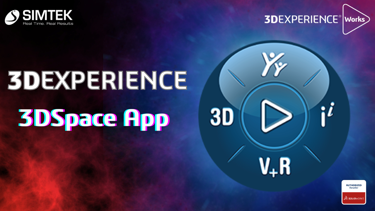
3DEXPERIENCE 3DSpace App
3DSpace App is a core application of the 3DEXPERIENCE platform designed for project management and collaboration. It serves as a centralized repository for project data, enabling teams to access, manage, and share information seamlessly. Features: 1. Centralized Data Management 3DSpace allows users to store and organize all project-related information in one location. 2. Intuitive User […]
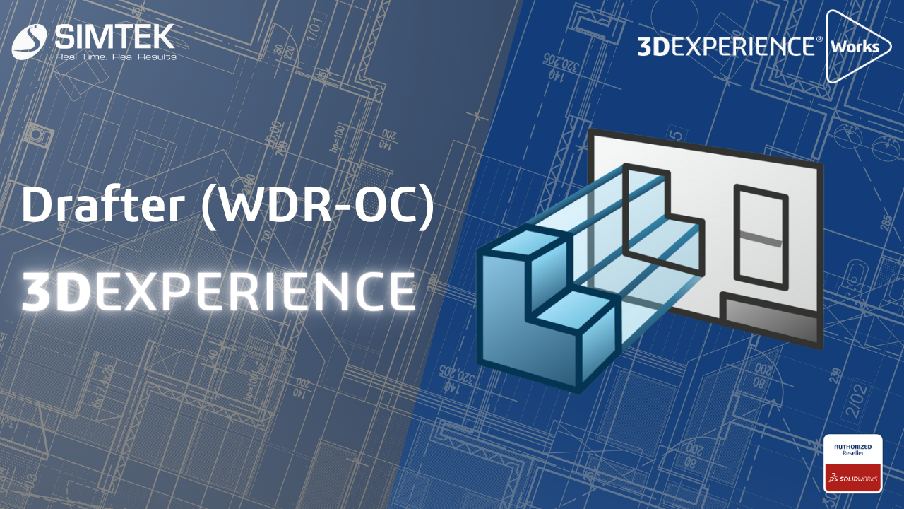
Drafter (WDR-OC) 3DEXPERIENCE
Drafter (WDR-OC) 3DEXPERIENCE Drafter WDR-OC enables rapid conversion of 3D models into accurate 2D drawings, significantly enhancing the product development cycle. With real-time updates, modifications to the 3D model are instantly reflected in the 2D drawings, minimizing errors. Users can easily annotate and dimension their drawings, facilitating clear communication among team members. Integrated with the […]
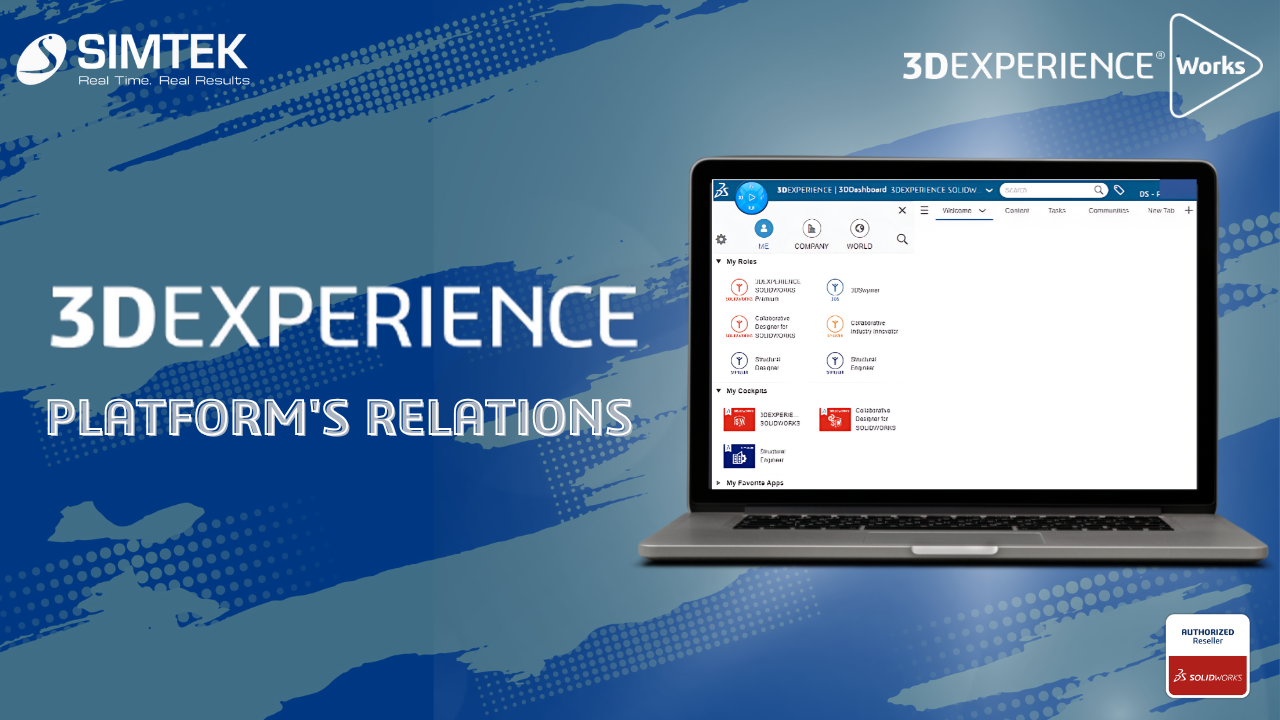
Transform Your Workflow with the 3DEXPERIENCE Platform’s Powerful Relations
The Relations app in the 3DEXPERIENCE platform is designed to help users manage and visualize relationships between various entities, such as parts, documents, and projects. This is a powerful tool for managing complex relationships in product development and ensuring that teams work cohesively. Using the Relations app: Benefits: Conclusion The Relations app in the 3DEXPERIENCE […]
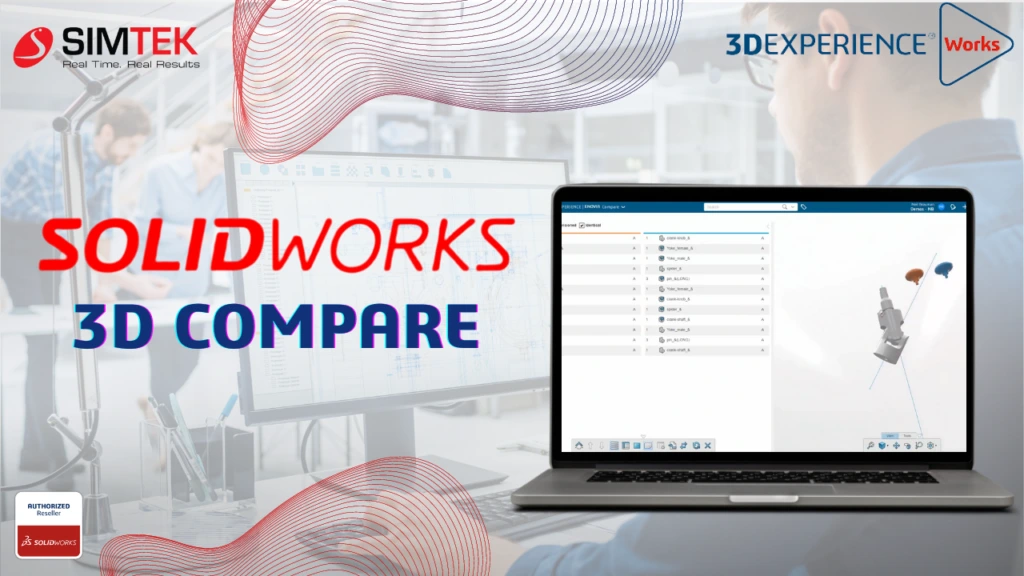
SOLIDWORKS 3D Compare
The powerful tool SOLIDWORKS 3D Compare streamlines the design review process by allowing users to visually compare different versions of 3D CAD models. Whether you’re tracking geometry changes, analyzing dimensions, or identifying discrepancies, this browser-based tool available within the Collaborative Industry Innovator role on the 3DEXPERIENCE platform ensures that design validation is efficient and accurate. […]
Route Management in 3DEXPERIENCE
Route Management in 3DEXPERIENCE simplifies workflows by automating tasks, tracking reviews, and managing approvals for efficient design and release processes. A route is a set of tasks that a person defines for a group of people. Routes typically contain several tasks. However, it is also possible to create a route that contains a single task. […]
- 1
- 2