How to Import a Manufacturer Part from Excel into SolidWorks Electrical

How to Import a Manufacturer Part from Excel into SolidWorks Electrical 

Why Import from Excel?

• Manual maintenance of manufacturer parts can be tedious.
• With Excel, dozens (or even hundreds) of parts can be imported in one go.
• Repetitive data entry is eliminated.
• Consistency across projects and teams is maintained.
• A custom library tailored to your workflow can be built easily.


Step 1: Excel File Preparation

The Excel file must be prepared in the correct format.
SolidWorks Electrical expects specific columns. The following format should be used:

ReferenceManufacturerDescriptionPart TypeSymbol NameClassification
123-ABCSchneider ElectricContactor 24VDCContactorSYM_CONTACTPower Components > Contactor
456-DEFSiemensCircuit Breaker 10ABreakerSYM_BREAKPower Components > Breaker

Step 2: SolidWorks Electrical Launch

• SolidWorks Electrical should be launched.
• A project can be opened, or work can be done from the library tab.
• The Manufacturer Parts Manager will be accessed next.


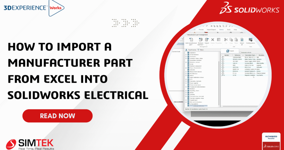
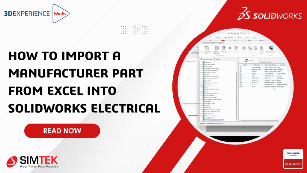
Step 3: Manufacturer Parts Manager Navigation

• The library tab should be clicked.
• "Manufacturer parts manager" should be selected.
• Within the manager, the Import > Manufacturer parts option should be clicked.
• Excel should be chosen as the file type.
• The Import Wizard will be launched automatically.


Step 4: Field Mapping

After the Excel file is loaded, column mapping will be requested by SolidWorks Electrical.
Ensure that fields such as:
• Reference
• Manufacturer
• Description
• Part Type
are mapped to their correct database fields.


Step 5: Import Completion

• Once mapping is finished, "Next" should be clicked to review the data.
• "Finish" should then be clicked.
• The Excel data will be processed by SolidWorks Electrical.
• A confirmation message will be displayed if the parts have been added successfully.


Step 6: Part Verification

• The Manufacturer Parts Manager should be revisited.
• Imported part numbers can be searched.
• They should appear in the list, with all relevant data.

Now, parts can:
• Be linked to symbols
• Be assigned to circuits
• Be used in schematics immediately


 Benefits:

Time Savings
• Hours are saved through bulk imports.
• Library setups for new projects or migrations are accelerated.

Reduced Errors
• Errors are minimized through direct import from validated Excel sheets.
• Part numbers, descriptions, and manufacturers are kept consistent across projects.

Linking SOLIDWORKS Electrical 2D to 3D Assemblies

 Linking SOLIDWORKS Electrical 2D to 3D Assemblies

Linking SolidWorks Electrical 2D to 3D Assemblies

🧭 Step 1: Electrical 2D Project Should Be Created

  • SOLIDWORKS Electrical 2D should be launched.
  • A new project should be created by selecting “New Project” and choosing a template or starting from scratch.
  • Schematics should be designed:
  • Components, symbols, wires, and cables should be added.
  • Circuits and terminal strips should be defined.
  • The project should be saved, and manufacturer part numbers must be assigned to all components to ensure 3D integration compatibility.

🔄 Step 2: 3D Part Data Should Be Assigned to Components

The manufacturer part manager should be opened.

For each component:

  • “Edit Part” should be selected, then navigated to the “SolidWorks Part” tab.
  • A 3D model from the library should be assigned, or a custom one should be inserted.
  • Mating points for wire connections must be defined properly.

🧩 Step 3: SolidWorks 3D Should Be Launched and the Electrical 3D Add-In Enabled

  • SolidWorks 3D CAD should be opened.
  • From the “Tools” > “Add-Ins” menu, SolidWorks Electrical 3D should be activated.
  • The Electrical 3D tab should be accessed from the Command Manager.

📁 Step 4: The 2D Project Should Be Linked in SolidWorks 3D

  • In the Electrical 3D tab, “Open Electrical Project” should be clicked.
  • The same project created in 2D should be located and opened.
  • Upon loading, the following will be imported automatically:
  • Component list
  • Wiring data
  • Cable references

📦 Step 5: Components Should Be Placed in the 3D Assembly

  • A new assembly should be started, or an existing enclosure layout should be opened.
  • The Place Component button should be used to insert parts defined in the 2D project.
  • Components should be positioned and mated as needed within the cabinet or panel.

🔌 Step 6: Wires and Cables Should Be Routed in 3D

  • The Route Wires or Route Cables function in the Electrical 3D tab should be clicked.
  • The software will:
    • Automatically generate paths between electrical connection points.
    • Respect wire types and lengths defined in the 2D schematic.
  • Routing paths can be manually adjusted using available Routing tools, if necessary.

📊 Step 7: Reports Should Be Synced and Generated

  • The Electrical 2D project should be reopened.
  • From the Project menu, Update from 3D should be selected to sync any changes made in 3D (e.g., lengths, locations).
  • The following updated reports should be generated:
    • Wire lists
    • Cable summaries
    • Cutting and routing reports

Final Checks

  • The Connection Report should be used to verify schematic completeness.
  • Wire lengths and 3D model accuracy should be carefully double-checked.
  • The project can be exported in PDF, DWG, or STEP formats for sharing.

📘 Conclusion

When SolidWorks Electrical 2D and 3D are linked, enhanced design integrity is achieved, collaboration between teams is improved, and production errors are significantly reduced. By following a streamlined workflow, smarter, cleaner, and more efficient control panels, harnesses, and assemblies can be delivered with confidence.

Transforming STL Files into SOLIDWORKS Solids or Surfaces for Effective 3D Editing

Transforming STL Files into SOLIDWORKS Solids or Surfaces for Effective 3D Editing

Transforming STL Files into SOLIDWORKS Solids or Surfaces for Effective 3D Editing

In the SOLIDWORKS Desktop My Session Task Pane, new revisions are created, and the old revision's files are immediately updated. When reference components are updated on the 3DEXPERIENCE Platform after the assembly has been downloaded, they continue appearing in the Task Pane as the previous revision. This lesson demonstrates the many approaches to revising these components.

You can import STL files into SOLIDWORKS as solid or surface models rather than just graphic bodies by using specific import options available in the software. Here's a detailed step-by-step process and important considerations:

Well the answer is yes, and it is pretty simple. All you need to do is follow these steps:

  1. Start SOLIDWORKS and click Open

Once the SOLIDWORKS main window appears, locate the menu bar at the top.

Click on the File menu.

From the dropdown list, select Open.

This action opens the file dialog box where you can browse files to open in SOLIDWORKS.

Alternatively, you can click the Open icon on the Standard toolbar (often shown as a folder icon).

You may also use the keyboard shortcut Ctrl + O to open this dialog quickly.

  1. Change the file type to STL (*.stl)

After the Open dialog box appears (from step 1), look towards the bottom right corner of the dialog.

Find the dropdown menu labeled "Files of type" or simply "Type". This menu lists all the supported file formats.

Click the dropdown arrow to expand the list of file formats.

Scroll through the list and select STL (*.stl) from the available file types.

Once selected, the dialog box will now filter and show only files with the .stl extension in the browse window.

You can now browse to the folder containing your STL file to select it for import.

  1. Notice that a new Options button is available now. Click on it.Browse to the STL file you want to import and click Open.

Click the Options button to open the STL Import Options dialog.

This dialog allows you to choose how SOLIDWORKS imports the STL file (as a Solid Body, Surface Body, or Graphics Body), and provides other settings related to mesh handling.

Take your time reviewing and adjusting these options before proceeding to open the file.

A screenshot of a computer

AI-generated content may be incorrect.
  1. Change import body to Solid Body or Surface Body and press OK.

In the STL Import Options, select Solid Body to attempt converting the mesh into a fully editable solid model, or Surface Body to import the file as surfaces that can be later stitched or repaired. Importing as a solid is ideal for smaller, simpler files;

A screenshot of a computer

AI-generated content may be incorrect.

5. If you look at the Feature Manager Design Tree you can now see that the part is imported 

6. Now you can use the FeatureWorks > Recognize Features  tool to convert the imported body into SOLIDWORKS features.

A computer screen shot of a blue object

AI-generated content may be incorrect.

7.Click Finish or OK to complete the recognition process and update the model

A computer screen shot of a grey object

AI-generated content may be incorrect.

8.In this example Two features have been recognized:

A computer screen shot of a grey object

AI-generated content may be incorrect.

If you want, I can help summarize or explain differences between the SOLIDWORKS Desktop and the 3DEXPERIENCE Platform or guide you through key features and collaboration capabilities of each system. Just let me know!

Back to Top
Product has been added to your cart