Complete Guide to SOLIDWORKS Routing and Piping
In this blog, we will explore the basics of SOLIDWORKS Routing for Pipe Design. In this tutorial, we will cover the following topics:
SOLIDWORKS routing and piping will be available in SOLIDWORKS premium only and will not be present in Standard and professional.
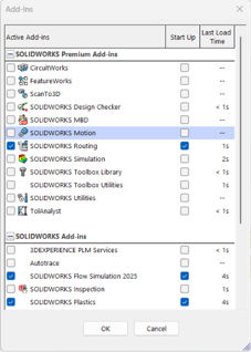
How To Turn On The SOLIDWORKS Routing Add-in
Go to Tools click on Add-ins, check the box for SOLIDWORKS Routing on the Active side. Checking the box on Start Up side will cause the Routing add-in to load when SOLIDWORKS is launched.
How to access the Routing Library.
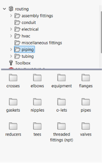
The SOLIDWORKS Design Library is located in the SOLIDWORKS Task Pane. Expand the Design Library folder to see the Routing subfolder. Located below the Routing folder, the Piping folder includes all components needed to create the Piping Route
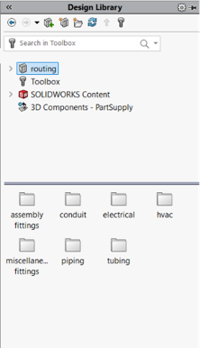
What are the components present in SOLIDWORKS design library,
In SOLIDWORKS piping we can find, crosses, elbows, equipment’s like pump, flanges, gasket, nipples, ect which are using in industry.
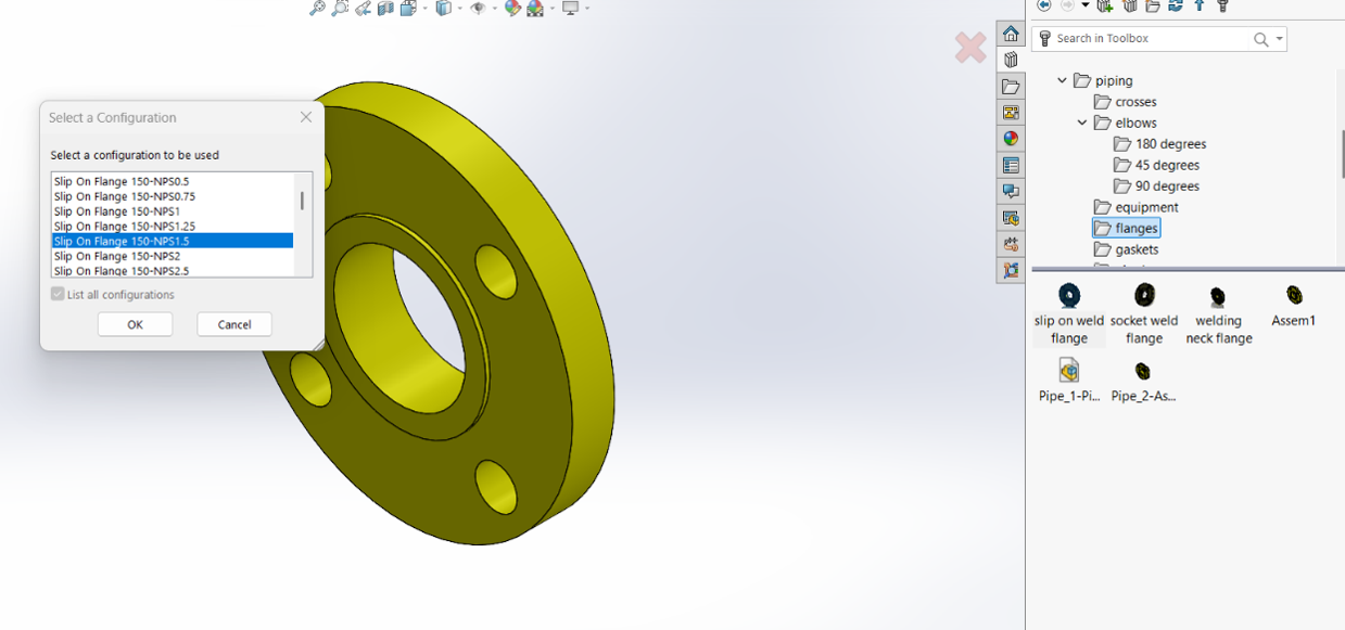
How to start a Pipe Route using Flanges.
Once you click OK in the Piping Property Manager, you will see a new Routing Subassembly in your Feature Tree. You will also notice that a 3D Sketch has been placed at the origin of the flange. The 3D Sketch is the path the pipe will be swept along.
On the Piping Toolbar or Sketch Toolbar choose the Line Tool. Start the next line at the endpoint of the 3D sketch. Drag the Line upwards and click the second point.
If the line is not going in the right direction, you can toggle the direction by hitting the Tab key. This changes the orientation of the sketch from YZ, to ZX, to XY.
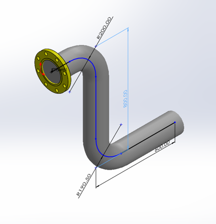
After you place the line, an elbow is placed to join the pipe. The radius is determined by the elbow chosen in the Routing Property Manager.
Continue adding lines. Dimension each segment by clicking Smart Dimension and selecting a line segment. The dimension goes to virtual sharp of radius if there is a change in direction of the pipe.
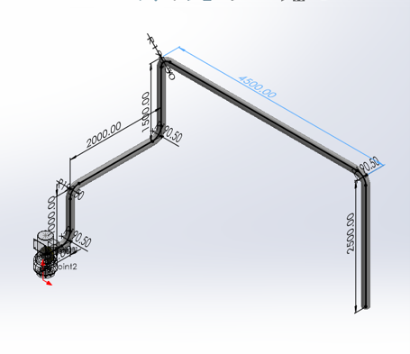
After clicking on the exit edit feature, we can see the pipe section completely.
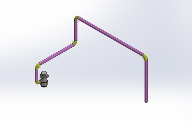
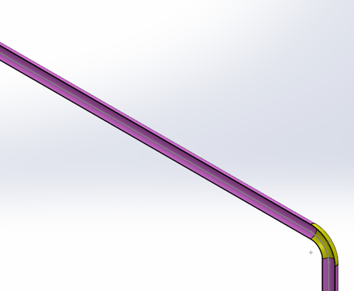
We can use section view to check the internal section of pipe.
You can notice that we have used a centrifugal pump from the equipment’s folder in piping
How to edit route and add fittings.
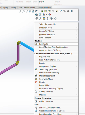
Once we click on edit routing, we can then add in the fittings required like valves tees or reducers.
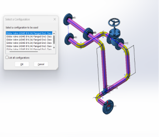
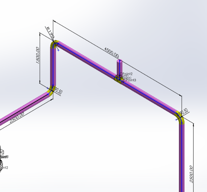
We can rotate the orientation of the fitting by clicking on the tab key.
Overview of Routing Property Manager.
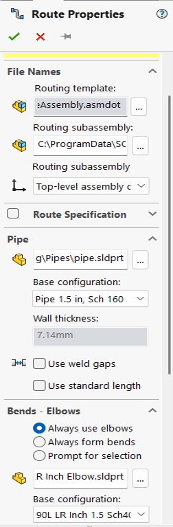
File Names > Routing Subassembly shows the nomenclature for the Routing Subassembly that will be created.
Under the Pipe Category, you can select Use Weld Gaps if you would like to add a gap between components.
The Use Standard Length option will divide the pipe into standard purchased lengths. So, if you buy pipe in 200mm lengths it will divide the pipe into 200mm sections.
Under Bends – Elbows, set the option to Always use elbows. For this tutorial, we are using a 90deg short radius elbow. You can click the browse button to find the component. Click OK in the Route Property Manager.
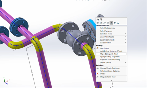
How to move fitting with triad.
Right-click on a gate valve face and choose Move Fitting with Triad.
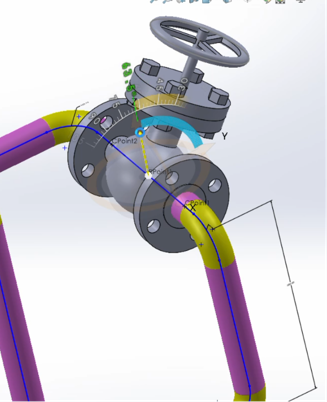
We can rotate the valve at any desired angle using the Triad Wheels.
How to add slope to pipe.
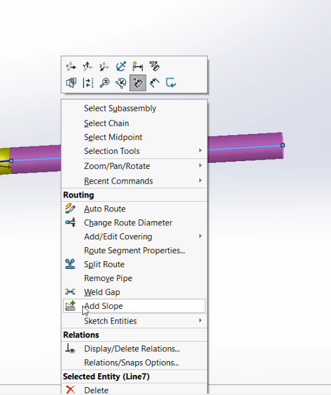
Right click on the pipe and click on add slope.
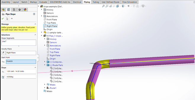
select the pipe segment, and select the gravity plane, notice that the gravity plane is selected based on real-world installation orientation of the piping system and click on the start point and enter the angle for the slope.
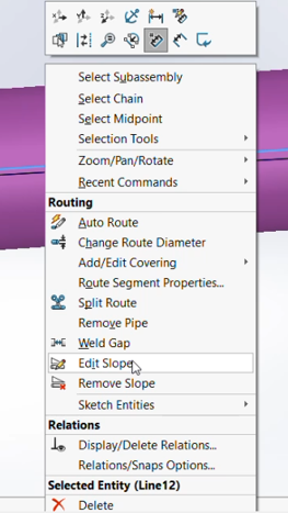
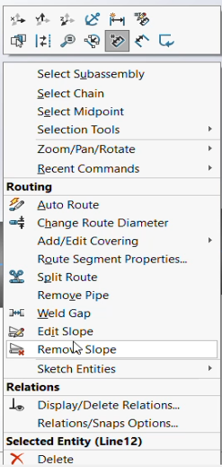
We can edit the slope and delete the slope by right clicking on the pipe and click on edit slope and remove slope option.
How to add covering to pipe
Right click on the pipe and click on add add covering, click on the line segment and then choose use covering library and then choose the covering type, it is noticed that on choosing the covering library the options we cannot edit the thickness and material type and appearance,
Hence, we have to create a custom covering to edit.
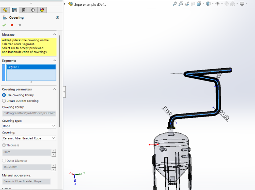
We can notice a transparent covering over the pipe which shows that a covering has been added.
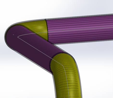
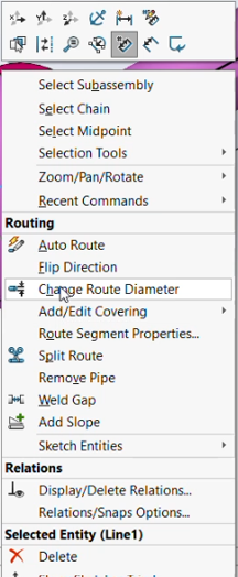
How to change route dia in pipe.
To change route dia, right click on the pipe, click on Change Route diameter option.
Click on the segment of the Change Diameter Pipe Specification Update fittings if required. Sometimes reducers are automatically added.
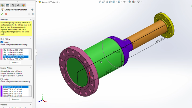
We can see that the diameter of the pipe has reduced from 254mm to 203mm
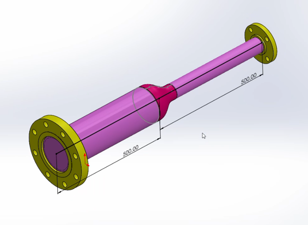
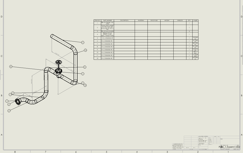
How to create a SOLIDWORKS Drawing of the Pipe Route.
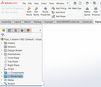
To create drawing in SOLIDWORKS for pipe routing, click on the route parts and then click on the pipe drawing in the task pane.
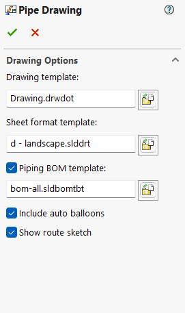
Then we have to select the drawing template and sheet format template and include any piping BOM template if required, we also recommend to click on including auto balloons and show route sketch option
we can see that the view has been inserted and also BOM with all the details have been included in the drawing sheet.