
Looking for Analysis Software at Affordable Price?

Engineering teams are under constant pressure to design lighter, stronger and more reliable products in less time and with fewer physical prototypes. ANSYS simulation software is one of the most widely used engineering tools for meeting that pressure, giving mechanical engineers, product designers and CAE analysts a way to predict how a part or assembly will behave before it is ever manufactured.
This guide breaks down the core simulation capabilities inside ANSYS that engineers rely on every day — from static structural and thermal analysis to fatigue, modal, buckling and motion analysis, along with meshing, optimization and reporting tools. Whether you are a student learning finite element analysis (FEA) for the first time or a senior engineer validating a new pump housing, valve body or structural bracket, this article explains what each capability does, how it works, and where it delivers the most value across automotive, aerospace, medical device and industrial machinery applications.
What Is Engineering Simulation and Why Does It Matter?
Engineering simulation is the use of computer-based models to predict how a physical part or system will respond to real-world conditions such as loads, temperature changes, vibration and motion. At the core of most mechanical simulation is finite element analysis (FEA) — a numerical method that divides a complex geometry into thousands or millions of small elements, then solves the governing physics equations for each element.
Engineers use simulation to identify weak points before manufacturing, reduce the number of physical prototypes required, shorten development cycles, optimize material usage and validate designs against industry standards before certification testing.
Simulation does not replace physical testing entirely, but it dramatically reduces how much testing is needed by filtering out weak design concepts early, when changes are cheapest to make.
Core Structural Analysis Capabilities
Structural analysis is the foundation of most mechanical simulation work. It answers a simple question:
will this part survive the loads it will experience in service?
Static Structural Analysis
Static structural analysis calculates how a component or assembly responds to loads that are applied gradually and do not change significantly over time — such as a bracket carrying a constant weight or a valve body under steady internal pressure
How it works: The geometry is meshed, materials are assigned, boundary conditions (fixtures) and loads are applied, and the solver calculates stress, strain, deformation, and reaction forces throughout the part.
Why engineers use it: to confirm a part won't yield or fracture under expected loads, to compare design variants before committing to tooling, and to correctly size structural members like beams, brackets, and housings.
Limitations: Static analysis assumes loads are applied slowly and the structure has time to reach equilibrium. It does not capture impact, vibration, or time-varying loads.
Real-world example: An industrial machinery manufacturer uses static structural analysis to verify a gearbox mounting bracket can support the weight and torque reaction of the gearbox without exceeding the steel's yield strength, avoiding a costly field failure.
Linear Stress Analysis
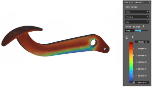
Linear stress analysis is a subset of static structural analysis that assumes a direct, proportional relationship between load and deformation — meaning the material stays within its elastic range and displacements are small relative to the part's overall size.
Benefits: Fast to solve, computationally efficient, and accurate for the majority of everyday structural components operating well below their yield point.
Limitations: Not appropriate for large deformations, contact-heavy assemblies, or materials that behave nonlinearly (plastics, rubber, or metals near yield).
Stress and Strain Analysis
Stress and strain results are the primary outputs engineers review after any structural solve.
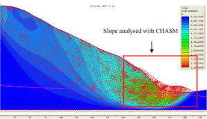
Engineers compare peak stress values against the material's yield strength to calculate a safety factor, which indicates how much margin exists before failure. A safety factor below 1.0 means the part is predicted to fail under the applied load.
Displacement Analysis
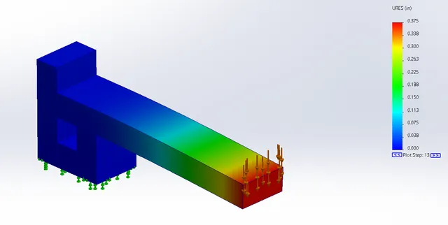
Displacement analysis shows how far each point on a structure moves under load. This matters in applications where excessive deflection — not necessarily material failure — is the design-limiting factor, such as a shaft that must stay within tight alignment tolerances or a consumer product housing that must not visibly flex.
Reaction Force Calculations
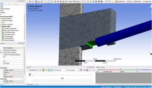
Reaction forces are the loads transferred to fixtures, supports, or mounting points. Engineers use this data to correctly size bolts, welds, and fasteners, and to design supporting structures such as frames or foundations
Practical tip: Cross-check reaction forces against applied loads. In a correctly set-up model, the sum of reaction forces should balance the applied loads — a useful sanity check for accuracy.
Thermal Analysis
Thermal analysis predicts how heat flows through a component and how temperature affects performance, expansion, and stress.
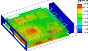
How it works: The solver calculates temperature distribution based on heat sources, material conductivity, and boundary conditions such as convection or fixed temperatures. Results can then feed into a structural analysis to calculate thermal stress caused by expansion or contraction.
Why engineers use it: to ensure electronic enclosures and motor housings stay within safe operating temperatures, to predict thermal expansion in precision assemblies, and to evaluate heat dissipation in braking systems, engine components, and industrial equipment.
Industry example: In heavy equipment design, thermal analysis helps confirm a hydraulic pump housing won't overheat during continuous operation, preventing seal degradation and premature failure.
Best practice: Validate thermal boundary conditions (convection coefficients, ambient temperature) against real operating environments — inaccurate thermal inputs are a common source of simulation error.
Fatigue Analysis
Fatigue analysis predicts how many load cycles a part can withstand before cracking or failing, even when the peak stress from any single load is well below the material's yield strength.
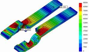
Why it matters: Most in-service mechanical failures are fatigue failures, not overload failures. A component can survive a single high load but still fail after thousands or millions of repeated smaller loads
How it works: Using stress results from a static or dynamic analysis combined with material fatigue (S-N) curves, the solver estimates the number of cycles to failure and produces a fatigue life or damage map across the part.
Applications: automotive suspension components subjected to millions of road-load cycles, pump shafts and valve stems exposed to repeated pressure cycling, and rotating machinery components under cyclic bending stress.
Limitations: Fatigue predictions are sensitive to surface finish, manufacturing defects, and load assumptions — results should be treated as comparative guidance and validated with physical testing for safety-critical parts.
Frequency (Modal) Analysis
Modal analysis calculates a structure's naturalfrequencies and corresponding mode shapes — the frequencies at which a part naturally wants to vibrate.
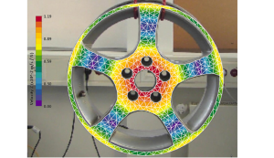
Why engineers use it: to avoid resonance, where an operating frequency (such as a motor's rotational speed) matches a natural frequency and causes amplified vibration; to improve the stiffness and dynamic stability of frames, brackets, and enclosures; and to support subsequent vibration studies.
Industry example: In automotive design, modal analysis is used to confirm that a dashboard support bracket's natural frequency is well separated from engine idle frequency, preventing rattling and long-term fatigue damage.
Best practice: Aim for a separation margin of at least 20–30% between excitation frequency and the nearest natural frequency where possible.
Buckling Analysis
Buckling analysis predicts the load at which a slender structure suddenly loses stability and deforms sideways, rather than failing due to material stress. Thin-walled columns, long shafts under compression, pressure vessel walls, and lightweight structural frames are all buckling-sensitive
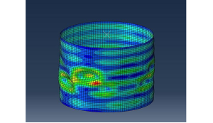
How it works: Linear buckling analysis calculates a buckling load factor — a multiplier on the applied load indicating how close the structure is to instability. A factor below 1.0 means buckling occurs before the design load is reached.
Applications: Heavy equipment booms, structural columns in industrial frames, and thinwalled aerospace panels are commonly checked for buckling in addition to standard stress limits.
Motion Analysis
Motion analysis (also called kinematic or rigid-body dynamic analysis) studies how interconnected parts move relative to one another, calculating displacement, velocity, acceleration, and the loads transmitted through joints, pins, and contacts over time.
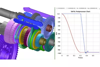
Why engineers use it: to verify mechanisms move through their intended range without interference, to extract dynamic loads that feed into downstream structural or fatigue analysis, and to evaluate cam, linkage, and gear-train behavior under operating speeds.
Industry example: In consumer product design, motion analysis is used to confirm that a folding mechanism opens and closes smoothly across thousands of cycles without binding, and to extract peak hinge loads for structural verification.
Design Studies, Optimization and Topology Optimization
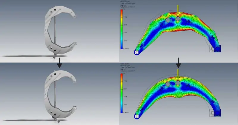
A design study runs multiple simulation iterations across a range of input parameters — such as wall thickness, hole diameter, or material choice — to understand how each variable affects performance, weight, or cost. Engineers can explore many design variants virtually instead of building physical prototypes for each option, shortening development cycles.
Design Optimization
Design optimization automates the design study process by letting the software search for the parameter combination that best meets defined goals (minimum weight, maximum stiffness) while satisfying constraints (maximum stress, minimum safety factor) — useful for optimizing rib patterns in plastic housings or wall thickness in cast pump components
Topology Optimization
Topology optimization takes a different approach: instead of adjusting a few parameters, it determines the most efficient material layout within a defined design space, removing material from low-stress regions while preserving load paths.
How it works: Engineers define the design space, loads, constraints, and a target (typically minimum weight or maximum stiffness). The solver iteratively removes unnecessary material and outputs an organic, load-optimized shape.
Benefits: significant weight reduction, especially valuable in aerospace and automotive components; material savings that reduce manufacturing cost; and design inspiration for advanced manufacturing methods.
Limitations: Resulting shapes are often complex and may require manufacturing methods capable of producing organic geometries, along with further refinement before they are production-ready.
Real-world example: An aerospace bracket redesigned through topology optimization can often achieve 20–40% weight reduction while maintaining the required stiffness and safety factor — a meaningful gain when every gram affects fuel efficiency.
Material Libraries
ANSYS includes built-in material libraries containing standard mechanical, thermal, and fatigue properties for common metals, plastics, and composites.
Why this matters: it ensures consistent, traceable material data across a design team; allows quick comparison between candidate materials (aluminum vs. steel, for example) without re-entering properties; and supports custom material creation for proprietary alloys, composites, or plastics.
Best practice: Verify library material properties against certified datasheets for safetycritical applications rather than relying solely on default values, particularly for fatigue and nonlinear material behavior.
Meshing and Contact Detection
Automatic Meshing
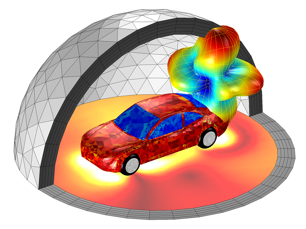
Meshing divides a CAD model into small elements (tetrahedral, hexahedral, or shell elements) that the solver uses to approximate the part's behavior. ANSYS automatic meshing tools generate a mesh based on geometry and physics settings, with options for local refinement in high-stress or high-curvature areas. Results accuracy depends heavily on mesh density and quality — too coarse a mesh can miss stress concentrations, while too fine a mesh increases solve time unnecessarily.
Best practice: Perform a mesh convergence study — progressively refining the mesh until results stabilize — to confirm reported stress and displacement values are not meshdependent.
Contact Detection
In assemblies, contact detection defines how parts interact where they touch — whether bonded, allowed to separate, or allowed to slide with friction. Incorrect contact definitions are one of the most common causes of inaccurate assembly results, since contact behavior directly affects load transfer and stress concentration.
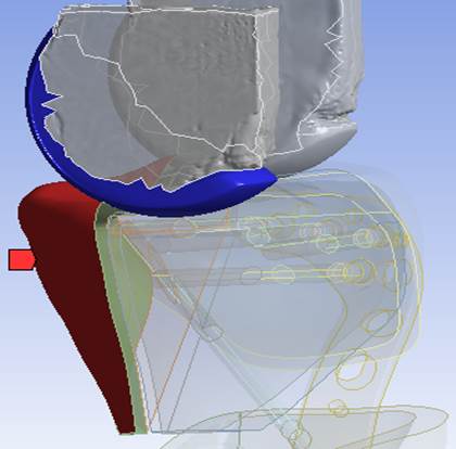
Applications: bolted flange connections in valve assemblies, press-fit bearings in rotating equipment, and interference fits in medical device housings all rely on accurate contact modeling.
Boundary Conditions, Fixtures, and Loads
Boundary conditions define how a model connects to the outside world and what forces act upon it. Getting these right is arguably the most important step in any simulation — even a perfectly meshed model produces misleading results if loads or supports don't reflect reality.
Pressure Load Simulation
Pressure loads simulate distributed forces such as internal fluid pressure in a pipe, hydraulic pressure in a cylinder, or external wind load on a structure. This is essential for pump, valve, and pressure vessel design, where internal pressure is often the dominant load case.
Gravity Loading

Gravity loading applies a body force representing self-weight throughout the entire volume of a part, which is critical for large structures, heavy equipment frames, and any assembly where self-weight contributes meaningfully to total stress.
Practical tip: Combine load cases realistically. A pump housing rarely sees pressure alone — combining internal pressure, gravity, and mounting loads in a single study produces far more representative results than analyzing each in isolation.
Assembly Simulation
Assembly simulation extends structural analysis to multi-part systems, capturing how loads transfer between components through bolts, welds, pins, and contact surfaces.
Why it's used: to evaluate how an entire mechanism or machine behaves under load rather than just individual parts, to identify load paths and stress concentrations at connection points, and to validate bolted joint integrity
Industry example: In heavy equipment design, assembly simulation evaluates an excavator arm assembly, capturing how load transfers through each pin joint to identify the most highly stressed connection point.
Limitation: Assembly models are computationally heavier than single-part analysis, so simplifying non-critical connections (using bonded contact where appropriate) helps manage solve time
Weldment Simulation
Weldment simulation evaluates the structural performance of welded connections within fabricated assemblies, such as steel frames, machine bases, and structural housings
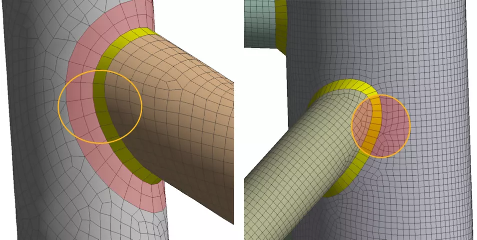
How it works: Welds are typically represented as connections between plates or beams, and the solver reports stress along the weld line, which engineers compare against weldspecific allowable stress values. This is valuable for fabricated equipment frames, structural supports for industrial machinery, and welded brackets in heavy equipment.
Best practice: Weld geometry (throat size, leg length) significantly affects local stress, so use consistent weld representations and validate critical welds against applicable structural design codes.
Result Visualization and Engineering Reports
Result Visualization
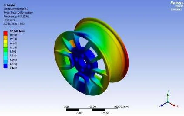
Once a solve is complete, results are displayed as color-coded contour plots showing stress, strain, displacement, temperature, or safety factor across the model. Engineers can animate deformation, plot results along a path, and compare design iterations side by side — making it easy to communicate findings to non-simulation stakeholders without requiring them to interpret raw numerical data.
Engineering Reports
ANSYS can automatically generate structured engineering reports documenting model setup, boundary conditions, mesh statistics, and results. These reports serve as design validation documentation for internal review, traceable records supporting regulatory certification (particularly valuable in medical device and aerospace industries), and reference material for future design iterations.
Best practice: Include assumptions, boundary conditions, and material data explicitly in every report so results can be understood and reproduced by someone who wasn't involved in the original analysis.
CAD Data Import
ANSYS supports direct import of 3D CAD geometry from common neutral and native file formats, allowing engineers to simulate designs without rebuilding geometry from scratch.
Why it matters: it preserves design intent and avoids geometry translation errors, supports associative updates so simulation models update automatically when the CAD design changes, and reduces setup time so engineers can focus on physics rather than geometry cleanup.
Best practice: Simplify imported geometry (removing cosmetic fillets, logos, and nonstructural features) before meshing to reduce solve time without affecting result accuracy.
Engineering Validation Before Manufacturing
Bringing all these capabilities together, the ultimate purpose of simulation is engineering validation — confirming a design meets performance, safety, and durability requirements before committing to tooling, casting, or fabrication.
A typical validation workflow: import and clean up CAD geometry, assign accurate material properties, apply realistic boundary conditions and loads, generate and refine an appropriate mesh, run the required analysis types, review results, iterate on design changes, and document findings in an engineering report.
Why this matters industry-wide: automotive teams validate suspension and chassis components against durability targets before tooling investment; aerospace teams confirm structural margins meet certification requirements; medical device makers verify housings and mechanisms meet strength and fatigue requirements under regulatory scrutiny; pump and valve manufacturers confirm pressure-containing components meet code-required safety factors; consumer product companies validate housings survive drop, load, and cyclic use testing; and industrial equipment builders confirm frames handle operational loads safely over the equipment's service life.
Comparison of Common ANSYS Analysis Types
Conclusion
ANSYS simulation capabilities give engineers a structured, physics-based way to answer the question every product development team faces: will this design actually work in the real world? From static structural and thermal analysis to fatigue, modal, buckling, and motion studies, each capability addresses a specific engineering question, and together they form a validation workflow spanning concept design through pre-manufacturing sign-off.
For engineers, product designers, and CAE professionals, mastering these core capabilities — and applying them with sound boundary conditions, mesh quality, and material data — is what turns simulation from a checkbox exercise into a genuine driver of safer, lighter, and more reliable products.
Contact US
Contact us today to discuss your simulation requirements, request a quote, or schedule a personalized walkthrough of ANSYS capabilities tailored to your industry — automotive, aerospace, medical devices, industrial machinery, or beyond.